JP2022147396A - Remote standard image generation system, remote standard image generation method and program - Google Patents
Remote standard image generation system, remote standard image generation method and programDownload PDFInfo
- Publication number
- JP2022147396A JP2022147396AJP2021048616AJP2021048616AJP2022147396AJP 2022147396 AJP2022147396 AJP 2022147396AJP 2021048616 AJP2021048616 AJP 2021048616AJP 2021048616 AJP2021048616 AJP 2021048616AJP 2022147396 AJP2022147396 AJP 2022147396A
- Authority
- JP
- Japan
- Prior art keywords
- image
- spectral
- subject
- remote
- standard image
- Prior art date
- Legal status (The legal status is an assumption and is not a legal conclusion. Google has not performed a legal analysis and makes no representation as to the accuracy of the status listed.)
- Granted
Links
Images


Landscapes
- Medical Treatment And Welfare Office Work (AREA)
Abstract
Description
Translated fromJapanese本発明は、遠隔標準画像生成システム、遠隔標準画像生成方法及びプログラムに関する。 The present invention relates to a remote standard image generation system, a remote standard image generation method, and a program.
近年、遠隔診療(オンライン診療)や化粧品のオンラインカウンセリングの需要が高まっている。
例えば、一般的な通院患者に対する主な診療方法は、患者が定期的に医療機関に通院し、医療機関にある医療機器および健康機器によって身体の検査を行ない、検査結果に対応して医師などの専門家が患者の状態を判断している。
近年、離島やへき地の遠隔診療が医師不足を背景に増加しており、患者が直接に医療機関に容易に通院できないため、患者を撮像した画像や映像をもとに、医療機関において医師が診察を行う(例えば、特許文献1及び特許文献2を参照)。In recent years, the demand for telemedicine (online medical treatment) and online counseling for cosmetics has increased.
For example, the main treatment method for general outpatients is that the patient regularly visits a medical institution, undergoes a physical examination using the medical and health equipment at the medical institution, and responds to the examination results by a doctor, etc. A specialist is assessing the patient's condition.
In recent years, due to the shortage of doctors in remote islands and remote areas, there has been an increase in telemedicine. (see, for example, Patent Documents 1 and 2).
同様に、在宅療養を行っている患者も同様であり、医師が頻繁に診察に出向けないため、上述した遠隔診療が行われている。
また、急病や事故などでの負傷した場合に救急搬送が行われるが、自宅や事故現場あるいは救急車の中などで一刻を争うため、患者に対して上述と同様の遠隔診療が行われる。
自宅或いは事故現場または搬送時などにおいて、患者の診察ができれば、受け入れ後の検査などを想定することが可能となり、患者の状態に合わせた早期治療に役立つ。Similarly, the same is true for patients undergoing home care, and the above-mentioned telemedicine is being used because doctors do not visit frequently.
In addition, when a patient is injured due to a sudden illness or an accident, an ambulance is carried out, and since time is of the essence, the same telemedicine is provided to the patient at home, at the scene of the accident, or in an ambulance.
If the patient can be examined at home, at the site of the accident, or during transport, it will be possible to anticipate examinations after acceptance, which will be useful for early treatment according to the patient's condition.
しかしながら、通常のデジタルカメラで撮像しても、あるいはハイパースペクトルカメラで撮像しても、照明などの環境光により、患者の患部の正確な色を観察することができない。
例えば、医師は通常の場合、医療機関における診察室で患者の診察を行っているため、環境が異なった場合に、患部の色が医療機関で観察される色と一致しないため、正確な診察が行えない虞がある。However, even if the image is taken by a normal digital camera or by a hyperspectral camera, it is impossible to observe the correct color of the patient's affected area due to ambient light such as lighting.
For example, a doctor usually examines a patient in a doctor's office at a medical institution, and in different environments, the color of the affected area may not match the color observed in the medical institution, making an accurate examination difficult. There is a possibility that it cannot be done.
また、せっかく高価なハイパースペクトルカメラで撮像したとしても、患者の患部の色が上述した環境光の影響を、デジタルカメラと同様に受けてしまう。
このため、性能に対応した高い分解能での波長毎の色を抽出できたとしても、環境光の影響を受けることから、抽出した色からの状態の解析の精度が低くなり、視診の精度を向上させることができない。
さらに、電子カルテは、遠隔治療に不可欠な患者のデータとなるため、患部の画像を撮像する撮像装置が異なっていても、画像を表示する表示装置が異なっていても、電子カルテ上の患部の色のデータは所定の特性で統一されている必要がある。Moreover, even if the image is taken with an expensive hyperspectral camera, the color of the patient's affected area is affected by the above-described environmental light in the same way as with a digital camera.
For this reason, even if the color of each wavelength can be extracted with high resolution corresponding to the performance, the accuracy of the analysis of the state from the extracted color will be affected by the influence of the ambient light, and the accuracy of visual inspection will be improved. I can't let you.
Furthermore, since electronic medical records provide patient data that is indispensable for remote treatment, even if the imaging device that captures the image of the affected area is different, and the display device that displays the image is different, the affected area on the electronic medical record can be Color data must be unified with predetermined characteristics.
本発明は、このような状況に鑑みてなされたもので、観察者(医師やビューティアドバイザー)が観察する観察場所と異なる撮像場所において撮像した被写体(患者、あるいは患者の患部、または相談者の肌など)の撮像画像である観察画像(患部画像)から、光源環境の影響を除いた色の情報による画像を生成することにより、観察画像の色の視認における特性を統一し、遠隔診療における視診や、オンラインカウンセリングの精度を向上させることができる遠隔標準画像生成システム、遠隔標準画像生成方法及びプログラムを提供する。 The present invention has been made in view of such a situation, and an object (a patient, an affected part of the patient, or the skin of the person who consulted) was imaged at an imaging location different from the observation location observed by the observer (doctor or beauty advisor). etc.), which is a captured image (image of the affected area), by generating an image based on color information that excludes the influence of the light source environment. , to provide a remote reference image generation system, a remote reference image generation method, and a program capable of improving the accuracy of online counseling.
上述した課題を解決するために、本発明の遠隔標準画像生成システムは、観察者(医師やビューティアドバイザー)が観察する観察場所と異なる撮像場所において撮像した被写体(患者、あるいは患者の患部、または相談者の肌など)の撮像画像である観察画像(患部画像)から、前記観察者が前記被写体の観察に用いる画像として、前記被写体の分光反射率の情報を含む遠隔標準画像を生成する遠隔標準画像生成システムであって、少なくとも前記観察画像と、前記撮像場所の環境における光源の分光分布と、前記観察画像を撮像した撮像装置の分光感度とから、前記被写体の分光反射率を推定する被写体分光反射率推定部と、前記推定された分光反射率の情報を含む前記遠隔標準画像を生成する標準化画像生成部とを備えることを特徴とする。 In order to solve the above-described problems, the remote reference image generation system of the present invention provides a subject (patient, patient's affected area, or consultation) imaged at an imaging location different from an observation location observed by an observer (doctor or beauty advisor). A remote standard image for generating a remote standard image including information on the spectral reflectance of the subject as an image used by the observer for observing the subject from an observation image (affected area image) that is a captured image of a person's skin, etc. A subject spectral reflectance generating system for estimating the spectral reflectance of the subject from at least the observed image, the spectral distribution of a light source in the environment of the imaging location, and the spectral sensitivity of an imaging device that captured the observed image. and a standardized image generator for generating the remote standard image including information on the estimated spectral reflectance.
本発明の遠隔標準画像生成システムは、前記被写体分光反射率推定部が、前記遠隔標準画像の色チャネル数より少ない色チャネル数の前記観察画像から、当該遠隔標準画像の色チャネル数からなる、前記被写体の分光反射率を推定することを特徴とする。 In the remote standard image generating system of the present invention, the subject spectral reflectance estimating unit obtains the number of color channels of the remote standard image from the observed image having a number of color channels smaller than the number of color channels of the remote standard image. It is characterized by estimating the spectral reflectance of a subject.
本発明の遠隔標準画像生成システムは、前記観察画像を撮像した撮像場所を推定する撮像環境推定部をさらに備えることを特徴とする。 The remote reference image generation system of the present invention is characterized by further comprising an imaging environment estimation section for estimating an imaging location where the observation image was captured.
本発明の遠隔標準画像生成システムは、撮像環境推定部が、前記撮像場所で被写体を撮像する担当者が携帯するGPS(global positioning system)受信機により取得した位置情報を用い、地図データにおける当該位置情報の示す位置により前記撮像場所を推定し、また撮像場所における天候の状態を取得することを特徴とする。 In the remote reference image generation system of the present invention, the imaging environment estimation unit uses position information acquired by a GPS (global positioning system) receiver carried by a person in charge of imaging a subject at the imaging location to determine the position in the map data. It is characterized by estimating the imaging location from the position indicated by the information and acquiring the weather conditions at the imaging location.
本発明の遠隔標準画像生成システムは、撮像環境推定部が、前記撮像場所の色合い(色調)から、当該撮像場所の光源の種類の分類を行うことを特徴とする。 The remote standard image generation system of the present invention is characterized in that the imaging environment estimating section classifies the type of light source of the imaging location from the hue (color tone) of the imaging location.
本発明の遠隔標準画像生成システムは、撮像環境推定部が、前記観察画像の背景画像から、当該観察画像を撮像した前記撮像場所を推定することを特徴とする。 The remote standard image generation system of the present invention is characterized in that the imaging environment estimation unit estimates the imaging location where the observation image was captured from a background image of the observation image.
本発明の遠隔標準画像生成システムは、前記光源の分光分布を推定して取得する際、当該分光分布を所定の条件により判定し、推定精度が悪いと判定された場合、前記分光分布に対応する過去の分光分布である参照分光分布を用いて補正するデータ補正部をさらに備えることを特徴とする。 In the remote standard image generation system of the present invention, when estimating and acquiring the spectral distribution of the light source, the spectral distribution is determined according to a predetermined condition, and if it is determined that the estimation accuracy is poor, the spectral distribution corresponding to the spectral distribution is determined. It is characterized by further comprising a data corrector that corrects using a reference spectral distribution, which is a past spectral distribution.
本発明の遠隔標準画像生成システムは、前記データ補正部が、推定した前記分光分布に含まれるはずのない波長のスペクトルが存在する場合に、当該波長のスペクトルを補正することを特徴とする。 The remote standard image generating system of the present invention is characterized in that the data correction unit corrects the spectrum of wavelengths when there is a spectrum of wavelengths that should not be included in the estimated spectral distribution.
本発明の遠隔標準画像生成システムは、前記データ補正部が、推定した前記分光感度に含まれるはずの波長のスペクトルが存在していない場合に、当該波長のスペクトルを補正することを特徴とする。 The remote standard image generation system of the present invention is characterized in that the data correction unit corrects the spectrum of the wavelength when the spectrum of the wavelength that should be included in the estimated spectral sensitivity does not exist.
本発明の遠隔標準画像生成システムは、前記データ補正部が、前記推定した前記分光分布の各波長のスペクトルの各々と、当該分光分布に類似する参照分光分布の各波長のスペクトルのそれぞれとを比較し、当該参照分光分布に対して所定の差分以上のスペクトルを補正することを特徴とする。 In the remote standard image generation system of the present invention, the data correction unit compares each spectrum of each wavelength of the estimated spectral distribution with each spectrum of each wavelength of a reference spectral distribution similar to the spectral distribution. and correcting a spectrum having a predetermined difference or more with respect to the reference spectral distribution.
本発明の遠隔標準画像生成方法は、観察者が観察する観察場所と異なる撮像場所において撮像した被写体の撮像画像である観察画像から、前記観察者が前記被写体の観察に用いる画像として、前記被写体の分光反射率の情報を含む遠隔標準画像を生成する遠隔標準画像生成方法であって、被写体分光反射率推定部が、少なくとも前記観察画像と、前記撮像場所の環境における光源の分光分布と、前記観察画像を撮像した撮像装置の分光感度とから、前記被写体の分光反射率を推定する被写体分光反射率推定過程と、標準化画像生成部が、前記推定された分光反射率の情報を含む前記遠隔標準画像を生成する標準化画像生成過程とを含むことを特徴とする。 The remote reference image generating method of the present invention is a method of generating an image of a subject as an image used by the observer to observe the subject, from an observation image that is a photographed image of the subject captured at an imaging location different from the observation location observed by the observer. A remote standard image generating method for generating a remote standard image including spectral reflectance information, wherein the subject spectral reflectance estimating unit generates at least the observation image, the spectral distribution of a light source in the environment of the imaging location, and the observation a subject spectral reflectance estimating process for estimating the spectral reflectance of the subject from the spectral sensitivity of an imaging device that captured the image; and a standardized image generation process that generates
本発明のプログラムは、観察者が観察する観察場所と異なる撮像場所において撮像した被写体の撮像画像である被写体画像から、前記観察者が前記被写体の観察に用いる画像として、前記被写体の分光反射率の情報を含む遠隔標準画像を生成する遠隔標準画像生成システムとしてコンピュータを機能させるプログラムであって、前記コンピュータを、少なくとも前記観察画像と、前記撮像場所の環境における光源の分光分布と、前記観察画像を撮像した撮像装置の分光感度とから、前記被写体の分光反射率を推定する被写体分光反射率推定手段、前記推定された分光反射率の情報を含む前記遠隔標準画像を生成する標準化画像生成手段として機能させるためのプログラムである。 The program of the present invention extracts the spectral reflectance of the subject as the image used by the observer for observing the subject from the subject image, which is the captured image of the subject captured at an imaging location different from the observation location observed by the observer. A program that causes a computer to function as a remote standard image generation system that generates a remote standard image containing information, wherein the computer generates at least the observation image, the spectral distribution of a light source in the environment of the imaging location, and the observation image. Functions as subject spectral reflectance estimation means for estimating the spectral reflectance of the subject from the spectral sensitivity of the imaging device that captured the image, and standardized image generation means for generating the remote standard image including information on the estimated spectral reflectance. It is a program for
以上説明したように、本発明によれば、観察者(医師やビューティアドバイザー)が観察する観察場所と異なる撮像場所において撮像した被写体(患者、あるいは患者の患部、または相談者の肌など)の撮像画像である観察画像(患部画像)から、光源環境の影響を除いた色の情報による画像を生成することにより、観察画像の色の視認における特性を統一し、遠隔診療における視診や、オンラインカウンセリングの精度を向上させることができる遠隔標準画像生成システム、遠隔標準画像生成方法及びプログラムを提供することができる。 As described above, according to the present invention, an image of a subject (a patient, an affected part of the patient, or the skin of the person consulting) is imaged at an imaging location different from the observation location observed by the observer (doctor or beauty advisor). By generating an image based on color information that excludes the influence of the light source environment from an observation image (image of the affected area), which is an image, the characteristics of the color perception of the observation image are unified, and visual inspection in telemedicine and online counseling are possible. It is possible to provide a remote standard image generation system, a remote standard image generation method, and a program that can improve accuracy.
<第1の実施形態>
以下、本発明の第1の実施形態について、図面を参照して説明する。
図1は、本発明の第1の実施形態による遠隔標準画像生成システムの構成例を示すブロック図である。本実施形態においては、遠隔診療に用いる標準画像を生成する遠隔標準画像生成システム100を例に説明する。遠隔標準画像生成システム100は、化粧品のカウンセリングに用いられてもよい。
遠隔標準画像生成システム100は、画像データ入力部101、観察画像補正部102、撮像装置分光感度取得部103、撮像場所推定部104、環境光源分光分布取得部105、被写体分光反射率推定部106、標準画像生成部107、出力画像生成部108、表示部109、画像データ出力部110、観察画像データ記憶部111、撮像装置分光感度記憶部112、環境光源分光分布記憶部113、遠隔標準画像記憶部114及び出力画像記憶部115の各々を備えている。<First Embodiment>
A first embodiment of the present invention will be described below with reference to the drawings.
FIG. 1 is a block diagram showing a configuration example of a remote standard image generation system according to the first embodiment of the present invention. In the present embodiment, a remote standard
The remote standard
画像データ入力部101は、外部装置である撮像装置が撮像した患部の画像である患部画像(観察画像)を、当該撮像装置から入力する。
また、画像データ入力部101は、観察画像データ記憶部111に書き込んで記憶させる。The image
Further, the image
観察画像補正部102は、観察画像データ記憶部111から患部画像のデータを読み込み、周囲の人間、例えば家族、救急隊員及び医師や、器具などの患者の患部以外に映り込んでいる画像領域を不必要な部分として削除するトリミングを行ない、患者の患部(被写体)のみが撮像された領域のみの補正患部画像(補正観察画像)を生成する。
また、観察画像補正部102は、補正患部画像と、当該補正患部画像を生成したトリミング前の患部画像とを対応付けて、観察画像データ記憶部111に書き込んで記憶させる。The observation
In addition, the observed
撮像装置分光感度取得部103は、例えば、患部画像に付加されている、当該患部画像を撮像した撮像装置の製品番号などの撮像装置を識別する識別情報を検索キーとして、撮像装置分光感度記憶部112において撮像装置を検索する。
そして、撮像装置分光感度取得部103は、検索キーに対応する撮像装置が検索された場合、撮像装置分光感度記憶部112から、この撮像装置の分光感度のデータを読み出す。
また、撮像装置分光感度取得部103は、撮像装置分光感度記憶部112において、検索キーに対応する撮像装置が検索できなかった場合、インターネットを介して当該撮像装置の分光感度を検索することにより、この分光感度を外部から取得する。The imaging device spectral
When an imaging device corresponding to the search key is found, the imaging device spectral
Further, if the image pickup device spectral
また、撮像装置分光感度取得部103は、撮像装置の分光感度が不明の場合、分光分布、分光感度及び分光反射率の各々を乗算した結果が撮像装置の撮像した患部画像の各画素の色成分R、色成分G及び色成分Bとなる関係を用いて、撮像装置の分光感度を推定する。
例えば、本実施形態において、撮像装置分光感度取得部103は、例えば、撮像装置の分光感度を、予め複数の撮像装置の分光感度の主成分分析から取得した分光感度基底ベクトルの各々の重み付け和により推定する(後述する光源分光分布及び分光反射率の推定と同様)。Further, when the spectral sensitivity of the imaging device is unknown, the imaging device spectral
For example, in the present embodiment, the imaging device spectral
そして、撮像装置分光感度取得部103は、補正患部画像における各々の画素の色成分R、色成分G及び色成分Bが得られる、当該補正患部画像を撮像した撮像装置の分光感度を、サンプリングした部分の分光反射率(後述する推定される分光反射率)と、撮像した環境の光源の分光分布(後述する光源分光分布)とにより当該画素毎に推定する(例えば、特開2021-12514号公報参照)。
ここで、撮像装置分光感度取得部103は、例えば、推定された分光分布の波長において、400nmから700nmの波長単位を、10nm刻みでサンプリングして、31次元ベクトルとして分光感度を求める。Then, the imaging device spectral
Here, the imaging device spectral
撮像場所推定部104は、GPS(global positioning system)の受信機により受信した電波により得られる位置情報(緯度経度情報)と、地図データにおける緯度経度とを対応させ、当該緯度経度がどのような場所であるかの推定を行う。
例えば、地図データにおける緯度経度にビルが建っている場合、ビル内部であると推定し、緯度経度が道路であれば屋外の道路上であることが推定される。
これにより、撮像された場所が室内か屋外か、室内であればどのような施設かが判り、撮像場所推定部104は、その推定された撮像場所を環境光源分光分布取得部105に対して出力する。The imaging
For example, if there is a building at the latitude and longitude in the map data, it is presumed that it is inside a building, and if the latitude and longitude is a road, it is presumed that it is on an outdoor road.
As a result, it can be determined whether the place where the image was taken is indoors or outdoors, and if it is indoors, what kind of facility it is. do.
また、屋外であることが推定できれば、撮像場所推定部104は、インターネットを介して、その緯度経度における地域の天気予報のホームページを参照し、天気データ(晴天、曇り、雨、雪など)を取得する。
そして、撮像場所推定部104は、撮像場所の天気予報の天気データを、環境光源分光分布取得部105に対して出力する。If it can be estimated that the location is outdoors, the imaging
Then, the imaging
また、撮像場所推定部104は、GPSにより移動している場合、速度により救急車で移動している(救急車の車内にいる)か、あるいは救急隊員などに押された搬送台上にいる(屋外あるいは建物の内部)のかなどの撮像場所を推定することができる。
そして、撮像場所推定部104は、環境光源分光分布取得部105に対して、移動速度に基づいて推定した場所を出力する。In addition, when the imaging
Then, the imaging
また、撮像場所推定部104は、患部画像に撮像されている患者以外の背景画像、例えば室内や屋外などの画像認識を行う。
すなわち、撮像場所推定部104は、自宅の室内、救急車の車内、屋外(路上など)、病院内の通路、診察室などを判定することで、患部が撮像された撮像場所の推定(機械学習モデルを用いてもよい)を行う。
ここで、撮像場所推定部104は、患部画像の患部以外の肌の色の色合い(色調)から、撮像場所の光源の種別の推定を行い、推定した種別を環境光源分光分布取得部105に出力する。In addition, the imaging
That is, the imaging
Here, the imaging
環境光源分光分布取得部105は、例えば、供給される患部画像に付加されている、当該患部画像を撮像した環境の光源を識別する識別情報(光源の製造番号、製品番号など)を検索キーとして、環境光源分光分布記憶部113において光源を検索する。
また、この識別情報は、撮像した人間が光源を確認して、撮像装置で撮像した患部画像を送付する際に付加する光源の製品番号及び製品番号、あるいはLED(light emitting diode)、蛍光灯、白熱電球などの光源の種別などでもよい。The environmental light source spectral
In addition, this identification information is the product number and product number of the light source added when the person who took the image confirms the light source and sends the affected area image taken by the imaging device, or the LED (light emitting diode), fluorescent lamp, The type of light source such as an incandescent lamp may be used.
そして、環境光源分光分布取得部105は、検索キーに対応する光源が検索された場合、環境光源分光分布記憶部113から、この光源の分光分布のデータを読み出す。
また、環境光源分光分布取得部105は、LED、蛍光灯及び白熱電球などの光源の種別の場合、撮像場所推定部104から供給される、当該撮像場所推定部104が推定した撮像場所において、一般的に用いられている種別の光源の分光分布のデータを、環境光源分光分布記憶部113から読み出す。Then, when the light source corresponding to the search key is retrieved, the ambient light source spectral
In addition, in the case of the type of light source such as an LED, a fluorescent lamp, and an incandescent lamp, the environmental light source spectral
また、環境光源分光分布取得部105は、LED、蛍光灯及び白熱電球などの光源の種別が撮像した人間から供給されない場合においても、撮像場所推定部104から供給される、当該撮像場所推定部104が推定した撮像場所に対応した、一般的に用いられている種別の光源の分光分布のデータを、環境光源分光分布記憶部113から読み出す。このため、環境光源分光分布記憶部113には、場所と、当該場所における一般的な光源との対応テーブルが予め書き込まれて記憶されている。
また、環境光源分光分布取得部105は、環境光源分光分布記憶部113において、検索キーに対応する光源、あるいは撮像場所において一般的に用いられている光源(撮像場所推定部104が患部画像の色合いから推定した光源の種別も含む)の各々の分光分布が検索できなかった場合、インターネットを介して当該光源の分光分布を検索することにより、この分光分布を外部から取得する。In addition, even when the type of light source such as LED, fluorescent lamp, and incandescent lamp is not supplied from the person who captured the image, the environmental light source spectral
Further, the environmental light source spectral
また、環境光源分光分布取得部105は、環境の光源が不明の場合、分光感度の場合と同様に、分光分布、分光感度及び分光反射率の各々を乗算した結果が撮像装置の撮像した患部画像の画素の色成分R、色成分G及び色成分Bとなる関係を用いて、光源の分光分布を推定する。
例えば、本実施形態において、環境光源分光分布取得部105は、環境光源分光分布を、予め複数の光源の分光分布の主成分分析から取得した光源分光分布規定ベクトルの各々の重み付け和により推定する。In addition, when the environmental light source is unknown, the environmental light source spectral
For example, in the present embodiment, the environmental light source spectral
そして、環境光源分光分布取得部105は、補正患部画像における各々の画素の色成分R、色成分G及び色成分Bが得られる分光分布を、サンプリングした部分の分光反射率(後述する推定される分光反射率)と、撮像装置の分光感度とにより当該画素毎に対応して推定する(例えば、特開2021-12514号公報参照)。
ここで、環境光源分光分布取得部105は、例えば、推定された分光分布の波長において、400nmから700nmの波長単位を、10nm刻みでサンプリングして、31次元ベクトルとして分光分布の情報を求める。Then, the environmental light source spectral
Here, the environmental light source spectral
このとき、環境光源分光分布取得部105は、撮像場所推定部104が推定した撮像場所に対応した一般的な光源の情報を用いることにより、分光分布を推定する際における波長のスペクトルの推定する検索範囲を狭めることができる。
すなわち、環境光源分光分布取得部105は、推定された場所が室内であれば、例えば、蛍光灯またはLEDが照明の光源であることができる。
そして、環境光源分光分布取得部105は、一般的な蛍光灯やLEDなどの光源の波長ごとのスペクトルから推定を開始することにより、高速かつ高精度に光源の分光分布を推定することができる。At this time, the environmental light source spectral
That is, if the estimated location is indoors, the environmental light source spectral
Then, the environmental light source spectral
また、環境光源分光分布取得部105は、撮像場所推定部104が推定した撮像場所が屋外の場合、天気予報の天気データ(撮像した時間の情報も含めて)に対応した太陽光の分光分布を、インターネットを介して光源の推定値として取得する。 Further, when the imaging location estimated by the imaging
被写体分光反射率推定部106は、補正患部画像と、撮像装置分光感度取得部103が取得した撮像装置の分光感度と、環境光源分光分布取得部105が取得した撮像場所における光源の分光分布との各々により、患者の患部の分光反射率を推定する。
本実施形態において、被写体分光反射率推定部106は、例えば、患部の分光反射率を、予め複数の患部の分光反射率の主成分分析から取得した複数の分光反射率基底ベクトルの重み付け和により推定する。The subject spectral
In the present embodiment, the subject spectral
そして、被写体分光反射率推定部106は、補正患部画像における各々の画素の色成分R、色成分G及び色成分Bが得られる分光反射率を、当該画素毎に推定する(例えば、特開2021-12514号公報参照)。
ここで、被写体分光反射率推定部106は、例えば、推定された分光反射率の波長において、400nmから700nmの波長単位を、10nm刻みでサンプリングして、31次元ベクトルとして分光反射率の情報を求める。Then, the subject spectral
Here, the subject spectral
これにより、撮像装置がデジタルカメラの場合、色成分R、色成分G及び色成分Bの3次元(3チャネル、チャネルは色チャネル)で表現される色を、色の次元(チャネル)を増加させて、色成分として31次元(31チャネル)で表現され、かつ撮像した際の光源の影響を受けていない標準的な特性としての分光反射率の情報が取得できる。すなわち、被写体分光反射率推定部106は、分光画像の枚数(遠隔標準画像の色チャネル数)より少ない色チャネル数の患部画像(色成分R、色成分G及び色成分Bの3チャネル)から、分光画像(遠隔標準画像)の色チャネル数からなる患部の分光反射率(分光反射率の情報)を推定する。 As a result, when the imaging device is a digital camera, the color dimension (channel) is increased by increasing the color dimension (channel) of the color expressed in three dimensions (three channels, each channel being a color channel) of the color component R, the color component G, and the color component B. Thus, it is possible to acquire spectral reflectance information as a standard characteristic that is expressed in 31 dimensions (31 channels) as color components and is not affected by the light source when the image is captured. That is, the subject spectral
標準画像生成部107は、上記31次元の各々の波長単位のスペクトルを階調度としてスケール化して示す、31個の分光画像を分光反射率の情報を含む生成する。
ここで、標準画像生成部107は、31次元の各々の次元が一枚の分光画像とするため、31枚の分光画像が生成され、これら31枚の分光画像群を遠隔標準画像として、遠隔医療用標準画像記憶部114に対して書き込んで記憶させる。The standard
Here, the standard
この遠隔標標準画像生成システム100が診察(観察)する医師(観察者)の診察室(観察場所)にある場合、出力画像生成部108は、遠隔標画像記憶部114から遠隔標準画像を読み込む。
そして、出力画像生成部108は、読み込んだ遠隔標準画像と、医師のいる診察室の環境における光源の分光分布とを用いて、当該診察室で観察される色(色成分R、色成分G及び色成分Bで表す表示色)として患部画像(観察画像)を生成し、表示画面に表示する。When the remote target standard
Then, the output
また、出力画像生成部108は、31次元のいずれか、あるいは複数の次元の各々を、色成分R、色成分G及び色成分Bで表す色に変換し(分光画像の分光反射率をカラースケール化した色に変換する)、次元の波長とともに表示画面に表示する表示形態を備えていてもよい。
この場合、分光画像が分光反射率における31次元の各々に対応しているため、上述した色成分R、色成分G及び色成分Bで表す表示色の階調度で分光画像をスケール化することにより、31個の分光画像それぞれを用いて、患部画像の波長毎のスペクトルを観察することが可能となる。
このため、医師は、分光画像から生成される表示画像を観察することにより、患部の病状に対応した特定の波長のスペクトルの強度変化により、患部の状態の診断が行える。In addition, the output
In this case, since the spectral image corresponds to each of the 31 dimensions in the spectral reflectance, by scaling the spectral image with the gradation of the display color represented by the color component R, the color component G, and the color component B described above, , 31 spectral images, it is possible to observe the spectrum for each wavelength of the affected area image.
Therefore, by observing the display image generated from the spectroscopic image, the doctor can diagnose the condition of the diseased part based on the intensity change of the spectrum of the specific wavelength corresponding to the disease condition of the diseased part.
また、この遠隔標準画像生成システム100が診察する医師の診察室にない、例えば病院の管理センターなどのサーバ上に存在する場合、出力画像生成部108は、遠隔標準画像記憶部114から遠隔標準画像を読み込む。
そして、出力画像生成部108は、当該遠隔標準画像と、医師のいる診察室の環境における光源の分光分布とを用いて、当該診察室で観察される色(色成分R、色成分G及び色成分Bで表す表示色)として、医師の診察室の端末における表示装置の表示特性に合わせて表示患部画像を生成し、医師の診察室における表示装置の表示画面に表示する。If the remote standard
Then, the output
表示部109は、例えば、液晶ディスプレイや有機EL(electroluminescent)ディスプレイである。
画像データ出力部110は、外部装置から遠隔標準画像生成システム100がアクセスされた際に、要求される患者の分光画像を遠隔標準画像記憶部114から読み出し、上記外部装置に対して出力する。The
When the remote standard
観察画像データ記憶部111には、外部の撮像装置から供給される患部画像が患者の識別情報とともに書き込まれて記憶されている。また、観察画像データ記憶部111には、観察画像補正部102がトリミングして補正した補正患部画像が、上記患部画像とともに患者の識別情報とともに書き込まれて記憶されている。
撮像装置分光感度記憶部112には、撮像装置の各々の識別情報と、当該識別情報の示す撮像装置の分光感度とが組として、予め書き込まれて記憶されている。In the observation image
The imaging device spectral
環境光源分光分布記憶部113には、光源の各々の識別情報と、当該識別情報の示す光源の分光分布(光源分光分布)とが組として、予め書き込まれて記憶されている。
遠隔標準画像記憶部114には、標準画像生成部107が生成した分光画像の各々が、患者の識別情報とともに書き込まれて記憶されている。
出力画像記憶部115には、出力画像生成部108が生成した出力画像(表示画像)の各々が、患者の識別情報とともに書き込まれて記憶されている。The environmental light source spectral
Each spectroscopic image generated by the standard
Each output image (display image) generated by the output
図2は、表示部109の表示装置の表示画面における遠隔標準画像の表示例を示す概念図である。図2における以下の処理は、出力画像生成部108が行う。
図2において、「画像1」の選択欄201は、撮像された患部画像から分光反射率を推定し、推定された分光反射率から作成した表示患部画像か、あるいは分光画像のいずれを表示するかを選択する欄である。
欄202は、分光画像を選択欄201で選択した場合に、表示する分光画像の最小波長を入力する欄である。FIG. 2 is a conceptual diagram showing a display example of a remote standard image on the display screen of the display device of the
In FIG. 2, the selection column 201 of "Image 1" is used to select whether to display an affected area image created from the estimated spectral reflectance by estimating the spectral reflectance from the imaged affected area image, or a spectral image. is a column for selecting
A column 202 is a column for inputting the minimum wavelength of the spectral image to be displayed when the spectral image is selected in the selection column 201 .
欄203は、分光画像を選択欄201で選択した場合に、表示する分光画像の最大波長を入力する欄である。
ここで、欄202における最小波長のみを設定し、欄203には設定を行わない場合、欄202の波長の分光画像のカラースケール化した画像が表示される。
一方、欄202及び欄203の各々に最小波長、最大波長それぞれを設定した場合、欄202から欄203の各波長の分光画像の積分値、すなわちそれぞれの画素のスペクトルの積算値をカラースケール化した画像が表示される。A column 203 is a column for inputting the maximum wavelength of the spectral image to be displayed when the spectral image is selected in the selection column 201 .
Here, if only the minimum wavelength is set in column 202 and no setting is made in column 203, a color-scaled image of the spectral image of the wavelength in column 202 is displayed.
On the other hand, when the minimum wavelength and the maximum wavelength are set in each of columns 202 and 203, the integrated value of the spectral image of each wavelength in columns 202 to 203, that is, the integrated value of the spectrum of each pixel is converted into a color scale. An image is displayed.
同様に、「画像2」の選択欄204は、撮像された患部画像から分光反射率を推定し、推定された分光反射率から作成した表示患部画像か、あるいは分光画像のいずれを表示するかを選択する欄である。
欄205は、分光画像を選択欄204で選択した場合に、表示する分光画像の最小波長を入力する欄である。
欄206は、分光画像を選択欄204で選択した場合に、表示する分光画像の最大波長を入力する欄である。Similarly, the selection column 204 of "
A column 205 is a column for inputting the minimum wavelength of the spectral image to be displayed when the spectral image is selected in the selection column 204 .
A column 206 is a column for inputting the maximum wavelength of the spectral image to be displayed when the spectral image is selected in the selection column 204 .
ここで、欄205における最小波長のみを設定し、欄206には設定を行わない場合、欄205の波長の分光画像のカラースケール化した画像が表示される。
一方、欄205及び欄206の各々に最小波長、最大波長それぞれを設定した場合、欄205から欄206の各波長の分光画像の積分値、すなわちそれぞれの画素のスペクトルの積算値をカラースケール化した画像が表示される。Here, if only the minimum wavelength is set in column 205 and no setting is made in column 206, a color-scaled image of the spectral image of the wavelength in column 205 is displayed.
On the other hand, when the minimum wavelength and the maximum wavelength are set in each of columns 205 and 206, the integrated value of the spectral image of each wavelength in columns 205 to 206, that is, the integrated value of the spectrum of each pixel is converted into a color scale. An image is displayed.
「ID」の欄207は、表示対象とする患者を識別する識別情報の入力欄であり、患部を有する患者を識別する情報、例えば診察券番号、救急医療の際に付与される患者番号などである。
また、同一の患者であっても、複数の患部が存在する場合、患者番号の下に患部番号の枝番を付加してもよい。
表示切替ボタン208は、欄207で選択した患者の患部の画像として、マウス等で押下する毎に、選択欄201で選択した表示画像210Aと、選択欄204で選択した表示画像201Bとが順次切り替えられて、表示枠209に表示する。An “ID” column 207 is an input column for identification information for identifying a patient to be displayed, and includes information for identifying a patient having an affected area, such as a patient registration number or a patient number assigned for emergency medical care. be.
In addition, even for the same patient, if there are multiple affected areas, the branch number of the affected area number may be added below the patient number.
The display switching button 208 switches sequentially between the display image 210A selected in the selection field 201 and the display image 201B selected in the selection field 204 each time the display switching button 208 is pressed with a mouse or the like as the image of the patient's affected area selected in the field 207. is displayed in the display frame 209 .
上述した図2における表示例として2つの表示画像を切替えて表示する構成として説明したが、これに限定されることなく、2個の表示枠の各々に対して、表示画像210A、210Bそれぞれを表示するようにしてもよい。
また、同一患者の異なる撮像日時における履歴を比較するように、2個の異なる撮像タイミングの補正患部画像あるいは分光画像を表示する構成としてもよい。
また、診察対象の患者の患部画像と、異なる患者の患部画像との各々を、2個の表示枠のそれぞれ並列に表示して比較、例えば診察対象の患者と正常人との比較や、すでに診察により病状が確定した患者との比較を行うように表示する構成としてもよい。Although the configuration in which two display images are switched and displayed has been described as a display example in FIG. You may make it
In addition, a configuration may be adopted in which corrected affected area images or spectral images of two different imaging timings are displayed so as to compare histories of the same patient at different imaging dates and times.
In addition, an affected area image of a patient to be examined and an affected area image of a different patient are displayed in parallel in two display frames for comparison. A configuration may be adopted in which the display is performed so as to be compared with a patient whose medical condition has been confirmed.
図3は、本実施形態の遠隔標準画像生成システム100による患部画像から遠隔標準画像を生成する処理の動作例を示すフローチャートである。
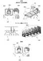
また、図4は、本実施形態の遠隔標準画像生成システム100による患部画像から遠隔標準画像を生成する処理の概念を示す概念図である。FIG. 3 is a flowchart showing an operation example of processing for generating a remote reference image from an affected area image by the remote reference
FIG. 4 is a conceptual diagram showing the concept of processing for generating a remote reference image from an affected area image by the remote reference
ステップS101:
画像データ入力部101は、外部の撮像装置から供給される患部画像を、観察画像データ記憶部111に対して書き込んで記憶させる。
例えば、シーン501(図4)に示すように、撮像場所として患者200の自宅の場合、撮像装置は、患者200の操作するパーソナルコンピュータ221に備えられたWebカメラ222である。
このとき、パーソナルコンピュータ221は、Webカメラ222が撮像した患部画像を遠隔標準画像生成システム100に対して出力する。Step S101:
The image
For example, as shown in a scene 501 ( FIG. 4 ), if the imaging location is the home of the
At this time, the
一方、シーン501(図4)に示すように、撮像場所として患者200が救急隊員223に搬送される救急現場である場合、撮像装置は救急隊員223が携帯する、あるいは救急車に備えられたデジタルカメラ225である。
このとき、救急隊員223は、携帯する携帯端末(不図示)により、デジタルカメラ225が撮像した患部画像を遠隔標準画像生成システム100に対して出力する。On the other hand, as shown in a scene 501 (FIG. 4), if the imaging location is an emergency site where the
At this time, the
ステップS102:
観察画像補正部102は、観察画像データ記憶部111に対して患部画像が書き込まれる毎に、書き込まれた患部画像を読み出す。
そして、観察画像補正部102は、読み出した患部画像に対してトリミング処理を行い、患部画像から補正患部画像を生成し、生成した補正患部画像を観察画像データ記憶部111に書き込んで記憶させる。Step S102:
The observed
Then, the observation
ステップS103:
撮像装置分光感度取得部103は、例えば、患部画像に付加されている、撮像に用いた撮像装置の識別情報により、撮像装置分光感度記憶部112を検索し、識別情報に対応する撮像装置の分光感度を読み出す。
そして、撮像装置分光感度取得部103は、読み出した分光感度を、被写体分光反射率推定部106に対して出力する。Step S103:
The imaging device spectral
The imaging device spectral
ステップS104:
環境光源分光分布取得部105は、例えば、患部画像に付加されている、撮像した環境の光源の識別情報により、環境光源分光分布記憶部113を検索し、識別情報に対応する光源の分光分布を読み出す。
そして、環境光源分光分布取得部105は、読み出した分光分布を、被写体分光反射率推定部106に対して出力する。
このとき、環境光源分光分布取得部105は、光源の識別情報が付加されていない場合、撮像場所推定部104が推定した撮像場所に対応した光源を、環境光源分光分布記憶部113から、あるいはインターネットから検索して取得してもよい。Step S104:
The environmental light source spectral
Then, the environmental light source spectral
At this time, if the identification information of the light source is not added, the environmental light source spectral
ステップS105:
被写体分光反射率推定部106は、所定対象の患者の識別情報に対応した補正患部画像を、観察画像データ記憶部111から読み出す。
そして、被写体分光反射率推定部106は、読み出した補正患部画像と、撮像装置分光感度取得部103から供給される分光感度と、環境光源分光分布取得部105から供給される分光分布との各々から、補正患部画像における各画素の分光反射率を推定する(図4の分光反射率503)。Step S105:
The subject spectral
Then, the subject spectral
ステップS106:
標準画像生成部107は、被写体分光反射率推定部106が推定した分光反射率から、所定の波長間隔で抽出した波長の複数の次元、例えば10nm毎に抽出した31次元の各々に対応する31枚の分光画像(図4の分光画像504)からなる画像セットを、遠隔標準画像として生成する(図4の分光画像の画像セット505)。
そして、標準画像生成部107は、生成した分光画像の各々を、患者を識別する識別情報とともに、遠隔標準画像記憶部114に対して書き込んで記憶させる。Step S106:
The standard
Then, the standard
ステップS107:
出力画像生成部108は、分光画像の各々の波長におけるスペクトル強度を、色成分R、色成分G、色成分Bそれぞれの階調度でスケール化した画像を、出力画像として生成する。
また、出力画像生成部108は、分光画像の各々の波長のスペクトル(分光反射率)から、医師などが観察する環境における光源の分光分布を用いて、表示部109の色成分R、色成分G、色成分Bの原色によるカラー画像を、出力画像として生成する。Step S107:
The output
In addition, the output
ステップS108:
そして、出力画像生成部108は、色成分R、色成分G、色成分Bそれぞれの階調度でスケール化した出力画像を表示部109に表示させる(図2)。
これにより、図4のシーン506のように、医師210などは、表示部109に表示される出力画像211により、色成分R、色成分G及び色成分Bのカラー画像では視認し難い微妙な状態を31次元の波長のスペクトル強度の変化などから検出し、診察の精度を向上させることができる。Step S108:
Then, the output
As a result, the
また、出力画像生成部108は、生成した色成分R、色成分G、色成分Bの原色による出力画像を表示部109に表示する。
これにより、医師などは、表示部109に表示される出力画像により、通常の診察室の光源下と同様の状態で、患者の患部を観察して診察を行うことができる。Further, the output
As a result, a doctor or the like can examine the affected area of the patient by observing the affected area of the patient from the output image displayed on the
上述したように、本実施形態によれば、異なる光源環境の場所において撮像した患者の患部の画像(患部画像)の各々から、光源環境の影響を除いた色の情報、すなわち分光反射率における波長のスペクトル強度を、色成分R、色成分G及び色成分Bの各々の階調度によりスケール化した分光画像(遠隔標準画像)を生成することにより、患部画像の色の視認する際における特性を統一し、遠隔診療における視診による診察の精度を向上させることができる。 As described above, according to the present embodiment, color information excluding the influence of the light source environment, that is, wavelength By generating a spectral image (remote standard image) in which the spectral intensity of is scaled by the gradation of each of the color component R, the color component G, and the color component B, the characteristics when viewing the color of the affected area image are unified. It is possible to improve the accuracy of diagnosis by visual inspection in telemedicine.
また、本実施形態によれば、31次元の波長のスペクトル強度を各々の分光画像で観察することが可能となり、色成分R、色成分G及び色成分Bが合成されたカラー画像では視認し難い微妙な色の変化状態を、31次元の波長のスペクトル強度の変化から検出し、患部の診察の精度を向上させることができる。
また、本実施形態によれば、分光画像の各々(すなわち、分光反射率)と、医師が使用する診察室の光源の分光分布とにより、患部画像を診察室で観察する色の状態で表示することが可能となり、患者の患部の観察を通常の環境下における診察と同様に行うことができ、光源の分光分布の違いによる色の変化を気にすることなく、診察時間を短縮して迅速な対応が可能となる。Further, according to the present embodiment, it is possible to observe the spectral intensity of 31-dimensional wavelengths in each spectral image, and it is difficult to visually recognize the color image in which the color component R, the color component G, and the color component B are combined. Subtle changes in color can be detected from changes in spectral intensity of 31-dimensional wavelengths, improving the accuracy of diagnosis of affected areas.
Further, according to the present embodiment, each spectral image (that is, spectral reflectance) and the spectral distribution of the light source in the examination room used by the doctor display the diseased part image in the state of the color observed in the examination room. As a result, the patient's affected area can be observed in the same way as in a normal examination environment. Correspondence becomes possible.
本実施形態においては、分光感度、分光分布及び分光反射率の各々の推定を、撮像装置分光感度取得部103、環境光源分光分布取得部105、被写体分光反射率推定部106のそれぞれが行う構成として説明した。
しかしながら、分光感度が判っており、分光分布及び分光反射率の各々の推定を行う場合、被写体分光反射率推定部106が既知の分光感度を用いて、分光分布、分光反射率のそれぞれを順次変更しつつ、補正患部画像の各画素の色成分R、色成分G及び色成分Bが得られる推定値を求める構成としてもよい。In this embodiment, the spectral sensitivity, spectral distribution, and spectral reflectance are each estimated by the imaging device spectral
However, when the spectral sensitivity is known and each of the spectral distribution and the spectral reflectance is estimated, the subject spectral
同様に、分光分布が判っており、分光感度及び分光反射率の各々の推定を行う場合、被写体分光反射率推定部106が既知の分光分布を用いて、分光感度、分光反射率のそれぞれを順次変更しつつ、補正患部画像の各画素の色成分R、色成分G及び色成分Bが得られる推定値を求める構成としてもよい。
さらに、分光感度、分光分布及び分光反射率の各々が不明の場合、被写体分光反射率推定部106が分光感度、分光分布、分光反射率のそれぞれを順次変更しつつ、補正患部画像の各画素の色成分R、色成分G及び色成分Bが得られる推定値を求める構成としてもよい。Similarly, when the spectral distribution is known and each of the spectral sensitivity and the spectral reflectance is estimated, the subject spectral
Furthermore, when each of the spectral sensitivity, the spectral distribution, and the spectral reflectance is unknown, the subject spectral
また、本実施形態においては、撮像装置としてデジタルカメラを例に説明したが、撮像装置としてハイパースペクトルカメラを用いてもよい。
ハイパースペクトルカメラの場合、複数の波長毎にサンプリングした複数の波長のスペクトル画像が得られる。このため、ハイパースペクトルカメラの場合には、デジタルカメラと異なり、撮像装置の分光感度の取得(推定)を行わない。
ハイパースペクトルカメラの撮像した患部画像は、患部の分光反射率と撮像環境における分光分布とが乗算された情報であり、分光反射率の推定のために、分光分布の取得(推定)が必要となる。分光反射率の推定及び分光分布の取得についてはすでに説明した推定及び取得の方法と同様である。Further, in the present embodiment, a digital camera is used as an imaging device, but a hyperspectral camera may be used as the imaging device.
In the case of a hyperspectral camera, spectral images of multiple wavelengths sampled at multiple wavelengths are obtained. Therefore, unlike a digital camera, a hyperspectral camera does not obtain (estimate) the spectral sensitivity of an imaging device.
The affected area image captured by the hyperspectral camera is information obtained by multiplying the spectral reflectance of the affected area by the spectral distribution in the imaging environment, and the acquisition (estimation) of the spectral distribution is required to estimate the spectral reflectance. . Estimation of the spectral reflectance and acquisition of the spectral distribution are the same as the methods of estimation and acquisition already described.
また、撮像装置分光感度取得部103、環境光源分光分布取得部105及び被写体分光反射率推定部106の各々は、デジタルカメラの色成分R、色成分G及び色成分Bの3個の色チャネルからなる補正患部画像から、分光感度、分光分布、分光反射率のそれぞれを推定する機械学習モデルを使用して、分光感度、分光分布及、分光反射率を推定する構成としてもよい。 In addition, each of the imaging device spectral
<第2の実施形態>
以下、本発明の第2の実施形態について、図面を参照して説明する。
図5は、本発明の第2の実施形態による遠隔標準画像生成システムの構成例を示すブロック図である。
遠隔標準画像生成システム100Aは、画像データ入力部101、観察画像補正部102、撮像装置分光感度取得部103、撮像場所推定部104、環境光源分光分布取得部105、被写体分光反射率推定部106、標準画像生成部107、出力画像生成部108、表示部109、画像データ出力部110、観察画像データ記憶部111、撮像装置分光感度記憶部112、環境光源分光分布記憶部113、遠隔標準画像記憶部114、出力画像記憶部115、データ補正部116及び過去データ履歴記憶部117の各々を備えている。<Second embodiment>
A second embodiment of the present invention will be described below with reference to the drawings.
FIG. 5 is a block diagram showing a configuration example of a remote standard image generation system according to the second embodiment of the present invention.
The remote standard
以下、第2の実施形態において、第1の実施形態と異なるデータ補正部116及び過去データ履歴記憶部117の各々の説明のみを行う。
データ補正部116は、推定した分光感度、光源分光分布及び分光反射率の各々の波長におけるスペクトル強度の補正を行う。
過去データ履歴記憶部117には、過去に推定した分光感度、光源分光分布及び分光反射率の各々の波長毎のスペクトル強度の推定結果が記憶されている。Hereinafter, in the second embodiment, only the
The
The past data
ここで、データ補正部116は、推定した分光感度の補正を行う場合、例えば、撮像装置分光感度記憶部112に記憶されている分光感度の各々とテンプレートマッチングを行ない、最も類似している分光感度のデータを、参照分光感度として抽出する。このとき、データ補正部116は、過去データ履歴記憶部117に記憶されている、過去に推定して補正した分光感度と、推定した分光感度とのテンプレートマッチングを行ない、推定した分光感度と類似する、過去データ履歴記憶部117における分光感度を参照分光感度として抽出してもよい。
そして、データ補正部116は、参照分光感度と、推定した分光感度との各々の波長毎のスペクトル強度を比較し、スペクトル強度の差分が予め設定された強度差を超えるか否かの判定を行う。Here, when correcting the estimated spectral sensitivity, the
Then, the
このとき、データ補正部116は、スペクトル強度の差分が上記強度差を超えた波長を検出した場合、参照分光感度及び推定した分光感度の各々のスペクトル強度の重み付けの係数を乗じた後に加算を行ない、加算結果の平均値(1/2)を算出する。
データ補正部116は、処理した波長において、算出した上記平均値を、推定した分光感度のスペクトル強度に変更する補正を行なう。参照分光感度及び推定した分光感度の各々に乗ずる重み付けの係数は、それぞれ任意に設定することができる。At this time, when the
The
また、上述したように、撮像装置分光感度記憶部112及び過去データ履歴記憶部117における複数の分光感度とのマッチング処理により、参照分光感度を抽出する処理を行わずに、撮像装置分光感度記憶部112に記憶されている一般的な撮像装置の分光感度を参照分光感度として用いる構成としてもよい。
そして、データ補正部116は、参照分光感度において大きくスペクトル強度が異なる波長が存在する、すなわち予め設定したスペクトル強度の範囲に含まれていない波長の有無を判定し、含まれているはずあるいは含まれているはずのない波長として抽出する。Further, as described above, by matching processing with a plurality of spectral sensitivities in the imaging device spectral
Then, the
この場合、データ補正部116は、この波長において、推定した分光感度と参照分光感度との各々のスペクトル強度の重み付けの係数を乗じた後に加算を行ない、加算結果の平均値(1/2)を算出する。
データ補正部116は、処理した波長において、算出した上記平均値を、推定した分光感度のスペクトル強度に変更する補正を行なう。In this case, the
The
また、データ補正部116は、推定した分光分布の補正を行う場合、例えば、環境光源分光分布記憶部113に記憶されている分光分布の各々とテンプレートマッチングを行ない、最も類似している分光分布のデータを、参照分光分布として抽出する。このとき、データ補正部116は、過去データ履歴記憶部117に記憶されている、過去に推定して補正した分光分布と、推定した分光分布とのテンプレートマッチングを行ない、推定した分光分布と類似する、過去データ履歴記憶部117における分光分布を参照分光分布として抽出してもよい。
そして、データ補正部116は、参照分光分布と、推定した分光分布との各々の波長毎のスペクトル強度を比較し、スペクトル強度の差分が予め設定された強度差を超えるか否かの判定を行う。Further, when correcting the estimated spectral distribution, the
Then, the
このとき、データ補正部116は、スペクトル強度の差分が上記強度差を超えた波長を検出した場合、参照分光分布及び推定した分光分布の各々のスペクトル強度の重み付けの係数を乗じた後に加算を、加算結果の平均値(1/2)を算出する。
データ補正部116は、処理した波長において、算出した上記平均値を、推定した分光分布のスペクトル強度に変更する補正を行なう。参照分光分布及び推定した分光分布の各々に乗ずる重み付けの係数は、それぞれ任意に設定することができる。At this time, when the
The
また、上述したように、環境光源分光分布記憶部113及び過去データ履歴記憶部117における複数の分光分布とのマッチング処理を行って、参照分光分布を抽出する処理を行わず、環境光源分光分布記憶部113に記憶されている一般的な光源の分光分布(撮像位置の情報により推定される光源の種類において一般的な光源の分光分布)を参照分光分布として用いる構成としてもよい。
この場合、データ補正部116は、推定した分光分布と参照分光分布との各々のスペクトル強度の重み付けの係数を乗じた後に加算を、加算結果の平均値(1/2)を算出する。
データ補正部116は、処理した波長において、算出した上記平均値を、推定した分光分布のスペクトル強度に変更する補正を行なう。Further, as described above, the environmental light source spectral
In this case, the
The
また、上述したように、環境光源分光分布記憶部113及び過去データ履歴記憶部117における複数の分光分布とのマッチング処理により、参照分光分布を抽出する処理を行わずに、環境光源分光分布記憶部113に記憶されている、撮像場所における一般的な光源の分光分布を参照分光分布として用いる構成としてもよい。
そして、データ補正部116は、参照分光分布において大きくスペクトル強度が異なる波長が存在する、すなわち予め設定したスペクトル強度の範囲に含まれていない波長の有無を判定し、含まれているはずあるいは含まれているはずのない波長として抽出する。In addition, as described above, the environment light source spectral
Then, the
この場合、データ補正部116は、この波長において、推定した分光分布と参照分光分布との各々のスペクトル強度の重み付けの係数を乗じた後に加算を行ない、加算結果の平均値(1/2)を算出する。
データ補正部116は、処理した波長において、算出した上記平均値を、推定した分光分布のスペクトル強度に変更する補正を行なう。In this case, the
The
また、データ補正部116は、推定した分光反射率の補正を行う場合、例えば、遠隔標準画像記憶部114に記憶されている、過去に生成された患部画像の分光画像(分光反射率の情報)の各々と、推定された分光反射率の各々とのテンプレートマッチングを行ない、最も類似している分光反射率の情報を有する分光画像の画像セットを、参照分光反射率として抽出する。このとき、データ補正部116は、過去データ履歴記憶部117に記憶されている、過去に推定して補正した分光反射率と、推定した分光反射率とのテンプレートマッチングを行ない、推定した分光反射率と類似する、過去データ履歴記憶部117における分光反射率を参照分光反射率として抽出してもよい。
そして、データ補正部116は、参照分光反射率と、推定した分光反射率との各々の波長毎のスペクトル強度を比較し、スペクトル強度の差分が予め設定された強度差を超えるか否かの判定を行う。Further, when correcting the estimated spectral reflectance, the
Then, the
このとき、データ補正部116は、スペクトル強度の差分が上記強度差を超えた波長を検出した場合、参照分光反射率及び推定した分光反射率の各々のスペクトル強度の重み付けの係数を乗じた後に加算を、加算結果の平均値(1/2)を算出する。
データ補正部116は、処理した波長において、算出した上記平均値を、推定した分光反射率のスペクトル強度に変更する補正を行なう。参照分光反射率及び推定した分光反射率の各々に乗ずる重み付けの係数は、それぞれ任意に設定することができる。At this time, when the
The
また、上述したように、遠隔標準画像記憶部114及び過去データ履歴記憶部117における複数の分光反射率とのマッチング処理を行って、参照分光反射率を抽出する処理を行わず、遠隔標準画像記憶部114に記憶されている同様な患部の分光反射率(患者番号により患部の病状の種別を抽出し、当該種別に対応する病状の患部の分光反射率)を参照分光反射率として用いる構成としてもよい。
この場合、データ補正部116は、推定した分光反射率と参照分光反射率との各々のスペクトル強度の重み付けの係数を乗じた後に加算を、加算結果の平均値(1/2)を算出する。
データ補正部116は、処理した波長において、算出した上記平均値を、推定した分光反射率のスペクトル強度に変更する補正を行なう。Further, as described above, matching processing with a plurality of spectral reflectances in the remote standard
In this case, the
The
また、上述したように、遠隔標準画像記憶部114及び過去データ履歴記憶部117における複数の分光反射率とのマッチング処理により、参照分光反射率を抽出する処理を行わずに、遠隔標準画像記憶部114に記憶されている、同様な病状の患部の一般的な分光反射率を参照分光反射率として用いる構成としてもよい。
そして、データ補正部116は、参照分光反射率において大きくスペクトル強度が異なる波長が存在する、すなわち予め設定したスペクトル強度の範囲に含まれていない波長の有無を判定し、含まれているはずあるいは含まれているはずのない波長として抽出する。In addition, as described above, the remote standard
Then, the
この場合、データ補正部116は、この波長において、推定した分光反射率と参照分光反射率との各々のスペクトル強度の重み付けの係数を乗じた後に加算を行ない、加算結果の平均値(1/2)を算出する。
データ補正部116は、処理した波長において、算出した上記平均値を、推定した分光反射率のスペクトル強度に変更する補正を行なう。In this case, the
The
上述したように、本実施形態によれば、第1の実施形態と同様に、異なる光源環境の場所において撮像した患者の患部の画像(患部画像)の各々から、光源環境の影響を除いた色の情報、すなわち分光反射率における波長のスペクトル強度を、色成分R、色成分G及び色成分Bの各々の階調度によりスケール化した分光画像(遠隔標準画像)を生成することにより、患部画像の色の視認する際における特性を統一し、遠隔診療における視診による診察の精度を向上させることができる。 As described above, according to the present embodiment, similarly to the first embodiment, each image of a patient's diseased part (affected part image) captured at locations with different light source environments has color excluding the influence of the light source environment. information, that is, the spectral intensity of the wavelength in the spectral reflectance, is scaled by the gradation of each of the color component R, the color component G, and the color component B to generate a spectral image (remote standard image) of the affected area image It is possible to unify the characteristics when visually recognizing colors and improve the accuracy of diagnosis by visual inspection in telemedicine.
また、本実施形態によれば、推定した分光感度、分光分布及び分光反射率の波長及びスペクトル強度とを、過去に推定した、あるいは一般的な分光感度、分光分布、分光反射率のそれぞれの波長及びスペクトル強度とを元に補正するため、推定した波長及びスペクトル強度の関係における推定における異常なデータを妥当な数値に補正することが可能となり、分光感度、分光分布及び分光反射率を高い精度で推定することが可能となり、得られた分光反射率により分光画像を生成することができ、医師が患部画像を診察室で観察する色の状態、あるいは観察する分光画像から正確な患部の病状の診察を行うことができる。 Further, according to the present embodiment, the estimated spectral sensitivity, the spectral distribution, the wavelength and the spectral intensity of the spectral reflectance, and the previously estimated or general wavelengths of the spectral sensitivity, the spectral distribution, and the spectral reflectance and spectral intensity, it is possible to correct abnormal data in the estimated relationship between the estimated wavelength and spectral intensity to a reasonable value, and the spectral sensitivity, spectral distribution, and spectral reflectance with high accuracy A spectroscopic image can be generated from the obtained spectral reflectance, and a doctor can accurately diagnose the disease state of the affected area from the color state observed in the examination room or the observed spectral image. It can be performed.
また、本実施形態によれば、31次元の波長のスペクトル強度を各々の分光画像で観察することが可能となり、色成分R、色成分G及び色成分Bが合成されたカラー画像では視認し難い微妙な色の変化状態を、31次元の波長のスペクトル強度の変化から検出し、患部の診察の精度を向上させることができる。
また、本実施形態によれば、分光画像の各々(すなわち、分光反射率)と、医師が使用する診察室の光源の分光分布とにより、患部画像を診察室で観察する色の状態で表示することが可能となり、患者の患部の観察を通常の環境下における診察と同様に行うことができ、光源の分光分布の違いによる色の変化を気にすることなく、診察時間を短縮して迅速な対応が可能となる。Further, according to the present embodiment, it is possible to observe the spectral intensity of 31-dimensional wavelengths in each spectral image, and it is difficult to visually recognize the color image in which the color component R, the color component G, and the color component B are combined. Subtle changes in color can be detected from changes in spectral intensity of 31-dimensional wavelengths, improving the accuracy of diagnosis of affected areas.
Further, according to the present embodiment, each spectral image (that is, spectral reflectance) and the spectral distribution of the light source in the examination room used by the doctor display the diseased part image in the state of the color observed in the examination room. As a result, the patient's affected area can be observed in the same way as in a normal examination environment. Correspondence becomes possible.
第1の実施形態及び第2の実施形態の遠隔標準画像生成システムの応用例として、化粧品のオンラインカウンセリングシステムについて説明する。
オンラインカウンセリングシステムでは、相談者が自身の肌(被写体)の色や状態に適した化粧品の選定や使い方等についてBA(ビューティーアドバイザー、すなわち観察者)にオンラインで相談を行う。
オンラインカウンセリングシステムの構成としては上述した遠隔標準画像生成システムと同じでよく、患者(被写体)を相談者、医師(観察者)をBAと置き換えればよい。また、過去データ履歴記憶部117については、分光反射率の情報として、素肌または化粧時の画像から抽出して記憶しておけばよい。
オンラインカウンセリングシステムは、上述した構成により、BAが相談者の肌の色や状態を正確に把握することができる。An online counseling system for cosmetics will be described as an application example of the remote standard image generation system of the first and second embodiments.
In the online counseling system, a counselor consults online with a BA (Beauty Advisor, that is, an observer) about the selection and use of cosmetics suitable for the color and condition of his/her own skin (subject).
The configuration of the online counseling system may be the same as that of the remote standard image generation system described above, and the patient (subject) should be replaced with the counselor, and the doctor (observer) with the BA. Further, the past data
With the configuration described above, the online counseling system allows the BA to accurately grasp the color and condition of the client's skin.
なお、本発明における図1の遠隔標準画像生成システム100及び図5の遠隔標準画像生成システム100Aのそれぞれ機能を実現するためのプログラムをコンピュータ読み取り可能な記録媒体に記録して、この記録媒体に記録されたプログラムをコンピュータシステムに読み込ませて実行することにより、遠隔標準画像を生成する処理を行ってもよい。なお、ここでいう「コンピュータシステム」とは、OS(Operating System)や周辺機器等のハードウェアを含むものとする。また、「コンピュータシステム」は、ホームページ提供環境(あるいは表示環境)を備えたWWW(World Wide Web)システムも含むものとする。また、「コンピュータ読み取り可能な記録媒体」とは、フレキシブルディスク、光磁気ディスク、ROM(Read Only Memory)、CD-ROM(Compact Disc - Read Only Memory)等の可搬媒体、コンピュータシステムに内蔵されるハードディスク等の記憶装置のことをいう。さらに「コンピュータ読み取り可能な記録媒体」とは、インターネット等のネットワークや電話回線等の通信回線を介してプログラムが送信された場合のサーバやクライアントとなるコンピュータシステム内部の揮発性メモリ(RAM(Random Access Memory))のように、一定時間プログラムを保持しているものも含むものとする。 1 and the remote standard
また、上記プログラムは、このプログラムを記憶装置等に格納したコンピュータシステムから、伝送媒体を介して、あるいは、伝送媒体中の伝送波により他のコンピュータシステムに伝送されてもよい。ここで、プログラムを伝送する「伝送媒体」は、インターネット等のネットワーク(通信網)や電話回線等の通信回線(通信線)のように情報を伝送する機能を有する媒体のことをいう。また、上記プログラムは、前述した機能の一部を実現するためのものであっても良い。さらに、前述した機能をコンピュータシステムにすでに記録されているプログラムとの組み合わせで実現できるもの、いわゆる差分ファイル(差分プログラム)であっても良い。 Further, the above program may be transmitted from a computer system storing this program in a storage device or the like to another computer system via a transmission medium or by a transmission wave in a transmission medium. Here, the "transmission medium" for transmitting the program refers to a medium having a function of transmitting information, such as a network (communication network) such as the Internet or a communication line (communication line) such as a telephone line. Further, the program may be for realizing part of the functions described above. Further, it may be a so-called difference file (difference program) that can realize the above-described functions in combination with a program already recorded in the computer system.
以上、この発明の実施形態を図面を参照して詳述してきたが、具体的な構成はこの実施形態に限られるものではなく、この発明の要旨を逸脱しない範囲の設計変更等も含まれる。 Although the embodiment of the present invention has been described in detail with reference to the drawings, the specific configuration is not limited to this embodiment, and design changes and the like are included within the scope of the present invention.
100,100A…遠隔標準画像生成システム
101…画像データ入力部
102…観察画像補正部
103…撮像装置分光感度取得部
104…撮像場所推定部
105…環境光源分光分布取得部
106…被写体分光反射率推定部
107…標準画像生成部
108…出力画像生成部
109…表示部
110…画像データ出力部
111…観察画像データ記憶部
112…撮像装置分光感度記憶部
113…環境光源分光分布記憶部
114…遠隔標準画像記憶部
115…出力画像記憶部
116…データ補正部
117…過去データ履歴記憶部DESCRIPTION OF
Claims (12)
Translated fromJapanese少なくとも前記観察画像と、前記撮像場所の環境における光源の分光分布と、前記観察画像を撮像した撮像装置の分光感度とから、前記被写体の分光反射率を推定する被写体分光反射率推定部と、
前記推定された分光反射率の情報を含む前記遠隔標準画像を生成する標準化画像生成部と
を備えることを特徴とする遠隔標準画像生成システム。A remote standard image including information on the spectral reflectance of the subject as an image used by the observer to observe the subject from an observation image that is a captured image of the subject captured at an imaging location different from the observation location observed by the observer. A remote standard image generation system that generates a
a subject spectral reflectance estimating unit that estimates the spectral reflectance of the subject from at least the observed image, the spectral distribution of a light source in the environment of the imaging location, and the spectral sensitivity of an imaging device that captured the observed image;
and a standardized image generator that generates the remote standard image including the estimated spectral reflectance information.
ことを特徴とする請求項1に記載の遠隔標準画像生成システム。wherein the subject spectral reflectance estimator estimates the spectral reflectance of the subject based on the number of color channels of the remote standard image from the observed image, which has a number of color channels smaller than that of the remote standard image. 2. The remote standard image generation system of claim 1.
さらに備える
ことを特徴とする請求項1または請求項2に記載の遠隔標準画像生成システム。3. The remote standard image generation system according to claim 1, further comprising an imaging environment estimation unit that estimates an imaging location where the observation image was captured.
ことを特徴とする請求項3に記載の遠隔標準画像生成システム。The imaging environment estimating unit uses position information acquired by a GPS (global positioning system) receiver carried by the person in charge of imaging the subject at the imaging location, and estimates the imaging location from the position indicated by the position information in the map data. 4. The remote standard image generation system according to claim 3, wherein the remote standard image generation system according to claim 3, further obtains weather conditions at the imaging location.
ことを特徴とする請求項3または請求項4に記載の遠隔標準画像生成システム。5. The remote standard image generation system according to claim 3, wherein the imaging environment estimating unit classifies the type of light source of the imaging location from the hue (color tone) of the imaging location.
ことを特徴とする請求項3から請求項5のいずれか一項に記載の遠隔標準画像生成システム。6. The remote standard image generator according to any one of claims 3 to 5, wherein the imaging environment estimation unit estimates the imaging location where the observation image was captured from a background image of the observation image. system.
をさらに備える
ことを特徴とする請求項1から請求項6のいずれか一項に記載の遠隔標準画像生成システム。When estimating and acquiring the spectral distribution of the light source, the spectral distribution is determined according to a predetermined condition, and if it is determined that the estimation accuracy is poor, a reference spectral distribution that is a past spectral distribution corresponding to the spectral distribution is obtained. 7. The remote reference image generation system according to any one of claims 1 to 6, further comprising a data correction unit that corrects using a data correction unit.
ことを特徴とする請求項7に記載の遠隔標準画像生成システム。8. The remote standard image generating system according to claim 7, wherein the data correction unit corrects a spectrum of wavelengths that should not be included in the estimated spectral distribution, if any.
ことを特徴とする請求項7または請求項8に記載の遠隔標準画像生成システム。9. The remote control according to claim 7 or 8, wherein the data correction unit corrects the spectrum of the wavelength when the spectrum of the wavelength that should be included in the estimated spectral sensitivity does not exist. Standard image generation system.
ことを特徴とする請求項7から請求項9のいずれか一項に記載の遠隔標準画像生成システム。The data correction unit compares each spectrum of each wavelength of the estimated spectral distribution with each spectrum of each wavelength of a reference spectral distribution similar to the spectral distribution, and performs a predetermined 10. The remote standard image generation system according to any one of claims 7 to 9, wherein a spectrum greater than or equal to the difference of .
被写体分光反射率推定部が、少なくとも前記観察画像と、前記撮像場所の環境における光源の分光分布と、前記観察画像を撮像した撮像装置の分光感度とから、前記被写体の分光反射率を推定する被写体分光反射率推定過程と、
標準化画像生成部が、前記推定された分光反射率の情報を含む前記遠隔標準画像を生成する標準化画像生成過程と
を含むことを特徴とする遠隔標準画像生成方法。A remote standard image including information on the spectral reflectance of the subject as an image used by the observer to observe the subject from an observation image that is a captured image of the subject captured at an imaging location different from the observation location observed by the observer. A remote standard image generation method for generating a
A subject whose spectral reflectance estimation unit estimates the spectral reflectance of the subject from at least the observed image, the spectral distribution of a light source in the environment of the imaging location, and the spectral sensitivity of an imaging device that captured the observed image. a spectral reflectance estimation process;
and a standardized image generating process in which a standardized image generating unit generates the remote standard image including the estimated spectral reflectance information.
前記コンピュータを、
少なくとも前記観察画像と、前記撮像場所の環境における光源の分光分布と、前記観察画像を撮像した撮像装置の分光感度とから、前記被写体の分光反射率を推定する被写体分光反射率推定手段、
前記推定された分光反射率の情報を含む前記遠隔標準画像を生成する標準化画像生成手段
として機能させるためのプログラム。A remote standard image including information on the spectral reflectance of the subject as an image used by the observer to observe the subject from an observation image that is a captured image of the subject captured at an imaging location different from the observation location observed by the observer. A program that causes a computer to function as a remote standard image generation system that generates
said computer,
subject spectral reflectance estimation means for estimating the spectral reflectance of the subject from at least the observed image, the spectral distribution of a light source in the environment of the imaging location, and the spectral sensitivity of an imaging device that captured the observed image;
A program for functioning as standardized image generating means for generating the remote standard image including the estimated spectral reflectance information.
Priority Applications (1)
| Application Number | Priority Date | Filing Date | Title |
|---|---|---|---|
| JP2021048616AJP7631953B2 (en) | 2021-03-23 | 2021-03-23 | Remote standard image generation system, remote standard image generation method and program |
Applications Claiming Priority (1)
| Application Number | Priority Date | Filing Date | Title |
|---|---|---|---|
| JP2021048616AJP7631953B2 (en) | 2021-03-23 | 2021-03-23 | Remote standard image generation system, remote standard image generation method and program |
Publications (2)
| Publication Number | Publication Date |
|---|---|
| JP2022147396Atrue JP2022147396A (en) | 2022-10-06 |
| JP7631953B2 JP7631953B2 (en) | 2025-02-19 |
Family
ID=83463553
Family Applications (1)
| Application Number | Title | Priority Date | Filing Date |
|---|---|---|---|
| JP2021048616AActiveJP7631953B2 (en) | 2021-03-23 | 2021-03-23 | Remote standard image generation system, remote standard image generation method and program |
Country Status (1)
| Country | Link |
|---|---|
| JP (1) | JP7631953B2 (en) |
Citations (5)
| Publication number | Priority date | Publication date | Assignee | Title |
|---|---|---|---|---|
| JP2001258044A (en)* | 2000-03-14 | 2001-09-21 | Matsushita Research Institute Tokyo Inc | Medical use image processing unit |
| JP2012050650A (en)* | 2010-08-31 | 2012-03-15 | Fujifilm Corp | Endoscope system and calibration method thereof |
| US20140313303A1 (en)* | 2013-04-18 | 2014-10-23 | Digimarc Corporation | Longitudinal dermoscopic study employing smartphone-based image registration |
| JP2019045993A (en)* | 2017-08-30 | 2019-03-22 | キヤノン株式会社 | Image processing apparatus, image processing method and program |
| JP2019153951A (en)* | 2018-03-05 | 2019-09-12 | 株式会社Jvcケンウッド | Image pickup apparatus, image pickup method, and program |
- 2021
- 2021-03-23JPJP2021048616Apatent/JP7631953B2/enactiveActive
Patent Citations (5)
| Publication number | Priority date | Publication date | Assignee | Title |
|---|---|---|---|---|
| JP2001258044A (en)* | 2000-03-14 | 2001-09-21 | Matsushita Research Institute Tokyo Inc | Medical use image processing unit |
| JP2012050650A (en)* | 2010-08-31 | 2012-03-15 | Fujifilm Corp | Endoscope system and calibration method thereof |
| US20140313303A1 (en)* | 2013-04-18 | 2014-10-23 | Digimarc Corporation | Longitudinal dermoscopic study employing smartphone-based image registration |
| JP2019045993A (en)* | 2017-08-30 | 2019-03-22 | キヤノン株式会社 | Image processing apparatus, image processing method and program |
| JP2019153951A (en)* | 2018-03-05 | 2019-09-12 | 株式会社Jvcケンウッド | Image pickup apparatus, image pickup method, and program |
Also Published As
| Publication number | Publication date |
|---|---|
| JP7631953B2 (en) | 2025-02-19 |
Similar Documents
| Publication | Publication Date | Title |
|---|---|---|
| US11382558B2 (en) | Skin feature imaging system | |
| JP6450871B2 (en) | Surface condition imaging display system | |
| AU2008223050B2 (en) | Quantitative analysis of skin characteristics | |
| Tsouri et al. | On the benefits of alternative color spaces for noncontact heart rate measurements using standard red-green-blue cameras | |
| JP6450085B2 (en) | Health condition inspection device | |
| US20090092297A1 (en) | Image processing apparatus, image processing system and image processing program | |
| US20080080766A1 (en) | Apparatus and Method for Analyzing Skin Using L*a*b* Colorspace | |
| WO2006115826A2 (en) | Method for diagnosing disease from tongue image | |
| Li et al. | AOTF based molecular hyperspectral imaging system and its applications on nerve morphometry | |
| Holm et al. | Prognostic value of infrared thermography in an emergency department | |
| CA3026633C (en) | Information search system, information search method, and information search program | |
| JP7631953B2 (en) | Remote standard image generation system, remote standard image generation method and program | |
| KR102056847B1 (en) | Remote cervical cancer screening system based on automatic cervix reading and clinical decision support system | |
| Ohya et al. | Natural color reproduction of human skin for telemedicine | |
| Gewirtzman et al. | Computerized digital dermoscopy | |
| JP2022182590A (en) | Information processing device and information processing method | |
| JP6400159B2 (en) | Medical imaging apparatus and imaging method for photosensitive object, for example, biological tissue | |
| Wu et al. | Recovering sensor spectral sensitivity from raw data | |
| JP2022151736A (en) | Remote image display system, remote image display method, and program | |
| US12262125B2 (en) | Systems, methods and computer programs for a microscope system and for determining a transformation function | |
| US20250000237A1 (en) | Advanced skyn | |
| JP7622552B2 (en) | Color confirmation system, color confirmation method, and program | |
| Yala et al. | Thermal Imaging and Deep Learning For Neuropathy Risk Detection in Diabetic Feet | |
| Ohya et al. | Natural color reproduction system for telemedicine | |
| JP6517766B2 (en) | Color conversion table creation device, color conversion device, color conversion system, and program |
Legal Events
| Date | Code | Title | Description |
|---|---|---|---|
| A621 | Written request for application examination | Free format text:JAPANESE INTERMEDIATE CODE: A621 Effective date:20240221 | |
| A977 | Report on retrieval | Free format text:JAPANESE INTERMEDIATE CODE: A971007 Effective date:20241009 | |
| A131 | Notification of reasons for refusal | Free format text:JAPANESE INTERMEDIATE CODE: A131 Effective date:20241015 | |
| A521 | Request for written amendment filed | Free format text:JAPANESE INTERMEDIATE CODE: A523 Effective date:20241209 | |
| TRDD | Decision of grant or rejection written | ||
| A01 | Written decision to grant a patent or to grant a registration (utility model) | Free format text:JAPANESE INTERMEDIATE CODE: A01 Effective date:20250107 | |
| A61 | First payment of annual fees (during grant procedure) | Free format text:JAPANESE INTERMEDIATE CODE: A61 Effective date:20250120 | |
| R150 | Certificate of patent or registration of utility model | Ref document number:7631953 Country of ref document:JP Free format text:JAPANESE INTERMEDIATE CODE: R150 |