JP2022146204A - medical suction tube - Google Patents
medical suction tubeDownload PDFInfo
- Publication number
- JP2022146204A JP2022146204AJP2021047044AJP2021047044AJP2022146204AJP 2022146204 AJP2022146204 AJP 2022146204AJP 2021047044 AJP2021047044 AJP 2021047044AJP 2021047044 AJP2021047044 AJP 2021047044AJP 2022146204 AJP2022146204 AJP 2022146204A
- Authority
- JP
- Japan
- Prior art keywords
- tube
- peripheral surface
- distal tip
- tip
- distal
- Prior art date
- Legal status (The legal status is an assumption and is not a legal conclusion. Google has not performed a legal analysis and makes no representation as to the accuracy of the status listed.)
- Granted
Links
Images


Landscapes
- Media Introduction/Drainage Providing Device (AREA)
Abstract
Description
Translated fromJapanese本発明は、医療用吸引管に関し、より詳しくは、口腔内に挿入されて唾液を吸引する排唾管に関する。 TECHNICAL FIELD The present invention relates to a suction tube for medical use, and more particularly to a saliva ejector that is inserted into the oral cavity and sucks saliva.
従来、体内に挿入して体液を吸引する目的で使用される医療用吸引管が知られている。排唾管は、唾液を吸引するための医療用吸引管であって、口腔内に挿入されて使用される。例えば、特許文献1には、可撓性チューブの先端にストレーナチップが設けられた排唾管が開示されている。このストレーナチップには、体液及び小さな固形物を吸引するための複数のスロットが形成されている。また、特許文献1の排唾管は、口腔内組織のスロットへの吸い付きを抑制するために、チップの一部を覆うように設けられたフランジを有する。特許文献2には、カテーテルチューブの先端に着脱自在に装着される吸引補助具が開示されている。特許文献2の吸引補助具は、チューブに挿入される管状の装着部と、先端が球状に形成された吸引部とを有する。 2. Description of the Related Art Conventionally, there is known a medical aspiration tube that is used for the purpose of inserting into the body and aspirating bodily fluids. A saliva ejector is a medical suction tube for sucking saliva, and is used by being inserted into the oral cavity. For example, Patent Literature 1 discloses a saliva ejector in which a strainer tip is provided at the distal end of a flexible tube. The strainer tip is formed with multiple slots for aspirating body fluids and small solids. In addition, the saliva ejector of Patent Document 1 has a flange provided so as to partially cover the tip in order to suppress sticking of intraoral tissue to the slot. Patent Literature 2 discloses a suction aid detachably attached to the tip of a catheter tube. The suction aid disclosed in Patent Literature 2 has a tubular mounting portion that is inserted into a tube, and a suction portion that has a spherical tip.
排唾管等の医療用吸引管は、良好な操作性を有し、かつ患者に痛みや不快感を与えないことが求められる。例えば、特許文献1の排唾管には、ストレーナチップの端部に大きな段差が存在するため、排唾管を口腔内から引き抜く方向に移動させた際に段差が口腔内組織に引っ掛かり、患者に痛みや不快感を与えるおそれがある。 Medical suction tubes such as saliva ejectors are required to have good operability and not to cause pain or discomfort to patients. For example, the saliva ejector of Patent Document 1 has a large step at the end of the strainer tip. May cause pain and discomfort.
本発明の目的は、良好な操作性を有し、かつ患者の痛みや不快感を効果的に抑制できる医療用吸引管を提供することである。 SUMMARY OF THE INVENTION An object of the present invention is to provide a medical aspiration tube that has good operability and can effectively suppress patient's pain and discomfort.
本発明の一態様である医療用吸引管は、可撓性のチューブと、チューブの先端部に外装された筒状の先端チップとを備え、先端チップは、チューブよりも軟質の材料で形成されており、チューブの内径の1/2を超える長さがチューブの先端から延出しており、先端チップの軸方向中間部から基端に向かって外径が次第に縮径した基端側テーパー部を有することを特徴とする。 A medical aspiration tube, which is one aspect of the present invention, comprises a flexible tube and a cylindrical distal tip attached to the distal end of the tube, and the distal tip is made of a material softer than the tube. A length of more than 1/2 of the inner diameter of the tube extends from the distal end of the tube, and a proximal tapered portion in which the outer diameter gradually decreases from the axially intermediate portion of the distal tip toward the proximal end. characterized by having
上記構成によれば、チューブよりも柔軟性の高い先端チップが、チューブの内径の1/2を超える長さがチューブの先端から延出してチューブの先端を完全に覆っているので、排唾管を口腔内に挿入する方向に移動させた際に先端チップ先端が口腔内組織等に触れても、患者の痛みや不快感を効果的に抑制できる。また、先端チップの基端部には、外径が次第に縮径したテーパー部が形成されているため、先端チップの基端とチューブとの間に大きな段差が形成されない。このため、排唾管を口腔内から引き抜く方向に移動させた際に段差が口腔内組織に引っ掛かる事態が抑制され、良好な操作性を実現でき、患者の痛みや不快感を効果的に抑制できる。 According to the above configuration, the distal tip, which is more flexible than the tube, extends from the distal end of the tube for a length exceeding 1/2 of the inner diameter of the tube and completely covers the distal end of the tube. Even if the distal end of the distal tip comes into contact with intraoral tissue or the like when the device is moved in the direction of insertion into the oral cavity, the patient's pain and discomfort can be effectively suppressed. Also, since the proximal end of the distal tip is formed with a tapered portion whose outer diameter gradually decreases, a large step is not formed between the proximal end of the distal tip and the tube. Therefore, when the saliva ejector is moved in the direction of pulling out from the oral cavity, the step is prevented from being caught in the intraoral tissue, realizing good operability and effectively suppressing patient's pain and discomfort. .
本発明の一態様である医療用吸引管において、先端チップの内径がチューブの外径より小さく、先端チップの内周面がチューブの外周面に密着する第1固定部と、先端チップの内周面とチューブの外周面が接着剤により接合される第2固定部とを有することが好ましい。医療用吸引管を口腔内に挿入すると、歯等から先端チップに外力が作用するが、当該構成によれば、第1固定部と第2固定部による二重の固定構造を採用することにより、先端チップがチューブの外周面にしっかり固定され、先端チップが外れることをより確実に抑制できる。 In the medical suction tube that is one aspect of the present invention, a first fixing portion in which the inner diameter of the distal tip is smaller than the outer diameter of the tube and the inner peripheral surface of the distal tip is in close contact with the outer peripheral surface of the tube, and the inner periphery of the distal tip It is preferable to have a second fixing portion where the surface and the outer peripheral surface of the tube are joined with an adhesive. When a medical suction tube is inserted into the oral cavity, an external force acts on the distal tip from teeth or the like. The distal tip is firmly fixed to the outer peripheral surface of the tube, and detachment of the distal tip can be suppressed more reliably.
本発明の一態様である医療用吸引管において、先端チップの基端側の内周面と、チューブの外周面との間に隙間が形成され、当該隙間には接着剤が充填されていることが好ましい。当該構成によれば、先端チップとチューブとの隙間に接着剤を充填することで、チューブの先端部に先端チップを固定することができる。この場合、先端チップの先端側に接着剤が付着しないので、口腔内組織と接着剤とが接触することを防止できる。 In the medical aspiration tube of one aspect of the present invention, a gap is formed between the inner peripheral surface of the proximal end of the tip and the outer peripheral surface of the tube, and the gap is filled with an adhesive. is preferred. According to this configuration, the tip can be fixed to the tip of the tube by filling the gap between the tip and the tube with the adhesive. In this case, since the adhesive does not adhere to the distal end side of the tip, contact between the intraoral tissue and the adhesive can be prevented.
上記接着剤の一部は、先端チップとチューブの隙間からはみ出してチューブの外周面に固着し、チューブの外周面には、接着剤の一部により、先端チップから離れるほど次第に縮径したテーパー面が形成されていることが好ましい。本発明の一態様である医療用吸引管では、先端チップの基端とチューブとの間に大きな段差は存在しないが、当該構成によれば、接着剤のテーパー面により、この小さな段差が埋められて更に小さくなる。即ち、接着剤のテーパー面は外径変化をより緩やかにし、口腔内での引っ掛かりをより効果的に抑制する。このため、操作性が更に改善され、患者の痛みや不快感をより効果的に抑制できる。また、先端チップの基端が引っ掛かり難くなるので、チップのめくれがより確実に抑制される。 Part of the adhesive protrudes from the gap between the tip and the tube and adheres to the outer peripheral surface of the tube, and part of the adhesive forms a tapered surface on the outer peripheral surface of the tube whose diameter gradually decreases as it moves away from the tip. is preferably formed. In the medical aspiration tube that is one aspect of the present invention, there is no large step between the proximal end of the distal tip and the tube. becomes even smaller. That is, the tapered surface of the adhesive makes the change in the outer diameter more gradual, and effectively suppresses catching in the oral cavity. Therefore, operability is further improved, and pain and discomfort of the patient can be suppressed more effectively. In addition, since the proximal end of the distal tip is less likely to be caught, the tip is more reliably prevented from being turned over.
本発明の一態様である医療用吸引管において、先端チップは、軸方向中間部から先端に向かって外径が次第に縮径した先端側テーパー部を有することが好ましい。当該構成によれば、頬と歯茎の間などの狭い場所に吸引管の先端(先端チップ)を挿入することが容易になり、操作性が更に向上する。 In the medical suction tube that is one aspect of the present invention, the distal tip preferably has a distal side tapered portion in which the outer diameter gradually decreases from the axially intermediate portion toward the distal end. According to this configuration, it becomes easy to insert the tip (tip) of the suction tube into a narrow place such as between the cheek and the gum, and the operability is further improved.
本発明の一態様である医療用吸引管において、チューブには、先端チップと隣接する位置に横孔が形成されていることが好ましい。当該構成によれば、横穴から圧力を逃がすことができ、吸引管の先端開口が口腔内組織等に吸い付くことを抑制できる。また、先端チップに孔を形成する場合と比べて、開口及び横孔が塞がってしまう事態を抑制できる。 In the medical suction tube that is one aspect of the present invention, the tube preferably has a lateral hole formed adjacent to the distal tip. According to this configuration, pressure can be released from the lateral hole, and it is possible to suppress the tip opening of the suction tube from sticking to intraoral tissue or the like. Moreover, compared with the case where a hole is formed in the tip, it is possible to prevent the opening and the lateral hole from being blocked.
本発明によれば、良好な操作性を有し、かつ患者の痛みや不快感を効果的に抑制できる医療用吸引管を提供できる。 ADVANTAGE OF THE INVENTION According to this invention, the medical suction tube which has favorable operability and can suppress a patient's pain and discomfort effectively can be provided.
以下、図面を参照しながら、本発明に係る医療用吸引管の実施形態の一例について詳細に説明する。以下で説明する実施形態はあくまでも一例であって、本発明は以下の実施形態に限定されない。また、以下で説明する複数の実施形態、変形例の各構成要素を選択的に組み合わせてなる構成は本発明に含まれている。 Hereinafter, an example of an embodiment of a medical suction tube according to the present invention will be described in detail with reference to the drawings. The embodiments described below are merely examples, and the present invention is not limited to the following embodiments. In addition, the present invention includes a configuration in which each component of a plurality of embodiments and modified examples described below are selectively combined.
以下では、本発明に係る医療用吸引管の実施形態として排唾管10を例示する。排唾管10は、主に唾液を吸引するための吸引管であって、口腔内に挿入されて使用される。なお、本発明に係る医療用吸引管は、唾液を吸引するものに限定されず、血液、リンパ液、髄液、胃液、胸水、腹水、鼻水、尿、精液、膣液、羊水など、他の体液を吸引するものであってもよい。また、吸引管は、体液と共に小さな固形物を吸引してもよい。 Below, the
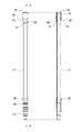
図1は、実施形態の一例である排唾管10の斜視図である。図2は、排唾管10の正面図及び断面図である。図1及び図2に示すように、排唾管10は、可撓性のチューブ11と、チューブ11の先端部に外装された筒状の先端チップ30とを備える。先端チップ30は、チューブ11よりも柔軟性が高く、その一部がチューブ11の先端から延出している。詳しくは後述するが、先端チップ30は、チューブ11の内径の1/2を超える長さがチューブ11の先端から延出している。また、先端チップ30は、軸方向中間部から基端に向かって外径が次第に縮径した基端側テーパー部31を有する。 FIG. 1 is a perspective view of a
本明細書において、排唾管10の基端とは、先端チップ30が装着される側と反対側の端を意味する。基端と反対側の排唾管10の端を「先端」とする。先端及び基端の用語は、排唾管10の各構成要素についても同様の方向を示すものとして使用する。 In this specification, the proximal end of the
排唾管10は、チューブ11の基端部に固定されたコネクタ20を備える。コネクタ20は、例えば、吸引装置につながったチューブ(図示せず)が接続される筒状の部材である。コネクタ20の外周面には、径方向外側に張り出したフランジ状の係止部21が形成されている。係止部21は、コネクタ20に外装されるチューブの固定に利用される。また、係止部21よりもコネクタ20の先端側の外周面には、コネクタ20の軸方向に沿って複数の凹凸22が形成されている。複数の凹凸22は、例えば、周方向溝を軸方向に間隔をあけて複数配置することにより形成され、チューブを挿抜する際の滑り止めとして機能する。
コネクタ20は、チューブ11の基端部に外装されている。チューブ11に対するコネクタ20の固定方法は特に限定されないが、一般的に、コネクタ20は溶剤溶着により、又は接着剤を用いてチューブ11に固定される。なお、コネクタ20の形状等は特に限定されず、コネクタ20には従来公知のコネクタを適用できる。 A
チューブ11は、手で容易に曲げることができる管状の部材であって、軸方向両端が開口している。本実施形態では、チューブ11の先端部に先端チップ30が、チューブ11の基端部にコネクタ20がそれぞれ固定されている。チューブ11の長さは特に限定されないが、チューブ11の先端部を患者の口腔内に挿入したときにチューブ11を把持して排唾管10を操作するのに適した長さとされる。好適なチューブ11の長さの一例は、120mm~180mmである。チューブ11の直径は、例えば内径が3mm~5mm、外径が5mm~7mmである。 The
チューブ11は、全長にわたって一定の直径(内径及び外径)を有する。チューブ11は不透明な材料で構成されてもよいが、好ましくは透明な樹脂で構成される。好適なチューブ11は、無色透明であり、管内を容易に視認できるものである。チューブ11を構成する樹脂の一例は、軟質のポリ塩化ビニル(PVC)である。チューブ11は、排唾管10の操作性等の観点から、手で容易に曲げることができ、かつ除荷すると緩やかに元の形状を復元する硬さ(柔軟性)を有することが好ましい。JIS K 7215に基づくデュロメータにより測定されるチューブ11の材料の硬度は、例えば85A~100Aであり、好ましくは90A~100A、又は94A~98Aである。 The
チューブ11は、口腔内組織への吸い付きを防止するために、圧逃がし用の横孔12を有している。横孔12は、必要な吸引力を確保しつつ、排唾管10の先端が口腔内組織に吸い付かないように適切な大きさで形成される。チューブ11には、例えば先端近傍に、チューブ11の内径より小さな直径を有する横孔12が複数形成されている。本実施形態では、チューブ11の径方向に並んで2つの横孔12が形成されている。横孔12の直径は、例えば1mm~3mmである。横孔12を先端チップ30が固定される位置に形成し、横孔12と重なる孔を先端チップ30に形成することもできるが、好ましくはチューブ11の先端チップ30と重ならない位置に横孔12を形成する。 The
横孔12は、チューブ11の側面において、先端チップ30と隣接する位置に形成されていることが好ましい。この場合、必要な吸引力を確保しつつ、排唾管10の先端が口腔内組織に吸い付くことを高度に抑制できる。横孔12は、例えば、先端チップ30の基端から横孔12の縁までの距離がチューブ11の内径に相当する長さより短くなる位置に形成される。横孔12を先端チップ30に近接配置することで、横孔12が形成された部分と口腔内組織との間に隙間が形成され易くなり、横孔12の機能が効果的に発揮される。詳しくは後述するが、先端チップ30と横孔12の間には、横孔12と干渉することなく後述の接着剤40によるテーパー面が形成されるように、当該テーパー面の形成スペースを確保する必要がある。 The
先端チップ30は、軸方向両端が開口した可撓性を有する筒状の部材であって、チューブ11の先端部に外装されている。先端チップ30は、チューブ11の外周面を覆い、一部がチューブ11の先端から延出している。このため、チューブ11の先端は、先端チップ30の筒内に存在し、先端チップ30により完全に覆われている。先端チップ30の先端側の内周面はチューブ11の外周面に密接し、基端側の内周面は接着剤40によりチューブ11の外周面に接合されている。先端チップ30の基端側の内周面とチューブ11の外周面との間には隙間34が形成され、この隙間34に接着剤40が充填されている。 The
先端チップ30は、軸方向中間部において外径が最も大きく、軸方向中間部から先端側及び基端側に近づくにつれて次第に外径が縮径した形状を有する。詳しくは後述するが、先端チップ30は、外周面が軸方向と平行ではなく、軸方向に対して傾斜した2つの斜面(基端側テーパー部31及び先端側テーパー部32)を有している。基端側テーパー部31及び先端側テーパー部32は、排唾管10の操作性の改善に大きく寄与する。接着剤40の一部は、隙間34からはみ出し、基端側テーパー部31と連続するテーパー面を形成している。先端チップ30の内径は、先端側で小さく、基端側で大きくなり、基端において最大となっている。 The
先端チップ30は、チューブ11よりも軟質の材料で形成されており、チューブ11の先端部を覆って先端部が口腔内組織に直接触れることを防止している。特に、チューブ11の先端から延出した先端チップ30の延出部33は、容易に弾性変形するため、口腔内組織に対する刺激を大きく低減している。先端チップ30は、チューブ11よりも柔らかく、容易に弾性変形するゴム又はエラストマーにより構成されることが好ましい。先端チップ30を構成するゴム又はエラストマーの一例は、スチレン系エラストマーである。JIS K 6253に基づくデュロメータにより測定される先端チップ30の材料の硬度は、例えば20A~40Aであり、好ましくは20A~30A、又は24A~28Aである。先端チップ30の硬度は、チューブ11の硬度の50%以下が好ましく、好適な範囲の一例は20%~40%である。 The
以下、図3を更に参照しながら、先端チップ30の構成について詳説する。図3は、排唾管10の断面図において、先端チップ30及びその近傍を拡大して示す図である。 The configuration of the
図3に示すように、チューブ11の先端から延出した部分である先端チップ30の延出部33は、チューブ11の内径D11の1/2を超える長さL33を有する。延出部33の長さL33とは、チューブ11及び先端チップ30の軸方向に沿った、チューブ11の先端から先端チップ30の先端までの長さを意味する。このような延出部33を設けることにより、患者の痛みや不快感を効果的に抑制できる。内径D11の一例は3.5mm~4.5mmであり、延出部33の長さL33の一例は4.0mm~5.0mmである。本実施形態では、延出部33の長さL33がチューブ11の内径D11より長くなっている。As shown in FIG. 3 , the
延出部33の長さL33の上限は特に限定されないが、排唾管10の操作性向上等の観点から、チューブ11の内径D11の3倍以下が好ましく、2倍以下がより好ましい。長さL33の好適な範囲の一例は、内径D11の1/2~2倍、又は2/3~1.5倍である。延出部33の長さL33が当該範囲内であれば、患者の痛みや不快感を抑制しつつ、良好な操作性を実現することが容易になる。延出部33の長さL33は、例えばチューブ11の内径D11より長く、チューブ11の外径より短くなっている。長さL33は、先端チップ30の軸方向長さの1/6~1/2が好ましい。The upper limit of the length L33 of the extension part33 is not particularly limited, but from the viewpoint of improving the operability of the
また、延出部33は先端チップ30の他の部分よりも厚肉に形成され、延出部33の内径は他の部分の内径よりも小さくなっている。先端チップ30の先端部には、チューブ11の外径より内径が小さく、チューブ11の内径D11と同程度の内径を有する部分が形成されている。本実施形態では、この部分が延出部33となっており、延出部33の内周面の基端には内径が急峻に変化する段差が形成されている。先端チップ30は、内周面の段差がチューブ11の先端の角に沿うように配置され、延出部33の基端がチューブ11の先端面に当接している。Moreover, the
先端チップ30は、上述のように、軸方向中間部から基端に向かって外径が次第に縮径した基端側テーパー部31を有する。また、先端チップ30は、軸方向中間部から先端に向かって外径が次第に縮径した先端側テーパー部32を有する。先端チップ30の外径は、基端側テーパー部31と先端側テーパー部32の境界部35で最大となっている。2つのテーパー部の境界部35は、先端チップ30の基端と延出部33の基端との間であって、例えば各基端から略等距離の位置に形成される。先端側テーパー部32は、境界部35から先端チップ30の先端にわたって形成され、延出部33についても外径は先端に向かって次第に縮径している。先端側テーパー部32は、例えば、延出部33の長さ分、基端側テーパー部31よりも長く形成されている。この場合、先端チップ30の基端側を肉厚に形成し易くなり、接着剤40を隙間34に充填した際の基端側の変形(外径の拡がり)を抑えることができる。 As described above, the
先端チップ30に基端側テーパー部31を形成することで、先端チップ30の基端とチューブ11の外周面との間に大きな段差が形成されなくなり、排唾管10の先端部が口腔内組織に引っ掛かることを効果的に抑制できる。このため、排唾管10の良好な操作性を実現でき、また患者の痛みや不快感を十分に抑制できる。先端側テーパー部32は、頬と歯茎の間などの狭い場所への先端チップ30の挿入を容易にし、排唾管10の操作性を更に向上させる。 By forming the proximal side tapered
先端チップ30の外周面は、基端側テーパー部31と先端側テーパー部32の境界部35(最大外径部)から離れるほど先端チップ30の中心軸側に位置するように傾斜しており、凹凸や段差がなく軸方向に対して緩やかに傾斜した面となっている。本実施形態では、先端チップ30の軸方向に対する基端側テーパー部31の外周面の傾斜が、先端側テーパー部32の外周面の傾斜よりも大きくなっている。各テーパー部の外周面の傾斜角度は、例えば20°以下であり、好適な範囲の一例としては2°~15°である。傾斜角度が当該範囲内であれば、良好な操作性が得られる。基端側テーパー部31の傾斜角度の具体例は6°~12°先端側テーパー部32の傾斜角度の具体例は2°~5°である。 The outer peripheral surface of the
先端チップ30は、全周に沿って同じ形状を有する。また、先端チップ30の軸方向に対する各テーパー部の外周面の傾斜角度は、それぞれの全長にわたって略一定である。先端チップ30の外周面は、境界部35において緩やかに湾曲しており、軸方向に対する傾斜角度が緩やかに変化している。先端チップ30の外周面の先端は、角ばっておらず外側に凸となるように湾曲している。このため、先端チップ30の先端が口腔内組織に触れたときの刺激が低減される。
先端チップ30の基端部は、軸方向中間部から基端に向かって内径が次第に拡径している。本実施形態では、基端側テーパー部31と先端側テーパー部32の境界部35から基端に向かって内径が次第に大きくなり、先端チップ30の内周面と、チューブ11の外周面との間に隙間34が形成されている。即ち、基端側テーパー部31の内周面は、チューブ11の外周面に当接していない。基端側テーパー部31の内周面は、接着剤40によりチューブ11の外周面に固定される。基端側テーパー部31は、境界部35から基端にわたって外径が次第に小さくなり、内径が次第に大きくなって、薄肉化している。 The proximal end portion of the
先端側テーパー部32の内周面は、延出部33を除き、チューブ11の外周面に隙間なく当接している。チューブ11の外周面に当接する部分の先端側テーパー部32の内径は、チューブ11の外径よりやや小さいことが好ましい。この場合、先端側テーパー部32の内周面がチューブ11の外周面に密着し易くなり、先端チップ30の装着状態がより安定化する。延出部33は、先端に向かって外径が次第に小さくなり、内径が次第に大きくなっているが、薄肉化の程度は基端側テーパー部31より緩やかである。 The inner peripheral surface of the tip-side tapered
排唾管10は、先端チップ30の内径がチューブ11の外径より小さく、先端チップ30の内周面がチューブ11の外周面に密着する第1固定部F1と、先端チップ30の内周面とチューブ11の外周面が接着剤40により接合される第2固定部F2とを有する。第1固定部F1と第2固定部F2による二重の固定構造を採用することにより、先端チップ30がチューブ11の外周面にしっかり固定され、先端チップ30の脱落をより確実に抑制できる。 The
先端チップ30には、基端側の内周面とチューブ11の外周面との間に、接着剤40が充填される隙間34が形成されている。本実施形態では、基端側テーパー部31の内径が基端に向かって次第に大きくなることにより、隙間34が形成されている。隙間34は、先端側テーパー部32の範囲まで広がっていてもよいが、好ましくは先端チップ30の内周面のうち、チューブ11の外周面に密着する部分(即ち、第1固定部F1)の軸方向長さ(L1)と、隙間34が形成される部分(即ち、第2固定部F2)の軸方向長さ(L2)を同程度とする。長さ(L1)と(L2)の比率は、例えば、1.0:1.2~1.2:1.0である。この場合、先端チップ30の装着状態がより安定化する。 A
隙間34は、先端チップ30の基端に向かって次第に広がり基端で最大となっている。隙間34には、先端チップ30の基端から接着剤40が充填される。接着剤40は、隙間34の全体に充填されていることが好ましい。先端チップ30は、内周面の基端側が接着剤40によりチューブ11の外周面に接合されることで、チューブ11に対してしっかり固定されている。隙間34に接着剤40を充填することにより、先端チップ30の外周面に接着剤40が付着することを防止できる。
接着剤40は、隙間34に充填することができ、チューブ11と先端チップ30を接合できるものであればよく、接着剤40には従来公知の接着剤を使用できる。好適な接着剤40の一例は、UV硬化接着剤等の硬化型接着剤である。UV硬化接着剤は、硬化前は液状であるため、隙間34に充填することが容易であり、隙間34に充填した後、紫外線を照射することで素早く硬化する。硬化後のUV硬化接着剤は、例えば、先端チップ30よりも硬くなる。 Any adhesive 40 can be used as long as it can fill the
接着剤40の一部は、隙間34からはみ出してチューブ11の外周面に固着している。隙間34からはみ出して硬化した接着剤40は、チューブ11の外周面の先端チップ30と隣接する部分に凸部を形成する。この凸部は、チューブ11の周方向全長にわたってリング状に形成され、その表面は先端チップ30から離れるほどチューブ11の外周面に近づくように傾斜している。つまり、チューブ11の外周面には、接着剤40の一部により、先端チップ30から離れるほど次第に縮径したテーパー面が形成されている。 Part of the adhesive 40 protrudes from the
接着剤40の上記テーパー面は、基端側テーパー部31の外周面と連続するように形成されている。このため、先端チップ30の基端とチューブ11の外周面との間に存在する段差が更に小さくなり、操作性が向上して患者の痛みや不快感をより効果的に抑制できる。基端側テーパー部31と連続する接着剤40のテーパー面は、平坦であってもよく、外側又は内側に向かって緩やかに湾曲していてもよい。 The tapered surface of the adhesive 40 is formed so as to be continuous with the outer peripheral surface of the proximal side tapered
接着剤40の上記テーパー面の軸方向長さは、特に限定されないが、チューブ11に形成された横孔12と干渉しない長さであることが好ましい。本実施形態では、先端チップ30の基端と横孔12の間に、接着剤40のテーパー面の形成スペースが確保されている。接着剤40のテーパー面は、隙間34を埋める量よりも多い量の接着剤40を隙間34に充填して隙間34から接着剤40の一部をはみ出させ、紫外線の照射等により接着剤40を硬化させることにより形成できる。接着剤40は、先端チップ30とチューブ11の段差を埋めるだけでなく、先端チップ30の基端に付着して、基端がめくれることを抑制する。 Although the length of the tapered surface of the adhesive 40 in the axial direction is not particularly limited, it is preferably a length that does not interfere with the
以上のように、上記構成を備えた排唾管10は、良好な操作性を有し、かつ患者の痛みや不快感を効果的に抑制する。排唾管10のチューブ11の先端部には、チューブ11よりも柔軟性の高い先端チップ30が外装されているため、チューブ11の先端部が口腔内組織に直接触れることがなく、口腔内組織への刺激を大きく低減している。 As described above, the
先端チップ30は、チューブ11の先端から延出した柔らかい延出部33を有し、これがチューブ11の先端を完全に覆っているので、患者の痛みや不快感を効果的に抑制できる。また、先端チップ30の基端部には、基端に近づくほど外径が次第に小さくなった基端側テーパー部31が形成されているため、先端チップ30の基端とチューブ11の外周面との間には従来の排唾管のような大きな段差は形成されない。 The
更に、隙間34からはみ出した接着剤40の一部が、先端チップ30の基端とチューブ11の外周面との間の小さな段差を埋めるテーパー面をチューブ11の外周面に形成する。これにより、排唾管10を口腔内から引き抜く際に先端チップ30が口腔内組織に引っ掛かることをより高度に抑制できる。また、先端チップ30の先端部にも、先端に近づくほど外径が次第に小さくなった先端側テーパー部32を形成することにより、頬と歯茎の間などの狭い場所に排唾管10の先端部を挿入することが容易になり、操作性が更に向上する。 Further, part of the adhesive 40 protruding from the
なお、上記実施形態は、本発明の目的を損なわない範囲で適宜設計変更できる。例えば、上記実施形態では、チューブ11の基端部にコネクタ20が外装される構成を例示したが、チューブ11の基端部には、コネクタ20に代えて他の部材が装着されていてもよく、吸引装置につながるチューブ等が挿し込まれてもよい。 It should be noted that the above-described embodiment can be appropriately modified in design without impairing the object of the present invention. For example, in the above-described embodiment, the
上記実施形態では、2つのテーパー部の境界部35が緩やかに湾曲しているが、2つのテーパー部の間には、先端チップの軸方向に沿った面が形成されていてもよい。また、先端チップの外周面は、基端側の外径だけが基端に向かって次第に縮径していてもよい。即ち、先端チップは先端側テーパー部を有さず、先端側の外周面は軸方向に沿って形成されていてもよい。 Although the
また、先端チップの基端から離れるほど次第に縮径した、チューブの外周面に形成されるテーパー面は、先端チップの内周面とチューブの外周面との隙間に充填される接着剤と別の接着剤で構成されていてもよい。或いは、チューブの外周面の加工等により当該テーパー面を形成することも可能である。 In addition, the tapered surface formed on the outer peripheral surface of the tube, which gradually decreases in diameter as it moves away from the proximal end of the distal tip, is different from the adhesive that fills the gap between the inner peripheral surface of the distal tip and the outer peripheral surface of the tube. It may be composed of an adhesive. Alternatively, the tapered surface can be formed by processing the outer peripheral surface of the tube.
10 排唾管、11 チューブ、12 横孔、20 コネクタ、21 係止部、22 凹凸、30 先端チップ、31 基端側テーパー部、32 先端側テーパー部、33 延出部、34 隙間、35 境界部、40 接着剤、F1 第1固定部、F2 第2固定部
10 saliva ejector, 11 tube, 12 lateral hole, 20 connector, 21 locking portion, 22 unevenness, 30 distal tip, 31 proximal side tapered portion, 32 distal side tapered portion, 33 extending portion, 34 gap, 35 boundary part, 40 adhesive, F1 first fixing part, F2 second fixing part
Claims (6)
Translated fromJapanese前記チューブの先端部に外装された筒状の先端チップと、
を備え、
前記先端チップは、
前記チューブよりも軟質の材料で形成されており、前記チューブの内径の1/2を超える長さが前記チューブの先端から延出しており、
前記先端チップの軸方向中間部から基端に向かって外径が次第に縮径した基端側テーパー部を有することを特徴とする医療用吸引管。a flexible tube;
a cylindrical distal tip attached to the distal end of the tube;
with
The tip tip
is formed of a material softer than the tube, and a length exceeding 1/2 of the inner diameter of the tube extends from the tip of the tube,
A medical aspiration tube, characterized in that it has a proximal side tapered portion in which the outer diameter gradually decreases from the axially intermediate portion of the distal tip toward the proximal end.
前記先端チップの内周面と前記チューブの外周面が接着剤により接合される第2固定部と、
を有する、請求項1に記載の医療用吸引管。a first fixing part in which the inner diameter of the distal tip is smaller than the outer diameter of the tube, and the inner peripheral surface of the distal tip is in close contact with the outer peripheral surface of the tube;
a second fixing part in which the inner peripheral surface of the distal tip and the outer peripheral surface of the tube are bonded with an adhesive;
The medical suction tube of claim 1, comprising:
前記隙間には、接着剤が充填されている、請求項1又は2に記載の医療用吸引管。A gap is formed between the proximal inner peripheral surface of the distal tip and the outer peripheral surface of the tube,
The medical suction tube according to claim 1 or 2, wherein the gap is filled with an adhesive.
前記チューブの外周面には、前記接着剤の一部により、前記先端チップから離れるほど次第に縮径したテーパー面が形成されている、請求項3に記載の医療用吸引管。part of the adhesive protrudes from the gap and adheres to the outer peripheral surface of the tube;
4. The medical aspiration tube according to claim 3, wherein the outer peripheral surface of the tube is formed with a portion of the adhesive to form a tapered surface whose diameter gradually decreases with increasing distance from the distal tip.
The medical suction tube according to any one of claims 1 to 5, wherein the tube has a horizontal hole formed adjacent to the distal tip.
Priority Applications (1)
| Application Number | Priority Date | Filing Date | Title |
|---|---|---|---|
| JP2021047044AJP7639433B2 (en) | 2021-03-22 | 2021-03-22 | Medical Suction Tube |
Applications Claiming Priority (1)
| Application Number | Priority Date | Filing Date | Title |
|---|---|---|---|
| JP2021047044AJP7639433B2 (en) | 2021-03-22 | 2021-03-22 | Medical Suction Tube |
Publications (2)
| Publication Number | Publication Date |
|---|---|
| JP2022146204Atrue JP2022146204A (en) | 2022-10-05 |
| JP7639433B2 JP7639433B2 (en) | 2025-03-05 |
Family
ID=83461583
Family Applications (1)
| Application Number | Title | Priority Date | Filing Date |
|---|---|---|---|
| JP2021047044AActiveJP7639433B2 (en) | 2021-03-22 | 2021-03-22 | Medical Suction Tube |
Country Status (1)
| Country | Link |
|---|---|
| JP (1) | JP7639433B2 (en) |
Citations (10)
| Publication number | Priority date | Publication date | Assignee | Title |
|---|---|---|---|---|
| JPH04133819U (en)* | 1991-06-03 | 1992-12-14 | 兵一郎 宮尾 | Dental saliva evacuation device with adjustable insertion depth |
| JP3078575U (en)* | 2000-12-26 | 2001-07-10 | ティーディーケイ株式会社 | Salivary duct |
| US20060024641A1 (en)* | 2004-08-02 | 2006-02-02 | Mahlmann Lee A | Aspirator having cushioned tip |
| JP2007037878A (en)* | 2005-08-05 | 2007-02-15 | Fujinon Corp | Endoscope insertion part |
| JP2010512824A (en)* | 2006-12-15 | 2010-04-30 | キンバリー クラーク ワールドワイド インコーポレイテッド | Yanker suction device |
| US20110144571A1 (en)* | 2009-12-15 | 2011-06-16 | Ahluwalia Prabhat K | Suction device |
| JP2015192841A (en)* | 2014-03-28 | 2015-11-05 | 寿一郎 笠澄 | Tip end chip for liquid suction tool |
| CN105343981A (en)* | 2014-08-18 | 2016-02-24 | 腾中锦鹏科技发展(北京)有限公司 | Closed type phlegm suction catheter |
| WO2019187210A1 (en)* | 2018-03-29 | 2019-10-03 | オリンパス株式会社 | Insertion tool |
| JP2019187770A (en)* | 2018-04-25 | 2019-10-31 | テルモ株式会社 | catheter |
- 2021
- 2021-03-22JPJP2021047044Apatent/JP7639433B2/enactiveActive
Patent Citations (10)
| Publication number | Priority date | Publication date | Assignee | Title |
|---|---|---|---|---|
| JPH04133819U (en)* | 1991-06-03 | 1992-12-14 | 兵一郎 宮尾 | Dental saliva evacuation device with adjustable insertion depth |
| JP3078575U (en)* | 2000-12-26 | 2001-07-10 | ティーディーケイ株式会社 | Salivary duct |
| US20060024641A1 (en)* | 2004-08-02 | 2006-02-02 | Mahlmann Lee A | Aspirator having cushioned tip |
| JP2007037878A (en)* | 2005-08-05 | 2007-02-15 | Fujinon Corp | Endoscope insertion part |
| JP2010512824A (en)* | 2006-12-15 | 2010-04-30 | キンバリー クラーク ワールドワイド インコーポレイテッド | Yanker suction device |
| US20110144571A1 (en)* | 2009-12-15 | 2011-06-16 | Ahluwalia Prabhat K | Suction device |
| JP2015192841A (en)* | 2014-03-28 | 2015-11-05 | 寿一郎 笠澄 | Tip end chip for liquid suction tool |
| CN105343981A (en)* | 2014-08-18 | 2016-02-24 | 腾中锦鹏科技发展(北京)有限公司 | Closed type phlegm suction catheter |
| WO2019187210A1 (en)* | 2018-03-29 | 2019-10-03 | オリンパス株式会社 | Insertion tool |
| JP2019187770A (en)* | 2018-04-25 | 2019-10-31 | テルモ株式会社 | catheter |
Also Published As
| Publication number | Publication date |
|---|---|
| JP7639433B2 (en) | 2025-03-05 |
Similar Documents
| Publication | Publication Date | Title |
|---|---|---|
| CN111902182B (en) | Female catheter positioner tip | |
| EP2712576B1 (en) | Dental suction tube | |
| US5451216A (en) | Non-occluding catheter bolus | |
| US6068477A (en) | Foam-cushioned aspirator | |
| CN106620946A (en) | Extension Tube Strain Relief | |
| WO2007046444A1 (en) | Treatment device for endoscope and double tube for the treatment device | |
| US20210259817A1 (en) | Suction tip | |
| WO2025180234A1 (en) | Guide sheath component, guide sheath, and sealing structure thereof | |
| US20060024641A1 (en) | Aspirator having cushioned tip | |
| JP7639433B2 (en) | Medical Suction Tube | |
| JP4648615B2 (en) | Medical needle device with a winged shield | |
| WO2014033901A1 (en) | Butterfly needle assembly | |
| JP5151322B2 (en) | Medical device for fixing guide wire | |
| WO2019044884A1 (en) | Backflush needle | |
| JPS63246132A (en) | Medical flexible tube | |
| WO2014033903A1 (en) | Butterfly needle | |
| JP2005230084A (en) | Balloon attaching tool | |
| JP4853076B2 (en) | Oral suction device | |
| JP2018064866A (en) | Catheter pushing-in support tool | |
| JP4985917B2 (en) | Suction tip | |
| JP3992820B2 (en) | Endoscope forceps plug | |
| CN119055175B (en) | Insertion portion and endoscope | |
| JP6485908B2 (en) | Medical suction tool | |
| JP2005013394A (en) | Point chip for liquid suction device | |
| WO2023190684A1 (en) | Endoscope hood |
Legal Events
| Date | Code | Title | Description |
|---|---|---|---|
| A621 | Written request for application examination | Free format text:JAPANESE INTERMEDIATE CODE: A621 Effective date:20240213 | |
| A977 | Report on retrieval | Free format text:JAPANESE INTERMEDIATE CODE: A971007 Effective date:20241017 | |
| A131 | Notification of reasons for refusal | Free format text:JAPANESE INTERMEDIATE CODE: A131 Effective date:20241029 | |
| A521 | Request for written amendment filed | Free format text:JAPANESE INTERMEDIATE CODE: A523 Effective date:20241227 | |
| TRDD | Decision of grant or rejection written | ||
| A01 | Written decision to grant a patent or to grant a registration (utility model) | Free format text:JAPANESE INTERMEDIATE CODE: A01 Effective date:20250121 | |
| A61 | First payment of annual fees (during grant procedure) | Free format text:JAPANESE INTERMEDIATE CODE: A61 Effective date:20250203 | |
| R150 | Certificate of patent or registration of utility model | Ref document number:7639433 Country of ref document:JP Free format text:JAPANESE INTERMEDIATE CODE: R150 |