JP2022141628A - flow cell - Google Patents
flow cellDownload PDFInfo
- Publication number
- JP2022141628A JP2022141628AJP2022092251AJP2022092251AJP2022141628AJP 2022141628 AJP2022141628 AJP 2022141628AJP 2022092251 AJP2022092251 AJP 2022092251AJP 2022092251 AJP2022092251 AJP 2022092251AJP 2022141628 AJP2022141628 AJP 2022141628A
- Authority
- JP
- Japan
- Prior art keywords
- primer
- layer
- functionalized
- region
- cleavable
- Prior art date
- Legal status (The legal status is an assumption and is not a legal conclusion. Google has not performed a legal analysis and makes no representation as to the accuracy of the status listed.)
- Pending
Links
Images


Classifications
- C—CHEMISTRY; METALLURGY
- C12—BIOCHEMISTRY; BEER; SPIRITS; WINE; VINEGAR; MICROBIOLOGY; ENZYMOLOGY; MUTATION OR GENETIC ENGINEERING
- C12Q—MEASURING OR TESTING PROCESSES INVOLVING ENZYMES, NUCLEIC ACIDS OR MICROORGANISMS; COMPOSITIONS OR TEST PAPERS THEREFOR; PROCESSES OF PREPARING SUCH COMPOSITIONS; CONDITION-RESPONSIVE CONTROL IN MICROBIOLOGICAL OR ENZYMOLOGICAL PROCESSES
- C12Q1/00—Measuring or testing processes involving enzymes, nucleic acids or microorganisms; Compositions therefor; Processes of preparing such compositions
- C12Q1/68—Measuring or testing processes involving enzymes, nucleic acids or microorganisms; Compositions therefor; Processes of preparing such compositions involving nucleic acids
- C12Q1/6869—Methods for sequencing
- C—CHEMISTRY; METALLURGY
- C08—ORGANIC MACROMOLECULAR COMPOUNDS; THEIR PREPARATION OR CHEMICAL WORKING-UP; COMPOSITIONS BASED THEREON
- C08F—MACROMOLECULAR COMPOUNDS OBTAINED BY REACTIONS ONLY INVOLVING CARBON-TO-CARBON UNSATURATED BONDS
- C08F220/00—Copolymers of compounds having one or more unsaturated aliphatic radicals, each having only one carbon-to-carbon double bond, and only one being terminated by only one carboxyl radical or a salt, anhydride ester, amide, imide or nitrile thereof
- C08F220/02—Monocarboxylic acids having less than ten carbon atoms; Derivatives thereof
- C08F220/52—Amides or imides
- C08F220/54—Amides, e.g. N,N-dimethylacrylamide or N-isopropylacrylamide
- C08F220/56—Acrylamide; Methacrylamide
- B—PERFORMING OPERATIONS; TRANSPORTING
- B01—PHYSICAL OR CHEMICAL PROCESSES OR APPARATUS IN GENERAL
- B01J—CHEMICAL OR PHYSICAL PROCESSES, e.g. CATALYSIS OR COLLOID CHEMISTRY; THEIR RELEVANT APPARATUS
- B01J19/00—Chemical, physical or physico-chemical processes in general; Their relevant apparatus
- B01J19/0046—Sequential or parallel reactions, e.g. for the synthesis of polypeptides or polynucleotides; Apparatus and devices for combinatorial chemistry or for making molecular arrays
- C—CHEMISTRY; METALLURGY
- C08—ORGANIC MACROMOLECULAR COMPOUNDS; THEIR PREPARATION OR CHEMICAL WORKING-UP; COMPOSITIONS BASED THEREON
- C08F—MACROMOLECULAR COMPOUNDS OBTAINED BY REACTIONS ONLY INVOLVING CARBON-TO-CARBON UNSATURATED BONDS
- C08F212/00—Copolymers of compounds having one or more unsaturated aliphatic radicals, each having only one carbon-to-carbon double bond, and at least one being terminated by an aromatic carbocyclic ring
- C08F212/02—Monomers containing only one unsaturated aliphatic radical
- C08F212/04—Monomers containing only one unsaturated aliphatic radical containing one ring
- C08F212/06—Hydrocarbons
- C08F212/08—Styrene
- C08F212/10—Styrene with nitriles
- C—CHEMISTRY; METALLURGY
- C08—ORGANIC MACROMOLECULAR COMPOUNDS; THEIR PREPARATION OR CHEMICAL WORKING-UP; COMPOSITIONS BASED THEREON
- C08F—MACROMOLECULAR COMPOUNDS OBTAINED BY REACTIONS ONLY INVOLVING CARBON-TO-CARBON UNSATURATED BONDS
- C08F299/00—Macromolecular compounds obtained by interreacting polymers involving only carbon-to-carbon unsaturated bond reactions, in the absence of non-macromolecular monomers
- C—CHEMISTRY; METALLURGY
- C08—ORGANIC MACROMOLECULAR COMPOUNDS; THEIR PREPARATION OR CHEMICAL WORKING-UP; COMPOSITIONS BASED THEREON
- C08G—MACROMOLECULAR COMPOUNDS OBTAINED OTHERWISE THAN BY REACTIONS ONLY INVOLVING UNSATURATED CARBON-TO-CARBON BONDS
- C08G77/00—Macromolecular compounds obtained by reactions forming a linkage containing silicon with or without sulfur, nitrogen, oxygen or carbon in the main chain of the macromolecule
- C08G77/04—Polysiloxanes
- C08G77/14—Polysiloxanes containing silicon bound to oxygen-containing groups
- C—CHEMISTRY; METALLURGY
- C12—BIOCHEMISTRY; BEER; SPIRITS; WINE; VINEGAR; MICROBIOLOGY; ENZYMOLOGY; MUTATION OR GENETIC ENGINEERING
- C12N—MICROORGANISMS OR ENZYMES; COMPOSITIONS THEREOF; PROPAGATING, PRESERVING, OR MAINTAINING MICROORGANISMS; MUTATION OR GENETIC ENGINEERING; CULTURE MEDIA
- C12N15/00—Mutation or genetic engineering; DNA or RNA concerning genetic engineering, vectors, e.g. plasmids, or their isolation, preparation or purification; Use of hosts therefor
- C12N15/09—Recombinant DNA-technology
- C12N15/10—Processes for the isolation, preparation or purification of DNA or RNA
- C12N15/1003—Extracting or separating nucleic acids from biological samples, e.g. pure separation or isolation methods; Conditions, buffers or apparatuses therefor
- C12N15/1006—Extracting or separating nucleic acids from biological samples, e.g. pure separation or isolation methods; Conditions, buffers or apparatuses therefor by means of a solid support carrier, e.g. particles, polymers
- C—CHEMISTRY; METALLURGY
- C12—BIOCHEMISTRY; BEER; SPIRITS; WINE; VINEGAR; MICROBIOLOGY; ENZYMOLOGY; MUTATION OR GENETIC ENGINEERING
- C12N—MICROORGANISMS OR ENZYMES; COMPOSITIONS THEREOF; PROPAGATING, PRESERVING, OR MAINTAINING MICROORGANISMS; MUTATION OR GENETIC ENGINEERING; CULTURE MEDIA
- C12N15/00—Mutation or genetic engineering; DNA or RNA concerning genetic engineering, vectors, e.g. plasmids, or their isolation, preparation or purification; Use of hosts therefor
- C12N15/09—Recombinant DNA-technology
- C12N15/11—DNA or RNA fragments; Modified forms thereof; Non-coding nucleic acids having a biological activity
- C—CHEMISTRY; METALLURGY
- C12—BIOCHEMISTRY; BEER; SPIRITS; WINE; VINEGAR; MICROBIOLOGY; ENZYMOLOGY; MUTATION OR GENETIC ENGINEERING
- C12Q—MEASURING OR TESTING PROCESSES INVOLVING ENZYMES, NUCLEIC ACIDS OR MICROORGANISMS; COMPOSITIONS OR TEST PAPERS THEREFOR; PROCESSES OF PREPARING SUCH COMPOSITIONS; CONDITION-RESPONSIVE CONTROL IN MICROBIOLOGICAL OR ENZYMOLOGICAL PROCESSES
- C12Q1/00—Measuring or testing processes involving enzymes, nucleic acids or microorganisms; Compositions therefor; Processes of preparing such compositions
- C12Q1/68—Measuring or testing processes involving enzymes, nucleic acids or microorganisms; Compositions therefor; Processes of preparing such compositions involving nucleic acids
- C12Q1/6806—Preparing nucleic acids for analysis, e.g. for polymerase chain reaction [PCR] assay
- G—PHYSICS
- G03—PHOTOGRAPHY; CINEMATOGRAPHY; ANALOGOUS TECHNIQUES USING WAVES OTHER THAN OPTICAL WAVES; ELECTROGRAPHY; HOLOGRAPHY
- G03F—PHOTOMECHANICAL PRODUCTION OF TEXTURED OR PATTERNED SURFACES, e.g. FOR PRINTING, FOR PROCESSING OF SEMICONDUCTOR DEVICES; MATERIALS THEREFOR; ORIGINALS THEREFOR; APPARATUS SPECIALLY ADAPTED THEREFOR
- G03F7/00—Photomechanical, e.g. photolithographic, production of textured or patterned surfaces, e.g. printing surfaces; Materials therefor, e.g. comprising photoresists; Apparatus specially adapted therefor
- G03F7/0002—Lithographic processes using patterning methods other than those involving the exposure to radiation, e.g. by stamping
- G—PHYSICS
- G03—PHOTOGRAPHY; CINEMATOGRAPHY; ANALOGOUS TECHNIQUES USING WAVES OTHER THAN OPTICAL WAVES; ELECTROGRAPHY; HOLOGRAPHY
- G03F—PHOTOMECHANICAL PRODUCTION OF TEXTURED OR PATTERNED SURFACES, e.g. FOR PRINTING, FOR PROCESSING OF SEMICONDUCTOR DEVICES; MATERIALS THEREFOR; ORIGINALS THEREFOR; APPARATUS SPECIALLY ADAPTED THEREFOR
- G03F7/00—Photomechanical, e.g. photolithographic, production of textured or patterned surfaces, e.g. printing surfaces; Materials therefor, e.g. comprising photoresists; Apparatus specially adapted therefor
- G03F7/004—Photosensitive materials
- G03F7/0046—Photosensitive materials with perfluoro compounds, e.g. for dry lithography
- G—PHYSICS
- G03—PHOTOGRAPHY; CINEMATOGRAPHY; ANALOGOUS TECHNIQUES USING WAVES OTHER THAN OPTICAL WAVES; ELECTROGRAPHY; HOLOGRAPHY
- G03F—PHOTOMECHANICAL PRODUCTION OF TEXTURED OR PATTERNED SURFACES, e.g. FOR PRINTING, FOR PROCESSING OF SEMICONDUCTOR DEVICES; MATERIALS THEREFOR; ORIGINALS THEREFOR; APPARATUS SPECIALLY ADAPTED THEREFOR
- G03F7/00—Photomechanical, e.g. photolithographic, production of textured or patterned surfaces, e.g. printing surfaces; Materials therefor, e.g. comprising photoresists; Apparatus specially adapted therefor
- G03F7/004—Photosensitive materials
- G03F7/027—Non-macromolecular photopolymerisable compounds having carbon-to-carbon double bonds, e.g. ethylenic compounds
- G—PHYSICS
- G03—PHOTOGRAPHY; CINEMATOGRAPHY; ANALOGOUS TECHNIQUES USING WAVES OTHER THAN OPTICAL WAVES; ELECTROGRAPHY; HOLOGRAPHY
- G03F—PHOTOMECHANICAL PRODUCTION OF TEXTURED OR PATTERNED SURFACES, e.g. FOR PRINTING, FOR PROCESSING OF SEMICONDUCTOR DEVICES; MATERIALS THEREFOR; ORIGINALS THEREFOR; APPARATUS SPECIALLY ADAPTED THEREFOR
- G03F7/00—Photomechanical, e.g. photolithographic, production of textured or patterned surfaces, e.g. printing surfaces; Materials therefor, e.g. comprising photoresists; Apparatus specially adapted therefor
- G03F7/004—Photosensitive materials
- G03F7/038—Macromolecular compounds which are rendered insoluble or differentially wettable
- G—PHYSICS
- G03—PHOTOGRAPHY; CINEMATOGRAPHY; ANALOGOUS TECHNIQUES USING WAVES OTHER THAN OPTICAL WAVES; ELECTROGRAPHY; HOLOGRAPHY
- G03F—PHOTOMECHANICAL PRODUCTION OF TEXTURED OR PATTERNED SURFACES, e.g. FOR PRINTING, FOR PROCESSING OF SEMICONDUCTOR DEVICES; MATERIALS THEREFOR; ORIGINALS THEREFOR; APPARATUS SPECIALLY ADAPTED THEREFOR
- G03F7/00—Photomechanical, e.g. photolithographic, production of textured or patterned surfaces, e.g. printing surfaces; Materials therefor, e.g. comprising photoresists; Apparatus specially adapted therefor
- G03F7/004—Photosensitive materials
- G03F7/075—Silicon-containing compounds
- G03F7/0755—Non-macromolecular compounds containing Si-O, Si-C or Si-N bonds
- G—PHYSICS
- G03—PHOTOGRAPHY; CINEMATOGRAPHY; ANALOGOUS TECHNIQUES USING WAVES OTHER THAN OPTICAL WAVES; ELECTROGRAPHY; HOLOGRAPHY
- G03F—PHOTOMECHANICAL PRODUCTION OF TEXTURED OR PATTERNED SURFACES, e.g. FOR PRINTING, FOR PROCESSING OF SEMICONDUCTOR DEVICES; MATERIALS THEREFOR; ORIGINALS THEREFOR; APPARATUS SPECIALLY ADAPTED THEREFOR
- G03F7/00—Photomechanical, e.g. photolithographic, production of textured or patterned surfaces, e.g. printing surfaces; Materials therefor, e.g. comprising photoresists; Apparatus specially adapted therefor
- G03F7/004—Photosensitive materials
- G03F7/075—Silicon-containing compounds
- G03F7/0757—Macromolecular compounds containing Si-O, Si-C or Si-N bonds
- G—PHYSICS
- G03—PHOTOGRAPHY; CINEMATOGRAPHY; ANALOGOUS TECHNIQUES USING WAVES OTHER THAN OPTICAL WAVES; ELECTROGRAPHY; HOLOGRAPHY
- G03F—PHOTOMECHANICAL PRODUCTION OF TEXTURED OR PATTERNED SURFACES, e.g. FOR PRINTING, FOR PROCESSING OF SEMICONDUCTOR DEVICES; MATERIALS THEREFOR; ORIGINALS THEREFOR; APPARATUS SPECIALLY ADAPTED THEREFOR
- G03F7/00—Photomechanical, e.g. photolithographic, production of textured or patterned surfaces, e.g. printing surfaces; Materials therefor, e.g. comprising photoresists; Apparatus specially adapted therefor
- G03F7/16—Coating processes; Apparatus therefor
- G03F7/165—Monolayers, e.g. Langmuir-Blodgett
- B—PERFORMING OPERATIONS; TRANSPORTING
- B01—PHYSICAL OR CHEMICAL PROCESSES OR APPARATUS IN GENERAL
- B01J—CHEMICAL OR PHYSICAL PROCESSES, e.g. CATALYSIS OR COLLOID CHEMISTRY; THEIR RELEVANT APPARATUS
- B01J2219/00—Chemical, physical or physico-chemical processes in general; Their relevant apparatus
- B01J2219/00274—Sequential or parallel reactions; Apparatus and devices for combinatorial chemistry or for making arrays; Chemical library technology
- B01J2219/00277—Apparatus
- B01J2219/00279—Features relating to reactor vessels
- B01J2219/00306—Reactor vessels in a multiple arrangement
- B01J2219/00313—Reactor vessels in a multiple arrangement the reactor vessels being formed by arrays of wells in blocks
- B01J2219/00315—Microtiter plates
- B01J2219/00317—Microwell devices, i.e. having large numbers of wells
- B—PERFORMING OPERATIONS; TRANSPORTING
- B01—PHYSICAL OR CHEMICAL PROCESSES OR APPARATUS IN GENERAL
- B01J—CHEMICAL OR PHYSICAL PROCESSES, e.g. CATALYSIS OR COLLOID CHEMISTRY; THEIR RELEVANT APPARATUS
- B01J2219/00—Chemical, physical or physico-chemical processes in general; Their relevant apparatus
- B01J2219/00274—Sequential or parallel reactions; Apparatus and devices for combinatorial chemistry or for making arrays; Chemical library technology
- B01J2219/00277—Apparatus
- B01J2219/00497—Features relating to the solid phase supports
- B01J2219/00527—Sheets
- B01J2219/00529—DNA chips
- B—PERFORMING OPERATIONS; TRANSPORTING
- B01—PHYSICAL OR CHEMICAL PROCESSES OR APPARATUS IN GENERAL
- B01J—CHEMICAL OR PHYSICAL PROCESSES, e.g. CATALYSIS OR COLLOID CHEMISTRY; THEIR RELEVANT APPARATUS
- B01J2219/00—Chemical, physical or physico-chemical processes in general; Their relevant apparatus
- B01J2219/00274—Sequential or parallel reactions; Apparatus and devices for combinatorial chemistry or for making arrays; Chemical library technology
- B01J2219/00583—Features relative to the processes being carried out
- B01J2219/00603—Making arrays on substantially continuous surfaces
- B01J2219/00605—Making arrays on substantially continuous surfaces the compounds being directly bound or immobilised to solid supports
- B01J2219/00608—DNA chips
- B—PERFORMING OPERATIONS; TRANSPORTING
- B01—PHYSICAL OR CHEMICAL PROCESSES OR APPARATUS IN GENERAL
- B01J—CHEMICAL OR PHYSICAL PROCESSES, e.g. CATALYSIS OR COLLOID CHEMISTRY; THEIR RELEVANT APPARATUS
- B01J2219/00—Chemical, physical or physico-chemical processes in general; Their relevant apparatus
- B01J2219/00274—Sequential or parallel reactions; Apparatus and devices for combinatorial chemistry or for making arrays; Chemical library technology
- B01J2219/00583—Features relative to the processes being carried out
- B01J2219/00603—Making arrays on substantially continuous surfaces
- B01J2219/00605—Making arrays on substantially continuous surfaces the compounds being directly bound or immobilised to solid supports
- B01J2219/00614—Delimitation of the attachment areas
- B01J2219/00617—Delimitation of the attachment areas by chemical means
- B01J2219/00619—Delimitation of the attachment areas by chemical means using hydrophilic or hydrophobic regions
- B—PERFORMING OPERATIONS; TRANSPORTING
- B01—PHYSICAL OR CHEMICAL PROCESSES OR APPARATUS IN GENERAL
- B01J—CHEMICAL OR PHYSICAL PROCESSES, e.g. CATALYSIS OR COLLOID CHEMISTRY; THEIR RELEVANT APPARATUS
- B01J2219/00—Chemical, physical or physico-chemical processes in general; Their relevant apparatus
- B01J2219/00274—Sequential or parallel reactions; Apparatus and devices for combinatorial chemistry or for making arrays; Chemical library technology
- B01J2219/00583—Features relative to the processes being carried out
- B01J2219/00603—Making arrays on substantially continuous surfaces
- B01J2219/00605—Making arrays on substantially continuous surfaces the compounds being directly bound or immobilised to solid supports
- B01J2219/00614—Delimitation of the attachment areas
- B01J2219/00621—Delimitation of the attachment areas by physical means, e.g. trenches, raised areas
- B—PERFORMING OPERATIONS; TRANSPORTING
- B01—PHYSICAL OR CHEMICAL PROCESSES OR APPARATUS IN GENERAL
- B01J—CHEMICAL OR PHYSICAL PROCESSES, e.g. CATALYSIS OR COLLOID CHEMISTRY; THEIR RELEVANT APPARATUS
- B01J2219/00—Chemical, physical or physico-chemical processes in general; Their relevant apparatus
- B01J2219/00274—Sequential or parallel reactions; Apparatus and devices for combinatorial chemistry or for making arrays; Chemical library technology
- B01J2219/00718—Type of compounds synthesised
- B01J2219/0072—Organic compounds
- B01J2219/00722—Nucleotides
- C—CHEMISTRY; METALLURGY
- C12—BIOCHEMISTRY; BEER; SPIRITS; WINE; VINEGAR; MICROBIOLOGY; ENZYMOLOGY; MUTATION OR GENETIC ENGINEERING
- C12Q—MEASURING OR TESTING PROCESSES INVOLVING ENZYMES, NUCLEIC ACIDS OR MICROORGANISMS; COMPOSITIONS OR TEST PAPERS THEREFOR; PROCESSES OF PREPARING SUCH COMPOSITIONS; CONDITION-RESPONSIVE CONTROL IN MICROBIOLOGICAL OR ENZYMOLOGICAL PROCESSES
- C12Q2565/00—Nucleic acid analysis characterised by mode or means of detection
- C12Q2565/50—Detection characterised by immobilisation to a surface
- C12Q2565/513—Detection characterised by immobilisation to a surface characterised by the pattern of the arrayed oligonucleotides
- C—CHEMISTRY; METALLURGY
- C12—BIOCHEMISTRY; BEER; SPIRITS; WINE; VINEGAR; MICROBIOLOGY; ENZYMOLOGY; MUTATION OR GENETIC ENGINEERING
- C12Q—MEASURING OR TESTING PROCESSES INVOLVING ENZYMES, NUCLEIC ACIDS OR MICROORGANISMS; COMPOSITIONS OR TEST PAPERS THEREFOR; PROCESSES OF PREPARING SUCH COMPOSITIONS; CONDITION-RESPONSIVE CONTROL IN MICROBIOLOGICAL OR ENZYMOLOGICAL PROCESSES
- C12Q2565/00—Nucleic acid analysis characterised by mode or means of detection
- C12Q2565/50—Detection characterised by immobilisation to a surface
- C12Q2565/518—Detection characterised by immobilisation to a surface characterised by the immobilisation of the nucleic acid sample or target
- C—CHEMISTRY; METALLURGY
- C12—BIOCHEMISTRY; BEER; SPIRITS; WINE; VINEGAR; MICROBIOLOGY; ENZYMOLOGY; MUTATION OR GENETIC ENGINEERING
- C12Q—MEASURING OR TESTING PROCESSES INVOLVING ENZYMES, NUCLEIC ACIDS OR MICROORGANISMS; COMPOSITIONS OR TEST PAPERS THEREFOR; PROCESSES OF PREPARING SUCH COMPOSITIONS; CONDITION-RESPONSIVE CONTROL IN MICROBIOLOGICAL OR ENZYMOLOGICAL PROCESSES
- C12Q2565/00—Nucleic acid analysis characterised by mode or means of detection
- C12Q2565/50—Detection characterised by immobilisation to a surface
- C12Q2565/537—Detection characterised by immobilisation to a surface characterised by the capture oligonucleotide acting as a primer
- Y—GENERAL TAGGING OF NEW TECHNOLOGICAL DEVELOPMENTS; GENERAL TAGGING OF CROSS-SECTIONAL TECHNOLOGIES SPANNING OVER SEVERAL SECTIONS OF THE IPC; TECHNICAL SUBJECTS COVERED BY FORMER USPC CROSS-REFERENCE ART COLLECTIONS [XRACs] AND DIGESTS
- Y02—TECHNOLOGIES OR APPLICATIONS FOR MITIGATION OR ADAPTATION AGAINST CLIMATE CHANGE
- Y02E—REDUCTION OF GREENHOUSE GAS [GHG] EMISSIONS, RELATED TO ENERGY GENERATION, TRANSMISSION OR DISTRIBUTION
- Y02E60/00—Enabling technologies; Technologies with a potential or indirect contribution to GHG emissions mitigation
- Y02E60/30—Hydrogen technology
- Y02E60/50—Fuel cells
Landscapes
- Chemical & Material Sciences (AREA)
- Organic Chemistry (AREA)
- Health & Medical Sciences (AREA)
- Life Sciences & Earth Sciences (AREA)
- Engineering & Computer Science (AREA)
- Physics & Mathematics (AREA)
- Zoology (AREA)
- Wood Science & Technology (AREA)
- Genetics & Genomics (AREA)
- Proteomics, Peptides & Aminoacids (AREA)
- General Engineering & Computer Science (AREA)
- Bioinformatics & Cheminformatics (AREA)
- Biotechnology (AREA)
- Chemical Kinetics & Catalysis (AREA)
- Molecular Biology (AREA)
- Medicinal Chemistry (AREA)
- Polymers & Plastics (AREA)
- General Physics & Mathematics (AREA)
- Microbiology (AREA)
- Biochemistry (AREA)
- Biophysics (AREA)
- General Health & Medical Sciences (AREA)
- Biomedical Technology (AREA)
- Analytical Chemistry (AREA)
- Immunology (AREA)
- Spectroscopy & Molecular Physics (AREA)
- Plant Pathology (AREA)
- Crystallography & Structural Chemistry (AREA)
- Apparatus Associated With Microorganisms And Enzymes (AREA)
- Measuring Or Testing Involving Enzymes Or Micro-Organisms (AREA)
- Micro-Organisms Or Cultivation Processes Thereof (AREA)
- Shaping Of Tube Ends By Bending Or Straightening (AREA)
- Micromachines (AREA)
- Optical Measuring Cells (AREA)
- Application Of Or Painting With Fluid Materials (AREA)
- Physical Or Chemical Processes And Apparatus (AREA)
- Automatic Analysis And Handling Materials Therefor (AREA)
- External Artificial Organs (AREA)
Abstract
Translated fromJapaneseDescription
Translated fromJapanese関連出願の相互参照
本出願は、2018年6月29日に出願された米国仮出願第62/692,511号お
よび2018年10月9日に出願された米国仮出願第62/743,373号の利益を主
張し、その各々の内容は、その全体が参照により本明細書に組み込まれる。CROSS-REFERENCE TO RELATED APPLICATIONS This application is based on U.S. Provisional Application No. 62/692,511, filed June 29, 2018 and U.S. Provisional Application No. 62/743,373, filed October 9, 2018. , the contents of each of which are hereby incorporated by reference in their entirety.
配列表の参照
配列EFS-ウェブを通じて提出された配列表は、その全体を参照して組み込まれてい
る。ファイル名はILI172APCT_IP-1806-PCT_Sequence_Listing_ST25.txt、ファイ
ルサイズは551バイト、ファイル作成日は2019年5月20日である。REFERENCE TO SEQUENCE LISTINGS Sequence listings submitted through Sequence EFS-Web are incorporated by reference in their entirety. The file name is ILI172APCT_IP-1806-PCT_Sequence_Listing_ST25. txt, file size is 551 bytes, file creation date is May 20, 2019.
核酸を配列決定するためのいくつかの利用可能なプラットフォームは、合成による配列
決定アプローチを利用する。このアプローチを用いて、発生期のストランドが合成され、
そして成長するストランドへの各モノマー(単量体)(例えば、ヌクレオチド)の付加が
、光学的および/または電子的に検出される。鋳型(テンプレート)ストランドは発生期
ストランドの合成を方向づけるので、合成の間に成長ストランドに添加された一連のヌク
レオチドモノマーから鋳型DNAの配列を推測することができる。いくつかの例において
、ペアエンド(対末端)配列決定が使用され得、ここで、順方向ストランドが配列決定さ
れ、そして除去され、次いで、逆方向ストランドが構築され、そして配列決定される。Several available platforms for sequencing nucleic acids utilize a sequencing-by-synthesis approach. Using this approach, nascent strands are synthesized,
The addition of each monomer (eg, nucleotide) to the growing strand is then detected optically and/or electronically. Since the template (template) strand directs the synthesis of the nascent strand, the sequence of the template DNA can be deduced from the series of nucleotide monomers added to the growing strand during synthesis. In some examples, paired-end sequencing can be used, where the forward strand is sequenced and removed, then the reverse strand is built and sequenced.
イントロダクション
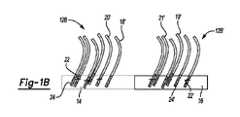
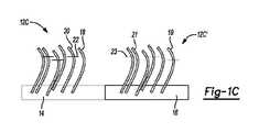
本明細書に開示される第1の態様は、基材と、基材上の第1の領域に結合した第1のプ
ライマーセットであって、切断不可能な第1のプライマーおよび切断可能な第2のプライ
マーを含む第1のプライマーセットと、基材上の第2の領域に結合した第2のプライマー
セットであって、切断可能な第1のプライマーおよび切断不可能な第2のプライマーを含
む第2のプライマーセットとを含むフローセルである。A first aspect disclosed herein is a substrate and a first set of primers attached to a first region on the substrate, comprising a non-cleavable first primer and a cleavable A first primer set comprising a second primer and a second primer set bound to a second region on the substrate, wherein the cleavable first primer and the non-cleavable second primer are and a second primer set comprising.
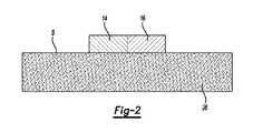
第1の態様の一例では、第1の領域は、第1の官能基を有する材料を含み、第2の領域
は、第1の官能基とは異なった第2の官能基を有する材料を含む。In one example of the first aspect, the first region comprises a material having a first functional group and the second region comprises a material having a second functional group different than the first functional group. .
第1の態様の一例では、フローセルは、第1のプライマーセットを第2のプライマーセ
ットから分離するギャップをさらに含む。In one example of the first aspect, the flow cell further comprises a gap separating the first primer set from the second primer set.
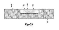
第1の態様の一例では、基材は、間隙領域によって分離された凹部を含み、凹部のそれ
ぞれは、第1の部分に位置する第1の領域と、第2の部分に位置する第2の領域とを含む
。この例の1つのバージョンでは、フローセルは、第1の領域を第2の領域から分離する
ギャップをさらに含むことができる。この例の別のバージョンでは、第1の領域と第2の
領域とが部分的に重なり合う。この例のさらに別のバージョンでは、第1および第2の部
分は、異なる深さを有する。この実施例のさらなるバージョンでは、第1および第2の領
域は、ブロック共ポリマー(ブロックコポリマー)の異なるブロックである。In one example of the first aspect, the substrate includes recesses separated by gap regions, each recess having a first region located in the first portion and a second region located in the second portion. area. In one version of this example, the flow cell can further include a gap separating the first region from the second region. In another version of this example, the first region and the second region partially overlap. In yet another version of this example, the first and second portions have different depths. In a further version of this example, the first and second regions are different blocks of a block copolymer (block copolymer).
第1の態様の一例では、基材は、間隙領域によって分離された凹部を含み、凹部のそれ
ぞれは、第1の領域を含み、第2の領域は、間隙領域の少なくともいくつかの上に位置す
る。In one example of the first aspect, the substrate includes recesses separated by interstitial regions, each recess comprising a first region and a second region overlying at least some of the interstitial regions. do.
第1の態様の一例では、第1の領域は、第1のポリマーを含み、第1のプライマーセッ
トは、第1のポリマーにグラフト(移植)され、第2の領域は、第2のポリマーを含み、
第2のプライマーセットは、第2のポリマーにグラフトされる。この実施形態の1つの態
様では、フローセルは、第1のプライマーセット上および第1のポリマー上に保護塗装を
さらに含む。この実施形態の別の態様では、第1のポリマーは、基材上の第1の層であり
、第2のポリマーは、第1の層上の第2の層であり、フローセルは、第2の層上のパッシ
ベーション(不動態化)樹脂と、パッシベーション樹脂、第2のポリマー、および第1の
ポリマーに画定された特徴(形状)とをさらに含み、第1および第2のプライマーセット
のそれぞれは、特徴のそれぞれで露出される。In one example of the first aspect, the first region comprises a first polymer, the first primer set is grafted onto the first polymer, and the second region comprises a second polymer. including
A second set of primers is grafted onto the second polymer. In one aspect of this embodiment, the flow cell further includes a protective coating over the first primer set and over the first polymer. In another aspect of this embodiment, the first polymer is the first layer on the substrate, the second polymer is the second layer on the first layer, and the flow cell is the second and a passivation resin, a second polymer, and features (shapes) defined in the first polymer, each of the first and second primer sets comprising , exposed in each of the features.
第1の態様の一例では、基材は、間隙領域によって分離された凹部を含み、凹部のそれ
ぞれは、第1の領域が位置する第1の部分と、第2の部分とを含み、フローセルは、第2
の部分に位置するビーズ(ビード)をさらに含み、第2の領域は、ビーズの表面にある。In one example of the first aspect, the substrate includes recesses separated by interstitial regions, each of the recesses including a first portion in which the first region is located and a second portion, the flow cell comprising: , second
and the second region is on the surface of the bead.
第1の態様の一例では、切断可能な第1のプライマーは第1の切断部位を含み、切断可
能な第2のプライマーは第2の切断部位を含み、第1および第2の切断部位は同一タイプ
である。この例の1つのバージョンでは、切断不可能な第1のプライマー、切断可能な第
2のプライマー、切断可能な第1のプライマー、および切断可能な第2のプライマーのそ
れぞれは、それぞれのリンカーを含み、第1の切断可能なプライマーの第1の切断部位は
、そのリンカーに沿って位置し、第2の切断可能なプライマーの第2の切断部位は、その
リンカーに沿って位置する。In one example of the first aspect, the first cleavable primer comprises a first cleavage site and the second cleavable primer comprises a second cleavage site, wherein the first and second cleavage sites are identical. Type. In one version of this example, each of the non-cleavable first primer, cleavable second primer, cleavable first primer, and cleavable second primer includes a respective linker. , the first cleavage site of the first cleavable primer is located along the linker and the second cleavage site of the second cleavable primer is located along the linker.
第1の態様の一例では、切断可能な第1のプライマーは第1の切断部位を含み、切断可
能な第2のプライマーは第2の切断部位を含み、第1および第2の切断部位は異なるタイ
プである。この例の1つのバージョンでは、切断不可能な第1のプライマー、切断可能な
第2のプライマー、切断可能な第1のプライマー、および切断可能な第2のプライマーの
それぞれは、それぞれのリンカーを含み、第1の切断可能なプライマーの第1の切断部位
は、そのリンカーに沿って位置し、第2の切断可能なプライマーの第2の切断部位は、そ
のリンカーに沿って位置する。In one example of the first aspect, the first cleavable primer comprises a first cleavage site and the second cleavable primer comprises a second cleavage site, the first and second cleavage sites being different Type. In one version of this example, each of the non-cleavable first primer, cleavable second primer, cleavable first primer, and cleavable second primer includes a respective linker. , the first cleavage site of the first cleavable primer is located along the linker and the second cleavage site of the second cleavable primer is located along the linker.
第1の態様の一例では、第1のプライマーセットは、第1の保持体構造に結合され、第
1の領域は、第1の保持体構造に結合された第1の捕捉部位であり、第2のプライマーセ
ットは、第1の保持体構造とは異なった第2の保持体構造に結合され、第2の領域は、第
2の保持体構造に結合された第2の捕捉部位である。In one example of the first aspect, the first primer set is bound to a first support structure, the first region is a first capture site bound to the first support structure, and the first The two primer sets are bound to a second support structure different from the first support structure, and the second region is a second capture site bound to the second support structure.
本明細書に開示された第1の態様の任意の特徴は、任意の望ましい方法および/または
構成で一緒に組み合わせることができることを理解されたい。It should be appreciated that any feature of the first aspect disclosed herein can be combined together in any desired manner and/or configuration.
本明細書に開示される第2の態様は、第1の基材と、第1の基材に結合した第1のプラ
イマーセットであって、切断不可能な第1のプライマーおよび切断可能な第2のプライマ
ーを含む第1のプライマーセットと、第1の基材に対向する第2の基材と、第2の基材に
結合した第2のプライマーセットとを含み、第2のプライマーセットは、切断可能な第1
のプライマーおよび切断不可能な第2のプライマーを含むフローセルである。A second aspect disclosed herein is a first substrate and a first set of primers attached to the first substrate, wherein the non-cleavable first primer and the cleavable first primer a first primer set comprising two primers, a second substrate facing the first substrate, and a second primer set bound to the second substrate, the second primer set comprising , severable first
and a non-cleavable second primer.
第2の態様の任意の特徴は、任意の望ましい方法で一緒に組み合わせることができるこ
とを理解されたい。さらに、第1の態様および/または第2の態様の特徴の任意の組み合
わせが、一緒に使用されてもよく、および/または本明細書で開示された例の任意のもの
と組み合わせられてもよいことを理解されたい。It should be appreciated that any features of the second aspect can be combined together in any desired manner. Moreover, any combination of features of the first aspect and/or the second aspect may be used together and/or combined with any of the examples disclosed herein Please understand.
本明細書に開示される第3の態様は、間隙領域によって分離された凹部を含む基材と、
第1のポリマー層のいくつかの官能基がキャップされる、凹部のそれぞれの中の第1のポ
リマー層と、凹部のそれぞれの中の第1のポリマー層の他の官能基に結合された第1のプ
ライマーセットと、間隙領域上の第2のポリマー層と、流体キャリアを含むプライミング
流体と、第1のプライマーセットとは異なった第2のプライマーセットとを含む、フロー
セルを含むキットである。A third aspect disclosed herein is a substrate comprising recesses separated by interstitial regions;
a first polymer layer in each of the recesses, where some functional groups of the first polymer layer are capped, and a second polymer layer bound to other functional groups of the first polymer layer in each of the recesses A kit comprising a flow cell comprising one primer set, a second polymer layer on the interstitial region, a priming fluid comprising a fluid carrier, and a second primer set different from the first primer set.
第3の態様の例では、第1のプライマーセットは、切断不可能な第1のプライマーおよ
び切断可能な第2のプライマーを含み、第2のプライマーセットは、切断可能な第1のプ
ライマーおよび切断不可能な第2のプライマーを含む。In an example of the third aspect, the first primer set comprises a non-cleavable first primer and a cleavable second primer, and the second primer set comprises the cleavable first primer and a cleavable Including a second primer that is not possible.
第3の態様の任意の特徴は、任意の望ましい方法で一緒に組み合わせることができるこ
とを理解されたい。さらに、第3の態様および/または第2の態様および/または第1の
態様の特徴の任意の組み合わせが、一緒に使用されてもよく、および/または本明細書で
開示される例の任意のものと組み合わせられてもよいことを理解されたい。It should be appreciated that any features of the third aspect can be combined together in any desired manner. Moreover, any combination of features of the third aspect and/or the second aspect and/or the first aspect may be used together and/or any of the examples disclosed herein. It should be understood that it may be combined with
本明細書に開示される第4の態様は、フローセルに鋳型流体を導入することを含む方法
であって、フローセルは、間隙領域によって分離された凹部を含む基材と、凹部のそれぞ
れの中における第1のポリマー層であって、露出した官能基がキャップされている第1の
ポリマー層と、凹部のそれぞれの中の第1のポリマー層に結合し、切断可能な第1のプラ
イマーセットおよび切断不可能な第2のプライマーを含む第1のプライマーセットと、間
隙領域上の第2のポリマー層とを含み、これにより、鋳型流体からの鋳型が増幅されて凹
部の少なくともいくつかの中にクラスターを形成し、切断不可能な第1のプライマーおよ
び切断可能な第2のプライマーを含むプライミング流体をフローセルに導入し、これによ
り、切断不可能な第1のプライマーおよび切断可能な第2のプライマーが第2のポリマー
層にグラフトされ、クラスターから切断不可能な第1のプライマーおよび切断可能な第2
のプライマーへのブリッジ増幅(bridgeamplification)を開始し、これにより、間隙領
域の少なくともいくつかの上に第2のクラスターを形成する、方法である。A fourth aspect disclosed herein is a method comprising introducing a template fluid to a flow cell, the flow cell comprising a substrate comprising recesses separated by interstitial regions, and a first polymer layer, wherein the exposed functional groups are capped, and a first set of cleavable primers bound to the first polymer layer in each of the recesses and cleavable; a first set of primers comprising non-impossible second primers and a second polymer layer over the interstitial regions whereby templates from the template fluid are amplified and clustered within at least some of the recesses; and introducing a priming fluid comprising a first non-cleavable primer and a second cleavable primer into the flow cell, whereby the first non-cleavable primer and the second cleavable primer are A non-cleavable first primer and a cleavable second primer grafted to the second polymer layer from the clusters;
to primers, thereby forming a second cluster over at least some of the interstitial regions.
第4の態様の任意の特徴は、任意の望ましい方法で一緒に組み合わせることができるこ
とを理解されたい。さらに、第4の態様および/または第3の態様および/または第2の
態様および/または第1の態様の特徴の任意の組み合わせが、一緒に使用されてもよく、
および/または本明細書で開示される例の任意のものと組み合わせられてもよいことを理
解されたい。It should be appreciated that any features of the fourth aspect can be combined together in any desired manner. Furthermore, any combination of features of the fourth aspect and/or the third aspect and/or the second aspect and/or the first aspect may be used together,
and/or may be combined with any of the examples disclosed herein.
本明細書に開示される第5の態様は、間隙領域によって分離された凹部を含む基材と、
凹部のそれぞれにある第1のポリマー層と、第1のポリマー層に取り付けられた第1のプ
ライマーセットであって、切断可能な第1のプライマーおよび切断不可能な第2のプライ
マーを含む第1のプライマーセットと、第1のポリマー層上および第1のプライマーセッ
ト上の任意の光学保護塗装層と、間隙領域上の第2のポリマー層と、第2のポリマー層に
取り付けられた第2のプライマーセットであって、切断不可能な第1のプライマーおよび
切断可能な第2のプライマーを含む第2のプライマーセットと、を含むフローセルに鋳型
流体を導入するステップであって、これにより、鋳型流体からの鋳型が増幅されて、凹部
の少なくともいくつかおよび間隙領域の少なくともいくつかにクラスターを形成するステ
ップと、切断可能な第1のプライマーおよび切断可能な第2のプライマーを切断するステ
ップとを含む、方法である。A fifth aspect disclosed herein is a substrate comprising recesses separated by interstitial regions;
a first polymer layer in each of the recesses and a first set of primers attached to the first polymer layer, the first primer set comprising a cleavable first primer and a non-cleavable second primer; an optional optical protective coating layer on the first polymer layer and on the first primer set; a second polymer layer on the interstitial regions; and a second polymer layer attached to the second polymer layer introducing a template fluid into a flow cell comprising a set of primers, the second primer set comprising a first non-cleavable primer and a second cleavable primer, whereby the template fluid template from is amplified to form clusters in at least some of the recesses and at least some of the interstitial regions; and cleaving the first cleavable primer and the second cleavable primer. , is the method.
第5の態様の任意の特徴は、任意の望ましい方法で一緒に組み合わせることができるこ
とを理解されたい。さらに、第5の態様および/または第3の態様および/または第2の
態様および/または第1の態様の特徴の任意の組み合わせが、一緒に使用されてもよく、
および/または本明細書で開示される例の任意のものと組み合わせられてもよいことを理
解されたい。It should be appreciated that any features of the fifth aspect can be combined together in any desired manner. Furthermore, any combination of features of the fifth aspect and/or the third aspect and/or the second aspect and/or the first aspect may be used together,
and/or may be combined with any of the examples disclosed herein.
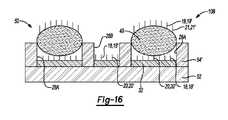
本明細書に開示される第6の態様は、保持体と、保持体上のパターン化(パターニング
/パターン形成)された樹脂であって、間隙領域によって分離された第1の凹部および第
2の凹部を含み、第1の凹部は、第2の凹部よりも小さい開口部寸法を有する、パターン
化された樹脂と、第1の凹部の少なくともいくつかに取り付けられた第1のプライマーセ
ットと、第2の凹部の少なくともいくつかにそれぞれ配置された官能基を有するビーズと
を含み、官能基を有するビーズは、コア構造の表面に取り付けられた第2のプライマーセ
ットを含み、第2のプライマーセットは、第1のプライマーセットとは異なっている、フ
ローセルである。A sixth aspect disclosed herein is a carrier and a patterned (patterned/patterned) resin on the carrier comprising a first recess and a second recess separated by a gap region. a patterned resin comprising recesses, the first recesses having a smaller opening dimension than the second recesses; a first set of primers attached to at least some of the first recesses; and beads having functional groups respectively disposed in at least some of the two recesses, the beads having functional groups comprising a second set of primers attached to the surface of the core structure, the second set of primers being , different from the first primer set, the flow cell.
第6の態様では、官能基を有するビーズのコア構造は、二酸化ケイ素、超常磁性物質、
ポリスチレン、およびアクリル酸塩からなる群から選択される。In a sixth aspect, the core structure of the functionalized bead comprises silicon dioxide, a superparamagnetic substance,
selected from the group consisting of polystyrene and acrylates;
第6の態様の一例では、パターン化された樹脂は、多面体オリゴマーシルセスキオキサ
ン樹脂(POSS)ベースの樹脂、エポキシ樹脂、ポリ(エチレングリコール)樹脂、ポ
リエーテル樹脂、アクリル樹脂、アクリル酸塩樹脂、メタクリレート樹脂、およびこれら
の組み合わせからなる群から選択される。In one example of the sixth aspect, the patterned resin is a polyhedral oligomeric silsesquioxane resin (POSS) based resin, an epoxy resin, a poly(ethylene glycol) resin, a polyether resin, an acrylic resin, an acrylate resin. , methacrylate resins, and combinations thereof.
第6の態様の一例では、フローセルは、第1の凹部および第2の凹部にポリマーをさら
に含み、第1のプライマーセットは、第1の凹部の少なくともいくつかのポリマーに結合
される。この例の1つのバージョンでは、官能基を有するビーズは、第2の凹部の少なく
ともいくつかのポリマー上に配置される。この例の別のバージョンでは、第1のプライマ
ーセットはまた、第2の凹部の少なくともいくつかのポリマーに結合され、官能基を有す
るビーズは、第2の凹部の少なくともいくつかの第1のプライマーセット上に配置される
。In one example of the sixth aspect, the flow cell further comprises a polymer in the first recess and the second recess, and the first primer set is bound to the polymer in at least some of the first recess. In one version of this example, beads with functional groups are placed on the polymer in at least some of the second recesses. In another version of this example, the first primer set is also attached to the polymer in at least some of the second depressions, and the beads with functional groups are attached to the first primers in at least some of the second depressions. placed on the set.
第6の態様の例では、第1のプライマーセットは、第1のプライマーおよびウラシル修
飾された第2のプライマーを含み、第2のプライマーセットは、ウラシル修飾された第1
のプライマーおよび第2のプライマーを含む。In an example of the sixth aspect, the first primer set comprises a first primer and a uracil-modified second primer, and the second primer set comprises a uracil-modified first
and a second primer.
本明細書に開示された第6の態様の任意の特徴は、任意の望ましい方法および/または
構成で一緒に組み合わせることができることを理解されたい。It should be appreciated that any feature of the sixth aspect disclosed herein can be combined together in any desired manner and/or configuration.
本明細書に開示される第7の態様は、保持体と、保持体上のパターン化された樹脂であ
って、間隙領域によって分離された凹部を含むパターン化された樹脂と、凹部の少なくと
もいくつかに取り付けられた第1のプライマーセットと、第1のプライマーセットの少な
くともいくつかのプライマーが露出されるように、凹部の少なくともいくつかに配置され
た官能化されたビーズとを含み、官能化されたビーズは、コア構造の表面に取り付けられ
た第2のプライマーセットを含み、第2のプライマーセットは、第1のプライマーセット
とは異なっている、フローセルである。A seventh aspect disclosed herein is a carrier, a patterned resin on the carrier, the patterned resin comprising recesses separated by gap regions, and at least some of the recesses. and functionalized beads positioned in at least some of the recesses such that at least some primers of the first primer set are exposed; The beads are flow cells that contain a second set of primers attached to the surface of the core structure, the second set of primers being different than the first set of primers.
第7の態様の一例では、凹部のそれぞれは、官能基を有するビーズの直径より大きいか
または等しい第1の開口部寸法を有する第1の部分と、官能基を有するビーズの直径より
小さい第2の開口部寸法を有する第2の部分とを含み、官能基を有するビーズは、凹部の
少なくともいくつかのそれぞれの第1の部分に配置される。In one example of the seventh aspect, each of the recesses has a first portion having a first opening dimension greater than or equal to the diameter of the functionalized bead and a second portion having a smaller diameter than the functionalized bead. and a second portion having an opening dimension of , wherein beads having functional groups are disposed in respective first portions of at least some of the recesses.
第7の態様の一例では、官能基を有するビーズのコア構造は、二酸化ケイ素、超常磁性
物質、ポリスチレン、およびアクリル酸塩からなる群から選択される。In one example of the seventh aspect, the core structure of the functionalized bead is selected from the group consisting of silicon dioxide, superparamagnetic materials, polystyrene, and acrylates.
第7の態様の一例では、パターン化された樹脂は、多面体オリゴマーシルセスキオキサ
ン樹脂(POSS)ベースの樹脂、エポキシ樹脂、ポリ(エチレングリコール)樹脂、ポ
リエーテル樹脂、アクリル樹脂、アクリル酸塩樹脂、メタクリレート樹脂、およびこれら
の組み合わせからなる群から選択される。In one example of the seventh aspect, the patterned resin is a polyhedral oligomeric silsesquioxane resin (POSS) based resin, an epoxy resin, a poly(ethylene glycol) resin, a polyether resin, an acrylic resin, an acrylate resin. , methacrylate resins, and combinations thereof.
第7の態様の一例では、フローセルは、凹部においてポリマーをさらに含む。この局面
の1つのバージョンにおいて、第1のプライマーセットは、官能基を有するビーズによっ
て占有されていないポリマーの部分に結合される。このバージョンの一例では、第1のプ
ライマーセットは、凹部においてポリマーに結合され、官能基を有するビーズは、第1の
プライマーセットのいくつかの他のプライマー上に配置される。In one example of the seventh aspect, the flow cell further comprises a polymer in the recess. In one version of this aspect, the first set of primers is attached to the portion of the polymer not occupied by the functionalized beads. In one example of this version, a first primer set is attached to the polymer in the recess and beads with functional groups are placed on some other primer of the first primer set.
本明細書に開示された第7の態様の任意の特徴は、任意の望ましい方法および/または
構成で一緒に組み合わせることができることを理解されたい。It should be appreciated that any feature of the seventh aspect disclosed herein can be combined together in any desired manner and/or configuration.
本明細書に開示される第8の態様は、保持体上のパターン化された樹脂の凹部にポリマ
ーを選択的に適用(塗布)することと、第1のプライマーセットを少なくともいくつかの
凹部にポリマーにグラフトすることと、第1のプライマーセットをグラフトする前後に、
i)少なくともいくつかの凹部のそれぞれの一部に、またはii)少なくともいくつかの
凹部よりも大きい開口部寸法を有する第2の凹部に官能基を有するビーズを堆積させるこ
ととを含み、官能基を有するビーズは、コア構造の表面に結合された第2のプライマーセ
ットを含み、第1および第2のプライマーセットが異なっている、方法である。An eighth aspect disclosed herein comprises selectively applying a polymer to patterned resin depressions on a support, and applying a first set of primers to at least some of the depressions. before and after grafting the polymer and grafting the first set of primers;
i) in a portion of each of the at least some of the recesses, or ii) in a second recess having a larger opening dimension than the at least some of the recesses, the functionalized beads comprising comprises a second set of primers attached to the surface of the core structure, wherein the first and second primer sets are different.
第8の態様の実施形態では、官能基を有するビーズを堆積させる前に、該方法は、第2
のプライマーセットをコア構造に結合させることによって官能基を有するビーズを形成す
ることをさらに含む。In an embodiment of the eighth aspect, prior to depositing the functionalized beads, the method comprises a second
to the core structure to form functionalized beads.
第8の態様の一例では、凹部の少なくともいくつかのそれぞれの部分は、官能基を有す
るビーズのそれぞれの直径より大きいかまたは等しい開口部寸法を有し、凹部の少なくと
もいくつかは、部分と相互接続された第2の部分を含み、第2の部分は、官能基を有する
ビーズのそれぞれの直径より小さい第2の開口部寸法を有し、官能基を有するビーズは、
サイズ排除凹部の少なくともいくつかのそれぞれの部分に自己集合(セルフアセンブル)
する。In one example of the eighth aspect, each portion of at least some of the recesses has an opening dimension greater than or equal to the diameter of each of the functionalized beads, and at least some of the recesses are mutually a connected second portion, the second portion having a second opening dimension less than a respective diameter of the functionalized bead, the functionalized bead comprising:
Self-assemble into respective portions of at least some of the size exclusion recesses
do.
第8の態様の一実施形態では、方法は、前記ポリマーを選択的に適用する前に、前記保
持体上に樹脂を堆積させるステップと、ナノインプリントリソグラフィを用いて前記樹脂
をパターン化するステップとによって、前記パターン化された樹脂を前記保持体上に形成
するステップとをさらに含む。In an embodiment of the eighth aspect, the method comprises depositing a resin on said support and patterning said resin using nanoimprint lithography prior to selectively applying said polymer. and forming the patterned resin on the carrier.
第8の態様の任意の特徴は、任意の望ましい方法で一緒に組み合わせることができるこ
とを理解されたい。さらに、第8の態様および/または第7の態様および/または第6の
態様および/または第1の態様の特徴の任意の組み合わせが、一緒に使用されてもよく、
かつ/または本明細書で開示される例の任意のものと組み合わせられてもよいことを理解
されたい。It should be appreciated that any feature of the eighth aspect can be combined together in any desired manner. Furthermore, any combination of the features of the eighth aspect and/or the seventh aspect and/or the sixth aspect and/or the first aspect may be used together,
and/or may be combined with any of the examples disclosed herein.
本明細書に開示される第9の態様は、保持体と、保持体上のパターン化された樹脂であ
って、間隙領域によって分離された凹部を含むパターン化された樹脂と、凹部におけるパ
ターン化された樹脂上のブロック共ポリマーであって、ブロック共ポリマーの各ブロック
が、他の各ブロックのブロック特異的官能基とは異なるブロック特異的官能基を有する、
ブロック共ポリマーと、ブロックのうちの少なくとも1つのブロック特異的官能基に結合
されたプライマーとを含む、フローセルである。A ninth aspect disclosed herein is a carrier, a patterned resin on the carrier, the patterned resin comprising recesses separated by gap regions, and the patterned resin in the recesses a block copolymer on a polymerized resin, each block of the block copolymer having a block-specific functional group different from the block-specific functional group of each other block;
A flow cell comprising a block copolymer and a primer attached to a block-specific functional group of at least one of the blocks.
第9の態様の一例では、パターン化された樹脂は、多面体オリゴマーシルセスキオキサ
ン樹脂(POSS)ベースの樹脂、エポキシ樹脂、ポリ(エチレングリコール)樹脂、ポ
リエーテル樹脂、アクリル樹脂、アクリル酸塩樹脂、メタクリレート樹脂、およびこれら
の組み合わせからなる群から選択される。この実施例の1つのバージョンでは、パターン
化された樹脂はPOSSベースの樹脂であり、POSSベースの樹脂は架橋エポキシPO
SS樹脂である。本実施例の別のバージョンでは、ブロック共ポリマーは、ブロック特異
的官能基としてアミノ基を有するアクリルアミドモノマーを含む第1のブロックと、ブロ
ック特異的官能基としてアジド基を有するアジドアセトアミドペンチルアクリルアミドモ
ノマーを含む第2のブロックとを含む。この他の例では、ブロック共ポリマーは、
式中、Rは水素またはポリマー開始種末端基であり、nは1~10,000の範囲であ
り、mは1~10,000の範囲である。この実施別のバージョンの形態では、ブロック
共ポリマーは、
式中、nは1~10,000の範囲であり、mは1~10,000の範囲である。In one example of the ninth aspect, the patterned resin is a polyhedral oligomeric silsesquioxane resin (POSS) based resin, an epoxy resin, a poly(ethylene glycol) resin, a polyether resin, an acrylic resin, an acrylate resin. , methacrylate resins, and combinations thereof. In one version of this example, the patterned resin is a POSS-based resin, and the POSS-based resin is a crosslinked epoxy PO
SS resin. In another version of this example, the block copolymer has a first block comprising an acrylamide monomer having an amino group as the block-specific functional group and an azidoacetamidopentylacrylamide monomer having an azide group as the block-specific functional group. and a second block containing. In this other example, the block copolymer is
where R is hydrogen or a polymer initiating species end group, n ranges from 1 to 10,000, and m ranges from 1 to 10,000. In another version of this embodiment, the block copolymer is
wherein n ranges from 1 to 10,000 and m ranges from 1 to 10,000.
第9の態様では、パターン化された樹脂は、非晶質フッ素ポリマーである。この実施形
態の一態様では、ブロック共ポリマーは、ブロック特異的官能基としてトリフルオロメチ
ル基を有するモノマーを含む第1のブロックと、ブロック特異的官能基としてプライマー
グラフト官能基を有するモノマーを含む第2のブロックとを含む。In a ninth aspect, the patterned resin is an amorphous fluoropolymer. In one aspect of this embodiment, the block copolymer comprises a first block comprising monomers having trifluoromethyl groups as block-specific functional groups and a second block comprising monomers having primer-grafting functional groups as block-specific functional groups. 2 blocks.
第9の態様の一例では、ブロック共ポリマーは、ブロック特異的官能基としてプライマ
ーグラフト化官能基を有するモノマーを含む第1のブロックと、第1および第2のブロッ
クの相分離を駆動するための相互作用パラメータを調整するためのモノマーを含む第2の
ブロックとを含む。この実施形態の一態様では、プライマーグラフト化官能基はアジド基
であり、第2のブロックのモノマーのブロック特異的官能基は、アミノ基、アルコール基
、アリール基、および荷電基からなる群から選択される。In one example of the ninth aspect, the block copolymer comprises a first block comprising a monomer having a primer-grafted functional group as a block-specific functional group, and a and a second block containing monomers for adjusting interaction parameters. In one aspect of this embodiment, the primer-grafting functional group is an azide group and the block-specific functional group of the second block monomer is selected from the group consisting of amino groups, alcohol groups, aryl groups, and charged groups. be done.
第9の態様の一例では、ブロック共ポリマーは、第1のブロック、第2のブロック、お
よび第3のブロックを含む三元共ポリマーであり、第1のブロックのブロック特異的官能
基は、パターン化された樹脂に結合され、第2のブロックのブロック特異的官能基は、プ
ライマーに結合され、第3のブロックのブロック特異的官能基は、前記プライマーとは別
の他のプライマーまたは酵素に結合される。In one example of the ninth aspect, the block copolymer is a terpolymer comprising a first block, a second block, and a third block, wherein the block-specific functional groups of the first block are in the pattern a block-specific functional group of a second block is attached to a primer and a block-specific functional group of a third block is attached to another primer or enzyme apart from said primer; be done.
第9の態様の一例では、ブロック共ポリマーは、第1のブロック、第2のブロック、お
よび第3のブロックを含む三元共ポリマーであり、第1のブロックのブロック特異的官能
基は、パターン化された樹脂に結合され、第2のブロックのブロック特異的官能基は、プ
ライマーに結合され、第3のブロックのブロック特異的官能基は、ブロック共ポリマーの
表面自由エネルギーに影響を及ぼすか、またはブロック共ポリマーの安定性に影響を及ぼ
す。In one example of the ninth aspect, the block copolymer is a terpolymer comprising a first block, a second block, and a third block, wherein the block-specific functional groups of the first block are in the pattern the block-specific functional group of the second block is attached to the primer and the block-specific functional group of the third block affects the surface free energy of the block copolymer; or affect the stability of the block copolymer.
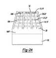
第9の態様の一例では、凹部は、ウェルおよびトレンチからなる群から選択される。 In one example of the ninth aspect, the recess is selected from the group consisting of wells and trenches.
第9の態様では、パターン化された樹脂およびブロック共ポリマーは、それぞれ、約2
5mN/m~約50mN/mの表面自由エネルギーを有する。In a ninth aspect, the patterned resin and block copolymer are each about 2
It has a surface free energy of 5 mN/m to about 50 mN/m.
本明細書に開示された第9の態様の任意の特徴は、任意の望ましい方法および/または
形状で一緒に組み合わせることができることを理解されたい。さらに、第9の態様および
/または第1の態様の特徴の任意の組み合わせが、一緒に使用されてもよく、および/ま
たは本明細書で開示された例の任意のものと組み合わせられてもよいことを理解されたい
。It should be appreciated that any feature of the ninth aspect disclosed herein can be combined together in any desired manner and/or shape. Additionally, any combination of features of the ninth aspect and/or the first aspect may be used together and/or combined with any of the examples disclosed herein Please understand.
本明細書に開示される第10の態様は、保持体と、保持体上のパターン化された多面体
オリゴマーシルセスキオキサン(POSS)ベースの樹脂と、間隙領域によって分離され
た凹部を含むパターン化されたPOSSベースの樹脂と、凹部におけるパターン化された
POSSベースの樹脂上の分離されたブロック共ポリマーであって、分離されたブロック
共ポリマーの一方のブロックが、パターン化されたPOSSベースの樹脂に結合された官
能基を有し、分離されたブロック共ポリマーの他方のブロックが別の官能基を有する、ブ
ロック共ポリマーと、当該別の官能基に結合されたプライマーと、を有するフローセルで
ある。A tenth aspect disclosed herein is a support, a patterned polyhedral oligomeric silsesquioxane (POSS)-based resin on the support, and a patterned resin comprising recesses separated by interstitial regions. and a separated block copolymer on the patterned POSS-based resin in the recesses, wherein one block of the separated block copolymer is the patterned POSS-based resin. a flow cell having a block copolymer and a primer attached to the separate functional group, wherein the other block of the isolated block copolymer has a different functional group; .
第10の態様では、分離されたブロック共ポリマーは、

り、mは1~10,000の範囲である。)、
からなる群から選択される。In a tenth aspect, the isolated block copolymer comprises
selected from the group consisting of
本明細書に開示された第10の態様の任意の特徴は、任意の望ましい方法および/また
は構成で一緒に組み合わせることができることを理解されたい。さらに、第10の態様お
よび/または第9の態様および/または第1の態様の特徴の任意の組み合わせが、一緒に
使用されてもよく、および/または本明細書で開示される例の任意のものと組み合わせら
れてもよいことを理解されたい。It should be appreciated that any feature of the tenth aspect disclosed herein can be combined together in any desired manner and/or configuration. Additionally, any combination of features of the tenth and/or ninth and/or first aspect may be used together and/or any of the examples disclosed herein. It should be understood that it may be combined with
本明細書に開示された第11の態様は、間隙領域によって分離された凹部を含むパター
ン化された樹脂を形成するために樹脂をパターン化することと、パターン化された樹脂上
にブロック共ポリマーを含む溶液を導入することであって、ブロック共ポリマーの各ブロ
ックがブロック共ポリマーの他の各ブロックのブロック特異的官能基とは異なったブロッ
ク特異的官能基を有し、溶液を溶媒蒸気焼鈍に曝し、それによってブロック共ポリマー相
が凹部において分離し、自己集合し、ブロックの少なくとも1つのブロック特異的官能基
にプライマーをグラフトする、方法である。An eleventh aspect disclosed herein is patterning a resin to form a patterned resin comprising recesses separated by interstitial regions; wherein each block of the block copolymer has a block-specific functional group different from the block-specific functional groups of each other block of the block copolymer, and the solution is subjected to a solvent vapor anneal. exposing the block copolymer phase to , whereby the block copolymer phase separates and self-assembles in the recesses, grafting the primer onto at least one block-specific functional group of the block.
第11の態様の実施形態では、樹脂をパターン化することは、ナノインプリントリソグ
ラフィを含む。In an embodiment of the eleventh aspect, patterning the resin comprises nanoimprint lithography.
第11の態様の実施形態では、ブロック共ポリマーを含む溶液は、約0.04~約0.
30の範囲のフロリ-ハギンズ相互作用パラメータを有する。In an embodiment of the eleventh aspect, the solution containing the block copolymer has a concentration of about 0.04 to about 0.04.
It has a Flory-Huggins interaction parameter in the range of 30.
第11の態様の例において、グラフト化の前に、該方法は、凹部における相分離および
自己集合(自己組織化)ブロック共ポリマーを含むパターン化された樹脂を硬化工程に曝
すことをさらに含む。In an example of the eleventh aspect, prior to grafting, the method further comprises exposing the patterned resin comprising phase separation and self-assembly (self-assembly) block copolymers in the recesses to a curing step.
本明細書に開示された第11の態様の任意の特徴は、任意の望ましい方法および/また
は構成で一緒に組み合わせることができることを理解されたい。さらに、第11の態様お
よび/または第10の態様および/または第9の態様および/または第1の態様の特徴の
任意の組み合わせが、一緒に使用されてもよく、かつ/または本明細書で開示される例の
任意のものと組み合わせられてもよいことを理解されたい。It should be appreciated that any feature of the eleventh aspect disclosed herein can be combined together in any desired manner and/or configuration. Moreover, any combination of features of the eleventh aspect and/or the tenth aspect and/or the ninth aspect and/or the first aspect may be used together and/or herein It should be understood that any of the disclosed examples may be combined.
本明細書に開示される第12の態様は、基材上に第1の官能化層を適用するステップと
、第1の官能化層をパターン化し、それによってフォトレジストによって覆われた第1の
官能化領域を形成するステップと、フォトレジストおよび基材の部分上に第2の官能化層
を適用するステップと、フォトレジストおよびその上の第2の官能化層のいずれかをリフ
トオフするステップと、第2の官能化層の一部を除去し、それによって第1の官能化領域
に近接する第2の官能化領域を形成するステップと、第1のプライマーセットを第1の官
能化層または第1の官能化領域におよび第2のプライマーセットに第2の官能化層または
第2の官能化領域に結合させるステップであって、第1のプライマーセットが第2のプラ
イマーセットとは異なっているステップと、を含む方法である。A twelfth aspect disclosed herein is the steps of applying a first functionalized layer onto a substrate; forming a functionalized region; applying a second functionalized layer over portions of the photoresist and the substrate; and lifting off either the photoresist and the second functionalized layer thereon. removing a portion of the second functionalized layer, thereby forming a second functionalized region proximate to the first functionalized region; and applying the first primer set to the first functionalized layer or binding the first functionalized region and the second primer set to the second functionalized layer or the second functionalized region, wherein the first primer set is different than the second primer set; and .
第12の態様の例では、第1のプライマーセットの結合は、第1の官能化層が適用され
る前に、切断不可能な第1のプライマーおよび切断可能な第2のプライマーを第1の官能
化層に予めグラフトすることを含み、第2のプライマーセットの結合は、第2の官能化層
が適用される前に、切断可能な第1のプライマーおよび切断不可能な第2のプライマーを
第2の官能化層に予めグラフトすることを含む。In an example of the twelfth aspect, the combination of the first primer set comprises combining the non-cleavable first primer and the cleavable second primer with the first primer set before the first functionalization layer is applied. The attachment of the second set of primers comprises pre-grafting the functionalized layer, the cleavable first primer and the non-cleavable second primer before the second functionalized layer is applied. Pre-grafting to the second functionalization layer.
第12の態様の例では、第1のプライマーセットの結合は、その適用後に、切断不可能
な第1のプライマーおよび切断可能な第2のプライマーを第1の官能化層にグラフトする
ことを含み、第2のプライマーセットの結合は、その適用後に、切断可能な第1のプライ
マーおよび切断不可能な第2のプライマーを第2の官能化層にグラフトすることを含む。In an example of the twelfth aspect, combining the first primer set comprises grafting the first non-cleavable primer and the second cleavable primer to the first functionalization layer after its application. , the coupling of the second primer set comprises grafting the cleavable first primer and the non-cleavable second primer onto the second functionalization layer after its application.
第12の態様の一例では、方法は、第1の自己集合単層(単分子層)を第1の官能化領
域上に、第2の自己集合単分子層を第2の官能化領域上にそれぞれ堆積させることをさら
に含み、第1のプライマーセットの結合は、切断不可能な第1のプライマーおよび切断可
能な第2のプライマーを第1の自己集合単層にグラフトすることを含み、第2のプライマ
ーセットの結合は、切断可能な第1のプライマーおよび切断不可能な第2のプライマーを
第2の自己集合単層にグラフトすることを含む。In one example of the twelfth aspect, the method comprises forming a first self-assembled monolayer (monolayer) on the first functionalized region and a second self-assembled monolayer on the second functionalized region. respectively, wherein the joining of the first primer set comprises grafting the non-cleavable first primer and the cleavable second primer to the first self-assembled monolayer; involves grafting a cleavable first primer and a second non-cleavable primer onto a second self-assembled monolayer.
第12の態様の一例では、除去することは、第1の官能化領域上に第2のフォトレジス
トを適用し、第2の官能化領域になる第2の官能化層の第2の部分を適用することと、第
2の官能化層の一部をエッチングすることとを含む。In one example of the twelfth aspect, the removing includes applying a second photoresist over the first functionalized region and a second portion of the second functionalized layer to become the second functionalized region. applying and etching a portion of the second functionalization layer.
第12の態様の一例では、基材は、保持体上に樹脂を含み、樹脂は、間隙領域によって
分離された凹部を含み、第1の官能化領域は、各凹部の第1の部分上にあり、第2の官能
化層は、各凹部の第2の部分上および間隙領域上にあり、除去することは、間隙領域から
第2の官能化層を研磨することを含む。In one example of the twelfth aspect, the substrate comprises a resin on the carrier, the resin comprises recesses separated by interstitial regions, and the first functionalized region overlies a first portion of each recess. A second functionalized layer is on the second portion of each recess and on the interstitial region, and removing includes polishing the second functionalized layer from the interstitial region.
第12の態様の一例では、基材は、保持体上の樹脂を含み、樹脂は、間隙領域によって
分離されたマルチレベル凹部を含み、第1の官能化領域は、それぞれのマルチレベル凹部
の第1のレベルにあり、第2の官能化層を適用する前に、フォトレジストおよび樹脂の一
部分上に犠牲層を適用するステップと、樹脂の一部分から犠牲層を除去するステップと、
多層の凹部から樹脂の領域を除去して、第1の官能化領域に近接する領域を生成するステ
ップと、第2の官能化層が、フォトレジスト上の犠牲層上、領域上、および間隙領域上に
適用されるステップと、をさらに含む。In one example of the twelfth aspect, the substrate comprises a resin on a carrier, the resin comprises multi-level recesses separated by interstitial regions, and the first functionalized region comprises a first region of each multi-level recess. applying a sacrificial layer over a portion of the photoresist and the resin at level 1 and prior to applying the second functionalization layer; removing the sacrificial layer from the portion of the resin;
removing regions of resin from the multi-layer recesses to create regions proximate to the first functionalized regions; and a step as applied above.
本明細書に開示された第12の態様の任意の特徴は、任意の望ましい方法および/また
は構成で一緒に組み合わせることができることを理解されたい。さらに、第12の態様お
よび/または第1の態様および/または第2の態様の特徴の任意の組み合わせは、本明細
書で開示される例の任意のものと組み合わせることができることを理解されたい。It should be appreciated that any feature of the twelfth aspect disclosed herein can be combined together in any desired manner and/or configuration. Furthermore, it should be understood that any combination of features of the twelfth aspect and/or the first aspect and/or the second aspect can be combined with any of the examples disclosed herein.
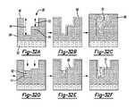
本明細書に開示される第13の態様は、第1の基材部分が露出(露光)されるように基
材上に第1のフォトレジストを適用するステップと、フォトレジストおよび第1の基材部
分上に第1の官能化層を適用するステップと、フォトレジストおよびその上の第1の官能
化層のいずれかをリフトオフするステップと、それによって第1の基材部分上に第1の官
能化領域を形成するステップと、第1の官能化領域上および基材上に第2のフォトレジス
トを適用して第1の官能化領域に隣接する第2の基材部分を露出するステップと、第2の
フォトレジストおよび第2の基材部分上に第2の官能化層を適用するステップと、第2の
フォトレジストおよびその上の第2の官能化層のいずれかをリフトオフするステップと、
それによって第1の官能化領域に隣接する第2の官能化領域を形成するステップと、第1
のプライマーセットを第1の官能化層または第1の官能化領域におよび第2のプライマー
セットを第2の官能化層または第2の官能化領域に結合させるステップであって、第1の
プライマーセットが第2のプライマーセットとは異なっているステップと、を含む。A thirteenth aspect disclosed herein comprises applying a first photoresist onto a substrate such that portions of the first substrate are exposed (exposed); applying a first functionalized layer over the material portion and lifting off either the photoresist and the first functionalized layer thereon, thereby forming a first functionalized layer over the first substrate portion; forming a functionalized region; and applying a second photoresist over the first functionalized region and over the substrate to expose portions of the second substrate adjacent to the first functionalized region. , applying a second functionalized layer over the second photoresist and the second substrate portion; and lifting off the second photoresist and the second functionalized layer thereon. ,
thereby forming a second functionalized region adjacent to the first functionalized region;
to the first functionalized layer or first functionalized region and a second primer set to the second functionalized layer or second functionalized region, wherein the first primer the set is different from the second primer set.
第13の態様の例では、第1のプライマーセットの結合は、第1の官能化層が適用され
る前に、切断不可能な第1のプライマーおよび切断可能な第2のプライマーを第1の官能
化層に予めグラフトすることを含み、第2のプライマーセットの結合は、第2の官能化層
が適用される前に、切断可能な第1のプライマーおよび切断不可能な第2のプライマーを
第2の官能化層に予めグラフトすることを含む。In an example of the thirteenth aspect, the joining of the first primer set comprises the non-cleavable first primer and the cleavable second primer to the first primer set before the first functionalization layer is applied. The attachment of the second set of primers comprises pre-grafting the functionalized layer, the cleavable first primer and the non-cleavable second primer before the second functionalized layer is applied. Pre-grafting to the second functionalized layer.
第13の態様の例では、第1のプライマーセットの結合は、その適用後に、切断不可能
な第1のプライマーおよび切断可能な第2のプライマーを第1の官能化層にグラフトする
ことを含み、第2のプライマーセットの結合は、その適用後に、切断可能な第1のプライ
マーおよび切断不可能な第2のプライマーを第2の官能化層にグラフトすることを含む。In an example of the thirteenth aspect, combining the first primer set comprises grafting the first non-cleavable primer and the second cleavable primer to the first functionalization layer after its application. , the coupling of the second primer set comprises grafting the cleavable first primer and the non-cleavable second primer onto the second functionalization layer after its application.
第13の態様の一例では、方法は、第1の自己集合単層を第1の官能化領域上に、第2
の自己集合単層を第2の官能化領域上にそれぞれ堆積させることをさらに含み、第1のプ
ライマーセットの結合は、切断不可能な第1のプライマーおよび切断可能な第2のプライ
マーを第1の自己集合単層にグラフトすることを含み、第2のプライマーセットの結合は
、切断可能な第1のプライマーおよび切断不可能な第2のプライマーを第2の自己集合単
層にグラフトすることを含む。In one example of the thirteenth aspect, the method comprises forming the first self-assembled monolayer on the first functionalized region, the second
onto the second functionalized regions, respectively, wherein the binding of the first primer set comprises depositing the non-cleavable first primer and the cleavable second primer on the first and the binding of the second primer set comprises grafting the cleavable first primer and the non-cleavable second primer to the second self-assembled monolayer. include.
本明細書に開示された第13の態様の任意の特徴は、任意の望ましい方法および/また
は構成で一緒に組み合わせることができることを理解されたい。さらに、第13の態様お
よび/または第1の態様および/または第2の態様の特徴の任意の組み合わせは、本明細
書で開示される例の任意のものと組み合わせることができることを理解されたい。It should be appreciated that any feature of the thirteenth aspect disclosed herein can be combined together in any desired manner and/or configuration. Further, it should be understood that any combination of the features of the thirteenth aspect and/or the first aspect and/or the second aspect can be combined with any of the examples disclosed herein.
本明細書に開示される第14の態様は、間隙領域によって分離されたトレンチおよびト
レンチのそれぞれの第1の部分における犠牲材料領域を含む基板上に第1の官能化層を適
用するステップと、第1の官能化層をパターン化して、各トレンチの第2の部分において
フォトレジストによって覆われた第1の官能化領域を形成するステップと、犠牲材料領域
を除去して、各トレンチの第1の部分を露出させるステップと、第2の官能化層を、間隙
領域上に、第1の部分上に、フォトレジスト上に、適用するステップと、フォトレジスト
およびその上の任意の第2の官能化層をリフトオフするステップと、任意の第2の官能化
層を間隙領域から除去し、これにより、第2の官能化領域を、各トレンチの第1の部分に
残すステップと、少なくとも実質的にトレンチに垂直な空間的に分離されたストライプの
パターンで第2のフォトレジストを適用するステップと、空間的に分離されたストライプ
間に露出された第1の官能化領域および第2の官能化領域の部分を除去するステップと、
第2のフォトレジストを除去するステップと、第1のプライマーセットを第1の官能化層
または第1の官能化領域におよび第2のプライマーセットを第2の官能化層または第2の
官能化領域に結合させるステップであって、第1のプライマーセットが第2のプライマー
セットとは異なっているステップと、を含む。A fourteenth aspect disclosed herein is applying a first functionalization layer over a substrate comprising trenches separated by gap regions and sacrificial material regions in respective first portions of the trenches; patterning the first functionalized layer to form a first functionalized region covered by photoresist in a second portion of each trench; applying a second functionalization layer over the interstitial region over the first portion over the photoresist; exposing the photoresist and any second functionalization over it; lifting off the layer of functionalization; removing any second functionalization layer from the interstitial regions, thereby leaving the second functionalization region in the first portion of each trench; Applying a second photoresist in a pattern of spatially separated stripes perpendicular to the trenches and exposing the first and second functionalized regions between the spatially separated stripes. removing a portion of
removing the second photoresist and applying the first set of primers to the first functionalized layer or first functionalized region and the second set of primers to the second functionalized layer or second functionalized region; binding to the region, wherein the first primer set is different than the second primer set.
第14の態様の例では、第1のプライマーセットの結合は、第1の官能化層が適用され
る前に、切断不可能な第1のプライマーおよび切断可能な第2のプライマーを第1の官能
化層に予めグラフトすることを含み、第2のプライマーセットの結合は、第2の官能化層
が適用される前に、切断可能な第1のプライマーおよび切断不可能な第2のプライマーを
第2の官能化層に予めグラフトすることを含む。In an example of the fourteenth aspect, the joining of the first primer set comprises combining the non-cleavable first primer and the cleavable second primer with the first primer set before the first functionalization layer is applied. The attachment of the second set of primers comprises pre-grafting the functionalized layer, the cleavable first primer and the non-cleavable second primer before the second functionalized layer is applied. Pre-grafting to the second functionalization layer.
第14の態様の例では、第1のプライマーセットの結合は、その適用後に、切断不可能
な第1のプライマーおよび切断可能な第2のプライマーを第1の官能化層にグラフトする
ことを含み、第2のプライマーセットの結合は、その適用後に、切断可能な第1のプライ
マーおよび切断不可能な第2のプライマーを第2の官能化層にグラフトすることを含む。In an example of the fourteenth aspect, combining the first primer set comprises grafting the first non-cleavable primer and the second cleavable primer to the first functionalization layer after its application. , the coupling of the second primer set comprises grafting the cleavable first primer and the non-cleavable second primer onto the second functionalization layer after its application.
第14の態様の一例では、基材は、各トレンチの第2の部分に第2の犠牲材料領域を含
み、基材、犠牲材料領域、および第2の犠牲材料領域は、異なるエッチング率(速度)を
有し、第1の官能化層を適用する前に、該方法は、各トレンチの第2の部分から第2の犠
牲材料領域を除去することをさらに含む。本実施例の1つのバージョンは、第2の犠牲材
料領域を除去する前に、方法は、間隙領域によって分離されたトレンチを含む基材上に犠
牲材料を適用することと、犠牲材料の領域が各トレンチの各サイドウォールに直接隣接し
て残るように犠牲材料の一部を除去することと、第2の犠牲材料を基材上および犠牲材料
領域上に適用することと、第2の犠牲材料の領域が各犠牲材料領域に直接隣接して残るよ
うに第2の犠牲材料の一部を除去することと、第2の犠牲材料領域の間の任意の空間を充
填するために材料を適用することとによって、犠牲材料領域および第2の犠牲材料領域を
形成することをさらに含む。本バージョンの一実施例では、基材は多層基材であり、トレ
ンチは多層基材の最表層に画定され、該材料および最表層は同じである。In one example of the fourteenth aspect, the substrate includes a second sacrificial material region in the second portion of each trench, the substrate, the sacrificial material region, and the second sacrificial material region having different etch rates. ), and prior to applying the first functionalization layer, the method further includes removing the second sacrificial material region from the second portion of each trench. In one version of this embodiment, prior to removing the second sacrificial material region, the method includes applying a sacrificial material over the substrate including the trenches separated by the gap regions, and the regions of sacrificial material are removing a portion of the sacrificial material to remain directly adjacent each sidewall of each trench; applying a second sacrificial material over the substrate and over the sacrificial material regions; and applying a second sacrificial material. removing portions of the second sacrificial material so that regions of the second sacrificial material remain directly adjacent to each sacrificial material region; and applying material to fill any spaces between the second sacrificial material regions. By further comprising forming a sacrificial material region and a second sacrificial material region. In one example of this version, the substrate is a multi-layer substrate, the trench is defined in the top layer of the multi-layer substrate, and the material and top layer are the same.
本明細書に開示された第14の態様の任意の特徴は、任意の望ましい方法および/また
は構成で一緒に組み合わせることができることを理解されたい。さらに、第14の態様お
よび/または第1の態様および/または第2の態様の特徴の任意の組み合わせは、本明細
書で開示される例の任意のものと組み合わせることができることを理解されたい。It should be appreciated that any feature of the fourteenth aspect disclosed herein can be combined together in any desired manner and/or configuration. Further, it should be understood that any combination of the features of the fourteenth aspect and/or the first aspect and/or the second aspect can be combined with any of the examples disclosed herein.
本明細書に開示される第15の態様は、第1の間隙領域によって分離された凹部を含む
基板に犠牲材料を適用することを含み、各凹部は、ステップ部分によって画定される深い
部分および浅い部分を含み、犠牲層(犠牲材料の層)は、深い部分を部分的に充填し、犠
牲層の一部分および基板の一部分を順次除去して、犠牲層の残りの部分と少なくとも実質
的に同じ高さである第2の間隙領域を形成し、犠牲層の残りの部分に隣接する領域を形成
するステップ部分を除去するステップと、第2の間隙領域、犠牲層の残りの部分、および
領域上に第1の官能化層を適用するステップと、第1の官能化層にフォトレジストを適用
するステップと、フォトレジストの一部分および下にある第1の官能化層の部分を除去し
て、犠牲層の残りの部分および第2の間隙領域が露出されるようにし、その上にフォトレ
ジストの第2の部分を有する第1の官能化層をその領域に残すステップと、犠牲層の残り
の部分を除去してから第1の官能化層の部分に隣接する第2の領域を形成するステップと
、第2の官能化層をその領域に適用し、それによって第2の官能化領域を形成するステッ
プと、フォトレジストの第2の部分をリフトオフし、それによって第1の官能化領域を形
成するステップと、第1のプライマーセットを第1の官能化層または第1の官能化領域に
結合させ、第2のプライマーセットを第2の官能化層または第2の官能化領域に結合させ
、第1のプライマーセットは第2のプライマーセットとは異なるステップと、を含む。A fifteenth aspect disclosed herein includes applying a sacrificial material to a substrate including recesses separated by a first gap region, each recess having a deep portion and a shallow portion defined by a step portion. A sacrificial layer (a layer of sacrificial material) partially fills the deep portion and sequentially removes a portion of the sacrificial layer and a portion of the substrate so as to be at least substantially as high as the remaining portion of the sacrificial layer. forming a second interstitial region that is thicker and removing a stepped portion forming a region adjacent to the remaining portion of the sacrificial layer; applying a first functionalization layer; applying a photoresist to the first functionalization layer; removing a portion of the photoresist and an underlying portion of the first functionalization layer to form a sacrificial layer; and a second interstitial region exposed, leaving the first functionalized layer thereon with a second portion of photoresist thereon; and removing the remaining portion of the sacrificial layer. removing and forming a second region adjacent to portions of the first functionalized layer; and applying the second functionalized layer to the region, thereby forming a second functionalized region. and lifting off a second portion of the photoresist, thereby forming a first functionalized region; bonding a first set of primers to the first functionalized layer or the first functionalized region; binding a second set of primers to the second functionalized layer or second functionalized region, the first set of primers being different than the second set of primers.
第15の態様の一例では、第2の官能化層は、フォトレジストの第2の部分および第2
の間隙領域にも適用され、第2の官能化層の第1の部分は、フォトレジストの第2の部分
と共に除去され、方法は、第2の間隙領域から第2の官能化層を研磨することをさらに含
む。In one example of the fifteenth aspect, the second functionalization layer comprises the second portion of the photoresist and the second
wherein the first portion of the second functionalized layer is removed along with the second portion of the photoresist and the method polishes the second functionalized layer from the second interstitial region. further including
第15の態様の例では、第1のプライマーセットの結合は、第1の官能化層が適用され
る前に、切断不可能な第1のプライマーおよび切断可能な第2のプライマーを第1の官能
化層に予めグラフトすることを含み、第2のプライマーセットの結合は、第2の官能化層
が適用される前に、切断可能な第1のプライマーおよび切断不可能な第2のプライマーを
第2の官能化層に予めグラフトすることを含む。In an example of the fifteenth aspect, the joining of the first primer set comprises the non-cleavable first primer and the cleavable second primer to the first primer set before the first functionalization layer is applied. The attachment of the second set of primers comprises pre-grafting the functionalized layer, the cleavable first primer and the non-cleavable second primer before the second functionalized layer is applied. Pre-grafting to the second functionalization layer.
第15の態様の例では、第1のプライマーセットの結合は、その適用後に、切断不可能
な第1のプライマーおよび切断可能な第2のプライマーを第1の官能化層にグラフトする
ことを含み、第2のプライマーセットの結合は、その適用後に、切断可能な第1のプライ
マーおよび切断不可能な第2のプライマーを第2の官能化層にグラフトすることを含む。In an example of the fifteenth aspect, combining the first primer set comprises grafting the first non-cleavable primer and the second cleavable primer to the first functionalization layer after its application. , the coupling of the second primer set comprises grafting the cleavable first primer and the non-cleavable second primer onto the second functionalization layer after its application.
本明細書に開示された第15の態様の任意の特徴は、任意の望ましい方法および/また
は構成で一緒に組み合わせることができることを理解されたい。さらに、第15の態様お
よび/または第1の態様および/または第2の態様の特徴の任意の組み合わせは、本明細
書で開示される例の任意のものと組み合わせることができることを理解されたい。It should be appreciated that any feature of the fifteenth aspect disclosed herein can be combined together in any desired manner and/or configuration. Further, it should be understood that any combination of the features of the fifteenth aspect and/or the first aspect and/or the second aspect can be combined with any of the examples disclosed herein.
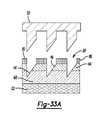
本明細書に開示される第16の態様は、保持体と、保持体上の第1の官能化層と、第1
の官能化層上の第2の官能化層と、第2の官能化層上のパッシベーション層とを含み、そ
れによってパッシベーション層の間隙領域によって分離された特徴部分を形成し、第1お
よび第2の官能化層のそれぞれの領域が各特徴部分で露出され、第1のプライマーセット
を第1の官能化層または第1の官能化領域に結合させ、第2のプライマーセットを第2の
官能化層または第2の官能化領域に結合させ、第1のプライマーセットは第2のプライマ
ーセットとは異なる、多層基材をインプリント(刻印)することを含む方法である。A sixteenth aspect disclosed herein is a support, a first functionalized layer on the support, and a first
and a passivation layer on the second functionalization layer, thereby forming features separated by interstitial regions of the passivation layer, the first and second of the functionalized layer are exposed at each feature to bind a first set of primers to the first functionalized layer or first functionalized region and a second set of primers to the second functionalized region. A method comprising imprinting a multilayer substrate to which a layer or second functionalized region is attached, wherein the first set of primers is different than the second set of primers.
第16の態様の例において、第1のプライマーセットの結合は、第1の官能化層が多層
基材に組み込まれる前に、切断不可能な第1のプライマーおよび切断可能な第2のプライ
マーを第1の官能化層に予めグラフトすることを含み、第2のプライマーセットの結合は
、第2の官能化層が多層基材に組み込まれる前に、切断可能な第1のプライマーおよび切
断不可能な第2のプライマーを第2の官能化層に予めグラフトすることを含む。In an example of the sixteenth aspect, the attachment of the first primer set comprises the non-cleavable first primer and the cleavable second primer before the first functionalization layer is incorporated into the multilayer substrate. The attachment of the second primer set includes pre-grafting onto the first functionalized layer, the cleavable first primer and the non-cleavable primer set prior to incorporation of the second functionalized layer into the multilayer substrate. pre-grafting a second primer onto the second functionalization layer.
第16の態様の例では、第1のプライマーセットの結合は、切断不可能な第1のプライ
マーおよび切断可能な第2のプライマーを各凹部の第1の官能化領域にグラフトすること
を含み、第2のプライマーセットの結合は、切断可能な第1のプライマーおよび切断不可
能な第2のプライマーを各凹部の第2の官能化領域にグラフトすることを含む。In an example of the sixteenth aspect, attaching the first primer set comprises grafting a first non-cleavable primer and a second cleavable primer to the first functionalized region of each recess; Attaching the second primer set involves grafting a cleavable first primer and a second non-cleavable primer to the second functionalized region of each recess.
本明細書に開示された第16の態様の任意の特徴は、任意の望ましい方法および/また
は形状で一緒に組み合わせることができることを理解されたい。さらに、第16の態様お
よび/または第1の態様および/または第2の態様の特徴の任意の組み合わせは、本明細
書で開示される例の任意のものと組み合わせることができることを理解されたい。It should be appreciated that any feature of the sixteenth aspect disclosed herein can be combined together in any desired manner and/or shape. Further, it should be understood that any combination of features of the sixteenth aspect and/or the first aspect and/or the second aspect can be combined with any of the examples disclosed herein.
本明細書に開示される第17の態様は、第1の樹脂をインプリントして、段差部分によ
って画定される深い部分と浅い部分とを含む凹部を形成するステップであって、第1の樹
脂が第2の樹脂上に配置される犠牲層上に配置される犠牲層と、第1の樹脂の第1の部分
および深い部分の下にある犠牲層の一部をエッチングし、それによって第2の樹脂の一部
を露出させるステップと、段差部分をエッチングして、犠牲層の第2の部分を露出させる
ステップと、第1の官能化層を第2の樹脂の部分に適用して、第1の官能化領域を形成す
るステップと、犠牲層の第2の部分を除去し、これにより、第2の樹脂の第2の部分を露
出させるステップと、第2の官能化層を第2の樹脂の第2の部分に適用して、第2の官能
化領域を形成するステップと、第1のプライマーセットを第1の官能化層または第1の官
能化領域に結合させ、第2のプライマーセットを第2の官能化層または第2の官能化領域
に結合させ、第1のプライマーセットは第2のプライマーセットとは異なるステップと、
を含む方法である。A seventeenth aspect disclosed herein is imprinting a first resin to form a recess including a deep portion and a shallow portion defined by a stepped portion, wherein the first resin etch the sacrificial layer disposed on the sacrificial layer disposed on the second resin and a portion of the sacrificial layer underlying the first portion and the deep portion of the first resin, thereby forming a second resin. etching the stepped portion to expose a second portion of the sacrificial layer; applying a first functionalization layer to the second resin portion to form a second forming a functionalized region of 1; removing a second portion of the sacrificial layer, thereby exposing a second portion of the second resin; applying to a second portion of the resin to form a second functionalized region; bonding a first primer set to the first functionalized layer or the first functionalized region; binding the set to a second functionalized layer or second functionalized region, the first primer set being different than the second primer set;
is a method that includes
第17の態様の一例では、第2の官能化層の適用中に、第2の官能化層は、凹部を取り
囲む間隙領域上に堆積され、第1の官能化領域上に堆積されず、方法は、間隙領域から第
2の官能化層を研磨することをさらに含む。In one example of the seventeenth aspect, during the application of the second functionalization layer, the second functionalization layer is deposited on the interstitial region surrounding the recess and not on the first functionalization region, and the method further includes abrading the second functionalized layer from the interstitial regions.
本明細書に開示された第17の態様の任意の特徴は、任意の望ましい方法および/また
は構成で一緒に組み合わせることができることを理解されたい。さらに、第17の態様お
よび/または第1の態様および/または第2の態様の特徴の任意の組み合わせは、本明細
書で開示される例の任意のものと組み合わせることができることを理解されたい。It should be appreciated that any feature of the seventeenth aspect disclosed herein can be combined together in any desired manner and/or configuration. Furthermore, it should be understood that any combination of the features of the seventeenth aspect and/or the first aspect and/or the second aspect can be combined with any of the examples disclosed herein.
本明細書に開示される第18の態様は、第1のプライマーセットを第1の保持体構造に
結合させるステップと、第2のプライマーセットを第2の保持体構造に結合させるステッ
プであって、第2のプライマーセットおよび第2の保持体構造が、第1のプライマーセッ
トおよび第1の保持体構造とは異なっているステップと、第1の保持体構造に選択的に結
合する複数の第1の捕捉部位および第2の保持体構造に選択的に結合する複数の第2の捕
捉部位を有する基材面に第1および第2の保持体構造をロードするステップとを含む方法
である。An eighteenth aspect disclosed herein is the steps of binding a first primer set to a first support structure and binding a second primer set to a second support structure, wherein , wherein the second set of primers and the second support structure are different from the first set of primers and the first support structure; and a plurality of second support structures that selectively bind to the first support structure. loading the first and second support structures onto a substrate surface having a plurality of second capture sites that selectively bind to one capture site and the second support structure.
本明細書に開示された第18の態様の任意の特徴は、任意の望ましい方法および/また
は構成で一緒に組み合わせることができることを理解されたい。さらに、第18の態様お
よび/または第1の態様および/または第2の態様の特徴の任意の組み合わせは、本明細
書で開示される例の任意のものと組み合わせることができることを理解されたい。It should be appreciated that any feature of the eighteenth aspect disclosed herein can be combined together in any desired manner and/or configuration. Furthermore, it should be understood that any combination of the features of the eighteenth aspect and/or the first aspect and/or the second aspect can be combined with any of the examples disclosed herein.
本開示の例の特徴は、以下の詳細な説明および図面を参照することによって明らかにな
り、図面において、同様の参照番号は、おそらく同一ではないが、同様の構成要素に対応
する。簡潔にするために、先に説明した機能を有する符号または特徴は、それらが現れる
他の図面と関連して説明されてもよいし、説明されなくてもよい。Features of examples of the present disclosure will become apparent by reference to the following detailed description and drawings, in which like reference numbers correspond to like, perhaps not identical, components. For the sake of brevity, symbols or features having previously described functions may or may not be described in connection with other drawings in which they appear.
本明細書中に開示されるフローセルの例は、核酸配列決定のために使用され得る。 Examples of flow cells disclosed herein can be used for nucleic acid sequencing.
フローセルのいくつかは、フローセル基材の別領域に結合した異なるプライマーセット
を含む。これらの例では、切断(線状化)ケミストリーが異なる領域で直交するようにプ
ライマーセットを制御することができる。直交切断ケミストリーは、異なるセットの異な
るプライマーに結合した同一の切断部位を通して、または異なるセットの異なるプライマ
ーに結合した異なる切断部位を通して実現することができる。これにより、基材の1つの
領域にフォワード(順方向)ストランドのクラスターを生成することができ、基材の別の
領域にリバース(逆方向)ストランドのクラスターを生成することができる。一例では、
領域は互いに直接隣接している。別の例では、領域間の任意の空間は、クラスター化が2
つの領域にまたがることができるほど十分に小さい。本明細書に開示されるフローセル構
成のいくつかでは、フォワードおよびリバースストランドは、空間的に分離され、これは
、それぞれの読み取りの同時の塩基呼び出しを可能にしながら、両方の読み取りから蛍光
信号を分離する。したがって、本明細書に開示されるフローセルのいくつかの例は、同時
のペアエンド読み取りが得られることを可能にする。Some of the flow cells contain different primer sets attached to different regions of the flow cell substrate. In these examples, primer sets can be controlled such that the cleavage (linearization) chemistry is orthogonal at different regions. Orthogonal cleavage chemistry can be achieved through identical cleavage sites attached to different sets of different primers or through different cleavage sites attached to different sets of different primers. This can produce clusters of forward strands in one region of the substrate and clusters of reverse strands in another region of the substrate. In one example,
The regions are directly adjacent to each other. In another example, any space between regions has a clustering of 2
small enough to span two regions. In some of the flow cell configurations disclosed herein, the forward and reverse strands are spatially separated, which separates the fluorescent signal from both reads while allowing simultaneous base calling of each read. do. Accordingly, some examples of flow cells disclosed herein allow simultaneous paired-end readings to be obtained.
フローセルの他の例は、同時ペアエンド読み取りを得るために使用され得るか;または
順次ペアエンド読み取りを得るために使用され得、ここで、フォワードストランドが配列
決定され、そして除去され、次いで、リバースストランドが配列決定され、そして除去さ
れる。これらの他の例では、フローセル保持体上のパターン化された樹脂は、パターン化
された樹脂の凹部において方向付けられた自己集合を受けるブロック共ポリマーでコーテ
ィングされる。パターン化された樹脂は、ブロック共ポリマーの配置のためのガイドとし
ての役割を果たす。制御された条件下で、ブロック共ポリマーは特異的ドメインに自己集
合する。本明細書中に開示される例のいくつかにおいて、ドメインの官能性は、1つ以上
のドメインがパターン化された樹脂と反応し得、そして1つ以上の他のドメインがプライ
マーをグラフトし得るように、直交するように制御される。いくつかの例では、ドメイン
の官能性を制御して、そのドメインの特性を変更することができる。これらの例示的なフ
ローセルは、光学的または非光学的検出方法での使用に好適であり得る。Other examples of flow cells can be used to obtain simultaneous paired-end reads; or can be used to obtain sequential paired-end reads, where the forward strand is sequenced and removed, then the reverse strand Sequenced and removed. In these other examples, the patterned resin on the flow cell support is coated with a block copolymer that undergoes directed self-assembly in the recesses of the patterned resin. The patterned resin serves as a guide for placement of the block copolymer. Under controlled conditions, block copolymers self-assemble into specific domains. In some of the examples disclosed herein, the functionalities of the domains are such that one or more domains can react with the patterned resin and one or more other domains can graft primers. are controlled to be orthogonal. In some examples, the functionality of a domain can be controlled to alter the properties of that domain. These exemplary flow cells may be suitable for use with optical or non-optical detection methods.
定義
本明細書で使用される用語は、別段の指定がない限り、関連技術におけるそれらの通常
の意味をとることを理解されたい。本明細書で使用されるいくつかの用語およびそれらの
意味を以下に示す。DEFINITIONS It should be understood that the terms used herein take their ordinary meaning in the relevant art unless otherwise specified. Some terms used in this specification and their meanings are given below.
単数形「1つ(a)」、「1つ(an)」、および「前記(the)」は、文脈が明ら
かにそうでないことを示さない限り、複数の指示対象を含む。The singular forms "a,""an," and "the" include plural referents unless the context clearly dictates otherwise.
用語含む(comprising)、含む(including)、からなる(containing)およびこれら
の用語の様々な形状は、互いに同義であり、等しく広いことを意味する。The terms comprising, including, containing and various forms of these terms are synonymous with each other and mean equally broad.
用語「上部」、「下部」、「下側」、「上側」などは、本明細書では、フローセルおよ
び/またはフローセルの様々な構成要素を説明するために使用される。これらの方向を示
す用語は、具体的な配向性を意味するものではなく、構成要素間の相対的な配向性を示す
ために使用されることを理解されたい。方向を示す用語の使用は、本明細書に開示される
実施例を任意の具体的な配向性に限定すると解釈されるべきではない。The terms "upper", "lower", "lower", "upper", etc. are used herein to describe the flow cell and/or various components of the flow cell. It should be understood that these directional terms do not imply specific orientations, but are used to indicate relative orientations between components. The use of directional terms should not be construed to limit the embodiments disclosed herein to any particular orientation.
「アクリルアミドモノマー」は、構造を有するモノマー、またはその構造を有するアク
リルアミド基を含むモノマーである。アクリルアミド基を含むモノマーとしては、例えば
、
他のアクリルアミドモノマーを使用してもよい。An "acrylamide monomer" is a monomer having a structure or a monomer containing an acrylamide group having that structure. Examples of monomers containing an acrylamide group include
Other acrylamide monomers may be used.
アルデヒドは、本明細書中で使用される場合、カルボニル中心(すなわち、酸素に二重
結合した炭素)を含み、炭素原子もまた水素に結合した構造-CHOおよびR基(例えば
、アルキルまたは他の側鎖)を有する官能基を含む有機化合物である。アルデヒドの一般
構造は、
本明細書中で使用される場合、「アルキル」は、完全に飽和した(すなわち、二重結合
または三重結合を含まない)直鎖または分岐鎖状炭化水素鎖を指し、アルキル基は、1~
20個の炭素原子を有し得る。例示的なアルキル基には、メチル、エチル、プロピル、イ
ソプロピル、ブチル、イソブチル、第三ブチル、ペンチル、ヘキシルなどが含まれる。例
として、「C1~4アルキル」という名称は、アルキル鎖中に1~4個の炭素原子が存在
すること、すなわち、アルキル鎖は、メチル、エチル、プロピル、イソプロピル、n-ブ
チル、イソブチル、sec-ブチル、およびt-ブチルからなる群より選択されることを
示す。As used herein, "alkyl" refers to a fully saturated (i.e., containing no double or triple bonds) straight or branched hydrocarbon chain;
It can have 20 carbon atoms. Exemplary alkyl groups include methyl, ethyl, propyl, isopropyl, butyl, isobutyl, tert-butyl, pentyl, hexyl, and the like. By way of example, the designation "C1-4 alkyl" refers to the presence of 1-4 carbon atoms in the alkyl chain, i.e. the alkyl chain can be methyl, ethyl, propyl, isopropyl, n-butyl, isobutyl, sec -butyl, and t-butyl.
本明細書中で使用される場合、「アルケニル」は、1つ以上の二重結合を含む直鎖また
は分岐鎖状炭化水素鎖をいう。アルケニル基は、2~20個の炭素原子を有することがで
きる。例示的なアルケニル基には、エテニル、プロペニル、ブテニル、ペンテニル、ヘキ
セニルなどが含まれる。As used herein, "alkenyl" refers to straight or branched hydrocarbon chains containing one or more double bonds. Alkenyl groups can have from 2 to 20 carbon atoms. Exemplary alkenyl groups include ethenyl, propenyl, butenyl, pentenyl, hexenyl, and the like.
本明細書中で使用される場合、「アルキン」または「アルキニル」は、1つ以上の三重
結合を含む直鎖または分枝鎖炭化水素鎖をいう。アルキニル基は、2~20個の炭素原子
を有していてもよい。As used herein, "alkyne" or "alkynyl" refer to straight or branched hydrocarbon chains containing one or more triple bonds. Alkynyl groups may have from 2 to 20 carbon atoms.
本明細書中で使用される場合、「アリール」は、環骨格に炭素のみを含む芳香環または
環系(すなわち、2つの隣り合う炭素原子を共有する2つ以上の縮合環)をいう。アリー
ルが環系である場合、系中の全ての環は芳香族である。アリール基は、6~18個の炭素
原子を有することができる。アリール基の例には、フェニル、ナフチル、アズレニル、お
よびアントラセニルが含まれる。As used herein, "aryl" refers to an aromatic ring or ring system containing only carbon in the ring backbone (ie, two or more fused rings that share two adjacent carbon atoms). When aryl is a ring system, all rings in the system are aromatic. Aryl groups can have from 6 to 18 carbon atoms. Examples of aryl groups include phenyl, naphthyl, azulenyl, and anthracenyl.
「アミノ」官能基は、-NRaRb基を指し、ここで、RaおよびRbは、本明細書中
で定義されるように、水素
、C6~10アリール、5~10員ヘテロアリール、および5~10員ヘテロシクリルか
らそれぞれ独立して選択される。An "amino" functional group refers to a -NRa Rb group, where Ra and Rb are hydrogen, as defined herein.
本明細書中で使用される場合、用語「取り付けられた」は、2つのものが、直接的また
は間接的のいずれかで、互いに接合され、固定され、接着され、連結され、または結合さ
れる状態をいう。例えば、凹部に取り付けられたビーズは、凹部に物理的に閉じ込められ
てもよい。別の例では、核酸を、共有結合または非共有結合によって官能化ポリマーに結
合させることができる。共有結合は、原子間で電子の一対を共有することを特徴とする。
非共有結合は、一対の共有を伴わない物理的な結合であり、例えば、水素結合、イオン結
合、ファンデルワールス力、親水性相互作用および疎水性相互作用を含むことができる。
さらに別の例では、プライマーは、保持体構成を介して基材上の領域に結合させることが
できる。As used herein, the term "attached" means that two things are either directly or indirectly joined, fixed, adhered, connected or coupled to each other state. For example, a bead attached to a recess may be physically trapped in the recess. In another example, nucleic acids can be covalently or non-covalently attached to functionalized polymers. A covalent bond is characterized by the sharing of a pair of electrons between atoms.
Non-covalent bonds are non-covalent physical associations between pairs and can include, for example, hydrogen bonds, ionic bonds, van der Waals forces, hydrophilic interactions and hydrophobic interactions.
In yet another example, primers can be bound to regions on the substrate via a support configuration.
「アジド(azide)」または「アジド(azido)」官能基は、-N3を指す。An “azide” or “azido” functional group refers to—N3 .
官能基を有するビーズの「ビーズ」または「コア構造」という用語は、剛性または半剛
性の材料から作られた小さな本体を指す。本体は、例えば、球形、楕円形、微小球形、ま
たは規則的または不規則な寸法を有するかどうかにかかわらず他の認識された粒子形状と
して特徴付けられる形状を有することができる。ビーズ/コア構造に役立つ例示的な材料
には、ガラス;アクリル酸、ポリスチレンなどのプラスチック、またはスチレンと別の材
料とのコポリマー、ポリプロピレン、ポリエチレン、ポリブチレン、ポリウレタン、また
はポリテトラフルオロエチレン(Teflon(登録商標)、Chemours製);アガロースまたは
セファロースなどの多糖または架橋多糖;ナイロン;ニトロセルロース;ケイ素および改
質ケイ素を含む樹脂;シリカまたはシリカベースの材料;炭素繊維、金属;無機ガラス;
光ファイバ束、または様々な他のポリマーが含まれるが、これらに限定されない。ビーズ
/コア構造の例には、制御された気孔ガラスビーズ、常磁性ビーズ、トリアゾル、セファ
ロースビーズ、ナノ結晶、および、例えば、Bangs Laboratories、Fishers Ind.のマイク
ロスフェアディテクションガイドに記載されているような検出当業者で公知の他のものが
含まれる。ビーズはまた、プライマーに結合し得る官能基を有するポリマーで被覆され得
る。The term "bead" or "core structure" of functionalized beads refers to a small body made of rigid or semi-rigid material. The bodies can have shapes that are characterized as, for example, spherical, ellipsoidal, microspherical, or other recognized particle shapes, whether having regular or irregular dimensions. Exemplary materials useful for the bead/core construction include glass; plastics such as acrylics, polystyrene, or copolymers of styrene with another material, polypropylene, polyethylene, polybutylene, polyurethane, or polytetrafluoroethylene (Teflon®). Polysaccharides or cross-linked polysaccharides such as agarose or sepharose; nylon; nitrocellulose; resins containing silicon and modified silicon; silica or silica-based materials; carbon fibers, metals;
Including, but not limited to, fiber optic bundles, or various other polymers. Examples of bead/core structures include controlled pore glass beads, paramagnetic beads, triazoles, sepharose beads, nanocrystals, and microspheres as described, for example, in Bangs Laboratories, Fishers Ind. detection methods and others known to those skilled in the art. The beads can also be coated with a polymer having functional groups that can bind to the primer.
「ブロック共ポリマー」は、2つ以上のモノマーが一緒にクラスター化し、繰り返し単
位のブロックを形成する場合に形成されるコポリマーである。各ブロックは、隣り合うブ
ロックに存在しない少なくとも1つの特徴および/または少なくとも1つのブロック特異
的官能基を有するべきである。本明細書に開示される実施例では、ブロック共ポリマーは
、特定の焼鈍条件に曝されると、構成ポリマーブロックのミクロ相分離によって、ナノメ
ートルスケールの寸法で規則正しいドメインに自己集合することができる。ブロック共ポ
リマーの具体例については、後述する。A "block copolymer" is a copolymer formed when two or more monomers are clustered together to form a block of repeating units. Each block should have at least one feature and/or at least one block-specific functional group that is not present in adjacent blocks. In the examples disclosed herein, block copolymers can self-assemble into ordered domains at nanometer-scale dimensions through microphase separation of the constituent polymer blocks upon exposure to specific annealing conditions. . Specific examples of block copolymers will be described later.
「ブロック特異的官能基」は、パターン化された樹脂との反応、プライマーの結合、ミ
クロ相分離を駆動するための相互作用パラメータの調整、ブロック共ポリマーの特性の変
更などのような、特定の機能性を有するブロックポリマーの特定のブロックにおける原子
および/または結合の部分を指す。本明細書で開示されるいくつかの例では、それぞれの
ブロックは、様々なブロック特異的官能基を含む。以下、それぞれのブロック固有官能基
の具体例についてさらに説明する。A "block-specific functional group" is defined as a specific functional group, such as reacting with patterned resins, binding primers, tuning interaction parameters to drive microphase separation, altering properties of block copolymers, etc. Refers to a portion of the atoms and/or bonds in a particular block of a functionalized block polymer. In some examples disclosed herein, each block includes different block-specific functional groups. Specific examples of each block-specific functional group are further described below.
本明細書で使用されるように、「結合領域」は、別の物質に結合されるべき保持体上の
領域を指し、別の物質は、例として、スペーサー層、蓋、別の基材など、またはそれらの
組み合わせ(例えば、スペーサー層および蓋)であってもよい。結合領域で形成される結
合は、化学結合(上述のようである)または機械的結合(例えば、ファスナなどを使用す
る)であってもよい。As used herein, "bonding area" refers to an area on the support that is to be bonded to another substance, such as a spacer layer, a lid, another substrate, etc. , or a combination thereof (eg, a spacer layer and a lid). The bond formed at the bond area may be a chemical bond (as described above) or a mechanical bond (eg, using fasteners, etc.).
本明細書で使用される「捕捉部位」は、官能化された保持体組織の局在化を可能にする
化学的性質で物理的に修飾および/または修飾されたフローセル表面の一部を指す。一例
では、捕捉部位は、化学的捕捉剤を含むことができる。As used herein, "capture site" refers to a portion of the flow cell surface that is physically modified and/or modified with chemistries that allow localization of the functionalized support tissue. In one example, a capture site can include a chemical capture agent.
本明細書中で使用される場合、「カルボシクリル」は、環系骨格中に炭素原子のみを含
む非芳香族環または環系を意味する。カルボシクリルが環系である場合、2つ以上の環が
、縮合、架橋、またはスピロ連結様式で一緒に結合され得る。カルボシクリルは、環系中
の少なくとも1つの環が芳香族でないという条件で、任意の程度の飽和度を有し得る。し
たがって、カルボシクリルには、シクロアルキル、シクロアルケニル、およびシクロアル
キニルが含まれる。カルボシクリル基は、3~20個の炭素原子を有してもよい。カルボ
シクロ環の例には、シクロプロピル、シクロブチル、シクロペンチル、シクロヘキシル、
シクロヘキセニル、2,3-ジヒドロ-インデン、ビシクロ[2.2.2]オクタニル、
アダマンチル、およびスピロ[4.4]ノナニルが含まれる。As used herein, "carbocyclyl" means a non-aromatic ring or ring system containing only carbon atoms in the ring system backbone. When a carbocyclyl is a ring system, two or more rings may be joined together in a fused, bridged, or spiro-linked manner. A carbocyclyl can have any degree of saturation, provided that at least one ring in the ring system is not aromatic. Carbocyclyl therefore includes cycloalkyl, cycloalkenyl, and cycloalkynyl. A carbocyclyl group may have from 3 to 20 carbon atoms. Examples of carbocyclo rings include cyclopropyl, cyclobutyl, cyclopentyl, cyclohexyl,
cyclohexenyl, 2,3-dihydro-indene, bicyclo[2.2.2]octanyl,
Included are adamantyl, and spiro[4.4]nonanyl.
本明細書で使用される「カルボン酸」または「カルボキシル」という語は、本明細書で
使用される場合、-COOHを指す。The term "carboxylic acid" or "carboxyl" as used herein refers to -COOH.
「化学捕捉剤」は、標的分子(例えば、官能化保持体構造)に結合、保持、または結合
することができる物質、分子、または部分である。1つの例示的な化学捕捉剤は、標的分
子の標的核酸の少なくとも一部に相補的であるか、または標的分子に結合した捕捉核酸(
例えば、捕捉オリゴヌクレオチド)を含む。さらに別の例示的な化学捕捉剤は、標的分子
(または標的分子に結合した連結部分)に結合することができる受容体-配位子結合対(
例えば、アビジン、ストレプトアビジン、ビオチン、レクチン、炭水化物、核酸結合蛋白
質、エピトープ、抗体など)の部材を含む。化学的捕集剤のもう一つの例は、標的分子と
共に静電相互作用、水素結合、または同価結合を形成することができる化学試薬である(
例えば、チオール‐ジスルフィド交換、クリック化学、ディール‐アルダー等)。A "chemical capture agent" is a substance, molecule, or moiety capable of binding, retaining, or binding to a target molecule (eg, a functionalized support structure). One exemplary chemical capture agent is a capture nucleic acid (
For example, capture oligonucleotides). Yet another exemplary chemical capture agent is a receptor-ligand binding pair (
For example, avidin, streptavidin, biotin, lectins, carbohydrates, nucleic acid binding proteins, epitopes, antibodies, etc.). Another example of a chemical scavenger is a chemical reagent that can form electrostatic interactions, hydrogen bonds, or equivalence bonds with target molecules (
For example, thiol-disulfide exchange, Click chemistry, Diel-Alder, etc.).
本明細書中で使用される場合、「シクロアルキレン」は、2つの結合点を介して分子の
残りの部分に結合している完全に飽和したカルボシクリル環または環系を意味する。As used herein, "cycloalkylene" means a fully saturated carbocyclyl ring or ring system attached to the rest of the molecule through two points of attachment.
本明細書中で使用される場合、「シクロアルケニル」または「シクロアルケン」は、少
なくとも1つの二重結合を有するカルボシクリル環または環系を意味し、環系中の環は芳
香族ではない。例としては、シクロヘキセニルまたはシクロヘキセンおよびノルボルネニ
ルまたはノルボルネンが挙げられる。また、本明細書中で使用される場合、「ヘテロシク
ロアルケニル」または「ヘテロシクロアルケン」は、環骨格中に少なくとも1つのヘテロ
原子を有するカルボシクリル環または環系であって、環系中に環が芳香族ではないものを
意味する。As used herein, "cycloalkenyl" or "cycloalkene" means a carbocyclyl ring or ring system having at least one double bond, wherein the rings in the ring system are not aromatic. Examples include cyclohexenyl or cyclohexene and norbornenyl or norbornene. Also, as used herein, "heterocycloalkenyl" or "heterocycloalkene" are carbocyclyl rings or ring systems having at least one heteroatom in the ring backbone, wherein the ring is not aromatic.
本明細書で使用する「シクロアルキニル」または「シクロアルキン」とは、少なくとも
1つの三重結合を有するカルボシクリル環または環系を意味し、環系中に環が芳香族では
ない。例はシクロオクチンである。他の例はビシクロノインである。本明細書で使用する
「ヘテロシクロアルキニル」または「ヘテロシクロアルキン」とは、少なくとも1つの三
重結合を有し、環系中に環が芳香族ではない、環骨格中に少なくとも1つのヘテロ原子を
有するカルボシクリル環または環系を意味する。As used herein, "cycloalkynyl" or "cycloalkyne" means a carbocyclyl ring or ring system having at least one triple bond, in which the rings are not aromatic. An example is cyclooctyne. Another example is bicyclonoin. As used herein, "heterocycloalkynyl" or "heterocycloalkyne" has at least one triple bond and at least one heteroatom in the ring skeleton in which the ring is not aromatic. means a carbocyclyl ring or ring system having a
本明細書で使用される「堆積」という用語は、任意の適切な適用技術を指し、これは、
手動であっても自動であってもよく、いくつかの例では、表面性状の改変をもたらす。一
般に、蒸着は、蒸着技術、塗装技術、グラフト技術などを使用して行うことができる。い
くつかの具体例は、化学蒸着(CVD)、スプレーコーティング(例えば、超音波スプレ
ーコーティング)、スピンコーティング、ダンクまたはディップ法、ドクターブレードコ
ーティング、パドルディスペンシング、フロースルーコーティング、エアロゾルプリンテ
ィング、スクリーンプリンティング、マイクロコンタクトプリンティング、インクジェッ
トプリンティングなどを含む。The term "deposition" as used herein refers to any suitable application technique, which is
It may be manual or automatic, and in some instances results in modification of the surface texture. In general, vapor deposition can be performed using vapor deposition techniques, painting techniques, grafting techniques, and the like. Some specific examples include chemical vapor deposition (CVD), spray coating (e.g., ultrasonic spray coating), spin coating, dunk or dip methods, doctor blade coating, paddle dispensing, flow-through coating, aerosol printing, screen printing, Including microcontact printing, inkjet printing, etc.
本明細書で使用されるように、「凹部」という語は、基材またはパターン化された樹脂
の間隙領域によって少なくとも部分的に取り囲まれた面開口を有する基材またはパターン
化された樹脂における個別の凹状形状(特徴部)を指す。凹部は、例えば、円形、楕円形
、正方形、多角形、星形(任意の個数の頂点を有する)等を含む様々な形状のいずれかを
表面における開口部に有することができる。表面と直交する凹部の断面は、湾曲、正方形
、多角形、双曲線、円錐状、角度等であってもよい。例として、凹部は、ウェルまたは2
つの相互接続されたウェルとすることができる。また、凹部は、隆起部、階段形状等のよ
うな、より複雑なアーキテクチャを有してもよい。As used herein, the term "recesses" refers to discrete recesses in a substrate or patterned resin having areal openings that are at least partially surrounded by interstitial regions of the substrate or patterned resin. refers to the concave shape (feature) of The recesses can have any of a variety of shapes, including, for example, circular, elliptical, square, polygonal, star-shaped (with any number of vertices), etc., in openings in the surface. The cross-section of the recess perpendicular to the surface may be curved, square, polygonal, hyperbolic, conical, angular, and the like. As an example, the recess may be a well or two
There can be two interconnected wells. The recesses may also have more complex architectures, such as ridges, stepped shapes, and the like.
用語「各々」は、アイテムのコレクションに関して使用される場合、コレクションにお
ける個々のアイテムを識別することを意図するが、必ずしもコレクションにおけるあらゆ
るイテムを指すわけではない。例外は、明示的な開示または文脈が明らかにそうでないこ
とを指示する場合に発生する可能性がある。The term "each," when used in reference to a collection of items, is intended to identify individual items in the collection, but does not necessarily refer to every item in the collection. Exceptions may occur where explicit disclosure or context clearly dictates otherwise.
用語「エポキシ」(グリシジルまたはオキシラン基とも呼ばれる)は、本明細書で使用
される場合、

本明細書で使用される「フローセル」という語は、反応を行うことができるチャンバ(
すなわち、流路)と、チャンバに試薬を送達するための入口と、チャンバから試薬を除去
するための出口とを有する容器を意味することを意図している。いくつかの例では、チャ
ンバは、チャンバ内で起こる反応の検出を可能にする。例えば、チャンバ/流路は、凹部
におけるアレイ、光学的に標識された分子などの光学的検出を可能にする1つ以上の透明
な表面を含むことができる。The term "flow cell" as used herein refers to a chamber (
ie, a flow path), an inlet for delivering reagents to the chamber, and an outlet for removing reagents from the chamber. In some examples, the chamber allows for detection of reactions occurring within the chamber. For example, the chamber/channel can include one or more transparent surfaces that allow for optical detection of arrays in recesses, optically labeled molecules, and the like.
本明細書中で使用される場合、「流路」は、液状試料を選択的に受容し得る、2つの結
合された構成要素の間に規定される領域であり得る。いくつかの例では、流路は、パター
ン化された樹脂と蓋との間に画定されてもよく、したがって、パターン化された樹脂に画
定された1つまたは複数の凹部と連通してもよい。As used herein, a "channel" can be an area defined between two bonded components that can selectively receive a liquid sample. In some examples, the channels may be defined between the patterned resin and the lid and thus may communicate with one or more recesses defined in the patterned resin. .
「官能化保持体構造」とは、本明細書に開示されるプライマーセットの1つがその表面
に結合している剛性または半剛性材料から作製された小型本体を指す。本体は、例えば、
球形、楕円形、微小球形、または規則的または不規則な寸法を有するかどうかにかかわら
ず他の認識された粒子形状として特徴付けられる形状を有することができる。本体に役立
つ例示的な材料には、ガラス;アクリル酸、ポリスチレンなどのプラスチック、またはス
チレンと別の材料とのコポリマー、ポリプロピレン、ポリエチレン、ポリブチレン、ポリ
ウレタン、またはポリテトラフルオロエチレン(Teflon(登録商標)、Chemours製);ア
ガロースまたはセファロースなどの多糖または架橋多糖;ナイロン;ニトロセルロース;
ケイ素および改質ケイ素を含む樹脂;シリカまたはシリカベースの材料、炭素繊維、金属
;無機ガラス;光ファイバ束、または様々な他のポリマーが含まれるが、これらに限定さ
れない。A "functionalized support structure" refers to a small body made of a rigid or semi-rigid material with one of the primer sets disclosed herein attached to its surface. For example, the body
They can have shapes that are characterized as spherical, elliptical, microspherical, or other recognized particle shapes, whether they have regular or irregular dimensions. Exemplary materials useful for the body include glass; plastics such as acrylics, polystyrene, or copolymers of styrene with another material, polypropylene, polyethylene, polybutylene, polyurethane, or polytetrafluoroethylene (Teflon®, Chemours); polysaccharides or cross-linked polysaccharides such as agarose or sepharose; nylon; nitrocellulose;
Resins containing silicon and modified silicon; silica or silica-based materials, carbon fibers, metals; inorganic glasses; fiber optic bundles, or various other polymers.
本明細書中で使用される場合、「ヘテロアリール」は、環骨格中に1つ以上のヘテロ原
子、すなわち、炭素以外の元素(窒素、酸素およびイオウを含むが、これらに限定されな
い)を含有する芳香族環または環系(すなわち、2つ以上の隣り合う原子を共有する2つ
以上の縮合環)をいう。ヘテロアリールが環系である場合、系中の全ての環は芳香族であ
る。ヘテロアリール基は、5~18リング部材を有することができる。As used herein, "heteroaryl" contains one or more heteroatoms, i.e., elements other than carbon (including but not limited to nitrogen, oxygen and sulfur) in the ring backbone refers to an aromatic ring or ring system (ie, two or more fused rings that share two or more adjacent atoms). When heteroaryl is a ring system, all rings in the system are aromatic. A heteroaryl group can have from 5 to 18 ring members.
本明細書中で使用される場合、「ヘテロシクリル」は、環骨格中に少なくとも1つのヘ
テロ原子を含む非芳香族環または環系を意味する。複素環は、融合、架橋またはスピロ連
結様式で一緒に結合され得る。複素環は、環系中の少なくとも1つの環が芳香族でないこ
とを条件として、任意の程度の飽和度を有することができる。環系において、ヘテロ原子
は、非芳香環または芳香環のいずれかで存在し得る。ヘテロシクリル基は、3~20リン
グ部材(すなわち、炭素原子およびヘテロ原子を含む、環骨格を構成する原子の数)を有
し得る。いくつかの例では、ヘテロ原子は、O、N、またはSである。As used herein, "heterocyclyl" means a non-aromatic ring or ring system containing at least one heteroatom in the ring backbone. Heterocycles may be joined together in a fused, bridged or spiro-linked manner. A heterocycle can have any degree of saturation, provided that at least one ring in the ring system is not aromatic. In ring systems, heteroatoms may be present in either non-aromatic or aromatic rings. A heterocyclyl group can have from 3 to 20 ring members (ie, the number of atoms that make up the ring skeleton, including carbon atoms and heteroatoms). In some examples, the heteroatom is O, N, or S.
本明細書で使用される「ヒドラジン」または「ヒドラジニル」という語は、-NHNH
2基を指す。The term "hydrazine" or "hydrazinyl" as used herein means -NHNH
Point totwo groups.
本明細書で使用する「ヒドラゾン」または「ヒドラゾニル」という語は、本明細書で使
用する場合、
基を指し、
RaおよびRbが、本明細書で定義するように、水素、C1~6アルキル、C2~6ア
ルケニル、C2~6アルキニル、C3~7カルボシクリル、C6~10アリール、5~1
0員ヘテロアリール、および5~10員ヘテロシクリルからそれぞれ独立して選択される
。The term "hydrazone" or "hydrazonyl" as used herein means
pointing to the base
Ra and Rb are hydrogen, C1-6 alkyl, C2-6 alkenyl, C2-6 alkynyl, C3-7 carbocyclyl, C6-10 aryl, 5-1 as defined herein.
each independently selected from 0-membered heteroaryl, and 5-10 membered heterocyclyl;
本明細書中で使用される「ヒドロキシ」または「ヒドロキシル」は-OH基を意味する
。As used herein, "hydroxy" or "hydroxyl" means a -OH group.
本明細書で使用される「間隙領域」という語は、例えば、基材、パターン化された樹脂
、または凹部を分離する他の保持体の面積を指す。例えば、間隙領域は、アレイの1つの
凹部をアレイの別の凹部から分離することができる。互いに分離された2つの凹部は、離
散的であってもよく、すなわち、互いに物理的接触を欠いていてもよい。多くの例では、
間隙領域は連続的であるが、凹部は、例えば、他の点では連続的な表面に画定された複数
の凹部の場合のように、不連続である。他の例では、間隙領域および特徴部(フィーチャ
)は、例えば、それぞれの間隙領域によって分離された複数のトレンチの場合のように、
離散的である。間隙領域によって提供される分離は、部分的または完全な分離であり得る
。間隙領域は、表面に画定された凹部の表面材料とは異なる表面材料を有することができ
る。例えば、凹部は、その中にポリマーおよび第1のプライマーセットを有することがで
き、間隙領域は、その上にポリマーおよび第2のプライマーセットを有することができる
。別の例では、アレイの凹部は、その中にビーズを有することができ、間隙領域は、その
上にビーズを有さない。As used herein, the term "interstitial region" refers to, for example, the area of the substrate, patterned resin, or other support that separates the recesses. For example, a gap region can separate one recess of the array from another recess of the array. Two recesses that are separated from each other may be discrete, ie lack physical contact with each other. In many examples,
The interstitial regions are continuous, whereas the recesses are discontinuous, such as, for example, multiple recesses defined in an otherwise continuous surface. In other examples, the interstitial regions and features are:
Discrete. The separation provided by the interstitial regions can be partial or complete separation. The interstitial region can have a surface material that is different than the surface material of the recesses defined in the surface. For example, the recesses can have a polymer and a first set of primers therein and the interstitial regions can have a polymer and a second set of primers thereon. In another example, the recesses of the array can have beads therein and the interstitial regions have no beads thereon.
本明細書中で使用される「ニトリルオキシド」は、Raが本明細書中で定義される「R
aC≡N+O-」基を意味する。ニトリルオキシドを調製する例には、クロラミド-Tで
の処理による、またはイミドイルクロリド[RC(Cl)=NOH]に対する塩基の作用
による、またはヒドロキシルアミンとアルデヒドとの間の反応からの、アルドキシムから
のin situ生成が含まれる。As used herein, "nitrile oxide" means "R
a C≡N+O-" group. Examples of preparing nitrile oxides include aldoximes by treatment with chloramide-T, or by action of base on imidoyl chlorides [RC(Cl)=NOH], or from reaction between hydroxylamines and aldehydes. includes the in situ generation of
本明細書で使用される「ニトロン」は、
ここで、R1、R2、およびR3が、本明細書で定義されるRaおよびRb基のいずれ
かであり得る。As used herein, a "nitrone" is
where R1 , R2 and R3 can be any of the Ra and Rb groups defined herein.
本明細書中で使用される場合、「ヌクレオチド」は、窒素を含む複素環塩基、糖、およ
び1つ以上のリン酸基を含む。ヌクレオチドは、核酸配列のモノマー単位である。RNA
では、糖はリボースであり、DNAでは、糖はデオキシリボース、すなわち、リボースの
2’位に存在する水酸基を欠く糖である。窒素含有複素環塩基(すなわち、核酸塩基)は
、プリン塩基またはピリミジン塩基であり得る。プリン塩基には、アデニン(A)および
グアニン(G)、ならびにそれらの修飾誘導体またはアナログが含まれる。ピリミジン塩
基には、シトシン(C)、チミン(T)、およびウラシル(U)、ならびにそれらの修飾
誘導体またはアナログが含まれる。デオキシリボースのC-1原子はピリミジンのN-1
またはプリンのN-9に結合している。核酸類似体は、改変されたリン酸骨格、糖、また
は核酸塩基のいずれかを有し得る。核酸アナログの例には、例えば、ペプチド核酸(PN
A)などのユニバーサル塩基またはリン酸-糖骨格アナログが含まれる。As used herein, "nucleotide" includes a nitrogen-containing heterocyclic base, a sugar, and one or more phosphate groups. A nucleotide is the monomeric unit of a nucleic acid sequence. RNA
In DNA the sugar is ribose and in DNA the sugar is deoxyribose, ie the sugar lacking the hydroxyl group present at the 2' position of ribose. Nitrogen-containing heterocyclic bases (ie, nucleobases) can be purine bases or pyrimidine bases. Purine bases include adenine (A) and guanine (G), and modified derivatives or analogs thereof. Pyrimidine bases include cytosine (C), thymine (T), and uracil (U), and modified derivatives or analogs thereof. C-1 atom of deoxyribose is N-1 of pyrimidine
or bound to N-9 of purine. Nucleic acid analogs can have either modified phosphate backbones, sugars, or nucleobases. Examples of nucleic acid analogs include, for example, peptide nucleic acids (PN
A) or universal base or phosphate-sugar backbone analogs are included.
「パターン化された樹脂」は、その中に規定された凹部を有することができる任意のポ
リマーを指す。樹脂をパターン化するための樹脂および技術の具体例は、以下でさらに説
明される。本明細書で開示されるいくつかの例では、パターン化された樹脂は、その上に
自己集合するためのブロック共ポリマーのためのガイド鋳型として機能することができる
。ポリマーを「ガイド鋳型」にする特性の具体例は、以下でさらに説明される。"Patterned resin" refers to any polymer that can have depressions defined therein. Specific examples of resins and techniques for patterning the resin are described further below. In some examples disclosed herein, the patterned resin can serve as a guide template for the block copolymer to self-assemble thereon. Specific examples of the properties that make a polymer a "guide template" are discussed further below.
本明細書中で使用される場合、「プライマー」は、一本鎖核酸配列(例えば、一本鎖D
NAまたは一本鎖RNA)として定義される。本明細書中で増幅プライマーと呼ばれるい
くつかのプライマーは、鋳型増幅およびクラスター生成のための起点として役立つ。本明
細書中で配列決定プライマーと呼ばれる他のプライマーは、DNAまたはRNA合成の開
始点として役立つ。プライマーの5’末端は、ポリマーの官能基またはビーズ面とのカッ
プリング反応を可能にするように修飾することができる。プライマー長は、任意の数の塩
基長であってよく、様々な非天然ヌクレオチドを含むことができる。例えば、配列決定プ
ライマーは、10~60塩基、または20~40塩基の範囲の短いストランドである。As used herein, a "primer" refers to a single-stranded nucleic acid sequence (e.g., single-stranded D
NA or single-stranded RNA). Some primers, referred to herein as amplification primers, serve as starting points for template amplification and cluster generation. Other primers, referred to herein as sequencing primers, serve as initiation points for DNA or RNA synthesis. The 5' end of the primer can be modified to allow coupling reactions with polymer functional groups or bead surfaces. Primers can be any number of bases long and can include a variety of non-natural nucleotides. For example, sequencing primers are short strands ranging from 10-60 bases, or 20-40 bases.
本明細書で使用される「スペーサー層」は、2つの成分を互いに結合する材料を指す。
いくつかの例では、スペーサー層は、結合を助ける放射線吸収材料であってもよく、また
は結合を助ける放射線吸収材料と接してもよい。A "spacer layer" as used herein refers to a material that bonds two components together.
In some examples, the spacer layer may be a radiation absorbing material that aids in bonding or may be in contact with a radiation absorbing material that aids in bonding.
「溶媒焼鈍」または「溶媒蒸気焼鈍」は、ポリマーの上に飽和蒸気(すなわち、溶媒雰
囲気)を生成するために、ポリマー(例えば、フィルムまたは層の形成で)を密閉された
エンクロージャ内の過剰の溶媒に曝すことを含む。ポリマーフィルムまたは層は、室温(
例えば、約18℃~約25℃)または高温で保持され得、これは、ポリマーを膨潤させ、
そしてその鎖易動度を増加させる。A "solvent anneal" or "solvent vapor anneal" involves exposing a polymer (e.g., in the formation of a film or layer) to an excess of heat in a sealed enclosure to produce a saturated vapor (i.e., solvent atmosphere) over the polymer. Including solvent exposure. The polymer film or layer is kept at room temperature (
for example, from about 18° C. to about 25° C.) or held at an elevated temperature, which causes the polymer to swell and
and increase its chain mobility.
用語「基材」は、フローセルの種々の成分(例えば、ポリマー、プライマーなど)が添
加され得る構造をいう。基材は、ウェハ、パネル、矩形板、ダイス、または好適な形態で
あってもよい。基材は、一般に剛性であり、水溶液に不溶である。基材は、凹部を改質す
るために使用されるか、または凹部に存在する薬品に対して不活性であってもよい。例え
ば、基材は、ポリマーを形成するため、プライマーを結合させるためなどに使用される化
学物質に対して不活性であり得る。基材は、単層であってもよいし、多積層構造(例えば
、保持体上に保持体およびパターン化された樹脂を含む)であってもよい。好適な基材の
例を以下にさらに説明する。The term "substrate" refers to a structure to which various components of the flow cell (eg, polymers, primers, etc.) can be added. The substrate may be a wafer, panel, rectangular plate, dice, or any suitable form. The substrate is generally rigid and insoluble in aqueous solutions. The substrate may be used to modify the recess or be inert to chemicals present in the recess. For example, the substrate can be inert to chemicals used to form polymers, to bind primers, and the like. The substrate may be a single layer or a multilayer structure (eg, including a carrier and patterned resin on a carrier). Examples of suitable substrates are described further below.
「チオール」官能基は、-SHを指す。 A "thiol" functional group refers to -SH.
ここで用いられているように、「テトラジン」および「テトラジニル」という用語は、
4つの窒素原子を含む6員ヘテロアリール基を指す。テトラジンは、任意に置換されてい
てもよい。As used herein, the terms "tetrazine" and "tetrazinyl" are
Refers to a 6-membered heteroaryl group containing 4 nitrogen atoms. A tetrazine may be optionally substituted.
本明細書で使用される「テトラゾール」は、4個の窒素原子を含む5員複素環基を指す
。テトラゾールは、任意に置換されていてもよい。As used herein, "tetrazole" refers to a 5-membered heterocyclic group containing 4 nitrogen atoms. A tetrazole may be optionally substituted.
同時ペアエンド読み出しシーケンスのためのフローセル Flow cell for simultaneous paired-end readout sequences
本明細書中に開示されるフローセルの例は、基材;基材上の第1の領域に結合した第1
のプライマーセットであって、切断不可能な第1のプライマーおよび切断可能な第2のプ
ライマーを含む第1のプライマーセット;および基材上の第2の領域に結合した第2のプ
ライマーセットであって、切断可能な第1のプライマーおよび切断不可能な第2のプライ
マーを含む第2のプライマーセットを含む。An example of a flow cell disclosed herein includes a substrate; a first region attached to a first region on the substrate;
comprising a first non-cleavable primer and a second cleavable primer; and a second primer set bound to a second region on the substrate. and a second primer set comprising a first cleavable primer and a second non-cleavable primer.
適切な基材の例としては、エポキシシロキサン、ガラスおよび修正機能性ガラス、プラ
スチック(アクリル、ポリスチレンおよびスチレン他の材料の共重合物、ポリプロピレン
、ポリエチレン、ポリブチレン、ポリウレタン、ポリテトラフルオロエチレン(Chemours
からのTEFLON(登録商標)など)、環状オレフィン/シクロオレフィンポリマー(ゼオン
社からのZEONOR(登録商標)など)、ポリイミド等を含む)、ナイロン、セラミック/セ
ラミック酸化物、シリカ、溶融シリカ、またはシリカベースの材料、ケイ酸アルミニウム
、シリコンと修飾シリコン(例えば、ホウ素をドープしたp+シリコン)、窒化シリコン
(Si3N4)、酸化ケイ素(SiO2)、五酸化タンタル(Ta2O5)または他の酸
化タンタル(TaOx)、酸化ハフニウム(HaO2)、カーボン、金属、無機ガラスな
どなどが挙げられる。基材はまた、マルチ積層構造であってもよい。多重積層構造のいく
つかの例としては、ガラスまたはケイ素が挙げられ、その表面には、酸化タンタルまたは
別のセラミックス酸化物の塗装層がある。マルチ積層構造の他の例は、パターン化された
樹脂をその上に有する下にある保持体(例えば、ガラスまたはケイ素)を含む。多層基材
の他の例としては、シリコン-オン-絶縁材(SOI)基材が挙げられる。Examples of suitable substrates include epoxy siloxanes, glasses and modified functional glasses, plastics (copolymers of acrylics, polystyrene and styrene other materials, polypropylene, polyethylene, polybutylene, polyurethane, polytetrafluoroethylene (Chemours
TEFLON® from Zeon Corporation), cyclic olefin/cycloolefin polymers (such as ZEONOR® from Zeon Corporation), polyimides, etc.), nylon, ceramics/ceramic oxides, silica, fused silica, or silica Base material, aluminum silicate, silicon and modified silicon (e.g. boron doped p+ silicon), silicon nitride(Si3N4 ), silicon oxide (SiO2 ), tantalum pentoxide(Ta2O5 ) or others tantalum oxide (TaOx ), hafnium oxide (HaO2 ), carbon, metal, inorganic glass, and the like. The substrate may also be a multi-laminate structure. Some examples of multi-laminate structures include glass or silicon with a coating layer of tantalum oxide or another ceramic oxide on the surface. Another example of a multi-laminate structure includes an underlying carrier (eg, glass or silicon) having patterned resin thereon. Other examples of multilayer substrates include silicon-on-insulator (SOI) substrates.
一実施形態では、基材は、約2mm~約300mmの範囲の径、または最大約10フィ
ート(~3メートル)までの最大寸法を有する長方形の板またはパネルを有することがで
きる。一実施形態では、基材は、約200mm~約300mmの範囲の径を有するウェハ
である。別の実施形態では、基材は、約0.1mm~約10mmの幅を有するダイスであ
る。例示的な寸法が提供されたが、適切な寸法を有する基材が使用されてもよいことを理
解されたい。別の例として、300ミリメートルの円形ウェハよりも大きい表面積を有す
る長方形の保持体であるパネルを使用することができる。In one embodiment, the substrate can have a rectangular plate or panel with a diameter ranging from about 2 mm to about 300 mm, or a maximum dimension up to about 10 feet (-3 meters). In one embodiment, the substrate is a wafer having a diameter ranging from about 200mm to about 300mm. In another embodiment, the substrate is a die having a width of about 0.1 mm to about 10 mm. Although exemplary dimensions have been provided, it should be understood that substrates having suitable dimensions may be used. As another example, a panel that is a rectangular carrier with a surface area larger than a 300 millimeter circular wafer can be used.
フローセルのいくつかの例において、第1のプライマーセットは、基材上の第1の領域
に結合され、第2のプライマーセットは、基材上の第2の領域に結合される。図1A~図
1Dは、別領域14、16に結合したプライマーセット12A、12A’、12B、12
B’、12C、12C’、および12D、12D’の異なる形状を示す。In some examples of flow cells, a first primer set is attached to a first region on the substrate and a second primer set is attached to a second region on the substrate. 1A-1D show primer sets 12A, 12A', 12B, 12 bound to
Different shapes of B', 12C, 12C' and 12D, 12D' are shown.
第1のプライマーセット12A、12B、12Cおよび12Dの各々は、切断不可能な
第1のプライマー18または18’および切断可能な第2のプライマー20または20’
を含み;第2のプライマーセット12A’、12B’、12C’および12D’の各々は
、切断可能な第1のプライマー19および切断不可能な第2のプライマー21を含む。Each of the first primer sets 12A, 12B, 12C and 12D comprises a first
each of the second primer sets 12A', 12B', 12C' and 12D' comprises a cleavable
切断不可能な第1のプライマー18または18’および切断可能な第2のプライマー2
0または20’は、例えば、切断不可能な第1のプライマー18または18’が順方向増
幅プライマーであり、切断可能な第2のプライマー20または20’が逆方向増幅プライ
マーである場合、または切断可能な第2のプライマー20または20’が順方向増幅プラ
イマーであり、切断不可能な第1のプライマー18または18’が逆方向増幅プライマー
である場合、オリゴ一対である。第1のプライマーセット12A、12B、12C、およ
び12Dの各例において、切断可能な第2のプライマー20または20’は切断部位22
を含むが、切断不可能な第1のプライマー18または18’は切断部位22を含まない。non-cleavable
0 or 20', for example, if the non-cleavable
but the non-cleavable
切断可能な第1のプライマー19または19’および切断不可能な第2のプライマー2
1または21’もまたオリゴペアであり、例えば、切断可能な第1のプライマー19また
は19’は順方向増幅プライマーであり、切断不可能な第2のプライマー21または21
’は逆方向増幅プライマーであるか、または切断不可能な第2のプライマー21または2
1’は順方向増幅プライマーであり、切断可能な第1のプライマー19または19’は逆
方向増幅プライマーである。第2のプライマーセット12A’、12B’、12C’およ
び12D’の各例において、切断可能な第1のプライマー19または19’は、切断部位
22’または23を含み、一方、切断不可能な第2のプライマー21または21’は、切
断部位22’または23を含まない。Cleavable
1 or 21' is also an oligo pair, for example the
' is the reverse amplification primer or the non-cleavable
1' is the forward amplification primer and the
第1のプライマーセット12A、12B、12C、12Dの切断不可能な第1のプライ
マー18または18’および第2のプライマーセット12A’、12B’、12C’およ
び12D’の切断可能な第1のプライマー19または19’は、切断可能な第1のプライ
マー19または19’がヌクレオチド配列またはヌクレオチド配列に結合したリンカー2
4’に組み込まれた切断部位22’または23を含むことを除いて、同じヌクレオチド配
列(例えば、両方とも順方向増幅プライマーである)を有することを理解されたい。同様
に、第1のプライマーセット12A、12B、12C、12Dの切断可能な第2のプライ
マー20または20’および第2のプライマーセット12A’、12B’、12C’およ
び12D’の切断不可能な第2のプライマー21または21’は、切断可能な第2のプラ
イマー20または20’がヌクレオチド配列またはヌクレオチド配列に結合したリンカー
24に組み込まれた切断部位22を含むことを除いて、同じヌクレオチド配列を有する(
例えば、両方とも逆増幅プライマーである)。uncleavable
It should be understood that they have the same nucleotide sequence (eg, both are forward amplification primers) except that they include a cleavage site 22' or 23 incorporated in the 4'. Similarly, the cleavable
For example, both are reverse amplification primers).
第1のプライマー18および19または18’および19’が順方向増幅プライマーで
ある場合、第2のプライマー20および21または20’および21’は逆方向プライマ
ーであり、逆もまた同様であることが理解されるべきである。If the
切断不可能なプライマー18、21または18’、21’の例としては、P5およびP
7プライマーが挙げられ、その例は、例えば、HISEQ(商標)、HISEQX(商標
)、MISEQ(商標)、MISEQDX(商標)、MINISEQ(商標)、NEXT
SEQ(商標)、NEXTSEQDX(商標)、NOVASEQ(商標)、ISEQTM
、GENOMEANALYZER(商標)、および他の機器プラットフォームなどのシー
ケンシングのためにIlluminaInc.が販売する市販のフローセルの表面上で使用される。P
5およびP7プライマーは、捕捉および/または増幅目的のための普遍的な配列を有する
。一例において、P5およびP7プライマーは、以下を含む:
P5:5’→3’
AATGATACGGCGACCACCGA(配列番号1)
P7:5’→3’
CAAGCAGAAGACGGCATACGA(配列番号2)
P5およびP7プライマーは、切断部位22、22’、23を含まないので、切断不可
能プライマー18、21または18’、21’である。任意の適切な普遍的配列が、切断
不可能なプライマー18、21または18’、21’として使用され得ることが理解され
るべきである。Examples of
7 primers, examples of which are, for example, HISEQ™, HISEQX™, MISEQ™, MISEQDX™, MINISEQ™, NEXT
SEQ™, NEXTSEQDX™, NOVASEQ™, ISEQ™
, GENOMEANALYZER™, and on the surface of commercial flow cells sold by Illumina Inc. for sequencing, such as the GENOMEANALYZER™, and other instrument platforms. P.
5 and P7 primers have universal sequences for capture and/or amplification purposes. In one example, the P5 and P7 primers contain:
P5: 5′→3′
AATGATACGGCGACCACCGA (SEQ ID NO: 1)
P7: 5′→3′
CAAGCAGAAGACGGCATACGA (SEQ ID NO: 2)
The P5 and P7 primers are
切断可能なプライマー19、20または19’、20’の例には、それぞれの核酸配列
(例えば、図1Aおよび図1C)に、または切断可能なプライマー19、20または19
’、20’をそれぞれの領域16、14に結合させるリンカー24’、24に組み込まれ
たそれぞれの切断部位22、22’、23を有するP5およびP7(または他の普遍的配
列)プライマーが含まれる(図1Bおよび図1D)。適切な切断部位22、22’、23
の例には、酵素的に切断可能な核酸塩基または化学的に切断可能な核酸塩基、修飾された
核酸塩基、またはリンカー(例えば、核酸塩基間)が含まれる。酵素的に切断可能な核酸
塩基は、グリコシラーゼおよびエンドヌクレアーゼ、またはエキソヌクレアーゼとの反応
によって切断されやすくてもよい。切断可能な核酸塩基の1つの具体例は、デオキシウラ
シル(dU)であり、これは、USER酵素によって標的化され得る。例えば、ウラシル
塩基は、P5プライマー(P5U)またはP7プライマー(P7U)の3’末端から7番
目の塩基の位置に組み込むことができる。他の非塩基性部位も使用することができる。化
学的に切断可能な核酸塩基、修飾された核酸塩基、またはリンカーの例には、ビシナルジ
オール、ジスルフィド、シラン、アゾベンゼン、光切断可能な基、アリルT(アリル官能
性を有するチミンヌクレオチド類似体)、アリルエーテル、またはアジド官能性エーテル
が含まれる。Examples of
Included are P5 and P7 (or other universal sequence) primers with
Examples of include enzymatically or chemically cleavable nucleobases, modified nucleobases, or linkers (eg, between nucleobases). Enzymatically cleavable nucleobases may be susceptible to cleavage by reaction with glycosylases and endonucleases, or exonucleases. One specific example of a cleavable nucleobase is deoxyuracil (dU), which can be targeted by the USER Enzyme. For example, a uracil base can be incorporated at the 7th base position from the 3' end of the P5 primer (P5U) or P7 primer (P7U). Other non-basic sites can also be used. Examples of chemically cleavable nucleobases, modified nucleobases, or linkers include vicinal diols, disulfides, silanes, azobenzenes, photocleavable groups, allyl T (thymine nucleotide analogues with allyl functionality). ), allyl ethers, or azide-functional ethers.
それぞれのプライマーセット12Aおよび12A’または12Bおよび12B’または
12Cおよび12C’または12Dおよび12D’は、基材上のそれぞれの領域14また
は16に結合される。いくつかの例では、領域14、16は、同じ表面化学を有し、本明
細書に記載される技術のいずれかを使用して、領域14上にプライマー18、20または
18’、20’の1つのセットを、そして領域16上にプライマー19、21または19
’、21’の別のセットをグラフトし得る。他の例では、領域14または16は、それぞ
れのプライマー18、20または18’、20’または19、21または19’、21’
と選択的に反応することができる様々な表面化学物質(例えば、官能基)を含む。これら
の他の例では、第1の領域14は第1の官能基を有し、第2の領域16は第1の官能基と
は異なった第2の官能基を有する。Each primer set 12A and 12A' or 12B and 12B' or 12C and 12C' or 12D and 12D' is attached to a
Another set of ', 21' can be grafted. In other examples,
It contains various surface chemistries (eg, functional groups) that can selectively react with. In these other examples,
前述のように、図1A~図1Dは、別領域14、16に結合したプライマーセット12
A、12A’、12B、12B’、12C、12C’、および12D、12D’の異なる
構成を示す。より具体的には、図1A~図1Dは、使用され得るプライマー18、20お
よび19、21または18’、20’および19’、21’の異なる形状を示す。As mentioned above, FIGS. 1A-1D show primer set 12 bound to
Different configurations of A, 12A', 12B, 12B', 12C, 12C' and 12D, 12D' are shown. More specifically, Figures 1A-1D show different shapes of
図1Aに示される例において、プライマーセット12Aおよび12A’のプライマー1
8、20および19、21は、例えば、リンカー24、24’なしで、領域14および1
6に直接結合される。領域14は、プライマー18、20の5’末端に末端基を固定化す
ることができる表面官能基を有していてもよい。同様に、領域16は、プライマー19、
21の5’末端に末端基を固定化することができる表面官能基を有することができる。一
例では、領域14とプライマー18、20との間の固定化化学(固定化ケミストリー)、
および領域16とプライマー19、21との間の固定化化学は、プライマー18、20ま
たは19、21が所望の領域14または16に選択的に結合するように異なっていてもよ
い。別の例では、固定化化学は、領域14、16およびそれぞれのプライマー18、20
または19、21について同じであってもよく、一度に1つのプライマーセット12A、
12A’をグラフトするために、パターン化技術が使用されてもよい。さらに別の例では
、領域14、16を形成するために適用される材料は、それに予めグラフトされたそれぞ
れのプライマー18、20または19、21を有してもよく、したがって、固定化化学は
、同じであっても異なっていてもよい。In the example shown in FIG. 1A, primer 1 of primer sets 12A and 12A'
8, 20 and 19, 21 are for
6 directly.
The 5' end of 21 can have surface functional groups that can immobilize end groups. In one example, immobilization chemistry between
and the immobilization chemistry between
or may be the same for 19, 21, one primer set 12A at a time,
Patterning techniques may be used to graft 12A'. In yet another example, the material applied to form
この例では、固定化は、それぞれのプライマー18および20または19および21の
5’末端におけるそれぞれの領域14または16への一点共有結合によるものであっても
よい。領域14、16では、当該技術分野で公知の任意の適切な共有結合手段を使用する
ことができる。使用され得る末端プライマーの例としては、アルキン末端プライマー、テ
トラジン末端プライマー、アジド末端プライマー、アミノ末端プライマー、エポキシまた
はグリシジル末端プライマー、チオホスフェート末端プライマー、チオール末端プライマ
ー、アルデヒド末端プライマー、ヒドラジン末端プライマー、ホスホラミダイト末端プラ
イマー、およびトリアゾリンジオン末端プライマーが挙げられる。いくつかの具体例では
、スクシンイミジル(NHS)酸エステル末端プライマーは、領域14および/または1
6の表面でアミンと反応させてもよく、アルデヒド末端プライマーは、領域14および/
または16の表面でヒドラジンと反応させてもよく、またはアルキン末端プライマーは、
領域14および/または16の表面でアジドと反応させてもよく、またはアジド末端プラ
イマーは、領域14および/または16の表面でアルキンまたはDBCO(ジベンゾシク
ロオクチン)させてもよく、またはアミノ末端プライマーは、領域14および/または1
6の表面で活性化カルボキシレート基またはNHSエステルと反応させてもよく、または
チオール末端プライマーは、領域14および/または16の表面でアルキル化反応物(例
えば、ヨードアセトアミンまたはマレイミド)と反応させてもよく、ホスホラミダイト末
端プライマーは、領域14および/または16の表面でチオエーテルと反応させてもよく
、またはビオチン修飾プライマーは、領域14および/または16の表面でストレプトア
ビジンと反応させてもよい。In this example, immobilization may be by single point covalent attachment to
6 and aldehyde-terminated primers on the surface of
or may be reacted with hydrazine on the surface of 16, or an alkyne-terminated primer
Either the azide-terminated primer may be reacted with an azide on the surface of
6 may be reacted with activated carboxylate groups or NHS esters, or thiol-terminated primers may be reacted with alkylating reagents (e.g., iodoacetamine or maleimide) at the surface of
また、図1Aに示される例において、切断可能なプライマー20、19の各々の切断部
位22、22’は、プライマー20、19の配列に組み込まれる。この例では、同じタイ
プの切断部位22、22’が、それぞれのプライマーセット12A、12A’の切断可能
なプライマー20、19において使用される。例えば、切断部位22、22’はウラシル
塩基であり、切断可能なプライマー20、19はP5UおよびP7Uである。この例では
、オリゴペア18、20の切断不可能プライマー18はP7であってもよく、オリゴペア
19、21の切断不可能プライマー21はP5であってもよい。したがって、この例では
、第1のプライマーセット12AはP7、P5Uを含み、第2のプライマーセット12A
’はP5、P7Uを含む。プライマーセット12A、12A’は、反対側の線形化化学を
有し、これは、増幅、クラスター生成、および線形化の後、順方向鋳型ストランドが1つ
の領域14または16上に形成されること、および反転ストランドが他の領域16または
14上に形成されることを可能にする。Also, in the example shown in FIG. 1A, the
' includes P5 and P7U. Primer sets 12A, 12A' have opposite linearization chemistries, which after amplification, clustering and linearization, the forward template strand is formed on one
図1Bに示される例において、プライマーセット12Bおよび12B’のプライマー1
8’、20’および19’、21’は、例えば、リンカー24、24’を介して領域14
および16に結合される。領域14は、プライマー18’、20’の5’末端にリンカー
24を固定することができる表面官能基を有することができる。同様に、領域16は、プ
ライマー19’、21’の5’末端にリンカー24’を固定することができる表面官能基
を有することができる。一例では、領域14およびリンカー24のための固定化化学、な
らびに領域16およびリンカー24’のための固定化化学は、プライマー18’、20’
または19’、21’が所望の領域14または16に選択的にグラフトされるように、異
なっていてもよい。別の例において、固定化化学は、領域14、16およびリンカー24
、24’について同じであり得、そして本明細書中に開示される任意の適切な技術が、一
度に1つのプライマーセット12B、12B’をグラフトするために使用され得る。さら
に別の例では、領域14、16を形成するために適用される材料は、予めグラフトされた
それぞれのプライマー18’、20’および19’、21’を有していてもよく、したが
って、固定化化学は、同じであっても異なっていてもよい。好適なリンカー24、24’
の例としては、核酸リンカー(例えば、10ヌクレオチド以下)または非核酸リンカー(
例えば、ポリエチレングリコール鎖、アルキル基もしくは炭素鎖、ビシナルジオールを有
する脂肪族リンカー、ペプチドリンカーなど)が挙げられ得る。核酸リンカーの例は、ポ
リTスペーサーであるが、他のヌクレオチドもまた使用され得る。一実施形態では、スペ
ーサーは、6T~10Tスペーサーである。以下は、非核酸リンカー(ここで、Bは核酸
塩基であり、「オリゴ」はプライマーである)を含むヌクレオチドのいくつかの例である
:
In the example shown in FIG. 1B, primer 1 of primer sets 12B and 12B'
8′, 20′ and 19′, 21′ are connected to
and 16.
Or 19', 21' may be different such that they are selectively grafted onto the desired
, 24', and any suitable technique disclosed herein can be used to graft one
Examples of include nucleic acid linkers (e.g., 10 nucleotides or less) or non-nucleic acid linkers (
For example, polyethylene glycol chains, alkyl groups or carbon chains, aliphatic linkers with vicinal diols, peptide linkers, etc.) can be mentioned. An example of a nucleic acid linker is a poly-T spacer, but other nucleotides can also be used. In one embodiment, the spacer is a 6T-10T spacer. The following are some examples of nucleotides containing non-nucleic acid linkers (where B is a nucleobase and "oligo" is a primer):
図1Bに示される例において、プライマー18’、19’は、同じ配列および同じまた
は異なるリンカー24、24’を有する。プライマー18’は切断不可能であるが、プラ
イマー19’はリンカー24’に組み込まれた切断部位22’を含む。また、この例では
、プライマー20’、21’は、同じ配列(例えば、P7)および同じまたは異なるリン
カー24、24’を有する。プライマー21’は切断不可能であり、プライマー20’は
リンカー24に組み込まれた切断部位22を含む。切断可能なプライマー20’、19’
の各々のリンカー24、24’において、同じタイプの切断部位22、22’が使用され
る。例えば、切断部位22、22’は、核酸リンカー24、24’に組み込まれるウラシ
ル塩基であってもよい。プライマーセット12B、12B’は、反対側の線形化化学を有
し、これは、増幅、クラスター生成、および線形化の後、順方向鋳型ストランドが1つの
領域14または16上に形成されること、および逆方向ストランドが他の領域16または
14上に形成されることを可能にする。In the example shown in Figure IB, primers 18', 19' have the same sequence and the same or
The same type of
図1Cに示される例は、異なるタイプの切断部位22、23が、それぞれのプライマー
セット12C、12C’の切断可能プライマー20、19において使用されることを除い
て、図1Aに示される例と同様である。例として、2つの異なる酵素的切断部位を使用し
てもよく、2つの異なる化学的切断部位を使用してもよく、または1つの酵素的切断部位
および1つの化学的切断部位を使用してもよい。それぞれの切断可能なプライマー20、
19において使用され得る異なる切断部位22、23の例としては、ビシナルジオール、
ウラシル、アリルエーテル、ジスルフィド、制限酵素部位、および8-オキソグアニンの
任意の組み合わせが挙げられる。The example shown in Figure 1C is similar to the example shown in Figure 1A, except that different types of
Examples of
Any combination of uracil, allyl ether, disulfide, restriction enzyme site, and 8-oxoguanine are included.
図1Dに示される例は、異なるタイプの切断部位22、23が、それぞれのプライマー
セット12D、12D’の切断可能なプライマー20’、19’に結合したリンカー24
、24’において使用されることを除いて、図1Bに示される例と同様である。切断可能
なプライマー20、19に結合したリンカー24、24’のそれぞれにおいて使用され得
る異なる切断部位22、23の例としては、ビシナルジオール、ウラシル、アリルエーテ
ル、ジスルフィド、制限酵素部位、および8-オキソグアニンの任意の組み合わせが挙げ
られる。The example shown in FIG. 1D is a
, 24' are similar to the example shown in FIG. 1B. Examples of
図1A~図1Dに示される実施例のいずれにおいても、プライマー18、20および1
9、21または18’、20’および19’、21’の領域14、16への取り付け部材
は、プライマー18、20および19、21または18’、20’および19’、21’
の鋳型特定部位を、その同族鋳型へのアニーリングのために自由に残し、そしてプライマ
ー伸長のために3’水酸基を自由に残す。In any of the examples shown in FIGS. 1A-1D,
9, 21 or 18', 20' and 19', 21' attachment members to
template-specific sites are left free for annealing to their cognate templates, and the 3' hydroxyl group is left free for primer extension.
領域14、16は、異なるプライマーセット12A、12A’、または12B、12B
’、または12C、12C’、または12D、12D’が結合している基材上の異なる領
域を表す。領域14、16は、異なった官能基の材料を含むことができる。いくつかの例
では、様々な官能基は、基材の表面に導入された基材または官能基の表面官能基であるか
、または基材上に堆積される別の構成要素(例えば、ポリマー層、ビーズなど)の官能基
であってもよい。
', or 12C, 12C', or 12D, 12D' represent different regions on the substrate that are attached.
いくつかの例では、領域14、16は化学的に同じであり、本明細書に開示される任意
の技術を使用して、それぞれのセット12Aおよび12A’、または12Bおよび12B
’、または12Cおよび12C’、または12Dおよび12D’のプライマー18、20
および19、21、または18’、20’および19’、21’をそれぞれの領域14、
16に順次結合させてもよい。In some examples,
', or 12C and 12C', or 12D and 12D'
and 19, 21 or 18′, 20′ and 19′, 21′ to
16 may be connected sequentially.
領域14、16が化学的に同じである一例では、領域14、16の両方が同じポリマー
層を含む。ポリマー層は、液体および気体に対して透過性である半剛性ポリマー材料であ
ってもよい。ポリマー層の例は、ポリ(N-(5-アジドアセトアミジルペンチル)アク
リルアミド-co-アクリルアミド、PAZAMなどのアクリルアミドコポリマーを含む
。PAZAMおよびアクリルアミドコポリマーのいくつかの他の形態は、以下の構造(I
)で表される:
RAは、アジド、置換されていてもよいアミノ、置換されていてもよいアルケニル、置
換されていてもよいヒドラゾン、置換されていてもよいヒドラジン、カルボキシル、ヒド
ロキシ、置換されていてもよいテトラゾール、置換されていてもよいテトラジン、ニトリ
ルオキシド、ニトロン、およびチオールからなる群より選択され、
RBは、Hまたは任意に置換されたアルキルであり、
RC、RDおよびREは、それぞれ独立して、Hおよび置換されていてもよいアルキル
からなる群から選択され、
-(CH2)p-のそれぞれを任意に置換することができ、
pは、1~50の範囲の整数であり、
nは1~50,000の範囲の整数であり、
mは1~100,000の範囲の整数である。
当業者は、構造(I)における繰り返し「n」および「m」特徴の配置が代表的であり
、モノマーサブユニットが、ポリマー構造中に任意の順序で存在し得る(例えば、ランダ
ム、ブロック、パターン化、またはそれらの組み合わせ)ことを認識する。In one example where
) is represented by:
RA is azido, optionally substituted amino, optionally substituted alkenyl, optionally substituted hydrazone, optionally substituted hydrazine, carboxyl, hydroxy, optionally substituted tetrazole, selected from the group consisting of optionally substituted tetrazines, nitrile oxides, nitrones, and thiols;
RB is H or optionally substituted alkyl;
RC , RD and RE are each independently selected from the group consisting of H and optionally substituted alkyl;
each of —(CH2 )p — can be optionally substituted;
p is an integer ranging from 1 to 50;
n is an integer ranging from 1 to 50,000;
m is an integer ranging from 1 to 100,000.
Those skilled in the art will appreciate that the arrangement of repeating 'n' and 'm' features in structure (I) is representative and the monomeric subunits can occur in any order in the polymer structure (e.g., random, block, patterned (or a combination thereof).
PAZAMの分子量は、約10kDa~約1500kDaの範囲であってもよく、また
は具体例では、約312kDaであってもよい。The molecular weight of PAZAM may range from about 10 kDa to about 1500 kDa, or in specific examples about 312 kDa.
いくつかの例では、PAZAMは直鎖状ポリマーである。いくつかの他の例では、PA
ZAMは、軽度に架橋されたポリマーである。In some examples, PAZAM is a linear polymer. In some other examples, PA
ZAM is a lightly crosslinked polymer.
他の例では、ポリマー26は、構造(I)の変形であってもよい。一例では、アクリル
アミド単位は、N,N-ジメチルアクリルアミド

びRHがそれぞれメチル基である(アクリルアミドの場合のようにHの代わりに)。この
例では、qは、1~100,000の範囲の整数であってもよい。別の例では、アクリル
アミド単位に加えて、N,N-ジメチルアクリルアミドを使用することができる。この実
施形態では、構造(I)は、繰り返される「n」および「m」の特徴に加えて、
がそれぞれメチル基であることを含むことができる。この例では、qは、1~100,0
00の範囲の整数であってもよい。In other examples,
are each methyl groups. In this example q is between 1 and 100,0
It may be an integer in the range of 00.
別の例のポリマーとして、構造(I)における繰り返し「n」特徴は、構造(II):
たはC1~C4アルキルであり;R2はHまたはC1~C4アルキルであり;Lは、炭素
、酸素、および窒素からなる群から選択される2~20原子を有する直鎖状鎖、ならびに
鎖中の炭素および任意の窒素原子上の10個の任意の置換基を含むリンカーであり;Eは
、炭素、酸素、および窒素からなる群から選択される1~4個の原子、ならびに鎖中の炭
素および任意の窒素原子上の任意の置換基を含む直鎖状鎖であり;Aは、Nに結合したH
またはC1~C4アルキルを有するN置換アミドであり;およびZは、窒素を含む複素環
である。Zの例には、単一の環状構造または融合構造として存在する5~10環状メンバ
ー(ringmember)が含まれる。As another example polymer, the repeating 'n' feature in structure (I) is represented by structure (II):
or N-substituted amides with C1-C4 alkyl; and Z is a nitrogen-containing heterocycle. Examples of Z include 5-10 ringmembers present as a single ring structure or as a fused structure.
さらに別の例として、ポリマーは、構造(III)および(IV):
のそれぞれの繰り返し単位を含んでもよく、
ここで、R1a、R1b、R2aおよびR2bは、それぞれ独立して、水素、任意に置
換されたアルキルまたは任意に置換されたフェニルから選択され、各R3aおよびR3b
は、独立して、水素、任意に置換されたアルキル、任意に置換されたフェニル、または任
意に置換されたC7~C14アラルキルから選択され、各L1およびL2は、独立して、
任意に置換されたアルキレンリンカーまたは任意に置換されたヘテロアルキレンリンカー
から選択される。As yet another example, the polymer has structures (III) and (IV):
may contain a respective repeating unit of
wherein R1a , R1b , R2a and R2b are each independently selected from hydrogen, optionally substituted alkyl or optionally substituted phenyl and each R3a and R3b
is independently selected from hydrogen, optionally substituted alkyl, optionally substituted phenyl, or optionally substituted C7-C14 aralkyl, and each L1 and L2 is independently
It is selected from an optionally substituted alkylene linker or an optionally substituted heteroalkylene linker.
第1および第2のプライマーセット12A、12A’または12B、12B’または1
2C、12C’または12D、12D’と相互作用するように官能化されている限り、他
の分子を使用してポリマー層を形成してもよいことを理解されたい。好適なポリマー層の
他の例には、アガロースなどのコロイド構造;またはゼラチンなどのポリマーメッシュ構
造;またはポリアクリルアミドポリマーおよびコポリマーなどの架橋高分子構造、シラン
フリーアクリルアミド(SFA)、またはSFAのアジドール化版が含まれる。好適なポ
リアクリルアミドポリマーの例は、アクリルアミドおよびビニル基を含むアクリル酸また
はアクリル酸から、または[2+2]光環状付加反応を形成するモノマーから合成するこ
とができる。好適なポリマー層のさらに他の例には、アクリルアミドとアクリル酸塩との
混合共ポリマーが含まれる。星形ポリマー、星形または星形ブロックポリマー、デンドリ
マーなどの分枝ポリマーも使用することができる。First and second primer sets 12A, 12A' or 12B, 12B' or 1
It is understood that other molecules may be used to form the polymer layer as long as they are functionalized to interact with 2C, 12C' or 12D, 12D'. Other examples of suitable polymeric layers include colloidal structures such as agarose; or polymeric mesh structures such as gelatin; or crosslinked polymeric structures such as polyacrylamide polymers and copolymers, silane-free acrylamide (SFA), or azidolization of SFA. edition is included. Examples of suitable polyacrylamide polymers can be synthesized from acrylic acid or acrylic acid containing acrylamide and vinyl groups, or from monomers that form a [2+2] photocycloaddition reaction. Still other examples of suitable polymer layers include mixed copolymers of acrylamide and acrylate. Branched polymers such as star polymers, star or star block polymers, dendrimers can also be used.
他の例では、領域14、16は化学的に異なる。例えば、領域14は、第1のプライマ
ーセット12A、12B、12C、12Dのプライマー18、20または18’、20’
を固定することができる表面官能基を有することができ、領域16は、第2のプライマー
セット12A’、12B’、12C’、12D’のプライマー19、21または19’、
21’を固定することができる様々な表面官能基を有することができる。In other examples,
It can have various surface functional groups to which 21' can be immobilized.
領域14、16が化学的に異なっている1つの実施形態では、ブロック共ポリマーが使
用される。この実施例では、ブロック共ポリマーは、2つの異なったブロックを含み、一
方は、第1のプライマーセット12A、12B、12C、12Dのプライマー18、20
または18’、20’に結合することができるプライマーグラフト官能基を有し、他方は
、第2のプライマーセット12A’、12B’、12C’、12D’のプライマー19、
21または19’、21’に結合することができるプライマーグラフト官能基を有する。
プライマーグラフト化官能基の例は、アジド/アジド、任意に置換されたアミノ、任意に
置換されたアルケニル、アルデヒド、任意に置換されたヒドラゾン、任意に置換されたヒ
ドラジン、カルボキシル、ヒドロキシ、任意に置換されたテトラゾール、任意に置換され
たテトラジン、ニトリルオキシド、ニトロン、チオール、およびこれらの組み合わせから
なる群から選択される。In one embodiment where
or 18', 20' having a primer grafting functional group that can be attached to the
It has a primer graft functional group that can be attached to 21 or 19', 21'.
Examples of primer grafting functional groups are azide/azido, optionally substituted amino, optionally substituted alkenyl, aldehyde, optionally substituted hydrazone, optionally substituted hydrazine, carboxyl, hydroxy, optionally substituted tetrazoles, optionally substituted tetrazines, nitrile oxides, nitrones, thiols, and combinations thereof.
化学的に別領域14、16の他の例には、金およびPAZAM、金およびアルミニウム
、2つの異なる表面官能基を有するシラン(例えば、アジドおよびアミン)、金上のチオ
ール自己集合単層、ならびにアルミニウムまたは酸化ハフニウム、SiO2およびTa2
O5、エポキシおよびTa2O5上のホスホネート自己集合単層、アジド基を含む第1の
ポリマー、ならびにアミン基、SiO2および銅、またはエポキシおよび銅を含む第2の
ポリマーが含まれる。いくつかの例が提供されたが、化学的に別領域14、16の他の組
み合わせが使用されてもよいことが理解されるべきである。Other examples of chemically
Included are phosphonate self-assembled monolayers on O5 , epoxy and Ta2 O5 , a first polymer containing azide groups, and a second polymer containing amine groups, SiO2 and copper, or epoxy and copper. Although some examples have been provided, it should be understood that other combinations of chemically
領域14、16はまた、異なる物理的構成を有してもよい。図2~図6Bは、これらの
構造の異なる例を示す。これらの例では、基材26は、ガラス、シリコンなどのような単
一の層/材料として示されている。しかしながら、これらの例示的な構成のいずれかと共
に多層基材を使用できることを理解されたい。例えば、これらの例のいずれかは、保持体
上に形成された保持体およびパターン化された樹脂を含むことができる。
図2は、領域14、16が基材26の表面Sの様々な領域に配置されている例を示して
いる。FIG. 2 shows an example in which the
図2に図示例を作製するための1つの例示的な方法が、図26A~図26Hに示される
。プライマーセット12A、12A’または12B、12B’または12C、12C’ま
たは12D、12D’は、この説明を通して言及されているが、明確にするために示され
ているのではない。One exemplary method for making the example shown in FIG. 2 is shown in FIGS. 26A-26H. Primer sets 12A, 12A' or 12B, 12B' or 12C, 12C' or 12D, 12D' are referred to throughout this description but are not shown for clarity.
図26Aに示されるように、第1の官能化層60が基材26上に適用される。第1の官
能化層60は、ポリマー(PAZAM)、シラン、金属(金、アルミなど)、または第1
のプライマーの組12A、12B、12C、12Dに結合することができる官能基を有す
る任意の他の物質であってもよい。第1の官能化層60は、本明細書に記載される技術の
いずれかを使用して堆積されてもよい。A
any other substance having a functional group capable of binding to the primer set 12A, 12B, 12C, 12D.
使用される第1の官能化層60に応じて、基材26は、シラン化またはプラズマアッシ
ングを使用して活性化されて、第1の官能化層60と反応することができる表面基を生成
することができる。シラン化およびプラズマアッシングの例は、図13Aを参照してより
詳細に説明される。次いで、第1の官能化層60は、本明細書に記載される技術のいずれ
かを使用して堆積されてもよい。使用される材料に応じて、第1の官能化層60を硬化さ
せることもできる。Depending on the
図26Bおよび図26Cでは、次に、第1の官能化層60をパターン化して、フォトレ
ジスト62によって覆われた第1の官能化領域(領域14)を形成する。一例では、フォ
トレジスト62はネガ型フォトレジストである(露出領域は不溶性になる)。適切なネガ
型フォトレジストの例には、エポキシ系SU-8フォトレジスト(MicroChemi
calsから入手可能)が含まれる。フォトレジスト62は、第1の官能化層60に適用
され、特定の波長の光に選択的に露光されて不溶性部分(62で示す)を形成し、現像液
溶液に曝して可溶性部分を除去する。別の例では、フォトレジスト62はポジ型フォトレ
ジストである(露光領域は可溶性になる)。適切なポジ型フォトレジストの例としては、
MICROPOSIT(登録商標)S1800シリーズまたはAZ(登録商標)1500
シリーズが挙げられ、これらは両方ともMicroChemicalsから入手可能であ
る。フォトレジスト62を基材26に適用し、ある波長の光に選択的に露光して可溶性領
域を形成し、現像液溶液に曝して可溶性部分を除去し、不溶性領域(62で示す)を残す
。他の例では、フォトレジスト62は、該領域(例えば、62)を形成するためにパター
ン化されたナノインプリントリソグラフィ樹脂で置き換えることができる。26B and 26C,
cals). A
MICROPOSIT® S1800 series or AZ® 1500
series, both available from MicroChemicals. A
図26Cに示すように、次に、第1の官能化層60の露出部分(例えば、フォトレジス
ト62によって覆われていない部分)を、例えば、エッチングまたは別の適切な技法によ
って除去することができる。As shown in FIG. 26C, exposed portions of first functionalization layer 60 (eg, portions not covered by photoresist 62) may then be removed, eg, by etching or another suitable technique. .
図26Dに示すように、次いで、任意の好適な蒸着技術を用いて、フォトレジスト62
上及び基材26の一部(例えば、露出表面S)上に、第2の官能化層64を適用する。使
用する材料に応じて、第2の官能化層64も硬化させることができる。As shown in FIG. 26D,
A
次に、図26Eに示すように、フォトレジスト62をリフトオフして、その上の第2の
官能化層64のいずれかを除去することができる。The
図26Fおよび図26Gでは、第2の官能化層64の一部が除去される。この部分を除
去するために、第2のフォトレジスト62’を適用し、露光し、現像して、不溶性領域(
62’で示す)が第1の官能化領域14と、i)第1の官能化領域14に隣接し、ii)
第2の官能化領域16になる第2の官能化層64の望ましい部分とを覆うようにする。フ
ォトレジスト62’が形成されると、第2の官能化層64の露出部分(例えば、フォトレ
ジスト62’によって覆われていない部分)を、例えば、エッチングまたは他の適切な技
術によって除去することができる。In Figures 26F and 26G, a portion of the
62′) is adjacent to the first
desired portions of the second
次に、図26Hに示すように、フォトレジスト62’をリフトオフして、第1および第
2の官能化領域14、16を露出させる。The
いくつかの例において、プライマー18、20または18’、20’(図26A~図2
6Hには示されていない)は、第1の官能化層60に予めグラフトされ得、したがって、
第1の官能化領域14に結合される。同様に、プライマー19、21または19’、21
’(図26A~図26Hには示さず)は、第2の官能化層64に予めグラフトされ得、し
たがって、第2の官能化領域16に結合される。これらの実施例では、追加のプライマー
グラフトは行われない。In some examples,
6H) can be pre-grafted to the
It is attached to the first
' (not shown in FIGS. 26A-26H) may be pre-grafted to second
他の例では、プライマー18、20または18’、20’は、第1の官能化層60に予
めグラフトされていない。これらの実施例において、プライマー18、20または18’
、20’は、第1の官能化層60が適用された後にグラフトされ得る(例えば、図26A
で)。領域14、16が異なった官能基を有する場合、プライマー18、20または18
’、20’は、領域16の表層官能基にグラフトされないので、該方法の最後に(例えば
、図26Hで)グラフトされ得る。In other examples,
, 20′ can be grafted after the
and). If
', 20' may be grafted at the end of the method (eg, in FIG. 26H) as they are not grafted to the surface functional groups of
同様に、プライマー19、21または19’、21’は、第2の官能化層64に予めグ
ラフトされていなくてもよい。これらの実施例において、プライマー19、21または1
9’、21’は、第2の官能化層64が適用された後にグラフトされ得る(例えば、図2
6Dで)。領域14、16が異なった官能基を有する場合、プライマー19、21または
19’、21’は、領域14の表層官能基にグラフトされないので、該方法の最後に(例
えば、図26Hで)グラフトされ得る。Similarly, the
9′, 21′ can be grafted after the
in 6D). If
この方法の間にグラフト化が行われる場合、グラフト化は、フロースルー析出(例えば
、一時的に結合された蓋を使用して)、ダンクコーティング、スプレーコーティング、パ
ドルディスペンシングによって、またはプライマー18、20もしくは18’、20’を
領域14に結合させるか、またはプライマー19、21もしくは19’、21’を領域1
6に結合させる別の好適な方法によって達成され得る。これらの例示的な技術の各々は、
プライマー溶液または混合物を利用し得、これは、プライマー18、20または18’、
20’、19、21または19’、21’水、緩衝液、および触媒を含み得る。いずれの
グラフト化方法においても、プライマー18、20または18’、20’は領域14の反
応性基と反応し、またはプライマー19、21または19’、21’は領域16の反応性
基と反応し、基材26に対する親和性を有さない。If grafting is performed during this method, grafting may be by flow-through deposition (e.g., using a temporarily bonded lid), dunk coating, spray coating, paddle dispensing, or
6 can be achieved by another suitable method. Each of these exemplary techniques
Primer solutions or mixtures may be utilized, which may be
20', 19, 21 or 19', 21' may contain water, buffers, and catalysts. In either grafting method,
図26A~図26Hには示されていないが、この例示的な方法は、第1の自己集合単層
(SAM)を第1の官能化領域14上に堆積させるステップと、第2の自己集合単層(S
AM)を第2の官能化領域16上に堆積させるステップとをさらに含むことができる。例
えば、領域14は金であり、第1のSAMは、プライマー18、20または18’、20
’に結合することができる金およびアジド基に結合することができるチオール基を含む。
別の例では、領域16は、酸化ハフニウムまたは酸化アルミニウムであり、第2のSAM
は、酸化ハフニウムまたは酸化アルミニウムに結合することができるホスホネート基と、
プライマー19、21または19’、21’に結合することができるアミン基とを含む。
自己集合単層を使用する例では、プライマーセット12A、12A’または12B、12
B’または12C、12C’または12D、12D’は、SAMSが形成された後にグラ
フトされる。Although not shown in FIGS. 26A-26H, this exemplary method includes depositing a first self-assembled monolayer (SAM) over the first
AM) on the second
' which can be attached to gold and a thiol group which can be attached to an azide group.
In another example,
is a phosphonate group capable of bonding to hafnium oxide or aluminum oxide;
and an amine group capable of binding to
For examples using self-assembled monolayers, primer sets 12A, 12A' or 12B, 12
B' or 12C, 12C' or 12D, 12D' are grafted after the SAMS are formed.
図2に図示例を作製するための別の例示的な方法が、図27A~図27Fに示される。
プライマーセット12A、12A’または12B、12B’または12C、12C’また
は12D、12D’は、本明細書を通して言及されているが、明確にするために示されて
いるのではない。Another exemplary method for making the example shown in FIG. 2 is shown in FIGS. 27A-27F.
Primer sets 12A, 12A' or 12B, 12B' or 12C, 12C' or 12D, 12D' are referred to throughout the specification but are not shown for clarity.
図27Aに示すように、第1の基材部66が露出したままになるように、第1のフォト
レジスト62が基材26上に適用される。この例では、フォトレジスト62は、ポジ型フ
ォトレジスト(露光領域が可溶性になる)またはネガ型フォトレジスト(露光領域が不溶
性になる)とすることができる。フォトレジスト62はまた、領域(例えば、62)を形
成するためにパターン化されるナノインプリントリソグラフィ樹脂で置き換えられてもよ
い。As shown in FIG. 27A, a
図27Bに示されるように、第1の官能化層60は、本明細書に記載される技術のいず
れかを使用して、フォトレジスト62上および第1の基材部66上に堆積されてもよい。
場合によっては、第1の官能化層60を硬化させることもできる。As shown in FIG. 27B, a
Optionally, the
次に、図27Cに示すように、フォトレジスト62をリフトオフして、その上の第1の
官能化層60のいずれかを除去することができる。これにより、基材面Sに形成された範
囲14が残る。The
第2のフォトレジスト62’を適用し、露光し、現像して、不溶分領域(62’で示す
)が、第1の官能化領域14に近接する第2の基材部68を除いて、第1の官能化領域1
4および基材26を覆うようにする。A
4 and
図27Eに示すように、次に、任意の適当な堆積技術を用いて、場合によっては硬化さ
せて、フォトレジスト62’上及び第2の基材部68上に、第2の官能化層64を適用す
る。A second
次に、図27Fに示すように、フォトレジスト62’をリフトオフして、その上の第2
の官能化層64のいずれかを除去することができる。これにより、第1および第2の官能
化領域14、16が露出される。Next, as shown in FIG. 27F, the
いくつかの例において、プライマー18、20または18’、20’(図27A~図2
7Fには示されていない)は、第1の官能化層60に予めグラフトされ得、したがって、
第1の官能化領域14に結合される。同様に、プライマー19、21または19’、21
’(図27A~図27Fには示されていない)は、第2の官能化層64に予めグラフトさ
れ得、したがって、第2の官能化領域16に結合される。これらの実施例では、追加のプ
ライマーグラフトは行われない。In some examples,
7F) can be pre-grafted to the
It is attached to the first
' (not shown in FIGS. 27A-27F) may be pre-grafted to second
他の例では、プライマー18、20または18’、20’は、第1の官能化層60に予
めグラフトされていない。これらの実施例において、プライマー18、20または18’
、20’は、第1の官能化層60が適用された後にグラフトされ得る(例えば、図27B
または27Cで)。領域14、16が異なった官能基を有する場合、プライマー18、2
0または18’、20’は、領域16の表層官能基にグラフトされないので、該方法の最
後に(例えば、図27Fで)グラフトされ得る。In other examples,
, 20′ can be grafted after the
or at 27C). If
0 or 18', 20' may be grafted at the end of the method (eg, in Figure 27F) as they are not grafted to the surface functional groups of
同様に、プライマー19、21または19’、21’は、第2の官能化層64に予めグ
ラフトされていなくてもよい。これらの実施例において、プライマー19、21または1
9’、21’は、第2の官能化層64が適用された後にグラフトされ得る(例えば、図2
7Eで)。領域14、16が異なった官能基を有する場合、プライマー19、21または
19’、21’は、領域14の表層官能基にグラフトされないので、該方法の最後に(例
えば、図27Fで)グラフトされ得る。Similarly, the
9′, 21′ can be grafted after the
at 7E). If
グラフトがこの方法の間に行われる場合、グラフトは、本明細書中に開示される任意の
グラフト技術を使用して達成され得る。いずれのグラフト化方法においても、プライマー
18、20または18’、20’は領域14の反応性基と反応し、またはプライマー19
、21または19’、21’は領域16の反応性基と反応し、基材26に対する親和性を
有さない。If grafting is performed during this method, grafting can be accomplished using any of the grafting techniques disclosed herein. In either grafting method,
, 21 or 19 ′, 21 ′ react with the reactive groups of
図27A~図27Fには示されていないが、この例示的な方法は、第1の自己集合単層
(SAM)を第1の官能化領域14上に堆積させるステップと、第2の自己集合単層(S
AM)を第2の官能化領域16上に堆積させるステップとをさらに含むことができる。自
己集合単層を使用する例では、プライマーセット12A、12A’または12B、12B
’または12C、12C’または12D、12D’は、SAMSが形成された後にグラフ
トされる。Although not shown in FIGS. 27A-27F, this exemplary method includes depositing a first self-assembled monolayer (SAM) over the first
AM) on the second
' or 12C, 12C' or 12D, 12D' are grafted after the SAMS are formed.
図2に示される例を作製するためのさらに別の例示的な方法が、図41A~図41Gに
示される。プライマーセット12A、12A’または12B、12B’または12C、1
2C’または12D、12D’は、この説明を通して言及されているが、明確にするため
に示されているのではない。Yet another exemplary method for making the example shown in FIG. 2 is shown in FIGS. 41A-41G. primer set 12A, 12A' or 12B, 12B' or 12C, 1
2C' or 12D, 12D' are referred to throughout this description but are not shown for clarity.
基材26は、本明細書に開示される基材の任意の例であってもよい。図示されていない
が、基材は、保持体上のパターン化されていない樹脂(例えば、ガラス保持体上のナノイ
ンプリントリソグラフィ樹脂、または本明細書で説明される樹脂54および保持体52の
任意の他の例、「ビーズベースフローセル」の部を参照されたい)を含む多層基材であっ
てもよいことを理解されたい。
図41Aに示すように、本実施例では、基材26上に犠牲金属層98を適用する。例え
ば、多層基材のナノインプリントリソグラフィ樹脂/レジストは、酸素プラズマに曝され
、次いで、犠牲金属層98は、任意の好適な金属析出技術を用いて堆積されてもよい。例
えば、犠牲金属層98は、スパッタ法を用いて堆積される。犠牲金属層98の例は、アル
ミまたは銅を含み、層98は、約10nm~約100nmの範囲の厚さを有することがで
きる。In this embodiment, a
図41Bに示されるように、レジストが犠牲金属層98に適用され、その中にマルチレ
ベル(複数の高さ)またはマルチ深さ(複数の深さ)を有する凹部を画定するようにパタ
ーン化される。パターン化された樹脂は符号54’で示されている。この実施形態では、
樹脂は、任意のナノインプリントリソグラフィ樹脂とすることができる。一例では、樹脂
は、スピンコーティングされ、軟ベークされ、次いでスタンプされ、硬化されて(例えば
、紫外線硬化を使用して)、深い部分70と、部分的にパターン化された樹脂54’の段
差部分74によって画定される浅い部分72とを含むマルチレベルまたはマルチ深さの凹
部を画定する。As shown in FIG. 41B, a resist is applied to the
The resin can be any nanoimprint lithography resin. In one example, the resin is spin-coated, soft-baked, then stamped and cured (e.g., using UV curing) to form
次いで、ウェットエッチングまたはドライエッチングを使用して、深い部分70の下に
ある基材26の一部分100(例えば、多層基材のパターン化されていない樹脂またはガ
ラスの一部分)および浅い部分72の下にある犠牲金属層98の一部分102を露出させ
ることができる。露出した部分を図41Cに示す。ウェットエッチングの一例では、銅犠
牲金属層98を除去するために、FeCl3を使用することができる。ウェットエッチン
グの別の実施形態では、アルミニウム犠牲金属層98を除去するためにKOHを使用する
ことができる。ドライエッチングの一例では、まず、パターン化された樹脂54’の残留
分を除去するために酸素プラズマが使用され、次に、アルミニウム犠牲金属層98をエッ
チングするために、Cl2プラズマとBCl3プラズマの組合せが使用される。酸素プラ
ズマを再び使用して、露出部分100および102を洗浄することができる。この例では
、深さD1(例えば、浅い部分72の深さ)およびD2(例えば、深い部分70の底部か
ら段差部分74の頂部まで)、ならびに犠牲金属層98の厚さD3は、部分100および
102を露出させるために、エッチング中に材料54’および98のそれぞれの所望の厚
さが除去されるように、同一または類似(例えば、互いの1nm以内)であってもよい。A wet or dry etch is then used to form a
図41Dに示されるように、第1の官能化層60は、残りのパターン化された樹脂54
’、基材26の露出部分100、および犠牲金属層98の露出部分102上に堆積されて
もよい。第1の官能化層60は、任意の実施例であってもよく、本明細書に記載される任
意の技術を使用して堆積されてもよい。場合によっては、第1の官能化層60も硬化され
る。As shown in FIG. 41D, the first
' , exposed
図41Eでは、基材26の別の部分104を露出させるために、ウェットエッチングを
使用して、第1の官能化層60の一部および犠牲金属層98の別の部分を選択的に除去す
る。ウェットエッチングは、本明細書に記載されるように実行されてもよい。使用される
エッチャントは、犠牲金属層98をエッチングすることができ、したがって、第1の官能
化層60を持ち上げることができる。41E, a wet etch is used to selectively remove a portion of the
図41Fに示されるように、次に、第2の官能化層64が、露出部分104上および第
1の官能化層60上に適用される。第2の官能化層64には、任意の適切な堆積技術を使
用することができる。本明細書に開示される例示的な方法のいずれにおいても、堆積が高
イオン強度下(例えば、10×PBS、NaCl、KClなどの存在下)で行われる場合
、第2の官能化層64は、第1の官能化層60上に析出しないか、または第1の官能化層
60に結合しない。したがって、第2の官能化層64は、第1の官能化層60に混入せず
、領域16を残す。A second
次に、図41Gに示すように、残りのパターン化された樹脂54をリフトオフして、そ
の上の第1の官能化層60のいずれかを除去することができる。このリフトオフプロセス
は、超音波処理を用いてジメチルスルホキシド(DMSO)中で、またはアセトン中で、
またはNMP(N-メチル-2-ピロリドン)ベースのストリッパを用いて行うことがで
きる。次いで、残りの犠牲金属層98を露出させ、本明細書に記載のようにウェットエッ
チングを使用して除去することができる。部分的には、犠牲金属層98が領域14、16
の下方に存在しないので、領域14、16は、ウェットエッチング後に基材面上にそのま
ま残る。The remaining patterned
Alternatively, it can be done using an NMP (N-methyl-2-pyrrolidone) based stripper. The remaining
,
いくつかの例において、プライマー18、20または18’、20’(図41A~図4
1Gには示されていない)は、第1の官能化層60に予めグラフトされ得、したがって、
第1の官能化領域14に結合される。同様に、プライマー19、21または19’、21
’(図41A~図41Gには示さず)は、第2の官能化層64に予めグラフトされ得、し
たがって、第2の官能化領域16に結合される。これらの実施例では、追加のプライマー
グラフトは行われない。In some examples,
1G) can be pre-grafted to the
It is attached to the first
' (not shown in FIGS. 41A-41G) may be pre-grafted to second
他の例では、プライマー18、20または18’、20’は、第1の官能化層60に予
めグラフトされていない。これらの実施例において、プライマー18、20または18’
、20’は、第1の官能化層60が適用された後に(例えば、図41Dで)グラフトされ
得る。領域14、16が異なった官能基を有する場合、プライマー18、20または18
’、20’は、領域16の表層官能基にグラフトされないので、該方法の最後に(例えば
、図41Gで)グラフトされ得る。In other examples,
, 20′ may be grafted after the
', 20' may be grafted at the end of the method (eg, in FIG. 41G) as they are not grafted to the surface functional groups of
同様に、プライマー19、21または19’、21’は、第2の官能化層64に予めグ
ラフトされていなくてもよい。これらの実施例において、プライマー19、21または1
9’、21’は、第2の官能化層64が適用された後にグラフトされ得る(例えば、図4
1Fで)。領域14、16が異なった官能基を有する場合、プライマー19、21または
19’、21’は、領域14の表層官能基にグラフトされないので、該方法の最後に(例
えば、図41Gで)グラフトされ得る。Similarly, the
9′, 21′ can be grafted after the
at 1F). If
この方法の間にグラフト化が行われる場合、グラフト化は、フロースルー堆積(例えば
、一時的に結合された蓋を使用して)、ダンクコーティング、スプレーコーティング、パ
ドルディスペンシングによって、またはプライマー18、20もしくは18’、20’を
領域14に結合させるか、またはプライマー19、21もしくは19’、21’を領域1
6に結合させる別の好適な方法によって達成され得る。これらの例示的な技術の各々は、
プライマー溶液または混合物を利用し得、これは、プライマー18、20または18’、
20’、19、21または19’、21’水、緩衝液、および触媒を含み得る。いずれの
グラフト化方法においても、プライマー18、20または18’、20’は領域14の反
応性基と反応し、またはプライマー19、21または19’、21’は領域16の反応性
基と反応し、基材26に対する親和性を有さない。If grafting is performed during this method, grafting may be by flow-through deposition (e.g., using a temporarily bonded lid), dunk coating, spray coating, paddle dispensing, or
6 can be achieved by another suitable method. Each of these exemplary techniques
Primer solutions or mixtures may be utilized, which may be
20', 19, 21 or 19', 21' may contain water, buffers, and catalysts. In either grafting method,
図2に図示例を作製するためのさらに別の例示的な方法が、図42A~図42Hに示さ
れる。ここでも、プライマーセット12A、12A’または12B、12B’または12
C、12C’または12D、12D’は、本明細書全体を通して言及されているが、明確
にするために示されていない。Yet another exemplary method for making the example shown in FIG. 2 is shown in FIGS. 42A-42H. Again, primer sets 12A, 12A' or 12B, 12B' or 12
C, 12C' or 12D, 12D' are mentioned throughout the specification but are not shown for clarity.
基材26は、本明細書に開示される基材の任意の例であってもよい。図41A~図41
Gで説明した実施形態と同様に、基材は、保持体上にパターン化されていない樹脂を含む
多層基材であってもよい。
Similar to the embodiment described in G, the substrate may be a multi-layer substrate comprising unpatterned resin on a carrier.
図42Aに示すように、本実施例では、基材26上に犠牲金属層98を適用する。犠牲
金属層98は、例示的な物質のいずれであってもよく、図41Aに関して説明された例の
いずれかによって堆積されてもよい。In this embodiment, a
図42Bに示されるように、レジストが犠牲金属層98に適用され、その中にマルチレ
ベルまたはマルチ深さの凹部を画定するようにパターン化される。パターン化された樹脂
は符号54’で示されている。この実施形態では、樹脂は、任意のナノインプリントリソ
グラフィ樹脂とすることができる。一例では、樹脂は、スピンコーティングされ、軟ベー
クされ、次いでスタンプされ、硬化されて(例えば、紫外線硬化を使用して)、深い部分
70と、部分的にパターン化された樹脂54’の段差部分74によって画定される浅い部
分72とを含むマルチレベルまたはマルチ深さの凹部を画定する。As shown in FIG. 42B, resist is applied to the
次いで、ウェットエッチングまたはドライエッチングを使用して、深い部分70の下に
ある基材26の一部分100(例えば、多層基材のパターン化されていない樹脂の一部分
)および浅い部分72の下にある犠牲金属層98の一部分102を露出させることができ
る。露出部分100および102は、図42Cに示される。ウェットエッチングまたはド
ライエッチングは、図41Cを参照して説明したように実行することができる。A wet or dry etch is then used to remove the
図42Dに示すように、第1の官能化層60は、残りのパターン化された樹脂54’、
基材26の露出部分100、および犠牲金属層98の露出部分102上に堆積させること
ができる。第1の官能化層60は、任意の実施例であってもよく、本明細書に記載される
任意の技術を使用して堆積されてもよい。場合によっては、第1の官能化層60を硬化さ
せることもできる。As shown in Figure 42D, the first
It may be deposited on exposed
図42Eおよび図42Fでは、次に、第1の官能化層60をパターン化して、フォトレ
ジスト62によって覆われた第1の官能化領域(領域14)を形成する。この例では、フ
ォトレジスト62はネガ型フォトレジストである。フォトレジスト62は、第1の官能化
層60に適用され、特定の波長の光に選択的に露光されて不溶性部分を形成し、現像液溶
液に露出されて可溶性部分を除去することができる。残りのフォトレジスト62は、深い
部分70における部分100上にある第1の官能化層60の部分上に配置される。42E and 42F, the
図42Fに示すように、次に、第1の官能化層60の露出部分(例えば、フォトレジス
ト62によって覆われていない部分)を、例えば、エッチングまたは別の適切な技法によ
って除去することができる。このエッチングプロセス(例えば、酸素プラズマ)はまた、
パターン化された樹脂54’の一部およびフォトレジスト62の一部を除去する。別のエ
ッチング工程では、浅い部分72(図42B参照)の下にあった犠牲金属層98が除去さ
れる。この例では、図41Cを参照して説明したようなウェットエッチングまたはドライ
エッチングを使用することができる。この工程は、基材26の他の一部104を露出させ
る。As shown in FIG. 42F, exposed portions of first functionalization layer 60 (eg, portions not covered by photoresist 62) may then be removed, eg, by etching or another suitable technique. . This etching process (e.g. oxygen plasma) also
A portion of patterned
図42Gに示すように、次に、任意の適当な堆積技術を用いて、樹脂54’、フォトレ
ジスト62、及び基材26の露出部分104の露出部分に第2の官能化層64を適用する
。一実施例では、第2の官能化層64は、フォトレジスト62上に堆積されてもよいが、
フォトレジスト62が持ち上げられると、フォトレジスト62とともに除去されてもよい
。As shown in FIG. 42G, a
Once the
図42Hに示されるように、残りのパターン化された樹脂54’およびフォトレジスト
62は、次いで、リフトオフされ得、それは、その上の第2の官能化層64のいずれかを
除去する。このリフトオフプロセスは、超音波処理を用いてジメチルスルホキシド(DM
SO)中で、またはアセトン中で、またはメチルピロリドン(N-メチル-2-ピロリド
ン)ベースのストリッパを用いて行うことができる。次いで、残りの犠牲金属層98を露
出させ、本明細書に記載のようにウェットエッチングを使用して除去することができる。
部分的には、犠牲金属層98が領域14、16の下方に存在しないので、領域14、16
は、ウェットエッチング後に基材面上にそのまま残る。As shown in FIG. 42H, the remaining patterned
SO), or in acetone, or with a methylpyrrolidone (N-methyl-2-pyrrolidone)-based stripper. The remaining
In part because
remains intact on the substrate surface after wet etching.
いくつかの例において、プライマー18、20または18’、20’(図42A~図4
2Hには示されていない)は、第1の官能化層60に予めグラフトされ得、したがって、
第1の官能化領域14に結合される。同様に、プライマー19、21または19’、21
’(図42A~図42Hには示さず)は、第2の官能化層64に予めグラフトされ得、し
たがって、第2の官能化領域16に結合される。これらの実施例では、追加のプライマー
グラフトは行われない。In some examples,
2H) can be pre-grafted to the
It is attached to the first
' (not shown in FIGS. 42A-42H) may be pre-grafted to second
他の例では、プライマー18、20または18’、20’は、第1の官能化層60に予
めグラフトされていない。これらの実施例において、プライマー18、20または18’
、20’は、第1の官能化層60が適用された後に(例えば、図42Dで)グラフトされ
得る。領域14、16が異なった官能基を有する場合、プライマー18、20または18
’、20’は、領域16の表層官能基にグラフトされないので、該方法の最後に(例えば
、図42Hで)グラフトされ得る。In other examples,
, 20′ may be grafted after the
', 20' may be grafted at the end of the method (eg, in FIG. 42H) as they are not grafted to the surface functional groups of
同様に、プライマー19、21または19’、21’は、第2の官能化層64に予めグ
ラフトされていなくてもよい。これらの実施例において、プライマー19、21または1
9’、21’は、第2の官能化層64が適用された後にグラフトされ得る(例えば、図4
2Gで)。領域14、16が異なった官能基を有する場合、プライマー19、21または
19’、21’は、領域14の表層官能基にグラフトされないので、該方法の最後に(例
えば、図42Hで)グラフトされ得る。Similarly, the
9′, 21′ can be grafted after the
at 2G). If
この方法の間にグラフト化が行われる場合、グラフト化は、フロースルー析出(例えば
、一時的に結合された蓋を使用して)、ダンクコーティング、スプレーコーティング、パ
ドルディスペンシングによって、またはプライマー18、20もしくは18’、20’を
領域14に結合させるか、またはプライマー19、21もしくは19’、21’を領域1
6に結合させる別の好適な方法によって達成され得る。これらの例示的な技術の各々は、
プライマー溶液または混合物を利用し得、これは、プライマー18、20または18’、
20’、19、21または19’、21’水、緩衝液、および触媒を含み得る。いずれの
グラフト化方法においても、プライマー18、20または18’、20’は領域14の反
応性基と反応し、またはプライマー19、21または19’、21’は領域16の反応性
基と反応し、基材26に対する親和性を有さない。If grafting is performed during this method, grafting may be by flow-through deposition (e.g., using a temporarily bonded lid), dunk coating, spray coating, paddle dispensing, or
6 can be achieved by another suitable method. Each of these exemplary techniques
Primer solutions or mixtures may be utilized, which may be
20', 19, 21 or 19', 21' may contain water, buffers, and catalysts. In either grafting method,
図2に示す例示的な領域14、16は、マイクロコンタクトプリンティングまたはイン
クジェットプリンティングなどの直接印刷技術を使用して形成することもできる。これら
の方法は、約1μm~約50μmなどのミクロンスケールで領域を生成することが望まし
い場合に特に好適であり得る。The
図2に示される実施例では、基材表面Sを横切って複数セットの分離された領域14、
16をアレイ状に形成し得ることが理解される。分離されたセットにおける領域14、1
6が隣り合っていれば、多種多様なレイアウトを用いることができる。In the example shown in FIG. 2, a plurality of sets of
16 can be formed in an array.
6 are adjacent, a wide variety of layouts can be used.
図3A~図6Bは、領域14、16の少なくとも一方が基材26に画定された凹部28
に位置する様々な例を示す。凹部28は、単層基材(例えば、基材26)で形成されても
よいし、多層基材の最表層で形成されてもよい。3A-6B illustrate
We show various examples located in . The
凹部28は、フォトリソグラフィー、ナノインプリントリソグラフィ(NIL)、スタ
ンピング技術、エンボス加工技術、成形技術、マイクロエッチング技術などの任意の適切
な技術を使用して形成することができる。
図3A~図6Bの各々には単一の凹部28が示されているが、フローセルは、間隙領域
30によって分離された複数の凹部28を含むことができ、凹部28の各々は、第1の部
分に位置する第1の領域14と、第2の部分に位置する第2の領域16とを含むことを理
解されたい。なおさらに、本明細書に開示される例のいくつかは、異なるサイズを有する
凹部28Aおよび28B(例えば、図11Cを参照のこと)、または相互接続されるが異
なるサイズを有する2つの部分34、34’を含む凹部28C(例えば、図11Dを参照
のこと)を含む。凹部28に関する以下の説明は、本明細書に開示される凹部28、28
A、28B、28Cの任意の例に適用可能であることを理解されたい。Although a
It should be understood that any of the examples of A, 28B, 28C are applicable.
規則的パターン、繰り返しのパターン、および非規則的パターンを含む、凹部28の多
くの異なるレイアウトを想定することができる。例えば、凹部28は、密にパッキングし
、濃度を向上させるために、六角形の格子状に配置されている。他のレイアウトは、例え
ば、直線(すなわち、矩形)レイアウト(図24参照)、三角形レイアウトなどを含むこ
とができる。いくつかの例では、レイアウトまたはパターンは、行および列にある凹部2
8のx-yフォーマットとすることができる。いくつかの他の例では、レイアウトまたは
パターンは、凹部28および/または間隙領域30の繰り返し配列であってもよい。さら
に他の例では、レイアウトまたはパターンは、凹部28および/または間隙領域30のラ
ンダムな配列であってもよい。パターンは、ストライプ、スワール、線、三角形、長方形
、円、弧、チェック、プライド、対角線、矢印、正方形、および/またはクロスハッチを
含むことができる。Many different layouts of
8 xy format. In some other examples, the layout or pattern may be a repeating array of
レイアウトまたはパターンは、定義された領域における凹部28の密度(すなわち、凹
部28の数)に関して特徴付けられてもよい。例えば、凹部28は、約200万/mm2
の密度で存在してもよい。密度は、例えば、少なくとも約100/mm2、少なくとも約
1,000/mm2、少なくとも約10万/mm2、少なくとも約100万/mm2、少
なくとも約200万/mm2、少なくとも約500万/mm2、少なくとも約1000万
/mm2、少なくとも約5000万/mm2、またはそれ以上の密度を含む様々な密度に
調整することができる。代替的に又は追加的に、密度は、約5000万/mm2以下、約
1000万/mm2以下、約500万/mm2以下、約200万/mm2以下、約100
万/mm2以下、約10万/mm2以下、約1000/mm2以下、約100/mm2以
下に調整することができる。さらに、凹部28の密度は、上記の範囲から選択された、下
側の値の1つと上側の値の1つとの間とすることができることを理解されたい。例として
、高密度アレイは、約100nm未満だけ分離された凹部28を有することを特徴とする
ことができ、中密度アレイは、約400nm~約1μm(1000nm)だけ分離された
凹部28を有することを特徴とすることができ、低密度アレイは、約1μmを超えて分離
された凹部28を有することを特徴とすることができる。例示的な密度が提供されたが、
任意の好適な密度を有する基材が使用されてもよいことを理解されたい。A layout or pattern may be characterized in terms of the density of recesses 28 (ie, the number of recesses 28) in a defined area. For example, the
may exist at a density of The density is, for example, at least about 100/mm2 , at least about 1,000/mm2 , at least about 100,000/mm2 , at least about 1 million/mm2 , at least about 2 million/mm2 , at least about 5 million/
10,000/mm2 or less, approximately 100,000/mm2 or less, approximately 1,000/mm2 or less, or approximately 100/mm2 or less. Further, it should be understood that the density of the
It should be appreciated that substrates having any suitable density may be used.
凹部28のレイアウトまたはパターンは、平均ピッチ、すなわち、凹部28の中心から
隣接する凹部28の中心までの間隔(中心間間隔)、または1つの凹部28の縁から隣接
する凹部28の縁までの間隔(縁から縁までの間隔)に関して特徴付けられてもよいし、
代替的に特徴付けられてもよい。パターンは、平均ピッチの周りの変動係数が小さくなる
ように規則的であってもよく、またはパターンは、変動係数が比較的大きくなり得る非規
則的であってもよい。いずれの場合も、平均ピッチは、例えば、少なくとも約10nm、
約0.1μm、約0.5μm、約1μm、約5μm、約10μm、約100μm、または
それ以上であり得る。あるいは、またはさらに、平均ピッチは、例えば、多くとも約10
0μm、約10μm、約5μm、約1μm、約0.5μm、約0.1μm、またはそれ以
下であり得る。凹部28の特定のパターンの平均ピッチは、下側の値のうちの1つと、上
記の範囲から選択された上側の値のうちの1つとの間とすることができる。一例では、凹
部28は、約1.5μmのピッチ(中心間間隔)を有する。例示的な平均ピッチ値が提供
されたが、他の平均ピッチ値が使用されてもよいことが理解されるべきである。The layout or pattern of
may alternatively be characterized. The pattern may be regular such that the coefficient of variation around the average pitch is small, or the pattern may be irregular where the coefficient of variation may be relatively large. In either case, the average pitch is, for example, at least about 10 nm,
It can be about 0.1 μm, about 0.5 μm, about 1 μm, about 5 μm, about 10 μm, about 100 μm, or more. Alternatively, or additionally, the average pitch is, for example, at most about 10
It can be 0 μm, about 10 μm, about 5 μm, about 1 μm, about 0.5 μm, about 0.1 μm, or less. The average pitch of a particular pattern of
図3A~図6Bに図示例では、凹部28はウェルである。ウェルは、マイクロウェルま
たはナノウェルであってもよい。各ウェルのサイズは、その体積、ウェル開口面積、深さ
、および/または直径によって特徴付けることができる。In the example shown in FIGS. 3A-6B,
各ウェルは、液体を閉じ込めることができる任意の体積を有することができる。最小限
または最大限の体積は、例えば、処理量(例えば、多重性)、分解能、分析物組成物、ま
たはフローセルの下流での使用に予想される分析物反応性に適応するように選択すること
ができる。例えば、体積は、少なくとも約1×10⁻³μm3、少なくとも約1×10-
2μm3、少なくとも約0.1μm3、少なくとも約1μm3、少なくとも約10μm3
、少なくとも約100μm3、またはそれ以上とすることができる。あるいは、またはさ
らに、体積は、多くとも約1×104μm3、多くとも約1×103μm3、多くとも約
100μm3、多くとも約10μm3、多くとも約1μm3、多くとも約0.1μm3、
またはそれ以下であり得る。領域14、16は、ウェルの体積の全部または一部を満たす
ことができることを理解されたい。例えば、個々のウェル中のポリマー層の体積は、上記
で特定した値より大きくても、小さくても、またはその間であってもよい。Each well can have any volume that can contain a liquid. The minimum or maximum volume should be selected to accommodate, for example, throughput (e.g., multiplicity), resolving power, analyte composition, or analyte reactivity expected for use downstream of the flow cell. can be done. For example, the volume is at least about 1×10⁻³ μm3 , at least about 1×10⁻³ μm 3 .
2 μm3 , at least about 0.1 μm3 , at least about 1 μm3 , at least about 10 μm3
, at least about 100 μm3 , or more. Alternatively, or additionally, the volume is at most about 1 x 104μm3, at most about 1 x 103 μm3, at most about 100μm3 , at most about 10μm3, at most about 1μm3, at most about 0 .1 μm3 ,
or less. It should be understood that
表面上の各ウェル開口部によって占められる面積は、ウェル体積について上述したもの
と同様の基準に基づいて選択することができる。例えば、表面上の各ウェル開口部の表面
積は、少なくとも約1×10⁻³μm2、少なくとも約1×10⁻²μm2、少なくとも
約0.1μm2、少なくとも約1μm2、少なくとも約10μm2、少なくとも約100
μm2、またはそれ以上とすることができる。代替的に又は追加的に、面積は、最大約1
×103μm2、最大約100μm2、最大約10μm2、最大約1μm2、最大約0.
1μm2、約1×10⁻²μm2、又はそれ未満であってもよい。各ウェル開口部によっ
て占められる面積は、上記で特定された値より大きくても、小さくても、またはその間で
あってもよい。The area occupied by each well opening on the surface can be selected based on criteria similar to those described above for well volume. For example, the surface area of each well opening on the surface is at least about 1×10⁻³ μm2 , at least about 1×10⁻² μm2 , at least about 0.1 μm2 , at least about 1 μm2 , at least about 10 μm2 , at least about 100
It can be μm2 or larger. Alternatively or additionally, the area is up to about 1
× 103 μm2 , maximum about 100 μm2 , maximum about 10 μm2 , maximum about 1 μm2 , maximum about 0.
It may be 1 μm2 , about 1×10⁻² μm2 or less. The area occupied by each well opening may be greater, lesser, or in between than the values specified above.
各ウェル(または任意の他の種類の凹部28)の深さは、少なくとも約0.1μm、少
なくとも約1μm、少なくとも約10μm、少なくとも約100μm、またはそれ以上と
することができる。あるいは、またはさらに、深さは、最大で約1×103μm、最大で
約100μm、最大で約10μm、最大で約1μm、最大で約0.1μm、またはそれ以
下であり得る。各ウェル(または他の凹部28)の深さは、上記で特定された値より大き
くても、小さくても、またはその間であってもよい。Each well (or any other type of recess 28) can have a depth of at least about 0.1 μm, at least about 1 μm, at least about 10 μm, at least about 100 μm, or more. Alternatively, or additionally, the depth can be up to about 1×103 μm, up to about 100 μm, up to about 10 μm, up to about 1 μm, up to about 0.1 μm, or less. The depth of each well (or other recess 28) may be greater, lesser, or in between the values specified above.
いくつかの例では、各ウェル(または他の凹部28)の直径は、少なくとも約50nm
、少なくとも約0.1μm、少なくとも約0.5μm、少なくとも約1μm、少なくとも
約10μm、少なくとも約100μm、またはそれ以上とすることができる。あるいは、
またはさらに、直径は、多くとも約1×103μm、多くとも約100μm、多くとも約
10μm、多くとも約1μm、多くとも約0.5μm、多くとも約0.1μm、またはそ
れ以下(例えば、約50nm)であり得る。各ウェル(または他の凹部28)の直径は、
上記で特定された値より大きくても、小さくても、またはその間であってもよい。In some examples, each well (or other recess 28) has a diameter of at least about 50 nm
, at least about 0.1 μm, at least about 0.5 μm, at least about 1 μm, at least about 10 μm, at least about 100 μm, or more. or,
Or in addition, the diameter is at most about 1×103 μm, at most about 100 μm, at most about 10 μm, at most about 1 μm, at most about 0.5 μm, at most about 0.1 μm, or less (e.g., about 50 nm). The diameter of each well (or other recess 28) is
It may be greater than, less than, or in between the values specified above.
凹部28がトレンチである場合(例えば、図34Hを参照)、トレンチおよび間隙領域
の両方は、直線構成を有することができる。各トレンチの深さは、少なくとも約0.02
μm(20nm)、少なくとも約0.1μm(100nm)、少なくとも約1μm、少な
くとも約10μm、少なくとも約100μm、またはそれ以上とすることができる。ある
いは、またはさらに、深さは、最大で約1×103μm、最大で約100μm、最大で約
10μm、最大で約1μm、最大で約0.1μm、またはそれ以下であり得る。各トレン
チの深さは、上記で指定された値より大きくても、小さくても、またはその間であっても
よい。If the
It can be μm (20 nm), at least about 0.1 μm (100 nm), at least about 1 μm, at least about 10 μm, at least about 100 μm, or more. Alternatively, or additionally, the depth can be up to about 1×103 μm, up to about 100 μm, up to about 10 μm, up to about 1 μm, up to about 0.1 μm, or less. The depth of each trench may be greater, lesser, or in between than the values specified above.
いくつかの例では、各トレンチの幅は、少なくとも約0.02μm、少なくとも約0.
1μm、少なくとも約0.5μm、少なくとも約1μm、少なくとも約10μm、少なく
とも約100μm、またはそれ以上とすることができる。あるいは、またはさらに、幅は
、多くとも約1×103μm、多くとも約100μm、多くとも約10μm、多くとも約
1μm、多くとも約0.5μm、多くとも約0.1μm、またはそれ以下(例えば、約5
0nm)であり得る。各トレンチの幅は、上記で指定された値より大きくても、小さくて
も、またはその間であってもよい。In some examples, each trench has a width of at least about 0.02 μm, and at least about 0.02 μm.
It can be 1 μm, at least about 0.5 μm, at least about 1 μm, at least about 10 μm, at least about 100 μm, or more. Alternatively, or in addition, the width is at most about 1×103 μm, at most about 100 μm, at most about 10 μm, at most about 1 μm, at most about 0.5 μm, at most about 0.1 μm, or less ( For example, about 5
0 nm). The width of each trench may be greater, lesser, or in between than the values specified above.
図3Aおよび図3Bは、それぞれ、領域14、16が凹部28の異なる領域に位置する
例の断面図および上面図を示す。この例では、領域14、16は、凹部28において互い
に直接隣接している。3A and 3B show cross-sectional and top views, respectively, of an example in which
図3Aおよび図3Bに図示例を作製するための1つの例示的な方法が、図28Aから図
28Gに示される。プライマーセット12A、12A’または12B、12B’または1
2C、12C’または12D、12D’は、本明細書を通して言及されているが、明確に
するために示されていない。さらに、図3Aおよび図3Bは、単一層基材26に画定され
た凹部28を示し、一方、例示的な方法は、多層基材の保持体52上のパターン化された
樹脂54’に画定された凹部28を示す。この方法は、単層基材で使用されてもよいこと
を理解されたい。One exemplary method for making the example illustrated in FIGS. 3A and 3B is shown in FIGS. 28A-28G. Primer set 12A, 12A' or 12B, 12B' or 1
2C, 12C' or 12D, 12D' are referred to throughout the specification but are not shown for clarity. Further, FIGS. 3A and 3B show recesses 28 defined in single-
この実施形態では、多層基材は、保持体52上に(パターン化された)樹脂54’を含
む。樹脂54(例えば、「ビーズベースフローセル」の部を参照)、保持体52、および
本明細書に記載の樹脂54をパターン化するための方法の任意の例を使用することができ
る。In this embodiment, the multilayer substrate comprises a (patterned)
図28Aに示すように、パターン化された樹脂54’に形成された凹部28は、隣接す
る凹部28を互いに分離する間隙領域30に隣接している。図28Bに示されるように、
第1の官能化層60は、本明細書に記載される技術のいずれかを使用して、パターン化さ
れた樹脂54’上に適用される(例えば、堆積されるか、または堆積され、硬化される)
。As shown in FIG. 28A, recesses 28 formed in patterned
A
.
図28Cおよび図28Dでは、次に、第1の官能化層60をパターン化して、フォトレ
ジスト62によって覆われた第1の官能化領域(領域14)を形成する。この例では、フ
ォトレジスト62は、ネガ型フォトレジスト(露光領域が不溶性になる)またはポジ型フ
ォトレジスト(露光領域が可溶性になる)とすることができる。フォトレジスト62は、
第1の官能化層60に適用され、ある波長の光に選択的に露光されて不溶性または可溶性
部分を形成し、現像液溶液に露出されて可溶性部分を除去する。他の例では、フォトレジ
スト62は、ナノインプリントリソグラフィ樹脂で置き換えることができる。図28Cに
示すように、この例では、フォトレジスト62は、凹部28の第1の部分76上にある第
1の官能化層60の部分(例えば、領域14になる層60の部分)を覆い、凹部28の第
2の部分78上にある第1の官能化層60の第2の部分を覆わない。28C and 28D, the
It is applied to the first
図28Dに示すように、次に、第1の官能化層60の露出部分(例えば、フォトレジス
ト62によって覆われていない部分)を、例えば、エッチングまたは別の適切な技法によ
って除去することができる。これにより、凹部28の第2の部分78および間隙領域30
が露出する。As shown in FIG. 28D, exposed portions of first functionalization layer 60 (eg, portions not covered by photoresist 62) may then be removed, eg, by etching or another suitable technique. . Thereby, the second portion 78 of the
is exposed.
図28Eに示すように、第2の官能化層64は、次に、任意の好適な結合技術を用いて
(物質に応じて硬化を伴って、または伴わずに)、フォトレジスト62上に、および凹部
28の第2の部分78上および間隙領域30上を含む、基材26の部分(例えば、露出表
面S)上に適用される。As shown in FIG. 28E, a second
次に、図28Fに示すように、フォトレジスト62をリフトオフして、その上の第2の
官能化層64のいずれかを除去することができる。The
図28Gでは、第2の官能化層64の一部が除去される。特に、第2の官能化層64は
、間隙領域30から除去される。この例では、除去することは、第2の官能化層64(お
よび存在し得る第1の官能化層60のいずれか)を間隙領域30から研磨することを含む
。In FIG. 28G, a portion of
研磨工程は、緩やかな化学スラリー液(例えば、研磨剤、緩衝剤、キレート剤、界面活
性剤、および/または分散剤を含む)を用いて実施することができ、これは、下にある基
材26またはパターン化された樹脂54’にこれらの領域で有害な影響を及ぼすことなく
、間隙領域30から第2の官能化層64(および存在し得る第1の官能化層60のいずれ
か)を除去することができる。あるいは、研磨粒子を含まない溶液で研磨を行ってもよい
。The polishing step can be carried out using a mild chemical slurry liquid (eg, containing abrasives, buffers, chelating agents, surfactants, and/or dispersing agents), which removes the underlying substrate. second functionalized layer 64 (and any first functionalized
化学スラリー液は、間隙領域30の表面を研磨するために化学機械研磨系で使用するこ
とができる。研磨ヘッド/パッドまたは他の研磨ツールは、凹部28における領域14、
16を少なくとも実質的に無傷のままにしながら、間隙領域30から第2の官能化層64
(および存在し得る第1の官能化層60のいずれか)を研磨することができる。一例とし
て、研磨ヘッドは、Strasbaugh ViPRRII研磨ヘッドであってもよい。A chemical slurry liquid can be used in a chemical-mechanical polishing system to polish the surface of the
from the
(and any
洗浄および乾燥工程は、研磨後に実行されてもよい。洗浄工程は、水浴および音波処理
を利用してもよい。恒温水槽は、約22℃~約30℃の範囲の比較的低い温度に維持する
ことができる。乾燥工程は、スピン乾燥、または別の適切な技術による乾燥を含み得る。Washing and drying steps may be performed after polishing. Washing steps may utilize a water bath and sonication. The constant temperature water bath can be maintained at a relatively low temperature in the range of about 22°C to about 30°C. The drying step may include spin drying or drying by another suitable technique.
いくつかの例では、プライマー18、20または18’、20’(図28A~図28G
には示されていない)は、第1の官能化層60に予めグラフトされてもよく、したがって
、第1の官能化領域14に結合される。同様に、プライマー19、21または19’、2
1’(図28A~図28Gには示さず)は、第2の官能化層64に予めグラフトされ得、
したがって、第2の官能化領域16に結合される。これらの実施例では、追加のプライマ
ーグラフトは行われない。In some examples,
) may be pre-grafted to the first
1′ (not shown in FIGS. 28A-28G) can be pre-grafted to the
Therefore, it is bound to the second
他の例では、プライマー18、20または18’、20’は、第1の官能化層60に予
めグラフトされていない。これらの実施例において、プライマー18、20または18’
、20’は、第1の官能化層60が適用された後にグラフトされ得る(例えば、図28B
で)。領域14、16が異なった官能基を有する場合、プライマー18、20または18
’、20’は、領域16の表層官能基にグラフトされないので、該方法の最後に(例えば
、図28Gで)グラフトされ得る。In other examples,
, 20′ can be grafted after the
and). If
', 20' may be grafted at the end of the method (eg, in FIG. 28G) as they are not grafted to the surface functional groups of
同様に、プライマー19、21または19’、21’は、第2の官能化層64に予めグ
ラフトされていなくてもよい。これらの実施例において、プライマー19、21または1
9’、21’は、第2の官能化層64が適用された後にグラフトされ得る(例えば、図2
8Eで)。領域14、16が異なった官能基を有する場合、プライマー19、21または
19’、21’は、領域14の表層官能基にグラフトされないので、該方法の最後に(例
えば、図28Gで)グラフトされ得る。Similarly, the
9′, 21′ can be grafted after the
at 8E). If
グラフトがこの方法の間に行われる場合、グラフトは、本明細書中に開示される任意の
グラフト技術を使用して達成され得る。いずれのグラフト化方法においても、プライマー
18、20または18’、20’は領域14の反応性基と反応し、またはプライマー19
、21または19’、21’は領域16の反応性基と反応し、パターン化された樹脂54
’に対する親和性を有さない。If grafting is performed during this method, grafting can be accomplished using any of the grafting techniques disclosed herein. In either grafting method,
, 21 or 19′, 21′ react with the reactive groups of
' has no affinity for '.
図28A~図28Gには示されていないが、この例示的な方法は、第1の自己集合単層
(SAM)を第1の官能化領域14上に堆積させるステップと、第2の自己集合単層(S
AM)を第2の官能化領域16上に堆積させるステップとをさらに含むことができる。自
己集合単層を使用する例では、プライマーセット12A、12A’または12B、12B
’または12C、12C’または12D、12D’は、SAMSが形成された後にグラフ
トされる。Although not shown in FIGS. 28A-28G, this exemplary method includes depositing a first self-assembled monolayer (SAM) over the first
AM) on the second
' or 12C, 12C' or 12D, 12D' are grafted after the SAMS are formed.
図3Aおよび図3Bに図示例を作製するための別の例示的な方法が、図29Aから図2
9Hに示される。プライマーセット12A、12A’または12B、12B’または12
C、12C’または12D、12D’は、本明細書を通して言及されているが、明確にす
るために示されていない。さらに、図3Aおよび図3Bは、単一層基材26に画定された
凹部28を示し、一方、例示的な方法は、多層基材の保持体52上のパターン化された樹
脂54’に画定された凹部28’を示す。この方法は、単層基材で使用されてもよいこと
を理解されたい。Another exemplary method for making the example illustrated in FIGS. 3A and 3B is shown in FIGS.
9H. Primer set 12A, 12A' or 12B, 12B' or 12
C, 12C' or 12D, 12D' are referred to throughout the specification but are not shown for clarity. Further, FIGS. 3A and 3B show recesses 28 defined in single-
この実施形態では、多層基材は、保持体52上に(パターン化された)樹脂54’を含
む。図29Aに示すように、パターン化された樹脂54’に形成された凹部28’は、隣
接する凹部28’を互いに分離する間隙領域30に隣接している。凹部28’は、深い部
分70と、パターン化された樹脂54’の段差部分74によって部分的に画定される浅い
部分72とを含む、マルチレベルまたはマルチ深さの凹部である。In this embodiment, the multilayer substrate comprises a (patterned)
この実施形態では、犠牲層が凹部28’における深部70を少なくとも部分的に充填す
るように、犠牲層がパターン化された樹脂54’上に適用される。例示的な犠牲層76は
、該方法で使用される樹脂54’およびフォトレジスト62とは異なったエッチング率を
有する任意の物質である。適切な犠牲層材料76の例には、シリコン、アルミニウム、ネ
ガティブまたは正フォトレジスト、銅などが含まれる。これらの材料は、本明細書中に開
示される任意の適切な技術を使用して堆積され得る。図示されていないが、深部70の少
なくとも一部に堆積されることに加えて、犠牲層は、間隙領域30および段差部分74上
に堆積されてもよく、または凹部28’を完全に充填してもよいことを理解されたい。In this embodiment, a sacrificial layer is applied over the patterned
次に、犠牲層の一部と樹脂54’の一部とが連続的に除去される。犠牲層は、最初にエ
ッチバックされ、間隙領域30および段差部分74から除去され、深い部分70における
犠牲層の残りの部分(図29Bに符号80で示す)は、段差部分74と実質的に同じ高さ
になる。図29Bに示すように、樹脂54’のいくつかの部分が除去される。例えば、樹
脂54’の一部を除去して、犠牲層80の残りの部分と実質的に同じ高さの新しい(第2
の)間隙領域30’を形成し、樹脂54’を除去して段差部分74を除去する。段差部分
74を取り除くと、犠牲層80の残りの部分の隣に凹部28’の領域/部分76が形成さ
れる。A portion of the sacrificial layer and a portion of the
) forming the gap region 30' and removing the
図29Cに示されるように、第1の官能化層60は、犠牲層80の残りの部分、面積/
部分76、および(第2の)格子間面積30’上に適用される。次に、図29Dに示すよ
うに、フォトレジスト62を第1の官能化層60上に適用する。As shown in FIG. 29C, the
It is applied over the
次いで、フォトレジスト62の一部および下にある第1の官能化層60を除去して、犠
牲層80の残りの部分および間隙領域30’を露出させることができる。これを図29E
に示す。この除去プロセスは、フォトレジスト62の部分および下にある第1の官能化層
60を選択的に除去するが、犠牲層80の残りの部分を除去しないエッチング液でエッチ
ングすることによって達成することができる。本実施例では、ウェットエッチングは、N
aOH、KOH、TMAH(テトラメチルアンモニウムヒドロキシド)などの基本現像液
液を用いて行ってもよいし、酸素プラズマを用いてドライエッチングを行ってもよい。本
実施例では、犠牲層80の残りの部分が露出した時点でエッチングを停止する。これによ
り、第1の官能化層60の第2の部分(例えば、領域14)が残り、その上の領域/部分
76にフォトレジストの第2の部分62’’を有する。Portions of
shown in This removal process may be accomplished by etching with an etchant that selectively removes portions of
A basic developer solution such as aOH, KOH, or TMAH (tetramethylammonium hydroxide) may be used, or dry etching may be performed using oxygen plasma. In this embodiment, etching is stopped when the remaining portion of
図29Fに示すように、次に、犠牲層80の残りの部分を除去して、第1の官能化層6
0の第2の部分(例えば、領域14)に隣接する第2の領域/部分78を露出させる。こ
の除去プロセスは、残りの犠牲層76を選択的に除去するが、その上にフォトレジストの
第2の部分62’’を有する第1の官能化層60の第2の部分(例えば、領域14)を除
去しないエッチング液でエッチングすることによって達成することができる。例として、
アルミニウム犠牲層80は、酸性または基本条件で除去することができ、銅犠牲層80は
、FeCl3を使用して除去することができ、フォトレジスト犠牲層80は、アセトンな
どの有機溶媒を使用して、または塩基性(pH)条件で除去することができ、シリコン犠
牲層80は、塩基性(pH)条件で除去することができる。As shown in FIG. 29F, the remaining portions of
A second region/portion 78 adjacent to a second portion of 0 (eg, region 14) is exposed. This removal process selectively removes the remaining
The aluminum
図29Gに示すように、次いで、任意の適切な析出(および適用可能な場合には硬化)
技術を使用して、第2の官能化層64が面積/部分78に適用される。これにより、第2
の官能化領域16が形成される。図29Gに示されるように、第2の官能化層64はまた
、フォトレジストの第2の部分62’’上および間隙領域30上に適用され得る。As shown in FIG. 29G, then any suitable deposition (and curing where applicable)
A
of
図29Gに示されるように、フォトレジストの第2の部分62’’は、次いで、リフト
オフされ得、これはまた、その上の第2の官能化層64のいずれかを除去する。これによ
り、第1の官能化領域14が形成される。研磨は、間隙領域30’から第2の官能化層6
4を除去するために実行されてもよい。As shown in FIG. 29G, the second portion of
4 may be performed.
図29A~29Hに示す例はフォトレジスト62を含むが、第2の官能化層64が第1
の官能化層60に接着しない場合、フォトレジスト62を省略することができることを理
解されたい。さらに、犠牲層80が、第1の官能化層60が接着しない透明材料である場
合、犠牲層80は除去されず、領域16が犠牲層80上に形成されてもよい。The example shown in FIGS. 29A-29H includes
It should be understood that the
いくつかの例において、プライマー18、20または18’、20’(図29A~図2
9Hには示されていない)は、第1の官能化層60に予めグラフトされ得、したがって、
第1の官能化領域14に結合される。同様に、プライマー19、21または19’、21
’(図29A~図29Hには示さず)は、第2の官能化層64に予めグラフトされ得、し
たがって、第2の官能化領域16に結合される。これらの実施例では、追加のプライマー
グラフトは行われない。In some examples,
9H) can be pre-grafted to the
It is attached to the first
' (not shown in FIGS. 29A-29H) may be pre-grafted to second
他の例では、プライマー18、20または18’、20’は、第1の官能化層60に予
めグラフトされていない。これらの実施例において、プライマー18、20または18’
、20’は、第1の官能化層60が適用された後に(例えば、図29Cで)グラフトされ
得る。領域14、16が異なった官能基を有する場合、プライマー18、20または18
’、20’は、領域16の表層官能基にグラフトされないので、該方法の最後に(例えば
、図29Hで)グラフトされ得る。In other examples,
, 20′ may be grafted after the
', 20' may be grafted at the end of the method (eg, in FIG. 29H) as they are not grafted to the surface functional groups of
同様に、プライマー19、21または19’、21’は、第2の官能化層64に予めグ
ラフトされていなくてもよい。これらの実施例において、プライマー19、21または1
9’、21’は、第2の官能化層64が適用された後にグラフトされ得る(例えば、図2
9Gで)。領域14、16が異なった官能基を有する場合、プライマー19、21または
19’、21’は、領域14の表層官能基にグラフトされないので、該方法の最後に(例
えば、図29Hで)グラフトされ得る。Similarly, the
9′, 21′ can be grafted after the
at 9G). If
グラフトがこの方法の間に行われる場合、グラフトは、本明細書中に開示される任意の
グラフト技術を使用して達成され得る。いずれのグラフト化方法においても、プライマー
18、20または18’、20’は領域14の反応性基と反応し、またはプライマー19
、21または19’、21’は領域16の反応性基と反応し、パターン化された樹脂54
’に対する親和性を有さない。If grafting is performed during this method, grafting can be accomplished using any of the grafting techniques disclosed herein. In either grafting method,
, 21 or 19′, 21′ react with the reactive groups of
' has no affinity for '.
図29A~図29Hには示されていないが、この例示的な方法は、第1の自己集合単層
(SAM)を第1の官能化領域14上に堆積させるステップと、第2の自己集合単層(S
AM)を第2の官能化領域16上に堆積させるステップとをさらに含むことができる。自
己集合単層を使用する例では、プライマーセット12A、12A’または12B、12B
’または12C、12C’または12D、12D’は、SAMSが形成された後にグラフ
トされる。Although not shown in FIGS. 29A-29H, this exemplary method includes depositing a first self-assembled monolayer (SAM) over the first
AM) on the second
' or 12C, 12C' or 12D, 12D' are grafted after the SAMS are formed.
図3Aおよび図3Bに図示例を作製するためのさらに別の例示的な方法が、図30A~
図30Fに示される。プライマーセット12A、12A’または12B、12B’または
12C、12C’または12D、12D’は、本明細書を通して言及されているが、明確
にするために示されていない。さらに、図3Aおよび図3Bは、単一層基材26に画定さ
れた凹部28’を示し、一方、例示的な方法は、多層基材の保持体52上のパターン化さ
れた樹脂54’に画定された凹部28’を示す。この方法は、単層基材で使用されてもよ
いことを理解されたい。Yet another exemplary method for making the example illustrated in FIGS. 3A and 3B is shown in FIGS.
Shown in FIG. 30F. Primer sets 12A, 12A' or 12B, 12B' or 12C, 12C' or 12D, 12D' are referred to throughout the specification but are not shown for clarity. Further, FIGS. 3A and 3B show recesses 28' defined in single-
図30Aに示すように、この実施形態では、多層基材は、保持体52上のパターン化さ
れていない樹脂54と、樹脂54上の犠牲層80とを含む。樹脂54、保持体52、およ
び犠牲層80の任意の例を使用することができる。As shown in FIG. 30A, in this embodiment, the multilayer substrate includes an
図30Bに示されるように、追加の樹脂が犠牲層80に適用され、その中に凹部28’
を画定するようにパターン化される。追加の樹脂は、樹脂54と同じであっても異なって
いてもよい。凹部28’は、深い部分70と、部分的にパターン化された樹脂54’の段
差部分74によって画定される浅い部分72とを含む、マルチレベルまたはマルチ深さの
凹部である。As shown in FIG. 30B, additional resin is applied to the
is patterned to define The additional resin may be the same as or different from
図30Cに示すように、(深い部分70に隣接した)パターン化された樹脂54’の第
1の部分と、深い部分70の下にある犠牲層80の部分とがエッチングされる。これによ
り、樹脂54の一部82が露出する。一例では、パターン化された樹脂54’は、犠牲層
80の下にある部分を露出させるために異方性酸素プラズマを使用してエッチングされて
もよく、次いで、犠牲層80の部分は、例えば、BC13およびCl2プラズマを使用し
て除去されてもよい。As shown in FIG. 30C, a first portion of patterned
図30Dに示すように、パターン化された樹脂54’の段差部分74は、例えば、酸素
プラズマを用いてエッチング除去される。これにより、段差部分74の下にある犠牲層8
0が露出する。使用されるエッチャントは、樹脂54’をエッチングすることができるが
、犠牲層80をエッチングすることはできない。したがって、犠牲層80はエッチストッ
プとして作用し、したがって、犠牲層80の部分102’が露出される。As shown in FIG. 30D, the stepped
0 is exposed. The etchant used can etch the
樹脂54’がエッチングされると、最初の間隙領域30が短くなり得ることが理解され
るべきである。このようにして、間隙領域30’が形成される。It should be appreciated that the
また、図30Dに示されるように、第1の官能化層60は、堆積(および場合によって
は硬化)されてもよい。第1の官能化層60は、犠牲層80の露出部分102’に接着し
なくてもよいが、樹脂54の部分82と、凹部28’を囲む間隙領域30’とに接着する
。Also, as shown in FIG. 30D, a
次いで、犠牲層80の露出部分102’を(例えば、材料に応じて塩基性溶液またはF
eCl3を使用して)エッチング除去することができ、第2の官能化層64を堆積(およ
び材料に応じて硬化)することができる。図30Eに示されるように、第2の官能化層6
4は、樹脂54の新たに露出された部分(部分102’が除去された部分)に適用される
。一実施形態では、第1の官能化層60は、第2の官能化層64に対する親和性を有さず
、したがって、第2の官能化層64は、第1の官能化層60上に堆積しない。この方法の
例では、図30Fに示すように、第1の官能化層60を間隙領域30’から除去するため
に研磨を行うことができる。Exposed portion 102' of
It can be etched away (using eCl3 ) and a
4 is applied to the newly exposed portion of resin 54 (where portion 102' was removed). In one embodiment, the
図30A~図30Fの方法のいくつかの例において、プライマー18、20または18
’、20’(図30A~図30Fには示されていない)は、第1の官能化層60に予めグ
ラフトされ得、したがって、第1の官能化領域14に結合される。同様に、プライマー1
9、21または19’、21’(図30A~図30には示されていない)は、第2の官能
化層64に予めグラフトされ得、したがって、第2の官能化領域16に結合される。これ
らの実施例では、追加のプライマーグラフトは行われない。In some examples of the methods of FIGS. 30A-30F,
', 20' (not shown in FIGS. 30A-30F) may be pre-grafted to the first
9, 21 or 19′, 21′ (not shown in FIGS. 30A-30) may be pre-grafted to the second
他の例では、プライマー18、20または18’、20’は、第1の官能化層60に予
めグラフトされていない。これらの実施例において、プライマー18、20または18’
、20’は、第1の官能化層60が適用された後に(例えば、図30Aまたは30Dで)
グラフトされ得る。領域14、16が異なった官能基を有する場合、プライマー18、2
0または18’、20’は、領域16の表層官能基にグラフトされないので、該方法の最
後に(例えば、図30Fで)グラフトされ得る。In other examples,
, 20′ after the
can be grafted. If
0 or 18', 20' may be grafted at the end of the method (eg, in Figure 30F) as they are not grafted to the surface functional groups of
同様に、プライマー19、21または19’、21’は、第2の官能化層64に予めグ
ラフトされていなくてもよい。これらの実施例において、プライマー19、21または1
9’、21’は、第2の官能化層64が適用された後にグラフトされ得る(例えば、図3
0Eで)。領域14、16が異なった官能基を有する場合、プライマー19、21または
19’、21’は、領域14の表層官能基にグラフトされないので、該方法の最後に(例
えば、図30Fで)グラフトされ得る。Similarly, the
9′, 21′ can be grafted after the
at 0E). If
グラフトがこの方法の間に行われる場合、グラフトは、本明細書中に開示される任意の
グラフト技術を使用して達成され得る。いずれのグラフト化方法においても、プライマー
18、20または18’、20’は領域14の反応性基と反応し、またはプライマー19
、21または19’、21’は領域16の反応性基と反応し、パターン化された樹脂54
’に対する親和性を有さない。If grafting is performed during this method, grafting can be accomplished using any of the grafting techniques disclosed herein. In either grafting method,
, 21 or 19′, 21′ react with the reactive groups of
' has no affinity for '.
図30A~図30Fには示されていないが、この例示的な方法は、第1の自己集合単層
(SAM)を第1の官能化領域14上に堆積させるステップと、第2の自己集合単層(S
AM)を第2の官能化領域16上に堆積させるステップとをさらに含むことができる。自
己集合単層を使用する例では、プライマーセット12A、12A’または12B、12B
’または12C、12C’または12D、12D’は、SAMSが形成された後にグラフ
トされる。Although not shown in FIGS. 30A-30F, this exemplary method includes depositing a first self-assembled monolayer (SAM) over the first
AM) on the second
' or 12C, 12C' or 12D, 12D' are grafted after the SAMS are formed.
図3Aおよび図3Bに図示例を作製するためのさらに別の例示的な方法が、図31A~
図31Iに示される。プライマーセット12A、12A’または12B、12B’または
12C、12C’または12D、12D’は、この説明を通して言及されているが、明確
にするために示されていない。さらに、図3Aおよび図3Bは、単一層基材26に画定さ
れた凹部28’を示し、一方、例示的な方法は、多層基材の保持体52上のパターン化さ
れた樹脂54’に画定された凹部28’を示す。この方法は、単層基材で使用されてもよ
いことを理解されたい。Yet another exemplary method for making the example illustrated in FIGS. 3A and 3B is shown in FIGS.
It is shown in FIG. 31I. Primer sets 12A, 12A' or 12B, 12B' or 12C, 12C' or 12D, 12D' are referred to throughout this description but are not shown for clarity. Further, FIGS. 3A and 3B show recesses 28' defined in single-
図31Aに示すように、多層基材は、保持体52上に(パターン化された)樹脂54’
を含む。パターン化された樹脂54’に形成された凹部28’は、隣接する凹部28’を
互いに分離する間隙領域30に隣接している。凹部28’は、深い部分70と、パターン
化された樹脂54’の段差部分74によって部分的に画定される浅い部分72とを含む、
マルチレベルまたはマルチ深さの凹部である。As shown in FIG. 31A, the multilayer substrate has a (patterned)
including. Recesses 28' formed in patterned
It is a multi-level or multi-depth recess.
図31Bに示されるように、第1の官能化層60は、パターン化された樹脂54’上に
適用される。第1の官能化層60は、本明細書に開示される例のいずれかであってもよく
、本明細書に記載される技術のいずれかを使用して堆積されてもよい。As shown in Figure 31B, a
図31Cおよび図31Dでは、次に、第1の官能化層60をパターン化して、フォトレ
ジスト62によって覆われた第1の官能化領域(領域14)を形成する。この例では、フ
ォトレジスト62はネガ型フォトレジストである(露光された領域は不溶性になる)。図
31Cに示すように、フォトレジスト62は、第1の官能化層60に適用され、ある波長
の光に選択的に露光されて不溶性部分を形成し(図31Dに62で示す)、現像液溶液に
露出されて可溶性部分を除去する。図31Dに示すように、次に、第1の官能化層60の
露出部分(例えば、フォトレジスト62によって覆われていない部分)を、例えば、エッ
チングまたは別の適切な技法によって除去することができる。第1の官能化層60の残り
の部分(例えば、領域14)は、各マルチレベル凹部の第1のレベル(高さ)にある。こ
の実施形態では、第1のレベルは、保持体52上の深部70にある。31C and 31D,
この例では、フォトレジスト62及び樹脂54’の部分(例えば、間隙領域30、段差
部分74の表面)上に犠牲層84が適用される。犠牲層84を図31Eに示す。樹脂54
’に対してエッチング差を有する任意の材料を犠牲層84として使用することができる。
一例では、アルミニウムを犠牲層84として使用することができる。In this example, a
Any material that has an etch differential to ' can be used as the
In one example, aluminum can be used as
図31Fに示すように、犠牲層84は樹脂54’の部分から除去される。犠牲層84を
最初にエッチバックして、間隙領域30および段差部分74から除去し、犠牲層の残りの
部分(図31Fに符号84’で示す)が深い部分70のフォトレジスト62上に残るよう
にすることができる。As shown in FIG. 31F,
次いで、樹脂54’の領域(具体的には段差領域74)を多層の凹部28’から除去し
て、第1の官能化領域14に近接する領域/部分78(例えば、フォトレジスト62の下
にある第1の官能化層60の部分および犠牲層84’の残りの部分)を形成する。このプ
ロセスはまた、間隙領域30の一部を除去し、新たな間隙領域30’をもたらすことがで
きる。この除去工程は、樹脂54’を選択的に除去するが、犠牲層84’の残りの部分を
除去しない、酸素プラズマのようなエッチャントでエッチングすることによって達成され
る。Regions of
図31Hに示すように、次いで、任意の適切な堆積技術を使用して、犠牲層84の残り
の部分上、面積/部分78上、および間隙面積30’上に、第2の官能化層64が適用さ
れる。As shown in FIG. 31H, a
図31Iに示されるように、フォトレジスト62は、次いで、リフトオフされ得、これ
はまた、犠牲層84’の残りの部分およびその上の第2の官能化層64のいずれかを除去
する。間隙領域30’上の第2の官能化層64のいずれも、研磨によって除去することも
できる。The
図31A~図31Iの方法のいくつかの例において、プライマー18、20または18
’、20’(図31A~図31Iには示されていない)は、第1の官能化層60に予めグ
ラフトされ得、したがって、第1の官能化領域14に結合される。同様に、プライマー1
9、21または19’、21’(図31A~図31Iには示されていない)は、第2の官
能化層64に予めグラフトされ得、したがって、第2の官能化領域16に結合される。こ
れらの実施例では、追加のプライマーグラフトは行われない。In some examples of the methods of FIGS. 31A-31I,
', 20' (not shown in FIGS. 31A-31I) may be pre-grafted to the first
9, 21 or 19′, 21′ (not shown in FIGS. 31A-31I) may be pre-grafted to the second
他の例では、プライマー18、20または18’、20’は、第1の官能化層60に予
めグラフトされていない。これらの実施例では、プライマー18、20または18’、2
0’は、第1の官能化層60が適用された後に(例えば、図31Bで)グラフトされ得る
。領域14、16が異なった官能基を有する場合、プライマー18、20または18’、
20’は、領域16の表層官能基にグラフトされないので、該方法の最後に(例えば、図
31Iで)グラフトされ得る。In other examples,
0' can be grafted (eg, in FIG. 31B) after the
20′ is not grafted to the surface functional groups of
同様に、プライマー19、21または19’、21’は、第2の官能化層64に予めグ
ラフトされていなくてもよい。これらの実施例において、プライマー19、21または1
9’、21’は、第2の官能化層64が適用された後にグラフトされ得る(例えば、図3
1Hで)。領域14、16が異なった官能基を有する場合、プライマー19、21または
19’、21’は、領域14の表層官能基にグラフトされないので、該方法の最後に(例
えば、図31Iで)グラフトされ得る。Similarly, the
9′, 21′ can be grafted after the
at 1H). If
グラフトがこの方法の間に行われる場合、グラフトは、本明細書中に開示される任意の
グラフト技術を使用して達成され得る。いずれのグラフト化方法においても、プライマー
18、20または18’、20’は領域14の反応性基と反応し、またはプライマー19
、21または19’、21’は領域16の反応性基と反応し、パターン化された樹脂54
’に対する親和性を有さない。If grafting is performed during this method, grafting can be accomplished using any of the grafting techniques disclosed herein. In either grafting method,
, 21 or 19′, 21′ react with the reactive groups of
' has no affinity for '.
図31A~図31Iには示されていないが、この例示的な方法は、第1の自己集合単層
(SAM)を第1の官能化領域14上に堆積させるステップと、第2の自己集合単層(S
AM)を第2の官能化領域16上に堆積させるステップとをさらに含むことができる。自
己集合単層を使用する例では、プライマーセット12A、12A’または12B、12B
’または12C、12C’または12D、12D’は、SAMSが形成された後にグラフ
トされる。Although not shown in FIGS. 31A-31I, this exemplary method includes depositing a first self-assembled monolayer (SAM) over the first
AM) on the second
' or 12C, 12C' or 12D, 12D' are grafted after the SAMS are formed.
図31A~図31Iに示される例における処理の全体を通して、マルチレベル凹部28
’は、図3Aに示されるように、単一レベル凹部28になる。Throughout processing in the example shown in FIGS. 31A-31I, the
' becomes a
図4A~4Cは、凹部28の異なる部分に位置する領域14、16の異なる例を示す。 4A-4C show different examples of
図4Aでは、領域14、16の間に間隙36がある。このように、フローセルのこの例
は、第1のプライマーセット12A、12B、12C、12D(領域14で、図4Aには
示されていない)と第2のプライマーセット12A’、12B’、12C’、12D’(
領域16で、図4Bには示されていない)とを分離するギャップ36を含む。一例では、
ギャップ36は、領域14、16が形成されるそれぞれのポリマー部間の空間である。図
31A~図31Iに示す方法のいずれも、ギャップ36を形成するように変更することが
できる。ギャップ36は、ゼロより大きい任意の測定可能な長さを有することができる。
一例では、ギャップ36は1nmより大きい。一例では、ギャップは、約1nm~約10
nmの範囲である。In FIG. 4A there is a
region 16 (not shown in FIG. 4B). In one example,
In one example,
nm range.
図4Bでは、領域14、16は部分的に重なり合っている。重複領域38は、プライマ
ー18、20または18’、20’およびプライマー19、21または19’、21’の
両方がグラフトされる領域である。一例では、この重複領域38は、プライマー18、2
0または18’、20’がグラフトされたとき、およびプライマー19、21または19
’、21’がグラフトされたときに、ポリマー層32の同じ部分を露出させることによっ
て、パターン化およびグラフトプロセスの間に形成され得る。別の例において、この重複
領域38は、別々にグラフトされたプライマー18、20または18’、20’およびプ
ライマー19、21または19’、21’が、プロセスの間またはプロセスの後に物理的
に重複または相互拡散する場合に形成され得る。In FIG. 4B,
0 or 18', 20' when grafted and
can be formed during the patterning and grafting process by exposing the same portion of
図4Cでは、それぞれの領域14、16が生成される凹部28’の第1および第2の部
分は、異なる深さを有する。凹部28’の一方の部分が凹部28’の他方の部分よりも深
い限り、本明細書に記載の凹部深さのいずれかを使用することができる。凹部28’が、
例えば、ナノインプリンティング、エッチングなどによって形成されるとき、異なる深さ
が生成されてもよい。In FIG. 4C, the first and second portions of the recess 28' in which the
For example, different depths may be produced when formed by nanoimprinting, etching, or the like.
図4Cに図示例を作製するための1つの例示的な方法が、図32A~図32Fに示され
る。プライマーセット12A、12A’または12B、12B’または12C、12C’
または12D、12D’は、この説明を通して言及されているが、明確にするために示さ
れていない。さらに、図4Cは、単一層基材26に画定された凹部28’を示し、一方、
例示的な方法は、多層基材の保持体52上のパターン化された樹脂54’に画定された凹
部28’を示す。この方法は、単層基材で使用されてもよいことを理解されたい。One exemplary method for making the example shown in FIG. 4C is shown in FIGS. 32A-32F. Primer set 12A, 12A' or 12B, 12B' or 12C, 12C'
or 12D, 12D' are referred to throughout this description but are not shown for clarity. Additionally, FIG. 4C shows a recess 28' defined in the
The exemplary method shows
図32Aに示すように、多層基材は、保持体52上に(パターン化された)樹脂54’
を含む。パターン化された樹脂54’に形成された凹部28’は、隣接する凹部28’を
互いに分離する間隙領域30に隣接している。凹部28’は、深い部分70と、パターン
化された樹脂54’の段差部分74によって部分的に画定される浅い部分72とを含む、
マルチレベルまたはマルチ深さの凹部である。As shown in FIG. 32A, the multilayer substrate has a (patterned)
including. Recesses 28' formed in patterned
It is a multi-level or multi-depth recess.
図32Bに示されるように、第1の官能化層60は、パターン化された樹脂54’上に
適用される。第1の官能化層60は、本明細書に開示される例のいずれかであってもよく
、本明細書に記載される技術のいずれかを使用して堆積されてもよく、適切であれば、硬
化されてもよい。As shown in Figure 32B, a
図32Cおよび図32Dでは、次に、第1の官能化層60をパターン化して、フォトレ
ジスト62によって覆われた第1の官能化領域(領域14)を形成する。この例では、フ
ォトレジスト62は、ネガ型フォトレジストまたはポジ型フォトレジストである。図32
Cに示されるように、フォトレジスト62は、第1の官能化層60に適用され、不溶性領
域または可溶性領域(使用されるレジストに依存する)を形成するために特定の波長の光
に選択的に露光され、可溶性部分を除去するために現像液溶液に露光される。図32Dに
示すように、次に、第1の官能化層60の露出部分(例えば、フォトレジスト62によっ
て覆われていない部分)を、例えば、エッチングまたは別の適切な技法によって除去する
ことができる。ここで、第1官能化膜60及び樹脂54’はエッチング差を有することが
できる。第1の官能化層60の残りの部分(例えば、領域14)は、各マルチレベル凹部
の第1のレベルにある。この実施形態では、第1の高さは、樹脂54’上の深部70にあ
る。32C and 32D,
As shown in C, a
図32Eに示すように、次に、任意の好適な蒸着技術を用いて、樹脂54’の露出部分
(例えば、間隙領域30及び段差領域74)に第2の官能化層64を適用する。材料に応
じて、第2の官能化層64も硬化させることができる。一実施形態では、フォトレジスト
62は、第2の官能化層64に対する親和性を有さず、したがって、第2の官能化層64
は、フォトレジスト62上に堆積しない。別の例では、第2の官能化層64は、フォトレ
ジスト62上に堆積されてもよいが、フォトレジスト62がリフトオフされることによっ
て除去されてもよい。As shown in FIG. 32E, a
does not deposit on
図32Fに示されるように、フォトレジスト62はその後解放され、場合によっては、
第2の官能化層64のいずれかをも取り除くことができる。間隙領域30上の第2の官能
化層64のいずれも、研磨によって除去することもできる。As shown in FIG. 32F, the
Either of the second functionalization layers 64 can also be removed. Any of the
図32A~図32Fの方法のいくつかの例において、プライマー18、20または18
’、20’(図32A~図32Fには示されていない)は、第1の官能化層60に予めグ
ラフトされ得、したがって、第1の官能化領域14に結合される。同様に、プライマー1
9、21または19’、21’(図32A~図32Fには示さず)は、第2の官能化層6
4に予めグラフトされ得、したがって、第2の官能化領域16に結合される。これらの実
施例では、追加のプライマーグラフトは行われない。In some examples of the methods of Figures 32A-32F,
', 20' (not shown in FIGS. 32A-32F) may be pre-grafted to the first
9, 21 or 19′, 21′ (not shown in FIGS. 32A-32F) are the second functionalized layer 6
4 and thus attached to the second
他の例では、プライマー18、20または18’、20’は、第1の官能化層60に予
めグラフトされていない。これらの実施例において、プライマー18、20または18’
、20’は、第1の官能化層60が適用された後にグラフトされ得る(例えば、図32B
で)。領域14、16が異なった官能基を有する場合、プライマー18、20または18
’、20’は、領域16の表層官能基にグラフトされないので、該方法の最後に(例えば
、図32Fで)グラフトされ得る。In other examples,
, 20′ can be grafted after the
and). If
', 20' may be grafted at the end of the method (eg, in FIG. 32F) as they are not grafted to the surface functional groups of
同様に、プライマー19、21または19’、21’は、第2の官能化層64に予めグ
ラフトされていなくてもよい。これらの実施例において、プライマー19、21または1
9’、21’は、第2の官能化層64が適用された後にグラフトされ得る(例えば、図3
2Eで)。領域14、16が異なった官能基を有する場合、プライマー19、21または
19’、21’は、領域14の表層官能基にグラフトされないので、該方法の最後に(例
えば、図32Fで)グラフトされ得る。Similarly, the
9′, 21′ can be grafted after the
at 2E). If
グラフトがこの方法の間に行われる場合、グラフトは、本明細書中に開示される任意の
グラフト技術を使用して達成され得る。いずれのグラフト化方法においても、プライマー
18、20または18’、20’は領域14の反応性基と反応し、またはプライマー19
、21または19’、21’は領域16の反応性基と反応し、パターン化された樹脂54
’に対する親和性を有さない。If grafting is performed during this method, grafting can be accomplished using any of the grafting techniques disclosed herein. In either grafting method,
, 21 or 19′, 21′ react with the reactive groups of
' has no affinity for '.
図32A~図32Fには示されていないが、この例示的な方法は、第1の自己集合単層
(SAM)を第1の官能化領域14上に堆積させるステップと、第2の自己集合単層(S
AM)を第2の官能化領域16上に堆積させるステップとをさらに含むことができる。自
己集合単層を使用する例では、プライマーセット12A、12A’または12B、12B
’または12C、12C’または12D、12D’は、SAMSが形成された後にグラフ
トされる。Although not shown in FIGS. 32A-32F, this exemplary method includes depositing a first self-assembled monolayer (SAM) over the first
AM) on the second
' or 12C, 12C' or 12D, 12D' are grafted after the SAMS are formed.
図5、図6Aおよび図6Bは、基材26が間隙領域30によって分離された凹部28を
含み、凹部の各々が第1の領域14を含み、第2の領域16が間隙領域30の少なくとも
いくつかの上に位置する様々な例を示す。このように、これらの例では、領域14の一方
は凹部28に位置し、領域16の他方は凹部28に隣接する基材面S上に位置する。図5
に示す実施形態では、基材面S上の領域16は、凹部28の隣にある。図6Aおよび6B
に示される例では、基材面S上の領域16が凹部28を取り囲んでいる。次に、図7A~
図7Gおよび図8A~図8Fに関連して、基材面Sの少なくとも一部上の凹部28の領域
14、16のうちの一方および領域16、14のうちの他方を作製するための例示的な方
法を説明する。5, 6A and 6B illustrate that
In the embodiment shown in ,
, the
With reference to FIGS. 7G and 8A-8F, illustrative explain how.
図6Aおよび6Bに示される例を作製するための1つの例示的な方法を図7A~7Gに
示す。図7Aに示すように、該方法は、間隙領域30によって分離された複数の凹部28
を有する基材26を利用する。この例示的な方法では、図3Aおよび図3Bに関連して説
明したように、ポリマー層32が基材26上に堆積され、間隙領域30から研磨される。
これにより、ポリマー層32は、間隙領域30上ではなく、凹部28に残る。領域14が
凹部28にあることが望ましい場合、プライマー18、20または18’、20’は、本
明細書に開示される例のいずれかを使用してグラフトされてもよい。領域16が凹部28
にあることが望ましい場合、プライマー19、21または19’、21’は、本明細書に
開示される例のいずれかを用いてグラフトされてもよい。図7Bに示される例において、
プライマー18、20または18’、20’は、ポリマー層32にグラフトされる。プラ
イマー18、20または18’、20’は、図7Bに示すように、凹部28のポリマー層
32にグラフトし、間隙領域30にグラフトしないことを理解されたい。One exemplary method for making the example shown in Figures 6A and 6B is shown in Figures 7A-7G. As shown in FIG. 7A, the method includes a plurality of
A
This leaves the
A
本方法のいくつかの例では、基材26(凹部28に形成された領域14または16を有
する)は、キャッピング剤に曝される。キャッピング剤は、ポリマー層32の未反応官能
基(例えば、プライマー18、20または18’、20’’と反応していない官能基)と
反応して、後続の処理中にこれらの官能基を非機能性にすることができる化学種を含む。
このプロセスは、その後に堆積されるポリマー層32’が領域14に接着する能力を低下
させる可能性がある。換言すれば、ポリマー層32とその後に堆積されるポリマー層32
’との間の相互作用は、ポリマー層32に接着するポリマー層32’がほとんどまたは全
くないように低減される。これは、次に、続いて堆積されるプライマー(例えば、19、
21または19’、21’)が、面積14を覆う面積にグラフトする能力を低下させる。In some examples of the method, substrate 26 (having
This process can reduce the ability of subsequently deposited
' is reduced such that little or no
21 or 19′, 21′) reduce the ability to graft onto
ポリマー層32がアジド官能基を含む実施例では、キャッピング剤中の化学種は、ホス
フィンなどの還元剤であってもよい。ホスフィンの例は、トリス(ヒドロキシプロピル)
ホスフィンである。ポリマー層32の未反応アジドは、ホスフィンによって還元され、追
加のプライマーグラフト化のために機能しなくなる。In embodiments where
is a phosphine. Any unreacted azide in
図7Cに示すように、この方法は、次に、第2のポリマー層32’を堆積させることを
含む。ポリマー層32’は、ポリマー層32に使用されるものと同じポリマーであっても
よく、またはポリマー層32に使用されるものとは異なるタイプのポリマーであってもよ
い。一例では、第1のポリマー32および第2のポリマー32’のそれぞれは、PAZA
Mなどのアクリルアミドコポリマーである。ポリマー層32’は、間隙領域30を単独で
被覆してもよく、または間隙領域30に加えて領域14の少なくともいくつかを被覆して
もよい。ポリマー層32’が領域14を少なくとも部分的に被覆するかどうかは、ポリマ
ー層32に使用されるキャッピング剤に依存する。As shown in FIG. 7C, the method next includes depositing a second polymer layer 32'.
Acrylamide copolymers such as M. The
この実施形態では、切断不可能な第1の鋳型鎖40および切断可能な第2の鋳型鎖42
を含む鋳型ポリヌクレオチドストランドを、それぞれプライマー18または18’および
20、20’を用いて領域14に形成することができる。鋳型ポリヌクレオチド鎖生成の
最初に、ライブラリー鋳型は、任意の核酸試料(例えば、DNA試料またはRNA試料)
から調製され得る。核酸試料は、一本鎖、同様の大きさ(例えば、<1000bp)のD
NAまたはRNA断片に断片化され得る。調製中、これらのフラグメントの末端にアダプ
ターを付加することができる。減少したサイクル増幅によって、異なるモチーフ(例えば
、配列決定結合部位、指数、および領域14におけるプライマー18または18’および
20、20’に相補的である領域)が、アダプターに導入され得る。最終ライブラリー鋳
型は、DNAまたはRNA断片および両端のアダプターを含む。いくつかの例において、
単一の核酸試料由来のフラグメントは、それに付加された同じアダプターを有する。In this embodiment, a non-cleavable
can be formed in
can be prepared from Nucleic acid samples should be single-stranded, similarly sized (e.g., <1000 bp) D
It can be fragmented into NA or RNA fragments. Adapters can be added to the ends of these fragments during preparation. By reduced cycle amplification, different motifs, such as sequencing binding sites, indices, and regions complementary to
Fragments from a single nucleic acid sample have the same adapter attached to them.
複数のライブラリー鋳型を基材26に導入することができる。これは、フローセルに鋳
型流体を導入することを含み得る。鋳型流体は、液体キャリアおよび複数のライブラリー
鋳型を含み得る。基材26は凹部28に領域14の配列を含むので、多数のライブラリー
鋳型が、例えば、その中に固定化された2つのタイプのプライマー18、18’または2
0、20’のうちの1つにハイブリダイズされる。Multiple library templates can be introduced to
Hybridized to one of 0, 20'.
次に、クラスター生成を実行することができる。クラスター生成の間、鋳型流体からの
鋳型は、少なくともいくつかの凹部28にクラスターを形成するために増幅される。クラ
スター生成の一例において、ライブラリー鋳型は、ハイブリダイズしたプライマー18、
18’または20、20’から、高フィデリティーDNAポリメラーゼを用いて3’伸長
によりコピーされる。元のライブラリー鋳型は変性され、領域14に固定化されたコピー
を残す。等温ブリッジ増幅を用いて、固定化されたコピーを増幅することができる。例え
ば、コピーされた鋳型は、隣り合う相補的プライマー20、20’または18、18’に
ハイブリダイズするためにループし、ポリメラーゼは、コピーされた鋳型をコピーして二
本鎖橋梁を形成し、これらは変性されて2本の一本鎖ストランドを形成する。これらの2
つのストランドは、隣り合う相補的プライマー20、20’または18、18’上でルー
プし、かつハイブリダイズし、再度伸長されて、2つの新しい二本鎖ループを形成する。
このプロセスを、等温変性および増幅のサイクルによって各鋳型コピーについて繰り返し
、密なクローンクラスターを作製する。二本ストランド橋梁の各々のクラスターは変性さ
れ、図7Dに示されるように、切断不可能な第1のプライマー18、18’に結合した切
断不可能な第1の鋳型ストランド40、および切断可能な第2のプライマー20、20’
に結合した切断可能な第2の鋳型ストランド42を生じる。プライマーの切断性が、それ
に結合した鋳型鎖の切断性を駆動することが理解されるべきである。切断可能な第2のプ
ライマー20、20’に結合した第2の鋳型鎖42は切断部位22を含むので、切断可能
な第2の鋳型鎖42は切断可能である。このクラスター化の例は、ブリッジ増幅であり、
実行され得る増幅の一例である。排除増幅(Examp)ワークフロー(Illumina Inc.
)のような他の増幅技術が使用されてもよいことが理解されるべきである。Cluster generation can then be performed. During cluster generation, templates from the template fluid are amplified to form clusters in at least some recesses 28 . In one example of cluster generation, the library template is hybridized
Copied from 18' or 20,20' by 3' extension using a high fidelity DNA polymerase. The original library template is denatured, leaving a copy immobilized in
The two strands loop and hybridize on adjacent
This process is repeated for each template copy through cycles of isothermal denaturation and amplification to generate tight clonal clusters. Each cluster of two-stranded bridges is denatured, as shown in FIG.
resulting in a severable
It is an example of amplification that can be performed. Exclusion Amplification (Examp) Workflow (Illumina Inc.
) may be used.
第2のポリマー層32’にはプライマー18、18’または20、20’がグラフトさ
れていないので、増幅プロセスは個々の凹部28を越えて延在しないことを理解されたい
。It should be understood that the amplification process does not extend beyond the
次に、プライミング流体を基材26に導入することができる。プライミング流体は、液
体キャリアと、凹部28に導入された第1のプライマーセット12A、12B、12C、
12Dとは異なる第2のプライマーセット12A’、12B’、12C’、12D’とを
含む。プライミング流体中の液体キャリアは、クリックケミストリーを支持することがで
きる任意の液体、例えば、リン酸緩衝生理食塩水(PBS)、生理食塩水-クエン酸ナト
リウム(SSC)、炭酸塩ベースの緩衝液などであってもよい。この例では、プライミン
グ流体中のプライマーセットは、プライマー19または19’および21または21’を
含む。プライマーセット12A’、12B’、12C’、12D’(プライマー19また
は19’および21または21’を含む)を最初にグラフトして凹部28に領域16を形
成する場合、プライミング流体はプライマーセット12A、12B、12C、12D(プ
ライマー18または18’および20または20’を含む)を含むことができることを理
解されたい。A priming fluid can then be introduced to
and a second primer set 12A', 12B', 12C', 12D' different from 12D. The liquid carrier in the priming fluid is any liquid capable of supporting click chemistry, such as phosphate-buffered saline (PBS), saline-sodium citrate (SSC), carbonate-based buffers, etc. may be In this example, the primer set in the priming fluid includes
プライミング流体中のプライマー19または19’および21または21’は、間隙領
域30の上にある第2のポリマー層32’にグラフトしてもよい。第2のポリマー層32
’はポリマー層32に接着しないので、部分14で増幅が行われ、下にあるポリマー層3
2の官能基が非機能性にされているので、プライマー19または19’および21または
21’は露出したポリマー層32にグラフトしないかもしれない。The
' does not adhere to the
図7Eに示されるように、グラフト化プライマー19または19’および21または2
1’は、領域16を形成する間隙領域30を覆う第2のポリマー層32’に結合する。As shown in Figure 7E, grafted
1 ′ bonds to a
次いで、さらなる増幅が行われ得る。例えば、ブリッジ部増幅は、間隙領域の少なくと
もいくつかの上に第2のクラスターを形成するために、クラスターからグラフトプライマ
ー19または19’および21または21’に開始され得る。このラウンドの増幅の間、
切断不可能な第1の鋳型鎖40は、隣接する相補的プライマー21、21’の上をループ
し、これにハイブリダイズし、一方、切断可能な第2の鋳型鎖42は、隣接する相補的プ
ライマー19、19’の上をループし、これにハイブリダイズする。それぞれのストラン
ド40、42は、2つの新たな二本鎖ループを形成するように延長される。このプロセス
は、等温変性および増幅のサイクルによって各鋳型コピーについて繰り返され、凹部28
から間隙領域30へと成長する密なクローンクラスターを作製する。二本鎖橋梁のそれぞ
れのさらなるクラスターが変性され、その結果、図7Fに示されるように、切断不可能な
第2のプライマー21、21’に結合した切断不可能な第2の鋳型鎖44、および切断可
能な第1のプライマー19、19’に結合した切断可能な第1の鋳型鎖46が生じる。切
断可能な第1のプライマー19、19’に結合した切断可能な第1の鋳型鎖46は、切断
部位22’または23を含むので、切断可能な第1の鋳型鎖46は切断可能である。Further amplification can then be performed. For example, bridge amplification can be initiated from the cluster to graft
A first
produces dense clonal clusters growing from to
切断不可能な第1の鋳型ストランド40が順方向ストランドである場合、切断不可能な
第2の鋳型ストランド44は逆方向ストランドであり、切断不可能な第1の鋳型ストラン
ド40が逆方向ストランドである場合、切断不可能な第2の鋳型ストランド44は順方向
ストランドであることを理解されたい。同様に、切断可能な第1の鋳型ストランド46が
順方向ストランドである場合、切断可能な第2の鋳型ストランド42は逆方向ストランド
であり、切断可能な第1の鋳型ストランド46が逆方向ストランドである場合、切断可能
な第2の鋳型ストランド42は順方向ストランドである。If the first
次いで、切断可能な第1および第2の鋳型鎖46、42は、切断部位22、22’また
は22、23に依存して、薬剤または酵素的切断剤を導入することによって除去され得る
。図7Gに示すように、切断後、切断不可能な第1の鋳型鎖40は、凹部28の領域14
に残り、切断不可能な第2の鋳型鎖44は、間隙領域30の領域16に残る。切断が行わ
れた後の一実施形態では、領域14は順方向ストランドを含み、領域16は逆方向ストラ
ンドを含む。The cleavable first and
and the uncleavable
図5、6Aおよび6Bに示される例を作製するための別の例示的な方法が、図8A~8
Gに示される。図8Aに示すように、該方法は、間隙領域30によって分離された複数の
凹部28を有する基材26を利用する。この実施例では、ポリマー層32は、凹部28お
よび間隙領域30上に存在するように、基材26上に堆積される。領域14が凹部28に
あることが望ましい場合、プライマー18、20または18’、20’は、本明細書に開
示される例のいずれかを使用してグラフトされてもよい。領域16が凹部28にあること
が望ましい場合、プライマー19、21または19’、21’は、本明細書に開示される
例のいずれかを用いてグラフトされてもよい。図8Bに示される例において、プライマー
18、20または18’、20’は、ポリマー層32にグラフトされる。プライマー18
、20または18’、20’は、図8Bに示されるように、基材26全体にわたってポリ
マー層32にグラフトすることが理解されるべきである。Another exemplary method for making the example shown in FIGS. 5, 6A and 6B is
Shown in G. As shown in FIG. 8A, the method utilizes a
, 20 or 18', 20'
本実施例の方法では、図8Cに示すように、プライマーセット12A、12B、12C
、12Dがグラフトされたポリマー層32上に保護塗装48を堆積させる。保護塗装48
は、リフトオフレジストであってもよい。この種の保護塗装48は、スピンオンされ、硬
化され、その後、処理中の所望の時点で除去されてもよい。保護塗装48は、水溶性塗装
であってもよい。In the method of this example, as shown in FIG. 8C, primer sets 12A, 12B, 12C
, 12D are deposited on the
may be a lift-off resist. This type of
次いで、エッチングを行って、プライマーセット12A’、12B’、12C’、12
D’を含む領域16を生成することが望ましい間隙領域30を露出させることができる。
例えば、凹部28に隣接する基材面Sの孤立した部分をエッチングにより露出させて、図
5に示す例を形成してもよい。別の例として、凹部28全体を囲む基材面Sの一部をエッ
チングにより露出させて、図6Aおよび6Bにしめされる実施例を形成してもよい。図8
Dは、間隙領域30を露出させるためにエッチングが行われた後の基材26の一例を示す
。ここで、プラズマエッチングは、大気または酸素ガスを用いて行ってもよい。Etching is then performed to obtain primer sets 12A', 12B', 12C', 12
For example, an isolated portion of the substrate surface S adjacent to the
D shows an example of
次いで、この例示的な方法は、基材表面Sの露出部分をシラン化することを含むことが
でき、シラン化は、密着性促進剤を基材表面Sに導入して、第2のポリマー層32’がそ
れに接着するのを助ける。This exemplary method can then include silanizing the exposed portion of the substrate surface S, which introduces an adhesion promoter into the substrate surface S to form the second polymer layer. 32' helps to adhere to it.
次に、第2のポリマー層32’が堆積される。図8Eに示されるように、第2のポリマ
ー層32’は、基材面Sの露出部分(例えば、間隙領域30)および保護塗装48上に堆
積されてもよい。この例示的な方法では、ポリマー層32’は、ポリマー層32で使用さ
れるものと同じポリマーであってもよく、またはポリマー層32で使用されるものとは異
なるタイプのポリマーであってもよい。A second polymer layer 32' is then deposited. A second polymer layer 32' may be deposited over exposed portions of substrate surface S (eg, interstitial regions 30) and
図8Fに示されるように、第2のプライマーセット12A’、12B’、12C’、1
2D’のプライマー19、19’および21、21’は、次いで、ポリマー層32’にグ
ラフトされて、領域16を生成し得る。グラフトは、本明細書に記載の方法のいずれかを
用いて行うことができる。別の例では、ポリマー層32’は、プライマー19、19’お
よび21、21’で予めグラフトされてもよい。As shown in Figure 8F, the second primer set 12A', 12B', 12C', 1
2D′
図示されていないが、この例示的な方法は、保護塗装48を除去することを含むことが
できることを理解されたい。例えば、リフトオフ法を用いて、保護塗装48と、その上の
任意のポリマー層32’およびプライマー19、19’および21、21’とを除去する
ことができる。保護塗装48が水溶性である場合、取り除くことは、塗装48を水に再溶
解することを含み得、これはまた、任意の上にあるポリマー層32’およびプライマー1
9、19’および21、21’を取り除く。保護塗装を取り除くと、領域14のプライマ
ー18、18’および20、20’のすべてが露出し、領域16のプライマー19、19
’および21、21’のすべてが露出する。Although not shown, it should be appreciated that this exemplary method may include removing the
Remove 9,19' and 21,21'. Removal of the protective coating exposes all of the
' and 21, 21' are all exposed.
図8A~図8Fには示されていないが、複数のライブラリー鋳型を基材26に導入する
ことができることを理解されたい。基材26は凹部28に領域14の配列を含むので、多
数のライブラリー鋳型が、例えば、その中に固定化された2つのタイプのプライマー18
、18’または20、20’のうちの1つにハイブリダイズされる。この例では、基材2
6はまた、少なくともいくつかの間隙領域30上に領域16の配列を含むので、多数のラ
イブラリー鋳型が、例えば、その中に固定化された2つの型のプライマー19、19’ま
たは21、21’のうちの1つにハイブリダイズされる。次いで、本明細書に記載される
ように、クラスター生成を実行することができる。切断可能な鋳型の切断はまた、切断可
能な第1のプライマー19、19’および切断可能な第2のプライマー20、20’を切
断することによって行われ得る。Although not shown in FIGS. 8A-8F, it should be understood that multiple library templates can be introduced into
, 18′ or 20, 20′. In this example,
6 also contains the sequence of
図9は、凹部28の異なる部分に位置する領域14、16の別例を示す。この例では、
領域14または16の一方は、凹部28に配置されたビーズ50の一部である。ビーズ5
0は、コア構造49と、コア構造49の表面にある領域16とを含む。この例では、領域
16は、コア構造49の表面に本質的に存在する官能基、または任意の好適な官能化技術
(例えば、化学反応、コア構造49と反応性基含有ポリマーとの塗装など)によってコア
構造49の表面に組み込まれた官能基を含むことができる。FIG. 9 shows another example of
One of
0 includes
図9には単一の凹部28が示されているが、いくつかの例では、基材26は、間隙領域
30によって分離された複数の凹部28を含み、凹部のそれぞれは、第1の領域14が位
置する第1の部分と、第2の部分とを含み、フローセルは、第2の部分に位置するビーズ
50をさらに含み、第2の領域16は、ビーズの表面にあることを理解されたい。この例
のいくつかの変形例が、「ビーズベースフローセル」のセクションの図11A~図20を
参照して本明細書でさらに説明される。Although a
図10は、領域14、16のさらに別の構成例を示す。この実施形態では、領域14、
16は、別個の基材26、26’上に配置されている。このように、このフローセルの例
示は、第1の基材26、第1の基材26に付属する第1のプライマーセット12A、第1
のプライマーセットは切断不可能な第1のプライマーセット18、18’および切断可能
な第2のプライマー20、20’を含み、第1の基材26に対向する第2の基材26であ
って、第2のプライマーセット12A’が第2の基材26’に結合され、第2のプライマ
ーセット12A’が切断可能な第1のプライマー19、19’および切断不可能な第2の
プライマー21、21’を含む。このフローセルを作製するための一方法の例として、基
材26、26’の各々は、ポリマー層(例えば、32、図10には示さず)でコーティン
グされ得、第1のプライマーセット12A(または12B、12C、または12D)は、
基材26の一方にグラフトされ得、そして第2のプライマーセット12A’(または12
B’、12C’、または12D’)は、基材26’の他方にグラフトされ得る。FIG. 10 shows yet another configuration example of the
16 are placed on
comprises a first non-cleavable primer set 18, 18' and a second cleavable primer set 20, 20' on a
can be grafted onto one of the
B', 12C', or 12D') can be grafted to the other of substrate 26'.
それぞれの基材面S上に示されているが、領域14、16は、代替的に、それぞれの基
材26、26’の凹部28に配置されてもよいことを理解されたい。この例では、ポリマ
ー層は、凹部28および間隙領域30上に堆積され、次いで、研磨によって間隙領域30
から除去されてもよい。第1のプライマーセット12A(または12B、12C、または
12D)は、一方の基材26の凹部28にグラフトされてもよく、第2のプライマーセッ
ト12A’ (または12B’、12C’、または12D’)は、他方の基材26’の凹
部にグラフトされてもよい。Although shown on respective substrate surfaces S, it should be understood that
may be removed from A first primer set 12A (or 12B, 12C, or 12D) may be grafted into the
この実施形態では、基材26、26’は、鋳型のシーディングおよびクラスター化が成
功裏に実行されるように、極めて接近した範囲にあることが望ましい場合がある。例えば
、「近接」とは、2つの基材26、26’間の間隔が約100μm以下であることを意味
する。別の実施形態では、2つの基材26、26’間の間隔は、約10μm~約90μm
の範囲である。In this embodiment, it may be desirable for the
is in the range of
別個の基材26、26’上に配置される代わりに、第1および第2の領域14、16な
らびにプライマーセット12A、12A’、または12B、12B’、または12C、1
2C’、または12D、12D’は、基材面S上でマクロ分離されてもよく、または互い
にマクロ分離された別個の凹部28に存在してもよい。マクロ分離とは、領域14、16
が少なくとも5μmだけ互いに分離されていることを意味する。一例では、領域14、1
6は、約5μm~約100μmの範囲の距離だけ互いに分離されている。Instead of being disposed on
2C' or 12D, 12D' may be macro-separated on the substrate surface S or may be in
are separated from each other by at least 5 μm. In one example,
6 are separated from each other by a distance ranging from about 5 μm to about 100 μm.
図33Aは、領域14、16のさらに別の例示的な構成を示す。この実施形態では、第
1および第2の官能化層60、64は、多層基材の樹脂部に一体化される。図33Aに示
すように、この多層基材は、保持体52と、保持体52上の第1の官能化層60と、第1
の官能化層60上の第2の官能化層64と、第2の官能化層64上のパッシベーション層
86とを含む。FIG. 33A shows yet another exemplary configuration of
a
この実施形態では、第1および第2の官能化層60、64は、それぞれのプライマーセ
ット12A、12A’、または12B、12B’、または12C、12C’、または12
D、12D’に結合することができる面官能基を有するか、または導入することができる
任意のナノインプリントリソグラフィ樹脂とすることができる。一実施形態では、層60
はエポキシ基で官能化されてもよく、層64はアミン基で官能化されてもよい。In this embodiment, the first and second functionalized layers 60, 64 are each primer set 12A, 12A', or 12B, 12B', or 12C, 12C', or 12
It can be any nanoimprint lithography resin that has or can introduce face functional groups that can be attached to D, 12D'. In one embodiment,
may be functionalized with epoxy groups and
層60、64の樹脂は、それぞれのプライマーセット12A、12A’、または12B
、12B’、または12C、12C’、または12D、12D’が、図33Aに示される
多層基材が形成される前に、層60、64に予めグラフトされる場合、同じであり得る。
この方法のこれらの例では、第1の官能化層60が多層基材に組み込まれる前に、第1の
プライマーセット12A、12B、12C、12D(例えば、切断不可能な第1のプライ
マー18、18’および切断不可能な第2のプライマー20、20’)を第1の官能化層
60に予めグラフトすることができ、第2の官能化層64が多層基材に組み込まれる前に
、第2のプライマーセット12A’、12B’、12C’、12D’(例えば、切断可能
な第1のプライマー19、19’および切断不可能な第2のプライマー21、21’)を
第2の官能化層66に予めグラフトすることができる。The resin of
, 12B′, or 12C, 12C′, or 12D, 12D′ can be the same if they are pre-grafted to
In these examples of the method, the first primer set 12A, 12B, 12C, 12D (e.g., non-cleavable
層(予めグラフトされているか否かにかかわらず)は、本明細書に開示される例のいず
れかを使用して、保持体52上に堆積されてもよい。Layers (whether pre-grafted or not) may be deposited onto
プライマーがインプリント後にグラフトされる場合、層60、64は、少なくとも、そ
れぞれのプライマーセット12A、12A’、または12B、12B’、または12C、
12C’、または12D、12D’に結合し得る異なった表面官能基を有することが理解
されるべきである。本明細書中に開示される樹脂のいずれかが使用され得る。If the primers are grafted after imprinting, the
It should be understood that it has different surface functional groups that can be attached to 12C', or 12D, 12D'. Any of the resins disclosed herein can be used.
パッシベーション層86は、インプリントすることができる任意の疎水性層とすること
ができる。例として、パッシベーション層86は、フッ素化ポリマー、過フッ素化ポリマ
ー、シリコンポリマー、およびそれらの混合物からなる群から選択される。例として、パ
ッシベーション層86は、非晶質フッ素ポリマー(AGC ChemicalsからのC
YTOP(登録商標)におけるものを含む商業的に入手可能な例であり、以下の末端官能
基のうちの1つを有する:A型:-COOH、M型:-CONH-Si(OR)nまたは
S型:-CF3)、ポリテトラフルオロエチレン(その商業的に入手可能な例はChem
oursからのテフロン(登録商標)である)、パリレン、フッ素化炭化水素、フルオロ
アクリルコポリマー(その商業的に入手可能な例はCytonixからのFLUOROP
EL(登録商標))。パッシベーション層86は、本明細書に開示される例のいずれかを
使用して保持体52上に堆積されてもよい。
Commercially available examples, including those in YTOP®, with one of the following terminal functional groups: Form A: —COOH, Form M: —CONH—Si(OR)n or S-type: —CF3 ), polytetrafluoroethylene (commercially available examples of which are Chem
ours), parylene, fluorinated hydrocarbons, fluoroacrylic copolymers (commercially available examples of which are FLUOROP from Cytonix)
EL®).
図33Aに示されるように、該方法のこの例は、多層基材をインプリントすることを含
み、それによって、パッシベーション層86の間隙領域30によって分離された特徴部(
例えば、凹部28)を形成し、第1および第2の官能化層のそれぞれの領域14、16が
、各特徴部/凹部28において露出される。単一の特徴/凹部28の露光領域14、16
およびパッシベーション層86の周囲の間隙領域30が、図33Bの上面図から示されて
いる。各領域14、16について、特徴部/凹部28は、傾斜した底部または段差領域、
または層60の一部および層64の一部の両方を特徴部/凹部28の上部から露出させる
幾何学的形状の他の変形を有する。As shown in FIG. 33A, this example of the method involves imprinting a multi-layer substrate whereby features separated by
For example, recesses 28 ) are formed such that
and the
or have other variations in geometry that expose both a portion of
多層基材をインプリントするために、ナノインプリントリソグラフィ金型または加工(
ワーキング)スタンプ56が樹脂54の層に押し付けられて、層60、64、68に特徴
部のインプリントを生成する。言い換えれば、層60、64、68の各々は、加工スタン
プ56の張出し部によって、へこんだり、穿孔されたりする。次に、層60、64、68
は、加工スタンプ56を所定の位置にして硬化される。硬化は、可視光照射または紫外(
UV)照射などの化学線、またはフォトレジストを使用する場合には約240nm~38
0nmの範囲の波長の照射に露光することによって、または熱硬化性レジストを使用する
場合には熱に露出することによって達成することができる。硬化は、重合および/または
架橋結合を促進し得る。一例として、硬化は、ソフトベーク(例えば、溶媒を除去するた
めの)およびハードベークを含む複数の段階を含むことができる。ソフトベークは、約5
0℃~約150℃の範囲のより低い温度で行うことができる。ハードベークの持続時間は
、約100℃~約300℃の範囲の温度で約5秒~約10分間続くことができる。ソフト
ベーキングおよび/またはハードベーキングに使用することができるデバイスの例には、
ホットプレート、オーブンなどが含まれる。To imprint multilayer substrates, a nanoimprint lithography mold or process (
A working)
is cured with the working
actinic radiation such as UV) radiation, or about 240 nm to 38 nm if photoresist is used
This can be achieved by exposure to radiation of wavelengths in the range of 0 nm, or by exposure to heat when thermosetting resists are used. Curing may facilitate polymerization and/or cross-linking. As an example, curing can include multiple stages including a soft bake (eg, to remove solvent) and a hard bake. Soft bake is about 5
Lower temperatures ranging from 0°C to about 150°C can be performed. The duration of the hard bake can last from about 5 seconds to about 10 minutes at temperatures ranging from about 100.degree. C. to about 300.degree. Examples of devices that can be used for soft baking and/or hard baking include:
Hotplates, ovens, etc. are included.
硬化後、加工スタンプ56は解放される。これにより、層60、64、68に地形的特
徴、すなわち凹部28が形成される。After curing, working
上述のように、プライマー18、20または18’、20’(図33Aまたは図33B
には示されていない)は、第1の官能化層60に予めグラフトされてもよく、したがって
、第1の官能化領域14に結合され、プライマー19、21または19’、21’(図3
3Aまたは図33Bには示されていない)は、第2の官能化層64に予めグラフトされて
もよく、したがって、第2の官能化領域16に結合される。これらの実施例では、追加の
プライマーグラフトは行われない。
) may be pre-grafted to the first
3A or not shown in FIG. 33B ) may be pre-grafted to the second
他の例では、プライマー18、20または18’、20’および/またはプライマー1
9、21または19’、21’は、それぞれ、第1の官能化層60および第2の官能化層
64に予めグラフトされていない。これらの実施例では、領域14、16は異なった官能
基を有し、プライマー18、20または18’、20’およびプライマー19、21また
は19’、21’はインプリント後にグラフトされてもよい。In other examples,
9, 21 or 19', 21' are not pre-grafted to the
グラフトがインプリント後に行われる場合、グラフトは、本明細書中に開示される任意
のグラフト技術を使用して達成され得る。いずれのグラフト法においても、プライマー1
8、20または18’、20’は領域14の反応性基と反応し、またはプライマー19、
21または19’、21’は領域16の反応性基と反応し、パッシベーション層86に対
する親和性を有さない。If grafting is performed after imprinting, grafting can be accomplished using any of the grafting techniques disclosed herein. In either grafting method, primer 1
8, 20 or 18′, 20′ react with reactive groups in
21 or 19′, 21′ react with the reactive groups of
上述のように、凹部28のいくつかの例は、トレンチの形成であってもよい。図34S
は、領域14、16がトレンチ28’’に形成される領域14、16のさらに別の例示的
な構成を(上面図から)示す。As noted above, some examples of
shows yet another exemplary configuration of
図34Aに示すように、多層基材は、保持体52上に(パターン化された)樹脂54’
を含む。パターン化された樹脂54’に画定されたトレンチ28’’(例えば、NIL樹
脂、SiO2など)は、隣接するトレンチ28’’を互いに分離する間隙領域30に隣接
する(例えば、多数のトレンチ28’’の上面図を示す図34Hを参照)。As shown in FIG. 34A, the multilayer substrate has a (patterned)
including. Trenches 28'' (eg, NIL resin,SiO.sub.2 , etc.) defined in patterned
図34Bに示されるように、犠牲層84が樹脂54’(例えば、間隙領域30およびト
レンチ28’’)上に適用される。樹脂54’および使用される第2の犠牲層88に対し
てエッチング差を有する任意の物質を犠牲層84として使用することができる。一例では
、犠牲層84は、シリコン、アルミニウム、またはクロムである。As shown in FIG. 34B, a
図34Cに示すように、犠牲層84は樹脂54’の部分から除去される。この実施形態
では、犠牲層84は、犠牲材料84’’の領域が各トレンチ28’’の各サイドウォール
90に直接的に隣接して残るようにエッチングされ、エッチング後、間隙領域30および
各トレンチ28’’の底部が露出される。As shown in FIG. 34C,
図34Dに示されるように、第2の犠牲層88は、犠牲材料84’’の領域上、および
樹脂54’の任意の露出領域(例えば、間隙領域30およびトレンチ28’’の底部)上
に適用される。樹脂54’および使用される第2の犠牲層84に対してエッチング差を有
する任意の物質を第2の犠牲層88として使用することができる。例えば、層84がシリ
コンである場合、層88はアルミニウムまたはクロムであってもよい。As shown in FIG. 34D, a second
犠牲層84、88は、本明細書に記載の堆積技術のいずれかを使用して適用することが
できる。
図34Eに示されるように、第2の犠牲層88は、犠牲材料84’’の領域および樹脂
54’’の部分から除去される。この例では、第2の犠牲層88は、第2の犠牲材料88
’’の領域が犠牲材料領域84’’のそれぞれのすぐ隣に残るようにエッチングされても
よく、この例では、エッチング後、間隙領域30および各トレンチ28’’の別の(より
小さい)底部が露出される。As shown in FIG. 34E, the second
'' may be etched such that it remains immediately adjacent to each of the sacrificial material regions 84'', in this example after etching the
図34F(上面図を示す)に示すように、材料92が堆積されて、第2の犠牲材料領域
84’’間の任意の空間を充填し、換言すれば、追加の材料92は、各トレンチ28’’
の底部を覆い、第2の犠牲材料88’の領域を完全に分離する。追加の材料92は、樹脂
54’と同じ材料とすることができる。例えば、二酸化ケイ素が樹脂54’として使用さ
れる場合、追加の材料92は二酸化ケイ素であってもよい。追加の材料92は、そのトレ
ンチ28’’よりも小さい、新しいトランシェ28’’(領域14、16が定義される)
を定義するのに役立つ。この領域は、)。As shown in FIG. 34F (showing a top view),
and completely isolate the region of the second
helps define the This area is ).
この方法の例では、図34Gに示すように、間隙領域30’から追加の材料92を除去
するために研磨を行うことができる。In this method example, polishing may be performed to remove
図34Hは、2つの犠牲材料/層84’’、88’’で充填されたトレンチ28’’’
の上面図を示し、示されるように、犠牲材料/層84’’、88’’の各々は、各トレン
チ28’’’の長手に延在する。FIG. 34H shows trench 28''' filled with two sacrificial materials/layers 84'', 88''.
, and as shown, each of the sacrificial materials/layers 84'', 88'' extends the length of each trench 28'''.
図34Iは、2つの犠牲材料/層84’’、88’’で充填されたトレンチ28’’’
の1つの断面図を示す。FIG. 34I shows trench 28''' filled with two sacrificial materials/layers 84'', 88''.
1 shows a cross-sectional view of one of the .
図34Jに示すように、犠牲材料領域84’’は、トレンチ28’’’の各々の一部か
ら除去され、これは、第1の官能化領域14が形成される領域/部分76を露出させ、犠
牲材料領域84’’はエッチングされてもよく、このエッチングプロセスは、異なったエ
ッチング率のために、樹脂54’または第2の犠牲材料領域88’に影響を及ぼさない。As shown in FIG. 34J, the sacrificial material regions 84'' are removed from a portion of each of the trenches 28''', which exposes the regions/
図34Kでは、第1の官能化層60が、間隙領域30、面積76、および第2の犠牲材
料面積88’上に適用される。第1の官能化層60は、本明細書に開示される例のいずれ
かであってもよく、本明細書に記載される技術のいずれかを使用して堆積されてもよい。In FIG. 34K, a
図34KLおよび図34Mでは、次に、第1の官能化層60をパターン化して、面積/
部分76にフォトレジスト62によって覆われた第1の官能化面積(面積14)を形成す
る。フォトレジスト62およびその下の第1の官能化層60は、間隙領域30および第2
の犠牲材料領域88’をエッチストップとして使用して、研磨またはエッチング除去する
ことができる。これにより、トレンチ28’’’の領域/部分76に、フォトレジスト6
2によって覆われた第1の官能化領域14が形成される。34KL and 34M, the
Form a first functionalized area (area 14) covered by
can be polished or etched away using the
A first
図34Nに示すように、第2の犠牲材料領域88’は、各トレンチ28’’’の一部か
ら除去される。これにより、第2の官能化領域16が形成される領域/部分78が露出す
る。第2の犠牲材料領域88’はエッチングされてもよく、このエッチングプロセスは、
異なったエッチング率のために樹脂54’またはフォトレジスト62に影響を及ぼさない
。第1の官能化層60の露出部分は、このエッチングプロセス中に除去することができる
。As shown in FIG. 34N, the second
It does not affect
図34Oでは、第2の官能化層64が、間隙領域30、面積78、フォトレジスト62
、および面積14の任意の露出部分上に適用される。第2の官能化層64は、本明細書に
開示される例のいずれかであってもよく、本明細書に記載される技術のいずれかを使用し
て堆積されてもよい。In FIG. 34O, second
, and over any exposed portion of
次に、図34Pにおいて、フォトレジスト62をリフトオフして、その上の第2の官能
化層64のいずれかを除去することができる。本明細書に開示される実施例のいずれにお
いても、超音波処理は、フォトレジスト剥離またはリフトオフプロセスの効率を改善する
ために行われてもよい。Next, in FIG. 34P, the
図34Qでは、間隙領域30を研磨して、その上の第2の官能化層64のいずれかを除
去することができる。図34Qに示すように、領域14、16は、トレンチ28’’’の
それぞれの領域に形成されるが、領域14、16は、(図34Rに示すように)トレンチ
28’’’の長手に延在することを理解されたい。領域14、16のこの構成は、本明細
書中に開示されるプライマーセット12A、12A’、または12B、12B’、または
12C、12C’、または12D、12D’を使用して、同時対合末端読み取り配列決定
のために使用され得る。In FIG. 34Q, the
図34Rでは、第2のフォトレジスト62’を適用(および露光および現像)して、ト
レンチ28’’’に少なくとも実質的に垂直な空間的に分離されたストライプのパターン
を形成する。このパターンは、図34Rに示されるように、空間的に分離されたストライ
プの間に露出される第1の官能化領域14および第2の官能化領域14の部分を残す。空
間的に分離されたストライプの間に露出された第1の官能化領域14および第2の官能化
領域16の部分が除去され(例えば、エッチングによって)、次いで、空間的に分離され
たストライプ(第2のフォトレジスト62’)が除去される(例えば、エッチングによっ
て)。図34Sに示されるように、空間的に分離されたストライプ(第2のフォトレジス
ト62’)の下にある領域14、16は、空間的に分離されたストライプ(第2のフォト
レジスト62’)の除去後も無傷のままである。本実施例では、それぞれの領域14、1
6は、トレンチ28’’’に沿って分離された対である。In FIG. 34R, a
6 are pairs separated along trenches 28'''.
いくつかの実施例では、プライマー18、20または18’、20’(図34A~図3
4Sには示されていない)は、第1の官能化層60に予めグラフトされ得、したがって、
第1の官能化領域14に結合される。同様に、プライマー19、21または19’、21
’(図34A~図34Sには示されていない)は、第2の官能化層64に予めグラフトさ
れ得、したがって、第2の官能化領域16に結合される。これらの実施例では、追加のプ
ライマーグラフトは行われない。In some examples,
4S) can be pre-grafted to the
It is attached to the first
' (not shown in FIGS. 34A-34S) may be pre-grafted to second
他の実施例では、プライマー18、20または18’、20’は、第1の官能化層60
に予めグラフトされていない。これらの実施例において、プライマー18、20または1
8’、20’は、第1の官能化層60が適用された後に(例えば、図34Kで)グラフト
され得る。領域14、16が異なった官能基を有する場合、プライマー18、20または
18’、20’は、領域16の表層官能基にグラフトされないので、該方法の最後に(例
えば、図34Sで)グラフトされ得る。In other embodiments,
not pre-grafted to In these examples,
8′, 20′ may be grafted (eg, in FIG. 34K) after the
同様に、プライマー19、21または19’、21’は、第2の官能化層64に予めグ
ラフトされていなくてもよい。これらの実施例において、プライマー19、21または1
9’、21’は、第2の官能化層64が適用された後にグラフトされ得る(例えば、図3
4Oで)。領域14、16が異なった官能基を有する場合、プライマー19、21または
19’、21’は、領域14の表層官能基にグラフトされないので、該方法の最後に(例
えば、図34Sで)グラフトされ得る。Similarly, the
9′, 21′ can be grafted after the
at 4O). If
グラフトがこの方法の間に行われる場合、グラフトは、本明細書中に開示される任意の
例を使用して行われ得る。いずれのグラフト化方法においても、プライマー18、20ま
たは18’、20’は領域14の反応性基と反応し、またはプライマー19、21または
19’、21’は領域16の反応性基と反応し、樹脂54’に対する親和性を有さない。If grafting is performed during this method, grafting can be performed using any of the examples disclosed herein. In either grafting method,
フローセルのさらに別の実施例では、領域14、16は、図35に示されるように、そ
れぞれの官能化保持体構造93、94上に形成されてもよい。官能化保持体構造93、9
4は、本明細書に開示されるそれぞれのプライマーセット12A、12A’、または12
B、12B’、または12C、12C’、または12D、12D’を結合させることがで
きる面官能基を有する。本明細書に開示されるコア構造49の任意の例が、官能化保持体
構造93、94のために使用されてもよい。種々のプライマーセット12A、12A’、
または12B、12B’、または12C、12C’、または12D、12D’を結合させ
ることができる、本明細書中に開示される任意の表層官能基もまた、使用され得る。官能
化保持体構成93、94は、例えば、官能基を有するビーズ50を形成するために本明細
書に開示される一方法(複数可)を使用して形成されてもよい(「ビーズベースフローセ
ル」の部を参照されたい)。In yet another embodiment of a flow cell,
4 for each primer set 12A, 12A', or 12
B, 12B', or 12C, 12C', or 12D, 12D' have face functional groups to which they can be attached. Any example of
Or any surface functional group disclosed herein to which 12B, 12B', or 12C, 12C', or 12D, 12D' can be attached can also be used. Functionalized support configurations 93, 94 may be formed, for example, using one of the method(s) disclosed herein for forming
いくつかの実施例では、官能化保持体構造93、94はまた、様々な形状を有してもよ
い。いくつかの例では、それぞれの形状は、基材(本明細書に記載されるような単層また
は多層基材であってもよい)の表面S上または表面Sに画定された捕捉部位95、96(
図36A、図36B、図37A、および図37Bに示される)の形状にそれぞれ対応する
。例えば、官能化保持体構造93、94は、それぞれ、ウェル捕捉部位95、96(後述
)と同じ形を有することができる。種々の形状は、官能化された保持体構造93が相補的
な形状のウェル捕捉部位95に物理的に捕捉されるようになり、官能化された保持体構造
94が相補的な形状のウェル捕捉部位96に物理的に捕捉されるようになるのを助ける。In some embodiments, the functionalized support structures 93, 94 may also have various shapes. In some examples, each shape is a
36A, 36B, 37A and 37B), respectively. For example, functionalized support structures 93, 94 can have the same shape as well capture
いくつかの実施例では、官能化保持体構造93、94は、異なった捕捉ケミストリーを
有することもできる。捕捉ケミストリーは、基材表面S上の望ましい位置に取り付けるこ
とを可能にする構造93,94を可能にするケミストリーであり、いくつかの実施例では
、官能化された保持体構造93,94の捕捉ケミストリーが、それぞれの官能化された保
持体構造93,94を受け取ることを可能にする捕捉サイト95,96の捕捉ケミストリ
ーとそれぞれ対応する。例えば、官能化保持体構造93および捕捉部位95は、それぞれ
、1つの型の受容体-配位子結合対のメンバーを含み得、一方、官能化保持体構造94お
よび捕捉部位96は、それぞれ、異なった型の受容体-配位子結合対のメンバーを含み得
る。種々の化学的性質は、官能化保持体構造93、94(およびそれぞれの領域14、1
6)が基材面S上の所望の領域で捕捉されることに耐えるのを助けることができる。In some embodiments, functionalized support structures 93, 94 can also have different trapping chemistries. The trapping chemistry is a chemistry that enables the structures 93, 94 to be attached to desired locations on the substrate surface S, and in some embodiments the trapping of the support structures 93, 94 that are functionalized. The chemistries correspond to the trapping chemistries of trapping
6) can help resist being trapped in desired areas on the substrate surface S;
捕捉部位95、96は、それぞれの官能化保持体93、94を基材26(または多層基
材の樹脂54’)上に固定化することが物理的および/または化学的に可能である。捕捉
部位95、96は、隣接領域14、16を有することが望ましい任意の適切な位置に配置
することができる。基材26を横切る捕捉部位95、96の位置は、均一であってもよく
(図36Aおよび36Bを参照のこと)、または不均一であってもよい。捕捉部位95、
96は、捕捉部位95、96(例えば、斑点、ウェル、張出し部など)の構成、および捕
捉部位95、96によって捕捉される官能化保持体93、94の種類に少なくとも部分的
に依存し得る、任意の好適な形、幾何学的形状および寸法を有し得る。
96 can depend, at least in part, on the configuration of the
いくつかの実施例では、捕捉部位95、96は、基材面Sの一部に適用される様々な化
学捕捉剤である。本明細書に開示される化学捕捉剤の任意の例を使用することができる。
一例では、それぞれの化学捕捉剤は、マイクロコンタクト印刷、または別の適切な技法を
使用して、所望の位置に堆積させることができる。In some embodiments, the
In one example, each chemical scavenger can be deposited at the desired location using microcontact printing, or another suitable technique.
他の実施例では、捕捉部位95、96は、基材26(または樹脂54’)の表面Sに画
定されるそれぞれのウェルを含む。ウェルは、使用される基材(例えば、単層または多層
)に応じて、エッチングまたはインプリントを使用して形成することができる。ウェルは
、凹部28について本明細書に記載したものなど、任意の適切な形状および幾何学的形状
を有することができる。In another embodiment, capture
いくつかの実施例では、ウェルは、追加の化学捕捉剤を添加されない。これらの実施例
では、開口部寸法は、それぞれの官能化保持体93、94が(例えば、形に基づいて)対
応するウェルに自己集合することを可能にする。他の例では、ウェルは、それに添加され
るそれぞれの化学捕捉剤を有する。In some examples, the wells do not have additional chemical capture agents added. In these examples, the opening dimensions allow each functionalized support 93, 94 to self-assemble into a corresponding well (eg, based on shape). In other examples, the wells have respective chemical capture agents added to them.
捕捉部位95、96の他の例には、ウェルおよびその表面に化学捕捉剤を有する捕捉ビ
ーズが含まれる。捕捉ビーズは、ウェルに適合するようにサイズ決定され得る。いくつか
の例では、捕捉ビーズは、隣り合う間隙領域30、30’と同一平面上にあるか、または
わずかに上に延在してもよく、その結果、そこに最終的に結合する官能化保持体構造93
、94は、ウェルに閉じ込められない。例えば、捕捉ビーズは、二酸化ケイ素、超常磁性
物質、ポリスチレン、およびアクリル酸塩からなる群から選択される。本明細書中に開示
される化学捕捉剤の任意の例は、捕捉ビーズの表面上で使用され得、そして捕捉ビーズが
ウェルに導入される前に捕捉ビーズ上にコーティングされ得る。これらの捕捉部位95、
96のウェルおよびビーズの構成は、官能化保持体93、94(結合された場合)が、互
いに近接する領域14、16を形成するようなものであり得る。Other examples of
, 94 are not confined to the well. For example, capture beads are selected from the group consisting of silicon dioxide, superparamagnetic materials, polystyrene, and acrylates. Any of the examples of chemical capture agents disclosed herein can be used on the surface of the capture beads and coated onto the capture beads before they are introduced into the wells. These
The configuration of the 96 wells and beads can be such that functionalized supports 93, 94 (when bound)
捕捉部位95、96のウェルの深さは、化学捕捉剤がそこに導入されるべきかどうか、
および捕捉ビーズがそこに導入されるべきかどうかに依存して変化し得る。深さは、少な
くともこれらの材料を収容するように選択することができる(すなわち、材料はウェルに
収容される)。一例では、ウェルの深さは、約1nm~約5ミクロンの範囲である。The well depth of the
and whether capture beads are to be introduced therein. The depth can be selected to accommodate at least these materials (ie, the materials are accommodated in the well). In one example, the well depth ranges from about 1 nm to about 5 microns.
別の例として、捕捉部位95、96は、基材26(または樹脂54’)に規定される張
出し部を含む。張出し部は、隣り合う面から外側(上方)に延びる三次元構造である。張
出し部は、エッチング、フォトリソグラフィー、インプリントなどによって生成すること
ができる。As another example, capture
張出し部捕捉部位95、96には任意の適当な三次元形状を使用することができるが、
少なくとも実質的に扁平状な上面を有する形状が望ましい場合がある。例示的な張出し部
形状は、球、円柱、立方体、多角形プリズム(例えば、直角プリズム、六角形プリズムな
ど)などを含む。Although any suitable three-dimensional shape can be used for the
A shape having an at least substantially flat top surface may be desirable. Exemplary lobed shapes include spheres, cylinders, cubes, polygonal prisms (eg, rectangular prisms, hexagonal prisms, etc.), and the like.
それぞれの張出し部捕捉部位95、96の上面には、様々な化学捕捉剤を適用すること
ができる。本明細書に開示される化学捕捉剤の任意の例が使用されてもよく、任意の結合
技術が、化学捕捉剤を張出し部の上面に適用するために使用されてもよい。Various chemical scavengers can be applied to the top surface of each
捕捉部位95、96は、捕捉剤、ウェルなどの両方であると記載されているが、捕捉部
位95、96のタイプの任意の組み合わせが、フローセル上で一緒に使用され得る(例え
ば、捕捉剤およびウェル)ことが理解されるべきである。Although
図36Aでは、表面S上の捕捉部位95、96は異なる形状を有する。それぞれ対応す
る形状を有する官能化保持体構造93、94がフローセルにロードされると(図36B)
、官能化保持体構造93、94は、物理的な排除および/または捕捉ケミストリーのいず
れかによって自己集合し、その結果、官能化保持体構造93が捕捉部位95に結合し、官
能化保持体構造94が捕捉部位96に結合する。In FIG. 36A, capture
, the functionalized support structures 93, 94 self-assemble either by physical exclusion and/or capture chemistry, such that the functionalized support structure 93 binds to the
図37Aでは、表面S上の捕捉部位95、96も異なる形状を有するが、図36Aに図
示例とは異なるように配置される。それぞれ対応する形状を有する官能化保持体構造93
、94がフローセルにロードされると(図37B)、官能化保持体構造93、94は、物
理的な排除および/または捕捉ケミストリーのいずれかによって自己集合し、その結果、
官能化保持体構造93が捕捉部位95に結合し、官能化保持体構造94が捕捉部位96に
結合する。In Figure 37A, the
, 94 are loaded into the flow cell (FIG. 37B), the functionalized support structures 93, 94 self-assemble either by physical exclusion and/or trapping chemistry, resulting in
Functionalized support structures 93 bind to capture
図36Bおよび図37Bに示される両方の構成は、基材面Sを横切る独立した位置に領
域14、16の配列をもたらす。Both configurations shown in FIGS. 36B and 37B provide an array of
図2~図10、図33A、図34S、図36B、および図37Bは、基材26(または
樹脂54’)に接合された蓋を有さないフローセルの領域14、16の様々な構成を示す
。図示されていないが、フローセルは、間隙領域30、30’の少なくとも一部に結合さ
れた蓋を有することができることを理解されたい。いくつかの例において、蓋は、プライ
マーセット12A、12A’、または12B、12B’、または12C、12C’、また
は12D、12D’のグラフト化の前または後に結合され得る。蓋がプライマーグラフト
の前に結合される場合、フロースルー処理がグラフトのために使用され得ることが理解さ
れるべきである。フロースルー処理において、プライマー溶液または混合物は、それぞれ
のインプットポート(図示せず)を通ってフローチャネル(蓋と間隙領域30、30’と
の間に規定される)に導入され得、プライマー18、18’、20、20’、19、19
’、21、21’がそれぞれの領域14、16に結合するのに十分な時間(すなわち、イ
ンキュベーション期間)、フローチャネルに維持され得、次いで、それぞれのアウトプッ
トポート(図示せず)から除去され得る。プライマー18、18’、20、20’、19
、19’、21、21’の結合後、追加の流体は、今や官能化された凹部および流路を洗
浄するために、流路を通って導かれてもよい。2-10, 33A, 34S, 36B, and 37B show various configurations of
', 21, 21' can be maintained in the flow channel for a sufficient time (i.e., incubation period) to bind to their
, 19′, 21, 21′, additional fluid may be directed through the channels to wash the now functionalized recesses and channels.
蓋は、単一の流路または複数の流体的に分離された流路を画定するように、間隙領域3
0上に配置されてもよい。The lid has interstitial regions 3 so as to define a single flow path or multiple fluidly separated flow paths.
It may be placed on 0.
蓋は、基材26に向けられる励起光に対して透明な任意の物質であってもよい。例とし
て、蓋は、ガラス(例えば、ホウケイ酸塩、溶融シリカなど)、プラスチックなどであっ
てもよい。好適な瑚珪酸ガラスの商業的に入手可能な例は、ショットノースアメリカ社か
ら入手可能なD263(登録商標)である。好適なプラスチック材料、すなわちシクロオ
レフィンポリマーの市販の例は、ゼオンケミカルズ(Zeon Chemicals)L.P.から入手
可能なゼオノア(登録商標)製品である。The lid may be any material that is transparent to the excitation light directed at
いくつかの例では、蓋は、蓋が接合される間隙領域30の一部の形に対応するサイドウ
ォールと一体的に形成されてもよい。例えば、凹部は、実質的に平坦な(例えば、上部)
部分および実質的に平坦な部分から延びるサイドウォールを形成するために、透明なブロ
ックにエッチングされてもよい。エッチングされた塊が間隙領域30に取り付けられると
、凹部は流路となる。他の例では、サイドウォール(複数可)および蓋は、互いに結合さ
れる別個の構成要素であってもよい。例えば、蓋は、少なくとも実質的に平坦な外装と、
流路の一部(例えば、天板部)を画定する少なくとも実質的に平坦な内面とを有する実質
的に矩形の塊であってもよい(間隙領域30の一部に接合されると)。ブロックは、間隙
領域30の一部に接合され、流路のサイドウォールを形成するサイドウォール上に取り付
けられてもよい(例えば、接合されてもよい)。この実施形態では、サイドウォールは、
スペーサー層(後述)について本明細書に記載される材料のいずれかを含むことができる
。In some examples, the lid may be integrally formed with sidewalls that correspond to the shape of the portion of the
The transparent block may be etched to form sidewalls extending from the portion and the substantially planar portion. When the etched mass is attached to the
It may be a substantially rectangular mass (when joined to a portion of the interstitial region 30) having an at least substantially flat interior surface that defines a portion of the flow path (eg, top portion). The block may be bonded to a portion of the
It can comprise any of the materials described herein for the spacer layer (described below).
蓋は、レーザー接合、拡散接合、陽極接合、共晶接合、プラズマ活性化接合、ガラスフ
リット接合、または当技術分野で知られている他の方法など、任意の好適な技法を使用し
て接合することができる。例えば、蓋を間隙領域30の一部に結合するために、スペーサ
ー層が使用されてもよい。スペーサー層は、間隙領域30の少なくとも一部と蓋とを一緒
に封止する任意の物質であってもよい。The lid is bonded using any suitable technique such as laser bonding, diffusion bonding, anodic bonding, eutectic bonding, plasma activated bonding, glass frit bonding, or other methods known in the art. be able to. For example, a spacer layer may be used to bond the lid to a portion of the
一例では、スペーサー層は、蓋および/または基材26(または、例えば、基材26の
パターン化された樹脂)によって透過される波長の放射を吸収する放射吸収材であっても
よい。次に、吸収エネルギーは、スペーサー層と蓋との間、およびスペーサー層と基材2
6との間の結合を形成する。この放射線吸収物質の例は、デュポン(米国)からの黒色K
APTON(登録商標)(カーボンブラックを含むポリイミド)であり、これは約106
4nmで吸収する。ポリイミドは、天然のポリイミド物質によって著しく吸収されるもの
(例えば、480nm)に波長を変えなければならないことを除いて、カーボンブラック
を加えることなく使用することができることを理解されたい。別の例として、ポリイミド
CEN JPは、532nmの光で照射された場合に結合され得る。スペーサー層が放射
線吸収材である場合、スペーサー層は、スペーサー層が所望の接合領域に接触するように
、蓋と間隙領域30の一部との間のインタフェースに配置されてもよい。適当な波長のレ
ーザーエネルギがインタフェースに印加される(すなわち、放射線吸収物質が照射される
)間に、圧力が適用されてもよい(例えば、約100psiの圧)。レーザーエネルギは
、好適な結合を達成するために、上から及び下からの両方からインタフェースに印加され
てもよい。In one example, the spacer layer may be a radiation absorber that absorbs radiation at wavelengths transmitted by the lid and/or substrate 26 (or patterned resin of
6 to form a bond. An example of this radiation absorbing material is Black K from DuPont (USA).
APTON® (a polyimide with carbon black), which is about 106
Absorbs at 4 nm. It should be understood that polyimide can be used without the addition of carbon black, except that the wavelength must be changed to one that is significantly absorbed by the natural polyimide material (eg, 480 nm). As another example, the polyimide CEN JP can bond when illuminated with 532 nm light. If the spacer layer is a radiation absorbing material, the spacer layer may be placed at the interface between the lid and a portion of the
別の実施例では、スペーサー層は、それに接する放射線吸収材を含むことができる。放
射線吸収材は、スペーサー層と蓋との間のインタフェース、並びにスペーサー層と間隙領
域30の一部との間のインタフェースに適用することができる。例えば、スペーサー層は
、ポリイミドであってもよく、別個の放射線吸収物質は、カーボンブラックであってもよ
い。この実施例では、別個の放射線吸収材は、スペーサー層と蓋との間、およびスペーサ
ー層と間隙領域30の一部との間に結合を形成するレーザーエネルギを吸収する。この実
施形態では、適当な波長のレーザーエネルギがインタフェースに印加されている間(すな
わち、放射線吸収物質が照射されている間)、それぞれのインタフェースで圧迫を加える
ことができる。In another example, the spacer layer can include a radiation absorbing material in contact with it. A radiation absorbing material can be applied to the interface between the spacer layer and the lid as well as the interface between the spacer layer and a portion of the
同時ペアエンドシーケンシング方法
本明細書中に記載されるプライマーセット12A、12A’、または12B、12B’
、または12C、12C’、または12D、12D’を含むフローセルの任意の例は、同
時ペアエンド配列決定において使用され得、ここで、順方向および逆方向ストランド(例
えば、ストランド40および44)は、同時に読み出される。Simultaneous paired-end sequencing method Primer sets 12A, 12A' or 12B, 12B' described herein
, or 12C, 12C′, or 12D, 12D′ can be used in simultaneous paired-end sequencing, wherein the forward and reverse strands (e.g.,
切断不可能な第1の鋳型鎖40のクラスターが領域14に生成され、切断不可能な第2
の鋳型鎖44のクラスターが領域16に生成されると(図7C~図7Gを参照して説明さ
れる)、遊離末端は、望ましくないプライミングを防ぐためにブロックされ得る。残存す
る任意のプライマーの遊離末端もまた、ブロックされ得ることが理解されるべきである。Clusters of uncleavable
Once clusters of
これらの方法では、未切断の第1の鋳型鎖40および未切断の第2の鋳型鎖44にそれ
ぞれハイブリダイズすることができる配列決定プライマーを含む組み込み混合物を添加す
ることができる。それぞれの鋳型鎖40、44に沿った配列決定プライマーの伸長をモニ
ターして、鋳型鎖40、44中のヌクレオチドの配列を決定する。基礎となる化学的処理
は、重合(例えば、ポリメラーゼ酵素によって触媒される)またはライゲーション(例え
ば、リガーゼ酵素によって触媒される)であり得る。特定のポリメラーゼベースのプロセ
スにおいて、蛍光標識されたヌクレオチドは、それぞれの配列決定プライマーに付加され
たヌクレオチドの順序およびタイプの検出が鋳型の配列を決定するために使用され得るよ
うに、鋳型依存的な様式でそれぞれの配列決定プライマーに付加される。例えば、合成サ
イクルによって第1の配列決定を開始するために、1つ以上の標識されたヌクレオチド、
DNAポリメラーゼなどが、フローセルに/を通って送達され得、ここで、配列決定プラ
イマー伸長は、標識されたヌクレオチドが、それぞれの鋳型40、44に相補的である発
生期ストランドに組み込まれることを引き起こす。取り込み有害事象は、それぞれの鋳型
40、44で生成された蛍光シグナルの実質的な物理的重複なしに、画像化有害事象を通
してタンデムに検出することができる。これにより、それぞれの鋳型40、44で同時に
塩基を呼び出すことができる。画像化事象の間、イルミネーションシステム(図示せず)
は、フローセルに励起光を提供し得、画像は、捕捉および分析され得る。例として、照度
は、レーザー、発光ダイオード、平面導波路などを用いて達成されてもよい。In these methods, an integration mixture containing sequencing primers capable of hybridizing to uncleaved
DNA polymerase or the like can be delivered to/through the flow cell, where sequencing primer extension causes labeled nucleotides to be incorporated into nascent strands that are complementary to their
can provide excitation light to the flow cell and images can be captured and analyzed. By way of example, illumination may be achieved using lasers, light emitting diodes, planar waveguides, and the like.
いくつかの実施例において、蛍光標識されたヌクレオチドは、ヌクレオチドがそれぞれ
の鋳型40、44に付加されると、さらなるプライマー伸長を終結する可逆的終結特性を
さらに含み得る。例えば、可逆的停止部分を有するヌクレオチドアナログは、鋳型40、
44に付加され得、その結果、その部分を除去するために脱ブロッキング剤が送達される
まで、その後の伸長が起こり得ない。したがって、可逆的終結を使用する例では、脱ブロ
ッキング試薬をフローセルなどに送達することができる(検知が起こった後)。In some examples, the fluorescently labeled nucleotides may further comprise a reversible termination property that terminates further primer extension once the nucleotides have been added to their
44 so that subsequent extension cannot occur until a deblocking agent is delivered to remove that portion. Thus, in examples using reversible termination, deblocking reagents can be delivered to the flow cell or the like (after detection has occurred).
洗浄は、様々な流体送達工程の間に行うことができる。次いで、配列決定サイクルをn
時間繰り返して、鋳型をnヌクレオチド伸長させ、それによって長さnの配列を検出する
ことができる。Washing can occur between various fluid delivery steps. Then the sequencing cycle is n
Over time, the template can be extended by n nucleotides, thereby detecting a sequence of length n.
ペアエンド配列決定は、ユーザがフラグメントの両端を配列決定し、高品質で整列可能
な配列データを生成することを可能にする。ペア末端配列決定は、ゲノム再配列および反
復配列エレメント、ならびに遺伝子融合および新規転写物の検出を容易にする。1つの例
示的なペアエンド配列決定方法が詳細に記載されているが、本明細書中に記載されるフロ
ーセルは、遺伝子型決定のために、または他の化学的および/または生物学的適用におい
て、他の配列決定プロトコルとともに利用され得ることが理解されるべきである。別例で
は、本明細書に開示されるフローセルは、オンセルライブラリ生成のために使用されても
よい。Paired-end sequencing allows the user to sequence both ends of a fragment and generate high quality, alignable sequence data. Paired-end sequencing facilitates detection of genomic rearrangements and repetitive sequence elements, as well as gene fusions and novel transcripts. Although one exemplary paired-end sequencing method is described in detail, the flow cells described herein can be used for genotyping or in other chemical and/or biological applications. It should be understood that it can be utilized with other sequencing protocols. Alternatively, the flow cells disclosed herein may be used for on-cell library generation.
キット
本明細書中に記載されるフローセルの任意の例は、キットの一部であり得る。
キットのいくつかの例には、フローセル、鋳型混合/流体、および組み込み混合物が含
まれる。フローセルのこれらの例は、それに結合するプライマーセット12A、12A’
、または12B、12B’、または12C、12C’、または12D、12D’の両方を
有する。鋳型混合物/流体は、配列決定される鋳型を含み、組み込み混合物は、切断不可
能な第1の鋳型鎖40および切断不可能な第2の鋳型鎖44(鋳型を使用して形成される
)にそれぞれハイブリダイズすることができる配列決定プライマーを含む。Kits Any example of a flow cell described herein can be part of a kit.
Some examples of kits include flow cells, template mixes/fluids, and incorporation mixes. These examples of flow cells have primer sets 12A, 12A' bound thereto.
, or 12B, 12B', or 12C, 12C', or both 12D, 12D'. The template mixture/fluid contains the template to be sequenced, and the incorporation mixture is a non-cleavable
キットの他の例には、本明細書に記載のフローセルおよびプライミング流体が含まれる
。フローセルのこれらの例は、それに結合する1つのプライマーセット12A、12B、
12C、または12Dを有しており、プライミング流体を使用して、他方のプライマーセ
ット12A’、12B’、12C’、または12D’を導入することができる。このキッ
トの一実施例では、フローセルは、間隙領域30によって分離された凹部28を含む基材
26と、各凹部内のいくつかの官能基がキャップされている第1のポリマー層32と、凹
部28の各々内の第1のポリマー層32の他の官能基に結合された第1のプライマーセッ
ト12A、12B、12C、または12Dと、間隙領域30上の第2のポリマー層32’
とを含み、プライミング流体は、流体キャリアと、第1のプライマーセット12A、12
B、12C、または12Dとは異なった第2のプライマーセット12A’、12B’、1
2C’、または12D’とを含む。この例示的なキットはまた、鋳型混合物および組み込
み混合物を含み得る。Other examples of kits include the flow cells and priming fluids described herein. These examples of flow cells have one primer set 12A, 12B,
12C or 12D, the priming fluid can be used to introduce the other primer set 12A', 12B', 12C' or 12D'. In one embodiment of this kit, the flow cell comprises a
and the priming fluid comprises a fluid carrier and the first primer set 12A, 12
A second primer set 12A', 12B', 1 different from B, 12C, or 12D
2C', or 12D'. This exemplary kit can also include a template mixture and an incorporation mixture.
ビーズベースのフローセル
図9は、領域14または16の一方がビーズ50の一部であるフローセルの1つの構成
を示す。このセクションは、このフローセル構成のための様々な例および方法を説明する
。Bead-Based Flow Cell FIG. 9 shows one configuration of a flow cell in which one of
本明細書に開示されるこのフローセル10A(図13Dおよび14)、10B(図15
Dおよび16)、10C(図17Dおよび18)、10D(図19Dおよび20)の例は
、保持体52上の保持体52およびパターン化された樹脂54’、54’’を含み、パタ
ーン化された樹脂は、間隙領域30によって分離された凹部28A、28Bまたは28C
を含む。凹部28A、28B、または28Cを形成するために樹脂54をパターン化する
方法の一例を、図11Aから11Dまでにともに示す。より具体的には、図11A~11
Cは、凹部28A、28B、の形成を示し、図11A、11B、11Dは、凹部28Cの
形成を示す。The
D and 16), 10C (FIGS. 17D and 18), 10D (FIGS. 19D and 20) include
including. An example of how
C shows the formation of
図11Aは、保持体52を示し、図11Bは、保持体52上に堆積された樹脂54を示
す。本明細書に記載される基材12の任意の実施例が、保持体52のために使用されても
よい。11A shows the
好適な樹脂54のいくつかの例は、多面体オリゴマーシルセスキオキサン樹脂(POS
S)ベースの樹脂、エポキシ樹脂、ポリ(エチレングリコール)樹脂、ポリエーテル樹脂
、アクリル樹脂、アクリル酸塩樹脂、メタクリレート樹脂、およびこれらの組み合わせか
らなる群から選択される。いくつかの例が提供されたが、硬化され得る任意の樹脂が使用
され得ると考えられる。Some examples of
S) is selected from the group consisting of base resins, epoxy resins, poly(ethylene glycol) resins, polyether resins, acrylic resins, acrylate resins, methacrylate resins, and combinations thereof. Although some examples have been provided, it is believed that any resin that can be cured can be used.
本明細書で使用する「多面体オリゴマーシルセスキオキサン」(POSS)および「P
OSSベースの樹脂」という用語は、シリカ(SiO2)とシリコン(R2SiO)との
間の混成中間体(RSiO1.5)である成分組成を指す。POSSの例は、Kehagias e
t al.,Microelectronic Engineering 86 (2009), pp.776-778に記載されているもの
であることができ、その全体が参照により組み込まれる。化合物は、化学式[RSiO3
/2]nを有する有機ケイ素化合物であり、ここで、R基は、同一であっても異なってい
てもよい。この配合物は、モノマー単位として、1つ以上の異なったケージまたはコア構
造を含んでいてもよい。場合によっては、構造は、以下の多八面体のケージまたはコア構
造を含む。場合によっては、多面体構造は、以下のようなT8構造であってもよく、
する。As used herein, "polyhedral oligomeric silsesquioxanes" (POSS) and "P
The term "OSS-based resin" refers to a composition that is a hybrid intermediate (RSiO1.5 ) between silica(SiO2 ) and silicon (R2SiO). An example of POSS is Kehagias e
tal., Microelectronic Engineering 86 (2009), pp. 776-778, which is incorporated by reference in its entirety. The compound has the chemical formula [RSiO3
/2 ]n , wherein the R groups can be the same or different. The formulation may contain one or more different cage or core structures as monomeric units. In some cases, the structure comprises the following polyoctahedral cage or core structure.In some cases, the polyhedral structure may be a T8 structure such as
モノマー単位は、以下のような、10個のケイ素原子および10個のR基(例えば、T
10と称される)を有するケージ構造を有し得るか、または12個のケイ素原子および1
2個のR基(例えば、T12と称される)を有するケージ構造
ができる。平均ケージ含有量は、合成中に調整することができ、および/または精製的な
方法によって制御することができ、本明細書に開示される実施例では、モノマー単位のケ
ージサイズの分布を使用することができる。例として、ケージ構造のいずれかは、使用さ
れる合計POSSモノマー単位の約30%~約100%の範囲の量で存在し得る。POS
Sベースの材料は、開いたケージ構造および部分的に開いたケージ構造とともに、ケージ
構造の混合物であってもよい。したがって、POSSベースの樹脂前駆体または樹脂は、
シルセスキオキサン構成の混合物であってもよいエポキシPOSS材料を含んでもよい。
例えば、本明細書中に記載される任意のPOSS材料は、別個のPOSSケージと、非別
個のシルセスキオキサン構造および/または不完全に縮合した別個の構造(例えば、ポリ
マー、ラダーなど)との混合物であり得る。したがって、部分的に縮合した材料は、本明
細書に記載されるように、いくつかのケイ素頂点にエポキシR基を含むが、いくつかのケ
イ素原子は、R基で置換されず、代わりにOH基で置換され得る。いくつかの例では、P
OSS材料は、以下のような様々な形状の混合物を含む:
(a)
(b)
および/または(c)。
A monomer unit contains 10 silicon atoms and 10 R groups (e.g., T
10 ), or 12 silicon atoms and 1
Cage structures with two R groups (referred to asT12 , for example)
The S-based material may be a mixture of cage structures, as well as open cage structures and partially open cage structures. Therefore, POSS-based resin precursors or resins are
It may also include an epoxy POSS material, which may be a mixture of silsesquioxane compositions.
For example, any of the POSS materials described herein may comprise discrete POSS cages and non-discrete silsesquioxane structures and/or incompletely condensed discrete structures (e.g., polymers, ladders, etc.). can be a mixture of Thus, the partially condensed material contains epoxy R groups on some silicon vertices, as described herein, but some silicon atoms are not substituted with R groups, but instead OH can be substituted with groups. In some examples, P
OSS materials include mixtures of various shapes such as:
(a)
(b)
and/or (c).
本明細書に開示される実施例のいくつかでは、R1~R8またはR10またはR12の
少なくとも1つは、エポキシを含み、したがって、POSSは、エポキシPOSSと呼ば
れる。いくつかの例では、8、10、または12個のアーム、またはR基などのアームの
大部分は、エポキシ基を含む。他の例では、R1~R8またはR10またはR12は同じ
であり、したがって、R1~R8またはR10またはR12の各々はエポキシ基を含む。
さらに他の例では、R1~R8、R10、またはR12は同じではなく、したがって、R
1~R8、R10、またはR12のうちの少なくとも1つはエポキシを含み、R1~R8
、R10、またはR12のうちの少なくとも1つは非エポキシ官能基である。非エポキシ
官能基は、(a)エポキシ基に対して直角に反応性である(すなわち、エポキシ基とは異
なった条件下で反応する)、樹脂を増幅プライマー、ポリマー、または重合剤に結合させ
るためのハンドルとして働く反応性基、または(b)樹脂の機械的または機能的特性、例
えば、表面エネルギー調節を調節する基であってもよい。いくつかの例では、非エポキシ
官能基は、アジド(azide)/アジド(azido)、チオール、ポリ(エチレングリコール)
、ノルボルネン、テトラジン、アミノ、水酸基、アルキニル、ケトン、アルデヒド、エス
テル基、アルキル、アリール、アルコキシ、およびハロアルキルからなる群から選択され
る。いくつかの態様では、非エポキシ官能基は、樹脂の表面エネルギーを増大させるよう
に選択される。これらの他の実施例では、エポキシ基対非エポキシ基の比率は、7:1~
1:7、または9:1~1:9、または11:1~1:11の範囲である。実施例のいず
れにおいても、二置換または一置換(末端)エポキシ基は、紫外(UV)光および酸を用
いた開始時にモノマー単位が重合して架橋マトリックスになることを可能にする。いくつ
かの態様では、エポキシPOSSは末端エポキシ基を含む。このタイプのPOSSの例は
、以下の構造:
In still other examples, R1 -R8 , R10 , or R12 are not the same, thus R
At least one of1 through R8 , R10 , or R12 comprises an epoxy, and R1 through R8
, R10 , or R12 is a non-epoxy functional group. The non-epoxy functional groups are: (a) orthogonally reactive to epoxy groups (i.e., react under different conditions than epoxy groups), for binding resins to amplification primers, polymers, or polymerization agents; or (b) groups that modulate mechanical or functional properties of the resin, such as surface energy modulation. In some examples, non-epoxy functional groups include azide/azido, thiol, poly(ethylene glycol)
, norbornene, tetrazine, amino, hydroxyl, alkynyl, ketone, aldehyde, ester, alkyl, aryl, alkoxy, and haloalkyl. In some aspects, the non-epoxy functional groups are selected to increase the surface energy of the resin. In these other examples, the ratio of epoxy groups to non-epoxy groups is from 7:1 to
1:7, or 9:1 to 1:9, or 11:1 to 1:11. In any of the examples, the disubstituted or monosubstituted (terminal) epoxy groups allow the monomer units to polymerize into a crosslinked matrix upon initiation with ultraviolet (UV) light and acid. In some aspects, the epoxy POSS comprises terminal epoxy groups. An example of this type of POSS is the following structure:
エポキシPOSSはまた、1つ以上の官能基R1~R8またはR10またはR12とし
て、樹脂またはコアまたはケージ構造に組み込まれた、制御されたラジカル重合(CRP
)剤および/または別の目的の官能基を含む、改質エポキシPOSSであってもよい。EpoxyPOSS can also be used for controlled radical polymerization(CRP
) agents and/or functional groups of other interest.
本明細書に開示されるPOSSベースの樹脂の他の例では、R1~R8またはR10ま
たはR12のそれぞれは、アクリル酸塩、メタクリレート、エチレングリコール、または
短ポリエチレングリコール鎖(最大50繰り返し単位)などの任意の非エポキシ基を含む
。ラジカル重合することができる任意の非エポキシPOSS一量体を使用することができ
る。一例は、以下の構造:
別の例は、以下の構造:
PEG-POSSの例では、Rグループの末端メチル基(CH3)をXに置き換えても
よいが、ここでXはアクリル基、メタクリル基、または別の適当な末端基である。In the PEG-POSS example, the terminal methyl group (CH3 ) of the R group may be replaced with X, where X is an acrylic group, a methacrylic group, or another suitable terminal group.
他の樹脂54を使用することもできる。例としては、(非POSS)エポキシ樹脂、ポ
リ(エチレングリコール)樹脂、ポリエーテル樹脂(開環エポキシであってもよい)、ア
クリル樹脂、アクリレート樹脂、メタクリレート樹脂、およびこれらの組み合わせが挙げ
られる。例として、エポキシおよびアクリレートモノマーを含む樹脂が使用され得るか、
またはエポキシおよびエチレンモノマーを含む樹脂が使用され得る。
Or resins containing epoxy and ethylene monomers can be used.
好適な樹脂54の別の例は、非晶質フッ素ポリマーである。商業的に入手可能な非晶質
(非結晶)フッ素ポリマーの例は、BellexからのCYTOP(登録商標)である。Another example of a
図11Bに示すように、樹脂54は保持体52上に堆積される。例えば、樹脂54の堆
積は、化学蒸着、ディップ法、ダンクコーティング、スピンコーティング、スプレーコー
ティング、パドルディスペンシング、超音波スプレーコーティング、ドクターブレードコ
ーティング、エアロゾルプリンティング、スクリーンプリンティング、マイクロコンタク
トプリンティング、またはインクジェットプリンティングを含む。As shown in FIG. 11B,
次いで、堆積された樹脂54は、本明細書に記載されたパターン化技術のいずれかを用
いてパターン化される。図11Bに示す実施形態では、ナノインプリントリソグラフィを
使用して樹脂54をパターン化する。樹脂54を堆積させた後、ソフトベークして余分な
溶剤を除去することができる。ナノインプリントリソグラフィ金型または加工スタンプ5
6を樹脂54の層に押し付けて、樹脂54上にインプリントを生成する。言い換えれば、
樹脂54は、加工スタンプ56の張出し部によって、へこんだり、穿孔されたりする。次
いで、樹脂54は、加工スタンプ56を所定の位置にして硬化させることができる。硬化
は、可視光照射または紫外(UV)照射などの化学線、またはフォトレジストを使用する
場合には約240nm~380nmの範囲の波長の照射に曝すことによって、または熱硬
化性レジストを使用する場合には熱に曝すことによって達成することができる。硬化は、
重合および/または架橋を促進し得る。一例として、硬化は、ソフトベーク(例えば、溶
媒を除去するための)およびハードベーキングを含む複数の段階を含むことができる。ソ
フトベーキングは、約50℃~約150℃の範囲のより低い温度で行うことができる。ハ
ードベーキングの持続時間は、約100℃~約300℃の範囲の温度で約5秒~約10分
間続くことができる。ソフトベーキングおよび/またはハードベーキングに使用すること
ができるデバイスの例には、ホットプレート、オーブンなどが含まれる。The deposited
6 is pressed against the layer of
The
It can promote polymerization and/or cross-linking. As an example, curing can include multiple stages including a soft bake (eg, to remove solvent) and a hard bake. Soft baking can be performed at lower temperatures ranging from about 50.degree. C. to about 150.degree. The duration of hard baking can last from about 5 seconds to about 10 minutes at temperatures ranging from about 100°C to about 300°C. Examples of devices that can be used for soft baking and/or hard baking include hotplates, ovens, and the like.
硬化後、加工スタンプ56は解放される。これにより、樹脂54に地形的特徴、すなわ
ち凹部28Aおよび28Bまたは28Cが形成される。図11Cに示すように、凹部28
Aおよび28Bが形成された樹脂54は、パターン化された樹脂54’と呼ばれる。図1
1Dに示すように、凹部28Cが形成された樹脂54は、パターン化された樹脂54’’
と呼ばれ、パターン化された樹脂54’、54’’は、硬化を完了し、インプリントされ
たトポグラフィを固定するために、さらにハードベーキングに供される。いくつかの例で
は、ハードベーキングは、約60℃~約300℃の範囲の温度で行うことができる。After curing, working
As shown in 1D, the
The patterned
図11Cに示される凹部28Aおよび28Bは、異なるサイズを有する。この例では、
「異なったサイズ」は、凹部28Bのいくつかが他の凹部28Aのいくつかよりも小さい
開口部寸法を有することを意味し、この例では、「開口部寸法」は、パターン化された樹
脂54’上の各凹部開口部によって占められる面積および/またはパターン化された樹脂
54’上の各凹部開口部の径を指す。図11Cに示される例では、各凹部28Bの開口部
の面積および直径は、各凹部28Aの開口部の面積および直径よりも小さい。より大きな
凹部28Aの開口部の面積および直径は、そこに導入されるビーズ50の粒径(例えば、
直径)に依存する。より小さい凹部28Bの開口部の面積及び径は、ビーズ50の粒径よ
りも小さい。これらの開口寸法は、ビーズ50が、サイズ排除によって凹部28Bではな
く、凹部28A内に自己集合することを可能にする。
"Different size" means that some of the
diameter). The area and diameter of the openings of the
図11Dに示される凹部28Cは、相互接続されるが異なるサイズを有する2つの部分
34、34’を含む。この例では、「異なったサイズ」とは、凹部28Cの各々の部分3
4’が部分34よりも小さい開口部寸法を有することを意味し、また、この例では、「開
口部寸法」は、パターン化された樹脂54上の各部分開口部によって占められる面積、お
よび/またはパターン化された樹脂54’’上の各部分開口部の径を指す。図11Dに示
す実施形態では、各部分34’の開口部の面積および直径は、各部分34の開口部の面積
および直径よりも小さい。より大きい部分34の開口部の面積および直径は、そこに導入
されるビーズ50の粒径(例えば、直径)に依存する。小さな部分34’の開口部の面積
及び径は、ビーズ50の粒径よりも小さい。これらの開口部の寸法は、ビーズ50が、サ
イズ排除によって部分34’ではなく部分34に自己集合することを可能にする。The
4' has a smaller opening dimension than
表面上のそれぞれの凹部開口部または部分開口部の表面積の例は、少なくとも約1×1
0-3μm2、少なくとも約1×10⁻²μm2、少なくとも約0.1μm2、少なくと
も約1μm2、少なくとも約10μm2、少なくとも約100μm2、またはそれ以上と
することができる。あるいは、またはさらに、面積は、最大で約1×103μm2、最大
で約100μm2、最大で約10μm2、最大で約1μm2、最大で約0.1μm2、最
大で約1×10⁻²μm2、またはそれ以下であってもよい。いくつかの例では、各凹部
28A、28Bまたは部分34、34’の直径は、少なくとも約50nm、少なくとも約
0.1μm、少なくとも約0.5μm、少なくとも約1μm、少なくとも約10μm、少
なくとも約100μm、またはそれ以上とすることができる。あるいは、またはさらに、
直径は、多くとも約1×103μm、多くとも約100μm、多くとも約10μm、多く
とも約1μm、多くとも約0.5μm、多くとも約0.1μm、またはそれ以下(例えば
、約50nm)であり得る。それぞれの凹部開口部または部分開口部の面積および径は、
上記で特定した値より大きくても、小さくても、またはその間であってもよい。凹部28
Aの開口部の面積および直径が凹部28Bの開口部の面積および直径よりも大きい限り、
または凹部28Cの部分34の開口部の面積および直径が凹部28Cの部分34’の開口
部の面積および直径よりも大きい限り、任意の望ましい面積および直径を使用することが
できる。An example surface area of each recess opening or sub-opening on the surface is at least about 1×1
It can be 0−3 μm2 , at least about 1×10⁻² μm2 , at least about 0.1 μm2 , at least about 1 μm2 , at least about 10 μm2 , at least about 100 μm2 , or more. Alternatively, or in addition, the area is up to about 1 x 103μm2 , up to about 100 μm2, up to about10μm2 , up to about1μm2 , up to about 0.1 μm2, up to about1 x 10 It may be-2 μm2 or less. In some examples, each
Diameter at most about 1×103 μm, at most about 100 μm, at most about 10 μm, at most about 1 μm, at most about 0.5 μm, at most about 0.1 μm, or less (e.g., about 50 nm) can be The area and diameter of each recess opening or partial opening is
It may be greater than, less than, or in between the values specified above.
As long as the area and diameter of the opening of A are greater than the area and diameter of the opening of
Alternatively, any desired area and diameter can be used as long as the area and diameter of the opening of
規則的なパターン、反復パターン、および非規則的なパターンを含む、凹部28Aおよ
び28Bまたは28Cの多くの異なるレイアウトを想定することができる。例えば、凹部
28A、28B、28Cは、密接にパッキングし、密度を改善するために、六角形の格子
状に配置されている。他のレイアウトとしては、例えば、凹部28Aまたは部分34が機
能化ビーズ50(例えば、図13C、14などに示されるように、その上に形成された領
域16を有するコア構造49)を受容することができる限り、例えば、直線(すなわち、
矩形)レイアウト、三角形レイアウトなどが挙げられ得る。いくつかの例では、レイアウ
トまたはパターンは、行および列にある凹部28Aおよび28Bまたは28Cのx-yフ
ォーマットとすることができる。いくつかの他の例では、レイアウトまたはパターンは、
凹部28Aおよび28Bまたは28Cおよび/または間隙領域30の繰り返し配列であっ
てもよい。さらに他の例では、レイアウトまたはパターンは、凹部28Aおよび28Bま
たは28Cおよび/または間隙領域30のランダムな配列であってもよい。パターンは、
ストライプ、スワール、線、三角形、長方形、円、弧、小切手、プライド、対角線、矢印
、正方形、および/またはクロスハッチを含むことができる。Many different layouts of
rectangular layout, triangular layout, and the like. In some examples, the layout or pattern may be an xy format of
There may be a repeating array of
Stripes, swirls, lines, triangles, rectangles, circles, arcs, checks, prides, diagonals, arrows, squares, and/or cross hatches can be included.
凹部28Aおよび28Bまたは28Cのレイアウトまたはパターンは、本明細書に記載
されるように、密度および/または平均ピッチに関して特徴付けられ得ることが理解され
るべきである。It should be appreciated that the layout or pattern of
さらに、凹部28Aおよび28Bまたは28Cは、任意の適切な深さを有してもよい。 Additionally, recesses 28A and 28B or 28C may have any suitable depth.
図11Cに示されるパターン化された樹脂54’または図11Dに示されるパターン化
された樹脂54’’を使用するフローセルの例を作製するための方法100の例は、図1
2に示される。図12Cに示されるように、方法100は、保持体52(参照番号102
)上のパターン化された樹脂54’または54’’の凹部28A、28Bまたは28Cに
ポリマー32を選択的に適用すること;第1のプライマーセット12A、12B、12C
、12Dを、凹部28A、28Bまたは28C(参照番号104)の少なくともいくつか
でポリマー32にグラフトすること;および第1のプライマーセット12A、12B、1
2C、12Dをグラフトする前または後に、i)凹部28Cの少なくともいくつかのそれ
ぞれの一部、またはii)少なくともいくつかの凹部28Bより大きい開口寸法を有する
第2の凹部28Aにおいて、官能基を有するビーズ50を堆積することを含み、
官能基を有するビーズ50はコア構造49の表面に取り付けられた第2のプライマーセッ
ト12A’、12B’、12C’、12D’を含み、第1および第2のプライマーセット
12A、12A’または12B、12B’、または12C、12C’、または12D、1
2D’は異なる。凹部28A、28Bを含むこの方法100の異なる例を、図13A~1
3Dおよび14ならびに図15A~15D、16を参照してさらに説明する。凹部28C
を含むこの方法100の異なる例を、図17A~図17Dおよび図18ならびに図19A
~19D、20を参照してさらに説明する。An
2. As shown in FIG. 12C, the
) selectively applying
, 12D onto the
2C, 12D before or after grafting i) at least some respective portions of the
2D' is different. A different example of this
3D and 14 and FIGS. 15A-15D, 16 for further explanation.
Different examples of this
19D, 20 for further explanation.
図13Aは、より大きな凹部28Aおよびより小さな凹部28Bを含む、パターン化さ
れた樹脂54’を示す。凹部16Aおよび16Bの深さは、明確化のために省略されてい
る。FIG. 13A shows a patterned
図13Bは、凹部28Aおよび28Bの各々へのポリマー32の選択的適用を示す。ポ
リマー32の選択的適用は、間隙領域30および凹部28A、28B内の露出表面の活性
化、活性化された間隙領域30上および凹部28A、28B内にポリマー32を堆積させ
ること、および間隙領域30からポリマー32を除去することを含む、複数のプロセスを
含み得る。FIG. 13B shows selective application of
いくつかの例では、活性化は、パターン化された樹脂54’の間隙領域30と、凹部2
8A、28B内に露出された保持体52の領域とを含む表面をシラン化することを含む。
シラン化は、任意のシランまたはシラン誘導体を使用して達成することができる。シラン
またはシラン誘導体の選択は、シランまたはシラン誘導体とポリマー32との間に共有結
合を形成することが望ましい場合があるので、形成されるポリマー32に部分的に依存し
得る。シランまたはシラン誘導体を結合させるために使用される方法は、使用されるシラ
ンまたはシラン誘導体に依存して変化し得る。いくつかの例を本明細書に記載する。In some examples, the activation includes
8A, 28B and the areas of
Silanization can be accomplished using any silane or silane derivative. The choice of silane or silane derivative may depend in part on the
好適なシラン化方法の例には、蒸着(例えば、YES法)、スピンコーティング、また
は他の堆積方法が含まれる。Examples of suitable silanization methods include vapor deposition (eg, YES method), spin coating, or other deposition methods.
YESCVDオーブンを使用する実施例では、パターン化された樹脂54’をその上に
有する保持体52は、CVDオーブン内に配置される。チャンバを排気し、次いでシラン
化サイクルを開始することができる。サイクルの間、シランまたはシラン誘導体の容器は
、適切な温度(例えば、ノルボルネンシランについて約120℃)に維持されてもよく、
シランまたはシラン誘導体蒸気ラインは、適切な温度(例えば、ノルボルネンシランにつ
いて約125℃)に維持されてもよく、真空ラインは、適切な温度(例えば、約145℃
)に維持されてもよい。In embodiments using a YESCVD oven, the
The silane or silane derivative vapor line may be maintained at a suitable temperature (e.g., about 125°C for norbornene silane) and the vacuum line may be maintained at a suitable temperature (e.g., about 145°C).
) may be maintained.
別の例では、シランまたはシラン誘導体(例えば、液状ノルボルネンシラン)は、ガラ
ス瓶の内部に堆積され、パターン化された樹脂54’を有する保持体52を有するガラス
バキュームデシケータの内部に配置されてもよい。次いで、デシケータを約15mTor
r~約30mTorrの範囲の圧力まで排気し、約60℃~約125℃の範囲の温度でオ
ーブン内に配置することができる。シラン化を進行させ、次いで乾燥器を炉から取り出し
、冷却し、大気中で排気する。In another example, a silane or silane derivative (eg, liquid norbornene silane) may be deposited inside a glass bottle and placed inside a glass vacuum desiccator having a
It can be evacuated to a pressure in the range of r to about 30 mTorr and placed in an oven at a temperature in the range of about 60°C to about 125°C. Silanization is allowed to proceed, then the dryer is removed from the oven, cooled and vented to the atmosphere.
蒸着、YES法および/または真空デシケータは、多種のシランまたはシラン誘導体、
例えばシクロアルケン不飽和部分を含むシランまたはシラン誘導体、例えばノルボルネン
、ノルボルネン誘導体(例えば、炭素原子の1つの代わりに酸素または窒素を含む(ヘテ
ロ)ノルボルネン)、トランスシクロオクテン、トランスシクロオクテン誘導体、トラン
スシクロペンテン、トトランスシクロヘプテン、トランス-シクロノネン、ビシクロ[3
.3.1]ノン-1-エン、ビシクロ[4.3.1]dec-1(9)-エン、ビシクロ
[4.2.1]ノン-1(8)-エン、およびビシクロ[4.2.1]ノン-1-エンな
どと共に使用することができる。これらのシクロアルケンのいずれも、例えば、水素、ア
ルキル、アルケニル、アルキニル、シクロアルキル、シクロアルケニル、シクロアルキニ
ル、アリール、ヘテロアリール、ヘテロアリシクリル、アラルキル、または(ヘテロアリ
シクリル)アルキルなどのR基で置換することができる。ノルボルネン誘導体の一例とし
ては、[(5-ビシクロ[2.2.1]ヘプト-2-エニル)エチル]トリメトキシシラ
ンが挙げられる。他の例として、シランまたはシラン誘導体が、シクロオクチン、シクロ
オクチン誘導体、またはビシクロノニン(例えば、ビシクロ[6.1.0]ノン4-イン
またはその誘導体、ビシクロ[6.1.0]ノン2-イン、またはビシクロ[6.1.0
]ノン3-イン)などのシクロアルキン不飽和部分を含む場合、これらの方法を使用する
ことができる。これらのシクロアルキンは、本明細書中に記載されるR基のいずれかで置
換され得る。Vapor deposition, YES method and/or vacuum desiccator can be used for various silanes or silane derivatives,
e.g. silanes or silane derivatives containing cycloalkene unsaturation, e.g. norbornene, norbornene derivatives (e.g. (hetero)norbornene containing oxygen or nitrogen in place of one of the carbon atoms), transcyclooctene, transcyclooctene derivatives, transcyclopentene , trans-cycloheptene, trans-cyclononene, bicyclo[3
. 3.1]non-1-ene, bicyclo[4.3.1]dec-1(9)-ene, bicyclo[4.2.1]non-1(8)-ene, and bicyclo[4.2 .1] can be used with non-1-enes and the like. Any of these cycloalkenes can be represented by R groups such as, for example, hydrogen, alkyl, alkenyl, alkynyl, cycloalkyl, cycloalkenyl, cycloalkynyl, aryl, heteroaryl, heteroalicyclyl, aralkyl, or (heteroalicyclyl)alkyl. can be replaced. An example of a norbornene derivative is [(5-bicyclo[2.2.1]hept-2-enyl)ethyl]trimethoxysilane. As another example, the silane or silane derivative is cyclooctyne, a cyclooctyne derivative, or a bicyclononine (e.g., bicyclo[6.1.0]non-4-yne or a derivative thereof, bicyclo[6.1.0]non-2- in, or bicyclo [6.1.0
] non-3-yne), these methods can be used. These cycloalkynes can be substituted with any of the R groups described herein.
シラン又はシラン誘導体の結合は、間隙領域30及び凹部28A、28Bの両方に活性
化表面を形成する。The bonding of the silane or silane derivative forms active surfaces in both the
次いで、ポリマー層32は、本明細書に記載されるように適用されてもよい。例として
、ポリマー(例えば、PAZAM)は、スピンコーティング、またはディッピングもしく
はディップコーティング、または陽圧もしくは陰圧下での官能化分子のフロー、または別
の好適な技術を使用して堆積されてもよい。ポリマー層32を形成するために堆積された
ポリマーは、混合物中に存在してもよい。例えば、混合物は、水中またはエチルアルコー
ルと水の混合物中のPAZAMを含む。
コーティングされた後、ポリマーを含む混合物はまた、硬化工程にさらされて、パター
ン化された樹脂54’の活性化された間隙領域30を横切って、そして凹部28A、28
B中にポリマー層32を形成し得る。一例では、硬化は、室温(例えば、約25℃)~約
95℃の範囲の温度で、約1ミリ秒~約数日の範囲の時間にわたって行うことができる。
別の例では、時間は、10秒~少なくとも24時間の範囲であってもよい。さらに別の例
では、時間は、約5分~約2時間の範囲であってもよい。After being coated, the polymer-containing mixture is also subjected to a curing process to cross the activated
A
In another example, the time period may range from 10 seconds to at least 24 hours. In yet another example, the time can range from about 5 minutes to about 2 hours.
活性化された(この例ではシラン化された)表面へのポリマー層32の結合は、共有結
合を介してもよい。共有結合は、種々の使用の間に最終的に形成されるフローセルの寿命
を通して、凹部28B中に少なくとも第1のプライマーセット12A、12B、12C、
12Dを維持するのに有用である。以下は、活性化された(例えば、シラン化された)表
面とポリマー層32との間で起こり得る反応のいくつかの例である。The attachment of
Useful for maintaining 12D. The following are some examples of reactions that can occur between the activated (eg, silanized) surface and the
シランまたはシラン誘導体が不飽和部分としてノルボルネンまたはノルボルネン誘導体
を含む場合、ノルボルネンまたはノルボルネン誘導体は、i)PAZAMのアジド(azid
e)/アジド(azido)基との1,3-双極性環化付加反応を受けることができ、ii)P
AZAMに結合したテトラジン基とのカップリング反応を受けることができ、PAZAM
に結合したヒドラゾン基との環化付加反応を受けることができ、PAZAMに結合したテ
トラゾール基とのフォトクリック反応を受けることができ、またはPAZAMに結合した
ニトリルオキシド基との環化付加を受けることができる。When the silane or silane derivative contains norbornene or a norbornene derivative as an unsaturated moiety, the norbornene or norbornene derivative is i) an azide of PAZAM.
e) can undergo a 1,3-dipolar cycloaddition reaction with /azido groups, ii) P
PAZAM can undergo a coupling reaction with a tetrazine group attached to AZAM.
can undergo a cycloaddition reaction with a hydrazone group attached to, can undergo a photoclick reaction with a tetrazole group attached to PAZAM, or can undergo a cycloaddition reaction with a nitrile oxide group attached to PAZAM can be done.
シランまたはシラン誘導体が不飽和部分としてシクロオクチンまたはシクロオクチン誘
導体を含む場合、シクロオクチンまたはシクロオクチン誘導体は、i)PAZAMのアジ
ド(azide)/アジド(azido)との歪み促進アジド-アルキン1,3-環化付加(SPA
AC)反応を受けるか、またはii)PAZAMに結合したニトリルオキシド基との歪み
促進アルキン-ニトリルオキシド環化付加反応を受けることができる。When the silane or silane derivative contains cyclooctyne or a cyclooctyne derivative as the unsaturated moiety, the cyclooctyne or cyclooctyne derivative can be: i) strain-promoting azide-alkyne with PAZAM azide/azido 1,3 - Cycloaddition (SPA)
AC) reactions or ii) undergo strain-promoting alkyne-nitrile oxide cycloaddition reactions with nitrile oxide groups attached to PAZAM.
シランまたはシラン誘導体が、不飽和部分としてビシクロノニンを含む場合、ビシクロ
ノニンは、二環系における歪みのために、PAZAMに結合したアジドまたはニトリルオ
キシドによる同様のSPAACアルキン環化付加を受けることができる。If the silane or silane derivative contains a bicyclononine as the unsaturated moiety, the bicyclononine can undergo a similar SPAAC alkyne cycloaddition with an azide or nitrile oxide attached to PAZAM due to strain in the bicyclic system.
他の例では、シラン化ではなくプラズマアッシングを使用して、間隙領域30および凹
部28A、28B内の保持体52の露出表面を活性化することができる。プラズマアッシ
ング後、ポリマーを含有する混合物は、プラズマアッシングされた表面上に直接スピンコ
ーティング(または他の方法で堆積)され、次いで硬化されてポリマー層32を形成する
ことができる。本実施例では、プラズマアッシングにより、表面活性化剤(例えば、ヒド
ロキシル(C-OHまたはSi-OH)および/またはカルボキシル基)が生成され、そ
れらは、凹部28A、28Bにおける、間隙領域30および保持体52の露出表面にポリ
マーを接着させることができる。これらの例では、ポリマー26は、プラズマアッシング
によって生成された表面基と反応するように選択される。In another example, plasma ashing, rather than silanization, can be used to activate the exposed surfaces of
活性化がシラン化またはプラズマアッシングを介して行われるかどうかにかかわらず、
活性化された間隙領域30からポリマー層32を除去するために、研磨を行うことができ
る。研磨は、本明細書に記載されるように実行されてもよい。いくつかの例では、研磨は
また、間隙領域30に隣接するシランまたはシラン誘導体を除去しても、しなくてもよい
。これらのシラン化された部分が完全に除去されると、下にあるパターン化された樹脂5
4’が露出されることが理解されるべきである。Whether activation is via silanization or plasma ashing,
Polishing can be performed to remove the
It should be understood that 4' is exposed.
図13Cに示すように、方法100のこの例では、官能基を有するビーズ50が凹部2
8A内に堆積される。それぞれの官能基を有するビーズ50は、コア構造49と、コア構
造49の表面に結合した第2のプライマーセット12A’、12B’、12C’、12D
’とを含む。第2のプライマーセット12A’、12B’、12C’、12D’は、本明
細書中に記載されるように、第1のプライマーセット12A、12B、12C、12Dと
は異なる。プライマーセット12A、12A’または12B、12B’または12C、1
2C’または12D、12D’の任意の例が使用され得る。As shown in FIG. 13C, in this example of
8A. Each
' and . The second primer set 12A', 12B', 12C', 12D' is different from the first primer set 12A, 12B, 12C, 12D as described herein. primer set 12A, 12A' or 12B, 12B' or 12C, 1
Any example of 2C' or 12D, 12D' can be used.
コア構造49は、ビーズ/コア構造について本明細書で言及される例のいずれかであっ
てもよい。例えば、官能基を有するビーズ50のコア構造49は、二酸化ケイ素、超常磁
性物質、ポリスチレン、およびアクリル酸塩からなる群から選択される。コア構造49は
、第2のプライマー組12A’、12B’、12C’、12D’への共有結合のために、
その表面上に反応性基を有することができる。このような反応性基の例としては、カルボ
ン酸、第一級脂肪族アミン、芳香族アミン、芳香族クロロメチル(例えば、ベンジルクロ
ライドビニル)、アミド、ヒドラジド、アルデヒド、水酸基、チオール、およびエポキシ
が挙げられる。これらの反応性基は、コア構造49の表面に本質的に存在してもよく、ま
たは任意の好適な官能化技術(例えば、化学反応、コア構造49と反応性基含有ポリマー
とのコーティングなど)によってコア構造49の表面に組み込まれてもよい。固有の反応
性基またはその付加された反応性基または塗装を有するコア構造49は、領域16を画定
する。
It can have reactive groups on its surface. Examples of such reactive groups include carboxylic acids, primary aliphatic amines, aromatic amines, aromatic chloromethyls (e.g., benzyl chloride vinyl), amides, hydrazides, aldehydes, hydroxyl groups, thiols, and epoxies. mentioned. These reactive groups may be inherently present on the surface of
ビーズ50を利用する本明細書中に開示される実施例において、1つのプライマーセッ
ト12A、12B、12C、12Dまたは12A’、12B’、12C’、12D’は、
播種後に生じる任意の伸長を阻害する3’末端のリン酸ブロック基で官能化され得る。最
初の伸長が起こると(他のプライマーセット12A’、12B’、12C’、12D’ま
たは12A、12B、12C、12D’で)、リン酸ブロックプライマーセット12A、
12B、12C、12Dまたは12A’、12B’、12C’、12D’に播種された任
意のストランドと共にリン酸基が除去され、2つのプライマーグループ12A、12B、
12C、12Dおよび12A’、12B’、12C’、12D’の間の増幅が進行する。
この方法は、1つのプライマーセット12A、12B、12C、12Dまたは12A’、
12B’、12C’、12D’のみが最初に伸長可能であるので、ポリクローン性率を減
少させるのに役立つ。In the examples disclosed herein utilizing
It can be functionalized with a phosphate blocking group at the 3' end that inhibits any extension that occurs after seeding. Once the initial extension occurs (with other primer sets 12A', 12B', 12C', 12D' or 12A, 12B, 12C, 12D'), phosphate blocked primer set 12A,
The phosphate group is removed along with any strand seeded at 12B, 12C, 12D or 12A', 12B', 12C', 12D' and the two
Amplification between 12C, 12D and 12A', 12B', 12C', 12D' proceeds.
This method comprises one primer set 12A, 12B, 12C, 12D or 12A',
Only 12B', 12C', 12D' are initially extendable, thus helping to reduce the polyclonal rate.
図13Aから13Dまでには示されていないが、官能化されたビーズ50を堆積する前
に、方法100は、第2プライマーセット12A’、12B’、12C’、12D’をコ
ア構造49に結合することにより官能化されたビーズ50を形成することを含んでいる。
官能化は、アジド(例えば、スクシンイミジル(NHS)酸エステル)末端プライマーを
コア構造49の表面上のヒドラジンと反応させること、またはアルキン末端プライマーを
コア構造の表面上のアジドと反応させること、またはアミノ末端プライマーをコア構造4
9の表面上の活性化カルボキシレート基もしくはNHS酸エステルに反応させること、ま
たはチオール末端プライマーをアルキル化反応物(例えば、ヨードアセトアミンもしくは
マレイミド)、チオエーテルを有するホスホラミダイト末端プライマー、またはコア構造
49の表面上のストレプトアビジンを有するビオチン修飾プライマーと反応させることを
含む、任意の好適な技術を使用して行うことができる。いくつかの核酸プライマー19、
19’、21、21’は、カオトロピック剤(KI、NI、またはNaSCN)の存在下
でシリカビーズ上に捕捉され得る。具体的には、例えば、ジベンゾシクロオクチン(アル
キンを含むDBCO)末端プライマーを銅フリークリックグラフトに用いることができる
。Although not shown in FIGS. 13A through 13D,
Functionalization can be achieved by reacting an azide (e.g., succinimidyl (NHS) ester)-terminated primer with hydrazine on the surface of the
9, or thiol-terminated primers with alkylating reagents (e.g., iodoacetamine or maleimide), phosphoramidite-terminated primers with thioethers, or
19', 21, 21' can be captured on silica beads in the presence of chaotropic agents (KI, NI, or NaSCN). Specifically, for example, dibenzocyclooctyne (DBCO containing alkynes) terminated primers can be used for copper free click grafting.
官能化されたビーズ50は、任意の好適な技術を用いて、パターン化された樹脂54’
上に堆積されてもよい。一例として、官能基を有するビーズ50は、液状キャリア(例え
ば、水)中で混合され得、これは、パターン化された樹脂54’の表面上にロードされ得
る。別の実施形態では、官能化されたビーズ50は、パターン化された樹脂54’をその
上に有する保持体52も含む振とう機内で、50μm~150μmのスチールビーズと共
にビーズ50を振とうすることによって、凹部28A内に強制的に埋め込まれてもよい。
官能基を有するビーズ50のサイズ、並びに凹部28A及び28Bのサイズのために、サ
イズ排除は、官能基を有するビーズ50がより小さい凹部28Bに入ることを妨げ、1つ
の官能基を有するビーズ50が1つの凹部28Aに自己集合することを可能にする。官能
化されたビーズ50は、それぞれの凹部28Aに物理的に閉じ込められてもよい。あるい
は、官能基を有するビーズ50は、例えば、ストレプトアビジン/ビオチンリンカーを介
して、それぞれの凹部28Aに化学的に結合されてもよい。
may be deposited on. As an example,
Because of the size of
図13Dに示されるように、凹部28Bは、次いで、第1のプライマーセット12A、
12B、12C、12Dで官能化され得る。プライマー18、18’および20、20’
は、本明細書中に開示される例のいずれかであり得、そしてポリマー層32の反応性基に
結合し得る官能基を含む。凹部28A内のポリマー層32は官能基を有するビーズ50で
覆われているので、凹部28A内のポリマー層32は露出されず、したがって、その反応
性基は、第1のプライマーセット12A、12B、12C、12Dとの反応に利用できな
い。As shown in FIG. 13D,
It can be functionalized with 12B, 12C, 12D.
can be any of the examples disclosed herein and include functional groups that can bond to reactive groups of
プライマー18、18’および20、20’は、本明細書中に示される例のいずれかで
あり得、そして互いに異なり、そしてプライマー19、19’および21、21’とは異
なる。例えば、プライマー21、19がP5およびP7Uプライマーを含む場合、プライ
マー20、18はP5UおよびP7プライマーを含み得る。この例では、第1のプライマ
ーセット12Aは、切断不可能な第1のプライマー18(例えば、P7)および切断可能
な(例えば、ウラシル修飾された)第2のプライマー(例えば、P5U)を含み、第2の
プライマーセット12A’は、切断可能な(例えば、ウラシル修飾された)第1のプライ
マー19(例えば、P7U)および切断不可能な第2のプライマー21(例えば、P5)
を含む。本明細書中で議論されるように、プライマーセット12A、12A’または12
B、12B’または12C、12C’または12D、12D’の化学は、直交し、これは
、両方のプライマー集団(セット12A、12A’または12B、12B’または12C
、12C’または12D、12D’)にわたる増幅、および生成された鋳型ストランドの
いくつか(例えば、42、46)を切断し、同じ(順方向または逆方向)鋳型ストランド
40または44を特定の領域14または16に残すことを可能にする。これにより、判別
可能なリード1信号とリード2信号とを同時に得ることができる。
including. As discussed herein, primer set 12A, 12A' or 12
The chemistries of B, 12B' or 12C, 12C' or 12D, 12D' are orthogonal, which is the same for both primer populations (sets 12A, 12A' or 12B, 12B' or 12C
, 12C′ or 12D, 12D′) and cleaving some of the generated template strands (e.g. 42, 46) to redirect the same (forward or reverse)
プライマー18、18’および20、20’を凹部28B内のポリマー層32にグラフ
トするために、グラフト化処理を実施することができる。一例では、フロースルー堆積(
例えば、一時的に結合された蓋を使用する)、ダンクコーティング、スプレーコーティン
グ、パドルディスペンシング、または、凹部28Bにおけるポリマー層32にプライマー
18,18,20’および20’を結合する別の適当な方法によってグラフト化が達成さ
れるであろう。これらの例示的な技術のそれぞれは、プライマー溶液または混合物を利用
してもよく、プライマー、水、緩衝液、および触媒を含んでもよい。A grafting process may be performed to graft the
dunk coating, spray coating, paddle dispensing, or other suitable bonding of
官能化されたビーズ50は、この実施形態では、凹部28Aに導入される前に官能化さ
れ、したがって、ダンクケミストリーと反応しないので、ダンクコーティングを使用する
ことができる。ダンクコーティングは、図13Cに示されるように、保持体52(その上
にパターン化された樹脂54’および凹部28A内の官能化されたビーズ50を有する)
を一連の温調槽に浸漬することを含み得る。浴槽はまた、流量制御されてもよく、および
/または窒素ブランケットで覆われてもよい。槽は、プライマー溶液または混合物を含ん
でもよい。種々の槽を通して、プライマー18、18’および20、20’は、ポリマー
層32の反応性基に結合する。例えば、保持体52は、プライマー18、18’および2
0、20’を結合させるために反応が起こるプライマー溶液またはプライマー混合物を含
む第1の槽に導入され、次いで、洗浄のために追加の槽に移動される。槽から槽への移動
は、ロボットアームを伴ってもよいし、手動で行ってもよい。また、乾式系をダンクコー
ティングに使用することもできる。A dunk coating can be used because the
in a series of temperature controlled baths. The bath may also be flow controlled and/or covered with a nitrogen blanket. The bath may contain a primer solution or mixture. Through various baths, the
Introduced into a first vessel containing a primer solution or mixture where reactions take place to bind 0,20' and then transferred to an additional vessel for washing. Movement from tank to tank may be accompanied by a robot arm or may be performed manually. Dry systems can also be used for dunk coating.
スプレーコーティングは、図13Cに示されるように、プライマー溶液または混合物を
保持体52上に直接的に噴霧することによって達成され得る(その上にパターン化された
樹脂54’および凹部28A内に官能化されたビーズ50を有する)。スプレーコーティ
ングされたウェハは、約0℃~約70℃の範囲の温度で、約4分~約60分の範囲の時間
インキュベートされ得る。インキュベーション後、プライマー溶液または混合物を希釈し
、例えばスピンコーターを用いて除去することができる。Spray coating can be accomplished by spraying a primer solution or mixture directly onto the carrier 52 (with the patterned
パドルディスペンシングは、プールおよびスピンオフ法に従って行うことができ、従っ
て、スピンコーターを用いて行うことができる。プライマー溶液または混合物は、図13
Cに示されるように(パターン化された樹脂54’および凹部28A内の官能化されたビ
ーズ50と共に)、保持体52に適用され得る(手動でまたは自動化された工程を介して
)。適用されたプライマー溶液または混合物は、官能基を有するビーズ50および間隙領
域30を含む表面全体に適用または広げることができる。プライマーコーティングされた
基材は、約0℃~約80℃の範囲で約2分~約60分間インキュベートすることができる
。インキュベーション後、プライマー溶液または混合物を希釈し、例えばスピンコーター
を用いて除去することができる。Paddle dispensing can be performed according to the pool and spin-off method and thus can be performed using a spin coater. A primer solution or mixture is shown in FIG.
As shown in C (together with patterned
いずれのグラフト化方法でも、プライマー18、18’および20、20’は、凹部2
8B内の露出したポリマー層32の反応性基と反応し、官能基を有するビーズ50または
パターン化された樹脂54’の間隙領域30に対する親和性を有さない。したがって、プ
ライマー18、18’および20、20’は、凹部28B内のポリマー層32に選択的に
グラフトする。In either grafting method,
It reacts with the reactive groups of the exposed
図14は、図13Dに描かれたフローセル10Aの部分の断面図である。フローセル1
0Aは、保持体52と、保持体52上のパターン化された樹脂54’であって、間隙領域
30によって分離された第1の凹部28Bおよび第2の凹部28Aを含むパターン化され
た樹脂54’と、第2の凹部28Aよりも小さな開口部寸法を有する第1の凹部28Bと
、第1の凹部28Bの少なくともいくつかにそれぞれ取り付けられた第1のプライマーセ
ット12A、12B、12C、または12D(プライマー18、18’および20、20
’を含む)と、第2の凹部28Aの少なくともいくつかにそれぞれ配置された官能基を有
するビーズ50とを含み、官能基を有するビーズ50は、コア構造49の表面に取り付け
られた第2のプライマーセット12A’、12B’、12C’、または12D’(プライ
マー19、19’および21、21’を含む)を含み、第2のプライマーセット12A’
、12B’、12C’、または12D’は、第1のプライマーセット12A、12B、1
2C、または12Dとは異なっている。図13Dおよび14に示す例では、ポリマー層3
2は、第1の凹部28Bおよび第2の凹部28Aに存在し、第1のプライマーセット12
A、12B、12C、または12Dは、第1の凹部28Bの少なくともいくつかのポリマ
ー層32に結合される。また、図13Dおよび14に示す例では、官能基を有するビーズ
50は、第2の凹部28Aの少なくともいくつかのポリマー層32上に配置される。FIG. 14 is a cross-sectional view of the portion of
0A is
') and functionalized
, 12B′, 12C′, or 12D′ are the first primer sets 12A, 12B, 1
It is different from 2C or 12D. In the example shown in Figures 13D and 14, the polymer layer 3
2 resides in the
A, 12B, 12C, or 12D are bonded to at least some of the polymer layers 32 of the
図15A~図15Dを参照すると、凹部28A、28Bを含む方法100の別の例が示
されている。図15Aは、より大きな凹部28Aおよびより小さな凹部28Bを含む、パ
ターン化された樹脂54’を描写する。凹部28Aおよび28Bの深さは、明確にするた
めに省略されている。15A-15D, another example of
図15Bは、凹部28Aおよび28Bの各々におけるポリマー層32を示す。ポリマー
層32は、本明細書に記載されるように選択的に適用されてもよく、これには、間隙領域
30および凹部28A、28B内の露出表面を活性化すること、活性化した間隙領域30
上および凹部28A、28B内にポリマー層32を堆積させること、および間隙領域30
からポリマー層32を除去することが含まれてもよい。FIG. 15B shows
Depositing a
may include removing the
本実施例では、図15Cに示されるように、プライマーセット12A、12B、12C
、12D(プライマー18、18’および20、20’を含む)は、次に、凹部28A、
28Bの各々のポリマー層32にグラフトされる。官能化されたビーズ50は導入されて
いないので、凹部28A、28Bの各々のポリマー層32は露出され、従って、その反応
性基は、第1のプライマーセット12A、12B、12C、12Dとの反応のために利用
可能である。グラフトは、図13Dを参照して記載される技術のいずれかを使用して達成
され得る。ポリマー層32は、凹部28A、28Bの各々において露出されるので、プラ
イマー18、18’および20、20’は、凹部28A、28Bの各々にグラフトされ得
る。In this example, as shown in FIG. 15C, primer sets 12A, 12B, 12C
, 12D (including
28B is grafted onto each
図15Dに示されるように、官能基を有するビーズ50は、次いで、凹部28A(ポリ
マー層32およびプライマーセット12A、12B、12C、12Dをその中に有する)
に導入され得る。官能化されたビーズ50は、任意の好適な技術を用いて、パターン化さ
れた樹脂54’上に堆積されてもよい。官能基を有するビーズ50のサイズ、並びに凹部
28A及び28Bのサイズのために、サイズ排除は、官能基を有するビーズ50がより小
さい凹部28Bに入ることを妨げ、1つの官能基を有するビーズ50が1つの凹部28A
に自己集合することを可能にする。この例では、官能基を有するビーズ50は、それぞれ
の凹部28Aに物理的に閉じ込められてもよい。あるいは、この例では、官能基を有する
ビーズ50は、例えば、ストレプトアビジン/ビオチンリンカーを介して、それぞれの凹
部28Aに化学的に結合されてもよい。As shown in FIG. 15D,
can be introduced into
allows it to self-assemble into In this example,
図16は、図15Dに示されるフローセル10Bの部分の断面図である。フローセル1
0Bは、保持体52と、保持体52上のパターン化された樹脂54’であって、間隙領域
30によって分離された第1の凹部28Bおよび第2の凹部28Aを含むパターン化され
た樹脂54’と、第2の凹部28Aよりも小さな開口部寸法を有する第1の凹部28Bと
、第1の凹部28Bの少なくともいくつかにそれぞれ結合された第1のプライマーセット
12A、12B、12C、12D(プライマー18、18’および20、20’を含む)
と、第2の凹部28Aの少なくともいくつかにそれぞれ配置された官能化ビーズ50とを
含み、官能化ビーズ50は、コア構造49の表面に結合された第2のプライマーセット1
2A’、12B’、12C’、12D’(プライマー19、19’および21、21’を
含む)を含み、第2のプライマーセット12A’、12B’、12C’、12D’は、第
1のプライマーセット12A、12B、12C、12Dとは異なっている。図15Dおよ
び16に示される例では、ポリマー層32は、第1の凹部28Bおよび第2の凹部28A
に存在し、第1のプライマーセット12A、12B、12C、12Dは、第1の凹部28
Bおよび第2の凹部28Aにおいてポリマー層32に結合される。次いで、この例では、
官能基を有するビーズ50は、第2の凹部28Aの少なくともいくつかにおける第1のプ
ライマーセット12A、12B、12C、12D(プライマー18、18’および20、
20’を含む)上に配置される。FIG. 16 is a cross-sectional view of the portion of
0B is
and
2A′, 12B′, 12C′, 12D′ (comprising
and the first primer set 12A, 12B, 12C, 12D resides in the
B and
20').
図17A~図17Dを参照すると、凹部28Cを含む方法100の一例が示されている
。17A-17D, one example of
図17Aは、凹部28Cを含むパターン化された樹脂54’’を示す。凹部28Cの各
々は、より大きな部分34とより小さな部分34’とを含む。凹部28Cの深さ(図11
Dに示す)は、明確にするために省略されている。FIG. 17A shows a patterned
D) are omitted for clarity.
図17Bは、凹部28Cの各々におけるポリマー層32を示す。図17Bに示すように
、各凹部28Cの大きい方の部分34と小さい方の部分34’の両方には、適用されたポ
リマー層32を有する。ポリマー層32は、本明細書に記載されるように選択的に適用さ
れてもよく、これは、一例では、間隙領域30および凹部28C内の露出表面を活性化す
ること、活性化間隙領域30上および凹部28C内にポリマー層32を堆積させること、
および間隙領域30からポリマー層32を除去することを含んでもよい。FIG. 17B shows the
and removing
図17Cに示されるように、方法100本実施例では、官能基を有するビーズ50は、
凹部28Cのより大きな部分34に堆積される。本明細書中に記載される官能基を有する
ビーズ50のいずれかが、本実施例において使用され得る。As shown in FIG. 17C, in this embodiment of
It is deposited in the
官能化されたビーズ50(プライマー19、19’および21、21’を含む)は、本
明細書中に記載されるような任意の好適な技術を使用して、パターン化された樹脂54’
’上に堆積され得る。官能基を有するビーズ50のサイズおよび部分34および34’の
サイズのために、サイズ排除は、官能基を有するビーズ50がより小さな部分34’に入
ることを妨げ、そして1つの官能基を有するビーズ50が各凹部28Cの1つのより大き
な部分34に自己集合することを可能にする。本実施例では、官能基を有するビーズ50
は、それぞれのより大きな部分34に物理的に捕捉されてもよく、または、例えばストレ
プトアビジン/ビオチンリンカーを介して、それぞれのより大きな部分34に化学的に結
合されてもよい。Functionalized beads 50 (including
' can be deposited on. Because of the size of
may be physically captured in each
図17Dに示されるように、凹部28Cのより小さい部分34’は、次いで、第1のプ
ライマーセット12A、12B、12C、12Dで官能化され得る。官能基を有するビー
ズ5のプライマー19、19’および21、21’とは異なり、それらと直交するように
選択される限り、本明細書に記載されるプライマー18、18’および20、20’の任
意の例が使用され得る。本実施例では、凹部28Cのより大きい部分34のポリマー層3
2は、官能基を有するビーズ50で覆われており、したがって、凹部28Cのより大きい
部分34のポリマー層32は、露出されていない。したがって、ポリマー反応性基は、第
1のプライマーセット12A、12B、12C、12Dとの反応には利用できない。より
小さな部分34’のポリマー反応性基は露出したままであり、したがって第1のプライマ
ーセット12A、12B、12C、12Dとの反応に利用可能である。プライマー18、
18’および20、20’の、より小さい部分34’におけるポリマー層32へのグラフ
ト化は、図13Dを参照して記載される技術のいずれかを使用して達成され得る。As shown in FIG. 17D, a smaller portion 34' of
2 are covered with
Grafting of 18' and 20, 20' to
図18は、図17Dに示されるフローセル10Cの部分の断面図である。フローセル1
0Cは、保持体52と、保持体52上のパターン化された樹脂54’’であって、間隙領
域30によって分離された凹部28Cを含むパターン化された樹脂54’’と、凹部28
Cの少なくともいくつかに結合された第1のプライマーセット12A、12B、12C、
12D(プライマー18、18’および20、20’を含む)と、第1のプライマーセッ
ト12A、12B、12C、12Dの少なくともいくつかのプライマー18、18’およ
び20、20’が露出されるように、凹部28Cの少なくともいくつかに配置された官能
化されたビーズ50と、を含み、官能化されたビーズ50は、コア構造49の表面に結合
された第2のプライマーセット12A’、12B’、12C’、12D’を含み、第2の
プライマーセット12A’、12B’、12C’、12D’は、第1のプライマーセット
12A、12B、12C、12Dとは異なっている。図17Dおよび18に示される例で
は、凹部28Cの各々が、官能基を有するビーズ50の直径より大きいかまたは等しい第
1の開口部寸法を有する第1の部分34と、官能基を有するビーズ50の直径より小さい
第2の開口部寸法を有する第2の部分34’とを含み、官能基を有するビーズ50は、凹
部28Cの少なくともいくつかの各々の第1の部分34に配置される。また、図に図示例
においても、同様である。17Dおよび18、ポリマー層32は凹部28Cに存在し、第
1のプライマーセット12A、12B、12C、12Dは、官能基を有するビーズ50に
よって占有されていないポリマー層32の部分(すなわち、凹部28Cのより小さい部分
34’におけるポリマー層32の部分)に結合される。FIG. 18 is a cross-sectional view of the portion of
0C is
a first set of
12D (including
図19A~図19Dを参照すると、凹部28Cを含む方法100の別の例が示されてい
る。凹部28Cの各々は、より大きな部分34とより小さな部分34’とを含む。凹部2
8Cの深さ(図11Dに示す)は、明確にするために省略されている。19A-19D, another example of
The depth of 8C (shown in FIG. 11D) has been omitted for clarity.
図19Bは、凹部28Cの各々におけるポリマー層32を示す。図19Bに示すように
、各凹部28Cの大きい方の部分34と小さい方の部分34’の両方には、適用されたポ
リマー層32を有する。ポリマー層32は、本明細書に記載されるように選択的に適用さ
れてもよく、この例では、間隙領域30および凹部28C内の露出表面を活性化すること
、活性化した間隙領域30上および凹部28C内にポリマー層32を堆積させること、お
よび間隙領域30からポリマー層32を除去することを含んでもよい。FIG. 19B shows the
本実施例では、図19Cに示されるように、プライマーセット12A、12B、12C
、12D(プライマー18、18’および20、20’を含む)は、次いで、凹部28C
の各々においてポリマー層32にグラフトされる。官能基を有するビーズ50が導入され
ていないので、凹部28Cの各部分34、34’のポリマー層32が露出され、したがっ
て、その反応性基が、第1のプライマーセット12A、12B、12C、12Dとの反応
に利用可能である。グラフトは、図13Dを参照して記載される技術のいずれかを使用し
て達成され得る。ポリマー層32は、凹部28Cの各部分34、34’において露出され
るので、プライマー18、18’および20、20’は、各部分34、34’の各々にグ
ラフトされ得る。In this example, as shown in FIG. 19C, primer sets 12A, 12B, 12C
, 12D (including
is grafted onto the
図19Dに示されるように、官能基を有するビーズ50は、次いで、(ポリマー層32
およびプライマーセット12A、12B、12C、12Dをその中に有する)凹部28C
のより大きな部分34に導入され得る。官能化されたビーズ50は、任意の好適な技術を
用いて、パターン化された樹脂54’’上に堆積されてもよい。官能化されたビーズ50
のサイズおよび部分34および34’のサイズのために、サイズ排除は、官能化されたビ
ーズ50がより小さい部分34’に入ることを妨げ、そして1つの官能化されたビーズ5
0が1つのより大きい部分34に自己集合することを可能にする。この例では、官能基を
有するビーズ50は、それぞれのより大きな部分34に物理的に捕捉されてもよく、また
は、例えばストレプトアビジン/ビオチンリンカーを介して、それぞれのより大きな部分
34に化学的に結合されてもよい。As shown in FIG. 19D,
and primer set 12A, 12B, 12C, 12D therein)
can be introduced into a
and the sizes of
Allows the 0's to self-assemble into one
図20は、図19Dに描かれたフローセル10Dの部分の断面図である。フローセル1
0Dは、保持体52と、保持体52上のパターン化された樹脂54’’であって、間隙領
域30によって分離された凹部28Cを含むパターン化された樹脂54’’と、凹部28
Cの少なくともいくつかに結合された第1のプライマーセット12A、12B、12C、
12D(プライマー18、18’および20、20’を含む)と、第1のプライマーセッ
ト12A、12B、12C、12Dの少なくともいくつかのプライマー18、18’およ
び20、20’が露出されるように凹部28Cの少なくともいくつかに配置された官能化
されたビーズ50と、を含み、官能化されたビーズ50は、コア構造49の表面に結合さ
れた第2のプライマーセット12A’、12B’、12C’、12D’を含み、第2のプ
ライマーセット12A’、12B’、12C’、12D’は、第1のプライマーセット1
2A、12B、12C、12Dとは異なっている。図19Dおよび20に示される例では
、凹部28Cの各々は、官能基を有するビーズ50の直径より大きいかまたは等しい第1
の開口部寸法を有する第1の部分34と、官能基を有するビーズ50の直径より小さい第
2の開口部寸法を有する第2の部分34’とを含み、官能基を有するビーズ50は、凹部
28Cの少なくともいくつかの各々の第1の部分34に配置される。また、図19Dおよ
び20においても示されるように、ポリマー層32は凹部28Cに存在し、第1のプライ
マーセット12A、12B、12C、12Dは凹部28Cのポリマー層32に結合し、官
能基を有するビーズ50は第1のプライマーセット12A、12B、12C、12Dのプ
ライマー18、18’および20、20’のいくつか(すなわち、凹部28Cのより大き
い部分34のポリマー層32に結合したプライマー18、18’および20、20’)に
配置される。FIG. 20 is a cross-sectional view of the portion of
0D is
a first set of
12D (including
2A, 12B, 12C and 12D are different. 19D and 20, each of the
and a second portion 34' having a second opening dimension smaller than the diameter of the
例示的なフローセル10A、10B、10C、10Dは、それに結合された蓋なしで示
されている。図示されていないが、フローセル10A、10B、10C、10Dは、記載
されているように、間隙領域30の少なくとも一部に結合された蓋を有してもよい。いく
つかの例では、フローセル10A、10B、10C、10Dが形成された後に蓋を接合す
ることができる。
フローセル10A、10B、10C、10Dは、しばしば合成による配列決定(SBS
)、環状アレイ配列決定、ライゲーションによる配列決定、パイロシークエンシングなど
と呼ばれる技術を含む、種々の配列決定アプローチまたは技術において使用され得る。1
つの特定の例において、フローセル10A、10B、10C、10Dは、鋳型流体/混合
物に曝露され得、そして増幅は、本明細書中に記載されるように実施されて、切断不可能
な第1の鋳型鎖40、切断可能な第1の鋳型鎖46、切断不可能な第2の鋳型鎖44、切
断可能な第2の鋳型鎖42を生成し得る。切断が行われ得、次いで、本明細書中に開示さ
れる同時対合末端配列決定方法が行われ得る。
), circular array sequencing, sequencing by ligation, pyrosequencing, and the like. 1
In one particular example, the
フローセル10A、10B、10C、10Dで使用される技術のいずれにおいても、プ
ライマーセット12A、12A’または12B、12B’または12C、12C’または
12D、12D’は、凹部28Aまたは28Bまたは凹部28Cの部分34または34’
に存在し、間隙領域30には存在しないので、増幅および配列決定は、凹部28Aおよび
28Bまたは28Cに制限される。Primer sets 12A, 12A' or 12B, 12B' or 12C, 12C' or 12D, 12D', in any of the techniques used in
and not in
ブロック共ポリマーベースのフローセル
本明細書に開示されるフローセルのいくつかの例は、パターン化された樹脂を含む多層
基材と共に使用されるブロック共ポリマーを含む。これらの例は、図21~図25Bを参
照して説明される。Block Copolymer-Based Flow Cells Some examples of flow cells disclosed herein include block copolymers used with multilayer substrates containing patterned resins. Examples of these are described with reference to FIGS. 21-25B.
これらの実施例では、パターン化された樹脂(例えば、54’)は、ナノインプリント
リソグラフィなどの「トップダウン」アプローチを使用して製造することができる。トッ
プダウンアプローチは、高密度、低ピッチ、および小さなナノ特徴を有する凹部28の配
列を生成することができる。「ボトムアップ」アプローチであるブロック共ポリマーの有
向自己集合と組み合わせると、さらに小さな特徴(サブリソグラフィサイズのドメインを
有する)を凹部28内に形成することができる。より高いクラスター密度を得ることがで
きるので、小さな特徴部が望ましい場合がある。より高いクラスター密度は、所与のユニ
ット領域からより多くの塩基を読み取ることができることを意味し、これは、パターン化
されたフローセルからの遺伝的収率を増加させる。さらに、非グラフト化領域(例えば、
間隙領域30)は、小さな特徴を取り囲み、これは、ブロック共ポリマーにグラフト化さ
れたプライマーへのより大きなアクセシビリティーを可能にする。そのようなものとして
、プライマーの利用が増加し得る。In these examples, the patterned resin (eg, 54') can be manufactured using a "top-down" approach such as nanoimprint lithography. A top-down approach can produce an array of
Interstitial regions 30) surround small features, which allow greater accessibility to the primer grafted to the block copolymer. As such, the utilization of primers can be increased.
これらの実施例では、ブロック共ポリマーは、パターン化された樹脂の凹部28内で自
己集合され、凹部28間の間隙領域30には自己集合されない。したがって、間隙領域3
0から材料を除去するための追加の処理は含まれない。In these examples, the block copolymer self-assembles in the
No additional processing is included to remove material from zero.
フローセルのこれらの実施例は、保持体52と、保持体52上のパターン化された樹脂
であって、間隙領域30によって分離された凹部28を含むパターン化された樹脂と、凹
部28内のパターン化された樹脂上のブロック共ポリマーであって、ブロック共ポリマー
の各ブロックが、ブロック共ポリマーの他の各ブロックのブロック特異的官能基とは異な
ったブロック特異的官能基を有するものと、ブロックの少なくとも1つのブロック特異的
官能基に結合されたプライマーとを含む。いくつかの例では、プライマーは、ブロック共
ポリマーの1つのブロックに結合した切断不可能なプライマー18、18’および21、
21’を含み、フローセルは、1つのブロックに結合した順方向鋳型ストランド、次いで
逆方向鋳型ストランドを連続的に配列決定することを含むペアエンド配列決定技術におい
て使用され得る。他の実施例では、本明細書中に開示されるそれぞれのプライマーセット
12A、12A’、または12B、12B’、または12C、12C’、または12D、
12D’は、ブロック共ポリマーの異なるブロックに結合される。この例では、1つのブ
ロックはプライマー18、18’および20、20’を含み、別のブロックはプライマー
19、19’および21、21’を含む。フローセルの本実施例は、本明細書中に開示さ
れる同時ペアエンド配列決定技術において使用され得る。These embodiments of the flow cell include a
21', the flow cell can be used in paired-end sequencing techniques involving sequentially sequencing the forward template strand bound in one block and then the reverse template strand. In other examples, each primer set 12A, 12A', or 12B, 12B', or 12C, 12C', or 12D disclosed herein,
12D' are attached to different blocks of the block copolymer. In this example, one block contains
フローセルの一部の例を図22Eおよび23に示し、本明細書でさらに説明される。 Some examples of flow cells are shown in FIGS. 22E and 23 and are further described herein.
フローセルの一例を作製するための方法200の一例を図21に示す。図21に示すよ
うに、該方法100は、間隙領域30によって分離された凹部28を含むパターン化され
た樹脂を形成するために樹脂をパターン化すること(符号202)、パターン化された樹
脂上にブロック共ポリマーを含む溶液を導入すること(ブロック共ポリマーの各ブロック
はブロック共ポリマーの他の各ブロックのブロック特異的官能基とは異なったブロック特
異的官能基を有する)(符号204)、溶液を溶媒蒸気焼鈍に曝し、それによってブロッ
ク共ポリマー相が分離し、凹部28内で自己集合すること(符号206)、およびブロッ
クの少なくとも1つのブロック特異的官能基にプライマーをグラフトすること(符号20
8)を含む。この方法200は、図22A~22Eを参照してさらに説明される。An
8). The
図22Aは、保持体52を示し、図22Bは、保持体52上に堆積された樹脂54Aを
示す。本明細書に記載の保持体52の任意の例を使用することができる。本ブロック共ポ
リマーでは、樹脂54Aは、その中に規定された凹部28(図22C)を有することがで
き、また、後に堆積されるブロック共ポリマー58(図22Cと図22Dとの間の「BC
P」)のためのガイド鋳型として作用することができる。したがって、フォトリソグラフ
ィー、ナノインプリントリソグラフィ、スタンピング技術、エンボス加工技術、モールデ
ィング技術、マイクロエッチング技術、プリント技術などを使用してパターン化すること
ができる任意の樹脂54Aを使用することができる。さらに、樹脂54Aは、パターン化
された後(すなわち、パターン化された樹脂54A’)、その上に堆積されるブロック共
ポリマー58と同じ範囲内にある表面エネルギーを有するべきである。例えば、樹脂54
A/パターン化された樹脂54A’およびブロック共ポリマー58は、それぞれ、約25
mN/m~約50mM/mの範囲内の表面エネルギーを有する。22A shows the
P'') can act as a guide template for Therefore, any
A/patterned
It has a surface energy within the range of mN/m to about 50 mM/m.
パターン化され、誘導鋳型として作用することができる樹脂54Aのいくつかの例は、
多面体オリゴマーシルセスキオキサン樹脂(POSS)ベースの樹脂、エポキシ樹脂、ポ
リ(エチレングリコール)樹脂、ポリエーテル樹脂、アクリル樹脂、アクリル酸塩樹脂、
メタクリレート樹脂、およびそれらの組み合わせからなる群から選択される。いくつかの
例が提供されたが、ラジカル硬化され得る任意の樹脂が使用され得ると考えられる。本明
細書に開示される樹脂54のいずれも、樹脂54Aに使用することができる。Some examples of
polyhedral oligomeric silsesquioxane resin (POSS) based resins, epoxy resins, poly(ethylene glycol) resins, polyether resins, acrylic resins, acrylate resins,
methacrylate resins, and combinations thereof. Although some examples have been provided, it is believed that any resin that can be radically cured can be used. Any of the
図22Aと図22Bとの間に示されるように、樹脂54Aは、保持体52上に堆積され
る。該方法200の一例では、樹脂44の堆積は、化学蒸着、化学蒸着、ディップ法、ダ
ンクコーティング、スピンコーティング、スプレーコーティング、パドルディスペンシン
グ、超音波スプレーコーティング、ドクターブレードコーティング、エアロゾルプリンテ
ィング、スクリーンプリンティング、マイクロコンタクトプリンティング、またはインク
ジェットプリンティングを含む。
次いで、堆積された樹脂54は、本明細書に記載されたパターン化技術のいずれかを用
いてパターン化される。図22Aと図22Bとの間に示される実施例では、ナノインプリ
ントリソグラフィを使用して樹脂54をパターン化する。樹脂54を堆積させた後、ソフ
トベークして余分な溶剤を除去することができる。ナノインプリントリソグラフィ金型ま
たは加工スタンプ56を樹脂54に押し付けて、樹脂54上にインプリントを生成する。
言い換えれば、樹脂54は、加工スタンプ56の張出し部によって、へこんだり、穿孔さ
れたりする。次いで、樹脂54は、加工スタンプ56を所定の位置にして硬化させること
ができる。硬化は、可視光照射または紫外(UV)照射などの化学線、またはフォトレジ
ストを使用する場合には約240nm~380nmの範囲の波長の照射に露光することに
よって、または熱硬化性レジストを使用する場合には熱に露光することによって達成する
ことができる。硬化は、重合および/または架橋を促進し得る。一例として、硬化は、ソ
フトベーク(例えば、溶媒を除去するための)およびハードベークを含む複数の段階を含
むことができる。ソフトベークは、約50℃~約150℃の範囲のより低い温度で行うこ
とができる。ハードベークの持続時間は、約100℃~約300℃の範囲の温度で約5秒
~約10分間続くことができる。ソフトベーキングおよび/またはハードベーキングに使
用することができるデバイスの例には、ホットプレート、オーブンなどが含まれる。The deposited
In other words, the
硬化後、加工スタンプ56は解放される。これにより、樹脂54に地形的特徴、すなわ
ち凹部16が形成される。図22Cに示すように、凹部28が形成された樹脂54は、パ
ターン化された樹脂54’と呼ばれる。パターン化された樹脂54’は、硬化を完了し、
インプリントされたトポグラフィを固定するために、さらにハードベーキングに供されて
もよい。いくつかの例では、ハードベーキングは、約60℃~約300℃の範囲の温度で
行うことができる。After curing, working
It may be further subjected to hard baking to fix the imprinted topography. In some examples, hard baking can be performed at temperatures ranging from about 60.degree. C. to about 300.degree.
図22Cに示すように、パターン化された樹脂54’は、その中に画定された凹部28
と、隣り合う凹部28を分離する間隙領域30とを含む。本明細書に開示される例では、
凹部28は、ブロック共ポリマー(BCP)58およびプライマー18、21で官能化さ
れるようになり(図22F)、間隙領域20の一部は、結合のために使用され得るが、ブ
ロック共ポリマー58またはプライマー18、21を有さない。As shown in FIG. 22C, the patterned
, and
図22Cに示されるように、パターン化された樹脂54’は、次に、凹部28内に相分
離ブロック共ポリマー58(ブロック58Aおよび58Bを含む)を形成するためのプロ
セスにさらされてもよい。図22Cと図22Dとの間に示されるように、ブロック共ポリ
マー58の溶液は、パターン化された樹脂54’上に堆積され、ブロック共ポリマー58
の各ブロック58A、58Bは、ブロック共ポリマー58の他の各ブロック58B、58
Aのブロック特異的官能基とは異なったブロック特異的官能基を有する。ここで、ブロッ
ク共ポリマー58の様々な例を説明する。The patterned
each
It has a block-specific functional group different from that of A. Various examples of
ブロック共ポリマー58は、少なくとも2つの異なったモノマーから構成されるヘテロ
ポリマーである。一実施形態では、ブロック共ポリマー58は、ブロック特異的官能基と
してプライマーグラフト化官能基を有するモノマーを含む第1のブロック58Aと、第1
および第2のブロックの相分離を駆動するために相互作用パラメータを調整するモノマー
を含む第2のブロック58Bとを含む。この実施形態では、第2のブロック58Bのモノ
マーはまた、パターン化された樹脂54’と反応する(したがって、それに結合する)こ
とができるブロック特異的官能基を含むことができる。パターン化された樹脂54’と反
応する(したがって、それに結合する)ことができるブロック特異的官能基は、本明細書
では樹脂結合官能基と呼ばれる。第1および第2の名称は、本ブロック共ポリマーにおい
て特定の順序を示すものではなく、任意のブロックが、相互作用パラメータを調整するた
めのプライマーグラフト化官能基または官能基を含み得ることを理解されたい。例えば、
第1のブロック58Aは、プライマー(例えば、18、21)をグラフトすることができ
、第1および第2のブロックの相分離を駆動するために相互作用パラメータを調整するこ
とができるブロック特異的官能基を有するモノマーを含むことができ、第2のブロック5
8Bは、樹脂結合官能基を有するモノマーを含むことができる。別の例では、第1のブロ
ック58Aは、プライマー(例えば、18、21)をグラフトし、樹脂54’に結合する
ことができるブロック特異的官能基を有するモノマーを含むことができ、第2のブロック
58Bは、第1および第2のブロックの相分離を駆動するために相互作用パラメータを調
整することができるモノマーを含むことができる。
and a
The
8B can include monomers with resin-binding functional groups. In another example, the
本明細書中に開示されるブロック共ポリマー58の任意の例において、プライマーグラ
フト化官能基は、アジド(azide)/アジド(azido)、任意に置換されたアミノ、任意に
置換されたアルケニル、アルデヒド、任意に置換されたヒドラゾン、任意に置換されたヒ
ドラジン、カルボキシル、ヒドロキシ、任意に置換されたテトラゾール、任意に置換され
たテトラジン、ニトリルオキシド、ニトロン、チオール、およびこれらの組み合わせから
なる群より選択される。多数のプライマーグラフト官能基が単一のブロックに含まれる場
合、異なったプライマーが単一のブロックに結合され得る。異なるプライマーグラフト化
官能基が異なるブロックに含まれる場合、異なるプライマーが異なるブロックに結合され
得る。In any of the examples of
プライマーグラフト官能基は、プライマーの5’末端に結合した官能基と反応すること
ができる。例えば、ビシクロ[6.1.0]ノン4-イン(BCN)末端プライマーは、
歪み促進触媒フリークリックケミストリーを介して、ブロック共ポリマー58のアジドプ
ライマーグラフト官能基によって捕捉され得る。別の例として、アルキン末端プライマー
は、銅触媒クリックケミストリーを介して、ブロック共ポリマー58のアジドプライマー
グラフト官能基によって捕捉され得る。さらに別の例として、ノルボルネン末端プライマ
ーは、ブロック共ポリマー58のテトラジンプライマーグラフト化官能基との触媒フリー
環歪み促進クリック反応を受けることができる。A primer-grafted functional group can react with a functional group attached to the 5' end of the primer. For example, a bicyclo[6.1.0]non-4-yne (BCN)-terminated primer is
It can be captured by the azide primer graft functionality of
例えば、プライマーグラフト化官能基は、アクリルアミドモノマーに結合したアジド基
である。このモノマーの例は、アジドアセトアミドペンチルアクリルアミドである。別の
実施例では、プライマーグラフト化官能基は、ベンゼン含有モノマーに結合したアジド基
である。このモノマーの2つの例には、アジ化ベンジルまたはアジド官能化スチレン(例
えば、
)が含まれる。For example, a primer-grafted functional group is an azide group attached to an acrylamide monomer. An example of this monomer is azidoacetamidopentylacrylamide. In another example, the primer-grafting functional group is an azide group attached to a benzene-containing monomer. Two examples of this monomer include benzyl azide or azide-functionalized styrene (e.g.
) is included.
本明細書に開示されるブロック共ポリマー58のいずれの例においても、樹脂結合官能
基は、アミノ基、アルコール基、アリール基、および荷電基からなる群から選択される。
好適なアニオン性荷電基には、硫酸塩またはカルボン酸が含まれる。好適なカチオン性荷
電基には、アンモニウム、グアニジニウム、またはイミダゾリウムが含まれる。他の例で
は、樹脂結合官能基は、トリフルオロメチル基(-CF3)であってもよい。本明細書に
開示されるブロック共ポリマー18のさらに別の実施形態では、樹脂結合官能基を含むモ
ノマーは、SiO(CH3)2などのシロキサンモノマーであってもよい。In any of the examples of
Suitable anionic charged groups include sulfate or carboxylic acid. Suitable cationic charged groups include ammonium, guanidinium, or imidazolium. In another example, the resin-bonding functional group can be a trifluoromethyl group (--CF3 ). In yet another embodiment of the
例えば、樹脂結合官能基は、アクリルアミドモノマーに結合したアミノ基である。この
モノマーの例は、
である。本実施例では、(窒素間の)エチル橋梁は、プロピル基橋梁またはモノマーの所
望の機能を妨害しない任意の他の橋梁な長さで置き換えることができる。例えば、橋梁長
は、16個までの炭素原子であってもよい。別の実施例では、樹脂結合官能基は、スチレ
ンモノマーの一アリール基である。(共有結合のための)他の樹脂結合基は、樹脂14が
どのように官能化されるかに依存する。例えば、樹脂がエポキシ基を含む場合、アミンま
たはアルコールは、好適な樹脂結合官能基であり得る。For example, a resin-bonded functional group is an amino group attached to an acrylamide monomer. An example of this monomer is
is. In this example, the ethyl bridge (between the nitrogens) can be replaced with a propyl-based bridge or any other bridge length that does not interfere with the desired function of the monomer. For example, the bridge length may be up to 16 carbon atoms. In another example, the resin binding functional group is a mono-aryl group of a styrene monomer. Other resin binding groups (for covalent bonding) depend on how
ブロック共ポリマー58のいくつかの例には、プライマーグラフト化官能基および樹脂
結合官能基が含まれる。これらの基は、グラフトされるプライマー(例えば18、21、
18、20、18’、20’、または19、21、または21’)に依存し、かつ、ブロ
ック共ポリマー58に接着されるパターン化された樹脂54’に、それぞれまたは部分的
に基づいてもよい。以下は、プライマーグラフト化官能基および樹脂結合官能基の両方を
含むブロック共ポリマー58のいくつかの例である。Some examples of
18, 20, 18′, 20′, or 19, 21, or 21′) and based respectively or in part on patterned
パターン化された樹脂54’がエポキシPOSSである実施例では、ブロック共ポリマ
ー58は、ブロック特異的官能基としてアミノ基を有するアクリルアミドモノマーを含む
第1のブロック58Aと、ブロック特異的官能基としてアジド基を有するアジドアセトア
ミドペンチルアクリルアミドモノマーを含む第2のブロック58Bとを含む。本実施例で
は、第1のブロック58Aは、樹脂結合官能基を含み、第2のブロック58Bは、プライ
マーグラフト化官能基を含むが、第2のブロック58Bは、樹脂結合官能基としても機能
し得る。このブロック共ポリマー18の具体例は、
であり、
式中、Rは水素またはポリマー開始種末端基であり、nは1~10,000の範囲であ
り、mは1~10,000の範囲である。ポリマー開始種末端基の例には、可逆的付加開
裂移動(RAFT)末端基、原子移動ラジカル重合(ATRP)末端基、ニトロキシド媒
介ラジカル重合(NMP)末端基、テトラメチルエチレンジアミン(TEMED)末端基
、またはフリーラジカル重合(FRP)末端基が含まれる。別の例において、nおよびm
は、独立して、約1~約1,000の範囲である。In embodiments where patterned
and
wherein R is hydrogen or a polymer initiating species end group, n ranges from 1 to 10,000, and m ranges from 1 to 10,000. Examples of polymer-initiating species end groups include reversible addition-fragmentation transfer (RAFT) end groups, atom transfer radical polymerization (ATRP) end groups, nitroxide mediated radical polymerization (NMP) end groups, tetramethylethylenediamine (TEMED) end groups, or free radical polymerization (FRP) end groups. In another example, n and m
independently ranges from about 1 to about 1,000.
パターン化された樹脂54’がエポキシPOSSである別の実施例では、ブロック共ポ
リマー58は、そのブロック特異的官能基としてアリール基を有するスチレンモノマーを
含む第1のブロック58Aと、そのブロック特異的官能基としてアジドを有するアジド官
能化スチレンを含む第2のブロック58Bとを含む。本実施例では、第1のブロック58
Aは、樹脂結合官能基を含み、第2のブロック58Bは、プライマーグラフト化官能基を
含むが、第2のブロック58Bは、樹脂結合官能基としても機能し得る。このブロック共
ポリマー58の具体的な例は、
であり、
式中、nは1~10,000の範囲であり、mは1~10,000の範囲である。別の
実施例において、nおよびmは、独立して、約1~約1,000の範囲である。In another embodiment where patterned
A contains a resin-binding functional group and a
and
wherein n ranges from 1 to 10,000 and m ranges from 1 to 10,000. In another embodiment, n and m independently range from about 1 to about 1,000.
パターン化された樹脂54’がエポキシPOSSであるさらに別の実施例では、ブロッ
ク共ポリマー58は、アジドをそのブロック特異的官能基として有するアジド官能化スチ
レンを含む第1のブロック58Aと、シロキサンをそのブロック特異的官能基として有す
るシロキサンモノマーを含む第2のブロック58Bとを含む。本実施例では、第1のブロ
ック58Aは、プライマーグラフト化官能基を含むが、第1のブロック58Aは、樹脂結
合官能基として機能することもでき、第2のブロック58Bは、樹脂結合官能基を含む。
このブロック共ポリマー58の具体的な例は、
であり、
式中、nは1~10,000の範囲であり、mは1~10,000の範囲である。別の
例において、nおよびmは、独立して、約1~約1,000の範囲である。In yet another embodiment where patterned
A specific example of this
and
wherein n ranges from 1 to 10,000 and m ranges from 1 to 10,000. In another example, n and m independently range from about 1 to about 1,000.
パターン化された樹脂54’が非晶質フッ素ポリマー(例えば、CYTOP(登録商標
))である場合、ブロック共ポリマー58は、そのブロック特異的官能基としてトリフル
オロメチル基を有するモノマーを含む第1のブロック58Aと、そのブロック特異的官能
基としてプライマーグラフト化および樹脂グラフト化官能基を有するモノマーを含む第2
のブロック58Bとを含む。このブロック共ポリマー58の一例では、第2のブロック5
8Bは、アジドアセトアミドペンチルアクリルアミドモノマーを含み、第1のブロック5
8A(この例では、表面エネルギー変更官能基であってもよい)は、フッ素化アクリル酸
塩またはフッ素化アクリルアミドであってもよい。このブロック共ポリマー18の具体例
は、
ように構成され、
式中、nは1~10,000の範囲であり、mは1~10,000の範囲である。別の
実施例において、nおよびmは、独立して、約1~約1,000の範囲である。このブロ
ック共ポリマー58(非晶質フッ素ポリマーと共に使用するのに適している)の別の実施
例では、第2のブロック58Bは、アジド官能化スチレンを含み、第1のブロック58A
(この例では、表面エネルギー変更官能基)は、アクリル酸トリフルオロエチルであって
もよい。このブロック共ポリマー58の具体的な構成は、
であり、
式中、nは1~10,000の範囲であり、mは1~10,000の範囲である。別の
実施例において、nおよびmは、独立して、約1~約1,000の範囲である。If the patterned
and block 58B. In one example of this
8B contains the azidoacetamidopentylacrylamide monomer, the first block 5
8A, which in this example may be a surface energy modifying functional group, may be a fluorinated acrylate or a fluorinated acrylamide. A specific example of this
configured as
wherein n ranges from 1 to 10,000 and m ranges from 1 to 10,000. In another embodiment, n and m independently range from about 1 to about 1,000. In another embodiment of this block copolymer 58 (suitable for use with amorphous fluoropolymers),
(In this example, the surface energy modifying functional group) may be trifluoroethyl acrylate. A specific configuration of this
and
wherein n ranges from 1 to 10,000 and m ranges from 1 to 10,000. In another embodiment, n and m independently range from about 1 to about 1,000.
本明細書中に開示されるブロック共ポリマー58はまた、ブロック58Aおよび/また
は58Bのそれぞれの機能を妨害しない1つ以上の他のモノマー(例えば、プライマーグ
ラフト、樹脂結合、相分離など)を含み得ることがさらに理解される。追加のブロックの
追加のモノマー(および特に追加のモノマーのブロック特異的官能基)は、ブロック共ポ
リマー58の表面自由エネルギーに影響を及ぼす/変更させる、ブロック共ポリマー58
の安定性に影響を及ぼす、別のプライマーを結合させる、および/または酵素を結合させ
るように選択することができる。表面自由エネルギーに影響を及ぼす/変更させることが
できるモノマーの例には、アクリル酸塩モノマー(例えば、アクリル酸トリフルオロエチ
ルまたはトリフルオロエチルメタクリレート)またはトリフルオロエチルアクリルアミド
のトリフルオロメチル基が含まれる。酵素を結合することができるモノマーの例には、以
下のブロック特異的官能基:N-ヒドロキシスクシンイミド(NHS)-官能化酵素と反
応することができるチオール、アミン、またはアルコールが含まれ得る。酵素または他の
生体分子を結合させるために、他の官能基が使用され得ることが理解されるべきである。
そのようなものとして、ブロック共ポリマー58のいくつかの例は、三元共ポリマーであ
り、これは、図24Aおよび図24Bに関してさらに詳細に議論される。
can be chosen to affect the stability of the , bind additional primers, and/or bind enzymes. Examples of monomers that can affect/modify the surface free energy include the trifluoromethyl group of acrylate monomers (e.g., trifluoroethyl acrylate or trifluoroethyl methacrylate) or trifluoroethylacrylamide. . Examples of monomers that can attach enzymes can include the following block-specific functional groups: N-hydroxysuccinimide (NHS)-functionalized thiols, amines, or alcohols that can react with enzymes. It should be understood that other functional groups can be used to attach enzymes or other biomolecules.
As such, some examples of
上述したように、方法200では、ブロック共ポリマー58の溶液が、(図22Cと図
22Dとの間に示されるように)パターン化された樹脂54’上に導入される。溶液は、
トルエンなどの適当な溶媒中のブロック共ポリマー58の希釈溶液(例えば、約0.01
重量%~約10重量%の範囲)であってもよい。ブロック共ポリマー58液は、スピンコ
ーティングなどの任意の好適な技術を用いて堆積されてもよい。As described above, in
A dilute solution of block copolymer 58 (e.g., about 0.01
% to about 10% by weight).
ブロック共ポリマー58が自己集合し、トポロジー的にパターン化された保持体(例え
ば、パターン化された樹脂54’)上でミクロ相分離を受けるために、ブロック共ポリマ
ーを含む溶液は、下にあるパターン化された樹脂54’との高ハギンズ相互作用パラメー
タを有することである。例えば、ブロック共ポリマー58の溶液は、約0.04~約0.
30の範囲のフロリ-ハギンズ(Flory-Huggins)相互作用パラメータを有する。別の実
施形態では、ブロック共ポリマー58の溶液は、約0.26のフロリ-ハギンズ相互作用
パラメータを有する。In order for
It has a Flory-Huggins interaction parameter in the range of 30. In another embodiment, a solution of
パターン化された樹脂54’上の堆積されたままのブロック共ポリマー58は、次いで
、溶剤焼鈍にさらされる。溶剤焼鈍に使用される溶剤の気体、温度、及び時間は、使用さ
れるブロック共ポリマー58に依存し、特に、ブロック共ポリマー58が凹部28に自己
集合し、ミクロ相がそれぞれのブロック58A及び58Bに分離する状態に依存する。一
例では、溶媒蒸気はトルエンであり、温度は室温(例えば、約14℃~約25℃)であり
、時間は約3時間である。溶剤の選択、焼鈍時間、および焼鈍温度は、ブロック共ポリマ
ーに依存することを理解されたい。いくつかの適当な溶媒は、トルエン、ヘプタン、高級
アルカンおよびそれらの混合物であってもよい。この時期及び気温は、凹部28内のモル
フォロジーに影響を及ぼすので、制御することができる。例えば、焼鈍時間は、1分~1
80分、またはさらに長く、例えば、約3時間~約48時間の範囲であってもよく、アニ
ーリング温度は、18℃~約250℃の範囲であってもよい。The as-deposited
It may range from 80 minutes, or longer, eg, from about 3 hours to about 48 hours, and the annealing temperature may range from 18°C to about 250°C.
溶媒焼鈍の結果として、ブロック共ポリマー58は、凹部16内に自己集合し(従って
、間隙領域30上には存在しない)、また、隔離されたドメイン、すなわちブロック58
A、58Bに相分離する。図2Dでは、分離されたブロック58A、58Bは、円形また
は螺旋パターンを有するが、このパターンは、使用されるブロック共ポリマー58に依存
し得る。ブロック共ポリマー58のパターンの他の例は、例えば、図23Aおよび23B
に示されている。図23Aは、凹部28および周囲の間隙領域30の一部の上面図であり
、凹部28内のブロック共ポリマー58は、フィンガープリントパターンを示すブロック
58Aおよび58Bに相分離する。図23Bは、凹部28および周囲の間隙部30の一部
の上面図であり、凹部28内のブロック共ポリマー58は、ラインパターンを示すブロッ
ク58Aおよび58Bに相分離する。ブロック58A、58Bは、サブリソグラフィサイ
ズドメインを有する。As a result of the solvent anneal,
Phase separation into A and 58B. In FIG. 2D, the separated
shown in FIG. 23A is a top view of a portion of
溶媒焼鈍の間、樹脂結合官能基を含むブロック58Aまたは58Bは、パターン化され
た樹脂54’と反応することができ、したがって、パターン化された樹脂54’に結合す
ることができる。During the solvent anneal, blocks 58A or 58B containing resin-binding functional groups can react with patterned
図示されていないが、メソッド200のいくつかの実施例では、凹部28内の相分離お
よび自己集合ブロック共ポリマー58A、58Bを含むパターン化された樹脂54’は、
追加の硬化処理にさらされる。硬化は、先に記載したように行うことができる。Although not shown, in some embodiments of the
Subject to additional hardening treatment. Curing can be performed as previously described.
図22Dと22Eとの間に示されるように、グラフト化処理は、プライマー(順次ペア
エンド配列決定のための18、21または18’、21’)または(同時ペアエンド配列
決定のための18、20または18’、20’および19、21または19’、21’)
を、凹部28におけるブロック58Aおよび/または58(B)の任意のプライマーグラ
フト官能基にグラフトために実施される。As shown between Figures 22D and 22E, the grafting treatment is either primer (18, 21 or 18', 21' for sequential paired-end sequencing) or (18, 20 or 18, 20 for simultaneous paired-end sequencing). 18', 20' and 19, 21 or 19', 21')
to any primer graft functionality of
一実施例では、グラフト化は、フロースルー堆積(例えば、一時的に結合した蓋を使用
して)、ダンクコーティング,スプレーコーティング、パドルディスペンシングによって
、またはプライマー(順次ペアエンド配列決定のための18、21もしくは18’、21
’)、または(同時ペアエンド配列決定のための18、20もしくは18’、20’およ
び19、21もしくは19’、21’、21’)を、ブロック58Aおよび/または58
Bのプライマーグラフト化官能基に結合させる別の好適な方法によって達成され得る。同
時ペアエンド配列決定の例において、プライマー18、20または18’、20’は、一
方のブロック58Aにグラフトされ得、そしてプライマー19、21または19’、21
’は、他方のブロック58Bにグラフトされ得る。これらの例示的な技術の各々は、本明
細書に記載されるように実施され得、プライマー溶液または混合物を利用し得、これは、
プライマー、水、緩衝液、および触媒を含み得る。In one example, grafting is by flow-through deposition (e.g., using a temporarily attached lid), dunk coating, spray coating, paddle dispensing, or by primers (18, 18, 18, 18, 18, 18, 18 for sequential paired-end sequencing), for sequential paired-end sequencing. 21 or 18', 21
'), or (18, 20 or 18', 20' and 19, 21 or 19', 21', 21' for simultaneous paired-end sequencing) to
This can be accomplished by another suitable method of attaching to the primer-grafted functional group of B. In the example of simultaneous paired-end sequencing,
' can be grafted to the
It may contain primers, water, buffers, and catalysts.
プライマー(順次ペアエンド配列決定のための非切断性プライマー18、21または1
8’、21’)または(同時ペアエンド配列決定のための非切断性/切断性プライマー対
18、20または18’、20’および19、21または19’、21’)は、プライマ
ー-グラフト化官能基を含むブロック58Aおよび/または58(B)に結合することが
理解されるべきである。図22Eおよび22Fに示される例において、プライマー18、
21は、ブロック58Aにではなく、ブロック58Bに結合される。本実施例では、ブロ
ック58Aは、第1および第2のブロック58A、58Bの相分離を駆動するために相互
作用パラメータに寄与している可能性があり、また、樹脂取り付け官能基を介してパター
ン化された樹脂54’に取り付けることもできる。Primers (
8′, 21′) or (non-cleavable/cleavable primer pairs 18, 20 or 18′, 20′ and 19, 21 or 19′, 21′ for simultaneous paired-end sequencing) are primer-grafted functional It should be understood that the
21 is coupled to block 58B rather than to block 58A. In this example, block 58A may contribute interaction parameters to drive phase separation of first and
ここで図24を参照すると、2つのブロック58Aおよび58Bに分離されたブロック
共ポリマー58相を有する別の実施例が示されている。本実施例は、2つの異なるプライ
マーセット(一方はプライマー18、18’および20、20’を含み、他方はプライマ
ー19、19’および21、21’を含む)が、それぞれのブロック58A、58Bに結
合される。この実施例は、本明細書中に記載されるように、配列決定の間に、同時ペアエ
ンド読み取りを可能にする。本実施例では、それぞれのブロック58A、58Bの各々は
、それぞれのプライマーセットを結合させることができるプライマーグラフト化官能基を
含む。Referring now to Figure 24, another embodiment is shown having a
上述のように、ブロック共ポリマー58のいくつかは三元共ポリマーであり、ここで、
各々のブロックは、異なったブロック特異的官能基を含む。一例では、ブロック共ポリマ
ー58は、第1のブロック、第2のブロック、および第3のブロックを含む三元共ポリマ
ーであり、第1のブロックのブロック特異的官能基は、パターン化された樹脂に結合され
(すなわち、樹脂結合官能基である)、第2のブロックのブロック特異的官能基は、プラ
イマーに結合され(すなわち、プライマーグラフト官能基である)、第3のブロックのブ
ロック特異的官能基は、i)第2のブロックのブロック特異的官能基に結合されたプライ
マーとは異なり、またはii)酵素(例えば、NEXTERA(商標)トランスポソーム
)に結合される。相分離三元共ポリマーの例を図25Aに示す。この実施例では、分離さ
れた三元共ポリマーは、ブロック58A、58B、58Cを含み、58Aは、プライマー
グラフト官能基を含み、58Bは、樹脂結合官能基を含み、および/またはブロック共ポ
リマーの表面自由エネルギーに影響を及ぼし、および/またはブロック共ポリマーの安定
性に影響を及ぼし、58Cは、異なったプライマーグラフト官能基または酵素結合官能基
を含む。示されるように、ブロック58Aは、プライマー18、18’および20、20
’を含む第1のプライマーセット12A、12B、12C、12Dを結合し、そしてブロ
ック58Cは、プライマー19、19’および21、21’を含む第2のプライマーセッ
ト12A’、12B’、12C’、12D’を結合する。この例では、ブロック58Aは
領域14として機能し、ブロック58Cは領域16として機能する。別の例では、領域1
4、16は、互いに直接隣接するブロック(例えば、58Aおよび58Bまたは58Bお
よび58C)であってもよい。As noted above, some of the
Each block contains different block-specific functional groups. In one example,
' and block 58C combines a first primer set 12A, 12B, 12C,
4, 16 may be blocks that are directly adjacent to each other (eg 58A and 58B or 58B and 58C).
別の実施形態では、ブロック共ポリマー58は、第1のブロック、第2のブロック、お
よび第3のブロックを含む三元共ポリマーであり、第1のブロックのブロック特異的官能
基は、パターン化された樹脂54’(すなわち、樹脂結合官能基)に結合され、第2のブ
ロックのブロック特異的官能基は、プライマー(すなわち、プライマーグラフト官能基)
に結合され、第3のブロックのブロック特異的官能基は、ブロック共ポリマーの表面自由
エネルギーに影響を及ぼすか、またはブロック共ポリマーの安定性に影響を及ぼす。相分
離三元共ポリマーの例を図25Bに示す。本実施例では、分離された三元共ポリマーは、
ブロック58A、58B、58Cを含み、58Aは、樹脂結合官能基を含み、58Bは、
ブロック共ポリマーの表面自由エネルギーに影響を及ぼすか、またはブロック共ポリマー
の安定性に影響を及ぼし、58Cは、プライマーグラフト官能基を含む。この実施例では
、切断不可能なプライマー18、21が結合しており、したがって、この実施例は、順次
ペアエンド配列決定に特に適している可能性がある。In another embodiment,
, the block-specific functional groups of the third block affect the surface free energy of the block copolymer or affect the stability of the block copolymer. An example of a phase separated terpolymer is shown in FIG. 25B. In this example, the isolated terpolymer is
comprising
Influencing the surface free energy of the block copolymer or affecting the stability of the block copolymer, 58C contains primer graft functionality. In this example,
図38Aおよび図38Bは、共に、ブロック共ポリマー58’を含む別の例示的な方法
を示す。この実施例では、ブロック共ポリマー58’は層状ブロック共ポリマーである。
層状ブロック共ポリマーは、種々のブロック58A’および58B’が、下にある材料5
4B、54Cおよび保持体52に並行になるように、一方が他方の上に積層されるように
、自己集合する。ラメラブロック共ポリマーの例には、複素環式アジド単位を含むコポリ
マーが含まれる。材料54B、54Cは、本明細書に記載の樹脂54A、シラン、または
シラン化樹脂の様々な例であってもよく、ブロック共ポリマー58’の自己集合を誘導す
るように選択されてもよい。制御された条件下で、ブロック共ポリマー58’は、下にあ
る材料54B、54C上に層状になっている特異的ドメイン/ブロック58A’および5
8B’に自己集合する。図38Aおよび38Bに図示される例では、アニーリングの結果
として、ドメイン/ブロック58A’および58B’は、ブロック58’Bが1つの領域
(上にある材料54B)の表面で露出され、他のブロック58A’が別の領域(上にある
材料54C)の表面で露出されるように、自己集合する。ブロック58B’は、プライマ
ー18、18’および20、20’を含む第1のプライマーセット12A、12B、12
C、12Dを結合させることができるプライマー結合官能基を含むことができ、ブロック
58A’は、プライマー19、19’および21、21’を含む第2のプライマーセット
12A’、12B’、12C’、12D’を結合させることができる様々なプライマー結
合官能基を含むことができる。この例では、ブロック58B’は領域14として働き、ブ
ロック58A’は領域16として働く。Figures 38A and 38B together show another exemplary method involving a block copolymer 58'. In this example, block copolymer 58' is a layered block copolymer.
The layered block copolymer has
4B, 54C and self-assemble so that they are parallel to the
It self-assembles to 8B'. In the example illustrated in Figures 38A and 38B, as a result of annealing, domains/blocks 58A' and 58B' are exposed at the surface of one region (overlying
C, 12D and block 58A' includes a second primer set 12A', 12B', 12C' comprising
ブロック共ポリマー58、58’を含むフローセルは、しばしば合成による配列決定(
SBS)、環状アレイ配列決定、ライゲーションによる配列決定、パイロシークエンシン
グなどと呼ばれる技術を含む、種々の配列決定アプローチまたは技術において使用され得
る。これらの例のいくつかでは、相分離ブロック58A、58B、58Cおよび結合プラ
イマー(順次ペアエンド配列決定のための非開裂性プライマー18、21または18’、
21’)または(同時ペアエンド配列決定のための非開裂性/開裂性プライマー対18、
20または18’、20’および19、21または19’、21’)が凹部28に存在し
、間隙領域30には存在しないので、増幅は凹部28に限定される。Flow cells containing
SBS), circular array sequencing, sequencing by ligation, pyrosequencing, and the like. In some of these examples,
21′) or (non-cleavable/
20 or 18′, 20′ and 19, 21 or 19′, 21′) are present in the
一例として、合成による配列決定(SBS)反応は、HiSeq(商標)、HiSeq
X(商標)、MiSeq(商標)、MiSeqDX(商標)、MiNISeq(商標)、
NovaSeq(商標)、NextSeqDX(商標)または他のあらゆるIllumina Inc
.(SanDIego, CA)からのシーケンサーシステム上ではしさせることができる。SBSで
は、核酸鋳型(例えば、配列決定鋳型)に沿った配列決定プライマーの伸長は、鋳型中の
ヌクレオチドの配列を決定するためにモニターされる。基礎となる化学的処理は、重合(
例えば、ポリメラーゼ酵素によって触媒される)またはライゲーション(例えば、リガー
ゼ酵素によって触媒される)であり得る。特定のポリメラーゼベースのSBS処理におい
て、蛍光標識されたヌクレオチドは、配列決定プライマーに付加されたヌクレオチドの順
序および型の検出が鋳型の配列を決定するために使用され得るように、鋳型依存的な様式
で配列決定プライマーに付加される(それによってプライマーを伸長する)。As an example, a sequencing-by-synthesis (SBS) reaction is HiSeq™, HiSeq
X™, MiSeq™, MiSeqDX™, MiNISeq™,
NovaSeq™, NextSeqDX™ or any other Illumina Inc
It can be run on a sequencer system from (San Diego, Calif.). In SBS, extension of a sequencing primer along a nucleic acid template (eg, a sequencing template) is monitored to determine the sequence of nucleotides in the template. The underlying chemical treatment is polymerization (
for example, catalyzed by a polymerase enzyme) or ligation (eg, catalyzed by a ligase enzyme). In certain polymerase-based SBS treatments, fluorescently labeled nucleotides are added in a template-dependent manner such that detection of the order and type of nucleotides added to the sequencing primer can be used to determine the sequence of the template. to the sequencing primer (thereby extending the primer).
例えば、第1のSBSサイクルを開始するために、1つ以上の標識ヌクレオチド、DN
Aポリメラーゼなどを、切断不可能プライマー18、21または18’、21’(順次ペ
アエンド配列決定のため)に結合したフォワードまたはリバースストランドのアレイ、ま
たは切断不可能/切断可能プライマー対18、20または18’、20’(同時ペアエン
ド配列決定のため)に結合したフォワードおよびリバースストランドの両方を収容する流
路などに/を通って送達することができ、配列決定プライマー伸長が標識ヌクレオチドを
組み込ませる場合、画像化事象を通して検出することができる。撮像イベントの間、イル
ミネーションシステム(図示せず)は、官能化された凹部に励起光を提供することができ
る。For example, to initiate the first SBS cycle, one or more labeled nucleotides, DN
Arrays of forward or reverse strands or uncleavable/cleavable primer pairs 18, 20 or 18 bound to
これらの実施例では、ヌクレオチドは、ヌクレオチドが付加されるとさらなるプライマ
ー伸長を終結させる可逆的終結特性をさらに含むことができ、脱ブロッキング剤を使用し
て配列決定を続けることができる。洗浄は、様々な流体送達工程の間に行うことができる
。次いで、SBSサイクルをn回繰り返して、配列決定プライマーをnヌクレオチドによ
り伸長させ、それによって長さnの配列を検出することができる。In these examples, the nucleotide can further comprise a reversible termination property that terminates further primer extension once the nucleotide is added, and a deblocking agent can be used to continue sequencing. Washing can occur between various fluid delivery steps. The SBS cycle is then repeated n times to extend the sequencing primer by n nucleotides so that a sequence of length n can be detected.
SBSが詳細に記載されているが、本明細書に記載されるフローセルは、遺伝子型決定
のために、または他の化学的および/または生物学的適用において、他の配列決定プロト
コルとともに利用され得ることが理解されるべきである。Although SBS is described in detail, the flow cells described herein can be utilized with other sequencing protocols for genotyping or in other chemical and/or biological applications. should be understood.
本開示をさらに説明するために、本明細書に実施例を示す。これらの実施例は、例示の
目的で提供され、本開示の範囲を限定するものとして解釈されるべきではないことが理解
されるべきである。
実施例Examples are provided herein to further illustrate the present disclosure. It should be understood that these examples are provided for illustrative purposes and should not be construed as limiting the scope of the present disclosure.
Example
実施例1
予めグラフトされたP7およびP5Uプライマーを有するPAZAMを、高さ約400
nmおよび直径約350nmのピラー特徴部を有するフローセル基材上に堆積させた。堆
積させたプレグラフトPAZAM層の一部のスキャニングエレクトロン組織写真(SEM
)画像を図39Aに示す。この第1のグラフトPAZAM層上にリフトオフレジストを堆
積させて、本明細書に記載の保護層の一例を形成した。堆積した保護層の一部のSEM画
像を図39Bに示す。次いで、エッチングを行って、ピラー状特徴部の上部から保護層お
よび第1のグラフトPAZAM層を除去した。エッチング後の基材の一部のSEM像を図
39Cに示す。PAZAMを、ピラー特徴部の上部および残りの保護層上に堆積させて、
第2のPAZAM層を形成した。第2のPAZAM層をP5およびP7Uプライマーでグ
ラフトした。Example 1
PAZAM with pre-grafted P7 and P5U primers was grown at a height of approximately 400
was deposited on a flow cell substrate with pillar features of 1.5 nm and approximately 350 nm in diameter. Scanning electron micrograph (SEM) of a portion of the deposited pre-grafted PAZAM layer
) image is shown in FIG. A lift-off resist was deposited over this first grafted PAZAM layer to form an example of the protective layer described herein. An SEM image of a portion of the deposited protective layer is shown in Figure 39B. An etch was then performed to remove the protective layer and the first grafted PAZAM layer from the top of the pillar-like features. An SEM image of a portion of the substrate after etching is shown in Figure 39C. depositing PAZAM on top of the pillar features and on the remaining protective layer;
A second PAZAM layer was formed. A second PAZAM layer was grafted with P5 and P7U primers.
リフトオフプロセスを使用して、第1のグラフトPAZAM層から保護層および第2の
グラフトPAZAM層のいずれかを除去した。A lift-off process was used to remove either the protective layer and the second grafted PAZAM layer from the first grafted PAZAM layer.
同じゲノム(ヒトゲノム由来)由来のライブラリーフラグメントをフローセルに導入し
た。ライブラリーフラグメントは、インデックス配列、すなわちリード1およびリード2
と共に、P7プライマー配列のP5に相補的な部分を含んだ。ライブラリーフラグメント
を播種し、ブリッジ増幅を用いてクラスター化を行った。次いで、同時ペアエンド配列決
定を行った。Library fragments from the same genome (derived from the human genome) were introduced into the flow cell. The library fragments are indexed, i.e. Read 1 and Read 2
along with the portion of the P7 primer sequence complementary to P5. Library fragments were seeded and clustered using bridge amplification. Simultaneous paired-end sequencing was then performed.
ピラー特徴部と隣接領域との間の境界領域において、全てのリードの約34%が対にな
っていることが見出された。About 34% of all leads were found to be paired in the boundary region between the pillar feature and the adjacent region.
リードを単一の位置から抽出し、ゲノムに整列させた。図40Aは、同時ペアエンドリ
ードであるように帰属される2つのR1リード(R1およびR1’)を示す。Reads were extracted from a single position and aligned to the genome. FIG. 40A shows two R1 reads (R1 and R1′) assigned to be co-paired-end reads.
フローセルはまた、順次ペアエンド合成(順方向ストランド配列決定および除去、続い
て逆方向ストランド配列決定)によって処理した。図40Bは、図40Aからの結果を示
し、順次ペアエンド合成からの第2のリード(R2)は、それが同時ペアエンドリードの
ペアに実際に一致することを示すためにフリップされている。R2のクリップされた部分
は、品質低下に起因する可能性があり、一方、R1リードは、より高品質のクリップされ
ていないリードである。これらの結果は、本明細書中に開示される方法が、同時に生成さ
れたペア(図40A)を使用して、標準的なペアエンド配列決定(図40B)に対する当
量インフォメーションを生成し得ることを実証する。Flow cells were also processed by sequential paired-end synthesis (forward strand sequencing and removal followed by reverse strand sequencing). FIG. 40B shows the results from FIG. 40A, with the second read (R2) from the sequential paired-end synthesis flipped to show that it actually matches a pair of simultaneous paired-end reads. The clipped portion of R2 may be due to quality loss, while the R1 lead is a higher quality unclipped lead. These results demonstrate that the methods disclosed herein can use co-generated pairs (Figure 40A) to generate equivalent information for standard paired-end sequencing (Figure 40B). do.
さらに、ライブラリーフラグメントの挿入サイズの分布は、同時ペアエンド配列決定と
順次(標準)ペアエンド配列決定のデータに基づいて大まかに当量であった。これらの結
果は、同時に生成された一対を使用して、本明細書中に開示される方法が、標準的な一ペ
アエンド配列決定に対する当量のインフォメーションを生成し得ることをさらに実証する
。Furthermore, the distribution of insert sizes of the library fragments was roughly equivalent based on data from simultaneous paired-end sequencing and sequential (standard) paired-end sequencing. These results further demonstrate that, using co-generated pairs, the methods disclosed herein can generate an equivalent amount of information to standard paired-end sequencing.
実施例2
PAZAMを平面フローセル基材上に堆積させ、P7およびP5Uプライマーでグラフ
トした。保護層(Shipley1813フォトレジスト)を、この第1のグラフトPA
ZAM層の上に堆積させた。紫外線を、フォトマスクを通して使用して、保護層の規定さ
れた部分を露光し、次いで溶媒中で現像し、保護層の50μmの円形パッドを残した。大
気プラズマを用いて、間隙領域の第1グラフトPAZAM層の露出部分をエッチング除去
したが、保護パッドの下の部分は無傷のままであった。次いで、PAZAMの第2の層を
、間隙領域上および残りの保護層上に堆積させた。次いで、この第2の堆積PAZAMを
、P5およびP7Uプライマーでグラフトした。Example 2
PAZAM was deposited on a planar flow cell substrate and grafted with P7 and P5U primers. A protective layer (Shipley 1813 photoresist) is applied to this first grafted PA
It was deposited on top of the ZAM layer. Ultraviolet light was used through a photomask to expose defined portions of the protective layer and then developed in solvent, leaving 50 μm circular pads of the protective layer. An atmospheric plasma was used to etch away the exposed portion of the first grafted PAZAM layer in the gap region, leaving the portion under the protective pad intact. A second layer of PAZAM was then deposited over the interstitial regions and over the remaining protective layer. This second deposited PAZAM was then grafted with P5 and P7U primers.
リフトオフプロセスを使用して、第1のグラフトPAZAM層から保護層および第2の
グラフトPAZAM層のいずれかを除去した。A lift-off process was used to remove either the protective layer and the second grafted PAZAM layer from the first grafted PAZAM layer.
同じゲノム(ヒトゲノム由来)由来のライブラリーフラグメントをフローセルに導入し
た。ライブラリーフラグメントは、インデックス配列、すなわちリード1およびリード2
と共に、P7プライマー配列のP5に相補的な部分を含んだ。ライブラリーフラグメント
を播種し、ブリッジ増幅を用いてクラスター化を行った。次いで、同時ペアエンド配列決
定を行った。Library fragments from the same genome (derived from the human genome) were introduced into the flow cell. The library fragments are indexed, i.e. Read 1 and Read 2
along with the portion of the P7 primer sequence complementary to P5. Library fragments were seeded and clustered using bridge amplification. Simultaneous paired-end sequencing was then performed.
第1のグラフトされたPAZAMと第2のグラフトされたPAZAMとの間の境界領域
において、全てのリードの約2.2%が対になっていることが見出された。これは、2つ
のリードが互いに2μm以内であり、ゲノムにおいて互いに2kb以内であったことを意
味した。About 2.2% of all leads were found to be paired in the boundary region between the first and second grafted PAZAM. This meant that the two reads were within 2 μm of each other and within 2 kb of each other in the genome.
注記事項
前述の概念と、以下でより詳細に論じられる追加の概念とのすべての組み合わせ(その
ような概念が相互に矛盾しないという条件で)が、本明細書で開示される本発明の対象の
一部であると考えられることを理解されたい。特に、本発明の最後に現れる特許請求の範
囲に記載された対象の全ての組み合わせは、本明細書に開示された本発明の対象の一部で
あると考えられる。同様に当然のことながら、本明細書に明示的に用いられ、参照として
組み込まれている任意の開示にも現れるであろう専門用語は、本明細書に開示された特定
の概念と最も整合する意味を有するものとする。Note: All combinations of the foregoing concepts with the additional concepts discussed in more detail below (provided that such concepts are not mutually exclusive) are considered part of the inventive subject matter disclosed herein. It should be understood that it is considered part. In particular, all combinations of subject matter recited in the claims that appear at the end of the invention are considered to be part of the subject matter of the invention disclosed herein. It should also be appreciated that the terminology that is expressly used herein and that will appear in any disclosure incorporated by reference is most consistent with the specific concepts disclosed herein. shall have meaning.
本明細書全体を通して、「一実施例」、「別の例」、「1つの例」などへの言及は、実
施例と関連して説明される特定の要素(例えば、特性、構成、および/または特性)が、
本明細書で説明される少なくとも1つの例に含まれ、他の例に存在しても存在しなくても
よいことを意味する。さらに、任意の例について記載された要素は、文脈が明確にそうで
ないことを指示しない限り、様々な例において任意の適切な方法で組み合わされてもよい
ことが理解されるべきである。Throughout this specification, references to "one embodiment,""anotherexample,""anexample," etc. refer to the specific elements (e.g., features, configurations, and/or features) described in connection with the embodiment. or properties), but
It is meant to be included in at least one example described herein and may or may not be present in other examples. Moreover, it should be understood that elements described in any given example may be combined in any suitable manner in the various examples unless the context clearly dictates otherwise.
本明細書で提供される範囲は、記載された範囲、および記載された範囲内の任意の値ま
たはサブ範囲を、そのような値またはサブ範囲が明示的に列挙されたかのように含むこと
を理解されたい。例えば、約400nm~約1μm(1000nm)の範囲は、約400
nm~約1μmの明示的に列挙された限界を含むだけでなく、約708nm、約945.
5nmなどのような個々の値、および約425nm~約825nm、約550nm~約9
40nmなどのようなサブ範囲を含むと解釈されるべきである。さらに、「約」および/
または「実質的に」が値を記述するために利用される場合、それらは、記載された値から
のわずかな変動(+/-10%まで)を包含することを意味する。It is understood that the ranges provided herein include the recited range, and any value or subrange within the recited range, as if such value or subrange were expressly recited. want to be For example, the range from about 400 nm to about 1 μm (1000 nm) is about 400
nm to about 1 μm, as well as about 708 nm, about 945. nm to about 1 μm.
individual values such as 5 nm, and from about 425 nm to about 825 nm, from about 550 nm to about 9
It should be construed to include sub-ranges such as 40 nm. In addition, “about” and/or
Or when "substantially" is used to describe a value, they are meant to include minor variations (up to +/- 10%) from the stated value.
いくつかの実施例を詳細に説明したが、開示された実施例は変更されてもよいことを理
解されたい。したがって、前述の説明は、非限定的であると考えられるべきである。While several implementations have been described in detail, it is to be understood that the disclosed implementations may vary. Accordingly, the foregoing description should be considered non-limiting.
Claims (88)
Translated fromJapanese該基材上の第1の領域に結合した第1のプライマーセットであって、切断不可能な第1
のプライマーおよび切断可能な第2のプライマーを含む第1のプライマーセットと、
前記基材上の第2の領域に結合した第2のプライマーセットであって、切断可能な第1
のプライマーおよび切断不可能な第2のプライマーを含む第2のプライマーセットと、
を含む、フローセル。a substrate;
A first set of primers bound to a first region on the substrate, the non-cleavable first
a first primer set comprising a primer of and a cleavable second primer;
A second set of primers bound to a second region on the substrate, wherein the cleavable first
a second primer set comprising a primer of and a non-cleavable second primer;
including a flow cell.
前記第2の領域は、前記第1の官能基とは異なった第2の官能基を有する材料を含む、
請求項1に記載のフローセル。the first region comprises a material having a first functional group;
the second region comprises a material having a second functional group different from the first functional group;
The flow cell of claim 1.
らに含む、請求項1に記載のフローセル。2. The flow cell of claim 1, further comprising a gap separating said first primer set from said second primer set.
該凹部のそれぞれは、
第1の部分に位置する前記第1の領域と、
第2の部分に位置する前記第2の領域と、
を含む、請求項1に記載のフローセル。the substrate includes recesses separated by interstitial regions;
Each of the recesses includes:
the first region located in a first portion;
the second region located in a second portion;
2. The flow cell of claim 1, comprising:
のフローセル。5. The flow cell of claim 4, further comprising a gap separating said first region from said second region.
ル。5. The flow cell of claim 4, wherein said first region and said second region partially overlap.
請求項4に記載のフローセル。wherein said first region and said second region are different blocks of a block copolymer;
5. The flow cell of claim 4.
前記凹部の各々は、前記第1の領域を含み、
前記第2の領域は、前記間隙領域の少なくともいくつかの上に位置する、請求項1に記
載のフローセル。the substrate includes recesses separated by interstitial regions;
each of the recesses includes the first region;
2. The flow cell of claim 1, wherein said second region overlies at least some of said interstitial regions.
リマーにグラフトされ、
前記第2の領域は第2のポリマーを含み、前記第2のプライマーセットは前記第2のポ
リマーにグラフトされる、請求項1に記載のフローセル。said first region comprising a first polymer, said first primer set grafted onto said first polymer;
2. The flow cell of claim 1, wherein said second region comprises a second polymer and said second primer set is grafted to said second polymer.
塗装をさらに含む、請求項10に記載のフローセル。11. The flow cell of claim 10, wherein said flow cell further comprises a protective coating over said first primer set and over said first polymer.
前記第2のポリマーは、前記第1の層上の第2の層であり、
前記第2の層上のパッシベーション樹脂と、該パッシベーション樹脂、前記第2のポリ
マーおよび前記第1のポリマーに画定された形状と、をさらに含み、
前記第1のプライマーセットおよび第2のプライマーセットのそれぞれが、前記形状の
それぞれにおいて露出される、請求項10に記載のフローセル。the first polymer is a first layer on the substrate;
the second polymer is a second layer on the first layer;
further comprising a passivation resin on the second layer and a shape defined in the passivation resin, the second polymer and the first polymer;
11. The flow cell of claim 10, wherein each of said first and second primer sets is exposed in each of said shapes.
該凹部の各々は、
前記第1の領域が位置する第1の部分と、
前記第2の部分と、
を含み、
該第2の部分に位置するビーズをさらに含み、
前記第2の領域は、前記ビーズの表面にある、請求項1に記載のフローセル。the substrate includes recesses separated by interstitial regions;
Each of the recesses includes:
a first portion where the first region is located;
the second portion;
including
further comprising a bead located in said second portion;
2. The flow cell of claim 1, wherein said second region is on the surface of said bead.
イマーが第2の切断部位を含み、前記第1の切断部位および第2の切断部位が同一のタイ
プである、請求項1に記載のフローセル。wherein said first cleavable primer comprises a first cleavage site and said second cleavable primer comprises a second cleavage site, wherein said first and second cleavage sites are of the same type 2. The flow cell of claim 1, wherein:
な第1のプライマーおよび前記切断可能な第2のプライマーのそれぞれは、それぞれのリ
ンカーを含み、
前記第1の切断可能なプライマーの前記第1の切断部位は、そのリンカーに沿って位置
し、
前記第2の切断可能なプライマーの前記第2の切断部位は、そのリンカーに沿って位置
する
請求項14に記載のフローセル。each of said non-cleavable first primer, said cleavable second primer, said cleavable first primer and said cleavable second primer comprises a respective linker;
the first cleavage site of the first cleavable primer is located along the linker;
15. The flow cell of claim 14, wherein said second cleavage site of said second cleavable primer is located along its linker.
イマーが第2の切断部位を含み、前記第1および第2の切断部位が異なるタイプである、
請求項1に記載のフローセル。wherein said first cleavable primer comprises a first cleavage site and said second cleavable primer comprises a second cleavage site, said first and second cleavage sites being of different types;
The flow cell of claim 1.
な第1のプライマー、および前記切断可能な第2のプライマーのそれぞれは、それぞれの
リンカーを含み、
前記第1の切断可能なプライマーの前記第1の切断部位は、そのリンカーに沿って位置
し、
前記第2の切断可能なプライマーの前記第2の切断部位は、そのリンカーに沿って位置
する、請求項16に記載のフローセル。each of said non-cleavable first primer, said cleavable second primer, said cleavable first primer, and said cleavable second primer comprises a respective linker;
the first cleavage site of the first cleavable primer is located along the linker;
17. The flow cell of claim 16, wherein said second cleavage site of said second cleavable primer is located along its linker.
前記第1の領域は、前記第1の保持体構造に結合した第1の捕捉部位であり、
前記第2のプライマーセットは、前記第1の保持体構造とは異なった第2の保持体構造
に結合され、
前記第2の領域は、前記第2の保持体構造に結合された第2の捕捉部位である、請求項
1に記載のフローセル。said first primer set is bound to a first support structure;
said first region is a first capture site bound to said first support structure;
said second set of primers is bound to a second support structure different from said first support structure;
2. The flow cell of claim 1, wherein said second region is a second capture site attached to said second support structure.
該第1の基材に結合した第1のプライマーセットであって、切断不可能な第1のプライ
マーおよび切断可能な第2のプライマーを含む第1のプライマーセットと、
前記第1の基材に対向する第2の基材と、
該第2の基材に結合した第2のプライマーセットであって、切断可能な第1のプライマ
ーおよび切断不可能な第2のプライマーを含む第2のプライマーセットと、
を含む、フローセル。a first substrate; a first primer set bound to the first substrate, the first primer set comprising a non-cleavable first primer and a cleavable second primer;
a second substrate facing the first substrate;
a second primer set attached to the second substrate, the second primer set comprising a first cleavable primer and a second non-cleavable primer;
including a flow cell.
前記凹部の各々の第1のポリマー層であって、いくつかの官能基がキャップされている
、第1のポリマー層と、
前記凹部の各々の第1のポリマー層の他の官能基に取り付けられた第1のプライマーセ
ットと、
前記間隙領域上の第2のポリマー層と、
流体キャリアと、前記第1のプライマーセットとは異なる第2のプライマーセットと、
を含むプライミング液と、
を含むフローセル、を含むキット。a substrate comprising recesses separated by interstitial regions;
a first polymer layer in each of said recesses, said first polymer layer being capped with a number of functional groups;
a first set of primers attached to other functional groups of the first polymer layer in each of said recesses;
a second polymer layer over the interstitial region;
a fluid carrier and a second primer set different from the first primer set;
a priming solution containing
kit containing a flow cell, containing
のプライマーを含み、
前記第2のプライマーセットは、切断可能な第1のプライマーおよび切断不可能な第2
のプライマーを含む、
請求項20に記載のキット。The first primer set comprises a non-cleavable first primer and a cleavable second
containing a primer of
The second primer set comprises a cleavable first primer and a non-cleavable second
including primers for
21. A kit according to claim 20.
前記フローセルは、
間隙領域によって分離された凹部を含む基材と、
前記凹部の各々における第1のポリマー層であって、露出した官能基がキャップされ
ている第1のポリマー層と、
前記凹部の各々における前記第1のポリマー層に結合された第1のプライマーセット
であって、切断可能な第1のプライマーおよび切断不可能な第2のプライマーを含む第1
のプライマーセットと、
前記間隙領域上の第2のポリマー層と、
を備え、
これにより、前記鋳型流体からの鋳型が増幅されて、前記凹部の少なくともいくつかに
クラスターを形成し、
切断不可能な第1のプライマーおよび切断可能な第2のプライマーを含むプライミング
液を前記フローセルに導入し、これにより、前記切断不可能な第1のプライマーおよび前
記切断可能な第2のプライマーを前記第2のポリマー層にグラフトし、
前記クラスターから前記切断不可能な第1のプライマーおよび前記切断可能な第2のプ
ライマーへのブリッジ増幅を開始し、これにより、前記間隙領域の少なくともいくつかに
第2のクラスターを形成する、方法。A method comprising introducing a template fluid to a flow cell, comprising:
The flow cell is
a substrate comprising recesses separated by interstitial regions;
a first polymer layer in each of the recesses, the first polymer layer having exposed functional groups capped;
a first set of primers attached to the first polymer layer in each of the recesses, the first primer set comprising a cleavable first primer and a non-cleavable second primer;
and a primer set of
a second polymer layer over the interstitial region;
with
thereby amplifying templates from the template fluid to form clusters in at least some of the recesses;
A priming solution comprising a first uncleavable primer and a second cleavable primer is introduced into the flow cell, thereby activating the first uncleavable primer and the second cleavable primer. grafting onto the second polymer layer;
initiating bridge amplification from said cluster to said non-cleavable first primer and said cleavable second primer, thereby forming a second cluster in at least some of said interstitial regions.
前記フローセルは、
間隙領域によって分離された凹部を含む基材と、
前記凹部の各々における第1のポリマー層と、
前記第1のポリマー層結合された第1のプライマーセットであって、切断可能な第1
のプライマーおよび切断不可能な第2のプライマーを含む第1のプライマーセットと、
前記第1のポリマー層上および前記第1のプライマーセット上の任意の保護塗装層と
、
前記間隙領域上の第2のポリマー層と、
前記第2のポリマー層に結合した第2のプライマーセットであって、切断不可能な第
1のプライマーおよび切断可能な第2のプライマーを含む第2のプライマーセットと、
を備え、
これにより、前記鋳型流体からの鋳型が増幅されて、前記凹部の少なくともいくつかお
よび前記間隙領域の少なくともいくつかにクラスターを形成し、
前記切断可能な第1のプライマーおよび前記切断可能な第2のプライマーを切断する、
方法。introducing the template fluid into the flow cell,
The flow cell is
a substrate comprising recesses separated by interstitial regions;
a first polymer layer in each of said recesses;
A first set of primers bound to the first polymer layer comprising a cleavable first
a first primer set comprising a primer of and a second non-cleavable primer;
an optional protective coating layer on the first polymer layer and on the first primer set;
a second polymer layer over the interstitial region;
a second primer set attached to the second polymer layer, the second primer set comprising a non-cleavable first primer and a cleavable second primer;
with
thereby amplifying templates from the template fluid to form clusters in at least some of the recesses and at least some of the interstitial regions;
cleaving the cleavable first primer and the cleavable second primer;
Method.
該保持体上のパターン化された樹脂であって、間隙領域によって分離された第1の凹部
および第2の凹部を含み、前記第1の凹部は前記第2の凹部よりも小さい開口部寸法を有
する、パターン化された樹脂と、
前記第1の凹部の少なくともいくつかに結合した第1のプライマーセットと、
前記第2の凹部の少なくともいくつかにそれぞれ配置された官能基を有するビーズであ
って、コア構造の表面に結合した第2のプライマーセットを含み、該第2のプライマーセ
ットは、前記第1のプライマーセットとは異なっている、官能基を有するビーズと、
を備える、フローセル。a holder;
a patterned resin on the carrier comprising a first recess and a second recess separated by a gap region, the first recess having a smaller opening dimension than the second recess; a patterned resin comprising;
a first set of primers bound to at least some of the first recesses;
beads having functional groups respectively disposed in at least some of the second recesses, comprising a second set of primers bound to the surface of the core structure, the second set of primers beads having functional groups that are different from the primer set;
a flow cell.
レン、およびアクリル酸塩からなる群から選択される、請求項24に記載のフローセル。25. The flow cell of claim 24, wherein the core structure of the functionalized bead is selected from the group consisting of silicon dioxide, superparamagnetic materials, polystyrene, and acrylates.
ベースの樹脂、エポキシ樹脂、ポリ(エチレングリコール)樹脂、ポリエーテル樹脂、ア
クリル樹脂、アクリル酸塩樹脂、メタクリレート樹脂、およびこれらの組み合わせからな
る群から選択される、請求項24に記載のフローセル。The patterned resin is a polyhedral oligomeric silsesquioxane resin (POSS)
25. The flow cell of claim 24 selected from the group consisting of base resins, epoxy resins, poly(ethylene glycol) resins, polyether resins, acrylic resins, acrylate resins, methacrylate resins, and combinations thereof.
セットが、前記第1の凹部の少なくともいくつかにおいて前記ポリマーに結合される、請
求項24に記載のフローセル。25. The flow cell of claim 24, further comprising a polymer in said first recesses and said second recesses, said first set of primers being bound to said polymer in at least some of said first recesses.
マー上に配置される、請求項27に記載のフローセル。28. The flow cell of claim 27, wherein the functionalized beads are disposed on the polymer in at least some of the second recesses.
マーに結合され、
前記官能基を有するビーズは、前記第2の凹部の少なくともいくつかにおいて前記第1
のプライマーセット上に配置される、請求項27に記載のフローセル。the first set of primers also bound to the polymer in at least some of the second recesses;
The bead having the functional group has the first
28. The flow cell of claim 27, wherein the primer set of .
ライマーを含み、
前記第2のプライマーセットは、ウラシル修飾された第1のプライマーおよび第2のプ
ライマーを含む、請求項24に記載のフローセル。The first primer set comprises a first primer and a uracil-modified second primer;
25. The flow cell of claim 24, wherein the second primer set comprises a uracil-modified first primer and a second primer.
該保持体上のパターン化された樹脂であって、間隙領域によって分離された凹部を含む
パターン化された樹脂と、
少なくともいくつかの前記凹部に結合した第1のプライマーセットと、
前記第1のプライマーセットの少なくともいくつかのプライマーが露出するように前記凹
部の少なくともいくつかに配置された、官能基を有するビーズであって、コア構造の表面
に結合した第2のプライマーセットを含み、該第2のプライマーセットが前記第1のプラ
イマーセットとは異なっている、官能基を有するビーズと、
を含む、フローセル。a holder;
a patterned resin on the carrier, the patterned resin comprising recesses separated by gap regions;
a first set of primers bound to at least some of said recesses;
a second set of primers bound to the surface of the core structure, the beads having functional groups disposed in at least some of the recesses such that at least some primers of the first primer set are exposed; beads having functional groups, wherein the second primer set is different from the first primer set;
including a flow cell.
部寸法を有する第1の部分と、前記官能基を有するビーズの直径より小さい第2の開口部
寸法を有する第2の部分とを含み、
前記官能基を有するビーズは、前記凹部の少なくともいくつかの各々の前記第1の部分
に配置される、請求項31に記載のフローセル。Each of the recesses has a first portion having a first opening dimension greater than or equal to the diameter of the functionalized bead and a second opening dimension less than the functionalized bead diameter. a second portion;
32. The flow cell of claim 31, wherein the functionalized bead is disposed in the first portion of each of at least some of the recesses.
レン、およびアクリル酸塩からなる群から選択される、請求項31に記載のフローセル。32. The flow cell of claim 31, wherein the core structure of the functionalized bead is selected from the group consisting of silicon dioxide, superparamagnetic materials, polystyrene, and acrylates.
ベースの樹脂、エポキシ樹脂、ポリ(エチレングリコール)樹脂、ポリエーテル樹脂、ア
クリル樹脂、アクリル酸塩樹脂、メタクリレート樹脂、およびこれらの組み合わせからな
る群より選択される、請求項31に記載のフローセル。The patterned resin is a polyhedral oligomeric silsesquioxane resin (POSS)
32. The flow cell of claim 31 selected from the group consisting of base resins, epoxy resins, poly(ethylene glycol) resins, polyether resins, acrylic resins, acrylate resins, methacrylate resins, and combinations thereof.
前記ポリマーの一部分に結合される、請求項35に記載のフローセル。36. The flow cell of claim 35, wherein the first set of primers is attached to a portion of the polymer not occupied by the functionalized beads.
基を有するビーズは、前記第1のプライマーセットの他のいくつかのプライマー上に配置
される、請求項36に記載のフローセル。37. The method of claim 36, wherein the first primer set is attached to the polymer in the recess, and the beads with functional groups are placed on some other primer of the first primer set. flow cell.
第1のプライマーセットを少なくともいくつかの前記凹部において前記ポリマーにグラ
フトし、
前記第1のプライマーセットをグラフトする前後に、
i)少なくともいくつかの前記凹部の各々の一部に、または
ii)少なくともいくつかの前記凹部よりも大きい開口部寸法を有する第2の凹部に、
官能基を有するビーズを堆積し、
該官能基を有するビーズは、コア構造の表面に結合された第2のプライマーセットを含
み、前記第1のプライマーセットと第2のプライマーセットとは異なっている、方法。selectively applying a polymer to the patterned resin recesses on the carrier;
grafting a first set of primers to the polymer in at least some of the recesses;
Before and after grafting the first primer set,
i) in a portion of each of at least some of said recesses, or ii) in a second recess having a larger opening dimension than at least some of said recesses,
depositing beads with functional groups;
The method, wherein the functionalized bead comprises a second set of primers attached to the surface of the core structure, wherein the first set of primers and the second set of primers are different.
構造に結合させることによって、前記官能基を有するビーズを形成することをさらに含む
、請求項38に記載の方法。39. The method of claim 38, further comprising forming said functionalized beads by binding said second set of primers to said core structure prior to depositing said functionalized beads.
より大きいかまたは等しい開口部寸法を有し、
前記凹部の少なくともいくつかは、前記一部と相互接続された第2の部分を含み、前記
第2の部分は、前記官能基を有するビーズの各々の直径よりも小さい第2の開口部寸法を
有し、
前記官能基を有するビーズは、サイズ排除によって前記凹部の少なくともいくつかの各
々の前記一部に自己集合する、請求項38に記載の方法。a portion of each of at least some of the recesses has an opening dimension greater than or equal to the diameter of each of the functionalized beads;
At least some of the recesses include a second portion interconnected with the portion, the second portion having a second opening dimension smaller than the diameter of each of the functionalized beads. have
39. The method of claim 38, wherein the functionalized beads self-assemble into the portion of each of at least some of the recesses by size exclusion.
前記保持体上に樹脂を堆積し、
ナノインプリントリソグラフィを使用して前記樹脂をパターン化することにより、
前記保持体上に前記パターン化された樹脂を形成することをさらに含む、請求項38に
記載の方法。Before selectively applying the polymer,
depositing a resin on the support;
By patterning the resin using nanoimprint lithography,
39. The method of Claim 38, further comprising forming said patterned resin on said carrier.
該保持体上のパターン化された樹脂であって、間隙領域によって分離された凹部を含む
パターン化された樹脂と、
前記凹部におけるパターン化された樹脂上のブロック共ポリマーであって、該ブロック
共ポリマーの他の各ブロックのブロック特異的官能基とは異なるブロック特異的官能基を
有するブロック共ポリマーの各ブロックと、
前記ブロックの少なくとも1つの前記ブロック特異的官能基に結合しているプライマー
と、
を含む、フローセル。a holder;
a patterned resin on the carrier, the patterned resin comprising recesses separated by gap regions;
a block copolymer on the patterned resin in the recesses, each block of the block copolymer having a block-specific functional group different from the block-specific functional groups of each other block of the block copolymer;
a primer bound to at least one of said block-specific functional groups of said block;
including a flow cell.
ベースの樹脂、エポキシ樹脂、ポリ(エチレングリコール)樹脂、ポリエーテル樹脂、ア
クリル樹脂、アクリル酸塩樹脂、メタクリレート樹脂、およびこれらの組み合わせからな
る群から選択される、請求項42に記載のフローセル。The patterned resin is a polyhedral oligomeric silsesquioxane resin (POSS)
43. The flow cell of claim 42 selected from the group consisting of base resins, epoxy resins, poly(ethylene glycol) resins, polyether resins, acrylic resins, acrylate resins, methacrylate resins, and combinations thereof.
架橋エポキシPOSS樹脂である、請求項43に記載のフローセル。44. The flow cell of claim 43, wherein the patterned resin is a POSS-based resin and the POSS-based resin is a crosslinked epoxy POSS resin.
そのブロック特異的官能基としてアミノ基を有するアクリルアミドモノマーを含む第
1のブロックと、
そのブロック特異的官能基としてアジド基を有するアジドアセトアミドペンチルアク
リルアミドモノマーを含む第2のブロックと、
を含む、請求項43に記載のフローセル。The block copolymer is
a first block comprising an acrylamide monomer having an amino group as its block-specific functional group;
a second block comprising an azidoacetamidopentylacrylamide monomer having an azide group as its block-specific functional group;
44. The flow cell of claim 43, comprising:

Rは水素またはポリマー開始種末端基であり、
nは1~10,000の範囲であり、
mは1~10,000の範囲である、請求項45に記載のフローセル。The block copolymer is
R is hydrogen or a polymer initiating species end group;
n ranges from 1 to 10,000;
46. The flow cell of claim 45, wherein m ranges from 1 to 10,000.

nは1~10,000の範囲であり、
mは1~10,000の範囲である、請求項43に記載のフローセル。The block copolymer is
n ranges from 1 to 10,000;
44. The flow cell of claim 43, wherein m ranges from 1 to 10,000.
セル。43. The flow cell of claim 42, wherein said patterned resin is an amorphous fluoropolymer.
そのブロック特異的官能基としてトリフルオロメチル基を有するモノマーを含む第1
のブロックと、
そのブロック特異的官能基としてプライマーグラフト官能基を有するモノマーを含む
第2のブロックと、
を含む、請求項48に記載のフローセル。the block copolymer comprises a monomer having a trifluoromethyl group as its block-specific functional group;
a block of and
a second block comprising a monomer having a primer-grafting functional group as its block-specific functional group;
49. The flow cell of claim 48, comprising:
そのブロック特異的官能基としてプライマーグラフト化官能基を有するモノマーを含
む第1のブロックと、
前記第1のブロックおよび第2のブロックの相分離を促進するための相互作用パラメ
ータを調整するためのモノマーを含む第2のブロックと、
を含む、請求項42に記載のフローセル。The block copolymer is
a first block comprising a monomer having a primer-grafting functional group as its block-specific functional group;
a second block comprising a monomer for adjusting interaction parameters to promote phase separation of said first block and second block;
43. The flow cell of claim 42, comprising:
前記第2のブロックのモノマーの前記ブロック特異的官能基は、アミノ基、アルコール
基、アリール基、および荷電基からなる群から選択される、請求項50に記載のフローセ
ル。the primer graft functional group is an azide group;
51. The flow cell of claim 50, wherein said block-specific functional groups of said second block monomers are selected from the group consisting of amino groups, alcohol groups, aryl groups, and charged groups.
を含む三元共ポリマーであり、
前記第1のブロックの前記ブロック特異的官能基は、前記パターン化された樹脂に結合
し、
前記第2のブロックの前記ブロック特異的官能基は、前記プライマーに結合し、
前記第3のブロックのブロック特異的官能基は、前記プライマーとは別のプライマーま
たは酵素に結合する、請求項42に記載のフローセル。the block copolymer is a terpolymer comprising a first block, a second block, and a third block;
the block-specific functional group of the first block binds to the patterned resin;
said block-specific functional group of said second block binds to said primer;
43. The flow cell of claim 42, wherein the block-specific functional group of said third block binds to a primer or enzyme separate from said primer.
を含む三元共ポリマーであり、
前記第1のブロックの前記ブロック特異的官能基は、前記パターン化された樹脂に結合
し
前記第2のブロックの前記ブロック特異的官能基は、前記プライマーに結合し、
前記第3のブロックの前記ブロック特異的官能基は、前記ブロック共ポリマーの表面自
由エネルギーに影響を及ぼすか、または前記ブロック共ポリマーの安定性に影響を及ぼす
、請求項42に記載のフローセル。the block copolymer is a terpolymer comprising a first block, a second block, and a third block;
said block-specific functional group of said first block binds to said patterned resin; said block-specific functional group of said second block binds to said primer;
43. The flow cell of claim 42, wherein said block-specific functional groups of said third block affect surface free energy of said block copolymer or affect stability of said block copolymer.
ローセル。43. The flow cell of claim 42, wherein said recess is selected from the group consisting of wells and trenches.
m~約50mN/mの表面自由エネルギーを有する、請求項42に記載のフローセル。The patterned resin and the block copolymer are each about 25 mN/
43. The flow cell of claim 42, having a surface free energy of m to about 50 mN/m.
該保持体上のパターン化された多面体オリゴマーシルセスキオキサン(POSS)ベー
スの樹脂であって、間隙領域によって分離された凹部を含むパターン化されたPOSSベ
ースの樹脂と、
前記凹部における前記パターン化されたPOSSベースの樹脂上の分離されたブロック
共ポリマーであって、前記分離されたブロック共ポリマーの一方のブロックが前記パター
ン化されたPOSSベースの樹脂に結合した官能基を有し、前記分離されたブロック共ポ
リマーの他方のブロックが他の官能基を有する、分離されたブロック共ポリマーと、
前記他の官能基に結合したプライマーと、
を含む、フローセル。a holder;
a patterned polyhedral oligomeric silsesquioxane (POSS)-based resin on the support, the patterned POSS-based resin comprising recesses separated by interstitial regions;
an isolated block copolymer on the patterned POSS-based resin in the recesses, wherein one block of the isolated block copolymer has a functional group attached to the patterned POSS-based resin; and wherein the other block of the separated block copolymer has another functional group;
a primer bound to the other functional group;
including a flow cell.

nは1~10,000の範囲であり、かつ
mは1~10,000の範囲である、および

ii)
Rは水素またはポリマー開始種末端基であり、
nは1~10,000の範囲であり、かつ
mは1~10,000の範囲である、
からなる群から選択される、請求項56に記載のフローセル。The isolated block copolymer is
n ranges from 1 to 10,000, and m ranges from 1 to 10,000, and
ii)
R is hydrogen or a polymer initiating species end group;
n ranges from 1 to 10,000, and m ranges from 1 to 10,000;
57. The flow cell of claim 56, selected from the group consisting of:
パターン化し、
ブロック共ポリマーの各ブロックが該ブロック共ポリマーの他の各ブロックのブロック
特異的官能基とは異なるブロック特異的官能基を有する、パターン化された前記樹脂上に
ブロック共ポリマーを含む溶液を導入し、
該溶液を溶媒蒸気焼鈍に曝し、これにより、前記ブロック共ポリマー相が分離し、前記
凹部において自己集合し、
前記ブロックの少なくとも1つの前記ブロック特異的官能基にプライマーをグラフトす
る、方法。patterning the resin to form a patterned resin comprising recesses separated by interstitial regions;
introducing a solution containing a block copolymer onto the patterned resin, wherein each block of the block copolymer has a block-specific functional group that is different from the block-specific functional groups of each other block of the block copolymer; ,
exposing the solution to a solvent vapor anneal whereby the block copolymer phase separates and self-assembles in the recesses;
A method, wherein a primer is grafted onto said block-specific functional group of at least one of said blocks.
に記載の方法。58. Patterning the resin comprises nanoimprint lithography.
The method described in .
ハギンズ相互作用パラメータを有する、請求項58に記載の方法。59. The method of claim 58, wherein said solution comprising said block copolymer has a Flory-Huggins interaction parameter in the range of about 0.04 to about 0.30.
む前記パターン化された樹脂を、硬化プロセスに曝すことをさらに含む、請求項58に記
載の方法。59. The method of claim 58, further comprising exposing the patterned resin comprising phase separation and self-assembling block copolymer in the recesses to a curing process prior to the grafting.
該第1の官能化層をパターン化し、これにより、フォトレジストによって覆われた第1
の官能化領域を形成し、
前記フォトレジストおよび前記基材の一部の上に第2の官能化層を適用し、
前記フォトレジストおよびその上の任意の前記第2の官能化層をリフトオフし、
前記第2の官能化層の一部を除去し、これにより、前記第1の官能化領域に隣接する第
2の官能化領域を形成し、
第1のプライマーセットを前記第1の官能化層または前記第1の官能化領域に結合させ
、第2のプライマーセットを前記第2の官能化層または前記第2の官能化領域に結合させ
、前記第1のプライマーセットは前記第2のプライマーセットとは異なる、方法。applying a first functionalization layer onto the substrate;
patterning the first functionalized layer, thereby covering the first layer with photoresist;
forming a functionalized region of
applying a second functionalization layer over a portion of the photoresist and the substrate;
lifting off the photoresist and any second functionalized layer thereon;
removing a portion of the second functionalized layer, thereby forming a second functionalized region adjacent to the first functionalized region;
binding a first set of primers to the first functionalized layer or the first functionalized region and binding a second set of primers to the second functionalized layer or the second functionalized region; The method, wherein said first primer set is different than said second primer set.
可能な第1のプライマーおよび切断可能な第2のプライマーを前記第1の官能化層に予め
グラフトすることを含み、
前記第2のプライマーセットの結合は、前記第2の官能化層が適用される前に、切断可
能な第1のプライマーおよび切断不可能な第2のプライマーを前記第2の官能化層に予め
グラフトすることを含む、請求項62に記載の方法。The attachment of the first primer set includes pre-coating a first non-cleavable primer and a second cleavable primer to the first functionalization layer before the first functionalization layer is applied. including grafting;
The attachment of the second primer set includes pre-coating a first cleavable primer and a second non-cleavable primer to the second functionalized layer before the second functionalized layer is applied. 63. The method of claim 62, comprising grafting.
および切断可能な第2のプライマーを、前記第1の官能化層にグラフトすることを含み、
前記第2のプライマーセットの結合は、その適用後に、切断可能な第1のプライマーお
よび切断不可能な第2のプライマーを前記第2の官能化層にグラフトすることを含む、請
求項62に記載の方法。combining said first primer set comprises grafting a non-cleavable first primer and a cleavable second primer to said first functionalized layer after its application;
63. The method of claim 62, wherein the coupling of the second primer set comprises grafting a cleavable first primer and a non-cleavable second primer to the second functionalized layer after its application. the method of.
自己集合単層のそれぞれを堆積することをさらに含み、
前記第1のプライマーセットの結合は、切断不可能な第1のプライマーおよび切断可能
な第2のプライマーを前記第1の自己集合単層にグラフトすることを含み、
前記第2のプライマーセットの結合は、切断可能な第1のプライマーおよび切断不可能
な第2のプライマーを前記第2の自己集合単層にグラフトすることを含む、請求項62に
記載の方法。further comprising depositing each of a first self-assembled monolayer on the first functionalized region and a second self-assembled monolayer on the second functionalized region;
joining the first primer set comprises grafting a non-cleavable first primer and a cleavable second primer to the first self-assembled monolayer;
63. The method of claim 62, wherein the joining of the second primer set comprises grafting a first cleavable primer and a second non-cleavable primer to the second self-assembled monolayer.
前記第1の官能化領域上に第2のフォトレジストを適用し、前記第2の官能化領域とな
る前記第2の官能化層の第2の部分を適用し、
前記第2の官能化層の前記一部をエッチングする、
ことを含む、請求項62に記載の方法。Said removal is
applying a second photoresist over the first functionalized area and applying a second portion of the second functionalized layer to become the second functionalized area;
etching the portion of the second functionalized layer;
63. The method of claim 62, comprising:
該樹脂は、間隙領域によって分離された凹部を備え、
前記第1の官能化領域は、各凹部の第1の部分上にあり、
前記第2の官能化層は、各凹部の第2の部分の上および前記間隙領域の上にあり、
前記除去は、前記第2の官能化層を前記間隙領域から研磨することを含む、
請求項62に記載の方法。The substrate comprises a resin on a support,
the resin comprises recesses separated by interstitial regions;
the first functionalized region is on a first portion of each recess;
said second functionalized layer overlying a second portion of each recess and overlying said interstitial region;
said removing comprises abrading said second functionalized layer from said interstitial regions;
63. The method of claim 62.
前記樹脂は、間隙領域によって分離された多層の凹部を含み、
前記第1の官能化領域は、各多層の凹部の第1のレベルにあり、前記第2の官能化層を
適用する前に、
前記方法は、さらに、
前記フォトレジストおよび前記樹脂の一部の上に犠牲層を適用するステップと、
前記樹脂の前記一部から前記犠牲層を除去するステップと、
前記多層の凹部から前記樹脂の領域を除去して、前記第1の官能化領域に近接する領
域を形成するステップと、
を含み、
前記第2の官能化層が、前記フォトレジスト上の前記犠牲層、前記領域上、および前記
間隙領域上に適用される、
請求項62に記載の方法。the substrate comprises a resin on a support,
the resin comprises multiple layers of recesses separated by interstitial regions;
The first functionalized region is at the first level of each multilayer recess, and prior to applying the second functionalized layer,
The method further comprises:
applying a sacrificial layer over a portion of the photoresist and the resin;
removing the sacrificial layer from the portion of the resin;
removing regions of the resin from the multilayer recesses to form regions proximate to the first functionalized regions;
including
the second functionalization layer is applied over the sacrificial layer over the photoresist, over the regions, and over the interstitial regions;
63. The method of claim 62.
該フォトレジストおよび前記第1の基材部上に第1の官能化層を適用し、
前記フォトレジストおよびその上の前記第1の官能化層のいずれかをリフトオフし、こ
れにより、前記第1の基材部上に第1の官能化領域を形成し、
該第1の官能化領域に隣接する第2の基材部が露光されるように、前記第1の官能化領
域上および前記基材上に第2のフォトレジストを適用し、
前記第2のフォトレジストおよび前記第2の基材部上に第2の官能化層を適用し、
前記第2のフォトレジストおよびその上の前記第2の官能化層のいずれかをリフトオフ
し、これにより、前記第1の官能化領域に隣接する第2の官能化領域を形成し、
第1のプライマーセットを前記第1の官能化層または前記第1の官能化領域に結合させ
、第2のプライマーセットを前記第2の官能化層または前記第2の官能化領域に結合させ
、前記第1のプライマーセットは前記第2のプライマーセットとは異なる、方法。applying a first photoresist onto the substrate such that portions of the first substrate are exposed;
applying a first functionalization layer over the photoresist and the first substrate portion;
lifting off either the photoresist and the first functionalized layer thereon, thereby forming a first functionalized region on the first substrate portion;
applying a second photoresist over the first functionalized areas and the substrate such that portions of the second substrate adjacent to the first functionalized areas are exposed;
applying a second functionalization layer over the second photoresist and the second substrate portion;
lifting off either the second photoresist and the second functionalized layer thereon, thereby forming a second functionalized region adjacent to the first functionalized region;
binding a first set of primers to the first functionalized layer or the first functionalized region and binding a second set of primers to the second functionalized layer or the second functionalized region; The method, wherein said first primer set is different than said second primer set.
可能な第1のプライマーおよび切断可能な第2のプライマーを前記第1の官能化層に予め
グラフトすることを含み、
前記第2のプライマーセットの結合は、前記第2の官能化層が適用される前に、切断可
能な第1のプライマーおよび切断不可能な第2のプライマーを前記第2の官能化層に予め
グラフトすることを含む、請求項69に記載の方法。The attachment of the first primer set includes pre-coating a first non-cleavable primer and a second cleavable primer to the first functionalization layer before the first functionalization layer is applied. including grafting;
The attachment of the second primer set includes pre-coating a first cleavable primer and a second non-cleavable primer to the second functionalized layer before the second functionalized layer is applied. 70. The method of claim 69, comprising grafting.
および切断可能な第2のプライマーを前記第1の官能化層にグラフトすることを含み、
前記第2のプライマーセットの結合は、その適用後に、切断可能な第1のプライマーお
よび切断不可能な第2のプライマーを前記第2の官能化層にグラフトすることを含む、請
求項69に記載の方法。combining said first primer set comprises grafting a first non-cleavable primer and a second cleavable primer to said first functionalized layer after its application;
70. The method of claim 69, wherein the coupling of the second primer set comprises grafting a cleavable first primer and a non-cleavable second primer to the second functionalized layer after its application. the method of.
自己集合単層をそれぞれ堆積することをさらに含み、
前記第1のプライマーセットの結合は、切断不可能な第1のプライマーおよび切断可能
な第2のプライマーを前記第1の自己集合単層にグラフトすることを含み、
前記第2のプライマーセットの結合は、切断可能な第1のプライマーおよび切断不可能
な第2のプライマーを前記第2の自己集合単層にグラフトすることを含む、請求項69に
記載の方法。further comprising respectively depositing a first self-assembled monolayer on the first functionalized region and a second self-assembled monolayer on the second functionalized region;
joining the first primer set comprises grafting a non-cleavable first primer and a cleavable second primer to the first self-assembled monolayer;
70. The method of claim 69, wherein the joining of the second primer set comprises grafting a first cleavable primer and a second non-cleavable primer to the second self-assembled monolayer.
材料領域とを含む基材上に第1の官能化層を適用し、
前記第1の官能化層をパターン化し、これにより、前記トレンチの各々の第2の部分に
フォトレジストによって覆われた第1の官能化領域を形成し、
前記トレンチの各々の前記第1の部分を露出させるために前記犠牲材料領域を除去し、
前記間隙領域上、前記第1の部分上、および前記フォトレジスト上に第2の官能化層を
適用し、
前記フォトレジストおよびその上の前記第2の官能化層のいずれかをリフトオフし、
前記第2の官能化層のいずれかを前記間隙領域から除去し、これにより、第2の官能化
領域が前記トレンチの各々の前記第1の部分に残り、
前記トレンチに少なくとも実質的に垂直な空間的に分離されたストライプのパターンで
第2のフォトレジストを適用し、
前記空間的に分離されたストライプの間に露出された前記第1の官能化領域および前記
第2の官能化領域の部分を除去し、
前記第2のフォトレジストを除去し、
第1のプライマーセットを前記第1の官能化層または前記第1の官能化領域に結合させ
、第2のプライマーセットを前記第2の官能化層または前記第2の官能化領域に結合させ
、前記第1のプライマーセットは前記第2のプライマーセットとは異なる、方法。applying a first functionalization layer over a substrate including trenches separated by gap regions and sacrificial material regions in first portions of each of the trenches;
patterning the first functionalized layer to thereby form a first functionalized region covered by photoresist in a second portion of each of the trenches;
removing the sacrificial material region to expose the first portion of each of the trenches;
applying a second functionalization layer over the interstitial region, over the first portion, and over the photoresist;
lifting off either the photoresist and the second functionalized layer thereon;
removing any of the second functionalized layers from the interstitial regions, thereby leaving a second functionalized region in the first portion of each of the trenches;
applying a second photoresist in a pattern of spatially separated stripes at least substantially perpendicular to said trenches;
removing portions of the first functionalized region and the second functionalized region exposed between the spatially separated stripes;
removing the second photoresist;
binding a first set of primers to the first functionalized layer or the first functionalized region and binding a second set of primers to the second functionalized layer or the second functionalized region; The method, wherein said first primer set is different than said second primer set.
可能な第1のプライマーおよび切断可能な第2のプライマーを前記第1の官能化層に予め
グラフトすることを含み、
前記第2のプライマーセットの結合は、前記第2の官能化層が適用される前に、切断可
能な第1のプライマーおよび切断不可能な第2のプライマーを前記第2の官能化層に予め
グラフトすることを含む、請求項73に記載の方法。The attachment of the first primer set includes pre-coating a first non-cleavable primer and a second cleavable primer to the first functionalization layer before the first functionalization layer is applied. including grafting;
The attachment of the second primer set includes pre-coating a first cleavable primer and a second non-cleavable primer to the second functionalized layer before the second functionalized layer is applied. 74. The method of claim 73, comprising grafting.
および切断可能な第2のプライマーを前記第1の官能化層にグラフトすることを含み、
前記第2のプライマーセットの結合は、その適用後に、切断可能な第1のプライマーお
よび切断不可能な第2のプライマーを前記第2の官能化層にグラフトすることを含む、請
求項73に記載の方法。combining said first primer set comprises grafting a first non-cleavable primer and a second cleavable primer to said first functionalized layer after its application;
74. The method of claim 73, wherein the coupling of the second primer set comprises grafting a cleavable first primer and a non-cleavable second primer to the second functionalized layer after its application. the method of.
前記基材、前記犠牲材料領域、および前記第2の犠牲材料領域は、異なったエッチング
率を有し、
前記第1の官能化層を適用する前に、前記トレンチの各々の第2の部分から前記第2の
犠牲材料領域を除去することをさらに含む、請求項73に記載の方法。the substrate including a second sacrificial material region in the second portion of each of the trenches;
the substrate, the sacrificial material region, and the second sacrificial material region have different etch rates;
74. The method of Claim 73, further comprising removing the second sacrificial material region from a second portion of each of the trenches prior to applying the first functionalization layer.
前記間隙領域によって分離された前記トレンチを含む前記基材上への前記犠牲材料を
適用し、
前記犠牲材料の一部を除去して、犠牲材料の領域が各トレンチの各サイドウォールに
直接的に隣接して残るようにし、
前記基材上および前記犠牲材料領域上に第2の犠牲材料を適用し、
該第2の犠牲材料の領域が前記犠牲材料領域のそれぞれに直接隣接して残るように、
前記第2の犠牲材料の一部を除去し、
前記第2の犠牲材料領域間の任意の空間を充填するために材料を適用する、
ことにより、前記犠牲材料領域および前記第2の犠牲材料領域を形成することをさらに含
む、請求項76に記載の方法。Before removing the second sacrificial material region,
applying the sacrificial material onto the substrate comprising the trenches separated by the interstitial regions;
removing a portion of the sacrificial material, leaving regions of sacrificial material directly adjacent each sidewall of each trench;
applying a second sacrificial material over the substrate and over the sacrificial material regions;
so that regions of the second sacrificial material remain immediately adjacent to each of the regions of sacrificial material;
removing a portion of the second sacrificial material;
applying material to fill any spaces between the second sacrificial material regions;
77. The method of Claim 76, further comprising thereby forming said sacrificial material region and said second sacrificial material region.
前記トレンチは前記多層基材の最表層に画定され、前記材料および前記最表層は同じで
ある、請求項77に記載の方法。the substrate is a multilayer substrate,
78. The method of claim 77, wherein the trench is defined in the topmost layer of the multi-layer substrate, the material and the topmost layer being the same.
って、それぞれの凹部は、段差部分によって画定された深い部分と浅い部分とを含み、前
記犠牲材料の層である犠牲層は、前記深い部分を部分的に充填する、ステップと、
前記犠牲層の一部および前記基材の一部を連続的に除去して、前記犠牲層の残りの部分
と少なくとも実質的に同じ高さである第2の間隙領域を形成し、段差部分を除去して、前
記犠牲層の残りの部分に隣接する領域を形成する、ステップと、
前記第2の間隙領域、前記犠牲層の残りの部分、および前記領域上に第1の官能化層を
適用するステップと、
該第1の官能化層上にフォトレジストを適用するステップと、
前記犠牲層の残りの部分および前記第2の間隙領域が露出されるように、および前記フ
ォトレジストの第2の部分をその上に有する前記第1の官能化層の一部がその領域に残る
ように、フォトレジストの一部および前記第1の官能化層の下にある部分を除去するステ
ップと、
前記犠牲層の残りの部分を除去して、前記第1の官能化領域の前記部分に隣接する第2
の領域を形成するステップと、
前記領域に第2の官能化層を適用し、これにより、第2の官能化領域を形成するステッ
プと、
前記フォトレジストの前記第2の部分をリフトオフし、これにより、第1の官能化領域
を形成し、
第1のプライマーセットを前記第1の官能化層または前記第1の官能化領域に結合させ
、第2のプライマーセットを前記第2の官能化層または前記第2の官能化領域に結合させ
るステップであって、前記第1のプライマーセットは前記第2のプライマーセットとは異
なるものである、ステップと、
を含む、方法。applying a sacrificial material to a substrate including recesses separated by a first gap region, each recess including a deep portion and a shallow portion defined by a stepped portion; a sacrificial layer partially filling the deep portion;
sequentially removing a portion of the sacrificial layer and a portion of the substrate to form a second interstitial region that is at least substantially the same height as the remaining portion of the sacrificial layer; removing to form a region adjacent to the remaining portion of the sacrificial layer;
applying a first functionalization layer over the second interstitial region, the remainder of the sacrificial layer, and the region;
applying a photoresist over the first functionalized layer;
A remaining portion of the sacrificial layer and the second interstitial region are exposed, and a portion of the first functionalization layer having the second portion of the photoresist thereon remains in that region. removing portions of the photoresist and underlying portions of the first functionalization layer as in;
removing a remaining portion of the sacrificial layer to form a second layer adjacent to the portion of the first functionalized region;
forming a region of
applying a second functionalized layer to said region, thereby forming a second functionalized region;
lifting off the second portion of the photoresist, thereby forming a first functionalized region;
attaching a first primer set to said first functionalized layer or said first functionalized region and attaching a second primer set to said second functionalized layer or said second functionalized region; wherein said first primer set is different than said second primer set;
A method, including
域にも適用され、
前記第2の官能化層の第1の部分は、前記フォトレジストの前記第2の部分と共に除去
され、
前記第2の間隙領域から前記第2の官能化層を研磨することをさらに含む、請求項79
に記載の方法。the second functionalization layer is also applied to the second portion of the photoresist and the second interstitial region;
removing a first portion of the second functionalization layer along with the second portion of the photoresist;
Claim 79, further comprising abrading said second functionalized layer from said second interstitial region.
The method described in .
可能な第1のプライマーおよび切断可能な第2のプライマーを前記第1の官能化層に予め
グラフトすることを含み、
前記第2のプライマーセットの結合は、前記第2の官能化層が適用される前に、切断可
能な第1のプライマーおよび切断不可能な第2のプライマーを前記第2の官能化層に予め
グラフトすることを含む、請求項79に記載の方法。The attachment of the first primer set includes pre-coating a first non-cleavable primer and a second cleavable primer to the first functionalization layer before the first functionalization layer is applied. including grafting;
The attachment of the second primer set includes pre-coating a first cleavable primer and a second non-cleavable primer to the second functionalized layer before the second functionalized layer is applied. 80. The method of claim 79, comprising grafting.
および切断可能な第2のプライマーを前記第1の官能化層にグラフトすることを含み、
前記第2のプライマーセットの結合は、その適用後に、切断可能な第1のプライマーお
よび切断不可能な第2のプライマーを前記第2の官能化層にグラフトすることを含む、請
求項79に記載の方法。combining said first primer set comprises grafting a first non-cleavable primer and a second cleavable primer to said first functionalized layer after its application;
80. The claim 79, wherein the coupling of the second primer set comprises grafting a cleavable first primer and a non-cleavable second primer to the second functionalized layer after its application. the method of.
該保持体の上の第1の官能化層と、
該第1の官能化層の上の第2の官能化層と、
該第2の官能化層の上のパッシベーション層と、
を備える多層基材をインプリントする方法であって、
これにより、前記パッシベーション層の間隙領域によって分離された形状を形成し、前
記第1および第2の官能化層の領域のそれぞれが、各形状において露出され、
第1のプライマーセットを前記第1の官能化層または前記第1の官能化層の領域に結合
させ、第2のプライマーセットを前記第2の官能化層または前記第2の官能化層の領域に
結合させ、前記第1のプライマーセットは前記第2のプライマーセットとは異なるもので
ある、方法。a holder;
a first functionalized layer on the support;
a second functionalized layer above the first functionalized layer;
a passivation layer over the second functionalized layer;
A method of imprinting a multilayer substrate comprising:
thereby forming features separated by interstitial regions of said passivation layer, with respective regions of said first and second functionalization layers exposed in each feature,
A first primer set is bound to the first functionalized layer or regions of the first functionalized layer and a second primer set is bound to the second functionalized layer or regions of the second functionalized layer. and wherein said first primer set is different than said second primer set.
れる前に、切断不可能な第1のプライマーおよび切断可能な第2のプライマーを前記第1
の官能化層に予めグラフトすることを含み、
前記第2のプライマーセットの結合は、前記第2の官能化層が前記多層基材に組み込ま
れる前に、切断可能な第1のプライマーおよび切断不可能な第2のプライマーを前記第2
の官能化層に予めグラフトすることを含む、請求項83に記載の方法。The combination of the first primer set comprises combining the first non-cleavable primer and the second cleavable primer with the first primer before the first functionalized layer is incorporated into the multilayer substrate.
pre-grafting to the functionalized layer of
Combining the second set of primers combines the cleavable first primer and the non-cleavable second primer into the second primer set before the second functionalized layer is incorporated into the multilayer substrate.
84. The method of claim 83, comprising pre-grafting the functionalized layer of
な第2のプライマーを各凹部の前記第1の官能化領域にグラフトすることを含み、
前記第2のプライマーセットの結合は、切断可能な第1のプライマーおよび切断不可能
な第2のプライマーを各凹部の前記第2の官能化領域にグラフトすることを含む、請求項
83に記載の方法。joining the first primer set comprises grafting a first non-cleavable primer and a second cleavable primer to the first functionalized region of each recess;
84. The method of claim 83, wherein coupling of said second primer set comprises grafting a cleavable first primer and a non-cleavable second primer to said second functionalized region of each recess. Method.
を含む凹部を形成し、前記第1の樹脂は、第2の樹脂上に配置される犠牲層の上に配置さ
れ、
前記第1の樹脂の第1の部分と、前記深い部分の下にある犠牲層の一部とをエッチング
し、これにより、前記第2の樹脂の一部を露出させ、
前記段差部分をエッチングし、これにより、前記犠牲層の第2の部分を露出させ、
前記第1の官能化層を前記第2の樹脂の一部に適用して第1の官能化領域を形成し、
前記犠牲層の前記第2の部分を除去し、これにより、前記第2の樹脂の第2の部分を露
出させ、
第2の官能化層を前記第2の樹脂の前記第2の部分に適用して、第2の官能化領域を形
成し、
第1のプライマーセットを前記第1の官能化層または前記第1の官能化領域に結合させ
、第2のプライマーセットを前記第2の官能化層または前記第2の官能化領域に結合させ
、前記第1のプライマーセット前記は第2のプライマーセットとは異なるものである、方
法。imprinting a first resin to form a recess including a deep portion and a shallow portion defined by a stepped portion, the first resin overlying a sacrificial layer disposed over a second resin; is placed in
etching a first portion of the first resin and a portion of the sacrificial layer underlying the deep portion, thereby exposing a portion of the second resin;
etching the stepped portion thereby exposing a second portion of the sacrificial layer;
applying the first functionalized layer to a portion of the second resin to form a first functionalized region;
removing the second portion of the sacrificial layer, thereby exposing a second portion of the second resin;
applying a second functionalized layer to said second portion of said second resin to form a second functionalized region;
binding a first set of primers to the first functionalized layer or the first functionalized region and binding a second set of primers to the second functionalized layer or the second functionalized region; The method, wherein the first primer set is different than the second primer set.
堆積され、前記第1の官能化領域上に堆積されず、
前記間隙領域から前記第2の官能化層を研磨することをさらに含む、請求項86に記載
の方法。during application of the second functionalization layer, the second functionalization layer is deposited on interstitial regions surrounding the recess and not on the first functionalization region;
87. The method of Claim 86, further comprising abrading said second functionalized layer from said interstitial regions.
第2のプライマーセットを第2の保持体構造に結合させ、
該第2のプライマーセットおよび前記第2の保持体構造は、前記第1のプライマーセッ
トおよび前記第1の保持体構造とは異なり、
前記第1の保持体構造に選択的に結合する複数の第1の捕捉部位および前記第2の保持
体構造に選択的に結合する複数の第2の捕捉部位を有する基材面に前記第1および第2の
保持体構造をロードすることを含む、方法。binding the first set of primers to the first support structure;
binding a second set of primers to a second support structure;
said second primer set and said second support structure being different from said first primer set and said first support structure,
said first support structure on a substrate surface having a plurality of first capture sites that selectively bind to said first support structure and a plurality of second capture sites that selectively bind to said second support structure; and loading a second carrier structure.
Applications Claiming Priority (6)
| Application Number | Priority Date | Filing Date | Title |
|---|---|---|---|
| US201862692511P | 2018-06-29 | 2018-06-29 | |
| US62/692,511 | 2018-06-29 | ||
| US201862743373P | 2018-10-09 | 2018-10-09 | |
| US62/743,373 | 2018-10-09 | ||
| JP2019571401AJP7437161B2 (en) | 2018-06-29 | 2019-06-07 | flow cell |
| PCT/US2019/036105WO2020005503A1 (en) | 2018-06-29 | 2019-06-07 | Flow cells |
Related Parent Applications (1)
| Application Number | Title | Priority Date | Filing Date |
|---|---|---|---|
| JP2019571401ADivisionJP7437161B2 (en) | 2018-06-29 | 2019-06-07 | flow cell |
Publications (1)
| Publication Number | Publication Date |
|---|---|
| JP2022141628Atrue JP2022141628A (en) | 2022-09-29 |
Family
ID=68985182
Family Applications (2)
| Application Number | Title | Priority Date | Filing Date |
|---|---|---|---|
| JP2019571401AActiveJP7437161B2 (en) | 2018-06-29 | 2019-06-07 | flow cell |
| JP2022092251APendingJP2022141628A (en) | 2018-06-29 | 2022-06-07 | flow cell |
Family Applications Before (1)
| Application Number | Title | Priority Date | Filing Date |
|---|---|---|---|
| JP2019571401AActiveJP7437161B2 (en) | 2018-06-29 | 2019-06-07 | flow cell |
Country Status (19)
| Country | Link |
|---|---|
| US (5) | US11124829B2 (en) |
| EP (1) | EP3814530A4 (en) |
| JP (2) | JP7437161B2 (en) |
| KR (2) | KR102406439B1 (en) |
| CN (2) | CN110656036B (en) |
| AU (2) | AU2019275675A1 (en) |
| CA (1) | CA3064690C (en) |
| CL (1) | CL2019003786A1 (en) |
| CO (1) | CO2019014781A2 (en) |
| CR (1) | CR20190591A (en) |
| IL (1) | IL271441B1 (en) |
| MX (1) | MX2019015848A (en) |
| PE (1) | PE20220773A1 (en) |
| PH (1) | PH12019502897A1 (en) |
| RU (1) | RU2763555C2 (en) |
| SG (1) | SG11201912113XA (en) |
| TW (1) | TWI721450B (en) |
| WO (1) | WO2020005503A1 (en) |
| ZA (1) | ZA201908180B (en) |
Families Citing this family (49)
| Publication number | Priority date | Publication date | Assignee | Title |
|---|---|---|---|---|
| IL271441B1 (en)* | 2018-06-29 | 2025-09-01 | Illumina Inc | Flow Cells |
| TW202130416A (en)* | 2019-12-20 | 2021-08-16 | 美商伊路米納有限公司 | Flow cells |
| AU2021213088A1 (en)* | 2020-01-27 | 2022-01-20 | Illumina, Inc. | Kit, system, and flow cell |
| WO2021154648A2 (en)* | 2020-01-27 | 2021-08-05 | Illumina, Inc. | Kit, system, and flow cell |
| JP2023522499A (en) | 2020-04-24 | 2023-05-31 | イルミナ ケンブリッジ リミテッド | flow cell |
| US12371743B2 (en) | 2022-03-04 | 2025-07-29 | Element Biosciences, Inc. | Double-stranded splint adaptors and methods of use |
| US12359193B2 (en) | 2022-03-04 | 2025-07-15 | Element Biosciences, Inc. | Single-stranded splint strands and methods of use |
| IL299439A (en)* | 2020-09-29 | 2023-02-01 | Illumina Inc | Flow cell manufacturing methods |
| JP2023544469A (en) | 2020-09-29 | 2023-10-24 | イルミナ インコーポレイテッド | Flow cell and method for making it |
| CA3182551A1 (en)* | 2020-10-20 | 2022-04-28 | Raymond Campos | Flow cells |
| CN116615559A (en) | 2020-11-16 | 2023-08-18 | 伊鲁米纳剑桥有限公司 | Functionalized plasmonic nanostructures |
| WO2022125742A1 (en) | 2020-12-10 | 2022-06-16 | Illumina, Inc. | Image sensor structures and related methods |
| JP2024500383A (en)* | 2020-12-15 | 2024-01-09 | イルミナ インコーポレイテッド | Flow cell coating method |
| WO2022147140A1 (en)* | 2020-12-30 | 2022-07-07 | 10X Genomics, Inc. | Molecular array generation using photoresist |
| CN115141819A (en)* | 2021-03-29 | 2022-10-04 | 上海近观科技有限责任公司 | Method for fixing DNA polymerase in gene sequencing |
| MX2023011749A (en)* | 2021-04-30 | 2024-01-12 | Illumina Cambridge Ltd | Flow cell and methods. |
| JP2024520575A (en)* | 2021-05-31 | 2024-05-24 | イルミナ インコーポレイテッド | Flow cell and method for making same |
| CN117642225A (en)* | 2021-05-31 | 2024-03-01 | 伊鲁米纳公司 | Flow cell and method for producing the same |
| CN117460836A (en)* | 2021-05-31 | 2024-01-26 | 伊鲁米纳公司 | Flow cells and methods |
| EP4363615A1 (en)* | 2021-07-02 | 2024-05-08 | Illumina, Inc. | Flow cells |
| EP4419705A1 (en)* | 2021-10-20 | 2024-08-28 | Illumina, Inc. | Methods for capturing library dna for sequencing |
| EP4422790A1 (en)* | 2021-10-28 | 2024-09-04 | Illumina, Inc. | Flow cells and methods for making the same |
| TW202317263A (en)* | 2021-10-28 | 2023-05-01 | 美商伊路米納有限公司 | Flow cells and methods for making the same |
| WO2023114397A1 (en) | 2021-12-16 | 2023-06-22 | Illumina, Inc. | Hybrid clustering |
| EP4448797A1 (en)* | 2021-12-17 | 2024-10-23 | Illumina, Inc. | Orthogonal hybridization |
| TW202335738A (en)* | 2021-12-21 | 2023-09-16 | 美商伊路米納有限公司 | Flow cells and methods for making the same |
| TW202335739A (en)* | 2021-12-27 | 2023-09-16 | 美商伊路米納有限公司 | Flow cell surface patterning |
| WO2023129878A1 (en)* | 2021-12-27 | 2023-07-06 | Illumina, Inc. | Flow cell surface patterning |
| EP4486910A1 (en)* | 2022-03-01 | 2025-01-08 | Illumina, Inc. | Functionalized nanostructures and flow cell depressions |
| EP4497037A2 (en)* | 2022-03-22 | 2025-01-29 | Illumina, Inc. | Methods for making flow cell surfaces |
| AU2023240153A1 (en)* | 2022-03-22 | 2024-01-18 | Illumina, Inc. | Chemical planar array |
| AU2023240337A1 (en) | 2022-03-22 | 2024-01-18 | Illumina, Inc. | Substrate with orthogonally functional nanodomains |
| EP4536858A1 (en)* | 2022-06-07 | 2025-04-16 | Illumina, Inc. | Enhancing clustering efficiency and kinetics |
| US20240167077A1 (en)* | 2022-06-29 | 2024-05-23 | 10X Genomics, Inc. | Covalent attachment of splint oligonucleotides for molecular array generation using ligation |
| WO2024003100A1 (en)* | 2022-06-30 | 2024-01-04 | Illumina Cambridge Limited | Sequencing nanoparticles and methods of making the same |
| JP2025527397A (en)* | 2022-08-26 | 2025-08-22 | イルミナ インコーポレイテッド | Flow cell with swelling resin |
| JP2024033616A (en)* | 2022-08-30 | 2024-03-13 | 富士フイルム株式会社 | Method for manufacturing molds and structures |
| JP2025530259A (en) | 2022-09-12 | 2025-09-11 | エレメント バイオサイエンシズ,インコーポレイティド | Dual-stranded splint adapter with universal long splint strand and method of use |
| EP4587173A1 (en)* | 2022-09-16 | 2025-07-23 | Illumina, Inc. | Reusable flow cells having signal intensity retention, methods of retaining signal intensity in reusable flow cells and reagents and kits therefor |
| KR20250075532A (en) | 2022-09-19 | 2025-05-28 | 일루미나, 인코포레이티드 | A deformable polymer comprising a fixed primer |
| WO2024073599A1 (en)* | 2022-09-29 | 2024-04-04 | Nautilus Subsidiary, Inc. | Preparation of array surfaces for single-analyte processes |
| EP4626596A1 (en)* | 2022-11-30 | 2025-10-08 | Illumina, Inc. | Flow cells with passivation components |
| WO2024123748A1 (en) | 2022-12-07 | 2024-06-13 | Illumina, Inc. | Etch-free photoresist patterning in multi-depth nanowells |
| WO2024129803A1 (en)* | 2022-12-13 | 2024-06-20 | Illumina, Inc. | Reusable flow cells having primer binding sites comprising reactive sulfur moieties and methods of using the same, and reagents for use therewith |
| AU2023396017A1 (en) | 2022-12-16 | 2024-10-03 | Illumina, Inc. | Flow cells and methods |
| US20240352510A1 (en)* | 2023-04-14 | 2024-10-24 | Illumina, Inc. | Capturing and amplifying polynucleotides |
| WO2024258824A1 (en)* | 2023-06-13 | 2024-12-19 | Illumina, Inc. | Flow cells and methods for preparing surfaces thereof |
| US20250010291A1 (en) | 2023-06-28 | 2025-01-09 | Illumina, Inc. | Photoresist patterning in multi-depth nanowells |
| WO2025137479A1 (en)* | 2023-12-22 | 2025-06-26 | Illumina, Inc. | Reusable flow cells and methods of using them for nucleic acid sequencing |
Citations (10)
| Publication number | Priority date | Publication date | Assignee | Title |
|---|---|---|---|---|
| JP2008109864A (en)* | 2006-10-30 | 2008-05-15 | Hitachi Ltd | Genetic sequence analysis system |
| JP2009195160A (en)* | 2008-02-21 | 2009-09-03 | Hitachi Ltd | Device for nucleic acid amplification |
| US20130344540A1 (en)* | 2011-02-03 | 2013-12-26 | Mark T. Reed | Methods for minimizing sequence specific bias |
| US20140057339A1 (en)* | 2011-05-27 | 2014-02-27 | Genapsys Inc. | Systems and methods for genetic and biological analysis |
| US20140194324A1 (en)* | 2013-01-09 | 2014-07-10 | Illumina Cambridge Limited | Sample preparation on a solid support |
| US20160318016A1 (en)* | 2013-12-31 | 2016-11-03 | IIIumina, Inc. | Addressable flow cell using patterned electrodes |
| WO2017117108A1 (en)* | 2015-12-28 | 2017-07-06 | Intelligent Bio-Systems, Inc. | Flowcells with microretainers for discrete seeding microspots |
| US20180037950A1 (en)* | 2014-11-11 | 2018-02-08 | Illumina Cambridge Limited | Methods and arrays for producing and sequencing monoclonal clusters of nucleic acid |
| WO2018119101A1 (en)* | 2016-12-22 | 2018-06-28 | Illumina, Inc. | Flow cell package and method for making the same |
| JP2021512587A (en)* | 2018-06-29 | 2021-05-20 | イラミーナ インコーポレーテッド | Flow cell |
Family Cites Families (51)
| Publication number | Priority date | Publication date | Assignee | Title |
|---|---|---|---|---|
| US6133436A (en) | 1996-11-06 | 2000-10-17 | Sequenom, Inc. | Beads bound to a solid support and to nucleic acids |
| US6887665B2 (en)* | 1996-11-14 | 2005-05-03 | Affymetrix, Inc. | Methods of array synthesis |
| AU1831700A (en)* | 1998-12-01 | 2000-06-19 | Syntrix Biochip, Inc. | Methods and compositions for performing an array of chemical reactions on a support surface |
| US6429027B1 (en) | 1998-12-28 | 2002-08-06 | Illumina, Inc. | Composite arrays utilizing microspheres |
| US6238868B1 (en)* | 1999-04-12 | 2001-05-29 | Nanogen/Becton Dickinson Partnership | Multiplex amplification and separation of nucleic acid sequences using ligation-dependant strand displacement amplification and bioelectronic chip technology |
| US20060275782A1 (en) | 1999-04-20 | 2006-12-07 | Illumina, Inc. | Detection of nucleic acid reactions on bead arrays |
| US7335153B2 (en) | 2001-12-28 | 2008-02-26 | Bio Array Solutions Ltd. | Arrays of microparticles and methods of preparation thereof |
| KR100668342B1 (en)* | 2005-07-02 | 2007-01-12 | 삼성전자주식회사 | Method for manufacturing a gene detection device |
| KR100785389B1 (en)* | 2006-05-25 | 2007-12-13 | 한국생명공학연구원 | Manufacturing method of substrate pattern for biochip and biochip using same |
| WO2008000031A1 (en) | 2006-06-28 | 2008-01-03 | Swinburne University Of Technology | Bead immobilisation method and bead arrays made thereby |
| US8597492B2 (en) | 2007-01-30 | 2013-12-03 | The Florida International University Board Of Trustees | Nanoscale DNA detection system using species-specific and/or disease-specific probes for rapid identification |
| US7790350B2 (en)* | 2007-07-30 | 2010-09-07 | International Business Machines Corporation | Method and materials for patterning a neutral surface |
| CA2720247C (en)* | 2008-03-31 | 2020-07-14 | Pacific Biosciences Of California, Inc. | Single molecule loading methods and compositions |
| US8114301B2 (en) | 2008-05-02 | 2012-02-14 | Micron Technology, Inc. | Graphoepitaxial self-assembly of arrays of downward facing half-cylinders |
| EP2291533B2 (en) | 2008-07-02 | 2020-09-30 | Illumina Cambridge Limited | Using populations of beads for the fabrication of arrays on surfaces |
| JP5457222B2 (en) | 2009-02-25 | 2014-04-02 | エフ.ホフマン−ラ ロシュ アーゲー | Miniaturized high-throughput nucleic acid analysis |
| WO2012009721A1 (en) | 2010-07-16 | 2012-01-19 | Elitech Holding B.V. | Orthogonal nucleic acid affinity pairs |
| US9299381B2 (en) | 2011-02-07 | 2016-03-29 | Wisconsin Alumni Research Foundation | Solvent annealing block copolymers on patterned substrates |
| EP2718465B1 (en) | 2011-06-09 | 2022-04-13 | Illumina, Inc. | Method of making an analyte array |
| CA2856163C (en) | 2011-10-28 | 2019-05-07 | Illumina, Inc. | Microarray fabrication system and method |
| GB201202519D0 (en)* | 2012-02-13 | 2012-03-28 | Oxford Nanopore Tech Ltd | Apparatus for supporting an array of layers of amphiphilic molecules and method of forming an array of layers of amphiphilic molecules |
| WO2013123125A1 (en) | 2012-02-17 | 2013-08-22 | President And Fellows Of Harvard College | Assembly of nucleic acid sequences in emulsions |
| GB201212775D0 (en)* | 2012-07-18 | 2012-08-29 | Dna Electronics Ltd | Sensing apparatus and method |
| US9449839B2 (en)* | 2012-08-06 | 2016-09-20 | Taiwan Semiconductor Manufacturing Co., Ltd. | Self-assembled monolayer for pattern formation |
| US9087699B2 (en)* | 2012-10-05 | 2015-07-21 | Micron Technology, Inc. | Methods of forming an array of openings in a substrate, and related methods of forming a semiconductor device structure |
| US9512422B2 (en) | 2013-02-26 | 2016-12-06 | Illumina, Inc. | Gel patterned surfaces |
| CN105247042B (en)* | 2013-03-15 | 2021-06-11 | 普林斯顿大学理事会 | Method and apparatus for high throughput purification |
| IL273519B2 (en)* | 2013-07-01 | 2023-04-01 | Illumina Inc | Catalyst-free surface functionalization and polymer grafting |
| US9193999B2 (en) | 2013-07-03 | 2015-11-24 | Illumina, Inc. | Sequencing by orthogonal synthesis |
| AU2014312043A1 (en) | 2013-08-30 | 2016-02-25 | Illumina France | Manipulation of droplets on hydrophilic or variegated-hydrophilic surfaces |
| RU2539038C1 (en)* | 2013-11-02 | 2015-01-10 | Общество с ограниченной ответственностью "Гамма" | Dna sequencing method and device therefor (versions) |
| US9557640B2 (en)* | 2014-03-15 | 2017-01-31 | Board Of Regents, University Of Texas System | Ordering block copolymers |
| JP6472208B2 (en)* | 2014-10-24 | 2019-02-20 | 株式会社日立ハイテクノロジーズ | Nucleic acid transport control device, manufacturing method thereof, and nucleic acid sequencing apparatus |
| EP3792378B1 (en)* | 2015-02-04 | 2023-08-23 | The University of British Columbia | Methods and devices for analyzing particles |
| US10808282B2 (en)* | 2015-07-07 | 2020-10-20 | Illumina, Inc. | Selective surface patterning via nanoimprinting |
| ES2945607T3 (en) | 2015-07-17 | 2023-07-04 | Illumina Inc | Polymer sheets for sequencing applications |
| CN106011230A (en)* | 2016-05-10 | 2016-10-12 | 人和未来生物科技(长沙)有限公司 | Primer composition for detecting fragmentized DNA target area and application thereof |
| SG11201809376WA (en) | 2016-05-18 | 2018-12-28 | Illumina Inc | Self assembled patterning using patterned hydrophobic surfaces |
| WO2018022944A1 (en)* | 2016-07-27 | 2018-02-01 | Massachusetts Institute Of Technology | BLOCK CO-POLY(METAL ORGANIC NANOSTRUCTURES) (BCPMONs) AND USES THEREOF |
| US10329610B2 (en) | 2016-08-02 | 2019-06-25 | Damoun Nashtaali | Paired-end sequencing method |
| KR102624409B1 (en)* | 2016-12-22 | 2024-01-11 | 일루미나, 인코포레이티드 | Arrays with quality control tracers |
| MX2019006705A (en)* | 2016-12-22 | 2019-11-08 | Illumina Inc | ARRANGEMENTS INCLUDING A RESIN FILM AND A PATTERNED POLYMER LAYER. |
| BR112019010217A2 (en)* | 2016-12-23 | 2019-08-27 | Intel Corp | advanced lithography and self-assembled devices |
| US10676779B2 (en)* | 2017-06-05 | 2020-06-09 | Becton, Dickinson And Company | Sample indexing for single cells |
| WO2019079653A1 (en)* | 2017-10-19 | 2019-04-25 | Ultima Genomics, Inc. | Methods for processing paired end sequences |
| US10541317B2 (en)* | 2018-03-01 | 2020-01-21 | Taiwan Semiconductor Manufacturing Co., Ltd. | Method of forming a metal gate using monolayers |
| CA3103807A1 (en)* | 2019-01-14 | 2020-07-23 | Illumina, Inc. | Flow cell including a heteropolymer |
| JP7607580B2 (en)* | 2019-12-16 | 2024-12-27 | イルミナ インコーポレイテッド | Kits and Flow Cells |
| TW202130416A (en)* | 2019-12-20 | 2021-08-16 | 美商伊路米納有限公司 | Flow cells |
| CN116615559A (en)* | 2020-11-16 | 2023-08-18 | 伊鲁米纳剑桥有限公司 | Functionalized plasmonic nanostructures |
| WO2022147140A1 (en)* | 2020-12-30 | 2022-07-07 | 10X Genomics, Inc. | Molecular array generation using photoresist |
- 2019
- 2019-06-07ILIL271441Apatent/IL271441B1/enunknown
- 2019-06-07JPJP2019571401Apatent/JP7437161B2/enactiveActive
- 2019-06-07CACA3064690Apatent/CA3064690C/enactiveActive
- 2019-06-07EPEP19812891.0Apatent/EP3814530A4/enactivePending
- 2019-06-07MXMX2019015848Apatent/MX2019015848A/enunknown
- 2019-06-07PEPE2019002654Apatent/PE20220773A1/enunknown
- 2019-06-07KRKR1020197038380Apatent/KR102406439B1/enactiveActive
- 2019-06-07SGSG11201912113XApatent/SG11201912113XA/enunknown
- 2019-06-07AUAU2019275675Apatent/AU2019275675A1/ennot_activeAbandoned
- 2019-06-07RURU2019145084Apatent/RU2763555C2/enactive
- 2019-06-07CRCR20190591Apatent/CR20190591A/enunknown
- 2019-06-07KRKR1020227018726Apatent/KR102698708B1/enactiveActive
- 2019-06-07WOPCT/US2019/036105patent/WO2020005503A1/ennot_activeCeased
- 2019-06-07USUS16/626,452patent/US11124829B2/enactiveActive
- 2019-06-12TWTW108120316Apatent/TWI721450B/enactive
- 2019-07-01CNCN201910586628.7Apatent/CN110656036B/enactiveActive
- 2019-07-01CNCN201921009261.4Upatent/CN212476738U/ennot_activeExpired - Fee Related
- 2019-12-09ZAZA2019/08180Apatent/ZA201908180B/enunknown
- 2019-12-20PHPH12019502897Apatent/PH12019502897A1/enunknown
- 2019-12-20CLCL2019003786Apatent/CL2019003786A1/enunknown
- 2019-12-26COCONC2019/0014781Apatent/CO2019014781A2/enunknown
- 2020
- 2020-12-31USUS17/139,834patent/US11384392B2/enactiveActive
- 2021
- 2021-06-04AUAU2021203672Apatent/AU2021203672B2/enactiveActive
- 2022
- 2022-06-07JPJP2022092251Apatent/JP2022141628A/enactivePending
- 2022-06-14USUS17/840,569patent/US11680292B2/enactiveActive
- 2023
- 2023-05-15USUS18/317,865patent/US11988957B2/enactiveActive
- 2024
- 2024-05-17USUS18/667,993patent/US20240302738A1/enactivePending
Patent Citations (10)
| Publication number | Priority date | Publication date | Assignee | Title |
|---|---|---|---|---|
| JP2008109864A (en)* | 2006-10-30 | 2008-05-15 | Hitachi Ltd | Genetic sequence analysis system |
| JP2009195160A (en)* | 2008-02-21 | 2009-09-03 | Hitachi Ltd | Device for nucleic acid amplification |
| US20130344540A1 (en)* | 2011-02-03 | 2013-12-26 | Mark T. Reed | Methods for minimizing sequence specific bias |
| US20140057339A1 (en)* | 2011-05-27 | 2014-02-27 | Genapsys Inc. | Systems and methods for genetic and biological analysis |
| US20140194324A1 (en)* | 2013-01-09 | 2014-07-10 | Illumina Cambridge Limited | Sample preparation on a solid support |
| US20160318016A1 (en)* | 2013-12-31 | 2016-11-03 | IIIumina, Inc. | Addressable flow cell using patterned electrodes |
| US20180037950A1 (en)* | 2014-11-11 | 2018-02-08 | Illumina Cambridge Limited | Methods and arrays for producing and sequencing monoclonal clusters of nucleic acid |
| WO2017117108A1 (en)* | 2015-12-28 | 2017-07-06 | Intelligent Bio-Systems, Inc. | Flowcells with microretainers for discrete seeding microspots |
| WO2018119101A1 (en)* | 2016-12-22 | 2018-06-28 | Illumina, Inc. | Flow cell package and method for making the same |
| JP2021512587A (en)* | 2018-06-29 | 2021-05-20 | イラミーナ インコーポレーテッド | Flow cell |
Also Published As
Similar Documents
| Publication | Publication Date | Title |
|---|---|---|
| JP2022141628A (en) | flow cell | |
| JP7699067B2 (en) | Flow Cell | |
| CN110382717B (en) | Flow cell kit and method of making same | |
| JP2023544469A (en) | Flow cell and method for making it | |
| JP2023544468A (en) | Method for making flow cells | |
| HK40019491A (en) | Flow cells | |
| BR112019028058B1 (en) | FLOW CELLS | |
| WO2025006346A2 (en) | Flow cells with dendron architecture | |
| JP2025527397A (en) | Flow cell with swelling resin | |
| TW202335738A (en) | Flow cells and methods for making the same |
Legal Events
| Date | Code | Title | Description |
|---|---|---|---|
| A521 | Request for written amendment filed | Free format text:JAPANESE INTERMEDIATE CODE: A523 Effective date:20220704 | |
| A621 | Written request for application examination | Free format text:JAPANESE INTERMEDIATE CODE: A621 Effective date:20220704 | |
| A131 | Notification of reasons for refusal | Free format text:JAPANESE INTERMEDIATE CODE: A131 Effective date:20230606 | |
| A601 | Written request for extension of time | Free format text:JAPANESE INTERMEDIATE CODE: A601 Effective date:20230905 | |
| A521 | Request for written amendment filed | Free format text:JAPANESE INTERMEDIATE CODE: A523 Effective date:20231003 | |
| A02 | Decision of refusal | Free format text:JAPANESE INTERMEDIATE CODE: A02 Effective date:20231205 |