JP2022140592A - flexible commissure frame - Google Patents
flexible commissure frameDownload PDFInfo
- Publication number
- JP2022140592A JP2022140592AJP2022120637AJP2022120637AJP2022140592AJP 2022140592 AJP2022140592 AJP 2022140592AJP 2022120637 AJP2022120637 AJP 2022120637AJP 2022120637 AJP2022120637 AJP 2022120637AJP 2022140592 AJP2022140592 AJP 2022140592A
- Authority
- JP
- Japan
- Prior art keywords
- frame
- struts
- axial
- diagonal struts
- rows
- Prior art date
- Legal status (The legal status is an assumption and is not a legal conclusion. Google has not performed a legal analysis and makes no representation as to the accuracy of the status listed.)
- Granted
Links
Images


Classifications
- A—HUMAN NECESSITIES
- A61—MEDICAL OR VETERINARY SCIENCE; HYGIENE
- A61F—FILTERS IMPLANTABLE INTO BLOOD VESSELS; PROSTHESES; DEVICES PROVIDING PATENCY TO, OR PREVENTING COLLAPSING OF, TUBULAR STRUCTURES OF THE BODY, e.g. STENTS; ORTHOPAEDIC, NURSING OR CONTRACEPTIVE DEVICES; FOMENTATION; TREATMENT OR PROTECTION OF EYES OR EARS; BANDAGES, DRESSINGS OR ABSORBENT PADS; FIRST-AID KITS
- A61F2/00—Filters implantable into blood vessels; Prostheses, i.e. artificial substitutes or replacements for parts of the body; Appliances for connecting them with the body; Devices providing patency to, or preventing collapsing of, tubular structures of the body, e.g. stents
- A61F2/02—Prostheses implantable into the body
- A61F2/24—Heart valves ; Vascular valves, e.g. venous valves; Heart implants, e.g. passive devices for improving the function of the native valve or the heart muscle; Transmyocardial revascularisation [TMR] devices; Valves implantable in the body
- A61F2/2412—Heart valves ; Vascular valves, e.g. venous valves; Heart implants, e.g. passive devices for improving the function of the native valve or the heart muscle; Transmyocardial revascularisation [TMR] devices; Valves implantable in the body with soft flexible valve members, e.g. tissue valves shaped like natural valves
- A61F2/2418—Scaffolds therefor, e.g. support stents
Landscapes
- Health & Medical Sciences (AREA)
- Cardiology (AREA)
- Engineering & Computer Science (AREA)
- Biomedical Technology (AREA)
- Life Sciences & Earth Sciences (AREA)
- Transplantation (AREA)
- Heart & Thoracic Surgery (AREA)
- Vascular Medicine (AREA)
- Oral & Maxillofacial Surgery (AREA)
- Animal Behavior & Ethology (AREA)
- General Health & Medical Sciences (AREA)
- Public Health (AREA)
- Veterinary Medicine (AREA)
- Prostheses (AREA)
- Biological Depolymerization Polymers (AREA)
- Chair Legs, Seat Parts, And Backrests (AREA)
Abstract
Description
Translated fromJapanese本開示は、人工心臓弁、人工心臓弁で使用するステント、および人工心臓弁を送達するための方法の分野に含まれる。 The present disclosure is in the field of prosthetic heart valves, stents for use in prosthetic heart valves, and methods for delivering prosthetic heart valves.
人工心臓弁用の既存のフレームは典型的に、斜め支柱の列、およびフレームの円周の周りに隔置された複数の軸方向フレーム部材を備える。複数の軸方向フレーム部材は、斜め支柱の列相互間に延在する、(支持される弁状構造の交連に結合するための)複数の弁尖取付け部材、および軸方向を向いた多数の支柱を備えることができる。フレームには通常、弁尖取付け部材1つにつき3つ以上の、軸方向を向いた支柱があり、一般には、2つ以下の斜め支柱が、隣接する支柱間または他の軸方向フレーム部材間にある。実際、軸方向を向いた支柱が多数あることが、ステントおよび/または弁の構造的安定性を維持するために必要であると分かっている。残念なことには、多数の軸方向支柱があると、弁の可撓性が犠牲になる場合がある。 Existing frames for prosthetic heart valves typically comprise a row of diagonal struts and a plurality of axial frame members spaced around the circumference of the frame. A plurality of axial frame members extend between rows of diagonal struts, a plurality of leaflet attachment members (for coupling to the commissures of the supported valve-like structure) and a plurality of axially oriented struts. can be provided. The frame usually has three or more axially oriented struts per leaflet attachment member, and generally no more than two diagonal struts between adjacent struts or between other axial frame members. be. In fact, a large number of axially oriented struts has been found necessary to maintain the structural stability of the stent and/or valve. Unfortunately, the large number of axial struts can compromise the flexibility of the valve.
したがって、機械的な完全性または機能を損なわずに高度の可撓性を有することのできる、ステントおよび人工弁が必要とされている。 Therefore, there is a need for stents and prosthetic valves that can have a high degree of flexibility without compromising mechanical integrity or function.
本開示の一態様では、心臓弁輪に移植するための人工装置が、流入端と、流出端と、斜め支柱の2つの円周方向延在列の橋渡しをする複数の軸方向フレーム部材とを備えた環状フレームを有し、その場合、複数の軸方向フレーム部材が、複数の軸方向延在弁尖取付け部材および複数の軸方向支柱を1対1の割合で備える。 In one aspect of the present disclosure, a prosthetic device for implantation in a heart valve annulus includes an inflow end, an outflow end, and a plurality of axial frame members bridging two circumferentially extending rows of diagonal struts. wherein the plurality of axial frame members comprise the plurality of axially extending leaflet attachment members and the plurality of axial struts in a one-to-one ratio.
いくつかの実施形態では、装置が、フレームに弁尖取付け部材のところで固定される複数の交連を有する、フレーム内に位置する弁尖構造を更に備えることができる。 In some embodiments, the device can further comprise a leaflet structure located within the frame having a plurality of commissures secured to the frame at the leaflet attachment members.
いくつかの実施形態では、少なくとも3つの斜め支柱が、隣接する軸方向フレーム部材を斜め支柱の2つの列のそれぞれに沿って分離する。 In some embodiments, at least three diagonal struts separate adjacent axial frame members along each of two rows of diagonal struts.
いくつかの実施形態では、正確に6つの斜め支柱が、隣接する弁尖取付け部材を斜め支柱の2つの列のそれぞれに沿って分離し、正確に3つの斜め支柱が、隣接する軸方向フレーム部材を斜め支柱の2つの列のそれぞれに沿って分離し、したがって各軸方向支柱が、隣接する弁尖取付け部材間の中間点に位置する。 In some embodiments, exactly six diagonal struts separate adjacent leaflet attachment members along each of two rows of diagonal struts, and exactly three diagonal struts separate adjacent axial frame members. along each of two rows of diagonal struts, so that each axial strut is located at the midpoint between adjacent leaflet attachment members.
いくつかの実施形態では、各軸方向フレーム部材が、隣接する斜め支柱が一点に集まることによって画定される位置相互間に延在する。 In some embodiments, each axial frame member extends between locations defined by convergence of adjacent diagonal struts.
いくつかの実施形態では、装置が、環状フレームの内側部分に固定された内側スカート、および環状フレームの外側部分に固定された外側スカートを更に備える。 In some embodiments, the device further comprises an inner skirt secured to the inner portion of the annular frame and an outer skirt secured to the outer portion of the annular frame.
いくつかの実施形態では、フレームが、斜め支柱の正確に4つの列を備える。 In some embodiments, the frame comprises exactly four rows of diagonal struts.
いくつかの実施形態では、弁部材が、三尖弁構成で配置された正確に3枚の弁尖を備え、その場合、フレームが、正確に3つの軸方向支柱、および正確に3つの弁尖取付け部材を備え、正確に3つの斜め支柱が、隣接する軸方向フレーム部材を斜め支柱の2つの列のそれぞれに沿って分離する。 In some embodiments, the valve member comprises exactly three leaflets arranged in a tricuspid configuration, wherein the frame includes exactly three axial struts and exactly three leaflets. With mounting members, exactly three diagonal struts separate adjacent axial frame members along each of two rows of diagonal struts.
本開示の別の態様では、人工心臓弁用の環状フレームが、流入端と、流出端と、フレームの円周の周りに角度を成して隔置された複数の軸方向フレーム部材とを備えることができる。複数の軸方向フレーム部材は、斜め支柱の2つの円周方向延在列の橋渡しをすることができ、その場合、2つの列がそれぞれ、隣接する軸方向フレーム部材間に少なくとも3つの斜め支柱を備える。 In another aspect of the present disclosure, an annular frame for a heart valve prosthesis comprises an inflow end, an outflow end, and a plurality of axial frame members angularly spaced about the circumference of the frame. be able to. A plurality of axial frame members may span two circumferentially extending rows of diagonal struts, where the two rows each have at least three diagonal struts between adjacent axial frame members. Prepare.
いくつかの実施形態では、2つの列がそれぞれ、隣接する軸方向フレーム部材間に正確に3つの斜め支柱を備える。 In some embodiments, each of the two rows comprises exactly three diagonal struts between adjacent axial frame members.
いくつかの実施形態では、複数の軸方向フレーム部材が、複数の軸方向延在弁尖取付け部材を備え、2つの列がそれぞれ、隣接する弁尖取付け部材間に正確に6つの斜め支柱を備える。 In some embodiments, the plurality of axial frame members comprises a plurality of axially extending leaflet attachment members, and two rows each comprise exactly six diagonal struts between adjacent leaflet attachment members. .
いくつかの実施形態では、複数の軸方向フレーム部材が、複数の軸方向延在弁尖取付け部材を備え、その場合、2つの列がそれぞれ、隣接する軸方向フレーム部材間に4つの斜め支柱を備え、隣接する弁尖取付け部材間に8つの斜め支柱を備える。 In some embodiments, the plurality of axial frame members comprises a plurality of axially extending leaflet attachment members, wherein two rows each define four diagonal struts between adjacent axial frame members. with eight diagonal struts between adjacent leaflet attachment members.
いくつかの実施形態では、複数の軸方向フレーム部材が、正確に3つの弁尖取付け部材、および正確に3つの軸方向支柱を備える。 In some embodiments, the plurality of axial frame members comprises exactly three leaflet mounting members and exactly three axial struts.
いくつかの実施形態では、弁尖取付け部材が、斜め支柱の各列の、隣接する斜め支柱の上端が一点に集まることによって画定される位置相互間に延在し、軸方向支柱が、斜め支柱の各列の、隣接する斜め支柱の下端が一点に集まることによって画定される位置相互間に延在する。 In some embodiments, the leaflet attachment members extend between locations of each row of diagonal struts defined by convergence of the upper ends of adjacent diagonal struts, and the axial struts are diagonal struts. extends between positions defined by the convergence of the lower ends of adjacent diagonal struts.
いくつかの実施形態では、斜め支柱の2つの列が、第1の列および第2の列を備えることができ、その場合、第1の列のほうが第2の列よりも流出端に近い。 In some embodiments, the two rows of diagonal struts can comprise a first row and a second row, where the first row is closer to the outflow end than the second row.
いくつかの実施形態では、弁尖取付け部材が、斜め支柱の第1の列に沿った隣接する斜め支柱の上端が一点に集まることによって画定される位置から、斜め支柱の第2の列に沿った隣接する斜め支柱の下端が一点に集まることによって画定される位置まで延在し、軸方向支柱が、斜め支柱の第1の列に沿った隣接する斜め支柱の下端が一点に集まることによって画定される位置と、斜め支柱の第2の列に沿った隣接する斜め支柱の上端が一点に集まることによって画定される位置との間に延在する。 In some embodiments, the leaflet attachment members extend along a second row of diagonal struts from a position defined by the convergence of the upper ends of adjacent diagonal struts along a first row of diagonal struts. extending to a position defined by the convergence of the lower ends of adjacent diagonal struts, the axial strut being defined by the convergence of the lower ends of adjacent diagonal struts along the first row of diagonal struts; and a position defined by the convergence of the upper ends of adjacent diagonal struts along the second row of diagonal struts.
いくつかの実施形態では、弁尖取付け部材が、斜め支柱の第1の列に沿った隣接する斜め支柱の上端が一点に集まることによって画定される位置から、斜め支柱の第2の列に沿った隣接する斜め支柱の上端が一点に集まることによって画定される位置まで延在し、軸方向支柱が、斜め支柱の第1の列に沿った隣接する斜め支柱の下端が一点に集まることによって画定される位置と、斜め支柱の第2の列に沿った隣接する斜め支柱の下端が一点に集まることによって画定される位置との間に延在する。 In some embodiments, the leaflet attachment members extend along a second row of diagonal struts from a position defined by the convergence of the upper ends of adjacent diagonal struts along a first row of diagonal struts. extending to a position defined by the convergence of the upper ends of adjacent diagonal struts, and the axial strut is defined by the convergence of the lower ends of adjacent diagonal struts along the first row of diagonal struts; and a position defined by the convergence of the lower ends of adjacent diagonal struts along the second row of diagonal struts.
いくつかの実施形態では、フレームが、斜め支柱の正確に4つの列を備える。 In some embodiments, the frame comprises exactly four rows of diagonal struts.
本開示の別の態様では、流入端と、流出端と、円周方向延在斜め支柱の少なくとも4つの列と、円周方向延在斜め支柱の4つの列のうちの2つの列の橋渡しをする正確に6つの軸方向フレーム部材とを有する環状フレームを備える、心臓弁輪に移植するための人工装置が提供される。複数の軸方向フレーム部材は、正確に3つの軸方向延在弁尖取付け部材、および正確に3つの軸方向支柱を備えることができ、その場合、2つの列がそれぞれ、弁尖取付け部材および軸方向支柱の隣接する各対間に正確に3つの斜め支柱を備え、隣接する弁尖取付け部材間に正確に6つの斜め支柱を備える。装置は、フレームに弁尖取付け部材のところで固定される交連を有する、フレーム内に位置する3葉弁部材を更に備えることができる。 In another aspect of the present disclosure, the inflow end, the outflow end, at least four rows of circumferentially extending diagonal struts, and bridging two of the four rows of circumferentially extending diagonal struts are: A prosthesis for implantation in a heart valve annulus is provided comprising an annular frame having exactly six axial frame members to accommodate. The plurality of axial frame members can comprise exactly three axially extending leaflet attachment members and exactly three axial struts, where the two rows are respectively the leaflet attachment members and the axial struts. There are exactly three diagonal struts between each adjacent pair of directional struts and exactly six diagonal struts between adjacent leaflet mounting members. The device may further comprise a tri-leaflet valve member located within the frame having commissures secured to the frame at the leaflet attachment members.
本発明の前述および他の目的、特徴、および利点は、添付の図面を参照して行われる以下の詳細な説明からより明らかとなるであろう。 The foregoing and other objects, features and advantages of the present invention will become more apparent from the following detailed description made with reference to the accompanying drawings.
人工心臓弁、およびそのような弁で使用する、高度の可撓性のあるステントについて、本明細書に開示する。この可撓性は、弁輪への送達(経カテーテル心臓弁(THV)を収縮(crimp)/拡張させるなど)に、かつ/または心臓周期中の弁の運動に適応するのに、有用となり得る。特定の実施形態では、フレームの円周の周りの戦略的に選択された位置に軸方向支柱がなく、その結果、可撓性が向上する。さまざまな実施形態では、各交連と(交連の支持体または窓枠部材など、交連のところにある任意の支持部材以外の)最寄りの軸方向フレーム部材との間の距離が広がる結果、交連の可撓性が高まる。フレームは、1つまたは複数の軸方向支持部対間に3つの連続した斜め支柱のある、支柱の1つまたは複数の円周方向延在列を有することができる。いくつかの実施形態では、支柱のこれらの1つまたは複数の列が、フレームの流出端の近くにある。いくつかの実施形態では、フレームは、軸方向支持部対間に3つの連続した斜め支柱を有する、円周方向延在支柱の2つの列を(弁の流出端の近くに)有することができる。いくつかの実施形態では、フレームは、(各交連のところにある)各交連支持体を最寄りの軸方向支持部から分離する、3つの連続した斜め支柱を有する。別の実施形態では、各交連支持体を最寄りの軸方向支柱から分離する、4つのそのような斜め支柱がある。 Disclosed herein are prosthetic heart valves and highly flexible stents for use in such valves. This flexibility can be useful for delivery to the valve annulus (such as crimping/dilating a transcatheter heart valve (THV)) and/or for accommodating movement of the valve during the cardiac cycle. . Certain embodiments lack axial struts at strategically selected locations around the circumference of the frame, resulting in improved flexibility. In various embodiments, the increased distance between each commissure and the nearest axial frame member (other than any support member at the commissure, such as a commissure support or window frame member) results in increased commissure availability. Increased flexibility. The frame may have one or more circumferentially extending rows of struts with three consecutive diagonal struts between one or more pairs of axial supports. In some embodiments, these one or more rows of struts are near the outflow end of the frame. In some embodiments, the frame can have two rows of circumferentially extending struts (near the outflow end of the valve) with three consecutive diagonal struts between pairs of axial supports. . In some embodiments, the frame has three consecutive diagonal struts separating each commissural support (at each commissure) from the nearest axial support. In another embodiment, there are four such diagonal struts separating each commissural support from the nearest axial strut.
本明細書では、「軸方向支持部」とは、2つの斜め支柱とそれらが接続している単一の軸方向支柱などの、少なくとも3つの支柱が接続される接合部、または2つの斜め支柱と交連支持体などの別の軸方向部材との接合部である。本明細書では、「軸方向フレーム部材」とは、斜め支柱の2つ(以上)の円周方向延在列を接続する、任意の軸方向延在支持部材である。したがって、軸方向フレーム部材は、1枚または複数枚の弁尖と結合する、交連支持体などの軸方向支持部材とすることができる。軸方向フレーム部材は、弁尖と結合しない、単純な軸方向支柱または他の軸方向部材とすることもできる。本明細書では、「交連支持体」(「弁尖取付け部材」とも呼ばれる)とは、人工弁部材のそれぞれの交連を支持するような形状の軸方向延在支持部材である。交連支持体は、以下に更に説明するように、人工弁部材の交連をフレーム部材に開いた開口部を通じて受領するような形状の、交連「窓枠部材」とすることができる。交連支持体は、交連を受領するようなサイズの窓または他の開口部を含まない、軸方向支柱または他の軸方向支持部材とすることもできる。したがって、交連は、さまざまな技法または機構を用いて、例えば、縫合糸が弁尖取付け部材に開いた縫合開口部を通って延在して交連をそれぞれに対応する弁尖取付け部材に固定することによって、弁尖取付け部材により支持することができる。 As used herein, an "axial support" is a joint where at least three struts are connected, such as two diagonal struts and a single axial strut that they connect, or two diagonal struts. and another axial member such as a commissural support. As used herein, an "axial frame member" is any axially extending support member that connects two (or more) circumferentially extending rows of diagonal struts. Thus, the axial frame member can be an axial support member, such as a commissural support, that mates with one or more leaflets. The axial frame member can also be a simple axial strut or other axial member that does not mate with the leaflets. As used herein, a "commissure support" (also referred to as a "leaflet attachment member") is an axially extending support member shaped to support each commissure of a prosthetic valve member. The commissural supports may be commissural "window frames" shaped to receive the commissures of the prosthetic valve member through openings in the frame member, as further described below. The commissure supports can also be axial struts or other axial support members that do not include windows or other openings sized to receive the commissures. Accordingly, the commissures are secured to their respective leaflet attachment members using various techniques or mechanisms, for example, sutures extending through suture openings in the leaflet attachment members. can be supported by the leaflet attachment member.
図1~図2は、一実施形態による人工心臓弁100を、それぞれ側面図および斜視で示す。図示の人工弁は、自己大動脈弁輪内に移植されるように適合されているが、他の実施形態では、心臓の他の自己弁輪(すなわち自己僧帽弁、自己肺動脈弁、および自己三尖弁)内、または体内の他の管状通路内に移植されるように適合することができる。弁100は、ステントまたはフレーム102、弁状構造104、内側スカート106、および外側スカート108の、4つの主要構成要素を有することができる。フレーム102は、流入端103および流出端105を有することができる。 1-2 show a
弁状構造104は、全体で弁尖構造を形成する3枚の弁尖110を備えることができ、この弁尖は、三尖弁構成で折りたためるように配置することができる。弁尖110は、それらの隣接する側面のところで互いに固定して、交連を形成することができる。弁尖110は、心膜組織(例えばウシの心膜組織)、生体適合性合成材料、または当技術分野で知られており、米国特許第6730118号に記載されている、さまざまな他の適切な天然材料もしくは合成材料から形成することができる。 The valve-
裸のフレーム102が図3~図5に、それぞれ側面図、斜視図、および展開された平坦な形状で示されている。フレーム102は、複数の円周方向に隔置されたスロットまたは交連窓120(図示の実施形態では3つ)を伴って形成することができ、それらは、以下により詳細に説明するように、弁状構造104の交連をフレームに取り付けるように適合される。フレーム102は、当技術分野で周知の、さまざまな適切な可塑的拡張型材料(例えばステンレス鋼など)または自己拡張型材料(例えばニチノール)のいずれかから作製することができる。 The
フレーム102の形成に使用することのできる適切な可塑的拡張型材料としては、それらに限定されないが、ステンレス鋼、ニッケル基合金(例えばコバルト-クロムもしくはニッケル-コバルト-クロム合金)、ポリマー、またはそれらの組合せがあり得る。特定の実施形態では、フレーム102は、(ASTM F562-02によってカバーされている)UNS R30035合金と同等の、MP35N(登録商標)合金(SPS Technologies)などのニッケル-コバルト-クロム-モリブデン合金から作製することができる。MP35N(登録商標)/UNS R30035合金は、重量で35%のニッケル、35%のコバルト、20%のクロム、および10%のモリブデンを含む。MP35N(登録商標)合金を使用してフレーム102を形成すると、ステンレス鋼に勝る構造上の優れた結果をもたらすことができることが分かっている。具体的には、MP35N(登録商標)合金をフレーム材料として使用すると、径方向力および圧潰力(crush force)への耐性、耐疲労性、および耐食性において、同じまたはより良い性能を達成するのに必要となる材料がより少なくて済む。更に、必要となる材料がより少なくて済むので、フレーム102の収縮後の外形を縮小し、それにより、体内の治療位置への経皮送達向けにより外形の小さな弁組立体を提供することが可能になる。 Suitable plastically expandable materials that can be used to form
フレーム102(と、したがって弁100)は、可塑的拡張型材料から構築されると、デリバリカテーテル上で径方向に圧縮された状態に収縮させ、次いで、患者の内部で、膨張可能なバルーンまたは同等の拡張機構によって拡張させることができる。フレーム102(と、したがって弁100)は、自己拡張型材料から構築されると、径方向に圧縮された状態に収縮させ、デリバリカテーテルのシースまたは同等の機構に挿入することによって圧縮された状態に抑えておくことができる。弁は、一旦体内に入るとデリバリシースから出て前進し、それにより弁が拡張してその機能し得るサイズになることができる。 Frame 102 (and thus valve 100), when constructed from a plastically expandable material, is deflated to a radially compressed state over a delivery catheter and then placed inside a patient to provide an inflatable balloon or equivalent. can be extended by the extension mechanism of When constructed from a self-expanding material, the frame 102 (and thus the valve 100) can be contracted to a radially compressed state and compressed by insertion into a delivery catheter sheath or equivalent mechanism. can be suppressed. Once inside the body, the valve can be advanced out of the delivery sheath, thereby expanding the valve to its functional size.
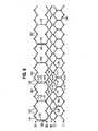
図5を参照すると、図示の実施形態におけるフレーム102(平坦な形状で示されている)は、端と端を接して配置され、フレームの流入端のところで円周方向に延在する、斜め支柱112の第1の下列Iと、円周方向に延在する、斜め支柱114の第2の列IIと、円周方向に延在する、斜め支柱116の第3の列IIIと、円周方向に延在する、斜め支柱118の第4の列IVと、円周方向に延在する、流出端105のところの斜め支柱122の第5の列Vとを備える。複数のほぼ真っすぐな軸方向延在支柱124を使用して、第1の列Iの支柱112を、第2の列IIの支柱114と相互接続することができる。斜め支柱122の第5の列Vは、斜め支柱118の第4の列IVに、(交連窓120を画定する)複数の軸方向延在窓枠部分130、および複数の軸方向延在支柱132によって接続される。 Referring to FIG. 5, the frame 102 (shown in a flattened configuration) in the illustrated embodiment comprises diagonal struts that are positioned end-to-end and extend circumferentially at the inflow end of the frame. A first lower row I of 112, a second circumferentially extending row II of
各交連窓枠部分130は、弁状構造104のそれぞれに対応する交連を取り付ける。図から分かるように、各窓枠部分130は、その上端および下端のところで、斜め支柱の隣接する列に固定されて、弁尖構造の交連の支持に片持ち梁状の支柱を用いる周知のフレームに比べて、弁の繰返し荷重下での耐疲労性を高める堅牢な構成を実現している。この構成により、フレーム壁厚さの低減が可能になって、弁の収縮後のより小さな直径が達成される。特定の実施形態では、内径と外径の間で測定されたフレーム102の厚さは、約0.48mm以下である。 Each commissure
図3~図4に最も良く示されているように、フレームの支柱および枠部分が全体で、フレームの複数のオープンセルを画定している。フレーム102の流入端のところで、支柱112、支柱114、および支柱124が、開口部136を画定するセルの下列を画定している。支柱114の第2の列、支柱116の第3の列、および支柱118の第4の列が、開口部138を画定するセルの2つの中間列を画定している。支柱118の第4の列および支柱122の第5の列が、窓枠部分130および支柱132と共に、開口部140を画定するセルの上列を画定している。開口部140は、比較的大きく、フレーム102が収縮したときに収縮外形を最小限に抑えるために、弁状構造104の一部分が開口部140内に、かつ/または開口部140を通って、突出または張出することのできるようなサイズになっている。 As best shown in FIGS. 3-4, the struts and frame portions of the frame collectively define a plurality of open cells of the frame. At the inflow end of
いくつかの実施形態では、隣接する窓枠部分130間に、列の長さに沿って、軸方向延在支柱132が2つだけ、または軸方向延在支柱132が1つだけ、のような、3つ未満の軸方向延在支柱132がある。いくつかの実施形態では、隣接する窓枠部分130間に、軸方向延在支柱132が1つだけあり、その軸方向延在支柱132は、窓枠部分130相互間の中間点に配置することができる。したがって、さまざまな実施形態では、フレームは、窓枠部分130および軸方向延在支柱132を1対1の割合で組み込むように特定的に構築することができる。 In some embodiments, such as only two axially extending
図3~図5に示す一実施形態では、正確に3つの窓枠部分130、および正確に3つの軸方向支柱132がある。窓枠部分130相互間の、軸方向延在支柱132の数を最小限に抑える、または低減させると、人工弁のよりコンパクトな収縮が促される。これによりまた、開口部140のサイズが最大化または増大し、そのことは、例えば、人工弁の流出端105が冠状動脈口のレベルよりも高度に延びる場合に有利である。そのような場合、開口部140がより大きいことにより、冠状動脈のカテーテル挿入を必要とする処置などの後々の処置のために、冠状動脈にアクセスすることができるようになる。 In one embodiment shown in FIGS. 3-5, there are exactly three
各窓枠部分130および/または各軸方向延在支柱132はそれぞれ、(流出端105のところの列Vの)2つの斜め支柱122の下端が一点に集まることによって特徴付けられる位置142と、(列IVの)2つの斜め支柱118の上端が一点に集まることによって画定される位置またはノード144との間に延在することができる。列Vに沿った斜め支柱122が、ある位置142から次の位置142までで2つあってよく、列IVに沿った斜め支柱118が、ある位置144から次の位置144までで2つあってよい。 Each
フレーム102は、軸方向延在フレーム部材(すなわち枠部分130または支柱132)を、列Vに沿ったそのような位置142と列VIに沿ったそのような位置144の、そのような対1つ置きにそこに備えることができる。フレーム102は、そのような位置4箇所ごとに1つの、フレーム102の円周の周りに等しく隔置された窓枠部分130を有することができ、それにより、合計で(3葉弁における3つの交連に対応する)3つの窓枠部分130を設けることができる。したがって、フレーム102は、列Vに沿って順番に、そのような位置142、144の対間に延在する窓枠部分130と、その次に続く、それらの間に延在する軸方向延在支柱またはフレーム部材のない位置142、144の第2の対と、それに次いで続く、位置142、144の第3の対間に延在する軸方向延在支柱132と、それに次いで続く、やはり軸方向延在支柱またはフレーム部材のない位置142、144の第4の対と、それに続く、そのような位置142、144の対間に延在(し、したがって、支柱および枠部分の並びを再開)する、別の窓枠部分130とを備えることができる。位置142、144の各組間に(列IVおよび列Vのそれぞれに沿った)2つの斜め支柱がある場合、本実施形態はすなわち、隣接する窓枠部分130間に各列に沿って8つの斜め支柱からなる組、および各窓枠部分130とその隣接する軸方向支柱132との間(すなわち、間に他の軸方向フレーム部材がない)に4つの連続した斜め支柱を有することができる。
人工心臓弁100が弁輪に適切に移植された後、人工弁100は、開放状態と閉鎖状態の間を循環して、血液が流れるように、または流れないようにすることができる。さまざまな実施形態では、人工心臓弁100のフレーム102は、心拡張期中に内向きに曲がることによって、弁閉鎖中にある程度の制動を行い、そうして曲がることにより、弁尖にかかる応力が軽減する。例えば、(弁閉鎖中などに)弁尖110の交連を径方向内向きに引く力は、フレームの交連に直接隣接する(窓枠部分130などの)領域も径方向内向きに引くことができるが、軸方向支柱132は、径方向外向きに強いることができる。さまざまな実施形態では、(枠部分130を径方向内向きに引くこと、および軸方向支柱132を径方向外向きに押すことを含む)この制動効果を、上段に沿って(弁100内の列IVと列Vの間に)存在する軸方向支柱の数を、本明細書に開示するように、より多数の軸方向フレーム部材(例えばより多数の軸方向支柱)を有するフレームに比べて低減させることによって、高めることができる。 After the
内側スカート106の主な機能は、弁状構造104をフレーム102に固定するのを助け、また、弁尖110の下縁部の下でフレーム102のオープンセルを通って血液が流れるのを阻止することによって、弁100と自己弁輪との間に良好なシールを形成するのを助けることである。内側スカート106は、望ましくは、ポリエチレンテレフタレート(PET)などの、強靭な耐引裂き性材料を含むが、さまざまな他の合成材料または天然材料を使用してもよい。内側スカート106は、フレーム102の内部に縫合糸によって固定することができる。弁状構造104を内側スカート106に、1つまたは複数の薄いPET補強ストリップ(全体でスリーブを成すことができる、図示せず)の助けを借りて取り付けることができ、このストリップは、確実な縫合を可能にし、また弁尖構造の心膜組織が裂けないように保護することができる。弁状構造104は、内側スカート106と薄いPETストリップとの間にサンドイッチ状に挟むことができる。 The primary function of the
内側スカート106の上縁部分は、軸方向支柱132の下端に直接隣接する支柱118の第4の列(列IV)の形状に概して従った、波形を画定する複数の突起を伴って形成することができる。このようにして、図1に最も良く示されているように、内側スカート106の上縁部を支柱118に、縫合146を用いてしっかりと固定することができる。内側スカート106は、支柱112の第1の列、支柱114の第2の列、および/または支柱116の第3の列(列I~III)にも、縫合146を用いて固定することができる。 The upper edge portion of the
内側スカート106は、フレーム102に、弁尖110の下縁部を内側スカート106に取り付ける縫合線から離れた位置において縫合することができ、それにより、弁尖縫合線に応力が集中するのが低減し、またその領域内でスカートに柔軟性が増す。 The
図1~図2に示すように、複数の可撓性コネクタ125を使用して、弁尖110の隣接する縁部の対をそれぞれ相互接続し、弁尖110を交連窓枠部分130に取り付けることができる。可撓性コネクタ125は、1片のPET織物から作製することができるが、他の合成材料および/または天然材料を使用してもよい。各交連は、2枚の隣接する弁尖の2つのタブ部分を備えることができる。各交連は、フレームに、例えばタブ部分を窓枠部分130の交連窓120から挿入し、タブ部分をフレーム102の外側のコネクタ125に縫合することによって、固定することができる。 Attaching the
外側スカート108は、織物状PETなどの強く耐久性のある材料片から、レーザ切断し、またはその他の方法で形成することができるが、他の合成材料または天然材料を使用してもよい。外側スカート108は、ほぼ直線状の下縁部、ならびに複数の交互する突起150および切欠き152を画定する上縁部を有することができる。外側スカート108の下縁部は、内側スカート106の下縁部に、弁100の流入端のところで縫合することができる。他の実施形態では、内側スカート106および外側スカート108が、単一構成要素として一体製作される。図1~図2に示すように、各突起150は、フレーム102の支柱114の第2の段IIに、縫合糸154を用いて固定することができる。
弁部材104、内側スカート106、および外側スカート108のフレーム102への固定に関連する更なる詳細は、米国特許出願公開第2011/0123529号に記載されている。 Further details relating to securing
さまざまな実施形態では、フレームを、斜め支柱の4つの列または6つの列など、フレーム102に含まれるよりも多数または少数の、斜め支柱の列を有するように構築することができる。さまざまな他のフレーム実施形態では、各窓枠部分および/または各軸方向延在支柱が、斜め支柱の上端が一点に集まることによってそれぞれが画定される、2つの位置間に延在することができる。さまざまな実施形態では、各窓枠部分および/または各軸方向延在支柱が、斜め支柱の下端が一点に集まることによってそれぞれが画定される、2つの位置間に延在することができる。 In various embodiments, the frame can be constructed with more or fewer rows of diagonal struts than are included in
図6は、内側スカート206、外側スカート208、およびステント202内に取り付けられた弁部材204を備えた、別の例示的人工弁200の斜視図を示す。弁部材204は、3枚の弁尖210を1組有することができる。複数の可撓性コネクタ225を使用して、弁尖210の隣接する縁部の対を相互接続し、弁尖210を交連窓枠部分230に取り付けることができる。 FIG. 6 shows a perspective view of another exemplary
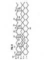
図7~図8は、流入端203、流出端205、および(図1~図5に示す5つの列ではなく)支柱214、216、218、222の4つの列(I~IV)を有する裸のステント202の、斜視図および平坦展開図を示す。斜め支柱222の第4の列IVを、斜め支柱218の第3の列IIIに、(交連窓220を画定する)複数の軸方向延在窓枠部分230、および複数の軸方向延在支柱232によって接続することができる。 Figures 7-8 show a bare tube having an
したがって、各窓枠部分230および各軸方向延在支柱232は、流出端205に最も近い斜め支柱の2つの列間に延在することができる。具体的には、各窓枠部分230は、2つの斜め支柱222の上端が一点に集まることによって画定される位置242と、2つの斜め支柱218の上端が一点に集まることによって画定される位置244との間に延在することができる。各軸方向延在支柱232は、2つの斜め支柱222の下端が一点に集まることによって画定される別の位置246と、2つの斜め支柱218の下端が一点に集まることによって画定される別の位置248との間に延在することができる。 Thus, each
フレーム202は、フレーム202の円周の周りに等しく隔置された3つの窓枠部分230を備えることができる。図示のように、フレーム202は、(列IIIおよび列IVのそれぞれに沿った)6つの斜め支柱を、窓枠部分230相互間に各列に沿って有するように構築することができる。フレームは、各窓枠部分230と隣接する軸方向支柱232との間に、3つの斜め支柱を有するように構築することができる。したがって、各軸方向支柱232は、隣接する窓枠部分230間の中間点に配置することができ、フレーム202は、窓枠部分および軸方向延在支柱を1対1の割合で組み込むように構築することができる。図示の実施形態では、正確に3つの窓枠部分230、および正確に3つの軸方向支柱232がある。
具体的には、フレーム202は、列IIIおよび列IVに沿って順番に、位置242、244の対間に延在する窓枠部分230と、それに続く、軸方向延在部材のない位置246、248の対と、それに続く、軸方向延在部材のない位置242、244の対と、それに続く、位置246、248の対間に延在する軸方向延在支柱232と、それに続く、軸方向延在部材のない位置242、244の対と、それに続く、軸方向延在部材のない位置246、248の対と、それに続く、位置242、244の対間に延在(し、したがって、窓枠部分230および軸方向延在支柱232の並びを再開)する、別の窓枠部分230と、を備えることができる。 Specifically, the
人工心臓弁200が弁輪に適切に設置された後、弁200は、開放状態と閉鎖状態の間を循環して、血液が流れるように、または流れないようにすることができる。人工弁100に関して論じたように、循環中に交連を径方向内向きに引く力は、窓枠部分230も径方向内向きに引いて、弁閉鎖中に弁尖にかかる応力を軽減することができる。その間、軸方向支柱232は、径方向外向きに強いることができる。 After the
フレーム202は、(カテーテル上またはカテーテル内で送達するためなどの)押縮(collapsed)形状、および拡張形状(すなわち弁輪のところでの機能し得る形状)をとることが可能であってよい。さまざまな実施形態では、押縮形状において、複数の軸方向支柱が、弁尖取付け部材および/または交連に比べて径方向外向きに位置する。一実施形態では、拡張形状から押縮形状に、かつ/または押縮形状から拡張形状に移行する過程において、弁200が、列IVの軸方向延在支柱232に隣接する支柱222だけが集まって、(隣り合って支柱232とほぼ軸方向に位置の合った状態で)軸方向に延在する、中間形状をとることができる。 The
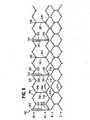
別の実施形態では、図9に示すように、フレーム302が、2つの斜め支柱322の上端が一点に集まることによって画定される位置342と、2つの斜め支柱318の下端が一点に集まることによって画定される位置344との間に延在する、軸方向窓枠部材330を有することができる。フレーム302は、2つの斜め支柱322の下端が一点に集まることによって画定される位置346と、2つの斜め支柱318の上端が一点に集まることによって画定される位置348との間に延在する、軸方向延在支柱332を有することができる。 In another embodiment, as shown in FIG. 9, the
フレーム302は、斜め支柱の最初の3つの列(列I、列II、および列III)が、フレーム202の同じ列に対して20度シフトしていることを除き、フレーム202に類似している。したがって、各窓枠部材330は、列IIIの2つの斜め支柱318の下端が一点に集まることによって画定される位置344と、軸方向に位置合わせされている。
各窓枠部材330は、交連窓320のレベルの下に(ステント302の流入端に向かって)下支柱部分334を備えることができる。この下支柱部分334は、窓枠部材330の下端から、2つの斜め支柱318の下端が一点に集まることによって画定される位置344まで延在する。下支柱部分334は、窓枠部材330に長さを追加し、枠部材330が、本実施形態では位置342、344間のより大きな距離の効果的な橋渡しができるようにする。フレーム302の他の特徴および構成要素は、上記でフレーム202について説明した他の特徴および構成要素に類似していてよい。
Each
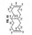
図10は、別の実施形態によるフレーム402の一部分を示す。図10では、斜め支柱の2つの上列(流出端に最も近い列)の円周の3分の1だけが示されている。フレーム402は、2つの斜め支柱422の下端が一点に集まることによって画定される位置442と、2つの斜め支柱418の下端が一点に集まることによって画定される位置444との間に延在する、軸方向窓枠部材430を有することができる。フレーム402は、2つの斜め支柱422の上端が一点に集まることによって画定される位置446と、2つの斜め支柱418の上端が一点に集まることによって画定される位置448との間に延在する、軸方向延在支柱432を有することができる。 FIG. 10 shows a portion of
斜め支柱の2つの上列は、軸方向窓枠部材430を合計で3つ、また窓枠部材430相互間の等距離のところにある軸方向延在支柱432を合計で3つ含み、3つの斜め支柱418および3つの斜め支柱422が、窓枠部材430と、隣接する軸方向延在支柱432との間に延在する。フレーム402は、上記で論じた実施形態と同様の、フレームの流入端のところにある斜め支柱の更なる3つの列(図10には図示せず)も含むことができる。各窓枠部材430の下端は、隣接する列(フレームの流出端から3番目の列)の2つの斜め支柱の上端に、位置444のところで接続することができる。したがって、本実施形態では、各軸方向延在支柱432の下端が、隣接する列のどの支柱にも接続されない。 The two upper rows of diagonal struts include a total of three axial
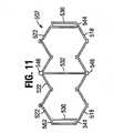
図11は、別の実施形態によるフレーム502の一部分を示す。図11では、斜め支柱の2つの上列(流出端に最も近い列)の円周の3分の1だけが示されている。フレーム502は、2つの斜め支柱522の下端が一点に集まることによって画定される位置542と、2つの斜め支柱518の上端が一点に集まることによって画定される位置544との間に延在する、軸方向窓枠部材530を有することができる。フレーム502は、2つの斜め支柱522の上端が一点に集まることによって画定される位置546と、2つの斜め支柱518の下端が一点に集まることによって画定される位置548との間に延在する、軸方向延在支柱532を有することができる。本実施形態での軸方向延在支柱532は、位置542、544間の距離に比べてより大きな、位置546、548間の距離を補うために、窓枠部材530よりも長くすることができる。 FIG. 11 shows a portion of
斜め支柱の2つの上列は、軸方向窓枠部材530を合計で3つ、また窓枠部材530相互間の等距離のところにある軸方向延在支柱532を合計で3つ含み、3つの斜め支柱518および3つの斜め支柱522が、窓枠部材530と、隣接する軸方向延在支柱532との間に延在する。フレーム502は、上記で論じた実施形態と同様の、フレームの流入端のところにある斜め支柱の更なる3つの列(図11には図示せず)も含むことができる。各軸方向延在支柱532の下端は、隣接する列(フレームの流出端から3番目の列)の2つの斜め支柱の上端に、位置548のところで接続することができる。したがって、本実施形態では、各窓枠部材530の下端が、隣接する列のどの斜め支柱にも接続されない。 The two upper rows of diagonal struts include a total of three axial
図12は、別の実施形態によるフレーム602の一部分を示す。図12では、斜め支柱の2つの上列(流出端に最も近い列)の円周の3分の1だけが示されている。フレーム602は、2つの斜め支柱622の上端が一点に集まることによって画定される位置642と、2つの斜め支柱618の上端が一点に集まることによって画定される位置644との間に延在する、軸方向窓枠部材630を有することができる。フレーム602は、2つの斜め支柱622の下端が一点に集まることによって画定される位置646と、2つの斜め支柱618の下端が一点に集まることによって画定される位置648との間に延在する、軸方向延在支柱632を有することができる。 FIG. 12 shows a portion of
図12の実施形態では、窓枠部材630の各対間に隔置された、2つのそのような軸方向延在支柱632がある。具体的には、窓枠部材の対ごとに、3つの斜め支柱618および3つの斜め支柱622が、各窓枠部材630と最も近い軸方向延在支柱632との間に、また2つの斜め支柱618および2つの斜め支柱622が、2つの軸方向延在支柱632間にある。したがって、フレーム602全体について、斜め支柱の2つの上列が、軸方向窓枠部材630を合計で3つ、また軸方向延在支柱632を合計で6つ含む。 In the embodiment of FIG. 12 there are two such
フレーム602は、上記で論じた実施形態と同様の、フレームの流入端のところにある斜め支柱の更なる3つの列(図12には図示せず)も含むことができる。各軸方向延在支柱632の下端は、隣接する列(フレームの流出端から3番目の列)の2つの斜め支柱の上端に、位置648のところで接続することができる。したがって、本実施形態では、各窓枠部材630の下端が、隣接する列のどの支柱にも接続されない。
図13は、別の実施形態によるフレーム702の一部分を示す。図13では、斜め支柱の2つの上列(流出端に最も近い列)の円周の3分の1だけが示されている。フレーム702は、2つの斜め支柱722の下端が一点に集まることによって画定される位置742と、2つの斜め支柱718の上端が一点に集まることによって画定される位置744との間に延在する、軸方向窓枠部材730を有することができる。フレーム702は、2つの斜め支柱722の上端が一点に集まることによって画定される位置746と、2つの斜め支柱718の下端が一点に集まることによって画定される位置748との間に延在する、軸方向延在支柱732を有することができる。 FIG. 13 shows a portion of
図13の実施形態では、窓枠部材730の各対間に隔置された、2つのそのような軸方向延在支柱732がある。具体的には、窓枠部材の対ごとに、3つの斜め支柱718および3つの斜め支柱722が、各窓枠部材730と最も近い軸方向延在支柱732との間に、また2つの斜め支柱718および2つの斜め支柱722が、2つの軸方向延在支柱732間にある。したがって、フレーム702全体について、斜め支柱の2つの上列が、軸方向窓枠部材730を合計で3つ、また軸方向延在支柱732を合計で6つ含む。また、支柱732は、位置742、744間の距離に比べてより大きな、位置746、748間の距離を補うために、窓枠部材730よりも長くすることができる。 In the embodiment of FIG. 13, there are two such
フレーム702は、上記で論じた実施形態と同様の、フレームの流入端のところにある斜め支柱の更なる3つの列(図13には図示せず)も含むことができる。各軸方向延在支柱732の下端は、隣接する列(フレームの流出端から3番目の列)の2つの斜め支柱の上端に、位置748のところで接続することができる。したがって、本実施形態では、各窓枠部材730の下端が、隣接する列のどの支柱にも接続されない。
本明細書に開示した人工弁実施形態は、外科的に移植することができ、かつ/またはカテーテルなどのデリバリ装置を用いて送達することができる。この人工弁は、収縮状態で、デリバリ装置の膨張可能なバルーンまたは同等の拡張機構上に、またはそれに隣接して、載置することができる。デリバリ装置および収縮した人工弁は、周知の技法を用いて患者の脈管系に挿入し、患者の体内を前進させることができる。 The prosthetic valve embodiments disclosed herein can be surgically implanted and/or delivered using a delivery device such as a catheter. The prosthetic valve, in a deflated state, can rest on or adjacent to an inflatable balloon or equivalent expansion mechanism of the delivery device. The delivery device and deflated prosthetic valve can be inserted into the patient's vasculature and advanced through the patient using well-known techniques.
一実装形態では、デリバリ装置を大腿動脈に挿入し、大動脈を通って前進させて自己大動脈弁(または心臓の別の自己弁)に至らせる、経大腿動脈的手法において、人工弁が送達される。別の実装形態では、デリバリ装置を、胸部に開いた小さな外科開口部、および左室壁などの心壁に開いた別の外科開口部を通じて挿入する、経心室的手法において、人工弁を送達することができる。別の実装形態では、デリバリ装置を、胸部に開いた小さな外科開口部、および大動脈弁の上方の位置の上行大動脈に開いた別の外科開口部を通じて挿入する、経大動脈的手法において、人工弁を送達することができる。別の実装形態では、人工弁が、静脈に移植するための置換静脈弁、または大動脈弁に比べて流量の少ない別の弁に代わる置換物である。 In one implementation, the prosthetic valve is delivered in a transfemoral approach in which a delivery device is inserted into the femoral artery and advanced through the aorta to the native aortic valve (or another native valve of the heart). . In another implementation, the prosthetic valve is delivered in a transventricular approach in which the delivery device is inserted through a small surgical opening in the chest and another surgical opening in the heart wall, such as the left ventricular wall. be able to. In another implementation, the delivery device is inserted through a small surgical opening in the chest and another surgical opening in the ascending aorta located above the aortic valve, in a trans-aortic approach. can be delivered. In another implementation, the prosthetic valve is a replacement venous valve for implantation into a vein or a replacement for another valve that has a lower flow rate than the aortic valve.
人工弁を所望の配備位置(例えば自己大動脈弁内)に位置付けると、デリバリ装置のバルーンを膨張させて、人工弁を径方向に拡張させることができる。いくつかの実施形態では、人工弁を完全に拡張させるのと同時に、人工弁の外側スカートを自己弁の周囲組織と強制的に接触させて、フレームの外面と周囲組織との間にシールを確立することができる。人工弁のフレームは、径方向に圧縮された載置形状にあるとき、フレームの流出端部分の外径よりも小さな外径を有する流入端部分を備えることができる。 Once the prosthetic valve is positioned at the desired deployment location (eg, within a native aortic valve), the balloon of the delivery device can be inflated to radially expand the prosthetic valve. In some embodiments, the prosthetic valve is fully expanded while simultaneously forcing the outer skirt of the prosthetic valve into contact with the surrounding tissue of the native valve to establish a seal between the outer surface of the frame and the surrounding tissue. can do. The frame of the prosthetic valve may comprise an inflow end portion having an outer diameter smaller than the outer diameter of the outflow end portion of the frame when in the radially compressed resting configuration.
人工弁は、自己拡張型材料から構築されると、径方向に圧縮された状態に収縮させ、デリバリカテーテルのシースまたは同等の機構に挿入することによって圧縮された状態に抑えておくことができる。デリバリ装置を体内に挿入し、前進させて、人工弁を所望の配備位置に位置付けた後で、人工弁をデリバリシースから出て前進させることができる。人工弁は、デリバリシースから出て配備されると、径方向に自己拡張してその機能し得るサイズになることができる。 When constructed from a self-expanding material, the prosthetic valve can be deflated to a radially compressed state and held in the compressed state by insertion into a delivery catheter sheath or equivalent mechanism. After the delivery device is inserted into the body and advanced to position the prosthetic valve in the desired deployment position, the prosthetic valve can be advanced out of the delivery sheath. Once deployed out of the delivery sheath, the prosthetic valve can radially self-expand to its functional size.
この人工心臓弁は、径方向外向きに延在し、対応する窓枠部分を通ってフレームの外側の位置に至り、交連窓枠の側方支柱に縫合される、弁尖の交連部分を備えることができる。人工弁の収縮外形を最小限に抑えるために、人工弁をカテーテル上で径方向に圧縮して押縮形状にしたときに、窓枠部分を、隣接する交連窓間に延在するフレーム部分などのフレームの周囲部分に比べて、径方向内向きに凹ませることができる。 The prosthetic heart valve comprises leaflet commissural portions extending radially outward through corresponding window frame portions to positions outside the frame and sutured to lateral struts of the commissural window frame. be able to. To minimize the deflated profile of the prosthetic valve, the window frame portions, such as the frame portions that extend between adjacent commissural windows, when the prosthetic valve is radially compressed onto the catheter into the compressed shape. can be recessed radially inwardly relative to the peripheral portion of the frame.
例えば、人工弁を径方向に押縮したときに、フレームの交連窓を、フレームの、隣接する交連窓間に延在する部分に比べて、0.2mmから1.0mmの間などの径方向距離だけ内向きに凹ませることができる。このようにして、人工弁の、交連部分を備える流出端部分の外径が、人工弁を体内へ送達する妨げとなるおそれのある、人工弁の周囲部分から外向きに突き出している交連部分とは対照的に、概して均一になることができる。径方向に凹んだ交連窓枠があっても、人工弁をカテーテル上で径方向に押縮したときに、フレームの流入端部分の外径は依然としてフレームの流出端部分の外径よりも小さいか、またはその外径にほぼ等しく、それにより、人工弁の最小の最大全径または低減された最大全径が可能になり得る。デリバリカテーテル上に載置したときの人工弁の直径を最小限に抑える、または低減させることによって、人工弁を前進させるデリバリカテーテルの直径も、最小限に抑える、または低減させることができる。これにより、人工弁をより狭い血管を通って体内に送達できるようになり、送達手法が一般により低侵襲性になる。 For example, when the prosthetic valve is radially compressed, the commissural windows of the frame are radially increased, such as between 0.2 mm and 1.0 mm, compared to the portion of the frame that extends between adjacent commissural windows. It can be recessed inward by a distance. In this way, the outer diameter of the outflow end portion of the prosthetic valve, including the commissure portions, and the commissure portions protruding outwardly from the surrounding portion of the prosthetic valve, which may interfere with delivery of the prosthetic valve into the body. , in contrast, can be generally uniform. Even with a radially recessed commissural window frame, is the outer diameter of the inflow end portion of the frame still smaller than the outer diameter of the outflow end portion of the frame when the prosthetic valve is radially compressed onto the catheter? , or approximately equal to its outer diameter, which may allow for a minimum or reduced maximum overall diameter of the prosthetic valve. By minimizing or reducing the diameter of the prosthetic valve when mounted on the delivery catheter, the diameter of the delivery catheter through which the prosthetic valve is advanced can also be minimized or reduced. This allows the prosthetic valve to be delivered into the body through narrower blood vessels, making the delivery technique generally less invasive.
本明細書に開示した人工心臓弁の送達に関連する更なる詳細は、米国特許出願公開第2011/0123529号に記載されている。 Further details related to delivery of the heart valve prostheses disclosed herein are described in US Patent Application Publication No. 2011/0123529.
一般的な考慮事項
本記載では、本開示の実施形態のいくつかの態様、利点、および新規な特徴が、本明細書の中で記述されている。開示した方法、装置、およびシステムは、いかなる形であれ、限定するものと解釈すべきではない。そうではなく、本開示は、開示したさまざまな実施形態のあらゆる新規かつ非自明な特徴および態様を、単独で、また互いにさまざまに組み合わせた形および部分的に組み合わせた形で、対象とする。その方法、装置、およびシステムは、任意の具体的な態様または特徴またはそれらの組合せに限定されるものではなく、また開示した実施形態は、任意の1つまたは複数の具体的な利点が存在すること、または任意の1つまたは複数の具体的な問題が解決することを要求するものでもない。General Considerations In this description, certain aspects, advantages and novel features of embodiments of the disclosure have been set forth herein. The disclosed methods, devices, and systems should not be construed as limiting in any way. Rather, the present disclosure covers each and every novel and non-obvious feature and aspect of the various disclosed embodiments singly and in various combinations and subcombinations with each other. The methods, apparatus, and systems are not limited to any specific aspect or feature or combination thereof, and the disclosed embodiments may present any one or more specific advantages nor does it claim that any one or more specific problems will be solved.
開示した方法のうちのいくつかの方法の操作が、提示の便宜上、特定の起こった順序で記述されているが、このような記述は、具体的な文言によって特定の順序付けが要求されていない限り、並替えを包含することを理解されたい。例えば、連続して記述される操作は、場合によっては、並び替えることもでき、同時に実施することもできる。更に、簡単にするために、添付の図面は、開示した方法を他の方法と一緒に使用することのできる、さまざまな方途を示していないことがある。本明細書では、「1つの(a)」、「1つの(an)」、および「少なくとも1つの」という用語は、1つまたは複数の特定された要素を包含する。すなわち、2つの特定の要素が存在する場合、それらの要素のうちの一方も存在し、したがって、「1つの(an)」要素が存在する。「複数の(a plurality of)」および「複数の(plural)」という用語は、2つ以上の特定された要素を意味する。 Although the operations of some of the disclosed methods are described in a particular order of occurrence for convenience of presentation, such description is not intended unless a specific ordering is required by specific language. , is understood to encompass permutations. For example, operations described sequentially may in some cases be rearranged and performed concurrently. Furthermore, for the sake of simplicity, the accompanying drawings may not show the various ways in which the disclosed methods can be used with other methods. As used herein, the terms "a," "an," and "at least one" encompass one or more of the specified elements. That is, if two particular elements are present, then one of those elements is also present and thus "an" element is present. The terms "a plurality of" and "plural" mean two or more of the specified elements.
本明細書では、要素のリストのうちの最後の2つの間で使用される「および/または」という用語は、リストした要素のうちのいずれか1つまたは複数を意味する。例えば、「A、Bおよび/またはC」という表現は、「A」、「B」、「C」、「AおよびB」、「AおよびC」、「BおよびC」、または「A、BおよびC」を意味する。 As used herein, the term "and/or" used between the last two of a list of elements means any one or more of the listed elements. For example, the expression "A, B and/or C" can be changed to "A", "B", "C", "A and B", "A and C", "B and C", or "A, B and C”.
開示した本発明の原理を適用することのできる可能な多くの実施形態に鑑みて、例示した実施形態は、本発明の好ましい例にすぎず、本発明の範囲を限定するものと解釈すべきではないことを理解されたい。そうではなく、本発明の範囲は、添付の特許請求の範囲によって定められる。したがって、本発明者は、こうした特許請求の範囲に記載の範囲および趣旨に含まれるものすべてを、本発明者の発明として特許請求する。 In view of the many possible embodiments in which the disclosed principles of the invention can be applied, the illustrated embodiments are merely preferred examples of the invention and should not be construed as limiting the scope of the invention. It should be understood that no Rather, the scope of the invention is defined by the appended claims. I therefore claim as my invention all that comes within the scope and spirit of these claims.
100 人工心臓弁、人工弁
102 ステント、フレーム
103 流入端
104 弁状構造、弁部材
105 流出端
106 内側スカート
108 外側スカート
110 弁尖
112 斜め支柱
114 斜め支柱
116 斜め支柱
118 斜め支柱
120 交連窓
122 斜め支柱
124 軸方向延在支柱
125 可撓性コネクタ
130 軸方向延在窓枠部分、交連窓枠部分
132 軸方向延在支柱、軸方向支柱
136 開口部
138 開口部
140 開口部
142 位置
144 位置、ノード
146 縫合
150 突起
152 切欠き
154 縫合糸
200 人工弁、人工心臓弁
202 ステント、フレーム
203 流入端
204 弁部材
205 流出端
206 内側スカート
208 外側スカート
210 弁尖
214 支柱
216 支柱
218 斜め支柱
220 交連窓
222 斜め支柱
225 可撓性コネクタ
230 交連窓枠部分、軸方向延在窓枠部分
232 軸方向延在支柱、軸方向支柱
242 位置
244 位置
246 位置
248 位置
302 フレーム、ステント
318 斜め支柱
320 交連窓
322 斜め支柱
330 軸方向窓枠部材
332 軸方向延在支柱
334 下支柱部分
342 位置
344 位置
346 位置
348 位置
402 フレーム
418 斜め支柱
422 斜め支柱
430 軸方向窓枠部材
432 軸方向延在支柱
442 位置
444 位置
446 位置
448 位置
502 フレーム
518 斜め支柱
522 斜め支柱
530 軸方向窓枠部材
532 軸方向延在支柱
542 位置
544 位置
546 位置
548 位置
602 フレーム
618 斜め支柱
622 斜め支柱
630 軸方向窓枠部材
632 軸方向延在支柱
642 位置
644 位置
646 位置
648 位置
702 フレーム
718 斜め支柱
722 斜め支柱
730 軸方向窓枠部材
732 軸方向延在支柱
742 位置
744 位置
746 位置
748 位置
I 第1の下列
II 第2の列、第2の段
III 第3の列
IV 第4の列
V 第5の列100 heart valve prosthesis, prosthetic valve 102 stent, frame 103 inflow end 104 valve-like structure, valve member 105 outflow end 106 inner skirt 108 outer skirt 110 leaflet 112 diagonal strut 114 diagonal strut 116 diagonal strut 118 diagonal strut 120 commissure window 122 diagonal Post 124 Axially Extending Post 125 Flexible Connector 130 Axially Extending Window Frame Portion, Commissure Window Frame Portion 132 Axially Extending Post, Axial Post 136 Opening 138 Opening 140 Opening 142 Location 144 Location, Node 146 Suture 150 Protrusion 152 Notch 154 Suture Thread 200 Artificial Valve, Heart Valve 202 Stent, Frame 203 Inflow End 204 Valve Member 205 Outflow End 206 Inner Skirt 208 Outer Skirt 210 Leaflet 214 Strut 216 Strut 218 Diagonal Strut 220 Commissural Window 222 Diagonal struts 225 Flexible connectors 230 Commissural window frame portions, axially extending window frame portions 232 Axial extending struts, axial struts 242 Positions 244 Positions 246 Positions 248 Positions 302 Frames, stents 318 Diagonal struts 320 Commissural windows 322 Oblique Post 330 Axial window frame member 332 Axial extending post 334 Lower post portion 342 Position 344 Position 346 Position 348 Position 402 Frame 418 Diagonal post 422 Diagonal post 430 Axial window frame member 432 Axial extending post 442 Position 444 Position 446 Position 448 Position 502 Frame 518 Diagonal strut 522 Diagonal strut 530 Axial window frame member 532 Axial extending strut 542 Position 544 Position 546 Position 548 Position 602 Frame 618 Diagonal strut 622 Diagonal strut 630 Axial window frame member 632 Axial extension Post 642 Position 644 Position 646 Position 648 Position 702 Frame 718 Diagonal Post 722 Diagonal Post 730 Axial Window Frame Member 732 Axially Extending Post 742 Position 744 Position 746 Position 748 Position I First Lower Row II Second Row, Second column III 3rd column IV 4th column V 5th column
Claims (15)
Translated fromJapanese流入端(103;203)、流出端(105;205)、少なくとも4列の円周方向に延びる斜め支柱(112、114、116、118、122)、及び、前記少なくとも4列の円周方向に延びる斜め支柱のうち少なくとも2つを繋ぐ複数の軸方向フレーム部材(330、332、334)を有する環状フレーム(102;202;302)を含み、前記複数の軸方向フレーム部材は、1:1の比率で、複数の軸方向に延在する弁尖取付け部材(330、334)と、複数の軸方向支柱(332)と、を含み、
前記人工装置(100; 200)は、前記前記環状フレーム(302)内に配置された弁状構造(104; 204)をさらに含み、前記弁状構造(104; 204)は、前記弁尖取付け部材(330)で前記環状フレーム(302)に固定された複数の交連を有し、
前記弁尖取付け部材それぞれは、交連窓(120、220、320)を画定する窓枠部分(130、230、330)を備えることを特徴とする人工装置。A prosthetic device (100; 200) for implantation in a heart valve annulus, said prosthetic device (100; 200) being radially compressed as expected when crimped onto a delivery catheter having an inflatable balloon. and an assumed expanded state upon expansion of the inflatable balloon of the delivery catheter; and
an inflow end (103; 203), an outflow end (105; 205), at least four rows of circumferentially extending diagonal struts (112, 114, 116, 118, 122), and said at least four rows of circumferentially An annular frame (102; 202; 302) having a plurality of axial frame members (330, 332, 334) connecting at least two of the extending diagonal struts, said plurality of axial frame members having a 1:1 comprising, in proportion, a plurality of axially extending leaflet attachment members (330, 334) and a plurality of axial struts (332);
Said prosthesis (100; 200) further comprises a valve-like structure (104; 204) disposed within said annular frame (302), said valve-like structure (104; 204) being attached to said leaflet attachment member. having a plurality of commissures secured to said annular frame (302) at (330);
A prosthetic device, wherein each of said leaflet mounting members comprises a window frame portion (130, 230, 330) defining a commissural window (120, 220, 320).
前記弁尖取付け部材(330)は、第1の列に沿って隣接する前記斜め支柱(322)の上端が一点に集まることによって画定される位置(342)から、第2の列に沿って隣接する斜め支柱(318)の下端が一点に集まることによって画定される位置(344)まで延在し、
前記軸方向支柱(332)は、前記第1の列に沿って隣接する前記斜め支柱(322)の下端が一点に集まることによって画定される位置(346)から、前記第2の列に沿って隣接する前記斜め支柱(318)の上端が一点に集まることによって画定される位置(348)まで延在することを特徴とする請求項1~7のいずれか一項に記載の人工装置。each of the leaflet attachment members comprises an inferior strut portion (334) positioned below the level of the commissural window (320) and toward the inflow end of the frame (302);
The leaflet attachment members (330) are adjacent along a second row from a position (342) defined by the convergence of the upper ends of adjacent diagonal struts (322) along a first row. extending to a position (344) defined by the convergence of the lower ends of the diagonal struts (318) that
The axial struts (332) extend along the second row from a position (346) defined by the convergence of the lower ends of adjacent diagonal struts (322) along the first row. The prosthesis of any one of the preceding claims, wherein the upper ends of adjacent diagonal struts (318) extend to a position (348) defined by convergence.
前記弁状構造が閉じている間、前記複数の軸方向支柱は、前記弁尖取付け部材に対して半径方向外側に配置されることを特徴とする請求項1~8のいずれか一項に記載の人工装置。Upon proper placement of the prosthetic device in the heart valve annulus, the prosthetic device is configured to cycle between closed and open states of the valve-like structure to restrict or permit blood flow. is,
9. The method of any one of claims 1-8, wherein the plurality of axial struts are positioned radially outwardly with respect to the leaflet attachment member during closure of the valve-like structure. artificial device.
Priority Applications (1)
| Application Number | Priority Date | Filing Date | Title |
|---|---|---|---|
| JP2024020485AJP7741909B2 (en) | 2014-02-18 | 2024-02-14 | flexible linkage frame |
Applications Claiming Priority (3)
| Application Number | Priority Date | Filing Date | Title |
|---|---|---|---|
| US201461941123P | 2014-02-18 | 2014-02-18 | |
| US61/941,123 | 2014-02-18 | ||
| JP2021199320AJP7358443B2 (en) | 2014-02-18 | 2021-12-08 | flexible linkage frame |
Related Parent Applications (1)
| Application Number | Title | Priority Date | Filing Date |
|---|---|---|---|
| JP2021199320ADivisionJP7358443B2 (en) | 2014-02-18 | 2021-12-08 | flexible linkage frame |
Related Child Applications (1)
| Application Number | Title | Priority Date | Filing Date |
|---|---|---|---|
| JP2024020485ADivisionJP7741909B2 (en) | 2014-02-18 | 2024-02-14 | flexible linkage frame |
Publications (2)
| Publication Number | Publication Date |
|---|---|
| JP2022140592Atrue JP2022140592A (en) | 2022-09-26 |
| JP7439184B2 JP7439184B2 (en) | 2024-02-27 |
Family
ID=53797053
Family Applications (7)
| Application Number | Title | Priority Date | Filing Date |
|---|---|---|---|
| JP2016569582AActiveJP6615790B2 (en) | 2014-02-18 | 2015-02-18 | Flexible commissure frame |
| JP2019200980AActiveJP6992034B2 (en) | 2014-02-18 | 2019-11-05 | Flexible mating frame |
| JP2021199320AActiveJP7358443B2 (en) | 2014-02-18 | 2021-12-08 | flexible linkage frame |
| JP2022120637AActiveJP7439184B2 (en) | 2014-02-18 | 2022-07-28 | flexible linkage frame |
| JP2022120636AActiveJP7439183B2 (en) | 2014-02-18 | 2022-07-28 | flexible linkage frame |
| JP2024020484AActiveJP7741908B2 (en) | 2014-02-18 | 2024-02-14 | flexible linkage frame |
| JP2024020485AActiveJP7741909B2 (en) | 2014-02-18 | 2024-02-14 | flexible linkage frame |
Family Applications Before (3)
| Application Number | Title | Priority Date | Filing Date |
|---|---|---|---|
| JP2016569582AActiveJP6615790B2 (en) | 2014-02-18 | 2015-02-18 | Flexible commissure frame |
| JP2019200980AActiveJP6992034B2 (en) | 2014-02-18 | 2019-11-05 | Flexible mating frame |
| JP2021199320AActiveJP7358443B2 (en) | 2014-02-18 | 2021-12-08 | flexible linkage frame |
Family Applications After (3)
| Application Number | Title | Priority Date | Filing Date |
|---|---|---|---|
| JP2022120636AActiveJP7439183B2 (en) | 2014-02-18 | 2022-07-28 | flexible linkage frame |
| JP2024020484AActiveJP7741908B2 (en) | 2014-02-18 | 2024-02-14 | flexible linkage frame |
| JP2024020485AActiveJP7741909B2 (en) | 2014-02-18 | 2024-02-14 | flexible linkage frame |
Country Status (15)
| Country | Link |
|---|---|
| US (8) | US10058420B2 (en) |
| EP (8) | EP4062874B1 (en) |
| JP (7) | JP6615790B2 (en) |
| CN (2) | CN105555232B (en) |
| CA (3) | CA3153863C (en) |
| CR (1) | CR20150598A (en) |
| DK (1) | DK3107500T3 (en) |
| ES (6) | ES2964127T3 (en) |
| HR (1) | HRP20211867T1 (en) |
| HU (2) | HUE070611T2 (en) |
| PL (4) | PL4062874T4 (en) |
| PT (1) | PT3107500T (en) |
| SG (1) | SG11201508887SA (en) |
| SI (1) | SI3107500T1 (en) |
| WO (1) | WO2015126933A1 (en) |
Families Citing this family (65)
| Publication number | Priority date | Publication date | Assignee | Title |
|---|---|---|---|---|
| US8579964B2 (en) | 2010-05-05 | 2013-11-12 | Neovasc Inc. | Transcatheter mitral valve prosthesis |
| US11653910B2 (en) | 2010-07-21 | 2023-05-23 | Cardiovalve Ltd. | Helical anchor implantation |
| US9308087B2 (en) | 2011-04-28 | 2016-04-12 | Neovasc Tiara Inc. | Sequentially deployed transcatheter mitral valve prosthesis |
| US9554897B2 (en) | 2011-04-28 | 2017-01-31 | Neovasc Tiara Inc. | Methods and apparatus for engaging a valve prosthesis with tissue |
| US9345573B2 (en) | 2012-05-30 | 2016-05-24 | Neovasc Tiara Inc. | Methods and apparatus for loading a prosthesis onto a delivery system |
| CA2900862C (en)* | 2013-02-11 | 2017-10-03 | Cook Medical Technologies Llc | Expandable support frame and medical device |
| US9572665B2 (en) | 2013-04-04 | 2017-02-21 | Neovasc Tiara Inc. | Methods and apparatus for delivering a prosthetic valve to a beating heart |
| PL4062874T4 (en) | 2014-02-18 | 2024-03-04 | Edwards Lifesciences Corporation | Flexible commissure frame |
| CN110141399B (en) | 2015-02-05 | 2021-07-27 | 卡迪尔维尔福股份有限公司 | Prosthetic valve with axial sliding frame |
| CA3007660A1 (en) | 2015-12-15 | 2017-06-22 | Neovasc Tiara Inc. | Transseptal delivery system |
| US10433952B2 (en) | 2016-01-29 | 2019-10-08 | Neovasc Tiara Inc. | Prosthetic valve for avoiding obstruction of outflow |
| US10231829B2 (en) | 2016-05-04 | 2019-03-19 | Boston Scientific Scimed Inc. | Leaflet stitching backer |
| US9999502B2 (en) | 2016-11-04 | 2018-06-19 | Highlife Sas | Transcather valve prosthesis |
| CA3042588A1 (en) | 2016-11-21 | 2018-05-24 | Neovasc Tiara Inc. | Methods and systems for rapid retraction of a transcatheter heart valve delivery system |
| WO2018184225A1 (en)* | 2017-04-07 | 2018-10-11 | 上海甲悦医疗器械有限公司 | Artificial heart valve |
| US11793633B2 (en) | 2017-08-03 | 2023-10-24 | Cardiovalve Ltd. | Prosthetic heart valve |
| US12064347B2 (en) | 2017-08-03 | 2024-08-20 | Cardiovalve Ltd. | Prosthetic heart valve |
| US10898319B2 (en)* | 2017-08-17 | 2021-01-26 | Edwards Lifesciences Corporation | Sealing member for prosthetic heart valve |
| CA3073834A1 (en) | 2017-08-25 | 2019-02-28 | Neovasc Tiara Inc. | Sequentially deployed transcatheter mitral valve prosthesis |
| CN117481869A (en) | 2018-01-25 | 2024-02-02 | 爱德华兹生命科学公司 | Delivery system for assisting in recapture and repositioning of replacement valves after deployment |
| WO2019195860A2 (en) | 2018-04-04 | 2019-10-10 | Vdyne, Llc | Devices and methods for anchoring transcatheter heart valve |
| US10321995B1 (en) | 2018-09-20 | 2019-06-18 | Vdyne, Llc | Orthogonally delivered transcatheter heart valve replacement |
| US10595994B1 (en) | 2018-09-20 | 2020-03-24 | Vdyne, Llc | Side-delivered transcatheter heart valve replacement |
| US11071627B2 (en) | 2018-10-18 | 2021-07-27 | Vdyne, Inc. | Orthogonally delivered transcatheter heart valve frame for valve in valve prosthesis |
| US11278437B2 (en) | 2018-12-08 | 2022-03-22 | Vdyne, Inc. | Compression capable annular frames for side delivery of transcatheter heart valve replacement |
| US11344413B2 (en) | 2018-09-20 | 2022-05-31 | Vdyne, Inc. | Transcatheter deliverable prosthetic heart valves and methods of delivery |
| US12186187B2 (en) | 2018-09-20 | 2025-01-07 | Vdyne, Inc. | Transcatheter deliverable prosthetic heart valves and methods of delivery |
| US11109969B2 (en) | 2018-10-22 | 2021-09-07 | Vdyne, Inc. | Guidewire delivery of transcatheter heart valve |
| CN113271890B (en) | 2018-11-08 | 2024-08-30 | 内奥瓦斯克迪亚拉公司 | Ventricular deployment of transcatheter mitral valve prosthesis |
| US11253359B2 (en) | 2018-12-20 | 2022-02-22 | Vdyne, Inc. | Proximal tab for side-delivered transcatheter heart valves and methods of delivery |
| WO2020146842A1 (en) | 2019-01-10 | 2020-07-16 | Vdyne, Llc | Anchor hook for side-delivery transcatheter heart valve prosthesis |
| WO2020150378A1 (en)* | 2019-01-17 | 2020-07-23 | Edwards Lifesciences Corporation | Frame for prosthetic heart valve |
| US11185409B2 (en) | 2019-01-26 | 2021-11-30 | Vdyne, Inc. | Collapsible inner flow control component for side-delivered transcatheter heart valve prosthesis |
| US11273032B2 (en) | 2019-01-26 | 2022-03-15 | Vdyne, Inc. | Collapsible inner flow control component for side-deliverable transcatheter heart valve prosthesis |
| US11648109B2 (en) | 2019-02-04 | 2023-05-16 | Medtronic, Inc. | Balloon expandable frame for transcatheter implantation of a cardiac valve prosthesis |
| WO2020181154A2 (en) | 2019-03-05 | 2020-09-10 | Vdyne, Inc. | Tricuspid regurgitation control devices for orthogonal transcatheter heart valve prosthesis |
| CA3132873A1 (en) | 2019-03-08 | 2020-09-17 | Neovasc Tiara Inc. | Retrievable prosthesis delivery system |
| US11173027B2 (en) | 2019-03-14 | 2021-11-16 | Vdyne, Inc. | Side-deliverable transcatheter prosthetic valves and methods for delivering and anchoring the same |
| US11076956B2 (en) | 2019-03-14 | 2021-08-03 | Vdyne, Inc. | Proximal, distal, and anterior anchoring tabs for side-delivered transcatheter mitral valve prosthesis |
| CA3135753C (en) | 2019-04-01 | 2023-10-24 | Neovasc Tiara Inc. | Controllably deployable prosthetic valve |
| US11491006B2 (en) | 2019-04-10 | 2022-11-08 | Neovasc Tiara Inc. | Prosthetic valve with natural blood flow |
| CA3138875A1 (en) | 2019-05-04 | 2020-11-12 | Vdyne, Inc. | Cinch device and method for deployment of a side-delivered prosthetic heart valve in a native annulus |
| WO2020236520A1 (en) | 2019-05-17 | 2020-11-26 | Medtronic, Inc. | Supra annular tapered balloon expandable stent for transcatheter implantation of a cardiac valve prosthesis |
| US11779742B2 (en) | 2019-05-20 | 2023-10-10 | Neovasc Tiara Inc. | Introducer with hemostasis mechanism |
| JP7520897B2 (en) | 2019-06-20 | 2024-07-23 | ニオバスク ティアラ インコーポレイテッド | Thin prosthetic mitral valve |
| EP4480458A3 (en) | 2019-08-20 | 2025-04-09 | Vdyne, Inc. | Delivery devices for side-deliverable transcatheter prosthetic valves |
| CN120531525A (en) | 2019-08-26 | 2025-08-26 | 维迪内股份有限公司 | Laterally deliverable transcatheter prosthetic valve and method for its delivery and anchoring |
| US11234813B2 (en) | 2020-01-17 | 2022-02-01 | Vdyne, Inc. | Ventricular stability elements for side-deliverable prosthetic heart valves and methods of delivery |
| US12011349B2 (en)* | 2020-03-04 | 2024-06-18 | Medtronic, Inc. | Balloon expandable stent with lengthened commissure posts for transcatheter implantation of a cardiac valve prosthesis |
| US12064343B2 (en)* | 2020-03-04 | 2024-08-20 | Medtronic, Inc. | Devices and methods for multi-alignment of implantable medical devices |
| WO2021202172A1 (en)* | 2020-03-31 | 2021-10-07 | Edwards Lifesciences Corporation | Leaflet commissure assemblies and assembly methods for a prosthetic heart valve |
| US20230248513A1 (en)* | 2020-07-07 | 2023-08-10 | Anteris Technologies Corporation | Expandable frame for improved hemodynamic performance of transcatheter replacement heart valve |
| EP4185244B1 (en)* | 2020-07-23 | 2025-01-29 | St. Jude Medical, Cardiology Division, Inc. | Low profile expandable heart valve |
| US20230263623A1 (en)* | 2020-08-03 | 2023-08-24 | Medtronic, Inc. | Balloon expandable stent with symmetrical crimped configuration for transcatheter implantation of a cardiac valve prosthesis |
| CN114469446B (en)* | 2020-11-13 | 2025-02-21 | 上海微创心通医疗科技有限公司 | Valve stents and valve prostheses |
| US12357459B2 (en) | 2020-12-03 | 2025-07-15 | Cardiovalve Ltd. | Transluminal delivery system |
| US11969343B2 (en) | 2020-12-07 | 2024-04-30 | Medtronic, Inc. | Transcatheter heart valve prosthesis systems and methods for rotational alignment |
| US12383395B2 (en)* | 2020-12-22 | 2025-08-12 | Medtronic, Inc. | Skirt-reinforcement members for prosthetic valve devices |
| EP4376770A1 (en)* | 2021-07-28 | 2024-06-05 | Edwards Lifesciences Corporation | Prosthetic heart valve frames with radially offset commissure portions |
| JP2024543493A (en)* | 2021-11-15 | 2024-11-21 | エドワーズ ライフサイエンシーズ コーポレイション | Prosthetic valve with wider outflow cell |
| JP2023127496A (en) | 2022-03-01 | 2023-09-13 | 株式会社デンソー | Rotary electric machine stator |
| CN115153963B (en)* | 2022-07-13 | 2025-09-26 | 梅州市人民医院(梅州市医学科学院) | Implantable aortic bioprosthesis |
| CN119923240A (en)* | 2022-08-26 | 2025-05-02 | 爱德华兹生命科学公司 | Prosthetic heart valves |
| WO2025049197A1 (en)* | 2023-08-29 | 2025-03-06 | St. Jude Medical, Cardiology Division, Inc. | Tavi deployment accuracy – stent frame improvements |
| WO2025090437A1 (en)* | 2023-10-23 | 2025-05-01 | Edwards Lifesciences Corporation | Frames for prosthetic valves |
Citations (9)
| Publication number | Priority date | Publication date | Assignee | Title |
|---|---|---|---|---|
| US20050267560A1 (en)* | 2000-02-03 | 2005-12-01 | Cook Incorporated | Implantable bioabsorbable valve support frame |
| US20060122693A1 (en)* | 2004-05-10 | 2006-06-08 | Youssef Biadillah | Stent valve and method of manufacturing same |
| US20060178740A1 (en)* | 2005-02-10 | 2006-08-10 | Sorin Biomedica Cardio S.R.L. | Cardiac-valve prosthesis |
| JP2006524119A (en)* | 2003-04-24 | 2006-10-26 | クック インコーポレイティド | Prosthetic valve prosthesis with improved hydrodynamic properties |
| JP2010540079A (en)* | 2007-09-26 | 2010-12-24 | セント ジュード メディカル インコーポレイテッド | Foldable prosthetic heart valve |
| WO2013155474A1 (en)* | 2012-04-12 | 2013-10-17 | California Institute Of Technology | Percutaneous heart valve delivery systems |
| JP2013543406A (en)* | 2010-10-05 | 2013-12-05 | エドワーズ ライフサイエンシーズ コーポレイション | Prosthetic heart valve |
| JP2014000440A (en)* | 2008-06-06 | 2014-01-09 | Edwards Lifesciences Corp | Low-profile transcatheter cardiac valve |
| JP2016501113A (en)* | 2012-12-19 | 2016-01-18 | ダブリュ.エル.ゴア アンド アソシエイツ,インコーポレイティドW.L. Gore & Associates, Incorporated | Geometric heart valve |
Family Cites Families (127)
| Publication number | Priority date | Publication date | Assignee | Title |
|---|---|---|---|---|
| US3755823A (en) | 1971-04-23 | 1973-09-04 | Hancock Laboratories Inc | Flexible stent for heart valve |
| US4035849A (en) | 1975-11-17 | 1977-07-19 | William W. Angell | Heart valve stent and process for preparing a stented heart valve prosthesis |
| IT1212547B (en) | 1982-08-09 | 1989-11-30 | Iorio Domenico | INSTRUMENT FOR SURGICAL USE INTENDED TO MAKE INTERVENTIONS FOR THE IMPLANTATION OF BIOPROTESIS IN HUMAN ORGANS EASIER AND SAFER |
| US4787899A (en) | 1983-12-09 | 1988-11-29 | Lazarus Harrison M | Intraluminal graft device, system and method |
| SU1271508A1 (en) | 1984-11-29 | 1986-11-23 | Горьковский государственный медицинский институт им.С.М.Кирова | Artificial heart valve |
| US4777951A (en) | 1986-09-19 | 1988-10-18 | Mansfield Scientific, Inc. | Procedure and catheter instrument for treating patients for aortic stenosis |
| US4878495A (en) | 1987-05-15 | 1989-11-07 | Joseph Grayzel | Valvuloplasty device with satellite expansion means |
| US4796629A (en) | 1987-06-03 | 1989-01-10 | Joseph Grayzel | Stiffened dilation balloon catheter device |
| US4856516A (en) | 1989-01-09 | 1989-08-15 | Cordis Corporation | Endovascular stent apparatus and method |
| US4966604A (en) | 1989-01-23 | 1990-10-30 | Interventional Technologies Inc. | Expandable atherectomy cutter with flexibly bowed blades |
| US4994077A (en) | 1989-04-21 | 1991-02-19 | Dobben Richard L | Artificial heart valve for implantation in a blood vessel |
| US5059177A (en) | 1990-04-19 | 1991-10-22 | Cordis Corporation | Triple lumen balloon catheter |
| US5411552A (en) | 1990-05-18 | 1995-05-02 | Andersen; Henning R. | Valve prothesis for implantation in the body and a catheter for implanting such valve prothesis |
| DK124690D0 (en) | 1990-05-18 | 1990-05-18 | Henning Rud Andersen | FAT PROTECTION FOR IMPLEMENTATION IN THE BODY FOR REPLACEMENT OF NATURAL FLEET AND CATS FOR USE IN IMPLEMENTING A SUCH FAT PROTECTION |
| US5282847A (en) | 1991-02-28 | 1994-02-01 | Medtronic, Inc. | Prosthetic vascular grafts with a pleated structure |
| US5370685A (en) | 1991-07-16 | 1994-12-06 | Stanford Surgical Technologies, Inc. | Endovascular aortic valve replacement |
| US5584803A (en) | 1991-07-16 | 1996-12-17 | Heartport, Inc. | System for cardiac procedures |
| US5558644A (en) | 1991-07-16 | 1996-09-24 | Heartport, Inc. | Retrograde delivery catheter and method for inducing cardioplegic arrest |
| US5769812A (en) | 1991-07-16 | 1998-06-23 | Heartport, Inc. | System for cardiac procedures |
| US5192297A (en) | 1991-12-31 | 1993-03-09 | Medtronic, Inc. | Apparatus and method for placement and implantation of a stent |
| US5683448A (en) | 1992-02-21 | 1997-11-04 | Boston Scientific Technology, Inc. | Intraluminal stent and graft |
| US6346074B1 (en) | 1993-02-22 | 2002-02-12 | Heartport, Inc. | Devices for less invasive intracardiac interventions |
| CA2125258C (en) | 1993-08-05 | 1998-12-22 | Dinah B Quiachon | Multicapsule intraluminal grafting system and method |
| US5609627A (en) | 1994-02-09 | 1997-03-11 | Boston Scientific Technology, Inc. | Method for delivering a bifurcated endoluminal prosthesis |
| US5554185A (en) | 1994-07-18 | 1996-09-10 | Block; Peter C. | Inflatable prosthetic cardiovascular valve for percutaneous transluminal implantation of same |
| DE19532846A1 (en) | 1995-09-06 | 1997-03-13 | Georg Dr Berg | Valve for use in heart |
| US5591195A (en) | 1995-10-30 | 1997-01-07 | Taheri; Syde | Apparatus and method for engrafting a blood vessel |
| DE19546692C2 (en) | 1995-12-14 | 2002-11-07 | Hans-Reiner Figulla | Self-expanding heart valve prosthesis for implantation in the human body via a catheter system |
| EP0808614B1 (en) | 1996-05-23 | 2003-02-26 | Samsung Electronics Co., Ltd. | Flexible self-expandable stent and method for making the same |
| EP0850607A1 (en) | 1996-12-31 | 1998-07-01 | Cordis Corporation | Valve prosthesis for implantation in body channels |
| US6245102B1 (en) | 1997-05-07 | 2001-06-12 | Iowa-India Investments Company Ltd. | Stent, stent graft and stent valve |
| US5855597A (en) | 1997-05-07 | 1999-01-05 | Iowa-India Investments Co. Limited | Stent valve and stent graft for percutaneous surgery |
| US5925063A (en) | 1997-09-26 | 1999-07-20 | Khosravi; Farhad | Coiled sheet valve, filter or occlusive device and methods of use |
| EP0935978A1 (en) | 1998-02-16 | 1999-08-18 | Medicorp S.A. | Angioplasty and stent delivery catheter |
| EP0943300A1 (en) | 1998-03-17 | 1999-09-22 | Medicorp S.A. | Reversible action endoprosthesis delivery device. |
| US6527979B2 (en) | 1999-08-27 | 2003-03-04 | Corazon Technologies, Inc. | Catheter systems and methods for their use in the treatment of calcified vascular occlusions |
| DE19857887B4 (en) | 1998-12-15 | 2005-05-04 | Fraunhofer-Gesellschaft zur Förderung der angewandten Forschung e.V. | Anchoring support for a heart valve prosthesis |
| FR2788217A1 (en) | 1999-01-12 | 2000-07-13 | Brice Letac | PROSTHETIC VALVE IMPLANTABLE BY CATHETERISM, OR SURGICAL |
| US6425916B1 (en) | 1999-02-10 | 2002-07-30 | Michi E. Garrison | Methods and devices for implanting cardiac valves |
| DE19907646A1 (en) | 1999-02-23 | 2000-08-24 | Georg Berg | Valve for blood vessels uses flap holders and counterpart holders on stent to latch together in place and all channeled for guide wire. |
| US7018406B2 (en) | 1999-11-17 | 2006-03-28 | Corevalve Sa | Prosthetic valve for transluminal delivery |
| FR2800984B1 (en) | 1999-11-17 | 2001-12-14 | Jacques Seguin | DEVICE FOR REPLACING A HEART VALVE PERCUTANEOUSLY |
| FR2815844B1 (en) | 2000-10-31 | 2003-01-17 | Jacques Seguin | TUBULAR SUPPORT FOR THE PERCUTANEOUS POSITIONING OF A REPLACEMENT HEART VALVE |
| US6458153B1 (en) | 1999-12-31 | 2002-10-01 | Abps Venture One, Ltd. | Endoluminal cardiac and venous valve prostheses and methods of manufacture and delivery thereof |
| MXPA02007426A (en) | 2000-01-31 | 2003-10-14 | Cook Biotech Inc | Stent valves and uses of same. |
| DE10010074B4 (en) | 2000-02-28 | 2005-04-14 | Fraunhofer-Gesellschaft zur Förderung der angewandten Forschung e.V. | Device for fastening and anchoring heart valve prostheses |
| DE10010073B4 (en) | 2000-02-28 | 2005-12-22 | Fraunhofer-Gesellschaft zur Förderung der angewandten Forschung e.V. | Anchoring for implantable heart valve prostheses |
| US6454799B1 (en)* | 2000-04-06 | 2002-09-24 | Edwards Lifesciences Corporation | Minimally-invasive heart valves and methods of use |
| WO2002022054A1 (en) | 2000-09-12 | 2002-03-21 | Gabbay S | Valvular prosthesis and method of using same |
| US7510572B2 (en) | 2000-09-12 | 2009-03-31 | Shlomo Gabbay | Implantation system for delivery of a heart valve prosthesis |
| US6461382B1 (en) | 2000-09-22 | 2002-10-08 | Edwards Lifesciences Corporation | Flexible heart valve having moveable commissures |
| US6482228B1 (en) | 2000-11-14 | 2002-11-19 | Troy R. Norred | Percutaneous aortic valve replacement |
| EP1341487B1 (en) | 2000-12-15 | 2005-11-23 | Angiomed GmbH & Co. Medizintechnik KG | Stent with valve |
| US6503272B2 (en) | 2001-03-21 | 2003-01-07 | Cordis Corporation | Stent-based venous valves |
| US7556646B2 (en) | 2001-09-13 | 2009-07-07 | Edwards Lifesciences Corporation | Methods and apparatuses for deploying minimally-invasive heart valves |
| US6733525B2 (en) | 2001-03-23 | 2004-05-11 | Edwards Lifesciences Corporation | Rolled minimally-invasive heart valves and methods of use |
| US7374571B2 (en) | 2001-03-23 | 2008-05-20 | Edwards Lifesciences Corporation | Rolled minimally-invasive heart valves and methods of manufacture |
| US6893460B2 (en) | 2001-10-11 | 2005-05-17 | Percutaneous Valve Technologies Inc. | Implantable prosthetic valve |
| US6740105B2 (en) | 2001-11-23 | 2004-05-25 | Mind Guard Ltd. | Expandable delivery appliance particularly for delivering intravascular devices |
| US7141064B2 (en) | 2002-05-08 | 2006-11-28 | Edwards Lifesciences Corporation | Compressed tissue for heart valve leaflets |
| US6878162B2 (en) | 2002-08-30 | 2005-04-12 | Edwards Lifesciences Ag | Helical stent having improved flexibility and expandability |
| US7137184B2 (en) | 2002-09-20 | 2006-11-21 | Edwards Lifesciences Corporation | Continuous heart valve support frame and method of manufacture |
| US20100003253A1 (en) | 2002-11-08 | 2010-01-07 | Ablynx N.V. | Single domain antibodies directed against epidermal growth factor receptor and uses therefor |
| US7399315B2 (en) | 2003-03-18 | 2008-07-15 | Edwards Lifescience Corporation | Minimally-invasive heart valve with cusp positioners |
| EP1635736A2 (en) | 2003-06-05 | 2006-03-22 | FlowMedica, Inc. | Systems and methods for performing bi-lateral interventions or diagnosis in branched body lumens |
| US20050075725A1 (en) | 2003-10-02 | 2005-04-07 | Rowe Stanton J. | Implantable prosthetic valve with non-laminar flow |
| US20050075719A1 (en)* | 2003-10-06 | 2005-04-07 | Bjarne Bergheim | Minimally invasive valve replacement system |
| US9579194B2 (en)* | 2003-10-06 | 2017-02-28 | Medtronic ATS Medical, Inc. | Anchoring structure with concave landing zone |
| US20060259137A1 (en)* | 2003-10-06 | 2006-11-16 | Jason Artof | Minimally invasive valve replacement system |
| EP3821852A3 (en) | 2003-10-06 | 2021-09-22 | Medtronic 3F Therapeutics, Inc. | Minimally invasive valve replacement system |
| DE10352874B4 (en) | 2003-11-10 | 2008-03-27 | Qualimed Innovative Medizinprodukte Gmbh | stent |
| US7258697B1 (en) | 2003-12-22 | 2007-08-21 | Advanced Cardiovascular Systems, Inc. | Stent with anchors to prevent vulnerable plaque rupture during deployment |
| US8828078B2 (en) | 2003-12-23 | 2014-09-09 | Sadra Medical, Inc. | Methods and apparatus for endovascular heart valve replacement comprising tissue grasping elements |
| US8182528B2 (en) | 2003-12-23 | 2012-05-22 | Sadra Medical, Inc. | Locking heart valve anchor |
| US7959666B2 (en) | 2003-12-23 | 2011-06-14 | Sadra Medical, Inc. | Methods and apparatus for endovascularly replacing a heart valve |
| CA2556077C (en) | 2004-02-05 | 2012-05-01 | Children's Medical Center Corporation | Transcatheter delivery of a replacement heart valve |
| CA2813136A1 (en) | 2004-02-27 | 2005-09-15 | Aortx, Inc. | Prosthetic heart valve delivery systems and methods |
| BRPI0510107A (en) | 2004-04-23 | 2007-09-25 | 3F Therapeutics Inc | implantable protein valve |
| US20060122692A1 (en)* | 2004-05-10 | 2006-06-08 | Ran Gilad | Stent valve and method of using same |
| US20060095115A1 (en)* | 2004-05-10 | 2006-05-04 | Youssef Bladillah | Stent and method of manufacturing same |
| US7462191B2 (en) | 2004-06-30 | 2008-12-09 | Edwards Lifesciences Pvt, Inc. | Device and method for assisting in the implantation of a prosthetic valve |
| US7276078B2 (en) | 2004-06-30 | 2007-10-02 | Edwards Lifesciences Pvt | Paravalvular leak detection, sealing, and prevention |
| US7704277B2 (en) | 2004-09-14 | 2010-04-27 | Edwards Lifesciences Ag | Device and method for treatment of heart valve regurgitation |
| SE531468C2 (en) | 2005-04-21 | 2009-04-14 | Edwards Lifesciences Ag | An apparatus for controlling blood flow |
| US7914569B2 (en) | 2005-05-13 | 2011-03-29 | Medtronics Corevalve Llc | Heart valve prosthesis and methods of manufacture and use |
| JP4912395B2 (en) | 2005-05-24 | 2012-04-11 | エドワーズ ライフサイエンシーズ コーポレイション | Rapid placement prosthetic heart valve |
| US7780723B2 (en) | 2005-06-13 | 2010-08-24 | Edwards Lifesciences Corporation | Heart valve delivery system |
| US20080058856A1 (en) | 2005-06-28 | 2008-03-06 | Venkatesh Ramaiah | Non-occluding dilation device |
| US8167932B2 (en) | 2005-10-18 | 2012-05-01 | Edwards Lifesciences Corporation | Heart valve delivery system with valve catheter |
| US7785366B2 (en) | 2005-10-26 | 2010-08-31 | Maurer Christopher W | Mitral spacer |
| US8449606B2 (en) | 2005-10-26 | 2013-05-28 | Cardiosolutions, Inc. | Balloon mitral spacer |
| US8778017B2 (en) | 2005-10-26 | 2014-07-15 | Cardiosolutions, Inc. | Safety for mitral valve implant |
| US8764820B2 (en) | 2005-11-16 | 2014-07-01 | Edwards Lifesciences Corporation | Transapical heart valve delivery system and method |
| EP1959864B1 (en) | 2005-12-07 | 2018-03-07 | Medtronic, Inc. | Connection systems for two piece prosthetic heart valve assemblies |
| EP1988851A2 (en) | 2006-02-14 | 2008-11-12 | Sadra Medical, Inc. | Systems and methods for delivering a medical implant |
| US8147541B2 (en) | 2006-02-27 | 2012-04-03 | Aortx, Inc. | Methods and devices for delivery of prosthetic heart valves and other prosthetics |
| US8038710B2 (en) | 2006-05-30 | 2011-10-18 | Cook Medical Technologies Llc | Artificial valve prosthesis |
| US8029556B2 (en) | 2006-10-04 | 2011-10-04 | Edwards Lifesciences Corporation | Method and apparatus for reshaping a ventricle |
| US8052732B2 (en) | 2006-11-14 | 2011-11-08 | Medtronic Vascular, Inc. | Delivery system for stent-graft with anchoring pins |
| WO2008091493A1 (en)* | 2007-01-08 | 2008-07-31 | California Institute Of Technology | In-situ formation of a valve |
| EP2444031B1 (en) | 2007-01-19 | 2015-07-15 | Medtronic, Inc. | Stent delivery device |
| CA2676588A1 (en) | 2007-01-26 | 2008-07-31 | 3F Therapeutics, Inc. | Methods and systems for reducing paravalvular leakage in heart valves |
| DE102007043830A1 (en) | 2007-09-13 | 2009-04-02 | Lozonschi, Lucian, Madison | Heart valve stent |
| US20090094188A1 (en) | 2007-10-03 | 2009-04-09 | Edward Covannon | Facilitating identification of an object recorded in digital content records |
| ES2781686T3 (en) | 2007-12-14 | 2020-09-04 | Edwards Lifesciences Corp | Leaflet Junction Frame for a Prosthetic Valve |
| CA2714062A1 (en) | 2008-01-24 | 2009-07-30 | Medtronic, Inc. | Stents for prosthetic heart valves |
| US20090276040A1 (en) | 2008-05-01 | 2009-11-05 | Edwards Lifesciences Corporation | Device and method for replacing mitral valve |
| US9061119B2 (en) | 2008-05-09 | 2015-06-23 | Edwards Lifesciences Corporation | Low profile delivery system for transcatheter heart valve |
| EP2119417B2 (en) | 2008-05-16 | 2020-04-29 | Sorin Group Italia S.r.l. | Atraumatic prosthetic heart valve prosthesis |
| US8323335B2 (en) | 2008-06-20 | 2012-12-04 | Edwards Lifesciences Corporation | Retaining mechanisms for prosthetic valves and methods for using |
| CN102245129B (en) | 2008-07-21 | 2015-03-18 | 詹妮弗·K·怀特 | Repositionable intraluminal support structures and their applications |
| US8652202B2 (en) | 2008-08-22 | 2014-02-18 | Edwards Lifesciences Corporation | Prosthetic heart valve and delivery apparatus |
| CN102292053A (en)* | 2008-09-29 | 2011-12-21 | 卡迪尔克阀门技术公司 | Heart valve |
| CA2961053C (en) | 2009-04-15 | 2019-04-30 | Edwards Lifesciences Cardiaq Llc | Vascular implant and delivery system |
| CN102481190A (en) | 2009-06-05 | 2012-05-30 | 美敦力Ats医药股份有限公司 | Flexible commissure structure for attaching valve bioprosthesis |
| US8439970B2 (en) | 2009-07-14 | 2013-05-14 | Edwards Lifesciences Corporation | Transapical delivery system for heart valves |
| WO2011025896A1 (en) | 2009-08-26 | 2011-03-03 | Coalstar Industries, Inc. | Apparatus and processes for production of coal derived oil products |
| AU2011300644B2 (en) | 2010-09-10 | 2015-08-20 | Symetis Sa | Valve replacement devices and a system comprising the valve replacement device and a delivery device therefor |
| US20120172981A1 (en)* | 2011-01-05 | 2012-07-05 | Curia, Inc. | Prosthetic valves formed with supporting structure and isotropic filter screen leaflets |
| US8888843B2 (en) | 2011-01-28 | 2014-11-18 | Middle Peak Medical, Inc. | Device, system, and method for transcatheter treatment of valve regurgitation |
| US9717593B2 (en) | 2011-02-01 | 2017-08-01 | St. Jude Medical, Cardiology Division, Inc. | Leaflet suturing to commissure points for prosthetic heart valve |
| US20130023984A1 (en)* | 2011-07-20 | 2013-01-24 | Edwards Lifesciences Corporation | Commissure modification of prosthetic heart valve frame for improved leaflet attachment |
| US9039757B2 (en)* | 2011-10-19 | 2015-05-26 | Twelve, Inc. | Prosthetic heart valve devices, prosthetic mitral valves and associated systems and methods |
| CN104114127B (en) | 2011-12-09 | 2017-09-05 | 爱德华兹生命科学公司 | Prosthetic heart valve with improved commissural support |
| US9326856B2 (en)* | 2013-03-14 | 2016-05-03 | St. Jude Medical, Cardiology Division, Inc. | Cuff configurations for prosthetic heart valve |
| CN103550015B (en) | 2013-11-01 | 2015-07-01 | 金仕生物科技(常熟)有限公司 | Heart valve prosthesis valve frame and intervened heart valve prosthesis using valve frame |
| PL4062874T4 (en) | 2014-02-18 | 2024-03-04 | Edwards Lifesciences Corporation | Flexible commissure frame |
- 2015
- 2015-02-18PLPL22167265.2Tpatent/PL4062874T4/enunknown
- 2015-02-18HUHUE23203298Apatent/HUE070611T2/enunknown
- 2015-02-18EPEP22167265.2Apatent/EP4062874B1/enactiveActive
- 2015-02-18EPEP15752088.3Apatent/EP3107500B1/enactiveActive
- 2015-02-18CNCN201580001526.4Apatent/CN105555232B/enactiveActive
- 2015-02-18PLPL15752088Tpatent/PL3107500T3/enunknown
- 2015-02-18EPEP21209237.3Apatent/EP4014928B1/enactiveActive
- 2015-02-18ESES21209237Tpatent/ES2964127T3/enactiveActive
- 2015-02-18CACA3153863Apatent/CA3153863C/enactiveActive
- 2015-02-18SGSG11201508887SApatent/SG11201508887SA/enunknown
- 2015-02-18ESES22183861Tpatent/ES2974896T3/enactiveActive
- 2015-02-18EPEP22183861.8Apatent/EP4091581B1/enactiveActive
- 2015-02-18HRHRP20211867TTpatent/HRP20211867T1/enunknown
- 2015-02-18EPEP23203298.7Apatent/EP4285866B1/enactiveActive
- 2015-02-18SISI201531765Tpatent/SI3107500T1/enunknown
- 2015-02-18PLPL23203298.7Tpatent/PL4285866T3/enunknown
- 2015-02-18PLPL23203320.9Tpatent/PL4285867T3/enunknown
- 2015-02-18DKDK15752088.3Tpatent/DK3107500T3/enactive
- 2015-02-18CACA2910087Apatent/CA2910087C/enactiveActive
- 2015-02-18EPEP23203320.9Apatent/EP4285867B1/enactiveActive
- 2015-02-18WOPCT/US2015/016367patent/WO2015126933A1/enactiveApplication Filing
- 2015-02-18JPJP2016569582Apatent/JP6615790B2/enactiveActive
- 2015-02-18USUS14/625,344patent/US10058420B2/enactiveActive
- 2015-02-18ESES23203320Tpatent/ES3016658T3/enactiveActive
- 2015-02-18CNCN201911323089.4Apatent/CN110934666B/enactiveActive
- 2015-02-18PTPT157520883Tpatent/PT3107500T/enunknown
- 2015-02-18EPEP23201694.9Apatent/EP4275656A3/enactivePending
- 2015-02-18EPEP22182369.3Apatent/EP4104797A1/enactivePending
- 2015-02-18HUHUE15752088Apatent/HUE057160T2/enunknown
- 2015-02-18CACA3205819Apatent/CA3205819A1/enactivePending
- 2015-02-18ESES15752088Tpatent/ES2900857T3/enactiveActive
- 2015-02-18ESES22167265Tpatent/ES2969270T3/enactiveActive
- 2015-02-18ESES23203298Tpatent/ES3016646T3/enactiveActive
- 2015-11-02CRCR20150598Apatent/CR20150598A/enunknown
- 2018
- 2018-08-24USUS16/112,556patent/US11432923B2/enactiveActive
- 2019
- 2019-11-05JPJP2019200980Apatent/JP6992034B2/enactiveActive
- 2021
- 2021-12-08JPJP2021199320Apatent/JP7358443B2/enactiveActive
- 2022
- 2022-03-28USUS17/706,419patent/US11969340B2/enactiveActive
- 2022-03-31USUS17/710,281patent/US11957574B2/enactiveActive
- 2022-07-28JPJP2022120637Apatent/JP7439184B2/enactiveActive
- 2022-07-28JPJP2022120636Apatent/JP7439183B2/enactiveActive
- 2024
- 2024-02-14JPJP2024020484Apatent/JP7741908B2/enactiveActive
- 2024-02-14JPJP2024020485Apatent/JP7741909B2/enactiveActive
- 2024-03-15USUS18/606,350patent/US20240216131A1/enactivePending
- 2024-07-25USUS18/784,107patent/US20240374385A1/enactivePending
- 2025
- 2025-01-16USUS19/025,954patent/US20250152348A1/enactivePending
- 2025-01-17USUS19/027,440patent/US20250161035A1/enactivePending
Patent Citations (9)
| Publication number | Priority date | Publication date | Assignee | Title |
|---|---|---|---|---|
| US20050267560A1 (en)* | 2000-02-03 | 2005-12-01 | Cook Incorporated | Implantable bioabsorbable valve support frame |
| JP2006524119A (en)* | 2003-04-24 | 2006-10-26 | クック インコーポレイティド | Prosthetic valve prosthesis with improved hydrodynamic properties |
| US20060122693A1 (en)* | 2004-05-10 | 2006-06-08 | Youssef Biadillah | Stent valve and method of manufacturing same |
| US20060178740A1 (en)* | 2005-02-10 | 2006-08-10 | Sorin Biomedica Cardio S.R.L. | Cardiac-valve prosthesis |
| JP2010540079A (en)* | 2007-09-26 | 2010-12-24 | セント ジュード メディカル インコーポレイテッド | Foldable prosthetic heart valve |
| JP2014000440A (en)* | 2008-06-06 | 2014-01-09 | Edwards Lifesciences Corp | Low-profile transcatheter cardiac valve |
| JP2013543406A (en)* | 2010-10-05 | 2013-12-05 | エドワーズ ライフサイエンシーズ コーポレイション | Prosthetic heart valve |
| WO2013155474A1 (en)* | 2012-04-12 | 2013-10-17 | California Institute Of Technology | Percutaneous heart valve delivery systems |
| JP2016501113A (en)* | 2012-12-19 | 2016-01-18 | ダブリュ.エル.ゴア アンド アソシエイツ,インコーポレイティドW.L. Gore & Associates, Incorporated | Geometric heart valve |
Also Published As
Similar Documents
| Publication | Publication Date | Title |
|---|---|---|
| JP7741908B2 (en) | flexible linkage frame | |
| HK40076558A (en) | Flexible commissure frame | |
| HK40076558B (en) | Flexible commissure frame |
Legal Events
| Date | Code | Title | Description |
|---|---|---|---|
| A621 | Written request for application examination | Free format text:JAPANESE INTERMEDIATE CODE: A621 Effective date:20220803 | |
| A131 | Notification of reasons for refusal | Free format text:JAPANESE INTERMEDIATE CODE: A131 Effective date:20230424 | |
| A601 | Written request for extension of time | Free format text:JAPANESE INTERMEDIATE CODE: A601 Effective date:20230724 | |
| A521 | Request for written amendment filed | Free format text:JAPANESE INTERMEDIATE CODE: A523 Effective date:20231024 | |
| TRDD | Decision of grant or rejection written | ||
| A01 | Written decision to grant a patent or to grant a registration (utility model) | Free format text:JAPANESE INTERMEDIATE CODE: A01 Effective date:20240115 | |
| A61 | First payment of annual fees (during grant procedure) | Free format text:JAPANESE INTERMEDIATE CODE: A61 Effective date:20240214 | |
| R150 | Certificate of patent or registration of utility model | Ref document number:7439184 Country of ref document:JP Free format text:JAPANESE INTERMEDIATE CODE: R150 |