JP2022136481A - Heat insulation container and temperature management system - Google Patents
Heat insulation container and temperature management systemDownload PDFInfo
- Publication number
- JP2022136481A JP2022136481AJP2021036113AJP2021036113AJP2022136481AJP 2022136481 AJP2022136481 AJP 2022136481AJP 2021036113 AJP2021036113 AJP 2021036113AJP 2021036113 AJP2021036113 AJP 2021036113AJP 2022136481 AJP2022136481 AJP 2022136481A
- Authority
- JP
- Japan
- Prior art keywords
- container body
- heat insulating
- tag
- container
- waveguide member
- Prior art date
- Legal status (The legal status is an assumption and is not a legal conclusion. Google has not performed a legal analysis and makes no representation as to the accuracy of the status listed.)
- Pending
Links
Images


Classifications
- B—PERFORMING OPERATIONS; TRANSPORTING
- B65—CONVEYING; PACKING; STORING; HANDLING THIN OR FILAMENTARY MATERIAL
- B65D—CONTAINERS FOR STORAGE OR TRANSPORT OF ARTICLES OR MATERIALS, e.g. BAGS, BARRELS, BOTTLES, BOXES, CANS, CARTONS, CRATES, DRUMS, JARS, TANKS, HOPPERS, FORWARDING CONTAINERS; ACCESSORIES, CLOSURES, OR FITTINGS THEREFOR; PACKAGING ELEMENTS; PACKAGES
- B65D81/00—Containers, packaging elements, or packages, for contents presenting particular transport or storage problems, or adapted to be used for non-packaging purposes after removal of contents
- B65D81/18—Containers, packaging elements, or packages, for contents presenting particular transport or storage problems, or adapted to be used for non-packaging purposes after removal of contents providing specific environment for contents, e.g. temperature above or below ambient
- G—PHYSICS
- G06—COMPUTING OR CALCULATING; COUNTING
- G06K—GRAPHICAL DATA READING; PRESENTATION OF DATA; RECORD CARRIERS; HANDLING RECORD CARRIERS
- G06K19/00—Record carriers for use with machines and with at least a part designed to carry digital markings
- G06K19/06—Record carriers for use with machines and with at least a part designed to carry digital markings characterised by the kind of the digital marking, e.g. shape, nature, code
- G06K19/067—Record carriers with conductive marks, printed circuits or semiconductor circuit elements, e.g. credit or identity cards also with resonating or responding marks without active components
- G06K19/07—Record carriers with conductive marks, printed circuits or semiconductor circuit elements, e.g. credit or identity cards also with resonating or responding marks without active components with integrated circuit chips
- G06K19/077—Constructional details, e.g. mounting of circuits in the carrier
Landscapes
- Engineering & Computer Science (AREA)
- Computer Hardware Design (AREA)
- Microelectronics & Electronic Packaging (AREA)
- Physics & Mathematics (AREA)
- General Physics & Mathematics (AREA)
- Theoretical Computer Science (AREA)
- Mechanical Engineering (AREA)
- Packages (AREA)
Abstract
Description
Translated fromJapanese本発明は、保温容器、及び、この保温容器を含む温度管理システムに関する。 TECHNICAL FIELD The present invention relates to a heat-retaining container and a temperature control system including this heat-retaining container.
食材や薬品などの保温対象品を所定の温度環境下で保管するために保温容器が広く用いられている。このような保温容器として、特許文献1には、保温対象品が所定の温度環境下にあることを管理するため、容器内空間に連通する連通路に温度検出器を設けた保温容器が開示されており、さらに、温度検出器として温度センサを内蔵したICタグを用いることが開示されている。 2. Description of the Related Art Heat-retaining containers are widely used for storing heat-retaining items such as foodstuffs and chemicals under a predetermined temperature environment. As such a heat-retaining container, Patent Document 1 discloses a heat-retaining container in which a temperature detector is provided in a communication passage that communicates with the inner space of the container in order to control that an object to be heat-retained is in a predetermined temperature environment. Furthermore, it is disclosed that an IC tag with a built-in temperature sensor is used as the temperature detector.
また、保温容器の保温性能を向上するために、発泡スチロールなどの熱伝導性が低い材料からなる断熱材を断熱層とし、熱反射性が高いアルミなどの金属箔などからなる遮熱材を遮熱層として、保温容器の壁体に断熱層と遮熱層を組み合わせることが広く行われている。 In addition, in order to improve the heat retention performance of the heat retaining container, a heat insulating layer made of a material with low thermal conductivity such as styrofoam is used as a heat insulating layer, and a heat shielding material made of metal foil such as aluminum with high heat reflectance is used as a heat insulating layer. As layers, it is widely practiced to combine a heat-insulating layer and a heat-shielding layer on the wall of a heat-retaining container.
電気伝導体からなる遮熱層を保温容器の壁体に備えた場合、保温容器の内部に金属対応無線ICタグを配置し、遮熱層を利用し、外部からリーダにより通信を行うことが考えられる。なお、金属対応無線ICタグとは、例えば、特開2012-253700号公報に記載されているような無線通信デバイスであり、金属部品などの電気伝導体に対して、電気的又は電磁界的に結合することで、電波の送信性能や読取性能が向上する無線ICタグである。
しかしながら、保温性能を更に向上させた保温容器として、2つの電気的に接続していない遮熱層により両面が覆われた断熱層を備えた保温容器の場合には、保温容器内部に金属対応無線ICタグを配置したとしても、2つのうち1方の遮熱層により電波が遮断されるため、外部からリーダにより金属対応無線ICタグとの通信を行うことができない。When a heat shielding layer made of an electric conductor is provided on the wall of a heat insulating container, it is conceivable to place a wireless IC tag for metal inside the heat insulating container and use the heat shielding layer to communicate from the outside with a reader. be done. The metal-compatible wireless IC tag is, for example, a wireless communication device as described in Japanese Patent Laid-Open No. 2012-253700. This is a wireless IC tag whose radio wave transmission performance and reading performance are improved by combining.
However, in the case of a heat insulating container with a heat insulating layer in which both sides are covered with two heat insulating layers that are not electrically connected, as a heat insulating container with further improved heat insulating performance, a metal compatible wireless Even if the IC tag is arranged, radio waves are blocked by one of the two heat shield layers, so communication with the metal-compatible wireless IC tag cannot be performed from the outside using a reader.
本発明は、上記の問題に鑑みなされたものであり、容器の遮熱層などの金属等からなる電波の伝搬を妨げる部材が設けられた場合であっても、容器内に配置された無線ICタグと外部から通信を行うことができる保温容器を提供することを目的としている。 The present invention has been made in view of the above problems. An object of the present invention is to provide a heat insulating container capable of communicating with a tag from the outside.
本発明は、内部に対象物を保温状態で保管するための保温容器であって、対象物を収容する容器本体と、容器本体の内部に設けられた金属対応無線ICタグと、金属対応無線ICタグが取り付けられた導波部材と、を備え、導波部材は、金属対応無線ICタグと容器本体の外部に設けられたリーダとの間で通信できるように、容器本体の内側と外側との間で高周波の伝搬を可能にする、ことを特徴とする。
上記構成の本発明によれば、導波部材により容器本体の内側と外側の間で高周波が伝搬されるため、保温容器に電波の伝搬を妨げる部材が設けられた場合であっても、容器本体の内部に設けられた金属対応無線ICタグと、容器本体の外部に設けられたリーダとの間で通信が可能になる。The present invention is a heat-retaining container for storing an object in a heat-retaining state, comprising: a container body containing the object; a metal-compatible wireless IC tag provided inside the container body; and a metal-compatible wireless IC. a waveguide member to which a tag is attached, wherein the waveguide member is provided between the inside and the outside of the container body so that communication can be performed between the metal-compatible wireless IC tag and a reader provided outside the container body. It is characterized by enabling high frequency propagation between.
According to the present invention having the above configuration, the waveguide member propagates the high frequency between the inside and the outside of the container body. Communication is possible between the metal-compatible wireless IC tag provided inside the container and the reader provided outside the container body.
本発明において、好ましくは、導波部材は、容器本体の内側に位置し、金属対応無線ICタグが取り付けられた内側部と、容器本体の内側から外側まで延びる空間内に配置され、内側部に接続されている連結部と、容器本体の外側に位置し、連結部に接続された外側部と、を含む。
上記構成の本発明によれば、容器本体に形成された隙間などの内側から外側まで延びる空間に導波部材を設けるのみの簡単な構成で、容器本体の内側と外側との間で高周波の伝搬が可能になる。In the present invention, preferably, the waveguide member is located inside the container body, and is arranged in the inner part to which the metal-compatible wireless IC tag is attached, and in the space extending from the inside to the outside of the container body. A connected joint and an outer portion located outside the container body and connected to the joint.
According to the present invention having the above configuration, a high frequency is propagated between the inside and the outside of the container body with a simple configuration in which the waveguide member is provided only in the space extending from the inside to the outside such as the gap formed in the container body. becomes possible.
本発明において、好ましくは、導波部材は、内側部と外側部とが重なりあうことがないように配置されている。
導波部材の内側部と外側部とが重なりあうと、内側部と外側部とにより静電容量が構成されてしまい、通信性能が低下してしまう。これに対して、上記構成の本発明によれば、導波部材が内側部と外側部とが重なりあうことがないため、通信性能の低下を防止できる。In the present invention, the waveguide member is preferably arranged such that the inner portion and the outer portion do not overlap.
If the inner part and the outer part of the waveguide member overlap each other, the inner part and the outer part form an electrostatic capacitance, which deteriorates the communication performance. In contrast, according to the present invention having the above configuration, since the inner portion and the outer portion of the waveguide member do not overlap each other, deterioration of communication performance can be prevented.
本発明において、好ましくは、容器本体は、蓋部を形成する一対のフラップを備え、導波部材の連結部は、一対のフラップの間を通る。
上記構成の本発明によれば、例えばA式段ボール箱などにより形成される容器本体に元々存在する隙間を通じて導波部材を配置することができる。In the present invention, the container body preferably has a pair of flaps forming the lid, and the connecting portion of the waveguide member passes between the pair of flaps.
According to the present invention having the above configuration, the waveguide member can be arranged through the gap that originally exists in the container body formed by, for example, an A-type corrugated cardboard box.
本発明において、好ましくは、容器本体は、筒状の側壁と、側壁の開口を閉鎖する蓋部とを備え、導波部材の連結部は、側壁と蓋部の間を通る。
上記構成の本発明によれば、側壁と蓋部を有する一般的な容器に元々存在する隙間を通じて導波部材を配置することができる。In the present invention, the container body preferably includes a cylindrical side wall and a lid portion that closes the opening of the side wall, and the connecting portion of the waveguide member passes between the side wall and the lid portion.
According to the present invention having the above configuration, the waveguide member can be arranged through the gap originally present in a general container having side walls and a lid.
本発明において、好ましくは、容器本体は、当該容器本体の壁面の少なくとも一部の外面又は壁面内に電気伝導体からなる遮熱層を有し、導波部材は、遮熱層と電気的又は電磁界的に結合されている。
上記構成の本発明によれば、容器本体の外面に形成された遮熱層を利用して、容器本体の内側と外側との間で高周波の伝搬を可能にすることができる。In the present invention, preferably, the container body has a heat shielding layer made of an electric conductor on at least a part of the outer surface or inside the wall surface of the container body, and the waveguide member is electrically or electrically connected to the heat shielding layer. electromagnetically coupled.
According to the present invention having the above configuration, the heat shield layer formed on the outer surface of the container body can be used to enable high-frequency propagation between the inside and the outside of the container body.
本発明において、好ましくは、容器本体は、筒状の側壁と、当該側壁から延びる内フラップ及び外フラップを有し、容器本体の側壁及び内フラップの外面に遮熱層が形成されており、容器本体を閉鎖した状態で内フラップが内部空間に位置し、遮熱層の内フラップ外面に形成された部分と、導波部材が電気的又は電磁界的に結合されている。
上記構成の本発明によれば、容器本体の外面に形成された遮熱層を利用して容器本体の内側と外側との間で高周波の伝搬を可能にすることができる。In the present invention, preferably, the container body has a cylindrical side wall and an inner flap and an outer flap extending from the side wall, and a heat insulating layer is formed on the outer surface of the side wall and the inner flap of the container body. The inner flap is located in the inner space when the main body is closed, and the portion of the heat shield layer formed on the outer surface of the inner flap and the waveguide member are electrically or electromagnetically coupled.
According to the present invention having the above configuration, it is possible to allow high-frequency propagation between the inside and outside of the container body by utilizing the heat shield layer formed on the outer surface of the container body.
本発明において、好ましくは、容器本体の壁面は、交互に備えられた断熱層と遮熱層を有し、電気的に独立した遮熱層が少なくとも2層以上形成されている。
上記構成の本発明によれば、遮熱層が設けられた容器であっても、容器本体の内部に設けられた金属対応無線ICタグと、容器本体の外部に設けられたリーダとの間で通信が可能になる。In the present invention, the wall surface of the container body preferably has heat insulating layers and heat shielding layers alternately provided, and at least two electrically independent heat shielding layers are formed.
According to the present invention having the above-described configuration, even in a container provided with a heat shield layer, the metal compatible wireless IC tag provided inside the container body and the reader provided outside the container body communication becomes possible.
本発明において、好ましくは、導波部材の金属対応無線ICタグが取り付けられた領域を含んだ少なくとも一部は、スペーサを介して容器本体の遮熱層上に取り付けられている。
上記構成の本発明によれば、金属対応無線ICタグに対して容器本体による通信への影響を軽減することができ、通信性能を安定させることができる。In the present invention, preferably, at least a part of the waveguide member including the area to which the metal-compatible wireless IC tag is attached is attached onto the heat shield layer of the container body via a spacer.
According to the present invention having the above configuration, it is possible to reduce the influence of the container body on communication with respect to the metal-compatible wireless IC tag, and to stabilize the communication performance.
本発明において、好ましくは、導波部材は、金属対応無線ICタグと電気的又は電磁界的に結合されている。
上記構成の本発明によれば、金属対応無線ICタグから送信された高周波が確実に導波部材に伝達され、導波部材を伝搬した高周波が確実に金属対応無線ICタグに伝達される。In the present invention, the waveguide member is preferably electrically or electromagnetically coupled to the metal-compatible wireless IC tag.
According to the present invention configured as described above, the high frequency transmitted from the metal-compatible wireless IC tag is reliably transmitted to the waveguide member, and the high frequency propagated through the waveguide member is reliably transmitted to the metal-compatible wireless IC tag.
本発明において、好ましくは、導波部材は、シート状の電気伝導体を含む。
上記構成の本発明によれば、非常に狭い空間を通じて導波部材を配置することができる。In the present invention, the waveguide member preferably includes a sheet-like electrical conductor.
According to the present invention having the above configuration, the waveguide member can be arranged through a very narrow space.
本発明において、好ましくは、金属対応無線ICタグは、温度センサを有する。
上記構成の本発明によれば、金属製の遮熱層などを備えた容器本体内の温度を無線ICタグで測定し、外部で管理することができる。In the present invention, the metal-compatible wireless IC tag preferably has a temperature sensor.
According to the present invention having the above configuration, the temperature inside the container body provided with the metal heat shield layer can be measured by the wireless IC tag and managed externally.
本発明において、好ましくは、金属対応無線ICタグは、パッシブ型のタグである。
アクティブ型のタグは温度が低い場合などには電池性能が低下するおそれがある。これに対して、上記構成の本発明によれば、容器本体内が低温であっても、無線ICタグの性能が低下するのを防止できる。In the present invention, the metal-compatible wireless IC tag is preferably a passive tag.
The battery performance of active tags may deteriorate when the temperature is low. In contrast, according to the present invention having the above configuration, even if the inside of the container body is at a low temperature, it is possible to prevent the performance of the wireless IC tag from deteriorating.
本発明の管理システムは、上記の保温容器と、金属対応無線ICタグと導波部材を含む導波構造体を介して通信可能なリーダと、を備える。 A management system according to the present invention includes the heat insulating container described above, and a reader capable of communicating via a waveguide structure including a wireless IC tag corresponding to metal and a waveguide member.
本発明によれば、容器に遮熱層などの金属等からなる電波の伝搬を妨げる部材が設けられた場合であっても、容器内に配置された無線ICタグと外部から通信を行うことができる保温容器を提供することができる。 According to the present invention, even if the container is provided with a member such as a heat shielding layer that blocks the propagation of radio waves, it is possible to communicate with the wireless IC tag placed inside the container from the outside. It is possible to provide a heat insulating container that can
<第1実施形態>
以下、本発明の第1実施形態による保温容器を含む管理システムを、図面を参照しながら、詳細に説明する。
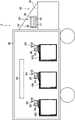
図1は、本発明の第1実施形態による保温容器を含む管理システムの構成を示す構成図である。本実施形態の管理システムは、例えば、トラックなどの貨物室に保温容器を積載して搬送する際に、保温容器内の温度を管理するためのシステムである。<First Embodiment>
Hereinafter, a management system including a heat insulating container according to a first embodiment of the present invention will be described in detail with reference to the drawings.
FIG. 1 is a configuration diagram showing the configuration of a management system including heat insulating containers according to a first embodiment of the present invention. The management system of the present embodiment is a system for managing the temperature inside a heat insulating container when the heat insulating container is loaded and transported in a cargo compartment of a truck or the like, for example.
図1に示すように、管理システム1は、管理端末10と、複数の保温容器100と、各保温容器100に対応して設けられた中継端末20を備える。本実施形態では、管理システム1は、トラック40の貨物室42内及び搭乗室43に設けられている。貨物室42は、空調装置44を有している。空調装置44は、貨物室42の内部空間を所定の温度に保つように制御されている。 As shown in FIG. 1 , the management system 1 includes a
管理端末10は、制御部12、アンテナ14、表示部16、及び警報部18と、例えば、LANなどの有線により通信可能に接続されている。制御部12は、例えば、CPU、RAM、ROM、外部メモリと、入力部と、出力部などを含んで構成される。RAM、ROM、外部メモリ、入力部、出力部はバスを介してCPUに接続されている。CPUは、システムバスに接続される各デバイスを統括的に制御する。なお、管理端末10は、空調装置44に制御可能に接続されていてもよい。 The
ROMや外部メモリには、CPUの制御プログラムであるBIOSやOS、コンピュータが実行する機能を実現するために必要な各種プログラムやデータ等が記憶されている。
RAMは、CPUの主メモリや作業領域等として機能する。CPUは、処理の実行に際して必要なプログラム等をROMや外部メモリからRAMにロードして、ロードしたプログラムを実行することで各種動作を実現する。
外部メモリは、例えば、フラッシュメモリ、ハードディスク、DVD-RAM、USBメモリ等から構成される。The ROM and external memory store BIOS and OS, which are control programs for the CPU, and various programs and data necessary for realizing the functions executed by the computer.
The RAM functions as a main memory, work area, etc. of the CPU. The CPU loads necessary programs and the like from the ROM or external memory to the RAM when executing processing, and executes the loaded programs to realize various operations.
The external memory is composed of, for example, flash memory, hard disk, DVD-RAM, USB memory, and the like.
入力部は、ユーザ等から操作指示等を受け付ける。入力部は、例えば、入力ボタン、キーボード、ポインティングデバイス、ワイヤレスリモコン、マイクロフォン、カメラ等の入力デバイスから構成される。
出力部は、CPUで処理されるデータや、RAM、ROMや外部メモリに記憶されるデータを出力する。The input unit receives an operation instruction or the like from a user or the like. The input unit includes input devices such as input buttons, keyboards, pointing devices, wireless remote controllers, microphones, and cameras.
The output unit outputs data processed by the CPU and data stored in the RAM, ROM, or external memory.
図1に示す管理システム1の管理端末10の制御部12は、ROMや外部メモリに記憶された各種プログラムが、CPU、RAM、ROM、外部メモリ、入力部、出力部等を資源として使用することで実現される。 The
制御部12は、後述するように各保温容器の内部温度に関する情報を、中継端末20を介して、保温容器100の無線ICタグから受信し、保温容器を示す識別用IDに対応付けて、温度情報に関する情報と、測定時間とを組み合わせて、RAM又はROMなどに記録する。なお、保温容器の内部の温度情報だけでなく、湿度情報も取得してよい。また、制御部12は、受信した保温容器の内部温度に関する情報を、保温容器を示す識別用IDと、測定時間とともに出力部から出力する。 As will be described later, the
表示部16は、例えば、有機ELディスプレイなどからなり、制御部12の出力部に接続されている。表示部16は、制御部12の出力部から受信した各保温容器100内の温度に関する情報を、保温容器を示す識別用IDと、測定時間とともに画面表示する。
警報部18は、例えば、スピーカやライトなどであり、ブザー音や警報ランプなどを使用し、保温容器100内の温度が所定の範囲から外れると制御部12で判断される場合には、リアルタイムでユーザ等に通知する。
アンテナ14は、制御部12の入力部及び出力部に接続されており、無線により中継端末20との間で通信することができる。また、アンテナ14は出力部から出力された情報を管理システム1の外部と通信可能なアンテナを有することもできる。The
The
The
中継端末20は、制御部26と、リーダライタ部22と、アンテナ24と、を備える。制御部26は、CPU、RAM、ROM、入力部、出力部などを含んで構成される。制御部26も、管理端末10の制御部12と同様に、ROMに記憶された各種プログラムが、CPU、RAM、ROM、入力部、出力部等を資源として使用することで実現される。制御部26には、リーダライタ部22と、アンテナ24が接続されている。 The
アンテナ24は、管理端末10のアンテナ14と無線通信可能である。
リーダライタ部22は、無線ICタグと通信可能なトランスポンダからなり、高周波を送受信し、この高周波により後述するように保温容器100の無線ICタグ120と導波構造体160を通じて通信可能である。The
The reader/writer unit 22 is composed of a transponder capable of communicating with a wireless IC tag, transmits and receives high frequency waves, and can communicate with the
無線ICタグ120は、後述するようにアンテナ及びICチップを有し、ICチップは記憶装置、温度センサや湿度センサを含んでいる。ICチップには保温容器100を識別するための識別用IDが記憶されている。無線ICタグ120はリーダライタ部から所定の搬送周波数の高周波を受信すると、この高周波により電力を生成し、ICチップを駆動することができる。そして、ICチップは生成された電力により、温度センサを作動させて保温容器内の温度を測定し、測定した温度を識別用IDに対応付けて温度情報を生成する。また、無線ICタグ120は、アンテナから高周波により温度情報をリーダライタ部22に送信することができる。 The
本実施形態の管理システム1は、例えば、以下のように作動する。
本実施形態の管理システム1では、所定の時間間隔をあけて、制御部12がアンテナ14から問い合わせ信号を、中継端末20のアンテナ24に送信する。The management system 1 of this embodiment operates, for example, as follows.
In the management system 1 of this embodiment, the
中継端末20は問い合わせ信号を受信すると、リーダライタ部22により導波構造体160を通じて無線ICタグ120に高周波を、後述する導波構造体を通じて送信する。無線ICタグ120は、高周波を受信すると、この高周波により電力を生成し、ICチップを駆動する。ICチップが駆動されると温度センサにより保温容器内の温度を測定して温度情報を生成し、識別用IDを対応付けた温度情報をアンテナから高周波により送信する。 When the
中継端末は、リーダライタ部22が導波構造体を通じて無線ICタグから温度情報を受信すると、アンテナ24によりこの温度情報を管理端末10のアンテナ14に送信する。 When the reader/writer unit 22 receives the temperature information from the wireless IC tag through the waveguide structure, the relay terminal transmits this temperature information to the
また、管理端末10は、各中継端末20から受信した各保温容器100の温度情報に基づき、表示部16に、識別IDと、保温容器内の温度と、測定時間とを表示する。また、管理端末10は、アンテナ14により温度情報を受信すると、識別IDと温度情報と、測定時間とを対応付けて制御部12に記憶する。これにより、制御部12には、各保温容器の識別IDに対して、測定時間と保温容器内の温度とが対応付けられた時系列データが作成される。 In addition, the
また、管理端末10は、保温容器100内の温度が所定の範囲から外れる場合には、制御部12から警報部18への警報信号を送信する。ユーザ等は、警報部18から通知された警報に基づいて空調装置44の駆動を操作し、保温容器100内の温度が所定の範囲内になるように、貨物室42内の温度を調整することができる。 Moreover, the
次に、保温容器100について詳細に説明する。
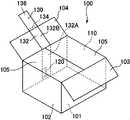
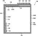
図2A~図2Cは、本発明の第1実施形態による保温容器を示す斜視図であり、図2Aは、前部フラップ、後部フラップ、及び、側部フラップを開放した状態であり、図2Bは前部フラップ及び後部フラップを開放し、側部フラップを閉鎖した状態であり、図2Cは、前部フラップ、後部フラップ、及び、側部フラップを閉鎖した状態である。また、図3は、無線ICタグを通る縦断面図であり、図2CにおけるA-A断面図である。Next, the
2A to 2C are perspective views showing the thermal insulation container according to the first embodiment of the present invention, FIG. 2A showing a state in which the front flap, rear flap and side flaps are opened, and FIG. The front and rear flaps are open and the side flaps are closed; FIG. 2C is the front, rear and side flaps closed. Also, FIG. 3 is a longitudinal sectional view passing through the wireless IC tag, which is a sectional view taken along line AA in FIG. 2C.
図2A~図2C及び図3に示すように、保温容器100は、容器本体110と、無線通信デバイスとしての無線ICタグ120と、導波部材130と、を備える。
容器本体110は、通称A式段ボール箱などと呼ばれる組み立てた状態で直方体状になる容器からなる。容器本体110は、矩形状に形成された底部101と、底部101の周縁から筒状に立設された側壁102と、側壁102の前面の上端から延びる前部フラップ103と、側壁102の後面の上端から延びる後部フラップ104と、側壁の側面の上端から延びる一対の側部フラップ105と、を備える。As shown in FIGS. 2A to 2C and 3, the
The container
底部101は、詳細は図示しないが、側壁102から下方に延びる外フラップ及び内フラップが折りたたまれて構成されている。 Although details are not shown, the
側壁102は、前方及び後方の横方向長さが側方の横方向幅よりも長いような上面視矩形状の筒状に形成されている。なお、ここでいう筒状とは、細長い部材の両端部を接続して環状に形成したものも含む。側壁102の前部及び後部の下縁及び上縁には、それぞれ外フラップ(前部フラップ103及び後部フラップ104)が接続されており、側壁の側部の下縁及び上縁には、それぞれ、内フラップ(側部フラップ105)が接続されている。 The
前部フラップ103及び後部フラップ104の長さは、容器本体110の奥行の略半分となっている。前部フラップ103、後部フラップ104及び側部フラップ105は、保温容器100を開放した状態では上方又は外方に向かうように折り曲げられている。また、側部フラップ105を内側に向かって折り曲げ、次に、前部フラップ103及び後部フラップ104を側部フラップ105の上方に位置するように、側壁102に対して内側に向かって折り曲げることにより、これら前部フラップ103、後部フラップ104及び側部フラップ105が保温容器100の天板(蓋)を構成する。 The length of the
図3に示すように、容器本体110の壁面は、第一遮熱層100A、第二遮熱層100B及び断熱層100Cにより構成され、第一遮熱層100Aが保温容器100の内表面となり、第二遮熱層100Bが保温容器100の外表面となるように、第一遮熱層100A及び第二遮熱層100Bにより断熱層100Cの両面がそれぞれ覆われている。第一遮熱層100A及び第二遮熱層100Bは、熱反射性の高いアルミなどの金属箔からなり、断熱層100Cは発泡スチロールや段ボールなどからなる。第一遮熱層100A及び第二遮熱層100Bは、断熱層100Cに対して、例えば、アルミを蒸着させたり、アルミ蒸着フィルムを貼り付けたりすることにより形成されている。このようなアルミ蒸着は、容器本体110を構成する段ボール箱を組み立てる前の展開された状態で全面に行えばよい。また、本実施形態では、容器本体110の壁面の表面に遮熱層が形成されているが、電気的に独立した遮熱層が2層以上あればよく、容器本体110の表面が断熱層または保護層により覆われていてもよい。また、断熱層100Cは、段ボール層と発泡スチロール層とを接着層により接着させた複数の材料からなる断熱層で構成してもよい。 As shown in FIG. 3, the wall surface of the
無線ICタグ120は金属対応無線ICタグからなり、容器本体110の側壁102の後方面の表面に取り付けられた導波部材130の表面に取り付けられている。例えば、無線ICタグ120の底部101側の端部から側壁102の上縁まで距離が、リーダライタ部との通信に用いられる搬送波の周波数の波長の1/2の整数倍となるように取り付けることができる。金属対応無線ICタグは、金属部品などの電気伝導体に取付けられることで、電気伝導体と電気的又は電磁界的に結合することにより、電波の送信性能や読取性能が向上する無線ICタグである。無線ICタグ120は、基板本体124と、ICチップ122と、基板本体124の表面に形成されたプリント回路(図示せず)とを備える。プリント回路はアンテナを形成するとともにICチップに接続されている。本実施形態のICチップは、温度センサや湿度センサを内蔵するとともに、保温容器100を識別するための固有の識別IDを記憶している。また、ICチップに温度センサや湿度センサに対する温度校正値を記憶しておき、温度センサや湿度センサの測定値を補正してもよい。無線ICタグは、高周波をプリント回路が形成するアンテナにおいて受信し、受信した電波を電源としてICチップを起動させ、ICチップで測定した温度を、ICチップで記憶している識別IDと組みつけて、アンテナを通じてリーダに高周波の応答波を送信する。なお、本明細書でいう高周波とは、リーダライタ部と、無線ICタグとの間で通信するための電波、電磁波又は磁界の変動をいい、通信に用いられる搬送波の周波数は、長波帯域、RF帯域、UHF帯域、マイクロ波帯のいずれであってもよい。また、無線ICタグの通信方式は、電磁誘導方式であっても電波を使用する電界方式であってもよい。無線ICタグ120の取り付け方法は、導波部材130の表面に取り付ける方法に限らず、無線ICタグ120のアンテナと導波部材130とが電気的に結合されればよい。 The
なお、本明細書において、電気的又は電磁界的に結合されるとは、導波部材130が無線ICタグ120に直接接続される場合に限らず、例えば、導波部材130と無線ICタグ120のアンテナとが容量結合することにより、アンテナから送信する電波が導波部材130に伝達されるような構成であればこれに含まれる。 In this specification, the term "electrically or electromagnetically coupled" is not limited to the case where the
導波部材130は容易に折り曲げ可能で柔軟性のある一枚の電気伝導体からなる。このような電気伝導体としては、例えば、細長い矩形状の金属箔を用いることができる。このような金属箔としては、例えば、アルミ箔、金属箔(銅、銀、金、白金、チタン、ステンレス、アルミニウム合金、ベリリウム銅、燐青銅、黄銅、洋白、ニッケル、ニクロム、ニッケル合金、錫、亜鉛、鉛、タンタル、モリブデン、ニオブ、鉄、銀ろう、C276合金、C22合金、Alloy600、Alloy718、コバール、ジルコニウム、イリジウム、はんだ、モネル、インコネル)などを用いることができる。また、金属箔ではなく、グラファイトシートを用いることもできる。導波部材130は、容器本体110を組み立てた状態で容器本体110の内側に位置する内側部132と、容器本体110の外側に位置する外側部136と、内側部132と外側部136との間を接続する連結部134と、を備える。導波部材130は、折り返すことなく、外周に沿って連続的に配置されている。このように導波部材130が折り返すことがないため、内側部132と外側部136とが重なりあって、互いに対向するように配置されることがない。 The waveguiding
内側部132は、側壁102に沿うように取り付けられた側壁部132Aと、後部フラップ104に沿うように形成された後方上部132Bとを備える。側壁部132A及び後方上部132Bは、絶縁性材料からなるスペーサ137を介して容器本体110の後方の側壁102に取り付けられている。スペーサとしては、例えば、発泡PS、発泡PP、発泡ポリウレタン、発泡ポリエチレン、EVA架橋発泡体、PET樹脂発泡体、フェノールフォーム、シリコーンフォーム、ポリ塩化ビニルフォーム、ユリアフォーム、アクリルフォーム、ポリイミドフォーム、EPDMフォーム等の発泡プラスチック、プラスチックに中空ビーズ、エアロゲル、フュームドシリカ等を混練した複合プラスチック、ビニール製の気泡緩衝材、コルク、エアロゲル、繊維系断熱材などを用いることができる。
連結部134は、前部フラップ103と後部フラップ104との間の隙間を通じて容器本体110の内部空間から外部へと延びている。なお、金属箔は非常に薄いため、容器本体110の前部フラップ103と後部フラップ104との間を容易に通過させることができる。 The connecting
外側部136は、容器本体110を閉鎖した状態で、接着剤139を介して前部フラップ103の上面に接着されている。接着剤139は、絶縁性能はなくてもよいが、断熱性を有する材料が好ましい。このような接着剤139としては、特に限定されず、金属箔と第二遮熱層100Bとに対して十分な接着性を有していればよい。 The
外側部136の上面は保護シール140により外部に露出する全面が覆われている。保護シール140としては、断熱性を有する材料が好ましい。このような保護シール140としては、例えば、スペーサと同様の材料を用いることができる。 The upper surface of the
本実施形態では、導波部材130により、容器本体110の内側と外側との間で高周波の伝搬を可能にする導波構造体160が形成される。 In this embodiment, the
保温容器100内に温度管理の対象となる食品や薬剤などの物品を収容して閉鎖する際には以下のようにすればよい。なお、容器本体110の底部は、予め、内フラップ及び外フラップを折り曲げ、テープなどにより隙間を塞ぐことにより形成されている。
まず、容器本体110に導波部材130がスペーサ137を介して取り付け、導波部材130には無線ICタグ120を取り付ける。なお、無線ICタグ120が取り付けられた状態の導波部材130を容器本体110に取り付けてもよい。When storing articles such as foods and medicines whose temperature is to be controlled in the
First, the
次に、容器本体110の内部に温度管理の対象となる食品や薬剤などの物品を収容する。
次に、図2Bに示すように、側部フラップ105を内側に折り曲げる。Next, articles such as foods and medicines to be subjected to temperature control are accommodated inside the
The side flaps 105 are then folded inwardly as shown in FIG. 2B.
次に、前部フラップ103を内側に折り曲げ、前部フラップ103の上面の一部に接着剤139を塗布する。また、外側部136が容器本体110の外部に位置するように、後部フラップ104を内側に折り曲げ、外側部136を接着剤139に付着させる。なお、先に前部フラップ103及び後部フラップ104を内側に折り曲げ、その後、外側部136を接着剤139により前部フラップ103に取り付けてもよい。 Next, the
次に、外側部136を覆うように、保護シール140を貼り付ける。
そして、必要に応じて、前部フラップ103と後部フラップ104との間や、前部フラップ103及び後部フラップ104と側壁102との間をテープなどにより塞ぐ。これにより、容器本体110が閉鎖状態となる。Next, a
Then, if necessary, the space between the
なお、容器本体110を開放する場合には、容器本体110を閉鎖する際の逆に行えばよいが、例えば、導波部材130に易裂加工をほどこしておけば、導波部材130を切って容易に開放することができる。 In order to open the
本実施形態の保温容器100によれば、無線ICタグ120が導波部材130に電気的に結合されているため、導波部材130により電波を送信することが可能な導波構造体160が形成される。このため、中継端末20のリーダライタ部22から送信された高周波は、導波部材130により形成された導波構造体160を通じて、保温容器100の外部から内部に伝達され、無線ICタグ120のアンテナにより受信される。また、無線ICタグ120から送信された高周波は、導波部材130により形成された導波構造体160を通じて、保温容器100の内部から外部に伝達され、導波部材130から発信される。そして、導波部材130から発信された高周波は、中継端末20のリーダライタ部22により受信される。 According to the
以上説明したように、本実施形態によれば以下の効果が奏される。
本実施形態によれば、導波部材130により容器本体110の内側と外側の間で高周波が伝搬されるため、保温容器100に2つ以上の遮熱層100A、100Bが設けられることにより保温容器100の内部と外部で電波の伝搬を妨げた場合であっても、容器本体110の内部に設けられた無線ICタグ120と、容器本体110の外部に設けられたリーダライタ部22との間で通信が可能になる。As described above, according to this embodiment, the following effects are achieved.
According to this embodiment, since the
また、本実施形態によれば、導波部材130が、内側部132と、連結部134と、外側部136と、を備えているため、容器本体110に形成された隙間に導波部材130を設けるのみの簡単な構成で、容器本体110の内側と外側との間で高周波の伝搬が可能になる。 Further, according to the present embodiment, since the
また、本実施形態によれば、導波部材130が内側部132と外側部136とが重なりあうことがないため、内側部132と外側部136の間で静電容量が形成され、通信性能が低下するのを防止できる。 Further, according to the present embodiment, since the
また、本実施形態によれば、A型の段ボール箱にもともと存在する、前部フラップ103と後部フラップ104の間の隙間を利用して導波部材130を配置することができる。 Further, according to this embodiment, the
また、本実施形態によれば、導波部材130と無線ICタグ120とが電気的又は電磁界的に結合されているため、無線ICタグ120から送信された高周波が確実に導波部材130に伝達され、導波部材130を伝搬した高周波が確実に無線ICタグ120に伝達される。 Further, according to the present embodiment, since the
また、本実施形態によれば、導波部材130がシート状の電気伝導体である金属箔からなるため、非常に狭い空間を通じて導波部材130を配置することができる。 Further, according to the present embodiment, since the
また、本実施形態によれば、導波部材130が、スペーサ137を介して容器本体110の遮熱層100A上に取り付けられているため、無線ICタグ120に対して容器本体110の状態による通信への影響を軽減することができ、通信性能を安定させることができる。 Further, according to the present embodiment, since the
また、本実施形態によれば、無線ICタグ120が、温度センサを有するため、金属製の第一遮熱層100Aと第二遮熱層100Bを備えた容器本体110内の温度を無線ICタグ120で測定し、外部で管理することができる。 Further, according to this embodiment, since the
また、本実施形態によれば、無線ICタグ120が、パッシブ型のタグであるため、容器本体110内が低温であっても、無線ICタグ120の性能が低下するのを防止できる。 Further, according to this embodiment, since the
<第2実施形態>
以下、本発明による保温容器の第2実施形態について説明する。なお、本実施形態の保温容器も第1実施形態のように管理システムに用いられるものである。また、第1実施形態と同様の構成については同じ符号を付して詳細な説明を省略する。<Second embodiment>
A second embodiment of a heat insulating container according to the present invention will be described below. Note that the heat insulating container of this embodiment is also used in the management system like the first embodiment. Also, the same reference numerals are assigned to the same configurations as in the first embodiment, and detailed description thereof will be omitted.
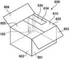
図4A及び図4Bは、本発明の第2実施形態による保温容器を示す斜視図であり、図4Aは、前部フラップ及び後部フラップを開放した状態であり、図4Bは前部フラップ及び後部フラップを閉鎖した状態である。また、図5は、図4BにおけるA-A断面図である。本実施形態では、保温容器200を構成する容器本体210が側部フラップを備えておらず、また、無線ICタグは、後部フラップ204に取り付けられている点で第1実施形態と異なっている。 4A and 4B are perspective views showing a heat insulating container according to a second embodiment of the present invention, where FIG. 4A shows a state in which the front and rear flaps are opened, and FIG. 4B shows a state in which the front and rear flaps are opened. is closed. 5 is a cross-sectional view taken along the line AA in FIG. 4B. This embodiment differs from the first embodiment in that a
図4A、図4B及び図5に示すように、保温容器200は、容器本体210と、無線通信デバイスとしての無線ICタグ120と、導波部材230と、を備える。
容器本体210は、組み立てた状態で直方体状になる段ボール箱に類する容器からなる。容器本体210は、矩形状に形成された底部201と、底部201の周縁から筒状に立設された側壁202と、側壁202の前面の上端から延びる前部フラップ203と、側壁202の後面の上端から延びる後部フラップ204と、を備える。As shown in FIGS. 4A, 4B, and 5, the
The
底部201は、詳細は図示しないが、側壁202から下方に延びる外フラップ及び内フラップが折りたたまれて構成されている。 Although details are not shown, the
側壁202は、前方及び後方の横方向長さが側方の横方向幅よりも長いような上面視矩形状の筒状に形成されている。側壁202の前部及び後部の上縁には、それぞれ前部フラップ203及び後部フラップ204が接続されており、側壁202の下縁には内フラップ及び外フラップが接続されている。 The
前部フラップ203及び後部フラップ204の長さは、容器本体210の奥行の略半分となっている。前部フラップ203及び後部フラップ204は、保温容器200を開放した状態では上方又は外方に向かうように折り曲げられている。また、前部フラップ203及び後部フラップ204を側壁202に対して内側に向かって折り曲げることにより、これら前部フラップ203及び後部フラップ204が保温容器200の天板(蓋)を構成する。 The length of the
図5に示すように、容器本体210の壁面は、熱反射性の高い金属からなりそれぞれ電気的に独立した第一遮熱層200A及び第二遮熱層200Bと、断熱層200Cとにより構成され、容器本体210の内表面には、第1実施形態と同様に第一遮熱層200Aが形成されている。
無線ICタグ120は、第1実施形態と同様に金属対応無線ICタグからなり、容器本体210の後部フラップ204の内面に取り付けられた導波部材230の表面に、導波部材230と電気的又は電磁界的に結合されるように取り付けられている。As shown in FIG. 5, the wall surface of the
The
導波部材230は、容器本体210を組み立てた状態で容器本体210の内側に位置する内側部232と、容器本体210の外側に位置する外側部236と、内側部232と外側部236とを接続する連結部234と、を備える。本実施形態においても導波部材230は折り返されていない。 The
内側部232は、後部フラップ204に絶縁材料からなるスペーサ137を介して取り付けられている。連結部234は、前部フラップ203と後部フラップ204との間の隙間を通じて容器本体210の内部空間から外部へと延びている。なお、金属箔からなる導波部材230は非常に薄いため、容器本体210の前部フラップ203と後部フラップ204との間を容易に通過させることができる。外側部236は、容器本体210を閉鎖した状態で、接着剤139を介して前部フラップ203の上面に接着されている。外側部236の上面は保護シール140により外部に露出する全面が覆われている。 The
本実施形態では、導波部材230により、容器本体210の内側と外側との間で高周波の伝搬を可能にする導波構造体260が形成される。 In this embodiment, the
保温容器200内に温度管理の対象となる食品や薬剤などの物品を収容して閉鎖する(保温容器を組み立てる)際には以下のようにすればよい。なお、容器本体210の底部は、予め、内フラップ及び外フラップを折り曲げ、テープなどにより隙間を塞ぐことにより形成されている。 When storing articles such as foods and medicines whose temperature is to be controlled in the heat-retaining
まず、容器本体210に、導波部材230をスペーサ137を介して取り付け、導波部材230に無線ICタグ120を取り付ける。なお、無線ICタグ120が取り付けられた状態の導波部材230を容器本体210に取り付けてもよい。 First, the
次に、容器本体210の内部に温度管理の対象となる食品や薬剤などの物品を収容する。
次に、図4Bに示すように、前部フラップ203を内側に折り曲げ、前部フラップ203の上面の一部に接着剤139を塗布する。また、外側部236が容器本体210の外部に位置するように、後部フラップ204を内側に折り曲げ、外側部236を接着剤139に付着させる。なお、先に前部フラップ203及び後部フラップ204を内側に折り曲げ、その後、外側部236を接着剤139により前部フラップ203に取り付けてもよい。Next, articles such as foods and medicines whose temperature is to be controlled are stored inside the container
Next, as shown in FIG. 4B, the
次に、外側部236を覆うように、保護シール140を貼り付ける。
そして、必要に応じて、前部フラップ203と後部フラップ204との間や、前部フラップ203及び後部フラップ204と側壁202との間をテープなどにより塞ぐ。これにより、容器本体210が閉鎖状態となる。Next, a
Then, if necessary, the space between the
なお、容器本体210を開放する場合には、容器本体210を閉鎖する際の逆に行えばよいが、例えば、導波部材230に易裂加工をほどこしておけば、導波部材230を切って容易に開放することができる。 In order to open the
本実施形態の保温容器200によれば、無線ICタグ120が導波部材230に電気的又は電磁界的に接続されているため、導波部材230により高周波を伝搬することが可能な導波構造体260が形成される。このため、中継端末20のリーダライタ部22から送信された高周波は、導波部材230により形成された導波構造体260を通じて、保温容器200の外部から内部に伝達され、無線ICタグ120のアンテナにより受信される。また、無線ICタグ120から送信された高周波は、導波部材230により形成された導波構造体260を通じて、保温容器200の内部から外部に伝達され、導波部材230から発信される。そして、導波部材230から発信された高周波は、中継端末20のリーダライタ部22により受信される。 According to the
本実施形態によれば、第1実施形態と同様の効果が奏される。 According to this embodiment, the same effects as those of the first embodiment can be obtained.
<第3実施形態>
以下、本発明による保温容器の第3実施形態について説明する。なお、本実施形態の保温容器も第1実施形態のように管理システムに用いられるものである。また、第1実施形態と同様の構成については同じ符号を付して詳細な説明を省略する。<Third Embodiment>
A third embodiment of a heat insulating container according to the present invention will be described below. Note that the heat insulating container of this embodiment is also used in the management system like the first embodiment. Also, the same reference numerals are assigned to the same configurations as in the first embodiment, and detailed description thereof will be omitted.
図6A及び図6Bは、本発明の第3実施形態による保温容器を示す斜視図であり、図6Aは、蓋フラップ及び側部フラップを開放した状態であり、図6Bは蓋フラップ及び側部フラップを閉鎖した状態である。また、図7は、図6BにおけるA-A断面図である。本実施形態では、保温容器300を構成する容器本体310が前部フラップを備えておらず、後部フラップに代えて蓋フラップを備えており、また、無線ICタグは、側壁302の前方の内面に取り付けられている点で第1実施形態と異なっている。 6A and 6B are perspective views showing a heat insulating container according to a third embodiment of the present invention, FIG. 6A showing a state in which the lid flap and the side flaps are opened, and FIG. 6B showing the lid flap and the side flaps. is closed. Also, FIG. 7 is a sectional view taken along the line AA in FIG. 6B. In this embodiment, the
図6A、図6B及び図7に示すように、保温容器300は、容器本体310と、無線通信デバイスとしての無線ICタグ120と、導波部材330と、を備える。
容器本体310は、通称B式段ボール箱又はN式段ボール箱などと呼ばれる組み立てた状態で直方体状になる容器からなる。容器本体310は、矩形状に形成された底部301と、底部301の周縁から筒状に立設された側壁302と、側壁302の側壁の両側の上端から延びる側部フラップ305と、側壁302の後面の上端から延びる後部フラップ(蓋部)304と、を備える。As shown in FIGS. 6A, 6B, and 7, the
The container
底部301は、詳細は図示しないが、側壁302から下方に延びる外フラップ及び内フラップが折りたたまれて構成されている。 Although details are not shown, the
側壁302は、前方及び後方の横方向長さが側方の横方向幅よりも長いような上面視矩形状の筒状に形成されている。側壁302の後部の上縁には、後部フラップ304が接続されており、側壁302の下縁には内フラップ及び外フラップが接続されている。 The
後部フラップ304の長さは、容器本体310の奥行の長さと略等しくなっている。また、後部フラップ304の先端縁には差込部304Aが接続されている。後部フラップ304及び側部フラップ305は、保温容器300を開放した状態では上方又は外方に向かうように折り曲げられている。また、側部フラップ305を側壁302に対して内側に向かって折り曲げ、後部フラップ304を側壁302に対して内側に向かって折り曲げ、差込部304Aを側壁302の内側に差し込むことにより、後部フラップ304が保温容器300の天板(蓋)を構成する。 The length of the
図7に示すように、容器本体310の壁面は、熱反射性の高い金属からなりそれぞれ電気的に独立した第一遮熱層300A及び第二遮熱層300Bと、断熱層300Cとにより構成され、容器本体310の内表面には、第1実施形態と同様に第一遮熱層300Aが形成されている。
無線ICタグ120は、第1実施形態と同様に金属対応無線ICタグからなり、容器本体310の側壁302の前方部分の内面に取り付けられた導波部材330の表面に、導波部材330と電気的又は電磁界的に結合されるように取り付けられている。As shown in FIG. 7, the wall surface of the
The
導波部材330は、容器本体310を組み立てた状態で容器本体310の内側に位置する内側部332と、容器本体310の外側に位置する外側部336と、内側部332と外側部336とを接続する連結部334と、を備える。本実施形態においても導波部材330は折り返されていない。 The
内側部332は、後部フラップ304に絶縁材料からなるスペーサ137を介して取り付けられている。連結部334は、組み立て状態において、後部フラップ304及び差込部304Aと側壁302の間の隙間を通じて容器本体310の内部空間から外部へと延びている。なお、金属箔からなる導波部材330は非常に薄いため、容器本体310の後部フラップ304及び差込部304Aと側壁302の間を容易に通過させることができる。外側部336は、容器本体310を閉鎖した状態で、接着剤139を介して後部フラップ304の上面に接着されている。外側部336の上面は保護シール140により外部に露出する全面が覆われている。 The
本実施形態では、導波部材330により、容器本体310の内側と外側との間で高周波の伝搬を可能にする導波構造体360が形成される。 In this embodiment, the
保温容器300内に温度管理の対象となる食品や薬剤などの物品を収容して閉鎖する際には以下のようにすればよい。なお、容器本体310の底部は、内フラップ及び外フラップを折り曲げ、テープなどにより隙間を塞ぐことにより形成されている。 When storing articles such as foods and medicines whose temperature is to be controlled in the
まず、容器本体310には、導波部材330をスペーサ137を介して取り付け、導波部材330に無線ICタグ120を取り付ける。なお、無線ICタグ120が取り付けられた状態の導波部材330を容器本体310に取り付けてもよい。 First, the
次に、容器本体310の内部に温度管理の対象となる食品や薬剤などの物品を収容する。
次に、側部フラップ305を内側に折り曲げる。Next, articles such as foods and medicines whose temperature is to be controlled are accommodated inside the container
Next, the side flaps 305 are folded inward.
次に、外側部336が容器本体310の外部に位置するように、後部フラップ304を内側に折り曲げ、後部フラップ304の上面の一部に接着剤139を塗布する。そして、外側部336を接着剤139に付着させる。 Next, the
次に、外側部336を覆うように、保護シール140を貼り付ける。
そして、必要に応じて、後部フラップ304と側壁302との間をテープなどにより塞ぐ。これにより、容器本体310が閉鎖状態となる。Next, a
Then, if necessary, the gap between the
なお、容器本体310を開放する場合には、容器本体310を閉鎖する際の逆に行えばよいが、例えば、導波部材330に易裂加工をほどこしておけば、導波部材330を切って容易に開放することができる。 When the
本実施形態の保温容器300によれば、無線ICタグ120が導波部材330に電気的又は電磁界的に結合されているため、導波部材330により電波を送信することが可能な導波構造体360が形成される。このため、中継端末20のリーダライタ部22から送信された高周波は、導波部材330により形成された導波構造体360を通じて、保温容器300の外部から内部に伝達され、無線ICタグ120のアンテナにより受信される。また、無線ICタグ120から送信された高周波は、導波部材330により形成された導波構造体360を通じて、保温容器300の内部から外部に伝達され、導波部材330から発信される。そして、導波部材330から発信された高周波は、中継端末20のリーダライタ部22により受信される。 According to the
本実施形態によれば、第1実施形態の効果に加えて以下の効果が奏される。
本実施形態では、導波部材330の連結部334が容器本体310の側壁302と後部フラップ304との間を通るため、一般的な容器にもともと存在する隙間を通じて導波部材330を配置することができる。According to this embodiment, the following effects are obtained in addition to the effects of the first embodiment.
In this embodiment, since the connecting
<第4実施形態>
以下、本発明による保温容器の第4実施形態について説明する。なお、本実施形態の保温容器も第1実施形態のように管理システムに用いられるものである。また、第1実施形態と同様の構成については同じ符号を付して詳細な説明を省略する。<Fourth Embodiment>
A fourth embodiment of the heat insulating container according to the present invention will be described below. Note that the heat insulating container of this embodiment is also used in the management system like the first embodiment. Also, the same reference numerals are assigned to the same configurations as in the first embodiment, and detailed description thereof will be omitted.
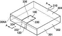
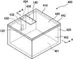
図8A及び図8Bは、本発明の第4実施形態による保温容器を示す斜視図であり、図8Aは、蓋部を取り外して容器本体を開放した状態であり、図8Bは蓋部を取り付けて容器本体を閉鎖した状態である。また、図9は、図8BにおけるA-A断面図である。本実施形態では、保温容器400は、容器本体410と、無線通信デバイスとしての無線ICタグ120と、導波部材430と、を備え、保温容器400を構成する容器本体410が容器基部420と、蓋部440とにより構成されている。 8A and 8B are perspective views showing a heat insulating container according to a fourth embodiment of the present invention, FIG. 8A is a state in which the lid is removed and the container main body is opened, and FIG. 8B is a state in which the lid is attached. The container body is closed. 9 is a cross-sectional view taken along the line AA in FIG. 8B. In this embodiment, the
容器基部420及び蓋部440は、例えば、発泡スチロールからなる。
容器基部420は、矩形状に形成された底部401と、底部401の周縁から筒状に立設された側壁402と、を備える。The
The
蓋部440は、天板442と、差込部444とを含む。天板442は、底部401と同形状の板状に形成されている。差込部444は、天板442の下面に取り付けられた直方体状の部位からなり、その外形が容器基部420の側壁402の内周の形状と略等しくなっている。
図9に示すように、容器基部420の壁面は、熱反射性の高い金属からなりそれぞれ電気的に独立した第一遮熱層400A及び第二遮熱層400Bと、発泡スチロールからなる断熱層400Cとにより構成され、容器基部420の内表面には第一遮熱層400Aが形成されている。第一遮熱層400A及び第二遮熱層400Bは、容器基部420の断熱層400Cに、例えば、アルミを蒸着させたり、アルミ蒸着フィルムを貼り付けたりすることにより形成されている。このようなアルミ蒸着は、また、本実施形態では、容器基部420のみに遮熱層が形成されているが、蓋部440の内表面、内部または外表面などにも形成してもよい。なお、蓋部440の内表面にアルミを蒸着させる場合には、導波部材430と遮熱層との間に絶縁部材を配置することが好ましい。 As shown in FIG. 9, the wall surface of the
無線ICタグ120は金属対応無線ICタグからなり、容器基部420の側壁402の一面の上部に取り付けられた導波部材430の表面に、導波部材430と電気的又は電磁界的に結合されるように取り付けられている。 The
導波部材430は、容器本体410を組み立てた状態で容器本体410の内側に位置する内側部432と、容器本体410の外側に位置する外側部436と、内側部432と外側部436とを接続する連結部434と、を備える。 The
内側部432は、絶縁性材料からなるスペーサ137を介して容器基部420の一方の側壁402に取り付けられている。 The
連結部434は、組み立て状態において、容器基部420の側壁402の上部と蓋部440の差込部444の側部との間の隙間、及び、容器基部420の側壁402の上縁部と蓋部440の天板442との間の隙間を通じて、容器本体410の内部空間から外部へと延びている。なお、金属箔からなる導波部材430は非常に薄いため、容器基部420と蓋部440の間を容易に通過させることができる。 In the assembled state, the connecting
外側部436は、容器本体410を閉鎖した状態で、接着剤139を介して蓋部440の天板442の上面及び側面に折り曲げられた状態で接着されている。外側部436の上面及び側面は保護シール140により外部に露出する全面が覆われている。
本実施形態においても導波部材430は折り返されていない。With the
Also in this embodiment, the
本実施形態では、導波部材430により、容器本体410の内側と外側との間で高周波の伝搬を可能にする導波構造体460が形成される。 In this embodiment, the
保温容器400内に温度管理の対象となる食品や薬剤などの物品を収容して閉鎖する際には以下のようにすればよい。 When storing articles such as foods and medicines whose temperature is to be controlled in the
まず、容器本体410の容器基部420に、導波部材430をスペーサ137を介して取り付け、導波部材430に無線ICタグ120を取り付けられる。なお、無線ICタグ120が取り付けられた状態の導波部材430を容器基部420に取り付けてもよい。
次に、容器基部420の内部に温度管理の対象となる食品や薬剤などの物品を収容する。First, the
Next, articles such as foods and medicines whose temperature is to be controlled are accommodated inside the
次に、図8Bに示すように、導波部材430の外側部436を外方に向けた状態で、蓋部440を差込部444が、容器基部420の側壁402内に挿入されるように、蓋部440を容器基部420に取り付ける。 Next, as shown in FIG. 8B, with the
次に、外側部436において蓋部440の天板442の側面及び上面の一部と接触する部分に両面テープのような接着剤139を貼り付ける。そして、蓋部440の天板442の側面及び上面の一部を接着剤139に付着させる。
次に、外側部436を覆うように、保護シール140を貼り付ける。
これにより、容器本体410が閉鎖状態となる。Next, an adhesive 139 such as double-sided tape is attached to the portion of the
Next, a
Thereby, the container
なお、容器本体410を開放する場合には、容器本体410を閉鎖する際の逆に行えばよいが、例えば、導波部材430に易裂加工をほどこしておけば、導波部材430を切って容易に開放することができる。 In order to open the
本実施形態の保温容器400によれば、無線ICタグ120が導波部材430に電気的に接続されているため、導波部材430により電波を伝搬することが可能な導波構造体460が形成される。このため、中継端末20のリーダライタ部22から送信された高周波は、導波部材430により形成された導波構造体460を通じて、保温容器400の外部から内部に伝達され、無線ICタグ120のアンテナにより受信される。また、無線ICタグ120から送信された高周波は、導波部材430により形成された導波構造体460を通じて、保温容器400の内部から外部に伝達され、導波部材430から発信される。そして、導波部材430から発信された高周波は、中継端末20のリーダライタ部22により受信される。 According to the
本実施形態によれば、第4実施形態と同様の効果が奏される。 According to this embodiment, the same effects as those of the fourth embodiment can be obtained.
<第5実施形態>
以下、本発明による保温容器の第5実施形態について説明する。なお、本実施形態の保温容器も第1実施形態のように管理システムに用いられるものである。また、第1実施形態と同様の構成については同じ符号を付して詳細な説明を省略する。<Fifth Embodiment>
A fifth embodiment of the heat insulating container according to the present invention will be described below. Note that the heat insulating container of this embodiment is also used in the management system like the first embodiment. Also, the same reference numerals are assigned to the same configurations as in the first embodiment, and detailed description thereof will be omitted.
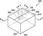
図10A~図10Cは、本発明の第5実施形態による保温容器を示す斜視図であり、図10Aは、前部フラップ、後部フラップ、及び、側部フラップを開放した状態であり、図10Bは前部フラップ及び後部フラップを開放し、側部フラップを閉鎖した状態であり、図10Cは、前部フラップ、後部フラップ、及び、側部フラップを閉鎖した状態である。また、図11は、図10CにおけるA-A断面図であり、図12は、図10CにおけるB-B断面図である。 10A to 10C are perspective views showing a heat insulating container according to a fifth embodiment of the present invention, FIG. 10A showing a state in which the front flap, rear flap and side flaps are opened, and FIG. The front and rear flaps are open and the side flaps are closed. FIG. 10C is the front, rear and side flaps closed. 11 is a sectional view taken along line AA in FIG. 10C, and FIG. 12 is a sectional view taken along line BB in FIG. 10C.
本実施形態では、容器本体は第1実施形態と同様のA式段ボール箱形式の容器である。 In this embodiment, the container body is an A-type cardboard box type container similar to that of the first embodiment.
図10A~図10C、図11及び図12に示すように、保温容器600は、容器本体610と、無線通信デバイスとしての無線ICタグ120と、導波部材630と、を備える。
容器本体610は、通称A式段ボール箱などと呼ばれる組み立てた状態で直方体状になる容器からなる。容器本体610は、矩形状に形成された底部601と、底部601の周縁から筒状に立設された側壁602と、側壁602の前面の上端から延びる前部フラップ603と、側壁602の後面の上端から延びる後部フラップ604と、側壁の側面の上端から延びる一対の側部フラップ605と、を備える。As shown in FIGS. 10A to 10C, 11 and 12, the
The container
底部601は、詳細は図示しないが、側壁602から下方に延びる外フラップ及び内フラップが折りたたまれて構成されている。 Although details are not shown, the
側壁602は、前方及び後方の横方向長さが側方の横方向幅よりも長いような上面視矩形状の筒状に形成されている。側壁602の前部及び後部の下縁及び上縁には、それぞれ外フラップ(前部フラップ603及び後部フラップ604)が接続されており、側壁の側部の下縁及び上縁には、それぞれ、内フラップ(側部フラップ605)が接続されている。 The
前部フラップ603及び後部フラップ604の長さは、容器本体610の奥行の略半分となっている。前部フラップ603、後部フラップ604及び側部フラップ605は、保温容器600を開放した状態では上方又は外方に向かうように折り曲げられている。また、側部フラップ605を内側に向かって折り曲げ、次に、前部フラップ603及び後部フラップ604を側部フラップ605の上方に位置するように、側壁602に対して内側に向かって折り曲げることにより、これら前部フラップ603、後部フラップ604及び側部フラップ605が保温容器600の天板(蓋)を構成する。 The length of
図11及び図12に示すように、容器本体610の壁面は、第一遮熱層600A、第二遮熱層600B及び断熱層600Cにより構成され、容器本体610の内表面には熱反射性の高い金属からなる第一遮熱層600Aが形成されている。また、容器本体610の外表面には熱反射性の高い金属からなる第二遮熱層600Bが形成されている。第一遮熱層600A、第二遮熱層600Bは、容器本体610の内面及び外面に、例えば、アルミを蒸着させたり、アルミ蒸着フィルムを貼り付けたりすることにより形成されている。このようなアルミ蒸着は、容器本体610を構成する段ボール箱を組み立てる前の展開された状態で両面に行えばよい。 As shown in FIGS. 11 and 12, the wall surface of the
無線ICタグ120は金属対応無線ICタグからなり、容器本体610の側壁602の後方面の表面に取り付けられた導波部材630の表面に、導波部材630と電気的又は電磁界的に結合されるように取り付けられている。 The
導波部材630は、容器本体610を組み立てた状態で容器本体610の内側に位置する内側部632と、側部フラップ605と電気的に接続された接続部634と、を備える。 The
内側部632は、絶縁性材料からなるスペーサ137を介して容器本体610の後方の側壁602の一側に取り付けられている。 The
接続部634は、側部フラップ605が折り曲げられた状態で、側部フラップ605の外面に、第二遮熱層600Bと電気的又は電磁界的に結合されるように、接着剤237を介して接続されている。なお、接続部634は、側部フラップ605の外面側の第二遮熱層600Bに直接取り付けられていてもよいし、第二遮熱層600Bにスペーサを介して接続し第二遮熱層600Bと電磁界的に結合させてもよい。
本実施形態においても導波部材630は折り返されていない。With the
Also in this embodiment, the
本実施形態では、導波部材630と、側部フラップ605及び側壁602の第二遮熱層600Bにより、容器本体610の内側と外側との間で高周波の伝搬を可能にする導波構造体660が形成される。 In this embodiment, a
保温容器600内に温度管理の対象となる食品や薬剤などの物品を収容して閉鎖する際には以下のようにすればよい。なお、容器本体610の底部は、内フラップ及び外フラップを折り曲げ、テープなどにより隙間を塞ぐことにより形成されている。 When storing articles such as foods and medicines whose temperature is to be controlled in the
まず、容器本体610に、導波部材630がスペーサ137を介して取り付け、導波部材630に無線ICタグ120を取り付ける。なお、無線ICタグ120が取り付けられた状態の導波部材630を容器本体610に取り付けてもよい。
次に、容器本体610の内部に温度管理の対象となる食品や薬剤などの物品を収容する。First, the
Next, articles such as foods and medicines whose temperature is to be controlled are stored inside the container
次に、図10Bに示すように、導波部材630の接続部634が外部に位置するように側部フラップ605を内側に折り曲げる。そして側部フラップ605の外面に接着剤237を塗布し、接続部634を側部フラップ605の外面に取り付ける。 Next, as shown in FIG. 10B, the side flaps 605 are folded inward so that the connecting
次に、前部フラップ603及び後部フラップ604を内側に折り曲げる。
そして、必要に応じて、前部フラップ603と後部フラップ604との間や、前部フラップ603及び後部フラップ604と側壁602との間をテープなどにより塞ぐ。これにより、容器本体610が閉鎖状態となる。Next,
Then, if necessary, the space between the
なお、容器本体610を開放する場合には、容器本体610を閉鎖する際の逆に行えばよいが、例えば、導波部材630に易裂加工をほどこしておけば、導波部材630を切って容易に開放することができる。 When the
図13は、本発明の第5実施形態による保温容器において、無線ICタグから放射された高周波が保温容器の外部まで伝搬される流れを示す図である。
本実施形態の保温容器600によれば、無線ICタグ120が導波部材630に電気的又は電磁界的に接続されているため、無線ICタグ120から送信された高周波は導波部材630に沿って内側部632から接続部634に向かって伝搬される。さらに、導波部材630の接続部634が側部フラップ605の第二遮熱層600Bに電気的又は電磁界的に接続されているため、接続部634まで到達した高周波は、側部フラップ605の第二遮熱層600Bに伝搬され、この部分から側壁602の外面の部分まで伝達される。そして、高周波は側部フラップ605の外方の第二遮熱層600Bから放射され、リーダライタ部まで伝達される。FIG. 13 is a diagram showing a flow of propagation of high frequency waves emitted from a wireless IC tag to the outside of the heat insulating container according to the fifth embodiment of the present invention.
According to the
また、リーダライタ部から送信された高周波は、側部フラップ605の外方の第二遮熱層600Bから第二遮熱層600Bを伝搬し、導波部材630の接続部634に伝達される。そして、高周波は導波部材630内を伝搬し、導波部材630の内側部632から無線ICタグ120のアンテナに放射される。 Further, the high frequency transmitted from the reader/writer section propagates from the second
このように、本実施形態では、導波部材630と、容器本体610の側壁602の外面に形成された第二遮熱層(壁面部)600Bと、容器本体610の側部フラップ605の第二遮熱層(延長部)600Bとにより、保温容器600の内側と外側との間で高周波の伝搬を可能にする導波構造体660が形成され、この導波構造体650を通じてリーダライタ部と無線ICタグ120との間で高周波を通信することが可能になる。 Thus, in this embodiment, the
本実施形態によれば、第1実施形態で奏される効果に加えて以下の効果が奏される。
本実施形態では、容器本体610が、側壁602の外面に形成された壁面部と、内フラップ605の外面に形成されて容器本体610の内部まで伸びる延長部とを含む第二遮熱層600Bを含み、導波部材630が延長部と電気的又は電磁界的に結合されている。このため、本実施形態によれば、導波部材630により、容器本体610の外面の熱反射のために形成された第二遮熱層600Bを利用して、容器本体610の内側と外側との間で高周波を伝搬する導波構造体660を形成することができる。According to this embodiment, the following effects are obtained in addition to the effects obtained by the first embodiment.
In this embodiment, the
なお、上記の第1~第5実施形態では、容器本体110、210、310、410、610の表面に金属箔からなる遮熱層が形成されていたため、導波部材130、230、330、430、630を容器本体110、210、310、410、610の内部の内面に取り付ける際にスペーサ137を介して取り付けていた。これに対して、遮熱層が容器本体の表面に形成されていない場合にはスペーサが不要となる。図14は、遮熱層が側壁内部に設けられた容器本体における導波部材の取り付け方法を説明するための保温容器の断面図である。図14に示す構成では、保温容器100の壁面は、第一遮熱層100A、第二遮熱層100B、断熱層100C、外部断熱層100D、及び内部断熱層100Eにより構成され、中間に備えられる断熱層100Cの内面は第一遮熱層100Aにより覆われており、第一遮熱層100Aの内面は絶縁性を有する内部断熱層100Eにより覆われている。また、断熱層100Cの外面は第二遮熱層100Bにより覆われており、第二遮熱層100Bの外面は、外部断熱層100Dにより覆われている。このように、容器本体110の側壁102内に第一遮熱層100A及び第二遮熱層100Bが設けられており、第一遮熱層100Aの表面が内部断熱層100Eにより覆われている場合には、導波部材130を直接側壁102の内側面に接着剤141を介して導波部材130を取り付け、この導波部材130に無線ICタグ120を取り付ければよい。このような構成であっても、導波部材130と第一遮熱層100Aとが側壁102を構成する断熱材料等により絶縁される。 In the first to fifth embodiments described above, since the heat shielding layer made of metal foil is formed on the surface of the
1 :管理システム
10 :管理端末
12 :制御部
14 :アンテナ
16 :表示部
18 :警報部
20 :中継端末
22 :リーダライタ部
24 :アンテナ
26 :制御部
40 :トラック
42 :貨物室
43 :搭乗室
44 :空調装置
100 :保温容器
100A :第一遮熱層
100B :第二遮熱層
100C :断熱層
100D :外部断熱層
100E :内部断熱層
101 :底部
102 :側壁
103 :前部フラップ
104 :後部フラップ
105 :側部フラップ
110 :容器本体
120 :無線ICタグ
122 :ICチップ
124 :基板本体
130 :導波部材
132 :内側部
132A :側壁部
132B :後方上部
134 :連結部
136 :外側部
137 :スペーサ
139 :接着剤
140 :保護シール
141 :接着剤
160 :導波構造体
200 :保温容器
200A :第一遮熱層
200B :第二遮熱層
200C :断熱層
201 :底部
202 :側壁
203 :前部フラップ
204 :後部フラップ
210 :容器本体
230 :導波部材
232 :内側部
234 :連結部
236 :外側部
237 :接着剤
260 :導波構造体
300 :保温容器
300A :第一遮熱層
300B :第二遮熱層
300C :断熱層
301 :底部
302 :側壁
304 :後部フラップ
304A :差込部
305 :側部フラップ
310 :容器本体
330 :導波部材
332 :内側部
334 :連結部
336 :外側部
360 :導波構造体
400 :保温容器
400A :第一遮熱層
400B :第二遮熱層
400C :断熱層
401 :底部
402 :側壁
410 :容器本体
420 :容器基部
430 :導波部材
432 :内側部
434 :連結部
436 :外側部
440 :蓋部
442 :天板
444 :差込部
460 :導波構造体
600 :保温容器
600A :第一遮熱層
600B :第二遮熱層
600C :断熱層
601 :底部
602 :側壁
603 :前部フラップ
604 :後部フラップ
605 :側部フラップ
610 :容器本体
630 :導波部材
632 :内側部
634 :接続部
660 :導波構造体
A :通称
B :通称
N :通称1: Management system 10: Management terminal 12: Control unit 14: Antenna 16: Display unit 18: Alarm unit 20: Relay terminal 22: Reader/writer unit 24: Antenna 26: Control unit 40: Truck 42: Cargo compartment 43: Boarding room 44: Air conditioner 100: Thermal insulation container 100A: First heat insulation layer 100B: Second heat insulation layer 100C: Heat insulation layer 100D: External heat insulation layer 100E: Internal heat insulation layer 101: Bottom 102: Side wall 103: Front flap 104: Rear Flap 105 : Side flap 110 : Container main body 120 : Wireless IC tag 122 : IC chip 124 : Substrate main body 130 : Waveguide member 132 : Inner part 132A : Side wall part 132B : Rear upper part 134 : Connecting part 136 : Outer part 137 : Spacer 139 : Adhesive 140 : Protective seal 141 : Adhesive 160 : Waveguide structure 200 : Thermal insulation container 200A : First heat shielding layer 200B : Second heat shielding layer 200C : Heat insulating layer 201 : Bottom 202 : Side wall 203 : Front Part flap 204 : Rear flap 210 : Container main body 230 : Waveguide member 232 : Inner part 234 : Connecting part 236 : Outer part 237 : Adhesive 260 : Waveguide structure 300 : Thermal insulation container 300A : First heat shield layer 300B : Second heat shield layer 300C: Heat insulating layer 301: Bottom portion 302: Side wall 304: Rear flap 304A: Insertion portion 305: Side flap 310: Container body 330: Waveguide member 332: Inner portion 334: Connecting portion 336: Outer portion 360: Waveguide structure 400: Thermal insulation container 400A: First heat insulation layer 400B: Second heat insulation layer 400C: Heat insulation layer 401: Bottom 402: Side wall 410: Container main body 420: Container base 430: Waveguide member 432: Inside Part 434 : Connecting part 436 : Outer part 440 : Lid part 442 : Top plate 444 : Insertion part 460 : Waveguide structure 600 : Insulating container 600A : First heat shielding layer 600B : Second heat shielding layer 600C : Heat insulating layer 601 : Bottom 602 : Side wall 603 : Front flap 604 : Rear flap 605 : Side flap 610 : Container main body 630 : Waveguide member 632 : Inner portion 634 : Connection portion 660 : Waveguide structure A : Common name B : Common name N : common name
Claims (14)
Translated fromJapanese前記対象物を収容する容器本体と、
前記容器本体の内部に設けられた金属対応無線ICタグと、
前記金属対応無線ICタグが取り付けられた導波部材と、を備え、
前記導波部材は、前記金属対応無線ICタグと前記容器本体の外部に設けられたリーダとの間で通信できるように、前記容器本体の内側と外側との間で高周波の伝搬を可能にする、
ことを特徴とする保温容器。A heat-retaining container for storing an object in a heat-retaining state,
a container body that accommodates the object;
a metal-compatible wireless IC tag provided inside the container body;
a waveguide member to which the metal compatible wireless IC tag is attached,
The waveguide member enables high-frequency propagation between the inside and outside of the container body so that communication can be performed between the metal-compatible wireless IC tag and a reader provided outside the container body. ,
A heat insulating container characterized by:
前記容器本体の内側に位置し、前記金属対応無線ICタグが取り付けられた内側部と、
前記容器本体の内側から外側まで延びる空間内に配置され、前記内側部に接続されている連結部と、
前記容器本体の外側に位置し、前記連結部に接続された外側部と、を含む、
請求項1に記載の保温容器。The waveguide member is
an inner portion positioned inside the container body and having the metal-compatible wireless IC tag attached thereto;
a connecting portion disposed in a space extending from the inside to the outside of the container body and connected to the inner portion;
an outer portion located outside the container body and connected to the connecting portion;
The heat insulating container according to claim 1.
前記導波部材の前記連結部は、前記一対のフラップの間を通る、
請求項2又は3に記載の保温容器。The container body includes a pair of flaps forming a lid,
the connecting portion of the waveguide member passes between the pair of flaps,
The heat insulating container according to claim 2 or 3.
前記導波部材の前記連結部は、前記側壁と前記蓋部の間を通る、
請求項2又は3に記載の保温容器。The container body includes a cylindrical side wall and a lid that closes the opening of the side wall,
wherein the connecting portion of the waveguide member passes between the side wall and the lid portion;
The heat insulating container according to claim 2 or 3.
前記導波部材は、前記遮熱層と電気的又は電磁界的に結合されている、
請求項1~5の何れか1項に記載の保温容器。The container body has a heat shielding layer made of an electric conductor on at least a part of the outer surface or inside the wall surface of the container body,
The waveguide member is electrically or electromagnetically coupled to the heat shield layer,
The heat insulating container according to any one of claims 1 to 5.
前記容器本体の前記側壁及び前記内フラップの外面に前記遮熱層が形成されており、
前記容器本体を閉鎖した状態で前記内フラップが内部空間に位置し、前記遮熱層の前記内フラップ外面に形成された部分と、前記導波部材が電気的又は電磁界的に結合されている、
請求項6に記載の保温容器。The container body has a cylindrical side wall, an inner flap and an outer flap extending from the side wall,
The heat shield layer is formed on the outer surface of the side wall and the inner flap of the container body,
The inner flap is positioned in the inner space when the container body is closed, and the portion of the heat shield layer formed on the outer surface of the inner flap and the waveguide member are electrically or electromagnetically coupled. ,
The heat insulating container according to claim 6.
請求項6~8の何れか1項に記載の保温容器。At least a portion of the waveguide member including the region to which the metal-compatible wireless IC tag is attached is attached on the heat shield layer of the container body via a spacer,
The heat insulating container according to any one of claims 6 to 8.
請求項1~9の何れか1項に記載の保温容器。The waveguide member is electrically or electromagnetically coupled to the metal-compatible wireless IC tag,
The heat insulating container according to any one of claims 1 to 9.
請求項1~10の何れか1項に記載の保温容器。The waveguide member includes a sheet-like electrical conductor,
The heat insulating container according to any one of claims 1 to 10.
請求項1~11の何れか1項に記載の保温容器。The metal-compatible wireless IC tag has a temperature sensor,
The heat insulating container according to any one of claims 1 to 11.
請求項1~12の何れか1項に記載の保温容器。The metal-compatible wireless IC tag is a passive tag,
The heat insulating container according to any one of claims 1 to 12.
前記金属対応無線ICタグと前記導波部材を含む導波構造体を介して通信可能なリーダと、
を備える、管理システム。The heat insulating container according to any one of claims 1 to 13,
a reader capable of communicating via a waveguide structure including the metal-compatible wireless IC tag and the waveguide member;
A management system comprising:
Priority Applications (2)
| Application Number | Priority Date | Filing Date | Title |
|---|---|---|---|
| JP2021036113AJP2022136481A (en) | 2021-03-08 | 2021-03-08 | Heat insulation container and temperature management system |
| PCT/JP2022/005722WO2022190775A1 (en) | 2021-03-08 | 2022-02-14 | Heat insulating container and temperature management system |
Applications Claiming Priority (1)
| Application Number | Priority Date | Filing Date | Title |
|---|---|---|---|
| JP2021036113AJP2022136481A (en) | 2021-03-08 | 2021-03-08 | Heat insulation container and temperature management system |
Publications (1)
| Publication Number | Publication Date |
|---|---|
| JP2022136481Atrue JP2022136481A (en) | 2022-09-21 |
Family
ID=83227607
Family Applications (1)
| Application Number | Title | Priority Date | Filing Date |
|---|---|---|---|
| JP2021036113APendingJP2022136481A (en) | 2021-03-08 | 2021-03-08 | Heat insulation container and temperature management system |
Country Status (2)
| Country | Link |
|---|---|
| JP (1) | JP2022136481A (en) |
| WO (1) | WO2022190775A1 (en) |
Family Cites Families (5)
| Publication number | Priority date | Publication date | Assignee | Title |
|---|---|---|---|---|
| CN101948025B (en)* | 2006-02-22 | 2012-05-30 | 东洋制罐株式会社 | Metal cover with RFID tag and metal article |
| JP2007261664A (en)* | 2006-03-29 | 2007-10-11 | Oki Electric Ind Co Ltd | Transporting box |
| US9536122B2 (en)* | 2014-11-04 | 2017-01-03 | General Electric Company | Disposable multivariable sensing devices having radio frequency based sensors |
| JP5234139B2 (en)* | 2010-05-20 | 2013-07-10 | 株式会社日本自動車部品総合研究所 | Wireless communication device |
| EP2390203B1 (en)* | 2010-05-31 | 2013-01-16 | Nxp B.V. | Food package with integrated RFID-tag and sensor |
- 2021
- 2021-03-08JPJP2021036113Apatent/JP2022136481A/enactivePending
- 2022
- 2022-02-14WOPCT/JP2022/005722patent/WO2022190775A1/ennot_activeCeased
Also Published As
| Publication number | Publication date |
|---|---|
| WO2022190775A1 (en) | 2022-09-15 |
Similar Documents
| Publication | Publication Date | Title |
|---|---|---|
| JP4560480B2 (en) | Wireless tag | |
| JP5777096B2 (en) | Universal IC tag, its manufacturing method, and communication management system | |
| KR101602381B1 (en) | Rf tag | |
| US11264697B2 (en) | Linked antenna pair for transmission through shielded shipping container | |
| US10192083B2 (en) | Article management system and article management method | |
| JP4409257B2 (en) | Radio tag, article provided with the same, and RFID system | |
| JP2007118973A (en) | Container box | |
| WO2006126524A1 (en) | Id tag package and rfid system | |
| JP2022136481A (en) | Heat insulation container and temperature management system | |
| JP5076439B2 (en) | RFID tag holder | |
| US12027752B2 (en) | Electronic device | |
| JP4226742B2 (en) | Contactless ID tag | |
| KR20230082947A (en) | Smart fresh logistics box and artificial intelligence fresh logistics system using the same | |
| JP5708900B2 (en) | Spatial complex permittivity change detection device and article presence / absence detection system | |
| JP6135358B2 (en) | Antenna and method for manufacturing antenna | |
| JP4312548B2 (en) | Wireless device | |
| JP2008090621A (en) | Wireless ic tag unit and wireless ic tag storage device | |
| JP2016170576A (en) | Rfid label | |
| KR100773817B1 (en) | RFID tag and RFID system having same | |
| JP5715663B2 (en) | Handy antenna, inventory device, inventory system, and inventory method | |
| JP4365365B2 (en) | Equipment equipped with wireless device and storage structure of wireless device | |
| JP7109832B2 (en) | RF tags and RF tagged conductors | |
| JP2008217522A (en) | Radio tag | |
| JP5336439B2 (en) | Wireless terminal | |
| JP6451027B2 (en) | Non-contact data transmitter / receiver |
Legal Events
| Date | Code | Title | Description |
|---|---|---|---|
| RD02 | Notification of acceptance of power of attorney | Free format text:JAPANESE INTERMEDIATE CODE: A7422 Effective date:20220524 |