JP2022136164A - Transcatheter atrial sealing skirt, anchor and tether, and methods of implantation - Google Patents
Transcatheter atrial sealing skirt, anchor and tether, and methods of implantationDownload PDFInfo
- Publication number
- JP2022136164A JP2022136164AJP2022117984AJP2022117984AJP2022136164AJP 2022136164 AJP2022136164 AJP 2022136164AJP 2022117984 AJP2022117984 AJP 2022117984AJP 2022117984 AJP2022117984 AJP 2022117984AJP 2022136164 AJP2022136164 AJP 2022136164A
- Authority
- JP
- Japan
- Prior art keywords
- anchor
- valve
- delivery
- catheter
- distal end
- Prior art date
- Legal status (The legal status is an assumption and is not a legal conclusion. Google has not performed a legal analysis and makes no representation as to the accuracy of the status listed.)
- Pending
Links
- 238000002513implantationMethods0.000titleclaimsabstractdescription19
- 230000001746atrial effectEffects0.000titleabstractdescription98
- 238000000034methodMethods0.000titleabstractdescription46
- 238000007789sealingMethods0.000titleabstractdescription25
- 210000002216heartAnatomy0.000claimsabstractdescription58
- 239000007943implantSubstances0.000claimsabstractdescription10
- 239000012530fluidSubstances0.000claimsdescription16
- 238000004891communicationMethods0.000claimsdescription11
- 210000001174endocardiumAnatomy0.000claimsdescription5
- 230000013011matingEffects0.000claimsdescription5
- 230000000149penetrating effectEffects0.000claims3
- 210000002808connective tissueAnatomy0.000claims1
- 210000003709heart valveAnatomy0.000abstractdescription8
- 230000000452restraining effectEffects0.000abstract2
- 230000002861ventricularEffects0.000description37
- 238000004873anchoringMethods0.000description35
- 201000001943Tricuspid Valve InsufficiencyDiseases0.000description23
- 206010044640Tricuspid valve incompetenceDiseases0.000description23
- 210000005240left ventricleAnatomy0.000description22
- 210000000591tricuspid valveAnatomy0.000description22
- 210000005242cardiac chamberAnatomy0.000description19
- 210000005241right ventricleAnatomy0.000description17
- CURLTUGMZLYLDI-UHFFFAOYSA-NCarbon dioxideChemical compoundO=C=OCURLTUGMZLYLDI-UHFFFAOYSA-N0.000description12
- 210000001631vena cava inferiorAnatomy0.000description10
- 230000006870functionEffects0.000description8
- 210000005245right atriumAnatomy0.000description8
- 210000002620vena cava superiorAnatomy0.000description7
- 210000004204blood vesselAnatomy0.000description6
- 229910002092carbon dioxideInorganic materials0.000description6
- 229920000295expanded polytetrafluoroethylenePolymers0.000description6
- 238000012986modificationMethods0.000description6
- 230000004048modificationEffects0.000description6
- 238000003032molecular dockingMethods0.000description6
- 210000001765aortic valveAnatomy0.000description5
- 238000013459approachMethods0.000description5
- 239000007789gasSubstances0.000description5
- 210000002837heart atriumAnatomy0.000description5
- 230000007246mechanismEffects0.000description5
- 229910001000nickel titaniumInorganic materials0.000description5
- HLXZNVUGXRDIFK-UHFFFAOYSA-Nnickel titaniumChemical compound[Ti].[Ti].[Ti].[Ti].[Ti].[Ti].[Ti].[Ti].[Ti].[Ti].[Ti].[Ni].[Ni].[Ni].[Ni].[Ni].[Ni].[Ni].[Ni].[Ni].[Ni].[Ni].[Ni].[Ni].[Ni]HLXZNVUGXRDIFK-UHFFFAOYSA-N0.000description5
- 230000008439repair processEffects0.000description5
- 230000005856abnormalityEffects0.000description4
- 238000000429assemblyMethods0.000description4
- 230000000712assemblyEffects0.000description4
- 230000008901benefitEffects0.000description4
- 238000003780insertionMethods0.000description4
- 230000037431insertionEffects0.000description4
- 238000011282treatmentMethods0.000description4
- 241000283690Bos taurusSpecies0.000description3
- 241000283073Equus caballusSpecies0.000description3
- 206010016803Fluid overloadDiseases0.000description3
- 241001465754MetazoaSpecies0.000description3
- 241001494479PecoraSpecies0.000description3
- 210000003484anatomyAnatomy0.000description3
- 239000001569carbon dioxideSubstances0.000description3
- 230000000295complement effectEffects0.000description3
- 230000008602contractionEffects0.000description3
- 230000006378damageEffects0.000description3
- 238000011161developmentMethods0.000description3
- 239000000463materialSubstances0.000description3
- 210000004379membraneAnatomy0.000description3
- 239000012528membraneSubstances0.000description3
- 210000004115mitral valveAnatomy0.000description3
- 210000003516pericardiumAnatomy0.000description3
- 208000024891symptomDiseases0.000description3
- 210000001519tissueAnatomy0.000description3
- 229920000785ultra high molecular weight polyethylenePolymers0.000description3
- 229910000684Cobalt-chromeInorganic materials0.000description2
- 206010013012Dilatation ventricularDiseases0.000description2
- 241000258963DiplopodaSpecies0.000description2
- 241000282412HomoSpecies0.000description2
- 206010067171RegurgitationDiseases0.000description2
- 229910001069Ti alloyInorganic materials0.000description2
- 239000004699Ultra-high molecular weight polyethyleneSubstances0.000description2
- 208000027418Wounds and injuryDiseases0.000description2
- WAIPAZQMEIHHTJ-UHFFFAOYSA-N[Cr].[Co]Chemical compound[Cr].[Co]WAIPAZQMEIHHTJ-UHFFFAOYSA-N0.000description2
- 230000000747cardiac effectEffects0.000description2
- 239000010952cobalt-chromeSubstances0.000description2
- SWQJXJOGLNCZEY-UHFFFAOYSA-Nhelium atomChemical compound[He]SWQJXJOGLNCZEY-UHFFFAOYSA-N0.000description2
- 230000001965increasing effectEffects0.000description2
- 208000014674injuryDiseases0.000description2
- 210000004731jugular veinAnatomy0.000description2
- 229910052751metalInorganic materials0.000description2
- 239000002184metalSubstances0.000description2
- 210000004165myocardiumAnatomy0.000description2
- 229920000139polyethylene terephthalatePolymers0.000description2
- 239000005020polyethylene terephthalateSubstances0.000description2
- 229920000642polymerPolymers0.000description2
- 238000003825pressingMethods0.000description2
- 210000003102pulmonary valveAnatomy0.000description2
- 238000007634remodelingMethods0.000description2
- 230000006641stabilisationEffects0.000description2
- 238000011105stabilizationMethods0.000description2
- 229910001220stainless steelInorganic materials0.000description2
- 239000010935stainless steelSubstances0.000description2
- 230000002459sustained effectEffects0.000description2
- 210000000596ventricular septumAnatomy0.000description2
- 206010003445AscitesDiseases0.000description1
- OYPRJOBELJOOCE-UHFFFAOYSA-NCalciumChemical compound[Ca]OYPRJOBELJOOCE-UHFFFAOYSA-N0.000description1
- 241000283707CapraSpecies0.000description1
- 208000006017Cardiac TamponadeDiseases0.000description1
- 206010007559Cardiac failure congestiveDiseases0.000description1
- 241000036569Carp sprivivirusSpecies0.000description1
- 208000027205Congenital diseaseDiseases0.000description1
- 229920000742CottonPolymers0.000description1
- 208000000059DyspneaDiseases0.000description1
- 206010013975DyspnoeasDiseases0.000description1
- 206010019280Heart failuresDiseases0.000description1
- MWCLLHOVUTZFKS-UHFFFAOYSA-NMethyl cyanoacrylateChemical compoundCOC(=O)C(=C)C#NMWCLLHOVUTZFKS-UHFFFAOYSA-N0.000description1
- 206010030124Oedema peripheralDiseases0.000description1
- 208000008601PolycythemiaDiseases0.000description1
- 229920005830Polyurethane FoamPolymers0.000description1
- 208000025747Rheumatic diseaseDiseases0.000description1
- 208000008166Right Ventricular DysfunctionDiseases0.000description1
- 206010067282Right atrial dilatationDiseases0.000description1
- 206010039163Right ventricular failureDiseases0.000description1
- 230000006978adaptationEffects0.000description1
- 230000002411adverseEffects0.000description1
- 230000009286beneficial effectEffects0.000description1
- 230000036772blood pressureEffects0.000description1
- 229910052791calciumInorganic materials0.000description1
- 239000011575calciumSubstances0.000description1
- 208000002458carcinoid tumorDiseases0.000description1
- 238000007675cardiac surgeryMethods0.000description1
- 230000008859changeEffects0.000description1
- 239000002872contrast mediaSubstances0.000description1
- 230000007423decreaseEffects0.000description1
- 230000002950deficientEffects0.000description1
- 230000007850degenerationEffects0.000description1
- 238000002716delivery methodMethods0.000description1
- 230000000994depressogenic effectEffects0.000description1
- 230000010339dilationEffects0.000description1
- 239000003814drugSubstances0.000description1
- 229940079593drugDrugs0.000description1
- 230000004064dysfunctionEffects0.000description1
- 230000000694effectsEffects0.000description1
- 206010014665endocarditisDiseases0.000description1
- 230000003628erosive effectEffects0.000description1
- 210000003191femoral veinAnatomy0.000description1
- 239000006260foamSubstances0.000description1
- 230000002440hepatic effectEffects0.000description1
- 230000006872improvementEffects0.000description1
- 238000011065in-situ storageMethods0.000description1
- 230000001939inductive effectEffects0.000description1
- 230000003993interactionEffects0.000description1
- 230000002452interceptive effectEffects0.000description1
- 238000007914intraventricular administrationMethods0.000description1
- 230000000366juvenile effectEffects0.000description1
- 210000005246left atriumAnatomy0.000description1
- 239000007788liquidSubstances0.000description1
- 150000002739metalsChemical class0.000description1
- 230000005012migrationEffects0.000description1
- 238000013508migrationMethods0.000description1
- 229920003052natural elastomerPolymers0.000description1
- 229920001194natural rubberPolymers0.000description1
- 210000000056organAnatomy0.000description1
- 210000002381plasmaAnatomy0.000description1
- 229920000515polycarbonatePolymers0.000description1
- 239000004417polycarbonateSubstances0.000description1
- 229920000728polyesterPolymers0.000description1
- -1polyethylene terephthalatePolymers0.000description1
- 229920002635polyurethanePolymers0.000description1
- 239000004814polyurethaneSubstances0.000description1
- 239000011496polyurethane foamSubstances0.000description1
- 230000008569processEffects0.000description1
- 230000000750progressive effectEffects0.000description1
- 230000035485pulse pressureEffects0.000description1
- 230000006814right ventricular dysfunctionEffects0.000description1
- 230000037390scarringEffects0.000description1
- 229920002379silicone rubberPolymers0.000description1
- 238000007711solidificationMethods0.000description1
- 230000008023solidificationEffects0.000description1
- 125000006850spacer groupChemical group0.000description1
- 210000001321subclavian veinAnatomy0.000description1
- 239000000126substanceSubstances0.000description1
- 239000013589supplementSubstances0.000description1
- 229920003051synthetic elastomerPolymers0.000description1
- 229920002994synthetic fiberPolymers0.000description1
- 239000005061synthetic rubberSubstances0.000description1
- 238000012876topographyMethods0.000description1
- 230000002792vascularEffects0.000description1
- 210000003462veinAnatomy0.000description1
- 238000004804windingMethods0.000description1
Images


Classifications
- A—HUMAN NECESSITIES
- A61—MEDICAL OR VETERINARY SCIENCE; HYGIENE
- A61F—FILTERS IMPLANTABLE INTO BLOOD VESSELS; PROSTHESES; DEVICES PROVIDING PATENCY TO, OR PREVENTING COLLAPSING OF, TUBULAR STRUCTURES OF THE BODY, e.g. STENTS; ORTHOPAEDIC, NURSING OR CONTRACEPTIVE DEVICES; FOMENTATION; TREATMENT OR PROTECTION OF EYES OR EARS; BANDAGES, DRESSINGS OR ABSORBENT PADS; FIRST-AID KITS
- A61F2/00—Filters implantable into blood vessels; Prostheses, i.e. artificial substitutes or replacements for parts of the body; Appliances for connecting them with the body; Devices providing patency to, or preventing collapsing of, tubular structures of the body, e.g. stents
- A61F2/02—Prostheses implantable into the body
- A61F2/24—Heart valves ; Vascular valves, e.g. venous valves; Heart implants, e.g. passive devices for improving the function of the native valve or the heart muscle; Transmyocardial revascularisation [TMR] devices; Valves implantable in the body
- A61F2/2412—Heart valves ; Vascular valves, e.g. venous valves; Heart implants, e.g. passive devices for improving the function of the native valve or the heart muscle; Transmyocardial revascularisation [TMR] devices; Valves implantable in the body with soft flexible valve members, e.g. tissue valves shaped like natural valves
- A61F2/2418—Scaffolds therefor, e.g. support stents
- A—HUMAN NECESSITIES
- A61—MEDICAL OR VETERINARY SCIENCE; HYGIENE
- A61F—FILTERS IMPLANTABLE INTO BLOOD VESSELS; PROSTHESES; DEVICES PROVIDING PATENCY TO, OR PREVENTING COLLAPSING OF, TUBULAR STRUCTURES OF THE BODY, e.g. STENTS; ORTHOPAEDIC, NURSING OR CONTRACEPTIVE DEVICES; FOMENTATION; TREATMENT OR PROTECTION OF EYES OR EARS; BANDAGES, DRESSINGS OR ABSORBENT PADS; FIRST-AID KITS
- A61F2/00—Filters implantable into blood vessels; Prostheses, i.e. artificial substitutes or replacements for parts of the body; Appliances for connecting them with the body; Devices providing patency to, or preventing collapsing of, tubular structures of the body, e.g. stents
- A61F2/02—Prostheses implantable into the body
- A61F2/24—Heart valves ; Vascular valves, e.g. venous valves; Heart implants, e.g. passive devices for improving the function of the native valve or the heart muscle; Transmyocardial revascularisation [TMR] devices; Valves implantable in the body
- A61F2/2412—Heart valves ; Vascular valves, e.g. venous valves; Heart implants, e.g. passive devices for improving the function of the native valve or the heart muscle; Transmyocardial revascularisation [TMR] devices; Valves implantable in the body with soft flexible valve members, e.g. tissue valves shaped like natural valves
- A—HUMAN NECESSITIES
- A61—MEDICAL OR VETERINARY SCIENCE; HYGIENE
- A61F—FILTERS IMPLANTABLE INTO BLOOD VESSELS; PROSTHESES; DEVICES PROVIDING PATENCY TO, OR PREVENTING COLLAPSING OF, TUBULAR STRUCTURES OF THE BODY, e.g. STENTS; ORTHOPAEDIC, NURSING OR CONTRACEPTIVE DEVICES; FOMENTATION; TREATMENT OR PROTECTION OF EYES OR EARS; BANDAGES, DRESSINGS OR ABSORBENT PADS; FIRST-AID KITS
- A61F2/00—Filters implantable into blood vessels; Prostheses, i.e. artificial substitutes or replacements for parts of the body; Appliances for connecting them with the body; Devices providing patency to, or preventing collapsing of, tubular structures of the body, e.g. stents
- A61F2/02—Prostheses implantable into the body
- A61F2/24—Heart valves ; Vascular valves, e.g. venous valves; Heart implants, e.g. passive devices for improving the function of the native valve or the heart muscle; Transmyocardial revascularisation [TMR] devices; Valves implantable in the body
- A61F2/2427—Devices for manipulating or deploying heart valves during implantation
- A61F2/2436—Deployment by retracting a sheath
- A—HUMAN NECESSITIES
- A61—MEDICAL OR VETERINARY SCIENCE; HYGIENE
- A61F—FILTERS IMPLANTABLE INTO BLOOD VESSELS; PROSTHESES; DEVICES PROVIDING PATENCY TO, OR PREVENTING COLLAPSING OF, TUBULAR STRUCTURES OF THE BODY, e.g. STENTS; ORTHOPAEDIC, NURSING OR CONTRACEPTIVE DEVICES; FOMENTATION; TREATMENT OR PROTECTION OF EYES OR EARS; BANDAGES, DRESSINGS OR ABSORBENT PADS; FIRST-AID KITS
- A61F2/00—Filters implantable into blood vessels; Prostheses, i.e. artificial substitutes or replacements for parts of the body; Appliances for connecting them with the body; Devices providing patency to, or preventing collapsing of, tubular structures of the body, e.g. stents
- A61F2/02—Prostheses implantable into the body
- A61F2/24—Heart valves ; Vascular valves, e.g. venous valves; Heart implants, e.g. passive devices for improving the function of the native valve or the heart muscle; Transmyocardial revascularisation [TMR] devices; Valves implantable in the body
- A61F2/2442—Annuloplasty rings or inserts for correcting the valve shape; Implants for improving the function of a native heart valve
- A61F2/2454—Means for preventing inversion of the valve leaflets, e.g. chordae tendineae prostheses
- A61F2/2457—Chordae tendineae prostheses
- A—HUMAN NECESSITIES
- A61—MEDICAL OR VETERINARY SCIENCE; HYGIENE
- A61F—FILTERS IMPLANTABLE INTO BLOOD VESSELS; PROSTHESES; DEVICES PROVIDING PATENCY TO, OR PREVENTING COLLAPSING OF, TUBULAR STRUCTURES OF THE BODY, e.g. STENTS; ORTHOPAEDIC, NURSING OR CONTRACEPTIVE DEVICES; FOMENTATION; TREATMENT OR PROTECTION OF EYES OR EARS; BANDAGES, DRESSINGS OR ABSORBENT PADS; FIRST-AID KITS
- A61F2/00—Filters implantable into blood vessels; Prostheses, i.e. artificial substitutes or replacements for parts of the body; Appliances for connecting them with the body; Devices providing patency to, or preventing collapsing of, tubular structures of the body, e.g. stents
- A61F2/02—Prostheses implantable into the body
- A61F2/24—Heart valves ; Vascular valves, e.g. venous valves; Heart implants, e.g. passive devices for improving the function of the native valve or the heart muscle; Transmyocardial revascularisation [TMR] devices; Valves implantable in the body
- A61F2/2442—Annuloplasty rings or inserts for correcting the valve shape; Implants for improving the function of a native heart valve
- A61F2/246—Devices for obstructing a leak through a native valve in a closed condition
- A—HUMAN NECESSITIES
- A61—MEDICAL OR VETERINARY SCIENCE; HYGIENE
- A61F—FILTERS IMPLANTABLE INTO BLOOD VESSELS; PROSTHESES; DEVICES PROVIDING PATENCY TO, OR PREVENTING COLLAPSING OF, TUBULAR STRUCTURES OF THE BODY, e.g. STENTS; ORTHOPAEDIC, NURSING OR CONTRACEPTIVE DEVICES; FOMENTATION; TREATMENT OR PROTECTION OF EYES OR EARS; BANDAGES, DRESSINGS OR ABSORBENT PADS; FIRST-AID KITS
- A61F2/00—Filters implantable into blood vessels; Prostheses, i.e. artificial substitutes or replacements for parts of the body; Appliances for connecting them with the body; Devices providing patency to, or preventing collapsing of, tubular structures of the body, e.g. stents
- A61F2/02—Prostheses implantable into the body
- A61F2/24—Heart valves ; Vascular valves, e.g. venous valves; Heart implants, e.g. passive devices for improving the function of the native valve or the heart muscle; Transmyocardial revascularisation [TMR] devices; Valves implantable in the body
- A61F2/2442—Annuloplasty rings or inserts for correcting the valve shape; Implants for improving the function of a native heart valve
- A61F2/2466—Delivery devices therefor
- A—HUMAN NECESSITIES
- A61—MEDICAL OR VETERINARY SCIENCE; HYGIENE
- A61F—FILTERS IMPLANTABLE INTO BLOOD VESSELS; PROSTHESES; DEVICES PROVIDING PATENCY TO, OR PREVENTING COLLAPSING OF, TUBULAR STRUCTURES OF THE BODY, e.g. STENTS; ORTHOPAEDIC, NURSING OR CONTRACEPTIVE DEVICES; FOMENTATION; TREATMENT OR PROTECTION OF EYES OR EARS; BANDAGES, DRESSINGS OR ABSORBENT PADS; FIRST-AID KITS
- A61F2210/00—Particular material properties of prostheses classified in groups A61F2/00 - A61F2/26 or A61F2/82 or A61F9/00 or A61F11/00 or subgroups thereof
- A61F2210/0014—Particular material properties of prostheses classified in groups A61F2/00 - A61F2/26 or A61F2/82 or A61F9/00 or A61F11/00 or subgroups thereof using shape memory or superelastic materials, e.g. nitinol
- A—HUMAN NECESSITIES
- A61—MEDICAL OR VETERINARY SCIENCE; HYGIENE
- A61F—FILTERS IMPLANTABLE INTO BLOOD VESSELS; PROSTHESES; DEVICES PROVIDING PATENCY TO, OR PREVENTING COLLAPSING OF, TUBULAR STRUCTURES OF THE BODY, e.g. STENTS; ORTHOPAEDIC, NURSING OR CONTRACEPTIVE DEVICES; FOMENTATION; TREATMENT OR PROTECTION OF EYES OR EARS; BANDAGES, DRESSINGS OR ABSORBENT PADS; FIRST-AID KITS
- A61F2210/00—Particular material properties of prostheses classified in groups A61F2/00 - A61F2/26 or A61F2/82 or A61F9/00 or A61F11/00 or subgroups thereof
- A61F2210/0061—Particular material properties of prostheses classified in groups A61F2/00 - A61F2/26 or A61F2/82 or A61F9/00 or A61F11/00 or subgroups thereof swellable
- A—HUMAN NECESSITIES
- A61—MEDICAL OR VETERINARY SCIENCE; HYGIENE
- A61F—FILTERS IMPLANTABLE INTO BLOOD VESSELS; PROSTHESES; DEVICES PROVIDING PATENCY TO, OR PREVENTING COLLAPSING OF, TUBULAR STRUCTURES OF THE BODY, e.g. STENTS; ORTHOPAEDIC, NURSING OR CONTRACEPTIVE DEVICES; FOMENTATION; TREATMENT OR PROTECTION OF EYES OR EARS; BANDAGES, DRESSINGS OR ABSORBENT PADS; FIRST-AID KITS
- A61F2220/00—Fixations or connections for prostheses classified in groups A61F2/00 - A61F2/26 or A61F2/82 or A61F9/00 or A61F11/00 or subgroups thereof
- A61F2220/0008—Fixation appliances for connecting prostheses to the body
- A61F2220/0016—Fixation appliances for connecting prostheses to the body with sharp anchoring protrusions, e.g. barbs, pins, spikes
- A—HUMAN NECESSITIES
- A61—MEDICAL OR VETERINARY SCIENCE; HYGIENE
- A61F—FILTERS IMPLANTABLE INTO BLOOD VESSELS; PROSTHESES; DEVICES PROVIDING PATENCY TO, OR PREVENTING COLLAPSING OF, TUBULAR STRUCTURES OF THE BODY, e.g. STENTS; ORTHOPAEDIC, NURSING OR CONTRACEPTIVE DEVICES; FOMENTATION; TREATMENT OR PROTECTION OF EYES OR EARS; BANDAGES, DRESSINGS OR ABSORBENT PADS; FIRST-AID KITS
- A61F2220/00—Fixations or connections for prostheses classified in groups A61F2/00 - A61F2/26 or A61F2/82 or A61F9/00 or A61F11/00 or subgroups thereof
- A61F2220/0025—Connections or couplings between prosthetic parts, e.g. between modular parts; Connecting elements
- A61F2220/0075—Connections or couplings between prosthetic parts, e.g. between modular parts; Connecting elements sutured, ligatured or stitched, retained or tied with a rope, string, thread, wire or cable
- A—HUMAN NECESSITIES
- A61—MEDICAL OR VETERINARY SCIENCE; HYGIENE
- A61F—FILTERS IMPLANTABLE INTO BLOOD VESSELS; PROSTHESES; DEVICES PROVIDING PATENCY TO, OR PREVENTING COLLAPSING OF, TUBULAR STRUCTURES OF THE BODY, e.g. STENTS; ORTHOPAEDIC, NURSING OR CONTRACEPTIVE DEVICES; FOMENTATION; TREATMENT OR PROTECTION OF EYES OR EARS; BANDAGES, DRESSINGS OR ABSORBENT PADS; FIRST-AID KITS
- A61F2250/00—Special features of prostheses classified in groups A61F2/00 - A61F2/26 or A61F2/82 or A61F9/00 or A61F11/00 or subgroups thereof
- A61F2250/0004—Special features of prostheses classified in groups A61F2/00 - A61F2/26 or A61F2/82 or A61F9/00 or A61F11/00 or subgroups thereof adjustable
- A—HUMAN NECESSITIES
- A61—MEDICAL OR VETERINARY SCIENCE; HYGIENE
- A61F—FILTERS IMPLANTABLE INTO BLOOD VESSELS; PROSTHESES; DEVICES PROVIDING PATENCY TO, OR PREVENTING COLLAPSING OF, TUBULAR STRUCTURES OF THE BODY, e.g. STENTS; ORTHOPAEDIC, NURSING OR CONTRACEPTIVE DEVICES; FOMENTATION; TREATMENT OR PROTECTION OF EYES OR EARS; BANDAGES, DRESSINGS OR ABSORBENT PADS; FIRST-AID KITS
- A61F2250/00—Special features of prostheses classified in groups A61F2/00 - A61F2/26 or A61F2/82 or A61F9/00 or A61F11/00 or subgroups thereof
- A61F2250/0058—Additional features; Implant or prostheses properties not otherwise provided for
- A61F2250/0069—Sealing means
Landscapes
- Health & Medical Sciences (AREA)
- Cardiology (AREA)
- Engineering & Computer Science (AREA)
- Biomedical Technology (AREA)
- Life Sciences & Earth Sciences (AREA)
- Transplantation (AREA)
- Heart & Thoracic Surgery (AREA)
- Vascular Medicine (AREA)
- Oral & Maxillofacial Surgery (AREA)
- Animal Behavior & Ethology (AREA)
- General Health & Medical Sciences (AREA)
- Public Health (AREA)
- Veterinary Medicine (AREA)
- Prostheses (AREA)
- Surgical Instruments (AREA)
- Media Introduction/Drainage Providing Device (AREA)
- Structures Of Non-Positive Displacement Pumps (AREA)
Abstract
Description
Translated fromJapanese本発明は、概して、弁を心臓内に最小侵襲的に埋め込む医療組立体、天然の心臓弁を置き換える新規の弁、及び弁を配置して制限するアンカ・システムに関する。本発明は、医療組立体及び弁の構成要素を埋め込む方法にも関する。より詳細には、本発明は、新規の経カテーテル弁、経カテーテル弁スカート、テザー及びアンカ、アンカ送達システム、並びに弁送達デバイスばかりでなく、血管内に三尖弁を横切って弁を埋め込み、天然の三尖弁の機能を置き換える、かかる組立体に関係する方法に関する。 The present invention generally relates to a medical assembly for minimally invasively implanting a valve within the heart, a novel valve to replace the natural heart valve, and an anchor system for positioning and restricting the valve. The present invention also relates to methods of implanting medical assemblies and valve components. More particularly, the present invention relates to novel transcatheter valves, transcatheter valve skirts, tethers and anchors, anchor delivery systems, and valve delivery devices, as well as implanting valves in blood vessels across the tricuspid valve to achieve natural to methods relating to such assemblies that replace the function of the tricuspid valve.
経カテーテル弁は、天然の心臓弁の置換にとって安全且つ効果的であることが証明されている。大動脈弁、僧帽弁、及び肺動脈弁の置換に関して広範囲にテストされてきたが、三尖弁の置換については、人工的補填物を係留する必要がある複雑且つデリケートな解剖学的構造を考えると、経験がより少ない。また、心臓弁のその場の位置又は他の体腔内に係留することは、心臓弁輪又は他の内腔の形状及び寸法の、広い多様性を考えると、困難なままである。この点で、三尖弁逆流の治療は依然として最も困難であり、経カテーテル治療はほとんど開発されてきていない。 Transcatheter valves have been proven to be safe and effective for replacement of natural heart valves. It has been extensively tested for aortic, mitral, and pulmonary valve replacements, but tricuspid valve replacement given the complex and delicate anatomy that requires anchoring of artificial prostheses. , less experienced. Also, anchoring heart valves in situ or within other body cavities remains difficult given the wide variety of shapes and sizes of heart valve annulus or other lumens. In this respect, treatment of tricuspid regurgitation remains the most difficult and few transcatheter treatments have been developed.
三尖弁逆流症(TR:tricuspid regurgitation)を主とする三尖弁膜症は、弁の一次性変性(たとえば心内膜炎、リウマチ性疾患、カルチノイド、先天性疾患、薬物、心腔内リードによる穿孔、又は他の原因)から、或いはより一般的には、右心房及び/又は右心室拡張に続いて発生する三尖弁輪拡張から生じる。TRは右心房容積の過負荷を引き起こし、上大静脈(SVC:superior vena cava)及び下大静脈(IVC:inferior vena cava)をうっ血させる。SVCのうっ血は上半身の多血症を引き起こし、IVCのうっ血は肝臓/腎臓のうっ血を引き起こし、うっ血性心不全の徴候及び症状、すなわち末梢浮腫、腹水、労作時呼吸困難、及び他の症状に至る。さらに、TRによる持続的な右心臓容積の過負荷は、進行性の右心室の拡張及び不全に至り、死亡率を増加させる。TRを罹患している患者は典型的に手術リスクが高いので、TRを治療するための最小侵襲的経カテーテル法の開発は重要であり得る。 Tricuspid regurgitation, primarily tricuspid regurgitation (TR), is caused by primary degeneration of the valve (e.g., endocarditis, rheumatic disease, carcinoids, congenital disease, drugs, intracardiac leads). perforation or other causes), or more commonly from tricuspid annulus dilatation following right atrial and/or right ventricular dilatation. TR causes an overload of the right atrial volume, congesting the superior vena cava (SVC) and inferior vena cava (IVC). SVC congestion causes upper body polycythemia and IVC congestion causes hepatic/renal congestion leading to the signs and symptoms of congestive heart failure: peripheral edema, ascites, dyspnea on exertion, and other symptoms. In addition, sustained right heart volume overload by TR leads to progressive right ventricular dilatation and failure, increasing mortality. Because patients with TR are typically at high surgical risk, the development of minimally invasive transcatheter techniques to treat TR may be important.
2005年に、Boudjemline等は、新規のステント弁を開発し、ステント弁を8頭の羊の三尖弁輪に入れた。ある動物では弁が三尖弁の腱索(cordae)に捕捉され、別の動物では弁に著しい弁周囲逆流が見られ、この手法に関する懸念が高まった。弁のさらなる開発は行われなかった。2008年に、Bai等は、同様の種類のステント弁をテストし、10頭の羊の三尖弁輪にステント弁を埋め込んだ。処置の間に、2匹の動物が死亡した。最長6ヶ月間生存した羊の体内で弁が機能を持続したにもかかわらず、この弁のさらなる開発は継続されなかった。 In 2005, Boudjemline et al. developed a novel stent-valve and placed it in the tricuspid annulus of eight sheep. One animal had the valve trapped in the tricuspid cordae, and another had significant perivalvular regurgitation in the valve, raising concerns about this procedure. No further development of the valve was performed. In 2008, Bai et al. tested a similar type of stent-valve and implanted the stent-valve in the tricuspid annulus of 10 sheep. Two animals died during the treatment. Further development of this valve was not continued, even though the valve remained functional in sheep that survived for up to 6 months.
三尖弁輪に弁を係留するこうした課題のため、Lauten等は2010年に、重度のTRの羊のモデルのIVC及びSVC内に、ステント弁を設計して埋め込み、それにより大静脈を通って臓器へ送られる三尖弁逆流量を最小化した。彼らは、IVCの脈圧低下及び心拍出量増加を実証した。 Because of these challenges of anchoring the valve to the tricuspid annulus, Lauten et al. It minimized the tricuspid regurgitant flow delivered to the organs. They demonstrated IVC lower pulse pressure and increased cardiac output.
2011年及び2013年に、Lauten及びLauleはそれぞれ、重度のTRを罹患している患者の大静脈内に同様の特注の自己拡張型ステントを埋め込み、両患者は、12ヶ月で大静脈圧の持続的低下及び臨床的改善を示した。 In 2011 and 2013, Lauten and Laule, respectively, implanted similar custom-made self-expanding stents in the vena cava of patients with severe TR, and both patients experienced sustained vena cava pressure at 12 months. showed clinical decline and clinical improvement.
米国特許第7,530,995号は、少なくとも1つの細長い接続部材を使ってしっかり留められたSVC内のステント付組織弁を、IVC内の第2のステント付組織弁に配置することによりTRの血圧の影響を低減する、上記方法に類似したデバイスを説明している。米国特許出願公開第2012/0136430(A1)号は、ブリッジを使って接続された2つの大静脈ステントからなり、弁間の距離を調整するためにブリッジに沿って移動可能な2つの円錐形の弁を備える、同様のデバイスを詳述している。 U.S. Pat. No. 7,530,995 discloses a TR by placing a stented tissue valve within an SVC secured using at least one elongate connecting member to a second stented tissue valve within an IVC. A device similar to the above method is described for reducing the effects of blood pressure. U.S. Patent Application Publication No. 2012/0136430 A1 consists of two vena cava stents connected using a bridge, with two conical stents movable along the bridge to adjust the distance between the valves. A similar device with a valve is detailed.
Laule等は、3人の患者の大静脈内に市販の経カテーテル弁であるSapien XT(Edwards LifeSciences、カリフォルニア州アーバイン)を使用し、自己拡張型ステントを到着区域として使用することにより、大静脈内の弁の埋込みをさらに簡素化した。 Laule et al. used a commercially available transcatheter valve, Sapien XT (Edwards LifeSciences, Irvine, Calif.), in the vena cava of three patients, with a self-expanding stent as the arrival segment to achieve intracaval further simplified valve implantation.
段落[0006]~[0009]で詳述されている方法には、いくつかの制限がある。Lautenの技法及びLauleの技法は、[0008]に説明したデバイスを使って、各患者へのカスタマイズが必要であり、広い範囲の寸法を有する生体弁につながる。本質的に、広い範囲の寸法などは、不確実な耐久性及び機能をもたらし、個々のカスタマイズの必要性を考えると、広範な適用を制限する。市販の経カテーテル弁であるSapien弁(数千人の患者で、その性能及び耐久性は知られている)を使用するLauleの技法は、これを部分的に解決するが、最大のSapien弁である29mmよりも大きいSVC又はIVC(TRの患者に一般的に見受けられる)内への埋込みの結果生じることになる、固定の困難さ及び弁周囲逆流によって制限される。同様に、現在入手可能な他の弁は、30~31mmより大きい直径であるSVC/IVCでは機能し得ない。 The method detailed in paragraphs [0006]-[0009] has several limitations. Lauten's and Laule's techniques, using the device described in [0008], require customization for each patient and lead to tissue valves with a wide range of dimensions. Inherently, a wide range of dimensions and the like leads to uncertain durability and function, limiting wide application given the need for individual customization. Laule's technique, using the Sapien valve, a commercially available transcatheter valve (with thousands of patients and known for its performance and durability) partially solves this, but the largest Sapien valve Limited by fixation difficulties and paravalvular regurgitation that result from implantation within an SVC or IVC greater than 29 mm (commonly found in patients with TR). Similarly, other currently available valves cannot function with SVC/IVC diameters greater than 30-31 mm.
これを解決するために、Lauten及び同僚は、段落[0007]で概説した寸法及びカスタマイズの問題の一部を解決する、SVC及びIVCの自己拡張型人工的補填物であるTrie Valve(Vertriebs GmbH、ドイツ)を開発した。 To solve this, Lauten and colleagues developed Trie Valve, a self-expanding artificial supplement for SVCs and IVCs (Vertriebs GmbH, Germany) was developed.
それにも関わらず、[0006]~[0009]及び[0011]で概説した大静脈弁の解決策は、この同じ制限を受けている。具体的には、IVC及び/又はSVCステント弁は、三尖弁輪を横切る解剖学的に正しい位置に配置されていないので、三尖弁の機能を完全には復元しない。従って、ステント弁は症状を緩和するが、TRによって引き起こされる右心室(RV:right ventricle)容積の過負荷に、根本的には対処しない。容量の過負荷に対処するには、天然の三尖弁を横切る弁の弁輪内での係留が必要であり、上記の技法は、三尖弁輪の脆弱且つ複雑な、放物面の弁輪の解剖学的構造を、弁輪に接続される心房及び心室内の大きくて裾の広がった係留区域と共に考えると、経カテーテル弁の弁輪内での係留に適していない。 Nevertheless, the vena cava valve solutions outlined in [0006]-[0009] and [0011] suffer from this same limitation. Specifically, the IVC and/or SVC stent-valves are not placed in the anatomically correct position across the tricuspid annulus and thus do not fully restore the function of the tricuspid valve. Thus, while stent-valves relieve symptoms, they do not fundamentally address right ventricular (RV) volume overload caused by TR. Addressing volume overload requires tethering of the valve within the annulus across the native tricuspid valve, and the above technique is useful for the fragile and complex, paraboloidal valves of the tricuspid annulus. Given the annulus anatomy, along with the large and flared anchoring areas in the atria and ventricles that connect to the annulus, transcatheter valves are not well suited for anchoring within the annulus.
研究者は、経カテーテル弁の弁輪内での係留を補助するドッキング・システムを開発したが、こうした技法は、いくつかの理由で三尖弁に対して機能する可能性がより低い。たとえば、Barbanti及び同僚は、延伸ポリテトラフルオロエチレン(ePTFE:expanded polytetrafluoroethylene)で覆われた自己拡張型ステントであるHelio経カテーテル大動脈ドック(Edwards LifeSciences、カリフォルニア州アーバイン)をテストし、これはSapien経カテーテル大動脈弁を係留するための、重度の逆流大動脈弁を横切るプラットフォームとして役立った。このプラットフォームは、この位置では効果的であるが、三尖弁輪内に係留されたまま留まることはないであろう。大動脈弁輪とは異なり、三尖弁輪は複雑な放物面形状であり、容易に膨張し、且つカルシウム不足であり、単純な管状構造であるHelioドックが適所に留まることを妨げる可能性がある。 Researchers have developed docking systems to assist in anchoring transcatheter valves within the annulus, but such techniques are less likely to work for the tricuspid valve for several reasons. For example, Barbanti and colleagues tested the Helio transcatheter aortic dock (Edwards LifeSciences, Irvine, Calif.), a self-expanding stent covered with expanded polytetrafluoroethylene (ePTFE), which is a Sapien transcatheter. It served as a platform across a severely regurgitated aortic valve for anchoring the aortic valve. The platform, while effective in this position, will not remain anchored within the tricuspid annulus. Unlike the aortic annulus, the tricuspid annulus has a complex paraboloidal shape, is easily inflated and calcium deficient, which can prevent the Helio dock, which is a simple tubular structure, from staying in place. be.
Buchbinder及び同僚は、経カテーテル大動脈弁を僧帽弁位置に係留するドッキング・システムを開発した。彼らは、心房内及び/又は心室内での安定化のために、リングを接続して経カテーテル弁を適所に係止するブリッジ部材を備えた、剛性及び半剛性材料から構成される1つ又は2つの自己拡張可能な、又はバルーンで拡張可能なリングからなるドッキング・システムについて説明している。太い線維三角が両側にあり、太い左心室心筋と連続している僧帽弁輪には、拡張可能な剛性及び半剛性材料を収容するための外部支持体がある。 Buchbinder and colleagues have developed a docking system that anchors a transcatheter aortic valve in the mitral position. They consist of one or more rigid and semi-rigid materials with bridge members that connect rings to lock the transcatheter valve in place for intra-atrial and/or intra-ventricular stabilization. A docking system consisting of two self-expandable or balloon-expandable rings is described. The mitral annulus, flanked by a thick fibrous trigone and continuous with the thick left ventricular myocardium, has external support to accommodate expandable rigid and semi-rigid materials.
逆に、三尖弁輪の約4分の3は最小限の外部支持体を有し、壁の薄いで膨張性の右心房及び右心室に接続されている。この弁輪の脆弱性を考えると、ニチノールなどの柔軟な金属を使用するときでさえも、あらゆる金属のドッキング・システムにおいて、他のどんな弁輪よりも三尖弁輪の周囲の侵食リスクがより高い。さらに、どんな三尖弁輪も数週間にわたって拡張する恐れがあるとすれば、どんな剛性又は半剛性の係留デバイスも、時間の経過と共に不完全な配置になる可能性がある。 Conversely, about three-quarters of the tricuspid annulus has minimal external support and is connected to the thin-walled, distending right atrium and right ventricle. Given this annulus fragility, there is a greater risk of erosion around the tricuspid annulus than any other annulus in any metal docking system, even when using flexible metals such as Nitinol. high. Moreover, given that any tricuspid annulus can expand over weeks, any rigid or semi-rigid anchoring device can become imperfectly deployed over time.
三尖弁輪の拡張に対処するために、弁輪の寸法を縮小するようにいくつかの経カテーテル手法が実行されており、TRの低減を含む、より良い三尖弁の接合を可能にしている。研究者はSCOUT I試験において、Mitralignシステム(Mitralign Inc.,米国マサチューセッツ州テュークスベリ)を使用して、経頚静脈手法を使って三尖弁輪内に綿縫合糸(pledgeted suture)を配置し、それにより弁輪の寸法を縮めることを説明している。同様に、TriCinchデバイス(4Tech、アイルランド国ゴールウェイ)は、IVC内のステントに張力がかけられた弁輪内のねじによって弁輪の寸法を縮小する。手術用リングを模倣するCardiobandデバイス(Valtech、Edwards LifeScience、カリフォルニア州アーバイン)は、最小侵襲的に三尖弁輪に送達して定着させることができる、半完成の弁輪形成リングである。同様に、Millipedeデバイス(Boston Scientific、マサチューセッツ州マールボロ)は、完全な手術用弁輪形成リングを模倣しており、最小侵襲的に送達することができる。 To address dilation of the tricuspid annulus, several transcatheter approaches have been performed to reduce the size of the annulus, allowing for better tricuspid coaptation, including reducing TR. there is In the SCOUT I trial, investigators used the Mitraalign system (Mitraalign Inc., Tewkesbury, MA, USA) to place cotton sutures within the tricuspid annulus using a transjugular technique, which describes the shrinking of the annulus size by Similarly, the TriCinch device (4Tech, Galway, Ireland) reduces the size of the annulus by screws in the annulus tensioned on a stent in the IVC. The Cardioband device (Valtech, Edwards LifeScience, Irvine, Calif.), which mimics a surgical ring, is a semi-finished annuloplasty ring that can be minimally invasively delivered and anchored to the tricuspid annulus. Similarly, the Millipede device (Boston Scientific, Marlborough, Mass.) mimics a complete surgical annuloplasty ring and can be delivered minimally invasively.
それにもかかわらず、こうした手法には制限がある。Mitralignシステムは急峻な学習曲線を有し、中程度から重度の残留TRを残すことが多く、弁尖の異常を修正せず、心腔内リードの存在下ではより効果が低い。さらに、弁尖を繋ぎ止める、さらなるどんなRVの再モデル化も、弁輪の収縮にもかかわらず、TRの再発を引き起こすであろう。TriCinchデバイスにも同じ制限が加わるが、これにはIVC内にステントが必要になるという欠点もある。Cardiobandデバイスは、より完全な弁輪収縮を提供するが、やはり中程度から重度のTRを残し、弁尖の異常又は心腔内リードの存在下では効果がより低い。最後に、Millipedeデバイスは、その完全なリングを使って最大の弁輪収縮を提供するが、やはり弁尖の異常又は心腔内リードに対処していない。 Nevertheless, these techniques have limitations. The Mitraalign system has a steep learning curve, often leaves moderate to severe residual TR, does not correct leaflet abnormalities, and is less effective in the presence of intracardiac leads. Moreover, any further remodeling of the RV that tethers the leaflets will cause recurrence of TR despite contraction of the annulus. The TriCinch device suffers from the same limitations, but also has the drawback of requiring a stent within the IVC. The Cardioband device provides more complete annulus contraction, but still leaves moderate to severe TR and is less effective in the presence of leaflet abnormalities or intracardiac leads. Finally, the Millipede device provides maximal annulus contraction with its full ring, but also does not address leaflet abnormalities or intracardiac leads.
他の経カテーテル手法は、デバイスの弁尖との直接的な相互作用によって弁尖の接合を円滑にすることにより、TRに対処する。Parada-Campello及び同僚は、Forma Repair System(Edwards Lifesciences、カリフォルニア州アーバイン)を使った彼らの最初の経験を説明した。このデバイスは、RVアンカの上に配置される、発泡体が充填されたポリマーのバルーンからなり、これにより三尖弁尖がスペーサに対して接合することができ、弁尖の機能上の能力が与えられ、それによってTRが減少する。別のデバイスであるMitraClip(Abbott Vascular、米国イリノイ州アボット・パーク)は、弁尖を一体に複製するために使用される。 Other transcatheter approaches address TR by facilitating leaflet coaptation through direct interaction of the device with the leaflets. Parada-Campello and colleagues described their initial experience with the Forma Repair System (Edwards Lifesciences, Irvine, Calif.). This device consists of a foam-filled polymeric balloon placed over the RV anchor, which allows the tricuspid leaflets to coapt against the spacer and enhance the functional capabilities of the leaflets. given, thereby reducing TR. Another device, the MitraClip (Abbott Vascular, Abbott Park, IL, USA), is used to replicate the leaflets together.
しかし、両方のデバイスは、重大な制限を受ける。Forma Repairシステムは寸法が固定のバルーンを備え、埋込後のさらなるどんな弁輪の拡張及び/又は弁尖の繋ぎ止めも、TRの再発をもたらす。さらに、ヒトの初期の経験では、アンカの除去、心膜タンポナーデ、及び緊急心臓手術を含む、重大で不都合な事象の発生率が高いことが実証された。MitraClipシステムを使用した三尖弁のクリップは、再現性が不明確な技術的に厳しいものであり、一般に中程度から重度のTRが残留する。弁輪形成技法と同様に、Forma Repairシステム及びMitraClipは、かなりの弁尖の異常又はペースメーカのリードの存在下では、TRを効果的に治療することができない。 However, both devices suffer from significant limitations. The Forma Repair system has a fixed size balloon and any further annulus dilatation and/or leaflet tethering after implantation will result in recurrence of TR. Moreover, early human experience has demonstrated a high incidence of serious adverse events, including anchor removal, pericardial tamponade, and emergency cardiac surgery. Clipping of the tricuspid valve using the MitraClip system is technically demanding with uncertain reproducibility and generally leaves moderate to severe residual TR. Similar to annuloplasty techniques, the Forma Repair system and the MitraClip cannot effectively treat TR in the presence of significant leaflet abnormalities or pacemaker leads.
この点に関して、経カテーテル弁は、脆弱な三尖弁及び右心室の問題を考えると、弁を弁尖又は弁輪の定着を必要とせずに係留できる場合、傷害リスクを最小限に抑えながら上記の問題を解決できる。 In this regard, transcatheter valves, given the fragile tricuspid valve and right ventricular problem, could be used with minimal risk of injury if the valve could be anchored without the need for leaflet or annulus anchorage. can solve the problem of
米国特許出願公開第2013/0172978(A1)号は、心房スカート、弁輪内弁、及び心室テザーを使って僧帽弁の位置に配置された弁を説明しており、このシステムは、テザーを使わない他の経カテーテル弁が必要とする、弁輪又は弁尖の定着を必要としない。ただし、この弁には心室への経心尖通路が必要であり、右心室に対するリスクの非常に高い手法であろう。また、テザーは弁の端部に定着されている。このように、経心尖部の切開を通してテザーを引っ張り、心外膜アンカを使って弁をしっかり留めることにより弁の位置が調整され、これは開胸及び心尖部への通路を必要とする。 U.S. Patent Application Publication No. 2013/0172978 A1 describes a valve positioned at the mitral valve using an atrial skirt, an intra-annular valve, and a ventricular tether; It does not require annulus or leaflet anchoring, which is required by other transcatheter valves that are not used. However, this valve requires a transapical access to the ventricle and would be a very risky procedure for the right ventricle. A tether is also anchored to the end of the valve. Thus, the position of the valve is adjusted by pulling the tether through the transapical incision and anchoring the valve using an epicardial anchor, which requires a thoracotomy and access to the apex.
対照的に、Lux弁(Ningbo Jenscare Biotechnology Co., LTD、中国寧波)は、弁の端部に定着され、心室中隔に係留される三角形のパドルによってしっかり留められる。Lux弁はヤギの体内で安定した係留を示したが、こうした動物は小さな非球形の心臓を有していた(平均的な三尖弁輪の寸法は、ヒトの≧4cmと比較して~2.5cmである)。こうした患者の右心室の基底の/縦方向の再モデル化におけるとてつもない多様性を考えると、定着された心室アンカが、重度のTRを罹患するヒトでどのように機能することになるかは不明である。さらに、多くのTR患者は右心室機能障害を罹患しており、右心室心筋へ定着されたテザーは、物理的制限又は瘢痕化の誘発によって、右心室の機能をさらに損なう可能性がある。 In contrast, the Lux valve (Ningbo Jenscare Biotechnology Co., LTD, Ningbo, China) is anchored by a triangular paddle anchored to the end of the valve and anchored to the interventricular septum. Although the Lux valve showed stable tethering in goats, these animals had small, non-spherical hearts (average tricuspid annulus dimensions ~2 cm compared to >4 cm in humans). .5 cm). Given the tremendous diversity in basal/longitudinal remodeling of the right ventricle of these patients, it is unclear how an anchored ventricular anchor will function in humans with severe TR. be. In addition, many TR patients suffer from right ventricular dysfunction, and tethers anchored to the right ventricular myocardium may further impair right ventricular function by physical restriction or by inducing scarring.
NaviGate弁(NaviGate Cardiac Structures, Inc., カリフォルニア州レークフォレスト)は、弁尖及び弁輪の定着を使用して天然の三尖弁に直接係留するので、テザーを必要としない。ヒトの初期の経験では、右心房又は心室の傷害は実証されていないが、NaviGateの弁尖及び弁輪への係留機構によって、重要な安全機能である、弁の処置中の再配置又は回収ができなくなる。さらに、NaviGateの弁輪係留機構は、大きな弁を必要とし、非常に大きな送達システムを必要とし、患者を選択するため、真の経皮的送達を制限する。NaviGateの寸法が大きいため、NaviGateの構造が劣化した場合に、NaviGateを市販の経カテーテル弁のドッキング・システムとして使用することもできない。最後に、弁輪を押しつけて完全に拡張する必要があることを考えると、この弁を、以前の三尖弁尖クリップの存在下でMitraClipを使用して埋め込み得る見込みはなく、この弁が、以前からある、三尖弁を横切るどんな心腔内リードをも損傷する可能性がある。 The NaviGate valve (NaviGate Cardiac Structures, Inc., Lake Forest, Calif.) uses leaflet and annulus anchorage to anchor directly to the native tricuspid valve and does not require a tether. Although early human experience has not demonstrated right atrial or ventricular injury, the NaviGate's anchoring mechanism to the leaflets and annulus allows the valve to be repositioned or retrieved during the procedure, an important safety feature. become unable. In addition, the NaviGate annulus anchoring mechanism requires a large valve, requires a very large delivery system, and is patient-selective, thus limiting true percutaneous delivery. Due to the large dimensions of the NaviGate, it also cannot be used as a docking system for commercially available transcatheter valves if the structure of the NaviGate deteriorates. Finally, given the need to compress and fully dilate the annulus, it is unlikely that this valve could be implanted using the MitraClip in the presence of a previous tricuspid leaflet clip and that the valve Any preexisting intracardiac lead that crosses the tricuspid valve can be damaged.
従って、関連技術において、弁輪の係留を必要とせず、経心尖通路なしに送達でき、再配置可能且つ回収可能であり、以前の三尖弁のクリップを含むどんな三尖弁修復の存在下でも機能することができ、他の経カテーテル弁用のドッキング・システムとしても作用することができ、心腔内リードを損傷しない、三尖弁輪を横切って配置する経カテーテル弁を提供することは望ましいまま残っている。 Thus, in the related art, it does not require annulus anchoring, can be delivered without a transapical passage, is repositionable and retrievable, and can be used in the presence of any tricuspid valve repair, including prior tricuspid valve clips. It would be desirable to provide a transcatheter valve for placement across the tricuspid annulus that can function, can also act as a docking system for other transcatheter valves, and does not damage intracardiac leads. remains.
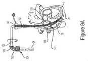
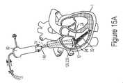
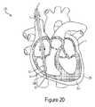
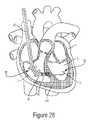
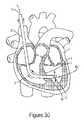
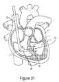
本明細書で、天然の三尖弁の機能を置き換える、最小侵襲的に三尖弁を横切って埋め込まれる医療組立体を提示する。本明細書で開示する方法は、内頸静脈、鎖骨下静脈、大腿静脈のいずれも含むがこれらに限定されない静脈又は静脈様解剖学的構造体を通して三尖弁を埋め込む。従って、有益なことに、システムのどの部分も、埋込みのための外科的開胸術及び経心尖通路は不要である。 Presented herein is a medical assembly that is minimally invasively implanted across the tricuspid valve to replace the function of the native tricuspid valve. The methods disclosed herein implant a tricuspid valve through a vein or vein-like anatomical structure including, but not limited to, any of the internal jugular vein, subclavian vein, femoral vein. Beneficially, therefore, no part of the system requires a surgical thoracotomy and a transapical passageway for implantation.
一態様では、システムは、弁を心房床及び少なくとも1つのテザーに連結し、且つ/又はしっかり留めるよう構成された心房密封スカートを具備する経カテーテル弁を備え、各テザーは、1つのアンカに取り付けられ、心室自由壁、心室尖部、又は心室中隔を含むがこれらに限定されない心腔内壁に弁を連結し、且つ/又はしっかり留めるよう構成される。 In one aspect, a system comprises a transcatheter valve comprising an atrial sealing skirt configured to couple and/or secure the valve to the atrial floor and at least one tether, each tether attached to one anchor. and configured to couple and/or anchor the valve to the inner wall of the heart chamber including, but not limited to, the ventricular free wall, the ventricular apex, or the ventricular septum.
弁は、一態様によれば、ニチノール及びウシ、ウマ、又はブタの心膜弁尖から構成される自己拡張型の弁である。別の態様では、心房密封スカートは、使用中に膜が三尖弁輪をほぼ覆うように、配置部位で弁輪より大きい直径を有する膜で覆われている。 The valve, according to one aspect, is a self-expanding valve constructed from nitinol and bovine, equine, or porcine pericardial leaflets. In another aspect, the atrial sealing skirt is covered with a membrane having a diameter larger than the annulus at the deployment site such that the membrane substantially covers the tricuspid annulus in use.
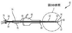
医療組立体は、アンカ送達システム及び弁送達システムを備える。アンカ送達システムは、アンカ、及び1本又は複数のコードにより成る、取り付けられるテザーを導入し、アンカをしっかり留める。弁送達システムは、弁及び弁の上の密封スカートの配置を可能にする。 A medical assembly includes an anchor delivery system and a valve delivery system. An anchor delivery system introduces an attached tether consisting of an anchor and one or more cords to secure the anchor. The valve delivery system allows placement of a valve and a sealing skirt over the valve.
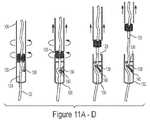
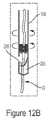
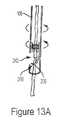
少なくとも1つのテザーは、少なくとも1本のコードを含み、各コードは縫合糸に融着され、テザーは、アンカ・キャップ及びアンカねじにより成る1つのアンカに連結され、アンカは、心室尖部又は心室中隔などの心腔内壁の一部内にねじ込まれるか、そうでなければしっかりと取り付けられるよう構成される。一態様では、アンカ・キャップがアンカねじに連結され、テザーの少なくとも1本のコードは、アンカ・キャップから三尖弁輪を通って延出することができる。弁及び密封スカートにコードが通され、従って弁及び密封スカートは、コードに摺動して係合する。別の態様では、縫合糸は、コードの近位端部に連結され、ユーザが利用可能なように心臓の外側に延出することができる。 The at least one tether includes at least one cord, each cord fused to a suture, the tether connected to an anchor consisting of an anchor cap and an anchor screw, the anchor connecting the ventricular apex or the ventricle. It is configured to be threaded or otherwise securely attached within a portion of the inner heart chamber wall, such as the septum. In one aspect, an anchor cap is coupled to the anchor screw and at least one cord of the tether can extend from the anchor cap through the tricuspid annulus. A cord is threaded through the valve and sealing skirt so that the valve and sealing skirt are slidably engaged with the cord. Alternatively, a suture may be coupled to the proximal end of the cord and extend outside the heart for access by the user.
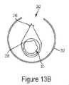
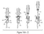
弁送達システムは、遠位端部、反対側の近位端部、及び遠位端部と近位端部との間に延在する内側ロッド内腔を具備する、少なくとも1つの心房位置決めロッドをさらに備える。着脱可能な係止部は、各位置決めロッドの遠位端部に解放可能に連結される。縫合糸の一部が内側ロッド内腔を通って挿入され、位置決めロッドは、ロッドの遠位端部が心房密封スカートに隣接するまで、縫合糸を覆って前進する。一態様では、位置決めロッドは、スカートを所望の位置に配置するために使用される。別の態様において、位置決めロッドを回転させることにより、着脱可能な係止部はコードと係合し、コードを密封スカートに所望の位置でしっかり留めることができる。位置決めロッドを継続的に回転させて、係止部を位置決めロッドから分離することができ、ロッドは心臓から引き込まれる。 The valve delivery system includes at least one atrial positioning rod having a distal end, an opposite proximal end, and an inner rod lumen extending between the distal and proximal ends. Prepare more. A removable lock is releasably coupled to the distal end of each positioning rod. A portion of the suture is inserted through the inner rod lumen and the positioning rod is advanced over the suture until the distal end of the rod is adjacent the atrial sealing skirt. In one aspect, the positioning rods are used to place the skirt in a desired position. In another aspect, by rotating the positioning rod, the removable lock can engage the cord to secure the cord to the sealing skirt at a desired position. By continuing to rotate the positioning rod, the lock can be separated from the positioning rod and the rod is withdrawn from the heart.
従って、テザーの少なくとも1本のコードは、アンカを使って、心室尖部又は心室中隔などの心腔内壁に弁を連結し、一方係止位置にある少なくとも1つの着脱可能な係止部は、コードの近位端部が密封スカートに対して動くことを防止し、それにより弁を三尖弁輪内の適所にしっかりと定着させる。 Thus, at least one cord of the tether uses an anchor to connect the valve to the inner wall of the heart chamber, such as the ventricular apex or the ventricular septum, while the at least one detachable lock in the locked position , prevents the proximal end of the cord from moving relative to the sealing skirt, thereby anchoring the valve firmly in place within the tricuspid annulus.
関連する埋込方法も提供する。心臓内に最小侵襲的に埋め込まれる医療デバイス及びシステムの他の装置、方法、システム、特徴、及び利点は、以下の図及び詳細な説明を考察することにより、当業者には明らかであろう、又は明らかになろう。かかるさらなる装置、方法、システム、特徴、及び利点はすべて、この説明の中に含まれ、心臓内に最小侵襲的に埋め込まれる医療組立体の範囲内にあり、添付の特許請求の範囲によって保護されることを意図する。
例えば、本願は以下の項目を提供する。
(項目1)
弁を心臓内の弁配置部位へ最小侵襲的に埋め込む医療組立体であって、前記医療組立体は、
血管内へ導入して埋め込むよう構成され、天然の心臓弁を置き換えるよう構成及び寸法決めされた前記弁と、
心腔内壁上の係留部位に係留するため血管内へ導入されるよう構成及び寸法決めされたアンカと、
前記弁及び前記アンカと動作可能に接続するための、前記弁及び前記アンカに接続された少なくとも1本のコードを備えるテザー組立体と、
前記アンカ及びテザー組立体を血管内に導入するための、取外し可能なアンカ送達システムと、
前記弁を配置して密封する、取外し可能な弁送達システムと
を備える、医療組立体。
(項目2)
前記アンカは、
近位端部及び遠位端部を備えるアンカ・キャップと、
前記アンカ・キャップ遠位端部から延出し、前記心腔内壁の前記係留部位に前記アンカ・キャップをしっかり取り付けるよう構成されているアンカねじと
を備える、項目1に記載の医療組立体。
(項目3)
前記テザーは、前記少なくとも1本のコードの近位端部から延出する少なくとも1本の縫合糸をさらに備え、前記少なくとも1本のコードの遠位端部は、前記アンカ・キャップの前記近位端部に接続される、項目2に記載の医療組立体。
(項目4)
前記テザーは、前記アンカ・キャップの前記近位端部から延出する少なくとも2本の前記コードを備える、項目2に記載の医療組立体。
(項目5)
前記テザーは、前記アンカ・キャップの前記近位端部から延出する少なくとも2本の前記コードを備え、前記テザーは、前記少なくとも2本のコードのそれぞれ1本の前記近位端部から延出する、少なくとも2本の前記縫合糸を備える、項目3に記載の医療組立体。
(項目6)
前記取外し可能なアンカ送達システムは、長手方向に延在する内腔を画定するアンカ送達ガイドを備え、前記アンカは、前記送達ガイド内腔内に取外し可能に受容される、項目2に記載の医療組立体。
(項目7)
前記取外し可能なアンカ送達システムは、前記送達ガイド内腔内に取外し可能に配置され、前記アンカと協働するよう構成されるアンカ送達ロッドをさらに備える、項目6に記載の医療組立体。
(項目8)
前記アンカ送達ロッドは、第1の形状を有する遠位端部を備え、前記アンカ・キャップの近位端部は、第2の形状を有し、前記第1及び第2の構成は嵌合する構成であり、前記アンカ送達ロッドにかかる回転力が、前記アンカ・キャップに回転力を加える、項目7に記載の医療組立体。
(項目9)
前記テザーの少なくとも一部は、ロッド内腔内に選択的に延出する、項目7に記載の医療組立体。
(項目10)
前記テザーの前記コードは、前記ロッド内腔内に選択的に延出する、項目9に記載の医療組立体。
(項目11)
前記送達ロッドの遠位部分は、実質的に可撓性である、項目7に記載の医療組立体。
(項目12)
前記アンカ送達システムを誘導するJ字型ワイヤをさらに備える、項目1に記載の医療組立体。
(項目13)
前記アンカ送達システムは、アンカ送達ガイドと取外し可能に連結され、且つ流体連通するシースをさらに備える、項目2に記載の医療組立体。
(項目14)
前記テザーは、前記少なくとも1本のコードの近位端部から延出する少なくとも1本の縫合糸をさらに備え、前記縫合糸の一部は前記送達ガイド内腔内に延出し、前記縫合糸の近位部分は前記送達ガイド内腔の近位端部から延出する、項目6に記載の医療組立体。
(項目15)
前記取外し可能な弁送達システムは、内側ガイド内腔を画定し、近位端部及び遠位端部を具備する弁送達ガイドを備え、前記弁送達ガイドは、前記弁及び前記テザーの一部を受容するよう構成される、項目1に記載の医療組立体。
(項目16)
前記少なくとも1本のコードの近位端部から延出する少なくとも1本の縫合糸をさらに備え、前記少なくとも1本のコードは前記アンカに接続され、前記少なくとも1本の縫合糸及びコードは、選択的に前記内側ガイド内腔を通って延出して前記弁と協働し、前記少なくとも1本の縫合糸は、前記内側ガイド内腔の近位端部を超えて延出する、項目15に記載の医療組立体。
(項目17)
前記取外し可能な弁送達システムは、前記内側ガイド内腔と流体連通する中央チャネルを画定する弁配置ノブを備え、前記弁配置ノブは前記弁送達ガイドと動作可能に接続され、前記配置ノブの回転により、選択的に前記送達ノブ内の前記弁送達ガイドを延出し、また引き込む、項目15に記載の医療組立体。
(項目18)
前記弁送達ガイドの遠位部分は可撓性である、項目15に記載の医療組立体。
(項目19)
前記弁送達システムは、前記弁送達ガイドの前記近位端部上に配置され、前記弁を、前記弁送達ガイドを通って前記弁配置部位に誘導するよう構成されるノーズコーンをさらに備える、項目15に記載の医療組立体。
(項目20)
前記弁は開口部を画定し、前記少なくとも1本の縫合糸及びコードは、前記弁の開口部を通って選択的に延出し、前記弁送達ガイドは、前記縫合糸を選択的に受容する中央内腔を画定する少なくとも1つの位置決めロッドをさらに備え、前記位置決めロッドは、前記縫合糸及びコードに沿って前記弁の近位に配置され、前記弁を配置するために前記弁の上面と協働する、項目16に記載の医療組立体。
(項目21)
前記取外し可能な弁送達システムは、前記内側ガイド内腔と流体連通する中央チャネルを画定する弁配置ノブを備え、前記位置決めロッドは、前記ロッド内腔及び前記弁配置ノブの中央チャネルを通って延出する、項目20に記載の医療組立体。
(項目22)
前記テザーはアンカ・キャップの近位端部から延出する少なくとも2本の前記コードを備え、前記テザーは、前記少なくとも2本のコードのそれぞれ1本の前記近位端部から延出する少なくとも2本の前記縫合糸を備え、前記弁送達システムは、前記少なくとも2本のコードのうちのそれぞれ1本、及び前記少なくとも2本の縫合糸のうちのそれぞれ1本を選択的に受容する、少なくとも2つの位置決めロッドを備える、項目20に記載の医療組立体。
(項目23)
弁を心臓内の弁配置部位へ最小侵襲的に埋め込む医療組立体であって、前記医療組立体は、
血管内へ導入するよう構成され、天然の心臓弁を置き換え、少なくとも1つの開口部を画定するよう構成及び寸法決めされた前記弁と、
前記弁を配置して密封し、内側ガイド内腔を画定し近位端部及び遠位端部を具備する弁送達ガイドを備える、取外し可能な弁送達システムであって、前記弁送達ガイド内腔は、前記弁を受容するよう構成される弁送達システムと、
前記弁の開口部を通って延出し、前記内側ガイド内腔内に延出する、少なくとも1本のコードと
を備え、前記弁送達システムは、前記コードを選択的に受容する中央内腔を画定する少なくとも1つの位置決めロッドを備え、前記位置決めロッドは前記弁の近位に前記コードに沿って配置され、前記弁を配置するために前記弁の上面と協働する、医療組立体。
(項目24)
前記少なくとも1本のコードの近位端部から延出する少なくとも1本の縫合糸をさらに備え、前記少なくとも1本のコード及び前記少なくとも1本の縫合糸は、前記位置決めロッドの中央内腔の中に選択的に延出する、項目23に記載の医療組立体。
(項目25)
少なくとも2本の前記コード、及び前記少なくとも2本のコードのうちのそれぞれ1本の前記近位端部から延出する、少なくとも2本の前記縫合糸をさらに備え、前記弁送達システムは、前記少なくとも2本のコードのうちのそれぞれ1本、及び前記少なくとも2本の縫合糸のうちのそれぞれ1本を選択的に受容する、少なくとも2つの位置決めロッドを備える、項目24に記載の医療組立体。
(項目26)
第1の近位端部及び第2の遠位端部を具備する着脱可能な弁係止部、並びに前記第1の端部と第2の端部との間に延在する中央内腔をさらに備え、前記コードは、前記係止部の中央内腔を通って選択的に延出し、前記係止部の中央内腔の前記第2の遠位端部から遠位方向に延出し、前記弁係止部は前記弁の上面の上に隣接して配置される、項目20に記載の医療組立体。
(項目27)
前記位置決めロッドの遠位端部は第1の構成を画定し、前記弁係止部の前記近位端部は第2の構成を画定し、前記第1及び第2形状は嵌合して係合し、前記弁係止部と前記位置決めロッドとを着脱可能に接続する、項目26に記載の医療組立体。
(項目28)
前記位置決めロッド及び前記弁係止部の、前記第1及び第2の構成は嵌合し、ねじを切った構成である、項目26に記載の医療組立体。
(項目29)
前記着脱可能な弁係止部は、前記係止部の中央空洞内にクランプをさらに備え、前記クランプは、前記コードを選択的に係止するよう、第1の係止位置と第2の係止解除位置との間を移動可能であり、前記位置決めロッドの遠位端部は、前記クランプを前記第2の位置に維持するために前記クランプと協働する、項目27に記載の医療組立体。
(項目30)
前記着脱可能な弁係止部は、
前記係止部中央内腔を画定し、側壁上に出口ポートを画定する前記側壁と、
前記係止部中央内腔内にある心房アンカであって、前記アンカは前記側壁及び第2の端部から内側に延出する第1の端部を備え、クランプは第1の係止位置間を移動可能であり、前記アンカは前記第1の係止位置で前記出口ポートを通って延出し、前記コードを選択的に係止し、前記位置決めロッドの遠位端部は、前記アンカを前記第1及び第2の位置から移動させるため前記アンカと協働する、アンカとをさらに備える、項目27に記載の医療組立体。
(項目31)
前記位置決めロッド及び前記弁係止部の、前記第1及び第2の形状は嵌合し、ねじを切った形状である、項目30に記載の医療組立体。
(項目32)
前記弁係止部は、少なくとも2つの前記心房アンカを備え、前記係止部の側壁は、前記心房アンカを受容するよう構成される少なくとも2つの出口ポートを画定し、前記位置決めロッドの遠位端部は、前記心房アンカが前記係止部中央内腔から前記出口ポートを通って外側に延出するよう、前記心房アンカに力を加える、項目30に記載の医療組立体。
(項目33)
最小侵襲的に心臓内の弁配置部位に弁を埋め込み、心臓の心房床を押しつけて前記弁を密封し、心腔内壁の埋込部位に、アンカ並びに前記アンカ及び前記弁に接続する少なくとも1本のコードを備えるテザーを使って、前記弁を係留する、医療組立体を血管内に送達し埋め込む方法であって、前記医療組立体は、長手方向に延在する内腔を画定するアンカ送達ガイドを具備し、また内側ロッド内腔を画定し、前記アンカ送達ガイド内に取外し可能に配置されているアンカ送達ロッドを具備するアンカ送達システムと、前記弁及び前記テザーの一部を受容するよう構成される内側ガイド内腔を画定する弁送達ガイドを具備し、また少なくとも1つの位置決めロッドを具備する弁送達システムとを備え、前記方法は、
前記アンカ送達システムを、血管内に心臓内へ導入するステップであって、前記アンカ送達システムは、前記アンカ送達ロッド内腔の中に配置される前記アンカ及びコードの少なくとも一部と、前記アンカ送達ガイド内腔の中に配置される前記アンカ送達ロッドの少なくとも一部とを備えるステップと、
前記アンカ送達ガイドの遠位端部を、心臓内へ、前記配置部位を通って前記埋込部位に前進させるステップと、
前記アンカ位置決めロッドを前進させて、アンカねじを前記埋込部位に対して接触させるステップと、
前記アンカ送達ロッドを操作して、前記アンカを係留し、前記心腔内壁に繋ぎ止めるように、前記アンカを前記埋込部位の中に埋め込むステップと、
前記埋込部位に埋め込まれた前記アンカ、及び前記弁配置部位を通って延出し、心臓から外部へ延出する、前記テザーの前記コードを残して、前記アンカ送達ガイド及びアンカ送達ロッドを引き込むステップと、
前記送達ガイド内側内腔の中の前記コードと協働する前記弁を備える、前記弁送達ガイドを導入することによって、前記弁送達システムを血管内に導入するステップであって、前記テザーの前記少なくとも1本のコードは、前記弁送達ガイド内側内腔の中に延出するステップと、
前記弁が前記配置部位に隣接して配置されるように、前記弁送達システムを前進させるステップと、
心臓の外部の前記少なくとも1本のコードの近位端部に沿って、前記少なくとも1つの位置決めロッドを配置するステップであって、前記位置決めロッドは、前記送達ガイド内側内腔の中に延出するステップと、
前記配置部位にある前記弁を解放するために、前記弁送達ガイドを少なくとも部分的に引き込むステップと、前記弁を拡張するステップと、
前記弁を配置するために、前記弁と接触するように、前記コードに沿って前記位置決めロッドを前進させるステップと、
前記心房床に対する前記弁の位置を変更するために、前記位置決めロッドを操作するステップと、前記心房床に押しつけて前記弁を密封するステップと、
さらに、前記弁を前記配置部位に残し、前記アンカを前記埋込部位に残して、前記弁送達ガイドを引き込むステップと、前記位置決めロッドを引き込むステップと
を含む方法。
(項目34)
前記アンカ送達ガイドを心臓内に前進させる前記ステップの前に、J字型ワイヤを血管内に、心臓内へ、前記配置部位を通して前記埋込部位へ導入するステップをさらに含み、
前記アンカ送達を心臓内に前進させる前記ステップは、誘導するために、前記挿入されたJ字型ワイヤを覆って前記アンカ・ガイドを前進させるステップを含む、項目33に記載の方法。
(項目35)
前記アンカを埋め込むために、前記アンカ送達ロッドを操作する前記ステップは、前記アンカの近位面に接触するように前記アンカ送達ロッドの遠位端部を前進させるステップと、前記送達ロッドを前記アンカと係合するために表面を嵌合するステップとを含む、項目33に記載の方法。
(項目36)
前記埋込部位に前記アンカねじを埋め込むために、前記アンカ送達ロッド及び前記アンカを回転させるステップをさらに含む、項目35に記載の方法。
(項目37)
前記弁送達システムを導入する前記ステップは、前記弁送達ガイドの近位部分を受容し、前記弁送達ガイド内腔と流体連通する、弁配置ノブを設けるステップも含み、前記弁送達ガイドを少なくとも部分的に引き込む前記ステップは、前記配置ノブ内で前記弁送達ガイドを引き込むステップを含む、項目33に記載の方法。
(項目38)
前記アンカを埋め込む前記ステップは、心室間に埋め込むステップを含む、項目33に記載の方法。
(項目39)
前記アンカを埋め込む前記ステップは、心外膜へ埋め込むステップを含む、項目33に記載の方法。
(項目40)
前記位置決めロッドを操作し、前記弁を前記心房床に押しつけて密封する前記ステップの後に、前記位置決めロッドの遠位端部と嵌合する係止部を備えることによって、前記弁に対して前記コードを係止するステップをさらに含む、項目33に記載の方法。
(項目41)
前記コードを含む、前記アンカ送達ステップを導入する前記ステップは、前記コードの近位端部から延出する少なくとも1本の縫合糸を導入するステップ含み、前記縫合糸は、前記コードの近位から延出する、項目40に記載の方法。
(項目42)
前記弁に対して前記コードを係止する前記ステップの後に、前記少なくとも1本の縫合糸を切断するステップをさらに含む、項目41に記載の方法。
(項目43)
アンカを血管内に、心膜腔内へ送達して埋め込む心外膜アンカ組立体であって、前記心外膜アンカ組立体は、
近位端部及び遠位端部を備え、前記近位端部と遠位端部との間に中央内腔を画定する取外し可能なカテーテルであって、前記カテーテルの遠位端部は、血管内に心臓内へ、心内膜を通って心膜腔内へ導入されるよう構成され、前記カテーテルの近位端部及び中央内腔は流体供給源と流体連通するカテーテルと、
前記カテーテル中央内腔の中に延出するJ字型ワイヤと、
中央内腔を画定する取外し可能なアンカ送達ガイドであって、前記送達ガイドは前記J字型ワイヤに沿って移動するアンカ送達ガイドと、
前記アンカ送達ガイド内腔内に配置されたアンカ送達ロッドと、
前記送達ロッドの遠位端部に接続された前記アンカであって、前記アンカは、心膜腔内で拡張するよう拡張可能であるアンカと、
前記アンカの近位端部に接続され、送達ロッド内腔に沿って延出し、前記送達ロッド及び前記カテーテルから近位方向に延出する少なくとも1本のコードと
を備える、心外膜アンカ組立体。
(項目44)
アンカを血管内に、中隔内へ送達して埋め込む心室間アンカ組立体であって、前記心室間アンカ組立体は、
近位端部及び遠位端部を備え、前記近位端部と遠位端部との間に中央内腔を画定する取外し可能なカテーテルであって、前記カテーテルの遠位端部は、血管内に心臓内へ、中隔を通って導入されるよう構成されるカテーテルと、
心臓内へ中隔を通して誘導するために、前記中央内腔を通って延出し無線周波数発生源と動作可能に接続される、取外し可能な無線周波数ワイヤと、
前記カテーテル中央内腔の中に延出する、取外し可能なJ字型ワイヤと、
中央内腔を画定する取外し可能なアンカ送達ガイドであって、前記送達ガイドは前記J字型ワイヤに沿って選択的に配置されるアンカ送達ガイドと、
前記アンカ送達ガイド内腔内に配置されるアンカ送達ロッドと、
前記送達ロッドの遠位端部に接続される前記アンカであって、前記アンカは、前記中膜を突き刺した後で拡張するよう拡張可能であるアンカと、
前記アンカの近位端部に接続され、送達ロッド内腔に沿って延出し、前記送達ロッド及び前記カテーテルから近位方向に延出する少なくとも1本のコードと
を備える、心室間アンカ組立体。A related embedding method is also provided. Other apparatus, methods, systems, features and advantages of medical devices and systems that are minimally invasively implanted within the heart will be apparent to one of ordinary skill in the art upon consideration of the following figures and detailed description: or will become clear. All such additional devices, methods, systems, features and advantages are included within this description, fall within the scope of minimally invasively implanted medical assemblies within the heart, and are protected by the accompanying claims. intended to
For example, the present application provides the following items.
(Item 1)
A medical assembly for minimally invasively implanting a valve at a valve placement site within the heart, said medical assembly comprising:
said valve configured for introduction and implantation into a blood vessel and configured and dimensioned to replace a natural heart valve;
an anchor configured and dimensioned to be introduced into the vessel to anchor to the anchoring site on the inner wall of the heart chamber;
a tether assembly for operative connection with the valve and the anchor, the tether assembly comprising at least one cord connected to the valve and the anchor;
a removable anchor delivery system for introducing the anchor and tether assembly into a blood vessel;
a removable valve delivery system that deploys and seals the valve;
A medical assembly comprising:
(Item 2)
The anchor is
an anchor cap having a proximal end and a distal end;
an anchor screw extending from the anchor cap distal end and configured to securely attach the anchor cap to the anchoring site on the inner heart chamber wall;
The medical assembly of item 1, comprising:
(Item 3)
The tether further comprises at least one suture extending from a proximal end of the at least one cord, a distal end of the at least one cord being connected to the proximal end of the anchor cap. 3. Medical assembly according to item 2, connected to the ends.
(Item 4)
3. The medical assembly of claim 2, wherein said tether comprises at least two said cords extending from said proximal end of said anchor cap.
(Item 5)
The tether comprises at least two cords extending from the proximal end of the anchor cap, the tether extending from the proximal end of each one of the at least two cords. 4. The medical assembly of claim 3, comprising at least two sutures.
(Item 6)
3. The medical treatment of claim 2, wherein the removable anchor delivery system comprises an anchor delivery guide defining a longitudinally extending lumen, the anchor removably received within the delivery guide lumen. Assembly.
(Item 7)
7. The medical assembly of clause 6, wherein the removable anchor delivery system further comprises an anchor delivery rod removably disposed within the delivery guide lumen and configured to cooperate with the anchor.
(Item 8)
The anchor delivery rod has a distal end having a first shape, the proximal end of the anchor cap has a second shape, and the first and second configurations are mating. configuration, wherein a rotational force on the anchor delivery rod applies a rotational force to the anchor cap.
(Item 9)
8. The medical assembly of item 7, wherein at least a portion of the tether selectively extends into the rod lumen.
(Item 10)
10. The medical assembly of item 9, wherein the cord of the tether selectively extends into the rod lumen.
(Item 11)
8. The medical assembly of item 7, wherein the distal portion of the delivery rod is substantially flexible.
(Item 12)
2. The medical assembly of item 1, further comprising a J-wire that guides the anchor delivery system.
(Item 13)
3. The medical assembly of clause 2, wherein the anchor delivery system further comprises a sheath removably coupled to and in fluid communication with the anchor delivery guide.
(Item 14)
The tether further comprises at least one suture extending from a proximal end of the at least one cord, a portion of the suture extending into the delivery guide lumen, 7. The medical assembly of item 6, wherein the proximal portion extends from the proximal end of the delivery guide lumen.
(Item 15)
The removable valve delivery system includes a valve delivery guide defining an inner guide lumen and having a proximal end and a distal end, the valve delivery guide enclosing a portion of the valve and the tether. 2. The medical assembly of item 1, configured to receive.
(Item 16)
further comprising at least one suture extending from a proximal end of said at least one cord, said at least one cord being connected to said anchor, said at least one suture and cord being selected; 16. Clause 16, wherein the at least one suture extends substantially through the inner guide lumen to cooperate with the valve, and the at least one suture extends beyond a proximal end of the inner guide lumen. medical assembly.
(Item 17)
The removable valve delivery system comprises a valve deployment knob defining a central channel in fluid communication with the inner guide lumen, the valve deployment knob operably connected to the valve delivery guide, and rotation of the deployment knob. 16. The medical assembly of item 15, wherein selectively extending and retracting the valve delivery guide within the delivery knob by.
(Item 18)
16. The medical assembly of item 15, wherein a distal portion of the valve delivery guide is flexible.
(Item 19)
wherein the valve delivery system further comprises a nosecone disposed on the proximal end of the valve delivery guide and configured to guide the valve through the valve delivery guide to the valve deployment site. 16. The medical assembly according to 15.
(Item 20)
The valve defines an opening, the at least one suture and cord selectively extend through the valve opening, and the valve delivery guide is central for selectively receiving the suture. Further comprising at least one positioning rod defining a lumen, said positioning rod positioned proximal to said valve along said sutures and cords and cooperating with a top surface of said valve to locate said valve. 17. The medical assembly according to item 16.
(Item 21)
The removable valve delivery system comprises a valve deployment knob defining a central channel in fluid communication with the inner guide lumen, the positioning rod extending through the central channel of the rod lumen and the valve deployment knob. 21. The medical assembly of item 20, wherein the medical assembly is released.
(Item 22)
The tether comprises at least two cords extending from the proximal end of the anchor cap, and the tether includes at least two cords extending from the proximal end of each one of the at least two cords. at least two sutures, wherein the valve delivery system selectively receives a respective one of the at least two cords and a respective one of the at least two sutures; 21. A medical assembly according to item 20, comprising two positioning rods.
(Item 23)
A medical assembly for minimally invasively implanting a valve at a valve placement site within the heart, said medical assembly comprising:
said valve configured and dimensioned to replace a natural heart valve and define at least one opening, configured for introduction into a blood vessel;
A removable valve delivery system comprising a valve delivery guide that positions and seals the valve, defines an inner guide lumen and has a proximal end and a distal end, the valve delivery guide lumen a valve delivery system configured to receive the valve;
at least one cord extending through an opening in the valve and extending into the inner guide lumen;
wherein the valve delivery system comprises at least one positioning rod defining a central lumen for selectively receiving the cord, the positioning rod positioned along the cord proximal to the valve; A medical assembly that cooperates with a top surface of the valve to position the valve.
(Item 24)
further comprising at least one suture extending from a proximal end of said at least one cord, said at least one cord and said at least one suture extending through a central lumen of said positioning rod; 24. The medical assembly according to item 23, selectively extending into the body.
(Item 25)
at least two of said cords and at least two of said sutures extending from said proximal end of each one of said at least two cords, said valve delivery system comprising: 25. The medical assembly of claim 24, comprising at least two positioning rods selectively receiving respective ones of two cords and respective ones of said at least two sutures.
(Item 26)
a removable valve stop having a first proximal end and a second distal end; and a central lumen extending between the first and second ends. Further comprising, the cord selectively extends through the central lumen of the locking portion and extends distally from the second distal end of the central lumen of the locking portion; 21. The medical assembly of item 20, wherein the valve lock is positioned above and adjacent to the top surface of the valve.
(Item 27)
The distal end of the positioning rod defines a first configuration, the proximal end of the valve lock defines a second configuration, the first and second shapes matingly engage. 27. The medical assembly according to item 26, wherein the medical assembly mates and detachably connects the valve lock and the positioning rod.
(Item 28)
27. The medical assembly of clause 26, wherein the first and second configurations of the positioning rod and the valve lock are mating and threaded configurations.
(Item 29)
The removable valve lock further comprises a clamp within the central cavity of the lock, the clamp having a first locking position and a second locking position to selectively lock the cord. 28. The medical assembly of clause 27, wherein the distal end of the positioning rod is movable between an unlocked position and the distal end of the positioning rod cooperates with the clamp to maintain the clamp in the second position. .
(Item 30)
The detachable valve locking portion is
said side wall defining said lock central lumen and defining an exit port thereon;
an atrial anchor within the locking central lumen, the anchor having a first end extending inwardly from the side wall and a second end, and a clamp between a first locking position; the anchor extends through the exit port in the first locked position to selectively lock the cord, the distal end of the positioning rod moving the anchor to the 28. The medical assembly according to item 27, further comprising an anchor that cooperates with the anchor for movement from the first and second positions.
(Item 31)
31. The medical assembly of claim 30, wherein the first and second shapes of the positioning rod and the valve lock are mating, threaded shapes.
(Item 32)
the valve stop comprises at least two of the atrial anchors, sidewalls of the stop defining at least two exit ports configured to receive the atrial anchors, and a distal end of the positioning rod; 31. The medical assembly of clause 30, wherein a portion applies force to the atrial anchor such that the atrial anchor extends outwardly from the locking portion central lumen through the exit port.
(Item 33)
minimally invasively implanting a valve at a valve placement site within the heart, pressing against the atrial bed of the heart to seal said valve, and placing an anchor and at least one wire connecting said anchor and said valve at the implantation site on the inner wall of the heart chamber. a method of intravascularly delivering and implanting a medical assembly anchoring the valve using a tether comprising a cord of: and an anchor delivery rod defining an inner rod lumen and removably disposed within the anchor delivery guide; and configured to receive a portion of the valve and the tether. and a valve delivery system comprising at least one positioning rod, the method comprising:
introducing the anchor delivery system intravascularly into the heart, the anchor delivery system comprising at least a portion of the anchor and cord disposed within the anchor delivery rod lumen; at least a portion of said anchor delivery rod positioned within a guide lumen;
advancing a distal end of the anchor delivery guide into the heart through the deployment site to the implantation site;
advancing the anchor positioning rod to bring the anchor screw into contact with the implantation site;
manipulating the anchor delivery rod to implant the anchor within the implantation site so as to anchor the anchor and anchor it to the inner wall of the heart chamber;
Retracting the anchor delivery guide and anchor delivery rod leaving the anchor embedded at the implantation site and the cord of the tether extending through the valve placement site and extending out of the heart. When,
introducing the valve delivery system intravascularly by introducing the valve delivery guide comprising the valve cooperating with the cord within the delivery guide inner lumen, wherein the at least one of the tethers a length of cord extending into the valve delivery guide inner lumen;
advancing the valve delivery system such that the valve is positioned adjacent to the deployment site;
positioning the at least one positioning rod along the proximal end of the at least one cord outside the heart, the positioning rod extending into the delivery guide inner lumen; a step;
at least partially retracting the valve delivery guide to release the valve at the deployment site; and expanding the valve;
advancing the positioning rod along the cord into contact with the valve to locate the valve;
manipulating the positioning rod to change the position of the valve relative to the atrial bed; pressing against the atrial bed to seal the valve;
Further, leaving the valve at the deployment site and the anchor at the implantation site, retracting the valve delivery guide and retracting the positioning rod.
method including.
(Item 34)
prior to the step of advancing the anchor delivery guide into the heart, introducing a J-wire into the vessel, into the heart, through the placement site and into the implantation site;
34. The method of item 33, wherein the step of advancing the anchor delivery into the heart includes advancing the anchor guide over the inserted J-wire to guide.
(Item 35)
Manipulating the anchor delivery rod to implant the anchor includes advancing a distal end of the anchor delivery rod into contact with a proximal surface of the anchor; 34. A method according to item 33, comprising mating the surfaces to engage with.
(Item 36)
36. The method of item 35, further comprising rotating the anchor delivery rod and the anchor to embed the anchor screw at the implantation site.
(Item 37)
The step of introducing the valve delivery system also includes providing a valve deployment knob that receives a proximal portion of the valve delivery guide and is in fluid communication with the valve delivery guide lumen; 34. The method of item 33, wherein the step of objectively retracting includes retracting the valve delivery guide within the deployment knob.
(Item 38)
34. The method of item 33, wherein the step of implanting the anchor comprises implanting between ventricles.
(Item 39)
34. The method of item 33, wherein the step of implanting the anchor comprises epicardial implantation.
(Item 40)
After the step of manipulating the locating rod to seal the valve against the atrial floor, the cord is attached to the valve by providing a stop that mates with the distal end of the locating rod. 34. The method of item 33, further comprising locking the .
(Item 41)
The step of introducing the anchor delivering step including the cord includes introducing at least one suture extending from a proximal end of the cord, the suture extending from the proximal end of the cord. 41. The method of item 40, extending.
(Item 42)
42. The method of paragraph 41, further comprising cutting the at least one suture after the step of locking the cord to the valve.
(Item 43)
An epicardial anchor assembly for delivering and implanting an anchor intravascularly into the pericardial space, said epicardial anchor assembly comprising:
1. A removable catheter comprising a proximal end and a distal end and defining a central lumen therebetween, the distal end of the catheter being in a blood vessel. a catheter configured to be introduced into the heart through the endocardium and into the pericardial space, the proximal end and central lumen of the catheter being in fluid communication with a fluid source;
a J-shaped wire extending into the catheter central lumen;
a removable anchor delivery guide defining a central lumen, said delivery guide traveling along said J-wire;
an anchor delivery rod disposed within the anchor delivery guide lumen;
said anchor connected to the distal end of said delivery rod, said anchor being expandable to expand within the pericardial space;
at least one cord connected to the proximal end of the anchor, extending along the delivery rod lumen and extending proximally from the delivery rod and the catheter;
An epicardial anchor assembly comprising:
(Item 44)
An interventricular anchor assembly for delivering and implanting an anchor intravascularly and intraseptally, said interventricular anchor assembly comprising:
1. A removable catheter comprising a proximal end and a distal end and defining a central lumen therebetween, the distal end of the catheter being in a blood vessel. a catheter configured to be introduced into the heart and through the septum;
a removable radio frequency wire extending through the central lumen and operably connected to a radio frequency source for guidance through the septum into the heart;
a removable J-wire extending into the catheter central lumen;
a removable anchor delivery guide defining a central lumen, said delivery guide selectively positioned along said J-wire;
an anchor delivery rod disposed within the anchor delivery guide lumen;
said anchor connected to a distal end of said delivery rod, said anchor being expandable to expand after piercing said media;
at least one cord connected to the proximal end of the anchor, extending along the delivery rod lumen and extending proximally from the delivery rod and the catheter;
An interventricular anchor assembly comprising:
本発明は、以下の詳細な説明、実例、並びに特許請求の範囲、及び特許請求の範囲の前後の説明を参照することにより、より容易に理解される。本システム、デバイス、及び/又は方法を開示及び説明する前に、この発明は、別段の指定がない限り、開示する特定のシステム、デバイス、及び/又は方法に限定されない、従って当然変更できることを理解されたい。本明細書で使用される用語は、特定の態様だけを説明することを目的としており、限定することを意図しないことも理解されたい。 The present invention is more readily understood by reference to the following detailed description, examples, and claims, as well as the discussion surrounding the claims. Before disclosing and describing the present systems, devices and/or methods, it should be understood that this invention is not limited to the particular systems, devices and/or methods disclosed, unless otherwise specified, as such may, of course, vary. want to be It is also to be understood that the terminology used herein is for the purpose of describing particular aspects only and is not intended to be limiting.
本発明の以下の説明は、現在知られているその最良の態様で本発明の教示を可能にするよう提供される。関連する分野の技術者は、本発明の有益な結果を依然として得ながら、説明する態様に多くの変更が加えられることを認識するであろう。本発明の所望の利益の一部が、他の特徴を利用することなく、本発明の特徴の一部を選択することにより得られることも明らかであろう。従って、当業者は、本発明に対する多くの修正形態及び適合形態が可能であり、特定の状況では望ましい場合さえあり、本発明の一部であることを認識するであろう。従って、以下の説明は、本発明の原理を例示するものとして提供しており、本発明を限定するものではない。 The following description of the invention is provided as an enabling teaching of the invention in its best mode currently known. Those skilled in the relevant art will recognize that many modifications may be made to the described embodiments while still obtaining the beneficial results of the invention. It will also be apparent that some of the desired benefits of the invention are obtained by selecting some of the features of the invention without utilizing other features. Accordingly, those skilled in the art will recognize that many modifications and adaptations to the present invention are possible, and may even be desirable in certain circumstances, and are a part of this invention. Accordingly, the following description is offered as an illustration of the principles of the invention and not as a limitation of the invention.
本明細書で使用される単数形「a」、「an」、及び「the」は、文脈上明らかにそうでないと規定しない限り、複数の指示対象を含む。従って、たとえば、「テザー」への言及は、文脈上明らかにそうでないと示さない限り、2つ以上のテザーを備える態様を含む。 As used herein, the singular forms "a," "an," and "the" include plural referents unless the context clearly dictates otherwise. Thus, for example, reference to a "tether" includes aspects with two or more tethers, unless the context clearly dictates otherwise.
本明細書では、範囲を、「約」1つの特定の値から、且つ/又は「約」別の特定の値までとして表す。かかる範囲が表現されるとき、別の態様は、1つの特定の値から、且つ/又は他の特定の値までを含む。同様に、値が先行詞「約」を使用して近似値として表されるとき、特定の値が別の態様を形成することが理解されよう。範囲のそれぞれのエンドポイントは、他のエンドポイントに関連して、及び他のエンドポイントとは無関係に、その両方で意味を持つことがさらに理解されよう。 Ranges are expressed herein as from "about" one particular value, and/or to "about" another particular value. When such a range is expressed, another aspect includes from the one particular value and/or to the other particular value. Similarly, when values are expressed as approximations using the antecedent "about," it will be understood that the particular value forms another aspect. It will be further understood that each endpoint of a range has meaning both in relation to and independently of the other endpoint.
本明細書で使用する用語「任意選択の」又は「任意選択で」は、続いて説明する事象又は状況が起こる場合と起こらない場合とがあり、説明には前記事象又は状況が起こる場合と起こらない場合とが含まれることを意味する。本明細書で使用する「流体」は、自由に流動し、液体、気体、及びプラズマを含む任意の物質を指す。本明細書で使用する「流体連通」は、関連する構成要素間で物質が自由に流れることを可能にする、任意の接続又は相対的な配置を指す。 As used herein, the term “optional” or “optionally” refers to the event or circumstance that is subsequently described may or may not occur, and the description includes both the event or circumstance that occurs and the event or circumstance that occurs. It is meant to include cases that do not occur and cases that do not occur. As used herein, "fluid" refers to any substance that is free to flow, including liquids, gases, and plasmas. As used herein, "fluid communication" refers to any connection or relative arrangement that permits the free flow of matter between associated components.
本明細書の開示は、心臓1内に最小侵襲的に弁を埋め込む医療組立体10、及び天然の心臓弁の置換を実現する組立体10の部分の埋込方法に関する。図1は、本明細書に開示する方法に従って、本明細書に開示する医療組立体10を使って、(たとえば)天然の三尖弁を置き換えるように埋め込まれた経カテーテル弁12を示す。組立体は、心房床16に連結するよう構成された心房密封スカート14を具備する経カテーテル弁12と、弁を、図示する心室尖部20などの心腔内壁に固定する、少なくとも1つのアンカ19(図2)に接続するよう構成される少なくとも1つのテザー18とを備える。テザー18を、アンカ19を使って、心室中隔、右室心尖部、又は右心室自由壁を含むがそれに限定されるものではない任意の心腔壁に係留することができる。議論のためだけに、心室尖部20を示しているが、テザー18をあらゆる心腔内壁に係留することが、本発明の精神及び範囲内にある。医療組立体10は、アンカ送達システム50(図3A及び図3Bに示す)及び弁送達組立体100(図7Aに示す)を備える。本明細書に示し説明する経カテーテル三尖弁を埋め込む方法は、概して、以下のステップの方法を含む。アンカ送達システム50を利用してアンカを送達し、テザーは、心室尖部などの心腔内壁にアンカをしっかり留めるステップと、アンカ送達システム50を取り外すステップと、弁送達組立体100を利用して弁及びスカートを配置するステップと、心房スカートを係止するステップと、弁送達組立体100を取り外し、それによって弁を天然の三尖弁の代わりに残すステップ。 The present disclosure relates to a medical assembly 10 for minimally invasively implanting a valve within the heart 1 and a method of implanting portions of the assembly 10 to achieve replacement of the natural heart valve. FIG. 1 shows a transcatheter valve 12 implanted to replace (for example) the natural tricuspid valve using the medical assembly 10 disclosed herein according to the methods disclosed herein. The assembly comprises a transcatheter valve 12 comprising an atrial sealing skirt 14 configured to connect to the atrial bed 16 and at least one anchor 19 that secures the valve to the inner wall of the heart chamber, such as the ventricular apex 20 shown. and at least one tether 18 configured to connect to (FIG. 2). Tether 18 can be anchored to any heart chamber wall including, but not limited to, the interventricular septum, right ventricular apex, or right ventricular free wall using anchor 19 . For purposes of discussion only, the ventricular apex 20 is shown, but it is within the spirit and scope of the present invention to anchor the tether 18 to any heart chamber inner wall. Medical assembly 10 comprises an anchor delivery system 50 (shown in FIGS. 3A and 3B) and a valve delivery assembly 100 (shown in FIG. 7A). The method of implanting a transcatheter tricuspid valve shown and described herein generally includes the following steps. The anchor is delivered using the anchor delivery system 50, the tether securing the anchor to the inner wall of the heart chamber, such as the ventricular apex, removing the anchor delivery system 50, and using the valve delivery assembly 100. Deploying the valve and skirt, locking the atrial skirt, and removing the valve delivery assembly 100 thereby leaving the valve in place of the native tricuspid valve.
弁
経カテーテル弁12は、図1に示すように、右心房2と右心室3との間の三尖弁を置き換えるよう寸法決め及び構成される。しかし任意選択で、わずかな変更によって、弁は、左心房4と左心室5との間の僧帽弁輪内に配置されるように寸法決め及び構成される。従って、次に、主に三尖弁置換デバイス、システム、及び方法を参照するが、わずかな変更によって、こうしたデバイス、システム、及び方法を使用して、僧帽弁、大動脈弁、肺動脈弁など、他の弁を置き換えることができることを理解されたい。議論のためだけに、以下の説明及び添付の図面は三尖弁に関する。送達組立体及び方法に関して、これらは、任意の適切な弁置換デバイスと共に使用及び実施され得る。本明細書の開示は、図示し説明する弁に限定されるものではない。Valves Transcatheter valve 12 is sized and configured to replace the tricuspid valve between right atrium 2 and right ventricle 3, as shown in FIG. Optionally, however, with minor modifications, the valve is sized and configured to be positioned within the mitral annulus between left atrium 4 and left ventricle 5 . Accordingly, reference will now be made primarily to tricuspid valve replacement devices, systems and methods, although with minor modifications such devices, systems and methods can be used to treat mitral valves, aortic valves, pulmonary valves, etc. It should be understood that other valves can be substituted. For discussion purposes only, the following description and attached drawings relate to a tricuspid valve. Regarding the delivery assemblies and methods, they can be used and implemented with any suitable valve replacement device. The disclosure herein is not limited to the valves shown and described.
図示のように、弁12は自己拡張型の弁である(すなわち、弁は、組立体10のカテーテルを通って適合するよう圧縮可能である)。一態様では、弁12は、図7Cに示すニチノール及びウシ、ウマ、又はブタの心膜弁尖19から構成される。別の態様では、弁12は、三尖弁輪などの配置部位13で弁輪よりも小さいか又はほぼ等しい弁の直径を有し、それによって、脆弱な三尖弁輪への並置を防止又は低減する。弁12は、後述するように、心臓内に弁12をしっかり留める少なくとも1本のコード32を備える、少なくとも1つのテザー18に動作可能に接続される。別の態様によれば、図7Cに示すように、少なくとも1つの孔15が弁12の外壁17内に画定されている。各孔15は、テザーのコードの一部が孔15を通過するよう寸法及び形状決めされる。従って、テザー18の各コード32は、弁のどんな弁尖19とも干渉することなく弁に連結される。さらなる態様(図示せず)では、弁12は、その外径に沿って配置された係留要素を備えることができる。この係留要素は、三尖弁尖へのさらなる定着を可能にするが、必ずしも主要な定着機構として使用されるわけではない。再び図1を参照すると、心房密封スカート14は、経カテーテル弁12の上端部の周りにほぼ円周方向に延在する。スカート14は膜で覆われ、配置部位13で弁輪より大きい直径を有する。たとえば、密封スカート22は、三尖弁輪の直径よりも大きいスカート直径を有し得る。別の態様では、心房スカートは、ポリカーボネート、ポリウレタン、ポリエステル、延伸ポリテトラフルオロエチレン(ePTFE)、ポリエチレンテレフタレート(PET:polyethylene terephthalate)、シリコン、天然若しくは合成ゴム、又はその組合せからなる部類の合成材料で形成されるが、それに限定されるものではない。心房スカートはまた、成年又は若年のウシ、ヒツジ、ウマ、又はブタの心膜で覆われる場合がある。任意選択で、心房スカート14の少なくとも一部は、たとえば、それに限定されるものではないが、ポリウレタン発泡体、又はリングの固化のためのポリマー交換能力を有する、生理食塩水で膨張可能なリングなどの代替材料で形成される。 As shown, valve 12 is a self-expanding valve (ie, the valve is compressible to fit through the catheter of assembly 10). In one aspect, the valve 12 is composed of nitinol and bovine, equine, or porcine pericardial leaflets 19 shown in FIG. 7C. In another aspect, the valve 12 has a valve diameter at a deployment site 13, such as the tricuspid annulus, that is smaller than or approximately equal to the annulus, thereby preventing or reducing apposition to the vulnerable tricuspid annulus. Reduce. Valve 12 is operably connected to at least one tether 18 comprising at least one cord 32 that secures valve 12 within the heart, as described below. According to another aspect, at least one hole 15 is defined in the outer wall 17 of the valve 12, as shown in FIG. 7C. Each hole 15 is sized and shaped so that a portion of the cord of the tether passes through hole 15 . Thus, each cord 32 of tether 18 is connected to the valve without interfering with any leaflets 19 of the valve. In a further aspect (not shown), the valve 12 can be provided with anchoring elements arranged along its outer diameter. This anchoring element allows for additional anchorage to the tricuspid leaflet, but is not necessarily used as the primary anchorage mechanism. Referring again to FIG. 1, the atrial sealing skirt 14 extends generally circumferentially around the upper end of the transcatheter valve 12 . The skirt 14 is covered with a membrane and has a diameter greater than the annulus at the placement site 13 . For example, the sealing skirt 22 may have a skirt diameter greater than the diameter of the tricuspid annulus. In another aspect, the atrial skirt is a synthetic material from the class consisting of polycarbonate, polyurethane, polyester, expanded polytetrafluoroethylene (ePTFE), polyethylene terephthalate (PET), silicone, natural or synthetic rubber, or combinations thereof. formed, but not limited to. The atrial skirt may also be covered with adult or juvenile bovine, ovine, equine, or porcine pericardium. Optionally, at least a portion of the atrial skirt 14 is made of, for example, but not limited to, polyurethane foam or a saline-swellable ring having polymer exchange capabilities for solidification of the ring. made of alternative materials.
一態様では、心房密封スカート14は、心房内での安定を可能にする、アンカ出口ポート242を通って突出する部材などの、少なくとも1つの心房アンカ238をさらに備える。その結果、心房内での安定性が、心室アンカ機能障害などの事象のような、弁12の逆行性移動を防ぐ。 In one aspect, the atrial sealing skirt 14 further comprises at least one atrial anchor 238, such as a member projecting through the anchor exit port 242, to allow stabilization within the atrium. As a result, stability within the atrium prevents retrograde movement of the valve 12, such as in events such as ventricular anchor dysfunction.
別の態様では、心房密封スカート14の少なくとも一部は、図15Bに示す、スカートの下方縁部に沿って配置された1つ又は複数の定着部材24を備え、右心房床16及び/又は三尖弁輪の心房側の他の部分へのさらなる係留を可能にし、弁12の右心房2の近位への移動を防ぎ、それにより、人工補填物の不安定性(たとえば、揺れ)及び弁周囲逆流を防止する。また、心房スカート14は、心房床の局所解剖学的構造(topography)に適合し、恒久的ペースメーカのリードなど、心腔内リードを覆って密封する能力を有する。心房スカート14がリードを覆って密封し、リードの周りの逆流を防ぐ能力により、この経カテーテル弁システムは、他の経カテーテル三尖弁修復システムと区別される。 Alternatively, at least a portion of the atrial sealing skirt 14 includes one or more anchoring members 24 disposed along the skirt's lower edge, shown in FIG. Allowing further anchoring to other portions of the atrial side of the cusp annulus prevents migration of the valve 12 proximal to the right atrium 2, thereby reducing prosthesis instability (e.g., rocking) and perivalvular Prevent backflow. Atrial skirt 14 also conforms to the topography of the atrial bed and has the ability to cover and seal intracardiac leads, such as permanent pacemaker leads. The ability of the atrial skirt 14 to seal over and prevent backflow around the lead distinguishes this transcatheter valve system from other transcatheter tricuspid valve repair systems.
テザー及びアンカ
ここで図2を参照すると、少なくとも1つのテザー18は、置換弁12に動作可能に接続され、弁12をアンカ19に接続する。テザー18は、少なくとも1本のコード32を備え、各コード32は縫合糸34に接続されている。アンカ19は、アンカねじ28及びアンカ・キャップ30を備える。一態様では、アンカねじは、アンカ・キャップの遠位端部36に連結され、遠位端部から延出し、テザー18の少なくとも1本のコード32は、アンカ・キャップ30の近位端部38に連結され、近位端部から延出する。すなわち、アンカ・キャップ30は、アンカねじ28とコード32との間に配置される。アンカ19のアンカねじ28は、テザー18を心臓1の心室尖部20などの心腔内壁にしっかりと取り付けるよう構成される。たとえば、アンカねじ28は、心室尖部の中へしっかりと回転するねじ山又はコイルを備える能動的定着ねじである。アンカは、アンカねじを介して、心尖を通って心臓の外側に延出することなく、テザーを心臓の心室尖部20などの心腔内壁にしっかりと取り付けるよう構成される。従ってこの態様では、実質的に組立体10のどの部分も、心臓壁のどの部分も完全に貫通する、且つ/又はそこを通って完全に延出することなく、経心尖通路は不要である。さらなる態様(図示せず)では、アンカねじ28ではなく、それに限定されるものではないが、ニチノール、ステンレス鋼、コバルトクロム、又はチタン合金から構成され、棘、フック、突起などの形状である定着機構が、心尖部及び心臓の外側を通って延出することなく、テザー18を心臓1の心室尖部20にしっかりと取り付けるために、アンカ・キャップ30の遠位端部36に配置される。Tethers and Anchors Referring now to FIG. 2 , at least one tether 18 is operably connected to replacement valve 12 and connects valve 12 to anchor 19 . Tether 18 includes at least one cord 32 , each cord 32 being connected to suture 34 . Anchor 19 comprises an anchor screw 28 and an anchor cap 30 . In one aspect, the anchor screw is coupled to and extends from the distal end 36 of the anchor cap, and at least one cord 32 of the tether 18 is connected to the proximal end 38 of the anchor cap 30 . and extends from the proximal end. That is, anchor cap 30 is positioned between anchor screw 28 and cord 32 . Anchor screw 28 of anchor 19 is configured to securely attach tether 18 to an inner heart chamber wall, such as ventricular apex 20 of heart 1 . For example, anchor screw 28 is an active anchor screw with threads or coils that rotate tightly into the ventricular apex. The anchor is configured to securely attach the tether to the inner heart chamber wall, such as the ventricular apex 20 of the heart, without extending through the apex and outside the heart via the anchor screw. Thus, in this aspect, substantially no portion of the assembly 10 completely penetrates and/or extends completely through any portion of the heart wall, and no transapical passageway is required. In a further aspect (not shown), the anchor screw 28 is not limited to, but is constructed from, but not limited to, Nitinol, stainless steel, cobalt chromium, or titanium alloys and is in the form of barbs, hooks, protrusions, or the like. A mechanism is located at the distal end 36 of the anchor cap 30 to securely attach the tether 18 to the ventricular apex 20 of the heart 1 without extending through the apex and outside of the heart.
少なくとも1本のコード32は、アンカ・キャップ30の一部に連結される遠位端部40及び縫合糸34に連結される近位端部42を備える。一態様では、コードは、たとえば、それに限定されるものではないが、延伸ポリテトラフルオロエチレン(ePTFE)又は超高分子量ポリエチレン(UHMWPE、又はUHMW:ultra-high-molecular-weight polyethylene)コードなどの、強力でその上可撓なコードである。使用中、以下でより完全に説明するように、コード32の中央部分(遠位端部と近位端部との間)は、弁12を通って延出し、且つ/又は弁12に連結して、三尖弁輪に対して所望の位置に弁を保持する。 At least one cord 32 has a distal end 40 connected to a portion of anchor cap 30 and a proximal end 42 connected to suture 34 . In one aspect, the cord includes, for example, but is not limited to, expanded polytetrafluoroethylene (ePTFE) or ultra-high-molecular-weight polyethylene (UHMWPE, or UHMW) cord, It is a powerful yet flexible cord. In use, a central portion (between the distal and proximal ends) of cord 32 extends through and/or couples to valve 12, as described more fully below. to hold the valve in the desired position relative to the tricuspid annulus.
アンカ送達システム
ここで図3A~図3C、図4A、及び図4Bを参照して、アンカ19のアンカ・キャップ30を所望の位置に位置決め及び配置する、アンカ送達システム50を示す。送達システム50は、アンカ送達ガイド52及びアンカ送達ロッド54を備える。この態様では、アンカ送達ガイド52は、遠位端部56、反対側の近位端部58、及びアンカ送達ガイド先端部60と反対側の近位端部58との間に延在する内側ガイド内腔57を備え、アンカ送達ロッド54の少なくとも一部が内側ガイド内腔を通って延出するよう構成される。別の態様では、アンカ送達ガイド52の少なくとも一部は、可撓性であり、それによりアンカ送達ガイド52の遠位端部にある先端部60が、心室尖部20などの心腔内壁係留部位62に又は心腔内壁係留部位に隣接して配置される。Anchor Delivery System Referring now to FIGS. 3A-3C, 4A and 4B, there is shown an anchor delivery system 50 for positioning and placing anchor cap 30 of anchor 19 in a desired position. Delivery system 50 includes anchor delivery guide 52 and anchor delivery rod 54 . In this aspect, the anchor delivery guide 52 includes a distal end 56 , an opposite proximal end 58 , and an inner guide extending between the anchor delivery guide tip 60 and the opposite proximal end 58 . A lumen 57 is provided with at least a portion of anchor delivery rod 54 configured to extend through the inner guide lumen. In another aspect, at least a portion of the anchor delivery guide 52 is flexible such that the tip 60 at the distal end of the anchor delivery guide 52 aligns with an intracardiac wall anchoring site, such as the ventricular apex 20 . 62 or adjacent to an intracardiac wall anchoring site.
アンカ送達ロッド54は、アンカねじ28を係留部位62にしっかりと取り付けるよう構成される。アンカ送達ロッド54は、遠位端部64、反対側の近位端部66、及び遠位端部と近位端部との間に延在する内側ロッド内腔59を備え、内側ロッド内腔59は、少なくとも1つのテザー18の少なくとも一部が内側ロッド内腔を通って挿入されるよう寸法決め及び構成される。別の態様では、アンカ送達ロッド54の少なくとも一部は、可撓性であり、それによりアンカ送達ロッド54の遠位端部にあるロッド先端部68が、心室尖部20などの心腔内壁係留部位62に又は心腔内壁係留部位に隣接して配置される。 Anchor delivery rod 54 is configured to securely attach anchor screw 28 to anchoring site 62 . Anchor delivery rod 54 includes a distal end 64, an opposite proximal end 66, and an inner rod lumen 59 extending between the distal and proximal ends. 59 is sized and configured such that at least a portion of at least one tether 18 is inserted through the inner rod lumen. In another aspect, at least a portion of the anchor delivery rod 54 is flexible such that the rod tip 68 at the distal end of the anchor delivery rod 54 is adapted to anchor the intracardiac wall, such as the ventricular apex 20 . It is positioned at site 62 or adjacent to an intracardiac wall anchoring site.
図3Bに示すように、孔又はソケット70が、アンカ送達ロッド54のロッド先端部68内に画定される。ソケットは、アンカ・キャップ30と嵌合し係合するよう、寸法決め及び構成される。すなわち、ソケットの壁72がアンカ・キャップと係合するように、アンカ・キャップの少なくとも一部がソケット70内に配置される。従って、たとえば、アンカ・キャップ30がソケット70内に配置され、ソケットと係合すると、アンカ送達ロッド54の回転により、アンカ・キャップ30が回転する。従って、ソケットはアンカ・キャップ30と係合し、アンカねじ28は、図3Bに示すように、アンカ送達ロッド54から遠位方向に延出する。さらなる態様では、ソケット70がアンカ・キャップ30と係合すると、少なくとも1本のコード32及び少なくとも1本の縫合糸34の少なくとも一部が、アンカ送達ロッド54の内側ロッド内腔を通って延出する。 A hole or socket 70 is defined in the rod tip 68 of the anchor delivery rod 54, as shown in FIG. 3B. The socket is sized and configured to fit and engage the anchor cap 30 . That is, at least a portion of the anchor cap is positioned within socket 70 such that walls 72 of the socket engage the anchor cap. Thus, for example, when anchor cap 30 is positioned within socket 70 and engages the socket, rotation of anchor delivery rod 54 causes anchor cap 30 to rotate. The socket thus engages anchor cap 30 and anchor screw 28 extends distally from anchor delivery rod 54, as shown in FIG. 3B. In a further aspect, at least a portion of the at least one cord 32 and the at least one suture 34 extends through the inner rod lumen of the anchor delivery rod 54 when the socket 70 is engaged with the anchor cap 30 . do.
アンカ送達システム50は、アンカ送達ガイド52に連結された、偏向ノブ76を具備するガイド・ハンドル74をさらに備える。ガイド・ハンドル及び偏向ノブは、アンカ送達ガイドの先端部60を、心室尖部20などの心腔内壁係留部位62に誘導するのを助けるよう構成され、使用される。図3Aに示すように、アンカ送達システム50は、アンカ送達ロッド54と連結されるロッド・ハンドル78を備える。使用中、以下により完全に説明するように、アンカ・キャップ30がソケット70内に受容されると、ロッド・ハンドル78の回転により、それに応じてロッド先端部68及びアンカ・キャップ30が回転する。 Anchor delivery system 50 further comprises a guide handle 74 having a deflection knob 76 coupled to anchor delivery guide 52 . The guide handle and deflection knob are configured and used to help guide the tip 60 of the anchor delivery guide to an intracardiac wall anchoring site 62 such as the ventricular apex 20 . As shown in FIG. 3A, anchor delivery system 50 includes a rod handle 78 coupled with anchor delivery rod 54 . In use, as anchor cap 30 is received within socket 70, rotation of rod handle 78 causes rod tip 68 and anchor cap 30 to rotate accordingly, as described more fully below.
アンカ送達システム50は、アンカ送達ガイド52に取外し可能に連結されたシース80を備える。シース80は、二酸化炭素などの流体などが、シースを通ってアンカ送達ガイドを囲繞するように、アンカ送達ガイド52と流体連通する。中央シース・チャネル84は、アンカ送達ガイド52と連通するシース80によって画定され、その結果アンカ送達ロッド54及び他のシステム構成要素が、中央シース・チャネル84を通って延出する。 Anchor delivery system 50 includes a sheath 80 removably coupled to anchor delivery guide 52 . Sheath 80 is in fluid communication with anchor delivery guide 52 such that a fluid such as carbon dioxide passes through the sheath and surrounds the anchor delivery guide. A central sheath channel 84 is defined by sheath 80 in communication with anchor delivery guide 52 so that anchor delivery rod 54 and other system components extend through central sheath channel 84 .
アンカ送達システム50は、任意選択で、図7A、図7B、図8A及び図8Bに示す、ユーザが係留部位62に誘導することができるJ字型ワイヤ82を備える。J字型ワイヤは、たとえば、0.635mm(0.025インチ)又は0.889mm(0.035インチ)のJ字型ワイヤであるが、それに限定されるものではない。もちろん、他の直径を有するJ字型ワイヤが考えられる。どんなオーバ・ザ・ワイヤ式のシステムとも同じく、J字型ワイヤはまずシース80を通って右心房内3に、配置部位13を横切って右心室3内に、係留部位62まで導入される。アンカ送達ガイド52がその最終標的まで通り過ぎる経路を提供することにより、J字型ワイヤは、このステップの効率と安全性を向上させる。 Anchor delivery system 50 optionally comprises a J-wire 82 that can be guided by the user to anchoring site 62, shown in FIGS. 7A, 7B, 8A and 8B. The J-wire is, for example, but not limited to, 0.025 inch or 0.035 inch J-wire. Of course, J-shaped wires with other diameters are conceivable. As with any over-the-wire system, the J-wire is first introduced through the sheath 80 into the right atrium 3 and across the placement site 13 into the right ventricle 3 to the anchoring site 62 . By providing a path for the anchor delivery guide 52 to traverse to its final target, the J-wire improves the efficiency and safety of this step.
アンカ送達方法
弁12を三尖弁輪内に装着するために、図4Aに示すように、ガイドワイヤとして働くJ字型ワイヤ82は右内頸静脈内に挿入され、右心房に入り、アンカ埋込部位62に接近する。アンカ送達システム50は、ユーザによって、先に埋め込まれたJ字型ワイヤ82の長手方向に沿って、心室尖部20などの心腔内壁係留部位62まで案内される。アンカ送達ガイド52の遠位端部56にあるアンカ送達ガイド先端部60は、心室尖部などの係留部位に又は係留部位に隣接して配置される。図3Aに示すように、アンカ送達ロッド54、並びにアンカ19のアンカ・キャップ30及びアンカねじ28に接続されたテザー18は、アンカ送達ガイド52の内側ガイド内腔57内に配置される。アンカ・キャップ30は、アンカ送達ロッド54の内腔59の中に配置されたテザー18のコード32と共に、アンカ送達ロッド54の遠位端部64に連結される。アンカ送達ロッド54は、アンカ送達ロッド54の遠位端部に連結されたアンカ・キャップ30が、心室尖部20などの心腔内壁係留部位62に又は心腔内壁係留部位に隣接して配置されるまで、アンカ送達ガイド52の内側ガイド内腔を通って遠位方向に前進する。Anchor Delivery Method To seat the valve 12 within the tricuspid annulus, a J-wire 82 acting as a guidewire is inserted into the right internal jugular vein, enters the right atrium, and implants the anchor, as shown in FIG. 4A. Approach the insertion site 62 . Anchor delivery system 50 is guided by the user along the length of previously implanted J-wire 82 to heart chamber endowall anchoring site 62 , such as ventricular apex 20 . Anchor delivery guide tip 60 at distal end 56 of anchor delivery guide 52 is positioned at or adjacent to an anchoring site, such as the ventricular apex. As shown in FIG. 3A, anchor delivery rod 54 and tether 18 connected to anchor cap 30 and anchor screw 28 of anchor 19 are positioned within inner guide lumen 57 of anchor delivery guide 52 . Anchor cap 30 is coupled to distal end 64 of anchor delivery rod 54 with cord 32 of tether 18 disposed within lumen 59 of anchor delivery rod 54 . Anchor delivery rod 54 is configured such that anchor cap 30 coupled to the distal end of anchor delivery rod 54 is positioned at or adjacent to a chamber endocardial anchoring site 62, such as ventricular apex 20. advance distally through the inner guide lumen of the anchor delivery guide 52 until it reaches the tip.
アンカ19のアンカねじ28が、アンカ・キャップ30を介してテザー18に接続され、係留部位62に隣接して配置された状態で、アンカ送達ロッド54の近位端部66を回転させ、図4Bに示すアンカ・キャップ30の対応する回転を引き起こす。たとえば、回転ハンドル78を、アンカ・キャップの対応する回転を引き起こすために第1の方向に回転させる。アンカ・キャップ30に連結されたアンカねじも回転し、アンカ・キャップの遠位端部36が心腔内壁に隣接し、且つ/又はテザーが心腔内壁にしっかり取り付けられるまで、心室尖部20などの心腔内壁係留部位62の一部の中にねじ込まれる。この位置では、アンカねじ28は、心臓壁のどの部分も完全に貫いて延出しておらず、経心尖通路は不要であることに留意されたい。アンカ・キャップ30を所望の位置に配置すると、図5Aに示すように、アンカ送達システム50のアンカ送達ロッド54及びアンカ送達ガイド52が、心臓1から引き込まれる。従って、図5Bでは、アンカ・キャップ30に連結されたテザー18のコード32は、アンカ19のアンカねじ28によってしっかり留められ、右心室内に留まり、弁送達システム100が使用される。 With anchor screw 28 of anchor 19 connected to tether 18 through anchor cap 30 and positioned adjacent anchoring site 62, proximal end 66 of anchor delivery rod 54 is rotated, FIG. causes a corresponding rotation of the anchor cap 30 shown in . For example, rotation handle 78 is rotated in a first direction to cause corresponding rotation of the anchor cap. The anchor screw coupled to the anchor cap 30 is also rotated, and the ventricular apex 20, etc., is rotated until the distal end 36 of the anchor cap abuts the inner heart chamber wall and/or the tether is securely attached to the inner heart chamber wall. is threaded into a portion of the inner wall anchoring portion 62 of the heart chamber. Note that in this position the anchor screw 28 does not extend completely through any portion of the heart wall and no transapical passageway is required. Once the anchor cap 30 is in the desired position, the anchor delivery rod 54 and anchor delivery guide 52 of the anchor delivery system 50 are retracted from the heart 1, as shown in FIG. 5A. Thus, in FIG. 5B, cord 32 of tether 18 coupled to anchor cap 30 is secured by anchor screw 28 of anchor 19 and remains in the right ventricle and valve delivery system 100 is in use.
図5Bに示すように、アンカ19のアンカ・キャップ30の配置後、テザー18の少なくとも1本のコード32は、アンカ・キャップから三尖弁輪を通って右心房2内に延出する。縫合糸34は、各コードの近位端部に連結され、上(又は下)大静脈を通って、心臓1の外へ延出する。 After deployment of anchor cap 30 of anchor 19, at least one cord 32 of tether 18 extends from the anchor cap through the tricuspid annulus and into right atrium 2, as shown in FIG. 5B. A suture 34 is connected to the proximal end of each cord and extends out of the heart 1 through the superior (or inferior) vena cava.
アンカ19に接続された複数のテザー18が送達される場合、各アンカ19がそのアンカねじ28によってしっかり留められ、アンカに接続されたすべてのテザーが心臓壁にしっかりと取り付けられるまでこのプロセスが繰り返される。一態様では、図6A及び図6Bに示すように、組立体10は、2つのアンカ及びテザー、3つのアンカ及びテザー、4つのアンカ及びテザーを利用し、又はそれより多くのアンカ及びテザーも考えられる。 If multiple tethers 18 connected to anchors 19 are to be delivered, each anchor 19 is secured by its anchor screw 28 and the process is repeated until all tethers connected to the anchors are securely attached to the heart wall. be In one aspect, as shown in FIGS. 6A and 6B, assembly 10 utilizes two anchors and tethers, three anchors and tethers, four anchors and tethers, or more anchors and tethers are contemplated. be done.
アンカねじ28が心室尖部及び適所にあるテザー18にしっかり留められた状態で、弁送達組立体100をここで利用して、弁12を導入及び配置することができる。 With anchor screw 28 secured to the ventricular apex and tether 18 in place, valve delivery assembly 100 can now be utilized to introduce and deploy valve 12 .
弁送達システム
ここで図7A及び図7Bを参照して、所望の配置部位13で弁12を位置決めして配置する、弁送達組立体100を示す。図示のように、弁送達組立体100は、弁送達ガイド102、ノーズコーン104、弁配置ノブ106、及び少なくとも1つの心房位置決めロッド108を備える。この態様では、弁送達ガイドは、遠位端部110、反対側の近位端部112、及び遠位端部と近位端部との間に延在する内側ガイド内腔114を備え、内側ガイド内腔は、弁12及び他のシステム構成要素が内側ガイド内腔を通って延出するよう寸法決め及び構成される。別の態様では、弁送達ガイド102の少なくとも一部は、可撓性であり、それにより弁送達ガイドの遠位端部にある先端部116が、配置部位13を通り過ぎて右心室3内に配置される。Valve Delivery System Referring now to FIGS. 7A and 7B, valve delivery assembly 100 is shown for positioning and deploying valve 12 at desired deployment site 13 . As shown, valve delivery assembly 100 includes valve delivery guide 102 , nosecone 104 , valve placement knob 106 , and at least one atrial positioning rod 108 . In this aspect, the valve delivery guide comprises a distal end 110, an opposite proximal end 112, and an inner guide lumen 114 extending between the distal and proximal ends to provide an inner The guide lumen is sized and configured so that the valve 12 and other system components extend through the inner guide lumen. In another aspect, at least a portion of valve delivery guide 102 is flexible such that tip 116 at the distal end of the valve delivery guide is positioned past placement site 13 and into right ventricle 3 . be done.
弁配置ノブ106は、弁送達ガイド102の近位端部112に連結される。中央チャネル118は、弁配置ノブ106によって画定され、心房位置決めロッド108、J字型ワイヤ82、及び/又は少なくとも1本の縫合糸34が中央チャネル118を通って内側ガイド内腔114内に延出するように、内側ガイド内腔114と流体連通している。別の態様では、弁展開ノブ106は回転可能であり、ノブ106が第1の方向に回転することにより、弁12の周りのシース102が取り外されるよう構成される。ノーズコーン104は、弁送達ガイド102に連結され、弁12を配置部位13に誘導するよう構成される、従来のノーズコーンであってもよい。 Valve deployment knob 106 is coupled to proximal end 112 of valve delivery guide 102 . A central channel 118 is defined by valve deployment knob 106 through which atrial positioning rod 108, J-wire 82, and/or at least one suture 34 extends through central channel 118 and into inner guide lumen 114. It is in fluid communication with the inner guide lumen 114 so as to do so. In another aspect, the valve deployment knob 106 is rotatable and configured such that rotation of the knob 106 in a first direction removes the sheath 102 around the valve 12 . Nosecone 104 may be a conventional nosecone coupled to valve delivery guide 102 and configured to guide valve 12 to deployment site 13 .
図8A及び図8Bを参照すると、少なくとも1つの心房位置決めロッド108は、遠位端部120、反対側の近位端部122、及び遠位端部と近位端部との間に延在する内側ロッド内腔124を備え、内側ロッド内腔は、縫合糸34及び/又はコード32の一部が内側ロッド内腔を通って挿入されるよう寸法決め及び構成される。別の態様では、心房位置決めロッド108の少なくとも一部は、可撓性であり、それにより心房位置決めロッドの遠位端部120は、配置部位13に、又は配置部位に隣接して配置される。 8A and 8B, at least one atrial positioning rod 108 extends at a distal end 120, an opposite proximal end 122, and between the distal and proximal ends. An inner rod lumen 124 is provided that is sized and configured such that a portion of suture 34 and/or cord 32 is inserted therethrough. In another aspect, at least a portion of the atrial positioning rod 108 is flexible such that the distal end 120 of the atrial positioning rod is positioned at or adjacent to the deployment site 13 .
心房スカート係止部
少なくとも1つの心房位置決めロッド108は、図9~図14に示すように、ロッドの遠位端部120上に又はロッドの遠位端部に隣接して配置される着脱可能な係止部126を備える。一態様では、着脱可能な係止部は、少なくとも1本のコード32を右心房2の一部にしっかりと取り付けるよう構成される。それによって、コードの遠位端部40は、右心室3内のアンカ・キャップ30にしっかりと取り付けられ、着脱可能な係止部126は、コード32を右心房内にしっかりと取り付ける。Atrial Skirt Lock At least one atrial positioning rod 108 is a removable atrial positioning rod positioned on or adjacent the distal end 120 of the rod, as shown in FIGS. A locking portion 126 is provided. In one aspect, the removable lock is configured to securely attach at least one cord 32 to a portion of right atrium 2 . The distal end 40 of the cord is thereby securely attached to the anchor cap 30 within the right ventricle 3 and the removable locking portion 126 securely attaches the cord 32 within the right atrium.
図10A、図10B、及び図11A~図11Dは、着脱可能な係止部126の一実施例を示す。一態様において、係止部は、協働して中央空洞134を画定する、第1の端部128、反対側の第2の端部130、及び側壁132を備える。別の態様では、第1の端部は、心房位置決めロッド108の遠位端部120上の相補的なねじ山と嵌合し係合するよう、ねじが切られ構成されている。開口部136が、コード32の一部が両方の開口部を通り、中央空洞を通って延出するように、係止部126の第1及び第2の端部のそれぞれに画定されている。使用中、以下により完全に説明するように、着脱可能な係止部は、ロッド108を第1の方向に回転させることにより心房位置決めロッドに選択的に取り付けられ、着脱可能な係止部126は、ロッド108を第1の方向と反対方向である第2の方向に回転させることにより、心房位置決めロッドから選択的に分離される。 FIGS. 10A, 10B, and 11A-11D illustrate one embodiment of removable locking portion 126. FIG. In one aspect, the locking portion comprises a first end 128 , an opposite second end 130 and a side wall 132 that cooperate to define a central cavity 134 . Alternatively, the first end is threaded and configured to matingly engage complementary threads on the distal end 120 of the atrial positioning rod 108 . An opening 136 is defined in each of the first and second ends of locking portion 126 such that a portion of cord 32 extends through both openings and through the central cavity. In use, as described more fully below, the removable lock is selectively attached to the atrial positioning rod by rotating rod 108 in a first direction, and removable lock 126 is , is selectively separated from the atrial positioning rod by rotating the rod 108 in a second direction opposite the first direction.
一態様において、着脱可能な係止部126は、クランプの一部がコード32を所望の位置にしっかり留める第1の係止位置と、クランプがコードを所望の位置で留めない第2の係止解除位置との周辺及びその間で移動可能な、クランプ138をさらに備える。バネなどの付勢部材140は、クランプ138を第1の係止位置に押しつけるように構成される。心房位置決めロッド108の遠位端部120から離れて延出するタブ135又は他の突起は、着脱可能な係止部がロッド108に取り付けられたときに、クランプを第2の係止解除位置に維持するよう構成される。 In one aspect, the removable locking portion 126 has a first locking position where a portion of the clamp secures the cord 32 in the desired position and a second locking position where the clamp does not hold the cord in the desired position. Further provided is a clamp 138 movable about and between the released positions. A biasing member 140, such as a spring, is configured to urge the clamp 138 into the first locked position. A tab 135 or other projection extending away from the distal end 120 of the atrial positioning rod 108 allows the clamp to be in a second unlocked position when the removable lock is attached to the rod 108. configured to maintain
図12A~図14Dは、着脱可能な係止部226の別の実施例を示す。一態様において、係止部は、協働して中央空洞234を画定する、第1の端部228、反対側の第2の端部230、及び側壁232を備える。別の態様では、第1の端部は、心房位置決めロッド108の遠位端部120上の相補的なねじ山と嵌合し係合するよう、ねじが切られ構成されている。開口部236が、コード32の一部が両方の開口部を通り、中央空洞を通って延出するように、係止部226の第1及び第2の端部のそれぞれに画定されている。使用中、以下により完全に説明するように、着脱可能な係止部は、ロッド108を第1の方向に回転させることにより心房位置決めロッドに選択的に取り付けられ、着脱可能な係止部226は、ロッド108を第1の方向と反対方向である第2の方向に回転させることにより、心房位置決めロッドから選択的に分離される。 FIGS. 12A-14D illustrate another embodiment of removable locking portion 226. FIG. In one aspect, the locking portion comprises a first end 228 , an opposite second end 230 and a side wall 232 that cooperate to define a central cavity 234 . Alternatively, the first end is threaded and configured to matingly engage complementary threads on the distal end 120 of the atrial positioning rod 108 . An opening 236 is defined in each of the first and second ends of locking portion 226 such that a portion of cord 32 extends through both openings and through the central cavity. In use, as described more fully below, the removable lock is selectively attached to the atrial positioning rod by rotating rod 108 in a first direction such that removable lock 226 is , is selectively separated from the atrial positioning rod by rotating the rod 108 in a second direction opposite the first direction.
一態様において、着脱可能な係止部226は、心房アンカの一部がコード32を所望の位置にしっかり留める第1の係止位置と、心房アンカがコードを所望の位置で留めない第2の係止解除位置との周辺及びその間で移動可能な、心房アンカ238をさらに備える。バネなどの付勢部材240は、心房アンカ238を第1の係止位置に押しつけるように構成される。心房位置決めロッド108の遠位端部120から離れて延出するタブ135又は他の突起は、着脱可能な係止部がロッド108に取り付けられたときに、心房アンカを第2の係止解除位置に維持するよう構成される。 In one aspect, the removable locking portion 226 has a first locking position where a portion of the atrial anchor secures the cord 32 in a desired position and a second locking position where the atrial anchor does not hold the cord in a desired position. Further provided is an atrial anchor 238 movable about and between the unlocked position. A biasing member 240, such as a spring, is configured to urge atrial anchor 238 into the first locked position. A tab 135 or other projection extending away from the distal end 120 of the atrial positioning rod 108 moves the atrial anchor to a second unlocked position when the removable lock is attached to the rod 108. is configured to maintain
一態様では、アンカ出口ポート242は、着脱可能な係止部226の側壁232の一部に画定される。この態様では、アンカ出口ポートは、心房アンカの246の先端部に配置されるフック244又は他の把持要素が、第1の係止位置で、ポート242を通って中央空洞234の外側に延出するよう寸法及び形状決めされる。使用中、第1の係止位置では、フックは、着脱可能な係止部(及びそれによってコード32)を、心房2の一部にしっかりと係留する。ここで図15を参照すると、組立体10は、弁送達シース80を通って、少なくとも1本の縫合糸34を覆って通過し、少なくとも1本の縫合糸34を切断するよう寸法決め及び構成される、縫合糸カッタ148をさらに備える。 In one aspect, anchor exit port 242 is defined in a portion of side wall 232 of removable lock 226 . In this aspect, the anchor exit port is such that a hook 244 or other grasping element located at the distal end of atrial anchor 246 extends through port 242 and out of central cavity 234 in the first locked position. sized and shaped to In use, in the first locking position, the hook securely anchors the detachable locking portion (and thereby the cord 32) to a portion of the atrium 2. Referring now to FIG. 15, assembly 10 is sized and configured to pass over and cut at least one suture 34 through valve delivery sheath 80 . and a suture cutter 148 .
使用中、組立体10は、最初に右心室アンカを配置することにより、経カテーテル手法で弁12を埋め込む。弁12は、所望の弁位置が実現されるまでテザー上を自由に移動するので、弁の位置は、心臓1の心室尖部20などの心腔内壁を貫通してテザー18を引くことを必要としないはずである。所望の弁位置が実現された後、少なくとも1つの心房位置決めロッド108は、心房密封スカート14を適所に押しつけ、各位置決めロッドの端部にある着脱可能な係止部126、226を使って適所に係止する。弁は、各心房位置決めロッド108を通って延出する縫合糸34が解放されるまで、再配置又は回収される。 In use, assembly 10 implants valve 12 via a transcatheter approach by first placing a right ventricular anchor. Since the valve 12 is free to move on the tether until the desired valve position is achieved, the position of the valve requires pulling the tether 18 through the inner wall of the heart chamber, such as the ventricular apex 20 of the heart 1. should not. After the desired valve position is achieved, at least one atrial positioning rod 108 presses the atrial sealing skirt 14 into place and is held in place using removable locks 126, 226 at the end of each positioning rod. Lock. The valve is repositioned or retrieved until the sutures 34 extending through each atrial positioning rod 108 are released.
図14Eは、着脱可能な係止部526の別の実施例を示す。一態様において、係止部は、協働して中央空洞534を画定する、第1の端部528、反対側の第2の端部530、及び側壁532を備える。別の態様では、第1の端部は、心房位置決めロッド108の遠位端部120上の相補的なねじ山と嵌合し係合するよう、ねじが切られ構成されている。開口部536が、コード32の一部が両方の開口部を通り、中央空洞を通って延出するように、係止部526の第1及び第2の端部のそれぞれに画定されている。使用中、以下により完全に説明するように、着脱可能な係止部は、ロッド108を第1の方向に回転させることにより心房位置決めロッドに選択的に取り付けられ、着脱可能な係止部526は、ロッド108を第1の方向と反対方向である第2の方向に回転させることにより、心房位置決めロッドから選択的に分離される。 FIG. 14E shows another embodiment of a removable lock 526. FIG. In one aspect, the locking portion comprises a first end 528 , an opposite second end 530 and a side wall 532 that cooperate to define a central cavity 534 . Alternatively, the first end is threaded and configured to matingly engage complementary threads on the distal end 120 of the atrial positioning rod 108 . An opening 536 is defined in each of the first and second ends of locking portion 526 such that a portion of cord 32 extends through both openings and through the central cavity. In use, as described more fully below, the removable lock is selectively attached to the atrial positioning rod by rotating rod 108 in a first direction such that removable lock 526 is , is selectively separated from the atrial positioning rod by rotating the rod 108 in a second direction opposite the first direction.
一態様において、着脱可能な係止部526は、心房アンカの一部がコード32を所望の位置にしっかり留める第1の係止位置と、心房アンカがコードを所望の位置で留めない第2の係止解除位置との周辺及びその間で移動可能な、少なくとも1つの心房アンカ538をさらに備える。任意選択で、心房アンカは、第1の心房アンカ542及び第2の心房アンカ544を備える。別の態様では、心房アンカはカム・レバー・アームを備える。バネなどの付勢部材540は、心房アンカ538を第1の係止位置に押しつけるように構成される。さらなる態様では、付勢部材は、圧縮可能なポリマーである。心房位置決めロッド108の遠位端部120から離れて延出するタブ135又は他の突起は、着脱可能な係止部がロッド108に取り付けられたときに、心房アンカを第2の係止解除位置に維持するよう構成される。 In one aspect, the removable locking portion 526 has a first locking position in which a portion of the atrial anchor secures the cord 32 in a desired position, and a second locking position in which the atrial anchor does not hold the cord in a desired position. Further includes at least one atrial anchor 538 movable about and between the unlocked position. Optionally, atrial anchors comprise first atrial anchor 542 and second atrial anchor 544 . In another aspect, the atrial anchor comprises a cam lever arm. A biasing member 540, such as a spring, is configured to urge atrial anchor 538 into the first locked position. In a further aspect, the biasing member is a compressible polymer. A tab 135 or other projection extending away from the distal end 120 of the atrial positioning rod 108 moves the atrial anchor to a second unlocked position when the removable lock is attached to the rod 108. is configured to maintain
一態様では、アンカ出口ポート546は、着脱可能な係止部526の側壁532の一部に画定される。この態様では、アンカ出口ポートは、心房アンカ538の一部548が、第1の係止位置で、ポート546を通って中央空洞534の外側に延出するよう寸法及び形状決めされる。使用中、第1の係止位置では、心房アンカは、着脱可能な係止部(及びそれによってコード32)を、心房2の一部にしっかりと係留する。 In one aspect, anchor exit port 546 is defined in a portion of side wall 532 of removable lock 526 . In this aspect, the anchor exit port is sized and shaped such that portion 548 of atrial anchor 538 extends out of central cavity 534 through port 546 in the first locked position. In use, in the first locking position, the atrial anchor securely anchors the removable locking portion (and thereby the cord 32) to a portion of the atrium 2.
ここで図15を参照すると、組立体10は、任意選択で、弁送達シース80を通過し、少なくとも1本の縫合糸34を切断するよう寸法決め及び構成される、縫合糸カッタ148をさらに備える。 Referring now to FIG. 15, assembly 10 optionally further comprises a suture cutter 148 sized and configured to pass through valve delivery sheath 80 and cut at least one suture 34. .
弁送達及び配置方法
使用中、組立体10は、最初に右心室アンカを配置することにより、経カテーテル手法で弁12を埋め込む。弁12は、所望の弁位置が実現されるまでテザー上を自由に移動するので、弁の位置は、心臓1の心室尖部20などの心腔内壁を貫通してテザー18を引くことを必要としないはずである。所望の弁位置が実現された後、少なくとも1つの心房位置決めロッド108は、心房密封スカート14を適所に押しつけ、各位置決めロッドの端部にある着脱可能な係止部126、226を使って適所に係止する。弁は、各心房位置決めロッド108を通って延出する縫合糸34が解放されるまで、再配置又は回収される。Valve Delivery and Placement Methods In use, assembly 10 implants valve 12 via a transcatheter approach by first placing a right ventricular anchor. Since the valve 12 is free to move on the tether until the desired valve position is achieved, the position of the valve requires pulling the tether 18 through the inner wall of the heart chamber, such as the ventricular apex 20 of the heart 1. should not. After the desired valve position is achieved, at least one atrial positioning rod 108 presses the atrial sealing skirt 14 into place and is held in place using removable locks 126, 226 at the end of each positioning rod. Lock. The valve is repositioned or retrieved until the sutures 34 extending through each atrial positioning rod 108 are released.
ここで図7Aを参照すると、次いで、弁送達組立体100を、J字型ワイヤ82を覆って心臓1の一部の中に挿入することができる。弁送達ガイド102が心臓に向かう途中でシース80に挿入される前に、弁12は、弁送達ガイド102の遠位端部110に予め装填される。縫合糸34の少なくとも一部は、図7B及び図7Cに示すように、弁12の外壁17内に画定された少なくとも1つの孔15に通され、弁送達ガイド102の内側ガイド内腔114の中を通り過ぎる。遠位端部110の内側の弁12及び弁送達ガイド102が一体にJ字型ワイヤ82を覆って移動するとき、少なくとも1本のコードの一部は、弁送達ガイドの遠位端部110を通って、弁送達ガイドの遠位端部から離れて延出することができ、少なくとも1本の縫合糸の一部は、弁送達ガイド102の近位端部112を通って、弁送達ガイドの近位端部から離れて延出することができる。弁送達ガイドは、弁送達ガイド102の遠位端部にある先端部116が、配置部位13を通過して右心室3内に入るよう配置される。 Referring now to FIG. 7A, valve delivery assembly 100 can then be inserted over J-wire 82 and into a portion of heart 1 . The valve 12 is preloaded into the distal end 110 of the valve delivery guide 102 before the valve delivery guide 102 is inserted into the sheath 80 en route to the heart. At least a portion of suture 34 is threaded through at least one hole 15 defined in outer wall 17 of valve 12 and into inner guide lumen 114 of valve delivery guide 102, as shown in FIGS. 7B and 7C. pass by. As the valve 12 and the valve delivery guide 102 inside the distal end 110 move together over the J-wire 82, a portion of the at least one cord pulls the distal end 110 of the valve delivery guide. A portion of the at least one suture can extend through and away from the distal end of the valve delivery guide 102 through the proximal end 112 of the valve delivery guide 102 and into the valve delivery guide. It can extend away from the proximal end. The valve delivery guide is positioned such that tip 116 at the distal end of valve delivery guide 102 passes through placement site 13 and into right ventricle 3 .
弁送達ガイド102の遠位端部110内に予め装填された弁12は、展開部位13に配置される。一態様では、弁送達ガイド内に挿入する前に、各縫合糸34は、図7B及び図7Cに示す弁12の外壁17内に画定された少なくとも1つの孔15に通される。別の態様では、同様の孔(図示せず)が心房密封スカート14内に画定され、それにより各縫合糸が、密封スカート内に画定された孔に通される。弁12及び弁送達ガイド102が一体に配置部位へ向かって移動すると、弁12は縫合糸の端部に達し、コード32の一部が弁内に画定された孔15に通されるようになるであろう。一態様では、弁12及び弁送達ガイド102は、所望の配置部位13に達するまで、少なくとも1本のコードを上下に摺動させることができる。すなわち、弁は、着脱可能な係止部126、226によって適所に係止されるまで、コード32上で自由に遊動する。 A valve 12 preloaded within the distal end 110 of the valve delivery guide 102 is positioned at the deployment site 13 . In one aspect, prior to insertion within the valve delivery guide, each suture 34 is threaded through at least one hole 15 defined within the outer wall 17 of the valve 12 shown in FIGS. 7B and 7C. Alternatively, similar holes (not shown) are defined in the atrial sealing skirt 14 so that each suture passes through a hole defined in the sealing skirt. As the valve 12 and valve delivery guide 102 move together toward the deployment site, the valve 12 reaches the end of the suture so that a portion of the cord 32 is threaded through the hole 15 defined within the valve. Will. In one aspect, the valve 12 and valve delivery guide 102 can be slid up and down at least one cord until the desired placement site 13 is reached. That is, the valve is free to float on cord 32 until it is locked in place by removable locks 126,226.
理解されるように、弁12が所望の配置部位13にある状態で、弁配置ノブ106は、弁12を所定の位置に定着させたまま、弁送達ガイド102の遠位端部110を引き込み、それにより弁12の「シースを外し」、その結果弁及び/又は心房密封スカート14は、その完全な圧縮されていない寸法まで拡張することになる。任意選択で、一態様では、弁位置が調整されるので、弁配置ノブ106を使用して弁送達ガイド102の遠位端部110を引き込み、それにより弁12の「シースを外し」、その結果弁及び/又はスカートは、弁が所望の配置部位の近くにある状態で、その完全な圧縮されていない寸法まで拡張することになる。 As can be seen, with the valve 12 at the desired deployment site 13, the valve deployment knob 106 retracts the distal end 110 of the valve delivery guide 102 while keeping the valve 12 anchored in place, This "unsheaths" the valve 12 so that the valve and/or the atrial sealing skirt 14 expands to its full, uncompressed dimensions. Optionally, in one aspect, as the valve position is adjusted, valve deployment knob 106 is used to retract distal end 110 of valve delivery guide 102, thereby "unsheathing" valve 12, resulting in The valve and/or skirt will expand to its full, uncompressed dimensions with the valve near the desired deployment site.
次いで、各縫合糸の一部が内側ロッド内腔124内にあり、各縫合糸の一部が位置決めロッドの近位端部122から延出するように、心房位置決めロッド108が各縫合糸34を覆って挿入される。図8A及び図8Bを参照すると、位置決めロッド108は、弁送達ガイド102を通って、コード32の一部が、内側ロッド内腔の中に入り、(着脱可能な係止部126、226がそこに取り付けられている)位置決めロッドの遠位端部120が、心房密封スカート14に隣接するまで、挿入される。位置決めロッド108は、密封スカートが三尖弁輪に対して所望の位置になるまで、ユーザによって押し下げられる。密封スカート14及び弁12が配置部位13の所望の位置にある状態で、各縫合糸34はユーザによりきつく引っ張られ、次に、各コード32がぴんと張られるまで内側ロッド内腔124を通して緩みを引っ張ることになる。たとえば、心房位置決めロッドの近位端部122から延出する縫合糸の端部は、対応するコードの張力を調整するため、ユーザにより引っ張られる。一態様では、縫合糸34に加えられる力を調整することにより、コード32に差別的な張力が加えられる。たとえば、ユーザが第2の縫合糸34よりもきつく第1の縫合糸を引っ張る場合、第1の縫合糸に対応するコード32の張力は、第2の縫合糸34に連結されたコードの張力よりも大きい。 Atrial positioning rod 108 then guides each suture 34 such that a portion of each suture is within inner rod lumen 124 and a portion of each suture extends out proximal end 122 of the positioning rod. It is covered and inserted. 8A and 8B, positioning rod 108 passes through valve delivery guide 102 such that a portion of cord 32 enters the inner rod lumen (with removable locks 126, 226 therein). The distal end 120 of the positioning rod (attached to the atrial sealing skirt 14) is inserted until it is adjacent. Locating rod 108 is depressed by the user until the sealing skirt is in the desired position relative to the tricuspid annulus. With the sealing skirt 14 and valve 12 in the desired position at the deployment site 13, each suture 34 is pulled tight by the user, who then pulls the slack through the inner rod lumen 124 until each cord 32 is taut. It will be. For example, the suture ends extending from the proximal end 122 of the atrial positioning rod are pulled by the user to adjust the tension of the corresponding cords. In one aspect, differential tension is applied to cords 32 by adjusting the force applied to sutures 34 . For example, if the user pulls the first suture tighter than the second suture 34, the tension in the cord 32 corresponding to the first suture will be greater than the tension in the cord connected to the second suture 34. is also big.
ここで図9A及び図9Bを参照すると、各心房位置決めロッド108は、次いで、第1の方向に回転して、各着脱可能な係止部126、226を心房密封スカート14及びコード32に対して係止する。従って、弁12は、三尖弁輪の心房側の着脱可能な係止部によって係止される。第1の方向へ継続的に回転させて、係止部126、226を、位置決めロッドから分離する。係止部が位置決めロッド108から分離されると、ロッドは、弁送達ガイド102を通って心臓1から引き込まれる。位置決めロッド108が引き込まれた状態で、少なくとも1つのテザー18のコード32は、弁を、心室尖部20などの心腔内アンカの壁に連結する。係止位置にある着脱可能な係止部126、226は、コードの近位端部42が密封スカート14に対して移動するのを防ぎ、それにより、弁12を配置部位13の適所にしっかりと定着させる。 9A and 9B, each atrial positioning rod 108 is then rotated in a first direction to engage each removable lock 126, 226 with respect to the atrial sealing skirt 14 and cord 32. Lock. The valve 12 is thus locked by a removable lock on the atrial side of the tricuspid annulus. Continued rotation in the first direction separates the stops 126, 226 from the positioning rods. Once the stop is separated from the positioning rod 108 the rod is withdrawn from the heart 1 through the valve delivery guide 102 . With the positioning rod 108 retracted, the cords 32 of at least one tether 18 connect the valve to the wall of the intracardiac anchor, such as the ventricular apex 20 . The removable locks 126 , 226 in the locked position prevent the cord proximal end 42 from moving relative to the sealing skirt 14 , thereby securing the valve 12 in place at the deployment site 13 . Settle.
図15A及び図15Bに示すように、弁12が配置部位13にしっかりと定着した状態で、縫合糸カッタ148は、縫合糸34上、且つ着脱可能な係止部126、226まで前進する。次いで、縫合糸カッタは、各縫合糸の遠位端部を、着脱可能な係止部のすぐ上で切断する。次いで、縫合糸及び縫合糸カッタを心臓1から取り外す。 With valve 12 firmly seated in deployment site 13, suture cutter 148 is advanced over suture 34 and to removable stops 126, 226, as shown in FIGS. 15A and 15B. A suture cutter then cuts the distal end of each suture just above the removable lock. The suture and suture cutter are then removed from heart 1 .
一態様では、縫合糸34を切断する前に、弁12が回収又は再配置される。たとえば、弁を取り外す又は再配置するべきであると決定した場合、心房位置決めロッド108は、各縫合糸を覆って配置され、従って縫合糸の一部は内側ロッド内腔124内にある。位置決めロッドの遠位端部120が着脱可能な係止部126、226に隣接するか、又は契約するとき、位置決めロッド108を第1の方向とは反対方向である第2の方向に回転させることにより、着脱可能な係止部は、位置決めロッドの遠位端部に取り付けられる。第2の方向へ継続的に回転させて、係止部を、コード32から係止解除する。各コードの係止を解除した状態で、弁を配置部位13から取り外し、且つ/又は配置部位内で再配置する。 In one aspect, valve 12 is retrieved or repositioned prior to cutting sutures 34 . For example, if it is determined that the valve should be removed or repositioned, the atrial positioning rod 108 is placed over each suture so that a portion of the suture is within the inner rod lumen 124 . Rotating the positioning rod 108 in a second direction opposite the first direction when the distal end 120 of the positioning rod abuts or engages the removable stops 126, 226. A removable lock is attached to the distal end of the positioning rod by . Continued rotation in the second direction unlocks the lock from cord 32 . With each cord unlocked, the valve is removed from and/or repositioned within the deployment site 13 .
別の態様では、弁12を、弁を配置して数日から数週間後に、再配置及び/又は取り外すことができる。この態様では、縫合糸は切断されず、糸巻き又は他の巻付けデバイスの周りに巻き付けられる。次いで、このデバイスを、弁12の心房スカート14に取り付けることができる。弁を配置し処置が完了して数日後、糸巻き/巻付けデバイスを再び取り込むことができ、縫合糸の巻付けを解除し回収することができる。縫合糸の一部が内側ロッド内腔124内にあるように、心房位置決めロッド108が各縫合糸を覆って配置され得る。位置決めロッドの遠位端部120が着脱可能な係止部126、226に隣接するか、又は契約するとき、位置決めロッド108を第1の方向とは反対方向である第2の方向に回転させることにより、着脱可能な係止部は、位置決めロッドの遠位端部に取り付けられる。第2の方向へ継続的に回転させて、係止部を、コード32から係止解除する。各コードの係止を解除した状態で、弁を配置部位13から取り外し、且つ/又は配置部位13内で再配置する。 Alternatively, the valve 12 can be repositioned and/or removed days to weeks after the valve is placed. In this aspect, the suture is not cut but wrapped around a spool or other wrapping device. This device can then be attached to the atrial skirt 14 of the valve 12 . A few days after the valve is placed and the procedure is completed, the winding/wrapping device can be reloaded and the suture can be unwrapped and retrieved. An atrial positioning rod 108 may be placed over each suture such that a portion of the suture is within the inner rod lumen 124 . Rotating the positioning rod 108 in a second direction opposite the first direction when the distal end 120 of the positioning rod abuts or engages the removable stops 126, 226. A removable lock is attached to the distal end of the positioning rod by . Continued rotation in the second direction unlocks the lock from cord 32 . With each cord unlocked, the valve is removed from and/or repositioned within the deployment site 13 .
心外膜テザー・システム
図16~図23に示す一実施例では、組立体10は、心膜腔304内にアンカ302を配置する心外膜テザー・システム300を備える。一態様では、心外膜テザーは、カテーテル306、CO2ガス管308、及びマニホールド310を備える。別の態様では、カテーテルは、心臓1の壁の少なくとも一部を通って、ねじって取り付けられる、且つ/又は他の方法で押しつけられるよう構成された、遠位端部312を備えるマイクロカテーテルである。たとえば、図16に示すように、マイクロカテーテルの遠位端部は、心臓の心内膜314と係合する。マイクロカテーテル306は、遠位端部と反対側の近位端部316、及び内側カテーテル内腔318も備える。マイクロカテーテルの近位端部は、CO2ガス管308及びマニホールド310に連結されており、それによりCO2ガス管及びマニホールドは、内側カテーテル内腔と密封されて流体連通している。Epicardial Tether System In one embodiment, shown in FIGS. 16-23, the assembly 10 includes an epicardial tether system 300 that positions an anchor 302 within the pericardial space 304 . In one aspect, the epicardial tether comprises catheter 306 , CO2 gas tube 308 and manifold 310 . In another aspect, the catheter is a microcatheter with a distal end 312 configured to be twisted and/or otherwise forced through at least a portion of the wall of the heart 1. . For example, as shown in FIG. 16, the distal end of the microcatheter engages the endocardium 314 of the heart. The microcatheter 306 also has a proximal end 316 opposite the distal end and an inner catheter lumen 318 . The proximal end of the microcatheter is connected to aCO2 gas tube 308 and manifold 310 such that theCO2 gas tube and manifold are in sealed fluid communication with the inner catheter lumen.
ここで図17を参照すると、マイクロカテーテル306の遠位端部312は、マイクロカテーテルの遠位端部が心膜320の傍の心膜腔304内に配置されるまで、心臓壁を通って押しつけられる。一態様では、マイクロカテーテル306の遠位端部312が心膜腔304内にあることを確認するために、造影剤322がマニホールド310から内側カテーテル内腔318を通って心膜腔内に注入される。 Referring now to FIG. 17, the distal end 312 of the microcatheter 306 is pushed through the heart wall until the distal end of the microcatheter is positioned within the pericardial space 304 beside the pericardium 320 . be done. In one aspect, a contrast agent 322 is injected from the manifold 310 through the inner catheter lumen 318 into the pericardial space to confirm that the distal end 312 of the microcatheter 306 is within the pericardial space 304 . be.
マイクロカテーテル306の遠位端部312が心膜腔304内に配置されると、図18に示すように、二酸化炭素が、腔に送気するために、CO2ガス管308から内側カテーテル内腔318を通って心膜腔304に注入される。Once the distal end 312 of the microcatheter 306 is positioned within the pericardial space 304, carbon dioxide is drawn from theCO2 gas tube 308 into the inner catheter lumen to insufflate the space, as shown in FIG. 318 into the pericardial space 304 .
一態様では、次いで、図19に示すように、J字型ワイヤ82を、内側カテーテル内腔318を通して心膜腔304内に前進させる。J字型ワイヤが適所にある状態で、カテーテル306は、心臓1から取り外される。 In one aspect, the J-wire 82 is then advanced through the inner catheter lumen 318 and into the pericardial space 304, as shown in FIG. With the J-wire in place, catheter 306 is removed from heart 1 .
図20及び図21に示す別の態様では、アンカ送達ガイド52は、アンカ送達ガイドの遠位端部56にある先端部60が、心膜腔304内の係留部位324に、又は係留部位に隣接して配置されるまで、J字型ワイヤ82を覆って挿入される。アンカ送達ロッド54は、アンカ送達ロッドの遠位端部64が心膜腔304内に配置されるまで、アンカ送達ガイド52の内側ガイド内腔を通して挿入される。 In another aspect, shown in FIGS. 20 and 21, the anchor delivery guide 52 is configured so that the tip 60 at the distal end 56 of the anchor delivery guide is at or adjacent to the anchoring site 324 within the pericardial space 304 . It is inserted over the J-wire 82 until it is positioned as is. Anchor delivery rod 54 is inserted through the inner guide lumen of anchor delivery guide 52 until anchor delivery rod distal end 64 is positioned within pericardial space 304 .
心外膜テザー・システム300のアンカ302は、アンカ送達ロッド54の遠位端部64に連結されている。一態様では、アンカは自己拡張型アンカである(すなわち、アンカは圧縮可能であり、従ってアンカ送達ガイド52の内側ガイド内腔を通って適合する)。図21及び図22に示すように、アンカ送達ロッドの遠位端部上に配置されたアンカ302が心膜腔304に達すると、アンカはその最大寸法まで拡張し、それによりアンカ302を適所に係止する。アンカの左心室部分326は、心内膜を通って左心室内に延出する。 Anchor 302 of epicardial tether system 300 is coupled to distal end 64 of anchor delivery rod 54 . In one aspect, the anchor is a self-expanding anchor (ie, the anchor is compressible and thus fits through the inner guide lumen of anchor delivery guide 52). As shown in FIGS. 21 and 22, when the anchor 302 positioned on the distal end of the anchor delivery rod reaches the pericardial space 304, the anchor expands to its maximum dimension, thereby holding the anchor 302 in place. Lock. A left ventricle portion 326 of the anchor extends through the endocardium into the left ventricle.
一態様では、少なくとも1本のコード32がアンカ302に、心膜腔304内に配置される前に連結される。たとえば、コードがアンカ送達ロッド54の内側ロッド内腔の中に配置されるように、コードはアンカに連結される。従って、図23に示すように、アンカ送達ロッドが心臓から取り外されると、コードは心膜腔内のアンカ302から三尖弁輪及び上(又は下)大静脈を通って、心臓の外側に延出する。この態様では、次いで、弁12、着脱可能な係止部126、226、縫合糸34などが、前述のようにコード32に連結される。しかし、アンカが、挿入時に、弁に繋ぎ止められないか、又は連結されないことは、本発明の範囲内にある。理解されるように、心膜腔304内の二酸化炭素は吸収され、心膜はその通常の位置に戻る。 In one aspect, at least one cord 32 is coupled to anchor 302 prior to placement within pericardial space 304 . For example, the cord is coupled to the anchor such that the cord is disposed within the inner rod lumen of anchor delivery rod 54 . Thus, as shown in FIG. 23, when the anchor delivery rod is removed from the heart, the cord extends from the anchor 302 in the pericardial space, through the tricuspid annulus and superior (or inferior) vena cava, and out of the heart. put out In this aspect, valve 12, removable locks 126, 226, sutures 34, etc. are then coupled to cord 32 as previously described. However, it is within the scope of the invention that the anchor is not anchored or coupled to the valve upon insertion. As can be seen, carbon dioxide within the pericardial space 304 is absorbed and the pericardium returns to its normal position.
心室間テザー・システム
一実施例では、図24~図32に示すように、組立体10は、左心室5内にアンカ402を配置する心室間テザー・システム400を備える。一態様では、心室間テザー・システムのテザーは、カテーテル406、無線周波数(「RF:radiofrequency」)発生器408、及びRF発生器に電気的に結合されたRFワイヤ410を備える。別の態様では、カテーテルは、心臓1の中隔7に隣接して又はその近くに配置されるよう構成される、遠位端部412を備えるワイヤ送達カテーテルである。使用中、RF発生器408によって生成されたRFは、図24及び図25に示すように、RFワイヤの遠位端部414を押し込んで中隔を貫通し、右心室3から左心室5内へ移動する。Interventricular Tether System In one embodiment, as shown in FIGS. 24-32, the assembly 10 includes an interventricular tether system 400 that positions an anchor 402 within the left ventricle 5 . In one aspect, the tether of the interventricular tether system comprises a catheter 406, a radio frequency (“RF”) generator 408, and an RF wire 410 electrically coupled to the RF generator. In another aspect, the catheter is a wire delivery catheter comprising a distal end 412 configured to be placed adjacent to or near septum 7 of heart 1 . In use, the RF generated by the RF generator 408 penetrates the septum by pushing the distal end 414 of the RF wire into the right ventricle 3 and into the left ventricle 5, as shown in FIGS. Moving.
ここで図26を参照すると、カテーテル406は、次いで、左心室5内に押し込まれる。たとえば、カテーテルの遠位端部412の一部にねじが切られている場合、カテーテル406の回転により、遠位端部が中隔7を横切って左心室内に押し込まれる。カテーテルの一部が左心室内にある状態で、図27に示すように、RFワイヤが引き込まれ、J字型ワイヤ82が、カテーテル406を通ってJ字型ワイヤの一部が左心室5内に入るまで挿入される。 Referring now to FIG. 26, catheter 406 is then pushed into left ventricle 5 . For example, if a portion of the distal end 412 of the catheter is threaded, rotation of the catheter 406 will force the distal end across the septum 7 and into the left ventricle. With the catheter partially in the left ventricle, the RF wire is retracted and the J-wire 82 is pulled through the catheter 406 until the J-wire is partially in the left ventricle 5, as shown in FIG. is inserted until the
図28及び図29に示す別の態様では、アンカ送達ガイド52は、アンカ送達ガイドの遠位端部56にある先端部60が、左心室5内の係留部位416に、又は係留部位に隣接して配置されるまで、J字型ワイヤ82を覆って挿入される。アンカ送達ロッド54は、図30に示すように、アンカ送達ロッドの遠位端部64が左心室内に配置されるまで、アンカ送達ガイド52の内側ガイド内腔を通して挿入される。 In another aspect, shown in FIGS. 28 and 29, the anchor delivery guide 52 is configured such that the tip 60 at the distal end 56 of the anchor delivery guide is at or adjacent to the anchoring site 416 within the left ventricle 5. It is inserted over the J-wire 82 until it is positioned in place. Anchor delivery rod 54 is inserted through the inner guide lumen of anchor delivery guide 52 until distal end 64 of the anchor delivery rod is positioned within the left ventricle, as shown in FIG.
心室間テザー・システム400のアンカ402は、アンカ送達ロッド54の遠位端部64に連結されている。一態様では、アンカは自己拡張型アンカである(すなわち、アンカは圧縮可能であり、従ってアンカ送達ガイド52の内側ガイド内腔を通って適合する)。図31及び図32に示すように、アンカ送達ロッドの遠位端部上に配置されたアンカ402が左心室5に達すると、アンカは、アンカ送達ガイドの内側ガイド内腔を出て、その最大寸法まで拡張し、それによりアンカ402を適所に係止する。図32に示すように、アンカの右心室部分418は、中核7を通って右心室3内に延出する。 Anchor 402 of interventricular tether system 400 is coupled to distal end 64 of anchor delivery rod 54 . In one aspect, the anchor is a self-expanding anchor (ie, the anchor is compressible and thus fits through the inner guide lumen of anchor delivery guide 52). As shown in FIGS. 31 and 32, when the anchor 402 positioned on the distal end of the anchor delivery rod reaches the left ventricle 5, the anchor exits the inner guide lumen of the anchor delivery guide and reaches its maximum length. expand to size, thereby locking anchor 402 in place. As shown in FIG. 32, the right ventricle portion 418 of the anchor extends through the nucleus 7 and into the right ventricle 3 .
一態様では、少なくとも1本のコード32がアンカ402の右心室部分418に、左心室3内に配置される前に連結される。たとえば、コードがアンカ送達ロッド54の内側内腔の中に配置されるように、コードはアンカに連結される。従って、アンカ送達ロッドが心臓1から取り外されると、図32に示すように、コードはアンカ402の右心室部分から三尖弁輪を通って延出する。この態様では、次いで、弁12、着脱可能な係止部126、226などが、前述のようにコード32に連結される。しかし、アンカが、挿入時に、弁に繋ぎ止められないか、又は連結されないことは、本発明の範囲内にある。 In one aspect, at least one cord 32 is coupled to right ventricular portion 418 of anchor 402 prior to placement within left ventricle 3 . For example, the cord is coupled to the anchor such that the cord is disposed within the inner lumen of anchor delivery rod 54 . Thus, when the anchor delivery rod is removed from heart 1, the cord extends from the right ventricular portion of anchor 402 through the tricuspid annulus, as shown in FIG. In this aspect, the valve 12, removable stops 126, 226, etc. are then connected to the cord 32 as previously described. However, it is within the scope of the invention that the anchor is not anchored or coupled to the valve upon insertion.
別の態様では、心室間アンカ402は、アンカねじ28と同様のねじ、又はそれに限定されるものではないが、ニチノール、ステンレス鋼、コバルトクロム、又はチタン合金から構成され、棘、フック、突起の形状である定着機構である。この種類の心室間アンカは、アンカ送達ガイド52を通してアンカ送達ロッド54によって送達され得る。 In another aspect, the interventricular anchor 402 is constructed from a thread similar to the anchor screw 28 or from, but not limited to, nitinol, stainless steel, cobalt chromium, or titanium alloys, and includes barbs, hooks, projections. It is a fixing mechanism that has a shape. This type of interventricular anchor may be delivered by anchor delivery rod 54 through anchor delivery guide 52 .
本発明のいくつかの態様を前述の明細書に開示してきたが、当業者は、本発明がそれに関係し、前述の説明及び関連する図面で提示された教示の利点を有する、本発明の多くの修正形態及び他の態様を思いつくであろうことを理解されたい。従って、本発明は上記で開示した特定の態様に限定されるものではなく、多くの修正形態及び他の態様が、添付の特許請求の範囲内に含まれることを意図していると理解されたい。さらに、本明細書ばかりでなく後の特許請求の範囲でも特定の用語が使用されているが、それらは一般的且つ説明的な意味でのみ使用され、説明した発明を限定するためではない。
While several aspects of the invention have been disclosed in the foregoing specification, it will be appreciated by those skilled in the art that many of the inventions to which the invention pertains have the benefit of the teachings presented in the foregoing descriptions and the associated drawings. It is to be understood that modifications of and other aspects will come to mind. Therefore, it should be understood that the invention is not limited to the particular aspects disclosed above, but that many modifications and other aspects are intended to be included within the scope of the appended claims. . Moreover, although specific terms are employed in the following claims as well as the specification, they are used in a generic and descriptive sense only and not for the purpose of limiting the invention as described.
Claims (7)
Translated fromJapanese近位端部と遠位端部とを有するカテーテルであって、前記カテーテルは、前記近位端部と前記遠位端部との間に中央内腔を画定し、前記カテーテルの遠位端部は、心臓内へ前記中隔を通して血管内を導入されるように構成されており、前記カテーテルは、前記心室間アンカ組立体から取り外し可能である、カテーテルと、A catheter having a proximal end and a distal end, said catheter defining a central lumen between said proximal end and said distal end; a catheter configured to be endovascularly introduced into the heart through the septum, the catheter being removable from the interventricular anchor assembly;
前記中央内腔を通って延在する無線周波数ワイヤであって、前記無線周波数ワイヤは、心臓内へ前記中隔を通して前記ワイヤを誘導するために、無線周波数発生源に接続されており、前記周波数ワイヤは、前記心室間アンカ組立体から取り外し可能である、無線周波数ワイヤと、a radio frequency wire extending through the central lumen, the radio frequency wire being connected to a radio frequency source for guiding the wire through the septum into the heart; a radio frequency wire, wherein the wire is removable from the interventricular anchor assembly;
前記カテーテルの中央内腔内で延在するJ字型ワイヤであって、前記J字型ワイヤは、前記心室間アンカ組立体から取り外し可能である、J字型ワイヤと、a J-wire extending within a central lumen of the catheter, wherein the J-wire is removable from the interventricular anchor assembly;
中央内腔を画定するアンカ送達ガイドであって、前記送達ガイドは、前記J字型ワイヤに沿って配置されており、前記J字型ワイヤは、前記送達ガイド内腔内で延在し、前記アンカ送達ガイドは、前記心室間アンカ組立体から取り外し可能である、アンカ送達ガイドと、An anchor delivery guide defining a central lumen, said delivery guide disposed along said J-wire, said J-wire extending within said delivery guide lumen, said an anchor delivery guide, wherein the anchor delivery guide is removable from the interventricular anchor assembly;
中央内腔を画定するアンカ送達ロッドであって、前記アンカ送達ロッドは、前記アンカ送達ガイド内腔内に配置されている、アンカ送達ロッドと、an anchor delivery rod defining a central lumen, said anchor delivery rod disposed within said anchor delivery guide lumen;
前記送達ロッドの遠位端部に接続されているアンカであって、前記アンカは、前記中隔の反対側から出ると、前記中膜を突き刺した後で拡張するように拡張可能である、アンカと、An anchor connected to the distal end of the delivery rod, the anchor being expandable to expand after penetrating the media upon exiting the opposite side of the septum. When,
前記アンカの近位端部に接続されている少なくとも1本のコードであって、送達ロッド内腔に沿って延在する少なくとも1本のコードとat least one cord connected to the proximal end of the anchor, the at least one cord extending along the delivery rod lumen;
を備える、心室間アンカ組立体。An interventricular anchor assembly comprising:
近位端部と遠位端部とを有するカテーテルであって、前記カテーテルは、前記近位端部と前記遠位端部との間に中央内腔を画定し、前記カテーテルの遠位端部は、心臓内へ、心内膜を貫通して心膜腔内に血管内を導入されるように構成されており、前記カテーテルの近位端部および中央内腔は、流体源と流体連通し、前記カテーテルは、前記心外膜アンカ組立体から取り外し可能である、カテーテルと、A catheter having a proximal end and a distal end, said catheter defining a central lumen between said proximal end and said distal end; is configured to be intravascularly introduced into the heart, through the endocardium and into the pericardial space, the proximal end and central lumen of the catheter being in fluid communication with a source of fluid; a catheter, wherein the catheter is removable from the epicardial anchor assembly;
中央内腔を画定する取り外し可能なアンカ送達ガイドと、a removable anchor delivery guide defining a central lumen;
前記アンカ送達ガイド内腔内に配置されているアンカ送達ロッドと、an anchor delivery rod disposed within the anchor delivery guide lumen;
前記送達ロッドの遠位端部に接続されているアンカであって、前記アンカ送達ロッドは、前記アンカを前記心膜腔内に配置するように前記送達ガイド内腔に沿って前進され、前記アンカは、前記心膜腔内で拡張するように拡張可能である、アンカと、an anchor connected to a distal end of the delivery rod, the anchor delivery rod being advanced along the delivery guide lumen to position the anchor within the pericardial space; an anchor that is expandable to expand within the pericardial space;
前記アンカの近位端部に接続されている少なくとも1本のコードであって、少なくとも1本のコードは、前記送達ロッド内腔に沿って延在し、かつ、前記送達ロッドおよび前記カテーテルから近位方向に延在する、少なくとも1本のコードとAt least one cord connected to the proximal end of the anchor, the at least one cord extending along the delivery rod lumen and proximal to the delivery rod and the catheter. at least one cord extending in the longitudinal direction; and
を備える、心外膜アンカ組立体。An epicardial anchor assembly comprising:
Applications Claiming Priority (8)
| Application Number | Priority Date | Filing Date | Title |
|---|---|---|---|
| US201762481846P | 2017-04-05 | 2017-04-05 | |
| US62/481,846 | 2017-04-05 | ||
| US201762509587P | 2017-05-22 | 2017-05-22 | |
| US62/509,587 | 2017-05-22 | ||
| US201762558315P | 2017-09-13 | 2017-09-13 | |
| US62/558,315 | 2017-09-13 | ||
| JP2019555113AJP7179012B2 (en) | 2017-04-05 | 2018-04-03 | Transcatheter atrial sealing skirt, anchor and tether and method of implantation |
| PCT/US2018/025971WO2018187390A1 (en) | 2017-04-05 | 2018-04-03 | Transcatheter atrial sealing skirt, anchor, and tether and methods of implantation |
Related Parent Applications (1)
| Application Number | Title | Priority Date | Filing Date |
|---|---|---|---|
| JP2019555113ADivisionJP7179012B2 (en) | 2017-04-05 | 2018-04-03 | Transcatheter atrial sealing skirt, anchor and tether and method of implantation |
Publications (1)
| Publication Number | Publication Date |
|---|---|
| JP2022136164Atrue JP2022136164A (en) | 2022-09-15 |
Family
ID=63710530
Family Applications (6)
| Application Number | Title | Priority Date | Filing Date |
|---|---|---|---|
| JP2019555113AActiveJP7179012B2 (en) | 2017-04-05 | 2018-04-03 | Transcatheter atrial sealing skirt, anchor and tether and method of implantation |
| JP2019555194AActiveJP7166283B2 (en) | 2017-04-05 | 2018-04-04 | Transcatheter atrial sealing skirt, anchor and tether and method of implantation |
| JP2022117984APendingJP2022136164A (en) | 2017-04-05 | 2022-07-25 | Transcatheter atrial sealing skirt, anchor and tether, and methods of implantation |
| JP2022117990AActiveJP7291278B2 (en) | 2017-04-05 | 2022-07-25 | Transcatheter atrial sealing skirt, anchor and tether and method of implantation |
| JP2022117985APendingJP2022136165A (en) | 2017-04-05 | 2022-07-25 | Transcatheter atrial sealing skirt, anchor and tether, and methods of implantation |
| JP2022117991AActiveJP7336006B2 (en) | 2017-04-05 | 2022-07-25 | Transcatheter atrial sealing skirt, anchor and tether and method of implantation |
Family Applications Before (2)
| Application Number | Title | Priority Date | Filing Date |
|---|---|---|---|
| JP2019555113AActiveJP7179012B2 (en) | 2017-04-05 | 2018-04-03 | Transcatheter atrial sealing skirt, anchor and tether and method of implantation |
| JP2019555194AActiveJP7166283B2 (en) | 2017-04-05 | 2018-04-04 | Transcatheter atrial sealing skirt, anchor and tether and method of implantation |
Family Applications After (3)
| Application Number | Title | Priority Date | Filing Date |
|---|---|---|---|
| JP2022117990AActiveJP7291278B2 (en) | 2017-04-05 | 2022-07-25 | Transcatheter atrial sealing skirt, anchor and tether and method of implantation |
| JP2022117985APendingJP2022136165A (en) | 2017-04-05 | 2022-07-25 | Transcatheter atrial sealing skirt, anchor and tether, and methods of implantation |
| JP2022117991AActiveJP7336006B2 (en) | 2017-04-05 | 2022-07-25 | Transcatheter atrial sealing skirt, anchor and tether and method of implantation |
Country Status (13)
| Country | Link |
|---|---|
| US (4) | US10820991B2 (en) |
| EP (4) | EP3606444B1 (en) |
| JP (6) | JP7179012B2 (en) |
| KR (4) | KR102339027B1 (en) |
| CN (7) | CN116115390A (en) |
| AU (7) | AU2018248410B2 (en) |
| BR (4) | BR122020023074B1 (en) |
| CA (3) | CA3059102C (en) |
| IL (3) | IL297339A (en) |
| SG (2) | SG11201909246YA (en) |
| UY (2) | UY37667A (en) |
| WO (2) | WO2018187390A1 (en) |
| ZA (2) | ZA201907132B (en) |
Families Citing this family (66)
| Publication number | Priority date | Publication date | Assignee | Title |
|---|---|---|---|---|
| US20090276040A1 (en)* | 2008-05-01 | 2009-11-05 | Edwards Lifesciences Corporation | Device and method for replacing mitral valve |
| US9554897B2 (en) | 2011-04-28 | 2017-01-31 | Neovasc Tiara Inc. | Methods and apparatus for engaging a valve prosthesis with tissue |
| US9308087B2 (en) | 2011-04-28 | 2016-04-12 | Neovasc Tiara Inc. | Sequentially deployed transcatheter mitral valve prosthesis |
| CA3007660A1 (en) | 2015-12-15 | 2017-06-22 | Neovasc Tiara Inc. | Transseptal delivery system |
| US11833034B2 (en) | 2016-01-13 | 2023-12-05 | Shifamed Holdings, Llc | Prosthetic cardiac valve devices, systems, and methods |
| US10433952B2 (en) | 2016-01-29 | 2019-10-08 | Neovasc Tiara Inc. | Prosthetic valve for avoiding obstruction of outflow |
| CA3042588A1 (en) | 2016-11-21 | 2018-05-24 | Neovasc Tiara Inc. | Methods and systems for rapid retraction of a transcatheter heart valve delivery system |
| CN110337280A (en)* | 2017-02-17 | 2019-10-15 | 株式会社田端心脏医学研究 | Artificial heart valve |
| DE102017002974B4 (en)* | 2017-03-28 | 2024-08-08 | Immanuel Albertinen Diakonie Ggmbh | Heart valve implant, suitable for use in minimally invasive surgery to repair a heart valve and/or a heart valve leaflet on the beating heart and heart valve implant system |
| US11337685B2 (en) | 2017-04-05 | 2022-05-24 | Opus Medical Therapies, LLC | Transcatheter anchoring assembly for a mitral valve, a mitral valve, and related methods |
| US10716668B2 (en)* | 2017-04-05 | 2020-07-21 | Medtronic, Inc. | Delivery system with anchoring nosecone and method of delivery |
| US11103351B2 (en) | 2017-04-05 | 2021-08-31 | Opus Medical Therapies, LLC | Transcatheter atrial sealing skirt and related method |
| US11123187B2 (en) | 2017-04-05 | 2021-09-21 | Opus Medical Therapies, LLC | Transcatheter atrial anchors and methods of implantation |
| CN116115390A (en)* | 2017-04-05 | 2023-05-16 | 欧普斯医疗疗法有限公司 | Medical assembly |
| US10820992B2 (en)* | 2017-04-05 | 2020-11-03 | Opus Medical Therapies, LLC | Transcatheter atrial sealing skirt, anchor, and tether and methods of implantation |
| CA3073834A1 (en) | 2017-08-25 | 2019-02-28 | Neovasc Tiara Inc. | Sequentially deployed transcatheter mitral valve prosthesis |
| WO2019195860A2 (en) | 2018-04-04 | 2019-10-10 | Vdyne, Llc | Devices and methods for anchoring transcatheter heart valve |
| US12121775B2 (en) | 2018-06-27 | 2024-10-22 | Dhiren Rajagopal | Brace for preventing finger injuries |
| AU2019325548B2 (en) | 2018-08-21 | 2025-06-26 | Shifamed Holdings, Llc | Prosthetic cardiac valve devices, systems, and methods |
| US10595994B1 (en) | 2018-09-20 | 2020-03-24 | Vdyne, Llc | Side-delivered transcatheter heart valve replacement |
| US11278437B2 (en) | 2018-12-08 | 2022-03-22 | Vdyne, Inc. | Compression capable annular frames for side delivery of transcatheter heart valve replacement |
| US11344413B2 (en) | 2018-09-20 | 2022-05-31 | Vdyne, Inc. | Transcatheter deliverable prosthetic heart valves and methods of delivery |
| US11071627B2 (en) | 2018-10-18 | 2021-07-27 | Vdyne, Inc. | Orthogonally delivered transcatheter heart valve frame for valve in valve prosthesis |
| US12186187B2 (en) | 2018-09-20 | 2025-01-07 | Vdyne, Inc. | Transcatheter deliverable prosthetic heart valves and methods of delivery |
| US10321995B1 (en) | 2018-09-20 | 2019-06-18 | Vdyne, Llc | Orthogonally delivered transcatheter heart valve replacement |
| CN113260337A (en) | 2018-10-05 | 2021-08-13 | 施菲姆德控股有限责任公司 | Prosthetic heart valve devices, systems, and methods |
| CN113056302B (en) | 2018-10-19 | 2023-03-28 | 施菲姆德控股有限责任公司 | Adjustable medical device |
| US11109969B2 (en) | 2018-10-22 | 2021-09-07 | Vdyne, Inc. | Guidewire delivery of transcatheter heart valve |
| CN113271890B (en) | 2018-11-08 | 2024-08-30 | 内奥瓦斯克迪亚拉公司 | Ventricular deployment of transcatheter mitral valve prosthesis |
| US11253359B2 (en) | 2018-12-20 | 2022-02-22 | Vdyne, Inc. | Proximal tab for side-delivered transcatheter heart valves and methods of delivery |
| WO2020146842A1 (en) | 2019-01-10 | 2020-07-16 | Vdyne, Llc | Anchor hook for side-delivery transcatheter heart valve prosthesis |
| JP2022523456A (en)* | 2019-01-14 | 2022-04-25 | エムテックス カーディオ アーゲー | Heart valve apex coapter |
| US11185409B2 (en) | 2019-01-26 | 2021-11-30 | Vdyne, Inc. | Collapsible inner flow control component for side-delivered transcatheter heart valve prosthesis |
| US11273032B2 (en) | 2019-01-26 | 2022-03-15 | Vdyne, Inc. | Collapsible inner flow control component for side-deliverable transcatheter heart valve prosthesis |
| WO2020154797A1 (en)* | 2019-01-28 | 2020-08-06 | Vesalius Cardiovascular Inc. | Apparatus for use in repairing mitral valves and method of use thereof |
| WO2020181154A2 (en) | 2019-03-05 | 2020-09-10 | Vdyne, Inc. | Tricuspid regurgitation control devices for orthogonal transcatheter heart valve prosthesis |
| CA3132873A1 (en) | 2019-03-08 | 2020-09-17 | Neovasc Tiara Inc. | Retrievable prosthesis delivery system |
| US11173027B2 (en) | 2019-03-14 | 2021-11-16 | Vdyne, Inc. | Side-deliverable transcatheter prosthetic valves and methods for delivering and anchoring the same |
| US11076956B2 (en) | 2019-03-14 | 2021-08-03 | Vdyne, Inc. | Proximal, distal, and anterior anchoring tabs for side-delivered transcatheter mitral valve prosthesis |
| EP3941391B1 (en) | 2019-03-19 | 2024-12-04 | Shifamed Holdings, LLC | Prosthetic cardiac valve devices, systems |
| US11491006B2 (en) | 2019-04-10 | 2022-11-08 | Neovasc Tiara Inc. | Prosthetic valve with natural blood flow |
| CA3138875A1 (en) | 2019-05-04 | 2020-11-12 | Vdyne, Inc. | Cinch device and method for deployment of a side-delivered prosthetic heart valve in a native annulus |
| US11779742B2 (en) | 2019-05-20 | 2023-10-10 | Neovasc Tiara Inc. | Introducer with hemostasis mechanism |
| JP7520897B2 (en) | 2019-06-20 | 2024-07-23 | ニオバスク ティアラ インコーポレイテッド | Thin prosthetic mitral valve |
| EP4480458A3 (en) | 2019-08-20 | 2025-04-09 | Vdyne, Inc. | Delivery devices for side-deliverable transcatheter prosthetic valves |
| CN120531525A (en) | 2019-08-26 | 2025-08-26 | 维迪内股份有限公司 | Laterally deliverable transcatheter prosthetic valve and method for its delivery and anchoring |
| CN114786593B (en) | 2019-10-11 | 2023-12-12 | 欧普斯医疗疗法有限公司 | Transcatheter chordae implantation device and implantation method |
| US11234813B2 (en) | 2020-01-17 | 2022-02-01 | Vdyne, Inc. | Ventricular stability elements for side-deliverable prosthetic heart valves and methods of delivery |
| CA3162885A1 (en) | 2020-01-22 | 2021-07-29 | Vivek RAJAGOPAL | Transcatheter anchor support, systems and methods of implantation |
| US20210369454A1 (en)* | 2020-02-10 | 2021-12-02 | Synedcor LLC | System and Method for Percutaneously Delivering a Tricuspid Valve |
| JP7624749B2 (en)* | 2020-02-20 | 2025-01-31 | エンリケス-サラノ、モーリス | Transcatheter valve leads and valve elements |
| EP4114313B1 (en)* | 2020-03-03 | 2025-10-01 | Shifamed Holdings, LLC | Prosthetic cardiac valve devices, systems |
| US11951002B2 (en)* | 2020-03-30 | 2024-04-09 | Tendyne Holdings, Inc. | Apparatus and methods for valve and tether fixation |
| CN116456937A (en) | 2020-08-31 | 2023-07-18 | 施菲姆德控股有限责任公司 | Prosthetic Valve Delivery System |
| US11173028B1 (en)* | 2020-09-09 | 2021-11-16 | Cardiac Implants Llc | Positioning a medical device in the right atrium or right ventricle using a non-flexible catheter |
| CN116916855A (en)* | 2020-09-14 | 2023-10-20 | Nvt亚洲运营中心 | Anchor delivery systems and related methods |
| CA3194445A1 (en)* | 2020-10-01 | 2022-04-07 | Vivek RAJAGOPAL | Transcatheter anchor support and methods of implantation |
| EP4029477A4 (en)* | 2020-11-23 | 2022-11-02 | Jiangsu Trulive Medtech Co., Ltd | MITRAL VALVE DEVICE IMPLANTED THROUGH ATRIAL SEPTUM AND IMPLANTATION PROCEDURE |
| US12329635B2 (en) | 2020-12-04 | 2025-06-17 | Shifamed Holdings, Llc | Flared prosthetic cardiac valve delivery devices and systems |
| US11957578B2 (en) | 2020-12-14 | 2024-04-16 | Synecor Llc | Device and method for percutaneously delivering a tricuspid valve |
| CN112891024B (en)* | 2021-01-14 | 2025-08-08 | 上海汇禾医疗科技有限公司 | Anchoring devices |
| US12201521B2 (en) | 2021-03-22 | 2025-01-21 | Shifamed Holdings, Llc | Anchor position verification for prosthetic cardiac valve devices |
| CN112932742A (en)* | 2021-03-31 | 2021-06-11 | 宁波健世生物科技有限公司 | Implantation instrument system capable of reducing loading pipe diameter |
| CN114041872B (en)* | 2021-09-28 | 2023-07-18 | 四川大学华西医院 | A leaflet segmentation device |
| CN114145885B (en)* | 2021-12-06 | 2023-06-16 | 上海汇禾医疗科技股份有限公司 | Integrated medical instrument |
| CN114795588B (en)* | 2022-04-24 | 2025-03-25 | 鑫依医疗科技(北京)有限公司 | Retrievable artificial valve system |
Citations (4)
| Publication number | Priority date | Publication date | Assignee | Title |
|---|---|---|---|---|
| US20070118151A1 (en)* | 2005-11-21 | 2007-05-24 | The Brigham And Women's Hospital, Inc. | Percutaneous cardiac valve repair with adjustable artificial chordae |
| US20110011917A1 (en)* | 2008-12-31 | 2011-01-20 | Hansen Medical, Inc. | Methods, devices, and kits for treating valve prolapse |
| US20150196393A1 (en)* | 2012-07-30 | 2015-07-16 | Tendyme Holdings, Inc. | Delivery systems and methods for transcatheter prosthetic valves |
| US20160000563A1 (en)* | 2010-10-29 | 2016-01-07 | Medtronic, Inc. | Telescoping catheter delivery system for left heart endocardial device placement |
Family Cites Families (179)
| Publication number | Priority date | Publication date | Assignee | Title |
|---|---|---|---|---|
| US3489165A (en) | 1968-10-30 | 1970-01-13 | Vapor Corp | Inline pressure regulator |
| JPS5549049Y2 (en) | 1977-06-27 | 1980-11-15 | ||
| US4242715A (en) | 1978-08-10 | 1980-12-30 | Ultradyne, Inc. | Self-defense apparatus |
| US4337496A (en) | 1978-08-10 | 1982-06-29 | Ultradyne, Inc. | Self-defense apparatus |
| US4441489A (en) | 1981-03-10 | 1984-04-10 | National Research Development Corporation | Orthopaedic splints |
| US4657000A (en) | 1981-07-23 | 1987-04-14 | Dynasplints Systems, Inc. | Adjustable splint and securing means therefor |
| US4441890A (en) | 1982-09-29 | 1984-04-10 | Exxon Research And Engineering Co. | Method for improving stability of residual fuel oils |
| US4549175A (en) | 1982-10-06 | 1985-10-22 | Dainichi-Nippon Cables, Ltd. | Image transmission apparatus using a random arrangement of optical fibers |
| BR8407183A (en) | 1983-11-21 | 1985-11-05 | Univ Southampton | INSECTICIDE COMPOSITION |
| US4677971A (en) | 1985-12-26 | 1987-07-07 | Rolyan Manufacturing Co. Inc | Adjustable wrist splint |
| US4746057A (en) | 1986-03-25 | 1988-05-24 | Wagner Otto W | Finger-stabilized eating plate |
| US4665905A (en) | 1986-06-09 | 1987-05-19 | Brown Charles S | Dynamic elbow and knee extension brace |
| US4830360A (en) | 1987-07-24 | 1989-05-16 | Carr Jr Earnest F | Orthopedic exercise glove |
| US5020524A (en) | 1989-08-03 | 1991-06-04 | Donohue Patrick T | Modular digital traction system |
| US5079776A (en) | 1989-12-07 | 1992-01-14 | Crawford David H | Glove for rock climbing |
| US5038764A (en) | 1989-12-20 | 1991-08-13 | Camp International, Inc. | Orthotic splint |
| EP0503182A1 (en) | 1991-03-08 | 1992-09-16 | Patrick T. Donohue | Modular digital traction system |
| US5230699A (en) | 1992-02-18 | 1993-07-27 | Grasinger John E | Phalanx splint |
| WO1994020049A1 (en) | 1993-03-08 | 1994-09-15 | Fingease Pty. Ltd. | Dynamic traction splint |
| US5312438A (en)* | 1993-05-03 | 1994-05-17 | Lanny L. Johnson | Suture anchor and method of use |
| US5683451A (en)* | 1994-06-08 | 1997-11-04 | Cardiovascular Concepts, Inc. | Apparatus and methods for deployment release of intraluminal prostheses |
| US5569306A (en)* | 1995-06-06 | 1996-10-29 | Thal; Raymond | Knotless suture anchor assembly |
| US6042583A (en)* | 1995-06-14 | 2000-03-28 | Medworks Corporation | Bone anchor-insertion tool and surgical method employing same |
| US5706520A (en) | 1995-08-15 | 1998-01-13 | The United States Of America As Represented By The Department Of Health And Human Services | Hand puncture protector |
| US5662704A (en)* | 1995-12-01 | 1997-09-02 | Medtronic, Inc. | Physiologic mitral valve bioprosthesis |
| US5849004A (en)* | 1996-07-17 | 1998-12-15 | Bramlet; Dale G. | Surgical anchor |
| US6093162A (en) | 1998-11-16 | 2000-07-25 | Fairleigh; Angela | Dynamic splint for post-operative treatment of flexible implant arthroplasty of the fingers |
| US6752813B2 (en)* | 1999-04-09 | 2004-06-22 | Evalve, Inc. | Methods and devices for capturing and fixing leaflets in valve repair |
| US20060106279A1 (en)* | 2004-05-14 | 2006-05-18 | Ample Medical, Inc. | Devices, systems, and methods for reshaping a heart valve annulus, including the use of a bridge implant having an adjustable bridge stop |
| GB0125925D0 (en)* | 2001-10-29 | 2001-12-19 | Univ Glasgow | Mitral valve prosthesis |
| US20060241656A1 (en)* | 2002-06-13 | 2006-10-26 | Starksen Niel F | Delivery devices and methods for heart valve repair |
| US20050119735A1 (en)* | 2002-10-21 | 2005-06-02 | Spence Paul A. | Tissue fastening systems and methods utilizing magnetic guidance |
| US7404824B1 (en) | 2002-11-15 | 2008-07-29 | Advanced Cardiovascular Systems, Inc. | Valve aptation assist device |
| US20040138707A1 (en)* | 2003-01-14 | 2004-07-15 | Greenhalgh E. Skott | Anchor removable from a substrate |
| EP1462880A3 (en) | 2003-03-24 | 2005-04-06 | Fila Luxembourg S.a.r.l. | Housing for electronic device wearable on user's finger |
| US20040190383A1 (en) | 2003-03-24 | 2004-09-30 | Fila Luxembourg S.A.R.L. | Housing for electronic device wearable on user's finger |
| US7530995B2 (en) | 2003-04-17 | 2009-05-12 | 3F Therapeutics, Inc. | Device for reduction of pressure effects of cardiac tricuspid valve regurgitation |
| US20050247320A1 (en)* | 2003-10-10 | 2005-11-10 | Stack Richard S | Devices and methods for retaining a gastro-esophageal implant |
| US7780725B2 (en) | 2004-06-16 | 2010-08-24 | Sadra Medical, Inc. | Everting heart valve |
| US7748389B2 (en) | 2003-12-23 | 2010-07-06 | Sadra Medical, Inc. | Leaflet engagement elements and methods for use thereof |
| EP2529699B1 (en) | 2003-12-23 | 2014-01-29 | Sadra Medical, Inc. | Repositionable heart valve |
| EP2926767B2 (en) | 2003-12-23 | 2023-03-08 | Boston Scientific Scimed, Inc. | Repositionable heart valve |
| US8343213B2 (en)* | 2003-12-23 | 2013-01-01 | Sadra Medical, Inc. | Leaflet engagement elements and methods for use thereof |
| WO2005094711A2 (en) | 2004-03-30 | 2005-10-13 | Green Alan J | Flowable agent dispenser |
| US8005084B2 (en) | 2004-11-30 | 2011-08-23 | Broadcom Corporation | Mirroring in a network device |
| WO2011034628A1 (en)* | 2005-02-07 | 2011-03-24 | Evalve, Inc. | Methods, systems and devices for cardiac valve repair |
| CA2597066C (en) | 2005-02-07 | 2014-04-15 | Evalve, Inc. | Methods, systems and devices for cardiac valve repair |
| US7722666B2 (en)* | 2005-04-15 | 2010-05-25 | Boston Scientific Scimed, Inc. | Valve apparatus, system and method |
| SE531468C2 (en) | 2005-04-21 | 2009-04-14 | Edwards Lifesciences Ag | An apparatus for controlling blood flow |
| US9492277B2 (en)* | 2005-08-30 | 2016-11-15 | Mayo Foundation For Medical Education And Research | Soft body tissue remodeling methods and apparatus |
| US20070142838A1 (en)* | 2005-12-19 | 2007-06-21 | Christopher Jordan | Surgical suture staple and attachment device for securing a soft tissue to a bone |
| US8932348B2 (en) | 2006-05-18 | 2015-01-13 | Edwards Lifesciences Corporation | Device and method for improving heart valve function |
| US20070277279A1 (en) | 2006-05-19 | 2007-12-06 | David Battat | Finger mounted rock climbing implement |
| US20080044847A1 (en) | 2006-06-23 | 2008-02-21 | Shusta Eric V | Blood-Brain Barrier Model |
| US8333155B2 (en) | 2006-11-28 | 2012-12-18 | Zipholdings, Llc. | Trim controlled, dynamically controllable, trolley brake |
| US20080228266A1 (en)* | 2007-03-13 | 2008-09-18 | Mitralign, Inc. | Plication assistance devices and methods |
| US8034033B2 (en) | 2007-04-13 | 2011-10-11 | Yair Grinberg | Hypodermic syringe with vial attachment |
| DE102007043830A1 (en)* | 2007-09-13 | 2009-04-02 | Lozonschi, Lucian, Madison | Heart valve stent |
| WO2009055952A1 (en)* | 2007-10-30 | 2009-05-07 | Woodwelding Ag | Method and device for producing an anchorage in human or animal tissue |
| US8382829B1 (en)* | 2008-03-10 | 2013-02-26 | Mitralign, Inc. | Method to reduce mitral regurgitation by cinching the commissure of the mitral valve |
| MX2010011789A (en) | 2008-04-29 | 2011-04-21 | Things 4 Strings Llc | Bow hold training device. |
| US20090276040A1 (en)* | 2008-05-01 | 2009-11-05 | Edwards Lifesciences Corporation | Device and method for replacing mitral valve |
| US8323335B2 (en) | 2008-06-20 | 2012-12-04 | Edwards Lifesciences Corporation | Retaining mechanisms for prosthetic valves and methods for using |
| US8425402B2 (en)* | 2008-07-21 | 2013-04-23 | Bioventrix, Inc. | Cardiac anchor structures, methods, and systems for treatment of congestive heart failure and other conditions |
| US8652202B2 (en)* | 2008-08-22 | 2014-02-18 | Edwards Lifesciences Corporation | Prosthetic heart valve and delivery apparatus |
| CN102292053A (en) | 2008-09-29 | 2011-12-21 | 卡迪尔克阀门技术公司 | Heart valve |
| JP2012505049A (en)* | 2008-10-10 | 2012-03-01 | ガイデッド デリバリー システムズ, インコーポレイテッド | Tether tensioning device and related methods |
| US8489165B2 (en) | 2008-10-29 | 2013-07-16 | Cnoga Medical Ltd. | Finger deployed device for measuring blood and physiological characteristics |
| EP3613383B1 (en)* | 2008-11-21 | 2023-08-30 | Percutaneous Cardiovascular Solutions Pty Limited | Heart valve prosthesis |
| US8911494B2 (en)* | 2009-05-04 | 2014-12-16 | Valtech Cardio, Ltd. | Deployment techniques for annuloplasty ring |
| US8808368B2 (en)* | 2008-12-22 | 2014-08-19 | Valtech Cardio, Ltd. | Implantation of repair chords in the heart |
| US8147542B2 (en)* | 2008-12-22 | 2012-04-03 | Valtech Cardio, Ltd. | Adjustable repair chords and spool mechanism therefor |
| US9402720B2 (en) | 2009-01-12 | 2016-08-02 | Valve Medical Ltd. | Modular percutaneous valve structure and delivery method |
| US9011522B2 (en)* | 2009-04-10 | 2015-04-21 | Lon Sutherland ANNEST | Device and method for temporary or permanent suspension of an implantable scaffolding containing an orifice for placement of a prosthetic or bio-prosthetic valve |
| US8549175B2 (en) | 2009-06-09 | 2013-10-01 | Qualcomm Incorporated | Methods and apparatus for adaptively scheduling a finger stabilization algorithm |
| EP2470119B1 (en) | 2009-08-27 | 2017-05-10 | Medtronic Inc. | Transcatheter valve delivery systems |
| US8690939B2 (en) | 2009-10-29 | 2014-04-08 | Valtech Cardio, Ltd. | Method for guide-wire based advancement of a rotation assembly |
| US8615349B2 (en) | 2009-11-11 | 2013-12-24 | GM Global Technology Operations LLC | Method of detecting filling of hydraulic clutch |
| US8449599B2 (en) | 2009-12-04 | 2013-05-28 | Edwards Lifesciences Corporation | Prosthetic valve for replacing mitral valve |
| US20130190861A1 (en) | 2012-01-23 | 2013-07-25 | Tendyne Holdings, Inc. | Prosthetic Valve for Replacing Mitral Valve |
| EP3300695B1 (en)* | 2009-12-08 | 2023-05-24 | Avalon Medical Ltd. | Device and system for transcatheter mitral valve replacement |
| US8475525B2 (en)* | 2010-01-22 | 2013-07-02 | 4Tech Inc. | Tricuspid valve repair using tension |
| US9441832B2 (en) | 2010-03-02 | 2016-09-13 | Glenn Bushee | Compact lighting system with infrared indicator |
| US20110224785A1 (en)* | 2010-03-10 | 2011-09-15 | Hacohen Gil | Prosthetic mitral valve with tissue anchors |
| SE535140C2 (en) | 2010-03-25 | 2012-04-24 | Jan Otto Solem | An implantable device, kit and system for improving cardiac function, including means for generating longitudinal movement of the mitral valve |
| US8579964B2 (en)* | 2010-05-05 | 2013-11-12 | Neovasc Inc. | Transcatheter mitral valve prosthesis |
| US10856978B2 (en)* | 2010-05-20 | 2020-12-08 | Jenavalve Technology, Inc. | Catheter system |
| US8790394B2 (en)* | 2010-05-24 | 2014-07-29 | Valtech Cardio, Ltd. | Adjustable artificial chordeae tendineae with suture loops |
| CN101917638B (en) | 2010-07-07 | 2012-10-31 | 深圳超多维光电子有限公司 | Stereo display device, mobile terminal and stereo display tracking method |
| AU2011275468B2 (en) | 2010-07-09 | 2014-02-06 | Highlife Sas | Transcatheter atrio-ventricular valve prosthesis |
| EP2600798B1 (en) | 2010-08-03 | 2015-10-28 | Cook Medical Technologies LLC | Two valve caval stent for functional replacement of incompetent tricuspid valve |
| US10105224B2 (en) | 2010-09-01 | 2018-10-23 | Mvalve Technologies Ltd. | Cardiac valve support structure |
| US8641757B2 (en) | 2010-09-10 | 2014-02-04 | Edwards Lifesciences Corporation | Systems for rapidly deploying surgical heart valves |
| US20120078360A1 (en) | 2010-09-23 | 2012-03-29 | Nasser Rafiee | Prosthetic devices, systems and methods for replacing heart valves |
| US10321998B2 (en) | 2010-09-23 | 2019-06-18 | Transmural Systems Llc | Methods and systems for delivering prostheses using rail techniques |
| EP2478868A1 (en)* | 2011-01-25 | 2012-07-25 | The Provost, Fellows, Foundation Scholars, and the other Members of Board, of the College of the Holy and Undivided Trinity of Queen Elizabeth | Implant device |
| US8888843B2 (en)* | 2011-01-28 | 2014-11-18 | Middle Peak Medical, Inc. | Device, system, and method for transcatheter treatment of valve regurgitation |
| EP2688516B1 (en) | 2011-03-21 | 2022-08-17 | Cephea Valve Technologies, Inc. | Disk-based valve apparatus |
| CN103814128A (en) | 2011-04-04 | 2014-05-21 | 加利福尼亚大学董事会 | Enhanced cellulose degradation |
| CN103491901B (en)* | 2011-04-04 | 2016-04-20 | 特拉维夫医学中心医学研究,基础设施及健康服务基金 | Device and method for heart valve repair |
| US9308087B2 (en) | 2011-04-28 | 2016-04-12 | Neovasc Tiara Inc. | Sequentially deployed transcatheter mitral valve prosthesis |
| US8702635B2 (en) | 2011-05-13 | 2014-04-22 | June M. Hegland | Phalangeal deformity ring splint |
| CN103813757A (en) | 2011-06-01 | 2014-05-21 | 尼奥绰德有限公司 | Minimally Invasive Repair of heart valve leaflets |
| US9331855B2 (en) | 2011-07-01 | 2016-05-03 | Intel Corporation | Apparatus, system, and method for providing attribute identity control associated with a processor |
| US8998976B2 (en) | 2011-07-12 | 2015-04-07 | Boston Scientific Scimed, Inc. | Coupling system for medical devices |
| SI2734307T1 (en) | 2011-07-21 | 2020-10-30 | Menarini Silicon Biosystems S.P.A. | Assay to capture and detect circulating multiple myeloma cells from blood |
| EP4289398A3 (en)* | 2011-08-11 | 2024-03-13 | Tendyne Holdings, Inc. | Improvements for prosthetic valves and related inventions |
| KR20130027807A (en) | 2011-09-08 | 2013-03-18 | 현대자동차주식회사 | System for supporting movement for disabled person's drive |
| US20130331929A1 (en) | 2011-09-09 | 2013-12-12 | Endoluminal Sciences Pty Ltd. | Means for Controlled Sealing of Endovascular Devices |
| US8900295B2 (en)* | 2011-09-26 | 2014-12-02 | Edwards Lifesciences Corporation | Prosthetic valve with ventricular tethers |
| EA201400478A1 (en) | 2011-10-19 | 2014-10-30 | Твелв, Инк. | DEVICES, SYSTEMS AND METHODS OF PROTESIZING THE HEART VALVE |
| US9039757B2 (en)* | 2011-10-19 | 2015-05-26 | Twelve, Inc. | Prosthetic heart valve devices, prosthetic mitral valves and associated systems and methods |
| US8858623B2 (en) | 2011-11-04 | 2014-10-14 | Valtech Cardio, Ltd. | Implant having multiple rotational assemblies |
| US9827092B2 (en) | 2011-12-16 | 2017-11-28 | Tendyne Holdings, Inc. | Tethers for prosthetic mitral valve |
| WO2013103612A1 (en) | 2012-01-04 | 2013-07-11 | Tendyne Holdings, Inc. | Improved multi-component cuff designs for transcatheter mitral valve replacement, subvalvular sealing apparatus for transcatheter mitral valves and wire framed leaflet assembly |
| US20130184811A1 (en)* | 2012-01-13 | 2013-07-18 | Tendyne Holdings, Inc. | Device and Method for Replacing Mitral Valve |
| US9005084B2 (en) | 2012-01-26 | 2015-04-14 | Cognatus Innovations Llc | Apparatus and systems for finger exercise |
| DE102012002785B4 (en) | 2012-02-15 | 2017-06-01 | Festo Ag & Co. Kg | orthosis |
| US10420645B2 (en)* | 2012-02-15 | 2019-09-24 | Children's Medical Center Corporation | Right ventricular papillary approximation |
| US20130304197A1 (en) | 2012-02-28 | 2013-11-14 | Mvalve Technologies Ltd. | Cardiac valve modification device |
| US9033393B2 (en) | 2012-03-21 | 2015-05-19 | Everest DAMSI | Convertible tarp system |
| US9427315B2 (en)* | 2012-04-19 | 2016-08-30 | Caisson Interventional, LLC | Valve replacement systems and methods |
| US9474605B2 (en) | 2012-05-16 | 2016-10-25 | Edwards Lifesciences Corporation | Devices and methods for reducing cardiac valve regurgitation |
| US9345573B2 (en)* | 2012-05-30 | 2016-05-24 | Neovasc Tiara Inc. | Methods and apparatus for loading a prosthesis onto a delivery system |
| US9033383B2 (en) | 2012-07-11 | 2015-05-19 | Kenrick Rampersad | Disposable finger tongs for handling a food product |
| US9578982B2 (en) | 2012-07-11 | 2017-02-28 | Kenrick Rampersad | Disposable finger tongs for handling a food product |
| WO2016179427A1 (en) | 2015-05-07 | 2016-11-10 | Kenrick Rampersad | Disposable finger tongs for handling food product |
| WO2014022124A1 (en) | 2012-07-28 | 2014-02-06 | Tendyne Holdings, Inc. | Improved multi-component designs for heart valve retrieval device, sealing structures and stent assembly |
| US10499941B2 (en)* | 2012-12-14 | 2019-12-10 | Mayo Foundation For Medical Education And Research | Mitral valve repair devices |
| US20150351906A1 (en)* | 2013-01-24 | 2015-12-10 | Mitraltech Ltd. | Ventricularly-anchored prosthetic valves |
| US9439763B2 (en) | 2013-02-04 | 2016-09-13 | Edwards Lifesciences Corporation | Prosthetic valve for replacing mitral valve |
| DE102013102609A1 (en) | 2013-03-14 | 2014-09-18 | Technische Universität Dresden | Fingerling |
| US9486306B2 (en) | 2013-04-02 | 2016-11-08 | Tendyne Holdings, Inc. | Inflatable annular sealing device for prosthetic mitral valve |
| US20140296972A1 (en) | 2013-04-02 | 2014-10-02 | Tendyne Holdings | Deployment Compensator for Transcatheter Valve Delivery |
| WO2014201452A1 (en)* | 2013-06-14 | 2014-12-18 | Cardiosolutions, Inc. | Mitral valve spacer and system and method for implanting the same |
| CN105658178B (en) | 2013-06-25 | 2018-05-08 | 坦迪尼控股股份有限公司 | Thrombus management and structural compliance features for prosthetic heart valves |
| US20140379076A1 (en) | 2013-06-25 | 2014-12-25 | Tendyne Holdings, Inc. | Halo Wire Fluid Seal Device for Prosthetic Mitral Valves |
| WO2015020682A1 (en) | 2013-08-07 | 2015-02-12 | The United States Of America, As Represented By The Secretary, Department Of Health And Human Service | Transvascular and transcameral device access and closure |
| US9848880B2 (en)* | 2013-11-20 | 2017-12-26 | James E. Coleman | Adjustable heart valve implant |
| US20150196363A1 (en) | 2013-12-07 | 2015-07-16 | Insurgical Inc. | Limited-use tool disposable enclosure |
| EP2896387A1 (en) | 2014-01-20 | 2015-07-22 | Mitricares | Heart valve anchoring device |
| WO2015120122A2 (en) | 2014-02-05 | 2015-08-13 | Robert Vidlund | Apparatus and methods for transfemoral delivery of prosthetic mitral valve |
| US9986993B2 (en) | 2014-02-11 | 2018-06-05 | Tendyne Holdings, Inc. | Adjustable tether and epicardial pad system for prosthetic heart valve |
| US20150250590A1 (en) | 2014-03-10 | 2015-09-10 | St. Jude Medical, Cardiology Division, Inc. | Transapical mitral chordae replacement |
| GB2524326B (en) | 2014-03-21 | 2017-12-20 | Tim Wong Leung | Novel freight container |
| EP3157469B2 (en) | 2014-06-18 | 2024-10-02 | Polares Medical Inc. | Mitral valve implants for the treatment of valvular regurgitation |
| WO2015193728A2 (en)* | 2014-06-19 | 2015-12-23 | 4Tech Inc. | Cardiac tissue cinching |
| CA2958065C (en)* | 2014-06-24 | 2023-10-31 | Middle Peak Medical, Inc. | Systems and methods for anchoring an implant |
| US9180005B1 (en)* | 2014-07-17 | 2015-11-10 | Millipede, Inc. | Adjustable endolumenal mitral valve ring |
| US10383729B2 (en) | 2014-09-29 | 2019-08-20 | The Provost, Fellows Foundation Scholars, and The Other Members of the Board, of the College of The Holy and Undivided Trinity of Queen Elizabeth Near Dublin (TCD) | Heart valve treatment device and method |
| US10213307B2 (en) | 2014-11-05 | 2019-02-26 | Medtronic Vascular, Inc. | Transcatheter valve prosthesis having an external skirt for sealing and preventing paravalvular leakage |
| EP4344676A1 (en) | 2014-12-14 | 2024-04-03 | Trisol Medical Ltd. | Prosthetic valve and deployment system |
| US9861477B2 (en) | 2015-01-26 | 2018-01-09 | Boston Scientific Scimed Inc. | Prosthetic heart valve square leaflet-leaflet stitch |
| WO2016126739A1 (en) | 2015-02-03 | 2016-08-11 | RCM Enterprise, LLC | Biomechanical finger brace assembly |
| US20160245616A1 (en) | 2015-02-23 | 2016-08-25 | Damon William Derousse | Vertical forward grip |
| US10080652B2 (en) | 2015-03-13 | 2018-09-25 | Boston Scientific Scimed, Inc. | Prosthetic heart valve having an improved tubular seal |
| CA2983002C (en)* | 2015-04-16 | 2023-07-04 | Tendyne Holdings, Inc. | Apparatus and methods for delivery, repositioning, and retrieval of transcatheter prosthetic valves |
| US10441416B2 (en)* | 2015-04-21 | 2019-10-15 | Edwards Lifesciences Corporation | Percutaneous mitral valve replacement device |
| AU2016202264B2 (en) | 2015-04-23 | 2017-12-07 | T.J Preston & D.L Taylor | Climbing tool |
| US10232564B2 (en) | 2015-04-29 | 2019-03-19 | Edwards Lifesciences Corporation | Laminated sealing member for prosthetic heart valve |
| US10779936B2 (en) | 2015-05-18 | 2020-09-22 | Mayo Foundation For Medical Education And Research | Percutaneously-deployable prosthetic tricuspid valve |
| CA2990872C (en)* | 2015-06-22 | 2022-03-22 | Edwards Lifescience Cardiaq Llc | Actively controllable heart valve implant and methods of controlling same |
| EP3370649B1 (en) | 2015-11-02 | 2023-03-15 | Edwards Lifesciences Corporation | Devices for reducing cardiac valve regurgitation |
| PL3184081T3 (en) | 2015-12-22 | 2021-10-04 | Medira Ag | Prosthetic mitral valve coaptation enhancement device |
| CN108778187A (en) | 2015-12-30 | 2018-11-09 | 管道医疗技术股份有限公司 | tethered mitral valve leaflets |
| US10188541B2 (en) | 2016-01-21 | 2019-01-29 | William Miles Combs | Immobilizing splints |
| WO2017189276A1 (en) | 2016-04-29 | 2017-11-02 | Medtronic Vascular Inc. | Prosthetic heart valve devices with tethered anchors and associated systems and methods |
| WO2017201196A1 (en) | 2016-05-17 | 2017-11-23 | Boston Scientific Scimed, Inc. | Replacement heart valve implant with inflow stitching |
| US20170340443A1 (en)* | 2016-05-24 | 2017-11-30 | Edwards Lifesciences Corporation | Posterior mitral valve leaflet approximation |
| EP3311774B1 (en) | 2016-10-19 | 2022-05-11 | P+F Products + Features Vertriebs GmbH | Self-expandable atrioventricular valve and system of cardiac valves |
| CN106618798B (en) | 2016-10-24 | 2019-10-11 | 宁波健世生物科技有限公司 | A kind of heart valve prosthesis and its conveying and method for releasing fixed by interventricular septum |
| US9877833B1 (en) | 2016-12-30 | 2018-01-30 | Pipeline Medical Technologies, Inc. | Method and apparatus for transvascular implantation of neo chordae tendinae |
| CN116115390A (en) | 2017-04-05 | 2023-05-16 | 欧普斯医疗疗法有限公司 | Medical assembly |
| US10820992B2 (en)* | 2017-04-05 | 2020-11-03 | Opus Medical Therapies, LLC | Transcatheter atrial sealing skirt, anchor, and tether and methods of implantation |
| US11103351B2 (en)* | 2017-04-05 | 2021-08-31 | Opus Medical Therapies, LLC | Transcatheter atrial sealing skirt and related method |
| US11123187B2 (en)* | 2017-04-05 | 2021-09-21 | Opus Medical Therapies, LLC | Transcatheter atrial anchors and methods of implantation |
| US10327895B2 (en) | 2017-05-05 | 2019-06-25 | Vdyne, Llc | Pressure differential actuated prosthetic medical device |
| US12121775B2 (en) | 2018-06-27 | 2024-10-22 | Dhiren Rajagopal | Brace for preventing finger injuries |
| CN114786593B (en) | 2019-10-11 | 2023-12-12 | 欧普斯医疗疗法有限公司 | Transcatheter chordae implantation device and implantation method |
- 2018
- 2018-04-03CNCN202310004269.6Apatent/CN116115390A/enactivePending
- 2018-04-03CACA3059102Apatent/CA3059102C/enactiveActive
- 2018-04-03BRBR122020023074-6Apatent/BR122020023074B1/enactiveIP Right Grant
- 2018-04-03KRKR1020197032772Apatent/KR102339027B1/ennot_activeExpired - Fee Related
- 2018-04-03EPEP18781785.3Apatent/EP3606444B1/enactiveActive
- 2018-04-03WOPCT/US2018/025971patent/WO2018187390A1/ennot_activeCeased
- 2018-04-03KRKR1020217039390Apatent/KR102493649B1/enactiveActive
- 2018-04-03AUAU2018248410Apatent/AU2018248410B2/enactiveActive
- 2018-04-03JPJP2019555113Apatent/JP7179012B2/enactiveActive
- 2018-04-03CNCN201880034100.2Apatent/CN110730633B/enactiveActive
- 2018-04-03BRBR112019020867-4Apatent/BR112019020867B1/ennot_activeIP Right Cessation
- 2018-04-03USUS15/943,792patent/US10820991B2/enactiveActive
- 2018-04-03CACA3178029Apatent/CA3178029A1/enactivePending
- 2018-04-03SGSG11201909246Ypatent/SG11201909246YA/enunknown
- 2018-04-04EPEP23152358.0Apatent/EP4190280A1/ennot_activeWithdrawn
- 2018-04-04CACA3059106Apatent/CA3059106C/enactiveActive
- 2018-04-04CNCN202310004290.6Apatent/CN116059008A/enactivePending
- 2018-04-04ILIL297339Apatent/IL297339A/enunknown
- 2018-04-04CNCN201880033804.8Apatent/CN110799102B/enactiveActive
- 2018-04-04EPEP23152356.4Apatent/EP4186475A1/ennot_activeWithdrawn
- 2018-04-04KRKR1020217040132Apatent/KR20210152032A/ennot_activeCeased
- 2018-04-04JPJP2019555194Apatent/JP7166283B2/enactiveActive
- 2018-04-04BRBR112019020864-0Apatent/BR112019020864B1/ennot_activeIP Right Cessation
- 2018-04-04AUAU2018248292Apatent/AU2018248292B2/ennot_activeCeased
- 2018-04-04CNCN202310004288.9Apatent/CN116077238A/enactivePending
- 2018-04-04EPEP18780758.1Apatent/EP3606443B1/enactiveActive
- 2018-04-04KRKR1020197032776Apatent/KR102339045B1/ennot_activeExpired - Fee Related
- 2018-04-04CNCN202310004287.4Apatent/CN116059007A/enactivePending
- 2018-04-04CNCN202310004292.5Apatent/CN116059009A/enactivePending
- 2018-04-04WOPCT/US2018/026118patent/WO2018187495A1/ennot_activeCeased
- 2018-04-04SGSG11201909247Upatent/SG11201909247UA/enunknown
- 2018-04-04BRBR122020025165-4Apatent/BR122020025165B1/enactiveIP Right Grant
- 2018-04-05UYUY0001037667Apatent/UY37667A/ennot_activeApplication Discontinuation
- 2018-04-05UYUY0001037668Apatent/UY37668A/ennot_activeApplication Discontinuation
- 2019
- 2019-10-03ILIL26980519Apatent/IL269805A/enunknown
- 2019-10-03ILIL269802Apatent/IL269802B2/enunknown
- 2019-10-29ZAZA2019/07132Apatent/ZA201907132B/enunknown
- 2019-10-29ZAZA2019/07131Apatent/ZA201907131B/enunknown
- 2020
- 2020-09-03USUS17/011,364patent/US11911266B2/enactiveActive
- 2020-09-23USUS17/029,462patent/US20210030538A1/ennot_activeAbandoned
- 2020-09-23USUS17/029,447patent/US20210000595A1/ennot_activeAbandoned
- 2021
- 2021-07-07AUAU2021204745Apatent/AU2021204745B2/ennot_activeCeased
- 2021-10-11AUAU2021250836Apatent/AU2021250836A1/ennot_activeAbandoned
- 2021-10-13AUAU2021250884Apatent/AU2021250884B2/ennot_activeCeased
- 2021-11-17AUAU2021269345Apatent/AU2021269345A1/ennot_activeAbandoned
- 2022
- 2022-03-08AUAU2022201586Apatent/AU2022201586A1/ennot_activeAbandoned
- 2022-07-25JPJP2022117984Apatent/JP2022136164A/enactivePending
- 2022-07-25JPJP2022117990Apatent/JP7291278B2/enactiveActive
- 2022-07-25JPJP2022117985Apatent/JP2022136165A/enactivePending
- 2022-07-25JPJP2022117991Apatent/JP7336006B2/enactiveActive
Patent Citations (4)
| Publication number | Priority date | Publication date | Assignee | Title |
|---|---|---|---|---|
| US20070118151A1 (en)* | 2005-11-21 | 2007-05-24 | The Brigham And Women's Hospital, Inc. | Percutaneous cardiac valve repair with adjustable artificial chordae |
| US20110011917A1 (en)* | 2008-12-31 | 2011-01-20 | Hansen Medical, Inc. | Methods, devices, and kits for treating valve prolapse |
| US20160000563A1 (en)* | 2010-10-29 | 2016-01-07 | Medtronic, Inc. | Telescoping catheter delivery system for left heart endocardial device placement |
| US20150196393A1 (en)* | 2012-07-30 | 2015-07-16 | Tendyme Holdings, Inc. | Delivery systems and methods for transcatheter prosthetic valves |
Also Published As
Similar Documents
| Publication | Publication Date | Title |
|---|---|---|
| JP7179012B2 (en) | Transcatheter atrial sealing skirt, anchor and tether and method of implantation | |
| US11864995B2 (en) | Implant for heart valve | |
| US10702385B2 (en) | Implant for heart valve | |
| US11083581B2 (en) | Expandable heart valve coaptation device | |
| CN107690323B (en) | Small-profile artificial heart valve for mitral valve replacement | |
| EP3549556B1 (en) | Prosthetic mitral valve assembly | |
| JP7193655B2 (en) | Transcatheter anchoring assembly for mitral valve, mitral valve, and related methods | |
| CA3004418A1 (en) | Device, system, and method for transcatheter treatment of valvular regurgitation | |
| HK40013432B (en) | Implantational components of transcatheter atrial sealing skirt, anchor and tether | |
| NZ757887B2 (en) | Transcatheter atrial sealing skirt, anchor, and tether and methods of implantation | |
| HK40013432A (en) | Transcatheter atrial sealing skirt, anchor, and tether and methods of implantation |
Legal Events
| Date | Code | Title | Description |
|---|---|---|---|
| A621 | Written request for application examination | Free format text:JAPANESE INTERMEDIATE CODE: A621 Effective date:20220725 | |
| A131 | Notification of reasons for refusal | Free format text:JAPANESE INTERMEDIATE CODE: A131 Effective date:20230428 | |
| A601 | Written request for extension of time | Free format text:JAPANESE INTERMEDIATE CODE: A601 Effective date:20230719 | |
| A02 | Decision of refusal | Free format text:JAPANESE INTERMEDIATE CODE: A02 Effective date:20231220 |