JP2022133993A - Storage system, resource control method, and resource control program - Google Patents
Storage system, resource control method, and resource control programDownload PDFInfo
- Publication number
- JP2022133993A JP2022133993AJP2021032991AJP2021032991AJP2022133993AJP 2022133993 AJP2022133993 AJP 2022133993AJP 2021032991 AJP2021032991 AJP 2021032991AJP 2021032991 AJP2021032991 AJP 2021032991AJP 2022133993 AJP2022133993 AJP 2022133993A
- Authority
- JP
- Japan
- Prior art keywords
- physical server
- load
- virtual
- virtual machine
- allocated
- Prior art date
- Legal status (The legal status is an assumption and is not a legal conclusion. Google has not performed a legal analysis and makes no representation as to the accuracy of the status listed.)
- Pending
Links
Images


Classifications
- H—ELECTRICITY
- H04—ELECTRIC COMMUNICATION TECHNIQUE
- H04L—TRANSMISSION OF DIGITAL INFORMATION, e.g. TELEGRAPHIC COMMUNICATION
- H04L67/00—Network arrangements or protocols for supporting network services or applications
- H04L67/01—Protocols
- H04L67/06—Protocols specially adapted for file transfer, e.g. file transfer protocol [FTP]
- G—PHYSICS
- G06—COMPUTING OR CALCULATING; COUNTING
- G06F—ELECTRIC DIGITAL DATA PROCESSING
- G06F16/00—Information retrieval; Database structures therefor; File system structures therefor
- G06F16/10—File systems; File servers
- G06F16/18—File system types
- G06F16/182—Distributed file systems
- G06F16/1824—Distributed file systems implemented using Network-attached Storage [NAS] architecture
- G06F16/183—Provision of network file services by network file servers, e.g. by using NFS, CIFS
- G—PHYSICS
- G06—COMPUTING OR CALCULATING; COUNTING
- G06F—ELECTRIC DIGITAL DATA PROCESSING
- G06F16/00—Information retrieval; Database structures therefor; File system structures therefor
- G06F16/10—File systems; File servers
- G06F16/18—File system types
- G06F16/188—Virtual file systems
- G—PHYSICS
- G06—COMPUTING OR CALCULATING; COUNTING
- G06F—ELECTRIC DIGITAL DATA PROCESSING
- G06F9/00—Arrangements for program control, e.g. control units
- G06F9/06—Arrangements for program control, e.g. control units using stored programs, i.e. using an internal store of processing equipment to receive or retain programs
- G06F9/44—Arrangements for executing specific programs
- G06F9/455—Emulation; Interpretation; Software simulation, e.g. virtualisation or emulation of application or operating system execution engines
- G06F9/45533—Hypervisors; Virtual machine monitors
- G06F9/45558—Hypervisor-specific management and integration aspects
- G—PHYSICS
- G06—COMPUTING OR CALCULATING; COUNTING
- G06F—ELECTRIC DIGITAL DATA PROCESSING
- G06F9/00—Arrangements for program control, e.g. control units
- G06F9/06—Arrangements for program control, e.g. control units using stored programs, i.e. using an internal store of processing equipment to receive or retain programs
- G06F9/46—Multiprogramming arrangements
- G06F9/50—Allocation of resources, e.g. of the central processing unit [CPU]
- G06F9/5061—Partitioning or combining of resources
- G06F9/5077—Logical partitioning of resources; Management or configuration of virtualized resources
- H—ELECTRICITY
- H04—ELECTRIC COMMUNICATION TECHNIQUE
- H04L—TRANSMISSION OF DIGITAL INFORMATION, e.g. TELEGRAPHIC COMMUNICATION
- H04L67/00—Network arrangements or protocols for supporting network services or applications
- H04L67/01—Protocols
- H04L67/10—Protocols in which an application is distributed across nodes in the network
- H04L67/1001—Protocols in which an application is distributed across nodes in the network for accessing one among a plurality of replicated servers
- G—PHYSICS
- G06—COMPUTING OR CALCULATING; COUNTING
- G06F—ELECTRIC DIGITAL DATA PROCESSING
- G06F9/00—Arrangements for program control, e.g. control units
- G06F9/06—Arrangements for program control, e.g. control units using stored programs, i.e. using an internal store of processing equipment to receive or retain programs
- G06F9/44—Arrangements for executing specific programs
- G06F9/455—Emulation; Interpretation; Software simulation, e.g. virtualisation or emulation of application or operating system execution engines
- G06F9/45533—Hypervisors; Virtual machine monitors
- G06F9/45558—Hypervisor-specific management and integration aspects
- G06F2009/4557—Distribution of virtual machine instances; Migration and load balancing
- G—PHYSICS
- G06—COMPUTING OR CALCULATING; COUNTING
- G06F—ELECTRIC DIGITAL DATA PROCESSING
- G06F9/00—Arrangements for program control, e.g. control units
- G06F9/06—Arrangements for program control, e.g. control units using stored programs, i.e. using an internal store of processing equipment to receive or retain programs
- G06F9/44—Arrangements for executing specific programs
- G06F9/455—Emulation; Interpretation; Software simulation, e.g. virtualisation or emulation of application or operating system execution engines
- G06F9/45533—Hypervisors; Virtual machine monitors
- G06F9/45558—Hypervisor-specific management and integration aspects
- G06F2009/45579—I/O management, e.g. providing access to device drivers or storage
- G—PHYSICS
- G06—COMPUTING OR CALCULATING; COUNTING
- G06F—ELECTRIC DIGITAL DATA PROCESSING
- G06F9/00—Arrangements for program control, e.g. control units
- G06F9/06—Arrangements for program control, e.g. control units using stored programs, i.e. using an internal store of processing equipment to receive or retain programs
- G06F9/44—Arrangements for executing specific programs
- G06F9/455—Emulation; Interpretation; Software simulation, e.g. virtualisation or emulation of application or operating system execution engines
- G06F9/45533—Hypervisors; Virtual machine monitors
- G06F9/45558—Hypervisor-specific management and integration aspects
- G06F2009/45595—Network integration; Enabling network access in virtual machine instances
Landscapes
- Engineering & Computer Science (AREA)
- Theoretical Computer Science (AREA)
- Software Systems (AREA)
- Physics & Mathematics (AREA)
- General Engineering & Computer Science (AREA)
- General Physics & Mathematics (AREA)
- Data Mining & Analysis (AREA)
- Databases & Information Systems (AREA)
- Computer Networks & Wireless Communication (AREA)
- Signal Processing (AREA)
- Information Retrieval, Db Structures And Fs Structures Therefor (AREA)
Abstract
Translated fromJapaneseDescription
Translated fromJapanese本発明は、1以上の物理サーバを含むストレージシステムにおいて、物理サーバに生成される仮想計算機に対するリソースの割り当てを制御する技術に関する。 The present invention relates to technology for controlling allocation of resources to virtual machines created in physical servers in a storage system that includes one or more physical servers.
例えば、ストレージやネットワーク機器がもつ基盤機能を仮想化させて実現する1台以上の物理サーバを備えるHCI(Hyper―Converged Infrastructure)システムが知られている。HCIシステムでは、物理サーバには、各種機能を実行する仮想計算機(VM)が生成される。例えば、物理サーバにおいては、仮想計算機を管理するための仮想計算機(ハイパバイザ)と、記憶デバイスに対するブロックストレージの機能を提供する仮想計算機(ブロックストレージVM)と、ファイルストレージの機能を提供する仮想計算機(ファイルストレージVM)とが生成される。 For example, an HCI (Hyper-Converged Infrastructure) system is known that includes one or more physical servers that virtualize and realize the base functions of storage and network equipment. In the HCI system, virtual machines (VMs) that execute various functions are created in physical servers. For example, in a physical server, a virtual machine (hypervisor) for managing virtual machines, a virtual machine (block storage VM) that provides block storage functions for storage devices, and a virtual machine that provides file storage functions ( File Storage VM) is generated.
例えば、特許文献1には、仮想的なファイルサーバを、その仮想的なファイルサーバのスループット等に基づいて、スケールアップ、スケールダウン、スケールイン、スケールアウトする技術が開示されている。 For example,
特許文献1に開示された技術によると、仮想的なファイルサーバの負荷が増えた場合においては、仮想的なファイルサーバを単位として、リソースの制御が行われることとなる。 According to the technique disclosed in
例えば、仮想的なファイルサーバが、数千人規模の会社のユーザによって使用されている場合には、会社の始業時間に一斉にログインが発生することがあり、この際には、主に、仮想的なファイルサーバにおけるログインに関わる処理にのみ負荷が掛かることとなる。これに対して、特許文献1に開示された技術によると、仮想的なファイルサーバに対してリソースが割り当てられることとなり、割り当てられたリソースが、負荷が掛かっている処理に効率よく使用されることとはならず、リソースの利用効率が上がらない虞がある。 For example, if a virtual file server is used by thousands of users in a company, logins may occur all at once during the opening hours of the company. The load is applied only to the processing related to login in the typical file server. On the other hand, according to the technology disclosed in
本発明は、上記事情に鑑みなされたものであり、その目的は、物理サーバのリソースを適切に割り当てることのできる技術を提供することにある。 The present invention has been made in view of the circumstances described above, and an object thereof is to provide a technology capable of appropriately allocating resources of physical servers.
上記目的を達成するため、一観点に係るストレージシステムは、1以上の物理サーバを備えるストレージシステムであって、前記物理サーバには、前記物理サーバのリソースが割り当てられる、クライアントとのネットワークを介してのファイルストレージのプロトコルに関する処理を実行する1以上の第1仮想計算機と、前記ファイルストレージにおけるファイルの管理に関する処理を実行する1以上の第2仮想計算機と、が形成され、前記物理サーバは、前記第1仮想計算機と前記第2仮想計算機との負荷に関する負荷情報を取得し、前記負荷情報に基づいて、前記第1仮想計算機と前記第2仮想計算機とに対する前記物理サーバのリソースの割り当てを制御する。 In order to achieve the above object, a storage system according to one aspect is a storage system comprising one or more physical servers, wherein resources of the physical servers are allocated to the physical servers via a network with clients. and one or more second virtual computers that execute processing related to the file storage protocol of the file storage, and one or more second virtual computers that execute processing related to file management in the file storage, and the physical server comprises the Acquiring load information relating to loads on the first virtual machine and the second virtual machine, and controlling resource allocation of the physical server to the first virtual machine and the second virtual machine based on the load information. .
本発明によれば、物理サーバのリソースを適切に割り当てることができる。 According to the present invention, resources of physical servers can be appropriately allocated.
実施形態について、図面を参照して説明する。なお、以下に説明する実施形態は特許請求の範囲に係る発明を限定するものではなく、また実施形態の中で説明されている諸要素及びその組み合わせの全てが発明の解決手段に必須であるとは限らない。 Embodiments will be described with reference to the drawings. It should be noted that the embodiments described below do not limit the invention according to the claims, and that all of the elements described in the embodiments and their combinations are essential to the solution of the invention. is not limited.
以下の説明では、「AAAテーブル」の表現にて情報を説明することがあるが、情報は、どのようなデータ構造で表現されていてもよい。すなわち、情報がデータ構造に依存しないことを示すために、「AAAテーブル」を「AAA情報」と呼ぶことができる。 In the following description, the information may be described using the expression of "AAA table", but the information may be expressed in any data structure. That is, the "AAA table" can be called "AAA information" to indicate that the information is independent of the data structure.
また、以下の説明では、「プログラム」を動作主体として処理を説明する場合があるが、プログラムは、プロセッサ(例えばCPU(Central Processing Unit))によって実行されることで、定められた処理を、適宜に記憶部(例えばメモリ)及び/又はインターフェースデバイス等を用いながら行うため、処理の動作主体が、プロセッサ(或いは、そのプロセッサを有する装置又はシステム)とされてもよい。また、プロセッサは、処理の一部または全部を行うハードウェア回路を含んでもよい。プログラムは、プログラムソースから計算機のような装置にインストールされてもよい。プログラムソースは、例えば、プログラム配布サーバまたは計算機が読み取り可能な記録メディア(例えば可搬型の記録メディア)であってもよい。また、以下の説明において、2以上のプログラムが1つのプログラムとして実現されてもよいし、1つのプログラムが2以上のプログラムとして実現されてもよい。 Further, in the following description, the processing may be described with the “program” as the main body of operation, but the program is executed by a processor (for example, a CPU (Central Processing Unit)) to perform a predetermined process as appropriate. Since processing is performed while using a storage unit (for example, memory) and/or an interface device, etc., a processor (or a device or system having the processor) may be the subject of processing. A processor may also include hardware circuitry that performs some or all of the processing. A program may be installed on a device, such as a computer, from a program source. The program source may be, for example, a program distribution server or a computer-readable recording medium (for example, a portable recording medium). Also, in the following description, two or more programs may be implemented as one program, and one program may be implemented as two or more programs.
図1は、一実施形態に係る計算機システムの全体構成図である。 FIG. 1 is an overall configuration diagram of a computer system according to one embodiment.
計算機システム1は、1以上のクライアント10と、管理計算機20と、ストレージシステム2とを備える。ストレージシステム2は、1以上の物理サーバ100を備える。 The
クライアント10は、ストレージシステム2に格納されているデータ(例えば、ファイル)を使用して各種処理を行う。管理計算機20は、ストレージシステム2を管理する処理を行う。 The
物理サーバ100は、VM(仮想計算機)として、ハイパバイザ(Hypervisor)110と、1以上のプロトコルVM(Protocol VM:第1仮想計算機)120と、ファイルシステムVM(FileSystem VM:第2仮想計算機)130と、ブロックストレージVM(BlockStorage VM)140とを含む。 The
1以上のクライアント10と、物理サーバ100のプロトコルVM120とは、フロントエンドネットワーク30を介して接続されている。フロントエンドネットワーク30は、例えば、有線LAN(Local Area Network)、無線LAN、WAN(Wide Area Network)などの通信ネットワークである。 One or
管理計算機20と、物理サーバ100のブロックストレージVM140とは、管理ネットワーク40を介して接続されている。管理ネットワーク40は、例えば、有線LAN、無線LAN、WANなどの通信ネットワークである。 The
物理サーバ100のそれぞれのVM(110~140)は、ノード間ネットワーク50を介して接続されている。ノード間ネットワーク50は、例えば、有線LAN、無線LAN、WANなどの通信ネットワークである。 Each VM (110-140) of the
なお、本実施形態では、フロントエンドネットワーク30、管理ネットワーク40、及びノード間ネットワーク50は、別のネットワークとしていたが、例えば、いずれか複数を同一のネットワークとしてもよい。 In this embodiment, the front-
図2は、一実施形態に係るストレージシステムの全体構成図である。 FIG. 2 is an overall configuration diagram of a storage system according to one embodiment.
ストレージシステム2は、分散ファイルシステムのクラスタを構成する複数の物理サーバ100を備える。図2の例では、ストレージシステム2は、物理サーバ100Aと、物理サーバ100Bと、物理サーバ100Cとを備える。 The
物理サーバ100Aは、分散ファイルシステムのクラスタを構成する物理サーバを統括するマスタープライマリ(主マスタ)として動作する物理サーバである。分散ファイルシステムのクラスタでは、例えば、マスタプライマリとして動作する物理サーバ100を1台備える。 The
物理サーバ100Aは、ハイパバイザ110と、1以上のプロトコルVM120と、ファイルシステムVM130と、ブロックストレージVM140と、を有する。 The
ハイパバイザ110は、VMを生成したり、削除したり、VMに対するリソースの割り当てを制御する。ハイパバイザ110は、負荷分散プログラム111と、リソース制御プログラム112とを実行する。負荷分散プログラム111は、プロトコルVM120間のクライアント10の接続数の違いによる負荷を分散する処理を行うためのプログラムである。リソース制御プログラム112は、プロトコルVM120と、ファイルシステムVM130とについてのリソースの割り当てを制御する処理を行うためのプログラムである。 The
プロトコルVM120は、ファイルストレージにおける機能の一部、例えば、フロントエンドネットワーク30を介してクライアント10との間でファイルシステム(例えば、NFS(Network File System)及び/又はCIFS(Common Internet File System))のプロトコルに従う機能を実行する。プロトコルVM120が実行する処理としては、例えば、ユーザログイン、ユーザ間のロックの管理、windows(登録商標)/Linux(登録商標)間のユーザマッピング等の処理がある。プロトコルVM120は、負荷登録プログラム121を実行する。負荷登録プログラム121は、自VM(ここでは、プロトコルVM120)での負荷の情報を取得し、後述するデータベース141に登録する処理を行うためのプログラムである。 The protocol VM 120 is a part of the function in the file storage, for example, the file system (for example, NFS (Network File System) and/or CIFS (Common Internet File System)) with the
ファイルシステムVM130は、ファイルストレージにおける機能の一部(プロトコルVM120の機能以外)、例えば、ファイルを管理するための機能(ファイルI/OとブロックI/Oとの間の変換機能等)を実行する。ファイルシステムVM130は、負荷登録プログラム121を実行する。負荷登録プログラム121は、自VM(ここでは、ファイルシステムVM130)での負荷の情報を取得し、後述するデータベース141に登録する処理を行うためのプログラムである。これらプロトコルVM120とファイルシステムVM130とにより、ファイルストレージに必要な機能が揃う。 The
ブロックストレージVM140は、データをブロック単位で後述する記憶デバイス154に格納して管理するブロックストレージとして機能する。ブロックストレージVM140は、データベース141を有する。データベース141は、各種情報を格納する。データベース141は、ストレージシステム2の各物理サーバ100が読み書き可能となっている。データベース141は、本実施形態では、後述するファイルシステムVM管理テーブル161と、プロトコルVM管理テーブル162と、物理サーバ管理テーブル163と、閾値管理テーブル164とを格納する。ブロックストレージVM140は、負荷登録プログラム121を実行する。負荷登録プログラム121は、自VM(ここでは、ブロックストレージVM140)での負荷の情報を取得し、データベース141に登録する処理を行うためのプログラムである。 The
物理サーバ100Bは、分散ファイルシステムにおいて、マスタプライマリとして動作する物理サーバ100Aに障害が発生した際に、マスタプライマリとして動作可能なマスタセカンダリ(副マスタ)として動作する物理サーバである。分散ファイルシステムのクラスタでは、例えば、マスタプライマリとして動作する物理サーバを2台まで備えることができる。 The
物理サーバ100Bは、ハイパバイザ110と、1以上のプロトコルVM120と、ファイルシステムVM130と、ブロックストレージVM140と、を有する。物理サーバ100Bのハイパバイザ110は、リソース制御プログラム112を実行し、負荷分散プログラム111を実行しない。なお、物理サーバBが、物理サーバ100Aの障害により、マスタプライマリとして動作する場合には、負荷分散プログラム111を実行する。 The
物理サーバ100BのブロックストレージVM140のデータベース141は、物理サーバ100AのブロックストレージVM140のデータベース141のレプリカであり、例えば、物理サーバ100AのブロックストレージVM140により所定のタイミングで物理サーバ100Aのデータベース141のデータがコピーされる。 The
物理サーバ100Cは、分散ファイルシステムにおける、マスタ(マスタプライマリ及びマスタセカンダリ)と動作する物理サーバ以外の物理サーバである。物理サーバ100Cは、ハイパバイザ110と、1以上のプロトコルVM120と、ファイルシステムVM130と、ブロックストレージVM140と、を有する。なお、物理サーバ100CのブロックストレージVM140は、データベース141を備えていなくてよい。 The
図3は、一実施形態に係る物理サーバの構成図である。 FIG. 3 is a configuration diagram of a physical server according to one embodiment.
物理サーバ100(100A,100B,100C)は、例えば、PC(Personal Computer)、汎用サーバによって構成されている。物理サーバ100は、通信I/F151と、1以上のCPU(Central Processing Unit)152と、入力装置153と、記憶デバイス154と、メモリ155と、表示装置156とのリソースを備える。 The physical servers 100 (100A, 100B, 100C) are composed of, for example, PCs (Personal Computers) and general-purpose servers. The
通信I/F151は、例えば、有線LANカードや無線LANカードなどのインターフェースであり、ネットワーク(30,40,50)を介して他の装置(例えば、クライアント10、管理計算機20、他の物理サーバ100)と通信する。 The communication I/
CPU152は、メモリ155及び/又は記憶デバイス154に格納されているプログラムに従って各種処理を実行する。本実施形態では、CPU152が各VMに割り当てられる。各VMに割り当てられる単位としては、CPU152の個数単位であってもよい。 The
メモリ155は、例えば、RAM(RANDOM ACCESS MEMORY)であり、CPU152で実行されるプログラムや、必要な情報を記憶する。本実施形態では、メモリ155は、各VMに割り当てられて使用される。 The
記憶デバイス154は、例えば、ハードディスクやフラッシュメモリなどであり、CPU152で実行されるプログラムや、CPU152に利用されるデータ、クライアント10によって利用されるユーザデータのファイル等を記憶する。本実施形態では、記憶デバイス154は、ハイパバイザ110を実現するプログラム(例えば、負荷分散プログラム111、リソース制御プログラム112を含む)、ハイパバイザ110によって生成されたVMをプロトコルVM120として機能させるプログラム(例えば、負荷登録プログラム121を含む)、ハイパバイザ110によって生成されたVMをファイルシステムVM130として機能させるプログラム(例えば、負荷登録プログラム121を含む)、ハイパバイザ110によって生成されたVMをブロックストレージVM140として機能させるプログラム等を記憶する。また、記憶デバイス154は、ブロックストレージVM140のデータベース141で管理されるデータを記憶する。 The
入力装置153は、例えば、マウス、キーボード等であり、ユーザによる情報の入力を受け付ける。表示装置156は、例えば、ディスプレイであり、各種情報を表示出力する。 The
次に、物理サーバ100AのブロックストレージVM140のデータベース141に格納されている各種情報について説明する。 Next, various information stored in the
まず、ファイルシステムVM管理テーブル161について説明する。 First, the file system VM management table 161 will be explained.
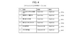
図4は、一実施形態に係るファイルシステムVM管理テーブルの構成を説明する図である。 FIG. 4 is a diagram illustrating the configuration of a file system VM management table according to one embodiment.
ファイルシステムVM管理テーブル161は、ストレージシステム2におけるファイルシステムVM130の情報を管理するテーブルであり、ファイルシステムVM130毎のエントリを格納する。 The file system VM management table 161 is a table for managing information of the
ファイルシステムVM管理テーブル161のエントリは、ファイルシステムVM識別子161aと、物理サーバ識別子161bと、割り当てCPU数161cと、割り当てメモリサイズ161dと、CPU使用率161eと、メモリ使用量161fとの項目を含む。 The entry of the file system VM management table 161 includes items of a file
ファイルシステムVM識別子161aには、エントリに対応するファイルシステムVM130を一意に特定可能な識別子(ファイルシステムVM識別子)が格納される。物理サーバ識別子161bには、エントリに対応するファイルシステムVM130が生成されている物理サーバ100を一意に特定する識別子(物理サーバ識別子)が格納される。割り当てCPU数161cには、エントリに対応するファイルシステムVM130に割り当てられているCPU152の数が格納される。割り当てメモリサイズ161dには、エントリに対応するファイルシステムVM130に割り当てられているメモリ155のサイズが格納される。CPU使用率161eには、エントリに対応するファイルシステムVM130に割り当てられているCPU152の使用率が格納される。メモリ使用量161fには、エントリに対応するファイルシステムVM130に割り当てられたメモリ155の中の使用されているサイズ(メモリ使用量)が格納される。 The file
ファイルシステムVM管理テーブル161においては、ファイルシステムVM識別子161aと、物理サーバ識別子161bと、割り当てCPU数161cと、割り当てメモリサイズ161dとの値は、ハイパバイザ110により、更新されるとともに参照される。CPU使用率161eと、メモリ使用量161fとの値は、ファイルシステムVM130により更新され、ハイパバイザ110により参照される。 In the file system VM management table 161, the values of the file
次に、プロトコルVM管理テーブル162について説明する。 Next, the protocol VM management table 162 will be explained.
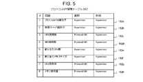
図5は、一実施形態に係るプロトコルVM管理テーブルの構成を説明する図である。 FIG. 5 is a diagram illustrating the configuration of a protocol VM management table according to one embodiment.
プロトコルVM管理テーブル162は、ストレージシステム2におけるプロトコルVM120の情報を管理するテーブルであり、プロトコルVM120毎のエントリを格納する。 The protocol VM management table 162 is a table for managing information of the
プロトコルVM管理テーブル162のエントリは、プロトコルVM識別子162aと、物理サーバ識別子162bと、CIFS接続数162cと、NFS接続数162dと、割り当てCPU数162eと、割り当てメモリサイズ162fと、CPU使用率162gと、メモリ使用量162hとの項目を含む。 The entries in the protocol VM management table 162 include a
プロトコルVM識別子162aには、エントリに対応するプロトコルVM120を一意に特定可能な識別子(プロトコルVM識別子)が格納される。物理サーバ識別子162bには、エントリに対応するプロトコルVM120が生成されている物理サーバ100を一意に特定する識別子(物理サーバ識別子)が格納される。CIFS接続数162cには、エントリに対応するプロトコルVM120に対するCIFSによるクライアントの接続数が格納される。NFS接続数162dには、エントリに対応するプロトコルVM120に対するNFSによるクライアントの接続数が格納される。割り当てCPU数162eには、エントリに対応するプロトコルVM120に割り当てられているCPU152の数が格納される。割り当てメモリサイズ162fには、エントリに対応するプロトコルVM120に割り当てられているメモリ155のサイズが格納される。CPU使用率162gには、エントリに対応するプロトコルVM120に割り当てられているCPU152の使用率が格納される。メモリ使用量162hには、エントリに対応するプロトコルVM120に割り当てられたメモリ155の中の使用されているサイズが格納される。 The
プロトコルVM管理テーブル162においては、プロトコルVM識別子162aと、物理サーバ識別子162bと、割り当てCPU数162eと、割り当てメモリサイズ162fとの値は、ハイパバイザ110により、更新されるとともに参照される。CIFS接続数162cと、NFS接続数162dと、CPU使用率162gと、メモリ使用量162hとの値は、プロトコルVM120により更新され、ハイパバイザ110により参照される。 In the protocol VM management table 162, the values of the
次に、物理サーバ管理テーブル163について説明する。 Next, the physical server management table 163 will be explained.
図6は、一実施形態に係る物理サーバ管理テーブルの構成を説明する図である。 FIG. 6 is a diagram illustrating the configuration of a physical server management table according to one embodiment.
物理サーバ管理テーブル163は、ストレージシステム2における物理サーバ100の情報を管理するテーブルであり、物理サーバ100毎のエントリを格納する。 The physical server management table 163 is a table for managing information on the
物理サーバ管理テーブル163のエントリは、物理サーバ識別子163aと、割り当てCPU数163bと、割り当てメモリサイズ163cとの項目を含む。 The entry of the physical server management table 163 includes items of a
物理サーバ識別子163aには、エントリに対応する物理サーバ100を一意に特定する識別子(物理サーバ識別子)が格納される。割り当てCPU数163bには、エントリに対応する物理サーバ100において、割り当て可能なCPU152の数が格納される。割り当てメモリサイズ163cには、エントリに対応する物理サーバ100において、割り当て可能なメモリ155のサイズが格納される。 The
物理サーバ管理テーブル163においては、物理サーバ識別子163aと、割り当てCPU数163bと、割り当てメモリサイズ163cとの値は、ハイパバイザ110により、更新されるとともに参照される。 In the physical server management table 163, the values of the
次に、閾値管理テーブル164について説明する。 Next, the threshold management table 164 will be explained.
図7は、一実施形態に係る閾値管理テーブルの構成を説明する図である。 FIG. 7 is a diagram illustrating the configuration of a threshold management table according to one embodiment.
閾値管理テーブル164は、処理に使用する閾値を管理するテーブルであり、ユーザ接続上限値164aと、ユーザ接続下限値164bと、Scale-out上限値164cと、Scale-in下限値164dと、Scale-up上限値164eと、Scale-down下限値164fとの項目を含む。 The threshold management table 164 is a table for managing thresholds used in processing, and includes a user connection
ユーザ接続上限値164aには、負荷分散プログラム111において、プロトコルVM120の負荷が高いと判断するためのユーザ接続数の上限値(ユーザ接続上限値)が格納される。ユーザ接続下限値164bには、負荷分散プログラム111において、プロトコルVM120の負荷が低いと判断するためのユーザ接続数の下限値(ユーザ接続下限値)が格納される。Scale-out上限値164cには、リソース制御プログラム112において、プロトコルVM120の負荷が高いと判断するための上限値(Scale-out上限値)が格納される。なお、プロトコルVM120の負荷がこの上限値より高い場合には、Scale-out、すなわち、新しいプロトコルVM120の追加が行われる。Scale-in下限値164dには、リソース制御プログラム112において、プロトコルVM120の負荷が低いと判断するための下限値(Scale-in下限値)が格納される。なお、プロトコルVM120の負荷がこの下限値より低い場合には、Scale-in、すなわち、プロトコルVM120の削除が行われる。 The user connection
Scale-up上限値164eには、リソース制御プログラム112において、ファイルシステムVM130の負荷が高いと判断するための上限値(Scale-up上限値)が格納される。なお、ファイルシステムVM130の負荷がこの上限値より高い場合には、Scale-up、すなわち、ファイルシステムVM130へのリソースの追加が行われる。Scale-down下限値164fには、リソース制御プログラム112において、ファイルシステムVM130の負荷が低いと判断するための下限値(Scale-down下限値)が格納される。なお、ファイルシステムVM130の負荷がこの下限値より低い場合には、Scale-down、すなわち、ファイルシステムVM130のリソースの解放が行われる。 The Scale-up
次に、ストレージシステム2による処理動作について説明する。 Next, processing operations by the
まず、負荷登録処理について説明する。 First, load registration processing will be described.
図8は、一実施形態に係る負荷登録処理のフローチャートである。 FIG. 8 is a flowchart of load registration processing according to one embodiment.
負荷登録処理は、プロトコルVM120、ファイルシステムVM130、ブロックストレージVM140のそれぞれに割り当てられたCPU152が負荷登録プログラム121を実行することにより実行される。 The load registration process is executed by executing the
負荷登録プログラム121は、この負荷登録プログラム121を実行するVMにおける各種負荷をチェックする(ステップS11)。例えば、プロトコルVM120で実行される負荷登録プログラム121は、プロトコルVM120におけるCIFS接続数、NFS接続数、CPU使用率、及びメモリ使用量をチェックする。また、ファイルシステムVM130で実行される負荷登録プログラム121は、ファイルシステムVM130におけるCPU使用率、及びメモリ使用量をチェックする。また、ブロックストレージVM140で実行される負荷登録プログラム121は、ブロックストレージVM140におけるCPU使用率、及びメモリ使用量をチェックする。 The
次いで、負荷登録プログラム121は、チェックした各種負荷に基づいて、マスタプライマリの物理サーバ100のデータベース141の対応する表の対応する項目を更新する(ステップS12)。次いで、負荷登録プログラム121は、一定時間経過したか否かを判定し(ステップS13)、一定時間経過したと判定した場合(ステップS13:YES)には、処理をステップS11に進める。 Next, the
プロトコルVM120、ファイルシステムVM130、及びブロックストレージVM140において実行される負荷登録処理により、マスタプライマリの物理サーバ100のデータベース141には、各VMの最新の負荷の情報が格納されることとなる。 By the load registration processing executed in the
次に、負荷分散処理について説明する。 Next, load distribution processing will be described.
図9は、一実施形態に係る負荷分散処理のフローチャートである。 FIG. 9 is a flowchart of load distribution processing according to one embodiment.
負荷分散処理は、マスタプライマリの物理サーバ100のハイパバイザ110に割り当てられたCPU152が負荷分散プログラム111を実行することにより実行される。 The load distribution process is executed by the
負荷分散プログラム111は、データベース141からストレージシステム2における各VMの負荷の情報を取得する(ステップS21)。 The
次いで、負荷分散プログラム111は、接続ユーザ数(CIFS接続数+NFS接続数)が上限値(閾値管理テーブル164のユーザ接続上限値164aのユーザ接続上限値)を超えている物理サーバ(物理サーバ(1)という)が存在するか否かを判定する(ステップS22)。 Next, the
この結果、接続数がユーザ接続上限値を超えている物理サーバが存在する場合(ステップS22:YES)には、負荷分散プログラム111は、処理をステップS23に進める一方、接続数がユーザ接続上限値を超えている物理サーバが存在しない場合(ステップS22:NO)には、処理をステップS26に進める。 As a result, if there is a physical server with the number of connections exceeding the user connection upper limit (step S22: YES), the
ステップS23では、負荷分散プログラム111は、接続ユーザ数が下限値(閾値管理テーブル164のユーザ接続下限値164bのユーザ接続下限値)よりも少ない物理サーバ(物理サーバ(2)という)が存在するか否かを判定する。 In step S23, the
この結果、接続数がユーザ接続下限値よりも少ない物理サーバが存在する場合(ステップS23:YES)には、負荷分散プログラム111は、処理をステップS24に進める一方、接続数がユーザ接続下限値よりも少ない物理サーバが存在しない場合(ステップS23:NO)には、処理をステップS26に進める。 As a result, if there is a physical server whose number of connections is less than the user connection lower limit value (step S23: YES), the
ステップS24では、負荷分散プログラム111は、物理サーバ(1)から物理サーバ(2)へ負荷を分散する。具体的には、負荷分散プログラム111は、物理サーバ(1)のプロトコルVM120から物理サーバ(2)のプロトコルVM120へ、接続しているユーザについての一部のプロセスについて、等価的フェイルオーバーを行う。 In step S24, the
次いで、負荷分散プログラム111は、負荷分散した結果に基づいて、データベース141の対応する表の値を更新する(ステップS25)。 Next, the
ステップS26では、負荷分散プログラム111は、各物理サーバ100のハイパバイザ110に対して、リソース制御プログラム112の実行を指示する。 In step S26, the
次いで、負荷分散プログラム111は、一定時間経過したか否かを判定し(ステップS27)、一定時間経過したと判定した場合(ステップS27:YES)には、処理をステップS21に進める。 Next, the
上記した負荷分散処理によると、物理サーバ100間でユーザ接続数を分散することができ、各物理サーバ100の負荷を分散することができる。 According to the load distribution processing described above, the number of user connections can be distributed among the
次に、リソース制御処理について説明する。 Next, resource control processing will be described.
図10は、一実施形態に係るリソース制御処理のフローチャートである。 FIG. 10 is a flowchart of resource control processing according to one embodiment.
リソース制御処理は、各物理サーバ100のハイパバイザ110に割り当てられたCPU152がリソース制御プログラム112を実行することにより実行される。 Resource control processing is executed by the
リソース制御プログラム112は、データベース141からリソース制御プログラム112を実行するハイパバイザ110が存在している物理サーバ100(本処理の説明において、自物理サーバという)における各VMの負荷の情報を取得する(ステップS31)。 The
次いで、リソース制御プログラム112は、物理サーバ100に負荷が高いプロトコルVM120が存在するか否か、すなわち、負荷が所定の負荷以上であるプロトコルVM120が存在するか否かを判定する(ステップS32)。例えば、リソース制御プログラム112は、メモリ使用量が所定の閾値を超える場合、CPU使用率が所定の閾値を超える場合、接続ユーザ数(CIFS接続数+NFS接続数)の合計が所定の閾値を超える場合のいずれかを満たすプロトコルVM120が存在する場合に、負荷が高いプロトコルVM120が存在すると判定してもよい。 Next, the
この結果、負荷が高いプロトコルVM120が存在すると判定した場合(ステップS32:YES)、リソース制御プログラム112は、処理をステップS33に進める一方、負荷が高いプロトコルVM120が存在しないと判定した場合(ステップS32:NO)には、処理をステップS42に進める。 As a result, if it is determined that the
ステップS33では、リソース制御プログラム112は、自物理サーバ内に空きリソースが存在するか否かを判定する。ここで、空きリソースがあるか否かは、例えば、物理サーバ管理テーブル163の自物理サーバに対応するエントリにおける割り当てCPU数及び割り当てメモリサイズと、自物理サーバに存在する全てのVMにおける割り当てCPU数及び割り当てメモリサイズとに差があるか否かにより特定することができる。 At step S33, the
この結果、自物理サーバ内に空きリソースが存在すると判定した場合(ステップS33:YES)には、リソース制御プログラム112は、自物理サーバの空きリソースを割り当てた新しいプロトコルVM120を生成し(ステップS34)、生成したプロトコルVM120を、ストレージシステム2における分散ファイルシステムのクラスタに組み込むことにより、分散ファイルシステムをScale-outする(ステップS35)。これにより、プロトコルVM120により実行される処理の効率を向上することができる。次いで、リソース制御プログラム112は、処理をステップS36に進める。 As a result, if it is determined that there is a free resource in the own physical server (step S33: YES), the
ステップS36では、リソース制御プログラム112は、一定時間経過したか否かを判定し、一定時間経過したと判定した場合(ステップS36:YES)には、処理をステップS31に進める。 In step S36, the
一方、自物理サーバ内に空きリソースが存在しないと判定した場合(ステップS33:NO)には、リソース制御プログラム112は、自物理サーバ上のファイルシステムVM130の負荷が低いか否かを判定する(ステップS37)。例えば、リソース制御プログラム112は、ファイルシステムVM130のメモリ使用量が所定の閾値以下であり、且つCPU使用率が所定の閾値以下である場合に、ファイルシステムVM130の負荷が低いと判定してもよい。 On the other hand, if it is determined that there is no free resource in its own physical server (step S33: NO), the
この結果、自物理サーバ上のファイルシステムVM130の負荷が低いと判定した場合(ステップS37:YES)には、リソース制御プログラム112は、ファイルシステムVM130に割り当てられた一部のリソースを解放(Scale-down)し(ステップS38)、解放されたリソースを割り当てた新しいプロトコルVM120を生成し(ステップS39)、生成したプロトコルVM120を、ストレージシステム2における分散ファイルシステムのクラスタに組み込むことにより、分散ファイルシステムをScale-outする(ステップS40)。これにより、プロトコルVM120により実行される処理の効率を向上することができる。次いで、リソース制御プログラム112は、処理をステップS36に進める。処理をステップS36に進める。 As a result, when it is determined that the load on the
一方、自物理サーバ上のファイルシステムVM130の負荷が低いと判定しなかった場合(ステップS37:NO)には、リソース制御プログラム112は、自物理サーバの性能上限に達していることを示すアラートを通知し(例えば、管理計算機20に通知し)(ステップS41)、処理をステップS36に進める。 On the other hand, if it is not determined that the load on the
ステップS42では、ソース制御プログラム112は、自物理サーバ上のファイルシステムVM130の負荷が高いか否か、すなわち、ファイルシステムVM130の負荷が所定の負荷以上であるか否かを判定する。例えば、リソース制御プログラム112は、ファイルシステムVM130のメモリ使用量が所定の閾値を超える場合、又は、CPU使用率が所定の閾値を超える場合に、ファイルシステムVM130の負荷が高いと判定してもよい。 In step S42, the
この結果、ファイルシステムVM130の負荷が高いと判定した場合(ステップS42:YES)、リソース制御プログラム112は、処理をステップS43に進める一方、ファイルシステムVM130の負荷が高くないと判定した場合(ステップS42:NO)には、処理をステップS36に進める。 As a result, when it is determined that the load on the
ステップS43では、リソース制御プログラム112は、自物理サーバ内に空きリソースが存在するか否かを判定する。ここで、空きリソースがあるか否かは、例えば、物理サーバ管理テーブル163の自物理サーバに対応するエントリにおける割り当てCPU数及び割り当てメモリサイズと、自物理サーバに存在する全てのVMにおける割り当てCPU数及び割り当てメモリサイズとに差があるか否かにより特定することができる。 In step S43, the
この結果、自物理サーバ内に空きリソースが存在すると判定した場合(ステップS43:YES)には、リソース制御プログラム112は、自物理サーバの空きリソースをファイルシステムVM130に割り当てることにより、分散ファイルシステムをScale-upする(ステップS44)。これにより、ファイルシステムVM130により実行される処理の効率を向上することができる。次いで、リソース制御プログラム112は、処理をステップS36に進める。 As a result, if it is determined that there are free resources in the own physical server (step S43: YES), the
一方、自物理サーバ内に空きリソースが存在しないと判定した場合(ステップS43:NO)には、リソース制御プログラム112は、自物理サーバ上のプロトコルVM120の負荷が低いか否かを判定する(ステップS45)。例えば、リソース制御プログラム112は、プロトコルVM120のメモリ使用量が所定の閾値以下であり、CPU使用率が所定の閾値以下であり、且つ接続ユーザ数(CIFS接続数+NFS接続数)の合計が所定の閾値以下である場合に、プロトコルVM120の負荷が低いと判定してもよい。 On the other hand, if it is determined that there is no free resource in its own physical server (step S43: NO), the
この結果、自物理サーバ上のプロトコルVM120の負荷が低いと判定した場合(ステップS45:YES)には、リソース制御プログラム112は、自物理サーバ内のプロトコルVM120間で負荷を調整し、いずれか少なくとも1つのプロトコルVM120の負荷を0にし(ステップS46)、負荷を0にしたプロトコルVM120を分散ファイルシステムのクラスタから除外(Scale-out)する(ステップS47)。次いで、リソース制御プログラム112は、クラスタから除外されたプロトコルVM120をハイパバイザ110の管理するVMから削除する(ステップS48)。これにより、プロトコルVM130に割り当てられていたリソースが解放されることとなる。次いで、リソース制御プログラム112は、ファイルシステムVM130に解放されたリソースを割り当てることにより、分散ファイルシステムをScale-upする(ステップS49)。これにより、ファイルシステムVM130により実行される処理の効率を向上することができる。次いで、リソース制御プログラム112は、処理をステップS36に進める。 As a result, when it is determined that the load of the
一方、自物理サーバ上のプロトコルVM120の負荷が低いと判定しなかった場合(ステップS45:NO)には、リソース制御プログラム112は、自物理サーバの性能上限に達していることを示すアラートを通知し(例えば、管理計算機20に通知し)(ステップS50)、処理をステップS36に進める。 On the other hand, if it is not determined that the load of the
なお、本発明は、上述の実施形態に限定されるものではなく、本発明の趣旨を逸脱しない範囲で、適宜変形して実施することが可能である。 It should be noted that the present invention is not limited to the above-described embodiments, and can be modified appropriately without departing from the scope of the present invention.
例えば、上記実施形態では、ファイルシステムVM130の増減に伴うファイルを管理するための各種データの転送による負荷を発生させないために、ファイルシステムVM130の数を調整する制御を行わないようにしていたが、本発明はこれに限られず、ファイルシステムVM130の数を調整することにより、物理サーバ100におけるファイルシステムVM130に対して割り当てるリソースの量を調整するようにしてもよい。 For example, in the above embodiment, in order not to generate a load due to transfer of various data for managing files accompanying increase or decrease in the number of
また、上記実施形態において、CPU152について個数を単位としてリソースの割り当てをしていたが、本発明はこれに限られず、例えば、CPU152のCPUコアを単位としてリソース割り当てをしてもよく、CPU152又はCPUコアの処理時間を単位としてリソース割り当てをしてもよい。 Further, in the above embodiment, resources are allocated in units of the number of
また、上記実施形態において、CPUが行っていた処理の一部又は全部を、ハードウェア回路で行うようにしてもよい。また、上記実施形態におけるプログラムは、プログラムソースからインストールされてよい。プログラムソースは、プログラム配布サーバ又は記憶メディア(例えば可搬型の記憶メディア)であってもよい。 Moreover, in the above embodiments, part or all of the processing performed by the CPU may be performed by a hardware circuit. Also, the programs in the above embodiments may be installed from program sources. The program source may be a program distribution server or storage media (eg, portable storage media).
1…計算機システム、2…ストレージシステム、10…クライアント、20…管理計算機、30…フロントエンドネットワーク、40…管理ネットワーク、50…ノード間ネットワーク、100,100A,100B,100C…物理サーバ、110…ハイパバイザ、120…プロトコルVM、130…ファイルシステムVM、140…ブロックストレージVM、151…通信I/F、152…CPU、153…入力装置、154…記憶デバイス、155…メモリ、156…表示装置
1... Computer system, 2... Storage system, 10... Client, 20... Management computer, 30... Front-end network, 40... Management network, 50... Inter-node network, 100, 100A, 100B, 100C... Physical server, 110... Hypervisor , 120... Protocol VM, 130... File system VM, 140... Block storage VM, 151... Communication I/F, 152... CPU, 153... Input device, 154... Storage device, 155... Memory, 156... Display device
Claims (10)
Translated fromJapanese前記物理サーバには、前記物理サーバのリソースが割り当てられる、クライアントとのネットワークを介してのファイルストレージのプロトコルに関する処理を実行する1以上の第1仮想計算機と、前記ファイルストレージにおけるファイルの管理に関する処理を実行する1以上の第2仮想計算機と、が形成され、
前記物理サーバは、
前記第1仮想計算機と前記第2仮想計算機との負荷に関する負荷情報を取得し、
前記負荷情報に基づいて、前記第1仮想計算機と前記第2仮想計算機とに対する前記物理サーバのリソースの割り当てを制御する
ストレージシステム。A storage system comprising one or more physical servers,
The physical server has one or more first virtual computers that execute processing related to a file storage protocol via a network with a client, to which resources of the physical server are allocated, and processing related to file management in the file storage. and one or more second virtual machines running
The physical server is
obtaining load information about the load on the first virtual computer and the second virtual computer;
A storage system that controls allocation of resources of the physical server to the first virtual machine and the second virtual machine based on the load information.
前記負荷情報に基づいて、前記第1仮想計算機又は前記第2仮想計算機に対して割り当てる前記物理サーバのリソースの割り当て量を制御する
請求項1に記載のストレージシステム。The physical server is
2. The storage system according to claim 1, wherein, based on said load information, the allocation amount of resources of said physical server to be allocated to said first virtual machine or said second virtual machine is controlled.
前記負荷情報に基づいて、前記第1仮想計算機又は前記第2仮想計算機の少なくとも一方の数を制御することにより、前記物理サーバのリソースの割り当てを制御する
請求項1に記載のストレージシステム。The physical server is
2. The storage system according to claim 1, wherein allocation of resources of said physical server is controlled by controlling the number of at least one of said first virtual machine and said second virtual machine based on said load information.
前記第1仮想計算機の負荷が所定の負荷以上であり、前記物理サーバに空きリソースが存在する場合に、新たな第1仮想計算機を生成する
請求項3に記載のストレージシステム。The physical server is
4. The storage system according to claim 3, wherein a new first virtual computer is created when the load on said first virtual computer is greater than or equal to a predetermined load and there is a free resource in said physical server.
前記第1仮想計算機の負荷が所定の負荷以上であり、前記物理サーバに空きリソースが存在しない場合に、負荷が所定負荷よりも低い第2仮想計算機に割り当てられたリソースの一部を解放し、前記解放したリソースを用いて新たな第1仮想計算機を生成する
請求項4に記載のストレージシステム。The physical server is
When the load of the first virtual computer is equal to or greater than a predetermined load and there is no free resource in the physical server, releasing a part of the resources allocated to the second virtual computer whose load is lower than the predetermined load; 5. The storage system according to claim 4, wherein the released resource is used to generate a new first virtual machine.
前記第2仮想計算機の負荷が所定の負荷以上であり、前記物理サーバに空きリソースが存在する場合に、前記第2仮想計算機に、前記物理サーバの空きリソースを追加して割り当てる
請求項2に記載のストレージシステム。The physical server is
3. The method according to claim 2, wherein when the load on said second virtual machine is equal to or greater than a predetermined load and there is a free resource on said physical server, the free resource on said physical server is additionally allocated to said second virtual machine. storage system.
前記物理サーバは、
前記第2仮想計算機の負荷が所定の負荷以上であり、前記物理サーバに空きリソースが存在しない場合に、複数の前記第1仮想計算機の一部の第1仮想計算機を削除し、削除した第1仮想計算機に割り当てられていたリソースを前記第2仮想計算機に割り当てる
請求項6に記載のストレージシステム。A plurality of the first virtual machines are generated in the physical server,
The physical server is
When the load on the second virtual computer is equal to or greater than a predetermined load and there is no free resource in the physical server, the first virtual computer of a part of the plurality of first virtual computers is deleted, and the deleted first virtual computer is deleted. 7. The storage system according to claim 6, wherein resources that have been allocated to a virtual machine are allocated to said second virtual machine.
複数の物理サーバを備え、
少なくとも一つの物理サーバは、
接続されているクライアントの数が所定数以下の物理サーバに対して、他の物理サーバに接続されているクライアントの一部を移管する処理を行う
請求項1に記載のストレージシステム。The storage system is
Equipped with multiple physical servers,
At least one physical server
2. The storage system according to claim 1, wherein a physical server having a number of connected clients equal to or less than a predetermined number performs a process of transferring some of the clients connected to other physical servers.
前記物理サーバには、前記物理サーバのリソースが割り当てられる、クライアントとのネットワークを介してのファイルストレージのプロトコルに関する処理を実行する1以上の第1仮想計算機と、前記ファイルストレージにおけるファイルの管理に関する処理を実行する1以上の第2仮想計算機と、が形成され、
前記物理サーバは、
前記第1仮想計算機と前記第2仮想計算機との負荷に関する負荷情報を取得し、
前記負荷情報に基づいて、前記第1仮想計算機と前記第2仮想計算機に対する前記物理サーバのリソースの割り当てを制御する
リソース制御方法。A resource control method by a storage system comprising one or more physical servers,
The physical server has one or more first virtual computers that execute processing related to a file storage protocol via a network with a client, to which resources of the physical server are allocated, and processing related to file management in the file storage. and one or more second virtual machines running
The physical server is
obtaining load information about the load on the first virtual computer and the second virtual computer;
A resource control method for controlling resource allocation of the physical server to the first virtual machine and the second virtual machine based on the load information.
前記物理サーバには、前記物理サーバのリソースが割り当てられる、クライアントとのネットワークを介してのファイルストレージのプロトコルに関する処理を実行する1以上の第1仮想計算機と、前記ファイルストレージにおけるファイルの管理に関する処理を実行する1以上の第2仮想計算機と、が形成され、
前記物理サーバに、
前記第1仮想計算機と前記第2仮想計算機との負荷に関する負荷情報を取得させ、
前記負荷情報に基づいて、前記第1仮想計算機と前記第2仮想計算機に対する前記物理サーバのリソースの割り当てを制御させる
リソース制御プログラム。
A resource control program to be executed by a physical server that constitutes a storage system,
The physical server has one or more first virtual computers that execute processing related to a file storage protocol via a network with a client, to which resources of the physical server are allocated, and processing related to file management in the file storage. and one or more second virtual machines running
on the physical server,
obtaining load information about the load on the first virtual machine and the second virtual machine;
A resource control program for controlling allocation of resources of the physical server to the first virtual machine and the second virtual machine based on the load information.
Priority Applications (2)
| Application Number | Priority Date | Filing Date | Title |
|---|---|---|---|
| JP2021032991AJP2022133993A (en) | 2021-03-02 | 2021-03-02 | Storage system, resource control method, and resource control program |
| US17/460,670US20220283875A1 (en) | 2021-03-02 | 2021-08-30 | Storage system, resource control method, and recording medium |
Applications Claiming Priority (1)
| Application Number | Priority Date | Filing Date | Title |
|---|---|---|---|
| JP2021032991AJP2022133993A (en) | 2021-03-02 | 2021-03-02 | Storage system, resource control method, and resource control program |
Publications (1)
| Publication Number | Publication Date |
|---|---|
| JP2022133993Atrue JP2022133993A (en) | 2022-09-14 |
Family
ID=83116165
Family Applications (1)
| Application Number | Title | Priority Date | Filing Date |
|---|---|---|---|
| JP2021032991APendingJP2022133993A (en) | 2021-03-02 | 2021-03-02 | Storage system, resource control method, and resource control program |
Country Status (2)
| Country | Link |
|---|---|
| US (1) | US20220283875A1 (en) |
| JP (1) | JP2022133993A (en) |
Cited By (1)
| Publication number | Priority date | Publication date | Assignee | Title |
|---|---|---|---|---|
| CN115749980A (en)* | 2022-11-18 | 2023-03-07 | 中国船舶重工集团公司第七一九研究所 | A Calculation Resource Reconfiguration Method for Network Control System of Steam Turbine Unit |
Families Citing this family (2)
| Publication number | Priority date | Publication date | Assignee | Title |
|---|---|---|---|---|
| US11960913B2 (en)* | 2021-03-16 | 2024-04-16 | Nerdio, Inc. | Systems and methods of auto-scaling a virtual desktop environment |
| US12254352B2 (en)* | 2021-10-28 | 2025-03-18 | Servicenow, Inc. | Reduced memory utilization for data analytics procedures |
Family Cites Families (4)
| Publication number | Priority date | Publication date | Assignee | Title |
|---|---|---|---|---|
| WO2016030973A1 (en)* | 2014-08-27 | 2016-03-03 | 株式会社日立製作所 | Multi-tenant resource coordination method |
| JP6447217B2 (en)* | 2015-02-17 | 2019-01-09 | 富士通株式会社 | Execution information notification program, information processing apparatus, and information processing system |
| US11550558B2 (en)* | 2016-02-12 | 2023-01-10 | Nutanix, Inc. | Virtualized file server deployment |
| US12169727B2 (en)* | 2021-01-12 | 2024-12-17 | Citrix Systems, Inc. | Systems and methods to improve application performance |
- 2021
- 2021-03-02JPJP2021032991Apatent/JP2022133993A/enactivePending
- 2021-08-30USUS17/460,670patent/US20220283875A1/ennot_activeAbandoned
Cited By (1)
| Publication number | Priority date | Publication date | Assignee | Title |
|---|---|---|---|---|
| CN115749980A (en)* | 2022-11-18 | 2023-03-07 | 中国船舶重工集团公司第七一九研究所 | A Calculation Resource Reconfiguration Method for Network Control System of Steam Turbine Unit |
Also Published As
| Publication number | Publication date |
|---|---|
| US20220283875A1 (en) | 2022-09-08 |
Similar Documents
| Publication | Publication Date | Title |
|---|---|---|
| US11922203B2 (en) | Virtualized server systems and methods including scaling of file system virtual machines | |
| US10824455B2 (en) | Virtualized server systems and methods including load balancing for virtualized file servers | |
| US10394847B2 (en) | Processing data in a distributed database across a plurality of clusters | |
| Nashaat et al. | Smart elastic scheduling algorithm for virtual machine migration in cloud computing | |
| CN107273185B (en) | Load balancing control method based on virtual machine | |
| US20200287961A1 (en) | Balancing resources in distributed computing environments | |
| Rao et al. | Performance issues of heterogeneous hadoop clusters in cloud computing | |
| US12373405B2 (en) | Data migration method and apparatus, device, medium, and computer product | |
| JP2022133993A (en) | Storage system, resource control method, and resource control program | |
| JP2018520402A (en) | Object-based storage cluster with multiple selectable data processing policies | |
| JP2012159928A (en) | Information processing device, information processing system, arrangement configuration determination method, and program and recording medium therefor | |
| US11609831B2 (en) | Virtual machine configuration update technique in a disaster recovery environment | |
| CN117215484A (en) | Metadata control in load balancing distributed storage systems | |
| CN113821340A (en) | Dynamic balancing method, system, terminal and storage medium for distributed system | |
| US20190235907A1 (en) | Efficient distributed arrangement of virtual machines on plural host machines | |
| US10019182B2 (en) | Management system and management method of computer system | |
| US10956442B1 (en) | Dedicated source volume pool for accelerated creation of block data volumes from object data snapshots | |
| US11704145B1 (en) | Infrastructure-based risk diverse placement of virtualized computing resources | |
| JP2022188458A (en) | Storage system, failover control method, and failover control program | |
| JP2014167713A (en) | Information processing device, information processing system, information processing device management program and information processing device management method | |
| JP2023100222A (en) | System configuration management device, system configuration management method, and system configuration management program | |
| US10379902B2 (en) | Information processing device for aggregating load information, information processing system for aggregating load information, and non-transitory computer-readable storage medium recording program for aggregating load information | |
| Meng et al. | A network load sensitive block placement strategy of HDFS | |
| JP2014126940A (en) | Cloud configuration management support system, cloud configuration management support method and cloud configuration management support program | |
| Guroob et al. | Efficient replica consistency model (ERCM) for update propagation in data grid environment |