JP2022132660A - Power supply system and power supply method - Google Patents
Power supply system and power supply methodDownload PDFInfo
- Publication number
- JP2022132660A JP2022132660AJP2022118235AJP2022118235AJP2022132660AJP 2022132660 AJP2022132660 AJP 2022132660AJP 2022118235 AJP2022118235 AJP 2022118235AJP 2022118235 AJP2022118235 AJP 2022118235AJP 2022132660 AJP2022132660 AJP 2022132660A
- Authority
- JP
- Japan
- Prior art keywords
- power
- power supply
- supply system
- low
- voltage
- Prior art date
- Legal status (The legal status is an assumption and is not a legal conclusion. Google has not performed a legal analysis and makes no representation as to the accuracy of the status listed.)
- Granted
Links
Images


Classifications
- Y—GENERAL TAGGING OF NEW TECHNOLOGICAL DEVELOPMENTS; GENERAL TAGGING OF CROSS-SECTIONAL TECHNOLOGIES SPANNING OVER SEVERAL SECTIONS OF THE IPC; TECHNICAL SUBJECTS COVERED BY FORMER USPC CROSS-REFERENCE ART COLLECTIONS [XRACs] AND DIGESTS
- Y02—TECHNOLOGIES OR APPLICATIONS FOR MITIGATION OR ADAPTATION AGAINST CLIMATE CHANGE
- Y02B—CLIMATE CHANGE MITIGATION TECHNOLOGIES RELATED TO BUILDINGS, e.g. HOUSING, HOUSE APPLIANCES OR RELATED END-USER APPLICATIONS
- Y02B90/00—Enabling technologies or technologies with a potential or indirect contribution to GHG emissions mitigation
- Y02B90/20—Smart grids as enabling technology in buildings sector
- Y—GENERAL TAGGING OF NEW TECHNOLOGICAL DEVELOPMENTS; GENERAL TAGGING OF CROSS-SECTIONAL TECHNOLOGIES SPANNING OVER SEVERAL SECTIONS OF THE IPC; TECHNICAL SUBJECTS COVERED BY FORMER USPC CROSS-REFERENCE ART COLLECTIONS [XRACs] AND DIGESTS
- Y02—TECHNOLOGIES OR APPLICATIONS FOR MITIGATION OR ADAPTATION AGAINST CLIMATE CHANGE
- Y02E—REDUCTION OF GREENHOUSE GAS [GHG] EMISSIONS, RELATED TO ENERGY GENERATION, TRANSMISSION OR DISTRIBUTION
- Y02E10/00—Energy generation through renewable energy sources
- Y02E10/70—Wind energy
- Y02E10/76—Power conversion electric or electronic aspects
- Y—GENERAL TAGGING OF NEW TECHNOLOGICAL DEVELOPMENTS; GENERAL TAGGING OF CROSS-SECTIONAL TECHNOLOGIES SPANNING OVER SEVERAL SECTIONS OF THE IPC; TECHNICAL SUBJECTS COVERED BY FORMER USPC CROSS-REFERENCE ART COLLECTIONS [XRACs] AND DIGESTS
- Y02—TECHNOLOGIES OR APPLICATIONS FOR MITIGATION OR ADAPTATION AGAINST CLIMATE CHANGE
- Y02E—REDUCTION OF GREENHOUSE GAS [GHG] EMISSIONS, RELATED TO ENERGY GENERATION, TRANSMISSION OR DISTRIBUTION
- Y02E70/00—Other energy conversion or management systems reducing GHG emissions
- Y02E70/30—Systems combining energy storage with energy generation of non-fossil origin
- Y—GENERAL TAGGING OF NEW TECHNOLOGICAL DEVELOPMENTS; GENERAL TAGGING OF CROSS-SECTIONAL TECHNOLOGIES SPANNING OVER SEVERAL SECTIONS OF THE IPC; TECHNICAL SUBJECTS COVERED BY FORMER USPC CROSS-REFERENCE ART COLLECTIONS [XRACs] AND DIGESTS
- Y04—INFORMATION OR COMMUNICATION TECHNOLOGIES HAVING AN IMPACT ON OTHER TECHNOLOGY AREAS
- Y04S—SYSTEMS INTEGRATING TECHNOLOGIES RELATED TO POWER NETWORK OPERATION, COMMUNICATION OR INFORMATION TECHNOLOGIES FOR IMPROVING THE ELECTRICAL POWER GENERATION, TRANSMISSION, DISTRIBUTION, MANAGEMENT OR USAGE, i.e. SMART GRIDS
- Y04S20/00—Management or operation of end-user stationary applications or the last stages of power distribution; Controlling, monitoring or operating thereof
- Y04S20/12—Energy storage units, uninterruptible power supply [UPS] systems or standby or emergency generators, e.g. in the last power distribution stages
Landscapes
- Supply And Distribution Of Alternating Current (AREA)
- Remote Monitoring And Control Of Power-Distribution Networks (AREA)
- Charge And Discharge Circuits For Batteries Or The Like (AREA)
- Distribution Board (AREA)
Abstract
Description
Translated fromJapanese本発明は、電力供給システムおよび電力供給方法に関する。 The present invention relates to a power supply system and a power supply method.
従来、高圧一括受電契約を結び、受電した電力を各戸に配電する集合住宅における配電システムが知られている(例えば特許文献1および2)。 2. Description of the Related Art Conventionally, there has been known a power distribution system in an apartment complex in which a high-voltage bulk power receiving contract is concluded and the received power is distributed to each house (for example,
しかしながら、高圧受変電装置は一定のコストがかかる。また、基準値(例えば50kW)以上の容量での電力契約でなければ高圧一括受電契約をそもそも結べないため、高圧一括受電契約は一定規模以上の集合住宅しか結ぶことができない。高圧一括受電契約を結ぶことができない規模の集合住宅でも低圧一括受電契約を結ぶことができるが、必ずしも電気料金の低減を実現できない。 However, high-voltage power receiving and transforming equipment requires a certain amount of cost. In addition, since a high-voltage bulk power supply contract cannot be concluded unless the power contract is for a capacity of a reference value (for example, 50 kW) or more, a high-voltage bulk power supply contract can only be concluded for collective housing of a certain size or larger. Although it is possible to conclude a low-voltage bulk power receiving contract even in collective housing that cannot conclude a high-voltage bulk power receiving contract, it is not always possible to realize a reduction in electricity charges.
かかる事情に鑑みてなされた本発明の目的は、低圧一括受電を行うときに電気料金の低減を実現することができる電力供給システムおよび電力供給方法を提供することにある。 SUMMARY OF THE INVENTION An object of the present invention, which has been made in view of such circumstances, is to provide a power supply system and a power supply method that can realize a reduction in electricity charges when performing low-voltage batch power reception.
上記課題を解決するため、本発明の一実施形態に係る電力供給システムは、
高圧一括受電契約に必要な電力未満の電力の低圧一括受電契約に基づいて系統から低圧一括受電する集合住宅であって、前記低圧一括受電契約を結ぶ電力会社とは異なる前記集合住宅を管理する事業者から電力の使用量に応じて電気料金が振り分けられることになる複数の住戸及び共用部を有する1棟の集合住宅における電力供給システムであって、
キュービクル式高圧受電設備を介さずに前記系統と直接接続され、前記集合住宅において前記系統から買電した電力量を測定する上位メータ装置と、
前記系統側に接続される第1ブレーカと、
前記系統から前記キュービクル式高圧受電設備を介さずに前記上位メータ装置を経由して電力の供給を受ける低圧一括受電盤と、
前記複数の住戸及び前記共用部それぞれに接続される複数の第2ブレーカと、
前記低圧一括受電盤で受電された電力を、前記第2ブレーカを経由して前記複数の住戸及び前記共用部それぞれに供給する分岐点と、
前記分岐点と前記複数の住戸との間に接続され、前記複数の住戸の消費電力量を測定する複数の下位メータ装置と、
蓄電池と、燃料電池、太陽光発電装置および風力発電装置の少なくとも1つを含む発電装置との少なくとも一方を含む分散型電源であって、前記上位メータ装置と前記複数の下位メータ装置との間に接続され、前記複数の住戸及び前記共用部に電力を供給可能な分散型電源と、
を有し、
前記第1ブレーカの容量は、前記各第2ブレーカの容量の合計値よりも小さい。In order to solve the above problems, a power supply system according to one embodiment of the present invention includes:
A business that manages a collective housing that receives low-voltage bulk power from the grid based on a low-voltage bulk power receiving contract that is less than the power required for the high-voltage bulk power receiving contract, and is different from a power company that concludes the low-voltage bulk power receiving contract. A power supply system in a single apartment building having a plurality of dwelling units and a common area where electricity charges are distributed from the person according to the amount of power used,
a high-level meter device that is directly connected to the system without passing through a cubicle-type high-voltage power receiving facility and measures the amount of power purchased from the system in the housing complex;
a first breaker connected to the system side;
a low-voltage collective power receiving panel that receives power from the system via the host meter device without passing through the cubicle-type high-voltage power receiving equipment;
a plurality of second breakers connected respectively to the plurality of dwelling units and the common area;
a branch point that supplies the power received by the low-voltage collective power receiving board to each of the plurality of dwelling units and the common area via the second breaker;
a plurality of subordinate meter devices connected between the branch point and the plurality of dwelling units for measuring power consumption of the plurality of dwelling units;
A distributed power supply including at least one of a storage battery and a power generation device including at least one of a fuel cell, a solar power generation device, and a wind power generation device, between the upper meter device and the plurality of lower meter devices a distributed power source that is connected and capable of supplying power to the plurality of dwelling units and the common area;
has
The capacity of the first breaker is smaller than the total capacity of the second breakers.
また、上記課題を解決するため、本発明の一実施形態に係る電力供給方法は、
高圧一括受電契約に必要な電力未満の電力の低圧一括受電契約に基づいて系統から低圧一括受電する集合住宅であって、前記低圧一括受電契約を結ぶ電力会社とは異なる前記集合住宅を管理する事業者から電力の使用量に応じて電気料金が振り分けられることになる複数の住戸及び共用部を有する1棟の集合住宅における電力供給方法であって、
キュービクル式高圧受電設備を介さずに前記系統と直接接続され、前記集合住宅において前記系統から買電した消費電力量を測定する上位メータ装置において、当該消費電力量を測定する第1ステップと、
前記系統側に接続される、前記低圧一括受電契約の契約容量より大きい電力を遮断する第1ブレーカを介して前記系統から前記キュービクル式高圧受電設備を介さずに電力の供給を受ける第2ステップと、
前記第2ステップで受電された電力を、前記複数の住戸及び前記共用部それぞれに接続される複数の第2ブレーカを経由して前記複数の住戸及び前記共用部それぞれに供給する第3ステップと、
前記複数の住戸の消費電力量を測定する複数の下位メータ装置において、当該複数の住戸の消費電力量を測定する第4ステップと、
蓄電池と、燃料電池、太陽光発電装置および風力発電装置の少なくとも1つを含む発電装置との少なくとも一方を含む分散型電源から、前記上位メータ装置と前記複数の下位メータ装置との間を経由して前記複数の住戸及び前記共用部に電力を供給する第5ステップと
を含み、
前記第1ブレーカの容量は、前記各第2ブレーカの容量の合計値よりも小さい。Moreover, in order to solve the above problems, a power supply method according to an embodiment of the present invention includes:
A business that manages a collective housing that receives low-voltage bulk power from the grid based on a low-voltage bulk power receiving contract that is less than the power required for the high-voltage bulk power receiving contract, and is different from a power company that concludes the low-voltage bulk power receiving contract. A power supply method in a single collective housing having a plurality of dwelling units and a common area in which electricity charges are distributed according to the amount of power used by a person,
a first step of measuring the power consumption in an upper-level meter device that is directly connected to the system without passing through a cubicle-type high-voltage power receiving equipment and measures the power consumption purchased from the system in the collective housing;
a second step of receiving power supply from the system via a first breaker that is connected to the system side and cuts off power greater than the contracted capacity of the low-voltage bulk power receiving contract, without passing through the cubicle-type high-voltage power receiving equipment; ,
a third step of supplying the electric power received in the second step to each of the plurality of dwelling units and the common area via a plurality of second breakers connected to each of the plurality of dwelling units and the common area;
a fourth step of measuring the power consumption of the plurality of dwelling units in the plurality of subordinate meter devices for measuring the power consumption of the plurality of dwelling units;
from a distributed power supply including at least one of a storage battery and a power generation device including at least one of a fuel cell, a solar power generation device, and a wind power generation device via between the upper meter device and the plurality of lower meter devices and a fifth step of supplying power to the plurality of dwelling units and the common area,
The capacity of the first breaker is smaller than the total capacity of the second breakers.
本発明の一実施形態に係る電力供給システムおよび電力制御方法によれば、低圧一括受電を行うときに電気料金の低減を実現することができる。 According to the power supply system and the power control method according to one embodiment of the present invention, it is possible to reduce electricity charges when performing low-voltage batch power reception.
図1は、本発明の実施形態に係る電力供給システム90の機能ブロック図である。制御ラインおよび情報伝達ラインは破線で示し、電力ラインは実線で示す。電力供給システム90は系統80に接続される。電力供給システム90は上位メータ装置1、一括受電盤2、分散型電源3、分電盤4を少なくとも有し、さらに、下位メータ装置5、下位制御装置6、負荷7、上位制御装置8およびサーバ装置9の少なくとも1つを含んでもよい。電力供給システム90の各機能を説明するが、電力供給システム90が有する他の機能を排除することを意図したものではないことに留意されたい。 FIG. 1 is a functional block diagram of a
図1に示す通り、上位メータ装置1、一括受電盤2、分散型電源3、分電盤4、下位メータ装置5、下位制御装置6、負荷7および上位制御装置8は複合需要家施設に設けられる。代替例として一括受電盤2は上位メータ装置1および分電盤4を内部に有してもよい。また、上位メータ装置1は複合需要家施設外に設けられてもよい。複合需要家施設は本実施形態では集合住宅であり複数の需要家施設(例えば1階に3戸且つ2階に3戸の合計で6戸)および共用部分(例えば廊下、階段、エレベータホール)を有する。下位制御装置6は需要家施設のそれぞれおよび共用部分に設けられ、負荷7も需要家施設のそれぞれおよび共用部分に設けられる。 As shown in FIG. 1, a high-
電力供給システム90は例えば電力の事業者(新電力事業者または集合住宅管理会社ともいう)によって設けられる。本実施形態における複合需要家施設は集合住宅としては比較的小規模であるため、高圧一括受電契約に必要な電力を消費しない。このため複合需要家施設は高圧一括受電契約を行うことができない。そこで複合需要家施設は高圧一括受電契約に必要な電力(例えば50kW)未満の電力で電力会社と低圧一括受電契約を行う。 The
複合需要家施設は電力会社と低圧一括受電契約を結ぶと共に、太陽光発電の余剰電力の売電契約を結ぶ。また複合需要家施設は需要家施設の各入居者と電力契約を結ぶ。このようにして複合需要家施設は電力会社から電力を受電すると共に、受電した電力を需要家施設に供給する。 The complex consumer facility concludes a low-voltage bulk power receiving contract with an electric power company, and also concludes a power selling contract for surplus power generated by photovoltaic power generation. Also, the complex consumer facility concludes an electric power contract with each resident of the consumer facility. In this manner, the complex consumer facility receives power from the electric power company and supplies the received power to the consumer facility.
上位メータ装置1は検定付きメータ装置であり、複合需要家施設による消費電力量を測定する。上位メータ装置1は、電気料金の計算等のため、測定した消費電力量を上位制御装置8に出力する。検定付きメータ装置は、計量法により検定し、且つ検定有効期間内のものである。また上位メータ装置1としてスマートメータを用いてもよい。 The upper-
一括受電盤2は上位メータ装置1に接続され、低圧一括受電により系統80から電力の供給を受ける。一括受電盤2は当該供給された電力を分電盤4に供給する。 The collective
分散型電源3は複数の需要家施設に電力を供給可能である。分散型電源3は、蓄電池と、燃料電池、太陽光発電装置および風力発電装置の少なくとも1つを含む発電装置との少なくとも一方を含む。このため、様々なタイプの分散型電源を組み合わせて電気料金を低減することが可能となる。蓄電池は自立出力可能であり、例えば停電時に需要家施設および共用部分の少なくとも一方に電力を供給可能である。発電装置は、発電した電力を蓄電池、需要家施設および共用部分の少なくとも一方に供給可能である。 The distributed power source 3 can supply power to a plurality of consumer facilities. The distributed power source 3 includes at least one of a storage battery and a power generation device including at least one of a fuel cell, a solar power generation device, and a wind power generation device. Therefore, it is possible to combine various types of distributed power sources to reduce electricity charges. The storage battery is capable of independent output, and can supply electric power to at least one of consumer facilities and common areas during a power outage, for example. The power generation device can supply generated power to at least one of the storage battery, the consumer facility, and the common area.
分電盤4は連系運転時に一括受電盤2で受電された電力を複数の支幹に分岐させ、共用部分および需要家施設のそれぞれの少なくとも一方に供給する。また分電盤4は、分散型電源3から供給される電力を複数の支幹に分岐させて需要家施設に分配する。 The
下位メータ装置5は例えば検定付きの証明用電気計器(子メータ)であり、需要家施設のそれぞれに接続される。需要家施設のそれぞれに接続される下位メータ装置5は需要家施設のそれぞれの負荷7の消費電力量を測定する。下位メータ装置5は分電盤4に接続され、需要家施設内または需要家施設外に事業者によって設けられる。また、下位メータ装置5は、共用部分にも接続される。共用部分に接続される下位メータ装置5は、共用部分の負荷7の消費電力量を測定する。下位メータ装置5はスマートメータであってもよい。下位メータ装置5は測定した消費電力量を上位制御装置8に通知する。 The
下位制御装置6は例えばHEMS(Home Energy Management System)である。下位制御装置6が実行する処理は、制御手順を規定したプログラムを実行するCPU(Central Processing Unit)等のプロセッサを含む制御部で実行され、当該プログラムは下位制御装置6の記憶部又は外部の記憶媒体に格納される。下位制御装置6は需要家施設のそれぞれおよび共用部分の少なくとも一方に設けられ、対応する需要家施設および共用部分の少なくとも一方の負荷7の消費電力量を制御可能である。下位制御装置6は上位制御装置8から、需要家施設および共用部分の少なくとも一方における消費電力量を抑制するように要求されたとき、負荷7を制御して消費電力量を抑制可能である。 The
負荷7は、電力を消費する電力負荷であり、例えば需要家施設によって使用されるエアコン、電子レンジ、冷蔵庫、テレビ、ルータ等の各種電気製品である。負荷7は空調機または照明器具等の機械、照明設備等であってもよい。負荷7のうち共用部分におけるものは、例えば、照明設備、非常設備(例えば、火災報知機等)等の、共用部分において電力を消費する機器である。 The
上位制御装置8は例えばHEMSである。上位制御装置8が実行する処理は、制御手順を規定したプログラムを実行するCPU等のプロセッサを含む制御部で実行され、当該プログラムは上位制御装置8の記憶部又は外部の記憶媒体に格納される。上位制御装置8は複合需要家施設に設けられる。代替例として上位制御装置8は、複合需要家施設内および複合需要家施設外の少なくとも一方のサーバ装置9に設けられてもよい。上位制御装置8は下位メータ装置5によって測定された電力量を通信で定期的(例えば1時間に1回)に取得し、サーバ装置9に出力する。また上位制御装置8は分散型電源3の動作状態を監視し、取得した動作ログ(発電装置の発電状況、蓄電池の充放電状況、エラー情報等)をサーバ装置9に出力する。 The
上位制御装置8はデマンドレスポンスの信号を取得したとき、複数の需要家施設による消費電力量を抑制するように下位制御装置6に要求する。例えば上位制御装置8は、デマンドレスポンスの信号を取得したとき、複数の需要家施設のそれぞれにおける現在の消費電力量に応じて、複数の需要家施設のそれぞれの消費電力削減量を決定し、当該決定の通りに削減を実施するよう下位制御装置6に要求してもよい。これにより、複数の需要家施設のうちそれぞれの需要家施設又は複合需要家施設を管理する事業者はインセンティブを得ることができる。上位制御装置8は共用部分における消費電力量を同様に抑制してもよい。 When the
より具体的に、インセンティブは、上位制御装置8が受信したデマンドレスポンスの送信者から得ることができる。デマンドレスポンスの送信者は、例えば、電力事業者(電力会社)、電力配信事業者(電力アグリゲータ)等が想定される。送信者からのインセンティブは、まず複合需要家施設を管理する事業者に与えられる。そして、事業者は、需要家施設の需要家のデマンドレスポンスへの貢献度合いに応じて、送信者からのインセンティブを振り分ける。需要家に対して与えられる事業者のインセンティブは、送信者から与えられるインセンティブと異なっていてもよい。 More specifically, the incentive can be obtained from the sender of the demand response received by the
上位制御装置8は、系統80への電力の出力を抑制する指示を取得したとき、発電装置の余剰電力を蓄電池に充電させる。例えば上位制御装置8は、当該指示を電力事業者(電力会社)、電力配信事業者(電力アグリゲータ)、電力送配電事業者、特定規模電気事業者(PPS:Power Producer and Supplier)等から取得したとき、発電装置の余剰電力を蓄電池に充電させる。上位制御装置8以外の装置(例えば出力制御装置、パワーコンディショナ)が当該指示を取得したとき、上位制御装置8以外の装置は当該指示を上位制御装置8に転送する。このため、出力抑制指示に対応するだけでなく、発電装置による発電を継続して、将来の放電のために蓄電池に余剰電力を充電させることができる。 When the
サーバ装置9は複合需要家施設を管理する事業者によって用いられる。サーバ装置9はクラウドサーバであってもよい。サーバ装置9は上位制御装置8から消費電力量等の情報を取得して、検針データ管理支援、料金請求データ作成支援、創エネ・蓄エネ設備管理、需要家施設向け(入居者向け)電気使用量の見える化サービス(Webサービス)等を行う。サーバ装置9は上位制御装置8からエラー情報を取得したとき、サーバ装置9のユーザである監視員に音声、ランプ、画像、映像、電話、メール等でエラーが生じていることを通知する。 The
またサーバ装置9は上位制御装置8より、蓄電池が自立出力モードに変わったことの通知を取得したとき、一括受電盤2のブレーカがオフになったと判定し、監視員に警告情報を通知する。一般に低圧一括受電盤のブレーカをオンにすることを需要家施設の入居者が行うことは難しい。そのため警告情報を取得した監視員は、複合需要家施設に駆けつけ、ブレーカをオンにする。代替例としてサーバ装置9は、上位制御装置8との通信が断たれたとき、一括受電盤2のブレーカがオフになったと判定してもよい。 Further, when the
以下、低圧一括受電を行うときに電気料金の低減を実現するための構成を説明する。 A configuration for realizing a reduction in electricity charges when performing low-voltage batch power reception will be described below.
第1の構成として、電力供給システム90は低圧一括受電を単に行うだけでなく、分散型電源3を有する。複数の需要家施設は分散型電源3を共有し、電気料金が高い時間帯に分散型電源3から電力の供給を受けることにより系統80からの買電電力量を削減することができる。これにより、電気料金の低減を実現することができる。 As a first configuration, the
第2の構成として、低圧一括受電契約における契約容量は、需要家施設のそれぞれのブレーカ容量の合計値よりも小さい。例えば複合需要家施設における需要家施設の数が6戸であり各戸のブレーカ容量が40Aとする。また共用部分のブレーカ容量が50Aとすると、複合需要家施設全体のブレーカ容量の合計値は40×6+50=290(A)である。しかしながら、全戸が同時に最大容量を消費する可能性は低いため、例えば複合需要家施設は240Aの契約容量で低圧一括受電契約を結ぶ。これにより、電気料金の低減を実現することができる。 As a second configuration, the contract capacity in the low-voltage bulk power receiving contract is smaller than the total value of the respective breaker capacities of the customer facilities. For example, it is assumed that the number of customer facilities in a complex customer facility is 6 and the breaker capacity of each house is 40A. Assuming that the breaker capacity of the shared portion is 50A, the total value of the breaker capacity of the entire complex consumer facility is 40×6+50=290 (A). However, since it is unlikely that all households will consume the maximum capacity at the same time, for example, a complex consumer facility concludes a low-voltage bulk power receiving contract with a contract capacity of 240A. This makes it possible to reduce the electricity bill.
第3の構成として、複数の需要家施設のそれぞれが各戸契約を結ぶのではなく、複合需要家施設が低圧一括受電契約を結び、複数の需要家施設は低圧一括受電契約で受電された電力の供給を受ける。電力会社の料金プランによっては、契約容量が大きくなるにつれて1戸あたりの電気料金が安くなる。このため電気料金の低減を実現することができる。 As a third configuration, multiple consumer facilities do not each conclude a contract for each house, but a complex consumer facility concludes a low-voltage bulk power receiving contract, and multiple consumer facilities receive power under the low-voltage bulk power receiving contract. receive supply. Depending on the rate plan of the electric power company, the electricity rate per household decreases as the contract capacity increases. Therefore, it is possible to realize a reduction in electricity charges.
第4の構成として、上位制御装置8は上位メータ装置1から買電電力量の値(単位:kWh)を取得し、サーバ装置9に出力する。当該値を取得したサーバ装置9は、買電電力量の時系列でのパターンを参照し、当該パターンに適した(最も安い)低圧一括受電の料金プランを選択する。例えば電力供給システム90は昼間に分散型電源3から電力供給を受けることが可能であるため昼間の系統80からの買電電力量は比較的小さくなる。したがって、料金プランを変更して夜間の電気料金を下げることによって電気料金を低減することが可能である。そこで上位制御装置8は、夜間の電気料金が安い料金プランを決定する。上位制御装置8は決定された料金プランをサーバ装置9に出力する。このためサーバ装置9を用いる事業者は、どの料金プランを採用すべきかを判断することができる。すなわち、料金プランの選択、変更および決定は、上位制御装置8、サーバ装置9または事業者が行なえばよい。料金プランの選択、変更および決定を、電力事業者、電力配信事業者、電力送配電事業者または特定規模電気事業者等が行ってもよい。 As a fourth configuration, the
第5の構成として、分散型電源3が蓄電池を含むとき、上位制御装置8は次のように、第1モードを通常モードとして、第1モードと第2モードとを切り替えて蓄電池を制御する。 As a fifth configuration, when the distributed power supply 3 includes a storage battery, the
第1モードとして蓄電池は、電気単価が所定基準値より安いときに充電し、電気単価が所定基準値より高いときに放電する。所定基準値は任意に設定することができる。例えば、所定基準値より電気単価が安いときが夜間になり、所定基準値より電気単価が高いときが昼間になるように所定基準値を設定することができる。代替例として、所定基準値として、2つの基準値(第1基準値、第2基準値)を設定してもよい。より具体的には、第1モードとして蓄電池は、電気単価が第1基準値より安いとき(例えば夜間)に系統80からの電力を充電し、電気単価が第1基準値以上の第2基準値より高いとき(例えば昼間)に放電する。分散型電源3がさらに太陽光発電装置を含むとき蓄電池は昼間に太陽光発電装置の余剰電力を蓄電池に充電してもよい。太陽光発電装置の余剰電力が多い昼間には、電力供給システム90は当該余剰電力を売電してもよい。 In the first mode, the storage battery is charged when the unit price of electricity is lower than a predetermined reference value, and discharged when the unit price of electricity is higher than the predetermined reference value. The predetermined reference value can be set arbitrarily. For example, the predetermined reference value can be set so that nighttime is when the unit price of electricity is lower than the predetermined reference value, and daytime is when the unit price of electricity is higher than the predetermined reference value. Alternatively, two reference values (a first reference value and a second reference value) may be set as predetermined reference values. More specifically, in the first mode, the storage battery is charged with power from the
第2モードとして蓄電池は、複合需要家施設の消費電力が低圧一括受電契約の契約電力を超えないように、充電された電力を放電する。すなわち、消費電力が増えて低圧一括受電契約の契約電力から所定電力以内になったとき、蓄電池は充電された電力を放電する。このためブレーカがオフになることは起こりにくい。契約電力以上の買電を行うことができる契約の場合には、電力供給システム90が契約電力以上の買電を行うことを低減することができる。 As a second mode, the storage battery discharges the charged power so that the power consumption of the complex consumer facility does not exceed the contracted power of the low-voltage bulk power receiving contract. That is, when the power consumption increases and becomes within a predetermined power from the contracted power of the low-voltage bulk power receiving contract, the storage battery discharges the charged power. Therefore, it is unlikely that the breaker will be turned off. In the case of a contract that allows purchase of power exceeding the contracted power, it is possible to reduce the
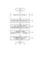
消費電力が低圧一括受電契約の契約電力から所定電力以内になることなく(すなわち、第2モードに切り替える必要なく)、上位制御装置8が蓄電池を第1モードで制御したときの電力消費の様子を図2に示す。図2に示す通り、上位制御装置8は、夜間または早朝(0時~7時)に系統80から買電を行って蓄電池を充電させ、次の時間帯(7時~16時)は発電装置(太陽光発電装置)からの発電電力と蓄電池からの放電電力とにより、複数の需要家施設による消費電力を賄う。賄った状態でもなお余った余剰電力は売電される。その後の時間帯(16時~24時)は消費電力量が発電量を上回るが、上位制御装置8は蓄電池を放電させて系統80からの買電電力量を抑制する。 The state of power consumption when the
少なくとも上記の5つの構成により、複数の需要家施設のそれぞれに請求される電気料金は、複数の需要家施設のそれぞれが個別に各戸契約を行ったときに請求される電気料金を超えない。 According to at least the above five configurations, the electricity bill charged to each of the plurality of consumer facilities does not exceed the electricity bill billed when each of the plurality of consumer facilities individually contracts for each house.
電気料金の低減を実現するための構成だけでなく電力供給システム90は次の構成を有する。 The
第1に、上位制御装置8は上位メータ装置1から通信で最大買電電力(単位:kW)または最大電流(単位:A)の値を取得しサーバ装置9に出力する。サーバ装置9は取得した値に所定値を加えた契約容量で電力会社と電力契約の更新を行うことができる。仮に消費電力または消費電流が最大買電電力または最大電流を超過しても超過分が当該所定値以内であれば、ブレーカがオフになることはない。すなわち、系統80からの電力供給は遮断されない。 First, the
第2に、複数の需要家施設は分散型電源3を共有している。このため、1戸あたりの分散型電源3の設置費用は、各戸で分散型電源3をそれぞれ設置したときの費用よりも安くなる。したがって、設置コストを低減することができる。 Secondly, multiple consumer facilities share the distributed power source 3 . Therefore, the cost of installing the distributed power source 3 per household is lower than the cost of installing the distributed power source 3 in each household. Therefore, installation costs can be reduced.
図3は電力供給システム90の動作を示すフローチャートである。 FIG. 3 is a flow chart showing the operation of the
電力供給システム90は一括受電盤2において、系統80から電力の供給を受ける(ステップS1)。電力供給システム90は上位メータ装置1において、複合需要家施設の消費電力量を測定する(ステップS2)。電力供給システム90は分電盤4から、ステップS1で受電された電力を複数の需要家施設のそれぞれに供給する(ステップS3)。電力供給システム90は分散型電源3から複数の需要家施設に電力を供給する(ステップS4)。電力供給システム90は下位メータ装置5において、複数の需要家施設のそれぞれの消費電力量を測定する(ステップS5)。電力供給システム90はステップS2、ステップS4およびステップS5を適宜行うことができるため、それらのステップの順番は入れ替え可能である。また電力供給システム90はステップS4を任意の時点で行うことができる。任意の時点とは昼間などの電気単価が高いとき、または、消費電力が低圧一括受電契約の契約電力を超える可能性があるとき等である。 The
また、電力供給システム90はステップS4およびステップS5を状況に応じて行なわなくてもよい。例えば、分散型電源3から複数の需要家施設への電力供給が不要であるときは、電力供給システム90はステップS5を行なわなくてもよい。すなわち、電力供給システム90は、分散型電源3から複数の需要家施設への電力の供給を必要に応じて行なえばよい。
本実施形態によれば、電力供給システム90は高圧一括受電契約に必要な電力未満の電力で低圧一括受電契約を行う複合需要家施設におけるシステムである。電力供給システム90は系統80から電力の供給を受ける一括受電盤2と、複合需要家施設による消費電力量を測定する上位メータ装置1と、一括受電盤2で受電された電力を複合需要家施設内の複数の需要家施設に供給する分電盤4と、複数の需要家施設に電力を供給可能な分散型電源3とを有する。すなわち、複合需要家施設は低圧一括受電を行うだけでなく分散型電源3を有する。需要家施設は分散型電源3を共有し、電気料金が高い時間帯等に分散型電源3から電力の供給を受けることにより買電電力量を抑制することができる。これにより、電気料金の低減を実現することができる。 According to the present embodiment, the
また、全戸が同時に最大容量を消費する可能性が低いことを考慮すれば、複合需要家施設は、全戸のブレーカ容量および共用部分のブレーカ容量の合計値よりも小さい契約容量で低圧一括受電契約を結ぶことができる。若しくは、複合需要家施設は、全戸のブレーカ容量および共用部分のブレーカ容量の合計値が高圧一括受電契約の必要な値であっても、低圧一括受電契約により電力を賄うことができる。これにより、電気料金の低減を実現することができる。 In addition, considering that it is unlikely that all units will consume the maximum capacity at the same time, complex consumer facilities should conclude a low-voltage bulk power supply contract with a contract capacity that is smaller than the sum of the breaker capacity of all units and the breaker capacity of common areas. can tie. Alternatively, even if the total value of the breaker capacity of all households and the breaker capacity of common areas is the required value for the high voltage bulk power receiving contract, the complex consumer facility can cover power with the low voltage bulk power receiving contract. This makes it possible to reduce the electricity bill.
また、電力会社の料金プランによっては、契約容量が大きくなるにつれて1戸あたりの電気料金が安くなる。本実施形態によれば需要家施設のそれぞれが各戸契約を結ぶのではなく複合需要家施設が低圧一括受電契約を結ぶ。これにより、需要家施設のそれぞれは、複合需要家施設の事業者から電力の使用量に応じて電気料金が振り分けられることになり、各戸契約で電力料金を負担するよりも低圧一括受電契約をした方がそれぞれの需要家施設における電気料金の低減を実現することができる。 Also, depending on the rate plan of the power company, the electricity rate per household decreases as the contracted capacity increases. According to this embodiment, each customer facility does not conclude a contract for each house, but a complex customer facility concludes a low-voltage collective power receiving contract. As a result, each customer facility will be allocated electricity charges according to the amount of electricity used by the operator of the complex customer facility, and a low-voltage bulk power supply contract will be made rather than paying the electricity charges with each household contract. This makes it possible to reduce the electricity charges at each consumer's facility.
また本実施形態によれば、分散型電源3は、蓄電池と、燃料電池、太陽光発電装置および風力発電装置の少なくとも1つを含む発電装置との少なくとも一方を含む。このため、電気料金の低減を実現するために、様々なタイプの分散型電源を組み合わせた手法が可能となる。 Further, according to this embodiment, the distributed power source 3 includes at least one of a storage battery and a power generation device including at least one of a fuel cell, a solar power generation device, and a wind power generation device. Therefore, in order to reduce electricity charges, it is possible to combine various types of distributed power sources.
また本実施形態によれば、電力供給システム90は、複数の需要家施設のそれぞれに設けられる下位制御装置6と、複合需要家施設に設けられ、または、複合需要家施設内および複合需要家施設外の少なくとも一方のサーバ装置9に設けられる上位制御装置8とをさらに有する。このため、それぞれの需要家施設ごとに消費電力に関する制御が可能となる。 Further, according to the present embodiment, the
また本実施形態によれば、上位制御装置8はデマンドレスポンスの信号を取得したとき、複数の需要家施設による消費電力量を抑制するように下位制御装置6に要求する。このため、複数の需要家施設ごとに消費電力量の制御を行い、デマンドレスポンスに対応してインセンティブを得ることが可能となる。 Further, according to the present embodiment, when the
また本実施形態によれば、上位制御装置8が、系統80への電力の出力を抑制する指示を取得したとき、発電装置の余剰電力を蓄電池に充電させる。このため出力抑制指示に対応することもできるだけでなく、発電装置による発電を継続して、将来の放電のために蓄電池に余剰電力を充電させることができる。 Further, according to the present embodiment, when the
また本実施形態によれば、電力供給システム90は複数の需要家施設のそれぞれの消費電力量を測定する下位メータ装置5をさらに有し、下位メータ装置5は当該測定した消費電力量を上位制御装置8に通知する。このため、上位制御装置8は需要家施設のそれぞれの消費電力量に応じて、需要家施設のそれぞれにサービスを提供することができる。 Further, according to the present embodiment, the
また本実施形態によれば、上位制御装置8は、上位メータ装置1によって測定された消費電力量に基づいて、低圧一括受電契約の複数の料金プランのうち最も安い料金プランを選択し、複合需要家施設を管理する事業者のサーバ装置9に通知する。このため、事業者等は最も安いプランを判断することができ、もって電気料金の低減を実現することができる。 Further, according to the present embodiment, the
また本実施形態によれば、蓄電池は、電気単価が所定基準値より安いときに充電し、電気単価が当該所定基準値より高いときに放電する。このため、電気単価が高いときにおける系統80からの買電電力量を減らすことができ、もって電気料金の低減を実現することができる。 Further, according to this embodiment, the storage battery is charged when the unit price of electricity is lower than the predetermined reference value, and discharged when the unit price of electricity is higher than the predetermined reference value. Therefore, it is possible to reduce the amount of power purchased from the
また本実施形態によれば、蓄電池は、複合需要家施設全体の消費電力が低圧一括受電契約の契約電力を超えないように、充電された電力を放電して、複合需要家施設全体で受電する電力量を低減する。このため、複合需要家施設全体の消費電力が契約電力を超えることにより電力供給システム90が契約電力以上の買電を行うことを低減することができる。 Further, according to this embodiment, the storage battery discharges the charged power so that the power consumption of the entire complex consumer facility does not exceed the contracted power of the low-voltage bulk power receiving contract, and the power is received by the entire complex consumer facility. Reduce power consumption. Therefore, it is possible to prevent the
また本実施形態によれば、複数の需要家施設のそれぞれに請求される電気料金は、複数の需要家施設のそれぞれが個別に各戸契約を行ったときに請求される電気料金を超えない。このため、需要家施設の各入居者の満足度を高め、電力供給システム90の需要を高めることができる。 Further, according to the present embodiment, the electricity bill charged to each of the plurality of consumer facilities does not exceed the electricity bill billed when each of the plurality of consumer facilities individually contracts for each house. Therefore, it is possible to increase the satisfaction level of each resident of the consumer facility and increase the demand for the
本発明を諸図面や実施例に基づき説明してきたが、当業者であれば本開示に基づき種々の変形や修正を行うことが容易であることに注意されたい。したがって、これらの変形や修正は本発明の範囲に含まれることに留意されたい。例えば、各部材、各部、各ステップなどに含まれる機能などは論理的に矛盾しないように再配置可能である。また、本発明を方法の発明として実施するときにも、複数の部やステップなどを1つに組み合わせたり、或いは分割したりすることが可能である。 Although the present invention has been described with reference to the drawings and examples, it should be noted that various variations and modifications will be readily apparent to those skilled in the art based on this disclosure. Therefore, please note that these variations and modifications are included in the scope of the present invention. For example, the functions included in each member, each part, each step, etc. can be rearranged so as not to be logically inconsistent. Also, when implementing the present invention as a method invention, a plurality of parts, steps, etc. can be combined into one or divided.
上述の説明では、複合需要家施設が高圧一括受電契約に必要な電力を消費しない場合についてであるが、これに限定されない。すなわち、複合需要家施設が高圧一括受電契約の必要な電力を消費する場合(例えば、各戸別契約の電力の和が高圧一括受電契約の必要な電力である場合)であっても、分散型電源3を有していることによって、低圧一括受電契約で電力を賄うことができる。これにより、複合需要家施設は高圧一括受電契約を行わなくてもよいため、キュービクル式高圧受電設備を設置しなくてもよくなり、初期投資またはメンテナンス費用を軽減することができる。 In the above description, the case where the complex consumer facility does not consume the power required for the high voltage bulk power receiving contract is described, but the present invention is not limited to this. In other words, even if the complex consumer facility consumes the power required for the high voltage bulk power receiving contract (for example, when the sum of the power for each household contract is the power required for the high voltage bulk power receiving contract), the distributed power supply 3, electricity can be covered by a low-voltage lump-sum contract. As a result, the complex consumer facility does not need to enter into a high-voltage bulk power receiving contract, thereby eliminating the need to install a cubicle-type high-voltage power receiving facility, thereby reducing initial investment or maintenance costs.
また、上述の説明では、デマンドレスポンスの信号を上位制御装置8が受信したときに、上位制御装置8が下位制御装置6に消費電力量の抑制を要求する場合についてである。しかしながら、上位制御装置8は需要家施設における下位制御装置6には要求せずに、共用部分における下位制御装置6のみに抑制を要求してもよい。このような処理は、例えば、抑制する消費電力量が所定基準値より小さい場合に実施され得る。この場合、上位制御装置8は需要家にデマンドレスポンスに応じるか否かを問い合わせる必要がないため、容易にデマンドレスポンスに応じることができる。 In the above description, the
また、上位制御装置8は、一部の需要家施設における下位制御装置6のみ選択的に要求してもよく、どの需要家施設に要求するのかは、例えば、需要家施設における現在の消費電力量に応じて決定すればよい。上位制御装置8がそれぞれの需要家施設内の機器を直接的に制御できるときには、上位制御装置8はデマンドレスポンスに応じて、下位制御装置6を介さずに需要家施設内の機器を直接制御してもよい。上位制御装置8が直接機器を制御したとき、需要家に与えるインセンティブを大きくしてもよい。 Also, the
また、発電装置として燃料電池を用いる場合には、排熱を利用した空調、蒸気、温水、冷水等を需要家施設のそれぞれに対して供給してもよい。このように、複合需要家施設の事業者が一括して排熱を利用した空調等を提供することにより、需要家施設のそれぞれにおける電気料金、ガス料金および水道料金を低減することができる。燃料電池としては、固体酸化物形燃料電池、固体高分子形燃料電池、リン酸形燃料電池、バイオ燃料電池等を用いることができる。 Further, when a fuel cell is used as a power generation device, air conditioning, steam, hot water, cold water, etc. using exhaust heat may be supplied to each of the consumer facilities. In this way, by collectively providing air-conditioning and the like using exhaust heat by the operator of the complex consumer facility, it is possible to reduce the electricity, gas, and water charges in each of the customer facilities. As the fuel cell, a solid oxide fuel cell, a polymer electrolyte fuel cell, a phosphoric acid fuel cell, a biofuel cell, or the like can be used.
また、上述の説明では、図1に示すように、下位メータ装置5が共用部分に接続され且つ下位制御装置6を共用部分に設けている場合であるが、それらを必ずしも設ける必要はない。下位メータ装置5が共用部分に接続されず且つ下位制御装置6が共用部分に設けられていない場合は、上位メータ装置1のデータから、需要家施設のそれぞれに接続された下位メータ装置5のデータ全ての合計を差し引くことにより、共用部分の消費電力量を算出することができる。共用部分の消費電力量の算出は、上位制御装置8またはサーバ装置9が行なうことができる。 Further, in the above description, as shown in FIG. 1, the
上述の説明では、上位制御装置8は上位メータ装置1によって測定された消費電力量に基づいて、低圧一括受電契約の料金プランを選択するが、消費電力(kW)に基づいて選択して判断してもよい。また、蓄電池は、消費電力量(kWh)に基づいて低圧一括受電契約の契約量を超えないように制御されるが、消費電力(kW)に基づいて制御されてもよい。 In the above description, the
また、本発明に係る上位制御装置8および下位制御装置6の制御部をコンピュータで構成したとき、各機能を実現する処理内容を記述したプログラムを、そのコンピュータの内部または外部の記憶部に格納しておき、そのコンピュータの中央演算処理装置(CPU)によってこのプログラムを読み出して実行させることで実現することができる。また、このようなプログラムは、例えばDVDまたはCD-ROMなどの可搬型記録媒体の販売、譲渡、貸与等により流通させることができるほか、そのようなプログラムを、例えばネットワーク上にあるサーバの記憶部に記憶しておき、ネットワークを介してサーバから他のコンピュータにそのプログラムを転送することにより、流通させることができる。また、そのようなプログラムを実行するコンピュータは、例えば、可搬型記録媒体に記録されたプログラムまたはサーバから転送されたプログラムを、一旦、自己の記憶部に記憶することができる。また、このプログラムの別の実施態様として、コンピュータが可搬型記録媒体から直接プログラムを読み取り、そのプログラムに従った処理を実行することとしてもよく、更に、このコンピュータにサーバからプログラムが転送される度に、逐次、受け取ったプログラムに従った処理を実行することとしてもよい。 Further, when the control units of the
1 上位メータ装置
2 一括受電盤
3 分散型電源
4 分電盤
5 下位メータ装置
6 下位制御装置
7 負荷
8 上位制御装置
9 サーバ装置
80 系統
90 電力供給システム1 High-
上記課題を解決するため、本発明の一実施形態に係る電力供給システムは、
高圧一括受電契約に必要な電力未満の電力の低圧一括受電契約に基づいて系統から低圧一括受電する集合住宅であって、電力の使用量に応じて電気料金が振り分けられることになる複数の住戸及び共用部を有する1棟の集合住宅における電力供給システムであって、
キュービクル式高圧受電設備を介さずに前記系統と直接接続され、前記集合住宅において前記系統から買電した電力量を測定する上位メータと、
前記系統側に接続される第1ブレーカと、
前記複数の住戸及び前記共用部それぞれに接続される複数の第2ブレーカと、
前記系統から前記キュービクル式高圧受電設備を介さずに前記上位メータを経由して低圧一括受電された電力を、前記第2ブレーカを経由して前記複数の住戸及び前記共用部それぞれに供給する分岐点と、
前記分岐点と前記複数の住戸との間に接続され、前記複数の住戸の消費電力量を測定する複数の下位メータと、
蓄電池と、燃料電池、太陽光発電装置および風力発電装置の少なくとも1つを含む発電装置との少なくとも一方を含む分散型電源であって、前記上位メータと前記複数の下位メータとの間に接続され、前記複数の住戸及び前記共用部に電力を供給可能な分散型電源と、
を有し、
前記第1ブレーカの容量は、前記各第2ブレーカの容量の合計値よりも小さい。In order to solve the above problems, a power supply system according to one embodiment of the present invention includes:
Collective housing that receives low-voltage bulk power from the grid based on a low-voltage bulk power receiving contract that is less than the power required for the high-voltage bulk power receiving contract, and multiple dwelling units where electricity charges are distributed according to the amount ofpower used. and a power supply system in one collective housing having a common area,
a high-levelmeter that is directly connected to the system without passing through a cubicle-type high-voltage power receiving equipment and measures the amount of power purchased from the system in the housing complex;
a first breaker connected to the system side;
a plurality of second breakers connected respectively to the plurality of dwelling units and the common area;
A branch point that suppliesthe low-voltage collectively received power from the system via the host meter without via the cubicle-type high-voltage power receiving equipment to each of the plurality of dwelling units and the common area via the second breaker. When,
a plurality of sub-meters connected between the branch point and the plurality of dwelling units for measuring power consumption of the plurality of dwelling units;
Distributed power supply including at least one of a storage battery and a power generation device including at least one of a fuel cell, a solar power generation device and a wind power generation device, between the uppermeter and the plurality of lowermeters a distributed power source that is connected and capable of supplying power to the plurality of dwelling units and the common area;
has
The capacity of the first breaker is smaller than the total capacity of the second breakers.
また、上記課題を解決するため、本発明の一実施形態に係る電力供給方法は、
高圧一括受電契約に必要な電力未満の電力の低圧一括受電契約に基づいて系統から低圧一括受電する集合住宅であって、電力の使用量に応じて電気料金が振り分けられることになる複数の住戸及び共用部を有する1棟の集合住宅における電力供給方法であって、
キュービクル式高圧受電設備を介さずに前記系統と直接接続され、前記集合住宅において前記系統から買電した消費電力量を測定する上位メータにおいて、当該消費電力量を測定する第1ステップと、
前記系統側に接続される、前記低圧一括受電契約の契約容量より大きい電力を遮断する第1ブレーカを介して、前記系統から前記キュービクル式高圧受電設備を介さずに電力の供給を受ける第2ステップと、
前記第2ステップで受電された電力を、前記複数の住戸及び前記共用部それぞれに接続される複数の第2ブレーカを経由して前記複数の住戸及び前記共用部それぞれに供給する第3ステップと、
前記複数の住戸の消費電力量を測定する複数の下位メータにおいて、当該複数の住戸の消費電力量を測定する第4ステップと、
蓄電池と、燃料電池、太陽光発電装置および風力発電装置の少なくとも1つを含む発電装置との少なくとも一方を含む分散型電源から、前記上位メータと前記複数の下位メータとの間を経由して前記複数の住戸及び前記共用部に電力を供給する第5ステップと
を含み、
前記第1ブレーカの容量は、前記各第2ブレーカの容量の合計値よりも小さい。Moreover, in order to solve the above problems, a power supply method according to an embodiment of the present invention includes:
Collective housing that receives low-voltage bulk power from the grid based on a low-voltage bulk power receiving contract that is less than the power required for the high-voltage bulk power receiving contract, and multiple dwelling units where electricity charges are distributed according to the amount ofpower used. And a power supply method in one collective housing having a common area,
a first step of measuring the amount of power consumptionin an upper-level meter that is directly connected to the system without passing through a cubicle-type high-voltage power receiving facility and measures the amount of power consumption purchased from the system in the housing complex; ,
A second step of receiving power supply from the system via a first breaker that is connected to the system side and cuts off power that is larger than the contracted capacity of the low-voltage bulk power receiving contract, without passing through the cubicle-type high-voltage power receiving equipment. When,
a third step of supplying the electric power received in the second step to each of the plurality of dwelling units and the common area via a plurality of second breakers connected to each of the plurality of dwelling units and the common area;
a fourth step of measuring the power consumption of the plurality of dwelling unitsin the plurality of sub-meters for measuring the power consumption of the plurality of dwelling units;
from a distributed power supply including at least one of a storage battery and a power generation device including at least one of a fuel cell, a solar power generation device and a wind power generation device, via between the uppermeter and the plurality of lowermeters and a fifth step of supplying power to the plurality of dwelling units and the common area,
The capacity of the first breaker is smaller than the total capacity of the second breakers.
Claims (18)
Translated fromJapaneseキュービクル式高圧受電設備を介さずに前記系統と直接接続され、前記集合住宅において前記系統から買電した電力量を測定する上位メータ装置と、
前記系統側に接続される第1ブレーカと、
前記系統から前記キュービクル式高圧受電設備を介さずに前記上位メータ装置を経由して電力の供給を受ける低圧一括受電盤と、
前記複数の住戸及び前記共用部それぞれに接続される複数の第2ブレーカと、
前記低圧一括受電盤で受電された電力を、前記第2ブレーカを経由して前記複数の住戸及び前記共用部それぞれに供給する分岐点と、
前記分岐点と前記複数の住戸との間に接続され、前記複数の住戸の消費電力量を測定する複数の下位メータ装置と、
蓄電池と、燃料電池、太陽光発電装置および風力発電装置の少なくとも1つを含む発電装置との少なくとも一方を含む分散型電源であって、前記上位メータ装置と前記複数の下位メータ装置との間に接続され、前記複数の住戸及び前記共用部に電力を供給可能な分散型電源と、
を有し、
前記第1ブレーカの容量は、前記各第2ブレーカの容量の合計値よりも小さい、電力供給システム。A business that manages a collective housing that receives low-voltage bulk power from the grid based on a low-voltage bulk power receiving contract that is less than the power required for the high-voltage bulk power receiving contract, and is different from a power company that concludes the low-voltage bulk power receiving contract. A power supply system in a single apartment building having a plurality of dwelling units and a common area where electricity charges are distributed from the person according to the amount of power used,
a high-level meter device that is directly connected to the system without passing through a cubicle-type high-voltage power receiving facility and measures the amount of power purchased from the system in the housing complex;
a first breaker connected to the system side;
a low-voltage collective power receiving panel that receives power from the system via the host meter device without passing through the cubicle-type high-voltage power receiving equipment;
a plurality of second breakers connected respectively to the plurality of dwelling units and the common area;
a branch point that supplies the power received by the low-voltage collective power receiving board to each of the plurality of dwelling units and the common area via the second breaker;
a plurality of subordinate meter devices connected between the branch point and the plurality of dwelling units for measuring power consumption of the plurality of dwelling units;
A distributed power supply including at least one of a storage battery and a power generation device including at least one of a fuel cell, a solar power generation device, and a wind power generation device, between the upper meter device and the plurality of lower meter devices a distributed power source that is connected and capable of supplying power to the plurality of dwelling units and the common area;
has
The power supply system, wherein the capacity of the first breaker is smaller than the sum of the capacities of the second breakers.
前記分散型電源は、前記分岐点と各住戸の負荷との間に接続されていない、電力供給システム。In the power supply system according to claim 1,
The power supply system, wherein the distributed power source is not connected between the branch point and the load of each dwelling unit.
前記複数の住戸に設けられる下位制御装置と、
前記集合住宅に設けられ、または、前記集合住宅内および前記集合住宅外の少なくとも一方のサーバ装置に設けられる、上位制御装置と
を有する電力供給システム。In the power supply system according to claim 1 or 2,
a subordinate control device provided in each of the plurality of dwelling units;
A power supply system comprising: a host controller installed in the collective housing, or installed in at least one of server devices inside and outside the collective housing.
前記下位メータ装置は、前記測定した消費電力量を前記上位制御装置に通知し、
前記上位制御装置は、検針データの管理支援サービスを提供するサーバ装置に消費電力量を通知する、電力供給システム。In the power supply system according to claim 3,
The lower-level meter device notifies the higher-level control device of the measured power consumption,
The power supply system, wherein the host controller notifies a server device that provides a meter reading data management support service of power consumption.
前記下位制御装置、及び、前記上位制御装置はいずれもHEMSである電力供給システム。In the power supply system according to claim 3 or 4,
A power supply system in which both the low-order control device and the high-order control device are HEMS.
前記上位制御装置はデマンドレスポンスの信号を取得したとき、前記複数の住戸及び前記共用部による消費電力量を抑制するように前記下位制御装置に要求する、電力供給システム。In the power supply system according to any one of claims 3 to 5,
The power supply system, wherein the upper control device requests the lower control device to reduce the power consumption by the plurality of dwelling units and the common area when receiving a demand response signal.
前記分散型電源は前記蓄電池および前記発電装置を含み、
前記上位制御装置が、前記系統への電力の出力を抑制する指示を取得したとき、前記発電装置は余剰電力を前記蓄電池に充電させる、電力供給システム。In the power supply system according to any one of claims 3 to 6,
The distributed power supply includes the storage battery and the power generation device,
A power supply system according to claim 1, wherein, when the host control device acquires an instruction to suppress power output to the system, the power generation device causes the storage battery to be charged with surplus power.
前記上位制御装置は、前記上位メータ装置によって測定された消費電力量に基づいて、前記低圧一括受電契約の複数の料金プランのうち最も安い料金プランを選択し、前記集合住宅を管理する事業者のサーバ装置に通知する、電力供給システム。In the power supply system according to any one of claims 3 to 7,
The host controller selects the cheapest rate plan from among a plurality of rate plans of the low-voltage bulk power receiving contract based on the power consumption measured by the host meter device, A power supply system that notifies the server device.
前記上位制御装置は、デマンドレスポンスの信号を取得したとき、前記複数の住戸及び前記共用部による消費電力量を抑制するように前記集合住宅内の機器に要求する、電力供給システム。In the power supply system according to any one of claims 3 to 8,
The power supply system, wherein the host control device requests devices in the housing complex to reduce power consumption by the plurality of dwelling units and the common area when a demand response signal is acquired.
前記分散型電源は、少なくとも蓄電池を含み、前記上位制御装置はデマンドレスポンスの信号を取得したとき、前記蓄電池とは異なる他の分散型電源の余剰電力を、前記蓄電池に充電させる、電力供給システム。In the power supply system according to any one of claims 3 to 9,
The power supply system, wherein the distributed power source includes at least a storage battery, and when the host control device acquires a demand response signal, the storage battery is charged with surplus power of another distributed power source different from the storage battery.
前記分電盤は、前記低圧一括受電盤で受電された電力を前記集合住宅の全ての住戸に供給可能とする、電力供給システム。The power supply system according to any one of claims 1 to 10, further comprising a distribution board having the branch point,
The power supply system, wherein the power distribution board can supply the power received by the low-voltage collective power receiving board to all the dwelling units of the collective housing.
前記低圧一括受電盤は、内部に前記分岐点を有する、電力供給システム。In the power supply system according to any one of claims 1 to 11,
The power supply system, wherein the low-voltage collective power receiving board has the branch point inside.
前記蓄電池は、電気単価が所定基準値より安いときに充電し、前記電気単価が前記所定基準値より高いときに放電する、電力供給システム。In the power supply system according to any one of claims 1 to 12,
The power supply system, wherein the storage battery is charged when the unit price of electricity is lower than a predetermined reference value, and discharged when the unit price of electricity is higher than the predetermined reference value.
前記蓄電池は、前記集合住宅の消費電力が前記低圧一括受電契約の契約電力を超えないように、充電された電力を放電する、電力供給システム。In the power supply system according to any one of claims 1 to 13,
The power supply system, wherein the storage battery discharges the charged power so that the power consumption of the collective housing does not exceed the contracted power of the low-voltage bulk power receiving contract.
前記複数の住戸のそれぞれに請求される電気料金は、前記複数の住戸のそれぞれが個別に各戸契約を行ったときに請求される電気料金を超えない、電力供給システム。In the power supply system according to any one of claims 1 to 14,
The power supply system, wherein the electricity bill charged to each of the plurality of dwelling units does not exceed the electricity bill billed when each of the plurality of dwelling units individually contracts for each unit.
前記第1ブレーカは、前記低圧一括受電契約の契約容量より大きい電力を遮断する、電力供給システム。In the power supply system according to any one of claims 1 to 15,
The power supply system, wherein the first breaker cuts off power greater than the contracted capacity of the low-voltage bulk power receiving contract.
前記分散型電源は、停電時に少なくとも前記共用部に電力を供給する、電力供給システム。In the power supply system according to any one of claims 1 to 16,
A power supply system in which the distributed power source supplies power to at least the common area during a power outage.
キュービクル式高圧受電設備を介さずに前記系統と直接接続され、前記集合住宅において前記系統から買電した消費電力量を測定する上位メータ装置において、当該消費電力量を測定する第1ステップと、
前記系統側に接続される、前記低圧一括受電契約の契約容量より大きい電力を遮断する第1ブレーカを介して、前記系統から前記キュービクル式高圧受電設備を介さずに電力の供給を受ける第2ステップと、
前記第2ステップで受電された電力を、前記複数の住戸及び前記共用部それぞれに接続される複数の第2ブレーカを経由して前記複数の住戸及び前記共用部それぞれに供給する第3ステップと、
前記複数の住戸の消費電力量を測定する複数の下位メータ装置において、当該複数の住戸の消費電力量を測定する第4ステップと、
蓄電池と、燃料電池、太陽光発電装置および風力発電装置の少なくとも1つを含む発電装置との少なくとも一方を含む分散型電源から、前記上位メータ装置と前記複数の下位メータ装置との間を経由して前記複数の住戸及び前記共用部に電力を供給する第5ステップと
を含み、
前記第1ブレーカの容量は、前記各第2ブレーカの容量の合計値よりも小さい、電力供給方法。A business that manages a collective housing that receives low-voltage bulk power from the grid based on a low-voltage bulk power receiving contract that is less than the power required for the high-voltage bulk power receiving contract, and is different from a power company that concludes the low-voltage bulk power receiving contract. A power supply method in a single collective housing having a plurality of dwelling units and a common area in which electricity charges are distributed according to the amount of power used by a person,
a first step of measuring the power consumption in an upper-level meter device that is directly connected to the system without passing through a cubicle-type high-voltage power receiving equipment and measures the power consumption purchased from the system in the collective housing;
A second step of receiving power supply from the system via a first breaker that is connected to the system side and cuts off power that is larger than the contracted capacity of the low-voltage bulk power receiving contract, without passing through the cubicle-type high-voltage power receiving equipment. When,
a third step of supplying the electric power received in the second step to each of the plurality of dwelling units and the common area via a plurality of second breakers connected to each of the plurality of dwelling units and the common area;
a fourth step of measuring the power consumption of the plurality of dwelling units in the plurality of subordinate meter devices for measuring the power consumption of the plurality of dwelling units;
from a distributed power supply including at least one of a storage battery and a power generation device including at least one of a fuel cell, a solar power generation device, and a wind power generation device via between the upper meter device and the plurality of lower meter devices and a fifth step of supplying power to the plurality of dwelling units and the common area,
The power supply method, wherein the capacity of the first breaker is smaller than the sum of the capacities of the second breakers.
Priority Applications (1)
| Application Number | Priority Date | Filing Date | Title |
|---|---|---|---|
| JP2022118235AJP7455163B2 (en) | 2015-06-26 | 2022-07-25 | Power supply system and method |
Applications Claiming Priority (3)
| Application Number | Priority Date | Filing Date | Title |
|---|---|---|---|
| JP2015129159AJP6824600B2 (en) | 2015-06-26 | 2015-06-26 | Power supply system |
| JP2020201091AJP7113060B2 (en) | 2015-06-26 | 2020-12-03 | Power supply system and power supply method |
| JP2022118235AJP7455163B2 (en) | 2015-06-26 | 2022-07-25 | Power supply system and method |
Related Parent Applications (1)
| Application Number | Title | Priority Date | Filing Date |
|---|---|---|---|
| JP2020201091ADivisionJP7113060B2 (en) | 2015-06-26 | 2020-12-03 | Power supply system and power supply method |
Publications (2)
| Publication Number | Publication Date |
|---|---|
| JP2022132660Atrue JP2022132660A (en) | 2022-09-08 |
| JP7455163B2 JP7455163B2 (en) | 2024-03-25 |
Family
ID=57829429
Family Applications (7)
| Application Number | Title | Priority Date | Filing Date |
|---|---|---|---|
| JP2015129159AActiveJP6824600B2 (en) | 2015-06-26 | 2015-06-26 | Power supply system |
| JP2020201091AActiveJP7113060B2 (en) | 2015-06-26 | 2020-12-03 | Power supply system and power supply method |
| JP2020201098AActiveJP7101744B2 (en) | 2015-06-26 | 2020-12-03 | Power supply system and power supply method |
| JP2022118238AActiveJP7460701B2 (en) | 2015-06-26 | 2022-07-25 | Power supply system and power supply method |
| JP2022118235AActiveJP7455163B2 (en) | 2015-06-26 | 2022-07-25 | Power supply system and method |
| JP2024045296AActiveJP7724893B2 (en) | 2015-06-26 | 2024-03-21 | Power supply system and power supply method |
| JP2025061251AActiveJP7723223B2 (en) | 2015-06-26 | 2025-04-02 | Power supply system and power supply method |
Family Applications Before (4)
| Application Number | Title | Priority Date | Filing Date |
|---|---|---|---|
| JP2015129159AActiveJP6824600B2 (en) | 2015-06-26 | 2015-06-26 | Power supply system |
| JP2020201091AActiveJP7113060B2 (en) | 2015-06-26 | 2020-12-03 | Power supply system and power supply method |
| JP2020201098AActiveJP7101744B2 (en) | 2015-06-26 | 2020-12-03 | Power supply system and power supply method |
| JP2022118238AActiveJP7460701B2 (en) | 2015-06-26 | 2022-07-25 | Power supply system and power supply method |
Family Applications After (2)
| Application Number | Title | Priority Date | Filing Date |
|---|---|---|---|
| JP2024045296AActiveJP7724893B2 (en) | 2015-06-26 | 2024-03-21 | Power supply system and power supply method |
| JP2025061251AActiveJP7723223B2 (en) | 2015-06-26 | 2025-04-02 | Power supply system and power supply method |
Country Status (1)
| Country | Link |
|---|---|
| JP (7) | JP6824600B2 (en) |
Families Citing this family (22)
| Publication number | Priority date | Publication date | Assignee | Title |
|---|---|---|---|---|
| JP6642470B2 (en) | 2017-02-02 | 2020-02-05 | 株式会社デンソー | Power control device, battery pack, and power system |
| JP7059580B2 (en)* | 2017-11-15 | 2022-04-26 | 株式会社アイシン | Electricity billing system |
| JP7100443B2 (en)* | 2017-11-22 | 2022-07-13 | 京セラ株式会社 | housing complex |
| JP7057245B2 (en)* | 2018-07-30 | 2022-04-19 | 京セラ株式会社 | Power supply system and construction method of power supply system |
| JP7221634B2 (en)* | 2018-10-02 | 2023-02-14 | 株式会社大林組 | Power receiving equipment |
| JP7290932B2 (en)* | 2018-10-22 | 2023-06-14 | 京セラ株式会社 | Power management method, power management system, and lead-in panel |
| JP7084844B2 (en)* | 2018-10-22 | 2022-06-15 | 京セラ株式会社 | Power management system and apartment building |
| JP7084285B2 (en)* | 2018-11-29 | 2022-06-14 | 京セラ株式会社 | Drop-in board, power supply system, and apartment building |
| JP7450337B2 (en)* | 2019-02-27 | 2024-03-15 | 東京瓦斯株式会社 | Power supply system, power supply method and power supply program |
| JP7246230B2 (en)* | 2019-03-29 | 2023-03-27 | 旭化成ホームズ株式会社 | Power receiving system modification method and power supply system |
| JP7626338B2 (en)* | 2020-02-19 | 2025-02-07 | 京セラ株式会社 | Power supply equipment, housing complexes and power supply panels |
| JP2022138885A (en)* | 2021-03-11 | 2022-09-26 | 恒栄電設株式会社 | Notification system |
| JP2022189134A (en)* | 2021-06-10 | 2022-12-22 | 大和ハウス工業株式会社 | Power rate proposal system |
| JP2023059558A (en)* | 2021-10-15 | 2023-04-27 | 旭化成ホームズ株式会社 | Power supply system, power supply method, and program |
| JP7716967B2 (en)* | 2021-12-15 | 2025-08-01 | 東北電力株式会社 | Cubicle Monitoring System |
| JP7035267B2 (en)* | 2021-12-28 | 2022-03-14 | 北海道瓦斯株式会社 | Emergency power supply system |
| JP7216452B1 (en) | 2022-01-13 | 2023-02-01 | 合同会社コトブク | Management support system for real estate for rent |
| KR102644220B1 (en)* | 2022-06-28 | 2024-03-06 | 케빈랩 주식회사 | Power supply system and method for collective building |
| KR102644221B1 (en)* | 2022-06-28 | 2024-03-06 | 케빈랩 주식회사 | Power supply system and method for collective building |
| JP7584164B2 (en)* | 2023-01-31 | 2024-11-15 | 合同会社コトブク | Rental property management support system |
| JP7625049B1 (en) | 2023-09-29 | 2025-01-31 | アビームコンサルティング株式会社 | Power supply system and power supply method |
| CN119603102A (en)* | 2024-09-04 | 2025-03-11 | 灏翰创科有限公司 | Solar communication gateway, communication system and power supply mode switching method |
Citations (10)
| Publication number | Priority date | Publication date | Assignee | Title |
|---|---|---|---|---|
| JP2002159138A (en)* | 2000-11-17 | 2002-05-31 | Sanyo Electric Co Ltd | High voltage package reception/low voltage distribution system and condominium employing the system |
| JP2007159388A (en)* | 2005-11-11 | 2007-06-21 | Funakoshi Norihiro | Power-supply broker terminal |
| JP2011101538A (en)* | 2009-11-06 | 2011-05-19 | Panasonic Electric Works Co Ltd | Power distribution system |
| JP2011130649A (en)* | 2009-12-21 | 2011-06-30 | Panasonic Electric Works Co Ltd | Electric power supply system |
| JP2012087466A (en)* | 2010-10-15 | 2012-05-10 | Takenaka Komuten Co Ltd | Solar cell power generating system for group of apartment houses |
| JP2012143046A (en)* | 2010-12-28 | 2012-07-26 | Tokyo Gas Co Ltd | Distribution panel with current management function |
| JP2013143815A (en)* | 2012-01-10 | 2013-07-22 | Ntt Facilities Inc | Power supply system, power supply control device, power supply method and program |
| JP2014137726A (en)* | 2013-01-17 | 2014-07-28 | Sharp Corp | Sever device, electronic apparatus, communication system, information processing method and program |
| JP2014200153A (en)* | 2013-03-29 | 2014-10-23 | 株式会社東芝 | Energy management system, energy management apparatus and energy management method |
| JP2014221001A (en)* | 2010-08-05 | 2014-11-20 | パナソニック株式会社 | Charging system |
Family Cites Families (23)
| Publication number | Priority date | Publication date | Assignee | Title |
|---|---|---|---|---|
| JP3400478B2 (en)* | 1993-02-02 | 2003-04-28 | 松下電工株式会社 | Switchboard |
| JP2002171660A (en)* | 2000-12-04 | 2002-06-14 | Sanyo Electric Co Ltd | Current limiter |
| JP2002258934A (en)* | 2001-03-01 | 2002-09-13 | Daikin Ind Ltd | Equipment management system |
| JP2007012005A (en)* | 2005-06-29 | 2007-01-18 | Matsumoto Denki Kk | Business model for improving service by collectively intermediating power purchase and supply in specific area or other detached house |
| JP4722585B2 (en)* | 2005-06-29 | 2011-07-13 | エフビットパワー株式会社 | An electricity reduction system for collective housing using solar cells and / or cubicles that can reduce not only electricity charges but also CO2 emissions |
| JP2011083085A (en)* | 2009-10-05 | 2011-04-21 | Panasonic Electric Works Co Ltd | Power management system |
| JP5603704B2 (en)* | 2010-08-05 | 2014-10-08 | パナソニック株式会社 | Charging system |
| JP2012239260A (en)* | 2011-05-10 | 2012-12-06 | Toyota Motor Corp | Power supply system for collective housing |
| US9153964B2 (en)* | 2011-09-09 | 2015-10-06 | General Electric Company | Systems and methods to aggregate loads for demand response events |
| JP5729764B2 (en)* | 2011-09-28 | 2015-06-03 | 京セラ株式会社 | Apartment house power system and control device |
| JP6021312B2 (en)* | 2011-10-26 | 2016-11-09 | 株式会社東芝 | Distributed power supply system and circuit switching device |
| JP6106904B2 (en)* | 2011-12-05 | 2017-04-05 | パナソニックIpマネジメント株式会社 | Power measurement system |
| KR20130091573A (en) | 2012-02-08 | 2013-08-19 | 한국전자통신연구원 | Energy management and facility-device control system for apartment/condomimium complex |
| JP6051404B2 (en)* | 2012-09-13 | 2016-12-27 | 株式会社キャプテックス | Power interchange control system |
| JP6099954B2 (en)* | 2012-12-05 | 2017-03-22 | キヤノン株式会社 | Electronic device, control method therefor, and program |
| WO2014203478A1 (en)* | 2013-06-19 | 2014-12-24 | パナソニックIpマネジメント株式会社 | Power control apparatus, power control method, program, and power control system |
| JP2015015802A (en)* | 2013-07-03 | 2015-01-22 | パナソニックIpマネジメント株式会社 | Power management system and control device |
| JP6432816B2 (en)* | 2013-07-10 | 2018-12-05 | パナソニックIpマネジメント株式会社 | Power management system, control device |
| JP5796041B2 (en)* | 2013-07-11 | 2015-10-21 | 大和ハウス工業株式会社 | Power management apparatus and power management method |
| JP2015035913A (en)* | 2013-08-09 | 2015-02-19 | 三菱重工業株式会社 | Control apparatus of power storage system and control method of power storage system |
| US9543775B2 (en)* | 2013-09-11 | 2017-01-10 | Kabushiki Kaisha Toshiba | Battery controller, management system, battery control method, battery control program, and storage medium |
| JP2015106952A (en)* | 2013-11-28 | 2015-06-08 | 富士通株式会社 | Estimation program, estimation method, and estimation apparatus |
| WO2015079769A1 (en)* | 2013-11-29 | 2015-06-04 | 株式会社日立製作所 | Storage battery control device |
- 2015
- 2015-06-26JPJP2015129159Apatent/JP6824600B2/enactiveActive
- 2020
- 2020-12-03JPJP2020201091Apatent/JP7113060B2/enactiveActive
- 2020-12-03JPJP2020201098Apatent/JP7101744B2/enactiveActive
- 2022
- 2022-07-25JPJP2022118238Apatent/JP7460701B2/enactiveActive
- 2022-07-25JPJP2022118235Apatent/JP7455163B2/enactiveActive
- 2024
- 2024-03-21JPJP2024045296Apatent/JP7724893B2/enactiveActive
- 2025
- 2025-04-02JPJP2025061251Apatent/JP7723223B2/enactiveActive
Patent Citations (10)
| Publication number | Priority date | Publication date | Assignee | Title |
|---|---|---|---|---|
| JP2002159138A (en)* | 2000-11-17 | 2002-05-31 | Sanyo Electric Co Ltd | High voltage package reception/low voltage distribution system and condominium employing the system |
| JP2007159388A (en)* | 2005-11-11 | 2007-06-21 | Funakoshi Norihiro | Power-supply broker terminal |
| JP2011101538A (en)* | 2009-11-06 | 2011-05-19 | Panasonic Electric Works Co Ltd | Power distribution system |
| JP2011130649A (en)* | 2009-12-21 | 2011-06-30 | Panasonic Electric Works Co Ltd | Electric power supply system |
| JP2014221001A (en)* | 2010-08-05 | 2014-11-20 | パナソニック株式会社 | Charging system |
| JP2012087466A (en)* | 2010-10-15 | 2012-05-10 | Takenaka Komuten Co Ltd | Solar cell power generating system for group of apartment houses |
| JP2012143046A (en)* | 2010-12-28 | 2012-07-26 | Tokyo Gas Co Ltd | Distribution panel with current management function |
| JP2013143815A (en)* | 2012-01-10 | 2013-07-22 | Ntt Facilities Inc | Power supply system, power supply control device, power supply method and program |
| JP2014137726A (en)* | 2013-01-17 | 2014-07-28 | Sharp Corp | Sever device, electronic apparatus, communication system, information processing method and program |
| JP2014200153A (en)* | 2013-03-29 | 2014-10-23 | 株式会社東芝 | Energy management system, energy management apparatus and energy management method |
Also Published As
| Publication number | Publication date |
|---|---|
| JP2021036768A (en) | 2021-03-04 |
| JP7723223B2 (en) | 2025-08-13 |
| JP7460701B2 (en) | 2024-04-02 |
| JP7455163B2 (en) | 2024-03-25 |
| JP2022132661A (en) | 2022-09-08 |
| JP2025098266A (en) | 2025-07-01 |
| JP7101744B2 (en) | 2022-07-15 |
| JP6824600B2 (en) | 2021-02-03 |
| JP2024074822A (en) | 2024-05-31 |
| JP2021036767A (en) | 2021-03-04 |
| JP2017017779A (en) | 2017-01-19 |
| JP7724893B2 (en) | 2025-08-18 |
| JP7113060B2 (en) | 2022-08-04 |
Similar Documents
| Publication | Publication Date | Title |
|---|---|---|
| JP7113060B2 (en) | Power supply system and power supply method | |
| JP5530314B2 (en) | Regional power interchange system | |
| JP7144950B2 (en) | Power supply system and power supply control method | |
| US10608467B2 (en) | Supplying electrical power to multiple loads from more than one power source | |
| JP7297004B2 (en) | Power supply system and power management method | |
| US20090024545A1 (en) | Method and system for measurement and control of individual circuits | |
| US10461535B2 (en) | Power management system, power management method, and computer program | |
| JP2014150641A (en) | Energy management system, energy management method, program, and server device | |
| CN102668303A (en) | Electric power interchange system | |
| TWI814875B (en) | Energy control and storage system, method for operating the same and relevant computer system | |
| JP7205421B2 (en) | Power supply system and method of managing electricity rates | |
| JP2015107041A (en) | Energy management system, energy management method, program, server, and client device | |
| JP6148631B2 (en) | Electric storage device discharge start time determination system | |
| JP2018153011A (en) | Power control system | |
| JP2019126157A (en) | Power management system and power management method | |
| JPWO2019182016A1 (en) | Power information management system, management method, program, power information management server, communication terminal, and power system | |
| JP2020048370A (en) | Power management method and power management system | |
| JP2019068707A (en) | Power management system and power management method | |
| JP7162819B2 (en) | Power control device, power control system and power control method | |
| JP2025146997A (en) | Power supply system, power supply method, apartment building and complex consumer facility | |
| JP7290932B2 (en) | Power management method, power management system, and lead-in panel | |
| EP4506207A1 (en) | System and method for dynamically balancing energy demands of electric vehicles in a multi-unit dwelling | |
| WO2025169897A1 (en) | Power management system, power management method, and program |
Legal Events
| Date | Code | Title | Description |
|---|---|---|---|
| A521 | Request for written amendment filed | Free format text:JAPANESE INTERMEDIATE CODE: A523 Effective date:20220725 | |
| A621 | Written request for application examination | Free format text:JAPANESE INTERMEDIATE CODE: A621 Effective date:20220801 | |
| A977 | Report on retrieval | Free format text:JAPANESE INTERMEDIATE CODE: A971007 Effective date:20230907 | |
| A131 | Notification of reasons for refusal | Free format text:JAPANESE INTERMEDIATE CODE: A131 Effective date:20231003 | |
| A521 | Request for written amendment filed | Free format text:JAPANESE INTERMEDIATE CODE: A523 Effective date:20231201 | |
| TRDD | Decision of grant or rejection written | ||
| A01 | Written decision to grant a patent or to grant a registration (utility model) | Free format text:JAPANESE INTERMEDIATE CODE: A01 Effective date:20240220 | |
| A61 | First payment of annual fees (during grant procedure) | Free format text:JAPANESE INTERMEDIATE CODE: A61 Effective date:20240312 | |
| R150 | Certificate of patent or registration of utility model | Ref document number:7455163 Country of ref document:JP Free format text:JAPANESE INTERMEDIATE CODE: R150 |