JP2022132087A - Conveying system, conveying device and conveying method - Google Patents
Conveying system, conveying device and conveying methodDownload PDFInfo
- Publication number
- JP2022132087A JP2022132087AJP2021211397AJP2021211397AJP2022132087AJP 2022132087 AJP2022132087 AJP 2022132087AJP 2021211397 AJP2021211397 AJP 2021211397AJP 2021211397 AJP2021211397 AJP 2021211397AJP 2022132087 AJP2022132087 AJP 2022132087A
- Authority
- JP
- Japan
- Prior art keywords
- substrate
- end effector
- sensor
- control unit
- transport
- Prior art date
- Legal status (The legal status is an assumption and is not a legal conclusion. Google has not performed a legal analysis and makes no representation as to the accuracy of the status listed.)
- Pending
Links
Images


Classifications
- Y—GENERAL TAGGING OF NEW TECHNOLOGICAL DEVELOPMENTS; GENERAL TAGGING OF CROSS-SECTIONAL TECHNOLOGIES SPANNING OVER SEVERAL SECTIONS OF THE IPC; TECHNICAL SUBJECTS COVERED BY FORMER USPC CROSS-REFERENCE ART COLLECTIONS [XRACs] AND DIGESTS
- Y02—TECHNOLOGIES OR APPLICATIONS FOR MITIGATION OR ADAPTATION AGAINST CLIMATE CHANGE
- Y02P—CLIMATE CHANGE MITIGATION TECHNOLOGIES IN THE PRODUCTION OR PROCESSING OF GOODS
- Y02P90/00—Enabling technologies with a potential contribution to greenhouse gas [GHG] emissions mitigation
- Y02P90/02—Total factory control, e.g. smart factories, flexible manufacturing systems [FMS] or integrated manufacturing systems [IMS]
Landscapes
- Container, Conveyance, Adherence, Positioning, Of Wafer (AREA)
Abstract
Description
Translated fromJapanese本開示は、搬送システム、搬送装置及び搬送方法に関する。 TECHNICAL FIELD The present disclosure relates to a transport system, a transport apparatus, and a transport method.
外周縁部に複数のカメラが配置された検査用ウエハを用いた搬送装置のティーチング方法が知られている(例えば、特許文献1参照)。 2. Description of the Related Art A teaching method for a transfer apparatus using an inspection wafer having a plurality of cameras arranged on the outer peripheral edge thereof is known (see, for example, Patent Document 1).
フォーカスリング(環状部材)の搬送位置を調整してフォーカスリング(環状部材)の載置位置の精度を向上させる方法が知られている(例えば、特許文献2参照)。 2. Description of the Related Art There is known a method for improving the accuracy of the placement position of a focus ring (annular member) by adjusting the transport position of the focus ring (annular member) (see, for example, Japanese Unexamined Patent Application Publication No. 2002-100003).
本開示は、搬送ロボットに対するティーチングを自動化できる技術を提供する。 The present disclosure provides a technology capable of automating teaching to a transport robot.
本開示の一態様による搬送システムは、動作指示に基づいてエンドエフェクタにより搬送対象物を搬送する搬送ロボットと、前記動作指示を前記搬送ロボットに出力する制御部と、を備え、前記エンドエフェクタ及び前記搬送対象物の少なくともいずれか一方はセンサ及びカメラの少なくともいずれか一方を有し、前記制御部は、前記センサの検出結果及び前記カメラの撮影結果の少なくともいずれか一方に基づき、前記エンドエフェクタと前記搬送対象物との相対位置を算出し、前記制御部は、前記相対位置に基づいて前記搬送対象物に対する前記エンドエフェクタの教示位置を決定し、当該教示位置に当該エンドエフェクタが配置されるように前記動作指示を前記搬送ロボットに出力する。 A transport system according to an aspect of the present disclosure includes a transport robot that transports an object to be transported using an end effector based on an operation instruction, and a control unit that outputs the operation instruction to the transport robot, the end effector and the At least one of the objects to be conveyed has at least one of a sensor and a camera, and the controller controls the end effector and the A position relative to the object to be conveyed is calculated, and the controller determines a teaching position of the end effector with respect to the object to be conveyed based on the relative position, and arranges the end effector at the teaching position. The operation instruction is output to the transfer robot.
本開示によれば、搬送ロボットに対するティーチングを自動化できる。 According to the present disclosure, teaching to the transport robot can be automated.
以下、添付の図面を参照しながら、本開示の限定的でない例示の実施形態について説明する。添付の全図面中、同一又は対応する部材又は部品については、同一又は対応する参照符号を付し、重複する説明を省略する。 Non-limiting exemplary embodiments of the present disclosure will now be described with reference to the accompanying drawings. In all the attached drawings, the same or corresponding members or parts are denoted by the same or corresponding reference numerals, and overlapping descriptions are omitted.
<第1の実施形態>
〔処理システム〕
図1を参照し、実施形態の処理システムの一例について説明する。図1に示されるように、処理システムPSは、基板にプラズマ処理等の各種処理を施すことが可能なシステムである。<First embodiment>
[Processing system]
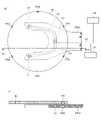
An example of a processing system according to an embodiment will be described with reference to FIG. As shown in FIG. 1, the processing system PS is a system capable of performing various types of processing such as plasma processing on substrates.
処理システムPSは、真空搬送モジュールTM1,TM2、プロセスモジュールPM1~PM12、ロードロックモジュールLL1,LL2、大気搬送モジュールLM、アライナAN、ストレージSR等を備える。 The processing system PS includes vacuum transfer modules TM1, TM2, process modules PM1 to PM12, load lock modules LL1, LL2, atmospheric transfer module LM, aligner AN, storage SR, and the like.
真空搬送モジュールTM1,TM2は、それぞれ平面視において略四角形状を有する。真空搬送モジュールTM1は、対向する2つの側面にプロセスモジュールPM1~PM6が接続されている。真空搬送モジュールTM1の他の対向する2つの側面のうち、一方の側面にはロードロックモジュールLL1,LL2が接続され、他方の側面には真空搬送モジュールTM2と接続するためのパス(図示せず)が接続されている。真空搬送モジュールTM1のロードロックモジュールLL1,LL2が接続される側面は、2つのロードロックモジュールLL1,LL2に応じて角度が付けられている。真空搬送モジュールTM2は、対向する2つの側面にプロセスモジュールPM7~PM12が接続されている。真空搬送モジュールTM2の他の対向する2つの側面のうち、一方の側面には真空搬送モジュールTM1と接続するためのパス(図示せず)が接続されている。真空搬送モジュールTM1,TM2は、真空雰囲気の真空室を有し、内部にそれぞれ真空搬送ロボットTR1,TR2が配置されている。 The vacuum transfer modules TM1 and TM2 each have a substantially rectangular shape in plan view. The vacuum transfer module TM1 has process modules PM1 to PM6 connected to two opposing sides thereof. Of the other two opposing sides of the vacuum transfer module TM1, one side is connected to the load lock modules LL1 and LL2, and the other side is a path (not shown) for connecting to the vacuum transfer module TM2. is connected. The sides of the vacuum transfer module TM1 to which the loadlock modules LL1, LL2 are connected are angled according to the two loadlock modules LL1, LL2. The vacuum transfer module TM2 has process modules PM7 to PM12 connected to two opposing sides thereof. A path (not shown) for connecting with the vacuum transfer module TM1 is connected to one side of the other two opposing sides of the vacuum transfer module TM2. The vacuum transfer modules TM1 and TM2 have vacuum chambers with a vacuum atmosphere, and vacuum transfer robots TR1 and TR2 are arranged therein, respectively.
真空搬送ロボットTR1,TR2は、旋回、伸縮、昇降自在に構成されている。真空搬送ロボットTR1,TR2は、後述する制御部CUが出力する動作指示に基づいて搬送対象物を搬送する。例えば、真空搬送ロボットTR1は、先端に配置されたフォークFK11,FK12で搬送対象物を保持し、ロードロックモジュールLL1,LL2、プロセスモジュールPM1~PM6及びパス(図示せず)の間で搬送対象物を搬送する。例えば、真空搬送ロボットTR2は、先端に配置されたフォークFK21,FK22で搬送対象物を保持し、プロセスモジュールPM7~PM12及びパス(図示せず)の間で搬送対象物を搬送する。なお、フォークは、ピック、エンドエフェクタとも称される。 The vacuum transfer robots TR1 and TR2 are configured to be able to turn, extend and retract, and move up and down. The vacuum transport robots TR1 and TR2 transport objects to be transported based on operation instructions output by a control unit CU, which will be described later. For example, the vacuum transfer robot TR1 holds an object to be transferred by forks FK11 and FK12 arranged at its tip, and holds the object to be transferred between the load lock modules LL1 and LL2, the process modules PM1 to PM6 and a path (not shown). to convey. For example, the vacuum transfer robot TR2 holds an object to be transferred by forks FK21 and FK22 arranged at its tip, and transfers the object to be transferred between the process modules PM7 to PM12 and paths (not shown). A fork is also called a pick or an end effector.
搬送対象物は、基板及び消耗部材を含む。基板は、例えば半導体ウエハ、センサウエハである。消耗部材は、プロセスモジュールPM1~PM12内に交換可能に取り付けられる部材であり、プロセスモジュールPM1~PM12内でプラズマ処理等の各種の処理が行われることで消耗する部材である。消耗部材は、例えば後述するリングアセンブリ112、シャワーヘッド13を構成する部材を含む。 Objects to be transported include substrates and consumables. The substrate is, for example, a semiconductor wafer, a sensor wafer. A consumable member is a member that is replaceably attached in the process modules PM1 to PM12, and is a member that is consumed when various processes such as plasma processing are performed in the process modules PM1 to PM12. Consumable members include, for example, a
プロセスモジュールPM1~PM12は、処理室を有し、内部に配置されたステージ(載置台)を有する。プロセスモジュールPM1~PM12は、ステージに基板が設置された後、内部を減圧して処理ガスを導入し、RF電力を印加してプラズマを生成し、プラズマによって基板にプラズマ処理を施す。真空搬送モジュールTM1,TM2とプロセスモジュールPM1~PM12とは、開閉自在なゲートバルブG1で仕切られている。 Each of the process modules PM1 to PM12 has a processing chamber and a stage (mounting table) arranged therein. After the substrate is placed on the stage, the process modules PM1 to PM12 depressurize the interior, introduce a processing gas, apply RF power to generate plasma, and perform plasma processing on the substrate with the plasma. The vacuum transfer modules TM1, TM2 and the process modules PM1 to PM12 are partitioned by an openable/closable gate valve G1.
ロードロックモジュールLL1,LL2は、真空搬送モジュールTM1と大気搬送モジュールLMとの間に配置されている。ロードロックモジュールLL1,LL2は、内部を真空、大気圧に切り換え可能な内圧可変室を有する。ロードロックモジュールLL1,LL2は、内部に配置されたステージを有する。ロードロックモジュールLL1,LL2は、基板を大気搬送モジュールLMから真空搬送モジュールTM1へ搬入する際、内部を大気圧に維持して大気搬送モジュールLMから基板を受け取り、内部を減圧して真空搬送モジュールTM1へ基板を搬入する。ロードロックモジュールLL1,LL2は、基板を真空搬送モジュールTM1から大気搬送モジュールLMへ搬出する際、内部を真空に維持して真空搬送モジュールTM1から基板を受け取り、内部を大気圧まで昇圧して大気搬送モジュールLMへ基板を搬入する。ロードロックモジュールLL1,LL2と真空搬送モジュールTM1とは、開閉自在なゲートバルブG2で仕切られている。ロードロックモジュールLL1,LL2と大気搬送モジュールLMとは、開閉自在なゲートバルブG3で仕切られている。 The load lock modules LL1 and LL2 are arranged between the vacuum transfer module TM1 and the atmosphere transfer module LM. The load lock modules LL1 and LL2 have internal pressure variable chambers that can be switched between vacuum and atmospheric pressure. The load lock modules LL1, LL2 have stages arranged therein. When a substrate is transferred from the atmospheric transfer module LM to the vacuum transfer module TM1, the load lock modules LL1 and LL2 receive the substrate from the atmospheric transfer module LM while maintaining the inside at atmospheric pressure, depressurize the inside, and transfer the substrate to the vacuum transfer module TM1. Carry in the board to When a substrate is unloaded from the vacuum transfer module TM1 to the atmospheric transfer module LM, the load lock modules LL1 and LL2 receive the substrate from the vacuum transfer module TM1 while keeping the inside vacuum, pressurize the inside to the atmospheric pressure, and transfer the substrate in the atmosphere. A substrate is loaded into the module LM. The load lock modules LL1 and LL2 and the vacuum transfer module TM1 are partitioned by an openable/closable gate valve G2. The load-lock modules LL1, LL2 and the atmosphere transfer module LM are partitioned by an openable/closable gate valve G3.
大気搬送モジュールLMは、真空搬送モジュールTM1に対向して配置されている。大気搬送モジュールLMは、例えばEFEM(Equipment Front End Module)であってよい。大気搬送モジュールLMは、直方体状であり、FFU(Fan Filter Unit)を備え、大気圧雰囲気に保持された大気搬送室である。大気搬送モジュールLMの長手方向に沿った一の側面には、2つのロードロックモジュールLL1,LL2が接続されている。大気搬送モジュールLMの長手方向に沿った他の側面には、ロードポートLP1~LP4が接続されている。ロードポートLP1~LP4には、複数(例えば25枚)の基板を収容する容器Cが載置される。容器Cは、例えばFOUP(Front-Opening Unified Pod)であってよい。大気搬送モジュールLM内には、搬送対象物を搬送する大気搬送ロボットTR3が配置されている。 The atmospheric transfer module LM is arranged to face the vacuum transfer module TM1. The atmospheric transfer module LM may be, for example, an EFEM (Equipment Front End Module). The atmospheric transfer module LM is an atmospheric transfer chamber that has a rectangular parallelepiped shape, is equipped with an FFU (Fan Filter Unit), and is maintained in an atmospheric pressure atmosphere. Two load lock modules LL1 and LL2 are connected to one side surface along the longitudinal direction of the atmospheric transfer module LM. Load ports LP1 to LP4 are connected to other side surfaces along the longitudinal direction of the atmospheric transfer module LM. A container C containing a plurality of (for example, 25) substrates is placed on the load ports LP1 to LP4. The container C may be, for example, a FOUP (Front-Opening Unified Pod). In the atmospheric transfer module LM, an atmospheric transfer robot TR3 for transferring an object to be transferred is arranged.
大気搬送ロボットTR3は、大気搬送モジュールLMの長手方向に沿って移動可能に構成されると共に、旋回、伸縮、昇降自在に構成されている。大気搬送ロボットTR3は、後述する制御部CUが出力する動作指示に基づいて搬送対象物を搬送する。例えば、大気搬送ロボットTR3は、先端に配置されたフォークFK31で搬送対象物を保持し、ロードポートLP1~LP4、ロードロックモジュールLL1,LL2、アライナAN及びストレージSRの間で搬送対象物を搬送する。 The atmospheric transfer robot TR3 is configured to be movable along the longitudinal direction of the atmospheric transfer module LM, and is configured to be able to rotate, extend and retract, and ascend and descend. The atmospheric transport robot TR3 transports an object to be transported based on an operation instruction output by a control unit CU, which will be described later. For example, the atmospheric transfer robot TR3 holds an object to be transferred by a fork FK31 arranged at its tip, and transfers the object to be transferred between the load ports LP1 to LP4, load lock modules LL1 and LL2, the aligner AN, and the storage SR. .
アライナANは、大気搬送モジュールLMの短手方向に沿った一の側面に接続されている。ただし、アライナANは、大気搬送モジュールLMの長手方向に沿った側面に接続されていてもよい。また、アライナANは、大気搬送モジュールLMの内部に設けられていてもよい。アライナANは、支持台、光学センサ(いずれも図示せず)等を有する。ここでいうアライナとは、搬送対象物の位置を検出する装置である。 The aligner AN is connected to one lateral side of the atmospheric transfer module LM. However, the aligner AN may be connected to the side surface along the longitudinal direction of the atmospheric transfer module LM. Also, the aligner AN may be provided inside the atmospheric transfer module LM. The aligner AN has a support base, an optical sensor (none of which is shown), and the like. The aligner here is a device that detects the position of the object to be conveyed.
支持台は、鉛直方向に延びる軸線中心に回転可能な台であり、その上に基板を支持するように構成されている。支持台は、駆動装置(図示せず)によって回転される。駆動装置は、後述する制御部CUによって制御される。駆動装置からの動力により支持台が回転すると、当該支持台の上に設置された基板も回転するようになっている。 The support base is a base rotatable about an axis extending in the vertical direction, and is configured to support the substrate thereon. The support base is rotated by a drive (not shown). The driving device is controlled by a control unit CU, which will be described later. When the support table is rotated by power from the driving device, the substrate placed on the support table is also rotated.
光学センサは、基板が回転する間、基板のエッジを検出する。光学センサは、エッジの検出結果から、基準角度位置に対する基板のノッチ(或いは、別のマーカー)の角度位置のずれ量、及び、基準位置に対する基板の中心位置のずれ量を検出する。光学センサは、ノッチの角度位置のずれ量及び基板の中心位置のずれ量を後述する制御部CUに出力する。制御部CUは、ノッチの角度位置のずれ量に基づき、ノッチの角度位置を基準角度位置に補正するための回転支持台の回転量を算出する。制御部CUは、この回転量の分だけ回転支持台を回転させるよう、駆動装置(図示せず)を制御する。これにより、ノッチの角度位置を基準角度位置に補正することができる。また、制御部CUは、大気搬送ロボットTR3のフォークFK31上の所定位置に基板の中心位置が一致するよう、アライナANから基板を受け取る際の大気搬送ロボットTR3のフォークFK31の位置を、基板の中心位置のずれ量に基づき、制御する。 An optical sensor detects the edge of the substrate while the substrate rotates. The optical sensor detects the amount of deviation of the notch (or another marker) of the substrate from the reference angular position and the amount of deviation of the center position of the substrate from the reference position from the edge detection result. The optical sensor outputs the deviation amount of the angular position of the notch and the deviation amount of the center position of the substrate to the control unit CU, which will be described later. Based on the deviation amount of the notch angular position, the control unit CU calculates the rotation amount of the rotary support base for correcting the notch angular position to the reference angular position. The control unit CU controls a driving device (not shown) so as to rotate the rotary support by this amount of rotation. Thereby, the angular position of the notch can be corrected to the reference angular position. Further, the control unit CU adjusts the position of the fork FK31 of the atmospheric transfer robot TR3 when receiving the substrate from the aligner AN so that the center of the substrate coincides with a predetermined position on the fork FK31 of the atmospheric transfer robot TR3. Control is performed based on the amount of positional deviation.
ストレージSRは、大気搬送モジュールLMの長手方向に沿った側面に接続されている。ただし、ストレージSRは、大気搬送モジュールLMの短手方向に沿った側面に接続されていてもよい。また、ストレージSRは、大気搬送モジュールLMの内部に設けられていてもよい。ストレージSRは、搬送対象物を収容する。 The storage SR is connected to the side along the longitudinal direction of the atmospheric transfer module LM. However, the storage SR may be connected to the lateral side of the atmospheric transfer module LM along the lateral direction. Also, the storage SR may be provided inside the atmospheric transfer module LM. The storage SR accommodates objects to be transferred.
処理システムPSには、制御部CUが設けられている。制御部CUは、例えばコンピュータであってよい。制御部CUは、CPU(Central Processing Unit)、RAM(Random Access Memory)、ROM(Read Only Memory)、補助記憶装置等を備える。CPUは、ROM又は補助記憶装置に格納されたプログラムに基づいて動作し、処理システムPSの各部を制御する。例えば、制御部CUは、動作指示を真空搬送ロボットTR1,TR2、大気搬送ロボットTR3等に出力する。動作指示は、搬送対象物を搬送するフォークFK11,FK12,FK21,FK22,FK31と、搬送対象物の搬送場所との位置合わせの指示を含む。 The processing system PS is provided with a control unit CU. The control unit CU may be, for example, a computer. The control unit CU includes a CPU (Central Processing Unit), a RAM (Random Access Memory), a ROM (Read Only Memory), an auxiliary storage device, and the like. The CPU operates based on programs stored in the ROM or auxiliary storage device, and controls each part of the processing system PS. For example, the control unit CU outputs operation instructions to the vacuum transfer robots TR1 and TR2, the atmospheric transfer robot TR3, and the like. The operation instructions include instructions for aligning the forks FK11, FK12, FK21, FK22, and FK31 that transport the objects to be transported with the transport location of the objects to be transported.
〔プラズマ処理システム〕
図2を参照し、プロセスモジュールPM1~PM12のいずれかとして採用され得るプラズマ処理システムの一例について説明する。[Plasma processing system]
An example of a plasma processing system that can be employed as any of the process modules PM1-PM12 will be described with reference to FIG.
一実施形態において、プラズマ処理システムは、プラズマ処理装置1及びプラズマ処理制御部2を含む。プラズマ処理装置1は、プラズマ処理チャンバ10、基板支持部11及びプラズマ生成部12を含む。プラズマ処理チャンバ10は、プラズマ処理空間を有する。また、プラズマ処理チャンバ10は、少なくとも1つの処理ガスをプラズマ処理空間に供給するための少なくとも1つのガス供給口と、プラズマ処理空間からガスを排出するための少なくとも1つのガス排出口とを有する。ガス供給口は、後述するガス供給部20に接続され、ガス排出口は、後述する排気システム40に接続される。基板支持部11は、プラズマ処理空間内に配置され、基板を支持するための基板支持面を有する。 In one embodiment, the plasma processing system includes a plasma processing apparatus 1 and a
プラズマ生成部12は、プラズマ処理空間内に供給された少なくとも1つの処理ガスからプラズマを生成するように構成される。プラズマ処理空間において形成されるプラズマは、容量結合プラズマ(CCP;Capacitively Coupled Plasma)、誘導結合プラズマ(ICP;Inductively Coupled Plasma)、ECRプラズマ(Electron-Cyclotron-resonance plasma)、ヘリコン波励起プラズマ(HWP:Helicon Wave Plasma)、又は、表面波プラズマ(SWP:Surface Wave Plasma)等であってもよい。また、AC(Alternating Current)プラズマ生成部及びDC(Direct Current)プラズマ生成部を含む、種々のタイプのプラズマ生成部が用いられてもよい。一実施形態において、ACプラズマ生成部で用いられるAC信号(AC電力)は、100kHz~10GHzの範囲内の周波数を有する。従って、AC信号は、RF(Radio Frequency)信号及びマイクロ波信号を含む。一実施形態において、RF信号は、200kHz~150MHzの範囲内の周波数を有する。 The
プラズマ処理制御部2は、本開示において述べられる種々の工程をプラズマ処理装置1に実行させるコンピュータ実行可能な命令を処理する。プラズマ処理制御部2は、ここで述べられる種々の工程を実行するようにプラズマ処理装置1の各要素を制御するように構成され得る。一実施形態において、プラズマ処理制御部2の一部又は全てがプラズマ処理装置1に含まれてもよい。プラズマ処理制御部2は、例えばコンピュータ2aを含んでもよい。コンピュータ2aは、例えば、処理部(CPU:Central Processing Unit)2a1、記憶部2a2、及び通信インターフェース2a3を含んでもよい。処理部2a1は、記憶部2a2に格納されたプログラムに基づいて種々の制御動作を行うように構成され得る。記憶部2a2は、RAM(Random Access Memory)、ROM(Read Only Memory)、HDD(Hard Disk Drive)、SSD(Solid State Drive)、又はこれらの組み合わせを含んでもよい。通信インターフェース2a3は、LAN(Local Area Network)等の通信回線を介してプラズマ処理装置1との間で通信してもよい。
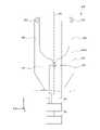
図3を参照し、以下に、プラズマ処理装置1の一例としての容量結合プラズマ処理装置の構成例について説明する。 A configuration example of a capacitively-coupled plasma processing apparatus as an example of the plasma processing apparatus 1 will be described below with reference to FIG.
容量結合プラズマ処理装置1は、プラズマ処理チャンバ10、ガス供給部20、電源30及び排気システム40を含む。また、プラズマ処理装置1は、基板支持部11及びガス導入部を含む。ガス導入部は、少なくとも1つの処理ガスをプラズマ処理チャンバ10内に導入するように構成される。ガス導入部は、シャワーヘッド13を含む。基板支持部11は、プラズマ処理チャンバ10内に配置される。シャワーヘッド13は、基板支持部11の上方に配置される。一実施形態において、シャワーヘッド13は、プラズマ処理チャンバ10の天部(ceiling)の少なくとも一部を構成する。プラズマ処理チャンバ10は、シャワーヘッド13、プラズマ処理チャンバ10の側壁10a及び基板支持部11により規定されたプラズマ処理空間10sを有する。側壁10aは接地される。シャワーヘッド13及び基板支持部11は、プラズマ処理チャンバ10筐体とは電気的に絶縁される。 The capacitively coupled plasma processing apparatus 1 includes a
基板支持部11は、本体部111及びリングアセンブリ112を含む。本体部111は、基板(ウエハ)Wを支持するための中央領域(基板支持面)111aと、リングアセンブリ112を支持するための環状領域(リング支持面)111bとを有する。本体部111の環状領域111bは、平面視で本体部111の中央領域111aを囲んでいる。基板Wは、本体部111の中央領域111a上に配置され、リングアセンブリ112は、本体部111の中央領域111a上の基板Wを囲むように本体部111の環状領域111b上に配置される。一実施形態において、本体部111は、基台及び静電チャックを含む。基台は、導電性部材を含む。基台の導電性部材は下部電極として機能する。静電チャックは、基台の上に配置される。静電チャックの上面は、基板支持面111aを有する。リングアセンブリ112は、1又は複数の環状部材を含む。1又は複数の環状部材のうち少なくとも1つはエッジリングである。また、図示は省略するが、基板支持部11は、静電チャック、リングアセンブリ112及び基板のうち少なくとも1つをターゲット温度に調節するように構成される温調モジュールを含んでもよい。温調モジュールは、ヒータ、伝熱媒体、流路、又はこれらの組み合わせを含んでもよい。流路には、ブラインやガスのような伝熱流体が流れる。また、基板支持部11は、基板Wの裏面と基板支持面111aとの間に伝熱ガスを供給するように構成された伝熱ガス供給部を含んでもよい。 The
シャワーヘッド13は、ガス供給部20からの少なくとも1つの処理ガスをプラズマ処理空間10s内に導入するように構成される。シャワーヘッド13は、少なくとも1つのガス供給口13a、少なくとも1つのガス拡散室13b、及び複数のガス導入口13cを有する。ガス供給口13aに供給された処理ガスは、ガス拡散室13bを通過して複数のガス導入口13cからプラズマ処理空間10s内に導入される。また、シャワーヘッド13は、導電性部材を含む。シャワーヘッド13の導電性部材は上部電極として機能する。なお、ガス導入部は、シャワーヘッド13に加えて、側壁10aに形成された1又は複数の開口部に取り付けられる1又は複数のサイドガス注入部(SGI:Side Gas Injector)を含んでもよい。 The
ガス供給部20は、少なくとも1つのガスソース21及び少なくとも1つの流量制御器22を含んでもよい。一実施形態において、ガス供給部20は、少なくとも1つの処理ガスを、それぞれに対応のガスソース21からそれぞれに対応の流量制御器22を介してシャワーヘッド13に供給するように構成される。各流量制御器22は、例えばマスフローコントローラ又は圧力制御式の流量制御器を含んでもよい。さらに、ガス供給部20は、少なくとも1つの処理ガスの流量を変調又はパルス化する少なくとも1つの流量変調デバイスを含んでもよい。
電源30は、少なくとも1つのインピーダンス整合回路を介してプラズマ処理チャンバ10に結合されるRF電源31を含む。RF電源31は、ソースRF信号及びバイアスRF信号のような少なくとも1つのRF信号(RF電力)を、基板支持部11の導電性部材及び/又はシャワーヘッド13の導電性部材に供給するように構成される。これにより、プラズマ処理空間10sに供給された少なくとも1つの処理ガスからプラズマが形成される。従って、RF電源31は、プラズマ生成部12の少なくとも一部として機能し得る。また、バイアスRF信号を基板支持部11の導電性部材に供給することにより、基板Wにバイアス電位が発生し、形成されたプラズマ中のイオン成分を基板Wに引き込むことができる。
一実施形態において、RF電源31は、第1のRF生成部31a及び第2のRF生成部31bを含む。第1のRF生成部31aは、少なくとも1つのインピーダンス整合回路を介して基板支持部11の導電性部材及び/又はシャワーヘッド13の導電性部材に結合され、プラズマ生成用のソースRF信号(ソースRF電力)を生成するように構成される。一実施形態において、ソースRF信号は、13MHz~150MHzの範囲内の周波数を有する。一実施形態において、第1のRF生成部31aは、異なる周波数を有する複数のソースRF信号を生成するように構成されてもよい。生成された1又は複数のソースRF信号は、基板支持部11の導電性部材及び/又はシャワーヘッド13の導電性部材に供給される。第2のRF生成部31bは、少なくとも1つのインピーダンス整合回路を介して基板支持部11の導電性部材に結合され、バイアスRF信号(バイアスRF電力)を生成するように構成される。一実施形態において、バイアスRF信号は、ソースRF信号よりも低い周波数を有する。一実施形態において、バイアスRF信号は、400kHz~13.56MHzの範囲内の周波数を有する。一実施形態において、第2のRF生成部31bは、異なる周波数を有する複数のバイアスRF信号を生成するように構成されてもよい。生成された1又は複数のバイアスRF信号は、基板支持部11の導電性部材に供給される。また、種々の実施形態において、ソースRF信号及びバイアスRF信号のうち少なくとも1つがパルス化されてもよい。 In one embodiment, the
また、電源30は、プラズマ処理チャンバ10に結合されるDC電源32を含んでもよい。DC電源32は、第1のDC生成部32a及び第2のDC生成部32bを含む。一実施形態において、第1のDC生成部32aは、基板支持部11の導電性部材に接続され、第1のDC信号を生成するように構成される。生成された第1のDC信号は、基板支持部11の導電性部材に印加される。一実施形態において、第1のDC信号が、静電チャック内の電極のような他の電極に印加されてもよい。一実施形態において、第2のDC生成部32bは、シャワーヘッド13の導電性部材に接続され、第2のDC信号を生成するように構成される。生成された第2のDC信号は、シャワーヘッド13の導電性部材に印加される。種々の実施形態において、第1及び第2のDC信号がパルス化されてもよい。なお、第1及び第2のDC生成部32a,32bは、RF電源31に加えて設けられてもよく、第1のDC生成部32aが第2のRF生成部31bに代えて設けられてもよい。
排気システム40は、例えばプラズマ処理チャンバ10の底部に設けられたガス排出口10eに接続され得る。排気システム40は、圧力調整弁及び真空ポンプを含んでもよい。圧力調整弁によって、プラズマ処理空間10s内の圧力が調整される。真空ポンプは、ターボ分子ポンプ、ドライポンプ又はこれらの組み合わせを含んでもよい。 The
〔相対位置の算出方法〕
図4を参照し、真空搬送ロボットTR1のフォークFK11と基板Wとの相対位置を算出する方法の一例について説明する。なお、真空搬送ロボットTR1のフォークFK12及び真空搬送ロボットTR2のフォークFK21,FK22と基板Wとの相対位置を算出する方法についても同様であってよい。[Calculation method of relative position]
An example of a method for calculating the relative position between the fork FK11 of the vacuum transfer robot TR1 and the substrate W will be described with reference to FIG. The method of calculating the relative positions of the substrate W and the fork FK12 of the vacuum transfer robot TR1 and the forks FK21 and FK22 of the vacuum transfer robot TR2 may be the same.
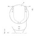
図4は、真空搬送ロボットTR1のフォークFK11と基板Wとの相対位置の説明図である。図4(a)は、基板Wを保持したフォークFK11の平面図である。図4(b)は、基板Wを保持したフォークFK11の断面図であり、図4(a)における一点鎖線4B-4Bで切断した断面を示す。 FIG. 4 is an explanatory diagram of the relative positions of the fork FK11 and the substrate W of the vacuum transfer robot TR1. 4A is a plan view of the fork FK11 holding the substrate W. FIG. FIG. 4(b) is a cross-sectional view of the fork FK11 holding the substrate W, showing a cross-section cut along the dashed
フォークFK11は、平面視で略U字形状を有する。フォークFK11は、複数のパッドPD、導体CD1等を含む。複数のパッドPDは、基板Wの下面に接触して該基板Wを保持する。導体CD1は、フォークFK11の所定位置(例えば中心位置)に基板Wが設置されたときに、平面視でその中心が静電容量センサCSの中心と一致する位置に設けられている。導体CD1は、例えばアルミニウムである。 The fork FK11 has a substantially U shape in plan view. Fork FK11 includes a plurality of pads PD, conductors CD1, and the like. A plurality of pads PD hold the substrate W in contact with the lower surface of the substrate W. As shown in FIG. The conductor CD1 is provided at a position where its center coincides with the center of the capacitance sensor CS in plan view when the substrate W is placed at a predetermined position (for example, center position) of the fork FK11. Conductor CD1 is, for example, aluminum.
基板Wは、円板形状のセンサウエハである。基板Wは、位置検出センサPS1~PS6、静電容量センサCS等を含む。 The substrate W is a disk-shaped sensor wafer. The substrate W includes position detection sensors PS1 to PS6, a capacitance sensor CS, and the like.
位置検出センサPS1~PS6は、例えば基板Wの表面の外周縁部に同一円周上に配置されている。位置検出センサPS1~PS6は、例えば基板Wの下方や側方を撮影可能に構成されるカメラであってよい。ただし、位置検出センサPS1~PS6の種類はこれに限定されるものではない。 The position detection sensors PS1 to PS6 are arranged on the same circumference at the outer peripheral edge of the surface of the substrate W, for example. The position detection sensors PS1 to PS6 may be cameras capable of photographing the bottom and sides of the substrate W, for example. However, the types of position detection sensors PS1 to PS6 are not limited to this.
静電容量センサCSは、基板Wの所定位置に設けられている。静電容量センサCSは、基板WがフォークFK11に保持された際、フォークFK11に設けられた導体CD1との位置関係に応じた静電容量を検出し、検出値(検出結果)を制御部CUに出力する。 The capacitance sensor CS is provided at a predetermined position on the substrate W. As shown in FIG. When the substrate W is held by the fork FK11, the capacitance sensor CS detects the capacitance according to the positional relationship with the conductor CD1 provided on the fork FK11, and outputs the detected value (detection result) to the control unit CU. output to
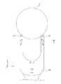
図5を参照し、大気搬送ロボットTR3のフォークFK31と基板Wとの相対位置を算出する方法の一例について説明する。 An example of a method for calculating the relative position between the fork FK31 of the atmospheric transport robot TR3 and the substrate W will be described with reference to FIG.
図5は、大気搬送ロボットTR3のフォークFK31と基板Wとの相対位置の説明図である。図5(a)は、基板Wを保持したフォークFK31の平面図である。図5(b)は、基板Wを保持したフォークFK31の断面図であり、図5(a)における一点鎖線5B-5Bで切断した断面を示す。 FIG. 5 is an explanatory diagram of the relative positions of the fork FK31 and the substrate W of the atmospheric transfer robot TR3. FIG. 5(a) is a plan view of the fork FK31 holding the substrate W. FIG. FIG. 5(b) is a cross-sectional view of the fork FK31 holding the substrate W, showing a cross section taken along the dashed
フォークFK31は、平面視で略U字形状を有する。フォークFK31は、複数の吸引孔V1、吸引路V2、導体CD2等を含む。フォークFK31は、基板Wの下面を複数の吸引孔V1により真空吸着して保持する。複数の吸引孔V1は、吸引路V2及び排気管V3を介して排気装置V4に接続されている。排気装置V4は、バルブ、レギュレータ、真空ポンプ等を含み、圧力を調整しながら吸引路V2及び排気管V3内を吸引する。排気管V3には、吸着センサV5が介設されている。吸着センサV5は、排気管V3内の圧力(以下「吸着圧力」ともいう。)を検出し、制御部CUに出力する。制御部CUは、吸着センサV5により検出される吸着圧力に基づいて、フォークFK31の上面が基板Wの下面と接触したときの高さ位置を算出する。導体CD2は、フォークFK31の所定位置(例えば中心位置)に基板Wが設置されたときに、平面視でその中心が静電容量センサCSの中心と一致する位置に設けられている。導体CD2は、例えばアルミニウムである。 The fork FK31 has a substantially U shape in plan view. The fork FK31 includes a plurality of suction holes V1, suction paths V2, conductors CD2, and the like. The fork FK31 holds the lower surface of the substrate W by vacuum suction through the plurality of suction holes V1. The plurality of suction holes V1 are connected to an exhaust device V4 via a suction path V2 and an exhaust pipe V3. The evacuation device V4 includes a valve, a regulator, a vacuum pump, etc., and sucks the insides of the suction path V2 and the evacuation pipe V3 while adjusting the pressure. An adsorption sensor V5 is interposed in the exhaust pipe V3. The adsorption sensor V5 detects the pressure in the exhaust pipe V3 (hereinafter also referred to as "adsorption pressure") and outputs it to the control unit CU. The control unit CU calculates the height position when the upper surface of the fork FK31 contacts the lower surface of the substrate W based on the suction pressure detected by the suction sensor V5. The conductor CD2 is provided at a position where its center coincides with the center of the capacitance sensor CS in plan view when the substrate W is placed at a predetermined position (for example, center position) of the fork FK31. Conductor CD2 is, for example, aluminum.
基板Wは、図4(a)及び図4(b)に示される基板Wと同じである。すなわち、基板Wは、円板形状のセンサウエハである。基板Wは、位置検出センサPS1~PS6、静電容量センサCS等を含む。 The substrate W is the same as the substrate W shown in FIGS. 4(a) and 4(b). That is, the substrate W is a disk-shaped sensor wafer. The substrate W includes position detection sensors PS1 to PS6, a capacitance sensor CS, and the like.
静電容量センサCSは、基板Wの所定位置に設けられている。静電容量センサCSは、基板WがフォークFK31に吸着保持された際、フォークFK31に設けられた導体CD2との位置関係に応じた静電容量を検出し、検出値(検出結果)を制御部CUに出力する。 The capacitance sensor CS is provided at a predetermined position on the substrate W. As shown in FIG. The capacitance sensor CS detects the capacitance corresponding to the positional relationship with the conductor CD2 provided on the fork FK31 when the substrate W is attracted and held by the fork FK31, and outputs the detected value (detection result) to the control unit. Output to CU.
静電容量センサCSは、例えば図6に示されるように、平面視で導体CD1(CD2)よりも大きい円形状を有する。ただし、静電容量センサCSは、平面視で導体CD1(CD2)と同じ大きさの円形状を有していてもよく、平面視で導体CD1(CD2)よりも小さい円形状を有していてもよい。また、静電容量センサCSは、円形状とは異なる形状、例えば矩形状等の多角形状を有していてもよい。 The capacitive sensor CS has a circular shape larger than the conductor CD1 (CD2) in plan view, as shown in FIG. 6, for example. However, the capacitive sensor CS may have a circular shape that is the same size as the conductor CD1 (CD2) in plan view, or has a circular shape that is smaller than the conductor CD1 (CD2) in plan view. good too. Also, the capacitive sensor CS may have a shape different from the circular shape, for example, a polygonal shape such as a rectangular shape.
静電容量センサCSは、例えば図7に示されるように、平面視で正三角形の頂点に配置された3つの静電容量センサCS1~CS3を含んでいてもよい。3つの静電容量センサCS1~CS3は、それぞれ平面視で導体CD1(CD2)よりも小さい円形状を有する。ただし、複数の静電容量センサの各々は、円形状とは異なる形状、例えば矩形状等の多角形状を有していてもよい。また、静電容量センサCSは、2つの静電容量センサを含んでいてもよく、4つ以上の静電容量センサを含んでいてもよい。 The capacitance sensor CS may include three capacitance sensors CS1 to CS3 arranged at the vertices of an equilateral triangle in plan view, as shown in FIG. 7, for example. Each of the three capacitive sensors CS1 to CS3 has a circular shape smaller than the conductor CD1 (CD2) in plan view. However, each of the plurality of capacitive sensors may have a shape different from the circular shape, for example, a polygonal shape such as a rectangular shape. Also, the capacitance sensor CS may include two capacitance sensors, or may include four or more capacitance sensors.
なお、図4及び図5の例では、静電容量センサCSが基板Wに設けられている場合を説明したが、これに限定されない。例えば、静電容量センサCSはフォークFK11,FK31に設けられていてもよい。 In addition, although the case where the capacitance sensor CS is provided on the substrate W has been described in the examples of FIGS. 4 and 5, the present invention is not limited to this. For example, the capacitance sensor CS may be provided on the forks FK11 and FK31.
〔位置合わせ方法〕
実施形態の位置合わせ方法について、前述の処理システムPSにおいて実施される場合を例に挙げて説明する。[Positioning method]
The alignment method of the embodiment will be described by exemplifying the case where it is implemented in the above-described processing system PS.
実施形態の位置合わせ方法は、例えば処理システムPSの起動時に実施される。また、実施形態の位置合わせ方法は、例えば真空搬送ロボットTR1のフォークFK11,FK12、真空搬送ロボットTR2のフォークFK21,FK22、大気搬送ロボットTR3のフォークFK31の交換時に実施される。また、実施形態の位置合わせ方法は、例えばプロセスモジュールPM1~PM12内の部品(例えば静電チャック、エッジリング)の交換時に実施される。ただし、実施形態の位置合わせ方法が実施されるタイミングは、例示したタイミングに限定されるものではない。 The alignment method of the embodiment is performed, for example, when the processing system PS is started. Further, the alignment method of the embodiment is performed, for example, when exchanging the forks FK11 and FK12 of the vacuum transfer robot TR1, the forks FK21 and FK22 of the vacuum transfer robot TR2, and the fork FK31 of the atmospheric transfer robot TR3. Further, the alignment method of the embodiment is performed, for example, when replacing parts (for example, electrostatic chucks, edge rings) in the process modules PM1 to PM12. However, the timing at which the alignment method of the embodiment is performed is not limited to the illustrated timing.
また、実施形態の位置合わせ方法に先立って、ラフティーチングを実施することが好ましい。ラフティーチングは、搬送ロボットのフォークについて、搬送対象物の搬送場所に対して搬送位置座標を仮決定するものである。ラフティーチングは、フォークに保持される搬送対象物が処理システム内の部材等と接触しないようにするために実施されるものであり、荒い精度で搬送位置座標が仮決定される。なお、処理システムの組み立て誤差が小さい場合等には、処理システムの設計数値から搬送位置座標を算出し、ラフティーチングを省略してもよい。 Also, it is preferable to perform rough teaching prior to the alignment method of the embodiment. Rough teaching is to provisionally determine the transport position coordinates of the fork of the transport robot with respect to the transport location of the object to be transported. Rough teaching is performed to prevent the object to be conveyed held by the forks from coming into contact with members or the like in the processing system, and the coordinates of the conveying position are tentatively determined with rough accuracy. If the assembly error of the processing system is small, the transfer position coordinates may be calculated from the design values of the processing system, and the rough teaching may be omitted.
以下では、まず大気搬送ロボットTR3の位置合わせ方法について説明し、次いで真空搬送ロボットTR1,TR2の位置合わせ方法について説明する。 In the following, first, a method of aligning the atmospheric transfer robot TR3 will be described, and then a method of aligning the vacuum transport robots TR1 and TR2 will be described.
(大気搬送ロボットの位置合わせ)
図8を参照し、大気搬送ロボットTR3の位置合わせ方法の一例について説明する。図8に示されるように、大気搬送ロボットTR3の位置合わせ方法では、まず、工程S10において、大気搬送ロボットTR3とアライナANとロードポートLP1~LP4との位置合わせを行う。次いで、工程S20において、大気搬送ロボットTR3とストレージSRとの位置合わせを行う。次いで、工程S30において、大気搬送ロボットTR3とロードロックモジュールLL1,LL2との位置合わせを行う。ただし、工程S20と工程S30との順序は入れ替えてもよい。(Positioning of atmospheric transfer robot)
With reference to FIG. 8, an example of a method of aligning the atmosphere transfer robot TR3 will be described. As shown in FIG. 8, in the method for aligning the atmospheric transfer robot TR3, first, in step S10, the atmospheric transfer robot TR3, the aligner AN, and the load ports LP1 to LP4 are aligned. Next, in step S20, the atmosphere transfer robot TR3 and the storage SR are aligned. Next, in step S30, the atmosphere transfer robot TR3 and the load lock modules LL1 and LL2 are aligned. However, the order of step S20 and step S30 may be changed.
図9を参照し、大気搬送ロボットTR3とアライナANとロードポートLP1との位置合わせ(工程S10)の一例について説明する。なお、工程S10の開始時において、ロードポートLP1にセンサウエハを収容した容器Cが載置されているものとする。 An example of alignment (step S10) of the atmospheric transfer robot TR3, the aligner AN, and the load port LP1 will be described with reference to FIG. It is assumed that the container C containing the sensor wafers is placed on the load port LP1 at the start of step S10.
ステップS11において、制御部CUは、フォークFK31によりロードポートLP1に載置された容器C内からセンサウエハを取得するように、大気搬送ロボットTR3を制御する。このとき、制御部CUは、フォークFK31の吸着センサV5の検出値に基づいて、フォークFK31の上面がセンサウエハの下面と接触したときの高さ位置を算出する。また、制御部CUは、算出した高さ位置に基づいてZ軸の教示(ティーチング)位置を補正する。 In step S11, the control unit CU controls the atmosphere transfer robot TR3 so as to obtain the sensor wafer from the container C placed on the load port LP1 by the fork FK31. At this time, based on the detection value of the suction sensor V5 of the fork FK31, the control unit CU calculates the height position when the upper surface of the fork FK31 contacts the lower surface of the sensor wafer. Further, the control unit CU corrects the teaching position of the Z-axis based on the calculated height position.
ステップS12において、制御部CUは、フォークFK31が取得したセンサウエハをアライナANに搬送するように、大気搬送ロボットTR3を制御する。 In step S12, the control unit CU controls the atmosphere transfer robot TR3 to transfer the sensor wafer acquired by the fork FK31 to the aligner AN.
ステップS13において、制御部CUは、センサウエハの水平方向の位置を検出するように、アライナANを制御する。水平方向の位置は、ノッチの角度位置、センサウエハの中心位置等を含む。 In step S13, the control unit CU controls the aligner AN to detect the horizontal position of the sensor wafer. The horizontal position includes the angular position of the notch, the center position of the sensor wafer, and the like.
ステップS14において、制御部CUは、アライナANの検出結果に基づいて、ロードポートLP1とアライナANとの間の水平方向の位置ずれ量を算出する。また、制御部CUは、算出した位置ずれ量に基づいて、X軸の教示位置及びY軸の教示位置を補正する。 In step S14, the control unit CU calculates the amount of horizontal positional deviation between the load port LP1 and the aligner AN based on the detection result of the aligner AN. Further, the control unit CU corrects the X-axis teaching position and the Y-axis teaching position based on the calculated positional deviation amount.
ステップS15において、制御部CUは、補正された位置でフォークFK31によりアライナANからセンサウエハを取得するように、大気搬送ロボットTR3を制御する。 In step S15, the control unit CU controls the atmospheric transport robot TR3 so as to acquire the sensor wafer from the aligner AN with the fork FK31 at the corrected position.
ステップS16において、制御部CUは、フォークFK31とセンサウエハとの相対位置を算出する。例えば、制御部CUは、センサウエハに設けられた静電容量センサCSの検出値に基づいて、フォークFK31とセンサウエハとの相対位置を算出する。ただし、制御部CUは、センサウエハに設けられた位置検出センサPS1~PS6の検出値に基づいて、フォークFK31とセンサウエハとの相対位置を算出してもよい。 In step S16, the control unit CU calculates the relative position between the fork FK31 and the sensor wafer. For example, the control unit CU calculates the relative position between the fork FK31 and the sensor wafer based on the detection value of the capacitance sensor CS provided on the sensor wafer. However, the control unit CU may calculate the relative position between the fork FK31 and the sensor wafer based on the detection values of the position detection sensors PS1 to PS6 provided on the sensor wafer.
ステップS17において、制御部CUは、算出したフォークFK31とセンサウエハとの相対位置が基準値内であるか否かを判定する。ステップS17において、相対位置が基準値内である場合、制御部CUは処理をステップS18へ進める。一方、ステップS17において、相対位置が基準値内でない場合、制御部CUは相対位置が基準値内となるように教示位置の補正を行い、処理をステップS15へ戻す。 In step S17, the control unit CU determines whether or not the calculated relative position between the fork FK31 and the sensor wafer is within a reference value. In step S17, when the relative position is within the reference value, the control unit CU advances the process to step S18. On the other hand, if the relative position is not within the reference value in step S17, the control unit CU corrects the taught position so that the relative position is within the reference value, and returns the process to step S15.
ステップS18において、制御部CUは、フォークFK31が取得したセンサウエハを所定の回収位置に搬送するように、大気搬送ロボットTR3を制御する。所定の回収位置は、ロードポートLP1に載置された容器C、ストレージSR等であってよい。センサウエハが回収された後、制御部CUは処理を終了させる。 In step S18, the control unit CU controls the atmosphere transfer robot TR3 so as to transfer the sensor wafer acquired by the fork FK31 to a predetermined recovery position. The predetermined collection position may be the container C placed on the load port LP1, the storage SR, or the like. After the sensor wafer is recovered, the control unit CU terminates the process.
以上、大気搬送ロボットTR3とアライナANとロードポートLP1との位置合わせの一例について説明したが、ロードポートLP2~LP4についてもロードポートLP1と同様の方法により位置合わせできる。 An example of positioning the atmospheric transfer robot TR3, the aligner AN, and the load port LP1 has been described above, but the load ports LP2 to LP4 can also be positioned by the same method as for the load port LP1.
図10を参照し、大気搬送ロボットTR3とストレージSRとの位置合わせ(工程S20)の一例について説明する。なお、工程S20の開始時において、大気搬送ロボットTR3とアライナANとロードポートLP1との位置合わせ(工程S10)が完了しているものとする。 An example of alignment (step S20) between the atmospheric transport robot TR3 and the storage SR will be described with reference to FIG. It is assumed that the atmospheric transfer robot TR3, the aligner AN, and the load port LP1 have already been aligned (step S10) at the start of step S20.
ステップS21において、制御部CUは、フォークFK31によりストレージSRの所定位置(例えば中心位置)にセンサウエハを設置するように、大気搬送ロボットTR3を制御する。このとき、制御部CUは、センサウエハの位置検出センサPS1~PS6の検出値に基づいて、センサウエハをストレージSRの所定位置に設置するように、大気搬送ロボットTR3を制御する。 In step S21, the control unit CU controls the atmospheric transfer robot TR3 so that the fork FK31 places the sensor wafer at a predetermined position (for example, the central position) of the storage SR. At this time, the control unit CU controls the atmospheric transfer robot TR3 to install the sensor wafer at a predetermined position in the storage SR based on the detection values of the sensor wafer position detection sensors PS1 to PS6.
ステップS22において、制御部CUは、フォークFK31によりストレージSRからセンサウエハを取得するように、大気搬送ロボットTR3を制御する。このとき、制御部CUは、フォークFK31の吸着センサV5の検出値に基づいて、フォークFK31の上面がセンサウエハの下面と接触したときの高さ位置を算出する。また、制御部CUは、算出した高さ位置に基づいてZ軸の教示位置を補正する。 In step S22, the control unit CU controls the atmospheric transfer robot TR3 to acquire the sensor wafer from the storage SR by the fork FK31. At this time, based on the detection value of the suction sensor V5 of the fork FK31, the control unit CU calculates the height position when the upper surface of the fork FK31 contacts the lower surface of the sensor wafer. Further, the control unit CU corrects the teaching position of the Z-axis based on the calculated height position.
ステップS23において、制御部CUは、フォークFK31によりセンサウエハをアライナANに搬送するように、大気搬送ロボットTR3を制御する。 In step S23, the control unit CU controls the atmosphere transfer robot TR3 to transfer the sensor wafer to the aligner AN by the fork FK31.
ステップS24において、制御部CUは、センサウエハの水平方向の位置を検出するように、アライナANを制御する。 In step S24, the control unit CU controls the aligner AN to detect the horizontal position of the sensor wafer.
ステップS25において、制御部CUは、アライナANの検出結果に基づいて、ストレージSRとアライナANとの間の水平方向の位置ずれ量を算出する。また、制御部CUは、算出した位置ずれ量に基づいて、X軸の教示位置及びY軸の教示位置を補正する。 In step S25, the control unit CU calculates the amount of horizontal misalignment between the storage SR and the aligner AN based on the detection result of the aligner AN. Further, the control unit CU corrects the X-axis teaching position and the Y-axis teaching position based on the calculated positional deviation amount.
ステップS26において、制御部CUは、フォークFK31によりセンサウエハを所定の回収位置に搬送するように、大気搬送ロボットTR3を制御する。所定の回収位置は、ロードポートLP1に載置された容器C、ストレージSR等であってよい。センサウエハが回収された後、制御部CUは処理を終了させる。 In step S26, the control unit CU controls the atmosphere transfer robot TR3 so that the fork FK31 transfers the sensor wafer to a predetermined recovery position. The predetermined collection position may be the container C placed on the load port LP1, the storage SR, or the like. After the sensor wafer is recovered, the control unit CU terminates the process.
図11を参照し、大気搬送ロボットTR3とストレージSRとの位置合わせ(工程S20)の別の一例について説明する。なお、工程S20の開始時において、大気搬送ロボットTR3とアライナANとロードポートLP1との位置合わせ(工程S10)が完了しているものとする。 Another example of alignment (step S20) between the atmospheric transfer robot TR3 and the storage SR will be described with reference to FIG. It is assumed that the atmospheric transfer robot TR3, the aligner AN, and the load port LP1 have already been aligned (step S10) at the start of step S20.
ステップS21Aにおいて、制御部CUは、フォークFK31によりストレージSRの所定位置(例えば中心位置)にセンサウエハを設置するように、大気搬送ロボットTR3を制御する。また、制御部CUは、フォークFK31の吸着センサV5の検出値に基づいて、フォークFK31の上面がセンサウエハの下面と接触したときの高さ位置を算出する。また、制御部CUは、算出した高さ位置に基づいてZ軸の教示位置を補正する。 In step S21A, the control unit CU controls the atmospheric transfer robot TR3 so that the fork FK31 places the sensor wafer at a predetermined position (for example, the central position) of the storage SR. Further, based on the detection value of the suction sensor V5 of the fork FK31, the control unit CU calculates the height position when the upper surface of the fork FK31 contacts the lower surface of the sensor wafer. Further, the control unit CU corrects the teaching position of the Z-axis based on the calculated height position.
ステップS22Aにおいて、制御部CUは、ストレージSRとセンサウエハとの相対位置を算出する。例えば、制御部CUは、センサウエハに設けられた位置検出センサPS1~PS6の検出値に基づいて、ストレージSRとセンサウエハとの相対位置を算出する。ただし、制御部CUは、センサウエハに設けられた静電容量センサCSの検出値に基づいて、ストレージSRとセンサウエハとの相対位置を算出してもよい。 At step S22A, the control unit CU calculates the relative position between the storage SR and the sensor wafer. For example, the control unit CU calculates the relative position between the storage SR and the sensor wafer based on the detection values of the position detection sensors PS1 to PS6 provided on the sensor wafer. However, the control unit CU may calculate the relative position between the storage SR and the sensor wafer based on the detection value of the capacitance sensor CS provided on the sensor wafer.
ステップS23Aにおいて、制御部CUは、算出したストレージSRとセンサウエハとの相対位置が基準値内であるか否かを判定する。ステップS23Aにおいて、相対位置が基準値内である場合、制御部CUは処理をステップS27Aへ進める。一方、ステップS23Aにおいて、相対位置が基準値内でない場合、制御部CUは、相対位置が基準値内となるように教示位置の補正を行い、処理をステップS24Aへ進める。 In step S23A, the control unit CU determines whether the calculated relative position between the storage SR and the sensor wafer is within a reference value. In step S23A, if the relative position is within the reference value, the control unit CU advances the process to step S27A. On the other hand, if the relative position is not within the reference value in step S23A, the control unit CU corrects the taught position so that the relative position is within the reference value, and advances the process to step S24A.
ステップS24Aにおいて、制御部CUは、補正された位置でフォークFK31によりストレージSRからセンサウエハを取得するように、大気搬送ロボットTR3を制御する。 In step S24A, the control unit CU controls the atmospheric transfer robot TR3 so as to acquire the sensor wafer from the storage SR with the fork FK31 at the corrected position.
ステップS25Aにおいて、制御部CUは、フォークFK31が取得したセンサウエハをストレージSRに戻すように、大気搬送ロボットTR3を制御する。 In step S25A, the control unit CU controls the atmospheric transfer robot TR3 to return the sensor wafer acquired by the fork FK31 to the storage SR.
ステップS26Aにおいて、制御部CUは、ストレージSRとセンサウエハとの相対位置を算出する。例えば、制御部CUは、センサウエハに設けられた位置検出センサPS1~PS6の検出値に基づいて、ストレージSRとセンサウエハとの相対位置を算出する。ただし、制御部CUは、センサウエハに設けられた静電容量センサCSの検出値に基づいて、ストレージSRとセンサウエハとの相対位置を算出してもよい。制御部CUは、相対位置を算出した後、処理をステップS23Aに戻す。 At step S26A, the control unit CU calculates the relative position between the storage SR and the sensor wafer. For example, the control unit CU calculates the relative position between the storage SR and the sensor wafer based on the detection values of the position detection sensors PS1 to PS6 provided on the sensor wafer. However, the control unit CU may calculate the relative position between the storage SR and the sensor wafer based on the detection value of the capacitance sensor CS provided on the sensor wafer. After calculating the relative position, the control unit CU returns the process to step S23A.
ステップS27Aにおいて、制御部CUは、フォークFK31によりセンサウエハを所定の回収位置に搬送するように、大気搬送ロボットTR3を制御する。所定の回収位置は、ロードポートLP1に載置された容器C、ストレージSR等であってよい。センサウエハが回収された後、制御部CUは処理を終了させる。 In step S27A, the control unit CU controls the atmosphere transfer robot TR3 so that the fork FK31 transfers the sensor wafer to a predetermined recovery position. The predetermined collection position may be the container C placed on the load port LP1, the storage SR, or the like. After the sensor wafer is recovered, the control unit CU terminates the process.
図12を参照し、大気搬送ロボットTR3とロードロックモジュールLL1との位置合わせ(工程S30)の一例について説明する。なお、工程S30の開始時において、大気搬送ロボットTR3とアライナANとロードポートLP1との位置合わせ(工程S10)が完了しているものとする。 An example of the alignment (step S30) between the atmosphere transfer robot TR3 and the load lock module LL1 will be described with reference to FIG. It is assumed that the atmospheric transfer robot TR3, the aligner AN, and the load port LP1 have already been aligned (step S10) at the start of step S30.
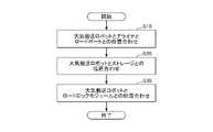
ステップS31において、制御部CUは、フォークFK31によりロードロックモジュールLL1の所定位置(例えば中心位置)にセンサウエハを設置するように、大気搬送ロボットTR3を制御する。このとき、制御部CUは、センサウエハの位置検出センサPS1~PS6の検出値に基づいて、センサウエハをロードロックモジュールLL1の所定位置に設置するように、大気搬送ロボットTR3を制御する。 In step S31, the control unit CU controls the atmospheric transfer robot TR3 so that the fork FK31 places the sensor wafer at a predetermined position (for example, the central position) of the load lock module LL1. At this time, the control unit CU controls the atmospheric transfer robot TR3 to install the sensor wafer at a predetermined position in the load lock module LL1 based on the detection values of the sensor wafer position detection sensors PS1 to PS6.
ステップS32において、制御部CUは、フォークFK31によりロードロックモジュールLL1からセンサウエハを取得するように、大気搬送ロボットTR3を制御する。このとき、制御部CUは、フォークFK31の吸着センサV5の検出値に基づいて、フォークFK31の上面がセンサウエハの下面と接触したときの高さ位置を算出する。また、制御部CUは、算出した高さ位置に基づいてZ軸の教示位置を補正する。 In step S32, the control unit CU controls the atmosphere transfer robot TR3 so as to acquire the sensor wafer from the load lock module LL1 by the fork FK31. At this time, based on the detection value of the suction sensor V5 of the fork FK31, the control unit CU calculates the height position when the upper surface of the fork FK31 contacts the lower surface of the sensor wafer. Further, the control unit CU corrects the teaching position of the Z-axis based on the calculated height position.
ステップS33において、制御部CUは、フォークFK31によりセンサウエハをアライナANに搬送するように、大気搬送ロボットTR3を制御する。 In step S33, the control unit CU controls the atmosphere transfer robot TR3 to transfer the sensor wafer to the aligner AN by the fork FK31.
ステップS34において、制御部CUは、センサウエハの水平方向の位置を検出するように、アライナANを制御する。 In step S34, the control unit CU controls the aligner AN to detect the horizontal position of the sensor wafer.
ステップS35において、制御部CUは、アライナANの検出結果に基づいて、ロードロックモジュールLL1とアライナANとの間の水平方向の位置ずれ量を算出する。また、制御部CUは、算出した位置ずれ量に基づいて、X軸の教示位置及びY軸の教示位置を補正する。 In step S35, the control unit CU calculates the amount of horizontal positional deviation between the load lock module LL1 and the aligner AN based on the detection result of the aligner AN. Further, the control unit CU corrects the X-axis teaching position and the Y-axis teaching position based on the calculated positional deviation amount.
ステップS36において、制御部CUは、フォークFK31によりセンサウエハを所定の回収位置に搬送するように、大気搬送ロボットTR3を制御する。所定の回収位置は、ロードポートLP1に載置された容器C、ストレージSR等であってよい。センサウエハが回収された後、制御部CUは処理を終了させる。 In step S36, the control unit CU controls the atmosphere transfer robot TR3 so that the fork FK31 transfers the sensor wafer to a predetermined recovery position. The predetermined collection position may be the container C placed on the load port LP1, the storage SR, or the like. After the sensor wafer is recovered, the control unit CU terminates the process.
以上、大気搬送ロボットTR3とロードロックモジュールLL1との位置合わせの一例について説明したが、ロードロックモジュールLL2についてもロードロックモジュールLL1と同様の方法により位置合わせできる。 An example of alignment between the atmosphere transfer robot TR3 and the load lock module LL1 has been described above, but the load lock module LL2 can also be aligned by the same method as for the load lock module LL1.
図13を参照し、大気搬送ロボットTR3とロードロックモジュールLL1との位置合わせ(工程S20)の別の一例について説明する。なお、工程S30の開始時において、大気搬送ロボットTR3とアライナANとロードポートLP1との位置合わせ(工程S10)が完了しているものとする。 Another example of alignment (step S20) between atmospheric transfer robot TR3 and load lock module LL1 will be described with reference to FIG. It is assumed that the atmospheric transfer robot TR3, the aligner AN, and the load port LP1 have already been aligned (step S10) at the start of step S30.
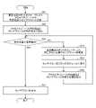
ステップS31Aにおいて、制御部CUは、フォークFK31によりロードロックモジュールLL1の所定位置(例えば中心位置)にセンサウエハを設置するように、大気搬送ロボットTR3を制御する。また、制御部CUは、フォークFK31の吸着センサV5の検出値に基づいて、フォークFK31の上面がセンサウエハの下面と接触したときの高さ位置を算出する。また、制御部CUは、算出した高さ位置に基づいてZ軸の教示位置を補正する。 In step S31A, the control unit CU controls the atmosphere transfer robot TR3 so that the fork FK31 places the sensor wafer at a predetermined position (for example, the center position) of the load lock module LL1. Further, based on the detection value of the suction sensor V5 of the fork FK31, the control unit CU calculates the height position when the upper surface of the fork FK31 contacts the lower surface of the sensor wafer. Further, the control unit CU corrects the teaching position of the Z-axis based on the calculated height position.
ステップS32Aにおいて、制御部CUは、ロードロックモジュールLL1とセンサウエハとの相対位置を算出する。例えば、制御部CUは、センサウエハに設けられた位置検出センサPS1~PS6の検出値に基づいて、ロードロックモジュールLL1とセンサウエハとの相対位置を算出する。ただし、制御部CUは、センサウエハに設けられた静電容量センサCSの検出値に基づいて、ロードロックモジュールLL1とセンサウエハとの相対位置を算出してもよい。 At step S32A, the control unit CU calculates the relative position between the load lock module LL1 and the sensor wafer. For example, the control unit CU calculates the relative position between the load lock module LL1 and the sensor wafer based on the detection values of the position detection sensors PS1 to PS6 provided on the sensor wafer. However, the control unit CU may calculate the relative position between the load lock module LL1 and the sensor wafer based on the detection value of the capacitance sensor CS provided on the sensor wafer.
ステップS33Aにおいて、制御部CUは、算出したロードロックモジュールLL1とセンサウエハとの相対位置が基準値内であるか否かを判定する。ステップS33Aにおいて、相対位置が基準値内である場合、制御部CUは処理をステップS37Aへ進める。一方、ステップS33Aにおいて、相対位置が基準値内でない場合、制御部CUは、相対位置が基準値内となるように教示位置の補正を行い、処理をステップS34Aへ進める。 In step S33A, the control unit CU determines whether or not the calculated relative position between the load lock module LL1 and the sensor wafer is within a reference value. In step S33A, if the relative position is within the reference value, the control unit CU advances the process to step S37A. On the other hand, if the relative position is not within the reference value in step S33A, the control unit CU corrects the taught position so that the relative position is within the reference value, and advances the process to step S34A.
ステップS34Aにおいて、制御部CUは、補正された位置でフォークFK31によりロードロックモジュールLL1からセンサウエハを取得するように、大気搬送ロボットTR3を制御する。 In step S34A, the control unit CU controls the atmosphere transfer robot TR3 so as to acquire the sensor wafer from the load lock module LL1 with the fork FK31 at the corrected position.
ステップS35Aにおいて、制御部CUは、フォークFK31が取得したセンサウエハをロードロックモジュールLL1に戻すように、大気搬送ロボットTR3を制御する。 In step S35A, the control unit CU controls the atmosphere transfer robot TR3 to return the sensor wafer acquired by the fork FK31 to the load lock module LL1.
ステップS36Aにおいて、制御部CUは、ロードロックモジュールLL1とセンサウエハとの相対位置を算出する。例えば、制御部CUは、センサウエハに設けられた位置検出センサPS1~PS6の検出値に基づいて、ロードロックモジュールLL1とセンサウエハとの相対位置を算出する。ただし、制御部CUは、センサウエハに設けられた静電容量センサCSの検出値に基づいて、ロードロックモジュールLL1とセンサウエハとの相対位置を算出してもよい。制御部CUは、相対位置を算出した後、処理をステップS33Aに戻す。 At step S36A, the control unit CU calculates the relative position between the load lock module LL1 and the sensor wafer. For example, the control unit CU calculates the relative position between the load lock module LL1 and the sensor wafer based on the detection values of the position detection sensors PS1 to PS6 provided on the sensor wafer. However, the control unit CU may calculate the relative position between the load lock module LL1 and the sensor wafer based on the detection value of the capacitance sensor CS provided on the sensor wafer. After calculating the relative position, the control unit CU returns the process to step S33A.
ステップS37Aにおいて、制御部CUは、フォークFK31によりセンサウエハを所定位置に搬送するように、大気搬送ロボットTR3を制御する。所定の回収位置は、ロードポートLP1に載置された容器C、ストレージSR等であってよい。センサウエハが回収された後、制御部CUは処理を終了させる。 In step S37A, the control unit CU controls the atmosphere transfer robot TR3 so that the fork FK31 transfers the sensor wafer to a predetermined position. The predetermined collection position may be the container C placed on the load port LP1, the storage SR, or the like. After the sensor wafer is recovered, the control unit CU terminates the process.
以上、大気搬送ロボットTR3とロードロックモジュールLL1との位置合わせの別の一例について説明したが、ロードロックモジュールLL2についてもロードロックモジュールLL1と同様の方法により位置合わせできる。 Another example of alignment between the atmospheric transfer robot TR3 and the load lock module LL1 has been described above.
(真空搬送ロボットの位置合わせ)
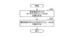
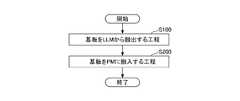
図14を参照し、真空搬送ロボットTR1,TR2の位置合わせ方法の一例について説明する。図14に示されるように、真空搬送ロボットTR1,TR2の位置合わせ方法では、まず、工程S40において、真空搬送ロボットTR1,TR2とロードロックモジュールLL1,LL2との位置合わせを行う。次いで、工程S50において、真空搬送ロボットTR1,TR2とプロセスモジュールPM1~PM12との位置合わせを行う。(Positioning of the vacuum transfer robot)
An example of the alignment method of the vacuum transfer robots TR1 and TR2 will be described with reference to FIG. As shown in FIG. 14, in the method of aligning the vacuum transfer robots TR1 and TR2, first, in step S40, the vacuum transfer robots TR1 and TR2 and the load lock modules LL1 and LL2 are aligned. Next, in step S50, the vacuum transfer robots TR1 and TR2 and the process modules PM1 to PM12 are aligned.
図15を参照し、真空搬送ロボットTR1のフォークFK11とロードロックモジュールLL1との位置合わせ(工程S40)の一例について説明する。なお、工程S40の開始時において、ロードロックモジュールLL1の所定位置(例えば中心位置)にセンサウエハが設置されているものとする。 An example of alignment (step S40) between the fork FK11 of the vacuum transfer robot TR1 and the load lock module LL1 will be described with reference to FIG. It is assumed that the sensor wafer is installed at a predetermined position (for example, the central position) of the load lock module LL1 at the start of step S40.
ステップS41において、制御部CUは、フォークFK11によりロードロックモジュールLL1の所定位置(例えば中心位置)に設置されたセンサウエハを取得するように、真空搬送ロボットTR1を制御する。 In step S41, the control unit CU controls the vacuum transfer robot TR1 so as to obtain the sensor wafer placed at a predetermined position (for example, center position) of the load lock module LL1 by the fork FK11.
ステップS42において、制御部CUは、フォークFK11とセンサウエハとの相対位置を算出する。例えば、制御部CUは、センサウエハに設けられた静電容量センサCSの検出値に基づいて、フォークFK11とセンサウエハとの相対位置を算出する。ただし、制御部CUは、センサウエハに設けられた位置検出センサPS1~PS6の検出値に基づいて、フォークFK11とセンサウエハとの相対位置を算出してもよい。 At step S42, the control unit CU calculates the relative position between the fork FK11 and the sensor wafer. For example, the control unit CU calculates the relative position between the fork FK11 and the sensor wafer based on the detection value of the capacitance sensor CS provided on the sensor wafer. However, the control unit CU may calculate the relative position between the fork FK11 and the sensor wafer based on the detection values of the position detection sensors PS1 to PS6 provided on the sensor wafer.
ステップS43において、制御部CUは、算出したフォークFK11とセンサウエハとの相対位置が基準値内であるか否かを判定する。ステップS43において、相対位置が基準値内である場合、制御部CUは処理をステップS47へ進める。一方、ステップS43において、相対位置が基準値内でない場合、制御部CUは、相対位置が基準値内となるように教示位置の補正を行い、処理をステップS43へ進める。 In step S43, the control unit CU determines whether or not the calculated relative position between the fork FK11 and the sensor wafer is within a reference value. In step S43, if the relative position is within the reference value, the control unit CU advances the process to step S47. On the other hand, if the relative position is not within the reference value in step S43, the control unit CU corrects the taught position so that the relative position is within the reference value, and advances the process to step S43.
ステップS44において、制御部CUは、フォークFK11によりセンサウエハをロードロックモジュールLL1に戻すように、真空搬送ロボットTR1を制御する。 In step S44, the control unit CU controls the vacuum transfer robot TR1 to return the sensor wafer to the load lock module LL1 by the fork FK11.
ステップS45において、制御部CUは、相対位置の検出結果に基づいて、フォークFK11とロードロックモジュールLL1との間の水平方向の位置ずれ量を算出する。また、制御部CUは、算出した位置ずれ量に基づいて、X軸の教示位置及びY軸の教示位置を補正する。 In step S45, the control unit CU calculates the amount of horizontal positional deviation between the fork FK11 and the load lock module LL1 based on the relative position detection result. Further, the control unit CU corrects the X-axis teaching position and the Y-axis teaching position based on the calculated positional deviation amount.
ステップS46において、制御部CUは、補正された位置でフォークFK11によりロードロックモジュールLL1からセンサウエハを取得するように、真空搬送ロボットTR1を制御する。 In step S46, the control unit CU controls the vacuum transfer robot TR1 so as to acquire the sensor wafer from the load lock module LL1 with the fork FK11 at the corrected position.
ステップS47において、制御部CUは、フォークFK11によりセンサウエハを所定の回収位置に搬送するように、真空搬送ロボットTR1を制御する。所定の回収位置は、ロードロックモジュールLL1等であってよい。センサウエハが回収された後、制御部CUは処理を終了させる。 In step S47, the control unit CU controls the vacuum transfer robot TR1 so that the fork FK11 transfers the sensor wafer to a predetermined recovery position. The predetermined collection position may be the load lock module LL1 or the like. After the sensor wafer is recovered, the control unit CU terminates the process.
以上、真空搬送ロボットTR1のフォークFK11とロードロックモジュールLL1との位置合わせの一例について説明したが、ロードロックモジュールLL2についてもロードロックモジュールLL1と同様の方法により位置合わせできる。 An example of alignment between the fork FK11 of the vacuum transfer robot TR1 and the load lock module LL1 has been described above.
図16を参照し、真空搬送ロボットTR1のフォークFK11とプロセスモジュールPM1との位置合わせ(工程S50)の一例について説明する。なお、工程S50の開始時において、ロードロックモジュールLL1の所定位置(例えば中心位置)にセンサウエハが設置されているものとする。 An example of alignment (step S50) between the fork FK11 of the vacuum transfer robot TR1 and the process module PM1 will be described with reference to FIG. It is assumed that the sensor wafer is installed at a predetermined position (for example, the center position) of the load lock module LL1 at the start of step S50.
ステップS51において、制御部CUは、フォークFK11によりプロセスモジュールPM1にセンサウエハを設置するように、真空搬送ロボットTR1を制御する。 In step S51, the control unit CU controls the vacuum transfer robot TR1 to set the sensor wafer on the process module PM1 by the fork FK11.
ステップS52において、制御部CUは、プロセスモジュールPM1内の部品(例えば静電チャック、エッジリング)とセンサウエハとの相対位置を算出する。例えば、制御部CUは、センサウエハに設けられた位置検出センサPS1~PS6の検出値に基づいて、プロセスモジュールPM1内の部品とセンサウエハとの相対位置を算出する。ただし、制御部CUは、センサウエハに設けられた静電容量センサCSの検出値に基づいて、プロセスモジュールPM1内の部品とセンサウエハとの相対位置を算出してもよい。 In step S52, the control unit CU calculates the relative positions of the parts (for example, electrostatic chuck, edge ring) in the process module PM1 and the sensor wafer. For example, the control unit CU calculates the relative positions of the components in the process module PM1 and the sensor wafer based on the detection values of the position detection sensors PS1 to PS6 provided on the sensor wafer. However, the control unit CU may calculate the relative position between the components in the process module PM1 and the sensor wafer based on the detection value of the capacitance sensor CS provided on the sensor wafer.
ステップS53において、制御部CUは、算出したプロセスモジュールPM1とセンサウエハとの相対位置が基準値内であるか否かを判定する。ステップS53において、相対位置が基準値内である場合、制御部CUは処理をステップS57へ進める。一方、ステップS53において、相対位置が基準値内でない場合、制御部CUは、相対位置が基準値内となるように教示位置の補正を行い、処理をステップS54へ進める。 In step S53, the control unit CU determines whether or not the calculated relative position between the process module PM1 and the sensor wafer is within a reference value. In step S53, if the relative position is within the reference value, the control unit CU advances the process to step S57. On the other hand, if the relative position is not within the reference value in step S53, the control unit CU corrects the taught position so that the relative position is within the reference value, and advances the process to step S54.
ステップS54において、制御部CUは、補正された位置でフォークFK11によりプロセスモジュールPM1からセンサウエハを取得するように、真空搬送ロボットTR1を制御する。 In step S54, the control unit CU controls the vacuum transfer robot TR1 so as to pick up the sensor wafer from the process module PM1 with the fork FK11 at the corrected position.
ステップS55において、制御部CUは、フォークFK11が取得したセンサウエハをプロセスモジュールPM1に戻すように、真空搬送ロボットTR1を制御する。 In step S55, the control unit CU controls the vacuum transfer robot TR1 so as to return the sensor wafer acquired by the fork FK11 to the process module PM1.
ステップS56において、制御部CUは、プロセスモジュールPM1内の部品(例えば静電チャック、エッジリング)とセンサウエハとの相対位置を算出する。例えば、制御部CUは、センサウエハに設けられた位置検出センサPS1~PS6の検出値に基づいて、プロセスモジュールPM1内の部品とセンサウエハとの相対位置を算出する。ただし、制御部CUは、センサウエハに設けられた静電容量センサCSの検出値に基づいて、プロセスモジュールPM1内の部品とセンサウエハとの相対位置を算出してもよい。制御部CUは、相対位置を算出した後、処理をステップS53に戻す。 In step S56, the control unit CU calculates the relative positions of the parts (for example, electrostatic chuck, edge ring) in the process module PM1 and the sensor wafer. For example, the control unit CU calculates the relative positions of the components in the process module PM1 and the sensor wafer based on the detection values of the position detection sensors PS1 to PS6 provided on the sensor wafer. However, the control unit CU may calculate the relative position between the components in the process module PM1 and the sensor wafer based on the detection value of the capacitance sensor CS provided on the sensor wafer. After calculating the relative position, the control unit CU returns the process to step S53.
ステップS57において、制御部CUは、フォークFK11によりセンサウエハを所定の回収位置に搬送するように、真空搬送ロボットTR1を制御する。所定の回収位置は、ロードロックモジュールLL1等であってよい。センサウエハが回収された後、制御部CUは処理を終了させる。 In step S57, the control unit CU controls the vacuum transfer robot TR1 so that the fork FK11 transfers the sensor wafer to a predetermined recovery position. The predetermined collection position may be the load lock module LL1 or the like. After the sensor wafer is recovered, the control unit CU terminates the process.
以上、真空搬送ロボットTR1のフォークFK11とプロセスモジュールPM1との位置合わせの一例について説明したが、プロセスモジュールPM2~PM6についてもプロセスモジュールPM1と同様の方法により位置合わせできる。 An example of alignment between the fork FK11 of the vacuum transfer robot TR1 and the process module PM1 has been described above.
以上に説明したように、実施形態によれば、静電容量センサがフォークと基板との相対位置を配置情報として制御部に出力し、制御部が該配置情報に基づいて基板に対するフォークの教示位置を決定する。これにより、フォークと基板との間の位置合わせを自動で調整できる。 As described above, according to the embodiment, the capacitance sensor outputs the relative position between the fork and the board to the control unit as arrangement information, and the control unit teaches the position of the fork relative to the board based on the arrangement information. to decide. This allows automatic adjustment of the alignment between the fork and the substrate.
なお、図8~図16を用いて実施形態の位置合わせ方法を例示したが、位置合わせ方法の具体的手法は必ずしもこれらのフローチャートに示したものに限定されない。 Although the alignment method of the embodiment has been illustrated using FIGS. 8 to 16, the specific technique of the alignment method is not necessarily limited to those shown in these flow charts.
上記の実施形態では、フォークと搬送対象物との相対位置を検出するセンサとして静電容量センサを利用する場合を説明したが、該センサの種類はこれに限定されない。例えば、静電容量センサに代えて、光学センサ、磁力センサ等の非接触式センサ、カメラ等を利用してもよい。光学センサは、LED(light emitting diode)センサでもよい。カメラは、例えばCCDカメラである。 In the above embodiment, the case of using the capacitance sensor as the sensor for detecting the relative position between the fork and the object to be conveyed has been described, but the type of sensor is not limited to this. For example, instead of the capacitance sensor, an optical sensor, a non-contact sensor such as a magnetic force sensor, a camera, or the like may be used. The optical sensor may be an LED (light emitting diode) sensor. The camera is for example a CCD camera.
カメラを用いることによって、基板Wやエンドエフェクタの位置精度が向上する効果および経時変化を観察できる効果が奏される。また、カメラを用いることによって、プラズマ処理チャンバ10の内部全体を観察できる。カメラは、静電容量センサと同じ位置に設置してもよく、エンドエフェクタの根元に設置してもよい。カメラは、エンドエフェクタの上面と下面の両方に設置してもよいし、いずれか一方に設置してもよい。カメラを用いると、下部電極(チャック)の溝や穴を目印にして、エンドエフェクタを位置合わせすることもできる。 By using a camera, the effect of improving the positional accuracy of the substrate W and the end effector and the effect of being able to observe changes over time are achieved. Also, by using a camera, the entire interior of the
フォークにカメラが設けられる場合、後の基板Wのプラズマ処理に際して付着したデポが剥離、飛散しないように、当該後の基板Wに対するプラズマ処理の条件(例えばプラズマ処理チャンバ10の内部圧力や処理ガス流量、RF信号のパワー等)を制御することができる。 When a camera is provided on the fork, the plasma processing conditions for the subsequent substrate W (for example, the internal pressure of the
具体的には、例えばプラズマ処理チャンバ10からの先の基板Wの搬出時において、カメラによりプラズマ処理チャンバ10の壁面や基板支持部11の表面を撮像する。そして、撮像により得られたプラズマ処理チャンバ10の内部におけるデポの付着状態と予め定められた基準となるデポの付着状態との変化量に基づいて後の基板Wに対するプラズマ処理の条件を最適化し、後の基板Wのプラズマ処理に際してデポの剥離や飛散の発生を抑制する。 Specifically, for example, when the previous substrate W is unloaded from the
なお、上述した「基準となるデポの付着状態」としては、例えば先の基板Wの搬出時の撮像結果を用いてもよいし、例えばプラズマ処理チャンバ10のセットアップ等に際して任意に決定された状態を用いてもよい。 As the above-mentioned "deposition state of deposition serving as a reference", for example, the imaging result when the substrate W was unloaded may be used, or a state arbitrarily determined when setting up the
なお、カメラによる撮像面は、例えば基板Wに対するプラズマ処理の条件に応じて適宜決定することができ、プラズマ処理チャンバ10の内部の側壁面や天井面、又は基板支持部11の上面や側面等から選択的に撮像してもよい。例えばプラズマ処理の条件によりデポの付着しやすい面が既知である場合には、当該デポの付着しやすい一面のみを撮像してもよいし、又は複数面を撮像してもよい。この時、プラズマ処理チャンバ10の天井面を撮像する場合にあっては、カメラはフォーク上に保持される基板Wとは干渉しない位置に設けられることが望ましい。 The imaging surface of the camera can be appropriately determined according to the plasma processing conditions for the substrate W, for example. You may image selectively. For example, if the surface on which deposits are likely to adhere is known depending on the plasma processing conditions, only one surface on which deposits are likely to adhere may be imaged, or a plurality of surfaces may be imaged. At this time, when imaging the ceiling surface of the
また、フォークに対するカメラの設置数も特に限定されるものではなく、複数のカメラが設置されていてもよいし、一のカメラがプラズマ処理チャンバ10内の複数面を撮像可能に構成されていてもよい。 In addition, the number of cameras installed on the fork is not particularly limited, and a plurality of cameras may be installed, or one camera may be configured to image multiple surfaces in the
なお、以上の説明においては基準の付着状態からの変化量に応じて、後の基板Wに対するプラズマ処理条件を変化させたが、例えばプラズマ処理チャンバ10の内部におけるデポの付着量が多い場合には、後の基板Wに対するプラズマ処理に先立ってドライクリーニング処理、すなわちデポの除去処理を行うように制御してもよい。また係る場合、デポの付着量に応じてドライクリーニング処理の条件(例えばクリーニングガスの流量やクリーニング時間等)の調整を行うようにしてもよい。 In the above description, the plasma processing conditions for the subsequent substrate W were changed according to the amount of change from the reference deposition state. , the dry cleaning process, that is, the deposit removal process may be performed prior to the subsequent plasma process on the substrate W. FIG. In such a case, the conditions of the dry cleaning process (for example, the flow rate of the cleaning gas, the cleaning time, etc.) may be adjusted according to the deposit amount.
なお、以上の説明においては、プラズマ処理チャンバ10からの先の基板Wの搬出時においてプラズマ処理チャンバ10の内部を撮像する場合を例に説明を行ったが、基板Wの搬出とは独立してフォークをプラズマ処理チャンバ10の内部に進入させ、デポの撮像を行ってもよい。 In the above description, the case where the inside of the
上記の実施形態では、基板が半導体ウエハである場合を説明したが、本開示はこれに限定されない。例えば、基板は、LCD(Liquid Crystal Display)、FPD(Flat Panel Display)に用いられる各種基板、CD基板、プリント基板等であっても良い。 Although the above embodiments describe the case where the substrate is a semiconductor wafer, the present disclosure is not limited to this. For example, the substrate may be various substrates used in LCDs (Liquid Crystal Displays), FPDs (Flat Panel Displays), CD substrates, printed substrates, and the like.
<第2の実施形態>
〔処理システム〕
図1を参照し、実施形態の処理システムの一例について説明する。図1に示されるように、処理システムPSは、基板にプラズマ処理等の各種処理を施すことが可能なシステムである。<Second embodiment>
[Processing system]
An example of a processing system according to an embodiment will be described with reference to FIG. As shown in FIG. 1, the processing system PS is a system capable of performing various types of processing such as plasma processing on substrates.
処理システムPSは、真空搬送モジュールTM1,TM2、プロセスモジュールPM1~PM12、ロードロックモジュールLL1,LL2、大気搬送モジュールLM、アライナAN、ストレージSR等を備える。 The processing system PS includes vacuum transfer modules TM1, TM2, process modules PM1 to PM12, load lock modules LL1, LL2, atmospheric transfer module LM, aligner AN, storage SR, and the like.
真空搬送モジュールTM1,TM2は、それぞれ平面視において略四角形状を有する。真空搬送モジュールTM1は、対向する2つの側面にプロセスモジュールPM1~PM6が接続されている。真空搬送モジュールTM1の他の対向する2つの側面のうち、一方の側面にはロードロックモジュールLL1,LL2が接続され、他方の側面には真空搬送モジュールTM2と接続するためのパス(図示せず)が接続されている。真空搬送モジュールTM1のロードロックモジュールLL1,LL2が接続される側面は、2つのロードロックモジュールLL1,LL2に応じて角度が付けられている。真空搬送モジュールTM2は、対向する2つの側面にプロセスモジュールPM7~PM12が接続されている。真空搬送モジュールTM2の他の対向する2つの側面のうち、一方の側面には真空搬送モジュールTM1と接続するためのパス(図示せず)が接続されている。真空搬送モジュールTM1,TM2は、真空雰囲気の真空室を有し、内部にそれぞれ真空搬送ロボットTR1,TR2が配置されている。 The vacuum transfer modules TM1 and TM2 each have a substantially rectangular shape in plan view. The vacuum transfer module TM1 has process modules PM1 to PM6 connected to two opposing sides thereof. Of the other two opposing sides of the vacuum transfer module TM1, one side is connected to the load lock modules LL1 and LL2, and the other side is a path (not shown) for connecting to the vacuum transfer module TM2. is connected. The sides of the vacuum transfer module TM1 to which the loadlock modules LL1, LL2 are connected are angled according to the two loadlock modules LL1, LL2. The vacuum transfer module TM2 has process modules PM7 to PM12 connected to two opposing sides thereof. A path (not shown) for connecting with the vacuum transfer module TM1 is connected to one side of the other two opposing sides of the vacuum transfer module TM2. The vacuum transfer modules TM1 and TM2 have vacuum chambers with a vacuum atmosphere, and vacuum transfer robots TR1 and TR2 are arranged therein, respectively.
真空搬送ロボットTR1,TR2は、旋回、伸縮、昇降自在に構成されている。真空搬送ロボットTR1,TR2は、後述する制御部CUが出力する動作指示に基づいて搬送対象物を搬送する。例えば、真空搬送ロボットTR1は、アームAR11、AR12の先端にそれぞれ配置されたエンドエフェクタFK11,FK12で搬送対象物を保持し、ロードロックモジュールLL1,LL2、プロセスモジュールPM1~PM6及びパス(図示せず)の間で搬送対象物を搬送する。例えば、真空搬送ロボットTR2は、アームAR21、AR22の先端にそれぞれ配置されたエンドエフェクタFK21,FK22で搬送対象物を保持し、プロセスモジュールPM7~PM12及びパス(図示せず)の間で搬送対象物を搬送する。なお、エンドエフェクタは、フォーク、ピックとも称される。 The vacuum transfer robots TR1 and TR2 are configured to be able to turn, extend and retract, and move up and down. The vacuum transport robots TR1 and TR2 transport objects to be transported based on operation instructions output by a control unit CU, which will be described later. For example, the vacuum transfer robot TR1 holds an object to be transferred by end effectors FK11 and FK12 arranged at the tips of arms AR11 and AR12, respectively, and includes load lock modules LL1 and LL2, process modules PM1 to PM6 and paths (not shown). ) to convey the object to be conveyed. For example, the vacuum transfer robot TR2 holds an object to be transferred by end effectors FK21 and FK22 arranged at the tips of arms AR21 and AR22, respectively, and holds the object to be transferred between process modules PM7 to PM12 and a path (not shown). to convey. Note that the end effector is also called a fork or a pick.
搬送対象物は、基板及び消耗部材を含む。基板は、例えば半導体ウエハ、センサウエハである。消耗部材は、プロセスモジュールPM1~PM12内に交換可能に取り付けられる部材であり、プロセスモジュールPM1~PM12内でプラズマ処理等の各種の処理が行われることで消耗する部材である。消耗部材は、例えば後述するリングアセンブリ112、シャワーヘッド13を構成する部材を含む。 Objects to be transported include substrates and consumables. The substrate is, for example, a semiconductor wafer, a sensor wafer. A consumable member is a member that is replaceably attached in the process modules PM1 to PM12, and is a member that is consumed when various processes such as plasma processing are performed in the process modules PM1 to PM12. Consumable members include, for example, a
プロセスモジュールPM1~PM12は、処理室を有し、内部に配置されたステージ(載置台)を有する。プロセスモジュールPM1~PM12は、ステージに基板が設置された後、内部を減圧して処理ガスを導入し、RF電力を印加してプラズマを生成し、プラズマによって基板にプラズマ処理を施す。真空搬送モジュールTM1,TM2とプロセスモジュールPM1~PM12とは、開閉自在なゲートバルブG1で仕切られている。 Each of the process modules PM1 to PM12 has a processing chamber and a stage (mounting table) arranged therein. After the substrate is placed on the stage, the process modules PM1 to PM12 depressurize the interior, introduce a processing gas, apply RF power to generate plasma, and perform plasma processing on the substrate with the plasma. The vacuum transfer modules TM1, TM2 and the process modules PM1 to PM12 are partitioned by an openable/closable gate valve G1.
ロードロックモジュールLL1,LL2は、真空搬送モジュールTM1と大気搬送モジュールLMとの間に配置されている。ロードロックモジュールLL1,LL2は、内部を真空、大気圧に切り換え可能な内圧可変室を有する。ロードロックモジュールLL1,LL2は、内部に配置されたステージを有する。ロードロックモジュールLL1,LL2は、基板を大気搬送モジュールLMから真空搬送モジュールTM1へ搬入する際、内部を大気圧に維持して大気搬送モジュールLMから基板を受け取り、内部を減圧して真空搬送モジュールTM1へ基板を搬入する。ロードロックモジュールLL1,LL2は、基板を真空搬送モジュールTM1から大気搬送モジュールLMへ搬出する際、内部を真空に維持して真空搬送モジュールTM1から基板を受け取り、内部を大気圧まで昇圧して大気搬送モジュールLMへ基板を搬入する。ロードロックモジュールLL1,LL2と真空搬送モジュールTM1とは、開閉自在なゲートバルブG2で仕切られている。ロードロックモジュールLL1,LL2と大気搬送モジュールLMとは、開閉自在なゲートバルブG3で仕切られている。 The load lock modules LL1 and LL2 are arranged between the vacuum transfer module TM1 and the atmosphere transfer module LM. The load lock modules LL1 and LL2 have internal pressure variable chambers that can be switched between vacuum and atmospheric pressure. The load lock modules LL1, LL2 have stages arranged therein. When a substrate is transferred from the atmospheric transfer module LM to the vacuum transfer module TM1, the load lock modules LL1 and LL2 receive the substrate from the atmospheric transfer module LM while maintaining the inside at atmospheric pressure, depressurize the inside, and transfer the substrate to the vacuum transfer module TM1. Carry in the board to When a substrate is unloaded from the vacuum transfer module TM1 to the atmospheric transfer module LM, the load lock modules LL1 and LL2 receive the substrate from the vacuum transfer module TM1 while keeping the inside vacuum, pressurize the inside to the atmospheric pressure, and transfer the substrate in the atmosphere. A substrate is loaded into the module LM. The load lock modules LL1 and LL2 and the vacuum transfer module TM1 are partitioned by an openable/closable gate valve G2. The load-lock modules LL1, LL2 and the atmosphere transfer module LM are partitioned by an openable/closable gate valve G3.
大気搬送モジュールLMは、真空搬送モジュールTM1に対向して配置されている。大気搬送モジュールLMは、例えばEFEM(Equipment Front End Module)であってよい。大気搬送モジュールLMは、直方体状であり、FFU(Fan Filter Unit)を備え、大気圧雰囲気に保持された大気搬送室である。大気搬送モジュールLMの長手方向に沿った一の側面には、2つのロードロックモジュールLL1,LL2が接続されている。大気搬送モジュールLMの長手方向に沿った他の側面には、ロードポートLP1~LP4が接続されている。ロードポートLP1~LP4には、複数(例えば25枚)の基板を収容する容器Cが載置される。容器Cは、例えばFOUP(Front-Opening Unified Pod)であってよい。大気搬送モジュールLM内には、搬送対象物を搬送する大気搬送ロボットTR3が配置されている。 The atmospheric transfer module LM is arranged to face the vacuum transfer module TM1. The atmospheric transfer module LM may be, for example, an EFEM (Equipment Front End Module). The atmospheric transfer module LM is an atmospheric transfer chamber having a rectangular parallelepiped shape, equipped with an FFU (Fan Filter Unit), and maintained in an atmosphere of atmospheric pressure. Two load lock modules LL1 and LL2 are connected to one side surface along the longitudinal direction of the atmospheric transfer module LM. Load ports LP1 to LP4 are connected to other side surfaces along the longitudinal direction of the atmospheric transfer module LM. A container C containing a plurality of (for example, 25) substrates is placed on the load ports LP1 to LP4. The container C may be, for example, a FOUP (Front-Opening Unified Pod). In the atmospheric transfer module LM, an atmospheric transfer robot TR3 for transferring an object to be transferred is arranged.
大気搬送ロボットTR3は、大気搬送モジュールLMの長手方向に沿って移動可能に構成されると共に、旋回、伸縮、昇降自在に構成されている。大気搬送ロボットTR3は、後述する制御部CUが出力する動作指示に基づいて搬送対象物を搬送する。例えば、大気搬送ロボットTR3は、アームAR31の先端に配置されたエンドエフェクタFK31で搬送対象物を保持し、ロードポートLP1~LP4、ロードロックモジュールLL1,LL2、アライナAN及びストレージSRの間で搬送対象物を搬送する。 The atmospheric transfer robot TR3 is configured to be movable along the longitudinal direction of the atmospheric transfer module LM, and is configured to be able to rotate, extend and retract, and ascend and descend. The atmospheric transport robot TR3 transports an object to be transported based on an operation instruction output by a control unit CU, which will be described later. For example, the atmospheric transport robot TR3 holds an object to be transported by an end effector FK31 arranged at the tip of an arm AR31, and transports the object between load ports LP1 to LP4, load lock modules LL1 and LL2, aligner AN, and storage SR. transport things.
アライナANは、大気搬送モジュールLMの短手方向に沿った一の側面に接続されている。ただし、アライナANは、大気搬送モジュールLMの長手方向に沿った側面に接続されていてもよい。また、アライナANは、大気搬送モジュールLMの内部に設けられていてもよい。アライナANは、支持台、光学センサ(いずれも図示せず)等を有する。ここでいうアライナとは、搬送対象物の位置を検出する装置である。 The aligner AN is connected to one lateral side of the atmospheric transfer module LM. However, the aligner AN may be connected to the side surface along the longitudinal direction of the atmospheric transfer module LM. Also, the aligner AN may be provided inside the atmospheric transfer module LM. The aligner AN has a support base, an optical sensor (none of which is shown), and the like. The aligner here is a device that detects the position of the object to be conveyed.
支持台は、鉛直方向に延びる軸線中心に回転可能な台であり、その上に基板を支持するように構成されている。支持台は、駆動装置(図示せず)によって回転される。駆動装置は、後述する制御部CUによって制御される。駆動装置からの動力により支持台が回転すると、当該支持台の上に設置された基板も回転するようになっている。 The support base is a base rotatable about an axis extending in the vertical direction, and is configured to support the substrate thereon. The support base is rotated by a drive (not shown). The driving device is controlled by a control unit CU, which will be described later. When the support table is rotated by power from the driving device, the substrate placed on the support table is also rotated.
光学センサは、基板が回転する間、基板のエッジを検出する。光学センサは、エッジの検出結果から、基準角度位置に対する基板のノッチ(或いは、別のマーカー)の角度位置のずれ量、及び、基準位置に対する基板の中心位置のずれ量を検出する。光学センサは、ノッチの角度位置のずれ量及び基板の中心位置のずれ量を後述する制御部CUに出力する。制御部CUは、ノッチの角度位置のずれ量に基づき、ノッチの角度位置を基準角度位置に補正するための回転支持台の回転量を算出する。制御部CUは、この回転量の分だけ回転支持台を回転させるよう、駆動装置(図示せず)を制御する。これにより、ノッチの角度位置を基準角度位置に補正することができる。また、制御部CUは、大気搬送ロボットTR3のエンドエフェクタFK31上の所定位置に基板の中心位置が一致するよう、アライナANから基板を受け取る際の大気搬送ロボットTR3のエンドエフェクタFK31の位置を、基板の中心位置のずれ量に基づき、制御する。 An optical sensor detects the edge of the substrate while the substrate rotates. The optical sensor detects the amount of deviation of the notch (or another marker) of the substrate from the reference angular position and the amount of deviation of the center position of the substrate from the reference position from the edge detection result. The optical sensor outputs the deviation amount of the angular position of the notch and the deviation amount of the center position of the substrate to the control unit CU, which will be described later. Based on the deviation amount of the notch angular position, the control unit CU calculates the rotation amount of the rotary support base for correcting the notch angular position to the reference angular position. The control unit CU controls a driving device (not shown) so as to rotate the rotary support by this amount of rotation. Thereby, the angular position of the notch can be corrected to the reference angular position. Further, the control unit CU adjusts the position of the end effector FK31 of the atmospheric transfer robot TR3 when receiving the substrate from the aligner AN so that the central position of the substrate coincides with a predetermined position on the end effector FK31 of the atmospheric transfer robot TR3. is controlled based on the deviation amount of the center position of .
ストレージSRは、大気搬送モジュールLMの長手方向に沿った側面に接続されている。ただし、ストレージSRは、大気搬送モジュールLMの短手方向に沿った側面に接続されていてもよい。また、ストレージSRは、大気搬送モジュールLMの内部に設けられていてもよい。ストレージSRは、搬送対象物を収容する。 The storage SR is connected to the side along the longitudinal direction of the atmospheric transfer module LM. However, the storage SR may be connected to the lateral side of the atmospheric transfer module LM along the lateral direction. Also, the storage SR may be provided inside the atmospheric transfer module LM. The storage SR accommodates objects to be transferred.
処理システムPSには、制御部CUが設けられている。制御部CUは、例えばコンピュータであってよい。制御部CUは、CPU(Central Processing Unit)、RAM(Random Access Memory)、ROM(Read Only Memory)、補助記憶装置等を備える。CPUは、ROM又は補助記憶装置に格納されたプログラムに基づいて動作し、処理システムPSの各部を制御する。例えば、制御部CUは、動作指示を真空搬送ロボットTR1,TR2、大気搬送ロボットTR3等に出力する。動作指示は、搬送対象物を搬送するエンドエフェクタFK11,FK12,FK21,FK22,FK31と、搬送対象物の搬送場所との位置合わせの指示を含む。 The processing system PS is provided with a control unit CU. The control unit CU may be, for example, a computer. The control unit CU includes a CPU (Central Processing Unit), a RAM (Random Access Memory), a ROM (Read Only Memory), an auxiliary storage device, and the like. The CPU operates based on programs stored in the ROM or auxiliary storage device, and controls each part of the processing system PS. For example, the control unit CU outputs operation instructions to the vacuum transfer robots TR1 and TR2, the atmospheric transfer robot TR3, and the like. The operation instruction includes an instruction to align the end effectors FK11, FK12, FK21, FK22, and FK31 that convey the object to be conveyed with the conveying location of the object to be conveyed.
〔プラズマ処理システム〕
図2を参照し、プロセスモジュールPM1~PM12のいずれかとして採用され得るプラズマ処理システムの一例について説明する。[Plasma processing system]
An example of a plasma processing system that can be employed as any of the process modules PM1-PM12 will be described with reference to FIG.
一実施形態において、プラズマ処理システムは、プラズマ処理装置1及びプラズマ処理制御部2を含む。プラズマ処理装置1は、プラズマ処理チャンバ10、基板支持部11及びプラズマ生成部12を含む。プラズマ処理チャンバ10は、プラズマ処理空間を有する。また、プラズマ処理チャンバ10は、少なくとも1つの処理ガスをプラズマ処理空間に供給するための少なくとも1つのガス供給口と、プラズマ処理空間からガスを排出するための少なくとも1つのガス排出口とを有する。ガス供給口は、後述するガス供給部20に接続され、ガス排出口は、後述する排気システム40に接続される。基板支持部11は、プラズマ処理空間内に配置され、基板を支持するための基板支持面を有する。 In one embodiment, the plasma processing system includes a plasma processing apparatus 1 and a
プラズマ生成部12は、プラズマ処理空間内に供給された少なくとも1つの処理ガスからプラズマを生成するように構成される。プラズマ処理空間において形成されるプラズマは、容量結合プラズマ(CCP;Capacitively Coupled Plasma)、誘導結合プラズマ(ICP;Inductively Coupled Plasma)、ECRプラズマ(Electron-Cyclotron-resonance plasma)、ヘリコン波励起プラズマ(HWP:Helicon Wave Plasma)、又は、表面波プラズマ(SWP:Surface Wave Plasma)等であってもよい。また、AC(Alternating Current)プラズマ生成部及びDC(Direct Current)プラズマ生成部を含む、種々のタイプのプラズマ生成部が用いられてもよい。一実施形態において、ACプラズマ生成部で用いられるAC信号(AC電力)は、100kHz~10GHzの範囲内の周波数を有する。従って、AC信号は、RF(Radio Frequency)信号及びマイクロ波信号を含む。一実施形態において、RF信号は、200kHz~150MHzの範囲内の周波数を有する。 The
プラズマ処理制御部2は、本開示において述べられる種々の工程をプラズマ処理装置1に実行させるコンピュータ実行可能な命令を処理する。プラズマ処理制御部2は、ここで述べられる種々の工程を実行するようにプラズマ処理装置1の各要素を制御するように構成され得る。一実施形態において、プラズマ処理制御部2の一部又は全てがプラズマ処理装置1に含まれてもよい。プラズマ処理制御部2は、例えばコンピュータ2aを含んでもよい。コンピュータ2aは、例えば、処理部(CPU:Central Processing Unit)2a1、記憶部2a2、及び通信インターフェース2a3を含んでもよい。処理部2a1は、記憶部2a2に格納されたプログラムに基づいて種々の制御動作を行うように構成され得る。記憶部2a2は、RAM(Random Access Memory)、ROM(Read Only Memory)、HDD(Hard Disk Drive)、SSD(Solid State Drive)、又はこれらの組み合わせを含んでもよい。通信インターフェース2a3は、LAN(Local Area Network)等の通信回線を介してプラズマ処理装置1との間で通信してもよい。
図3を参照し、以下に、プラズマ処理装置1の一例としての容量結合プラズマ処理装置の構成例について説明する。 A configuration example of a capacitively-coupled plasma processing apparatus as an example of the plasma processing apparatus 1 will be described below with reference to FIG.
容量結合プラズマ処理装置1は、プラズマ処理チャンバ10、ガス供給部20、電源30及び排気システム40を含む。また、プラズマ処理装置1は、基板支持部11及びガス導入部を含む。ガス導入部は、少なくとも1つの処理ガスをプラズマ処理チャンバ10内に導入するように構成される。ガス導入部は、シャワーヘッド13を含む。基板支持部11は、プラズマ処理チャンバ10内に配置される。シャワーヘッド13は、基板支持部11の上方に配置される。一実施形態において、シャワーヘッド13は、プラズマ処理チャンバ10の天部(ceiling)の少なくとも一部を構成する。プラズマ処理チャンバ10は、シャワーヘッド13、プラズマ処理チャンバ10の側壁10a及び基板支持部11により規定されたプラズマ処理空間10sを有する。側壁10aは接地される。シャワーヘッド13及び基板支持部11は、プラズマ処理チャンバ10筐体とは電気的に絶縁される。 The capacitively coupled plasma processing apparatus 1 includes a
基板支持部11は、本体部111及びリングアセンブリ112を含む。本体部111は、基板(ウエハ)Wを支持するための中央領域(基板支持面)111aと、リングアセンブリ112を支持するための環状領域(リング支持面)111bとを有する。本体部111の環状領域111bは、平面視で本体部111の中央領域111aを囲んでいる。基板Wは、本体部111の中央領域111a上に配置され、リングアセンブリ112は、本体部111の中央領域111a上の基板Wを囲むように本体部111の環状領域111b上に配置される。一実施形態において、本体部111は、基台及び静電チャックを含む。基台は、導電性部材を含む。基台の導電性部材は下部電極として機能する。静電チャックは、基台の上に配置される。静電チャックの上面は、基板支持面111aを有する。リングアセンブリ112は、1又は複数の環状部材を含む。1又は複数の環状部材のうち少なくとも1つはエッジリングである。また、図示は省略するが、基板支持部11は、静電チャック、リングアセンブリ112及び基板のうち少なくとも1つをターゲット温度に調節するように構成される温調モジュールを含んでもよい。温調モジュールは、ヒータ、伝熱媒体、流路、又はこれらの組み合わせを含んでもよい。流路には、ブラインやガスのような伝熱流体が流れる。また、基板支持部11は、基板Wの裏面と基板支持面111aとの間に伝熱ガスを供給するように構成された伝熱ガス供給部を含んでもよい。 The
シャワーヘッド13は、ガス供給部20からの少なくとも1つの処理ガスをプラズマ処理空間10s内に導入するように構成される。シャワーヘッド13は、少なくとも1つのガス供給口13a、少なくとも1つのガス拡散室13b、及び複数のガス導入口13cを有する。ガス供給口13aに供給された処理ガスは、ガス拡散室13bを通過して複数のガス導入口13cからプラズマ処理空間10s内に導入される。また、シャワーヘッド13は、導電性部材を含む。シャワーヘッド13の導電性部材は上部電極として機能する。なお、ガス導入部は、シャワーヘッド13に加えて、側壁10aに形成された1又は複数の開口部に取り付けられる1又は複数のサイドガス注入部(SGI:Side Gas Injector)を含んでもよい。 The
ガス供給部20は、少なくとも1つのガスソース21及び少なくとも1つの流量制御器22を含んでもよい。一実施形態において、ガス供給部20は、少なくとも1つの処理ガスを、それぞれに対応のガスソース21からそれぞれに対応の流量制御器22を介してシャワーヘッド13に供給するように構成される。各流量制御器22は、例えばマスフローコントローラ又は圧力制御式の流量制御器を含んでもよい。さらに、ガス供給部20は、少なくとも1つの処理ガスの流量を変調又はパルス化する少なくとも1つの流量変調デバイスを含んでもよい。
電源30は、少なくとも1つのインピーダンス整合回路を介してプラズマ処理チャンバ10に結合されるRF電源31を含む。RF電源31は、ソースRF信号及びバイアスRF信号のような少なくとも1つのRF信号(RF電力)を、基板支持部11の導電性部材及び/又はシャワーヘッド13の導電性部材に供給するように構成される。これにより、プラズマ処理空間10sに供給された少なくとも1つの処理ガスからプラズマが形成される。従って、RF電源31は、プラズマ生成部12の少なくとも一部として機能し得る。また、バイアスRF信号を基板支持部11の導電性部材に供給することにより、基板Wにバイアス電位が発生し、形成されたプラズマ中のイオン成分を基板Wに引き込むことができる。
一実施形態において、RF電源31は、第1のRF生成部31a及び第2のRF生成部31bを含む。第1のRF生成部31aは、少なくとも1つのインピーダンス整合回路を介して基板支持部11の導電性部材及び/又はシャワーヘッド13の導電性部材に結合され、プラズマ生成用のソースRF信号(ソースRF電力)を生成するように構成される。一実施形態において、ソースRF信号は、13MHz~150MHzの範囲内の周波数を有する。一実施形態において、第1のRF生成部31aは、異なる周波数を有する複数のソースRF信号を生成するように構成されてもよい。生成された1又は複数のソースRF信号は、基板支持部11の導電性部材及び/又はシャワーヘッド13の導電性部材に供給される。第2のRF生成部31bは、少なくとも1つのインピーダンス整合回路を介して基板支持部11の導電性部材に結合され、バイアスRF信号(バイアスRF電力)を生成するように構成される。一実施形態において、バイアスRF信号は、ソースRF信号よりも低い周波数を有する。一実施形態において、バイアスRF信号は、400kHz~13.56MHzの範囲内の周波数を有する。一実施形態において、第2のRF生成部31bは、異なる周波数を有する複数のバイアスRF信号を生成するように構成されてもよい。生成された1又は複数のバイアスRF信号は、基板支持部11の導電性部材に供給される。また、種々の実施形態において、ソースRF信号及びバイアスRF信号のうち少なくとも1つがパルス化されてもよい。 In one embodiment, the
また、電源30は、プラズマ処理チャンバ10に結合されるDC電源32を含んでもよい。DC電源32は、第1のDC生成部32a及び第2のDC生成部32bを含む。一実施形態において、第1のDC生成部32aは、基板支持部11の導電性部材に接続され、第1のDC信号を生成するように構成される。生成された第1のDC信号は、基板支持部11の導電性部材に印加される。一実施形態において、第1のDC信号が、静電チャック内の電極のような他の電極に印加されてもよい。一実施形態において、第2のDC生成部32bは、シャワーヘッド13の導電性部材に接続され、第2のDC信号を生成するように構成される。生成された第2のDC信号は、シャワーヘッド13の導電性部材に印加される。種々の実施形態において、第1及び第2のDC信号がパルス化されてもよい。なお、第1及び第2のDC生成部32a,32bは、RF電源31に加えて設けられてもよく、第1のDC生成部32aが第2のRF生成部31bに代えて設けられてもよい。
排気システム40は、例えばプラズマ処理チャンバ10の底部に設けられたガス排出口10eに接続され得る。排気システム40は、圧力調整弁及び真空ポンプを含んでもよい。圧力調整弁によって、プラズマ処理空間10s内の圧力が調整される。真空ポンプは、ターボ分子ポンプ、ドライポンプ又はこれらの組み合わせを含んでもよい。 The
(実施形態の第1構成例)
実施形態の第1構成例に係る搬送装置170のエンドエフェクタ100について説明する。図17は、実施形態の第1構成例に係る搬送装置170のエンドエフェクタ100の上面図である。(First configuration example of the embodiment)
The
なお、図には、説明の便宜のためXYZ直交座標系が設定される場合がある。図面の紙面に対して垂直な座標軸については、座標軸の丸の中にバツ印は紙面に対して奥の方向が正、丸の中に黒丸印は紙面に対して手前側が正であることを表している。ただし、当該座標系は、説明のために定めるものであって、エンドエフェクタ等の姿勢について限定するものではない。 Note that an XYZ orthogonal coordinate system may be set in the drawing for convenience of explanation. Regarding the coordinate axes that are perpendicular to the plane of the drawing, crosses in the circles of the coordinate axes indicate that the back side of the page is positive, and black circles in the circles indicate that the front side of the page is positive. ing. However, the coordinate system is defined for explanation and does not limit the attitude of the end effector or the like.
なお、本開示では、特に説明しない限り、X軸及びY軸はエンドエフェクタの載置面に平行な方向の軸とする。Y軸は、エンドエフェクタの先端部が延びる方向の軸とする。X軸は、Y軸に垂直な軸とする。Z軸は、当該X軸、Y軸に垂直な方向の軸とする。なお、Z軸方向を上下方向という場合がある。 In the present disclosure, unless otherwise specified, the X-axis and the Y-axis are parallel to the mounting surface of the end effector. The Y-axis is the axis in the direction in which the tip of the end effector extends. Let the X-axis be an axis perpendicular to the Y-axis. The Z-axis is an axis perpendicular to the X-axis and the Y-axis. Note that the Z-axis direction may be referred to as the vertical direction.
搬送装置170は、例えば、真空搬送ロボットTR1、真空搬送ロボットTR2及び大気搬送ロボットTR3の少なくともいずれか一つを示す。搬送装置170は、基板W及びプラズマ処理装置1(基板処理装置)内に設けられる消耗部品を搬送する。 The
搬送装置170は、エンドエフェクタ100と、アーム160と、制御装置150と、を備える。 The
エンドエフェクタ100は、例えば、エンドエフェクタFK11、エンドエフェクタFK12、エンドエフェクタFK22及びエンドエフェクタFK31の少なくともいずれか一つを示す。アーム160は、例えば、エンドエフェクタ100に対応するアームAR11、AR12、AR21、AR22、AR31のいずれかである。エンドエフェクタ100は、大気圧雰囲気下及び真空雰囲気下の少なくとも一方で、搬送対象物を搬送する。 The
制御装置150は、アーム160を制御する。また、制御装置150は、後述する静電容量センサ121、静電容量センサ122及び静電容量センサ123のそれぞれが接続される。制御装置150は、静電容量センサ121、静電容量センサ122及び静電容量センサ123のそれぞれが測定した結果に基づいて、基板Wとエンドエフェクタ100との位置関係を測定する。そして、制御装置150は、測定した基板Wとエンドエフェクタ100との位置関係に基づいて、基板Wの位置が所望の位置からずれている場合は、位置ずれを補正する。
エンドエフェクタ100は、基板及びプラズマ処理装置1に設けられる消耗部品が載置される。プラズマ処理装置1に設けられる消耗部品は、例えば、リングアセンブリ112の環状部材である。 The
エンドエフェクタ100は、平面視で略U字形状を有する。エンドエフェクタ100は、X軸方向の中心を通る中心軸AXに対して、平面視で対称な形状を有する。 The
エンドエフェクタ100は、基部101と、先端部102及び先端部103と、を有する。先端部102及び先端部103のそれぞれは、基部101から+Y軸方向に延びて設けられる。先端部102及び先端部103のそれぞれは、X軸方向に短く、Y軸方向に長い平面視で略長方形状である。先端部102は、先端部103に対して+X軸方向に離隔して設けられる。エンドエフェクタ100は、例えば、セラミックスで形成される。 The
エンドエフェクタ100は、基板及び消耗部品のいずれかを載置する載置面100Sを有する。エンドエフェクタ100は、載置面100Sに、静電容量センサ121、静電容量センサ122及び静電容量センサ123と、基板Wが載置面100Sに接触しないように保護する複数のパッド140と、を備える。 The
静電容量センサ121、静電容量センサ122及び静電容量センサ123のそれぞれは、平面視で略円形状の電極を備える。静電容量センサ121、静電容量センサ122及び静電容量センサ123のそれぞれは、それぞれの電極と載置面100Sに載置される基板Wとの間の静電容量を測定する。すなわち、静電容量センサ121、静電容量センサ122及び静電容量センサ123のそれぞれは、それぞれの電極と基板Wとの平面視における重なりを測定する。 Each of the
静電容量センサ121は、基部101のX軸方向の中心に設けられる。すなわち、静電容量センサ121は、中心軸AX上に設けられる。静電容量センサ122は、先端部102のY軸方向の+Y側の先端に設けられる。静電容量センサ123は、先端部103のY軸方向の+Y側の先端に設けられる。 The
静電容量センサ121、静電容量センサ122及び静電容量センサ123のそれぞれの位置について説明する。図18は、実施形態の第1構成例に係る搬送装置170のエンドエフェクタ100と基板Wとの相対位置の説明する図である。なお、図18は、基板Wが、エンドエフェクタ100に対して、位置ずれのない基準位置に載置されている状態を示す。 Each position of the
静電容量センサ121、静電容量センサ122及び静電容量センサ123のそれぞれは、基板Wが基準位置に載置されている場合に、静電容量センサ121、静電容量センサ122及び静電容量センサ123のそれぞれの電極が基板Wによって上面視で略半分覆われる位置に設けられる。 Each of the
静電容量センサ121、静電容量センサ122及び静電容量センサ123のそれぞれは、制御装置150に接続される。制御装置150は、基板Wを受け取る際に、静電容量センサ121、静電容量センサ122及び静電容量センサ123のそれぞれで測定した静電容量から、エンドエフェクタ100の基板を載置する基準位置に対する基板Wの位置ずれ量を算出する。例えば、制御装置150は、基板Wの中心位置を求める。そして、基準位置に対する当該中心位置のずれ量より基板Wの位置ずれ量を算出する。なお、静電容量センサ121、静電容量センサ122及び静電容量センサ123は、基板Wを搬送中に計測するようにしてもよい。 Each of the
基板Wが基準位置にある場合は、静電容量センサ121、静電容量センサ122及び静電容量センサ123のそれぞれが検出する静電容量は、互いに等しくなる。一方、基板Wが基準位置からずれている場合は、位置がずれている方向に位置する静電容量センサが検出する静電容量が大きくなる。したがって、静電容量センサ121、静電容量センサ122及び静電容量センサ123のそれぞれが検出する静電容量から、基板Wの中心位置が求められる。 When the substrate W is at the reference position, the capacitances detected by the
制御装置150は、算出した位置ずれ量が、所望の範囲より大きい場合、すなわち、基板Wが所望の位置からずれている場合、には、基板Wの位置ずれを補正して、再度基板Wを載置する。 When the calculated amount of misalignment is larger than the desired range, that is, when the substrate W is displaced from the desired position, the
なお、静電容量センサの数としては、3個に限らず、例えば、4個以上備えてもよい。すなわち、エンドエフェクタ100は、少なくとも2か所以上に設けられる静電容量センサを備えてもよい。また、静電容量センサは、エンドエフェクタ100の同一円周上の少なくとも3か所以上に設けられていてもよい。 Note that the number of capacitance sensors is not limited to three, and may be, for example, four or more. That is, the
また、エンドエフェクタ100の搬送対象物としては、基板Wに限らない。例えば、リングアセンブリ112の環状部材や、上部電極(例えば、シャワーヘッド13)を搬送対象物としてもよい。図19は、実施形態の第1構成例に係る搬送装置170のエンドエフェクタ100と環状部材RNGとの相対位置を説明する図である。 Further, the object to be transferred by the
リングアセンブリ112の環状部材RNGの内径は、基板Wの外形とほぼ等しい。したがって、図19に示すように、エンドエフェクタ100は、環状部材RNGの位置ずれを測定できる。 The inner diameter of the annular member RNG of the
[作用・効果]
実施形態の第1構成例に係る搬送装置170のエンドエフェクタ100によれば、エンドエフェクタ100に対する基板Wの位置ずれを検出できる。エンドエフェクタ100に対する基板Wの位置ずれを検出して、基板Wの位置を補正することにより、基板Wを搬送する際のエンドエフェクタ100に対する位置精度を向上できる。基板Wのエンドエフェクタ100に対する位置精度を向上させることにより、搬送精度を向上させ、搬送装置の性能を向上できる。[Action/effect]
According to the
また、実施形態の第1構成例に係る搬送装置170のエンドエフェクタ100によれば、リアルタイムで基板Wの搭載位置を補正できる。したがって、搬送装置の信頼性を向上できる。 Further, according to the
更に、実施形態の第1構成例に係る搬送装置170のエンドエフェクタ100によれば、複数枚の基板Wを処理する際に、それぞれの基板Wについて、位置ずれを測定して、搭載位置を補正できる。したがって、搬送装置の性能を向上できる。 Furthermore, according to the
更にまた、実施形態の第1構成例に係る搬送装置170のエンドエフェクタ100によれば、位置ずれを補正できることから、搬送装置の高精度なティーチングが不要となり、ティーチングの自動化を行うことができる。したがって、省人化ができる。また、生産性を向上できる。 Furthermore, according to the
また、実施形態の第1構成例に係る搬送装置170のエンドエフェクタ100によれば、位置ずれを補正できることから、繰り返し搬送性能の低い搬送装置を適用できる。したがって、搬送装置をコストダウンできる。 Further, according to the
更に、実施形態の第1構成例に係るエンドエフェクタ100によれば、位置ずれを補正できることから、対象の温度変化及び消耗による形状の変化に追従できる。 Furthermore, according to the
例えば、センサウエハ等を用いて、リングアセンブリ112の環状部材の中心位置を測定できたとしても、エンドエフェクタと基板Wとの位置が基準位置からずれていると、環状部材の中心位置に基板Wを載置できない。実施形態の第1構成例に係るエンドエフェクタ100によれば、エンドエフェクタ100に対する基板Wの位置ずれを補正できることから、リングアセンブリ112の環状部材の中心位置に基板Wを載置できる。 For example, even if the center position of the annular member of the
また、センサウエハ等を用いて、搬送ロボットをティーチングしても、環境の変化(例えば、温度)又はセンサウエハと実際に搬送する基板Wとの違い等により、基板Wの運搬時に、ティーチングを行ったときと同じ精度で基板Wを運搬できるとは限らない。実施形態の第1構成例に係るエンドエフェクタ100によれば、エンドエフェクタ100に対する基板Wの位置ずれを補正できることから、基板Wを高い位置精度で搬送できる。 In addition, even if the transfer robot is taught using a sensor wafer or the like, teaching may be performed during transfer of the substrate W due to changes in the environment (e.g., temperature) or differences between the sensor wafer and the substrate W to be actually transferred. It is not always possible to transport the substrate W with the same accuracy. According to the
(実施形態の第2構成例)
次に、実施形態の第2構成例に係る搬送装置270のエンドエフェクタ200について説明する。図20は、実施形態の第2構成例に係る搬送装置270のエンドエフェクタ200の上面図である。エンドエフェクタ200は、実施形態の第1構成例に係る搬送装置170のエンドエフェクタ100の静電容量センサ121、静電容量センサ122及び静電容量センサ123に換えて、光学センサ222及び光学センサ223を備える。(Second configuration example of the embodiment)
Next, the
搬送装置270は、エンドエフェクタ200と、アーム160と、制御装置250と、を備える。 The
光学センサ222及び光学センサ223のそれぞれは、光学的に光学センサ222及び光学センサ223のそれぞれの上側に基板Wが存在するかどうかを検出する。光学センサ222及び光学センサ223のそれぞれは、制御装置250に接続される。 Each of the
例えば、光学センサ222及び光学センサ223のそれぞれは画像センサである。画像センサである光学センサ222及び光学センサ223のそれぞれは、光学センサ222及び光学センサ223のそれぞれの上側を撮像する。そして、制御装置250は、撮像した画像から、光学センサ222及び光学センサ223のそれぞれの上側に基板Wがあるかどうかを判断する。 For example, each of
また、光学センサ222及び光学センサ223のそれぞれは、例えば、距離センサである。距離センサである光学センサ222及び光学センサ223のそれぞれは、光学センサ222及び光学センサ223のそれぞれの上側に位置する物体までの距離を計測する。そして、制御装置250は、計測した距離から、光学センサ222及び光学センサ223のそれぞれの上側に基板Wがあるかどうかを判断する。 Also, each of the
更に、光学センサ222及び光学センサ223のそれぞれは、例えば、反射型光強度センサである。反射型光強度センサである光学センサ222及び光学センサ223のそれぞれは、光学センサ222及び光学センサ223のそれぞれの上側に光を照射して、上側に位置する物体から反射して戻ってくる光の強度を計測する。そして、制御装置250は、計測した光の強度から、光学センサ222及び光学センサ223のそれぞれの上側に基板Wがあるかどうかを判断する。 Furthermore, each of
また、光学センサ222及び光学センサ223のそれぞれは、例えばLEDセンサであってもよい。 Also, each of the
位置ずれの測定方法について説明する。図21から図23は、実施形態の第2構成例に係る搬送装置270のエンドエフェクタ200による基板の位置ずれの測定を説明する図である。 A method for measuring positional deviation will be described. 21 to 23 are diagrams for explaining the measurement of substrate positional deviation by the
基板支持部11に載置された基板Wの下側に、矢印AMに沿って、エンドエフェクタ200を移動させる。図21に示すように、最初は、光学センサ222及び光学センサ223のそれぞれの上側には基板Wは位置していない。したがって、光学センサ222及び光学センサ223のそれぞれは、基板Wを検出しない。 The
更に、エンドエフェクタ200を矢印AMに沿って移動させると、図22に示すように、光学センサ222及び光学センサ223のそれぞれの上側に基板Wが位置する。したがって、光学センサ222及び光学センサ223のそれぞれは、基板Wを検出する。 Further, when the
更に、エンドエフェクタ200を矢印AMに沿って移動させると、図23に示すように、光学センサ222及び光学センサ223のそれぞれの上側には、基板Wは位置しない。したがって、光学センサ222及び光学センサ223のそれぞれは、基板Wを検出しない。 Furthermore, when the
そして、制御装置250は、光学センサ222及び光学センサ223のそれぞれが検出した基板Wが存在した位置の情報を用いて、エンドエフェクタ200に対する基板Wの位置ずれを検出する。例えば、制御装置250は、基板Wの中心位置を求める。そして、制御装置250は、基準位置に対する当該中心位置のずれ量より基板Wの位置ずれ量を算出する。 Then, the
制御装置250は、例えば、光学センサ222及び光学センサ223のそれぞれが検出した基板Wの端点の情報から、基板Wの中心位置を求めてもよい。光学センサ222及び光学センサ223のそれぞれにより、合計で4個の光学センサ222及び光学センサ223のそれぞれが検出する基板Wの端点が求められる。当該4個の端点の座標から、例えば、最小二乗法により基板Wの中心座標を求めてもよいし、当該4個の端点から3個の端点を抽出して、3個の端点を通る円の中心座標を基板Wの中心座標としてもよい。なお、中心座標の求め方については、上記に限らず公知の手法を適用してもよい。 The
なお、上述の説明では、矢印AMに沿って移動させる場合、すなわち、基板Wを載置する(受け取る)場合について説明したが、矢印AMと逆向き移動させる場合、すなわち、基板Wを載置後にエンドエフェクタ200を待避する場合に基板Wの位置を計測してもよい。 In the above description, the case of moving along the arrow AM, that is, the case of placing (receiving) the substrate W has been described. The position of the substrate W may be measured when the
また、光学センサ222及び光学センサ223は、基板Wに限らず、プラズマ処理装置1(基板処理装置)内に設けられる消耗部品、例えば、リングアセンブリ112の環状部材の位置を検出してもよい。なお、光学センサの数は2個に限らず、例えば、2個以上備えてもよい。すなわち、光学センサは、少なくとも2か所以上に設けられてもよい。 Also, the
[作用・効果]
実施形態の第2構成例に係るエンドエフェクタ200によれば、実施形態の第1構成例に係るエンドエフェクタ100の効果に加えて、搬送対象物を基板支持部11等の設置に載置後に、搬送対象物の位置を検出することができる。[Action/effect]
According to the
(実施形態の第3構成例)
次に、実施形態の第3構成例に係る搬送装置370のエンドエフェクタ300について説明する。図24は、実施形態の第3構成例に係る搬送装置370のエンドエフェクタ300の下面図である。エンドエフェクタ300は、実施形態の第1構成例に係る搬送装置170のエンドエフェクタ100に、更に、静電容量センサ331、静電容量センサ332及び静電容量センサ333を備える。エンドエフェクタ300の上面図は、図17と同様であることから省略する。(Third configuration example of the embodiment)
Next, the
搬送装置370は、エンドエフェクタ300と、アーム160と、制御装置350と、を備える。 The
エンドエフェクタ300は、載置面と反対側の底面300S1に、静電容量センサ331、静電容量センサ332及び静電容量センサ333を備える。すなわち、エンドエフェクタ300は、下側に、静電容量センサ331、静電容量センサ332及び静電容量センサ333を備える。 The
静電容量センサ331、静電容量センサ332及び静電容量センサ333のそれぞれは、平面視で略円形状の電極を備える。静電容量センサ331、静電容量センサ332及び静電容量センサ333のそれぞれは、それぞれの電極と底面300S1の下側に位置する基板Wとの間の静電容量を測定する。静電容量センサ331、静電容量センサ332及び静電容量センサ333のそれぞれは、平面視で、それぞれの電極と基板Wとの平面視における重なりを測定する。 Each of the
静電容量センサ331は、基部101のX軸方向の中心に設けられる。静電容量センサ331は、静電容量センサ121に対応する位置に設けられる。静電容量センサ332は、先端部102のY軸方向の+Y側の先端に設けられる。静電容量センサ332は、静電容量センサ122に対応する位置に設けられる。静電容量センサ333は、先端部103のY軸方向の+Y側の先端に設けられる。静電容量センサ333は、静電容量センサ123に対応する位置に設けられる。 The
静電容量センサ331、静電容量センサ332及び静電容量センサ333は、基板Wを載置対象、例えば、基板支持部11に載置後の基板Wの位置を検出する。載置後の基板Wの位置を検出することによって、基板Wを載置後に正しい位置に基板Wが載置されているかを検出できる。例えば、基板Wがずれて載置されている場合には、制御装置350は再度基板Wの位置を補正して載置する。 The
また、静電容量センサ331、静電容量センサ332及び静電容量センサ333は、基板Wに限らず、プラズマ処理装置1(基板処理装置)内に設けられる消耗部品、例えば、リングアセンブリ112の環状部材、の位置を検出してもよい。 The
なお、静電容量センサ331、静電容量センサ332及び静電容量センサ333のそれぞれは、第2センサの一例である。 Each of the
[作用・効果]
実施形態の第3構成例に係るエンドエフェクタ300によれば、実施形態の第1構成例に係るエンドエフェクタ100の効果に加えて、搬送対象物を基板支持部11等の設置に載置後に、搬送対象物の位置を検出することができる。[Action/effect]
According to the
なお、静電容量センサ331、静電容量センサ332及び静電容量センサ333に換えて、底面に実施形態の第2構成例において説明した光学センサを用いてもよい。また、載置面のセンサについても、静電容量センサに限らず光学センサとしてもよい。 Note that the optical sensor described in the second configuration example of the embodiment may be used on the bottom surface instead of the
上記の実施形態では、基板とエンドエフェクタとの位置関係の算出は、制御装置で行っていたが、基板とエンドエフェクタとの位置関係の算出は、制御装置に限らない。例えば、制御部CUが、搬送装置(搬送ロボット)に取り付けられたエンドエフェクタが備える静電容量センサ及び光学センサの少なくともいずれか一方の検出結果に基づいて、搬送対象物との相対位置(位置関係)を算出してもよい。また、制御部CUが、算出した相対位置に基づいて、当該搬送装置(搬送ロボット)への教示位置を決定してもよい。更に、制御部CUが決定した教示位置にエンドエフェクタが配置されるように動作指示を搬送装置(搬送ロボット)に出力してもよい。なお、制御部CUと、搬送装置と、を備えるシステムを搬送システムという。 In the above embodiment, the control device calculates the positional relationship between the substrate and the end effector, but the control device is not limited to calculating the positional relationship between the substrate and the end effector. For example, the control unit CU determines the relative position (positional relationship ) may be calculated. Also, the control unit CU may determine the teaching position for the transport device (transport robot) based on the calculated relative position. Further, an operation instruction may be output to the transport device (transport robot) so that the end effector is placed at the teaching position determined by the control unit CU. A system including the control unit CU and a transport device is called a transport system.
上記の実施形態では、フォークと搬送対象物との相対位置を検出するセンサとして静電容量センサ及び光学センサを利用する場合を説明したが、該センサの種類はこれに限定されない。例えば、静電容量センサ又は光学センサに換えて、磁力センサ等の非接触式センサ等を利用してもよい。また、第1の実施形態と同様に、センサとしてカメラを利用してもよい。 In the above embodiment, the case of using the electrostatic capacitance sensor and the optical sensor as the sensor for detecting the relative position between the fork and the object to be conveyed has been described, but the type of sensor is not limited to this. For example, a non-contact sensor such as a magnetic force sensor may be used instead of the capacitance sensor or the optical sensor. Also, as in the first embodiment, a camera may be used as the sensor.
上記の実施形態では、基板が半導体ウエハである場合を説明したが、本開示はこれに限定されない。例えば、基板は、LCD(Liquid Crystal Display)、FPD(Flat Panel Display)に用いられる各種基板、CD基板、プリント基板等であってもよい。 Although the above embodiments describe the case where the substrate is a semiconductor wafer, the present disclosure is not limited to this. For example, the substrate may be various substrates used in LCDs (Liquid Crystal Displays), FPDs (Flat Panel Displays), CD substrates, printed substrates, and the like.
<第3の実施形態>
〔処理システム〕
図1を参照し、実施形態の処理システムの一例について説明する。図1に示されるように、処理システムPSは、基板にプラズマ処理等の各種処理を施すことが可能なシステムである。<Third Embodiment>
[Processing system]
An example of a processing system according to an embodiment will be described with reference to FIG. As shown in FIG. 1, the processing system PS is a system capable of performing various types of processing such as plasma processing on substrates.
処理システムPSは、真空搬送モジュールTM1,TM2、プロセスモジュールPM1~PM12、ロードロックモジュールLL1,LL2、大気搬送モジュールLM、アライナAN、ストレージSR等を備える。 The processing system PS includes vacuum transfer modules TM1, TM2, process modules PM1 to PM12, load lock modules LL1, LL2, atmospheric transfer module LM, aligner AN, storage SR, and the like.
真空搬送モジュールTM1,TM2は、それぞれ平面視において略四角形状を有する。真空搬送モジュールTM1は、対向する2つの側面にプロセスモジュールPM1~PM6が接続されている。真空搬送モジュールTM1の他の対向する2つの側面のうち、一方の側面にはロードロックモジュールLL1,LL2が接続され、他方の側面には真空搬送モジュールTM2と接続するためのパス(図示せず)が接続されている。真空搬送モジュールTM1のロードロックモジュールLL1,LL2が接続される側面は、2つのロードロックモジュールLL1,LL2に応じて角度が付けられている。真空搬送モジュールTM2は、対向する2つの側面にプロセスモジュールPM7~PM12が接続されている。真空搬送モジュールTM2の他の対向する2つの側面のうち、一方の側面には真空搬送モジュールTM1と接続するためのパス(図示せず)が接続されている。真空搬送モジュールTM1,TM2は、真空雰囲気の真空室を有し、内部にそれぞれ真空搬送ロボットTR1,TR2が配置されている。 The vacuum transfer modules TM1 and TM2 each have a substantially rectangular shape in plan view. The vacuum transfer module TM1 has process modules PM1 to PM6 connected to two opposing sides thereof. Of the other two opposing sides of the vacuum transfer module TM1, one side is connected to the load lock modules LL1 and LL2, and the other side is a path (not shown) for connecting to the vacuum transfer module TM2. is connected. The sides of the vacuum transfer module TM1 to which the loadlock modules LL1, LL2 are connected are angled according to the two loadlock modules LL1, LL2. The vacuum transfer module TM2 has process modules PM7 to PM12 connected to two opposing sides thereof. A path (not shown) for connecting with the vacuum transfer module TM1 is connected to one side of the other two opposing sides of the vacuum transfer module TM2. The vacuum transfer modules TM1 and TM2 have vacuum chambers with a vacuum atmosphere, and vacuum transfer robots TR1 and TR2 are arranged therein, respectively.
真空搬送ロボットTR1,TR2は、旋回、伸縮、昇降自在に構成されている。真空搬送ロボットTR1,TR2は、後述する制御部CUが出力する動作指示に基づいて搬送対象物を搬送する。例えば、真空搬送ロボットTR1は、アームAR11、AR12の先端にそれぞれ配置されたエンドエフェクタFK11,FK12で搬送対象物を保持し、ロードロックモジュールLL1,LL2、プロセスモジュールPM1~PM6及びパス(図示せず)の間で搬送対象物を搬送する。例えば、真空搬送ロボットTR2は、アームAR21、AR22の先端にそれぞれ配置されたエンドエフェクタFK21,FK22で搬送対象物を保持し、プロセスモジュールPM7~PM12及びパス(図示せず)の間で搬送対象物を搬送する。なお、エンドエフェクタは、フォーク、ピックとも称される。 The vacuum transfer robots TR1 and TR2 are configured to be able to turn, extend and retract, and move up and down. The vacuum transport robots TR1 and TR2 transport objects to be transported based on operation instructions output by a control unit CU, which will be described later. For example, the vacuum transfer robot TR1 holds an object to be transferred by end effectors FK11 and FK12 arranged at the tips of arms AR11 and AR12, respectively, and includes load lock modules LL1 and LL2, process modules PM1 to PM6 and paths (not shown). ) to convey the object to be conveyed. For example, the vacuum transfer robot TR2 holds an object to be transferred by end effectors FK21 and FK22 arranged at the tips of arms AR21 and AR22, respectively, and holds the object to be transferred between process modules PM7 to PM12 and a path (not shown). to convey. Note that the end effector is also called a fork or a pick.
搬送対象物は、基板及び消耗部材を含む。基板は、例えば半導体ウエハ、センサウエハである。消耗部材は、プロセスモジュールPM1~PM12内に交換可能に取り付けられる部材であり、プロセスモジュールPM1~PM12内でプラズマ処理等の各種の処理が行われることで消耗する部材である。消耗部材は、例えば後述するリングアセンブリ112、シャワーヘッド13を構成する部材を含む。 Objects to be transported include substrates and consumables. The substrate is, for example, a semiconductor wafer, a sensor wafer. A consumable member is a member that is replaceably attached in the process modules PM1 to PM12, and is a member that is consumed when various processes such as plasma processing are performed in the process modules PM1 to PM12. Consumable members include, for example, a
プロセスモジュールPM1~PM12は、処理室を有し、内部に配置されたステージ(載置台)を有する。プロセスモジュールPM1~PM12は、ステージに基板が設置された後、内部を減圧して処理ガスを導入し、RF電力を印加してプラズマを生成し、プラズマによって基板にプラズマ処理を施す。真空搬送モジュールTM1,TM2とプロセスモジュールPM1~PM12とは、開閉自在なゲートバルブG1で仕切られている。 Each of the process modules PM1 to PM12 has a processing chamber and a stage (mounting table) arranged therein. After the substrate is placed on the stage, the process modules PM1 to PM12 depressurize the interior, introduce a processing gas, apply RF power to generate plasma, and perform plasma processing on the substrate with the plasma. The vacuum transfer modules TM1, TM2 and the process modules PM1 to PM12 are partitioned by an openable/closable gate valve G1.
ロードロックモジュールLL1,LL2は、真空搬送モジュールTM1と大気搬送モジュールLMとの間に配置されている。ロードロックモジュールLL1,LL2は、内部を真空、大気圧に切り換え可能な内圧可変室を有する。ロードロックモジュールLL1,LL2は、内部に配置されたステージを有する。ロードロックモジュールLL1,LL2は、基板を大気搬送モジュールLMから真空搬送モジュールTM1へ搬入する際、内部を大気圧に維持して大気搬送モジュールLMから基板を受け取り、内部を減圧して真空搬送モジュールTM1へ基板を搬入する。ロードロックモジュールLL1,LL2は、基板を真空搬送モジュールTM1から大気搬送モジュールLMへ搬出する際、内部を真空に維持して真空搬送モジュールTM1から基板を受け取り、内部を大気圧まで昇圧して大気搬送モジュールLMへ基板を搬入する。ロードロックモジュールLL1,LL2と真空搬送モジュールTM1とは、開閉自在なゲートバルブG2で仕切られている。ロードロックモジュールLL1,LL2と大気搬送モジュールLMとは、開閉自在なゲートバルブG3で仕切られている。 The load lock modules LL1 and LL2 are arranged between the vacuum transfer module TM1 and the atmosphere transfer module LM. The load lock modules LL1 and LL2 have internal pressure variable chambers that can be switched between vacuum and atmospheric pressure. The load lock modules LL1, LL2 have stages arranged therein. When a substrate is transferred from the atmospheric transfer module LM to the vacuum transfer module TM1, the load lock modules LL1 and LL2 receive the substrate from the atmospheric transfer module LM while maintaining the inside at atmospheric pressure, depressurize the inside, and transfer the substrate to the vacuum transfer module TM1. Carry in the board to When a substrate is unloaded from the vacuum transfer module TM1 to the atmospheric transfer module LM, the load lock modules LL1 and LL2 receive the substrate from the vacuum transfer module TM1 while keeping the inside vacuum, pressurize the inside to the atmospheric pressure, and transfer the substrate in the atmosphere. A substrate is loaded into the module LM. The load lock modules LL1 and LL2 and the vacuum transfer module TM1 are partitioned by an openable/closable gate valve G2. The load-lock modules LL1, LL2 and the atmosphere transfer module LM are partitioned by an openable/closable gate valve G3.
大気搬送モジュールLMは、真空搬送モジュールTM1に対向して配置されている。大気搬送モジュールLMは、例えばEFEM(Equipment Front End Module)であってよい。大気搬送モジュールLMは、直方体状であり、FFU(Fan Filter Unit)を備え、大気圧雰囲気に保持された大気搬送室である。大気搬送モジュールLMの長手方向に沿った一の側面には、2つのロードロックモジュールLL1,LL2が接続されている。大気搬送モジュールLMの長手方向に沿った他の側面には、ロードポートLP1~LP4が接続されている。ロードポートLP1~LP4には、複数(例えば25枚)の基板を収容する容器Cが載置される。容器Cは、例えばFOUP(Front-Opening Unified Pod)であってよい。大気搬送モジュールLM内には、搬送対象物を搬送する大気搬送ロボットTR3が配置されている。 The atmospheric transfer module LM is arranged to face the vacuum transfer module TM1. The atmospheric transfer module LM may be, for example, an EFEM (Equipment Front End Module). The atmospheric transfer module LM is an atmospheric transfer chamber having a rectangular parallelepiped shape, equipped with an FFU (Fan Filter Unit), and maintained in an atmosphere of atmospheric pressure. Two load lock modules LL1 and LL2 are connected to one side surface along the longitudinal direction of the atmospheric transfer module LM. Load ports LP1 to LP4 are connected to other side surfaces along the longitudinal direction of the atmospheric transfer module LM. A container C containing a plurality of (for example, 25) substrates is placed on the load ports LP1 to LP4. The container C may be, for example, a FOUP (Front-Opening Unified Pod). In the atmospheric transfer module LM, an atmospheric transfer robot TR3 for transferring an object to be transferred is arranged.
大気搬送ロボットTR3は、大気搬送モジュールLMの長手方向に沿って移動可能に構成されると共に、旋回、伸縮、昇降自在に構成されている。大気搬送ロボットTR3は、後述する制御部CUが出力する動作指示に基づいて搬送対象物を搬送する。例えば、大気搬送ロボットTR3は、アームAR31の先端に配置されたエンドエフェクタFK31で搬送対象物を保持し、ロードポートLP1~LP4、ロードロックモジュールLL1,LL2、アライナAN及びストレージSRの間で搬送対象物を搬送する。 The atmospheric transfer robot TR3 is configured to be movable along the longitudinal direction of the atmospheric transfer module LM, and is configured to be able to rotate, extend and retract, and ascend and descend. The atmospheric transport robot TR3 transports an object to be transported based on an operation instruction output by a control unit CU, which will be described later. For example, the atmospheric transport robot TR3 holds an object to be transported by an end effector FK31 arranged at the tip of an arm AR31, and transports the object between load ports LP1 to LP4, load lock modules LL1 and LL2, aligner AN, and storage SR. transport things.
アライナANは、大気搬送モジュールLMの短手方向に沿った一の側面に接続されている。ただし、アライナANは、大気搬送モジュールLMの長手方向に沿った側面に接続されていてもよい。また、アライナANは、大気搬送モジュールLMの内部に設けられていてもよい。アライナANは、支持台、光学センサ(いずれも図示せず)等を有する。ここでいうアライナとは、搬送対象物の位置を検出する装置である。 The aligner AN is connected to one lateral side of the atmospheric transfer module LM. However, the aligner AN may be connected to the side surface along the longitudinal direction of the atmospheric transfer module LM. Also, the aligner AN may be provided inside the atmospheric transfer module LM. The aligner AN has a support base, an optical sensor (none of which is shown), and the like. The aligner here is a device that detects the position of the object to be conveyed.
支持台は、鉛直方向に延びる軸線中心に回転可能な台であり、その上に基板を支持するように構成されている。支持台は、駆動装置(図示せず)によって回転される。駆動装置は、後述する制御部CUによって制御される。駆動装置からの動力により支持台が回転すると、当該支持台の上に設置された基板も回転するようになっている。 The support base is a base rotatable about an axis extending in the vertical direction, and is configured to support the substrate thereon. The support base is rotated by a drive (not shown). The driving device is controlled by a control unit CU, which will be described later. When the support table is rotated by power from the driving device, the substrate placed on the support table is also rotated.
光学センサは、基板が回転する間、基板のエッジを検出する。光学センサは、エッジの検出結果から、基準角度位置に対する基板のノッチ(或いは、別のマーカー)の角度位置のずれ量、及び、基準位置に対する基板の中心位置のずれ量を検出する。光学センサは、ノッチの角度位置のずれ量及び基板の中心位置のずれ量を後述する制御部CUに出力する。制御部CUは、ノッチの角度位置のずれ量に基づき、ノッチの角度位置を基準角度位置に補正するための回転支持台の回転量を算出する。制御部CUは、この回転量の分だけ回転支持台を回転させるよう、駆動装置(図示せず)を制御する。これにより、ノッチの角度位置を基準角度位置に補正することができる。また、制御部CUは、大気搬送ロボットTR3のエンドエフェクタFK31上の所定位置に基板の中心位置が一致するよう、アライナANから基板を受け取る際の大気搬送ロボットTR3のエンドエフェクタFK31の位置を、基板の中心位置のずれ量に基づき、制御する。 An optical sensor detects the edge of the substrate while the substrate rotates. The optical sensor detects the amount of deviation of the notch (or another marker) of the substrate from the reference angular position and the amount of deviation of the center position of the substrate from the reference position from the edge detection result. The optical sensor outputs the deviation amount of the angular position of the notch and the deviation amount of the center position of the substrate to the control unit CU, which will be described later. Based on the deviation amount of the notch angular position, the control unit CU calculates the rotation amount of the rotary support base for correcting the notch angular position to the reference angular position. The control unit CU controls a driving device (not shown) so as to rotate the rotary support by this amount of rotation. Thereby, the angular position of the notch can be corrected to the reference angular position. Further, the control unit CU adjusts the position of the end effector FK31 of the atmospheric transfer robot TR3 when receiving the substrate from the aligner AN so that the central position of the substrate coincides with a predetermined position on the end effector FK31 of the atmospheric transfer robot TR3. is controlled based on the deviation amount of the center position of .
ストレージSRは、大気搬送モジュールLMの長手方向に沿った側面に接続されている。ただし、ストレージSRは、大気搬送モジュールLMの短手方向に沿った側面に接続されていてもよい。また、ストレージSRは、大気搬送モジュールLMの内部に設けられていてもよい。ストレージSRは、搬送対象物を収容する。 The storage SR is connected to the side along the longitudinal direction of the atmospheric transfer module LM. However, the storage SR may be connected to the lateral side of the atmospheric transfer module LM along the lateral direction. Also, the storage SR may be provided inside the atmospheric transfer module LM. The storage SR accommodates objects to be transferred.
処理システムPSには、制御部CUが設けられている。制御部CUは、例えばコンピュータであってよい。制御部CUは、CPU(Central Processing Unit)、RAM(Random Access Memory)、ROM(Read Only Memory)、補助記憶装置等を備える。CPUは、ROM又は補助記憶装置に格納されたプログラムに基づいて動作し、処理システムPSの各部を制御する。例えば、制御部CUは、動作指示を真空搬送ロボットTR1,TR2、大気搬送ロボットTR3等に出力する。動作指示は、搬送対象物を搬送するエンドエフェクタFK11,FK12,FK21,FK22,FK31と、搬送対象物の搬送場所との位置合わせの指示を含む。 The processing system PS is provided with a control unit CU. The control unit CU may be, for example, a computer. The control unit CU includes a CPU (Central Processing Unit), a RAM (Random Access Memory), a ROM (Read Only Memory), an auxiliary storage device, and the like. The CPU operates based on programs stored in the ROM or auxiliary storage device, and controls each part of the processing system PS. For example, the control unit CU outputs operation instructions to the vacuum transfer robots TR1 and TR2, the atmospheric transfer robot TR3, and the like. The operation instruction includes an instruction to align the end effectors FK11, FK12, FK21, FK22, and FK31 that convey the object to be conveyed with the conveying location of the object to be conveyed.
〔プラズマ処理システム〕
図2を参照し、プロセスモジュールPM1~PM12のいずれかとして採用され得るプラズマ処理システムの一例について説明する。[Plasma processing system]
An example of a plasma processing system that can be employed as any of the process modules PM1-PM12 will be described with reference to FIG.
一実施形態において、プラズマ処理システムは、プラズマ処理装置1及びプラズマ処理制御部2を含む。プラズマ処理装置1は、プラズマ処理チャンバ10、基板支持部11及びプラズマ生成部12を含む。プラズマ処理チャンバ10は、プラズマ処理空間を有する。また、プラズマ処理チャンバ10は、少なくとも1つの処理ガスをプラズマ処理空間に供給するための少なくとも1つのガス供給口と、プラズマ処理空間からガスを排出するための少なくとも1つのガス排出口とを有する。ガス供給口は、後述するガス供給部20に接続され、ガス排出口は、後述する排気システム40に接続される。基板支持部11は、プラズマ処理空間内に配置され、基板を支持するための基板支持面を有する。 In one embodiment, the plasma processing system includes a plasma processing apparatus 1 and a
プラズマ生成部12は、プラズマ処理空間内に供給された少なくとも1つの処理ガスからプラズマを生成するように構成される。プラズマ処理空間において形成されるプラズマは、容量結合プラズマ(CCP:Capacitively Coupled Plasma)、誘導結合プラズマ(ICP:Inductively Coupled Plasma)、ECRプラズマ(Electron-Cyclotron-resonance plasma)、ヘリコン波励起プラズマ(HWP:Helicon Wave Plasma)、又は、表面波プラズマ(SWP:Surface Wave Plasma)等であってもよい。また、AC(Alternating Current)プラズマ生成部及びDC(Direct Current)プラズマ生成部を含む、種々のタイプのプラズマ生成部が用いられてもよい。一実施形態において、ACプラズマ生成部で用いられるAC信号(AC電力)は、100kHz~10GHzの範囲内の周波数を有する。従って、AC信号は、RF(Radio Frequency)信号及びマイクロ波信号を含む。一実施形態において、RF信号は、200kHz~150MHzの範囲内の周波数を有する。 The
プラズマ処理制御部2は、本開示において述べられる種々の工程をプラズマ処理装置1に実行させるコンピュータ実行可能な命令を処理する。プラズマ処理制御部2は、ここで述べられる種々の工程を実行するようにプラズマ処理装置1の各要素を制御するように構成され得る。一実施形態において、プラズマ処理制御部2の一部又は全てがプラズマ処理装置1に含まれてもよい。プラズマ処理制御部2は、例えばコンピュータ2aを含んでもよい。コンピュータ2aは、例えば、処理部(CPU:Central Processing Unit)2a1、記憶部2a2、及び通信インターフェース2a3を含んでもよい。処理部2a1は、記憶部2a2に格納されたプログラムに基づいて種々の制御動作を行うように構成され得る。記憶部2a2は、RAM(Random Access Memory)、ROM(Read Only Memory)、HDD(Hard Disk Drive)、SSD(Solid State Drive)、又はこれらの組み合わせを含んでもよい。通信インターフェース2a3は、LAN(Local Area Network)等の通信回線を介してプラズマ処理装置1との間で通信してもよい。
図3を参照し、以下に、プラズマ処理装置1の一例としての容量結合プラズマ処理装置の構成例について説明する。 A configuration example of a capacitively-coupled plasma processing apparatus as an example of the plasma processing apparatus 1 will be described below with reference to FIG.
容量結合プラズマ処理装置1は、プラズマ処理チャンバ10、ガス供給部20、電源30及び排気システム40を含む。また、プラズマ処理装置1は、基板支持部11及びガス導入部を含む。ガス導入部は、少なくとも1つの処理ガスをプラズマ処理チャンバ10内に導入するように構成される。ガス導入部は、シャワーヘッド13を含む。基板支持部11は、プラズマ処理チャンバ10内に配置される。シャワーヘッド13は、基板支持部11の上方に配置される。一実施形態において、シャワーヘッド13は、プラズマ処理チャンバ10の天部(ceiling)の少なくとも一部を構成する。プラズマ処理チャンバ10は、シャワーヘッド13、プラズマ処理チャンバ10の側壁10a及び基板支持部11により規定されたプラズマ処理空間10sを有する。側壁10aは接地される。シャワーヘッド13及び基板支持部11は、プラズマ処理チャンバ10筐体とは電気的に絶縁される。 The capacitively coupled plasma processing apparatus 1 includes a
基板支持部11は、本体部111及びリングアセンブリ112を含む。本体部111は、基板(ウエハ)Wを支持するための中央領域(基板支持面)111aと、リングアセンブリ112を支持するための環状領域(リング支持面)111bとを有する。本体部111の環状領域111bは、平面視で本体部111の中央領域111aを囲んでいる。基板Wは、本体部111の中央領域111a上に配置され、リングアセンブリ112は、本体部111の中央領域111a上の基板Wを囲むように本体部111の環状領域111b上に配置される。一実施形態において、本体部111は、基台及び静電チャックを含む。基台は、導電性部材を含む。基台の導電性部材は下部電極として機能する。静電チャックは、基台の上に配置される。静電チャックの上面は、基板支持面111aを有する。リングアセンブリ112は、1又は複数の環状部材を含む。1又は複数の環状部材のうち少なくとも1つはエッジリングである。また、図示は省略するが、基板支持部11は、静電チャック、リングアセンブリ112及び基板のうち少なくとも1つをターゲット温度に調節するように構成される温調モジュールを含んでもよい。温調モジュールは、ヒータ、伝熱媒体、流路、又はこれらの組み合わせを含んでもよい。流路には、ブラインやガスのような伝熱流体が流れる。また、基板支持部11は、基板Wの裏面と基板支持面111aとの間に伝熱ガスを供給するように構成された伝熱ガス供給部を含んでもよい。 The
シャワーヘッド13は、ガス供給部20からの少なくとも1つの処理ガスをプラズマ処理空間10s内に導入するように構成される。シャワーヘッド13は、少なくとも1つのガス供給口13a、少なくとも1つのガス拡散室13b、及び複数のガス導入口13cを有する。ガス供給口13aに供給された処理ガスは、ガス拡散室13bを通過して複数のガス導入口13cからプラズマ処理空間10s内に導入される。また、シャワーヘッド13は、導電性部材を含む。シャワーヘッド13の導電性部材は上部電極として機能する。なお、ガス導入部は、シャワーヘッド13に加えて、側壁10aに形成された1又は複数の開口部に取り付けられる1又は複数のサイドガス注入部(SGI:Side Gas Injector)を含んでもよい。 The
ガス供給部20は、少なくとも1つのガスソース21及び少なくとも1つの流量制御器22を含んでもよい。一実施形態において、ガス供給部20は、少なくとも1つの処理ガスを、それぞれに対応のガスソース21からそれぞれに対応の流量制御器22を介してシャワーヘッド13に供給するように構成される。各流量制御器22は、例えばマスフローコントローラ又は圧力制御式の流量制御器を含んでもよい。さらに、ガス供給部20は、少なくとも1つの処理ガスの流量を変調又はパルス化する少なくとも1つの流量変調デバイスを含んでもよい。
電源30は、少なくとも1つのインピーダンス整合回路を介してプラズマ処理チャンバ10に結合されるRF電源31を含む。RF電源31は、ソースRF信号及びバイアスRF信号のような少なくとも1つのRF信号(RF電力)を、基板支持部11の導電性部材及び/又はシャワーヘッド13の導電性部材に供給するように構成される。これにより、プラズマ処理空間10sに供給された少なくとも1つの処理ガスからプラズマが形成される。従って、RF電源31は、プラズマ生成部12の少なくとも一部として機能し得る。また、バイアスRF信号を基板支持部11の導電性部材に供給することにより、基板Wにバイアス電位が発生し、形成されたプラズマ中のイオン成分を基板Wに引き込むことができる。
一実施形態において、RF電源31は、第1のRF生成部31a及び第2のRF生成部31bを含む。第1のRF生成部31aは、少なくとも1つのインピーダンス整合回路を介して基板支持部11の導電性部材及び/又はシャワーヘッド13の導電性部材に結合され、プラズマ生成用のソースRF信号(ソースRF電力)を生成するように構成される。一実施形態において、ソースRF信号は、13MHz~150MHzの範囲内の周波数を有する。一実施形態において、第1のRF生成部31aは、異なる周波数を有する複数のソースRF信号を生成するように構成されてもよい。生成された1又は複数のソースRF信号は、基板支持部11の導電性部材及び/又はシャワーヘッド13の導電性部材に供給される。第2のRF生成部31bは、少なくとも1つのインピーダンス整合回路を介して基板支持部11の導電性部材に結合され、バイアスRF信号(バイアスRF電力)を生成するように構成される。一実施形態において、バイアスRF信号は、ソースRF信号よりも低い周波数を有する。一実施形態において、バイアスRF信号は、400kHz~13.56MHzの範囲内の周波数を有する。一実施形態において、第2のRF生成部31bは、異なる周波数を有する複数のバイアスRF信号を生成するように構成されてもよい。生成された1又は複数のバイアスRF信号は、基板支持部11の導電性部材に供給される。また、種々の実施形態において、ソースRF信号及びバイアスRF信号のうち少なくとも1つがパルス化されてもよい。 In one embodiment, the
また、電源30は、プラズマ処理チャンバ10に結合されるDC電源32を含んでもよい。DC電源32は、第1のDC生成部32a及び第2のDC生成部32bを含む。一実施形態において、第1のDC生成部32aは、基板支持部11の導電性部材に接続され、第1のDC信号を生成するように構成される。生成された第1のDC信号は、基板支持部11の導電性部材に印加される。一実施形態において、第1のDC信号が、静電チャック内の電極のような他の電極に印加されてもよい。一実施形態において、第2のDC生成部32bは、シャワーヘッド13の導電性部材に接続され、第2のDC信号を生成するように構成される。生成された第2のDC信号は、シャワーヘッド13の導電性部材に印加される。種々の実施形態において、第1及び第2のDC信号がパルス化されてもよい。なお、第1及び第2のDC生成部32a,32bは、RF電源31に加えて設けられてもよく、第1のDC生成部32aが第2のRF生成部31bに代えて設けられてもよい。
排気システム40は、例えばプラズマ処理チャンバ10の底部に設けられたガス排出口10eに接続され得る。排気システム40は、圧力調整弁及び真空ポンプを含んでもよい。圧力調整弁によって、プラズマ処理空間10s内の圧力が調整される。真空ポンプは、ターボ分子ポンプ、ドライポンプ又はこれらの組み合わせを含んでもよい。 The
<本実施形態に係る搬送ロボット470のエンドエフェクタ400>
本実施形態に係る搬送ロボット470のエンドエフェクタ400について説明する。図25は、本実施形態に係る搬送ロボット470のエンドエフェクタ400の上面図である。図26は、本実施形態に係る搬送ロボット470のエンドエフェクタ400の下面図である。<
The
なお、図には、説明の便宜のためXYZ直交座標系が設定される場合がある。図面の紙面に対して垂直な座標軸については、座標軸の丸の中にバツ印は紙面に対して奥の方向が正、丸の中に黒丸印は紙面に対して手前側が正であることを表している。ただし、当該座標系は、説明のために定めるものであって、エンドエフェクタ等の姿勢について限定するものではない。 Note that an XYZ orthogonal coordinate system may be set in the drawing for convenience of explanation. Regarding the coordinate axes that are perpendicular to the plane of the drawing, crosses in the circles of the coordinate axes indicate that the back side of the page is positive, and black circles in the circles indicate that the front side of the page is positive. ing. However, the coordinate system is defined for explanation and does not limit the attitude of the end effector or the like.
なお、本開示では、特に説明しない限り、X軸及びY軸はエンドエフェクタの載置面に平行な方向の軸とする。Y軸は、エンドエフェクタの先端部が延びる方向の軸とする。X軸は、Y軸に垂直な軸とする。Z軸は、当該X軸、Y軸に垂直な方向の軸とする。なお、Z軸方向を上下方向という場合がある。 In the present disclosure, unless otherwise specified, the X-axis and the Y-axis are parallel to the mounting surface of the end effector. The Y-axis is the axis in the direction in which the tip of the end effector extends. Let the X-axis be an axis perpendicular to the Y-axis. The Z-axis is an axis perpendicular to the X-axis and the Y-axis. Note that the Z-axis direction may be referred to as the vertical direction.
搬送ロボット470は、例えば、真空搬送ロボットTR1、真空搬送ロボットTR2及び大気搬送ロボットTR3の少なくともいずれか一つを示す。搬送ロボット470は、制御部CUからの動作指示に基づいて基板W及びプラズマ処理装置1(基板処理装置)内に設けられる消耗部品を搬送する。 The
搬送ロボット470は、エンドエフェクタ400と、アーム160と、制御装置450と、を備える。搬送ロボット470の制御装置450は、制御部CUと通信可能に接続される。制御部CUは、搬送ロボット470に動作指示を出力する。搬送ロボット470は、制御部CUが出力する動作指示に基づいて、エンドエフェクタ400により搬送対象物を搬送する。なお、搬送ロボット470と制御部CUとの組み合わせを搬送システム480という。 The
エンドエフェクタ400は、例えば、エンドエフェクタFK11、エンドエフェクタFK12、エンドエフェクタFK21、エンドエフェクタFK22及びエンドエフェクタFK31の少なくともいずれか一つを示す。アーム160は、例えば、エンドエフェクタ400に対応するアームAR11、アームAR12、アームAR21、アームAR22及びアームAR31のいずれかである。エンドエフェクタ400は、大気圧雰囲気下及び真空雰囲気下の少なくとも一方で、搬送対象物を搬送する。 The
制御装置450は、アーム160を制御する。また、制御装置450は、後述する光学センサ422及び光学センサ423のそれぞれが接続される。制御装置450は、光学センサ422及び光学センサ423のそれぞれが測定した結果に基づいて、基板Wとエンドエフェクタ400との位置関係を測定する。そして、制御装置450は、測定した基板Wとエンドエフェクタ400との位置関係を制御部CUに送信する。なお、制御部CUが、光学センサ422及び光学センサ423のそれぞれが測定した結果に基づいて、基板Wとエンドエフェクタ400との位置関係を測定してもよい。
エンドエフェクタ400は、基板及びプラズマ処理装置1に設けられる消耗部品が載置される。プラズマ処理装置1に設けられる消耗部品は、例えば、リングアセンブリ112の環状部材である。 The
エンドエフェクタ400は、平面視で略U字形状を有する。エンドエフェクタ400は、X軸方向における中心を通りY軸方向に延びる中心軸AXに対して、平面視で対称な形状を有する。 The
エンドエフェクタ400は、基部101と、先端部102及び先端部103と、を有する。先端部102及び先端部103のそれぞれは、基部101から+Y軸方向に延びて設けられる。先端部102及び先端部103のそれぞれは、X軸方向に短く、Y軸方向に長い平面視で略長方形状である。先端部102は、先端部103に対して+X軸方向に離隔して設けられる。エンドエフェクタ400は、例えば、セラミックスで形成される。 The
エンドエフェクタ400は、基板及び消耗部品のいずれかを載置する載置面100S1を有する。エンドエフェクタ400は、載置面100S1に、光学センサ422及び光学センサ423と、基板Wが載置面100S1に接触しないように保護する複数のパッド140と、を備える。光学センサ422は、先端部102のY軸方向の+Y側の先端に設けられる。光学センサ423は、先端部103のY軸方向の+Y側の先端に設けられる。 The
また、エンドエフェクタ400は、載置面100S1と反対側の底面100S2に、光学センサ522及び光学センサ523を備える。光学センサ522及び光学センサ523は、それぞれ光学センサ422及び光学センサ423の裏側に設けられる。 The
光学センサ422及び光学センサ423のそれぞれは、光学的に光学センサ422及び光学センサ423のそれぞれの上側に基板Wが存在するかどうかを検出する。光学センサ422及び光学センサ423のそれぞれは、制御装置450に接続される。 Each of the
光学センサ522及び光学センサ523のそれぞれは、光学的に光学センサ522及び光学センサ523のそれぞれの下側に基板Wが存在するかどうかを検出する。また、光学センサ522及び光学センサ523のそれぞれは、光学センサ522及び光学センサ523のそれぞれの下側にある、例えば、基板載置面又はリングアセンブリの環状部材等を検出する。光学センサ522及び光学センサ523のそれぞれは、光学センサ522及び光学センサ523のそれぞれの下側にある、例えば、基板載置面又はリングアセンブリの環状部材等を検出することにより、基板または環状部材の載置場所の状態を検出する。光学センサ522及び光学センサ523のそれぞれは、制御装置450に接続される。 Each of the
例えば、光学センサ422、光学センサ423、光学センサ522及び光学センサ523のそれぞれは画像センサである。画像センサである光学センサ422及び光学センサ423のそれぞれは、光学センサ422及び光学センサ423のそれぞれの上側を撮像する。また、画像センサである光学センサ522及び光学センサ523のそれぞれは、光学センサ522及び光学センサ523のそれぞれの下側を撮像する。 For example, each of
そして、制御装置450は、撮像した画像から、光学センサ422及び光学センサ423のそれぞれの上側に基板Wがあるかどうかを判断する。また、制御装置450は、撮像した画像から、光学センサ522及び光学センサ523のそれぞれの下側に基板Wがあるかどうかを判断する。さらに、制御装置450は、光学センサ522及び光学センサ523のそれぞれの下側にある、例えば、基板載置面又はリングアセンブリの環状部材等の状態(位置等)を判断する。 Then, the
また、光学センサ422、光学センサ423、光学センサ522及び光学センサ523のそれぞれは、例えば、距離センサである。距離センサである光学センサ422及び光学センサ423のそれぞれは、光学センサ422及び光学センサ423のそれぞれの上側に位置する物体までの距離を計測する。また、距離センサである光学センサ522及び光学センサ523のそれぞれは、光学センサ522及び光学センサ523のそれぞれの下側に位置する物体までの距離を計測する。 Also, each of the
そして、制御装置450は、計測した距離から、光学センサ422及び光学センサ423のそれぞれの上側に基板Wがあるかどうかを判断する。また、計測した距離から、光学センサ522及び光学センサ523のそれぞれの下側に基板Wがあるかどうかを判断する。さらに、制御装置450は、光学センサ522及び光学センサ523のそれぞれの下側にある、例えば、基板載置面又はリングアセンブリの環状部材等の状態(位置等)を判断する。 Then, the
さらに、光学センサ422、光学センサ423、光学センサ522及び光学センサ523のそれぞれは、例えば、反射型光強度センサである。反射型光強度センサである光学センサ422及び光学センサ423のそれぞれは、光学センサ422及び光学センサ423のそれぞれの上側に光を照射して、上側に位置する物体から反射して戻ってくる光の強度を計測する。また、反射型光強度センサである光学センサ522及び光学センサ523のそれぞれは、光学センサ522及び光学センサ523のそれぞれの下側に光を照射して、下側に位置する物体から反射して戻ってくる光の強度を計測する。 Furthermore, each of
そして、制御装置450は、計測した光の強度から、光学センサ422及び光学センサ423のそれぞれの上側に基板Wがあるかどうかを判断する。また、制御装置450は、計測した光の強度から、光学センサ522及び光学センサ523のそれぞれの下側に基板Wがあるかどうかを判断する。さらに、制御装置450は、光学センサ522及び光学センサ523のそれぞれの下側にある、例えば、基板載置面又はリングアセンブリの環状部材等の状態(位置等)を判断する。 Then, the
また、光学センサ422、光学センサ423、光学センサ522及び光学センサ523のそれぞれは、例えばLEDセンサであってもよい。 Also, each of the
位置ずれの測定方法について説明する。図27から図29は、本実施形態に係る搬送ロボット470のエンドエフェクタ400による基板の位置ずれの測定を説明する図である。ここでは、基板支持部11に載置された基板Wの位置ずれの測定について説明する。例えば、ロードロックモジュールにおける基板Wの測定についても同様に測定できる。基板Wは、エンドエフェクタ400の上側に位置する。なお、エンドエフェクタ400の下側の測定についても同様に測定できる。 A method for measuring positional deviation will be described. 27 to 29 are diagrams for explaining the measurement of the positional deviation of the substrate by the
基板支持部11に載置された基板Wの下側に、矢印AMに沿って、エンドエフェクタ400を移動させる。図27に示すように、最初は、光学センサ422及び光学センサ423のそれぞれの上側には基板Wは位置していない。したがって、光学センサ422及び光学センサ423のそれぞれは、基板Wを検出しない。 The
さらに、エンドエフェクタ400を矢印AMに沿って移動させると、図28に示すように、光学センサ422及び光学センサ423のそれぞれの上側に基板Wが位置する。したがって、光学センサ422及び光学センサ423のそれぞれは、基板Wを検出する。 Further, when the
さらに、エンドエフェクタ400を矢印AMに沿って移動させると、図29に示すように、光学センサ422及び光学センサ423のそれぞれの上側には、基板Wは位置しない。したがって、光学センサ422及び光学センサ423のそれぞれは、基板Wを検出しない。 Furthermore, when the
そして、制御装置450は、光学センサ422及び光学センサ423のそれぞれが検出した基板Wが存在した位置の情報を用いて、エンドエフェクタ400に対する基板Wの位置ずれを検出する。例えば、制御装置450は、基板Wの中心位置を求める。そして、制御装置450は、基準位置に対する当該中心位置のずれ量より基板Wの位置ずれ量を算出する。なお、制御部CUは、制御装置450に換えて、基板Wの位置ずれ量を算出してもよい。 Then, the
制御装置450は、例えば、光学センサ422及び光学センサ423のそれぞれが検出した基板Wの端点の情報から、基板Wの中心位置を求めてもよい。光学センサ422及び光学センサ423のそれぞれにより、合計で4個の基板Wの端点が求められる。当該4個の端点の座標から、例えば、最小二乗法により基板Wの中心座標を求めてもよいし、当該4個の端点から3個の端点を抽出して、3個の端点を通る円の中心座標を基板Wの中心座標としてもよい。なお、中心座標の求め方については、上記に限らず公知の手法を適用してもよい。 The
なお、上述の説明では、矢印AMに沿って移動させる場合、すなわち、基板Wを載置する(受け取る)場合について説明したが、矢印AMと逆向き移動させる場合、すなわち、基板Wを載置後にエンドエフェクタ400を退避する場合に基板Wの位置を計測してもよい。 In the above description, the case of moving along the arrow AM, that is, the case of placing (receiving) the substrate W has been described. The position of the substrate W may be measured when the
また、光学センサ522及び光学センサ523は、基板Wに限らず、プラズマ処理装置1(基板処理装置)内に設けられる消耗部品、例えば、リングアセンブリ112の環状部材の位置を検出してもよい。リングアセンブリ112の環状部材(エッジリング)の内径は、基板Wの外径と略等しいことから、基板Wの位置ずれ量の算出と同様に環状部材の位置ずれ量を算出できる。なお、光学センサの数は2個に限らず、例えば、2個以上備えてもよい。すなわち、光学センサは、少なくとも2か所以上に設けられてもよい。 Further, the
<本実施形態に係る搬送システム480の処理>
本実施形態に係る搬送システム480の処理について説明する。図30から図32は、本実施形態に係る搬送システム480の処理を説明するフロー図である。図33は、本実施形態に係る搬送システム480の処理を説明する図である。なお、図33では、搬送ロボット470のエンドエフェクタ400をエンドエフェクタFKとして示す。<Processing of the
Processing of the
ここでは、図30に示す基板WをロードロックモジュールLLMから搬出して、プロセスモジュールPMに搬入する搬送方法について説明する。 Here, a transport method for unloading the substrate W shown in FIG. 30 from the load lock module LLM and loading it into the process module PM will be described.
[基板WをロードロックモジュールLLMから搬出する工程]
最初に基板WをロードロックモジュールLLMから搬出する(ステップS100)。ステップS100の基板WをロードロックモジュールLLMから搬出する工程(ステップS100)の詳細について、図31を用いて説明する。[Step of Unloading Substrate W from Load Lock Module LLM]
First, the substrate W is unloaded from the load lock module LLM (step S100). Details of the step (step S100) of unloading the substrate W from the load lock module LLM in step S100 will be described with reference to FIG.
図33のaに示すように、ロードロックモジュールLLMから基板Wを搬出する際には、基板Wは、ロードロックモジュールLLMからピンPINにより、上側に持ち上げられた状態となっている。そして、制御部CUは、基板Wの位置を測定する。具体的には、エンドエフェクタFKを矢印A1の方向に移動させながら、搬送ロボット470の制御装置450は基板Wの位置を測定する(ステップS110)。なお、基板Wの位置を測定するために、図33のaの矢印S1の方向について載置面100S1側の光学センサ422及び光学センサ423を用いて測定を行う。 As shown in FIG. 33a, when the substrate W is unloaded from the loadlock module LLM, the substrate W is lifted upward by the pins PIN from the loadlock module LLM. Then, the control unit CU measures the position of the substrate W. FIG. Specifically, the
ステップS110の測定は、図33のbのように、エンドエフェクタFKが、基板Wの挿入側と反対側まで移動するまで行う。そして、搬送ロボット470の制御装置450は、基板Wの位置を測定した結果を制御部CUに送信する。 The measurement in step S110 is performed until the end effector FK moves to the side opposite to the insertion side of the substrate W, as shown in FIG. 33b. Then, the
制御部CUは、基板Wの位置と所望の位置とのずれ量を算出する(ステップS115)。制御部CUは、算出したずれ量が第1閾値以上であるかどうかを判定する(ステップS120)。算出したずれ量が第1閾値以上である場合(ステップS120のYES)は、制御部CUは、算出したずれ量が第1閾値より大きい第2閾値以上であるかどうかを判定する(ステップS130)。 The control unit CU calculates the amount of deviation between the position of the substrate W and the desired position (step S115). The control unit CU determines whether or not the calculated deviation amount is greater than or equal to the first threshold (step S120). When the calculated deviation amount is equal to or greater than the first threshold (YES in step S120), the control unit CU determines whether the calculated deviation amount is equal to or greater than a second threshold that is larger than the first threshold (step S130). .
算出したずれ量が第2閾値以上である場合(ステップS130のYES)は、制御部CUは、修復が困難な不具合が発生したとして緊急停止処理を実行する(ステップS140)。制御部CUは、緊急停止処理として、例えば、アラートを発してシステムを停止させる。 If the calculated amount of deviation is greater than or equal to the second threshold (YES in step S130), the control unit CU assumes that a problem that is difficult to repair has occurred and executes emergency stop processing (step S140). The control unit CU issues, for example, an alert to stop the system as an emergency stop process.
一方、ステップS130においてずれ量が第2閾値未満の場合(ステップS130のNO)は、制御部CUは、基板Wのずれを補正可能と判定してずれ補正処理を行う(ステップS150)。制御部CUは、例えば、ずれ量を補正するように、エンドエフェクタFKの位置を補正する。 On the other hand, if the deviation amount is less than the second threshold in step S130 (NO in step S130), the control unit CU determines that the deviation of the substrate W can be corrected and performs deviation correction processing (step S150). The control unit CU corrects the position of the end effector FK so as to correct the amount of deviation, for example.
そして、ステップS120においてずれ量が第1閾値未満の場合(ステップS120のNO)及びステップS150の処理終了後に、基板搬送処理を実行する(ステップS160)。ステップS160では、図33のcに示すように、エンドエフェクタFKに基板Wを載置して、矢印A2の方向に基板Wを載置したエンドエフェクタFKを移動させて、基板Wを搬出する。 Then, when the deviation amount is less than the first threshold in step S120 (NO in step S120) and after the process in step S150 is completed, the substrate transfer process is executed (step S160). In step S160, as shown in FIG. 33c, the substrate W is placed on the end effector FK, and the end effector FK on which the substrate W is placed is moved in the direction of the arrow A2 to unload the substrate W.
[基板WをプロセスモジュールPMに搬入する工程]
次に基板WをプロセスモジュールPMに搬入する(ステップS200)。ステップS200の基板WをプロセスモジュールPMに搬入する工程(ステップS200)の詳細について、図32を用いて説明する。[Step of Loading Substrate W into Process Module PM]
Next, the substrate W is loaded into the process module PM (step S200). Details of the step of loading the substrate W into the process module PM in step S200 (step S200) will be described with reference to FIG.
図33のdに示すように、プロセスモジュールに基板Wを搬入する際には、エンドエフェクタFKを矢印A3の方向に移動させる。そして、基板Wは、プロセスモジュールPMからピンPINにより、上側に持ち上げられた状態となる。 As shown in FIG. 33d, when loading the substrate W into the process module, the end effector FK is moved in the direction of arrow A3. Then, the substrate W is lifted upward from the process module PM by the pins PIN.
そして、エンドエフェクタFKを矢印A4の方向に移動させながら、搬送ロボット470の制御装置450は基板Wと基板Wが載置される載置場所の位置を測定する(ステップS210)。なお、基板Wと基板Wが載置される載置場所の位置を測定するために、図33のeの矢印S1の方向について載置面100S1側の光学センサ422及び光学センサ423を用いて測定を行う。また、図33のeの矢印S2の方向について底面100S2側の光学センサ522及び光学センサ523を用いて測定を行う。 Then, while moving the end effector FK in the direction of the arrow A4, the
基板Wが載置される載置場所の位置の測定は、リングアセンブリ112の環状部材(エッジリング)の端部を計測して測定してもよいし、基板支持面111a又はエッジリング支持面111bを計測して測定してもよい。 The position of the placement place where the substrate W is placed may be measured by measuring the end of the annular member (edge ring) of the
ステップS210の測定後、搬送ロボット470の制御装置450は、基板Wの位置を測定した結果を制御部CUに送信する。 After the measurement in step S210, the
制御部CUは、基板Wの位置と載置場所の位置とのずれ量を算出する(ステップS215)。制御部CUは、算出したずれ量が第1閾値以上であるかどうかを判定する(ステップS220)。算出したずれ量が第1閾値以上である場合(ステップS220のYES)は、制御部CUは、算出したずれ量が第1閾値より大きい第2閾値以上であるかどうかを判定する(ステップS230)。 The control unit CU calculates the amount of deviation between the position of the substrate W and the position of the placement location (step S215). The control unit CU determines whether or not the calculated deviation amount is greater than or equal to the first threshold (step S220). When the calculated deviation amount is equal to or greater than the first threshold (YES in step S220), the control unit CU determines whether the calculated deviation amount is equal to or greater than a second threshold that is larger than the first threshold (step S230). .
算出したずれ量が第2閾値以上である場合(ステップS230のYES)は、制御部CUは、修復が困難な不具合が発生したとして緊急停止処理を実行する(ステップS240)。制御部CUは、緊急停止処理として、例えば、アラートを発してシステムを停止させる。 If the calculated amount of deviation is greater than or equal to the second threshold (YES in step S230), the control unit CU determines that a problem that is difficult to repair has occurred and executes emergency stop processing (step S240). The control unit CU issues, for example, an alert to stop the system as an emergency stop process.
一方、ステップS230においてずれ量が第2閾値未満の場合(ステップS230のNO)は、制御部CUは、基板Wのずれを補正可能と判定してずれ補正処理を行う(ステップS250)。制御部CUは、基板Wを再びエンドエフェクタFKに載置して、例えば、ずれ量を補正するように、エンドエフェクタFKの位置を補正する。そして、再びプロセスモジュールPMに載置する。次に、ステップS210に戻って再度処理を繰り返す。 On the other hand, if the deviation amount is less than the second threshold in step S230 (NO in step S230), the control unit CU determines that the deviation of the substrate W can be corrected and performs deviation correction processing (step S250). The control unit CU places the substrate W on the end effector FK again, and corrects the position of the end effector FK, for example, to correct the deviation amount. Then, it is placed on the process module PM again. Next, the process returns to step S210 and repeats the process again.
そして、ステップS220においてずれ量が第1閾値未満の場合(ステップS220のNO)、基板載置処理を実行する(ステップS260)。ステップS260を実行することにより、図33のfに示すように、プロセスモジュールPMに基板Wが載置される。 Then, if the deviation amount is less than the first threshold in step S220 (NO in step S220), a substrate placement process is performed (step S260). By executing step S260, the substrate W is mounted on the process module PM as shown in FIG. 33f.
なお、上記の説明においては、ステップS120とステップS220において、同じ第1閾値により判定しているが、ステップS120とステップS220において異なる閾値を用いてよい。ステップS130とステップS230の第2閾値についても同様である。 In the above description, the same first threshold is used for determination in steps S120 and S220, but different thresholds may be used in steps S120 and S220. The same applies to the second thresholds in steps S130 and S230.
[作用・効果]
本実施形態に係る搬送システム480によれば、基板Wの位置ずれを搬送システム480で自己診断して自己補正できる。したがって、搬送システム480によれば、基板Wを搬送する際に位置精度を向上できる。基板Wを搬送する際に位置精度を向上させることにより、搬送精度を向上させ、搬送ロボットの性能を向上できる。また、自己補正することにより、装置稼働時間を引き延ばすことができる。[Action/effect]
According to the
また、本実施形態に係る搬送システム480によれば、リアルタイムで基板Wの搭載位置を補正できる。したがって、搬送ロボットの信頼性を向上できる。 Further, according to the
さらに、本実施形態に係る搬送システム480によれば、位置ずれを補正できることから、搬送ロボットの高精度なティーチングが不要となり、ティーチングの自動化を行うことができる。したがって、省人化ができる。また、調整の時間を短くして、生産性を向上できる。高精度なティーチングを行う際には、チャンバを大気開放して調整を行っていたが、搬送ロボットの高精度なティーチングが不要となることにより、チャンバを大気開放する時間を短くできる。 Furthermore, according to the
さらにまた、本実施形態に係る搬送システム480によれば、位置ずれを補正できることから、繰り返し搬送性能の低い搬送ロボットを適用できる。したがって、搬送ロボットをコストダウンできる。 Furthermore, according to the
さらに、本実施形態に係る搬送システム480によれば、位置ずれを補正できることから、対象の温度変化及び消耗による形状の変化に追従できる。 Furthermore, according to the
例えば、センサウエハ等を用いて、リングアセンブリ112の環状部材の中心位置を測定できたとしても、エンドエフェクタと基板Wとの位置が基準位置からずれていると、環状部材の中心位置に基板Wを載置できない。本実施形態に係る搬送システム480によれば、基板Wの位置ずれを補正できることから、リングアセンブリ112の環状部材の中心位置に基板Wを載置できる。 For example, even if the center position of the annular member of the
また、センサウエハ等を用いて、搬送ロボットをティーチングしても、環境の変化(例えば、温度)又はセンサウエハと実際に搬送する基板Wとの違い等により、基板Wの運搬時に、ティーチングを行ったときと同じ精度で基板Wを運搬できるとは限らない。本実施形態に係る搬送システム480によれば、基板Wの位置ずれを補正できることから、基板Wを高い位置精度で搬送できる。 In addition, even if the transfer robot is taught using a sensor wafer or the like, teaching may be performed during transfer of the substrate W due to changes in the environment (e.g., temperature) or differences between the sensor wafer and the substrate W to be actually transferred. It is not always possible to transport the substrate W with the same accuracy. According to the
なお、上記の説明においては、本実施形態に係る搬送システム480を用いて基板Wを搬送する場合について説明したが、搬送対象物は基板Wに限らない。例えば、本実施形態に係る搬送システム480を用いて、リングアセンブリ112、シャワーヘッド13を構成する部材を搬送する際に搬送システム480を用いてもよい。 In addition, in the above description, the case where the substrate W is transported using the
上記の実施形態では、フォークと搬送対象物との相対位置を検出するセンサとして光学センサを利用する場合を説明したが、該センサの種類はこれに限定されない。例えば、光学センサに換えて、磁力センサ等の非接触式センサ等を利用してもよい。また、第1の実施形態と同様に、センサとしてカメラを利用してもよい。 In the above embodiment, the case of using an optical sensor as a sensor for detecting the relative position between the fork and the object to be conveyed has been described, but the type of sensor is not limited to this. For example, a non-contact sensor such as a magnetic force sensor may be used instead of the optical sensor. Also, as in the first embodiment, a camera may be used as the sensor.
上記の実施形態では、基板が半導体ウエハである場合を説明したが、本開示はこれに限定されない。例えば、基板は、LCD(Liquid Crystal Display)、FPD(Flat Panel Display)に用いられる各種基板、CD基板、プリント基板等であってもよい。 Although the above embodiments describe the case where the substrate is a semiconductor wafer, the present disclosure is not limited to this. For example, the substrate may be various substrates used in LCDs (Liquid Crystal Displays), FPDs (Flat Panel Displays), CD substrates, printed substrates, and the like.
<第1~第3の実施形態の作用・効果>
以上に説明した第1~第3実施形態によれば、さらに以下に示す(1)搬送ロボットの自己発熱影響低減の効果、及び(2)搬送経路差影響低減の効果が奏される。<Functions and Effects of First to Third Embodiments>
According to the first to third embodiments described above, the effects of (1) reducing the effect of self-heating of the transfer robot and (2) reducing the effect of differences in transfer paths are further achieved.
(1)従来は、搬送ロボットの自己発熱によって、若干の制御誤差が生じる場合があった。しかし、第1~第3の実施形態では、搬送対象物とエンドエフェクタとの位置関係を逐一測定するため、自己発熱の有無にかかわらず位置補正ができる。また、搬送ロボットの冷却が重要ではなくなるため、冷媒(例えば冷却ガス)の流量を減らすことができる。 (1) Conventionally, there have been cases where slight control errors occur due to self-heating of the transfer robot. However, in the first to third embodiments, the positional relationship between the object to be conveyed and the end effector is measured one by one, so the position can be corrected regardless of the presence or absence of self-heating. Also, cooling of the transfer robot is less important, so the flow rate of coolant (eg, cooling gas) can be reduced.
(2)従来は、搬送経路によって搬送ロボットの姿勢が異なることから、搬送経路が異なると制御誤差が生じる場合があった。しかし、第1~第3の実施形態では、搬送対象物とエンドエフェクタとの位置関係を逐一測定するため、搬送経路にかかわらず位置補正ができる。 (2) Conventionally, since the posture of the transport robot differs depending on the transport route, a control error may occur when the transport route differs. However, in the first to third embodiments, the positional relationship between the object to be conveyed and the end effector is measured one by one, so the position can be corrected regardless of the conveying route.
今回開示された実施形態はすべての点で例示であって制限的なものではないと考えられるべきである。上記の実施形態は、添付の請求の範囲及びその趣旨を逸脱することなく、様々な形態で省略、置換、変更されてもよい。 It should be considered that the embodiments disclosed this time are illustrative in all respects and not restrictive. The above-described embodiments may be omitted, substituted or modified in various ways without departing from the scope and spirit of the appended claims.
本発明は、例示的実施形態を参照して説明されているが、この説明は、限定的な意味に解釈されるように意図されない。例示的実施形態の様々な修正及び組み合わせ、並びに本発明の他の実施形態は、説明の参照時に当業者に明らかであろう。例えば、図4から図7まで、及び図17から図29までの実施形態は、さらなる実施形態において組み合わされてもよい。同様に、図8から図16までの実施形態は、図17から図29までと組み合わされてもよい。したがって、添付の特許請求の範囲は、任意のそのような修正又は実施形態を包含することが意図される。 Although the invention has been described with reference to illustrative embodiments, this description is not intended to be construed in a limiting sense. Various modifications and combinations of the illustrative embodiments, as well as other embodiments of the invention, will be apparent to persons skilled in the art upon reference to the description. For example, the embodiments of Figures 4-7 and Figures 17-29 may be combined in further embodiments. Similarly, the embodiments of Figures 8-16 may be combined with Figures 17-29. It is therefore intended that the appended claims cover any such modifications or embodiments.
以上の実施形態に関し、さらに以下の付記を開示する。 Further, the following additional remarks are disclosed with respect to the above embodiment.
(付記1)
動作指示に基づいてエンドエフェクタにより搬送対象物を搬送する搬送ロボットと、
前記動作指示を前記搬送ロボットに出力する制御部と、
を備え、
前記エンドエフェクタ及び前記搬送対象物の少なくともいずれか一方はセンサ及びカメラの少なくともいずれか一方を有し、
前記制御部は、前記センサの検出結果及び前記カメラの撮影結果の少なくともいずれか一方に基づき、前記エンドエフェクタと前記搬送対象物との相対位置を算出し、
前記制御部は、前記相対位置に基づいて前記搬送対象物に対する前記エンドエフェクタの教示位置を決定し、当該教示位置に当該エンドエフェクタが配置されるように前記動作指示を前記搬送ロボットに出力する、
搬送システム。(Appendix 1)
a transport robot that transports an object to be transported using an end effector based on an operation instruction;
a control unit that outputs the operation instruction to the transfer robot;
with
at least one of the end effector and the object to be conveyed has at least one of a sensor and a camera;
The control unit calculates a relative position between the end effector and the object to be conveyed based on at least one of the detection result of the sensor and the photographing result of the camera,
The control unit determines a teaching position of the end effector with respect to the object to be transported based on the relative position, and outputs the operation instruction to the transport robot so that the end effector is arranged at the teaching position.
transport system.
(付記2)
前記動作指示は、前記搬送対象物を搬送するエンドエフェクタと、前記搬送対象物の搬送場所との位置合わせの指示を含む、
付記1に記載の搬送システム。(Appendix 2)
The operation instruction includes an instruction to align an end effector that conveys the object to be conveyed with a transportation location for the object to be conveyed.
1. The transport system according to appendix 1.
(付記3)
前記搬送場所は、
前記搬送対象物が収容される容器が載置されるロードポート、
大気圧雰囲気で前記搬送対象物の位置を検出するアライナ、
大気圧雰囲気で前記搬送対象物を収容するストレージ、
前記搬送対象物を収容して大気圧雰囲気と真空雰囲気とを切り替え可能なロードロックモジュール、及び
前記搬送対象物を収容してプラズマ処理を行うプロセスモジュール
の少なくとも1つを含む、
付記2に記載の搬送システム。(Appendix 3)
The transportation location is
a load port on which a container containing the object to be transported is placed;
an aligner that detects the position of the object to be conveyed in an atmospheric pressure atmosphere;
a storage that stores the object to be transferred in an atmosphere of atmospheric pressure;
At least one of a load lock module that accommodates the object to be transferred and is capable of switching between an atmospheric pressure atmosphere and a vacuum atmosphere, and a process module that accommodates the object to be transferred and performs plasma processing,
The transport system according to
(付記4)
前記搬送対象物は、基板及び該基板を囲むリングアセンブリの少なくともいずれか一方であり、
前記基板及び前記リングアセンブリは、前記搬送場所の位置を検出する位置検出センサを有する、
付記2又は付記3に記載の搬送システム。(Appendix 4)
the object to be transferred is at least one of a substrate and a ring assembly surrounding the substrate;
The substrate and the ring assembly have a position detection sensor that detects the position of the transfer location.
The transport system according to
(付記5)
前記搬送ロボットは、大気圧雰囲気下及び真空雰囲気下の少なくともいずれか一方で前記搬送対象物を搬送する、
付記1から付記4のいずれか一項に記載の搬送システム。(Appendix 5)
the transport robot transports the object to be transported in at least one of an atmospheric pressure atmosphere and a vacuum atmosphere;
The transport system according to any one of appendices 1 to 4.
(付記6)
搬送システムによる搬送方法であって、
前記搬送システムは、
動作指示に基づいてエンドエフェクタにより搬送対象物を搬送する搬送ロボットと、
前記動作指示を前記搬送ロボットに出力する制御部と、
を備え、
前記エンドエフェクタ及び前記搬送対象物の少なくともいずれか一方はセンサ及びカメラの少なくともいずれか一方を有し、
前記制御部が、前記センサの検出結果及び前記カメラの撮影結果の少なくともいずれか一方に基づき、前記エンドエフェクタと前記搬送対象物との相対位置を算出する工程と、
前記制御部が、前記相対位置に基づいて前記搬送対象物に対する前記エンドエフェクタの教示位置を決定し、当該教示位置に当該エンドエフェクタが配置されるように前記動作指示を前記搬送ロボットに出力する工程と、
を有する、搬送方法。(Appendix 6)
A conveying method by a conveying system,
The transport system is
a transport robot that transports an object to be transported using an end effector based on an operation instruction;
a control unit that outputs the operation instruction to the transfer robot;
with
at least one of the end effector and the object to be conveyed has at least one of a sensor and a camera;
a step in which the control unit calculates the relative position between the end effector and the object to be conveyed based on at least one of the detection result of the sensor and the photographing result of the camera;
A step in which the control unit determines a teaching position of the end effector with respect to the object to be transported based on the relative position, and outputs the operation instruction to the transport robot so that the end effector is arranged at the teaching position. When,
A conveying method.
(付記7)
前記動作指示は、前記搬送対象物を搬送するエンドエフェクタと、前記搬送対象物の搬送場所との位置合わせの指示を含む、
付記6に記載の搬送方法。(Appendix 7)
The operation instruction includes an instruction to align an end effector that conveys the object to be conveyed with a transportation location for the object to be conveyed.
The conveying method according to appendix 6.
(付記8)
前記搬送場所は、
前記搬送対象物が収容される容器が載置されるロードポート、
大気圧雰囲気で前記搬送対象物の位置を検出するアライナ、
大気圧雰囲気で前記搬送対象物を収容するストレージ、
前記搬送対象物を収容して大気圧雰囲気と真空雰囲気とを切り替え可能なロードロックモジュール、及び
前記搬送対象物を収容してプラズマ処理を行うプロセスモジュール
の少なくとも1つを含む、
付記7に記載の搬送方法。(Appendix 8)
The transportation location is
a load port on which a container containing the object to be transported is placed;
an aligner that detects the position of the object to be conveyed in an atmospheric pressure atmosphere;
a storage that stores the object to be transferred in an atmosphere of atmospheric pressure;
At least one of a load lock module that accommodates the object to be transferred and is capable of switching between an atmospheric pressure atmosphere and a vacuum atmosphere, and a process module that accommodates the object to be transferred and performs plasma processing,
The conveying method according to appendix 7.
(付記9)
前記搬送対象物は、基板及び該基板を囲むリングアセンブリの少なくともいずれか一方であり、
前記基板及び前記リングアセンブリは、前記搬送場所の位置を検出する位置検出センサを有する、
付記7または付記8に記載の搬送方法。(Appendix 9)
the object to be transferred is at least one of a substrate and a ring assembly surrounding the substrate;
The substrate and the ring assembly have a position detection sensor that detects the position of the transfer location.
The conveying method according to appendix 7 or appendix 8.
(付記10)
前記搬送ロボットは、大気圧雰囲気下及び真空雰囲気下の少なくともいずれか一方で前記搬送対象物を搬送する、
付記6から付記9のいずれか一項に記載の搬送方法。(Appendix 10)
the transport robot transports the object to be transported in at least one of an atmospheric pressure atmosphere and a vacuum atmosphere;
The conveying method according to any one of appendices 6 to 9.
(付記11)
前記搬送システムの起動時、前記エンドエフェクタの交換時及び前記搬送対象物を収容してプラズマ処理を行うプロセスモジュール内の部品の交換時の少なくとも1つにおいて実施する、
付記6から付記10のいずれか一項に記載の搬送方法。(Appendix 11)
at least one of when starting up the transfer system, when replacing the end effector, and when replacing parts in a process module that accommodates the object to be transferred and performs plasma processing;
The conveying method according to any one of appendices 6 to 10.
(付記12)
搬送対象物を搬送する搬送装置であって、
前記搬送対象物が載置されるエンドエフェクタと、
前記エンドエフェクタを移動させるアームと、
前記アームを制御する制御装置と、
を備え、
前記エンドエフェクタは、前記搬送対象物を載置する側にセンサ及びカメラの少なくともいずれか一方を有し、
前記センサ及び前記カメラの少なくともいずれか一方は、前記搬送対象物と前記エンドエフェクタとの位置関係を測定する、
搬送装置。(Appendix 12)
A conveying device for conveying an object to be conveyed,
an end effector on which the object to be conveyed is placed;
an arm for moving the end effector;
a control device that controls the arm;
with
The end effector has at least one of a sensor and a camera on the side on which the object to be conveyed is placed,
at least one of the sensor and the camera measures the positional relationship between the object to be conveyed and the end effector;
Conveyor.
(付記13)
前記搬送対象物は、基板及び該基板を囲むリングアセンブリの少なくともいずれか一方である、
付記12に記載の搬送装置。(Appendix 13)
The object to be transferred is at least one of a substrate and a ring assembly surrounding the substrate,
13. The transport device according to
(付記14)
前記センサ及び前記カメラの少なくともいずれか一方は、前記搬送対象物の中心位置を計測する、
付記12または付記13に記載の搬送装置。(Appendix 14)
at least one of the sensor and the camera measures the center position of the object to be conveyed;
14. The conveying device according to
(付記15)
前記センサ及び前記カメラの少なくともいずれか一方は、前記搬送対象物を搬送中に、前記搬送対象物の中心位置を計測する、
付記14に記載の搬送装置。(Appendix 15)
At least one of the sensor and the camera measures the center position of the transport object while the transport object is being transported.
15. The conveying device according to appendix 14.
(付記16)
前記エンドエフェクタは前記センサを有し、
前記センサは、前記エンドエフェクタの少なくとも2か所以上に設けられる静電容量センサである、
付記15に記載の搬送装置。(Appendix 16)
the end effector having the sensor;
The sensors are capacitive sensors provided in at least two locations on the end effector,
16. The conveying device according to appendix 15.
(付記17)
前記静電容量センサは、前記エンドエフェクタの同一円周上の少なくとも3か所以上に設けられる、
付記16に記載の搬送装置。(Appendix 17)
The capacitive sensors are provided at at least three locations on the same circumference of the end effector,
17. The conveying device according to appendix 16.
(付記18)
前記センサ及び前記カメラの少なくともいずれか一方は、前記搬送対象物を受け取る際に、前記搬送対象物の中心位置を計測する、
付記14から付記17のいずれか一項に記載の搬送装置。(Appendix 18)
at least one of the sensor and the camera measures the center position of the transport object when the transport object is received;
18. The conveying device according to any one of appendices 14 to 17.
(付記19)
前記センサ及び前記カメラの少なくともいずれか一方は、前記搬送対象物を基板処理装置内に載置する際に、前記搬送対象物の中心位置を計測する、
付記14から付記18のいずれか一項に記載の搬送装置。(Appendix 19)
at least one of the sensor and the camera measures the center position of the transport object when the transport object is placed in the substrate processing apparatus;
19. The transport device according to any one of appendices 14 to 18.
(付記20)
前記エンドエフェクタは前記センサを有し、
前記センサは、前記エンドエフェクタの少なくとも2か所以上に設けられる光学センサである、
付記18または付記19に記載の搬送装置。(Appendix 20)
the end effector having the sensor;
The sensors are optical sensors provided in at least two locations on the end effector,
19. The transport device according to appendix 18 or appendix 19.
(付記21)
前記光学センサは、前記エンドエフェクタの先端に設けられる、
付記20に記載の搬送装置。(Appendix 21)
The optical sensor is provided at the tip of the end effector,
21. The conveying device according to
(付記22)
前記制御装置は、前記中心位置が、所望の位置からずれている場合は、前記搬送対象物の位置ずれを補正する、
付記14から付記19のいずれか一項に記載の搬送装置。(Appendix 22)
When the center position is deviated from a desired position, the control device corrects the positional deviation of the object to be transported.
19. The transport device according to any one of appendices 14 to 19.
(付記23)
前記エンドエフェクタの下側に、第2センサを更に備え、
前記制御装置は、前記搬送対象物を載置した場所の位置ずれを測定して補正する、
付記12から付記22のいずれか一項に記載の搬送装置。(Appendix 23)
A second sensor is further provided below the end effector,
The control device measures and corrects the positional deviation of the place where the transport object is placed.
23. The conveying device according to any one of
(付記24)
前記搬送装置は、大気圧雰囲気下及び真空雰囲気下の少なくとも一方で前記搬送対象物を搬送する、
付記12から付記23のいずれか一項に記載の搬送装置。(Appendix 24)
The transport device transports the object to be transported in at least one of an atmospheric pressure atmosphere and a vacuum atmosphere.
24. The conveying device according to any one of
(付記25)
動作指示に基づいてエンドエフェクタにより搬送対象物を搬送する搬送ロボットと、
前記動作指示を前記搬送ロボットに出力する制御部と、
を備え、
前記エンドエフェクタはセンサ及びカメラの少なくともいずれか一方を有し、
前記制御部は、前記センサの検出結果及び前記カメラの少なくともいずれか一方に基づき、前記エンドエフェクタと前記搬送対象物との相対位置を算出し、
前記制御部は、前記相対位置に基づいて前記搬送対象物に対する前記エンドエフェクタの教示位置を決定し、当該教示位置に当該エンドエフェクタが配置されるように前記動作指示を前記搬送ロボットに出力する、
搬送システム。(Appendix 25)
a transport robot that transports an object to be transported using an end effector based on an operation instruction;
a control unit that outputs the operation instruction to the transfer robot;
with
the end effector has at least one of a sensor and a camera;
The control unit calculates a relative position between the end effector and the object to be conveyed based on at least one of the detection result of the sensor and the camera,
The control unit determines a teaching position of the end effector with respect to the object to be transported based on the relative position, and outputs the operation instruction to the transport robot so that the end effector is arranged at the teaching position.
transport system.
(付記26)
搬送システムによる搬送方法であって、
前記搬送システムは、
動作指示に基づいてエンドエフェクタにより搬送対象物を搬送する搬送ロボットと、
前記動作指示を前記搬送ロボットに出力する制御部と、
を備え、
前記エンドエフェクタは前記搬送対象物を載置する側にセンサ及びカメラの少なくともいずれか一方を有し、
(a)前記制御部が、前記センサの検出結果及び前記カメラの撮影結果の少なくともいずれか一方に基づき、前記搬送対象物の位置を測定する工程と、
(b)前記制御部が、測定した前記搬送対象物の位置と所望の位置とのずれ量を算出する工程と、
を有する、
搬送方法。(Appendix 26)
A conveying method by a conveying system,
The transport system is
a transport robot that transports an object to be transported using an end effector based on an operation instruction;
a control unit that outputs the operation instruction to the transfer robot;
with
The end effector has at least one of a sensor and a camera on the side on which the object to be conveyed is placed,
(a) the control unit measuring the position of the object to be conveyed based on at least one of the detection result of the sensor and the photographing result of the camera;
(b) the control unit calculating a deviation amount between the measured position of the object to be conveyed and a desired position;
having
Conveyance method.
(付記27)
(c)前記制御部が、前記ずれ量が第1閾値以上第2閾値未満である場合に、前記ずれ量を補正する工程を更に有する、
付記26に記載の搬送方法。(Appendix 27)
(c) the control unit further includes a step of correcting the deviation amount when the deviation amount is greater than or equal to a first threshold value and less than a second threshold value;
27. The transportation method according to appendix 26.
(付記28)
(d)前記制御部が、前記ずれ量が前記第2閾値以上である場合に、アラートを発してシステムを停止する工程を更に有する、
付記27に記載の搬送方法。(Appendix 28)
(d) further comprising the step of issuing an alert and stopping the system when the amount of deviation is equal to or greater than the second threshold,
27. The transportation method according to appendix 27.
(付記29)
前記(a)の工程は、前記エンドエフェクタが前記搬送対象物を受け取る際に行う、
付記26から付記28のいずれか一項に記載の搬送方法。(Appendix 29)
The step (a) is performed when the end effector receives the object to be conveyed.
28. The conveying method according to any one of appendices 26 to 28.
(付記30)
前記(a)の工程は、前記エンドエフェクタが前記搬送対象物を載置する際に行う、
付記26から付記28のいずれか一項に記載の搬送方法。(Appendix 30)
The step (a) is performed when the end effector places the object to be conveyed,
28. The conveying method according to any one of appendices 26 to 28.
(付記31)
前記エンドエフェクタは前記センサを有し、
前記センサは光学センサである、
付記26から付記30のいずれか一項に記載の搬送方法。(Appendix 31)
the end effector having the sensor;
the sensor is an optical sensor,
31. The conveying method according to any one of appendices 26 to 30.
(付記32)
動作指示に基づいてエンドエフェクタにより搬送対象物を搬送する搬送ロボットと、
前記動作指示を前記搬送ロボットに出力する制御部と、
を備え、
前記エンドエフェクタは前記搬送対象物を載置する側にセンサ及び前記カメラの少なくともいずれか一方を有し、
前記制御部は、
(a)前記センサの検出結果及び前記カメラの撮影結果の少なくともいずれか一方に基づき、前記搬送対象物の位置を測定する工程と、
(b)測定した前記搬送対象物の位置と所望の位置とのずれ量を算出する工程と、
を実行する、
搬送システム。(Appendix 32)
a transport robot that transports an object to be transported using an end effector based on an operation instruction;
a control unit that outputs the operation instruction to the transfer robot;
with
The end effector has at least one of a sensor and the camera on the side on which the object to be conveyed is placed,
The control unit
(a) measuring the position of the object to be conveyed based on at least one of the detection result of the sensor and the photographing result of the camera;
(b) calculating a deviation amount between the measured position of the object to be conveyed and a desired position;
run the
transport system.
CU 制御部
CS 静電容量センサ
TR1 真空搬送ロボット
FK11,FK12 フォーク
TR2 真空搬送ロボット
FK21,FK22 フォーク
TR3 大気搬送ロボット
FK31 フォーク
W 基板CU Control unit CS Capacitance sensor TR1 Vacuum transfer robot FK11, FK12 Fork TR2 Vacuum transfer robot FK21, FK22 Fork TR3 Atmospheric transfer robot FK31 Fork W Substrate
Claims (20)
Translated fromJapanese前記動作指示を前記搬送ロボットに出力する制御部と、
を備え、
前記エンドエフェクタ及び前記搬送対象物の少なくともいずれか一方はセンサ及びカメラの少なくともいずれか一方を有し、
前記制御部は、前記センサの検出結果及び前記カメラの撮影結果の少なくともいずれか一方に基づき、前記エンドエフェクタと前記搬送対象物との相対位置を算出し、
前記制御部は、前記相対位置に基づいて前記搬送対象物に対する前記エンドエフェクタの教示位置を決定し、当該教示位置に当該エンドエフェクタが配置されるように前記動作指示を前記搬送ロボットに出力する、
搬送システム。a transport robot that transports an object to be transported using an end effector based on an operation instruction;
a control unit that outputs the operation instruction to the transfer robot;
with
at least one of the end effector and the object to be conveyed has at least one of a sensor and a camera;
The control unit calculates a relative position between the end effector and the object to be conveyed based on at least one of the detection result of the sensor and the photographing result of the camera,
The control unit determines a teaching position of the end effector with respect to the object to be transported based on the relative position, and outputs the operation instruction to the transport robot so that the end effector is arranged at the teaching position.
transport system.
請求項1に記載の搬送システム。The operation instruction includes an instruction to align an end effector that conveys the object to be conveyed with a transportation location for the object to be conveyed.
A transport system according to claim 1 .
前記基板及び前記リングアセンブリは、前記搬送場所の位置を検出する位置検出センサを有する、
請求項2に記載の搬送システム。the object to be transferred is at least one of a substrate and a ring assembly surrounding the substrate;
The substrate and the ring assembly have a position detection sensor that detects the position of the transfer location.
3. The transport system according to claim 2.
前記搬送対象物が載置されるエンドエフェクタと、
前記エンドエフェクタを移動させるアームと、
前記アームを制御する制御装置と、
を備え、
前記エンドエフェクタは、前記搬送対象物を載置する側にセンサ及びカメラの少なくともいずれか一方を有し、
前記センサ及び前記カメラの少なくともいずれか一方は、前記搬送対象物と前記エンドエフェクタとの位置関係を測定する、
搬送装置。A conveying device for conveying an object to be conveyed,
an end effector on which the object to be conveyed is placed;
an arm for moving the end effector;
a control device that controls the arm;
with
The end effector has at least one of a sensor and a camera on the side on which the object to be conveyed is placed,
at least one of the sensor and the camera measures the positional relationship between the object to be conveyed and the end effector;
Conveyor.
請求項4に記載の搬送装置。the object to be transferred is at least one of a substrate, a ring assembly surrounding the substrate, and an upper electrode;
The conveying device according to claim 4.
請求項4または請求項5に記載の搬送装置。at least one of the sensor and the camera measures the center position of the object to be conveyed;
6. A conveying device according to claim 4 or claim 5.
請求項6に記載の搬送装置。At least one of the sensor and the camera measures the center position of the transport object while the transport object is being transported.
The conveying device according to claim 6.
前記センサは、前記エンドエフェクタの少なくとも2か所以上に設けられる静電容量センサである、
請求項7に記載の搬送装置。the end effector having the sensor;
The sensors are capacitive sensors provided in at least two locations on the end effector,
The conveying device according to claim 7.
請求項8に記載の搬送装置。The capacitive sensors are provided at at least three locations on the same circumference of the end effector,
The conveying device according to claim 8 .
請求項6から請求項9のいずれか一項に記載の搬送装置。at least one of the sensor and the camera measures the center position of the transport object when the transport object is received;
10. A conveying device according to any one of claims 6 to 9.
請求項6から請求項10のいずれか一項に記載の搬送装置。at least one of the sensor and the camera measures the center position of the transport object when the transport object is placed in the substrate processing apparatus;
A conveying device according to any one of claims 6 to 10.
前記センサは、前記エンドエフェクタの少なくとも2か所以上に設けられる光学センサである、
請求項10または請求項11に記載の搬送装置。the end effector having the sensor;
The sensors are optical sensors provided in at least two locations on the end effector,
12. A conveying device according to claim 10 or claim 11.
請求項12に記載の搬送装置。The optical sensor is provided at the tip of the end effector,
13. A conveying device according to claim 12.
請求項6から請求項11のいずれか一項に記載の搬送装置。When the center position is deviated from a desired position, the control device corrects the positional deviation of the object to be transported.
12. A conveying device according to any one of claims 6 to 11.
前記制御装置は、前記搬送対象物を載置した場所の位置ずれを測定して補正する、
請求項4から請求項14のいずれか一項に記載の搬送装置。A second sensor is further provided below the end effector,
The control device measures and corrects the positional deviation of the place where the transport object is placed.
15. A conveying device according to any one of claims 4 to 14.
前記搬送システムは、
動作指示に基づいてエンドエフェクタにより搬送対象物を搬送する搬送ロボットと、
前記動作指示を前記搬送ロボットに出力する制御部と、
を備え、
前記エンドエフェクタは前記搬送対象物を載置する側にセンサ及びカメラの少なくともいずれか一方を有し、
(a)前記制御部が、前記センサの検出結果及び前記カメラの撮影結果の少なくともいずれか一方に基づき、前記搬送対象物の位置を測定する工程と、
(b)前記制御部が、測定した前記搬送対象物の位置と所望の位置とのずれ量を算出する工程と、
を有する、
搬送方法。A conveying method by a conveying system,
The transport system is
a transport robot that transports an object to be transported using an end effector based on an operation instruction;
a control unit that outputs the operation instruction to the transfer robot;
with
The end effector has at least one of a sensor and a camera on the side on which the object to be conveyed is placed,
(a) the control unit measuring the position of the object to be conveyed based on at least one of the detection result of the sensor and the photographing result of the camera;
(b) the control unit calculating a deviation amount between the measured position of the object to be conveyed and a desired position;
having
Conveyance method.
請求項16に記載の搬送方法。(c) the control unit further includes a step of correcting the deviation amount when the deviation amount is greater than or equal to a first threshold value and less than a second threshold value;
The conveying method according to claim 16.
請求項17に記載の搬送方法。(d) further comprising the step of issuing an alert and stopping the system when the amount of deviation is equal to or greater than the second threshold,
The conveying method according to claim 17.
請求項16から請求項18のいずれか一項に記載の搬送方法。The step (a) is performed when the end effector receives the object to be conveyed.
19. The conveying method according to any one of claims 16-18.
請求項16から請求項18のいずれか一項に記載の搬送方法。The step (a) is performed when the end effector places the object to be conveyed,
19. The conveying method according to any one of claims 16-18.
Priority Applications (4)
| Application Number | Priority Date | Filing Date | Title |
|---|---|---|---|
| TW111105175ATW202238803A (en) | 2021-02-26 | 2022-02-14 | Transfer system, transfer device, and transfer method |
| KR1020220020220AKR20220122496A (en) | 2021-02-26 | 2022-02-16 | Transfer system, transfer device, and transfer method |
| CN202210163305.9ACN115050674A (en) | 2021-02-26 | 2022-02-22 | Conveying system, conveying device and conveying method |
| US17/680,296US12131937B2 (en) | 2021-02-26 | 2022-02-25 | Transfer system, transfer device, and transfer method |
Applications Claiming Priority (6)
| Application Number | Priority Date | Filing Date | Title |
|---|---|---|---|
| JP2021030806 | 2021-02-26 | ||
| JP2021030806 | 2021-02-26 | ||
| JP2021095292 | 2021-06-07 | ||
| JP2021095292 | 2021-06-07 | ||
| JP2021114080 | 2021-07-09 | ||
| JP2021114080 | 2021-07-09 |
Publications (1)
| Publication Number | Publication Date |
|---|---|
| JP2022132087Atrue JP2022132087A (en) | 2022-09-07 |
Family
ID=83153300
Family Applications (1)
| Application Number | Title | Priority Date | Filing Date |
|---|---|---|---|
| JP2021211397APendingJP2022132087A (en) | 2021-02-26 | 2021-12-24 | Conveying system, conveying device and conveying method |
Country Status (1)
| Country | Link |
|---|---|
| JP (1) | JP2022132087A (en) |
Cited By (5)
| Publication number | Priority date | Publication date | Assignee | Title |
|---|---|---|---|---|
| WO2024075592A1 (en)* | 2022-10-07 | 2024-04-11 | 東京エレクトロン株式会社 | Substrate processing system, and conveyance method |
| WO2024203507A1 (en)* | 2023-03-29 | 2024-10-03 | 東京エレクトロン株式会社 | Cluster tool |
| KR20250018092A (en) | 2023-07-28 | 2025-02-04 | 도쿄엘렉트론가부시키가이샤 | Transfer teaching method and substrate processing system |
| KR20250064593A (en) | 2023-10-31 | 2025-05-09 | 도쿄엘렉트론가부시키가이샤 | Method for controlling substrate processing system and substrate processing system |
| WO2025115488A1 (en)* | 2023-11-29 | 2025-06-05 | 株式会社Screenホールディングス | Substrate processing device and substrate transport method |
Citations (10)
| Publication number | Priority date | Publication date | Assignee | Title |
|---|---|---|---|---|
| JPH08335622A (en)* | 1995-06-07 | 1996-12-17 | Tokyo Electron Ltd | Substrate conveyer |
| JP2000156394A (en)* | 1998-11-20 | 2000-06-06 | Hitachi Ltd | Transfer apparatus and semiconductor manufacturing apparatus using the same |
| JP2009054993A (en)* | 2007-08-02 | 2009-03-12 | Tokyo Electron Ltd | Tool for detecting position |
| JP4813765B2 (en)* | 2002-02-06 | 2011-11-09 | サイバーオプティクス セミコンダクタ インコーポレイテッド | Wireless substrate sensor |
| JP2012038922A (en)* | 2010-08-06 | 2012-02-23 | Tokyo Electron Ltd | Substrate transferring apparatus, substrate transferring method, and record medium for recording program for executing substrate transferring method of the same |
| JP2013149902A (en)* | 2012-01-23 | 2013-08-01 | Toshiba Corp | Wafer transfer device |
| JP2018133415A (en)* | 2017-02-14 | 2018-08-23 | 株式会社Screenホールディングス | Substrate transport apparatus, substrate processing apparatus including the same, and substrate transport method |
| JP2019102728A (en)* | 2017-12-06 | 2019-06-24 | 東京エレクトロン株式会社 | Teaching method |
| JP2019212655A (en)* | 2018-05-31 | 2019-12-12 | 東芝メモリ株式会社 | Plasma processing device and method for manufacturing semiconductor device |
| WO2020121778A1 (en)* | 2018-12-11 | 2020-06-18 | ローツェ株式会社 | Electrostatic capacitance sensor |
- 2021
- 2021-12-24JPJP2021211397Apatent/JP2022132087A/enactivePending
Patent Citations (10)
| Publication number | Priority date | Publication date | Assignee | Title |
|---|---|---|---|---|
| JPH08335622A (en)* | 1995-06-07 | 1996-12-17 | Tokyo Electron Ltd | Substrate conveyer |
| JP2000156394A (en)* | 1998-11-20 | 2000-06-06 | Hitachi Ltd | Transfer apparatus and semiconductor manufacturing apparatus using the same |
| JP4813765B2 (en)* | 2002-02-06 | 2011-11-09 | サイバーオプティクス セミコンダクタ インコーポレイテッド | Wireless substrate sensor |
| JP2009054993A (en)* | 2007-08-02 | 2009-03-12 | Tokyo Electron Ltd | Tool for detecting position |
| JP2012038922A (en)* | 2010-08-06 | 2012-02-23 | Tokyo Electron Ltd | Substrate transferring apparatus, substrate transferring method, and record medium for recording program for executing substrate transferring method of the same |
| JP2013149902A (en)* | 2012-01-23 | 2013-08-01 | Toshiba Corp | Wafer transfer device |
| JP2018133415A (en)* | 2017-02-14 | 2018-08-23 | 株式会社Screenホールディングス | Substrate transport apparatus, substrate processing apparatus including the same, and substrate transport method |
| JP2019102728A (en)* | 2017-12-06 | 2019-06-24 | 東京エレクトロン株式会社 | Teaching method |
| JP2019212655A (en)* | 2018-05-31 | 2019-12-12 | 東芝メモリ株式会社 | Plasma processing device and method for manufacturing semiconductor device |
| WO2020121778A1 (en)* | 2018-12-11 | 2020-06-18 | ローツェ株式会社 | Electrostatic capacitance sensor |
Cited By (5)
| Publication number | Priority date | Publication date | Assignee | Title |
|---|---|---|---|---|
| WO2024075592A1 (en)* | 2022-10-07 | 2024-04-11 | 東京エレクトロン株式会社 | Substrate processing system, and conveyance method |
| WO2024203507A1 (en)* | 2023-03-29 | 2024-10-03 | 東京エレクトロン株式会社 | Cluster tool |
| KR20250018092A (en) | 2023-07-28 | 2025-02-04 | 도쿄엘렉트론가부시키가이샤 | Transfer teaching method and substrate processing system |
| KR20250064593A (en) | 2023-10-31 | 2025-05-09 | 도쿄엘렉트론가부시키가이샤 | Method for controlling substrate processing system and substrate processing system |
| WO2025115488A1 (en)* | 2023-11-29 | 2025-06-05 | 株式会社Screenホールディングス | Substrate processing device and substrate transport method |
Similar Documents
| Publication | Publication Date | Title |
|---|---|---|
| JP2022132087A (en) | Conveying system, conveying device and conveying method | |
| US12094696B2 (en) | Focus ring replacement method and plasma processing system | |
| JP6697984B2 (en) | Substrate processing method and substrate processing system | |
| US12131937B2 (en) | Transfer system, transfer device, and transfer method | |
| US8140181B2 (en) | Substrate transfer method, control program, and storage medium storing same | |
| US20220230856A1 (en) | Plasma processing system and plasma processing method | |
| JP7504058B2 (en) | PART REPLACEMENT METHOD, PART REPLACEMENT DEVICE, AND PART REPLACEMENT SYSTEM | |
| CN110243273B (en) | Determinator and method for operating a system for checking a focus ring | |
| KR102465043B1 (en) | Electrostatic capacitance measuring device | |
| TW202334609A (en) | Measurement method and measurement system | |
| WO2025177675A1 (en) | Substrate processing system | |
| WO2025177875A1 (en) | Substrate processing system | |
| KR20220062186A (en) | Apparatus for treating substrate and method for teaching conveying robot | |
| JP2025127868A (en) | Substrate Processing System | |
| WO2025033259A1 (en) | Substrate treatment system, substrate treatment method, program, and storage medium | |
| TW202534869A (en) | Substrate processing system | |
| US20250191898A1 (en) | Plasma processing method and plasma processing system | |
| WO2025182721A1 (en) | Substrate processing system and teaching method for conveyance robot | |
| KR20220034004A (en) | Execution device and execution method | |
| WO2024203507A1 (en) | Cluster tool | |
| TW202447835A (en) | Substrate processing system | |
| KR20230030210A (en) | Substrate treating apparatus and substrate treating method | |
| TW202534862A (en) | Substrate processing system and substrate processing method | |
| TW202534738A (en) | A plasma source with a water leakage detection system | |
| CN115810562A (en) | Substrate transfer position detection method and substrate processing apparatus |
Legal Events
| Date | Code | Title | Description |
|---|---|---|---|
| A621 | Written request for application examination | Free format text:JAPANESE INTERMEDIATE CODE: A621 Effective date:20240312 | |
| A977 | Report on retrieval | Free format text:JAPANESE INTERMEDIATE CODE: A971007 Effective date:20241219 | |
| A131 | Notification of reasons for refusal | Free format text:JAPANESE INTERMEDIATE CODE: A131 Effective date:20250121 | |
| A521 | Request for written amendment filed | Free format text:JAPANESE INTERMEDIATE CODE: A523 Effective date:20250324 | |
| A131 | Notification of reasons for refusal | Free format text:JAPANESE INTERMEDIATE CODE: A131 Effective date:20250708 | |
| A521 | Request for written amendment filed | Free format text:JAPANESE INTERMEDIATE CODE: A523 Effective date:20250902 |