JP2022125796A - reader and recorder - Google Patents
reader and recorderDownload PDFInfo
- Publication number
- JP2022125796A JP2022125796AJP2021023592AJP2021023592AJP2022125796AJP 2022125796 AJP2022125796 AJP 2022125796AJP 2021023592 AJP2021023592 AJP 2021023592AJP 2021023592 AJP2021023592 AJP 2021023592AJP 2022125796 AJP2022125796 AJP 2022125796A
- Authority
- JP
- Japan
- Prior art keywords
- document
- housing portion
- main body
- operation unit
- platen
- Prior art date
- Legal status (The legal status is an assumption and is not a legal conclusion. Google has not performed a legal analysis and makes no representation as to the accuracy of the status listed.)
- Granted
Links
Images


Classifications
- H—ELECTRICITY
- H04—ELECTRIC COMMUNICATION TECHNIQUE
- H04N—PICTORIAL COMMUNICATION, e.g. TELEVISION
- H04N1/00—Scanning, transmission or reproduction of documents or the like, e.g. facsimile transmission; Details thereof
- H04N1/00519—Constructional details not otherwise provided for, e.g. housings, covers
- H04N1/00551—Top covers or the like
- H—ELECTRICITY
- H04—ELECTRIC COMMUNICATION TECHNIQUE
- H04N—PICTORIAL COMMUNICATION, e.g. TELEVISION
- H04N1/00—Scanning, transmission or reproduction of documents or the like, e.g. facsimile transmission; Details thereof
- H04N1/04—Scanning arrangements, i.e. arrangements for the displacement of active reading or reproducing elements relative to the original or reproducing medium, or vice versa
- H04N1/10—Scanning arrangements, i.e. arrangements for the displacement of active reading or reproducing elements relative to the original or reproducing medium, or vice versa using flat picture-bearing surfaces
- H04N1/1013—Scanning arrangements, i.e. arrangements for the displacement of active reading or reproducing elements relative to the original or reproducing medium, or vice versa using flat picture-bearing surfaces with sub-scanning by translatory movement of at least a part of the main-scanning components
Landscapes
- Engineering & Computer Science (AREA)
- Multimedia (AREA)
- Signal Processing (AREA)
- Facsimiles In General (AREA)
- Accessory Devices And Overall Control Thereof (AREA)
- Electrophotography Configuration And Component (AREA)
Abstract
Translated fromJapaneseDescription
Translated fromJapanese本発明は、原稿から画像を読み取る読取部と、記録材に画像を記録する記録部と、それらを操作するための操作部と、を備えた記録装置に関する。 The present invention relates to a recording apparatus having a reading section for reading an image from a document, a recording section for recording an image on a recording material, and an operation section for operating them.
複写機等のような原稿から画像を読み取る読取部と記録材に画像を記録する記録部とを備えた記録装置において、装置本体の上側部分に装置を操作するための操作部を備えた構成が知られている。この操作部を回動可能な構成にすることで、ユーザの態勢や身長によらず視認性と操作性の向上が可能となるが、操作部の配置や構成によっては、原稿の取り出し性が悪くなり、原稿の傷つけや折れの原因となる可能性がある。そこで、原稿を取り出しやすくするために、読取部の原稿押さえ部が開いたことを検知すると操作パネルの上端部が原稿台よりも下方に移動する構成などが提案されている(特許文献1)。 In a recording apparatus such as a copier equipped with a reading unit for reading an image from a document and a recording unit for recording an image on a recording material, there is a configuration in which an operation unit for operating the apparatus is provided on the upper part of the main body of the apparatus. Are known. By making the operation unit rotatable, visibility and operability can be improved regardless of the posture and height of the user. This may cause the document to be damaged or folded. Therefore, in order to make it easier to take out the document, there has been proposed a configuration in which the upper end of the operation panel moves below the document platen when it is detected that the document holding portion of the reading unit is open (Patent Document 1).
しかしながら、特許文献1に開示されたような構成は、原稿押さえ部が開いたことを検知する検知手段や、操作パネルを上端部が原稿台よりも下方となるように移動させるための駆動部などが必要となり、コスト面において課題がある。 However, the configuration disclosed in Japanese Patent Application Laid-Open No. 2002-200031 includes detection means for detecting that the document holding portion is opened, a driving portion for moving the operation panel so that the upper end portion is below the document table, and the like. is required, and there is a problem in terms of cost.
本発明は、シンプルかつ低コストな構成によって原稿の取り出し性の向上を図ることができる技術を提供することを目的としている。 SUMMARY OF THE INVENTION It is an object of the present invention to provide a technique capable of improving the ease of taking out a document with a simple and low-cost configuration.
上述の課題を解決するために、本発明の読取装置は、
原稿が載置される原稿台と、前記原稿台に載置された原稿から画像を読み取る読取部と、を有する本体と、
前記本体における前記原稿台の前方に取り付けられる操作部と、
を備える読取装置において、
前記操作部は、
操作面側の前面筐体部と、
前記前面筐体部における前記操作面の裏側に係合されるとともに前記本体に支持される背面筐体部と、
を備え、
前記操作部の上端部は、前記原稿台と略同じ高さまたは前記原稿台よりも高く、
前記操作部の上端部における前記前面筐体部と前記背面筐体部との係合部において、前記前面筐体部の上端縁は、前記背面筐体部の上端縁よりも、前記操作部の上端部から下端部に向かう方向において前記操作部の下端部までの距離が短いことを特徴とする。In order to solve the above problems, the reading device of the present invention includes:
a main body having a platen on which a document is placed and a reading unit for reading an image from the document placed on the platen;
an operation unit attached to the front of the document table in the main body;
In a reading device comprising
The operation unit is
a front housing portion on the operation surface side;
a rear housing portion engaged with the back side of the operation surface of the front housing portion and supported by the main body;
with
an upper end portion of the operation unit is at substantially the same height as or higher than the document platen;
At the engagement portion between the front housing portion and the rear housing portion at the upper end portion of the operation portion, the upper edge of the front housing portion is positioned further than the upper edge of the rear housing portion of the operation portion. The distance from the upper end to the lower end of the operating portion is short in the direction from the upper end to the lower end.
本発明によれば、シンプルかつ低コストな構成によって原稿の取り出し性を向上させることができる。 According to the present invention, it is possible to improve the ease of taking out a document with a simple and low-cost configuration.
以下に図面を参照して、この発明を実施するための形態を、実施例に基づいて例示的に詳しく説明する。ただし、この実施の形態に記載されている構成部品の寸法、材質、形状それらの相対配置などは、発明が適用される装置の構成や各種条件により適宜変更されるべきものである。すなわち、この発明の範囲を以下の実施の形態に限定する趣旨のものではない。 BEST MODE FOR CARRYING OUT THE INVENTION A mode for carrying out the present invention will be exemplarily described in detail below based on an embodiment with reference to the drawings. However, the dimensions, materials, shapes and relative arrangement of the components described in this embodiment should be appropriately changed according to the configuration of the device to which the invention is applied and various conditions. That is, it is not intended to limit the scope of the present invention to the following embodiments.
(実施形態1)
本発明の実施形態に係る記録装置10は、本発明を、画像記録用の液体としてのインクを記録材に吐出して画像の記録を行う(液体吐出方式)、いわゆるインクジェットプリンタに適用した例である。本発明を適用可能な記録装置は、液体吐出方式の画像記録装置(画像形成装置)に限定されるものではなく、例えば、電子写真方式の画像記録装置(レーザープリンタ)の筐体構成に本発明を適用してもよい。なお、「記録」には、文字、図形等有意の情報を形成する場合のみならず、有意無意を問わず、広く記録媒体上に画像、模様、パターン等を形成する、又は媒体の加工を行う場合も含まれ、人間が視覚で知覚し得るように顕在化したものであるか否かを問わない。また、本実施例では「記録媒体」(記録材)としてシート材(紙)を想定するが、布、プラスチック・フィルム等であってもよい。(Embodiment 1)
A
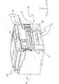
図1は、本実施形態に係る記録装置10の外観斜視図である。図1に示す矢印方向において、装置幅方向をX方向、装置奥行方向をY方向、装置高さ方向をZ方向と称する。また、それぞれの方向において、図の矢印に示すように、X方向では左と右、Y方向では手前/前面(正面)/先端と奥/背面/後端、Z方向では上と下などと称する。また、幅方向のうち左方向を第1幅方向、右方向を第2幅方向と称する場合もある。これら各方向は記録装置1の設置面を基準として定められる。例えば、記録装置1が、通常想定される設置状態として水平面に設置された場合には、高さ方向であるZ方向は鉛直方向と一致し、X、Y方向は水平方向と一致することになる。他の図における矢印X、Y、Zも同様である。特に、本実施形態では、シート搬送方向がY方向、キャリッジ走査方向(シート幅方向)がX方向に対応する。 FIG. 1 is an external perspective view of a
記録装置10は、概略、本体20、読取部30、操作部40、自動用紙搬送装置(ASF)50、カセット60、インクタンク70、排紙トレイ80及び不図示の制御部(本体
内部に設けられた制御回路基板)を備える。The
印刷(画像記録動作)の流れを説明する。パーソナルコンピュータ(PC)等の外部機器から送られたデータや読取部30で読み込んだ原稿をもとに、記録装置10は、記録材としてのシートに画像を記録する。自動用紙搬送装置(ASF)50もしくはカセット60に載置されたシートは、不図示の搬送ローラによって本体20に格納された不図示の記録部に給紙される。PCから送られたデータや読取部30で読み込んだ画像、あるいは後述するUSBメモリ等の外部記憶媒体100から読み込んだデータ等をもとに、記録部は、インクを貯留するインクタンク70から供給されるインクを用いて画像をシートに記録する。具体的には、本体20内部に格納された不図示のキャリッジ走査にて画像記録を行う。画像が記録されたシートは、紙ローラによって排紙トレイ80に排紙される。 The flow of printing (image recording operation) will be described. Based on data sent from an external device such as a personal computer (PC) or a document read by the
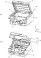
図2は、記録装置10の斜視図である。本体20の前面には、記憶媒体挿入部90(図1参照)が設けられている。オペレータは、USBメモリ等の外部記憶媒体100を記憶媒体挿入部90に挿入して本体20に接続し、外部記憶媒体100に格納されたデータを記録装置10に読み取らせ、該データを印刷することができる。 FIG. 2 is a perspective view of the
図3(a)は、読取装置としての読取部30において原稿台32に対して原稿押さえ台31を開いたときの記録装置10の斜視図である。読取部30は、原稿台32の上面(透明部材33の天面)に対して原稿押さえ台31が開閉可能に設けられている。ここで、本実施形態の原稿押さえ台31には、自動原稿搬送装置(ADF)36が搭載されている。自動原稿搬送装置(ADF)36は、複数の原稿をセットし、連続して原稿を自動で透明部材33に搬送することが可能である。ただし、ADF36が搭載されない原稿押さえ台であっても良い。 FIG. 3A is a perspective view of the
オペレータが用意した原稿Pを読み取り部30で読取り、読み取った画像等のデータを印刷する場合、まずオペレータは原稿押さえ台31を開き透明部材(ガラス等)33の上に原稿Pを置き、所定の位置に原稿Pをセットする。次に、オペレータは原稿押さえ台31を閉じ、所定の操作により透明部材33の下方に設けられた読取りユニット(不図示)で原稿Pの画像等を読み取る。読み取ったデータ等が印刷されたら、オペレータは再び原稿押さえ台31を開き原稿を矢印方向(-Y)に原稿を引き抜き、原稿を引き抜いた後で原稿押さえ台31を閉じる動作を行う。 When a document P prepared by an operator is read by the
図3(b)は、読み取り部30を開いたときの記録装置10の斜視図である。オペレータが手掛け部21に手(指)を挿入し、+Z方向に力を加えると、図3(b)に示す矢印方向に、読み取り部30が開き、本体内部が露出する。この状態で、オペレータは、インクタンクキャップ71を開けてインクタンク70にインクを補充したり、不図示の記録ヘッドを交換したり、搬送部等で紙づまりした用紙を取り除く作業を行うことができる。 FIG. 3B is a perspective view of the
図4は、操作部40が本体20から取外されたときの様子を示す記録装置10の斜視図である。後述するように、操作部40は、操作面として、オペレータに各種情報を伝える表示部や、各種機能を操作するためのキーを備えるとともに、不図示の電子部品を備える。また、操作部40は、その表示部等の操作面がオペレータの好みの位置(角度)となるように装置本体に対して回動可能とするための保持機構部45(図6参照)と、操作部40を読取り基台37(図15参照)に取り付けるためのパネル基台47が設けられる。 FIG. 4 is a perspective view of the
操作部40は、筐体構成として、操作面を備える前面筐体部41と、前面筐体部41における操作面の裏側に係合されるとともに装置本体に支持される背面筐体部42と、を備える。背面筐体部42は、操作面と平行かつ略水平方向に延びる回動軸R1を中心に装置本体に回動可能に軸支されている。操作部40は、装置本体に対する回動により、操作部
40の上端部と下端部が上下に並び操作面が略水平方向に向く閉姿勢(図7)と、操作部40の下端部が閉姿勢のときよりも装置手前側かつ上方に突き出て操作面が上向きに傾斜する開姿勢(図8~図10等)と、を取り得るように構成されている。The
ところで、図1に示すように、操作部4は、原稿台32のY方向前方に位置し、操作部40の少なくとも一部が、原稿台32と幅方向(X方向)で重なり、操作部4の上端部は、原稿台32の天面と略同じもしくは高い位置に構成される。 By the way, as shown in FIG. 1, the operation unit 4 is positioned in front of the
図6(a)は、操作部40の背面側からみた一部斜視図で保持機構部48を説明するものである。背面筐体部42には、操作部40を回動し、所定の角度で保持するための保持機構48が取り付けられる。保持機構40は、操作部ステイ43、操作部カム44、カムスプリング45及びカバー46から構成される。操作部ステイ43の一方の面(カム面)は所定の形状を呈しており、付勢部材としてのカムスプリング45の付勢によって操作部カム44の所定の面を操作部ステイ43の面に押し付ける。操作部カム44が押し付けられる操作部ステイ43のカム面(被係合面)の位置を選択することで、操作部40を所定の角度で選択的、段階的に保持することができるようになっている。カバー46は、操作部ステイ43、操作部カム44及びカムスプリング45を収納し、後述するパネル基台47にねじ止め等で固定する。なお、カムとステイの配置構成は上述した構成に限定されない。すなわち、カム側の構成が、操作部40と装置本体のいずれか一方に、ステイ側の構成がいずれか他方に、それぞれ設けられればよい。したがって、カム側の構成を操作部40に設け、ステイ側の構成を装置本体に設けた構成としてもよい。 FIG. 6A is a partial perspective view of the
図6(b)は、図6(a)におけるX1-X1断面図で、前面筐体部41と背面体部42の合わせ部の詳細図である。図6(b)では上部のみの図であるが、筐体部全周同じ関係である。図6(b)に示すように前面筐体部41の外周と背面筐体部42の合わせ部で段差D1を設け、D1の寸法は0より大きくなるように設定する。実施形態1では、D1はD1>0となるようにする。すなわち、背面筐体部42が前面筐体部41より必ず+Z方向に出張るようにする。なお、実施形態1においては、D1=0.5mmである。このような構成をとることにより、後述する原稿Pの引き出しをスムーズに行うことができ、原稿Pの傷付き等を低減させることができる。 FIG. 6(b) is a cross-sectional view taken along line X1-X1 in FIG. 6(a), which is a detailed view of the joining portion between the
<操作部回動機構>
図7(a)は、記録装置の一部断面図(操作パネルを閉じた状態)で、操作部40近傍の断面図である。図7(b)はXXX部拡大図である。操作部ステイ43には、操作部カム44が係合可能な複数の被係合面として、第一カム面43a、第二カム面43b、第三カム面43c及びストッパー部43dが一体形成される。上記カム面に操作部カム44を圧接させることにより、操作部40の回動角度を変え、そこで保持することができる。<Operating unit rotation mechanism>
FIG. 7A is a partial cross-sectional view of the recording apparatus (when the operation panel is closed), and is a cross-sectional view near the
図7(a)は、操作部40の開き角度が0°のとき(操作部40が閉じた状態)を示す。操作部カム44は、操作部ステイ43の第一カム面43aに圧接した状態であり、この時のフロントカバー35と背面筐体42との高さ(Zp)は0である。なお、図中二点鎖線はフロントカバー35より大きな原稿を読み取る場合の原稿の姿勢および定型原稿を引き抜くときの原稿の軌跡を示したものである。 FIG. 7A shows a state in which the opening angle of the operating
図7(a)に示すとおり、原稿押さえ台31の前面下部においてR形状31a及び窪み形状31bを形成する。さらには、操作部40の背面筐体部42に断面視R形状42aを設けている。ここで、R形状42aは操作部の厚さ(Dp)の略1/2程度である(Dr≒DP/2)。この構成をとることにより、特に操作部40が開いた状態(図8参照)において、原稿Pの通路に大きな空間を形成することになり原稿Pの姿勢が変化しても、局所的に原稿Pに圧接する部品がなく、原稿に傷や折れを作ることを防げる。 As shown in FIG. 7A, the lower front surface of the document holding table 31 is formed with an
図8は、記録装置の一部断面図であり、操作部40の開き角度が45°の場合を示している。このとき、操作部ステイ43と操作部カム44の位置関係は、操作部カム44が第二カム面43bに圧接した状態であり、このときのフロントカバー35と背面筐体42の高さ(Zp)は5mm程度である。 FIG. 8 is a partial cross-sectional view of the recording apparatus, and shows a case where the opening angle of the
図9は、記録装置の一部断面図であり、操作部40の開き角度が60°の場合を示している。このとき、操作部ステイ43と操作部カム43の位置関係は、操作部カム44が第三カム面43cに圧接した状態であり、このときのフロントカバー35と背面筐体42の高さ(Zp)は5.5mm程度である。 FIG. 9 is a partial cross-sectional view of the recording apparatus, showing a case where the opening angle of the
図10は、記録装置の一部断面図であり、操作パネルの回動が停止された状態、具体的には、操作部の開き角度が65.5°の場合を示している。このときは、操作部ステイ43のカム面と対向する位置に形成したリブ43dがカバー46に形成されたフック形状46aに当接するため、操作部40はこれ以上回動することはない(図中反時計周り)。 FIG. 10 is a partial cross-sectional view of the recording apparatus, showing a state in which the rotation of the operation panel is stopped, specifically, the opening angle of the operation portion is 65.5°. At this time, since the
上記構成により、オペレータの手動操作により好みの位置に操作部40を回動保持することができ、誤って操作部40を所定の開き角度以上に回動させようとした場合でも、操作部ステイ43のカム面と操作部カム44の圧接状態を常に維持することができる。したがって、安定した操作部40の回動動作を行うことができる。 With the above configuration, the
図13に、比較例の操作部と原稿押さえ台を配した装置の断面図を示す。図13に示す比較例の操作部140は、図14(b)に示すように、読み取り部140の前面筐体部141が背面筐体部142よりも+Z方向に大きくなるように構成されている。また、背面筐体部142の背面側は図7と比較して直角に近い形状となっている。図13に示す比較例構成では、読み取り部140が開いた状態で、読み取り部から原稿を引き抜こうとした場合、図14(b)に示すように、原稿が下向きに曲がっていった場合、背面筐体部142と直行に近い形で接触するため、そこで折れ曲がってしまうことがある。また、そこでは引っ掛からずとも、原稿が前面筐体部141と背面筐体部142の段差に引っ掛かってしまうと、引き抜きにくい。引っ掛かった状態でオペレータがさらに引き抜こうとすると原稿が折れ曲がってしまうこともある。 FIG. 13 shows a cross-sectional view of an apparatus in which an operation unit and a document holding table are arranged in a comparative example. The
対して、図7で示す本実施形態の記録装置に原稿取り出し時の原稿の様子(原稿を取り出すときの軌跡)を図14(a)に示す。背面筐体部42の背面である原稿台32との対向面にR形状が設けてあるため、原稿は図14(b)に示す場合よりも緩やかな角度で背面筐体部42に接触する。そのため、背面筐体部42に接触した後に折れ曲がることなく-Y方向に進む。また、背面筐体部42が前面筐体部41より+Z方向に大きい形状である。すなわち、操作部40の少なくとも上端部における前面筐体部41と背面筐体部42との係合部(前面筐体部41の係合面410と背面筐体部42の係合面420との接合部)において、前面筐体部41の上端縁411は、背面筐体部42の上端縁421よりも内側に位置している。内側に位置するというのは、操作部40の操作面の上端部から下端部に向かう方向(操作部40の角度が0°の場合はZ方向)において、接合部における前面筐体部41の係合面410から操作部40の下端部(操作部40の角度が0°の場合に操作部40において最も-Z方向の部分)までの距離が、接合部における背面筐体部42の係合面420から操作部40の下端部までの距離よりも短いということである。そして、前面筐体部41の上端縁411は、操作部40の装置本体に対する角度によらず、原稿台32に対して背面筐体部42の上端部に隠れた位置で維持される。すなわち、操作面側の前面筐体部41の上端縁411は、操作部40の装置本体に対する角度によらず、背面筐体部42の上端縁421よりも原稿台32から離れた位置であって、背面筐体部42の上端縁421よりも低い位置に維持される。これにより、原稿が進む経路には段差がなく、
段差による引っ掛かりが生じることなく原稿を引き抜くことができる。On the other hand, FIG. 14A shows the state of the document when the document is taken out of the recording apparatus of the present embodiment shown in FIG. 7 (trajectory when the document is taken out). Since the rear surface of the
A document can be pulled out without being caught by a step.
また、図13に示すように、原稿押さえ台131が直角に近い形状の形態で、原稿台よりも大きな原稿を読み取る場合、特に操作部140が開いた状態では、原稿押さえ台131と前面筐体部141とで原稿Plをせん断状態で挟み、折れ目が付いてしまうことがあった。これに対して、本実施形態の図7の形状の場合、原稿押さえ台31における、原稿台32と操作部40との境目に対向する角部が、R形状31a及び窪み形状31bが設けられることで凹状に凹んでいる。これにより、原稿押さえ台31において原稿を押さえている部分が図13よりも+Y方向になる。そのため、原稿を原稿押さえ台31と操作部40とでせん断状態で挟むことを防げ、折れ曲がりを防止することができる。 Also, as shown in FIG. 13, when the
本実施形態の記録装置10においては、本体20の両側にインクタンクを内蔵し、オペレータからインク残量が見えるようにカバーに開口部を設け、記録装置10の左側に操作部40を搭載している。図14(b)で説明したように、比較例の記録装置においては、大きな原稿を読み取る場合や原稿を引き抜くときなど操作パネル140で原稿を傷付けることがあると述べた。それを避けるためには、例えば、フロントカバー135と前面筐体部141との高さZZ分だけ操作部140を下げればよい。この場合の操作部40の配置の例を図12中一点鎖線で示す。しかしながら、上記図12の一点鎖線で示す位置に操作部40が位置するとインクタンク70の残量を確認するための窓を半分くらい隠してしまい、インクタンク70の残量の視認性が悪くなってしてしまうことになる。 In the
本実施形態の記録装置10においては、上述したように、操作部40の構成や原稿押さえ台31の形状を変更することにより可能な限り高い位置に操作部40を設けることができ、インクタンクの視認性を確保することができる。本実施形態では、窓の4分の3以上は見えるようになっている。より好ましくは、窓が操作部40によって隠れない(4分の3以上隠れない)ように配置されることである。 In the
(実施形態2)
本発明の実施形態2について説明する。ここで説明しない事項は、上記実施形態1と同様である。(Embodiment 2)
A second embodiment of the present invention will be described. Matters not described here are the same as in the first embodiment.
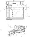
図11(a)は、図4におけるZ矢視図であり、原稿押さえ台(原稿押さえ部)31を取り外した状態における原稿台32の上面図である。図11(b)は、図11におけるXX部の拡大斜視図であり、原稿突き当て部の詳細を説明する図である。 FIG. 11A is a Z arrow view in FIG. 4, and is a top view of the
原稿台32は、外縁筐体部34と外縁筐体部34の裏面に固定された透明部材33と外縁筐体部34の全面に取り付けられたフロントカバー35より構成される。また、外縁筐体部34には所定の大きさの開口部が形成され、該開口部より透明部材33が露呈する。ここで透明部材33が露呈した領域内が原稿Pの読取り範囲(面)となる。なお、本実施形態においては、外縁筐体部34とフロントカバー35を別部品で構成したが、フロントカバー35を外縁筐体部34と一体で形成しても良い。 The document table 32 is composed of an outer
オペレータが原稿Pを読み取るとき、原稿押さえ台31を開いて原稿Pを所定の位置に置く必要がある。すなわち、オペレータは一度透明部材33に置いた原稿Pを図11(a)中の矢印方向に移動させ、原稿Pの左角部p1を外縁筐体部34の開口部基準点g1に突き当てる。そして、この動作を原稿Pの位置決めと呼ぶ。本実施形態においては、原稿Pの位置決めは図11(a)中で上方左角に設定したが、これに限らず、外縁筐体部34の開口部の四隅であればどこに設定してもよい。 When the operator reads the document P, it is necessary to open the document holding table 31 and place the document P at a predetermined position. That is, the operator once places the document P on the
上記原稿Pの位置決めを行うための開口部基準点g1を設定するために、図11(b)
に示すように外縁筐体部34を透明部材33の読取り面の間に段差Zx及びZyを設けている。In order to set the opening reference point g1 for positioning the document P, as shown in FIG.
2, steps Zx and Zy are provided between the reading surface of the
原稿Pの読取りが終了し、原稿Pを透明部材33の読取り面より取り出す際には原稿Pをオペレータが記録装置10の手前側(-Y方向)に引き抜く必要がある。 When the reading of the document P is completed and the document P is to be removed from the reading surface of the
従来、上記段差は透明部材33の読取り面に対して略垂直に形成されるため、オペレータが原稿P引き抜く際、原稿Pの端部が段差に引掛かり原稿Pの端部に傷や折り目を付けてしまことがあった。 Conventionally, since the step is formed substantially perpendicular to the reading surface of the
そこで、本実施形態においては、外縁筐体部34と透明部材33との段差の形状を図7(b)に示すように構成する。すなわち、外縁筐体部34における透明部材33との境界部は、その上面が、透明部材33に積載された原稿の取り出し方向と重なる(取り出し方向下流に位置する)領域において、透明部材33と接する端面の高さが透明部材33の天面よりも低くなるように傾斜した斜面(斜行面)34aとなっている。外縁筐体部34に、斜面34aを設け、斜面34aの+Y側の開始点を透明部材33の端部より低い位置(図7(b)ではhsだけ低い位置)となるように形成する。斜面34aは、外縁筐体部34における透明部材33との境界部から上記取り出し方向下流に向かって高くなるように形成されている。 Therefore, in the present embodiment, the shape of the step between the outer
上記構成により、オペレータが原稿Pを引き抜く際に原稿Pが通る経路に原稿Pが引っ掛かるような段差がないため、原稿Pをスムーズに引き抜くことができる。また、引っ掛かりがないため原稿を傷つけることもない。 With the above configuration, when the operator pulls out the document P, there is no level difference in the path through which the document P passes, so that the document P can be pulled out smoothly. Also, since there is no catching, the document is not damaged.
なお、本実施形態では、上記斜面34aを設ける範囲は、外縁筐体部34における透明部材33との境界部の四辺のうち前面側の辺に対応する領域のみとしているが、基準点g1の形成に用いられない右側の辺にも設けてもよい。すなわち、基準点g1を形成する二辺を除いた残りの二辺に設ける構成としてもよい。 In the present embodiment, the
(実施形態3)
本発明の実施形態3について説明する。ここで説明しない事項は、上記実施形態1、2と同様である。(Embodiment 3)
A third embodiment of the present invention will be described. Matters not described here are the same as in the first and second embodiments.
図3(b)で説明したとおり、記録装置10は、紙詰まり対応やインク補充時などのメンテナンス時には読み取り部30を開くことでユーザが装置内部にアクセスすることが可能となる。本体20は、読み取り部30を開くための手掛け部21とUSBメモリなどの外部記憶媒体100を挿入可能な記憶媒体挿入部90(図1参照)とを備えている。 As described with reference to FIG. 3B, the
図12は記録装置の正面図であり、外部記録媒体挿入部90には外部記憶媒体(USBメモリ)100を取り付けた状態である。外部記憶媒体100を記憶媒体挿入部90に装着した状態で、操作部40を回動するときや読み取り部30を使用するために原稿押さえ台31を開けるときに(図3(b)の状態)、オペレータが誤って手をぶつけ記憶媒体挿入部90に挿入された外部記憶媒体100を壊さないようにする必要がある。そのため、本実施形態においては、記憶媒体挿入部90は、操作部40および手掛け部21の両方と装置の幅方向(X方向)もしくは高さ方向(Z方向)のどちらかは重ならないよう配置されている。(図1、図2、図12参照)図12あるいは図2に示すように、USBメモリ100を本体20に装着した状態でも、手掛け部21とUSBメモリ100との間には必要最小限の距離Hを確保しているので、オペレータが読み取り部30を開くとき、あるいは操作部40を回動させるときでもUSBメモリ100に触れることはない。 FIG. 12 is a front view of the recording apparatus, in which an external storage medium (USB memory) 100 is attached to the external recording
以上説明したような構成により、外部記憶媒体100が取り付けられた状態で記録装置10の操作を行っても、外部記憶媒体100を壊してしまう可能性を低くすることができる。 With the configuration as described above, even if the
(実施形態4)
本発明の実施形態4について説明する。ここで説明しない事項は、上記実施形態1~3と同様である。(Embodiment 4)
A fourth embodiment of the present invention will be described. Matters not described here are the same as in the first to third embodiments.
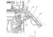
図15(a)は、操作部40を背面からみた斜視図である。背面筐体部42は回転自在にパネル基台47に取り付けられる。さらにパネル基台には前述した操作部40の開き角度を調整するパネル保持機構48を覆うカバー46が取り付けられる。パネル基台47には原稿台32にねじ止め等で固定される複数の固定形状47a~47dが形成される。 FIG. 15(a) is a perspective view of the
図15(b)は、図15(a)におけるカバー46を取外したときの斜視図であり、後述するパネル基台47を読み取り基台37に取り付ける構成を説明する図である。
「00」
図17は、パネル基台47からカバー46を取り外した状態における、パネル基台47の分解斜視図である。FIG. 15B is a perspective view when the
"00"
17 is an exploded perspective view of the
操作部40の原稿台32(本体側)に対する支持構成は、パネル基台47が、操作部40を原稿台32(本体側)に対して回動可能に支持する構成のベースとなり、パネル保持機構48がパネル基台47における支持角度を制御する構成部分をなしている。固定形状47a及び固定形状47bは、操作部カム44が操作部ステイ43のカム面を圧接する部位を中心とし、略対角線上(Tp)に位置する。かかる圧接部には強いカムスプリング45(図6)の復元力によって操作部カム44を操作部ステイ43のカム面を圧接するため、圧接部近傍が変形し、操作部40が傾くなどして所定の位置に保持できなくなる。また、オペレータが操作部40の回動動作を行うと回動動作中のガタつき等も発生してしまう。しかしながら、本実施形態においては、最も負荷が発生する上記圧接部の略対角線上(Tp)に固定手段を設けたので操作部40の傾きやがたつきを防ぐことができる。 A
図16は、原稿台32の一部斜視図で、フロントカバー35を外した状態である。パネル基台47は、読取りユニット(不図示)を格納する読取り基台37に形成された所定の箇所にネジ止めされる。なお、本実施形態においてはパネル基台47を読取り基台37の固定手段としてネジ止めで行ったが、これに限らず、パネル基台47あるいは読取り基台37にフック形状、溝形状を一体形成し固定を行っても良い。 FIG. 16 is a partial perspective view of the
10…記録装置、20…本体、21…手掛け部、30…読取部、31…原稿押さえ台(圧板)、32…原稿台(ガラスフレーム)、33…透明部材(ガラス等)、34…外縁筐体部、40…操作部、41…前面筐体部、42…背面筐体部、43…操作部ステイ、44…操作部カム、45…カムスプリング、46…カバー、47…パネル基台、48…パネル保持機構、90…記憶媒体挿入部 DESCRIPTION OF
Claims (12)
Translated fromJapanese前記本体における前記原稿台の前方に取り付けられる操作部と、
を備える読取装置において、
前記操作部は、
操作面側の前面筐体部と、
前記前面筐体部における前記操作面の裏側に係合されるとともに前記本体に支持される背面筐体部と、
を備え、
前記操作部の上端部は、前記原稿台と略同じ高さまたは前記原稿台よりも高く、
前記操作部の上端部における前記前面筐体部と前記背面筐体部との係合部において、前記前面筐体部の上端縁は、前記背面筐体部の上端縁よりも、前記操作部の上端部から下端部に向かう方向において前記操作部の下端部までの距離が短いことを特徴とする読取装置。a main body having a platen on which a document is placed and a reading unit for reading an image from the document placed on the platen;
an operation unit attached to the front of the document table in the main body;
In a reading device comprising
The operation unit is
a front housing portion on the operation surface side;
a rear housing portion engaged with the back side of the operation surface of the front housing portion and supported by the main body;
with
an upper end portion of the operation unit is at substantially the same height as or higher than the document platen;
At the engagement portion between the front housing portion and the rear housing portion at the upper end portion of the operation portion, the upper edge of the front housing portion is positioned further than the upper edge of the rear housing portion of the operation portion. A reading device, wherein the distance to the lower end of the operation unit is short in the direction from the upper end to the lower end.
前記操作部は、前記本体に対する回動により、
前記操作部の上端部と下端部が上下に並び前記操作面が略水平方向に向く閉姿勢と、
前記操作部の下端部が前記閉姿勢のときよりも装置手前側かつ上方に突き出て前記操作面が上向きに傾斜する開姿勢と、
を取り得るように構成されていることを特徴とする請求項1又は2に記載の読取装置。The back housing part is rotatably supported by the main body about a rotation shaft extending in a substantially horizontal direction parallel to the operation surface,
By rotating the operation part with respect to the main body,
a closed posture in which the upper end portion and the lower end portion of the operation portion are arranged vertically and the operation surface faces a substantially horizontal direction;
an open posture in which the lower end of the operation unit protrudes further toward the front side of the device and upward than in the closed posture, and the operation surface is inclined upward;
3. The reading device according to claim 1 or 2, characterized in that it is constructed so as to be able to read .
前記保持機構は、
前記本体及び前記操作部のうちの一方に設けられたカムと、
他方に設けられた、前記カムが係合可能な複数の被係合面を有するステイと、
前記カムを前記被係合面に付勢する付勢部材と、
を有し、
前記複数の被係合面のうち前記カムが係合する被係合面を選択することで、前記操作部の前記開姿勢における角度を段階的に調整することができることを特徴とする請求項3に記載の読取装置。A holding mechanism for holding the open posture of the operation unit,
The holding mechanism is
a cam provided on one of the main body and the operating portion;
a stay provided on the other side and having a plurality of engaged surfaces with which the cam can engage;
a biasing member that biases the cam toward the engaged surface;
has
3. The angle of the operating portion in the open posture can be adjusted stepwise by selecting the engaged surface with which the cam engages from among the plurality of engaged surfaces. The reader according to .
前記原稿押さえ台は、前記原稿台と前記操作部との境目に対向する角部が凹状に凹んでいることを特徴とする請求項1~6のいずれか1項に記載の読取装置。A document holding table provided to be openable and closable with respect to the upper surface of the document table,
The reading apparatus according to any one of claims 1 to 6, wherein the document holding plate has a concave corner portion facing a boundary between the document platen and the operation section.
前記透明部材に積載された原稿を取り出す場合に前記透明部材より取り出し方向下流に位置する前記外縁筐体部における前記透明部材との境界部の高さは、前記透明部材の天面よりも低いことを特徴とする請求項1~7のいずれか1項に記載の読取装置。The document platen has a transparent member on which a document is placed and an outer edge housing portion that supports the transparent member,
When the document stacked on the transparent member is to be taken out, the height of the boundary between the transparent member and the outer edge housing portion located downstream of the transparent member in the take-out direction is lower than the top surface of the transparent member. The reader according to any one of claims 1 to 7, characterized by:
前記本体の前面に設けられる外部記録媒体の挿入部と、を有し、
前記挿入部は、前記操作部及び前記手掛け部に対し、前記読取装置の幅方向又は高さ方向において重ならないように配置されることを特徴とする請求項1~9のいずれか1項に記載の読取装置。a document holding plate provided so as to be openable and closable with respect to the upper surface of the document table and provided with a handle portion for opening and closing;
an insertion part for an external recording medium provided on the front surface of the main body,
10. The apparatus according to any one of claims 1 to 9, wherein the insertion section is arranged so as not to overlap the operation section and the handle section in the width direction or the height direction of the reading device. reader.
前記読取装置には前記インクタンクの残量が見えるような窓が設けられており、
前記操作部は前記窓の前方に設けられ、
前記操作部と前記窓とは、前記操作部によって前記窓が4分の3以上隠れないように配置されていることを特徴とする請求項1~10のいずれか1項に記載の読取装置。having an ink tank for storing ink,
The reading device is provided with a window through which the remaining amount of the ink tank can be seen,
The operation unit is provided in front of the window,
The reading device according to any one of claims 1 to 10, wherein the operation section and the window are arranged so that the window is not hidden by the operation section by more than three quarters.
請求項1~11のいずれか1項に記載の読取装置と、
を備える記録装置において、
前記記録部は、前記読取装置の下方に配置されていることを特徴とする記録装置。a recording unit that records an image on a recording material;
a reader according to any one of claims 1 to 11;
In a recording device comprising
A recording apparatus, wherein the recording unit is arranged below the reading device.
Priority Applications (2)
| Application Number | Priority Date | Filing Date | Title |
|---|---|---|---|
| JP2021023592AJP7642393B2 (en) | 2021-02-17 | 2021-02-17 | Reading device and recording device |
| US17/665,312US12225167B2 (en) | 2021-02-17 | 2022-02-04 | Reading apparatus with operation panel configured to reduce interference with handling of original documents |
Applications Claiming Priority (1)
| Application Number | Priority Date | Filing Date | Title |
|---|---|---|---|
| JP2021023592AJP7642393B2 (en) | 2021-02-17 | 2021-02-17 | Reading device and recording device |
Publications (3)
| Publication Number | Publication Date |
|---|---|
| JP2022125796Atrue JP2022125796A (en) | 2022-08-29 |
| JP2022125796A5 JP2022125796A5 (en) | 2024-02-20 |
| JP7642393B2 JP7642393B2 (en) | 2025-03-10 |
Family
ID=82800671
Family Applications (1)
| Application Number | Title | Priority Date | Filing Date |
|---|---|---|---|
| JP2021023592AActiveJP7642393B2 (en) | 2021-02-17 | 2021-02-17 | Reading device and recording device |
Country Status (2)
| Country | Link |
|---|---|
| US (1) | US12225167B2 (en) |
| JP (1) | JP7642393B2 (en) |
Families Citing this family (5)
| Publication number | Priority date | Publication date | Assignee | Title |
|---|---|---|---|---|
| JP7706895B2 (en) | 2021-02-17 | 2025-07-14 | キヤノン株式会社 | Drawing device and recording device |
| US11622053B2 (en)* | 2021-04-01 | 2023-04-04 | Brother Kogyo Kabushiki Kaisha | Multifunction device including operation panel provided at pivotable upper housing |
| JP7371068B2 (en) | 2021-08-18 | 2023-10-30 | キヤノン株式会社 | Cassette and recording device |
| JP2023167890A (en) | 2022-05-13 | 2023-11-24 | キヤノン株式会社 | Image reading device and image forming apparatus |
| JP2023167891A (en)* | 2022-05-13 | 2023-11-24 | キヤノン株式会社 | Image reading device and image formation apparatus |
Citations (5)
| Publication number | Priority date | Publication date | Assignee | Title |
|---|---|---|---|---|
| JP2005020667A (en)* | 2003-06-30 | 2005-01-20 | Brother Ind Ltd | Document feeder |
| JP2014072458A (en)* | 2012-09-28 | 2014-04-21 | Brother Ind Ltd | Electronic device |
| JP2015063083A (en)* | 2013-09-25 | 2015-04-09 | ブラザー工業株式会社 | Image recording device |
| JP2016041478A (en)* | 2014-08-18 | 2016-03-31 | セイコーエプソン株式会社 | Liquid storage container and liquid injection device |
| JP2020009964A (en)* | 2018-07-11 | 2020-01-16 | 京セラドキュメントソリューションズ株式会社 | Electrical equipment and display device |
Family Cites Families (10)
| Publication number | Priority date | Publication date | Assignee | Title |
|---|---|---|---|---|
| US7896343B2 (en)* | 2005-09-26 | 2011-03-01 | Brother Kogyo Kabushiki Kaisha | Document or sheet material feeder |
| JP4333731B2 (en)* | 2006-11-28 | 2009-09-16 | コニカミノルタビジネステクノロジーズ株式会社 | Operation panel structure |
| US8909085B2 (en)* | 2011-09-23 | 2014-12-09 | Hewlett-Packard Development Company, L.P. | Methods, printers, and control panels for printers |
| US20130155450A1 (en)* | 2011-12-19 | 2013-06-20 | Brother Kogyo Kabushiki Kaisha | Recording apparatus having a plurality of antennas |
| JP2017109370A (en)* | 2015-12-16 | 2017-06-22 | キヤノン株式会社 | Image forming device |
| JP6766494B2 (en)* | 2016-07-20 | 2020-10-14 | 株式会社リコー | Image forming device |
| JP6843569B2 (en) | 2016-09-23 | 2021-03-17 | キヤノン株式会社 | Image forming device |
| JP6815949B2 (en) | 2017-08-08 | 2021-01-20 | キヤノン株式会社 | Printing device |
| JP7222793B2 (en) | 2019-04-04 | 2023-02-15 | キヤノン株式会社 | recording device |
| JP7256670B2 (en) | 2019-04-04 | 2023-04-12 | キヤノン株式会社 | recording device |
- 2021
- 2021-02-17JPJP2021023592Apatent/JP7642393B2/enactiveActive
- 2022
- 2022-02-04USUS17/665,312patent/US12225167B2/enactiveActive
Patent Citations (5)
| Publication number | Priority date | Publication date | Assignee | Title |
|---|---|---|---|---|
| JP2005020667A (en)* | 2003-06-30 | 2005-01-20 | Brother Ind Ltd | Document feeder |
| JP2014072458A (en)* | 2012-09-28 | 2014-04-21 | Brother Ind Ltd | Electronic device |
| JP2015063083A (en)* | 2013-09-25 | 2015-04-09 | ブラザー工業株式会社 | Image recording device |
| JP2016041478A (en)* | 2014-08-18 | 2016-03-31 | セイコーエプソン株式会社 | Liquid storage container and liquid injection device |
| JP2020009964A (en)* | 2018-07-11 | 2020-01-16 | 京セラドキュメントソリューションズ株式会社 | Electrical equipment and display device |
Also Published As
| Publication number | Publication date |
|---|---|
| US20220263960A1 (en) | 2022-08-18 |
| US12225167B2 (en) | 2025-02-11 |
| JP7642393B2 (en) | 2025-03-10 |
Similar Documents
| Publication | Publication Date | Title |
|---|---|---|
| JP7642393B2 (en) | Reading device and recording device | |
| JP6016538B2 (en) | Printing device | |
| JP4678436B2 (en) | Sheet storage device and image recording device | |
| US6961152B1 (en) | Multi-functional device having vertically arranged scanner and printer sections | |
| US8456714B2 (en) | Image forming apparatus | |
| JP2018165204A (en) | Sheet supporting apparatus, image forming apparatus, and multifunction machine | |
| JP2010042615A (en) | Opening and closing device of cover member | |
| JP4374405B2 (en) | Image forming apparatus | |
| CN111605308B (en) | recording device | |
| JP4071777B2 (en) | Image reading device | |
| JP4581700B2 (en) | Image recording device | |
| JP7215623B2 (en) | recording device | |
| JP5024565B2 (en) | Facsimile device and multi-function device having the same | |
| JP7439457B2 (en) | Lock mechanism of opening/closing member, medium transport device, document reading device, and recording device | |
| JP7142833B2 (en) | recording device | |
| JP4581707B2 (en) | Image recording device | |
| JP2010076930A (en) | Sheet storage device and image recording device | |
| JP7188211B2 (en) | recording device | |
| JP2023014772A (en) | reader and recorder | |
| JP4802612B2 (en) | Recording device | |
| JP2022080841A (en) | Printer | |
| JP4311479B2 (en) | Image recording device | |
| JPH11301859A (en) | Electronics | |
| JP2000138784A (en) | Information processing device with built-in image reading device | |
| JP2008306271A (en) | Image forming apparatus |
Legal Events
| Date | Code | Title | Description |
|---|---|---|---|
| A521 | Request for written amendment filed | Free format text:JAPANESE INTERMEDIATE CODE: A523 Effective date:20240209 | |
| A621 | Written request for application examination | Free format text:JAPANESE INTERMEDIATE CODE: A621 Effective date:20240209 | |
| A977 | Report on retrieval | Free format text:JAPANESE INTERMEDIATE CODE: A971007 Effective date:20241010 | |
| A131 | Notification of reasons for refusal | Free format text:JAPANESE INTERMEDIATE CODE: A131 Effective date:20241015 | |
| A521 | Request for written amendment filed | Free format text:JAPANESE INTERMEDIATE CODE: A523 Effective date:20241211 | |
| TRDD | Decision of grant or rejection written | ||
| A01 | Written decision to grant a patent or to grant a registration (utility model) | Free format text:JAPANESE INTERMEDIATE CODE: A01 Effective date:20250128 | |
| A61 | First payment of annual fees (during grant procedure) | Free format text:JAPANESE INTERMEDIATE CODE: A61 Effective date:20250226 | |
| R150 | Certificate of patent or registration of utility model | Ref document number:7642393 Country of ref document:JP Free format text:JAPANESE INTERMEDIATE CODE: R150 |