JP2022119475A - work vehicle - Google Patents
work vehicleDownload PDFInfo
- Publication number
- JP2022119475A JP2022119475AJP2021016628AJP2021016628AJP2022119475AJP 2022119475 AJP2022119475 AJP 2022119475AJP 2021016628 AJP2021016628 AJP 2021016628AJP 2021016628 AJP2021016628 AJP 2021016628AJP 2022119475 AJP2022119475 AJP 2022119475A
- Authority
- JP
- Japan
- Prior art keywords
- position information
- information acquisition
- acquisition unit
- posture
- unit
- Prior art date
- Legal status (The legal status is an assumption and is not a legal conclusion. Google has not performed a legal analysis and makes no representation as to the accuracy of the status listed.)
- Pending
Links
Images


Landscapes
- Guiding Agricultural Machines (AREA)
Abstract
Description
Translated fromJapanese本発明は、自動操舵が実行可能に構成された制御部を備えた作業車両に関する。 BACKGROUND OF THE INVENTION 1. Field of the Invention The present invention relates to a work vehicle provided with a control unit capable of executing automatic steering.
走行機体と、前記走行機体の位置情報を取得する位置情報取得ユニットと、前記位置情報取得ユニットを前記走行機体の上方側に支持する支持機構と、前記走行機体の操向操作を行うステアリングハンドルを自動操作する自動操舵装置と、制御部とを備えた特許文献1に記載の作業車両が従来公知である。 A traveling machine, a position information acquisition unit for acquiring position information of the traveling machine, a support mechanism for supporting the position information acquiring unit on the upper side of the traveling machine, and a steering handle for steering the traveling machine. 2. Description of the Related Art Conventionally, a work vehicle described in Japanese Patent Laid-Open Publication No. 2002-100002 is known, which includes an automatic steering device that automatically operates and a control unit.
上記文献の作業車両によれば、前記制御部によって、前記位置情報取得ユニットによって取得された前記走行機体の位置情報等に基づいて、前記走行機体を所定の目標経路に沿って自動走行するように操向操作を制御する自動走行モードに切換えることができる一方で、前記位置情報取得ユニットは、予備苗台を支持する左右一対の縦フレームの間に架設される左右の連結フレームに設けられるため、常に前記走行機体の上方の高いに設置されるため、使用しない路上走行時や停車時に邪魔になり易く、前記位置情報取得ユニットを取外す場合にも作業にも手間が掛かるという課題があった。 According to the work vehicle of the above document, the control unit causes the traveling machine body to automatically travel along a predetermined target route based on the position information of the traveling machine body acquired by the position information acquisition unit. While it is possible to switch to an automatic driving mode that controls the steering operation, the position information acquisition unit is provided in the left and right connecting frames that are installed between the pair of left and right vertical frames that support the spare seedling stand. Since it is always installed high above the traveling body, it tends to get in the way when traveling on the road when not in use or when the vehicle is stopped.
本発明は、前記位置情報取得ユニットを使用しない場合に、該位置情報取得ユニットを邪魔にならない位置へスムーズ且つ容易に切換ることができる作業車両を提供することを課題とする。 An object of the present invention is to provide a work vehicle that can smoothly and easily switch the position information acquisition unit to a position that does not interfere with the position information acquisition unit when the position information acquisition unit is not used.
上記課題を解決するため、本願発明は第1に、走行機体と、前記走行機体の位置情報を取得する位置情報取得ユニットと、前記位置情報取得ユニットを前記走行機体の上方側に支持するとともに、前記位置情報取得ユニットを使用姿勢と収納姿勢とに姿勢切換可能に支持する支持機構と、制御部とを備え、前記支持機構は、前記位置情報取得ユニットを回動可能に支持する支持部材と、該支持部材を姿勢切換するアクチュエータと、前記位置情報取得ユニットと一体回動するように支持されることにより前記位置情報取得ユニットの姿勢を検出する検出センサとを有し、前記制御部は、前記アクチュエータを介して前記位置情報取得ユニットの姿勢切換えを制御するように構成されたことを特徴としている。 In order to solve the above problems, the present invention firstly supports a traveling machine body, a position information acquisition unit that acquires position information of the traveling machine body, and the position information acquisition unit above the traveling machine body, a support mechanism that supports the position information acquisition unit so as to be switchable between a use posture and a storage posture; and a control section, wherein the support mechanism includes a support member that rotatably supports the position information acquisition unit; an actuator for switching the posture of the support member; and a detection sensor for detecting the posture of the position information acquisition unit by being supported so as to rotate integrally with the position information acquisition unit; It is characterized in that it is configured to control attitude switching of the position information acquisition unit via an actuator.
第2に、前記検出センサは、車両の姿勢を検出可能な慣性計測装置としたことを特徴としている。 Secondly, the detection sensor is an inertial measurement device capable of detecting the attitude of the vehicle.
第3に、前記走行機体の操向操作を行うステアリングハンドルを自動操作する自動操舵装置を設け、前記制御部は、前記位置情報取得ユニットにより取得された前記走行機体の位置情報に基づいて、前記自動操舵装置を介して前記走行機体の操向操作を制御する自動操舵制御が実行可能に構成され、前記制御部は、前記自動操舵装置の電源入り状態が検出された場合には、前記位置情報取得ユニットを自動的に使用姿勢に切換えるように構成されたことを特徴としている。 Thirdly, an automatic steering device is provided for automatically operating a steering handle for steering operation of the traveling machine body, and the control unit, based on the position information of the traveling machine body acquired by the position information acquisition unit, Automatic steering control for controlling the steering operation of the traveling body via an automatic steering device is configured to be executable, and the control unit detects the power-on state of the automatic steering device, the position information It is characterized in that it is arranged to automatically switch the acquisition unit to the use position.
第4に、前記走行機体は、少なくとも圃場での作業走行を行う作業状態と、路上を走行する路上状態とに切換可能に構成され、前記制御部は、路上状態に切換えられた場合には、前記位置情報取得ユニットが収納姿勢に切換えられるように構成されたことを特徴としている。 Fourthly, the traveling machine body is configured to be switchable between at least a working state in which it travels for work in a field and a road state in which it travels on a road, and the control section, when switched to the road state, It is characterized in that the position information acquisition unit is configured to be switched to a retracted posture.
前記制御部は、前記アクチュエータを介して前記位置情報取得ユニットの姿勢切換えを制御できるように構成したものによれば、前記位置情報取得ユニットは、使用時と収容時とで、オペレータによって手動で姿勢を切換える作業が必要なく、前記アクチュエータを介して自動的に姿勢切換え作動させることができるため、作業性が向上する。 According to the control unit configured to be able to control attitude switching of the position information acquisition unit via the actuator, the position information acquisition unit can be manually changed by an operator between use and storage. Since it is possible to automatically switch the posture via the actuator without the need to switch between the positions, workability is improved.
また、前記検出センサは、車両の姿勢を検出可能な慣性計測装置としたものによれば、車両の姿勢を検出するための前記慣性計測装置を前記位置情報取得ユニットの姿勢を検出センサとを兼用できるため、前記支持機構の設置コストをより低く抑えることができる。 Further, according to an inertial measuring device capable of detecting the posture of the vehicle, the inertial measuring device for detecting the posture of the vehicle is also used as a sensor for detecting the posture of the position information acquisition unit. Therefore, the installation cost of the support mechanism can be kept lower.
また、前記走行機体の操向操作を行うステアリングハンドルを自動操作する自動操舵装置を設け、前記制御部は、前記位置情報取得ユニットにより取得された前記走行機体の位置情報に基づいて、前記自動操舵装置を介して前記走行機体の操向操作を制御する自動操舵制御が実行可能に構成され、前記制御部は、前記自動操作装置の電源入り状態が検出された場合には、前記位置情報取得ユニットを自動的に使用姿勢に切換えるように構成されたものによれば、前記位置情報取得ユニットによって位置情報が取得を実行する際には、前記位置情報取得ユニットが自動的に使用姿勢に切換えられるため、作業性が向上する。 Further, an automatic steering device for automatically operating a steering handle for steering the traveling machine is provided, and the control unit controls the automatic steering based on the position information of the traveling machine acquired by the position information acquisition unit. Automatic steering control for controlling the steering operation of the traveling body can be executed via a device, and the control unit detects the power-on state of the automatic operation device, the position information acquisition unit automatically switched to the use posture, the position information acquisition unit is automatically switched to the use posture when the position information acquisition unit acquires the position information. , workability is improved.
なお、前記走行機体は、少なくとも圃場での作業走行を行う作業状態と、路上を走行する路上状態とに切換可能に構成され、路上状態に切換えられた場合には、前記位置情報取得ユニットが収納姿勢に切換えられるように構成されたものによれば、前記位置情報取得ユニットによる位置情報を使用しない路上走行時には、自動的に前記位置情報取得ユニットが収納姿勢に切換えられるため、安全性が向上する。 In addition, the traveling machine body is configured to be switchable between at least a working state in which it travels for work in a field and a road state in which it travels on a road. According to the configuration that can be switched to the posture, the position information acquisition unit is automatically switched to the retracted posture when traveling on the road when the position information obtained by the position information acquisition unit is not used, thereby improving safety. .
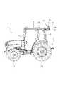
図1は、本発明を適用した作業車両を適用したトラクタの全体側面図であり、図2及び図3は、GNSSユニットを使用姿勢と収納姿勢に切換えた状態を示すトラクタの要部後方斜視図である。本トラクタは、左右一対の前輪1,1及び後輪2,2によって支持される機体フレーム3と、該機体フレーム3上に設置されたキャビン4とを備えることにより走行機体6が構成されており、前記走行機体6の後方には、昇降リンク7を介してロータリ耕運装置等の作業機(図示しない)を昇降可能に連結することができる。 FIG. 1 is an overall side view of a tractor to which a work vehicle to which the present invention is applied, and FIGS. 2 and 3 are rear perspective views of essential parts of the tractor showing a state in which the GNSS unit is switched between a use posture and a storage posture. is. This tractor comprises a body frame 3 supported by a pair of left and right front wheels 1, 1 and rear wheels 2, 2, and a
前記キャビン4内には、オペレータが着座する座席と、前記走行機体6(前輪1)の操向操作する操舵機構を操作するステアリングハンドルと、前記走行機体6の変速操作を行う主変速レバーと、前後進切換レバーと、副変速レバーと、前記作業機へ伝動されるエンジン動力の断続を操作するPTOスイッチ(PTO操作具)と、詳しくは後述する操舵ユニットとを備えている。 In the
上記副変速レバーは、トランスミッションを介して圃場面での作業走行に適した作業走行状態(作業状態)と、圃場面への移動の際に用いられる路上走行に適した路上走行状態(路上状態)とに切換えることができるように構成されている。 Through the transmission, the auxiliary transmission lever is set in a work travel state (working state) suitable for work travel in a field and a road travel state (road state) suitable for road travel used when moving to a field. It is configured to be able to switch between
上記操舵ユニット12は、詳しくは後述する操舵ユニット制御部50と、前記操舵ユニットの電源のON・OFFを操作する操作スイッチ53と、前記操舵機構による前記前輪1の操舵角を検出する操舵角センサ54と、前記操舵機構を操作するステッピングモータ56と、該ステッピングモータ56による駆動力を前記操舵機構に伝動する伝動部58とを有し、前記操舵機構20を介して前記走行機体6の操向操作を制御可能に構成されている(図6等参照)。 The
また、該キャビン4は、前記座席の後方側に配置された左右一対のリヤピラー13、13と、前記ステアリングハンドル8の前方側に配置された左右一対のフロントピラー14、14と、各ピラーの上端側に支持された天板16とを有し、前記キャビン4の上面(天板16)後端側には、測位衛星から前記走行機体6の位置情報を取得する位置情報受信装置であるRTK-GNSS受信装置(以下、GNSSユニット、GNSS受信装置、位置情報取得ユニット)17が取り付けられている(図1乃至3等参照)。 The
前記GNSSユニット17は、前記キャビンの後部側を左右方向に跨ぐように延設されて下方が開放されたコ字状に構成された可動支持フレーム(支持部材)18と、前記可動支持フレーム18に左右一対設けられた受信装置(受信アンテナ、GNSSアンテナ)21,21と、前記可動支持フレーム18の左右中央側に配置されてRTK基地局からの補正情報を取得する補正信号受信装置22と、前記補正信号受信装置22の下方側に設けられた後述する固定支持フレーム32に支持されたGNSS制御部30とを備え、前記可動支持フレーム18を含む支持機構20を介して前記キャビンの天板後部側に支持されている(図1等参照)。 The GNSS
このとき、前記支持機構20は、前記可動支持フレーム18を上方(前方)揺動することにより左右一対の前記受信装置21、21と、前記補正信号受信装置22とを前記キャビン4の天板16後部上側に掲げるように支持する使用姿勢と、前記可動支持フレーム18を下方(後方)揺動することによって前記受信装置21、21と前記補正信号受信装置22とを前記キャビン4の天板16よりも低い位置となるように退避させる収納姿勢とに姿勢切換できるように構成されている(図2及び図3参照)。該支持機構20の具体的な構成については後述する。 At this time, the
上記受信装置21,21は、左右一方側の受信装置21が前記走行機体6の基準となる位置情報を受信するための受信アンテナであり、左右他方側の受信装置21が前記走行機体の方位情報を取得するための受信アンテナである。また、上記受信装置21,21は、前記可動支持フレーム18によって前記キャビン4上面の後部側に配置されるように構成したことにより、前記GNSSユニット17の取付作業が容易になるとともに、受信装置21をキャビン4上側の中では設置高さを低くすることができる。 The
上記補正信号受信装置22は、作業走行する圃場面からある程度離れた場所に設置されたRTK基地局(図示しない)から補正情報(具体的には、RTK基地局の座標データと、前記走行機体6と前記RTK基地局との間の距離データ等)を受信するように構成されている。これにより、前記受信装置21によって取得された前記走行機体6の位置情報を補正することによって、前記走行機体6の位置情報の精度をセンチメートル単位まで向上させることができる。 The correction
上記GNSS制御部30(GNSSユニット17)は、コントロールエリアネットワーク(CAN)等を介して前記操舵ユニット制御部50に接続されており、該操舵ユニット制御部50に測位衛星システムから取得された前記走行機体6の位置情報、方位情報等を入力することができるように構成されている。これにより、前記操舵ユニット制御部50は、前記位置情報取得ユニットにより取得された前記走行機体6の位置情報を用いて、圃場を予め設定した走行ライン上を作業走行するように前記操舵ユニット12を制御する自動操舵制御が実行可能に構成されている。 The GNSS control unit 30 (GNSS unit 17) is connected to the steering
また、該GNSS制御部30は、無線通信(Bluetooth(登録商標))、wifi等)を介して情報端末であるタブレット端末23に接続できるように構成されている。前記タブレット端末23は、タブレット制御部60と、タッチパネル等のモニタからなる表示装置61と、前記GNSS制御部30と無線通信するための近距離無線機62とを備えている。 Also, the GNSS
該タブレット端末23には、例えば、前記副変速レバーの操作状態や、走行機体の速度、前記走行走行機体6後方の作業機の昇降・駆動状態等、前記トラクタの走行・作業状況に関する情報を各制御部30、50と共有できるように構成されている。また、該タブレット端末23には、ナビゲーションソフトがインストールされており、前記操舵ユニット制御部50による前記自動操舵制御の実行を補助できるようにも構成されている。 The
さらに、該タブレット端末23は、前記キャビン4内にいる作業者に対して前記GNSSユニット(支持機構)がどの姿勢に切換えられているか前記表示装置61を介して報知できるとともに、前記GNSSユニット17を使用姿勢にすべき状態(作業走行状態等)で収納姿勢に切換えられている場合や、前記GNSSユニット17を収納姿勢にすべき状態(路上走行状態等)で使用姿勢に切換えられている場合に、作業者に対してその旨の報知(注意喚起)を行うこともできる。 Furthermore, the
ちなみに、該タブレット端末23は、前記GNSSユニット17の姿勢を切換える姿勢切換スイッチを設ける(表示)ことで、オペレータによるスイッチ操作で前記GNSSユニット17の姿勢を任意に切換操作できるようにも構成されている。 Incidentally, the
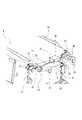
次に、図1乃至5に基づいて、前記支持機構の具体的な構成について説明する。図4(A)乃至(D)は、GNSSユニットを示した斜視図、平面図、正面図、側面図であり、図5(A)及び(B)は、GNSSユニットの分解斜視図である。 Next, a specific configuration of the support mechanism will be described with reference to FIGS. 1 to 5. FIG. 4A to 4D are a perspective view, a plan view, a front view and a side view showing the GNSS unit, and FIGS. 5A and 5B are exploded perspective views of the GNSS unit.
前記支持機構20は、前記可動支持フレーム18と、左右一対の前記リヤピラー13(前記キャビン4後端)の上端側に取付固定される一対の取付ブラケット31、31と、一対の前記取付ブラケット31の後部側同士を架渡すように左右方向に延設された前記固定支持フレーム32と、前記可動支持フレーム18側に取付固定されたセンサユニットである慣性計測装置(検出センサ、IMU)33と、前記可動支持フレーム18を上下揺動作動させる駆動モータ(アクチュエータ、モータ)35が収容された駆動装置34とを備えている(図4及び図5等参照)。 The
前記取付ブラケット31は、前記リヤピラー13側に取付固定される前側ブラケット31Aと、前記可動支持フレーム18と前記固定支持フレーム32と前記駆動装置34とが取付けられる後側ブラケット31Bとから構成されている。これにより、該取付ブラケット31は、その前端側が前記リヤピラー13の上部側に取付けられることにより、該リヤピラー13(前記キャビン4後端)から後方に向けて延設されている。 The mounting
上記前側ブラケット31Aは、左右外側が開放されたコ字状に屈曲形成された板状部材であって、その上面側には左右外側に長く延設された板状の固定部36が形成されている。これにより、該前側ブラケット31Aは、前記固定部36を、前記天板16の後端又は前記リヤピラー13の上端側に形成された板状の取付片37にボルト等を用いて取付固定することができるように構成されている(図3及び図4等参照)。 The
上記後側ブラケット31Bは、前後方向に長く形成されるとともに左右内側が開放された箱状に形成されており、その上面側には、前記固定支持フレーム32が取付固定され、その左右外面側には、前記可動支持フレーム18が上下(前後)揺動可能に軸支されるように構成されている。また、左右一方側の後側ブラケット31Bの左右内側には、前記駆動装置34が着脱可能に取付けられるように構成されている(図6等参照)。 The
前記固定支持フレーム32は、左右方向に延設された角柱(棒)状の部材であって、その両端側が一対の前記取付ブラケット31、31を架渡す(連結する)ように、前記後側ブラケット31Bの上面側に取付固定されている。このとき、該固定支持フレーム32の端部側は、上方が開放されたコ字状に形成されるとともに、該固定支持フレーム32が嵌合される凹部が形成された固定部材38を介して、前記後側ブラケット31Bの上面側に固定されている。 The fixed
また前記固定支持フレーム32は、その左右方向中央の上部側に、箱状のケース体に収容された前記GNSS制御部30が取付け固定されている。具体的に説明すると、前記ケース体(GNSS制御部30)の下部側には、前記固定支持フレーム32が嵌合する凹部が左右一対形成された取付部材39、39が設けられており、該取付部材39によって前記固定支持フレーム32側に安定的に取付固定されている。 The fixed
これにより、該固定支持フレーム32に固定された前記GNSS制御部30は、前記キャビン4の後方に支持されるとともに、前記支持機構20(可動支持フレーム18)の姿勢切換えの影響を受けることなく、常に前記キャビン4の天板16よりも低い位置に支持されるように構成されている。 As a result, the
前記可動支持フレーム18は、左右方向に延設された棒状の延設部18aと、該延設部18aの左右両端側を下方に向けて屈曲形成された屈曲部18b,18bとによって、全体で下方が開放されたコ字状に形成されており、前記屈曲部18bの左右内側に取付固定された円板状の取付部材41を介して、前記取付ブラケット31(後側ブラケット31B)の左右外側に軸支されている。 The
上記取付部材41は、左右一方(図示する例では左)側には、前記後側ブラケット31Bの外面側に突設された軸部42が軸支される筒状の軸支部43が形成され(図5(A)参照)、左右他方(図示する例では右)側には、前記後側ブラケット31B側に形成された軸孔44に挿通される軸部材46が設けられている(図5(A)及び(B)参照)。このとき、前記軸部材46は、前記後側ブラケット31Bを挟んだ反対側に設けられた前記駆動装置34と連結可能に構成されている。詳しくは後述する。 The mounting
また、各取付部材41、41には、前記軸支部43又は軸部材46を軸とした円弧状に形成された前後一対の規制孔47が形成されており、各規制孔47には、前記後側ブラケット31Bの左右外面側に突設されたボルトの頭部等からなる突設部48が挿通されるように構成されている(図4及び図5等参照)。これにより、前記可動支持フレーム18は、側面視で前記屈曲部18bが直立した使用姿勢(図2参照)と、前記屈曲部18bが後方に向けて略水平な状態とした収容姿勢(図3参照)とに姿勢切換可能な構成で、前記取付ブラケット31側に軸支されている。 A pair of front and rear restriction holes 47 formed in an arc shape about the
また、前記可動支持フレーム18は、前記延設部18aの左右両端側に、一対の前記受信装置21,21が取付けられ、前記延設部18aの左右中央には、前記慣性計測装置33と、前記補正信号受信装置22とが取付けられている。 The
具体的に説明すると、前記延設部18aの左右中央には、L字状に屈曲形成された板状部材である取付板49が取付固定されており、該取付板49の上面側に箱(四角推台)状のケース体に収容された前記慣性計測装置33が固定され、箱状の前記慣性計測装置33の上面側に前記補正信号受信装置22が取付固定されている(図5(A)及び(B)等参照)。 More specifically, a mounting
該構成によれば、前記支持機構20(可動支持フレーム18)を使用姿勢に切換えることにより、一対の前記受信装置21,21と、前記補正信号受信装置22と、前記慣性計測装置33とを前記キャビン4上面(天板)の上方側に掲げるように設置できる一方で、前記支持機構20を収納姿勢に切換えることにより、一対の前記受信装置21,21と、前記補正信号受信装置22と、前記慣性計測装置33とを前記キャビン4上面(天板16)の下方へとスムーズに移動させることができる(図2及び図3等参照)。 According to this configuration, by switching the support mechanism 20 (movable support frame 18) to the use posture, the pair of
これにより、前記慣性計測装置33は、前記支持機構20の姿勢が切換えられた際に、前記可動支持フレーム18と一体的に上下(前後)揺動操作されるため、該慣性計測装置33によって前記支持機構20の姿勢(切換)を検出することができる。すなわち、前記走行機体6(車体)の傾斜等の姿勢の検出に用いられる前記慣性計測装置33を、前記支持機構20の姿勢を検出するためセンサとしても兼用することで、前記支持機構20の姿勢を検出するための専用のセンサを別途に設ける必要がなくなるため、コストをより低く抑えることができる。 As a result, the
前記駆動装置34は、前記GNSS制御部30により制御可能な前記駆動モータ35と、前記駆動モータ35によって駆動する出力ギヤ35aによって駆動するとともに前記取付ブラケット41の左右内側から前記軸部材46と接続される駆動軸40と、前記駆動モータ35を収容するケース体とを有し、前記駆動モータ35の駆動によって、前記可動支持フレーム18の上下(前後)揺動操作(前記支持機構20(GNSSユニット17)の姿勢切換)を操作できるように構成されている(図5(A)及び(B)等参照)。 The
前記GNSS制御部30は、所定の操作が検出された場合や所定条件を満たした場合に、前記駆動モータ35を介して前記GNSSユニット17の姿勢を自動的に切換える(GNSSユニット)姿勢切換制御が実行可能に構成されている。該姿勢切換制御の詳細については後述する。 The
上述の構成の支持機構20によれば、前記GNSSユニット17を測位衛星から前記走行機体6の位置情報を取得し易いより高い位置へ支持する使用姿勢と、前記GNSSユニット17が邪魔にならない低い位置へ支持する収容姿勢との姿勢切換を、オペレータが手動で行う必要がなくなるため、作業性が向上する。 According to the
次に、図6に基づいて、前記GNSS制御部による姿勢切換制御について説明する。図7は、各制御部を示したブロック図である。 Next, attitude switching control by the GNSS control unit will be described with reference to FIG. FIG. 7 is a block diagram showing each control unit.
前記GNSS制御部30の入力側には、前記受信装置(GNSSアンテナ、GNSS受信機)21と、前記補正信号受信装置(無線アンテナ、特定小電力無線機)22と、前記慣性計測装置(加速度センサ、ジャイロセンサ)33とが接続されており、前記GNSS制御部30の出力側には、前記駆動モータ35と、7セグメントディスプレイ51と、前記タブレット端末23と通信するための近距離無線機52とが接続されている。 On the input side of the
該GNSS制御部30とCANを介して接続される前記操舵ユニット制御部50の入力側には、前記操作スイッチ53と、前記操舵角センサ54とが接続されており、前記操舵ユニット制御部50の出力側には、前記ステッピングモータ56と、前記操舵ユニット12の電源の入切状態等を表示するLEDランプ57とが接続されている。 The
前記GNSS制御部30による前記姿勢制御は、前記操作スイッチ53によって前記操舵ユニット12の電源ON操作(状態)が検出された場合には、前記駆動モータ35を介して前記GNSSユニット17を収納姿勢から使用姿勢へと切換えるように構成されている。 The attitude control by the
該構成によれば、前記GNSSユニット17により取得した前記走行機体6の位置情報を用いる前記自動操舵制御を実行するにあたり、前記GNSS制御部30は、前記操舵ユニット12の電源ON操作が検出された際に、特別な操作を行うことなく前記GNSSユニット17が自動的に使用姿勢に切換えられるため、作業性が向上する。 According to this configuration, in executing the automatic steering control using the position information of the traveling
また、前記姿勢制御(GNSS制御部30)は、前記副変速レバーによって路上走行状態に切換えられたことが検出された場合や、前記PTOスイッチの操作によって作業機(PTO軸)への動力伝動が切断操作された(作業機の駆動が終了した)場合には、前記GNSSユニット17が自動的に収納姿勢に切換えられるように構成されている。 In addition, the attitude control (GNSS control unit 30) is activated when it is detected that the sub-transmission lever is switched to the road running state, or when the PTO switch is operated to stop the power transmission to the working machine (PTO shaft). The
該構成によれば、前記副変速レバーや、前記PTOスイッチの操作により路上走行状態に切換えられた(作業機への動力伝動が切断操作された)状態、言い換えると、圃場以外での路上走行時や車庫等への駐車時には、オペレータが所定の切換操作を行わなくても前記GNSSユニット17が自動的に収納姿勢に切換えられるため、安全性が向上する。 According to this configuration, the auxiliary transmission lever and the PTO switch are operated to switch to a road running state (the power transmission to the work machine is cut off), in other words, when the vehicle is running on a road other than a field. When the vehicle is parked in a garage or the like, the
6 走行機体
9 ステアリングハンドル
12 操舵ユニット(自動操舵装置)
17 GNSSユニット(位置情報取得ユニット、位置情報取得装置)
18 可動支持フレーム(支持部材)
20 支持機構
30 GNSS制御部(制御部)
33 慣性計測装置(検出センサ、IMU)
35 駆動モータ(モータ、アクチュエータ)
50 操舵ユニット制御部(制御部)6 traveling body 9 steering handle 12 steering unit (automatic steering device)
17 GNSS unit (location information acquisition unit, location information acquisition device)
18 movable support frame (support member)
20
33 inertial measurement unit (detection sensor, IMU)
35 drive motor (motor, actuator)
50 steering unit control section (control section)
Claims (4)
Translated fromJapanese前記走行機体の位置情報を取得する位置情報取得ユニットと、
前記位置情報取得ユニットを前記走行機体の上方側に支持するとともに、前記位置情報取得ユニットを使用姿勢と収納姿勢とに姿勢切換可能に支持する支持機構と、
制御部とを備え、
前記支持機構は、前記位置情報取得ユニットを回動可能に支持する支持部材と、該支持部材を姿勢切換するアクチュエータと、前記位置情報取得ユニットと一体回動するように支持されることにより前記位置情報取得ユニットの姿勢を検出する検出センサとを有し、
前記制御部は、前記アクチュエータを介して前記位置情報取得ユニットの姿勢切換えを制御するように構成された
作業車両。a running body,
a position information acquisition unit that acquires position information of the traveling body;
a support mechanism that supports the position information acquisition unit on the upper side of the traveling body and supports the position information acquisition unit so that the posture can be switched between a use posture and a storage posture;
and a control unit,
The support mechanism includes a support member that rotatably supports the position information acquisition unit, an actuator that switches the posture of the support member, and the position information acquisition unit that is supported so as to rotate integrally with the position information acquisition unit. a detection sensor that detects the orientation of the information acquisition unit;
The work vehicle, wherein the control section is configured to control attitude switching of the position information acquisition unit via the actuator.
請求項1に記載の作業車両。The work vehicle according to claim 1, wherein the detection sensor is an inertial measurement device capable of detecting the posture of the vehicle.
前記制御部は、前記位置情報取得ユニットにより取得された前記走行機体の位置情報に基づいて、前記自動操舵装置を介して前記走行機体の操向操作を制御する自動操舵制御が実行可能に構成され、
前記制御部は、前記自動操舵装置の電源入り状態が検出された場合には、前記位置情報取得ユニットを自動的に使用姿勢に切換えるように構成された
請求項1又は2に記載の作業車両。An automatic steering device for automatically operating a steering handle for steering the traveling machine is provided,
The control unit is configured to be capable of executing automatic steering control for controlling a steering operation of the traveling machine body via the automatic steering device based on the position information of the traveling machine body acquired by the position information acquisition unit. ,
The work vehicle according to claim 1 or 2, wherein the control section is configured to automatically switch the position information acquisition unit to the use posture when a power-on state of the automatic steering device is detected.
前記制御部は、路上状態に切換えられた場合には、前記位置情報取得ユニットが収納姿勢に切換えられるように構成された
請求項1乃至3の何れかに記載の作業車両。The traveling machine body is configured to be switchable between at least a working state in which it travels for work in a field and a road state in which it travels on a road,
The work vehicle according to any one of claims 1 to 3, wherein the control section is configured to switch the position information acquisition unit to the retracted posture when the state is switched to the road state.
Priority Applications (1)
| Application Number | Priority Date | Filing Date | Title |
|---|---|---|---|
| JP2021016628AJP2022119475A (en) | 2021-02-04 | 2021-02-04 | work vehicle |
Applications Claiming Priority (1)
| Application Number | Priority Date | Filing Date | Title |
|---|---|---|---|
| JP2021016628AJP2022119475A (en) | 2021-02-04 | 2021-02-04 | work vehicle |
Publications (1)
| Publication Number | Publication Date |
|---|---|
| JP2022119475Atrue JP2022119475A (en) | 2022-08-17 |
Family
ID=82848220
Family Applications (1)
| Application Number | Title | Priority Date | Filing Date |
|---|---|---|---|
| JP2021016628APendingJP2022119475A (en) | 2021-02-04 | 2021-02-04 | work vehicle |
Country Status (1)
| Country | Link |
|---|---|
| JP (1) | JP2022119475A (en) |
Citations (9)
| Publication number | Priority date | Publication date | Assignee | Title |
|---|---|---|---|---|
| JP2002340567A (en)* | 2001-05-11 | 2002-11-27 | Pioneer Electronic Corp | System and method for navigation, information recording medium with recorded program for navigation, and the program for navigation |
| JP2006011623A (en)* | 2004-06-23 | 2006-01-12 | Denso Corp | On-vehicle communication terminal equipment |
| US20070198185A1 (en)* | 2002-12-11 | 2007-08-23 | Mcclure John A | GNSS control system and method |
| JP2011255787A (en)* | 2010-06-09 | 2011-12-22 | Tokai Rika Co Ltd | Device for housing of vehicle antenna |
| JP2015213519A (en)* | 2015-07-31 | 2015-12-03 | 井関農機株式会社 | Passenger management machine |
| CN207908976U (en)* | 2018-03-26 | 2018-09-25 | 遵义师范学院 | A kind of wireless automatic navigation control equipment of rotary cultivator |
| JP2019070544A (en)* | 2017-10-06 | 2019-05-09 | ヤンマー株式会社 | Work vehicle |
| JP2019080498A (en)* | 2017-10-27 | 2019-05-30 | 井関農機株式会社 | Work vehicle |
| JP2020103055A (en)* | 2018-12-26 | 2020-07-09 | 株式会社クボタ | Harvester |
- 2021
- 2021-02-04JPJP2021016628Apatent/JP2022119475A/enactivePending
Patent Citations (9)
| Publication number | Priority date | Publication date | Assignee | Title |
|---|---|---|---|---|
| JP2002340567A (en)* | 2001-05-11 | 2002-11-27 | Pioneer Electronic Corp | System and method for navigation, information recording medium with recorded program for navigation, and the program for navigation |
| US20070198185A1 (en)* | 2002-12-11 | 2007-08-23 | Mcclure John A | GNSS control system and method |
| JP2006011623A (en)* | 2004-06-23 | 2006-01-12 | Denso Corp | On-vehicle communication terminal equipment |
| JP2011255787A (en)* | 2010-06-09 | 2011-12-22 | Tokai Rika Co Ltd | Device for housing of vehicle antenna |
| JP2015213519A (en)* | 2015-07-31 | 2015-12-03 | 井関農機株式会社 | Passenger management machine |
| JP2019070544A (en)* | 2017-10-06 | 2019-05-09 | ヤンマー株式会社 | Work vehicle |
| JP2019080498A (en)* | 2017-10-27 | 2019-05-30 | 井関農機株式会社 | Work vehicle |
| CN207908976U (en)* | 2018-03-26 | 2018-09-25 | 遵义师范学院 | A kind of wireless automatic navigation control equipment of rotary cultivator |
| JP2020103055A (en)* | 2018-12-26 | 2020-07-09 | 株式会社クボタ | Harvester |
Similar Documents
| Publication | Publication Date | Title |
|---|---|---|
| JP7736854B2 (en) | Work vehicles | |
| JP7422909B2 (en) | work vehicle | |
| US20230127868A1 (en) | Antenna Unit for Work Vehicle and Work Vehicle | |
| KR20180002018A (en) | Working vehicle | |
| JP6716762B1 (en) | Work vehicle | |
| JP7146671B2 (en) | work vehicle | |
| JP6892363B2 (en) | Tractor | |
| KR102493703B1 (en) | work car | |
| JP7352679B2 (en) | rice transplanter | |
| JP2022119475A (en) | work vehicle | |
| JP7294990B2 (en) | work vehicle | |
| JP2023126413A (en) | Agricultural equipment | |
| JP2013087577A (en) | Display unit of work machine | |
| JP2021032773A (en) | Work vehicle | |
| JP7578495B2 (en) | Work vehicles | |
| JP7345383B2 (en) | rice transplanter | |
| JP2020128996A (en) | Work vehicle | |
| JP2023091607A (en) | Paddy work machine | |
| JP2023091608A (en) | Paddy work machine |
Legal Events
| Date | Code | Title | Description |
|---|---|---|---|
| RD04 | Notification of resignation of power of attorney | Free format text:JAPANESE INTERMEDIATE CODE: A7424 Effective date:20220804 | |
| A621 | Written request for application examination | Free format text:JAPANESE INTERMEDIATE CODE: A621 Effective date:20231130 | |
| A977 | Report on retrieval | Free format text:JAPANESE INTERMEDIATE CODE: A971007 Effective date:20240412 | |
| A131 | Notification of reasons for refusal | Free format text:JAPANESE INTERMEDIATE CODE: A131 Effective date:20240604 | |
| A521 | Request for written amendment filed | Free format text:JAPANESE INTERMEDIATE CODE: A523 Effective date:20240731 | |
| A02 | Decision of refusal | Free format text:JAPANESE INTERMEDIATE CODE: A02 Effective date:20241029 |