JP2022118593A - IoT control system, data display method, device control method and program - Google Patents
IoT control system, data display method, device control method and programDownload PDFInfo
- Publication number
- JP2022118593A JP2022118593AJP2021015216AJP2021015216AJP2022118593AJP 2022118593 AJP2022118593 AJP 2022118593AJP 2021015216 AJP2021015216 AJP 2021015216AJP 2021015216 AJP2021015216 AJP 2021015216AJP 2022118593 AJP2022118593 AJP 2022118593A
- Authority
- JP
- Japan
- Prior art keywords
- data
- allocation
- fixed
- iot
- input
- Prior art date
- Legal status (The legal status is an assumption and is not a legal conclusion. Google has not performed a legal analysis and makes no representation as to the accuracy of the status listed.)
- Granted
Links
Images


Landscapes
- Computer And Data Communications (AREA)
- User Interface Of Digital Computer (AREA)
Abstract
Translated fromJapaneseDescription
Translated fromJapanese本発明は、ユーザデバイスで取得したデータをユーザインタフェースに表示する及びユーザインタフェースから入力されたデータに基づきユーザデバイスを制御する有効な技術に関する。 The present invention relates to effective techniques for displaying data acquired by a user device on a user interface and for controlling the user device based on data input from the user interface.
近年、ユーザデバイスデバイスと、ユーザインタフェース(以下、単に、UI(User Interface)とも称す)とを接続するIoT(Internet of Things)システムに関して、様々な技術が提案されている。
例えば、特許文献1では、ユーザデバイス(文献中では、センサ装置)から収集したデータを種類・時間を分類して管理することにより、異なるデータを扱いやすいようにする手法が提案されている。また、特許文献2では、ユーザデバイス(文献中では、エッジ)からのデータをアプリケーションで利用しやすいデータに変換する手法が提案されている。また、特許文献3では、上位アプリケーションのリクエストに対するユーザデバイス(文献中ではデバイス)からのレスポンスを、上位アプリケーションに対応する形式に変換・成形する手法が提案されている。
また、他にも、特許文献4では、ユーザデバイス(文献中ではデバイス)の識別情報に基づいて制御アプリケーションをインストールする手法が提案されている。また、特許文献5では、ユーザデバイス(文献中では、リモートデバイス)から受信したデバイス情報に基づいて、UIを構成する手法が提案されている。In recent years, various techniques have been proposed for IoT (Internet of Things) systems that connect user devices and user interfaces (hereinafter also simply referred to as UIs (User Interfaces)).
For example,
In addition,
しかしながら、特許文献1-3において提案されている手法は、何れも、「ユーザデバイスで扱うデータ」と、「IoTアプリケーションで扱うデータ」とのデータ変換を行う必要が生じる。様々な用途(センサ等)が存在するユーザデバイスでは、その用途毎のデータ変換を各々行う必要が生じる。そのため、ユーザが所望するカスタマイズが容易に行えるものではなかった。
また、特許文献4及び5において提案されている手法でも、同様に、ユーザデバイスに合わせてUIを個別に設定する必要がある。そのため、ユーザデバイスからUIまでの間で、専用のサービス構築が必要になってしまっていた。
特許文献1-5において提案されている手法は、何れも、その導入、特に用途により異なるニーズにカスタマイズするハードルが高くなっていた。具体的には、ニーズに合わせてユーザデバイス及びUIを開発する必要があり、導入までのコスト・期間がかかってしまうという問題があった。そもそも、その効果が見えずに投資できないという課題のあるIoTシステムを導入するハードルが更に高くなっているのが現状である。
例えば、既存機器をIoT管理したい場合、既存アプリケーションから、「コマンドで」通信デバイスを制御するアプリケーションの開発が必要となる。このためには、通信モジュール・ルータのインタフェース・コマンド仕様を把握し、それに合わせたデバイスアプリケーションの開発が必要となる。また、UIは汎用的で、ニーズに合わせて一元管理するには、個別にUIを開発することが必要となる。その結果、開発コストが嵩んでしまうおそれがあった。
さらに、ユーザデバイスを複数管理する場合には、ネットワークに接続可能な有料通信を行う通信モジュールを増やすか、通信モジュールをゲートウェイとしたローカルネットワークを自ら開発する必要がある。ローカルネットワークが用意されている場合でも、そのインタフェース・コマンド仕様を把握し、それに合わせたデバイスアプリケーション開発が必要なことには変わりはない。このため、簡単且つ低コストで様々な用途に、IoTによるリモート管理を導入することは困難であった。However, all of the methods proposed in
Similarly, in the methods proposed in
All of the methods proposed in
For example, when IoT management of existing equipment is desired, it is necessary to develop an application that controls a communication device "by command" from an existing application. For this purpose, it is necessary to understand the interface command specifications of the communication module/router and develop device applications that match them. In addition, the UI is general-purpose, and it is necessary to develop the UI individually in order to centrally manage it according to needs. As a result, the development cost may increase.
Furthermore, when managing multiple user devices, it is necessary to increase the number of communication modules that can be connected to the network and perform paid communication, or to develop a local network using a communication module as a gateway. Even if a local network is available, it is still necessary to understand its interface and command specifications and develop device applications that match them. Therefore, it has been difficult to introduce IoT-based remote management for various purposes simply and at low cost.
この課題を生じている原因は、通信データセントリックなシステム構成を行っていないことに起因する。そこで、本発明者らは、エッジデバイスからUIまで一貫したデータ構成を用いれば、ユーザデバイスから通信モジュールまでの間は、特別な制御を一切不要にできるため、この問題が解決できることに着目した。 The cause of this problem is that the system configuration is not communication data-centric. Therefore, the inventors focused on the fact that using a consistent data structure from the edge device to the UI eliminates the need for any special control from the user device to the communication module, thus solving this problem.
そこで、本発明は、簡単且つ低コストで様々な用途に、IoTによるリモート管理を導入することが可能なIoT制御システム、データ表示方法、デバイス制御方法及びプログラムを提供することを目的とする。 Accordingly, an object of the present invention is to provide an IoT control system, a data display method, a device control method, and a program that enable remote management by IoT to be introduced simply and at low cost for various uses.
本発明は、ユーザデバイスで取得したデータをユーザインタフェースに表示するIoT制御システムであって、
データの割当順序、割当範囲が用途に基づいて予め定められた定型フォーマットを保存するストレージと、
前記ユーザデバイスから前記定型フォーマットの割当順序で送られた元データを受け取り、前記定型フォーマット内の割当範囲に、当該元データを挿入した定型データを生成するエッジデバイスと、
前記エッジデバイスが生成した前記定型データを受信し、前記ストレージを参照して、前記割当範囲から何の用途のデータであるかを判断するIoTアプリケーションと、
を備えることを特長とするIoT制御システムを提供する。The present invention is an IoT control system that displays data acquired by a user device on a user interface,
a storage that stores a fixed format in which the data allocation order and allocation range are predetermined based on the application;
an edge device that receives original data sent from the user device in the fixed format allocation order and generates fixed data by inserting the original data into the allocation range in the fixed format;
an IoT application that receives the fixed data generated by the edge device, refers to the storage, and determines for what purpose the data is used from the allocation range;
To provide an IoT control system characterized by comprising:
本発明によれば、ユーザデバイスで取得したデータをユーザインタフェースに表示するIoT制御システムは、ストレージが、データの割当順序、割当範囲が用途に基づいて予め定められた定型フォーマットを保存し、エッジデバイスが、前記ユーザデバイスから前記定型フォーマットの割当順序で送られた元データを受け取り、前記定型フォーマット内の割当範囲に、当該元データを挿入した定型データを生成し、IoTアプリケーションが、前記エッジデバイスが生成した前記定型データを受信し、前記ストレージを参照して、前記割当範囲から何の用途のデータであるかを判断する。 According to the present invention, in an IoT control system that displays data acquired by a user device on a user interface, the storage stores a fixed format in which the data allocation order and allocation range are predetermined based on the application, and the edge device receives the original data sent from the user device in the fixed format allocation order, generates fixed data by inserting the original data into the allocation range in the fixed format, and the IoT application receives the edge device The generated standard data is received, the storage is referenced, and the use of the data is determined from the allocation range.
また、本発明は、ユーザインタフェースから入力されたデータに基づきユーザデバイスを制御するIoT制御システムであって、
データの割当順序、割当範囲が用途に基づいて予め定められた定型フォーマットを保存するストレージと、
前記ユーザインタフェースから入力された入力データを受け取り、前記ストレージを参照して、予め定められた定型フォーマット内の割当範囲に、前記入力データを挿入した定型コマンドを生成するIoTアプリケーションと、
前記定型コマンドを受け取り、コマンド情報を前記ユーザデバイスに送信するエッジデバイスと、
を備えることを特長とするIoT制御システムを提供する。Further, the present invention is an IoT control system that controls a user device based on data input from a user interface,
a storage that stores a fixed format in which the data allocation order and allocation range are predetermined based on the application;
an IoT application that receives input data input from the user interface, refers to the storage, and generates a fixed command in which the input data is inserted into an allocation range within a predetermined fixed format;
an edge device that receives the fixed command and transmits command information to the user device;
To provide an IoT control system characterized by comprising:
本発明によれば、ユーザインタフェースから入力されたデータに基づきユーザデバイスを制御するIoT制御システムは、ストレージが、データの割当順序、割当範囲が用途に基づいて予め定められた定型フォーマットを保存し、IoTアプリケーションが、前記ユーザインタフェースから入力された入力データを受け取り、前記ストレージを参照して、予め定められた定型フォーマット内の割当範囲に、前記入力データを挿入した定型コマンドを生成し、エッジデバイスが、前記定型コマンドを受け取り、コマンド情報を前記ユーザデバイスに送信する。 According to the present invention, an IoT control system that controls a user device based on data input from a user interface stores a fixed format in which the order and range of data allocation are predetermined based on the application, An IoT application receives input data input from the user interface, refers to the storage, generates a fixed command in which the input data is inserted in an allocation range within a predetermined fixed format, and an edge device , receiving the fixed command and transmitting command information to the user device;
本発明によれば、簡単且つ低コストで様々な用途にIoT制御システムを導入することが可能となる。 According to the present invention, it is possible to introduce an IoT control system to various uses simply and at low cost.
以下、添付図面を参照して、本発明を実施するための形態(以下、実施形態)について詳細に説明する。以降の図においては、実施形態の説明の全体を通して同じ要素には同じ番号または符号を付している。 EMBODIMENT OF THE INVENTION Hereinafter, with reference to an accompanying drawing, the form (henceforth, embodiment) for implementing this invention is demonstrated in detail. In subsequent figures, the same numbers or symbols are attached to the same elements throughout the description of the embodiments.
[基本概念/基本構成]
図1及び図2は、IoT制御システム1の概要を説明するための図である。IoT制御システム1は、コンピュータ10、エッジデバイス20、ユーザデバイス30を少なくとも含むシステムである。IoT制御システム1は、ユーザデバイス30で取得したデータをユーザインタフェース端末40(以下、単にUI端末とも称す)に表示するシステムである。また、IoT制御システム1は、UI端末40から入力されたデータに基づきユーザデバイス30を制御するシステムである。
コンピュータ10は、各種データ等を保存するストレージ11を備える。また、コンピュータ10は、IoT管理に関する処理を実行するIoTアプリケーション12を備える。また、コンピュータ10は、データの入出力を制御するUI制御アプリケーション13を備える。
エッジデバイス20は、ユーザデバイス30及びコンピュータ10と各種データの遣り取りを行う装置である。
ユーザデバイス30は、温度センサ、湿度センサ等のIoTセンサ等からなる装置である。[Basic Concept/Basic Configuration]
1 and 2 are diagrams for explaining an overview of the
The
The edge device 20 is a device that exchanges various data with the user device 30 and the
The user device 30 is a device including an IoT sensor such as a temperature sensor and a humidity sensor.
IoT制御システム1がデータをUI端末40に表示する処理ステップについて、図1に基づいて概要を説明する。
初めに、コンピュータ10は、ストレージ11に、データの割当順序、割当範囲が用途に基づいて予め定められた定型フォーマットを保存する(ステップS1)。
UI制御アプリケーション13は、ユーザ等から、データの割当順序、割当範囲の設定を受け付ける。UI制御アプリケーション13は、ユーザ等から、データの順序、データの用途、長さ等をnbyteの範囲で任意に設定を受け付ける。
IoTアプリケーション12は、受け付けた設定に基づいて、定型フォーマットを設定し、ストレージ11に保存する。Processing steps for the
First, the
The UI control application 13 receives data allocation order and allocation range settings from the user or the like. The UI control application 13 accepts arbitrarily set data order, data usage, length, etc. within the range of n bytes from the user or the like.
The IoT application 12 sets a standard format based on the received settings and saves it in the
エッジデバイス20は、ユーザデバイス30から定型フォーマットの割当順序で送られた元データを受け取り、定型フォーマットの割当範囲に、この元データを挿入した定型データを生成する(ステップS2)。
ユーザデバイス30は、検出したデータ等を元データとして、エッジデバイス20に送信し、エッジデバイス20は、この元データを受け取る。
エッジデバイス20は、定型フォーマットに設定された元データの割当範囲に、元データを受け取った順番に、この元データを挿入し、定型データを生成する。The edge device 20 receives the original data sent from the user device 30 in the fixed format allocation order, and generates fixed data by inserting the original data into the fixed format allocation range (step S2).
The user device 30 transmits the detected data and the like as original data to the edge device 20, and the edge device 20 receives this original data.
The edge device 20 inserts the original data into the allocation range of the original data set in the fixed format in the order in which the original data was received, and generates fixed data.
コンピュータ10は、IoTアプリケーション12により、エッジデバイス20が生成した定型データを受信し、ストレージ11を参照して、割当範囲から何の用途のデータであるかを判断する(ステップS3)。
エッジデバイス20は、生成した定型データを、コンピュータ10に送信し、IoTアプリケーション12は、この定型データを受信する。IoTアプリケーション12は、ストレージ11を参照し、定型データを解析する。IoTアプリケーション12は、定型データにおける元データの割当範囲から、この元データが何の用途のデータであるかを判断する。
UI制御アプリケーション13は、判断したデータの用途に応じて、UI端末40に表示するグラフ等のデータを生成する。The
The edge device 20 transmits the generated fixed data to the
The UI control application 13 generates data such as graphs to be displayed on the UI terminal 40 according to the determined use of the data.
このようなIoT制御システム1によれば、エッジデバイス20からUI端末40まで一貫したデータ構成を用いることになり、簡単且つ低コストで様々な用途に、IoTによるリモート管理を導入することが可能となる。 According to such an
以上が、IoT制御システム1がデータをUI端末40に出力表示する処理ステップの概要である。 The above is an overview of the processing steps in which the
次に、IoT制御システム1がユーザデバイス30を制御する処理ステップについて、図2に基づいて概要を説明する。
初めに、コンピュータ10は、ストレージ11に、データの割当順序、割当範囲が用途に基づいて予め定められた定型フォーマットを保存する(ステップS4)。
UI制御アプリケーション13は、ユーザ等から、データの割当順序、割当範囲の設定を受け付ける。UI制御アプリケーション13は、ユーザ等から、データの順序、データの用途、長さ等をnbyteの範囲で任意に設定を受け付ける。
IoTアプリケーション12は、受け付けた設定に基づいて、定型フォーマットを設定し、ストレージ11に保存する。Next, processing steps for the
First, the
The UI control application 13 receives data allocation order and allocation range settings from the user or the like. The UI control application 13 accepts arbitrarily set data order, data usage, length, etc. within the range of n bytes from the user or the like.
The IoT application 12 sets a standard format based on the received settings and saves it in the
コンピュータ10は、UI制御アプリケーション13により、UI端末40から入力された入力データを受け取り、ストレージ11を参照して、予め定められた定型フォーマット内の割当範囲に、入力データを挿入した定型コマンドを生成する(ステップS5)。
IoTアプリケーション12は、UI端末40から入力された入力データを受け取る。IoTアプリケーション12は、ストレージ11を参照して、定型フォーマットに設定された入力データの割当範囲に、入力データを挿入し、定型コマンドを生成する。The
The IoT application 12 receives input data input from the UI terminal 40 . The IoT application 12 refers to the
次に、エッジデバイス20は、定型コマンドを受け取り、コマンド情報をユーザデバイス30に送信する(ステップS6)。
すなわち、IoTアプリケーション12は、生成した定型コマンドをエッジデバイス20に送信し、エッジデバイス20は、この定型コマンドを受け取り、コマンド情報をユーザデバイス30に送信し、ユーザデバイス30は、このコマンド情報を受け取る。
ユーザデバイス30は、受け取ったコマンド情報におけるコマンドの内容を解釈して動作する。Next, the edge device 20 receives the standard command and transmits command information to the user device 30 (step S6).
That is, the IoT application 12 transmits the generated fixed command to the edge device 20, the edge device 20 receives this fixed command, sends command information to the user device 30, and the user device 30 receives this command information. .
The user device 30 operates by interpreting the content of the command in the received command information.
このようなIoT制御システム1によれば、エッジデバイス20からUI端末40まで一貫したデータ構成を用いることになり、簡単且つ低コストで様々な用途に、IoTによるリモート管理を導入することが可能となる。 According to such an
以上が、IoT制御システム1がユーザデバイスを制御する処理ステップの概要である。 The above is an overview of the processing steps in which the
[機能構成]
図3に基づいて、IoT制御システム1の機能構成について説明する。
IoT制御システム1は、其々が公衆回線網等のネットワーク3を介して、データ通信可能に接続されたコンピュータ10、エッジデバイス20、ユーザデバイス30を備えるシステムである。ここで、エッジデバイス20とユーザデバイス30とは、図示したように、直接、通信可能に接続される。
IoT制御システム1は、ユーザが所持するUI端末40、エッジデバイス20とコンピュータ10との間で、データ通信を介在するゲートウェイ、その他の端末や装置類等が含まれていても良い。この場合、IoT制御システム1は、後述する処理を、コンピュータ10、エッジデバイス20、ユーザデバイス30、その他の端末や装置類の何れか又は複数の組み合わせにより実行する。
また、エッジデバイス20は、複数のユーザデバイス30が各々接続された複数のエッジデバイス群で構成され、このエッジデバイス群とのデータを送受信するゲートウェイが、コンピュータ10と相互にデータ通信を行う構成であっても良い。[Function configuration]
A functional configuration of the
The
The
The edge device 20 is composed of a plurality of edge device groups to which a plurality of user devices 30 are respectively connected, and a gateway that transmits and receives data to and from the edge device group performs data communication with the
コンピュータ10は、サーバ機能を有するパーソナルコンピュータ等である。
コンピュータ10は、例えば、1台のコンピュータで実現されてもよいし、クラウドコンピュータのように、複数のコンピュータで実現されてもよい。本明細書におけるクラウドコンピュータとは、ある特定の機能を果たす際に、任意のコンピュータをスケーラブルに用いるものや、あるシステムを実現するために複数の機能モジュールを含み、その機能を自由に組み合わせて用いるものの何れであってもよい。The
The
コンピュータ10は、制御部として、CPU(Central Processing Unit)、GPU(Graphics Processing Unit)、RAM(Random Access Memory)、ROM(Read Only Memory)等を備え、通信部として、他の端末や装置等と通信可能にするためのデバイス等を備える。
また、コンピュータ10は、記憶部として、ハードディスクや半導体メモリ、記憶媒体、メモリカード等によるストレージ11等を備える。
また、コンピュータ10は、処理部として、各種処理を実行する各種デバイス、IoTに関する処理を実行するモジュールを機能させるIoTアプリケーション12、UIに関する処理を実行するモジュールを機能させるUI制御アプリケーション13等を備える。The
The
In addition, the
コンピュータ10において、制御部が所定のプログラムを読み込むことにより、通信部と協働して、定型データ受信モジュール、定型コマンド送信モジュールを実現する。
また、コンピュータ10において、制御部が所定のプログラムを読み込むことにより、記憶部と協働して、デバイス情報登録モジュール、定型フォーマット保存モジュール、用途別データ保存モジュールを実現する。
また、コンピュータ10において、制御部が所定のプログラムを読み込むことにより、処理部と協働して、デバイス情報入力受付モジュール、データ割当入力受付モジュール、データ割当設定モジュール、データ用途判断モジュール、属性表示設定モジュール、データ出力モジュール、入力データ受取モジュール、定型コマンド生成モジュールを実現する。
上述した各モジュールは、IoTアプリケーション12が機能させるものである。In the
Further, in the
Further, in the
Each module mentioned above is what the IoT application 12 functions.
エッジデバイス20は、ユーザデバイス30からデータを受け取ることや、コンピュータ10にデータを受け渡し可能なデバイスである。 The edge device 20 is a device capable of receiving data from the user device 30 and transferring data to the
エッジデバイス20は、上述したコンピュータ10と同様に、制御部として、CPU、GPU、RAM、ROM等を備え、通信部として、他の端末や装置等と通信可能にするためのデバイス等を備え、処理部として、各種処理を実行するデバイス等を備える。 As with the
エッジデバイス20において、制御部が所定のプログラムを読み込むことにより、通信部と協働して、元データ受取モジュール、定型データ送信モジュール、定型コマンド受取モジュール、コマンド情報送信モジュールを実現する。
また、エッジデバイス20において、制御部が所定のプログラムを読み込むことにより、処理部と協働して、定型データ生成モジュールを実現する。In the edge device 20, the control unit reads a predetermined program, and cooperates with the communication unit to implement an original data reception module, a fixed data transmission module, a fixed command reception module, and a command information transmission module.
Also, in the edge device 20, the control unit reads a predetermined program, and cooperates with the processing unit to realize a fixed form data generation module.
ユーザデバイス30は、上述したIoTセンサ等のデバイスである。 The user device 30 is a device such as the IoT sensor described above.
ユーザデバイス30は、上述したエッジデバイス20と同様に、制御部として、CPU、GPU、RAM、ROM等を備え、通信部として、他の端末や装置等と通信可能にするためのデバイス等を備え、処理部として、各種処理を実行するデバイス等を備える。 As with the edge device 20 described above, the user device 30 includes a CPU, GPU, RAM, ROM, etc. as a control unit, and a device for enabling communication with other terminals, devices, etc. as a communication unit. , a processing unit including a device or the like for executing various types of processing.
ユーザデバイス30において、制御部が所定のプログラムを読み込むことにより、通信部と協働して、コマンド情報受信モジュールを実現する。
また、ユーザデバイス30において、制御部が所定のプログラムを読み込むことにより、処理部と協働して、動作実行モジュールを実現する。In the user device 30, the command information receiving module is implemented in cooperation with the communication section by the control section reading a predetermined program.
Also, in the user device 30, the control unit reads a predetermined program, and cooperates with the processing unit to realize an operation execution module.
[コンピュータ10が実行するデバイス情報登録処理]
図4に基づいて、コンピュータ10が実行するデバイス情報登録処理について説明する。図4は、コンピュータ10が実行するデバイス情報登録処理のフローチャートを示す図である。上述した各モジュールが実行する処理について、本処理に併せて説明する。[Device Information Registration Processing Executed by Computer 10]
Device information registration processing executed by the
デバイス情報入力受付モジュールは、UI端末40上で、エッジデバイス20およびそれに繋がるユーザデバイス30のデバイス情報の入力を受け付ける(ステップS10)。デバイス情報入力受付モジュールは、UI端末40上で、ユーザが所望するエッジデバイス20およびそれに繋がるユーザデバイス30のデバイス情報(デバイスID、タイトル、アドレス、ゲートウェイID、ID、パケット数、コメント等)の入力を受け付ける。
UI端末40について説明する。UI端末40は、通信端末であるコンピュータ、スマートフォン、タブレット端末等であってよく、UI制御アプリケーション13により制御される。UI制御アプリケーション13は、UI端末40からの要求に応じて、UIを、UI端末40上に出力する。UI制御アプリケーション13は、このUIに対するユーザからの入力内容を取得する。以下の説明において、UIに対する入力が行われる際、UI制御アプリケーション13は、同様の処理を実行する。
デバイス情報入力受付モジュールは、このUI上に対するデバイス情報の入力を受け付ける。The device information input reception module receives input of device information of the edge device 20 and the user device 30 connected thereto on the UI terminal 40 (step S10). The device information input reception module inputs device information (device ID, title, address, gateway ID, ID, number of packets, comment, etc.) of the edge device 20 desired by the user and the user device 30 connected thereto on the UI terminal 40. accept.
The UI terminal 40 will be explained. The UI terminal 40 may be a communication terminal such as a computer, a smartphone, a tablet terminal, or the like, and is controlled by the UI control application 13 . The UI control application 13 outputs a UI to the UI terminal 40 in response to a request from the UI terminal 40 . The UI control application 13 acquires input content from the user for this UI. In the following description, the UI control application 13 performs similar processing when an input is made to the UI.
A device information input reception module receives input of device information on this UI.
[デバイス情報の入力用UI]
デバイス情報の入力用UIについて、図5に基づいて説明する。図5は、デバイス情報の入力用UIの一例を模式的に示した図である。図5において、このUIは、デバイスID、タイトル、アドレス、ゲートウェイID、ID、パケット数、コメントのデバイス情報を其々入力するものである。UI制御アプリケーション13は、このUIに対する入力内容を取得する。デバイス情報は、ユーザが直接入力しても良いし、接続されるエッジデバイスおよびそれに繋がるユーザデバイス30からデバイス情報を取得し入力しても良い。[UI for inputting device information]
A UI for inputting device information will be described with reference to FIG. FIG. 5 is a diagram schematically showing an example of a UI for inputting device information. In FIG. 5, this UI is for inputting device information such as device ID, title, address, gateway ID, ID, number of packets, and comment. The UI control application 13 acquires input content for this UI. The device information may be directly input by the user, or obtained and input from the connected edge device and the user device 30 connected thereto.
図4に戻り、デバイス情報登録処理の続きを説明する。
デバイス情報登録モジュールは、入力を受け付けたデバイス情報を登録する(ステップS11)。デバイス情報登録モジュールは、デバイス情報を登録する際、IoTアプリケーション12に、このデバイス情報を紐付ける。Returning to FIG. 4, the continuation of the device information registration process will be described.
The device information registration module registers the received device information (step S11). The device information registration module associates the device information with the IoT application 12 when registering the device information.
以上が、デバイス情報登録処理である。本デバイス情報登録処理により登録されたデバイス情報が、後述する処理に用いられる。 The above is the device information registration processing. The device information registered by this device information registration process is used in the process described later.
本デバイス情報登録処理により、ユーザが自らUI上でエッジデバイス20およびそれに繋がるユーザデバイス30を登録し、IoTアプリケーション12とユーザデバイス30とを紐付けることが可能となる。 This device information registration processing enables the user to register the edge device 20 and the user device 30 connected thereto on the UI by himself/herself, and associate the IoT application 12 with the user device 30 .
[コンピュータ10が実行する上り定型フォーマット保存処理]
図6に基づいて、コンピュータ10が実行する上り定型フォーマット保存処理について説明する。図6は、コンピュータ10が実行する上り定型フォーマット保存処理のフローチャートを示す図である。上述した各モジュールが実行する処理について、本処理に併せて説明する。本上り定型フォーマット保存処理は、上述した定型フォーマットの保存処理(ステップS1)の詳細である。[Upstream Standard Format Saving Process Executed by Computer 10]
Based on FIG. 6, the upstream standard format saving process executed by the
データ割当入力受付モジュールは、UI上で、データの割当順序、割当範囲の入力を受け付ける(ステップS20)。データ割当入力受付モジュールは、データの割当順序と、割当範囲とを自由に決定する入力を受け付ける。また、データ割当入力受付モジュールは、データのデータ長を自由に決定する入力を受け付ける。データ割当入力受付モジュールは、このUI上で、データインデックス、タイトル、単位等、データ種別、X軸値、サイズ(byte)等の入力を受け付ける。
データ割当入力受付モジュールは、データの割当順序として、データインデックスに入力された数字の順番に、割当順序の入力を受け付ける。また、データ割当入力受付モジュールは、データの割当範囲として、データインデックスに入力された数に応じた分の割当範囲の入力を受け付ける。データ割当入力受付モジュールは、サイズに入力された数字に応じて、データ長(byte数)の入力を受け付ける。データ割当入力受付モジュールは、データの名称として、タイトルに入力された記号や文字列に応じて、データの名称の入力を受け付ける。データ割当入力受付モジュールは、データの単位等として、単位等に入力された記号や文字列に応じて、データの単位等の入力を受け付ける。データ割当入力受付モジュールは、データの種別として、データ種別に入力された記号や文字列に応じて、データ種別の入力を受け付ける。The data allocation input reception module receives input of data allocation order and allocation range on the UI (step S20). The data allocation input reception module receives input for freely determining the allocation order and allocation range of data. Also, the data allocation input receiving module receives input for freely determining the data length of data. The data allocation input reception module receives inputs such as data index, title, unit, etc., data type, X-axis value, size (byte), etc. on this UI.
The data allocation input reception module receives an allocation order input in the order of the numbers input to the data index as the data allocation order. Further, the data allocation input reception module receives an input of allocation range corresponding to the number input to the data index as a data allocation range. The data allocation input reception module receives an input of data length (number of bytes) in accordance with the number input for size. The data allocation input reception module receives input of a data name as a data name according to a symbol or character string input in the title. The data assignment input reception module receives input of data units and the like according to symbols and character strings input as units and the like. The data assignment input reception module receives input of a data type as a data type according to a symbol or character string input for the data type.
データ割当の入力用UIについて、図7に基づいて説明する。図7は、データ割当の入力用UIの一例を模式的に示した図である。図7において、このUIは、データインデックス、タイトル、単位等、データ種別、X軸値、サイズ(byte)を、其々入力するものである。
データ割当入力受付モジュールは、データインデックスに入力された内容に基づいて、データの割当順序及び割当範囲の入力を受け付けることになる。データ割当入力受付モジュールは、タイトルに入力された内容に基づいて、データの名称の入力を受け付けることになる。データ割当入力受付モジュールは、単位等に入力された内容に基づいて、データの単位等の入力を受け付けることになる。データ割当入力受付モジュールは、データ種別に入力された内容に基づいて、データ種別の入力を受け付けることになる。データ割当入力受付モジュールは、タイトルに入力された内容に基づいて、データの名称の入力を受け付けることになる。データ割当入力受付モジュールは、サイズ(byte)に入力された内容に基づいて、データのデータ長の入力を受け付けることになる。A data allocation input UI will be described with reference to FIG. FIG. 7 is a diagram schematically showing an example of a UI for inputting data allocation. In FIG. 7, this UI is for inputting the data index, title, unit, etc., data type, X-axis value, and size (bytes).
The data allocation input receiving module receives input of data allocation order and allocation range based on the contents input to the data index. The data assignment input reception module receives the input of the name of the data based on the content input for the title. The data allocation input reception module receives the input of data units and the like based on the contents of the input of units and the like. The data assignment input reception module receives the input of the data type based on the content input to the data type. The data assignment input reception module receives the input of the name of the data based on the content input for the title. The data allocation input reception module receives the input of the data length of the data based on the contents of the size (byte) input.
図6に戻り、上り定型フォーマット保存処理の続きを説明する。
データ割当設定モジュールは、受け付けたデータの割当順序、割当範囲を、定型フォーマットに設定する(ステップS21)。データ割当設定モジュールは、データ通信時に、遣り取りが行われるデータの定型フォーマットに、受け付けたデータの割当順序、割当範囲を設定する。データ割当設定モジュールは、各データ領域に、割当順序及び割当範囲に基づいて、受け付けたデータを割り当てる。データ割当設定モジュールは、具体的には、U0、U1、U2、…、Unの各データ領域に、受け付けたデータを割り当てる。データ割当設定モジュールは、割当順序のU0から順に、データ領域に受け付けたデータを割り当てる。データ割当設定モジュールは、割当範囲に応じて、U0から順に、データ領域に、割当範囲分の受け付けたデータを割り当てる。Returning to FIG. 6, the continuation of the upstream standard format saving process will be described.
The data allocation setting module sets the allocation order and allocation range of the received data in a standard format (step S21). The data allocation setting module sets the allocation order and allocation range of the received data in the standard format of data exchanged during data communication. The data allocation setting module allocates the received data to each data area based on the allocation order and allocation range. Specifically, the data allocation setting module allocates the received data to each data area of U0, U1, U2, . . . Un. The data allocation setting module allocates the received data to the data area in order from U0 in the allocation order. The data allocation setting module allocates the received data for the allocation range to the data area in order from U0 according to the allocation range.
[上り定型フォーマット]
上り定型フォーマットについて、図8に基づいて説明する。図8は、上り定型フォーマットの一例を模式的に示した図である。図8において、データ領域として、U0、U1、…、Unが設定されている。データ割当設定モジュールは、受け付けたデータの割当順序及び割当範囲に基づいて、受け付けたデータを、データ領域に割り当てる。データ領域U0-Unの順序は、U0が最初のデータ領域であり、Unが最後のデータ領域である。また、データ領域U0-Unは、其々が、同じデータ長である。
図8では、データ割当設定モジュールは、データ領域U0,U1に、データ1を割り当て、データ領域U2-U5に、データ2を割り当て、データ領域U6に、データ3を割り当て、データ領域U7に、データ4を割り当てる。データ1-4の其々には、データ種類定義、データ表示方法及びデータ表示単位が設定されている。これら、データ種類定義、データ表示方法及びデータ表示単位は、データ割当入力受付モジュールが入力を受け付けたものであっても良いし、それ以外の予め設定されたものであっても良い。
図8では、データ領域U0-Unのうち、データ領域U0-U7までが使用されており、データの種類が4種類であり、データ長が計8byte使用されている。[Upstream standard format]
The uplink standard format will be described with reference to FIG. FIG. 8 is a diagram schematically showing an example of an uplink fixed format. In FIG. 8, U0, U1, . . . Un are set as data areas. The data allocation setting module allocates the received data to the data area based on the allocation order and allocation range of the received data. The order of the data areas U0-Un is such that U0 is the first data area and Un is the last data area. Also, data areas U0 to Un have the same data length.
In FIG. 8, the data allocation setting module allocates
In FIG. 8, the data areas U0 to U7 of the data areas U0 to Un are used, and there are four types of data, with a total data length of 8 bytes.
図6に戻り、上り定型フォーマット保存処理の続きを説明する。
定型フォーマット保存モジュールは、設定された定型フォーマットを保存する(ステップS22)。定型フォーマット保存モジュールは、図8に一例として示す、設定された定型フォーマットをストレージ11に保存する。Returning to FIG. 6, the continuation of the upstream standard format saving process will be described.
The fixed format saving module saves the set fixed format (step S22). The fixed format saving module saves the set fixed format shown in FIG. 8 as an example in the
以上が、上り定型フォーマット保存処理である。
上述した上り定型フォーマット保存処理により、データの割当順序、割当範囲が用途に基づいて予め定められた定型フォーマットが保存されることになる。The above is the upstream standard format storage processing.
A fixed format in which the order of data allocation and the range of data allocation are determined in advance based on the purpose of use is saved by the upbound fixed format storage process described above.
本上り定型フォーマット保存処理により、定型フォーマットの範囲内で、ユーザは自ら通信データを自由に割り当てることが可能となる。 This upbound standard format storage process allows the user to freely assign communication data within the range of the standard format.
[コンピュータ10が実行する下り定型フォーマット保存処理]
図9に基づいて、コンピュータ10が実行する下り定型フォーマット保存処理について説明する。図9は、コンピュータ10が実行する下り定型フォーマット保存処理のフローチャートを示す図である。上述した各モジュールが実行する処理について、本処理に併せて説明する。本下り定型フォーマット保存処理は、上述した定型フォーマットの保存処理(ステップS4)の詳細である。[Download fixed format saving process executed by computer 10]
Based on FIG. 9, the downstream standard format saving process executed by the
データ割当入力受付モジュールは、UI上で、データ及びトリガの割当順序、割当範囲の入力を受け付ける(ステップS30)。データ割当入力受付モジュールは、データ及びトリガの割当順序、割当範囲を自由に決定する入力を受け付ける。また、データ割当入力受付モジュールは、データ及びトリガのデータ長を自由に決定する入力を受け付ける。データ割当入力受付モジュールは、このUI上で、データインデックス、データ種類、送信トリガ、サイズ(byte)等の入力を受け付ける。
データ割当入力受付モジュールは、データ及びトリガの割当順序として、データインデックスに入力された数字の順番に、割当順序の入力を受け付ける。また、データ割当入力受付モジュールは、データ及びトリガの割当範囲として、データインデックスに入力された数字の数に応じて、割当範囲の入力を受け付ける。データ割当入力受付モジュールは、サイズに入力された数字に応じて、データ長(byte数)の入力を受け付ける。データ割当入力受付モジュールは、データ種類として、データ種類に入力された記号や文字列に応じて、データ種類の入力を受け付ける。データ割当入力受付モジュールは、送信トリガとして、送信トリガに入力された記号や文字列に応じて、送信トリガの入力を受け付ける。
データ及びトリガの割当順序、割当範囲の入力を受け付けることにより、後述する定型コマンドの割当順序、割当範囲の入力を受け付けることにもなる。The data allocation input reception module receives input of allocation order and allocation range of data and triggers on the UI (step S30). The data allocation input reception module receives input for freely determining the allocation order and allocation range of data and triggers. Also, the data allocation input receiving module receives input for freely determining the data length of data and triggers. The data allocation input reception module receives inputs such as data index, data type, transmission trigger, size (byte), etc. on this UI.
The data allocation input reception module receives an allocation order input in the order of numbers input to the data index as the allocation order of data and triggers. The data allocation input receiving module also receives an input of an allocation range as the allocation range of data and triggers according to the number of numbers input to the data index. The data allocation input reception module receives an input of data length (number of bytes) in accordance with the number input for size. The data assignment input receiving module receives data type input according to the symbol or character string input as the data type. The data assignment input reception module receives an input of a transmission trigger as a transmission trigger according to a symbol or character string input to the transmission trigger.
By accepting the input of the allocation order and allocation range of data and triggers, the input of the allocation order and allocation range of fixed form commands, which will be described later, is also received.
[データ及びトリガ割当の入力用UI]
データ及びトリガ割当の入力用UIについて、図10に基づいて説明する。図10は、データ及びトリガ割当の入力用UIの一例を模式的に示した図である。図10において、このUIは、データインデックス、データ種類、送信トリガ、サイズ(byte)を、其々入力するものである。
データ割当入力受付モジュールは、データインデックスに入力された内容に基づいて、データ及びトリガの割当順序及び割当範囲の入力を受け付けることになる。データ割当入力受付モジュールは、データ種類に入力された内容に基づいて、データ種類の入力を受け付けることになる。データ割当入力受付モジューは、送信トリガに入力された内容に基づいて、送信トリガの入力を受け付ける。データ割当入力受付モジュールは、サイズ(byte)に入力された内容に基づいて、データ及びトリガのデータ長の入力を受け付けることになる。[UI for inputting data and trigger assignments]
A UI for inputting data and trigger assignment will be described with reference to FIG. FIG. 10 is a diagram schematically showing an example of a UI for inputting data and trigger assignment. In FIG. 10, this UI is for inputting the data index, data type, transmission trigger, and size (bytes).
The data allocation input reception module receives the input of the allocation order and allocation range of data and triggers based on the contents input to the data index. The data assignment input reception module receives the input of the data type based on the content input to the data type. The data allocation input receiving module receives input of the transmission trigger based on the content input to the transmission trigger. The data allocation input reception module receives the input of the data length of the data and the trigger based on the contents of the size (byte) input.
図9に戻り、下り定型フォーマット保存処理の続きを説明する。
データ割当設定モジュールは、受け付けたデータ及びトリガの割当順序、割当範囲を、定型フォーマットに設定する(ステップS31)。データ割当設定モジュールは、データ通信時に、遣り取りが行われるデータ及びトリガの定型フォーマットに、受け付けたデータ及びトリガの割当順序、割当範囲を設定する。データ割当設定モジュールは、各データ領域に、割当順序及び割当範囲に基づいて、受け付けたデータ及びトリガを割り当てる。データ割当設定モジュールは、具体的には、D0、D1、D2、…、Dmの各データ領域に、受け付けたデータ及びトリガを割り当てる。データ割当設定モジュールは、割当順序の順序に、D0から順に、データ領域に受け付けたデータ及びトリガを割り当てる。データ割当設定モジュールは、割当範囲に応じて、D0から順に、データ領域に、割当範囲分の受け付けたデータ及びトリガを割り当てる。Returning to FIG. 9, the continuation of the downstream standard format saving process will be described.
The data allocation setting module sets the allocation order and allocation range of the received data and triggers to a standard format (step S31). The data allocation setting module sets the allocation order and allocation range of the received data and triggers to the standard format of data and triggers exchanged during data communication. The data allocation setting module allocates the received data and triggers to each data area based on the allocation order and allocation range. Specifically, the data allocation setting module allocates the received data and triggers to the data areas D0, D1, D2, . . . , Dm. The data allocation setting module allocates the received data and triggers to the data area in order of allocation order, starting with D0. The data allocation setting module allocates the received data and triggers for the allocation range to the data area in order from D0 according to the allocation range.
[下り定型フォーマット]
下り定型フォーマットについて、図11に基づいて説明する。図11は、下り定型フォーマットの一例を模式的に示した図であり、このフォーマットに限定されるものではない。図11において、データ領域として、D0、D1、…、Dmが設定されている。データ割当設定モジュールは、受け付けたデータ及びトリガの割当順序及び割当範囲に基づいて、受け付けたデータ及びトリガを、データ領域に割り当てる。データ領域D0-Dmの順序は、D0が最初のデータ領域であり、Dmが最後のデータ領域である。また、データ領域D0-Dmは、其々が、同じデータ長である。
図11では、データ割当設定モジュールは、データ領域D0に、データ1を割り当て、データ領域D1,D2にデータ2を割り当て、データ領域D3-D6に、データ3を割り当てる。データ1-3の其々には、機能及びUIが設定されている。これら、機能及びUIは、データ割当入力受付モジュールが入力を受け付けたものであっても良いし、それ以外の予め設定されたものであっても良い。
図11では、データ領域D0-Dmのうち、データ領域D0-D6までが使用されており、データの種類が3種類であり、データ長が計7byte使用されている。[Downstream standard format]
The downlink standard format will be described with reference to FIG. FIG. 11 is a diagram schematically showing an example of a standard format for downlinks, and the format is not limited to this format. In FIG. 11, D0, D1, . . . , Dm are set as data areas. The data allocation setting module allocates the received data and triggers to the data areas based on the allocation order and allocation range of the received data and triggers. The order of data areas D0-Dm is such that D0 is the first data area and Dm is the last data area. Data areas D0-Dm have the same data length.
In FIG. 11, the data allocation setting module allocates
In FIG. 11, of the data areas D0 to Dm, the data areas D0 to D6 are used, there are three types of data, and the total data length is 7 bytes.
図9に戻り、下り定型フォーマット保存処理の続きを説明する。
定型フォーマット保存モジュールは、設定された定型フォーマットを保存する(ステップS32)。定型フォーマット保存モジュールは、図11に一例として示す、設定された定型フォーマットをストレージ11に保存する。Returning to FIG. 9, the continuation of the downstream standard format saving process will be described.
The fixed format saving module saves the set fixed format (step S32). The fixed format saving module saves the set fixed format shown in FIG. 11 as an example in the
以上が、下り定型フォーマット保存処理である。
上述した下り定型フォーマット保存処理により、データの割当順序、割当範囲が用途に基づいて予め定められた定型フォーマットが保存されることになる。The above is the download standard format storage processing.
A standard format in which the order of data allocation and the range of data allocation are determined in advance based on the purpose of use is stored by the above-described down standard format storage process.
本下り定型フォーマット保存処理により、定型フォーマットの範囲内で、ユーザは自ら通信データを自由に割り当てることが可能となる。 This downstream standard format storage process allows the user to freely assign communication data within the range of the standard format.
上述した上り定型フォーマット保存処理及び下り定型フォーマット保存処理により、割り当てる通信データが、上り(ユーザデバイス30からIoTアプリケーション12に送るデータ)と、下り(IoTアプリケーション12からユーザデバイス30に送るデータ)の両方を設定することが可能となる。 By the upstream standard format storage process and the downstream standard format storage process described above, communication data to be allocated is both upstream (data sent from the user device 30 to the IoT application 12) and downstream (data sent from the IoT application 12 to the user device 30). can be set.
[コンピュータ10、エッジデバイス20が実行するデータ表示処理]
図12に基づいて、コンピュータ10、エッジデバイス20が実行するデータ表示処理について説明する。図12は、コンピュータ10、エッジデバイス20が実行するデータ表示処理のフローチャートを示す図である。上述した各モジュールが実行する処理について、本処理に併せて説明する。本データ表示処理は、上述した定型データの生成処理(ステップS2)、データの用途判断処理(ステップS3)の詳細である。[Data Display Processing Executed by
Data display processing executed by the
元データ受取モジュールは、ユーザデバイス30から元データを受け取る(ステップS40)。ユーザデバイス30は、自身が検出する等したデータを、元データとして、エッジデバイス20に送信する。このとき、ユーザデバイス30は、定型フォーマットに割り当てられたデータの割当順序に従って、元データをエッジデバイス20に送信する。ユーザデバイス30は、予め、設定された定型フォーマットにおけるデータの割当順序を取得する等することにより、定型フォーマットの割り当て順序に従って、データを送信することになる。
元データ受取モジュールは、この元データを受信する。この結果、元データ受取モジュールは、ユーザデバイス30から元データを受け取ることになる。The original data receiving module receives original data from the user device 30 (step S40). The user device 30 transmits data detected by itself to the edge device 20 as original data. At this time, the user device 30 transmits the original data to the edge device 20 according to the data allocation order assigned to the fixed format. The user device 30 transmits data according to the allocation order of the fixed format by, for example, obtaining the data allocation order in the fixed format set in advance.
The original data receiving module receives this original data. As a result, the original data receiving module receives original data from the user device 30 .
定型データ生成モジュールは、定型フォーマットの割当範囲に、元データを挿入し、定型データを生成する(ステップS41)。定型データ生成モジュールは、元データを受け取った順番に、挿入する。定型データ生成モジュールは、定型フォーマットに元データを挿入することにより、設定された割当順序で、割当範囲に元データが挿入された定型データを生成する。 The fixed data generation module inserts the original data into the allocation range of the fixed format to generate fixed data (step S41). The fixed data generation module inserts the original data in the order in which they are received. The fixed data generation module inserts the original data into the fixed format to generate fixed data in which the original data is inserted into the allocation range in the set allocation order.
ここで、エッジデバイス20が、定型フォーマットのデータ通信頻度の周期時間よりも短い間隔で元データを取得する場合について説明する。
元データ受取モジュールは、周期時間Tよりも短い間隔で複数のデータを受け取る。この複数のデータは、周期時間Tで本来受け取るデータを、周期時間Tよりも短い間隔毎に分割して受け取ったものである。
定型データ生成モジュールは、コンピュータ10に、周期時間Tで送信する定型データの所定の割当範囲に、この複数のデータを挿入し、定型データを生成する。
通信速度、データ量を抑え通信コスト上昇を抑えるためには、通信頻度を下げる必要がある。また、通信を行う場合、エッジデバイス20とゲートウェイとの間、ゲートウェイとコンピュータ10との間で、データ通信の確からしさをリクエストに対するアクノリッジ取得により都度確認することでデータ通信の品質を高めることが可能である。しかしながら、この手順を行う場合、Ack通信が入ることで通信頻度が下がることになる。
例えば、通信頻度T秒でデータ通信を行う場合、T秒よりも短い間隔でデータを送る必要がある場合には、T秒周期で通信する定型フォーマット内に、送るデータ其々に取得した時刻情報を埋め込みまとめて送信することにより、IoTアプリケーション12で受信したデータから時刻情報によりデータを抽出して、ストレージ11に保存し、UI上であたかもT秒周期よりも短い間隔でデータを受信したような表示を行うことも可能となる。Here, the case where the edge device 20 acquires the original data at intervals shorter than the cycle time of the data communication frequency of the standard format will be described.
The original data receiving module receives a plurality of data at intervals shorter than the cycle time T. The plurality of data are obtained by dividing the data originally received in the cycle time T into intervals shorter than the cycle time T and received.
The fixed data generation module inserts the plurality of data into a predetermined allocation range of the fixed data to be transmitted to the
In order to suppress the communication speed and data volume and suppress the increase in communication cost, it is necessary to lower the frequency of communication. Also, when performing communication, the quality of data communication can be improved by confirming the reliability of data communication between the edge device 20 and the gateway and between the gateway and the
For example, when data communication is performed at a communication frequency of T seconds, and it is necessary to send data at an interval shorter than T seconds, time information acquired for each data to be sent is included in a fixed format for communication at intervals of T seconds. By embedding and transmitting together, data is extracted from the data received by the IoT application 12 based on the time information, stored in the
[定型データ]
定型データについて、図13に基づいて説明する。図13は、定型データの一例を模式的に示した図である。図13において、元データ受取モジュールは、データ1(温度)、データ2(状態)、データ3(重量)、データ4(個数)の順番に、元データを受け取る。定型データ生成モジュールは、定型フォーマットにおける割当範囲に従って、元データを受け取った順番に、定型フォーマットに挿入する。元データを挿入した結果、データ1が割り当てられたデータ領域には、データ1が挿入され、データ2が割り当てられたデータ領域には、データ2が挿入され、データ3が割り当てられたデータ領域には、データ3が挿入され、データ4が割り当てられたデータ領域には、データ4が挿入される。この結果、定型データとして、データ1、データ2、データ3、データ4の順番に、データが挿入されたデータが生成されることになる。[Standard data]
The standard data will be described with reference to FIG. 13 . FIG. 13 is a diagram schematically showing an example of fixed form data. In FIG. 13, the original data receiving module receives original data in the order of data 1 (temperature), data 2 (state), data 3 (weight), and data 4 (number). The fixed data generation module inserts the original data into the fixed format in the order in which they are received according to the allocation range in the fixed format. As a result of inserting the original data,
図12に戻り、データ表示処理の続きを説明する。
定型データ送信モジュールは、定型データを、コンピュータ10に送信する(ステップS42)。定型データ受信モジュールは、この定型データを受信する(ステップS43)。Returning to FIG. 12, the continuation of the data display process will be described.
The fixed data transmission module sends the fixed data to the computer 10 (step S42). The fixed data reception module receives this fixed data (step S43).
データ用途判断モジュールは、ストレージ11を参照し、定型データの割当範囲から元データの用途を判断する(ステップS44)。データ用途判断モジュールは、ストレージ11に保存された定型フォーマットの各データ領域の割当範囲を参照し、この割当範囲と、受信した定型データの各データ領域の割当範囲とを比較する。データ用途判断モジュールは、比較した結果に基づいて、定型データの各データ領域の割当範囲に挿入された各元データのデータ内容を認識する。データ用途判断モジュールは、認識したデータ内容に基づいて、元データの用途を判断する。データ用途判断モジュールは、認識したデータ内容が、データ種類が温度である場合、その用途を、温度の計測として判断する。データ用途判断モジュールは、定型データに含まれる全ての元データに対して、その用途を判断する。 The data usage determination module refers to the
用途別データ保存モジュールは、判断したデータの用途に応じて、各データを用途別データとして保存する(ステップS45)。用途別データ保存モジュールは、用途別データを、ストレージ11に保存する。用途別データ保存モジュールは、用途別データとして、元データと、判断した用途とを紐付けて、ストレージ11に保存する。 The use-specific data storage module saves each data as use-specific data according to the determined use of the data (step S45). The usage-specific data storage module stores usage-specific data in the
属性表示設定モジュールは、UI上で、用途別データに対応するタイトル、単位、表示期間等の属性の表示を設定する(ステップS46)。属性表示設定モジュールは、判断した元データにおけるデータ種類、データ表示方法、データ表示単位、表示期間等を、用途別データの属性とする。属性表示設定モジュールは、この属性を視覚化(グラフ化等)して表示するように設定する。属性表示設定モジュールは、用途別データ毎に、グラフ等のデータを生成することにより、属性の表示を設定する。 The attribute display setting module sets the display of attributes such as the title, unit, and display period corresponding to the application-specific data on the UI (step S46). The attribute display setting module sets the data type, data display method, data display unit, display period, etc. of the determined original data as attributes of the use-specific data. The attribute display setting module sets to visualize (graph, etc.) and display this attribute. The attribute display setting module sets display of attributes by generating data such as graphs for each use-specific data.
データ出力モジュールは、データの用途に基づいた、用途別データをUI端末40のUIに出力する(ステップS47)。データ出力モジュールが用途別データを出力する際、設定された属性の表示に従って、用途別データをUIに出力する。データ出力モジュールは、グラフ等のデータをUIに出力することになる。 The data output module outputs application-specific data based on the application of the data to the UI of the UI terminal 40 (step S47). When the data output module outputs the application-specific data, it outputs the application-specific data to the UI in accordance with the display of the set attributes. The data output module will output data such as graphs to the UI.
[用途別データの出力用UI]
用途別データの出力用UIについて、図14に基づいて説明する。図16は、用途別データの出力用UIの一例を模式的に示した図である。図14において、このUIは、設定された属性に従ったグラフを用途別データ毎に出力する。このUIにおいて、各用途別データが、データ種類、データ表示単位、表示期間に基づいたグラフとして出力される。[Usage-specific data output UI]
The UI for outputting application-specific data will be described with reference to FIG. 14 . FIG. 16 is a diagram schematically showing an example of a UI for outputting use-specific data. In FIG. 14, this UI outputs a graph according to the set attribute for each use-specific data. In this UI, each use-specific data is output as a graph based on the data type, data display unit, and display period.
以上が、データ表示処理である。 The above is the data display processing.
本データ表示処理により、上りに割り当てる通信データは、そのデータをUI端末40のUI上に表示する内容(名称・単位・範囲等)を設定することが可能となる。また、この通信データは、割当に応じて、コンピュータ10に分類・格納されることになる。また、ユーザデバイス30から、UIで割り当てた定型フォーマットに合わせてデータを送信するだけで、割当に応じコンピュータ10にデータが格納され、UI端末40にグラフ表示することが可能となる。 With this data display processing, it is possible to set the contents (name, unit, range, etc.) of the communication data to be assigned to the uplink to be displayed on the UI of the UI terminal 40 . Also, this communication data is classified and stored in the
[コンピュータ10、エッジデバイス20、ユーザデバイス30が実行するデバイス制御処理]
図15に基づいて、コンピュータ10、エッジデバイス20、ユーザデバイス30が実行するデバイス制御処理について説明する。図15は、コンピュータ10、エッジデバイス20、ユーザデバイス30が実行するデバイス制御処理のフローチャートを示す図である。上述した各モジュールが実行する処理について、本処理に併せて説明する。本デバイス制御処理は、上述した定型コマンドの生成処理(ステップS5)、コマンド情報の送信処理(ステップS6)の詳細である。[Device Control Processing Executed by
Device control processing executed by the
入力データ受取モジュールは、UIから、入力された入力データを受け取る(ステップS50)。入力データ受取モジュールは、UI上で、入力されたユーザデバイス30のOn/Off等のユーザデバイス30の動作を制御するコマンドを、入力データとして受け取る。 The input data receiving module receives input data that has been input from the UI (step S50). The input data receiving module receives, as input data, commands for controlling the operation of the user device 30, such as on/off of the user device 30, which are input on the UI.
定型コマンド生成モジュールは、定型フォーマットの割当範囲に、入力データを挿入し、定型コマンドを生成する(ステップS51)。定型コマンド生成モジュールは、ストレージ11を参照し、定型フォーマットにおけるデータの割当範囲及び割当順序を認識する。定型コマンド生成モジュールは、認識した割当範囲及び割当順序に、入力データを挿入する。定型コマンド生成モジュールは、定型フォーマットに入力データを挿入することにより、設定された割当範囲及び割当順序に、入力データが挿入された定型コマンドを生成する。 The standard command generation module inserts the input data into the allocation range of the standard format and generates a standard command (step S51). The fixed command generation module refers to the
[定型コマンド]
定型コマンドについて、図16に基づいて説明する。図16は、定型コマンドの一例を模式的に示した図である。図16において、入力データ受取モジュールは、データ1(On/Off)を入力データとして受け取っている。定型コマンド生成モジュールは、定型フォーマットにおける割当範囲及び割当順序に従って、入力データを定型フォーマットに挿入する。入力データを挿入した結果、データ1が割り当てられたデータ領域には、データ1が挿入される。この結果、定型コマンドとして、入力データが挿入されたコマンドが生成されることになる。[Standard command]
A fixed form command will be described with reference to FIG. FIG. 16 is a diagram schematically showing an example of a standard command. In FIG. 16, the input data receiving module receives data 1 (On/Off) as input data. The standard command generation module inserts the input data into the standard format according to the allocation range and allocation order in the standard format. As a result of inserting the input data,
図15に戻り、デバイス制御処理の続きを説明する。
定型コマンド送信モジュールは、定型コマンドを、エッジデバイス20に送信する(ステップS52)。このとき、定型コマンド送信モジュールは、UI上で、定型コマンド送信の入力を受け付けることにより、定型コマンドを送信する。
定型コマンド受取モジュールは、この定型コマンドを受信する(ステップS53)。この結果、コマンド受取モジュールは、定型コマンドを受け取ることになる。Returning to FIG. 15, the continuation of the device control process will be described.
The fixed command transmission module sends the fixed command to the edge device 20 (step S52). At this time, the fixed form command transmission module sends the fixed form command by accepting an input for sending a fixed form command on the UI.
The fixed command receiving module receives this fixed command (step S53). As a result, the command receiving module will receive the fixed command.
[定型コマンドの送信用UI]
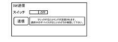
定型コマンドの送信用UIについて、図17に基づいて説明する。図17は、定型コマンドの送信用UIの一例を模式的に示した図である。図17において、このUIには、定型コマンドの内容と、送信用のアイコンが表示される。定型コマンド送信モジュールは、送信用のアイコンの入力が行われることを契機として、定型コマンドをエッジデバイス20に送信する。[UI for sending standard commands]
A UI for sending fixed form commands will be described with reference to FIG. 17 . FIG. 17 is a diagram schematically showing an example of a UI for sending standard commands. In FIG. 17, this UI displays the content of the standard command and an icon for transmission. The fixed command transmission module sends a fixed command to the edge device 20 when an icon for transmission is input.
図15に戻り、デバイス制御処理の続きを説明する。
コマンド情報送信モジュールは、コマンド情報を、ユーザデバイス30に送信し(ステップS54)、コマンド情報受信モジュールは、このコマンド情報を受信する(ステップS55)。Returning to FIG. 15, the continuation of the device control process will be described.
The command information transmission module transmits command information to the user device 30 (step S54), and the command information reception module receives this command information (step S55).
動作実行モジュールは、コマンド情報の内容を解釈し、動作を実行する(ステップS56)。動作実行モジュールは、コマンド情報が、ユーザデバイス30のOn/Offである場合、コマンド情報の内容として、スイッチのOn/Offを解釈し、自身のスイッチをOn/Offする。動作実行モジュールは、コマンド情報が、他の内容であっても同様に、コマンド情報の内容を解釈し、動作を実行する。 The action execution module interprets the contents of the command information and executes the action (step S56). When the command information indicates On/Off of the user device 30, the action execution module interprets the On/Off of the switch as the content of the command information and turns on/off its own switch. The action execution module similarly interprets the contents of the command information and executes the action even if the command information has other contents.
以上が、デバイス制御処理である。 The above is the device control processing.
本デバイス制御処理により、下りに割り当てる通信データは、そのデータを送るトリガや値を決めることが可能であり、スイッチやボタン、スライダ等を視覚的に操作できる部品をUI上に設定することも可能となる。また、ユーザデバイス30では、UIの操作により送られてきたデータを受信し、その受信データに基づいて任意の動作を行うことが可能である。例えば、動作モードの変更、何か判定しているデバイスであれば判定レベルの変更等を行うことが可能である。 With this device control processing, it is possible to determine the triggers and values for sending the communication data assigned to the downstream, and it is also possible to set on the UI parts that can be operated visually, such as switches, buttons, and sliders. becomes. In addition, the user device 30 can receive data sent by operating the UI and perform arbitrary operations based on the received data. For example, it is possible to change the operation mode, or change the determination level if the device is determining something.
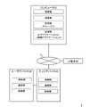
上述したデータ表示処理及びデバイス制御処理において、一のエッジデバイス20と、一のユーザデバイス30の場合を例として説明しているが、エッジデバイス及びユーザデバイスは、図18で示すような複数であっても良い。この場合について説明する。
図18は、IoT制御システム1において、複数のユーザデバイスと、複数のユーザデバイスが各々接続されたエッジデバイス群と、コンピュータ10とで構成された場合を示した図である。
エッジデバイスが、複数のユーザデバイスが各々接続された複数のエッジデバイス群で構成される場合、このエッジデバイス群とのデータを送受信するゲートウェイが、IoTアプリケーションと相互にデータ通信を行うことになる。このとき、エッジデバイスは、定型フォーマットのヘッダ部分に、ユーザデバイスを識別するデバイス番号を挿入する。エッジデバイスは、このデバイス番号を参照し、どのユーザデバイスの元データであるかを識別する。また、コンピュータ10は、定型コマンドのヘッダ部分に、ユーザデバイスを識別するデバイス番号を挿入する。ゲートウェイは、このデバイス番号を参照し、どのユーザデバイスに送信する定型コマンドであるかを識別する。In the data display processing and device control processing described above, the case of one edge device 20 and one user device 30 has been described as an example. can be This case will be explained.
FIG. 18 is a diagram showing a case where the
When an edge device is composed of a plurality of edge device groups to which a plurality of user devices are respectively connected, a gateway that transmits and receives data to and from this edge device group performs mutual data communication with an IoT application. At this time, the edge device inserts a device number that identifies the user device into the header portion of the fixed format. The edge device refers to this device number to identify which user device the original data belongs to. Also, the
1台のゲートウェイにエッジデバイス群が接続されている場合、複数のエッジデバイスは、ローカル通信方式で構成されるので、ランニングコストを増やさずに、管理エリアを拡大することが可能である。また、複数のエッジデバイス毎に其々通信データを割り当てることが可能となり、エッジデバイス毎に異なるタスクでもUIで一元化した遠隔管理が可能となる。 When a group of edge devices are connected to one gateway, a plurality of edge devices are configured by the local communication system, so it is possible to expand the management area without increasing running costs. In addition, it becomes possible to assign communication data to each of a plurality of edge devices, so that even tasks that differ for each edge device can be centralized and remotely managed using a UI.
上述した手段、機能は、コンピュータ(CPU、情報処理装置、各種端末を含む)が、所定のプログラムを読み込んで、実行することによって実現される。プログラムは、例えば、コンピュータからネットワーク経由で提供される(SaaS:ソフトウェア・アズ・ア・サービス)形態やクラウドサービスで提供されてよい。また、プログラムは、コンピュータ読取可能な記録媒体に記録された形態で提供されてよい。この場合、コンピュータはその記録媒体からプログラムを読み取って内部記録装置又は外部記録装置に転送し記録して実行する。また、そのプログラムを、記録装置(記録媒体)に予め記録しておき、その記録装置から通信回線を介してコンピュータに提供するようにしてもよい。 The means and functions described above are realized by a computer (including a CPU, an information processing device, and various terminals) reading and executing a predetermined program. The program may be provided, for example, from a computer via a network (SaaS: software as a service) or provided as a cloud service. Also, the program may be provided in a form recorded on a computer-readable recording medium. In this case, the computer reads the program from the recording medium, transfers it to an internal recording device or an external recording device, records it, and executes it. Alternatively, the program may be recorded in advance in a recording device (recording medium) and provided from the recording device to the computer via a communication line.
以上、本発明の実施形態について説明したが、本発明は上述したこれらの実施形態に限るものではない。また、本発明の実施形態に記載された効果は、本発明から生じる最も好適な効果を列挙したに過ぎず、本発明による効果は、本発明の実施形態に記載されたものに限定されるものではない。 Although the embodiments of the present invention have been described above, the present invention is not limited to these embodiments described above. Moreover, the effects described in the embodiments of the present invention are merely enumerations of the most suitable effects resulting from the present invention, and the effects of the present invention are limited to those described in the embodiments of the present invention. is not.
(1)ユーザデバイス(例えば、ユーザデバイス30)で取得したデータをユーザインタフェースに表示するIoT制御システムであって、
データの割当順序、割当範囲が用途に基づいて予め定められた定型フォーマット(例えば、図8)を保存するストレージ(例えば、ストレージ11)と、
前記ユーザデバイスから前記定型フォーマットの割当順序で送られた元データを受け取り、前記定型フォーマット内の割当範囲に、当該元データを挿入した定型データ(例えば、図13)を生成するエッジデバイス(例えば、エッジデバイス20)と、
前記エッジデバイスが生成した前記定型データを受信し、前記ストレージを参照して、前記割当範囲から何の用途のデータであるかを判断するIoTアプリケーション(例えば、IoTアプリケーション12)と、
を備えることを特長とするIoT制御システム。(1) An IoT control system that displays data acquired by a user device (e.g., user device 30) on a user interface,
A storage (for example, storage 11) that stores a fixed format (for example, FIG. 8) in which data allocation order and allocation range are predetermined based on the application;
An edge device (for example, an edge device 20);
an IoT application (for example, an IoT application 12) that receives the fixed data generated by the edge device, refers to the storage, and determines for what purpose the data is used from the allocation range;
An IoT control system comprising:
(1)の発明によれば、簡単且つ低コストで様々な用途に、IoTによるリモート管理を導入することが可能となる。 According to the invention of (1), remote management by IoT can be introduced easily and at low cost for various purposes.
(2)ユーザインタフェースから入力されたデータに基づきユーザデバイス(例えば、ユーザデバイス30)を制御するIoT制御システムであって、
データの割当順序、割当範囲が用途に基づいて予め定められた定型フォーマット(例えば、図11)を保存するストレージ(例えば、ストレージ11)と、
前記ユーザインタフェースから入力された入力データを受け取り、前記ストレージを参照して、予め定められた定型フォーマット内の割当範囲に、前記入力データを挿入した定型コマンド(例えば、図16)を生成するIoTアプリケーション(例えば、IoTアプリケーション12)と、
前記定型コマンドを受け取り、コマンド情報を前記ユーザデバイスに送信するエッジデバイス(例えば、エッジデバイス20)と、
を備えることを特長とするIoT制御システム。(2) An IoT control system that controls a user device (for example, a user device 30) based on data input from a user interface,
a storage (for example, storage 11) that stores a fixed format (for example, FIG. 11) in which data allocation order and allocation range are predetermined based on the application;
An IoT application that receives input data input from the user interface, refers to the storage, and generates a fixed command (for example, FIG. 16) in which the input data is inserted into an allocation range within a predetermined fixed format. (e.g. IoT application 12);
an edge device (for example, an edge device 20) that receives the fixed command and transmits command information to the user device;
An IoT control system comprising:
(2)の発明によれば、簡単且つ低コストで様々な用途に、IoTによるリモート管理を導入することが可能となる。 According to the invention of (2), remote management by IoT can be introduced easily and at low cost for various purposes.
(3)前記定型データの前記定型フォーマットにおける割当順序と割当範囲を自由に決定する入力を受付けるユーザインタフェースを備える(1)に記載のIoT制御システム。 (3) The IoT control system according to (1), further comprising a user interface that accepts input for freely determining the allocation order and allocation range in the fixed format of the fixed data.
(3)の発明によれば、定型フォーマットの範囲で、ユーザは自ら通信データを自由に割り当てることが可能となる。 According to the invention of (3), the user can freely assign the communication data within the range of the standard format.
(4)前記定型コマンドの前記定型フォーマットにおける割当順序と割当範囲を自由に決定する入力を受付けるユーザインタフェースを備える(2)に記載のIoT制御システム。 (4) The IoT control system according to (2), further comprising a user interface that accepts input for freely determining the allocation order and allocation range of the standard commands in the standard format.
(4)の発明によれば、定型フォーマットの範囲で、ユーザは自ら通信データを自由に割り当てることが可能となる。 According to the invention of (4), the user can freely assign communication data by himself/herself within the range of the standard format.
(5)前記IoTアプリケーションにおいて判断した用途に基づき、データを出力するユーザインタフェースを備える(1)又は(3)に記載のIoT制御システム。 (5) The IoT control system according to (1) or (3), comprising a user interface that outputs data based on the usage determined in the IoT application.
(5)の発明によれば、ユーザデバイスからUIで割り当てた定型フォーマットに合わせてデータを送信するだけで、割当に応じてUIにグラフ等を表示することが可能となる。 According to the invention of (5), it is possible to display a graph or the like on the UI in accordance with the allocation simply by transmitting data from the user device according to the fixed format allocated by the UI.
(6)前記定型コマンド送信の入力を受付けるユーザインタフェースを備える(2)又は(4)に記載のIoT制御システム。 (6) The IoT control system according to (2) or (4), comprising a user interface that accepts input of the fixed command transmission.
(6)の発明によれば、ユーザデバイスでは、UIの操作によりデータを受信し、この受信データに基づいて任意の動作を実行させることが可能となる。 According to the invention of (6), the user device can receive data by operating the UI and perform any operation based on the received data.
(7)前記ストレージは、前記IoTアプリケーションにおいて判断した用途に基づき、用途別データを保存する(1)、(3)又は(5)のいずれか一項に記載のIoT制御システム。 (7) The IoT control system according to any one of (1), (3), or (5), wherein the storage stores usage-specific data based on usage determined in the IoT application.
(7)の発明によれば、ユーザデバイスからUIで割り当てた定型フォーマットに合わせてデータを送信するだけで、割当に応じてコンピュータにデータを格納することが可能となる。 According to the invention of (7), data can be stored in the computer according to the allocation simply by transmitting the data from the user device according to the standard format allocated by the UI.
(8)前記ユーザインタフェースは、前記用途別データを出力する際に、対応するタイトル、単位、表示期間の属性の表示を設定可能である(5)に記載のIoT制御システム。 (8) The IoT control system according to (5), wherein the user interface is capable of setting display of attributes such as a corresponding title, unit, and display period when outputting the application-specific data.
(8)の発明によれば、通信データをUI上に表示する内容を設定することが可能となる。 According to the invention of (8), it is possible to set the content of communication data to be displayed on the UI.
(9)前記エッジデバイスは、複数のユーザデバイスが各々接続された複数のエッジデバイス群で構成され、当該エッジデバイス群とのデータを送受信するゲートウェイが、前記IoTアプリケーションと相互にデータ通信を行う(1)乃至(8)のいずれか一項に記載のIoT制御システム。 (9) The edge device is composed of a plurality of edge device groups to which a plurality of user devices are respectively connected, and a gateway that transmits and receives data to and from the edge device group performs mutual data communication with the IoT application ( The IoT control system according to any one of 1) to (8).
(9)の発明によれば、複数のエッジデバイスはローカル通信方式で構成されるので、ランニングコストを増やさずに、管理エリアを拡大することが可能となる。また、複数のエッジデバイス毎に其々通信データを割り当てることができ、エッジデバイス毎に異なるタスクでもUIで一元化した遠隔管理が可能となる。 According to the invention of (9), since the plurality of edge devices are configured by the local communication system, it is possible to expand the management area without increasing the running cost. In addition, communication data can be assigned to each of a plurality of edge devices, and even tasks that differ for each edge device can be centralized and remotely managed using a UI.
(10)前記ユーザインタフェースは、前記定型フーマットにおけるデータ長を自由に決定する入力を受け付ける(3)又は(4)に記載のIoT制御システム。 (10) The IoT control system according to (3) or (4), wherein the user interface receives input for freely determining the data length in the fixed format.
(10)の発明によれば、定型フォーマットの範囲でユーザは自ら通信データを自由に割り当てることが可能となる。 According to the invention (10), the user can freely assign communication data within the range of the standard format.
(11)前記エッジデバイスは、前記定型フォーマットのデータ通信頻度の周期時間よりも短い間隔でデータを取得する必要がある場合に、前記周期時間よりも短い間隔で取得した複数のデータを、前記周期時間で送信する定型データの所定の割当範囲に挿入した定型データを生成する(1)に記載のIoT制御システム。 (11) When the edge device needs to acquire data at intervals shorter than the cycle time of the data communication frequency of the fixed format, the edge device acquires a plurality of pieces of data at intervals shorter than the cycle time. The IoT control system according to (1), which generates fixed data inserted in a predetermined allocation range of fixed data to be transmitted in time.
(11)の発明によれば、IoTアプリケーションで受信したデータから時刻情報によりデータを分類してコンピュータに保存し、UI上であたかも通常周期よりも短い間隔でデータを受信したような表示を行うことが可能となる。 According to the invention of (11), the data received by the IoT application is classified according to the time information, stored in the computer, and displayed on the UI as if the data were received at intervals shorter than the normal cycle. becomes possible.
(12)ユーザデバイスで取得したデータをユーザインタフェースに表示するIoT制御システムが実行するデータ表示方法であって、
ストレージが、
データの割当順序、割当範囲が用途に基づいて予め定められた定型フォーマットを保存するステップ(例えば、ステップS22)と、
エッジデバイスが、
前記ユーザデバイスから前記定型フォーマットの割当順序で送られた元データを受け取り、前記定型フォーマット内の割当範囲に、当該元データを挿入した定型データを生成するステップ(例えば、ステップS40,S41)と、
IoTアプリケーションが、
前記エッジデバイスが生成した前記定型データを受信し、前記ストレージを参照して、前記割当範囲から何の用途のデータであるかを判断するステップ(例えば、ステップS43,S44)と、
を備えることを特長とするデータ表示方法。(12) A data display method executed by an IoT control system that displays data acquired by a user device on a user interface,
storage is
a step of storing a fixed format in which data allocation order and allocation range are predetermined based on the application (for example, step S22);
the edge device
a step of receiving original data sent from the user device in the order of allocation in the fixed format, and generating fixed data by inserting the original data into the allocation range in the fixed format (for example, steps S40 and S41);
IoT applications are
a step of receiving the fixed form data generated by the edge device, referring to the storage, and determining what purpose the data is for from the allocation range (for example, steps S43 and S44);
A data display method, comprising:
(13)ユーザインタフェースから入力されたデータに基づきユーザデバイスを制御するIoT制御システムが実行するデバイス制御方法であって、
ストレージが、
データの割当順序、割当範囲が用途に基づいて予め定められた定型フォーマットを保存するステップ(例えば、ステップS32)と、
IoTアプリケーションが、
前記ユーザインタフェースから入力された入力データを受け取り、前記ストレージを参照して、予め定められた定型フォーマット内の割当範囲に、前記入力データを挿入した定型コマンドを生成するステップ(例えば、ステップS50,S51)と、
エッジデバイスが、
前記定型コマンドを受け取り、コマンド情報を前記ユーザデバイスに送信するステップ(例えば、ステップS54)と、
を備えることを特長とするデバイス制御方法。(13) A device control method executed by an IoT control system that controls a user device based on data input from a user interface,
storage is
a step of storing a fixed format in which data allocation order and allocation range are predetermined based on the application (for example, step S32);
IoT applications are
A step of receiving input data input from the user interface, referring to the storage, and generating a fixed command in which the input data is inserted into an allocation range within a predetermined fixed format (for example, steps S50 and S51 )When,
the edge device
receiving the fixed command and sending command information to the user device (e.g., step S54);
A device control method comprising:
(14)ユーザデバイスで取得したデータをユーザインタフェースに表示するIoT制御システムが実行するプログラムであって、
ストレージに、
データの割当順序、割当範囲が用途に基づいて予め定められた定型フォーマットを保存するステップ(例えば、ステップS22)、
エッジデバイスに、
前記ユーザデバイスから前記定型フォーマットの割当順序で送られた元データを受け取り、前記定型フォーマット内の割当範囲に、当該元データを挿入した定型データを生成するステップ(例えば、ステップS40,S41)、
IoTアプリケーションに、
前記エッジデバイスが生成した前記定型データを受信し、前記ストレージを参照して、前記割当範囲から何の用途のデータであるかを判断するステップ(例えば、ステップS43,S44)、
を実行させるコンピュータ読み取り可能なプログラム。(14) A program executed by an IoT control system that displays data acquired by a user device on a user interface,
to the storage
a step of storing a fixed format in which the data allocation order and allocation range are predetermined based on the application (for example, step S22);
edge device,
receiving the original data sent from the user device in the order of allocation in the fixed format, and generating fixed data by inserting the original data into the allocation range in the fixed format (for example, steps S40 and S41);
IoT applications,
a step of receiving the fixed form data generated by the edge device, referring to the storage, and determining what purpose the data is for from the allocation range (for example, steps S43 and S44);
A computer readable program that causes a
(15)ユーザインタフェースから入力されたデータに基づきユーザデバイスを制御するIoT制御システムが実行するプログラムであって、
ストレージに、
データの割当順序、割当範囲が用途に基づいて予め定められた定型フォーマットを保存するステップ(例えば、テップS32)、
IoTアプリケーションに、
前記ユーザインタフェースから入力された入力データを受け取り、前記ストレージを参照して、予め定められた定型フォーマット内の割当範囲に、前記入力データを挿入した定型コマンドを生成するステップ(例えば、ステップS50,S51)、
エッジデバイスに、
前記定型コマンドを受け取り、コマンド情報を前記ユーザデバイスに送信するステップ(例えば、ステップS54)、
を実行させるコンピュータ読み取り可能なプログラム。(15) A program executed by an IoT control system that controls a user device based on data input from a user interface,
to the storage
a step of storing a fixed format in which the data allocation order and allocation range are predetermined based on the application (for example, step S32);
IoT applications,
A step of receiving input data input from the user interface, referring to the storage, and generating a fixed command in which the input data is inserted into an allocation range within a predetermined fixed format (for example, steps S50 and S51 ),
edge device,
receiving the fixed command and transmitting command information to the user device (for example, step S54);
A computer readable program that causes a
1 IoT制御システム
3 ネットワーク
10 コンピュータ
11 ストレージ
12 IoTアプリケーション
13 UI制御アプリケーション
20 エッジデバイス
30 ユーザデバイス
40 UI端末1
Claims (15)
Translated fromJapaneseデータの割当順序、割当範囲が用途に基づいて予め定められた定型フォーマットを保存するストレージと、
前記ユーザデバイスから前記定型フォーマットの割当順序で送られた元データを受け取り、前記定型フォーマット内の割当範囲に、当該元データを挿入した定型データを生成するエッジデバイスと、
前記エッジデバイスが生成した前記定型データを受信し、前記ストレージを参照して、前記割当範囲から何の用途のデータであるかを判断するIoTアプリケーションと、
を備えることを特長とするIoT制御システム。An IoT control system that displays data acquired by a user device on a user interface,
a storage that stores a fixed format in which the data allocation order and allocation range are predetermined based on the application;
an edge device that receives original data sent from the user device in the fixed format allocation order and generates fixed data by inserting the original data into the allocation range in the fixed format;
an IoT application that receives the fixed data generated by the edge device, refers to the storage, and determines for what purpose the data is used from the allocation range;
An IoT control system comprising:
データの割当順序、割当範囲が用途に基づいて予め定められた定型フォーマットを保存するストレージと、
前記ユーザインタフェースから入力された入力データを受け取り、前記ストレージを参照して、予め定められた定型フォーマット内の割当範囲に、前記入力データを挿入した定型コマンドを生成するIoTアプリケーションと、
前記定型コマンドを受け取り、コマンド情報を前記ユーザデバイスに送信するエッジデバイスと、
を備えることを特長とするIoT制御システム。An IoT control system that controls a user device based on data input from a user interface,
a storage that stores a fixed format in which the data allocation order and allocation range are predetermined based on the application;
an IoT application that receives input data input from the user interface, refers to the storage, and generates a fixed command in which the input data is inserted into an allocation range within a predetermined fixed format;
an edge device that receives the fixed command and transmits command information to the user device;
An IoT control system comprising:
ストレージが、
データの割当順序、割当範囲が用途に基づいて予め定められた定型フォーマットを保存するステップと、
エッジデバイスが、
前記ユーザデバイスから前記定型フォーマットの割当順序で送られた元データを受け取り、前記定型フォーマット内の割当範囲に、当該元データを挿入した定型データを生成するステップと、
IoTアプリケーションが、
前記エッジデバイスが生成した前記定型データを受信し、前記ストレージを参照して、前記割当範囲から何の用途のデータであるかを判断するステップと、
を備えることを特長とするデータ表示方法。A data display method executed by an IoT control system that displays data acquired by a user device on a user interface,
storage is
a step of storing a fixed format in which data allocation order and allocation range are predetermined based on usage;
the edge device
a step of receiving original data sent from the user device in the order of allocation in the fixed format, and generating fixed data by inserting the original data into an allocation range in the fixed format;
IoT applications are
a step of receiving the fixed form data generated by the edge device, referring to the storage, and determining what purpose the data is for from the allocation range;
A data display method, comprising:
ストレージが、
データの割当順序、割当範囲が用途に基づいて予め定められた定型フォーマットを保存するステップと、
IoTアプリケーションが、
前記ユーザインタフェースから入力された入力データを受け取り、前記ストレージを参照して、予め定められた定型フォーマット内の割当範囲に、前記入力データを挿入した定型コマンドを生成するステップと、
エッジデバイスが、
前記定型コマンドを受け取り、コマンド情報を前記ユーザデバイスに送信するステップと、
を備えることを特長とするデバイス制御方法。A device control method executed by an IoT control system that controls a user device based on data input from a user interface,
storage is
a step of storing a fixed format in which data allocation order and allocation range are predetermined based on usage;
IoT applications are
a step of receiving input data input from the user interface, referring to the storage, and generating a fixed command in which the input data is inserted into an allocation range within a predetermined fixed format;
the edge device
receiving the canned command and sending command information to the user device;
A device control method comprising:
ストレージに、
データの割当順序、割当範囲が用途に基づいて予め定められた定型フォーマットを保存するステップ、
エッジデバイスに、
前記ユーザデバイスから前記定型フォーマットの割当順序で送られた元データを受け取り、前記定型フォーマット内の割当範囲に、当該元データを挿入した定型データを生成するステップ、
IoTアプリケーションに、
前記エッジデバイスが生成した前記定型データを受信し、前記ストレージを参照して、前記割当範囲から何の用途のデータであるかを判断するステップ、
を実行させるコンピュータ読み取り可能なプログラム。A program executed by an IoT control system that displays data acquired by a user device on a user interface,
to the storage
a step of storing a fixed format in which data allocation order and allocation range are predetermined based on usage;
edge device,
receiving the original data sent from the user device in the order of allocation in the fixed format, and generating fixed data by inserting the original data into the allocation range in the fixed format;
IoT applications,
a step of receiving the fixed data generated by the edge device, referring to the storage, and determining from the allocation range what purpose the data is for;
A computer readable program that causes a
ストレージに、
データの割当順序、割当範囲が用途に基づいて予め定められた定型フォーマットを保存するステップ、
IoTアプリケーションに、
前記ユーザインタフェースから入力された入力データを受け取り、前記ストレージを参照して、予め定められた定型フォーマット内の割当範囲に、前記入力データを挿入した定型コマンドを生成するステップ、
エッジデバイスに、
前記定型コマンドを受け取り、コマンド情報を前記ユーザデバイスに送信するステップ、
を実行させるコンピュータ読み取り可能なプログラム。
A program executed by an IoT control system that controls a user device based on data input from a user interface,
to the storage
a step of storing a fixed format in which data allocation order and allocation range are predetermined based on usage;
IoT applications,
receiving input data input from the user interface, referring to the storage, and generating a fixed command in which the input data is inserted into an allocation range within a predetermined fixed format;
edge device,
receiving the canned command and sending command information to the user device;
A computer readable program that causes a
Priority Applications (2)
| Application Number | Priority Date | Filing Date | Title |
|---|---|---|---|
| JP2021015216AJP6944076B1 (en) | 2021-02-02 | 2021-02-02 | IoT control system, data display method, device control method and program |
| JP2021094511AJP7031042B1 (en) | 2021-02-02 | 2021-06-04 | IoT control system, data display method, device control method and program |
Applications Claiming Priority (1)
| Application Number | Priority Date | Filing Date | Title |
|---|---|---|---|
| JP2021015216AJP6944076B1 (en) | 2021-02-02 | 2021-02-02 | IoT control system, data display method, device control method and program |
Related Child Applications (1)
| Application Number | Title | Priority Date | Filing Date |
|---|---|---|---|
| JP2021094511ADivisionJP7031042B1 (en) | 2021-02-02 | 2021-06-04 | IoT control system, data display method, device control method and program |
Publications (2)
| Publication Number | Publication Date |
|---|---|
| JP6944076B1 JP6944076B1 (en) | 2021-10-06 |
| JP2022118593Atrue JP2022118593A (en) | 2022-08-15 |
Family
ID=77915105
Family Applications (1)
| Application Number | Title | Priority Date | Filing Date |
|---|---|---|---|
| JP2021015216AExpired - Fee RelatedJP6944076B1 (en) | 2021-02-02 | 2021-02-02 | IoT control system, data display method, device control method and program |
Country Status (1)
| Country | Link |
|---|---|
| JP (1) | JP6944076B1 (en) |
Citations (2)
| Publication number | Priority date | Publication date | Assignee | Title |
|---|---|---|---|---|
| JP2012164369A (en)* | 2012-06-08 | 2012-08-30 | Oki Electric Ind Co Ltd | Sensor data providing system, gateway, and abstracted sensor data generation method |
| JP2020198494A (en)* | 2019-05-31 | 2020-12-10 | ソフトバンク株式会社 | Gateway device, communication method, and program |
- 2021
- 2021-02-02JPJP2021015216Apatent/JP6944076B1/ennot_activeExpired - Fee Related
Patent Citations (2)
| Publication number | Priority date | Publication date | Assignee | Title |
|---|---|---|---|---|
| JP2012164369A (en)* | 2012-06-08 | 2012-08-30 | Oki Electric Ind Co Ltd | Sensor data providing system, gateway, and abstracted sensor data generation method |
| JP2020198494A (en)* | 2019-05-31 | 2020-12-10 | ソフトバンク株式会社 | Gateway device, communication method, and program |
Also Published As
| Publication number | Publication date |
|---|---|
| JP6944076B1 (en) | 2021-10-06 |
Similar Documents
| Publication | Publication Date | Title |
|---|---|---|
| CN104144118B (en) | Communicator, managing device and processing method | |
| CN113067811A (en) | Protocol conversion method, device, system, electronic equipment and storage medium | |
| CN110891005A (en) | IOT equipment control method, cloud server and IOT equipment control system | |
| CN113986349A (en) | Data processing method, data processing device, computer readable storage medium and computer equipment | |
| CN110321283A (en) | Interface testing case generation method, device, computer installation and storage medium | |
| CN108293199A (en) | The electronic device and method of event management service are provided | |
| CN104850403A (en) | Implementation method of remote control system of oscilloscope based on control component technology | |
| CN105302504A (en) | INFORMATION PROCESSING APPARATUS and INFORMATION PROCESSING METHOD | |
| CN105812211B (en) | Information processing system and communication means | |
| JP6802354B2 (en) | Communication test equipment, communication test methods and programs | |
| JP2022118593A (en) | IoT control system, data display method, device control method and program | |
| JP2022118685A (en) | IoT control system, data display method, device control method and program | |
| JP6042243B2 (en) | Monitoring system, monitoring server, and monitoring method | |
| CN112987597A (en) | FSU control method, device, equipment and computer readable storage medium | |
| CN117938891A (en) | Environmental monitoring method, device, electronic equipment and storage medium | |
| CN116302008A (en) | Firmware updating method and device, electronic equipment and storage medium | |
| JP7371410B2 (en) | Information processing device and information processing program | |
| KR100638207B1 (en) | Server-Client system and its method for the same | |
| CN112698829B (en) | Abnormal resource positioning method and device, storage medium and electronic equipment | |
| CN115633102A (en) | Multi-type protocol message processing system, method and readable storage medium | |
| CN111177059B (en) | A data processing method and system based on chemical composition system | |
| CN115658218A (en) | Method, device, equipment and storage medium for edge equipment to access cloud | |
| CN114130039A (en) | Real-life entertainment scene control method and device | |
| KR20220148579A (en) | An apparatus for automatically generating custom designed user interfaces of input interfaces and a method for operating it | |
| KR20220108967A (en) | Method for generating application for controlling external electronic device and electronic apparatus for supporting the same |
Legal Events
| Date | Code | Title | Description |
|---|---|---|---|
| A621 | Written request for application examination | Free format text:JAPANESE INTERMEDIATE CODE: A621 Effective date:20210216 | |
| A871 | Explanation of circumstances concerning accelerated examination | Free format text:JAPANESE INTERMEDIATE CODE: A871 Effective date:20210216 | |
| A975 | Report on accelerated examination | Free format text:JAPANESE INTERMEDIATE CODE: A971005 Effective date:20210326 | |
| A131 | Notification of reasons for refusal | Free format text:JAPANESE INTERMEDIATE CODE: A131 Effective date:20210511 | |
| A521 | Request for written amendment filed | Free format text:JAPANESE INTERMEDIATE CODE: A523 Effective date:20210604 | |
| TRDD | Decision of grant or rejection written | ||
| A01 | Written decision to grant a patent or to grant a registration (utility model) | Free format text:JAPANESE INTERMEDIATE CODE: A01 Effective date:20210824 | |
| A61 | First payment of annual fees (during grant procedure) | Free format text:JAPANESE INTERMEDIATE CODE: A61 Effective date:20210909 | |
| R150 | Certificate of patent or registration of utility model | Ref document number:6944076 Country of ref document:JP Free format text:JAPANESE INTERMEDIATE CODE: R150 | |
| LAPS | Cancellation because of no payment of annual fees |