JP2022114908A - Imaging condition setting system, imaging condition setting method and program - Google Patents
Imaging condition setting system, imaging condition setting method and programDownload PDFInfo
- Publication number
- JP2022114908A JP2022114908AJP2021011384AJP2021011384AJP2022114908AJP 2022114908 AJP2022114908 AJP 2022114908AJP 2021011384 AJP2021011384 AJP 2021011384AJP 2021011384 AJP2021011384 AJP 2021011384AJP 2022114908 AJP2022114908 AJP 2022114908A
- Authority
- JP
- Japan
- Prior art keywords
- image
- photographing
- workpiece
- condition setting
- work
- Prior art date
- Legal status (The legal status is an assumption and is not a legal conclusion. Google has not performed a legal analysis and makes no representation as to the accuracy of the status listed.)
- Granted
Links
Images


Classifications
- H—ELECTRICITY
- H04—ELECTRIC COMMUNICATION TECHNIQUE
- H04N—PICTORIAL COMMUNICATION, e.g. TELEVISION
- H04N23/00—Cameras or camera modules comprising electronic image sensors; Control thereof
- H04N23/70—Circuitry for compensating brightness variation in the scene
- H04N23/72—Combination of two or more compensation controls
- G—PHYSICS
- G01—MEASURING; TESTING
- G01N—INVESTIGATING OR ANALYSING MATERIALS BY DETERMINING THEIR CHEMICAL OR PHYSICAL PROPERTIES
- G01N21/00—Investigating or analysing materials by the use of optical means, i.e. using sub-millimetre waves, infrared, visible or ultraviolet light
- G01N21/84—Systems specially adapted for particular applications
- G01N21/88—Investigating the presence of flaws or contamination
- G01N21/8806—Specially adapted optical and illumination features
- G—PHYSICS
- G01—MEASURING; TESTING
- G01N—INVESTIGATING OR ANALYSING MATERIALS BY DETERMINING THEIR CHEMICAL OR PHYSICAL PROPERTIES
- G01N21/00—Investigating or analysing materials by the use of optical means, i.e. using sub-millimetre waves, infrared, visible or ultraviolet light
- G01N21/84—Systems specially adapted for particular applications
- G01N21/88—Investigating the presence of flaws or contamination
- G01N21/8851—Scan or image signal processing specially adapted therefor, e.g. for scan signal adjustment, for detecting different kinds of defects, for compensating for structures, markings, edges
- G—PHYSICS
- G03—PHOTOGRAPHY; CINEMATOGRAPHY; ANALOGOUS TECHNIQUES USING WAVES OTHER THAN OPTICAL WAVES; ELECTROGRAPHY; HOLOGRAPHY
- G03B—APPARATUS OR ARRANGEMENTS FOR TAKING PHOTOGRAPHS OR FOR PROJECTING OR VIEWING THEM; APPARATUS OR ARRANGEMENTS EMPLOYING ANALOGOUS TECHNIQUES USING WAVES OTHER THAN OPTICAL WAVES; ACCESSORIES THEREFOR
- G03B15/00—Special procedures for taking photographs; Apparatus therefor
- G03B15/02—Illuminating scene
- G03B15/03—Combinations of cameras with lighting apparatus; Flash units
- G03B15/05—Combinations of cameras with electronic flash apparatus; Electronic flash units
- G—PHYSICS
- G03—PHOTOGRAPHY; CINEMATOGRAPHY; ANALOGOUS TECHNIQUES USING WAVES OTHER THAN OPTICAL WAVES; ELECTROGRAPHY; HOLOGRAPHY
- G03B—APPARATUS OR ARRANGEMENTS FOR TAKING PHOTOGRAPHS OR FOR PROJECTING OR VIEWING THEM; APPARATUS OR ARRANGEMENTS EMPLOYING ANALOGOUS TECHNIQUES USING WAVES OTHER THAN OPTICAL WAVES; ACCESSORIES THEREFOR
- G03B7/00—Control of exposure by setting shutters, diaphragms or filters, separately or conjointly
- G03B7/08—Control effected solely on the basis of the response, to the intensity of the light received by the camera, of a built-in light-sensitive device
- G03B7/091—Digital circuits
- G—PHYSICS
- G03—PHOTOGRAPHY; CINEMATOGRAPHY; ANALOGOUS TECHNIQUES USING WAVES OTHER THAN OPTICAL WAVES; ELECTROGRAPHY; HOLOGRAPHY
- G03B—APPARATUS OR ARRANGEMENTS FOR TAKING PHOTOGRAPHS OR FOR PROJECTING OR VIEWING THEM; APPARATUS OR ARRANGEMENTS EMPLOYING ANALOGOUS TECHNIQUES USING WAVES OTHER THAN OPTICAL WAVES; ACCESSORIES THEREFOR
- G03B7/00—Control of exposure by setting shutters, diaphragms or filters, separately or conjointly
- G03B7/16—Control of exposure by setting shutters, diaphragms or filters, separately or conjointly in accordance with both the intensity of the flash source and the distance of the flash source from the object, e.g. in accordance with the "guide number" of the flash bulb and the focusing of the camera
- G03B7/17—Selection of modes in flash units by exposure control arrangements
- H—ELECTRICITY
- H04—ELECTRIC COMMUNICATION TECHNIQUE
- H04N—PICTORIAL COMMUNICATION, e.g. TELEVISION
- H04N23/00—Cameras or camera modules comprising electronic image sensors; Control thereof
- H04N23/70—Circuitry for compensating brightness variation in the scene
- H04N23/73—Circuitry for compensating brightness variation in the scene by influencing the exposure time
- H—ELECTRICITY
- H04—ELECTRIC COMMUNICATION TECHNIQUE
- H04N—PICTORIAL COMMUNICATION, e.g. TELEVISION
- H04N23/00—Cameras or camera modules comprising electronic image sensors; Control thereof
- H04N23/70—Circuitry for compensating brightness variation in the scene
- H04N23/74—Circuitry for compensating brightness variation in the scene by influencing the scene brightness using illuminating means
- H—ELECTRICITY
- H04—ELECTRIC COMMUNICATION TECHNIQUE
- H04N—PICTORIAL COMMUNICATION, e.g. TELEVISION
- H04N23/00—Cameras or camera modules comprising electronic image sensors; Control thereof
- H04N23/70—Circuitry for compensating brightness variation in the scene
- H04N23/741—Circuitry for compensating brightness variation in the scene by increasing the dynamic range of the image compared to the dynamic range of the electronic image sensors
- G—PHYSICS
- G01—MEASURING; TESTING
- G01N—INVESTIGATING OR ANALYSING MATERIALS BY DETERMINING THEIR CHEMICAL OR PHYSICAL PROPERTIES
- G01N21/00—Investigating or analysing materials by the use of optical means, i.e. using sub-millimetre waves, infrared, visible or ultraviolet light
- G01N21/84—Systems specially adapted for particular applications
- G01N2021/845—Objects on a conveyor
- G—PHYSICS
- G01—MEASURING; TESTING
- G01N—INVESTIGATING OR ANALYSING MATERIALS BY DETERMINING THEIR CHEMICAL OR PHYSICAL PROPERTIES
- G01N21/00—Investigating or analysing materials by the use of optical means, i.e. using sub-millimetre waves, infrared, visible or ultraviolet light
- G01N21/84—Systems specially adapted for particular applications
- G01N21/88—Investigating the presence of flaws or contamination
- G01N21/8806—Specially adapted optical and illumination features
- G01N2021/8835—Adjustable illumination, e.g. software adjustable screen
Landscapes
- Signal Processing (AREA)
- Engineering & Computer Science (AREA)
- Multimedia (AREA)
- General Physics & Mathematics (AREA)
- Physics & Mathematics (AREA)
- Analytical Chemistry (AREA)
- General Health & Medical Sciences (AREA)
- Biochemistry (AREA)
- Immunology (AREA)
- Pathology (AREA)
- Chemical & Material Sciences (AREA)
- Life Sciences & Earth Sciences (AREA)
- Health & Medical Sciences (AREA)
- Computer Vision & Pattern Recognition (AREA)
- Investigating Materials By The Use Of Optical Means Adapted For Particular Applications (AREA)
- Exposure Control For Cameras (AREA)
- Stroboscope Apparatuses (AREA)
- Studio Devices (AREA)
Abstract
Translated fromJapaneseDescription
Translated fromJapanese本発明は、撮影条件設定システム、撮影条件設定方法及びプログラムに関する。 The present invention relates to an imaging condition setting system, an imaging condition setting method, and a program.
製造現場における製品の外観検査は、機械による人員の置き換えが最も進んでいない分野の1つであり、将来の労働人口減少に向けて取り組まなければならない自動化の重要課題である。近年、ディープラーニングに代表される人工知能・機械学習技術の発展によって、検査の自動化技術は飛躍的に向上しつつある。 Visual inspection of products at manufacturing sites is one of the fields where the replacement of personnel by machines has not progressed the least, and it is an important automation issue that must be addressed for the future decline in the working population. In recent years, with the development of artificial intelligence and machine learning technology represented by deep learning, inspection automation technology is improving dramatically.
しかしながら、外観検査及びマシンビジョン一般において、検査システムを構築する際に最も手間がかかるプロセスは、照明パターンの最適化設計を含む撮像系の設計であり、この分野の自動化はあまり進んでいない。人が手作業でこの最適化設計を行う場合、ワーク(検査対象)の個体ばらつきに対応しつつ、ワークに生じたキズ等の欠陥を確実に検出するための撮像系の設計には、多大な労力が必要となる。すなわち、所望の検出性能を得るには、対象となる種々のワークを交換しつつ、照明の手調整による最適化と検査アルゴリズムの検討・調整を交互に繰り返すことが不可欠であり、そのために、非常に多くの工数が必要になる。 However, in visual inspection and machine vision in general, the most time-consuming process in constructing an inspection system is the design of the imaging system, including the optimized design of the illumination pattern, and automation in this field has not progressed much. When humans perform this optimization design manually, it takes a great deal of effort to design an imaging system for reliably detecting defects such as scratches on workpieces while coping with individual variations in workpieces (inspection targets). Labor is required. In other words, in order to obtain the desired detection performance, it is essential to alternately repeat optimization by manual adjustment of illumination and consideration and adjustment of inspection algorithms while exchanging various target workpieces. requires a lot of man-hours.
実際に検査のためにワークの撮影を行う際には、ワークに当たる光は照明光だけでなく、撮影環境に応じた環境光も含まれる。しかし、照明パターンの最適化設計を行うためのシミュレーションにおいては環境光の影響は考慮されていないため、シミュレーションによって推定される画像の明るさと実際の画像の明るさとの間には環境光の光度による誤差が生じてしまう。 When actually photographing a workpiece for inspection, the light that hits the workpiece includes not only illumination light but also ambient light according to the imaging environment. However, since the effects of ambient light are not taken into consideration in simulations for optimal lighting pattern design, the difference between the brightness of the image estimated by the simulation and the actual brightness of the image depends on the luminosity of the ambient light. An error will occur.
この問題に対処する方法としては、照明光の光度を、環境光の光度よりも十分に大きくし、環境光の影響を相対的に小さくすることが考えられる。しかしながら、光度が大きくなると、画像上で画素の飽和が生じやすいという問題がある。 As a method of coping with this problem, it is conceivable to make the luminous intensity of the illumination light sufficiently higher than the luminous intensity of the ambient light so that the influence of the ambient light is relatively small. However, when the luminous intensity increases, there is a problem that pixels tend to saturate on the image.
画素の飽和に関して、特許文献1には、画像上で輝度値が飽和している画素がある場合には、照明光源の発光輝度を変えて撮影した場合の複数の画像を生成し、各画素について輝度値の和を算出して合成画像を生成することが記載されている。 Regarding pixel saturation,
しかし、特許文献1に記載されるような従来の方法では、画素飽和を避けるために、ワークに照射する照明光の光度が照射可能な最大光度よりも小さいため、照明光に対する環境光の相対的な影響は十分に小さくならず、推定される画像の明るさと実際の画像の明るさの誤差を十分に小さくすることができなかった。 However, in the conventional method as described in
本発明は、上述した事情を鑑みてなされたものであり、検査対象を撮影する際の照明パターンの最適化設計において、環境光の影響を十分に低減することが可能な撮影条件設定システムを提供することを目的とする。 SUMMARY OF THE INVENTION The present invention has been made in view of the circumstances described above, and provides an imaging condition setting system capable of sufficiently reducing the influence of ambient light in the optimization design of an illumination pattern when imaging an inspection target. intended to
本発明は、上述した課題を解決するために、以下の構成を採用する。
本発明の一側面に係る撮影条件設定システムは、検査対象のワークの画像を撮影する撮影装置と、前記ワークに光を当てる光源を含む照明装置と、前記ワークを撮影する際の撮影の条件を設定する撮影条件設定部と、を備え、前記撮影条件設定部は、前記照明装置から前記ワークに当てる光度を閾値以上の値にして撮影した際に、前記ワークの画像の指定領域の画素値が指定範囲内の値になるように、前記撮影装置の露出時間を設定する。
上記構成により、検査対象を撮影する際に、照明光を環境光に比べて十分に大きくすることで、環境光の影響を相対的に低減することができる。The present invention adopts the following configurations in order to solve the above-described problems.
A photographing condition setting system according to one aspect of the present invention comprises a photographing device for photographing an image of a workpiece to be inspected, an illumination device including a light source for illuminating the workpiece, and photographing conditions for photographing the workpiece. and a photographing condition setting unit that sets the pixel value of the specified area of the image of the work when photographing with the luminous intensity applied to the work from the lighting device at a value equal to or higher than a threshold value. The exposure time of the photographing device is set so that the value falls within the designated range.
With the above configuration, when the inspection target is photographed, the illumination light is made sufficiently larger than the ambient light, so that the influence of the ambient light can be relatively reduced.
また、前記撮影条件設定部は、前記照明装置から前記ワークに当てる光度を最大値にして撮影した際に、前記ワークの画像の指定領域の画素値が指定範囲内の値になるように、前記撮影装置の露出時間を設定してもよい。これにより、検査対象を撮影する際に、照明光を環境光に比べて最大限大きくすることで、環境光の影響を十分に低減することができる。 Further, the photographing condition setting unit sets the pixel values of the designated area of the image of the work to be within the designated range when the work is photographed with the luminous intensity applied to the work from the lighting device at the maximum value. You may set the exposure time of an imaging device. As a result, the influence of the ambient light can be sufficiently reduced by maximizing the illumination light compared to the ambient light when photographing the inspection object.
また、前記照明装置は、それぞれの光度を調節可能な複数の光源を備え、前記撮影条件設定部は、前記複数の光源のうち、少なくとも1つの光源の光度を閾値以上の値に設定してもよい。これにより、マルチチャネル照明を用いた場合に、各チャネルの光度の最適なパターンを維持しつつ、環境光の影響を低減することができる。 Further, the illumination device may include a plurality of light sources each having an adjustable luminous intensity, and the imaging condition setting unit may set the luminous intensity of at least one light source among the plurality of light sources to a value equal to or higher than a threshold value. good. This reduces the effect of ambient light while maintaining an optimal pattern of luminous intensity for each channel when multi-channel illumination is used.
また、前記撮影条件設定部は、前記撮影装置の露出に対する画素値の特性が、線形の関係ではない場合には、前記撮影装置のキャリブレーションを実施した上で、露出時間を設定してもよい。これにより、撮影装置の特性に依存せず、特性が未知の場合でも露出時間の設定を行うことができる。 Further, when the characteristic of the pixel value with respect to the exposure of the imaging device is not in a linear relationship, the imaging condition setting unit may set the exposure time after calibrating the imaging device. . As a result, the exposure time can be set without depending on the characteristics of the photographing device even if the characteristics are unknown.
また、前記撮影条件設定部は、前記照明装置から前記ワークに当てる光度を閾値以上の値にして撮影した画像と、前記照明装置から前記ワークに当てる光度を最小値にして撮影した画像との差分に基づいて、前記ワークの画像の指定領域の画素値が指定範囲内の値になるように、前記撮影装置の露出時間を設定してもよい。これにより、精確に照明装置からの光のみを当てた場合の画像に基づいて露出時間を設定することができる。 Further, the photographing condition setting unit sets the difference between an image photographed with the luminous intensity applied from the lighting device to the work at a value equal to or higher than a threshold value and an image photographed with the luminous intensity applied from the lighting device to the work at a minimum value. , the exposure time of the imaging device may be set so that the pixel values of the specified area of the image of the workpiece are within the specified range. This makes it possible to accurately set the exposure time based on the image when only the light from the illumination device is applied.
また、前記撮影条件設定部は、前記照明装置から前記ワークに当てる光度を閾値以上の値にして撮影した画像と、異なる複数の環境光の条件下で、前記照明装置から前記ワークに当てる光度を最小値にして撮影した画像との差分に基づいて、前記ワークの画像の指定領域の画素値が指定範囲内の値になるように、前記撮影装置の露出時間を設定してもよい。これにより、撮影時の環境光の状況に対してロバストな露出時間の設定を行うことができる。
また、撮影条件設定部は、前記照明装置から前記ワークに当てる光度の設定値、実際に照射された光度の測定値、およびディスプレイに表示された光度のうちの少なくとも一つを所定の閾値以上の値にして撮影した際に、前記ワークの画像の指定領域の画素値が指定範囲内の値になるように、前記撮影装置の露出時間を設定するようにしてもよい。これにより、システムの構成に応じて、設定値、測定値、表示装置上での表示値のうちのいずれかの値に基づいて、露出時間を設定することができる。Further, the photographing condition setting unit sets an image photographed by setting the light intensity applied from the lighting device to the work to a value equal to or higher than a threshold value, and the light intensity applied from the lighting device to the work under a plurality of different ambient light conditions. The exposure time of the photographing device may be set so that the pixel values of the designated area of the image of the workpiece are within the designated range based on the difference from the image photographed with the minimum value. As a result, it is possible to set a robust exposure time against the ambient light conditions at the time of shooting.
Further, the photographing condition setting unit sets at least one of a set value of the luminous intensity applied from the illumination device to the workpiece, a measured value of the luminous intensity actually irradiated, and the luminous intensity displayed on the display to be equal to or higher than a predetermined threshold value. The exposure time of the photographing device may be set so that the pixel values of the designated area of the image of the workpiece are within the designated range when photographed with the values. Thereby, the exposure time can be set based on any one of the set value, the measured value, and the displayed value on the display device according to the configuration of the system.
本発明の一側面に係る撮影条件設定方法は、コンピュータによって、検査対象のワークの画像の撮影条件を決定する撮影条件設定方法であって、コンピュータが、前記ワークに光を当てる照明装置の光度を閾値以上の値に設定し、コンピュータが、前記光度の条件下で撮影装置によって前記ワークを撮影し、コンピュータが、撮影した前記ワークの画像に基づいて、前記ワークの画像の指定領域の画素値が指定範囲内の値になるように、前記撮影装置の露出時間を設定する。上記構成により、検査対象を撮影する際に、照明光を環境光に比べて十分に大きくすることで、環境光の影響を相対的に低減することができる。 A photographing condition setting method according to one aspect of the present invention is a photographing condition setting method for determining photographing conditions for an image of a workpiece to be inspected by a computer, wherein the computer determines the luminous intensity of an illumination device that illuminates the workpiece. A value greater than or equal to a threshold value is set, a computer photographs the work with a photographing device under the condition of the light intensity, and the computer, based on the photographed image of the work, determines the pixel value of the designated area of the image of the work. The exposure time of the photographing device is set so that the value falls within the specified range. With the above configuration, when the inspection target is photographed, the illumination light is made sufficiently larger than the ambient light, so that the influence of the ambient light can be relatively reduced.
本発明の一側面に係るプログラムは、検査対象のワークの画像の撮影条件を決定するコンピュータに、前記ワークに光を当てる照明装置の光度を閾値以上の値に設定すること、前記光度の条件下で撮影装置によって前記ワークを撮影すること、撮影した前記ワークの画像に基づいて、前記ワークの画像の指定領域の画素値が指定範囲内の値になるように、前記撮影装置の露出時間を設定すること、を実行させる。上記構成により、検査対象を撮影する際に、照明光を環境光に比べて十分に大きくすることで、環境光の影響を相対的に低減することができる。 A program according to one aspect of the present invention sets, in a computer that determines photographing conditions for an image of a workpiece to be inspected, the luminous intensity of an illumination device that illuminates the workpiece to a value equal to or greater than a threshold; and setting the exposure time of the photographing device so that the pixel values of the specified area of the image of the work are within the specified range based on the photographed image of the work. to do. With the above configuration, when the inspection target is photographed, the illumination light is made sufficiently larger than the ambient light, so that the influence of the ambient light can be relatively reduced.
本発明によれば、検査対象を撮影する際の照明パターンの最適化設計において、環境光の影響を十分に低減することが可能な撮影条件設定システムを提供することができる。 According to the present invention, it is possible to provide an imaging condition setting system capable of sufficiently reducing the influence of ambient light in the optimization design of an illumination pattern when imaging an inspection target.
以下、本発明の一側面に係る実施の形態(以下「本実施形態」とも表記する)を、図面に基づいて説明する。ただし、以下で説明する実施形態は、あらゆる点において本発明の例示に過ぎない。本発明の範囲を逸脱することなく種々の改良や変形を行うことができることは言うまでもない。つまり、本発明の実施にあたって、実施形態に応じた具体的構成が適宜採用されてもよい。なお、本実施形態において登場するデータを自然言語により説明しているが、より具体的には、コンピュータが認識可能な疑似言語、コマンド、パラメータ、マシン語等で指定される。 Hereinafter, an embodiment (hereinafter also referred to as "this embodiment") according to one aspect of the present invention will be described based on the drawings. However, the embodiments described below are merely examples of the present invention in all respects. It goes without saying that various modifications and variations can be made without departing from the scope of the invention. That is, in implementing the present invention, a specific configuration according to the embodiment may be appropriately employed. Although the data appearing in this embodiment are explained in terms of natural language, more specifically, they are specified in computer-recognizable pseudo-language, commands, parameters, machine language, and the like.
§1 適用例
図1を用いて、本発明が適用される場面の一例について説明する。図1は、本発明による検査システム(撮影条件設定システム)1の例を模式的に示す図である。また、図2は、検査システム1で用いられる光源の配置の一例を模式的に示す平面図である。§1 Application Example An example of a scene to which the present invention is applied will be described with reference to FIG. FIG. 1 is a diagram schematically showing an example of an inspection system (imaging condition setting system) 1 according to the present invention. FIG. 2 is a plan view schematically showing an example of arrangement of light sources used in the
検査システム1は、例えば、ベルトコンベア2上を搬送される検査対象であるワーク4を撮像して得られる入力画像に対して画像分析処理を実行することで、ワーク4の外観検査を実施する。以下においては、画像分析処理の典型例として、ワーク4の表面における欠陥の有無の検査等を応用例として説明するが、これに限らず、例えば欠陥の種類の特定や外観形状の計測等にも応用が可能である。 The
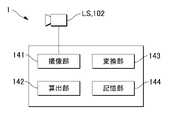
ベルトコンベア2の上部には、光源LSが一体化されたセンサとしてのカメラ102が配置されており、カメラ102の撮像視野6はベルトコンベア2の所定領域を含むように構成される。ここで、光源LSとしては、例えばMDMC(Multi Direction Multi Color)照明等のマルチチャネル照明が挙げられ、より具体的には、本出願人による例えば特願2018-031747に記載の照明を例示することができる。マルチチャネル照明としての光源LSは、複数のチャネル照明LSiを有している。より具体的には、光源LSは、例えば図2に示すように、平面視において円形状を成す1つのチャネル照明LSiと、その周りに同心円状に配置された扇帯状を成す12個のチャネル照明LSiを有している。この場合、光源LSは、合計13個のチャネル照明LSiから構成され、各チャネル照明LSiが3色発光する場合、単色且つ単チャネルの既定照明発光パターンは13×3=39パターンとなる。さらに、カメラ102の撮像により生成された評価用ワーク画像のデータは、制御装置100へ送信される。カメラ102による撮像は、周期的又はイベント的に実行される。 A
制御装置100は、光源LSを、離散値である照明指令値に基づいて複数の評価用発光パターンで発光させ、複数の評価用発光パターンで照明された少なくとも1つのワークに関する複数の評価用ワーク画像を撮像する。また、制御装置100は、複数の評価用ワーク画像に基づいて、連続値のパラメータを変化させることで発光パターンをシミュレートし、ワークの状態を識別するための発光パターンを表すパラメータを算出する。ここで、パラメータは、複数の評価用ワーク画像を重ね合わせて合成画像を生成するための重みパラメータである。さらに、制御装置100は、照度LUTに基づいて、パラメータを照明指令値に変換する。 The
制御装置100は、算出した照明指令値を用いて、検査対象のワーク4の検査用画像を撮像する。また、制御装置100は、ワーク4の外観検査のためのCNN(畳み込みニューラルネットワーク)エンジンを有する学習器を備えてよい。CNNエンジンを用いて検査用画像からクラス毎の特徴検出画像が生成される。生成された単数又は複数の特徴検出画像に基づいて、検査対象のワーク4の状態(欠陥の有無、欠陥の大きさ又は欠陥の位置等)が識別される。 The
制御装置100は、上位ネットワーク8を介して、PLC(プログラマブルコントローラ)10及びデータベース装置12等と接続されている。制御装置100における演算結果及び検出結果は、PLC10及び/又はデータベース装置12へ送信されてもよい。なお、上位ネットワーク8には、PLC10及びデータベース装置12に加えて、任意の装置が接続されるようにしてもよい。また、制御装置100は、処理中の状態や検出結果等を表示するための出力部としてのディスプレイ104と、ユーザによる操作を受け付ける入力部としての例えばキーボード106及びマウス108とが接続されていてもよい。 The
本開示においては、検査システム1は、離散値である照明指令値に基づく検査用発光パターンで検査対象のワーク(検査対象物)を照明し、適宜のセンサによってワークを撮像して検査用ワーク画像を取得する。そして、その検査用ワーク画像を画像処理することによって、ワークの状態(例えば、キズ等の欠陥の有無)を識別する。 In the present disclosure, the
検査システム1は、ワークの検査に最適化された発光パターンを決めるため、少なくとも1つのワークに関する複数の評価用ワーク画像を予め撮像する。そして、検査システムは、連続値のパラメータによって重み付けした複数の評価用ワーク画像の重ね合わせによって合成画像を生成し、合成画像を所定の評価関数により評価することで、ワークの状態を識別するために適した発光パターンを表すパラメータを算出する。検査システム1は、照明指令値をパラメータに対応付けるテーブルに基づいて、パラメータを照明指令値に変換する。 The
さらに、検査システム1は、画像合成の結果と実際の検査条件下で撮影されるワークの画像の一致精度を向上させるため、環境光による影響を排除する。具体的には、光源LSの各々のチャネル照明LSiの光度が最適化された発光パターンに合致するように制御しつつ、少なくとも1つのチャネル照明LSiの光度が、最大値になるように制御する。さらに、最大の光度で照らした場合、環境光の影響を相対的に抑えることができるものの、撮影した画像の一部に画素飽和が生じる可能性がある。このため、検査システム1は、照明の光度は最大値にした状態で、カメラ102の露出時間またはゲインを調整し、画素飽和が生じない最適な露出時間を探索する。 Furthermore, the
§2 構成例
(1.ハードウェア構成)
次に、図3を用いて、本開示の一実施形態に係る検査システム1に含まれる制御装置100のハードウェア構成の一例について説明する。図3は、制御装置100のハードウェア構成を模式的に示す図である。§2 Configuration example (1. Hardware configuration)
Next, an example of the hardware configuration of the
制御装置100は、一例として、汎用的なコンピュータアーキテクチャに従って構成される汎用コンピュータを用いて実現されてもよい。制御装置100は、プロセッサ110と、メインメモリ112と、カメラインターフェイス114と、入力インターフェイス116と、表示インターフェイス118と、通信インターフェイス120と、ストレージ130とを含む。これらのコンポーネントは、典型的には、内部バス122を介して互いに通信可能に接続されている。 As an example, the
プロセッサ110は、ストレージ130に格納されている各種プログラムをメインメモリ112に展開して実行することで、後述するような機能及び処理を実現する。メインメモリ112は、揮発性メモリにより構成され、プロセッサ110によるプログラム実行に必要なワークメモリとして機能する。 The
カメラインターフェイス114は、カメラ102と接続されて、カメラ102にて撮像された評価用ワーク画像138や検査用ワーク画像140を取得する。カメラインターフェイス114は、カメラ102に対して撮像タイミング等を指示するようにしてもよい。 The
入力インターフェイス116は、キーボード106及びマウス108といった入力部と接続されて、ユーザによる入力部に対する操作等を示す指令を取得する。 The
表示インターフェイス118は、プロセッサ110によるプログラムの実行によって生成される各種処理結果をディスプレイ104へ出力する。
通信インターフェイス120は、上位ネットワーク8を介して、PLC10及びデータベース装置12等と通信するための処理を担当する。 The
ストレージ130は、OS(Operating System)や検査プログラム132等のコンピュータを制御装置100として機能させるためのプログラムを格納している。ストレージ130は、さらに、照明パラメータ134、照度LUT136、複数の評価用ワーク画像138及び複数の検査用ワーク画像140を格納していてもよい。照明パラメータ134は、複数の評価用ワーク画像の数に等しい次元を有する連続値のパラメータであり、複数の評価用ワーク画像138を重ね合わせて合成画像を生成するための重みパラメータである。照度LUT136は、照明指令値を照度に対応付けるテーブルである。 The
ストレージ130に格納される検査プログラム132は、DVD(Digital Versatile Disc)等の光学記録媒体又はUSB(Universal Serial Bus)メモリ等の半導体記録媒体等を介して、制御装置100にインストールされてもよい。或いは、検査プログラム132は、ネットワーク上のサーバ装置等からダウンロードするようにしてもよい。 The
このように汎用コンピュータを用いて実現する場合には、OSが提供するソフトウェアモジュールのうち、必要なソフトウェアモジュールを所定の順序及び/又はタイミングで呼び出して処理することで、本実施形態に係る機能の一部を実現するものであってもよい。すなわち、本実施形態に係る検査プログラム132は、本実施形態に係る機能を実現するための全てのソフトウェアモジュールを含んでおらず、OSと協働することで、必要な機能が提供されるようにしてもよい。 When implemented using a general-purpose computer in this manner, necessary software modules among the software modules provided by the OS are called and processed in a predetermined order and/or timing, thereby realizing the functions according to the present embodiment. It may be one that realizes a part. That is, the
また、検査プログラム132は、他のプログラムの一部に組込まれて提供されるものであってもよい。その場合にも、検査プログラム132自体には、上記のような組み合せられる他のプログラムに含まれるモジュールを含んでおらず、当該他のプログラムと協働して処理が実行される。このように、本実施形態に係る検査プログラム132は、他のプログラムに組み込まれた形態であってもよい。 Also, the
なお、図3には、汎用コンピュータを用いて制御装置100を実現する例を示すが、これに限定されず、その全部又は一部の機能を専用回路(例えば、ASIC(Application Specific Integrated Circuit)やFPGA(Field-Programmable Gate Array)等)を用いて実現してもよい。さらに、一部の処理をネットワーク接続された外部装置に担当させてもよい。 Note that FIG. 3 shows an example of realizing the
以上のとおり、ハードウェア構成の観点から、検査システム1は、本開示における「検査システム1」の一例に相当する。また、ワーク4は、本開示における「ワーク」の一例に相当する。さらに、光源LSは、本開示における「光源」の一例に相当し、カメラ102は、本開示における「カメラ」の一例に相当する。 As described above, from the hardware configuration point of view, the
(2.機能構成)
次に、図4を用いて、本開示の実施形態に係る検査システム1の機能構成の一例を説明する。図4は、本開示の実施形態に係る検査システム1の機能構成の一例を模式的に示す図である。検査システム1の制御装置100は、撮像部141、算出部142、変換部143及び記憶部144を含むことができる。(2. Functional configuration)
Next, an example of the functional configuration of the
制御装置100における撮像部141、算出部142及び変換部143は、汎用プロセッサによって実現することができ、本開示においては限定されず、これらの部品の全部又は一部の機能を専用回路(例えば、ASIC(Application Specific Integrated Circuit)やFPGA(Field-Programmable Gate Array)等)を用いて実現してもよい。さらに、一部の処理をネットワーク接続された外部装置に担当させてもよい。 The
撮像部141は、光源LSを、離散値である照明指令値に基づいて複数の評価用発光パターンで発光させ、複数の評価用発光パターンで照明された少なくとも1つのワークに関する複数の評価用ワーク画像をカメラ102によって撮像する。撮像部141は、N枚の評価用ワーク画像を撮像してよい。 The
算出部142は、複数の評価用ワーク画像に基づいて、連続値のパラメータを変化させることで発光パターンをシミュレートし、ワークの状態を識別するための発光パターンを表すパラメータを算出する。算出部142は、複数の評価用ワーク画像の数に等しい次元を有するパラメータにより重み付けした複数の評価用ワーク画像の重ね合わせによって合成画像を生成し、合成画像を所定の評価関数により評価することで、ワークの状態を識別するための発光パターンを表すパラメータを算出する。 The
変換部143は、算出されたパラメータを照明指令値に変換する。変換部143は、照明指令値をパラメータに対応付ける照度LUTに基づいて、パラメータを照明指令値に変換する。 The
記憶部144は、照明最適化段階において、撮像部141によって得られた複数の評価用ワーク画像を記憶し、検査段階において、撮像部141によって得られた検査用ワーク画像を記憶する。また、記憶部144は、算出部142によって得られた照明パラメータを記憶する。さらに、記憶部144は、変換部143によって用いられる照度LUTを記憶する。記憶部144は、検査システム1の動作に必要なプログラム又はデータを記憶する上述したストレージ130によって実現される。なお、制御装置100は、記憶部144を含まなくてもよく、記憶部144に替えて、外部(装置)のストレージを用いてもよい。 The
以上のとおり、機能モジュールの観点から、制御装置100は、光源LS及びカメラ102とともに、本開示における「撮像部」の一例に相当する。また、制御装置100は、本開示における「算出部」及び「変換部」の一例として機能する。 As described above, from the viewpoint of functional modules, the
§3 動作例
以下の動作例の説明において、数式中で使用する各記号の意味は表1に示すとおりである。ボールドの小文字はベクトルを示し、ボールドの大文字は行列を示す(文中においては非ボールドで示す。)。それ以外の記号はスカラーである。また、∥∥はベクトルに対するL2ノルムを示し、[X]i,jは行列Xのi行j列の要素を示すものとする。§3 Operation example In the following explanation of the operation example, the meaning of each symbol used in the formulas is as shown in Table 1. Bold lowercase letters denote vectors, and bold uppercase letters denote matrices (shown in non-bold in the text). Other symbols are scalars. Also, <<∥ denotes the L2 norm for the vector, and [X]i,j denotes the element of the i row and j column of the matrix X.

(マルチチャネル照明による撮影と内積演算の等価性)
検査システム1では、光源LSとしてマルチチャネル照明を用いた撮像部141を用いるが、ここでは、検査システム1におけるセンサ側のリニアリティ(輝度とQL値の間のリニアリティ)が成立していると仮定する。これはつまり、カラーフィルタのデモザイキング等の信号処理やガンマ補正、暗電流オフセット補正等の撮像補正を全て含んだシステムにおいてリニアリティが成立しているという意味である。画素飽和による非線形を避けるために、画像の撮影にはHDR(High dynamic range)合成等を用いてもよい。このとき、K個のチャネル照明LSiで照らしたワーク4を撮像する状況を考え、各チャネル照明の発光強度を、下記式(1)のベクトルとして表記する。(Equivalence of shooting with multi-channel illumination and inner product calculation)
In the

このとき、ui=1,uj=0(j≠i)のようにi番目の照明のみを所定の強度で点灯させ、その他は消灯させて撮像された画像をコラムベクトルとして並べたものをfiとすると、任意の照明条件uにおける撮影画像gは、以下の式(2)のように画像合成によりモデル化できる。At this time, only the i-th illumination is turned on at a predetermined intensity such that ui =1 and uj =0 (j≠i), and the others are extinguished, and the images taken are arranged as column vectors. Assuming fi , a photographed image g under an arbitrary illumination condition u can be modeled by image synthesis as shown in the following equation (2).

ここで、f′は下記式(3)で定義されるK枚分の画像を縦に並べてまとめたマルチチャネル画像(大きな1つのコラムベクトル)である。 Here, f' is a multi-channel image (one large column vector) in which K images defined by the following equation (3) are arranged vertically and collected.

また、上記式(2)及び(3)における各演算子等の定義は以下のとおりである。
このように、マルチチャネル照明の最適化は元画像のf′からの内積演算による特徴ベクトルgの生成、つまり射影行列uT×I(「×」はクロネッカー積)における線形射影方向uの最適設計をしていることと等価である。Thus, the optimization of multi-channel illumination is the generation of the feature vector g by calculating the inner product from f' of the original image, that is, the optimal design of the linear projection direction u in the projection matrix uT ×I ("x" is the Kronecker product). is equivalent to doing
(既定の発光パターンによる評価画像の取得)
以下では一般に、K個の照明が実装されている状況において、1つのワークについて照明発光パターンを変化させてNパターンの撮影を行ない、最適照明を決定する(ティーチングする)ことを考える。(Acquisition of evaluation image by predetermined light emission pattern)
In the following, it is generally considered that, in a situation where K lightings are mounted, the lighting emission pattern is changed for one work, N patterns of photographing are performed, and the optimum lighting is determined (teaching).
n(1≦n≦N)枚目の撮影における発光パターンを下記式(5)のように定義する。 The light emission pattern in the nth (1≤n≤N)-th photographing is defined as in the following formula (5).

これらの発光パターンによってワークを撮影することで、任意の発光パターンで照らした場合のワークの撮影画像を再構成することが可能となる。これはLT(Light Transport)行列の推定を行っていることと等価となる。一般にLT行列の全ての自由度を取得するためには、hnが線形独立となるように発光パターンを決定することが望ましい。K個の照明の自由度を全て余すことなく活用させるためには、少なくともN=Kであり、その際にHのランクrank(H)=min(N,K)は、フルランクとなっている必要がある。By photographing the work with these light emission patterns, it is possible to reconstruct a photographed image of the work illuminated with an arbitrary light emission pattern. This is equivalent to estimating the LT (Light Transport) matrix. In general, in order to obtain all the degrees of freedom of the LT matrix, it is desirable to determine the emission pattern so that hn are linearly independent. In order to make full use of all K illumination degrees of freedom, at least N=K, where the rank of H rank(H)=min(N, K) is the full rank. There is a need.
一方、N<Kの場合、照明個数の自由度を十分に活用できないが、ワークの撮影時間を短縮させるためには有効な手法である。これを実現する手法としてはさまざまなものが考えられるが、代表的なものとしてCompressed Sensingを用いたLT行列推定を行う手法が挙げられる。 On the other hand, when N<K, although the degree of freedom of the number of illuminations cannot be fully utilized, this method is effective for shortening the photographing time of the workpiece. Various methods are conceivable as a method for realizing this, but a representative method is a method of performing LT matrix estimation using Compressed Sensing.
また、N>Kとするケースも考えられ、これは照明の自由度を十分に活用させるという意味では必要以上であり無駄な撮影枚数となるが、SN比やダイナミックレンジを稼ぐなどの別目的で選択されうる。 There is also a case where N>K. can be selected.
これらの発光パターンで撮影された画像をコラムベクトルとして並べたものをfiとして、これらをさらにN枚分縦に並べてまとめたマルチチャネル画像ベクトルを下記式(6)のように定義する。ここで、eiはRNの標準基底を表す。A column vector of images photographed with these light emission patterns is set as fi , and a multi-channel image vector obtained by vertically arranging N of these images is defined as shown in the following equation (6). where ei represents the canonical basis of RN .

各照明チャネルによる輝度uとその際の撮影画像gは下記式(7)のように表現される。 The luminance u of each illumination channel and the captured image g at that time are represented by the following equation (7).

ここで、wiは画像合成重み(照明パラメータ)である。なお、発光強度の指令値は画像合成重みを元に算出されるが、この値そのものではない。画像合成重みは一般に負の値をとることも許されるが、照明チャネルの発光強度は非負でなければならないため、下記式(8)の条件が課せられる。Here, wi is an image synthesis weight (illumination parameter). Although the command value of the emission intensity is calculated based on the image synthesis weight, it is not the value itself. Image synthesis weights are generally allowed to take negative values, but since the emission intensity of the illumination channel must be non-negative, the condition of equation (8) below is imposed.

ここで、ベクトルや行列に対する不等号は、全ての要素についての不等号であるとする。H=Iであるとき、つまり、照明を1つずつ点灯させてK(=N)枚撮影した場合には、uとwは等価となる。以下では、最適な画像合成重みwを求めることによって、その際の最適照明uを求める問題を扱う。 Here, the inequality sign for vectors and matrices is assumed to be the inequality sign for all elements. When H=I, that is, when K (=N) shots are taken with the lighting turned on one by one, u and w are equivalent. In the following, the problem of finding the optimum illumination u is dealt with by finding the optimum image synthesis weight w.
(照明最適化の評価基準)
ここでは、照明最適化の意義とその評価基準について概説した後、図面等を参照しながら、具体的な処理手順について説明する。まず、ワーク等の外観検査における照明設計の目的は、良品(正常品)と不良品(欠陥品)が正しく判別されるようにすることである。この問題は、従来、熟練者の人手によって解決されてきたが、システマティックに解決しようとした場合、「判定基準」と「照明設計の制御自由度」を予め決めて限定しておく必要がある。(Evaluation criteria for lighting optimization)
Here, the significance of illumination optimization and its evaluation criteria will be outlined, and then specific processing procedures will be described with reference to drawings and the like. First, the purpose of lighting design in visual inspection of workpieces is to correctly distinguish good products (normal products) and defective products (defective products). Conventionally, this problem has been solved manually by skilled workers, but when trying to solve it systematically, it is necessary to predetermine and limit the "judgment criteria" and the "degree of control of lighting design."
ここで、判定基準として既定の判別アルゴリズムが与えられ、制御自由度としてMDMC照明等のマルチチャネル照明が与えられた場合の照明最適化問題は、良品/不良品のカテゴリ分けを正解と一致させる「クロスエントロピー最小化問題」として定式化される。なお、ワークのラベル判定における判定器が機械学習器であった場合、照明最適化と判定器の学習を同時に行い、お互いにとって最も性能を発揮するチューニングを自動的にさせることも可能となる。 Here, the lighting optimization problem when a predetermined discrimination algorithm is given as a criterion and multi-channel lighting such as MDMC lighting is given as a degree of control freedom is to match the categorization of good/defective products with the correct answer. cross-entropy minimization problem”. If a machine learning device is used as a machine learning device to determine the labels of workpieces, it is also possible to perform illumination optimization and learning of the device at the same time and automatically perform tuning that maximizes performance for each other.
しかしながら、クロスエントロピー最小化を行わせようとする場合に大きな問題となるのが、良品/不良品のラベルが付加されたサンプルが大量に必要になる点にある。特に大きな自由度を有する照明を最適化させようとする場合、少数の良品/不良品ラベルを判別させるだけという基準では、最適な照明を一意に決めることが困難となってしまう。このような問題は、多くの評価用ワーク画像(サンプル画像)が得られない検査システムの立ち上げ時に特に憂慮すべき大きな課題となる。 However, a major problem in attempting to perform cross-entropy minimization is the need for a large number of samples labeled good/bad. In particular, when optimizing illumination that has a large degree of freedom, it is difficult to uniquely determine optimal illumination with the criterion of discriminating only a small number of non-defective/defective labels. Such a problem becomes a big concern especially when starting up an inspection system in which many work images (sample images) for evaluation cannot be obtained.
そこで、本開示においては、この問題を解決するために、画像自体の評価基準(コントラスト、明るさ、近さ)をベースとして照明を最適化する手法を提案する。この場合、ワーク等の外観検査における最適化照明設計に求められる要件としては、大きく以下に示す2つを挙げることができる。 Therefore, in order to solve this problem, this disclosure proposes a method of optimizing lighting based on the evaluation criteria (contrast, brightness, proximity) of the image itself. In this case, the following two major requirements are required for optimized lighting design in visual inspection of workpieces and the like.
[要件1]良品(ラベル)と不良品(ラベル)の識別を行い易くする特徴を見えやすくすること(つまり欠陥を見え易くすること)
[要件2]良品ばらつき(個品ばらつき)を見え難くすること[Requirement 1] Make the features that make it easier to distinguish good products (labels) from defective products (labels) (that is, make defects easy to see)
[Requirement 2] Make non-defective product variability (individual variability) less visible
但し、両要件は一般に相反する性質であるため、それらのバランスの取れた照明設計を行うことが照明最適化の難課題となる。以下では、これらの条件を満たす評価基準を用いて、照明の発光強度が正の値となるような制約条件下で解を求めるため、評価基準を判別分析であるととらえ、画像の評価基準を2次形式で表現されるとする。その場合、この問題はSDP(Semidefinite Programming)で解くことができる。 However, since both requirements are generally contradictory in nature, it is a difficult task for lighting optimization to achieve a lighting design that balances them. In the following, using the evaluation criteria satisfying these conditions, the solution is obtained under the constraint that the luminous intensity of the illumination has a positive value. Let it be expressed in a quadratic form. In that case, this problem can be solved by SDP (Semidefinite Programming).
いずれの評価基準を用いたとしても、照明最適化の評価関数は、下記式(9)のようにM個のワーク撮影画像を入力とした関数Fの最小化として表現することができる。この最適化で求められるのは、wiと表記される画像合成重み(照明パラメータ)である。これはi番目の基底発光パターンの光度を意味し、本来は照明指令値が離散的であることに起因して離散量であるが、ここでは連続緩和して連続量であるとして扱う。Regardless of which evaluation criterion is used, the lighting optimization evaluation function can be expressed as the minimization of a function F with M photographed images of the workpiece as input, as shown in Equation (9) below. What is determined in this optimization are image synthesis weights (illumination parameters) denoted wi . This means the luminous intensity of the i-th base light emission pattern, which is originally a discrete amount due to the discrete illumination command value, but is treated as a continuous amount by continuous relaxation here.

図5は、本開示に係るマルチチャネル照明を用いたシングルショット検査におけるリニアリティの成立を前提とした画像合成モデルを示す模式図である。 FIG. 5 is a schematic diagram showing an image synthesis model assuming linearity in single-shot inspection using multi-channel illumination according to the present disclosure.
この最適化問題は、uではなくwの少ない次元の連続量で探索することができるため効率的に実施することができる。以降では最適な画像合成ウェイトwoptをwと表記する。This optimization problem can be efficiently implemented because it can be searched in a continuous quantity with fewer dimensions of w than u. Hereinafter, the optimum image synthesis weight wopt will be denoted as w.
(露出時間の調節方法)
ここでは、露出時間を調節する方法の例として、AEC(Auto Exposure Control)撮影およびHDR(High Dynamic Range)撮影について説明する。両撮影方式共に、ワークに対して基底発光パターンを照射した際に、画像の関心領域(Region of Interest; ROI)内における画素飽和が回避できるような露出時間tnで撮影される。なお、露出時間ttで撮影した画像を基底画像とする。(How to adjust the exposure time)
Here, AEC (Auto Exposure Control) shooting and HDR (High Dynamic Range) shooting will be described as examples of methods for adjusting the exposure time. In both imaging methods, the exposure time tn is used to avoid pixel saturation in the region of interest (ROI) of the image when the workpiece is irradiated with the base emission pattern. An image captured with an exposure time of tt is used as a base image.
AEC撮影では、初めに目標となる画像上の明るさ(目標画素値yt)の設定および任意の露出時間での画像の撮影を行い、ROIの画像 Snを抽出する。この画像Snに含まれる画素の中で最大の画素値ym(注目画素値)を、目標画素値ytに変換するために必要な露出時間ttを算出する。目標画素値ytは、画素が黒つぶれになる閾値yminと画素飽和となる閾値ymaxの間の値に設定される。In AEC imaging, first, the target image brightness (target pixel value yt ) is set, the image is captured at an arbitrary exposure time, and the ROI imageSn is extracted. An exposure time tt required to convert the maximum pixel value ym (target pixel value) among the pixels included in this image Sn to the target pixel value yt is calculated. The target pixel value yt is set to a value between the threshold ymin at which the pixel becomes blackout and the threshold ymax at which the pixel becomes saturated.
目標画素値ytに変換するために必要な露出時間ttは、カメラのCRF(Camera Response Function)に基づいて計算される。なお、CRFは既知の値と仮定する。CRFは、光度と画素値の関係を表す関数であり、CRF関数f(i,t)を用いると、画素値yは、下記の一般式で表される。
y=f(i,t)+d
ここで、iは照度、tは露出時間、dは暗電流オフセットを表している。The exposure time tt required to convert to the target pixel value yt is calculated based on the CRF (Camera Response Function) of the camera. Note that CRF is assumed to be a known value. CRF is a function representing the relationship between luminous intensity and pixel value, and using the CRF function f(i, t), the pixel value y is represented by the following general formula.
y=f(i,t)+d
Here, i is the illuminance, t is the exposure time, and d is the dark current offset.
CRF関数f(i,t)は、カメラの特性として、光度が露出時間に対して線形(liner)な場合には、f(i)*t、a*i*t(aは重みを表す係数)、露出時間に対して非線形(non-liner)な場合には、f(i*t)、i*f(t)、f1(i)*f2(t)のように表現することができる。The CRF function f(i, t) is f(i)*t, a*i*t (a is a weighting coefficient ), and if it is non-linear with respect to the exposure time, it can be expressed as f(i*t), i*f( t), f1(i )*f2(t). can.
図6のグラフは、光度Iと画素値yの関係が線形(liner)の場合と、非線形(non-liner)の場合のCRF関数fCRF(i,t)を示している。ここで、ymは注目画素値、ytは目標画素値、tmは注目画素値の露出時間、ttは目標画素値を得るための露出時間を表している。The graph of FIG. 6 shows the CRF function fCRF (i, t) when the relationship between the luminous intensity I and the pixel value y is linear (liner) and non-linear (non-liner). Here, ym is the target pixel value, yt is the target pixel value, tm is the exposure time of the target pixel value, and tt is the exposure time for obtaining the target pixel value.
次に、最終的に求めたい目標画素値を得るための露出時間ttを取得する手順について説明する。まず、注目画素値ymから、下記式によって光度Imを算出する。
Im=f-1CRF(ym-d)Next, a procedure for obtaining the exposure timett for obtaining the target pixel value to be finally obtained will be described. First, the luminous intensity Im is calculated from the target pixel value ym by the following equation.
Im = f−1CRF (ym −d)
次に、目標画素値ytから、下記式によって光度Itを算出する。
It=f-1CRF(yt-d)Next, the luminous intensity It is calculated from the target pixel value yt by the following equation.
It = f−1CRF (yt −d)
次に、tt=It/Imを算出する。
ttは、下記式によって表すことができる。
(線形(liner)の場合)
(yt-d)/(ym-d)・tmNext, tt =It /Im is calculated.
tt can be represented by the following formula.
(for liner)
(yt −d)/(ym −d)・tm
(非線形(non-liner)の場合)
f-1CRF(yt-d)・tm/f-1CRF(ym-d)(for non-liner)
f−1CRF (yt −d)·tm /f−1CRF (ym −d)
ここで、d(光度がゼロの時の画素値)は一定値と仮定して計算している。上記の仮定が成立しなくなった場合には、補正処理を導入する必要がある。 Here, d (pixel value when luminous intensity is zero) is calculated assuming a constant value. If the above assumption is no longer valid, it is necessary to introduce correction processing.
AEC撮影方式では、任意の露出時間での画像の撮影を繰り返し、最大画素値(注目画素値)ymが目標画素値ytになる露出時間ttを取得する。In the AEC imaging method, an image is repeatedly captured with an arbitrary exposure time, and an exposure time tt at which the maximum pixel value (target pixel value) ym becomes the target pixel value yt is obtained.
HDR撮影では、初めに最小の露出時間で画像を撮影し、画像上で画素値が最大になる画素の画素値ymが目標画素値ytになる露出時間ttをCRFに基づいて算出する。次に、残りの画素についても同様の処理を繰り返し、全ての画素について、目標画素値ytになる露出時間ttを算出する。In HDR shooting, an image is first captured with the minimum exposure time, and the exposure time tt at which the pixel value ym of the pixel with the maximum pixel value on the image becomes the target pixel value yt is calculated based on the CRF. . Next, the same processing is repeated for the remaining pixels, and the exposure time tt that gives the target pixel value yt is calculated for all pixels.
(露出時間が可変の場合の画像合成の一般式)
次に、合成したい画像の露出時間τと撮影した基底画像の露出時間τnが異なる場合における画像合成の方法について説明する。この場合における画像合成の計算式を下記式(10)に示す。下記式は、基底発光パターンにおけるn枚(1≦n≦N)の撮影画像の合成式であり、fnは、n番目の基底発光パターンにおける撮影画像を表す。wnは各画像の合成重みを示している。τは任意の露出時間を、τnはn番目の基底発光パターンにおけるワーク撮影時の露出時間を表している。(General formula for image composition when exposure time is variable)
Next, a method of synthesizing images when the exposure time τ of the image to be synthesized and the exposure time τn of the photographed base image are different will be described. The calculation formula for image composition in this case is shown in the following formula (10). The following formula is a formula for synthesizing n (1≦n≦N) captured images in the base emission pattern, and fn represents the captured image in the n-th base emission pattern. wn indicates the composite weight of each image. τ represents an arbitrary exposure time, and τn represents an exposure time when photographing a workpiece in the n-th base emission pattern.

露出時間が不変の場合との違いは、基底画像を単位露出時間に対する光度に変換し、任意の露出時間τにおける画像を再現している点である。なお、ここでは、カメラのCRFが線形であると仮定している。CRFが線形ではない場合には補正処理を導入する必要がある。 The difference from the case where the exposure time is constant is that the base image is converted into the luminous intensity for the unit exposure time, and the image at an arbitrary exposure time τ is reproduced. It is assumed here that the CRF of the camera is linear. If the CRF is not linear, it is necessary to introduce a correction process.
(環境光画像による光度の補正)
実際に撮影した画像の明るさと基底画像を合成した画像明るさの誤差を生じさせる原因の1つに環境光の影響が挙げられる。環境光の影響を小さくするため、本実施形態では、照明の光度を大きくして、環境光の影響が相対的に小さくなるようにする。さらに、照明を消灯した状態で撮影したワークの画像(環境光画像)に基づき、基底画像中に混入している環境光の光度を補正することで、さらに精度を向上させる。環境光画像に基づく光度補正を加味した画像合成の計算式を下記式(11)に示す。n(1≦n≦N)は基底発光パターンにおける撮影画像の枚数を表し、fnはn番目の基底発光パターンにおける撮影画像を表す。wnは各画像の合成重みであり、τは任意の露出時間を、τnはn番目の基底発光パターンにおけるワーク撮影時の露出時間を表している。(Correction of luminous intensity by ambient light image)
One of the causes of an error in the brightness of an image obtained by synthesizing the brightness of an actually captured image and the brightness of a base image is the influence of ambient light. In order to reduce the influence of ambient light, in this embodiment, the luminous intensity of the illumination is increased so that the influence of ambient light is relatively reduced. Furthermore, the accuracy is further improved by correcting the brightness of the ambient light mixed in the base image based on the image of the workpiece (environmental light image) taken with the illumination turned off. The following formula (11) is a calculation formula for image synthesis that incorporates light intensity correction based on an ambient light image. n (1≦n≦N) represents the number of captured images in the base emission pattern, and fn represents the captured image in the n-th base emission pattern. wn is a composite weight for each image, τ is an arbitrary exposure time, and τn is an exposure time when photographing a workpiece in the n-th base emission pattern.

式(11)における光度補正の考え方は、基底画像および環境光画像を光度という共通の指標に変換した後に画像を再構成するものである。inは各基底画像を撮影した際の露出時間に変換した場合の環境光画像であり、iτは合成する画像の露出時間に変換した場合の環境光画像である。これらは基準となる環境光画像zに基づき、下記式(12)のように表される。下記式において、fzは照明の各チャネルを全て最小光度としたときの撮影画像であり、τzは、環境光撮影時の露出時間を示している。The idea of luminous intensity correction in equation (11) is to reconstruct the image after converting the base image and the ambient light image into a common measure of luminous intensity. in is an ambient light image when converted into the exposure time when each base image was captured, and iτ is an ambient light image when converted into the exposure time of the composite image. These are represented by the following formula (12) based on the reference ambient light image z. In the following formula, fz is the captured image when all illumination channels are at minimum luminosity, and τz indicates the exposure time during ambient light photography.

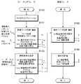
次に、図7のフローチャートを用いて、本実施形態の検査システム1による照明条件の決定(ティーチングフェーズ)から、決定した照明条件によるワークの検査(検査フェーズ)までの手順について説明する。 Next, the procedure from the determination of illumination conditions (teaching phase) by the
図7に示すように、まず、ティーチングフェーズにおいて、検査システム1は、N通りの照明発光パターンについて、それぞれのパターンを満たす最大光度ベクトルTmaxにしたがった光度でM個のワークを照明し、N×M枚の評価用の撮影画像fn,mを撮影する(S101)。この時、検査システム1は、各々の画像fn,mのROI内で画素飽和が発生しないような露出時間τn,mで撮影を行う。ここで、fn,mの露出時間をそれぞれτn,mと表す。As shown in FIG. 7, first, in the teaching phase, the
次に、検査システム1は、照明条件の決定を実行する(S102)。検査システム1は、照明最適化のための評価式Fの入力をユーザから受け付け、N×M枚の評価用の撮影画像fn,mと、それぞれの画像fn,mの露出時間τn,mを評価式Fで評価し、最適な照明条件ベクトルTと露出時間τを決定する。Next, the
次に、検査フェーズにおいて、検査システム1は、検査対象となるワークの検査用画像を撮影する(S103)。検査システム1は、ティーチングフェーズにおいて算出した照明条件ベクトルTと露出時間τを用いてワークを照明し、検査用画像gを撮影する。 Next, in the inspection phase, the
さらに、検査システム1は、撮影した検査用画像を検査判定器(例えばCNN等を用いた判定器)に入力し、検査パラメータPに基づく判定結果を出力する(S104)。 Further, the
なお、カメラのCRFが線形ではない場合には、図8のフローチャートに示すように、ティーチングフェーズの最初に、カメラキャリブレーションを実施し(S100)、その後、評価用の画像の撮影を行う。 If the CRF of the camera is not linear, as shown in the flowchart of FIG. 8, camera calibration is performed at the beginning of the teaching phase (S100), and then images for evaluation are captured.
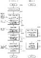
また、図9に示すフローチャートでは、ティーチングフェーズにおいて、照明の光度を最大とする条件で撮影した画像と、照明の光度を最小とする条件で撮影した画像(環境光画像)との差分を取ることで、環境光の影響をより精度よく排除している。 Further, in the flowchart shown in FIG. 9, in the teaching phase, the difference between the image captured under the condition of maximizing the luminous intensity of the illumination and the image captured under the condition of minimizing the luminous intensity of the illumination (environmental light image) is calculated. This eliminates the effects of ambient light with greater accuracy.
具体的には、ステップS101で最大光度でのN×M枚の評価用の撮影画像fn,mを撮影した後、環境光のみでの撮影を行う(S201)。具体的には、最小光度ベクトルTmin(例えば、消灯状態)の条件にて、各ワークの環境光画像fzを撮影する。露出時間は、画素飽和が発生しないような露出時間τzで行われる。Specifically, after capturing N×M images fn,m for evaluation at the maximum light intensity in step S101, capturing is performed only with ambient light (S201). Specifically, an ambient light image fz of each work is captured under the condition of the minimum light intensity vector Tmin (for example, in the off state). The exposure time is such that the exposure time τz does not cause pixel saturation.
次に、ステップS101で取得した最大光度での撮影画像fn,mと、ステップS201で取得した環境光画像fzとの差分画像f'n,mを生成する(S202)。Next, a difference image f′n, m between the photographed image fn,m at the maximum luminous intensity acquired in step S101 and the ambient light image fz acquired in step S201 is generated (S202).
次に、検査システム1は、照明条件を決定する(S203)。検査システム1は、照明最適化のための評価式Fの入力をユーザから受け付け、ステップS202で取得したN×M枚の差分画像f'n,mを評価式Fで評価し、最適な照明条件ベクトルTと露出時間τを決定する。Next, the
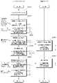
(複数の環境光画像による照明条件と検査パラメータのチューニング)
図9に示すフローチャートでは、環境光の条件を一定にして環境光画像を撮影しているが、図10に示すフローチャートでは、環境光の条件が変化する場合(例えば、時間経過による日照条件の変化など)を想定して、環境光画像を撮影している。(Tuning illumination conditions and inspection parameters using multiple ambient light images)
In the flowchart shown in FIG. 9, ambient light images are captured under constant ambient light conditions, but in the flowchart shown in FIG. etc.), the ambient light image is taken.
具体的には、まず、ステップS101でM個のワークについて最大光度での評価用の撮影画像fn,mを撮影し、次に、各ワークについて、最小光度ベクトルTminの条件下で、それぞれ環境光の条件が異なるi枚の環境光画像fi,dを撮影する(S301)。環境光画像の露出時間は、各画像について画素飽和が発生しないような露出時間τi,dで行われる。Specifically, first, in step S101, photographed images fn,m for evaluation are photographed for M workpieces at the maximum luminous intensity, and then, for each workpiece, under the condition of the minimum luminous intensity vector Tmin i images of ambient light fi,d with different ambient light conditions are taken (S301). The exposure time of the ambient light image is performed with an exposure time τi,d such that pixel saturation does not occur for each image.
次に、ステップS101で取得した最大光度での撮影画像fn,mと、ステップS301で取得した環境光画像fi,dとの差分画像f'i,n,mを生成する(S302)。差分画像は、各ワークについてi枚生成される。Next, a difference image f′i,n, m between the photographed image fn,m at the maximum luminous intensity acquired in step S101 and the ambient light image fi,d acquired in step S301 is generated (S302). i differential images are generated for each workpiece.
次に、検査システム1は、照明条件と検査パラメータの少なくとも一方を決定する(S303)。検査システム1は、照明最適化のための評価式Fと検査アルゴリズムAの入力を受け付け、ステップS302で取得したi×N×M枚の差分画像f'i,n,mを評価式Fと検査アルゴリズムAで評価し、最適な照明条件ベクトルTと露出時間τ、検査パラメータPを決定する。Next, the
このように、同一のワークに対して、環境光の条件が異なる複数枚の環境光画像を用いて照明条件を決定することにより、環境光の変化にロバストな照明条件を算出することができる。また、複数の環境光画像を利用することで、環境光の変化にロバストな検査パラメータを探索することも可能である。 In this way, by determining illumination conditions for the same workpiece using a plurality of ambient light images with different ambient light conditions, it is possible to calculate illumination conditions that are robust to changes in ambient light. Also, by using a plurality of ambient light images, it is possible to search for inspection parameters that are robust to changes in ambient light.
なお、上記の例では、複数の環境光画像をそのまま用いて、照明条件および検査パラメータを求めているが、環境光モデル(例えば、画像ベクトルxが多次元正規分布N(μ,Σ) に従うモデル)から複数の環境光画像を数値演算により生成し、環境光にロバストな照明条件および検査パラメータを求めるようにしてもよい。ここで、μ=E[x]は複数の環境光画像の各画素値の平均値を表すベクトルであり、Σ=E[(x-μ)(x-μ)T]は複数の環境光画像の各画素間の分散共分散行列である。In the above example, a plurality of ambient light images are used as they are to obtain the illumination conditions and inspection parameters. ), a plurality of ambient light images may be generated by numerical calculation, and illumination conditions and inspection parameters that are robust to ambient light may be obtained. Here, μ=E[x] is a vector representing the average value of each pixel value of multiple ambient light images, and Σ=E[(x−μ)(x−μ)T ] is multiple ambient light images. is the variance-covariance matrix between each pixel of .
以上のように、本実施形態によれば、ワークを撮影する際に、照明からの光の光度を最大に設定し、カメラの露出を調節することで、画素飽和を回避するようにした。これにより、照明光を最大限に大きくすることで、環境光の影響を相対的に十分に低減することができる。 As described above, according to the present embodiment, pixel saturation is avoided by setting the luminous intensity of the light from the illumination to the maximum and adjusting the exposure of the camera when photographing the workpiece. Accordingly, by maximizing the illumination light, the influence of ambient light can be relatively sufficiently reduced.
また、カメラのCRFが線形ではない場合には、カメラのキャリブレーションを行った上で、照明を最大光度にした際の露出時間を決定するようにした。これにより、カメラの特性に依存せず、CRFが未知の場合でも露出時間の調節を行うことができる。 In addition, when the CRF of the camera is not linear, the camera is calibrated and the exposure time is determined when the illumination is at maximum luminosity. This makes it possible to adjust the exposure time even if the CRF is unknown without depending on the characteristics of the camera.
また、露出時間を最適化する際に、照明を最大光度にして撮影した画像と、最小光度にして撮影した画像の差分を用いるようにした。これにより、精確に照明からの光度のみを当てた場合の画像に基づいて露出を調節することができる。 Also, when optimizing the exposure time, the difference between the image captured with the maximum illumination intensity and the image captured with the minimum illumination intensity is used. This allows the exposure to be adjusted based on the image given exactly the intensity of the illumination.
また、露出時間を最適化する際に、照明を最大光度にして撮影した画像と、環境光が異なる複数の条件下にて、照明を最小光度にして撮影した画像の差分を用いるようにした。これにより、撮影時の環境光の状況に対してロバストな露出の調整を行うことができる。 Also, when optimizing the exposure time, the difference between an image shot with the maximum lighting intensity and an image shot with the minimum lighting intensity under multiple different ambient light conditions is used. This makes it possible to perform exposure adjustment that is robust to the ambient light conditions at the time of shooting.
なお、上記の実施形態では、照明からの光を最大光度にしてカメラの露出またはゲインを調節しているが、環境光に比べて十分に強い光度であれば、必ずしも最大光度には限られず、一定値以上の光度の光を当てるようにしてもよい。 In the above embodiment, the exposure or gain of the camera is adjusted by setting the light from the illumination to the maximum luminosity. It is also possible to irradiate light with a luminous intensity equal to or higher than a certain value.
以上、本発明の実施の形態を詳細に説明してきたが、上述までの説明はあらゆる点において本発明の例示に過ぎない。本発明の範囲を逸脱することなく種々の改良や変形を行うことができることは言うまでもない。なお、上記の実施形態の一部又は全部は、以下の付記のようにも記載され得るが、以下には限られない。
(付記1)
検査対象のワーク(4)の画像を撮影する撮影装置(102)と、
前記ワーク(4)に光を当てる光源を含む照明装置(LS)と、
前記ワーク(4)を撮影する際の撮影の条件を設定する撮影条件設定部(100)と、を備え、
前記撮影条件設定部(100)は、
前記照明装置(LS)から前記ワーク(4)に当てる光度を閾値以上の値にして撮影した際に、前記ワーク(4)の画像の指定領域の画素値が指定範囲内の値になるように、前記撮影装置(102)の露出時間を設定する、撮影条件設定システム(1)。Although the embodiments of the present invention have been described above in detail, the above description is merely an example of the present invention in every respect. It goes without saying that various modifications and variations can be made without departing from the scope of the invention. Some or all of the above embodiments may be described as the following additional remarks, but are not limited to the following.
(Appendix 1)
a photographing device (102) for photographing an image of a workpiece (4) to be inspected;
a lighting device (LS) including a light source that illuminates the workpiece (4);
a photographing condition setting unit (100) for setting photographing conditions when photographing the work (4),
The imaging condition setting unit (100)
The pixel values of the specified area of the image of the work (4) are set to values within the specified range when the work (4) is photographed with the light intensity applied from the lighting device (LS) to a value equal to or higher than a threshold value. , a photographing condition setting system (1) for setting an exposure time of said photographing device (102).
(付記2)
前記撮影条件設定部(100)は、
前記照明装置(LS)から前記ワーク(4)に当てる光度を最大値にして撮影した際に、前記ワーク(4)の画像の指定領域の画素値が指定範囲内の値になるように、前記撮影装置(102)の露出時間を設定する、付記1に記載の撮影条件設定システム(1)。(Appendix 2)
The imaging condition setting unit (100)
The above-described 1. The imaging condition setting system (1) according to
(付記3)
前記照明装置(LS)は、
それぞれの光度を調節可能な複数の光源を備え、
前記撮影条件設定部(100)は、
前記複数の光源のうち、少なくとも1つの光源の光度を閾値以上の値に設定する、付記1または2に記載の撮影条件設定システム(1)。(Appendix 3)
The lighting device (LS) is
Equipped with multiple light sources with adjustable luminous intensity,
The imaging condition setting unit (100)
3. The imaging condition setting system (1) according to
(付記4)
前記撮影条件設定部は、
前記撮影装置の露出に対する画素値の特性が、線形の関係ではない場合には、前記撮影装置のキャリブレーションを実施した上で、露出時間を設定する、付記1から3のいずれか1項に記載の撮影条件設定システム(1)。(Appendix 4)
The imaging condition setting unit
4. The method according to any one of
(付記5)
前記撮影条件設定部(100)は、
前記照明装置(LS)から前記ワーク(4)に当てる光度を閾値以上の値にして撮影した画像と、前記照明装置(LS)から前記ワーク(4)に当てる光度を最小値にして撮影した画像との差分に基づいて、前記ワーク(4)の画像の指定領域の画素値が指定範囲内の値になるように、前記撮影装置(102)の露出時間を設定する、付記1から4のいずれか1項に記載の撮影条件設定システム(1)。(Appendix 5)
The imaging condition setting unit (100)
An image captured by setting the light intensity applied from the illumination device (LS) to the work (4) to a value equal to or higher than a threshold value, and an image captured by setting the light intensity applied to the work (4) from the lighting device (LS) to a minimum value. 5, wherein the exposure time of the photographing device (102) is set so that the pixel value of the specified area of the image of the work (4) is within the specified range based on the difference between 1. The imaging condition setting system (1) according to 1.
(付記6)
前記撮影条件設定部(100)は、
前記照明装置(LS)から前記ワーク(4)に当てる光度を閾値以上の値にして撮影した画像と、異なる複数の環境光の条件下で、前記照明装置(LS)から前記ワーク(4)に当てる光度を最小値にして撮影した画像との差分に基づいて、前記ワーク(4)の画像の指定領域の画素値が指定範囲内の値になるように、前記撮影装置(102)の露出時間を設定する、付記1から4のいずれか1項に記載の撮影条件設定システム(1)。
(付記7)
前記撮影条件設定部(100)は、
前記照明装置(LS)から前記ワーク(4)に当てる光度の設定値、実際に照射された光度の測定値、およびディスプレイに表示された光度のうちの少なくとも一つを所定の閾値以上の値にして撮影した際に、前記ワークの画像の指定領域の画素値が指定範囲内の値になるように、前記撮影装置(102)の露出時間を設定する、付記1から6のいずれか1項に記載の撮影条件設定システム(1)。(Appendix 6)
The imaging condition setting unit (100)
An image captured by setting the light intensity applied from the lighting device (LS) to the work (4) to a value equal to or higher than a threshold value, and an image captured from the lighting device (LS) to the work (4) under a plurality of different environmental light conditions The exposure time of the photographing device (102) is adjusted so that the pixel values of the designated area of the image of the work (4) are within the designated range based on the difference from the image photographed with the light intensity applied to the minimum value. 5. The imaging condition setting system (1) according to any one of
(Appendix 7)
The imaging condition setting unit (100)
At least one of a set value of the luminous intensity applied from the lighting device (LS) to the work (4), a measured value of the luminous intensity actually irradiated, and a luminous intensity displayed on the display is set to a value equal to or higher than a predetermined threshold value. 7. The exposure time of the photographing device (102) is set so that the pixel value of the designated area of the image of the work is within the designated range when photographed by An imaging condition setting system (1) as described.
(付記8)
コンピュータ(1)によって、検査対象のワーク(4)の画像の撮影条件を決定する撮影条件設定方法であって、
コンピュータ(1)が、前記ワーク(4)に光を当てる照明装置(LS)の光度を閾値以上の値に設定し、
コンピュータ(1)が、前記光度の条件下で撮影装置(102)によって前記ワーク(4)を撮影し、
コンピュータ(1)が、撮影した前記ワーク(4)の画像に基づいて、前記ワーク(4)の画像の指定領域の画素値が指定範囲内の値になるように、前記撮影装置(102)の露出時間を設定する、撮影条件設定方法。(Appendix 8)
An imaging condition setting method for determining imaging conditions for an image of a workpiece (4) to be inspected by a computer (1), comprising:
A computer (1) sets the luminous intensity of a lighting device (LS) that illuminates the work (4) to a value equal to or higher than a threshold,
a computer (1) photographing the work (4) with a photographing device (102) under the condition of the light intensity;
A computer (1) adjusts the photographing device (102) so that the pixel values of the specified area of the image of the work (4) are within the specified range based on the photographed image of the work (4). A shooting condition setting method that sets the exposure time.
(付記9)
検査対象のワーク(4)の画像の撮影条件を決定するコンピュータ(1)に、
前記ワーク(4)に光を当てる照明装置(LS)の光度を閾値以上の値に設定すること、
前記光度の条件下で撮影装置(102)によって前記ワーク(4)を撮影すること、
撮影した前記ワーク(4)の画像に基づいて、前記ワーク(4)の画像の指定領域の画素値が指定範囲内の値になるように、前記撮影装置(102)の露出時間を設定すること、を実行させるプログラム。(Appendix 9)
A computer (1) that determines imaging conditions for an image of a workpiece (4) to be inspected,
setting the luminous intensity of a lighting device (LS) that illuminates the work (4) to a value equal to or higher than a threshold;
photographing the work (4) with a photographing device (102) under the condition of the light intensity;
Setting the exposure time of the photographing device (102) based on the photographed image of the work (4) so that the pixel values of the designated area of the image of the work (4) are within the designated range. , the program that causes the .
1…検査システム、2…ベルトコンベア、4…ワーク、6…撮像視野、8…上位ネットワーク、10…PLC、12…データベース装置、100…制御装置、102…カメラ、104…ディスプレイ、106…キーボード、108…マウス、110…プロセッサ、112…メインメモリ、114…カメラインターフェイス、116…入力インターフェイス、118…表示インターフェイス、120…通信インターフェイス、122…内部バス、130…ストレージ、132…検査プログラム、134…照明パラメータ、136…照度LUT、138…評価用ワーク画像、140…検査用ワーク画像、141…撮像部、142…算出部、143…変換部、144…記憶部、LS…光源、LSi…チャネル照明DESCRIPTION OF
Claims (9)
Translated fromJapanese前記ワークに光を当てる光源を含む照明装置と、
前記ワークを撮影する際の撮影の条件を設定する撮影条件設定部と、を備え、
前記撮影条件設定部は、
前記照明装置から前記ワークに当てる光度を閾値以上の値にして撮影した際に、前記ワークの画像の指定領域の画素値が指定範囲内の値になるように、前記撮影装置の露出時間を設定する、撮影条件設定システム。a photographing device for photographing an image of a workpiece to be inspected;
a lighting device including a light source that illuminates the workpiece;
a photographing condition setting unit for setting photographing conditions when photographing the work,
The imaging condition setting unit
The exposure time of the imaging device is set so that the pixel values of the specified area of the image of the workpiece are within the specified range when the illumination device irradiates the workpiece with a light intensity equal to or greater than a threshold value. shooting condition setting system.
前記照明装置から前記ワークに当てる光度を最大値にして撮影した際に、前記ワークの画像の指定領域の画素値が指定範囲内の値になるように、前記撮影装置の露出時間を設定する、請求項1に記載の撮影条件設定システム。The imaging condition setting unit
setting the exposure time of the photographing device so that the pixel value of the specified area of the image of the work is within the specified range when the work is photographed with the light intensity applied to the work from the lighting device at the maximum value; The imaging condition setting system according to claim 1.
前記撮影条件設定部は、
前記複数の光源のうち、少なくとも1つの光源の光度を閾値以上の値に設定する、請求項1または2に記載の撮影条件設定システム。The lighting device includes a plurality of light sources each having an adjustable luminous intensity,
The imaging condition setting unit
3. The imaging condition setting system according to claim 1, wherein the luminous intensity of at least one light source among the plurality of light sources is set to a value equal to or greater than a threshold value.
前記撮影装置の露出に対する画素値の特性が、線形の関係ではない場合には、前記撮影装置のキャリブレーションを実施した上で、露出時間を設定する、請求項1から3のいずれか1項に記載の撮影条件設定システム。The imaging condition setting unit
4. The method according to any one of claims 1 to 3, wherein when the characteristic of the pixel value with respect to the exposure of the photographing device is not in a linear relationship, the exposure time is set after performing the calibration of the photographing device. Acquisition condition setting system described.
前記照明装置から前記ワークに当てる光度を閾値以上の値にして撮影した画像と、前記照明装置から前記ワークに当てる光度を最小値にして撮影した画像との差分に基づいて、前記ワークの画像の指定領域の画素値が指定範囲内の値になるように、前記撮影装置の露出時間を設定する、請求項1から4のいずれか1項に記載の撮影条件設定システム。The imaging condition setting unit
Based on the difference between an image captured with the luminous intensity applied to the workpiece from the illumination device at a value equal to or higher than a threshold value and an image captured with the luminous intensity applied from the illumination device to the workpiece at a minimum value, the image of the workpiece is determined. 5. The photographing condition setting system according to any one of claims 1 to 4, wherein the exposure time of the photographing device is set so that the pixel values of the designated area are within the designated range.
前記照明装置から前記ワークに当てる光度を閾値以上の値にして撮影した画像と、異なる複数の環境光の条件下で、前記照明装置から前記ワークに当てる光度を最小値にして撮影した画像との差分に基づいて、前記ワークの画像の指定領域の画素値が指定範囲内の値になるように、前記撮影装置の露出時間を設定する、請求項1から4のいずれか1項に記載の撮影条件設定システム。The imaging condition setting unit
An image captured by setting the luminous intensity applied from the lighting device to the work to a value equal to or higher than a threshold value, and an image captured by setting the light intensity applied to the work from the lighting device to the minimum value under a plurality of different environmental light conditions. 5. The photographing according to claim 1, wherein an exposure time of said photographing device is set so that pixel values of a designated area of said workpiece image are within a designated range based on said difference. Conditioning system.
前記照明装置から前記ワークに当てる光度の設定値、実際に照射された光度の測定値、およびディスプレイに表示された光度のうちの少なくとも一つを所定の閾値以上の値にして撮影した際に、前記ワークの画像の指定領域の画素値が指定範囲内の値になるように、前記撮影装置の露出時間を設定する、請求項1から6のいずれか1項に記載の撮影条件設定システム。The imaging condition setting unit
When photographing with at least one of the set value of the luminous intensity applied to the workpiece from the illumination device, the measured value of the luminous intensity actually irradiated, and the luminous intensity displayed on the display set to a value equal to or higher than a predetermined threshold, 7. The imaging condition setting system according to any one of claims 1 to 6, wherein an exposure time of said imaging device is set such that pixel values of a specified area of said work image are within a specified range.
コンピュータが、前記ワークに光を当てる照明装置の光度を閾値以上の値に設定し、
コンピュータが、前記光度の条件下で撮影装置によって前記ワークを撮影し、
コンピュータが、撮影した前記ワークの画像に基づいて、前記ワークの画像の指定領域の画素値が指定範囲内の値になるように、前記撮影装置の露出時間を設定する、撮影条件設定方法。An imaging condition setting method for determining imaging conditions for an image of a workpiece to be inspected by a computer, comprising:
The computer sets the luminous intensity of an illumination device that illuminates the workpiece to a value equal to or higher than a threshold;
a computer photographing the workpiece with a photographing device under the condition of the light intensity;
A photographing condition setting method, wherein a computer sets the exposure time of the photographing device based on the photographed image of the work so that the pixel values of the designated area of the image of the work are within the designated range.
前記ワークに光を当てる照明装置の光度を閾値以上の値に設定すること、
前記光度の条件下で撮影装置によって前記ワークを撮影すること、
撮影した前記ワークの画像に基づいて、前記ワークの画像の指定領域の画素値が指定範囲内の値になるように、前記撮影装置の露出時間を設定すること、を実行させるプログラム。A computer that determines the photographing conditions for images of workpieces to be inspected,
setting the luminous intensity of an illumination device that illuminates the workpiece to a value equal to or higher than a threshold;
photographing the workpiece with a photographing device under the condition of the light intensity;
A program for setting the exposure time of the photographing device so that the pixel values of the specified area of the image of the work are within the specified range based on the image of the work taken.
Priority Applications (5)
| Application Number | Priority Date | Filing Date | Title |
|---|---|---|---|
| JP2021011384AJP7602195B2 (en) | 2021-01-27 | 2021-01-27 | Photographing condition setting system, photographing condition setting method, and program |
| US18/260,772US12335628B2 (en) | 2021-01-27 | 2021-09-14 | Imaging condition setting system, imaging condition setting method, and program |
| EP21923010.9AEP4286939A4 (en) | 2021-01-27 | 2021-09-14 | SYSTEM FOR SETTING IMAGING CONDITIONS, METHOD FOR SETTING IMAGING CONDITIONS AND PROGRAM THEREFOR |
| PCT/JP2021/033690WO2022163002A1 (en) | 2021-01-27 | 2021-09-14 | Imaging condition setting system, imaging condition setting method, and program |
| CN202180088877.9ACN116745696A (en) | 2021-01-27 | 2021-09-14 | Shooting condition setting system, shooting condition setting method, and program |
Applications Claiming Priority (1)
| Application Number | Priority Date | Filing Date | Title |
|---|---|---|---|
| JP2021011384AJP7602195B2 (en) | 2021-01-27 | 2021-01-27 | Photographing condition setting system, photographing condition setting method, and program |
Publications (2)
| Publication Number | Publication Date |
|---|---|
| JP2022114908Atrue JP2022114908A (en) | 2022-08-08 |
| JP7602195B2 JP7602195B2 (en) | 2024-12-18 |
Family
ID=82654385
Family Applications (1)
| Application Number | Title | Priority Date | Filing Date |
|---|---|---|---|
| JP2021011384AActiveJP7602195B2 (en) | 2021-01-27 | 2021-01-27 | Photographing condition setting system, photographing condition setting method, and program |
Country Status (5)
| Country | Link |
|---|---|
| US (1) | US12335628B2 (en) |
| EP (1) | EP4286939A4 (en) |
| JP (1) | JP7602195B2 (en) |
| CN (1) | CN116745696A (en) |
| WO (1) | WO2022163002A1 (en) |
Cited By (2)
| Publication number | Priority date | Publication date | Assignee | Title |
|---|---|---|---|---|
| WO2025051768A1 (en)* | 2023-09-05 | 2025-03-13 | Top Seven Gmbh & Co. Kg | Method and device for setting a receiving unit for carrying out an inspection of an object |
| KR102787885B1 (en)* | 2023-12-22 | 2025-03-28 | 주식회사 파인더아이 | Optical Adjustment System and Method for Inspecting Different Objects |
Families Citing this family (2)
| Publication number | Priority date | Publication date | Assignee | Title |
|---|---|---|---|---|
| JP7613996B2 (en)* | 2021-04-16 | 2025-01-15 | 株式会社キーエンス | Image inspection device, control unit for image inspection device, image inspection method, image inspection program, computer-readable recording medium, and device having the program recorded thereon |
| IT202300000921A1 (en) | 2023-01-23 | 2024-07-23 | Gd Spa | PROCEDURE FOR OPERATING A VISION SYSTEM |
Citations (6)
| Publication number | Priority date | Publication date | Assignee | Title |
|---|---|---|---|---|
| US20040207836A1 (en)* | 2002-09-27 | 2004-10-21 | Rajeshwar Chhibber | High dynamic range optical inspection system and method |
| JP2005003385A (en)* | 2003-06-09 | 2005-01-06 | Mitsutoyo Corp | Image measuring method and image measuring apparatus |
| JP2009182461A (en)* | 2008-01-29 | 2009-08-13 | Panasonic Electric Works Co Ltd | Imaging device |
| US20150264278A1 (en)* | 2014-03-12 | 2015-09-17 | Apple Inc. | System and Method for Estimating an Ambient Light Condition Using an Image Sensor and Field-of-View Compensation |
| JP2017135528A (en)* | 2016-01-27 | 2017-08-03 | キヤノン株式会社 | Image processing device, imaging apparatus and image processing program |
| WO2020129140A1 (en)* | 2018-12-18 | 2020-06-25 | 三菱電機株式会社 | Testing device, testing system and testing method |
Family Cites Families (14)
| Publication number | Priority date | Publication date | Assignee | Title |
|---|---|---|---|---|
| JPS6270259A (en) | 1985-09-24 | 1987-03-31 | 旭化成株式会社 | Dielectric composition and its manufacturing method |
| US7394530B2 (en)* | 2004-03-30 | 2008-07-01 | Budd Gerald W | Surface inspection technology for the detection of porosity and surface imperfections on machined metal surfaces |
| US8018525B2 (en) | 2007-12-21 | 2011-09-13 | Nokia Corporation | Camera flash module and method for controlling same |
| JP5257375B2 (en)* | 2009-03-13 | 2013-08-07 | オムロン株式会社 | Image processing apparatus and image processing method |
| KR101214806B1 (en) | 2010-05-11 | 2012-12-24 | 가부시키가이샤 사무코 | Apparatus and method for defect inspection of wafer |
| JP5556346B2 (en)* | 2010-05-11 | 2014-07-23 | 株式会社Sumco | Wafer defect inspection apparatus and wafer defect inspection method |
| JP2012105225A (en)* | 2010-11-12 | 2012-05-31 | Sony Corp | Image processing system, imaging apparatus, image processing method and program |
| JP2015228641A (en)* | 2014-05-07 | 2015-12-17 | 株式会社リコー | Imaging apparatus, exposure adjustment method and program |
| JP6566737B2 (en)* | 2015-06-18 | 2019-08-28 | キヤノン株式会社 | Information processing apparatus, information processing method, and program |
| JP6601264B2 (en) | 2016-02-29 | 2019-11-06 | 富士通株式会社 | Lighting condition setting device, lighting condition setting method, and lighting condition setting computer program |
| JP6736423B2 (en) | 2016-08-26 | 2020-08-05 | 株式会社キーエンス | Three-dimensional measuring device |
| DE102016226206A1 (en)* | 2016-12-23 | 2018-06-28 | Fraunhofer-Gesellschaft zur Förderung der angewandten Forschung e.V. | System and method for acquiring measurement images of a measurement object |
| DE102017221649A1 (en)* | 2017-12-01 | 2019-06-06 | Volkswagen Aktiengesellschaft | Test method for detecting surface defects on matt and shiny surfaces and associated device and test arrangement between the device and component |
| WO2021262190A1 (en)* | 2020-06-26 | 2021-12-30 | Hewlett-Packard Development Company, L.P. | Activating light sources for output image |
- 2021
- 2021-01-27JPJP2021011384Apatent/JP7602195B2/enactiveActive
- 2021-09-14WOPCT/JP2021/033690patent/WO2022163002A1/ennot_activeCeased
- 2021-09-14EPEP21923010.9Apatent/EP4286939A4/enactivePending
- 2021-09-14USUS18/260,772patent/US12335628B2/enactiveActive
- 2021-09-14CNCN202180088877.9Apatent/CN116745696A/enactivePending
Patent Citations (6)
| Publication number | Priority date | Publication date | Assignee | Title |
|---|---|---|---|---|
| US20040207836A1 (en)* | 2002-09-27 | 2004-10-21 | Rajeshwar Chhibber | High dynamic range optical inspection system and method |
| JP2005003385A (en)* | 2003-06-09 | 2005-01-06 | Mitsutoyo Corp | Image measuring method and image measuring apparatus |
| JP2009182461A (en)* | 2008-01-29 | 2009-08-13 | Panasonic Electric Works Co Ltd | Imaging device |
| US20150264278A1 (en)* | 2014-03-12 | 2015-09-17 | Apple Inc. | System and Method for Estimating an Ambient Light Condition Using an Image Sensor and Field-of-View Compensation |
| JP2017135528A (en)* | 2016-01-27 | 2017-08-03 | キヤノン株式会社 | Image processing device, imaging apparatus and image processing program |
| WO2020129140A1 (en)* | 2018-12-18 | 2020-06-25 | 三菱電機株式会社 | Testing device, testing system and testing method |
Cited By (2)
| Publication number | Priority date | Publication date | Assignee | Title |
|---|---|---|---|---|
| WO2025051768A1 (en)* | 2023-09-05 | 2025-03-13 | Top Seven Gmbh & Co. Kg | Method and device for setting a receiving unit for carrying out an inspection of an object |
| KR102787885B1 (en)* | 2023-12-22 | 2025-03-28 | 주식회사 파인더아이 | Optical Adjustment System and Method for Inspecting Different Objects |
Also Published As
| Publication number | Publication date |
|---|---|
| JP7602195B2 (en) | 2024-12-18 |
| US20240305893A1 (en) | 2024-09-12 |
| EP4286939A4 (en) | 2024-12-11 |
| WO2022163002A1 (en) | 2022-08-04 |
| EP4286939A1 (en) | 2023-12-06 |
| CN116745696A (en) | 2023-09-12 |
| US12335628B2 (en) | 2025-06-17 |
Similar Documents
| Publication | Publication Date | Title |
|---|---|---|
| JP2022114908A (en) | Imaging condition setting system, imaging condition setting method and program | |
| CN112567428B (en) | Photographing method and photographing device | |
| TWI807414B (en) | Inspection device, inspection method, and storage medium | |
| CN112534243A (en) | Inspection apparatus and method | |
| JP5181970B2 (en) | Image processing apparatus and image processing method | |
| CN108986170B (en) | Linear array camera flat field correction method suitable for field working conditions | |
| CN110310596B (en) | GAMMA (GAMMA-GAMMA) adjustment initial value prediction method and system of OLED module | |
| JP2016045019A (en) | Teaching apparatus and teaching method for substrate inspection apparatus | |
| US20230162344A1 (en) | Appearance inspection apparatus and appearance inspection method | |
| CN113034620A (en) | Correction method, correction device, computer-readable storage medium, and computer apparatus | |
| CN118018715B (en) | Method and related device for adjusting consistency of exposure time of multiple cameras | |
| CN111638042B (en) | DLP optical characteristic test analysis method | |
| CN112381751A (en) | Online intelligent detection system and method based on image processing algorithm | |
| JP6395455B2 (en) | Inspection device, inspection method, and program | |
| CN115914616A (en) | Light source point detection method, device, equipment and computer readable storage medium | |
| CN112165616A (en) | Test method, device, electronic device and storage medium for camera module | |
| JP5609459B2 (en) | Binarization processing method and image processing apparatus | |
| CN116934693B (en) | Semiconductor laser module far-field image detection method and device | |
| CN103905762B (en) | Method for automatically detecting projection picture for projection module | |
| WO2015004672A1 (en) | A method and apparatus for inspection and quality assurance of material samples using qualified user definitions and data derived from images in a controlled environment | |
| US20070053583A1 (en) | Image correcting apparatus, pattern inspection apparatus, and image correcting method, and reticle | |
| Chay et al. | Development of an Algorithm for Size and Weight Measurement of Intact Pineapples | |
| CN118799435B (en) | Method for generating simulated hyperspectral image based on aerial image | |
| CN117745603B (en) | Product image correction method and device based on linear array scanning device and storage medium | |
| KR102049172B1 (en) | Adaptive method for a light source |
Legal Events
| Date | Code | Title | Description |
|---|---|---|---|
| A621 | Written request for application examination | Free format text:JAPANESE INTERMEDIATE CODE: A621 Effective date:20231109 | |
| A131 | Notification of reasons for refusal | Free format text:JAPANESE INTERMEDIATE CODE: A131 Effective date:20240814 | |
| A521 | Request for written amendment filed | Free format text:JAPANESE INTERMEDIATE CODE: A523 Effective date:20240925 | |
| TRDD | Decision of grant or rejection written | ||
| A01 | Written decision to grant a patent or to grant a registration (utility model) | Free format text:JAPANESE INTERMEDIATE CODE: A01 Effective date:20241106 | |
| A61 | First payment of annual fees (during grant procedure) | Free format text:JAPANESE INTERMEDIATE CODE: A61 Effective date:20241119 | |
| R150 | Certificate of patent or registration of utility model | Ref document number:7602195 Country of ref document:JP Free format text:JAPANESE INTERMEDIATE CODE: R150 |