JP2022113713A - Methods and systems for creating virtual and augmented reality - Google Patents
Methods and systems for creating virtual and augmented realityDownload PDFInfo
- Publication number
- JP2022113713A JP2022113713AJP2022083729AJP2022083729AJP2022113713AJP 2022113713 AJP2022113713 AJP 2022113713AJP 2022083729 AJP2022083729 AJP 2022083729AJP 2022083729 AJP2022083729 AJP 2022083729AJP 2022113713 AJP2022113713 AJP 2022113713A
- Authority
- JP
- Japan
- Prior art keywords
- user
- virtual
- item
- user interface
- illustrate
- Prior art date
- Legal status (The legal status is an assumption and is not a legal conclusion. Google has not performed a legal analysis and makes no representation as to the accuracy of the status listed.)
- Withdrawn
Links
Images


Classifications
- G—PHYSICS
- G06—COMPUTING OR CALCULATING; COUNTING
- G06F—ELECTRIC DIGITAL DATA PROCESSING
- G06F18/00—Pattern recognition
- G—PHYSICS
- G06—COMPUTING OR CALCULATING; COUNTING
- G06F—ELECTRIC DIGITAL DATA PROCESSING
- G06F3/00—Input arrangements for transferring data to be processed into a form capable of being handled by the computer; Output arrangements for transferring data from processing unit to output unit, e.g. interface arrangements
- G06F3/14—Digital output to display device ; Cooperation and interconnection of the display device with other functional units
- G—PHYSICS
- G02—OPTICS
- G02B—OPTICAL ELEMENTS, SYSTEMS OR APPARATUS
- G02B6/00—Light guides; Structural details of arrangements comprising light guides and other optical elements, e.g. couplings
- G02B6/0001—Light guides; Structural details of arrangements comprising light guides and other optical elements, e.g. couplings specially adapted for lighting devices or systems
- G02B6/0011—Light guides; Structural details of arrangements comprising light guides and other optical elements, e.g. couplings specially adapted for lighting devices or systems the light guides being planar or of plate-like form
- G—PHYSICS
- G02—OPTICS
- G02B—OPTICAL ELEMENTS, SYSTEMS OR APPARATUS
- G02B6/00—Light guides; Structural details of arrangements comprising light guides and other optical elements, e.g. couplings
- G02B6/24—Coupling light guides
- G02B6/26—Optical coupling means
- G02B6/27—Optical coupling means with polarisation selective and adjusting means
- G02B6/2706—Optical coupling means with polarisation selective and adjusting means as bulk elements, i.e. free space arrangements external to a light guide, e.g. polarising beam splitters
- G—PHYSICS
- G06—COMPUTING OR CALCULATING; COUNTING
- G06F—ELECTRIC DIGITAL DATA PROCESSING
- G06F3/00—Input arrangements for transferring data to be processed into a form capable of being handled by the computer; Output arrangements for transferring data from processing unit to output unit, e.g. interface arrangements
- G06F3/01—Input arrangements or combined input and output arrangements for interaction between user and computer
- G06F3/011—Arrangements for interaction with the human body, e.g. for user immersion in virtual reality
- G06F3/012—Head tracking input arrangements
- G—PHYSICS
- G06—COMPUTING OR CALCULATING; COUNTING
- G06F—ELECTRIC DIGITAL DATA PROCESSING
- G06F3/00—Input arrangements for transferring data to be processed into a form capable of being handled by the computer; Output arrangements for transferring data from processing unit to output unit, e.g. interface arrangements
- G06F3/01—Input arrangements or combined input and output arrangements for interaction between user and computer
- G06F3/011—Arrangements for interaction with the human body, e.g. for user immersion in virtual reality
- G06F3/013—Eye tracking input arrangements
- G—PHYSICS
- G06—COMPUTING OR CALCULATING; COUNTING
- G06F—ELECTRIC DIGITAL DATA PROCESSING
- G06F3/00—Input arrangements for transferring data to be processed into a form capable of being handled by the computer; Output arrangements for transferring data from processing unit to output unit, e.g. interface arrangements
- G06F3/01—Input arrangements or combined input and output arrangements for interaction between user and computer
- G06F3/017—Gesture based interaction, e.g. based on a set of recognized hand gestures
- G—PHYSICS
- G06—COMPUTING OR CALCULATING; COUNTING
- G06F—ELECTRIC DIGITAL DATA PROCESSING
- G06F3/00—Input arrangements for transferring data to be processed into a form capable of being handled by the computer; Output arrangements for transferring data from processing unit to output unit, e.g. interface arrangements
- G06F3/14—Digital output to display device ; Cooperation and interconnection of the display device with other functional units
- G06F3/147—Digital output to display device ; Cooperation and interconnection of the display device with other functional units using display panels
- G—PHYSICS
- G06—COMPUTING OR CALCULATING; COUNTING
- G06T—IMAGE DATA PROCESSING OR GENERATION, IN GENERAL
- G06T17/00—Three dimensional [3D] modelling, e.g. data description of 3D objects
- G—PHYSICS
- G06—COMPUTING OR CALCULATING; COUNTING
- G06V—IMAGE OR VIDEO RECOGNITION OR UNDERSTANDING
- G06V20/00—Scenes; Scene-specific elements
- G06V20/20—Scenes; Scene-specific elements in augmented reality scenes
- G—PHYSICS
- G06—COMPUTING OR CALCULATING; COUNTING
- G06V—IMAGE OR VIDEO RECOGNITION OR UNDERSTANDING
- G06V40/00—Recognition of biometric, human-related or animal-related patterns in image or video data
- G06V40/10—Human or animal bodies, e.g. vehicle occupants or pedestrians; Body parts, e.g. hands
- G06V40/107—Static hand or arm
- G06V40/113—Recognition of static hand signs
- G—PHYSICS
- G06—COMPUTING OR CALCULATING; COUNTING
- G06V—IMAGE OR VIDEO RECOGNITION OR UNDERSTANDING
- G06V40/00—Recognition of biometric, human-related or animal-related patterns in image or video data
- G06V40/10—Human or animal bodies, e.g. vehicle occupants or pedestrians; Body parts, e.g. hands
- G06V40/18—Eye characteristics, e.g. of the iris
- G06V40/19—Sensors therefor
- G—PHYSICS
- G09—EDUCATION; CRYPTOGRAPHY; DISPLAY; ADVERTISING; SEALS
- G09G—ARRANGEMENTS OR CIRCUITS FOR CONTROL OF INDICATING DEVICES USING STATIC MEANS TO PRESENT VARIABLE INFORMATION
- G09G3/00—Control arrangements or circuits, of interest only in connection with visual indicators other than cathode-ray tubes
- G09G3/001—Control arrangements or circuits, of interest only in connection with visual indicators other than cathode-ray tubes using specific devices not provided for in groups G09G3/02 - G09G3/36, e.g. using an intermediate record carrier such as a film slide; Projection systems; Display of non-alphanumerical information, solely or in combination with alphanumerical information, e.g. digital display on projected diapositive as background
- G09G3/002—Control arrangements or circuits, of interest only in connection with visual indicators other than cathode-ray tubes using specific devices not provided for in groups G09G3/02 - G09G3/36, e.g. using an intermediate record carrier such as a film slide; Projection systems; Display of non-alphanumerical information, solely or in combination with alphanumerical information, e.g. digital display on projected diapositive as background to project the image of a two-dimensional display, such as an array of light emitting or modulating elements or a CRT
- G—PHYSICS
- G09—EDUCATION; CRYPTOGRAPHY; DISPLAY; ADVERTISING; SEALS
- G09G—ARRANGEMENTS OR CIRCUITS FOR CONTROL OF INDICATING DEVICES USING STATIC MEANS TO PRESENT VARIABLE INFORMATION
- G09G3/00—Control arrangements or circuits, of interest only in connection with visual indicators other than cathode-ray tubes
- G09G3/001—Control arrangements or circuits, of interest only in connection with visual indicators other than cathode-ray tubes using specific devices not provided for in groups G09G3/02 - G09G3/36, e.g. using an intermediate record carrier such as a film slide; Projection systems; Display of non-alphanumerical information, solely or in combination with alphanumerical information, e.g. digital display on projected diapositive as background
- G09G3/003—Control arrangements or circuits, of interest only in connection with visual indicators other than cathode-ray tubes using specific devices not provided for in groups G09G3/02 - G09G3/36, e.g. using an intermediate record carrier such as a film slide; Projection systems; Display of non-alphanumerical information, solely or in combination with alphanumerical information, e.g. digital display on projected diapositive as background to produce spatial visual effects
- A—HUMAN NECESSITIES
- A61—MEDICAL OR VETERINARY SCIENCE; HYGIENE
- A61B—DIAGNOSIS; SURGERY; IDENTIFICATION
- A61B90/00—Instruments, implements or accessories specially adapted for surgery or diagnosis and not covered by any of the groups A61B1/00 - A61B50/00, e.g. for luxation treatment or for protecting wound edges
- A61B90/36—Image-producing devices or illumination devices not otherwise provided for
- A61B2090/364—Correlation of different images or relation of image positions in respect to the body
- A61B2090/365—Correlation of different images or relation of image positions in respect to the body augmented reality, i.e. correlating a live optical image with another image
- G—PHYSICS
- G09—EDUCATION; CRYPTOGRAPHY; DISPLAY; ADVERTISING; SEALS
- G09G—ARRANGEMENTS OR CIRCUITS FOR CONTROL OF INDICATING DEVICES USING STATIC MEANS TO PRESENT VARIABLE INFORMATION
- G09G2354/00—Aspects of interface with display user
- G—PHYSICS
- G09—EDUCATION; CRYPTOGRAPHY; DISPLAY; ADVERTISING; SEALS
- G09G—ARRANGEMENTS OR CIRCUITS FOR CONTROL OF INDICATING DEVICES USING STATIC MEANS TO PRESENT VARIABLE INFORMATION
- G09G2370/00—Aspects of data communication
- G09G2370/02—Networking aspects
- G—PHYSICS
- G09—EDUCATION; CRYPTOGRAPHY; DISPLAY; ADVERTISING; SEALS
- G09G—ARRANGEMENTS OR CIRCUITS FOR CONTROL OF INDICATING DEVICES USING STATIC MEANS TO PRESENT VARIABLE INFORMATION
- G09G2380/00—Specific applications
- G09G2380/08—Biomedical applications
Landscapes
- Engineering & Computer Science (AREA)
- Theoretical Computer Science (AREA)
- Physics & Mathematics (AREA)
- General Physics & Mathematics (AREA)
- General Engineering & Computer Science (AREA)
- Human Computer Interaction (AREA)
- Multimedia (AREA)
- Computer Hardware Design (AREA)
- Optics & Photonics (AREA)
- Data Mining & Analysis (AREA)
- Ophthalmology & Optometry (AREA)
- Evolutionary Biology (AREA)
- Life Sciences & Earth Sciences (AREA)
- Computer Vision & Pattern Recognition (AREA)
- Bioinformatics & Computational Biology (AREA)
- Bioinformatics & Cheminformatics (AREA)
- Health & Medical Sciences (AREA)
- General Health & Medical Sciences (AREA)
- Evolutionary Computation (AREA)
- Computer Graphics (AREA)
- Geometry (AREA)
- Software Systems (AREA)
- Artificial Intelligence (AREA)
- User Interface Of Digital Computer (AREA)
- Processing Or Creating Images (AREA)
- Two-Way Televisions, Distribution Of Moving Picture Or The Like (AREA)
Abstract
Description
Translated fromJapanese現代のコンピューティングおよびディスプレイ技術は、デジタル的に再現された画像またはその一部が、現実であるように見える、またはそのように知覚され得る様式においてユーザに提示される、いわゆる「仮想現実」または「拡張現実」体験のためのシステムの開発を促進している。仮想現実、すなわち、「VR」シナリオは、典型的には、他の実際の実世界の視覚的入力に対して透明性を伴わずに、デジタルまたは仮想画像情報の提示を伴い、拡張現実、すなわち、「AR」シナリオは、典型的には、ユーザの周囲の実際の世界の視覚化の拡張として、デジタルまたは仮想画像情報の提示を伴う。例えば、拡張現実場面は、AR技術のユーザに、実世界オブジェクト上またはその中間に重畳された1つ以上の仮想オブジェクトが見えることを可能にし得る(例えば、背景に人々、木々、建物を特徴とする、実世界の公園のような設定等)。 Modern computing and display technology is leading to the so-called "virtual reality" or Promotes the development of systems for "augmented reality" experiences. Virtual Reality, or “VR” scenarios typically involve the presentation of digital or virtual image information without transparency over other real-world visual inputs, augmented reality, or “VR” , “AR” scenarios typically involve the presentation of digital or virtual image information as an extension of the visualization of the real world around the user. For example, an augmented reality scene may allow a user of AR technology to see one or more virtual objects superimposed on or in between real-world objects (e.g., featuring people, trees, buildings in the background). , real-world park-like settings, etc.).
ヒトの視知覚系は、非常に複雑であって、他の仮想または実世界画像要素間における仮想画像要素の快適で、自然のような感覚で、かつ豊かな提示を促進する、VRまたはAR技術を生成することは、困難である。従来の立体視装着式眼鏡は、概して、3次元遠近画がヒトの視覚系によって知覚されるように、若干異なる要素の提示を伴う画像を表示するように構成される、2つのディスプレイを特徴とする。そのような構成は、画像を3次元で知覚するために克服され得る、両眼離反運動と遠近調節との間の不整合に起因して、多くのユーザにとって不快であることが見出されている。実際、一部のユーザは、立体視構成に耐えることができない。 The human visual perceptual system is highly complex, and VR or AR technology facilitates a comfortable, natural-feeling, and rich presentation of virtual image elements among other virtual or real-world image elements. is difficult to generate. Conventional stereoscopic eyeglasses generally feature two displays configured to display images with slightly different presentations of elements such that three-dimensional perspective is perceived by the human visual system. do. Such configurations have been found to be uncomfortable for many users due to the mismatch between binocular separation and accommodation that can be overcome to perceive images in three dimensions. there is In fact, some users cannot tolerate stereoscopic configurations.
いくつかの光学構成(例えば、頭部搭載式眼鏡)が、利用可能である(例えば、GoogleGlass(登録商標)、Occulus Rift(登録商標)等)が、これらの構成はいずれも、部分的に、従来のシステムが、可視化の知覚をユーザにもたらすための網膜の視細胞および脳とのその相互作用を含む、ヒトの知覚系の基本側面のいくつかに対処できていないため、ユーザにとって快適かつ最大限に有用となるであろう様式で、豊かな双眼用の3次元拡張現実体験を提示するために最適に適していない。 Several optical configurations (e.g., head-mounted glasses) are available (e.g., GoogleGlass®, Occulus Rift®, etc.), but any of these configurations are partially Comfort and maximum flexibility for the user, as conventional systems fail to address some of the fundamental aspects of the human perceptual system, including photoreceptors in the retina and its interaction with the brain to provide the user with the perception of visualization. It is not optimally suited for presenting a rich, binocular 3D augmented reality experience in a manner that would be extremely useful.
ヒトの眼は、非常に複雑な器官であって、典型的には、角膜、虹彩、水晶体、黄斑、網膜、および脳への視神経路を備えている。黄斑は、網膜の中枢であって、中程度の詳細を見るために利用される。黄斑の中枢には、「中心窩」と称される網膜の一部があり、これは、場面の最も細かい詳細を見るために利用され、網膜の任意の他の部分より多くの視細胞(視度あたり約120個の錐体)を含む。 The human eye is a very complex organ, typically comprising the cornea, iris, lens, macula, retina, and optic nerve pathways to the brain. The macula is the center of the retina and is used to see medium detail. At the center of the macula is the part of the retina called the "fovea" that is used to see the finest details of a scene and contains more photoreceptors (optical cells) than any other part of the retina. about 120 cones per degree).
ヒトの視覚系は、受動的センサタイプのシステムではない。すなわち、環境を能動的に走査する。画像を捕捉するためのフラットベッドスキャナの使用、または紙から点字を読み取るための指の使用に若干類似する様式において、眼の視細胞は、一定刺激状態に一定に応答するのではなく、刺激の変化に応答して、信号を発する。したがって、視細胞情報を脳に提示するための運動が、要求される。 The human visual system is not a passive sensor type system. That is, it actively scans the environment. In a manner somewhat analogous to the use of flatbed scanners to capture images, or the use of fingers to read Braille from paper, the photoreceptor cells of the eye do not respond constantly to constant stimulus conditions, but instead respond to stimuli. A signal is emitted in response to the change. Therefore, movement is required to present photoreceptor information to the brain.
実際、眼の筋肉を麻痺させるために利用されたコブラ毒等の物質を用いた実験は、ヒト対象が、眼が開かれ、毒によって誘発され麻痺した眼で静的場面を視認したまま位置付けられる場合、失明するであろうことを示している。言い換えると、刺激の変化がない場合、視細胞は、脳に入力を提供せず、失明する。これは、正常なヒトの眼が、「マイクロサッカード」としても知られる横運動において、往復移動する、すなわち、微動することが観察されていることの少なくとも1つの理由であると考えられる。 Indeed, experiments with substances such as cobra venom that have been utilized to paralyze eye muscles have shown that human subjects are positioned with their eyes open and viewing a static scene with the venom-induced paralyzed eyes. It indicates that you will go blind if you do. In other words, in the absence of change in stimulation, photoreceptor cells provide no input to the brain and blindness occurs. This is believed to be at least one reason why the normal human eye has been observed to oscillate or tremble in lateral movements, also known as "microsaccades."
前述のように、網膜の中心窩は、視細胞の最大密度を含む。典型的には、ヒトは、視野全体を通して高分解能可視化能力を持つ知覚を有することが認知されているが、実際には、ヒトは、中心窩で最近捕捉された高分解能情報の持続的記憶とともに、ほぼ常時、機械的に見渡す、小さな高分解能中枢のみを有する。若干類似する様式において、眼の焦点距離制御機構(例えば、毛様体弛緩が、毛様体結合線維の緊張を生じさせ、より離れた焦点距離のためにレンズを平坦化させ、毛様体収縮が、毛様体結合線維の弛緩を生じさせ、レンズがより近い焦点距離のためにより丸い幾何学形状をとることを可能にする様式で水晶体に動作可能に結合される毛様筋)は、標的焦点距離の近側および遠側の両方に、少量の「光屈折ぼけ」を周期的に誘発するために、約1/4~1/2ジオプタだけ往復微動する。これは、針路を常に補正し、固定されたオブジェクトの網膜画像をほぼ合焦させて保つのに役立つ、周期的負のフィードバックとして、脳の遠近調節制御回路によって利用される。 As mentioned above, the fovea of the retina contains the highest density of photoreceptor cells. Typically, humans are perceived to have a perceptual ability with high-resolution visualization throughout the entire visual field, but in practice humans have a persistent memory of recently captured high-resolution information in the fovea, along with persistent memory. , has only a small high-resolution center that looks mechanically almost all the time. In a somewhat analogous fashion, focal length control mechanisms of the eye (e.g., ciliary relaxation produce tension in the ciliary connective fibers, flattening the lens for greater focal length, ciliary contraction However, the ciliary muscle (ciliary muscle), which is operably coupled to the lens in a manner that causes relaxation of the ciliary connective fibers and allows the lens to adopt a rounder geometry for a closer focal length, is targeted To periodically induce a small amount of "photorefractive blur" on both the near and far sides of the focal length, a round-trip micromotion is performed by about 1/4 to 1/2 diopter. This is utilized by the brain's accommodative control circuitry as a periodic negative feedback that helps keep the retinal image of a fixed object nearly in focus, constantly correcting heading.
脳の可視化中枢はまた、両眼およびその構成要素の相互に対する運動から有益な知覚情報を得る。相互に対する両眼の両眼離反運動(例えば、眼の視線を収束させ、オブジェクトに固定するための相互に向かって、またはそこから離れる、瞳孔の転動)は、眼のレンズの合焦(または「遠近調節」)と密接に関連付けられる。正常条件下では、眼のレンズの焦点を変化させる、すなわち、眼を遠近調節させ、異なる距離におけるオブジェクトに合焦させることは、「遠近調節-両眼離反運動反射作用」として知られる関係下、自動的に、同一距離までの両眼離反運動における整合変化を生じさせるであろう。同様に、両眼離反運動の変化は、正常条件下では、遠近調節の整合変化も誘起するであろう。本反射作用に逆らう作用は(従来の立体視ARまたはVR構成の大部分におけるように)、眼疲労、頭痛、または他の形態の不快感をユーザにもたらすことが知られている。 The visualization center of the brain also obtains useful sensory information from the movements of the eyes and their components relative to each other. The binocular withdrawal movement of both eyes relative to each other (e.g., the rolling of the pupils toward or away from each other to converge the eye's line of sight and fixate on an object) is the focusing (or "accommodation"). Under normal conditions, changing the focus of the lens of the eye, i.e., accommodating the eye and focusing on objects at different distances, under the relationship known as the "accommodation-binocular withdrawal reflex" Automatically, it will produce matching changes in binocular separation up to the same distance. Similarly, changes in binocular withdrawal will, under normal conditions, also induce changes in accommodative alignment. Working against this reflex (as in most conventional stereoscopic AR or VR configurations) is known to cause eye strain, headaches, or other forms of discomfort to the user.
眼を格納する、頭部の移動もまた、オブジェクトの可視化に重要な影響を及ぼす。ヒトは、その頭部を移動させ、その周囲の世界を視覚化する傾向にあって、多くの場合、非常に一定状態において、頭部を着目オブジェクトに対して再位置付けおよび再配向する。さらに、大部分の人々は、その視線が、特定のオブジェクトに合焦させるために、中心から約20度を上回って移動する必要があるとき、その頭部を移動させることを好む(例えば、人々は、典型的には、「眼の端から」物を見ることを好まない)。ヒトはまた、典型的には、音に連動してその頭部を走査または移動させ、オーディオ信号捕捉を改善し、頭部に対する耳の幾何学形状を利用する。ヒトの視覚系は、頭部の運動および眼の両眼離反運動距離の関数として、異なる距離におけるオブジェクトの相対運動に関連する、「頭部運動視差」と呼ばれるものから優れた深度の手掛かりを得る。言い換えると、人がその頭部を横移動させ、オブジェクトに対して固定状態を維持する場合、そのオブジェクトからより遠いアイテムは、頭部と同一方向に移動し、そのオブジェクトの正面のアイテムは、頭部運動と反対に移動するであろう。これらは、オブジェクトが人に対して環境内に空間的に位置する場所の非常に顕著な手掛かりであり得る。頭部運動はまた、当然ながら、オブジェクトを見回すためにも利用される。 Movement of the head, which retracts the eyes, also has a significant effect on the visualization of objects. Humans tend to move their heads and visualize the world around them, repositioning and reorienting their heads relative to objects of interest, often in a very constant state. Additionally, most people prefer to move their head when their line of sight needs to move more than about 20 degrees from the center to focus on a particular object (e.g., people typically do not like to see things "out of the corner of the eye"). Humans also typically scan or move their heads in conjunction with sound to improve audio signal capture and take advantage of the ear to head geometry. The human visual system derives its superior depth cues from what is called "head motion parallax", which relates the relative motion of objects at different distances as a function of head motion and eye separation distance. . In other words, if a person moves their head laterally and remains fixed to an object, items farther from the object will move in the same direction as the head, and items in front of the object will move in the same direction as the head. will move in the opposite direction to the movement of the body. These can be very prominent cues of where the object is spatially located in the environment relative to the person. Head movements are also, of course, used to look around objects.
さらに、頭部および眼の運動は、頭部回転の間、網膜に対する画像情報を安定化させ、したがって、オブジェクト画像情報を網膜のほぼ中心に保つ、「前庭眼反射作用」と協調される。頭部の回転に応答して、眼は、反射的かつ比例的に反対方向に回転され、オブジェクトに対する安定した固定状態を維持する。本補償関係の結果として、多くのヒトは、その頭部を往復して振動させながら、本を読むことができる。興味深いことに、本が、頭部がほぼ定常のまま、同一速度で往復してめくられる場合、同じことは、概して、当てはまらない。すなわち、人は、めくられている本を読むことができない可能性が高い。前庭眼反射作用は、頭部および眼の運動協調のうちの1つであって、概して、手の運動のために発達されていない。本パラダイムは、ユーザの頭部運動が、比較的に直接、眼の運動に関連付けられ得るため、ARシステムのために重要であり得、理想的システムは、好ましくは、本関係と協働する準備ができたものとなるであろう。 In addition, head and eye movements are coordinated with the "vestibular ocular reflex" which stabilizes the image information to the retina during head rotation, thus keeping the object image information approximately centered on the retina. In response to head rotation, the eye is reflexively and proportionally rotated in the opposite direction to maintain a stable fixation on the object. As a result of this compensatory relationship, many people are able to read a book while vibrating their head back and forth. Interestingly, the same is generally not true when the book is flipped back and forth at the same speed while the head remains nearly stationary. That is, there is a high possibility that a person cannot read the book being turned over. The vestibulo-ocular reflex is one of the coordination of head and eye movements and is generally underdeveloped for hand movements. This paradigm can be important for AR systems because the user's head movements can be related relatively directly to eye movements, and an ideal system would preferably be prepared to work with this relationship. would be the result.
実際、これらの種々の関係を前提として、デジタルコンテンツ(例えば、部屋の実世界ビューを拡張させるために提示される仮想シャンデリアオブジェクト等の3-Dコンテンツ、または部屋の実世界ビューを拡張させるために提示される平面/平坦仮想油絵オブジェクト等の2-Dコンテンツ)を設置するとき、オブジェクトの挙動を制御するための設計選択が、行われ得る。例えば、2-D油絵オブジェクトは、頭部を中心とし得、その場合、オブジェクトは、ユーザの頭部に伴って移動する(例えば、GoogleGlass(登録商標)アプローチにおけるように)。別の実施例では、オブジェクトは、世界を中心とし得、その場合、ユーザが、実世界に対してオブジェクトの位置を移動させずに、その頭部または眼を移動させ得るように、実世界座標系の一部であるかのように提示され得る。 Indeed, given these various relationships, digital content (e.g., 3-D content such as a virtual chandelier object presented to enhance the real-world view of a room, or When placing a presented 2-D content (such as a planar/flat virtual oil painting object), design choices can be made to control the behavior of the object. For example, a 2-D oil painting object may be head-centered, where the object moves with the user's head (eg, as in the GoogleGlass® approach). In another example, the object may be world-centered, in which case the real-world coordinates are set so that the user can move its head or eyes without moving the object's position relative to the real world. It can be presented as if it were part of the system.
したがって、仮想コンテンツをARシステムを用いて提示される拡張現実世界の中に設置するとき、オブジェクトが、世界を中心として、身体を中心として、頭部を中心として、または眼を中心として提示されるべきかどうについて、選定が行われる。頭部中心アプローチでは、仮想オブジェクトは、ユーザが、実世界壁等のそれを囲繞する実世界オブジェクトに対してその位置を変化させずに、その身体、頭部、眼をその周囲で移動させ得るように、実世界内の定位置に留まる。身体中心アプローチでは、仮想要素は、ユーザが、オブジェクトを移動させずに、その頭部または眼を移動させることができるが、胴体の移動に従動されるように、ユーザの胴体に対して固定され得る。頭部中心アプローチでは、表示されるオブジェクト(および/またはディスプレイ自体)は、GoogleGlass(登録商標)を参照して前述のように、頭部の移動に伴って移動され得る。以下に説明されるような「中心窩ディスプレイ」構成におけるように、眼中心アプローチでは、コンテンツは、眼の位置の関数として従動される。 Therefore, when placing virtual content in an augmented reality world presented using an AR system, objects are presented centered around the world, the body, the head, or the eyes. A choice is made as to whether or not to do so. In the head-centered approach, a virtual object allows the user to move its body, head, and eyes around it without changing its position relative to the real-world objects that surround it, such as real-world walls. Like, it stays in place in the real world. In the body-centered approach, the virtual elements are fixed relative to the user's torso so that the user can move their head or eyes without moving the object, but are followed by the movement of the torso. obtain. In a head-centric approach, the displayed objects (and/or the display itself) can be moved with head movement, as described above with reference to GoogleGlass®. In the eye-centered approach, as in the "foveal display" configuration described below, the content is followed as a function of eye position.
世界を中心とした構成では、正確な頭部姿勢測定、ユーザの周囲の実世界オブジェクトおよび幾何学形状の正確な表現および/または測定、頭部姿勢の関数としての拡張現実ディスプレイにおける短待ち時間の動的レンダリング、ならびに概して短い待ち時間のディスプレイ等の入力を有することが望ましくあり得る。 The world-centric configuration provides accurate head pose measurements, accurate representation and/or measurement of real-world objects and geometric shapes around the user, and low latency in augmented reality displays as a function of head pose. It may be desirable to have inputs such as dynamic rendering, as well as generally low latency displays.
前述の米国特許出願は、典型的ヒトの視覚的構成と協働し、仮想現実および拡張現実用途における種々の課題に対処するためのシステムおよび技法を提示する。これらの仮想現実および/またはARシステムの設計は、仮想コンテンツを送達する際のシステムのスピード、仮想コンテンツの品質、ユーザの瞳距離、システムのサイズおよび可搬性、ならびに他のシステムおよび光学課題を含む、多数の課題を提示する。 The aforementioned US patent application presents systems and techniques for working with typical human visual configurations to address various challenges in virtual and augmented reality applications. The design of these virtual reality and/or AR systems includes system speed in delivering virtual content, virtual content quality, user pupil distance, system size and portability, and other system and optical challenges. , presents a number of challenges.
本明細書に説明されるシステムおよび技法は、典型的ヒトの視覚的構成と連動し、これらの課題に対処するように構成される。 The systems and techniques described herein are configured to work with typical human visual configurations and address these challenges.
本発明の実施形態は、1人以上のユーザのための仮想現実および/または拡張現実相互作用を促進するためのデバイス、システム、および方法を対象とする。一側面では、仮想コンテンツを表示するためのシステムが、開示される。 Embodiments of the present invention are directed to devices, systems and methods for facilitating virtual and/or augmented reality interactions for one or more users. In one aspect, a system for displaying virtual content is disclosed.
一側面では、拡張現実ディスプレイシステムは、1つ以上の画像を捕捉するための画像捕捉デバイスと、頭部搭載式拡張現実デバイスのユーザの視野に対応する1つ以上の画像と、画像捕捉デバイスに通信可能に結合され、マップ点の集合を画像の集合から抽出し、低密度点の集合および高密度点の集合を抽出されたマップ点の集合から識別し、正規化をマップ点の集合上で行う、プロセッサとを備えている。1つ以上の実施形態では、プロセッサは、それぞれ、低密度点の集合および高密度点の集合のための低密度および高密度点記述子を生成してもよい。 In one aspect, an augmented reality display system includes: an image capture device for capturing one or more images; one or more images corresponding to a field of view of a user of a head-mounted augmented reality device; communicatively coupled, extracting a set of map points from the set of images, identifying a set of low density points and a set of high density points from the extracted set of map points, and performing normalization on the set of map points. It has a processor and a do. In one or more embodiments, the processor may generate low density and high density point descriptors for the low density point set and the high density point set, respectively.
1つ以上の実施形態では、低密度点記述子および高密度点記述子は、マップデータとして記憶される。1つ以上の実施形態では、低密度点の集合は、1つ以上の画像の別個の特徴に対応する。1つ以上の実施形態では、別個の特徴は、角、円形、三角形、およびテキストから成る群から選択される。 In one or more embodiments, the low density point descriptors and the high density point descriptors are stored as map data. In one or more embodiments, the set of low density points corresponds to one or more distinct features of the image. In one or more embodiments, the distinct feature is selected from the group consisting of corners, circles, triangles, and text.
1つ以上の実施形態では、高密度点の集合は、視野内の3D点に対応する。1つ以上の実施形態では、高密度点の集合はさらに、色値を含む。1つ以上の実施形態では、正規化は、スケール正規化を備えている。1つ以上の実施形態では、正規化は、共通原点に対する座標正規化を備えている。1つ以上の実施形態では、正規化は、機械学習を利用する。1つ以上の実施形態では、低密度および高密度点記述子は、低密度および高密度点の集合のそれぞれの低密度および高密度点に対応する。1つ以上の実施形態では、低密度および高密度点記述子は、スケール、テクスチャ、配向、およびパッチデータのうちの少なくとも1つに関する情報を備えている。 In one or more embodiments, the dense set of points corresponds to 3D points within the field of view. In one or more embodiments, the dense point set further includes color values. In one or more embodiments, normalization comprises scale normalization. In one or more embodiments, normalization comprises coordinate normalization to a common origin. In one or more embodiments, normalization utilizes machine learning. In one or more embodiments, the low density and high density point descriptors correspond to respective low density and high density points of a set of low density and high density points. In one or more embodiments, the low density and high density point descriptors comprise information regarding at least one of scale, texture, orientation, and patch data.
別の側面では、マップデータを生成する方法は、1つ以上の画像に関連付けられたマップ点の集合を識別するステップと、低密度点の集合および高密度点の集合を識別されたマップ点から決定するステップと、それぞれの低密度点の集合および高密度点の正規化を行うステップとを含む。 In another aspect, a method of generating map data includes identifying a set of map points associated with one or more images; determining and normalizing each low density point set and high density point.
1つ以上の実施形態では、本方法はさらに、それぞれの低密度点の集合および高密度点のための低密度および高密度点記述子を生成するステップと、低密度点記述子および高密度点記述子を組み合わせ、マップデータとして記憶するステップとを含む。 In one or more embodiments, the method further comprises generating low density and high density point descriptors for each set of low density points and high density points; and combining the descriptors and storing them as map data.
1つ以上の実施形態では、低密度点の集合は、別個の特徴に対応する。1つ以上の実施形態では、別個の特徴は、角、円形、三角形、およびテキストから成る群から選択される。1つ以上の実施形態では、高密度点の集合は、視野内の3D点に対応する。1つ以上の実施形態では、高密度点の集合はまた、色値を含む。 In one or more embodiments, the sets of sparse points correspond to distinct features. In one or more embodiments, the distinct feature is selected from the group consisting of corners, circles, triangles, and text. In one or more embodiments, the dense set of points corresponds to 3D points within the field of view. In one or more embodiments, the set of dense points also includes color values.
1つ以上の実施形態では、正規化は、スケール正規化を備えている。1つ以上の実施形態では、正規化は、共通原点に対する座標正規化を備えている。1つ以上の実施形態では、正規化は、機械学習を使用して実装される。1つ以上の実施形態では、低密度および高密度点記述子は、それぞれの低密度および高密度点の集合の各低密度および高密度点に対応する。1つ以上の実施形態では、各低密度および高密度点記述子は、スケール、配向、パッチデータ、およびテクスチャから成る群から選択される、それぞれの低密度および高密度点に関する情報を含む。 In one or more embodiments, normalization comprises scale normalization. In one or more embodiments, normalization comprises coordinate normalization to a common origin. In one or more embodiments, normalization is implemented using machine learning. In one or more embodiments, a low density and high density point descriptor corresponds to each low density and high density point of the respective low density and high density point set. In one or more embodiments, each low density and high density point descriptor includes information about the respective low density and high density point selected from the group consisting of scale, orientation, patch data, and texture.
別の側面では、拡張現実ディスプレイシステムは、1つ以上の画像を捕捉するための画像捕捉デバイスであって、1つ以上の画像は、ユーザの視野に対応し、画像は、ユーザによって作成された少なくとも1つのジェスチャを捕捉する、画像捕捉デバイスと、画像捕捉デバイスに通信可能に結合され、ジェスチャに関連付けられた点の集合を識別し、点の集合と所定のジェスチャのデータベースを比較し、少なくとも部分的に比較に基づいて、ジェスチャを認識し、少なくとも部分的に認識されたジェスチャに基づいて、ユーザ入力を決定するように構成される、プロセッサとを備えている。 In another aspect, an augmented reality display system is an image capture device for capturing one or more images, the one or more images corresponding to a user's field of view, the images created by the user an image capture device that captures at least one gesture; identifying a set of points communicatively coupled to the image capture device and associated with the gesture; comparing the set of points to a database of predetermined gestures; a processor configured to recognize the gesture based on the comparison and determine a user input based at least in part on the recognized gesture.
1つ以上の実施形態では、プロセッサは、比較に基づいて、識別された点の集合のためのスコア化値を生成する。1つ以上の実施形態では、プロセッサは、スコア化値が閾値を超えている場合、ジェスチャを認識する。1つ以上の実施形態では、拡張現実ディスプレイシステムは、所定のジェスチャの集合を記憶するためのデータベースを備えている。1つ以上の実施形態では、本システムはさらに、所定のジェスチャのデータベースにアクセスするためのネットワーク化されたメモリを備えている。 In one or more embodiments, the processor generates a scored value for the set of identified points based on the comparison. In one or more embodiments, the processor recognizes the gesture if the scored value exceeds the threshold. In one or more embodiments, an augmented reality display system comprises a database for storing a set of predefined gestures. In one or more embodiments, the system further comprises networked memory for accessing a database of predetermined gestures.
1つ以上の実施形態では、ジェスチャは、手のジェスチャである。1つ以上の実施形態では、ジェスチャは、指ジェスチャである。1つ以上の実施形態では、ジェスチャは、指間相互作用である。1つ以上の実施形態では、ジェスチャは、指間相互作用、指示、タップ、および摩擦から成る群から選択される。 In one or more embodiments, the gesture is a hand gesture. In one or more embodiments, the gesture is a finger gesture. In one or more embodiments, the gesture is finger-to-finger interaction. In one or more embodiments, the gesture is selected from the group consisting of finger interaction, pointing, tapping, and rubbing.
1つ以上の実施形態では、拡張現実ディスプレイシステムはさらに、空間光変調器を備え、空間光変調器は、プロセッサに通信可能に結合され、プロセッサは、1つ以上の仮想オブジェクトが、少なくとも部分的に決定されたユーザ入力に基づいて、ユーザに表示されるように、空間光変調器を制御する。1つ以上の実施形態では、1つ以上の仮想オブジェクトは、仮想ユーザインターフェースを備えている。 In one or more embodiments, the augmented reality display system further comprises a spatial light modulator communicatively coupled to a processor, the processor causing the one or more virtual objects to at least partially controlling the spatial light modulator to be displayed to the user based on the user input determined in . In one or more embodiments, one or more virtual objects comprise virtual user interfaces.
別の側面では、ユーザ入力を決定する方法は、ユーザの視野の画像を捕捉するステップであって、画像は、ユーザによって作成されたジェスチャを含む、ステップと、捕捉された画像を分析し、ジェスチャに関連付けられた点の集合を識別するステップと、識別された点の集合と所定のジェスチャのデータベースに関連付けられた点の集合を比較するステップと、認識されたジェスチャに基づいて、ユーザ入力を決定するステップとを含む。 In another aspect, a method of determining user input includes capturing an image of a user's field of view, the image including a gesture made by the user; comparing the identified set of points with the set of points associated with a database of predetermined gestures; and determining a user input based on the recognized gesture and the step of
1つ以上の実施形態では、本方法はさらに、比較に基づいて、識別された点の集合のためのスコア化値を生成するステップを含む。1つ以上の実施形態では、本方法はさらに、スコア化値が閾値を超えている場合、ジェスチャを認識するステップを含む。1つ以上の実施形態では、本方法はさらに、所定のジェスチャをデータベース内に記憶するステップを含む。1つ以上の実施形態では、本方法はさらに、ネットワーク化されたメモリにアクセスし、所定のジェスチャのデータベースにアクセスするステップを含む。 In one or more embodiments, the method further includes generating a scored value for the set of identified points based on the comparison. In one or more embodiments, the method further includes recognizing the gesture if the scored value exceeds a threshold. In one or more embodiments, the method further includes storing the predetermined gesture in a database. In one or more embodiments, the method further includes accessing the networked memory and accessing a database of predetermined gestures.
1つ以上の実施形態では、ジェスチャは、手のジェスチャである。1つ以上の実施形態では、ジェスチャは、指ジェスチャである。1つ以上の実施形態では、ジェスチャは、指間相互作用である。1つ以上の実施形態では、ジェスチャは、指間相互作用、指示、タップ、および摩擦から成る群から選択される。 In one or more embodiments, the gesture is a hand gesture. In one or more embodiments, the gesture is a finger gesture. In one or more embodiments, the gesture is finger-to-finger interaction. In one or more embodiments, the gesture is selected from the group consisting of finger interaction, pointing, tapping, and rubbing.
1つ以上の実施形態では、本方法はさらに、少なくとも部分的に決定されたユーザ入力に基づいて、1つ以上の仮想オブジェクトをユーザに表示するステップを含む。1つ以上の実施形態では、1つ以上の仮想オブジェクトは、仮想ユーザインターフェースを備えている。 In one or more embodiments, the method further includes displaying one or more virtual objects to the user based at least in part on the determined user input. In one or more embodiments, one or more virtual objects comprise virtual user interfaces.
別の側面では、拡張現実ディスプレイシステムは、1つ以上の画像を捕捉するための画像捕捉デバイスと、画像捕捉デバイスに通信可能に結合され、捕捉された画像を分析し、ユーザによって作成された1つ以上のジェスチャを識別する、プロセッサとを備え、1つ以上のジェスチャの識別は、複数の段階を有するカスケード機構を利用するステップを含む。 In another aspect, an augmented reality display system includes: an image capture device for capturing one or more images; a processor for identifying one or more gestures, wherein identifying the one or more gestures includes utilizing a cascade mechanism having multiple stages.
1つ以上の実施形態では、カスケード機構は、複数のノードを備え、各ノードは、複数の段階のうちのある段階に対応する。1つ以上の実施形態では、カスケード機構は、一連のパーミッシブ型分析ノードを備えている。1つ以上の実施形態では、カスケード機構の複数の段階のうちの前の段階は、カスケード機構の複数の段階のうちの後の段階と比較して少ない処理電力を消費するように構成される。 In one or more embodiments, the cascade mechanism comprises multiple nodes, each node corresponding to a stage of the multiple stages. In one or more embodiments, the cascade mechanism comprises a series of permissive analytics nodes. In one or more embodiments, earlier stages of the multiple stages of the cascaded scheme are configured to consume less processing power than later stages of the multiple stages of the cascaded scheme.
1つ以上の実施形態では、非ジェスチャは、カスケード機構の前の段階において捕捉された画像の分析に基づいて、除去される。1つ以上の実施形態では、複数の段階のうちの後の段階は、少なくとも部分的に捕捉された画像に基づいて、より複雑なジェスチャを決定するように構成される。 In one or more embodiments, non-gestures are removed based on analysis of images captured in previous stages of the cascade mechanism. In one or more embodiments, a later stage of the multiple stages is configured to determine a more complex gesture based at least in part on the captured image.
1つ以上の実施形態では、捕捉された画像の分析は、捕捉された画像内の種々の形状の輪郭の鮮鋭度がジェスチャを構成するために十分に鮮鋭であるかどうかを決定するステップを含む。1つ以上の実施形態では、カスケード機構の後の段階は、異なるジェスチャ間で区別するために利用される。1つ以上の実施形態では、プロセッサはさらに、少なくとも部分的に分析に基づいて、スコアを生成するように構成される。1つ以上の実施形態では、プロセッサは、生成されたスコアが最小閾値より低い場合、候補画像を検討から除去する。1つ以上の実施形態では、プロセッサは、生成されたスコアが最小閾値より高い場合、カスケード機構の後の段階に前進する。 In one or more embodiments, analyzing the captured image includes determining whether the sharpness of contours of various shapes in the captured image is sharp enough to compose a gesture. . In one or more embodiments, later stages of the cascade mechanism are utilized to distinguish between different gestures. In one or more embodiments, the processor is further configured to generate a score based at least in part on the analysis. In one or more embodiments, the processor removes candidate images from consideration if the generated score is below a minimum threshold. In one or more embodiments, the processor advances to later stages of the cascade mechanism if the generated score is higher than the minimum threshold.
別の側面では、方法は、ユーザの視野に対応する1つ以上の画像を捕捉するステップと、捕捉された1つ以上の画像を分析し、ユーザによって作成された1つ以上のジェスチャを識別するステップであって、分析は、複数の段階を有するカスケード機構を利用するステップを含む、ステップとを含む。 In another aspect, a method includes capturing one or more images corresponding to a user's field of view and analyzing the captured one or more images to identify one or more gestures made by the user. A step wherein the analysis includes utilizing a cascade mechanism having multiple stages.
1つ以上の実施形態では、カスケード機構は、複数のノードを備え、各ノードは、複数の段階のうちのある段階に対応する。1つ以上の実施形態では、カスケード機構は、一連のパーミッシブ型分析ノードを備えている。1つ以上の実施形態では、カスケード機構の複数の段階のうちの前の段階は、カスケード機構の複数の段階のうちの後の段階と比較して少ない処理電力を消費するように構成される。 In one or more embodiments, the cascade mechanism comprises multiple nodes, each node corresponding to a stage of the multiple stages. In one or more embodiments, the cascade mechanism comprises a series of permissive analytics nodes. In one or more embodiments, earlier stages of the multiple stages of the cascaded scheme are configured to consume less processing power than later stages of the multiple stages of the cascaded scheme.
1つ以上の実施形態では、非ジェスチャは、カスケード機構の前の段階において捕捉された画像の分析に基づいて、除去される。1つ以上の実施形態では、複数の段階のうちの後の段階は、少なくとも部分的に捕捉された画像に基づいて、より複雑なジェスチャを決定するように構成される。 In one or more embodiments, non-gestures are removed based on analysis of images captured in previous stages of the cascade mechanism. In one or more embodiments, a later stage of the multiple stages is configured to determine a more complex gesture based at least in part on the captured image.
1つ以上の実施形態では、捕捉された画像の分析は、捕捉された画像内の種々の形状の輪郭の鮮鋭度がジェスチャを構成するために十分に鮮鋭であるかどうかを決定するステップを含む。1つ以上の実施形態では、カスケード機構の後の段階は、異なるジェスチャ間で区別するために利用される。 In one or more embodiments, analyzing the captured image includes determining whether the sharpness of contours of various shapes in the captured image is sharp enough to compose a gesture. . In one or more embodiments, later stages of the cascade mechanism are utilized to distinguish between different gestures.
1つ以上の実施形態では、本方法はさらに、少なくとも部分的に分析に基づいて、スコアを生成するステップを含む。1つ以上の実施形態では、本方法はさらに、候補画像を生成されたスコアが最小閾値より低いかどうかの検討から除去するステップを含む。1つ以上の実施形態では、本方法はさらに、生成されたスコアが最小閾値より高い場合、カスケード機構の後の段階に前進するステップを含む。 In one or more embodiments, the method further includes generating a score based at least in part on the analysis. In one or more embodiments, the method further includes removing candidate images from consideration if the generated score is below a minimum threshold. In one or more embodiments, the method further includes advancing to a later stage of the cascade mechanism if the generated score is above a minimum threshold.
別の側面では、拡張現実システムは、ユーザのそれぞれの視野の複数の画像を捕捉するための画像捕捉デバイスと、画像捕捉デバイスに通信可能に結合され、複数の画像を分析し、複数のジェスチャ候補を捕捉された複数の画像から生成し、複数のジェスチャ候補に対応する分析値を生成する、プロセッサとを備え、ジェスチャは、少なくとも部分的に分析値に基づいて、認識される。 In another aspect, an augmented reality system includes: an image capture device for capturing multiple images of respective fields of view of a user; from the plurality of captured images and generates analytical values corresponding to the plurality of candidate gestures, the gestures being recognized based at least in part on the analytical values.
1つ以上の実施形態では、プロセッサはさらに、少なくとも部分的にそれぞれの分析値に基づいて、ジェスチャ候補をソートするように構成される。1つ以上の実施形態では、プロセッサはさらに、最小閾値より低い分析値を有するジェスチャ候補を排除するように構成される。1つ以上の実施形態では、プロセッサはさらに、分析値が最小閾値より高い場合、ジェスチャ候補を処理の次の段階に前進させるように構成される。 In one or more embodiments, the processor is further configured to sort the gesture candidates based at least in part on their respective analysis values. In one or more embodiments, the processor is further configured to eliminate candidate gestures having an analysis value below a minimum threshold. In one or more embodiments, the processor is further configured to advance the candidate gesture to the next stage of processing if the analysis value is above a minimum threshold.
別の側面では、方法は、ユーザのそれぞれの視野の複数の画像を捕捉するステップと、複数の画像を分析し、複数のジェスチャ候補を生成するステップと、複数の分析値に対応する分析値を生成するステップであって、ジェスチャは、少なくとも部分的に分析値に基づいて、認識される、ステップとを含む。 In another aspect, a method includes capturing multiple images of respective fields of view of a user, analyzing the multiple images to generate multiple gesture candidates, and generating analytical values corresponding to the multiple analytical values. generating, wherein the gesture is recognized based at least in part on the analytical value.
1つ以上の実施形態では、本方法はさらに、少なくとも部分的にそれぞれの分析値に基づいて、ジェスチャ候補をソートするステップを含む。1つ以上の実施形態では、本方法はさらに、最小閾値より低い分析値を有するジェスチャ候補を排除するステップを含む。1つ以上の実施形態では、本方法はさらに、分析値が最小閾値より高い場合、ジェスチャ候補を処理の次の段階に前進させるステップを含む。 In one or more embodiments, the method further includes sorting the gesture candidates based at least in part on their respective analysis values. In one or more embodiments, the method further includes eliminating candidate gestures having an analysis value below a minimum threshold. In one or more embodiments, the method further includes advancing the candidate gesture to the next stage of processing if the analysis value is above a minimum threshold.
さらに別の側面では、拡張現実ディスプレイシステムは、ユーザの視野の画像を捕捉するための画像捕捉デバイスと、捕捉された画像に対応する深度マップを生成し、捕捉された画像の深度マップを分析し、ジェスチャを識別するように構成される、プロセッサとを備えている。 In yet another aspect, an augmented reality display system includes an image capture device for capturing an image of a user's field of view, generating a depth map corresponding to the captured image, and analyzing the depth map for the captured image. , and a processor configured to identify gestures.
1つ以上の実施形態では、プロセッサはさらに、分類機構を利用して、生成された深度マップの点に対応する手の一部を識別するように構成される。1つ以上の実施形態では、プロセッサはさらに、手の一部の識別に基づいて、深度マップを骨格化するように構成される。 In one or more embodiments, the processor is further configured to utilize the classifier to identify the portion of the hand corresponding to the generated depth map point. In one or more embodiments, the processor is further configured to skeletonize the depth map based on the identification of the portion of the hand.
1つ以上の実施形態では、プロセッサは、少なくとも部分的に骨格化された深度マップに基づいて、画像をジェスチャとして分類する。1つ以上の実施形態では、深度は、少なくとも部分的に深度区画化プロセスを行うことによって生成される。 In one or more embodiments, the processor classifies the image as a gesture based at least in part on the skeletonized depth map. In one or more embodiments, depth is generated at least in part by performing a depth partitioning process.
1つ以上の実施形態では、深度区画化は、線検索を備えている。1つ以上の実施形態では、プロセッサは、カスケード分析を深度マップに行い、画像をジェスチャとして分類する。1つ以上の実施形態では、プロセッサは、深度拡張を深度マップに行う。1つ以上の実施形態では、プロセッサは、表面正規化を深度マップに行う。 In one or more embodiments, depth segmentation comprises line searching. In one or more embodiments, the processor performs cascade analysis on the depth map to classify the image as a gesture. In one or more embodiments, the processor performs depth augmentation on the depth map. In one or more embodiments, the processor performs surface normalization on the depth map.
1つ以上の実施形態では、プロセッサは、配向正規化を深度マップに行う。1つ以上の実施形態では、プロセッサは、背景減算を深度マップに行う。1つ以上の実施形態では、プロセッサは、深度比較を深度マップに行う。1つ以上の実施形態では、プロセッサは、少なくとも部分的に骨格化された深度マップおよび以前の情報に基づいて、画像をジェスチャとして分類する。1つ以上の実施形態では、分類機構は、決定森である。 In one or more embodiments, the processor performs orientation normalization on the depth map. In one or more embodiments, the processor performs background subtraction on the depth map. In one or more embodiments, the processor performs depth comparisons on depth maps. In one or more embodiments, the processor classifies the image as a gesture based at least partially on the skeletonized depth map and previous information. In one or more embodiments, the classifier is a decision forest.
別の側面では、ジェスチャを分類する方法は、ユーザの視野の画像を捕捉するステップと、深度区画化を捕捉された画像に行い、深度マップを生成するステップと、少なくとも部分的に生成された深度マップに基づいて、ジェスチャを識別するステップとを含む。 In another aspect, a method of classifying gestures includes the steps of capturing an image of a user's field of view; performing depth compartmentalization on the captured image to generate a depth map; and identifying the gesture based on the map.
1つ以上の実施形態では、本方法はさらに、分類機構を使用して、深度マップを分析し、深度マップ内の点に対応する手の一部を識別するステップを含む。1つ以上の実施形態では、本方法はさらに、手の一部の識別に基づいて、深度マップを骨格化するステップを含む。1つ以上の実施形態では、本方法はさらに、骨格化された深度マップに基づいて、画像をジェスチャとして分類するステップを含む。 In one or more embodiments, the method further includes using a classifier to analyze the depth map and identify portions of the hand that correspond to points in the depth map. In one or more embodiments, the method further includes skeletonizing the depth map based on the identification of the portion of the hand. In one or more embodiments, the method further includes classifying the image as a gesture based on the skeletonized depth map.
1つ以上の実施形態では、深度区画化は、線検索を備えている。1つ以上の実施形態では、本方法はさらに、カスケード分析を深度マップに行い、画像をジェスチャとして分類するステップを含む。1つ以上の実施形態では、本方法はさらに、深度拡張を深度マップに行うステップを含む。 In one or more embodiments, depth segmentation comprises line searching. In one or more embodiments, the method further includes performing a cascade analysis on the depth map to classify the image as a gesture. In one or more embodiments, the method further includes performing depth dilation on the depth map.
1つ以上の実施形態では、本方法はさらに、表面正規化を深度マップに行うステップを含む。1つ以上の実施形態では、本方法はさらに、配向正規化を深度マップに行うステップを含む。1つ以上の実施形態では、本方法はさらに、背景減算を深度マップに行うステップを含む。 In one or more embodiments, the method further includes performing surface normalization on the depth map. In one or more embodiments, the method further includes performing orientation normalization on the depth map. In one or more embodiments, the method further includes performing background subtraction on the depth map.
1つ以上の実施形態では、本方法はさらに、深度比較を深度マップに行うステップを含む。1つ以上の実施形態では、本方法はさらに、骨格化された深度マップおよび以前の情報に基づいて、画像をジェスチャとして分類するステップを含む。1つ以上の実施形態では、分類機構は、決定森である。 In one or more embodiments, the method further includes performing a depth comparison on the depth map. In one or more embodiments, the method further includes classifying the image as a gesture based on the skeletonized depth map and previous information. In one or more embodiments, the classifier is a decision forest.
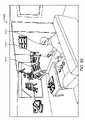
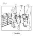
別の側面では、拡張現実ディスプレイシステムは、ユーザの視野の画像の集合を捕捉するための画像捕捉デバイスであって、画像の集合は、所定の物理オブジェクトに関係するユーザの移動を捕捉する、画像捕捉デバイスと、画像捕捉デバイスに通信可能に結合され、所定の物理オブジェクトに関係する移動を分析し、少なくとも部分的に分析された移動に基づいて、ユーザ入力を決定する、プロセッサとを備えている。 In another aspect, an augmented reality display system is an image capture device for capturing a set of images of a user's field of view, the set of images capturing movement of the user relative to a given physical object. a capture device; and a processor communicatively coupled to the image capture device for analyzing movement associated with a given physical object and determining user input based at least in part on the analyzed movement. .
1つ以上の実施形態では、プロセッサは、所定の物理オブジェクトを認識する。1つ以上の実施形態では、所定の物理オブジェクトは、少なくとも部分的に所定の物理オブジェクトの捕捉された画像と所定の物理オブジェクトのデータベースとの間の画像比較に基づいて、認識される。1つ以上の実施形態では、所定の物理オブジェクトに関係するユーザの分析された移動は、パターンを生成するために使用される。1つ以上の実施形態では、生成されたパターンは、所定のパターンのデータベースと比較される。1つ以上の実施形態では、プロセッサは、比較に基づいて、認識されたパターンのためのスコア化値を生成する。 In one or more embodiments, the processor recognizes predetermined physical objects. In one or more embodiments, a given physics object is recognized based at least in part on an image comparison between a captured image of the given physics object and a database of the given physics object. In one or more embodiments, the user's analyzed movement relative to a given physical object is used to generate the pattern. In one or more embodiments, the generated patterns are compared to a database of predetermined patterns. In one or more embodiments, the processor generates a scored value for the recognized pattern based on the comparison.
1つ以上の実施形態では、プロセッサは、スコア化値が閾値を超えている場合、ユーザ入力を決定する。1つ以上の実施形態では、画像捕捉デバイスは、所定の物理オブジェクトに関係する移動を視覚的に追跡し、ビデオ録画を生成する。1つ以上の実施形態では、ビデオ録画は、ユーザ入力を決定するために分析される。 In one or more embodiments, the processor determines the user input if the scored value exceeds the threshold. In one or more embodiments, an image capture device visually tracks movement associated with a given physical object and generates a video recording. In one or more embodiments, video recordings are analyzed to determine user input.
1つ以上の実施形態では、拡張現実ディスプレイシステムはさらに、所定のパターンのデータベースにアクセスするためのネットワーク化されたメモリを備えている。1つ以上の実施形態では、所定の物理オブジェクトは、視野内の既存の構造、能動的にマークされたトーテム、受動的にマークされたトーテム、カメラ/センサに統合されたオブジェクト、およびトーテムコントローラオブジェクトから成る群から選択される。 In one or more embodiments, the augmented reality display system further comprises networked memory for accessing a database of predetermined patterns. In one or more embodiments, the predetermined physics objects are existing structures in the field of view, actively marked totems, passively marked totems, camera/sensor integrated objects, and totem controller objects. selected from the group consisting of
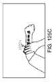
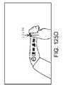
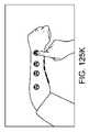
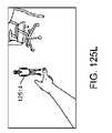
1つ以上の実施形態では、所定の物理オブジェクトに関係する移動は、基準フレームに対する所定の物理オブジェクトの位置、配向、および移動から成る群から選択される。1つ以上の実施形態では、所定の物理オブジェクトは、ユーザの手のうちの第1の手を備え、第1の手に関係する移動は、ユーザの手のうちの第2の手を用いた第1の手の操作を備えている。 In one or more embodiments, the movement associated with the given physics object is selected from the group consisting of position, orientation and movement of the given physics object relative to the reference frame. In one or more embodiments, the given physics object comprises a first one of the user's hands, and movement related to the first hand is performed using a second one of the user's hands. Equipped with first hand operation.
1つ以上の実施形態では、所定の物理オブジェクトは、軟質硬度表面を有し、所定の物理オブジェクトに関係する移動は、ユーザによる軟質硬度表面の押下を備えている。1つ以上の実施形態では、プロセッサは、ユーザのための所定の物理オブジェクトに関連付けられた仮想インターフェース要素をレンダリングし、仮想インターフェース要素は、ディスプレイデバイスを通してユーザによって視認される。 In one or more embodiments, the given physics object has a soft hard surface, and movement associated with the given physics object comprises pressing the soft hard surface by the user. In one or more embodiments, the processor renders virtual interface elements associated with predetermined physical objects for the user, the virtual interface elements being viewed by the user through the display device.
1つ以上の実施形態では、仮想インターフェース要素は、ユーザによって視認されると、仮想インターフェース要素が、少なくとも部分的に所定の物理オブジェクトに関係する修正に基づいて、修正されるように、所定の物理オブジェクトに関係して表示される。1つ以上の実施形態では、所定の物理オブジェクトは、電子入力デバイスを備え、ユーザ入力は、所定の物理オブジェクトの認識された移動に基づいて、決定され、電子入力デバイスから入力される。 In one or more embodiments, the virtual interface element is a predetermined physical object such that, when viewed by a user, the virtual interface element is modified based at least in part on a modification related to the predetermined physical object. Displayed in relation to an object. In one or more embodiments, the given physics object comprises an electronic input device and user input is determined and entered from the electronic input device based on the perceived movement of the given physics object.
1つ以上の実施形態では、プロセッサは、ユーザに表示される仮想コンテンツが、少なくとも部分的に決定されたユーザ入力に基づいて、修正されるように、ユーザの眼に結合されるディスプレイデバイスを制御するように構成される。 In one or more embodiments, the processor controls a display device coupled to the user's eye such that virtual content displayed to the user is modified based at least in part on the determined user input. configured to
別の側面では、ユーザ入力を決定する方法は、1つ以上のユーザの視野の画像を捕捉するステップであって、画像は、少なくとも所定の物理オブジェクトを備えている、ステップと、画像を分析し、所定の物理オブジェクトに関係するユーザの移動を検出するステップと、少なくとも部分的に所定の物理オブジェクトに関係する移動の分析に基づいて、ユーザ入力を決定するステップとを含む。 In another aspect, a method of determining user input includes capturing one or more images of a user's field of view, the images comprising at least predetermined physical objects; and analyzing the images. , detecting movement of the user relative to the given physics object, and determining user input based at least in part on analyzing the movement relative to the given physics object.
1つ以上の実施形態では、本方法はさらに、所定の物理オブジェクトを認識するステップを含む。1つ以上の実施形態では、所定の物理オブジェクトは、少なくとも部分的に所定の物理オブジェクトの捕捉された画像と所定の物理オブジェクトのデータベースとの間の画像比較に基づいて、認識される。1つ以上の実施形態では、所定の物理オブジェクトに関係するユーザの移動は、パターンを生成するために使用される。 In one or more embodiments, the method further includes recognizing the predetermined physics object. In one or more embodiments, a given physics object is recognized based at least in part on an image comparison between a captured image of the given physics object and a database of the given physics object. In one or more embodiments, user movement relative to a given physical object is used to generate the pattern.
1つ以上の実施形態では、本方法はさらに、生成されたパターンを所定のパターンのデータベースと比較するステップを含む。1つ以上の実施形態では、本方法はさらに、比較に基づいて、認識されたパターンのためのスコア化値を生成するステップを含む。1つ以上の実施形態では、本方法はさらに、スコア化値が閾値を超えている場合、ユーザ入力を決定するステップを含む。 In one or more embodiments, the method further includes comparing the generated pattern to a database of predetermined patterns. In one or more embodiments, the method further includes generating a scoring value for the recognized pattern based on the comparison. In one or more embodiments, the method further includes determining the user input if the scored value exceeds the threshold.
1つ以上の実施形態では、本方法はさらに、所定の物理オブジェクトに関係する移動を視覚的に追跡し、ビデオ録画を生成するステップを含む。1つ以上の実施形態では、ビデオ録画は、ユーザ入力を決定するために分析される。1つ以上の実施形態では、本方法はさらに、ネットワーク化されたメモリを通して、所定のパターンのデータベースにアクセスするステップを含む。1つ以上の実施形態では、所定の物理オブジェクトは、視野内の既存の構造、能動的にマークされたトーテム、受動的にマークされたトーテム、カメラ/センサに統合されたオブジェクト、およびトーテムコントローラオブジェクトから成る群から選択される。 In one or more embodiments, the method further includes visually tracking movement associated with the predetermined physical object and generating a video recording. In one or more embodiments, video recordings are analyzed to determine user input. In one or more embodiments, the method further includes accessing a database of predetermined patterns through the networked memory. In one or more embodiments, the predetermined physics objects are existing structures in the field of view, actively marked totems, passively marked totems, camera/sensor integrated objects, and totem controller objects. selected from the group consisting of
1つ以上の実施形態では、所定の物理オブジェクトに関係する移動は、基準フレームに対する所定の物理オブジェクトの位置、配向、および移動から成る群から選択される。1つ以上の実施形態では、所定の物理オブジェクトは、ユーザの手のうちの第1の手を備え、第1の手に関係する移動は、ユーザの手のうちの第2の手を用いた第1の手の操作を備えている。 In one or more embodiments, the movement associated with the given physics object is selected from the group consisting of position, orientation and movement of the given physics object relative to the reference frame. In one or more embodiments, the given physics object comprises a first one of the user's hands, and movement related to the first hand is performed using a second one of the user's hands. Equipped with first hand operation.
1つ以上の実施形態では、所定の物理オブジェクトは、軟質硬度表面を有し、所定の物理オブジェクトに関係する移動は、ユーザによる軟質硬度表面の押下を備えている。1つ以上の実施形態では、本方法はさらに、ユーザのための所定の物理オブジェクトに関連付けられた仮想インターフェース要素をレンダリングするステップを含む。 In one or more embodiments, the given physics object has a soft hard surface, and movement associated with the given physics object comprises pressing the soft hard surface by the user. In one or more embodiments, the method further includes rendering virtual interface elements associated with the predetermined physical object for the user.
1つ以上の実施形態では、仮想インターフェース要素は、ユーザによって視認されると、仮想インターフェース要素が、少なくとも部分的に所定の物理オブジェクトに関係する修正に基づいて、修正されるように、所定の物理オブジェクトに関係して表示される。1つ以上の実施形態では、所定の物理オブジェクトは、電子入力デバイスを備え、ユーザ入力は、所定の物理オブジェクトの認識された移動に基づいて、決定され、電子入力デバイスから入力される。1つ以上の実施形態では、本方法はさらに、少なくとも部分的に決定されたユーザ入力に基づいて、ユーザに表示される仮想コンテンツの少なくとも1つの特性を修正するステップを含む。 In one or more embodiments, the virtual interface element is a predetermined physical object such that, when viewed by a user, the virtual interface element is modified based at least in part on a modification related to the predetermined physical object. Displayed in relation to an object. In one or more embodiments, the given physics object comprises an electronic input device and user input is determined and entered from the electronic input device based on the perceived movement of the given physics object. In one or more embodiments, the method further includes modifying at least one characteristic of the virtual content displayed to the user based at least in part on the determined user input.
別の側面では、拡張現実ディスプレイシステムは、ユーザの眼に物理的に結合され、1つ以上の物理オブジェクトに関係する仮想コンテンツの集合を表示する、ディスプレイと、ディスプレイおよび画像捕捉デバイスに通信可能に結合され、ユーザ入力に基づいて、ディスプレイを介して、ユーザに表示されるべき仮想ユーザインターフェースを識別し、世界に関係するユーザの場所を得て、仮想ユーザインターフェースを表示すべき座標点の集合を決定し、識別された仮想ユーザインターフェースがユーザに表示されるように、ディスプレイを制御する、プロセッサとを備えている。 In another aspect, an augmented reality display system is physically coupled to a user's eye and communicable to a display and display and image capture device that displays a collection of virtual content related to one or more physical objects. Combined and based on user input, identifying a virtual user interface to be displayed to a user via a display, obtaining the user's location relative to the world, and determining a set of coordinate points at which the virtual user interface should be displayed. a processor for determining and controlling the display such that the identified virtual user interface is displayed to the user.
1つ以上の実施形態では、ユーザ入力は、少なくとも部分的に認識されたジェスチャに基づいて、決定される。1つ以上の実施形態では、ユーザ入力は、少なくとも部分的に音声コマンドに基づいて、決定される。1つ以上の実施形態では、ユーザ入力は、少なくとも部分的に所定の物理オブジェクトとの相互作用に基づいて、決定される。 In one or more embodiments, user input is determined based at least in part on the recognized gesture. In one or more embodiments, user input is determined based at least in part on voice commands. In one or more embodiments, user input is determined based at least in part on interaction with a predetermined physics object.
1つ以上の実施形態では、拡張現実ディスプレイシステムはさらに、ユーザインターフェースのライブラリを備え、識別されたユーザインターフェースは、ユーザインターフェースのライブラリから読み出される。1つ以上の実施形態では、識別された仮想ユーザインターフェースは、基準フレームに関連付けられる。1つ以上の実施形態では、基準フレームは、身体中心基準フレームである。 In one or more embodiments, the augmented reality display system further comprises a library of user interfaces, and the identified user interface is retrieved from the library of user interfaces. In one or more embodiments, the identified virtual user interface is associated with the frame of reference. In one or more embodiments, the reference frame is a body-centered reference frame.
1つ以上の実施形態では、基準フレームは、頭部中心基準フレームである。1つ以上の実施形態では、基準フレームは、手中心基準フレームである。1つ以上の実施形態では、基準フレームは、世界中心基準フレームである。1つ以上の実施形態では、プロセッサは、識別された仮想ユーザインターフェースに関連付けられた基準フレームと世界に関係するユーザの得られた場所との間の変換を行い、仮想ユーザインターフェースの座標点の集合を決定する。 In one or more embodiments, the reference frame is a head-centered reference frame. In one or more embodiments, the frame of reference is a hand-centered frame of reference. In one or more embodiments, the reference frame is a world-centered reference frame. In one or more embodiments, the processor performs a transformation between a frame of reference associated with the identified virtual user interface and the derived location of the user relative to the world to generate a set of coordinate points for the virtual user interface. to decide.
1つ以上の実施形態では、世界内のユーザの場所は、ユーザのGPS場所に基づいて、決定される。1つ以上の実施形態では、世界内のユーザの場所は、ユーザに関連付けられたマップ点の集合に基づいて、決定される。1つ以上の実施形態では、仮想ユーザインターフェースは、ユーザが移動するにつれて、定常であるように見える。 In one or more embodiments, the user's location in the world is determined based on the user's GPS location. In one or more embodiments, the user's location in the world is determined based on a set of map points associated with the user. In one or more embodiments, the virtual user interface appears stationary as the user moves.
1つ以上の実施形態では、仮想ユーザインターフェースは、ユーザの移動に関係して移動する。1つ以上の実施形態では、プロセッサは、識別された仮想ユーザインターフェースに関連付けられた基準フレームを決定し、世界基準フレームに関係する基準フレームの場所を決定し、決定された場所を原点として設定し、原点に関係する座標点の集合を決定する。 In one or more embodiments, the virtual user interface moves relative to the user's movements. In one or more embodiments, the processor determines a frame of reference associated with the identified virtual user interface, determines a location of the frame of reference relative to the world frame of reference, and sets the determined location as the origin. , determine the set of coordinate points related to the origin.
別の側面では、仮想ユーザインターフェースを生成する方法は、ユーザ入力に基づいて、ユーザに表示されるべき仮想ユーザインターフェースを識別するステップと、ユーザに関連付けられた場所を得るステップと、少なくとも部分的に得られた場所に基づいて、識別された仮想ユーザインターフェースを表示すべき座標点の集合を決定するステップと、決定された座標点において、仮想ユーザインターフェースをユーザに表示するステップとを含む。 In another aspect, a method of generating a virtual user interface includes, based on user input, identifying a virtual user interface to be displayed to a user; obtaining a location associated with the user; Based on the obtained locations, determining a set of coordinate points at which the identified virtual user interface should be displayed; and displaying the virtual user interface to the user at the determined coordinate points.
1つ以上の実施形態では、ユーザ入力は、少なくとも部分的に認識されたジェスチャに基づいて、決定される。1つ以上の実施形態では、ユーザ入力は、少なくとも部分的に音声コマンドに基づいて、決定される。1つ以上の実施形態では、ユーザ入力は、少なくとも部分的に所定の物理オブジェクトとの相互作用に基づいて、決定される。 In one or more embodiments, user input is determined based at least in part on the recognized gesture. In one or more embodiments, user input is determined based at least in part on voice commands. In one or more embodiments, user input is determined based at least in part on interaction with a predetermined physics object.
1つ以上の実施形態では、本方法はさらに、識別されたユーザ仮想ユーザインターフェースをユーザインターフェースのライブラリから読み出すステップを含む。1つ以上の実施形態では、識別された仮想ユーザインターフェースは、基準フレームに関連付けられる。1つ以上の実施形態では、基準フレームは、身体中心基準フレームである。 In one or more embodiments, the method further includes retrieving the identified user virtual user interface from a library of user interfaces. In one or more embodiments, the identified virtual user interface is associated with the frame of reference. In one or more embodiments, the reference frame is a body-centered reference frame.
1つ以上の実施形態では、基準フレームは、頭部中心基準フレームである。1つ以上の実施形態では、基準フレームは、手中心基準フレームである。1つ以上の実施形態では、基準フレームは、世界中心基準フレームである。 In one or more embodiments, the reference frame is a head-centered reference frame. In one or more embodiments, the frame of reference is a hand-centered frame of reference. In one or more embodiments, the reference frame is a world-centered reference frame.
1つ以上の実施形態では、本方法はさらに、識別された仮想ユーザインターフェースに関連付けられた基準フレームと世界に関係するユーザの得られた場所との間の変換を行い、仮想ユーザインターフェースの座標点の集合を決定するステップを含む。1つ以上の実施形態では、世界内のユーザの場所は、ユーザのGPS場所に基づいて、決定される。 In one or more embodiments, the method further performs a transformation between a frame of reference associated with the identified virtual user interface and the derived location of the user relative to the world, the coordinate points of the virtual user interface determining the set of . In one or more embodiments, the user's location in the world is determined based on the user's GPS location.
1つ以上の実施形態では、世界内のユーザの場所は、ユーザに関連付けられたマップ点の集合に基づいて、決定される。1つ以上の実施形態では、仮想ユーザインターフェースは、ユーザが移動するにつれて、定常であるように見える。1つ以上の実施形態では、仮想ユーザインターフェースは、ユーザの移動に関係して移動する。 In one or more embodiments, the user's location in the world is determined based on a set of map points associated with the user. In one or more embodiments, the virtual user interface appears stationary as the user moves. In one or more embodiments, the virtual user interface moves relative to the user's movements.
1つ以上の実施形態では、本方法はさらに、識別された仮想ユーザインターフェースに関連付けられた基準フレームを決定するステップと、世界基準フレームに関係する基準フレームの場所を決定するステップと、決定された場所を原点として設定するステップと、原点に関係する座標点の集合を決定するステップとを含む。 In one or more embodiments, the method further comprises determining a frame of reference associated with the identified virtual user interface; determining a location of the frame of reference relative to the world frame of reference; It includes the steps of setting a location as the origin and determining a set of coordinate points related to the origin.
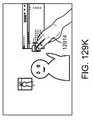
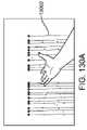
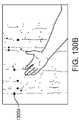
1つ以上の実施形態では、本方法はさらに、マップ点の集合をネットワーク化されたメモリから読み出すステップを含む。1つ以上の実施形態では、ユーザ入力は、仮想ユーザインターフェースが表示されるべき空間内の場所を備えている。1つ以上の実施形態では、空間内の場所は、ユーザの場所における物理エンティティに関連付けられる。1つ以上の実施形態では、ユーザ入力は、壁を示す投げる入力を含むジェスチャを含む。1つ以上の実施形態では、ユーザ入力は、仮想ユーザインターフェースを生成するための命令の終了を意味するジェスチャを含む。 In one or more embodiments, the method further includes reading the set of map points from the networked memory. In one or more embodiments, the user input comprises a location in space where the virtual user interface should be displayed. In one or more embodiments, locations in space are associated with physical entities at the user's location. In one or more embodiments, the user input includes gestures including throwing input pointing to a wall. In one or more embodiments, the user input includes a gesture that signifies the end of instructions for generating the virtual user interface.
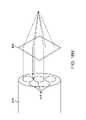
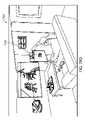
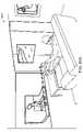
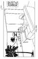
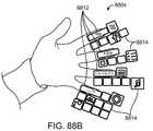
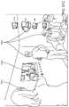
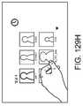
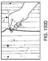
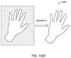
別の側面では、仮想ユーザインターフェースを生成する方法は、所定の物理オブジェクトの操作を検出するステップと、検出された操作に基づいて、仮想ユーザインターフェースを作成するためのコマンドを認識するステップと、仮想世界モデルから、所定の物理オブジェクトの位置に関連付けられたマップ点の集合を決定するステップと、仮想ユーザインターフェースが、ユーザによって視認されると、所定の物理オブジェクトの位置に定常であるように見えるように、仮想ユーザインターフェースをトーテムの位置に関連付けられた決定されたマップ点にリアルタイムでレンダリングするステップとを含む。 In another aspect, a method of generating a virtual user interface comprises detecting manipulation of a given physical object; recognizing a command for creating a virtual user interface based on the detected manipulation; determining from the world model a set of map points associated with a given physical object position; 3. rendering in real time the virtual user interface at the determined map point associated with the totem position.
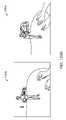
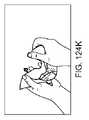
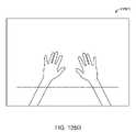
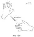
1つ以上の実施形態では、所定の物理オブジェクトの操作は、所定の物理オブジェクトの表面上でユーザの手によって挟んだ状態を広げるジェスチャを含む。1つ以上の実施形態では、仮想ユーザインターフェースは、ユーザによって視認されると、所定の物理オブジェクトの表面の一部を覆うように見え、部分は、挟んだ状態を広げるジェスチャの形成の間、ユーザの手の場所に対応する。1つ以上の実施形態では、所定の物理オブジェクトは、ユーザの手である。 In one or more embodiments, manipulation of a given physics object includes a gesture of unfolding the pinching of the user's hands on the surface of the given physics object. In one or more embodiments, the virtual user interface, when viewed by a user, appears to cover a portion of the surface of a given physical object such that the portion is not visible to the user during formation of the pinch and unfold gesture. corresponds to the location of the hands. In one or more embodiments, the predetermined physical object is the user's hand.
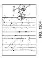
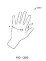
1つ以上の実施形態では、所定の物理オブジェクトの操作は、ユーザが手を広げること、ユーザが手のひらを広げて見せること、およびユーザが手を挙げることから成る群から選択される、アクションを含む。1つ以上の実施形態では、仮想ユーザインターフェースは、ユーザによって視認されると、手の表面の一部を被覆するように見える。 In one or more embodiments, manipulation of a given physics object includes an action selected from the group consisting of a user spreading his hand, a user showing his palm open, and a user raising his hand. . In one or more embodiments, the virtual user interface appears to cover a portion of the surface of the hand when viewed by a user.
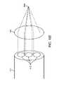
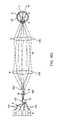
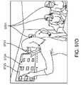
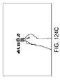
1つ以上の実施形態では、仮想ユーザインターフェースは、手の指または親指によって選択可能な複数の第1のレベルのメニューアイテムを備えている。1つ以上の実施形態では、本方法はさらに、手のさらなる操作を検出するステップと、検出されたさらなる操作に基づいて、第2の仮想ユーザインターフェースを作成するためのコマンドを認識するステップと、仮想ユーザインターフェースが、ユーザによって視認されると、所定の物理オブジェクトの位置において定常であるように見えるように、所定の物理オブジェクトの位置に関連付けられた決定されたマップ点に第2の仮想ユーザインターフェースをリアルタイムでレンダリングするステップとを含む。 In one or more embodiments, the virtual user interface comprises a plurality of first level menu items selectable with a finger or thumb. In one or more embodiments, the method further comprises detecting a further manipulation of the hand; based on the detected further manipulation, recognizing a command to create the second virtual user interface; A second virtual user interface at the determined map point associated with the predetermined physical object position such that the virtual user interface appears stationary at the predetermined physical object position when viewed by a user. and rendering in real time.
1つ以上の実施形態では、本方法はさらに、手の指が離れるように広げることを含む、手のさらなる操作を含む。1つ以上の実施形態では、第2の仮想ユーザインターフェースは、手の指または親指によって選択可能な複数の第2のレベルのメニューアイテムを備え、第2のレベルは、第1のレベルより低い。 In one or more embodiments, the method further includes further manipulation of the hand including spreading the fingers of the hand apart. In one or more embodiments, the second virtual user interface comprises a plurality of second level menu items selectable by a finger or thumb of the hand, the second level being lower than the first level.
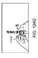
1つ以上の実施形態では、トーテムのさらなる操作は、ユーザの手のうちの第2の手からの指を用いて、手のひらに円を描写する運動を行なうことを含む。1つ以上の実施形態では、第2の仮想ユーザインターフェースは、弧に配列された複数のメニューアイテムを備え、メニューアイテムは、第2の手の指によってスクロール可能かつ選択可能である。 In one or more embodiments, further manipulation of the totem includes performing a palm circular motion with fingers from a second one of the user's hands. In one or more embodiments, the second virtual user interface comprises a plurality of menu items arranged in an arc, the menu items being scrollable and selectable by fingers of the second hand.
別の側面では、拡張現実ディスプレイシステムは、ユーザの視野の1つ以上の画像を捕捉するための画像捕捉デバイスであって、少なくとも1つの画像は、所定の物理オブジェクトの操作を捕捉する、画像捕捉デバイスと、1つ以上の仮想オブジェクトをユーザに表示するためのディスプレイデバイスと、パス可能世界モデルを備えている、データベースであって、パス可能世界モデルは、世界の物理オブジェクトに関連付けられたマップ点の集合を備えている、データベースと、画像捕捉デバイスに通信可能に結合され、1つ以上の画像に基づいて、仮想ユーザインターフェースを作成するためのコマンドを認識し、少なくとも部分的にパス可能世界モデルに基づいて、所定の物理オブジェクトに対応するマップ点を決定し、仮想ユーザインターフェースが所定の物理オブジェクトの位置において定常であるように見えるように、仮想ユーザインターフェースが所定の物理オブジェクトに対応する決定されたマップ点に生成されるような様式で、ディスプレイを制御する、プロセッサとを備えている。 In another aspect, an augmented reality display system is an image capture device for capturing one or more images of a user's field of view, wherein at least one image captures manipulation of a predetermined physical object. A database comprising a device, a display device for displaying one or more virtual objects to a user, and a passable world model, the passable world model comprising map points associated with physical objects in the world. and communicatively coupled to an image capture device and recognizing and at least partially passable world models for creating a virtual user interface based on one or more images, comprising a collection of , and the virtual user interface is determined to correspond to the given physical object such that the virtual user interface appears stationary at the position of the given physical object. and a processor for controlling the display in such a manner as to generate the map points.
1つ以上の実施形態では、所定の物理オブジェクトの操作は、所定の物理オブジェクトの表面上でユーザの手によって挟んだ状態を広げるジェスチャを含む。1つ以上の実施形態では、仮想ユーザインターフェースは、ユーザによって視認されると、所定の物理オブジェクトの表面の一部を覆うように見え、部分は、挟んだ状態を広げるジェスチャの形成の間、ユーザの手の場所に対応する。1つ以上の実施形態では、所定の物理オブジェクトは、ユーザの手である。 In one or more embodiments, manipulation of a given physics object includes a gesture of unfolding the pinching of the user's hands on the surface of the given physics object. In one or more embodiments, the virtual user interface, when viewed by a user, appears to cover a portion of the surface of a given physical object such that the portion is not visible to the user during formation of the pinch and unfold gesture. corresponds to the location of the hands. In one or more embodiments, the predetermined physical object is the user's hand.
1つ以上の実施形態では、所定の物理オブジェクトの操作は、ユーザが手を広げること、ユーザが手のひらを広げて見せること、およびユーザが手を挙げることから成る群から選択される、アクションを含む。1つ以上の実施形態では、仮想ユーザインターフェースは、ユーザによって視認されると、手の表面の一部を被覆するように見える。 In one or more embodiments, manipulation of a given physics object includes an action selected from the group consisting of a user spreading his hand, a user showing his palm open, and a user raising his hand. . In one or more embodiments, the virtual user interface appears to cover a portion of the surface of the hand when viewed by a user.
1つ以上の実施形態では、仮想ユーザインターフェースは、手の指または親指によって選択可能な複数の第1のレベルのメニューアイテムを備えている。1つ以上の実施形態では、所定の物理オブジェクトは、手であって、プロセッサは、手のさらなる操作を検出し、第2の仮想ユーザインターフェースを作成するためのコマンドを認識し、第2の仮想ユーザインターフェースが決定されたマップ点に表示されるように、ディスプレイを制御する。 In one or more embodiments, the virtual user interface comprises a plurality of first level menu items selectable with a finger or thumb. In one or more embodiments, the predetermined physical object is a hand, and the processor detects further manipulation of the hand, recognizes commands to create a second virtual user interface, and creates a second virtual user interface. Control the display so that the user interface appears at the determined map points.
1つ以上の実施形態では、手のさらなる操作は、手の指が離れるように広げることを含む。1つ以上の実施形態では、第2の仮想ユーザインターフェースは、手の指または親指によって選択可能な複数の第2のレベルのメニューアイテムを備え、第2のレベルは、第1のレベルより低い。1つ以上の実施形態では、トーテムのさらなる操作は、ユーザの手のうちの第2の手からの指を用いて、手のひらに円を描写する運動を行なうことを含む。 In one or more embodiments, further manipulation of the hand includes spreading the fingers of the hand apart. In one or more embodiments, the second virtual user interface comprises a plurality of second level menu items selectable by a finger or thumb of the hand, the second level being lower than the first level. In one or more embodiments, further manipulation of the totem includes performing a palm circular motion with fingers from a second one of the user's hands.
1つ以上の実施形態では、第2の仮想ユーザインターフェースは、弧に配列された複数のメニューアイテムを備え、メニューアイテムは、第2の手の指によってスクロール可能かつ選択可能である。 In one or more embodiments, the second virtual user interface comprises a plurality of menu items arranged in an arc, the menu items being scrollable and selectable by fingers of the second hand.
別の側面では、仮想世界を更新する方法は、第1の入力を第1のユーザの第1のデバイスから受信するステップであって、第1の入力は、第1のユーザの物理環境に対応する、ステップと、受信された第1の入力に基づいて、仮想世界モデルを更新するステップであって、仮想世界モデルは、第1のユーザの物理環境に対応する、ステップと、仮想世界モデルの第1の部分に対応する第1の更新された情報を第2のユーザに伝送するステップとを含み、第1の更新された情報は、第1の更新された情報の任意の部分が第2のユーザに表示される必要があるかどうかを示すように構成される。 In another aspect, a method of updating a virtual world comprises receiving a first input from a first device of a first user, the first input corresponding to a physical environment of the first user. and updating a virtual world model based on the received first input, wherein the virtual world model corresponds to the first user's physical environment. and transmitting to the second user first updated information corresponding to the first portion, the first updated information being any portion of the first updated information that corresponds to the second user. should be displayed to users of the
1つ以上の実施形態では、仮想世界モデルは、ネットワーク化されたメモリ上に常駐する。1つ以上の実施形態では、第1のユーザおよび第2のユーザは、それぞれの異なる場所に位置する。1つ以上の実施形態では、第1のユーザの第1のデバイスは、FOVカメラ、他のカメラ、センサ、眼追跡用の第1のデバイス、およびオーディオ用の第1のデバイスから成る群から選択される。 In one or more embodiments, the virtual world model resides on networked memory. In one or more embodiments, the first user and the second user are located at different locations. In one or more embodiments, the first user's first device is selected from the group consisting of a FOV camera, another camera, a sensor, a first device for eye tracking, and a first device for audio. be done.
1つ以上の実施形態では、本方法はさらに、仮想世界モデルの第1の部分に対応する第1の更新された情報を第1のユーザに伝送するステップを含み、第1の更新された情報は、第1の更新された情報の任意の部分が第1のユーザに表示される必要があるかどうかを示すように構成される。1つ以上の実施形態では、本方法はさらに、仮想世界モデルの第1の部分に対応する第1の更新された情報を複数の他のユーザに伝送するステップを含み、第1の更新された情報は、第1の更新された情報の任意の部分が複数の他のユーザの各々に表示される必要があるかどうかを示すように構成される。 In one or more embodiments, the method further comprises transmitting to the first user first updated information corresponding to the first portion of the virtual world model, the first updated information is configured to indicate whether any portion of the first updated information should be displayed to the first user. In one or more embodiments, the method further includes transmitting the first updated information corresponding to the first portion of the virtual world model to the plurality of other users, the first updated The information is configured to indicate whether any portion of the first updated information should be displayed to each of the plurality of other users.
1つ以上の実施形態では、本方法はさらに、複数の入力を複数の他のユーザのそれぞれの第1のデバイスから受信するステップであって、複数の入力は、第1のユーザの物理環境に対応する、ステップと、受信された複数の入力に基づいて、仮想世界モデルを更新するステップと、仮想世界モデルのそれぞれの追加の部分に対応する追加の更新された情報を第2のユーザに伝送するステップとを含み、追加の更新された情報は、追加の更新された情報の任意の部分が第2のユーザに表示される必要があるかどうかを示すように構成される。 In one or more embodiments, the method further comprises receiving a plurality of inputs from respective first devices of the plurality of other users, wherein the plurality of inputs correspond to the physical environment of the first user. A corresponding step of updating the virtual world model based on the plurality of received inputs and transmitting additional updated information corresponding to each additional portion of the virtual world model to the second user. and the additional updated information is configured to indicate whether any portion of the additional updated information should be displayed to the second user.
1つ以上の実施形態では、本方法はさらに、仮想世界モデルの部分に対応する追加の更新された情報を第1のユーザに伝送するステップを含み、追加の更新された情報は、追加の更新された情報の任意の部分が第1のユーザに表示される必要があるかどうかを示すように構成される。 In one or more embodiments, the method further includes transmitting to the first user additional updated information corresponding to the portion of the virtual world model, the additional updated information configured to indicate whether any portion of the displayed information should be displayed to the first user.
1つ以上の実施形態では、本方法はさらに、仮想世界モデルのそれぞれの追加の部分に対応する追加の更新された情報を複数の他のユーザに伝送するステップを含み、追加の更新された情報は、追加の更新された情報の任意の部分が複数の他のユーザの各々に表示される必要があるかどうかを示すように構成される。 In one or more embodiments, the method further includes transmitting additional updated information corresponding to each additional portion of the virtual world model to the plurality of other users, the additional updated information is configured to indicate whether any portion of the additional updated information should be displayed to each of the multiple other users.
1つ以上の実施形態では、本方法はさらに、第2の入力を第2のユーザの第2のデバイスから受信するステップであって、第2の入力は、第2のユーザの物理環境に対応する、ステップと、受信された第2の入力に基づいて、仮想世界モデルを更新するステップであって、仮想世界モデルは、第1のユーザの物理環境に対応する、ステップと、仮想世界モデルの第2の部分に対応する第2の更新された情報を第1のユーザに伝送するステップとを含み、第2の更新された情報は、第2の更新された情報の任意の部分が第1のユーザに表示される必要があるかどうかを示すように構成される。1つ以上の実施形態では、第2の更新された情報は、仮想世界モデルの第2の部分内の第2のユーザのアバタの移動に対応する。 In one or more embodiments, the method further comprises receiving a second input from the second user's second device, the second input corresponding to the second user's physical environment. and updating a virtual world model based on the received second input, wherein the virtual world model corresponds to the first user's physical environment. and transmitting second updated information corresponding to the second portion to the first user, the second updated information wherein any portion of the second updated information corresponds to the first should be displayed to users of the In one or more embodiments, the second updated information corresponds to movement of the second user's avatar within the second portion of the virtual world model.
別の側面では、方法は、光パターンを空間上に投影するステップと、カメラを用いて、光パターンの第1および第2の部分を検出し、パターンの第1および第2の部分に対応する第1および第2のデータ点を生成するステップと、三角測量分析を行い、少なくとも部分的に第1および第2のデータ点に基づいて、光パターンの第1および第2の部分の場所を決定するステップとを含む。 In another aspect, a method includes projecting a light pattern onto space, and using a camera to detect first and second portions of the light pattern, corresponding to the first and second portions of the pattern. generating first and second data points and performing a triangulation analysis to determine locations of first and second portions of the light pattern based at least in part on the first and second data points; and the step of
1つ以上の実施形態では、本方法はさらに、パターンの複数の部分を投影し、検出し、三角測量するステップを繰り返し、空間の追加のテクスチャデータを取得するステップを含む。1つ以上の実施形態では、光を空間上に投影するステップは、ファイバベースのプロジェクタを使用して、光を空間上に投影するステップを含む。 In one or more embodiments, the method further includes repeating the steps of projecting, detecting, and triangulating multiple portions of the pattern to obtain additional spatial texture data. In one or more embodiments, projecting the light onto the space includes projecting the light onto the space using a fiber-based projector.
1つ以上の実施形態では、本方法はさらに、光が空間上に投影される前に、光学要素を用いて光を修正し、光線の束を形成するステップを含む。1つ以上の実施形態では、光パターンは、構造化された光に対応し、光パターンは、動的である。1つ以上の実施形態では、光パターンは、パターン化された光に対応し、光パターンは、複数の点を含む。 In one or more embodiments, the method further includes using optical elements to modify the light to form a bundle of rays before the light is projected onto space. In one or more embodiments, the light pattern corresponds to structured light and the light pattern is dynamic. In one or more embodiments, the light pattern corresponds to patterned light, the light pattern comprising a plurality of points.
1つ以上の実施形態では、光パターンは、テクスチャ化された光に対応し、光パターンは、不規則である。1つ以上の実施形態では、光パターンの第1および第2の部分は、光パターンのそれぞれのピクセルである。 In one or more embodiments, the light pattern corresponds to textured light and the light pattern is irregular. In one or more embodiments, the first and second portions of the light pattern are respective pixels of the light pattern.
別の側面では、拡張現実ディスプレイシステムは、光パターンを空間内に投影するための光プロジェクタと、拡張現実ディスプレイシステムのフレームに結合され、ユーザの視野の画像を捕捉するためのカメラであって、投影された光パターンに対応する第1および第2の部分を捕捉するためのカメラと、カメラに通信可能に結合され、少なくとも部分的にカメラから受信されるデータに基づいて、パターンの第1および第2の部分に対応する第1および第2のデータ点を検出し、三角測量分析を行い、少なくとも部分的に第1および第2のデータ点に基づいて、光パターンの第1および第2の部分の場所を決定する、プロセッサとを備えている。 In another aspect, an augmented reality display system comprises a light projector for projecting a light pattern into space and a camera coupled to a frame of the augmented reality display system for capturing an image of a user's field of view, comprising: a camera communicatively coupled to the camera for capturing first and second portions corresponding to the projected light pattern; detecting first and second data points corresponding to a second portion, performing a triangulation analysis, and determining, based at least in part on the first and second data points, the first and second data points of the light pattern; a processor for determining the location of the portion;
1つ以上の実施形態では、プロセッサは、パターンの複数の部分を用いて、投影、検出、および三角測量するステップを繰り返し、空間の追加のテクスチャデータを取得する。1つ以上の実施形態では、光プロジェクタは、ファイバベースのプロジェクタを備えている。1つ以上の実施形態では、投影される光は、光が空間上に投影される前に、光線の束を形成するように、光学要素を用いて修正される。 In one or more embodiments, the processor repeats the steps of projecting, detecting, and triangulating with multiple portions of the pattern to obtain additional texture data for the space. In one or more embodiments, the light projector comprises a fiber-based projector. In one or more embodiments, the projected light is modified with optical elements to form a bundle of rays before the light is projected onto space.
1つ以上の実施形態では、光パターンは、構造化された光に対応し、光パターンは、動的である。1つ以上の実施形態では、光パターンは、パターン化された光に対応し、光パターンは、複数の点を含む。1つ以上の実施形態では、光パターンは、テクスチャ化された光に対応し、光パターンは、不規則である。1つ以上の実施形態では、光パターンの第1および第2の部分は、光パターンのそれぞれのピクセルである。 In one or more embodiments, the light pattern corresponds to structured light and the light pattern is dynamic. In one or more embodiments, the light pattern corresponds to patterned light, the light pattern comprising a plurality of points. In one or more embodiments, the light pattern corresponds to textured light and the light pattern is irregular. In one or more embodiments, the first and second portions of the light pattern are respective pixels of the light pattern.
別の側面では、拡張現実システムは、操作が拡張現実システムによってユーザ入力として検出可能であるように操作されるように構成される表面を有する、所定の物理オブジェクトを備え、所定の物理オブジェクトは、ユーザが、タッチを介して、所定の物理オブジェクトと相互作用すると、触覚知覚をユーザに提供するように構成される材料を備えている。 In another aspect, an augmented reality system comprises a predetermined physics object having a surface configured to be manipulated such that the manipulation is detectable as user input by the augmented reality system, the predetermined physics object comprising: A material configured to provide a tactile sensation to a user when the user interacts with the predetermined physical object via touch.
1つ以上の実施形態では、所定の物理オブジェクトは、ユーザ入力デバイスをシミュレートするように構成される。1つ以上の実施形態では、ユーザ入力デバイスは、コンピュータキーボード、コンピュータマウス、コンピュータトラックパッド、およびハンドヘルドコントローラから成る群から選択される。 In one or more embodiments, a given physics object is configured to simulate a user input device. In one or more embodiments, the user input device is selected from the group consisting of computer keyboards, computer mice, computer trackpads, and handheld controllers.
1つ以上の実施形態では、本システムはさらに、1つ以上の仮想オブジェクトをユーザに表示するためのディスプレイデバイスと、仮想ユーザインターフェースが所定の物理オブジェクトの表面上に表示されるように、ディスプレイデバイスを制御するためのプロセッサとを備えている。 In one or more embodiments, the system further includes a display device for displaying one or more virtual objects to a user, and a display device such that the virtual user interface is displayed on the surface of a given physical object. and a processor for controlling the
1つ以上の実施形態では、所定の物理オブジェクトは、球状形状を有する。1つ以上の実施形態では、本システムは、仮想ユーザインターフェースが所定の物理オブジェクトから出現するように見えるように、仮想ユーザインターフェースを表示するように構成される。1つ以上の実施形態では、所定の物理オブジェクトは、テクスチャ化された外側表面を有する。 In one or more embodiments, a given physics object has a spherical shape. In one or more embodiments, the system is configured to display the virtual user interface such that the virtual user interface appears to emerge from a given physical object. In one or more embodiments, a given physics object has a textured outer surface.
1つ以上の実施形態では、所定の物理オブジェクトは、ユーザ入力要素を備えている。1つ以上の実施形態では、ユーザ入力要素は、キー、ボタン、およびスクロールホイールから成る群から選択される。1つ以上の実施形態では、ユーザ入力要素は、電子機器に動作可能に結合されない。1つ以上の実施形態では、本システムはさらに、トーテムのユーザの操作を検出するように構成される、カメラを備えている。 In one or more embodiments, a given physics object comprises a user input element. In one or more embodiments, the user input elements are selected from the group consisting of keys, buttons, and scroll wheels. In one or more embodiments, user input elements are not operably coupled to the electronic device. In one or more embodiments, the system further comprises a camera configured to detect user manipulation of the totem.
1つ以上の実施形態では、所定の物理オブジェクトは、くぼみ、空洞、または突出部を備えている。1つ以上の実施形態では、操作は、スワイプ、揺動、回転、スクロール、タップ、ダブルタップ、短タップ、および長タップから成る、指運動の群から選択される。 In one or more embodiments, a given physics object comprises depressions, cavities, or protrusions. In one or more embodiments, the manipulation is selected from the group of finger movements consisting of swiping, rocking, rotating, scrolling, tapping, double tapping, short tapping, and long tapping.
1つ以上の実施形態では、操作は、いくつかの相互作用、相互作用のタイプ、および相互作用の持続時間から成る、指運動特性の群から選択される。1つ以上の実施形態では、操作は、距離、方向、スピード、および加速から成る、指特性の群から選択される。 In one or more embodiments, the manipulation is selected from a group of finger motion characteristics consisting of several interactions, interaction types, and interaction durations. In one or more embodiments, the manipulation is selected from a group of finger properties consisting of distance, direction, speed, and acceleration.
さらに別の側面では、仮想部屋を生成する方法は、ユーザに表示されるべき仮想部屋を識別するステップと、仮想部屋に関連付けられた第1のマップ点の集合を得るステップであって、第1のマップ点の集合は、ユーザの場所における第1の物理部屋に対応する、ステップと、仮想部屋を第1のマップ点の集合にテザリングするステップと、仮想部屋が、ユーザによって視認されると、第1のマップ点の集合の集合において定常であるように見えるように、仮想部屋をユーザに表示するステップとを含む。 In yet another aspect, a method of generating a virtual room includes the steps of identifying a virtual room to be displayed to a user; obtaining a first set of map points associated with the virtual room; corresponds to a first physical room at the user's location; tethering the virtual room to the first set of map points; when the virtual room is viewed by the user; and displaying the virtual room to the user such that it appears stationary at the set of the first set of map points.
1つ以上の実施形態では、本方法はさらに、ユーザ入力に基づいて、仮想部屋を識別するステップを含む。1つ以上の実施形態では、ユーザ入力は、ジェスチャ、視覚的データ、聴覚的データ、感覚データ、直接コマンド、音声コマンド、眼追跡、および物理ボタンの選択から成る群から選択される。 In one or more embodiments, the method further includes identifying the virtual room based on the user input. In one or more embodiments, the user input is selected from the group consisting of gestures, visual data, auditory data, sensory data, direct commands, voice commands, eye tracking, and physical button selection.
1つ以上の実施形態では、仮想部屋は、ユーザによって与えられる。1つ以上の実施形態では、本方法はさらに、第1のマップ点の集合をネットワーク化されたメモリから読み出すステップを含む。1つ以上の実施形態では、本方法はさらに、仮想部屋に関連付けられた第2のマップ点の集合を得るステップであって、第2のマップ点の集合は、ユーザが第1の物理部屋から移動した後のユーザの場所における第2の物理部屋に対応する、ステップと、仮想部屋を第2のマップ点の集合にテザリングするステップと、仮想部屋が、ユーザによって視認されると、第2のマップ点の集合において定常であるように見えるように、仮想部屋をユーザに表示するステップとを含む。 In one or more embodiments, a virtual room is provided by a user. In one or more embodiments, the method further includes reading the first set of map points from the networked memory. In one or more embodiments, the method further comprises the step of obtaining a second set of map points associated with the virtual room, the second set of map points being generated by the user from the first physical room. corresponding to a second physical room at the user's location after moving; tethering the virtual room to a second set of map points; and when the virtual room is viewed by the user, the second and displaying the virtual room to the user such that it appears stationary in the set of map points.
1つ以上の実施形態では、仮想部屋はまた、第1および第2の仮想オブジェクトを含み、本方法はさらに、仮想部屋が第2のマップ点の集合にテザリングされている場合、第1のマップ点の集合に対応する第1の仮想オブジェクトと第2の仮想オブジェクトとの間の相対的空間位置を保つステップを含む。1つ以上の実施形態では、本方法はさらに、仮想部屋が、ユーザによって視認されると、第1の物理部屋の一部に対して定常であるように見えるように、仮想部屋をユーザに表示するステップを含む。1つ以上の実施形態では、仮想部屋はまた、選択可能仮想装飾を含む。 In one or more embodiments, the virtual room also includes first and second virtual objects, and the method further comprises moving the first map point when the virtual room is tethered to the second set of map points. Preserving the relative spatial position between the first virtual object and the second virtual object corresponding to the set of points. In one or more embodiments, the method further comprises displaying the virtual room to the user such that, when viewed by the user, the virtual room appears stationary with respect to the portion of the first physical room. including the step of In one or more embodiments, the virtual room also includes selectable virtual decorations.
別の側面では、小売体験を作成する方法は、小売店舗内のユーザの場所を認識するステップと、小売店舗に対応するデータを読み出すステップと、読み出されたデータに基づいて、小売店舗に関連する仮想コンテンツを生成するステップと、仮想ユーザインターフェースをユーザの視野内に作成するステップと、ユーザが小売店舗内で小売アクティビティに従事する間、仮想コンテンツを仮想ユーザインターフェース上に表示するステップとを含む。 In another aspect, a method of creating a retail experience includes recognizing a user's location within a retail store; retrieving data corresponding to the retail store; creating a virtual user interface within the user's field of view; and displaying the virtual content on the virtual user interface while the user engages in retail activities within the retail store. .
1つ以上の実施形態では、読み出されたデータは、小売店舗に対応するマップ点の集合を備え、仮想ユーザインターフェースは、ユーザによって視認されると、マップ点の集合において定常であるように見える。1つ以上の実施形態では、ユーザの場所は、無線周波数識別トランスポンダおよび通信を使用して認識される。1つ以上の実施形態では、仮想コンテンツは、仮想キャラクタ、仮想クーポン、ユーザ場所に基づくゲーム、宣伝アイテムの一覧、栄養情報、アイテムに関連するメタデータ、有名人の登場、クロスセリング広告、ユーザに既知の人物からの情報、および電子書籍から成る群から選択される。 In one or more embodiments, the retrieved data comprises a set of map points corresponding to retail stores, and the virtual user interface appears stationary at the set of map points when viewed by a user. . In one or more embodiments, the user's location is recognized using radio frequency identification transponders and communications. In one or more embodiments, the virtual content includes virtual characters, virtual coupons, games based on user location, listings of promotional items, nutritional information, metadata associated with items, celebrity appearances, cross-selling advertisements, known to users. is selected from the group consisting of information from a person, and an e-book.
1つ以上の実施形態では、本方法はさらに、ユーザに対応するユーザデータを読み出すステップと、読み出されたデータおよび読み出されたユーザデータの両方に基づいて、仮想コンテンツを生成するステップとを含む。1つ以上の実施形態では、仮想コンテンツは、仮想食料品一覧、仮想クーポン書籍、仮想レシピ書籍、ユーザの家内の種々の資材の一覧、および仮想レシピビルダから成る群から選択される。1つ以上の実施形態では、本方法はさらに、ユーザ入力を受信するステップと、ユーザ入力に基づいて、追加の仮想コンテンツを生成するステップと、ユーザが小売店舗内の小売アクティビティに従事する間、追加の仮想コンテンツを仮想ユーザインターフェース上に表示するステップとを含む。 In one or more embodiments, the method further comprises retrieving user data corresponding to the user and generating virtual content based on both the retrieved data and the retrieved user data. include. In one or more embodiments, the virtual content is selected from the group consisting of a virtual grocery list, a virtual coupon book, a virtual recipe book, a list of various ingredients in the user's home, and a virtual recipe builder. In one or more embodiments, the method further comprises receiving user input; generating additional virtual content based on the user input; while the user engages in retail activities within the retail store; and displaying additional virtual content on the virtual user interface.
1つ以上の実施形態では、ユーザ入力は、ジェスチャ、視覚的データ、聴覚的データ、感覚データ、直接コマンド、音声コマンド、眼追跡、および物理ボタンの選択から成る群から選択される。1つ以上の実施形態では、仮想コンテンツは、総運営コスト、スマート仮想食料品一覧、ユーザ場所に近接するアイテムのインジケータ、および仮想支払システムから成る群から選択される。1つ以上の実施形態では、本方法はさらに、生成された仮想コンテンツを表示のためにユーザデバイスに送信するステップを含む。 In one or more embodiments, the user input is selected from the group consisting of gestures, visual data, auditory data, sensory data, direct commands, voice commands, eye tracking, and physical button selection. In one or more embodiments, the virtual content is selected from the group consisting of total operating costs, a smart virtual grocery list, an indicator of items proximate to the user location, and a virtual payment system. In one or more embodiments, the method further includes transmitting the generated virtual content to the user device for display.
別の側面では、方法は、患者の医療履歴に関連する患者データを読み出すステップと、少なくとも部分的に読み出された患者データに基づいて、仮想コンテンツを生成するステップと、第1のユーザの第1の場所に対応する第1のマップ点の集合を読み出すステップと、少なくとも部分的に読み出されたマップ点の集合に基づいて、第1の仮想ユーザインターフェースを第1のユーザの視野内に作成するステップと、第1の仮想ユーザインターフェースが、第1のユーザによって視認されると、第1のマップ点の集合において固定されるように見えるように、仮想コンテンツを第1の仮想ユーザインターフェース上に表示するステップとを含む。 In another aspect, a method includes the steps of retrieving patient data related to a patient's medical history; generating virtual content based at least in part on the retrieved patient data; retrieving a first set of map points corresponding to a location; and creating a first virtual user interface within a field of view of a first user based at least partially on the retrieved set of map points. and placing virtual content on the first virtual user interface such that the first virtual user interface appears fixed at the first set of map points when viewed by the first user. and displaying.
1つ以上の実施形態では、仮想コンテンツは、外科手術の標的の3次元画像、患者識別情報、医療画像、患者のバイタルサイン情報、およびカルテから成る群から選択される。1つ以上の実施形態では、患者データは、ネットワーク化されたメモリから読み出される。 In one or more embodiments, the virtual content is selected from the group consisting of three-dimensional images of surgical targets, patient identification information, medical images, patient vital sign information, and medical charts. In one or more embodiments, patient data is retrieved from networked memory.
1つ以上の実施形態では、本方法はさらに、第1のユーザと第2のユーザとの間の通信を促進するように構成される、第2の仮想ユーザインターフェースを生成するステップを含み、第2のユーザは、第1のユーザの第1の場所と異なる第2の場所内に居る。1つ以上の実施形態では、第2の仮想ユーザインターフェースは、第2のユーザの視覚的表現である。1つ以上の実施形態では、第2のユーザは、上級専門外科医、患者、患者に関連する者、および医学生から成る群から選択される。1つ以上の実施形態では、本方法はさらに、第1の仮想ユーザインターフェースが、第2のユーザによって視認されると、マップ点の集合において固定されるように見えるように、仮想コンテンツを第1の仮想ユーザインターフェース上において第2のユーザに表示するステップを含む。 In one or more embodiments, the method further comprises generating a second virtual user interface configured to facilitate communication between the first user and the second user; Two users are in a second location that is different from the first user's first location. In one or more embodiments, the second virtual user interface is a visual representation of the second user. In one or more embodiments, the second user is selected from the group consisting of senior specialist surgeons, patients, patient associates, and medical students. In one or more embodiments, the method further includes rendering the virtual content to the first virtual user interface such that the first virtual user interface appears fixed at the set of map points when viewed by a second user. displaying to a second user on a virtual user interface of.
1つ以上の実施形態では、仮想コンテンツは、外科手術手技中、第1のユーザに表示され、本方法はさらに、ユーザ入力を受信するステップと、ユーザ入力に基づいて、追加の仮想コンテンツを生成するステップと、第1のユーザが外科手術手技を行っている間、追加の仮想コンテンツを第1の仮想ユーザインターフェース上に表示するステップとを含む。 In one or more embodiments, the virtual content is displayed to the first user during the surgical procedure, the method further comprising receiving user input and generating additional virtual content based on the user input. and displaying additional virtual content on the first virtual user interface while the first user is performing the surgical procedure.
1つ以上の実施形態では、ユーザ入力は、ジェスチャ、視覚的データ、聴覚的データ、感覚データ、直接コマンド、音声コマンド、眼追跡、および物理ボタンの選択から成る群から選択される。1つ以上の実施形態では、ユーザ入力は、第1のユーザの視野の画像を備え、本方法はさらに、第1の仮想ユーザインターフェースが、第2のユーザによって視認されると、マップ点の集合において固定されるように見えるように、追加の仮想コンテンツを第1の仮想ユーザインターフェース上において第2のユーザに表示するステップを含む。 In one or more embodiments, the user input is selected from the group consisting of gestures, visual data, auditory data, sensory data, direct commands, voice commands, eye tracking, and physical button selection. In one or more embodiments, the user input comprises an image of the field of view of the first user, and the method further comprises displaying the set of map points when the first virtual user interface is viewed by the second user. displaying additional virtual content to the second user on the first virtual user interface such that it appears to be fixed in the .
1つ以上の実施形態では、医療リハビリテーションを促進する方法は、医療リハビリテーションに関連するユーザ入力を受信するステップと、受信されたユーザ入力に基づいて、医療リハビリテーションに関連する要求をクラウドサーバに送信するステップと、要求に基づいて、医療リハビリテーションに関連するデータをクラウドサーバに接続されている知識ベースから受信するステップと、受信されたデータに基づいて、医療リハビリテーションに関連する仮想コンテンツを第1のユーザに表示するステップとを含む。 In one or more embodiments, a method of facilitating medical rehabilitation includes receiving user input related to medical rehabilitation, and based on the received user input, sending a request related to medical rehabilitation to a cloud server. receiving, based on the request, data related to medical rehabilitation from a knowledge base connected to a cloud server; based on the received data, providing virtual content related to medical rehabilitation to the first user; and displaying to.
1つ以上の実施形態では、ユーザ入力は、視覚的、聴覚的、および感覚入力から成る群から選択される。1つ以上の実施形態では、本方法はさらに、要求をクラウドサーバに送信する前に、ユーザ入力が有効であるかどうかを決定するステップを含む。1つ以上の実施形態では、データは、クラウドサーバに接続されている複数の知識ベースから受信される。 In one or more embodiments, user input is selected from the group consisting of visual, auditory, and sensory input. In one or more embodiments, the method further includes determining whether the user input is valid before sending the request to the cloud server. In one or more embodiments, data is received from multiple knowledge bases connected to a cloud server.
1つ以上の実施形態では、要求は、クラウドサーバに、データを知識ベースから読み出すように命令する。1つ以上の実施形態では、仮想コンテンツは、リラックスさせる環境を含む。1つ以上の実施形態では、本方法はさらに、追加のデータを第2のユーザから受信するステップと、受信された追加のデータに基づいて、追加の仮想コンテンツを第1のユーザに表示するステップとを含む。 In one or more embodiments, the request instructs the cloud server to read data from the knowledge base. In one or more embodiments, the virtual content includes a relaxing environment. In one or more embodiments, the method further comprises receiving additional data from the second user and displaying additional virtual content to the first user based on the additional data received. including.
1つ以上の実施形態では、第1および第2のユーザは、異なる物理場所に位置する。1つ以上の実施形態では、追加の仮想コンテンツは、第2のユーザの視覚的表現である。1つ以上の実施形態では、本方法はさらに、第1のユーザデータを第1のユーザから受信するステップと、第2のユーザデータを第2のユーザから受信するステップと、受信された第1および第2のユーザデータに基づいて、仮想コンテンツを修正するステップと、修正された仮想コンテンツを第1および第2のユーザに表示するステップとを含む。 In one or more embodiments, the first and second users are located at different physical locations. In one or more embodiments, the additional virtual content is a visual representation of the second user. In one or more embodiments, the method further comprises receiving first user data from the first user; receiving second user data from the second user; and based on the second user data, and displaying the modified virtual content to the first and second users.
1つ以上の実施形態では、第1のユーザは、医療リハビリテーションのための物理アクティビティに従事し、仮想コンテンツは、物理アクティビティに関する。1つ以上の実施形態では、仮想コンテンツは、物理アクティビティについての情報、第1のユーザのパフォーマンス統計、物理アクティビティに対応する仮想体験、および仮想アバタから成る群から選択される。1つ以上の実施形態では、データは、ネットワーク化されたメモリから読み出される。 In one or more embodiments, the first user engages in a physical activity for medical rehabilitation and the virtual content relates to the physical activity. In one or more embodiments, the virtual content is selected from the group consisting of information about the physical activity, performance statistics of the first user, a virtual experience corresponding to the physical activity, and a virtual avatar. In one or more embodiments, data is read from networked memory.
別の側面では、タスクのパフォーマンスを向上させる方法は、ユーザによって行われるべきタスクに関連するタスクデータを読み出すステップと、タスクデータに基づいて、仮想コンテンツを生成するステップと、仮想ユーザインターフェースをユーザの視野内に作成するステップと、ユーザの場所に対応するマップ点の集合を読み出すステップと、仮想ユーザインターフェースが、ユーザによって視認されると、マップ点の集合において固定されるように見えるように、ユーザがタスクを行っている間、仮想コンテンツを仮想ユーザインターフェース上に表示するステップとを含む。 In another aspect, a method of improving task performance includes the steps of retrieving task data associated with a task to be performed by a user; generating virtual content based on the task data; creating within the field of view; retrieving a set of map points corresponding to the user's location; displaying the virtual content on the virtual user interface while the is performing the task.
1つ以上の実施形態では、仮想コンテンツは、仮想マップされたパターンを有するゲームであり、ゲームは、ユーザによるタスクのパフォーマンスを改良するように構成される。1つ以上の実施形態では、ゲームは、仮想マップされたパターンに従うことに対してポイントを与える。1つ以上の実施形態では、ゲームは、仮想マップされたパターン内の地点に所定の時間内に到達することに対してポイントを倍にする。 In one or more embodiments, the virtual content is a game having patterns that are virtually mapped, and the game is configured to improve performance of tasks by users. In one or more embodiments, the game awards points for following a virtually mapped pattern. In one or more embodiments, the game doubles points for reaching points within the virtual mapped pattern within a predetermined time.
1つ以上の実施形態では、ゲームは、仮想マップされたパターンから外れることに対してポイントを差し引く。1つ以上の実施形態では、ゲームは、物理オブジェクトに隣接して移動することに対してポイントを差し引く。1つ以上の実施形態では、タスクは、造園機械を運転すること、在庫アイテムを読み出すこと、小売棚に陳列すること、および郵便をソートすることから成る群から選択される。1つ以上の実施形態では、タスクデータは、ネットワーク化されたメモリから読み出される。 In one or more embodiments, the game deducts points for deviating from the virtual mapped pattern. In one or more embodiments, the game deducts points for moving adjacent to physics objects. In one or more embodiments, the task is selected from the group consisting of operating landscaping equipment, retrieving inventory items, displaying on retail shelves, and sorting mail. In one or more embodiments, task data is read from networked memory.
1つ以上の実施形態では、本方法はさらに、ユーザ入力を受信するステップと、ユーザ入力に基づいて、追加の仮想コンテンツを生成するステップと、ユーザがタスクを行っている間、追加の仮想コンテンツを仮想ユーザインターフェース上に表示するステップとを含む。1つ以上の実施形態では、ユーザ入力は、タスクのパフォーマンスに関連するユーザアクションを含む。 In one or more embodiments, the method further comprises receiving user input, generating additional virtual content based on the user input, and generating additional virtual content while the user is performing the task. on a virtual user interface. In one or more embodiments, user input includes user actions related to task performance.
さらに別の側面では、拡張現実ディスプレイシステムは、1つ以上の仮想画像をユーザの眼に表示するように構成可能なディスプレイデバイスと、1つ以上の仮想画像をディスプレイデバイスに提供するために構成されるディスプレイデバイスに通信可能に結合される、プロセッサであって、仮想画像のディスプレイに関するタイミング不一致を予測的に補正するための予測機構を備えている、プロセッサとを備えている。 In yet another aspect, an augmented reality display system is configured to provide a display device configurable to display one or more virtual images to a user's eyes, and to provide the one or more virtual images to the display device. a processor communicatively coupled to the display device, the processor comprising a prediction mechanism for predictively correcting timing discrepancies with respect to the display of the virtual image.
1つ以上の実施形態では、タイミング不一致は、1つ以上のセンサによって行われる1つ以上のセンサ測定に関わり、1つ以上のセンサは、プロセッサに通信可能に結合される。1つ以上の実施形態では、タイミング不一致は、着信データを処理するときの処理遅延に関わる。 In one or more embodiments, the timing mismatch involves one or more sensor measurements made by one or more sensors, the one or more sensors being communicatively coupled to the processor. In one or more embodiments, timing mismatch relates to processing delays when processing incoming data.
1つ以上の実施形態では、予測機構は、フィルタを利用して、タイミング不一致の影響を補正する。1つ以上の実施形態では、フィルタは、1つ以上のセンサ測定の相対的スピードを考慮し、センサ測定は、プロセッサに通信可能に結合されている1つ以上のセンサによって行われる。1つ以上の実施形態では、予測機構は、カルマン予測子を利用する。 In one or more embodiments, the predictor utilizes filters to compensate for the effects of timing mismatches. In one or more embodiments, the filter takes into account the relative speed of one or more sensor measurements, the sensor measurements made by one or more sensors communicatively coupled to the processor. In one or more embodiments, the predictor utilizes a Kalman predictor.
1つ以上の実施形態では、カルマン予測子は、ディスプレイ処理段階中、利用される。1つ以上の実施形態では、プロセッサは、補償変更を1つ以上の仮想画像に関連付けられたデータに行い、タイミング不一致を補償する。1つ以上の実施形態では、補償変更は、仮想画像に関連付けられたデータのシフトを行うステップを含む。 In one or more embodiments, Kalman predictors are utilized during the display processing stage. In one or more embodiments, the processor makes compensating changes to data associated with one or more virtual images to compensate for the timing mismatch. In one or more embodiments, compensating changes include shifting data associated with the virtual image.
1つ以上の実施形態では、補償変更は、仮想画像に関連付けられた1つ以上の視覚的アーチファクトを平滑化するステップを含む。1つ以上の実施形態では、補償変更は、1つ以上のセンサのセンサ測定の負の影響を補正するステップを含み、1つ以上のセンサは、プロセッサに通信可能に結合される。 In one or more embodiments, compensating modification includes smoothing one or more visual artifacts associated with the virtual image. In one or more embodiments, compensating changes include compensating for negative effects of sensor measurements of one or more sensors, the one or more sensors being communicatively coupled to the processor.
別の側面では、拡張現実ディスプレイシステムにおける遅延を補正する方法は、仮想画像をユーザに表示する少なくとも1つの段階における1つ以上のタイミング不一致を決定するステップと、予測機構を利用して、タイミング不一致を予測的に補正するステップと、少なくとも部分的に予測機構に基づいて、仮想画像のデータに関連する少なくとも1つの特性を補償するステップとを含む。 In another aspect, a method of compensating for delay in an augmented reality display system includes determining one or more timing discrepancies in at least one stage of displaying a virtual image to a user; and compensating for at least one characteristic associated with the data of the virtual image based at least in part on the predictive mechanism.
1つ以上の実施形態では、タイミング不一致は、1つ以上のセンサによって行われる1つ以上のセンサ測定に関わり、1つ以上のセンサは、プロセッサに通信可能に結合される。1つ以上の実施形態では、タイミング不一致は、着信データを処理するときの処理遅延に関わる。 In one or more embodiments, the timing mismatch involves one or more sensor measurements made by one or more sensors, the one or more sensors being communicatively coupled to the processor. In one or more embodiments, timing mismatch relates to processing delays when processing incoming data.
1つ以上の実施形態では、予測機構は、フィルタを利用して、タイミング不一致の影響を補正する。1つ以上の実施形態では、フィルタは、1つ以上のセンサ測定の相対的スピードを考慮し、センサ測定は、プロセッサに通信可能に結合されている1つ以上のセンサによって行われる。 In one or more embodiments, the predictor utilizes filters to compensate for the effects of timing mismatches. In one or more embodiments, the filter takes into account the relative speed of one or more sensor measurements, the sensor measurements made by one or more sensors communicatively coupled to the processor.
1つ以上の実施形態では、予測機構は、カルマン予測子を利用する。1つ以上の実施形態では、カルマン予測子は、ディスプレイ処理段階中、利用される。1つ以上の実施形態では、補償は、仮想画像に関連付けられたデータのシフトを行うステップを含む。1つ以上の実施形態では、補償は、仮想画像に関連付けられた1つ以上の視覚的アーチファクトを平滑化するステップを含む。1つ以上の実施形態では、補償は、1つ以上のセンサのセンサ測定の負の影響を補正するステップを含み、1つ以上のセンサは、プロセッサに通信可能に結合される。 In one or more embodiments, the predictor utilizes a Kalman predictor. In one or more embodiments, Kalman predictors are utilized during the display processing stage. In one or more embodiments, compensating includes shifting data associated with the virtual image. In one or more embodiments, compensating includes smoothing one or more visual artifacts associated with the virtual image. In one or more embodiments, compensating includes correcting for negative effects of sensor measurements of one or more sensors, the one or more sensors being communicatively coupled to the processor.
別の側面では、拡張現実システムを較正する方法は、仮想画像をユーザに表示するステップであって、仮想画像は、既知の焦点距離に表示されるように構成され、仮想画像は、ピクセル点を備えている、ステップと、ピクセル点がユーザに表示される場所を決定するステップであって、ピクセルの場所は、少なくとも部分的にユーザの眼の瞳孔の場所に基づいて、計算される、ステップと、仮想画像のピクセル点と空間内の既知の点を整合させるステップとを含む。 In another aspect, a method of calibrating an augmented reality system comprises displaying a virtual image to a user, the virtual image configured to be displayed at a known focal length, the virtual image having pixel points of determining where the pixel point will be displayed to the user, the pixel location being calculated based at least in part on the location of the pupil of the user's eye; , matching pixel points in the virtual image with known points in space.
1つ以上の実施形態では、ステップは、複数のピクセル点に対して繰り返される。1つ以上の実施形態では、ピクセル点がユーザに表示される場所は、少なくとも部分的に空間内の既知の点の場所に基づいて、計算される。1つ以上の実施形態では、瞳孔の場所、ピクセル点の場所、および空間内の既知の点の場所は、同一線上にある。 In one or more embodiments, the steps are repeated for multiple pixel points. In one or more embodiments, the locations where pixel points are displayed to the user are calculated based at least in part on known locations of points in space. In one or more embodiments, the pupil location, the pixel point location, and the known point location in space are collinear.
1つ以上の実施形態では、ピクセル点がユーザに表示される場所は、ユーザ入力に基づいて、修正される。1つ以上の実施形態では、本方法はさらに、複数のピクセル点がユーザに提示されるように、ゲーム用インターフェースを作成するステップを含む。1つ以上の実施形態では、ゲーム用インターフェースは、ユーザの眼移動を通してレーザを発射するステップを含む。 In one or more embodiments, where pixel points are displayed to the user is modified based on user input. In one or more embodiments, the method further includes creating a gaming interface such that the plurality of pixel points is presented to the user. In one or more embodiments, the gaming interface includes firing a laser through the user's eye movements.
1つ以上の実施形態では、既知の点の場所は、少なくとも部分的に1つ以上の世界カメラから受信されるデータに基づいて、決定される。1つ以上の実施形態では、ステップは、ユーザの別の眼に対して繰り返される。1つ以上の実施形態では、ピクセル点の場所は、少なくとも部分的に瞳孔の場所および既知の点の場所の関数に基づいて、決定される。1つ以上の実施形態では、関数は、二次関数を備えている。 In one or more embodiments, known point locations are determined based at least in part on data received from one or more world cameras. In one or more embodiments, the steps are repeated for another eye of the user. In one or more embodiments, the pixel point location is determined based at least in part on a function of the pupil location and the known point location. In one or more embodiments, the function comprises a quadratic function.
別の側面では、拡張現実ディスプレイシステムは、仮想画像をユーザに表示するためのディスプレイデバイスであって、仮想画像は、既知の焦点距離に表示されるように構成され、仮想画像は、ピクセル点を備えている、ディスプレイデバイスと、ディスプレイデバイスに通信可能に結合され、ピクセル点がユーザに表示される場所を決定し、少なくとも部分的にユーザの眼の瞳孔の場所に基づいて、ピクセル点の場所を計算し、仮想画像のピクセル点を空間内の既知の点に整合させるように構成される、プロセッサとを備えている。 In another aspect, an augmented reality display system is a display device for displaying a virtual image to a user, the virtual image configured to be displayed at a known focal length, the virtual image comprising pixel points. a display device communicatively coupled to the display device for determining where pixel points are displayed to a user; a processor configured to calculate and match pixel points of the virtual image to known points in space.
1つ以上の実施形態では、ステップは、複数のピクセル点に対して繰り返される。1つ以上の実施形態では、ピクセル点がユーザに表示される場所は、少なくとも部分的に空間内の既知の点の場所に基づいて、計算される。1つ以上の実施形態では、瞳孔の場所、ピクセル点の場所、および空間内の既知の点の場所は、同一線上にある。1つ以上の実施形態では、ピクセル点がユーザに表示される場所は、ユーザ入力に基づいて、修正される。 In one or more embodiments, the steps are repeated for multiple pixel points. In one or more embodiments, the locations where pixel points are displayed to the user are calculated based at least in part on known locations of points in space. In one or more embodiments, the pupil location, the pixel point location, and the known point location in space are collinear. In one or more embodiments, where pixel points are displayed to the user is modified based on user input.
1つ以上の実施形態では、本システムはさらに、複数のピクセル点をユーザに提示するように構成される、ゲーム用インターフェースを備えている。1つ以上の実施形態では、ゲーム用インターフェースは、ユーザの眼移動を通してレーザを発射するステップを含む。1つ以上の実施形態では、既知の点の場所は、少なくとも部分的に1つ以上の世界カメラから受信されるデータに基づいて、決定される。 In one or more embodiments, the system further comprises a gaming interface configured to present the plurality of pixel points to the user. In one or more embodiments, the gaming interface includes firing a laser through the user's eye movements. In one or more embodiments, known point locations are determined based at least in part on data received from one or more world cameras.
1つ以上の実施形態では、ステップは、ユーザの別の眼に対して繰り返される。1つ以上の実施形態では、ピクセル点の場所は、少なくとも部分的に瞳孔の場所および既知の点の場所の関数に基づいて、決定される。1つ以上の実施形態では、関数は、二次関数を備えている。 In one or more embodiments, the steps are repeated for another eye of the user. In one or more embodiments, the pixel point location is determined based at least in part on a function of the pupil location and the known point location. In one or more embodiments, the function comprises a quadratic function.
別の側面では、仮想インターフェースを表示する方法は、ユーザ入力に基づいて、ユーザに表示されるべきユーザインターフェースを識別するステップと、少なくとも1つの物理オブジェクトに関係して、アバタユーザインターフェースを表示するステップであって、アバタユーザインターフェースは、少なくとも1つの仮想ユーザインターフェース要素を提示する、ステップと、少なくとも部分的にユーザとアバタユーザインターフェースとの間の相互作用に基づいて、少なくとも1つの仮想ユーザインターフェース要素を選択するステップとを含む。 In another aspect, a method of displaying a virtual interface comprises identifying a user interface to be displayed to a user based on user input; and displaying an avatar user interface in relation to at least one physical object. wherein the avatar user interface presents at least one virtual user interface element; and presenting the at least one virtual user interface element based at least in part on an interaction between the user and the avatar user interface. selecting.
1つ以上の実施形態では、ユーザ入力は、ジェスチャを含む。1つ以上の実施形態では、本方法はさらに、ユーザの拡張現実ディスプレイシステムに関係するジェスチャの場所を決定するステップを含み、仮想ユーザインターフェースは、決定された場所に表示される。1つ以上の実施形態では、アバタは、事前に選択されたアバタである。1つ以上の実施形態では、アバタは、ユーザに似ている。 In one or more embodiments, user input includes gestures. In one or more embodiments, the method further includes determining a location of the user's gesture relative to the augmented reality display system, and the virtual user interface is displayed at the determined location. In one or more embodiments, the avatar is a pre-selected avatar. In one or more embodiments, the avatar resembles the user.
1つ以上の実施形態では、アバタは、物理オブジェクトの上に立っているかのように表示される。1つ以上の実施形態では、少なくとも1つの仮想要素は、アプリケーションを備えている。1つ以上の実施形態では、本方法はさらに、別のユーザ入力に少なくとも部分的に基づいて、少なくとも1つの仮想要素を選択するステップであって、少なくとも1つの仮想要素は、ユーザの仲介者を備えている、ステップと、アバタ仮想ユーザインターフェースおよび物理オブジェクトに関係して、ユーザの仲介者を表す別のアバタを表示するステップであって、ユーザとユーザの仲介者との間の相互作用は、アバタ仮想ユーザインターフェースとユーザの仲介者を表す他のアバタとの間の仮想相互作用を通して動画化される、ステップとを含む。 In one or more embodiments, the avatar is displayed as if standing on the physical object. In one or more embodiments, at least one virtual element comprises an application. In one or more embodiments, the method further comprises selecting at least one virtual element based at least in part on another user input, wherein the at least one virtual element is the user's mediator. and displaying another avatar representing the user's intermediary in relation to the avatar virtual user interface and the physical object, wherein the interaction between the user and the user's intermediary includes: animated through virtual interaction between the avatar virtual user interface and another avatar representing the user's intermediary.
1つ以上の実施形態では、相互作用は、データをユーザの拡張現実システムとユーザの仲介者に対応するコンピューティングシステムとの間で伝送するステップを含む。1つ以上の実施形態では、ユーザ入力は、音声コマンドを備えている。 In one or more embodiments, the interaction includes transmitting data between the user's augmented reality system and a computing system corresponding to the user's intermediary. In one or more embodiments, the user input comprises voice commands.
別の側面では、仮想インターフェースを表示する方法は、ユーザ入力に基づいて、ユーザに表示されるべきユーザインターフェースを識別するステップと、少なくとも1つの物理オブジェクトに関係して、1つ以上の選択可能仮想インターフェース要素を備えているフローティング式ユーザインターフェースを表示するステップであって、フローティング式ユーザインターフェースは、ユーザ入力が受信された場所から押し出されたように見える、ステップとを含む。 In another aspect, a method of displaying a virtual interface comprises identifying a user interface to be displayed to a user based on user input; displaying a floating user interface comprising interface elements, the floating user interface appearing to have been pushed out from where the user input was received.
1つ以上の実施形態では、ユーザ入力は、ユーザの指のジェスチャを含む。1つ以上の実施形態では、ユーザの指のジェスチャは、ユーザの一方の手の指をユーザの他方の手の別の指を用いてタッチすることを含む。1つ以上の実施形態では、本方法はさらに、ユーザの一方の手の指をユーザの他方の手の別の指を用いてタッチした場所を決定するステップを含み、フローティング式仮想ユーザインターフェースは、決定された場所から生じる。 In one or more embodiments, user input includes user finger gestures. In one or more embodiments, the user's finger gesture includes touching a finger of one of the user's hands with another finger of the user's other hand. In one or more embodiments, the method further includes determining where a finger of one of the user's hands is touched with another finger of the user's other hand, wherein the floating virtual user interface: arise from a determined place.
1つ以上の実施形態では、フローティング式ユーザインターフェースは、3次元ブロックの集合を備え、3次元ブロックの集合のうちの3次元ブロックは、少なくとも1つの選択可能仮想ユーザインターフェース要素を表す。1つ以上の実施形態では、フローティング式仮想ユーザインターフェースは、少なくとも部分的に世界基準フレームに基づいて、作成される。 In one or more embodiments, the floating user interface comprises a collection of three-dimensional blocks, a three-dimensional block of the collection of three-dimensional blocks representing at least one selectable virtual user interface element. In one or more embodiments, a floating virtual user interface is created based at least in part on a world frame of reference.
1つ以上の実施形態では、少なくとも1つの選択可能仮想ユーザインターフェース要素は、3次元ブロックのスタックとして存在し、3次元ブロックのスタックは、別のユーザ入力に少なくとも部分的に基づいて、回転される。1つ以上の実施形態では、本方法はさらに、少なくとも部分的にユーザから受信される別のユーザ入力に基づいて、少なくとも1つの選択可能仮想インターフェース要素の仮想ユーザインターフェース要素を選択するステップであって、仮想インターフェース要素は、少なくとも1つの他のサブ仮想インターフェース要素に関連付けられる、ステップと、少なくとも1つの他のサブ仮想インターフェース要素を選択された仮想インターフェース要素の下に表示するステップとを含む。 In one or more embodiments, the at least one selectable virtual user interface element exists as a stack of three-dimensional blocks, and the stack of three-dimensional blocks is rotated based at least in part on another user input. . In one or more embodiments, the method further comprises selecting a virtual user interface element of the at least one selectable virtual interface element based at least in part on another user input received from the user; , the virtual interface element is associated with at least one other sub-virtual interface element; and displaying the at least one other sub-virtual interface element below the selected virtual interface element.
1つ以上の実施形態では、本方法はさらに、少なくとも部分的にユーザから受信される別のユーザ入力に基づいて、少なくとも1つの選択可能仮想インターフェース要素の仮想ユーザインターフェース要素を選択するステップと、仮想ボックス内に、選択された仮想インターフェース要素に関連付けられたコンテンツを表示するステップであって、仮想ボックスは、ユーザの視野内に表示されるコンテンツを備えている、ステップとを含む。 In one or more embodiments, the method further comprises selecting a virtual user interface element of the at least one selectable virtual interface element based at least in part on another user input received from the user; displaying content associated with the selected virtual interface element within the box, the virtual box comprising the content displayed within the user's field of view.
1つ以上の実施形態では、本方法はさらに、仮想ボックスが閉鎖されるべきことを示す、第2のユーザ入力を識別するステップと、少なくとも部分的に第2のユーザ入力に基づいて、仮想ボックスを紙をくしゃくしゃに丸めることに似た様式で動画化するステップと、選択された仮想インターフェース要素に関連付けられたコンテンツを終了させるステップとを含む。1つ以上の実施形態では、第2のユーザ入力は、ジェスチャを含み、ジェスチャは、1枚の紙をくしゃくしゃに丸めることに似ている。 In one or more embodiments, the method further comprises identifying a second user input indicating that the virtual box should be closed; in a manner similar to crumpling up paper and terminating the content associated with the selected virtual interface element. In one or more embodiments, the second user input includes a gesture, which resembles crumpling a sheet of paper.
さらに別の側面では、仮想ユーザインターフェースを表示する方法は、ユーザ入力に基づいて、ユーザに表示されるべきユーザインターフェースを識別するステップと、少なくとも1つの物理オブジェクトに関係して、1つ以上の選択可能仮想インターフェース要素を備えているフローティング式ユーザインターフェースを表示するステップとを含み、フローティング式ユーザインターフェースは、少なくとも1つの物理オブジェクト上に置かれているように見え、少なくとも1つの物理オブジェクトの縦軸の周りでの少なくとも1つの物理オブジェクトの回転は、追加の選択可能仮想インターフェース要素が表示されることをもたらし、追加の選択可能仮想インターフェース要素は、少なくとも1つの物理オブジェクトの別の側に静置されるように見える。 In yet another aspect, a method of displaying a virtual user interface comprises the steps of identifying a user interface to be displayed to a user based on user input; displaying a floating user interface comprising possible virtual interface elements, the floating user interface appearing to rest on at least one physics object and extending along the vertical axis of the at least one physics object. Rotation of the at least one physics object about causes additional selectable virtual interface elements to be displayed, the additional selectable virtual interface elements resting on another side of the at least one physics object. looks like.
1つ以上の実施形態では、少なくとも1つの物理オブジェクトは、ユーザの腕を備えている。1つ以上の実施形態では、ユーザ入力は、ジェスチャを含む。1つ以上の実施形態では、ジェスチャは、選択可能仮想インターフェース要素が表示されるように見える、ユーザの腕上におけるユーザの手のカップを形成するような運動を含む。 In one or more embodiments, at least one physics object comprises a user's arm. In one or more embodiments, user input includes gestures. In one or more embodiments, the gesture includes a movement such as forming a cup of the user's hand on the user's arm such that the selectable virtual interface element appears to be displayed.
1つ以上の実施形態では、本方法はさらに、ユーザの腕上におけるユーザの手のカップを形成するような運動の場所を決定するステップを含み、フローティング式ユーザインターフェースは、決定された場所から生じる。1つ以上の実施形態では、本方法はさらに、別のユーザ入力に少なくとも部分的に基づいて、フローティング式仮想ユーザインターフェースのレンダリングを終了させるステップを含む。 In one or more embodiments, the method further includes determining a location of motion forming a cup of the user's hand on the user's arm, the floating user interface arising from the determined location. . In one or more embodiments, the method further includes terminating rendering of the floating virtual user interface based at least in part on another user input.
1つ以上の実施形態では、他のユーザ入力は、ジェスチャを含み、ジェスチャは、物理オブジェクトを横断してユーザのカップ状の手をドラッグする運動を含む。1つ以上の実施形態では、フローティング式仮想ユーザインターフェースは、少なくとも部分的に手中心基準フレームに基づいて、作成される。1つ以上の実施形態では、本方法はさらに、少なくとも部分的にユーザから受信される別のユーザ入力に基づいて、少なくとも1つの選択可能仮想インターフェース要素の仮想ユーザインターフェース要素を選択するステップと、選択された仮想インターフェース要素に関連付けられたコンテンツを表示するステップであって、コンテンツは、フローティング式仮想インターフェースに関係して表示される、ステップとを含む。 In one or more embodiments, other user input includes a gesture, where the gesture includes the movement of dragging the user's cupped hand across the physics object. In one or more embodiments, a floating virtual user interface is created based at least in part on a hand-centered frame of reference. In one or more embodiments, the method further comprises selecting a virtual user interface element of the at least one selectable virtual interface element based at least in part on another user input received from the user; displaying content associated with the displayed virtual interface element, the content being displayed in relation to the floating virtual interface.
1つ以上の実施形態では、表示されるコンテンツは、手中心基準フレームに対応する。1つ以上の実施形態では、本方法はさらに、少なくとも部分的にユーザから受信される入力に基づいて、フローティング式仮想ユーザインターフェースが移動している場合、表示されるコンテンツが静止したままであるように、表示されるコンテンツを手中心基準フレームから世界中心基準フレームに移動させるステップを含む。 In one or more embodiments, the displayed content corresponds to a hand-centered frame of reference. In one or more embodiments, the method further comprises determining, based at least in part on input received from a user, that displayed content remains stationary when the floating virtual user interface is moving. 2. includes moving the displayed content from a hand-centered frame of reference to a world-centered frame of reference.
別の側面では、仮想ユーザインターフェースを作成する方法は、ユーザ入力に基づいて、ユーザに表示されるべきユーザインターフェースを識別するステップと、少なくとも1つの物理オブジェクトに関係して、少なくとも1つの物理オブジェクトにタッチした場所から生じる、仮想ユーザインターフェースを表示するステップとを含み、仮想ユーザインターフェースは、少なくとも1つの物理オブジェクトにタッチした場所から飛び出ているように見え、仮想ユーザインターフェースは、仮想ユーザインターフェースに取り付けられるように見える少なくとも1つの選択可能仮想ユーザインターフェース要素を備えている。 In another aspect, a method of creating a virtual user interface includes identifying a user interface to be displayed to a user based on user input; displaying a virtual user interface emanating from the location of the touch, the virtual user interface appearing to protrude from the location of the touch on at least one physical object, the virtual user interface being attached to the virtual user interface. at least one selectable virtual user interface element that looks like a
1つ以上の実施形態では、少なくとも1つの物理オブジェクトは、水平表面を備えている。1つ以上の実施形態では、ユーザ入力は、ジェスチャを含む。1つ以上の実施形態では、ジェスチャは、所定の期間の間、伸ばされた指が少なくとも1つの物理オブジェクトをタッチすることを含む。1つ以上の実施形態では、本方法はさらに、ユーザの指が少なくとも1つの物理オブジェクトにタッチした場所を決定するステップを含み、仮想ユーザインターフェースは、決定された場所から生じる。 In one or more embodiments, at least one physics object comprises a horizontal surface. In one or more embodiments, user input includes gestures. In one or more embodiments, the gesture includes touching at least one physical object with an extended finger for a predetermined period of time. In one or more embodiments, the method further includes determining where the user's finger touched the at least one physical object, and the virtual user interface arises from the determined location.
1つ以上の実施形態では、本方法はさらに、別のユーザ入力に少なくとも部分的に基づいて、フローティング式仮想ユーザインターフェースのレンダリングを終了させるステップを含む。1つ以上の実施形態では、他のユーザ入力は、ジェスチャを含み、ジェスチャは、レンダリングされた仮想ユーザインターフェースを横断して、ユーザの手を用いて切断する運動を含む。1つ以上の実施形態では、仮想ユーザインターフェースは、仮想ユーザインターフェースがユーザの任意の移動に対して静止したままであるように、世界中心基準フレームに少なくとも部分的に基づいて、作成される。 In one or more embodiments, the method further includes terminating rendering of the floating virtual user interface based at least in part on another user input. In one or more embodiments, other user input includes a gesture, which includes a cutting motion with the user's hand across the rendered virtual user interface. In one or more embodiments, a virtual user interface is created based at least in part on a world-centered frame of reference such that the virtual user interface remains stationary with respect to any movement of the user.
1つ以上の実施形態では、本方法はさらに、少なくとも部分的にユーザから受信される別のユーザ入力に基づいて、少なくとも1つの選択可能仮想インターフェース要素の仮想ユーザインターフェース要素を選択するステップと、少なくとも1つの物理オブジェクトの別の場所に、第2の仮想ユーザインターフェースを生成するステップであって、第2の仮想ユーザインターフェースは、追加の選択可能仮想インターフェース要素を備えている、ステップとを含む。1つ以上の実施形態では、仮想ユーザインターフェースは、少なくとも1つの物理オブジェクトにタッチした場所から生える木に類似する。 In one or more embodiments, the method further comprises selecting a virtual user interface element of the at least one selectable virtual interface element based at least in part on another user input received from the user; generating a second virtual user interface at another location on the one physical object, the second virtual user interface comprising additional selectable virtual interface elements. In one or more embodiments, the virtual user interface resembles a tree growing from where the at least one physical object is touched.
別の側面では、仮想ユーザインターフェースを表示する方法は、ユーザ入力に基づいて、ユーザに表示されるべきユーザインターフェースを識別するステップと、仮想ユーザインターフェースが指の移動を鏡映するように、ユーザの指の運動を鏡映するような仮想ユーザインターフェースを描写するステップと、1つ以上の選択可能ユーザインターフェース要素を仮想ユーザインターフェースが描写されているエリア内に表示するステップとを含む。1つ以上の実施形態では、指ジェスチャは、所定の期間の間、ユーザの手の少なくとも1本の指を用いて指示するジェスチャを含む。 In another aspect, a method of displaying a virtual user interface includes identifying a user interface to be displayed to a user based on user input; Rendering a virtual user interface that mirrors finger movements; and displaying one or more selectable user interface elements within an area in which the virtual user interface is rendered. In one or more embodiments, finger gestures include pointing gestures with at least one finger of a user's hand for a predetermined period of time.
1つ以上の実施形態では、本方法はさらに、指示ジェスチャの場所を決定するステップを含み、仮想ユーザインターフェースは、決定された場所から生じる。1つ以上の実施形態では、本方法はさらに、ユーザが仮想ユーザインターフェースをもはや描写していないことを検出するステップを含み、仮想ユーザインターフェース要素は、少なくとも部分的に検出に基づいて、表示される。1つ以上の実施形態では、仮想ユーザインターフェースの描写は、空間を横断したユーザの指のドラッグ運動を鏡映する。1つ以上の実施形態では、本方法はさらに、別のユーザ入力に少なくとも部分的に基づいて、フローティング式仮想ユーザインターフェースのレンダリングを終了させるステップを含む。 In one or more embodiments, the method further includes determining a location of the pointing gesture, and the virtual user interface originates from the determined location. In one or more embodiments, the method further includes detecting that the user is no longer depicting the virtual user interface, and the virtual user interface element is displayed based at least in part on the detection. . In one or more embodiments, the representation of the virtual user interface mirrors the drag motion of the user's finger across space. In one or more embodiments, the method further includes terminating rendering of the floating virtual user interface based at least in part on another user input.
1つ以上の実施形態では、他のユーザ入力は、ジェスチャを含み、ジェスチャは、ユーザの指の連続ドラッグ運動の終了を含む。1つ以上の実施形態では、仮想ユーザインターフェースは、仮想ユーザインターフェースがユーザの任意の移動に対して静止したままであるように、世界中心基準フレームに少なくとも部分的に基づいて、作成される。 In one or more embodiments, the other user input includes a gesture, the gesture including terminating a continuous dragging motion of the user's finger. In one or more embodiments, a virtual user interface is created based at least in part on a world-centered frame of reference such that the virtual user interface remains stationary with respect to any movement of the user.
1つ以上の実施形態では、本方法はさらに、少なくとも部分的にユーザから受信される別のユーザ入力に基づいて、少なくとも1つの選択可能仮想インターフェース要素の仮想ユーザインターフェース要素を選択するステップと、仮想ユーザインターフェースに関係する選択された仮想インターフェース要素に関連付けられたコンテンツを生成するステップとを含む。1つ以上の実施形態では、仮想ユーザインターフェースの形状は、ユーザの指によって描写される形状に類似する。 In one or more embodiments, the method further comprises selecting a virtual user interface element of the at least one selectable virtual interface element based at least in part on another user input received from the user; generating content associated with the selected virtual interface elements related to the user interface. In one or more embodiments, the shape of the virtual user interface resembles a shape rendered by a user's finger.
別の側面では、仮想ユーザインターフェースを作成する方法は、ユーザの手のジェスチャに基づいて、ユーザに表示されるべきユーザインターフェースを識別するステップと、仮想ユーザインターフェースが物理オブジェクトの垂直側面にあるように見えるように、手のジェスチャの方向における物理オブジェクトの垂直側面の手のジェスチャに応答して、少なくとも1つの選択可能仮想インターフェース要素を有する仮想ユーザインターフェースを表示するステップとを含む。 In another aspect, a method of creating a virtual user interface includes identifying a user interface to be displayed to a user based on a user's hand gesture; visibly responsive to the hand gesture of the vertical side of the physical object in the direction of the hand gesture, displaying a virtual user interface having at least one selectable virtual interface element.
1つ以上の実施形態では、本方法はさらに、手のジェスチャに応答して、塗料の斑点に似た仮想コンテンツの集合を表示するステップを含み、仮想コンテンツは、手のジェスチャによって示される点において生じる。1つ以上の実施形態では、手のジェスチャは、物理オブジェクトの垂直側面の方向に振り上げられた伸ばされた指を含む。1つ以上の実施形態では、本方法はさらに、物理オブジェクトの垂直側面の方向に振り上げられた伸ばされた指の場所を決定するステップを含み、塗料の斑点に似た仮想コンテンツの集合は、決定された場所に表示される。 In one or more embodiments, the method further includes, in response to the hand gesture, displaying a collection of virtual content resembling a speck of paint, the virtual content at points indicated by the hand gesture. occur. In one or more embodiments, the hand gesture includes an outstretched finger raised in the direction of the vertical side of the physics object. In one or more embodiments, the method further includes determining the location of the outstretched finger raised in the direction of the vertical side of the physical object, the collection of virtual content resembling a speck of paint being the determined displayed in the specified location.
1つ以上の実施形態では、本方法はさらに、仮想斑点を物理オブジェクトの垂直側面に表示するステップを含み、仮想斑点の少なくとも1つの特性は、少なくとも部分的に物理オブジェクトの垂直側面の方向に振り上げられた伸ばされた指の決定された場所に基づいて、物理オブジェクトの垂直側面に表示される。1つ以上の実施形態では、物理オブジェクトは、壁を備えている。 In one or more embodiments, the method further includes displaying the virtual speckle on a vertical side of the physical object, wherein at least one characteristic of the virtual speckle is at least partially raised toward the vertical side of the physical object. displayed on the vertical side of the physics object based on the determined location of the outstretched finger. In one or more embodiments, physics objects comprise walls.
1つ以上の実施形態では、仮想ユーザインターフェースは、仮想ユーザインターフェースがユーザの任意の移動に対して静止したままであるように、世界中心基準フレームに少なくとも部分的に基づいて、作成される。1つ以上の実施形態では、本方法はさらに、少なくとも部分的にユーザから受信される別のユーザ入力に基づいて、少なくとも1つの選択可能仮想インターフェース要素の仮想ユーザインターフェース要素を選択するステップと、物理オブジェクトの別の場所に、選択されたユーザインターフェース要素に関連付けられたコンテンツを生成するステップとを含む。 In one or more embodiments, a virtual user interface is created based at least in part on a world-centered frame of reference such that the virtual user interface remains stationary with respect to any movement of the user. In one or more embodiments, the method further comprises selecting a virtual user interface element of the at least one selectable virtual interface element based at least in part on another user input received from the user; and generating content associated with the selected user interface element elsewhere on the object.
1つ以上の実施形態では、本方法はさらに、選択されたユーザインターフェース要素に関連付けられたコンテンツを縮小形態で記憶するステップを含み、縮小形態は、仮想バンドを備え、仮想バンドは、ユーザの手の周囲に表示される。1つ以上の実施形態では、仮想バンドは、仮想バンドが、少なくとも部分的に手の移動に基づいて、移動するように、少なくとも部分的に手中心基準フレームに基づいて、作成される。 In one or more embodiments, the method further includes storing content associated with the selected user interface element in a reduced form, the reduced form comprising a virtual band, the virtual band being held by the user. displayed around the In one or more embodiments, the virtual band is created based at least partially on a hand-centered reference frame such that the virtual band moves based at least partially on movement of the hand.
1つ以上の実施形態では、本方法はさらに、少なくとも部分的にユーザの別のジェスチャに基づいて、コンテンツを完全形態で表示するステップを含む。1つ以上の実施形態では、他のジェスチャは、仮想バンドが表示される、手の振り上げる運動を含む。 In one or more embodiments, the method further includes displaying the content in full form based at least in part on another gesture of the user. In one or more embodiments, other gestures include a hand up motion in which a virtual band is displayed.
別の側面では、仮想ユーザインターフェースを作成する方法は、ユーザの手のジェスチャに基づいて、ユーザに表示されるべきユーザインターフェースを識別するステップと、手のジェスチャに応答して、仮想ユーザインターフェースを表示するステップとを含み、仮想ユーザインターフェースは、少なくとも1つの選択可能仮想インターフェース要素が、少なくとも部分的にユーザの別の手のジェスチャに基づいて、移動し、追加の選択可能仮想インターフェース要素を表示するように、少なくとも1つの選択可能仮想インターフェース要素を有する水平糸に似ている。 In another aspect, a method of creating a virtual user interface includes identifying a user interface to be displayed to a user based on a hand gesture of the user; and displaying the virtual user interface in response to the hand gesture. and the virtual user interface is configured such that the at least one selectable virtual interface element moves and displays additional selectable virtual interface elements based, at least in part, on another hand gesture of the user. and a horizontal thread with at least one selectable virtual interface element.
1つ以上の実施形態では、手のジェスチャは、ユーザの第1の手の第1の指を第2の手の第2の指を用いてタッチする運動を含む。1つ以上の実施形態では、ジェスチャはさらに、第1の指が第2の指から引き離されるように、第1の指および第2の指の両方を引き離す運動を含む。1つ以上の実施形態では、仮想糸は、第1および第2の指の移動の長さを鏡映し、仮想糸の長さは、少なくとも部分的に第1および第2の指の移動に基づく。 In one or more embodiments, the hand gesture includes the motion of touching a first finger of a user's first hand with a second finger of a second hand. In one or more embodiments, the gesture further includes pulling both the first finger and the second finger apart such that the first finger is pulled away from the second finger. In one or more embodiments, the virtual thread mirrors the length of movement of the first and second fingers, the length of the virtual thread being based at least in part on the movement of the first and second fingers .
1つ以上の実施形態では、本方法はさらに、第1および第2の指のタッチ運動を決定するステップを含み、仮想糸は、決定された場所から生じる。1つ以上の実施形態では、他方の手のジェスチャは、ユーザの手の転向運動を含み、転向移動は、少なくとも1つの選択可能仮想インターフェース要素を転向運動の方向に移動させる。 In one or more embodiments, the method further includes determining touch movements of the first and second fingers, wherein the virtual threads originate from the determined locations. In one or more embodiments, the gesture of the other hand includes a turning movement of the user's hand, the turning movement moving at least one selectable virtual interface element in the direction of the turning movement.
1つ以上の実施形態では、仮想ユーザインターフェースは、仮想ユーザインターフェースがユーザの任意の移動に対して静止したままであるように、世界中心基準フレームに少なくとも部分的に基づいて、作成される。1つ以上の実施形態では、本方法はさらに、少なくとも部分的にユーザの別の手のジェスチャに基づいて、少なくとも1つの選択可能仮想インターフェース要素の仮想ユーザインターフェース要素を選択するステップと、物理オブジェクトの別の場所に、選択されたユーザインターフェース要素に関連付けられたコンテンツを生成するステップとを含む。1つ以上の実施形態では、他方の手のジェスチャは、ユーザの一方の手を前方に持って来る運動を含む。 In one or more embodiments, a virtual user interface is created based at least in part on a world-centered frame of reference such that the virtual user interface remains stationary with respect to any movement of the user. In one or more embodiments, the method further comprises selecting a virtual user interface element of the at least one selectable virtual interface element based at least in part on a gesture of another hand of the user; and generating, at another location, content associated with the selected user interface element. In one or more embodiments, the gesture of the other hand includes a motion of bringing one hand of the user forward.
別の側面では、仮想ユーザインターフェースを作成する方法は、ユーザの手のジェスチャに基づいて、ユーザに表示されるべきユーザインターフェースを識別するステップと、手のジェスチャに応答して、仮想ユーザインターフェースを表示するステップであって、仮想ユーザインターフェースは、垂直糸の集合を備え、垂直糸の各々は、少なくとも1つの選択可能仮想インターフェース要素に関連付けられる、ステップとを含む。 In another aspect, a method of creating a virtual user interface includes identifying a user interface to be displayed to a user based on a hand gesture of the user; and displaying the virtual user interface in response to the hand gesture. wherein the virtual user interface comprises a set of vertical threads, each vertical thread being associated with at least one selectable virtual interface element.
1つ以上の実施形態では、手のジェスチャは、所定の期間の間、ユーザの第1の手を広げるジェスチャを含む。1つ以上の実施形態では、本方法はさらに、別の手のジェスチャに少なくとも部分的に基づいて、少なくとも1つの選択可能仮想インターフェース要素を選択するステップを含み、他方の手のジェスチャは、ユーザの2本の指を用いて、仮想糸の集合の仮想糸のうちの少なくとも1つを引っ張る運動を含む。 In one or more embodiments, the hand gesture includes a gesture of spreading the user's first hand for a predetermined period of time. In one or more embodiments, the method further includes selecting at least one selectable virtual interface element based at least in part on a gesture of the other hand, the gesture of the other hand being the gesture of the user. The motion includes using two fingers to pull at least one of the virtual threads of the set of virtual threads.
1つ以上の実施形態では、本方法はさらに、手のジェスチャに少なくとも部分的に基づいて、第1の仮想糸に関連付けられた第1の仮想要素に関連付けられたデータを第2の仮想糸に関連付けられた第2の仮想要素に伝送するステップを含む。1つ以上の実施形態では、他方の手のジェスチャは、第2の仮想糸に関連付けられた第2の仮想要素を用いた第1の仮想糸に関連付けられた第1の仮想要素の圧搾運動を含み、圧搾運動は、ユーザの指によって行われる。 In one or more embodiments, the method further includes transferring data associated with the first virtual element associated with the first virtual thread to the second virtual thread based at least in part on the hand gesture. transmitting to the associated second virtual element; In one or more embodiments, the gesture of the other hand causes a squeezing motion of the first virtual element associated with the first virtual thread with the second virtual element associated with the second virtual thread. Including, the squeezing motion is performed by the user's fingers.
1つ以上の実施形態では、仮想インターフェースは、少なくとも1つの物理オブジェクトに関係して表示される。1つ以上の実施形態では、少なくとも1つの物理オブジェクトは、壁を備えている。1つ以上の実施形態では、本方法はさらに、手のジェスチャの場所を決定するステップを含み、仮想糸は、決定された場所から生じる。 In one or more embodiments, a virtual interface is displayed in relation to at least one physical object. In one or more embodiments, at least one physics object comprises a wall. In one or more embodiments, the method further includes determining the location of the hand gesture, the virtual thread originating from the determined location.
1つ以上の実施形態では、仮想ユーザインターフェースは、仮想ユーザインターフェースがユーザの任意の移動に対して静止したままであるように、世界中心基準フレームに少なくとも部分的に基づいて、作成される。1つ以上の実施形態では、本方法はさらに、少なくとも部分的にユーザの別の手のジェスチャに基づいて、少なくとも1つの選択可能仮想インターフェース要素の仮想ユーザインターフェース要素を選択するステップと、物理オブジェクトの別の場所に、選択されたユーザインターフェース要素に関連付けられた仮想コンテンツを生成するステップとを含む。 In one or more embodiments, a virtual user interface is created based at least in part on a world-centered frame of reference such that the virtual user interface remains stationary with respect to any movement of the user. In one or more embodiments, the method further comprises selecting a virtual user interface element of the at least one selectable virtual interface element based at least in part on a gesture of another hand of the user; and generating, at another location, virtual content associated with the selected user interface element.
別の側面では、仮想ユーザインターフェースを作成する方法は、ユーザの手のジェスチャに基づいて、ユーザに表示されるべきユーザインターフェースを識別するステップと、手のジェスチャに応答して、仮想ユーザインターフェースを表示するステップであって、仮想ユーザインターフェースは、垂直糸の集合を備え、垂直糸の各々は、少なくとも1つの選択可能仮想インターフェース要素に関連付けられる、ステップとを含む。1つ以上の実施形態では、手のジェスチャは、所定の期間の間、ユーザの第1の手を広げるジェスチャを含む。 In another aspect, a method of creating a virtual user interface includes identifying a user interface to be displayed to a user based on a hand gesture of the user; and displaying the virtual user interface in response to the hand gesture. wherein the virtual user interface comprises a set of vertical threads, each vertical thread being associated with at least one selectable virtual interface element. In one or more embodiments, the hand gesture includes a gesture of spreading the user's first hand for a predetermined period of time.
1つ以上の実施形態では、本方法はさらに、別の手のジェスチャに少なくとも部分的に基づいて、少なくとも1つの選択可能仮想インターフェース要素を選択するステップを含み、他方の手のジェスチャは、ユーザの2本の指を用いて、仮想糸の集合の仮想糸のうちの少なくとも1つを引っ張る運動を含む。1つ以上の実施形態では、本方法はさらに、手のジェスチャに少なくとも部分的に基づいて、第1の仮想糸に関連付けられた第1の仮想要素に関連付けられたデータを第2の仮想糸に関連付けられた第2の仮想要素に伝送するステップを含む。 In one or more embodiments, the method further includes selecting at least one selectable virtual interface element based at least in part on a gesture of the other hand, the gesture of the other hand being the gesture of the user. The motion includes using two fingers to pull at least one of the virtual threads of the set of virtual threads. In one or more embodiments, the method further includes transferring data associated with the first virtual element associated with the first virtual thread to the second virtual thread based at least in part on the hand gesture. transmitting to the associated second virtual element;
1つ以上の実施形態では、他方の手のジェスチャは、第2の仮想糸に関連付けられた第2の仮想要素を用いた第1の仮想糸に関連付けられた第1の仮想要素の圧搾運動を含み、圧搾運動は、ユーザの指によって行われる。1つ以上の実施形態では、仮想インターフェースは、少なくとも1つの物理オブジェクトに関係して表示される。1つ以上の実施形態では、少なくとも1つの物理オブジェクトは、壁を備えている。 In one or more embodiments, the gesture of the other hand causes a squeezing motion of the first virtual element associated with the first virtual thread with the second virtual element associated with the second virtual thread. Including, the squeezing motion is performed by the user's fingers. In one or more embodiments, a virtual interface is displayed in relation to at least one physical object. In one or more embodiments, at least one physics object comprises a wall.
1つ以上の実施形態では、本方法はさらに、手のジェスチャの場所を決定するステップを含み、仮想糸は、決定された場所から生じる。1つ以上の実施形態では、仮想ユーザインターフェースは、仮想ユーザインターフェースがユーザの任意の移動に対して静止したままであるように、世界中心基準フレームに少なくとも部分的に基づいて、作成される。 In one or more embodiments, the method further includes determining the location of the hand gesture, the virtual thread originating from the determined location. In one or more embodiments, a virtual user interface is created based at least in part on a world-centered frame of reference such that the virtual user interface remains stationary with respect to any movement of the user.
1つ以上の実施形態では、本方法はさらに、少なくとも部分的にユーザの別の手のジェスチャに基づいて、少なくとも1つの選択可能仮想インターフェース要素の仮想ユーザインターフェース要素を選択するステップと、物理オブジェクトの別の場所に、選択されたユーザインターフェース要素に関連付けられた仮想コンテンツを生成するステップとを含む。 In one or more embodiments, the method further comprises selecting a virtual user interface element of the at least one selectable virtual interface element based at least in part on a gesture of another hand of the user; and generating, at another location, virtual content associated with the selected user interface element.
さらに別の側面では、仮想ユーザインターフェースを作成する方法は、ユーザの手のジェスチャに基づいて、ユーザに表示されるべきユーザインターフェースを識別するステップと、手のジェスチャに応答して、仮想ユーザインターフェースを表示するステップとを含み、仮想ユーザインターフェースは、仮想クモの巣に似ており、ユーザは、仮想クモの巣の仮想糸を引っ張り、仮想インターフェースをユーザにより近付ける。 In yet another aspect, a method of creating a virtual user interface includes identifying a user interface to be displayed to a user based on a hand gesture of the user; The virtual user interface resembles a virtual spider web, and the user pulls the virtual threads of the virtual spider web to bring the virtual interface closer to the user.
1つ以上の実施形態では、手のジェスチャは、ユーザの手の握り拳を用いて引っ張る運動を含む。1つ以上の実施形態では、仮想クモの巣の仮想糸は、少なくとも1つの選択可能仮想要素を備えている。1つ以上の実施形態では、本方法はさらに、別の手のジェスチャに少なくとも部分的に基づいて、少なくとも1つの選択可能仮想インターフェース要素を選択するステップを含み、他方の手のジェスチャは、仮想糸のうちの少なくとも1つをユーザに向かって引っ張る運動を含む。 In one or more embodiments, the hand gesture includes a pulling motion with a clenched fist of the user's hand. In one or more embodiments, the virtual threads of the virtual spider web comprise at least one selectable virtual element. In one or more embodiments, the method further includes selecting at least one selectable virtual interface element based at least in part on the gesture of the other hand, the gesture of the other hand being the virtual thread. toward the user.
1つ以上の実施形態では、本方法はさらに、手のジェスチャに少なくとも部分的に基づいて、第1の仮想糸に関連付けられた第1の仮想要素に関連付けられたデータを第2の仮想糸に関連付けられた第2の仮想要素に伝送するステップを含む。1つ以上の実施形態では、他方の手のジェスチャは、第2の仮想糸に関連付けられた第2の仮想要素を用いた第1の仮想糸に関連付けられた第1の仮想要素の圧搾運動を含み、圧搾運動は、ユーザの指によって行われる。 In one or more embodiments, the method further includes transferring data associated with the first virtual element associated with the first virtual thread to the second virtual thread based at least in part on the hand gesture. transmitting to the associated second virtual element; In one or more embodiments, the gesture of the other hand causes a squeezing motion of the first virtual element associated with the first virtual thread with the second virtual element associated with the second virtual thread. Including, the squeezing motion is performed by the user's fingers.
1つ以上の実施形態では、仮想インターフェースは、少なくとも1つの物理オブジェクトに関係して表示される。1つ以上の実施形態では、少なくとも1つの物理オブジェクトは、壁を備えている。1つ以上の実施形態では、本方法はさらに、手のジェスチャの場所を決定するステップを含み、仮想クモの巣は、決定された場所から生じる。 In one or more embodiments, a virtual interface is displayed in relation to at least one physical object. In one or more embodiments, at least one physics object comprises a wall. In one or more embodiments, the method further includes determining the location of the hand gesture, the virtual spider web originating from the determined location.
1つ以上の実施形態では、仮想ユーザインターフェースは、仮想ユーザインターフェースがユーザの任意の移動に対して静止したままであるように、世界中心基準フレームに少なくとも部分的に基づいて、作成される。1つ以上の実施形態では、本方法はさらに、少なくとも部分的にユーザの別の手のジェスチャに基づいて、少なくとも1つの選択可能仮想インターフェース要素の仮想ユーザインターフェース要素を選択するステップと、物理オブジェクトの別の場所に、選択されたユーザインターフェース要素に関連付けられた仮想コンテンツを生成するステップとを含む。 In one or more embodiments, a virtual user interface is created based at least in part on a world-centered frame of reference such that the virtual user interface remains stationary with respect to any movement of the user. In one or more embodiments, the method further comprises selecting a virtual user interface element of the at least one selectable virtual interface element based at least in part on a gesture of another hand of the user; and generating, at another location, virtual content associated with the selected user interface element.
本発明の付加的ならびに他の目的、特徴、および利点は、詳細な説明、図、および請求項に説明される。
本願明細書は、例えば、以下の項目も提供する。
(項目1)
マップデータを生成する方法であって、
1つ以上の画像に関連付けられたマップ点の集合を識別することと、
低密度点の集合および高密度点の集合を前記識別されたマップ点から決定することと、
前記それぞれの低密度点および高密度点の集合の正規化を行うことと
を含む、方法。
(項目2)
前記それぞれの低密度点および高密度点の集合のための低密度および高密度点記述子を生成することと、
前記低密度点記述子および高密度点記述子を組み合わせ、マップデータとして記憶することと
をさらに含む、項目1に記載の方法。
(項目3)
前記低密度点の集合は、固有の特徴に対応する、項目1に記載の方法。
(項目4)
前記固有の特徴は、角、円形、三角形、およびテキストから成る群から選択される、項目3に記載の方法。
(項目5)
前記高密度点の集合は、視野内の3D点に対応する、項目1に記載の方法。
(項目6)
前記高密度点の集合はまた、色値を含む、項目5に記載の方法。
(項目7)
前記正規化は、スケール正規化を備えている、項目1に記載の方法。
(項目8)
前記正規化は、共通原点に対する座標正規化を備えている、項目1に記載の方法。
(項目9)
前記正規化は、機械学習を使用して実装される、項目1に記載の方法。
(項目10)
前記低密度および高密度点記述子は、前記それぞれの低密度および高密度点の集合の各低密度および高密度点に対応する、項目1に記載の方法。
(項目11)
各低密度および高密度点記述子は、スケール、配向、パッチデータ、およびテクスチャから成る群から選択される、それぞれの低密度および高密度点に関する情報を含む、項目10に記載の方法。
(項目12)
ユーザ入力を決定する方法であって、
ユーザの視野の画像を捕捉することであって、前記画像は、前記ユーザによって作成されたジェスチャを含む、ことと、
前記捕捉された画像を分析し、前記ジェスチャに関連付けられた点の集合を識別することと、
前記識別された点の集合を所定のジェスチャのデータベースに関連付けられた点の集合と比較することと、
認識されたジェスチャに基づいて、ユーザ入力を決定することと
を含む、方法。
(項目13)
前記比較に基づいて、前記識別された点の集合のためのスコア化値を生成することをさらに含む、項目12に記載の方法。
(項目14)
前記スコア化値が閾値を超えている場合、前記ジェスチャを認識することをさらに含む、項目13に記載の方法。
(項目15)
前記所定のジェスチャをデータベース内に記憶することをさらに含む、項目12に記載の方法。
(項目16)
ネットワーク化されたメモリにアクセスし、前記所定のジェスチャのデータベースにアクセスすることをさらに含む、項目15に記載の方法。
(項目17)
前記ジェスチャは、手のジェスチャである、項目12に記載の方法。
(項目18)
前記ジェスチャは、指ジェスチャである、項目12に記載の方法。
(項目19)
前記ジェスチャは、指間相互作用である、項目12に記載の方法。
(項目20)
前記ジェスチャは、指間相互作用、指示、タップ、および摩擦から成る群から選択される、項目12に記載の方法。
(項目21)
前記決定されたユーザ入力に少なくとも部分的に基づいて、1つ以上の仮想オブジェクトを前記ユーザに表示することをさらに含む、項目12に記載の方法。
(項目22)
前記1つ以上の仮想オブジェクトは、仮想ユーザインターフェースを備えている、項目21に記載の方法。
(項目23)
方法であって、
ユーザの視野に対応する1つ以上の画像を捕捉することと、
前記捕捉された1つ以上の画像を分析し、前記ユーザによって作成された1つ以上のジェスチャを識別することであって、前記分析は、複数の段階を有するカスケード機構を利用することを含む、ことと
を含む、方法。
(項目24)
前記カスケード機構は、複数のノードを備え、各ノードは、前記複数の段階のうちのある段階に対応する、項目23に記載の方法。
(項目25)
前記カスケード機構は、一連のパーミッシブ型分析ノードを備えている、項目23に記載の方法。
(項目26)
前記カスケード機構の前記複数の段階のうちの前の段階は、前記カスケード機構の前記複数の段階のうちの後の段階と比較して少ない処理電力を消費する、項目23に記載の方法。
(項目27)
非ジェスチャは、前記カスケード機構の前記前の段階において捕捉された画像の分析に基づいて、除去される、項目26に記載の方法。
(項目28)
前記複数の段階のうちの前記後の段階は、前記捕捉された画像に少なくとも部分的に基づいて、より複雑なジェスチャを決定する、項目26に記載の方法。
(項目29)
前記捕捉された画像の分析は、前記捕捉された画像内の種々の形状の輪郭の鮮鋭度がジェスチャを構成するために十分に鮮鋭であるかどうかを決定することを含む、項目26に記載の方法。
(項目30)
前記カスケード機構の前記後の段階は、異なるジェスチャ間で区別するために利用される、項目26に記載の方法。
(項目31)
前記分析に少なくとも部分的に基づいて、スコアを生成することをさらに含む、項目23に記載の方法。
(項目32)
前記生成されたスコアが最小閾値より低い場合、候補画像を検討から除くことをさらに含む、項目31に記載の方法。
(項目33)
前記生成されたスコアが最小閾値より高い場合、前記カスケード機構の前記後の段階に前進することをさらに含む、項目31に記載の方法。
(項目34)
方法であって、
ユーザのそれぞれの視野の複数の画像を捕捉することと、
前記複数の画像を分析し、複数のジェスチャ候補を生成することと、
前記複数の分析値に対応する分析値を生成することであって、ジェスチャが、前記分析値に少なくとも部分的に基づいて、認識される、ことと
を含む、方法。
(項目35)
前記それぞれの分析値に少なくとも部分的に基づいて、前記ジェスチャ候補をソートすることをさらに含む、項目34に記載の方法。
(項目36)
最小閾値より低い分析値を有するジェスチャ候補を排除することをさらに含む、項目34に記載の方法。
(項目37)
前記分析値が最小閾値より高い場合、前記ジェスチャ候補を処理の次の段階に前進させることをさらに含む、項目34に記載の方法。
(項目38)
ジェスチャを分類する方法であって、
ユーザの視野の画像を捕捉することと、
深度区画化を前記捕捉された画像に行い、深度マップを生成することと、
前記生成された深度マップに少なくとも部分的に基づいて、ジェスチャを識別することと
を含む、方法。
(項目39)
分類機構を使用して、前記深度マップを分析し、前記深度マップ内の点に対応する手の一部を識別することをさらに含む、項目38に記載の方法。
(項目40)
前記手の一部の識別に基づいて、前記深度マップを骨格化することをさらに含む、項目39に記載の方法。
(項目41)
前記骨格化された深度マップに基づいて、前記画像をジェスチャとして分類することをさらに含む、項目40に記載の方法。
(項目42)
前記深度区画化は、線検索を備えている、項目38に記載の方法。
(項目43)
カスケード分析を前記深度マップに行い、前記画像を前記ジェスチャとして分類することをさらに含む、項目38に記載の方法。
(項目44)
深度拡張を前記深度マップに行うことをさらに含む、項目38に記載の方法。
(項目45)
表面正規化を前記深度マップに行うことをさらに含む、項目38に記載の方法。
(項目46)
配向正規化を前記深度マップに行うことをさらに含む、項目38に記載の方法。
(項目47)
背景減算を前記深度マップに行うことをさらに含む、項目38に記載の方法。
(項目48)
深度比較を前記深度マップに行うことをさらに含む、項目38に記載の方法。
(項目49)
前記骨格化された深度マップおよび以前の情報に基づいて、前記画像をジェスチャとして分類することをさらに含む、項目38に記載の方法。
(項目50)
前記分類機構は、決定森である、項目38に記載の方法。
(項目51)
ユーザ入力を決定する方法であって、
1つ以上のユーザの視野の画像を捕捉することであって、前記画像は、少なくとも所定の物理オブジェクトを備えている、ことと、
前記画像を分析し、前記所定の物理オブジェクトに関係する前記ユーザの移動を検出することと、
前記所定の物理オブジェクトに関係する前記移動の分析に少なくとも部分的に基づいて、ユーザ入力を決定することと
を含む、方法。
(項目52)
前記所定の物理オブジェクトを認識することをさらに含む、項目51に記載の方法。
(項目53)
前記所定の物理オブジェクトは、前記所定の物理オブジェクトの捕捉された画像と所定の物理オブジェクトのデータベースとの間の画像比較に少なくとも部分的に基づいて、認識される、項目52に記載の方法。
(項目54)
前記所定の物理オブジェクトに関係する前記ユーザの前記移動は、パターンを生成するために使用される、項目51に記載の方法。
(項目55)
前記生成されたパターンを所定のパターンのデータベースと比較することをさらに含む、項目54に記載の方法。
(項目56)
前記比較に基づいて、前記認識されたパターンのためのスコア化値を生成することをさらに含む、項目51に記載の方法。
(項目57)
前記スコア化値が閾値を超えている場合、前記ユーザ入力を決定することをさらに含む、項目56に記載の方法。
(項目58)
前記所定の物理オブジェクトに関係する前記移動を視覚的に追跡し、ビデオ録画を生成することをさらに含む、項目51に記載の方法。
(項目59)
前記ビデオ録画は、前記ユーザ入力を決定するために分析される、項目58に記載の方法。
(項目60)
ネットワーク化されたメモリを通して、前記所定のパターンのデータベースにアクセスすることをさらに含む、項目55に記載の方法。
(項目61)
前記所定の物理オブジェクトは、前記視野内の既存の構造、能動的にマークされたトーテム、受動的にマークされたトーテム、カメラ/センサに統合されたオブジェクト、およびトーテムコントローラオブジェクトから成る群から選択される、項目51に記載の方法。
(項目62)
前記所定の物理オブジェクトに関係する前記移動は、基準フレームに対する前記所定の物理オブジェクトの位置、配向、および移動から成る群から選択される、項目51に記載の方法。
(項目63)
前記所定の物理オブジェクトは、前記ユーザの手のうちの第1の手を備え、前記第1の手に関係する移動は、前記ユーザの手のうちの第2の手を用いた前記第1の手の操作を備えている、項目51に記載の方法。
(項目64)
前記所定の物理オブジェクトは、軟質硬度表面を有し、前記所定の物理オブジェクトに関係する移動は、前記ユーザによる前記軟質硬度表面の押下を備えている、項目51に記載の方法。
(項目65)
前記ユーザのための前記所定の物理オブジェクトに関連付けられた仮想インターフェース要素をレンダリングすることをさらに含む、項目51に記載の方法。
(項目66)
前記仮想インターフェース要素は、前記ユーザによって視認されると、前記仮想インターフェース要素が、前記所定の物理オブジェクトに関係する修正に少なくとも部分的に基づいて、修正されるように、前記所定の物理オブジェクトに関係して表示される、項目65に記載の方法。
(項目67)
前記所定の物理オブジェクトは、電子入力デバイスを備え、ユーザ入力は、前記所定の物理オブジェクトの認識された移動に基づいて、決定され、前記電子入力デバイスから入力される、項目51に記載の方法。
(項目68)
前記決定されたユーザ入力に少なくとも部分的に基づいて、前記ユーザに表示される仮想コンテンツの少なくとも1つの特性を修正することをさらに含む、項目51に記載の方法。
(項目69)
仮想ユーザインターフェースを生成する方法であって、
ユーザ入力に基づいて、ユーザに表示されるべき仮想ユーザインターフェースを識別することと、
前記ユーザに関連付けられた場所を得ることと、
前記得られた場所に少なくとも部分的に基づいて、前記識別された仮想ユーザインターフェースを表示すべき座標点の集合を決定することと、
前記決定された座標点において、前記仮想ユーザインターフェースを前記ユーザに表示することと
を含む、方法。
(項目70)
前記ユーザ入力は、認識されたジェスチャに少なくとも部分的に基づいて、決定される、項目69に記載の方法。
(項目71)
前記ユーザ入力は、音声コマンドに少なくとも部分的に基づいて、決定される、項目69に記載の方法。
(項目72)
前記ユーザ入力は、所定の物理オブジェクトとの相互作用に少なくとも部分的に基づいて、決定される、項目69に記載の方法。
(項目73)
前記識別されたユーザ仮想ユーザインターフェースをユーザインターフェースのライブラリから読み出すことをさらに含む、項目69に記載の方法。
(項目74)
前記識別された仮想ユーザインターフェースは、基準フレームに関連付けられている、項目69に記載の方法。
(項目75)
前記基準フレームは、身体中心基準フレームである、項目74に記載の方法。
(項目76)
前記基準フレームは、頭部中心基準フレームである、項目74に記載の方法。
(項目77)
前記基準フレームは、手中心基準フレームである、項目74に記載の方法。
(項目78)
前記基準フレームは、世界中心基準フレームである、項目74に記載の方法。
(項目79)
前記識別された仮想ユーザインターフェースに関連付けられた基準フレームと前記世界に関係する前記ユーザの得られた場所との間の変換を行い、前記仮想ユーザインターフェースの座標点の集合を決定することをさらに含む、項目69に記載の方法。
(項目80)
前記世界内の前記ユーザの場所は、前記ユーザのGPS場所に基づいて、決定される、項目69に記載の方法。
(項目81)
前記世界内の前記ユーザの場所は、前記ユーザに関連付けられたマップ点の集合に基づいて、決定される、項目69に記載の方法。
(項目82)
前記仮想ユーザインターフェースは、前記ユーザが移動する場合、静止しているように見える、項目69に記載の方法。
(項目83)
前記仮想ユーザインターフェースは、前記ユーザの移動に関係して移動する、項目69に記載の方法。
(項目84)
前記識別された仮想ユーザインターフェースに関連付けられた基準フレームを決定することと、
前記世界基準フレームに関係する前記基準フレームの場所を決定することと、
前記決定された場所を原点として設定することと、
前記原点に関係する前記座標点の集合を決定することと
をさらに含む、項目69に記載の方法。
(項目85)
前記マップ点の集合をネットワーク化されたメモリから読み出すことをさらに含む、項目69に記載の方法。
(項目86)
前記ユーザ入力は、前記仮想ユーザインターフェースが表示されるべき空間内の場所を備えている、項目69に記載の方法。
(項目87)
前記空間内の場所は、前記ユーザの場所における物理エンティティに関連付けられている、項目86に記載の方法。
(項目88)
前記ユーザ入力は、壁を示す投げる入力を含むジェスチャを含む、項目69に記載の方法。
(項目89)
前記ユーザ入力は、前記仮想ユーザインターフェースを生成するための命令の終了を意味するジェスチャを含む、項目69に記載の方法。
(項目90)
仮想ユーザインターフェースを生成する方法であって、
所定の物理オブジェクトの操作を検出することと、
前記検出された操作に基づいて、仮想ユーザインターフェースを作成するためのコマンドを認識することと、
仮想世界モデルから、前記所定の物理オブジェクトの位置に関連付けられたマップ点の集合を決定することと、
前記仮想ユーザインターフェースが前記ユーザによって視認されると、前記所定の物理オブジェクトの位置に静止しているように見えるように、前記仮想ユーザインターフェースを前記トーテムの位置に関連付けられた前記決定されたマップ点にリアルタイムでレンダリングすることと
を含む、方法。
(項目91)
前記所定の物理オブジェクトの操作は、前記所定の物理オブジェクトの表面上で前記ユーザの手によって挟んだ状態を広げるジェスチャを含む、項目90に記載の方法。
(項目92)
前記仮想ユーザインターフェースは、前記ユーザによって視認されると、前記所定の物理オブジェクトの表面の一部を覆うように見え、前記部分は、前記挟んだ状態を広げるジェスチャの形成中の前記ユーザの手の場所に対応する、項目91に記載の方法。
(項目93)
前記所定の物理オブジェクトは、前記ユーザの手である、項目90に記載の方法。
(項目94)
前記所定の物理オブジェクトの操作は、前記ユーザが手を広げること、前記ユーザが手のひらを広げて見せること、および前記ユーザが手を挙げることから成る群から選択される、アクションを備えている、項目93に記載の方法。
(項目95)
前記仮想ユーザインターフェースは、前記ユーザによって視認されると、前記手の表面の一部を覆うように見える、項目94に記載の方法。
(項目96)
前記仮想ユーザインターフェースは、前記手の指または親指によって選択可能な複数の第1のレベルのメニューアイテムを備えている、項目95に記載の方法。
(項目97)
前記手のさらなる操作を検出することと、
前記検出されたさらなる操作に基づいて、第2の仮想ユーザインターフェースを作成するためのコマンドを認識することと、
前記ユーザによって視認されると、前記仮想ユーザインターフェースが前記所定の物理オブジェクトの位置において静止しているように見えるように、前記所定の物理オブジェクトの位置に関連付けられた前記決定されたマップ点に前記第2の仮想ユーザインターフェースをリアルタイムでレンダリングすることと
をさらに含む、項目96に記載の方法。
(項目98)
前記手のさらなる操作は、前記手の指が離れるように広げることを含む、項目97に記載の方法。
(項目99)
前記第2の仮想ユーザインターフェースは、前記手の指または親指によって選択可能な複数の第2のレベルのメニューアイテムを備え、前記第2のレベルは、前記第1のレベルより低い、項目98に記載の方法。
(項目100)
前記トーテムのさらなる操作は、前記ユーザの手のうちの第2の手からの指を用いて、前記手のひらに円を描写する運動を行なうことを含む、項目97に記載の方法。
(項目101)
前記第2の仮想ユーザインターフェースは、弧に配列された複数のメニューアイテムを備え、前記メニューアイテムは、前記第2の手の指によってスクロール可能かつ選択可能である、項目100に記載の方法。
(項目102)
仮想世界を更新する方法であって、
第1の入力を第1のユーザの第1のデバイスから受信することであって、前記第1の入力は、前記第1のユーザの物理環境に対応する、ことと、
前記受信された第1の入力に基づいて、仮想世界モデルを更新することであって、前記仮想世界モデルは、前記第1のユーザの物理環境に対応する、ことと、
前記仮想世界モデルの第1の部分に対応する第1の更新された情報を第2のユーザに伝送することと
を含み、
前記第1の更新された情報は、前記第1の更新された情報の任意の部分が前記第2のユーザに表示される必要があるかどうかを示す、方法。
(項目103)
前記仮想世界モデルは、ネットワーク化されたメモリ上に常駐する、項目102に記載の方法。
(項目104)
第1のユーザおよび前記第2のユーザは、それぞれの異なる場所に位置する、項目102に記載の方法。
(項目105)
前記第1のユーザの第1のデバイスは、FOVカメラ、他のカメラ、センサ、眼追跡用の第1のデバイス、およびオーディオ用の第1のデバイスから成る群から選択される、項目102に記載の方法。
(項目106)
前記仮想世界モデルの第1の部分に対応する前記第1の更新された情報を前記第1のユーザに伝送することをさらに含み、前記第1の更新された情報は、前記第1の更新された情報の任意の部分が前記第1のユーザに表示される必要があるかどうかを示す、項目102に記載の方法。
(項目107)
前記仮想世界モデルの第1の部分に対応する前記第1の更新された情報を複数の他のユーザに伝送することをさらに含み、前記第1の更新された情報は、前記第1の更新された情報の任意の部分が前記複数の他のユーザの各々に表示される必要があるかどうかを示す、項目102に記載の方法。
(項目108)
複数の入力を複数の他のユーザのそれぞれの第1のデバイスから受信することであって、前記複数の入力は、前記第1のユーザの物理環境に対応する、ことと、
前記受信された複数の入力に基づいて、前記仮想世界モデルを更新することと、
前記仮想世界モデルのそれぞれの追加の部分に対応する追加の更新された情報を前記第2のユーザに伝送することと
をさらに含み、
前記追加の更新された情報は、前記追加の更新された情報の任意の部分が前記第2のユーザに表示される必要があるかどうかを示す、項目102に記載の方法。
(項目109)
前記仮想世界モデルの前記部分に対応する前記追加の更新された情報を前記第1のユーザに伝送することをさらに含み、前記追加の更新された情報は、前記追加の更新された情報の任意の部分が前記第1のユーザに表示される必要があるかどうかを示す、項目108に記載の方法。
(項目110)
前記仮想世界モデルのそれぞれの追加の部分に対応する前記追加の更新された情報を前記複数の他のユーザに伝送することをさらに含み、前記追加の更新された情報は、前記追加の更新された情報の任意の部分が前記複数の他のユーザの各々に表示される必要があるかどうかを示す、項目108に記載の方法。
(項目111)
第2の入力を前記第2のユーザの第2のデバイスから受信することであって、前記第2の入力は、前記第2のユーザの物理環境に対応する、ことと、
前記受信された前記第2の入力に基づいて、前記仮想世界モデルを更新することであって、前記仮想世界モデルは、前記第1のユーザの物理環境に対応する、ことと、
前記仮想世界モデルの第2の部分に対応する第2の更新された情報を前記第1のユーザに伝送することと
をさらに含み、
前記第2の更新された情報は、前記第2の更新された情報の任意の部分が前記第1のユーザに表示される必要があるかどうかを示す、項目102に記載の方法。
(項目112)
前記第2の更新された情報は、前記仮想世界モデルの前記第2の部分内の前記第2のユーザのアバタの移動に対応する、項目111に記載の方法。
(項目113)
方法であって、
光パターンを空間上に投影することと、
カメラを用いて、前記光パターンの第1および第2の部分を検出し、前記パターンの前記第1および第2の部分に対応する第1および第2のデータ点を生成することと、
三角測量分析を行い、前記第1および第2のデータ点に少なくとも部分的に基づいて、前記光パターンの前記第1および第2の部分の場所を決定することと
を含む、方法。
(項目114)
前記パターンの複数の部分を投影し、検出し、三角測量するステップを繰り返し、前記空間の追加のテクスチャデータを取得することをさらに含む、項目113に記載の方法。
(項目115)
前記光を空間上に投影することは、ファイバベースのプロジェクタを使用して、前記光を前記空間上に投影することを含む、項目113に記載の方法。
(項目116)
前記光が前記空間上に投影される前に、光学要素を用いて前記光を修正し、光線の束を形成することをさらに含む、項目113に記載の方法。
(項目117)
前記光パターンは、構造化された光に対応し、前記光パターンは、動的である、項目113に記載の方法。
(項目118)
前記光パターンは、パターン化された光に対応し、前記光パターンは、複数の点を含む、項目113に記載の方法。
(項目119)
前記光パターンは、テクスチャ化された光に対応し、前記光パターンは、不規則である、項目113に記載の方法。
(項目120)
前記光パターンの前記第1および第2の部分は、前記光パターンのそれぞれの画素である、項目113に記載の方法。
(項目130)
仮想部屋を生成する方法であって、
ユーザに表示されるべき仮想部屋を識別することと、
前記仮想部屋に関連付けられた第1のマップ点の集合を得ることであって、前記第1のマップ点の集合は、前記ユーザの場所における第1の物理部屋に対応する、ことと、
前記仮想部屋を前記第1のマップ点の集合にテザリングすることと、
前記ユーザによって視認されると、前記仮想部屋が前記第1のマップ点の集合において静止しているように見えるように、前記仮想部屋を前記ユーザに表示することと
を含む、方法。
(項目131)
ユーザ入力に基づいて、前記仮想部屋を識別することをさらに含む、項目130に記載の方法。
(項目132)
前記ユーザ入力は、ジェスチャ、視覚的データ、聴覚的データ、感覚データ、直接コマンド、音声コマンド、眼追跡、および物理ボタンの選択から成る群から選択される、項目131に記載の方法。
(項目133)
前記仮想部屋は、前記ユーザによって事前決定される、項目131に記載の方法。
(項目134)
前記第1のマップ点の集合をネットワーク化されたメモリから読み出すことをさらに含む、項目131に記載の方法。
(項目135)
前記仮想部屋に関連付けられた第2のマップ点の集合を得ることであって、前記第2のマップ点の集合は、前記ユーザが前記第1の物理部屋から移動した後の前記ユーザの場所における第2の物理部屋に対応する、ことと、
前記仮想部屋を前記第2のマップ点の集合にテザリングすることと、
前記ユーザによって視認されると、前記仮想部屋が前記第2のマップ点の集合において静止しているように見えるように、前記仮想部屋を前記ユーザに表示することと
をさらに含む、項目131に記載の方法。
(項目136)
前記仮想部屋はまた、第1および第2の仮想オブジェクトを含み、前記方法は、前記仮想部屋が前記第2のマップ点の集合にテザリングされている場合、前記第1のマップ点の集合に対応する前記第1の仮想オブジェクトと第2の仮想オブジェクトとの間の相対的空間位置を保つことをさらに含む、項目135に記載の方法。
(項目137)
前記ユーザによって視認されると、前記仮想部屋が前記第1の物理部屋の一部に対して静止しているように見えるように、前記仮想部屋を前記ユーザに表示することをさらに含む、項目131に記載の方法。
(項目138)
前記仮想部屋はまた、選択可能仮想装飾を含む、項目131に記載の方法。
(項目139)
小売体験を作成する方法であって、
小売店舗内のユーザの場所を認識することと、
前記小売店舗に対応するデータを読み出すことと、
前記読み出されたデータに基づいて、前記小売店舗に関連する仮想コンテンツを生成することと、
仮想ユーザインターフェースを前記ユーザの視野内に作成することと、
前記ユーザが前記小売店舗内で小売アクティビティに従事する間、前記仮想コンテンツを前記仮想ユーザインターフェース上に表示することと
を含む、方法。
(項目140)
前記読み出されたデータは、前記小売店舗に対応するマップ点の集合を備え、
前記仮想ユーザインターフェースは、前記ユーザによって視認されると、前記マップ点の集合において静止しているように見える、項目139に記載の方法。
(項目141)
前記ユーザの場所は、無線周波数識別トランスポンダおよび通信を使用して認識される、項目139に記載の方法。
(項目142)
前記仮想コンテンツは、仮想キャラクタ、仮想クーポン、前記ユーザ場所に基づくゲーム、宣伝アイテムの一覧、栄養情報、アイテムに関連するメタデータ、有名人の登場、クロスセリング広告、前記ユーザに既知の人物からの情報、および電子書籍から成る群から選択される、項目139に記載の方法。
(項目143)
前記ユーザに対応するユーザデータを読み出すことと、
前記読み出されたデータおよび前記読み出されたユーザデータの両方に基づいて、前記仮想コンテンツを生成することと
をさらに含む、項目139に記載の方法。
(項目144)
前記仮想コンテンツは、仮想食料品一覧、仮想クーポン書籍、仮想レシピ書籍、前記ユーザの家内の種々の資材の一覧、および仮想レシピビルダから成る群から選択される、項目143に記載の方法。
(項目145)
ユーザ入力を受信することと、
前記ユーザ入力に基づいて、追加の仮想コンテンツを生成することと、
前記ユーザが前記小売店舗内の小売アクティビティに従事する間、前記追加の仮想コンテンツを前記仮想ユーザインターフェース上に表示することと
をさらに含む、項目139に記載の方法。
(項目146)
前記ユーザ入力は、ジェスチャ、視覚的データ、聴覚的データ、感覚データ、直接コマンド、音声コマンド、眼追跡、および物理ボタンの選択から成る群から選択される、項目145に記載の方法。
(項目147)
前記仮想コンテンツは、総運営コスト、スマート仮想食料品一覧、前記ユーザ場所に近接するアイテムのインジケータ、および仮想支払システムから成る群から選択される、項目145に記載の方法。
(項目148)
前記生成された仮想コンテンツを表示のためにユーザデバイスに送信することをさらに含む、項目139に記載の方法。
(項目149)
方法であって、
患者の医療履歴に関連する患者データを読み出すことと、
前記読み出された患者データに少なくとも部分的に基づいて、仮想コンテンツを生成することと、
前記第1のユーザの第1の場所に対応する第1のマップ点の集合を読み出すことと、
前記読み出されたマップ点の集合に少なくとも部分的に基づいて、第1の仮想ユーザインターフェースを第1のユーザの視野内に作成することと、
前記第1のユーザによって視認されると、前記第1の仮想ユーザインターフェースが前記第1のマップ点の集合において固定されているように見えるように、前記仮想コンテンツを前記第1の仮想ユーザインターフェース上に表示することと
を含む、方法。
(項目150)
前記仮想コンテンツは、外科手術の標的の3次元画像、患者識別情報、医療画像、患者のバイタルサイン情報、およびカルテから成る群から選択される、項目149に記載の方法。
(項目151)
前記患者データは、ネットワーク化されたメモリから読み出される、項目149に記載の方法。
(項目152)
第2の仮想ユーザインターフェースを生成し、前記第1のユーザと第2のユーザとの間の通信を促進することをさらに含み、前記第2のユーザは、前記第1のユーザの前記第1の場所と異なる第2の場所内に居る、項目149に記載の方法。
(項目153)
前記第2の仮想ユーザインターフェースは、前記第2のユーザの視覚的表現である、項目152に記載の方法。
(項目154)
前記第2のユーザは、上級専門外科医、患者、前記患者に関連する者、および医学生から成る群から選択される、項目152に記載の方法。
(項目155)
前記第2のユーザによって視認されると、前記第1の仮想ユーザインターフェースが前記マップ点の集合において固定されているように見えるように、前記仮想コンテンツを前記第1の仮想ユーザインターフェース上において前記第2のユーザに対して表示することをさらに含む、項目152に記載の方法。
(項目156)
前記仮想コンテンツは、前記外科手術手技中、前記第1のユーザに表示され、前記方法は、
ユーザ入力を受信することと、
前記ユーザ入力に基づいて、追加の仮想コンテンツを生成することと、
前記第1のユーザが前記外科手術手技を行っている間、前記追加の仮想コンテンツを前記第1の仮想ユーザインターフェース上に表示することと
をさらに含む、項目149に記載の方法。
(項目157)
前記ユーザ入力は、ジェスチャ、視覚的データ、聴覚的データ、感覚データ、直接コマンド、音声コマンド、眼追跡、および物理ボタンの選択から成る群から選択される、項目156に記載の方法。
(項目158)
前記ユーザ入力は、前記第1のユーザの視野の画像を備え、前記方法は、前記第2のユーザによって視認されると、前記第1の仮想ユーザインターフェースが前記マップ点の集合において固定されているように見えるように、前記追加の仮想コンテンツを前記第1の仮想ユーザインターフェース上において前記第2のユーザに対して表示することをさらに含む、項目156に記載の方法。
(項目159)
医療リハビリテーションを促進する方法であって、
医療リハビリテーションに関連するユーザ入力を受信することと、
前記受信されたユーザ入力に基づいて、医療リハビリテーションに関連する要求をクラウドサーバに送信することと、
前記要求に基づいて、医療リハビリテーションに関連するデータを前記クラウドサーバに接続されている知識ベースから受信することと、
前記受信されたデータに基づいて、医療リハビリテーションに関連する仮想コンテンツを第1のユーザに表示することと
を含む、方法。
(項目160)
前記ユーザ入力は、視覚的、聴覚的、および感覚入力から成る群から選択される、項目159に記載の方法。
(項目161)
前記要求を前記クラウドサーバに送信する前に、前記ユーザ入力が有効であるかどうかを決定することをさらに含む、項目159に記載の方法。
(項目162)
前記データは、前記クラウドサーバに接続されている複数の知識ベースから受信される、項目159に記載の方法。
(項目163)
前記要求は、前記クラウドサーバに、データを前記知識ベースから読み出すように命令する、項目159に記載の方法。
(項目164)
前記仮想コンテンツは、リラックスさせる環境を含む、項目159に記載の方法。
(項目165)
追加のデータを第2のユーザから受信することと、
前記受信された追加のデータに基づいて、追加の仮想コンテンツを前記第1のユーザに表示することと
をさらに含む、項目159に記載の方法。
(項目166)
前記第1および第2のユーザは、異なる物理場所に位置する、項目165に記載の方法。
(項目167)
前記追加の仮想コンテンツは、前記第2のユーザの視覚的表現である、項目165に記載の方法。
(項目168)
第1のユーザデータを前記第1のユーザから受信することと、
第2のユーザデータを第2のユーザから受信することと、
前記受信された第1および第2のユーザデータに基づいて、前記仮想コンテンツを修正することと、
修正された仮想コンテンツを前記第1および第2のユーザに表示することと
をさらに含む、項目159に記載の方法。
(項目169)
前記第1のユーザは、医療リハビリテーションのための物理アクティビティに従事し、前記仮想コンテンツは、前記物理アクティビティに関連する、項目159に記載の方法。(項目170)
前記仮想コンテンツは、前記物理アクティビティについての情報、前記第1のユーザのパフォーマンス統計、前記物理アクティビティに対応する仮想体験、および仮想アバタから成る群から選択される、項目169に記載の方法。
(項目171)
前記データは、ネットワーク化されたメモリから読み出される、項目159に記載の方法。
(項目172)
タスクのパフォーマンスを向上させる方法であって、
ユーザによって行われるべきタスクに関連するタスクデータを読み出すことと、
前記タスクデータに基づいて、仮想コンテンツを生成することと、
仮想ユーザインターフェースを前記ユーザの視野内に作成することと、
前記ユーザの場所に対応するマップ点の集合を読み出すことと、
前記ユーザによって視認されると、前記仮想ユーザインターフェースが前記マップ点の集合において固定されているように見えるように、前記ユーザが前記タスクを行っている間、前記仮想コンテンツを前記仮想ユーザインターフェース上に表示することと
を含む、方法。
(項目173)
前記仮想コンテンツは、仮想マップされたパターンを有するゲームであり、前記ゲームは、前記ユーザによる前記タスクのパフォーマンスを改良する、項目172に記載の方法。
(項目174)
前記ゲームは、前記仮想マップされたパターンに従うことに対してポイントを与える、項目173に記載の方法。
(項目175)
前記ゲームは、前記仮想マップされたパターン内の地点に所定の時間内に到達することに対してポイントを倍にする、項目174に記載の方法。
(項目176)
前記ゲームは、前記仮想マップされたパターンから外れることに対してポイントを差し引く、項目175に記載の方法。
(項目177)
前記ゲームは、物理オブジェクトに隣接して移動することに対してポイントを差し引く、項目175に記載の方法。
(項目178)
前記タスクは、造園機械を運転すること、在庫アイテムを読み出すこと、小売棚に陳列すること、および郵便をソートすることから成る群から選択される、項目172に記載の方法。
(項目179)
前記タスクデータは、ネットワーク化されたメモリから読み出される、項目172に記載の方法。
(項目180)
ユーザ入力を受信することと、
前記ユーザ入力に基づいて、追加の仮想コンテンツを生成することと、
前記ユーザが前記タスクを行っている間、前記追加の仮想コンテンツを前記仮想ユーザインターフェース上に表示することと
をさらに含む、項目172に記載の方法。
(項目181)
前記ユーザ入力は、前記タスクのパフォーマンスに関連するユーザアクションを備えている、項目180に記載の方法。
(項目182)
拡張現実ディスプレイシステムにおける遅延を補正する方法であって、
仮想画像をユーザに表示する少なくとも1つの段階における1つ以上のタイミング不一致を決定することと、
予測機構を利用して、前記タイミング不一致を予測的に補正することと、
前記予測機構に少なくとも部分的に基づいて、前記仮想画像のデータに関連する少なくとも1つの特性を補償することと
を含む、方法。
(項目183)
前記タイミング不一致は、1つ以上のセンサによって行われる1つ以上のセンサ測定に関わり、前記1つ以上のセンサは、前記プロセッサに通信可能に結合されている、項目182に記載の方法。
(項目184)
前記タイミング不一致は、着信データを処理するときの処理遅延に関わる、項目182に記載の方法。
(項目185)
前記予測機構は、フィルタを利用して、前記タイミング不一致の影響を補正する、項目182に記載の方法。
(項目186)
前記フィルタは、1つ以上のセンサ測定の相対的スピードを考慮し、前記センサ測定は、前記プロセッサに通信可能に結合されている1つ以上のセンサによって行われる、項目185に記載の方法。
(項目187)
前記予測機構は、カルマン予測子を利用する、項目182に記載の方法。
(項目188)
前記カルマン予測子は、ディスプレイ処理段階中、利用される、項目187に記載の方法。
(項目189)
前記補償は、前記仮想画像に関連付けられたデータのシフトを行うことを含む、項目182に記載の方法。
(項目190)
前記補償は、前記仮想画像に関連付けられた1つ以上の視覚的アーチファクトを平滑化することを含む、項目182に記載の方法。
(項目191)
前記補償は、1つ以上のセンサのセンサ測定の負の影響を補正することを含み、前記1つ以上のセンサは、前記プロセッサに通信可能に結合されている、項目182に記載の方法。
(項目192)
拡張現実システムを較正する方法であって、
仮想画像をユーザに表示することであって、前記仮想画像は、既知の焦点距離に表示され、前記仮想画像は、画素点を備えている、ことと、
前記画素点が前記ユーザに表示されている場所を決定することであって、前記画素の場所は、前記ユーザの眼の瞳孔の場所に少なくとも部分的に基づいて、計算される、ことと、
前記仮想画像の画素点を空間内の既知の点と整列させることと
を含む、方法。
(項目193)
項目331のステップは、複数の画素点に対して繰り返される、項目192に記載の方法。
(項目194)
前記画素点が前記ユーザに表示されている場所は、前記空間内の既知の点の場所に少なくとも部分的に基づいて、計算される、項目192に記載の方法。
(項目195)
前記瞳孔の場所、前記画素点の場所および前記空間内の既知の点の場所は、同一線上にある、項目192に記載の方法。
(項目196)
前記画素点が前記ユーザに表示されている場所は、ユーザ入力に基づいて、修正される、項目192に記載の方法。
(項目197)
複数の画素点が前記ユーザに提示されるように、ゲーム用インターフェースを作成することをさらに含む、項目196に記載の方法。
(項目198)
前記ゲーム用インターフェースは、前記ユーザの眼移動を通してレーザを発射することを含む、項目197に記載の方法。
(項目199)
前記既知の点の場所は、1つ以上の世界カメラから受信されるデータに少なくとも部分的に基づいて、決定される、項目197に記載の方法。
(項目200)
項目1のステップは、前記ユーザの他方の眼に対して繰り返される、項目192に記載の方法。
(項目201)
前記画素点の場所は、前記瞳孔の場所および前記既知の点の場所の関数に少なくとも部分的に基づいて、決定される、項目193に記載の方法。
(項目202)
前記関数は、二次関数を備えている、項目201に記載の方法。
(項目203)
仮想インターフェースを表示する方法であって、
ユーザ入力に基づいて、前記ユーザに表示されるべきユーザインターフェースを識別することと、
少なくとも1つの物理オブジェクトに関係して、アバタユーザインターフェースを表示することであって、前記アバタユーザインターフェースは、少なくとも1つの仮想ユーザインターフェース要素を提示する、ことと、
前記ユーザと前記アバタユーザインターフェースとの間の相互作用に少なくとも部分的に基づいて、少なくとも1つの仮想ユーザインターフェース要素を選択することと
を含む、方法。
(項目204)
前記ユーザ入力は、ジェスチャを含む、項目203に記載の方法。
(項目205)
前記ユーザの拡張現実ディスプレイシステムに関係する前記ジェスチャの場所を決定することをさらに含み、前記仮想ユーザインターフェースは、前記決定された場所に表示される、項目204に記載の方法。
(項目206)
前記アバタは、事前に選択されたアバタである、項目203に記載の方法。
(項目207)
前記アバタは、前記ユーザに似ている、項目203に記載の方法。
(項目208)
前記アバタは、前記物理オブジェクトの上に立っているかのように表示される、項目203に記載の方法。
(項目209)
前記少なくとも1つの仮想要素は、アプリケーションを備えている、項目203に記載の方法。
(項目210)
別のユーザ入力に少なくとも部分的に基づいて、前記少なくとも1つの仮想要素を選択することであって、前記少なくとも1つの仮想要素は、前記ユーザの連絡先を備えている、ことと、
前記アバタ仮想ユーザインターフェースおよび前記物理オブジェクトに関係して、前記ユーザの連絡先を表す別のアバタを表示することであって、前記ユーザと前記ユーザの連絡先との間の相互作用は、前記アバタ仮想ユーザインターフェースと前記ユーザの連絡先を表す他のアバタとの間の仮想相互作用を通して動画化される、ことと
をさらに含む、項目203に記載の方法。
(項目211)
前記相互作用は、データを前記ユーザの拡張現実システムと前記ユーザの連絡先に対応するコンピューティングシステムとの間で伝送することを含む、項目210に記載の方法。
(項目212)
前記ユーザ入力は、音声コマンドを備えている、項目203に記載の方法。
(項目213)
仮想インターフェースを表示する方法であって、
ユーザ入力に基づいて、前記ユーザに表示されるべきユーザインターフェースを識別することと、
少なくとも1つの物理オブジェクトに関係して、1つ以上の選択可能仮想インターフェース要素を備えているフローティング式ユーザインターフェースを表示することであって、前記フローティング式ユーザインターフェースは、前記ユーザ入力が受信された場所から押し出されたように見える、ことと
を含む、方法。
(項目214)
前記ユーザ入力は、前記ユーザの指のジェスチャを含む、項目213に記載の方法。
(項目215)
前記ユーザの指のジェスチャは、前記ユーザの一方の手の指を前記ユーザの他方の手の別の指を用いてタッチすることを含む、項目214に記載の方法。
(項目216)
前記ユーザの一方の手の指を前記ユーザの他方の手の別の指を用いてタッチした場所を決定することをさらに含み、前記フローティング式仮想ユーザインターフェースは、前記決定された場所から生じる、項目215に記載の方法。
(項目217)
前記フローティング式ユーザインターフェースは、3次元ブロックの集合を備え、前記3次元ブロックの集合のうちの3次元ブロックは、前記少なくとも1つの選択可能仮想ユーザインターフェース要素を表す、項目213に記載の方法。
(項目218)
前記フローティング式仮想ユーザインターフェースは、世界基準フレームに少なくとも部分的に基づいて、作成される、項目213に記載の方法。
(項目219)
前記少なくとも1つの選択可能仮想ユーザインターフェース要素は、3次元ブロックのスタックとして存在し、前記3次元ブロックのスタックは、別のユーザ入力に少なくとも部分的に基づいて、回転される、項目213に記載の方法。
(項目220)
前記ユーザから受信される別のユーザ入力に少なくとも部分的に基づいて、前記少なくとも1つの選択可能仮想インターフェース要素の仮想ユーザインターフェース要素を選択することであって、前記仮想インターフェース要素は、少なくとも1つの他のサブ仮想インターフェース要素に関連付けられている、ことと、
前記少なくとも1つの他のサブ仮想インターフェース要素を前記選択された仮想インターフェース要素の下に表示することと
をさらに含む、項目213に記載の方法。
(項目221)
前記ユーザから受信される別のユーザ入力に少なくとも部分的に基づいて、前記少なくとも1つの選択可能仮想インターフェース要素の仮想ユーザインターフェース要素を選択することと、
仮想ボックス内に、前記選択された仮想インターフェース要素に関連付けられたコンテンツを表示することであって、前記仮想ボックスは、前記ユーザの視野内に表示されるコンテンツを備えている、ことと
をさらに含む、項目213に記載の方法。
(項目222)
前記仮想ボックスが閉鎖されるべきことを示す第2のユーザ入力を識別することと、
前記第2のユーザ入力に少なくとも部分的に基づいて、前記仮想ボックスを紙をくしゃくしゃに丸めることに似た様式で動画化することと、
前記選択された仮想インターフェース要素に関連付けられたコンテンツを終了させることと
をさらに含む、項目221に記載の方法。
(項目223)
前記第2のユーザ入力は、ジェスチャを含み、前記ジェスチャは、1枚の紙をくしゃくしゃに丸めることに似ている、項目222に記載の方法。
(項目224)
仮想ユーザインターフェースを表示する方法であって、
ユーザ入力に基づいて、前記ユーザに表示されるべきユーザインターフェースを識別することと、
少なくとも1つの物理オブジェクトに関係して、1つ以上の選択可能仮想インターフェース要素を備えているフローティング式ユーザインターフェースを表示することと
を含み、
前記フローティング式ユーザインターフェースは、前記少なくとも1つの物理オブジェクト上に置かれているように見え、前記少なくとも1つの物理オブジェクトの縦軸の周りでの前記少なくとも1つの物理オブジェクトの回転は、追加の選択可能仮想インターフェース要素が表示されることをもたらし、前記追加の選択可能仮想インターフェース要素は、前記少なくとも1つの物理オブジェクトの別の側に置かれているように見える、方法。(項目225)
前記少なくとも1つの物理オブジェクトは、前記ユーザの腕を備えている、項目224に記載の方法。
(項目226)
前記ユーザ入力は、ジェスチャを含む、項目224に記載の方法。
(項目227)
前記ジェスチャは、前記選択可能仮想インターフェース要素が表示されているように見える、前記ユーザの腕上における前記ユーザの手のカップを形成するような運動を含む、項目226に記載の方法。
(項目228)
前記ユーザの腕上における前記ユーザの手のカップを形成するような運動の場所を決定することをさらに含み、前記フローティング式ユーザインターフェースは、前記決定された場所から生じる、項目227に記載の方法。
(項目229)
別のユーザ入力に少なくとも部分的に基づいて、前記フローティング式仮想ユーザインターフェースのレンダリングを終了させることをさらに含む、項目224に記載の方法。
(項目230)
前記他のユーザ入力は、ジェスチャを含み、前記ジェスチャは、前記物理オブジェクトを横断して前記ユーザのカップ状の手をドラッグする運動を含む、項目229に記載の方法。
(項目231)
前記フローティング式仮想ユーザインターフェースは、手中心基準フレームに少なくとも部分的に基づいて、作成される、項目224に記載の方法。
(項目232)
前記ユーザから受信される別のユーザ入力に少なくとも部分的に基づいて、前記少なくとも1つの選択可能仮想インターフェース要素の仮想ユーザインターフェース要素を選択することと、
前記選択された仮想インターフェース要素に関連付けられたコンテンツを表示することであって、前記コンテンツは、前記フローティング式仮想インターフェースに関係して表示される、ことと
をさらに含む、項目224に記載の方法。
(項目233)
前記表示されるコンテンツは、前記手中心基準フレームに対応する、項目231に記載の方法。
(項目234)
前記ユーザから受信される入力に少なくとも部分的に基づいて、前記フローティング式仮想ユーザインターフェースが移動している場合、前記表示されるコンテンツが静止したままであるように、前記表示されるコンテンツを前記手中心基準フレームから世界中心基準フレームに移動させることをさらに含む、項目231に記載の方法。
(項目235)
仮想ユーザインターフェースを作成する方法であって、
ユーザ入力に基づいて、前記ユーザに表示されるべきユーザインターフェースを識別することと、
少なくとも1つの物理オブジェクトに関係して、前記少なくとも1つの物理オブジェクトにタッチした場所から生じる仮想ユーザインターフェースを表示することであって、前記仮想ユーザインターフェースは、前記少なくとも1つの物理オブジェクトにタッチした場所から飛び出ているように見え、前記仮想ユーザインターフェースは、前記仮想ユーザインターフェースに取り付けられているように見える少なくとも1つの選択可能仮想ユーザインターフェース要素を備えている、ことと
を含む、方法。
(項目236)
前記少なくとも1つの物理オブジェクトは、水平表面を備えている、項目235に記載の方法。
(項目237)
前記ユーザ入力は、ジェスチャを含む、項目235に記載の方法。
(項目238)
前記ジェスチャは、所定の期間の間、伸ばされた指が前記少なくとも1つの物理オブジェクトをタッチすることを含む、項目237に記載の方法。
(項目239)
前記ユーザの指が前記少なくとも1つの物理オブジェクトにタッチした場所を決定することをさらに含み、前記仮想ユーザインターフェースは、前記決定された場所から生じる、項目235に記載の方法。
(項目240)
別のユーザ入力に少なくとも部分的に基づいて、前記フローティング式仮想ユーザインターフェースのレンダリングを終了させることをさらに含む、項目235に記載の方法。(項目241)
前記他のユーザ入力は、ジェスチャを含み、前記ジェスチャは、前記レンダリングされた仮想ユーザインターフェースを横断して、前記ユーザの手を用いて切断する運動を含む、項目240に記載の方法。
(項目242)
前記仮想ユーザインターフェースは、前記仮想ユーザインターフェースが前記ユーザの任意の移動に対して静止したままであるように、世界中心基準フレームに少なくとも部分的に基づいて、作成される、項目235に記載の方法。
(項目243)
前記ユーザから受信される別のユーザ入力に少なくとも部分的に基づいて、前記少なくとも1つの選択可能仮想インターフェース要素の仮想ユーザインターフェース要素を選択することと、
前記少なくとも1つの物理オブジェクトの別の場所に、第2の仮想ユーザインターフェースを生成することであって、前記第2の仮想ユーザインターフェースは、追加の選択可能仮想インターフェース要素を備えている、ことと
をさらに含む、項目235に記載の方法。
(項目244)
前記仮想ユーザインターフェースは、前記少なくとも1つの物理オブジェクトにタッチした場所から生えている木に似ている、項目235に記載の方法。
(項目245)
仮想ユーザインターフェースを表示する方法であって、
ユーザ入力に基づいて、前記ユーザに表示されるべきユーザインターフェースを識別することと、
前記仮想ユーザインターフェースが指の移動を鏡映するように、前記ユーザの前記指の運動を鏡映するような仮想ユーザインターフェースを描写することと、
1つ以上の選択可能ユーザインターフェース要素を前記仮想ユーザインターフェースが描写されているエリア内に表示することと
を含む、方法。
(項目246)
前記指ジェスチャは、所定の期間の間、前記ユーザの手の少なくとも1本の指を用いて指示するジェスチャを含む、項目245に記載の方法。
(項目247)
前記指示ジェスチャの場所を決定することをさらに含み、前記仮想ユーザインターフェースは、前記決定された場所から生じる、項目246に記載の方法。
(項目248)
前記ユーザが前記仮想ユーザインターフェースをもはや描写していないことを検出することをさらに含み、前記仮想ユーザインターフェース要素は、前記検出に少なくとも部分的に基づいて、表示される、項目245に記載の方法。
(項目249)
前記仮想ユーザインターフェースの描写は、空間を横断した前記ユーザの指のドラッグ運動を鏡映する、項目245に記載の方法。
(項目250)
別のユーザ入力に少なくとも部分的に基づいて、フローティング式仮想ユーザインターフェースのレンダリングを終了させることをさらに含む、項目245に記載の方法。
(項目251)
前記他のユーザ入力は、ジェスチャを含み、前記ジェスチャは、前記ユーザの指の連続ドラッグ運動の終了を含む、項目250に記載の方法。
(項目252)
前記仮想ユーザインターフェースは、前記仮想ユーザインターフェースが前記ユーザの任意の移動に対して静止したままであるように、世界中心基準フレームに少なくとも部分的に基づいて、作成される、項目245に記載の方法。
(項目253)
前記ユーザから受信される別のユーザ入力に少なくとも部分的に基づいて、前記少なくとも1つの選択可能仮想インターフェース要素のうちの仮想ユーザインターフェース要素を選択することと、
前記仮想ユーザインターフェースに関係して前記選択された仮想インターフェース要素に関連付けられたコンテンツを生成することと
をさらに含む、項目245に記載の方法。
(項目254)
前記仮想ユーザインターフェースの形状は、前記ユーザの指によって描写される形状に似ている、項目245に記載の方法。
(項目255)
仮想ユーザインターフェースを作成する方法であって、
ユーザの手のジェスチャに基づいて、前記ユーザに表示されるべきユーザインターフェースを識別することと、
前記手のジェスチャに応答して、前記仮想ユーザインターフェースが前記物理オブジェクトの垂直側面にあるように見えるように、前記手のジェスチャの方向における物理オブジェクトの前記垂直側面に少なくとも1つの選択可能仮想インターフェース要素を有する仮想ユーザインターフェースを表示することと
を含む、方法。
(項目256)
前記手のジェスチャに応答して、塗料の斑点に似た仮想コンテンツの集合を表示することをさらに含み、前記仮想コンテンツは、前記手のジェスチャによって示される点において生じる、項目255に記載の方法。
(項目257)
前記手のジェスチャは、前記物理オブジェクトの前記垂直側面の方向に振り上げられた伸ばされた指を含む、項目255に記載の方法。
(項目258)
前記物理オブジェクトの前記垂直側面の方向に振り上げられた伸ばされた指の場所を決定することをさらに含み、塗料の斑点に似た仮想コンテンツの集合は、前記決定された場所に表示される、項目257に記載の方法。
(項目259)
仮想斑点を前記物理オブジェクトの前記垂直側面に表示することをさらに含み、前記仮想斑点の少なくとも1つの特性は、前記物理オブジェクトの前記垂直側面の方向に振り上げられた伸ばされた指の決定された場所に少なくとも部分的に基づいて、前記物理オブジェクトの前記垂直側面に表示される、項目258に記載の方法。
(項目260)
前記物理オブジェクトは、壁を備えている、項目255に記載の方法。
(項目261)
前記仮想ユーザインターフェースは、前記仮想ユーザインターフェースが前記ユーザの任意の移動に対して静止したままであるように、世界中心基準フレームに少なくとも部分的に基づいて、作成される、項目255に記載の方法。
(項目262)
前記ユーザから受信される別のユーザ入力に少なくとも部分的に基づいて、前記少なくとも1つの選択可能仮想インターフェース要素のうちの仮想ユーザインターフェース要素を選択することと、
前記物理オブジェクトの別の場所に、前記選択されたユーザインターフェース要素に関連付けられたコンテンツを生成することと
をさらに含む、項目255に記載の方法。
(項目263)
前記選択されたユーザインターフェース要素に関連付けられたコンテンツを縮小形態で記憶することをさらに含み、前記縮小形態は、仮想バンドを備え、前記仮想バンドは、前記ユーザの手の周囲に表示される、項目2622に記載の方法。
(項目264)
前記仮想バンドは、前記仮想バンドが少なくとも部分的に前記手の移動に基づいて移動するように、少なくとも部分的に手中心基準フレームに基づいて、作成される、項目263に記載の方法。
(項目265)
前記ユーザの別のジェスチャに少なくとも部分的に基づいて、前記コンテンツを完全形態で表示することをさらに含む、項目263に記載の方法。
(項目266)
前記他のジェスチャは、前記仮想バンドが表示される前記手の振り上げる運動を含む、項目265に記載の方法。
(項目267)
仮想ユーザインターフェースを作成する方法であって、
ユーザの手のジェスチャに基づいて、前記ユーザに表示されるべきユーザインターフェースを識別することと、
前記手のジェスチャに応答して、仮想ユーザインターフェースを表示することと
を含み、
前記仮想ユーザインターフェースは、少なくとも1つの選択可能仮想インターフェース要素が前記ユーザの別の手のジェスチャに少なくとも部分的に基づいて、移動し、追加の選択可能仮想インターフェース要素を表示するように、前記少なくとも1つの選択可能仮想インターフェース要素を有する水平糸に似ている、方法。
(項目268)
前記手のジェスチャは、前記ユーザの第1の手の第1の指を第2の手の第2の指を用いてタッチする運動を含む、項目267に記載の方法。
(項目269)
前記ジェスチャは、前記第1の指が前記第2の指から離れるように、前記第1の指および前記第2の指の両方を引き離す運動をさらに含む、項目268に記載の方法。
(項目270)
前記仮想糸は、前記第1および第2の指の移動の長さを鏡映し、前記仮想糸の長さは、前記第1および第2の指の移動に少なくとも部分的に基づく、項目269に記載の方法。(項目271)
前記第1の指と第2の指とのタッチ運動の場所を決定することをさらに含み、前記仮想糸は、前記決定された場所から生じる、項目267に記載の方法。
(項目272)
前記他方の手のジェスチャは、前記ユーザの手の方向転換運動を含み、前記方向転換移動は、前記少なくとも1つの選択可能仮想インターフェース要素に前記方向転換運動の方向に移動させる、項目267に記載の方法。
(項目273)
前記仮想ユーザインターフェースは、前記仮想ユーザインターフェースが前記ユーザの任意の移動に対して静止したままであるように、世界中心基準フレームに少なくとも部分的に基づいて、作成される、項目267に記載の方法。
(項目274)
前記ユーザの別の手のジェスチャに少なくとも部分的に基づいて、前記少なくとも1つの選択可能仮想インターフェース要素のうちの仮想ユーザインターフェース要素を選択することと、
前記物理オブジェクトの別の場所に、前記選択されたユーザインターフェース要素に関連付けられたコンテンツを生成することと
をさらに含む、項目267に記載の方法。
(項目275)
前記他方の手のジェスチャは、前記ユーザの一方の手を前方に持って来る運動を含む、項目274に記載の方法。
(項目276)
仮想ユーザインターフェースを作成する方法であって、
ユーザの手のジェスチャに基づいて、前記ユーザに表示されるべきユーザインターフェースを識別することと、
前記手のジェスチャに応答して、仮想ユーザインターフェースを表示することと
を含み、
前記仮想ユーザインターフェースは、垂直糸の集合を備え、前記垂直糸の各々は、少なくとも1つの選択可能仮想インターフェース要素に関連付けられている、方法。
(項目277)
前記手のジェスチャは、所定の期間の間、前記ユーザの第1の手を広げるジェスチャを含む、項目276に記載の方法。
(項目278)
別の手のジェスチャに少なくとも部分的に基づいて、前記少なくとも1つの選択可能仮想インターフェース要素を選択することをさらに含み、前記他方の手のジェスチャは、前記ユーザの2本の指を用いて、前記仮想糸の集合のうちの仮想糸のうちの少なくとも1つを引っ張る運動を含む、項目277に記載の方法。
(項目279)
手のジェスチャに少なくとも部分的に基づいて、第1の仮想糸に関連付けられた第1の仮想要素に関連付けられたデータを第2の仮想糸に関連付けられた第2の仮想要素に伝送することをさらに含む、項目276に記載の方法。
(項目280)
前記他方の手のジェスチャは、前記第2の仮想糸に関連付けられた前記第2の仮想要素を用いた前記第1の仮想糸に関連付けられた前記第1の仮想要素の圧搾運動を含み、前記圧搾運動は、前記ユーザの指によって行われる、項目279に記載の方法。
(項目281)
前記仮想インターフェースは、少なくとも1つの物理オブジェクトに関係して表示される、項目276に記載の方法。
(項目282)
前記少なくとも1つの物理オブジェクトは、壁を備えている、項目281に記載の方法。
(項目283)
手のジェスチャの場所を決定することをさらに含み、前記仮想糸は、前記決定された場所から生じる、項目276に記載の方法。
(項目284)
前記仮想ユーザインターフェースは、前記仮想ユーザインターフェースが前記ユーザの任意の移動に対して静止したままであるように、世界中心基準フレームに少なくとも部分的に基づいて、作成される、項目276に記載の方法。
(項目285)
前記ユーザの別の手のジェスチャに少なくとも部分的に基づいて、前記少なくとも1つの選択可能仮想インターフェース要素のうちの仮想ユーザインターフェース要素を選択することと、
前記物理オブジェクトの別の場所に、前記選択されたユーザインターフェース要素に関連付けられた仮想コンテンツを生成することと
をさらに含む、項目276に記載の方法。
(項目286)
仮想ユーザインターフェースを作成する方法であって、
ユーザの手のジェスチャに基づいて、前記ユーザに表示されるべきユーザインターフェースを識別することと、
前記手のジェスチャに応答して、仮想ユーザインターフェースを表示することと
を含み、
前記仮想ユーザインターフェースは、垂直糸の集合を備え、前記垂直糸の各々は、少なくとも1つの選択可能仮想インターフェース要素に関連付けられている、方法。
(項目287)
前記手のジェスチャは、所定の期間の間、前記ユーザの第1の手を広げるジェスチャを含む、項目286に記載の方法。
(項目288)
別の手のジェスチャに少なくとも部分的に基づいて、前記少なくとも1つの選択可能仮想インターフェース要素を選択することをさらに含み、前記他方の手のジェスチャは、前記ユーザの2本の指を用いて、前記仮想糸の集合のうちの仮想糸のうちの少なくとも1つを引っ張る運動を含む、項目287に記載の方法。
(項目289)
手のジェスチャに少なくとも部分的に基づいて、第1の仮想糸に関連付けられた第1の仮想要素に関連付けられたデータを第2の仮想糸に関連付けられた第2の仮想要素に伝送することをさらに含む、項目286に記載の方法。
(項目290)
前記他方の手のジェスチャは、前記第2の仮想糸に関連付けられた前記第2の仮想要素を用いた前記第1の仮想糸に関連付けられた前記第1の仮想要素の圧搾運動を含み、前記圧搾運動は、前記ユーザの指によって行われる、項目289に記載の方法。
(項目291)
前記仮想インターフェースは、少なくとも1つの物理オブジェクトに関係して表示される、項目286に記載の方法。
(項目292)
前記少なくとも1つの物理オブジェクトは、壁を備えている、項目291に記載の方法。
(項目293)
手のジェスチャの場所を決定することをさらに含み、前記仮想糸は、前記決定された場所から生じる、項目286に記載の方法。
(項目294)
前記仮想ユーザインターフェースは、前記仮想ユーザインターフェースが前記ユーザの任意の移動に対して静止したままであるように、世界中心基準フレームに少なくとも部分的に基づいて、作成される、項目286に記載の方法。
(項目295)
前記ユーザの別の手のジェスチャに少なくとも部分的に基づいて、前記少なくとも1つの選択可能仮想インターフェース要素のうちの仮想ユーザインターフェース要素を選択することと、
前記物理オブジェクトの別の場所に、前記選択されたユーザインターフェース要素に関連付けられた仮想コンテンツを生成することと
をさらに含む、項目286に記載の方法。
(項目296)
仮想ユーザインターフェースを作成する方法であって、
ユーザの手のジェスチャに基づいて、前記ユーザに表示されるべきユーザインターフェースを識別することと、
前記手のジェスチャに応答して、仮想ユーザインターフェースを表示することと
を含み、
前記仮想ユーザインターフェースは、仮想クモの巣に似ており、前記ユーザは、前記仮想クモの巣の仮想糸を引っ張り、前記仮想インターフェースを前記ユーザに近付ける、方法。
(項目297)
前記手のジェスチャは、前記ユーザの手の握り拳を用いて引っ張る運動を含む、項目296に記載の方法。
(項目298)
前記仮想クモの巣の仮想糸は、少なくとも1つの選択可能仮想要素を備えている、項目297に記載の方法。
(項目299)
別の手のジェスチャに少なくとも部分的に基づいて、前記少なくとも1つの選択可能仮想インターフェース要素を選択することをさらに含み、前記他方の手のジェスチャは、前記仮想糸のうちの少なくとも1つを前記ユーザに向かって引っ張る運動を含む、項目298に記載の方法。
(項目300)
手のジェスチャに少なくとも部分的に基づいて、第1の仮想糸に関連付けられた第1の仮想要素に関連付けられたデータを第2の仮想糸に関連付けられた第2の仮想要素に伝送することをさらに含む、項目296に記載の方法。
(項目301)
前記他方の手のジェスチャは、前記第2の仮想糸に関連付けられた前記第2の仮想要素を用いた前記第1の仮想糸に関連付けられた前記第1の仮想要素の圧搾運動を含み、前記圧搾運動は、前記ユーザの指によって行われる、項目300に記載の方法。
(項目302)
前記仮想インターフェースは、少なくとも1つの物理オブジェクトに関係して表示される、項目296に記載の方法。
(項目303)
前記少なくとも1つの物理オブジェクトは、壁を備えている、項目302に記載の方法。
(項目304)
手のジェスチャの場所を決定することをさらに含み、前記仮想クモの巣は、前記決定された場所から生じる、項目296に記載の方法。
(項目305)
前記仮想ユーザインターフェースは、前記仮想ユーザインターフェースが前記ユーザの任意の移動に対して静止したままであるように、世界中心基準フレームに少なくとも部分的に基づいて、作成される、項目296に記載の方法。
(項目306)
前記ユーザの別の手のジェスチャに少なくとも部分的に基づいて、前記少なくとも1つの選択可能仮想インターフェース要素のうちの仮想ユーザインターフェース要素を選択することと、
前記物理オブジェクトの別の場所に、前記選択されたユーザインターフェース要素に関連付けられた仮想コンテンツを生成することと
をさらに含む、項目296に記載の方法。
(項目307)
前記方法ステップを実装する手段を有するシステムとして実装される、項目1-306に記載の方法。
(項目308)
前記方法ステップを実行するための実行可能コードを有するコンピュータ使用可能記憶媒体を備えているコンピュータプログラム製品として実装される、項目1-306に記載の方法。Additional and other objects, features, and advantages of the invention are set forth in the detailed description, figures, and claims.
This specification also provides the following items, for example.
(Item 1)
A method of generating map data, comprising:
identifying a set of map points associated with one or more images;
determining a low density point set and a high density point set from the identified map points;
and performing normalization on the respective sets of low density points and high density points.
(Item 2)
generating low density and high density point descriptors for the respective low density point and high density point sets;
The method of
(Item 3)
2. The method of
(Item 4)
4. The method of
(Item 5)
The method of
(Item 6)
6. The method of
(Item 7)
The method of
(Item 8)
The method of
(Item 9)
The method of
(Item 10)
2. The method of
(Item 11)
11. The method of
(Item 12)
A method for determining user input, comprising:
capturing an image of a user's field of view, the image including a gesture made by the user;
analyzing the captured image to identify a set of points associated with the gesture;
comparing the identified set of points to a set of points associated with a database of predetermined gestures;
determining user input based on a recognized gesture.
(Item 13)
13. The method of
(Item 14)
14. The method of
(Item 15)
13. The method of
(Item 16)
16. The method of
(Item 17)
13. The method of
(Item 18)
13. The method of
(Item 19)
13. Method according to
(Item 20)
13. The method of
(Item 21)
13. The method of
(Item 22)
22. The method of
(Item 23)
a method,
Capturing one or more images corresponding to a user's field of view;
analyzing the one or more captured images and identifying one or more gestures made by the user, the analysis comprising utilizing a cascade mechanism having multiple stages; A method, including and .
(Item 24)
24. The method of
(Item 25)
24. The method of
(Item 26)
24. The method of
(Item 27)
27. The method of
(Item 28)
27. The method of
(Item 29)
27. The method of
(Item 30)
27. Method according to
(Item 31)
24. The method of
(Item 32)
32. The method of
(Item 33)
32. The method of
(Item 34)
a method,
capturing multiple images of each field of view of the user;
analyzing the plurality of images to generate a plurality of gesture candidates;
generating analytical values corresponding to the plurality of analytical values, wherein a gesture is recognized based at least in part on the analytical values.
(Item 35)
35. The method of
(Item 36)
35. The method of
(Item 37)
35. The method of
(Item 38)
A method of classifying a gesture, comprising:
capturing an image of the user's field of view;
performing depth partitioning on the captured image to generate a depth map;
and identifying a gesture based at least in part on the generated depth map.
(Item 39)
39. The method of
(Item 40)
40. The method of item 39, further comprising skeletonizing the depth map based on identification of a portion of the hand.
(Item 41)
41. The method of
(Item 42)
39. The method of
(Item 43)
39. The method of
(Item 44)
39. The method of
(Item 45)
39. The method of
(Item 46)
39. The method of
(Item 47)
39. The method of
(Item 48)
39. The method of
(Item 49)
39. The method of
(Item 50)
39. The method of
(Item 51)
A method for determining user input, comprising:
capturing one or more images of a user's field of view, said images comprising at least predetermined physical objects;
analyzing the image to detect movement of the user relative to the predetermined physical object;
determining user input based at least in part on analysis of the movement associated with the given physical object.
(Item 52)
52. The method of item 51, further comprising recognizing the predetermined physical object.
(Item 53)
53. The method of item 52, wherein the given physical object is recognized based at least in part on an image comparison between a captured image of the given physical object and a database of given physical objects.
(Item 54)
52. Method according to item 51, wherein said movement of said user with respect to said predetermined physical object is used to generate a pattern.
(Item 55)
55. The method of
(Item 56)
52. The method of item 51, further comprising generating a scored value for the recognized pattern based on the comparison.
(Item 57)
57. The method of item 56, further comprising determining the user input if the scored value exceeds a threshold.
(Item 58)
52. The method of item 51, further comprising visually tracking said movement relative to said predetermined physical object and generating a video recording.
(Item 59)
59. Method according to
(Item 60)
56. The method of item 55, further comprising accessing said database of predetermined patterns through a networked memory.
(Item 61)
The predetermined physics object is selected from the group consisting of existing structures within the field of view, actively marked totems, passively marked totems, camera/sensor integrated objects, and totem controller objects. 52. The method of item 51.
(Item 62)
52. The method of item 51, wherein said movement related to said given physics object is selected from the group consisting of position, orientation and movement of said given physics object relative to a frame of reference.
(Item 63)
The predetermined physical object comprises a first hand of the user's hands, and movement related to the first hand is performed by moving the first hand using a second hand of the user. 52. Method according to item 51, comprising hand manipulation.
(Item 64)
52. Method according to item 51, wherein the predetermined physical object has a soft hardness surface and the movement associated with the predetermined physical object comprises pressing of the soft hardness surface by the user.
(Item 65)
52. The method of item 51, further comprising rendering a virtual interface element associated with said predetermined physical object for said user.
(Item 66)
The virtual interface element relates to the predetermined physics object such that, when viewed by the user, the virtual interface element is modified based at least in part on modifications pertaining to the predetermined physics object. 66. The method of
(Item 67)
52. The method of item 51, wherein the given physical object comprises an electronic input device and user input is determined and entered from the electronic input device based on recognized movement of the given physical object.
(Item 68)
52. The method of clause 51, further comprising modifying at least one characteristic of virtual content displayed to the user based at least in part on the determined user input.
(Item 69)
A method of generating a virtual user interface, comprising:
identifying a virtual user interface to be displayed to a user based on user input;
obtaining a location associated with the user;
determining a set of coordinate points at which to display the identified virtual user interface based at least in part on the obtained location;
and displaying the virtual user interface to the user at the determined coordinate point.
(Item 70)
70. The method of clause 69, wherein the user input is determined based at least in part on a recognized gesture.
(Item 71)
70. The method of item 69, wherein the user input is determined based at least in part on voice commands.
(Item 72)
70. The method of item 69, wherein the user input is determined based at least in part on interaction with a predetermined physical object.
(Item 73)
70. The method of item 69, further comprising retrieving the identified user virtual user interface from a library of user interfaces.
(Item 74)
70. The method of item 69, wherein the identified virtual user interface is associated with a frame of reference.
(Item 75)
75. Method according to
(Item 76)
75. Method according to
(Item 77)
75. Method according to
(Item 78)
75. Method according to
(Item 79)
further comprising transforming between a frame of reference associated with the identified virtual user interface and the derived location of the user relative to the world to determine a set of coordinate points of the virtual user interface; , item 69.
(Item 80)
70. The method of item 69, wherein the user's location within the world is determined based on the user's GPS location.
(Item 81)
70. Method according to item 69, wherein the user's location within the world is determined based on a set of map points associated with the user.
(Item 82)
70. The method of item 69, wherein the virtual user interface appears stationary when the user moves.
(Item 83)
70. The method of item 69, wherein the virtual user interface moves in relation to movement of the user.
(Item 84)
determining a frame of reference associated with the identified virtual user interface;
determining a location of the frame of reference relative to the world frame of reference;
setting the determined location as an origin;
70. The method of item 69, further comprising: determining the set of coordinate points related to the origin.
(Item 85)
70. The method of item 69, further comprising reading the set of map points from a networked memory.
(Item 86)
70. The method of item 69, wherein the user input comprises a location in space where the virtual user interface is to be displayed.
(Item 87)
87. Method according to item 86, wherein the location in space is associated with a physical entity at the user's location.
(Item 88)
70. The method of clause 69, wherein the user input includes a gesture including a throw input indicating a wall.
(Item 89)
70. The method of item 69, wherein the user input comprises a gesture signifying the end of instructions for generating the virtual user interface.
(Item 90)
A method of generating a virtual user interface, comprising:
detecting manipulation of a given physical object;
recognizing a command to create a virtual user interface based on the detected manipulation;
determining from a virtual world model a set of map points associated with the location of the given physical object;
The determined map point associated with the position of the totem such that when the virtual user interface is viewed by the user, it appears stationary at the position of the predetermined physical object. and rendering in real time to the .
(Item 91)
91. A method according to item 90, wherein the manipulation of the given physics object comprises a gesture of spreading out the user's hands on the surface of the given physics object.
(Item 92)
The virtual user interface, when viewed by the user, appears to cover a portion of the surface of the predetermined physical object, the portion corresponding to the position of the user's hands during formation of the pinch-open gesture. 92. Method according to item 91, corresponding to a location.
(Item 93)
91. Method according to item 90, wherein said predetermined physical object is said user's hand.
(Item 94)
wherein the manipulation of the predetermined physical object comprises an action selected from the group consisting of the user spreading his hand, the user showing his palm open, and the user raising his hand. 93. The method described in 93.
(Item 95)
95. Method according to item 94, wherein the virtual user interface appears to cover a portion of the surface of the hand when viewed by the user.
(Item 96)
96. The method of item 95, wherein the virtual user interface comprises a plurality of first level menu items selectable by a finger or thumb of the hand.
(Item 97)
detecting further manipulation of the hand;
recognizing a command to create a second virtual user interface based on the detected further manipulation;
to the determined map point associated with the predetermined physical object location such that when viewed by the user, the virtual user interface appears stationary at the predetermined physical object location. 97. The method of item 96, further comprising: rendering the second virtual user interface in real time.
(Item 98)
98. The method of item 97, wherein further manipulation of the hand includes spreading the fingers of the hand apart.
(Item 99)
99. Claimed in item 98, wherein said second virtual user interface comprises a plurality of second level menu items selectable by a finger or thumb of said hand, said second level being lower than said first level. the method of.
(Item 100)
98. The method of clause 97, wherein further manipulation of the totem includes performing a circular motion on the palm using fingers from a second one of the user's hands.
(Item 101)
100. The method of
(Item 102)
A method of updating a virtual world, comprising:
receiving a first input from a first device of a first user, said first input corresponding to a physical environment of said first user;
updating a virtual world model based on the received first input, wherein the virtual world model corresponds to the first user's physical environment;
transmitting to a second user first updated information corresponding to a first portion of the virtual world model;
The method, wherein the first updated information indicates whether any portion of the first updated information should be displayed to the second user.
(Item 103)
103. The method of
(Item 104)
103. The method of
(Item 105)
103.
(Item 106)
further comprising transmitting the first updated information corresponding to the first portion of the virtual world model to the first user, wherein the first updated information corresponds to the first updated virtual world model; 103. The method of
(Item 107)
further comprising transmitting the first updated information corresponding to the first portion of the virtual world model to a plurality of other users, wherein the first updated information corresponds to the first updated virtual world model; 103. The method of
(Item 108)
receiving a plurality of inputs from a first device of each of a plurality of other users, said plurality of inputs corresponding to said first user's physical environment;
updating the virtual world model based on the received plurality of inputs;
transmitting to the second user additional updated information corresponding to each additional portion of the virtual world model;
103. The method of
(Item 109)
further comprising transmitting the additional updated information corresponding to the portion of the virtual world model to the first user, wherein the additional updated information is any of the additional updated information; 109. The method of
(Item 110)
transmitting the additional updated information corresponding to each additional portion of the virtual world model to the plurality of other users, wherein the additional updated information corresponds to the additional updated 109. The method of
(Item 111)
receiving a second input from a second device of said second user, said second input corresponding to said second user's physical environment;
updating the virtual world model based on the received second input, wherein the virtual world model corresponds to the first user's physical environment;
transmitting to the first user second updated information corresponding to a second portion of the virtual world model;
103. The method of
(Item 112)
112. The method of item 111, wherein the second updated information corresponds to movement of the second user's avatar within the second portion of the virtual world model.
(Item 113)
a method,
projecting a light pattern onto space;
detecting first and second portions of the light pattern with a camera to generate first and second data points corresponding to the first and second portions of the pattern;
performing a triangulation analysis to determine locations of the first and second portions of the light pattern based at least in part on the first and second data points.
(Item 114)
114. The method of item 113, further comprising repeating the steps of projecting, detecting and triangulating portions of the pattern to obtain additional texture data of the space.
(Item 115)
114. The method of item 113, wherein projecting the light onto space comprises projecting the light onto the space using a fiber-based projector.
(Item 116)
114. The method of item 113, further comprising modifying the light with an optical element to form a bundle of rays before the light is projected onto the space.
(Item 117)
114. Method according to item 113, wherein said light pattern corresponds to structured light and said light pattern is dynamic.
(Item 118)
114. Method according to item 113, wherein said light pattern corresponds to patterned light, said light pattern comprising a plurality of points.
(Item 119)
114. Method according to item 113, wherein the light pattern corresponds to textured light and the light pattern is irregular.
(Item 120)
114. The method of item 113, wherein the first and second portions of the light pattern are respective pixels of the light pattern.
(Item 130)
A method of generating a virtual room, comprising:
identifying a virtual room to be displayed to a user;
obtaining a first set of map points associated with the virtual room, the first set of map points corresponding to a first physical room at the user's location;
tethering the virtual room to the first set of map points;
and displaying the virtual room to the user such that when viewed by the user, the virtual room appears stationary at the first set of map points.
(Item 131)
131. The method of
(Item 132)
132. The method of item 131, wherein the user input is selected from the group consisting of gestures, visual data, auditory data, sensory data, direct commands, voice commands, eye tracking, and physical button selections.
(Item 133)
132. Method according to item 131, wherein the virtual room is predetermined by the user.
(Item 134)
132. The method of item 131, further comprising reading the first set of map points from a networked memory.
(Item 135)
obtaining a second set of map points associated with the virtual room, the second set of map points being at the user's location after the user moves out of the first physical room corresponding to a second physical room;
tethering the virtual room to the second set of map points;
132. The method of claim 131, further comprising: displaying the virtual room to the user such that when viewed by the user, the virtual room appears stationary at the second set of map points. the method of.
(Item 136)
The virtual room also includes first and second virtual objects, and the method corresponds to the first set of map points when the virtual room is tethered to the second set of map points. 136. The method of item 135, further comprising maintaining a relative spatial position between the first virtual object and the second virtual object.
(Item 137)
Item 131 further comprising displaying the virtual room to the user such that when viewed by the user, the virtual room appears stationary with respect to a portion of the first physical room. The method described in .
(Item 138)
132. The method of item 131, wherein the virtual room also includes selectable virtual decorations.
(Item 139)
A method of creating a retail experience, comprising:
recognizing a user's location within a retail store;
retrieving data corresponding to the retail store;
generating virtual content related to the retail store based on the retrieved data;
creating a virtual user interface within the user's field of view;
displaying the virtual content on the virtual user interface while the user engages in retail activities within the retail store.
(Item 140)
the retrieved data comprises a set of map points corresponding to the retail store;
140. The method of
(Item 141)
140. Method according to
(Item 142)
The virtual content includes virtual characters, virtual coupons, games based on the user's location, listings of promotional items, nutritional information, metadata associated with items, celebrity appearances, cross-selling advertisements, information from persons known to the user. , and electronic books.
(Item 143)
reading user data corresponding to the user;
140. The method of
(Item 144)
144. The method of item 143, wherein the virtual content is selected from the group consisting of a virtual grocery list, a virtual coupon book, a virtual recipe book, a list of various ingredients in the user's home, and a virtual recipe builder.
(Item 145)
receiving user input;
generating additional virtual content based on the user input;
140. The method of
(Item 146)
146. The method of item 145, wherein the user input is selected from the group consisting of gestures, visual data, auditory data, sensory data, direct commands, voice commands, eye tracking, and physical button selections.
(Item 147)
146. The method of clause 145, wherein the virtual content is selected from the group consisting of total operating costs, smart virtual grocery lists, indicators of items proximate to the user location, and virtual payment systems.
(Item 148)
140. The method of
(Item 149)
a method,
retrieving patient data associated with the patient's medical history;
generating virtual content based at least in part on the retrieved patient data;
retrieving a first set of map points corresponding to a first location of the first user;
creating a first virtual user interface within a field of view of a first user based at least in part on the retrieved set of map points;
placing the virtual content on the first virtual user interface such that when viewed by the first user, the first virtual user interface appears fixed at the first set of map points; A method comprising displaying in and .
(Item 150)
149. The method of item 149, wherein the virtual content is selected from the group consisting of three-dimensional images of surgical targets, patient identification information, medical images, patient vital sign information, and medical charts.
(Item 151)
149. The method of item 149, wherein the patient data is read from a networked memory.
(Item 152)
further comprising generating a second virtual user interface to facilitate communication between the first user and a second user, wherein the second user is the first user of the first user; 149. The method of item 149, being in a second location that is different than the location.
(Item 153)
153. Method according to
(Item 154)
153. The method of
(Item 155)
The virtual content is displayed on the first virtual user interface such that when viewed by the second user, the first virtual user interface appears fixed at the set of map points. 153. The method of
(Item 156)
The virtual content is displayed to the first user during the surgical procedure, the method comprising:
receiving user input;
generating additional virtual content based on the user input;
150. The method of paragraph 149, further comprising: displaying the additional virtual content on the first virtual user interface while the first user is performing the surgical procedure.
(Item 157)
157. The method of
(Item 158)
The user input comprises an image of the first user's field of view, and the method is such that when viewed by the second user, the first virtual user interface is fixed at the set of map points. 157. The method of
(Item 159)
A method of promoting medical rehabilitation comprising:
receiving user input related to medical rehabilitation;
Sending a request related to medical rehabilitation to a cloud server based on the received user input;
receiving data related to medical rehabilitation from a knowledge base connected to the cloud server based on the request;
and displaying virtual content related to medical rehabilitation to a first user based on the received data.
(Item 160)
159. The method of item 159, wherein the user input is selected from the group consisting of visual, auditory, and sensory input.
(Item 161)
160. The method of clause 159, further comprising determining whether the user input is valid before sending the request to the cloud server.
(Item 162)
159. The method of item 159, wherein the data is received from a plurality of knowledge bases connected to the cloud server.
(Item 163)
160. The method of item 159, wherein the request instructs the cloud server to read data from the knowledge base.
(Item 164)
160. Method according to item 159, wherein the virtual content comprises a relaxing environment.
(Item 165)
receiving additional data from the second user;
160. The method of clause 159, further comprising: displaying additional virtual content to the first user based on the received additional data.
(Item 166)
166. The method of item 165, wherein the first and second users are located at different physical locations.
(Item 167)
166. Method according to item 165, wherein the additional virtual content is a visual representation of the second user.
(Item 168)
receiving first user data from the first user;
receiving second user data from a second user;
modifying the virtual content based on the received first and second user data;
160. The method of item 159, further comprising: displaying modified virtual content to the first and second users.
(Item 169)
160. The method of item 159, wherein the first user engages in a physical activity for medical rehabilitation and the virtual content is associated with the physical activity. (Item 170)
169. The method of item 169, wherein the virtual content is selected from the group consisting of information about the physical activity, performance statistics of the first user, a virtual experience corresponding to the physical activity, and a virtual avatar.
(Item 171)
159. The method of item 159, wherein the data is read from a networked memory.
(Item 172)
A method for improving the performance of a task, comprising:
retrieving task data associated with a task to be performed by a user;
generating virtual content based on the task data;
creating a virtual user interface within the user's field of view;
retrieving a set of map points corresponding to the user's location;
Displaying the virtual content on the virtual user interface while the user is performing the task such that when viewed by the user, the virtual user interface appears fixed at the set of map points. A method comprising displaying and .
(Item 173)
173. Method according to
(Item 174)
174. The method of item 173, wherein the game awards points for following the virtual mapped pattern.
(Item 175)
175. The method of
(Item 176)
176. The method of item 175, wherein the game deducts points for deviating from the virtual mapped pattern.
(Item 177)
176. The method of item 175, wherein the game deducts points for moving adjacent to a physics object.
(Item 178)
173. The method of
(Item 179)
173. The method of
(Item 180)
receiving user input;
generating additional virtual content based on the user input;
173. The method of
(Item 181)
181. The method of
(Item 182)
A method of compensating for delay in an augmented reality display system, comprising:
determining one or more timing discrepancies in at least one stage of displaying a virtual image to a user;
predictively correcting the timing mismatch using a predictive mechanism;
and compensating for at least one characteristic associated with the virtual image data based at least in part on the prediction mechanism.
(Item 183)
183. The method of
(Item 184)
183. The method of
(Item 185)
183. The method of
(Item 186)
186. The method of item 185, wherein the filter considers relative speed of one or more sensor measurements, the sensor measurements made by one or more sensors communicatively coupled to the processor.
(Item 187)
183. The method of
(Item 188)
188. The method of item 187, wherein the Kalman predictor is utilized during a display processing stage.
(Item 189)
183. The method of
(Item 190)
183. Method according to
(Item 191)
183. The method of
(Item 192)
A method of calibrating an augmented reality system, comprising:
displaying a virtual image to a user, said virtual image being displayed at a known focal length, said virtual image comprising pixel points;
determining where the pixel point is displayed to the user, wherein the pixel location is calculated based at least in part on the location of the pupil of the user's eye;
aligning pixel points of the virtual image with known points in space.
(Item 193)
192. The method of
(Item 194)
193. The method of
(Item 195)
193. The method of
(Item 196)
193. Method according to
(Item 197)
197. The method of
(Item 198)
198. The method of clause 197, wherein the gaming interface includes firing lasers through eye movements of the user.
(Item 199)
198. The method of item 197, wherein the known point locations are determined based at least in part on data received from one or more world cameras.
(Item 200)
193. The method of
(Item 201)
194. The method of item 193, wherein the pixel point location is determined based at least in part on a function of the pupil location and the known point location.
(Item 202)
202. The method of item 201, wherein the function comprises a quadratic function.
(Item 203)
A method of displaying a virtual interface, comprising:
identifying a user interface to be displayed to the user based on user input;
displaying an avatar user interface in relation to at least one physical object, said avatar user interface presenting at least one virtual user interface element;
selecting at least one virtual user interface element based at least in part on interactions between the user and the avatar user interface.
(Item 204)
204. The method of item 203, wherein the user input comprises a gesture.
(Item 205)
205. The method of
(Item 206)
204. The method of item 203, wherein the avatar is a pre-selected avatar.
(Item 207)
204. The method of item 203, wherein the avatar resembles the user.
(Item 208)
204. The method of item 203, wherein the avatar is displayed as if standing on the physical object.
(Item 209)
204. The method of item 203, wherein the at least one virtual element comprises an application.
(Item 210)
selecting the at least one virtual element based at least in part on another user input, the at least one virtual element comprising the user's contact information;
displaying another avatar representing a contact of the user in relation to the avatar virtual user interface and the physical object, wherein interaction between the user and the contact of the user is associated with the
(Item 211)
211. The method of
(Item 212)
204. The method of item 203, wherein the user input comprises a voice command.
(Item 213)
A method of displaying a virtual interface, comprising:
identifying a user interface to be displayed to the user based on user input;
displaying a floating user interface comprising one or more selectable virtual interface elements in relation to at least one physical object, the floating user interface being positioned where the user input is received; A method that appears to be extruded from
(Item 214)
214. The method of clause 213, wherein the user input comprises a finger gesture of the user.
(Item 215)
215. The method of
(Item 216)
further comprising determining where a finger of one hand of the user is touched with another finger of the other hand of the user, wherein the floating virtual user interface originates from the determined location; 215.
(Item 217)
214. The method of item 213, wherein the floating user interface comprises a set of three-dimensional blocks, a three-dimensional block of the set of three-dimensional blocks representing the at least one selectable virtual user interface element.
(Item 218)
214. The method of item 213, wherein the floating virtual user interface is created based at least in part on a world frame of reference.
(Item 219)
214. The method of claim 213, wherein the at least one selectable virtual user interface element exists as a stack of three-dimensional blocks, the stack of three-dimensional blocks being rotated based at least in part on another user input. Method.
(Item 220)
selecting a virtual user interface element of said at least one selectable virtual interface element based at least in part on another user input received from said user, said virtual interface element being selected from at least one other user input; that it is associated with a sub-virtual interface element of
214. The method of item 213, further comprising: displaying the at least one other sub-virtual interface element below the selected virtual interface element.
(Item 221)
selecting a virtual user interface element of the at least one selectable virtual interface element based at least in part on another user input received from the user;
displaying content associated with the selected virtual interface element in a virtual box, wherein the virtual box comprises content displayed within a field of view of the user. , item 213.
(Item 222)
identifying a second user input indicating that the virtual box should be closed;
Animating the virtual box in a manner similar to crumpling paper based at least in part on the second user input;
222. The method of
(Item 223)
223. The method of
(Item 224)
A method of displaying a virtual user interface, comprising:
identifying a user interface to be displayed to the user based on user input;
displaying a floating user interface comprising one or more selectable virtual interface elements in relation to at least one physical object;
The floating user interface appears to rest on the at least one physics object, and rotation of the at least one physics object about a longitudinal axis of the at least one physics object is additionally selectable. A method according to
224. The method of
(Item 226)
224. The method of
(Item 227)
227. The method of
(Item 228)
228. The method of clause 227, further comprising determining a location of movement on the user's arm that forms the cup of the user's hand, wherein the floating user interface originates from the determined location.
(Item 229)
225. The method of
(Item 230)
230. The method of clause 229, wherein the other user input comprises a gesture, the gesture comprising dragging the user's cupped hand across the physical object.
(Item 231)
225. The method of
(Item 232)
selecting a virtual user interface element of the at least one selectable virtual interface element based at least in part on another user input received from the user;
225. The method of
(Item 233)
232. The method of item 231, wherein the displayed content corresponds to the hand-centered frame of reference.
(Item 234)
Based at least in part on input received from the user, the displayed content may be moved by the hand such that the displayed content remains stationary when the floating virtual user interface is moving. 232. The method of item 231, further comprising moving from a centered frame of reference to a world centered frame of reference.
(Item 235)
A method of creating a virtual user interface, comprising:
identifying a user interface to be displayed to the user based on user input;
Displaying, in relation to at least one physical object, a virtual user interface resulting from a location of touching said at least one physical object, said virtual user interface originating from a location of touching said at least one physical object. Appearing to pop out, said virtual user interface comprising at least one selectable virtual user interface element appearing to be attached to said virtual user interface.
(Item 236)
236. The method of item 235, wherein the at least one physics object comprises a horizontal surface.
(Item 237)
235. The method of clause 235, wherein the user input comprises a gesture.
(Item 238)
238. The method of item 237, wherein the gesture comprises touching the at least one physical object with an extended finger for a predetermined period of time.
(Item 239)
236. The method of item 235, further comprising determining where the user's finger touched the at least one physical object, wherein the virtual user interface arises from the determined location.
(Item 240)
236. The method of clause 235, further comprising terminating rendering of the floating virtual user interface based at least in part on another user input. (Item 241)
241. The method of
(Item 242)
236. The method of item 235, wherein the virtual user interface is created based at least in part on a world-centered frame of reference such that the virtual user interface remains stationary with respect to any movement of the user. .
(Item 243)
selecting a virtual user interface element of the at least one selectable virtual interface element based at least in part on another user input received from the user;
generating a second virtual user interface elsewhere on said at least one physical object, said second virtual user interface comprising additional selectable virtual interface elements; 235. The method of item 235, further comprising.
(Item 244)
236. The method of item 235, wherein the virtual user interface resembles a tree growing from where the at least one physical object is touched.
(Item 245)
A method of displaying a virtual user interface, comprising:
identifying a user interface to be displayed to the user based on user input;
depicting a virtual user interface that mirrors movement of the finger of the user such that the virtual user interface mirrors movement of the finger;
and displaying one or more selectable user interface elements within an area in which the virtual user interface is depicted.
(Item 246)
246. The method of clause 245, wherein the finger gesture comprises a pointing gesture with at least one finger of the user's hand for a predetermined period of time.
(Item 247)
247. The method of
(Item 248)
246. The method of clause 245, further comprising detecting that the user is no longer depicting the virtual user interface, wherein the virtual user interface element is displayed based at least in part on the detection.
(Item 249)
246. The method of item 245, wherein the representation of the virtual user interface mirrors a drag motion of the user's finger across space.
(Item 250)
246. The method of clause 245, further comprising terminating rendering of the floating virtual user interface based at least in part on another user input.
(Item 251)
251. The method of
(Item 252)
246. The method of item 245, wherein the virtual user interface is created based at least in part on a world-centered frame of reference such that the virtual user interface remains stationary with respect to any movement of the user. .
(Item 253)
selecting a virtual user interface element of the at least one selectable virtual interface element based at least in part on another user input received from the user;
246. The method of clause 245, further comprising: generating content associated with the selected virtual interface element in relation to the virtual user interface.
(Item 254)
246. The method of item 245, wherein the shape of the virtual user interface resembles a shape rendered by the user's finger.
(Item 255)
A method of creating a virtual user interface, comprising:
identifying a user interface to be displayed to the user based on the user's hand gesture;
At least one selectable virtual interface element on the vertical side of a physical object in the direction of the hand gesture such that, in response to the hand gesture, the virtual user interface appears to be on the vertical side of the physical object. and displaying a virtual user interface having
(Item 256)
256. The method of clause 255, further comprising displaying a set of virtual content resembling a speck of paint in response to the hand gesture, the virtual content occurring at a point indicated by the hand gesture.
(Item 257)
256. The method of item 255, wherein the hand gesture comprises an outstretched finger raised toward the vertical side of the physical object.
(Item 258)
further comprising determining a location of an outstretched finger raised in the direction of the vertical side of the physical object, wherein a collection of virtual content resembling a speck of paint is displayed at the determined location. 257.
(Item 259)
further comprising displaying a virtual speckle on the vertical side of the physical object, wherein at least one characteristic of the virtual speckle is the determined location of an outstretched finger raised in the direction of the vertical side of the physical object; 258. The method of
(Item 260)
256. Method according to item 255, wherein the physics object comprises a wall.
(Item 261)
256. The method of item 255, wherein the virtual user interface is created based at least in part on a world-centered frame of reference such that the virtual user interface remains stationary with respect to any movement of the user. .
(Item 262)
selecting a virtual user interface element of the at least one selectable virtual interface element based at least in part on another user input received from the user;
256. The method of item 255, further comprising: generating content associated with the selected user interface element elsewhere on the physical object.
(Item 263)
and further comprising storing content associated with the selected user interface element in a reduced form, the reduced form comprising a virtual band, the virtual band being displayed around the user's hand. 2622.
(Item 264)
264. The method of item 263, wherein the virtual band is created based at least partially on a hand-centered frame of reference such that the virtual band moves based at least partially on movement of the hand.
(Item 265)
264. The method of clause 263, further comprising displaying the content in its complete form based at least in part on another gesture of the user.
(Item 266)
266. The method of item 265, wherein the other gesture includes a swinging motion of the hand with which the virtual band is displayed.
(Item 267)
A method of creating a virtual user interface, comprising:
identifying a user interface to be displayed to the user based on the user's hand gesture;
displaying a virtual user interface in response to the hand gesture;
The virtual user interface moves the at least one selectable virtual interface element such that the at least one selectable virtual interface element moves and displays additional selectable virtual interface elements based at least in part on a gesture of another hand of the user. A method resembling a horizontal thread with two selectable virtual interface elements.
(Item 268)
268. The method of clause 267, wherein the hand gesture comprises a motion of touching a first finger of a first hand of the user with a second finger of a second hand.
(Item 269)
268. The method of
(Item 270)
269, wherein the virtual thread mirrors the length of movement of the first and second fingers, the length of the virtual thread being based at least in part on the movement of the first and second fingers. described method. (Item 271)
268. The method of item 267, further comprising determining locations of touch movements of the first and second fingers, wherein the virtual thread originates from the determined locations.
(Item 272)
268. Clause 267, wherein the other hand gesture comprises a turning movement of the user's hand, the turning movement causing the at least one selectable virtual interface element to move in the direction of the turning movement. Method.
(Item 273)
268. The method of clause 267, wherein the virtual user interface is created based at least in part on a world-centered frame of reference such that the virtual user interface remains stationary with respect to any movement of the user. .
(Item 274)
selecting a virtual user interface element of the at least one selectable virtual interface element based at least in part on a gesture of another hand of the user;
268. The method of paragraph 267, further comprising: generating content associated with the selected user interface element elsewhere on the physical object.
(Item 275)
275. The method of
(Item 276)
A method of creating a virtual user interface, comprising:
identifying a user interface to be displayed to the user based on the user's hand gesture;
displaying a virtual user interface in response to the hand gesture;
The method of
(Item 277)
277. The method of
(Item 278)
further comprising selecting the at least one selectable virtual interface element based at least in part on a gesture of another hand, the gesture of the other hand using two fingers of the user to perform the 278. The method of item 277, comprising pulling at least one of the virtual threads of the set of virtual threads.
(Item 279)
transmitting data associated with a first virtual element associated with a first virtual thread to a second virtual element associated with a second virtual thread based at least in part on the hand gesture; 276. The method of
(Item 280)
the gesture of the other hand includes a squeezing motion of the first virtual element associated with the first virtual thread with the second virtual element associated with the second virtual thread; 280. The method of item 279, wherein the squeezing motion is performed by the user's fingers.
(Item 281)
276. The method of
(Item 282)
282. The method of item 281, wherein the at least one physics object comprises a wall.
(Item 283)
277. The method of
(Item 284)
277. The method of
(Item 285)
selecting a virtual user interface element of the at least one selectable virtual interface element based at least in part on a gesture of another hand of the user;
276. The method of
(Item 286)
A method of creating a virtual user interface, comprising:
identifying a user interface to be displayed to the user based on the user's hand gesture;
displaying a virtual user interface in response to the hand gesture;
The method of
(Item 287)
286. The method of
(Item 288)
further comprising selecting the at least one selectable virtual interface element based at least in part on a gesture of another hand, the gesture of the other hand using two fingers of the user to perform the 288. Method according to item 287, comprising pulling at least one of the virtual threads of the set of virtual threads.
(Item 289)
transmitting data associated with a first virtual element associated with a first virtual thread to a second virtual element associated with a second virtual thread based at least in part on the hand gesture; 286. The method of
(Item 290)
the gesture of the other hand includes a squeezing motion of the first virtual element associated with the first virtual thread with the second virtual element associated with the second virtual thread; 290. Method according to item 289, wherein the squeezing motion is performed by the user's fingers.
(Item 291)
286. The method of
(Item 292)
292. The method of item 291, wherein the at least one physics object comprises a wall.
(Item 293)
287. The method of
(Item 294)
287. The method of
(Item 295)
selecting a virtual user interface element of the at least one selectable virtual interface element based at least in part on a gesture of another hand of the user;
286. The method of
(Item 296)
A method of creating a virtual user interface, comprising:
identifying a user interface to be displayed to the user based on the user's hand gesture;
displaying a virtual user interface in response to the hand gesture;
The method wherein the virtual user interface resembles a virtual spider web and the user pulls virtual threads of the virtual spider web to bring the virtual interface closer to the user.
(Item 297)
297. The method of
(Item 298)
298. The method of item 297, wherein the virtual thread of the virtual spider web comprises at least one selectable virtual element.
(Item 299)
Further comprising selecting the at least one selectable virtual interface element based at least in part on a gesture of another hand, wherein the gesture of the other hand causes the user to select at least one of the virtual threads. 299. A method according to
(Item 300)
transmitting data associated with a first virtual element associated with a first virtual thread to a second virtual element associated with a second virtual thread based at least in part on the hand gesture; 296. The method of
(Item 301)
the gesture of the other hand includes a squeezing motion of the first virtual element associated with the first virtual thread with the second virtual element associated with the second virtual thread; 301. The method of
(Item 302)
296. The method of
(Item 303)
303. The method of
(Item 304)
297. The method of
(Item 305)
297. The method of
(Item 306)
selecting a virtual user interface element of the at least one selectable virtual interface element based at least in part on a gesture of another hand of the user;
296. The method of
(Item 307)
307. Method according to item 1-306, implemented as a system comprising means for implementing said method steps.
(Item 308)
307. Method according to item 1-306, implemented as a computer program product comprising a computer usable storage medium having executable code for performing said method steps.
図面は、本発明の種々の実施形態の設計および可用性を図示する。図は、正確な縮尺で描かれておらず、類似構造または機能の要素は、図全体を通して類似参照番号によって表されることに留意されたい。本発明の種々の実施形態の前述および他の利点ならびに目的を得る方法をより深く理解するために、簡単に前述された発明を実施するための形態が、付随の図面に図示されるその具体的実施形態を参照することによって与えられるであろう。これらの図面は、本発明の典型的実施形態のみを描写し、その範囲の限定として見なされないことを理解した上で、本発明は、付随の図面の使用を通して付加的具体性および詳細とともに記載ならびに説明されるであろう。
ここで、種々の実施形態が、当業者が本発明を実践することを可能にするように、本発明の例証的実施例として提供される、図面を参照して詳細に説明される。留意すべきこととして、以下の図および実施例は、本発明の範囲を限定することを意味するものではない。本発明のある要素が、公知の構成要素(または方法もしくはプロセス)を使用して部分的または完全に実装され得る場合、本発明の理解のために必要なそのような公知の構成要素(または方法もしくはプロセス)のそれらの部分のみ、説明され、そのような公知の構成要素(または方法もしくはプロセス)の他の部分の詳細な説明は、本発明を曖昧にしないように、省略されるであろう。さらに、種々の実施形態は、例証として本明細書に参照される構成要素の現在および将来的公知の均等物を包含する。 Various embodiments will now be described in detail with reference to the drawings, which are provided as illustrative examples of the invention so as to enable those skilled in the art to practice the invention. It should be noted that the following figures and examples are not meant to limit the scope of the invention. To the extent that certain elements of the invention can be partially or fully implemented using known components (or methods or processes), such known components (or methods or processes) necessary for understanding the invention are not disclosed. or processes) will be described, and detailed descriptions of other parts of such known components (or methods or processes) will be omitted so as not to obscure the present invention. . Moreover, the various embodiments encompass present and future known equivalents to the components referenced herein by way of illustration.
前述の明細書では、本発明は、その具体的実施形態を参照して説明された。しかしながら、種々の修正および変更が、本発明のより広範な精神および範囲から逸脱することなく、そこに成され得ることは明白となるであろう。例えば、前述のプロセスフローは、プロセスアクションの特定の順序を参照して説明される。しかしながら、説明されるプロセスアクションの多くの順序は、本発明の範囲または動作に影響を及ぼすことなく、変更されてもよい。明細書および図面は、故に、限定的意味ではなく、例証的であると見なされるものとする。 In the foregoing specification, the invention has been described with reference to specific embodiments thereof. It will, however, be evident that various modifications and changes may be made therein without departing from the broader spirit and scope of the invention. For example, the foregoing process flows are described with reference to a specific order of process actions. However, the order of many of the process actions described may be changed without affecting the scope or operation of the invention. The specification and drawings are, accordingly, to be regarded in an illustrative rather than a restrictive sense.
開示されるのは、仮想および/または拡張現実を生成する方法およびシステムである。現実的かつ楽しめる仮想現実(VR)または拡張現実(AR)体験を提供するために、仮想コンテンツは、ヒトの眼の生理学および限界を重視する様式でユーザの眼に方略的に送達され得る。以下の開示は、ARシステムの中に統合され得る、そのような光学システムの種々の実施形態を提供するであろう。本明細書における本開示の大部分は、ARシステムの文脈において論じられるであろうが、同一技術は、VRシステムのためにもまた使用されてもよく、以下の実施形態は、限定として読まれるべきではないことを理解されたい。 Disclosed are methods and systems for generating virtual and/or augmented reality. To provide a realistic and enjoyable virtual reality (VR) or augmented reality (AR) experience, virtual content can be strategically delivered to the user's eye in a manner that respects the physiology and limitations of the human eye. The following disclosure will provide various embodiments of such optical systems that can be integrated into AR systems. Although most of the disclosure herein will be discussed in the context of AR systems, the same techniques may also be used for VR systems, and the following embodiments should be read as limiting. It should be understood that it should not.
以下の開示は、ARユーザが、実世界の物理オブジェクトについての包括的情報をリアルタイムで備えているマップの作成を通して、相互に相互作用し得る、種々のタイプのシステムに関する詳細を提供するであろう。マップは、有利には、既知の実オブジェクトに関係する仮想画像を投影するために考慮され得る。以下の開示は実世界についての情報を理解し、本情報を使用して、より現実的かつ楽しめるAR体験を提供するための種々のアプローチを提供するであろう。加えて、本開示は、本明細書に説明されるもの等のARシステムが実現され得る、種々のユーザシナリオおよび用途を提供するであろう。 The following disclosure will provide details on various types of systems that AR users can interact with through the creation of maps that provide comprehensive information about real-world physical objects in real-time. . Maps can advantageously be considered for projecting virtual images relating to known real objects. The following disclosure will provide various approaches for understanding information about the real world and using this information to provide a more realistic and enjoyable AR experience. In addition, the present disclosure will provide various user scenarios and applications in which AR systems such as those described herein can be implemented.
(システム概要)
1つ以上の実施形態では、ARシステム10は、1つ以上の高帯域幅インターフェース15を通して接続される1つ以上のコンピュータサーバ11から成る、コンピューティングネットワーク5を備えている。コンピューティングネットワーク内のサーバ11は、同じ場所に位置してもよく、またはそうでなくてもよい。1つ以上のサーバ11の各々は、プログラム命令を実行するための1つ以上のプロセッサを備えている。サーバはまた、プログラム命令の指令下でサーバ11によって実施されるプロセスによって使用および/または生成される、プログラム命令およびデータを記憶するためのメモリを含んでもよい。(System overview)
In one or more embodiments,
コンピューティングネットワーク5は、1つ以上のデータネットワーク接続13を経由して、サーバ11間およびサーバと1つ以上のユーザデバイス12との間でデータを通信する。そのようなデータネットワークの実施例として、限定ではないが、例えば、一般にインターネットと称される、そのようなネットワークの多くの相互接続を含む、モバイルおよび有線の両方のあらゆるタイプの公共およびプライベートデータネットワークが挙げられる。特定の媒体、トポロジ、またはプロトコルが、図によって含意されることが意図されるわけではない。
ユーザデバイスは、直接、コンピューティングネットワーク5またはサーバ11のいずれかと通信するために構成される。代替として、ユーザデバイス12は、遠隔サーバ11と、随意に、他のユーザデバイスと、ネットワーク5と1つ以上のローカルユーザデバイス12との間でデータを処理し、および/またはデータを通信するための特別にプログラムされたローカルゲートウェイ14を通してローカルで、通信する。 User devices are configured to communicate directly with either
図示されるように、ゲートウェイ14は、ソフトウェア命令を実行するためのプロセッサと、ソフトウェア命令およびデータを記憶するためのメモリとを含む、別個のハードウェア構成要素として実装される。ゲートウェイは、コンピューティングネットワーク5を備えているサーバ11と通信するために、データネットワークへのその独自の有線および/または無線接続を有する。代替として、ゲートウェイ14は、ユーザによって装着または携行される、ユーザデバイス12と統合されることができる。例えば、ゲートウェイ14は、ユーザデバイス12内に含まれるプロセッサ上にインストールされ、起動する、ダウンロード可能ソフトウェアアプリケーションとして実装されてもよい。ゲートウェイ14は、一実施形態では、データネットワーク13を介して、コンピューティングネットワーク5への1つ以上のユーザアクセスを提供する。 As shown,
サーバ11の各々は、例えば、データおよびソフトウェアプログラムを記憶するための作業メモリおよび記憶と、プログラム命令を実行するためのマイクロプロセッサと、グラフィック、画像、ビデオ、オーディオ、およびマルチメディアファイルをレンダリングおよび生成するためのグラフィックプロセッサおよび他の特殊プロセッサとを含む。コンピューティングネットワーク5はまた、サーバ11によってアクセス、使用、または作成される、データを記憶するためのデバイスを備えてもよい。 Each of the
サーバ上と、随意に、ユーザデバイス12およびゲートウェイ14上とで起動するソフトウェアプログラムは、ユーザがユーザデバイス12と相互作用する、デジタル世界(本明細書では、仮想世界とも称される)を生成するために使用される。デジタル世界(またはマップ)(以下にさらに詳細に説明されるであろうように)は、ユーザが体験および相互作用するためのユーザデバイス12を通してユーザに提示され得る、仮想上の非存在エンティティ、環境、および条件を説明および/または定義する、データおよびプロセスによって表される。例えば、ユーザによって視認または体験されている場面内にインスタンス化されると、物理的に存在するように見えるでろう、いくつかのタイプのオブジェクト、エンティティ、またはアイテムは、その外観、その挙動、ユーザがそれと相互作用することが許可される方法、および他の特性の説明を含んでもよい。 A software program running on the server and, optionally, on the
仮想世界(仮想オブジェクトを含む)の環境を作成するために使用されるデータは、例えば、大気データ、地形データ、天候データ、温度データ、場所データ、ならびに仮想環境を定義および/または説明するために使用される他のデータを含んでもよい。加えて、仮想世界の動作を統制する、種々の条件を定義するデータは、例えば、物理の法則、時間、空間関係、ならびに仮想世界(仮想オブジェクトを含む)の動作を統制する種々の条件を定義および/または作成するために使用され得る、他のデータを含んでもよい。 Data used to create the environment of the virtual world (including virtual objects) includes, for example, atmospheric data, terrain data, weather data, temperature data, location data, and data used to define and/or describe the virtual environment. Other data used may also be included. In addition, the data defining the various conditions governing the behavior of the virtual world, such as the laws of physics, time and spatial relationships, as well as the various conditions governing the behavior of the virtual world (including virtual objects). and/or other data that may be used to create the
デジタル世界のエンティティ、オブジェクト、条件、特性、挙動、または他の特徴は、文脈によって別様に示されない限り、本明細書では、オブジェクト(例えば、デジタルオブジェクト、仮想オブジェクト、レンダリングされた物理オブジェクト等)と一般的に称されるであろう。オブジェクトは、限定ではないが、建物、植物、車両、人々、動物、創造物、機械、データ、ビデオ、テキスト、写真、および他のユーザを含む、任意のタイプの生物または非生物オブジェクトであってもよい。オブジェクトはまた、物理世界に実際に存在するアイテム、挙動、または条件についての情報を記憶するために、デジタル世界内に定義されてもよい。エンティティ、オブジェクト、またはアイテムを説明もしくは定義する、またはその現在の状態を記憶する、データは、概して、本明細書では、オブジェクトデータと称される。本データは、サーバ11によって、または実装に応じて、ゲートウェイ14またはユーザデバイス12によって、処理され、オブジェクトのインスタンスをインスタンス化し、ユーザがユーザデバイスを通して体験するための適切な様式でオブジェクトをレンダリングする。 An entity, object, condition, property, behavior, or other characteristic of the digital world is herein referred to as an object (e.g., digital object, virtual object, rendered physical object, etc.), unless the context indicates otherwise. will be commonly referred to as Objects can be any type of living or non-living object including, but not limited to, buildings, plants, vehicles, people, animals, creatures, machines, data, videos, text, photographs, and other users. good too. Objects may also be defined within the digital world to store information about items, behaviors, or conditions that actually exist in the physical world. Data that describes or defines an entity, object, or item, or stores its current state is generally referred to herein as object data. This data is processed by the
デジタル世界を開発および/または監督するプログラマは、オブジェクトおよびそれらがインスタンス化される条件を作成または定義する。しかしながら、デジタル世界は、他者が、オブジェクトを作成または修正することを可能にすることができる。いったんオブジェクトがインスタンス化されると、オブジェクトの状態は、デジタル世界を体験する1人以上のユーザによって、改変、制御、または操作されることが許可されてもよい。 Programmers who develop and/or oversee the digital world create or define objects and the conditions under which they are instantiated. However, the digital world can allow others to create or modify objects. Once an object is instantiated, the state of the object may be allowed to be altered, controlled, or manipulated by one or more users experiencing the digital world.
例えば、一実施形態では、デジタル世界の開発、作製、および管理は、概して、1つ以上のシステム管理プログラマによって提供される。いくつかの実施形態では、これは、デジタル世界内の話の筋、テーマ、およびイベントの開発、設計、および/または実行、ならびに、例えば、映画、デジタル、ネットワーク、モバイル、拡張現実、およびライブエンターテインメント等の種々の形態のイベントおよび媒体を通した物語の分布を含んでもよい。システム管理プログラマはまた、デジタル世界およびそれに関連付けられたユーザコミュニティの技術的管理、調整、および監督、ならびに典型的にはネットワーク管理人によって行われる他のタスクにも対処し得る。 For example, in one embodiment the development, creation and management of the digital world is generally provided by one or more system administration programmers. In some embodiments, this is the development, design and/or execution of plots, themes and events within the digital world and, for example, film, digital, network, mobile, augmented reality and live entertainment. It may also include the distribution of stories through various forms of events and mediums such as. System administration programmers may also handle technical management, coordination, and oversight of the digital world and its associated user community, as well as other tasks typically performed by network administrators.
ユーザは、概して、ユーザデバイス12として指定される、いくつかのタイプのローカルコンピューティングデバイスを使用して、1つ以上のデジタル世界と相互作用する。そのようなユーザデバイスの実施例として、限定ではないが、スマートフォン、タブレットデバイス、頭部搭載式ディスプレイ(HMD)、ゲーム用コンソール、またはデータを通信し、インターフェースもしくディスプレイをユーザに提供可能である、任意の他のデバイス、ならびにそのようなデバイスの組み合わせが挙げられる。いくつかの実施形態では、ユーザデバイス12は、例えば、キーボード、マウス、ジョイスティック、ゲーム用コントローラ、触知インターフェースデバイス、運動捕捉コントローラ、光学追跡デバイス、オーディオ機器、音声機器、プロジェクタシステム、3Dディスプレイ、および/またはホログラム3Dコンタクトレンズ等のローカル周辺機器または入力/出力構成要素を含む、またはそれらと通信してもよい。 Users generally interact with one or more digital worlds using some type of local computing device, designated as
システム10と相互作用するためのユーザデバイス12の実施例は、図2に図示される。図2に示される例示的実施形態では、ユーザ21は、スマートフォン22を通して1つ以上のデジタル世界とインターフェースをとってもよい。ゲートウェイは、スマートフォン22上に記憶され、その上で起動する、ソフトウェアアプリケーション23によって実装される。本特定の実施例では、データネットワーク13は、ユーザデバイス(例えば、スマートフォン22)をコンピュータネットワーク5に接続する、無線モバイルネットワークを含む。 An example of a
好ましい実施形態の一実装では、システム10は、それぞれ、いくつかのタイプのユーザデバイス12を使用して、同一デジタル世界または複数のデジタル世界とインターフェースをとる、多数の同時ユーザ(例えば、数百万人のユーザ)をサポート可能である。 In one implementation of the preferred embodiment,
ユーザデバイスは、ユーザに、他のユーザおよびユーザに提示されるオブジェクト(実または仮想)を含む、ユーザとサーバ11によって生成されたデジタル世界との間の視覚的、聴覚的、および/または物理的相互作用を可能にするためのインターフェースを提供する。インターフェースは、ユーザに、視認、聴取、または別様に感知され得る、レンダリングされた場面と、場面とリアルタイムで相互作用するための能力とを提供する。ユーザがレンダリングされた場面と相互作用する様式は、ユーザデバイスの能力によって決定され得る。例えば、ユーザデバイスが、スマートフォンである場合、ユーザ相互作用は、ユーザがタッチスクリーンに接触することによって実装されてもよい。別の実施例では、ユーザデバイスが、コンピュータまたはゲーム用コンソールである場合、ユーザ相互作用は、キーボードまたはゲーム用コントローラを使用して実装されてもよい。ユーザデバイスは、センサ等のユーザ相互作用を可能にする、付加的構成要素を含んでもよく、センサによって検出されるオブジェクトおよび情報(ジェスチャを含む)は、ユーザデバイスを使用した仮想世界とのユーザ相互作用を表す、入力として提供されてもよい。 The user device provides the user with visual, audible, and/or physical interaction between the user and the digital world generated by
レンダリングされた場面は、例えば、2次元または3次元視覚的ディスプレイ(投影を含む)、音、および触知または触覚フィードバック等の種々のフォーマットで提示されることができる。レンダリングされた場面は、例えば、拡張現実、仮想現実、およびそれらの組み合わせを含む、1つ以上のモードにおいて、ユーザによってインターフェースがとられてもよい。レンダリングされる場面のフォーマットならびにインターフェースモードは、ユーザデバイス、データ処理能力、ユーザデバイス接続、ネットワーク容量、およびシステム作業負荷のうちの1つ以上のものによって決定され得る。多数のユーザを同時にデジタル世界と相互作用させることおよびデータ交換のリアルタイム性質は、コンピューティングネットワーク5、サーバ11、ゲートウェイ構成要素14(随意)、およびユーザデバイス12によって可能にされる。 The rendered scene can be presented in various formats such as, for example, two-dimensional or three-dimensional visual display (including projection), sound, and tactile or tactile feedback. A rendered scene may be interfaced with by a user in one or more modes including, for example, augmented reality, virtual reality, and combinations thereof. The format of the rendered scene and the interface mode may be determined by one or more of user device, data processing capabilities, user device connectivity, network capacity, and system workload. Multiple users simultaneously interacting with the digital world and the real-time nature of data exchange are enabled by computing
一実施例では、コンピューティングネットワーク5は、高速接続(例えば、高帯域幅インターフェース15)を通して接続される単一および/またはマルチコアサーバ(例えば、サーバ11)を有する、大規模コンピューティングシステムから成る。コンピューティングネットワーク5は、クラウドまたはグリッドネットワークを形成してもよい。サーバの各々は、デジタル世界のオブジェクトを作成、設計、改変、または処理するためのデータを実装するために、メモリを含む、またはソフトウェアを記憶するためのコンピュータ可読メモリと結合される。これらのオブジェクトおよびそのインスタンス化は、動的であって、出現したり消失したりし、経時的に変化し、かつ他の条件に応答して変化してもよい。オブジェクトの動的能力の実施例は、概して、種々の実施形態に関して本明細書で論じられる。いくつかの実施形態では、システム10とインターフェースをとる各ユーザもまた、オブジェクトおよび/またはオブジェクトのコレクションとして1つ以上のデジタル世界内に表されてもよい。 In one embodiment,
コンピューティングネットワーク5内のサーバ11はまた、デジタル世界毎に計算状態データを記憶する。計算状態データ(本明細書では、状態データとも称される)は、オブジェクトデータの構成要素であり得、概して、所与の時間インスタンスにおけるオブジェクトのインスタンスの状態を定義する。したがって、計算状態データは、経時的に変化し得、システム10を維持する1人以上のユーザおよび/またはプログラマのアクションによって影響を受け得る。ユーザが計算状態データ(またはデジタル世界を備えている他のデータ)に影響を及ぼすにつれて、ユーザは、直接、デジタル世界を改変または別様に操作する。デジタル世界が、他のユーザと共有される、またはそれによってインターフェースがとられる場合、ユーザのアクションは、デジタル世界と相互作用する他のユーザによって体験されるものに影響を及ぼし得る。したがって、いくつかの実施形態では、ユーザによって作製されるデジタル世界への変更は、システム10とインターフェースをとる他のユーザによっても体験されるであろう。
コンピューティングネットワーク5内の1つ以上のサーバ11に記憶されるデータは、一実施形態では、高速かつ短待ち時間で、1つ以上のユーザデバイス12および/またはゲートウェイ構成要素14に伝送または展開される。一実施形態では、サーバによって共有されるオブジェクトデータは、完全であってもよく、または圧縮され、完全オブジェクトデータをユーザ側で再作成するための命令を含み、ユーザのローカルコンピューティングデバイス(例えば、ゲートウェイ14および/またはユーザデバイス12)によってレンダリングおよび視覚化されてもよい。コンピューティングネットワーク5のサーバ11上で起動するソフトウェアは、いくつかの実施形態では、それが生成し、特定のユーザのデバイス12に送信するデータを、ユーザの具体的デバイスおよび帯域幅の関数として、コンピューティングネットワーク5によって交換されるデジタル世界内のオブジェクト(または任意の他のデータ)のために適合させてもよい。 Data stored on one or
例えば、ユーザがユーザデバイス12を通してデジタル世界またはマップと相互作用するとき、サーバ11は、ユーザによって使用されているデバイスの具体的タイプ、デバイスの接続性、および/またはユーザデバイスとサーバとの間で利用可能な帯域幅を認識し、ユーザ相互作用を最適化するためにデバイスに送信されているデータを適切にサイズ設定および平衡化してもよい。これの実施例として、データが低分解能ディスプレイを有する特定のユーザデバイス上に表示され得るように、伝送されるデータのサイズを低分解能品質に低下させることが挙げられ得る。好ましい実施形態では、コンピューティングネットワーク5および/またはゲートウェイ構成要素14は、15フレーム/秒またはそれを上回って、かつ高精細度品質である分解能またはそれを上回って動作するインターフェースを提示するために十分なレートで、データをユーザデバイス12に送達する。 For example, when a user interacts with the digital world or map through
ゲートウェイ14は、1人以上のユーザのために、コンピューティングネットワーク5へのローカル接続を提供する。いくつかの実施形態では、図2に示されるもの等のユーザデバイス12または別のローカルデバイス上で起動する、ダウンロード可能ソフトウェアアプリケーションによって実装されてもよい。他の実施形態では、ユーザデバイス12と通信するが、それとともに組み込まれない、もしくはそれに取り込まれないか、またはユーザデバイス12とともに組み込まれるかのいずれかである、ハードウェア構成要素(構成要素上に記憶される適切なソフトウェア/ファームウェアを伴い、構成要素は、プロセッサを有する)によって実装されてもよい。ゲートウェイ14は、データネットワーク13を介して、コンピューティングネットワーク5と通信し、コンピューティングネットワーク5と1つ以上のローカルユーザデバイス12との間のデータ交換を提供する。以下により詳細に論じられるように、ゲートウェイ構成要素14は、ソフトウェア、ファームウェア、メモリ、および処理回路を含んでもよく、ネットワーク5と1つ以上のローカルユーザデバイス12との間で通信されるデータを処理可能であってもよい。
いくつかの実施形態では、ゲートウェイ構成要素14は、ユーザデバイス12とコンピュータネットワーク5との間で交換されるデータのレートを監視および調整し、特定のユーザデバイス12のための最適データ処理能力を可能にする。例えば、いくつかの実施形態では、ゲートウェイ14は、デジタル世界の静的および動的側面の両方(ユーザデバイスと接続されるインターフェースを通してユーザに提示される視野を越えるものさえ)をバッファおよびダウンロードする。そのような実施形態では、静的オブジェクト(構造化されたデータ、ソフトウェア実装方法、または両方)のインスタンスは、メモリ(ゲートウェイ構成要素14、ユーザデバイス12、または両方にローカル)内に記憶されてもよく、コンピューティングネットワーク5および/またはユーザのデバイス12によって提供されるデータによって示される、ローカルのユーザの現在の位置に対して参照される。 In some embodiments,
例えば、他のユーザおよび/またはローカルユーザによって制御される知的ソフトウェアエージェントおよびオブジェクトを含み得る、動的オブジェクトのインスタンスは、高速メモリバッファ内に記憶される。ユーザに提示される場面内の2次元または3次元オブジェクトを表す動的オブジェクトは、例えば、移動するが変化しない静的形状および変化する動的形状等の構成要素形状に分割されることができる。変化する動的オブジェクトの部分は、ゲートウェイ構成要素14によって管理されるコンピューティングネットワーク5を通して、サーバ11からのリアルタイムのスレッド化された高優先度データストリームによって更新されることができる。 For example, instances of dynamic objects, which may include intelligent software agents and objects controlled by other users and/or local users, are stored in high-speed memory buffers. A dynamic object representing a two- or three-dimensional object in a scene presented to a user can be divided into component shapes, such as static shapes that move but do not change and dynamic shapes that change. Portions of dynamic objects that change can be updated by real-time threaded high-priority data streams from
優先化されたスレッド化データストリームの一実施例として、ユーザの眼の60度視野内のデータは、より周辺にあるデータより高い優先度が与えられ得る。別の実施例として、背景内の静的オブジェクトにわたるユーザの視野内の動的キャラクタおよび/またはオブジェクトを優先化することが挙げられる。 As an example of a prioritized threaded data stream, data within the 60 degree field of view of the user's eye may be given higher priority than data more peripheral. Another example includes prioritizing dynamic characters and/or objects in the user's field of view over static objects in the background.
コンピューティングネットワーク5とユーザデバイス12との間のデータ接続の管理に加え、ゲートウェイ構成要素14は、ユーザデバイス12に提示され得るデータを記憶および/または処理してもよい。例えば、ゲートウェイ構成要素14は、いくつかの実施形態では、例えば、ユーザによって視認するためにレンダリングされるべきグラフィカルオブジェクトを記述する圧縮されたデータを、コンピューティングネットワーク5から受信し、コンピューティングネットワーク5からユーザデバイス12に伝送されるデータ負荷を軽減するための高度レンダリング技法を行ってもよい。ゲートウェイ14が別個のデバイスである、別の実施例では、ゲートウェイ14は、データを処理のためにコンピューティングネットワーク5に伝送するのではなく、オブジェクトのローカルインスタンスのためのデータを記憶および/または処理してもよい。 In addition to managing data connections between
ここで図3を参照すると、仮想世界は、ユーザのデバイスの能力に依存し得る種々のフォーマットにおいて、1人以上のユーザによって達成されてもよい。いくつかの実施形態では、ユーザデバイス12は、例えば、スマートフォン、タブレットデバイス、頭部搭載式ディスプレイ(HMD)、ゲーム用コンソール、または装着式デバイスを含んでもよい。概して、ユーザデバイスは、ディスプレイと結合される、デバイス上のメモリ内に記憶されるプログラムコードを実行するためのプロセッサと、通信インターフェースとを含むであろう。 Referring now to FIG. 3, virtual worlds may be accomplished by one or more users in various formats that may depend on the capabilities of the users' devices. In some embodiments,
ユーザデバイスの例示的実施形態は、図3に図示されており、ユーザデバイスは、モバイル装着式デバイス、すなわち、頭部搭載式ディスプレイシステム30を備えている。本開示のある実施形態によると、頭部搭載式ディスプレイシステム30は、ユーザインターフェース37と、ユーザ感知システム34と、環境感知システム36と、プロセッサ38とを含む。プロセッサ38は、頭部搭載式システム30と別個の隔離された構成要素として図3に示されるが、代替実施形態では、プロセッサ38は、頭部搭載式システム30の1つ以上の構成要素と統合されてもよく、または、例えば、図1および図2に示されるように、ゲートウェイ14等の他のシステム10構成要素の中に統合されてもよい。 An exemplary embodiment of a user device is illustrated in FIG. 3, the user device comprising a mobile wearable device, namely a head mounted
ユーザデバイス30は、ユーザに、デジタル世界と相互作用し、それを体験するためのインターフェース37を提示する。そのような相互作用は、ユーザおよびデジタル世界と、システム10とインターフェースをとる1人以上の他のユーザと、デジタル世界内のオブジェクトとを伴い得る。インターフェース37は、概して、画像および/またはオーディオ感覚入力(およびいくつかの実施形態では、物理感覚入力)をユーザに提供する。したがって、インターフェース37は、スピーカ(図示せず)と、いくつかの実施形態では、立体視3D視認および/またはヒト視覚系のより自然な特性を具現化する3D視認をもたらすことが可能なディスプレイ構成要素33とを含んでもよい。
いくつかの実施形態では、ディスプレイ構成要素33は、「オフ」設定にあるとき、殆ど/全く光学歪曲またはコンピューティングオーバーレイを伴わずに、ユーザの周囲の物理環境の光学的に正しいビューを可能にする、透明インターフェース(クリアOLED等)を備えてもよい。以下により詳細に論じられるように、インターフェース37は、種々の視覚的/インターフェース性能および機能性を可能にする、付加的設定を含んでもよい。 In some embodiments, the
ユーザ感知システム34は、いくつかの実施形態では、システム30を装着する個々のユーザに関連するある特徴、特性、または情報を検出するように動作可能な1つ以上のセンサ31を含んでもよい。例えば、いくつかの実施形態では、センサ31は、ユーザのリアルタイム光学特性/測定を検出する可能なカメラまたは光学検出/走査回路を含んでもよい。
ユーザのリアルタイム光学特性/測定は、例えば、瞳孔狭窄/拡張、各瞳孔の角度測定/測位、真球度、眼形状(眼形状が経時的に変化するにつれて)、および他の解剖学的データのうちの1つ以上のものであってもよい。本データは、ユーザの視認体験を最適化するために頭部搭載式システム30および/またはインターフェースシステム10によって使用され得る、情報(例えば、ユーザの視覚的焦点)を提供する、またはそれを計算するために使用されてもよい。例えば、一実施形態では、センサ31の各々は、ユーザの眼毎に、瞳孔収縮率を測定してもよい。本データは、プロセッサ38(またはゲートウェイ構成要素14もしくはサーバ11)に伝送されてもよく、データは、例えば、インターフェースディスプレイ33の輝度設定に対するユーザの反応を決定するために使用される。 Real-time optical properties/measurements of the user, for example, pupillary constriction/dilation, angular measurement/positioning of each pupil, sphericity, eye shape (as eye shape changes over time), and other anatomical data. may be one or more of This data provides or calculates information (eg, the user's visual focus) that can be used by head-mounted
インターフェース37は、ユーザの反応が、ディスプレイ33の輝度レベルが高すぎることを示す場合、例えば、ディスプレイ33を調光することによって、ユーザの反応に従って調節されてもよい。ユーザ感知システム34は、前述または図3に図示されるもの以外の他の構成要素を含んでもよい。例えば、いくつかの実施形態では、ユーザ感知システム34は、音声入力をユーザから受信するためのマイクロホンを含んでもよい。ユーザ感知システム34はまた、1つ以上の赤外線カメラセンサと、1つ以上の可視スペクトルカメラセンサと、構造化された光エミッタおよび/またはセンサと、赤外線光エミッタと、コヒーレント光エミッタおよび/またはセンサと、ジャイロスコープと、加速度計と、磁力計と、近接センサと、GPSセンサと、超音波エミッタおよび検出器と、触知インターフェースとを含んでもよい。 The
環境感知システム36は、データをユーザの周囲の物理環境から得るための1つ以上のセンサ32を含む。センサによって検出されたオブジェクトまたは情報は、ユーザデバイスへの入力として提供されてもよい。いくつかの実施形態では、本入力は、仮想世界とのユーザ相互作用を表してもよい。例えば、机上の仮想キーボードを視認しているユーザは、仮想キーボード上でタイプしているかのように指を用いてジェスチャしてもよい。指移動の運動は、センサ32によって捕捉され、ユーザデバイスまたはシステムに入力として提供されてもよく、入力は、仮想世界を変更する、または新しい仮想オブジェクトを作成するために使用されてもよい。
例えば、指の運動は、タイプとして認識されてもよく(例えば、プロセッサのソフトウェアプログラム等を使用して)、タイプの認識されたジェスチャは、仮想キーボード上の仮想キーの既知の場所と組み合わせられてもよい。システムは、次いで、ユーザ(またはシステムとインターフェースをとる他のユーザ)に表示される仮想モニタをレンダリングしてもよく、仮想モニタは、ユーザによってタイプされているテキストを表示する。 For example, finger movements may be recognized as typing (e.g., using a software program in a processor, etc.), and the recognized gestures of type are combined with known locations of virtual keys on a virtual keyboard. good too. The system may then render a virtual monitor displayed to the user (or other user interfacing with the system), which displays the text being typed by the user.
センサ32は、例えば、継続的および/または断続的に投影される赤外線の構造化された光を通して、場面情報を解釈するために、例えば、概して、外向きに面したカメラまたはスキャナを含んでもよい。環境感知システム(36)は、静的オブジェクト、動的オブジェクト、人々、ジェスチャおよび種々の照明、大気、および音響条件を含む、ローカル環境を検出および位置合わせすることによって、ユーザの周囲の物理環境の1つ以上の要素をマップするために使用されてもよい。したがって、いくつかの実施形態では、環境感知システム(36)は、ローカルコンピューティングシステム(例えば、ゲートウェイ構成要素14またはプロセッサ38)内に埋め込まれ、センサ32によって検出された1つ以上のオブジェクトもしくは情報をデジタル的に再構成するように動作可能である、画像ベースの3D再構成ソフトウェアを含んでもよい。
一例示的実施形態では、環境感知システム36は、運動捕捉データ(ジェスチャ認識を含む)、深度感知、顔認識、オブジェクト認識、一意のオブジェクト特徴認識、音声/オーディオ認識および処理、音響源位置特定、雑音低減、赤外線または類似レーザ投影、ならびに単色および/またはカラーCMOSセンサ(または他の類似センサ)、視野センサ、および種々の他の光学増強センサのうちの1つ以上のものを提供する。 In one exemplary embodiment,
環境感知システム36は、前述または図3に図示されるもの以外の他の構成要素を含んでもよいことを理解されたい。例えば、いくつかの実施形態では、環境感知システム36は、オーディオをローカル環境から受信するためのマイクロホンを含んでもよい。ユーザ感知システム(36)はまた、1つ以上の赤外線カメラセンサと、1つ以上の可視スペクトルカメラセンサと、構造光エミッタおよび/またはセンサと、赤外線光エミッタと、コヒーレント光エミッタおよび/またはセンサと、ジャイロスコープと、加速度計と、磁力計と、近接センサと、GPSセンサと、超音波エミッタおよび検出器と、触知インターフェースとを含んでもよい。 It should be appreciated that
前述のように、プロセッサ38は、いくつかの実施形態では、頭部搭載式システム30の他の構成要素と統合される、インターフェースシステム10の他の構成要素と統合されてもよく、または図3に示されるように、隔離されたデバイス(装着式またはユーザと別個)であってもよい。プロセッサ38は、物理的有線接続を通して、または、例えば、モバイルネットワーク接続(携帯電話およびデータネットワークを含む)、Wi-Fi、もしくはBluetooth(登録商標)等の無線接続を通して、頭部搭載式システム30の種々の構成要素および/またはインターフェースシステム10の構成要素に接続されてもよい。 As noted above,
1つ以上の実施形態では、プロセッサ38は、メモリモジュールと、統合されたおよび/または付加的グラフィック処理ユニットと、無線および/または有線インターネット接続と、源(例えば、コンピューティングネットワーク5、ユーザ感知システム34、環境感知システム36、またはゲートウェイ構成要素14)からのデータを画像および聴覚的データに変換可能なコーデックおよび/またはファームウェアとを含んでもよく、画像/ビデオおよびオーディオは、インターフェース37を介して、ユーザに提示されてもよい。 In one or more embodiments,
1つ以上の実施形態では、プロセッサ38は、頭部搭載式システム30の種々の構成要素のためのデータ処理と、頭部搭載式システム30とゲートウェイ構成要素14、いくつかの実施形態では、コンピューティングネットワーク5との間のデータ交換とに対処する。例えば、プロセッサ38は、ユーザとコンピューティングネットワーク5との間のデータストリームをバッファおよび処理し、それによって、平滑、連続、かつ高忠実性ユーザ体験を可能にするために使用されてもよい。 In one or more embodiments,
いくつかの実施形態では、プロセッサ38は、320×240分解能で8フレーム/秒~高精細度分解能(1280×720)で24フレーム/秒、または4k分解能で60~120フレーム/秒およびより高いもの(10k+分解能で50,000フレーム/秒)等、それを上回って達成するために十分なレートでデータを処理してもよい。加えて、プロセッサ38は、ユーザに提示され得るデータを、コンピューティングネットワーク5からリアルタイムでストリームされるのではなく、記憶および/または処理してもよい。 In some embodiments, the
例えば、プロセッサ38は、いくつかの実施形態では、圧縮されたデータをコンピューティングネットワーク5から受信し、および高度レンダリング技法(照射または陰影等)を行い、コンピューティングネットワーク5からユーザデバイス12に伝送されるデータ負荷を軽減してもよい。別の実施例では、プロセッサ38は、データをゲートウェイ構成要素14またはコンピューティングネットワーク5に伝送するのではなく、ローカルオブジェクトデータを記憶および/または処理してもよい。 For example,
頭部搭載式システム30は、いくつかの実施形態では、種々の視覚的/インターフェース性能および機能性を可能にするための種々の設定、すなわち、モードを含んでもよい。モードは、ユーザによって手動で、または頭部搭載式システム30もしくはゲートウェイ構成要素14の構成要素によって自動的に、選択されてもよい。前述のように、頭部搭載式システム30の一例示的モードは、「オフ」モードを含み、インターフェース37は、実質的に、デジタルまたは仮想コンテンツを提供しない。「オフ」モードでは、ディスプレイ構成要素33は、透明であって、それによって、光学歪曲またはコンピューティングオーバーレイを殆ど/全く伴わずに、ユーザの周囲に物理環境の光学的に正しいビューを可能にしてもよい。 Head-mounted
一例示的実施形態では、頭部搭載式システム30は、「拡張」モードを含み、インターフェース37は、拡張現実インターフェースを提供する。拡張モードでは、インターフェースディスプレイ33は、実質的に透明であって、それによって、ユーザが、ローカルの物理環境を視認することを可能にしてもよい。同時に、コンピューティングネットワーク5、プロセッサ38、および/またはゲートウェイ構成要素14によって提供される仮想オブジェクトデータが、物理的ローカル環境と組み合わせて、ディスプレイ33上に提供される。以下のセクションは、仮想および拡張現実目的のために使用され得る、例示的頭部搭載式ユーザシステムの種々の実施形態を検討するであろう。 In one exemplary embodiment, head-mounted
(ユーザシステム)
図4A-4Dを参照すると、いくつかの一般的構成要素選択肢が、図示される。図4A-4Dの議論に続く詳細な説明の一部では、種々のシステム、サブシステム、および構成要素が、ヒトVRおよび/またはARのための高品質で快適に知覚されるディスプレイシステムを提供する目的に対処するために提示される。(user system)
Referring to Figures 4A-4D, some common component options are illustrated. In the portion of the detailed description that follows the discussion of FIGS. 4A-4D, various systems, subsystems, and components provide a high quality, pleasingly perceived display system for human VR and/or AR. Presented to address the purpose.
図4Aに示されるように、頭部搭載式拡張現実システム(「ARシステム」)のユーザ60が、ユーザの眼の正面に位置付けられるディスプレイシステム62に結合される、フレーム64構造を装着した状態で描写される。スピーカ66が、描写される構成では、フレーム64に結合され、ユーザ60の外耳道に隣接して位置付けられる(一実施形態では、図示されない別のスピーカが、ユーザの他方の外耳道に隣接して位置付けられ、ステレオ/成形可能音制御を提供する)。ディスプレイ62は、有線導線または無線接続等によって、フレーム64に固定して取り付けられる、図4Bの実施形態に示されるように、ヘルメットまたは帽子80に固定して取り付けられる、ヘッドホン内に埋め込まれる、図4Cの実施形態に示されるように、ある構成で(例えば、リュック(図示せず)内に設置される)ユーザ60の胴体82に可撤性に取り付けられる、または図4Dの実施形態に示されるように、ベルト結合式構成でユーザ60の腰84に可撤性に取り付けられる等、種々の構成で搭載され得る、ローカル処理およびデータモジュール70に動作可能に結合される68。 As shown in FIG. 4A, a head-mounted augmented reality system (“AR system”)
ローカル処理およびデータモジュール70は、省電力プロセッサまたはコントローラと、フラッシュメモリ等のデジタルメモリとを備えてもよく、両方とも、(a)画像捕捉デバイス(カメラ等)、マイクロホン、慣性測定ユニット、加速度計、コンパス、GPSユニット、無線デバイス、および/またはジャイロスコープ等、フレーム64に動作可能に結合され得る、センサから捕捉された、および/または(b)可能性として、処理または読み出し後にディスプレイ62への通過のために、遠隔処理モジュール72および/または遠隔データリポジトリ74を使用して取得および/または処理されたデータの処理、キャッシュ、および記憶を補助するために利用されてもよい。 The local processing and
ローカル処理およびデータモジュール70は、これらの遠隔モジュール(72、74)が、相互に動作可能に結合され、ローカル処理およびデータモジュール70へのリソースとして利用可能であるように、有線または無線通信リンク等を介して、遠隔処理モジュール72および遠隔データリポジトリ74に動作可能に結合されてもよい(76、78)。処理モジュール70は、ARシステムの光学システムおよび他のシステムを制御し、仮想コンテンツをユーザに提供するために、メモリまたは1つ以上のデータベース(例えば、クラウドベースのサーバ)からのデータの読み出しを含む、1つ以上のコンピューティングタスクを実行してもよい。 The local processing and
一実施形態では、遠隔処理モジュール72は、データおよび/または画像情報を分析かつ処理するように構成される、1つ以上の比較的に強力なプロセッサまたはコントローラを備えてもよい。一実施形態では、遠隔データリポジトリ74は、「クラウド」リソース構成におけるインターネットまたは他のネットワーキング構成を通して利用可能であり得る、比較的に大規模なデジタルデータ記憶設備を備えてもよい。一実施形態では、全てのデータは、記憶され、全ての計算は、ローカル処理およびデータモジュール内で行われ、任意の遠隔モジュールからの完全自律使用を可能にする。 In one embodiment,
(光学実施形態)
頭部搭載式ユーザデバイスの光学要素を通して、ユーザの眼に3D仮想コンテンツを提示する多くのアプローチがあることを理解されたい。以下の例示的実施形態は、他のアプローチと組み合わせて使用されてもよく、限定的意味で読まれるべきではない。以下の例示的実施形態は、頭部搭載式ユーザデバイス(30)と統合され得るいくつかの実施例光学システムを表し、ユーザが快適で遠近調節しやすい様式で仮想コンテンツを視認できるようにする。(optical embodiment)
It should be appreciated that there are many approaches to presenting 3D virtual content to a user's eyes through the optics of a head-mounted user device. The exemplary embodiments below may be used in combination with other approaches and should not be read in a limiting sense. The following exemplary embodiments represent some example optical systems that may be integrated with a head-mounted user device (30) to allow users to view virtual content in a comfortable and accommodating manner.
図5Aから22Yを参照すると、ヒトの眼に、高レベルの画質および3次元知覚を伴って、かつ2次元コンテンツも提示可能である、物理的現実に対する拡張として快適に知覚され得る、光子ベースの放射パターンを提示するように設計される、種々のディスプレイ構成が、提示される。 5A to 22Y, a photon-based photon-based sensor that can be comfortably perceived by the human eye as an extension to physical reality, with a high level of image quality and three-dimensional perception, and capable of presenting two-dimensional content as well. Various display configurations are presented that are designed to present radiation patterns.
図5Aを参照すると、簡略化された実施例において、45度の反射表面102を伴う透過性ビームスプリッタ基板104が、レンズ(図示せず)から眼58の瞳孔45を通して網膜54に出力され得る、入射放射106を指向させる。そのようなシステムのための視野は、ビームスプリッタ104の幾何学形状によって限定される。最小限のハードウェアを用いて快適な視認を得たいという所望に対応するために、一実施形態では、より大きい視野が、種々の異なる反射および/または回折表面の出力/反射を凝集させることによって、作成され得る。これは、例えば、眼58に、高周波数でフレームのシーケンスが提示され、単一コヒーレント場面の知覚を提供するようなフレーム順次構成を使用して、達成され得る。 Referring to FIG. 5A, in a simplified example, a
異なる画像データを異なる反射体を介して時系列方式で提示することの代替として、またはそれに加え、反射体は、偏光選択性または波長選択性等の他の手段によって、コンテンツを分離してもよい。2次元画像を中継可能であることに加え、反射体はまた、実際の物理的オブジェクトの真の3次元視認に関連付けられた3次元波面を中継してもよい。 As an alternative or in addition to presenting different image data in a time-sequential manner through different reflectors, the reflectors may separate the content by other means such as polarization selectivity or wavelength selectivity. . In addition to being able to relay two-dimensional images, reflectors may also relay three-dimensional wavefronts associated with true three-dimensional viewing of real physical objects.
図5Bを参照すると、複数の角度110における複数の反射体を備えている、基板108が、示され、各反射体は、例証目的のために、描写される構成では、能動的に反射する。反射体は、時間的選択性を促進するように切替可能要素を備えてもよい。一実施形態では、反射表面は、意図的に、かつ順次、フレーム順次入力情報106で活性化されてもよく、各反射表面は、他の反射表面によって提示される他の狭視野サブ画像とともにタイル表示される狭視野サブ画像を提示し、複合広視野画像を形成する。 Referring to FIG. 5B,
例えば、図5C、5D、および5Eを参照すると、表面110(例えば、基板108の中央にある)は、入射画像情報106を反射させ、比較的に狭視野サブ画像をより大きい視野の中央に表すように反射状態「オン」に切り替えられる一方、他の潜在的反射表面は、透過性状態である。 For example, referring to FIGS. 5C, 5D, and 5E, surface 110 (eg, at the center of substrate 108) reflects
図5Cを参照すると、狭視野サブ画像の右側から生じる入射画像情報106(入力インターフェース112における基板108に対する入射ビーム106の角度と、基板108から出射する角度とによって示されるように)は、反射表面110から眼58に向かって反射される。図5Dは、同一反射体110が活性であることを図示し、画像情報は、入力インターフェース112における入力情報106の角度と、基板108から出射する際のその角度とによって示されるように、狭視野サブ画像の中央から生じる。 Referring to FIG. 5C, the incident image information 106 (as indicated by the angle of the
図5Eは、同一反射体110が活性であることを図示し、画像情報は、入力インターフェース112における入力情報106の角度と、基板108の表面において得られた出射角度とによって示されるように、視野の左側から生じる。図5Fは、底側反射体110が活性であって、画像情報106が、全体的視野の最右側から生じる、構成を図示する。例えば、図5C、5D、および5Eは、フレーム順次タイルディスプレイ画像の中心を表す1つのフレームを図示し得、図5Fは、そのタイルディスプレイ画像の最右側を表す第2のフレームを図示し得る。 FIG. 5E illustrates that the
一実施形態では、画像情報106を搬送する光は、最初に、基板108の表面から反射せずに、直接、入力インターフェース112において基板108に入射後、反射表面110に衝打してもよい。一実施形態では、画像情報106を搬送する光は、入力インターフェース112に入射後、反射表面110に衝打する前に、基板108の1つ以上の表面から反射してもよい。例えば、基板108は、平面導波管として作用し、画像情報106を搬送する光を全内部反射によって伝搬させてもよい。光はまた、部分反射コーティング、波長選択コーティング、角度選択コーティング、および/または偏光選択コーティングを通して、基板108の1つ以上の表面から反射してもよい。 In one embodiment, the light carrying the
一実施形態では、角度付けられた反射体は、特定の反射体への電圧および/または電流の印加に応じて、そのような反射体を備えている材料の屈折率が、基板108の残りと実質的に一致する屈折率から変化するように、電気活性材料を使用して構築されてもよい。反射体の屈折率が基板108の残りのものと整合するとき、反射体は、透過性構成にある。反射体の屈折率が基板108の残りのものと不整合であるとき、反射体は、反射効果が作成されるように、反射構成にある。例示的電気活性材料として、ニオブ酸リチウムおよび電気活性ポリマーが挙げられる。複数のそのような反射体を制御するための好適な実質的に透明な電極として、液晶ディスプレイにおいて利用される、インジウムスズ酸化物等の材料が挙げられ得る。 In one embodiment, angled reflectors are such that, upon application of a voltage and/or current to a particular reflector, the refractive index of the material comprising such reflectors will differ from that of the rest of
一実施形態では、電気活性反射体110は、ガラスまたはプラスチック等の基板108のホスト媒体中に埋め込まれる、液晶を備えてもよい。いくつかの変形例では、バイナリ(1つの透過性状態から1つの反射状態に)とは対照的に、よりアナログ的な変化が遂行され得るように、印加される電気信号の関数として屈折率を変化させる、液晶が、選択されてもよい。6つのサブ画像が、眼にフレーム順次方式で提示され、全体的リフレッシュレート60フレーム/秒で大規模なタイルディスプレイ画像を形成する、ある実施形態では、約360Hzのレートでリフレッシュすることができる入力ディスプレイとともに、そのような周波数を保つことができる電気活性反射体アレイを有することが望ましい。 In one embodiment,
一実施形態では、ニオブ酸リチウムが、液晶とは対照的に、電気活性反射材料として利用されてもよい。ニオブ酸リチウムは、高速スイッチおよび光ファイバネットワークのための光工学産業において利用されており、印加された電圧に応答して、超高周波数において屈折率を切り替える能力を有する。本高周波数は、特に、入力ディスプレイが、ファイバ走査ディスプレイまたは走査鏡ベースのディスプレイ等の走査光ディスプレイである場合、線順次またはピクセル順次サブ画像情報を操向するために使用されてもよい。 In one embodiment, lithium niobate may be utilized as an electroactive reflective material, as opposed to liquid crystals. Lithium niobate is utilized in the optical engineering industry for high speed switches and fiber optic networks and has the ability to switch refractive indices at very high frequencies in response to an applied voltage. This high frequency may be used to steer line-sequential or pixel-sequential sub-image information, especially when the input display is a scanned light display such as a fiber scanned display or a scanning mirror based display.
別の実施形態では、可変切替可能な角度付けられた鏡構成が、MEMS(微小電気機械システム)デバイス等の1つ以上の高速機械的に再位置付け可能である反射表面を備えてもよい。MEMSデバイスは、「デジタル鏡デバイス」、すなわち、「DMD」、(多くの場合、Texas Instruments, Inc.から利用可能なもの等の「デジタル光処理」、すなわち、「DLP」システムの一部)として知られるものを含んでもよい。別の電気機械的実施形態では、複数の空気で隔てられた(または真空中)反射表面が、高周波数で、定位置および定位置外に機械的に移動され得る。別の電気機械的実施形態では、単一反射表面が、上下に移動され、超高周波数で再ピッチ化されてもよい。 In another embodiment, the variably switchable angled mirror configuration may comprise one or more fast mechanically repositionable reflective surfaces, such as MEMS (Micro Electro Mechanical Systems) devices. MEMS devices are known as "digital mirror devices" or "DMDs" (often part of "digital light processing" or "DLP" systems such as those available from Texas Instruments, Inc.). may include known In another electromechanical embodiment, multiple air-separated (or in-vacuum) reflective surfaces can be mechanically moved into and out of position at high frequencies. In another electromechanical embodiment, a single reflective surface may be moved up and down and re-pitched at very high frequencies.
図5Gを参照すると、本明細書に説明される切替可能可変角度反射体構成は、コリメートまたは平坦波面情報を眼58の網膜54だけではなく、また、図5Gの例証に示されるように、湾曲波面122の画像情報も通過させることが可能であることに留意されたい。これは、概して、湾曲波面情報の全内部反射が望ましくない複雑化を生じさせ、したがって、入力は、概して、コリメートされなければならない、他の導波管ベースの構成には該当しない。湾曲波面情報をパスするための能力は、網膜54に、光学無限遠(他の手掛かりがない場合のコリメートされた光の解釈となるであろう)だけではなく、眼58からの種々の距離において合焦されるにつれて知覚される入力を提供するための図5B-5Hに示されるもの等の構成の能力を促進する。 5G, the switchable variable angle reflector configurations described herein provide collimated or flat wavefront information not only to the
図5Hを参照すると、別の実施形態では、静的部分反射表面116のアレイ(例えば、常時、反射モードである;別の実施形態では、前述のように、電気活性であり得る)が、眼58の出力を制御する高周波数ゲーティング層118とともに、基板114内に埋め込まれてもよい。高周波数ゲーティング層118は、制御可能に可動である、開口120を通した伝送のみを可能にしてもよい。言い換えると、開口120を通した伝送以外全て、選択的に遮断され得る。ゲーティング層118は、液晶アレイ、ニオブ酸リチウムアレイ、MEMSシャッタ要素のアレイ、DLP DMD要素のアレイ、または伝送モードに切り替えられることに応じて、比較的に高周波数切替および高伝達率で通過もしくは伝送するように構成される、他のMEMSデバイスのアレイを備えてもよい。 Referring to FIG. 5H, in another embodiment, an array of static partially reflective surfaces 116 (eg, always in reflective mode; It may be embedded in
図6A-6Bを参照すると、アレイ状光学要素が、射出瞳拡大構成と組み合わせられ、ユーザの仮想または拡張現実体験の快適性を補助し得る、他の実施形態が、描写される。光学構成のための「射出瞳」が大きいほど、システムのより大きい射出瞳に起因して、ユーザの解剖学的瞳孔が、依然として、所望に応じて、ディスプレイシステムから情報を受信するように位置付けられ得る、より大きい容認可能面積が存在するため、ディスプレイ(図4A-4Dにおけるように、眼鏡状の構成でユーザの頭部に取り付けられ得る)に対するユーザの眼の位置決めは、その体験を妨害しにくい。言い換えると、射出瞳が大きいほど、システムは、ユーザの解剖学的瞳孔に対するディスプレイの若干の不整合に対して感受性が低くなり、ディスプレイ/眼鏡とのその関係に及ぼす幾何学的制約が少ないことから、ユーザにとってより快適性が、達成され得る。 6A-6B, another embodiment is depicted in which an array of optical elements may be combined with an exit pupil expansion arrangement to aid in the comfort of a user's virtual or augmented reality experience. The larger the "exit pupil" for the optical configuration, the user's anatomical pupil is still positioned to receive information from the display system as desired due to the larger exit pupil of the system. Positioning of the user's eyes relative to the display (which may be mounted on the user's head in a spectacle-like configuration, as in FIGS. 4A-4D) is less likely to interfere with the experience, since there is a larger acceptable area to obtain . In other words, the larger the exit pupil, the less sensitive the system is to slight misalignment of the display to the user's anatomical pupil, since there are fewer geometric constraints on its relationship to the display/glasses. , more comfort for the user can be achieved.
ここで図6Aおよび6Bを参照すると、代替アプローチが、図示される。図6Aに示されるように、左側のディスプレイ140は、平行な光線の集合を基板124の中に供給する。一実施形態では、ディスプレイは、示されるような角度で光の狭ビームを往復走査し、角度走査光を収集し、それを光線の平行束に変換するために利用され得る、レンズまたは他の光学要素142を通して、画像を投影する、走査ファイバディスプレイであってもよい。光線は、光が反射表面(126、128、130、132、134、136)群を横断してほぼ等しく共有され得るように、入射光を部分的に反射し、部分的に伝送し得る、一連の反射表面(126、128、130、132、134、136)から反射されてもよい。小型レンズ138が、導波管124からの各出射点に設置され、出射光線は、節点を通して操向され、眼58に向かって走査され、ディスプレイシステムを注視する際、ユーザによって使用可能な射出瞳のアレイまたは1つの大きな射出瞳の機能的均等物を提供し得る。 Referring now to Figures 6A and 6B, an alternative approach is illustrated. As shown in FIG. 6A,
導波管を通して実世界144もまた透視可能であることが望ましい仮想現実構成のために、レンズ139の類似集合が、導波管124の反対側に提示され、レンズの下位集合を補償し、したがって、ゼロ倍率望遠鏡の均等物を作成してもよい。反射表面(126、128、130、132、134、136)の各々は、示されるように、約45度で整合されてもよく、または異なる整合を有するように構成されてもよい(例えば、図5B-5Hの構成に類似する)。反射表面(126、128、130、132、134、136)は、波長選択反射体、帯域通過反射体、半透鏡、または他の反射構成を備えてもよい。示されるレンズ(138、139)は、屈折レンズであるが、回折レンズ要素もまた、利用されてもよい。 For virtual reality configurations where it is desired that the
図6Bを参照すると、複数の湾曲反射表面(148、150、152、154、156、158)が、図6Aの実施形態のレンズ(図6Aの要素138)と反射体(図6Aの要素126、128、130、132、134、136)の機能性を効果的に組み合わせ、それによって、2つのレンズ群(図6Aの要素138)の必要性を排除するために利用され得る、若干類似する構成が、描写される。 6B, the plurality of curved reflective surfaces (148, 150, 152, 154, 156, 158) form the lens (
湾曲反射表面(148、150、152、154、156、158)は、放物または楕円形湾曲表面等、反射および角度変化の付与の両方を行うように選択される、種々の湾曲構成であってもよい。放物形状では、入射光線の平行集合は、単一出力点の中に収集されるであろう。楕円形構成では、単一生成点から発散する光線の集合が、単一出力点に収集される。図6Aの構成と同様に、湾曲反射表面(148、150、152、154、156、158)は、好ましくは、入射光が導波管146の長さを横断して共有されるように、部分的に反射し、部分的に伝送する。湾曲反射表面(148、150、152、154、156、158)は、波長選択ノッチ反射体、半透鏡、または他の反射構成を備えてもよい。別の実施形態では、湾曲反射表面(148、150、152、154、156、158)は、反射させ、また、偏向させる、回折反射体と置換されてもよい。 Curved reflective surfaces (148, 150, 152, 154, 156, 158) may be of various curved configurations selected to both reflect and impart angular change, such as parabolic or elliptical curved surfaces. good too. In a parabolic shape, a parallel collection of incident rays will be collected into a single output point. In an elliptical configuration, a set of rays diverging from a single generation point are collected at a single output point. Similar to the configuration of FIG. 6A, the curved reflective surfaces (148, 150, 152, 154, 156, 158) are preferably segmented so that the incident light is shared across the length of
図7Aを参照すると、Z軸差(例えば、光学軸に沿って眼からの直線距離)の知覚が、導波管と可変焦点光学要素構成を併用することによって、促進され得る。図7Aに示されるように、ディスプレイ160からの画像情報が、例えば、図6Aおよび6Bを参照して説明されるもの等の構成、または当業者に公知の他の基板誘導光学方法を使用して、コリメートされ、導波管164の中に投入され、大射出瞳様式で分布されてもよく、次いで、可変焦点光学要素能力が、導波管から現れる光の波面の焦点を変化させ、眼に、導波管164から生じる光が特定の焦点距離からのものであるという知覚を提供するために利用されてもよい。 Referring to FIG. 7A, the perception of Z-axis difference (eg, linear distance from the eye along the optical axis) can be facilitated by using a waveguide and variable focus optical element configuration together. As shown in FIG. 7A, image information from the
言い換えると、入射光は、全内部反射導波管構成における課題を回避するためにコリメートされているため、コリメートされた方式で出射し、視認者の眼が、遠点が網膜上で合焦するように遠近調節することを要求し、必然的に、何らかの他の介入が、光を再合焦され、異なる視認距離からとして知覚させない限り、光学無限遠からであるように解釈されるであろう。好適なそのような介入の1つは、可変焦点レンズである。 In other words, the incident light is collimated to avoid problems in total internal reflection waveguide configurations, so it exits in a collimated fashion, and the viewer's eye sees the far point focused on the retina. and will necessarily be interpreted to be from optical infinity unless some other intervention causes the light to be refocused and perceived as from a different viewing distance. One such intervention that is suitable is a variable focus lens.
図7Aの実施形態では、ディスプレイ160からコリメートされた画像情報は、全内部反射し、隣接する導波管164の中に通過されるような角度で、ガラス162または他の材料片の中に投入される。導波管164は、ディスプレイからのコリメートされた光が、導波管の長さに沿って、反射体または回折特徴の分布を横断してほぼ均一に出射するよう分布されるように、図6Aまたは6Bの導波管(それぞれ、124、146)と同様に構成されてもよい。眼58に向かう出射に応じて、描写される構成では、出射光は、可変焦点レンズ要素166を通して通過され、可変焦点レンズ要素166の制御された焦点に応じて、可変焦点レンズ要素166から出射し、眼58に入射する光は、種々のレベルの焦点を有するであろう(コリメートされた平坦波面は、光学無限遠を表し、ビーム発散/波面曲率が大きいほど、眼58に対してより近い視認距離を表す)。 In the embodiment of FIG. 7A, collimated image information from
眼58と導波管164との間の可変焦点レンズ要素166を補償するために、別の類似可変焦点レンズ要素167が、導波管164の反対側に設置され、拡張現実のために、世界144から生じる光に対するレンズ166の光学効果を相殺する(例えば、前述のように、一方のレンズが、他方のレンズを補償し、ゼロ倍率望遠鏡の機能的均等物を生成する)。 To compensate for the variable
可変焦点レンズ要素166は、液晶レンズ、電気活性レンズ、可動要素を伴う従来の屈折レンズ、機械的変形ベースのレンズ(流体充填膜レンズ、または可撓性要素がアクチュエータによって撓曲および弛緩される、ヒト水晶体に類似するレンズ等)、エレクトロウェッティングレンズ、または異なる屈折率を伴う複数の流体等の屈折要素であってもよい。 The variable
可変焦点レンズ要素166はまた、切替可能回折光学要素を備えてもよい(電圧が印加されると、分子が、その屈折率がホスト媒体のものともはや一致しないように再配向し、それによって、高周波数切替可能回折パターンを作成する、ポリマー材料等のホスト媒体が材料内に分散された液晶の微小液滴を有する、高分子分散型液晶アプローチを特徴とするもの等)。 The variable
一実施形態は、ニオブ酸リチウム等のカー効果ベースの電気活性材料の微小液滴が、ホスト媒体内に分散され、ファイバ走査ディスプレイまたは走査鏡ベースのディスプレイ等の走査光ディスプレイと結合されると、ピクセル毎または行毎ベースで画像情報の再合焦を可能にする、ホスト媒体を含む。液晶、ニオブ酸リチウム、または他の技術が、パターンを表すために利用される、可変焦点レンズ要素166構成では、パターン間隔は、可変焦点レンズ要素166の焦点力を変化させるだけではなく、また、ズームレンズタイプの機能性のために、全体的光学系の焦点力を変化させるために変調され得る。 One embodiment is that when microdroplets of Kerr effect-based electroactive material, such as lithium niobate, are dispersed in a host medium and coupled with a scanning light display, such as a fiber scanning display or a scanning mirror-based display, A host medium is included that allows refocusing of image information on a pixel-by-pixel or line-by-line basis. In variable
一実施形態では、レンズ166は、写真撮影用のズームレンズが焦点をズーム位置から切り離すように構成され得るものと同一方法で、ディスプレイ画像の焦点が倍率を一定に保ちながら改変されることができるという点において、テレセントリックであり得る。別の実施形態では、レンズ166は、焦点変化がまた、ズーム変化に従動するであろうように、非テレセントリックであってもよい。そのような構成では、そのような倍率変化は、焦点変化と同期するグラフィックシステムからの出力の動的スケーリングを用いて、ソフトウェアにおいて補償されてもよい。 In one embodiment, the
「フレーム順次」構成における、プロジェクタまたは他のビデオディスプレイユニット160と、画像を光学ディスプレイシステムの中に供給する方法の問題に戻って参照すると、順次2次元画像のスタックが、スタックされた画像スライスを使用して3次元構造を表す、コンピュータ断層撮影システムと同様の様式で、ディスプレイに順次供給され、3次元知覚を経時的に生成し得る。 Referring back to the issue of projectors or other
一連の2次元画像スライスが、それぞれ、眼に対して異なる焦点距離で、眼に提示され得、眼/脳は、そのようなスタックをコヒーレント3次元ボリュームの知覚の中に統合するであろう。ディスプレイタイプに応じて、行毎またはさらにピクセル毎シーケンス処理が、3次元視認の知覚を生成するために行われ得る。例えば、走査光ディスプレイ(走査ファイバディスプレイまたは走査鏡ディスプレイ等)では、ディスプレイは、導波管164に、順次方式で1度に1つの線または1つのピクセルを提示する。 A series of 2D image slices can be presented to the eye, each at a different focal length to the eye, and the eye/brain will integrate such stacks into the perception of a coherent 3D volume. Depending on the display type, row-by-row or even pixel-by-pixel sequential processing can be performed to produce the perception of a three-dimensional viewing. For example, in a scanning light display (such as a scanning fiber display or a scanning mirror display), the display presents
可変焦点レンズ要素166が、高周波数のピクセル毎または行毎提示を保つことが可能である場合、各線またはピクセルは、可変焦点レンズ要素166を通して提示され、動的に合焦され、眼58から異なる焦点距離で知覚され得る。ピクセル毎焦点変調は、概して、超高速/高周波数可変焦点レンズ要素166を要求する。例えば、全体的フレームレート60フレーム/秒を伴う、1080P分解能ディスプレイは、典型的には、約1億2,500万ピクセル/秒を表す。そのような構成はまた、電気活性材料、例えば、ニオブ酸リチウムまたは電気活性ポリマーを使用するもの等、固体切替可能レンズを使用して構築されてもよい。図7Aに図示されるシステムとのその互換性に加え、フレーム順次多焦点ディスプレイ駆動アプローチは、本開示に説明されるいくつかのディスプレイシステムおよび光学実施形態と併用されてもよい。 If the variable
図7Bを参照すると、電気活性層172(液晶またはニオブ酸リチウムを備えているもの等)が、(インジウムスズ酸化物から作製され得る)機能電極(170、174)と、従来の透過性基板176を伴う、導波管168とによって囲繞されてもよい。導波管は、1つ以上の実施形態では、電気活性層172のオンまたはオフ状態に一致する既知の全内部反射特性および屈折率を伴う、ガラスまたはプラスチックから作製されてもよい。電気活性層172は、入射ビームの経路が、本質的に、時変明視野を作成するように動的に改変され得るように、制御され得る。 Referring to FIG. 7B, an electroactive layer 172 (such as those comprising liquid crystal or lithium niobate) comprises functional electrodes (170, 174) (which may be made of indium tin oxide) and a conventional
図8Aを参照すると、スタックされた導波管アセンブリ178が、その導波管レベルに対して知覚されるべき焦点距離を示す導波管レベル毎の種々のレベルの波面曲率で、画像情報を眼に送信するようにともに構成される、複数の導波管(182、184、186、188、190)および複数の弱レンズ(198、196、194、192)を有することによって、3次元知覚を眼/脳に提供するために利用されてもよい。複数のディスプレイ(200、202、204、206、208)、または別の実施形態では、単一多重化ディスプレイが、それぞれ、前述のように、眼に出射するために、各導波管の長さを横断して、入射光を実質的に等しく分布させるように構成され得る、導波管(182、184、186、188、190)の中にコリメートされた画像情報を投入するために利用されてもよい。 Referring to FIG. 8A, the stacked
眼に最も近い導波管182は、光学無限遠焦点面を表し得る、そのような導波管182の中に投入されるにつれて、コリメートされた光を眼に送達するように構成される。別の導波管184は、第1の弱レンズ(192;例えば、弱い負のレンズ)を通して通過し、ユーザの眼58に送達される、コリメートされた光を送光するように構成される。第1の弱レンズ192は、眼/脳が、導波管184から生じる光を光学無限遠から人に向かって内向きにより近い第1の焦点面から生じているよう解釈するように、若干の凸面波面曲率を作成するように構成されてもよい。同様に、次の導波管186は、眼58に到達する前に、その出力光を第1の192および第2の194レンズを通して通過させる。第1の192および第2の194レンズの組み合わせられた屈折力は、眼/脳が、導波管186から生じている光を導波管184からの光より光学無限遠から人に向かってさらにより内向きに近い第2の焦点面から生じているよう解釈するように、別の漸増量の波面発散を作成するように構成されてもよい。 The
他の導波管層(188、190)および弱レンズ(196、198)も同様に、構成され、スタック内の最高導波管190は、人に最も近い焦点面を表す凝集焦点力のために、その出力をそれと眼との間の弱レンズの全てを通して送光する。スタックされた導波管アセンブリ178の他側の世界144から生じる光を視認/解釈するとき、レンズ(198、196、194、192)のスタックを補償するために、補償レンズ層180が、スタックの上部に配置され、下方のレンズスタック(198、196、194、192)の凝集屈折力を補償する。 The other waveguide layers (188, 190) and weak lenses (196, 198) are similarly configured, with the
そのような構成は、前述のように、利用可能な導波管/レンズ対合と同じ数の知覚される焦点面に、再び、比較的に大きな射出瞳構成を提供する。導波管の反射側面およびレンズの合焦側面は両方とも、静的であってもよい(例えば、動的または電気活性ではない)。代替実施形態では、動的であって、前述のように、電気活性特徴を使用し、少数の導波管が、時系列方式で多重化され、より多数の有効焦点面を生成することを可能にしてもよい。 Such a configuration provides as many perceived focal planes as there are waveguide/lens pairs available, again with a relatively large exit pupil configuration, as described above. Both the reflective side of the waveguide and the focusing side of the lens may be static (eg, not dynamic or electroactive). In an alternative embodiment, which is dynamic and uses electro-active features as described above, a small number of waveguides can be multiplexed in a time-sequential manner to produce a larger number of effective focal planes. can be
図8B-8Nを参照すると、コリメートされたビームを合焦および/または再指向させるための回折構成の種々の側面が、描写される。そのような目的のための回折システムの他の側面は、米国特許出願第14/331,218号に開示されている。 8B-8N, various aspects of diffractive configurations for focusing and/or redirecting a collimated beam are depicted. Other aspects of diffractive systems for such purposes are disclosed in US patent application Ser. No. 14/331,218.
図8Bを参照すると、ブラッググレーティング等のコリメートされたビームを線形回折パターン210を通して通過させることは、ビームを偏向、すなわち、「操向」させるであろうことを理解されたい。また、コリメートされたビームを半径方向対称回折パターン212、すなわち、「フレネルゾーンプレート」を通して通過させることは、ビームの焦点を変化させるであろうことを理解されたい。図8Cは、コリメートされたビームを線形回折パターン210を通して通過させる偏向効果を図示する。図8Dは、コリメートされたビームを半径方向対称回折パターン212を通して通過させることの合焦効果を図示する。 Referring to FIG. 8B, it should be appreciated that passing a collimated beam, such as a Bragg grating, through a
図8Eおよび8Fを参照すると、線形および半径方向要素214の両方を有する、組み合わせ回折パターンが、コリメートされた入力ビームの偏向および合焦の両方を生成する。これらの偏向および合焦効果は、反射ならびに透過性モードで生成されることができる。これらの原理は、例えば、図8G-8Nに示されるように、付加的光学系制御を可能にするための導波管構成とともに適用されてもよい。 8E and 8F, a combined diffraction pattern having both linear and
図8G-8Nに示されるように、回折パターン(220)、すなわち、「回折光学要素」(または「DOE」)が、コリメートされたビームが平面導波管216に沿って全内部反射されるにつれて、多数の場所において回折パターン220に交差するように、平面導波管216内に埋め込まれている。 As shown in FIGS. 8G-8N, the diffraction pattern (220), or “diffractive optical element” (or “DOE”), changes as the collimated beam undergoes total internal reflection along
好ましくは、DOE220は、ビームの光の一部のみ、DOE220の各交差点を用いて、眼58に向かって偏向される一方、残りは、全内部反射を介して、平面導波管216を通して移動し続けるように、比較的に低回折効率を有する。画像情報を搬送する光は、したがって、多数の場所において導波管から出射する、いくつかの関連光ビームに分割され、結果として、図8Hに示されるように、平面導波管216内で跳ね返る本特定のコリメートされたビームに対して、眼58に向かって非常に均一なパターンの出射放出がもたらされる。眼58に向かう出射ビームは、この場合、DOE220が、線形回折パターンのみを有するため、実質的に平行として図8Hに示される。図8L、8M、および8N間の比較に示されるように、本線形回折パターンピッチに対する変化は、出射平行ビームを制御可能に偏向させ、それによって、走査またはタイルディスプレイ機能性を生成するために利用されてもよい。 Preferably,
図8Iを参照すると、埋め込まれるDOE220の半径方向対称回折パターン構成要素の変化に伴って、出射ビームパターンは、より発散性となり、眼がより近い距離に対して遠近調節を行い、網膜上で合焦させることを要求し、光学無限遠より眼に近い視認距離からの光として脳によって解釈されるであろう。図8Jを参照すると、その中にビームが投入され得る(例えば、プロジェクタまたはディスプレイによって)、別の導波管218の追加に伴って、線形回折パターン等の本他の導波管218内に埋め込まれたDOE221は、光をより大きい平面導波管216全体を横断して拡散させるように機能し得る。これは、眼58に、稼働中の特定のDOE構成に従って、より大きい平面導波管216から出射する、入射光の非常に大きな入射場、例えば、大型のアイボックスを提供し得る。 Referring to FIG. 8I, as the radially symmetric diffraction pattern components of the implanted
DOE(220、221)は、関連付けられた導波管(216、218)を二分するように描写されるが、これは、該当する必要はない。1つ以上の実施形態では、それらは、同一機能性を有するように、導波管(216、218)のいずれかの両側により近くに、またはその上に設置されてもよい。したがって、図8Kに示されるように、単一のコリメートされたビームの投入に伴って、クローン化されたコリメートビームの場全体が、眼58に向かって指向され得る。加えて、図8Fの214および8Iの220に描写されるもの等の組み合わせられた線形回折パターン/半径方向対称回折パターンシナリオでは、Z軸合焦能力を伴う、ビーム分布導波管光学(射出瞳の機能的拡張等の機能性のため;図8Kのもの等の構成を用いると、射出瞳は、光学要素自体と同じ大きさとなり得、これは、ユーザ快適性および人間工学のために非常に有意な利点となり得る)が、提示され、クローン化されたビームの発散角度および各ビームの波面曲率は両方とも、光学無限遠より近い点から生じる光を表す。 Although the DOEs (220, 221) are depicted as bisecting the associated waveguides (216, 218), this need not be the case. In one or more embodiments, they may be placed closer to or on either side of the waveguides (216, 218) so as to have the same functionality. Thus, with the injection of a single collimated beam, the entire field of cloned collimated beams can be directed toward the
一実施形態では、1つ以上のDOEは、能動的に回折する「オン」状態と、有意に回折しない「オフ」状態との間で切替可能である。例えば、切替可能DOEは、微小液滴が、ホスト媒体内に回折パターンを備え、微小液滴の屈折率が、ホスト材料の屈折率に実質的に一致するように切り替えられることができる(その場合、パターンは、入射光を著しく回折しない)、高分子分散型液晶の層を備えてもよい。または微小液滴が、ホスト媒体のものに一致しない屈折率に切り替えられることができる(その場合、パターンは、入射光を能動的に回折する)。 In one embodiment, one or more DOEs are switchable between an actively diffracting "on" state and a non-significantly diffracting "off" state. For example, a switchable DOE can be switched such that the microdroplet comprises a diffraction pattern in the host medium and the refractive index of the microdroplet substantially matches the refractive index of the host material (where , the pattern does not significantly diffract the incident light), may comprise a layer of polymer dispersed liquid crystal. Or the microdroplets can be switched to a refractive index that does not match that of the host medium (in which case the pattern actively diffracts incident light).
さらに、図8L-8Nにおけるように、線形回折ピッチ項等の回折項に対する動的変化に伴って、ビーム走査またはタイルディスプレイ機能性が、達成され得る。前述のように、光の分布を促進するため、DOE(220、221)の各々に比較的に低回折グレーティング効率を有することが望ましくあり得る。また、望ましく伝送される、導波管を通して生じる光(例えば、拡張現実構成では、世界144から眼58に向かって生じる光)が、それが越えるDOE220の回折効率がより低いとき、あまり影響を受けないため、そのような構成を通して実世界のより優れたビューが、達成され得る。 Additionally, beam scanning or tile display functionality can be achieved with dynamic changes to diffraction terms, such as linear diffraction pitch terms, as in FIGS. 8L-8N. As mentioned above, it may be desirable to have relatively low diffraction grating efficiencies in each of the DOEs (220, 221) to facilitate light distribution. Also, light originating through a waveguide that is desirably transmitted (e.g., light originating from the
図8Kに図示されるもの等の構成は、好ましくは、時系列アプローチにおける画像情報の投入に伴って駆動され、フレーム順次駆動は、最も実装が簡単である。例えば、光学無限遠における空の画像が、時間1で投入され得、光のコリメートを保つ回折グレーティングが、利用されてもよい。次いで、より近い木の枝の画像が、時間2で投入され得る一方、DOEが、例えば、1ジオプタまたは1メートル離れて、焦点変化を制御可能に付与し、眼/脳に、枝の光情報がより近い焦点距離から生じているという知覚を提供する。 A configuration such as the one illustrated in FIG. 8K is preferably driven with image information ingestion in a time sequential approach, frame sequential driving being the simplest to implement. For example, an image of the sky at optical infinity can be thrown in at
本種類のパラダイムは、眼/脳が、入力が同一画像の全部分であることを知覚するような高速時系列方式で繰り返されてもよい。これは、2つの焦点面の実施例にすぎないが、好ましくは、システムは、より多くの焦点面を有し、オブジェクトとその焦点距離との間のより平滑な遷移を提供するように構成されるであろうことを理解されたい。本種類の構成は、概して、DOEが比較的に低速で(例えば、数十~数百サイクル/秒の範囲内で画像を投入するディスプレイのフレームレートと同期して)切り替えられると仮定する。 This type of paradigm may be repeated in a fast time series fashion such that the eye/brain perceives the input to be all parts of the same image. This is only an example of two focal planes, but preferably the system is configured to have more focal planes to provide smoother transitions between objects and their focal lengths. It should be understood that This type of configuration generally assumes that the DOE is switched relatively slowly (eg, synchronous with the frame rate of the display that populates the image in the range of tens to hundreds of cycles/second).
正反対のものは、DOE要素が、数十~数百MHzまたはそれを上回って焦点を偏移させることができ、ピクセルが、走査光ディスプレイタイプのアプローチを使用して、眼58の中に走査されるにつれて、ピクセル毎ベースでDOE要素の焦点状態の切替を促進する、構成であってもよい。これは、全体的ディスプレイフレームレートが非常に低く保たれ得る(「フリッカー」が問題ではない(約60~120フレーム/秒の範囲内である)ことを確実にするために十分に低い)ことを意味するため、望ましい。 On the contrary, the DOE element can shift the focus by tens to hundreds of MHz or more, and the pixels can be scanned into the
これらの範囲間では、DOEが、KHzレートで切り替えられ得る場合、行毎ベースで、各走査線上の焦点は、調節されてもよく、これは、ユーザに、例えば、ディスプレイに対する眼運動の間、時間的アーチファクトの観点から可視利点を与え得る。例えば、場面内の異なる焦点面は、このように、インタリーブされ、頭部の運動に応答して、可視アーチファクトを最小限にし得る(本開示の後半で詳細に論じられるように)。行毎焦点変調器は、ピクセルの線形アレイが、掃引され、画像を形成する、グレーティング光弁ディスプレイ等の線走査ディスプレイに動作可能に結合されてもよく、ファイバ走査ディスプレイおよび鏡走査光ディスプレイ等の走査光ディスプレイに動作可能に結合されてもよい。 Between these ranges, if the DOE can be switched at a KHz rate, on a row-by-row basis, the focus on each scan line may be adjusted, which allows the user to, for example, It may give a visual advantage in terms of temporal artifacts. For example, different focal planes within a scene may be interleaved in this manner to minimize visible artifacts in response to head movement (as discussed in detail later in this disclosure). A row-by-row focus modulator may be operably coupled to a line-scan display, such as a grating light valve display, such as a fiber-scan display and a mirror-scan light display, in which a linear array of pixels is swept to form an image. It may be operatively coupled to a scanning light display.
図8Aのものに類似するスタックされた構成は、動的DOE(図8Aの実施形態の静的導波管およびレンズではなく)を使用して、多平面合焦を同時に提供してもよい。例えば、3つの同時焦点面では、一次焦点平面(例えば、測定された眼遠近調節に基づいて)が、ユーザに提示され得、+境界および-境界(例えば、一方の焦点面は、より近く、一方の焦点面は、より離れている)が、平面の更新が必要とされる前に、ユーザが遠近調節することができる、大焦点距離を提供するために利用され得る。本増加される焦点距離は、ユーザが、より近いまたはより遠い焦点(例えば、遠近調節測定によって決定されるように)に切り替える場合、時間的利点を提供することができる。次いで、焦点の新しい平面が、中央焦点深度にされ得、+および-境界は、再び、システムが追い付く間、いずれか一方への高速切替の準備ができた状態となる。 A stacked configuration similar to that of FIG. 8A may use dynamic DOEs (rather than the static waveguides and lenses of the embodiment of FIG. 8A) to simultaneously provide multi-plane focusing. For example, with three simultaneous focal planes, the primary focal planes (eg, based on measured ocular accommodation) may be presented to the user, with the +boundary and −boundary (eg, one focal plane closer, One focal plane is farther away) can be utilized to provide a large focal length that allows the user to adjust before a plane update is required. This increased focal length can provide a temporal advantage when the user switches to closer or farther focus (eg, as determined by accommodation measurements). A new plane of focus can then be made to the central depth of focus, and the + and - boundaries are again ready for a fast switch to one or the other while the system catches up.
図8Oを参照すると、それぞれ、反射体(254、256、258、260、262)を端部に有し、ディスプレイ(224、226、228、230、232)によって一端に投入されたコリメートされた画像情報が、反射体までの全内部反射によって跳ね返り、その時点で、光の一部または全部が、眼もしくは他の標的に向かって反射されるように構成される、平面導波管(244、246、248、250、252)のスタック222が、示される。反射体の各々は、全て、出射光を瞳孔等の共通目的地に向かって反射させるように、若干異なる角度を有してもよい。そのような構成は、図5Bのものに若干類似するが、図8Oの実施形態における各異なる角度付けられた反射体は、投影された光が標的反射体に進行しているとき、殆ど干渉しないために、その独自の導波管を有する。レンズ(234、236、238、240、242)は、ビーム操向および/または合焦のために、ディスプレイと導波管との間に介在されてもよい。 Referring to FIG. 8O, collimated images having reflectors (254, 256, 258, 260, 262) at one end and cast at one end by displays (224, 226, 228, 230, 232), respectively. Planar waveguides (244, 246) configured such that information bounces back by total internal reflection to a reflector, at which point some or all of the light is reflected toward the eye or other target , 248, 250, 252) is shown. Each of the reflectors may all have slightly different angles to reflect the emitted light toward a common destination, such as the pupil. Such a configuration is somewhat similar to that of FIG. 5B, but each different angled reflector in the embodiment of FIG. 8O hardly interferes with the projected light as it travels to the target reflector. Because it has its own waveguide. Lenses (234, 236, 238, 240, 242) may be interposed between the display and the waveguide for beam steering and/or focusing.
図8Pは、反射体(276、278、280、282、284)が、出射ビームが解剖学的瞳孔等のオブジェクトと比較的に容易に整合され得るように、導波管(266、268、270、272、274)内で交互長に位置付けられる、幾何学的に交互にされたバージョンを図示する。スタック(264)と眼との間の距離(典型的快適幾何学形状である、眼の角膜と眼鏡レンズとの間の28mm等)は、既知であるため、反射体(276、278、280、282、284)および導波管(266、268、270、272、274)の幾何学形状は、出射光で眼の瞳孔を充填するように設定されてもよい(典型的には、幅約8mmまたはそれ未満)。 FIG. 8P shows that the reflectors (276, 278, 280, 282, 284) are aligned with the waveguides (266, 268, 270) so that the outgoing beam can be relatively easily aligned with an object such as the anatomical pupil. , 272, 274) positioned at alternating lengths. Since the distance between the stack (264) and the eye (such as 28 mm between the cornea of the eye and the spectacle lens, which is a typical comfort geometry) is known, the reflectors (276, 278, 280, 282, 284) and waveguides (266, 268, 270, 272, 274) may be set to fill the pupil of the eye with emitted light (typically about 8 mm wide). or less).
光を眼の瞳孔の直径より大きいアイボックスに指向することによって、視認者は、表示される画像を見る能力を保ちながら、任意の回数の眼の移動を自由に行なう。視野拡大および反射体サイズに関する図5Aおよび5Bに関連する議論に戻って参照すると、拡大される視野は、図8Pの構成によっても同様に提示され、図5Bの実施形態の切替可能反射要素の複雑性を伴わない。 By directing light into an eyebox that is larger than the pupil diameter of the eye, the viewer is free to make any number of eye movements while retaining the ability to see the displayed image. 5A and 5B regarding field expansion and reflector size, the expanded field of view is similarly presented by the configuration of FIG. without sex.
図8Qは、多くの反射体298が、全体的曲線と整合するように配向される、凝集または離散平坦ファセット内に比較的に連続した湾曲反射表面を形成する、バージョン286を図示する。曲線は、放物または楕円形曲線であり得、複数の導波管(288、290、292、294、296)を横断して切断し、任意のクロストーク問題を最小限にするように示されるが、また、モノリシック導波管構成とも併用され得る。 FIG. 8Q illustrates a
一実装では、高フレームレートおよびより低い持続性のディスプレイが、より低いフレームレートおよびより高い持続性ディスプレイならびに可変合焦要素と組み合わせられ、比較的に高周波数フレームの順次立体ディスプレイを構成してもよい。一実施形態では、高フレームレートディスプレイは、より低いビット深度を有し、より低いフレームレートディスプレイは、より高いビット深度を有し、フレーム順次方式における画像スライス提示に非常に好適である、効果的高フレームレートおよび高ビット深度ディスプレイを構成するように組み合わせられる。そのようなアプローチを用いて、望ましく表される3次元ボリュームが、一連の2次元スライスに機能的に分割される。それらの2次元スライスの各々は、眼フレームに順次投影され、本提示と同期して、可変合焦要素の焦点が、変化される。 In one implementation, a high frame rate and lower persistence display may be combined with a lower frame rate and higher persistence display and a variable focusing element to form a relatively high frequency frame sequential stereoscopic display. good. In one embodiment, the high frame rate display has a lower bit-depth and the lower frame rate display has a higher bit-depth and is highly suitable for image slice presentation in a frame sequential manner. Combined to form a high frame rate and high bit depth display. Using such an approach, a desired three-dimensional volume is functionally divided into a series of two-dimensional slices. Each of these two-dimensional slices are sequentially projected into the eye frame, and the focus of the variable focusing element is changed in synchronism with the present presentation.
一実施形態では、そのような構成をサポートするための十分なフレームレートを提供するために、2つのディスプレイ要素、すなわち、60フレーム/秒で動作する、フルカラー高分解能液晶ディスプレイ(「LCD」;背面光付き強誘電パネルディスプレイもまた、別の実施形態では利用されてもよい;さらなる実施形態では、走査ファイバディスプレイが、利用されてもよい)と、より高い周波数のDLPシステムの側面とが、統合されてもよい。LCDパネルの背面を従来の様式で(例えば、フルサイズ蛍光灯またはLEDアレイを用いて)照射する代わりに、従来の照射構成は、DLPプロジェクタを収容し、LCDの背面上にマスクパターンを投影するために除去されてもよい。一実施形態では、マスクパターンは、バイナリであってもよい(例えば、DLPは、照射されるか、または照射されないかのいずれかである)。以下に説明される別の実施形態では、DLPは、階調マスク画像を投影するために利用されてもよい。 In one embodiment, in order to provide a sufficient frame rate to support such a configuration, two display elements: a full-color high-resolution liquid crystal display (“LCD”) operating at 60 frames per second; A ferroelectric panel display with light may also be utilized in another embodiment; in a further embodiment, a scanning fiber display may be utilized) and higher frequency DLP system aspects integrated may be Instead of illuminating the back of the LCD panel in a conventional fashion (e.g. with full-size fluorescent lamps or LED arrays), conventional illumination arrangements house a DLP projector to project a mask pattern onto the back of the LCD. may be removed for In one embodiment, the mask pattern may be binary (eg, the DLP is either illuminated or not illuminated). In another embodiment described below, DLP may be utilized to project the tone mask image.
DLP投影システムは、非常に高いフレームレートで動作されることができることを理解されたい。60フレーム/秒における6つの深度平面のための一実施形態では、DLP投影システムは、360フレーム/秒でLCDディスプレイの背面に対して動作されることができる。次いで、DLPプロジェクタは、LCDパネルの視認側とユーザの眼との間に配置される、高周波数可変合焦要素(変形可能膜鏡等)(可変合焦要素(VFE)は、360フレーム/秒においてフレームベースでフレーム上の全体的ディスプレイ焦点を変動させるように構成される)と同期して、LCDパネルの一部を選択的に照射するために利用されてもよい。 It should be appreciated that DLP projection systems can be operated at very high frame rates. In one embodiment for 6 depth planes at 60 frames/second, the DLP projection system can be operated at 360 frames/second behind the LCD display. The DLP projector then uses a high-frequency variable focusing element (such as a deformable membrane mirror) placed between the viewing side of the LCD panel and the user's eye (Variable Focusing Element (VFE) is 360 frames per second (configured to vary the overall display focus over the frame on a frame-by-frame basis in ) to selectively illuminate portions of the LCD panel.
一実施形態では、VFEは、同時に、画像倍率または「ズーム」に影響を及ぼさずに、焦点の調節を可能にするために、射出瞳に光学的に共役するように位置付けられる。別の実施形態では、VFEは、画像倍率変化が焦点調節を伴うように、射出瞳に共役されない。そのような実施形態では、ソフトウェアが、提示されるべき画像を事前スケーリングし、歪曲させることによって、光学倍率変化および任意の歪曲を補償するために使用されてもよい。 In one embodiment, the VFE is positioned to be optically conjugate to the exit pupil to allow focus adjustment without simultaneously affecting image magnification or "zoom." In another embodiment, the VFE is not conjugated to the exit pupil so that image magnification changes are accompanied by focus adjustments. In such embodiments, software may be used to pre-scale and distort the image to be presented to compensate for optical magnification changes and any distortion.
動作上、3次元場面が、ユーザに提示されるべきであって、背景中の空が、光学無限遠の視認距離にあって、木に結合される枝が、枝の先端が木の幹に接合する枝の近位部分よりユーザに近くなるように、木の幹から延在する、実施例を検討することは、有用である。木は、光学無限遠より近い場所にあり得、枝は、木の幹と比較してさらに近くにあり得る。 In operation, a three-dimensional scene should be presented to the user, with the sky in the background at an optical infinity viewing distance, branches connected to the tree, and the tips of the branches at the trunk of the tree. It is useful to consider embodiments that extend from the trunk of the tree so that they are closer to the user than the proximal portions of the joining branches. A tree can be closer than optical infinity, and a branch can be even closer compared to the tree trunk.
一実施形態では、所与の全体的フレームのために、システムは、LCD上に、空の正面に木の枝のフルカラーの全合焦画像を提示するように構成されてもよい。次いで、全体的フレーム内のサブフレーム1において、バイナリマスキング構成(例えば、照射または無照射)におけるDLPプロジェクタが、空と同一焦点距離で知覚されるべきではない木の枝および他の要素を表す、LCDの部分を機能的に黒色マスキング(例えば、照射不能)しながら、曇った空を表す、LCDの部分のみを照射するために使用されてもよく、VFE(変形可能膜鏡等)が、サブフレーム1におけるサブ画像を無限に離れた雲として眼に見えるように、焦点面を光学無限遠に位置付けるために利用されてもよい。 In one embodiment, for a given overall frame, the system may be configured to present on the LCD a full-color, fully-focused image of tree branches in front of the sky. Then, in
次いで、サブフレーム2において、VFEは、ユーザの眼から約1メートル(例えば、枝の場所に対して1メートル)離れた点に合焦させるように切り替えられてもよい。DLPからの照射のパターンは、システムが、木の枝と同一焦点距離で知覚されるべきではない空および他の要素を表す、LCDの部分を機能的に黒色マスキング(例えば、照射不能)しながら、木の枝を表すLCDの部分のみを照射するように、切り替えられることができる。 Then, in
したがって、眼は、光学無限遠における雲の高速フラッシュに続いて、1メートルにおいて木の高速フラッシュを取得し、シーケンスは、眼/脳によって3次元知覚を形成するように統合される。枝は、視認距離の範囲を通して延在するように、視認者に対して対角線上に位置付けられてもよく、例えば、約2メートルの視認距離において幹と接合されてもよい一方、枝の先端は、1メートルのより近い位置にある。 Thus, the eye gets a fast flash of clouds at optical infinity followed by a fast flash of trees at 1 meter, and the sequence is integrated to form a 3D perception by the eye/brain. The branches may be positioned diagonally to the viewer so as to extend through a range of viewing distances, e.g., may be joined to the trunk at a viewing distance of about 2 meters, while the tips of the branches are , one meter closer.
この場合、ディスプレイシステムは、木の枝の3-Dボリュームを、1メートルにおける単一スライスではなく、複数のスライスに分割することができる。例えば、1つの焦点スライスが、空を表すために使用されてもよい(本スライスの提示の間、DLPを使用して、木の全面積をマスクする)一方、木の枝は、5つの焦点スライスを横断して分割される(DLPを使用して、空と、提示されるべき木の枝の部分毎に1つを除く木の全ての部分とをマスクする)。好ましくは、深度スライスは、視認者がスライス間の遷移に気付く可能性が低く、代わりに、焦点範囲を通して枝の平滑かつ連続したフローを知覚するであろうように、眼の焦点深度と等しいまたはより小さい間隔を有するように位置付けられる。 In this case, the display system can divide the 3-D volume of the tree branch into multiple slices at 1 meter instead of a single slice. For example, one focal slice may be used to represent the sky (using DLP to mask the entire area of the tree during presentation of this slice), while the branches of the tree represent five focal points Split across slices (using DLP to mask empty and all parts of the tree except one for each part of the tree branch to be presented). Preferably, the depth slices are equal to or equal to the focal depth of the eye so that the viewer will be less likely to notice transitions between slices and instead perceive a smooth and continuous flow of branches through the focal range. positioned to have a smaller spacing.
別の実施形態では、DLPをバイナリ(照射または暗視野のみ)モードで利用するのではなく、階調(例えば、256陰影の階調)マスクをLCDパネルの背面上に投影させ、3次元知覚を向上させるために利用されてもよい。階調陰影は、眼/脳に、何かが隣接する深度または焦点面間に存在しているという知覚を付与するために利用されてもよい。 In another embodiment, rather than utilizing the DLP in binary (illumination or darkfield only) mode, a grayscale (e.g., 256-shade grayscale) mask is projected onto the back of the LCD panel to provide three-dimensional perception. may be used to improve Gradient shading may be utilized to give the eye/brain the perception that something exists between adjacent depth or focal planes.
前述のシナリオに戻ると、ユーザに最も近い枝の前縁が、焦点平面1に投影されるべき場合、サブフレーム1において、LCD上のその部分は、焦点平面1におけるVFEを用いて、DLPシステムから最大強度白色で照らされてもよい。 Returning to the previous scenario, if the leading edge of the branch closest to the user is to be projected onto
次いで、サブフレーム2において、焦点平面2におけるVFEが、照らされた部分のすぐ背後にあると、照射はないであろう。これらは、前述のバイナリDLPマスキング構成と類似ステップである。しかしながら、焦点平面1と焦点平面1との間の、例えば、半分の位置に知覚されるべき枝の部分がある場合、階調マスキングが、利用されてもよい。DLPは、サブフレーム1およびサブフレーム2の両方の間、照射マスクをその部分に投影することができるが、サブフレーム毎に、半照射(256階調のレベル128等において)である。 Then in
これは、焦点深度層の混成の知覚を提供し、知覚される焦点距離は、サブフレーム1とサブフレーム2との間の照度比率に比例する。例えば、焦点平面1と焦点平面2との間の3/4にあるべき木の枝の部分に対して、約25%強度階調マスクが、サブフレーム1におけるLCDのその部分を照射するために使用されることができ、約75%階調マスクが、サブフレーム2におけるLCDの同一部分を照射するために使用されることができる。 This provides a mixed depth-of-focus layer perception, with the perceived focal length proportional to the illumination ratio between
一実施形態では、低フレームレートディスプレイおよび高フレームレートディスプレイの両方のビット深度は、画像変調のために組み合わせられ、高ダイナミックレンジディスプレイを作成することができる。高ダイナミックレンジ駆動は、前述の焦点平面アドレス指定機能と連動して行われ、高ダイナミックレンジ多焦点3-Dディスプレイを構成してもよい。 In one embodiment, the bit depths of both the low frame rate display and the high frame rate display can be combined for image modulation to create a high dynamic range display. High dynamic range driving may be performed in conjunction with the focal plane addressing function described above to form a high dynamic range multifocal 3-D display.
別のより効率的実施形態では、ディスプレイ(例えば、LCD)出力のある部分のみ、プロジェクタ(例えば、DMD、DMD等)によってマスク照射されてもよく、ユーザの眼までの途中で可変合焦されてもよい。例えば、ディスプレイの中央部分は、マスク照射され、ディスプレイの周縁は、均一遠近調節手掛かりをユーザに提供してもよい(例えば、周縁は、DLP DMDによって均一に照射され得る一方、中心部分は、能動的にマスクされ、眼までの途中で可変合焦される)。 In another more efficient embodiment, only some portion of the display (e.g. LCD) output may be mask illuminated by a projector (e.g. DMD, DMD, etc.) and variably focused en route to the user's eye. good too. For example, the central portion of the display may be mask-illuminated and the periphery of the display may provide the user with uniform accommodation cues (e.g., the periphery may be uniformly illuminated by the DLP DMD, while the center portion is actively illuminated). visibly masked and variably focused en route to the eye).
前述の説明される実施形態では、約360Hzのリフレッシュレートは、それぞれ、約60フレーム/秒における、6つの深度平面を可能にする。別の実施形態では、さらにより高いリフレッシュレートが、DLPの動作周波数を増加させることによって達成されてもよい。標準的DLP構成は、光をディスプレイまたはユーザに向かって反射させるモードと、光をディスプレイまたはユーザから光トラップ等の中に反射させるモードとの間でトグルする、MEMSデバイスおよび微小鏡のアレイを使用し、したがって、DLPは、本質的にバイナリである。DLPは、典型的には、鏡が、より明るいピクセルまたは中間の輝度のピクセルを作成するために、可変デューティサイクルのための可変時間量の間、「オン」状態にされる、パルス幅変調方式を使用して、階調画像を作成する。したがって、適度なフレームレートで階調画像を作成するために、DLPは、はるかに高いバイナリレートで起動していることになる。 In the previously described embodiment, a refresh rate of approximately 360 Hz allows for 6 depth planes, each at approximately 60 frames/second. In another embodiment, even higher refresh rates may be achieved by increasing the operating frequency of the DLP. A typical DLP configuration uses a MEMS device and an array of micromirrors that toggle between modes that reflect light toward the display or user and light from the display or user into a light trap or the like. , and therefore DLP is binary in nature. DLP is typically a pulse-width modulation scheme in which mirrors are turned "on" for variable amounts of time for variable duty cycles to create brighter or intermediate brightness pixels. to create a grayscale image. Therefore, in order to create grayscale images at reasonable frame rates, DLP is running at a much higher binary rate.
前述の説明される構成では、そのような設定は、階調マスキングを作成するために良好に機能する。しかしながら、DLP駆動方式が、バイナリパターンでサブ画像をフラッシュさせるように適合される場合、フレームレートは、数千フレーム/秒と有意に増加され得、これは、数百~数千の深度平面が、60フレーム/秒でリフレッシュされることを可能にし、前述のような深度平面間階調補間を排除するために利用され得る。Texas Instruments DLPシステムのための典型的パルス幅変調方式は、構成が28(2の8乗)の異なる照射レベルを作成し得るように、8ビットコマンド信号を有する(第1のビットは、鏡の第1の長パルスであって、第2のビットは、第1のものの長さの半分のパルスであって、第3のビットも、再び半分の長さである、等と続く)。一実施形態では、DLPからの背面照明は、DMDの異なるパルスと同期してその強度を変動させ、作成されるサブ画像の輝度を等化させてもよい。これは、既存のDMD駆動電子機器を使用して、有意により高いフレームレートを生成させるための実践的アプローチであり得る。With the configuration described above, such a setting works well for creating tonal masking. However, if the DLP driving scheme is adapted to flash sub-images in a binary pattern, the frame rate can be significantly increased to thousands of frames per second, which means that hundreds to thousands of depth planes , can be refreshed at 60 frames/sec and can be utilized to eliminate depth-plane tonal interpolation as described above. A typical pulse width modulation scheme for the Texas Instruments DLP system has an8 -bit command signal (the first bit is the mirror , the second bit is a pulse half the length of the first, the third bit is also half the length again, and so on). In one embodiment, the backlight from the DLP may vary its intensity in synchronism with different pulses of the DMD to equalize the brightness of the sub-images produced. This could be a practical approach to generate significantly higher frame rates using existing DMD drive electronics.
別の実施形態では、DMD駆動電子機器およびソフトウェアに対する直接制御変化は、鏡が、常時、従来の可変オン時間構成の代わりに、等しいオン時間を有するために利用されてもよく、これは、より高いフレームレートを促進するであろう。別の実施形態では、DMD駆動電子機器は、高ビット深度画像のものを上回るが、バイナリフレームレートより低いフレームレートで低ビット深度画像を提示し、焦点平面の数を適度に増加させながら、焦点平面間のある階調混成を可能にするように構成されてもよい。 In another embodiment, direct control changes to the DMD drive electronics and software may be utilized so that the mirrors always have equal on-times instead of the traditional variable on-time configuration, which is more It will encourage high frame rates. In another embodiment, the DMD drive electronics presents low bit depth images at a frame rate that exceeds that of high bit depth images but is lower than the binary frame rate, providing a modest increase in the number of focal planes while increasing the number of focus planes. It may be configured to allow some tonal mixing between planes.
別の実施形態では、有限数の深度平面(例えば、前述の実施例では、6)に限定されるとき、ユーザに提示されている場面内で最大限に有用であるように、これらの6つの深度平面を機能的に移動させることが望ましくあり得る。例えば、ユーザが、部屋の中に立っており、仮想モンスタが、その拡張現実ビューの中に設置されるべき場合、仮想モンスタは、ユーザの眼からZ軸において直線約2フィートの深度にあって、全6つの深度平面をモンスタの現在の場所の中心の周囲にクラス化する(かつモンスタがユーザに対して移動するにつれて、それらをモンスタとともに動的に移動させる)ことは、より有用となり得る。これは、モンスタの直接領域内の全6つの深度平面(例えば、モンスタの中心の正面に3つ、モンスタの中心の背面に3つ)とともに、より豊かな遠近調節の手掛かりがユーザに提供し得る。そのような深度平面の配分は、コンテンツ依存性である。 In another embodiment, when limited to a finite number of depth planes (e.g., 6 in the previous example), these six depth planes are maximally useful within the scene being presented to the user. It may be desirable to functionally move the depth plane. For example, if the user is standing in a room and a virtual monster is to be placed in the augmented reality view of the virtual monster, the virtual monster will be about 2 feet straight from the user's eye in the Z axis. , classifying all six depth planes around the center of the monster's current location (and dynamically moving them with the monster as it moves relative to the user) may be more useful. This, along with all six depth planes within the direct area of the monster (e.g., three in front of the monster's center and three behind the monster's center) may provide the user with richer accommodation cues. . The distribution of such depth planes is content dependent.
例えば、前述の場面では、同一モンスタが、同一部屋内に提示されてもよいが、仮想窓フレーム要素、次いで、仮想窓フレームから光学無限遠までの仮想ビューもまた、ユーザに提示されるためには、少なくとも1つの深度平面を光学無限遠において、1つを仮想窓フレームを格納するためのものである壁の深度において、次いで、おそらく、残りの4つの深度平面を部屋内のモンスタに費やすことが有用であろう。コンテンツが、仮想窓を消失させる場合、2つの深度平面が、モンスタの周囲の領域に動的に再割り当てされ得る。したがって、焦点面リソースのコンテンツベースの動的配分は、コンピューティングおよび提示リソースを前提として、最も豊かな体験をユーザに提供し得る。 For example, in the scene above, the same monster may be presented in the same room, but a virtual window frame element and then a virtual view from the virtual window frame to optical infinity are also presented to the user. spend at least one depth plane at optical infinity, one at wall depth which is for housing the virtual window frame, and then perhaps the remaining four depth planes for monsters in the room. would be useful. If the content causes the virtual window to disappear, the two depth planes can be dynamically reassigned to the area around the monster. Accordingly, content-based dynamic allocation of focal plane resources may provide the richest experience to users given computing and presentation resources.
別の実施形態では、マルチコアファイバまたは単一コアファイバのアレイにおける位相遅延が、可変焦点光波面を作成するために利用されてもよい。図9Aを参照すると、マルチコアファイバ(300)は、複数の個々のファイバ(302)の凝集体を備えてもよい。図9Bは、それぞれからの球状波面(304)の形態で各コアから光を放出する、マルチコアアセンブリの拡大図を示す。コアが、例えば、共有レーザ光源からコヒーレント光を伝送している場合、これらの小球状波面は、最終的には、相互に建設的および破壊的に干渉し、マルチコアファイバから同相で放出される場合、示されるように、略平面波面(306)を凝集体内に生成させるであろう。 In another embodiment, phase delays in arrays of multi-core fibers or single-core fibers may be utilized to create variable focus optical wavefronts. Referring to Figure 9A, a multi-core fiber (300) may comprise an aggregate of multiple individual fibers (302). FIG. 9B shows an enlarged view of a multi-core assembly, emitting light from each core in the form of a spherical wavefront (304) from each. If the core is carrying coherent light, e.g. from a shared laser source, these small spherical wavefronts will eventually interfere constructively and destructively with each other, and will be emitted in-phase from the multicore fiber. , as shown, will produce a substantially plane wavefront (306) within the agglomerate.
しかしながら、位相遅延が、コア間に誘発される(ニオブ酸リチウムを使用したもの等の従来の位相変調器を使用して、例えば、いくつかのコアの経路を他のコアの経路に対して減速させる)場合、湾曲または球状波面が、凝集体内に作成され、眼/脳に、光学無限遠により近い点から生じるオブジェクトを表し得る。これは、上記で論じられた前述の実施形態におけるように、VFEを使用するのではなく、複数の焦点面を提示するために使用され得る、別のアプローチとなり得る。言い換えると、そのような位相マルチコア構成、すなわち、位相アレイは、光源から複数の光学焦点レベルを作成するために利用されてもよい。 However, phase delays are induced between the cores (using conventional phase modulators such as those using lithium niobate to slow down the paths of some cores relative to the paths of other cores, for example). ), curved or spherical wavefronts can be created in the aggregates to represent objects originating from points closer to optical infinity to the eye/brain. This can be another approach that can be used to present multiple focal planes rather than using a VFE as in the previous embodiment discussed above. In other words, such phased multicore configurations, ie, phased arrays, may be utilized to create multiple optical focus levels from a light source.
光ファイバの使用に関連する別の実施形態では、マルチモード光ファイバまたは光誘導ロッドもしくはパイプの公知のフーリエ変換側面が、そのようなファイバから出力される波面の制御のために利用されてもよい。光ファイバは、典型的には、2つのカテゴリ、すなわち、単一モードおよびマルチモードにおいて利用可能である。マルチモード光ファイバは、典型的には、より大きいコア直径を有し、単一モード光ファイバのような1つだけではなく、複数の角度経路に沿って、光が伝搬することを可能にする。画像が、マルチモードファイバの一端の中に投入される場合、その画像の中にエンコードされるその角度差は、マルチモードファイバを通して伝搬するにつれて、ある程度まで保たれることが知られている。いくつかの構成では、ファイバからの出力は、ファイバの中に入力された画像のフーリエ変換に有意に類似するであろう。 In another embodiment related to the use of optical fibers, the known Fourier transform aspects of multimode optical fibers or optical guiding rods or pipes may be utilized for control of the wavefront output from such fibers. . Optical fibers are typically available in two categories: single mode and multimode. Multimode optical fibers typically have a larger core diameter, allowing light to propagate along multiple angular paths rather than just one as in single mode optical fibers. . It is known that when an image is launched into one end of a multimode fiber, the angular difference encoded in the image is preserved to some extent as it propagates through the multimode fiber. In some configurations, the output from the fiber will significantly resemble the Fourier transform of the image input into the fiber.
したがって、一実施形態では、波面(光学無限遠よりユーザに近い焦点面を表すための発散性球状波面等)の逆フーリエ変換が、フーリエ変換を光学的に付与するファイバを通して通過後、出力が所望の形状または合焦波面となるように入力されてもよい。そのような入力端は、例えば、走査ファイバディスプレイとして使用されるように走査されてもよく、または走査鏡のための光源として使用され、画像を形成してもよい。 Thus, in one embodiment, the inverse Fourier transform of a wavefront (such as a diverging spherical wavefront to represent a focal plane closer to the user than optical infinity) is passed through a fiber that optically imparts the Fourier transform, after which the output is the desired shape or focused wavefront. Such an input end may be scanned, for example for use as a scanning fiber display, or may be used as a light source for a scanning mirror to form an image.
したがって、そのような構成は、さらに別の焦点変調サブシステムとして利用されてもよい。入力端に、ある空間パターンが放出されるように、他の種類の光パターンおよび波面が、マルチモードファイバの中に投入されてもよい。これは、ウェーブレットパターンの均等物を提供するために利用されてもよい(光学では、光学系は、ゼルニケ係数の観点から分析されてもよく、画像は、同様に、特性評価され、より小さい主成分、すなわち、比較的より単純な画像成分の加重組み合わせに分解される)。したがって、光が、入力側の主成分を使用して眼の中に走査される場合、より高い分解能画像が、マルチモードファイバの入力端で回収され得る。 Accordingly, such a configuration may be utilized as yet another focus modulation subsystem. Other types of light patterns and wavefronts may be injected into the multimode fiber such that certain spatial patterns are emitted at the input end. This may be exploited to provide an equivalent wavelet pattern (in optics, the optical system may be analyzed in terms of the Zernike coefficients, and the image similarly characterized, with smaller principal components, ie weighted combinations of relatively simpler image components). Therefore, when light is scanned into the eye using the input principal component, a higher resolution image can be recovered at the input end of the multimode fiber.
別の実施形態では、ホログラムのフーリエ変換が、マルチモードファイバの入力端の中に投入され、3次元焦点変調および/または分解能向上のために使用され得る、波面を出力してもよい。ある単一ファイバコア、マルチコアファイバ、または同心コア+クラッディング構成もまた、前述の逆フーリエ変換構成において利用されてもよい。 In another embodiment, the Fourier transform of the hologram may be injected into the input end of a multimode fiber to output a wavefront that can be used for three-dimensional focus modulation and/or resolution enhancement. Certain single fiber core, multicore fiber, or concentric core+cladding configurations may also be utilized in the inverse Fourier transform configurations described above.
別の実施形態では、遠近調節または視線のユーザの特定の状態にかかわらず、高フレームレートでユーザの眼に接近する波面を物理的に操作するのではなく、システムは、ユーザの遠近調節を監視し、複数の異なる光波面の集合を提示するのではなく、眼の遠近調節状態に対応する単一波面を1度に提示するように構成されてもよい。 In another embodiment, regardless of the user's particular state of accommodation or line-of-sight, rather than physically manipulating the wavefront approaching the user's eye at a high frame rate, the system monitors the user's accommodation. However, rather than presenting a set of different optical wavefronts, it may be configured to present a single wavefront at a time corresponding to the accommodation state of the eye.
遠近調節は、直接(赤外線自動屈折計または偏心光屈折法等によって)または間接的に(ユーザの両眼の収束レベルを測定すること等によって;前述のように、両眼離反運動および遠近調節は、神経学的に強く結び付けられ、したがって、遠近調節の推定は、両眼離反運動幾何学形状に基づいて行われることができる)測定されてもよい。したがって、例えば、ユーザから1メートルの遠近調節が決定されると、次いで、眼における波面提示は、前述の可変焦点構成のいずれかを使用して、1メートル焦点距離のために構成されてもよい。2メートルにおいて合焦するための遠近調節変化が検出される場合、眼における波面提示は、2メートル焦点距離のために再構成されてもよい、等となる。 Accommodation can be performed directly (such as by an infrared autorefractometer or eccentric photorefractometry) or indirectly (such as by measuring the level of convergence of the user's eyes); , are strongly neurologically coupled, and thus accommodation estimates can be made based on binocular distancing geometry). Thus, for example, once 1 meter accommodation is determined from the user, then the wavefront presentation at the eye may be configured for a 1 meter focal length using any of the variable focus configurations previously described. . If an accommodation change to focus at 2 meters is detected, the wavefront presentation at the eye may be reconstructed for the 2 meter focal length, and so on.
したがって、遠近調節追跡を組み込む、一実施形態では、VFEが、焦点が眼の遠近調節変化とともに変化され得るように(例えば、好ましくは、それと同一レートで)、出力コンバイナ(例えば、導波管またはビームスプリッタ)とユーザの眼との間の光学経路内に設置されてもよい。ソフトウェア効果が、可変量ぼかし(例えば、ガウス)を合焦すべきではないオブジェクトに生成し、オブジェクトがその視認距離にあるかのように、網膜に予期される光屈折ぼけをシミュレートするために利用されてもよい。これは、眼/脳による3次元知覚を向上させる。 Thus, in one embodiment that incorporates accommodation tracking, the VFE is configured in an output combiner (e.g., waveguide or beamsplitter) and the user's eye. A software effect generates a variable amount of blur (e.g. Gaussian) on objects that should not be in focus, to simulate the light refraction blur expected on the retina as if the object were at its viewing distance. may be used. This enhances 3D perception by the eye/brain.
単純実施形態は、その焦点レベルが視認者の遠近調節レベルに従動される、単一平面である。しかしながら、遠近調節追跡システムに対する性能要求は、少数の複数の平面が使用される場合でも、緩和され得る。図10を参照すると、別の実施形態では、約3つの導波管(318、320、322)のスタック328が、波面の3つの焦点面を同時に作成するために利用されてもよい。一実施形態では、弱レンズ(324、326)は、静的焦点距離を有してもよく、可変焦点レンズ316は、3つの導波管のうちの1つ(例えば、中央導波管320)が、合焦波面であると見なされるものを出力する一方、他の2つの導波管(322、318)が、+境界波面および-境界波面(例えば、検出される焦点距離からわずかに遠い、検出される焦点距離からわずかに近い)を出力するように、眼の遠近調節追跡に従動されてもよい。これは、3次元知覚を改善し、また、脳/眼遠近調節制御システムがある程度のぼかしを負のフィードバックとして感知するために十分な差異を提供し、これは、ひいては、現実の知覚を向上させ、必要に応じて、焦点レベルの物理的調節の前に、ある遠近調節の範囲を可能にし得る。 A simple embodiment is a single plane whose focus level is driven by the viewer's accommodation level. However, the performance requirements for the accommodation tracking system can be relaxed even if a small number of multiple planes are used. Referring to FIG. 10, in another embodiment, a
拡張現実構成における実世界144から生じる光が、スタック328および出力レンズ316のアセンブリによって、再合焦または拡大されないことを確実にするために、可変焦点補償レンズ314もまた、示される。レンズ(316、314)内の可変焦点は、前述のように、屈折、回折、または反射技法を用いて達成されてもよい。 A variable focus compensation lens 314 is also shown to ensure that light originating from the
別の実施形態では、スタック内の導波管の各々は、VFEが、図10の構成のスタック328内の中心である必要はないように、焦点を変化させるためのその独自の能力を含み得る(含まれた電子的に切替可能なDOEを有すること等によって)。 In another embodiment, each of the waveguides in the stack may include its own ability to change focus such that the VFE need not be centered within the
別の実施形態では、VFEは、スタックの導波管間にインタリーブされ(例えば、図10の実施形態におけるように、固定された焦点弱レンズではなく)、固定された焦点弱レンズとスタック全体の再合焦可変合焦要素の組み合わせの必要性を排除してもよい。そのようなスタック構成は、本明細書に説明されるような遠近調節追跡変形例において、また、フレーム順次多焦点ディスプレイアプローチにおいて使用されてもよい。 In another embodiment, the VFE is interleaved between the waveguides of the stack (e.g., rather than a fixed weak lens as in the embodiment of FIG. 10), and the fixed weak lens and the entire stack The need for a combination of refocusing variable focusing elements may be eliminated. Such stack configurations may be used in accommodation tracking variants as described herein, and in frame sequential multifocal display approaches.
光が1/2mm直径またはそれ未満等の小射出瞳を伴う瞳に入射する、構成では、ビームが、常時、眼/脳によって合焦していると解釈される、ピンホールレンズ構成の均等物を有する。例えば、走査光ディスプレイは、0.5mm直径ビームを使用して、画像を眼に走査する。そのような構成は、マクスウェル視構成として知られ、一実施形態では、遠近調節追跡入力が、ソフトウェアを使用して、遠近調節追跡から決定された焦点面の背面または正面の焦点面として知覚されるべき画像情報にぼかしを誘発するために利用されてもよい。言い換えると、マクスウェル視を提示するディスプレイから開始する場合、全てのものが、理論的に合焦され得る。豊かであって、かつ自然な3次元知覚を提供するために、シミュレートされた光屈折ぼけが、ソフトウェアを用いて誘発されてもよく、遠近調節追跡ステータスに従動されてもよい。 Equivalent of a pinhole lens configuration where the light is incident on the pupil with a small exit pupil such as 1/2 mm diameter or less, the beam is interpreted as focused by the eye/brain at all times have For example, scanned light displays use a 0.5 mm diameter beam to scan an image into the eye. Such a configuration is known as a Maxwellian vision configuration, and in one embodiment, the accommodation tracking input is perceived using software as the focal plane behind or in front of the focal plane determined from the accommodation tracking. It may be used to induce blurring in the image information. In other words, if you start with a display that presents Maxwell's vision, everything can theoretically be in focus. A simulated photorefractive blur may be induced using software and followed by accommodation tracking status to provide a rich and natural 3D perception.
一実施形態では、走査ファイバディスプレイは、小径ビームのみをマクスウェル形態において出力するように構成され得るため、そのような構成に非常に好適である。別の実施形態では、小射出瞳のアレイが、1つ以上の走査ファイバディスプレイによって等、システムの機能的アイボックスを増加させる(また、眼の硝子体または角膜内に存在し得る、光遮断粒子の影響を低減させる)ために作成されてもよい。または、これは、1つのみが任意の所与の時間で解剖学的ユーザの瞳孔に衝突することを確実にする、提示される射出瞳のアレイ内のピッチを用いて(例えば、平均的解剖学的瞳孔径が4mmである場合、一構成は、約4mm間隔離して離間される、1/2mm射出瞳を備えてもよい)、図8Kを参照して説明されるもの等のDOE構成を通して達成されてもよい。 In one embodiment, the scanning fiber display can be configured to output only small diameter beams in Maxwell configuration and is therefore well suited for such a configuration. In another embodiment, an array of small exit pupils increases the functional eyebox of the system, such as by one or more scanning fiber displays (and light blocking particles, which may reside within the vitreous or cornea of the eye). may be created to reduce the impact of Or, this could be done with a pitch in the array of presented exit pupils that ensures that only one impinges on the anatomical user's pupil at any given time (e.g., the average anatomical If the optical pupil diameter is 4 mm, one configuration may comprise 1/2 mm exit pupils spaced apart by about 4 mm) through a DOE configuration such as that described with reference to FIG. 8K. may be achieved.
そのような射出瞳はまた、眼が、常時、1つであって、かつ1つのみである、活性小射出瞳のみを1度に受容し、より密度の高い射出瞳のアレイを可能にするように、眼の位置に応答して、切替可能であってもよい。そのようなユーザは、ソフトウェアベースのぼかし技法が知覚される深度知覚を向上させるために追加され得る、大焦点深度を有するであろう。 Such an exit pupil also accepts only one, and only one, active small exit pupil at a time, allowing for a denser array of exit pupils. As such, it may be switchable in response to eye position. Such users will have a large depth of focus to which software-based blurring techniques can be added to improve the perceived depth perception.
前述のように、光学無限遠におけるオブジェクトは、実質的に平面波面を作成する。眼から1m等、より近いオブジェクトは、湾曲波面(約1m凸面曲率半径を伴う)を作成する。眼の光学系は、光線が網膜上に合焦される(凸面波面は、凹面に変えられ、次いで、網膜上の焦点に至る)ように、光の入射光線を混成させるために十分な屈折力を保有することが要求されることを理解されたい。これらは、眼の基本機能である。 As mentioned above, an object at optical infinity creates a substantially plane wavefront. A closer object, such as 1 m from the eye, creates a curved wavefront (with a convex radius of curvature of about 1 m). The optical system of the eye has sufficient refractive power to mix an incident ray of light so that the ray is focused on the retina (a convex wavefront is changed to concave and then to focus on the retina). It should be understood that it is required to have These are the basic functions of the eye.
前述の実施形態の多くでは、眼に指向される光は、1つの連続波面の一部として取り扱われ、その一部の下位集合が、特定の眼の瞳孔に衝突するであろう。別のアプローチでは、眼に指向される光は、ビームレットまたは光線の凝集体とともに機能的に作成され得る、より大きな凝集波面の一部として、それぞれ、直径約0.5mm未満および一意の伝搬経路を有する、複数のビームレットまたは個々の光線に効果的に離散化もしくは分割されてもよい。例えば、湾曲波面は、それぞれ、適切な角度から眼に接近し、原点を表す、複数の離散する近隣のコリメートされたビームを凝集させることによって近似されてもよい。原点は、所望の凝集波面の曲率半径の中心に一致し得る。 In many of the above embodiments, the light directed to the eye is treated as part of one continuous wavefront, a subset of which will impinge on the pupil of a particular eye. In another approach, the light directed to the eye is each less than about 0.5 mm in diameter and has a unique propagation path as part of a larger aggregated wavefront that can be functionally created with a beamlet or aggregate of rays. may be effectively discretized or split into multiple beamlets or individual rays with . For example, a curved wavefront may be approximated by condensing a plurality of discrete neighboring collimated beams, each approaching the eye from an appropriate angle and representing the origin. The origin may coincide with the center of the radius of curvature of the desired cohesive wavefront.
ビームレットが、直径約0.5mmまたはそれ未満を有するとき、本構成は、ピンホールレンズ構成に類似する。言い換えると、各個々のビームレットが、常時、眼の遠近調節状態から独立して、網膜上の相対焦点内にあるが、しかしながら、各ビームレットの軌道が、遠近調節状態によって影響されるであろう。例えば、ビームレットが、眼に平行に接近し、離散化されたコリメートされた凝集波面を表す場合、無限遠に正しく遠近調節される眼は、ビームレットを偏向させ、網膜上の同一共有スポットに収束させ、合焦して見えるであろう。眼が、例えば、1mに遠近調節する場合、ビームは、網膜の正面のスポットに収束され、経路を越え、網膜上の複数の近隣または部分的重複スポットに当たり、ぼけて見えるであろう。 When the beamlets have diameters of about 0.5 mm or less, the configuration resembles a pinhole lens configuration. In other words, each individual beamlet is always in relative focus on the retina, independent of the accommodation state of the eye, however the trajectory of each beamlet may be affected by the accommodation state. deaf. For example, if the beamlets approach the eye parallel and represent a discretized collimated aggregated wavefront, then an eye correctly accommodated to infinity will deflect the beamlets to the same shared spot on the retina. It will appear converged and in focus. If the eye accommodates, say, to 1 m, the beam will be focused to a spot in front of the retina, cross the path, and hit multiple nearby or partially overlapping spots on the retina, appearing blurred.
ビームレットが、視認者から1メートルの共有原点を伴って、発散性構成において眼に接近する場合、1mの遠近調節は、ビームを網膜上の単一スポットに操向し、合焦して見えるであろう。視認者が、無限遠に遠近調節する場合、ビームレットは、網膜の背後のスポットに収束し、複数の近隣または部分的重複スポットを網膜上に生成し、ぼけた画像を生成するであろう。より一般的に述べると、眼の遠近調節は、網膜上のスポットの重複度を決定し、所与のピクセルは、スポットの全てが網膜上の同一スポットに指向されると、「合焦」し、スポットが相互からオフセットされると、「焦点ぼけ」となる。0.5mm直径またはそれ未満のビームレットが全て、常時、合焦し、ビームレットが、コヒーレント波面のように眼/脳によって知覚されるように凝集され得るという本概念は、快適な3次元仮想または拡張現実知覚のための構成を生成する際に利用されてもよい。 If the beamlets approach the eye in a diverging configuration, with a shared
言い換えると、複数の狭ビームの集合が、より大きい直径可変焦点ビームを用いる際の状態を模倣するために使用されてもよい。ビームレット径が、最大約0.5mmに保たれる場合、比較的に静的焦点レベルを維持され得る。所望に応じて、焦点がずれた知覚を生成するために、ビームレット角度軌道が、より大きい焦点ずれビームに類似する効果を作成するように選択されてもよい(そのような焦点ぼけ処理は、より大きいビームに対するようなガウスぼかし処理と同一ではない場合があるが、ガウスぼかしと類似方式で解釈され得る、多峰性点拡がり関数を作成するであろう)。 In other words, a collection of multiple narrow beams may be used to mimic the situation when using a larger diameter variable focus beam. A relatively static focus level can be maintained if the beamlet diameter is kept at a maximum of about 0.5 mm. If desired, beamlet angular trajectories may be selected to create an effect similar to a larger, defocused beam to produce the perception of defocus (such defocus processing is Although it may not be identical to Gaussian blurring as for larger beams, it will produce a multimodal point spread function that can be interpreted in a similar fashion to Gaussian blurring).
好ましい実施形態では、ビームレットは、本凝集焦点効果を形成するように機械的に偏向されず、むしろ、眼が、ビームレットが瞳孔を交差する多数の入射角度および多数の場所の両方を含む、多くのビームレットの上位集合を受光する。特定の視認距離からの所与のピクセルを表すために、適切な入射角度および瞳孔との交差点を備えている、上位集合からのビームレットの下位集合(空間内の同一共有原点から放出されているかのように)が、凝集波面を表すために、一致する色および強度でオンにされる一方、共有原点と一貫しない上位集合内のビームレットは、その色および強度でオンにされない(但し、そのうちの一部は、ある他の色および強度レベルでオンにされ、例えば、異なるピクセルを表し得る)。 In preferred embodiments, the beamlets are not mechanically deflected to create this cohesive focus effect, but rather the eye contains both multiple angles of incidence and multiple locations at which the beamlets intersect the pupil. Receive a superset of many beamlets. A subset of beamlets from the superset (either emitted from the same shared origin in space or ) are turned on with a matching color and intensity to represent the coherent wavefront, while beamlets in the superset that are inconsistent with the shared origin are not turned on with that color and intensity (but of course may be turned on at some other color and intensity level to represent different pixels, for example).
図11Aを参照すると、多数の入射ビームレット(332)の各々は、離散化された波面ディスプレイ構成において、眼58に対して小射出瞳(330)を通して通過する。図11Bを参照すると、ビームレット(332)群の下位集合(334)が、一致する色および強度レベルで駆動され、同一のより大きいサイズの光線の一部であるかのように知覚され得る(太字サブ群(334)は、「凝集されたビーム」と見なされ得る)。この場合、ビームレットの下位集合は、相互に平行であって、光学無限遠(遠くの山から生じる光等)からのコリメートされた凝集ビームを表す。眼は、無限遠に遠近調節され、したがって、ビームレットの下位集合は、眼の角膜およびレンズによって偏向され、全て、実質的に網膜の同一場所に当たり、単一合焦ピクセルを構成するように知覚される。 Referring to FIG. 11A, each of a number of incident beamlets (332) pass through a small exit pupil (330) to
図11Cは、眼58が、上から冠状式平面ビューで視認される場合、ユーザの眼58の視野の右側から生じる凝集されたコリメートビーム(336)を表す、別のビームレットの下位集合を示す。再び、眼は、無限遠に遠近調節されて示され、したがって、ビームレットは、網膜の同一スポットに当たり、ピクセルは、合焦して知覚される。対照的に、発散性光線扇として眼に到達している、異なるビームレットの下位集合が、選定される場合、それらのビームレットは、眼が遠近調節をその光線扇の幾何学的原点に一致する近点に偏移するまで、網膜上の同一場所に当たらない(かつ合焦して知覚されない)であろう。 FIG. 11C shows another subset of beamlets representing a collimated collimated beam (336) originating from the right side of the field of view of the user's
ビームレットと眼の解剖学的瞳孔の交差点のパターン(例えば、射出瞳のパターン)に関して、交差点の点は、断面効率的六角形格子(例えば、図12Aに示されるように)または正方形格子もしくは他の2次元アレイ等の構成で編成されてもよい。さらに、3次元射出瞳のアレイだけではなく、時変射出瞳のアレイも作成されてもよい。 For the pattern of intersections of the beamlets and the anatomical pupil of the eye (e.g., the pattern of the exit pupil), the points of intersection are arranged on a cross-sectionally efficient hexagonal grid (e.g., as shown in FIG. 12A) or a square grid or other may be organized in a configuration such as a two-dimensional array of . In addition, arrays of time-varying exit pupils may be created, as well as arrays of three-dimensional exit pupils.
離散化された凝集波面は、付加的中間視認光学、連続空間光変調アレイ技法、または図8Kに関係して説明されるもの等の導波管技法を伴わずに、眼に直接光を投影するように、直接視野基板(眼鏡レンズ等)に結合される、視認光学、マイクロディスプレイ、またはマイクロプロジェクタアレイの射出瞳と光学的に共役して設置されるマイクロディスプレイまたはマイクロプロジェクタのアレイ等のいくつかの構成を使用して、作成されてもよい。 The discretized coherent wavefront projects light directly to the eye without additional intermediate viewing optics, continuous spatial light modulation array techniques, or waveguide techniques such as those described in relation to FIG. 8K. Some such as viewing optics, microdisplays, or arrays of microprojectors placed in optical conjugate with the exit pupil of a microprojector array coupled to a direct field substrate (such as a spectacle lens) such as may be created using the configuration of
図12Aを参照すると、一実施形態では、明視野が、小型プロジェクタまたはディスプレイユニット(走査ファイバディスプレイ等)群を束化することによって作成されてもよい。図12Aは、例えば、7mm直径の六角形アレイを作成し得る、六角形格子投影束338を描写し、各ファイバディスプレイは、サブ画像(340)を出力する。そのようなアレイが、レンズ等の光学系を有する場合、アレイが眼の入射瞳と光学的に共役して設置されるように、その正面に設置され、これは、図12Bに示されるように、アレイの画像を眼の瞳孔に作成し、これは、本質的に、図11Aの実施形態と同一光学配列を提供する。 Referring to FIG. 12A, in one embodiment, a bright field may be created by bundling a group of small projectors or display units (such as scanning fiber displays). FIG. 12A depicts a hexagonal
構成の小射出瞳の各々は、走査ファイバディスプレイ等の束338内の専用小型ディスプレイによって作成される。光学的に、六角形アレイ338全体が、解剖学的瞳孔45の中に真っすぐ位置付けられるかのようである。そのような実施形態は、異なるサブ画像を、多数の入射角度および眼の瞳孔との交差点を伴うビームレットの上位集合を備えている、眼のより大きい解剖学的入射瞳45内の異なる小射出瞳に推進するために使用されてもよい。別個のプロジェクタまたはディスプレイの各々は、サブ画像が、異なる光強度および色で駆動されるべき異なる光線の集合を引き出すために作成され得るように、若干異なる画像で駆動されてもよい。 Each small exit pupil of the arrangement is created by a dedicated miniature display in
一変形例では、厳密な画像共役が、図12Bの実施形態におけるように、作成されてもよく、アレイ338と瞳孔45との直接1/1マッピングが存在する。別の変形例では、間隔は、アレイと眼の瞳孔の共役マッピングを受信する代わりに、眼の瞳孔が、ある他の距離でアレイから光線を捕捉し得るように、アレイ内のディスプレイと光学系(図12Bにおけるレンズ(342))との間で変化されてもよい。そのような構成では、依然として、それを通して離散化された凝集波面表現が作成され得る、ビームの角度多様性を得るであろうが、どの光線をどの屈折力および強度で推進させるかの方法に関する算術計算は、より複雑になり得る(但し、一方で、そのような構成は、視認光学の観点からは、より単純と見なされ得る)。明視野画像捕捉に関わる算術計算が、これらの計算に活用されてもよい。 In one variation, a strict image conjugate may be created, as in the embodiment of FIG. 12B, where there is a direct 1/1 mapping between
図13Aを参照すると、マイクロディスプレイまたはマイクロプロジェクタ346のアレイが、眼鏡フレーム等のフレーム(344)に結合され得る、別の明視野作成実施形態が、描写される。本構成は、眼58の正面に位置付けられてもよい。描写される構成は、非共役配列であって、大規模光学要素は、アレイ346のディスプレイ(例えば、走査ファイバディスプレイ)と眼58との間に介在されない。一対の眼鏡があって、眼鏡表面に直交して位置付けられ、ユーザの瞳孔を指すように全て内向きに角度付けられた、走査ファイバエンジン等の複数のディスプレイが、それらの眼鏡に結合されていると想像されたい。各ディスプレイは、ビームレット上位集合の異なる要素を表す光線の集合を作成するように構成されてもよい。 Referring to FIG. 13A, another brightfield producing embodiment is depicted in which an array of microdisplays or
そのような構成では、解剖学的瞳孔45において、ユーザは、図11Aを参照して論じられる実施形態において受容されるような類似結果を受容してもよく、ユーザの瞳孔における全ての点が、異なるディスプレイから寄与されている多数の入射角度および交差点を伴う光線を受光する。図13Bは、図13Aのものに類似する非共役構成を図示するが、図13Bの実施形態は、眼58の視野から離れるようなディスプレイアレイ346の移動を促進する一方、また、反射表面(348)を通した実世界144のビューも可能にする、反射表面(348)を特徴とする。 In such a configuration, at the
したがって、離散化された凝集波面ディスプレイのために必要な角度多様性を作成するための別の構成が、提示される。そのような構成を最適化するために、ディスプレイのサイズは、最大まで減少されてもよい。ディスプレイとして利用され得る、走査ファイバディスプレイは、1mmの範囲内のベースライン直径を有してもよいが、封入体および投影レンズハードウェアの縮小は、そのようなディスプレイの直径を約0.5mmまたはそれ未満まで減少させ得、これは、ユーザを殆ど妨害しない。別の小型化による幾何学的精緻化は、ファイバ走査ディスプレイアレイの場合、直接、コリメートレンズ(例えば、勾配屈折率を備え得る、すなわち、「GRIN」レンズ、従来の湾曲レンズ、または回折レンズ)を走査ファイバ自体の先端に結合することによって達成されてもよい。例えば、図13Dを参照すると、GRINレンズ(354)が、単一モード光ファイバの端部に融合されて示される。圧電アクチュエータ等のアクチュエータ350が、ファイバ352に結合されてもよく、ファイバ先端を走査するために使用されてもよい。 Therefore, another configuration is presented for creating the necessary angular diversity for a discretized cohesive wavefront display. To optimize such configurations, the size of the display may be reduced to a maximum. Scanning fiber displays, which may be utilized as displays, may have baseline diameters in the range of 1 mm, but shrinking of the enclosure and projection lens hardware reduces the diameter of such displays to about 0.5 mm or It can be reduced to less than that, which hardly disturbs the user. Another miniaturization geometric refinement is the direct collimating lens (e.g., which may have a gradient refractive index, i.e., a "GRIN" lens, a conventional curved lens, or a diffractive lens) for fiber scanned display arrays. It may be accomplished by coupling to the tip of the scanning fiber itself. For example, referring to Figure 13D, a GRIN lens (354) is shown fused to the end of a single mode optical fiber. An
別の実施形態では、ファイバの端部は、光ファイバの湾曲研磨処理を使用して半球状形状に成形され、レンズ効果を作成してもよい。別の実施形態では、標準的屈折レンズが、接着剤を使用して、各光ファイバの端部に結合されてもよい。別の実施形態では、レンズは、エポキシ等の少量の透過性ポリマー材料またはガラスから構築されてもよい。別の実施形態では、光ファイバの端部は、溶融され、レンズ効果のための湾曲表面を作成してもよい。 In another embodiment, the end of the fiber may be shaped into a hemispherical shape using an optical fiber bend polishing process to create a lens effect. In another embodiment, a standard refractive lens may be bonded to the end of each optical fiber using adhesive. In another embodiment, the lens may be constructed from a small amount of transmissive polymeric material such as epoxy or glass. In another embodiment, the ends of the optical fibers may be fused to create curved surfaces for lens effects.
図13C-2は、図13Dに示されるもの等のディスプレイ構成(例えば、図13C-1の拡大図に示される、GRINレンズを伴う走査ファイバディスプレイ)が、好ましくは、ファイバ自体が、描写されるアセンブリを横断して外界の視認のために実質的に可視ではないように、光ファイバ352のクラッディングに厳密に一致する屈折率を有する、単一透明基板356を通してともに結合され得る、実施形態を示す。クラッディングの屈折率整合が精密に行われる場合、より大きいクラッディング/筐体は、透明となり、好ましくは、約3ミクロンの直径の小コアのみ、ビューを妨害するであろうことを理解されたい。一実施形態では、ディスプレイのマトリクス358は全て、内向きに角度付けられ、したがって、ユーザの解剖学的瞳孔に向かって指向されてもよい(別の実施形態では、相互に平行に留まってもよいが、そのような構成は、あまり効率的ではない)。 FIG. 13C-2 depicts a display configuration such as that shown in FIG. 13D (eg, a scanning fiber display with a GRIN lens, shown in enlarged view in FIG. 13C-1), preferably the fiber itself. Embodiments that can be bonded together through a single
図13Eを参照すると、円形ファイバを使用して、周期的に移動するのではなく、薄型の一連の平面導波管(358)が、より大きい基板構造356に対して片持ち支持されるように構成される、別の実施形態が、描写される。一変形例では、基板356は、基板構造に対して平面導波管の周期的運動を生成するように移動されてもよい(例えば、片持ち支持される部材358の共振周波数において)。別の変形例では、片持ち支持される導波管部分358は、基板に対して圧電または他のアクチュエータとともに作動されてもよい。画像照射情報が、例えば、片持ち支持される導波管部分(358)の中に結合される基板構造の右側(360)から投入されてもよい。一実施形態では、基板356は、入射光360をその長さに沿って全内部反射させ、次いで、それを片持ち支持される導波管部分358に再指向するように構成される(前述のように、統合されたDOE構成等を用いて)、導波管を備えてもよい。人が、片持ち支持される導波管部分(358)に向かって、背後の実世界144を通して注視する際、平面導波管は、その平面形状因子を用いて、任意の分散および/または焦点変化を最小限にするように構成される。 Referring to FIG. 13E, a series of thin planar waveguides (358) are cantilevered against a
離散化された凝集波面ディスプレイの文脈では、眼の射出瞳内の全ての点のためにある程度の角度多様性をもたせることに重きが置かれ得る。言い換えると、各ピクセルを表示される画像内に表すために、複数の入射ビームを有することが望ましい。図13F-1および13F-2を参照すると、さらなる角度および空間多様性を得るためのアプローチの1つは、マルチコアファイバを使用して、GRINレンズ等のレンズを出射点に設置することである。これは、出射ビームを単一節点366を通して偏向させ得る。本節点366は、次いで、走査ファイバタイプの配列において往復走査され得る(圧電アクチュエータ368等によって)。網膜共役点が、GRINレンズの端部に定義された平面に設置される場合、ディスプレイは、前述の一般的場合の離散化された凝集波面構成と機能的均等物となるように作成されてもよい。 In the context of discretized cohesive wavefront displays, emphasis can be placed on having some degree of angular diversity for all points in the exit pupil of the eye. In other words, it is desirable to have multiple incident beams to represent each pixel in the displayed image. Referring to Figures 13F-1 and 13F-2, one approach to obtain additional angular and spatial diversity is to use multi-core fibers and place a lens, such as a GRIN lens, at the exit point. This can deflect the outgoing beam through a single
図13Gを参照すると、ビームのより高い角度および空間多様性をもたらすために、類似効果が、レンズを使用してではなく、光学系372の正しい共役点においてマルチコアシステムの面を走査することによって達成されてもよい。言い換えると、(前述の図12Aの束状実施例に示されるように)、複数の別個の走査ファイバディスプレイの束を有するのではなく、本必要角度および空間多様性の一部は、導波管によって中継され得る平面を作成するための複数のコアの使用を通してもたらされてもよい。図13Hを参照すると、マルチコアファイバ362は、導波管370によって眼58に中継され得る、多数の入射角度および交差点を伴うビームレットの集合を作成するように走査されてもよい(圧電アクチュエータ368によって等)。したがって、一実施形態では、コリメートされた明視野画像は、明視野ディスプレイが、直接、ヒトの眼に変換され得るように、任意の付加的再合焦要素を伴わずに、導波管の中に投入されてもよい。 Referring to FIG. 13G, a similar effect is achieved by scanning the plane of the multicore system at the correct conjugate point of the
図13I-13Lは、長方形断面を伴う一変形例363と、平坦出射面372および角度付けられた出射面374を伴う変形例とを含む、(Mitsubishi Cable
Industries, Ltd.(日本)等の供給業者からの)ある市販のマルチコアファイバ362の構成を描写する。Figures 13I-13L include one
Industries, Ltd. 1 depicts the configuration of one commercially available multi-core fiber 362 (from a supplier such as Japan).
図13Mを参照すると、ある程度の付加的角度多様性が、走査ファイバディスプレイ等のディスプレイ378の線形アレイが供給された導波管376を有することによってもたらされてもよい。 Referring to FIG. 13M, some additional angular diversity may be provided by having a
図14A-14Fを参照すると、固定された視点の明視野ディスプレイを作成するための別の構成群が、説明される。図11Aに戻って参照すると、2次元平面が、左側から生じる小ビームの全てを交差するように作成される場合、各ビームレットは、その平面とのある交差点を有するであろう。別の平面が、左側に異なる距離で作成される場合、ビームレットは全て、異なる場所でその平面に交差するであろう。次いで、図14Aに戻って参照すると、2つまたはそれを上回る平面のそれぞれ上の種々の位置が、それを通して指向される光放射を選択的に伝送または遮断することを可能にされることができる場合、そのような多平面構成は、独立して、個々のビームレットを変調させることによって、明視野を選択的に作成するために利用されてもよい。 Referring to FIGS. 14A-14F, another set of configurations for creating a fixed viewpoint bright field display is described. Referring back to FIG. 11A, if a two-dimensional plane were created to intersect all of the beamlets originating from the left, each beamlet would have some intersection point with that plane. If another plane is created at different distances to the left, the beamlets will all intersect that plane at different locations. Referring now back to FIG. 14A, various positions on each of the two or more planes can be enabled to selectively transmit or block optical radiation directed therethrough. In some cases, such multi-planar configurations may be utilized to selectively create bright fields by modulating individual beamlets independently.
図14Aの基本実施形態は、液晶ディスプレイパネル(380、382)等の2つの空間光変調器を示す。他の実施形態では、空間光変調器は、MEMSシャッタディスプレイまたはDLP DMDアレイであってもよい。空間光変調器は、独立して、高分解能ベースで異なる光線を遮断または伝送するように制御されてもよい。例えば、図14Aを参照すると、第2のパネル382が、点「a」384において、光線の伝送を遮断または減衰させる場合、描写される光線は全て、遮断されるであろう。しかしながら、第1のパネル380のみが、点「b」386において、光線の伝送を遮断または減衰させる場合、より低い入射光線388のみ、遮断/減衰されるであろう一方、残りは、瞳孔45に向かって伝送されるであろう。 The basic embodiment of Figure 14A shows two spatial light modulators, such as liquid crystal display panels (380, 382). In other embodiments, the spatial light modulator may be a MEMS shutter display or DLP DMD array. The spatial light modulators may be independently controlled to block or transmit different rays on a high resolution basis. For example, referring to FIG. 14A, if the
制御可能パネルまたは平面の各々は、「空間光変調器」または「fatte」と見なされ得る。一連のSLMを通して通過される各伝送ビームの強度は、種々のSLMアレイ内の種々のピクセルの透明度の組み合わせの関数となるであろう。したがって、任意の種類のレンズ要素を伴わずに、多数の角度および交差点を伴うビームレットの集合(または「明視野」)が、複数のスタックされたSLMを使用して作成されてもよい。2つを超える付加的数のSLMは、どのビームが選択的に減衰されるかを制御するためのより多くの機会を提供する。 Each controllable panel or plane may be considered a "spatial light modulator" or "fatte." The intensity of each transmitted beam passed through the series of SLMs will be a function of the combined transparency of the various pixels in the various SLM arrays. Thus, without any kind of lens element, a collection of beamlets (or "brightfields") with multiple angles and intersection points may be created using multiple stacked SLMs. An additional number of SLMs beyond two provides more opportunities to control which beams are selectively attenuated.
前述で簡単に述べられたように、SLMとしてスタックされた液晶ディスプレイの使用に加え、DLPシステムからのDMDデバイスの平面は、SLMとして機能するようにスタックされてもよい。1つ以上の実施形態では、それらは、光をより効率的に通過させるその能力に起因して、SLMとしての液晶システムより好ましくあり得る(例えば、鏡要素が第1の状態にあると、眼に向かう途中の次の要素に対する反射率は、非常に効率的となり得、鏡要素が第2の状態にあると、鏡の角度が、12度等の角度だけ移動され、光を経路から眼まで指向し得る)。 As mentioned briefly above, in addition to using stacked liquid crystal displays as SLMs, a plane of DMD devices from a DLP system may be stacked to act as an SLM. In one or more embodiments, they may be preferred over liquid crystal systems as SLMs due to their ability to pass light more efficiently (e.g., when the mirror element is in the first state, the eye The reflectivity for the next element on the way to can be very efficient, and when the mirror element is in the second state, the angle of the mirror is moved by an angle such as 12 degrees, directing the light from the path to the eye. can be directed).
図14Bを参照すると、一DMD実施形態では、2つのDMD(390、390)が、潜望鏡タイプの構成において、一対のレンズ(394、396)と直列に利用され、実世界144からユーザの眼58への多量の光の伝送を維持してもよい。図14Cの実施形態は、6つの異なるDMD(402、404、406、408、410、412)平面に、ビーム制御のための2つのレンズ(398、400)とともに、ビームが眼58に経路指定されるにつれて、SLM機能性を引き継ぐ機会を提供する。 Referring to FIG. 14B, in one DMD embodiment, two DMDs (390, 390) are utilized in series with a pair of lenses (394, 396) in a periscope-type configuration to provide an image of the user's
図14Dは、SLM機能性のための最大4つのDMD(422、424、426、428)と、4つのレンズ(414、420、416、418)とを伴う、より複雑な潜望鏡タイプ配列を図示する。本構成は、画像が眼58を通して進行するにつれて、上下逆に反転されないことを確実にするように設計される。図14Eは、ディスプレイが、「鏡の間」を通して視認され、図14Aに図示されるものに実質的に類似するモードで動作し得る、鏡の間タイプの配列において、任意の介在レンズ(前述の設計におけるレンズは、実世界からの画像情報を組み込むためのそのような構成において有用である)を伴わずに、光が2つの異なるDMDデバイス(430、432)間で反射され得る、実施形態を図示する。 FIG. 14D illustrates a more complex periscope-type arrangement with up to four DMDs (422, 424, 426, 428) and four lenses (414, 420, 416, 418) for SLM functionality. . The configuration is designed to ensure that the image is not flipped upside down as it progresses through the
図14Fは、2つの対面DMDチップ(434、436)の非ディスプレイ部分が、反射層で被覆され、DMDチップの活性ディスプレイ領域(438、440)へおよびそこから光を伝搬し得る、実施形態を図示する。他の実施形態では、SLM機能性のためのDMDの代わりに、スライド式MEMSシャッタ(Qualcomm, Inc.の子会社であるPixtronics等の供給業者から利用可能なもの等)のアレイが、光の通過または遮断のいずれかを行うために利用されてもよい。別の実施形態では、定位置外に移動し、光伝送開口を提示する、小型ルーバのアレイも同様に、SLM機能性のために凝集されてもよい。 FIG. 14F illustrates an embodiment in which the non-display portions of two facing DMD chips (434, 436) are coated with a reflective layer to allow light to propagate to and from the active display areas (438, 440) of the DMD chips. Illustrate. In other embodiments, instead of a DMD for SLM functionality, an array of sliding MEMS shutters (such as those available from suppliers such as Pixtronics, a subsidiary of Qualcomm, Inc.) directs the passage of light or It may be utilized to perform any of the blocking. In another embodiment, an array of miniature louvers that move out of position to present a light transmission aperture may also be aggregated for SLM functionality.
多くの小ビームレット(例えば、約0.5mm未満の直径)の明視野が、導波管または他の光学系の中に投入され、それを通して伝搬されてもよい。例えば、従来の「水盤」タイプの光学系は、以下に説明されるように、明視野入力、または自由形状光学設計、または任意の数の導波管構成の光の伝達のために好適であり得る。 A bright field of many small beamlets (eg, less than about 0.5 mm in diameter) may be launched into and propagated through a waveguide or other optical system. For example, conventional "water basin" type optics are suitable for bright field input, or free-form optical designs, or transmission of light in any number of waveguide configurations, as described below. obtain.
図15A-15Cは、明視野を作成する際に有用な別の構成として、複数の光源とともに、楔タイプ導波管442の使用を図示する。図15Aを参照すると、光は、2つの異なる場所/ディスプレイ(444、446)からの楔形状の導波管442の中に投入され得、導波管の中への投入点に基づいて、異なる角度448で楔形状の導波管の全内部反射特性に従って出現するであろう。 Figures 15A-15C illustrate the use of a wedge-
図15Bを参照すると、ディスプレイ(走査ファイバディスプレイ等)の線形アレイ450が作成され、示されるように導波管の端部の中に投影する場合、ビーム452の大角度多様性が、図15Cに示されるように、1次元において導波管から出射するであろう。実際、導波管の端部の中に投入するディスプレイのさらに別の線形アレイが、追加されるが、但し、若干異なる角度である場合、図15Cに示される扇状出射パターンに類似するが、但し、直交軸において、出射する、ビームの角度多様性が、作成され得る。ともにこれらのビームは、導波管の各場所から出射する光線の2次元扇を作成するために利用されてもよい。したがって、別の構成は、1つ以上の走査ファイバディスプレイアレイを使用して(または代替として、小型DLP投影構成等の空間要件を満たすであろう、他のディスプレイを使用して)、角度多様性をもたらし、明視野ディスプレイを形成するために提示される。 Referring to FIG. 15B, when a
代替として、本明細書に示される楔形状の導波管への入力として、SLMデバイスのスタックが、利用されてもよい。本実施形態では、前述のように、SLM出力の直接ビューではなく、SLM構成からの明視野出力が、図15Cに示されるもの等の構成への入力として使用されてもよい。従来の導波管が、小径コリメートビームの明視野を伴う、コリメートされた光のビームの中継を成功させるために最も好適であるが、従来の導波管技術が、ビームサイズ/コリメートに起因して、楔形状の導波管等の導波管の側方に投入されるにつれて、そのような明視野システムの出力をさらに操作するために利用され得ることを理解されたい。 Alternatively, a stack of SLM devices may be utilized as the input to the wedge-shaped waveguide shown here. In this embodiment, as described above, rather than a direct view of the SLM output, the brightfield output from the SLM configuration may be used as input to a configuration such as that shown in FIG. 15C. Although conventional waveguides are most suitable for successful relaying of beams of collimated light with a bright field of small diameter collimated beams, conventional waveguide technology has limitations due to beam size/collimation. can be utilized to further manipulate the output of such a bright field system as it is injected into the side of a waveguide, such as a wedge-shaped waveguide.
別の関連実施形態では、複数の別個のディスプレイを用いて投影するのではなく、マルチコアファイバは、明視野を生成させ、それを導波管の中に投入するために使用されてもよい。さらに、明視野から生じるビームレットの静的分布を作成するのではなく、ビームの集合の経路を方法論的に変化させる、動的要素もまた導入され得るように、時変明視野が、入力として利用されてもよい。これは、2つの光学経路が、作成される、DOE(例えば、図8B-8Nを参照して前述のもの、または図7Bを参照して説明されるような液晶層等)が埋め込まれた導波管等の構成要素を使用して遂行されてもよい。 In another related embodiment, rather than projecting with multiple separate displays, a multi-core fiber may be used to generate a bright field and launch it into a waveguide. Furthermore, the time-varying brightfield can be used as an input so that dynamic elements can also be introduced that methodologically change the path of the set of beams rather than creating a static distribution of beamlets originating from the brightfield. may be used. This is a guide embedded with a DOE (such as those described above with reference to FIGS. 8B-8N, or a liquid crystal layer as described with reference to FIG. 7B) in which two optical paths are created. It may also be accomplished using components such as wave tubes.
1つの経路は、液晶層が、第1の電圧状態に設置され、他の基板材料の導波管のみを辿って全内部反射を生じさせるように、他の基板材料と一致する屈折率を有する、より小さい全内部反射経路である。別の経路は、液晶層が、第2の電圧状態に設置され、光が、液晶部分および他の基板部分の両方を含む、複合導波管を通して全内部反射するように、他の基板材料と一致する屈折率を有する、より大きい全内部反射光学経路である。 One path has a refractive index that matches the other substrate material such that the liquid crystal layer is placed in a first voltage state and follows only the waveguide of the other substrate material to cause total internal reflection. , which is the smaller total internal reflection path. Another route is with the other substrate material such that the liquid crystal layer is placed in a second voltage state and the light undergoes total internal reflection through a composite waveguide that includes both the liquid crystal portion and the other substrate portion. A larger total internal reflection optical path with a matching index of refraction.
同様に、楔形状の導波管は、二峰性全内部反射パラダイムを有するように構成されてもよい。例えば、一変形例では、楔形状の要素は、液晶部分が活性化されると、間隔のみではなく、ビームが反射される角度も変化されるように構成されてもよい。 Similarly, a wedge-shaped waveguide may be configured to have a bimodal total internal reflection paradigm. For example, in one variation, the wedge-shaped elements may be configured such that when the liquid crystal portion is activated, not only the spacing but also the angle at which the beam is reflected is changed.
走査光ディスプレイの一実施形態は、単に、走査ファイバの端部にレンズを伴う走査ファイバディスプレイとして特徴付けられてもよい。GRINレンズ等の多くのレンズ変形例が、好適であって、光をコリメートする、またはファイバのモードフィールド径より小さいスポットまで光を合焦させ、開口数(または「NA」)増加を生成する利点を提供し、スポットサイズと逆相関する、光学不変量を回避するために使用されてもよい。 One embodiment of the scanning light display may simply be characterized as a scanning fiber display with a lens at the end of the scanning fiber. Many lens variations, such as GRIN lenses, are suitable and have the advantage of collimating or focusing light to a spot smaller than the mode field diameter of the fiber, producing numerical aperture (or "NA") increase. , and may be used to avoid optical invariants, which are inversely related to spot size.
より小さいスポットサイズは、概して、ディスプレイの観点から、より高い分解能機会を促進し、概して、好ましい。一実施形態では、GRINレンズは、振動要素を備え得る(例えば、走査ファイバディスプレイを伴う通常の遠位ファイバ先端振動ではなく)ファイバに対して、十分な長さであってもよい。 A smaller spot size generally facilitates higher resolution opportunities from a display standpoint and is generally preferred. In one embodiment, the GRIN lens may be long enough for the fiber to include an oscillating element (eg, rather than the usual distal fiber tip oscillations associated with scanning fiber displays).
別の実施形態では、回折レンズが、走査ファイバディスプレイの出射端で利用されてもよい(例えば、ファイバ上にパターン化される)。別の実施形態では、湾曲鏡が、ファイバの端部に位置付けられ、反射構成で動作してもよい。本質的に、ビームをコリメートおよび合焦させることが知られている構成のいずれも、好適な走査光ディスプレイを生成するために、走査ファイバの端部で使用されてもよい。 In another embodiment, a diffractive lens may be utilized at the output end of the scanning fiber display (eg patterned on the fiber). In another embodiment, a curved mirror may be positioned at the end of the fiber and operated in a reflective configuration. Essentially any configuration known to collimate and focus a beam may be used at the end of the scanning fiber to produce a suitable scanning light display.
走査ファイバの端部に結合される、またはそれを備えている、レンズを有することの2つの有意な有用性(例えば、非結合レンズが、ファイバから出射後、光を指向するために利用され得る、構成と比較して)は、(a)光出射が、コリメートされ、それを行うための他の外部光学を使用する必要性を回避し得ることと、(b)NA、すなわち、光が単一モードファイバコアの端部から広がる円錐角が、増加され、それによって、ファイバのための関連付けられたスポットサイズを減少させ、ディスプレイのために利用可能な分解能を増加させ得ることである。 There are two significant advantages of having a lens coupled to or with the end of the scanning fiber (e.g., a non-coupling lens can be utilized to direct the light after exiting the fiber). , compared to the configuration), (a) the light output is collimated, avoiding the need to use other external optics to do so; The cone angle emanating from the end of the unimode fiber core can be increased, thereby reducing the associated spot size for the fiber and increasing the resolution available for display.
前述のように、GRINレンズ等のレンズは、光ファイバの端部に融合もしくは別様に結合される、または研磨等の技法を使用して、ファイバの端部の一部から形成されてもよい。一実施形態では、NA約0.13または0.14を伴う典型的光ファイバは、約3ミクロンのスポットサイズ(開口数(NA)を前提として、光ファイバのための「モードフィールド径」としても知られる)を有し得る。これは、産業標準的ディスプレイ分解能パラダイムを前提として、比較的に高分解能のディスプレイの可能性を提供する(例えば、LCDまたは有機発光ダイオード、すなわち、「OLED」等の典型的マイクロディスプレイ技術は、スポットサイズ約5ミクロンを有する)。したがって、前述の走査光ディスプレイは、従来のディスプレイで利用可能な最小ピクセルピッチの3/5を有し得る。さらに、ファイバの端部にレンズを使用することによって、前述の構成は、1~2ミクロンの範囲内のスポットサイズを生成し得る。 As noted above, a lens such as a GRIN lens may be fused or otherwise bonded to the end of an optical fiber or formed from a portion of the end of the fiber using techniques such as polishing. . In one embodiment, a typical optical fiber with NA of about 0.13 or 0.14 has a spot size of about 3 microns (also known as the "mode field diameter" for the optical fiber, given a numerical aperture (NA) of known). This offers the potential for relatively high-resolution displays given the industry-standard display resolution paradigm (e.g., typical microdisplay technologies such as LCDs or organic light-emitting diodes, or "OLEDs", use spot having a size of about 5 microns). Thus, the aforementioned scanned light display can have 3/5 the minimum pixel pitch available in conventional displays. Furthermore, by using a lens at the end of the fiber, the configuration described above can produce spot sizes in the range of 1-2 microns.
別の実施形態では、走査円筒形ファイバを使用するのではなく、導波管(延伸マイクロファイバ技法ではなく、マスキングおよびエッチング等のマイクロ加工プロセスを使用して作成された導波管等)の片持ち支持される部分が、走査発振運動の中に設置されてもよく、出射端でレンズと嵌合されてもよい。 In another embodiment, rather than using a scanning cylindrical fiber, a piece of waveguide (such as a waveguide made using microfabrication processes such as masking and etching rather than drawn microfiber techniques) is used. A held portion may be placed in the scanning oscillating motion and may be fitted with a lens at the output end.
別の実施形態では、走査されるべきファイバのための開口数の増加が、ファイバの出射端を被覆する、拡散器(例えば、光を散乱させ、より大きいNAを作成するように構成されるもの)を使用してもたらされてもよい。一変形例では、拡散器は、ファイバの端部をエッチングし、光を散乱させる小領域を作成することによって作成されてもよい。別の変形例では、ビーズもしくはサンドブラスト技法または直接サンディング/スカッフィング技法が、散乱領域を作成するために利用されてもよい。さらに別の変形例では、工学的拡散器が、回折要素と同様に、望ましいNAを伴う完全スポットサイズを維持するために作成されてもよい。 In another embodiment, an increased numerical aperture for the fiber to be scanned is a diffuser (e.g., one configured to scatter light and create a larger NA) that coats the output end of the fiber ). In one variation, the diffuser may be made by etching the end of the fiber to create small areas that scatter light. In another variation, bead or sandblasting techniques or direct sanding/scuffing techniques may be utilized to create the scattering regions. In yet another variation, an optical diffuser, similar to a diffractive element, may be made to maintain the full spot size with the desired NA.
図16Aを参照すると、光ファイバのアレイ454が、その端部が、研削および研磨され、入力ファイバの縦方向軸に対する臨界角(458;例えば、大部分のガラスでは、42度)に出力縁を有し、角度付けられた面から出射する光が、プリズムを通して通過されるかのように出射し、屈曲し、研磨された面の表面と略平行になるであろうように、それらをともに平行に保持するように構成される、結合器456に結合されて示される。束内のファイバ460から出射するビームは、重畳されるであろうが、異なる経路長に起因して、縦方向に位相がずれるであろう(図16Bを参照すると、例えば、異なるコアに対する角度付けられた出射面から合焦レンズまでの経路長の差が、可視である)。 Referring to FIG. 16A, an
角度付けられた面から出射する前の束内のX軸タイプの分離は、Z軸分離となる。この事実は、そのような構成から多焦点光源を作成する際に有用である。別の実施形態では、束状/結合された複数の単一モードファイバを使用するのではなく、Mitsubishi CableIndustries, Ltd.(日本)から利用可能なもの等のマルチコアファイバが、角度研磨されてもよい。 An X-axis type separation within the bundle before exiting the angled face becomes a Z-axis separation. This fact is useful in creating multifocal light sources from such configurations. In another embodiment, rather than using multiple bundled/coupled single mode fibers, Mitsubishi Cable Industries, Ltd. Multi-core fibers such as those available from (Japan) may be angle polished.
一実施形態では、45度の角度が、鏡コーティング等の反射要素で被覆されたファイバの中に研磨される場合、出射光は、ファイバが走査されるにつれて、走査の過程の間の距離の変化に伴って、X-Y走査ではなく、X-Y走査の均等物において機能的に走査されるように、研磨された表面から反射され、ファイバの側面から(一実施形態では、平坦に研磨された出射窓がファイバの側面に作成された場所において)出現し得る。そのような構成は、ディスプレイの焦点を変化させるためにも同様に有益に利用され得る。 In one embodiment, if a 45 degree angle is polished into a fiber coated with a reflective element such as a mirror coating, then as the fiber is scanned, the output light will reflect the change in distance during the course of scanning. is reflected off the polished surface and off the side of the fiber (in one embodiment, polished flat (where a separate exit window is made in the side of the fiber). Such a configuration can be beneficially used to change the focus of the display as well.
マルチコアファイバは、ディスプレイ分解能向上(例えば、より高い分解能)に役割を果たすように構成されてもよい。例えば、一実施形態では、別個のピクセルデータが、マルチコアファイバ内の19のコアの密束に送信され、そのクラスタが、低密度な渦巻パターンの周囲で走査され、渦間のピッチが、マルチコアの直径にほぼ等しい場合、掃引が、同様に走査される単一コアファイバの分解能の約19倍のディスプレイ分解能を効果的に作成する。実際、7つのクラスタ464を有する、図16Cの構成におけるように、ファイバを相互に対してより低密度に配列することは、より実践的であり得る。7つのクラスタは、効率的タイルディスプレイ/六角形パターンであるため、例証目的のために使用され、他のパターンまたは数も、利用されてもよい(例えば、19のクラスタ)ことを理解されたい。それぞれ、導管462内に格納される、3つのファイバの構成は、スケールアップまたはダウンされる。 Multi-core fibers may be configured to play a role in display resolution enhancement (eg, higher resolution). For example, in one embodiment, separate pixel data is transmitted to a dense bundle of 19 cores in a multicore fiber, the cluster is scanned around a sparse spiral pattern, and the pitch between vortices is the When approximately equal to the diameter, the sweep effectively creates a display resolution approximately 19 times that of a similarly scanned single-core fiber. In fact, it may be more practical to arrange the fibers less densely relative to each other, such as in the configuration of FIG. 16C, which has seven
図16Cに示されるような低密度な構成では、マルチコアの走査は、コアが全て、ともに緊密に充塞され、走査される構成とは対照的に、その独自のローカル領域を通して、コアのそれぞれを走査する。コアは、コアが、過度に相互に近接する場合、走査と重複し得、コアのNAは、十分に大きくはなく、非常に密接に充塞されたコアは、相互にぼけさせ、それによって、識別可能であるように、ディスプレイのためのスポットを作成しない。したがって、分解能増加のために、低密度なタイルディスプレイではなく、非常に高密度のタイルディスプレイを有することが好ましいが、両アプローチとも、利用されてもよい。 In a low-density configuration, such as that shown in FIG. 16C, multi-core scanning scans each of the cores through its own local region, as opposed to configurations where the cores are all tightly packed together and scanned. do. Cores may overlap the scan if the cores are too close to each other, the NA of the cores is not large enough, and very closely packed cores will blur each other, thereby making them distinguishable. Do not create a spot for display, if possible. Therefore, it is preferable to have a very dense tiled display rather than a sparsely tiled display for increased resolution, although both approaches may be utilized.
高密度に充塞された走査コアは、一実施形態では、ディスプレイにぼかしを作成し得るという概念は、各三連構造が、赤色、緑色、および青色光を特徴とする重複されたスポットの三連構造を形成するように、複数のコア(例えば、赤色、緑色、および青色光を搬送するための三連構造またはコア)が、意図的にともに高密度に充塞され得る、利点として利用されてもよい。そのような構成では、赤色、緑色、および青色を単一モードコアの中に組み合わせる必要なく、RGBディスプレイを有することが可能であって、これは、光の複数(3つ等)のウェーブレットを単一コアの中に組み合わせるための従来の機構が、光学エネルギー中の有意な損失を被るため、利点である。 The concept that a densely packed scanning core can create a blur in a display, in one embodiment, is based on the idea that each triplet is a triplet of overlapping spots featuring red, green, and blue light. Multiple cores (e.g., triads or cores for transporting red, green, and blue light) may be intentionally densely packed together to form a structure, which may also be utilized as an advantage. good. In such a configuration, it is possible to have an RGB display without having to combine red, green, and blue into a single-mode core, which combines multiple (such as three) wavelets of light into a single This is an advantage because conventional mechanisms for combining into one core suffer significant losses in optical energy.
図16Cを参照すると、一実施形態では、3つのファイバコアの各緊密なクラスタは、赤色光を中継する1つのコアと、緑色光を中継する1つのコアと、青色光を中継する1つのコアとを含み、3つのファイバコアは、その位置差が後続中継光学によって分解可能ではないように十分にともに近接し、効果的に重畳されたRGBピクセルを形成する。したがって、7つのクラスタの低密度なタイルディスプレイは、分解能向上をもたらす一方、クラスタ内の3つのコアの緊密な充塞は、見かけ倒しのRGBファイバコンバイナ(例えば、波長分割多重化またはエバネセント結合技法を使用するもの)を利用する必要なく、シームレスな色混成を促進する。 Referring to FIG. 16C, in one embodiment, each tight cluster of three fiber cores has one core to relay red light, one core to relay green light, and one core to relay blue light. and the three fiber cores are sufficiently close together that their positional differences are not resolvable by subsequent relay optics, effectively forming a superimposed RGB pixel. Thus, a sparsely tiled display of 7 clusters provides resolution enhancement, while a tight packing of the 3 cores in a cluster can be used with a shoddy RGB fiber combiner (e.g., using wavelength-division multiplexing or evanescent combining techniques). facilitates seamless color blending without the need to utilize
図16Dを参照すると、別のより単純な変形例では、1つのみのクラスタ464が、例えば、赤色/緑色/青色のための導管468内に格納されてもよい(別の実施形態では、別のコアが、眼追跡等の使用のための赤外線のために追加されてもよい)。別の実施形態では、付加的コアが、緊密なクラスタ内に設置され、付加的波長の光を搬送し、色域増加のために、複数の一次ディスプレイを構成してもよい。 Referring to FIG. 16D, in another simpler variation, only one
図16Eを参照すると、別の実施形態では、導管466内の単一コア470の低密度なアレイ(一変形例では、赤色、緑色、および青色が、それらの各々に組み合わせられる)が、利用されてもよい。そのような構成は、分解能増加のためにそれほど効果的ではないものの機能可能であるが、赤色/緑色/青色の組み合わせに最適ではない。 16E, in another embodiment, a sparse array of single cores 470 (in one variation, red, green, and blue are combined with each of them) within
マルチコアファイバはまた、明視野ディスプレイを作成するために利用されてもよい。実際、コアが、明視野ディスプレイを用いて、走査光ディスプレイを作成する文脈に前述のように、ディスプレイパネルにおいて相互のローカル面積を走査しないように、コアを相互から十分に分離させて維持するのではなく、高密度に充塞された複数のファイバを走査することが望ましくあり得る。これは、生成されるビームがそれぞれ、明視野の具体的部分を表すためである。束状ファイバ先端から出射する光は、ファイバが小NAを有する場合、比較的に狭小であり得る。 Multicore fibers may also be utilized to create bright field displays. Indeed, it is important to keep the cores sufficiently separated from each other so that they do not scan each other's local areas in the display panel, as described above in the context of creating a scanned light display using a brightfield display. Instead, it may be desirable to scan multiple densely packed fibers. This is because each generated beam represents a specific portion of the bright field. Light exiting a bundled fiber tip can be relatively narrow if the fiber has a small NA.
明視野構成は、これを利用し、解剖学的瞳孔において、複数の若干異なるビームがアレイから受光される、構成を利用してもよい。したがって、単一走査ファイバモジュールのアレイの機能的均等物である、マルチコアの走査を伴う、光学構成が存在し、したがって、明視野は、単一モードファイバ群を走査するのではなく、マルチコアを走査することによって作成されてもよい。 A brightfield configuration may take advantage of this and utilize a configuration in which multiple, slightly different beams are received from the array at the anatomical pupil. Thus, there exists an optical configuration with scanning multiple cores that is the functional equivalent of an array of single-scan fiber modules, and thus brightfield scans multiple cores rather than scanning groups of single-mode fibers. may be created by
一実施形態では、マルチコア位相アレイアプローチが大射出瞳可変波面構成を作成し、3次元知覚を促進するように使用されてもよい。位相変調器を伴う単一レーザ構成が、前述されている。マルチコア実施形態では、位相遅延が、単一レーザの光が、相互コヒーレンスが存在するように、マルチコア構成のコアの全ての中に投入されるように、マルチコアファイバの異なるチャネルの中に誘発されてもよい。 In one embodiment, a multi-core phased array approach may be used to create a large exit pupil variable wavefront configuration and facilitate three-dimensional perception. A single laser configuration with a phase modulator has been previously described. In multicore embodiments, phase delays are induced in different channels of the multicore fiber such that the light of a single laser is injected into all of the cores of the multicore configuration such that mutual coherence exists. good too.
一実施形態では、マルチコアファイバは、GRINレンズ等のレンズと組み合わせられてもよい。そのようなレンズは、例えば、屈折レンズ、回折レンズ、またはレンズとして機能する研磨された縁であってもよい。レンズは、単一光学表面であってもよく、または上方にスタックされた複数の光学表面を備えてもよい。実際、マルチコアの直径を拡大する単一レンズを有することに加え、より小さいレンズレットアレイが、例えば、マルチコアのコアからの光の出射点において望ましくあり得る。図16Fは、マルチコアファイバ470が、複数のビームをGRINレンズ等のレンズ472の中に放出する、実施形態を示す。レンズは、ビームをレンズの正面の空間内の焦点474にまとめる。多くの従来の構成では、マルチコアファイバから出射するビームは、発散し得る。GRINまたは他のレンズは、コリメートされた結果が、例えば、明視野ディスプレイのために走査され得るように、それらを単一点に指向し、それらをコリメートするよう機能するように構成される。 In one embodiment, the multicore fiber may be combined with a lens such as a GRIN lens. Such lenses may be, for example, refractive lenses, diffractive lenses, or polished edges that act as lenses. The lens may be a single optical surface or may comprise multiple optical surfaces stacked above. In fact, in addition to having a single lens that expands the diameter of the multicore, a smaller lenslet array may be desirable, for example, at the exit point of light from the core of the multicore. FIG. 16F shows an embodiment in which a
図16Gを参照すると、より小さいレンズ478が、マルチコア476構成のコアのそれぞれの正面に設置されてもよく、これらのレンズは、光線をコリメートするために利用されてもよい。加えて、共有レンズ480が、コリメートされたビームを、3つのスポットの全てのために整合される、回折限界スポット482に合焦させるように構成されてもよい。3つのコリメートされた狭ビームと狭NAをともに組み合わせことによって、示されるように全3つをはるかに大きい放出角度に効果的に組み合わせ、例えば、頭部搭載式光学ディスプレイシステム内でより小さいスポットサイズに変換する。 Referring to FIG. 16G,
図16Hを参照すると、一実施形態は、個々のコアによって生成されるビームを共通点に偏向させる小プリズムアレイ484に光を供給する、レンズレット478アレイを伴う、マルチコアファイバ476を特徴とする。代替として、光が単一点に偏向および合焦されるように、小レンズレットアレイをコアに対して偏移させてもよい。そのような構成は、NAを増加させるために利用されてもよい。 Referring to FIG. 16H, one embodiment features a
図16Iを参照すると、マルチコアファイバ476から光を捕捉する小レンズレット478アレイに続いて、順次、共有レンズ486による、ビームの単一点488への合焦を伴う、2ステップ構成が、示される。そのような構成は、開口数を増加させるために利用されてもよい。前述のように、より大きいNAは、より小さいピクセルサイズおよびより高い可能性として考えられるディスプレイ分解能に対応する。 Referring to FIG. 16I, a two-step configuration is shown with a
図16Jを参照すると、前述のもの等の結合器456とともに保持され得る、斜角が付けられたファイバアレイが、DLPシステムのDMDモジュール等の反射デバイス494を用いて走査されてもよい。複数の単一ファイバ454が、アレイ、または代わりに、マルチコアの中に結合されると、重畳された光は、1つ以上の合焦レンズ(490、492)を通して指向され、多焦点ビームを作成することができる。アレイの重畳および角度付けを用いることによって、異なる源が、合焦レンズから異なる距離に存在し、レンズ492から出現し、ユーザの眼58の網膜54に向かって指向されるにつれて、ビームに異なる焦点レベルをもたらす。例えば、最も遠い光学ルート/ビームは、光学無限遠焦点位置を表す、コリメートされたビームとなるように設定され得る。より近いルート/ビームは、より近い焦点場所の発散性球状波面に関連付けられ得る。 Referring to FIG. 16J, a beveled fiber array, which may be held with a
多焦点ビームは、一連の合焦レンズを通して、次いで、眼の角膜および水晶体を通過され得る、多焦点ビームのラスター走査(または、例えば、リサジュー曲線走査パターンもしくは渦巻走査パターン)を作成するように構成され得る、走査鏡の中に通過されてもよい。レンズから出現する種々のビームは、重畳される可変焦点距離の異なるピクセルまたはボクセルを作成する。 The multifocal beam is configured to create a raster scan (or, for example, a Lissajous curve scan pattern or a spiral scan pattern) of the multifocal beam that can be passed through a series of focusing lenses and then through the cornea and lens of the eye. can be passed through the scanning mirror. The different beams emerging from the lens create different pixels or voxels of variable focal length that are superimposed.
一実施形態では、フロントエンドにおいて、異なるデータを光変調チャネルの各々に書き込み、それによって、1つ以上の合焦要素を用いて眼に投影される画像を作成してもよい。水晶体の焦点距離を変化させることによって(例えば、遠近調節することによって)、水晶体が異なるZ軸位置にある、図16Kおよび16Lに示されるように、異なる入射ピクセルは、合焦および合焦解除され得る。 In one embodiment, different data may be written to each of the light modulation channels at the front end, thereby creating an image projected to the eye using one or more focusing elements. By changing the focal length of the lens (e.g., by accommodating), different incident pixels are focused and defocused, as shown in FIGS. 16K and 16L, where the lens is at different Z-axis positions. obtain.
別の実施形態では、ファイバアレイは、圧電アクチュエータによって、作動/移動されてもよい。別の実施形態では、比較的に薄いリボンアレイが、圧電アクチュエータが活性化されると、アレイファイバの配列と垂直な軸に沿って(例えば、リボンの薄い方向に)、片持ち支持された形態で共振されてもよい。一変形例では、別個の圧電アクチュエータが、直交長軸において、振動走査をもたらすために利用されてもよい。別の実施形態では、単一鏡軸走査が、ファイバリボンが共振振動される間、長軸に沿った低速走査のために採用されてもよい。 In another embodiment, the fiber array may be actuated/moved by piezoelectric actuators. In another embodiment, a relatively thin ribbon array is cantilevered along an axis perpendicular to the alignment of the array fibers (e.g., in the thin direction of the ribbon) when the piezoelectric actuator is activated. may be resonated at . In one variation, separate piezoelectric actuators may be utilized to provide oscillating scanning in the orthogonal longitudinal axes. In another embodiment, a single mirror axis scan may be employed for slow scanning along the long axis while the fiber ribbon is resonantly oscillated.
図16Mを参照すると、走査ファイバディスプレイ498のアレイ496が、効果的分解能増加のために有益に束化/タイル表示され得る。そのような構成では、例えば、図16Nに示されるように、束の各走査ファイバが、画像平面500の異なる部分に書き込むように構成されることが予測される。図16Nを参照すると、画像平面の各部分が少なくとも1つの束からの放出によってアドレス指定される。他の実施形態では、光学構成が、ディスプレイ平面に衝突する六角形または他の格子パターン内にある程度の重複が存在するように、ビームが光ファイバから出射するにつれて、ビームの若干の拡大を可能にするために利用されてもよい。これは、適正な小スポットサイズもまた画像平面に維持しつつ、その画像平面にわずかな拡大を維持しながら、より優れた曲線因子を可能にし得る。 Referring to FIG. 16M, an
個々のレンズを各走査ファイバ封入体筐体の端部で利用するのではなく、一実施形態では、レンズが、可能な限り密接に配列され得るように、モノリシックレンズレットアレイが、利用されてもよい。これは、光学系内でより低い倍率量を使用し得るため、画像平面にさらにより小さいスポットサイズを可能にする。したがって、各エンジンが視野の異なる部分を走査するために使用されているため、ファイバ走査ディスプレイのアレイは、ディスプレイの分解能を増加させるために使用されてもよく、または言い換えると、ディスプレイの視野を増加させるために使用されてもよい。 Rather than utilizing individual lenses at the end of each scanning fiber enclosure housing, in one embodiment a monolithic lenslet array is utilized so that the lenses can be arranged as closely as possible. good. This allows for an even smaller spot size at the image plane because a lower amount of magnification can be used in the optical system. Thus, an array of fiber scanned displays may be used to increase the resolution of the display, or in other words increase the field of view of the display, as each engine is used to scan a different portion of the field of view. may be used to allow
明視野構成のために、放出は、より望ましくは、画像平面において重複され得る。一実施形態では、明視野ディスプレイは、空間内で走査される複数の小径ファイバを使用して作成されてもよい。例えば、前述のように、ファイバの全てに画像平面の異なる部分をアドレス指定させる代わりに、構成は、より多くの重複(例えば、内向きに角度付けられたより多くのファイバ等)を可能にしてもよい。または、別の実施形態では、小スポットサイズがタイル表示された画像平面構成と共役しないように、レンズの焦点力が、変化されてもよい。そのような構成は、同一物理的空間内で傍受される複数のより小さい直径の光線を走査するための明視野ディスプレイを作成するために使用されてもよい。 For bright field configurations, the emissions can more desirably be overlapped in the image plane. In one embodiment, a bright field display may be created using multiple small diameter fibers that are scanned in space. For example, instead of having all of the fibers address different portions of the image plane, as discussed above, the configuration may allow for more overlap (e.g., more fibers angled inward, etc.). good. Alternatively, in another embodiment, the focal power of the lens may be varied such that the small spot size is not conjugated with the tiled image plane configuration. Such a configuration may be used to create a bright field display for scanning multiple smaller diameter light beams intercepted within the same physical space.
図12Bに戻って参照すると、明視野ディスプレイを作成する方法の1つとして、左側の要素の出力を狭ビームとコリメートさせ、次いで、投影アレイを右側の眼の瞳孔と共役させることを伴うことが論じられた。 Referring back to FIG. 12B, one method of creating a brightfield display involves collimating the output of the left element with a narrow beam and then conjugate the projection array with the pupil of the right eye. discussed.
図16Oを参照すると、共通基板ブロック502とともに、単一アクチュエータが、図13-C-1および13-C-2を参照して前述される構成に類似する、複数のファイバ506をともに連動して作動させるために利用されてもよい。ファイバ全てに、同一共振周波数を保たせる、相互に望ましい位相関係で振動させる、または基板ブロックから片持ち支持する同一寸法を有することは、実践的に困難であり得る。本課題に対処するために、ファイバの先端は、非常に薄く、剛性であって、かつ軽量のグラフェンシート等の格子またはシート504と機械的に結合されてもよい。そのような結合を用いることによって、アレイ全体が、同様に振動し、かつ同一位相関係を有し得る。別の実施形態では、カーボンナノチューブのマトリクスが、ファイバを結合するために利用されてもよく、または非常に薄い平面ガラス片(液晶ディスプレイパネルを作成する際に使用される種類等)が、ファイバ端に結合されてもよい。さらに、レーザまたは他の精度の切断デバイスが、全関連付けられたファイバを同一片持ち支持長に切断するために利用されてもよい。 16O, along with a
図17を参照すると、一実施形態では、角膜と直接界面接触され、非常に近接する(角膜と眼鏡レンズとの間の典型的距離等)ディスプレイ上への眼の合焦を促進するように構成される、コンタクトレンズを有することが望ましくあり得る。光学レンズをコンタクトレンズとして設置するのではなく、一変形例では、レンズは、選択フィルタを備えてもよい。図17は、450nm(ピーク青色)、530nm(緑色)、および650nm等のある波長帯域のみを遮断し、概して、他の波長を通過または伝送させるためのその設計に起因する、プロット508または「ノッチフィルタ」を描写する。一実施形態では、誘電コーティングのいくつかの層は、凝集され、ノッチフィルタ機能性を提供してもよい。 Referring to FIG. 17, in one embodiment, the display is in direct interfacial contact with the cornea and is configured to facilitate focusing of the eye onto a display in very close proximity (such as the typical distance between the cornea and the spectacle lens). It may be desirable to have contact lenses that are worn. Rather than setting the optical lens as a contact lens, in one variation the lens may be provided with a selective filter. FIG. 17 shows a
そのようなフィルタ構成は、赤色、緑色、および青色のための非常に狭帯域の照射を生成する、走査ファイバディスプレイと結合されてもよく、ノッチフィルタを伴うコンタクトレンズは、透過性波長以外、ディスプレイ(通常眼鏡レンズによって占有される位置に搭載される、OLEDディスプレイ等の小型ディスプレイ等)から生じる光を全て遮断するであろう。 Such a filter arrangement may be combined with a scanning fiber display to produce very narrow band illumination for red, green, and blue, and a contact lens with a notch filter would provide a non-transmissive wavelength to the display. It will block all light coming from (such as a small display, such as an OLED display, mounted in a position normally occupied by spectacle lenses).
狭小ピンホールが、小開口(例えば、約1.5mm未満の直径)が、そうでなければ遮断される波長の通過を可能にするように、コンタクトレンズフィルタ層/フィルムの中央に作成されてもよい。したがって、赤色、緑色、および青色のみが、小型ディスプレイからの画像を取り込む一方、概して、広帯域照射である、実世界からの光が、比較的に妨害されずにコンタクトレンズを通して通過するであろう、ピンホール様式で機能する、ピンホールレンズ構成が、作成される。したがって、大焦点深度仮想ディスプレイ構成が、組み立てられ、動作され得る。別の実施形態では、導波管から出射するコリメートされた画像が、ピンホールの大焦点深度のため、網膜で可視となるであろう。 A narrow pinhole may be created in the center of the contact lens filter layer/film such that a small aperture (e.g., diameter less than about 1.5 mm) allows passage of wavelengths that would otherwise be blocked. good. Thus, while only red, green, and blue capture images from small displays, light from the real world, which is generally broadband illumination, will pass through the contact lens relatively unhindered. A pinhole lens arrangement is created that functions in a pinhole fashion. Thus, a large depth-of-focus virtual display configuration can be constructed and operated. In another embodiment, a collimated image exiting the waveguide will be visible at the retina due to the pinhole's large depth of focus.
その焦点深度を経時的に変動させることができる、ディスプレイを作成することは、有用となり得る。例えば、一実施形態では、ディスプレイは、非常に大きな焦点深度と小射出瞳径を組み合わせる、第1のモード(例えば、全てのものが常時合焦されるように)と、より大きい射出瞳およびより狭い焦点深度を特徴とする、第2のモード等、オペレータによって選択され得る(好ましくは、オペレータのコマンドでその2つの間を迅速にトグルする)、異なるディスプレイモードを有するように構成されてもよい。 It can be useful to create a display whose depth of focus can be varied over time. For example, in one embodiment, the display has a first mode (e.g., so that everything is always in focus) that combines a very large depth of focus with a small exit pupil diameter, and a larger exit pupil and a smaller exit pupil diameter. May be configured to have different display modes that may be selected by the operator (preferably to quickly toggle between the two at operator command), such as a second mode featuring a narrow depth of focus. .
動作時、ユーザが、多くの被写界深度で知覚されるべきオブジェクトを伴う、3次元ビデオゲームをプレイしようとする場合、オペレータは、第1のモードを選択してもよい。代替として、ユーザが、2次元ワード処理ディスプレイ構成を使用して、長いエッセイをタイプしようとする場合(例えば、比較的に長期間の間)、より大きい射出瞳およびより鮮明な画像の利便性を有するために、第2のモードに切り替えることがより望ましくあり得る。 In operation, the operator may select the first mode if the user intends to play a three-dimensional video game with objects to be perceived with many depths of field. Alternatively, if the user intends to type long essays (e.g., for relatively long periods of time) using a two-dimensional word processing display configuration, they may take advantage of the larger exit pupil and sharper image. It may be more desirable to switch to the second mode in order to have
別の実施形態では、いくつかのサブ画像が、大焦点深度で提示される一方、他のサブ画像が、小焦点深度で提示される、多焦点深度ディスプレイ構成を有することが望ましくあり得る。例えば、一構成は、常時、合焦するように、赤色波長および青色波長チャネルを非常に小射出瞳で提示させてもよい。次いで、緑色チャネルのみ、複数の深度平面を伴う大射出瞳構成で提示されてもよい(例えば、ヒトの遠近調節システムは、焦点レベルを最適化するために、緑色波長を優先的に標的化する傾向があるため)。 In another embodiment, it may be desirable to have a multi-focal depth display configuration where some sub-images are presented with a large depth of focus while other sub-images are presented with a small depth of focus. For example, one configuration may have the red and blue wavelength channels presented with a very small exit pupil so that they are always in focus. Only the green channel may then be presented in a large exit pupil configuration with multiple depth planes (e.g., the human accommodation system preferentially targets green wavelengths to optimize focus levels). because of the tendency).
したがって、赤色、緑色、および青色を全深度平面で表すためのあまりに多くの要素を含むことに関連付けられたコストを削減するために、緑色波長は、優先化され、種々の異なる波面レベルで表されてもよい。赤色および青色は、よりマクスウェル的アプローチで表されるように格下げされてもよい(マクスウェルディスプレイを参照して前述のように、ソフトウェアが、ガウスレベルのぼかしを誘発するために利用されてもよい)。そのようなディスプレイは、同時に、複数の焦点深度を提示するであろう。 Therefore, to reduce the costs associated with including too many elements to represent red, green, and blue in full depth planes, green wavelengths are prioritized and represented at a variety of different wavefront levels. may Reds and blues may be downgraded to be represented in a more Maxwellian approach (as described above with reference to Maxwell displays, software may be utilized to induce Gaussian-level blurring). . Such a display would simultaneously present multiple depths of focus.
前述のように、より高い密度の光センサを有する、網膜の部分がある。中心窩部分には、例えば、概して、約120錐体/視度が存在する。ディスプレイシステムは、従来、眼または注視追跡を入力として使用し、人がその時に注視している場所に基づいて、非常に高い分解能のレンダリングのみを作成することによって、計算リソースを節約するように作成されていた。しかしながら、より低い分解能のレンダリングが、網膜の残りに提示される。高対低分解能部分の場所は、「中心窩ディスプレイ」と称され得る、そのような構成では、追跡された注視場所に動的に従動され得る。 As mentioned above, there are parts of the retina that have a higher density of light sensors. In the foveal portion, for example, there are generally about 120 cones/diopter. Display systems have traditionally been created to conserve computational resources by using eye or gaze tracking as input and only producing very high resolution renderings based on where the person is currently gazing. It had been. However, a lower resolution rendering is presented on the rest of the retina. The location of the high vs. low resolution portion may be dynamically followed to the tracked gaze location in such a configuration, which may be referred to as a "foveal display."
そのような構成における改良として、追跡された視線に動的に従動され得るパターン間隔を伴う、走査ファイバディスプレイが挙げられ得る。例えば、図18に示されるように、渦巻パターンで動作する典型的走査ファイバディスプレイでは(図18における画像の最左部分510は、走査マルチコアファイバ514の渦巻運動パターンを図示し、図18における画像の最右部分512は、比較のための走査単一ファイバ516の渦巻運動パターンを図示する)、一定パターンピッチが、均一ディスプレイ分解能を提供する。 Improvements in such configurations can include scanning fiber displays with pattern spacing that can be dynamically followed to the tracked line of sight. For example, in a typical scanning fiber display operating in a spiral pattern, as shown in FIG. 18 (the
中心窩ディスプレイ構成では、非均一走査ピッチが、検出される注視場所に動的に従動される、より小さい/より緊密なピッチ(したがって、より高い分解能)とともに利用されてもよい。例えば、ユーザの注視が、ディスプレイ画面の縁に向かって移動するにつれて検出される場合、渦巻は、そのような場所においてより高密度にクラスタ化されてもよく、これは、高分解能部分のためにトロイドタイプ走査パターンを作成し、ディスプレイの残りは、より低い分解能モードにあるであろう。間隙が、より低い分解能モードにあるディスプレイの部分において作成され得る構成では、ぼかしが、走査間ならびに高分解能からより低い分解能走査ピッチへの遷移間の遷移を平滑化するために意図的に動的に作成され得る。 In a foveal display configuration, a non-uniform scanning pitch may be utilized with a smaller/tighter pitch (hence higher resolution) that is dynamically followed to the detected gaze location. For example, if the user's gaze is detected as moving toward the edge of the display screen, the vortices may be clustered more densely at such locations, which is due to the high-resolution part. Create a toroid-type scan pattern and the rest of the display will be in a lower resolution mode. In configurations where gaps may be created in portions of the display that are in lower resolution modes, blurring is intentionally dynamic to smooth transitions between scans as well as transitions from high resolution to lower resolution scan pitch. can be created in
用語「明視野」は、オブジェクトから視認者の眼に進行する光の立体3-D表現を説明するために使用され得る。しかしながら、光学透視ディスプレイは、光を眼に反射させることのみでき、光が不在ではない場合、実世界からの周囲光が、仮想オブジェクトを表す任意の光に追加されるであろう。すなわち、眼に提示される仮想オブジェクトが、黒色または非常に暗部分を含む場合、実世界からの周囲光は、その暗部分を通して通過し、暗くなるように意図されるものを目立たなくし得る。 The term "brightfield" may be used to describe the stereoscopic 3-D representation of light traveling from an object to the viewer's eye. However, optical see-through displays can only reflect light to the eye, and ambient light from the real world will add to any light representing a virtual object if the light is not absent. That is, if a virtual object presented to the eye contains black or very dark areas, ambient light from the real world may pass through the dark areas and obscure what is intended to be dark.
それにもかかわらず、暗仮想オブジェクトを明るい実背景にわたって提示し、その暗仮想オブジェクトが、ボリュームを所望の視認距離で占有して見えることが可能となることが望ましい。例えば、光の不在が空間内の特定の点に位置するように知覚される、その暗仮想オブジェクトの「暗視野」表現を作成することが有用である。非常に明るい実際の環境においても、仮想オブジェクトの暗視野側面を知覚し得るような遮閉要素およびユーザの眼への情報の提示に関して、前述の空間光変調器、すなわち、「SLM」構成のある側面が、関連する。 Nonetheless, it is desirable to be able to present a dark virtual object over a bright real background so that the dark virtual object can be seen occupying a volume at a desired viewing distance. For example, it is useful to create a "dark field" representation of that dark virtual object, where the absence of light is perceived as being located at a particular point in space. With respect to the presentation of information to the eye of the user and the occluding element such that the dark field side of the virtual object can be perceived even in a very bright real environment, the aforementioned spatial light modulator, i.e. with the "SLM" configuration. Aspects are relevant.
前述のように、眼等の光感知系では、暗視野の選択知覚のためのアプローチの1つは、ディスプレイのそのような部分からの光を選択的に減衰させることである。言い換えると、暗視野は、本質的に、投影されることができない。これは、暗視野として知覚され得る照射の欠如である。以下の議論は、照射の選択減衰のための種々の構成を提示するであろう。 As mentioned above, in light sensing systems such as the eye, one approach for selective perception of dark field is to selectively attenuate light from such portions of the display. In other words, the dark field cannot be projected per se. This is the lack of illumination that can be perceived as dark field. The following discussion will present various configurations for selective attenuation of illumination.
SLM構成の議論に戻って参照すると、暗視野知覚のために選択的に減衰させる方法の1つは、1つの角度から生じる光を全て遮断する一方、他の角度からの光が伝送されることを可能にすることである。これは、前述のように、液晶(伝送状態にあるとき、その比較的に低透明度に起因して、最適ではなくなり得る)、DLPシステムのDMD要素(そのようなモードにあるとき、相対的高伝送/反射比率を有する)、および光放射を制御可能に閉鎖または通過させるように構成されるMEMSアレイまたはシャッタ等の要素を備えている複数のSLM平面を用いて遂行されてもよい。 Referring back to the discussion of SLM configurations, one method of selective attenuation for dark field perception is to block all light originating from one angle while allowing light from other angles to be transmitted. is to enable As mentioned earlier, this may be due to the liquid crystal (which may be less than optimal when in transmission due to its relatively low transparency), the DMD element of the DLP system (which is relatively high when in such mode). with transmission/reflection ratios) and with elements such as MEMS arrays or shutters configured to controllably close or pass optical radiation.
好適な液晶ディスプレイ(「LCD」)構成に関して、コレステリックLCDアレイが、制御式遮閉/遮断アレイのために利用されてもよい。偏光状態が電圧の関数として変化される、従来のLCDパラダイムとは対照的に、コレステリックLCD構成では、顔料が、液晶分子に結合されており、次いで、分子は、印加される電圧に応答して、物理的に傾斜される。そのような構成は、透過性モードにあるとき、従来のLCDより高い透明度を達成するように設計されてもよく、偏光フィルムのスタックは、必要とされなくてもよい。 Regarding the preferred liquid crystal display (“LCD”) configuration, a cholesteric LCD array may be utilized for the controlled blocking/blocking array. In contrast to the conventional LCD paradigm, in which the polarization state is changed as a function of voltage, in cholesteric LCD constructions, pigments are attached to liquid crystal molecules, which in turn react to applied voltage. , is physically tilted. Such configurations may be designed to achieve higher transparency than conventional LCDs when in transmissive mode, and a stack of polarizing films may not be required.
別の実施形態では、制御可能に中断されたパターンの複数の層が、モアレ効果を使用して、光の選択された提示を制御可能に遮断するために利用されてもよい。例えば、一構成では、それぞれ、例えば、ガラス基板等の透明平面材料上に印刷または塗布された微細ピッチ正弦波を備え得る、減衰パターンの2つのアレイが、視認者がパターンのいずれかのみを通してみるとき、ビューが本質的に透明であるが、視認者がシーケンスで並べられた両パターンを通して見る場合、視認者には、2つの減衰パターンが、ユーザの眼に比較的に近接するシーケンス内に設置されるときでも、空間的ビート周波数のモアレ減衰パターンが見えるであろうために十分に近接した距離で、ユーザの眼に提示されてもよい。 In another embodiment, multiple layers of controllably interrupted patterns may be utilized to controllably block selected presentations of light using a moire effect. For example, in one configuration, two arrays of attenuating patterns, each of which may comprise, for example, fine-pitch sinusoidal waves printed or painted on a transparent planar material such as a glass substrate, allow the viewer to look through only one of the patterns. When the view is essentially transparent, but the viewer looks through both patterns arranged in sequence, the viewer sees two attenuated patterns placed in sequence relatively close to the user's eye. may be presented to the user's eye at a sufficiently close distance so that the moiré decay pattern of the spatial beat frequencies will be visible even when the spatial beat frequency is displayed.
ビート周波数は、2つの減衰平面上のパターンのピッチに依存し、したがって、一実施形態では、暗視野知覚のために、ある光伝送を選択的に遮断するための減衰パターンは、それぞれ、そうでなければユーザに透明となるであろうが、ともに直列に、ARシステムにおいて所望される暗視野知覚に従って減衰させるように選択される、空間的ビート周波数のモアレ減衰パターンを作成する、2つの順次パターンを使用して作成されてもよい。 The beat frequency depends on the pitch of the patterns on the two attenuation planes, so in one embodiment the attenuation patterns for selectively blocking certain light transmissions for dark field perception are each Two sequential patterns that would otherwise be transparent to the user, but together in series create a moire attenuation pattern of spatial beat frequencies selected to attenuate according to the desired dark field perception in the AR system. may be created using
別の実施形態では、暗視野効果のための制御式遮閉パラダイムが、マルチビューディスプレイ式オクルーダを使用して作成されてもよい。例えば、一構成は、前述のもの等のLCD、DLPシステム、または他の選択減衰層構成を備え得る、選択減衰層と直列に、小開口またはピンホール以外、完全に遮閉する、1つのピンホール層を備えてもよい。一シナリオでは、角膜から典型的眼鏡レンズ距離(約30mm)に設置されるピンホールアレイと、眼から見てピンホールアレイと反対に位置する選択減衰パネルとを用いることによって、空間内に鮮明な機械的縁の知覚が、作成され得る。 In another embodiment, a controlled occlusion paradigm for dark field effects may be created using a multi-view display occluder. For example, one configuration may comprise an LCD, DLP system, or other selective attenuation layer configuration such as those described above. A hole layer may be provided. In one scenario, by using a pinhole array placed at a typical spectacle lens distance from the cornea (approximately 30 mm) and a selective attenuation panel positioned opposite the pinhole array from the eye, sharp A perception of mechanical edges can be created.
要するに、構成が、ある角度の光が通過し、他の光が遮断または遮閉されることを可能にするであろう場合、鮮明な縁投影等の非常に鮮明なパターンの知覚が、作成され得る。別の関連実施形態では、ピンホールアレイ層は、第2の動的減衰層と置換され、若干類似するが、静的ピンホールアレイ層(静的ピンホール層が、シミュレートされ得るが、そうである必要はない)より制御を伴う構成を提供してもよい。 In short, if the configuration would allow light at certain angles to pass through and others to be blocked or occluded, the perception of very sharp patterns, such as sharp edge projections, could be created. obtain. In another related embodiment, the pinhole array layer is replaced with a second dynamic damping layer, somewhat similar but static pinhole array layer (a static pinhole layer can be simulated, but not ) may provide configuration with more control.
別の関連実施形態では、ピンホールは、円筒形レンズと置換されてもよい。ピンホールアレイ層構成におけるような遮閉の同一パターンが、達成されてもよいが、円筒形レンズでは、アレイは、非常に極小のピンホール幾何学形状に制限されない。実世界を通して視認するとき、レンズに起因して、眼に歪曲が提示されないように防止するために、第2のレンズアレイが、眼に最も近い側の開口またはレンズアレイの反対側に追加され、照射を通したビューを補償し、基本的にゼロ屈折力の望遠鏡構成を提供してもよい。 In another related embodiment, the pinhole may be replaced with a cylindrical lens. The same pattern of occlusion as in pinhole array layer construction may be achieved, but with cylindrical lenses the array is not limited to very small pinhole geometries. A second lens array is added opposite the aperture or lens array on the side closest to the eye to prevent the lens from presenting distortion to the eye when viewing through the real world, The view through illumination may be compensated to provide an essentially zero power telescope configuration.
別の実施形態では、暗視野知覚の遮閉および作成のために、光を物理的に遮断するのではなく、光は、屈曲もしくは再指向されてもよい。または、液晶層が利用される場合、光の偏光が、変化されてもよい。例えば、一変形例では、各液晶層は、パターン化された偏光材料が、パネルの1面上に組み込まれる場合、実世界から生じる個々の光線の偏光が、選択的に操作され、パターン化された偏光子の一部を捕捉し得るように、偏光回転子として作用してもよい。「市松模様ボックス」の半分が垂直偏光を有し、残りの半分が水平偏光を有する、市松模様パターンを有する、当技術分野において公知の偏光子がある。加えて、偏光が選択的に操作され得る、液晶等の材料が、使用される場合、光は、これを用いて選択的に減衰されてもよい。 In another embodiment, rather than physically blocking the light, the light may be bent or redirected to occlude and create a dark field perception. Or, if a liquid crystal layer is used, the polarization of the light may be changed. For example, in one variation, each liquid crystal layer can selectively manipulate and pattern the polarization of individual light rays emanating from the real world when a patterned polarizing material is incorporated on one side of the panel. It may also act as a polarization rotator so that it can capture a portion of the polarizer. There are polarizers known in the art that have a checkerboard pattern in which half of the "checkerboard box" has vertical polarization and the other half has horizontal polarization. In addition, if materials such as liquid crystals are used, the polarization of which can be selectively manipulated, light may be selectively attenuated therewith.
前述のように、選択反射体は、LCDより大きな伝送効率を提供し得る。一実施形態では、レンズシステムが、実世界から生じる光が、画像平面上に合焦させるように設置される場合、かつDMD(例えば、DLP技術)が、その画像平面に設置され、「オン」状態にあるとき、光を眼に通過させるレンズの別の集合に向かって光を反射させ、それらのレンズもまた、DMDをその焦点距離に有する場合、眼のために合焦する減衰パターンが、作成され得る。言い換えると、DMDは、図19Aに示されるように、ゼロ倍率望遠鏡構成において、選択反射体平面内で使用され、暗視野知覚の作成を制御可能に遮閉および促進してもよい。 As mentioned above, selective reflectors can provide greater transmission efficiency than LCDs. In one embodiment, if the lens system is placed to focus light originating from the real world onto an image plane, and a DMD (e.g., DLP technology) is placed at that image plane, When in the state, reflect the light towards another set of lenses that pass the light to the eye, and if those lenses also have the DMD at their focal length, the attenuation pattern that focuses for the eye is: can be created. In other words, the DMD may be used in a selective reflector plane to controllably occlude and facilitate the creation of darkfield perception in a zero magnification telescope configuration, as shown in FIG. 19A.
図19Aに示されるように、レンズ(518)は、光を実世界144から捕らえ、それを画像平面520に合焦させている。DMD(または他の空間減衰デバイス)522が、レンズの焦点距離(例えば、画像平面520)に設置される場合、レンズ518は、光学無限遠から生じる光を利用し、それを画像平面520上に合焦させるであろう。次いで、空間減衰器522は、減衰されるべきものコンテンツを選択的に遮断するために利用されてもよい。 A lens (518) captures light from the
図19Aは、透過性モードにおける減衰器DMDを示し、それらは、示されるビームを通過させ、デバイスを越えさせる。画像は、次いで、第2のレンズ524の焦点距離に設置される。好ましくは、2つのレンズ(518、524)は、実世界144からの光が拡大させないように、同一焦点力を有する。そのような構成は、あるピクセルの選択遮断/減衰もまた可能にしながら、世界の非拡大ビューを提示するために使用されてもよい。 FIG. 19A shows the attenuator DMD in transmissive mode, which allows the beams shown to pass and over the device. The image is then placed at the focal length of the
別の実施形態では、図19Bおよび19Cに示されるように、付加的DMDが、光が眼に通過する前に、4つのDMD(526、528、530、532)のそれぞれから反射するように、追加されてもよい。図19Bは、ゼロ屈折力望遠鏡効果を有するように相互から2F関係に設置される、好ましくは、同一焦点力(焦点距離「F」)の2つのレンズ(第1のものの焦点距離は、第2のものの焦点距離に共役される)を伴う、実施形態を示す。図19Cは、レンズを伴わない、実施形態を示す。図19Bおよび19Cの描写される実施形態における4つの反射パネル(526、528、530、532)の配向の角度は、単純例証目的のために、約45度であるように示されるが、具体的相対配向が、1つ以上の実施形態では、要求されてもよい(例えば、典型的DMDは、約12度の角度で反射する)。 In another embodiment, as shown in FIGS. 19B and 19C, additional DMDs reflect from each of the four DMDs (526, 528, 530, 532) before the light passes to the eye. may be added. FIG. 19B shows two lenses (the focal length of the first is the focal length of the second conjugated to the focal length of ). FIG. 19C shows an embodiment without lenses. The angle of orientation of the four reflective panels (526, 528, 530, 532) in the depicted embodiment of FIGS. 19B and 19C is shown to be about 45 degrees for simple illustrative purposes, but specifically Relative orientation may be required in one or more embodiments (eg, a typical DMD reflects at an angle of about 12 degrees).
別の実施形態では、パネルはまた、強誘電性であってもよく、または任意の他の種類の反射または選択減衰器パネルもしくはアレイであってもよい。一実施形態では、図19Bおよび19Cに描写されるものと同様に、3つの反射体アレイのうちの1つは、他の3つが選択減衰器であって、したがって、依然として、3つの独立平面を提供し、暗視野知覚の増進のために、入射照射の一部を制御可能に遮閉するように、単純鏡であってもよい。複数の動的反射減衰器を直列に有することによって、実世界に対して異なる光学距離におけるマスクが、作成され得る。 In another embodiment, the panel may also be ferroelectric, or any other type of reflective or selective attenuator panel or array. In one embodiment, similar to that depicted in FIGS. 19B and 19C, one of the three reflector arrays is the other three are selective attenuators, thus still providing three independent planes It may be a simple mirror to provide and controllably occlude a portion of the incident illumination for enhanced dark field perception. By having multiple dynamic return attenuators in series, masks at different optical distances to the real world can be created.
代替として、図19Cに戻って参照すると、1つ以上のDMDが、任意のレンズを伴わずに、反射潜望鏡構成で設置される、構成を作成してもよい。そのような構成は、明視野アルゴリズムで駆動され、選択的に、ある光線を減衰させる一方、他の光線を通過させてもよい。 Alternatively, referring back to FIG. 19C, a configuration may be created in which one or more DMDs are placed in a reflecting periscope configuration without any lenses. Such an arrangement may be driven by a brightfield algorithm to selectively attenuate certain rays while allowing other rays to pass.
別の実施形態では、DMDまたは類似マトリクスの制御可能に可動であるデバイスが、仮想現実等の透過性構成において使用するための概して不透明の基板とは対照的に、透明基板上に作成されてもよい。 In another embodiment, a DMD or similar matrix controllably movable device may be fabricated on a transparent substrate, as opposed to a generally opaque substrate for use in transmissive configurations such as virtual reality. good.
別の実施形態では、2つのLCDパネルが、明視野オクルーダとして利用されてもよい。一変形例では、2つのLCDパネルは、前述のようなその減衰能力に起因して、減衰器と見なされ得る。代替として、それらは、共有偏光子スタックを伴う偏光回転子と見なされ得る。好適なLCDは、青色相液晶、コレステリック液晶、強誘電液晶、および/またはねじれネマティック液晶等の構成要素が挙げられ得る。 In another embodiment, two LCD panels may be utilized as brightfield occluders. In one variation, the two LCD panels can be considered attenuators due to their attenuation capabilities as described above. Alternatively, they can be viewed as polarization rotators with shared polarizer stacks. Suitable LCDs may include components such as blue phase liquid crystals, cholesteric liquid crystals, ferroelectric liquid crystals, and/or twisted nematic liquid crystals.
一実施形態は、特定の角度から生じる光の大部分は通過されるが、広い面が異なる角度から生じる光に提示されるように、回転を変化させ得るルーバの集合を特徴とする、MEMSデバイス等の指向性の選択遮閉要素のアレイを備えてもよい。これは、農園のシャッタが典型的ヒトスケールの窓とともに利用され得る様式に若干類似する。MEMS/ルーバ構成は、実質的に不透明のルーバとともに、光学的に透明な基板上に設置されてもよい。 One embodiment is a MEMS device featuring a collection of louvers that can be varied in rotation such that most of the light originating from a particular angle is passed through, but a wide surface is presented to light originating from different angles. An array of directional selective shielding elements, such as, may be provided. This is somewhat similar to the manner in which farm shutters can be utilized with typical human-scale windows. The MEMS/louver arrangement may be placed on an optically transparent substrate with substantially opaque louvers.
理想的には、そのような構成は、ピクセル毎ベースで光を選択的に遮閉するために十分に微細なルーバピッチを備えているであろう。別の実施形態では、ルーバの2つまたはそれを上回る層もしくはスタックが、組み合わせられ、さらなる制御を提供してもよい。別の実施形態では、光を選択的に遮断するのではなく、ルーバは、制御可能に可変ベースで光の偏光状態を変化させるように構成される、偏光子であってもよい。 Ideally, such an arrangement would have a fine enough louver pitch to selectively block light on a pixel-by-pixel basis. In another embodiment, two or more layers or stacks of louvers may be combined to provide additional control. In another embodiment, rather than selectively blocking light, the louver may be a polarizer configured to change the polarization state of light on a controllably variable basis.
前述のように、選択遮閉のための別の実施形態は、スライド式パネルが、光を小フレームまたは開口を通して伝送するために制御可能に開放され、かつフレームまたは開口を遮閉し、伝送を防止するように制御可能に閉鎖され得るように、MEMSデバイス内にスライド式パネルのアレイを備えてもよい(例えば、第1の位置から第2の位置に平面方式で摺動することによって、または第1の配向から第2の配向に回転させることによって、または、例えば、回転再配向および変位を組み合わせて)。アレイは、減衰されるべき光線を最大限に減衰させ、伝送されるべき光線を最小限にのみ減衰させるよう種々のフレームまたは開口を開放もしくは遮閉するように構成されてもよい。 As previously mentioned, another embodiment for selective blocking is for a sliding panel to be controllably opened to transmit light through a small frame or aperture and to block the frame or aperture to prevent transmission. An array of sliding panels may be provided within the MEMS device so that they can be controllably closed to prevent (e.g., by sliding from a first position to a second position in a planar fashion, or by rotating from a first orientation to a second orientation, or a combination of rotational reorientation and displacement, for example). The array may be configured to open or close various frames or apertures to maximize attenuation of the rays to be attenuated and only minimally attenuate the rays to be transmitted.
固定数のスライド式パネルが、第1の開口を遮閉し、第2の開口を開放させる第1の位置または第2の開口を遮閉し、第1の開口を開放させる第2の位置のいずれかを占有することができる、ある実施形態では、常時、同一量の光が全体的に伝送され得る(そのような構成では、開口の50%は、遮閉され、他の50%は、開放されるため)が、シャッタまたはドアのローカル位置変化は、種々のスライド式パネルの動的位置付けに伴って、暗視野知覚のための標的モアレまたは他の効果を作成し得る。一実施形態では、スライド式パネルは、スライド式偏光子を備えてもよい。スライド式パネルが、他の偏光要素とともにスタックされた構成に配置される場合、パネルは、静的または動的のいずれかであってもよく、選択的に減衰させるために利用されてもよい。 A fixed number of sliding panels are in a first position to block the first opening and open the second opening or in a second position to block the second opening and open the first opening. In some embodiments, the same amount of light may be transmitted overall at all times (in such a configuration, 50% of the aperture is occluded and the other 50% is open), but local position changes of shutters or doors, along with dynamic positioning of various sliding panels, can create targeted moire or other effects for dark field perception. In one embodiment, the sliding panel may comprise a sliding polarizer. When the sliding panel is placed in a stacked configuration with other polarizing elements, the panel may be either static or dynamic and may be utilized for selective attenuation.
図19Dを参照すると、一対の合焦要素(540、542)および反射体(534;DMD等)とともに、2つの導波管(536、538)のスタックされた集合が、入射反射体(544)を用いて入射光の一部を捕捉するために使用され得るように、DMD式反射体アレイ(534)等を介して、選択反射のための機会を提供する別の構成が、示される。反射された光は、第1の導波管(536)の長さを辿って、合焦要素(540)の中に全内部反射され、光をDMDアレイ等の反射体(534)上に合焦させてもよい。DMDは、導波管から眼58に向かって光を出射するように構成される、出射反射体(546)までの全内部反射のために、光の一部を選択的に減衰させ、合焦レンズ(542;第2の導波管の中に戻る光の投入を促進するように構成される、レンズ)を通して第2の導波管(538)の中に反射させてもよい。 Referring to FIG. 19D, a stacked collection of two waveguides (536, 538) along with a pair of focusing elements (540, 542) and a reflector (534; DMD, etc.) form an incident reflector (544). Another configuration is shown that provides the opportunity for selective reflection, such as through a DMD-style reflector array (534), such that it can be used to capture a portion of the incident light with a . The reflected light follows the length of the first waveguide (536) and undergoes total internal reflection into a focusing element (540) to focus the light onto a reflector (534) such as a DMD array. You can burn it. The DMD selectively attenuates and focuses a portion of the light due to total internal reflection to an exit reflector (546) configured to emit the light from the waveguide towards the
そのような構成は、比較的に薄い形状因子を有してもよく、実世界144からの光が選択的に減衰されることを可能にするように設計されてもよい。導波管が、コリメートされた光と最も滑らかに協働するため、そのような構成は、合焦距離が光学無限遠の範囲内にある仮想現実構成に非常に好適となり得る。より近い焦点距離のためには、明視野ディスプレイが、前述の選択減衰/暗視野構成によって作成された輪郭の上部の層として使用され、光が別の焦点距離から生じているという他の手掛かりをユーザの眼に提供してもよい。別の実施形態では、遮閉マスクが、望ましくないことに、焦点から外れ得る。さらに別の実施形態では、マスキング層の上部の明視野が、ユーザが暗視野が誤った焦点距離にあり得るということを検出しないように使用されてもよい。 Such configurations may have a relatively thin form factor and may be designed to allow light from the
図19Eを参照すると、それぞれ、約45度で示される、例証目的のために2つの角度付けられた反射体(558、544および556、546)を有する、2つの導波管(552、554)を特徴とする、実施形態が、示される。実際の構成では、角度は、導波管の反射表面、反射/屈折特性等に応じて異なってもよいことを理解されたい。角度付けられた反射体は、選択減衰のために使用され得るDMD等の各端部における反射体(548、550)に衝突するように、実世界から入射する光の一部を第1の導波管の両側(または上部層がモノリシックではない場合、2つの別個の導波管)まで指向する。反射された光は、眼58に向かった出射のために、第2の導波管(または底側層がモノリシックではない場合、2つの別個の導波管)の中に、2つの角度付けられた反射体(再び、示されるような45度である必要はない)に引き返して投入され得る。 Referring to FIG. 19E, two waveguides (552, 554) with two angled reflectors (558, 544 and 556, 546) for illustrative purposes, each shown at approximately 45 degrees. Embodiments are shown, characterized by: It should be appreciated that in a practical configuration the angles may vary depending on the waveguide's reflective surfaces, reflective/refractive properties, and the like. The angled reflectors first direct a portion of the light incident from the real world to impinge on reflectors (548, 550) at each end, such as DMDs, which can be used for selective attenuation. Point up to both sides of the wave tube (or two separate waveguides if the top layer is not monolithic). The reflected light is directed into two angled waveguides (or two separate waveguides if the bottom layer is not monolithic) for emission toward the
合焦レンズもまた、各端部における反射体と導波管との間に設置されてもよい。別の実施形態では、各端部における反射体(548、550)は、標準的鏡(アルミ表面鏡等)を備えてもよい。さらに、反射体は、二色性鏡またはフィルム干渉フィルタ等の波長選択反射体であってもよい。さらに、反射体は、入射光を反射させるように構成される、回折要素であってもよい。 A focusing lens may also be placed between the reflector and the waveguide at each end. In another embodiment, the reflectors (548, 550) at each end may comprise standard mirrors (such as aluminum surface mirrors). Additionally, the reflector may be a wavelength selective reflector such as a dichroic mirror or film interference filter. Additionally, the reflector may be a diffractive element configured to reflect incident light.
図19Fは、ピラミッドタイプ構成における4つの反射表面が、光を2つの導波管(560、562)を通して指向するために利用され、実世界からの入射光が、分割され、4つの異なる軸に反射され得る、構成を図示する。ピラミッド形状の反射体(564)は、4つを上回るファセットを有してもよく、図19Eの構成の反射体と同様に、基板プリズム内に存在してもよい。図19Fの構成は、図19Eのものの拡張である。 FIG. 19F shows that four reflective surfaces in a pyramid-type configuration are utilized to direct light through two waveguides (560, 562) so that incident light from the real world is split into four different axes. Figure 4 illustrates a configuration that can be reflected; The pyramid-shaped reflector (564) may have more than four facets and may reside within the substrate prism, similar to the reflector in the configuration of Figure 19E. The configuration of Figure 19F is an extension of that of Figure 19E.
図19Gを参照すると、単一導波管(566)が、1つ以上の反射表面(574、576、578、580、582)を用いて、光を世界144から捕捉し、570を選択減衰器(568;DMDアレイ等)に中継し、伝搬572し、少なくとも部分的に、経路上の導波管からユーザの眼58に向かって出射(594)させる、1つ以上の他の反射表面(584、586、588、590、592)に遭遇するように、それを同一導波管の中に戻って再結合させるために利用されてもよい。好ましくは、導波管は、1つの群(574、576、578、580、582)が、入射光を捕捉し、それを選択減衰器まで指向させるようオンに切り替えられ得る一方、別個の別の群(584、586、588、590、592)が、選択減衰器から戻る光を眼58に向かって出射させるようオンに切り替えられ得るように、選択反射体を備えている。 Referring to FIG. 19G, a single waveguide (566) captures light from the
便宜上、選択減衰器は、導波管に対して実質的に垂直に配向されて示される。他の実施形態では、屈折または反射光学等の種々の光学構成要素が、導波管に対して異なり、かつよりコンパクトな配向で選択減衰器を平面化するために利用されてもよい。 For convenience, the selective attenuator is shown oriented substantially perpendicular to the waveguide. In other embodiments, various optical components, such as refractive or reflective optics, may be utilized to planarize the selective attenuator in a different and more compact orientation with respect to the waveguide.
図19Hを参照すると、図19Dを参照して説明される構成における変形例が、図示される。本構成は、図5Bを参照して前述されているものに若干類似し、切替可能反射体のアレイが、一対の導波管(602、604)のそれぞれ内に埋め込まれてもよい。図19Hを参照すると、コントローラが、複数の反射体がフレーム順次ベースで動作されるように、反射体(598、600)をシーケンスでオンおよびオフにするように構成されてもよい。次いで、DMDまたは他の選択減衰器(594)もまた、オンおよびオフにされる異なる鏡と同期して、順次、駆動されてもよい。 Referring to Figure 19H, a variation on the configuration described with reference to Figure 19D is illustrated. The configuration is somewhat similar to that described above with reference to FIG. 5B, with an array of switchable reflectors embedded within each of a pair of waveguides (602, 604). Referring to Figure 19H, the controller may be configured to turn the reflectors (598, 600) on and off in sequence such that the multiple reflectors are operated on a frame-sequential basis. A DMD or other selective attenuator (594) may then also be driven sequentially, synchronously with the different mirrors being turned on and off.
図19Iを参照すると、前述のもの(例えば、図15A-15Cを参照して)に類似する一対の楔形状の導波管が、側面図または断面図に示され、各楔形状の導波管(610、612)の2つの長い表面が同一平面ではないことを図示する。「転向フィルム」(606、608;本質的に、マイクロプリズムアレイを備えている、商標名「TRAF」の下、3M corporationから利用可能なもの等)が、光線が全内部反射によって捕捉されるであろうような角度で入射光線を転向させるか、または導波管から出射する出射光線を眼または他の標的に向かって再指向させるかのいずれかのために、楔形状の導波管の1つ以上の表面上で利用されてもよい。入射光線は、第1の楔を辿って、DMD、LCD(強誘電LCD等)、またはLCDスタック(マスクとして作用する)等の選択減衰器614に向かって指向される。 Referring to FIG. 19I, a pair of wedge-shaped waveguides similar to those previously described (see, for example, FIGS. 15A-15C) are shown in side or cross-sectional view, each wedge-shaped waveguide It illustrates that the two long surfaces of (610, 612) are not coplanar. A "turning film" (606, 608; essentially comprising a microprism array, such as those available from 3M corporation under the trade name "TRAF") allows light rays to be captured by total internal reflection. One of the wedge-shaped waveguides to either turn an incident light beam at an angle that would otherwise occur, or to redirect an output light beam exiting the waveguide toward the eye or other target. May be utilized on more than one surface. Incident light rays follow the first wedge and are directed toward a
選択減衰器(614)後、反射された光は、第2の楔形状の導波管の中に逆結合され、次いで、全内部反射によって光を楔に沿って中継する。楔形状の導波管の特性は、光の各跳ね返りが、角度変化を生じさせるように意図的であることである。角度が全内部反射を逃散させるための臨界角となるために十分に変化した点は、楔形状の導波管からの出射点となる。典型的には、出射は、斜角において行われるであろう。したがって、転向フィルムの別の層が、出射光を眼58等の標的オブジェクトに向かって「転向」させるために使用されてもよい。 After the selective attenuator (614), the reflected light is coupled back into a second wedge-shaped waveguide, which then relays the light along the wedge by total internal reflection. A property of a wedge-shaped waveguide is that each bounce of light is intentional to cause an angular change. The point at which the angle has changed enough to become the critical angle for total internal reflection to escape becomes the point of exit from the wedge-shaped waveguide. Typically the exit will be at an oblique angle. Thus, another layer of turning film may be used to "turn" the emitted light toward a target object, such as
図19Jを参照すると、いくつかの弧状レンズレットアレイ(616、620、622)が、眼に対して位置付けられ、空間減衰器アレイ618が、眼58と合焦し得るように、焦点/画像平面に位置付けられるように構成される。第1の616および第2の620のアレイは、凝集体として、実世界から眼に通過する光が、本質的に、ゼロ屈折力望遠鏡を通して通過されるように構成される。図19Jの実施形態は、改良された光学補償のために利用され得るが、一般的場合、そのような第3の層を要求しない、レンズレットの第3のアレイ622を示す。前述のように、視認光学の直径を保有する伸縮自在レンズを利用することは、望ましくないほど大きい形状因子を作成し得る(小集合の双眼鏡の束を眼の正面に有することに若干類似する)。 Referring to FIG. 19J, several arcuate lenslet arrays (616, 620, 622) are positioned with respect to the eye such that the
全体的幾何学形状を最適化する方法の1つは、図19Jに示されるように、より小さいレンズレットに分割することによって(例えば、1つの単一の大きなレンズではなく、レンズのアレイ)、レンズの直径を縮小させることである。レンズレットアレイ(616、620、622)は、瞳孔に入射するビームが適切なレンズレットを通して整合される(そうでなければ、システムは、分散、エイリアシング、および/または焦点の欠如等の光学問題に悩まされ得る)ことを確実にするために、半径方向または弧状に眼58の周囲に巻装されるように示される。したがって、レンズレットは全て、「内向きに」配向され、眼58の瞳孔に向けられ、システムは、光線が瞳孔までの途中で意図されないレンズの集合を通して伝搬される、シナリオの回避を促進する。 One way to optimize the overall geometry is by dividing it into smaller lenslets (e.g. an array of lenses rather than one single large lens), as shown in Figure 19J: One is to reduce the diameter of the lens. The lenslet array (616, 620, 622) is such that the beams incident on the pupil are aligned through the appropriate lenslets (otherwise the system suffers from optical problems such as dispersion, aliasing, and/or lack of focus). It is shown radially or arcuately wrapped around the
図19K-19Nを参照すると、種々のソフトウェアアプローチが、仮想または拡張現実変位シナリオにおける暗視野の提示を補助するために利用されてもよい。図19Kを参照すると、拡張現実に関する典型的課題シナリオが、織加工されたカーペット624および非均一背景の建築特徴626(両方とも、薄く着色されている)とともに描写される632。描写される黒色ボックス628は、1つ以上の拡張現実特徴が、3次元知覚のためにユーザに提示されるべき、ディスプレイの領域を示し、黒色ボックス内では、例えば、ユーザが関わる拡張現実ゲームの一部であり得る、ロボット創造物630が、提示されている。描写される実施例では、ロボットキャラクタ630は、濃く着色されおり、特に、本実施例シナリオのために選択される背景では、3次元知覚における提示を困難にする。 Referring to Figures 19K-19N, various software approaches may be utilized to assist in the presentation of darkfield in virtual or augmented reality displacement scenarios. Referring to FIG. 19K, a typical challenge scenario for augmented reality is depicted 632 with a
前述で簡単に論じられたように、暗視野拡張現実オブジェクトを提示するための主要な課題の1つは、システムが、概して、「暗度」を追加または塗布することができない。概して、ディスプレイは、光を追加するように構成される。したがって、図19Lを参照すると、暗視野知覚を向上させるための任意の特殊ソフトウェア処理を伴わない場合、拡張現実ビュー内のロボットキャラクタの提示は、提示内で本質的に艶無しの黒色となるべきロボットキャラクタの部分が不可視となり、ある程度の照明を有するロボットキャラクタの部分(ロボットキャラクタの肩撃ち銃の薄く着色されたカバー等)がかろうじてのみ可視である、場面をもたらす(634)。これらの部分は、そうでなければ正常な背景画像に対して、明階調崩壊のように見える。 As discussed briefly above, one of the major challenges for presenting dark-field augmented reality objects is that systems generally cannot add or apply "darkness". Generally, the display is configured to add light. Therefore, referring to FIG. 19L, without any special software processing to improve dark field perception, the presentation of the robot character in the augmented reality view should be essentially matte black in the presentation. Parts of the robot character become invisible, resulting in a scene where parts of the robot character that have some lighting (such as the tinted cover of the robot character's shoulder gun) are only barely visible (634). These parts look like lighttone collapse against an otherwise normal background image.
図19Mを参照すると、ソフトウェアベースの全体的減衰処理(一対のサングラスをデジタル的に置くことに類似する)の使用は、ほぼ黒色のロボットキャラクタの輝度が、ここではより暗く見える、空間の残りに対して効果的に増加されるため、向上した可視性をロボットキャラクタに提供する640。また、図19Mに示されるのは、ここではより可視であるロボットキャラクタ形状638を強調させ、背景から区別するために追加され得る、デジタル的に追加された光の後光636である。後光処理を用いることによって、艶無しの黒色として提示されるべきロボットキャラクタの部分さえ、ロボットキャラクタの周囲に提示される白色後光、すなわち、「オーラ」と対照的に可視となる。 Referring to FIG. 19M, the use of a software-based global attenuation process (analogous to digitally placing a pair of sunglasses) reduces the brightness of the robot character, which is almost black, to the rest of the space, which now appears darker. 640 to provide enhanced visibility to the robot character as it is effectively increased relative to. Also shown in FIG. 19M is a digitally added
好ましくは、後光は、3次元空間内のロボットキャラクタの焦点距離の背後の知覚される焦点距離とともに、ユーザに提示されてもよい。前述のもの等の単一パネル遮閉技法が暗視野を提示するために利用されている構成では、光の後光は、遮閉をともに得る暗後光に一致する強度勾配とともに提示され、いずれかの暗視野効果の可視性を最小限にしてもよい。さらに、後光は、さらなる区別効果のために、提示される後光照射の背景に対するぼかしとともに提示されてもよい。よりわずかなオーラまたは後光効果は、少なくとも部分的に、比較的に薄く着色された背景の色および/または輝度を一致させることによって、作成され得る。 Preferably, the halo may be presented to the user with a perceived focal length behind the focal length of the robot character in three-dimensional space. In configurations where single-panel occlusion techniques, such as those described above, are utilized to present a dark field, the light halo is presented with an intensity gradient that matches the dark halo that together obtains occluded, The visibility of any dark field effects may be minimized. Additionally, the halo may be presented with a blur against the background of the halo illumination being presented, for a further distinguishing effect. A more subtle aura or halo effect can be created, at least in part, by matching the color and/or brightness of a relatively lightly colored background.
図19Nを参照すると、ロボットキャラクタの黒色色調の一部または全部は、暗いクールブルー色に変化され、背景に対してさらなる区別効果と、ロボット642の比較的に良好な可視化とを提供してもよい。 Referring to FIG. 19N, some or all of the black tones of the robot character may be changed to a darker cool blue color to provide a further distinguishing effect against the background and better visualization of the
楔形状の導波管が、図15A-15Dおよび図19I等を参照して前述されている。楔形状の導波管の重要な側面は、光線が非同一平面表面の1つから跳ね返る度に、角度変化がもたらされ、最終的には、表面の1つに対するそのアプローチ角が臨界角を上回ると、光線が全内部反射から出射する結果をもたらすことである。転向フィルムが、出射ビームが、幾何学的および人間工学的当該問題に応じて、出射表面に略垂直な軌道を伴って出て行くように、出射光を再指向するために使用されてもよい。 Wedge-shaped waveguides are described above, such as with reference to Figures 15A-15D and Figure 19I. An important aspect of the wedge-shaped waveguide is that each time a ray of light bounces off one of the non-coplanar surfaces, an angular change is introduced, eventually resulting in its approach angle to one of the surfaces reaching the critical angle. Exceeding it will result in rays exiting from total internal reflection. A turning film may be used to redirect the output light so that the output beam exits with a trajectory substantially perpendicular to the output surface, depending on geometric and ergonomic considerations. .
例えば、図15Cに示されるように、画像情報を楔形状の導波管の中に投入する、一連またはアレイのディスプレイでは、楔形状の導波管は、楔から出現する角度バイアス光線の微細ピッチアレイを作成するように構成されてもよい。若干類似するように、明視野ディスプレイまたは可変波面作成導波管が両方とも、眼がどこに位置付けられようとも、眼が、ディスプレイパネルの正面のその特定の眼の位置に一意である、複数の異なるビームレットまたはビームによって衝突されるように、空間内の単一ピクセルを表すために、多数のビームレットまたはビームを生成し得ることが前述されている。 For example, in a series or array of displays that injects image information into wedge-shaped waveguides, as shown in FIG. It may be configured to create an array. In a somewhat analogous manner, both the bright field display or the variable wavefront generating waveguide have a plurality of different eye positions that are unique to that particular eye position in front of the display panel, no matter where the eye is positioned. It has been mentioned above that multiple beamlets or beams can be generated to represent a single pixel in space to be impinged by the beamlets or beams.
明視野ディスプレイの文脈においてさらに前述されたように、複数の視認ゾーンが、所与の瞳孔内に作成されてもよく、それぞれ、異なる焦点距離のために使用されてもよく、その凝集体は、可変波面作成導波管のものと類似する、または実物として視認されるオブジェクトの現実の実際の光物理学に類似する、知覚を生成する。したがって、複数のディスプレイを伴う楔形状の導波管が、明視野を生成させるために利用されてもよい。画像情報を投入するディスプレイの線形アレイを伴う、図15Cのものに類似する実施形態では、出射光線の扇が、ピクセル毎に作成される。本概念は、複数の線形アレイが、スタックされ、全て、画像情報を楔形状の導波管の中に投入し(一変形例では、1つのアレイが、楔形状の導波管面に対して1つの角度で投入する一方、第2のアレイは、楔形状の導波管面に対して第2の角度で投入してもよい)、その場合、出射ビームが、楔から2つの異なる軸において扇状になる、実施形態に拡張されてもよい。 As discussed further above in the context of brightfield displays, multiple viewing zones may be created within a given pupil, each used for a different focal length, the aggregate being It produces a perception similar to that of variable wavefront-producing waveguides, or similar to the real-world photophysics of objects viewed in real life. Therefore, a wedge-shaped waveguide with multiple displays may be utilized to generate a bright field. In embodiments similar to that of FIG. 15C, with a linear array of displays populating the image information, a fan of exiting rays is created for each pixel. The concept is that multiple linear arrays are stacked, all injecting image information into a wedge-shaped waveguide (in one variation, one array (While launching at one angle, the second array may launch at a second angle to the wedge-shaped waveguide face), in which case the exiting beams are at two different axes from the wedge. It may be extended to fan out embodiments.
したがって、そのような構成は、複数の異なる角度で広がる複数のビームを生成するために利用されてもよく、各ビームは、そのような構成下では、各ビームが別個のディスプレイを使用して駆動されるという事実に起因して、別個に駆動されてもよい。別の実施形態では、1つ以上のアレイまたはディスプレイは、全内部反射構成の中に投入された画像情報を楔形状の導波管に対して屈曲させるための回折光学等を使用して、画像情報を、図15Cに示されるもの以外の楔形状の導波管の側面または面を通して楔形状の導波管の中に投入するように構成されてもよい。 Accordingly, such a configuration may be utilized to generate multiple beams spread at multiple different angles, each beam being driven using a separate display under such a configuration. may be driven separately due to the fact that In another embodiment, one or more arrays or displays use diffractive optics or the like to bend image information injected into a total internal reflection configuration into a wedge-shaped waveguide. Information may be configured to be injected into the wedge-shaped waveguide through sides or faces of the wedge-shaped waveguide other than that shown in FIG. 15C.
種々の反射体または反射表面もまた、そのような楔形状の導波管実施形態と連動して利用され、楔形状の導波管からの光を出力結合および管理してもよい。一実施形態では、楔形状の導波管に対する入射開口または図15Cに示されるもの以外の異なる面を通した画像情報の投入が、Z軸デルタもまた、3次元情報を楔形状の導波管の中に投入するための手段として開発され得るように、異なるディスプレイおよびアレイの(幾何学的および/または時間的)交互配置を促進するために利用されてもよい。3次元を上回るアレイ構成のために、種々のディスプレイが、より高い次元構成を得るための交互配置を用いて、複数のスタック内の複数の縁において楔形状の導波管に進入するように構成されてもよい。 Various reflectors or reflective surfaces may also be utilized in conjunction with such wedge-shaped waveguide embodiments to out-couple and manage light from the wedge-shaped waveguide. In one embodiment, injection of image information through an entrance aperture to the wedge-shaped waveguide or through a different plane other than that shown in FIG. It may be utilized to facilitate interleaving (geometric and/or temporal) of different displays and arrays so that it can be developed as a means to populate in. For array configurations greater than three dimensions, various displays are configured to enter wedge-shaped waveguides at multiple edges within multiple stacks, with interleaving to obtain higher dimensional configurations. may be
図20Aを参照すると、導波管646が中央に狭入された回折光学要素(648;または前述のような「DOE」)を有する、図8Hに描写されるものに類似する構成が、示される(代替として、前述のように、回折光学要素は、描写される導波管の正面または背面上に存在してもよい)。光線は、プロジェクタまたはディスプレイ644から導波管646に入射してもよい。いったん導波管646に入ると、光線がDOE648に交差する度に、光線の一部は、導波管646から出射される。 Referring to FIG. 20A, a configuration similar to that depicted in FIG. 8H is shown with a
前述のように、DOEは、導波管646の長さを横断する出射照度が、ほぼ均一であるように設計されてもよい。例えば、第1のそのようなDOE交差点は、光の約10%を出射するように構成されてもよい。次いで、第2のDOE交差点は、81%が通過されるように、残りの光の約10%を出射するように構成されてもよい等となる。別の実施形態では、DOEは、その長さに沿って、線形減少回折効率等の可変回折効率を備え、導波管の長さを横断してより均一な出射照度をマップするように設計されてもよい。 As mentioned above, the DOE may be designed so that the emitted illumination across the length of
端部に到達する残りの光をさらに分布させるために(一実施形態では、世界に対するビューの透明度の観点から好ましいであろう、比較的に低回折効率DOEの選択を可能にするために)、反射要素(650)が、一端または両端に含まれてもよい。さらに、図20Bの実施形態を参照すると、付加的分布および保存が、示されるように、導波管の長さを横断して伸長反射体652を含む(例えば、波長選択性である薄膜二色性コーティングを備えている)ことによって、達成されてもよい。好ましくは、そのような反射体は、偶発的に上向きに(視認者によって利用されないであろうように、出射のために実世界144に引き返して)反射される光を遮断するであろう。いくつかの実施形態では、そのような伸長反射体は、ユーザによる「ゴースト生成」効果知覚に寄与し得る。 To further distribute the remaining light reaching the edges (in one embodiment, to allow the selection of a relatively low diffraction efficiency DOE, which would be preferable in terms of transparency of the view to the world), A reflective element (650) may be included at one or both ends. Further, with reference to the embodiment of FIG. 20B, additional distribution and storage includes an
一実施形態では、本ゴースト生成効果は、導波管アセンブリの長さを横断して、好ましくは、実質的に等しく分布された様式で、眼58に向かって出射されるまで、光を移動させ続けるように設計される、図20Cに示されるもの等の二重導波管(646、654)循環反射構成を有することによって、排除され得る。図20Cを参照すると、光が、プロジェクタまたはディスプレイ644を用いて投入され、第1の導波管654のDOE656を横断して進行するにつれて、好ましくは、光の実質的に均一パターンを眼58に向かって放出させてもよい。第1の導波管内に留まる光は、第1の反射体アセンブリ660によって、第2の導波管646の中に反射される。一実施形態では、第2の導波管646は、第2の反射体アセンブリを使用して、単に、残りの光を第1の導波管に逆移送または再利用するように、DOEを有しないように構成されてもよい。 In one embodiment, this ghosting effect causes the light to travel across the length of the waveguide assembly until it is emitted toward the
別の実施形態では(図20Cに示されるように)、第2の導波管646はまた、3次元知覚のために、進行する光の一部を均一に放出し、第2の焦点平面を提供するように構成される、DOE648を有してもよい。図20Aおよび20Bの構成と異なり、図20Cの構成は、光が導波管を一方向に進行するように設計され、DOEを用いて導波管を通して後方に通過する光に関連する前述のゴースト生成問題を回避する。図20Dを参照すると、光を再利用するために、導波管の端部に鏡またはボックス式反射体アセンブリ660を含むのではなく、より小さい逆反射体662のアレイまたは逆反射材料が、利用されてもよい。 In another embodiment (as shown in FIG. 20C), the
図20Eを参照すると、底側に到達する前に、導波管646を複数回往復して交差し、その時点で、さらなる再利用のための最大レベルまで再利用され得るように、図20Cの実施形態の光再利用構成のいくつかを利用し、ディスプレイまたはプロジェクタ644を用いて投入された後、狭入DOE648を有する導波管646を通して光を「蛇行」させる、実施形態が、示される。そのような構成は、光を再利用し、光を眼58に向かって出射するための比較的に低回折効率のDOE要素の使用を促進させるだけではなく、また、光を分布させ、図8Kを参照して説明されるものに類似する大射出瞳構成を提供する。 Referring to FIG. 20E,
図20Fを参照すると、入力投影106、走査、またはその他が、プリズムの跳ね返り内に保たれるため、入射光が、全内部反射を伴わずに(例えば、プリズムは、導波管と見なされない)、従来のプリズムまたはビームスプリッタ基板104に沿って反射体102に投入される、図5Aのものに類似する例証的構成が、示される。これは、そのようなプリズムの幾何学形状が有意な制約となることを意味する。別の実施形態では、導波管が、図20Fの単純プリズムの代わりに利用されてもよく、これは、全内部反射の使用を促進し、より幾何学的柔軟性を提供する。 Referring to FIG. 20F, the
前述の他の構成は、類似操作および光のための導波管を含むことから利益を享受するように構成される。例えば、図7Aに戻って参照すると、その中に図示される一般的概念は、実世界からの光の視認を促進するようにもまた設計される構成において、導波管の中に投入されたコリメート画像が、眼に向かって移送される前に、再合焦され得るというものである。図7Aに示される屈折レンズの代わりに、回折光学要素が、可変合焦要素として使用されてもよい。 Other configurations described above are configured to benefit from including waveguides for similar manipulation and light. For example, referring back to FIG. 7A, the general concept illustrated therein has been cast into a waveguide in a configuration also designed to facilitate the viewing of light from the real world. The collimated image can be refocused before being transported towards the eye. A diffractive optical element may be used as the variable focusing element instead of the refractive lens shown in FIG. 7A.
図7Bに戻って参照すると、別の導波管構成が、より小さい経路(導波管を通した全内部反射)とより大きい経路(元々の導波管と、屈折率が主導波管と補助導波管との間で実質的に整合されるモードに切り替えられる液晶を伴う液晶隔離領域とを備えている、ハイブリッド導波管を通した全内部反射)との間の制御可能アクセストグルを伴う、相互にスタックされた複数の層を有する文脈において図示される。これは、コントローラが、フレーム毎ベースでどの経路が辿られるかを調整可能となることを可能にする。ニオブ酸リチウム等の電気活性材料の高速切替は、より大きいレート(例えば、約GHz)におけるそのような構成を用いた経路変化を促進し、これは、ピクセル毎ベースで、光の経路を変化させることを可能にする。 Referring back to FIG. 7B, alternative waveguide configurations include a smaller path (total internal reflection through the waveguide) and a larger path a liquid crystal isolation region with the liquid crystal switched to a mode that is substantially matched between the waveguide and total internal reflection through the hybrid waveguide). , in the context of having multiple layers stacked together. This allows the controller to be able to adjust which paths are followed on a frame-by-frame basis. Fast switching of electroactive materials, such as lithium niobate, facilitates path changes with such configurations at higher rates (e.g., about GHz), which alter the path of light on a pixel-by-pixel basis. make it possible.
図8Aに戻って参照すると、弱レンズと対合された導波管のスタックが、レンズおよび導波管要素が静的であり得る、多焦点構成を実証するために図示される。各対の導波管およびレンズは、図8Iを参照して説明されるもの等のDOE要素が埋め込まれた導波管(図8Aの構成により類似するものでは、静的であってもよく、または動的であってもよい)と機能的に置換されてもよい。 Referring back to FIG. 8A, a stack of waveguides mated with weak lenses is illustrated to demonstrate a multifocal configuration in which the lens and waveguide elements can be static. Each pair of waveguides and lenses may be static, in waveguides with embedded DOE elements such as those described with reference to FIG. or dynamic).
図20Gを参照すると、透明プリズムまたはブロック104(例えば、導波管ではない)が、鏡または反射体102を潜望鏡タイプの構成に保持し、光をレンズ662およびプロジェクタまたはディスプレイ644等の他の構成要素から受光するために利用される場合、視野は、その反射体102のサイズによって限定される。 Referring to FIG. 20G, a transparent prism or block 104 (eg, not a waveguide) holds mirror or
反射体が大きいほど、視野が広くなることを理解されたい。したがって、そのような構成を用いてより大きい視野を遠近調節するために、より厚い基板が、より大きい反射体を保持するために必要とされ得る。別様に、凝集された複数の反射体の機能性が、図8O、8P、および8Qを参照して説明されるように、機能的視野を増加させるために利用されてもよい。図20Hを参照すると、それぞれ、ディスプレイまたはプロジェクタ(644;または別の実施形態では、単一ディスプレイの多重化)が供給され、出射反射体668を有する、平面導波管666のスタック664が、より大きい単一反射体の機能に向かって凝集させるために利用されてもよい。出射反射体は、アセンブリに対する眼58の位置付けに応じて、ある場合には、同一角度にあって、または他の場合には、同一角度になくてもよい。 It should be appreciated that the larger the reflector, the wider the field of view. Therefore, to accommodate a larger field of view with such a configuration, a thicker substrate may be required to hold a larger reflector. Alternatively, the functionality of aggregated multiple reflectors may be utilized to increase the functional field of view, as described with reference to FIGS. 8O, 8P, and 8Q. Referring to FIG. 20H, a
図20Iは、平面導波管(670、672、674、676、678)のそれぞれ内の反射体(680、682、684、686、688)が、相互からオフセットされた関連構成を図示する。各導波管は、光をプロジェクタまたはディスプレイ644から受光し、これは、平面導波管(670、672、674、676、678)のそれぞれ内の反射体(680、682、684、686、688)によってレンズ690を通して送光され、最終的には、眼58の瞳孔45に出射光を伝送し得る。場面に見られることが予期されるであろう角度の全ての総範囲を作成することができる場合(例えば、好ましくは、重要な視野内に盲目点を伴わない)、有用視野が、達成され得る。 Figure 20I illustrates a related configuration in which the reflectors (680, 682, 684, 686, 688) within each of the planar waveguides (670, 672, 674, 676, 678) are offset from each other. Each waveguide receives light from a projector or
前述のように、眼58は、少なくとも部分的に、光線が眼に入射する角度に基づいて機能する。これは、有利には、シミュレートされ得る。光線は、瞳孔における空間内の正確に同一点を通して通過する必要はない。むしろ、光線は、瞳孔を通り抜け、網膜によって感知されることのみ必要である。図20Kは、光学アセンブリの陰影部分が、補償レンズとして利用され、ゼロ屈折力望遠鏡を通して通過されるかのように、実世界144からの光をアセンブリを通して通過させるように機能し得る、変形例692を図示する。 As previously mentioned,
図20Jを参照すると、前述の光線はそれぞれまた、全内部反射によって、関連導波管(670、672)を通して反射されている、相対的広ビームであってもよい。反射体(680、682)ファセットサイズは、出射ビーム幅を決定するであろう。 Referring to Figure 20J, each of the aforementioned rays may also be relatively broad beams that have been reflected through the associated waveguides (670, 672) by total internal reflection. The reflector (680, 682) facet size will determine the output beam width.
図20Lを参照すると、複数の小直線角度反射体が、導波管またはそのスタック696を通して、凝集体として略放物反射表面694を形成し得る、反射体のさらなる離散化が、示される。レンズ690等を通して、ディスプレイ(644;または、例えば、単一多重ディスプレイ)から生じる光は全て、眼58の瞳孔45における同一共有焦点に向かって指向される。 Referring to FIG. 20L, a further discretization of reflectors is shown where multiple small straight angle reflectors can form a substantially parabolic
図13Mに戻って参照すると、ディスプレイ378の線形アレイが、光を共有導波管376の中に投入する。別の実施形態では、単一ディスプレイが、一連の入射レンズに多重化され、図13Mの実施形態と類似機能性を提供してもよく、入射レンズは、導波管を通して伝わる光線の平行経路を作成する。 Referring back to FIG. 13M, a linear array of
全内部反射が光伝搬のために依拠される、従来の導波管アプローチでは、導波管を通して伝搬する光線のある角度範囲のみがある(他の光線は逃散し得る)ため、視野が制限される。一実施形態では、ある波長のみに対して高度に反射性であり、他の波長に対しては低反射性である、薄膜干渉フィルタと同様に、赤色/緑色/青色(または「RGB」)レーザ線反射体が平面の一端または両端に設置される場合には、光伝搬の角度の範囲を機能的に増加させることができる。窓(コーティングを伴わない)が、光が所定の場所で出射することを可能にするために提供されてもよい。さらに、コーティングは、(若干ある入射角度のみに対して高度に反射性である反射要素のように)を有する指向選択性を有するように選択されてもよい。そのようなコーティングは、導波管のより大きい平面/側に最も関連し得る。 Conventional waveguide approaches, where total internal reflection is relied upon for light propagation, have a limited field of view because there is only a certain angular range of rays propagating through the waveguide (other rays can escape). be. In one embodiment, a red/green/blue (or "RGB") laser, similar to a thin film interference filter, that is highly reflective only for some wavelengths and less reflective for others If a line reflector is placed at one or both ends of the plane, the angular range of light propagation can be functionally increased. A window (without coating) may be provided to allow light to exit in place. Additionally, the coating may be selected to have a directional selectivity (like a reflective element that is highly reflective only for some angles of incidence). Such coatings may be most relevant to the larger planes/sides of the waveguide.
図13Eに戻って参照すると、種々の投入されたビームが全内部反射に伴って通り過ぎている場合に、構成が振動要素358の縁から逃散するビームの線形アレイを機能的に提供するであろうように、複数の非常に薄い平面導波管358が発振または振動させられ得るような走査薄型導波管構成と見なされ得る、走査ファイバディスプレイの変形例が論じられた。描写される構成は、透明であるが、好ましくは、光が、外部投影平面導波管部分358に最終的に供給する(描写される実施形態では、光を外向きに伝送するために平面、湾曲、または他の反射体が利用され得る点において、各経路内に90度転向がある)、基板結合小型導波管のそれぞれの内の全内部反射の中にとどまるように、異なる屈折率を有する、ホスト媒体または基板356の中に約5つの外部投影平面導波管部分358を有する。 Referring back to FIG. 13E, the configuration would functionally provide a linear array of beams escaping from the edges of vibrating
外部投影平面導波管部分358は、個々に、または基板356の発振運動とともに一群として、振動させられてもよい。そのような走査運動は、水平走査を提供してもよく、垂直走査のために、アセンブリの入力360の側面(例えば、垂直軸において走査する、1つ以上の走査ファイバディスプレイ等)が利用されてもよい。したがって、走査ファイバディスプレイの変形例が提示される。 The external projected
図13Hに戻って参照すると、導波管(370)が、明視野を作成するために利用されてもよい。知覚の観点から光学無限遠に関連付けられ得る、コリメートされたビームとともに最良に機能する導波管を用いることによって、合焦したままである全てのビームが、知覚不快感を引き起こし得る(例えば、眼は、遠近調節の関数として光屈折ぼけの識別できる差異を生じず、言い換えると、0.5mmまたはそれ未満等の狭い直径のコリメートされたビームレットは、眼の遠近調節/両眼離反運動系を開ループし、不快感を引き起こし得る)。 Referring back to Figure 13H, a waveguide (370) may be utilized to create a bright field. By using waveguides that work best with collimated beams, which can be associated with optical infinity from a perceptual point of view, any beam that remains focused can cause perceptual discomfort (e.g., eye yields no discernible difference in diopter blur as a function of accommodation, in other words, collimated beamlets of narrow diameter, such as 0.5 mm or less, can induce the accommodation/binocular retraction system of the eye. open loop and can cause discomfort).
一実施形態では、いくつかの円錐ビームレットが生じるとともに、単一のビームが供給されてもよいが、入射ビームの導入ベクトルが変化させられた(例えば、導波管に対してプロジェクタ/ディスプレイのためのビーム投入場所を側方に偏移させる)場合、眼に向かって指向されるにつれて、ビームが導波管から出射する場所を制御してもよい。したがって、狭い直径のコリメートされたビームの束を作成することによって、明視野を作成するために導波管を使用してもよく、そのような構成は、眼における所望の知覚に関連付けられる光波面の真の変動に依拠しない。 In one embodiment, several conical beamlets may be generated and a single beam may be delivered, but the introduction vector of the incident beam was changed (e.g. laterally shifting the beam injection location for the eye, one may control where the beam exits the waveguide as it is directed toward the eye. Waveguides may therefore be used to create a bright field by creating a bundle of collimated beams of narrow diameter, and such a configuration provides a light wavefront associated with the desired perception in the eye. does not rely on the true variation of
角度的および側方に多様なビームレットの集合が、導波管の中に投入される場合(例えば、マルチコアファイバを使用して、各コアを別個に駆動することによって;別の構成は、異なる角度から生じる複数のファイバスキャナを利用してもよい;別の構成は、その上にレンズレットアレイを伴う高分解能パネルディスプレイを利用してもよい)、いくつかの出射ビームレットが、異なる出射角度および出射場所で作成されることができる。導波管が明視野を混乱させ得るため、好ましくは、復号が事前に決定される。 If an angularly and laterally diverse set of beamlets is injected into the waveguide (e.g., using a multicore fiber, by driving each core separately; Multiple fiber scanners originating from angles may be utilized; another configuration may utilize a high-resolution panel display with a lenslet array on top), with some exit beamlets at different exit angles. and can be created at the emission site. Decoding is preferably pre-determined because waveguides can perturb the bright field.
図20Mおよび20Nを参照すると、垂直または水平軸にスタックされた導波管構成要素を備えている、導波管646のアセンブリ696が示されている。1つのモノリシック平面導波管を有するのではなく、導波管アセンブリ696は、全内部反射によって、そのような導波管を辿って伝搬する(例えば、+X、-Xにおける全内部反射に伴ってZ軸に沿って伝搬する)ことに加えて、1つの導波管に導入される光もまた、他の面積の中へ溢出しないように、垂直軸(+y、-Y)において完全に内部反射するように、相互に直接隣接して複数のより小さい導波管646をスタックする。 Referring to Figures 20M and 20N, an
言い換えると、全内部反射がZ軸伝搬の間に左から右にある場合、上側または底側に衝突する任意の光を全内部反射するように、構成が設定されるであろう。各層は、他の層からの干渉を伴わずに、別個に駆動されてもよい。各導波管は、所定の焦点距離構成(0.5メートルから光学無限遠に及ぶように図20Mに示される)を伴って、前述のように、導波管の長さに沿った所定の分布で光を放出するように埋め込まれ、構成されるDOE648を有してもよい。 In other words, if total internal reflection is from left to right during Z-axis propagation, the configuration would be set to total internal reflect any light impinging on the top or bottom side. Each layer may be driven separately without interference from other layers. Each waveguide has a predetermined focal length configuration (shown in FIG. 20M extending from 0.5 meters to optical infinity) along the length of the waveguide, as described above. It may have a
別の変形例では、埋め込みDOEを伴う導波管の非常に高密度のスタックが、眼の解剖学的瞳孔のサイズに跨架するように(例えば、複合導波管の複数の層698が、図20Nに図示されるように、射出瞳を横断することを要求され得るように)生成されてもよい。そのような構成では、1つの波長のためのコリメートされた画像を供給してもよく、次いで、次の1ミリメートルに位置する部分が、例えば、15メートル等の離れた焦点距離から生じるオブジェクトを表す、発散性波面を生成する等となる。ここでの概念は、DOEおよび導波管を通してDOEを横断する全内部反射の結果として、射出瞳がいくつかの異なる導波管から生じているというものである。したがって、1つの均一な射出瞳を作成するのではなく、そのような構成は、凝集体として、眼/脳による異なる焦点深度の知覚を促進する、複数の縞を作成する。 In another variation, a very dense stack of waveguides with embedded DOEs spans the size of the anatomical pupil of the eye (e.g., multiple layers of
そのような概念は、各導波管を横断する軸においてより効率的な光捕捉を可能にする、図8B-8Nに関して説明されるもの等の切替可能/制御可能な埋め込みDOEを伴う(例えば、異なる焦点距離に切替可能である)導波管を備えている、構成に拡張されてもよい。複数のディスプレイが、層のそれぞれの中に結合されてもよく、DOEを伴う各導波管は、その独自の長さに沿って光線を放出するであろう。別の実施形態では、全内部反射に依拠するのではなく、レーザ線反射体が、角度範囲を増加させるために使用されてもよい。複合導波管の層の間には、アルミニウム等の完全に反射性の金属化コーティングが、全反射を確実にするために利用されてもよく、または代替として、二色性もしくは狭帯域反射体が利用されてもよい。 Such concepts involve switchable/controllable embedded DOEs such as those described with respect to FIGS. It may be extended to configurations with waveguides that are switchable to different focal lengths). Multiple displays may be coupled into each of the layers, and each waveguide with a DOE will emit light along its own length. In another embodiment, rather than relying on total internal reflection, laser line reflectors may be used to increase the angular range. Between the layers of the composite waveguide, a fully reflective metallized coating such as aluminum may be utilized to ensure total internal reflection, or alternatively a dichroic or narrow band reflector. may be used.
図20Oを参照すると、複合導波管アセンブリ696全体は、個々の導波管のそれぞれが瞳孔に向かって指向されるように、眼58に向かって凹面状に湾曲されてもよい。言い換えると、構成は、瞳孔が存在する可能性が高い場所に向かって光をより効率的に指向するように設計されてもよい。そのような構成はまた、視野を増加させるために利用されてもよい。 Referring to FIG. 20O, the entire
図8L、8M、および8Nに関して前述されたように、変化可能な回折構成は、走査光ディスプレイと若干類似する、1つの軸における走査を可能にする。図21Aは、示されるように、導波管からの出射光702の出射角度を変更するように変化させられ得る、線形グレーティング項を伴う埋め込み(例えば、その中に挟入された)DOE700を有する、導波管698を図示する。ニオブ酸リチウム等の高周波数切替えDOE材料、が利用されてもよい。一実施形態では、そのような走査構成は、1つの軸においてビームを走査するための唯一の機構として使用されてもよく、別の実施形態では、走査構成は、他の走査軸と組み合わせられてもよく、より大きい視野を作成するために使用されてもよい。例えば、正常な視野が40度であって、線形回折ピッチを変化させることによって、別の40度にわたって操向することができる場合、システムのための効果的な使用可能視野は、80度である。 As previously described with respect to Figures 8L, 8M, and 8N, variable diffraction configurations allow scanning in one axis, somewhat similar to scanning light displays. FIG. 21A, as shown, has an embedded (e.g., interleaved)
図21Bを参照すると、従来の構成では、導波管(708)は、ビームが、テレビまたは他の目的のために視認可能なディスプレイを提供する走査構成において、導波管708からレンズ706を通してパネル704の中へ投入され得るように、LCDまたはOLEDパネル等のパネルディスプレイ704と垂直に設置されてもよい。したがって、導波管は、単一の光のビームが、異なる角度場所を通して掃引するように走査ファイバまたは他の要素によって操作されてもよく、加えて、別の方向が、高周波数回折光学要素を使用して走査され得る、図21Aを参照して説明される構成とは対照的に、走査画像源等の構成で利用されてもよい。 Referring to FIG. 21B, in a conventional configuration, the waveguide (708) passes from
別の実施形態では、一軸方向走査ファイバディスプレイ(例えば、走査ファイバが比較的高周波数であるため、高速線走査を走査する)が、導波管の中に高速線走査を投入するために使用されてもよく、次いで、比較的に低いDOE切替(例えば、100Hzの範囲内)が、他の軸における線を走査して画像を形成するために使用されてもよい。 In another embodiment, a uniaxially scanning fiber display (e.g. scanning fast line scans because the scanning fiber is relatively high frequency) is used to inject fast line scans into the waveguide. A relatively low DOE switching (eg, in the range of 100 Hz) may then be used to scan lines in the other axis to form an image.
別の実施形態では、固定ピッチのグレーティングを伴うDOEは、光が異なる角度でグレーティングの中に再指向され得るように、動的屈折率を有する電気活性材料(液晶等)の隣接する層と組み合わせられてもよい。これは、光線が導波管から出現する角度を変化させるように、液晶またはニオブ酸リチウム等の電気活性材料を備えている電気活性層が、その屈折率を変化させ得る、図7Bを参照して前述されている基本的多経路構成の用途である。回折グレーティングが、固定ピッチでとどまり得るが、光がグレーティングに衝突する前にバイアスをかけられるように、線形回折グレーティングが、図7Bの構成に追加されてもよい(一実施形態では、より大きい下側導波管を備えている、ガラスまたは他の材料内に狭入される)。 In another embodiment, a DOE with a fixed-pitch grating is combined with an adjacent layer of electro-active material (such as liquid crystal) with a dynamic refractive index such that light can be redirected into the grating at different angles. may be This is because an electroactive layer comprising an electroactive material such as liquid crystal or lithium niobate can change its refractive index so as to change the angle at which light rays emerge from the waveguide, see FIG. 7B. It is an application of the basic multipath configuration previously described in . A linear diffraction grating may be added to the configuration of FIG. 7B (in one embodiment, a larger lower nested in glass or other material with side waveguides).
図21Cは、2つの楔状導波管要素(710、712)を特徴とする、別の実施形態を示し、それらのうちの1つ以上のものは、関連屈折率が変化させられ得るように、電気活性であり得る。要素は、楔が一致する屈折率を有するとき、光がその対(凝集体として、両方の楔が一致している平面導波管に類似して機能する)を通して全内部反射する一方、楔界面がいかなる効果も及ぼさないように、構成されてもよい。屈折率のうちの1つが不整合をもたらすように変化させられる場合、楔界面714におけるビーム偏向が引き起こされ、全内部反射がその表面から関連楔の中へ戻るように引き起こされる。次いで、線形グレーティングを伴う制御可能DOE716は、光が出射して望ましい出射角度で眼に到達することを可能にするように、楔の長縁のうちの1つに沿って結合されてもよい。 FIG. 21C shows another embodiment featuring two wedge-shaped waveguide elements (710, 712), one or more of which has a It can be electroactive. The element has a wedge interface that, when the wedges have matching indices of refraction, causes total internal reflection of light through the pair (which, as an aggregate, acts analogously to a planar waveguide in which both wedges are matched), whereas the wedge interface may be configured so that it has no effect. If one of the indices of refraction is changed to introduce a mismatch, beam deflection at
別の実施形態では、ブラッググレーティング等のDOEは、グレーティングの機械的延伸(例えば、グレーティングが弾性材料上に存在するか、またはそれを備えている場合)、2つの異なる平面上の2つのグレーティングの間のモアレビートパターン(グレーティングは、同一または異なるピッチであってもよい)、仮想上グレーティングの延伸に機能的に類似する、グレーティングのZ軸運動(例えば、眼により近い、または眼からより遠い)、または液晶液滴が屈折率を変化させて活性グレーティングになるように制御可能に活性化される、高分子分散型液晶アプローチを使用して作成されるもの等のオンまたはオフに切り替えられ得る電気活性グレーティングによって等、ピッチ対時間を変化させるように構成されてもよい。これは、電圧をオフにし、ホスト媒体のものに一致する屈折率への切替を可能にすることと対照的である。 In another embodiment, a DOE, such as a Bragg grating, is a mechanical stretching of the grating (e.g., if the grating resides on or comprises an elastic material), stretching of two gratings on two different planes. Moiré beat patterns between (the gratings may be of the same or different pitch), Z-axis motion of the grating (e.g., closer to or farther from the eye), functionally analogous to stretching a hypothetical grating , or those made using a polymer-dispersed liquid crystal approach in which liquid crystal droplets are controllably activated to change their refractive index and become an active grating. It may be configured to vary pitch versus time, such as by an active grating. This is in contrast to turning off the voltage and allowing switching to a refractive index that matches that of the host medium.
別の実施形態では、時変グレーティングが、タイル表示されたディスプレイ構成を作成することによって、視野拡大のために利用されてもよい。さらに、時変グレーティングは、色収差(同一の焦点において全ての色/波長を合焦できないこと)に対処するために利用されてもよい。回折グレーティングの1つの特性は、それらがその入射角度および波長の関数としてビームを偏向させるであろうことである(例えば、単純なプリズムがビームをその波長成分に分割するであろう様式に若干類似して、DOEが、異なる角度によって異なる波長を偏向させるであろう)。 In another embodiment, time-varying gratings may be utilized for field-of-view enhancement by creating a tiled display configuration. Additionally, time-varying gratings may be utilized to address chromatic aberration (the inability to focus all colors/wavelengths at the same focal point). One property of diffraction gratings is that they will deflect a beam as a function of its angle of incidence and wavelength (somewhat analogous, for example, to the way a simple prism would split a beam into its wavelength components). So the DOE will deflect different wavelengths by different angles).
視野拡大に加えて、色収差を補償するために、時変グレーティング制御を使用してもよい。したがって、例えば、前述のような埋め込みDOEタイプの構成を伴う導波管は、DOEが、赤色波長を緑色および青色と若干異なる場所に駆動して、望ましくない色収差に対処するように構成されてもよい。DOEは、オンおよびオフに切り替える(例えば、赤色、緑色、および青色を同様に外向きに回折されるように)要素のスタックを有することによって、時間変動されてもよい。 In addition to field expansion, time-varying grating control may be used to compensate for chromatic aberration. Thus, for example, a waveguide with an embedded DOE type configuration as described above may be configured such that the DOE drives the red wavelengths slightly different than the green and blue wavelengths to address undesirable chromatic aberration. good. The DOE may be time-varying by having a stack of elements that are switched on and off (eg, so that red, green, and blue are similarly diffracted outward).
別の実施形態では、時変グレーティングが、射出瞳拡大のために利用されてもよい。例えば、図21Dを参照すると、関連ピクセルがユーザによって欠損されるであろうように、ベースラインモードにおいて出射するビームが実際に標的瞳孔45に入射しないように、埋め込みDOE720を伴う導波管718が標的瞳孔に対して位置付けられ得ることが、可能である。時変構成は、5つの出射ビームのうちの1つが眼の瞳孔に衝突することをより確実にするように、出射パターンを側方に(鎖線/点線で示される)偏移させてビームのそれぞれを効果的に走査することによって、外向き出射パターンで間隙を充填するために利用されてもよい。言い換えると、ディスプレイシステムの機能的な射出瞳は、拡大される。 In another embodiment, a time-varying grating may be utilized for exit pupil expansion. For example, referring to FIG. 21D, a
別の実施形態では、時変グレーティングは、1、2、または3軸光走査のための導波管とともに利用されてもよい。図21Aを参照して説明されるものに類似する様式において、垂直軸にビームを走査しているグレーティングならびに水平軸に走査しているグレーティングにおける項を使用してもよい。さらに、グレーティングの半径方向要素が、図8B-8Nに関して上記で論じられるように組み込まれる場合、全て時系列走査であり得る、Z軸における(例えば、眼に向かった/から離れた)ビームの走査を有してもよい。 In another embodiment, time-varying gratings may be utilized with waveguides for 1-, 2-, or 3-axis optical scanning. In a manner similar to that described with reference to FIG. 21A, the terms in the grating scanning beam in the vertical axis as well as the grating scanning in the horizontal axis may be used. Further, if the radial elements of the grating are incorporated as discussed above with respect to FIGS. 8B-8N, scanning of the beam in the Z-axis (eg, towards/away from the eye) can be all time-sequential scanning may have
概して、導波管に関連する、DOEの特殊処理および使用に関する、本明細書の議論にかかわらず、DOEのこれらの使用の多くは、DOEが導波管に埋め込まれているかどうかを問わず使用可能である。例えば、導波管の出力は、DOEを使用して別個に操作されてもよい。または、ビームは、導波管の中に投入される前にDOEによって操作されてもよい。さらに、時変DOE等の1つ以上のDOEは、以下に論じられるように、自由形状光学構成のための入力として利用されてもよい。 Notwithstanding the discussion herein regarding specialized processing and uses of DOEs in relation to waveguides in general, many of these uses of DOEs apply whether or not the DOE is embedded in a waveguide. It is possible. For example, the waveguide outputs may be separately manipulated using a DOE. Alternatively, the beam may be manipulated by a DOE before being launched into the waveguide. Additionally, one or more DOEs, such as time-varying DOEs, may be utilized as inputs for the freeform optical configuration, as discussed below.
図8B-8Nを参照して前述のように、DOEの要素は、制御された出射パターンを作成するように線形項と合計され得る、円形対称項を有してもよい(例えば、前述のように、光を出力結合する同一のDOEもそれを合焦させてもよい)。別の実施形態では、DOE回折グレーティングの円形対称項は、それらの関連ピクセルを表すビームの焦点が変調されるように変動されてもよい。加えて、一構成は、DOEにおいて線形項を有する必要性を排除して、第2/別個の円形DOEを有してもよい。 As described above with reference to FIGS. 8B-8N, the DOE elements may have circular symmetric terms that can be summed with linear terms to create a controlled exit pattern (e.g., In addition, the same DOE that outcouples the light may also focus it). In another embodiment, the circular symmetry terms of the DOE diffraction grating may be varied such that the focus of beams representing their associated pixels is modulated. Additionally, one configuration may have a second/separate circular DOE, eliminating the need to have a linear term in the DOE.
図21Eを参照すると、DOE要素が埋め込まれていない、コリメートされた光を出力する導波管722と、一実施形態では、オン/オフに切り替えられることができる、そのようなDOE要素のスタック724を有することによって、複数の構成の間で切り替えられることができる円形対称DOEを有する第2の導波管とを有してもよい(図21Fは、DOE要素の機能的スタック728が、前述のように、高分子分散型液晶要素のスタック726を備え得る、別の構成を示し、電圧が印加されていないと、ホスト媒体屈折率は、液晶の分散分子の屈折率に一致する;別の実施形態では、ニオブ酸リチウムの分子は、より速い応答時間のために分散させられてもよい:ホスト媒体の両側の透明インジウムスズ酸化物層等を通して、電圧が印加されると、分散された分子が屈折率を変化させ、ホスト媒体内に回折パターンを機能的に形成する)。 Referring to FIG. 21E, a
別の実施形態では、円形DOEが、焦点変調のために、導波管の正面に層化されてもよい。図21Gを参照すると、導波管722は、別様に修正されない限り、光学無限遠の焦点深度に関連付けられると知覚されるであろう、コリメートされた光を出力している。導波管からのコリメートされた光は、動的焦点変調のために使用され得る回折光学要素730の中に入力されてもよい(例えば、種々の異なる焦点を出射光に付与するように、異なる円形DOEパターンをオンおよびオフに切り替えてもよい)。関連実施形態では、導波管から出射するコリメートされた光を、特定のユーザ用途のために有用であり得る単一の焦点深度に合焦させるために、静的DOEが使用されてもよい。 In another embodiment, a circular DOE may be layered in front of the waveguide for focus modulation. Referring to FIG. 21G,
別の実施形態では、複数のスタックされた円形DOEが、比較的少数の切替可能DOE層から、付加屈折力および多くの焦点レベルのために使用されてもよい。言い換えると、3つの異なるDOE層が、相互に対して種々の組み合わせでオンに切り替えられてもよく、オンに切り替えられるDOEの屈折力が追加されてもよい。最大4ジオプタの範囲が所望される、一実施形態では、例えば、第1のDOEは、所望される全ジオプタ範囲の半分(本実施例では、2ジオプタの焦点変化)を提供するように構成されてもよく、第2のDOEは、1ジオプタ焦点変化を誘発するように構成されてもよく、次いで、第3のDOEは、1/2ジオプタ焦点変化を誘発するように構成されてもよい。これら3つのDOEは、混合され、1/2、1、1.5、2、2.5、3、および3.5ジオプタの焦点変化を提供するように一致させられてもよい。したがって、比較的広い範囲の制御を得るために、極めて多数のDOEは、必要とされない。 In another embodiment, multiple stacked circular DOEs may be used for added power and many focal levels from a relatively small number of switchable DOE layers. In other words, three different DOE layers may be switched on in various combinations with respect to each other, and the refractive power of the DOEs switched on may be added. In one embodiment, where a range of up to 4 diopters is desired, for example, the first DOE is configured to provide half of the total desired diopter range (2 diopters of focus change in this example). A second DOE may be configured to induce a 1 diopter focus change and then a third DOE may be configured to induce a 1/2 diopter focus change. These three DOEs may be mixed and matched to provide focus changes of 1/2, 1, 1.5, 2, 2.5, 3, and 3.5 diopters. Therefore, a large number of DOEs are not required to obtain a relatively wide range of control.
一実施形態では、切替可能DOE要素のマトリクスが、走査、視野拡大、および/または射出瞳拡大のために利用されてもよい。概して、DOEの前述の議論では、典型的DOEは、全てオンまたは全てオフのいずれかであると仮定されている。一変形例では、DOE732は、それぞれ、好ましくは、オンまたはオフであるように一意に制御可能である、複数の機能的サブセクション(図21Hで要素734として標識されるもの等)に細分されてもよい(例えば、図21Hを参照すると、各サブセクションは、インジウムスズ酸化物、または他の制御線材料、中心コントローラに戻る電圧印加線736のその独自の集合によって動作されてもよい)。DOEパラダイムに対する本レベルの制御を前提として、付加的構成が促進される。 In one embodiment, a matrix of switchable DOE elements may be utilized for scanning, field expansion, and/or exit pupil expansion. In general, the foregoing discussion of DOEs assumes that a typical DOE is either all on or all off. In one variation,
図21Iを参照すると、埋め込みDOE740を伴う導波管738が、ユーザの眼が導波管の前に位置付けられた状態で、上から下に視認される。所与のピクセルが、ビームの集合として導波管から出て行くように回折パターンによって出射され得るまで、導波管の中に入り、全内部反射するビームとして表されてもよい。回折構成に応じて、ビームは、(便宜上図21Iに示されるように)平行に/コリメートされて、または光学無限遠より近い焦点距離を表す場合は、発散扇構成で出て行ってもよい。 Referring to FIG. 21I,
平行出射ビームの描写される集合は、例えば、導波管を通して視認されるように、ユーザが実世界で見ているものの最左ピクセルを表してもよく、最右端へ出る光は、異なる一群の平行出射ビームであろう。実際、前述のようなDOEサブセクションのモジュール式制御を用いると、ユーザの瞳孔に能動的に対処している可能性が高いビームのわずかな下位集合を作成して操作することにより多くのコンピューティングリソースまたは時間を費やし得る(例えば、他のビームがユーザの眼に決して到達せず、仮想上無駄にされるため)。したがって、図21Jを参照すると、ユーザの瞳孔45に対処する可能性が高いと見なされる、DOE744の2つのサブセクション(740、742)が起動される、導波管738構成が示されている。好ましくは、1つのサブセクションは、別のサブセクションが異なる方向に光を指向すると同時に、一方向に光を指向するように構成されてもよい。 The depicted set of collimated exiting beams may represent the leftmost pixel of what a user sees in the real world, for example, as viewed through a waveguide, and the rightmost exiting light represents a different set of There will be collimated exit beams. In fact, with modular control of the DOE subsections as described above, much computing can be done by creating and manipulating a small subset of beams that are likely to be actively addressing the user's pupil. Resources or time may be wasted (eg, because other beams never reach the user's eye and are virtually wasted). Thus, referring to FIG. 21J, there is shown a
図21Kは、DOE732の2つの独立して制御されるサブセクション(734、746)の直交図を示す。図21Lの上面図を参照すると、そのような独立制御は、光を走査または合焦させるために使用されてもよい。図21Kに描写される構成では、3つの独立して制御されるDOE/導波管サブセクション(750、752、754)のアセンブリ748が、走査し、視野を増加させ、および/または射出瞳領域を増加させるために使用されてもよい。そのような機能性は、そのような独立して制御可能なDOEサブセクションを伴う単一の導波管、または付加的複雑性のためのこれらの垂直スタックから生じ得る。 FIG. 21K shows an orthogonal view of two independently controlled subsections (734, 746) of
一実施形態では、円形DOEが、半径方向に対称的に、制御可能に延伸され得る場合、回折ピッチが変調されてもよく、DOEが、アナログタイプの制御とともに同調可能レンズとして利用されてもよい。別の実施形態では、(例えば、線形DOE項の角度を調節するための)単一の延伸軸が、DOE制御のために利用されてもよい。さらに、別の実施形態では、ドラムヘッドに類似する膜が、経時的にZ軸制御および焦点変化を提供する、Z軸における(例えば、眼に向かった/から離れた)発振運動とともに振動させられてもよい。 In one embodiment, if a circular DOE can be radially symmetrically and controllably stretched, the diffraction pitch may be modulated, and the DOE may be utilized as a tunable lens with analog-type control. . In another embodiment, a single stretch axis (eg, for adjusting the angle of the linear DOE term) may be utilized for DOE control. Further, in another embodiment, a drumhead-like membrane is oscillated with an oscillatory motion in the Z-axis (e.g., toward/away from the eye) that provides Z-axis control and focus changes over time. may
図21Mを参照すると、導波管722からコリメートされた光を受光し、活性化されたDOEの付加屈折力に基づいてそれを再合焦させる、いくつかのDOE756のスタックが示されている。DOEの線形および/または半径方向対称項は、導波管から生じ、好ましくは、ユーザの眼に向かって出射する光のための種々の処理(タイルディスプレイディスプレイ構成または拡大した視野等)を生成するように、フレーム順次ベース等で経時的に変調されてもよい。DOEまたは複数のDOEが導波管内に埋め込まれる構成では、実世界から通過される光の透明度を最大限にするように、低回折効率が所望される。DOEまたは複数のDOEが埋め込まれていない構成では、前述のように、高回折効率が所望され得る。一実施形態では、線形および半径方向DOE項は両方とも、導波管の外側で組み合わせられてもよく、その場合、高回折効率が所望されるであろう。 Referring to FIG. 21M, a stack of
図21Nを参照すると、図8Qにおいて前述のもの等のセグメント化または放物反射体が示されている。複数のより小さい反射体を組み合わせることによって、セグメント化反射体を実行するのではなく、一実施形態では、サブセクションによって制御可能であるように、同一の機能性が、各セクションのための異なる位相プロファイルを有するDOEを伴う単一の導波管から生じてもよい。言い換えると、セグメント化反射体の機能性全体は、ともにオンまたはオフにされてもよいが、概して、DOEは、空間(例えば、ユーザの瞳孔)内の同一の領域に向かって光を指向するように構成されてもよい。 Referring to FIG. 21N, there is shown a segmented or parabolic reflector such as the one described above in FIG. 8Q. Rather than implementing a segmented reflector by combining multiple smaller reflectors, in one embodiment, the same functionality is implemented with different phases for each section, as controllable by subsection. It may originate from a single waveguide with a profiled DOE. In other words, the entire functionality of the segmented reflectors may be turned on or off together, but in general the DOE is designed to direct light towards the same region in space (e.g., the user's pupil). may be configured to
図22A-22Zを参照すると、「自由形状光学」として知られる光学構成が、前述の課題のうちのあるものにおいて利用されてもよい。用語「自由形状」は、概して、球状、放物、または円筒形レンズが幾何学的制約等の設計複雑性を満たさない状況で利用され得る、恣意的に湾曲した表面を参照して使用される。例えば、図22Aを参照すると、ユーザが鏡(およびまた、時として、レンズ760)を覗き込んでいるときのディスプレイ762構成に関する共通課題のうちの1つは、視野がシステムの最終レンズ760によって輪郭を成される面積によって制限されることである。 Referring to Figures 22A-22Z, an optical configuration known as "freeform optics" may be utilized in some of the aforementioned challenges. The term "freeform" is used generally to refer to arbitrarily curved surfaces that can be utilized in situations where spherical, parabolic, or cylindrical lenses do not meet design complexities such as geometric constraints. . For example, referring to FIG. 22A, one of the common issues with
図22Bを参照すると、簡単に言うと、いくつかのレンズ要素を含み得るディスプレイ762を有する場合、視野がディスプレイ(762)によって輪郭を成される角度より大きくなり得ないように、単純な幾何学的関係がある。図22Cを参照すると、そのような場合において、多くの場合、レンズ760につながる反射体764があるため、本課題は、実世界からの光も光学システムを通過させられる、拡張現実体験を有しようとしている場合に悪化する。反射体を介在させることによって、眼からレンズに達する全体的経路長が増加させられ、角度をきつくし、視野を縮小させる。 Referring to FIG. 22B, briefly, if you have a
これを前提として、視野が増加させられるべき場合、レンズのサイズもまた増加され得る。しかしながら、これは、人間工学的な観点から、ユーザの額に向かって物理的レンズを押動させることを意味し得る。さらに、反射体は、より大きいレンズから光の全てを捕捉しない場合がある。したがって、ヒトの頭部の幾何学形状によって課せられる実用的制限があり、概して、従来の透視ディスプレイおよびレンズを使用して、40度を上回る視野を得る課題がある。 Given this, if the field of view is to be increased, the lens size can also be increased. However, from an ergonomic point of view, this may mean pushing the physical lens towards the user's forehead. Additionally, the reflector may not capture all of the light from the larger lens. Thus, there are practical limitations imposed by the geometry of the human head, and there is generally a challenge to obtaining a field of view greater than 40 degrees using conventional see-through displays and lenses.
自由形状レンズでは、前述のような標準的平面反射体を有するのではなく、湾曲レンズ幾何学形状が視野を決定することを意味する、屈折力を伴う複合反射体およびレンズ(例えば、湾曲反射体766)を有する。図22Dを参照すると、図22Cを参照して前述のような従来のパラダイムの遠回りの経路長がないと、自由形状配列が光学的要件の所与の集合のために有意により大きい視野を実現することが、可能である。 In a freeform lens, rather than having a standard flat reflector as described above, a compound reflector and lens with refractive power, meaning that the curved lens geometry determines the field of view (e.g. curved reflector 766). Referring to FIG. 22D, without the circuitous path length of the conventional paradigm as described above with reference to FIG. 22C, freeform arrays achieve significantly larger fields of view for a given set of optical requirements. Is possible.
図22Eを参照すると、典型的自由形状光学は、3つの活性表面を有する。図22Eを参照すると、1つの典型的自由形状光学770構成では、光は、フラットパネルディスプレイ768等の画像平面から自由形状光学に向かって、第1の活性表面772の中へ指向されてもよい。本第1の活性表面772は、透過光を屈折させ、焦点変化を付与する、主に透過性の自由形状表面(第3の表面からの最終的な跳ね返りが一致/反対無非点収差を追加し得、これらが望ましくは相殺されるため、追加無非点収差等)であってもよい。入射光は、第1の表面から第2の表面(774)へ指向されてもよく、それは、第3の表面776に向かった全内部反射下で光を反射させるために十分に浅い角度で衝打してもよい。 Referring to FIG. 22E, a typical freeform optic has three active surfaces. Referring to FIG. 22E, in one exemplary
第3の表面は、図22Eに示されるように、第2の表面を通して眼に向かって光を跳ね返すように構成される、半透の恣意的に湾曲した表面を備えてもよい。したがって、描写される典型的自由形状構成では、光は、第1の表面を通って入射し、第2の表面から跳ね返り、第3の表面から跳ね返り、第2の表面から外へ指向される。第1の通過での必要反射特性、ならびに光が眼に向かって出射される際の第2の通過での屈折特性を有するための第2の表面の最適化により、単純な球体または放物線よりも高次の形状を伴う種々の湾曲表面が、自由形状光学の中に形成される。 The third surface may comprise a semi-transparent, arbitrarily curved surface configured to bounce light through the second surface toward the eye, as shown in FIG. 22E. Thus, in the typical freeform configuration depicted, light enters through the first surface, bounces off the second surface, bounces off the third surface, and is directed out of the second surface. By optimizing the second surface to have the required reflective properties on the first pass, as well as the refractive properties on the second pass as the light is emitted towards the eye, the Various curved surfaces with higher order shapes are formed in the freeform optics.
図22Fを参照すると、補償レンズ780は、光学アセンブリの総厚が実質的に均一な厚さであるように、自由形状光学770に、好ましくは、倍率を伴わずに、拡張現実構成において実世界144から入射する光に追加されてもよい。 Referring to FIG. 22F, compensating
図22Gを参照すると、自由形状光学770は、ある制約内で捕捉された光の全内部反射を促進するように構成される導波管778と組み合わせられてもよい。例えば、図22Gに示されるように、光は、フラットパネルディスプレイ等の画像平面から自由形状/導波管アセンブリの中へ指向され、湾曲自由形状表面に衝突し、ユーザの眼に向かって逃散するまで、導波管内で全内部反射されてもよい。したがって、光は、自由形状楔部分に接近するまで、全内部反射において数回跳ね返る。 Referring to FIG. 22G, the
そのようなアセンブリを用いた主要な目的のうちの1つは、より大きい視野のために(全内部反射による移送、また、さらなる補償を伴わないアセンブリを通した世界の視認を促進するように)可能な限り均一な厚さを保持しながら、光学アセンブリを延長しようとすることである。図22Hは、図22Hの構成がまた、厚さの均一性をさらに拡張し、さらなる補償を伴わないアセンブリを通した世界の視認を支援するように、補償レンズ部分を特徴とすることを除いて、図22Gに類似する構成を描写する。 One of the primary purposes of using such an assembly is for a larger field of view (to promote transport by total internal reflection and also viewing of the world through the assembly without further compensation). The goal is to extend the optical assembly while maintaining as uniform a thickness as possible. 22H except that the configuration of FIG. 22H also features a compensating lens portion to further enhance thickness uniformity and aid in viewing the world through the assembly without further compensation. , depict a configuration similar to FIG. 22G.
図22Iを参照すると、別の実施形態では、左下の角に、典型的には、自由形状光学とともに使用されるものとは異なる場所において画像情報の投入を促進するように構成される、小さい平坦表面、すなわち、第4の面784を伴って、自由形状光学782が示されている。入力デバイス786は、例えば、非常に小さい出力幾何学形状を有するように設計され得る、走査ファイバディスプレイを備えてもよい。第4の面は、それ自体が種々の幾何学形状を備え、平面または自由形状表面幾何学形状を使用すること等によって、その独自の屈折力を有してもよい。 Referring to FIG. 22I, in another embodiment, in the lower left corner, a small flat plate is configured to facilitate input of image information in a different location than typically used with freeform optics. A
図22Jを参照すると、実際は、そのような構成はまた、光を第2の表面に戻るように指向し、次いで、第2の表面を横断して眼58に光を指向する、第3の表面に光を跳ね返すように、第1の表面に沿って反射コーティング788を特徴としてもよい。画像情報の投入のための第4の小さい表面の追加は、よりコンパクトな構成を促進する。古典的な自由形状入力構成および走査ファイバディスプレイ790が利用される、ある実施形態では、いくつかのレンズ(792、794)が、走査ファイバディスプレイからの出力を使用して画像平面(796)を適切に形成するために必要とされてもよい。これらのハードウェア構成要素は、所望されない場合がある、余分な体積を追加し得る。 Referring to FIG. 22J, in practice, such a configuration also directs light back to the second surface and then across the second surface to the
図22Kを参照すると、走査ファイバディスプレイ790からの光が、画像平面796まで入力光学アセンブリ(792、794)を通過され、次いで、自由形状光学770の第1の表面を横断して、第2の表面から跳ね返る全内部反射に指向され、次いで、第3の表面から跳ね返る別の全内部反射が、光を第2の表面を横断して出射させ、眼58に向かって指向させる、実施形態が示されている。 Referring to FIG. 22K, light from scanning
反射コーティングがないように(例えば、表面との入射臨界角が満たされ、その時点で前述の楔形状の光学に類似する様式で光が出射するまで、全内部反射が光の伝搬のために依拠されているように)完全内部反射自由形状導波管が、作成されてもよい。言い換えると、2つの平面表面を有するのではなく、放物線、球体、楕円形等の円錐形曲線の集合からの1つ以上のサブ表面を備えている、表面を有してもよい。 No reflective coatings (e.g., total internal reflection is relied upon for light propagation until the critical angle of incidence with the surface is met, at which point the light exits in a manner similar to the wedge-shaped optics described above). A fully internally reflecting free-form waveguide may be fabricated. In other words, rather than having two planar surfaces, we may have a surface comprising one or more sub-surfaces from a collection of conic curves such as parabolas, spheres, ellipses, and the like.
そのような構成は、光学内で全内部反射のための十分に浅い角度を生成してもよい。本アプローチは、従来の自由形状光学と楔形状の導波管との間のハイブリッドであると見なされ得る。そのような構成を有する1つの動機は、製品反射に役立ち得るが、実世界144から透過する光の比較的大部分(50%等)の透過を防止することが知られている、反射コーティングの使用を回避することである。さらに、そのようなコーティングはまた、入力デバイスから自由形状光学の中に入る同等量の光を遮断し得る。したがって、反射コーティングを有していない設計を開発する理由がある。 Such a configuration may produce sufficiently shallow angles for total internal reflection within the optics. This approach can be viewed as a hybrid between conventional free-form optics and wedge-shaped waveguides. One motivation for having such a configuration is the use of reflective coatings, which are known to prevent transmission of a relatively large proportion (such as 50%) of the light transmitted from the
前述のように、従来の自由形状光学の表面の内の1つは、半透反射表面を備えてもよい。概して、そのような反射表面は、概して、全ての波長を同様に反射することを意味する、「中性密度」であろう。走査ファイバディスプレイが入力として利用される実施形態等の別の実施形態では、従来の反射体パラダイムは、薄膜レーザ線反射体等の波長感受性である狭帯域反射体と置換されてもよい。したがって、一実施形態では、構成は、特定の赤色/緑色/青色波長範囲を反射し、他の波長に対して受動的なままであってもよい。これは、概して、光学の透明度を増加させ、したがって、光学を横断する実世界144からの画像情報の伝送も重視される、拡張現実構成のために好ましいであろう。 As mentioned above, one of the surfaces of a conventional freeform optic may comprise a transflective surface. In general, such reflective surfaces will generally be "neutral density", meaning that they reflect all wavelengths equally. In other embodiments, such as those in which a scanning fiber display is utilized as an input, the conventional reflector paradigm may be replaced with a wavelength-sensitive narrowband reflector, such as a thin film laser beam reflector. Thus, in one embodiment, the configuration may reflect a particular red/green/blue wavelength range and remain passive to other wavelengths. This would generally be preferable for augmented reality configurations where the transmission of image information from the
図22Lを参照すると、複数の自由形状光学(770)がZ軸において(例えば、眼の光学軸と実質的に整合される軸に沿って)スタックされ得る、実施形態が描写されている。一変形例では、3つの描写される自由形状光学のそれぞれは、青色を1つの表面から、緑色を別の表面から、赤色を第3の表面から反射させるよう、画像がそれぞれの中へ投入され得るように、波長選択的コーティング(例えば、1つが青色に対して、次が緑色に対して、次が赤に対して高度に選択的である)を有してもよい。そのような構成は、例えば、色収差問題に対処するため、明視野を作成するため、および/または機能的な射出瞳サイズを増加させるために利用されてもよい。 Referring to FIG. 22L, an embodiment is depicted in which multiple freeform optics (770) may be stacked in the Z-axis (eg, along an axis that is substantially aligned with the optical axis of the eye). In one variation, each of the three depicted freeform optics has an image cast into each such that it reflects blue from one surface, green from another surface, and red from a third surface. As such, it may have wavelength selective coatings (eg, one highly selective to blue, the next to green, and the next to red). Such configurations may be utilized, for example, to address chromatic aberration issues, create bright field, and/or increase functional exit pupil size.
図22Mを参照すると、単一の自由形状光学798が、それらの反射特性が個々に制御され得るように、それぞれ、波長または偏光選択的であり得る、複数の反射表面(800、802、804)を有する、実施形態が示されている。 Referring to FIG. 22M, a single
図22Nを参照すると、一実施形態では、走査光ディスプレイ786等の複数のマイクロディスプレイが、画像をタイル状にし(それによって、増加した視野を提供し)、機能的瞳孔サイズを増加させ、または(例えば、1つのディスプレイにつき1つの波長を反射することによって)色収差等の課題に対処するように、単一自由形状光学の中に投入されてもよい。描写されるディスプレイのそれぞれは、自由形状光学に対するディスプレイの異なる位置付けにより、自由形状光学を通した異なる経路をとるであろう光を投入し、それによって、より大きい機能的射出瞳出力を提供するであろう。 Referring to FIG. 22N, in one embodiment, multiple microdisplays, such as
一実施形態では、走査ファイバディスプレイのパケットまたは束が、走査ファイバディスプレイを自由形状光学に動作時可能に結合する際に課題のうちの1つを克服するために、入力として利用されてもよい。走査ファイバディスプレイ構成に関する1つのそのような課題は、個々のファイバの出力が、ある開口数または「NA」を用いて放出されることである。NAは、ファイバからの光の投影角度である。最終的には、本角度は、種々の光学を通過するビームの直径を決定し、かつ最終的には、出射機能的射出瞳サイズを決定する。 In one embodiment, a packet or bundle of scanning fiber displays may be utilized as an input to overcome one of the challenges in operably coupling scanning fiber displays to freeform optics. One such challenge with scanning fiber display configurations is that the output of each individual fiber is emitted with a certain numerical aperture or "NA." NA is the projection angle of the light from the fiber. This angle ultimately determines the diameter of the beam passing through the various optics, and ultimately the exit functional exit pupil size.
したがって、自由形状光学構成を伴う射出瞳サイズを最大限にするために、コアとクラッディングとの間等の最適化された屈折関係を使用して、ファイバのNAを増加させてもよく、または、ファイバの端部にレンズ(例えば、勾配屈折率レンズまたは「GRIN」レンズ等の屈折レンズ)を設置し、もしくは前述のようにファイバの端部の中へレンズを構築してもよい。別のアプローチは、自由形状光学の中へ供給しているファイバのアレイを作成することであってもよく、その場合、束の中のこれらのNAの全ては、小さいままであり、それによって、射出瞳において、凝集体として大射出瞳の機能的均等物を形成する、小射出瞳のアレイを生成する。 Therefore, in order to maximize the exit pupil size with a freeform optical configuration, an optimized refractive relationship such as between the core and cladding may be used to increase the NA of the fiber, or , a lens (eg, a gradient index lens or a refractive lens such as a "GRIN" lens) may be placed at the end of the fiber, or a lens may be constructed into the end of the fiber as previously described. Another approach might be to create an array of fibers feeding into free-form optics, where all of these NAs in the bundle remain small, thereby At the exit pupil, an array of small exit pupils is produced which as agglomerates form the functional equivalent of the large exit pupil.
代替として、別の実施形態では、走査ファイバディスプレイまたは他のディスプレイのより低密度なアレイ(例えば、パケットとして緊密に束化されていない)が、仮想画像の視野を自由形状光学を通して機能的に増加させるために利用されてもよい。図22Oを参照すると、別の実施形態では、複数のディスプレイまたはディスプレイ786が、自由形状光学770の上部を通して、別の複数のディスプレイ786が、下側の角を通して投入されてもよい。ディスプレイアレイは、2または3次元アレイであってもよい。図22Pを参照すると、別の関連実施形態では、画像情報はまた、自由形状光学770の側面806からも同様に投入されてもよい。 Alternatively, in another embodiment, a scanning fiber display or other less dense array of displays (e.g., not tightly bundled as packets) functionally increases the field of view of the virtual image through free-form optics. may be used to allow Referring to FIG. 22O, in another embodiment, multiple displays or displays 786 may be thrown through the top of the
複数のより小さい射出瞳が機能的により大きい射出瞳の中に凝集されるべき、ある実施形態では、所与の束または複数のプロジェクタもしくはディスプレイ内に、赤色ファイバのみのサブ群、青色ファイバのみのサブ群、および緑色ファイバのみのサブ群を有し得るように、走査ファイバのそれぞれを単色にするように選択してもよい。そのような構成は、光を光ファイバの中にもたらすための出力結合の際、さらなる効率性を促進する。例えば、本アプローチは、赤色、緑色、および青色を同一帯域の中に重畳させる必要はないであろう。 In some embodiments, where multiple smaller exit pupils are to be functionally aggregated into a larger exit pupil, within a given bundle or multiple projectors or displays, a subgroup of red fibers only, a blue fiber only Each of the scanning fibers may be selected to be monochromatic so that one may have a subgroup, and a subgroup of only green fibers. Such a configuration promotes greater efficiency in outcoupling light to bring it into the optical fiber. For example, the approach would not require red, green, and blue to be superimposed in the same band.
図22Q-22Vを参照すると、種々の自由形状光学タイルディスプレイ構成が、描写される。図22Qを参照すると、2つの自由形状光学が、隣り合わせでタイル表示され、各側の走査光ディスプレイ786等のマイクロディスプレイが、1つの自由形状光学楔が視野の各半分を表すように、画像情報を各側から投入するように構成される、実施形態が、描写される。 Referring to Figures 22Q-22V, various freeform optical tile display configurations are depicted. Referring to FIG. 22Q, two freeform optics are tiled side by side, with microdisplays such as
図22Rを参照すると、補償器レンズ808が、光学アセンブリを通して実世界のビューを促進するために含まれてもよい。図22Sは、自由形状光学楔が、そのような光学アセンブリの厚さを比較的に均一に保ちながら、機能的視野を増加させるために隣り合わせでタイル表示される、構成を図示する。 Referring to FIG. 22R, a
図22Tを参照すると、星形形状のアセンブリが、比較的に薄い全体的光学アセンブリ厚もまた維持しながら、より大きい視野拡大を提供し得る構成において、複数の自由形状光学楔を備えている(また、画像情報を入力するための複数のディスプレイとともに示される)。 Referring to FIG. 22T, a star-shaped assembly is provided with multiple free-form optical wedges in a configuration that can provide greater field expansion while also maintaining a relatively thin overall optical assembly thickness ( Also shown with multiple displays for entering image information).
タイル表示された自由形状光学アセンブリでは、光学要素は、より大きい視野を生成するように凝集されてもよい。前述のタイルディスプレイ構成は、本概念に対処している。例えば、2つの自由形状導波管が、図22Rに描写されるもの等、眼に照準されている構成では、視野を増加させるためのいくつかの方法がある。1つの選択肢は、その出力が、瞳孔の空間内で共有、すなわち、重畳されるように、自由形状導波管を「内向き」にすることである。例えば、ユーザには、左側自由形状導波管を通して視野の左半分が、右側自由形状導波管を通して視野の右半分が見え得る。 In a tiled freeform optical assembly, the optical elements may be clustered to produce a larger field of view. The tiled display configuration described above addresses this concept. For example, in configurations where two freeform waveguides are aimed at the eye, such as that depicted in FIG. 22R, there are several ways to increase the field of view. One option is to turn the freeform waveguides "inward" so that their outputs are shared or superimposed in the space of the pupil. For example, a user may see the left half of the field of view through the left freeform waveguide and the right half of the field of view through the right freeform waveguide.
そのような構成では、視野は、タイル表示された自由形状導波管を用いて増加されているが、射出瞳のサイズは、拡大されていない。代替として、自由形状導波管は、それほど内向きではないように配向されてもよく、したがって、眼の解剖学的瞳孔において隣り合わせの射出瞳が作成される。一実施例では、解剖学的瞳孔は、8mmの幅であり得、隣り合わせの射出瞳の各々は、機能的射出瞳が約2倍拡大されるように、8mmであってもよい。したがって、そのような構成は、拡大された射出瞳を提供する。しかしながら、眼が、その射出瞳によって定義された「アイボックス」の周囲で移動される場合、その眼は、視野の一部を喪失(例えば、そのような構成の隣り合わせの性質のため、左または右入射光のいずれかの一部を損失)し得る。 In such a configuration, the field of view is increased using a tiled freeform waveguide, but the exit pupil size is not enlarged. Alternatively, the freeform waveguides may be oriented less inward, thus creating side-by-side exit pupils at the anatomical pupil of the eye. In one example, the anatomical pupil may be 8 mm wide and each adjacent exit pupil may be 8 mm, such that the functional exit pupil is enlarged by a factor of approximately 2. Such a configuration therefore provides an enlarged exit pupil. However, if the eye is moved around the "eyebox" defined by its exit pupil, it loses part of its field of view (e.g. left or Any part of the right incident light can be lost).
特に、ユーザの眼に対してZ軸において、自由形状光学をタイル表示するためのそのようなアプローチを使用する、一実施形態では、赤色/緑色/青色色収差が対処され得るように、赤色波長は、1つの自由形状光学を通して、緑色は、別の自由形状光学を通して、青色は、別の自由形状光学を通して駆動されてもよい。複数の自由形状光学要素がまた、それぞれ、特定の波長をアドレス指定するように構成される、スタックされたそのような構成に提供されてもよい。 In particular, in one embodiment using such an approach for tiling free-form optics in the Z-axis relative to the user's eye, red wavelengths are , through one freeform optic, green through another freeform optic, and blue through another freeform optic. A plurality of freeform optical elements may also be provided in such a stacked configuration, each configured to address a particular wavelength.
図22Uを参照すると、2つの反対に配向された自由形状光学が、Z軸にスタックされて示される(例えば、相互に対して上下逆である)。そのような構成では、補償レンズは、アセンブリを通した正確なビューを促進するために要求されなくてもよい。言い換えると、図22Fまたは図22Rの実施形態におけるように、補償レンズを有するのではなく、光を眼に経路指定するのをさらに補助し得る、付加的自由形状光学が、利用されてもよい。図22Vは、2つの自由形状光学要素のアセンブリが垂直スタックとして提示される、別の類似構成を示す。 Referring to FIG. 22U, two oppositely oriented freeform optics are shown stacked in the Z-axis (eg, upside down with respect to each other). In such configurations, compensating lenses may not be required to facilitate accurate viewing through the assembly. In other words, rather than having compensating lenses as in the embodiments of Figures 22F or 22R, additional freeform optics may be utilized that may further assist in routing light to the eye. FIG. 22V shows another similar configuration in which an assembly of two freeform optical elements is presented as a vertical stack.
1つの表面が自由形状光学内の別の表面に干渉しないことを確実にするために、波長または偏光選択反射体表面を使用してもよい。例えば、図22Vを参照すると、650nm、530nm、および450nmの形態の赤色、緑色、ならびに青色波長が、620nm、550nm、および470nmの形態における赤色、緑色、ならびに青色波長と同様に、投入されてもよい。異なる選択反射体が、相互に干渉しないように、自由形状光学の各々において利用されてもよい。偏光フィルタが類似目的のために使用される構成では、特定の軸において偏光される光のための反射/伝送選択性が、変動されてもよい(例えば、画像は、各自由形状導波管に送信される前に事前に偏光され、反射体選択性と協働してもよい)。 Wavelength or polarization selective reflector surfaces may be used to ensure that one surface does not interfere with another surface in the freeform optic. For example, referring to FIG. 22V, red, green, and blue wavelengths in the form of 650 nm, 530 nm, and 450 nm, as well as red, green, and blue wavelengths in the form of 620 nm, 550 nm, and 470 nm can be turned on. good. Different selective reflectors may be utilized in each of the freeform optics so that they do not interfere with each other. In configurations where polarizing filters are used for similar purposes, the reflection/transmission selectivity for light polarized in a particular axis may be varied (e.g., the image is directed to each free-form waveguide may be pre-polarized before being transmitted, cooperating with reflector selectivity).
図22Wおよび22Xを参照すると、複数の自由形状導波管がともに直列に利用され得る構成が、図示される。図22Wを参照すると、光が、実世界から入射し、順次、第1の自由形状光学770を通して、ピクセル毎ベースでフィルタリングされた光を反射させるように構成され得る(例えば、遮閉マスクが、前述のように、暗視野知覚等のために、実世界のある要素を遮断するために利用されてもよい;前述のように、DMD、LCD、強誘電LCOS、MEMSシャッタアレイ、および同等物を備えている、好適な空間光変調器が、使用されてもよい)、DLPシステムからのDMD等の反射体810に光を中継するように構成され得る、随意のレンズ812を通して、光をユーザの眼28に中継する別の自由形状光学770に指向され得る。そのような構成は、空間光変調のための従来のレンズを使用するものよりコンパクトであり得る。 Referring to Figures 22W and 22X, configurations are illustrated in which multiple freeform waveguides can be utilized together in series. Referring to FIG. 22W, light may be incident from the real world and configured to reflect the filtered light on a pixel-by-pixel basis in turn through the first freeform optic 770 (e.g., an occlusion mask may As previously mentioned, it may be utilized to block certain elements of the real world, such as for dark field perception; (A suitable spatial light modulator may be used) directs the light to the user through an
図22Xを参照すると、全体的厚さを最小限に保つことが非常に重要なシナリオでは、高反射性表面が光を別のコンパクトに位置付けられた自由形状光学の中に直線に跳ね返り得るように高反射性である、1つの表面を有する、構成が、利用されてもよい。一実施形態では、選択減衰器814が、2つの自由形状光学770間に介在されてもよい。 Referring to FIG. 22X, in scenarios where it is very important to keep the overall thickness to a minimum, a highly reflective surface can bounce light straight into another compactly positioned freeform optic. A configuration having one surface that is highly reflective may be utilized. In one embodiment, a
図22Yを参照すると、自由形状光学770がコンタクトレンズシステムの一側面を備え得る、実施形態が、描写される。小型自由形状光学が、図22Fを参照して説明されるものと同様に、小型補償器レンズ部分780とともに、ユーザの眼58の角膜に対して係合されて示される。信号が、例えば、自由形状光学とユーザの涙管面積との間または自由形状光学と別の頭部搭載ディスプレイ構成との間に結合され得る、テザリングされた走査ファイバディスプレイを使用して、小型自由形状アセンブリの中に投入されてもよい。 Referring to FIG. 22Y, embodiments are depicted in which a
(1人以上のユーザとARシステムとの間の相互作用)
(クラウドとのユーザシステム相互作用)
前述の実施形態では、種々の光学が説明されたが、以下の議論は、1つ以上のARシステム間の相互作用およびARシステムと物理世界との間の相互作用に焦点を当てるであろう。図23および24に図示されるように、明視野生成サブシステム(例えば、それぞれ、2300および2302)は、好ましくは、明視野を生成するために動作可能である。例えば、光学装置2360またはサブシステムは、光を生成または投影し、実3次元オブジェクトまたは場面から反射する光によって生成されるであろう、4次元(4D)明視野をシミュレートしてもよい。例えば、導波管反射体アレイプロジェクタ(WRAP)装置2310または複数の深度平面3次元(3D)ディスプレイシステム等の光学装置が、複数の仮想深度平面をそれぞれの半径方向焦点距離に生成または投影し、4D明視野をシミュレートしてもよい。(interaction between one or more users and the AR system)
(User system interaction with cloud)
While various optics were described in the previous embodiments, the following discussion will focus on interactions between one or more AR systems and interactions between AR systems and the physical world. As illustrated in Figures 23 and 24, the bright field generation subsystems (eg, 2300 and 2302, respectively) are preferably operable to generate a bright field. For example, the
WRAP装置2310または複数の深度平面3Dディスプレイシステムの形態における光学装置2360は、例えば、直接または間接的にのいずれかにおいて、画像をユーザの各眼の中に投影してもよい。仮想深度平面の数および半径方向場所が、半径方向距離の関数として、ヒト視覚系の深度分解能に匹敵するとき、離散集合の投影された深度平面は、実連続3次元オブジェクトまたは場面によって生成される、心理物理的影響を模倣する。1つ以上の実施形態では、システム2300は、ARユーザ毎にカスタマイズされ得る、フレーム2370を備えてもよい。システム2300の付加的構成要素は、ARシステムの種々の電気および電子サブ部分を相互に接続する、(以下にさらに詳細に論じられるであろうような)電子機器2330を含んでもよい。 A
システム2300はさらに、1つ以上の仮想画像に関連付けられた光を導波管プリズム2310の中に投影する、マイクロディスプレイ2320を備えてもよい。図23に示されるように、マイクロディスプレイ2320から生成される光は、導波管2310内を進行し、光の一部は、ユーザの眼2390に到達する。1つ以上の実施形態では、システム2300はさらに、1つ以上の補償レンズ2380を備え、仮想画像に関連付けられた光を改変してもよい。図24は、図23と同一構成要素を図示するが、マイクロディスプレイ2320からの光が、どのように導波管2310を通して進行し、ユーザの眼2390に到達するかを図示する。
光学装置2360は、それぞれ、線形導波管のそれぞれ内に埋め込まれる、位置する、または形成される、それぞれの一連の非構成湾曲球状反射体または鏡を伴う、いくつかの線形導波管を含んでもよいことを理解されたい。一連の非構成湾曲球状反射体または鏡は、無限遠合焦光を具体的半径方向距離に再合焦するように設計される。凸面球状鏡が、出力球状波を生成し、凸面球状鏡映の背後の定義された距離に位置するように見える、仮想点源を表すために使用されることができる。
線形または長方形導波管内に一連のマイクロ反射体(その形状(例えば、2つの軸を中心とする曲率半径)および配向)をともに連結することによって、特定のx、y、z座標における仮想点源によって生成される球状波正面に対応する、3D画像を投影可能となる。2D導波管または層の各々は、他の導波管に対して独立光学経路を提供し、波正面を成形し、入射光を合焦させ、それぞれの半径方向距離に対応する仮想深度平面を投影する。 Virtual point sources at specific x, y, z coordinates by coupling together a series of micro-reflectors (their shape (e.g. radius of curvature about two axes) and orientation) in a linear or rectangular waveguide A 3D image can be projected, corresponding to the spherical wave front generated by . Each of the 2D waveguides or layers provides an independent optical path with respect to the other waveguides, shapes the wavefront, focuses the incident light, and creates a virtual depth plane corresponding to their respective radial distances. Project.
十分な数の2D導波管を用いることで、投影された仮想深度平面を視認するユーザは、3D効果を体験する。そのようなデバイスは、2013年6月11日に出願された米国特許出願第13/915,530号に説明されている。他の実施形態は、他の組み合わせの光学システムを備えてもよく、図23および24に関連して説明される実施形態は、例証目的にすぎないことを理解されたい。 With a sufficient number of 2D waveguides, a user viewing the projected virtual depth plane experiences a 3D effect. Such devices are described in US patent application Ser. No. 13/915,530, filed Jun. 11, 2013. It should be understood that other embodiments may comprise other combinations of optical systems and the embodiments described with respect to Figures 23 and 24 are for illustrative purposes only.
ARシステムのオーディオサブシステムは、種々の形態をとってもよい。例えば、オーディオサブシステムは、単純な2つのスピーカの2チャネルステレオシステムまたはより複雑な複数のスピーカシステム(5.1、7.1、12.1チャネル)の形態をとってもよい。いくつかの実装では、オーディオサブシステムは、3次元音場を生成するように動作可能であってもよい。 The audio subsystem of an AR system may take various forms. For example, the audio subsystem may take the form of a simple two speaker two-channel stereo system or a more complex multiple speaker system (5.1, 7.1, 12.1 channels). In some implementations, the audio subsystem may be operable to generate a three-dimensional sound field.
ARシステムは、1つ以上の別個の構成要素を含んでもよい。例えば、ARシステムは、図23および24の例証される実施形態に示されるもの等の頭部装着または搭載式構成要素を含んでもよい。頭部装着または搭載式構成要素は、典型的には、視覚システム(例えば、図23および24に示されるもの等)を含む。頭部装着式構成要素はまた、オーディオ変換器(例えば、スピーカ、マイクロホン)を含んでもよい。 An AR system may include one or more separate components. For example, the AR system may include head-mounted or on-board components such as those shown in the illustrated embodiments of FIGS. A head-mounted or mounted component typically includes a vision system (eg, such as that shown in FIGS. 23 and 24). Head-mounted components may also include audio transducers (eg, speakers, microphones).
オーディオ変換器は、視覚的構成要素と統合されてもよく、例えば、各オーディオ変換器は、視覚的構成要素を伴う共通フレームから支持される。代替として、オーディオ変換器は、視覚的構成要素を担持するフレームと別個であってもよい。例えば、オーディオ変換器は、図4Dに示されるもの等、ベルトパックの一部であってもよい。 The audio transducers may be integrated with the visual component, eg each audio transducer is supported from a common frame with the visual component. Alternatively, the audio converter may be separate from the frame carrying the visual component. For example, the audio transducer may be part of a beltpack such as that shown in Figure 4D.
図23および24に図示されるように、ARシステムは、頭部装着式構成要素(例えば、図23および24に示されるように、光学サブシステム)と別個の、別個の計算構成要素(例えば、処理サブシステム)を含んでもよい。処理サブシステムまたは計算構成要素は、例えば、使用の間、ベルトまたはズボンの胴回りに便宜的に結合され得る、ベルトパックの形態をとってもよい。代替として、計算構成要素は、例えば、携帯情報端末またはスマートフォンタイプデバイスの形態をとってもよい。 As illustrated in FIGS. 23 and 24, the AR system has a separate computational component (e.g., processing subsystem). The processing subsystem or computing component may, for example, take the form of a belt pack that may be conveniently coupled to the girth of a belt or pants during use. Alternatively, the computing component may take the form of a personal digital assistant or smart phone type device, for example.
計算構成要素は、1つ以上のプロセッサ、例えば、1つ以上のマイクロコントローラ、マイクロプロセッサ、グラフィカル処理ユニット、デジタル信号プロセッサ、特定用途向け集積回路(ASIC)、プログラマブルゲートアレイ、プログラマブル論理回路、または論理を具現化するか、もしくはソフトウェアまたはファームウェア内にエンコードされた命令内に具現化された論理を実行可能であるかのいずれかである、他の回路を含んでもよい。計算構成要素は、1つ以上の非一過性コンピュータまたはプロセッサ可読媒体、例えば、揮発性および/または不揮発性メモリ、例えば読取専用メモリ(ROM)、ランダムアクセスメモリ(RAM)、静的RAM、動的RAM、フラッシュメモリ、EEPROM等を含んでもよい。 A computing component may be one or more processors, such as one or more microcontrollers, microprocessors, graphical processing units, digital signal processors, application specific integrated circuits (ASICs), programmable gate arrays, programmable logic circuits, or logic or capable of executing logic embodied in instructions encoded in software or firmware. A computing component may be one or more non-transitory computer or processor readable media, such as volatile and/or nonvolatile memory, such as read only memory (ROM), random access memory (RAM), static RAM, dynamic It may also include static RAM, flash memory, EEPROM, and the like.
前述のように、計算構成要素は、頭部装着式構成要素に通信可能に結合されてもよい。例えば、計算構成要素は、適切なコネクタを伴うケーブルを介した1つ以上のワイヤまたは光ファイバを介して、頭部装着式構成要素に通信可能にテザリングされてもよい。計算構成要素および頭部装着式構成要素は、種々のテザリングされたプロトコル、例えば、UBS(登録商標)、USB2(登録商標)、USB3(登録商標)、Ethernet(登録商標)、Thunderbolt(登録商標)、Lightning(登録商標)プロトコルのいずれかに従って通信してもよい。 As noted above, the computing component may be communicatively coupled to the head-mounted component. For example, the computing component may be communicatively tethered to the head-mounted component via one or more wires or optical fibers via cables with appropriate connectors. Compute and head-mounted components support various tethered protocols, e.g., UBS®, USB2®, USB3®, Ethernet®, Thunderbolt® , the Lightning® protocol.
代替として、または加えて、計算構成要素は、頭部装着式構成要素に無線で通信可能に結合されてもよい。例えば、計算構成要素および頭部装着式構成要素の各々は、送信機と、受信機または送受信機(集合的に、無線)に関連付けられたアンテナとを含み、無線通信をその間に確立してもよい。無線およびアンテナは、種々の形態をとってもよい。例えば、無線は、短距離通信可能であってもよく、Bluetooth(登録商標)、WI-FI(登録商標)、またはあるIEEE802.11準拠プロトコル(例えば、IEEE802.11n、IEEE802.11a/c)等の通信プロトコルを採用してもよい。 Alternatively or additionally, the computing component may be wirelessly communicatively coupled to the head-mounted component. For example, each of the computing component and the head-mounted component may include a transmitter and an antenna associated with a receiver or transceiver (collectively, wireless) to establish wireless communication therebetween. good. Radios and antennas may take various forms. For example, the radio may be capable of short-range communication, such as Bluetooth®, WI-FI®, or some IEEE 802.11 compliant protocol (eg, IEEE 802.11n, IEEE 802.11a/c). communication protocol may be adopted.
図23および24に図示されるように、身体または頭部装着式構成要素は、拡張現実コンテンツ、例えば、拡張現実視覚および/または聴覚コンテンツをユーザに送達するように動作可能な電子機器ならびにマイクロディスプレイを含んでもよい。電子機器(例えば、図23および24における2320の一部)は、電気または電子構成要素を含む、種々の回路を含んでもよい。種々の回路は、拡張現実コンテンツを送達するか、および/または周囲物理環境および/またはユーザについての情報を感知、測定、もしくは収集するかのいずれかである、いくつかの変換器に通信可能に結合される。 As illustrated in FIGS. 23 and 24, the body or head-mounted component includes electronics and a microdisplay operable to deliver augmented reality content, e.g., augmented reality visual and/or auditory content, to a user. may include Electronics (eg, part of 2320 in FIGS. 23 and 24) may include various circuits, including electrical or electronic components. Various circuits can communicate to a number of transducers that either deliver augmented reality content and/or sense, measure, or gather information about the surrounding physical environment and/or the user. combined.
図25は、例証される実施形態の1つによる、拡張現実デバイスのための電子機器のための例示的アーキテクチャ2500を示す。 FIG. 25 shows an
ARデバイスは、1つ以上の印刷回路基板構成要素、例えば、左(2502)および右(2504)印刷回路基板アセンブリ(PCBA)を含んでもよい。図示されるように、左PCBA2502は、能動電子機器の大部分を含む一方、右PCBA604は、主に、ディスプレイまたはプロジェクタ要素をサポートする。 The AR device may include one or more printed circuit board components, eg, left (2502) and right (2504) printed circuit board assemblies (PCBA). As shown, left
右PCBA2504は、画像情報および制御信号を画像生成構成要素に提供する、いくつかのプロジェクタドライバ構造を含んでもよい。例えば、右PCBA2504は、第1または左のプロジェクタドライバ構造2506および第2または右のプロジェクタドライバ構造2508を担持してもよい。第1または左のプロジェクタドライバ構造2506は、第1または左のプロジェクタファイバ2510および信号線の集合(例えば、圧電ドライバワイヤ)を接合する。第2または右のプロジェクタドライバ構造2508は、第2または右のプロジェクタファイバ2512および信号線の集合(例えば、圧電ドライバワイヤ)を接合する。第1または左のプロジェクタドライバ構造2506は、第1または左の画像プロジェクタに通信可能に結合される一方、第2または右のプロジェクタドライバ構造2508は、第2または右の画像プロジェクタに通信可能に結合される。
動作時、画像プロジェクタは、仮想コンテンツを、それぞれの光学構成要素、例えば導波管および/または補償レンズを介して、ユーザの左および右眼(例えば、網膜)にレンダリングする(例えば、図23および24に示されるように)。 In operation, the image projector renders virtual content to the user's left and right eyes (e.g., retinas) via respective optical components, e.g., waveguides and/or compensating lenses (e.g., FIG. 23 and 24).
画像プロジェクタは、例えば、左および右プロジェクタアセンブリを含んでもよい。プロジェクタアセンブリは、種々の異なる画像形成または作製技術、例えば、ファイバ走査プロジェクタ、液晶ディスプレイ(LCD)、LCOSディスプレイ、デジタル光処理(DLP)ディスプレイを使用してもよい。ファイバ走査プロジェクタが採用される場合、画像は、光ファイバの先端を介して、光ファイバに沿って、そこから投影されるように送達され得る。先端は、導波管の中に送り込まれるように配向されてもよい(図23および24)。光ファイバの先端は、画像を投影してもよく、撓曲または発振するようにサポートされ得る。いくつかの圧電アクチュエータは、先端の発振(例えば、周波数、振幅)を制御してもよい。プロジェクタドライバ構造は、画像をそれぞれの光ファイバに提供し、圧電アクチュエータを制御するための信号を制御し、画像をユーザの眼に投影する。 An image projector may, for example, include left and right projector assemblies. Projector assemblies may use a variety of different imaging or production technologies, such as fiber scanning projectors, liquid crystal displays (LCD), LCOS displays, digital light processing (DLP) displays. If a fiber scanning projector is employed, the image can be delivered via the tip of the optical fiber, along the optical fiber, and projected therefrom. The tip may be oriented to feed into the waveguide (Figs. 23 and 24). The fiber optic tip may project an image and may be supported to flex or oscillate. Some piezoelectric actuators may control tip oscillation (eg, frequency, amplitude). The projector driver structure provides images to respective optical fibers and controls signals to control the piezoelectric actuators to project the images to the eyes of the user.
右PCBA2504について継続すると、ボタンボードコネクタ2514は、種々のユーザアクセス可能ボタン、キー、スイッチ、または他の入力デバイスを担持する、ボタンボード2516に通信および物理結合を提供してもよい。右PCBA2504は、右イヤホンまたはスピーカコネクタ2518を含み、オーディオ信号を頭部装着式構成要素の右イヤホン2520またはスピーカに通信可能に結合してもよい。右PCBA2504はまた、右マイクロホンコネクタ2522を含み、オーディオ信号を頭部装着式構成要素のマイクロホンから通信可能に結合してもよい。右PCBA2504はさらに、右遮蔽ドライバコネクタ2524を含み、遮蔽情報を頭部装着式構成要素の右遮蔽ディスプレイ2526に通信可能に結合してもよい。右PCBA2504はまた、ボード/ボードコネクタを含み、そのボード/ボードコネクタ2534を介して、左PCBA2502との通信を提供してもよい。 Continuing with
右PCBA2504は、身体または頭部装着式である、1つ以上の右外向きに面したまたは世界ビューカメラ2528に、随意に、画像が捕捉されているときを他者に示すために照射する、右カメラ視覚的インジケータ(例えば、LED)に通信可能に結合されてもよい。右PCBA2504は、頭部装着式構成要素によって担持され、右眼の画像を捕捉し、右眼の配向および/または移動の追跡、検出、または監視を可能にするように位置付けられ、配向される、1つ以上の右眼カメラ2532に通信可能に結合されてもよい。右PCBA2504は、随意に、本明細書に説明されるように、右眼をあるパターン(例えば、時間的、空間的)の照射を用いて照射し、右眼の配向および/または移動の追跡、検出、または監視を促進する、1つ以上の右眼照射源2530(例えば、LED)に通信可能に結合されてもよい。 The
左PCBA2502は、1つ以上のコントローラ(例えば、マイクロコントローラ、マイクロプロセッサ、デジタル信号プロセッサ、グラフィカル処理ユニット、中央処理ユニット、特定用途向け集積回路(ASIC)、フィールドプログラマブルゲートアレイ(FPGA)2540、および/またはプログラマブル論理ユニット(PLU))を含み得る、制御サブシステムを含んでもよい。制御システムは、実行可能論理もしくは命令および/またはデータもしくは情報を記憶する、1つ以上の非一過性コンピュータまたはプロセッサ可読媒体を含んでもよい。非一過性コンピュータまたはプロセッサ可読媒体は、種々の形態、例えば、揮発性および不揮発性形態、例えば、読取専用メモリ(ROM)、ランダムアクセスメモリ(RAM、DRAM、SD-RAM)、フラッシュメモリ等をとってもよい。非一過性コンピュータまたはプロセッサ可読媒体は、例えば、マイクロプロセッサ、FPGA、またはASICの1つ以上のレジスタとして形成されてもよい。 Left PCBA 2502 includes one or more controllers (e.g., microcontrollers, microprocessors, digital signal processors, graphical processing units, central processing units, application specific integrated circuits (ASICs), field programmable gate arrays (FPGAs) 2540, and/or or a control subsystem, which may include a programmable logic unit (PLU). The control system may include one or more non-transitory computer or processor readable media storing executable logic or instructions and/or data or information. Non-transitory computer or processor readable media may take various forms, including volatile and nonvolatile forms, such as read only memory (ROM), random access memory (RAM, DRAM, SD-RAM), flash memory, etc. very good A non-transitory computer or processor readable medium may be formed, for example, as one or more registers of a microprocessor, FPGA, or ASIC.
左PCBA2502は、左イヤホンまたはスピーカコネクタ2536を含み、オーディオ信号を頭部装着式構成要素の左イヤホンまたはスピーカ2538に通信可能に結合してもよい。左PCBA2502は、ドライバイヤホンまたはスピーカに通信可能に結合される、オーディオ信号増幅器(例えば、ステレオ増幅器)2542を含んでもよい。左PCBA2502はまた、左マイクロホンコネクタ2544を含み、オーディオ信号を頭部装着式構成要素のマイクロホンから通信可能に結合してもよい。左PCBA2502はさらに、左遮蔽ドライバコネクタ2546を含み、遮蔽情報を頭部装着式構成要素の左遮蔽ディスプレイ2548に通信可能に結合してもよい。 The left PCBA 2502 may include a left earpiece or
左PCBA2502はまた、周囲環境および/またはユーザについての情報を検出、測定、捕捉、または別様に感知する、1つ以上のセンサまたは変換器を含んでもよい。例えば、加速変換器2550(例えば、3軸加速度計)は、3つの軸における加速を検出し、それによって、移動を検出してもよい。ジャイロスコープセンサ2552は、磁石またはコンパスの向きもしくは配向を検出してもよい。他のセンサまたは変換器は、同様に、採用されてもよい。 Left PCBA 2502 may also include one or more sensors or transducers that detect, measure, capture, or otherwise sense information about the surrounding environment and/or the user. For example, an acceleration transducer 2550 (eg, a 3-axis accelerometer) may detect acceleration in 3 axes and thereby detect movement. A
左PCBA2502は、身体または頭部装着式である、1つ以上の左外向きに面したまたは世界ビューカメラ2554、随意に、画像が捕捉されているときを他者に示すように照射する、左カメラ視覚的インジケータ(例えば、LED)2556に通信可能に結合されてもよい。左PCBAは、頭部装着式構成要素によって担持され、左眼の画像を捕捉し、左眼の配向および/または移動の追跡、検出、または監視を可能にするように位置付けられ、配向される、1つ以上の左眼カメラ2558に通信可能に結合されてもよい。左PCBA2502は、随意に、本明細書に説明されるように、左眼をあるパターン(例えば、時間的、空間的)の照射を用いて照射し、左眼の配向および/または移動の追跡、検出、または監視を促進する、1つ以上の左眼照射源(例えば、LED)2556に通信可能に結合されてもよい。 Left PCBA 2502 includes one or more left outward-facing or world-
PCBA2502および2504は、1つ以上のポート、コネクタ、および/または経路を介して、別個の計算構成要素(例えば、ベルトパック)と通信可能に結合される。例えば、左PCBA2502は、1つ以上の通信ポートまたはコネクタを含み、ベルトパックとの通信(例えば、双方向通信)を提供してもよい。1つ以上の通信ポートまたはコネクタはまた、電力をベルトパックから左PCBA2502に提供してもよい。左PCBA2502は、通信ポートまたはコネクタに電気的に結合され、調整(例えば、昇圧、降圧、電流平滑化、過渡電圧の低減)するように動作可能な電力調整回路2580(例えば、DC/DC電力コンバータ、入力フィルタ)を含んでもよい。 PCBAs 2502 and 2504 are communicatively coupled to separate computing components (eg, beltpacks) via one or more ports, connectors, and/or pathways. For example, left PCBA 2502 may include one or more communication ports or connectors to provide communication (eg, two-way communication) with the beltpack. One or more communication ports or connectors may also provide power from the beltpack to left PCBA 2502 . Left PCBA 2502 is electrically coupled to a communication port or connector and is operable to regulate (e.g., step up, step down, current smoothing, transient voltage reduction) power conditioning circuitry 2580 (e.g., DC/DC power converter , input filters).
通信ポートまたはコネクタは、例えば、データおよび電力コネクタまたは送受信機2582(例えば、Thunderbolt(登録商標)ポート、USB(登録商標)ポート)の形態をとってもよい。右PCBA2504は、ポートまたはコネクタを含み、電力をベルトパックから受信してもよい。画像生成要素は、電力を、例えば、ベルトパック内に位置し得る、ポータブル電源(例えば、化学電池、一次または二次電池、ウルトラキャパシタ電池、燃料電池)から受信してもよい。 A communication port or connector may, for example, take the form of a data and power connector or transceiver 2582 (eg, Thunderbolt port, USB port). Right PCBA 2504 may include ports or connectors to receive power from the beltpack. The imaging element may receive power from a portable power source (eg, chemical battery, primary or secondary battery, ultracapacitor battery, fuel cell), which may be located, for example, in a beltpack.
図示されるように、左PCBA2502は、能動電子機器の大部分を含む一方、右PCBA2504は、主に、ディスプレイまたはプロジェクタおよび関連付けられた圧電駆動信号をサポートする。電気および/または光ファイバ接続は、ARシステムの身体または頭部装着式構成要素の正面、後面、または上部を横断して採用される。 As shown, left PCBA 2502 contains most of the active electronics, while right PCBA 2504 primarily supports the display or projector and associated piezoelectric drive signals. Electrical and/or fiber optic connections are employed across the front, back, or top of the body or head-mounted components of the AR system.
PCBA2502および2504は両方とも、ベルトパックに通信可能に(例えば、電気的に、光学的に)結合される。左PCBA2502は、電力サブシステムおよび高速通信サブシステム含む。右PCBA2504は、ファイバディスプレイ圧電駆動信号に対処する。例証される実施形態では、右PCBA2504のみ、ベルトパックに光学的に接続される必要がある。他の実施形態では、右PCBAおよび左PCBAは両方とも、ベルトパックに接続されてもよい。 Both
2つのPCBA2502および2504を採用するように図示されるが、身体または頭部装着式構成要素の電子機器は、他のアーキテクチャを採用してもよい。例えば、いくつかの実装は、より少ないまたはより多い数のPCBAを使用してもよい。また、例えば、種々の構成要素またはサブシステムは、図25に図示されるものと異なるように配列されてもよい。例えば、いくつかの代替実施形態では、一方のPCBA上に常駐する図25に図示される構成要素のうちのいくつかは、一般性を失うことなく、他方のPCBA上に位置してもよい。 Although illustrated as employing two
図4A-4Dに図示されるように、各ユーザは、そのそれぞれのARシステム(概して、以下の議論では、個々のARシステムと称される)を使用してもよい。いくつかの実装では、個々のARシステムは、相互に通信してもよい。例えば、2つまたはそれを上回る近接して位置するARシステムは、相互に通信してもよい。本明細書にさらに説明されるように、通信は、1つ以上の実施形態では、ハンドシェイキングプロトコルの実施後に生じてもよい。ARシステムは、1つ以上の無線を介して、無線で通信してもよい。前述のように、そのような無線は、短距離の直接通信が可能であってもよく、またはより長距離の直接通信が可能であってもよい(例えば、リピータ、エクステンダ等を伴わずに)。加えて、または代替として、間接的なより長距離の通信が、1つ以上の中間デバイス(例えば、無線アクセスポイント、リピータ、エクステンダ)を介して、達成されてもよい。 As illustrated in FIGS. 4A-4D, each user may use its respective AR system (generally referred to as an individual AR system in the discussion below). In some implementations, individual AR systems may communicate with each other. For example, two or more closely located AR systems may communicate with each other. As further described herein, communication may occur after implementation of a handshaking protocol in one or more embodiments. AR systems may communicate wirelessly via one or more radios. As noted above, such radios may be capable of direct short-range communication, or they may be capable of direct communication over longer distances (e.g., without repeaters, extenders, etc.). . Additionally or alternatively, indirect longer-range communication may be accomplished via one or more intermediate devices (eg, wireless access points, repeaters, extenders).
ARシステムの頭部装着式構成要素は、1つ以上の「外向き」に面したカメラを有してもよい。1つ以上の実施形態では、頭部装着式構成要素は、1つ以上の「内向き」に面したカメラを有してもよい。本明細書で使用されるように、「外向きに面した」とは、頭部装着式構成要素を装着しているユーザではなく、カメラが周囲環境の画像を捕捉することを意味する。とりわけ、「外向き」に面したカメラは、ユーザの正面、左、右、またはさらに背後の面積を包含する、視野を有し得る。これは、ユーザの顔に面し、ユーザの顔の表情または眼の移動を捕捉する、頭部装着式構成要素、例えば、カメラを装着している個人の画像を捕捉する、内向きに面したカメラとは対照的である。 The head-mounted component of the AR system may have one or more "outward" facing cameras. In one or more embodiments, the head-mounted component may have one or more "inwardly" facing cameras. As used herein, "outwardly facing" means that the camera captures an image of the surrounding environment, rather than the user wearing the head-mounted component. In particular, an "outward" facing camera may have a field of view that encompasses areas in front of, to the left, to the right of, or even behind the user. This is a head-mounted component that faces the user's face and captures the user's facial expressions or eye movements, e.g. Contrast with camera.
多くの実装では、ユーザによって装着されるパーソナル(または個人)ARシステムは、1つ以上のセンサ、変換器、または他の構成要素を含んでもよい。センサ、変換器、または他の構成要素は、(i)センサを装着するユーザの側面を検出するもの(例えば、本明細書では、内向きに面したセンサと称される)と、(ii)ユーザが位置する周囲環境内の条件を検出するもの(例えば、本明細書では、外向きに面したセンサと称される)との2つの一般的カテゴリにカテゴリ化され得る。これらのセンサは、多種多様な形態をとってもよい。例えば、センサは、1つ以上の画像センサ、例えばデジタル静止画または動画カメラを含んでもよい。また、例えば、センサは、1つ以上のオーディオセンサまたはマイクロホンを含んでもよい。他のセンサは、位置、移動、温度、心拍数、発汗等を検出してもよい。 In many implementations, a personal (or individual) AR system worn by a user may include one or more sensors, transducers, or other components. The sensor, transducer, or other component is (i) one that detects the side of the user wearing the sensor (e.g., referred to herein as an inwardly facing sensor), and (ii) They can be categorized into two general categories: those that detect conditions in the surrounding environment in which the user is located (eg, referred to herein as outward-facing sensors). These sensors may take a wide variety of forms. For example, the sensors may include one or more image sensors, such as digital still or video cameras. Also, for example, the sensors may include one or more audio sensors or microphones. Other sensors may detect position, movement, temperature, heart rate, perspiration, and the like.
前述のように、1つ以上の実施形態では、センサは、内向きに面してもよい。例えば、ユーザによって装着される画像センサは、ユーザの眼移動、ユーザの表情、またはユーザの四肢(腕、脚、手)を検出するように位置付けられる、および/または配向されてもよい。例えば、ユーザによって装着されるオーディオセンサまたはマイクロホンは、ユーザによって行われた発話を検出するように位置付けられる、および/または配向されてもよい。そのようなオーディオセンサまたはマイクロホンは、指向性であってもよく、使用の間、ユーザの口に近接して位置してもよい。 As mentioned above, in one or more embodiments, the sensor may face inward. For example, an image sensor worn by the user may be positioned and/or oriented to detect the user's eye movements, the user's facial expression, or the user's extremities (arms, legs, hands). For example, an audio sensor or microphone worn by the user may be positioned and/or oriented to detect speech made by the user. Such audio sensors or microphones may be directional and may be positioned close to the user's mouth during use.
前述のように、センサは、外向きに面してもよい。例えば、ユーザによって装着される画像センサは、ユーザが位置する周囲環境および/またはユーザが相互作用するオブジェクトを視覚的に検出するように位置付けられる、および/または配向されてもよい。1つ以上の実施形態では、画像ベースのセンサは、カメラ(例えば、視野カメラ、IRカメラ、眼追跡カメラ等)を指し得る。また、例えば、ユーザによって装着されるオーディオセンサまたはマイクロホンは、他の人々のような自然源またはオーディオスピーカ等の非生物オブジェクトから生成されるかどうかにかかわらず、周囲環境内の音を検出するように位置付けられる、および/または配向されてもよい。外向きに面したセンサは、周囲環境の他の特性を検出してもよい。例えば、外向きに面したセンサは、周囲環境内の温度を検出する、温度センサまたは熱電対を含んでもよい。 As previously mentioned, the sensors may face outwards. For example, an image sensor worn by a user may be positioned and/or oriented to visually detect the surrounding environment in which the user is located and/or objects with which the user interacts. In one or more embodiments, image-based sensors may refer to cameras (eg, field-of-view cameras, IR cameras, eye-tracking cameras, etc.). Also, for example, audio sensors or microphones worn by a user may detect sounds in the surrounding environment, whether generated from natural sources such as other people or non-living objects such as audio speakers. may be positioned and/or oriented in the Outwardly facing sensors may detect other characteristics of the surrounding environment. For example, an outwardly facing sensor may include a temperature sensor or thermocouple that senses the temperature within the surrounding environment.
外向きに面したセンサは、周囲環境内の湿度、空気の質、および/または気流を検出してもよい。外向きに面したセンサは、光検出器(例えば、フォトダイオード)を含み、周囲環境内の周囲光条件を検出してもよい。1つ以上の実施形態では、光プローブもまた、個々のARシステムの一部として使用されてもよい。外向きに面したセンサは、周囲環境内の他の人々および/または周囲環境内の移動を含む、オブジェクトの存在および/または不在を検出する、1つ以上のセンサを含んでもよい。 Outwardly facing sensors may detect humidity, air quality, and/or airflow within the surrounding environment. The outwardly facing sensor may include a photodetector (eg, photodiode) to detect ambient light conditions within the surrounding environment. In one or more embodiments, optical probes may also be used as part of individual AR systems. Outwardly facing sensors may include one or more sensors that detect the presence and/or absence of objects, including other people in the surroundings and/or movement within the surroundings.
(物理空間/部屋ベースのセンサシステム)
図26のシステムアーキテクチャ2600に図示されるように、いくつかの実装では、ARシステムは、物理空間または部屋ベースのセンサシステムを含んでもよい。図26に図示されるように、ARシステム2602は、図23および24に示されるようなユーザの個々のARシステム(例えば、頭部搭載式拡張現実ディスプレイシステム等)から引き出すだけではなく、また、部屋ベースのセンサシステム2604を使用して、部屋および物理空間についての情報を収集してもよい。空間または部屋ベースのセンサシステム2604は、物理環境、例えば、部屋(例えば、オフィス、リビングルーム、メディアルーム、キッチン、または他の物理空間)等の空間から情報を検出および/または収集する。空間または部屋ベースのセンサシステム2604は、典型的には、1つ以上の画像センサ2606、例えば、1つ以上のカメラ(例えば、デジタル静止画カメラ、デジタル動画またはビデオカメラ)を含む。(physical space/room-based sensor system)
As illustrated in
画像センサは、1つ以上の実施形態では、ユーザによって装着されるパーソナルARシステムの一部を形成する、画像センサに加え、使用されてもよい。空間または部屋ベースのセンサシステムはまた、1つ以上のオーディオセンサまたは変換器2608、例えば、多指向性または指向性マイクロホンを含んでもよい。オーディオセンサまたは変換器は、音を生物オブジェクト(例えば、1人以上のユーザまたは周囲環境内の他の人々)から検出してもよい。オーディオセンサまたは変換器は、音を非生物オブジェクト、例えば、足音、テレビ、ステレオシステム、無線、または他の器具から検出してもよい。 Image sensors, in one or more embodiments, may be used in addition to image sensors forming part of a personal AR system worn by a user. Spatial or room-based sensor systems may also include one or more audio sensors or
空間または部屋ベースのセンサシステム2604はまた、周囲環境内の温度2612、湿度2614、空気の質2610、気流または速度2612、周囲光2616、存在/不在、移動2614等を感知する、他の環境センサを含んでもよい。これらの入力は全て、図26に示されるように、ARシステム2602にフィードバックされる。部屋ベースのセンサのうちのいくつかのみが、図26に示され、いくつかの実施形態は、より少ないまたはより多いセンササブシステムを備えてもよく、図26の実施形態は、限定として見なされるべきではないことを理解されたい。 Space or room-based
空間または部屋ベースのセンサシステム2604は、空間または部屋ベースの座標系に関する情報を検出および/または収集してもよい。例えば、視覚もしくは光学情報および/または聴覚情報は、ユーザの基準フレームと異なる基準フレーム内のそのような情報の場所または源に対して参照されてもよい。例えば、そのような情報の源の場所は、空間または部屋ベースのセンサシステムもしくはその構成要素の基準フレーム内で識別されてもよい。空間または部屋ベースのセンサシステムもしくは構成要素の基準フレームは、比較的に固定されてもよく、物理空間自体の基準フレームと同じであってもよい。代替として、1つ以上の変換(例えば、平行移動および/または回転行列)が、空間または部屋ベースのセンサシステムもしくは構成要素の基準フレームと物理空間の基準フレームを数学的に関連させてもよい。 Spatial or room-based
図27は、例証される実施形態の1つによる、1つ以上の有線または無線ネットワークによって通信可能に結合される、1つ以上のハブと、中央または分散型サーバコンピュータシステムと、1つ以上の個々のARシステムとを採用する、通信アーキテクチャを図示する。1つ以上の実施形態では、クラウドサーバは、ネットワーク(例えば、有線ネットワーク、無線ネットワーク、Bluetooth(登録商標)、セルラーネットワーク等)を通して、1つ以上の個々のARシステムによってアクセスされる、サーバを指し得る。例証される実施形態では、個々のARシステムは、ネットワーク2704を通して、クラウドサーバまたはサーバコンピュータシステム2780と通信する。1つ以上の実施形態では、クラウドサーバは、異なる場所にホストし、インターネットまたはあるタイプのネットワークを通して、オンデマンドで複数のユーザによってアクセスされる、ホスト化されたサーバまたは処理システムを指し得る。1つ以上の実施形態では、クラウドサーバは、クラウドを備えている、複数の接続されたサーバの集合であってもよい。 FIG. 27 illustrates one or more hubs, a central or distributed server computer system, and one or more hubs, communicatively coupled by one or more wired or wireless networks, according to one illustrated embodiment. 1 illustrates a communication architecture employing individual AR systems; In one or more embodiments, cloud server refers to a server that is accessed by one or more individual AR systems through a network (e.g., wired network, wireless network, Bluetooth®, cellular network, etc.). obtain. In the illustrated embodiment, each AR system communicates with a cloud server or
サーバコンピュータシステム2780は、例えば、クラスタ化されてもよい。例えば、サーバコンピュータシステムのクラスタは、種々の地理的に散乱した場所に位置してもよい。そのようなものは、通信を促進し、通過経路を短縮し、および/または冗長性を提供し得る。
パーソナルARシステム2708の具体的インスタンスは、クラウドネットワーク2704を通して、サーバコンピュータシステム2780に通信可能に結合されてもよい。サーバコンピュータシステム2780は、具体的ユーザの独自の物理および/または仮想世界についての情報を維持してもよい。サーバコンピュータシステム2780は、所与のユーザが、具体的ユーザの独自の物理および/または仮想世界についての情報を他のユーザと共有することを可能にしてもよい。加えて、または代替として、サーバコンピュータシステム2780は、他のユーザが、その独自の物理および/または仮想世界についての情報を所与のまたは具体的ユーザと共有することを可能にしてもよい。本明細書に説明されるように、サーバコンピュータシステム2780は、物理世界の大部分のマッピングおよび/またはキャラクタ化を可能にしてもよい。情報は、1人以上のユーザのパーソナルARシステムを介して、収集されてもよい。物理世界のモデルは、経時的に、多数のユーザを介した収集によって開発されてもよい。これは、所与のユーザが、物理世界の新しい部分または場所に進入し、特定の場所に以前行ったことがあるか、または現在居るかのいずれかである、他者によって収集された情報によって利益を享受することを可能にし得る。仮想世界のモデルは、それぞれのユーザによって、ユーザを介して経時的に作成されてもよい。 A specific instance of
個々のARシステム2708は、サーバコンピュータシステムに通信可能に結合されてもよい。例えば、パーソナルARシステム2708は、1つ以上の無線を介して、サーバコンピュータシステム2780に無線で通信可能に結合されてもよい。無線は、前述のような短距離無線、または比較的に長距離の無線、例えば、セルラーチップセットおよびアンテナの形態をとってもよい。個々のARシステム2708は、典型的には、いくつかの中間通信ネットワークまたは構成要素介して、間接的に、サーバコンピュータシステム2780に通信可能に結合されるであろう。例えば、個々のARシステム2708は、典型的には、1つ以上の電気通信プロバイダシステム、例えば、1つ以上のセルラー通信プロバイダネットワークを介して、サーバコンピュータシステム2780に通信可能に結合されるであろう。 Each
多くの実装では、ARシステムは、付加的構成要素を含んでもよい。1つ以上の実施形態では、ARデバイスは、例えば、1つ以上の触知デバイスもしくは構成要素を含んでもよい。触知デバイスまたは構成要素は、触感をユーザに提供するように動作可能であってもよい。例えば、触知デバイスまたは構成要素は、仮想コンテンツ(例えば、仮想オブジェクト、仮想ツール、他の仮想構造物)にタッチすると、圧力および/またはテクスチャの触感を提供してもよい。触感は、仮想オブジェクトが表す、物理オブジェクトの感触を複製してもよく、または仮想コンテンツが表す、想像上のオブジェクトもしくはキャラクタ(例えば、ドラゴン)の感触を複製してもよい。 In many implementations, the AR system may include additional components. In one or more embodiments, an AR device may include, for example, one or more tactile devices or components. A tactile device or component may be operable to provide a tactile sensation to a user. For example, a tactile device or component may provide a tactile sensation of pressure and/or texture upon touching virtual content (eg, virtual objects, virtual tools, other virtual structures). Haptic sensations may replicate the feel of physical objects represented by virtual objects, or may replicate the feel of imaginary objects or characters (eg, dragons) represented by virtual content.
いくつかの実装では、触知デバイスまたは構成要素は、ユーザによって装着されてもよい。ユーザ装着式手袋の形態の触知デバイスの実施例が、本明細書に説明される。いくつかの実装では、触知デバイスまたは構成要素は、ユーザによって保持されてもよい。ユーザ装着式手袋の形態の触知デバイスの実施例(例えば、図34A)が、本明細書に説明される。種々の触知トーテムの形態の触知デバイスの他の実施例は、以下にさらに説明される。ARシステムは、加えて、または代替として、他のタイプの触知デバイスまたはユーザ入力構成要素を採用してもよい。 In some implementations, the tactile device or component may be worn by the user. Examples of tactile devices in the form of user-worn gloves are described herein. In some implementations, the tactile device or component may be held by the user. An example of a tactile device in the form of a user-worn glove (eg, FIG. 34A) is described herein. Other examples of tactile devices in the form of various tactile totems are described further below. AR systems may additionally or alternatively employ other types of tactile devices or user input components.
ARシステムは、例えば、ARシステムを用いて入力または相互作用可能であるようにユーザによって操作可能である、1つ以上の物理オブジェクトを含んでもよい。これらの物理オブジェクトは、本明細書では、トーテムと称され、以下にさらに詳細に説明されるであろう。いくつかのトーテムは、非生物オブジェクト、例えば、金属またはプラスチック片、壁、テーブルの表面の形態をとってもよい。代替として、いくつかのトーテムは、生物オブジェクト、例えば、ユーザの手の形態をとってもよい。 An AR system may include, for example, one or more physics objects that can be manipulated by a user such that they can be input or interacted with the AR system. These physics objects are referred to herein as totems and will be described in further detail below. Some totems may take the form of non-living objects such as metal or plastic pieces, walls, table surfaces. Alternatively, some totems may take the form of biological objects, such as the user's hand.
本明細書に説明されるように、トーテムは、実際には、任意の物理入力構造(例えば、キー、トリガ、ジョイスティック、トラックボール、ロッカスイッチ)を有していなくてもよい。代わりに、トーテムは、単に、物理表面を提供してもよく、ARシステムは、トーテムの1つ以上の表面上にあるようにユーザに見るように、ユーザインターフェースをレンダリングしてもよい。例えば、さらに本明細書により詳細に論じられるように、ARシステムは、トーテムの1つ以上の表面上に常駐するように見えるように、コンピュータキーボードおよびトラックパッドの画像をレンダリングしてもよい。例えば、ARシステムは、トーテムとしての役割を果たす、アルミニウムの薄い長方形プレートの表面上に見えるように、仮想コンピュータキーボードおよび仮想トラックパッドをレンダリングしてもよい。長方形プレート自体は、任意の物理キーまたはトラックパッドもしくはセンサを有していない。しかしながら、ARシステムは、長方形プレートを用いたユーザ操作または相互作用もしくはタッチを、仮想キーボードおよび/または仮想トラックパッドを介して行われた選択または入力として、検出してもよい。これらの構成要素の多くは、以下にさらに詳細に説明される。 As described herein, a totem may not actually have any physical input structure (eg, keys, triggers, joysticks, trackballs, rocker switches). Alternatively, the totem may simply provide a physical surface, and the AR system may render the user interface to appear to the user as if it were on one or more surfaces of the totem. For example, as discussed in further detail herein, the AR system may render images of computer keyboards and trackpads to appear to reside on one or more surfaces of the totem. For example, an AR system may render a virtual computer keyboard and virtual trackpad to appear on the surface of a thin rectangular plate of aluminum that acts as a totem. The rectangular plate itself does not have any physical keys or trackpads or sensors. However, the AR system may detect user manipulations or interactions or touches with the rectangular plate as selections or inputs made via a virtual keyboard and/or virtual trackpad. Many of these components are described in further detail below.
(パス可能世界モデル)
パス可能世界モデルは、ユーザが、仮想上、ユーザの世界の断片(例えば、周囲環境、相互作用等)を別のユーザにパスすることを可能にする。各ユーザのそれぞれの個々のARシステムは、ユーザが環境を通過またはそこに存在するにつれて、ARシステムがパス可能世界モデルを生成するために処理する、情報を捕捉する。(passable world model)
The passable world model allows users to virtually pass fragments of their world (eg, surroundings, interactions, etc.) to another user. Each individual AR system for each user captures information that the AR system processes to generate a passable world model as the user traverses or resides in the environment.
個々のARシステムは、パス可能世界モデルをクラウドにおける共通または共有データのコレクションに通信またはパスしてもよい。個々のARシステムは、直接またはクラウドを介してのいずれかにおいて、パス可能世界モデルをARシステムの他のユーザに通信またはパスしてもよい。パス可能世界モデルは、本質的に、少なくともユーザの視野を包含する、情報を効率的に通信またはパスする能力を提供する。当然ながら、他の入力(例えば、感覚入力、画像入力、眼追跡入力等)も、加えて、クラウドにおけるパス可能世界モデルを拡張させるために伝送されてもよいことを理解されたい。 Individual AR systems may communicate or pass passable world models to a common or shared collection of data in the cloud. Individual AR systems may communicate or pass passable world models to other users of the AR system, either directly or via the cloud. The passable world model essentially provides the ability to efficiently communicate or pass information that encompasses at least the user's field of view. Of course, it should be understood that other inputs (eg, sensory input, image input, eye tracking input, etc.) may additionally be transmitted to extend the passable world model in the cloud.
図28は、例証される実施形態の1つによる、パス可能世界モデル2800の構成要素を図示する。ユーザ2801が、環境を通して歩くにつれて、ユーザの個々のARシステム2810は、情報(例えば、画像、場所情報、位置、および配向情報等)を捕捉し、姿勢がタグ付けされた画像を通して情報を保存する。例証される実施形態では、オブジェクト2820(テーブルに類似する)の画像が、撮影されてもよく、マップ点2804は、捕捉された画像に基づいて収集されてもよい。これは、環境についての情報を捕捉した複数のキーフレーム(例えば、カメラ)2802によって示されるように、パス可能世界モデルのコアを形成する。 FIG. 28 illustrates the components of a
図28に示されるように、任意の所与の時間点における空間についての情報を捕捉する、複数のキーフレーム2802が存在してもよい。例えば、キーフレームは、特定の視点から情報を捕捉する、別のユーザのARシステムであってもよい。別のキーフレームは、定常視点を通して画像および点2804を捕捉する、部屋ベースのカメラ/センサシステムであってもよい。複数の視点からの画像および点を三角測量することによって、3D空間内の実オブジェクトの位置および配向が、決定されてもよい。 As shown in FIG. 28, there may be
1つ以上の実施形態では、パス可能世界モデル2808は、ラスタ画像、点および記述子クラウド、ならびに多角形/幾何学的定義(本明細書では、パラメータ幾何学形状と称される)の組み合わせである。全本情報は、クラウドにアップロードされ、そこから読み出され、その区分は、ユーザが歩いたであろう特定の空間に対応する。図28に示されるように、パス可能世界モデルはまた、クラウドまたはユーザの個々のシステム2810上で機能し、複数のユーザの種々のキーフレームを通して捕捉された点および姿勢がタグ付けされた画像に基づいて、環境内のオブジェクトを認識する、多くのオブジェクト認識器2812を含む。本質的に、複数のキーフレーム2802を通して物理世界についての情報を継続して捕捉することによって、パス可能世界は、常時、成長し、実世界の既存の物理オブジェクトに関係する仮想コンテンツをレンダリングする方法を決定するために、検討されてもよい(継続的にまたは必要に応じて、)。情報をユーザの環境から収集することによって、パス可能世界2806の断片が、構築/拡張され、同時にまたは将来的に、1人以上のARユーザに「パス」されてもよい。 In one or more embodiments, the
非同期通信が、ユーザのそれぞれの個々のARシステムとクラウドベースのコンピュータ(例えば、サーバコンピュータ)との間に確立される。言い換えると、ユーザの個々のARシステムは、常時、ユーザの周囲についての情報をクラウドに更新し、パス可能世界についてクラウドから情報を受信する。したがって、各ARユーザが、画像を捕捉し、捕捉された画像に基づいて、オブジェクトを認識する必要なく、非同期システムを有することによって、システムがより効率的となることが可能となる。世界のその部分についてすでに存在する情報は、自動的に、個々のARシステムに通信される一方、新しい情報は、クラウドに更新される。パス可能世界モデルは、クラウドまたは他の形態のネットワーキングコンピューティングもしくはピアツーピアシステム上に存在するだけではなく、また、ユーザの個々のARシステム上の両方に存在することを理解されたい。 Asynchronous communication is established between each individual AR system of the user and a cloud-based computer (eg, a server computer). In other words, the user's individual AR system constantly updates information about the user's surroundings to the cloud and receives information from the cloud about passable worlds. Thus, having an asynchronous system without each AR user having to capture an image and recognize an object based on the captured image allows the system to be more efficient. Information that already exists about that part of the world is automatically communicated to the individual AR system, while new information is updated to the cloud. It should be understood that the passable world model exists both on the cloud or other forms of networking computing or peer-to-peer systems, as well as on users' individual AR systems.
1つ以上の実施形態では、ARシステムは、ローカル構成要素(例えば、ベルトパック等の計算構成要素)および遠隔構成要素(例えば、クラウドベースのコンピュータ2780)のための異なるレベルの分解能を採用してもよい。これは、遠隔構成要素(例えば、クラウドサーバ上に常駐するリソース)が、典型的には、ローカル構成要素より計算能力が高いためである。クラウドベースのコンピュータは、多くの異なる個々のARシステムおよび/または1つ以上の空間または部屋ベースのセンサシステムによって収集されたデータを取り上げ、本情報を利用して、パス可能世界モデルに追加してもよい。クラウドベースのコンピュータは、最良(例えば、最も有用な)情報のみを持続的世界モデルの中に集約してもよい。言い換えると、冗長情報および/または準最適品質情報は、システムの品質および/または性能を低下させないように、タイムリーに廃棄され得る。 In one or more embodiments, the AR system employs different levels of resolution for local components (e.g., computational components such as beltpacks) and remote components (e.g., cloud-based computer 2780). good too. This is because remote components (eg, resources residing on cloud servers) typically have more computational power than local components. A cloud-based computer takes data collected by many different individual AR systems and/or one or more spatial or room-based sensor systems and uses this information to add to a passable world model. good too. A cloud-based computer may aggregate only the best (eg, most useful) information into a persistent world model. In other words, redundant information and/or sub-optimal quality information can be discarded in a timely manner so as not to degrade system quality and/or performance.
図29は、パス可能世界モデルと相互作用する例示的方法2900を図示する。2902では、ユーザの個々のARシステムは、世界内のユーザの場所および配向を検出してもよい。1つ以上の実施形態では、場所は、以下にさらに詳細に説明されるであろうように、システムのトポロジマップによって導出されてもよい。他の実施形態では、場所は、GPSまたは任意の他の位置特定ツールによって導出されてもよい。パス可能世界は、常時、個々のARシステムによってアクセスされてもよいことを理解されたい。 FIG. 29 illustrates an
別の実施形態では(図示せず)、ユーザは、別のユーザの空間へのアクセスを要求し、他のユーザに対応するパス可能世界のその区分および関連付けられたパラメータ情報にアクセスするようにシステムを促してもよい。したがって、パス可能世界のための多くのトリガが存在し得る。しかしながら、最も単純レベルでは、パス可能世界は、常時、複数のユーザシステムによって更新およびアクセスされ、それによって、常時、情報をクラウドに追加し、そこから受信することを理解されたい。 In another embodiment (not shown), a user requests access to another user's space and the system accesses that section of the passable world corresponding to the other user and associated parameter information. may be encouraged. Therefore, there may be many triggers for passable worlds. However, it should be understood that at the simplest level, the passable world is constantly being updated and accessed by multiple user systems, thereby constantly adding and receiving information from the cloud.
前述の実施例に従って、既知のユーザの場所に基づいて、2904では、システムは、ユーザの位置および意図される方向の両方を通信する、ユーザの周囲の物理面積を示す半径を引き出してもよい。次に、2906では、システムは、ユーザの予期される位置に基づいて、パス可能世界の断片を読み出してもよい。1つ以上の実施形態では、パス可能世界の断片は、以前のキーフレームを通して取得された空間の幾何学的マップと、クラウド内に記憶された捕捉された画像およびデータとからの情報を含み得る。2908では、ARシステムは、ユーザの環境からの情報をパス可能世界モデルの中にアップロードする。2910では、アップロードされた情報に基づいて、ARシステムは、ユーザの位置に関連付けられたパス可能世界をユーザの個々のARシステムにレンダリングする。 Based on the known user's location, at 2904, according to the previous example, the system may derive a radius indicating the physical area around the user that communicates both the user's position and the intended direction. Next, at 2906, the system may retrieve fragments of the passable world based on the user's expected location. In one or more embodiments, a fragment of the passable world may include information from geometric maps of space obtained through previous keyframes and captured images and data stored in the cloud. . At 2908, the AR system uploads information from the user's environment into the passable world model. At 2910, based on the uploaded information, the AR system renders the passable world associated with the user's location into the user's individual AR system.
本情報は、仮想コンテンツが、コヒーレント様式でユーザの実環境と有意義に相互作用することを可能にする。例えば、仮想「モンスタ」が、実世界の特定の建物から生じるようにレンダリングされてもよい。または、別の実施例では、ユーザは、友人(同様に、ARシステムを装着している)が同一物理座標内で仮想オブジェクトを見つけるように、実世界の物理座標に関係する仮想オブジェクトを残してもよい。そのような能力(およびより多くのもの)を可能にするために、ARシステムが、常時、パス可能世界にアクセスし、情報を読み出し、アップロードすることが重要である。パス可能世界は、物理空間の実座標に関係する仮想および/またはデジタルコンテンツをレンダリングする際に必ず利用される、実空間の持続的デジタル表現を含むことを理解されたい。ARシステムは、実世界および/または仮想世界の座標を維持し得ることを理解されたい。いくつかの実施形態では、第三者は、実世界のマップ(例えば、座標)を維持してもよく、ARシステムは、世界の実オブジェクトに関係する仮想コンテンツをレンダリングするために、マップを検討し、1つ以上のパラメータを決定してもよい。 This information enables virtual content to meaningfully interact with the user's real environment in a coherent manner. For example, a virtual "monster" may be rendered as emerging from a particular building in the real world. Or, in another embodiment, the user leaves the virtual object relative to real-world physical coordinates so that a friend (also wearing an AR system) will find the virtual object in the same physical coordinates. good too. To enable such capabilities (and many more), it is important that AR systems access, read, and upload information to the passable world at all times. It should be appreciated that the passable world includes persistent digital representations of real space that are utilized whenever rendering virtual and/or digital content that relates to real coordinates in physical space. It should be appreciated that the AR system may maintain coordinates in the real world and/or the virtual world. In some embodiments, a third party may maintain a map (e.g., coordinates) of the real world, and the AR system considers the map to render virtual content related to real objects in the world. and may determine one or more parameters.
パス可能世界モデル自体は、ユーザに表示されるコンテンツをレンダリングしないことを理解されたい。むしろ、これは、クラウド内の実世界の持続的デジタル表現を動的に読み出し、更新する高レベル概念である。1つ以上の実施形態では、導出された幾何学的情報は、ゲームエンジン上にロードされ、これは、次いで、パス可能世界に関連付けられたコンテンツをレンダリングする。したがって、ユーザが特定の空間内に居るかどうかにかかわらず、その特定の空間は、デジタル表現を任意のユーザによってアクセスされ得るクラウド内に有する。パス可能世界の本断片は、空間の物理幾何学形状および空間の画像についての情報、空間を占有する種々のアバタについての情報、仮想オブジェクトについての情報、ならびに他の様々な情報を含み得る。 It should be appreciated that the passable world model itself does not render content that is displayed to the user. Rather, it is a high-level concept that dynamically retrieves and updates persistent digital representations of the real world in the cloud. In one or more embodiments, the derived geometric information is loaded onto the game engine, which then renders content associated with the passable world. Thus, regardless of whether a user is within a particular space, that particular space has a digital representation in the cloud that can be accessed by any user. This piece of the passable world may contain information about the physical geometry of the space and images of the space, information about the various avatars that occupy the space, about virtual objects, and various other information.
本明細書にさらに詳細に説明されるように、1つ以上のオブジェクト認識器は、パス可能世界モデルを検証または「クロール」し、パラメータ幾何学形状に属する点をタグ付けしてもよい。パラメータ幾何学形状、点、および記述子は、パス可能世界モデルの中にパッケージ化され、物理世界または環境の一部に対応する情報の短待ち時間パスまたは通信を可能にしてもよい。1つ以上の実施形態では、ARシステムは、2つの階層構造を実装することができ、パス可能世界モデルは、第1の階層において、高速後処理を可能にするが、次いで、その枠組みの中には、第2の階層(例えば、高速特徴)がある。1つ以上の実施形態では、第2の階層構造は、フレーム毎ベースの3次元(3D)特徴マッピングを行うことによって、分解能を増加させることができる。 As described in further detail herein, one or more object recognizers may validate or "crawl" the passable world model and tag points that belong to parametric geometries. Parametric geometries, points, and descriptors may be packaged into passable world models to enable low-latency paths or communication of information corresponding to portions of the physical world or environment. In one or more embodiments, an AR system can implement a two-tiered structure, where a passable world model enables fast post-processing in the first layer, but then within that framework has a second hierarchy (eg, fast features). In one or more embodiments, the second hierarchy can increase resolution by performing three-dimensional (3D) feature mapping on a frame-by-frame basis.
図30は、オブジェクト認識器を通してオブジェクトを認識する例示的方法3000を図示する。3002では、ユーザが部屋の中に歩いていくと、ユーザの個々のARシステムは、ユーザの周囲についての情報(例えば、画像、センサ情報、姿勢タグ付けされた画像等)を複数の視点から捕捉する。3004では、3D点の集合が、1つ以上の捕捉された画像から抽出されてもよい。例えば、ユーザが部屋のある区分の中に歩いていくまでに、ユーザの個々のARシステムは、周囲についての多数のキーフレームおよび姿勢タグ付けされた画像をすでに捕捉している(図28に示される実施形態に類似する)。1つ以上の実施形態では、各キーフレームは、周囲内のオブジェクトの深度および色についての情報を含んでもよいことを理解されたい。 FIG. 30 illustrates an
1つ以上の実施形態では、オブジェクト認識器(ローカルまたはクラウド内のいずれか)は、画像区画化技法を使用して、1つ以上のオブジェクトを見つけてもよい。異なるオブジェクトが、開発者によって書き込まれ、その特定のオブジェクトを認識するようにプログラムされたその独自のオブジェクト認識器によって認識され得ることを理解されたい。例証目的のために、以下の実施例は、オブジェクト認識器がドアを認識すると仮定するであろう。オブジェクト認識器は、キーフレームならびに複数のキーフレームから得られた2Dおよび3D特徴点を含む、空間の姿勢タグ付けされた画像を利用し、本情報および空間の幾何学形状を使用して、1つ以上のオブジェクト(例えば、ドア)を認識する、自律的および/またはアトミックなソフトウェアオブジェクトまたは「ロボット」であってもよい。 In one or more embodiments, an object recognizer (either local or in the cloud) may use image segmentation techniques to locate one or more objects. It should be appreciated that different objects can be recognized by their own object recognizer written by the developer and programmed to recognize that particular object. For illustrative purposes, the following examples will assume that the object recognizer recognizes doors. The object recognizer utilizes spatial pose-tagged images, including keyframes and 2D and 3D feature points derived from multiple keyframes, and uses this information and the spatial geometry to identify one It may be an autonomous and/or atomic software object or "robot" that recognizes more than one object (eg, doors).
複数のオブジェクト認識器が、同時に、データの集合に起動されてもよく、複数のオブジェクト認識器は、相互に独立して起動してもよいことを理解されたい。オブジェクト認識器は、オブジェクトの2D画像(2Dカラー情報等)、3D画像(深度情報)を求め、また、3D低密度点を求め、世界の幾何学的座標フレーム内のオブジェクトを認識することを理解されたい。 It should be appreciated that multiple object recognizers may be invoked on a set of data at the same time, and multiple object recognizers may be invoked independently of each other. Understand that the object recognizer determines 2D images of objects (such as 2D color information), 3D images (depth information), and also determines 3D sparse points to recognize objects within the world's geometric coordinate frame. want to be
次に、3006では、オブジェクト認識器は、2D区画化された画像特徴と低密度3D点を相関させ、2D/3Dデータ融合を使用して、オブジェクト構造およびオブジェクトについての1つ以上の特性を導出してもよい。例えば、オブジェクト認識器は、キーフレームに対するドアの具体的幾何学形状を識別してもよい。次に、3008では、オブジェクト認識器は、オブジェクトの幾何学形状をパラメータ化する。例えば、オブジェクト認識器は、意味論的情報をオブジェクトの幾何学的基本要素(例えば、ドアは、ヒンジを有する、ドアは、90度回転することができる等)に結び付けてもよい。または、オブジェクト認識器は、ドアのサイズを縮小し、オブジェクトの残りを周囲内に一致させてもよい等である。 Next, at 3006, the object recognizer correlates the 2D segmented image features with the sparse 3D points and uses 2D/3D data fusion to derive object structure and one or more properties about the object. You may For example, an object recognizer may identify the specific geometry of a door for keyframes. Next, at 3008, the object recognizer parameterizes the geometry of the object. For example, an object recognizer may tie semantic information to geometric primitives of objects (eg, doors have hinges, doors can rotate 90 degrees, etc.). Alternatively, the object recognizer may reduce the size of the door and match the rest of the object within the perimeter, and so on.
3010では、ARシステムは、オブジェクトのパラメータ幾何学形状をクラウドに同期化させてもよい。次に、3012では、オブジェクト認識器は、幾何学的およびパラメータ情報をパス可能世界モデル中に再挿入してもよい。例えば、オブジェクト認識器は、ドアの角度を動的に推定し、それを世界の中に挿入してもよい。したがって、オブジェクト認識器の使用は、常時、ドアの角度またはドアの移動についての情報をリアルタイムで捕捉することを要求するのではなく、オブジェクト認識器が、記憶されたパラメータ情報を使用して、ドアの移動または角度を推定するため、システムが計算パワーを節約することを可能にすると予期され得る。これは、システムが、必ずしも、クラウドサーバ内の情報に依拠せずに、個々のARシステムの計算能力に基づいて、独立して機能することを可能にする。本情報は、仮想コンテンツが認識されたドアに関係して適切に表示され得るように、クラウドに更新され、他のARシステムに伝送されてもよいことを理解されたい。 At 3010, the AR system may synchronize the parametric geometry of the object to the cloud. Next, at 3012, the object recognizer may reinsert the geometric and parametric information into the passable world model. For example, an object recognizer may dynamically estimate the angle of a door and insert it into the world. Therefore, the use of an object recognizer does not always require real-time capture of information about the angle of the door or movement of the door, but rather that the object recognizer uses the stored parameter information to It can be expected to allow the system to save computational power for estimating the displacement or angle of . This allows the system to function independently based on the computing power of individual AR systems without necessarily relying on information in cloud servers. It should be appreciated that this information may be updated to the cloud and transmitted to other AR systems so that the virtual content can be properly displayed in relation to the recognized door.
前述で概略されたように、オブジェクト認識器は、低密度点(例えば、必ずしも、高密度点クラウドではない)、姿勢がタグ付けされた画像、および幾何学形状を取り込み、結び付けられた意味論を有する、パラメータ幾何学形状を生成する、アトミックな自律的ソフトウェアおよび/またはハードウェアモジュールである。意味論は、分類上の記述子、例えば、「壁」、「椅子」、「Aeron(登録商標)椅子」、および分類上の記述子に関連付けられた特性または特徴の形態をとってもよい。例えば、テーブル等の分類上の記述子は、「他のオブジェクトを支持することができる、平坦水平表面を有する」等の関連付けられた説明を有してもよい。存在論を前提として、オブジェクト認識器は、画像、点、随意に、他の幾何学形状を、意味(例えば、意味論)を有する幾何学形状に変換する。 As outlined above, the object recognizer takes in low-density points (e.g., not necessarily high-density point clouds), pose-tagged images, and geometry, and extracts the associated semantics. Atomic, autonomous software and/or hardware modules that generate parametric geometries. Semantics may take the form of taxonomic descriptors, eg, "wall", "chair", "Aeron® chair", and properties or features associated with taxonomic descriptors. For example, a taxonomic descriptor such as a table may have an associated description such as "has a flat horizontal surface that can support other objects". Given ontology, the object recognizer transforms images, points, and optionally other geometric shapes into geometric shapes that have meaning (eg, semantics).
個々のARシステムは、実世界環境内で動作することが意図されるため、点は、低密度の統計的に関連する自然特徴を表す。自然特徴は、機械視覚認識の目的のために、オブジェクトに追加(例えば、印刷、彫刻、または標識)される人工特徴とは対照的に、オブジェクトに固有のもの(例えば、縁、孔)である。点は、必ずしも、ヒトに可視である必要はない。点は、点特徴、例えば、線特徴および高次元特徴に限定されないことを理解されたい。 Since individual AR systems are intended to operate in a real-world environment, the dots represent low-density, statistically relevant natural features. Natural features are inherent to the object (e.g. edges, holes), as opposed to artificial features that are added to the object (e.g. printed, engraved, or marked) for the purpose of machine vision recognition. . The points do not necessarily have to be visible to humans. It should be understood that points are not limited to point features, such as line features and high-dimensional features.
1つ以上の実施形態では、オブジェクト認識器は、タイプ1-基本オブジェクト(例えば、壁、カップ、椅子)と、タイプ2-詳細なオブジェクト(例えば、Aeron(登録商標)椅子、私の壁等)の2つのタイプにカテゴリ化され得る。いくつかの実装では、タイプ1認識器は、クラウド全体を横断して起動する一方、タイプ2認識器は、以前に見つけたタイプ1データに対して起動される(例えば、Aeron(登録商標)椅子に対して全椅子を検索する)。1つ以上の実施形態では、オブジェクト認識器は、オブジェクトの固有の特性を使用し、オブジェクト識別を促進してもよい。または、他の実施形態では、オブジェクト認識器は、実装を促進するために、オブジェクト間の存在論関係を使用してもよい。例えば、オブジェクト認識器は、窓が壁の「中」にあり得るという事実を使用し、窓のインスタンスの認識を促進してもよい。 In one or more embodiments, the object recognizer recognizes type 1 - basic objects (e.g. walls, cups, chairs) and type 2 - detailed objects (e.g. Aeron chair, my wall, etc.). can be categorized into two types: In some implementations, the
1つ以上の実施形態では、オブジェクト認識器は、バンドル化、対合、または1つ以上のアプリケーションと論理的に関連付けられてもよい。例えば、「カップファインダ」オブジェクト認識器は、物理空間内のカップの存在を識別することが有用となるであろう、1つ、2つ、またはそれを上回るアプリケーションに関連付けられてもよい。例えば、コーヒー会社は、コーヒー会社によって提供されるカップの認識を可能にする、その独自の「カップファインダ」アプリケーションを作成してもよい。これは、コーヒー会社に関連する仮想コンテンツ/広告等の配信を可能にし得、直接および/または間接的に、コーヒー会社への関わりまたは関心を促し得る。 In one or more embodiments, object recognizers may be bundled, paired, or logically associated with one or more applications. For example, a "cup finder" object recognizer may be associated with one, two, or more applications where identifying the presence of a cup in physical space would be useful. For example, a coffee company may create its own "Cup Finder" application that enables recognition of cups offered by the coffee company. This may enable delivery of virtual content/advertisements etc. related to the coffee company and may directly and/or indirectly encourage engagement or interest in the coffee company.
アプリケーションは、定義された認識可能視覚的データまたはモデルに論理的に接続される、もしくはそれに関連付けられることができる。例えば、画像内の任意のAeron(登録商標)椅子の検出に応答して、ARシステムは、Aeron(登録商標)椅子の製造業者および/または販売者であるHerman Miller Companyからのアプリケーションを呼び出す、または実行する。同様に、画像内のStarbucks(登録商標)の標識またはロゴの検出に応答して、ARシステムは、Starbucks(登録商標)アプリケーションを呼び出す、または実行する。 Applications can be logically connected or associated with defined recognizable visual data or models. For example, in response to detecting any Aeron® chair in the image, the AR system invokes an application from Aeron® chair manufacturer and/or seller Herman Miller Company, or Run. Similarly, in response to detecting a Starbucks® sign or logo in an image, the AR system invokes or executes a Starbucks® application.
さらに別の実施例では、ARシステムは、一般的壁ファインダオブジェクト認識器のインスタンスを採用してもよい。一般的壁ファインダオブジェクト認識器は、壁についての詳細にかかわらず、画像情報内の壁のインスタンスを識別する。したがって、一般的壁ファインダオブジェクト認識器は、画像データ内に壁を構成する、垂直に配向された表面を識別し得る。ARシステムはまた、一般的壁ファインダと別個かつ異なる、具体的壁ファインダオブジェクト認識器のインスタンスを採用してもよい。 In yet another embodiment, the AR system may employ an instance of the generic wall finder object recognizer. A generic wall finder object recognizer identifies instances of walls in image information regardless of the details about the wall. Thus, a generic wall finder object recognizer can identify vertically oriented surfaces that make up walls in the image data. The AR system may also employ an instance of a specific wall finder object recognizer that is separate and distinct from the generic wall finder.
具体的壁ファインダオブジェクト認識器は、画像データ内で壁を構成し、一般的壁のもの以外の1つ以上の具体的特性を有する、垂直に配向された表面を識別する。例えば、所与の具体的壁は、定義された位置における1つ以上の窓と、定義された位置における1つ以上のドアとを有し得、定義された塗料色を有し得、壁から吊架された絵画を有し得る等であって、具体的壁を他の壁と視覚的に区別する。そのような特徴は、具体的壁ファインダオブジェクト認識器が、特定の壁を識別することを可能にする。例えば、具体的壁ファインダオブジェクト認識器の1つのインスタンスは、ユーザのオフィスの壁を識別してもよい。具体的壁ファインダオブジェクト認識器の他のインスタンスは、ユーザのリビングルームまたはベッドルームのそれぞれの壁を識別してもよい。 The concrete wall finder object recognizer identifies vertically oriented surfaces that constitute walls within the image data and that have one or more concrete properties other than those of general walls. For example, a given concrete wall may have one or more windows at defined locations, one or more doors at defined locations, may have a defined paint color, and may have Visually distinguish a concrete wall from other walls, such as may have hanging paintings. Such features enable a concrete wall finder object recognizer to identify specific walls. For example, one instance of a concrete wall finder object recognizer may identify walls in a user's office. Another instance of a concrete wall finder object recognizer may identify each wall in a user's living room or bedroom.
具体的オブジェクト認識器は、一般的オブジェクト認識器から自立してもよい。例えば、具体的壁ファインダオブジェクト認識器は、一般的壁ファインダオブジェクト認識器によって生成される任意の情報を採用せずに、一般的壁ファインダオブジェクト認識器から完全に独立して起動してもよい。代替として、具体的(例えば、より精緻化された)オブジェクト認識器は、より一般的オブジェクト認識器によって以前に見つけられたオブジェクトに対してネスト化されて起動されてもよい。例えば、一般的および/または具体的ドアファインダオブジェクト認識器は、ドアが壁内にあるはずであるため、一般的および/または具体的壁ファインダオブジェクト認識器によって見つけられた壁に対して起動してもよい。同様に、一般的および/または具体的窓ファインダオブジェクト認識器は、窓が壁の「中」にあるはずであるため、一般的および/または具体的壁ファインダオブジェクト認識器によって見つけられた壁に対して起動してもよい。 A specific object recognizer may be independent from a general object recognizer. For example, a specific wall finder object recognizer may run completely independently of a generic wall finder object recognizer, without employing any information generated by a generic wall finder object recognizer. Alternatively, a specific (eg, more refined) object recognizer may be invoked nested against objects previously found by a more general object recognizer. For example, the general and/or specific door finder object recognizer fires against walls found by the general and/or specific wall finder object recognizer because the door should be inside the wall. good too. Similarly, the general and/or specific window finder object recognizer will use can be started with
1つ以上の実施形態では、オブジェクト認識器は、オブジェクトの実在または存在を識別し得るだけではなく、また、オブジェクトに関連付けられた他の特性を識別してもよい。例えば、一般的または具体的ドアファインダオブジェクト認識器は、ドアが、ヒンジ付きまたはスライド式であるかどうか、ヒンジまたはスライドが位置するかどうか、ドアが現在開放または閉鎖位置にあるかどうか、および/またはドアが透明または不透明であるかどうか等、ドアのタイプを識別してもよい。 In one or more embodiments, an object recognizer may not only identify the existence or existence of an object, but may also identify other characteristics associated with the object. For example, a general or specific door finder object recognizer can determine whether a door is hinged or sliding, whether hinges or slides are in place, whether the door is currently in an open or closed position, and/or Or it may identify the type of door, such as whether the door is transparent or opaque.
前述のように、各オブジェクト認識器は、アトミックである、すなわち、オブジェクト認識器は、自発的、自律的、非同期的、かつ本質的にブラックボックスソフトウェアオブジェクトである。これは、オブジェクト認識器が、コミュニティ構築されることを可能にする。開発者は、オブジェクト認識器を構築するように動機付けされてもよい。例えば、オブジェクト認識器のためのオンライン市場またはコレクションポイントが、確立されてもよい。オブジェクト認識器開発者は、他のオブジェクト認識器またはアプリケーション開発者によって開発されたアプリケーションとリンクまたは関連付けるために、オブジェクト認識器をポストすることが可能にされてもよい。 As mentioned above, each object recognizer is atomic, ie, it is spontaneous, autonomous, asynchronous, and essentially a black-box software object. This allows object recognizers to be community built. Developers may be motivated to build object recognizers. For example, an online marketplace or collection point for object recognizers may be established. Object recognizer developers may be enabled to post object recognizers for linking or association with applications developed by other object recognizers or application developers.
種々の他の報奨も同様に、提供されてもよい。また、例えば、報奨は、オブジェクト認識器がアプリケーションと論理的に関連付けられた回数に基づいて、および/またはオブジェクト認識器が論理的に関連付けられたアプリケーションの配信総数に基づいて、オブジェクト認識器開発者または作者に提供されてもよい。さらなる実施例として、報奨は、オブジェクト認識器がオブジェクト認識器と論理的に関連付けられたアプリケーションによって使用された回数に基づいて、オブジェクト認識器開発者または作者に提供されてもよい。報奨は、1つ以上の実施形態では、金銭による報奨であってもよい。他の実施形態では、報奨は、有料コンテンツのサービスまたは媒体へのアクセスの提供、および/または提供するサービス、媒体、または商品を取得するためのクレジットの提供を含んでもよい。 Various other rewards may be provided as well. Also, for example, rewards may be awarded to object recognizer developers based on the number of times an object recognizer has been logically associated with an application and/or based on the total number of applications distributed that the object recognizer has been logically associated with. or may be provided to the author. As a further example, rewards may be provided to object recognizer developers or authors based on the number of times the object recognizer has been used by an application that is logically associated with the object recognizer. The reward may be a monetary reward in one or more embodiments. In other embodiments, rewards may include providing access to paid content services or media, and/or providing credits for obtaining services, media, or merchandise provided.
例えば、任意の数の別個の一般的および/または具体的オブジェクト認識器をインスタンス化可能であろう。いくつかの実施形態は、非常に多数の一般的および具体的オブジェクト認識器を要求してもよい。これらの一般的および/または具体的オブジェクト認識器は全て、同一データに対して起動されてもよい。前述のように、いくつかのオブジェクト認識器は、本質的に、相互の上部に層化されるように、ネスト化されることができる。 For example, any number of separate general and/or specific object recognizers could be instantiated. Some embodiments may require a large number of general and specific object recognizers. All of these general and/or specific object recognizers may be run on the same data. As mentioned above, several object recognizers can be nested, essentially layered on top of each other.
1つ以上の実施形態では、制御プログラムは、種々のオブジェクト認識器の選択、使用、または動作を制御し、例えば、その使用または動作を仲裁してもよい。いくつかのオブジェクト認識器は、異なる領域内に設置され、オブジェクト認識器が相互に重複しないことを確実にしてもよい。前述のように、オブジェクト認識器は、個々のARシステムのベルトパックにおいてローカルで起動してもよく、もしくは1つ以上のクラウドサーバ上で起動されてもよい。 In one or more embodiments, a control program may control the selection, use or operation of various object recognizers, eg, mediate their use or operation. Several object recognizers may be placed in different regions to ensure that the object recognizers do not overlap each other. As previously mentioned, the object recognizer may be run locally in each AR system's beltpack, or may be run on one or more cloud servers.
(オブジェクト認識器のリングバッファ)
図31は、例証される実施形態の1つによる、オブジェクト認識器のリングバッファ3100を示す。ARシステムは、オブジェクト認識器をリング型トポロジ内に編成し、例えば、低ディスク読取利用を達成してもよい。種々のオブジェクト認識器は、リング上またはそれに沿って着座し、全て、並行して起動してもよい。パス可能世界モデルデータ(例えば、壁、天井、床)は、1つ以上の実施形態では、リングを通して起動されてもよい。データが、通り過ぎるにつれて、各オブジェクト認識器は、オブジェクト認識器が認識するオブジェクトに関連するそのデータを収集する。いくつかのオブジェクト認識器は、大量のデータを収集する必要があり得る一方、その他は、少量のデータのみを収集する必要があり得る。それぞれのオブジェクト認識器は、要求するデータは何でも収集し、前述の同一様式で結果を返す。(Ring buffer of object recognizer)
FIG. 31 shows an object
例証される実施形態では、パス可能世界データ3116は、リングを通して起動する。時計回りに開始し、一般的壁オブジェクト認識器3102が、最初に、パス可能世界データ3116上で起動され得る。一般的壁オブジェクト認識器3102は、壁3118のインスタンスを認識し得る。次に、具体的壁オブジェクト認識器3104が、パス可能世界データ3116上で起動し得る。同様に、テーブルオブジェクト認識器3106および一般的椅子オブジェクト認識器3108が、パス可能世界データ3116上で起動され得る。 In the illustrated embodiment, passable world data 3116 launches through the ring. Starting clockwise, the general
具体的Aeron(登録商標)オブジェクト認識器3110等の具体的オブジェクト認識器もまた、データ上で起動され、Aeron椅子3120のインスタンスの認識に成功し得る。1つ以上の実施形態では、より大きいまたはより多くの一般的オブジェクト認識器が、データを最初に検証してもよく、より小さくかつより詳細な認識器が、より大きいものが起動された後にデータに目を通してもよい。リングを進むことによって、カップオブジェクト認識器3112およびフォークオブジェクト認識器3114が、パス可能世界データ3116上で起動されてもよい。 A concrete object recognizer, such as concrete Aeron
(パス可能世界内のアバタ)
パス可能世界モデルの延長として、オブジェクトだけが、認識されるのではなく、実世界の他のユーザ/人々も、認識されてもよく、仮想オブジェクトとしてレンダリングされてもよい。例えば、前述のように、第1のユーザの友人が、第1のユーザのARシステムにおいてアバタとしてレンダリングされてもよい。(Avatar in passable world)
As an extension of the passable world model, not only objects are recognized, other users/people in the real world may also be recognized and rendered as virtual objects. For example, as described above, a first user's friend may be rendered as an avatar in the first user's AR system.
いくつかの実装では、ユーザを適切に模倣するアバタをレンダリングするために、ユーザは、例えば、所望のまたは規定の移動の集合を通して移動させることによって、ARシステムを訓練してもよい。それに応答して、ARシステムは、アバタシーケンスを生成してもよく、アバタは、例えば、アバタを動画化することによって、移動を複製する。したがって、ARシステムは、ユーザの画像を捕捉または受信し、捕捉された画像内のユーザの移動に基づいて、アバタの動画を生成する。ユーザは、例えば、1つ以上のセンサを装着することによって装備されてもよい。1つ以上の実施形態では、ARシステムは、その個々のARシステムの種々のセンサによって捕捉されたデータに基づいて、ユーザの頭部、眼、および/または手の姿勢の場所を把握する。 In some implementations, the user may train the AR system, for example, by moving through a desired or prescribed set of movements, in order to render an avatar that adequately mimics the user. In response, the AR system may generate an avatar sequence, the avatar replicating the movements, eg, by animating the avatar. Thus, an AR system captures or receives an image of a user and generates an animation of the avatar based on the user's movement within the captured image. A user may be equipped, for example, by wearing one or more sensors. In one or more embodiments, an AR system localizes the user's head, eye, and/or hand pose based on data captured by the various sensors of that individual AR system.
1つ以上の実施形態では、ARシステムは、ユーザが、所定の移動および/またはパターンに基づいて、アバタを「設定」し、アバタを「訓練」することを可能にしてもよい。ユーザは、例えば、単に、訓練目的のために、いくつかの運動を行動で示すことができる。1つ以上の実施形態では、ARシステムは、ユーザの身体の残りの逆運動学分析を行ってもよく、逆運動学分析に基づいて、動画を作成してもよい。 In one or more embodiments, an AR system may allow a user to "set up" an avatar and "train" an avatar based on predetermined movements and/or patterns. The user can, for example, simply demonstrate some exercises for training purposes. In one or more embodiments, the AR system may perform inverse kinematics analysis of the rest of the user's body and may create animations based on the inverse kinematics analysis.
1つ以上の実施形態では、パス可能世界はまた、空間に居る種々のアバタについての情報を含み得る。全てのユーザが、一実施形態では、アバタとしてレンダリングされてもよいことを理解されたい。または、個々のARシステムを遠隔場所から動作させているユーザは、アバタを作成し、同様に、特定の空間をデジタル的に占有することができる。いずれの場合も、パス可能世界は、静的データ構造ではなく、むしろ、常時、情報を受信するため、アバタのレンダリングおよび空間の中へのユーザの遠隔存在は、ユーザの個々のARシステムとのユーザの相互作用に基づき得る。したがって、カメラによって捕捉された捕捉されたキーフレームに基づいて、常時、アバタの移動を更新するのではなく、アバタは、その個々の拡張現実デバイスとのユーザの相互作用に基づいて、レンダリングされてもよい。有利には、これは、個々のARシステムが、データをクラウドから読み出す必要性を低減させ、代わりに、システムが、アバタ動画に関わる多数の計算タスクを個々のARシステム自体に行うことを可能にする。 In one or more embodiments, the passable world may also include information about various avatars in space. It should be appreciated that all users may be rendered as avatars in one embodiment. Alternatively, users remotely operating individual AR systems can create avatars and similarly occupy specific spaces digitally. In either case, since the passable world is not a static data structure, but rather receives information at all times, the rendering of the avatar and the user's remote presence in space are directly related to the user's individual AR system. It can be based on user interaction. Thus, rather than constantly updating the avatar's movement based on captured keyframes captured by the camera, the avatar is rendered based on the user's interaction with its respective augmented reality device. good too. Advantageously, this reduces the need for individual AR systems to retrieve data from the cloud, instead allowing the system to perform many of the computational tasks involved in avatar animation within the individual AR systems themselves. do.
より具体的には、ユーザの個々のARシステムは、空間内のユーザの頭部の姿勢および配向についての情報、ユーザの手の移動等についての情報、ユーザの眼および眼の視線についての情報、ユーザによって使用されている任意のトーテムについての情報を含む。したがって、ユーザの個々のARシステムは、パス可能世界モデルに伝送される、特定の空間内でのユーザの相互作用についての情報をすでにたくさん保持している。本情報は、次いで、ユーザのためのアバタを作成するめに確実に使用され、アバタがその空間の他のアバタまたはユーザと通信するのに役立ち得る。1つ以上の実施形態では、第三者カメラは、アバタを動画化するために必要ではなくてもよいことを理解されたい。むしろ、アバタは、ユーザの個々のARシステムに基づいて、動画化され、次いで、クラウドに伝送され、ARシステムの他のユーザによって視認/相互作用され得る。 More specifically, a user's individual AR system can provide information about the pose and orientation of the user's head in space, information about the movement of the user's hands, etc., information about the user's eyes and eye line-of-sight, Contains information about any totems in use by the user. Thus, a user's individual AR system already holds a lot of information about the user's interaction within a particular space, which is transferred to the pathable world model. This information can then certainly be used to create an avatar for the user and help the avatar communicate with other avatars or users in the space. It should be appreciated that in one or more embodiments, a third person camera may not be required to animate the avatar. Rather, avatars can be animated based on the user's individual AR system, then transmitted to the cloud and viewed/interacted by other users of the AR system.
1つ以上の実施形態では、ARシステムは、ARシステムのセンサを通して、ユーザに関するデータの集合を捕捉する。例えば、加速度計、ジャイロスコープ、深度センサ、IRセンサ、画像ベースのカメラ等が、頭部搭載式システムに対するユーザの移動を決定してもよい。本移動は、プロセッサを通して計算され、1つ以上のアルゴリズムを通して翻訳され、選定されたアバタにおいて類似移動を生成してもよい。アバタは、1つ以上の実施形態では、ユーザによって選択されてもおい。または、他の実施形態では、アバタは、単に、アバタを視認している別のユーザによって選択されてもよい。または、アバタは、単に、ユーザ自体の仮想のリアルタイムかつ動的な画像であってもよい。 In one or more embodiments, the AR system captures a collection of data about the user through the AR system's sensors. For example, accelerometers, gyroscopes, depth sensors, IR sensors, image-based cameras, etc. may determine user movement relative to the head-mounted system. This movement may be calculated through a processor and translated through one or more algorithms to generate a similar movement in the selected avatar. The avatar may be selected by the user in one or more embodiments. Or, in other embodiments, the avatar may simply be selected by another user viewing the avatar. Alternatively, the avatar may simply be a virtual, real-time, dynamic image of the user himself.
ユーザに関する捕捉されたデータの集合(例えば、移動、表情、移動の方向、移動のスピード、物理属性、頭部に対する身体部分の移動等)に基づいて、ユーザに対するセンサの姿勢(例えば、個々のARシステムのセンサ)が、決定されてもよい。姿勢(例えば、位置および配向)は、システムが、正確に翻訳/変換され得るように、移動/データの集合が捕捉された視点を決定することを可能にする。本情報に基づいて、ARシステムは、ユーザの移動(例えば、ベクトルを通して)に関連するパラメータの集合を決定し、計算された移動を用いて、所望のアバタを動画化してもよい。 Based on a set of captured data about the user (e.g., movement, facial expression, direction of movement, speed of movement, physical attributes, movement of body parts relative to head, etc.), sensor poses (e.g., individual AR system sensors) may be determined. Pose (eg, position and orientation) allows the system to determine the viewpoint from which the movement/data set was captured so that it can be translated/translated accurately. Based on this information, the AR system may determine a set of parameters related to the user's movement (eg, through vectors) and use the calculated movement to animate the desired avatar.
任意の類似方法が、アバタを動画化し、ユーザの移動を模倣するために使用されてもよい。ユーザの移動およびアバタの移動(例えば、別のユーザの個々のARデバイスに表示されている仮想画像内における)は、移動が、可能な限り短時間で捕捉され、アバタに転送されるように、協調されることを理解されたい。理想的には、ユーザの捕捉された移動とアバタの動画との間の時間遅延は、最小限となるべきである。 Any similar method may be used to animate the avatar and mimic the movement of the user. User movement and avatar movement (e.g., within a virtual image displayed on another user's individual AR device) are controlled so that movement is captured and transferred to the avatar in the shortest possible time It should be understood to be coordinated. Ideally, the time delay between the user's captured movement and the animation of the avatar should be minimal.
例えば、ユーザが、現在、会議室内に居ないが、会議室における会議に参加するために、アバタをその空間の中に挿入することを所望する場合、ARシステムは、その独自のシステムとのユーザの相互作用についての情報を得て、それらの入力を使用して、パス可能世界モデルを通して、アバタを会議室の中にレンダリングする。アバタは、ユーザ自身が会議に参加しているように、アバタがユーザ自身の画像の形態をとるようレンダリングされてもよい。または、ユーザの選好に基づいて、アバタは、ユーザによって選定される任意の画像であってもよい。例えば、ユーザは、会議室の空間の周囲を飛ぶ鳥として自身をレンダリングしてもよい。 For example, if a user is not currently in a conference room but wishes to insert an avatar into the space to participate in a meeting in the conference room, the AR system will allow the user with its own system , and uses those inputs to render the avatar into the conference room through the passable world model. The avatar may be rendered such that the avatar takes the form of the user's own image, as if the user were participating in the meeting. Or, based on the user's preferences, the avatar can be any image chosen by the user. For example, a user may render himself as a bird flying around the space of a conference room.
同時に、会議室についての情報(例えば、キーフレーム、点、姿勢がタグ付けされた画像、会議室内の人々のアバタ情報、認識されたオブジェクト等)は、仮想コンテンツとして会議室内に現在居ないユーザにレンダリングされてもよい。物理空間では、システムは、幾何学的に位置合わせされる、捕捉されたキーフレームを有してもよく、次いで、点を捕捉されたキーフレームから導出してもよい。前述のように、これらの点に基づいて、システムは、姿勢を計算してもよく、オブジェクト認識器を起動させてもよく、キーフレームの点もまた、それらに結び付けられた意味論的情報を有するように、パラメータ幾何学形状をキーフレームの中に再挿入してもよい。したがって、全ての本幾何学的および意味論的情報を用いて、会議室は、現時点で、他のユーザと共有され得る。例えば、会議室場面は、ユーザのテーブル上にレンダリングされてもよい。したがって、会議室にカメラが存在しない場合でも、パス可能世界モデルは、以前のキーフレーム等を通して収集される情報を使用して、会議室についての情報を他のユーザに伝送し、他の空間内の他のユーザのために、部屋の幾何学形状を再作成可能である。 At the same time, information about the conference room (e.g., keyframes, points, pose-tagged images, avatar information of people in the conference room, recognized objects, etc.) can be made available to users not currently in the conference room as virtual content. may be rendered. In physical space, the system may have captured keyframes that are geometrically aligned, and then derive points from the captured keyframes. Based on these points, as described above, the system may compute poses and trigger object recognizers, and the keyframe points also capture the semantic information associated with them. The parametric geometry may be reinserted into the keyframes to have Therefore, with all this geometric and semantic information, the conference room can now be shared with other users. For example, a conference room scene may be rendered on the user's table. Therefore, even if there are no cameras in the conference room, the passable world model uses information gathered through previous keyframes, etc., to transmit information about the conference room to other users, and It is possible to recreate the room geometry for other users of .
(トポロジマップ)
パス可能世界モデルの一体部分は、実世界の非常に細部の面積のマップを作成することである。例えば、物理オブジェクトに関係する仮想コンテンツをレンダリングするために、非常に詳細な位置特定が、要求される。そのような位置特定は、単に、GPSまたは従来の場所検出技法を通して達成されない場合がある。例えば、ARシステムは、ユーザが居る物理場所の座標のみを要求するのではなく、例えば、ユーザが位置する建物の部屋を正確に把握する必要があり得る。本情報に基づいて、ARシステムは、その部屋に対するデータ(例えば、部屋内の実オブジェクトの具体的幾何学形状、部屋に対するマップ点、部屋の幾何学的情報等)を読み出し、識別された部屋の実オブジェクトに関係する仮想コンテンツを適切に表示してもよい。しかしながら、同時に、本精密な粒度の細かい位置特定は、あまりに多くのリソースが不必要に消費されないように、費用効果的様式で行われてもよい。(topology map)
An integral part of the passable world model is to create maps of very detailed areas of the real world. For example, very detailed localization is required to render virtual content related to physical objects. Such location determination may not simply be achieved through GPS or conventional location detection techniques. For example, the AR system may need to know, for example, exactly which room in the building the user is located in, instead of only requiring the coordinates of the physical location where the user is. Based on this information, the AR system retrieves data for the room (e.g., specific geometry of real objects in the room, map points for the room, geometric information for the room, etc.) and Virtual content related to real objects may be appropriately displayed. At the same time, however, this precise fine-grained localization may be performed in a cost-effective manner so that too many resources are not unnecessarily consumed.
この目的を達成するために、ARシステムは、GPSまたは抽出された点および姿勢タグ付けされた画像から作成された詳細な幾何学的マップ(例えば、幾何学的点は、非常に具体的であり、故に、最もコストがかかり得る)を読み出す代わりに、位置特定目的のために、トポロジマップを使用してもよい。1つ以上の実施形態では、トポロジマップは、クラウドから容易にアクセス可能であって、空間のフィンガプリントおよび種々の空間間の関係のみを提示する、実世界内の物理空間の簡略化された表現である。トポロジマップについてのさらなる詳細は、以下にさらに提供されるであろう。 To this end, AR systems use detailed geometric maps created from GPS or extracted point- and pose-tagged images (e.g., geometric points are highly specific). , and therefore may be the most costly), the topology map may be used for localization purposes. In one or more embodiments, a topology map is a simplified representation of physical space in the real world that is readily accessible from the cloud and presents only the fingerprint of the space and the relationships between the various spaces. is. Further details about topology maps will be provided further below.
1つ以上の実施形態では、ARシステムは、トポロジマップをパス可能世界モデル上に層化し、例えば、ノードを位置特定してもよい。トポロジマップは、種々のタイプの情報、例えば、空間内の点クラウド、画像、オブジェクト、全地球測位システム(GPS)データ、Wi-Fiデータ、ヒストグラム(例えば、部屋のカラーヒストグラム)、受信された信号強度(RSS)データ等をパス可能世界モデル上に層化することができる。これは、情報の種々の層(例えば、より高レベル層と相互作用するための情報のより詳細な層)が、容易に読み出され得るように、相互に関連して設置されることを可能にする。本情報は、フィンガプリントデータと見なされ得る。言い換えると、場所(例えば、特定の部屋)に一意であるために十分に具体的に設計される。 In one or more embodiments, an AR system may layer a topology map over a pathable world model to locate nodes, for example. Topological maps can represent various types of information, such as point clouds in space, images, objects, global positioning system (GPS) data, Wi-Fi data, histograms (e.g., room color histograms), received signals Intensity (RSS) data, etc. can be layered onto the passable world model. This allows different layers of information (e.g., more detailed layers of information to interact with higher level layers) to be placed in relation to each other so that they can be easily read. to This information can be considered fingerprint data. In other words, it is designed specifically enough to be unique to a location (eg, a particular room).
前述のように、種々のユーザ間で確実にパスされ得る完全仮想世界を作成するために、ARシステムは、異なるタイプのユーザの周囲についての情報(例えば、マップ点、特徴、姿勢タグ付けされた画像、場面内のオブジェクト等)を捕捉する。本情報は、必要に応じて読み出され得るように、処理され、クラウド内に記憶される。前述のように、パス可能世界モデルは、ラスタ画像、点および記述子クラウド、ならびに多角形/幾何学的定義(本明細書では、パラメータ幾何学形状と称される)の組み合わせである。したがって、ユーザの個々のARシステムを通して捕捉された非常に多くの情報が、仮想世界を作成する際に、高品質および正確度を可能にすることを理解されたい。 As mentioned above, in order to create a complete virtual world that can be reliably passed between different users, the AR system uses different types of information about the user's surroundings (e.g., map points, features, poses tagged images, objects in the scene, etc.). This information is processed and stored in the cloud so that it can be retrieved as needed. As mentioned above, the passable world model is a combination of raster images, point and descriptor clouds, and polygon/geometric definitions (referred to herein as parametric geometries). It should therefore be appreciated that the sheer amount of information captured through a user's individual AR system allows for high quality and accuracy in creating virtual worlds.
言い換えると、種々のARシステム(例えば、ユーザ特有の頭部搭載式システム、部屋ベースのセンサシステム等)は、常時、それぞれのARシステムの即時環境に対応するデータを捕捉しているため、任意の時点における実世界についての非常に詳細かつ正確な情報が、高度な確実性を伴って把握され得る。本量の情報は、位置特定目的のために、ARアプリケーションのホストのために非常に有用であるが、ユーザに最も関連するパス可能世界の断片を見つけるために、その多くの情報を通してソートすることは、非常に非効率的であって、貴重な処理能力を犠牲にする。 In other words, various AR systems (e.g., user-specific head-mounted systems, room-based sensor systems, etc.) are constantly capturing data corresponding to the immediate environment of each AR system, so any Very detailed and accurate information about the real world at a point in time can be captured with a high degree of certainty. While this amount of information is very useful for hosting AR applications, for location purposes, it is difficult to sort through that much information in order to find the pieces of the passable world that are most relevant to the user. is very inefficient and sacrifices valuable processing power.
この目的を達成するために、ARシステムは、本質的に、特定の場面または特定の箇所についてのあまり粒度の細かくない情報を提供する、トポロジマップを作成する。1つ以上の実施形態では、トポロジマップは、全地球測位システム(GPS)データ、Wi-Fiデータ、ヒストグラム(例えば、部屋のカラーヒストグラム)、受信された信号強度(RSS)データ等を通して導出されてもよい。例えば、トポロジマップは、種々の部屋/面積/空間のヒストグラム(例えば、カラーヒストグラム)によって作成され、トポロジマップ上のノードに縮小されてもよい。例えば、ユーザが部屋または空間の中に歩いていくと、ARシステムは、単一画像(または他の情報)を撮影し、画像のカラーヒストグラムを構築してもよい。あるレベルでは、特定の空間のヒストグラムは、経時的に大部分が一定であろうことを理解されたい(例えば、部屋の壁の色、オブジェクトの色等)。言い換えると、各部屋または空間は、任意の他の部屋または箇所と異なる、別個のシグネチャを有する。本一意のヒストグラムは、他の空間/面積の他のヒストグラムと比較され、識別されてもよい。本時点で、ARシステムは、ユーザが居る部屋を把握しており、残りの粒度の細かい情報は、容易にアクセスされ、ダウンロードされてもよい。 To this end, AR systems essentially create topological maps that provide less granular information about a particular scene or location. In one or more embodiments, the topology map is derived through global positioning system (GPS) data, Wi-Fi data, histograms (eg, room color histograms), received signal strength (RSS) data, etc. good too. For example, a topology map may be created by histograms (eg, color histograms) of various rooms/areas/spaces and reduced to nodes on the topology map. For example, as a user walks into a room or space, the AR system may capture a single image (or other information) and build a color histogram of the image. It should be appreciated that, at some level, the histogram of a particular space will be largely constant over time (eg, room wall color, object color, etc.). In other words, each room or space has a distinct signature that differs from any other room or location. This unique histogram may be compared and identified with other histograms of other spaces/areas. At this point, the AR system knows which room the user is in, and the rest of the fine-grained information may be easily accessed and downloaded.
したがって、ヒストグラムは、種々のカメラ(キーフレーム)によって捕捉された全特徴および点についての特定の情報を含まないであろうが、システムは、ヒストグラムに基づいて、ユーザが居る場所を直ちに検出し、次いで、その特定の部屋または箇所に関連付けられた全てのより特定の幾何学的情報を読み出し得る。言い換えると、そのパス可能世界モデルを包含する、膨大な量の幾何学的およびパラメータ情報を通してソートするのではなく、トポロジマップは、ARユーザを位置特定するための迅速かつ効率的方法を可能にする。位置特定に基づいて、ARシステムは、識別された場所に最も関連する、キーフレームおよび点を読み出す。例えば、システムは、ユーザが建物の会議室に居ることを決定した後、システムは、次いで、クラウド内に記憶された全ての幾何学的情報を通して検索するのではなく、会議室に関連付けられた全てのキーフレームおよび点を読み出してもよい。 Therefore, the histogram will not contain specific information about all features and points captured by the various cameras (keyframes), but the system will immediately detect where the user is based on the histogram, All more specific geometric information associated with that particular room or location can then be retrieved. In other words, rather than sorting through the vast amount of geometric and parametric information that encompasses its passable world model, topology maps enable a quick and efficient way to locate AR users. . Based on the localization, the AR system retrieves the keyframes and points most relevant to the identified location. For example, after the system determines that the user is in a conference room in a building, the system then searches through all geometric information stored in the cloud, rather than searching through all the geometric information associated with the conference room. keyframes and points of .
ここで図32を参照すると、トポロジマップ3200の例示的実施形態が、提示される。前述のように、トポロジマップ3200は、ノード3202およびノード3202間の接続3204(例えば、接続線によって表される)のコレクションであり得る。各ノード3202は、別個のシグネチャまたはフィンガプリント(例えば、GPS情報、カラーヒストグラムまたは他のヒストグラム、Wi-Fiデータ、RSSデータ等)を有する、特定の場所(例えば、オフィス建物の会議室)を表し、線は、それらの間の接続を表し得る。接続は、地理的接続に関係しなくてもよく、むしろ、単に、共有デバイスまたは共有ユーザであってもよいことを理解されたい。例えば、第1のユーザは、第1のノードから第2のノードに歩いていってもよい。本関係は、ノード間の接続を通して表されてもよい。ARユーザの数が増加するにつれて、ノードおよびノード間の接続もまた、比例して増加し、種々の場所についてのより精密な情報を提供するであろう。 Referring now to Figure 32, an exemplary embodiment of a
いったんARシステムが、トポロジマップのノードを識別すると、システムは、次いで、ノードに関する幾何学的情報の集合を読み出し、その空間の実オブジェクトに関係する仮想コンテンツの表示方法/場所を決定してもよい。したがって、トポロジマップを幾何学的マップ上に層化することは、特に、位置特定および関連情報のみをクラウドから効率的に読み出すことに有用である。 Once the AR system has identified a node in the topology map, the system may then retrieve the set of geometric information about the node and determine how/where to display virtual content related to real objects in that space. . Therefore, layering topological maps over geometric maps is particularly useful for efficiently retrieving only localization and relevant information from the cloud.
1つ以上の実施形態では、ARシステムは、第1および第2の姿勢タグ付けされた画像として、グラフ理論的文脈において、同一場面の一部のそれぞれのカメラによって捕捉された2つの画像を表すことができる。本文脈におけるカメラは、異なる場面の画像を撮影する単一カメラを指し得る、または2つの異なるカメラであってもよいことを理解されたい。例えば、カメラの両方の視野内にある点であり得る、姿勢タグ付けされた画像間には、ある接続強度が存在する。1つ以上の実施形態では、クラウドベースのコンピュータは、そのようなグラフ(例えば、図32のものに類似する幾何学的世界のトポロジ表現)を構築してもよい。グラフ内のノードおよびエッジの総数は、画像内の点の総数よりはるかに小さい。 In one or more embodiments, the AR system represents two images captured by respective cameras of a portion of the same scene in a graph-theoretical context as first and second pose-tagged images. be able to. It should be understood that a camera in this context may refer to a single camera taking images of different scenes, or it may be two different cameras. For example, there is some connection strength between pose-tagged images, which can be points within the field of view of both cameras. In one or more embodiments, a cloud-based computer may construct such a graph (eg, a topological representation of the geometric world similar to that of FIG. 32). The total number of nodes and edges in the graph is much smaller than the total number of points in the image.
より高いレベルの抽象化では、ARシステムによって監視される他の情報が、ともにハッシュ化されることができる。例えば、クラウドベースのコンピュータは、全地球測位システム(GPS)場所情報、Wi-Fi場所情報(例えば、信号強度)、物理空間のカラーヒストグラム、および/またはユーザの周囲の物理オブジェクトについての情報のうちの1つ以上のものをともにハッシュ化してもよい。より多くのデータ点が存在するほど、コンピュータは、統計的に、その空間に対して一意の識別子を有するであろう可能性が高い。この場合、空間は、統計的に定義された概念である。 At a higher level of abstraction, other information monitored by the AR system can be hashed together. For example, the cloud-based computer may store global positioning system (GPS) location information, Wi-Fi location information (e.g., signal strength), color histograms of physical space, and/or information about physical objects in the user's surroundings. may be hashed together. The more data points there are, the more likely it is that a computer will statistically have a unique identifier for that space. Space, in this case, is a statistically defined concept.
実施例として、オフィスは、例えば、多数の点および二十数枚の姿勢タグ付けされた画像として表される、空間であってもよい。同一空間は、容易にハッシュ化され得る、ある数のノード(例えば、5、25、100、1000等)のみを有するグラフとして、トポロジ的に表されてもよい。グラフ理論は、例えば、2つの空間間のアルゴリズム的に最短の経路として、接続性の表現を可能にする。 As an example, an office may be a space represented, for example, as a number of points and a couple of dozen pose-tagged images. The same space may be represented topologically as a graph with only a certain number of nodes (eg, 5, 25, 100, 1000, etc.) that can be easily hashed. Graph theory allows representation of connectivity, for example, as an algorithmically shortest path between two spaces.
したがって、システムは、幾何学形状を暗黙的トポロジを有する姿勢タグ付けされた画像に変換することによって、具体的幾何学形状を抽象化する。システムは、情報の他の断片、例えば、カラーヒストグラムプロファイルおよびWi-Fi信号強度を追加することによって、抽象化レベルをより高くする。これは、システムが、場所に関連付けられた幾何学形状の全てを理解または処理する必要なく、ユーザの実際の実世界場所を識別することをより容易にする。 Thus, the system abstracts the concrete geometry by transforming the geometry into pose-tagged images with implicit topology. The system takes the abstraction level higher by adding other pieces of information, such as color histogram profiles and Wi-Fi signal strength. This makes it easier for the system to identify the user's actual real-world location without having to understand or process all of the geometry associated with the location.
図33は、トポロジマップを構築する例示的方法3300を図示する。最初に、3302では、ユーザの個々のARシステムは、特定の場所の第1の視点から画像を捕捉してもよい(例えば、ユーザが建物の部屋の中に歩いていき、画像が、その視点から捕捉される)。3304では、カラーヒストグラムが、捕捉された画像に基づいて生成されてもよい。前述で論じられたように、システムは、任意の他のタイプの識別情報(例えば、Wi-Fiデータ、RSS情報、GPSデータ、窓の数等)を使用してもよいが、カラーヒストグラムが、例証目的のために、本実施例では使用される。 FIG. 33 illustrates an
次に、3306では、システムは、カラーヒストグラムをクラウド内に記憶されたカラーヒストグラムのデータベースと比較することによって、ユーザの場所を識別するための検索を起動する。3310では、カラーヒストグラムがクラウド内に記憶された既存のカラーヒストグラムと一致するかどうかを決定するための決定が行われる。カラーヒストグラムが、カラーヒストグラムのデータベースの任意のカラーヒストグラムと一致しない場合、次いで、作製されたトポロジ内にノードとして記憶され得る3314。カラーヒストグラムが、データベースの既存のカラーヒストグラムに一致する場合、クラウド内にノードとして記憶される3312。カラーヒストグラムが、データベース内の既存のカラーヒストグラムと一致する場合、場所が、識別され、適切な幾何学的情報が、個々のARシステムに提供される。 Next, at 3306, the system initiates a search to identify the user's location by comparing the color histogram to a database of color histograms stored in the cloud. At 3310, a determination is made to determine if the color histogram matches existing color histograms stored in the cloud. If the color histogram does not match any color histograms in the database of color histograms, then it can be stored 3314 as a node within the created topology. If the color histogram matches an existing color histogram in the database, it is stored 3312 as a node in the cloud. If the color histogram matches an existing color histogram in the database, the location is identified and appropriate geometric information is provided to the individual AR system.
同一実施例を継続すると、ユーザは、別の部屋または別の場所の中に歩いていき得、そこで、ユーザの個々のARシステムが、別の写真を撮影し、他の場所の別のカラーヒストグラムを生成する。カラーヒストグラムが、以前のカラーヒストグラムまたは任意の他のカラーヒストグラムと同一である場合、ARシステムは、ユーザの場所を識別する。カラーヒストグラムが、記憶されたヒストグラムと同一ではない場合、別のノードが、トポロジマップ上に作成される。加えて、第1のノードおよび第2のノードは、同一ユーザ(または同一カメラ/同一の個々のユーザシステム)によって撮影されたため、2つのノードは、トポロジマップ内で接続される。 Continuing with the same embodiment, the user may walk into another room or another location, where the user's individual AR system takes another picture and another color histogram of another location. to generate If the color histogram is the same as the previous color histogram or any other color histogram, the AR system identifies the user's location. If the color histogram is not identical to the stored histogram, another node is created on the topology map. Additionally, since the first node and the second node were photographed by the same user (or the same camera/same individual user system), the two nodes are connected in the topology map.
1つ以上の実施形態では、ARシステムは、メッシュネットワーキング位置特定を採用してもよい。個々のARシステムは、位置のネイティブ知識を有する。これは、トポロジマップの明示的構築を可能にし、接続は、前述のように、距離によって加重される。これは、ユーザが、ARシステムによるメッシュネットワークアルゴリズムを最適化することを可能にする。したがって、ARシステムは、その既知の絶対姿勢に基づいて、モバイル通信ルーティングを最適化することができる。ARシステムは、機械視覚に加え、通信および位置特定の両方のために、超広帯域幅(UWB)通信インフラストラクチャを使用することができる。 In one or more embodiments, the AR system may employ mesh networking localization. Each AR system has native knowledge of location. This allows explicit construction of a topology map, with connections weighted by distance as described above. This allows the user to optimize the mesh network algorithm by the AR system. Therefore, the AR system can optimize mobile communication routing based on its known absolute attitude. AR systems can use ultra-wideband (UWB) communication infrastructure for both communication and localization, in addition to machine vision.
位置特定の補助に加え、トポロジマップはまた、幾何学的マップ内の誤差および/または逸失情報を改良/修復するために使用されてもよい。1つ以上の実施形態では、トポロジマップは、特定の箇所の幾何学的マップまたは幾何学的構成内でループ閉鎖歪みを見つけるために使用されてもよい。前述のように、任意の所与の場所または空間に対して、1つ以上のARシステムによって撮影された画像(1人のユーザの個々のARシステムまたは複数のユーザのARシステムによって捕捉された複数の視野画像)は、特定の空間の多数のマップ点をもたらす。例えば、単一部屋は、種々のカメラ(または種々の位置に移動する1つのカメラ)の複数の視点を通して捕捉された数千のマップ点に対応し得る。 In addition to assisting in localization, the topology map may also be used to improve/repair errors and/or missing information in the geometric map. In one or more embodiments, a topology map may be used to find loop closure distortions within a geometric map or geometric configuration at a particular location. As mentioned above, for any given location or space, images captured by one or more AR systems (either individual AR systems of one user or multiple AR systems captured by multiple users). field of view image) yields a large number of map points in a particular space. For example, a single room may correspond to thousands of map points captured through multiple viewpoints of different cameras (or one camera moving to different positions).
ARシステムは、前述のように、マップ点を利用して、オブジェクトを認識し(オブジェクト認識器を通して)、実世界の種々のオブジェクトの幾何学形状のより包括的写真を記憶するために、パス可能世界モデルに追加する。1つ以上の実施形態では、種々のキーフレームから導出されるマップ点は、画像を捕捉したカメラの姿勢および配向を三角測量するために使用されてもよい。言い換えると、収集されたマップ点は、画像を捕捉するキーフレーム(例えば、カメラ)の姿勢(例えば、位置および配向)を推定するために使用されてもよい。 AR systems can use map points to recognize objects (through an object recognizer) and store a more comprehensive picture of the geometry of various objects in the real world, as described above. Add to the world model. In one or more embodiments, map points derived from various keyframes may be used to triangulate the pose and orientation of the camera that captured the image. In other words, the collected map points may be used to estimate the pose (eg, position and orientation) of the keyframe (eg, camera) that captured the image.
しかしながら、多数のマップ点およびキーフレームを前提として、マップ点に基づいて、キーフレーム位置の本計算内にいくつかの誤差(例えば、歪み)が必ず存在することを理解されたい。これらの歪みを考慮するために、ARシステムは、バンドル調節を行ってもよい。バンドル調節は、マップ点およびキーフレームの精緻化または最適化を可能にし、幾何学的マップ内の歪みを最小限する。 However, given the large number of map points and keyframes, it should be understood that there will necessarily be some error (eg, distortion) in this calculation of keyframe positions based on the map points. To account for these distortions, AR systems may perform bundle adjustments. Bundle adjustment allows refinement or optimization of map points and keyframes to minimize distortion in geometric maps.
例えば、図34に図示されるように、例示的幾何学的マップが、提示される。図34に示されるように、幾何学的マップは、全て相互に接続される、キーフレーム3402の集合であってもよい。キーフレーム3402は、種々のマップ点が幾何学的マップのために導出される、視点を表してもよい。例証される実施形態では、幾何学的マップの各ノードは、キーフレーム(例えば、カメラ)を表し、種々のキーフレームは、接続線3404を通して相互に接続される。 For example, as illustrated in Figure 34, an exemplary geometric map is presented. As shown in Figure 34, the geometric map may be a collection of
例証される実施形態では、異なるキーフレーム間の接続の強度は、接続線3404の太さによって表される。例えば、図34に示されるように、ノード3402aと3402bとの間の接続線は、ノード3402aとノード3402fとの間の接続線と比較して、より太い接続線3404として描写される。ノード3402aとノード3402dとの間の接続線はまた、接続線3402bとノード3402dとの間より太くなるように描写される。1つ以上の実施形態では、接続線の太さは、それらの間で共有される特徴またはマップ点の数を表す。例えば、第1のキーフレームおよび第2のキーフレームが、ともに近接する場合、それらは、多数のマップ点(例えば、ノード3402aおよびノード3402b)を共有し得、したがって、より太い接続線を用いて表され得る。当然ながら、幾何学的マップを表す他の方法も同様に、使用されてもよいことを理解されたい。 In the illustrated embodiment, the strength of the connection between different keyframes is represented by the thickness of the connecting
例えば、線の強度は、別の実施形態では、キーフレーム間の地理的近接に基づいてもよい。したがって、図34に示されるように、各幾何学的マップは、多数のキーフレーム3402および相互へのその接続を表す。ここで、歪みが幾何学的マップの特定の点内で識別されたと仮定すると、バンドル調節が、歪みを歪み3406の識別された点から半径方向に押し出すことによって、歪みを軽減するために行われてもよい。歪みは、以下にさらに詳細に説明されるであろうように、歪み点から伝搬する波3408(例えば、n=1、n=2等)内で半径方向に押し出される。 For example, line strength may be based on geographic proximity between keyframes in another embodiment. Thus, as shown in Figure 34, each geometric map represents a number of
以下の説明は、波伝搬バンドル調節を行う例示的方法を図示する。以下の全ての実施例は、波伝搬バンドル調節のみを参照し、他のタイプのバンドル調節も同様に、他の実施形態では、使用されてもよいことを理解されたい。最初に、特定の歪み点が、識別される。図34の例証される実施形態では、中心(ノード3402a)を識別された歪み点と見なす。例えば、システムは、幾何学的マップの特定の点における歪みが特に大きい(例えば、残余誤差等)ことを決定してもよい。歪みは、2つの理由のうちの1つに基づいて識別されてもよい。1つ目は、最大残余誤差は、幾何学的マップに対して定義され得る。特定の点における残余誤差が、所定の最大残余誤差を上回る場合、バンドル調節が、開始されてもよい。2つ目は、バンドル調節は、以下にさらに説明されるであろうように、ループ閉鎖歪みの場合に(トポロジマップがマップ点の不整合を示すとき)開始され得る。 The following description illustrates an exemplary method of performing wave propagation bundle adjustment. It should be understood that all examples below refer only to wave propagation bundle adjustments, and that other types of bundle adjustments may be used in other embodiments as well. First, specific distortion points are identified. In the illustrated embodiment of Figure 34, the center (
歪みが識別されると、ARシステムは、歪み点から開始して、それを特定の歪み点を囲繞するノードのネットワークを通して半径方向に伝搬させ、誤差を均一に分布させる。例えば、例証される実施形態では、バンドル調節は、誤差を識別された歪み点の周囲のn=1(識別された歪み点であるノード3402aから1度の分離)まで分布させてもよい。例証される実施形態では、ノード3402b-3402gは全て、歪み点ノード3402aの周囲のn=1波の一部である。 Once a distortion is identified, the AR system starts from the distortion point and propagates it radially through the network of nodes surrounding the particular distortion point, evenly distributing the error. For example, in the illustrated embodiment, the bundle adjustment may distribute the error around the identified distortion point up to n=1 (1 degree separation from the identified distortion point,
ある場合には、これは、十分であり得る。他の実施形態では、ARシステムは、歪みをさらに伝搬させ歪みが均一に分布されるまで、歪みが半径方向にますます押し出されるように、歪みをn=2(識別された歪み点であるノード3402aから2度の分離)またはn=3(識別された歪み点であるノード3402aから3度の分離)まで押し出してもよい。したがって、バンドル調節を行うことは、幾何学的マップ内の歪みを低減させる重要な方法である。理想的には、歪みは、より優れた結果のために、n=2またはn=3まで押し出される。 In some cases this may be sufficient. In other embodiments, the AR system pushes the strain more and more radially, propagating the strain more and more until the strain is uniformly distributed, n=2 (identified strain points,
1つ以上の実施形態では、波は、より小さい漸増で伝搬されてもよい。例えば、波が歪み点の周囲のn=2まで押し出された後、バンドル調節が、n=3とn=2との間の面積内で行われ、半径方向に伝搬されることができる。波漸増を制御することによって、本反復波伝搬バンドル調節プロセスは、大量のデータ上で起動され、システム上の歪みを低減させることができる。随意の実施形態では、各波は一意であるため、波(例えば、バンドル調節された)によって触れられたノードは、波が幾何学的マップの調節された区分上に再伝搬しないように着色されてもよい。別の実施形態では、ノードは、同時波が幾何学的マップ内の異なる点から伝搬/生じ得るように着色されてもよい。 In one or more embodiments, waves may propagate in smaller increments. For example, after a wave has been pushed up to n=2 around the strain point, bundle accommodation can take place in an area between n=3 and n=2 and propagate radially. By controlling wave recruitment, the present iterative wave propagation bundle adjustment process can be invoked on large amounts of data to reduce distortions on the system. In an optional embodiment, since each wave is unique, nodes touched by a wave (e.g., bundle adjusted) are colored to prevent the wave from repropagating on the adjusted section of the geometric map. may In another embodiment, nodes may be colored such that simultaneous waves may propagate/originate from different points in the geometric map.
前述のように、トポロジマップをキーフレームおよびマップ点の幾何学的マップ上に層化することは、特に、ループ閉鎖歪みを見つける際に重要であり得る。ループ閉鎖歪みは、整合されるべきであるが、不整合である、異なる時間に捕捉されたマップ点間の相違を指す。例えば、ユーザがブロックの周囲を歩き、同一箇所に戻る場合、第1のキーフレームの位置から導出されたマップ点および収集されたマップ点から外挿される最後のキーフレームの位置から導出されたマップ点は、理想的には、同じであるはずである。しかしながら、異なるマップ点に基づく姿勢(キーフレームの位置)の計算に固有の歪みを前提として、多くの場合、誤差が存在し、システムは、第1のキーフレームから推定されるキー点が最後のキーフレームから導出されるマップ点と幾何学的に整合されないため、ユーザが同一位置に戻ったことを認識しない。これは、ループ閉鎖歪みの実施例であり得る。 As mentioned above, layering the topology map over the geometric map of keyframes and map points can be especially important in finding loop closure distortions. Loop closure distortion refers to the difference between map points captured at different times that should be aligned but are mismatched. For example, if the user walks around a block and returns to the same point, the map point derived from the first keyframe position and the map derived from the last keyframe position extrapolated from the collected map points The points should ideally be the same. However, given the distortions inherent in the calculation of pose (position of keyframes) based on different map points, errors often exist and the system predicts that the keypoint estimated from the first keyframe will be the last It is not geometrically aligned with the map points derived from the keyframes, so the user does not know that he has returned to the same position. This can be an example of loop closure distortion.
この目的を達成するために、トポロジマップが、幾何学的マップ内のループ閉鎖歪みを見つけるために使用されてもよい。以前の実施例に戻って参照すると、トポロジマップと幾何学的マップの併用は、トポロジマップが、ユーザが開始点に戻ったことを示し得るため(例えば、カラーヒストグラムに基づいて)、ARシステムが幾何学的マップ内のループ閉鎖歪みを認識することを可能にする。例えば、図35の層化されたマップ3500を参照すると、トポロジマップのノード(例えば、3504aおよび3504b)は、幾何学的マップのノード(例えば、3502a-3502f)の上部に層化される。図16に示されるように、トポロジマップは、幾何学的マップの上部に設置されるとは、キーフレームB(ノード3502g)がキーフレームA(ノード3502a)と同一であることを示唆し得る。これに基づいて、ループ閉鎖歪みは、検出され得、システムは、キーフレームAおよびBが同一ノード内でともにより近接すべきであることを検出し、システムは、次いで、バンドル調節を行ってもよい。したがって、ループ閉鎖歪みを識別したことによって、ARシステムは、次いで、前述のもの等のバンドル調節技法を使用して、バンドル調節を識別された歪み点に行ってもよい。 To this end, a topology map may be used to find loop closure distortions within the geometric map. Referring back to the previous example, the combination of the topology map and the geometric map is such that the AR system can Allows recognition of loop closure distortions in geometric maps. For example, referring to the
トポロジマップおよび幾何学的マップの層化に基づいてバンドル調節を行うことは、システムが、システム内の全てのキーフレームを読み出す代わりに、バンドル調節が行われる必要があるキーフレームのみを読み出すことを確実にすることを理解されたい。例えば、ARシステムが、トポロジマップに基づいて、ループ閉鎖歪みが存在することを識別する場合、システムは、単に、トポロジマップのその特定のノードまたは複数のノードに関連付けられたキーフレームを読み出し、幾何学的マップの全てのキーフレームではなく、それらのキーフレームのみにバンドル調節を行い得る。再び、これは、システムが、効率的となり、システムに不必要に負担をかけ得る、不必要情報を読み出すことをさせないことを可能にする。 Performing bundle adjustment based on layering of topological and geometric maps allows the system to retrieve only the keyframes for which bundle adjustment needs to be performed, instead of retrieving all keyframes in the system. It should be understood to ensure For example, if the AR system identifies that a loop closure distortion exists based on the topology map, the system simply reads the keyframes associated with that particular node or nodes of the topology map, Instead of all keyframes of the physics map, bundle adjustments can be made only to those keyframes. Again, this allows the system to be efficient and not have unnecessary information read out, which can unnecessarily burden the system.
ここで図36を参照すると、トポロジマップに基づいてループ閉鎖歪みを補正するための例示的方法3600が、説明される。3602では、システムは、幾何学的マップの上部に層化されたトポロジマップに基づいて、ループ閉鎖歪みを識別してもよい。いったんループ閉鎖歪みが識別されると、3604では、システムは、ループ閉鎖歪みが生じたトポロジマップのノードに関連付けられたキーフレームの集合を読み出してもよい。トポロジマップのそのノードのキーフレームを読み出した後、システムは、3606において、バンドル調節を幾何学的マップ内のその点で開始してもよい。3608では、歪みは、図34に示される技法と同様に、識別された歪み点から伝搬され、n=1(次いで、n=2、n=3等)まで波内に半径方向に分布される。 Referring now to FIG. 36, an
仮想世界をマッピングする際、実世界内の全ての特徴および点を把握し、実世界に関係する仮想オブジェクトを正確に描写することが重要である。この目的を達成するために、前述のように、種々の頭部装着式ARシステムから捕捉されたマップ点は、実世界の種々の点および特徴についての情報を伝達する新しい写真を追加することによって、常時、パス可能世界モデルに追加される。点および特徴に基づいて、前述のように、また、キーフレーム(例えば、カメラ等)の姿勢および位置を外挿することができる。これは、ARシステムが特徴(2D点)およびマップ点(3D点)の集合を収集することを可能にするが、また、新しい特徴およびマップ点を見つけ、より正確なバージョンのパス可能世界をレンダリングすることが重要となり得る。 When mapping a virtual world, it is important to capture all features and points in the real world and accurately depict virtual objects that relate to the real world. To this end, as mentioned above, map points captured from various head-mounted AR systems are combined by adding new photographs that convey information about various points and features in the real world. , is always added to the passable world model. Based on the points and features, the pose and position of keyframes (eg, cameras, etc.) can also be extrapolated, as described above. This allows the AR system to collect a set of features (2D points) and map points (3D points), but also find new features and map points and render a more accurate version of the passable world. can be important to
新しいマップ点および/または特徴を見つける方法の1つは、1つの画像の特徴を別の画像に対して比較することであり得る。各特徴は、それに結び付けられる標識または特徴記述子を有し得る(例えば、色、識別子等)。1つの写真内の特徴の標識と別の写真の比較は、環境内の自然特徴を一意に識別する方法の1つであり得る。例えば、それぞれ、約500個の特徴を捕捉する、2つのキーフレームが存在する場合、1つのキーフレームの特徴と他のキーフレームを比較することは、新しいマップ点を決定するのに役立ち得る。しかしながら、これは、2つのみのキーフレームが存在するときに実行可能な解決策であり得るが、それぞれ、数百万個の点を捕捉する、複数のキーフレームが存在するとき、多くの処理パワーを消耗するという、非常に大きな検索問題となる。言い換えると、M個のキーフレームが存在し、それぞれ、N個の不一致特徴を有する場合、新しい特徴の検索は、MN2(O(MN2))の演算を伴う。残念ながら、これは、非常に大きな検索動作である。One way to find new map points and/or features can be to compare features of one image against another. Each feature may have a label or feature descriptor associated with it (eg, color, identifier, etc.). Labeling features in one photograph and comparing them to another can be one way to uniquely identify natural features in an environment. For example, if there are two keyframes, each capturing approximately 500 features, comparing the features of one keyframe to the other can help determine new map points. However, while this may be a viable solution when there are only two keyframes, it is a lot of processing when there are multiple keyframes, each capturing millions of points. It becomes a very big search problem that consumes power. In other words, if there are M keyframes, each with N unmatched features, searching for new features involves MN2 (O(MN2 )) operations. Unfortunately, this is a very large search operation.
そのような大きな検索動作を回避する、新しい点を見つけるアプローチの1つは、検索ではなく、レンダリングによるものである。言い換えると、M個のキーフレームの位置が既知であって、そのそれぞれがN個の点を有すると仮定すると、ARシステムは、M個のキーフレームのN個の特徴からの線(または円錐)を投影し、種々の2D点の3D位置を三角測量してもよい。ここで図37を参照すると、本特定の実施例では、6個のキーフレーム3702が存在し、線または光線が、6個のキーフレームからそれぞれのキーフレームから導出される点3704にレンダリングされる(グラフィックカードを使用して)。1つ以上の実施形態では、新しい3Dマップ点が、レンダリングされた線の交差点に基づいて、決定されてもよい。言い換えると、2つのレンダリングされた線が交差するとき、3D空間内のその特定のマップ点のピクセル座標は、1または0の代わりに、2であり得る。したがって、特定の点における線の交差点が大きい数であるほど、3D空間内の特定の特徴に対応するマップ点が存在する可能性がより高くなる。1つ以上の実施形態では、図37に示されるような本交差点アプローチは、3D空間内の新しいマップ点を見つけるために使用されてもよい。 One approach to finding new points that avoids such large search operations is by rendering rather than searching. In other words, assuming that the positions of the M keyframes are known, each of which has N points, the AR system will generate a line (or cone) from the N features of the M keyframes. and triangulate the 3D positions of various 2D points. Referring now to Figure 37, in this particular example there are 6
最適化目的のために、キーフレームから線をレンダリングするのではなく、三角錐が、代わりに、より正確な結果のために、キーフレームからレンダリングされ得ることを理解されたい。三角錐は、N個の特徴(例えば、3704)に対してレンダリングされた線が、三角錐の二等分線を表し、円錐の辺が、N番目の特徴の両側に投影されるように投影される。1つ以上の実施形態では、2つの辺縁に対する半角は、レンズマッピング機能をN番目の特徴の両辺に行う、カメラのピクセルピッチによって定義されてもよい。 It should be appreciated that rather than rendering lines from keyframes for optimization purposes, the pyramids may instead be rendered from keyframes for more accurate results. The triangular pyramid is projected such that a line rendered for N features (e.g., 3704) represents the bisector of the triangular pyramid, with the sides of the cone projected on either side of the Nth feature. be done. In one or more embodiments, the half angle for the two edges may be defined by the pixel pitch of the camera performing the lens mapping function on both sides of the Nth feature.
円錐の内部は、二等分線が最も明るく、N番目の特徴の両辺の縁が0の集合となり得るように、陰影されてもよい。カメラバッファは、明るいスポットが新しい特徴の候補場所を表し得るが、カメラ分解能およびレンズ較正の両方を考慮するような総和バッファであってもよい。言い換えると、線ではなく、円錐を投影することは、あるキーフレームが、より近い距離に特徴を捕捉し得たその他より遠くにあるという事実を補償するのに役立ち得る。本アプローチでは、より遠くにあるキーフレームからレンダリングされた三角錐は、より近くにあるキーフレームからレンダリングされたものより大きくなる(かつ大半径を有する)であろう。総和バッファは、3Dマップ点を決定するために適用されてもよい(例えば、マップの最も明るいスポットは、新しいマップ点を表してもよい)。 The interior of the cone may be shaded so that the bisector is the brightest and the edge on both sides of the Nth feature may be a set of zeros. The camera buffer may be a summation buffer such that bright spots may represent candidate locations for new features, but considers both camera resolution and lens calibration. In other words, projecting cones rather than lines can help compensate for the fact that some keyframes may capture features at a closer distance while others are farther away. With this approach, the triangular pyramids rendered from more distant keyframes will be larger (and have larger radii) than those rendered from closer keyframes. A summation buffer may be applied to determine the 3D map point (eg, the brightest spot in the map may represent the new map point).
本質的に、ARシステムは、光線または円錐をあるM個の数の以前のキーフレーム内のN個の数の不一致特徴からM+1個のキーフレームのテクスチャの中に投影し、キーフレーム識別子および特徴識別子をエンコードし得る。ARシステムは、現在のキーフレーム内の特徴から別のテクスチャを構築し、第1のテクスチャを第2のテクスチャでマスクし得る。色は全て、制約のための検索に対する候補対合である。本アプローチは、有利には、制約のためのO(MN2)検索をO(MN)レンダリングに変換した後、小規模なO((<M)N(<<N))検索が続く。Essentially, the AR system projects rays or cones into the texture of M+1 keyframes from N number of non-matching features in some M number of previous keyframes, and Encode the identifier. The AR system may construct another texture from the features in the current keyframe and mask the first texture with the second texture. All colors are candidate matches for searching for constraints. The present approach advantageously transforms O(MN2 ) searches for constraints into O(MN) renderings followed by small O((<M)N(<<N)) searches.
別のアプローチでは、新しいマップ点は、既存のN個の特徴を視認する仮想キーフレームを選択することによって決定されてもよい。言い換えると、ARシステムは、マップ点を視認すべき仮想キーフレームを選択し得る。例えば、ARシステムは、前述のキーフレーム投影を使用するが、{M,N}標識が探されるM個のキーフレームの法線のPCA(主成分分析)に基づいて、新しい「キーフレーム」を取り上げてもよい(例えば、PCA導出キーフレームは、標識を導出すべき最適ビューを与えるであろう)。 In another approach, new map points may be determined by selecting virtual keyframes that view existing N features. In other words, the AR system may choose a virtual keyframe at which the map point should be viewed. For example, AR systems use the aforementioned keyframe projections, but generate new “keyframes” based on PCA (principal component analysis) of the normals of M keyframes where {M,N} labels are found. (eg, PCA-derived keyframes would give the best view from which to derive signs).
PCAを既存のM個のキーフレームに行うことは、既存のM個のキーフレームに最も直交する新しいキーフレームを提供する。したがって、仮想キーフレームを最も直交する方向に位置付けることは、3D空間内に新しいマップ点を見つけるべき最良視点を提供し得る。別のPCAを行うことは、次の最も直交する方向を提供し、さらなる別のPCAを行うことは、さらに別の直交方向を提供する。したがって、3回のPCAを行うことは、N個の特徴を有する既存のM個のキーフレームに基づいて、マップ点を構築すべき3D空間内のx、y、およびz座標を提供し得ると理解されたい。 Performing PCA on the existing M keyframes provides new keyframes that are most orthogonal to the existing M keyframes. Therefore, positioning the virtual keyframes in the most orthogonal direction may provide the best viewpoint from which to find new map points in 3D space. Performing another PCA provides the next most orthogonal direction, and performing yet another PCA provides yet another orthogonal direction. Therefore, performing three PCAs can provide the x, y, and z coordinates in 3D space from which map points should be constructed, based on existing M keyframes with N features. be understood.
図38は、マップ点をM個の既知のキーフレームから決定するための例示的方法3800を説明する。最初に、3802では、ARシステムは、特定の空間に関連付けられたM個のキーフレームを読み出す。前述のように、M個のキーフレームは、特定の空間を捕捉した既知のキーフレームを指す。次に、3804では、キーフレームの法線のPCAが、M個のキーフレームの最も直交する方向を見つけるために行われる。PCAは、それぞれ、M個のキーフレームに直交する、3つの主成分を生成し得ることを理解されたい。次に、3806では、ARシステムは、3D空間内で最小であって、また、全てのM個のキーフレームのビューに最も直交する主成分を選択する。 FIG. 38 describes an
3808では、キーフレームに直交する主成分を識別した後、仮想キーフレームは、選択された主成分の軸に沿って設置されてもよい。1つ以上の実施形態では、仮想キーフレームは、その視野が全てのM個のキーフレームを含むように十分に離れて設置されてもよい。 At 3808, after identifying the principal component that is orthogonal to the keyframe, a virtual keyframe may be placed along the axis of the selected principal component. In one or more embodiments, the virtual keyframes may be placed far enough apart so that the field of view includes all M keyframes.
次に、3810では、ARシステムは、光線(または円錐)がM個のキーフレームのそれぞれからN番目の特徴までレンダリングされるように、特徴バッファをレンダリングしてもよい。特徴バッファは、明るいスポット(N個の線が交差するピクセル座標)がN個の特徴の候補場所を表すように、総和バッファであってもよい。前述の同一プロセスは、マップ点がx、y、およびz軸上で見つけられるように、全3つのPCA軸を用いて繰り返されてもよいことを理解されたい。 Next, at 3810, the AR system may render the feature buffer such that rays (or cones) are rendered from each of the M keyframes to the Nth feature. The feature buffer may be a summation buffer such that the bright spots (pixel coordinates where the N lines intersect) represent candidate locations for the N features. It should be appreciated that the same process described above may be repeated using all three PCA axes so that map points are found on the x, y, and z axes.
次に、3812では、システムは、画像内の全ての明るいスポットを仮想「特徴」として記憶してもよい。次に、3814では、第2の「標識」バッファが、仮想キーフレームにおいて作成され、線(または円錐)をスタックし、その{M、N}標識を保存してもよい。次に、3816では、「マスク半径」が、特徴バッファ内の各明るいスポットの周囲に描写されてもよい。マスク半径は、仮想カメラの角度ピクセル誤差を表すことを理解されたい。ARシステムは、各明るいスポットの周囲の結果として生じる円形を充填し、標識バッファを結果として生じるバイナリ画像でマスクしてもよい。随意の実施形態では、円形は、円形の中心が明るいが、輝度が円形の周縁でゼロまで減退するように、勾配フィルタを適用することによって充填されてもよい。 Next, at 3812, the system may store all bright spots in the image as virtual "features." Next, at 3814, a second "indicator" buffer may be created at the virtual keyframe to stack the line (or cone) and save its {M, N} indices. Next, at 3816, a "mask radius" may be drawn around each bright spot in the feature buffer. It should be appreciated that the mask radius represents the angular pixel error of the virtual camera. The AR system may fill the resulting circle around each bright spot and mask the label buffer with the resulting binary image. In an optional embodiment, the circle may be filled by applying a gradient filter such that the center of the circle is bright, but the intensity falls off to zero at the periphery of the circle.
現時点でマスクされた標識バッファでは、主光線が、各三角形の{M、N}個の要素から成る標識を使用して収集されてもよい。円錐/三角形が、光線の代わりに使用される場合、ARシステムは、三角形の両辺が円形の内側に捕捉される、三角形のみを収集し得ることを理解されたい。したがって、マスク半径は、本質的に、低条件の光線または大発散を有する光線(例えば、視野(FOV)の縁にある光線または遠くから発出する光線)を排除する、フィルタとして作用する。 In the currently masked signature buffer, the chief rays may be collected using {M, N} element signatures for each triangle. It should be appreciated that if cones/triangles are used instead of rays, the AR system can only collect triangles where both sides of the triangle are captured inside the circle. Thus, the mask radius essentially acts as a filter, excluding low-order rays or rays with high divergence (eg, rays at the edge of the field of view (FOV) or rays emanating from far away).
最適化目的のために、標識バッファは、円錐/三角形内で生成された以前に使用された同一陰影を用いてレンダリングされてもよい。別の随意の最適化実施形態では、三角形密度は、三角形の広がり(辺)をチェックする代わりに、1からゼロまでスケーリングされてもよい。したがって、非常に発散する光線は、マスクされた領域の内側の雑音レベルを効果的に上昇させるであろう。ローカル閾値検出をマークの内側で起動することは、完全にマークの内側にあるそれらの光線のみから重心を引き出すことは自明であろう。 For optimization purposes, the sign buffer may be rendered with the same previously used shading generated within the cone/triangle. In another optional optimization embodiment, the triangle density may be scaled from 1 to 0 instead of checking the extent (edge) of the triangle. Therefore, a highly divergent ray will effectively raise the noise level inside the masked area. It would be trivial to launch the local threshold detection inside the mark to derive centroids only from those rays that are completely inside the mark.
3818では、マスク/最適化された光線mのコレクションが、バンドル調節器に送られ、新しく決定されたマップ点の場所を推定および/または補正してもよい。本システムは、採用されるレンダリングバッファのサイズに機能的に限定されることを理解されたい。例えば、キーフレームが広範に分離される場合、結果として生じる光線/円錐は、より低い分解能を有するであろう。 At 3818, the masked/optimized collection of rays m may be sent to a bundle adjuster to estimate and/or correct the locations of the newly determined map points. It should be appreciated that the system is functionally limited to the size of the rendering buffer employed. For example, if the keyframes are widely separated, the resulting rays/cones will have lower resolution.
代替実施形態では、PCA分析を使用して、直交方向を見つけるのではなく、仮想キーフレームは、M個のキーフレームのうちの1つの場所に設置されてもよい。これは、M個のキーフレームがカメラの最良分解能で空間をすでに捕捉しているため、より単純かつより効果的解決策であり得る。PCAが、仮想キーフレームを設置すべき直交方向を見つけるために使用される場合、前述のプロセスは、仮想カメラを各PCA軸に沿って設置し、軸のそれぞれ内のマップ点を見つけることによって繰り返される。 In an alternative embodiment, rather than using PCA analysis to find an orthogonal direction, a virtual keyframe may be placed at one location out of the M keyframes. This may be a simpler and more effective solution because the M keyframes already capture the space at the camera's best resolution. If PCA is used to find orthogonal directions in which to place virtual keyframes, the above process is repeated by placing a virtual camera along each PCA axis and finding map points within each of the axes. be
新しいマップ点を見つけるさらに別の例示的方法では、ARシステムは、新しいマップ点を仮定してもよい。ARシステムは、最初に、M個のキーフレーム上のPCA分析から3つの主成分を読み出してもよい。次に、仮想キーフレームは、各主成分に設置されてもよい。次に、特徴バッファは、ちょうど前述のように、3つの仮想キーフレームの各々にレンダリングされてもよい。主成分は、定義上、相互に直交するため、各カメラから外向きに描写される光線は、3D空間内の点において相互に衝突し得る。 In yet another exemplary method of finding new map points, the AR system may hypothesize new map points. The AR system may first read out the three principal components from the PCA analysis on M keyframes. A virtual keyframe may then be placed on each principal component. The feature buffer may then be rendered into each of the three virtual keyframes, just as before. Since the principal components are by definition mutually orthogonal, the rays drawn outward from each camera can collide with each other at points in 3D space.
いくつかのインスタンスでは、光線の複数の交差点が存在し得ることを理解されたい。したがって、現時点で、各仮想キーフレーム内にN個の特徴が存在し得る。次に、幾何学的アルゴリズムが、異なる光線間の交差点を見つけるために使用されてもよい。本幾何学的アルゴリズムは、N3個の光線が存在し得るため、一定時間アルゴリズムであってもよい。マスキングおよび最適化は、3D空間内のマップ点を見つけるための前述と同一様式で行われてもよい。It should be appreciated that in some instances there may be multiple intersections of rays. Therefore, there can currently be N features in each virtual keyframe. A geometrical algorithm may then be used to find the intersection points between the different rays. This geometrical algorithm may be a constant time algorithm since there may beN3 rays. Masking and optimization may be done in the same manner as described above for finding map points in 3D space.
1つ以上の実施形態では、ARシステムは、別個の小世界モデル区画をより大きいコヒーレント区画の中にステッチしてもよい。これは、小モデルおよび大モデルの2つのレベルで生じてもよい。小モデルは、ローカルユーザレベル(例えば、計算構成要素、例えば、ベルトパック上)に対応する。一方、大モデルは、「世界全体」モデル化のための大規模またはシステム全体レベル(例えば、クラウドシステム)に対応する。これは、パス可能世界モデル概念の一部として実装されることができる。 In one or more embodiments, the AR system may stitch separate small-world model partitions into larger coherent partitions. This may occur at two levels, the small model and the large model. A small model corresponds to a local user level (eg on a computational component, eg a beltpack). A large model, on the other hand, corresponds to a large scale or system-wide level (eg, cloud system) for "world-wide" modeling. This can be implemented as part of the passable world model concept.
例えば、第1のユーザによって装着される個々のARシステムは、第1のオフィスについての情報を捕捉する一方、第2のユーザによって装着される個々のARシステムは、第1のオフィスと異なる第2のオフィスについての情報を捕捉する。捕捉された情報は、クラウドベースのコンピュータにパスされてもよく、これは、最終的に、個々のARデバイスとともに歩き回る種々のユーザによってサンプリングまたは収集される実空間の包括的一貫した表現を構築する。クラウドベースのコンピュータは、経時的使用を介して、パス可能世界モデルを徐々に構築する。異なる地理的場所は、人口集中地域を最も中心として構築され、最終的に、より郊外地を充填するであろうことが予期される。 For example, an individual AR system worn by a first user captures information about a first office, while an individual AR system worn by a second user may be worn in a second office different from the first office. captures information about the office of The captured information may be passed to a cloud-based computer, which ultimately builds a comprehensive and consistent representation of the real space sampled or collected by various users walking around with individual AR devices. . A cloud-based computer gradually builds a passable world model through use over time. It is expected that different geographic locations will be built around population centers, eventually filling more suburban areas.
クラウドベースのコンピュータは、例えば、GPS、Wi-Fi、部屋のカラーヒストグラム、および部屋内の全ての自然特徴にハッシュを行い、写真とともに並べ、前述のように、事物の接続性のトポロジである、トポロジグラフを生成してもよい。クラウドベースのコンピュータは、トポロジを使用して、領域をともにステッチすべき場所を識別してもよい。代替として、クラウドベースのコンピュータは、特徴のハッシュ(例えば、トポロジマップ)を使用して、例えば、ある箇所において、別の箇所における幾何学的構成に一致する幾何学的構成を識別し得る。 A cloud-based computer, for example, does a hash on GPS, Wi-Fi, the color histogram of the room, and all the natural features in the room, lined up with the photo, and, as mentioned above, the topology of the connectivity of things. A topology graph may be generated. A cloud-based computer may use the topology to identify where regions should be stitched together. Alternatively, a cloud-based computer may use a hash of features (eg, a topology map) to identify, for example, geometries at one location that match geometries at another location.
1つ以上の実施形態では、ARシステムは、同時に、または並行して、別個の遮蔽、深度、および色表示、またはレンダリングを採用してもよい。 In one or more embodiments, an AR system may employ separate occlusion, depth and color display or rendering simultaneously or in parallel.
例えば、個々のARシステムは、空間色および空間逆光を与え、選択的に、色機構の一部を照射し得る、色レンダリングモジュール(例えば、LCD、DLP、LCOS、ファイバスキャナプロジェクタ等)を有してもよい。1つ以上の実施形態では、個々のARシステムは、時系列アプローチを採用してもよい。例えば、個々のARシステムは、1つのカラー画像を生成またはロードし、次いで、画像の異なる領域を検討し、選択的に、領域を照射してもよい。 For example, individual AR systems have color rendering modules (e.g., LCD, DLP, LCOS, fiber scanner projectors, etc.) that can provide spatial color and spatial backlighting, and optionally illuminate portions of the color scheme. may In one or more embodiments, individual AR systems may employ a time series approach. For example, an individual AR system may generate or load one color image, then consider different regions of the image and selectively illuminate the regions.
選択的照射と併せて、個々のARシステムは、光の実際の感知された深度を変化させる、可変焦点要素を動作させることができる。可変焦点要素は、例えば、逆光と同期して、波正面を成形してもよい。個々のARシステムは、例えば、60フレーム/秒で、色をレンダリングしてもよい。それらのフレームの1つ毎に、個々のARシステムは、選択的に、背景の1つの部分を照射する、その期間の間、レンダリングされる、6つのフレームを有することができる。個々のARシステムは、60分の1秒以内に背景内に全ての光をレンダリングする。本アプローチは、有利には、画像の種々の断片を異なる深度にレンダリングすることを可能にする。 In conjunction with selective illumination, individual AR systems can operate variable focus elements that change the actual perceived depth of light. The variable focus element may shape the wavefront, for example in synchronism with the backlight. An individual AR system may, for example, render color at 60 frames per second. For each one of those frames, an individual AR system can have six frames rendered during the period that selectively illuminate one portion of the background. Individual AR systems render all the light in the background within 1/60th of a second. This approach advantageously allows different pieces of the image to be rendered at different depths.
最も多くの場合、人の頭部は、前方に面する。ARシステムは、ユーザの頭部が向いている方向を識別する低域通過フィルタを使用して、および/または実世界または周囲環境に対する運動を検出することによって、臀部配向を推測してもよい。1つ以上の実施形態では、ARシステムは、加えて、または代替として、手の配向の知識を採用してもよい。これらの身体部分と臀部場所および/または臀部配向との間には、統計的相関がある。したがって、ARシステムは、臀部配向を検出するための器具類を使用せずに、臀部座標フレームを推測することができる。 Most often, a person's head faces forward. The AR system may infer hip orientation using a low-pass filter that identifies the direction the user's head is pointing and/or by detecting movement relative to the real world or surrounding environment. In one or more embodiments, an AR system may additionally or alternatively employ knowledge of hand orientation. There is a statistical correlation between these body parts and hip location and/or hip orientation. Therefore, the AR system can infer the hip coordinate frame without the use of instrumentation to detect hip orientation.
1つ以上の実施形態では、ARシステムは、臀部座標フレームを仮想コンテンツがレンダリングされる仮想座標フレームとして使用することができる。これは、最も一般的クラスを構成し得る。ARシステムは、ホーム画面(例えば、ユーザのビューの一部分上にレンダリングされたソーシャルネットワーキング画面、ユーザのビューの別の部分上にレンダリングされたビデオ画面等)のような臀部座標フレームの周囲に仮想オブジェクトをレンダリングしてもよい。 In one or more embodiments, the AR system can use the hip coordinate frame as the virtual coordinate frame in which virtual content is rendered. This may constitute the most general class. The AR system creates a virtual object around the hip coordinate frame, such as a home screen (e.g., a social networking screen rendered over part of the user's view, a video screen rendered over another part of the user's view, etc.). may be rendered.
世界中心座標フレームでは、仮想コンテンツ(例えば、仮想オブジェクト、仮想ツール、および他の仮想構造物、例えば、アプリケーション、特徴、キャラクタ、テキスト、および他の記号)は、ユーザの周囲に配向される座標フレームに固定されるのではなく、実世界のオブジェクトに対して固定される。 In a world-centered coordinate frame, virtual content (e.g., virtual objects, virtual tools, and other virtual structures such as applications, features, characters, text, and other symbols) is oriented around the user in a coordinate frame. It is fixed to a real-world object instead of being fixed to
いくつかの実装では、ARシステムは、例えば、LCDディスプレイのタイミング特性を利用して、複数のレベルの深度データを単一色フレームの中に混成する。例えば、ARシステムは、データの6つの深度層を1つの単一赤色/緑色/青色(RGB)フレームの中に詰め込んでもよい。 In some implementations, AR systems blend multiple levels of depth data into single-color frames, for example, by exploiting the timing properties of LCD displays. For example, an AR system may pack six depth layers of data into one single red/green/blue (RGB) frame.
色空間内の深度は、例えば、色空間内のZ-バッファをエンコードするにより深度フレームを操作することによって、達成されてもよい。ARシステムは、深度平面を個々の色チャネル内の層マスクとしてエンコードしてもよい。 Depth in color space may be achieved, for example, by manipulating the depth frame by encoding a Z-buffer in color space. AR systems may encode depth planes as layer masks within individual color channels.
1つ以上の実施形態では、これは、標準的グラフィックカードを使用して、RGBフレームおよびz距離を有する単一フレームをレンダリングする、カスタムシェーダを作成することによって、実装されてもよい。したがって、エンコードされたz-バッファは、体積情報を生成し、画像の深度を決定するために使用されてもよい。ハードウェア構成要素が、フレームバッファおよびエンコードされたz-バッファを解釈するために使用されてもよい。これは、ハードウェアおよびソフトウェア部分が完全に抽象化され、ソフトウェア部分とハードウェア部分との間に最小限の結合が存在することを意味する。 In one or more embodiments, this may be implemented by creating a custom shader that renders an RGB frame and a single frame with z-distance using a standard graphics card. The encoded z-buffer may thus be used to generate volumetric information and determine the depth of the image. Hardware components may be used to interpret the framebuffer and the encoded z-buffer. This means that the hardware and software parts are completely abstracted and there is minimal coupling between software and hardware parts.
ARシステムは、前述のように、種々の基準フレームにロックされた仮想コンテンツをレンダリングしてもよい。例えば、ARシステムが、頭部装着式構成要素を含む場合、ビューロック基準頭部搭載式(HMD)フレームが、有用となり得る。すなわち、基準フレームは、頭部の基準フレームにロックされたままであって、頭部の移動に伴って転向および/または傾斜する。身体ロック基準フレームは、身体の基準フレームにロックされ、本質的に、ユーザの身体の移動に伴って動き回る(例えば、平行移動、回転する)。世界ロック基準フレームは、環境の基準フレームに固定され、環境内で静止したままである。例えば、世界ロック基準フレームは、部屋、壁、またはテーブルに固定されてもよい。 The AR system may render virtual content locked to various frames of reference, as described above. For example, if the AR system includes head-mounted components, a Viewlock reference head-mounted (HMD) frame may be useful. That is, the frame of reference remains locked to the head frame of reference and turns and/or tilts as the head moves. The body-locked frame of reference is locked to the body frame of reference and essentially moves about (eg, translates, rotates) with movement of the user's body. The world lock frame of reference is fixed to the frame of reference of the environment and remains stationary in the environment. For example, a world-lock reference frame may be fixed to a room, wall, or table.
いくつかの実装では、ARシステムは、2つまたはそれを上回る基準フレームのそれぞれのものにロックされた部分を伴う、仮想コンテンツをレンダリングしてもよい。例えば、ARシステムは、2つまたはそれを上回るネスト下された基準フレームを使用して、仮想コンテンツをレンダリングしてもよい。例えば、ARシステムは、球状パラダイムを採用してもよい。実施例として、第1の半径方向距離に延在する最内球体は、頭部またはビュー基準フレームにロックされてもよい。最内球体の半径方向外向きには、中間球体(例えば、腕の長さに若干満たない)は、身体基準フレームにロックされてもよい。中間球体の半径方向外向きには、外側または最外球体(例えば、腕を完全に伸長)は、世界基準フレームにロックされてもよい。 In some implementations, the AR system may render virtual content with portions locked to each of two or more reference frames. For example, an AR system may use two or more nested reference frames to render virtual content. For example, an AR system may employ a spherical paradigm. As an example, the innermost sphere extending a first radial distance may be locked to the head or view reference frame. Radially outward of the innermost sphere, an intermediate sphere (eg, slightly less than arm's length) may be locked to the body frame of reference. Radially outward of the intermediate spheres, the outer or outermost spheres (eg, arms fully extended) may be locked to the world frame of reference.
前述のように、ARシステムは、統計的にまたは別様に、身体またはその一部(例えば、臀部、手)の実際の姿勢を推測してもよい。例えば、ARシステムは、ユーザの臀部を座標フレームとして選択または使用してもよい。ARシステムは、臀部の場所(例えば、位置、配向)を統計的に推測し、その姿勢を持続的座標フレームとして取り扱う。ユーザがその頭部を移動(例えば、回転、傾斜)させるにつれて、ARシステムは、ユーザの姿勢の臀部の姿勢にロックされる、仮想コンテンツ(例えば、仮想オブジェクト、仮想ツール、および他の仮想構造物、例えば、アプリケーション、特徴、キャラクタ、テキスト、数字、および他の記号)をレンダリングする。これは、有利には、仮想視野を著しく増加させることができる。ユーザがその頭部を移動させ、見渡す場合、ユーザには、ユーザの身体の周囲に結び付けられた仮想コンテンツが見える。すなわち、ARシステムは、レンダリングするために身体中心座標フレームを使用し、例えば、仮想コンテンツを臀部座標フレームに対してレンダリングすることができ、ユーザの頭部がどのように移動しても、仮想コンテンツがユーザの視野にロックされたまま留まる。 As noted above, the AR system may statistically or otherwise infer the actual posture of the body or parts thereof (eg, hips, hands). For example, the AR system may select or use the user's buttocks as the coordinate frame. The AR system statistically infers the hip location (eg, position, orientation) and treats its pose as a persistent coordinate frame. As the user moves (e.g., rotates, tilts) their head, the AR system displays virtual content (e.g., virtual objects, virtual tools, and other virtual structures) that are locked to the hip pose of the user's pose. , for example, applications, features, characters, text, numbers, and other symbols). This can advantageously significantly increase the virtual field of view. If the user moves their head and looks around, they see virtual content tied around their body. That is, the AR system uses a body-centered coordinate frame for rendering, and can, for example, render virtual content relative to the hip coordinate frame, so that no matter how the user's head moves, the virtual content remains locked in the user's field of view.
(予測頭部モデル)
1つ以上の実施形態では、ARシステムは、実際の特徴追跡器、ジャイロスコープ、加速度計、コンパス、および他のセンサのうちの1つ以上のものからの情報を使用して、頭部移動方向、スピード、および/または加速を予測してもよい。レンダリングエンジンが仮想コンテンツのフレームをレンダリングするためには、ある時間がかかる。ARシステムは、仮想コンテンツのフレームをレンダリングするために、種々の構造または構成要素を使用してもよい。例えば、ARシステムは、ファイバ走査プロジェクタを採用してもよい。代替として、ARシステムは、低残光性ディスプレイを採用してもよい。ARシステムは、例えば、逆光を介して、フレームの明滅を生じさせてもよい。ARシステムは、LCDを使用して、例えば、LCDを非常に明るい逆光で急明滅させ、ラスタ化を通して走査しない、非常に低残光性のディスプレイを実現させ得る。言い換えると、ARシステムは、ピクセルを整列させ、次いで、非常に短持続時間の間、LCDを非常に明るい光で明滅させる。(prediction head model)
In one or more embodiments, the AR system uses information from one or more of real feature trackers, gyroscopes, accelerometers, compasses, and other sensors to determine head movement direction. , speed, and/or acceleration may be predicted. It takes some time for the rendering engine to render a frame of virtual content. AR systems may use various structures or components to render frames of virtual content. For example, an AR system may employ a fiber scanning projector. Alternatively, the AR system may employ a low persistence display. AR systems may cause flickering of frames, for example, through backlighting. AR systems can use LCDs to achieve very low persistence displays, for example, flashing LCDs with very bright backlight and not scanning through rasterization. In other words, the AR system aligns the pixels and then blinks the LCD with a very bright light for a very short duration.
いくつかの実装では、ARシステムは、フレームを世界座標系にレンダリングし、フレーム走査プロジェクタ(FSP)が、世界座標を走査し、フレームをサンプリングすることを可能にしてもよい。予測頭部モデル化に関するさらなる詳細は、弁理士整理番号20006.00の下、2014年3月14日に出願された米国特許出願第14/212,961号「DISPLAY SYSTEMS AND METHOD」に開示されている。 In some implementations, the AR system may render frames into the world coordinate system and allow a frame scanning projector (FSP) to scan the world coordinates and sample the frames. Further details regarding predictive head modeling are disclosed in U.S. patent application Ser. there is
周囲光は、時として、ユーザへの仮想コンテンツの投影の品質に影響を及ぼし得るため、ARシステムにとって問題となる。典型的には、ARシステムは、周囲光の進入の制御を殆どまたは全く有していない。したがって、典型的には、ARシステムが実世界環境内で使用される場合、周囲環境の見え方の制御は、殆どまたは全くない。例えば、場面全体に及ぶ周囲光条件は、過度に明るいまたは過度に薄暗くなり得る。また、例えば、光強度は、場面全体を通して、徐々に変動し得る。さらに、場面内に現れる物理オブジェクトの制御は、殆どまたは全くなく、そのうちのいくつかは、光源(例えば、照明器具、窓)または反射源であり得る。これは、レンダリングされた仮想コンテンツ(例えば、仮想オブジェクト、仮想ツール、および他の仮想構造物、例えば、アプリケーション、特徴、キャラクタ、テキスト、および他の記号)のARユーザによる知覚を困難にさせ得る。 Ambient light is a problem for AR systems because it can sometimes affect the quality of the projection of virtual content to the user. Typically, AR systems have little or no control over ambient light ingress. Therefore, typically when an AR system is used in a real-world environment, there is little or no control over how the surrounding environment appears. For example, ambient lighting conditions throughout the scene may be too bright or too dim. Also, for example, the light intensity may vary gradually throughout the scene. Additionally, there is little or no control over the physical objects that appear in the scene, some of which may be light sources (eg, lighting fixtures, windows) or reflectors. This can make it difficult for AR users to perceive rendered virtual content (eg, virtual objects, virtual tools, and other virtual constructs such as applications, features, characters, text, and other symbols).
1つ以上の実施形態では、ARシステムは、自動的に、周囲環境内の比較的に暗いおよび/または比較的に明るい面積を識別してもよい。識別された暗いおよび/または明るい面積に基づいて、ARシステムは、仮想コンテンツ(例えば、仮想テキスト、数字、または他の記号)を遮蔽問題に対処するために、ARユーザの視野内の比較的に暗い箇所にレンダリングしてもよい。このように、ARシステムは、周囲環境のビュー内でARユーザに最良に可視となるように、仮想コンテンツをレンダリングする。 In one or more embodiments, the AR system may automatically identify relatively dark and/or relatively bright areas in the surrounding environment. Based on the identified dark and/or bright areas, the AR system may place virtual content (e.g., virtual text, numbers, or other symbols) relatively within the AR user's field of view to address the occlusion problem. May be rendered in dark areas. In this way, the AR system renders the virtual content as best visible to the AR user within the view of the surrounding environment.
1つ以上の実施形態では、ARシステムは、加えて、または代替として、少なくとも部分的に特定の周囲環境の1つ以上の特性に基づいて、レンダリングされた仮想コンテンツを最適化してもよい。ARシステムは、いくつかの実施形態では、周囲環境の側面に対応するように仮想コンテンツをレンダリングしてもよい。例えば、壁が、比較的に明るい場合、ARシステムは、ドア上に暗いテキストとして重畳されて見えるであろうテキストをレンダリングしてもよい。または、別のインスタンスでは、仮想コンテンツは、周囲環境の検出された光に基づいて、動的に改変(例えば、暗化、光化等)されてもよい。 In one or more embodiments, the AR system may additionally or alternatively optimize the rendered virtual content based at least in part on one or more characteristics of the particular surrounding environment. AR systems may, in some embodiments, render virtual content to correspond to aspects of the surrounding environment. For example, if the walls are relatively bright, the AR system may render text that would appear superimposed as dark text on the door. Or, in another instance, the virtual content may be dynamically altered (eg, darkened, illuminated, etc.) based on the detected light of the surrounding environment.
典型的には、ARシステムは、黒色をレンダリングすることが困難であり得る。しかしながら、ARシステムは、白色または他の色をレンダリング可能であってもよい。場面が、白色物理壁を含む場合、ARシステムは、白色背景に対して見ることができる、テキスト、数字、および/または他の記号をレンダリングするであろう。例えば、ARシステムは、テキスト、数字、または他の記号を中心としてカラー後光をレンダリングし、白色壁が、輝くことを可能にしてもよい。場面が、黒色または暗い色の壁を含む場合、ARシステムは、テキスト、数字、他の記号を比較的に明るい色でレンダリングしてもよい。したがって、ARシステムは、周囲背景の特性に基づいて、レンダリングされているものの視覚的特性を調節する。 Typically, AR systems can have difficulty rendering black. However, AR systems may be capable of rendering white or other colors. If the scene contains a white physical wall, the AR system will render text, numbers, and/or other symbols visible against a white background. For example, an AR system may render a colored halo around text, numbers, or other symbols, allowing a white wall to glow. If the scene contains black or dark walls, the AR system may render text, numbers, and other symbols in relatively light colors. Therefore, AR systems adjust the visual characteristics of what is being rendered based on the characteristics of the surrounding background.
(画像ベースの照明解決策)
拡張現実内の仮想コンテンツ(例えば、仮想オブジェクト、仮想ツール、および他の仮想構造物、例えば、アプリケーション、特徴、キャラクタ、テキスト、数字、および他の記号)において説得力のある現実感を作成するために、それが重畳される環境に入射する照明システムを模倣することが有利である。古典的ランバート照明モデルは、人々が実自然世界において見るために使用する方法においてオブジェクトを照射しない。実世界環境内の照明は、常時かつ継続的に、空間全体を通して変化し、著しいコントラストと強度および色の微妙なニュアンスの両方が豊富である、複雑なシステムである。眼は、実世界においてこれを見るために使用される。ランバート照明モデルは、これらのニュアンスを捕捉せず、ヒト視知覚系は、照明効果の逸失に気付き、それによって、現実感の錯覚を破壊してしまう。(image-based lighting solution)
To create a compelling sense of reality in virtual content within augmented reality (e.g., virtual objects, virtual tools, and other virtual constructs such as applications, features, characters, text, numbers, and other symbols) In addition, it is advantageous to mimic the lighting system incident on the environment in which it is superimposed. The classical Lambertian lighting model does not illuminate objects in the way people use to see them in the real world. Lighting in real-world environments is a complex system that constantly and continuously changes throughout space, rich in both striking contrast and subtle nuances of intensity and color. The eye is used to see this in the real world. The Lambertian lighting model does not capture these nuances and the human visual perceptual system notices the loss of lighting effects, thereby destroying the illusion of reality.
1つ以上の実施形態では、画像ベースの照明(IBL)と呼ばれる技法は、現実感をコンピュータグラフィック(CG)に作成する際に効果的であり得る。IBLは、ラジオシティ解決策のように、複雑な照明システムを計算しようとせず、むしろ、光プローブを用いて、実世界の照明を写真のように捕捉する。「銀球光プローブ」技法と称される技法は、視認者に向かって反射された複雑な色を捕捉する際に効果的である。しかしながら、360度カメラは、より高い忠実性の環境全体のデータを捕捉し、はるかに説得力のある光マップを作成することが可能である。 In one or more embodiments, a technique called image-based lighting (IBL) can be effective in creating realism in computer graphics (CG). Like radiosity solutions, IBL does not attempt to compute complex lighting systems, but rather uses optical probes to photographically capture real-world lighting. A technique referred to as the "silver ball light probe" technique is effective in capturing complex colors reflected back toward the viewer. However, a 360 degree camera can capture data of the entire environment with higher fidelity and create a much more convincing light map.
1つ以上の実施形態では、IBL技法が、実オブジェクトから区別不能に見える、仮想コンテンツをレンダリングするために使用されてもよい。Maya(登録商標)等のモデル化パッケージは、IBL光マップのライブラリを利用し、そこから、ユーザは、特定の仮想場面を照射することを選定することができる。ユーザは、ライブラリから、場面のコンテンツと一貫して見える光マップを選定する。したがって、光マップが、単に、環境に類似する場合、光マップが光マップが使用される環境と同じでなくても、IBLから現実感を作成することが可能である。これは、ヒトの視知覚系がオブジェクトを見るために予期する照明における微妙なニュアンスを示唆する。それらのニュアンスが、環境と一貫しない場合、現実の錯覚の作成に干渉し得る。 In one or more embodiments, IBL techniques may be used to render virtual content that appears indistinguishable from real objects. Modeling packages such as Maya(R) make use of a library of IBL light maps from which a user can choose to illuminate a particular virtual scene. The user selects a light map from the library that looks consistent with the content of the scene. Therefore, if the light map simply resembles the environment, it is possible to create a sense of reality from the IBL even if the light map is not the same as the environment in which the light map is used. This suggests subtle nuances in lighting that the human visual perception system expects to see an object. If those nuances are inconsistent with the environment, they can interfere with creating the illusion of reality.
IBLをARシステム内で採用するための解決策の1つは、写真によって作成されたサンプル光マップの膨大なライブラリを供給し、多くの異なる環境を網羅し、様々な潜在的状況を包含することである。光マップの各々は、識別された状況に特有の種々の光パラメータに関連付けられ得る。光マップは、クラウド内に記憶され、必要に応じて参照され、仮想コンテンツの種々のアイテムまたはインスタンスを照射し得る。そのような実装では、特定の実世界環境のための光マップの選択を自動化することが有利となるであろう。 One solution for employing IBL within an AR system is to supply a huge library of sample light maps produced by photography, covering many different environments and encompassing a variety of potential situations. is. Each light map may be associated with different light parameters specific to the identified situation. Light maps may be stored in the cloud and referenced as needed to illuminate various items or instances of virtual content. Such implementations would benefit from automating the selection of light maps for a particular real-world environment.
ユーザの個々のARシステムは、1つ以上のカメラ(例えば、外向きに面したカメラ)をすでに具備しており、ユーザが位置する環境を写真のようにサンプリングする。ARシステムは、捕捉された画像データをマップ選択基準として使用してもよい。カメラからのサンプルは、光マップのライブラリを発見的に検索し、最近似光マップを見つけるために使用されることができる。ARシステムは、種々のパラメータ、例えば、周波数データ、色パレット、ダイナミックレンジ等を使用してもよい。ARシステムは、捕捉された視覚的データのパラメータとライブラリ光マップを比較し、最小誤差を伴う光マップを見つけてもよい。 A user's individual AR system is already equipped with one or more cameras (eg, outward-facing cameras) that photographically sample the environment in which the user is located. AR systems may use captured image data as map selection criteria. Samples from the camera can be used to heuristically search a library of light maps and find the closest light map. AR systems may use various parameters, such as frequency data, color palette, dynamic range, and the like. The AR system may compare the parameters of the captured visual data with the library light map and find the light map with the least error.
ここで図39を参照すると、適切な光マップを選択する例示的方法3900が、提供される。3902では、ユーザの個々のARシステムは、ユーザのカメラを通して、周囲環境の画像を捕捉する。次に、システムは、捕捉された画像データの少なくとも1つのパラメータを選択し、光マップのライブラリと比較する。例えば、システムは、捕捉された画像の色パレットと光マップのライブラリを比較してもよい。3904では、システムは、捕捉された画像のパラメータと光マップのパラメータを比較し、パラメータの最近似を決定し(3906)、最近似を有する光マップを選択する(3908)。システムは、3910では、最近似を選択し、選択された光マップに基づいて、仮想オブジェクトをレンダリングする。 Referring now to Figure 39, an
代替として、または加えて、人工神経ネットワークを利用する選択技法が、使用されてもよい。ARシステムは、光マップの集合またはライブラリ上で訓練された神経ネットワークを使用してもよい。神経ネットワークは、選択基準データを入力として使用し、光マップ選択を出力として生成する。神経ネットワークが、ライブラリ上で訓練された後、ARシステムは、ユーザのカメラからの実世界データを神経ネットワークに提示し、神経ネットワークは、瞬時またはリアルタイムのいずれかにおいて、最小誤差を伴う光マップをライブラリから選択する。 Alternatively or additionally, selection techniques utilizing artificial neural networks may be used. AR systems may use neural networks trained on collections or libraries of light maps. A neural network uses selection criteria data as input and produces light map selections as output. After the neural network has been trained on the library, the AR system presents real-world data from the user's camera to the neural network, which either instantaneously or in real time produces a light map with minimal error. Choose from the library.
本アプローチはまた、光マップの修正を可能にし得る。選択が、発見的に、または神経ネットワークを用いて行われるかにかかわらず、選択された光マップは、基準データ内の入力サンプルと比較された誤差を有するであろう。選択された光マップが、例えば、周波数データおよびダイナミックレンジが近いが、色パレットが、過剰誤差を含む場合、ARシステムは、色パレットを修正し、実世界のサンプリングされたデータの色パレットとより良好に整合させてもよく、修正された光マップを新しい構成データから構築してもよい。 This approach may also allow modification of the light map. Whether the selection is done heuristically or using a neural network, the selected light map will have an error compared to the input samples in the reference data. If the selected light map is, for example, close in frequency data and dynamic range, but the color palette contains excessive error, the AR system modifies the color palette to make it more similar to that of the real-world sampled data. A good match may be made and a revised light map may be constructed from the new configuration data.
ARシステムはまた、近似解決策として識別された複数の光マップからのデータを組み合わせ、新しく構築された光マップを生成してもよい。1つ以上の実施形態では、ARシステムは、次いで、将来的選択のために、新しく構築されたマップをライブラリ内の新しいエントリとして記憶することができる。神経ネットワーク選択が使用される場合、これは、拡張集合またはライブラリ上でクラウド内神経ネットワークの再訓練を要求するであろう。しかしながら、再訓練は、新しい追加が神経ネットワークによって利用される1つ以上のネットワーク加重へのわずかな調節のみを要求し得るため、短時間となり得る。 The AR system may also combine data from multiple light maps identified as approximate solutions to generate a newly constructed light map. In one or more embodiments, the AR system can then store the newly constructed map as a new entry in the library for future selection. If neural network selection is used, this would require retraining of the in-cloud neural network on an extended set or library. However, retraining can be short-lived because new additions may require only minor adjustments to one or more network weights utilized by the neural network.
図40は、光マップを作成するための例示的方法4000を図示する。最初に、4002では、ユーザの個々のARシステムは、ユーザのカメラを通して、周囲環境の画像を捕捉する。次に、システムは、捕捉された画像データの少なくとも1つのパラメータを選択し、光マップのライブラリを比較する。例えば、システムは、捕捉された画像の色パレットと光マップのライブラリを比較してもよい。次に、4004では、システムは、捕捉された画像のパラメータと光マップのパラメータを比較し、パラメータの1つ以上の最近似を決定し(4006)、最近似に対応する光マップを選択する。 FIG. 40 illustrates an
例えば、光マップは、捕捉された画像から検出された光強度に基づいて選択されてもよい。または、光マップは、輝度、または輝度の勾配、または画像内の輝度のパターンを比較し、その情報を使用して、最近似を選択してもよい。4008では、システムは、選択された光マップのパラメータを組み合わせることによって、新しい光マップを構築する。次に、4010では、新しい光マップが、光マップのライブラリに追加される。 For example, a light map may be selected based on the light intensity detected from the captured image. Alternatively, the light map may compare brightness, or gradients of brightness, or patterns of brightness within the image and use that information to select the closest approximation. At 4008, the system builds a new light map by combining the parameters of the selected light maps. Next, at 4010, the new light map is added to the library of light maps.
IBLアプリケーションのための適切な光マップを供給する別のアプローチは、ユーザのARデバイス(例えば、頭部装着式構成要素)自体を光プローブとして使用し、IBL光マップを最初から作成することである。前述のように、デバイスは、1つ以上のカメラを具備する。カメラは、360度環境全体の画像を捕捉するために配列および/または配向されることができ、これは、使用可能光マップを原位置で作成するために使用されることができる。360度カメラまたはともに繋がれた狭角カメラのアレイのいずれかを用いて、ARシステムは、環境の近似だけではなく、実際の環境の光マップをリアルタイムで捕捉するように動作する、光プローブとして使用されてもよい。 Another approach to providing a suitable light map for IBL applications is to use the user's AR device (e.g., head-mounted component) itself as a light probe and create an IBL light map from scratch. . As mentioned above, the device is equipped with one or more cameras. The cameras can be arranged and/or oriented to capture images of the entire 360 degree environment, which can be used to create a usable light map in situ. Using either a 360-degree camera or an array of narrow-angle cameras tethered together, AR systems act as light probes that operate to capture real-time light maps of the actual environment, not just an approximation of the environment. may be used.
捕捉された光マップは、ユーザの位置を中心とするが、「十分に説得力のある」オブジェクト光マップを作成するために十分であり得る。そのような状況では、誤差は、受けるレビューのレベルに逆比例する。すなわち、遠く離れたオブジェクトは、ユーザ中心光マップを使用して大量の誤差を呈するであろうが、ユーザの視知覚系は、眼からの距離が比較的に遠いことに起因して、その誤差を検出不良な位置にあるであろう。一方、ユーザがオブジェクトに近いほど、ユーザの視知覚系は、誤差の検出により過敏になるが、同時に、光マップは、ユーザの頭部がオブジェクトの位置に接近するにつれて、より正確となるであろう。これは、多くの状況において十分であり得るが、そのような誤差に対処する技法が、以下に論じられる。 The captured light map is centered on the user's position, but may be sufficient to create a "compelling enough" object light map. In such situations, the error is inversely proportional to the level of review received. That is, a far away object will exhibit a large amount of error using the user-centered light map, but the user's visual perception system will be unaware of that error due to its relatively large distance from the eye. The detection will be in a bad position. On the other hand, the closer the user is to the object, the more sensitive the user's visual perception system will be to detecting errors, but at the same time the light map will be more accurate as the user's head approaches the position of the object. deaf. While this may be sufficient in many situations, techniques for dealing with such errors are discussed below.
1つ以上の実施形態では、ARシステム(例えば、クラウドベースのコンピュータ、個々の計算構成要素)は、ユーザ中心光マップを好適なオブジェクト中心光マップとして投影する変換をユーザ中心光マップに適用し、平行移動オフセットの誤差を低減または排除してもよい。図41に図式的に図示されるように、1つの技法は、ユーザ中心光マップを、おそらく、部屋のサイズに類似する、ユーザ4120を中心とする適切な半径の古典的球体4124としてモデル化する。ユーザ中心球体4124の内側に嵌合する半径の別の球体4126は、照らされるべきオブジェクト4122の周囲にモデル化される。ユーザ中心球体4124からのデータは、次いで、オブジェクト4122の視点からオブジェクト中心球体4126上に投影され、新しい光マップを作成する。光線投射が、本投影のために良好に機能するであろう。代替として、数値法が、採用されてもよい。本変換は、ユーザ中心光マップをオブジェクトの視点からより正確となるように歪める。 In one or more embodiments, the AR system (e.g., cloud-based computer, individual computational component) applies a transformation to the user-centered light map that projects the user-centered light map as a preferred object-centered light map; Translation offset errors may be reduced or eliminated. As illustrated schematically in FIG. 41, one technique models the user-centered light map as a
色強度が、次いで、オブジェクトのオフセット位置に従って、距離減衰を調節するように修正される。att(x)が光減衰関数であって、式中、xは、光から視認者までの距離とする。ユーザ中心光マップの所与のテクセルの強度は、Im=が、Is×att(d)として表され、式中、Imは、マップ内の強度であって、Isは、光の源の強度である。したがっては、Is=Im/att(d)となる。したがって、新しいオブジェクト中心変換における新しい強度は、Im’=Is×att(d’)となる。 The color intensity is then modified to adjust the distance attenuation according to the offset position of the object. Let att(x) be the light attenuation function, where x is the distance from the light to the viewer. The intensity of a given texel in the user-centered light map is expressed as Im=Is*att(d), where Im is the intensity in the map and Is is the intensity of the light source. be. Therefore, Is=Im/att(d). Therefore, the new intensity in the new object-centered transformation is Im'=Is*att(d').
変換の天球法は、捕捉された光の源がユーザおよびオブジェクト位置から著しく離れている状況に良好に機能し得ることを理解されたい。 It should be appreciated that the celestial method of transformation may work well in situations where the source of the captured light is significantly distant from the user and object positions.
より具体的には、光の源が、少なくとも、球体境界(光の源を表すようにモデル化された)と同程度離れている場合、本技法は、良好に機能する可能性が高いであろう。しかしながら、光データ源が、内側球体空間に侵入するにつれて、誤差は、急激に大きくなり得る。最悪の場合のシナリオは、光データが、直接、ユーザとオブジェクトとの間で発生するときである。これは、必要とされる正面ではなく、オブジェクトの後面にマッピングされた光データをもたらすであろう。 More specifically, the technique would likely work well if the light source was at least as far away as the sphere boundary (modeled to represent the light source). . However, the error can grow exponentially as the optical data source penetrates the inner spherical space. The worst case scenario is when optical data occurs directly between the user and the object. This will result in the light data being mapped to the back side of the object rather than the required front side.
ユーザのデバイス上の光カメラシステムが、立体視または深度感知ユーティリティを具備する場合、ARシステムは、光マップの各テクセルに関連付けられた深度値を記憶することができる。本深度データが特に有用である唯一の面積は、ユーザとオブジェクトとの間に常駐するデータ上である。したがって、立体視カメラシステムは、当該面積であるユーザの視野内の深度を捕捉する限り、十分であり得る。ユーザの背後、またはついでに言えば、オブジェクトの背後に常住する光マップの面積は、それらの面積がユーザおよびオブジェクト等の両方と同様に投影するため、深度データに殆ど依存しない。単に、異なる距離に対する値を減衰させることは、光マップのその面積に十分であり得る。 If the optical camera system on the user's device is equipped with stereoscopic or depth sensing utilities, the AR system can store depth values associated with each texel of the optical map. The only area where this depth data is particularly useful is on the data residing between the user and the object. Therefore, a stereoscopic camera system may be sufficient as long as it captures the depth in the user's field of view that area. Areas of the light map that reside behind the user, or for that matter behind objects, are largely independent of depth data, as those areas project similarly to both the user and the object and so on. Simply attenuating the values for different distances may be sufficient for that area of the light map.
いったん深度データが、必要とされるマップの面積(例えば、ユーザの正面)のために捕捉されると、ARシステムは、テクセルベースでテクセル上のその光データの源の正確なユークリッド座標を計算することができる。図42に図式的に図示されるように、オブジェクト中心光マップは、それらの座標をオブジェクト球体上に投影し、適宜、強度を減衰させることによって、構築されてもよい。図42に示されるように、ユーザは、ユーザ半球体4228の中心に位置し、オブジェクト球体4226は、図41のものと同様に、オブジェクト4222の周囲にモデル化される。いったん深度データが、マップの面積のために捕捉されると、ARシステムは、深度データに基づいて、空間点4230毎に光データの源の正確な座標を計算する。 Once the depth data is captured for the required map area (e.g., the front of the user), the AR system calculates the exact Euclidean coordinates of the source of that light data on a texel-by-texel basis. be able to. As illustrated schematically in FIG. 42, an object-centered light map may be constructed by projecting their coordinates onto the object sphere and attenuating the intensity accordingly. As shown in FIG. 42, the user is positioned in the center of
オブジェクトに向かって投影する色データが、これらの内側空間点からユーザに向かって投影する色と同一である保証はないが、色データは、一般的場合、十分に近似する可能性が高いであろう。 There is no guarantee that the color data that projects toward the object will be the same as the color that projects toward the user from these inner space points, but the color data will likely be a close enough approximation in the general case. .
前述の議論は、1つのサンプリングされたユーザ位置からのユーザ中心データに基づいて、オブジェクト中心光マップを構築することに焦点を当てた。しかしながら、多くのまたは大部分の場合、ユーザは、環境全体を通してナビゲートし、多くの異なる視点からの光環境の多くのサンプルの収集を可能にするであろう。さらに、複数のユーザを環境内に有することは、双方向にリアルタイムで収集され得る、サンプル集合を増加させる。ユーザまたは複数のユーザが物理空間を横断するにつれて、ARシステムは、賢明な間隔および重要位置において新しい光マップを捕捉する。これらの光マップは、グリッドとしてクラウド内に記憶されてもよい。新しい仮想コンテンツが場面に進入するにつれて、ARシステムは、記憶されたグリッドにアクセスし、仮想コンテンツの場所に最も近い位置を表す、対応する光マップを見つける。ARシステムは、グリッド位置から仮想オブジェクトの独自の位置までの光マップの変換を計算する。 The previous discussion focused on constructing an object-centered light map based on user-centered data from one sampled user position. However, in many or most cases the user will be able to navigate through the environment and collect many samples of the light environment from many different viewpoints. Furthermore, having multiple users in the environment increases the sample set that can be collected interactively in real time. As the user or users traverse the physical space, the AR system captures new light maps at sensible intervals and key locations. These light maps may be stored in the cloud as a grid. As new virtual content enters the scene, the AR system accesses the stored grid and finds the corresponding light map that represents the closest position to the location of the virtual content. The AR system computes the transformation of the light map from the grid positions to the unique positions of the virtual objects.
図43は、仮想コンテンツを投影するために、変換光マップを使用するための例示的方法4300を説明する。4302では、ユーザの個々のARシステムは、世界に対するユーザの場所および位置を推定する。次に、4304では、ARシステムは、クラウド内に記憶された光マップのグリッドにアクセスし、ユーザの場所および位置に最も近いグリッド内の光マップを選択する(4306)。4308では、ARシステムは、仮想オブジェクトの照明が周囲環境の照明と一致するように、グリッド位置から仮想オブジェクトの位置への光マップの変換を計算する。 FIG. 43 describes an
1つ以上の実施形態では、「最近傍インスタンス」の解決策が、採択、修正、および採用される、インスタンスベースの推論が、採用される。変換されるインスタンスは、より優れたサンプリングされたデータがメタインスタンスデータを置換するために利用可能となるまで、その場所に対して使用されるべきメタインスタンスとして、グリッド内に記憶し戻されてもよい。グリッドにますます多くのインスタンスが取り込まれるにつれて、既存の仮想コンテンツのための光マップをより適切なインスタンスに対してアップグレードする機会が、利用可能になるであろう。このように、ユーザの相互作用は、ARシステムが、環境の照明を学習し、反復的に仮想コンテンツを現実的解決策に近づくことを可能にする。 In one or more embodiments, instance-based reasoning is employed in which a "nearest neighbor instance" solution is adopted, modified, and adopted. Transformed instances may be stored back into the grid as the meta-instance to be used for that location until better sampled data is available to replace the meta-instance data. good. As the grid is populated with more and more instances, opportunities will become available to upgrade the light maps for existing virtual content to more appropriate instances. User interaction thus allows the AR system to learn the lighting of the environment and iteratively approach the virtual content to a realistic solution.
記憶されたグリッドは、同一環境内における将来的使用のために、クラウド内に残されてもよい。明らかに、環境への著しい変更は、グリッドの有効性を疑われ得、グリッドは、最初から再構築される必要があり得る。しかしながら、あるタイプの変更は、依然として、以前に収集されたデータを利用することができる。例えば、減光等の大域的変更は、より高い頻度のデータを保ちながら、データ集合を横断して輝度の低下を用いて、依然として、収集されたデータを使用することができる。 A stored grid may remain in the cloud for future use within the same environment. Clearly, significant changes to the environment can call the grid's effectiveness into question, and the grid may need to be rebuilt from scratch. However, certain types of modifications can still make use of previously collected data. For example, global changes such as dimming can still use the collected data with reduced brightness across the data set while keeping the data at a higher frequency.
ARシステムにおいて、効果的画像ベースの照明を仮想コンテンツに適用するためのいくつかの技法が、以下に論じられる。1つ以上の実施形態では、ARシステムは、ユーザとそのデバイスカメラの相互作用を通して、物理環境の照明を学習する。データは、クラウド内に記憶され、さらなる相互作用に伴って継続的に改良され得る。オブジェクトは、インスタンスベースの推論技法を使用して光マップを選択し、光マップを調節するために変換を適用し、光マップを好都合の時間または条件で慎重に更新し、現実的解決策に向かって近付ける。 Some techniques for applying effective image-based lighting to virtual content in AR systems are discussed below. In one or more embodiments, the AR system learns the lighting of the physical environment through the interaction of the user and their device camera. Data is stored in the cloud and can be continuously improved with further interactions. Objects use instance-based reasoning techniques to select a light map, apply transformations to adjust the light map, and deliberately update the light map at favorable times or conditions, moving toward a realistic solution. to bring it closer.
相互作用およびサンプリングを通して、ARシステムは、物理空間の光環境のその理解を改良する。1つ以上の実施形態では、ARシステムは、光環境の取得された知識に基づいて、種々の仮想コンテンツのレンダリングにおいて使用されている光マップをより現実的光マップに更新するであろう。 Through interaction and sampling, AR systems improve their understanding of the light environment of physical space. In one or more embodiments, the AR system will update the light maps used in rendering various virtual content to more realistic light maps based on the acquired knowledge of the lighting environment.
潜在的問題は、例えば、ユーザが更新(例えば、仮想コンテンツのレンダリングにおける変更)を目撃する場合に生じ得る。例えば、ユーザに仮想オブジェクトの表面上で生じている変化が見える場合、表面は、生物のように見え、現実感の所望の錯覚を破壊するであろう。本潜在的問題を解決するために、ARシステムは、ユーザが仮想コンテンツの断片またはインスタンスに対する更新または変更に気付くリスクを最小限にする特殊状況の間、更新を慎重に実行する。 A potential problem can arise, for example, when a user witnesses an update (eg, a change in the rendering of virtual content). For example, if a user sees changes occurring on the surface of a virtual object, the surface will appear lifelike, destroying the desired illusion of realism. To solve this potential problem, AR systems perform updates judiciously during special circumstances to minimize the risk that users will notice updates or changes to pieces or instances of virtual content.
例えば、仮想オブジェクトが場面に進入するときの初期適用を検討する。更新または変更は、ほんの少しだけまたはさらにユーザの視野の非常に周縁のみ、仮想オブジェクトがユーザの視野から離れるにつれて行われてもよい。これは、ユーザが仮想オブジェクトの更新または変更を知覚するであろう可能性を最小限にする。 For example, consider the initial application when a virtual object enters the scene. Updates or changes may be made as the virtual object moves away from the user's field of view only slightly or even very peripherally in the user's field of view. This minimizes the likelihood that a user will perceive an update or change to the virtual object.
ARシステムはまた、ユーザが見えない仮想オブジェクトの後に面した部分に対応する、部分的マップを更新してもよい。ユーザが仮想オブジェクトの周囲を歩く場合、ユーザは、更新または変更を全く見ることなく、遠側の現実感の増加を発見するであろう。ARシステムは、ユーザが仮想オブジェクトの後または遠側を視認している間、現時点でユーザの視野から外れている、仮想オブジェクトの前側を更新または変更してもよい。ARシステムは、それらの部分がユーザの視野内にない間に、仮想オブジェクトのマップの種々の選択された部分(例えば、上、下、左、右、前、後)に更新または変更を行ってもよい。 The AR system may also update the partial map, corresponding to the rear-facing parts of the virtual object that are not visible to the user. If the user walks around the virtual object, the user will find an increase in the realism of the far side without seeing any updates or changes. The AR system may update or change the front side of the virtual object, which is currently out of the user's field of view, while the user is viewing the back or far side of the virtual object. The AR system updates or modifies various selected portions (e.g., top, bottom, left, right, front, back) of the virtual object's map while those portions are not in the user's field of view. good too.
1つ以上の実施形態では、ARシステムは、典型的には、仮想オブジェクトの表面/光の変更を期待するようにユーザを仕向け得る、1つ以上の条件の発生まで、更新または変更を行うことを待機してもよい。例えば、ARシステムは、陰が仮想オブジェクトを通り過ぎるとき、変更または更新を行ってもよい。仮想および実オブジェクトの両方の位置が既知であるため、標準的陰影技法が、適用されることができる。陰は、更新または変更を視認者から目立たなくさせるであろう。また、例えば、ARシステムは、環境調光における光に応答して仮想オブジェクトのマップを更新または変更し、ユーザによる更新または変更の知覚を低減させてもよい。 In one or more embodiments, the AR system typically updates or changes until the occurrence of one or more conditions that may lead the user to expect a change in the surface/light of the virtual object. may wait. For example, the AR system may change or update as the shadow passes over the virtual object. Since the positions of both virtual and real objects are known, standard shading techniques can be applied. Shadows will make updates or changes less noticeable to the viewer. Also, for example, the AR system may update or change the map of the virtual object in response to the light in the environment dimming to reduce the user's perception of the update or change.
さらに別の実施例では、ARシステムは、ユーザの注意を引く確率が高いことが分かっているイベントの発生に応答して、仮想オブジェクトのマップを更新または変更してもよい。例えば、ビデオゲームにおけるように、天井を突き抜けて倒れてくる仮想モンスタに応答して、ARシステムは、ユーザが、仮想モンスタに焦点を当てており、他の仮想オブジェクトには当てていない可能性が高いため、他の仮想オブジェクトのためのマップを更新または変更してもよい。 In yet another example, the AR system may update or change the map of virtual objects in response to the occurrence of events that are known to have a high probability of attracting the user's attention. For example, in response to a virtual monster falling through a ceiling, such as in a video game, the AR system may indicate that the user is focusing on the virtual monster and not other virtual objects. Due to the high cost, maps for other virtual objects may be updated or changed.
(アバタ)
ARシステムは、上記である程度詳細に説明されたように、アバタと称される、ユーザまたは他のエンティティの仮想表現をレンダリングしてもよい。ARシステムは、ユーザのアバタをユーザの独自の仮想空間および/または他のユーザの仮想空間内にレンダリングしてもよい。(Avatar)
An AR system may render a virtual representation of a user or other entity, referred to as an avatar, as described in some detail above. The AR system may render the user's avatar within the user's own virtual space and/or other users' virtual spaces.
いくつかの実装では、ARシステムは、アバタが、環境内で動作するように、仮想機械、例えば、仮想ロボットを動作させることを可能にしてもよい。例えば、ARシステムは、アバタがロボットの中に「飛び込む」ように見え、アバタが、環境を物理的に変更することを可能にし、次いで、アバタが、ロボットから飛び出すことを可能にするようにレンダリングしてもよい。本アプローチは、物理アセットの時間多重化を可能にする。 In some implementations, the AR system may allow the avatar to operate a virtual machine, eg, a virtual robot, to operate within the environment. For example, the AR system renders the avatar to appear to "fly" into the robot, allow the avatar to physically change the environment, and then allow the avatar to jump out of the robot. You may This approach allows time multiplexing of physical assets.
例えば、ARシステムは、第1のユーザのアバタが、仮想ロボットが存在する、第2のユーザの仮想空間内に現れるようにレンダリングしてもよい。第1のユーザの「訪問」アバタは、第2のユーザの仮想空間内のロボットの身体内に進入する。第1のユーザは、仮想ロボットを介して、第2のユーザの仮想環境を操作することができる。別のアバタがロボット内に以前に常駐していた場合、その他のアバタは、除去され、第1のユーザのアバタが、ロボット内に進入または存在することを可能にする。ロボットに元々存在し、ロボットから除去された他のアバタは、遠隔アバタとなり、ある他の仮想空間を訪問してもよい。ロボットに元々存在していたアバタは、いったん第1のユーのザアバタがロボットの使用が終了すると、ロボットに再進入してもよい。 For example, an AR system may render a first user's avatar to appear within a second user's virtual space in which a virtual robot resides. The first user's "visiting" avatar enters the robot's body in the second user's virtual space. A first user can manipulate a second user's virtual environment via a virtual robot. If another avatar was previously resident in the robot, the other avatar is removed, allowing the first user's avatar to enter or reside within the robot. Other avatars originally present in the robot and removed from the robot may become remote avatars and visit some other virtual space. The avatar that originally resided in the robot may re-enter the robot once the first user's avatar has finished using the robot.
ARシステムは、器具類を伴わずに、アバタの存在を仮想空間内にレンダリングし、仮想相互作用を可能にしてもよい。パス可能世界モデルは、第1のユーザが、第2のユーザに、世界の第1のユーザの区分(例えば、ローカルで起動するレベル)のコピーをパスすることを可能にする。第2のユーザの個々のARシステムがローカルレンダリングを行っている場合、第1のユーザの個々のARシステムが送信する必要があるものは、骨組み動画だけである。 The AR system may render the avatar's presence in virtual space and enable virtual interaction without the instrumentation. The passable world model allows a first user to pass a copy of the first user's section of the world (eg, locally activated levels) to a second user. If the second user's individual AR system is doing local rendering, all the first user's individual AR system needs to transmit is the skeleton video.
ARシステムは、アバタレンダリングの連続性またはスペクトルを可能にし得ることを理解されたい。 It should be appreciated that the AR system may allow for continuity or spectrum of avatar rendering.
最も単純なものでは、ARシステムは、マルチプレーヤオンラインゲーム内でキャラクタを駆動させるのと同様な様式において、推論に基づいたアバタレンダリングを駆動させることができる。結果として生じるアバタは、ゲームキャラクタの外観(例えば、動画)を伴ってレンダリングされ、仮想世界内を歩き回ってもよい。本実装では、アバタに関連付けられたユーザから生じる唯一のデータは、進行速度および方向、ならびに可能性として、単純移動、例えば、手運動等である。 At its simplest, an AR system can drive inference-based avatar rendering in a manner similar to driving characters in multiplayer online games. The resulting avatar may be rendered with the appearance (eg, animated) of a game character and roam the virtual world. In this implementation, the only data coming from the user associated with the avatar is the speed and direction of travel, and possibly simple movements, such as hand movements.
次に複雑なものでは、アバタは、関連付けられたユーザの物理外観に類似してもよく、関連付けられたユーザから収集される情報に基づいて、アバタのリアルタイム更新を含んでもよい。例えば、第1のユーザの顔の画像は、アバタを生成する際に使用するために、捕捉または事前走査されていてもよい。アバタは、現実的表現(例えば、写真)または認識可能表現(例えば、描写、漫画、または戯画)のいずれかとして見える、顔を有してもよい。アバタの身体は、例えば、描写、漫画、または戯画化されてもよく、さらに、アバタの頭部と釣り合いがとれていなくてもよい。 Next in complexity, the avatar may resemble the physical appearance of the associated user and may include real-time updates of the avatar based on information collected from the associated user. For example, an image of the first user's face may have been captured or pre-scanned for use in generating the avatar. Avatars may have faces that appear as either realistic representations (eg, photographs) or recognizable representations (eg, drawings, cartoons, or caricatures). The avatar's body may, for example, be depicted, cartoonized, or caricatured, and may be disproportionate to the avatar's head.
ARシステムは、第1のユーザから収集される情報を採用し、アバタをリアルタイムで動画化してもよい。例えば、個々のARシステムの頭部装着式構成要素は、1つ以上の内向きに面したカメラおよび/またはマイクロホンもしくは他のセンサ(例えば、温度、発汗、心拍数、血圧、呼吸数)を含み、リアルタイム情報またはデータを第1のユーザから収集してもよい。情報は、抑揚を伴う音声等を含む、画像および音を含んでもよい。 The AR system may employ information collected from the first user to animate the avatar in real time. For example, individual AR system head-mounted components include one or more inward-facing cameras and/or microphones or other sensors (e.g., temperature, perspiration, heart rate, blood pressure, respiration rate). , real-time information or data may be collected from the first user. The information may include images and sounds, including voice with intonation, and the like.
音声は、アバタから発出するように見えるように伝えられてもよい。アバタが現実的顔を有する、いくつかの実装では、顔画像もまた、伝えられてもよい。アバタが現実的顔を有していない場合、ARシステムは、表情を画像および/または音からの音声の抑揚から見分けてもよい。ARシステムは、見分けられた表情および/または音声の抑揚に基づいて、アバタの表情を更新してもよい。例えば、ARシステムは、表情および/または抑揚に基づいて、第1のユーザの感情状態(例えば、嬉しい、悲しい、怒っている、不満ではない、苛立っている、満足している)を決定してもよい。ARシステムは、第1のユーザの決定された感情状態に基づいて、アバタ上にレンダリングするための表情を選択してもよい。例えば、ARシステムは、感情のいくつかの動画またはグラフィック表現から選択してもよい。したがって、ARシステムは、リアルタイムテクスチャマッピングを採用し、ユーザの感情状態をユーザを表すアバタ上にレンダリングしてもよい。 Sound may be conveyed in such a way that it appears to emanate from the avatar. In some implementations where the avatar has a realistic face, facial images may also be conveyed. If the avatar does not have a realistic face, the AR system may discern facial expressions from voice inflections from images and/or sounds. The AR system may update the avatar's facial expressions based on the discerned facial expressions and/or voice inflections. For example, the AR system determines the first user's emotional state (e.g., happy, sad, angry, not dissatisfied, frustrated, satisfied) based on facial expressions and/or inflections. good too. The AR system may select facial expressions to render on the avatar based on the determined emotional state of the first user. For example, the AR system may choose from several animated or graphical representations of emotions. AR systems may therefore employ real-time texture mapping to render a user's emotional state onto an avatar representing the user.
次に複雑なものでは、ARシステムは、ユーザの顔または音声に加え、またはそれ以外に、ユーザの身体の一部についての情報を収集してもよい。例えば、ARシステムは、ユーザの1つ以上の四肢および/またはユーザの全身の移動を表す情報を収集してもよい。ARシステムは、ユーザ装着式センサ(例えば、加速度計、ジャイロスコープ)を介して、および/またはユーザが位置する物理空間の少なくとも一部を監視する、部屋センサシステムを介して、そのような情報を収集してもよい。 Next in complexity, the AR system may collect information about parts of the user's body in addition to or in addition to the user's face or voice. For example, the AR system may collect information representing movement of one or more of the user's limbs and/or the user's entire body. AR systems capture such information via user-worn sensors (e.g., accelerometers, gyroscopes) and/or via room sensor systems that monitor at least a portion of the physical space in which the user is located. may be collected.
ARシステムは、アバタが表す、ユーザのその実際の移動を反映するように、収集された情報を使用して、アバタの全身をレンダリングしてもよい。ARシステムは、リアルタイムテクスチャマッピングとともに、そのような機能を行い、画像(例えば、ビデオ)をアバタに適用してもよい。 The AR system may use the collected information to render the full body of the avatar to reflect the user's actual movement that the avatar represents. AR systems may perform such functions, along with real-time texture mapping, to apply images (eg, videos) to avatars.
さらにより複雑な実装では、ARシステムは、物理空間内のユーザの明視野を捕捉する、1つ以上の明視野カメラを含んでもよい。第2のユーザは、第1のユーザのライブ実3次元画像を音とともに視認してもよく、これは、前述の実装より現実的である。 In even more complex implementations, the AR system may include one or more brightfield cameras that capture the user's brightfield in physical space. A second user may see a live real 3D image of the first user with sound, which is more realistic than the implementation described above.
最も複雑な実装では、ARシステムは、物理空間内のユーザの明視野を捕捉する、1つ以上の明視野カメラを含んでもよい。ARシステムは、捕捉された明視野をモデルにコード化し、第2のユーザの仮想空間の中にレンダリングするために、モデルを第2のユーザの個々のARシステムに送信してもよい。 In the most complex implementation, an AR system may include one or more brightfield cameras that capture the user's brightfield in physical space. The AR system may encode the captured bright field into a model and transmit the model to the second user's individual AR system for rendering in the second user's virtual space.
前述のように、ARシステムは、頭部、手、環境姿勢、音声抑揚、および/または眼視線を使用し、空間内のユーザの仮想自体またはアバタを動画化もしくは修正してもよい。ARシステムは、単に、環境に対するユーザの頭部および/または手の位置に基づいて、ユーザのアバタの場所を推測してもよい。ARシステムは、音声抑揚(例えば、発話の内容ではなく)を統計的に処理し、対応するアバタの感情表現を動画化または修正し、アバタが表すそれぞれのユーザの感情を反映してもよい。 As mentioned above, AR systems may use head, hands, environmental poses, audio inflections, and/or eye gaze to animate or modify the user's virtual self or avatar in space. The AR system may simply infer the location of the user's avatar based on the position of the user's head and/or hands relative to the environment. AR systems may statistically process audio inflections (eg, rather than speech content) to animate or modify corresponding avatar emotional expressions to reflect the respective user's emotions expressed by the avatar.
例えば、ユーザが、カボチャに類似するアバタを選択した場合、怒りを示すユーザの音声における検出パターンに応答して、ARシステムは、カボチャアバタの口の切れ込み内に歯をレンダリングしてもよい。さらなる実施例として、ユーザは、特定のキャラクタに類似するアバタを有してもよい。好奇心を示す音声抑揚の検出に応答して、ARシステムは、例えば、ユーザの口および眼等と同一様式で口が動き、眼があちこち見回している、特定のキャラクタに類似するアバタをレンダリングしてもよい。 For example, if a user selects an avatar that resembles a pumpkin, the AR system may render teeth within the cutouts in the pumpkin avatar's mouth in response to detected patterns in the user's voice that indicate anger. As a further example, a user may have an avatar that resembles a particular character. In response to detecting a curious vocal inflection, the AR system renders an avatar that resembles a particular character, e.g. may
ユーザのそれぞれの仮想空間または環境のレンダリングは、非同期である。比較的に少量の情報の交換は、第1のユーザが、別のユーザの空間内に存在することを体験する、または第1のユーザの空間内に別のユーザを有することを体験することを可能にする。第1のユーザが、第2のユーザの空間のコピーを有する場合、第1のユーザは、第2のユーザの空間のその独自の視点の制御ならびに第2のユーザの空間内のその独自の相互作用の制御を伴って、第2のユーザの空間内に現れることができる。器具類を伴わずに、情報の下位集合を使用して、アバタを動画化することは、スケーラビリティを提供する。 The rendering of each user's virtual space or environment is asynchronous. Exchanging a relatively small amount of information allows the first user to experience being in another user's space or having another user in the first user's space. to enable. If a first user has a copy of a second user's space, the first user has control of its own perspective of the second user's space as well as its own interaction within the second user's space. It can appear in the second user's space with control of the action. Animating avatars using a subset of information without instrumentation provides scalability.
ARシステムは、環境を通して仮想オブジェクトの自律的ナビゲーションを提供することができる。仮想オブジェクトが、アバタを構成する場合、アバタの種々の感情状態は、アバタが存在する空間を通して自律的にナビゲートすることが考慮される。 AR systems can provide autonomous navigation of virtual objects through the environment. When the virtual object constitutes an avatar, the various emotional states of the avatar are considered to navigate autonomously through the space in which the avatar exists.
図44に図示されるように、ARシステムは、仮想空間または環境内で生じる、もしくは感知され得る、ある定義された条件を感知し、それに対して所定の方法で応答する、自律的ナビゲーション定義またはオブジェクト4400a-4400d(集合的に、4400)のコレクションまたはライブラリを含んでもよい。自律的ナビゲーション定義またはオブジェクトの各々は、仮想空間または環境内で生じる、もしくは感知され得る、条件または刺激に関連付けられる。 As illustrated in FIG. 44, an AR system is an autonomous navigation defined or It may contain a collection or library of
自律的ナビゲーション定義またはオブジェクト4400aは、例えば、構造(例えば、壁)の存在に応答してもよい。自律的ナビゲーション定義またはオブジェクト4400bは、例えば、光または光の源(例えば、照明器具、窓)に応答してもよい。自律的ナビゲーション定義またはオブジェクト4400cは、例えば、音または音の源(例えば、ベル、サイレン、口笛、音声)に応答してもよい。自律的ナビゲーション定義またはオブジェクト4400dは、例えば、食物もしくは水または食物もしくは水の源に応答してもよい。他の自律的ナビゲーション定義またはオブジェクト(図44には図示せず)は、他の条件または刺激、例えば、恐れの源(例えば、モンスタ、武器、火災、崖)、食物の源、水の源、宝物、貨幣、宝石、貴金属等に応答してもよい。 An autonomous navigation definition or
自律的ナビゲーション定義またはオブジェクト4400の各々は、定義された応答に関連付けられる。自律的ナビゲーション定義またはオブジェクトは、例えば、移動を生じさせる、または生じさせる傾向にすることによって応答する。例えば、いくつかの自律的ナビゲーション定義またはオブジェクト4400は、条件または刺激の源から移動させる、もしくは生じさせる傾向にある。また、例えば、いくつかの自律的ナビゲーションオブジェクト2300は、条件または刺激の源に向かって移動させる、もしくは生じさせる傾向にある。 Each autonomous navigation definition or object 4400 is associated with a defined response. An autonomous navigation definition or object responds, for example, by causing or tending to cause movement. For example, some autonomous navigation definitions or objects 4400 tend to move or cause a source of conditions or stimuli. Also, for example, some autonomous
自律的ナビゲーション定義またはオブジェクト4400のうちの少なくともいくつかは、1つ以上の調節可能パラメータを有する。調節可能パラメータは、自律的ナビゲーション定義またはオブジェクト4400が反応する基本条件または刺激を変更しないが、条件または刺激への感度レベルおよび/または応答レベルもしくは強度を設定してもよい。ARシステムは、特性を調節するための1つ以上のユーザインターフェースツールを提供してもよい。例えば、ユーザインターフェースツール(例えば、スライダバーアイコン、ノブアイコン)は、特性のスケーリング、特性の反転(例えば、向かって移動する、離れるように移動する)等を可能にしてもよい。 At least some of the autonomous navigation definitions or objects 4400 have one or more adjustable parameters. The adjustable parameters do not change the autonomous navigation definition or the underlying conditions or stimuli to which the object 4400 responds, but may set the level of sensitivity and/or the level or intensity of response to conditions or stimuli. AR systems may provide one or more user interface tools for adjusting properties. For example, user interface tools (eg, slider bar icons, knob icons) may allow scaling of properties, reversing of properties (eg, move toward, move away), and the like.
調節可能パラメータは、例えば、自律的ナビゲーション定義またはオブジェクトが応答する条件または刺激への自律的ナビゲーション定義またはオブジェクト4400の感度のレベルを設定してもよい。例えば、感度パラメータは、低レベルに設定されてもよく、その場合、自律的ナビゲーション定義またはオブジェクト4400が、条件の発生または刺激の存在にあまり応答せず、例えば、条件または刺激の源が非常に近くなるまで応答しない。 The adjustable parameters may, for example, set the level of sensitivity of the autonomous navigation definition or object 4400 to the conditions or stimuli to which the autonomous navigation definition or object responds. For example, the sensitivity parameter may be set to a low level, in which case the autonomous navigation definition or object 4400 is less responsive to the occurrence of a condition or presence of a stimulus, e.g. Do not respond until near.
また、例えば、感度パラメータは、高レベルに設定されてもよく、その場合、自律的ナビゲーション定義またはオブジェクト4400は、条件の発生または刺激の存在に非常に応答し、例えば、条件または刺激の源があまり近くないときでも応答する。低レベルと高レベルとの間のレベルもまた、採用されてもよい。いくつかの実装では、感度のレベルは、感度の範囲と見なされ得る。したがって、自律的ナビゲーション定義またはオブジェクト4400が敏感である外側境界を設定してもよく、もしくは感度に1つ以上の別個の段階に伴って、線形、指数関数的、またはさらに階段関数であり得る、感度の勾配を設定してもよい。 Also, for example, the sensitivity parameter may be set to a high level, in which case the autonomous navigation definition or object 4400 is highly responsive to the occurrence of conditions or the presence of stimuli, e.g. Respond even when not too close. Levels between the low and high levels may also be employed. In some implementations, the level of sensitivity may be considered a range of sensitivity. Thus, the autonomous navigation definition or outer boundary to which the object 4400 is sensitive may be set, or may be linear, exponential, or even step function, with one or more discrete steps in sensitivity. A sensitivity gradient may be set.
調節可能パラメータは、例えば、自律的ナビゲーション定義またはオブジェクト4400が応答する条件または刺激への自律的ナビゲーション定義またはオブジェクト4400の応答のレベルを設定してもよい。例えば、パラメータは、自律的ナビゲーション定義またはオブジェクト4400が条件または刺激の発生に応答する、強度を調節してもよい。例えば、パラメータは、移動する傾向または可能性の強度を設定してもよい。例えば、傾向パラメータは、低レベルに設定されてもよく、その場合、自律的ナビゲーション定義またはオブジェクト4400は、条件の発生または刺激の存在にあまり応答しない。 The adjustable parameters may, for example, set the level of response of the autonomous navigation definition or object 4400 to conditions or stimuli to which the autonomous navigation definition or object 4400 responds. For example, a parameter may adjust the intensity with which an autonomous navigation definition or object 4400 responds to the occurrence of a condition or stimulus. For example, a parameter may set the strength of the tendency or likelihood of moving. For example, the propensity parameter may be set at a low level, in which case the autonomous navigation definition or object 4400 is less responsive to the occurrence of conditions or the presence of stimuli.
また、例えば、傾向パラメータは、高レベルに設定されてもよく、その場合、自律的ナビゲーション定義またはオブジェクト4400は、条件の発生または刺激の存在に非常に応答し、条件または刺激の源に向かうか、またはそこから離れるかのいずれかの移動を著しく生じさせるであろう。スピードパラメータは、自律的ナビゲーション定義またはオブジェクト4400が条件または刺激の検出に応答して移動する、スピードを設定してもよい。スピードは、固定スピード、または時間(例えば、応答開始から5秒後、減速する)もしく距離(例えば、固定距離を移動後、減速する)に伴って変化する可変スピードであってもよい。方向パラメータは、移動の方向(例えば、向かう、離れる)を設定してもよい。 Also, for example, the propensity parameter may be set to a high level, in which case the autonomous navigation definition or object 4400 is highly responsive to the occurrence of a condition or the presence of a stimulus and is directed toward the source of the condition or stimulus. will significantly cause movement either to, or away from. A speed parameter may set the speed at which an autonomous navigation definition or object 4400 moves in response to detecting a condition or stimulus. The speed may be a fixed speed or a variable speed that changes with time (eg, slows down after 5 seconds of response initiation) or distance (eg, travels a fixed distance, then slows down). A direction parameter may set the direction of movement (eg, toward or away).
自律的ナビゲーション定義またはオブジェクト4400は、2次元面積における条件および刺激に応答してもよいが、いくつかの実装では、自律的ナビゲーション定義またはオブジェクト4400は、3次元体積における条件および刺激に応答する。いくつかの自律的ナビゲーション定義またはオブジェクト4400は、自律的ナビゲーションオブジェクト4400に対して全方向に生じる条件を検出し、それに応答する、等方性であってもよい。いくつかの自律的ナビゲーション定義またはオブジェクト4400は、自律的ナビゲーション定義またはオブジェクトに対して限定された方向のみに生じる条件を検出し、それに応答する、異方性であってもよい。等方性または異方性動作は、いくつかの自律的ナビゲーション定義またはオブジェクト4400のための調節可能パラメータであってもよい。 Autonomous navigation definition or object 4400 may respond to conditions and stimuli in a two-dimensional area, but in some implementations autonomous navigation definition or object 4400 responds to conditions and stimuli in a three-dimensional volume. Some autonomous navigation definitions or objects 4400 may be isotropic, detecting and responding to conditions occurring in all directions to the autonomous navigation object 4400 . Some autonomous navigation definitions or objects 4400 may be anisotropic, detecting and responding to conditions that occur only in a limited orientation with respect to the autonomous navigation definition or object. Isotropic or anisotropic behavior may be an adjustable parameter for some autonomous navigation definitions or objects 4400 .
自律的ナビゲーション定義またはオブジェクト4400は、事前に定義され、ユーザまたは他者によって選択可能であってもよい。いくつかの実装では、ユーザは、新しい自律的ナビゲーション定義またはオブジェクト4400を定義し、随意に、ユーザによる再使用のために、または他者による使用のために、新しい自律的ナビゲーション定義またはオブジェクトをコレクションまたはライブラリの中に組み込んでもよい。 Autonomous navigation definitions or objects 4400 may be pre-defined and selectable by the user or others. In some implementations, users define new autonomous navigation definitions or objects 4400 and optionally collect new autonomous navigation definitions or objects for reuse by the user or for use by others. Or you can include it in your library.
図45に図示されるように、1つ以上の自律的ナビゲーション定義またはオブジェクト4400a、4400cは、仮想オブジェクト4500、例えば、アバタに論理的に関連付け可能である。仮想オブジェクト4500と論理的に関連付けられると、自律的ナビゲーション定義またはオブジェクト4400a、4400cは、仮想オブジェクト4500を中心とする身体中心座標フレームとしてプロット化されてもよい。すなわち、自律的ナビゲーション定義またはオブジェクト4400a、4400cの中心は、仮想オブジェクト4500自体の本体の中心である。自律的ナビゲーション定義またはオブジェクト4400は、例えば、無限遠を1および近接を0にスケーリングする、例えば、対数関数またはある他の関数を用いて、スケーリングされてもよい。 As illustrated in FIG. 45, one or more autonomous navigation definitions or
自律的ナビゲーション定義またはオブジェクト4400の各々は、相互から独立する。任意の数の自律的ナビゲーション定義またはオブジェクト4400が、仮想オブジェクト4500に関連付けられる、または適用されることができる。例えば、数千個の自律的ナビゲーション定義またはオブジェクト4400が、単一仮想オブジェクト4500に適用されてもよい。 Each of the autonomous navigation definitions or objects 4400 are independent of each other. Any number of autonomous navigation definitions or objects 4400 can be associated with or applied to
図46は、所与の仮想オブジェクト4500と論理的に関連付けられ、例えば、図45に図示されるように、仮想オブジェクト4500を中心とするリングとして配列されることができる、自律的ナビゲーション定義またはオブジェクト4400の集合または「スタック」4600を示す。いったん自律的ナビゲーションオブジェクト4400a-4400dの集合またはスタック4600が定義され、総和線4602(図46)によって示されるように複合されると、自律的ナビゲーション定義またはオブジェクト44の値は、ゼロと1との間にあるように正規化される。 FIG. 46 illustrates autonomous navigation definitions or objects that are logically associated with a given
前述のように、自律的ナビゲーションオブジェクト4400のうちの少なくともいくつかのいくつかの特性は、調節可能であってもよい。それらの特性は、感度のレベルならびに応答の強度を含んでもよい。利用可能な自律的ナビゲーション定義またはオブジェクト4400のタイプ(例えば、条件または刺激)が固定されてもよいが、ユーザは、自律的ナビゲーション定義またはオブジェクト4400を複合4602し、複合または組み合わせられた出力4604(図41)を提供することができる。複合機構は、例えば、1つ以上の実施形態では、最低値を探し得る。他の場合には、トリガは、用途に応じて、高値であってもよい。 As previously mentioned, some properties of at least some of the autonomous navigational objects 4400 may be adjustable. Those properties may include the level of sensitivity as well as the strength of the response. Although the types of autonomous navigation definitions or objects 4400 available (e.g., conditions or stimuli) may be fixed, the user may compound 4602 the autonomous navigation definitions or objects 4400 to produce a compound or combined output 4604 ( 41) can be provided. A compound mechanism may, for example, look for the lowest value in one or more embodiments. In other cases, the trigger may be high, depending on the application.
複合機構は、例えば、構造(例えば、ソナーまたは衝突検出)の存在に応答する、自律的ナビゲーション定義またはオブジェクト4400aをフィルタ(例えば、バイナリ転帰、パス/パスしない、オン/オフ)として取り扱い、他の自律的ナビゲーション定義またはオブジェクト4400b-4400dの全てをスケーリング係数として取り扱い得る。例えば、1つ以上の自律的ナビゲーション定義またはオブジェクト4400の複合4604は、値または形状(例えば、中心からの最大距離)にピーク検出を行い、仮想オブジェクト4500が検出された条件または刺激に応答して進行し得る、速度の方向および大きさ(ベクトル4602によって示される)のインジケーションを提供してもよい。 A compound mechanism may, for example, treat an autonomous navigation definition or object 4400a as a filter (eg, binary outcome, pass/not pass, on/off) in response to the presence of structures (eg, sonar or collision detection), and other All of the autonomous navigation definitions or objects 4400b-4400d may be treated as scaling factors. For example, one or more autonomous navigation definitions or
自律的ナビゲーション定義またはオブジェクトの応答またはアクションの強度は、潜在的フィールドとして表されてもよい。例えば、潜在的フィールドは、アバタを誘引または撃退する傾向を定義してもよい。例えば、ARシステムは、正の潜在的フィールドがアバタを誘引する一方、負の潜在的フィールドがアバタを撃退する、慣例を確立してもよい。代替として、慣例は、正の潜在的フィールドがアバタを撃退する一方、負の潜在的フィールドがアバタを誘引するものであってもよい。 An autonomous navigation definition or the strength of an object's response or action may be represented as a latent field. For example, latent fields may define tendencies to attract or repel avatars. For example, the AR system may establish a convention that positive latent fields attract the avatar, while negative latent fields repel the avatar. Alternatively, the convention may be that negative potential fields attract the avatar, while positive potential fields repel the avatar.
さらなる代替として、あるタイプの潜在的フィールドは、アバタを撃退するか、または代替として誘引するかのいずれかである、確立された慣例下で利用可能であってもよい。さらに、ARシステムは、潜在的フィールドに大きさまたは勾配が割り当てられ得る、慣例を採用してもよく、大きさまたは勾配は、強度または誘引もしくは撃退に対応する。勾配は、線形または非線形関数であってもよく、さらに、特異性を含んでもよい。潜在的フィールドは、仮想オブジェクトまたはアバタと一致して確立されてもよい。潜在的フィールドは、アバタを条件または刺激(例えば、音、光)の源を回避させる、例えば、条件または刺激の源の周囲を操向させる傾向にあってもよい。 As a further alternative, certain types of latent fields may be available under established conventions that either repel or, alternatively, attract avatars. Additionally, AR systems may employ a convention whereby potential fields may be assigned magnitudes or gradients, which correspond to strength or attraction or repulsion. The slope may be a linear or non-linear function and may also include singularities. A latent field may be established consistent with a virtual object or avatar. The latent field may tend to cause the avatar to avoid the source of the condition or stimulus (eg, sound, light), eg, to steer around the source of the condition or stimulus.
図45に図示されるように、一実施例では、仮想空間または環境4502内で移動している第1の仮想オブジェクト4500が存在してもよい。仮想空間または環境4502は、仮想または物理オブジェクトのいずれかであり得る、壁4504を含んでもよい。仮想空間または環境4502は、音4508の源4506を含んでもよい。1つ以上の実施形態では、ARシステムは、人工知能を使用して、壁4504との衝突を回避しながら、壁4504を含む仮想空間または環境4502内の標的、例えば、音4508の源4506に向かって第1の仮想オブジェクト4500を操向させてもよい。 As illustrated in FIG. 45, in one example, there may be a first
例えば、構造の存在に応答する、自律的ナビゲーションオブジェクト4400aは、仮想オブジェクト4500と論理的に関連付けられてもよい。また、例えば、音4508に応答する自律的ナビゲーションオブジェクト4400cは、仮想オブジェクト4500と論理的に関連付けられてもよい。自律的ナビゲーションオブジェクト4400a、4400cは、仮想オブジェクト4500の本体の中心に位置する1つ以上のリングを構成するように定義されてもよい。例えば、自律的ナビゲーションオブジェクト4400は、許容可能移動を定義する特性を有してもよい。 For example, an autonomous
例えば、自律的ナビゲーションオブジェクト4400aは、構造の存在下、構造との衝突をもたらすであろう、移動を制限してもよい。例えば、平坦壁4504の存在下、自律的ナビゲーションオブジェクト4400aは、限定ではないが、第1の仮想オブジェクト4500を側方方向における移動に制限する(例えば、壁の中に移動することができない)一方、第1の仮想オブジェクト4500が、任意の他の方向に移動することを可能にしてもよい。また、例えば、自律的ナビゲーションオブジェクト4400cは、音4508の存在下、関連付けられた第1の仮想オブジェクト4500を、概して、音4508の源4506に向かって移動させてもよい。 For example, the
前述の実施例は、仮想空間または環境4502への光の源の追加に伴って修正されてもよい。光に応答する、自律的ナビゲーション定義またはオブジェクト4400b(図44)は、第1の仮想オブジェクト4500に関連付けられてもよい。光応答自律的ナビゲーション定義またはオブジェクト4400bによる光の検出は、第1の仮想オブジェクト4500を光の源に向かって移動する傾向にさせる、または逆に言えば、光の源から離れるように移動する傾向にさせてもよい。この場合、第1の仮想オブジェクト4500は、3つの条件、すなわち、構造、音、および光の複合に応答するであろう。 The above examples may be modified with the addition of light sources to the virtual space or
前述のように、集合の自律的ナビゲーション定義またはオブジェクトは、仮想オブジェクト(例えば、アバタ)を中心とするリングとして配列されて表され、ともに複合される。これらは、状態機械内の状態として表され、自律的ナビゲーション定義またはオブジェクトが進行または移動情報(例えば、進行もしくは移動の方向、配向、スピード、および/または距離)に関連付けられる、仮想オブジェクトを提供することができる。これは、完全に挙動的に、進行すべき場所について仮想オブジェクトに命令する時間ベースの方法を提供する。いくつかの実装では、人工知能アルゴリズムが、経験的入力データのみに基づいて、適用され、状態を完璧に調整してもよい。 As previously mentioned, the collection's autonomous navigation definitions or objects are represented arranged as a ring centered on the virtual object (eg, avatar) and composited together. These are represented as states within a state machine and provide autonomous navigation definitions or virtual objects in which the object is associated with progression or movement information (e.g., direction, orientation, speed, and/or distance of progression or movement). be able to. This provides a completely behavioral, time-based method of instructing a virtual object as to where to proceed. In some implementations, artificial intelligence algorithms may be applied to perfectly tune the state based solely on empirical input data.
ARシステムは、持続的感情ベクトル(PEV)を提供し、状態遷移を定義してもよい。PEVは、種々の感情を表すことが可能であって、ある時間内において、特定の状態での特定の値を有してもよい。1つ以上の実施形態では、PEVは、大域的に使用されてもよい。 AR systems may provide Persistent Emotion Vectors (PEV) to define state transitions. PEV can represent a variety of emotions and may have specific values in specific situations within a certain period of time. In one or more embodiments, PEV may be used globally.
状態間の遷移は、PEVの集合またはスタックによって制御されてもよい。とりわけ、状態機械は、完全状態機械である必要がなくてもよく、むしろ、あらゆる可能性として考えられる状態の一部のみを網羅してもよい。ユーザは、ユーザが関心がある特定の状態遷移のための状態を設定してもよい。 Transitions between states may be controlled by a collection or stack of PEVs. Notably, the state machine need not be a complete state machine, but rather cover only a subset of all possible states. A user may set states for particular state transitions that are of interest to the user.
図47Aに図示されるように、所与の仮想オブジェクト(例えば、アバタ)4702aに関連付けられた自律的ナビゲーション定義またはオブジェクト4400a-4400の集合4700aは、単一リング4704aに総和されるように複合される。集合4700aは、1つ以上の感情状態、例えば、怒り4706a、悲しい4706b、嬉しい、怖がっている、満足している、空腹である、疲れている、寒い、暑い、喜んでいる、落胆している等が割り当てられる、またはそれらと論理的に関連付けられてもよい。(集合的に、4706、2つの感情状態のみ図47Aには呼び出されている)。 As illustrated in FIG. 47A, the autonomous navigation definition or set 4700a of
ARシステムは、自律的ナビゲーション定義またはオブジェクト4400a-4400bがフィードする、ユーザ構成可能な総和ブロック4708a、4708b(集合的に、4708として、2つのみ示される)を提供する。総和ブロック4708は、それぞれの感情ベクトルを駆動させる。ユーザは、特定のアクションを生じさせるように総和ブロック4708を構成してもよい。これらは、本質的に、時間ベースであって、アバタ等の仮想オブジェクト4702aの現在の状態に基づいて、大域的加重を適用してもよい。 The AR system provides user-
図47Bに図示されるように、ユーザまたはある他者は、例えば、怖がっているまたは恐怖感情ベクトルを確立してもよい。例えば、怖がっているまたは恐怖自律的ナビゲーション定義またはオブジェクト4400nは、仮想オブジェクト(例えば、アバタ)4702bと論理的に関連付けられてもよい。怖がっているまたは恐怖自律的ナビゲーション定義またはオブジェクト4400nは、集合4700n内の唯一の自律的ナビゲーション定義またはオブジェクト4400であってもよく、総和ブロック4708nを介して、識別機能に複合4704nしてもよい。 As illustrated in FIG. 47B, a user or some other person may, for example, establish a scared or fear emotion vector. For example, a scared or fear autonomous navigation definition or object 4400n may be logically associated with a virtual object (eg, avatar) 4702b. A scared or fearful autonomous navigation definition or object 4400n may be the only autonomous navigation definition or object 4400 in the
怖がっているまたは恐怖感情ベクトルは、恐怖4706n等のある定義された条件または刺激が提示されるとき、仮想オブジェクト(例えば、アバタ)4702bを怖がらせる傾向にある。怖がっているまたは恐怖感情ベクトルは、典型的には、比較的に短時定数および非常に低い閾値を有してもよい。恐怖状態への状態遷移は、大域的状態によって制御される。その結果、状態は、単独で、または他の感情ベクトルと組み合わせてのいずれかにおいて、怖がっているまたは恐怖感情ベクトルが低くなると、恐怖状態に遷移する。 A scared or fear emotion vector tends to scare a virtual object (eg, avatar) 4702b when presented with some defined condition or stimulus, such as
ARシステムは、例えば相関または統計的機構を使用して、フィードバックを採用してもよい。例えば、相関閾値グラフ4800が、図48に図示されるように、任意の特定の自律的ナビゲーション定義またはオブジェクトのために定義されてもよい。相関閾値グラフ4800は、例えば、水平軸4800aに沿って時間プロット化され、垂直軸4800bに沿ってスケールプロット化(例えば、ゼロから1)されてもよい。垂直軸上における自律的ナビゲーション定義またはオブジェクトの関係を制御するために、ユーザは、時間t0における閾値および閾値感知条件または刺激レベルCTを規定することができる。関数fnは、いったん閾値が満たされると、それぞれの応答を定義する。 AR systems may employ feedback, for example, using correlation or statistical mechanisms. For example, a
したがって、ARシステムは、2つまたはそれを上回る自律的ナビゲーション定義またはオブジェクト4400がともに総和されることを可能にする。ARシステムはまた、ユーザがトリガ閾値を調節することを可能にしてもよい。例えば、自律的ナビゲーション定義またはオブジェクト4400の特定の組み合わせがある時間閾値を超えたことに応答して、それらの自律的ナビゲーション定義またはオブジェクト4400の値は、特定の感情ベクトルに対するランピング機構に適用されてもよい。 Thus, the AR system allows two or more autonomous navigation definitions or objects 4400 to be summed together. The AR system may also allow the user to adjust the trigger threshold. For example, in response to exceeding a certain time threshold for a particular combination of autonomous navigation definitions or objects 4400, the values of those autonomous navigation definitions or objects 4400 are applied to a ramping mechanism for a particular emotion vector. good too.
本明細書に説明されるアプローチは、ある状態から別の状態に遷移するための完全に決定的な大域的可視機構を用いて決定的アクションを行うことによって、非常に複雑な人工知能(AI)特性を提供する。これらのアクションは、ユーザが関心がある挙動に暗示的にマップ可能である。システムの全体的状態のこれらの大域値の監視を通した一定洞察が、要求され、これは、他の状態の挿入または現在の状態への変更を可能にする。さらなる実施例として、自律的ナビゲーション定義またはオブジェクトは、近隣までの距離に応答してもよい。自律的ナビゲーション定義またはオブジェクトは、例えば、正面部分に急勾配および背面部分に緩勾配を伴う、近隣の周囲の勾配を定義してもよい。これは、関連付けられた仮想オブジェクトのための自動挙動を作成する。例えば、そのように定義される場合、仮想オブジェクトが移動するにつれて、例えば、急勾配ではなく、緩勾配に向かって移動する傾向にあってもよい。 The approach described herein allows highly complex artificial intelligence (AI) provide properties. These actions can be implicitly mapped to behaviors that the user is interested in. A constant insight through monitoring these global values of the overall state of the system is required, which allows the insertion of other states or changes to the current state. As a further example, an autonomous navigation definition or object may respond to distance to neighbors. An autonomous navigation definition or object may, for example, define a slope around a neighborhood with a steep slope in the front portion and a gentle slope in the back portion. This creates an automatic behavior for the associated virtual object. For example, if so defined, as the virtual object moves, it may tend to move, for example, towards a gentler slope rather than a steeper one.
代替として、仮想オブジェクトは、例えば、そのように定義される場合、緩勾配ではなく、急勾配に向かって移動する傾向にあってもよい。勾配は、仮想オブジェクトを近隣の背後を動き回る傾向にさせるように定義されてもよい。これは、例えば、近隣が敵であって、自律的ナビゲーションオブジェクトが、敵センサとして機能する、ゲーム環境において使用され得る。これはさらに、敵が面する方向を考慮してもよい。例えば、値は、アバタが正面にある場合、高くなり得る。アバタは、移動するにつれて、敵の背後に現れるようにアバタを誘引する、より小さい勾配を感知する(例えば、迂回するように遅れ、パンチする挙動)。 Alternatively, the virtual object may, for example, if so defined, tend to move towards steep slopes rather than gentle slopes. Gradients may be defined to make virtual objects tend to move around behind their neighbors. This can be used, for example, in a game environment where the neighbors are enemies and the autonomous navigation objects act as enemy sensors. It may also take into account the direction the enemy is facing. For example, the value may be higher if the avatar is facing the front. As the avatar moves, it senses smaller gradients that entice the avatar to appear behind the enemy (eg, lagging around and punching behavior).
したがって、自律的ナビゲーション定義またはオブジェクト4400は、人工的環境内の状態、例えば、水の存在、食物の存在、地面の傾き、敵の近接、光、音、テクスチャを感知するように構成される。自律的ナビゲーション定義またはオブジェクト4400およびPEVは、ユーザが、仮想オブジェクトをユーザが所望する挙動に向かう傾向にさせる定義を構成することを可能にする。これは、ユーザが、状態を追加し、個々の状態を最適化し、新しい状態への遷移を定義することによって、徐々にかつアトミックまたはモジュール的に、無限レベルの複雑性を規定することを可能にし得る。 Thus, the autonomous navigation definition or object 4400 is configured to sense conditions within the artificial environment, such as presence of water, presence of food, slope of the ground, proximity of enemies, light, sound, texture. Autonomous navigation definitions or objects 4400 and PEV allow users to configure definitions that tend virtual objects toward user-desired behavior. It allows users to specify infinite levels of complexity incrementally and atomically or modularly by adding states, optimizing individual states, and defining transitions to new states. obtain.
1つ以上の実施形態では、ARシステムは、ナビゲーションオブジェクトと仮想オブジェクトを関連付けてもよい。ナビゲーションオブジェクトは、1つ以上の所定の条件(例えば、移動、コマンド、構造、感情、距離等)に応答してもよい。ナビゲーションオブジェクトの変更に基づいて、仮想オブジェクトの少なくとも1つのパラメータも、同様に変更されてもよい。例えば、仮想オブジェクトは、より高速に移動する、または別のオブジェクトに向かって移動する、または表情を呈する等であってもよい。
処理
ARシステムは、少なくともいくつかの実装では、有利には、画像処理ユニット(IPU)を介して、特徴を見つけ、次いで、汎用集合論的プロセッサ(GPSTP)を用いて、フレーム毎に特徴を見つけることによって、ハードウェア内で光学フロー分析を行ってもよい。これらの構成要素は、ARシステムが、本願全体を通して説明される複雑な計算のうちのいくつかを行うことを可能にする。これらの構成要素に関するさらなる詳細は、以下に提供されるであろうが、任意の他の類似処理構成要素も同様に、使用される、または加えて使用されてもよいことを理解されたい。In one or more embodiments, the AR system may associate navigational objects with virtual objects. A navigational object may respond to one or more predetermined conditions (eg, movement, command, structure, emotion, distance, etc.). Based on the modification of the navigation object, at least one parameter of the virtual object may be modified as well. For example, the virtual object may move faster, or move towards another object, or take on facial expressions, and the like.
process
AR systems, in at least some implementations, advantageously find features via an Image Processing Unit (IPU) and then use a General Purpose Set Theoretical Processor (GPSTP) to find features for each frame. may perform optical flow analysis in hardware. These components allow the AR system to perform some of the complex computations described throughout this application. Further details regarding these components will be provided below, but it should be understood that any other similar processing components may be used as well or in addition.
GPSTPは、定義されたオブジェクトを効率的に見つける、検索エンジンである。GPSTPは、集合論的検索を行う。説明として、組み合わせ論のベン図検索が、階乗次数ではなく、次数nにおいて検索されることができる。GPSTPは、定義されたオブジェクトを見つけるための集合理論を使用して、比較を効率的に行う。例えば、GPSTPは、1987年製キャデラックを有していたことがあり、7月31日にStarbucks(登録商標)コーヒーを購入し、1983年にエベレスト山に登山し、青色のシャツを有する、男性という例示的基準に例証されるように、非常に具体的基準を満たす人物を見つけるための効率的構造である。 GPSTP is a search engine that efficiently locates defined objects. GPSTP performs set-theoretical searches. As an illustration, a combinatorial Venn diagram search can be searched in order n rather than in factorial order. GPSTP uses set theory to find defined objects to make comparisons efficient. For example, the GPSTP said a man who had a 1987 Cadillac, bought a Starbucks® coffee on July 31, climbed Mount Everest in 1983, and had a blue shirt. It is an efficient structure for finding people who meet very specific criteria, as illustrated in the example criteria.
IPUは、ピクセル単位で画像を撮影し、それを特徴に変換することができる、1組の撮像処理ハードウェアである。特徴は、メタ情報を伴うピクセル座標と見なされ得る。 An IPU is a set of imaging processing hardware that can take an image pixel by pixel and convert it into features. Features can be viewed as pixel coordinates with meta-information.
光学フローアルゴリズムおよび撮像を実行する際、ARシステムは、フレーム内のオブジェクトを識別し、次いで、そのオブジェクトが少なくとも1つの後続フレームに現れる場所を決定する。IPUは、特徴を効率的に生成し、ピクセルからのデータを特徴の集合に縮小する。例えば、IPUは、数百万個の点サイズのメガピクセルを伴うフレームを撮影し、はるかに小さい特徴の集合(例えば、200個の特徴)を生成し得る。これらの特徴の集合は、処理のために、GPSTPに提供されてもよい。GPSTPは、見つけられるべき特徴を記憶してもよい。前述のように、特徴は、関連付けられたメタ情報またはデータを伴う、画像内の2D点である。特徴は、名前または標識を有することができる。GPSTPは、最も以前のリング内で見つかったn-1個の特徴を有する。 In performing optical flow algorithms and imaging, the AR system identifies objects in a frame and then determines where that object appears in at least one subsequent frame. The IPU efficiently generates features and reduces the data from pixels to a set of features. For example, an IPU may capture frames with millions of point-sized megapixels and generate a much smaller set of features (eg, 200 features). A set of these features may be provided to GPSTP for processing. GPSTP may store the features to be found. As mentioned above, features are 2D points in an image with associated meta-information or data. Features can have names or labels. GPSTP has n-1 features found in the earliest ring.
一致が見つかる場合、対応が、2Dで保存されてもよい。これは、汎用プロセッサがバンドル調節を計算し、どの相対または絶対姿勢が最後のフレームから現在のフレームまで存在したかを理解するために、少量の計算のみを要求する。これは、非常に高速かつ非常に効率的である、ハードウェア閉ループを提供する。 If a match is found, the correspondence may be saved in 2D. This requires only a small amount of computation for a general purpose processor to compute the bundle adjustments and figure out what relative or absolute poses have existed from the last frame to the current frame. This provides a hardware closed loop that is very fast and very efficient.
モバイル計算シナリオでは、2組のハードウェア(IPUおよびGPSTP)は、通常、大量の従来の撮像処理を要求するであろうものを効率的に行い得る。 In a mobile computing scenario, two sets of hardware (IPU and GPSTP) can efficiently do what would normally require a large amount of conventional imaging processing.
いくつかの実装では、ARシステムは、位置特定、姿勢、およびマッピングプロセスにおける全てのアトミックモジュールのためのタイミングおよび品質標的を提供する、メタプロセスを採用してもよい。各アトミックモジュールに、タイミングおよび品質標的を提供することによって、それらのモジュールは、そのアルゴリズムを最適に内部的または自律的に自己調整することができる。これは、有利には、困難なリアルタイム動作の必要性を回避する。メタコントローラが、次いで、アトミックモジュールから統計を引き出し、システムが動作している場所のクラスを統計的に識別してもよい。種々の場所(例えば、飛行機、道路、病院、リビングルーム等)のための全体的システム調整構成が、保存されてもよい。 In some implementations, an AR system may employ a metaprocess that provides timing and quality targets for all atomic modules in the localization, pose, and mapping processes. By providing timing and quality targets to each atomic module, those modules can optimally self-tune their algorithms internally or autonomously. This advantageously avoids the need for difficult real-time operation. A meta-controller may then pull statistics from the atomic modules to statistically identify the class of locations in which the system is operating. Overall system tuning configurations for various locations (eg, planes, streets, hospitals, living rooms, etc.) may be saved.
ARシステムは、追跡モジュールを採用してもよい。コンピュータ処理の任意の断片は、異なる時間がかかり得る。全てのモジュールが、アトミックであって、タイミングおよび品質データを受信および使用することができる場合、モジュールは、プロセスを起動するためにかかる時間を決定または少なくとも推定することができる。モジュールは、それぞれのプロセスの品質に関するある測定基準を有してもよい。モジュールは、種々のモジュールの決定または推定されたタイミングを考慮し、自動的に、可能である場合、トレードオフを実装してもよい。例えば、モジュールは、より高い品質を達成するためにより長い時間がかかることが推奨されることを決定することを決定してもよい。メタコントローラは、品質時間標的を全てのモジュールシステム内の全てのモジュールにシードし得る。これは、各モジュールが、自ら自己調整し、タイミング標的に達することを可能にし得る。これは、スケジュールなしでリアルタイムで起動する必要がある、非常に複雑な処理システムの動作を可能にする。これは、フィードバックループを形成する。 AR systems may employ tracking modules. Any piece of computer processing can take a different amount of time. If all modules are atomic and can receive and use timing and quality data, they can determine or at least estimate the time it takes to launch a process. Modules may have certain metrics for the quality of their respective processes. Modules may consider various module decisions or estimated timings and automatically implement trade-offs where possible. For example, the module may decide that it is recommended that it take longer to achieve higher quality. The meta-controller can seed quality time targets to all modules in all module systems. This may allow each module to self-adjust itself and reach its timing target. This enables the operation of very complex processing systems that need to start in real time without a schedule. This forms a feedback loop.
本アプローチは、困難なリアルタイムで動作するシステムの必要性を回避する。メタコントローラは、時間標的メッセージをモジュールに送信する。例えば、ユーザがゲームを行っている場合、メタコントローラは、メタコントローラがある他のタスク(例えば、キャラクタ一革新に関する)のための計算パワーを空けることを所望するため、モジュールに、低品質位置特定標的を使用するように伝えることを決定してもよい。メタコントローラは、統計的に定義されてもよく、異なる構成において平衡する、標的を提供することができる。 This approach avoids the need for systems that operate in difficult real-time. The meta-controller sends time-targeted messages to the modules. For example, if the user is playing a game, the metacontroller may wish to free up computational power for some other task (e.g., regarding character innovation), so the module may provide low-quality localization It may decide to tell it to use the target. A meta-controller may be statistically defined and can provide targets that are balanced in different configurations.
本アプローチはまた、システム調整を節約し得る。例えば、修正可能アルゴリズムパラメータの大域的集合が、調整を可能にしてもよい。例えば、動作は、場所(例えば、飛行機上、車を運転中、病院内、リビングルーム内)に基づいて調整されてもよい。アプローチは、全てのこれらのパラメータのバンドル化を可能にする。例えば、特徴追跡は、低品質標的を有することができ、したがって、比較的に短時間のみを要求し、時間予算の残りは、他の処理のために使用されることができる。 This approach may also save system tuning. For example, a global set of modifiable algorithm parameters may allow tuning. For example, actions may be adjusted based on location (eg, on an airplane, while driving, in a hospital, in the living room). The approach allows bundling of all these parameters. For example, feature tracking may have low quality targets, and thus require only a relatively short time, and the rest of the time budget can be used for other processing.
古典的「加速セグメントテストからの特徴」(FAST)特徴抽出器(上記である程度詳細に論じられたように)が、超並列バイトマッチングシステム汎用集合論的プロセッサ(GPSTP)の中に構成されてもよい。前述のように、GPSTPは、比較のみを行う、プロセッサである。結果として生じる特徴抽出器は、FASTに類似する出力および能力を有するが、数学ではなく、完全に、総当たり検索および比較を通して実装される。特徴抽出器は、1つ以上の実施形態では、カメラの近傍に位置し、フレームを特徴データ(x、y、z基本記述子情報)に直ちに処理するであろう。超並列比較は、GPSTPを介して、連続ストリーム化データに行われるであろう。 A classical "features from accelerated segment test" (FAST) feature extractor (as discussed in some detail above) may also be configured into a Massively Parallel Byte Matching System Generalized Set Theoretical Processor (GPSTP). good. As mentioned above, GPSTP is a processor that does only comparisons. The resulting feature extractor has similar output and capabilities to FAST, but is implemented entirely through brute force search and comparison rather than mathematics. The feature extractor, in one or more embodiments, will be located near the camera and immediately process the frame into feature data (x, y, z basic descriptor information). Massively parallel comparisons will be performed on serially streamed data via GPSTP.
アプローチは、本質的に、画像シーケシャルを作り、GPSTPに、可能性として考えられる全てのタイプのFAST特徴を見つけさせるであろう。特徴のタイプが、列挙され、GPSTPは、限定されたサイズ、例えば、ピクセルあたり8ビットのみ存在するため、特徴を見つける。GPSTPは、総当たり検索を介して、全ての組み合わせを検討し、見つける。任意の画像は、連続化されることができ、任意の着目特徴は、変換されてもよい。変換は、事前に画像に行われてもよく、これは、ビットパターンを回転またはスケーリング等に不変にする。GPSTPは、あるピクセル群を取り上げ、1つ以上の畳み込み動作を適用する。 The approach would essentially make the image sequential and let GPSTP find all possible types of FAST features. The types of features are enumerated and GPSTP finds features because there is only a limited size, eg, 8 bits per pixel. GPSTP considers and finds all combinations via a brute force search. Any image can be serialized and any feature of interest may be transformed. A transformation may be performed on the image beforehand, which makes the bit pattern invariant to rotation, scaling, etc. GPSTP takes a group of pixels and applies one or more convolution operations.
したがって、上記で概略された種々のARシステム、種々のソフトウェア、および光学技法を利用することによって、システムは、ユーザのための仮想現実および/または拡張現実体験を作成可能である。 Thus, by utilizing the various AR systems, various software, and optical techniques outlined above, the system can create virtual reality and/or augmented reality experiences for users.
図49は、例示的ARシステムの別のシステムアーキテクチャを図示する。図49に示されるように、ARシステム4900は、ARシステム4900が入力を受信する、複数の入力チャネルを備えている。入力は、感覚入力4906、視覚的入力4902、または定常入力4904であってもよい。他のタイプの入力もまた、同様に受信されてもよい(例えば、ジェスチャ情報、聴覚情報等)。図49の実施形態は、例証目的のためだけに簡略化され、他のタイプの入力も、受信され、ARシステム4900にフィードされてもよいことを理解されたい。 FIG. 49 illustrates another system architecture for an exemplary AR system. As shown in FIG. 49,
基本レベルでは、ARシステム4900は、入力(例えば、ユーザの装着式システムからの視覚的入力4902、部屋カメラからの入力、システム内の種々のセンサの形態における感覚入力、ジェスチャ、トーテム、眼追跡等)を1つ以上のARシステムから受信してもよい。ARシステムは、1つ以上のユーザ装着式システムおよび/または定常部屋システム(部屋カメラ等)を構成してもよい。装着式ARシステムは、カメラからの画像を提供するだけではなく、また、種々のセンサ(例えば、加速度計、温度センサ、移動センサ、深度センサ、GPS等)を具備し、ユーザの場所および環境の種々の他の属性を決定してもよい。当然ながら、本情報はさらに、前述で論じられた定常カメラからの情報で補足されてもよい。これらのカメラは、装着式ARシステムとともに、異なる視点からの画像および/または種々のキューを提供してもよい。画像データは、前述のように、点の集合に縮小されてもよいことを理解されたい。 At a basic level, the
前述のように、受信されたデータは、マップデータベース4910内に記憶される、ラスタ画像および点情報の集合であってもよい。前述のように、マップデータベース4910は、有利には、1つ以上の実オブジェクトの既知の場所に関係する仮想オブジェクトを投影するために使用され得る、実世界についての情報を収集する。前述のように、トポロジマップ、幾何学的マップ等は、マップデータベース4910内に記憶される情報に基づいて構築されてもよい。 As previously mentioned, the received data may be raster images and collections of point information stored in map database 4910 . As mentioned above, map database 4910 advantageously collects information about the real world that can be used to project virtual objects relative to known locations of one or more real objects. As discussed above, topological maps, geometric maps, etc. may be constructed based on information stored in map database 4910 .
1つ以上の実施形態では、ARシステム4900はまた、オブジェクト認識器4908(上記で詳細に説明されるオブジェクト認識器)を備えている。上記で詳細に論じられたように、オブジェクト認識器4908は、ARシステム4900の1つ以上のデータベース(例えば、マップデータベース4910)内に記憶されるデータ(例えば、点のコレクション)を通して「クロール」し、1つ以上のオブジェクトを認識する(およびタグ付けする)。マッピングデータベースは、経時的に収集された種々の点およびその対応するオブジェクトを備えてもよい。本情報に基づいて、オブジェクト認識器は、オブジェクトを認識し、これを意味論的情報で補対してもよい(前述のように)。 In one or more embodiments,
例えば、オブジェクト認識器が、ドアである点の集合を認識する場合、システムは、ある意味論的情報(例えば、ドアがヒンジを有し、ヒンジを中心として90度移動を有する)を結び付けてもよい。経時的に、マップデータベースは、システムが(ローカルで常駐してもよく、または無線ネットワークを通してアクセス可能であってもよい)がより多くのデータを世界から蓄積するにつれて増大する。 For example, if an object recognizer recognizes a set of points that are doors, the system may associate some semantic information (e.g., doors have hinges and have 90 degree movement about hinges). good. Over time, the map database grows as the system (which may be locally resident or accessible through a wireless network) accumulates more data from around the world.
いったんオブジェクトが認識されると、情報は、1つ以上のユーザ装着式システム4920に伝送されてもよい。例えば、ARシステム4900は、第1の場所(例えば、San Francisco)内のある場面に関するデータをNew York City内の装着式システムを有する1人以上のユーザに伝送してもよい。マップデータベース4910内のデータ(例えば、複数のカメラおよび他の入力、オブジェクト認識器、ならびに他のソフトウェア構成要素から受信されるデータは、種々の画像を通して収集される点をマップする、オブジェクトを認識する等を行う)を利用することによって、場面は、世界の異なる部分に居るユーザに正確に「パス」され得る。前述のように、ARシステム4900はまた、位置特定目的のために、トポロジマップを利用してもよい。より具体的には、以下の議論は、ARシステムの1人以上のユーザ間の相互作用を可能にする、全体的システムの種々の要素について詳細に進められるであろう。 Once the object is recognized, the information may be transmitted to one or more user-worn systems 4920 . For example,
図50は、仮想場面が1つ以上の実オブジェクトに関係してユーザに表示される方法を図示する、例示的プロセスフロー図5000である。例えば、ユーザは、New York Cityに存在し得るが、San Franciscoで現在進んでいる場面を視認することを所望し得る。または、ユーザは、San Franciscoに常駐する友人と「仮想」散歩することを所望し得る。これを行うために、ARシステム4900は、原則的に、San Franciscoユーザに対応する世界をNew Yorkユーザの装着式ARシステムに「パス」し得る。例えば、装着式ARシステムは、New Yorkユーザの装着式ARシステムにおいて、San Franciscoユーザの実世界環境を模倣する、周囲の仮想集合を作成し得る。同様に、反対側では、San Franciscoユーザの装着式ARシステムは、仮想アバタ(またはNew Yorkユーザのアクションを模倣するNew Yorkユーザの仮想類似物)を作成し得る。したがって、両ユーザは、他方のユーザの世界から「パス」されている1つ以上の仮想要素をユーザの個々のARシステム上に可視化する。 FIG. 50 is an exemplary process flow diagram 5000 illustrating how a virtual scene is displayed to a user in relation to one or more real objects. For example, a user may be in New York City, but may wish to see what is currently going on in San Francisco. Or, the user may wish to take a "virtual" walk with a friend who resides in San Francisco. To do this, the
最初に、5002では、ARシステムは、入力(例えば、視覚的入力、感覚入力、聴覚的入力、知識ベース等)を特定の環境の1人以上のユーザから受信してもよい。前述のように、これは、種々の入力デバイスおよびマップデータベース内にすでに記憶されている知識を通して達成されてもよい。ユーザのカメラ、センサ、GPSシステム、眼追跡等が、情報をシステムに伝達する(ステップ5002)。そのような情報は、複数のユーザから収集され、マップデータベースにリアルタイムおよび最新情報を包括的に取り込んでもよいことを理解されたい。 First, at 5002, the AR system may receive input (eg, visual input, sensory input, auditory input, knowledge base, etc.) from one or more users in a particular environment. As mentioned above, this may be accomplished through various input devices and knowledge already stored in the map database. The user's camera, sensors, GPS system, eye tracking, etc. communicate information to the system (step 5002). It should be appreciated that such information may be collected from multiple users to comprehensively populate the map database with real-time and up-to-date information.
1つ以上の実施形態では、ARシステム4900は、受信されたデータの集合に基づいて、低密度点の集合を決定してもよい(5004)。前述のように、低密度点は、特定の画像を撮影したキーフレームの姿勢を決定する際に使用されてもよい。これは、ユーザの周囲内の種々のオブジェクトの配向および位置を理解する際に重要となり得る。オブジェクト認識器は、これらの収集された点を通してクロールし、マップデータベース4910を使用して、1つ以上のオブジェクトを認識してもよい(5006)。 In one or more embodiments,
1つ以上の実施形態では、1つ以上のオブジェクトは、事前に認識され、マップデータベース内に記憶されてもよい。他の実施形態では、情報が新しい場合、オブジェクト認識器は、新しいデータ上で起動してもよく、データは、1つ以上の装着式ARシステムに伝送されてもよい(5008)。認識された実オブジェクトおよび/またはARシステムによって伝達された他の情報に基づいて、所望の仮想場面が、適宜、装着式ARシステムのユーザに表示されてもよい(5010)。例えば、所望の仮想場面(例えば、San Franciscoに居るユーザとの散歩)が、適宜、New Yorkに居るユーザの種々のオブジェクトおよび他の周囲に関係して表示されてもよい(例えば、適切な配向、位置等における実オブジェクトの集合を含む)。前述のフロー図は、非常に基本レベルにおけるシステムを表すことを理解されたい。以下の図51は、より詳細なシステムアーキテクチャを表す。 In one or more embodiments, one or more objects may be pre-recognized and stored within the map database. In other embodiments, if the information is new, the object recognizer may run on new data, and the data may be transmitted to one or more wearable AR systems (5008). Based on the recognized real objects and/or other information conveyed by the AR system, the desired virtual scene may be displayed 5010 to the user of the wearable AR system accordingly. For example, a desired virtual scene (e.g., a walk with a user in San Francisco) may be displayed relative to various objects and other surroundings of the user in New York, as appropriate (e.g., a proper orientation , a set of real objects at positions, etc.). It should be appreciated that the preceding flow diagram represents the system at a very basic level. Figure 51 below presents a more detailed system architecture.
図51を参照すると、種々の要素が、好適な視覚システムの一実施形態のために描写される。図51に示されるように、ARシステム5100は、少なくとも、姿勢モジュール5108、深度マップまたは融合モジュール5104から情報を受信したマップ5106を備えている。以下にさらに詳細に説明されるであろうように、姿勢モジュール5108は、情報を複数の装着式ARシステムから受信する。具体的には、システムのカメラ5120から受信されるデータおよびIMU5122等のセンサから受信されるデータは、種々の画像が捕捉された姿勢を決定するために利用されてもよい。本情報は、システムが、画像から導出された1つ以上のマップ点をマップ5106内の適切な位置および配向に置くことを可能にする。本姿勢情報は、本情報を使用し、捕捉されたマップ点に対するカメラの位置および配向に基づいて、マップ点記憶する、マップ5106に伝送される。 Referring to FIG. 51, various elements are depicted for one embodiment of the preferred vision system. As shown in FIG. 51, the
図51に示されるように、マップ5106はまた、深度マップモジュール5104と相互作用する。深度マップモジュール5104は、以下にさらに詳細に説明されるであろうように、情報をステレオプロセス5110から受信する。ステレオプロセス5110は、複数の装着式ARシステム上のステレオカメラ5116およびIRカメラ(またはIRアクティブプロジェクタ5118)から受信されるデータを利用して、深度マップ5126を構築する。ステレオプロセス5110はまた、手のジェスチャ5112に基づいて、入力を受信してもよい。手のジェスチャおよび/またはトーテムジェスチャは、少なくとも部分的にユーザの手のジェスチャを追跡する眼カメラ5114から受信されるデータに基づいて、決定されてもよいことを理解されたい。 As shown in FIG. 51,
図51に示されるように、ステレオプロセス5110からのデータおよび姿勢プロセス5108からのデータは、深度マップ融合モジュール5104において使用される。言い換えると、融合プロセス5108は、姿勢プロセス5108からの姿勢情報もまた利用して、オブジェクトの深度を決定する。本情報は、次いで、マップ5106に伝送および記憶される。図51に示されるように、マップ5106からのデータは、必要に応じて伝送され、AR体験を装着式ARシステムの複数のユーザに提供する。1人以上のユーザは、ジェスチャ追跡5128、眼追跡5130、トーテム追跡5132を通して、またはゲーム用コンソール5134を通して、ARシステムと相互作用してもよい。 As shown in FIG. 51, data from
マップ5106は、世界のためのマップデータを含むデータベースである。一実施形態では、マップ5106は、部分的に、ユーザ装着式構成要素上に常駐してもよく、および/または部分的に、有線または無線ネットワークによってアクセス可能なクラウド記憶場所に常駐してもよい。マップ5106は、ますます多くのユーザがシステム上に増えるにつれて、ますます大きくなるであろう、有意な成長構成要素である。1つ以上の実施形態では、マップ5106は、ラスタ画像の集合、点+記述子クラウド、および/または実世界の1つ以上のオブジェクトに対応する多角形/幾何学的定義を備えてもよい。
マップ5106は、常時、複数の拡張現実デバイスから受信される情報で更新され、経時的に、ますます正確になる。システムはさらに、図51に関して説明される種々の構成要素に関するアクションの集合を行う、プロセッサ/コントローラを含んでもよいことを理解されたい。また、プロセッサ/コントローラは、種々の構成要素(例えば、融合プロセス、姿勢プロセス、ステレオ等)を通して、画像の集合を好適な視覚システムを通してユーザに投影するために使用されることができる、集合の出力パラメータの集合を決定してもよい。例えば、出力パラメータは、投影される画像の1つ以上の側面を変動させる、決定された姿勢に関してもよい。または、出力パラメータは、投影される画像の1つ以上の側面の修正を生じさせ得る、検出されたユーザ入力に関してもよい。システムアーキテクチャの種々の部分の他のそのような出力パラメータは、以下にさらに詳細に説明されるであろう。
1つ以上の実施形態では、マップ5106は、パス可能世界モデルを備えてもよい。パス可能世界モデルは、ユーザが、ユーザの世界の断片(すなわち、周囲環境、相互作用等)を別のユーザに仮想上「パス」することを可能にする。各ユーザのそれぞれの個々のARシステム(例えば、個々の拡張現実デバイス)は、ユーザが、ARシステム(またはいくつかの実施形態では、仮想現実世界システム)がパス可能世界モデルを生成するために処理する、環境を通過またはそこに存在するにつれて、情報を捕捉する。個々のARシステムは、パス可能世界モデルをクラウドと称されるデータの共通または共有コレクションに通信またはパスしてもよい。 In one or more embodiments,
個々のARシステムは、直接、またはクラウド介してのいずれかにおいて、パス可能世界モデルを他のユーザに通信またはパスしてもよい。パス可能世界モデルは、本質的に、少なくともユーザの視野を包含する、情報を効率的に通信またはパスする能力を提供する。 Individual AR systems may communicate or pass passable world models to other users, either directly or via the cloud. The passable world model essentially provides the ability to efficiently communicate or pass information that encompasses at least the user's field of view.
例えば、ユーザが環境を通して歩くにつれて、ユーザの個々のARシステムは、情報(例えば、画像)を捕捉し、パス可能世界モデルのコアを形成する、情報を姿勢タグ付けされた画像として保存する。パス可能世界モデルは、ラスタ画像、点+記述子クラウド、および/または多角形/幾何学的定義(本明細書では、パラメータ幾何学形状と称される)の組み合わせである。本情報の一部または全部は、クラウドにアップロードされ、そこから読み出され、その区分は、ユーザが歩いた本特定の空間に対応する。 For example, as the user walks through the environment, the user's individual AR system captures information (e.g., images) and stores the information as pose-tagged images that form the core of the passable world model. A passable world model is a combination of raster images, point+descriptor clouds, and/or polygon/geometric definitions (referred to herein as parametric geometries). Some or all of this information is uploaded to the cloud and retrieved from there, the segments corresponding to this particular space the user has walked through.
非同期通信は、ユーザのそれぞれの個々のARシステムとクラウドベースのコンピュータ(例えば、サーバコンピュータ)との間で確立される。言い換えると、ユーザの個々のARシステムは、常時、ユーザの周囲についての情報をクラウドに更新し、また、クラウドからパス可能世界についての情報を受信する。したがって、各ユーザが画像を捕捉し、画像のオブジェクトを認識する等を行う必要なく、非同期システムを有することによって、システムがより効率的となることを可能にする。世界のその部分についてすでに存在する情報は、自動的に、個々のARシステムに通信される一方、新しい情報は、クラウドに更新される。パス可能世界モデルは、クラウドまたは他の形態のネットワーキングコンピューティングまたはピアツーピアシステム上にあって、また、ユーザの個々のシステム上にもあり得ることを理解されたい。 Asynchronous communication is established between the user's respective individual AR system and a cloud-based computer (eg, a server computer). In other words, the user's individual AR system constantly updates information about the user's surroundings to the cloud and also receives information about passable worlds from the cloud. Thus, having an asynchronous system without each user having to capture an image, recognize objects in the image, etc. allows the system to be more efficient. Information that already exists about that part of the world is automatically communicated to the individual AR system, while new information is updated to the cloud. It should be understood that the passable world model can reside on a cloud or other form of networking computing or peer-to-peer system, and also on a user's individual system.
姿勢プロセス5108は、装着式コンピューティングアーキテクチャ上で起動し、マップ5106からのデータを利用して、装着式コンピューティングハードウェアまたはユーザの位置および配向を決定してもよい。姿勢データは、ユーザがシステムを体験し、世界内で動作するにつれてオンザフライで収集されたデータから計算されてもよい。データは、画像、センサ(慣性測定、すなわち、概して、加速度計およびジャイロ構成要素を備えている、「IMU」デバイス等)からのデータ、および実または仮想環境内のオブジェクトに関する表面情報を備えてもよい。 Posture process 5108 may run on the wearable computing architecture and utilize data from
任意の所与の空間のために、ユーザの個々のARシステムによって撮影された画像(1人のユーザの個々のARシステムまたは複数のユーザのARシステムによって捕捉された複数の視野画像)は、特定の空間の多数のマップ点を生じさせることを理解されたい。例えば、単一部屋は、種々のカメラ(または種々の位置に移動している1つのカメラ)の複数の視点を通して捕捉された千個のマップ点を有してもよい。 For any given space, images captured by a user's individual AR systems (multiple field-of-view images captured by a single user's individual AR systems or multiple users' AR systems) are yields a large number of map points in the space of . For example, a single room may have a thousand map points captured through multiple viewpoints of different cameras (or one camera moving to different positions).
したがって、ユーザの個々のARシステムに関連付けられたカメラ(または複数のカメラ)が複数の画像を捕捉する場合、多数の点が、収集され、クラウドに伝送される。これらの点は、システムがオブジェクトを認識するだけではなく、パス可能世界モデルの一部として読み出され得る、より完全な仮想世界を作成するのに役立ち、また、点の位置に基づいて、カメラの位置の計算の精緻化を可能にする。言い換えると、収集された点は、画像を捕捉するキーフレーム(例えば、カメラ)の姿勢(例えば、位置および配向)を推定するために使用されてもよい。 Thus, when the camera (or cameras) associated with a user's individual AR system captures multiple images, a large number of points are collected and transmitted to the cloud. These points help the system not only recognize objects, but also create a more complete virtual world that can be read as part of a passable world model, and also, based on the position of the points, the camera allows refinement of the calculation of the position of In other words, the collected points may be used to estimate the pose (eg, position and orientation) of the keyframe (eg, camera) that captured the image.
「低密度点表現」の集合は、同時位置特定およびマッピング(または「SLAM」もしくは「V-SLAM」)5124の出力であってもよい。これは、入力が画像/視覚専用
プロセスである、構成を指す。システムは、種々の構成要素が存在する世界の中の場所だけではなく、また、世界が備えているものも決定する。姿勢5108は、マップ5106に取り込むことと、マップ5106からのデータを使用することとを含む、多くの目標を達成する、構築ブロックである。A collection of “sparse point representations” may be the output of co-localization and mapping (or “SLAM” or “V-SLAM”) 5124 . This refers to configurations where the input is an image/visual-only process. The system determines not only where in the world the various components reside, but also what the world has. Pose 5108 is a building block that accomplishes many goals, including populating
一実施形態では、低密度点位置は、完全に適正ではなく、さらなる情報が、前述のような多焦点仮想または拡張現実体験5102を生成するために必要とされ得る。高密度表現(概して、深度マップ情報と称される)は、少なくとも部分的に、本間隙を充填するために利用され得る。そのような情報は、「ステレオ」と称されるプロセスから計算されてもよい。ステレオプロセス5110では、深度情報は、三角測量または飛行時間感知等の技法を使用して決定される。データの高密度および低密度表現に関するさらなる詳細は、以下にさらに提供される。 In one embodiment, the sparse point locations are not perfectly correct and additional information may be required to generate a multifocal virtual or
1つ以上の実施形態では、3D点が、環境から補足されてもよく、それらの画像または点を捕捉するカメラの姿勢(すなわち、世界に対するベクトルおよび/または原点位置情報)が、これらの点または画像が、「タグ付け」される、すなわち、本姿勢情報に関連付けられ得るように決定されてもよい。次いで、第2のカメラによって捕捉された点が、第2のカメラの姿勢を決定するために利用されてもよい。言い換えると、第1のカメラからのタグ付けされた画像との比較に基づいて、第2のカメラを配向および/また配置特定することができる。 In one or more embodiments, 3D points may be captured from the environment, and the pose of the camera capturing those images or points (i.e., vector and/or origin position information relative to the world) may be used to convert these points or It may be determined that an image may be "tagged", ie associated with this pose information. The points captured by the second camera may then be utilized to determine the pose of the second camera. In other words, the second camera can be oriented and/or located based on comparison with tagged images from the first camera.
本知識は、テクスチャを抽出し、マップを作製し、実世界の仮想コピーを作成する(次いで、位置合わせされる2つのカメラが存在するため)ために利用されてもよい。したがって、基本レベルでは、一実施形態では、装着式ARシステムは、点を生成した3D点および2D画像の両方を捕捉するために利用されることができ、これらの点および画像は、クラウド記憶および処理リソース(すなわち、マッピングデータベース)に送信されてもよい。それらはまた、クラウドが、3D点とともに、タグ付けされた2D画像(すなわち、3D姿勢でタグ付けされた)へのアクセスを有し得るように(すなわち、利用可能なキャッシュ内において)、埋め込まれた姿勢情報とともにローカルでキャッシュされてもよい(すなわち、タグ付けされた画像をキャッシュする)。 This knowledge may be exploited to extract textures, create maps, and create virtual copies of the real world (as there are then two cameras aligned). Thus, at a basic level, in one embodiment, a wearable AR system can be utilized to capture both 3D point generated point and 2D images, which can be stored in cloud storage and It may be sent to a processing resource (ie, a mapping database). They are also embedded so that the cloud can have access (i.e., within the available cache) to tagged 2D images (i.e., tagged with 3D poses) along with 3D points. may be cached locally (i.e. cache the tagged image) along with the pose information.
クラウドシステムは、いくつかの点を姿勢専用の起点として保存し、全体的姿勢追跡計算を削減してもよい。概して、ユーザが部屋を動き回るにつれて、壁、テーブル等、ユーザの環境内の主要アイテムを追跡可能となるためのいくつかの輪郭特徴を有することは、望ましくあり得、ユーザは、世界を「共有」し、ある他のユーザにその部屋の中を歩かせ、また、それらの点を見せることが可能となることを所望し得る。そのような有用かつ重要な点は、係留点として非常に有用である、すなわち、機械視覚を用いて認識され得、異なる組のユーザハードウェア上で、一貫し、かつ繰り返し、世界から抽出され得る、特徴に関連するため、「起点」と称され得る。したがって、これらの起点は、好ましくは、さらなる使用のために、クラウドに保存されてもよい。 The cloud system may save some points as pose-specific origins to reduce the overall pose tracking computation. In general, it may be desirable to have some outline features to be able to track key items in the user's environment, such as walls, tables, etc., as the user moves around the room, allowing the user to "share" the world. However, some other user may want to be able to walk around the room and see those points. Such useful and important points are very useful as anchor points, i.e. they can be recognized using machine vision, and extracted from the world consistently and repeatedly on different sets of user hardware. , may be referred to as the “origin” as it relates to the features. These origins may therefore preferably be stored in the cloud for further use.
一実施形態では、カメラが場所を認識するために容易に使用することができるアイテムの種類であるため、関連世界全体を通して比較的に均一な起点の分布を有することが好ましい。一実施形態では、関連クラウドコンピューティング構成は、3D点および任意の関連付けられたメタデータのデータベースを周期的に整備し、起点精緻化および世界作成の両方のために、種々のユーザからの最良データを使用してもよい。言い換えると、システムは、関連世界を見て、その中で機能する種々のユーザからの入力を使用することによって、最良データ集合を得てもよい。 In one embodiment, it is preferable to have a relatively uniform distribution of origins throughout the relevant world, as cameras are the type of item that can be readily used to recognize locations. In one embodiment, an associated cloud computing configuration periodically maintains a database of 3D points and any associated metadata and collects the best data from various users for both origin refinement and world creation. may be used. In other words, the system may obtain the best data set by looking at the relevant world and using input from various users working within it.
一実施形態では、データベースは、本質的に、フラクタルである、すなわち、ユーザがオブジェクトのより近くに移動するにつれて、クラウドがより高い分解能情報をそのようなユーザにパスする。ユーザがオブジェクトをより近似的にマップするにつれて、そのデータは、クラウドに送信され、クラウドは、新しいマップがデータベース内に以前に記憶されたものより優れている場合、新しい3D点および画像ベースのテクスチャマップをデータベースに追加することができる。データベースは、複数のユーザによって同時にアクセスされてもよいことを理解されたい。 In one embodiment, the database is fractal in nature, ie, as the user moves closer to the object, the cloud passes higher resolution information to such user. As the user maps the object more closely, that data is sent to the cloud, which uses new 3D point and image-based textures if the new map is better than the one previously stored in the database. Maps can be added to the database. It should be appreciated that the database may be accessed simultaneously by multiple users.
1つ以上の実施形態では、システムは、収集された情報に基づいて、オブジェクトを認識してもよい。例えば、そのようなオブジェクトを認識および理解するために、オブジェクトの深度を理解することが重要であり得る。認識器ソフトウェアオブジェクト(「認識器」)が、クラウドまたはローカルリソース上に展開され、具体的には、ユーザが世界内でデータをナビゲートするにつれて、一方または両方のプラットフォーム上の種々のオブジェクトの認識を補助してもよい。例えば、システムが、3D点クラウドおよび姿勢がタグ付けされた画像を備えている、世界モデルのためのデータを有し、その上に多数の点を伴う机ならびに机の画像が存在する場合、ヒトがそれを把握するにつれて、観察されているものが、実際、机であるという決定がされない場合がある。言い換えると、空間内のいくつかの3D点および机の大部分を示す空間から外れたある場所からの画像は、机が観察されていることを瞬時に認識するために十分ではない場合がある。 In one or more embodiments, the system may recognize objects based on the collected information. For example, to recognize and understand such objects, it may be important to understand the depth of the objects. Recognizer software objects ("recognizers") are deployed on cloud or local resources, specifically recognition of various objects on one or both platforms as the user navigates data in the world. may be assisted. For example, if the system has data for a world model, comprising a 3D point cloud and pose-tagged images, on which there is a desk and an image of a desk with many points, the human grasps it, the determination that what is being observed is in fact a desk may not be made. In other words, a few 3D points in space and an image from some location out of space showing most of the desk may not be enough to instantly recognize that the desk is being observed.
本識別を補助するために、具体的オブジェクト認識器が、未加工3D点クラウドに進入し、点の集合を区画化し、例えば、机の上側表面の平面を抽出するように作成されてもよい。同様に、認識器は、ユーザが、壁紙を変更する、または仮想もしくは拡張現実内の壁の一部を除去し、実世界内に実際には存在しない別の部屋へのポータルを有し得るように、3D点から壁を区画化するように作成されてもよい。そのような認識器は、世界モデルのデータ内で動作し、世界モデルをクロールし、その世界モデルに、意味論的情報、すなわち、空間内の点間に存在すると考えられるものについての存在論を植え付ける、ソフトウェア「ロボット」と見なされ得る。そのような認識器またはソフトウェアロボットは、その存在全体が、データの関連世界を周回し、それが考えているものが、壁、または椅子、または他のアイテムであることを見つけるようにプログラムされてもよい。それらは、点の集合を「本点の集合は壁に属する」という機能的均等物でタグ付けしてもよく、点内に存在するものに関してシステムに相互に知らせるために、点ベースのアルゴリズムおよび姿勢がタグ付けされた画像分析の組み合わせを備えてもよい。 To aid this identification, a concrete object recognizer may be created to enter the raw 3D point cloud, segment the set of points, and extract, for example, the plane of the top surface of the desk. Similarly, the recognizer allows the user to change the wallpaper or remove part of a wall in virtual or augmented reality and have a portal to another room that does not actually exist in the real world. Alternatively, it may be created to compartmentalize the wall from 3D points. Such a recognizer operates within the data of a world model, crawls the world model, and feeds the world model with semantic information, i.e., an ontology about what is thought to exist between points in space. Instilling can be viewed as a software "robot". Such a recognizer or software robot, whose entire existence is programmed to orbit the world of data associations, finds what it thinks is a wall, or a chair, or some other item. good too. They may tag a set of points with the functional equivalent of "this set of points belongs to a wall", and point-based algorithms and A combination of pose-tagged image analysis may be provided.
オブジェクト認識器は、視点に応じて、種々のユーティリティの多くの目的のために作成されてもよい。例えば、一実施形態では、Starbucks等のコーヒーの提供業者は、データの関連世界内におけるStarbucksコーヒーカップの正確な認識器の作成に投資してもよい。そのような認識器は、関連近傍空間内で動作しているとき、区画化され、ユーザに識別され得るように(すなわち、おそらく、ユーザが、ある期間の間、そのStarbucksカップを見ているとき、角を曲がってすぐのStarbucks直売店でユーザにコーヒーを提供するため)、Starbucksコーヒーカップを検索する大小様々なデータの世界をクロールするように構成されてもよい。カップが区画化されると、ユーザがそれをその机上で移動させるとき、迅速に認識され得る。 Object recognizers may be written for many purposes of different utility, depending on the point of view. For example, in one embodiment, a coffee provider such as Starbucks may invest in creating an accurate recognizer of Starbucks coffee cups within the relevant world of data. Such a recognizer, when operating within the relevant neighborhood space, is compartmentalized so that it can be identified to the user (i.e., perhaps when the user is looking at the Starbucks cup for a period of time). , to serve coffee to users at a Starbucks retail store just around the corner), it may be configured to crawl a world of data large and small searching for Starbucks coffee cups. Once the cup is compartmentalized, it can be quickly recognized when the user moves it around his desk.
そのような認識器は、利用可能な計算リソースに応じて、クラウドコンピューティングリソースおよびデータ上だけではなく、また、ローカルリソースおよびデータ上、またはクラウドおよびローカルの両方上で起動もしくは動作するように構成されてもよい。一実施形態では、その大域的モデルに寄与する数百万人のユーザを伴う、世界モデルの大域的コピーがクラウド上に存在するが、特定の町における特定の個人のようなより小さい世界またはサブ世界のために、大域的世界の大部分は、そのオフィスがどのようなものであるかは配慮せず、したがって、システムは、データを整備し、最もローカルで所与のユーザに関連すると考えられるローカルキャッシュ情報に移動してもよい。 Such recognizers are configured to launch or run not only on cloud computing resources and data, but also on local resources and data, or both cloud and local, depending on the computational resources available. may be In one embodiment, a global copy of the world model exists on the cloud, with millions of users contributing to that global model, but a smaller world or sub-world like a particular individual in a particular town. For the world, most of the global world doesn't care what the office is like, so the system organizes the data and thinks it's most local and relevant to a given user. You may go to local cache information.
一実施形態では、ユーザが机まで歩くとき、テーブル上のカップ等の頻繁に移動するものとして識別されるオブジェクトが、クラウドモデルおよびクラウドとローカルリソースとの間の伝送負荷に負担をかけない必要があるため、関連情報(そのテーブル上の特定のカップの区画化等)は、クラウドではなく、そのローカルコンピューティングリソース上のみに常駐してもよい。したがって、クラウドコンピューティングリソースは、区画3D点および画像を区画化し、したがって、恒久的(例えば、概して、移動しない)オブジェクトを移動可能であるオブジェクトから分ける。 In one embodiment, objects identified as frequently moving, such as cups on the table, should not burden the cloud model and the transmission load between the cloud and local resources as the user walks to the desk. As such, relevant information (such as the partitioning of a particular cup on that table) may only reside on that local computing resource, not in the cloud. Accordingly, the cloud computing resource compartmentalizes the compartmental 3D points and images, thus separating permanent (eg, generally non-moving) objects from movable objects.
これは、関連付けられたデータがとどまるべき場所、処理されるべき場所に影響を及ぼし、より恒久的オブジェクトに関連するあるデータのために、装着式/ローカルシステムから処理負担を除去し、次いで、他のユーザと共有され得る、場所の1回の処理を可能にし、特定の物理場所内の固定および移動可能であるオブジェクトのデータベースを同時に構築するための複数のデータの源を可能にし、オブジェクトを背景から区画化し、オブジェクト特有の起点およびテクスチャマップを作成し得る。 This affects where the associated data should stay, where it should be processed, and removes the processing burden from the wearable/local system for some data related to more permanent objects and then others. allows multiple sources of data to simultaneously build a database of fixed and movable objects within a particular physical location, which can be shared with users of to create object-specific origins and texture maps.
システムは、基本要素(壁、窓、机幾何学形状等)を、仮想または拡張現実内の部屋中に歩いて来て、かつ一実施形態では、その人物のシステムが、その特定の視点から画像を撮影し、それらをクラウドにアップロードするであろう、任意のユーザと共有してもよい。次いで、クラウドに、古いおよび新しいデータの集合が取り込まれ、最適化ルーチンを起動し、個々のオブジェクト上に存在する、起点を確立することができる。 The system walks a primitive (wall, window, desk geometry, etc.) into a room in virtual or augmented reality, and in one embodiment, the person's system walks the image from that particular point of view. , and share them with any user who will upload them to the cloud. The cloud is then populated with old and new data sets, and optimization routines can be invoked to establish starting points residing on individual objects.
画像情報およびアクティブパターン(図51に示されるように、アクティブプロジェクタを使用して作成された赤外線パターン等)が、ステレオプロセス5110への入力として使用される。有意な量の深度マップ情報は、ともに融合されてもよく、これの一部は、表面表現を用いて要約されてもよい。例えば、数学的に定義可能な表面は、ゲームエンジンのようなものへの効率的(すなわち、大規模点クラウドと比較して)かつ摘要しやすい入力である。 Image information and active patterns (such as infrared patterns created using an active projector, as shown in FIG. 51) are used as inputs to
前述の技法は、深度マッピングプロセス5104のいくつかの実施形態を表すが、他のそのような技法も、深度マッピングおよび融合のために使用されてもよいことを理解されたい。ステレオプロセスの出力(深度マップ)は、融合プロセス5104内で組み合わせられてもよい。姿勢5108は、同様に、本融合プロセス5104への入力であってもよく、融合5108の出力は、図51の実施形態に示されるように、マッププロセス5106に取り込むための入力となる。サブ表面は、トポグラフィマッピングにおけるように、相互に接続し、より大きい表面を形成してもよく、マップ5106は、点および表面の大規模なハイブリッドとなってもよい。 Although the techniques described above represent several embodiments of the
拡張現実プロセス5102における種々の側面を解決するために、種々の入力が、利用されてもよい。例えば、描写される実施形態では、種々のゲームパラメータ5134は、システムのユーザまたはオペレータが、種々の場所で1匹またはそれを上回るモンスタとのモンスタ戦闘ゲームを行っていること、種々の条件下で死亡または逃走しているモンスタ(ユーザがモンスタを射撃する場合等)、種々の場所における壁または他のオブジェクト、および同等物を決定するための入力であってもよい。 Various inputs may be utilized to solve various aspects in the
マップ5105は、AR体験5102への別の有用な入力となる、そのようなオブジェクトが相互に対する場所に関する情報を含んでもよい。マップ5106からARプロセス5102への入力は、「世界マップ」と呼ばれ得る。世界に対する姿勢は、入力となり、ほぼ任意の双方向システムに対して重要な役割を果たし得る。 The map 5105 may contain information about where such objects are relative to each other, another useful input to the
ユーザからの制御または入力は、別の重要な入力である。動き回る、またはゲームを行うために、例えば、ユーザは、システムに、ユーザが所望するものに関して命令する必要があり得る。空間内を自ら移動するだけ以外に、利用され得る種々の形態のユーザ制御が存在する。一実施形態では、トーテムまたはオブジェクト(例えば、銃)に関するデータ5112は、ユーザによって保持され、システムによって追跡されてもよい。システムは、好ましくは、ユーザがアイテムを保持していることを把握し、ユーザがアイテムと行う相互作用の種類を理解するであろう(すなわち、トーテムまたはオブジェクトが銃である場合、システムは、場所および配向だけではなく、IMU等のセンサを具備し得る、トリガまたは他の感知ボタンまたは要素をユーザがクリックしているかどうかを理解し得、そのようなアクティビティがカメラのいずれかの視野内にない場合でも、状況についての決定を補助し得る)。 Control or input from the user is another important input. To move around or play a game, for example, the user may need to instruct the system as to what the user wants. There are various forms of user control that can be utilized other than just moving oneself through space. In one embodiment,
手のジェスチャの追跡または認識に関するデータ5112もまた、有用な入力情報を提供し得る。システムは、ボタン押下のため、左または右、停止等のジェスチャために、手のジェスチャを追跡および解釈してもよい。例えば、ある構成では、ユーザは、非ゲーム環境において電子メールもしくカレンダをめくる、または別の人物またはプレーヤと「フィストバンプ」を行うことを所望し得る。システムは、最小量の手のジェスチャを活用してもよく、これは、動的であってもよく、またはそうでなくてもよい。例えば、ジェスチャは、単純静的ジェスチャ(例えば、停止のために手を広げる、OKのために親指を上げる、反対のために親指を下げる、指向性コマンドのために手を右または左または上/下に向ける等)であってもよい。一実施形態は、ジェスチャ追跡および解釈のために非常に限定された語彙から開始し、最終的に、より微妙かつ複雑になってもよい。
眼追跡5114は、別の重要な入力である(すなわち、ユーザが見ている場所を追跡し、ディスプレイ技術を制御し、具体的深度または範囲にレンダリングする)。一実施形態では、眼の両眼離反運動は、三角測量を使用して決定されてもよく、次いで、その特定の人物のために開発された両眼離反運動/遠近調節モデルを使用して、遠近調節が、決定されてもよい。
カメラシステムに関して、いくつかの実施形態は、ユーザの顔の両側に配列される相対的広視野(「FOV」)また「受動的SLAM」対のカメラ5120と、ユーザの正面に配向され、ステレオプロセス5104に対処し、また、ユーザの顔の正面における手のジェスチャおよびトーテム/オブジェクト追跡を捕捉する、異なる対のカメラの3つの対のカメラに対応する。一対の眼カメラ5114は、ユーザの眼の中に配向され、眼ベクトルおよび/または他の情報を三角測量してもよい。前述のように、システムはまた、以下にさらに詳細に説明されるであろうように、1つ以上のテクスチャ化された光プロジェクタ(赤外線、すなわち、「IR」プロジェクタ5118等)を備え、テクスチャを場面の中に投入してもよい。 With respect to the camera system, some embodiments include a relative wide-field-of-view (“FOV”) or “passive SLAM” pair of
これらのデバイス(例えば、種々のカメラ、IMU、および他のセンサ等)の全ての較正は、システムおよびその構成要素を協調させる際に重要である。システムはまた、無線三角測量技術(モバイル無線ネットワーク三角測量および/または汎地球測位衛星技術等、その両方とも、システムが屋外で利用されるため、より関連するようになる)を利用してもよい。ユーザによって装着される歩数計、ユーザの場所および/または配向に関連付けられたホイールエンコーダ等の他のデバイスまたは入力も、システムに有用となるために較正される必要があり得る。 Calibration of all of these devices (eg, various cameras, IMUs, and other sensors, etc.) is important in coordinating the system and its components. The system may also utilize wireless triangulation technology (such as mobile radio network triangulation and/or global positioning satellite technology, both of which become more relevant as the system is used outdoors). . Other devices or inputs such as a pedometer worn by the user, wheel encoders associated with the user's location and/or orientation, etc. may also need to be calibrated to be useful to the system.
ディスプレイシステムはまた、較正視点から入力要素と見なされ得る。言い換えると、システムの種々の要素は、好ましくは、相互に関連し、同様に、内部較正される(すなわち、要素が実世界行列を測定の中にマップする方法;実世界測定から行列に進むと、そこは「内部」と称され得る)。カメラモジュールのために、標準的内部パラメータは、ピクセル単位の焦点距離、主点(光学軸とセンサの交差点)、および歪曲パラメータ(特に、幾何学形状)を含んでもよい。 A display system can also be considered an input element from a calibration point of view. In other words, the various elements of the system are preferably interrelated and similarly internally calibrated (i.e., how the elements map real-world matrices into measurements; when going from real-world measurements to matrices , which may be referred to as "inside"). For camera modules, standard intrinsic parameters may include focal length in pixels, principal point (intersection of optical axis and sensor), and distortion parameters (especially geometry).
また、空間内の測定または放射輝度の正規化に着目する場合、写真測量パラメータを検討してもよい。ジャイロおよび加速度計デバイスを組み合わせる、IMUモジュール5122を用いる場合、スケーリング係数は、重要な較正入力であり得る。カメラ間較正もまた、重要であり得、相互に堅く結合された3つのカメラの集合(例えば、眼カメラ、ステレオカメラ、および広視野カメラ等)を有することによって行われてもよい。一実施形態では、ディスプレイは、2つの眼用サブディスプレイを有してもよく、これは、少なくとも部分的に、工場内で、かつユーザの解剖学的変動に起因して(頭蓋骨に対する眼の場所、相互に対する眼の場所等)、部分的に、原位置で較正されてもよい。したがって、一実施形態では、プロセスは、特定のユーザのためのディスプレイシステムを較正するために、ランタイム時に行われる。 Photogrammetric parameters may also be considered when looking at measurements in space or normalization of radiance. When using the
概して、較正は全て、前述のように、他の機能ブロックへの入力として使用され得る、パラメータまたは構成を生成するであろう。例えば、較正は、空間内の光線方向の視点から画像内の全てのピクセルの場所を決定するために、システムが画像をリアルタイムで調節し得るように、カメラがヘルメットまたは他の頭部装着式モジュールに対する場所、ヘルメットの大域的基準、カメラの内部パラメータ等に関する入力を生成してもよい。 In general, all calibrations will produce parameters or configurations that can be used as inputs to other functional blocks, as described above. For example, calibration may involve a camera mounted on a helmet or other head-mounted module so that the system may adjust the image in real time to determine the location of every pixel in the image from the point of view of the ray direction in space. Inputs may be generated regarding the location for the , the helmet's global reference, the camera's internal parameters, and the like.
同じことはまた、ステレオカメラ5116にも当てはまる。1つ以上の実施形態では、ステレオカメラの相違マップが、深度マップの中と、3Dにおける点の実際のクラウドの中とにマップされてもよい。したがって、較正は、この場合も同様に基本的である。カメラは全て、好ましくは、単一基準フレームに対して把握されるであろう。これは、較正の文脈における基本概念である。前述と同様に、同じことはまた、IMU5122にも当てはまる。概して、3つの軸回転が、それに関連する少なくともいくつかの特性評価/変換を促進するために、ARシステムに対して決定されてもよい。他の較正技法も、以下にさらに論じられるであろう。 The same also applies to
(高密度/低密度マッピング追跡)
前述のように、所与の場所に対するマップ点を得ることができる、多くの方法が存在し、いくつかのアプローチは、多数の(高密度)点、より低い分解能深度点を生成してもよく、他のアプローチは、はるかに少ない数の(低密度)点を生成してもよい。しかしながら、従来の視覚技術は、マップデータが全て1つの密度の点から成ることを前提とする。(high density/low density mapping tracking)
As mentioned above, there are many ways that map points can be obtained for a given location, some approaches may produce a large number (high density) of points, lower resolution depth points. , other approaches may generate a much smaller number of (lower density) points. However, conventional vision techniques assume that the map data consists of all points of one density.
これは、様々なレベルの低密度から完全に高密度のデータの集合まで様々な密度の点を有する、単一マップを有する必要があるとき、問題を提起する。例えば、所与の空間内の屋内設定に居るとき、例えば、部屋内の点に対するより高いレベルおよび体積の詳細が、多くのゲームまたは事業用途の要件を充足させるために重要となり得るため、多くの場合、部屋内の点の非常に高密度マップを記憶する必要がある。一方、長廊下または屋外設定では、高密度量のデータ記憶する必要はめったになく、故に、より低密度の点の集合を使用して、屋外空間を表すことが非常に効率的であり得る。 This presents a problem when it is necessary to have a single map with points of various densities, from various levels of sparseness to a fully dense set of data. For example, when in an indoor setting within a given space, a higher level of detail and volume detail for points within the room, for example, can be important to meet the requirements of many gaming or business applications. If so, we need to store a very dense map of the points in the room. On the other hand, in a long corridor or outdoor setting, it is rarely necessary to store high-density amounts of data, so it can be very efficient to use a less dense set of points to represent the outdoor space.
装着式ARシステムを用いて、システムアーキテクチャは、ユーザが、高密度マッピング(例えば、屋内)に対応する設定からより低密度マッピングに対応する場所(例えば、屋外)に移動し得ることと、その逆も同様であるという事実を考慮可能である。一般的考えは、前述で詳細に説明されるように、識別された点の性質にかかわらず、ある情報が、その点に対して得られ、これらの点が、共通マップの中にともに記憶されるというものである。正規化プロセスは、点に対して記憶された情報が、システムが着式デバイスのための所望の機能性を行うことを可能にするために十分であることを確認するために行われる。本共通マップは、したがって、異なるタイプおよび/または密度のデータの統合を可能にし、マップデータへのシームレスなアクセスおよびその使用を伴う装着式デバイスの移動を可能にする。 With a wearable AR system, the system architecture allows a user to move from a setting that supports high density mapping (e.g., indoors) to a location that supports lower density mapping (e.g., outdoors), and vice versa. It is possible to consider the fact that The general idea is that regardless of the nature of an identified point, some information is obtained for that point, and these points are stored together in a common map, as explained in detail above. It is said that A normalization process is performed to ensure that the information stored for the points is sufficient to enable the system to perform the desired functionality for the wearable device. The present common map thus allows for the integration of different types and/or densities of data and enables seamless access to and use of map data and movement of wearable devices.
図114を先に参照すると、マップに低密度マップデータおよび高密度マップデータの両方を取り込むための1つの可能性として考えられるアプローチのフロー図11400が、図示される。左部分上の経路は、低密度点に対処し、右部分上の経路は、高密度点に対処する。 Referring now to FIG. 114, a flow diagram 11400 of one possible approach for incorporating both low density map data and high density map data into a map is illustrated. The path on the left portion addresses low density points and the path on the right portion addresses high density points.
11401aでは、プロセスは、機械に可視の任意の別個の/繰り返し可能テクスチャに関し得る、低密度特徴点を識別する。そのような別個の点の実施例として、角、円形、三角形、テキスト等が挙げられる。これらの別個の特徴の識別は、その点に対する特性を識別し、また、識別された点を位置特定することを可能にする。点の座標ならびに点を囲繞または隣接する領域のテクスチャの特性に関する他の情報を含む、種々のタイプの情報が、点に対して得られる。 At 11401a, the process identifies low density feature points that may be associated with any distinct/repeatable texture visible to the machine. Examples of such discrete points include corners, circles, triangles, text, and the like. Identification of these distinct features identifies properties for that point and also allows the identified point to be located. Various types of information are obtained for the points, including the coordinates of the points as well as other information about the texture properties of the area surrounding or adjacent to the points.
同様に、11401bでは、空間内の多数の点の識別が、行われる。例えば、深度カメラが、その点の(x,y,z)座標を識別する、空間内の3D点の集合を捕捉するために使用されてもよい。いくつかの深度カメラはまた、点に対するD(深度)値とともに、RGB値を捕捉してもよい。これは、捕捉された点に対する世界座標の集合を提供する
本時点における問題は、潜在的に互換性のない点の2つの集合が存在することであって、一方の集合は、低密度(11401aから生じる)であって、他方の集合は、高密度(11401bから生じる)である。本発明は、捕捉されたデータに正規化を行い、本潜在的問題に対処する。正規化は、装着式デバイスのために必要とされる視覚機能性を促進するために必要とされ得る、データの任意の側面に対処するように行われる。例えば、11403aでは、スケール正規化が、低密度データの密度を正規化するために行われることができる。ここでは、点が、識別され、その点からのオフセットもまた、識別され、識別された点からオフセットまでの差異を決定し、本プロセスは、点に関連付けられるべき適切なスケーリングをチェックおよび決定するために行われる。同様に、11403bでは、高密度データもまた、必要に応じて、正規化され、識別された高密度点を適切にスケーリングしてもよい。他のタイプの正規化、例えば、共通原点に対する座標正規化もまた、当業者に公知のように行われてもよい。機械学習フレームワークが、点のローカル集合から学習された正規化が、全ての必要点が正規化されるまで、第2の点等を正規化するために使用されるように、正規化プロセスを実装するために使用されることができる。Similarly, at 11401b, identification of multiple points in space is performed. For example, a depth camera may be used to capture a set of 3D points in space identifying the (x,y,z) coordinates of that point. Some depth cameras may also capture RGB values along with D (depth) values for points. This provides a set of world coordinates for the captured points. The problem at this point is that there are two potentially incompatible sets of points, one of which has a lower density (11401a ) and the other set is dense (resulting from 11401b). The present invention performs normalization on the captured data to address this potential problem. Normalization is performed to address any aspect of the data that may be required to facilitate the visual functionality required for the wearable device. For example, at 11403a, scale normalization can be performed to normalize the density of low density data. Here, a point is identified, an offset from that point is also identified, the difference from the identified point to the offset is determined, and the process checks and determines the appropriate scaling to be associated with the point. done for Similarly, at 11403b, the high density data may also be normalized, appropriately scaling the identified high density points, if desired. Other types of normalization, such as coordinate normalization to a common origin, may also be performed as known to those skilled in the art. A machine learning framework runs the normalization process such that the normalization learned from the local set of points is used to normalize the second point, etc. until all the required points are normalized. can be used to implement
低密度および高密度点の両方のために正規化された点データは、次いで、適切なデータフォーマットで表される。11405aでは、記述子が、生成され、低密度点毎に取り込まれる。同様に、11405bでも、記述子が、生成され、高密度点のために取り込まれる。記述子(例えば、A-KAZE、球体またはLATCH記述子アルゴリズムを使用する)は、低密度または高密度データに対応するかどうか、点のそれぞれを特性評価する。例えば、記述子は、点のスケール、配向、パッチデータ、および/またはテクスチャについての情報を含んでもよい。その後、11407では、記述子は、次いで、共通マップデータベースの中に記憶され(前述のように)、低密度および高密度データの両方を含む、データを統合する。 The normalized point data for both low density and high density points are then represented in an appropriate data format. At 11405a, descriptors are generated and captured for each low density point. Similarly, at 11405b, descriptors are generated and captured for high density points. A descriptor (eg, using A-KAZE, Sphere or LATCH descriptor algorithms) characterizes each of the points as to whether it corresponds to low density or high density data. For example, descriptors may include information about point scale, orientation, patch data, and/or texture. Thereafter, at 11407, the descriptor is then stored in the common map database (as described above) to integrate the data, including both low density and high density data.
装着式デバイスの動作の間、必要とされるデータが、システムによって使用される。例えば、ユーザが高密度データに対応する空間内に居るとき、多数の点が、そのデータを使用して任意の必要機能性を行うために利用可能である可能性が高い。一方、ユーザが低密度データに対応する場所に移動すると、必要機能性を行うために使用される、限定数の点が存在し得る。ユーザは、4つの点のみ識別される、屋外空間に存在してもよい。4つの点は、例えば、オブジェクト識別およびそのオブジェクトの配向のために使用されてもよい。 The required data is used by the system during operation of the wearable device. For example, when a user is in a space corresponding to high density data, many points are likely available to perform any desired functionality using that data. On the other hand, as the user moves to locations corresponding to low density data, there may be a limited number of points used to perform the required functionality. A user may be in an outdoor space where only four points are identified. Four points may be used, for example, for object identification and orientation of the object.
点はまた、ユーザの姿勢を決定するために使用されてもよい。例えば、ユーザがすでにマップされた部屋の中に移動したと仮定する。ユーザのデバイスは、部屋内の点を識別するであろう(例えば、装着式デバイス上のモノまたはステレオカメラを使用して)。例えば、既知の点を識別することによって、以前にマップされた同一点/パターンのチェックが試行され、ユーザの場所が、ユーザの配向とともに識別されることができる。部屋の3Dモデル内の4つまたはそれを上回る識別された点を前提として、これは、ユーザの姿勢を決定することを可能にする。高密度マッピングが存在する場合、高密度データに適切なアルゴリズムが、決定を行うために使用されることができる。空間が、低密度マッピングに対応する場合、低密度データに適切なアルゴリズムが、決定を行うために使用されることができる。 Points may also be used to determine the user's pose. For example, assume the user has moved into a room that has already been mapped. The user's device will identify points in the room (eg, using mono or stereo cameras on the wearable device). For example, by identifying a known point, a check for previously mapped identical points/patterns can be attempted and the user's location along with the user's orientation can be identified. Given four or more identified points in the 3D model of the room, this allows the pose of the user to be determined. If there is a high density mapping, an algorithm suitable for high density data can be used to make the decision. If the space corresponds to low density mapping, algorithms suitable for low density data can be used to make the decision.
(投影されるテクスチャ源)
いくつかの場所では、その空間に対するテクスチャデータを得るべき特徴点が乏しい場合がある。例えば、ある部屋は、識別して、マッピングデータを得るための別個の特徴点が存在しない、幅広い開口部のない壁を有し得る。(projected texture source)
At some locations, there may be scarce feature points from which to obtain texture data for that space. For example, a room may have wide, non-opening walls for which there are no distinct feature points to identify and obtain mapping data.
本発明のいくつかの実施形態は、自然特徴点または自然発生テクスチャの不在下でも、各点の別個のテクスチャを能動的に生成するためのフレームワークを提供する。図115は、本発明の実施形態の本側面を実装するためにとられ得る、例示的アプローチを図示する。1つ以上のファイバベースのプロジェクタ11501が、カメラ1(11502)および/またはカメラ2(11503)等の1つ以上のカメラに可視である光を投影するために採用される。 Some embodiments of the present invention provide a framework for actively generating separate textures for each point, even in the absence of natural feature points or naturally occurring textures. FIG. 115 illustrates an exemplary approach that may be taken to implement this aspect of embodiments of the invention. One or more fiber-based
一実施形態では、ファイバベースのプロジェクタは、光の狭ビームを前後に選択された角度で投影する、走査式ファイバディスプレイスキャナを備えている。光は、角度走査された光を収集し、それを1つ以上の光線の束に変換するために利用され得る、レンズまたは他の光学要素を通して投影されてもよい。 In one embodiment, a fiber-based projector includes a scanning fiber display scanner that projects a narrow beam of light back and forth at selected angles. The light may be projected through a lens or other optical element that may be utilized to collect the angularly scanned light and transform it into one or more bundles of light rays.
ファイバベースのプロジェクタによって投影されるべき投影データ11507は、任意の好適なタイプの光を備えてもよい。いくつかの実施形態では、投影データ11507は、一連の動的既知のパターンを有する構造化された光11504を備え、連続光パターンが、投影され、個々に、アドレス指定およびテクスチャ化され得る、個々のピクセルを識別する。投影データはまた、識別およびテクスチャ化されるべき点の既知のパターンを有する、パターン化された光11505を備えてもよい。さらに別の実施形態では、投影データは、必ずしも、既知のまたは認識可能パターンを備えている必要はないが、光データ内の点を別々に識別するために十分なテクスチャを含む、テクスチャ化された光11506を備えている。
動作時、1つ以上のカメラが、プロジェクタから認識可能オフセットを有するように設置される。点は、1つ以上のカメラから捕捉された画像から識別され、三角測量が、行われ、点に対して必要な場所および深度情報を決定する。テクスチャ化された光アプローチを用いることで、テクスチャ化された光は、投影された表面上にすでにあるテクスチャ化が存在する場合でも、点を識別することを可能にする。 In operation, one or more cameras are mounted to have a discernible offset from the projector. Points are identified from images captured from one or more cameras and triangulation is performed to determine the necessary location and depth information for the points. Using the textured light approach, textured light allows points to be identified even when there is already some texturing on the projected surface.
これは、例えば、複数のカメラに(テクスチャ化された光または実世界オブジェクトのいずれかからの)投影からの同一点を識別させ、次いで、テクスチャ抽出モジュール11508を通してその識別された点に対して正しい場所および深度情報を三角測量することによって実装される。これは、テクスチャパターンが既知である必要がないため、構造化された光およびパターン化された光アプローチより有利であり得る。むしろ、テクスチャパターンは、2つまたはそれを上回るカメラから三角測量されるだけである。これは、周囲光条件に対してよりロバストである。さらに、2つまたはそれを上回るプロジェクタは、テクスチャが、識別ではなく、直接、三角測量のために使用されるため、相互に干渉しない。 This, for example, allows multiple cameras to identify the same point from projection (either from textured light or real-world objects) and then corrects for that identified point through
本機能性のためのファイバベースのプロジェクタの使用は、多数の利点を提供する。1つの利点は、ファイバベースのアプローチが、テクスチャ化目的のために所望される場所に正確に光データを引き出すために使用されることができることである。これは、システムが、カメラによって投影される、および/または見える必要がある場所に正確に可視点を置くことを可能にする。実際、これは、テクスチャデータを生成するためのトリガ可能テクスチャ源の完全に制御可能なトリガを可能にする。これは、システムが、非常に迅速かつ容易に光を投影し、次いで、テクスチャ化されるべき所望の点を見つけ、次いで、その位置および深度を三角測量することを可能にする。 Using a fiber-based projector for this functionality offers a number of advantages. One advantage is that a fiber-based approach can be used to extract optical data precisely where desired for texturing purposes. This allows the system to place the visible point exactly where it needs to be projected and/or visible by the camera. In effect, this allows fully controllable triggering of triggerable texture sources to generate texture data. This allows the system to very quickly and easily project light, then find the desired point to be textured, and then triangulate its position and depth.
本アプローチによって提供される別の利点は、いくつかのファイバベースのプロジェクタもまた、画像を捕捉可能であることである。したがって、本アプローチでは、カメラは、プロジェクタ装置の中に統合され、コスト、デバイス専有面積、および電力利用の観点から節約を提供することができる。例えば、2つのファイバプロジェクタ/カメラが使用されるとき、これは、第1のプロジェクタ/カメラが、第2のプロジェクタ/カメラによって捕捉される光データを精密に投影することを可能にする。次に、逆のことが生じ、第2のプロジェクタ/カメラが、第1のプロジェクタ/カメラによって捕捉されるべき光データを精密に投影する。三角測量が、次いで、捕捉されたデータに対して行われ、点に対するテクスチャ情報を生成することができる。 Another advantage offered by this approach is that some fiber-based projectors can also capture images. Therefore, in this approach, the camera can be integrated into the projector apparatus, providing savings in terms of cost, device footprint, and power usage. For example, when two fiber projectors/cameras are used, this allows the first projector/camera to precisely project the light data captured by the second projector/camera. The opposite then occurs and the second projector/camera precisely projects the light data to be captured by the first projector/camera. Triangulation can then be performed on the captured data to generate texture information for the points.
前述のように、ARシステムユーザは、ユーザの眼の正面に位置付けられるディスプレイシステムを有する、装着式構造を使用してもよい。ディスプレイは、有線導線または無線接続等によって、種々の構成において搭載され得る、ローカル処理およびデータモジュールに動作可能に結合される。ローカル処理およびデータモジュールは、電力効率的プロセッサまたはコントローラと、フラッシュメモリ等のデジタルメモリとを備えてもよく、両方とも、a)画像捕捉デバイス(カメラ等)、マイクロホン、慣性測定ユニット、加速度計、コンパス、GPSユニット、無線デバイス、および/またはジャイロスコープ等のフレームに動作可能に結合され得るセンタさから捕捉される、および/またはb)可能性として、そのような処理または読み出しの後にディスプレイへのパスのために、遠隔処理モジュールおよび/または遠隔データリポジトリを使用して、取得および/または処理される、データの処理、キャッシュ、および記憶を補助するために利用されてもよい。ローカル処理およびデータモジュールは、これらの遠隔モジュールが、相互に動作可能に結合され、ローカル処理およびデータモジュールへのリソースとして利用可能であるように、有線または無線通信リンク等を介して、遠隔処理モジュールおよび遠隔データリポジトリに動作可能に結合されてもよい。 As mentioned above, an AR system user may use a wearable structure that has the display system positioned in front of the user's eyes. The display is operably coupled, such as by wired leads or wireless connections, to local processing and data modules that can be mounted in various configurations. The local processing and data module may comprise a power efficient processor or controller and digital memory such as flash memory, both of which include: a) image capture devices (such as cameras), microphones, inertial measurement units, accelerometers; captured from the center of a compass, GPS unit, wireless device, and/or gyroscope, which may be operatively coupled to the frame, and/or b) possibly to a display after such processing or readout. Paths may be utilized to assist in processing, caching, and storing data retrieved and/or processed using remote processing modules and/or remote data repositories. The local processing and data modules communicate with the remote processing modules via wired or wireless communication links or the like such that these remote modules are operably coupled to each other and available as resources to the local processing and data modules. and may be operably coupled to a remote data repository.
いくつかのクラウドベースの実施形態では、遠隔処理モジュールは、データおよび/または画像情報を分析ならびに/もしくは処理するために、1つ以上の比較的に高性能のプロセッサまたはコントローラを備えてもよい。図116は、あるクラウドベースのコンピューティング実施形態において使用され得る、例示的アーキテクチャを描写する。クラウドベースのサーバ11612は、クラウドリソース構成におけるインターネットまたは他のネットワーキング構成を通して利用可能であり得る、比較的に大規模デジタルデータ記憶設備として具現化される、1つ以上の遠隔データリポジトリとして実装されることができる。 In some cloud-based embodiments, the remote processing module may comprise one or more relatively powerful processors or controllers for analyzing and/or processing data and/or image information. FIG. 116 depicts an exemplary architecture that may be used in certain cloud-based computing embodiments. Cloud-based
種々のタイプのコンテンツが、クラウドベースのリポジトリ内に記憶されてもよい。例えば、ユーザが、システムを体験し、世界内で動作するにつれて、オンザフライで収集されるデータは、クラウドベースのリポジトリ内に記憶されてもよい。データは、画像、センサ(概して、加速度計およびジャイロ構成要素を備えている、慣性測定、すなわち、IMUデバイス等)からのデータ、および実または仮想環境内のオブジェクトに関連する表面情報を備えてもよい。システムは、種々のタイプのデータおよび収集されたセンサデータからのメタデータを生成してもよい。例えば、幾何学形状マッピングデータ11606および意味論的マッピングデータ11608が、生成され、クラウドベースのリポジトリ内に記憶されることができる。 Various types of content may be stored within the cloud-based repository. For example, data collected on-the-fly as a user experiences the system and operates in the world may be stored in a cloud-based repository. The data may comprise images, data from sensors (generally inertial measurements, i.e., IMU devices, with accelerometers and gyro components, etc.), and surface information related to objects in real or virtual environments. good. The system may generate metadata from various types of data and collected sensor data. For example,
マップデータは、世界のためのマップデータを含むデータベースであり得る、クラウドベースであってもよい。一実施形態では、本データは、全体としてクラウド内に記憶される。別の実施形態では、本マップデータは、部分的に、ユーザ装着式構成要素上に常駐し、部分的に、有線または無線ネットワークによってアクセス可能なクラウド記憶場所に常駐してもよい。クラウドサーバ11612はさらに、ユーザの個人情報および/または企業のポリシーを別のデータベース11610内に記憶してもよい。 Map data may be cloud-based, which may be a database containing map data for the world. In one embodiment, this data is stored entirely in the cloud. In another embodiment, the map data may reside partially on the user-worn component and partially in a cloud storage location accessible by a wired or wireless network.
クラウドベースの処理が、データを処理および/または分析するために行われてもよい。例えば、意味論的マップ11608は、例えば、マップによって追跡されている世界内のオブジェクトおよび場所のために、システムによって使用可能な意味論的コンテンツを提供する、情報を備えている。1つ以上の遠隔サーバは、処理11602(例えば、機械学習処理)を行い、センサデータを分析し、関連意味論的マップデータを識別/生成するために使用されることができる。別の実施例として、姿勢プロセスが、装着式コンピューティングハードウェアまたはユーザの位置および配向を決定するために起動されてもよい。本姿勢処理はまた、遠隔サーバ上で行われることができる。 Cloud-based processing may be performed to process and/or analyze the data. For example, the
一実施形態では、システム処理は、部分的に、クラウドベースのサーバ上で行われ、部分的に、装着式コンピューティングアーキテクチャ内のプロセッサ上で行われる。代替実施形態では、処理の全体が、遠隔サーバ上で行われる。装着式デバイスと遠隔サーバ(例えば、クラウドベースのサーバ)との間の作業負荷の任意の好適なパーティション化が、要求される具体的作業、装着式とサーバとの間の相対的利用可能なリソース、およびネットワーク帯域幅可用性/要件の検討とともに実装されてもよい。 In one embodiment, system processing occurs partially on cloud-based servers and partially on processors within the wearable computing architecture. In an alternative embodiment, the entire processing takes place on the remote server. Any suitable partitioning of the workload between the wearable device and a remote server (e.g., cloud-based server) depends on the specific work required, the relative available resources between the wearable device and the server , and considerations of network bandwidth availability/requirements.
クラウドベースの設備もまた、記憶されたデータのための品質保証処理および誤差補正11604を行うために使用されてもよい。そのようなタスクとして、例えば、誤差補正、標識化タスク、クリーンアップアクティビティ、および訓練データの生成が挙げられ得る。自動化が、遠隔サーバにおいて使用され、これらのアクティビティを行うことができる。代替として、遠隔「人的リソース」もまた、あるコンピューティングプロバイダによって提供されるMechanical Turkプログラムと同様に採用されることができる。 Cloud-based facilities may also be used to perform quality assurance processing and
(個人データ)
個人データもまた、全体的アーキテクチャ内の種々の場所に構成可能に記憶されることができる。いくつかの実施形態では、ユーザが装着式デバイスを利用するにつれて、ユーザについての履歴データが、取得および維持され、例えば、ある期間にわたって、そのユーザの場所、アクティビティ、およびセンサデータのコピーを反映させる。個人データは、装着式デバイス自体にローカルで記憶されてもよいが、通常の使用の間に生成される可能性が高い大量のデータを前提として、クラウドベースのリポジトリが、その履歴データを記憶するために最良場所であり得る。(personal data)
Personal data can also be configurable stored in various locations within the overall architecture. In some embodiments, as the user utilizes the wearable device, historical data is acquired and maintained about the user, reflecting, for example, copies of that user's location, activity, and sensor data over time. . Personal data may be stored locally on the wearable device itself, but given the large amount of data likely to be generated during normal use, a cloud-based repository stores that historical data. can be the best place for
1つ以上のプライバシーポリシーが、個人データの記憶のために、特に、クラウドベースの設定におけるそのデータへのアクセスを制御してもよい。プライバシーポリシーは、ユーザの個人データが第三者によってアクセスされ得る条件を設定するために、ユーザによって構成可能である。ユーザは、例えば、第三者が、個人データに基づいて、サービスをユーザに提供することを可能にすることを求めるユーザのために、具体的状況下でアクセスを許可してもよい。例えば、マーケティング責任者は、そのユーザの大体の近傍で事業のためのクーポンを提供するために、そのユーザの場所を決定することを求め得る。ユーザは、ユーザがマーケティング情報/クーポンを第三者マーケティング責任者からを受信することは有益であると考えるため、その場所データが第三者と共有されることを可能にするためのプライバシーポリシーを使用してもよい。一方、ユーザは、個人データのいずれかへの第三者によるいかなるアクセスも可能にしない構成に対応する、最高のレベルのプライバシーを求めてもよい。任意の好適なプライバシーポリシー構成が、本発明の実施形態に従って、使用可能であり得る。 One or more privacy policies may control access to personal data for storage, particularly in cloud-based settings. A privacy policy is configurable by the user to set the conditions under which the user's personal data may be accessed by third parties. The user may, for example, grant access under specific circumstances for the user seeking to allow third parties to provide services to the user based on personal data. For example, a marketing executive may want to determine the user's location in order to offer coupons for businesses in the user's general vicinity. The User believes it is beneficial for the User to receive marketing information/coupons from third party marketing officers and therefore has a privacy policy to allow its location data to be shared with third parties. may be used. On the other hand, a user may want the highest level of privacy, corresponding to a configuration that does not allow any third party access to any of the personal data. Any suitable privacy policy configuration may be usable in accordance with embodiments of the present invention.
(ARシステムとの相互作用)
以下の実施形態は、1つ以上のARシステムが実環境および/または他のARユーザと相互作用する、種々のアプローチを図示する。一例示的実施形態では、ARシステムは、ARデバイスのインターフェースが、実質的に透明であって、それによって、ユーザがローカル的物理環境を視認することを可能にし得る、「拡張」モードを含んでもよい。(Interaction with AR system)
The following embodiments illustrate various approaches in which one or more AR systems interact with the real environment and/or other AR users. In one exemplary embodiment, the AR system may include an "extended" mode in which the interface of the AR device may be substantially transparent, thereby allowing the user to view the local physical environment. good.
図52は、ARシステムが拡張モードで動作しているとき、ユーザによって視認されるオブジェクトの例示的実施形態を図示する。図52に示されるように、ARシステムは、物理オブジェクト5202と、仮想オブジェクト5204とを提示する。図5に図示される実施形態では、物理オブジェクト5202は、ユーザのローカル環境内に存在する実物理オブジェクトである一方、仮想オブジェクト5204は、ARシステムによって作成された仮想オブジェクトである。いくつかの実施形態では、仮想オブジェクト5204は、物理環境内の固定位置または場所に表示されてもよく(例えば、物理環境内に位置する特定の道路標識の隣に立っている仮想サル)、またはユーザに対してある位置に位置するオブジェクト(例えば、ディスプレイの左上角に可視である仮想掛時計または温度計)としてユーザに表示されてもよい。 FIG. 52 illustrates an exemplary embodiment of objects viewed by a user when the AR system is operating in enhanced mode. As shown in FIG. 52, the AR system presents
いくつかの実施形態では、仮想オブジェクトは、ユーザの視野内または外に物理的に存在するオブジェクトからキューが送られる、またはそれによってトリガされるように作製されてもよい。仮想オブジェクト5204は、物理オブジェクト5202からキューが送られる、またはそれによってトリガされる。例えば、物理オブジェクト5202は、実際には、スツールであってもよく、仮想オブジェクト5204は、スツール上に立っている仮想動物としてユーザ(およびいくつかの実施形態では、ARシステムとインターフェースをとる他のユーザ)に表示されてもよい。そのような実施形態では、ARシステム(例えば、例えば、プロセッサ内に記憶され、種々の特徴および/または形状パターンを認識するソフトウェアおよび/またはファームウェアを使用して)は、物理オブジェクト5202をスツールとして識別してもよい。例えば、スツール座面等のこれらの認識された形状パターンは、仮想オブジェクト5204の設置をトリガするために使用されてもよい。他の実施例として、オブジェクトまたはオブジェクトとのある関係において、拡張現実体験をトリガするために見える、または使用されることができる、壁、テーブル、家具、車、建物、人々、床、植物、動物、または任意のオブジェクトが挙げられる。 In some embodiments, virtual objects may be made to be cued or triggered by objects that are physically present within or outside the user's field of view.
いくつかの実施形態では、トリガされる特定の仮想オブジェクト5204は、ユーザによって選択される、または頭部搭載式ARシステムの他の構成要素によって自動的に選択されてもよい。加えて、仮想オブジェクト5204が自動的に、トリガされる実施形態では、特定の仮想オブジェクト5204は、仮想オブジェクト5204が、キューが送られる、またはトリガされる、特定の物理オブジェクト5202(またはその特徴)に基づいて選択されてもよい。例えば、物理オブジェクトが、プールの上方に延在する飛込台として識別される場合、トリガされる仮想オブジェクトは、シュノーケル、水着、救命胴衣、または他の関連アイテムを装着する創造物であってもよい。 In some embodiments, the particular
別の例示的実施形態では、ARシステムは、ARシステムが仮想現実インターフェースを提供する、「仮想」モードを含んでもよい。仮想モードでは、物理環境は、ディスプレイから省略され、仮想オブジェクトデータが、ディスプレイ303上に提示される。物理環境の省略は、視覚的ディスプレイを物理的にブロックすることによって(例えば、カバーを介して)、またはディスプレイが不透明設定に遷移する、ARシステムの特徴を通して、遂行されてもよい。仮想モードでは、ライブおよび/または記憶された視覚および聴覚感覚が、ARシステムのインターフェースを通してユーザに提示されてもよく、ユーザは、インターフェースの仮想モードを通して、デジタル世界(デジタルオブジェクト、他のユーザ等)を体験し、それと相互作用する。したがって、仮想モードにおいてユーザに提供されるインターフェースは、仮想デジタル世界を備えている仮想オブジェクトデータから成る。 In another exemplary embodiment, the AR system may include a "virtual" mode, in which the AR system provides a virtual reality interface. In virtual mode, the physical environment is omitted from the display and virtual object data is presented on display 303 . Omitting the physical environment may be accomplished by physically blocking the visual display (eg, through a cover) or through features of the AR system where the display transitions to an opaque setting. In the virtual mode, live and/or stored visual and auditory sensations may be presented to the user through the AR system's interface, and the user, through the interface's virtual mode, interacts with the digital world (digital objects, other users, etc.). experience and interact with it. Thus, the interface presented to the user in virtual mode consists of virtual object data comprising the virtual digital world.
図53は、仮想モードで動作するときのユーザインターフェースの例示的実施形態を図示する。図53に示されるように、ユーザインターフェースは、デジタルオブジェクト5310から成る仮想世界5300を提示し、デジタルオブジェクト5310は、大気、天候、地形、建物、および人々を含んでもよい。図53に図示されないが、デジタルオブジェクトはまた、例えば、植物、車両、動物、創造物、機械、人工知能、場所情報、および仮想世界5300を定義する任意の他のオブジェクトまたは情報を含んでもよい。 FIG. 53 illustrates an exemplary embodiment of the user interface when operating in virtual mode. As shown in Figure 53, the user interface presents a
別の例示的実施形態では、ARシステムは、ARシステムの種々の特徴(ならびに仮想および拡張モードの特徴)が1つ以上のカスタムインターフェースモードを作成するために組み合わせられ得る、「混成」モードを含んでもよい。一例示的カスタムインターフェースモードでは、物理環境が、省略され、仮想オブジェクトデータが、仮想モードに類似する様式で提示される。しかしながら、本例示的カスタムインターフェースモードでは、仮想オブジェクトは、完全仮想であってもよく(例えば、ローカル物理環境に存在しない)またはオブジェクトは、物理オブジェクトの代わりに、インターフェース内に仮想オブジェクトとしてレンダリングされた実ローカル物理オブジェクトであってもよい。したがって、本特定のカスタムモード(本明細書では、混成仮想インターフェースモードと称される)では、ライブおよび/または記憶された視覚および聴覚感覚が、ARシステムのインターフェースを通してユーザに提示されてもよく、ユーザは、完全仮想オブジェクトおよびレンダリングされた物理オブジェクトを備えているデジタル世界を体験し、それと相互作用する。 In another exemplary embodiment, the AR system includes a "hybrid" mode in which various features of the AR system (as well as features of the virtual and augmented modes) can be combined to create one or more custom interface modes. It's okay. In one exemplary custom interface mode, the physical environment is omitted and virtual object data is presented in a manner similar to virtual mode. However, in this exemplary custom interface mode, the virtual object may be fully virtual (e.g., not existing in the local physical environment) or the object may have been rendered as a virtual object within the interface instead of a physical object. It may be a real local physical object. Thus, in this particular custom mode (herein referred to as the hybrid virtual interface mode), live and/or stored visual and auditory sensations may be presented to the user through the AR system's interface, A user experiences and interacts with a digital world comprising fully virtual objects and rendered physical objects.
図54は、混成仮想インターフェースモードに従って動作する、ユーザインターフェースの例示的実施形態を図示する。図54に示されるように、ユーザインターフェースは、完全仮想オブジェクト5410およびレンダリングされた物理オブジェクト5420(場面内にそうでなければ物理的に存在するオブジェクトのレンダリング)から成る仮想世界5400を提示する。図54に図示される実施例によると、レンダリングされた物理オブジェクト5420は、建物5420Aと、地面5420Bと、プラットフォーム5420Cとを含む。これらの物理オブジェクトは、太い輪郭5430で示され、ユーザに、オブジェクトがレンダリングされていることを示す。加えて、完全仮想オブジェクト5410は、付加的ユーザ5410Aと、クラウド5410Bと、太陽5410Cと、プラットフォーム620Cの上部の炎5410Dとを含む。 FIG. 54 illustrates an exemplary embodiment of a user interface operating according to the hybrid virtual interface mode. As shown in FIG. 54, the user interface presents a
完全仮想オブジェクト5410は、例えば、大気、天候、地形、建物、人々、植物、車両、動物、創造物、機械、人工知能、場所情報、および仮想世界5400を定義し、ローカル物理環境内に存在するオブジェクトからレンダリングされていない、任意の他のオブジェクトまたは情報を含んでもよいことを理解されたい。逆に言えば、レンダリングされた物理オブジェクト5420は、仮想オブジェクトとしてレンダリングされた実ローカル物理オブジェクトである。太い輪郭5430は、レンダリングされた物理オブジェクトをユーザに示すための一実施例を表す。したがって、レンダリングされた物理オブジェクトは、本明細書に開示されるもの以外の方法等を使用して示されてもよい。 Complete virtual objects 5410 define, for example, atmosphere, weather, terrain, buildings, people, plants, vehicles, animals, creatures, machines, artificial intelligence, location information, and
したがって、ユーザが、混成仮想インターフェースモードにおいてARシステムとインターフェースをとるにつれて、種々の物理オブジェクトが、レンダリングされた物理オブジェクトとしてユーザに表示されてもよい。これは、依然として、ローカル物理環境を安全にナビゲートすることが可能でありながら、ユーザがARシステムとインターフェースをとることを可能にするために、特に有用であり得る。いくつかの実施形態では、ユーザは、選択的に、レンダリングされた物理オブジェクトを除去または追加することが可能であってもよい。 Thus, as the user interfaces with the AR system in the hybrid virtual interface mode, different physics objects may be displayed to the user as rendered physics objects. This can be particularly useful for allowing the user to interface with the AR system while still being able to safely navigate the local physical environment. In some embodiments, a user may be able to selectively remove or add rendered physics objects.
別の例示的カスタムインターフェースモードでは、インターフェースは、実質的に透明であって、それによって、種々のローカル物理オブジェクトがレンダリングされた物理オブジェクトとしてユーザに表示される間、ユーザが、ローカル物理環境を視認することを可能にしてもよい。本例示的カスタムインターフェースモードは、拡張モードに類似するが、仮想オブジェクトのうちの1つ以上のものは、前述の実施例に関して前述のように、レンダリングされた物理オブジェクトであってもよい。 In another exemplary custom interface mode, the interface is substantially transparent, thereby allowing the user to view the local physical environment while various local physical objects are displayed to the user as rendered physical objects. may allow you to do so. This exemplary custom interface mode is similar to the enhanced mode, but one or more of the virtual objects may be rendered physical objects, as described above with respect to previous embodiments.
前述の例示的カスタムインターフェースモードは、ARシステムの混成モードによって提供されることが可能な種々のカスタムインターフェースモードのいくつかの例示的実施形態を表す。故に、種々の他のカスタムインターフェースモードは、本開示の範囲から逸脱することなく、ARシステムの構成要素によって提供される特徴および機能性および前述の種々のモードの種々の組み合わせから作成されてもよい。 The example custom interface modes described above represent some example embodiments of the various custom interface modes that can be provided by the hybrid mode of the AR system. Thus, various other custom interface modes may be created from various combinations of the features and functionality provided by the components of the AR system and the various modes described above without departing from the scope of the present disclosure. .
本明細書で論じられる実施形態は、単に、オフ、拡張、仮想、または混成モードで動作するインターフェースを提供するためのいくつかの実施例を説明し、ARシステムの構成要素のそれぞれのインターフェースモードまたは機能性の範囲またはコンテンツを限定することを意図するものではない。例えば、いくつかの実施形態では、仮想オブジェクトは、ユーザに表示されるデータ(時間、温度、高度等)、システムによって作成および/または選択されるオブジェクト、ユーザによって作成および/または選択されるオブジェクト、もしくはさらにシステムとインターフェースをとる他のユーザを表すオブジェクトを含んでもよい。加えて、仮想オブジェクトは、物理オブジェクトの延在部を含んでもよく(例えば、物理プラットフォームから延びる仮想彫像)、物理オブジェクトに視覚的に接続される、またはそこから切断されてもよい。 The embodiments discussed herein simply describe some examples for providing an interface that operates in off, enhanced, virtual, or mixed modes, and the interface mode or It is not intended to limit the scope of functionality or content. For example, in some embodiments, virtual objects include data displayed to the user (time, temperature, altitude, etc.), objects created and/or selected by the system, objects created and/or selected by the user, Or it may also contain objects representing other users that interface with the system. Additionally, the virtual object may include extensions of the physical object (eg, a virtual statue extending from the physical platform) and may be visually connected to or disconnected from the physical object.
仮想オブジェクトはまた、動的であって、時間に伴って変化する、ユーザまたは他のユーザ、物理オブジェクト、および他の仮想オブジェクト間の種々の関係(例えば、場所、距離等)に従って変化する、および/またはARシステム、ゲートウェイ構成要素、またはサーバのソフトウェアおよび/またはファームウェア内に規定された他の変数に従って変化してもよい。例えば、ある実施形態では、仮想オブジェクトは、ユーザデバイスまたはその構成要素(例えば、触知デバイスがそれに隣接して設置されるとき、仮想ボールが移動する)、物理的または言葉によるユーザ相互作用(例えば、ユーザがそれに接近すると、仮想創造物が逃げる、またはユーザがそれに話しかけると、話す、椅子が仮想創造物に投げられと、創造物が椅子をかわす)、他の仮想オブジェクト(例えば、第1の仮想創造物が第2の仮想創造物を見ると反応する)、場所、距離、温度、時間等の物理変数、またはユーザの環境内の他の物理オブジェクト(例えば、物理的通りに立っているように示される仮想創造物が、物理的車が通過すると平坦になる)に応答してもよい。 Virtual objects are also dynamic and change over time, change according to various relationships (e.g., location, distance, etc.) between users or other users, physical objects, and other virtual objects, and /or may vary according to other variables defined within the software and/or firmware of the AR system, gateway component, or server. For example, in some embodiments, a virtual object may be a user device or a component thereof (e.g., a virtual ball moves when a tactile device is placed adjacent to it), a physical or verbal user interaction (e.g., , the virtual creature runs away when the user approaches it, or speaks when the user talks to it, a chair is thrown at it and the creature dodges it), other virtual objects (e.g., the first physical variables such as location, distance, temperature, time, or other physical objects in the user's environment (e.g., like standing on a physical street). ) may respond to the virtual creation shown in , flattening out when a physical car passes by.
本明細書で論じられる種々のモードは、ARシステム以外のユーザデバイスに適用されてもよい。例えば、拡張現実インターフェースは、携帯電話またはタブレットデバイスを介して提供されてもよい。そのような実施形態では、電話またはタブレットは、カメラを使用して、ユーザの周囲の物理環境を捕捉してもよく、仮想オブジェクトは、電話/タブレットディスプレイ画面上にオーバーレイされてもよい。加えて、仮想モードは、デジタル世界を電話/タブレットのディスプレイ画面上に表示することによって提供されてもよい。故に、これらのモードは、前述のように、本明細書で論じられる電話/タブレットの構成要素、ならびにユーザデバイスに接続される、またはそれと組み合わせて使用される他の構成要素を使用して、種々のカスタムインターフェースモードを作成するように混成されてもよい。例えば、混成仮想インターフェースモードは、運動または画像捕捉システムと組み合わせて動作するカメラを欠いたコンピュータモニタ、テレビ画面、または他のデバイスによって提供されてもよい。本例示的実施形態では、仮想世界は、モニタ/画面から視認されてもよく、オブジェクト検出およびレンダリングは、運動または画像捕捉システムによって行われてもよい。 The various modes discussed herein may apply to user devices other than AR systems. For example, an augmented reality interface may be provided via a mobile phone or tablet device. In such embodiments, the phone or tablet may use a camera to capture the physical environment around the user, and virtual objects may be overlaid on the phone/tablet display screen. Additionally, a virtual mode may be provided by displaying the digital world on the phone/tablet display screen. Thus, these modes can be varied using the phone/tablet components discussed herein as well as other components connected to or used in conjunction with the user device, as previously described. may be mixed to create custom interface modes for For example, a hybrid virtual interface mode may be provided by a camera-less computer monitor, television screen, or other device operating in conjunction with a motion or image capture system. In this exemplary embodiment, the virtual world may be viewed from a monitor/screen and object detection and rendering may be performed by a motion or image capture system.
図55は、それぞれ異なる地理的場所に位置する2人のユーザが他方のユーザおよびそのそれぞれのユーザデバイスを通して共通仮想世界と相互作用する、本開示の例示的実施形態を図示する。本実施形態では、2人のユーザ5501および5502は、仮想ボール5503(仮想オブジェクトのあるタイプ)を行ったり来たり投げ合っており、各ユーザは、仮想世界上の他方のユーザの影響を観察可能である(例えば、各ユーザは、他方のユーザによってキャッチされている、仮想ボールが変化する方向を観察する等)。仮想オブジェクト(例えば、仮想ボール5503)の移動および場所は、ARシステムに関連付けられたコンピューティングネットワーク内のサーバによって追跡されるため、システムは、いくつかの実施形態では、ユーザ5501および5502のそれぞれへの各ユーザに対するボール5503の到着の正確な場所およびタイミングを通信し得る。 FIG. 55 illustrates an exemplary embodiment of the present disclosure in which two users, each located in different geographic locations, interact with a common virtual world through the other user and their respective user devices. In this embodiment, two
例えば、第1のユーザ5501がLondonに位置する場合、ユーザ5501は、ARシステムによって計算される速度で、ボール5503をLos Angelesに位置する第2のユーザ5502に投げてもよい。故に、ARシステムは、第2のユーザ5502に(例えば、電子メール、テキストメッセージ、インスタントメッセージ等を介して)ボールの到着の正確な時間および場所を通信し得る。したがって、第2のユーザ5502は、ARデバイスを使用して、ボール5503が規定された時間および位置に到着するのが見え得る。1人以上のユーザはまた、地理的場所マッピングソフトウェア(または類似物)を使用して、仮想上地球を横断して進行するにつれて、1つ以上の仮想オブジェクトを追跡してもよい。これの実施例は、3D頭部搭載式ディスプレイを装着しているユーザが、空を見上げると、実世界上に重畳される、頭上を飛んでいる仮想飛行機が見えるというものであり得る。仮想飛行機は、ユーザ、知的ソフトウェアエージェント(ユーザデバイスまたはゲートウェイ上で起動するソフトウェア)、ローカルおよび/または遠隔に存在し得る他のユーザ、および/またはこれらの組み合わせのいずれかによって、飛ばされてもよい。 For example, if a
前述のように、ユーザデバイスは、触知インターフェースデバイスを含んでもよく、触知インターフェースデバイスは、触知デバイスが、ARシステムによって、仮想オブジェクトに対して物理的空間場所に位置することが決定されると、フィードバック(例えば、抵抗、振動、光、音等)をユーザに提供する。例えば、図55に関して前述の実施形態は、図56に示されるように、触知デバイス5602の使用を含むように拡張されてもよい。 As mentioned above, the user device may include a tactile interface device, which is determined by the AR system to be located at a physical spatial location relative to the virtual object. and provide feedback (eg, resistance, vibration, light, sound, etc.) to the user. For example, the embodiment described above with respect to FIG. 55 may be expanded to include the use of
本例示的実施形態では、触知デバイス5602は、野球バットとして仮想世界内に表示されてもよい。ボール5503が到着すると、ユーザ5502は、触知デバイス5602を仮想ボール5503に対して振ってもよい。ARシステムが、触知デバイス5602によって提供される仮想バットがボール5503と「接触」したと決定する場合、触知デバイス5602は、振動する、また他のフィードバックをユーザ5502に提供してもよく、仮想ボール5503は、ボールとバットの接触の検出されたスピード、方向、およびタイミングに従って、ARシステムによって計算された方向に仮想バットから跳ね返ってもよい。 In the exemplary embodiment,
開示されるARシステムは、いくつかの実施形態では、混合モードインターフェースを促進し得、複数のユーザが、異なるインターフェースモード(例えば、拡張、仮想、混成等)を使用して、共通仮想世界(およびその中に含まれる仮想オブジェクト)とインターフェースをとり得る。例えば、仮想インターフェースモード内の特定の仮想世界とインターフェースをとる第1のユーザは、拡張現実モード内の同一仮想世界とインターフェースをとる第2のユーザと相互作用してもよい。 The disclosed AR system, in some embodiments, may facilitate mixed-mode interfaces, where multiple users can interact with a common virtual world (and virtual objects contained therein). For example, a first user interfacing with a particular virtual world in virtual interface mode may interact with a second user interfacing with the same virtual world in augmented reality mode.
図57Aは、第1のユーザ5701(混成仮想インターフェースモードにおいてARシステムのデジタル世界とインターフェースをとる)および第1のオブジェクト5702が、完全仮想現実モードにおけるARシステムの同一デジタル世界とインターフェースをとる第2のユーザ5722に仮想オブジェクトとして見える、実施例を図示する。前述のように、混成仮想インターフェースモードを介してデジタル世界とインターフェースをとると、ローカル物理オブジェクト(例えば、第1のユーザ5701および第1のオブジェクト5702)が、仮想世界内の仮想オブジェクトとして走査およびレンダリングされてもよい。第1のユーザ5701は、例えば、運動捕捉システムまたは類似デバイスによって走査され、仮想世界内で第1のレンダリングされた物理オブジェクト5731としてレンダリングされてもよい。 FIG. 57A shows a first user 5701 (interfacing with the digital world of the AR system in hybrid virtual interface mode) and a
同様に、第1のオブジェクト5702は、例えば、ARシステムの環境感知システム5706によって走査され、仮想世界内に第2のレンダリングされた物理オブジェクト5732としてレンダリングされてもよい。第1のユーザ5701および第1のオブジェクト5702は、図57Aの第1の部分5710に物理世界内の物理オブジェクトとして示される。図57Aの第2の部分5720では、第1のユーザ5701および第1のオブジェクト5702は、第1のレンダリングされた物理オブジェクト5731および第2のレンダリングされた物理オブジェクト5732として、完全仮想現実モードにおいてARシステムの同一仮想世界とインターフェースをとる第2のユーザ5722に見えるように示される。 Similarly, the
図57Bは、混合モードインターフェースの別の例示的実施形態を図示し、第1のユーザ5701は、前述のように、混成仮想インターフェースモードにおいてデジタル世界とインターフェースをとり、第2のユーザ5722は、拡張現実モードにおいて同一デジタル世界(および第2のユーザの物理ローカル環境5725)とインターフェースをとる。図57Bにおける実施形態では、第1のユーザ5701および第1のオブジェクト5702は、第1の物理場所5715に位置し、第2のユーザ5722は、第1の場所5715からある距離によって分離される、異なる第2の物理場所5725に位置する。本実施形態では、仮想オブジェクト5731および5732は、リアルタイム(またはほぼリアルタイム)で、第2の場所5725に対応する仮想世界内の場所に転置されてもよい。したがって、第2のユーザ5722は、第2のユーザの物理ローカル環境5725内において、それぞれ、第1のユーザ5701および第1のオブジェクト5702を表す、レンダリングされた物理オブジェクト5731および5732を観察し、それと相互作用してもよい。 FIG. 57B illustrates another exemplary embodiment of a mixed mode interface, in which a
図58は、拡張現実モードにおいてARシステムとインターフェースをとるときのユーザのビューの例示的例証を図示する。図58に示されるように、ユーザには、ローカル物理環境(例えば、複数の建物を有する都市)ならびに仮想キャラクタ5810(例えば、仮想オブジェクト)が見える。仮想キャラクタ5810の位置は、2D視覚的標的(例えば、広告看板、ポストカード、または雑誌)および/または建物、車、人々、動物、飛行機、建物の一部、および/または任意の3D物理オブジェクト、仮想オブジェクト、および/またはそれらの組み合わせ等の1つ以上の3D基準フレームによってトリガされてもよい。図58に図示される実施例では、都市内の建物の既知の位置が、仮想キャラクタ5810をレンダリングするための位置合わせ起点および/または情報ならびに重要特徴を提供してもよい。 FIG. 58 illustrates an exemplary illustration of the user's view when interfacing with the AR system in augmented reality mode. As shown in Figure 58, the user sees a local physical environment (eg, a city with multiple buildings) as well as a virtual character 5810 (eg, a virtual object). The position of the
加えて、ユーザの地理的空間場所(例えば、GPS、姿勢/位置センサ等によって提供される)または建物に対するモバイル機器の場所は、ARシステムのコンピューティングネットワークによって使用されるデータを備え、仮想キャラクタ5810を表示するために使用されるデータの伝送をトリガしてもよい。いくつかの実施形態では、仮想キャラクタ5810を表示するために使用されるデータは、レンダリングされたキャラクタ5810および/または仮想キャラクタ5810またはその一部をレンダリングするための命令を備えてもよい。 In addition, the user's geospatial location (e.g., provided by GPS, attitude/position sensors, etc.) or the location of the mobile device relative to the building, comprises data used by the AR system's computing network, to create a
いくつかの実施形態では、地理的空間ユーザの場所が、利用不可能または未知である場合、ARシステムは、依然として、時間および/または他のパラメータの関数としてユーザの最後の既知の位置を使用して、特定の仮想オブジェクトおよび/または物理オブジェクトが位置し得る場所を推定する、推定アルゴリズムを使用して仮想オブジェクト5810を表示してもよい。これはまた、ARシステムのセンサが遮蔽されたおよび/または他の故障を被った場合、任意の仮想オブジェクトの位置を決定するために使用されてもよい。 In some embodiments, if the geospatial user's location is unavailable or unknown, the AR system still uses the user's last known location as a function of time and/or other parameters. The
いくつかの実施形態では、仮想キャラクタまたは仮想オブジェクトは、仮想像を備えてもよく、仮想像のレンダリングは、物理オブジェクトによってトリガされる。例えば、ここで図59を参照すると、仮想像5910は、実物理プラットフォーム5920によってトリガされてもよい。像5910のトリガは、視覚的オブジェクトまたはユーザデバイスまたはARシステムの他の構成要素によって検出された特徴(例えば、起点、設計特徴、幾何学形状、パターン、物理場所、高度等)に応答してもよい。ユーザが、ユーザデバイスを用いずに、プラットフォーム5920を視認すると、ユーザには、像5910を伴わないプラットフォーム5920が見える。 In some embodiments, a virtual character or virtual object may comprise a virtual image, and rendering of the virtual image is triggered by the physical object. For example, referring now to FIG. 59,
しかしながら、ユーザが、装着式ARデバイスを通して、プラットフォーム5920を視認すると、ユーザは、図59に示されるように、プラットフォーム5920上に像5910が見える。像5910は、仮想オブジェクトであって、したがって、定常である、動画化される、経時的にまたはユーザの視認位置に対して変化する、またはさらに、像5910を視認してる特定のユーザに応じて変化してもよい。 However, when the
例えば、ユーザが、小さな子供である場合、像は、犬であってもよい。視認者が、成人男性である場合、像は、図59に示されるように、大きなロボットであってもよい。これらは、ユーザ依存および/または状態依存体験の実施例である。これは、1人以上のユーザが、1つ以上の仮想オブジェクトのみおよび/または物理オブジェクトと組み合わせて知覚し、仮想オブジェクトのカスタマイズおよび個人化されたバージョンを体験するのに役立つであろう。像5910(またはその一部)は、例えば、ユーザデバイス上にインストールされたソフトウェア/ファームウェアを含む、システムの種々の構成要素によってレンダリングされてもよい。 For example, if the user is a small child, the image may be a dog. If the viewer is an adult male, the image may be a large robot, as shown in FIG. These are examples of user dependent and/or state dependent experiences. This will help one or more users perceive one or more virtual objects alone and/or in combination with physical objects to experience customized and personalized versions of the virtual objects. Image 5910 (or portions thereof) may be rendered by various components of the system, including, for example, software/firmware installed on the user device.
ユーザデバイスの場所および姿勢を示すデータを、仮想オブジェクト(例えば、像5910)の位置合わせ特徴と組み合わせ使用して、仮想オブジェクト(例えば、像5910)は、物理オブジェクト(例えば、プラットフォーム5920)との関係を形成可能である。例えば、1つ以上の仮想オブジェクトと1つ以上の物理オブジェクトとの間の関係は、距離、測位、時間、地理的場所、1つ以上の他の仮想オブジェクトへの近接度、ならびに/もしくは任意の種類の仮想および/または物理データを含む任意の他の機能関係の関数であってもよい。いくつかの実施形態では、ユーザデバイス内の画像認識ソフトウェアはさらに、仮想オブジェクト/物理オブジェクト関係を向上させ得る。 Using data indicative of the location and pose of the user device in combination with alignment features of a virtual object (eg, image 5910), the virtual object (eg, image 5910) is mapped to a physical object (eg, platform 5920). can be formed. For example, the relationship between one or more virtual objects and one or more physical objects may include distance, positioning, time, geographic location, proximity to one or more other virtual objects, and/or any It may be a function of any other functional relationship involving virtual and/or physical data of a kind. In some embodiments, image recognition software within the user device may further enhance virtual object/physical object relationships.
開示されるシステムおよび方法によって提供される双方向インターフェースは、例えば、1つ以上の仮想環境およびオブジェクトとの相互作用、他のユーとの相互作用、ならびに広告、音楽コンサート、および映画を含む、メディアコンテンツの種々の形態の体験等の種々のアクティビティを促進するように実装されてもよい。故に、開示されるシステムは、ユーザが、メディアコンテンツを視聴するだけではなく、むしろ、能動的に、メディアコンテンツに参加し、それを体験するように、ユーザ相互作用を促進する。いくつかの実施形態では、ユーザ参加は、既存のコンテンツを改変する、もしくは1つ以上の仮想世界内にレンダリングされるべき新しいコンテンツを作成することを含んでもよい。いくつかの実施形態では、メディアコンテンツおよび/またはユーザ作成コンテンツは、1つ以上の仮想世界の神話環境の周囲にテーマ化されてもよい。 The interactive interface provided by the disclosed systems and methods can be used, for example, to interact with one or more virtual environments and objects, interact with other users, and interact with media, including advertisements, music concerts, and movies. It may be implemented to facilitate different activities, such as experiencing different forms of content. Thus, the disclosed system facilitates user interaction such that users do not just view media content, but rather actively participate in and experience media content. In some embodiments, user participation may include modifying existing content or creating new content to be rendered within one or more virtual worlds. In some embodiments, media content and/or user-generated content may be themed around one or more virtual world mythological environments.
一実施例では、ミュージシャン(または他のユーザ)は、特定の仮想世界と相互作用するユーザにレンダリングされるべき音楽コンテンツを作成してもよい。音楽コンテンツは、例えば、種々のシングル、EP、アルバム、ビデオ、ショートフィルム、およびコンサート演奏を含んでもよい。一実施例では、多数のユーザは、ARシステムとインターフェースをとり、同時に、ミュージシャンによって行われる仮想コンサートを体験してもよい。 In one example, a musician (or other user) may create musical content to be rendered to a user interacting with a particular virtual world. Musical content may include, for example, various singles, EPs, albums, videos, short films, and concert performances. In one example, multiple users may interface with the AR system and simultaneously experience a virtual concert performed by a musician.
いくつかの実施形態では、生成されるメディアは、特定のエンティティ(例えば、バンド、アーティスト、ユーザ等)に関連付けられた一意の識別子コードを含み得る。コードは、英数字文字、UPCコード、QRコード(登録商標)、2D画像トリガ、3D物理オブジェクト特徴トリガ、または他のデジタルマーク、ならびに音、画像、および/またはの両方の集合の形態であってもよい。いくつかの実施形態では、コードはまた、ARシステムを使用してインターフェースがとられ得る、デジタルメディアとともに埋め込まれてもよい。ユーザは、コード(例えば、料金の支払を介して)を得て、コードを識別子コードに関連付けられたエンティティによって生成されるメディアコンテンツへのアクセスと引き換えてもよい。メディアコンテンツは、ユーザのインターフェースから追加または除去されてもよい。 In some embodiments, generated media may include a unique identifier code associated with a particular entity (eg, band, artist, user, etc.). The code may be in the form of a collection of alphanumeric characters, UPC codes, QR codes, 2D image triggers, 3D physical object feature triggers, or other digital marks, and sounds, images, and/or both. good too. In some embodiments, the code may also be embedded with digital media that can be interfaced using AR systems. A user may obtain a code (eg, via payment of a fee) and redeem the code for access to media content generated by the entity associated with the identifier code. Media content may be added or removed from the user's interface.
一実施形態では、短待ち時間で、クラウドコンピューティングシステムからユーザに結合されるローカルプロセッサ等、リアルタイムまたはほぼリアルタイムビデオデータをあるコンピューティングシステムから別のコンピューティングシステムにパスするための計算および帯域幅制限を回避するために、種々の形状および幾何学形状に関するパラメータ情報が、転送され、表面を定義するために利用されてもよい一方、テクスチャが、パラメータ的に再現された顔幾何学形状上にマップされた人物の顔のビットマップベースのビデオ詳細等、静的または動的詳細をもたらすために、転送され、これらの表面に追加されてもよい。 In one embodiment, the compute and bandwidth to pass real-time or near-real-time video data from one computing system to another, such as a local processor coupled to a user from a cloud computing system, with low latency To circumvent the limitation, parametric information about various shapes and geometries may be transferred and utilized to define surfaces, while textures are applied onto parametrically reproduced facial geometry. These surfaces may be transferred and added to provide static or dynamic detail, such as bitmap-based video detail of a mapped person's face.
別の実施例として、システムが、人物の顔を認識し、人物のアバタが拡張世界内に位置することを認識する場合、システムは、比較的に大きな設定転送において、関連世界情報および人物のアバタ情報をパスしてもよく、その後、ローカルレンダリングのためのローカルコンピューティングシステムへの残りの転送は、パラメータおよびテクスチャ更新に限定されてもよい。これは、人物の骨組み構造の運動パラメータおよび人物の顔の移動ビットマップを含んでもよい。これらは、初期設定転送またはリアルタイムビデオのパスに対して殆ど帯域幅を要求し得ない。 As another example, if the system recognizes a person's face and recognizes that the person's avatar is located within the augmented world, the system may, in a relatively large setting transfer, recognize relevant world information and the person's avatar. Information may be passed, after which the remaining transfer to the local computing system for local rendering may be limited to parameter and texture updates. This may include the motion parameters of the person's skeleton and the movement bitmap of the person's face. These may require little bandwidth for default transfer or real-time video paths.
クラウドベースのおよびローカルコンピューティングアセットが、したがって比較的に短待ち時間を要求しないクラウドハンドリング計算と、短待ち時間が最優先事項であるローカル処理アセットハンドリングタスクと、統合方式で使用されてもよい。そのような場合、ローカルシステムに転送されるデータの形態は、好ましくは、そのようなデータ(例えば、周囲のリアルタイムビデオではなく、パラメータ情報、テクスチャ等)の形態または量に起因して、比較的に低帯域幅でパスされる。 Cloud-based and local computing assets may thus be used in an integrated manner with cloud-handling computations that do not require relatively low latency and local processing asset-handling tasks where low latency is paramount. In such cases, the form of data transferred to the local system is preferably relatively is passed with low bandwidth to
先に図63を参照すると、概略は、クラウドコンピューティングアセット6346とローカル処理アセット(6308、6320)との間の協調を図示する。一実施形態では、クラウド6346アセットは、有線または無線ネットワーキング(6340、6342)を介して、直接、ユーザの頭部またはベルト6308に結合される構造で格納され得るプロセッサおよびメモリ構成等のローカルコンピューティングアセット(6320、6308)の一方または両方に動作可能に結合される(無線が、移動性のために好ましく、有線は、所望され得るある高帯域幅または高データ量転送のために好ましい)。 Referring previously to FIG. 63, the schematic illustrates cooperation between
ユーザにローカルのこれらのコンピューティングアセットは、同様に、有線および/または無線接続構成6344を介して、相互にも動作可能に結合されてもよい。一実施形態では、低慣性および小型サイズ頭部搭載式サブシステム6320を維持するために、ユーザとクラウド6346との間の一次転送は、ベルトベースのサブシステム6308とクラウドとの間のリンクを介してもよく、頭部搭載式サブシステム6320は、例えば、パーソナルコンピューティング周辺接続用途において現在採用されているように、主に、超広帯域(「UWB」)接続等の無線接続を使用して、ベルトベースのサブシステム6308にデータテザリングされる。 These computing assets local to the user may similarly be operably coupled to each other via wired and/or
上記である程度詳細に論じられたように、効率的ローカルおよび遠隔処理協調ならびにユーザのための適切なディスプレイデバイスを用いることで、ユーザの現在の実際または仮想場所に関連するある世界の側面が、ユーザに転送または「パス」され、効率的方式で更新され得る。実際、一実施形態では、ある人物が拡張現実モードで仮想現実システム(「VRS」)を利用し、第1の人物にローカルの同一世界を探索するために、別の人物が完全仮想モードでVRSを利用すると、2人のユーザは、種々の方式でその世界内で相互を体験し得る。例えば、図60を参照すると、図59を参照して説明されたものに類似するシナリオが、完全仮想現実シナリオから描写される拡張現実世界を通して飛んでいる第2のユーザのアバタ6002の可視化の追加を伴って描写されている。 As discussed in some detail above, with efficient local and remote processing collaboration and appropriate display devices for the user, certain aspects of the world relevant to the user's current real or virtual location can be viewed by the user. , and can be updated in an efficient manner. Indeed, in one embodiment, one person utilizes a virtual reality system (“VRS”) in augmented reality mode and another person utilizes the VRS in full virtual mode to explore the same world local to the first person. With , two users can experience each other within their world in a variety of ways. For example, referring to FIG. 60, a scenario similar to that described with reference to FIG. 59 adds a visualization of a second user's avatar 6002 flying through an augmented reality world depicted from a full virtual reality scenario. is depicted with
言い換えると、図60に描写される場面は、第1の人物のための拡張現実において体験および表示され得る。すなわち、2つの拡張現実要素(像6010および第2の人物の飛んでいるマルハナバチアバタ2)が、地面、背景内の建物、像プラットフォーム6020等の場面内のローカル世界の周囲の実際の物理要素に加え、表示される。動的更新が、利用され、第1の人物が、アバタ2が第1の人物にローカルな世界を通して飛ぶにつれて、第2の人物のアバタ2の進度を可視化することを可能にしてもよい。 In other words, the scene depicted in FIG. 60 may be experienced and displayed in augmented reality for the first person. That is, two augmented reality elements (
再び、前述のように、クラウドコンピューティングリソース上に常駐し、そこから配信され得る、ある世界モデルが存在する、構成を用いることで、そのような世界は、比較的に低帯域幅形態で1人以上のユーザに「パス可能」となることができる。これは、リアルタイムでビデオデータをパスするより好ましくあり得る。像の近傍に立っている人物の拡張体験(例えば、図60に示されるように)は、クラウドベースの世界モデルによって情報提供されてもよく、その下位集合は、彼らおよびそのローカルディスプレイデバイスにパスされ、ビューを完成してもよい。 Again, as noted above, there is a model of the world that resides on and can be distributed from cloud computing resources. It can be "passable" to more than one user. This may be preferable to passing the video data in real time. The augmented experience of a person standing near a statue (eg, as shown in FIG. 60) may be informed by a cloud-based world model, a subset of which is passed on to them and their local display device. and may complete the view.
机上にある単純パーソナルコンピュータとしてであり得る、遠隔ARデバイスの前に座っている人物は、情報の同一区分をクラウドから効率的にダウンロードし、それをそのディスプレイ上にレンダリングさせることができる。実際、像の近傍の公園内に実際に存在するある人物は、その公園内を遠隔で位置する友人と散歩してもよく、友人は、仮想および拡張現実を通して参加する。システムは、通りの場所、木の場所、像の場所等を把握する必要があるであろう。本情報およびクラウドからのデータを使用して、参加する友人が、クラウドからのシナリオの側面をダウンロードし、次いで、実際に公園内に居る人物に対してローカルの拡張現実に沿って散歩を始めることができる。 A person sitting at a remote AR device, which can be a simple personal computer on a desk, can effectively download the same section of information from the cloud and have it rendered on its display. Indeed, a person who is physically present in the park near the statue may take a walk in the park with a remotely located friend, who participates through virtual and augmented reality. The system would need to know where the street is, where the trees are, where the statues are, and so on. Using this information and data from the cloud, a participating friend can download aspects of a scenario from the cloud and then initiate a walk along local augmented reality to a person who is actually in the park. can be done.
図61を参照すると、時間および/または他の付随パラメータベースの実施形態が、描写されており、仮想および/または拡張現実インターフェースと繋がれた人物は、ARシステム(6104)を利用し、コーヒー施設に入り、1杯のコーヒーを注文する(6106)。VRSは、ローカルでおよび/または遠隔で、感知およびデータ収集能力を利用して、コーヒー施設内のハイライトされたドアの場所または関連コーヒーメニューの吹き出しウィンドウ等、その人物のために、拡張および/または仮想現実内にディスプレイ機能強化を提供してもよい(6108)。 Referring to FIG. 61, a time and/or other incidental parameter based embodiment is depicted in which a person interfaced with a virtual and/or augmented reality interface utilizes an AR system (6104) to interact with a coffee establishment. to order a cup of coffee (6106). The VRS, locally and/or remotely, utilizes sensing and data collection capabilities to augment and/or Or it may provide display enhancements within virtual reality (6108).
ユーザが注文した1杯のコーヒーを受け取ると、またはある他の関連パラメータのシステムによる検出に応じて、システムは、ディスプレイデバイスを用いて、静的または動的のいずれかである、ジャングルの音および他の効果の有無にかかわらず、壁および天井から、マダガスカルのジャングルの場面等、1つ以上の時間ベースの拡張もしくは仮想現実画像、ビデオ、および/または音をローカル環境内に表示してもよい(6110)。 Upon receipt of the cup of coffee ordered by the user, or in response to detection by the system of some other relevant parameter, the system uses a display device to display, either statically or dynamically, jungle sounds and One or more time-based augmented or virtual reality images, video, and/or sounds may be displayed within the local environment, such as a Madagascar jungle scene, from walls and ceilings, with or without other effects. (6110).
ユーザへのそのような提示は、タイミングパラメータ(例えば、満杯のコーヒーカップが認識され、ユーザに手渡されてから5分後、システムがユーザが施設の正面ドアを通って歩き去ったことを認識してから10分後等)、またはユーザがカップからのコーヒーの最後の1滴を飲み終えて、コーヒーカップの配向を上下逆にしたことに気付くことによる、ユーザがコーヒーを飲み終えたことのシステムによる認識、もしくはユーザが施設の正面ドアから去ったことのシステムによる認識等、他のパラメータに基づいて、切断されてもよい(6312)。 Such presentation to the user may be based on timing parameters (e.g., 5 minutes after a full coffee cup has been recognized and handed to the user, the system recognizes that the user has walked away through the front door of the facility). 10 minutes after) or by noticing that the user has finished the last drop of coffee from the cup and turned the coffee cup upside down. (6312), or based on other parameters such as recognition by the system that the user has left the front door of the facility.
図62を参照すると、好適なユーザディスプレイデバイス6214の一実施形態が、筐体またはフレーム6284によってユーザの頭部または眼に搭載され得るディスプレイレンズ6282を備えているように示されている。ディスプレイレンズ6282は、ユーザの眼6220の正面に筐体6284によって位置付けられる1つ以上の透明鏡を備え、投影される光6238を眼6220の中に送達し、ビーム成形を促進する一方、また、拡張現実構成内のローカル環境からの少なくとも一部の光の伝送も可能にしてもよい。 Referring to FIG. 62, one embodiment of a suitable
仮想現実構成では、ディスプレイシステム6214は、暗化されたバイザー、ブロック用カーテン、全黒色LCDパネルモード、または同等物等によって、ローカル環境からの実質的に全光をブロック可能であることが望ましくあり得る。描写される実施形態では、2つの広視野機械視覚カメラ6216が、筐体6284に結合され、ユーザの周囲の環境を撮像する。一実施形態では、これらのカメラ6216は、二重捕捉可視光/赤外線光カメラである。描写される実施形態はまた、示されるように、ディスプレイ鏡および光学を伴う、一対の走査式レーザ成形波正面(例えば、深度のために)光プロジェクタモジュールを備え、光6238を眼6220の中に投影する。 In virtual reality configurations, the
描写される実施形態はまた、ユーザの眼6220を追跡し、レンダリングおよびユーザ入力をサポートする、赤外線光源6226(例えば、発光ダイオード「LED」)と対合された2つの小型赤外線カメラ6224を備えている。システム6214はさらに、X、Y、およびZ軸加速度計能力ならびに磁気コンパスおよびX、Y、およびZ軸ジャイロ能力を備え、好ましくは、200Hz等の比較的に高周波数でデータを提供し得る、センサアセンブリ6239を特徴とする。 The depicted embodiment also includes two miniature
描写されるシステム6214はまた、捕捉デバイス6216から出力される広視野画像情報からの実またはほぼリアルタイムユーザ頭部姿勢を計算し得る、ASIC(特定用途向け集積回路)、FPGA(フィールドプログラマブルゲートアレイ)、および/またはARMプロセッサ(新型縮小命令セット機械)等の頭部姿勢プロセッサ6236を備えている。また、示されるのは、デジタルおよび/またはアナログ処理を実行し、センサアセンブリ6239からのジャイロ、コンパス、および/または加速度計データから姿勢を導出するための別のプロセッサ6232である。 The depicted
描写される実施形態はまた、姿勢および測位を補助するためのGPS6237(例えば、全地球測位衛星)サブシステムを特徴とする。最後に、描写される実施形態は、世界のユーザのビューのために、ソフトウェアプログラムを起動し、ユーザにローカルのレンダリング情報を提供し、スキャナの動作およびユーザの眼の中への結像を促進するハードウェアを特徴とし得る、レンダリングエンジン6234を備えている。 The depicted embodiment also features a GPS6237 (eg, global positioning satellite) subsystem to assist with attitude and positioning. Finally, the depicted embodiment launches software programs for the user's view of the world, provides the user with local rendering information, and facilitates scanner operation and imaging into the user's eye.
レンダリングエンジン6234は、ンダリングされた拡張および/または仮想現実オブジェクトの光が、網膜走査ディスプレイと類似する様式で走査レーザ配列6218を使用して投影されるように、センサ姿勢プロセッサ6232、画像姿勢プロセッサ6236、眼追跡カメラ6224、および投影サブシステム6218に動作可能に結合される(6281、6270、6276、6278、6280)(例えば、有線または無線接続を介して)。他の実施形態は、前述の種々の光学実施形態に類似する他の光学配列を利用してもよい。 The
投影される光ビーム6238の波正面は、拡張および/または仮想現実オブジェクトの所望の焦点距離と一致するように屈曲または合焦されてもよい。小型赤外線カメラ6224は、眼を追跡し、レンダリングおよびユーザ入力(例えば、ユーザが見ている場所、焦点深度等)をサポートするために利用されてもよい。以下に論じられるように、眼の両眼離反運動は、焦点深度を推定するために利用されてもよい。 The wave front of the projected
GPS6237、ジャイロスコープ、コンパス、および加速度計6239は、進路および/または高速姿勢推定を提供するために利用されてもよい。カメラ6216画像および姿勢情報は、関連付けられたクラウドコンピューティングリソースからのデータと併せて、ローカル世界をマップし、ユーザビューを仮想または拡張現実コミュニティと共有するために利用されてもよい。
図62に特徴とされるディスプレイシステム6214内のハードウェアの多くは、ディスプレイ6282およびユーザの眼6220に隣接する筐体6284に直接結合されるように描写されるが、描写されるハードウェア構成要素は、ベルト搭載式構成要素等の他の構成要素に搭載される、またはその中に格納されてもよい。 Although much of the hardware within the
一実施形態では、図62に特徴とされるシステム6214の構成要素は全て、ディスプレイ筐体6284に直接結合されるが、画像姿勢プロセッサ6236、センサ姿勢プロセッサ6232、およびレンダリングエンジン6234を除く。画像姿勢プロセッサ6236、センサ姿勢プロセッサ6232、およびレンダリングエンジン6243間の通信は、超広帯域等の無線通信または有線通信を通してもよいことを理解されたい。 In one embodiment, all of the components of
描写される筐体6284は、ユーザに自然に嵌合し、ユーザの頭部上に頭部搭載可能である、形状である。筐体6284はまた、ユーザの耳の中に挿入され、図61に関して参照されたジャングルの音等、拡張または仮想現実体験に関連し得る、音をユーザに提供するために利用され得るもの等のスピーカと、ユーザにローカルの音を捕捉するために利用され得る、マイクロホンとを特徴としてもよい。 The depicted
1つ以上の実施形態では、ミニカメラ6224は、一般に、眼6220の焦点の位置または「焦点深度」と一致する、ユーザの眼6220の中心が幾何学的に接する場所を測定するために利用されてもよい。前述のように、眼が接する全点の3次元表面は、「単視軌跡」と呼ばれる。焦点距離は、有限数の深度を取り得る、または無限に変動し得る。両眼離反運動距離から投影される光は、対象の眼6220に合焦されるように見える一方、両眼離反運動距離の正面または背面の光は、ぼやける。 In one or more embodiments, the mini-camera 6224 is utilized to measure where the center of the user's
さらに、約0.7ミリメートル未満のビーム直径を伴う空間的にコヒーレントな光は、眼が合焦する場所にかかわらず、ヒトの眼によって正しく分解されることが発見されている。本理解を前提として、適切な焦点深度の錯覚を作成するために、眼の両眼離反運動が、小型カメラ6224を用いて追跡されてもよく、レンダリングエンジン6234および投影サブシステム6218は、単視軌跡上またはそれに近接する全オブジェクトを合焦させて、かつ全ての他のオブジェクトを様々な焦点ぼけ度で(例えば、意図的に作成されたぼけを使用して)レンダリングするために利用されてもよい。 Moreover, it has been discovered that spatially coherent light with a beam diameter of less than about 0.7 millimeters is correctly resolved by the human eye regardless of where the eye is focused. Given this understanding, in order to create the illusion of proper depth of focus, the eye's binocular separation may be tracked using a
好ましくは、システム6214は、約60フレーム/秒またはそれを上回るフレームレートでユーザにレンダリングする。前述のように、好ましくは、小型カメラ6224が、眼追跡のために利用されてもよく、ソフトウェアは、両眼離反運動幾何学形状だけではなく、また、焦点場所キューも取り上げ、ユーザ入力として保存してもよい。好ましくは、そのようなシステムは、昼間または夜間使用に好適な輝度およびコントラストを有する。一実施形態では、そのようなシステムは、好ましくは、ヒトの眼のほぼ限界である、視覚的オブジェクト整合のための約20ミリ秒未満の待ち時間、約0.1度未満の角度整合、および約1分の分解能を有する。 Preferably,
ディスプレイシステム6214は、GPS要素、光学追跡、コンパス、加速度計、および/または他のデータソースを伴い、位置および姿勢決定を補助し得る、位置特定システムと統合されてもよい。位置特定情報は、関連世界のユーザのビューにおける正確なレンダリングを促進するために使用されてもよいことを理解されたい(例えば、そのような情報は、眼鏡が実世界に対する場所を把握するのを促進するであろう)。
他の好適なディスプレイデバイスは、限定ではないが、デスクトップおよびモバイルコンピュータ、スマートフォン、3D斜視図を促進またはシミュレートするために、ソフトウェアおよびハードウェア特徴を用いてさらに機能強化され得る(例えば、一実施形態では、フレームはスマートフォンに可撤性に結合されてもよく、フレームは、200Hzジャイロおよび加速度計センサ下位集合と、広視野レンズを伴う2つの小型機械視覚カメラと、ARMプロセッサとを特徴とし、図14に特徴とされる構成の機能性のうちのいくつかをシミュレートする)、スマートフォン、タブレットコンピュータ、スマートフォンに関して前述のように機能強化され得る、タブレットコンピュータ、付加的処理および感知ハードウェアを用いて機能強化される、タブレットコンピュータ、スマートフォンおよび/またはタブレットを使用して、拡張および仮想視点(拡大光学鏡、コンタクトレンズ、または光構造化要素を介した視覚的遠近調節)を表示する、頭部搭載式システム、発光要素の非シースルーディスプレイ(LCD、OLED、垂直共振器面発光レーザ、操向式レーザビーム等)、ヒトに自然世界および人工的に生成された画像が同時に見えることを可能にする、シースルーディスプレイ(例えば、光誘導光学要素、近焦点コンタクトレンズの中に差し込む透明かつ偏光OLED、操向式レーザビーム等)、発光要素を伴うコンタクトレンズ(特殊な相補的眼眼鏡構成要素と組み合わせられてもよい)、発光要素を伴う埋込型デバイス、ならびにヒトの脳の光受容体をシミュレートする、埋込型デバイスを含んでもよい。 Other suitable display devices can be further enhanced with software and hardware features to facilitate or simulate, without limitation, desktop and mobile computers, smart phones, 3D perspective views (e.g., one implementation In form, the frame may be removably coupled to a smartphone, the frame features a 200 Hz gyro and accelerometer sensor subset, two miniature machine vision cameras with wide-field lenses, and an ARM processor, simulating some of the functionality of the configuration featured in FIG. display augmented and virtual viewpoints (visual accommodation via magnifying glasses, contact lenses, or light structuring elements) using a tablet computer, smartphone and/or tablet, enhanced with a head On-board systems, non-see-through displays of light-emitting elements (LCD, OLED, vertical cavity surface-emitting lasers, steerable laser beams, etc.), allowing humans to simultaneously see the natural world and artificially generated images. , see-through displays (e.g., light-guiding optical elements, transparent and polarized OLEDs inserted into near-focus contact lenses, steerable laser beams, etc.), contact lenses with light-emitting elements (combined with special complementary ophthalmic components). may include), implantable devices with light emitting elements, as well as implantable devices that simulate photoreceptors in the human brain.
図63に描写されるもの等のシステムを用いることで、3D点が、環境から捕捉され得、それらの画像または点を捕捉するカメラの姿勢(例えば、世界に対するベクトルおよび/または原位置情報)が、これらの点または画像が、「タグ付け」され、または本姿勢情報に関連付けられ得るように決定され得る。次いで、第2のカメラ(例えば、別のARシステム)によって捕捉された点は、第2のカメラの姿勢を決定するために利用されてもよい。 Using a system such as the one depicted in FIG. 63, 3D points can be captured from the environment, and the pose (e.g., vector and/or in situ information relative to the world) of the camera capturing those images or points is , these points or images can be "tagged" or otherwise associated with this pose information. Points captured by a second camera (eg, another AR system) may then be utilized to determine the pose of the second camera.
言い換えると、第1のカメラからのタグ付けされた画像との比較に基づいて、第2のカメラを配向および/また配置特定することができる。本知識は、テクスチャを抽出し、マップを作り、実世界の仮想コピーを作成する(次いで、位置合わせされる2つのカメラが存在するため)ために利用されてもよい。したがって、基本レベルでは、一実施形態では、ARシステムは、3D点および点を生成した2D画像の両方を捕捉することができ、これらの点および画像は、クラウド記憶および処理リソースに送信されてもよい。それらはまた、クラウドが、3D点とともにタグ付けされた2D画像(例えば、3D姿勢とタグ付けされた)にアクセス可能であり得るように(例えば、利用可能なキャッシュ内の)、埋め込まれた姿勢情報とともにローカルでキャッシュされてもよい(例えば、タグ付けされた画像をキャッシュする)。 In other words, the second camera can be oriented and/or localized based on comparison with the tagged image from the first camera. This knowledge may be exploited to extract textures, create maps, and create virtual copies of the real world (as there are then two cameras aligned). Thus, at a basic level, in one embodiment, an AR system can capture both 3D points and 2D images that generated the points, and these points and images can be transmitted to cloud storage and processing resources. good. They also include embedded poses so that the cloud may be able to access (e.g., in an available cache) 2D images tagged with 3D points (e.g., tagged with 3D poses). May be cached locally with the information (eg, cache tagged images).
ユーザが、動的である何らかのものを観察している場合、ユーザのARシステムはまた、付加的情報を運動に関連するクラウドに送信してもよい(例えば、別の人物の顔を見ている場合、ユーザは、顔のテクスチャマップを持ち出し、テクスチャマップを最適化された周波数で当てはめることができ、周囲世界は、そうでなければ基本的に静的である)。 If the user is observing something that is dynamic, the user's AR system may also send additional information to the motion-related cloud (e.g. looking at another person's face). In that case, the user can bring up the texture map of the face and apply the texture map at the optimized frequency, the surrounding world is otherwise essentially static).
クラウドシステムは、いくつかの点を姿勢専用の起点として保存し、全体的姿勢追跡計算を削減してもよい。概して、ユーザが部屋を動き回るにつれて、壁、テーブル等のユーザの環境内の主要アイテムを追跡するために、いくつかの輪郭特徴を使用することが望ましくあり得る。ユーザは、世界を「共有」し、ある他のユーザを部屋の中に歩いてこさせ、また、それらの点を見せることを所望してもよい。そのような有用および重要点は、アンカ点として非常に有用であるため、「起点」と称され得る。それらは、機械視覚を用いて認識され得、異なる一式のユーザハードウェア上で一貫し、かつ繰り返し世界から抽出され得る、特徴に関連する。したがって、これらの起点は、好ましくは、さらなる使用のために、クラウドに保存され得る。 The cloud system may store some points as pose-specific origins to reduce the overall pose tracking computation. In general, it may be desirable to use some contour features to track key items in the user's environment, such as walls, tables, etc., as the user moves around the room. A user may wish to "share" the world and have some other user walk into the room and see their points. Such useful and important points are so useful as anchor points that they may be referred to as "starting points." They relate to features that can be recognized using machine vision, are consistent on different sets of user hardware, and can be repeatedly extracted from the world. These origins can therefore preferably be saved in the cloud for further use.
一実施形態では、カメラが場所を認識するために容易に使用することができるアイテムの種類であるため、関連世界全体を通して比較的に均一な起点分布を有することが好ましい。 In one embodiment, it is preferable to have a relatively uniform distribution of origins throughout the relevant world, as cameras are the type of item that can be readily used to recognize locations.
一実施形態では、関連クラウドコンピューティング構成は、起点精緻化および世界作成の両方のために、種々のユーザからの最良データを使用するために、3D点および任意の関連付けられたメタデータのデータベースを周期的に整備する。言い換えると、システムは、関連世界内を見て、機能させている種々のユーザからの入力を使用することによって、最良データ集合を得てもよい。一実施形態では、データベースは、本質的にフラクタルである。すなわち、ユーザがオブジェクトのより近くに移動するにつれて、クラウドは、より高い分解能情報をそのようなユーザにパスする。ユーザがオブジェクトをより近接してマップするにつれて、そのデータは、クラウドに送信され、クラウドは、新しい点が以前に記憶された点より優れている場合、新しい3D点および画像ベースのテクスチャマップをデータベースに追加することができる。本プロセスは、複数のユーザのために同時に起動してもよいことを理解されたい。 In one embodiment, an associated cloud computing configuration stores a database of 3D points and any associated metadata to use the best data from various users for both origin refinement and world creation. Maintain periodically. In other words, the system may obtain the best data set by using input from various users looking and working within the relevant world. In one embodiment, the database is fractal in nature. That is, as the user moves closer to the object, the cloud passes higher resolution information to such user. As the user maps objects closer together, that data is sent to the cloud, which stores new 3D points and image-based texture maps in its database if the new points are better than the previously stored points. can be added to It should be appreciated that the process may run simultaneously for multiple users.
前述のように、ARまたはVR体験は、大部分において、あるタイプのオブジェクトを認識することに依拠し得る。例えば、そのようなオブジェクトを認識および理解するために、特定のオブジェクトが所与の深度を有することを理解することが重要であり得る。上記である程度詳細に説明されたように、オブジェクト認識ソフトウェア(「認識器」)が、クラウドまたはローカルリソース上に展開され、ユーザが世界内をナビゲートするにつれて、プラットフォームの一方または両方上の種々のオブジェクトの認識を具体的に補助してもよい。 As mentioned above, AR or VR experiences can rely in large part on recognizing certain types of objects. For example, in order to recognize and understand such objects, it may be important to understand that certain objects have a given depth. As described in some detail above, object recognition software (“recognizers”) are deployed on cloud or local resources, and as a user navigates in the world, various objects on one or both of the platforms. Object recognition may be specifically assisted.
例えば、システムが、3D点クラウドおよび姿勢がタグ付けされた画像を備えている世界モデルのためのデータを有し、その上に点の束を伴う机と、机の画像とが存在する場合、机の幾何学形状が、システムがそれを認識するために、システムに教示され得る。言い換えると、空間内のいくつかの3D点および机の大部分を示す画像は、机が観察されていることを瞬時に認識するために十分ではない場合がある。 For example, if the system has data for a world model comprising a 3D point cloud and pose-tagged images, and there is a desk with a bunch of points on it and an image of the desk, The geometry of the desk can be taught to the system in order for it to recognize it. In other words, a few 3D points in space and an image showing most of the desk may not be enough to instantly recognize that the desk is being observed.
本識別を補助するために、具体的オブジェクト認識器が、未加工3D点クラウド上で起動し、点の集合を区画し、例えば、机の上側表面の平面を抽出するように作成されてもよい。同様に、認識器は、ユーザが、単に、仮想もしくは拡張現実内の「仮想」壁紙を変更する、または壁の一部を除去する、および/または実世界の一部ではない別の仮想部屋へのポータルを有し得るように、3D点から壁を区画化するように作成されてもよい。 To aid this identification, a concrete object recognizer may be created to run on the raw 3D point cloud, segment the set of points, and extract, for example, the plane of the top surface of the desk. . Similarly, the recognizer could be useful if the user simply changes the "virtual" wallpaper in virtual or augmented reality, or removes part of a wall, and/or moves to another virtual room that is not part of the real world. It may be made to compartmentalize the walls from 3D points so that we can have a portal of .
そのような認識器は、世界モデルのデータ内で動作し、世界モデルをクロールし、その世界モデルに意味論的情報または空間内の点間に存在すると考えられるものについての存在論を植え付ける、ソフトウェア「ロボット」と見なされ得る。そのような認識器またはソフトウェアロボットは、その存在全体が、データの関連世界を動き回り、壁、または椅子、または他のアイテムであると考えるものを見つけるように構成されてもよい。それらは、点の集合に、「本点の集合は壁に属する」という機能的均等物をタグ付けするように構成されてもよく、点内にあるものに関してシステムに相互に知らせるために、点ベースのアルゴリズムおよび姿勢がタグ付けされた画像分析の組み合わせを備えてもよい。 Such a recognizer is software that operates within the data of a world model, crawling the world model and imbuing it with semantic information or an ontology about what is thought to exist between points in space. It can be considered a "robot". Such a recognizer or software robot, whose entire existence may be configured to move around the relevant world of data, find what it thinks is a wall, or a chair, or other item. They may be configured to tag a set of points with the functional equivalent of "this set of points belongs to a wall", and to let the systems interact with each other about what is within the points. A combination of base algorithms and pose-tagged image analysis may be provided.
オブジェクト認識器は、観点に応じて、様々なユーティリティの多くの目的のために作成されてもよい。例えば、一実施形態では、Starbucks(登録商標)等のコーヒーの提供業者は、データの関連世界内のStarbucksコーヒーカップの正確な認識器の作成に投資してもよい。そのような認識器は、関連近傍空間内で動作しているとき、区画化され、ユーザに認識され得るように、大小のデータの世界をクロールし、Starbucksコーヒーカップを検索してもよい(例えば、おそらく、ユーザが、ある期間の間、そのStarbucksカップを見ているとき、角を曲がってすぐのStarbucks直売店でユーザにコーヒーを提供するため)。 Object recognizers may be created for many purposes of varying utility, depending on the point of view. For example, in one embodiment, a coffee provider such as Starbucks(R) may invest in creating an accurate recognizer of Starbucks coffee cups within the relevant world of data. Such a recognizer, when operating within the relevant neighborhood space, may crawl a world of data large or small, searching for Starbucks coffee cups, so that they can be compartmentalized and recognized by the user (e.g. , perhaps to offer the user coffee at the Starbucks retail store just around the corner when the user is looking at that Starbucks cup for a period of time).
カップが区画化されると、ユーザがそれをその机上に移動させると、迅速に認識され得る。そのような認識器は、利用可能な計算リソースに応じて、クラウドコンピューティングリソースおよびデータ上でのみではなく、また、ローカルリソースおよびデータ、またはクラウドおよびローカルの両方で起動もしくは動作してもよい。一実施形態では、クラウド上に世界モデルの大域的コピーが存在し、数百万人のユーザが、その大域的モデルに寄与している。しかしながら、より小さい世界(例えば、特定の町内の特定の個人のオフィス)のためには、ローカル情報は、世界の大部分のユーザに関連しないであろう。したがって、システムは、データを整備し、所与のユーザに最もローカルで関連すると考えられる情報をローカルキャッシュに移動させてもよい。 Once the cup is compartmentalized, it can be quickly recognized when the user moves it onto his desk. Such recognizers may run or operate not only on cloud computing resources and data, but also on local resources and data, or both cloud and local, depending on the computational resources available. In one embodiment, there is a global copy of the world model on the cloud, with millions of users contributing to the global model. However, for a smaller world (eg, a particular person's office in a particular town), local information may not be relevant to most users in the world. Accordingly, the system may cleanse the data and move information deemed most locally relevant to a given user into the local cache.
一実施形態では、例えば、ユーザが机まで歩いてくるとき、テーブル上のカップ等、頻繁に移動するものとして識別されるオブジェクトが、クラウドとローカルリソースとの間にクラウドモデル伝送に負担をかける必要がないため、関連情報(そのテーブル上の特定のカップの区画化等)は、クラウド上ではなく、ローカルコンピューティングリソース上に常駐してもよい。 In one embodiment, objects identified as frequently moving, such as a cup on a table, for example when a user walks to a desk, need to strain the cloud model transmission between the cloud and local resources. Since there is no , the relevant information (such as the partitioning of a particular cup on that table) may reside on local computing resources rather than on the cloud.
したがって、クラウドコンピューティングリソースは、3D点および画像を区画化し、したがって、恒久的(例えば、概して、移動しない)オブジェクトを移動可能であるものから分解してもよく、これは、関連付けられたデータが留まる場所、処理されるべき場所に影響を及ぼし、恒久的オブジェクトにより関連するあるデータのための処理負担を装着式/ローカルシステムから除去し得る。これはまた、1回の場所処理を可能にし、これは、次いで無制限の他のユーザと共有され、複数のデータのソースが、同時に、特定の物理場所内の固定および移動可能であるオブジェクトのデータベースを構築し、オブジェクトを背景から区画化し、オブジェクト特有の起点およびテクスチャマップを作成することを可能にし得る。 Thus, cloud computing resources may compartmentalize 3D points and images, thus decomposing permanent (e.g., generally non-moving) objects from those that are movable, which means that the associated data is It affects where it stays, where it should be processed, and can remove the processing burden from the wearable/local system for certain data related by permanent objects. It also allows for one-time location processing, which is then shared with an unlimited number of other users, multiple sources of data simultaneously, a database of objects that are fixed and movable within a particular physical location. to partition the object from the background and create object-specific origins and texture maps.
一実施形態では、システムは、ユーザが、システムを訓練し、システムが、意味論的情報を実世界内のオブジェクトに関連付けることを可能にし得るように、ユーザに、あるオブジェクトの識別についての入力をクエリしてもよい(例えば、システムは、ユーザに、「それはStarbucksコーヒーカップであるか?」等の質問を提示してもよい)。存在論基準は、世界から区画化されたオブジェクトに関するガイダンス(例えば、オブジェクトが行うもの、オブジェクトの挙動方法等)を提供してもよい。一実施形態では、システムは、無線で接続されるキーパッド、スマートフォンのキーパッドへの接続、または同等物等の仮想または実際のキーパッドを特徴とし、システムへのあるユーザ入力を促進してもよい。 In one embodiment, the system prompts a user for input about the identity of an object so that the user can train the system and allow the system to associate semantic information with objects in the real world. may be queried (eg, the system may present the user with a question such as "Is that a Starbucks coffee cup?"). Ontological criteria may provide guidance about objects compartmentalized from the world (eg, what they do, how they behave, etc.). In one embodiment, the system may feature a virtual or real keypad, such as a wirelessly connected keypad, a connection to a smartphone keypad, or the like, to facilitate certain user input into the system. good.
システムは、基本要素(壁、窓、机幾何学形状等)を仮想または拡張現実内の部屋の中に歩いてくる任意のユーザと共有してもよく、一実施形態では、その人物のシステムは、その特定の視点から画像を撮影し、それらをクラウドにアップロードしてもよい。次いで、クラウドに、古いおよび新しいデータの集合が取り込まれ、最適化ルーチンを起動し、個々のオブジェクト上に存在する起点を確立することができる。 The system may share primitives (walls, windows, desk geometry, etc.) with any user who walks into a room in virtual or augmented reality, and in one embodiment, that person's system , may take images from that particular viewpoint and upload them to the cloud. The cloud is then populated with old and new data sets, and optimization routines can be invoked to establish origins residing on individual objects.
GPSおよび他の位置特定情報が、そのような処理への入力として利用されてもよいことを理解されたい。さらに、オンラインカレンダまたはFacebook(登録商標)アカウント情報等の他のコンピューティングシステムおよびデータも、入力として利用されてもよい(例えば、一実施形態では、クラウドおよび/またはローカルシステムは、所与の目的地におけるユーザの到着時間に備えているために、経時的に、情報が、クラウドからユーザのローカルシステムに移動され得るように、飛行機のチケット、日付、および目的地に関して、ユーザのカレンダのコンテンツを分析してもよい)。 It should be appreciated that GPS and other location-specific information may be utilized as inputs to such processing. Additionally, other computing systems and data, such as online calendars or Facebook account information, may also be utilized as inputs (e.g., in one embodiment, cloud and/or local systems may be used for a given purpose). Over time, the content of the user's calendar with respect to flight tickets, dates, and destinations can be moved from the cloud to the user's local system to prepare for the user's arrival time at the location. may be analyzed).
一実施形態では、クラウドリソースは、前述のように、パラメータおよびテクスチャに基づいて個々のユーザによってレンダリングされているモデルを伴う、「パス可能世界」を参照して、ユーザ間で実および仮想世界のデジタルモデルをパスしてもよい。これは、リアルタイムビデオのパスと比較して帯域幅を低減させ、場面の仮想視点のレンダリングを可能にし、数百万またはそれを上回るユーザが、ユーザのビューがそのローカルコンピューティングリソースによってレンダリングされるため、彼らの各々に見える必要があるデータ(ビデオ等)を送信せずに1つの仮想集会に参加することを可能にする。 In one embodiment, cloud resources refer to "passable worlds", with models being rendered by individual users based on parameters and textures, as described above, to communicate real and virtual worlds between users. You can pass the digital model. This reduces bandwidth compared to real-time video paths, allows rendering of a virtual viewpoint of a scene, and allows millions or more users whose views are rendered by their local computing resources. thus allowing them to participate in one virtual gathering without transmitting the data (such as video) that each of them needs to see.
ARシステムは、カメラを使用するリアルタイム計量コンピュータ視覚、同時位置特定およびマッピング技法、地図、ならびにジャイロスコープ、加速度計、コンパス、気圧計、GPS、無線信号強度三角測量、信号飛行時間分析、LIDAR測距、RADAR測距、走行距離計、およびソナー測距等のセンサからのデータのうちの1つ以上のものを通して、ユーザ場所および視野(ともに「姿勢」として知られる)を位置合わせしてもよい。 AR systems include real-time metric computer vision using cameras, simultaneous localization and mapping techniques, maps, and gyroscopes, accelerometers, compasses, barometers, GPS, wireless signal strength triangulation, signal time-of-flight analysis, LIDAR ranging , RADAR ranging, odometer, and sonar ranging.
ARシステムは、同時に、マップおよび配向してもよい。例えば、未知の環境では、ARシステムは、環境についての情報を収集し、ユーザ姿勢計算のために好適な起点、世界モデル化のための他の点、世界のテクスチャマップを提供するための画像を確認してもよい。起点は、姿勢を光学的に計算するために使用されてもよい。 The AR system may map and orient at the same time. For example, in an unknown environment, an AR system can collect information about the environment, choose a preferred starting point for user pose calculation, other points for world modeling, and an image to provide a texture map of the world. You can check. The origin may be used to optically compute pose.
世界がより詳細にマップされるにつれて、より多くのオブジェクトは、区画化され、その独自のテクスチャマップが与えられ得るが、世界は、依然として、好ましくは、低分解能テクスチャマップを伴う単純多角形における低空間分解能で表現可能である。前述のもの等の他のセンサが、本モデル化の試みをサポートするために利用されてもよい。世界は、移動または別様により優れたビューを求める(視点、「超視覚」モード、ズーム等を通して)ことが、クラウドリソースからの高分解能情報を要求するという点において、本質的にフラクタルであり得る。オブジェクトのより近くに移動することは、より高い分解能データを捕捉し、これは、クラウドに送信され得、世界モデル内の格子間位置における新しいデータを計算および/または挿入し得る。 As the world is mapped more finely, more objects can be compartmentalized and given their own texture maps, but the world is still preferably a low resolution polygon in simple polygons with a low resolution texture map. It can be expressed with spatial resolution. Other sensors, such as those mentioned above, may be utilized to support this modeling effort. The world can be fractal in nature, in that moving or otherwise seeking a better view (through viewpoints, "supervisual" modes, zooms, etc.) requires high-resolution information from cloud resources. . Moving closer to the object captures higher resolution data, which can be sent to the cloud to calculate and/or insert new data at interstitial locations within the world model.
図64を参照すると、装着式システムは、画像情報を捕捉し、起点および認識された点6452を抽出し得る。装着式ローカルシステムは、後述される姿勢計算技法のうちの1つを使用して、姿勢を計算してもよい。クラウド6454は、画像および起点を使用して、3Dオブジェクトをより静的3D背景から区画化してもよい。画像は、オブジェクトおよび世界に関するテクスチャマップを提供してもよい(テクスチャは、リアルタイムビデオであってもよい)。クラウドリソースは、世界位置合わせのために、静的起点およびテクスチャを記憶および利用してもよい。 Referring to FIG. 64, the wearable system can capture image information and extract origin and recognized
クラウドリソースは、位置合わせのために、最適点密度のための点クラウドを整備してもよい。クラウドリソース6460は、オブジェクト位置合わせおよび操作のために、オブジェクト起点およびテクスチャを記憶および利用してもよい。クラウドは、位置合わせのために、最適密度のための点クラウドを整備してもよい。クラウドリソース6462は、全ての有効点およびテクスチャを使用して、オブジェクトのフラクタル固体モデルを生成してもよい。クラウドは、最適起点密度のために、点クラウド情報を整備してもよい。クラウドリソース6464は、区画化されたオブジェクトおよび世界の識別における訓練のために、ユーザにクエリしてもよい。前述のように、存在論データベースは、回答を使用して、オブジェクトおよび世界にアクション可能特性を植え込んでもよい。 The cloud resource may maintain a point cloud for optimal point density for alignment.
位置合わせおよびマッピングの以下の具体的モードは、光学またはカメラシステムから決定される姿勢を表す、用語「O-姿勢」と、センサ(例えば、前述のように、GPS、ジャイロ、コンパス、加速度計等のデータの組み合わせ等)から決定される姿勢を表す、「S-姿勢」と、ARサーバ(クラウドコンピューティングおよびデータ管理リソースを表す)とを特徴とする。 The following specific modes of registration and mapping use the term "O-Attitude", which stands for attitude determined from an optical or camera system, and sensors (e.g., GPS, gyro, compass, accelerometer, etc., as described above). and the AR Server (representing cloud computing and data management resources), which represents the pose determined from a combination of data such as ).
「配向」モードは、新しい環境の基本マップを作成し、その目的は、新しい環境がマップされない場合またはユーザがARサーバに接続されていない場合、ユーザの姿勢を確立することである。配向モードでは、装着式システムは、点を画像から抽出し、フレームからフレームへと点を追跡し、S-姿勢を使用して、起点を三角測量する(画像から抽出された起点が存在しないため)。装着式システムはまた、ユーザの残光性に基づいて、不良起点をフィルタ除去してもよい。 The 'orientation' mode creates a base map of the new environment and its purpose is to establish the user's pose if the new environment is not mapped or if the user is not connected to the AR server. In orientation mode, the wearable system extracts points from the image, tracks them from frame to frame, and uses S-pose to triangulate the origin (because there is no origin extracted from the image). ). The wearable system may also filter out fault origins based on the user's persistence.
配向モードは、位置合わせおよびマッピングの最も基本モードであって、常時、低精度姿勢に対しても機能するであろうことを理解されたい。しかしながら、ARシステムが、少なくともわずかな時間の間、相対的運動において使用された後、最小起点集合が、装着式システムが、O-姿勢を使用して、オブジェクトを認識し、環境をマップするために設定されるように、確立されるであろう。O-姿勢は、確実になるとすぐに(最小起点集合を用いて)、装着式セットは、配向モードを終了し得る。「マップおよびO-姿勢」モードは、環境をマップするために使用されてもよい。マップおよびO-姿勢モードの目的は、高精度姿勢を確立し、環境をマップし、マップおよび画像をARサーバに提供することである。本モードでは、O-姿勢は、ARサーバからダウンロードされる、および/またはローカルで決定される、完全となった世界起点から計算される。 It should be appreciated that orientation mode is the most basic mode of registration and mapping and will always work even for low precision poses. However, after the AR system has been used in relative motion for at least a short period of time, a minimal set of origins is required for the wearable system to recognize objects and map the environment using the O-pose. will be established as set to As soon as the O-posture is assured (using the minimum set of origins), the wearable set can exit orientation mode. A "Map and O-Attitude" mode may be used to map the environment. The purpose of the Map and O-Attitude modes is to establish a high-precision pose, map the environment, and provide maps and images to the AR Server. In this mode, the O-attitude is computed from a complete world origin downloaded from the AR server and/or determined locally.
しかしながら、S-姿勢は、計算されたO-姿勢のチェックとして使用されてもよく、また、O-姿勢の計算を加速化するために使用されてもよいことを理解されたい。上記と同様に、装着式システムは、点を画像から抽出し、フレームからフレームへと点を追跡し、O-姿勢を使用して、起点を三角測量し、残光性に基づいて、不良起点をフィルタ除去する。残りの起点および姿勢がタグ付けされた画像は、次いで、ARサーバクラウドに提供される。 However, it should be appreciated that the S-pose may be used as a check of the calculated O-pose and may also be used to accelerate the O-pose calculation. Similar to above, the wearable system extracts the points from the image, tracks the points from frame to frame, uses the O-pose to triangulate the origin, and based on persistence, the bad origin to filter out. The remaining origin and pose tagged images are then provided to the AR Server Cloud.
これらの機能(点の抽出、不良起点のフィルタ除去、および起点および姿勢がタグ付けされた画像の提供)は、リアルタイムで行われる必要はなく、帯域幅を保存するために、後に行われてもよいことを理解されたい。 These functions (extracting points, filtering out bad origins, and providing images tagged with origins and poses) do not have to be done in real time, but can be done later to save bandwidth. Please understand that it is good.
O-姿勢は、ユーザの姿勢(ユーザ場所および視野)を決定するために使用される。O-姿勢の目的は、最小処理パワーを使用して、すでにマップされた環境内に高精度姿勢を確立することである。O-姿勢の計算は、いくつかのステップを伴う。 O-Pose is used to determine the user's pose (user location and field of view). The purpose of the O-pose is to establish a high-precision pose within an already mapped environment using minimal processing power. Calculating the O-pose involves several steps.
nにおける姿勢を推定することは、装着式システムが、S-姿勢およびO-姿勢から集められた履歴データ(n-1、n-2、n-3等)を使用してもよい。nにおける姿勢は、次いで、起点をnにおいて捕捉された画像の中に投影し、画像マスクを投影から作成するために使用される。装着式システムは、点をマスクされた領域から抽出し、O-姿勢を抽出された点および完全となった世界起点から計算する。 To estimate the pose at n, the body-worn system may use historical data (n-1, n-2, n-3, etc.) gathered from S-pose and O-pose. The pose at n is then used to project the origin into the image captured at n and create an image mask from the projections. The wearable system extracts points from the masked region and computes the O-pose from the extracted points and the complete world origin.
処理負担は、点を特定の画像のマスクされた下位集合から検索/抽出することによって大幅に低減されることを理解されたい。1ステップさらに進むと、nにおける計算されたO-姿勢およびnにおけるS-姿勢は、n+1における姿勢を推定するために使用されてもよい。姿勢がタグ付けされた画像および/またはビデオは、ARサーバクラウドに伝送されてもよい。 It should be appreciated that the processing burden is greatly reduced by retrieving/extracting points from a masked subset of a particular image. Going one step further, the computed O-pose at n and the S-pose at n may be used to estimate the pose at n+1. The pose-tagged images and/or videos may be transmitted to the AR server cloud.
「超分解能」モードは、超分解能画像および起点を作成するために使用されてもよい。複合姿勢タグ付け画像は、超分解能画像を作成するために使用されてもよく、これは、順に、起点位置推定を向上させるために使用されてもよい。超分解能起点および画像からのO-姿勢推定を反復することを理解されたい。前述のステップは、装着式デバイス上でリアルタイムで行われてもよく、またはARサーバクラウドに伝送され、後に行われてもよい。 A "super-resolution" mode may be used to create super-resolution images and origins. A composite pose tagged image may be used to create a super-resolution image, which in turn may be used to improve origin position estimation. It should be appreciated that iterative O-pose estimation from super-resolution origins and images. The foregoing steps may be performed in real-time on the wearable device or transmitted to the AR Server cloud and performed at a later time.
一実施形態では、ARシステムは、ある基本機能性と、ARシステムを通して配信され、ある特殊機能性を提供し得る、「アプリ」またはアプリケーションによって促進される、機能性とを有してもよい。例えば、以下のアプリが、本主題のARシステムにインストールされ、特殊機能性を提供してもよい。 In one embodiment, an AR system may have some base functionality and functionality facilitated by "apps" or applications that may be delivered through the AR system to provide certain specialized functionality. For example, the following apps may be installed on the subject AR system to provide specialized functionality.
一実施形態では、ディスプレイデバイスが連続フレームを通して2D点を追跡する場合、ベクトル値関数をそれらの点の時間発展に適合し、ベクトル値関数を任意の時点(例えば、フレーム間)または近い将来のある時点においてサンプリングすることが可能である(ベクトル値関数を時間的に前方に投影することによって)。これは、高分解能後処理の作成および次の画像が実際に捕捉される前の将来的姿勢の予測を可能にする(例えば、位置合わせスピードを2倍にすることは、カメラフレームレートを2倍にすることなく可能である)。 In one embodiment, if the display device tracks 2D points through successive frames, a vector-valued function is fitted to the time evolution of those points, and the vector-valued function is applied at any point in time (e.g., between frames) or at some point in the near future. It is possible to sample in time (by projecting the vector-valued function forward in time). This allows the creation of high-resolution post-processing and prediction of future poses before the next image is actually captured (e.g. doubling the registration speed doubles the camera frame rate). possible without changing).
身体中心レンダリング(頭部固定または世界固定レンダリングとは対照的に)に関して、身体の正確なビューが、所望される。身体を測定するのではなく、一実施形態では、ユーザの頭部の平均位置を通してその場所を導出することが可能である。ユーザの顔が、殆どの時間、前方を向いている場合、頭部位置の複数日平均は、その方向を表すであろう。 For body-centric rendering (as opposed to head-fixed or world-fixed rendering), an accurate view of the body is desired. Rather than measuring the body, in one embodiment the location can be derived through the average position of the user's head. If the user's face is facing forward most of the time, the multi-day average of head position will represent that direction.
重力ベクトルと併せて、これは、身体固定レンダリングのための合理的に安定した座標フレームを提供する。本長持続時間座標フレームに対する頭部位置の現在の測定値の使用は、余剰器具類を伴わずに、ユーザの身体上/その周囲におけるオブジェクトの一貫したレンダリングを可能にする。本実施形態の実装のために、頭部方向ベクトルの単一登録平均が、開始されてもよく、デルタ-tによって除算されたデータの累計は、現在の平均頭部位置を与えるであろう。第n-5日目から開始して、第n-4日目、第n-3日目、第n-2日目、第n-1日目の5日程度の登録を維持することは、過去「n」日のみのローリング平均の使用を可能にする。 Together with the gravity vector, this provides a reasonably stable coordinate frame for body-fixed rendering. The use of current measurements of head position for this long duration coordinate frame allows for consistent rendering of objects on/around the user's body without redundant instrumentation. For implementation of this embodiment, a single registration average of the head direction vectors may be initiated, and the accumulation of the data divided by delta-t will give the current average head position. Starting on day n-5, maintaining enrollment for about 5 days on days n-4, n-3, n-2, n-1 is Allows the use of a rolling average of only the last 'n' days.
一実施形態では、場面は、スケールダウンされ、実際より小さい空間内でユーザに提示されてもよい。例えば、巨大空間(例えば、フットボール競技場等)内にレンダリングされ得る場面が存在する状況では、同等巨大空間が存在しない場合がある、またはそのような大空間は、ユーザに不便であり得る。一実施形態では、システムは、ユーザに縮小して見え得るように、場面のスケールを縮使用してもよい。例えば、全体が見渡せるビデオゲームまたは世界選手権フットボールゲームを有し、スケーリンされていないフィールドでプレイする、またはスケールダウンされ、リビングルームの床に提示され得る。システムは、単に、レンダリング投射、スケール、および関連付けられた遠近調節距離をシフトさせてもよい。 In one embodiment, the scene may be scaled down and presented to the user within a smaller space than it actually is. For example, in situations where there is a scene that can be rendered in a large space (eg, a football field, etc.), there may be no equivalent large space, or such a large space may be inconvenient for the user. In one embodiment, the system may reduce the scale of the scene so that it may appear reduced to the user. For example, one could have a panoramic video game or world championship football game and play it on an unscaled field, or it could be scaled down and presented on the living room floor. The system may simply shift the rendering projection, scale, and associated accommodation distance.
システムはまた、仮想または拡張現実オブジェクトの焦点を操作する、それらをハイライトする、コントラスト、輝度、スケール等を変更することによって、提示される場面内の具体的アイテムにユーザの注意を引いてもよい。 The system may also draw the user's attention to specific items within the presented scene by manipulating the focus of virtual or augmented reality objects, highlighting them, changing contrast, brightness, scale, etc. good.
好ましくは、システムは、以下のモードを達成し得る。開放空間レンダリングモードでは、システムは、重要点を構造化された環境から取り上げ、レンダリングでその間の空間を充填してもよい。本モードは、ステージ、出力空間、広い屋内空間等のような潜在的場を作成するために使用されてもよい。 Preferably, the system can achieve the following modes. In open-space rendering mode, the system may take points of interest from the structured environment and fill the space in between with renderings. This mode may be used to create potential fields such as stages, output spaces, large indoor spaces, and so on.
オブジェクトラッピングモードでは、システムは、実世界内の3Dオブジェクトを認識し、次いで、それを拡張してもよい。本文脈における「認識」は、画像を3Dオブジェクトにアンカするために十分に高い精度で3Dオブジェクトを識別することを意味し得る。本文脈における「認識」は、オブジェクトのタイプ(例えば、人物の顔)の分類、および/またはオブジェクトの特定のインスタンス(例えば、Joe、人物)の分類のいずれかを意味し得ることを理解されたい。これらの原理を想定して使用すると、認識器ソフトウェアは、壁、天井、床、顔、道路、空、飛行機、牧場、テーブル、椅子、車、道路標識、広告掲示板、ドア、窓、書棚等のような種々の物を認識するために使用されることができる。いくつかの認識器ソフトウェアプログラムは、タイプIであって、一般的機能性を有し得る(例えば、「私のビデオをその壁に置く」、「あれは、犬である」等)一方、他の認識器ソフトウェアプログラムは、タイプIIであって、具体的機能性を有し得る(私のTVは、天井から3.2フィートのリビングルームの壁にある)、「あれは、Fidoである」等)
身体中心レンダリングでは、任意のレンダリングされた仮想オブジェクトは、ユーザの身体に固定される。例えば、いくつかのオブジェクトは、ユーザの身体(例えば、ユーザのベルト)の周囲に浮遊してもよい。これの達成は、頭部だけではなく、身体の位置を把握することを要求する。しかしながら、身体の位置は、頭部の位置によって推定されてもよい。例えば、頭部は、通常、地面と平行に前方を向いている。また、身体の位置は、ユーザの頭部位置の長期平均によって取得されたデータを使用して、時間に伴って、より正確になってもよい。In object wrapping mode, the system may recognize 3D objects in the real world and then augment them. "Recognition" in this context can mean identifying a 3D object with sufficiently high accuracy to anchor an image to the 3D object. It should be appreciated that "recognition" in this context can mean either classifying a type of object (e.g. a person's face) and/or classifying a particular instance of an object (e.g. Joe, person). . Given these principles, the recognizer software can recognize walls, ceilings, floors, faces, roads, skies, planes, farms, tables, chairs, cars, street signs, billboards, doors, windows, bookshelves, etc. It can be used to recognize various objects such as Some recognizer software programs are Type I and may have general functionality (e.g. "put my video on that wall", "that's a dog", etc.), while others 's recognizer software program is Type II and may have a specific functionality (my TV is on the living room wall, 3.2 feet from the ceiling), "That's Fido." etc)
In body-centric rendering, any rendered virtual object is fixed to the user's body. For example, some objects may float around the user's body (eg, the user's belt). Achieving this requires knowing the position of the body, not just the head. However, the body position may be estimated by the head position. For example, the head normally faces forward parallel to the ground. Body position may also become more accurate over time using data obtained by long-term averaging of the user's head position.
タイプIIとして認識されたオブジェクトは、種々の3Dモデルのオンラインデータベースにリンクされてもよい。認識プロセスを開始するとき、車または公益施設のように、一般に利用可能である3Dモデルを有するオブジェクトから開始することが理想的である。 Objects identified as Type II may be linked to online databases of various 3D models. When starting the recognition process, it is ideal to start with objects that have 3D models that are commonly available, such as cars or utilities.
システムはまた、仮想存在のために使用され、例えば、ユーザが、遠隔人物のアバタを特定の開放空間の中に描くことを可能にしてもよい。これは、前述の「開放空間レンダリング」の下位集合と見なされ得る。ユーザは、ローカル環境の大まかな幾何学形状を作成し、幾何学形状およびテクスチャマップの両方を他者に反復的に送信してもよい。ユーザは、しかしながら、他者が、その環境に進入する許可を与えてもよい。微妙な音声キュー、手の追跡、および頭部運動が、遠隔アバタに送信されてもよい。前述の情報に基づいて、アバタは、動画化されてもよい。仮想存在の作成は、帯域幅を最小限にし、慎重に使用されてもよいことを理解されたい。 The system may also be used for virtual presences, for example allowing a user to draw a remote person's avatar into a particular open space. This can be considered a subset of the "open space rendering" described above. Users may create rough geometries of their local environment and iteratively send both geometry and texture maps to others. The user may, however, allow others to enter the environment. Subtle audio cues, hand tracking, and head movements may be sent to the remote avatar. Based on the aforementioned information, the avatar may be animated. It should be appreciated that the creation of virtual entities minimizes bandwidth and may be used judiciously.
システムはまた、オブジェクトを別の部屋への「ポータル」にするために構成されてもよい。言い換えると、ローカル部屋内にアバタを示す代わりに、認識されたオブジェクト(例えば、壁)が、別のユーザの環境へのポータルとして使用されてもよい。したがって、複数のユーザは、その独自の部屋内に座り、他のユーザの環境を壁を「通して」見てもよい。 The system may also be configured to make the object a "portal" to another room. In other words, instead of showing the avatar within the local room, the recognized object (eg, wall) may be used as a portal to another user's environment. Thus, multiple users may sit in their own room and see other users' surroundings "through" the walls.
システムはまた、カメラ(人々)の群が異なる視点から場面を視認するとき、ある面積の高密度デジタルモデルを作成するために構成されてもよい。本モデルは、その面積が少なくとも1つのカメラを通して視認される限り、任意の視点からレンダリング可能であり得る。例えば、結婚式の場面が、複数のユーザの視点を通してレンダリングされてもよい。認識器は、定常オブジェクトを移動オブジェクトから区別し、異なるようにマップし得ることを理解されたい(例えば、壁は、安定したテクスチャマップを有する一方、人々は、より高い頻度の移動テクスチャマップを有する)。 The system may also be configured to create a high-density digital model of an area when a group of cameras (people) view the scene from different viewpoints. The model may be renderable from any viewpoint as long as the area is viewed through at least one camera. For example, a wedding scene may be rendered through the perspectives of multiple users. It should be appreciated that the recognizer may distinguish stationary objects from moving objects and map them differently (e.g. walls have a stable texture map, while people have a higher frequency moving texture map). ).
リアルタイムで更新された豊富なデジタルモデルを用いることで、場面は、任意の視点からレンダリングされ得る。結婚式の実施例に戻ると、背後における出席者は、より優れたビューのために、前列へと空中を飛んで行ってもよい。または、敷地外出席者は、アバタを用いて、または主催者によって許可される場合、不可視のいずれかにおいて、「席」を見つけることができる。出席者は、移動するアバタを示すことができる、またはビューから隠れたアバタを有してもよい。本側面は、非常に高帯域幅を要求する可能性があることを理解されたい。高周波数データは、クラウドを通して高速ローカル無線接続上でストリームされてもよい一方、低周波数データは、クラウド内のARサーバから生じてもよい。前述の実施例では、結婚式の全出席者は、高精度位置情報を有し得るため、したがって、ローカルネットワーキングのための最適ルーティング経路の作成は、わけがないことである。 With rich digital models updated in real time, scenes can be rendered from any perspective. Returning to the wedding example, attendees in the back may fly to the front row for a better view. Alternatively, off-site attendees can find a "seat" either with an avatar or, if permitted by the organizer, invisibly. Attendees can show moving avatars or may have avatars hidden from view. It should be appreciated that this aspect can be very bandwidth demanding. High-frequency data may be streamed over a high-speed local wireless connection through the cloud, while low-frequency data may originate from an AR server in the cloud. In the above example, all wedding attendees may have high-precision location information, so the creation of optimal routing paths for local networking is trivial.
システムへ、またはユーザ間の通信のために、単純無音メッセージングが、多くの場合、望ましい。例えば、指コーディングキーボードが、使用されてもよい。随意の実施形態では、触覚手袋解決策が、性能向上をもたらし得る。 Simple silent messaging is often desirable for communication to a system or between users. For example, a finger coding keyboard may be used. In an optional embodiment, a tactile glove solution may provide improved performance.
完全仮想現実体験をユーザに与えるために、視覚系は、暗化され、ユーザは、実世界とオーバーレイされないビューが示される。本モードでも、位置合わせシステムは、依然として、ユーザの頭部位置を追跡するために必要であり得る。完全仮想現実を体験するために使用され得る、いくつかのモードが存在し得る。例えば、「ソファー」モードでは、ユーザは、飛ぶことが可能であり得る。「歩行」モードでは、実世界のオブジェクトは、ユーザが実世界と衝突しないように、仮想オブジェクトとして再レンダリングされ得る。 To give the user a full virtual reality experience, the visual system is darkened and the user is shown a view that is not overlaid with the real world. Even in this mode, an alignment system may still be required to track the user's head position. There can be several modes that can be used to experience full virtual reality. For example, in "sofa" mode, the user may be able to fly. In "walking" mode, real-world objects may be re-rendered as virtual objects so that the user does not collide with the real world.
原則として、身体部分のレンダリングは、仮想世界を通してナビゲートする際、ユーザの不信の一時的停止のために重要であり得る。1つ以上の実施形態では、これは、身体部分を追跡し、ユーザの視野内にレンダリングする方法を有することを要求し得る。例えば、不透明バイザーは、多くの画像強調可能性を伴う仮想現実の形態であり得る。別の実施例では、広視野は、ユーザに背後のビューを与え得る。さらに別の実施例では、システムは、望遠鏡視覚、シースルー視覚、赤外線視覚、神の視覚等のような種々の形態の「超視覚」を含んでもよい。 In principle, the rendering of body parts can be important for the user's suspension of disbelief when navigating through the virtual world. In one or more embodiments, this may require having a way to track body parts and render them within the user's field of view. For example, an opaque visor can be a form of virtual reality with many image enhancement possibilities. In another example, a wide field of view may give the user a view behind. In yet another embodiment, the system may include various forms of "super vision" such as telescopic vision, see-through vision, infrared vision, god vision, and the like.
一実施形態では、仮想および/または拡張ユーザ体験のためのシステムが、ユーザに関連付けられた遠隔アバタが、関連ソフトウェアモジュールによって行われるような音声抑揚分析および顔認識分析等のソースからの入力を用いて、少なくとも部分的に、装着式デバイス上のデータに基づいて動画化され得るように作成される。例えば、図60に戻って参照すると、ハチアバタ6002は、ユーザの顔上の笑顔の顔認識に基づいて、またはユーザからローカルで音声サンプルを捕捉し得るマイクロホンに入力される音声を分析するソフトウェアによって決定されるように、音声または発話の優しいトーンに基づいて、優しい笑顔を有するように動画化されてもよい。さらに、アバタキャラクタは、アバタがある感情を表す可能性が高い様式において動画化されてもよい。例えば、アバタが犬である、ある実施形態では、ヒトユーザにローカルのシステムによって検出された嬉しい笑顔またはトーンは、犬アバタがしっぽを振ると、アバタ内に表されてもよい。 In one embodiment, a system for virtual and/or augmented user experiences uses input from sources such as speech intonation analysis and facial recognition analysis, such as performed by associated software modules, for a remote avatar associated with the user. are adapted to be animated based, at least in part, on data on the wearable device. For example, referring back to FIG. 60, wasp butterflies 6002 are determined based on facial recognition of a smile on the user's face, or by software that analyzes audio input into a microphone that may capture audio samples locally from the user. It may be animated to have a friendly smile, based on a friendly tone of voice or speech, as is done. Additionally, the avatar character may be animated in a manner in which the avatar is likely to express certain emotions. For example, in one embodiment where the avatar is a dog, a happy smile or tone detected by the system local to the human user may be represented within the avatar when the dog avatar wags its tail.
図65-70を参照すると、複雑なゲーム実施形態の種々の側面が、「Secret agent007」下で作られたキャラクタに関係して提示されるスパイテーマのうちのいくつかを用いてテーマ的に配向され得る、スパイタイプゲームの文脈において図示される。図65を参照すると、家族6584の例証が、パーソナルコンピュータまたは専用ゲーム用システムに基づくもの等、ゲーム用コンピュータまたはコンソール6586に動作可能に結合される、ゲーム用ジョイスティックまたはコントローラ等の入力デバイス6588を動作させることによって、ゲーム内でキャラクタを操縦する家族6585の一員とともに描写される。 65-70, various aspects of the complex game embodiment are thematically oriented with some of the espionage themes presented in relation to characters created under "Secret agent007". It is illustrated in the context of a spy-type game that can be played. Referring to FIG. 65, an illustration of a
ゲーム用コンソール6586は、ユーザインターフェースビュー6592をパイロット/オペレータ6585およびその近くに居る他者に示す、ディスプレイ6592に動作可能に結合される。図66は、そのようなユーザインターフェースビュー6592の一実施例を図示しており、本主題のゲームは、London(England)の町内の橋上またはその近傍で行われている。本特定のプレーヤ6585のためのユーザインターフェースビュー6592は、純粋仮想現実(例えば、表示されるユーザインターフェースの全要素が、実際には、プレーヤ6585とともに存在しない)であって、モニタまたはディスプレイ(図65における要素6590)を使用して表示される仮想要素である。
再び、図66を参照すると、描写される仮想現実ビュー6592は、Londonの町のビューを特徴とし、橋6602および種々の建物6698ならびに他の建築特徴とともに、図66のユーザインターフェースビュー6592に示されるように、斜視図から本主題のプレーヤ6585によって動作されるゲーム用キャラクタ(6618-本例証的実施例では、「エージェント009」とも称される)の描写を特徴とする。 Referring again to FIG. 66, the
また、プレーヤ6585に表示されるのは、通信ディスプレイ6696、コンパスインジケータ6694、キャラクタステータスインジケータ6614、ニュースツールユーザインターフェース6604、ソーシャルネットワーキングツールユーザインターフェース6632、およびメッセージングユーザインターフェース6612である。さらに示されるのは、ゲーム内の別のキャラクタの代表(6622-本例証的実施例では、「エージェント006」とも称される)である。ユーザインターフェースビュー6592に示されるように、システムは、エージェント006キャラクタの周囲に視覚的に提示されるハイライトとともに、エージェント006が接近中であるというメッセージングインターフェース6612を通したメッセージ等、提示される場面に関連すると見なされる情報を提示してもよい。 Also displayed on
オペレータ6585は、利用しているビューの視点を随時変更してもよい。例えば、図66に示されるヘリコプター状斜視図ではなく、プレーヤは、そのようなキャラクタの眼の視点、または計算および提示され得る、多くの他の可能性として考えられるビューのうちの1つからのビューを選択することを決定してもよい。
図67を参照すると、別の例証的ビュー6744は、家のリビングルームにおいてオペレータ(例えば、図65におけるプレーヤ6585)によってプレイされている、同一ゲームに参加しており、その混成または拡張現実体験のために、Londonの実際の町を実際に通って歩きながら、頭部搭載式ARディスプレイシステム6700および関連付けられたローカル処理システム6708を装着してキャラクタ「エージェント006」6740として動作する、実際のヒトプレーヤを示す。 Referring to FIG. 67, another
描写される実施形態では、プレーヤ6740は、その拡張現実頭部搭載式ディスプレイ6700を装着して橋に沿って歩ている間、そのローカル処理システム6708は、そのディスプレイに、実際の現実のそのビュー上にオーバーレイされる、描写されるような種々の仮想現実要素(例えば、London6738の実際の地平線および構造等)をフィードしている。 In the depicted embodiment, while the
ヒトは、一実施形態では、印刷およびゲーム用シナリオで使用するために、事前に電子的に通信された、1つ以上の実際の文書6842をその手に携行してもよい。図68は、その実際の文書6742を見ながら、実際のLondonの地平線6738が見える一方、また、その頭部搭載式ディスプレイを通して拡張現実ビューのための種々の仮想要素が提示されている、プレーヤの6740眼の視点からのビュー6846の例証を示す。 A human, in one embodiment, may carry in their hands one or more
仮想要素は、例えば、通信ディスプレイ6826、ニュースディスプレイ6828、1つ以上の電子通信またはソーシャルネットワーキングツールディスプレイ6832、1つ以上のプレーヤステータスインジケータ6834、メッセージングインターフェース6836、コンパス配向インジケータ6824、およびテキスト、オーディオ、またはビデオコンテンツ等のコンテンツ6848の1つ以上のディスプレイを含んでもよい。これは、プレーヤ6840によって携行される実際の文書6842内に特徴付けられるテキストまたは写真等、他の表示または捕捉された情報に従って、読み出され、提示されてもよい。 Virtual elements include, for example, a
近傍には、仮想現実にのみ存在する、別のキャラクタ「エージェント009」が、キャラクタ「エージェント006」として動作するプレーヤ6840の拡張現実ビュー6846の中に提示され、図68に示されるように、容易な識別のために、ユーザインターフェース内にそのように標識されてもよい。 In the vicinity, another character, "
図69を参照すると、同様に、London6938に偶然に実際に存在し、「エージェント006」プレーヤ6940に向かって同一橋を横断して歩いているが、頭部装着式ARシステムを伴わない、別のプレーヤ6950のプレーヤの眼のビュー6952が、提示される。本プレーヤ6950は、タブレットまたはスマートフォン等のモバイル通信デバイス6954を携行し得、これは、本実施形態では、より大きいシステムと無線で接続され、本主題のゲームの拡張現実世界の中への「ウィンドウ」として利用され、デバイスの限定されたユーザインターフェース6956内に、警告またはキャラクタ情報等の他の拡張現実ディスプレイ情報6962とともに、1人または2人の他の近傍プレーヤ(例えば、実際または仮想)に関する拡張現実情報を提示するように構成されてもよい。図69に示されるように、エージェント006プレーヤ6958およびエージェント009 6960の仮想表現は、ユーザインターフェース6956上に示される。 Referring to FIG. 69, similarly, another player who happens to actually be in
図70を参照すると、「鳥瞰図」または有人または無人航空機(または「UAV」)ビューが、提示される7064。一実施形態では、ビュー7064は、別のプレーヤまたは前述のプレーヤのうちの1人によって動作される仮想UAVに基づいてもよい。描写されるビュー7064は、完全仮想モードにおいて、例えば、大型コンピュータディスプレイ6590または頭部搭載式ARシステムを用いて、家のソファーに座っている、プレーヤに提示されてもよい。代替として、そのようなビューは、拡張現実ビューとして、偶然飛行機または他の飛行体(例えば、そのような位置における人物にとって、ビューの少なくとも一部は、実際の現実であろうため、「拡張」または混成)に乗っているプレーヤに提示されてもよい。図示されるビュー7064は、ビュー内で見つけられた識別された相手方に関する情報等、関連情報を特徴とする情報ダッシュボード7070のためのインターフェース面積を含む。描写されるビュー7064はまた、着目敷地情報7068、他のプレーヤまたはキャラクタ7066の場所および/またはステータス、ならびに/もしくは他の情報提示7067等の仮想ハイライト情報を特徴とする。 Referring to FIG. 70, a “bird's eye view” or manned or unmanned aerial vehicle (or “UAV”) view is presented 7064 . In one embodiment,
図71を参照すると、例証目的のために、別の拡張現実シナリオが、部屋の構造物7174、コーヒーテーブル7180、DJテーブル7178、およびそれぞれ、世界のそれぞれの拡張現実ビュー(例えば、実際の人々7188のうちの1人に対する仮想現実漫画キャラクタ7198、仮想現実スペイン人ダンサーキャラクタ7196、漫画キャラクタ7194、および丸いウサギ耳の付いた頭部の被り物7192)を体験し得るように、頭部搭載式ARシステムを装着している、5人の実際の人々(7176、7188、7182、7184、7186)等、ある実際の現実要素を特徴とするビュー7172とともに、提示される。拡張現実インターフェースハードウェアを伴わない場合、部屋は、家具、DJテーブルを伴う部屋のように、5人の実際の人々に対面するであろう。 Referring to FIG. 71, for illustrative purposes, another augmented reality scenario includes a
しかしながら、ARシステムを用いることで、システムは、従事するプレーヤまたは参加者が、漫画キャラクタもしくはスペイン人ダンサーの形態で、または漫画キャラクタとして、現在部屋の中に居る、別のユーザ、または通常の衣服を装着しているが、その頭部が、頭部が丸いウサギ耳の付いた頭部の被り物とともに可視化されるユーザ7192を体験し得るように構成されてもよい。システムはまた、DJ7176にのみ可視になり得る、仮想音楽楽譜7190、またはその拡張現実インターフェースハードウェアを使用して、周りの任意の人物に可視になり得る、DJテーブル照明特徴等、実際のDJテーブル7178に関連付けられたある仮想特徴を示すように構成されてもよい。 However, by using the AR system, the system can identify the engaged player or participant in the form of a cartoon character or Spanish dancer, or as a cartoon character, currently in the room, another user, or in normal clothing. , but whose head is visualized with a head covering with rounded bunny ears. The system also includes a
図72Aおよび72Bを参照すると、タブレットコンピュータまたはスマートフォン等のモバイル通信デバイスの適応が、本主題のシステムを使用して作成された本主題のゲームまたは体験の拡張現実世界の中への修正される「ウィンドウ」として、拡張現実を体験するために利用されてもよい。図72Aを参照すると、典型的スマートフォンまたはタブレットコンピューティングシステムモバイルデバイス7254は、比較的に単純視覚的ユーザインターフェース7256を特徴とし、典型的には、1つ以上のカメラを有する。 72A and 72B, the adaptation of a mobile communication device such as a tablet computer or smart phone is modified into the augmented reality world of the subject game or experience created using the subject system. A window” may be used to experience augmented reality. Referring to FIG. 72A, a typical smart phone or tablet computing system
図72Bを参照すると、モバイルコンピューティングデバイスは、拡張用コンソール7218の中に可撤性かつ動作可能に結合され、モバイルコンピューティングデバイスの拡張現実参加能力を増加させる。例えば、描写される実施形態は、眼追跡のために利用され得る、2つのプレーヤに配向されたカメラ7202、単純高品質オーディオおよび/または指向性音成形のために利用され得る、4つのスピーカ7200、機械視覚、位置合わせ、および/または位置特定のための2つの前方に配向されるカメラ7204、追加バッテリまたは電力供給源能力7212と、プレーヤが結合されるシステムを把持することによる容易な利用のために位置付けられ得る、1つ以上の入力インターフェース(214、216)、フィードバックを結合されたシステムを把持しているユーザに提供するための触知フィードバックデバイス7222(一実施形態では、触知フィードバックデバイスは、軸毎に+または-方向に2つのフィードバック軸を提供し、指向性フィードバックを提供してもよく、そのような構成は、例えば、オペレータがシステムを特定の着目標的に照準させたまま保つことを保持するため等に利用されてもよい)、1つ以上のGPSまた配置特定センサ7206、ならびに/もしくは1つ以上の加速度計、慣性測定ユニット(IMU)、および/またはジャイロスコープ(208)を特徴とする。 Referring to FIG. 72B, the mobile computing device is removably and operably coupled into the
図73を参照すると、一実施形態では、図72Bに描写されるもの等のシステムは、GPSセンサおよび/または無線三角測量を使用して、XおよびY(緯度および経度の地球の座標に類似する)デカルト方向において、参加者を大まかに位置特定するために利用されてもよい(7332)。大まかな配向は、コンパスおよび/または無線配向技法を使用して達成されてもよい(7334)。大まかな位置特定および配向が決定されると、分散システムは、ローカル特徴マッピング情報をローカルデバイスにロードしてもよい(例えば、無線通信を介して)。 Referring to FIG. 73, in one embodiment, a system, such as the one depicted in FIG. ) may be utilized to roughly locate the participant in the Cartesian direction (7332). Coarse orientation may be achieved using compass and/or radio orientation techniques (7334). Once coarse location and orientation are determined, the distributed system may load local feature mapping information to the local device (eg, via wireless communication).
そのような情報は、例えば、地平線幾何学形状、建築幾何学形状、水路/平面要素幾何学形状、風景幾何学形状、および同等物等の幾何学的情報を備えてもよい(7336)。ローカルおよび分散システムは、大まかな位置特定、大まかな配向、およびローカル特徴マップ情報の組み合わせを利用して、細かい位置特定および配向特性を決定してもよく(X、Y、およびZ{高度に類似する}座標および3-D配向等)(7338)、これは、分散システムに、細かいピッチのローカル特徴マッピング情報をローカルシステムにロードさせ、ユーザ体験および動作を向上させるために利用されてもよい。異なる配向および場所への移動は、大まかな位置特定および配向ツール、ならびに参加者によって携行され得る、タブレットまたは携帯電話等のモバイルコンピューティングシステムに結合され得る、慣性測定ユニット、ジャイロスコープ、および加速度計等のローカルに展開されたデバイスを利用して追跡されてもよい(7342)。 Such information may comprise geometric information such as, for example, horizon geometry, building geometry, waterway/surface element geometry, landscape geometry, and the like (7336). Local and distributed systems may utilize a combination of coarse localization, coarse orientation, and local feature map information to determine fine localization and orientation properties (X, Y, and Z {highly similar coordinates and 3-D orientations, etc.) (7338), which may be utilized to allow the distributed system to load fine-pitch local feature mapping information into the local system to enhance user experience and behavior. Movement to different orientations and locations can be combined with coarse localization and orientation tools and mobile computing systems such as tablets or mobile phones that can be carried by participants, inertial measurement units, gyroscopes, and accelerometers. 7342 may be tracked using locally deployed devices such as
図71に特徴とされるDJテーブル7178等の実際のオブジェクトは、仮想現実表面、形状、および/または機能性とともに拡張されてもよい。例えば、一実施形態では、そのようなデバイス上の実際のボタンは、実際のデバイスおよび/または他のデバイス、人々、またはオブジェクトと相互作用するように構成される、仮想パネルを開くように構成されてもよい。 A real object, such as the DJ table 7178 featured in FIG. 71, may be augmented with virtual reality surfaces, shapes, and/or functionality. For example, in one embodiment, physical buttons on such devices are configured to open virtual panels configured to interact with the physical device and/or other devices, people, or objects. may
図71に描写されるパーティルーム等の部屋7174は、任意の部屋または空間であるように外挿されてもよい。システムは、いくつかの既知のデータ(部屋の他の関連付けられた構造または物に関する既存の2または3次元データ等)から任意の場所を有してもよく、または新しいゼロデータを有してもよく、図72Bのコントローラコンソール上に搭載されるもの等のカメラを利用する機械視覚構成は、追加のデータを捕捉するために利用されることができる。さらに、システムは、人々の群が、使用可能な2または3次元マップ情報源を収集し得るように作成されてもよい。
Londonの町の3次元マップデータ等の既存のマップ情報が利用可能な構成では、頭部搭載式ARシステムを装着するユーザは、GPS、コンパス、および/または他方の手段(付加的固定追跡カメラ、他のプレーヤに結合されるデバイス等)を使用して、大まかに位置特定されてもよい。細かい位置合わせが、ユーザのセンサから遂行され、そのような位置合わせのための起点として物理場所の既知の幾何学形状を決定してもよい。 In configurations where existing map information is available, such as 3D map data for the town of London, a user wearing a head-mounted AR system can use GPS, compass, and/or other means (additional fixed tracking cameras, (such as devices coupled to other players). Fine alignment may be performed from the user's sensors to determine the known geometry of the physical location as a starting point for such alignment.
例えば、距離Xにおいて視認されるときLondon特有の建物において、システムが、GPS情報から、Yフィート内であって、かつコンパスおよびマップMから、方向Cにユーザを特定すると、システムは、位置合わせアルゴリズム(幾分、ロボットまたはコンピュータ支援外科手術において利用される技法に類似する)を実装し、ユーザの3次元場所をある程度の誤差E内に「ロックイン」するように構成されてもよい。 For example, in a building peculiar to London when viewed at distance X, if the system identifies the user within Y feet from the GPS information and in direction C from the compass and map M, the system uses the alignment algorithm (somewhat similar to techniques utilized in robotic or computer-assisted surgery) and configured to "lock-in" the user's three-dimensional location to within some error E.
固定カメラはまた、頭部搭載式または感覚生成システムとともに利用されてもよい。例えば、図71に描写されるもの等のパーティルームでは、部屋のある側面7174に搭載された固定カメラは、部屋および動く人々のライブの進行中ビューを提供し、仮想および部屋内の物理的人々の両方とのそのソーシャル相互作用が、はるかに豊かになるように、遠隔参加者に、部屋全体の「ライブ」デジタル遠隔存在ビューを提供するように構成されてもよい。 Fixed cameras may also be utilized with head-mounted or sensory-producing systems. For example, in a party room such as the one depicted in FIG. 71, a fixed camera mounted on one
そのような実施形態では、いくつかの部屋が、相互にマップされてもよい。すなわち、物理部屋および仮想部屋幾何学形状が、相互にマップされてもよい。付加的拡張または視覚が、物理的および仮想「メタ」部屋の両方を通して行き来するオブジェクトとともに、それを物理部屋と等しく、それ未満、またはより大きくマップするように作成されてもよく、次いで、視覚的にカスタマイズまたは「スキニング」されたバージョンの部屋は、各ユーザまたは参加者に利用可能になってもよい。例えば、ユーザが、正確に同一の物理的または仮想部屋内に存在し得る間、システムは、ユーザによるカスタムビューを可能にしてもよい。例えば、あるユーザは、パーティに居るが、「Death Star」モチーフまたはスキンでマップされた環境を有することができる一方、別のユーザは、パーティ環境とともに図71に示されるようなスキニングされた部屋を有してもよい。 In such embodiments, several rooms may be mapped to each other. That is, physical room and virtual room geometries may be mapped to each other. An additional extension or visual may be created to map it equal, less than, or larger than the physical room, with objects traveling through both the physical and virtual "meta" rooms, and then the visual A customized or "skinned" version of the room may be made available to each user or participant. For example, the system may allow custom views by the user while the user may be in exactly the same physical or virtual room. For example, one user may be at a party but have an environment mapped with a "Death Star" motif or skin, while another user may have a skinned room as shown in FIG. 71 along with the party environment. may have.
(ディスプレイ)
1つ以上の実施形態では、予測子/修正子機構が、ディスプレイプロセスにおける遅延および/またはタイミング不一致を平滑化および/または予測的に補正するために適用されることができる。図示するために、画像を装着式デバイスの接眼レンズ内に表示するためのプロセスに多数の段階が存在することを検討する。例えば、装着式デバイスは、少なくとも以下の処理段階に対応すると仮定する。
センサ->計算->アプリケーション->ディスプレイ処理
センサ段階は、装着式デバイスを通してデータを作成または表示するために使用される、1つ以上のセンサから得られた測定に関する。そのようなセンサは例えば、カメラ、IMU等、を含んでもよい。問題は、センサのうちのいくつかが、相互から有意に異なる測定率を有し得、いくつかは、比較的に「高速」と見なされ、その他は、比較的に「低速」と見なされ得ることである。カメラセンサは、例えば、30~60測定/秒の範囲内で比較的に低速で動作し得る。対照的に、IMUは、例えば、500~2000測定/秒の範囲内で比較的に高速で動作し得る。これらの異なる測定率は、測定データを使用して、ディスプレイ情報を生成しようと試みるとき、遅延および不一致を導入し得る。(display)
In one or more embodiments, a predictor/corrector mechanism can be applied to smooth and/or predictively correct delays and/or timing discrepancies in the display process. To illustrate, consider that there are a number of stages in the process for displaying an image within the eyepiece of a wearable device. For example, assume that the wearable device supports at least the following processing steps.
Sensor->Computation->Application->Display Processing The sensor phase concerns measurements obtained from one or more sensors that are used to create or display data through the wearable device. Such sensors may include, for example, cameras, IMUs, and the like. The problem is that some of the sensors may have measurement rates significantly different from each other, some may be considered relatively "fast" and others relatively "slow". That is. The camera sensor may operate relatively slowly, for example in the range of 30-60 measurements/second. In contrast, IMUs can operate at relatively high speeds, eg, in the range of 500-2000 measurements/second. These different measurement rates can introduce delays and inconsistencies when attempting to generate display information using the measured data.
加えて、タイミング遅延が、前述の識別された処理段階のうちのいくつかの間に導入され得る。例えば、タイミング遅延は、センサデータが受信され、そのセンサデータに基づく計算が起動される、計算段階において導入され得る。例えば、センサデータを正規化、計算、調節、および/またはスケーリングするためのアクションは、本処理段階の間に、遅延Δtcomuteをもたらす可能性が高いであろう。同様に、アプリケーション段階もまた、ある量の遅延を導入する可能性が高い。アプリケーション段階は、特定のアプリケーションが、ユーザによって所望される機能性のための入力データにおいて動作するために実行される、段階である。例えば、ユーザがゲームをプレイしている場合、ゲームアプリケーションが、アプリケーション段階で起動される。アプリケーションによって要求される処理は、本処理段階の間、遅延Δタップplicationを導入するであろう。ディスプレイ処理段階もまた、その独自の遅延Δtdisplayをプロセスの中に導入する可能性が高い。本遅延は、例えば、装着式接眼レンズ内に表示されるべきピクセルをレンダリングするために必要とされる処理を行うために導入される。明白なこととして、多くのタイプの遅延が、処理の種々の段階の間に導入される。Additionally, timing delays may be introduced during some of the previously identified processing stages. For example, timing delays can be introduced during the calculation phase, where sensor data is received and calculations based on the sensor data are initiated. For example, actions to normalize, calculate, adjust, and/or scale sensor data would likely introduce a delayΔt_comute during this processing stage. Similarly, the application stage is also likely to introduce some amount of delay. An application phase is a phase in which a particular application is executed to operate on input data for functionality desired by a user. For example, if the user is playing a game, the game application is launched at the application stage. The processing required by the application will introduce a delayΔtap application during this processing step. The display processing stage also likely introduces its own delay Δtdisplay into the process. This delay is introduced, for example, to perform the processing required to render the pixels to be displayed in the wearable eyepiece. Obviously, many types of delays are introduced during various stages of processing.
本発明の実施形態は、予測フィルタを使用して、表示される画像へのこれらの遅延および/または不一致の影響を考慮および/または補正する。これは、これらの問題の影響を予測的に決定することによって遂行される(例えば、クロックならびにΔtcomputeおよびΔタップplicationおよびΔtdisplayの影響を加算/計算することによって)。予測フィルタはまた、センサ段階におけるセンサ測定の相対的スピードを考慮する。本予測を行うためにとられ得る1つの可能性として考えられるアプローチは、ディスプレイ処理段階においてカルマン予測子を利用することである。少なくとも部分的に本予測に基づいて、補償変更が、ディスプレイデータに行われ、遅延および/または測定スピードの負の影響を考慮および/または補正することができる。Embodiments of the present invention use prediction filters to account for and/or compensate for the effects of these delays and/or mismatches on the displayed image. This is accomplished by predictively determining the effects of these problems (eg, by adding/calculating the effects of clocks and Δtcompute andΔtap application and Δtdisplay ). The prediction filter also takes into account the relative speed of sensor measurements at the sensor stage. One possible approach that can be taken to make this prediction is to make use of the Kalman predictor at the display processing stage. Based at least in part on this prediction, compensating changes can be made to the display data to account for and/or compensate for the negative effects of delay and/or measurement speed.
例証的実施例として、ある視覚的データの集合が装着式デバイス内で表示される必要があるときを検討する。しかしながら、ユーザはまた、その特定の時点でも移動中であって、前述の遅延は、顕著な遅れをその場面に関してユーザにレンダリングされたピクセルに生じさせ得る。本状況では、本実施形態は、予測フィルタを使用して、遅延の存在および影響を識別し、ユーザの移動を分析し、「向かっている場所」を決定し、次いで、表示されるデータの「シフト」を行い、処理遅延を考慮する。フィルタはまた、例えば、カルマン平滑化を使用して、センサ測定からの視覚的アーチファクトおよび負の影響を「平滑化」するために使用されることができる。 As an illustrative example, consider when a set of visual data needs to be displayed within a wearable device. However, the user is also in motion at that particular time, and the aforementioned delays can cause noticeable delays in pixels rendered to the user with respect to the scene. In this context, the present embodiment uses predictive filters to identify the presence and impact of delays, analyze user movement, determine "where we are headed," and then " shift” to account for processing delays. Filters can also be used to "smooth" visual artifacts and negative effects from sensor measurements using, for example, Kalman smoothing.
(UIシステム)
以下の議論は、ARシステムと通信するために使用され得る、種々のタイプのユーザインターフェース構成要素に焦点を当てるであろう。(UI system)
The following discussion will focus on various types of user interface components that can be used to communicate with the AR system.
ARシステムは、多種多様なユーザインターフェース(UI)構成要素のうちの1つ以上のものを使用してもよい。ユーザインターフェース構成要素は、眼追跡、手追跡、トーテム追跡、自然特徴姿勢決定、頭部姿勢決定、ならびに予測頭部姿勢決定を行う、構成要素を含んでもよい。ユーザインターフェースシステムは、非同期世界モデルを採用してもよい。ユーザインターフェース構成要素は、本明細書に論じられるように、ビュー中心(例えば、頭部中心)レンダリング、身体中心レンダリング、および/または世界中心レンダリングを採用してもよい。さらに、ユーザインターフェース構成要素は、種々のタイプの環境データ、例えば、GPS場所データ、Wi-Fi信号強度データ、携帯電話差動信号強度、既知の特徴、画像ヒストグラムプロファイル、部屋特徴等のハッシュ、壁/天井/床/3D-ブロブ/等の近接度、世界内の場所(例えば、家、オフィス、車、通り)、親近ソーシャルデータ(例えば、「友人」)、および/または音声認識を採用してもよい。 AR systems may use one or more of a wide variety of user interface (UI) components. User interface components may include components that perform eye tracking, hand tracking, totem tracking, natural feature pose determination, head pose determination, and predicted head pose determination. A user interface system may employ an asynchronous world model. User interface components may employ view-centric (eg, head-centric) rendering, body-centric rendering, and/or world-centric rendering, as discussed herein. In addition, the user interface components can handle various types of environmental data, such as GPS location data, Wi-Fi signal strength data, cellular differential signal strength, known features, image histogram profiles, hashes of room features, wall /ceilings/floors/3D-blobs/etc., locations in the world (e.g. homes, offices, cars, streets), proximate social data (e.g. "friends"), and/or voice recognition. good too.
前述のように、非同期部分モデルは、ローカルコピーを個々のARシステム内に構築し、クラウドに対する任意の変更を同期させることを指す。例えば、椅子が、空間内で移動される場合、椅子オブジェクト認識器は、椅子が移動されたことを認識し得る。しかしながら、その情報をクラウドに取得し、次いで、遠隔存在アバタが椅子に座っているように、それをローカルシステムにダウンロードさせる際に遅延が存在し得る。 As previously mentioned, the asynchronous partial model refers to building a local copy within each AR system and synchronizing any changes to the cloud. For example, if a chair is moved in space, the chair object recognizer may recognize that the chair has been moved. However, there can be a delay in getting that information to the cloud and then having it downloaded to the local system, much like a remotely existing avatar sitting in a chair.
環境データは、ユーザインターフェースが使用され得る方法に寄与し得ることを理解されたい。ARシステムは、状況的に認識するため、暗示的に、ユーザまたは物理オブジェクトが位置する場所の意味論的理解を有する。例えば、GPS場所データ、Wi-Fi信号強度またはネットワーク識別、差動信号強度、既知の特徴、ヒストグラムプロファイル等が、トポロジマップのための統計的推測を行うために使用されることができる。拡張現実実装におけるユーザインターフェースの概念は、拡張されることができる。例えば、ユーザが壁に接近しており、壁をノックする場合、ノックは、ユーザインターフェースによってユーザ体験(UX)相互作用モダリティとして解釈されることができる。別の実施例として、ユーザが、デバイス上の特定のWi-Fi信号を選択する場合、選択は、ユーザインターフェースによって相互作用モダリティとして解釈され得る。ユーザの周囲の世界は、ユーザのためのユーザインターフェース(UI)の一部となる。 It should be appreciated that environmental data can contribute to the way the user interface can be used. Because AR systems are contextually aware, they implicitly have a semantic understanding of where a user or physical object is located. For example, GPS location data, Wi-Fi signal strength or network identification, differential signal strength, known features, histogram profiles, etc. can be used to make statistical inferences for the topology map. The concept of user interfaces in augmented reality implementations can be extended. For example, if a user is close to a wall and knocks on the wall, the knock can be interpreted by the user interface as a user experience (UX) interaction modality. As another example, if the user selects a particular Wi-Fi signal on the device, the selection may be interpreted by the user interface as an interaction modality. The world around the user becomes part of the user interface (UI) for the user.
(ユーザ入力)
図100を先に参照すると、ユーザインターフェースは、種々の入力のうちの1つ以上のものに応答してもよい。ARシステムのユーザインターフェースは、例えば、手入力10002、例えば、ジェスチャ、タッチ、マルチタッチ、および/または複数の手入力に応答してもよい。ARシステムのユーザインターフェースは、例えば、眼入力10004、例えば、眼ベクトルおよび/または眼条件(例えば、開放/閉鎖)に応答してもよい。ARシステムのユーザインターフェースは、例えば、トーテム入力10006に応答してもよい。トーテムは、多種多様な形態のいずれか、例えば、ベルトパックをとってもよい。トーテム入力は、静的であって、例えば、閉鎖された書籍/タブレット等を追跡してもよい。トーテム入力は、動的であって、例えば、書籍等のページをめくるような動的変化であってもよい。トーテム入力は、トーテム、例えば、光線銃トーテムとの通信と関連してもよい。トーテム入力は、固有の通信、例えば、USB、データ通信等を介した通信と関連してもよい。トーテム入力は、アナログジョイスティック、クリックホイール等を介して生成されてもよい。(user input)
Referring now to diagram 100, the user interface may respond to one or more of a variety of inputs. A user interface of the AR system may, for example, respond to
ARシステムのユーザインターフェースは、例えば、頭部姿勢、例えば、頭部位置および/または配向に応答してもよい。ARシステムのユーザインターフェースは、例えば、音声、例えば、発話コマンドおよびパラメータに応答してもよい。ARシステムのユーザインターフェースは、例えば、環境音に応答してもよい。ARシステムは、例えば、1つ以上の周囲マイクロホンを含み、音、例えば、胸部タップ等を取り上げてもよい。 A user interface of an AR system may, for example, be responsive to head pose, eg, head position and/or orientation. The user interface of the AR system may, for example, respond to voice, eg, spoken commands and parameters. The user interface of the AR system may respond to environmental sounds, for example. AR systems may include, for example, one or more ambient microphones to pick up sounds, such as chest taps.
ARシステムのユーザインターフェースは、例えば、環境状況に応答してもよい。例えば、ユーザインターフェースは、壁に対してもしくはそれに近接して生じる移動または定義された閾値を上回る移動(例えば、比較的に高速における移動)に応答してもよい。 A user interface of an AR system may be responsive to environmental conditions, for example. For example, the user interface may respond to movement that occurs against or in close proximity to a wall or movement that exceeds a defined threshold (eg, movement at a relatively high speed).
開発者に提案し、ARシステムのオペレーティングシステム(OS)の中に内蔵し、種々のアプリケーションおよび/またはゲームを再スキニングすることを可能にし得る、一貫したユーザインターフェースメタファを有することが有用であり得る。1つのアプローチは、ユーザ作動可能レバーまたはボタンアイコンを採用してもよいが、そのアプローチは、触覚フィードバックを欠いている。レバーは、それぞれの支点を有してもよいが、そのようなアプローチは、ユーザにとって困難であり得る。別のアプローチは、意図的に物を引き離す、「力場」メタファ(例えば、境界上の閃光等)に基づく。 It can be useful to have a consistent user interface metaphor that can be suggested to developers and built into the AR system's operating system (OS) to allow re-skinning of different applications and/or games. . One approach may employ a user-actuatable lever or button icon, but that approach lacks tactile feedback. The levers may have respective fulcrums, but such an approach can be difficult for the user. Another approach is based on 'force field' metaphors (eg, flashes on boundaries, etc.) that intentionally pull things apart.
1つ以上の実施形態では、仮想画像は、仮想ユーザインターフェースの形態でユーザに提示されてもよい。仮想ユーザインターフェースは、図100に示されるように、フローティング式仮想画面であってもよい。システムは、仮想ユーザインターフェースの場所(例えば、深度、距離、感知された場所等)を把握するため、システムは、仮想インターフェースの座標を容易に計算し、ユーザが、相互作用が生じた座標およびユーザの手、眼等の既知の座標に基づいて、仮想画面と相互作用し、入力を仮想ユーザインターフェースから受信することを可能にし得る。 In one or more embodiments, the virtual image may be presented to the user in the form of a virtual user interface. The virtual user interface may be a floating virtual screen, as shown in FIG. Since the system knows the location of the virtual user interface (e.g., depth, distance, sensed location, etc.), the system can easily calculate the coordinates of the virtual interface, allowing the user to see the coordinates where the interaction occurred and the user's Based on known coordinates of the user's hand, eye, etc., it may be possible to interact with the virtual screen and receive input from the virtual user interface.
したがって、言い換えると、システムは、仮想ユーザインターフェースの種々の「キー」または特徴の座標をマップし、また、ユーザの手、眼(または任意の他のタイプの入力)の座標をマップし/その場所を把握し、それらを相関させ、ユーザ入力を受信する。 So, in other words, the system maps the coordinates of various "keys" or features of the virtual user interface, and also maps the coordinates of the user's hands, eyes (or any other type of input)/their location. , correlates them, and receives user input.
例えば、仮想ユーザインターフェースが、頭部中心基準フレーム内でユーザに提示される場合、システムは、常時、世界中心基準フレームに関係する仮想ユーザインターフェースの種々の「キー」または特徴の距離/場所を把握する。システムは、次いで、いくつかの数学的平行移動/変換を行い、両基準フレーム間の関係を見つける。次に、ユーザは、仮想アイコンを圧搾することによって、ユーザインターフェースのボタンを「選択」してもよい。システムは、タッチの場所を把握するため(例えば、触知センサ、画像ベースのセンサ、深度センサ等に基づいて)、システムは、手圧搾の場所およびボタンユーザインターフェースの既知の場所に基づいて選択されたボタンを決定する。 For example, if the virtual user interface is presented to the user in a head-centered frame of reference, the system will always know the distance/location of various "keys" or features of the virtual user interface relative to the world-centered frame of reference. do. The system then performs some mathematical translations/transformations to find the relationship between both reference frames. The user may then "select" a button on the user interface by squeezing the virtual icon. Since the system knows the location of the touch (e.g., based on tactile sensors, image-based sensors, depth sensors, etc.), the system is selected based on the location of the hand squeeze and the known location of the button user interface. button.
したがって、常時、実オブジェクトに関係する、および種々の基準フレーム(例えば、世界中心、頭部中心、手中心、臀部中心等)に関係する仮想オブジェクトの場所を把握することは、システムが、種々のユーザ入力を理解することを可能にする。入力に基づいて、システムは、マッピングテーブルを使用して、特定のアクションまたはコマンドへの入力を相関させ、アクションを実行してもよい。 Therefore, knowing the location of virtual objects in relation to real objects at all times and in relation to different frames of reference (e.g., world-centered, head-centered, hand-centered, hip-centered, etc.) allows the system to Allows to understand user input. Based on the input, the system may use a mapping table to correlate the input to a particular action or command and execute the action.
言い換えると、仮想ユーザインターフェースとのユーザの相互作用は、常時、追跡されている(例えば、眼相互作用、ジェスチャ相互作用、手相互作用、頭部相互作用等)。限定ではないが相互作用の場所、相互作用の力、相互作用の方向、相互作用の頻度、相互作用の回数、相互作用の性質等を含む、これらの相互作用(またはこれらの相互作用の特性)はユーザが、表示される仮想ユーザインターフェースに応答して、ユーザ入力をユーザインターフェースに提供することを可能にするために使用される。 In other words, the user's interactions with the virtual user interface are constantly being tracked (eg, eye interactions, gesture interactions, hand interactions, head interactions, etc.). These interactions (or characteristics of these interactions), including but not limited to the location of the interactions, the forces of the interactions, the directions of the interactions, the frequency of the interactions, the number of interactions, the nature of the interactions, etc. is used to allow the user to provide user input to the user interface in response to the displayed virtual user interface.
(眼追跡)
1つ以上の実施形態では、ARシステムは、物理空間または環境(例えば、物理部屋)内の1人以上のユーザの眼姿勢(例えば、配向、方向)および/または眼移動を追跡することができる。ARシステムは、ユーザの眼の姿勢および/または移動を検出するように位置付けられ、配向される1つ以上のセンサまたは変換器(例えば、カメラ)によって収集される情報(例えば、捕捉された画像または画像データ)を採用してもよい。例えば、個々のARシステムの頭部装着式構成要素は、1つ以上の内向きに面したカメラおよび/または光源を含み、ユーザの眼を追跡してもよい。(eye tracking)
In one or more embodiments, an AR system can track eye poses (e.g., orientation, orientation) and/or eye movements of one or more users within a physical space or environment (e.g., physical room). . AR systems use information (e.g., captured images or image data) may be adopted. For example, individual AR system head-mounted components may include one or more inward-facing cameras and/or light sources to track the user's eyes.
前述のように、ARシステムは、ユーザの眼姿勢(例えば、配向、方向)および眼移動を追跡し、「ヒートマップ」を構築することができる。ヒートマップは、1つ以上の仮想または実オブジェクトに指向された眼姿勢インスタンスの時間、頻度、および回数を追跡および記録する、世界のマップであってもよい。例えば、ヒートマップは、眼視線または注視の最大回数/時間/頻度をもたらした仮想および/または実オブジェクトに関する情報を提供してもよい。これはさらに、システムが、特定の仮想または実オブジェクトにおけるユーザの関心を理解することを可能にし得る。 As mentioned above, AR systems can track a user's eye pose (eg, orientation, direction) and eye movement, building a "heat map." A heatmap may be a map of the world that tracks and records the time, frequency, and number of eye pose instances directed at one or more virtual or real objects. For example, a heatmap may provide information about virtual and/or real objects that caused the greatest number/time/frequency of eye gazes or gazes. This may further allow the system to understand user interests in particular virtual or real objects.
有利には、1つ以上の実施形態では、ヒートマップは、いくつかの実施形態では、広告またはマーケティング目的において使用され、広告キャンペーンの有効性を決定してもよい。ARシステムは、ユーザが注意を払っている空間内の面積を表すヒートマップを生成または決定してもよい。1つ以上の実施形態では、ARシステムは、例えば、眼追跡および/またはヒートマップに基づいて最適化された位置および/または光学特性(例えば、色、明度、輝度)とともに、仮想コンテンツ(例えば、仮想オブジェクト、仮想ツール、および他の仮想構造物、例えば、アプリケーション、特徴、キャラクタ、テキスト、数字、および他の記号)をレンダリングすることができる。 Advantageously, in one or more embodiments, heatmaps may be used, in some embodiments, for advertising or marketing purposes to determine the effectiveness of advertising campaigns. The AR system may generate or determine a heatmap that represents the area in space that the user is paying attention to. In one or more embodiments, the AR system combines virtual content (e.g., Virtual objects, virtual tools, and other virtual constructs such as applications, features, characters, text, numbers, and other symbols can be rendered.
(視線追跡)
視線追跡に対する概略された概念は、以下にさらに説明されるユーザシナリオおよび実施形態のいずれかに適用されてもよいことを理解されたい。1つ以上の実施形態では、以下に説明される種々のユーザインターフェースはまた、検出された視線に起因してアクティブ化/発生し得る。本明細書に説明される原理は、本開示の任意の他の部分に適用されてもよく、限定として読み取られるべきではない。(eye tracking)
It should be appreciated that the concepts outlined for eye-tracking may be applied to any of the user scenarios and embodiments described further below. In one or more embodiments, various user interfaces described below may also be activated/generated due to the detected line of sight. The principles described herein may be applied to any other portion of this disclosure and should not be read as limiting.
ARシステムは、いくつかの実施形態では、眼視線を追跡してもよい。視線追跡に対して3つの主要構成要素が存在する。すなわち、眼追跡モジュール(瞳孔検出および角膜中心検出)、頭部追跡モジュール、および眼追跡モジュールと頭部追跡モジュールを相関させる、相関モジュールである。相関モジュールは、世界座標(例えば、実世界内のオブジェクトの位置)と眼座標(例えば、眼追跡カメラに関係する眼の移動等)との間の情報を相関させる。 The AR system may track eye gaze in some embodiments. There are three main components to eye tracking. an eye tracking module (pupil detection and corneal center detection), a head tracking module, and a correlation module that correlates the eye and head tracking modules. A correlation module correlates information between world coordinates (eg, the position of an object in the real world) and eye coordinates (eg, eye movement relative to an eye-tracking camera, etc.).
眼追跡モジュールは、角膜の中心および瞳孔の中心を決定するように構成される。図117を先に参照すると、眼11702の概略が、図示される。図117に示されるように、線11704が、角膜の中心、瞳孔の中心、および眼球の中心を通して通過するように示される。本線11704は、光学軸と称され得る。 The eye tracking module is configured to determine the center of the cornea and the center of the pupil. Referring now to Figure 117, a schematic of an
図117はまた、角膜を通して通過する、別の視線11706示す。本線は、視覚軸と称され得る。図17に示されるように、視覚軸は、光学軸に関係する傾斜線である。視覚軸11706が交差する中心窩11708の面積は、光受容体の非常に高密度面積と見なされ、したがって、外側世界を視認するために、眼にとって重要であることを理解されたい。視覚軸11706は、典型的には、光学軸から1~5°の逸脱にある(必ずしも、垂直逸脱ではない)。 FIG. 117 also shows another line of
従来の視線追跡技術では、主要な仮定のうちの1つは、頭部が移動していないということである。これは、視線追跡目的のために、光学軸に関係する視覚軸を決定することをより容易にする。しかしながら、ARシステムの文脈では、ユーザは、常時その頭部を移動させているであろうことが予期される。したがって、従来の視線追跡機構は、実行可能ではあり得ない。 In conventional eye-tracking techniques, one of the main assumptions is that the head is not moving. This makes it easier to determine the visual axis relative to the optical axis for eye tracking purposes. However, in the context of AR systems, it is expected that the user will be moving his head all the time. Therefore, conventional eye-tracking mechanisms may not be viable.
この目的を達成するために、ARシステムは、システムに関係する角膜の位置を正規化するように構成される。角膜の位置は、光学軸および視覚軸の両方が、前述の図117に示されるように、角膜を通して通過するため、視線追跡において非常に重要であることを理解されたい。 To this end, the AR system is configured to normalize the position of the cornea relative to the system. It should be appreciated that the position of the cornea is very important in eye tracking since both the optical and visual axes pass through the cornea as shown in FIG. 117 above.
ここで図118を参照すると、ARシステムは、装着式ARシステム11806に結び付けられる世界カメラシステム(例えば、ユーザの頭部上に設置され、周囲の集合を捕捉するためのカメラ、ユーザの移動の頭部とともに移動するカメラ)11804を備えている。また、図118に示されるように、ARシステム11806はさらに、眼11802の移動を追跡する、1つ以上の眼追跡カメラ11808を備えてもよい。両カメラ(例えば、眼追跡カメラ11808および世界カメラ11804)は、移動しているため、システムは、頭部移動および眼移動の両方を考慮し得る。頭部移動(例えば、FOVカメラ11804に基づいて計算される)および眼移動(例えば、眼追跡カメラ11808に基づいて計算される)の両方が、角膜の位置を正規化するために追跡されてもよい。 Referring now to FIG. 118, the AR system can be a world camera system (e.g., a camera placed on the user's head to capture a collection of surroundings, a user's moving head camera) 11804 that moves with the unit. Also, as shown in FIG. 118,
眼追跡カメラ11808は、カメラから角膜の中心までの距離を測定することを理解されたい。したがって、装着式ARシステム11806が眼に対して移動する方法における任意の変更を補償するために、角膜の中心までの距離が、正規化される。例えば、眼鏡移動に伴って、角膜からカメラの若干の回転および/または平行移動が存在し得る。しかしながら、システムは、角膜の中心までに距離を正規化することによって、本移動を補償する。 It should be appreciated that the
眼追跡カメラおよび頭部カメラ(世界カメラ)の両方が、剛性本体(例えば、ARシステムのフレーム)であるため、眼追跡カメラの任意の正規化または補正はまた、世界カメラ上でも同様に行われる必要があることを理解されたい。例えば、同一回転および平行移動ベクトルが、世界カメラシステムにも同様に適用され得る。したがって、本ステップは、眼追跡システムと頭部追跡システムとの間の関係(例えば、回転ベクトル、平行移動ベクトル等)を識別する。 Since both the eye-tracking camera and the head camera (world camera) are rigid bodies (e.g. frames of an AR system), any normalization or correction of the eye-tracking camera is also done on the world camera as well. It should be understood that there is a need. For example, the same rotation and translation vectors can be applied to the world camera system as well. Therefore, this step identifies the relationship (eg, rotation vector, translation vector, etc.) between the eye tracking system and the head tracking system.
いったん回転および/または平行移動ベクトルが識別されると、較正ステップが、ユーザからの種々の深度で行われる。例えば、ユーザからの固定距離にある、既知の点が存在し得る。世界カメラ11804は、ユーザからの空間内に固定される点間の距離を測定してもよい。前述のように、角膜の位置の中心はまた、眼追跡カメラ11808に関連付けられた計算に基づいて把握される。 Once the rotation and/or translation vectors are identified, calibration steps are performed at various depths from the user. For example, there may be a known point at a fixed distance from the user.
加えて、前述のように、眼追跡カメラ11808と世界カメラとの間の関係もまた、把握される(例えば、任意の平行移動または回転ベクトル)。したがって、いったん標的の位置(例えば、空間内の固定される既知の点)および角膜の位置が識別されると、視線(角膜から標的まで)が、容易に識別され得ることを理解されたい。本情報は、物理世界の1つ以上の実オブジェクトに関係する空間内の仮想オブジェクトを正確に描写するために、マッピングおよび/またはレンダリングにおいて使用されてもよい。 Additionally, as described above, the relationship between the
より具体的には、世界カメラ11804と眼追跡カメラ11806との間の関係を決定するため、少なくとも2つの固定された画像が、眼カメラおよび世界カメラの両方に提示されてもよく、画像内の差異は、両カメラを較正するために使用されてもよい。例えば、角膜の中心が、眼追跡システム11808に関係して把握される場合、角膜の中心は、眼カメラと世界カメラとの間の既知の関係を利用することによって、世界座標系11804に関係して決定され得る。 More specifically, to determine the relationship between the
1つまたはより多くの実施形態では、較正プロセスの間(例えば、ユーザが最初にARデバイスを受け取るときの設定プロセスの間等)、第1の固定画像が、眼カメラ11806、次いで、世界カメラ11804によって捕捉される。例証目的のために、眼カメラによって行われる第1の画像捕捉は、「E」と見なされ得、世界カメラによって行われる第1の画像捕捉は、「W」と見なされ得る。次いで、第2の固定画像が、眼カメラ11806によって捕捉され、次いで、世界カメラ11804によって捕捉される。第2の固定画像は、若干、第1の固定画像と異なる位置にあり得る。 In one or more embodiments, during the calibration process (eg, during the setup process when the user first receives the AR device), the first fixed image is the
眼カメラの第2の画像捕捉は、E´と称され得、世界カメラの第2の画像捕捉は、W´と称され得る。Z=WXEおよびZ=W´XE´であるため、Xは、前述の2つの方程式を使用して容易に計算されることができる。したがって、本情報は、世界に関係するカメラの位置を自然に構成するように、点を確実にマップするために使用されてもよい。本マッピング情報を確立することによって、視線11706は、容易に決定され得る、これは、順に、仮想コンテンツをユーザに方略的に提供するために使用され得る。 The eye camera second image capture may be referred to as E' and the world camera second image capture may be referred to as W'. Since Z=WXE and Z=W'XE', X can be easily calculated using the two equations above. Therefore, this information may be used to reliably map the points in a way that naturally constitutes the position of the camera relative to the world. By establishing this mapping information, line of
(視線追跡ハードウェア)
ここで図119を参照すると、眼追跡モジュールを使用して角膜の中心を検出するために、ARシステムは、2つの閃光(例えば、LED光)を伴う1つのカメラまたはそれぞれ1つの閃光を伴う2つのカメラのいずれかを利用する。例証される実施形態では、1つのみの閃光11902が、眼11802および眼追跡カメラ11806に関係して示される。角膜の表面は、非常に反射性であって、したがって、眼を追跡するカメラ(例えば、眼追跡カメラ)が存在する場合、カメラの画像平面上に形成される閃光が存在し得ることを理解されたい。(eye tracking hardware)
Referring now to FIG. 119, in order to detect the center of the cornea using the eye tracking module, the AR system uses one camera with two flashes (e.g., LED lights) or two cameras with one flash each. use one of the two cameras. In the illustrated embodiment, only one
LED光11902の3D位置は、既知であって、カメラの画像平面から閃光11910までの線も、既知であるため、閃光および画像平面を備えている3D平面が、作成される。角膜の中心は、本作成された3D平面11904(図119内に線として表される)上に位置する。同様に、別の閃光(別のLED光から)が、使用される場合、2つの3D平面は、他の3D平面もまた角膜の中心を有するように相互に公差する。したがって、両3D平面の交差点は、角膜の中心を保持する線を生成することを理解されたい。ここで、その線内の角膜の正確な点が、決定され得る。 Since the 3D position of the
反射の法則を満たすその線(閃光からプロジェクタまで)上には、一意の位置が存在することを理解されたい。物理特性において周知であるように、反射の法則は、光線が表面から反射するとき、入射の角度が反射の角度に等しいことを述べる。本法則は、角膜の中心を見つけるために使用されてもよい。 It should be understood that there is a unique position on that line (from flash to projector) that satisfies the law of reflection. As is well known in physics, the law of reflection states that when a ray of light reflects from a surface, the angle of incidence equals the angle of reflection. This rule may be used to find the center of the cornea.
図120を参照すると、ここで、角膜の中心から原点(例えば、閃光11910)までの距離が、決定されてもよい(r´、図示せず)。同様に、同一分析が、他の線12004(他の閃光12002から他のプロジェクタまで)上で行われ、r´´(交線から他の線までの距離)(図示せず)を見つけてもよい。角膜の中心は、相互に値が最も近いr´およびr´´の値に基づいて推定されてもよい。前述の例示的実施形態は、2つの平面を説明するが、角膜の位置は、より多くの平面が使用される場合、より容易に見つけられ得ることを理解されたい。これは、複数のLED光(例えば、より多くの閃光)を使用することによって達成されてもよい。 Referring to FIG. 120, the distance from the center of the cornea to the origin (eg, flash 11910) may now be determined (r', not shown). Similarly, the same analysis is done on the other line 12004 (from the
眼追跡システムは、眼上で少なくとも2つの閃光を生成することが重要である。正確度を増加させるために、より多くの閃光が、眼上に生成されてもよい。しかしながら、付加的閃光が眼の表面上に生成されることで、どの閃光がどのLEDによって生成されたかを決定することが困難になる。この目的を達成するために、閃光とLEDとの間の対応を理解するため、同時に、各フレーム上で閃光を反射させるのではなく、1つのLEDが、1つのフレームに対してオンにされてもよく、他のものは、第1のものがオフにされた後、オンにされてもよい。本アプローチは、ARシステムをより信頼性のあるものにし得る。 It is important that the eye tracking system produce at least two flashes of light on the eye. More flashes of light may be generated on the eye to increase accuracy. However, the additional flashes of light produced on the surface of the eye make it difficult to determine which flashes were produced by which LEDs. To this end, in order to understand the correspondence between flashes and LEDs, one LED is turned on for one frame at the same time, rather than reflecting flashes on each frame. may also be turned on after the first is turned off. This approach can make AR systems more reliable.
同様に、屈折によって生じる分散のため、瞳孔の正確な中心を決定することは、困難である。瞳孔の中心を検出するために、眼の画像が、捕捉されてもよい。瞳孔を見つけるために、中心点から半径方向外向きに「星形」パターンで画像の中心を動き回ってもよい。いったん見つけられると、同一プロセスは、瞳孔の縁を見つけるために、瞳孔内の点から開始するように行われてもよい。本情報は、瞳孔中心を推測するために使用されてもよい。本プロセスが数回繰り返される場合、いくつかの中心は、外れ値であり得ることを理解されたい。しかしながら、これらの外れ値は、フィルタ除去されてもよい。しかしながら、本アプローチを用いても、瞳孔の中心は、依然として、前述の屈折原理のため、正しい位置にない場合がある。 Similarly, it is difficult to determine the exact center of the pupil because of dispersion caused by refraction. An image of the eye may be captured to detect the center of the pupil. To find the pupil, one may move around the center of the image in a "star" pattern radially outward from the center point. Once found, the same process may be performed starting from a point within the pupil to find the edge of the pupil. This information may be used to infer the pupil center. It should be appreciated that some centers may be outliers if the process is repeated several times. However, these outliers may be filtered out. However, even with this approach, the center of the pupil may still not be in the correct position due to the refraction principle described above.
ここで図121を参照すると、較正が、視覚軸と光学軸との間の逸脱を決定するために行われてもよい。システムを較正するとき、瞳孔の実中心は、問題となり得ないが、世界におけるマッピング(例えば、世界が2Dにあるように考慮する)のために、世界と眼との間の距離を決定することが重要である。瞳孔中心および画像平面を前提として、図121に示されるように、2D世界における相関座標を見つけるためのマッピングを見つけることが重要である。この目的を達成するために、放物線マッピングを使用して、画像平面内の対応する座標を見つけることができる。以下のようなサンプル方程式が、使用されてもよい。
Xs=a1xe2+a2ye2+a3xeye+a4xe+a5ye+a6
Xs=∫x(Xe、Ye)
Ys=∫y(Xe、Ye)
図121の12100に示されるように、前述に類似する方程式が、(Xs、Ys)を決定された(Xe、Ye)から決定するために使用されてもよい。ここでは、合計パラメータは、12個である。各点は、2つの方程式を提供する。したがって、少なくとも6つの点(例えば、a1-a6)が、本方程式を解くために必要とされ得る。Referring now to FIG. 121, calibration may be performed to determine the deviation between the visual axis and the optical axis. The real center of the pupil may not matter when calibrating the system, but for mapping in the world (e.g., considering the world to be in 2D), determining the distance between the world and the eye is important. Given a pupil center and an image plane, it is important to find a mapping to find the correlated coordinates in the 2D world, as shown in FIG. To this end, we can use parabolic mapping to find the corresponding coordinates in the image plane. A sample equation such as the following may be used.
Xs =a1xe2+a2ye2+a3xeye+a4xe+a5ye+a6
Xs =∫x(Xe, Ye)
Ys =∫y(Xe, Ye)
As shown at 12100 in FIG. 121, equations similar to those described above may be used to determine (Xs, Ys) from determined (Xe, Ye). Here, there are 12 total parameters. Each point provides two equations. Therefore, at least 6 points (eg, a1-a6) may be required to solve the equation.
ここで、角膜の中心が把握され、標的点の位置が把握されると、線が、角膜の中心から標的点まで引かれ得る。世界カメラ11804は、空間内の固定点において画像を撮影し得る、画像を撮影する固定平面を有する。次いで、別の標的点が、人物に表示され、次いで、仮想上世界カメラに結び付けられる交差平面が、決定される。 Now, once the center of the cornea is known and the location of the target point is known, a line can be drawn from the center of the cornea to the target point. The
前述のマッピング技法は、上記で詳細に説明されるように、その交差平面内の対応する点を決定するために使用されてもよい。角膜の中心を把握することで、前述のマッピング技法は、世界カメラに仮想上結び付けられる画像平面上の点を識別することができる。全てのこれらの点がここで把握されていることを前提として、視線が、角膜の中心から画像平面上の点まで構築され得る。視線は、眼毎に別個に構築されることを理解されたい。 The mapping technique described above may be used to determine corresponding points in that intersection plane, as described in detail above. Knowing the center of the cornea, the mapping technique described above can identify points on the image plane that are virtually associated with the world camera. Given that all these points are now known, a line of sight can be constructed from the center of the cornea to a point on the image plane. It should be understood that the line of sight is constructed separately for each eye.
ここで図122を参照すると、視線を決定する例示的方法12200が、図示される。最初に、12202では、角膜の中心が、決定されてもよい(例えば、前述のLED三角測量アプローチ通して等)。次いで、112204では、眼カメラと世界カメラとの間の関係が、決定されてもよい。12206では、標的位置が、決定されてもよい。最後に、12208では、マッピング技法が、全ての決定された情報に基づいて、視線を構築するために利用されてもよい。 Referring now to FIG. 122, an
(疑似ランダムパターン)
1つ以上の実施形態では、ARシステムは、眼姿勢または眼移動を追跡する際、疑似ランダム雑音を採用してもよい。例えば、個々のARシステムの頭部装着式構成要素は、頭部装着式構成要素がユーザによって装着されるとき、ユーザの眼を照射するように位置付けられ、配向される、1つ以上の光源(例えば、LED)を含んでもよい。カメラは、眼から返される光源からの光を検出する。例えば、ARシステムは、プルキニエ像、例えば、眼の構造からのオブジェクトの反射を使用してもよい。(pseudo-random pattern)
In one or more embodiments, an AR system may employ pseudo-random noise when tracking eye pose or eye movement. For example, a head-mounted component of an individual AR system has one or more light sources ( for example, LEDs). A camera detects light from a light source that returns from the eye. For example, an AR system may use Purkinje imagery, eg reflections of objects from the structures of the eye.
ARシステムは、光源によって放出される光のパラメータを変動させ、認識可能パターンを、放出され、故に、眼から反射される、検出された光に与えてもよい。例えば、ARシステムは、光源の動作パラメータを疑似ランダムに変動させ、放出される光のパラメータを疑似ランダムに変動させてもよい。例えば、ARシステムは、光源の放出の長さ(オン/オフ)を変動させてもよい。これは、周囲光源から放出および反射された光からの放出および反射された光の自動検出を促進する。 The AR system may vary the parameters of the light emitted by the light source to impart a recognizable pattern to the detected light emitted and thus reflected from the eye. For example, the AR system may pseudo-randomly vary the operating parameters of the light source and pseudo-randomly vary the parameters of the emitted light. For example, the AR system may vary the length of emission (on/off) of the light source. This facilitates automatic detection of emitted and reflected light from ambient light sources.
図101および図102に図示されるように、一実装では、光源(例えば、LED)10102は、眼の片側(例えば、上側)のフレーム上に位置付けられ、センサ(例えば、フォトダイオード)は、フレームの底側部分上に位置付けられる。眼は、反射体として見られ得る。とりわけ、対の眼が連動して移動する傾向にあるため、片眼のみ、器具を備え、追跡される必要がある。光源10102(例えば、LED)は、通常、パターン化されたコード(例えば、振幅変動または変調)を生成するために、一度(例えば、時間スライス)に1つオンおよびオフにされる。ARシステムは、センサ(例えば、フォトダイオード)によって生成される信号の自動相関を行い、飛行時間信号を決定する。1つ以上の実施形態では、ARシステムは、既知の幾何学形状の光源(例えば、LED)、センサ(例えば、フォトダイオード)、および眼までの距離を採用する。 As illustrated in FIGS. 101 and 102, in one implementation, the light source (eg, LED) 10102 is positioned on the frame on one side (eg, upper side) of the eye and the sensor (eg, photodiode) is positioned on the frame. positioned on the bottom portion of the The eye can be seen as a reflector. Especially since pairs of eyes tend to move in unison, only one eye needs to be instrumented and tracked. Light sources 10102 (eg, LEDs) are typically turned on and off one at a time (eg, time slices) to generate a patterned code (eg, amplitude variation or modulation). AR systems perform autocorrelation of signals produced by sensors (eg, photodiodes) to determine time-of-flight signals. In one or more embodiments, an AR system employs known geometries of light sources (eg, LEDs), sensors (eg, photodiodes), and eye distances.
眼の既知の幾何学形状に伴うベクトルの和は、眼追跡を可能にする。眼の位置を推定するとき、眼は、強膜および眼球を有するため、幾何学形状は、相互の上に層化された2つの円形として表されることができる。本システム10100を使用して、眼の向きのベクトルが、カメラを用いずに、決定または計算されることができる。また、眼の回転中心が、眼の断面が円形であって、強膜が特定の角度を通して揺動するため、推定され得る。これは、実際には、光線トレースだけではなく、既知の伝送される信号に対する受信された信号の自己相関のため、ベクトル距離をもたらす。出力は、図102に示されるように、プルキニエ像10200として見られ得、これは、順に、眼の移動を追跡するために使用され得る。 A sum of vectors along with the known geometry of the eye enables eye tracking. When estimating the position of the eye, since the eye has a sclera and a globe, the geometry can be represented as two circles layered on top of each other. Using the
いくつかの実装では、光源は、電磁スペクトルの赤外線(IR)範囲内の光を放出してもよく、光センサは、選択的に、IR範囲内の電磁エネルギーに応答し得る。 In some implementations, the light source may emit light in the infrared (IR) range of the electromagnetic spectrum, and the photosensor may selectively respond to electromagnetic energy in the IR range.
1つ以上の実施形態では、光線は、例証される実施形態に示されるように、ユーザの眼に向かって放出される。ARシステムは、光とユーザの眼の相互作用に関連付けられた1つ以上の特性(例えば、プルキニエ像、フォトダイオードによって検出された後方散乱された光の範囲、後方散乱された光の方向等)を検出するように構成される。これは、例証される実施形態に示されるように、フォトダイオードによって捕捉されてもよい。相互作用の1つ以上のパラメータは、フォトダイオードで測定されてもよい。これらのパラメータは、順に、眼移動または眼姿勢の特性を外挿するために使用されてもよい。 In one or more embodiments, light rays are emitted toward the user's eye, as shown in the illustrated embodiments. An AR system uses one or more characteristics (e.g., Purkinje image, range of backscattered light detected by a photodiode, direction of backscattered light, etc.) associated with the interaction of light with the user's eye. configured to detect This may be captured by a photodiode as shown in the illustrated embodiment. One or more parameters of the interaction may be measured with a photodiode. These parameters, in turn, may be used to extrapolate eye movement or eye pose characteristics.
(手追跡)
1つ以上の実施形態では、ARシステムは、1つ以上のユーザ入力検出デバイスおよび/または技法を介して、手追跡を行ってもよい。(hand tracking)
In one or more embodiments, an AR system may perform hand tracking via one or more user input detection devices and/or techniques.
例えば、ARシステムは、頭部装着式であって、ユーザの身体基準フレームから前方に向く、1つ以上の画像センサ(例えば、カメラ)を採用してもよい。加えて、または代替として、ARシステムは、頭部装着式ではなく、またはユーザの身体の任意の部分にも装着されない、1つ以上のセンサ(例えば、カメラ)を使用してもよい。例えば、ARシステムは、物理環境に搭載される1つ以上のセンサ(例えば、カメラ、慣性センサ、ジャイロスコープ、加速度計、温度センサまたは熱電対、発汗センサ)(例えば、前述の部屋ベースのセンサシステム)を使用してもよい。 For example, an AR system may employ one or more image sensors (eg, cameras) that are head-mounted and facing forward from the user's body frame of reference. Additionally or alternatively, the AR system may use one or more sensors (eg, cameras) that are not head-mounted or worn on any part of the user's body. For example, an AR system may include one or more sensors (e.g., cameras, inertial sensors, gyroscopes, accelerometers, temperature sensors or thermocouples, perspiration sensors) mounted in a physical environment (e.g., room-based sensor systems as described above). ) may be used.
別の実施例として、ARシステムは、ステレオ対のカメラまたは光センサに依拠してもよい。代替として、ARシステムは、構造化された光の1つ以上の源を含み、手を照射してもよい。構造化された光は、ユーザに可視であってもよく、またはそうでなくてもよい。例えば、光源は、選択的に、電磁スペクトルの赤外線または近赤外線範囲内で放出してもよい。 As another example, an AR system may rely on a stereo pair of cameras or light sensors. Alternatively, the AR system may include one or more sources of structured light to illuminate the hand. The structured light may or may not be visible to the user. For example, the light source may selectively emit within the infrared or near-infrared range of the electromagnetic spectrum.
なおもさらなる実施例として、ARシステムは、例えば、本明細書で論じられる触知手袋に類似する、器具を装備した手袋を介して、手追跡を行ってもよい。ARシステムは、触知手袋を光学的に追跡してもよい。加えて、または代替として、ARシステムは、手袋内に位置する1つ以上の手袋センサ、例えば、1つ以上の内部センサまたは加速度計(例えば、MEMS加速度計)からの遠隔測定法を使用してもよい。 As a still further example, an AR system may perform hand tracking through instrumented gloves, for example similar to the tactile gloves discussed herein. The AR system may optically track the tactile glove. Additionally or alternatively, the AR system uses telemetry from one or more glove sensors located within the glove, such as one or more internal sensors or accelerometers (e.g., MEMS accelerometers). good too.
(指ジェスチャ)
いくつかの実装では、指ジェスチャが、ARシステムのための入力として使用されてもよい。指ジェスチャは、種々の形態をとることができ、例えば、指間相互作用、指示、タップ、摩擦等に基づいてもよい。(finger gesture)
In some implementations, finger gestures may be used as input for the AR system. Finger gestures can take a variety of forms, and may be based, for example, on inter-finger interactions, pointing, tapping, friction, and the like.
他のジェスチャは、例えば、文字列(例えば、文字、数字、句読点)の2Dまたは3D表現を含んでもよい。そのようなジェスチャを入力するために、ユーザは、単に、所定のキャラクタパターンにおいて指をスワイプさせてもよい。 Other gestures may include, for example, 2D or 3D representations of strings (eg, letters, numbers, punctuation marks). To enter such gestures, the user may simply swipe his finger in predetermined character patterns.
ユーザインターフェースの一実装では、ARシステムは、3つの円形をレンダリングしてもよく、具体的に選定された文字列(例えば、文字、数字、句読点)を伴う各円形が、周縁の周囲に円周方向に配列される。ユーザは、円形および文字を通してスワイプし、文字列選択または入力を指定することができる。別の実装では、ARシステムは、腕を曲げた位置において、ユーザの利き手の位置に近接するユーザの視野内にキーボード(例えば、QWERTYキーボード)列をレンダリングする。ユーザは、次いで、所望のキーを通してスワイプ状運動を行い、次いで、別のジェスチャ(例えば、親指と薬指のジェスチャ)または他の固有受容相互作用を行うことによって、スワイプジェスチャ選択が、完了したことを示すことができる。 In one implementation of the user interface, the AR system may render three circles, each with a specifically chosen string of characters (e.g., letters, numbers, punctuation marks), with a circumference around the perimeter. arranged in the direction The user can swipe through circles and letters to specify string selection or input. In another implementation, the AR system renders a keyboard (eg, QWERTY keyboard) row in the user's field of view proximate to the user's dominant hand position in the arm-bent position. The user then performs a swipe-like motion through the desired key and then performs another gesture (e.g., a thumb and ring finger gesture) or other proprioceptive interaction to indicate that the swipe gesture selection is complete. can be shown.
他のジェスチャとして、例えば、例証される実施形態の1つによる、ユーザの視野内にレンダリングされ得る、「ポップアップ」円形半径方向メニューと併用され得る、サムホイール選択タイプジェスチャが挙げられ得る。 Other gestures may include, for example, a thumbwheel selection type gesture that may be used in conjunction with a "pop-up" circular radial menu that may be rendered in the user's field of view according to one illustrated embodiment.
ここで図103を参照すると、いくつかの付加的ジェスチャ10320もまた、図示される。図103に示される指ジェスチャは、例示目的にすぎず、他のジェスチャも同様に使用されてもよいことを理解されたい。上列最左位置では、指示された人差し指は、焦点、例えば、人差し指が指示される場面または仮想コンテンツの特定の部分に焦点を当てるコマンドを示し得る。例えば、ジェスチャ10322は、指示された人差し指から成る「焦点」コマンドのためのジェスチャを示す。ARシステムは、ジェスチャを認識し(例えば、指の捕捉された画像/ビデオを通して、触知手袋が使用される場合、センサを通して等)、所望のアクションを行ってもよい。 Referring now to FIG. 103, some
上列中央位置では、人差し指の先端が親指の先端にタッチし、閉鎖された円形を形成する、第1の挟むジェスチャは、掴むおよび/またはコピーコマンドを示し得る。図103に示されるように、ユーザは、人差し指および親指をともにくっつけ、ユーザインターフェースのある部分から別の部分に「挟む」または掴んで持って行ってもよい(例えば、ジェスチャ10324)。例えば、ユーザは、仮想ユーザインターフェースのある部分から別の部分にアイコン(例えば、アプリケーション)をコピーまたは移動させるために本ジェスチャを使用してもよい。 In the upper row middle position, a first pinch gesture, where the tip of the index finger touches the tip of the thumb to form a closed circle, may indicate a grab and/or copy command. As shown in FIG. 103, the user may bring the index finger and thumb together and "pinch" or grab from one portion of the user interface to another (eg, gesture 10324). For example, a user may use this gesture to copy or move an icon (eg, an application) from one portion of the virtual user interface to another.
上列最右位置では、薬指の先端が親指の先端にタッチし、閉鎖された円形を形成する、第2の挟むジェスチャは、選択コマンドを示し得る。同様に、「選択」ジェスチャは、1つ以上の実施形態では、図10326に示されるように、ユーザの親指と薬指をくっつけることから成ってもよい。例えば、ユーザは、特定の文書を選択する、またはあるタイプのARコマンドを行うために、本ジェスチャを使用してもよい。 In the top row rightmost position, a second pinching gesture, where the tip of the ring finger touches the tip of the thumb to form a closed circle, may indicate a selection command. Similarly, a "select" gesture, in one or more embodiments, may consist of bringing the user's thumb and ring finger together, as shown in FIG. For example, the user may use this gesture to select a particular document or perform some type of AR command.
下列最左位置では、小指の先端が親指の先端にタッチし、閉鎖された円形を形成する、第3の挟むジェスチャは、戻るおよび/またはキャンセルコマンドを示し得る。ジェスチャ10330は、小指および親指をともにくっつけることを伴う、例示的「戻る/キャンセル」ジェスチャを示す。 In the bottom row leftmost position, a third pinch gesture, where the tip of the little finger touches the tip of the thumb to form a closed circle, may indicate a back and/or cancel command.
下列中央位置では、薬指および中指が曲げられ、薬指の先端が親指の先端にタッチする、ジェスチャは、クリックおよび/またはメニューコマンドを示し得る。ジェスチャ10332(例えば、親指と中指および薬指をともにくっつける)は、「右クリック」コマンドのために、またはシステムが「メインメニュー」に戻ることを示すために使用されてもよい。 In the bottom row center position, the ring and middle fingers are flexed and the tip of the ring finger touches the tip of the thumb, a gesture that may indicate a click and/or menu command. Gesture 10332 (eg, thumb and middle and ring fingers pressed together) may be used for a "right click" command or to indicate that the system returns to the "main menu."
1つ以上の実施形態では、ユーザは、単に、ARシステムバイザー上の「ホーム空間」ボタンを叩き、ホームページに戻ってもよい(例えば、10334)。下列最右位置では、人差し指の先端が頭部装着式構成要素またはフレーム上のある場所にタッチすることは、ホームコマンドに戻ることを示し得る。これは、ARシステムに、ホームまたはデフォルト構成に戻らせ、例えば、ホームまたはデフォルトメニューを表示させ得る。 In one or more embodiments, the user may simply hit the "home space" button on the AR system visor to return to the home page (eg, 10334). In the bottom row rightmost position, the tip of the index finger touching some location on the head mounted component or frame may indicate a return to home command. This may cause the AR system to return to the home or default configuration, eg display the home or default menu.
図103に示されるように、ARシステムは、種々のコマンドを認識し、これらのコマンドに応答して、コマンドにマップされたある機能を行う。コマンドへのジェスチャのマッピングは、多くのユーザを横断して汎用的に定義され、少なくともいくつかの共通性をユーザインターフェースにおいて採用する、種々のアプリケーションの開発を促進してもよい。代替として、または加えて、ユーザまたは開発者は、ジェスチャの少なくともいくつかと、コマンドの検出に応答してARシステムによって実行されるべき対応するコマンドとの間のマッピングを定義してもよい。 As shown in Figure 103, the AR system recognizes various commands and, in response to these commands, performs certain functions mapped to the commands. The mapping of gestures to commands is generically defined across many users and may facilitate the development of a variety of applications that employ at least some commonality in their user interfaces. Alternatively or additionally, a user or developer may define a mapping between at least some of the gestures and corresponding commands to be executed by the AR system in response to detecting the commands.
(トーテム)
ARシステムは、トーテムの追跡(例えば、視覚的追跡)を介して、ユーザの相互作用を検出または捕捉してもよい。トーテムは、システムによって認識され、ARシステムと通信するために使用され得る、所定の物理オブジェクトである。(totem)
AR systems may detect or capture user interactions via totem tracking (eg, visual tracking). A totem is a predefined physical object that can be recognized by the system and used to communicate with the AR system.
任意の好適な既存の物理構造が、トーテムとして使用されることができる。例えば、ゲーム用アプリケーションでは、ゲームオブジェクト(例えば、テニスラケット、銃コントローラ等)が、トーテムとして認識されることができる。1つ以上の特徴点が、物理構造上で認識され、物理構造をトーテムとして識別するためのコンテキストを提供することができる。トーテムの視覚的追跡は、1つ以上のカメラを採用して行われ、ある基準フレーム(例えば、メディアの断片、実世界、物理部屋、ユーザの身体、ユーザの頭部の基準フレーム)に対するトーテムの位置、配向、および/または移動(例えば、位置、方向、距離、スピード、加速)を検出することができる。 Any suitable existing physical structure can be used as a totem. For example, in gaming applications, game objects (eg, tennis rackets, gun controllers, etc.) can be recognized as totems. One or more feature points can be recognized on the physical structure to provide context for identifying the physical structure as a totem. Visual tracking of the totem is performed employing one or more cameras to track the totem relative to some reference frame (e.g., media fragment, real world, physical room, user's body, user's head reference frame). Position, orientation, and/or movement (eg, position, direction, distance, speed, acceleration) can be detected.
能動的にマークされたトーテムは、ある種類の能動的照明または他の形態の視覚的識別を備えている。そのような能動的マーキングの実施例として、(a)明滅光(例えば、LED)、(b)照明パターン群、(c)照明によってハイライトされる反射マーカー、(d)ファイバベースの照明、(e)静的光パターン、および/または(f)動的光パターンが挙げられる。光パターンは、複数のトーテムの中の具体的トーテムを一意に識別するために使用されることができる。 Actively marked totems have some kind of active lighting or other form of visual identification. Examples of such active marking include: (a) blinking lights (e.g., LEDs), (b) illumination patterns, (c) reflective markers highlighted by illumination, (d) fiber-based illumination, ( e) static light patterns, and/or (f) dynamic light patterns. A light pattern can be used to uniquely identify a specific totem among a plurality of totems.
受動的にマークされたトーテムは、非能動的照明または識別手段を備えている。そのような受動的にマークされたトーテムの実施例として、テクスチャ化されたパターンおよび反射マーカーが挙げられる。 A passively marked totem is equipped with non-active illumination or identification means. Examples of such passively marked totems include textured patterns and reflective markers.
トーテムはまた、外部機器がトーテムを追跡するために必要とされないように、1つ以上のカメラ/センサを組み込むことができる。代わりに、トーテムは、自らを追跡し、その独自の場所、配向、および/または識別を他のデバイスに提供するであろう。オンボードカメラが、特徴点を視覚的にチェックし、視覚的追跡を行い、トーテム自体の、および基準フレームに対する位置、配向、および/または移動(例えば、位置、方向、距離、スピード、加速)を検出するために使用される。加えて、トーテム上に搭載されるセンサ(GPSセンサまたは加速度計等)は、トーテムの位置および場所を検出するために使用されることができる。 Totems can also incorporate one or more cameras/sensors so that no external equipment is required to track the totem. Instead, the totem will track itself and provide its unique location, orientation, and/or identification to other devices. An on-board camera visually checks feature points and performs visual tracking to determine the position, orientation, and/or movement (e.g., position, direction, distance, speed, acceleration) of the totem itself and relative to the reference frame. used for detection. Additionally, sensors mounted on the totem (such as GPS sensors or accelerometers) can be used to detect the position and location of the totem.
トーテムコントローラオブジェクトは、任意の物理構造に搭載されることができ、トーテムの追跡/識別を促進するための機能性を組み込む、デバイスである。これは、単に、トーテムコントローラオブジェクトをその物理構造に設置または添着させることによって、任意の物理構造が、トーテムになることを可能にする。トーテムコントローラオブジェクトは、オブジェクト上の電子機器に給電するためのバッテリを含む、給電式オブジェクトであってもよい。トーテムコントローラオブジェクトは、通信、例えば、アンテナおよび無線ネットワーキングモデム等の無線通信インフラストラクチャを含み、メッセージを他のデバイスと交換してもよい。トーテムコントローラオブジェクトはまた、任意の能動的マーキング(LEDまたはファイバベースの照明等)、受動的マーキング(反射体またはパターン等)、またはカメラ/センサ(カメラ、GPSロケータ、または加速度計等)を含んでもよい。 A totem controller object is a device that can be mounted on any physical structure and that incorporates functionality to facilitate tracking/identification of totems. This allows any physical structure to become a totem simply by placing or attaching a totem controller object to that physical structure. A totem controller object may be a powered object that includes a battery for powering electronics on the object. A totem controller object may contain communications, eg, wireless communications infrastructure such as antennas and wireless networking modems, to exchange messages with other devices. A totem controller object may also include any active markings (such as LED or fiber-based lighting), passive markings (such as reflectors or patterns), or cameras/sensors (such as cameras, GPS locators, or accelerometers). good.
トーテムは、1つ以上の実施形態では、仮想ユーザインターフェースを提供するために使用されてもよい。ARシステムは、例えば、仮想ユーザインターフェースをレンダリングし、トーテム上に現れるようにしてもよい。トーテムは、多種多様な形態をとってもよい。例えば、トーテムは、非生物オブジェクトであってもよい。例えば、トーテムは、金属(例えば、アルミニウム)の断片またはシートの形態をとってもよい。個々のARシステムのプロセッサ構成要素、例えば、ベルトパックが、トーテムとしての役割を果たしてもよい。 Totems may be used to provide a virtual user interface in one or more embodiments. The AR system may, for example, render a virtual user interface to appear on the totem. Totems may take a wide variety of forms. For example, a totem may be a non-living object. For example, a totem may take the form of a piece or sheet of metal (eg, aluminum). Individual AR system processor components, such as beltpacks, may serve as totems.
ARシステムは、例えば、実際の物理デバイスのユーザインターフェース(例えば、コンピュータ、携帯電話のキーボードおよび/またはトラックパッド)を「非知能型」トーテム上に複製してもよい。実施例として、ARシステムは、電話の特定の動作システムのユーザインターフェースをアルミニウムシートの表面上にレンダリングしてもよい。ARシステムは、例えば、正面に面したカメラを介して、レンダリングされた仮想ユーザインターフェースとの相互作用を検出し、検出された相互作用に基づいて、機能を実装してもよい。 An AR system may, for example, replicate the user interface of a real physical device (eg, a computer, cell phone keyboard and/or trackpad) onto a "non-intelligent" totem. As an example, an AR system may render the user interface of a particular operating system of a phone onto the surface of an aluminum sheet. The AR system may detect interaction with a rendered virtual user interface, for example, via a front-facing camera, and implement functionality based on the detected interaction.
例えば、ARシステムは、1つ以上の仮想アクションを実装し、例えば、電話のオペレーティングシステムの更新されたディスプレイをレンダリングする、ビデオをレンダリングする、ウェブページのディスプレイをレンダリングしてもよい。加えて、または代替として、ARシステムは、1つ以上の実際のもしくは非仮想アクションを実装し、例えば、電子メールを送信する、テキストを送信する、および/または電話をかけてもよい。これは、ユーザが、所望のユーザインターフェースを選択し、実際の物理デバイスの集合、例えば、スマートフォンおよび/またはタブレットの種々のモデル、もしくは他のスマートフォン、タブレット、またはさらに、テレビ、DVD/ブルーレイプレーヤ、サーモスタット等のユーザインターフェースを有する他のタイプの器具と相互作用することを可能にし得る。 For example, the AR system may implement one or more virtual actions, for example rendering an updated display of the phone's operating system, rendering a video, rendering a display of a web page. Additionally or alternatively, the AR system may implement one or more real or non-virtual actions, such as sending an email, sending a text, and/or making a phone call. This allows the user to select the desired user interface and use a collection of real physical devices, such as various models of smartphones and/or tablets, or other smartphones, tablets, or even televisions, DVD/Blu-ray players, It may allow interaction with other types of appliances that have a user interface, such as thermostats.
したがって、トーテムは、例えば、仮想コンテンツがユーザ体験(UX)コンテキスト内にロックされ得る、身体部分(例えば、手)を含む、仮想コンテンツがレンダリングされ得る、任意のオブジェクトであってもよい。いくつかの実装では、ARシステムは、トーテムの背後から生じるように見える、例えば、ユーザの手の背後から現れ、少なくとも部分的に、ユーザの手の周囲にゆっくりと巻き付くように見えるように、仮想コンテンツをレンダリングすることができる。ARシステムは、仮想コンテンツとのユーザ相互作用、例えば、部分的に、ユーザの手の周囲に巻かれた仮想コンテンツとのユーザ指操作を検出する。 Thus, a totem may be any object for which virtual content can be rendered, including, for example, body parts (eg, hands) for which virtual content can be locked within a user experience (UX) context. In some implementations, the AR system appears to emerge from behind the totem, e.g., from behind the user's hand, at least partially so that it appears to wrap slowly around the user's hand. It can render virtual content. AR systems detect user interactions with virtual content, for example, user finger gestures with virtual content wrapped in part around the user's hand.
代替として、ARシステムは、ユーザの手のひらから現れるように見えるように仮想コンテンツをレンダリングしてもよく、システムは、その仮想コンテンツのユーザの指先端相互作用および/または操作を検出してもよい。したがって、仮想コンテンツは、ユーザの手の基準フレームにロックされ得る。ARシステムは、仮想コンテンツのあるアイテムを見る、手を移動させる、手で自分自身または環境にタッチする、他のジェスチャ、眼を開放および/または閉鎖する等を含む、種々のユーザ相互作用またはジェスチャに応答してもよい。 Alternatively, the AR system may render the virtual content to appear to emerge from the user's palm, and the system may detect the user's fingertip interaction and/or manipulation of that virtual content. Thus, the virtual content can be locked to the frame of reference of the user's hand. AR systems can perform various user interactions or gestures, including looking at some item of virtual content, moving hands, touching oneself or the environment with hands, other gestures, opening and/or closing eyes, etc. may respond to
本明細書に説明されるように、ARシステムは、身体中心レンダリング、ユーザ中心レンダリング、手中心レンダリング、臀部中心レンダリング、世界中心レンダリング、固有受容触覚相互作用、指示、眼ベクトル、トーテム、オブジェクト認識器、身体センサレンダリング、頭部姿勢検出、音声入力、環境または周囲音入力、および環境状況入力を採用して、ARシステムのユーザと相互作用してもよい。 As described herein, AR systems include body-centric rendering, user-centric rendering, hand-centric rendering, hip-centric rendering, world-centric rendering, proprioceptive tactile interaction, pointing, eye vectors, totems, object recognizers, , body sensor rendering, head pose detection, voice input, environmental or ambient sound input, and environmental context input may be employed to interact with the user of the AR system.
図104は、例証される実施形態の1つによる、トーテムを示し、これは、仮想キーボード10422実装の一部として使用されてもよい。トーテムは、略長方形プロファイルおよび軟質硬度表面を有してもよい。軟質表面は、ユーザがタッチを介してトーテムと相互作用するにつれて、ある触覚知覚をユーザに提供する。 FIG. 104 shows a totem, according to one of the illustrated embodiments, which may be used as part of a
前述のように、ARシステムは、仮想キー、スイッチ、または他のユーザ入力構成要素が、トーテムの表面上に常駐して見えるように、仮想キーボード画像をユーザの視野内にレンダリングしてもよい。ARシステムは、例えば、直接、ユーザの網膜に投影される、4D明視野をレンダリングしてもよい。4D明視野は、ユーザが、実深度にあるように見えるものを伴う仮想キーボードを視覚的に知覚することを可能にする。 As mentioned above, the AR system may render a virtual keyboard image in the user's field of view such that the virtual keys, switches, or other user input components appear to reside on the surface of the totem. An AR system may, for example, render a 4D bright field projected directly onto the user's retina. 4D brightfield allows users to visually perceive a virtual keyboard with what appears to be at real depth.
ARシステムはまた、トーテムの表面とのユーザの相互作用を検出または捕捉してもよい。例えば、ARシステムは、1つ以上の正面に面したカメラを採用して、ユーザの指の位置および/または移動を検出してもよい。特に、ARシステムは、捕捉された画像から、ユーザの指とトーテムの表面の種々の部分の任意の相互作用を識別してもよい。ARシステムは、仮想キーの位置と、故に、種々の入力(例えば、文字列、数字、句読点、制御、機能)のそれらの相互作用の場所をマップする。入力に応答して、ARシステムは、入力をコンピュータまたはある他のデバイスに提供させてもよい。 The AR system may also detect or capture the user's interaction with the surface of the totem. For example, an AR system may employ one or more front-facing cameras to detect the position and/or movement of a user's fingers. In particular, the AR system may identify any interaction of the user's finger with various portions of the totem's surface from the captured image. AR systems map the positions of virtual keys and thus their interaction locations for various inputs (eg, strings, numbers, punctuation, controls, functions). In response to the input, the AR system may cause the computer or some other device to provide the input.
加えて、または代替として、ARシステムは、選択されるユーザ相互作用に応答して、仮想ユーザインターフェースを異なるようにレンダリングしてもよい。例えば、いくつかのユーザ相互作用は、特定のサブメニュー、アプリケーション、または機能の選択に対応してもよい。ARシステムは、少なくとも部分的に選択に基づいて、新しい仮想インターフェース要素の集合をレンダリングすることによって、そのような選択に応答してもよい。例えば、ARシステムは、選択されたアプリケーションまたは機能に関連付けられたサブメニューまたはメニューまたは他の仮想インターフェース要素をレンダリングしてもよい。したがって、ARシステムによってレンダリングすることは、コンテキスト依存性であり得る。 Additionally or alternatively, the AR system may render the virtual user interface differently in response to selected user interactions. For example, some user interactions may correspond to selection of a particular submenu, application, or function. The AR system may respond to such selections by rendering a new set of virtual interface elements based at least in part on the selections. For example, the AR system may render submenus or menus or other virtual interface elements associated with the selected application or function. Therefore, rendering by an AR system can be context sensitive.
図105Aは、仮想マウス実装10502の一部として使用され得る、例証される実施形態の1つによる、トーテムの上側表面を示す。トーテムの上側表面は、略卵形プロファイルを有し、硬質表面部分と、1つ以上の軟質表面部分とを伴い、物理マウスのキーを複製してもよい。軟質表面部分は、実際には、スイッチを実装するために必要ではなく、トーテムは、物理キー、物理スイッチ、または物理電子機器を有していなくてもよい。軟質表面部分は、ユーザがタッチを介してトーテムと相互作用するにつれて、ある触覚知覚をユーザに提供する。 FIG. 105A shows the upper surface of a totem, according to one illustrated embodiment, which may be used as part of a
ARシステムは、仮想入力構造(例えば、キー、ボタン、スクロールホイール、ジョイスティック、サムスティック等)が、トーテムの上側表面上に常駐して見えるように、仮想マウス画像10502をユーザの視野内にレンダリングしてもよい。前述のように、ARシステムは、例えば、直接、ユーザの網膜に投影され、実深度にあるように見えるものを伴う仮想マウスの視覚的知覚を提供する、4D明視野をレンダリングしてもよい。 The AR system renders a
ARシステムはまた、ユーザによるトーテムの移動ならびにトーテムの表面とのユーザ相互作用を検出または捕捉してもよい。例えば、ARシステムは、1つ以上の正面に面したカメラを採用して、マウスの位置および/または移動および/またはユーザの指と仮想入力構造(例えば、キー)の相互作用を検出してもよい。ARシステムは、マウスの位置および/または移動をマップする。ARシステムは、仮想入力構造(例えば、キー)の位置、故に、種々の入力(例えば、制御、機能)とのユーザ相互作用をマップする。位置、移動、および/または仮想入力構造アクティブ化に応答して、ARシステムは、対応する入力をコンピュータまたはある他のデバイスに提供させてもよい。 The AR system may also detect or capture movement of the totem by the user as well as user interaction with the surface of the totem. For example, an AR system may employ one or more front-facing cameras to detect mouse position and/or movement and/or interaction of a user's fingers with virtual input structures (e.g., keys). good. The AR system maps mouse position and/or movement. AR systems map the positions of virtual input structures (eg, keys) and thus user interactions with various inputs (eg, controls, functions). In response to position, movement, and/or virtual input structure activation, the AR system may cause a computer or some other device to provide corresponding input.
加えて、または代替として、ARシステムは、選択ユーザ相互作用に応答して、仮想ユーザインターフェースを異なるようにレンダリングしてもよい。例えば、いくつかのユーザ相互作用は、特定のサブメニュー、アプリケーション、または機能の選択に対応してもよい。ARシステムは、少なくとも部分的に選択に基づいて、新しい仮想インターフェース要素の集合をレンダリングすることによって、そのような選択に応答してもよい。例えば、ARシステムは、前述のように、選択されたアプリケーションまたは機能に関連付けられたサブメニューまたはメニューまたは他の仮想インターフェース要素をレンダリングしてもよい。 Additionally or alternatively, the AR system may render the virtual user interface differently in response to selected user interactions. For example, some user interactions may correspond to selection of a particular submenu, application, or function. The AR system may respond to such selections by rendering a new set of virtual interface elements based at least in part on the selections. For example, the AR system may render submenus or menus or other virtual interface elements associated with the selected application or function, as described above.
図105Bは、仮想トラックパッド実装の一部として使用され得る、例証される実施形態の1つによる、図105Aのトーテムの底側表面10504を示す。トーテムの底側表面は、略卵形または円形プロファイルを伴う平坦であってもよい。底側表面は、硬質表面であってもよい。トーテムは、物理入力構造(例えば、キー、ボタン、スクロールホイール)、物理スイッチ、および物理電子機器を有していなくてもよい。 FIG. 105B shows the
ARシステムは、随意に、仮想分界がトーテムの底側表面上に常駐して見えるように、仮想トラックパッド画像をユーザの視野内にレンダリングしてもよい。ARシステムは、トーテムの底側表面とのユーザの相互作用を検出または捕捉する。例えば、ARシステムは、1つ以上の正面に面したカメラを採用して、トーテムの底側表面上のユーザの指の位置および/または移動を検出してもよい。例えば、ARシステムは、1つ以上の指の1つ以上の静的位置、もしくは1つ以上の指の位置の変化(例えば、1つ以上の指を用いたスワイプジェスチャ、2つまたはそれを上回る指を使用した挟むジェスチャ)を検出してもよい。 The AR system may optionally render a virtual trackpad image in the user's field of view such that the virtual demarcation appears to reside on the bottom surface of the totem. The AR system detects or captures the user's interaction with the bottom surface of the totem. For example, an AR system may employ one or more front-facing cameras to detect the position and/or movement of a user's finger on the bottom surface of the totem. For example, the AR system can detect one or more static positions of one or more fingers, or changes in one or more finger positions (e.g., swipe gestures with one or more fingers, two or more A pinching gesture using fingers) may also be detected.
ARシステムはまた、正面に面したカメラを採用して、ユーザの指とトーテムの底側表面の相互作用(例えば、タップ、ダブルタップ、短タップ、長タップ)を検出してもよい。ARシステムは、トーテムの底側表面に沿ってユーザの指の位置および/または移動(例えば、距離、方向、スピード、加速)をマップする。ARシステムは、トーテムの底側表面、故に、種々の入力(例えば、制御、機能)とのユーザ相互作用(例えば、相互作用の回数、相互作用のタイプ、相互作用の持続時間)をマップする。位置、移動、および/または相互作用に応答して、ARシステムは、対応する入力をコンピュータまたはある他のデバイスに提供させてもよい。 The AR system may also employ a front-facing camera to detect interactions (eg, taps, double taps, short taps, long taps) between the user's finger and the bottom surface of the totem. The AR system maps the position and/or movement (eg, distance, direction, speed, acceleration) of the user's finger along the bottom surface of the totem. The AR system maps the bottom surface of the totem and thus the user interaction (eg number of interactions, type of interaction, duration of interaction) with various inputs (eg control, function). In response to position, movement, and/or interaction, the AR system may cause a computer or some other device to provide corresponding input.
図105Cは、仮想マウス実装の一部として使用され得る、別の例証される実施形態による、トーテム10506の上側表面を示す。図105Cのトーテムは、図105Aのトーテムのものと多くの点において類似する。故に、類似またはさらに同じ構造は、同一参照番号で識別される。 FIG. 105C shows the upper surface of
図105Cのトーテムの上側表面は、ARシステムがキーをレンダリングする、または他の構造(例えば、スクロールホイール)を現させるであろう、上側表面上の1つ以上のそれぞれの場所に1つ以上のくぼみまたはへこみを含む。 The upper surface of the totem of FIG. 105C has one or more hexagons in each of one or more locations on the upper surface that would cause the AR system to render keys or reveal other structures (e.g., scroll wheels). Including dents or dents.
図106Aは、別の例証される実施形態による、花弁形状の(例えば、蓮の花)仮想ユーザインターフェース10604を伴う球体トーテム10602を示す。 FIG. 106A shows a
トーテム10602は、硬質外側表面または軟質外側表面のいずれかを伴う、球状形状を有してもよい。トーテムの外側表面10602は、ユーザによる確実な把持を促進するようなテクスチャを有してもよい。トーテム10602は、物理キー、物理スイッチ、または物理電子機器を有していなくてもよい。
ARシステムは、トーテム10602から発出するように見えるように、花弁形状の仮想ユーザインターフェース画像10604をユーザの視野内にレンダリングしてもよい。仮想ユーザインターフェース10604の花弁のそれぞれは、機能、機能のカテゴリ、ならびに/もしくはコンテンツまたはメディアタイプ、ツール、および/またはアプリケーションのカテゴリに対応してもよい。 The AR system may render a petal-shaped virtual
ARシステムは、随意に、1つ以上の分界をトーテムの外側表面上にレンダリングしてもよい。代替として、または加えて、トーテム10602は、随意に、1つ以上の物理分界(例えば、印刷、刻設される)を外側表面上に担持してもよい。分界は、ユーザがトーテム10602を花弁形状の仮想ユーザインターフェース10604と視覚的に配向するのを補助してもよい。 The AR system may optionally render one or more demarcations on the outer surface of the totem. Alternatively or additionally,
1つ以上の実施形態では、ARシステムは、トーテム10602とのユーザの相互作用を検出または捕捉する。例えば、ARシステムは、1つ以上の正面に面したカメラを採用し、ある基準フレーム(例えば、花弁形状の仮想ユーザインターフェースの基準フレーム、実世界、物理部屋、ユーザの身体、ユーザの頭部)に対するトーテムの位置、配向、および/または移動(例えば、回転方向、回転の大きさ、角度スピード、角度加速)を検出してもよい。例えば、ARシステムは、トーテム10602またはトーテム10602上の分界の1つ以上の静的配向または配向変化を検出してもよい。 In one or more embodiments, the AR system detects or captures user interaction with
ARシステムはまた、正面に面したカメラを採用して、ユーザの指とトーテムの外側表面の相互作用(例えば、タップ、ダブルタップ、短タップ、長タップ、指先端把持、包み込み把持等)を検出してもよい。ARシステムは、トーテムの配向および/または配向変化(例えば、距離、方向、スピード、加速)をユーザ選択または入力にマップする。ARシステムは、随意に、トーテムの外側表面10602、故に、種々の入力(例えば、制御、機能)とのユーザ相互作用(例えば、相互作用の回数、相互作用のタイプ、相互作用の持続時間)をマップする。配向、位置変化(例えば、移動)、および/または相互作用に応答して、ARシステムは、対応する入力をコンピュータまたはある他のデバイスに提供させてもよい。 The AR system also employs a front-facing camera to detect interactions between the user's finger and the outer surface of the totem (e.g., tap, double-tap, short-tap, long-tap, fingertip grip, wrap-around grip, etc.). You may The AR system maps totem orientation and/or orientation changes (eg, distance, direction, speed, acceleration) to user selections or inputs. The AR system optionally controls the user interaction (e.g. number of interactions, type of interaction, duration of interaction) with the
加えて、または代替として、および前述のように、ARシステムは、種々のユーザ相互作用に応答して、仮想ユーザインターフェース10604を異なるようにレンダリングしてもよい。例えば、いくつかのユーザ相互作用は、特定のサブメニュー、アプリケーション、または機能の選択に対応してもよい。ARシステムは、少なくとも部分的に選択に基づいて、新しい仮想インターフェース要素の集合をレンダリングすることによって、そのような選択に応答してもよい。例えば、ARシステムは、選択されたアプリケーションまたは機能に関連付けられたサブメニューまたはメニューまたは他の仮想インターフェース要素をレンダリングしてもよい。 Additionally or alternatively, and as described above, the AR system may render the
ここで図106Bを参照すると、トーテム10606は、円盤形状である。図106Aのユーザインターフェース10604と同様に、花弁形状の仮想ユーザインターフェース10604が、いくつかの実施形態では、トーテム10606が選択されると、レンダリングされる。 Referring now to FIG. 106B,
図106Bのトーテムは、図106Bに図示されるように、平坦またはドーム状であり得る上側表面および底側表面を有する、円盤形状である。すなわち、曲率半径は、無限またはトーテムの周辺縁の曲率半径よりはるかに大きくあり得る。 The totem of FIG. 106B is disc-shaped, with top and bottom surfaces that may be flat or domed, as illustrated in FIG. 106B. That is, the radius of curvature can be infinite or much larger than the radius of curvature of the peripheral edge of the totem.
ARシステムは、トーテム10606から発出するように見えるように、花弁形状の仮想ユーザインターフェース10604画像をユーザの視野内にレンダリングする。前述のように、花弁の各々は、機能、機能のカテゴリ、ならびに/もしくはコンテンツまたはメディアタイプ、ツール、および/またはアプリケーションのカテゴリに対応してもよい。図106Bは、検索機能、設定機能、お気に入りのコレクション、プロファイル、ゲームのコレクション、ツールおよび/またはアプリケーションのコレクション、ソーシャルメディアまたはアプリケーションカテゴリ、メディアまたはコンテンツカテゴリもしくはコレクション(例えば、エンターテインメント、電子雑誌、電子書籍、他の刊行物、映画、テレビ番組等)を含む、いくつかの実施例を表す。 The AR system renders a petal-shaped
図106Cは、別の例証される実施形態による、第1の構成10610および第2の構成10612内の球体トーテム10608を示す。特に、トーテム10608は、相互に対して選択的に移動可能または位置付け可能である、いくつかのアームまたは要素を有する。例えば、第1のアームまたは対のアームは、第2のアームまたは対のアームに対して回転されてもよい。第1のアームまたは対のアームは、第1の構成10610から第2の構成10612に回転されてもよい。アームは、第1の構成10610では、図示されるように、略弧状である場合、アームは、球体または略球状構造を形成する。第2の構成10612では、第2のアームまたは対のアームは、例証される実施形態に示されるように、第1のアームまたは対のアームと整合し、C形状のプロファイルを伴う、部分的管を形成する。 FIG. 106C shows
アームは、1つ以上の実施形態では、ユーザの手首または他の四肢を受容するために十分に大きい内径サイズを有してもよい。内径は、使用の間、トーテム10608が四肢から摺動して外れないように防止するために十分に小さく定寸されてもよい。例えば、内径は、ユーザの手首を快適に受容する一方、ユーザの手を越えて摺動しないように定寸されてもよい。これは、トーテム10608が、例えば、便宜的携行のために使用しないとき、ブレスレット型の形態をとることを可能にする。ユーザは、次いで、前述の球体トーテムに類似する様式で使用するために、球体形状にしてもよい。トーテムは、物理キー、物理スイッチ、または物理電子機器を有していなくてもよい。 The arm, in one or more embodiments, may have an inner diameter size large enough to receive a user's wrist or other extremity. The inner diameter may be sized small enough to prevent the
とりわけ、仮想ユーザインターフェース(図106Aおよび106Bに示される仮想ユーザインターフェース10604等)は、図106Cから省略される。ARシステムは、多種多様な形態のいずれか、例えば、前述で図示および論じられる花弁形状の仮想ユーザインターフェース10604において、仮想ユーザインターフェースをレンダリングしてもよい。 Notably, virtual user interfaces (such as
図107Aは、別の例証される実施形態による、ハンドヘルドコントローラ形状のトーテム10702を示す。トーテム10702は、定寸された把持区分を有し、ユーザの手内に快適に嵌合し得る。トーテム10702は、いくつかのユーザ入力要素、例えば、キーまたはボタンおよびスクロールホイールを含んでもよい。ユーザ入力要素は、物理要素であってもよいが、トーテム10702内の任意のセンサまたはスイッチに接続されず、それ自体は、物理スイッチまたは物理電子機器を有していなくてもよい。代替として、ユーザ入力要素は、ARシステムによってレンダリングされた仮想要素であってもよい。トーテム10702は、くぼみ、空洞、突出部、テクスチャまたは他の構造を有し、ユーザ入力要素の感触を触覚的に複製してもよいことを理解されたい。 FIG. 107A shows a handheld controller shaped
ARシステムは、トーテム10702のユーザ入力要素とのユーザの相互作用を検出または捕捉する。例えば、ARシステムは、1つ以上の正面に面したカメラを採用して、トーテム10702のユーザ入力要素に対するユーザの指の位置および/または移動を検出してもよい。例えば、ARシステムは、1つ以上の指の1つ以上の静的位置、または1つ以上の指の位置の変化(例えば、1つ以上の指を用いたスワイプまたは揺動ジェスチャ、回転またはスクロールジェスチャ、または両方)を検出してもよい。 The AR system detects or captures user interactions with user input elements of
ARシステムはまた、正面に面したカメラを採用して、ユーザの指とトーテム10702のユーザ入力要素の相互作用(例えば、タップ、ダブルタップ、短タップ、長タップ)を検出してもよい。ARシステムは、トーテム10702のユーザ入力要素とのユーザの指の位置および/または移動(例えば、距離、方向、スピード、加速)をマップする。ARシステムは、ユーザの指とトーテム10702のユーザ入力要素、故に、種々の入力(例えば、制御、機能)とのユーザ相互作用(例えば、相互作用の回数、相互作用のタイプ、相互作用の持続時間)をマップする。位置、移動、および/または相互作用に応答して、ARシステムは、対応する入力をコンピュータまたはある他のデバイスに提供させてもよい。 The AR system may also employ a front-facing camera to detect interactions (eg, taps, double taps, short taps, long taps) between the user's finger and user input elements of
図107Bは、別の例証される実施形態による、ブロック形状のトーテム10704を示す。トーテム10704は、6つの面を伴う立方体の形状またはある他の3次元幾何学的構造を有してもよい。トーテム10704は、硬質外側表面または軟質外側表面を有してもよい。トーテムの外側表面10704は、ユーザによる確実な把持を促進するようなテクスチャを有してもよい。トーテム10704は、物理キー、物理スイッチ、または物理電子機器を有していなくてもよい。 FIG. 107B shows a block-shaped
ARシステムは、1つ以上の実施形態では、トーテム10704の外側表面の面上に現れるように、仮想ユーザインターフェース画像をユーザの視野内にレンダリングしてもよい。面のそれぞれおよび対応するユーザ入力は、機能、機能のカテゴリ、ならびに/もしくはコンテンツまたはメディアタイプ、ツール、および/またはアプリケーションのカテゴリに対応してもよい。 The AR system, in one or more embodiments, may render a virtual user interface image within the user's field of view to appear on the plane of the outer surface of
ARシステムは、トーテム10704とのユーザの相互作用を検出または捕捉する。例えば、ARシステムは、1つ以上の正面に面したカメラを採用して、ある基準フレーム(例えば、実世界、物理部屋、ユーザの身体、ユーザの頭部の基準フレーム等の)に対するトーテム10704の位置、配向、および/または移動(例えば、回転方向、回転の大きさ、角度スピード、角度加速)を検出してもよい。例えば、ARシステムは、トーテム10704の1つ以上の静的配向または配向変化を検出してもよい。 The AR system detects or captures user interaction with
ARシステムはまた、正面に面したカメラを採用して、ユーザの指とトーテム10704の外側表面の相互作用(例えば、タップ、ダブルタップ、短タップ、長タップ、指先端把持、包み込み把持等)を検出してもよい。ARシステムは、トーテム10704の配向および/または配向変化(例えば、距離、方向、スピード、加速)をユーザ選択または入力にマップする。ARシステムは、随意に、トーテム10704の外側表面、故に、種々の入力(例えば、制御、機能)とのユーザ相互作用(例えば、相互作用の回数、相互作用のタイプ、相互作用の持続時間)をマップする。配向、位置変化(例えば、移動)、および/または相互作用に応答して、ARシステムは、対応する入力をコンピュータまたはある他のデバイスに提供させてもよい。 The AR system also employs a front-facing camera to capture interactions between the user's finger and the outer surface of totem 10704 (e.g., tap, double-tap, short-tap, long-tap, fingertip grasp, wrap-around grasp, etc.). may be detected. The AR system maps the orientation and/or orientation changes (eg, distance, direction, speed, acceleration) of the
配向、位置変化(例えば、移動)、および/または相互作用に応答して、ARシステムは、仮想ユーザインターフェースをレンダリングする1つ以上の側面を変更し、対応する入力をコンピュータまたはある他のデバイスに提供させてもよい。例えば、ユーザがトーテム10704を回転させるにつれて、異なる面が、ユーザの視野の中に入ってくる一方、他の面は、ユーザの視野から外れるように回転してもよい。ARシステムは、前はユーザのビューから隠れていた仮想インターフェース要素を現時点で可視面上に見えるようにレンダリングすることによって応答してもよい。同様に、ARシステムは、そうでなければ現時点でユーザのビューから隠れている面上に見えるであろう仮想インターフェース要素のレンダリングを停止することによって応答してもよい。 In response to orientation, position change (e.g., movement), and/or interaction, the AR system changes one or more aspects of rendering the virtual user interface and sends corresponding input to a computer or some other device. may be provided. For example, as the user rotates the
加えて、または代替として、ARシステムは、選択ユーザ相互作用に応答して、仮想ユーザインターフェースを異なるようにレンダリングしてもよい。例えば、いくつかのユーザ相互作用は、特定のサブメニュー、アプリケーション、または機能の選択に対応してもよい。ARシステムは、少なくとも部分的に選択に基づいて、新しい仮想インターフェース要素の集合をレンダリングすることによって、そのような選択に応答してもよい。例えば、ARシステムは、選択されたアプリケーションまたは機能に関連付けられたサブメニューまたはメニューまたは他の仮想インターフェース要素をレンダリングする。 Additionally or alternatively, the AR system may render the virtual user interface differently in response to selected user interactions. For example, some user interactions may correspond to selection of a particular submenu, application, or function. The AR system may respond to such selections by rendering a new set of virtual interface elements based at least in part on the selections. For example, the AR system renders submenus or menus or other virtual interface elements associated with the selected application or function.
図107Cは、別の例証される実施形態による、ハンドヘルドコントローラ形状のトーテム10706を示す。トーテム10706は、例えば、円筒形管状部分等の定寸された把持区分を有し、ユーザの手内に快適に嵌合し得る。トーテム10706は、いくつかのユーザ入力要素、例えば、いくつかの感圧式スイッチおよびジョイスティックまたはサムスティックを含んでもよい。 FIG. 107C shows a handheld controller shaped
ユーザ入力要素は、物理要素であってもよいが、トーテム10706内の任意のセンサまたはスイッチに接続されず、それ自体は、物理スイッチまたは物理電子機器を有していなくてもよい。代替として、ユーザ入力要素は、ARシステムによってレンダリングされた仮想要素であってもよい。ユーザ入力要素が、仮想要素である場合、トーテム10706は、くぼみ、空洞、突出部、テクスチャまたは他の構造を有し、ユーザ入力要素の感触を触覚的に複製してもよい。 User input elements may be physical elements, but are not connected to any sensors or switches within
ARシステムは、トーテム10706のユーザ入力要素とのユーザの相互作用を検出または捕捉する。例えば、ARシステムは、1つ以上の正面に面したカメラを採用し、トーテム10706のユーザ入力要素に対するユーザの指の位置および/または移動を検出してもよい。例えば、ARシステムは、1つ以上の指の1つ以上の静的位置、または1つ以上の指の位置の変化(例えば、1つ以上の指を用いたスワイプまたは揺動ジェスチャ、回転またはスクロールジェスチャ、または両方)を検出してもよい。ARシステムはまた、正面に面したカメラを採用して、ユーザの指とトーテム10706のユーザ入力要素の相互作用(例えば、タップ、ダブルタップ、短タップ、長タップ)を検出してもよい。 The AR system detects or captures user interactions with user input elements of
前述のように、ARシステムは、トーテムのユーザ入力要素10706とのユーザの指の位置および/または移動(例えば、距離、方向、スピード、加速)をマップする。ARシステムは、ユーザの指とトーテム10706のユーザ入力要素、故に、種々の入力(例えば、制御、機能)とのユーザ相互作用(例えば、相互作用の回数、相互作用のタイプ、相互作用の持続時間)をマップする。位置、移動、および/または相互作用に応答して、ARシステムは、対応する入力をコンピュータまたはある他のデバイスに提供させてもよい。 As previously described, the AR system maps the position and/or movement (eg, distance, direction, speed, acceleration) of the user's finger with the totem's
図107Dは、別の例証される実施形態による、別のハンドヘルドコントローラ形状のトーテム10708を示す。トーテム10708は、定寸された把持区分を有し、ユーザの手内に快適に嵌合し得る。トーテム10708は、いくつかのユーザ入力要素、例えば、キーまたはボタンおよびジョイスティックまたはサムスティックを含んでもよい。ユーザ入力要素は、物理要素であってもよいが、トーテム10708内の任意のセンサまたはスイッチに接続されず、それ自体は、物理スイッチまたは物理電子機器を有していなくてもよい。代替として、ユーザ入力要素は、ARシステムによってレンダリングされた仮想要素であってもよい。1つ以上の実施形態では、トーテム10708は、くぼみ、空洞、突出部、テクスチャまたは他の構造を有し、ユーザ入力要素の感触を触覚的に複製してもよい。 FIG. 107D shows another handheld controller-shaped
ARシステムは、トーテム10708のユーザ入力要素とのユーザの相互作用を検出または捕捉する。例えば、ARシステムは、1つ以上の正面に面したカメラを採用して、トーテム10708のユーザ入力要素に対するユーザの指の位置および/または移動を検出してもよい。例えば、ARシステムは、1つ以上の指の1つ以上の静的位置、または1つ以上の指の位置の変化(例えば、1つ以上の指を用いたスワイプまたは揺動ジェスチャ、回転またはスクロールジェスチャ、または両方)を検出してもよい。 The AR system detects or captures user interactions with user input elements of
前述と同様に、ARシステムはまた、正面に面したカメラを採用してユーザの指とトーテムのユーザ入力要素の相互作用(例えば、タップ、ダブルタップ、短タップ、長タップ)、を検出してもよい。ARシステムは、トーテムのユーザ入力要素10708とのユーザの指の位置および/または移動(例えば、距離、方向、スピード、加速)をマップする。ARシステムは、ユーザの指とトーテムのユーザ入力要素10708、故に、種々の入力(例えば、制御、機能)とのユーザ相互作用(例えば、相互作用の回数、相互作用のタイプ、相互作用の持続時間)をマップする。位置、移動、および/または相互作用に応答して、ARシステムは、対応する入力をコンピュータまたはある他のデバイスに提供させてもよい。 Similar to the above, the AR system also employs a front-facing camera to detect interactions (e.g., tap, double-tap, short-tap, long-tap) between the user's finger and the totem's user input elements. good too. The AR system maps the position and/or movement (eg, distance, direction, speed, acceleration) of the user's finger with the totem's
図108Aは、例証される実施形態の1つによる、リング型トーテム10802を示す。特に、リング型トーテム10802は、管状部分および管状部分に物理的に結合される相互作用部分を有する。管状および相互作用部分は、一体型であってもよく、単一一体型構造として、またはそこから形成されてもよい。管状部分は、ユーザの指を受容するために十分に大きく定寸される内径を有する。内径は、トーテム10802を通常使用の間、指から摺動して外れないように防止するために十分に小さく定寸されてもよい。これは、リング型トーテム10802が、能動的に使用されていないときでも、快適に装着されることを可能にし、必要に応じて、可用性を確実にする。リング型トーテム10802は、物理キー、物理スイッチ、または物理電子機器を有していなくてもよい。 FIG. 108A shows a ring-shaped
とりわけ、仮想ユーザインターフェース(例えば、図106Aおよび106Bに示される10604)は、省略される。ARシステムは、多種多様な形態のいずれかにおいて、仮想ユーザインターフェースをレンダリングしてもよい。例えば、ARシステムは、仮想ユーザインターフェース要素が相互作用表面上に常駐するかのように見えるように、仮想ユーザインターフェースをユーザの視野内にレンダリングしてもよい。代替として、ARシステムは、相互作用表面から発出する、前述で図示および論じられる花弁形状の仮想ユーザインターフェース10604として仮想ユーザインターフェースをレンダリングしてもよい。 Notably, the virtual user interface (eg, 10604 shown in FIGS. 106A and 106B) is omitted. AR systems may render virtual user interfaces in any of a wide variety of forms. For example, an AR system may render a virtual user interface within the user's field of view such that the virtual user interface elements appear to reside on the interaction surface. Alternatively, the AR system may render the virtual user interface as the petal-shaped
前述と同様に、ARシステムは、トーテム10802とのユーザの相互作用を検出または捕捉する。例えば、ARシステムは、1つ以上の正面に面したカメラを採用し、ある基準フレーム(例えば、相互作用表面、実世界、物理部屋、ユーザの身体、ユーザの頭部の基準フレーム)内の相互作用表面に対するユーザの指の位置、配向、および/または移動(例えば、位置、方向、距離、スピード、加速)を検出してもよい。例えば、ARシステムは、タッチの1つ以上の場所または相互作用表面上の指の位置の変化を検出してもよい。 As before, the AR system detects or captures user interaction with
再び、前述のように、ARシステムはまた、正面に面したカメラを採用して、相互作用表面に対するユーザの指とトーテムの相互作用表面10802の相互作用(例えば、タップ、ダブルタップ、短タップ、長タップ、指先端把持、包み込み把持)を検出してもよい。ARシステムは、相互作用表面に対する指の位置、配向、および/または移動をユーザ選択または入力の集合にマップする。ARシステムは、随意に、トーテム10802の相互作用表面、故に、種々の入力(例えば、制御、機能)との他のユーザ相互作用(例えば、相互作用の回数、相互作用のタイプ、相互作用の持続時間)をマップする。位置、配向、移動、および/または他の相互作用に応答して、ARシステムは、対応する入力をコンピュータまたはある他のデバイスに提供させてもよい。 Again, as mentioned above, the AR system also employs a front-facing camera to measure the interaction of the user's finger and the totem's
加えて、または代替として、前述のように、ARシステムは、選択ユーザ相互作用に応答して、仮想ユーザインターフェースを異なるようにレンダリングしてもよい。例えば、いくつかのユーザ相互作用は、特定のサブメニュー、アプリケーション、または機能の選択に対応してもよい。ARシステムは、少なくとも部分的に選択に基づいて、新しい仮想インターフェース要素の集合をレンダリングすることによって、そのような選択に応答してもよい。例えば、ARシステムは、選択されたアプリケーションまたは機能に関連付けられたサブメニューまたはメニューまたは他の仮想インターフェース要素をレンダリングする。 Additionally or alternatively, as noted above, the AR system may render the virtual user interface differently in response to selected user interactions. For example, some user interactions may correspond to selection of a particular submenu, application, or function. The AR system may respond to such selections by rendering a new set of virtual interface elements based at least in part on the selections. For example, the AR system renders submenus or menus or other virtual interface elements associated with the selected application or function.
図108Bは、例証される実施形態の1つによる、ブレスレット型トーテム10804を示す。特に、ブレスレット型トーテム10804は、管状部分および管状部分に物理的に結合されるタッチ表面を有する。管状部分およびタッチ表面は、一体型であってもよく、単一一体型構造として、またはそこから形成されてもよい。管状部分は、ユーザの手首または他の四肢を受容するために十分に大きく定寸される内径を有する。内径は、トーテム10804が、使用の間、四肢から摺動して外れないように防止するために十分に小さく定寸されてもよい。例えば、内径は、ユーザの手首を快適に受容する一方、ユーザの手を越えて摺動しないように定寸されてもよい。これは、ブレスレット型トーテム10804が、能動的に使用されているかどうかにかかわらず、装着されることを可能にし、所望されるとき、可用性を確実にする。ブレスレット型トーテム10804は、物理キー、物理スイッチ、または物理電子機器を有していなくてもよい。 FIG. 108B shows a bracelet-
ARシステムは、多種多様な形態のいずれかにおいて、仮想ユーザインターフェースをレンダリングしてもよい。例えば、ARシステムは、仮想ユーザインターフェース要素がタッチ表面上に常駐するかのように見えるように、仮想ユーザインターフェースをユーザの視野内にレンダリングしてもよい。代替として、ARシステムは、タッチ表面から発出する、前述で図示および論じられる花弁形状の仮想ユーザインターフェース10604と同様に、仮想ユーザインターフェースをレンダリングしてもよい。 AR systems may render virtual user interfaces in any of a wide variety of forms. For example, an AR system may render a virtual user interface within the user's field of view such that the virtual user interface elements appear to reside on the touch surface. Alternatively, the AR system may render a virtual user interface, similar to the petal-shaped
ARシステムは、トーテム10804とのユーザの相互作用を検出または捕捉する。例えば、ARシステムは、1つ以上の正面に面したカメラを採用して、ある基準フレーム(例えば、タッチ表面、実世界、物理部屋、ユーザの身体、ユーザの頭部の基準フレーム)内のトーテムのタッチ表面に対するユーザの指の位置、配向、および/または移動(例えば、位置、方向、距離、スピード、加速)を検出してもよい。例えば、ARシステムは、タッチの1つ以上の場所またはタッチ表面上の指の位置の変化を検出してもよい。 The AR system detects or captures user interaction with
前述のように、ARシステムはまた、正面に面したカメラを採用して、ユーザの指とトーテム10804のタッチ表面の相互作用(例えば、タップ、ダブルタップ、短タップ、長タップ、指先端把持、包み込み把持)を検出してもよい。ARシステムは、タッチ表面に対する指の位置、配向、および/または移動をユーザ選択または入力の集合にマップする。ARシステムは、随意に、トーテム10804のタッチ表面、故に、種々の入力(例えば、制御、機能)との他のユーザ相互作用(例えば、相互作用の回数、相互作用のタイプ、相互作用の持続時間)をマップする。位置、配向、移動、および/または他の相互作用に応答して、ARシステムは、対応する入力をコンピュータまたはある他のデバイスに提供させてもよい。 As mentioned above, the AR system also employs a front-facing camera to detect interactions between the user's finger and the touch surface of the totem 10804 (e.g., tap, double-tap, short-tap, long-tap, fingertip grasp, wrapping grip) may be detected. AR systems map finger position, orientation, and/or movement relative to a touch surface to a set of user selections or inputs. The AR system optionally controls the touch surface of the
加えて、または代替として、前述のように、ARシステムは、選択ユーザ相互作用に応答して、仮想ユーザインターフェースを異なるようにレンダリングしてもよい。例えば、いくつかのユーザ相互作用は、特定のサブメニュー、アプリケーション、または機能の選択に対応してもよい。ARシステムは、少なくとも部分的に選択に基づいて、新しい仮想インターフェース要素の集合をレンダリングすることによって、そのような選択に応答してもよい。例えば、ARシステムは、選択されたアプリケーションまたは機能に関連付けられたサブメニューまたはメニューまたは他の仮想インターフェース要素をレンダリングしてもよい。 Additionally or alternatively, as noted above, the AR system may render the virtual user interface differently in response to selected user interactions. For example, some user interactions may correspond to selection of a particular submenu, application, or function. The AR system may respond to such selections by rendering a new set of virtual interface elements based at least in part on the selections. For example, the AR system may render submenus or menus or other virtual interface elements associated with the selected application or function.
図108Cは、別の例証される実施形態による、リング型トーテム10806を示す。特に、リング型トーテム10806は、管状部分と、管状部分に物理的に回転可能に結合され、それに対して回転する相互作用部分とを有する。管状部分は、それを通してユーザの指を受容するために十分に大きく定寸される内径を有する。内径は、トーテムが、通常使用の間、指から摺動して外れないように防止するために十分に小さく定寸されてもよい。これは、リング型トーテムが、能動的に使用されていないときでも、快適に装着されることを可能にし、必要に応じて、可用性を確実にする。 FIG. 108C shows a ring-shaped
相互作用部分自体は、閉鎖された管状部材であって、管状部分の外径を中心として受容されるそれぞれの内径を有してもよい。例えば、相互作用部分は、管状部分に軸支される、または摺動可能に搭載されてもよい。相互作用部分は、リング型トーテムの外部表面からアクセス可能である。相互作用部分は、例えば、管状部分の縦軸を中心として第1の回転方向に回転可能であってもよい。相互作用部分は、加えて、管状部分の縦軸を中心として第1の回転方向と反対の第2の回転に回転可能であってもよい。リング型トーテム10806は、物理スイッチまたは物理電子機器を有していなくてもよい。 The interacting portions themselves may be closed tubular members having respective inner diameters received about the outer diameter of the tubular portion. For example, the interaction portion may be pivoted or slidably mounted on the tubular portion. The interaction portion is accessible from the outer surface of the ring totem. The interaction portion may, for example, be rotatable in the first rotational direction about the longitudinal axis of the tubular portion. The interaction portion may additionally be rotatable about the longitudinal axis of the tubular portion in a second rotation opposite to the first direction of rotation.
ARシステムは、多種多様な形態のいずれかにおいて、仮想ユーザインターフェースをレンダリングしてもよい。例えば、ARシステムは、仮想ユーザインターフェース要素が相互作用部分上に常駐するかのように見えるように、仮想ユーザインターフェースをユーザの視野内にレンダリングしてもよい。代替として、ARシステムは、相互作用部分から発出する、前述で図示および論じられる花弁形状の仮想ユーザインターフェースと同様に、仮想ユーザインターフェースをレンダリングしてもよい。 AR systems may render virtual user interfaces in any of a wide variety of forms. For example, the AR system may render a virtual user interface within the user's field of view such that it appears as if the virtual user interface elements resided on the interacting portion. Alternatively, the AR system may render a virtual user interface emanating from the interaction portion, similar to the petal-shaped virtual user interface shown and discussed above.
前述と同様に、ARシステムは、トーテムとのユーザの相互作用を検出または捕捉する。例えば、ARシステムは、1つ以上の正面に面したカメラを採用して、ある基準フレーム(例えば、管状部分、実世界、物理部屋、ユーザの身体、ユーザの頭部の基準フレーム)内の管状部分(例えば、指受容部分)に対する相互作用部分の位置、配向、および/または移動(例えば、位置、方向、距離、スピード、加速)を検出してもよい。 As before, the AR system detects or captures the user's interaction with the totem. For example, an AR system employs one or more front-facing cameras to capture tubular images within a certain frame of reference (eg, a frame of reference for a tubular portion, the real world, a physical room, a user's body, a user's head). The position, orientation, and/or movement (eg, position, direction, distance, speed, acceleration) of the interaction portion relative to the portion (eg, finger-receiving portion) may be detected.
例えば、ARシステムは、管状部分に対する相互作用部分の1つ以上の場所もしくは配向または位置もしくは配向変化を検出してもよい。ARシステムはまた、正面に面したカメラを採用して、ユーザの指とトーテムの相互作用部分の相互作用(例えば、タップ、ダブルタップ、短タップ、長タップ、指先端把持、包み込み把持)を検出してもよい。ARシステムは、管状部分に対する相互作用部分の位置、配向、および/または移動をユーザ選択または入力の集合にマップする。ARシステムは、随意に、トーテムの相互作用部分、故に、種々の入力(例えば、制御、機能)との他のユーザ相互作用(例えば、相互作用の回数、相互作用のタイプ、相互作用の持続時間)をマップする。位置、配向、移動、および/または他の相互作用に応答して、ARシステムは、対応する入力をコンピュータまたはある他のデバイスに提供させてもよい。 For example, the AR system may detect one or more locations or orientations or changes in position or orientation of the interacting portion relative to the tubular portion. The AR system also employs a front-facing camera to detect the interaction of the user's finger with the interacting portion of the totem (e.g., tap, double tap, short tap, long tap, fingertip grip, wrapped grip). You may The AR system maps the position, orientation, and/or movement of the interacting portion relative to the tubular portion to a set of user selections or inputs. The AR system optionally uses the interaction part of the totem and thus other user interactions (e.g. number of interactions, type of interaction, duration of interaction) with various inputs (e.g. controls, functions). ). In response to position, orientation, movement, and/or other interactions, the AR system may cause a computer or some other device to provide corresponding input.
加えて、または代替として、前述のように、ARシステムは、選択ユーザ相互作用に応答して、仮想ユーザインターフェースを異なるようにレンダリングしてもよい。例えば、いくつかのユーザ相互作用は、特定のサブメニュー、アプリケーション、または機能の選択に対応してもよい。ARシステムは、少なくとも部分的に選択に基づいて、新しい仮想インターフェース要素の集合をレンダリングすることによって、そのような選択に応答してもよい。 Additionally or alternatively, as noted above, the AR system may render the virtual user interface differently in response to selected user interactions. For example, some user interactions may correspond to selection of a particular submenu, application, or function. The AR system may respond to such selections by rendering a new set of virtual interface elements based at least in part on the selections.
図109Aは、例証される実施形態の1つによる、手袋形状の触知トーテム10902を示す。特に、手袋形状の触知トーテム10902は、手袋または部分的手袋のように成形され、手首を受容するための開口部およびユーザの指を受容するように定寸された1つ以上の管状手袋指(3つが示される)を有する。手袋形状の触知トーテム10902は、種々の材料のうちの1つ以上のものから作製されてもよい。材料は、エラストマーであってもよく、またはユーザの手の形状もしくは輪郭に別様に共形化し、しっかりとしているが、快適な嵌合を提供してもよい。 FIG. 109A shows a glove-shaped
ARシステムは、多種多様な形態のいずれかにおいて、仮想ユーザインターフェースをレンダリングしてもよい。例えば、ARシステムは、仮想ユーザインターフェース要素が手袋形状の触知トーテム10902を介して相互作用可能であるかのように見えるように、仮想ユーザインターフェースをユーザの視野内にレンダリングしてもよい。例えば、ARシステムは、前述で図示および/または説明されたトーテムまたは仮想ユーザインターフェースのうちの1つとして仮想ユーザインターフェースをレンダリングしてもよい。 AR systems may render virtual user interfaces in any of a wide variety of forms. For example, the AR system may render a virtual user interface within the user's field of view such that it appears as if the virtual user interface elements are interactable via a glove-shaped
前述と同様に、ARシステムは、手袋形状の触知トーテム10902が装着されるユーザの手および指の視覚的追跡を介して、ユーザの相互作用を検出または捕捉する。例えば、ARシステムは、1つ以上の正面に面したカメラを採用して、ある基準フレーム(例えば、タッチ表面、実世界、物理部屋、ユーザの身体、ユーザの頭部の基準フレーム)に対するユーザの手および/または指の位置、配向、および/または移動(例えば、位置、方向、距離、スピード、加速)を検出してもよい。 As before, the AR system detects or captures user interactions via visual tracking of the user's hands and fingers on which glove-shaped
前述の実施形態と同様に、例えば、ARシステムは、タッチの1つ以上の場所または手および/または指の位置の変化を検出してもよい。ARシステムはまた、正面に面したカメラを採用して、ユーザの手および/または指の相互作用(例えば、タップ、ダブルタップ、短タップ、長タップ、指先端把持、包み込み把持)を検出してもよい。とりわけ、ARシステムは、ユーザの手および指の代わりに、手袋形状の触知トーテム10902を追跡してもよい。ARシステムは、手および/または指の位置、配向、および/または移動をユーザ選択または入力の集合にマップする。 Similar to the previous embodiments, for example, the AR system may detect changes in one or more locations of touch or hand and/or finger position. AR systems also employ front-facing cameras to detect user hand and/or finger interactions (e.g., taps, double taps, short taps, long taps, fingertip grasps, wrapped grasps). good too. Among other things, the AR system may track a glove-shaped
ARシステムは、随意に、種々の入力(例えば、制御、機能)との他のユーザ相互作用(例えば、相互作用の回数、相互作用のタイプ、相互作用の持続時間)をマップする。位置、配向、移動、および/または他の相互作用に応答して、ARシステムは、対応する入力をコンピュータまたはある他のデバイスに提供させてもよい。 The AR system optionally maps other user interactions (eg number of interactions, type of interaction, duration of interaction) with various inputs (eg controls, functions). In response to position, orientation, movement, and/or other interactions, the AR system may cause a computer or some other device to provide corresponding input.
加えて、または代替として、前述のように、ARシステムは、選択ユーザ相互作用に応答して、仮想ユーザインターフェースを異なるようにレンダリングしてもよい。例えば、いくつかのユーザ相互作用は、特定のサブメニュー、アプリケーション、または機能の選択に対応してもよい。ARシステムは、少なくとも部分的に選択に基づいて、新しい仮想インターフェース要素の集合をレンダリングすることによって、そのような選択に応答してもよい。例えば、ARシステムは、選択されたアプリケーションまたは機能に関連付けられたサブメニューまたはメニューまたは他の仮想インターフェース要素をレンダリングする。 Additionally or alternatively, as noted above, the AR system may render the virtual user interface differently in response to selected user interactions. For example, some user interactions may correspond to selection of a particular submenu, application, or function. The AR system may respond to such selections by rendering a new set of virtual interface elements based at least in part on the selections. For example, the AR system renders submenus or menus or other virtual interface elements associated with the selected application or function.
手袋形状の触知トーテム10902は、信号に応答して、圧力およびテクスチャ等の触知間隔を提供する、複数のアクチュエータを含む。アクチュエータは、多種多様な形態、例えば、圧電要素および/またはマイクロ電気機械的構造(MEMS)のいずれかをとってもよい。 The glove-shaped
ARシステムは、手袋形状の触知トーテム10902を介して、触知フィードバックをユーザに提供する。特に、ARシステムは、信号を手袋形状の触知トーテム10902に提供し、仮想オブジェクトが表し得る、物理オブジェクトとの相互作用の知覚感覚を複製する。そのようなものは、物理オブジェクトに関連付けられた圧力および/またはテクスチャの感知の提供を含んでもよい。したがって、ARシステムは、例えば、縁、角、真円度等の物理オブジェクトの種々の構造特徴を含む、ユーザに仮想オブジェクトの存在を感じさせ得る。ARシステムはまた、ユーザに、平滑、粗度、くぼみ等の感触テクスチャを生じさせてもよい。 The AR system provides tactile feedback to the user via a glove-shaped
図109Bは、例証される実施形態の1つによる、スタイラスまたはブラシ形状のトーテム10904を示す。スタイラスまたはブラシ形状のトーテム10904は、任意のいくつかの従来のスタイラスまたはブラシ10904のものに類似する、伸長ハンドルを含む。従来のスタイラスまたはブラシとは対照的に、スタイラスまたはブラシは、仮想先端または剛毛を有する。特に、ARシステムは、物理スタイラスまたはブラシ10904の端部に現れるように、所望のスタイルの仮想先端または仮想剛毛をレンダリングしてもよい。先端または剛毛は、狭または広点、平坦剛毛ブラシ、テーパ状、傾斜または切断剛毛ブラシ、自然ファイバ剛毛ブラシ(例えば、馬毛)、人工ファイバ剛毛ブラシ等を含む、任意の従来のスタイルをとってもよい。これは、有利には、仮想先端または剛毛が交換可能となることを可能にする。 FIG. 109B shows a stylus or brush shaped
前述と同様に、ARシステムは、スタイラスまたはブラシ10904上のユーザの手および/または指の視覚的追跡を介して、および/またはスタイラスまたはブラシ10904の端部の視覚的追跡を介して、ユーザの相互作用を検出または捕捉する。例えば、ARシステムは、1つ以上の正面に面したカメラを採用し、ある基準フレーム(例えば、メディアの断片、実世界、物理部屋、ユーザの身体、ユーザの頭部の基準フレーム)に対するユーザの手および/または指および/またはスタイラスまたはブラシの端部の位置、配向、および/または移動(例えば、位置、方向、距離、スピード、加速)を検出してもよい。例えば、ARシステムは、タッチの1つ以上の場所または手および/または指の位置の変化を検出してもよい。また、例えば、ARシステムは、スタイラスまたはブラシ10904の端部の1つ以上の場所および/または、例えば、メディアの断片またはメディアの断片を表すトーテムに対するスタイラスまたはブラシの端部の配向を検出してもよい。ARシステムは、加えて、または代替として、スタイラスまたはブラシ10904の端部の場所の1つ以上の変更、および/または、例えば、メディアの断片またはメディアの断片を表すトーテムに対するスタイラスまたはブラシ10904の端部の配向変化を検出してもよい。 As before, the AR system can detect the user's hand and/or finger on the stylus or
前述のように、ARシステムはまた、正面に面したカメラを採用して、ユーザの手および/または指もしくはスタイラスまたはブラシ10904の相互作用(例えば、タップ、ダブルタップ、短タップ、長タップ、指先端把持、包み込み把持)を検出してもよい。ARシステムは、手および/または指および/またはスタイラスまたはブラシ10904の端部の位置、配向、および/または移動をユーザ選択または入力の集合にマップする。ARシステムは、随意に、種々の入力(例えば、制御、機能)との他のユーザ相互作用(例えば、相互作用の回数、相互作用のタイプ、相互作用の持続時間)をマップする。位置、配向、移動、および/または他の相互作用に応答して、ARシステムは、対応する入力をコンピュータまたはある他のデバイスに提供させてもよい。 As mentioned above, the AR system also employs a front-facing camera to detect user hand and/or finger or stylus or
加えて、または代替として、ARシステムは、スタイラスまたはブラシ10904を使用してユーザによって行われたマーキングの仮想画像をレンダリングし、選択された先端または剛毛によって達成されるであろう視覚的効果を考慮してもよい。 Additionally or alternatively, the AR system renders a virtual image of the markings made by the user using the stylus or
スタイラスまたはブラシ10904は、1つ以上の触知要素(例えば、圧電要素、MEMS要素)を有してもよく、ARシステムは、選択された点または剛毛がメディアにわたって通過するにつれて、選択された点または剛毛の感触を複製する、感覚(例えば、平滑、粗度、低摩擦、高摩擦)を提供するように制御する。感覚はまた、端部または剛毛がユーザによって選択され得るメディアの異なるタイプの物理側面と相互作用するであろう方法を反映または複製してもよい。したがって、紙およびカンバスは、2つの異なるタイプの触知応答を生成し得る。 The stylus or
図109Cは、例証される実施形態の1つによる、ペン形状のトーテム10906を示す。ペン形状のトーテム10906は、任意のいくつかの従来のペン、鉛筆、スタイラス、またはブラシのものに類似する、伸長シャフトを含む。ペン形状のトーテム10906は、シャフトの一端に位置するユーザ作動可能ジョイスティックまたはサムスティックを有する。ジョイスティックまたはサムスティックは、ユーザ作動に応答して、伸長シャフトに対して移動可能である。ジョイスティックまたはサムスティックは、例えば、4つの方向(例えば、前方、後方、左、右)にピボット可能に移動可能であってもよい。代替として、ジョイスティックまたはサムスティックは、例えば、ナビゲートするために、例えば、全方向に、すなわち、4つの方向に移動可能であってもよく、または、円形において任意の角度方向にピボット可能に移動可能であってもよい。とりわけ、ジョイスティックまたはサムスティックは、任意のスイッチまたは電子機器に結合されない。 FIG. 109C shows a pen-shaped
ジョイスティックまたはサムスティックをスイッチまたは電子機器に結合する代わりに、ARシステムは、ジョイスティックまたはサムスティックの位置、配向、または移動を検出または捕捉する。例えば、ARシステムは、1つ以上の正面に面したカメラを採用して、所与の基準フレーム(例えば、伸長シャフトの基準フレーム等)に対してジョイスティックまたはサムスティックの位置、配向、および/または移動(例えば、位置、方向、距離、スピード、加速)を検出してもよい。 Instead of coupling a joystick or thumbstick to a switch or electronics, AR systems detect or capture the position, orientation, or movement of the joystick or thumbstick. For example, an AR system employs one or more front-facing cameras to determine the position, orientation, and/or orientation of a joystick or thumbstick with respect to a given frame of reference (eg, an extended shaft frame of reference, etc.). Movement (eg, position, direction, distance, speed, acceleration) may be detected.
加えて、前述のように、ARシステムは、1つ以上の正面に面したカメラを採用して、ある基準フレーム(例えば、伸長シャフト、メディアの断片、実世界、物理部屋、ユーザの身体、ユーザの頭部の基準フレーム)に対するユーザの手および/または指および/またはペン形状のトーテム10906の端部の位置、配向、および/または移動(例えば、位置、方向、距離、スピード、加速)を検出してもよい。 In addition, as mentioned above, AR systems employ one or more front-facing cameras to capture some frame of reference (e.g., elongated shaft, piece of media, real world, physical room, user's body, user Detect the position, orientation, and/or movement (e.g., position, direction, distance, speed, acceleration) of the user's hand and/or fingers and/or the end of the pen-shaped
例えば、ARシステムは、タッチの1つ以上の場所または手および/または指の位置の変化を検出してもよい。また、例えば、ARシステムは、ペン形状のトーテム10906の端部の1つ以上の場所、および/または、例えば、メディアの断片またはメディアの断片を表すトーテムに対するペン形状のトーテム10906の端部の配向を検出してもよい。ARシステムは、加えて、または代替として、ペン形状のトーテム10906の端部の場所の1つ以上の変更、および/または、例えば、メディアの断片またはメディアの断片を表すトーテムに対するペン形状のトーテム10906の端部の配向変化を検出してもよい。 For example, the AR system may detect one or more locations of touch or changes in hand and/or finger position. Also, for example, the AR system may determine one or more locations of the ends of the pen-shaped
前述と同様に、ARシステムはまた、正面に面したカメラを採用して、ユーザの手および/または指とジョイスティックまたはサムスティックまたはペン形状のトーテム10906の伸長シャフトの相互作用(例えば、タップ、ダブルタップ、短タップ、長タップ、指先端把持、包み込み把持等)を検出してもよい。ARシステムは、手および/または指ならびに/もしくはジョイスティックまたはサムスティックの端部の位置、配向、および/または移動をユーザ選択または入力の集合にマップする。ARシステムは、随意に、種々の入力(例えば、制御、機能)との他のユーザ相互作用(例えば、相互作用の回数、相互作用のタイプ、相互作用の持続時間)をマップする。位置、配向、移動、および/または他の相互作用に応答して、ARシステムは、対応する入力をコンピュータまたはある他のデバイスに提供させてもよい。 As before, the AR system also employs a front-facing camera to allow interaction of the user's hand and/or fingers with the joystick or thumbstick or the elongated shaft of the pen-shaped totem 10906 (e.g., tap, double tap, short tap, long tap, finger tip grip, wrapped grip, etc.) may be detected. The AR system maps the position, orientation, and/or movement of the hands and/or fingers and/or joystick or thumbstick ends to a set of user selections or inputs. The AR system optionally maps other user interactions (eg number of interactions, type of interaction, duration of interaction) with various inputs (eg controls, functions). In response to position, orientation, movement, and/or other interactions, the AR system may cause a computer or some other device to provide corresponding input.
加えて、または代替として、前述のように、ARシステムは、ペン形状のトーテム10906を使用してユーザによって行われるマーキングの仮想画像をレンダリングし、選択された先端または剛毛によって達成されるであろう視覚的効果を考慮してもよい。 Additionally or alternatively, as noted above, the AR system may render a virtual image of the marking made by the user using the pen-shaped
ペン形状のトーテム10906は、1つ以上の触知要素(例えば、圧電要素、MEMS要素)を有してもよく、ARシステムは、メディアにわたって通過する感触を複製する、感覚(例えば、平滑、粗度、低摩擦、高摩擦)を提供するように制御する。 The pen-shaped
図110Aは、例証される実施形態の1つによる、チャームチェーントーテム11002を示す。チャームチェーントーテム11002は、チェーンおよびいくつかのチャームを含む。チェーンは、可撓性をチェーンに提供する、複数の相互接続されるリンクを含んでもよい。チェーンはまた、チェーンの対向端がともにしっかり結合されることを可能にする、閉鎖部または留め金を含んでもよい。チェーンおよび/または留め金は、多種多様な形態、例えば、単鎖、多鎖、リンク、または編組をとってもよい。 FIG. 110A shows a
チェーンおよび/または留め金は、任意の種々の金属または他の非金属材料から形成されてもよい。チェーンの長さは、2つの端部がともに留め金で留められると、ユーザの四肢の一部を収容すべきである。チェーンの長さはまた、チェーンが、2つの端部がともに留め金で留められると、四肢の一部上に緩くであっても保定されることを確実にするように定寸されるべきである。チェーンは、腕の手首または脚の足首上にブレスレットとして装着されてもよい。 Chains and/or clasps may be formed from any of a variety of metallic or other non-metallic materials. The length of the chain should accommodate a portion of the user's limb when the two ends are clipped together. The length of the chain should also be sized to ensure that the chain is retained, even loosely, over a portion of the limb when the two ends are clamped together. be. The chain may be worn as a bracelet on the wrist of the arm or the ankle of the leg.
チェーンは、首を中心とするネックレスとして装着されてもよい。チャーム型は、多種多様な形態のいずれかをとってもよい。チャームは、種々の形状を有してもよいが、典型的には、プレートまたはディスクの形態をとってもよい。概して、長方形プロファイルとともに図示されるが、チャームは、任意の種々のプロファイルを有してもよく、単一チェーン上の異なるチャームは、相互に異なるそれぞれのプロファイルを有してもよい。チャームは、多種多様な金属または非金属材料のいずれかから形成されてもよい。 The chain may be worn as a necklace centered around the neck. Charms may take any of a wide variety of forms. Charms may have a variety of shapes, but typically may take the form of plates or discs. Although generally illustrated with rectangular profiles, the charms may have any of a variety of profiles, and different charms on a single chain may have respective profiles that differ from each other. Charms may be formed from any of a wide variety of metallic or non-metallic materials.
各チャームは、少なくとも1つのコンピュータまたはプロセッサ可読非一過性記憶媒体内において、ARシステムを介してアクセス可能な機能、機能のカテゴリ、コンテンツもしくはメディアタイプのカテゴリ、および/またはツールもしくはアプリケーションと論理的に関連付け可能な印を担持してもよい。 Each charm is logically associated with features, categories of features, categories of content or media types, and/or tools or applications accessible via the AR system in at least one computer- or processor-readable non-transitory storage medium. may carry indicia that can be associated with.
図110Bは、例証される実施形態の1つによる、キーチェーン型トーテム11004を示す。キーチェーン型トーテム11004は、チェーンおよびいくつかのキーを含む。チェーンは、可撓性をチェーンに提供する、複数の相互接続されるリンクを含んでもよい。チェーンはまた、チェーンの対向端がともにしっかりと結合されることを可能にする、閉鎖部または留め金を含んでもよい。チェーンおよび/または留め金は、多種多様な形態、例えば、単鎖、多鎖、リンク、または編組をとってもよい。チェーンおよび/または留め金は、任意の種々の金属または他の非金属材料から形成されてもよい。 FIG. 110B shows a
キーは、多種多様な形態のいずれかをとってもよい。キーは、種々の形状を有してもよいが、典型的には、山および谷(例えば、歯)の有無にかかわらず、従来のキーの形態をとってもよい。いくつかの実装では、キーは、対応する機械的ロックを開放してもよい一方、他の実装では、キーは、トーテムとしてのみ機能し、機械的ロックを開放しない。キーは、任意の種々のプロファイルを有してもよく、単一チェーン上の異なるキーは、相互に異なるそれぞれのプロファイルを有してもよい。キーは、多種多様な金属または非金属材料のいずれかから形成されてもよい。種々のキーは、相互と異なる色であってもよい。 A key may take any of a wide variety of forms. The keys may have a variety of shapes, but typically may take the form of conventional keys, with or without peaks and valleys (eg, teeth). In some implementations the key may open the corresponding mechanical lock, while in other implementations the key functions only as a totem and does not open the mechanical lock. Keys may have any of a variety of profiles, and different keys on a single chain may have respective profiles that differ from each other. Keys may be formed from any of a wide variety of metallic or non-metallic materials. Various keys may be of different colors from each other.
各キーは、少なくとも1つのコンピュータまたはプロセッサ可読非一過性記憶媒体内において、ARシステムを介してアクセス可能な機能、機能のカテゴリ、コンテンツまたはメディアタイプのカテゴリ、および/またはツールまたはアプリケーションと論理的に関連付け可能な印を担持してもよい。 Each key is logically associated with functions, categories of functions, categories of content or media types, and/or tools or applications accessible via the AR system in at least one computer- or processor-readable non-transitory storage medium. may carry indicia that can be associated with.
前述のように、ARシステムは、キーとのユーザの相互作用を検出または捕捉する。例えば、ARシステムは、1つ以上の正面に面したカメラを採用して、ユーザの指または手によるキーのタッチまたは操作を検出してもよい。例えば、ARシステムは、ユーザが、指を用いてそれぞれのキーをタッチする、または2つまたはそれを上回る指を用いてそれぞれのキーを把持することによって、特定のキーの選択を検出してもよい。 As mentioned above, the AR system detects or captures user interactions with keys. For example, an AR system may employ one or more front-facing cameras to detect key touches or manipulations by a user's fingers or hands. For example, the AR system may detect the selection of a particular key by the user touching each key with a finger or grasping each key with two or more fingers. good.
さらに、ARは、ある基準フレーム(例えば、身体の一部、実世界、物理部屋、ユーザの身体、ユーザの頭部の基準フレーム)に対するキーの位置、配向、および/または移動(例えば、回転方向、回転の大きさ、角度スピード、角度加速)を検出してもよい。ARシステムはまた、正面に面したカメラを採用して、ユーザの指とキーの他の相互作用(例えば、タップ、ダブルタップ、短タップ、長タップ、指先端把持、包み込み把持等)を検出してもよい。 In addition, the AR measures the position, orientation, and/or translation (e.g., rotational orientation) of the key with respect to some reference frame (e.g., body part, real world, physical room, user's body, user's head reference frame). , magnitude of rotation, angular speed, angular acceleration) may be detected. AR systems also employ a front-facing camera to detect other interactions of a user's fingers with keys (e.g., tap, double-tap, short-tap, long-tap, fingertip grasp, wrap-around grasp, etc.). may
前述のように、ARシステムは、キーの選択をユーザ選択または入力、例えば、ソーシャルメディアアプリケーションの選択にマップする。ARシステムは、随意に、キー、故に、対応するアプリケーションを用いた種々の入力(例えば、制御、機能)との他のユーザ相互作用(例えば、相互作用の回数、相互作用のタイプ、相互作用の持続時間)をマップする。タッチする、操作、またはキーとの他の相互作用に応答して、ARシステムは、対応するアプリケーションをアクティブ化させる、および/または対応する入力をアプリケーションに提供してもよい。 As mentioned above, the AR system maps key selections to user selections or inputs, for example, social media application selections. The AR system optionally uses keys and thus other user interactions (e.g. number of interactions, type of interaction, number of interactions) with various inputs (e.g. controls, functions) with the corresponding application. duration). In response to a touch, manipulation, or other interaction with a key, the AR system may activate the corresponding application and/or provide corresponding input to the application.
加えて、または代替として、前述の実施形態と同様に、ARシステムは、選択ユーザ相互作用に応答して、仮想ユーザインターフェースを異なるようにレンダリングしてもよい。例えば、いくつかのユーザ相互作用は、特定のサブメニュー、アプリケーション、または機能の選択に対応してもよい。ARシステムは、少なくとも部分的に選択に基づいて、仮想インターフェース要素の集合をレンダリングすることによって、そのような選択に応答してもよい。例えば、ARシステムは、選択されたアプリケーションまたは機能に関連付けられたサブメニューまたはメニューまたは他の仮想インターフェース要素をレンダリングする。 Additionally or alternatively, similar to the previous embodiments, the AR system may render the virtual user interface differently in response to selective user interactions. For example, some user interactions may correspond to selection of a particular submenu, application, or function. The AR system may respond to such selections by rendering a collection of virtual interface elements based at least in part on the selections. For example, the AR system renders submenus or menus or other virtual interface elements associated with the selected application or function.
ここで図111を参照すると、トーテムを使用する例示的方法11100が、説明される。11102では、トーテムとのユーザの相互作用が、検出および/または捕捉される。例えば、相互作用は、触知手袋から、または正面に面したカメラ(例えば、世界カメラ、FOVカメラ等)を通した入力に基づいて、捕捉されてもよい。11104では、ARシステムは、所与の基準フレームに対するトーテムの位置、配向、および/または移動を検出してもよい。基準フレームは、ARシステムが、ユーザコマンドを理解するために、トーテムの移動の1つ以上の特性を計算することを可能にする、所定の基準フレームであってもよい。11106では、ユーザの相互作用(例えば、基準フレームに対する位置/配向/移動)は、システム内に記憶されるマップを用いて検討される。1つ以上の実施形態では、マップは、ある移動/位置または配向と特定のユーザ入力を相関させる、1:1マップであってもよい。他のマッピングテーブルおよび/または技法も同様に、他の実施形態では、使用されてもよい。11108では、ARシステムは、マッピングに基づいて、ユーザ入力を決定してもよい。 Referring now to FIG. 111, an
1つ以上の実施形態では、ARシステムは、オブジェクトをトーテムとして識別してもよい。オブジェクトは、実オブジェクトまたは仮想オブジェクトであってもよい。典型的には、トーテムは、事前指定されるオブジェクト、例えば、トーテムとして表示され得る、キーの集合または仮想キーの集合であってもよい。1つ以上の実施形態では、ユーザは、トーテムを選択してもよい。または、トーテムが実オブジェクトである場合、システムは、捕捉された1つ以上の画像および/またはトーテムについての他のデータを有し、それを将来認識してもよい。さらに、ARシステムは、システムがトーテムに関係して行われるコマンドを理解するように、ユーザに、トーテムを「設定」することを要求してもよい。例えば、トーテムの中心部分は、特定のコマンドを示すように押圧されてもよい。1つ以上の実施形態では、これは、システムがそのコマンドを理解するように事前プログラムされることを要求してもよい。 In one or more embodiments, the AR system may identify objects as totems. Objects may be real objects or virtual objects. Typically, a totem may be a predesignated object, eg, a set of keys or a set of virtual keys that can be displayed as a totem. In one or more embodiments, a user may select a totem. Or, if the totem is a real object, the system may have one or more captured images and/or other data about the totem to recognize it in the future. Additionally, the AR system may require the user to "configure" the totem so that the system understands commands made in relation to the totem. For example, the center portion of the totem may be pressed to indicate a particular command. In one or more embodiments, this may require the system to be preprogrammed to understand the command.
1つ以上の実施形態では、トーテムの基準フレームは、あるコマンドを理解するために、世界の基準フレームに対して相関されてもよい。例えば、システムは、トーテムに関係するユーザの手の移動(一実施形態では)を認識してもよい。1つ以上の実施形態では、ARシステムは、ユーザとトーテムの相互作用(例えば、手移動、トーテム移動、眼移動等)を追跡する。相互作用が所定の相互作用(例えば、移動のパターン、移動のスピード、移動の方向、タッチの力、別のオブジェクトへの近接度等)に一致すると、システムは、ユーザ入力を決定し、決定されたユーザ入力に応答して、コマンドを理解し得る。 In one or more embodiments, the totem's frame of reference may be correlated against the world's frame of reference to understand certain commands. For example, the system may recognize movement of the user's hand (in one embodiment) relative to the totem. In one or more embodiments, the AR system tracks user-totem interactions (eg, hand movements, totem movements, eye movements, etc.). If the interaction matches a predetermined interaction (e.g., pattern of movement, speed of movement, direction of movement, force of touch, proximity to another object, etc.), the system determines the user input and determines Commands may be understood in response to user input.
ここで概略される概念は、ARシステムの種々の側面に適用されてもよいことを理解されたい。例えば、トーテムの認識、トーテムに関係する移動のパターンの認識、および認識されたトーテムジェスチャに関連付けられたコマンドの読み出しは、以下に論じられるほぼ全ての種々の実施形態およびユーザシナリオにおいて使用されてもよい。これらの同一概念は、システムが、トーテムジェスチャを認識し、コマンドを行うのに役立つ(例えば、アプリケーションを開く、ユーザインターフェースを表示する、アイテムを購入する、アプリケーションを切り替える等)。したがって、トーテムおよびトーテムコマンドの認識ならびにトーテムに関連付けられたコマンドの読み出しに関する、ここで概略される原理は、以下に説明されるほぼ全ての実施形態において使用されてもよい。これらの概念は、簡略目的のために、具体的実施形態の議論の際に繰り返されないであろうことを理解されたい。 It should be appreciated that the concepts outlined here may be applied to various aspects of AR systems. For example, recognition of totems, recognition of patterns of movement associated with totems, and retrieval of commands associated with recognized totem gestures may be used in nearly all of the various embodiments and user scenarios discussed below. good. These same concepts help the system recognize totem gestures and perform commands (eg, open an application, display a user interface, purchase an item, switch applications, etc.). Accordingly, the principles outlined herein regarding recognizing totems and totem commands, and reading commands associated with totems may be used in nearly all embodiments described below. It should be understood that these concepts will not be repeated during discussion of specific embodiments for brevity purposes.
(光波正面+音波正面)
1つ以上の実施形態では、ARシステムは、光波正面に類似する、音波正面を生成し、現実的音場を生成してもよい。いくつかの実装では、ARシステムは、音範囲内のマイクロホン利得を動的に調節し、実物理プレーヤと仮想空間内の仮想プレーヤを混合してもよい。言い換えると、ARシステムは、特定のオブジェクト(例えば、仮想オブジェクト等)から発出する音が明視野に一致するように、現実的音波正面を生成する。(front of light wave + front of sound wave)
In one or more embodiments, an AR system may generate a sound wave front, similar to a light wave front, to create a realistic sound field. In some implementations, the AR system may dynamically adjust the microphone gain within the sound range to mix the real physical player with the virtual player within the virtual space. In other words, the AR system produces a realistic sound front, such that sounds emanating from a particular object (eg, virtual objects, etc.) match the bright field.
例えば、仮想オブジェクトが、離れた所から現れるように描写される場合、オブジェクトから発出する音は、離れた所から接近した場合、一定ではなく、むしろ、オブジェクトから生じるであろう音を模倣すべきである。ARシステムの明視野は、仮想オブジェクトの現実的視覚体験を生成するため、ARシステムの音波正面もまた、音を現実的に描写するように修正される。例えば、仮想オブジェクトが、背後から接近している場合、仮想オブジェクトから生じる音は、単に、正面側から接近していた場合と異なるであろう。または、仮想オブジェクトが、右側から接近している場合、音は、ユーザが本能的に右を向き、仮想オブジェクトを見るように修正され得る。したがって、音を現実的に描写するための音波正面の修正は、ARシステムの全体的体験を改善し得ることを理解されたい。 For example, if a virtual object is depicted as appearing from a distance, the sound emanating from the object should not be constant, but rather mimic the sound that the object would produce if approached from a distance. is. Since the AR system's bright field produces a realistic visual experience of virtual objects, the AR system's acoustic front is also modified to realistically depict the sound. For example, if a virtual object is approaching from behind, the sound emanating from the virtual object will simply be different than if it were approaching from the front. Or, if the virtual object is approaching from the right, the sound can be modified so that the user instinctively turns to the right and looks at the virtual object. Therefore, it should be appreciated that modifying the sound wave front to realistically portray the sound can improve the overall experience of the AR system.
音波正面はまた、ユーザの物理場所に依存し得る。例えば、自然音は、ユーザが開放空間内に居るときと比較して、ユーザが大聖堂内に居る場合、異なるように感知される(例えば、エコー等が存在し得る)。ARシステムは、ローカルおよび周囲音(例えば、ゲームエンジン駆動)再現を捕捉してもよい。 The sonic front may also depend on the user's physical location. For example, natural sounds are perceived differently (e.g., echoes, etc. may be present) when the user is inside a cathedral compared to when the user is in an open space. AR systems may capture local and ambient sound (eg, game engine driven) reproductions.
ここで図113を参照すると、音設計システムの種々の構成要素を示す、ブロック図が、提供される。図113に示されるように、頭部姿勢情報11318が、オブジェクトおよび聴取者姿勢11320を決定するために使用されてもよい。本情報は、いったん決定されると、空間および近接音レンダリングモジュール11302の中にフィードされてもよい。 Referring now to FIG. 113, a block diagram is provided showing various components of the sound design system. As shown in FIG. 113, head pose
オブジェクトおよび聴取者姿勢11320は、1つ以上の実施形態では、データベース内に記憶され得る種々の音データファイルを備え得る、音データモジュール11322の中にフィードされてもよい。音データモジュール11322は、音設計ツール11324(例えば、FMOD Studio等)と相互作用し、音設計フィルタ等を提供し、音データファイルを操作してもよい。 Objects and listener poses 11320 may, in one or more embodiments, be fed into
音およびメタデータ11322は、チャネルベースのコンテンツ11316もまたフィードされ得る、等化モジュール11314の中にフィードされてもよい。等化された音はまた、空間および近接レンダリングモジュール11302の中にフィードされてもよい。 Sound and
1つ以上の実施形態では、3D頭部モデル伝達関数11310および動的に作成された空間モデル(例えば、空間伝達関数)もまた、空間および近接音レンダリングモジュール11302に入力される。1つ以上の実施形態では、空間および近接音レンダリングモジュール11302はまた、あらかじめ準備された空間11312からの音についての入力を受信してもよい。伝達関数は、それぞれ、頭部姿勢11318およびオブジェクトおよび聴取者姿勢11320モジュールから受信されるユーザの頭部姿勢および仮想オブジェクト情報に基づいて、変換を適用することによって、音データを操作してもよい。 In one or more embodiments, a 3D head
1つ以上の実施形態では、空間および近接音レンダリングモジュール11302は、両耳バーチャライザ11304と相互作用し、音は、最後に、ユーザのヘッドホン11306に出力される。 In one or more embodiments, the spatial and proximity
1つ以上の実施形態では、ARシステムは、ユーザの頭部姿勢を決定し、オーディオオブジェクトの操作方法を決定してもよい。オーディオオブジェクトは、仮想オブジェクトに結び付けられてもよい(例えば、オーディオは、仮想オブジェクトから生じるように見える、または異なる場所に位置してもよいが、仮想オブジェクトに関連付けられる)。オーディオオブジェクトは、オーディオオブジェクト(音データ)が仮想オブジェクトの感知された場所から発出するように、感知された場所に基づいて、仮想オブジェクトに関連付けられてもよい。 In one or more embodiments, the AR system may determine the user's head pose to determine how to manipulate audio objects. An audio object may be associated with the virtual object (eg, the audio may appear to originate from the virtual object or may be located at a different location, but is associated with the virtual object). An audio object may be associated with the virtual object based on the sensed location such that the audio object (sound data) emanates from the sensed location of the virtual object.
ARシステムは、仮想オブジェクトの感知された場所(例えば、マップ、パス可能世界モデル等)を把握し、したがって、ARシステムは、オーディオオブジェクトを同一場所に設置してもよい。ユーザの頭部姿勢に関係してオーディオオブジェクトの感知された場所および/または決定された場所に基づいて、音データは、1つ以上の実施形態では、音が仮想オブジェクトの起源の場所から生じるように見えるように、音設計アルゴリズムを受け、動的に改変されてもよい。 The AR system knows the perceived location of the virtual object (eg, map, passable world model, etc.), so the AR system may co-locate the audio object. Based on the sensed and/or determined location of the audio object in relation to the user's head pose, sound data is generated, in one or more embodiments, such that the sound originates from the virtual object's location of origin. may be dynamically modified, subject to sound design algorithms, to appear as
1つ以上の実施形態では、ARシステムは、種々の視覚的および/または聴覚的トリガを意図的に使用して、ユーザ頭部運動を開始してもよい。ARシステムは、トリガ(例えば、仮想視覚的キューまたは仮想音キュー)を選択して、ユーザの周縁から発出する(例えば、正面またはユーザが面してる方向から変位する)ように見えるように仮想視覚的画像または音キューをレンダリングしてもよい。例えば、明視野を眼の中にレンダリングする場合、側面または周縁上の非画像形成光学は、ユーザの周辺視覚に現れ、ユーザにユーザの頭部を所望の方向に向けさせるように、視覚的キューまたはトリガをレンダリングしてもよい。加えて、または代替として、ARシステムは、音上に波正面合成を伴う空間音場を、ユーザの視野から外れて現れ、再び、ユーザを所望の方向に向けさせる、オーディオまたは聴覚キューもしくはトリガとともに、レンダリングしてもよい。 In one or more embodiments, the AR system may intentionally use various visual and/or auditory triggers to initiate user head movements. The AR system selects a trigger (e.g., a virtual visual cue or a virtual sound cue) to trigger the virtual visual cues to appear to emanate from the user's periphery (e.g., displace from the front or the direction the user is facing). It may also render visual images or sound cues. For example, when rendering a bright field into the eye, non-imaging optics on the sides or rim appear in the user's peripheral vision and provide visual cues to force the user to orient the user's head in a desired direction. Or you may render the trigger. Additionally or alternatively, the AR system creates a spatial sound field with wavefront synthesis on sound, appearing out of the user's field of view, again with audio or auditory cues or triggers to orient the user in the desired direction. , may be rendered.
(座標フレーム)
上記の種々の実施形態において詳細に論じられたように、かつ図133を参照すると、仮想コンテンツは、仮想コンテンツが静止したままである、または座標系に対して移動するように、1つ以上の座標系に結び付けられてもよいことを理解されたい。例えば、13302に示されるように、仮想コンテンツは、部屋中心であってもよい。言い換えると、仮想コンテンツは、ユーザがその周囲を移動する、またはそこから離れるように移動し得る間、仮想コンテンツが空間内の一定場所に留まるように、実世界の1つ以上の座標にテザリングされる。(coordinate frame)
As discussed in detail in various embodiments above, and with reference to FIG. 133, the virtual content may be configured with one or more coordinates such that the virtual content remains stationary or moves relative to the coordinate system. It should be appreciated that it may be tied to a coordinate system. For example, as shown at 13302, the virtual content may be room-centric. In other words, the virtual content is tethered to one or more coordinates in the real world such that the virtual content remains fixed in space while the user can move around it or move away from it. be.
別の実施形態では、13304に示されるように、仮想コンテンツは、身体中心であってもよい。したがって、仮想コンテンツは、ユーザの中心軸に対して移動されてもよい。例えば、ユーザが移動する場合、仮想コンテンツは、ユーザの移動に基づいて移動する。 In another embodiment, as shown at 13304, the virtual content may be body-centric. Accordingly, the virtual content may be moved relative to the user's central axis. For example, if the user moves, the virtual content moves based on the user's movements.
さらに別の実施形態では、13306に示されるように、仮想コンテンツは、頭部中心であってもよい。言い換えると、仮想コンテンツは、ユーザの頭部の周囲を中心とする座標系に結び付けられる。仮想コンテンツは、ユーザがユーザの頭部を移動させるにつれて、移動してもよい。これは、種々のユーザインターフェースに当てはまり得る。仮想コンテンツは、ユーザがその頭部を転向させると移動し、それによって、常時、ユーザのビュー内にある、ユーザのインターフェースを提供してもよい。 In yet another embodiment, as shown at 13306, the virtual content may be head-centered. In other words, the virtual content is bound to a coordinate system centered around the user's head. Virtual content may move as the user moves the user's head. This may apply to various user interfaces. The virtual content may move as the user turns his or her head, thereby providing the user's interface that is always within the user's view.
さらに別の実施形態では、13308に示されるように、仮想コンテンツは、仮想コンテンツがユーザの手移動に基づいて移動するように、手中心基準点に基づいて取り込まれてもよい(例えば、以下に説明される長手袋ユーザ体験)。 In yet another embodiment, as shown at 13308, virtual content may be captured based on a hand-centered reference point such that the virtual content moves based on the user's hand movements (e.g., gauntlets user experience described).
ここで図134を参照すると、前述の種々の実施形態を通して図示されるように、ユーザに提示される仮想コンテンツと相互作用する多くの方法が存在し得る。ジェスチャ(例えば、手、頭部、身体、トーテム等)13402、音声相互作用13404、眼ベクトル13406、および生体フィードバック13408等の無形相互作用を含む、いくつかの実施例が、図134に示される。 Referring now to FIG. 134, as illustrated throughout the various embodiments described above, there may be many ways to interact with the virtual content presented to the user. Some examples are shown in FIG. 134, including gestures (eg, hand, head, body, totem, etc.) 13402,
前述で詳細に説明されたように、ジェスチャフィードバック13402は、ユーザが、一般に、ユーザの手、指、または腕の移動を通してARシステムと相互作用することを可能にし得る。音声ユーザ入力13404は、ユーザが、単に、ARシステムに「話しかけ」、音声コマンドを、必要に応じて、ARシステムに発話することを可能にし得る。眼ユーザ入力13406は、ユーザが、単に、ユーザの眼を移動させ、ユーザインターフェースに変更をもたらし得るように、眼追跡システムの使用を伴ってもよい。例えば、ユーザ入力は、所定のアクションに対応し得る、瞬きまたは眼移動であってもよい。例えば、ユーザは、その焦点が仮想アイコン上にある間、3回、連続的に瞬きしてもよい。これは、システムによって認識される所定の選択コマンドとなり得る。それに応答して、システムは、単に、仮想アイコンを選択してもよい(例えば、アプリケーションを開く等)。したがって、ユーザは、最小限の努力でARシステムと通信し得る。 As described in detail above, gesture feedback 13402 may allow the user to interact with the AR system generally through movement of the user's hand, fingers, or arm.
生体フィードバック13408もまた、ARシステムと相互作用するために使用されてもよい。例えば、ARシステムは、ユーザの心拍数を監視し、適宜、応答してもよい。例えば、ユーザが運動課題に参加しているとする。ユーザの心拍数上昇に応答して、ARシステムは、仮想コンテンツをユーザに表示してもよい(例えば、ユーザが減速する、水を飲むこと等を助長する)。
1つ以上の実施形態では、ARシステムとの相互作用は、有形であってもよい。例えば、特定のコマンドであることが事前に定義される、既知の体積13410が、定義されてもよい。例えば、ユーザは、単に、ARシステムが特定のコマンドとして理解する、ある形状を空中に描いてもよい。 In one or more embodiments, interaction with the AR system may be tangible. For example, a known
相互作用は、手袋13412(例えば、触知手袋等)を通してもよい。したがって、手袋13412は、ジェスチャ、物理タッチ等を取り上げてもよく、これは、順に、1つ以上のコマンドのために使用されてもよい。同様に、認識されたリング13414は、入力をARシステムに提供するために使用されてもよい。さらに別の実施形態では、展性表面13416が、入力をシステムに提供するために使用されてもよい。例えば、展性オブジェクト13416は、トーテムとして使用されてもよいが、固定サイズのオブジェクトに関係して相互作用するだけではなく、入力は、展性オブジェクト13416を、それぞれ、所定の特定のコマンドとして事前に定義され得る、異なる形状およびサイズに伸縮させてもよい。 Interaction may be through gloves 13412 (eg, tactile gloves, etc.). Thus,
または、他の実施形態では、単純コントローラデバイス13418(例えば、キーボード、マウス、コンソール等)が、システムと相互作用するために使用されてもよい。他の実施形態では、オブジェクト13420の物理特性が、システムと相互作用するために使用されてもよい。 Alternatively, in other embodiments, a simple controller device 13418 (eg, keyboard, mouse, console, etc.) may be used to interact with the system. In other embodiments, physical properties of
(ジェスチャ)
いくつかの実装では、ARシステムは、1つ以上の指/手のジェスチャを検出し、それに応答してもよい。これらのジェスチャは、種々の形成をとることができ、例えば、指間相互作用、指示、タップ、摩擦等に基づいてもよい。他のジェスチャは、例えば、文字列(例えば、文字、数字、句読点)の2Dまたは3D表現を含んでもよい。そのように入力するために、ユーザは、その指を定義された文字列パターンでスワイプする。他のジェスチャは、例証される実施形態の1つによると、サムホイール選択タイプジェスチャを含んでもよく、これは、例えば、ユーザの視野内にレンダリングされ得る、「ポップアップ」円形半径方向メニューと併用されてもよい。(gesture)
In some implementations, the AR system may detect and respond to one or more finger/hand gestures. These gestures can take a variety of forms and may be based, for example, on inter-finger interaction, pointing, tapping, friction, and the like. Other gestures may include, for example, 2D or 3D representations of strings (eg, letters, numbers, punctuation marks). To do so, the user swipes his finger in a defined string pattern. Other gestures, according to one illustrated embodiment, may include a thumbwheel selection type gesture, which may be rendered in the user's field of view, for example, in conjunction with a "pop-up" circular radial menu. may
ここで概略される概念は、ARシステムの種々の側面に適用されてもよいことを理解されたい。例えば、ジェスチャの認識および認識されたジェスチャに関連付けられたコマンドの読み出しは、以下に論じられるほぼ全ての種々の実施形態およびユーザシナリオにおいて使用されてもよい。例えば、ジェスチャは、以下に論じられる種々のユーザインターフェース実施形態において使用されてもよい。これらの同一概念は、システムが、ジェスチャを認識し、コマンドを行う(例えば、アプリケーションを開く、ユーザインターフェースを表示する、アイテムを購入する、アプリケーションを切り替える等)ことに役立つ。したがって、ジェスチャの認識およびジェスチャに関連付けられたコマンドの読み出しに関する、ここで概略される原理は、以下に説明されるほぼ全ての実施形態において使用されてもよい。これらの概念は、簡略目的のために、具体的実施形態の議論の際に繰り返されないであろうことを理解されたい。 It should be appreciated that the concepts outlined here may be applied to various aspects of AR systems. For example, recognizing gestures and retrieving commands associated with recognized gestures may be used in nearly all of the various embodiments and user scenarios discussed below. For example, gestures may be used in various user interface embodiments discussed below. These same concepts help the system recognize gestures and perform commands (eg, open applications, display user interfaces, purchase items, switch applications, etc.). Accordingly, the principles outlined herein regarding recognizing gestures and retrieving commands associated with gestures may be used in nearly all embodiments described below. It should be understood that these concepts will not be repeated during discussion of specific embodiments for brevity purposes.
ARシステムの実施形態は、したがって、ジェスチャを使用して、種々のコマンドを認識し、それに応答して、コマンドにマップされたある機能を行うことができる。コマンドへのジェスチャのマッピングは、多くのユーザを横断して汎用的に定義され、ユーザインターフェース内に少なくともいくつかの共通性を採用する、種々のアプリケーションの開発を促進してもよい。代替として、または加えて、ユーザまたは開発者は、ジェスチャのうちの少なくともいくつかと、コマンドの検出に応答して、ARシステムによって実行されるべき対応するコマンドとの間のマッピングを定義してもよい。 Embodiments of the AR system can therefore use gestures to recognize various commands and, in response, perform certain functions mapped to the commands. The mapping of gestures to commands is generically defined across many users and may facilitate the development of a variety of applications that employ at least some commonality in their user interfaces. Alternatively or additionally, a user or developer may define a mapping between at least some of the gestures and corresponding commands to be executed by the AR system in response to detecting the commands. .
例えば、指示された人差し指は、焦点、例えば、人差し指が指示される場面または仮想コンテンツの特定の部分に焦点を当てるコマンドを示し得る。挟むジェスチャは、人差し指の先端が親指の先端にタッチし、閉鎖された円形を形成し、例えば、掴むおよび/またはコピーコマンドを示すために行われることができる。別の例示的挟むジェスチャは、薬指の先端が親指の先端にタッチし、閉鎖された円形を形成し、例えば、選択コマンドを示すために行われることができる。さらに別の例示的挟むジェスチャは、小指の先端が親指の先端にタッチし、閉鎖された円形を形成し、例えば、戻るおよび/またはキャンセルコマンドを示すために行われることができる。薬指および中指が曲げられ、薬指の先端が親指の先端にタッチする、ジェスチャは、例えば、クリックおよび/またはメニューコマンドを示し得る。人差し指の先端が頭部装着式構成要素またはフレーム上のある場所にタッチすることは、ホームコマンドに戻ることを示し得る。 For example, a pointed index finger may indicate a focus, eg, a command to focus on a particular portion of the scene or virtual content to which the index finger is pointed. A pinching gesture can be performed, for example, to indicate a grab and/or copy command, with the tip of the index finger touching the tip of the thumb to form a closed circle. Another exemplary pinching gesture can be made with the tip of the ring finger touching the tip of the thumb to form a closed circle, eg, to indicate a selection command. Yet another exemplary pinching gesture can be performed with the tip of the little finger touching the tip of the thumb to form a closed circle, eg, to indicate a back and/or cancel command. A gesture in which the ring and middle fingers are flexed and the tip of the ring finger touches the tip of the thumb may indicate a click and/or menu command, for example. Touching the tip of the index finger somewhere on the head-mounted component or frame may indicate a return to home command.
本発明の実施形態は、ジェスチャ追跡および識別を行うための高度なシステムおよび方法を提供する。一実施形態では、拒否カスケードアプローチが、行われ、ジェスチャ分析の複数の段階が、ジェスチャを識別するために画像データ上にで行われる。図135Aを先に参照すると、着信画像13542(例えば、深度DにおけるRGB画像)は、一連の許可分析ノードを使用して処理される。各分析ノード13544(例えば、13544a、13544b等)は、画像がジェスチャとして識別可能であるかどうかを決定する別個のステップを行う。 Embodiments of the present invention provide sophisticated systems and methods for gesture tracking and identification. In one embodiment, a rejection cascade approach is taken, where multiple stages of gesture analysis are performed on the image data to identify the gesture. 135A, an incoming image 13542 (eg, an RGB image at depth D) is processed using a series of authorized analysis nodes. Each analysis node 13544 (eg, 13544a, 13544b, etc.) performs a separate step of determining whether an image is identifiable as a gesture.
本プロセスにおける各段階は、その全体性における異なる決定のシーケンスが、ジェスチャ処理を効率的に行うために使用され得るように、標的計算を行う。これは、例えば、プロセスの各段階における処理パワーの量が、ノードのシーケンス/順序とともに、最小限の計算費用でそれを行いながら、非ジェスチャを除去する能力を最適化するために使用されることを意味する。例えば、計算的に安価なアルゴリズムは、前の段階に適用され、多数の「より容易な」候補を除去し、それによって、より少ない数の「より困難な」データを計算的に高価なアルゴリズムを使用して後の段階で分析されるように残してもよい。 Each stage in the process performs a target computation such that a different sequence of decisions in its totality can be used to perform gesture processing efficiently. This means, for example, that the amount of processing power at each stage of the process, along with the sequence/order of the nodes, is used to optimize the ability to remove non-gestures while doing so with minimal computational expense. means For example, a computationally cheap algorithm can be applied to the previous stage to eliminate a large number of 'easier' candidates, thereby replacing a smaller number of 'harder' data with a computationally expensive algorithm. It may be used and left to be analyzed at a later stage.
一実施形態における本タイプの処理を行うための一般的アプローチが、図135Bのフロー図13501に示される。第1のステップ13502は、ジェスチャ処理のための候補を生成するためのものである。これらは、例えば、装着式デバイスのセンサ測定、例えば、装着式デバイス上に搭載されるカメラから捕捉された画像を含む。次に、13504では、分析が、分析データを生成するための候補上で行われる。例えば、あるタイプの分析は、画像内の形状(例えば、指)の輪郭が十分に鋭的であるかどうかをチェックするためのものであってもよい。13506では、ソートが、次いで、分析された候補上で行われる。最後に、13508では、最小閾値より低いスコア化/分析値に対応する任意の候補は、検討から除去される。 A general approach for performing this type of processing in one embodiment is shown in flow diagram 13501 in FIG. 135B. A
図135Cは、本発明の一実施形態による、ジェスチャ分析のためのより詳細なアプローチを描写する。第1のアクションは、深度区画化13520を入力データに行うことである。例えば、典型的には、データ入力を提供するカメラ(例えば、RGB+深度データを生成するカメラ)が、ユーザの頭部上に搭載され、ユーザの世界カメラ(例えば、正面に面したカメラ、FOVカメラ等)が、ヒトがジェスチャを合理的に行い得る範囲を網羅するであろう。 FIG. 135C depicts a more detailed approach for gesture analysis, according to one embodiment of the invention. The first action is to perform
図135Dに示されるように、線検索13560が、データを通して行われることができる(例えば、視野の下側から)。その線に沿って識別可能である深度点が存在する場合、潜在的ジェスチャが識別される。そうではない場合、さらなる処理が、行われる必要はない。 As shown in FIG. 135D, a
いくつかの実施形態では、本タイプの深度点の線処理は、非常に低密度であり得る。おそらく、50個の点が、比較的に迅速に取得される。当然ながら、異なる種類の線系列も、採用されることができる。例えば、下側を横断する平坦線に加え、またはその代わりに、より小さい対角線が、手/腕が存在し得る面積において使用される面積で採用される。 In some embodiments, this type of line processing of depth points can be very sparse. Perhaps 50 points are acquired relatively quickly. Of course, different types of line series can also be employed. For example, in addition to or instead of a flat line across the underside, a smaller diagonal line is employed in the area used in the area where the hand/arm may reside.
任意の好適な深度サンプリングパターンが、採用され、好ましくは、ジェスチャを検出する際に最も効果的であるものを選択してもよい。いくつかの実施形態では、信頼度向上深度マップが、得られ、検出された潜在的に有効であるジェスチャ深度点は、その点から埋めていき、潜在的手または腕を区画化し、次いで、識別されたオブジェクトが実際に手または腕であるかどうかをチェックするためにさらにフィルタ処理されるために使用される。別の信頼性向上が、例えば、手の鮮明な深度マップを得て、次いで、画像内の手からセンサに反射された光の量をチェックすることによって行われることができ、量の光の量が多いほど、より高い信頼性レベルに対応する。 Any suitable depth sampling pattern may be employed, preferably choosing the one that is most effective in detecting gestures. In some embodiments, a confidence-enhancing depth map is obtained and the detected potentially valid gesture depth points are filled in from that point to segment a potential hand or arm and then identified. It is used to be further filtered to check if the object seen is actually a hand or an arm. Another reliability improvement can be done, for example, by obtaining a sharp depth map of the hand and then checking the amount of light reflected from the hand onto the sensor in the image, and the amount of light A higher number corresponds to a higher confidence level.
深度データから、カスケード表示し、即時/高速処理13530を行うことができ、例えば、画像データは、ジェスチャの非常に高速認識に適している。これは、非常に単純ジェスチャおよび/または手/指位置に最良に機能する。 From depth data, cascading and immediate/
多くの場合、より深い処理が、深度マップを拡張するために行われる必要がある13522。例えば、あるタイプの深度拡張は、深度変換をデータに行うことである。あるタイプの拡張は、境界、重心等の規定された点集合からの測地距をチェックすることである。例えば、表面場所から、マップ上の種々の点までの距離の決定が行われる。これは、例えば、指の先端(指の端部を見つけることによって)まで最も遠い点を見つけることを試みる。点集合は、境界(例えば、手の輪郭)または重心(例えば、統計的質量中心場所)からであってもよい。 Often deeper processing needs to be done 13522 to extend the depth map. For example, one type of depth extension is performing a depth transform on the data. One type of extension is to check geodesic distances from a defined set of points such as boundaries, centroids, and so on. For example, a determination of the distance from a surface location to various points on the map is made. It tries to find the farthest point to the tip of the finger (by finding the end of the finger), for example. The set of points may be from boundaries (eg, hand contours) or centroids (eg, statistical center of mass locations).
表面正規化もまた、計算されてもよい。加えて、曲率もまた、推定されてもよく、これは、輪郭が旋回する速度を識別する(例えば、フィルタ処理プロセスを行い、点を検討し、凹面点を指から除去することによって)。いくつかの実施形態では、配向正規化が、データに行われてもよい。例証するために、手の所与の画像が、異なる位置における手とともに捕捉され得ることを検討する。しかしながら、分析は、正準位置における手の画像データを予期し得る。本状況では、図135Eに13570として示されるように、マップされたデータは、再配向され、正規化/正準手位置に変化してもよい。 Surface normalization may also be calculated. Additionally, the curvature may also be estimated, which identifies the speed at which the contour turns (eg, by performing a filtering process, considering points, and removing concave points from the finger). In some embodiments, orientation normalization may be performed on the data. To illustrate, consider that a given image of a hand can be captured with the hand in different positions. However, the analysis may expect image data of the hand in a canonical position. In this situation, the mapped data may be reoriented and changed to a normalized/canonical hand position, shown as 13570 in FIG. 135E.
いくつかの実施形態における有利なアプローチの1つは、背景減算をデータに行うことである。多くの場合、既知の背景が、場面内に存在する、例えば、背景壁のパターンである。本状況では、分析されるべきオブジェクトのマップは、背景画像データを除去することによって向上されることができる。本プロセス13580の実施例は、図135Fに示され、図135Fの左部分は、いくつかの背景画像データにわたる手の画像を示す。図135Fの右側部分は、背景を画像から除去し、鮮明度および焦点が増加した拡張手データを残す結果を示す。 One advantageous approach in some embodiments is to perform background subtraction on the data. Often the known background is present in the scene, for example the pattern of a background wall. In this situation, the map of objects to be analyzed can be enhanced by removing the background image data. An example of this
深度比較もまた、画像内の点に行われ、手に関する具体的点を識別してもよい(背景非手データとは対照的に)。例えば、図135Gの13590に示されるように、第1の点Aは、第1の深度に位置し、第2の点Bは、有意に異なる第2の深度に位置するように見られ得る。本状況では、これらの2つの点の深度の差異は、2つの点が異なるオブジェクトに属する可能性が高いことを非常に明白にする。したがって、手の深度が点Aと同一深度値にあることを把握する場合、点Aが手の一部であると結論付けることができる。一方、点Bに関する深度値は、手の深度と同一ではないため、点Bは手の一部ではないと容易に結論付けることができる。 Depth comparisons may also be performed on points within the image to identify specific points on the hand (as opposed to background non-hand data). For example, as shown at 13590 in FIG. 135G, a first point A can be seen to be located at a first depth and a second point B can be seen to be located at a second significantly different depth. In this situation, the difference in depth of these two points makes it very clear that the two points likely belong to different objects. Therefore, if we know that the depth of the hand is at the same depth value as point A, we can conclude that point A is part of the hand. On the other hand, the depth value for point B is not the same as the depth of the hand, so we can easily conclude that point B is not part of the hand.
本時点では、一連の分析段階が、深度マップに行われる。任意の数の分析段階が、データに適用されることができる。本実施形態は、3つの段階(例えば、13524、13526、および13528等)を示すが、当業者は、任意の他のいくつかの段階(より少ないか、またはより多いかのいずれか)が、本発明が適用される用途に対する必要に応じて、使用されてもよいことを容易に理解するであろう。 At this point, a series of analysis steps are performed on the depth map. Any number of stages of analysis can be applied to the data. Although this embodiment shows three stages (e.g., 13524, 13526, and 13528, etc.), it will be appreciated by those skilled in the art that any other number of stages (either less or more) may be It will be readily understood that they may be used as desired for the application to which the invention is applied.
本実施形態では、段階1分析13524は、分類機構を使用してデータに行われる。例えば、深層神経網または分類化/決定森が、分析における一連のはい/いいえ決定を適用し、マッピング内の異なる点に対する手の異なる部分を識別するために使用されることができる。これは、例えば、特定の点が、手のひら部分、手の背面、非親指、親指、指先端、および/または指関節に属するかどうかを識別する。任意の好適な分類子が、本分析段階のために使用されることができる。例えば、深層学習モジュールまたは神経ネットワーク機構が、分類化森の代わりに、またはそれに加え、使用されることができる。加えて、回帰森(例えば、ハフ変換等を使用する)が、分類化森に加え、使用されることができる。 In this embodiment, a
次の分析段階(段階2)13526は、マッピングデータをさらに分析するために使用されることができる。例えば、分析が、特に、関節場所を識別する、または骨格化をデータに行うために行われることができる。図135Hは、骨格化の例証13595を提供し、手データのオリジナルマップが、手内の骨/関節の場所を識別し、手/手骨格のあるタイプの「棒線」図モデルをもたらすために使用される。本タイプのモデルは、鮮明度を伴って、指の場所ならびに手構成要素の具体的配向および/または構成の非常に区別できるビューを提供する。標識化もまた、本段階において、手の異なる部分に適用されてもよい。 A next analysis stage (stage 2) 13526 can be used to further analyze the mapping data. For example, analysis can be performed to identify joint locations or perform skeletonization on the data, among others. FIG. 135H provides a
本時点では、データは、現時点で、任意のさらなる分析を要求することなく、下流アプリケーション13534によって直接消費可能であることが可能である。これは、例えば、下流アプリケーション自体が、付加的分析/計算をモデルデータに行うために論理を含む場合、生じ得る。加えて、システムはまた、随意に、カスケード表示し、即時/高速処理13532を行うことができ、例えば、データは、(1)拳ジェスチャ、(2)開放手のひらジェスチャ、(3)指銃ジェスチャ、(4)挟む等のジェスチャの非常に高速認識に適している。例えば、図135Iの13598に示されるように、手マッピング上の種々の点(例えば、延在された親指上の点および延在された人差し指の点)は、指示ジェスチャを即時に識別するために使用されることができる。出力は、次いで、世界エンジン13536に進み、例えば、アクションを認識されたジェスチャに行うであろう。 At this point, the data can now be directly consumed by
加えて、より深い処理が、段階3分析において行われることができる。これは、例えば、深層神経ネットワークまたは決定森/木を使用して、ジェスチャを分類することを伴うことができる。本付加的処理は、ジェスチャを識別する、手姿勢を決定する、文脈依存性を識別する、および/または必要に応じた任意の他の情報のために使用されることができる。 Additionally, deeper processing can be performed in the
以前の/制御情報は、説明されるステップのいずれかに適用され、処理を最適化することができる。これは、その処理の段階で行われる分析アクションのためのあるバイアス化を可能にする。例えば、ゲーム処理のために、ゲームで行われた以前のアクションは、前の手位置/姿勢に基づいて、分析をバイアス化するために使用されることができる。加えて、混同行列が、分析をより正確に行うために使用されることができる。 Previous/control information can be applied to any of the steps described to optimize processing. This allows some bias for analytical actions taken at that stage of processing. For example, for game processing, previous actions taken in the game can be used to bias the analysis based on previous hand position/posture. Additionally, a confusion matrix can be used to make the analysis more accurate.
前述のジェスチャ認識の原理を使用して、ARシステムは、ユーザのFOVカメラから集められた視覚的入力を使用して、所定のコマンドまたはアクションに関連付けられ得る種々のジェスチャを認識してもよい。ここで図135Jのフロー図13521を参照すると、ステップ13503では、ARシステムは、上記で詳細に論じられたように、ジェスチャを検出してもよい。前述のように、ステップ13505において、指の移動またはトーテムの移動は、マッピングデータベースと比較され、所定のコマンドを検出してもよい。ステップ13507では、ARシステムがステップ13505におけるマッピングに基づいてコマンドを認識するかどうかの決定が行われる。 Using the gesture recognition principles described above, AR systems may use visual input gathered from a user's FOV camera to recognize various gestures that may be associated with a given command or action. Referring now to the flow diagram 13521 of FIG. 135J, at
コマンドが検出される場合、ARシステムは、ステップ13507において、ジェスチャに基づいて、所望のアクションおよび/または所望の仮想コンテンツを決定する。ジェスチャまたはトーテムの移動が、任意の既知のコマンドに対応しない場合、ARシステムは、単に、他のジェスチャまたは移動を検出するために、ステップ13503に戻る。 If a command is detected, the AR system determines the desired action and/or desired virtual content based on the gesture at
ステップ13509では、ARシステムは、コマンドを満たすために必要なアクションのタイプを決定する。例えば、ユーザは、アプリケーションをアクティブ化することを所望し得る、ページをめくることを所望し得る、ユーザインターフェースを生成することを所望し得る、別の物理場所に位置する友人に接続することを所望し得る等が考えられる。所望のアクション/仮想コンテンツに基づいて、ARシステムは、ステップ13511において、情報をクラウドサーバから読み出すかどうか、またはアクションがユーザデバイス上のローカルリソースを使用して行われ得るかどうかを決定する。 At
例えば、ユーザが、単に、仮想書籍のページをめくることを所望する場合、関連データは、すでにダウンロードされている場合がある、またはローカルデバイス上に全体として常駐する場合があり、その場合、ARシステムは、単に、次のページに関連付けられたデータを読み出し、次のページをユーザに表示する。同様に、ユーザが、ユーザが空間の中央に絵を描くように、ユーザインターフェースを作成することを所望する場合、ARシステムは、単に、クラウドからのデータを要求せず、仮想描画表面を所望の場所に生成してもよい。多くのアプリケーションおよび能力に関連付けられたデータが、ユーザデバイスが、不必要にクラウドに接続する、またはパス可能世界モデルにアクセスする必要がないように、ローカルデバイス上に記憶されてもよい。したがって、所望のアクションが、ローカルで行われることができる場合、ローカルデータは、検出されたジェスチャに対応する仮想コンテンツを表示するために使用されてもよい(ステップ13513)。 For example, if a user simply wishes to turn the pages of a virtual book, the relevant data may already have been downloaded, or may reside entirely on the local device, in which case the AR system simply reads the data associated with the next page and displays the next page to the user. Similarly, if a user wants to create a user interface so that the user draws a picture in the center of space, the AR system simply does not request data from the cloud, but instead creates a virtual drawing surface as desired. May be generated in place. Data associated with many applications and capabilities may be stored on the local device so that the user device does not need to connect to the cloud or access the passable world model unnecessarily. Therefore, if the desired action can be performed locally, local data may be used to display virtual content corresponding to the detected gesture (step 13513).
代替として、ステップ13515では、システムが、データをクラウドまたはパス可能世界モデルから読み出す必要がある場合、システムは、アクションが行われ得るように、または仮想コンテンツが適切にユーザに表示され得るように、要求をクラウドネットワークに送信し、適切なデータを読み出し、それをローカルデバイスに返信してもよい。例えば、ユーザが、別の物理場所における友人に接続することを所望する場合、ARシステムは、適宜、ローカルユーザデバイスにレンダリングするために、パス可能世界モデルにアクセスし、物理形態の友人に関連付けられた必要データを読み出す必要があり得る。 Alternatively, in
したがって、ユーザのARシステムとの相互作用に基づいて、ARシステムは、ユーザによる所望に応じて、多くのタイプのユーザインターフェースを作成してもよい。以下は、前述の例示的プロセスに類似する方式で作成され得る、ユーザインターフェースのいくつかの例示的実施形態を表す。前述のプロセスは、例証目的のために簡略化されており、他の実施形態が、所望のユーザインターフェースに基づいて、付加的ステップを含んでもよいことを理解されたい。以下の議論は、ARシステムの付加的アプリケーションの集合を詳述する。 Therefore, based on the user's interaction with the AR system, the AR system may create many types of user interfaces as desired by the user. The following represent several exemplary embodiments of user interfaces that can be created in a manner similar to the exemplary processes described above. It should be appreciated that the foregoing process has been simplified for illustrative purposes, and that other embodiments may include additional steps based on the desired user interface. The following discussion details a set of additional applications for AR systems.
(UIハードウェア)
ARシステムは、物理オブジェクトに結び付けられる、圧力および/または振動の感覚を提供する、疑似触知手袋を採用してもよい。触覚効果は、例えば、手を泡に通すことに類似し得る。(UI hardware)
AR systems may employ pseudo-tactile gloves that provide pressure and/or vibration sensations that are tied to physical objects. The haptic effect can be similar to running a hand through bubbles, for example.
振動が、指上に導入される場合、ユーザは、その振動をテクスチャとして解釈するであろう。疑似触知手袋は、硬質物理オブジェクト、軟質物理オブジェクト、および曖昧な物理オブジェクトの感触を複製する、触感を提供してもよい。疑似触知手袋は、選択的に、圧力および振動の両方の感覚を生成する。 If vibrations are introduced on the finger, the user will interpret the vibrations as texture. Pseudo-tactile gloves may provide tactile sensations that replicate the feel of hard, soft, and fuzzy physical objects. Pseudo-tactile gloves selectively produce both pressure and vibration sensations.
例えば、空間内を浮遊する無質量オブジェクト(例えば、泡)が存在する場合、ユーザは、無質量オブジェクトにタッチする触感を感じることが可能であり得る。ユーザは、仮想オブジェクトをタッチする触感を、例えば、堅さ指向感覚ではなく、テクスチャ指向感覚に変化させることができる。例えば、ユーザが手を泡を通して通過させる場合、ユーザは、ある触感を感じ得るが、ユーザは、物理オブジェクトを把持する感覚を感じないであろう。触感を提供する類似アプローチは、ARシステムの他の装着式部分または構成要素に実装されてもよい。手袋および/または他の構成要素は、種々の異なるアクチュエータ、例えば、圧電アクチュエータを使用してもよい。 For example, if there is a massless object (eg, bubble) floating in space, it may be possible for the user to feel the tactile sensation of touching the massless object. The user can change the tactile sensation of touching a virtual object to, for example, a texture-oriented sensation rather than a firmness-oriented sensation. For example, if a user passes his hand through a bubble, the user may feel some tactile sensation, but the user will not feel the sensation of grasping a physical object. Similar approaches to providing haptics may be implemented in other wearable parts or components of AR systems. Gloves and/or other components may use a variety of different actuators, such as piezoelectric actuators.
したがって、ユーザは、タッチ無質量仮想オブジェクトを直接タッチ可能であるかのように感じ得る。例えば、仮想オブジェクトが、テーブルに位置する場合、触知手袋に対応する一貫したUX要素が、ユーザに固有受容触覚相互作用を提供してもよい。例えば、ユーザは、ドアに近接する特定の取っ手を把持または握持してもよい。取っ手を仮想オブジェクトのための座標フレームとして使用することは、ユーザに非常に直感的であり得る。これは、ユーザが、物理物を取り上げ、実際に、触覚プロキシ取っ手を通して物理感覚を感じることを可能にする。 Therefore, the user may feel as if the touch massless virtual object can be directly touched. For example, if a virtual object is positioned on a table, consistent UX elements corresponding to tactile gloves may provide proprioceptive tactile interactions to the user. For example, a user may grasp or grasp a particular handle proximate a door. Using handles as coordinate frames for virtual objects can be very intuitive to the user. This allows the user to pick up the physical object and actually feel the physical sensation through the haptic proxy handle.
個々のARシステムの頭部装着式構成要素はまた、イヤホンまたはイヤーバズが、ユーザの耳に近接して、その上、またはその中に位置付けられるとき、それを検出するためのセンサを含んでもよい。ARシステムは、多種多様なセンサ、例えば、容量センサ、圧力センサ、電気抵抗センサ等のいずれかを使用してもよい。定位置におけるイヤホンまたはイヤーバズの検出に応答して、ARシステムは、イヤホンまたはイヤーバズを介して、音をルーティングしてもよい。定位置におけるイヤホンまたはイヤーバズの検出の失敗に応答して、ARシステムは、従来の独立型スピーカを通して、音をルーティングしてもよい。 Each AR system head-mounted component may also include a sensor for detecting when an earphone or earbud is positioned close to, on, or within the user's ear. AR systems may use any of a wide variety of sensors, such as capacitive sensors, pressure sensors, electrical resistance sensors, and the like. In response to detecting earphones or earbuds in place, the AR system may route sound through the earphones or earbuds. In response to failure to detect an earphone or earbud in place, the AR system may route sound through conventional stand-alone speakers.
加えて、ARシステムは、複合カメラを採用してもよい。複合カメラは、可撓性基板、例えば、可撓性印刷回路基板上に搭載される、またはそれによって担持される、複数のチップレベルカメラを備えてもよい。可撓性基板は、埋込用樹脂で修正および/または再構成され、本質的に、単一広角レンズを形成してもよい。 Additionally, the AR system may employ compound cameras. A compound camera may comprise multiple chip-level cameras mounted on or carried by a flexible substrate, eg, a flexible printed circuit board. The flexible substrate may be modified and/or reconfigured with potting compound to essentially form a single wide-angle lens.
例えば、小型カメラが、ウエハレベル技術を使用する、層アプローチを用いて構築されてもよい。例えば、複数のビデオグラフィックアレイ(VGA)パッドが、これらのカメラを通信可能に結合するために、可撓性基板上に形成されてもよい。カメラを伴う可撓性基板は、アンビルにわたって伸展され、例えば、接着剤を介して、固定されてもよい。これは、約60度または70度の光学的に広視野を有する、安価なVGAカメラの集合を提供する。 For example, miniature cameras may be built using a layered approach using wafer level technology. For example, multiple video graphics array (VGA) pads may be formed on a flexible substrate to communicatively couple the cameras. A flexible substrate with a camera may be stretched over the anvil and secured, for example, via an adhesive. This provides an inexpensive VGA camera set with a wide optical field of view of about 60 or 70 degrees.
有利には、平坦プロセスが、採用されてもよく、可撓性基板は、アンビルにわたって伸展されてもよい。得られた構造は、ピクセル数画質の観点から均等物であるが、重複または非重複視野を伴う、広視野カメラを提供する。複数の2つまたは3つの要素ウエハのレベルのカメラは、依然として、広視野カメラと同一視野を達成しながら、5つのまたは6つの要素を有する具体的広視野レンズに取って代わることができる。 Advantageously, a planarization process may be employed and the flexible substrate may be stretched over the anvil. The resulting structure provides a wide field of view camera that is equivalent in terms of pixel count image quality, but with overlapping or non-overlapping fields of view. A multiple two or three element wafer level camera can replace a specific wide field lens with five or six elements while still achieving the same field of view as the wide field camera.
(ユーザインターフェース)
以下の種々の実施形態に説明されるように、ARシステムは、多くのタイプのユーザインターフェースを作成してもよい。以下に説明される実施形態のいくつかでは、ARシステムは、ユーザの場所およびタイプの基準フレームユーザインターフェースが動作し得るタイプに基づいて、ユーザインターフェースを作成する。例えば、いくつかのユーザインターフェース(例えば、以下の図85A-85C)は、身体中心ユーザインターフェースであって、その場合、ARシステムは、ユーザの場所の中心(例えば、臀部、腰部等)を決定し、その基準フレームに基づいて、仮想インターフェースを投影してもよい。他のユーザインターフェースは、頭部中心基準フレーム、手中心基準フレーム等に基づいて作成される。さらに、ARシステムは、前述のジェスチャ追跡および/またはトーテム追跡の原理を利用して、また、いくつかのユーザインターフェースを作成し、および/またはそれと相互作用してもよい。(user interface)
AR systems may create many types of user interfaces, as described in various embodiments below. In some of the embodiments described below, the AR system creates a user interface based on the user's location and type of frame of reference user interface can operate on. For example, some user interfaces (eg, FIGS. 85A-85C below) are body-centered user interfaces, in which the AR system determines the center of the user's location (eg, hips, waist, etc.). , may project a virtual interface based on that frame of reference. Other user interfaces are created based on head-centered frames of reference, hand-centered frames of reference, and the like. Additionally, the AR system may utilize the aforementioned gesture-tracking and/or totem-tracking principles and also create and/or interact with some user interfaces.
以下に説明されるユーザインターフェースの各々は、いくつかの差異を有するが、主に、いくつかの共通原理を使用して機能する。ユーザが選定するユーザインターフェースを表示するために、ARシステムは、世界(例えば、世界座標フレーム)内のユーザの場所を決定しなければならない。例えば、ユーザの場所は、前述の位置特定技法(例えば、GPS、Bluetooth(登録商標)、トポロジマップ、ユーザのARシステムに関連するマップ点等)のいずれかを通して決定されてもよい。いったん世界座標フレーム内のユーザの場所が決定されると、ユーザのARシステムに関係してユーザの手/指等間の関係が、決定されてもよい。例えば、ユーザが、所定のリング型ベースのユーザインターフェース(例えば、図85A-85C等)を選択した場合、ユーザのARシステムと身体中心基準フレームとの間の関係が、決定されてもよい。 Each of the user interfaces described below have some differences, but primarily function using some common principles. In order to display a user-selected user interface, the AR system must determine the user's location in the world (eg, world coordinate frame). For example, the user's location may be determined through any of the aforementioned localization techniques (eg, GPS, Bluetooth, topology maps, map points associated with the user's AR system, etc.). Once the user's location in the world coordinate frame is determined, the relationship between the user's hands/fingers etc. in relation to the user's AR system may be determined. For example, if the user selects a predetermined ring-based user interface (eg, FIGS. 85A-85C, etc.), the relationship between the user's AR system and the body-centered reference frame may be determined.
例えば、図85A-85Cの身体中心ユーザインターフェースは、ユーザの臀部の座標に基づいて決定されてもよい。ユーザの臀部の位置は、ARシステムによって収集されるデータに基づいて決定されてもよい。言い換えると、ARシステムの種々のセンサ(例えば、カメラ、センサ等)は、ユーザの臀部の座標(例えば、世界座標系内)を決定するのに役立ち得る。本決定された場所は、ユーザインターフェースの原点座標(0,0,0)として設定されてもよい。 For example, the body-centered user interfaces of FIGS. 85A-85C may be determined based on the coordinates of the user's hips. The position of the user's buttocks may be determined based on data collected by the AR system. In other words, various sensors (eg, cameras, sensors, etc.) of the AR system can help determine the coordinates of the user's hips (eg, in the world coordinate system). This determined location may be set as the origin coordinates (0,0,0) of the user interface.
原点座標を決定すると、仮想ユーザインターフェースは、ユーザが移動するにつれて、仮想ユーザインターフェースがユーザの身体とともに移動するように、決定されたユーザの臀部の場所に基づいてレンダリングされてもよい(例えば、図85A-85Cのリング型ユーザインターフェースは、ユーザの身体の周囲に留まる)。1つ以上の実施形態では、種々の事前構成されるユーザインターフェースは、適切なユーザインターフェースがデータベースから読み出されるように、ユーザインターフェースデータベース内に記憶されてもよい。 Once the origin coordinates are determined, the virtual user interface may be rendered based on the determined location of the user's buttocks such that as the user moves, the virtual user interface moves with the user's body (e.g., 85A-85C ring-shaped user interfaces remain around the user's body). In one or more embodiments, various pre-configured user interfaces may be stored within a user interface database such that the appropriate user interface is retrieved from the database.
記憶されたユーザインターフェースプログラムは、仮想ユーザインターフェースの種々の部分が原点座標に関係して表示されなければならない座標を含む、ユーザインターフェースについての特性および/またはパラメータの集合を備えてもよい。例えば、2ピクセルのみを有する非常に単純なユーザインターフェースでは、原点臀部座標に関係して表示されるべきピクセルの座標が、定義されてもよい。特定のユーザインターフェースが選択されると、ユーザインターフェースデータは、データベースから読み出されてもよく、種々の平行移動ベクトルが、世界座標を決定するために、ピクセル座標に適用されてもよい。言い換えると、記憶されるユーザインターフェースプログラムの各々は、特定の基準フレームに関係して事前定義されてもよく、本情報は、特定のユーザインターフェースをレンダリングすべき場所を決定するために使用されてもよい。以下に説明されるユーザインターフェースの大部分は、本基本原理に基づいて機能することを理解されたい。前述の実施例は、2ピクセルのみを使用する概念を例証するが、仮想ユーザインターフェースの全ピクセルに対する適切な座標が、関連平行移動および/または回転が適用され得るように、同様に定義されてもよいことを理解されたい。 A stored user interface program may comprise a set of properties and/or parameters for the user interface, including coordinates at which various portions of the virtual user interface should be displayed relative to the origin coordinates. For example, in a very simple user interface with only 2 pixels, the coordinates of the pixels to be displayed relative to the origin hip coordinates may be defined. When a particular user interface is selected, user interface data may be read from the database and various translation vectors may be applied to pixel coordinates to determine world coordinates. In other words, each stored user interface program may be predefined with respect to a particular frame of reference, and this information may be used to determine where to render a particular user interface. good. It should be appreciated that most of the user interfaces described below work on this basis. Although the above example illustrates the concept using only two pixels, the appropriate coordinates for all pixels of the virtual user interface can be similarly defined so that the relevant translation and/or rotation can be applied. Please understand that it is good.
別の実施例では、例えば、ユーザインターフェースは、ユーザのジェスチャの場所に表示されなければならない。以下の多くの実施形態に示されるように、いくつかのユーザインターフェースは、ユーザインターフェースがユーザによって定義された空間内の特定の点において生じるように、単に、「オンザフライで」作成されてもよい。前述のような類似位置特定概念が、この場合の同様に使用されてもよい。 In another embodiment, for example, the user interface should be displayed at the location of the user's gesture. As shown in many embodiments below, some user interfaces may simply be created "on the fly" such that the user interface occurs at a particular point within a space defined by the user. Similar localization concepts as described above may be used in this case as well.
例えば、ユーザが、その腕を空間内で伸ばし、その指で特定のジェスチャを行い、ARシステムに、ユーザインターフェースがその場所において取り込まれるべきであることを示してもよい。この場合、前述と同様に、世界内のARシステムの場所は、把握される(例えば、GPS、Bluetooth(登録商標)、トポロジマップ等)。ARシステムの種々のセンサおよび/またはカメラは、ARシステムに関係するユーザの場所のジェスチャを決定してもよい(例えば、ユーザインターフェースを生成するためのコマンドが意味するジェスチャを認識した後)。 For example, a user may extend their arm in space and perform a particular gesture with their fingers to indicate to the AR system that the user interface should be captured at that location. In this case, as before, the AR system's location in the world is known (eg, GPS, Bluetooth®, topology map, etc.). Various sensors and/or cameras of the AR system may determine gestures of the user's location relative to the AR system (eg, after recognizing gestures implied by commands to generate a user interface).
前述のように、いったんARシステムカメラまたはセンサに関係するジェスチャの場所が決定されると、いくつかの三角測量技法が、使用され(例えば、平行移動ベクトル等)、その場所の世界座標を決定してもよい。いったん場所の世界座標が決定されると、所望のユーザインターフェースが、その特定の場所において生じるように生成され得る。 As mentioned above, once the location of a gesture relative to an AR system camera or sensor is determined, some triangulation technique is used (e.g., translation vectors, etc.) to determine the world coordinates of that location. may Once the world coordinates of a location are determined, the desired user interface can be generated to occur at that particular location.
以下に説明されるユーザインターフェースのうちのいくつかにおける別のテーマは、いくつかの仮想コンテンツのための基準フレームが、現在第1の基準フレームに結び付けられている仮想コンテンツが別の基準フレームに結び付けられるように修正されてもよいことである。以下に説明されるいくつかの実施形態において明白であるように、ユーザは、手中心ユーザインターフェースを通してアプリケーションを開いてもよい。アプリケーションは、ユーザが将来における容易な視認のために記憶することを所望し得る、友人のプロファイルページを開いてもよい。1つ以上の実施形態では、ユーザは、プロファイルページに対応する仮想オブジェクトまたは仮想ボックス(現在、手中心基準フレームに関係して表示されている)を取り上げ、もはや手中心基準フレームに結び付けられず、代わりに、世界中心基準フレームに結び付けられるように、それを修正してもよい。 Another theme in some of the user interfaces described below is that the frame of reference for some virtual content is currently tied to a first frame of reference, while the virtual content is tied to another frame of reference. It may be modified so that As evident in some embodiments described below, a user may open an application through a hand-centric user interface. The application may open a friend's profile page, which the user may wish to store for easy viewing in the future. In one or more embodiments, the user picks up a virtual object or box (currently displayed relative to the hand-centered frame of reference) that corresponds to the profile page and is no longer tied to the hand-centered frame of reference, Alternatively, it may be modified so that it is tied to the world-centered reference frame.
例えば、ARシステムは、ユーザのジェスチャ(例えば、投げるジェスチャ、アプリケーションを取り上げ、それを第1の基準フレームから離して置くジェスチャ等)を認識し、システムに、ARユーザが特定の仮想オブジェクトの基準フレームを修正することを所望することを示してもよい。いったんジェスチャが認識されると、ARシステムは、仮想コンテンツの世界座標(例えば、世界内のARシステムの既知の場所に関係する仮想コンテンツの場所に基づいて)を決定し、もはや手中心基準フレームに結び付けられておらず、代わりに、世界座標基準フレームに結び付けられるように、仮想コンテンツの1つ以上のパラメータ(例えば、原点座標フィールド等)を修正してもよい。 For example, the AR system recognizes a user's gesture (e.g., a throwing gesture, a gesture that picks up an application and places it away from a first reference frame, etc.) and tells the system that the AR user You may indicate that you wish to modify the Once the gesture is recognized, the AR system determines the world coordinates of the virtual content (e.g., based on the virtual content's location relative to the AR system's known location in the world), no longer in the hand-centered reference frame. One or more parameters of the virtual content (eg, the origin coordinate field, etc.) may be modified so that they are not bound and instead are bound to the world coordinate reference frame.
さらに別の実施形態では、ARシステムは、特定の仮想アイコンが選択されたことを認識し、ユーザの手とともに移動しているように見えるように(例えば、ユーザが特定の仮想アプリケーションを保持しているかのように等)、仮想アイコンを移動させなければならない。この目的を達成するために、ARシステムは、最初に、ジェスチャ(例えば、ユーザの指で把持する運動等)を認識し、次いで、ユーザの指/手の座標を決定してもよい。同様に、仮想アイコンの世界座標もまた、前述のように、把握される(例えば、特定の基準フレームに関係する仮想コンテンツの既知の場所および基準フレームと世界中心基準フレームとの間の既知の関係を通して)。両座標が把握されるため、仮想コンテンツは、ユーザの指の移動を鏡映するように移動され得る。 In yet another embodiment, the AR system recognizes that a particular virtual icon has been selected so that it appears to move with the user's hand (e.g., when the user holds a particular virtual application). etc.), the virtual icon must be moved. To this end, an AR system may first recognize a gesture (eg, a user's finger-grasping motion, etc.) and then determine the coordinates of the user's fingers/hands. Similarly, the world coordinates of the virtual icon are also known, as described above (e.g., the known location of the virtual content relative to a particular reference frame and the known relationship between the reference frame and the world center reference frame). through). Since both coordinates are known, the virtual content can be moved to mirror the movement of the user's finger.
以下の種々の実施形態に説明されるように、ユーザの周囲の任意の空間が、ユーザがシステムと相互作用し得るように、ユーザインターフェースに変換されてもよい。したがって、ARシステムは、マウス/キーボード等の物理ユーザインターフェースを要求せず(但し、トーテムは、前述のように、基準点として使用されてもよい)、代わりに、仮想ユーザインターフェースが、任意の場所に、任意の形態で作成され、ユーザがARシステムと相互作用するのに役立ち得る。一実施形態では、種々の仮想ユーザインターフェースの所定のモデルまたはテンプレートが存在してもよい。前述のように、設定の間、ユーザは、好ましいタイプ(または複数のタイプ)の仮想UI(例えば、身体中心UI、頭部-中心UI、手中心UI等)を指定してもよい。 Any space around a user may be transformed into a user interface so that the user may interact with the system, as described in various embodiments below. Therefore, AR systems do not require a physical user interface such as a mouse/keyboard (although the totem may be used as a reference point, as mentioned above), instead a virtual user interface can be used anywhere In addition, it can be created in any form to help users interact with the AR system. In one embodiment, there may be predefined models or templates of various virtual user interfaces. As mentioned above, during setup, the user may specify the preferred type (or types) of virtual UI (eg, body-centric UI, head-centric UI, hand-centric UI, etc.).
代替として、または加えて、種々のアプリケーションは、その独自のタイプの仮想UIに関連付けられてもよい。代替として、または加えて、ユーザは、UIをカスタマイズし、最も快適となり得るものを作成してもよい。例えば、ユーザは、単に、その手の運動を使用して、仮想UIを空間内に「描写」してもよく、種々のアプリケーションまたは機能性は、自動的に、描写される仮想UIを取り込んでもよい。 Alternatively or additionally, various applications may be associated with their own type of virtual UI. Alternatively or additionally, the user may customize the UI to create what they may be most comfortable with. For example, a user may simply use motions of their hands to "draw" a virtual UI into space, and various applications or functionality may automatically populate the drawn virtual UI. good.
図140を先に参照すると、ユーザインターフェースを表示する例示的フロー図が、図示される。ステップ14002では、ARシステムは、特定のUIを識別してもよい。UIのタイプは、ユーザによって事前定義されてもよい。システムは、少なくとも部分的にユーザ入力(例えば、ジェスチャ、視覚的データ、聴覚的データ、感覚データ、直接コマンド等)に基づいて、取り込まれるUIの必要性を識別してもよい。ステップ14004では、ARシステムは、仮想UIのためのデータを生成してもよい。例えば、UIの制約、一般的構造、形状等に関連付けられたデータが、生成されてもよい。加えて、ARシステムは、ARシステムがユーザの物理場所に関係してUIを表示し得るように、ユーザの物理場所のマップ座標を決定してもよい。例えば、UIが身体中心である場合、ARシステムは、リング型UIがユーザの周囲に表示され得るように、ユーザの物理姿勢の座標を決定してもよい。または、UIが手中心である場合、ユーザの手のマップ座標が、決定される必要があり得る。これらのマップ点は、FOVカメラ、感覚入力、または任意の他のタイプの収集されるデータを通して受信されたデータを通して導出されてもよいことを理解されたい。 Referring now to FIG. 140, an exemplary flow diagram for displaying a user interface is illustrated. At
ステップ14006では、ARシステムは、データをユーザデバイスにクラウドから送信してもよい。他の実施形態では、データは、ローカルデータベースからディスプレイ構成要素に送信されてもよい。ステップ14008では、UIは、送信されたデータに基づいて、ユーザに表示される。 At
いったん仮想UIが作成されると、ARシステムは、ステップ14010において、単に、ユーザからのコマンドを待機し、より多くの仮想コンテンツを仮想UI上に生成してもよい。例えば、UIは、ユーザの身体の周囲における身体中心リングであってもよい。ARシステムは、次いで、コマンドを待機してもよく、認識される場合(ステップ14012)、コマンドに関連付けられた仮想コンテンツが、ユーザに表示されてもよい。 Once the virtual UI is created, the AR system may simply wait for commands from the user in
ここで図141を参照すると、ユーザインターフェースの表示を説明するより具体的フロー図14100が、説明される。14102では、ARシステムは、所望の仮想UIに関する入力を受信してもよい。例えば、ARシステムは、検出されたジェスチャ、音声コマンド等を通して、これを検出してもよい。14104では、ARシステムは、ユーザ入力に基づいて、UIのライブラリからUIを識別し、UIを表示するために、必要データを読み出してもよい。 Referring now to Figure 141, a more specific flow diagram 14100 describing the display of the user interface is described. At 14102, the AR system may receive input regarding the desired virtual UI. For example, the AR system may detect this through detected gestures, voice commands, and the like. At 14104, the AR system may identify a UI from a library of UIs based on user input and retrieve the necessary data to display the UI.
14106では、ARシステムは、識別されたUIに関連付けられた座標フレームまたは基準フレーム系を決定してもよい。例えば、前述のように、いくつかのUIは、頭部中心であってもよく、その他は、手中心、身体中心等であってもよい。14108では、いったん座標フレームタイプが決定されると、ARシステムは、仮想ユーザインターフェースがユーザの場所に対して表示されなければならない場所を決定する。例えば、識別されたUIが身体中心UIである場合、ARシステムは、ユーザの身体の中心軸/点の場所(例えば、世界座標フレーム内のユーザの場所)を決定してもよい(例えば、マップ点、位置特定技法等)。 At 14106, the AR system may determine a coordinate frame or frame of reference associated with the identified UI. For example, as discussed above, some UIs may be head-centric, others may be hand-centric, body-centric, and so on. At 14108, once the coordinate frame type is determined, the AR system determines where the virtual user interface should be displayed relative to the user's location. For example, if the identified UI is a body-centered UI, the AR system may determine the location of the center axis/point of the user's body (eg, the user's location in the world coordinate frame) (eg, map points, localization techniques, etc.).
いったん本点/軸が位置特定されると、座標フレームの原点(例えば、x、y、z座標フレーム内の(0,0,0))として設定され得る(14110)。言い換えると、仮想UIが表示されるべき場所は、決定された座標フレーム(例えば、ユーザの身体の中心)を参照して決定されるであろう。いったんユーザの身体の中心が決定されると、仮想UIが取り込まれなければならない場所を決定するために、計算が行われ得る(14112)。14114では、所望のUIは、決定されたマップ点に取り込まれ得る。 Once this point/axis is located, it can be set 14110 as the origin of the coordinate frame (eg, (0,0,0) in the x,y,z coordinate frame). In other words, the location where the virtual UI should be displayed will be determined with reference to a determined coordinate frame (eg, the center of the user's body). Once the center of the user's body is determined, calculations can be performed to determine where the virtual UI should be captured (14112). At 14114, the desired UI can be captured at the determined map point.
前述の他の実施形態では、カスタマイズされた仮想ユーザインターフェースは、単に、ユーザの指の場所に基づいて、オンザフライで作成されてもよい。例えば、前述のように、ユーザは、単に、仮想境界を「描写」してもよく、ユーザインターフェースは、その仮想境界内に取り込まれてもよい。ここで図142を参照すると、例示的フロー図14200が、図示される。 In other embodiments described above, a customized virtual user interface may be created on-the-fly simply based on the location of the user's fingers. For example, as described above, a user may simply "draw" a virtual boundary and a user interface may be captured within that virtual boundary. Referring now to FIG. 142, an exemplary flow diagram 14200 is illustrated.
ステップ14202では、ARシステムは、ユーザの指または手の移動を検出する。本移動は、ユーザがユーザインターフェースを作成することを所望することを示す所定のジェスチャであってもよい(ARシステムは、例えば、ジェスチャを所定のジェスチャのマップと比較してもよい)。本検出に基づいて、ARシステムは、ステップ14204において、ジェスチャを有効ジェスチャとして認識してもよい。ステップ14206では、ARシステムは、クラウドサーバを通して、ユーザの指または手の移動に伴って、仮想UIを正しい場所にリアルタイムで表示するために、世界座標フレーム内のユーザの指/手の位置に関連付けられた場所を読み出してもよい。 At
ステップ14208では、ARシステムは、ユーザのジェスチャを鏡映するUIを作成する。これは、ユーザの指に関連付けられた場所を識別し、ユーザインターフェースをその場所に表示することによって行われてもよい。ステップ14210では、UIは、決定された場所を使用して、リアルタイムで正しい位置に表示され得る。 At
ARシステムは、次いで、システムに、ユーザインターフェースの作成が行われることを示す、指の別の移動または別の所定のジェスチャを検出してもよい(ステップ14212)。例えば、ユーザは、その指の運動を停止し、ARシステムに、UIの「描写」の停止を示してもよい。ステップ14214では、ARシステムは、UIをユーザの指の移動によって描写される境界内の場所に表示する。したがって、カスタムユーザインターフェースが、作成され得る。 The AR system may then detect another finger movement or another predetermined gesture that indicates to the system that a user interface is to be created (step 14212). For example, the user may stop moving their finger, indicating to the AR system to stop "painting" the UI. At
ジェスチャ追跡/UI作成等の原理を使用して、いくつかの例示的ユーザアプリケーションが、ここで説明される。以下に説明されるアプリケーションは、いくつかの実施形態では、システム上に別個にインストールされ得る、ハードウェアおよび/またはソフトウェア構成要素を有してもよい。他の実施形態では、システムは、種々の産業等において使用されてもよく、以下の実施形態のうちのいくつかを達成するために修正されてもよい。 Several exemplary user applications are described here using principles such as gesture tracking/UI creation. The applications described below, in some embodiments, may have hardware and/or software components that may be separately installed on the system. In other embodiments, the system may be used in various industries, etc., and may be modified to achieve some of the following embodiments.
以下に説明される特定の実施形態は、多くの場合、ジェスチャを使用して、ARシステムと通信するが、前述の任意の他のユーザ入力も同様に、使用されてもよいことを理解されたい。例えば、ジェスチャに加え、ユーザインターフェースおよび/または他の仮想コンテンツ(例えば、アプリケーション、ページ、ウェブサイト等)が、音声コマンド、直接入力、トーテム、視線追跡入力、眼追跡入力、または上記で詳細に論じられる任意の他のタイプのユーザ入力に応答して、レンダリングされてもよい。 Although the specific embodiments described below often use gestures to communicate with the AR system, it should be understood that any other user input as described above may be used as well. . For example, in addition to gestures, the user interface and/or other virtual content (e.g., applications, pages, websites, etc.) can be voice commands, direct input, totems, eye-tracking input, eye-tracking input, or any of the functions discussed in detail above. may be rendered in response to any other type of user input received.
以下のセクションは、ARシステムを通して表示され、ユーザと相互作用することを可能にし得る、ユーザインターフェースの種々の実施形態を提供する。ここで図85Aを参照すると、図85Aは、例証される実施形態の1つによる、ARシステム(図85A-85Cには図示せず)によってレンダリングされたユーザインターフェース構造物8500とのジェスチャを介して相互作用するユーザを示す。 The following sections provide various embodiments of user interfaces that may be displayed through the AR system and allow user interaction. Referring now to FIG. 85A, FIG. 85A shows via gestures with a
特に、図85Aは、種々のユーザ選択可能仮想アイコンを有する、略環状レイアウトまたは構成の仮想ユーザインターフェース8512と相互作用するユーザのシナリオ8500を示す。略環状レイアウトまたは構成は、図79Eに図示されるものに実質的に類似する。 In particular, FIG. 85A illustrates a
ユーザ選択可能仮想アイコンは、アプリケーション(例えば、ソーシャルメディアアプリケーション、ウェブブラウザ、電子メール等)、機能、メニュー、仮想部屋、または仮想空間等を表してもよい。ユーザは、例えば、スワイプジェスチャを行ってもよい。ARシステムは、スワイプジェスチャを検出し、スワイプジェスチャを略環状レイアウトまたは構成のユーザインターフェースをレンダリングするための命令として解釈する。ARシステムは、次いで、例証される実施形態に示されるように、ユーザの腕の範囲内にある距離にユーザから離間されて、少なくとも部分的にユーザを囲繞するように見えるように、略環状レイアウトまたは構成の仮想ユーザインターフェース8512をユーザの視野にレンダリングする。前述のように、ユーザインターフェース座標は、ユーザの身体に結び付けられるように、決定されたユーザの中心の場所に結び付けられてもよい。 User-selectable virtual icons may represent applications (eg, social media applications, web browsers, email, etc.), functions, menus, virtual rooms, virtual spaces, or the like. A user may, for example, perform a swipe gesture. The AR system detects swipe gestures and interprets the swipe gestures as instructions to render a user interface in a generally circular layout or composition. The AR system is then spaced from the user at a distance that is within the user's arm, as shown in the illustrated embodiment, in a generally circular layout such that it appears to at least partially surround the user. Or render a
図85Bは、別の例証される実施形態による、ARシステム(図85Bには図示せず)によってレンダリングされたユーザインターフェース仮想構造物8512とジェスチャを介して相互作用するユーザの別のシナリオ8502を示す。 FIG. 85B shows another
略環状レイアウトまたは構成の仮想ユーザインターフェース8512は、種々のユーザ選択可能仮想アイコンをスクロール可能形態で提示してもよい。ユーザは、例えば、手の掃引運動を用いてジェスチャし、種々のユーザ選択可能仮想アイコンをスクロールさせてもよい。例えば、ユーザは、それぞれ、左(例えば、反時計回り)または右(例えば、時計回り)方向にスクロールを生じさせるために、掃引運動をユーザの左またはユーザ右に行ってもよい。 A generally circular layout or configuration of
ユーザは、例えば、指示またはタッチジェスチャを行い、ユーザ選択可能仮想アイコンのうちの1つを近位に識別してもよい。ARシステムは、指示またはタッチジェスチャを検出し、指示またはタッチジェスチャを対応するアプリケーション、機能、メニュー、または仮想部屋もしくは仮想空間を開くまたは実行する命令として解釈する。ARシステムは、次いで、ユーザ選択に基づいて、適切な仮想コンテンツをレンダリングする。 A user may, for example, make a pointing or touch gesture to proximally identify one of the user-selectable virtual icons. An AR system detects a pointing or touch gesture and interprets the pointing or touch gesture as an instruction to open or execute a corresponding application, function, menu, or virtual room or space. The AR system then renders appropriate virtual content based on user selections.
図85Cは、さらに別の例証される実施形態による、ARシステム(図39Cには図示せず)によってレンダリングされたユーザインターフェース仮想構造物8512とジェスチャを介して相互作用するユーザのさらに別のシナリオ8504を示す。 FIG. 85C shows yet another
図85Cは、図85Aおよび85Bの種々のユーザ選択可能仮想アイコンの略環状レイアウトまたは構成の仮想ユーザインターフェース8512と相互作用するユーザを示す。特に、ユーザは、ユーザ選択可能仮想アイコンのうちの1つを選択する。それに応答して、ARシステムは、対応するアプリケーション、機能、メニュー、または仮想部屋もしくは仮想空間を開くまたは実行する。例えば、ARシステムは、図85Cに図示されるように、対応するアプリケーション8514のための仮想ユーザインターフェースをレンダリングしてもよい。代替として、ARシステムは、ユーザ選択に基づいて、対応する仮想部屋または仮想空間をレンダリングしてもよい。 FIG. 85C shows a user interacting with a
ここで図86Aを参照すると、図86Aは、例証される実施形態の1つによる、ARシステム(図86Aには図示せず)によってレンダリングされたユーザインターフェース仮想構造物8612とジェスチャを介して相互作用するユーザのシナリオ8602を示す。 Referring now to FIG. 86A, FIG. 86A shows interaction via gestures with a user interface
特に、図86Aは、物理環境における空間内にホバリングするまたは物理環境の壁等の物理表面に懸架もしくは糊付された新しい仮想作業ポータルまたは構造物を作成するためのジェスチャを行うユーザを示す。ユーザは、例えば、図86Aに示されるように、2つの腕のジェスチャを行う、例えば、中心点から仮想作業ポータルまたは構造物の左上および右下角を表す場所に外向きにドラッグしてもよい。仮想作業ポータルまたは構造物8612は、例えば、長方形として表されてもよく、ユーザジェスチャは、仮想作業ポータルまたは構造物の位置だけではなく、また、寸法も確立する。 In particular, FIG. 86A shows a user making a gesture to create a new virtual working portal or structure hovering in space in the physical environment or suspended or glued to a physical surface such as a wall of the physical environment. A user may perform a two arm gesture, eg, drag outward from a center point to locations representing the upper left and lower right corners of a virtual working portal or structure, eg, as shown in FIG. 86A. A virtual work portal or
仮想作業ポータルまたは構造物8612は、他の仮想コンテンツ、例えば、アプリケーション、機能、メニュー、ツール、ゲーム、および仮想部屋または仮想空間へのアクセスを提供してもよい。ユーザは、いったん仮想作業ポータルまたは構造物が作成または開かれると、ナビゲートするための種々の他のジェスチャを採用してもよい。 A virtual work portal or
図86Bは、例証される実施形態の1つによる、ARシステム(図86Bには図示せず)によってレンダリングされたユーザインターフェース仮想構造物8614とのジェスチャを介して相互作用するユーザの別のシナリオ8604を示す。 FIG. 86B shows another
特に、図86Bは、トーテムとしての役割を果たす、物理オブジェクトの物理表面8614上に新しい仮想作業ポータルまたは構造物を作成するためのジェスチャを行うユーザを示す。ユーザは、例えば、2つの指のジェスチャ、例えば、中心点から仮想作業ポータルまたは構造物の左上および右下角が位置すべき場所に外向きドラッグする、挟んだ状態を広げるジェスチャを行ってもよい。仮想作業ポータルまたは構造物は、例えば、長方形として表されてもよく、ユーザジェスチャは、仮想作業ポータルまたは構造物の位置だけではなく、また、寸法も確立する。 In particular, FIG. 86B shows a user gesturing to create a new virtual working portal or structure on the
図86Cは、例証される実施形態の1つによる、ARシステム(図86Cには図示せず)によってレンダリングされたユーザインターフェース仮想構造物8616とジェスチャを介して相互作用するユーザの別のシナリオ8606を示す。 FIG. 86C shows another
特に、図86Cは、物理テーブルまたは机の上側表面等の物理表面上に新しい仮想作業ポータルまたは構造物8616を作成するためのジェスチャを行うユーザを示す。ユーザは、例えば、中心点から仮想作業ポータルまたは構造物の左上および右下角が位置すべき場所に外向きドラッグする、例えば、2つの腕のジェスチャを行ってもよい。仮想作業ポータルまたは構造物は、例えば、長方形として表されてもよく、ユーザジェスチャは、仮想作業ポータルまたは構造物の位置だけではなく、また、寸法も確立する。 In particular, FIG. 86C shows a user gesturing to create a new virtual work portal or
図86Cに図示されるように、具体的アプリケーション、機能、ツール、メニュー、モデル、または仮想部屋もしくは仮想空間が、具体的物理オブジェクトまたは表面に割り当てられる、または関連付けられることができる。したがって、定義された物理構造または物理表面上もしくはそれに近接して行われるジェスチャに応答して、ARシステムは、自動的に、物理構造または物理表面に関連付けられたそれぞれのアプリケーション8618(または、例えば、機能、ツール、メニュー、モデル、または仮想部屋もしくは仮想空間)を開き、ユーザインターフェースをナビゲートする必要性を排除する。前述のように、仮想作業ポータルまたは構造物は、他の仮想コンテンツ、例えば、アプリケーション、機能、メニュー、ツール、ゲーム、3次元モデル、および仮想部屋または仮想空間へのアクセスを提供してもよい。ユーザは、いったん仮想作業ポータルまたは構造物が作成または開かれると、ナビゲートするための種々の他のジェスチャを採用してもよい。 As illustrated in FIG. 86C, specific applications, functions, tools, menus, models, or virtual rooms or spaces can be assigned or associated with specific physical objects or surfaces. Thus, in response to a gesture made on or in proximity to a defined physical structure or surface, the AR system automatically activates the
図87A-87Cは、例証される実施形態の1つによる、それぞれ、ARシステム(図87A-87Cには図示せず)によってレンダリングされた種々のユーザインターフェース仮想構造物とジェスチャを介して相互作用するユーザのシナリオ8702、8704、および8706を示す。 Figures 87A-87C respectively interact via gestures with various user interface virtual structures rendered by an AR system (not shown in Figures 87A-87C) according to one illustrated embodiment.
ユーザインターフェースは、直接入力またはプロキシ入力として表される、少なくとも2つの別個のタイプのユーザ相互作用の一方または両方を採用してもよい。直接入力は、従来のドラッグアンドドロップタイプユーザ相互作用に対応し、ユーザは、例えば、ポインティングデバイス(例えば、マウス、トラックボール、指)を用いて、仮想コンテンツのインスタンスのアイコン化を選択し、選択されたアイコンを標的(例えば、フォルダ、例えば、アプリケーションの他のアイコン化)にドラッグする。 A user interface may employ one or both of at least two distinct types of user interaction, represented as direct input or proxy input. Direct input corresponds to traditional drag-and-drop type user interaction, where the user selects and iconifies instances of virtual content, e.g., using a pointing device (e.g., mouse, trackball, finger) Drag the selected icon to a target (eg, a folder, eg, another iconification of the application).
プロキシ入力は、ユーザの眼で具体的アイコン化を注視またはそれに焦点を当て、次いで、例えば、トーテムを介して、ある他のアクション(例えば、ジェスチャ)を実行することによって、ユーザが仮想コンテンツのインスタンスのアイコン化を選択することに対応する。さらなる別個のタイプのユーザ入力は、投げる入力として表される。投げる入力は、ユーザが第1のジェスチャ(例えば、把持するまたは挟む)を行い、仮想コンテンツのインスタンスのアイコン化を選択した後、第2のジェスチャ(例えば、標的に向かって腕を掃引または投げる運動)を行い、仮想コンテンツを少なくとも概して第2のジェスチャによって示される方向に移動させるためのコマンドを示すことに対応する。 Proxy input allows the user to interact with an instance of virtual content by gazing at or focusing on a concrete iconification with the user's eye and then performing some other action (eg, a gesture), eg, via a totem. Corresponds to choosing to iconify the . A further distinct type of user input is represented as throwing input. A throw input is a user performing a first gesture (e.g., grasping or pinching), selecting to iconify an instance of virtual content, followed by a second gesture (e.g., sweeping or throwing an arm toward a target). ) and indicating a command to move the virtual content at least generally in the direction indicated by the second gesture.
投げる入力は、典型的には、標的(例えば、フォルダ)を示すための第3のジェスチャ(例えば、解放)を含むであろう。第3のジェスチャは、ユーザの手が、標的と整合される、または少なくとも標的と近接するときに行われてもよい。第3のジェスチャは、ユーザの手が標的の一般的方向に移動しているときに行われてもよいが、標的とまだ整合または近接していない場合があり、標的に近接する他の仮想コンテンツが存在しないと仮定して、意図される標的をARシステムに曖昧にするであろう。 Throwing input will typically include a third gesture (eg, release) to indicate a target (eg, folder). A third gesture may be made when the user's hand is aligned with, or at least in close proximity to, the target. A third gesture may be made while the user's hand is moving in the general direction of the target, but may not yet be aligned or in close proximity to the target, and other virtual content in close proximity to the target. , would obscure the intended target to the AR system.
したがって、ARシステムは、ジェスチャ(例えば、投げるジェスチャ、指示ジェスチャ)を検出し、それに応答し、これは、レンダリングまたは移動されるべき仮想コンテンツを示す自由形状場所仕様を可能にする。例えば、ユーザが、仮想ディスプレイ、モニタ、または画面を所望する場合、ユーザは、仮想ディスプレイ、モニタ、または画面を現せる、物理環境内の場所をユーザの視野内で規定してもよい。これは、物理デバイスへのジェスチャ入力とは対照的であって、ジェスチャは、物理デバイスを動作させてもよいが(例えば、オン/オフ、メディアコンテンツのチャネルまたはソースの変更)が、物理デバイスの場所を変化させない。 Thus, the AR system detects and responds to gestures (eg, throwing gestures, pointing gestures), which allows free-form location specification indicating virtual content to be rendered or moved. For example, if a user desires a virtual display, monitor, or screen, the user may define a location within the user's field of view within the physical environment where the virtual display, monitor, or screen can appear. This is in contrast to gesture input to a physical device, where the gesture may operate the physical device (e.g., turn on/off, change channel or source of media content), but not the physical device. Do not change location.
加えて、ユーザが、仮想コンテンツの第1のインスタンス(例えば、ファイルを表すアイコン)と第2のインスタンス(例えば、記憶フォルダまたはアプリケーションを表すアイコン)を論理的に関係付けることを所望する場合、ジェスチャは、仮想コンテンツの第1のインスタンスのための目的地を定義する。 Additionally, if the user wishes to logically associate a first instance of virtual content (eg, an icon representing a file) with a second instance (eg, an icon representing a storage folder or application), the gesture defines a destination for the first instance of virtual content.
特に、図87Aは、仮想コンテンツを選択するための第1のジェスチャを行うユーザを示す。ユーザは、例えば、仮想作業ポータルまたは構造物8712を親指と人差し指との間に挟み、保持して現す、挟むジェスチャを行ってもよい。ARシステムが仮想作業ポータルまたは構造物の選択(例えば、把持する、挟む、または保持する)を検出したことに応答して、ARシステムは、例えば、図87Aに示されるように、仮想作業ポータルまたは構造物を視覚的強調とともに再レンダリングしてもよい。視覚的強調は、ユーザに、ARシステムの断片が選択されていると検出した仮想コンテンツについてキューを出し、ユーザが必要に応じて選択を補正することを可能にする。例えば、ハイライト、マーキー、明滅、色変更等、他のタイプの視覚的キューまたは強調が、採用されてもよい。 In particular, FIG. 87A shows a user making a first gesture for selecting virtual content. The user may, for example, make a pinch gesture to pinch and hold the virtual work portal or
特に、図87Bは、仮想作業ポータルまたは構造物を物理オブジェクト8714、例えば、ユーザが仮想作業ポータルまたは構造物をマップすることを所望する壁の表面に移動させるための第2のジェスチャを行うユーザを示す。ユーザは、例えば、挟むジェスチャを維持しながら、掃引タイプジェスチャを行ってもよい。いくつかの実装では、ARシステムは、例えば、近接度および/または運動の方向のいずれかに基づいて、ユーザが意図する物理オブジェクトを決定してもよい。 In particular, FIG. 87B shows the user performing a second gesture to move the virtual work portal or structure to a
例えば、ユーザが単一物理オブジェクトに向かって掃引運動を行う場合、ユーザは、物理オブジェクトの実際の場所に達せずに、ユーザの手で解放ジェスチャを行ってもよい。解放ジェスチャが行われるとき、掃引ジェスチャに近接する、またはそれに並ぶ他の物理オブジェクトが存在しないため、ARシステムは、ユーザが意図した物理オブジェクトの識別を明確に決定することができる。これは、いくつかの点において、投げる運動に類似すると見なされ得る。 For example, if the user makes a sweeping motion toward a single physics object, the user may make a release gesture with his hand without reaching the actual location of the physics object. Because there are no other physical objects near or alongside the sweep gesture when the release gesture is made, the AR system can unambiguously determine the identity of the user's intended physical object. This can be viewed in some respects as similar to a throwing motion.
ARシステムが見掛け標的物理オブジェクトを検出したことに応答して、ARシステムは、検出された意図される標的と同範囲に現れる、または少なくともそれに近接するように、視覚的キューをユーザの視野内に位置付けられるようにレンダリングしてもよい。例えば、ARシステムは、図87Bに示されるように、検出された意図される標的を包囲する境界をレンダリングしてもよい。ARシステムはまた、例えば、図87Bに示されるように、仮想作業ポータルまたは構造物を視覚的強調とともにレンダリングし続けてもよい。視覚的強調は、ユーザに、ARシステムが選択されていると検出した物理オブジェクトまたは表面についてキューを出し、ユーザが必要に応じて選択を補正することを可能にする。例えば、ハイライト、マーキー、明滅、色変更等の他のタイプの視覚的キューまたは強調が、採用されてもよい。 In response to the AR system detecting an apparent target physical object, the AR system places visual cues in the user's field of view such that they appear co-located with, or at least proximate to, the detected intended target. May be rendered as positioned. For example, the AR system may render a boundary surrounding the detected intended target, as shown in FIG. 87B. The AR system may also continue to render the virtual working portal or structure with visual enhancement, for example, as shown in FIG. 87B. Visual enhancement cues the user as to which physical object or surface the AR system has detected to be selected and allows the user to correct the selection as needed. For example, other types of visual cues or enhancements such as highlights, marquees, blinks, color changes, etc. may be employed.
特に、図87Cは、仮想作業ポータルまたは構造物を識別された物理オブジェクト、例えば、壁の表面にマップし、ARシステムに、仮想作業ポータルまたは構造物を物理オブジェクトにマップさせるためのコマンドを示す第3のジェスチャを行うユーザを示す。ユーザは、例えば、挟んだ状態を解放し、仮想作業ポータルまたは構造物8716の解放をシミュレートする、解放ジェスチャを行ってもよい。 In particular, FIG. 87C shows commands for mapping a virtual work portal or structure to an identified physical object, e.g., a wall surface, and causing the AR system to map the virtual work portal or structure to the physical object. 3 shows a user making a gesture of 3; The user may perform a release gesture, for example, to release the pinch and simulate release of the virtual work portal or
図88A-88Cは、例証される実施形態の1つによる、ユーザの手がトーテムとしての役割を果たす、ARシステム(図88A-8Cには図示せず)によってレンダリングされたいくつかのユーザインターフェース仮想構造物(それぞれ、8802、8804、および8806)を示す。 Figures 88A-88C show several user interface virtualizations rendered by an AR system (not shown in Figures 88A-8C), with a user's hand serving as a totem, according to one illustrated embodiment. The structures (8802, 8804 and 8806 respectively) are shown.
図88Aに図示されるように、第1の定義されたジェスチャ(例えば、ユーザが手を開く、または広げた手のひらを表示する、ユーザが手を挙げる)の検出に応答して、ARシステムは、ユーザの手の一部上に現れる、またはそれに結び付けられるように、一次ナビゲーションメニューをユーザの視野内にレンダリングする。例えば、高レベルナビゲーションメニューアイテム、アイコン、またはフィールドが、親指以外の各指上に現れるようにレンダリングされてもよい。親指は、ポインタとしての役割を果たすように自由に残されてもよく、これは、ユーザが、第2の定義されたジェスチャのうちの1つを介して、例えば、親指が対応する指先端にタッチすることによって、高レベルナビゲーションメニューアイテムまたはアイコンのうちの所望の1つを選択することを可能にする。 As illustrated in FIG. 88A, in response to detecting a first defined gesture (e.g., user opens hand or displays palms spread out, user raises hand), the AR system: Rendering the primary navigation menu in the user's field of view so that it appears on or is tied to a portion of the user's hand. For example, high-level navigation menu items, icons, or fields may be rendered to appear on each finger other than the thumb. The thumb may be left free to serve as a pointer, which means that the user can, for example, place the thumb on the corresponding fingertip via one of the second defined gestures. A touch allows selection of the desired one of the high-level navigation menu items or icons.
メニューアイテム、アイコン、またはフィールド8812は、例えば、ユーザ選択可能仮想コンテンツ、例えば、アプリケーション、機能、メニュー、ツール、モデル、ゲーム、および仮想部屋または仮想空間を表してもよい。 Menu items, icons, or
図88Bに図示されるように、定義されたジェスチャ(例えば、ユーザが指を広げる)の検出に応答して、ARシステムは、ユーザの手の一部上に現れる、またはそれに結び付けられるように、メニューを拡張し、より低いレベルナビゲーションメニュー8814をユーザの視野内にレンダリングする。例えば、いくつかのより低いレベルナビゲーションメニューアイテムまたはアイコン8814は、親指以外の指のそれぞれ上に現れるようにレンダリングされてもよい。再び、例えば、親指は、ポインタとしての役割を果たすように自由に残されてもよく、これは、ユーザが、親指が対応する指の対応する部分にタッチすることによって、より低いレベルナビゲーションメニューアイテムまたはアイコンのうちの所望の1つを選択することを可能にする。 As illustrated in FIG. 88B, in response to detecting a defined gesture (e.g., the user spreads their fingers), the AR system will appear on or be attached to a portion of the user's hand, Extend the menu to render a lower
図88Cに図示されるように、別の定義されたジェスチャ8816(例えば、ユーザが、他方の手からの指で手のひらに円を描写する)の検出に応答して、ARシステムは、ユーザの手の一部上に現れる、またはそれに結び付けられるように、メニューをスクロールし、ナビゲーションメニューのフィールドをユーザの視野内にレンダリングする。例えば、いくつかのフィールドは、ある指から次の指に連続的にスクロールするように見えてもよい。新しいフィールドは、視野の中にスクロールし、ある方向(例えば、親指に近接する)から進入してもよく、他のフィールドは、視野からスクロールし、他の方向(例えば、小指に近接する)から退出してもよい。スクロールの方向は、手のひら内の指の回転方向に対応してもよい。例えば、フィールドは、時計回り回転ジェスチャに応答して、ある方向にスクロールし、反時計回り回転ジェスチャに応答して、第2の反対方向にスクロールしてもよい。 In response to detecting another defined gesture 8816 (eg, the user draws a circle on the palm with the fingers from the other hand), the AR system moves the user's hand, as illustrated in FIG. 88C. scrolls the menu and renders the fields of the navigation menu in the user's field of view so that they appear on or are attached to a portion of the . For example, some fields may appear to scroll continuously from one finger to the next. New fields may scroll into the field of view and enter from one direction (e.g., close to the thumb) and other fields may scroll out of the field of view and enter from the other direction (e.g., close to the little finger). You may leave. The direction of scrolling may correspond to the rotational direction of the fingers within the palm. For example, the field may scroll in one direction in response to a clockwise rotation gesture and scroll in a second opposite direction in response to a counterclockwise rotation gesture.
(他のUI実施形態)
前述のように、ユーザは、一連のジェスチャ、トーテム、UIハードウェア、およびシステムと相互作用する他の一意のモードを通して、ARシステムのユーザインターフェースと通信してもよい。以下の実施形態は、UI体験のいくつかの実施例を表す。以下の一覧は、包括的ではなく、システムと相互作用する他の実施形態も同様に、使用されてもよいことを理解されたい。(Other UI embodiments)
As previously mentioned, users may communicate with the AR system's user interface through a series of gestures, totems, UI hardware, and other unique modes of interacting with the system. The following embodiments represent some examples of UI experiences. It should be appreciated that the list below is not exhaustive and that other embodiments of interacting with the system may be used as well.
システムと相互作用する以下の方法は、トーテムの有無にかかわらず、使用されてもよい。以下の実施形態は、ユーザが、システムをオンにする、所望のアプリケーションを開始または終了させる、ウェブをブラウズする、アバタを作成する、コンテンツをピアと共有する等し得る、異なる方法を表す。以下の一連の例示的実施形態は、包括的ではなく、単に、ユーザがARシステムと相互作用し得る例示的ユーザインターフェース/ユーザ体験を表すことを理解されたい。
アバタ
前述のように、ユーザインターフェースは、種々の入力に応答してもよい。ARシステムのユーザインターフェースは、例えば、手入力、例えば、ジェスチャ、タッチ、マルチタッチ、および/または複数の手入力に応答してもよい。ARシステムのユーザインターフェースは、例えば、眼入力、例えば、眼ベクトル、眼条件(例えば、開放/閉鎖)等に応答してもよい。The following methods of interacting with the system may be used with or without totems. The following embodiments represent different ways a user can turn on the system, start or end a desired application, browse the web, create an avatar, share content with peers, and so on. It should be understood that the following set of exemplary embodiments is not exhaustive and merely represents an exemplary user interface/user experience by which a user may interact with the AR system.
Avatars
As mentioned above, the user interface may respond to various inputs. A user interface of an AR system may, for example, respond to manual input, eg, gesture, touch, multi-touch, and/or multiple manual inputs. A user interface of an AR system may, for example, respond to eye input, such as eye vectors, eye conditions (eg, open/closed), and the like.
図123Aを先に参照すると、前述の1つ以上のユーザ入力(例えば、例証される実施形態に示されるように、指示された指ジェスチャを用いたカップ状の手のひら等)に応答して、システムは、ユーザに種々の選択肢に導き得る、アバタを生成してもよい。1つ以上の実施形態では、アバタは、ユーザの表現であってもよい。要するに、ユーザは、「人形遣い」としてレンダリングされ、ARシステムのユーザアバタは、アイコンの集合を提示し、そのうちのいずれかが、ユーザによって選択され得る。 Referring now to FIG. 123A, in response to one or more of the aforementioned user inputs (eg, cupped palm with directed finger gesture, etc., as shown in the illustrated embodiment), the system may generate an avatar that can lead the user to various options. In one or more embodiments, an avatar may be a representation of a user. In short, the user is rendered as a "puppeteer" and the AR system's user avatar presents a set of icons, any of which can be selected by the user.
場面12302に示されるように、ユーザは、ARシステムによって認識される所定のジェスチャ(例えば、手で引っ張るジェスチャ、指ジェスチャ等)を通して、アバタを所望の場所から「引っ張って」もよい。場面12304に示されるように、アバタは、取り込まれている。 As shown in
アバタは、いくつかの実施形態では、ユーザによって事前選択されてもよく、または他の実施形態では、システムは、毎回、ユーザに異なるアバタを提示してもよい。アバタの知覚を生成するであろうジェスチャもまた、事前決定されてもよい。他の実施形態では、異なる手のジェスチャは、異なるアバタに関連付けられてもよい。例えば、手で引っ張るジェスチャは、図123Aに示されるアバタを生成してもよいが、指を交差させるジェスチャは、例えば、人魚のアバタ(図示せず)を生成してもよい。他の実施形態では、異なるアプリケーションは、その独自の一意のアバタを有してもよい。例えば、ユーザがソーシャルメディアアプリケーションを開くことを所望する場合、ソーシャルメディアアプリケーションは、その独自の特定のアバタに関連付けられてもよく、これは、アプリケーションと相互作用するために使用されてもよい。 The avatar may be pre-selected by the user in some embodiments, or the system may present a different avatar to the user each time in other embodiments. Gestures that will generate avatar perceptions may also be predetermined. In other embodiments, different hand gestures may be associated with different avatars. For example, a hand pull gesture may generate the avatar shown in FIG. 123A, while a finger crossing gesture may generate, for example, a mermaid avatar (not shown). In other embodiments, different applications may have their own unique avatars. For example, if a user wishes to open a social media application, the social media application may be associated with its own particular avatar, which may be used to interact with the application.
アバタを生成する/作成する/取り込む、手のジェスチャを検出する多くの方法が存在し得る。ジェスチャは、世界カメラ、センサ、手のジェスチャ触知、または前述の任意の他の入力デバイスによって検出または認識されてもよい。いくつかの例示的アプローチが前述された。 There may be many ways to detect hand gestures that generate/create/capture avatars. Gestures may be detected or recognized by a world camera, sensors, hand gesture haptics, or any other input device as previously described. Some exemplary approaches have been described above.
ここで図123Bを参照すると、いったんアバタが取り込まれると、付加的選択肢が、アバタに隣接してレンダリングされ、ユーザが、1つ以上の選択肢を選定するのに役立ってもよい。図123Bに示されるように、アバタは、ユーザが選択肢を選択するにつれて、ユーザとともに移動およびプレースする、動的アバタであってもよい。例示的実施形態に示されるように、図123Bにおけるアバタは、ユーザが別の手のジェスチャを通して選択し得る、種々の選択肢(場面12306)を保持してもよい。場面12308に示されるように、ユーザは、アバタに隣接してレンダリングされた提示されるアイコン(例えば、電話、ゲーム、連絡等)から特定のアプリケーションを選択してもよい。ユーザは、例えば、場面12308に示されるように、「ゲーム」アイコンを選択してもよい。いったんアイコンが選択されると、アバタは、ゲームを開いてもよい(12308に示されるように、アバタの手のジェスチャを使用して)。ゲームは、次いで、3Dでユーザにレンダリングされてもよい。一実施形態では、アバタは、ユーザがゲームを選択した後、消失してもよく、または他の実施形態では、アバタは、残ってもよく、ユーザは、他の機能性のための他の選択肢/アイコンを同様に自由に選択してもよい。 Referring now to FIG. 123B, once the avatar is captured, additional options may be rendered adjacent to the avatar to help the user select one or more options. As shown in FIG. 123B, the avatar may be a dynamic avatar that moves and places with the user as the user selects options. As shown in the exemplary embodiment, the avatar in FIG. 123B may hold various options (Scene 12306) that the user may select through different hand gestures. As shown in
ここで図123Cを参照すると、ユーザは、アバタを通して別の選択肢を選択してもよい。例示的実施形態では、ユーザは、ユーザが通信することを所望し得る「友人」を選択してもよい(場面12310)。友人は、次いで、場面12312に示されるように、アバタとしてレンダリングされてもよい。 Referring now to FIG. 123C, the user may select another option through the avatar. In an exemplary embodiment, the user may select "friends" with whom the user may wish to communicate (scene 12310). The friend may then be rendered as an avatar, as shown in
1つ以上の実施形態では、アバタは、単に、システムの別のアバタまたはゲーム内のキャラクタを表してもよい。または、他のアバタは、別のユーザのアバタであってもよく、2人のユーザは、そのアバタを通して相互に相互作用可能であってもよい。例えば、第1のユーザは、ファイルを別のユーザと共有することを所望してもよい。本アクションは、両システムにアバタを取り込むことによって、遊び心に満ちた様式で動画化されてもよい。 In one or more embodiments, an avatar may simply represent another avatar of the system or a character within a game. Alternatively, the other avatar may be another user's avatar, and the two users may be able to interact with each other through that avatar. For example, a first user may wish to share a file with another user. This action may be animated in a playful fashion by incorporating avatars into both systems.
図123Cに示されるように、他のアバタを生成することで、アバタは、場面12312に示されるように、相互に相互作用し、仮想オブジェクトを相互にパスしてもよい。例えば、第1のアバタは、仮想ゲームに関連する仮想オブジェクトを他のアバタにパスしてもよい。図123Dは、アバタと相互作用するために使用され得る、詳細な入力制御12314を示す。図123Dに示されるように、種々のジェスチャは、ユーザ入力挙動のための使用されてもよい。図123Dに示されるように、いくつかのタイプのアクションは、仮想コンテンツの場所に基づいてもよい一方、その他は、仮想コンテンツに依存しなくてもよい。 By creating other avatars, as shown in FIG. 123C, the avatars may interact with each other and pass virtual objects to each other, as shown in
(押出)
別の実施形態では、UIは、押出テーマに従ってもよい。例えば、図124Aに示されるように、ユーザは、三角形ジェスチャ12402(例えば、例証される実施形態では、人差し指をともに使う)を行い、ユーザインターフェースを開いてもよい。三角形ジェスチャに応答して、ARシステムは、図124Bに示されるように、フローティング式仮想アイコン12404の集合を押出してもよい。1つ以上の実施形態では、仮想アイコンは、フローティング式ブロックであってもよく、または、単に、特定のアプリケーションもしくは機能性に関連付けられたロゴであってもよい。図124Bに示される実施形態では、ジェスチャに応答して、メールアプリケーション、音楽アプリケーション、電話アプリケーション等が取り込まれる。(Extrusion)
In another embodiment, the UI may follow extrusion themes. For example, as shown in FIG. 124A, a user may perform a triangle gesture 12402 (eg, using index fingers together in the illustrated embodiment) to open a user interface. In response to the triangle gesture, the AR system may extrude a collection of floating
1つ以上の実施形態では、押出は、仮想オブジェクト(この場合、アイコン、選択可能オブジェクト等)を固定された断面プロファイル上に取り込むことを指し得る。断面プロファイルは、回転され、転向されてもよく、種々のブロックは、並べ替え等されてもよい。 In one or more embodiments, extrusion may refer to bringing a virtual object (in this case, an icon, selectable object, etc.) onto a fixed cross-sectional profile. Cross-sectional profiles may be rotated, turned, various blocks may be permuted, and the like.
図124Bに示されるように、ブロックは、水平に開かれ、次いで、ユーザの選好に基づいて並べ替えられてもよい。ユーザが、特定のアイコンを選択する場合、図124Cに示されるように、選択されたアイコンの下位集合である、より多くのアイコンが、選択されたアイコンの下にレンダリングされてもよい。前述のように、ブロックは、図124Dに示されるように、断面平面の周囲で回転され、特定のアイコンのより多くの選択肢を開いてもよい。例えば、ユーザが、特定のアプリケーションを開き、そのアプリケーション内の友人のプロファイルを選択することを選定することを所望する場合、ユーザは、図124Eおよび124Fの断面図に示されるように、種々のプロファイルのためのアイコンを押出してもよい。 As shown in FIG. 124B, the blocks may be opened horizontally and then reordered based on user preferences. If the user selects a particular icon, more icons that are subsets of the selected icon may be rendered below the selected icon, as shown in FIG. 124C. As previously mentioned, blocks may be rotated about the cross-sectional plane to open more options for a particular icon, as shown in FIG. 124D. For example, if a user wishes to open a particular application and choose to select a friend's profile within that application, the user can select various profiles, as shown in the cross-sectional views of FIGS. 124E and 124F. You may extrude an icon for .
図124Gに示されるように、ユーザは、次いで、仮想アイコンが、断面平面から「引っ張られ」、ユーザの手の中にネスト化されるように、手の保持ジェスチャを用いて、特定のアイコンを選択してもよい。図124Gに示されるように、ユーザは、ユーザの手を用いて、選択された仮想アイコンを操作してもよい(12406)。本質的に、仮想アイコンまたはブロックは、断面平面から生じ、ユーザは、アイコンまたはブロックをその手の中に把持してもよい。 As shown in FIG. 124G, the user then holds a particular icon using a hand holding gesture such that the virtual icon is "pulled" out of the cross-sectional plane and nested in the user's hand. You may choose. As shown in FIG. 124G, the user may use the user's hand to manipulate the selected virtual icon (12406). Essentially, a virtual icon or block arises from a cross-sectional plane, and a user may hold the icon or block in their hand.
例えば、ユーザは、特定の友人のプロファイルをより詳細に視認することを所望してもよい。図124Hに示されるように、ユーザは、特定の手のジェスチャ(例えば、図124Hに示されるような閉鎖および開放ジェスチャ)を用いて、単に、丸められた1枚の紙を開くかのように、プロファイルページ12408を開いてもよい(図124Iおよび124J)。いったんユーザが、友人のプロファイルページに目を通し終わると12410、ユーザは、同様に、図124Kに示されるように、仮想ページを丸め戻し、それをユーザが以前に押出した一連のブロックに戻してもよい(図124L)。図124Mは、アバタと相互作用するために使用され得る、詳細な入力制御12620を示す。図124Mに示されるように、種々のジェスチャは、ユーザ入力挙動のために使用されてもよい。図124Mに示されるように、いくつかのタイプのアクションは、仮想コンテンツの場所に基づいてもよい一方、その他は、仮想コンテンツに依存しなくてもよい。 For example, a user may desire to view a particular friend's profile in greater detail. As shown in FIG. 124H, the user can use specific hand gestures (eg, close and open gestures as shown in FIG. 124H) to simply open a rolled-up sheet of paper. , may open profile page 12408 (FIGS. 124I and 124J). Once the user has finished looking through the friend's
(長手袋)
さらに別のアプローチでは、UIは、長手袋テーマに従ってもよく、ユーザの手(この場合)または任意の他の身体部分が、回転軸として使用されてもよく、アイコンは、ユーザの腕上に現れるかのようにレンダリングされてもよい。図125Aおよび125Bに示されるように、ユーザは、システムによって認識される所定のジェスチャ12502(例えば、本実施例では、腕をその他方の手で握る)を通して、種々のアイコンの生成をユーザの腕上に生じさせてもよい。図125Cに示されるように、システムは、その腕を横断するユーザのドラッグジェスチャ12506に基づいて、自動的にアイコン12504を生成してもよい。ドラッグジェスチャ12506は、仮想アイコン12506の取り込みを生じさせ得る。前述の実施例の場合のように、仮想アイコンは、アプリケーション、友人のプロファイル、またはユーザによってさらに選択され得る、任意の他のタイプの機能性であってもよい。(long gloves)
In yet another approach, the UI may follow a gauntlet theme, and the user's hand (in this case) or any other body part may be used as the axis of rotation, with the icon appearing on the user's arm. may be rendered as As shown in FIGS. 125A and 125B, the user controls the creation of various icons on the user's arm through a predetermined gesture 12502 (eg, in this example, the arm is grasped with the other hand) that is recognized by the system. may be generated above. As shown in FIG. 125C, the system may automatically generate
図125Dに示されるように、いったんジェスチャが取り込まれると、ユーザは、システムによって認識される別のジェスチャ12508(例えば、2つの指)を用いて、腕の周囲でアイコンの集合を回転させてもよい。これは、より多くの仮想アイコンを、図125Eに示されるように、ユーザの腕の側面に取り込ませ得る。本質的に、ユーザの腕の長さは、ユーザの腕の周囲で仮想軸を回転させる軸として使用されてもよい。 As shown in FIG. 125D, once the gesture is captured, the user may rotate the collection of icons around their arm with another gesture 12508 (e.g., two fingers) that is recognized by the system. good. This may cause more virtual icons to be captured on the side of the user's arm, as shown in FIG. 125E. Essentially, the length of the user's arm may be used as the axis to rotate the virtual axis around the user's arm.
一実施例では、ユーザは、特定のアイコン12510(図125F)を選択してもよい。システムは、現在選択されていることを示すいくつかのインジケータを有してもよい(例えば、異なる色によって示される等)。図125Gに示されるように、ユーザは、選択されたアイコン12510をその手首にドラッグしてもよい。本アクションは、システムによって認識され、ユーザに、本アプリケーションが開かれ得ることを示してもよい。ここでは、ユーザは、仮想オブジェクトアイコン(例えば、図125Gに示されるように、菱形形状のアイコン)を選択している。アイコン選択に基づいて、他の仮想アイコンは、フェードアウェイしてもよく、仮想フェーディングパターンは、それぞれ、図125Hおよび125Iに示されるように、ユーザの手首に投影されてもよい。 In one example, the user may select a particular icon 12510 (Fig. 125F). The system may have some indicator that it is currently selected (eg, indicated by different colors, etc.). The user may drag the
アイコンをユーザの手首にドラッグすることに応じて、ユーザは、菱形アイコン12510がより大きいスケールで部屋の中にレンダリングされるように、握る運動において、アイコンを持ち上げてもよい(図125J)。したがって、ユーザは、仮想オブジェクトを開き、仮想オブジェクトを現在専有している物理空間の中に解放する。例えば、ユーザは、別のユーザが同一物理空間に進入するとき、それを見つけ得るように、仮想オブジェクトを物理空間内に残してもよい。 In response to dragging the icon onto the user's wrist, the user may lift the icon in a squeezing motion such that a
または、別の実施例では、図125Kおよび125Iに示されるように、ユーザは、知り合いまたは友人を表す、アイコンを選択してもよい。例えば、ユーザは、友人とライブ会話を開始することを所望してもよく、またはその友人とあるアクティビティに従事することを所望してもよい。前述の実施例と同様に、ユーザは、友人を表すアイコンを手首にドラッグし、握る運動を行い、友人の仮想レンダリング12514が、図125Lに示されるように、ユーザの正面に現れ得るように、友人を「解放」してもよい。ユーザは、仮想友人とリアルタイムで相互作用してもよく、これは、前述のパス可能世界技法を通して可能になることを理解されたい。図125Mは、ユーザインターフェースと相互作用するために使用され得る、詳細な入力制御12516を示す。図125Mに示されるように、種々のジェスチャは、ユーザ入力挙動のために使用されてもよい。図125Mに示されるように、いくつかのタイプのアクションは、仮想コンテンツの場所に基づいてもよい一方、その他は、仮想コンテンツに依存しなくてもよい。
成長
別のアプローチでは、UIは、例えば、ARシステムのアイコンが例えば、地面または机からの木のように「成長」され得るように、成長する木等の成長アプローチに従ってもよい。図126A-126Lを参照すると、ユーザは、種々のジェスチャを通して、1つ以上のアイコン(例えば、アプリケーション、アプリケーションのカテゴリ等)を選択し、それを木に成長させ、選択されたアプリケーションの一部であり得る、他のアイコンを取り込んでもよい。Or, in another example, as shown in FIGS. 125K and 125I, the user may select icons representing acquaintances or friends. For example, a user may desire to initiate a live conversation with a friend, or may desire to engage in an activity with that friend. Similar to the previous example, the user drags the icon representing the friend onto the wrist and performs a squeezing motion such that the friend's
growth
In another approach, the UI may follow a growing approach, such as a growing tree, such that an AR system icon may be "grown", for example, like a tree from the ground or a desk. Referring to FIGS. 126A-126L, through various gestures, a user can select one or more icons (eg, applications, categories of applications, etc.), grow them into trees, and select them as part of the application. Other possible icons may be included.
より具体的には、図126Aを参照すると、種々のアプリケーションまたは機能性を示すアイコンの集合12602が、ユーザの手の上に取り込まれてもよい。図126Bおよび126Bに示されるように、ユーザは、特定のアイコンを選択し、「成長」させ、仮想アイコン(例えば、ユーザの指の握る運動を通して)を平坦表面(例えば、机等)上に置いてもよい。ここでは、例えば、ユーザは、例えば、ソーシャルメディアカテゴリを選択している。カテゴリ(例えば、カテゴリ内の他のアプリケーションを見つけるために)を「成長」させるために、図126Cに示されるように、ユーザは、仮想アイコンを「植え」(例えば、押圧運動を用いて)、平坦表面の中に押し込んでもよい。本ジェスチャは、図126Dに示されるように、仮想木または植物12604のレンダリングを生じさせ得る。図126Dに示されるように、植物は、小さい状態から開始し、図126Eに示されるもの等、より大きい木に成長してもよい。図126Dおよび126Eに示されるように、植物は、種々の枝を備えてもよく、それぞれ、より多くのアプリケーションまたは特定のアプリケーション内の選択肢を現すアイコンを有する。ここでは、現在の実施例では、枝は、ソーシャルメディアのカテゴリ内の種々のアプリケーションであってもよい(例えば、Youtube(登録商標)、Facebook(登録商標)等)。 More specifically, referring to FIG. 126A, a collection of
図126Eに示されるように、ユーザは、植物または木の枝上のアイコンのうちの1つを選択し、前述の実施例と同様に、仮想アイコンを握るジェスチャ12606を通して取り上げ、それを成長させるために、再び別の場所に「植え」てもよい。例えば、図126Fおよび126Gに示されるように、ユーザは、アプリケーションを握り、次いで、それを平坦表面上に置き、図126Hに示されるように、ページを地面から「成長」させる。仮想ページは、次いで、図126Iに示されるように、地面から芽を出すかのように現れてもよい。仮想ページは、図126Iに示されるように、成長し、仮想独立木構造12608になり、ユーザによって詳細に視認され得る。 As shown in FIG. 126E, the user selects one of the icons on the plant or tree branch and picks it up through a squeezing
いったんユーザがページ12608を終了すると、ユーザは、木を閉鎖または「切断」し、アプリケーションを閉じてもよい。図126J-126Lに示されるように、ユーザは、切断運動において、ページまたは木の幹を通して切断し、アプリケーションを閉じてもよい。閉じられたアプリケーションは、次いで、図126Eと同様に、オリジナル仮想アイコン木の枝として現れ得る。 Once the user exits
種々のジェスチャが、システムによって与えられることを理解されたい。ジェスチャは、アプリケーションに基づいて、事前プログラムされるか、またはユーザの好ましいジェスチャに好適であるようにカスタマイズされるかのいずれかであってもよい。例えば、システムは、木の幹における素早い手の運動を、システムにアプリケーションが閉じられるべきことを示す「切断」スワイプとして認識するようにプログラムされてもよい。 It should be appreciated that various gestures are provided by the system. The gestures may be either pre-programmed or customized to suit the user's preferred gestures, based on the application. For example, the system may be programmed to recognize a quick hand movement on a tree trunk as a "disconnect" swipe that indicates to the system that the application should be closed.
ARシステムは、例えば、前方方向に木および後方方向に末端を伴うページとして、ウェブブラウザのためのユーザインターフェースをレンダリングしてもよい。例えば、ユーザインターフェースは、そのウェブページからのリンクを示すウェブページの上部から生じる枝付きの木とともにレンダリングされてもよい。ユーザインターフェースはさらに、水平線の中に消えるように延在する枝付きの木とともにレンダリングされてもよい。ARシステムは、ウェブページ上のリンクにグラフィック的に結び付けられる枝付きの木の根とともにユーザインターフェースをレンダリングしてもよい。その結果、一度に1つのウェブページ(例えば、3つまたは4つの選択)を通してナビゲート(例えば、クリック)する必要なく、ユーザは、葉ノードまたは任意の他のノードを選択し、直接、葉ノードによって表される所望のウェブページにジャンプしてもよい。 An AR system may, for example, render a user interface for a web browser as a page with a tree in the forward direction and a tail in the backward direction. For example, a user interface may be rendered with a tree with branches growing from the top of a web page showing links from that web page. The user interface may also be rendered with a branched tree that extends to disappear into the horizon. The AR system may render the user interface with branched tree roots graphically attached to links on the web page. As a result, users can select leaf nodes or any other node and directly may jump to the desired web page represented by .
いくつかの実装では、ARシステムは、スクロールツールを提供してもよい。枝付きの木は、前述の図に示されるように、スクロールの間、動的に変化してもよい。 In some implementations, the AR system may provide scrolling tools. A tree with branches may change dynamically during scrolling, as shown in the previous figure.
枝および葉ノードは、グラフィックアイコン化を有してもよい。アイコンは、例えば、そのそれぞれのノードの選択に応答してナビゲートされるであろう、ウェブサイトまたはウェブページのスクリーンショットまたはサムネイルビューを示す、または表してもよい。 Branch and leaf nodes may have graphic iconification. The icons may, for example, show or represent screenshots or thumbnail views of websites or web pages that would be navigated in response to selection of their respective nodes.
ユーザインターフェースは、連続から並列体験にブラウジングを変化させる。ユーザがウェブページを選択することに応答して、ARシステムは、選択に基づいて、別の枝付きの木をレンダリングする。枝付きの木は、水平線(例えば、背景、前景、側景)に接近するにつれて、次第に弱まるように視覚的にレンダリングされてもよい。例えば、ARシステムは、水平線が接近されるにつれて、平面に見えるように枝付きの木をレンダリングしてもよい。ARシステムは、現在選択されているウェブサイトまたはウェブページにナビゲートするために使用されたウェブサイトまたはウェブページを表すノードで中断された末端をレンダリングしてもよい。 The user interface transforms browsing from a sequential to a parallel experience. In response to the user selecting a web page, the AR system renders another branched tree based on the selection. A tree with branches may be visually rendered to taper off as it approaches the horizon (eg, background, foreground, side view). For example, an AR system may render a branched tree to appear flat as the horizon approaches. The AR system may render the tail interrupted at the node representing the website or webpage used to navigate to the currently selected website or webpage.
(指ブラシ)
別の実施形態では、システムは、所定の指ブラシジェスチャに基づいて、仮想アイコン/アプリケーション/機能性等を取り込んでもよい。例えば、図127Aに示されるように、システムは、ユーザが指または複数の指を「指ブラシ」として使用することを所望することを示す、ユーザの指の特定のジェスチャ12702(例えば、所定の期間の間の人差し指の指示)を認識してもよい。図127Bに示されるように、ユーザは、次いで、空間を通して指をドラッグすることによって、図を「描写」してもよい。これは、ARシステムに、ユーザの指の移動に基づいて、仮想形状を描写させ得る。(finger brush)
In another embodiment, the system may populate virtual icons/applications/functionality, etc. based on predetermined finger brush gestures. For example, as shown in FIG. 127A, the system may display a
図127Bに示されるように、ユーザは、長方形を描写するプロセス中にある。1つ以上の実施形態では、仮想アイコンまたはアプリケーションが、ユーザによって描写される形状の制約内に取り込まれてもよい。図127Cに示されるように、種々の仮想アイコン12704が、現時点で、描写される形状内に現れる。現時点で、ユーザは、図127Dに示されるように、任意の特定のアイコンを開き、それをその傍に取り込させてもよい。図127Eは、描写される形状と相互作用するために使用され得る、詳細な入力制御12706を示す。図127Eに示されるように、種々のジェスチャは、ユーザ入力挙動のために使用されてもよい。図127Eに示されるように、いくつかのタイプのアクションは、仮想コンテンツの場所に基づいてもよい一方、その他は、仮想コンテンツに依存しなくてもよい。 As shown in FIG. 127B, the user is in the process of drawing a rectangle. In one or more embodiments, a virtual icon or application may be captured within the constraints of a shape drawn by a user. As shown in FIG. 127C, various
(塗料バケツ)
ここで図128A-128Pを参照すると、ユーザインターフェース相互作用の別の実施形態が、図示される。図128Aに示されるように、前述の実施例の場合のように、ユーザジェスチャ12802(例えば、手のひらを広げる等)に基づいて、仮想アイコン12804の集合が、ユーザの手上に取り込まれるように見えるようにレンダリングされてもよい。ユーザは、図128Bに示されるように、特定のアイコンを選択し、塗料バケツ方式でそれを壁(図128C)または任意の他の空間に向かってフリックしてもよい。フリック運動は、選択されたアイコンまたはそのアイコン内のアプリケーション(例えば、アプリケーションのカテゴリ)が、次いで、壁または任意の他の空間上に「描写」され得るように、壁に向かって放り投げられたように見え得る塗料の仮想液滴に変換してもよい。(paint bucket)
128A-128P, another embodiment of user interface interaction is illustrated. As shown in FIG. 128A, based on user gestures 12802 (eg, palms outstretched, etc.), as in the previous examples, a collection of
ユーザは、次いで、手または指ジェスチャを使用して、特定の仮想アイコンを選択してもよい。図128Eおよび128Fに示されるように、特定のアイコン12808が、選択されてもよい。選択ジェスチャの認識に応じて、ARシステムは、アプリケーション(例えば、図128Gに示されるように、検索ページ)を表示してもよい。ユーザは、次いで、図128Hに示されるように、検索ページと相互作用し、1つ以上の所望のウェブサイトをナビゲートしてもよい。 The user may then use a hand or finger gesture to select a particular virtual icon. A
閉じ込めるジェスチャ12810(例えば、人差し指および親指を握る等)を使用して、ユーザは、その選好に基づいて、ある所望のアプリケーションまたはウェブページ(例えば、図128Iのウェブページ)を記憶または「保持」してもよい。図128Hおよび128Iを参照すると、ユーザは、例えば、特定のウェブページまたはウェブページの特定の部分に関心があり得、ジェスチャ(例えば、閉じ込める運動)を通して、所望の部分を記憶してもよい。図128Iに示されるように、閉じ込めるジェスチャ12810に基づいて、所望の仮想コンテンツは、単に、所望のページを仮想バンド12812に圧潰または変形させる。これは、例えば、図128Iに示されるように、ユーザの手首上に記憶されてもよい。他の実施形態では、ユーザは、所望のウェブページを他の方法で保持または記憶してもよいことを理解されたい。例えば、所望のウェブページは、仮想ボックスもしくは実ボックス内に記憶される、またはトーテムの一部になってもよい。 Using the closing gesture 12810 (eg, index finger and thumb clasped, etc.), the user stores or "holds" certain desired applications or web pages (eg, the web page of FIG. 128I) based on their preferences. may Referring to FIGS. 128H and 128I, a user may be interested in a particular web page or a particular portion of a web page, for example, and may memorize the desired portion through a gesture (eg, a closing motion). Based on the
図128J-128Lを参照すると、他のウェブページ/ユーザプロファイルまたは任意の他の所望の情報も同様に、他の仮想バンドとしてユーザの手首の周囲に記憶されてもよい。図128Jに示される実施形態では、種々の仮想アイコンは、ユーザの手のひら上に記憶されてもよい。ユーザは、次いで、図128Kおよび128Lに示されるように、所望のアイコンを選択し、アイコンと相互作用してもよい。種々の記憶されるアイテムは、種々の色によって示されてもよいが、他の類似区別インジケータも同様に、使用されてもよい。 Referring to Figures 128J-128L, other web pages/user profiles or any other desired information may also be stored as other virtual bands around the user's wrist. In the embodiment shown in FIG. 128J, various virtual icons may be stored on the palm of the user's hand. The user may then select the desired icon and interact with the icon, as shown in Figures 128K and 128L. Different stored items may be indicated by different colors, but other similar distinguishing indicators may be used as well.
ここで図128N-128Pを参照すると、記憶されたオブジェクト(例えば、ユーザの手首上の仮想バンド12812によって示される)を開くために、ユーザは、単に、別のジェスチャ12814(例えば、手のひらを放り投げるアクション/運動)を使用して、仮想バンドを一気に開いてもよい。本例示的実施形態では、放り投げるまたはフリック運動は、図128Oに示されるように、2つの異なる色(仮想バンド毎の異なる色)が所与の空間を横断して放り投げられ、所望の記憶されるウェブページ、ユーザプロファイル等を生成するように、別の塗料バケツ錯覚を生成する。したがって、図128Pに示されるように、ユーザは、次いで、記憶されたアプリケーションおよび/またはウェブページをレビューし、記憶されたコンテンツと所望の様式で相互作用してもよい。 128N-128P, to open a stored object (eg, indicated by a
(ピボット)
ここで図129A-131Lを参照すると、ユーザインターフェース相互作用の別の実施形態が、図示される。図129Aに示されるように、ユーザは、認識された手のジェスチャ12902(例えば、一方の手の人差し指および親指を他方の手の人差し指および親指に近接させる)を通して、仮想糸12904をユーザにレンダリングさせてもよい。図129Bに示されるように、仮想糸は、所望のユーザによって任意の長さに伸長させてもよい。例えば、ユーザが多くのアプリケーションを視認することを所望する場合、糸は、より長い仮想糸となるように引き出されてもよい。または、糸がより少量のみ引き出される場合、より少ないアプリケーションが、取り込まれてもよい。仮想糸13104の長さは、ユーザの手の運動を模倣するように取り込まれてもよい。(pivot)
129A-131L, another embodiment of user interface interaction is illustrated. As shown in FIG. 129A, the user causes the
図129Cに示されるように、種々の仮想アイコン12906が、物干し用ロープと同様に、糸上に取り込まれてもよく、ユーザは、単に、手のジェスチャ12908を用いて、アイコンがユーザの手に対して移動されるように、アイコンを動き回らせてもよい。例えば、ユーザは、図129Cに示されるように、その手を右にスワイプさせ、故に、仮想アイコンもまた右に移動させることによって、仮想アイコンをスクロールさせてもよい。 As shown in FIG. 129C, various virtual icons 12906 may be incorporated onto the string, similar to a clothesline, and the user simply uses a
ユーザは、次いで、図129Dに示されるように、別のジェスチャ12910(例えば、2つの指で特定の仮想アイコンを指示する)を通して、特定のアイコンを選択してもよい。ここで図129Eを参照すると、「連絡先」アプリケーションが、仮想アイコン上の着色されたインジケータによって示されるように、選択されてもよい。1つ以上の実施形態では、特定の仮想アイコンの選択は、仮想アイコンをユーザに向かわせる、またはユーザから離れさせる、手のジェスチャ12912によって、仮想アイコンまたはページをz方向に移動させてもよい。図129F-129Hに示されるように、いったん連絡先アプリケーションが開かれると、ユーザは、連絡先を通してブラウズし、電話をかける連絡先を選択してもよい。図129Gに示されるように、ユーザは、「Matt」を連絡先から選択してもよく、電話を開始してもよい(図129H)。 The user may then select a particular icon through another gesture 12910 (eg, pointing two fingers at a particular virtual icon), as shown in FIG. 129D. Referring now to Figure 129E, the "Contacts" application may be selected, as indicated by the colored indicator on the virtual icon. In one or more embodiments, selection of a particular virtual icon may move the virtual icon or page in the z-direction with a
図129Lに示されるように、ユーザが連絡者と話しているとき、ユーザは、同時に、他のアプリケーションを開くことが可能であってもよい。例えば、ユーザは、図129J-129Lに示されるように、別の手のジェスチャ12912を通して、特定の文書を開き、別の手のジェスチャ12914を用いて、文書を連絡先アイコン上に物理的に移動させることによって、それを連絡者に「送信」してもよい。したがって、ユーザは、単純な手のジェスチャによって、ファイルを他のユーザにシームレスに送信することができる。ARシステムでは、ユーザは、文書、ウェブページ等にタッチし、実オブジェクトであるかのように、空間の中に放り投げられ、動き回され、物理的に走査されることができる、3D仮想オブジェクトとして、それを保持することが可能である。図129Mは、ユーザインターフェースと相互作用するために使用され得る、詳細な入力制御12916を示す。図129Mに示されるように、種々のジェスチャは、ユーザ入力挙動のために使用されてもよい。図129Mに示されるように、いくつかのタイプのアクションは、仮想コンテンツの場所に基づいてもよい一方、その他は、仮想コンテンツに依存しなくてもよい。 As shown in FIG. 129L, when the user is talking to the contact, the user may be able to open other applications at the same time. For example, the user may open a particular document through another
(糸の引張)
別の実施形態では、種々の仮想アイコンは、懸架された仮想糸13002としてレンダリングされてもよい。各糸は、図130A-130Cに示されるように、アプリケーションまたはアプリケーションのカテゴリの異なる仮想アイコンを表してもよい。特定の仮想アイコン13004を選択するために、ユーザは、図130Cおよび130Dに示されるように、仮想糸を牽引してもよい(例えば、牽引ジェスチャ13206を通して)。牽引運動13006は、ユーザが特定のアプリケーションのサブカテゴリまたは異なるアイコンを視認し得るように、糸を下に「引っ張」ってもよい。(Thread tension)
In another embodiment, various virtual icons may be rendered as suspended
ここでは、図130Dおよび130Eに示されるように、ユーザは、音楽アプリケーションを選択してもよく、図130Eに示される種々のアイコン13010は、種々のトラックを表してもよい。ユーザは、次いで、図130Fおよび130Fに示されるように、特定のトラックを選択し、ページを開き、例えば、トラックについての詳細またはトラックに関連付けられたウェブページを視認してもよい。例証される実施形態では、握る運動13012が、特定の着目トラックを選択するために使用されてもよい。 Here, as shown in FIGS. 130D and 130E, the user may select a music application and the
ユーザはさらに、図130Hに示されるように、単に、ユーザの友人を表す別のアイコンを用いて、トラックまたは音楽ファイルに関連付けられた仮想アイコンを押圧すること(例えば、押圧ジェスチャ13014を通して)によって、トラックまたはウェブページを他のユーザ/友人にパスすることが可能であってもよい。したがって、押圧運動を検出することによって、ARシステムは、ユーザによって意図される入力を認識し、ARシステムのユーザの友人へのファイルの転送プロセスを開始してもよい。図130Iは、ユーザインターフェースと相互作用するために使用され得る、詳細な入力制御13020を示す。図130Iに示されるように、種々のジェスチャは、ユーザ入力挙動のために使用されてもよい。図130Iに示されるように、いくつかのタイプのアクションは、仮想コンテンツの場所に基づいてもよい一方、その他は、仮想コンテンツに依存しなくてもよい。 The user can also simply press the virtual icon associated with the track or music file (eg, through press gesture 13014) with another icon representing the user's friend, as shown in FIG. 130H, to It may be possible to pass tracks or web pages to other users/friends. Therefore, by detecting the pressing motion, the AR system may recognize the input intended by the user and initiate the process of transferring the file to the user's friend of the AR system. FIG. 130I shows detailed input controls 13020 that may be used to interact with the user interface. As shown in FIG. 130I, various gestures may be used for user input behavior. As shown in FIG. 130I, some types of actions may be based on the location of the virtual content, while others may be independent of the virtual content.
(クモの巣)
別の実施形態では、システムとのユーザ相互作用は、ユーザの周囲の物理空間内に作成された仮想「クモの巣」を通してもよい。例えば、図131Aに示されるように、ユーザは、仮想クモの巣の糸が、空間を横断して放り投げられるように、拳を作り、それを広げてもよい13102(図131B)。特定の仮想アイコン/アプリケーション/アプリケーションのカテゴリを選択するために、ユーザは、クモの巣の糸13104に沿って引っ張り、仮想アイコンを自身に近づけてもよい(図131C-131D)。図131Dの例証される実施形態では、ウェブページ13106が、より近いビューのために取り込まれる。(spider web)
In another embodiment, user interaction with the system may be through a virtual "spider web" created in the physical space around the user. For example, as shown in FIG. 131A, the user may make a fist and spread it out 13102 (FIG. 131B) so that a virtual spider web thread is tossed across space. To select a particular virtual icon/application/category of applications, the user may pull along the
図131Eを参照すると、ユーザは、次いで、ウェブページ13106から、例えば、特定の連絡先13108を選択し、連絡先をクモの巣13110の糸上に記憶してもよい(図131Eおよび131F)。上記の他の実施形態と同様に、ユーザは、図131Gおよび131Hに示されるように、仮想糸13110を通して、文書13112を選択されたユーザ13108にパスしてもよい。図131Hに示されるように、転送プロセスは、進行中であって、ファイルは、連絡先に転送されている。図131Iは、ユーザインターフェースと相互作用するために使用され得る、詳細な入力制御13120を示す。図131Iに示されるように、種々のジェスチャは、ユーザ入力挙動のために使用されてもよい。図131Iに示されるように、いくつかのタイプのアクションは、仮想コンテンツの場所に基づいてもよい一方、その他は、仮想コンテンツに依存しなくてもよい。 Referring to FIG. 131E, the user may then select, for example, a
前述の実施形態に示されるように、ARシステムのユーザインターフェースは、ARシステムを用いたユーザ体験を向上させる革新的かつ遊び心に満ちた方法で、ユーザがシステムと相互作用することを可能にする。他のゲーム用技法も同様に、システムの中で使用またはプログラムされてもよいことを理解されたい。 As shown in the previous embodiments, the AR system's user interface allows users to interact with the system in innovative and playful ways that enhance the user's experience with the AR system. It should be appreciated that other gaming techniques may be used or programmed into the system as well.
ここで図132を参照すると、仮想コンテンツと1つ以上の物理オブジェクトとの間の関係を実証する例示的実施形態が、図示される。13202に示されるように、仮想オブジェクトは、浮遊していてもよい。オブジェクトは、他の物理表面またはオブジェクトに関係しないとき、浮遊していてもよい。本外観は、ユーザが仮想オブジェクトを全角度から視認することを可能にする、コンテンツの部屋中心処理であってもよい。 Referring now to FIG. 132, an exemplary embodiment demonstrating relationships between virtual content and one or more physical objects is illustrated. As shown at 13202, the virtual object may be floating. Objects may float when not related to other physical surfaces or objects. This look may be room-centric processing of the content, allowing the user to view the virtual object from all angles.
同様に、13204に示されるように、コンテンツは、前述のいくつかの実施形態の場合のように、壁、カップ、または人物の腕のような物理表面に適用されてもよい。仮想コンテンツは、その表面の物理量の一部を占めてもよい。例えば、仮想オブジェクトが1枚の実際の紙であって、実際の紙が持ち上げられる場合、仮想オブジェクトもまた、持ち上げられてもよい。または、別の実施形態では、紙が地面に落下する場合、仮想オブジェクトもまた、落下し、引力を模倣してもよい。これはまた、コンテンツと相互作用するとき、ユーザにタッチの物理感覚を提供し得る。 Similarly, as shown at 13204, content may be applied to a physical surface such as a wall, a cup, or a person's arm, as in some of the previous embodiments. Virtual content may occupy a portion of the physical quantity of that surface. For example, if the virtual object is a piece of real paper and the real paper is lifted, the virtual object may also be lifted. Or, in another embodiment, if the paper falls to the ground, the virtual object may also fall, mimicking gravity. This may also provide the user with a physical sensation of touch when interacting with the content.
他の実施形態では、仮想コンテンツは、前述のいくつかの実施形態の場合のように、アンカされてもよい。本外観タイプは、浮遊および適用されたオブジェクトの要素を組み合わせる。仮想コンテンツは、13206に示されるように、具体的表面にアンカされ、その表面の挙動およびアクションに従ってもよい(例えば、クモの巣のユーザインターフェース体験、ピボットユーザインターフェース体験等)。代替として、13208に示されるように、仮想コンテンツは、もはや可視ではないように、単に、物理オブジェクトに「割り当てられ」てもよい。例えば、文書(仮想文書アイコンによって示される)が、単に、物理オブジェクトに割り当てられてもよいが、仮想アイコンは、転送プロセスが完了するとすぐに消失してもよい。これは、ユーザが、必ずしも全てのステップを視覚化することなく、コンテンツを通して迅速にナビゲートすることができる方法であり得る。 In other embodiments, the virtual content may be anchored, as in some embodiments above. This appearance type combines elements of floating and applied objects. Virtual content may be anchored to a concrete surface and follow the behavior and actions of that surface, as shown at 13206 (eg, a spider web user interface experience, a pivot user interface experience, etc.). Alternatively, as indicated at 13208, virtual content may simply be "assigned" to a physical object such that it is no longer visible. For example, a document (indicated by a virtual document icon) may simply be assigned to a physical object, but the virtual icon may disappear as soon as the transfer process is completed. This can be a way for the user to be able to quickly navigate through the content without necessarily visualizing every step.
(ユーザシナリオ)
他の具体的アプリケーションおよび/またはユーザシナリオを論じるのに先立って、パス可能世界モデルからの情報を受信および更新する例示的プロセスが、簡単に論じられる。前述のパス可能世界モデルは、複数のユーザが、クラウドサーバ上に記憶される仮想世界にアクセスし、本質的に、ユーザの世界の断片を1つ以上のピアにパスすることを可能にする。(user scenario)
Prior to discussing other specific applications and/or user scenarios, an exemplary process for receiving and updating information from the passable world model will be briefly discussed. The passable world model described above allows multiple users to access a virtual world stored on a cloud server, essentially passing pieces of the user's world to one or more peers.
例えば、前述の他の実施例と同様に、LondonにおけるARシステムの第1のユーザは、New Yorkに現在位置するARシステムの第2のユーザとの会議に参加することを所望し得る。パス可能世界モデルは、第1のユーザが、第1のユーザの現在の物理環境を構成するパス可能世界の断片を第2のユーザにパスし、同様に、第2のユーザがLondonにおける第1のユーザと同一部屋に居るように見えるように、第2のユーザのアバタを構成するパス可能世界の断片をパスすることを可能にしてもよい。 For example, similar to other examples described above, a first user of an AR system in London may wish to participate in a conference with a second user of an AR system currently located in New York. The passable world model assumes that a first user passes a fragment of the passable world that makes up the first user's current physical environment to a second user, and similarly the second user passes a piece of the passable world that makes up the first user's current physical environment It may be possible to pass fragments of the passable world that make up a second user's avatar so that they appear to be in the same room as the second user.
言い換えると、パス可能世界は、第1のユーザが、部屋についての情報を第2のユーザに伝送することを可能にし、同時に、第2のユーザが、自身を第1のユーザの物理環境内に置くためのアバタを作成することを可能にする。したがって、両ユーザは、情報を継続的に更新し、クラウドに伝送し、そこから受信し、両ユーザに、同一部屋に居る体験を同時に与える。 In other words, the passable world allows a first user to transmit information about a room to a second user, while at the same time allowing the second user to place himself within the first user's physical environment. Allows you to create an avatar to put on. Thus, both users continuously update and transmit information to and receive information from the cloud, giving both users the experience of being in the same room at the same time.
図143を参照すると、データが2つの別個の物理場所に位置する2人のユーザ間で行ったり来たり通信される方法の例示的プロセス14300が、開示される。各入力ARシステム(例えば、センサ、カメラ、眼追跡、オーディオ等を有する)は、以下のものに類似するプロセスを有し得ることを理解されたい。例証目的のために、以下のシステムの入力は、カメラから入力されてもよいが、ARシステムの任意の他の入力デバイスが同様に、使用されてもよい。 Referring to FIG. 143, an
ステップ14302では、ARシステムは、カメラからの入力をチェックしてもよい。例えば、前述の実施例に従って、Londonにおけるユーザは、会議室に居て、いくつかの図をホワイトボード上に描写してもよい。これは、ARシステムのための入力を構成してもよく、またはそうでなくてもよい。パス可能世界は、複数のユーザから受信されるデータに応じて、常時、更新および構築されているため、クラウド上に存在する仮想世界は、新しい情報のみがクラウドに更新される必要があるように、ますます精密になる。 At
例えば、ユーザが、単に、部屋を動き回る場合、New YorkにおけるユーザのARデバイスが、Londonにおけるユーザから新しいデータを能動的に受信せずに、Londonにおける会議室を投影可能であるように、十分な3D点、姿勢データ情報等をすでに有し得る。しかしながら、Londonにおけるユーザが、会議室内のボード上に図を描写する等の新しい情報を追加している場合、これは、パス可能世界モデルに伝送され、New Yorkにおけるユーザにパスされる必要がある、入力を構成し得る。したがって、ステップ14304では、ユーザデバイスは、受信された入力が有効な入力であるかどうかをチェックする。受信された入力が有効ではない場合、システムが単にさらなる入力をチェックするような待機ループが置かれる14302。 For example, if a user simply moves around the room, there is enough space for the user's AR device in New York to be able to project a conference room in London without actively receiving new data from the user in London. You may already have 3D points, pose data information, etc. However, if the user in London has added new information, such as drawing a diagram on a board in the conference room, this needs to be transmitted to the passable world model and passed to the user in New York. , may constitute the input. Therefore, at
入力が有効である場合、受信された入力は、ステップ14306において、クラウドサーバにフィードされる。例えば、FOVカメラを通して収集される全ての点に関連付けられたデータを送信するのではなく、ボードへの更新のみ、サーバに送信されてもよい。 If the input is valid, the received input is fed to the cloud server at
クラウドサーバ上では、ステップ14308において、入力が、ユーザデバイスから受信され、ステップ14310において、パス可能世界モデルの中に更新される。前述のシステムアーキテクチャに関して論じられるように、クラウドサーバ上のパス可能世界モデルは、処理回路、複数のデータベース(幾何学的およびトポロジマップの両方を伴うマッピングデータベース14334を含む)、オブジェクト認識器14332、および他の好適なソフトウェア構成要素を備えてもよい。 On the cloud server, input is received from the user device at
ステップ14320では、受信された入力14308に基づいて、パス可能世界モデルは、更新される。更新は、次いで、ステップ14312において、更新された情報を必要とし得る、種々のユーザデバイスに送信されてもよい。ここでは、更新された情報は、パス可能世界がNew Yorkにおけるユーザにパスされ、図がLondonにおける会議室内のボード上に描写されるにつれて、第1のユーザの描写を同様に視認し得るように、New Yorkにおけるユーザに送信されてもよい。 At
第2のユーザのデバイスは、New Yorkにおける第2のユーザがLondonにおける会議室に居るように知覚するように、パス可能世界モデル内の既存の情報に基づいて、Londonにおける会議室のバージョンをすでに投影し得ることを理解されたい。ステップ14326では、第2のユーザデバイスは、更新をクラウドサーバから受信する。ステップ14328では、第2のユーザデバイスは、更新が表示される必要があるかどうかを決定してもよい。例えば、パス可能世界へのある変更は、第2のユーザに関連しない場合があり、更新されなくてもよい。 The second user's device already has a version of the conference room in London based on existing information in the passable world model, such that the second user in New York perceives it as being in a conference room in London. It should be understood that it can be projected. At
ステップ14330では、更新されたパス可能世界モデルは、第2のユーザのハードウェアデバイス上に表示される。情報をクラウドサーバから送信および受信する本プロセスは、第1のユーザがアクションを行うとほぼすぐに、第2のユーザに会議室のボード上に図を描写する第1のユーザが見えるように、迅速に行われることを理解されたい。 At step 14330, the updated passable world model is displayed on the second user's hardware device. The process of sending and receiving information from the cloud server is such that almost immediately after the first user takes an action, the second user sees the first user drawing a diagram on a conference room board. It should be understood that it will be done quickly.
同様に、第2のユーザからの入力はまた、ステップ14320-14324において受信され、クラウドサーバに送信され、パス可能世界モデルに更新される。本情報は、次いで、ステップ14314-14318において第1のユーザのデバイスに送信されてもよい。例えば、第2のユーザのアバタが、Londonにおける会議室の物理空間内に座っているように見えると仮定すると、第2のユーザのアバタ(第2のユーザのアクション/外観を鏡映してもよく、またはそうでなくてもよい)への任意の変更もまた、第1のユーザが第2のユーザと相互作用することが可能であるように、第1のユーザに伝送されてもよい。 Similarly, input from the second user is also received in steps 14320-14324 and sent to the cloud server to update the passable world model. This information may then be sent to the first user's device in steps 14314-14318. For example, assuming the second user's avatar appears to be sitting within the physical space of a conference room in London, the second user's avatar (the actions/appearance of the second user may be mirrored). , or otherwise) may also be transmitted to the first user so that the first user can interact with the second user.
一実施例では、第2のユーザは、ユーザに似ている仮想アバタを作成してもよく、またはアバタは、Londonにおける会議室の周囲をホバリングするハチの形態をとってもよい。いずれの場合も、第2のユーザからの入力(例えば、第2のユーザは、第1のユーザの図に応答して、その頭部を振ってもよい)もまた、第1のユーザが第2のユーザの反応を判断し得るように、第1のユーザに伝送される。この場合、受信された入力は、顔認識に基づいてもよく、第2のユーザの顔への変更は、Londonにおける会議室内に投影されているアバタへの変更が第1のユーザに見えるように、パス可能世界モデルに送信され、次いで、第1のユーザのデバイスにパスされてもよい。 In one example, the second user may create a virtual avatar that resembles the user, or the avatar may take the form of a bee hovering around a conference room in London. In either case, input from the second user (eg, the second user may shake its head in response to the first user's drawing) is also It is transmitted to the first user so that the reaction of the two users can be determined. In this case, the input received may be based on facial recognition, and changes to the second user's face are similar to changes to the avatar being projected into the conference room in London, such that changes to the avatar are visible to the first user. , may be sent to the passable world model and then passed to the first user's device.
同様に、ARシステムの複数のユーザ間で行ったり来たり効果的にパスされる、多くの他のタイプの入力が存在してもよい。特定の実施例は、変化してもよいが、ARシステムのユーザとパス可能世界との間の相互作用は全て、図143を参照して前述のプロセスに類似する。前述のプロセスフロー図は、パス可能世界の断片にアクセスし、それを相互にパスする、複数のユーザ間の相互作用を説明するが、図144は、単一ユーザとARシステムとの間の相互作用を図示する、例示的プロセスフロー図14400である。ユーザは、クラウドサーバから読み出されたデータを要求する種々のアプリケーションにアクセスし、それと相互作用してもよい。 Similarly, there may be many other types of input that are effectively passed back and forth between multiple users of an AR system. Although specific implementations may vary, all interactions between the user of the AR system and the passable world are similar to the process described above with reference to FIG. While the previous process flow diagram describes the interaction between multiple users accessing and passing fragments of the passable world to each other, FIG. 14400 is an exemplary process flow diagram illustrating operation. Users may access and interact with various applications that request data retrieved from cloud servers.
ステップ14402では、ARシステムは、ユーザからの入力をチェックする。例えば、入力は、ユーザがあるタイプのデータを要求することを示す、視覚、聴覚、感覚入力等であってもよい。例えば、ユーザは、仮想テレビ上で見たばかりの広告についての情報を調べることを所望してもよい。ステップ14404では、システムは、ユーザ入力が有効であるかどうかを決定する。ユーザ入力が有効である場合、ステップ14406では、入力は、サーバの中にフィードされる。サーバ側では、ユーザ入力が、ステップ14408において受信されると、適切なデータが、ステップ4410において、知識ベース14440から読み出される。前述のように、データを読み出す、クラウドサーバに接続される複数の知識データベースが存在してもよい。ステップ14412では、データは、読み出され、データを要求するユーザデバイスに伝送される。 At
ユーザデバイスに戻ると、データが、ステップ14414において、クラウドサーバから受信される。ステップ14416では、システムは、データが仮想コンテンツの形態で表示される必要があるかどうかを決定し、必要である場合、データは、ユーザハードウェア上に表示される14418。 Back at the user device, data is received from the cloud server at
上記で簡単に論じられるように、多くのユーザシナリオは、ARシステムが、実世界アクティビティを識別し、検出された実世界アクティビティに基づいて、自動的に、アクションを行うおよび/または仮想コンテンツを表示することを伴い得る。例えば、ARシステムは、ユーザアクティビティを認識し、次いで、ユーザの基準フレームの周囲に浮遊する、ユーザインターフェースを作成し、アクティビティに関連付けられた有用情報/仮想コンテンツを提供する。同様に、多くの他の使用も想定され得、そのうちのいくつかは、以下のユーザシナリオに説明されるであろう。 As discussed briefly above, many user scenarios involve an AR system identifying real-world activity and automatically taking action and/or displaying virtual content based on the detected real-world activity. can involve doing For example, an AR system recognizes user activity and then creates a user interface that floats around the user's frame of reference and provides useful information/virtual content associated with the activity. Likewise, many other uses may be envisioned, some of which will be described in the user scenarios below.
ARシステムの光学および種々のシステム構成要素について説明したので、ARシステムのいくつかのさらなるアプリケーションが、ここで論じられる。以下に説明されるアプリケーションは、いくつかの実施形態では、システム上に別個にインストールされ得る、ハードウェアおよび/またはソフトウェア構成要素を有してもよい。他の実施形態では、システムは、種々の産業等において使用されてもよく、以下の実施形態のうちのいくつかを達成するように修正される必要があってもよい。以下の実施形態は、例証目的のために簡略化され、限定として読み取られるべきはなく、多くのより複雑な実施形態が想定されてもよいことを理解されたい。 Having described the optics and various system components of the AR system, some further applications of the AR system are now discussed. The applications described below, in some embodiments, may have hardware and/or software components that may be separately installed on the system. In other embodiments, the system may be used in various industries, etc., and may need to be modified to achieve some of the embodiments below. It should be understood that the following embodiments are simplified for illustrative purposes and should not be read as limiting, and that many more complex embodiments may be envisioned.
(プライバシー)
ARシステムは、ユーザの周囲からのデータ継続的に捕捉し得るため、プライバシーの懸念が存在し得る。例えば、ARデバイスを装着するユーザは、秘密の会議空間の中に歩いて入り得る、または機密コンテンツ(例えば、裸、性的コンテンツ等)に暴露され得る。したがって、ARシステムを使用する間、プライバシーを確実にするのに役立つ1つ以上の機構を提供することが有利であり得る。(privacy)
Privacy concerns may exist because AR systems may continuously capture data from the user's surroundings. For example, a user wearing an AR device may walk into a secret meeting space or be exposed to sensitive content (eg, nudity, sexual content, etc.). Therefore, it may be advantageous to provide one or more mechanisms that help ensure privacy while using an AR system.
一実装では、ARシステムの1つ以上の構成要素は、情報がARシステムによって収集されているとき、それを示す、視覚的インジケータを含んでもよい。例えば、頭部装着または搭載式構成要素は、視覚および/または聴覚いずれかの情報が収集されているとき、それを視覚的に示す、1つ以上の視覚的インジケータ(例えば、LED)を含んでもよい。例えば、視覚的情報が頭部装着式構成要素によって担持されているカメラによって収集されているとき、第1のLEDが、照射されてもよく、または第1の色を放出してもよい。視覚的情報が頭部装着式構成要素によって担持されているマイクロホンまたはオーディオ変換器によって収集されているとき、第2のLEDが、照射されてもよく、または第2の色を放出してもよい。 In one implementation, one or more components of the AR system may include visual indicators that indicate when information is being collected by the AR system. For example, a head-mounted or mounted component may include one or more visual indicators (e.g., LEDs) that visually indicate when either visual and/or auditory information is being collected. good. For example, a first LED may be illuminated or emit a first color when visual information is being collected by a camera carried by the head-mounted component. A second LED may illuminate or emit a second color when visual information is being collected by a microphone or audio transducer carried by the head-mounted component. .
加えて、または代替として、ARシステムは、ARシステムのカメラまたは他の光学センサの視野内の任意の人物からの定義されたジェスチャに応答してもよい。特に、ARシステムは、選択的に、定義されたジェスチャの検出に応答して、画像の捕捉を停止してもよい。したがって、ARユーザの視野内の人物は、選択的に、ARシステムに、単に、ジェスチャ(例えば、手のジェスチャ、腕のジェスチャ、顔のジェスチャ等)を実行することによって、画像の捕捉を停止させることができる。1つ以上の実施形態では、ARシステムは、ARデバイスを装着する人物のジェスチャに応答してもよい。他の実施形態では、ARシステムは、ARシステムを装着する人物と共有される物理空間または環境内の他者のジェスチャに応答してもよい。 Additionally or alternatively, the AR system may respond to defined gestures from any person within the field of view of the AR system's camera or other optical sensor. In particular, the AR system may optionally stop capturing images in response to detecting a defined gesture. Thus, a person in the AR user's field of view selectively causes the AR system to stop capturing images simply by performing a gesture (e.g., hand gesture, arm gesture, facial gesture, etc.). be able to. In one or more embodiments, an AR system may respond to gestures of a person wearing an AR device. In other embodiments, the AR system may respond to gestures of others within a physical space or environment shared with the person wearing the AR system.
さらに別の実施形態では、プライバシー目的のために、ユーザは、ARシステムに関連付けられたアプリケーションに登録してもよい。これは、システムの他のユーザの画像/ビデオおよびレンダリングによって捕捉/記憶されるかどうかに関して、ユーザのさらなる制御を可能にし得る。ARシステム(またはARシステムに関連付けられたアプリケーション)に登録されたユーザは、システムにアカウントを有していない者よりさらなるプライバシー制御を有し得る。 In yet another embodiment, for privacy purposes, a user may register with an application associated with the AR system. This may allow the user more control over what is captured/stored by images/videos and renderings of other users of the system. Users registered with the AR system (or an application associated with the AR system) may have more privacy controls than those who do not have an account with the system.
例えば、登録されたユーザが、他のユーザの他のARシステムによって捕捉されることを所望しない場合、システムは、その人物の認識に応じて、その特定のユーザの画像の捕捉を停止する、または代替として、その人物に関連付けられた視覚的画像をぼかしてもよい。一方、ARシステムに登録されていない人物は、自動的に、登録された者よりプライバシーに関する制御を有していない。したがって、ARシステム(または関連付けられたアプリケーション)に登録することがより推奨され得る。 For example, if a registered user does not want to be captured by other AR systems of other users, the system stops capturing images of that particular user, or Alternatively, the visual image associated with the person may be blurred. On the other hand, persons who are not registered with the AR system automatically have less control over privacy than those who are registered. Therefore, registering with the AR system (or associated application) may be more recommended.
別の実施形態では、ARシステムは、ユーザの検出されたアクティビティおよび/または認識された周囲に基づいて、安全性制御を自動的に実装してもよい。ARシステムは、常時、ユーザの周囲およびアクティビティ(例えば、FOVカメラ、眼カメラ、センサ等を通して)を認識しているため、ARシステムは、自動的に、ARシステムが特定のアクティビティまたは周囲を検出すると、一時停止モードに入ってもよい。例えば、ARシステムが、ユーザが家の中の特定の部屋(例えば、浴室、子供部屋、事前指定された秘密面積等)を専有しようとしていることを決定する場合、ARシステムは、自動的に、一時停止モードに入り、情報の捕捉を終了する、または選択的に、ユーザのARシステムからの基本情報のみを捕捉してもよい。または、ARシステムが、ユーザが特定のアクティビティ(例えば、運転等)に従事していると決定する場合、ARシステムは、任意の着信メッセージまたは仮想コンテンツによってユーザの気を逸らさないように、自動的に、一時停止または「オフ」モードに入ってもよい。同様に、多くの他の安全性および/またはプライバシー制御が、他の用途では同様に実装されてもよい。 In another embodiment, the AR system may automatically implement safety controls based on the user's detected activity and/or perceived surroundings. Because the AR system is constantly aware of the user's surroundings and activities (e.g., through FOV cameras, eye cameras, sensors, etc.), the AR system automatically detects a specific activity or surroundings. , may enter pause mode. For example, if the AR system determines that the user intends to occupy a particular room in the house (e.g., bathroom, children's room, pre-designated secret area, etc.), the AR system automatically: It may enter a pause mode and end capturing information, or optionally capture only basic information from the user's AR system. Or, if the AR system determines that the user is engaged in a particular activity (e.g., driving, etc.), the AR system automatically prevents the user from being distracted by any incoming messages or virtual content. may enter a pause or "off" mode. Similarly, many other security and/or privacy controls may be implemented in other applications as well.
(仮想部屋/空間およびユーザインターフェースの具体的用途および実施例)
以下のセクションは、仮想部屋および/または空間の種々の実施例および用途を検討し、実生活の実践的用途の前述のARシステム種々の実施形態を利用する。(Specific Applications and Examples of Virtual Rooms/Spaces and User Interfaces)
The following sections discuss various examples and applications of virtual rooms and/or spaces, utilizing various embodiments of the AR system described above for real-life practical applications.
前述のように、ARシステムは、1つ、または典型的には、それを上回る、個々のARシステムのインスタンスを含んでもよい。これらの個々のARシステムは、典型的には、少なくとも頭部装着または頭部搭載式構成要素を含み、少なくとも視覚的拡張現実ユーザ体験と、典型的には、聴覚的拡張現実体験とを提供する。上記で詳細に論じられるように、ARシステムは、また、典型的には、プロセッサ構成要素を含む。プロセッサ構成要素は、頭部装着または搭載式構成要素と別個かつ異なり、例えば、頭部装着または搭載式構成要素に通信可能に結合される(例えば、テザリング、無線)、ベルトパック(例えば、図4A-4D)であってもよい。 As previously mentioned, an AR system may include one, or typically more, individual AR system instances. These individual AR systems typically include at least head-mounted or head-mounted components to provide at least a visual augmented reality user experience and typically an auditory augmented reality experience. . As discussed in detail above, AR systems typically also include a processor component. The processor component is separate and distinct from the head-mounted or on-board component, e.g., communicatively coupled (e.g., tethered, wireless) to the head-mounted or on-board component, beltpack (e.g., FIG. 4A -4D).
また、前述のように、ARシステムは、随意に、1つ以上の空間または部屋ベースのセンサシステム(例えば、図26)を含んでもよい。空間または部屋ベースのセンサシステムは、1つ以上の画像捕捉デバイス(例えば、カメラ)を含んでもよい。カメラは、空間、例えば、部屋を監視するために位置してもよい。例えば、カメラは、部屋内のいくつかの角に位置付けられてもよい。カメラは、例えば、頭部装着または搭載式構成要素の前方に面したカメラに構造が非常に類似する、またはさらに同じであってもよい。したがって、これらのカメラは、好ましくは、3D情報を、例えば、明視野として捕捉する。空間または部屋ベースのセンサシステムデバイスのカメラは、典型的には、頭部装着または搭載式構成要素のカメラとは対照的に、空間内に固定される。1つ以上の実施形態では、複数の空間または部屋毎の空間または部屋ベースのセンサシステムが存在してもよい。 Also, as noted above, the AR system may optionally include one or more spatial or room-based sensor systems (eg, FIG. 26). A spatial or room-based sensor system may include one or more image capture devices (eg, cameras). A camera may be positioned to monitor a space, eg a room. For example, cameras may be positioned in several corners of a room. The camera may, for example, be very similar or even identical in construction to the front-facing camera of a head-mounted or on-board component. Therefore, these cameras preferably capture 3D information, eg, as bright field. Cameras in space or room-based sensor system devices are typically fixed in space, as opposed to cameras in head-mounted or mounted components. In one or more embodiments, there may be multiple space or room-by-space or room-based sensor systems.
また、前述のように、ARシステムは、オブジェクトを認識する(例えば、分類上の認識、および/または具体的認識)、複数のオブジェクト認識器を採用してもよい。ARシステムは、空間の構造および/またはコンテンツのオブジェクト認識に基づいて、空間を認識することができる。また、前述のように、ARシステムは、付加的情報、例えば、時間、地理的座標(GPS場所情報)、コンパス方向、無線ネットワーク等)を採用して、空間を識別してもよい。 Also, as mentioned above, the AR system may employ multiple object recognizers to recognize objects (eg, categorical recognition and/or specific recognition). The AR system can perceive the space based on the structure of the space and/or the object recognition of the content. Also, as mentioned above, the AR system may employ additional information such as time, geographical coordinates (GPS location information), compass direction, wireless network, etc.) to identify the space.
1つ以上の実施形態では、ARシステムは、仮想空間(例えば、メタ部屋)をユーザの視野内に取り込む、またはレンダリングしてもよい。例えば、個々のARシステムは、仮想画像をユーザの網膜にレンダリングまたは投影し、実世界または物理空間のユーザのビュー上に与えてもよい。同様に、上記で詳述された任意の他の光学アプローチが、使用されてもよい。 In one or more embodiments, an AR system may bring or render a virtual space (eg, a meta-room) within the user's field of view. For example, an individual AR system may render or project a virtual image onto the user's retina, presenting it on the user's view of the real world or physical space. Similarly, any other optical approach detailed above may be used.
ARシステムは、様々な日々の用途のために使用されてもよい。ARシステムは、ユーザが勤務中、使用されてもよく、ユーザの作業の成果を向上させるのにさせ役立ち得る。また、例えば、ARシステムは、ユーザを訓練する際(例えば、教育訓練、運動訓練、仕事関連訓練等)に使用されてもよい。さらなる実施例として、ARシステムは、エンターテインメント(例えば、ゲーム用)のために使用されてもよい。なおもさらなる実施例として、ARシステムは、例えば、命令および/または動機付けを提供することによって、運動を補助する際に使用されてもよい。例えば、ARシステムは、ユーザが追尾する何らかのもの(例えば、世界クラスランナー)またはユーザを追尾する仮想キャラクタ(例えば、T-Rex)をレンダリングしてもよい。 AR systems may be used for a variety of everyday applications. The AR system may be used while the user is at work and may help improve the user's work performance. Also, for example, the AR system may be used in training users (eg, educational training, athletic training, work-related training, etc.). As a further example, AR systems may be used for entertainment (eg, for gaming). As a still further example, AR systems may be used in assisting movement, for example, by providing instructions and/or motivation. For example, the AR system may render something the user is chasing (eg, a world-class runner) or a virtual character chasing the user (eg, a T-Rex).
1つ以上の実施形態では、ARシステムは、付加的特定用途向け構成要素を備えてもよい。例えば、ARシステムは、1つ以上の随意のセンサ(例えば、歩数計、運動センサ、心拍数センサ、呼吸数センサ、発汗センサ等)に通信可能に結合されてもよい。1つ以上の実施形態では、ARシステムは、動機付けコンテンツをゲーム(例えば、シークレットエージェントテーマのゲーム)として提示してもよい。ARシステムはまた、種々のタイプのトーテム(または以下にさらに詳細に説明されるであろうように、ユーザ入力を提供するために使用され得る、オブジェクト)を採用してもよい。言い換えると、ARシステムは、様々な拡張現実体験を提供するために使用されてもよく、日々の体験を向上させ、および/または日々のタスクを補助するために使用されてもよい。以下の開示は、一連のそのような用途および/または実施形態を検討する。以下に説明される実施形態は、例証目的のためにすぎず、限定として読み取られるべきはないことを理解されたい。 In one or more embodiments, the AR system may comprise additional application-specific components. For example, the AR system may be communicatively coupled to one or more optional sensors (eg, pedometer, motion sensor, heart rate sensor, respiration rate sensor, perspiration sensor, etc.). In one or more embodiments, the AR system may present motivational content as a game (eg, a secret agent-themed game). AR systems may also employ various types of totems (or objects, which may be used to provide user input, as will be described in greater detail below). In other words, AR systems may be used to provide a variety of augmented reality experiences and may be used to enhance everyday experiences and/or assist with everyday tasks. The following disclosure contemplates a range of such applications and/or embodiments. It should be understood that the embodiments described below are for illustrative purposes only and should not be read as limiting.
(部屋または仮想空間)
以下の議論は、仮想部屋または仮想空間の概念に対処する。本議論はまた、ユーザが仮想部屋または仮想空間間をナビゲートする方法に対処する。1つ以上の実施形態では、ユーザは、仮想部屋または仮想空間内に居るとき、具体的ツールおよび/またはアプリケーションにアクセスしてもよい。(room or virtual space)
The discussion below addresses the concept of a virtual room or space. The discussion also addresses how users navigate between virtual rooms or spaces. In one or more embodiments, a user may access specific tools and/or applications while within a virtual room or space.
ARシステムは、動的部屋マッピングを提供する。例えば、ARシステムは、仮想空間を物理場所、物理部屋、または他の物理空間にマップしてもよい。マッピングは、手動で、半自動的に、または自動的に、行われてもよい。ARシステムは、既存の部屋を物理環境にマッピングおよび修正するためのプロセスを提供する。ARシステムは、複数の部屋を物理空間内に同時にマッピングするためのプロセスを提供する。ARシステムは、共存体験を共有する、例えば、実装することを可能にする。また、例えば、ARシステムは、具体的アプリを共有する、部屋全体を共有する、および/またはアイテムを公共またはプライベートにすることを可能にする。 AR systems provide dynamic room mapping. For example, AR systems may map virtual spaces to physical locations, physical rooms, or other physical spaces. Mapping may be done manually, semi-automatically, or automatically. AR systems provide a process for mapping and modifying an existing room into a physical environment. AR systems provide a process for simultaneously mapping multiple rooms into a physical space. AR systems make it possible to share, eg implement, coexistence experiences. Also, for example, the AR system allows sharing specific apps, sharing entire rooms, and/or making items public or private.
いくつかの例示的シナリオが、以下に論じられる。例えば、ユーザは、物理オフィス空間内で仕事していてもよく、同僚からのメッセージが、到着し、仮想アラートをユーザにプロンプトしてもよい。別の実施例では、そのリビングルーム内に位置するユーザは、仮想部屋または空間を選択してもよく、またはその環境を仮想エンターテインメントもしくはメディアルームから仮想トレーニング部屋または仮想オフィス空間に変更してもよい。 Some example scenarios are discussed below. For example, a user may be working within a physical office space and a message from a colleague may arrive prompting the user with a virtual alert. In another example, a user located within the living room may select a virtual room or space, or change the environment from a virtual entertainment or media room to a virtual training room or virtual office space. .
別の実施例では、ある仮想部屋または空間内で動作しているユーザは、異なる部屋または空間に関連付けられた具体的アプリケーションを開くまたは別様にそれにアクセスしてもよい。例えば、ユーザは、エンターテインメントまたはメディアルームからのカメラアプリケーションを開くまたはそれにアクセスしてもよい。本明細書における議論から明白であろうように、ARシステムは、多数の他のシナリオを実装してもよい。 In another example, a user operating within one virtual room or space may open or otherwise access a specific application associated with a different room or space. For example, a user may open or access a camera application from an entertainment or media room. As will be apparent from the discussion herein, AR systems may implement numerous other scenarios.
仮想部屋または仮想空間は、ユーザの視野内にレンダリング可能な仮想オブジェクト、仮想ツール、アプリケーション、特徴、および他の仮想構造物(例えば、集合的に、仮想コンテンツ)の便宜的グループまたは組織である。 A virtual room or space is a convenient grouping or organization of virtual objects, virtual tools, applications, features, and other virtual constructs (eg, collectively, virtual content) that can be rendered within a user's field of view.
仮想部屋または仮想空間は、1つ以上の異なる方法で定義されてもよい。例えば、仮想部屋または仮想空間は、i)アクティビティ、目標、または目的、ii)場所(例えば、仕事、家等)、iii)時刻等によって定義されてもよい。ユーザは、仮想部屋または仮想空間を定義または作成し、理解、使用しやすさ、および/または検索効率をサポートしてもよい。1つ以上の実施形態では、仮想部屋および/または空間は、ユーザによってカスタム定義されてもよい。 A virtual room or space may be defined in one or more different ways. For example, a virtual room or space may be defined by i) an activity, goal or purpose, ii) a location (eg, work, home, etc.), iii) a time of day, and the like. A user may define or create a virtual room or space to support comprehension, ease of use, and/or search efficiency. In one or more embodiments, virtual rooms and/or spaces may be custom defined by a user.
1つ以上の実施形態では、ARシステムは、事前定義された仮想部屋または仮想空間のカタログまたはライブラリを提供してもよい。例えば、仮想部屋または空間は、テーマに基づいて、仮想コンテンツ(例えば、仮想オブジェクト、仮想ツール、および他の仮想構造物、例えば、アプリケーション、特徴、キャラクタ、テキスト、数字、および他の記号)が事前に取り込まれてもよい。テーマは、アクティビティベース、場所ベース、時間ベース、知能ベース等であってもよい。 In one or more embodiments, the AR system may provide a catalog or library of predefined virtual rooms or spaces. For example, a virtual room or space can be pre-populated with virtual content (e.g., virtual objects, virtual tools, and other virtual constructs such as applications, features, characters, text, numbers, and other symbols) based on a theme. may be incorporated into Themes may be activity-based, location-based, time-based, intelligence-based, and the like.
ARシステムは、ユーザが、ユーザによって設定される選好の集合に基づいて、仮想部屋または仮想空間を作成または修正することを可能にする、ユーザインターフェースを提供する。ユーザは、部屋を最初から設計するか、または事前定義された仮想部屋もしくは空間を修正もしくは向上させるかのいずれかであってもよい。仮想部屋は、装着式ARシステムのユーザインターフェースを介して、仮想部屋または空間内の仮想コンテンツを追加する、除去する、または並べ替えることによって修正されてもよい。 AR systems provide user interfaces that allow users to create or modify virtual rooms or spaces based on a set of preferences set by the user. A user may either design a room from scratch or modify or enhance a pre-defined virtual room or space. The virtual room may be modified by adding, removing, or rearranging virtual content within the virtual room or space through the user interface of the wearable AR system.
図74Aは、例証される実施形態の1つによる、第1の時間における、仮想オフィスの形態で、物理オフィス空間7402内に座っており、装着式ARシステム7401を使用して、仮想部屋または仮想空間を体験している、ユーザを示す。 FIG. 74A is sitting in a
物理オフィスは、1つ以上の物理オブジェクト、例えば、壁、床(図示せず)、天井(図示せず)、机、および椅子を含んでもよい。図示されるようにARシステムは、仮想部屋7402をレンダリングして、ユーザは、仕事関連タスクを行ってもよい。故に、仮想オフィスには、ユーザの仕事を行う際に有用な種々の仮想ツールまたはアプリケーションが取り込まれる。 A physical office may include one or more physical objects such as walls, floors (not shown), ceilings (not shown), desks, and chairs. As shown, the AR system renders a
仮想ツールまたはアプリケーションは、図74Aに示されるように、例えば、種々の仮想オブジェクトまたは他の仮想コンテンツ、例えば、2次元図面または概略、2次元画像または写真、および/または3次元建築モデルを含んでもよい。仮想ツールまたはアプリケーションは、ルーラ、キャリパ、コンパス、分度器、テンプレート、またはステンシル等のツールを含んでもよい。仮想ツールまたはアプリケーションは、例えば、種々のソフトウェアアプリケーション(例えば、電子メール、ウェブブラウザ、ワードプロセッサソフトウェア、プレゼンテーションソフトウェア、スプレッドシートソフトウェア、音声電子メールソフトウェア等)のためのインターフェースを含んでもよい。 The virtual tools or applications may include, for example, various virtual objects or other virtual content, such as two-dimensional drawings or schematics, two-dimensional images or photographs, and/or three-dimensional architectural models, as shown in FIG. 74A. good. Virtual tools or applications may include tools such as rulers, calipers, compasses, protractors, templates, or stencils. Virtual tools or applications may include, for example, interfaces for various software applications (eg, email, web browsers, word processing software, presentation software, spreadsheet software, voice email software, etc.).
図74Aに示されるように、いくつかの仮想オブジェクトは、相互に対してスタックまたはオーバーレイされてもよい。ユーザは、対応するジェスチャを用いて、所望の仮想オブジェクトを選択してもよい。例えば、ユーザは、指フリックジェスチャを用いて、文書または画像のページをめくり、仮想オブジェクトのスタックを通して反復的に移動させてもよい。仮想オブジェクトのうちのいくつかは、メニューの形態をとってもよく、その選択は、サブメニューのレンダリングを生じさせてもよい。図74Aに示されるように、ユーザは、ユーザがARデバイス7401を通して視認し得る、仮想コンテンツの集合が示される。例証される実施形態では、ユーザは、手のジェスチャを利用して、仮想建築モデルを構築および/または向上させてもよい。したがって、モデルを物理構造から構築する必要なく、建築モデルは、単に、3Dで視認および構築され、それによって、構造を視覚化するより現実的かつ容易に修正可能な方法を提供する。 Several virtual objects may be stacked or overlaid on top of each other, as shown in FIG. 74A. A user may select a desired virtual object using a corresponding gesture. For example, a user may use a finger flick gesture to page through a document or image and move iteratively through a stack of virtual objects. Some of the virtual objects may take the form of menus, selection of which may result in the rendering of submenus. As shown in FIG. 74A, the user is presented with a collection of virtual content that the user can view through the
ここで図74Bを参照すると、図74Bの物理オフィスは、図74Aのものと同じであって、図74Bの仮想オフィスは、図74Aの仮想オフィスに類似する。同じまたは類似要素は、図74Aにおけるものと同一参照番号を使用して識別される。有意な差異のみが、以下に論じられる。 Referring now to Figure 74B, the physical office of Figure 74B is the same as that of Figure 74A, and the virtual office of Figure 74B is similar to the virtual office of Figure 74A. The same or similar elements are identified using the same reference numerals as in FIG. 74A. Only significant differences are discussed below.
図74Bに示されるように、ARシステムは、仮想アラートまたは通知を仮想オフィス内のユーザにレンダリングしてもよい。例えば、ARシステムは、仮想アラートまたは通知の視覚的表現をユーザの視野内にレンダリングしてもよい。ARシステムは、加えて、または代替として、仮想アラートまたは通知の聴覚的表現をレンダリングしてもよい。 As shown in FIG. 74B, the AR system may render virtual alerts or notifications to the user within the virtual office. For example, an AR system may render a visual representation of a virtual alert or notification within the user's field of view. The AR system may additionally or alternatively render an audible representation of the virtual alert or notification.
図75は、1つ以上の実施形態による、別の例示的仮想部屋を図示する。図75の仮想部屋7500に示されるように、ユーザは、装着式ARシステム7501を装着しており、物理リビングルーム内で1つ以上の仮想要素を体験している。しかしながら、リビングルームは、図74Aおよび74Bのものと同様に、仮想建築モデル等の1つ以上の仮想要素が取り込まれている。例えば、ユーザは、家に居てもよいが、建築モデルで作業することを所望し得る。したがって、ユーザは、図75に示されるように、仮想建築モデルがテーブルの上部にあるように、ARシステムに、リビングルームの物理テーブル上に最新の保存されたバージョンの建築モデルをレンダリングさせてもよい。 FIG. 75 illustrates another exemplary virtual room in accordance with one or more embodiments. As shown in the
物理リビングルームは、1つ以上の物理オブジェクト、例えば、壁、床、天井、コーヒーテーブル、およびソファを含んでもよい。図74A-Bおよび75が図示するように、仮想オフィスは、種々の異なる物理環境においてレンダリング可能である、ポータブルであってもよい。したがって、仮想オフィスが、後続使用において、仮想オフィスが最新の使用またはレンダリングに現れたようにその外観またはレイアウトを同じくレンダリングする場合、特に有利であり得る。したがって、各後続使用またはレンダリングにおいて、同一仮想オブジェクトが現れ、種々の仮想オブジェクトが、仮想オフィスの最新のレンダリングにおけるものと相互に対してその同一空間位置を保ち得る。 A physical living room may include one or more physical objects such as walls, floors, ceilings, coffee tables, and sofas. As Figures 74A-B and 75 illustrate, the virtual office may be portable, capable of being rendered in a variety of different physical environments. It may therefore be particularly advantageous if the virtual office renders in subsequent uses the same look or layout as the virtual office appeared in the most recent use or rendering. Thus, in each subsequent use or rendering, the same virtual object will appear and the various virtual objects may keep their same spatial position relative to each other as in the latest rendering of the virtual office.
いくつかの実装では、ある使用から次の後続使用における外観またはレイアウトの本一貫性または持続性は、仮想空間がレンダリングされる物理環境から独立し得る。したがって、第1の物理環境(例えば、物理オフィス空間)から第2の物理環境(例えば、物理リビングルーム)への移動は、仮想オフィスの外観またはレイアウトに影響を及ぼさないであろう。 In some implementations, this consistency or persistence of appearance or layout from one use to the next subsequent use may be independent of the physical environment in which the virtual space is rendered. Therefore, moving from a first physical environment (eg, physical office space) to a second physical environment (eg, physical living room) will not affect the appearance or layout of the virtual office.
図76は、装着式ARシステム7601を使用するユーザを含む、別のシナリオ7600を示す。例証される実施形態では、ユーザは、再び、その自身の実リビングルーム内に居るが、いくつかの仮想要素(例えば、仮想TV画面7604、靴の仮想広告7608、仮想ミニフットボールゲーム7610等)を体験している。図76に示されるように、仮想オブジェクトは、部屋の実物理オブジェクト(例えば、机、壁等)に関係して設置される。 FIG. 76 shows another
物理リビングルームは、1つ以上の物理オブジェクト、例えば、壁、床、天井、コーヒーテーブル、およびソファを含んでもよい。便宜上、物理リビングルームは、図75のものと同じであるように図示される。故に、同じまたは類似要素は、図75におけるものと同一参照番号を使用して識別され、仮想オフィスの議論は、簡略化目的のために繰り返されないであろう。 A physical living room may include one or more physical objects such as walls, floors, ceilings, coffee tables, and sofas. For convenience, the physical living room is illustrated as being the same as in FIG. Therefore, the same or similar elements are identified using the same reference numerals as in Figure 75, and the discussion of the virtual office will not be repeated for purposes of brevity.
図示されるようにARシステムは、仮想部屋または仮想空間を仮想エンターテインメントまたはメディアルームの形態でレンダリングし、ユーザは、くつろいでおり、および/またはエンターテインメントを楽しんでいる、もしくはメディア(例えば、TVプログラム、映画、ゲーム、音楽、読書等)を消費している。故に、仮想エンターテインメントまたはメディアルームは、種々の仮想ツールまたはアプリケーションが取り込まれる。 As shown, the AR system renders a virtual room or space in the form of a virtual entertainment or media room, where the user is relaxing and/or enjoying entertainment or watching media (e.g., TV programs, movies, games, music, reading, etc.). Thus, a virtual entertainment or media room is populated with various virtual tools or applications.
ARシステム7601は、仮想テレビまたは一次画面7604とともに仮想エンターテインメントまたはメディアルームをレンダリングしてもよい。仮想テレビまたは一次画面は、任意の所望のサイズにレンダリングされることができる。仮想テレビまたは一次画面はさらに、物理部屋の制限を超えて延在し得る。ARシステムは、仮想テレビまたは一次画面をレンダリングし、任意の既知のまたはまだ発明されていない物理テレビを複製してもよい。
したがって、ARシステムは、仮想テレビまたは一次画面をレンダリングし、1950、1960、もしくは1970年代からの年代物または古典的テレビを複製してもよく、または任意の現在のテレビを複製してもよい。例えば、仮想テレビまたは一次画面は、具体的メーカーおよびモデルおよび年式の物理テレビの外観とともにレンダリングされてもよい。また、例えば、仮想テレビまたは一次画面は、具体的メーカーおよびモデルおよび年式の物理テレビの同一映像特性とともにレンダリングされてもよい。同様に、ARシステムは、具体的メーカーおよびモデルおよび年式の物理テレビからの音と同一聴覚特性を有するように音をレンダリングしてもよい。 Thus, an AR system may render a virtual television or primary screen, replicating a vintage or classic television from the 1950s, 1960s, or 1970s, or any modern television. For example, a virtual television or primary screen may be rendered with the appearance of a physical television of a specific make and model and year. Also, for example, a virtual television or primary screen may be rendered with the same visual characteristics of a physical television of a particular make and model and year. Similarly, an AR system may render sound to have the same auditory characteristics as sound from a physical television of a specific make and model and year.
ARシステムはまた、メディアコンテンツが仮想テレビまたは一次画面によって表示されているかのように見えるようにメディアコンテンツをレンダリングする。メディアコンテンツは、テレビ番組、映画、ビデオ会議、または電話等を含む、多種多様な形態のいずれかをとってもよい。 AR systems also render media content such that it appears as if the media content is being displayed by a virtual television or primary screen. Media content may take any of a wide variety of forms, including television programs, movies, videoconferencing, or telephone calls.
ARシステムは、1つ以上の付加的仮想テレビまたは二次画面とともに、仮想エンターテインメントまたはメディアルームをレンダリングしてもよい。付加的仮想テレビまたは二次画面は、ユーザが、第2の画面体験を楽しむことを可能にしてもよい。 An AR system may render a virtual entertainment or media room with one or more additional virtual televisions or secondary screens. An additional virtual television or secondary screen may allow the user to enjoy a second screen experience.
例えば、第1の二次画面7610は、ユーザが、プレーヤおよびチームに関する種々の統計を含む、ファンタジーリーグ(例えば、ファンタジーフットボールリーグ)のファンタジーチームまたはプレーヤのステータスを監視することを可能にしてもよい。 For example, a first
加えて、または代替として、第2の画面7610は、ユーザが、他のアクティビティ、例えば、一次画面上のメディアコンテンツにわずかでも関連するアクティビティを監視することを可能にしてもよい。 Additionally or alternatively, the
例えば、第2の画面7610は、ユーザが試合のうちの1つを一次画面上で観戦している間、競技連盟またはリーグからの試合におけるスコアの一覧を表示してもよい。また、例えば、第2の画面7610は、ユーザが試合のうちの1つを一次画面上で観戦している間、競技連盟またはリーグからの試合からのハイライトを表示してもよい。二次画面のうちの1つ以上のものは、図76に図示されるようにスタックされ、ユーザが、例えば、ジェスチャを介して、二次画面を上に持ってくることを選択することを可能にしてもよい。例えば、ユーザは、ジェスチャを使用して、二次画面のスタックを通して順番にトグルしてもよく、またはジェスチャを使用して、特定の二次画面を他の二次画面に対して前景に持ってくることを選択してもよい。 For example, the
ARシステムは、1つ以上の3次元リプレイまたはプレイバックタブレットとともに、仮想エンターテインメントまたはメディアルームをレンダリングしてもよい。3次元リプレイまたはプレイバックタブレットは、小型模型において、ユーザが一次ディスプレイ上で観戦している試合のピッチまたは競技場を複製し、例えば、「神の眼ビュー」を提供してもよい。3D次元リプレイまたはプレイバックタブレットは、例えば、ユーザが、一次画面上に現れるメディアコンテンツのオンデマンドプレイバックまたはリプレイを楽しむことを可能にしてもよい。 An AR system may render a virtual entertainment or media room with one or more 3D replay or playback tablets. A 3D replay or playback tablet may replicate, in a miniature model, the pitch or arena of the game the user is watching on the primary display, providing, for example, a "God's eye view". A 3D dimensional replay or playback tablet, for example, may allow a user to enjoy on-demand playback or replay of media content that appears on a primary screen.
これは、プレイバックまたはリプレイされるメディアコンテンツの部分のユーザ選択を含んでもよい。これは、特殊効果、例えば、スローモーションリプレイ、停止もしくは静止画リプレイ、または実際の時間より高速である加速もしくは高速モーションリプレイのユーザ選択を含んでもよい。例えば、ユーザは、1つ以上のジェスチャを使用して、フットボールの試合中のプレイのリプレイの間、レシーバーのルートに注釈マーキングを追加する、またはラインマンもしくはクォーターバックに対するブロッキング任務をマークしてもよい。 This may include user selection of portions of the media content to be played back or replayed. This may include user selection of special effects such as slow motion replay, stop or still image replay, or acceleration or fast motion replay that is faster than real time. For example, a user may use one or more gestures to add annotation markings to a receiver's route during a replay of a play during a football game, or to mark blocking duties for a lineman or quarterback. good.
3Dリプレイまたはプレイバックタブレットはさらに、ユーザが、レビューされている以前のプレイの展開方法を修正する、変更(例えば、異なる指示)を追加することを可能にしてもよい。例えば、ユーザは、レシーバーによって走行されるルートの変更またはラインマンもしくはクォーターバックに割り当てられるブロッキング任務を規定してもよい。ARシステム7601は、実際のプレイの基本パラメータを使用し、1つ以上のパラメータを修正し、次いで、ゲームエンジンをパラメータ上で実行し、実際の物理ゲーム内で実行されたものであるが、ユーザ修正を伴う、以前のプレイを展開してもよい。 A 3D replay or playback tablet may also allow the user to add changes (eg, different instructions) that modify how the previous play being reviewed unfolded. For example, a user may define a change of route run by a receiver or a blocking duty assigned to a lineman or quarterback. The
例えば、ユーザは、ワイドレシーバーに対する代替ルートを追跡してもよい。ARシステムは、選択されたワイドレシーバー、クォーターバック、およびワイドレシーバーをカバーするであろう任意のディフェンスプレーヤ以外、プレーヤのアクションに変更を行わなくてもよい。仮想ファンタジープレイ全体が展開されてもよく、さらに、実際のプレイと異なる結果を生成してもよい。これは、例えば、コマーシャルの時間またはゲーム中のタイムアウトの間に生じてもよい。 For example, a user may track alternate routes to wide receivers. The AR system may make no changes to player actions other than the selected wide receiver, quarterback, and any defensive player that would cover the wide receiver. An entire virtual fantasy play may unfold and even produce different results than the actual play. This may occur, for example, during commercial breaks or timeouts during games.
これは、ユーザが、実戦経験のないコーチまたはプレーヤとしてその能力を試すことを可能にする。類似アプローチは、他のスポーツにも適用され得る。例えば、いくつかの実施例を挙げると、ユーザは、バスケットボールの試合のリプレイにおいて異なるプレー指示を出してもよく、または野球の試合のリプレイにおいて異なるピッチを要求してもよい。ゲームエンジンの使用は、ARシステムが、統計的機会の要素を、但し、実際のゲームにおいて予期されるであろうものの制約内において、導入することを可能にする。 This allows users to test their abilities as coaches or players with no real-world experience. A similar approach can be applied to other sports. For example, a user may issue different play instructions in a replay of a basketball game, or request a different pitch in a replay of a baseball game, to name some examples. The use of a game engine allows the AR system to introduce an element of statistical chance, but within the constraints of what would be expected in a real game.
ARシステムは、追加の仮想コンテンツ、例えば、3D仮想広告をレンダリングしてもよい。3D仮想広告7608の主題またはコンテンツは、例えば、少なくとも部分的に、仮想テレビまたは一次画面上で再生もしくは視聴されているコンテンツに基づいてもよい。 The AR system may render additional virtual content, such as 3D virtual advertisements. The subject matter or content of the 3D
ARシステムは、仮想制御をレンダリングしてもよい。例えば、ARシステムは、ユーザの腕の届く範囲内に見えるようにユーザの視野内にマップされた仮想制御をレンダリングしてもよい。 AR systems may render virtual controls. For example, an AR system may render virtual controls mapped within the user's field of view to appear within arm's reach of the user.
ARシステムは、ユーザが、仮想空間から仮想空間にナビゲートすることを可能にする。例えば、ユーザは、仮想オフィス空間(図74Aおよび74B)と仮想エンターテインメントまたはメディア空間(図75および76)との間をナビゲートしてもよい。本明細書に論じられるように、ARシステムは、あるユーザ入力に応答して、ある仮想空間から別の仮想空間に直接ナビゲートする、または利用可能な仮想空間の集合を通してトグルもしくはブラウズすることを可能にしてもよい。仮想空間の集合は、ユーザ特有、ユーザが属するエンティティ特有であってもよく、および/またはシステム全体に及ぶ、もしくは全ユーザに一般的であってもよい。 AR systems allow users to navigate from virtual space to virtual space. For example, a user may navigate between a virtual office space (FIGS. 74A and 74B) and a virtual entertainment or media space (FIGS. 75 and 76). As discussed herein, AR systems respond to certain user inputs by navigating directly from one virtual space to another, or by toggling or browsing through a collection of available virtual spaces. It may be possible. The collection of virtual spaces may be user-specific, entity-specific to which the user belongs, and/or may be system-wide or general to all users.
仮想部屋または仮想空間間のユーザ選択および/またはナビゲーションを可能にするために、ARシステムは、例えば、ジェスチャ、音声コマンド、眼追跡、および/または、例えば、頭部装着式構成要素、ベルトパック、または個々のARシステムの他の物理構造によって担持される物理ボタン、キー、もしくはスイッチの選択のうちの1つ以上のものに応答してもよい。ユーザ入力は、仮想空間もしくは部屋の直接選択を示してもよく、またはメニューもしくはサブメニューのレンダリングを生じさせ、仮想空間もしくは部屋のユーザ選択を可能にしてもよい。 To enable user selection and/or navigation between virtual rooms or spaces, the AR system may, for example, use gestures, voice commands, eye tracking, and/or head-worn components, beltpacks, or in response to one or more of the selection of physical buttons, keys, or switches carried by other physical structures of the respective AR system. User input may indicate direct selection of a virtual space or room, or may cause the rendering of a menu or sub-menu to allow user selection of a virtual space or room.
図77は、図76のシナリオと同様に、ユーザが、物理リビングルーム空間内に座っており、そのリビングルーム内で仮想要素を体験している、別のシナリオ7700を示す。本実施形態では、ユーザは、スワイプ運動において左から右に移動するユーザの手によって示されるように、手のジェスチャを使用し、種々の仮想ユーザインターフェースに目を通す。 FIG. 77 shows another
図77に図示されるように、ARシステムは、ユーザに、仮想部屋または仮想空間の選択肢の表現と、可能性として、ユーザに利用可能な仮想部屋または仮想空間の集合内で現在選択されている仮想部屋または仮想空間の位置とを提供する、ユーザインターフェースツールをレンダリングしてもよい。図示されるように、表現は、マークまたは記号の線の形態をとり、各マーキングは、ユーザに利用可能な仮想部屋または仮想空間のそれぞれのものを表す。仮想部屋または仮想空間のうちの現在選択されているものは、視覚的に強調され、ユーザが、その集合を通して前方または後方にナビゲートするのを補助する。 As illustrated in FIG. 77, the AR system provides the user with a representation of a choice of virtual rooms or spaces and, possibly, the currently selected set of virtual rooms or spaces available to the user. A user interface tool may be rendered that provides the location of the virtual room or space. As shown, the representation takes the form of a line of marks or symbols, each marking representing a respective one of the virtual rooms or spaces available to the user. The currently selected one of the virtual rooms or spaces is visually highlighted to assist the user in navigating forward or backward through the collection.
図78Aおよび78Bは、それぞれ、類似シナリオ7802および7804を示す。図78Aおよび78Bに示されるように、場面は、仮想要素(例えば、仮想画面、広告等)の集合を有する、ARシステム7801を装着するユーザのリビングルーム内に設定される。図77に図示される実施形態と同様に、ユーザは、手のジェスチャを使用して、ARシステムと相互作用する。図78Aに示されるように、ユーザは、認識されたジェスチャにおいて両手を移動させ、付加的機能またはアプリケーションを開く。図78Bに示されるように、ユーザのジェスチャに応答して、付加的仮想インターフェース要素(または「アプリ」)が、ユーザのビュー内にレンダリングされてもよい。 Figures 78A and 78B show
図78Aに図示されるように、ユーザは、第1のジェスチャ(両頭矢印によって図示される)を実行し、アイコンベースのクラスタユーザインターフェース仮想構造物(図78B)を開く。ジェスチャは、ユーザの腕および/または手もしくはユーザの身体の他の部分、例えば、頭部姿勢または眼の移動を含んでもよい。代替として、ユーザは、発話コマンドを使用して、アイコンベースのクラスタユーザインターフェース仮想構造物(図78B)にアクセスしてもよい。より包括的メニューが所望される場合、ユーザは、異なるジェスチャを使用してもよい。前述の実施例は、例証目的のために手のジェスチャを使用するが、任意の他のタイプのユーザ入力が同様に、使用されてもよい(例えば、眼ジェスチャ、音声コマンド、トーテム等)。 As illustrated in Figure 78A, the user performs a first gesture (illustrated by a double-headed arrow) to open an icon-based cluster user interface virtual construct (Figure 78B). Gestures may include movements of the user's arms and/or hands or other parts of the user's body, such as head posture or eyes. Alternatively, the user may use speech commands to access the icon-based cluster user interface virtual construct (FIG. 78B). The user may use a different gesture if a more comprehensive menu is desired. Although the above examples use hand gestures for illustrative purposes, any other type of user input may be used as well (eg, eye gestures, voice commands, totems, etc.).
図78Bに図示されるように、アイコンベースのクラスタユーザインターフェース仮想構造物7808は、ユーザが選択し得る、種々の異なる仮想部屋または空間の小仮想表現の集合を提供する。本仮想ユーザインターフェース7808は、仮想部屋または仮想空間の表現を介して、仮想部屋または仮想空間への迅速なアクセスを提供してもよい。小仮想表現自体は、機能的仮想コンテンツを含まないという点において、本質的に、非機能的である。したがって、小仮想表現は、小仮想表現のうちの1つの選択に応答して、対応する仮想部屋または空間の機能的表現のレンダリングを生じさせることが可能であることを除き、非機能的である。 As illustrated in FIG. 78B, the icon-based cluster user interface
小仮想表現の集合は、特定のユーザに利用可能な仮想部屋または空間の集合もしくはライブラリに対応してもよい。集合が比較的に多数の選択肢を含む場合、アイコンベースのクラスタユーザインターフェース仮想構造物は、例えば、ユーザが、選択肢をスクロールすることを可能にしてもよい。例えば、第2のジェスチャに応答して、ARシステムは、1つのアイコンが視野(例えば、最右アイコン)から外れ、新しいアイコンが視野に入った状態において、第1の方向に(例えば、ユーザの右に向かって)シフトされたアイコンとともに、アイコンベースのクラスタユーザインターフェース仮想構造物を再レンダリングしてもよい。新しいアイコンは、アイコンベースのクラスタユーザインターフェース仮想構造物の時間的に直前のレンダリングに表示、レンダリング、または示されていなかったそれぞれの仮想部屋または仮想空間に対応する。第3のジェスチャは、例えば、ARシステムにアイコンを反対方向に(例えば、ユーザの左に向かって)スクロールさせてもよい。 A collection of small virtual representations may correspond to a collection or library of virtual rooms or spaces available to a particular user. If the collection contains a relatively large number of choices, the icon-based cluster user interface virtual construct may, for example, allow the user to scroll through the choices. For example, in response to the second gesture, the AR system moves in a first direction (e.g., the user's The icon-based cluster user interface virtual construct may be re-rendered with the icon shifted (towards the right). The new icon corresponds to each virtual room or space that was not displayed, rendered, or shown in the temporally previous rendering of the icon-based cluster user interface virtual construct. A third gesture, for example, may cause the AR system to scroll the icons in the opposite direction (eg, toward the user's left).
仮想部屋または仮想空間のユーザ選択に応答して、ARシステムは、ユーザの視野内に見えるように、仮想部屋または仮想空間に関連付けられた仮想コンテンツをレンダリングしてもよい。仮想コンテンツは、物理空間にマップまたは「糊付け」されてもよい。例えば、ARシステムは、仮想コンテンツのそれぞれのアイテムまたはインスタンスが物理空間内の種々の物理表面、例えば、壁、テーブル等上にあるかのように見えるように、ユーザの視野内に位置付けられる仮想コンテンツの一部または全部をレンダリングしてもよい。また、例えば、ARシステムは、仮想コンテンツのそれぞれのアイテムまたはインスタンスが、物理空間内、例えば、ユーザの届く範囲内に浮遊しているかのように見えるように、ユーザの視野内に位置付けられる仮想コンテンツの一部または全部をレンダリングしてもよい。 In response to a user's selection of a virtual room or space, the AR system may render virtual content associated with the virtual room or space to appear within the user's field of view. Virtual content may be mapped or "glued" to physical space. For example, AR systems provide virtual content that is positioned within the user's field of view such that each item or instance of the virtual content appears to be on various physical surfaces within the physical space, e.g., walls, tables, etc. may be rendered in part or in whole. Also, for example, an AR system may provide virtual content that is positioned within a user's field of view such that each item or instance of the virtual content appears to float within physical space, e.g., within reach of the user. may be rendered in part or in whole.
図79Aは、例証される実施形態の1つによる、物理リビングルーム空間7902内に座っており、ARシステム7901を使用して、仮想エンターテインメントまたはメディアルームの形態における仮想部屋または仮想空間(前述の実施形態と同様に)を体験しているユーザであって、ユーザインターフェース仮想構造物7904と相互作用するためのジェスチャを実行している、ユーザを示す。 Figure 79A depicts sitting within a physical
図79Aに図示されるように、ARシステム7901は、ユーザの視野内に見えるように、好ましくは、ユーザの届く範囲内に常駐するように見えるように、機能的グループまたはポッドユーザインターフェース仮想構造物7904をレンダリングしてもよい。ポッドユーザインターフェース仮想構造物7904は、便宜的に、ある仮想部屋または仮想空間から別の仮想部屋または仮想空間と論理的に関連付けられた機能的ツールおよびアプリケーションへのアクセスを提供する、複数の仮想部屋または仮想空間ベースのアプリケーションを含む。ポッドユーザインターフェース仮想構造物7904は、ユーザのための小型ワークステーションを形成してもよい。 As illustrated in FIG. 79A, the
ARシステムは、ポッドユーザインターフェース仮想構造物または仮想部屋もしくは空間の仮想コンテンツとのユーザ相互作用を検出する。例えば、ARシステムは、コンテキスト依存部屋を通してナビゲートするためのスワイプジェスチャを検出してもよい。ARシステムは、例えば、ユーザが異なる部屋に居ることを示す、通知またはダイアログボックス7908をレンダリングしてもよい。通知またはダイアログボックス7908は、ユーザに、ユーザがARシステムが行うことを所望するであろうアクション(例えば、既存の部屋を閉じ、自動的に部屋のコンテンツをマップする、自動的に部屋のコンテンツを既存の部屋にマップする、またはキャンセルする)に関してクエリしてもよい。 The AR system detects user interaction with the pod user interface virtual structure or the virtual content of the virtual room or space. For example, an AR system may detect a swipe gesture to navigate through a context-sensitive room. The AR system may, for example, render a notification or
図79Bは、例証される実施形態の1つによる、物理リビングルーム空間内に座っており、ARシステムを使用して、仮想エンターテインメントまたはメディアルームの形態における仮想部屋または仮想空間を体験している、ユーザであって、ユーザインターフェース仮想構造物と相互作用するためのジェスチャを実行している、ユーザを示す。 FIG. 79B is sitting in a physical living room space and using an AR system to experience a virtual room or space in the form of a virtual entertainment or media room, according to one of the illustrated embodiments; Figure 3 shows a user performing a gesture for interacting with a user interface virtual structure;
図79Aと同様に、ARシステム7901は、ユーザの視野内に見えるように、好ましくは、ユーザの届く範囲内に常駐するように見えるように、機能的グループまたはポッドユーザインターフェース仮想構造物7904をレンダリングしてもよい。図79Bに図示されるように、ARシステム7901は、ポッドユーザインターフェース仮想構造物7904または仮想部屋もしくは空間の仮想コンテンツとのユーザ相互作用を検出する。例えば、ARシステムは、コンテキスト依存仮想部屋または仮想空間にナビゲートし、それを開くためのスワイプまたは挟むジェスチャを検出してもよい。ARシステムは、選択される表現を示すように、視覚的効果をレンダリングしてもよい。 Similar to FIG. 79A, the
図79Cは、例証される実施形態の1つによる、物理リビングルーム空間内に座っており、ARシステム7901を使用して、仮想エンターテインメントまたはメディアルームの形態における仮想部屋または仮想空間を体験している、ユーザであって、ユーザインターフェース仮想構造物と相互作用するためのジェスチャを実行している、ユーザを示す。 Figure 79C is sitting in a physical living room space and using an
図79Cに図示されるように、ARシステムは、図79Bに図示される表現の選択に応答して、選択されたアプリケーションをユーザの視野内にレンダリングしてもよい。例えば、ユーザは、仮想エンターテインメントまたはメディアルームもしくは空間を視認しながら、ソーシャルネットワーキングアプリケーション、ウェブブラウジングアプリケーション、または電子メール(電子メール)アプリケーションを、例えば、仮想作業空間から選択してもよい。 As illustrated in FIG. 79C, the AR system may render the selected application in the user's field of view in response to selecting the representation illustrated in FIG. 79B. For example, while viewing a virtual entertainment or media room or space, a user may select a social networking application, a web browsing application, or an electronic mail (email) application, eg, from a virtual workspace.
図79Dは、例証される実施形態の1つによる、別の場面7908を示し、ユーザは、物理リビングルーム空間内に座っており、ARシステム7901を使用して、仮想エンターテインメントまたはメディアルームの形態における仮想部屋または仮想空間を体験しており、ユーザは、ユーザインターフェース仮想構造物と相互作用するためのジェスチャを実行している。 FIG. 79D shows another
図79Dに図示されるように、ユーザは、一般に使用されるアプリケーション(例えば、カメラアプリケーション)のためのホットキーとしての役割を果たす、定義されたジェスチャを行ってもよい。ARシステムは、ユーザのジェスチャを検出し、ジェスチャを解釈し、対応するアプリケーションを開くまたは実行する。例えば、ARシステムは、定義されたジェスチャに応答して、選択されたアプリケーション7920または選択されたアプリケーションのユーザインターフェースをユーザの視野内にレンダリングしてもよい。特に、ARシステムは、例えば、ユーザの腕が到達する範囲内に見えるように、完全に機能的バージョンの選択されたアプリケーションまたはアプリケーションユーザインターフェースをユーザの眼の網膜にレンダリングしてもよい。 As illustrated in FIG. 79D, the user may perform defined gestures that serve as hotkeys for commonly used applications (eg, camera applications). The AR system detects user gestures, interprets the gestures, and opens or runs the corresponding application. For example, the AR system may render the selected
カメラアプリケーション7920は、ユーザがARシステムに画像または画像データを捕捉させることを可能にする、ユーザインターフェースを含んでもよい。例えば、カメラアプリケーション7920は、ユーザが個々のARシステムの身体または頭部装着式構成要素上の外向きに面したカメラに外向きに面したカメラおよび/またはユーザの視野内の場面の画像または画像データ(例えば、4D明視野)を捕捉させることを可能にしてもよい。
定義されたジェスチャは、好ましくは、直感的である。例えば、カメラアプリケーションまたはカメラユーザインターフェースを開くための直感的2つの手の挟むタイプジェスチャが、図79Dに図示される。ARシステムは、他のタイプのジェスチャを認識してもよい。ARシステムは、ジェスチャをそれぞれのアプリケーションおよび/または機能にマップする、ジェスチャのカタログまたはライブラリを記憶してもよい。ジェスチャは、全て一般に使用されるアプリケーションのために定義されてもよい。ジェスチャのカタログまたはライブラリは、特定のユーザに特有であってもよい。代替として、または加えて、ジェスチャのカタログまたはライブラリは、具体的仮想部屋または仮想空間に特有であってもよい。代替として、ジェスチャのカタログまたはライブラリは、具体的物理部屋または物理空間に特有であってもよい。代替として、または加えて、ジェスチャのカタログまたはライブラリは、多数のユーザおよび/またはいくつかの仮想部屋もしくは仮想空間を横断して一般的であってもよい。 Defined gestures are preferably intuitive. For example, an intuitive two hand pinch type gesture for opening a camera application or camera user interface is illustrated in FIG. 79D. AR systems may recognize other types of gestures. The AR system may store a catalog or library of gestures that map gestures to respective applications and/or functions. Gestures may be defined for all commonly used applications. A catalog or library of gestures may be specific to a particular user. Alternatively or additionally, the catalog or library of gestures may be specific to a particular virtual room or space. Alternatively, the catalog or library of gestures may be specific to a specific physical room or space. Alternatively or additionally, a catalog or library of gestures may be common across multiple users and/or several virtual rooms or spaces.
前述のように、ジェスチャは、好ましくは、特に、それぞれのジェスチャが論理的に関連付けられたまたはマップされた、特定の機能、アプリケーション、または仮想コンテンツと関係して直感的である。加えて、ジェスチャは、人間工学的であるべきである。すなわち、ジェスチャは、様々な身体サイズおよび能力のユーザによって行われることが快適であるべきである。ジェスチャはまた、好ましくは、流体運動、例えば、腕掃引を伴う。定義されたジェスチャは、好ましくは、スケーラブルである。定義されたジェスチャの集合はさらに、特に、慎重さが望ましいまたは適切であるであろう場合、離散的に行われ得る、ジェスチャを含んでもよい。一方、いくつかの定義されたジェスチャは、離散的であるべきではなく、むしろ、実証的であるべきであって、例えば、ジェスチャは、ユーザが環境内に存在する他者の画像および/またはオーディオを捕捉することを意図することを示す。ジェスチャはまた、例えば、広範囲の文化にわたって、文化的に容認可能であるべきである。例えば、1つ以上の文化において攻撃的であると見なされる、あるジェスチャは、回避されるべきである。 As mentioned above, the gestures are preferably intuitive, especially in relation to the particular function, application or virtual content with which each gesture is logically associated or mapped. Additionally, gestures should be ergonomic. That is, the gesture should be comfortable to be performed by users of various body sizes and abilities. Gestures also preferably involve fluid movements, such as arm sweeps. The defined gestures are preferably scalable. The set of defined gestures may further include gestures that may be performed discretely, especially where discretion would be desirable or appropriate. On the other hand, some defined gestures should not be discrete, but rather empirical, e.g., a gesture may indicate that the user has images and/or audio of others present in the environment. indicates that it is intended to capture Gestures should also be culturally acceptable, for example, across a wide range of cultures. For example, certain gestures that are considered offensive in one or more cultures should be avoided.
いくつかの提案されるジェスチャが、以下の表Aに記載される。 Some suggested gestures are listed in Table A below.

ここで図79Eを参照すると、例証される実施形態の1つによる、別のシナリオ7910が、図示され、物理リビングルーム空間内に座っており、ARシステム7901を使用して、仮想エンターテインメントまたはメディアルームの形態における仮想部屋または仮想空間を体験している、ユーザであって、ユーザインターフェース仮想構造物と相互作用するためのジェスチャを実行している、ユーザを示す。 Referring now to FIG. 79E , another
図79Eに図示されるように、ARシステム7901は、包括的仮想ダッシュボードメニューユーザインターフェースをレンダリングする、例えば、画像をユーザの眼の網膜にレンダリングする。仮想ダッシュボードメニューユーザインターフェースは、ユーザの腕が届く範囲内に離間される種々のユーザ選択可能仮想アイコンを伴って、少なくとも部分的に、ユーザを囲繞する、略環状レイアウトまたは構成を有してもよい。 As illustrated in FIG. 79E,
ARシステムは、ユーザのジェスチャまたは仮想ダッシュボードメニューユーザインターフェースのユーザ選択可能仮想アイコンとの相互作用を検出し、ジェスチャを解釈し、対応するアプリケーションを開くまたは実行する。例えば、ARシステムは、定義されたジェスチャに応答して、選択されたアプリケーションまたは選択されたアプリケーションのユーザインターフェースをユーザの視野内にレンダリングしてもよい。例えば、ARシステムは、完全に機能的バージョンの選択されたアプリケーションまたはアプリケーションユーザインターフェースをユーザの眼の網膜にレンダリングしてもよい。図79Eに図示されるように、ARシステムは、メディアコンテンツをレンダリングしてもよく、アプリケーションは、メディアコンテンツのソースである。ARシステムは、アプリケーション、アプリケーションユーザインターフェース、またはメディアコンテンツをレンダリングし、他の仮想コンテンツをオーバーレイしてもよい。例えば、ARシステムは、アプリケーション、アプリケーションユーザインターフェース、またはメディアコンテンツをレンダリングし、一次コンテンツのディスプレイを仮想部屋または空間(例えば、仮想エンターテインメントまたはメディアルームもしくは空間)内に表示されている仮想一次画面上にオーバーレイしてもよい。 The AR system detects a user's gesture or interaction with a user-selectable virtual icon of the virtual dashboard menu user interface, interprets the gesture, and opens or executes the corresponding application. For example, the AR system may render the selected application or the selected application's user interface in the user's field of view in response to the defined gesture. For example, the AR system may render a fully functional version of the selected application or application user interface to the retina of the user's eye. As illustrated in FIG. 79E, the AR system may render media content, and the application is the source of the media content. AR systems may render applications, application user interfaces, or media content and overlay other virtual content. For example, an AR system renders an application, application user interface, or media content and displays the primary content on a virtual primary screen displayed within a virtual room or space (e.g., a virtual entertainment or media room or space). May be overlaid.
図80Aは、例証される実施形態の1つによる、物理リビングルーム空間内に座っており、ARシステム8001を使用して、第1の仮想装飾(例えば、審美的外装または審美的処理)を体験している、ユーザであって、ユーザインターフェース仮想構造物と相互作用するためのジェスチャを実行している、ユーザを図示する、さらに別のシナリオ8002を示す。 FIG. 80A is sitting in a physical living room space and using an AR system 8001 to experience a first virtual decoration (eg, an aesthetic exterior or aesthetic treatment) according to one of the illustrated embodiments. Yet another
ARシステム8001は、ユーザが、物理部屋または物理空間の仮想装飾を変更または修正(例えば、再外装)することを可能にしてもよい。例えば、図80Aに図示されるように、ユーザは、ジェスチャを利用して、第1の仮想装飾、例えば、仮想火を伴う仮想暖炉ならびに第1および第2の仮想写真を持ち出してもよい。第1の仮想装飾(例えば、第1の外装)は、物理部屋または空間(例えば、物理リビングルーム)の物理構造にマップされる。 AR system 8001 may allow a user to change or modify (eg, re-dress) the virtual decoration of a physical room or space. For example, as illustrated in FIG. 80A, a user may utilize a gesture to bring up a first virtual decoration, eg, a virtual fireplace with a virtual fire and first and second virtual photographs. A first virtual decoration (eg, first exterior) is mapped to the physical structure of a physical room or space (eg, physical living room).
また、図80Aに図示されるように、ARシステムは、ユーザに、仮想装飾の選択肢の表現と、可能性として、ユーザに利用可能な仮想装飾の集合内の現在選択されている仮想装飾の位置とを提供する、ユーザインターフェースツールをレンダリングしてもよい。図示されるように、表現は、マークまたは記号の線の形態をとり、各マーキングは、ユーザに利用可能な仮想装飾のそれぞれのものを表す。仮想装飾の現在選択されているものは、視覚的に強調され、ユーザが集合を通して前方または後方にナビゲートするのを補助する。仮想装飾の集合は、ユーザに特有である、物理部屋もしくは物理空間に具体的である、または2人またはそれを上回るユーザによって共有されてもよい。 Also, as illustrated in FIG. 80A, the AR system provides the user with a representation of the virtual decoration choices and, possibly, the position of the currently selected virtual decoration within the set of virtual decorations available to the user. A user interface tool may be rendered that provides As shown, the representation takes the form of a line of marks or symbols, each marking representing a respective one of the virtual decorations available to the user. The current selection of virtual decorations is visually highlighted to assist the user in navigating forward or backward through the collection. A collection of virtual decorations may be user-specific, specific to a physical room or space, or shared by two or more users.
図80Bは、例証される実施形態の1つによる、別のシナリオ8004を示し、ユーザは、ユーザインターフェース仮想構造物と相互作用するためのジェスチャを実行している。図80Bに図示されるように、ユーザは、ジェスチャを利用して、第1の仮想装飾と異なる第2の仮想装飾を持ち出してもよい。第2の仮想装飾は、例えば、惑星、航空機の技術的図面または図、および仮想照明具または照明器具のビューとともに、航空機(例えば、Starsship)の司令室を複製してもよい。第2の仮想装飾を持ち出すためのジェスチャは、第1の仮想装飾を持ち出すためのジェスチャと同じであってもよく、ユーザは、本質的に、物理部屋または物理空間(例えば、物理リビングルーム)のための定義された仮想装飾の集合を通してトグル、ステップ、またはスクロールする。代替として、各仮想装飾は、それぞれのジェスチャに関連付けられてもよい。 FIG. 80B shows another
図80Cは、例証される実施形態の1つによる、物理リビングルーム空間内に座っており、ARシステム8001を使用して、第3の仮想装飾(例えば、審美的外装または審美的処理)を体験している、ユーザであって、ユーザインターフェース仮想構造物と相互作用するためのジェスチャを実行している、ユーザを示す、別のシナリオ8006を図示する。 FIG. 80C is sitting in a physical living room space and using an AR system 8001 to experience a third virtual decoration (eg, an aesthetic exterior or aesthetic treatment), according to one of the illustrated embodiments. Another scenario 8006 is illustrated showing a user performing a gesture for interacting with a user interface virtual structure.
図80Cに図示されるように、ユーザは、第1および第2の仮想装飾と異なる第3の仮想装飾を持ち出すためのジェスチャを行ってもよい。第3の仮想装飾は、例えば、ビーチ場面および異なる仮想写真のビューを複製してもよい。第3の仮想装飾を持ち出すためのジェスチャは、第1および第2の仮想装飾を持ち出すためのジェスチャと同じであってもよく、ユーザは、本質的に、物理部屋または物理空間(例えば、物理リビングルーム)のための定義された仮想装飾の集合を通してトグル、ステップ、またはスクロールする。代替として、各仮想装飾は、それぞれのジェスチャに関連付けられてもよい。 As illustrated in FIG. 80C, the user may make a gesture to bring up a third virtual decoration that is different from the first and second virtual decorations. A third virtual decoration may replicate, for example, a beach scene and a different virtual photographic view. The gesture for bringing up the third virtual decoration may be the same as the gesture for bringing up the first and second virtual decorations, and the user is essentially in the physical room or physical space (e.g., physical living room). Toggle, step, or scroll through a set of defined virtual decorations for a room. Alternatively, each virtual decoration may be associated with a respective gesture.
図81は、例証される実施形態の1つによる、さらに別のシナリオ8100を示し、ARシステム8102のユーザは、仮想エンターテインメントまたはメディアルームの形態における、別の仮想部屋空間を体験しており、ユーザは、ユーザインターフェース仮想構造物と相互作用するためのジェスチャを実行している。 Figure 81 shows yet another
図81に図示されるように、ARシステム8101は、複数の仮想タブレットまたはタッチパッドを含む、階層メニューユーザインターフェース仮想構造物8111をユーザの視野内に見えるように、好ましくは、ユーザの届く範囲内に常駐するように見えるように、レンダリングしてもよい。これらは、ユーザが、一次メニューをナビゲートし、一次ナビゲーションメニューの特徴である、ユーザ定義された仮想部屋または仮想空間にアクセスすることを可能にする。仮想部屋または仮想空間の種々の機能または目的は、図81に示されるように、アイコンを通して表されてもよい。 As illustrated in FIG. 81, an
図82は、例証される実施形態の1つによる、別のシナリオ8200を示し、ARシステム8201のユーザは、仮想エンターテインメントまたはメディアルームの形態における仮想部屋または仮想空間と相互作用し、ユーザは、ユーザインターフェース仮想構造物と相互作用するためのジェスチャを実行し、プロキシによって入力を提供している。 FIG. 82 shows another
図82に図示されるように、ARシステムは、複数のユーザ選択可能仮想要素を含む、ユーザインターフェース仮想構造物8211をユーザの視野内に見えるようにレンダリングしてもよい。ユーザは、トーテム8213を操作し、ユーザインターフェース仮想構造物8211の仮想要素と相互作用する。ユーザは、例えば、トーテム8213の正面を所望の要素に向けてもよい。ユーザはまた、例えば、トーテムが指示または整合される要素の選択を示す、トーテムの表面上をタップまたはタッチすることによって、トーテム8213と相互作用してもよい。 As illustrated in FIG. 82, the AR system may render a user interface
ARシステム8201は、トーテムの配向およびトーテムとのユーザ相互作用を検出し、トーテムが指示または整合される要素の選択等を解釈する。ARシステムは、対応するアクション、例えば、アプリケーションを開く、サブメニューを開く、または選択された要素に対応する仮想部屋もしくは仮想空間をレンダリングすることを実行する。 The
トーテム8213は、遠隔制御、例えば、一般にテレビおよびメディアプレーヤに関連付けられた遠隔制御を複製してもよい。いくつかの実装では、トーテム8213は、電子デバイス(例えば、テレビ、メディアプレーヤ、メディアストリーミングボックス)のための実際の遠隔制御であってもよいが、しかしながら、ARシステムは、実際には、任意の無線通信信号を遠隔制御から受信しなくてもよい。遠隔制御は、バッテリを有してさえいない場合があるが、ARシステムが、位置、配向、およびトーテム(例えば、遠隔制御)との相互作用を捕捉する、画像に依拠するため、依然として、トーテムとして機能する。
図83Aおよび83Bは、例証される実施形態の1つによる、物理リビングルーム空間内に座っており、ARシステム8301を使用して、仮想エンターテインメントまたはメディアルームの形態における仮想部屋または仮想空間を体験している、ユーザであって、ユーザインターフェース仮想構造物と相互作用するためのジェスチャを実行し、入力を提供している、ユーザを例証する、シナリオ8302および8304を示す。 Figures 83A and 83B are sitting in a physical living room space and using an
図83Aに図示されるように、ARシステム8301は、常時利用可能である拡張可能メニューアイコンを含む、ユーザインターフェース仮想構造物をレンダリングしてもよい。ARシステム8301は、拡張可能メニューアイコンを、ユーザの視野内内の所与の場所、または好ましくは、ユーザの視野の周辺部分、例えば、右上角に一貫してレンダリングしてもよい。代替として、ARシステム8301は、拡張可能メニューアイコン8311を物理部屋または物理空間内の所与の場所に一貫してレンダリングしてもよい。 As illustrated in FIG. 83A,
図83Bに図示されるように、ユーザは、拡張可能メニューアイコン8311にまたはそれに向かってジェスチャを行い、拡張可能メニュー構造物8312を拡張してもよい。それに応答して、ARシステムは、ユーザの視野内に見えるように、拡張された拡張可能メニュー構造物8312をレンダリングしてもよい。拡張可能メニュー構造物8312は、ユーザに利用可能な1つ以上の仮想部屋または仮想空間を表すように拡張してもよい。ARシステム8301は、拡張可能メニューを、ユーザの視野内内の所与の場所に、または好ましくは、ユーザの視野の周辺部分、例えば、右上角に一貫してレンダリングしてもよい。代替として、ARシステム8301は、拡張可能メニュー8311を物理部屋または物理空間内の所与の場所に一貫してレンダリングしてもよい。 As illustrated in FIG. 83B, the user may gesture to or towards
図84Aは、例証される実施形態の1つによる、仮想装飾を体験しているARシステム8401のユーザであって、指示ユーザインターフェース仮想構造物と相互作用するためのジェスチャを実行している、ユーザを例証する、別のシナリオ8402を示す。 FIG. 84A shows a user of an
図84Aに図示されるように、ARシステム8401は、いくつかの事前マップされたメニューを含む、ユーザインターフェースツールをレンダリングしてもよい。例えば、ARシステム8401は、ユーザが1つ以上の指示ジェスチャを介して選択することができる、エンターテインメントまたはメディアコンテンツ(例えば、映画、スポーツイベント)のそれぞれの断片に対応する、いくつかのポスター状仮想画像8412をレンダリングしてもよい。ARシステム8401は、例えば、図84Aに示されるように、リビングルームの物理壁に懸架または糊付けされているかのようにユーザに見えるように、ポスター状仮想画像8412をレンダリングしてもよい。 As illustrated in FIG. 84A,
ARシステム8401は、ユーザのジェスチャ、例えば、手または腕をポスター状仮想画像のうちの1つに向かって指示することを含み得る、指示ジェスチャを検出する。ARシステムは、指示ジェスチャまたは投影ベースのプロキシ入力を、ポスター状仮想画像が表すエンターテインメントまたはメディアコンテンツの配信をトリガするように意図されるユーザ選択として認識する。ARシステム8401は、1つ以上の実施形態では、ユーザがジェスチャを行う位置に向かって投影されるように見えるカーソルとともに、カーソルの画像をレンダリングしてもよい。
図84Bは、図84Aのものに類似するポスター仮想画像8412と相互作用するARシステム8401のユーザを例証する、別のシナリオ8402を示す。例証される実施形態では、ユーザは、ジェスチャ8416を通してポスター仮想画像8412と相互作用する。 Figure 84B shows another
図84Cは、例証される実施形態の1つによる、エンターテインメントまたはメディアコンテンツの選択された(例えば、図84Bのジェスチャ8416に基づいて)断片を体験している、ARシステム8401のユーザであって、ユーザインターフェース仮想構造物と相互作用するためのタッチジェスチャを実行している、ユーザを示す、別のシナリオ8406を示す。 FIG. 84C shows a user of an
図84Cに図示されるように、ユーザ選択に応答して、ARシステム8401は、選択されたエンターテインメントもしくはメディアコンテンツおよび/または関連付けられた仮想メニュー(例えば、高レベル仮想ナビゲーションメニュー、例えば、余剰材料の一次特徴、エピソードの選択を可能にする、ナビゲーションメニュー)のディスプレイ8420をレンダリングする。図84Cに図示されるように、選択されたエンターテインメントまたはメディアコンテンツのディスプレイは、第1の仮想装飾の少なくとも一部に取って代わってもよい。 As illustrated in FIG. 84C, in response to user selection,
図84Cに図示されるように、応答ユーザ選択に応答して、ARシステムはまた、高レベル仮想ナビゲーションメニューより詳細な仮想ナビゲーションメニュー8422を提供する、仮想タブレットタイプユーザインターフェースツールをレンダリングしてもよい。より詳細な仮想ナビゲーションメニュー8422は、高レベル仮想ナビゲーションメニューのメニュー選択肢ならびに付加的選択肢(例えば、付加的コンテンツの読み出し、メディアタイトルまたはシリーズに関連付けられた双方向ゲームのプレイ、場面選択、キャラクタ調査、俳優調査、コメント)の一部または全部を含んでもよい。例えば、ARシステムは、例えば、ユーザの腕が届く範囲内のテーブルの上側表面上にあるかのようにユーザに見えるように、詳細な仮想ナビゲーションメニューをレンダリングしてもよい。 In response to a responsive user selection, the AR system may also render a virtual tablet-type user interface tool that provides a
(ユーザ体験小売実施例)
図89A-89Jは、例証される実施形態の1つによる、ARシステム実装小売体験を図示する。図示されるように、それぞれ、それぞれの個々のARシステム(それぞれ、8901および8903)を装着している、母親および娘は、小売環境、例えば、スーパーマーケット内で買物中、拡張現実体験8902を受信する。本明細書に説明されるように、ARシステムは、買物体験を促進することに加え、エンターテインメントを提供してもよい。(User Experience Retail Example)
Figures 89A-89J illustrate an AR system implemented retail experience, according to one of the illustrated embodiments. As shown, a mother and daughter, each wearing their respective individual AR systems (8901 and 8903, respectively), receive an
例えば、ARシステムは、仮想コンテンツ、例えば、ボックスまたは段ボール箱から飛び出し、および/または選択されたアイテムに対する仮想クーポンをもたらすように見え得る、仮想キャラクタをレンダリングしてもよい。ARシステムは、ゲーム、例えば、店舗全体を通した場所に基づく、および/または買物一覧、お気に入りの一覧、または宣伝アイテムの一覧上のアイテムに基づく、ゲームをレンダリングしてもよい。拡張現実環境は、親または同伴の成人がアイテムを取り上げる必要がある、各場所を通して移動する間、子供がプレイするように促す。 For example, the AR system may render virtual content, eg, a virtual character that may appear to pop out of a box or cardboard box and/or bring a virtual coupon for selected items. The AR system may render games, for example, based on locations throughout the store and/or based on items on a shopping list, a favorites list, or a promotional item list. The augmented reality environment encourages the child to play while moving through each location where a parent or accompanying adult must pick up items.
別の実施形態では、ARシステムは、食物選択肢についての情報を提供してもよく、ユーザのその健康/体重/生活スタイル目標を支援してもよい。ARシステムは、ユーザがそれを消費中、種々の食物のカロリー数をレンダリングし、したがって、その食物選択肢についてユーザを教育してもよい。ユーザが健康ではない食物を消費している場合、ARシステムは、ユーザが知らされた選択肢を行うことが可能であるように、ユーザに食物について警告してもよい。 In another embodiment, the AR system may provide information about food choices and assist the user with their health/weight/lifestyle goals. The AR system may render the calorie count of various foods while the user is consuming them, thus educating the user on the food options. If the user is consuming unhealthy food, the AR system may warn the user about the food so that the user can make informed choices.
ARシステムは、例えば、無線周波数識別(RFID)トランスポンダおよび通信を使用して、仮想クーポンをさりげなくレンダリングしてもよい。ARシステムは、アイテムに結び付けられるまたはそれと近接して関連付けられた視覚的効果をレンダリングし、例えば、ボックスの周囲に、アイテムに関連付けられたメタデータが存在することを示す、発光効果を発光させてもよい。メタデータはまた、アイテムに関する割引または割戻のためのクーポンを含む、またはそこにリンクしてもよい。 AR systems may subtly render virtual coupons using, for example, radio frequency identification (RFID) transponders and communications. The AR system renders a visual effect tied to or closely associated with the item, e.g., a glowing light effect around the box indicating that there is metadata associated with the item. good too. The metadata may also include or link to coupons for discounts or rebates on the item.
ARシステムは、ユーザジェスチャを検出し、例えば、定義されたジェスチャに応答して、メタデータをロック解除してもよい。ARシステムは、異なるアイテムのための異なるジェスチャを認識してもよい。例えば、本明細書に説明されるように、仮想動画化創造物が、潜在的購入者または顧客に対して、クーポンを保持しながらボックスから飛び出すように見えるようにレンダリングされてもよい。例えば、ARシステムは、ユーザにボックスが開く様子を知覚させる、仮想コンテンツをレンダリングしてもよい。ARシステムは、顧客または消費者決定時点で広告作成および/または配信を可能にする。 The AR system may detect user gestures and unlock metadata, eg, in response to defined gestures. AR systems may recognize different gestures for different items. For example, as described herein, a virtual animated creation may be rendered that appears to a potential purchaser or customer to pop out of a box while holding a coupon. For example, an AR system may render virtual content that gives the user the perception of a box opening. AR systems enable advertisement creation and/or delivery at the point of customer or consumer decision.
ARシステムは、有名人の外観を複製する、仮想コンテンツをレンダリングしてもよい。例えば、ARシステムは、スーパーマーケットにおいて、有名シェフの仮想外観をレンダリングしてもよい。ARシステムは、製品の抱き合わせを補助する、仮想コンテンツをレンダリングしてもよい。例えば、1つ以上の仮想効果が、1本のワインに、ワインと良く合うチーズを推奨させてもよい。ARシステムは、買物者の注意を引くために、チーズに近接して見える、視覚的および/または聴覚的効果をレンダリングしてもよい。ARシステムは、ユーザの視野内にユーザにあるクラッカーを推奨するチーズを知覚させる、1つ以上の仮想効果をレンダリングしてもよい。ARシステムは、種々の製品(例えば、ワイン、チーズ、クラッカー)に関する意見またはコメントを提供し得る、仮想友人をレンダリングしてもよい。ARシステムは、ユーザの視野内に、ユーザが従っている食事に関連する、仮想効果をレンダリングしてもよい。例えば、効果は、細いバージョンのユーザの画像を含んでもよく、これは、ユーザが高カロリー製品を見ていることに応答してレンダリングされる。これは、食事に関する聴覚リマインダを含んでもよい。 AR systems may render virtual content that replicates the appearance of celebrities. For example, an AR system may render the virtual appearance of a celebrity chef in a supermarket. AR systems may render virtual content that aids in product tying. For example, one or more virtual effects may cause a bottle of wine to recommend cheeses that go well with the wine. The AR system may render visual and/or auditory effects of appearing close to the cheese to attract the shopper's attention. The AR system may render one or more virtual effects that make the user perceive cheese recommended crackers within the user's field of view. AR systems may render virtual friends who may provide opinions or comments on various products (eg, wine, cheese, crackers). The AR system may render in the user's field of view a virtual effect related to the meal the user is following. For example, an effect may include a skinny version of the user's image, which is rendered in response to the user viewing a high-calorie product. This may include an audible reminder about eating.
特に、図89Aは、母親および娘が食料品店において拡張現実体験を楽しんでいる、シナリオ8902を図示する。ARシステム(8901および8903)は、買物カートの存在または買物カート上の手を認識してもよく、ユーザおよび/または買物カートの場所を決定してもよい。本検出された場所に基づいて、1つ以上の実施形態では、ARシステムは、図89Aに示されるように、買物カートのハンドルにテザリングされる、仮想ユーザインターフェース8932をレンダリングしてもよい。1つ以上の実施形態では、仮想ユーザインターフェース8932は、ARシステム8901および8903の両方、または単に、母親のARシステム8901に可視であってもよい。例証される実施形態では、仮想クーポン8934もまた、表示される(例えば、フローティング式仮想コンテンツ、壁にテザリングされる等)。1つ以上の実施形態では、食料品店は、ARシステムのユーザによって視認可能であるよう、仮想クーポンが食料品店の種々の物理場所においてユーザに方略的に表示されるように、アプリケーションを開発してもよい。 In particular, Figure 89A illustrates a
アプリケーションは、例えば、仮想食料品一覧を含んでもよい。食料品一覧は、ユーザ定義された基準(例えば、夕食のレシピ)によって編成されてもよい。仮想食料品一覧は、ユーザが家を出る前に生成されてもよく、またはある後の時間に生成される、もしくはさらにオンザフライで生成され、例えば、他のアプリケーションのうちの1つと協働してもよい。アプリケーションは、例えば、種々の製品に関する割引または割戻と交換できる仮想クーポンを含む、仮想クーポンブックを含んでもよい。アプリケーションは、例えば、種々のレシピ、目次、インデックス、および材料一覧を含む、仮想レシピ本を含んでもよい。仮想レシピの選択は、ARシステムに食料品一覧を更新させてもよい。 Applications may include, for example, a virtual grocery list. The grocery list may be organized by user-defined criteria (eg, dinner recipes). The virtual grocery list may be generated before the user leaves home, or generated at some later time, or even generated on-the-fly, e.g., in collaboration with one of the other applications. good too. The application may include, for example, a virtual coupon book containing virtual coupons that can be redeemed for discounts or rebates on various products. An application may include, for example, a virtual recipe book containing various recipes, a table of contents, an index, and an ingredient list. Selecting a virtual recipe may cause the AR system to update the grocery list.
いくつかの実装では、ARシステムは、冷蔵庫、冷凍庫、またはカップボード内のいずれかにかかわらず、ユーザがすでに家に有している種々の材料の知識に基づいて、食料品一覧を更新してもよい。ARシステムは、ユーザがその家のキッチン内で作業する際、1日を通して本情報を収集してもよい。アプリケーションは、例えば、仮想レシピビルダを含んでもよい。レシピビルダは、定義された材料に関するレシピを構築してもよい。例えば、ユーザは、あるタイプの魚(例えば、鮭)を入力してもよく、レシピビルダは、その材料を使用するレシピを生成してもよい。レシピビルダによって生成された仮想レシピの選択は、ARシステムに食料品一覧を更新させてもよい。いくつかの実装では、ARシステムは、既存の材料の知識に基づいて、食料品一覧を更新してもよい。アプリケーションは、例えば、買物カート内の全アイテムの現在までのコストの合計を維持し得る、仮想計算機を含んでもよい。 In some implementations, the AR system updates the grocery list based on knowledge of the various ingredients the user already has in the home, whether in the refrigerator, freezer, or cupboard. good too. The AR system may collect this information throughout the day as the user works in the kitchen of their home. Applications may include, for example, a virtual recipe builder. A recipe builder may build recipes for defined ingredients. For example, a user may enter a certain type of fish (eg, salmon) and the recipe builder may generate a recipe using that ingredient. Selecting a virtual recipe generated by the recipe builder may cause the AR system to update the grocery list. In some implementations, the AR system may update the grocery list based on existing ingredient knowledge. An application may include, for example, a virtual computer that may maintain a running cost total for all items in a shopping cart.
図89Bは、ARシステム(それぞれ、8901および8903)を伴う母親および娘が食料品店の青果コーナーにおいて拡張現実体験を楽しんでいる、別のシナリオ8904を示す。母親は、物理食物アイテムをスケール上で計量する。仮想コンテンツボックス8938は、図89Bに示されるように、スケールの隣に表示され、製品についてのさらなる情報を提供してもよい。 FIG. 89B shows another
1つ以上の実施形態では、ARシステムは、アイテムの合計コスト(例えば、重量で乗算されるポンドあたりの金額)を自動的に決定し、その金額を現在までのコストの合計に入力する。1つ以上の実施形態では、ARシステムは、近傍にある食料品一覧上のアイテムに注意を引くために、場所に基づいて、「スマート」仮想食料品一覧を自動的に更新する。例えば、ARシステムは、仮想食料品一覧のレンダリングを更新し、あるアイテムを視覚的に強調してもよい(例えば、青果コーナー内のフルーツおよび野菜に焦点が当てられる)。図89Bに示されるように、仮想名称タグ8936が、物理野菜(例えば、ジャガイモ、コーン等)の隣に現れ、それによって、ユーザへのリマインダとしての役割を果たしてもよい。 In one or more embodiments, the AR system automatically determines the total cost of the item (eg, amount per pound multiplied by weight) and enters that amount into the total cost to date. In one or more embodiments, the AR system automatically updates a "smart" virtual grocery list based on location to draw attention to nearby items on the grocery list. For example, the AR system may update the rendering of the virtual grocery list to visually emphasize certain items (eg, the focus is on fruits and vegetables in the produce section). As shown in FIG. 89B, a
さらに、ARシステムは、視覚的効果が、仮想食料品一覧上に現れる、近傍物理アイテムの周囲またはそれに近接して見えるように、視覚的効果をユーザの視野内にレンダリングしてもよい。図89Cは、子供が、仮想アイコン8940を選択し、スカベンジャーハントアプリケーションを始める、別のシナリオ8906を示す。スカベンジャーハントアプリケーションは、子供の買物体験をより充実かつ教育的にし得る。スカベンジャーハントアプリケーションは、課題(例えば、食物アイテムを世界中の異なる国から特定する)を提示してもよい。ポイントが、食物アイテムを識別し、それらをその仮想買物カート内に入れるにつれて、子供のスコアに追加されてもよい。 Additionally, the AR system may render visual effects within the user's field of view such that the visual effects appear around or in close proximity to nearby physical items appearing on the virtual grocery list. FIG. 89C shows another
図89Dは、子供がフレンドリーなモンスタまたはアバタの形態におけるボーナス仮想アイコン8942に向かってジェスチャしている別のシナリオ8908を示す。ARシステムは、予期しないまたはボーナス仮想コンテンツを子供のARシステム8903の視野にレンダリングし、子供のためのより楽しくかつ充実したユーザ体験を提供してもよい。 FIG. 89D shows another
図89Eは、母親および娘が食料品店のシリアル通路に居る、別のシナリオ8910を示す。母親は、特定のシリアルを選択し、例えば、仮想コンテンツ8944によって示されるように、シリアルについてのメタデータの仮想提示を介して、付加的情報を調べる。メタデータ8944は、例えば、食事制限、栄養情報(例えば、健康度スター)、製品レビュー、および/または製品比較、もしくは顧客コメントを含んでもよい。メタデータのレンダリングは、特に、小さい文字またはフォントを読むことが困難であり得る、成人のために容易に可読であるように、メタデータが提示されることを仮想上可能にする。例証される実施形態では、母親は、ジェスチャ8946を通してメタデータ8944と相互作用する。 FIG. 89E shows another
また、図89Eに図示されるように、動画化されたキャラクタ8948が、特定のアイテムに利用可能であり得る仮想クーポンとともに、任意の顧客にレンダリングされてもよい。ARシステムは、所与の製品のためのクーポンを全通過顧客にまたは停止した顧客にのみレンダリングしてもよい。代替として、または加えて、ARシステムは、所与の製品のためのクーポンを所与の製品をその仮想食料品一覧上に有する顧客にまたはその仮想食料品一覧上に匹敵する製品を有する者にのみレンダリングしてもよい。代替として、または加えて、ARシステムは、顧客の過去または現在の購買習慣および/または買物カートのコンテンツの知識に基づいて、所与の製品のためのクーポンをレンダリングしてもよい。 Also, as illustrated in FIG. 89E, an
図89Fの別のシナリオ8912に図示されるように、ARシステムは、動画化されたキャラクタ8950(例えば、フレンドリーなモンスタ)を少なくとも子供の視野内にレンダリングしてもよい。ARシステムは、ボックス(例えば、シリアルボックス)から這い出てくるように見えるように、動画化されたキャラクタをレンダリングしてもよい。動画化されたキャラクタの突然の出現は、子供にゲーム(例えば、モンスタバトル)を開始するように促してもよい。子供は、ジェスチャを用いて、キャラクタを生物化する、または命を吹き込むことができる。例えば、手首のフリックは、ARシステムに、シリアルボックスを通して飛び出る動画化されたキャラクタをレンダリングさせてもよい。 As illustrated in another
図89Gは、通路の端に居て、ARシステム8901を介して、ライブデモを行う仮想有名シェフ8952(例えば、Mario Batali)を視聴している母親を図示する、別のシナリオ8914を示す。仮想有名シェフ8952は、単純レシピを顧客に実証してもよい。実証されるレシピにおいて使用される全材料は、食料品店で利用可能であって、それによって、ユーザが購入することを促し得る。 FIG. 89G shows another
いくつかのインスタンスでは、ARシステムは、提示用ライブを提示してもよい。これは、質問が種々の小売場所において顧客によって有名シェフ8952に尋ねられることを可能にし得る。他のインスタンスでは、ARシステムは、以前に記録された提示を提示してもよい。 In some instances, the AR system may present live for presentation. This may allow questions to be asked of
いくつかの実装では、ARシステムは、例えば、各顧客の個々の頭部装着式ARシステムによって担持される内向きに面したカメラを介して、顧客の画像を捕捉してもよい。ARシステムは、種々の顧客から成る群集の複合された仮想画像を有名人に提供してもよい。これは、ARシステムまたは有名シェフに関連付けられたデバイスにおいて有名シェフによって視認されてもよい。 In some implementations, the AR system may capture images of the customer, for example, via an inward-facing camera carried by each customer's individual head-mounted AR system. An AR system may provide a celebrity with a composite virtual image of a crowd of different customers. This may be viewed by the celebrity chef in an AR system or device associated with the celebrity chef.
図89Hは、ARシステム8901を装着する母親が食料品店のワインコーナーに居る、別のシナリオ8916を図示する。母親は、アプリケーションの仮想ユーザインターフェース8954を使用して、具体的ワインを検索してもよい。アプリケーションは、ワイン特有アプリケーション、電子書籍、またはより一般的ウェブブラウザであってもよい。ワインの選択に応答して、ARシステムは、仮想名称タグ8958によって示される所望のワインにナビゲートするための方向とともに、仮想マップ8956をユーザの視野内にレンダリングしてもよい。 FIG. 89H illustrates another
母親が通路を通して歩いている間、ARシステムは、それぞれのワインのボトルに取り付けられる、または少なくともそれに近接して見える、仮想名称タグ8958に結び付けられるデータをレンダリングしてもよい。データは、例えば、友人からの推奨、顧客の個人用ワイン一覧上にあるワイン、および/または専門家からの推奨を含んでもよい。データは、加えて、または代替として、特定のワインに合う食物を含んでもよい。 While the mother walks through the aisle, the AR system may render data tied to a
図89Iは、母親および子供がその買物体験を完了する、シナリオ8918を図示する。母親および子供は、例えば、閾値8960上に、それを横断して、またはそれを通して、歩いて通りすぎてもよい。閾値8960は、多種多様な方式のいずれかにおいて、例えば、好適にマークされたマップとして実装されてもよい。ARシステムは、閾値8960にわたる、またはそれを通る通路を検出し、それに応答して、買物カート内の全ての食料品のコストを合計する。ARシステムはまた、買物カート内にない、したがって、忘れた可能性がある、仮想食料品一覧上の任意のアイテムを識別する、通知またはリマインダをユーザに提供してもよい。顧客は、仮想ディスプレイ8962を通して、清算を完了してもよい。1つ以上の実施形態では、トランザクションは、クレジットカードまたはキャッシャとの任意の相互作用を伴わずに、シームレスに行われてもよい(例えば、貨幣は、ユーザの銀行から自動的に引き落とされる等)。 FIG. 89I illustrates a
図89Jのシナリオ8920に図示されるように、買物体験の終了時、子供は、仮想スコアボックス8964を通してそのスカベンジャーハントゲーム体験の概要を受信する。ARシステムは、ARシステム8903を使用して、概要を仮想コンテンツとして、少なくとも子供の視野内にレンダリングしてもよい。 At the end of the shopping experience, the child receives a summary of their scavenger hunt game experience through a
図90は、例証される実施形態の1つによる、ARシステム9001を採用する顧客が小売環境、例えば、書店に居る、シナリオ9000を示す。 FIG. 90 shows a
図90に示されるように、顧客は、書籍トーテム9012を取り上げてもよい。ARシステム9001は、書籍トーテム9012が開かれたことを検出し、それに応答して、没入型仮想書店体験をユーザの視野内にレンダリングする。仮想書店体験は、例えば、書籍のレビュー、提案、および作者コメント、説明、または見解を含んでもよい。ARシステムは、付加的コンテンツ9014、例えば、仮想クーポンをレンダリングしてもよい。仮想環境は、オンライン書店の便宜性と物理環境の体験を組み合わせる。 As shown in FIG. 90, a customer may pick up a book totem 9012 . The
図91A-91Fは、医療関連用途においてARシステムを使用するシナリオを図示する。特に、図91Aは、外科医および外科手術チーム(それぞれ、ARシステム9101を装着する)が今後行われる僧帽弁置換手技のための術前計画セッションを行っている、シナリオ9102を示す。医療介護提供者の各々は、それぞれの個々のARシステム9101を装着している。 Figures 91A-91F illustrate scenarios for using AR systems in medical-related applications. In particular, FIG. 91A shows a
前述のように、ARシステムは、上級専門外科医または主治医である外科医の視覚的表現9114をレンダリングする。本明細書に論じられるように、視覚的表現9114は、非常に単純表現(例えば、アバタ)から非常に現実的表現(例えば、図91Aに示されるように、外科医の物理形態)の多くの形態をとってもよい。 As previously described, the AR system renders a
ARシステムは、チームが計画の間に分析するために、患者の事前マップされた生体構造(例えば、心臓)を仮想形態9112でレンダリングする。ARシステムは、任意の角度または配向からの視認を可能にする、明視野を使用して生体構造をレンダリングしてもよい。例えば、外科医は、その裏側が見えるように、心臓の周囲を歩き得る。 The AR system renders the patient's pre-mapped anatomy (eg, heart) in
ARシステムはまた、患者情報をレンダリングしてもよい。例えば、ARシステムは、物理テーブルの表面上に見えるように、ある患者情報9116(例えば、識別情報)をレンダリングしてもよい。また、例えば、ARシステムは、1つ以上の物理壁の表面上に見えるように、他の患者情報(例えば、医療画像、バイタルサイン、チャート)をレンダリングしてもよい。 AR systems may also render patient information. For example, the AR system may render certain patient information 9116 (eg, identification information) visible on the surface of a physical table. Also, for example, the AR system may render other patient information (eg, medical images, vital signs, charts) visible on the surface of one or more physical walls.
図91Bに図示されるように、外科医は、手技の間、事前マップされた3D生体構造9112(例えば、心臓)を参照可能である。生体構造をリアルタイムで参照可能であることは、例えば、弁修復の留置正確度を改善し得る。外向きに向いたカメラは、手技からの画像情報を捕捉し、医学生が、仮想上ARシステムを介して、その遠隔クラスルームから観察することを可能にする。ARシステムは、患者の情報を容易に利用可能にし、例えば、病理学を確認し、および/または任意の臨界誤差を回避する。 As illustrated in FIG. 91B, the surgeon can view a pre-mapped 3D anatomy 9112 (eg, heart) during the procedure. Being able to see the anatomy in real time can improve the placement accuracy of valve repair, for example. An outward-facing camera captures image information from the procedure and allows medical students to view it from their remote classroom via a virtual AR system. The AR system makes patient information readily available, eg, confirms pathology and/or avoids any critical errors.
図91Cは、外科医と患者との間の術後面談またはデブリーフィングを示す。術後面談の間、外科医は、患者の実際の生体構造の仮想生体構造9112または仮想3D解剖学的モデルの断面を使用して、外科手術が行われた方法を説明することが可能である。ARシステムは、患者の配偶者が、職場に居る間、仮想上仮想表現9118を通して、面談に参加することを可能にする。再び、ARシステムは、外科医、患者、および配偶者が、患者の実際の生体構造の仮想3D解剖学的モデルを所望の角度または配向から検査することを可能にする、明視野をレンダリングしてもよい。 FIG. 91C shows a post-operative interview or debriefing between the surgeon and the patient. During the post-operative interview, the surgeon can use cross-sections of the
図91Dは、患者が病院の部屋で回復中である、シナリオ9108を示す。ARシステム9101は、患者が、患者によって選択される仮想設定9120、例えば、穏やかなビーチ設定を通して、任意のタイプのリラックスする環境を知覚することを可能にする。 FIG. 91D shows a
図92Eのシナリオ9110に図示されるように、患者は、病院滞在の間および/または退院後、ヨガを練習する、またはある他のリハビリテーションに参加してもよい。ARシステム9101は、患者が、仮想ヨガクラス内に仮想上レンダリングされた環境の友人を知覚することを可能にする。 As illustrated in
図91Fのシナリオ9142に図示されるように、患者は、病院滞在の間および/または退院後、例えば、定常自転車9152をこぐことによって、リハビリテーションに参加してもよい。ARシステム(図示せず)は、ユーザの視野内に、シミュレートされたサイクルルーティング(例えば、マップ、高度、距離)、患者のパフォーマンス統計(例えば、パワー、スピード、心拍数、走行時間)についての仮想情報9154をレンダリングする。ARシステムは、例えば、お気に入りの物理ルート等の走行コースを複製する、屋外場面を含む、仮想バイク体験をレンダリングする。加えて、または代替として、ARシステムは、仮想アバタ9156を動機付けツールとしてレンダリングする。仮想アバタは、例えば、以前の走行を複製し、患者がその独自の個人的最良時間と競うことを可能にしてもよい。 As illustrated in
図92は、例証される実施形態の1つによる、作業者が作業環境内でARシステム9201を採用する、シナリオ9200を示す。特に、図92は、機械類(例えば、芝刈り機)を動作させている造園作業者を示す。多くの反復仕事のように、芝の伐採は、骨が折れ得る。作業者は、一定期間後、関心を失い、それによって、事故の確率が増加し得る。さらに、有資格作業者を魅了すること、または作業者が適正に作業を行うことを確実にすることは困難であり得る。 Figure 92 shows a
作業者は、個々のARシステム9201を装着し、仮想コンテンツをユーザの視野内にレンダリングし、仕事のパフォーマンスを向上させる。例えば、ARシステムは、仮想ゲーム9212をレンダリングしてもよく、その目標は、仮想マップされたパターンに従うことである。パターンに正確に従い、消失する前に、あるスコア倍率器にヒットすると、ポイントが、受信される。パターンから外れる、またはある物理オブジェクト(例えば、木、スプリンクラーヘッド、ポイント)に近づきすぎると、ポイントが、引かれてもよい。 Workers wear
1つのみの例示的環境が図示されたが、本アプローチは、多種多様な作業状況および環境において実装されることができる。例えば、類似アプローチは、アイテムを読み出すために倉庫において、または棚に並べるためにもしくはメール等のアイテムをソートするために小売環境において、使用されることができる。本アプローチは、ゲームまたはパターンが多くの特定のタスクのために提供され得るため、訓練の必要性を低減または排除し得る。 Although only one exemplary environment has been illustrated, the present approach can be implemented in a wide variety of work situations and environments. For example, a similar approach can be used in a warehouse to retrieve items, or in a retail environment for shelving or sorting items such as mail. This approach may reduce or eliminate the need for training, as games or patterns may be provided for many specific tasks.
図93A-93Cは、別の例証される実施形態による、物理球体形状のトーテム9312(例えば、球体トーテム)と相互作用する、物理オフィス環境内のARシステム9301のユーザを示す。図93Bに図示されるように、その手首の捻転を用いて、ユーザは、球体トーテムの上方に見えるようにユーザの視野内にレンダリングされる、ARシステムの仮想上の一次ナビゲーションメニューをアクティブ化する。図93Cに最良に図示されるように、ARシステムはまた、同様に、作業空間の周囲に見えるように、以前にマップされた仮想コンテンツをレンダリングする。例えば、ARシステムはまた、ソーシャルメディアアカウント(例えば、Twitter(登録商標)、Facebook(登録商標))、カレンダ、ウェブブラウザ、電子メールアプリケーションに関連付けられた仮想ユーザインターフェースをレンダリングしてもよい。 93A-93C show a user of an
例証される実施形態では、ARシステム9301のユーザは、時計回り(または反時計回り)運動を使用し、トーテム9312を「開く」。トーテム9312は、ユーザがARシステムと相互作用することを可能にする、仮想ユーザインターフェースと見なされ得る。 In the illustrated embodiment, a user of
例証される実施形態では、場面9320において、ユーザは、トーテム9312を取り上げる。場面9322において、ユーザは、トーテム9312に関係する所定のジェスチャまたは移動を行い、仮想メニュー9316の集合を表示させる。トーテムおよび仮想インターフェースの本マッピングは、ARシステムがジェスチャおよび/または移動を認識し、ユーザインターフェースを適切に表示させるように事前マップされてもよいことを理解されたい。 In the illustrated embodiment, at
場面924において、1つ以上の仮想アイテム9318もまた、ユーザの物理空間内に表示される。例えば、ユーザは、選択された1つ以上のアイテムをユーザインターフェース9316を通して表示させてもよい。ユーザの物理空間は、現時点で、ユーザによって所望される仮想コンテンツによって囲繞される。1つ以上の実施形態では、仮想アイテム9318は、ユーザに関係して浮遊する(例えば、身体中心、頭部中心、手中心等)、または物理環境に固定されてもよい(例えば、世界中心)。球体トーテム9312は、ある種類のリュックとしての役割を果たし、ユーザがユーザによって所望される仮想コンテンツの集合を携行することを可能にする。 In scene 924, one or more virtual items 9318 are also displayed within the user's physical space. For example, a user may cause one or more selected items to be displayed through
図93Dは、別の例証される実施形態による、ユーザがARシステム9301によってレンダリングされた第2の物理トーテム9332と相互作用する、場面9326を示す。 FIG. 93D shows a
ARシステム9301は、例えば、身体または頭部装着式構成要素上の1つ以上の外向きに面したカメラを介して、画像情報を収集する。ARシステム9301は、随意に、物理空間についての付加的情報、例えば、任意の利用可能な無線通信ネットワーク、GPS場所情報、コンパス等の識別を収集する。ARシステムは、ユーザが位置する特定の物理空間の識別を決定するために、収集された情報を処理する。例えば、ARシステムは、種々のオブジェクト認識器を採用して、環境内の種々の物理オブジェクト(例えば、壁、机、椅子)を認識してもよい。また、例えば、ARシステムは、ユーザの物理場所を確認するために、そのようなものと、例えば、トポグラフィマップとして他の情報(例えば、GPS、コンパス、無線ネットワーク関連)を組み合わせてもよい。例えば、ARシステムは、幾何学的マップを採用し、トポロジマップへの接続を伝搬してもよい。トポロジマップは、例えば、基本ベクトル(例えば、WI-FI、GPS、RSS、空間オブジェクト
のハッシュ、特徴のハッシュ、ヒストグラムプロファイル、光学マーカー)に基づく、幾何学形状の中へのインデックスであってもよい。
ARシステムはまた、随意に、物理場所における現在の時間(例えば、9:15AM)を決定してもよい。決定された物理場所と、随意に、現在の時間とに基づいて、ARシステムは、仮想コンテンツをユーザの視野にレンダリングし、仮想オブジェクト、人々、および/またはアバタが取り込まれる、仮想オフィス空間のビューを生成する。 The AR system may also optionally determine the current time (eg, 9:15 AM) at the physical location. Based on the determined physical location and, optionally, the current time, the AR system renders virtual content in the user's field of view, a view of the virtual office space populated with virtual objects, people, and/or avatars. to generate
ARシステムは、例えば、仮想カレンダをレンダリングしてもよい。ARシステムは、例えば、仮想カレンダが物理オフィス環境内のユーザの作業空間内の物理壁上に懸架しているかのようにユーザに見えるように、仮想カレンダをレンダリングしてもよい。ARシステムは、例えば、作業の1つ以上の仮想断片(例えば、仮想チャート、仮想略図、仮想提示、仮想文書)をレンダリングしてもよい。ARシステムは、例えば、作業の仮想断片が物理オフィス環境内のユーザの作業空間における物理壁の正面に掲示されているかのようにユーザに見えるように、作業の断片をレンダリングしてもよい。 An AR system may, for example, render a virtual calendar. The AR system may, for example, render the virtual calendar such that it appears to the user as if the virtual calendar were suspended on a physical wall in the user's workspace within the physical office environment. The AR system may, for example, render one or more virtual pieces of work (eg, virtual charts, virtual diagrams, virtual presentations, virtual documents). An AR system may, for example, render a piece of work such that it appears to the user as if the virtual piece of work were posted in front of a physical wall in the user's workspace within the physical office environment.
ARシステムは、仮想ソーシャルネットワーク(例えば、Twitter(登録商標))ユーザインターフェースをレンダリングしてもよい。ARシステムは、例えば、仮想カレンダが物理オフィス環境内のユーザの作業空間における物理壁上に懸架しているかのようにユーザに見えるように、例えば、仮想ソーシャルネットワークユーザインターフェースをレンダリングしてもよい。 The AR system may render a virtual social network (eg, Twitter®) user interface. An AR system may, for example, render a virtual social network user interface such that a virtual calendar appears to the user as if it were suspended on a physical wall in the user's workspace within the physical office environment.
ARシステムは、仮想電子メール(例えば、電子メール)ユーザインターフェースをレンダリングしてもよい。ARシステムは、例えば、複数の仮想電子メールメッセージを、ユーザによって行われ、ARシステムによって検出されたジェスチャを介して、スクロールされ得る、ある集合内にレンダリングしてもよい。例えば、ARシステムは、読まれるべき仮想電子メールメッセージの集合と、ユーザがすでに読んだ仮想電子メールメッセージの集合とをレンダリングしてもよい。ユーザが仮想電子メールメッセージをスクロールするにつれて、ARシステムは、読まれた仮想電子メールメッセージが未読集合から既読集合に移動されるように、仮想コンテンツを再レンダリングする。ユーザは、例えば、適切なジェスチャを介して、いずれかの方向にスクロールすることを選定してもよい。新しい電子メールメッセージの受信に応じて、ARシステムは、新しい電子メールメッセージの到着を示す、仮想アイコンをユーザの視野内にレンダリングしてもよい。仮想アイコンは、例えば、球体トーテムに向かって、例えば、空中を飛ぶように見えてもよい。 The AR system may render a virtual email (eg, email) user interface. The AR system may, for example, render multiple virtual email messages into a collection that can be scrolled through via gestures made by the user and detected by the AR system. For example, the AR system may render a set of virtual email messages to be read and a set of virtual email messages that the user has already read. As the user scrolls through the virtual email messages, the AR system re-renders the virtual content such that read virtual email messages are moved from the unread collection to the read collection. A user may choose to scroll in either direction, for example, via an appropriate gesture. In response to receiving a new email message, the AR system may render a virtual icon in the user's field of view indicating the arrival of the new email message. The virtual icon may appear, for example, to fly through the air, for example, towards a spherical totem.
図93Dに図示されるように、ユーザは、第2の物理トーテム9332と相互作用することができ、ARシステムは、仮想キーパッドをマップさせてもよい。したがって、ARシステムは、仮想キーパッドが第2の物理トーテム9332の表面上にあるかのように見えるように、仮想キーパッドをユーザの視野内にレンダリングしてもよい。ユーザは、例えば、タイピングタイプの指運動および/またはタブレットタイプの指運動(例えば、スワイプ)を介して、第2の物理トーテム9332と相互作用する。ARシステムは、第2の物理トーテムとのユーザの相互作用の画像情報を捕捉する。ARシステムは、相互作用の場所とレンダリングされている種々の仮想キーの場所との間のマッピングに照らして、ユーザ相互作用を解釈する。ARシステム9301は、相互作用をキーストロークデータに変換し、これは、多種多様な形態(例えば、ASCII、拡張ASCII)のいずれかにおいて表されてもよい。これは、ユーザが、例えば、電子メールメッセージ、ソーシャルネットワークインターフェース、カレンダ、および/または作業の断片と相互作用することを可能にしてもよい。 As illustrated in FIG. 93D, the user can interact with a second
図93Eは、別の例証される実施形態による、物理オフィス環境内のユーザが物理キーボードと相互作用する、場面9328を示す。 FIG. 93E shows a
ARシステムは、物理オフィス空間内の種々の場所に現れるようにユーザに見えるようにマップされた仮想コンテンツ9340を仮想オフィス空間内にマップおよびレンダリングする。仮想コンテンツ9340は、種々の作業関連アプリケーションまたはアプリケーションユーザインターフェースを含んでもよい。例えば、ARシステム9301は、ユーザが構造を可視化するのに役立つ3D建築モデルを含む、3Dプログラムをレンダリングしてもよい。 The AR system maps and renders within the virtual office space the mapped
新しいメッセージの受信に応答して、ARシステムは、通知をユーザに提供してもよい。例えば、ARシステムは、ユーザの視野の中に飛んでくるメッセージ9342(例えば、電子メール、Tweet(登録商標))の仮想視覚的効果と、随意に、聴覚アラートまたは通知とをレンダリングしてもよい。いくつかの実装では、ARシステムは、メッセージの相対的重要性を査定し、例えば、有意に重要なメッセージに対してのみ、視覚的および/または聴覚的効果にレンダリングする。 In response to receiving new messages, the AR system may provide notifications to the user. For example, the AR system may render virtual visual effects of messages 9342 (e.g., emails, Tweets) flying into the user's field of view and, optionally, audible alerts or notifications. . In some implementations, the AR system assesses the relative importance of messages, eg, rendering visual and/or auditory effects only for messages of significant importance.
新しいギフト(例えば、友人からの仮想ギフト)の受領に応答して、ARシステムは、通知をユーザに提供してもよい。例えば、ARシステムは、ユーザの視野の中に飛んできて、仮想パッケージを球体トーテム9312の隣に落とす、鳥9344の仮想視覚的効果をレンダリングしてもよい。ARシステムは、加えて、または代替として、聴覚アラートまたは通知を提供してもよい。ユーザは、仮想パッケージを開くジェスチャを行ってもよい。ジェスチャに応答して、ARシステムは、仮想パッケージを開く画像をレンダリングし、ギフトがユーザがプレイするためのゲームであることを明らかにする。 In response to receiving a new gift (eg, a virtual gift from a friend), the AR system may provide a notification to the user. For example, the AR system may render a virtual visual effect of a
図93Eに示されるように、ユーザは、物理(実)キーボードと相互作用し、仮想コンテンツと相互作用してもよい。物理キーボードは、実際のキーボードであってもよいが、トーテムとして機能してもよい。例えば、ARシステムは、物理キーボードにマップされた仮想キーの集合を有してもよい。ユーザは、例えば、タイピングタイプの指運動を介して、物理キーボードと相互作用する。ARシステムは、物理キーボードとのユーザの相互作用の画像情報を捕捉する。ARシステムは、相互作用の場所と種々の物理キーの場所との間のマッピングに照らして、ユーザ相互作用を解釈する。 As shown in FIG. 93E, the user may interact with a physical (real) keyboard and interact with virtual content. A physical keyboard may be an actual keyboard, but may function as a totem. For example, an AR system may have a set of virtual keys mapped to a physical keyboard. A user interacts with a physical keyboard, for example, through typing-type finger movements. AR systems capture image information of a user's interaction with a physical keyboard. AR systems interpret user interactions in light of a mapping between interaction locations and locations of various physical keys.
ARシステムは、相互作用をキーストロークデータに変換し、これは、多種多様な形態(例えば、ASCII、拡張ASCII)のいずれかにおいて表されてもよい。これは、ユーザが、例えば、電子メールメッセージ、ソーシャルネットワークインターフェース、カレンダ、および/または作業の断片と相互作用することを可能にしてもよい。とりわけ、物理キーボードから任意の他の構成要素への有線または無線通信が存在しなくてもよい。 The AR system converts interactions into keystroke data, which may be represented in any of a wide variety of forms (eg, ASCII, extended ASCII). This may allow users to interact with e-mail messages, social network interfaces, calendars, and/or work pieces, for example. Notably, there may be no wired or wireless communication from the physical keyboard to any other component.
図93Fは、別の例証される実施形態による、仮想オフィス空間およびゲームと相互作用する、物理オフィス環境内におけるユーザのペア(それぞれ、ARデバイス9301および9303を装着する)の場面9330を示す。 Figure 93F shows a
図93Fに図示されるように、ARシステム9303のユーザは、ゲーム9350を始めていてもよい。ARシステム9303は、直接または間接的のいずれかにおいて、例えば、パス可能世界モデルを介して、第1のARシステム9301と通信する。2つの個々のARシステムとの間の相互作用は、第1のユーザの個々のARシステムに、仕切り壁越しにのぞき、第1のユーザに特定のゲームに挑ませる、仮想モンスタキャラクタを含む場面をレンダリングさせる。これは、ゲームに参加するための仮想招待としての役割を果たす。第1のユーザは、その独自の仮想モンスタを選択し、それを第1のユーザの机の端部における戦場に割り当てることによって、承諾してもよい。ゲームは、その時点から展開し、各ユーザは、そのそれぞれの個々のARシステムへのレンダリングを介して、同一ゲームを体験し得る。2人のユーザとともに図示されるが、ゲームは、単一ユーザまたは2人を上回るユーザを伴ってもよい。いくつかの実装では、ゲームは、数千万人のユーザを含んでもよい。 A user of the
図93Gは、そのそれぞれのARシステム9301および9303を通して仮想オフィス空間およびゲームと相互作用する、物理オフィス環境内におけるユーザのペアの場面9348を示す。 FIG. 93G shows a
図93Gに図示されるように、第1のユーザは、そのプレーヤ(例えば、モンスタ)に、その机の端部から物理オフィス環境の床に戦場を再割り当てする。それに応答して、ARシステムは、戦いが床で生じているかのようにユーザの各々に見えるように、ゲームに関連する仮想コンテンツを再レンダリングしてもよい。ARシステムは、ゲームを物理場所内の変更に適応させてもよい。例えば、ARシステムは、仮想コンテンツがマップされた面積または体積のサイズに基づいて、レンダリングされたコンテンツを自動的にスケーリングしてもよい。 As illustrated in FIG. 93G, the first user reassigns the player (eg, monster) from the edge of the desk to the floor of the physical office environment. In response, the AR system may re-render the virtual content associated with the game so that it appears to each of the users as if the battle were taking place on the floor. AR systems may adapt the game to changes in the physical location. For example, the AR system may automatically scale rendered content based on the size of the area or volume to which the virtual content is mapped.
図示される実施例では、そのモンスタを机から地面に移動させることは、利用可能な空間を増加させる。故に、ARシステムは、第1のユーザのモンスタのサイズを自動的に拡大し、利用可能な空間を埋める。 In the illustrated example, moving the monster from the desk to the ground increases the available space. Therefore, the AR system automatically increases the size of the first user's monster to fill the available space.
図93Hは、そのそれぞれのARシステム9301および9303を通して仮想オフィス空間およびゲームと相互作用する、物理オフィス環境内におけるユーザのペアの場面9346を示す。 FIG. 93H shows a
図93Hに図示されるように、ARシステムは、以前のレンダリング(図93F)から拡大された第1のユーザのモンスタをレンダリングする。第2のユーザまたは同僚は、そのモンスタを新しい戦場(例えば、オフィス空間の物理床)に設置することによって承諾する。それに応答して、ARシステムは、戦いが床上で生じているかのようにユーザの各々に見えるように、ゲームに関連する仮想コンテンツを再レンダリングしてもよい。ARシステムは、ゲームを物理場所内の変更に適応させてもよい。例えば、ARシステムは、同僚のモンスタのサイズを自動的に拡大し、利用可能な空間を埋め、戦いが開始または継続することを可能にしてもよい。 As illustrated in Figure 93H, the AR system renders the first user's monster enlarged from the previous rendering (Figure 93F). A second user or colleague consents by placing the monster on a new battlefield (eg, the physical floor of an office space). In response, the AR system may re-render the virtual content associated with the game so that it appears to each of the users as if the battle were occurring on the floor. AR systems may adapt the game to changes in the physical location. For example, the AR system may automatically increase the size of fellow monsters to fill available space, allowing battles to begin or continue.
図93I-93Kは、別の例証される実施形態による、ARシステムによってレンダリングされた仮想オフィス空間の仮想コンテンツと相互作用する、ARシステム9301のユーザを示す。 93I-93K show a user of an
特に、図93I-93Kは、時系列インスタンスを表し、その間、ユーザは、スケーリングツール9360にジェスチャを行い、その環境内で可視である、非作業関連画像の量をスケーリングする。それに応答して、ARシステムは、仮想部屋または仮想空間を再レンダリングし、例えば、ユーザの作業に関連しない視覚的コンテンツの相対的サイズを縮小させる。代替として、ユーザは、あるアプリケーション、ツール、機能、および/または仮想部屋もしくは仮想空間をオフにする、または背景に移動される(例えば、半径方向外向きに離間される)ように選択してもよい。図93Jに示されるように、スケーリングツール9360は、移動され、図93Iに示されたものより小さいパーセンテージを表す。同様に、図93Kでは、スケーリングツール9360は、移動され、図93Iおよび93Jと比較して、さらにより小さいパーセンテージを表す。 In particular, FIGS. 93I-93K represent time-series instances during which the user gestures to scaling
図93Lは、別の例証される実施形態による、仮想オフィス空間の仮想コンテンツと相互作用するARシステムのユーザを示す。ユーザは、仮想連絡先一覧を通して、仮想連絡先ユーザインターフェース9362を介して、その連絡先アプリケーションからグループ会議に招待するいくつかの連絡先を選択する。ユーザは、その名前および/または画像をARシステム9301によってユーザの視野内にレンダリングされる仮想会議部屋9364の中にドラッグアンドドロップすることによって、出席者を招待してもよい。ユーザは、種々のジェスチャを介して、または代替として、音声コマンドを介して、仮想ユーザインターフェース9362構造物と相互作用してもよい。ARシステムは、1つ以上の実施形態では、ジェスチャまたは音声コマンドを検出し、招待者に電子的に送信される、会議要求を生成する。 FIG. 93L shows a user of an AR system interacting with virtual content in a virtual office space, according to another illustrated embodiment. Through the virtual contact list, the user selects a number of contacts to invite to the group meeting from their contacts application via the virtual
図93Lは、別の例証される実施形態による、ARシステムによってレンダリングされた仮想コンテンツと相互作用する、物理会議室環境内の幾人かのユーザを示す。 FIG. 93L shows several users in a physical conference room environment interacting with virtual content rendered by an AR system, according to another illustrated embodiment.
会議は、ユーザのうちの第1の1人によって送信されるグループ会議招待に応答してもよい(図93L)。招待者またはグループ会議参加者のうちの1人である、第1のユーザおよび第2のユーザは、物理会議部屋内に物理的に存在してもよい。招待者またはグループ会議参加者のうちの別の1人である、第3のユーザは、物理会議部屋内に仮想上存在してもよい。すなわち、第3のユーザの仮想表現が、そのそれぞれの個々のARシステムを介して、第1および第2のユーザに視覚的および聴覚的にレンダリングされる。それぞれの個々のARシステムは、第1および第2のユーザから物理テーブルを横断して着座して見えるように、第3のユーザの表現をレンダリングしてもよい。ARシステムは、種々の個々のARシステムによって、随意に、存在する場合、任意の部屋または空間ベースのセンサシステムによって捕捉された画像情報から生成されたパス可能世界モデルを使用して、これを達成する。 The meeting may respond to a group meeting invite sent by the first one of the users (Fig. 93L). A first user and a second user, one of the invitees or group meeting participants, may be physically present in the physical meeting room. A third user, either an invitee or another one of the group meeting participants, may be virtually present within the physical meeting room. That is, a virtual representation of the third user is visually and audibly rendered to the first and second users via their respective respective AR systems. Each individual AR system may render a representation of the third user as seen seated across the physical table from the first and second users. The AR system accomplishes this using passable world models generated from image information captured by various individual AR systems, optionally by any room- or space-based sensor systems, if any. do.
同様に、第1および第2のユーザの仮想表現は、会議室とともに、第3のユーザのそれぞれの個々のARシステムを介して、第3のユーザに視覚的および聴覚的にレンダリングされる。個々のARシステムは、第1および第2のユーザが第3のユーザから物理テーブルを横断して着座しているかのように第3のユーザに見えるように、第1および第2のユーザならびに会議室の表現をレンダリングしてもよい。ARシステムは、種々の個々のARシステムによって、随意に、存在する場合、任意の部屋または空間ベースのセンサシステムによって捕捉された画像情報から生成されたパス可能世界モデルを使用して、これを達成する。 Similarly, virtual representations of the first and second users, along with the conference room, are visually and audibly rendered to the third user via the third user's respective individual AR system. The individual AR system is designed to communicate with the first and second users and confer with them in such a way that the first and second users appear to the third user as if they were seated across a physical table from the third user. A representation of the room may be rendered. The AR system accomplishes this using passable world models generated from image information captured by various individual AR systems, optionally by any room- or space-based sensor systems, if any. do.
ARシステムは、会議に出席するユーザの2人またはそれを上回る者によって共有される、仮想コンテンツをレンダリングしてもよい。例えば、ARシステムは、仮想3Dモデル(例えば、建物の明視野表現)をレンダリングしてもよい。また、例えば、ARシステムは、物理的に存在する、または仮想上のみ存在するかどうかにかかわらず、ユーザの全てによって視認可能である仮想チャート、図面、文書、画像、写真、提示等をレンダリングしてもよい。 The AR system may render virtual content shared by two or more of the users attending the meeting. For example, an AR system may render a virtual 3D model (eg, a brightfield representation of a building). Also, for example, AR systems render virtual charts, drawings, documents, images, photographs, presentations, etc. that are viewable by all of the users, whether physically present or only virtually present. may
ユーザの各々は、その独自の視点から仮想コンテンツを視覚的に知覚してもよい。例えば、ユーザの各々は、その独自の視点から仮想3Dモデルを視覚的に知覚してもよい。したがって、ユーザの任意の1人は、立ち上がり、仮想3Dモデルの周囲を歩き回り、3Dモデルを異なる立場または視点から視覚的に検査してもよい。仮想3Dモデルへの変更または修正は、ユーザの各々によって視認可能である。例えば、第1のユーザが3Dモデルへの修正を行う場合、ARシステムは、修正された仮想3Dモデルを第1、第2、および第3のユーザに再レンダリングする。 Each of the users may visually perceive the virtual content from their unique perspective. For example, each of the users may visually perceive the virtual 3D model from their unique perspective. Thus, any one of the users may stand up and walk around the virtual 3D model to visually inspect the 3D model from different positions or viewpoints. Changes or modifications to the virtual 3D model are visible to each of the users. For example, if a first user makes modifications to the 3D model, the AR system re-renders the modified virtual 3D model to the first, second, and third users.
第1および第2のユーザが同一物理場所に居て、第3のユーザが異なる物理場所に位置するように図示されたが、1つ以上の実施形態では、例えば、各人物は、他者から別個のおよび/または遠隔である、それぞれの物理場所に居てもよい。代替として、全出席者は、共有仮想コンテンツ(例えば、仮想3Dモデル)を利用しながら、同一物理空間内に存在してもよい。したがって、具体的数の出席者およびそのそれぞれの具体的場所は、限定ではない。いくつかの実装では、他のユーザが、すでに進行中のグループ会議に参加するように招待されることができる。ユーザは、同様に、望ましいとき、グループ会議から退席することができる。他のユーザは、グループ会議が開始する前またはグループ会議が進行中の間のいずれかにおいて、グループ会議に招待されるように要求することができる。ARシステムは、グループ会議を手配するために、そのような招待を前述と類似する方式で実装してもよい。 Although the first and second users are shown at the same physical location and the third user is at a different physical location, in one or more embodiments, for example, each person may Each may reside at a separate and/or remote physical location. Alternatively, all attendees may be in the same physical space while utilizing shared virtual content (eg, virtual 3D models). Accordingly, specific numbers of attendees and their respective specific locations are not limiting. In some implementations, other users can be invited to join a group meeting already in progress. Users can likewise leave group meetings when desired. Other users can request to be invited to the group meeting either before the group meeting starts or while the group meeting is in progress. The AR system may implement such invitations in a manner similar to that described above to arrange group meetings.
ARシステムは、ユーザ間で仮想コンテンツを共有する前に、ハンドシェイキングプロトコルを実装してもよい。ハンドシェイキングは、参加することを所望するユーザを認証または認定することを含んでもよい。いくつかの実装では、ARシステムは、例えば、パス可能世界モデルを介して、視点を共有する個々のデバイス間のピアツーピア接続を採用する。 AR systems may implement a handshaking protocol prior to sharing virtual content between users. Handshaking may include authenticating or authorizing users desiring to participate. In some implementations, AR systems employ peer-to-peer connections between individual devices that share a viewpoint, eg, via a pathable world model.
いくつかの実装では、ARシステムは、発話のリアルタイム文書翻訳を提供してもよい。例えば、第1のユーザは、他のユーザのうちの1つ以上の者の発言のリアルタイム文書翻訳を受信することを選択することができる。したがって、英語を話す第1のユーザは、ARシステムが、例えば、フランス語を話す第2または第3のユーザのうちの少なくとも1人の発話の文書翻訳を提供することを要求してもよい。ARシステムは、1つ以上のマイクロホン、例えば、発話者によって装着される個々のARシステムの一部であるマイクロホンを介して、発話者の発話を検出する。ARシステムは、音声データをテキストに変換する、チップまたはシステム(もしくはアプリケーション)を有してもよく、テキストをある言語から別の言語に翻訳する、翻訳システムを有してもよい。ARシステムは、発話者の発話の機械翻訳を行う、または行っている。ARシステムは、翻訳を文書形態で第1のユーザの視野にレンダリングする。 In some implementations, the AR system may provide real-time document translation of speech. For example, a first user may choose to receive real-time document translations of statements made by one or more of the other users. Thus, a first English-speaking user may request that the AR system provide a document translation of at least one of the utterances of, for example, a second or third French-speaking user. The AR system detects the speaker's speech via one or more microphones, eg, microphones that are part of the individual AR system worn by the speaker. An AR system may have a chip or system (or application) that converts audio data into text, and may have a translation system that translates text from one language to another. The AR system performs or is performing machine translation of the speaker's utterances. The AR system renders the translation in document form in the first user's field of view.
ARシステムは、例えば、発話者の視覚的表現に近接して現れるように、文書翻訳をレンダリングしてもよい。例えば、発話者が第3のユーザであるとき、ARシステムは、第1のユーザの視野内の第3のユーザの仮想表現に近接して現れるように、文書テキストをレンダリングする。発話者が第2のユーザであるとき、ARシステムは、第1のユーザの視野内の第2のユーザの実画像に近接して現れるように、文書テキストをレンダリングする。翻訳アプリケーションは、旅行用途のために使用されてもよく、人々がその母国語以外の言語において遭遇する看板/言語/コマンドを理解することをより容易にし得ることを理解されたい。 The AR system may, for example, render the document translation so that it appears in close proximity to the visual representation of the speaker. For example, when the speaker is a third user, the AR system renders the document text to appear proximate to the third user's virtual representation within the first user's field of view. When the speaker is the second user, the AR system renders the document text to appear proximate to the second user's real image within the first user's field of view. It should be appreciated that translation applications may be used for travel applications and may make it easier for people to understand signs/languages/commands they encounter in languages other than their native language.
他の実装では、上記の実施例と同様に、ARシステムは、メタデータ(「プロファイル情報」)を仮想コンテンツとして人物の物理身体に隣接して表示してもよい。例えば、ユーザがビジネス会議の中に歩いていき、会議における人々を良く知らないと仮定する。ARシステムは、人物の顔特徴(例えば、眼位置、顔形状等)に基づいて、人物を認識し、その人物のプロファイル情報またはビジネスプロファイル情報を読み出し、その情報を仮想形態で人物のすぐ隣に表示してもよい。したがって、ユーザは、人物についてのある事前の情報を読んで調べることで、より生産的かつ建設的会議を有することが可能となり得る。人々は、上記のプライバシーセクションに説明されるように、選定する場合、その情報を表示させないように選択してもよいことを理解されたい。好ましい実施形態では、ライブ翻訳および/またはメタデータのロック解除のいずれかは、ユーザのシステム(ベルトパック、コンピュータ)上で行われてもよい。 In other implementations, similar to the above examples, the AR system may display metadata (“profile information”) as virtual content adjacent to the person's physical body. For example, suppose a user walks into a business meeting and is unfamiliar with the people in the meeting. Based on the person's facial features (e.g., eye position, facial shape, etc.), the AR system recognizes the person, retrieves the person's profile information or business profile information, and presents the information in virtual form right next to the person. may be displayed. Thus, a user may be able to have a more productive and constructive meeting by reading and researching some prior information about a person. It should be understood that people may choose not to have that information displayed if they so choose, as described in the Privacy section above. In preferred embodiments, either live translation and/or metadata unlocking may be done on the user's system (beltpack, computer).
ここで図94を参照すると、それぞれのARシステム9401を装着するユーザ間の例示的場面が、図示される。図94に示されるように、ユーザは、例えば、建築会社の従業員であてもよく、今後のプロジェクトについて議論してもよい。有利には、ARシステム9401は、ユーザが、物理テーブル上に建築モデル9412の視覚的表現を提供することによって、相互に相互作用し、プロジェクトについて議論することを可能にしてもよい。図94に示されるように、ユーザは、仮想建築モデル9412を構築する、またはそれに任意の編集もしくは修正を行うことが可能であってもよい。図94に示されるように、ユーザはまた、ユーザが構造の側面をより良く理解することを可能にする、仮想コンパスと相互作用してもよい。 Referring now to FIG. 94, an exemplary scene between users wearing
また、図94に図示されるように、種々の仮想コンテンツ9414は、ユーザが専有している物理部屋にテザリングされ、それによって、ユーザのための生産的会議を可能にしてもよい。例えば、仮想コンテンツ9414は、他の類似建築計画の図面であってもよい。または、仮想コンテンツ9414は、実世界内に構築されるべき場所のマップ等に関連付けられてもよい。 Also, as illustrated in FIG. 94, various
図95A-95Eは、別の例証される実施形態による、連続間隔においてARシステムによってレンダリングされた仮想コンテンツと相互作用する、屋外物理環境におけるARシステム9501のユーザを示す。 Figures 95A-95E show a user of an
特に、図95Aは、いくつかの建物を含む、町の通りに沿って家に歩いて帰るユーザを示す。施設(例えば、レストラン、店、建物)は、ユーザの注意を引きつける。ユーザは、図95Aに示されるように、施設の看板またはロゴに体を向けて、注視する。ARシステム9501は、ユーザの視野内に現れる看板またはロゴを検出し、メタデータまたは他の情報が利用可能であるかどうかを決定する。メタデータまたは他の情報が利用可能である場合、ARシステムは、キューをユーザにレンダリングし、メタデータまたは他の情報が利用可能であることを示す。例えば、ARシステムは、少なくとも看板またはロゴに近接して、視覚的効果(例えば、ハイライト、後光、マーキー、色)を生じさせてもよい。例証される実施形態では、仮想「+」看板9532は、看板の隣にレンダリングされ、メタデータが利用可能であることを示す。 In particular, FIG. 95A shows a user walking home along a town street that includes several buildings. Facilities (eg, restaurants, shops, buildings) attract the user's attention. The user turns and gazes at the facility's sign or logo, as shown in FIG. 95A. The
図95Bに図示されるように、ユーザは、仮想アイコン9532を選択し、看板またはロゴが関連付けられた施設(例えば、レストラン、店、建物)に関連付けられたメタデータまたは他の情報を視認してもよい。例えば、ユーザは、ジェスチャ、例えば、看板またはロゴに向かって指示ジェスチャを行ってもよい。 As illustrated in FIG. 95B, the user selects
図95Cに図示されるように、ユーザ選択に応答して、ARシステム9501は、仮想コンテンツボックス9534を通して、施設(例えば、レストラン、店、建物)に関連付けられた情報および/またはメタデータの表現を近接してレンダリングする。例えば、ARシステム9501は、メニュー、写真、およびレビューをユーザによって視認され得る別の仮想フォルダ9536内にレンダリングしてもよい。 As illustrated in FIG. 95C, in response to user selections,
実際、ARシステム9501は、種々の異なるタイプの物理および/または仮想オブジェクトに関連付けられた情報および/またはメタデータの表現を近接してレンダリングしてもよい。例えば、ARシステムは、ユーザの視野内に見える、建物、人物、車両、車道、機器の断片、生体構造の断片等上またはそれに近接して、メタデータをレンダリングしてもよい。ARシステムが、物理オブジェクトに関するメタデータをレンダリングしているとき、ARシステムは、最初に、物理オブジェクトの画像を捕捉し、画像を処理し(例えば、オブジェクト認識器)、物理オブジェクトを識別する。 Indeed, the
ARシステムは、識別された物理オブジェクトと論理的に関連付けられたメタデータを決定してもよい。例えば、ARシステムは、名前および場所、建築家、建築年、高さ、写真、階数、着目点、利用可能なアメニティ、建物の営業時間を検索してもよい。また、例えば、ARシステムは、レストランに関するメニュー、批評家によるレビュー、友人によるレビュー、写真、クーポン等を見つけてもよい。また、例えば、ARシステムは、映画館、映画、または他の製品に関する上映時間、チケット情報、批評家によるレビュー、友人によるレビュー、クーポン等を見つけてもよい。また、例えば、ARシステムは、ある人物の名前、仕事、および/または肩書き、人物との関係、人物の配偶者の名前、子供の名前、誕生日、写真、お気に入りの食物、または他の選好等の個人的詳細を見つけてもよい。 The AR system may determine metadata logically associated with the identified physical object. For example, the AR system may search for name and location, architect, year built, height, photo, floor number, points of interest, available amenities, building hours of operation. Also, for example, the AR system may find menus, critic reviews, friend reviews, photos, coupons, etc. for restaurants. Also, for example, the AR system may find show times, ticket information, critic reviews, friend reviews, coupons, etc. for theaters, movies, or other products. Also, for example, the AR system can display a person's name, job, and/or title, relationship to the person, name of the person's spouse, names of children, birthdays, photos, favorite foods, or other preferences, etc. You may find the personal details of
メタデータは、定義され、ユーザの母集団全体に対してオブジェクト(例えば、非生物オブジェクトもしくは人物)と論理的に関連付けられてもよく、または単一ユーザもしくはユーザの集合(例えば、同僚)に特有であってもよい。ARシステムは、ユーザが、他のユーザと共有されるメタデータまたは他の情報を選定し、メタデータまたは他の情報にアクセスし得る他のユーザを識別することを可能にしてもよい。例えば、ユーザは、メタデータの集合または物理場所(例えば、地理的座標、建物)もしくは人物に関連する他の情報を定義してもよい。ユーザは、メタデータまたは他の情報にアクセスする権限が付与される、またはその特権が提供される、ユーザの集合(例えば、ユーザの母集団の下位集合)を定義してもよい。権限または特権は、種々のレベル、例えば、読取専用アクセス、書込アクセス、修正アクセス、および/または削除アクセスに設定されてもよい。 Metadata may be defined and logically associated with an object (e.g., non-biological object or person) for an entire population of users, or specific to a single user or set of users (e.g., peers). may be The AR system may allow users to select metadata or other information to be shared with other users and to identify other users who may have access to the metadata or other information. For example, a user may define a set of metadata or other information associated with a physical location (eg, geographic coordinates, buildings) or person. A user may define a set of users (eg, a subset of a population of users) who are authorized or provided with privileges to access metadata or other information. Rights or privileges may be set at various levels, such as read-only access, write access, modify access, and/or delete access.
ユーザが、ユーザが場所またはオブジェクトに関連付けられたメタデータの情報を少なくとも読み取る、または別様にそれにアクセスする権限または特権を有する、ある場所に居る、またはオブジェクトを視認しているとき、ARシステムは、ユーザにキューを提供し、メタデータまたは他の情報の可用性を示す。例えば、個々のARシステムは、メタデータまたは他の情報が利用可能であるオブジェクトまたは人物に少なくとも近接して見えるように、定義された視覚的効果をユーザの視野内にレンダリングしてもよい。ARシステムは、例えば、発光するように見える線をレンダリングしてもよい。ARシステムは、トリガ、例えば、ジェスチャまたは音声コマンドに応答して、メタデータまたは他の情報をユーザの視野内にレンダリングする。 When a user is at a location or is viewing an object, the user has the right or privilege to at least read or otherwise access information in the metadata associated with the location or object, the AR system , provide cues to users and indicate the availability of metadata or other information. For example, an individual AR system may render a defined visual effect in the user's field of view to appear at least in close proximity to an object or person for which metadata or other information is available. AR systems may, for example, render lines that appear to glow. AR systems render metadata or other information in the user's field of view in response to triggers, eg, gestures or voice commands.
図95Dは、背景に待合所および建物を伴うバス停に居る、ARシステム9501のユーザを示す。例証される実施形態では、ARシステム9501は、視覚的情報および/または付加的情報(例えば、GPS場所情報、コンパス情報、無線ネットワーク情報)に基づいて、ユーザの場所を検出してもよい。例えば、オブジェクト認識器は、屋外環境内に存在する種々の物理オブジェクト、例えば、待合所または建物を識別してもよい。ARシステムは、一致する物理オブジェクトを伴う場所を見つける。前述のように、ARシステムは、物理場所を査定または決定する際に情報のトポグラフィマップ(例えば、利用可能な無線ネットワークの識別および/または信号強度、GPS場所情報)を採用してもよい。 FIG. 95D shows a user of the
ARシステムは、待合所の外観をユーザのビュー内に検出し、ユーザが待合所または待合所上にある何らかの物を注視していることを決定するために十分な長さの一時停止を検出してもよい。それに応答して、ARシステムは、適切または対応する仮想コンテンツをレンダリングしてもよい。例えば、ARシステムは、仮想コンテンツが待合所の1つ以上の表面上またはそこから延在するように見えるように、仮想コンテンツをユーザの視野内にレンダリングしてもよい。代替として、仮想コンテンツは、他の表面(例えば、歩道)上に見える、またはさらに空中に浮遊しているように見えるように、レンダリングされてもよい。 The AR system detects the appearance of the waiting area in the user's view and detects pauses long enough to determine that the user is gazing at the waiting area or something on the waiting area. may In response, the AR system may render appropriate or corresponding virtual content. For example, the AR system may render the virtual content within the user's field of view such that the virtual content appears to extend on or from one or more surfaces of the waiting area. Alternatively, the virtual content may be rendered to appear on other surfaces (eg, sidewalks), or even appear to float in mid-air.
ARシステムは、バス停において、バス停がユーザによって定期的に使用されていることを認識してもよい。それに応答して、ARシステムは、その公共交通(例えば、バス、電車)または他の輸送機関(例えば、タクシー、航空機)を待つとき、ユーザが典型的に使用する、第1の仮想コンテンツ9538の集合をレンダリングしてもよい。例えば、ARシステムは、ソーシャルネットワーキングユーザインターフェース(例えば、Twitter(登録商標)、Facebook(登録商標)等)をレンダリングしてもよい。別のインスタンスでは、ARシステムは、着信メッセージ(例えば、Tweet(登録商標))に応答して、キューをユーザの視野にレンダリングしてもよい。 The AR system may recognize that the bus stop is regularly used by the user at the bus stop. In response, the AR system displays first
また、例えば、ARシステムは、読物(例えば、新聞、雑誌、書籍)または他のメディア(例えば、ニュース、テレビ番組、映画、ビデオ、ゲーム)をレンダリングしてもよい。さらなる実施例として、ARシステムは、輸送機関についての情報(例えば、バスが到着するまでの時間および/または次のバスの現在の場所)をレンダリングしてもよい。 Also, for example, the AR system may render reading material (eg, newspapers, magazines, books) or other media (eg, news, TV shows, movies, videos, games). As a further example, the AR system may render information about the transportation (eg, the time until the bus arrives and/or the current location of the next bus).
別の実施形態では、ARシステムは、バス停をユーザによって定期的に使用されていないバス停として認識してもよい。それに応答して、ARシステムは、加えて、または代替として、ユーザが、典型的には、公共交通(例えば、バス、電車)または他の輸送機関(例えば、タクシー、航空機)を待つときに所望するであろう、第2の仮想コンテンツ9540の集合をレンダリングする。例えば、ARシステムは、ルートマップ、スケジュール、現在のルート情報、概算移動時間、および/または代替移動選択肢の仮想表現をレンダリングしてもよい。 In another embodiment, the AR system may recognize bus stops as those that are not regularly used by the user. In response, the AR system may additionally or alternatively provide the desired Render a second collection of
図95Eは、バス停でゲームをプレイしているARシステム9501のユーザを示す。図95Eに示されるように、ARシステム9501のユーザは、バスを待つ間、仮想ゲーム9542をプレイしていてもよい。 FIG. 95E shows a user of
例証される実施形態では、ARシステムは、ユーザの視野内に見えるようにゲームをレンダリングする。従来の2Dゲームとは対照的に、本3Dゲームの一部は、ユーザからある深度で離間されて現実的に現れる。例えば、標的(例えば、豚で保護された要塞)が、ユーザから数フィートまたはさらに数メートルの所において、通りに位置するように見えてもよい。ユーザは、非生物オブジェクトまたはユーザ自身の手であり得る、トーテムを発射構造(例えば、パチンコ)として使用してもよい。したがって、ユーザは、バスを待つ間、楽しめる。 In the illustrated embodiment, the AR system renders the game as seen within the user's field of view. In contrast to traditional 2D games, parts of this 3D game appear realistic at some depth away from the user. For example, a target (eg, a pig-protected fortress) may appear to be located on a street a few feet or even meters from the user. A user may use a totem, which may be an inanimate object or the user's own hand, as a projectile structure (eg, a slingshot). Therefore, the user can have fun while waiting for the bus.
図96A-96Dは、別の例証される実施形態による、連続間隔でARシステム9601によってレンダリングされた仮想コンテンツと相互作用する、物理キッチン内におけるARシステム9601のユーザを示す。 96A-96D show a user of
ARシステム9601は、例えば、視覚的情報および/または付加的情報(例えば、GPS場所情報、コンパス情報、無線ネットワーク情報)に基づいて、ユーザの場所を検出する。例えば、オブジェクト認識器は、キッチン環境内に存在する種々の物理オブジェクト、例えば、壁、天井、床、カウンタ、キャビネット、器具等を識別してもよい。ARシステムは、一致する物理オブジェクトを用いて場所を見つける。前述のように、ARシステムは、物理場所を査定または決定する際、情報(例えば、利用可能な無線ネットワークの識別および/または信号強度、GPS場所情報)のトポグラフィマップを採用してもよい。
図96Aに図示されるように、ユーザが、例えば、キッチンに居ることの認識に応答して、ARシステム9601は、適切なまたは対応する仮想コンテンツをレンダリングしてもよい。例えば、ARシステムは、仮想コンテンツ9632が1つ以上の表面(例えば、キッチンの壁、調理台、油はね防止板、器具等)上またはそこから延在するように見えるように、仮想コンテンツ9632をユーザの視野内にレンダリングしてもよい。仮想コンテンツはさらに、冷蔵庫またはキャビネットのドアの外側表面上にレンダリングされ、冷蔵庫またはキャビネットの内部の最近前もって捕捉された画像に基づいて、冷蔵庫またはキャビネットの予期される現在の内容物のインジケーション(例えば、一覧、画像)を提供してもよい。仮想コンテンツはさらに、冷蔵庫またはキャビネットの内部等の封鎖体積の制限内にあるように見えるようにレンダリングされてもよい。 As illustrated in FIG. 96A, in response to recognizing that the user is in the kitchen, for example, the
ARシステム9601は、ユーザが、例えば、ジェスチャを介して、選定するレシピのタイプのカテゴリを含む、仮想レシピユーザインターフェースをレンダリングしてもよい。ARシステムは、例えば、キッチンの壁にマップされたかのように見える、食物画像の集合(例えば、壁パネル)をユーザの視野内にレンダリングしてもよい。ARシステムは、例えば、調理台にマップされるように見えるように、ユーザの友人の種々の仮想プロファイル9634をレンダリングし、ユーザに、友人の任意の食物アレルギーまたは食事制限または選好をアラートしてもよい。図96Aはまた、ARシステムと相互作用し、常時、仮想コンテンツの集合をユーザとともに「携行」するために使用され得る、トーテム9636を図示する。したがって、キッチンの側壁には、仮想ソーシャルメディア9638が取り込まれてもよい一方、カウンタには、レシピ等が取り込まれてもよい。 The
図96Bに図示されるように、ユーザは、仮想レシピファインダユーザインターフェース9640を使用して、仮想検索ボックス9642を通して、種々のパラメータ、基準、またはフィルタを使用して、レシピを検索してもよい。例えば、ユーザは、グルテンフリーの前菜のレシピを検索してもよい。 As illustrated in FIG. 96B, a user may search for recipes using various parameters, criteria, or filters through
図96Cに図示されるように、仮想レシピファインダ9640のユーザインターフェースは、ある基準(例えば、グルテンフリーおよび前菜)に一致するレシピのための検索の種々の結果9644を仮想上提示する。ユーザインターフェースは、1つ以上のユーザ選択可能アイコンを有してもよく、その選択は、ユーザが、検索結果をスクロールすることを可能にする。ユーザは、検索結果9644が提示される、任意の所望の方向にスクロールすることを選択してもよい。 As illustrated in FIG. 96C, the
使用すべきレシピが決まっていない場合、ユーザは、仮想インターフェースを使用して、別のユーザに連絡してもよい。例えば、ユーザは、例えば、適切なまたは対応するエントリ(例えば、名前、写真、アイコン)をユーザの連絡先の集合(例えば、一覧)から選択することによって、その母親を選択して、連絡してもよい。ユーザは、適切なジェスチャを介して、または代替として、音声または発話コマンドを介して、選択を行ってもよい。ARシステムは、ジェスチャまたは音声もしくは発話コマンドを検出し、それに応答して、他のユーザ(例えば、母親)に連絡を試みてもよい。 If the recipe to use is undecided, the user may use the virtual interface to contact another user. For example, the user selects and contacts the mother by, for example, selecting an appropriate or corresponding entry (eg, name, photo, icon) from the user's contact collection (eg, list). good too. The user may make selections via appropriate gestures, or alternatively via voice or spoken commands. The AR system may detect gestures or voice or speech commands and, in response, attempt to contact another user (eg, mother).
図96Dに図示されるように、ソーシャルネットワーキングアプリケーションのユーザインターフェースは、キューを生成し、選択された連絡者が連絡の試みに応答していることを示す。例えば、ARシステムは、キューをユーザの視野内にレンダリングし、連絡者が応答していることを示してもよい。例えば、ARシステムは、連絡先の集合内の対応する名前、写真、またはアイコンを視覚的に強調してもよい。加えて、または代替として、ARシステムは、聴覚アラートまたは通知を生成してもよい。 As illustrated in FIG. 96D, the social networking application's user interface generates a queue indicating that the selected contact is responding to the contact attempt. For example, the AR system may render cues in the user's field of view to indicate that the contact is responding. For example, the AR system may visually highlight corresponding names, pictures, or icons in the collection of contacts. Additionally or alternatively, the AR system may generate audible alerts or notifications.
それに応答して、ユーザは、連絡の試みを承認し、連絡先または他のユーザ(例えば、母親)との通信ダイアログを確立してもよい。例えば、ユーザは、適切なジェスチャを行ってもよく、ARシステムは、それを検出し、通信ダイアログを確立することによって応答する。例えば、ARシステムは、ARデバイス9603を使用する他のユーザ(例えば、母親)の仮想表現9646を第1のユーザの視野の中にレンダリングしてもよい。表現は、多くの形態、例えば、単純戯画表現または他の人物を3次元で現実的に表す複雑な明視野をとってもよい。表現は、第1のユーザからカウンタを横断して立っている、または座っているかのように見えるように、レンダリングされてもよい。同様に、他のユーザも、第1のユーザの表現を視認してもよい。 In response, the user may approve the contact attempt and establish a communication dialog with the contact or other user (eg, mother). For example, the user may make an appropriate gesture, which the AR system will detect and respond by establishing a communication dialog. For example, the AR system may render a
2人のユーザは、両方とも同一物理空間内に存在するかのように、相互および共有仮想コンテンツと相互作用することができる。ARシステムは、有利には、上記で詳細に論じられるように、パス可能世界モデルを採用し、ユーザ体験を実装してもよい。 Two users can interact with each other and shared virtual content as if they were both in the same physical space. AR systems may advantageously employ a passable world model to implement the user experience, as discussed in detail above.
図97A-97Fは、別の例証される実施形態による、連続間隔でARシステムによってレンダリングされた仮想コンテンツと相互作用する、その家のリビングルームにおいてARシステム9701を装着するユーザを示す。 97A-97F show a user wearing an
図97Aに図示されるように、ユーザが、例えば、その自身のリビングルームに居ることを認識する、および/または種々の来客を認識することに応答して、ARシステム9701は、適切なまたは対応する仮想コンテンツをレンダリングしてもよい。加えて、または代替として、ARシステムは、スケジュールされたイベント、例えば、ユーザが申し込んだ、またはフィードもしくは参加のためのチケットを購入した、ライブまたは記録されたコンサートに応答してもよい。 As illustrated in FIG. 97A, in response to a user recognizing that they are in their own living room, for example, and/or recognizing various guests, the
例えば、ARシステムは、仮想コンテンツが1つ以上の表面(例えば、壁、天井、床等)または物理空間の体積内のいずれかの場所上またはそこから延在するように見えるように、仮想コンテンツ9732をユーザの視野内にレンダリングしてもよい。来客が存在する場合、来客によって装着される個々のARシステムは、仮想コンテンツを来客のそれぞれの視野内にレンダリングしてもよい。仮想コンテンツ9732は、その人物の現在の位置および/または配向に基づいて、各人物のARシステムにレンダリングされ、それぞれのユーザの視点から仮想コンテンツをレンダリングしてもよい。 For example, an AR system can render virtual content such that it appears to extend on or from one or more surfaces (e.g., walls, ceilings, floors, etc.) or anywhere within a volume of physical space. 9732 may be rendered in the user's field of view. If a guest is present, each AR system worn by the guest may render virtual content within the guest's respective field of view.
また、図97Aに図示されるように、ユーザは、例えば、仮想ユーザインターフェース9736を使用して、例えば、ユーザが主催している夕食パーティーに備えて、1つ以上の音楽ライブラリ、例えば、共有音楽ライブラリをブラウズしてもよい。ユーザは、例えば、ユーザのお気に入りの曲および/またはアーティストおよび/またはアルバムの仮想表現9734(例えば、アイコン、タイトル)をパーソナル仮想Beats Music
Roomの中にドラッグアンドドロップすることによって、曲または音楽断片を選択し、ユーザの来客を迎えるための完璧な雰囲気を作成してもよい。Also, as illustrated in FIG. 97A, a user may use, for example,
A song or piece of music may be selected by dragging and dropping it into the Room to create the perfect ambiance for welcoming the user's guests.
いくつかの実装では、ユーザは、音楽、コンサート、パフォーマンス、もしくは他のイベントにアクセスするためのチケットまたは権利を購入してもよい。音楽、コンサート、パフォーマンス、または他のイベントは、ライブであってもよく、または以前に記録されてもよい。図97Aに図示されるように、ARシステムは、コンサート、パフォーマンスまたは他のイベントをユーザの物理空間上にマップされた仮想空間としてレンダリングしてもよい。ARシステムは、パス可能世界モデルを採用し、それを実装してもよい。ARシステムは、例えば、会場のパス可能世界モデルを種々のユーザによって装着される個々のARシステムにパスしてもよい。初期パス可能世界モデルは、詳細を含む、会場全体を表す情報を含んでもよい。後続パス可能世界モデルは、以前のパス可能世界モデルからの変更のみを反映してもよい。 In some implementations, users may purchase tickets or rights to access music, concerts, performances, or other events. Music, concerts, performances, or other events may be live or previously recorded. As illustrated in FIG. 97A, an AR system may render a concert, performance, or other event as a virtual space mapped onto the user's physical space. An AR system may adopt and implement a passable world model. The AR system may, for example, pass passable world models of the venue to individual AR systems worn by different users. The initial passable world model may contain information representing the entire venue, including details. Subsequent passable world models may only reflect changes from previous passable world models.
オーディオまたは音は、標準的2チャネルステレオ、5.1もしくは7.1サラウンド音、または3D空間音(例えば、音波位相シフタ)で提供されてもよい。オーディオまたは音は、パーソナルスピーカによって、または音を2人またはそれを上回るユーザに同時に提供する、共有スピーカによって配信されてもよい。パーソナルスピーカは、イヤーバズ、オンイヤーヘッドホン、またはオーバーイヤーヘッドホンの形態をとってもよい。これらは、仮想画像(例えば、4D明視野)を提供する、頭部装着式構成要素の中に統合されてもよい。 Audio or sound may be provided in standard 2-channel stereo, 5.1 or 7.1 surround sound, or 3D spatial sound (eg, sonic phase shifters). Audio or sounds may be delivered by personal speakers or by shared speakers that provide sound to two or more users simultaneously. Personal speakers may take the form of earbuds, on-ear headphones, or over-ear headphones. These may be integrated into head-mounted components that provide virtual images (eg, 4D bright field).
共有スピーカは、ブックシェルフ型スピーカ、据置型スピーカ、モニタスピーカ、リファレンススピーカ、または他のオーディオ変換器の形態をとってもよい。とりわけ、ARシステムは、そのような配列における異なる聴取者位置を考慮する必要がないため、パーソナルスピーカを使用して現実的音場を配信することがより容易であろう。別の実施形態では、ARシステムは、ユーザが存在するはずであるデジタル環境に基づいて、現実的音/オーディオを配信してもよい。 Shared speakers may take the form of bookshelf speakers, stationary speakers, monitor speakers, reference speakers, or other audio transducers. Among other things, the AR system does not have to consider different listener positions in such an arrangement, so it would be easier to deliver a realistic sound field using personal speakers. In another embodiment, the AR system may deliver realistic sounds/audio based on the digital environment the user should be in.
例えば、ARシステムは、特定の源または空間から生じるように見えるように、オーディオ制御をシミュレートしてもよい。例えば、小封鎖部屋から発出する音は、オペラハウスから発出する音と非常に異なり得る。前述のように、音波正面は、ARシステムの視覚に付随して起こる正しい音質の作成の成功のために使用され得る。 For example, an AR system may simulate audio controls to appear to come from a particular source or space. For example, the sound emanating from a small enclosed room can be very different from the sound emanating from an opera house. As mentioned above, the sonic front can be used for successful creation of the correct sound quality that accompanies the vision of the AR system.
ARシステムは、仮想コンテンツをレンダリングし、ユーザに、パフォーマンスがその自身の場所(例えば、リビングルーム)において生じているように知覚させることができる。代替として、ARシステムは、仮想コンテンツをレンダリングし、ユーザに、例えば、任意の所与の視点から、その周囲の群集が見える能力もさらに伴って、会場において生じているパフォーマンスに参加しているように知覚させることができる。ユーザは、例えば、前列、ステージ上、またはバックステージを含む、会場内の任意の所望の視点を選択してもよい。 AR systems can render virtual content and make the user perceive the performance as if it were happening in their own location (eg, living room). Alternatively, the AR system renders virtual content, giving the user the impression that they are participating in the performance taking place at the venue, for example, with the additional ability to see the crowd around them from any given viewpoint. can be perceived by The user may select any desired viewpoint within the venue, including, for example, front row, onstage, or backstage.
いくつかの実装では、ライブを行っているアーティストは、アーティストが、遠隔でパフォーマンスに出席している種々のユーザの複合である、聴衆を知覚することを可能にする、それぞれの個々のARシステムを有してもよい。種々の聴衆メンバーからの画像および/または音は、それぞれの聴衆メンバーによって装着される個々のARシステムを介して捕捉されてもよい。これは、例えば、質問および回答セッションを含む、パフォーマーと聴衆との間の相互作用を可能にしてもよい。4D明視野の使用は、そうでなければより従来のアプローチを使用して達成され得るものより現実的体験を提供する。 In some implementations, artists performing live each have their own AR system, which allows the artist to perceive the audience, which is a composite of the various users attending the performance remotely. may have. Images and/or sounds from various audience members may be captured via individual AR systems worn by each audience member. This may allow interaction between the performer and the audience, including, for example, question and answer sessions. The use of 4D brightfield provides a more realistic experience than can otherwise be achieved using more conventional approaches.
図97Bは、物理リビングルーム内でARシステム9701を有する、来客のペアを示す。主催者ユーザ9720は、来客の写真を撮ることを決定する。主催者ユーザは、対応するジェスチャ(例えば、人差し指と親指で両手に直角を作る)を行い、対面して保持され、長方形またはフレームを形成する。主催者ユーザの独自の個々のARシステムは、ジェスチャを検出し、ジェスチャを解釈し、それに応答して、例えば、主催者ユーザによって装着される個々のARシステムの一部を形成する、1つ以上の外向きに面したカメラを介して、画像を捕捉する。ジェスチャはまた、その写真が撮影されていることの来客へのインジケーションとしての役割を果たし、それによって、プライバシーを保護する。 Figure 97B shows a pair of guests with an
いったんユーザが写真(例えば、デジタル写真)を撮ると、ユーザは、素早く写真を編集し(例えば、クロップ、注釈の追加、フィルタの追加)、写真をソーシャルネットワークにポストしてもよい。これは全て、ARシステムを介して、ジェスチャを使用して行われる。関連実施形態では、いったんユーザが写真を撮ると、写真の仮想コピーが、物理空間の中にピン留めされてもよい。 Once a user takes a photo (eg, a digital photo), the user may quickly edit the photo (eg, crop, add annotations, add filters) and post the photo to social networks. This is all done using gestures through the AR system. In related embodiments, once a user takes a photo, a virtual copy of the photo may be pinned in the physical space.
例えば、ユーザは、仮想写真を部屋内の物理壁上にピン留めしてもよく、または代替としてさらに、仮想写真をARシステムによって作成された仮想壁の中にピン留めしてもよい。写真は、いくつかの実施形態では、2D形態またはさらに3D写真のいずれかであってもよいことを理解されたい。したがって、ARシステムは、常時、3D情報を取得し、これは、後で読み出され、再使用されてもよい。例えば、テキストメッセージまたは任意のアイテムは、ユーザの選好に基づいて、2Dまたは3Dのいずれかで現れてもよい。ユーザは、以下にさらに論じられるように、ジェスチャを使用することによって、仮想コンテンツを操作してもよく、単に、ジェスチャまたは任意の他のユーザ入力を使用することによって、コンテンツを自身に引き寄せたり、引き離したりしてもよい。 For example, a user may pin a virtual photo onto a physical wall in a room, or alternatively also pin a virtual photo into a virtual wall created by the AR system. It should be appreciated that the photographs may be either in 2D form or even 3D photographs in some embodiments. Therefore, the AR system acquires 3D information all the time, which may be retrieved and reused later. For example, text messages or arbitrary items may appear in either 2D or 3D based on user preferences. A user may manipulate virtual content by using gestures, as discussed further below, simply draw content to themselves by using gestures or any other user input, You can pull them apart.
図97Cは、写真、例えば、パーティーの間に捕捉された写真を楽しんでいる、物理リビングルーム内の主催者ユーザおよび来客を示す。図示されるように、仮想写真9722は、リビングルームの物理壁にピン留めされている。ARシステム9701は、例えば、各ユーザが写真を壁上にあるように知覚するように、写真をレンダリングしてもよい。ユーザは、適切なジェスチャを介して、写真をスケーリングすることができる。 FIG. 97C shows a host user and guests in a physical living room enjoying photographs, eg, photographs captured during a party. As shown, a
パーティーウォールは、他者およびパーティーに出席している人々にパーティーを体験または再体験させる。パーティーは、全体的パーティーの完全明視野体験として捕捉されてもよい。これは、ビデオとしてではなく、完全視点体験として、パーティーを復元し、思い出すことを可能にする。言い換えると、ユーザは、本質的に任意の視点から、事後に、部屋を動き回り、ユーザを通り過ぎる人々が見え、パーティーを視認することを可能にするであろう。 Party walls allow others and those attending the party to experience or re-experience the party. A party may be captured as a full brightfield experience of the entire party. This allows the party to be reconstructed and remembered not as a video but as a full perspective experience. In other words, the user will be able to move around the room, see people walking past the user, and view the party after the fact from essentially any vantage point.
図97Dは、メディアコンテンツ、例えば、映画を楽しむための仮想ディスプレイ、モニタ、または画面を設定している、物理リビングルーム内における主催者ユーザおよび来客を示す。 FIG. 97D shows a host user and guests in a physical living room setting up a virtual display, monitor, or screen for enjoying media content, eg, a movie.
図97Dに図示されるように、主催者ユーザは、仮想ディスプレイ9724、モニタ、もしくは画面を作成するためのジェスチャを行う、または別様に、ARシステムに、ディスプレイメディアコンテンツ、例えば、映画、テレビタイプ番組、もしくはビデオを設定することを示すもしくはコマンドしてもよい。特に、主催者ユーザは、例えば、メディアコンテンツが現れるようにレンダリングされるべき壁に面して、2つの手のジェスチャ9726を使用して、ある面積をフレーム化する。主催者ユーザは、人差し指と親指を直角に広げ、L-形状を作り、仮想ディスプレイ9724、モニタ、または画面の所望の周縁の輪郭を描いてもよい。 As illustrated in FIG. 97D, the host user makes a gesture to create a
主催者ユーザは、別のジェスチャを通して、仮想ディスプレイ、モニタ、または画面9724の寸法を調節してもよい。とりわけ、実践上、スケーリングに機械的限界が存在せず、唯一の感知され得る限界が、ヒトの眼の分解能であるため、ユーザの眼の網膜に指向される4D明視野の使用は、仮想ディスプレイ、モニタ、または画面のサイズが仮想上無制限であることを可能にする。 The host user may adjust the dimensions of the virtual display, monitor, or
さらに、主催者ユーザの個々のARシステム(例えば、主催者ユーザによって装着される)は、来客ユーザが主催者ユーザの体験を共有することができるように、来客ユーザの個々のARシステムと協調してもよいことに留意されたい。したがって、主催者ユーザの個々のARシステムは、主催者ユーザのジェスチャを検出し、仮想ディスプレイ、モニタ、または画面を定義し、さらに、提示のためのユーザ選択メディアコンテンツを識別してもよい。主催者ユーザの個々のARシステムは、本情報を、直接または間接的にのいずれかにおいて、来客ユーザの個々のARシステムに通信してもよい。これは、1つ以上の実施形態では、パス可能世界モデルを通して遂行されてもよい。 Further, the host user's individual AR system (eg, worn by the host user) cooperates with the guest user's individual AR system so that the guest user can share the host user's experience. Note that you may Accordingly, the host user's individual AR system may detect the host user's gestures, define a virtual display, monitor, or screen, and identify user-selected media content for presentation. The host user's individual AR system may communicate this information, either directly or indirectly, to the guest user's individual AR system. This may be accomplished through a passable world model in one or more embodiments.
図97Eは、メディアコンテンツ、例えば、映画を楽しむための仮想ディスプレイ、モニタ、または画面を設定している、物理リビングルーム内における主催者ユーザおよび来客を示す。 FIG. 97E shows a host user and guests in a physical living room setting up a virtual display, monitor, or screen for enjoying media content, eg, a movie.
図97Dとは対照的に、主催者ユーザは、指示された人差し指を用いて、対角線を描き、所望の仮想ディスプレイ、モニタ、または画面の位置およびサイズを示す、別のジェスチャ9728を行う。 In contrast to FIG. 97D, the host user makes another
図97Fでは、ユーザはさらに、仮想ディスプレイ、モニタ、または画面9724のための特性を選んでもよい。例えば、ユーザは、仮想アイコン9730を通して、審美的特性、例えば、境界、ベゼル、またはフレームを選ぶためのジェスチャを行ってもよい。ユーザはまた、動作特性、例えば、画像再現および/または品質に関連する特性を選ぶためのジェスチャを行ってもよい。例えば、ユーザは、種々の旧来の物理モニタまたはテレビから選択してもよい。ARシステムは、旧来のモニタまたはテレビ(例えば、1967年からのカラーテレビ)の写真特性を複製してもよい。 In FIG. 97F, the user may also select properties for the virtual display, monitor, or
したがって、主催者ユーザは、モニタまたはテレビをメーカーおよびモデルおよび年式の一覧から選択し、同一物理キャビネットの外観、同一視覚的または写真特性の外観を伴う、歴史的に正確なデバイスを複製し、さらに、より古い音を複製してもよい。ユーザは、より古い番組またはメディアコンテンツを年代物の現実的モニタまたはテレビ上で体験することができる。ユーザは、新しいプログラムまたはメディアコンテンツをより古いモニタまたはテレビ上で体験してもよい。 Thus, the Host User selects a monitor or television from a list of makes and models and years, replicates a historically accurate device with the same physical cabinet appearance, the same visual or photographic characteristics appearance, Additionally, older sounds may be replicated. Users can experience older programs or media content on a vintage realistic monitor or television. Users may experience new programs or media content on older monitors or televisions.
ARシステムは、最上位の最新テレビもしくはモニタまたはさらに将来的テレビもしくはモニタを忠実に複製する、仮想ディスプレイ、モニタ、またはテレビ9724を作成してもよい。これらのタイプの実施形態は、本質的に、物理ディスプレイシステム(例えば、コンピュータ、テレビ等)を購入する任意の理由を排除する。 The AR system may create a virtual display, monitor, or
実際、複数のユーザが、複数のテレビを使用してもよく、各テレビ画面は、異なるコンテンツを表示する。ARシステムはまた、古典的年代物の製品または最新デジタル映写機であるかどうかにかかわらず、映写機の映像特性に一致するように仮想コンテンツをレンダリングしてもよい。例えば、ARシステムは、大型映画館の映写機およびスクリーンの1つ以上の特徴を複製するように仮想コンテンツをレンダリングしてもよい。利用可能であるスピーカ構成に応じて、ARシステムはさらに、映画館のサウンドシステムを複製してもよい。 In fact, multiple users may use multiple televisions, each television screen displaying different content. AR systems may also render virtual content to match the visual characteristics of the projector, whether it is a classic vintage product or a modern digital projector. For example, an AR system may render virtual content to replicate one or more features of a large movie theater's projector and screen. Depending on the speaker configurations that are available, the AR system may also replicate a movie theater sound system.
ARシステムは、映画館内に座っている状態を複製する、仮想コンテンツをレンダリングしてもよい。例えば、ARシステムは、映画館の建造物に一致または非常に類似する、仮想コンテンツをレンダリングしてもよい。したがって、ユーザは、例えば、古典的映画館の一覧から、複製のための映画館を選択してもよい。ARシステムはさらに、少なくとも部分的に、ユーザを囲繞する、聴衆を作成してもよい。仮想コンテンツは、例えば、身体座標フレームにロックされてもよい。したがって、ユーザがその頭部を転向または傾斜させるにつれて、ユーザは、映画館の異なる部分(例えば、壁、バルコニー)の仮想表現が、ユーザの周囲に着座して見える人々の仮想表現とともに見えてもよい。ユーザはさらに、着座位置または任意の他の視点を取り上げてもよい。 AR systems may render virtual content that replicates sitting in a movie theater. For example, an AR system may render virtual content that matches or closely resembles the architecture of a movie theater. Thus, a user may select a theater for reproduction, for example from a list of classic theaters. The AR system may also create an audience that at least partially surrounds the user. Virtual content may be locked to a body coordinate frame, for example. Thus, as the user turns or tilts his or her head, the user sees virtual representations of different parts of the theater (e.g., walls, balconies), along with virtual representations of people seated and seen around the user. good. The user may also pick up the seating position or any other point of view.
ウェブサイトまたはアプリケーションストアは、ユーザが、古典的テレビ、モニタ、プロジェクタ、および画面、ならびに映画館、コンサートホール等の種々の公演会場の外観と雰囲気を複製する、フィルタまたは他のソフトウェアを設計および共有することを可能にするように設定されてもよい。 Websites or application stores allow users to design and share filters or other software that replicate the look and feel of classic televisions, monitors, projectors, and screens, as well as various performance venues such as movie theaters, concert halls, etc. may be set to allow
したがって、ユーザは、特定の映画館、映画館内の場所、特定の映写機タイプ、および/またはサウンドシステムタイプを選択してもよい。これらの特徴は全て、単に、ユーザのARシステム上にレンダリングされてもよい。例えば、ユーザは、特定の年代物のTV番組を1960年代初期の年代物のテレビセット上で視聴することを所望し得る。ユーザは、仮想映画館内に座ってその1話を体験し、ユーザの周囲および/またはその正面に座っている人々も見え得る。身体中心視野は、ユーザが、ユーザが転向するにつれて他者が見えることを可能にしてもよい。ARシステムは、映画館体験を再現または複製することができる。同様に、ユーザは、特定のコンサート会場、会場内の特定の座席、または場所(例えば、ステージ上、バックステージ)を選択することができる。1つ以上の実施形態では、会場は、ユーザ間で共有されてもよい。 Accordingly, a user may select a particular theater, a location within the theater, a particular projector type, and/or a sound system type. All of these features may simply be rendered on the user's AR system. For example, a user may desire to watch a particular vintage TV program on an early 1960's vintage television set. A user can sit in a virtual movie theater to experience an episode and can also see people sitting around and/or in front of the user. Body-centered vision may allow the user to see others as the user turns. AR systems can recreate or replicate the cinema experience. Similarly, the user can select a particular concert venue, a particular seat within the venue, or a location (eg, onstage, backstage). In one or more embodiments, venues may be shared between users.
図97Gは、例証される実施形態の1つによる、幾人かのユーザを示し、それぞれ、それぞれの物理光線銃トーテム9750を保持し、ARシステムによってレンダリングされた仮想ユーザインターフェース9752と相互作用し、その武器をカスタマイズする。 FIG. 97G shows several users, each holding a respective physical
プレイの前に、各ユーザは、そのそれぞれの光線銃トーテムのための1つ以上の仮想カスタマイズ構成要素を取り上げてもよい。ユーザは、そのそれぞれの個々のARシステムによって各ユーザの視野にレンダリングするための仮想カスタマイズユーザインターフェースを介して、カスタマイズを選択してもよい。例えば、ユーザは、例えば、ジェスチャまたは音声コマンドによって、カスタム装備品(例えば、スコープ、暗視スコープ、レーザスコープ、フィン、ライト)を取り上げてもよい。 Prior to play, each user may pick up one or more virtual customization components for their respective ray gun totem. Users may select customizations via a virtual customization user interface for rendering into each user's field of view by their respective individual AR systems. For example, a user may pick up custom equipment (eg, scopes, night vision scopes, laser scopes, fins, lights), eg, by gesture or voice command.
各ユーザのそれぞれの個々のARシステムは、ユーザのジェスチャまたは選択を検出してもよい。付加的物理構成要素を追加するのではなく、個々のARシステム(例えば、身体および/または頭部装着式構成要素)は、各光線銃をカスタマイズする仮想コンテンツを各ユーザまたはプレーヤの視野内にレンダリングしてもよい。したがって、種々の個々のARシステムは、例えば、パス可能世界モデルを利用することによって、直接または間接的にのいずれかにおいて、情報を交換してもよい。 Each user's respective individual AR system may detect the user's gestures or selections. Rather than adding additional physical components, individual AR systems (e.g., body and/or head-mounted components) render virtual content within each user's or player's field of view that customizes each ray gun. You may Thus, various individual AR systems may exchange information either directly or indirectly, for example, by utilizing passable world models.
とりわけ、物理光線銃トーテム9750は、例えば、実際には、機能的ではあり得ない、単純デバイスであってもよい。むしろ、物理オブジェクトに関係して配信される仮想コンテンツを通して、命が与えられ得る、単なる物理オブジェクトである。前述のトーテムと同様に、ARシステムは、例えば、各ユーザの個々の拡張現実デバイス(例えば、頭部装着式構成要素)の外向きに面したカメラによって捕捉された画像情報を介して、ユーザ相互作用を検出する。 Among other things, the physical
同様に、ARシステムは、爆破もしくは他の視覚的および/または聴覚効果をユーザの視野内にレンダリングし、光線銃の発射を複製してもよい。例えば、第1のユーザによって装着される第1の個々のARデバイスは、第1のユーザが第1のユーザが携行している第1の光線銃トーテムの照準を合わせていることを検出し、第1のユーザがトリガをアクティブ化したことを検出してもよい。それに応答して、第1の個々のARデバイスは、第1の光線銃トーテムを用いて生じたように見える、仮想爆破効果を第1のユーザの視野に、および/または好適な音を第1のユーザの耳に、レンダリングする。 Similarly, the AR system may render blasts or other visual and/or auditory effects within the user's field of view, replicating the firing of the ray gun. For example, a first individual AR device worn by a first user detects that the first user is aiming a first ray gun totem carried by the first user; It may be detected that the first user has activated the trigger. In response, the first individual AR device displays a virtual blast effect in the field of view of the first user and/or a suitable sound to the first user, appearing to have been produced using the first ray gun totem. to the ear of the user.
第1の個々のARデバイスは、パス可能世界モードを、直接または間接的にのいずれかにおいて、それぞれ、第2および第3のユーザによって装着される第2および第3の個々のARシステムにパスする。これは、第2および第3の個々のARシステムに、第1の光線銃トーテムから生じたように見えるように、仮想爆破視覚的効果を第2および第3のユーザの視野内にレンダリングさせる。第2および第3の個々のARシステムはまた、第1の光線銃トーテムから生じたように見えるように、仮想爆破聴覚または音効果を第2および第3のユーザの耳にレンダリングしてもよい。 The first individual AR device passes the passable world mode, either directly or indirectly, to second and third individual AR systems worn by second and third users, respectively. do. This causes the second and third respective AR systems to render a virtual blast visual effect within the field of view of the second and third users, appearing to have originated from the first ray gun totem. The second and third respective AR systems may also render virtual blast hearing or sound effects to the ears of the second and third users to appear to come from the first ray gun totem. .
略銃形状のトーテムを用いて図示されるが、本アプローチは、非生物トーテムおよびさらに生物トーテムを含む、他のトーテムと併用されてもよい。例えば、ユーザは、身体の一部(例えば、手)を「武器化」することを選定し得る。例えば、ユーザは、仮想ロケットをその手の上に置き、および/または仮想火球をその指先端から発出させるように選定してもよい。当然ながら、ARシステムに、多くの他の仮想効果をレンダリングさせることも可能である。 Although illustrated with a generally gun-shaped totem, this approach may be used in conjunction with other totems, including non-living totems and even living totems. For example, a user may choose to "weaponize" a body part (eg, hand). For example, a user may choose to place a virtual rocket on their hand and/or launch a virtual fireball from their fingertips. Of course, it is also possible to have the AR system render many other virtual effects.
図97Hは、例証される実施形態の1つによる、ARシステム9701の幾人かのユーザを示し、ARシステムを介してレンダリングされた仮想コンテンツを用いてゲームをプレイする、それぞれ、仮想カスタマイズを伴うそれぞれの物理光線銃トーテム9750を保持する。 FIG. 97H shows several users of the
図97Hに図示されるように、ユーザは、別の世界からの仮想エイリアンまたはロボットと戦闘する、ゲームをプレイしてもよい。個々のARシステムは、仮想エイリアンをそれぞれのユーザの視野内にレンダリングする。前述のように、それぞれの個々のARシステムは、それぞれのユーザの照準および発射相互作用を追跡し、必要情報を個々のARシステムの他の者に中継してもよい。ユーザは、ゲーム内で協力してもよく、または相互に戦ってもよい。個々のARシステムは、仮想スコアボードをユーザの視野内にレンダリングしてもよい。スコアまたはさらにゲームプレイの一部は、ソーシャルメディアネットワークを介して共有されてもよい。 As illustrated in FIG. 97H, a user may play a game in which they battle virtual aliens or robots from another world. Each AR system renders a virtual alien within each user's field of view. As mentioned above, each individual AR system may track each user's aim and fire interactions and relay the necessary information to others of the individual AR system. Users may cooperate in a game or fight each other. Each AR system may render a virtual scoreboard within the user's field of view. Scores or even portions of gameplay may be shared via social media networks.
図98A-98Cは、別の例証される実施形態による、連続間隔でARシステムによってレンダリングされた仮想コンテンツと相互作用する、その家のリビングルーム内におけるユーザを示す。 98A-98C show a user in the living room of their home interacting with virtual content rendered by the AR system at successive intervals, according to another illustrated embodiment.
図98Aに図示されるように、ユーザが、例えば、その自身のリビングルームに居ることを認識することに応答して、ARシステムは、適切なまたは対応する仮想コンテンツをレンダリングしてもよい。例えば、ユーザは、リビングルームの物理壁上にあるかのように見えるようにその個々のARシステム9801がその視野内にレンダリングする、仮想テレビ9814上でテレビ番組を視聴していてもよい。個々のARシステム9801はまた、第2の仮想画面9816に関連メディアコンテンツ(例えば、投票メニュー、コンテスト参加者のランキング、または順位)をレンダリングし、ユーザに、第2の画面体験を提供してもよい。個々のARシステム9801はさらに、第3の画面(図示せず)に付加的コンテンツ、例えば、ソーシャルメディアコンテンツまたは電子メッセージもしくはメールをレンダリングしてもよい。 As illustrated in FIG. 98A, in response to the user realizing that they are in their living room, for example, the AR system may render appropriate or corresponding virtual content. For example, a user may be watching a television program on a
ユーザはまた、例えば、芸術品を視認または買物してもよい。例えば、個々のARシステムは、芸術品視認または買物ユーザインターフェースをトーテム9812にレンダリングしてもよい。前述のように、トーテム9812は、任意の物理オブジェクト(例えば、金属または木材のシート)であってもよい。トーテムは、例えば、面積寸法の観点から、タブレットコンピューティングデバイスに類似し得るが、オンボード電子機器が要求されないため、はるかに薄い厚さを有し得る。 The user may also view or shop for artwork, for example. For example, an individual AR system may render an art viewing or shopping user interface to the
また、前述のように、個々のARシステム9801は、トーテムとのユーザ相互作用、例えば、指ジェスチャを検出し、対応する入力を生成する。個々のARシステム9801はさらに、仮想フレーム9818を生成し、ユーザのリビングルームの壁上に見えるであろうように、芸術品を視認させてもよい。ユーザは、仮想ディスプレイ、モニタ、または画面の寸法を確立するための前述のもの等の単純ジェスチャを使用して、フレームの寸法を制御してもよい。ユーザはまた、例えば、フレーム画像の集合からフレーム設計を選択してもよい。したがって、ユーザは、種々の作品の断片が家の装飾に合うかどうか見ることが可能である。個々のARシステム9801はさらに、仮想ボックス9820に示されるように、価格情報を選択された芸術品およびフレームに近接してレンダリングしてもよい。 Also, as described above, each
図98Bに図示されるように、ユーザが好む車両の広告9822を見えたことに応答して、ユーザは、特定の車両に関する調査を行うためのジェスチャを行う。 As illustrated in FIG. 98B, in response to seeing an
それに応答して、個々のARシステム9801は、第2の仮想画面に関連メディアコンテンツ(例えば、車両仕様、専門家からの車両レビュー、友人からの車両レビュー、最近のコスト傾向、修理傾向、リコール通知)を再レンダリングしてもよい。 In response, each
また、図98Bに図示されるように、個々のARシステム9801は、例えば、仮想メニューがユーザのリビングルームの物理壁上にあるかのように見えるように、ユーザの仮想空間の高レベル仮想メニュー9824をユーザの視野内にレンダリングしてもよい。ユーザは、単純ジェスチャを使用して、メニューと相互作用し、個々のARシステムが監視する仮想空間と相互作用してもよい。仮想メニューは、定義されたジェスチャに応答して、スクロール可能であってもよい。 Also, as illustrated in FIG. 98B, an
また、図98Bに図示されるように、ユーザは、仮想テレビまたは仮想モニタから車両の仮想3Dモデルを引き出すためのジェスチャ(例えば、把持し、引っ張るジェスチャ)を行ってもよい。 Also, as illustrated in FIG. 98B, the user may make a gesture (eg, a grasp and pull gesture) to pull the virtual 3D model of the vehicle from the virtual television or monitor.
図99Cに図示されるように、ユーザの把持し、引っ張るジェスチャ(図98B)に応答して、ARシステムは、仮想3次元モデル9840を、例えば、ユーザと仮想テレビまたは仮想モニタとの間に位置する、ユーザの視野にレンダリングしてもよい。明視野を使用するとき、ユーザはさらに、車両を種々の異なる視点または観点から調べるために、車両の周囲を歩く、または車両の3次元モデルを回転させることが可能であってもよい。 As illustrated in FIG. 99C, in response to the user's grasp and pull gesture (FIG. 98B), the AR system positions a virtual three-
さらに、ユーザが車両内に座っているかのように、車両の内部をレンダリングすることも可能であってもよい。ARシステムは、車両を任意のユーザ選択色でレンダリングしてもよい。ARシステムはまた、図98Cに示されるように、ディーラー情報、色選択肢、および他の車両仕様を別の仮想画面9842にレンダリングしてもよい。 Additionally, it may be possible to render the interior of the vehicle as if the user were sitting inside the vehicle. The AR system may render the vehicle in any user-selected color. The AR system may also render dealer information, color options, and other vehicle specifications on another
3次元モデルを読み出すための能力等の仮想拡張は、ブロードキャストコンテンツもしくはプログラミングと同期される、またはそれによってトリガされてもよい。代替として、視覚的拡張は、ユーザ選択に基づいてもよい。 Virtual extensions, such as the ability to read 3D models, may be synchronized with or triggered by broadcast content or programming. Alternatively, visual enhancement may be based on user selection.
ユーザは、車両の3次元モデル9840および/または車両関連調査を車両仮想部屋または仮想空間に保存してもよい。例えば、ユーザは、仮想メニューの適切なフォルダに向かってジェスチャ(例えば、手を振るまたは逆手打ち掃引運動)を行ってもよい。ARシステム9801は、ジェスチャを認識し、後の呼び出しのために、車両関連情報を車両仮想部屋または仮想空間に関連付けられたデータ構造内に保存してもよい。 A user may save a
図98Dは、別の例証される実施形態による、ARシステム9801によってレンダリングされた仮想コンテンツ9850と相互作用する、私有車道におけるARシステム9801のユーザを示す。 FIG. 98D shows a user of
ユーザは、私有車道へと出て、車両がユーザの家の正面に駐車されて見えるであろう様子を確認してもよい。ARシステムは、車両が私有車道内に位置付けられて見えるように、車両9850の3次元ビューをユーザの視野にレンダリングする。ARシステムは、図98Dに示されるように、ジェスチャを通して仮想車両の外観を自動的にスケーリングしてもよい。 The user may walk out into the driveway to see what the vehicle would look like parked in front of the user's house. The AR system renders a three-dimensional view of the
1つ以上の実施形態では、ARシステムは、幾分、ゲームエンジンと同様に機能し得る、別個のオペレーティングシステムを使用してもよい。従来のゲームエンジンは、いくつかのシステムのために機能し得るが、他のシステムは、従来のゲームエンジンのユーザが困難となる付加的要件を課し得る。1つ以上の実施形態では、オペレーティングシステムは、対応する解決策および/またはアーキテクチャの2つの別個のモードに分割され、両モードの要件を満たし得る。 In one or more embodiments, an AR system may use a separate operating system that may function somewhat like a game engine. While traditional game engines may work for some systems, other systems may impose additional requirements that may be difficult for users of traditional game engines. In one or more embodiments, the operating system may be split into two separate modes of corresponding solutions and/or architectures to meet the requirements of both modes.
従来のコンピュータシステムのように、オペレーティングシステム(OS)は、2つの別個のモード、すなわち、i)モーダルと、ii)非モーダルとで動作する。非モーダルモードは、典型的コンピュータデスクトップに類似し、ユーザが、ウェブ、インスタントメッセージ(IM)をサーフィンし、同時に、電子メールをチェックし得るように、複数のアプリケーションが同時に起動する。 Like conventional computer systems, an operating system (OS) operates in two distinct modes: i) modal and ii) non-modal. The non-modal mode resembles a typical computer desktop, with multiple applications running simultaneously so that the user can surf the web, instant message (IM), and check email at the same time.
モーダルモードは、典型的ビデオゲームに類似し、全てのアプリケーションがシャットダウンし(または背景となり)、ゲームは、システムを完全に引き継ぐ。多くのゲームは、そのようなモードに適合する一方、従来のコンピューティング機能は、非モーダルアプローチを必要とするであろう。 Modal mode is similar to a typical video game, where all applications shut down (or become backgrounds) and the game takes over the system completely. While many games fit such modes, conventional computing capabilities would require a non-modal approach.
これを達成するために、OSは、2つの構成要素、すなわち、(a)サブシステムと、(b)ウィンドウ化インターフェースとに分割されてもよい。これは、いくつかの点において、現代のオペレーティングシステムが機能する方法に類似する。実施例のために、特定のオペレーティングシステム下では、カーネルおよび多くのアプリケーションは、ともに機能し、サブシステムを提供するが、次いで、他のオペレーティングシステムは、ユーザに、従来のデスクトップ、アイコン、およびウィンドウを提供してもよい。 To accomplish this, the OS may be split into two components: (a) subsystems and (b) windowing interfaces. In some respects this is similar to how modern operating systems work. By way of example, under certain operating systems, the kernel and many applications work together to provide a subsystem, while other operating systems then provide users with a traditional desktop, icons, and windows. may be provided.
同様に、OSは、同じように、オペレーティングシステム(例えば、基本動作のためのLinux(登録商標)カーネル)と、別のオペレーティングシステム(例えば、Window(登録商標)システム)のためのカスタムアプリケーション(例えば、PACER、ジャイロスコープ、GPS、パス可能世界モデル化等)とのうちの1つのサブシステムに分割されてもよい。2つのモードは、サブシステムが必然的に継続的に起動するであろうため、Window(登録商標)システムにのみ適用されるであろう。 Similarly, an OS can similarly be an operating system (e.g., Linux kernel for basic operations) and custom applications (e.g., Windows system) for another operating system (e.g., Windows system). , PACER, Gyroscope, GPS, Pathable World Modeling, etc.). The two modes will only apply to Windows systems since the subsystem will necessarily wake up continuously.
しかしながら、2つのモードはまた、付加的複雑性をシステムに導入し得る。非モーダルシステムは、従来のコンピューティング特徴をもたらし得るが、明らかに従来の方法ではなく動作する。その3D性質は、非平面オブジェクト(ユーザのビュー内に設置される3Dオブジェクト)と組み合わせられた平面表面(画面)の組み合わせとともに、現代のゲームエンジンによって共有される多くの特徴である、衝突、重力、および深度についての疑問を導入する。本理由から、システムの「オペレーティングシステム」部分は、カスタム設計されてもよい。 However, the two modes can also introduce additional complexity into the system. Non-modal systems can provide traditional computing features, but clearly operate in non-traditional ways. Its 3D nature, along with the combination of planar surfaces (screens) combined with non-planar objects (3D objects placed in the user's view) are many features shared by modern game engines: collisions, gravity , and introduces the question of depth. For this reason, the "operating system" portion of the system may be custom designed.
最も単純な非モーダルアプリケーションは、「表面」である。単純仮想2D平面表面が、3D環境にレンダリングされ、従来のコンピューティングツール(例えば、ウェブブラウザ等)を起動する。大部分のユーザは、身体中心配向(例えば、左にフィードされるTwitter(登録商標)、右のFacebook(登録商標))および世界中心配向(例えば、暖炉の上方の壁に貼り付けられたHulu(登録商標))の両方において、いくつかの表面とともにシステムを起動することが予期される。 The simplest non-modal application is "surface". A simple virtual 2D planar surface is rendered in a 3D environment and launches conventional computing tools (eg, web browsers, etc.). Most users prefer body-centered orientation (e.g. Twitter feeds left, Facebook right) and world-centered orientation (e.g. Hulu stuck on the wall above the fireplace). (trademark)), it is expected to start the system with several surfaces.
次の非モーダルアプリケーションステップは、「通知」である。これらは、例えば、ユーザにあるアクションを通知するために、3D動画で拡張された2D平面表面であってもよい。例えば、電子メールは、おそらく、従来の2D平面システムのままであろうが、新しいメールの通知は、例えば、池の中の水滴に類似する効果を用いて、メッセージが「受信」されると飛んできて、表面上に文字を落とす、鳥を介して行われ得る。 The next non-modal application step is "Notify". These may be, for example, 2D planar surfaces augmented with 3D animations to inform the user of certain actions. For example, email will probably remain a traditional 2D planar system, but new email notifications will fly when a message is "received," for example, with effects similar to drops in a pond. Can be done via a bird that drops letters on a surface.
別の非モーダルアプリケーションステップは、完全3Dアプリケーションに関する。全てのアプリケーションが、本空間の中に適合しない場合があり、最初に、提供が限定されるであろう。仮想ペットは、完全3D非モーダルアプリケーションの完璧な実施例である。すなわち、完全に3Dレンダリングされ、動画化された「創造物」が、1日を通してユーザに追従する。非モーダルアプリケーションはまた、既存のプラットフォームから「引き継がれた」アプリケーションの基礎であってもよい。 Another non-modal application step concerns full 3D applications. Not all applications may fit into this space and will be of limited availability at first. A virtual pet is a perfect example of a fully 3D non-modal application. That is, a fully 3D rendered and animated "creature" follows the user throughout the day. A non-modal application may also be the basis for an application "carried over" from an existing platform.
大部分のARシステムは、完全モーダルアプリケーションであろうことが予期される。例えば、ゲームが始められる(例えば、ユーザが光線銃トーテムを使用して、そのそれぞれの視野の中にレンダリングされた仮想侵入者と戦闘する)と、モーダルアプリケーションが、使用される。始められると、全てのユーザの表面および仮想コンテンツは、消失し、フィールド全体が、ゲームからのオブジェクトおよびアイテムと置換されるであろう。ゲームの終了に応じて、ユーザの個々の仮想表面および仮想コンテンツは、再開され得る。 It is expected that most AR systems will be fully modal applications. For example, when a game is started (eg, a user uses a ray gun totem to combat a virtual intruder rendered in their respective field of view), a modal application is used. Once started, all user surfaces and virtual content will disappear and the entire field will be replaced with objects and items from the game. Upon termination of the game, the user's individual virtual surfaces and virtual content may be resumed.
モーダルシステムは、ゲームエンジンに依拠してもよい。いくつかのゲームは、より高性能のゲームエンジンを利用し得る一方、その他は、より単純なゲーム用エンジンを要求する。各ゲームは、その設計選択肢に適合させ、ガイダンスを組み込むためのゲームエンジンを選択してもよい。 A modal system may rely on the game engine. Some games can utilize more sophisticated game engines, while others require simpler game engines. Each game may choose a game engine to fit its design choices and incorporate guidance.
1つ以上の実施形態では、モーダルシステム内の種々のガジェットの仮想コレクションが、利用されてもよい。開始時、ユーザは、「プレイ面積」(テーブル上または床空間であってもよい)を定義し、次いで、仮想「おもちゃ」の設置を開始する。最初は、仮想おもちゃは、基本的物理原理(例えば、重力、衝突検出)のみを伴う、非常に基本的なオブジェクト(例えば、ボール、スティック、ブロック)であり得る。 In one or more embodiments, virtual collections of various gadgets within the modal system may be utilized. At start up, the user defines a "play area" (which may be a table top or floor space) and then begins placing virtual "toys". Initially, virtual toys can be very basic objects (eg, balls, sticks, blocks) with only basic physics principles (eg, gravity, collision detection).
次いで、ユーザは、例えば、仮想店を介してゲーム内で購入して、または他のゲーム(例えば、Army Men)とともにバンドル化されたアドオンとして生じる、より高度な仮想おもちゃに進化させることができる。これらのより高度な仮想おもちゃは、その独自の動画または特殊属性とともに生じてもよい。各仮想おもちゃは、基本動画および挙動とともに生じ、他のオブジェクトとの相互作用を可能にしてもよい。「タグ」および「特性」のシステムを使用して、予期されない挙動が、使用またはプレイの間、展開し得る。 Users can then evolve into more advanced virtual toys, for example, through in-game purchases via a virtual store, or that come as bundled add-ons with other games (eg, Army Men). These more advanced virtual toys may come with their own animations or special attributes. Each virtual toy comes with a base animation and behavior and may allow interaction with other objects. Using the system of "tags" and "properties", unexpected behavior can evolve during use or play.
例えば、ユーザは、単純仮想漫画キャラクタをテーブル上にドロップしてもよい。仮想漫画キャラクタは、直ちに、「パトロールモード」に入ってもよい。その後すぐに、仮想漫画キャラクタおもちゃは、同様にタグ付けされたオブジェクトを認識し、編隊の協調を開始する。同様に、他のそのような仮想キャラクタは、仮想コレクションを使用して、テーブル上に持ってこられてもよい。 For example, a user may drop a simple virtual cartoon character onto a table. The virtual cartoon character may immediately enter "patrol mode". Shortly thereafter, the virtual cartoon character toy recognizes similarly tagged objects and initiates formation coordination. Similarly, other such virtual characters may be brought onto the table using virtual collections.
本アプローチは、いくつかの興味深い側面をシステムにもたらす。ユーザによって具体的に規定されたもの以外、殆どまたは全くルールが存在しなくてもよい。したがって、仮想コレクションが、真のプレイゾーンであるように設計される。 This approach brings several interesting aspects to the system. There may be few or no rules other than those specifically defined by the user. Thus, virtual collections are designed to be true play zones.
一実施形態では、ゲームは、「互換性のある」仮想コレクションと呼ばれ得る。加えて、要素は、直接、他者に販売されてもよい(例えば、マイクロトランザクションを通して)。これはまた、第1のステップをユーザに導入し、実および仮想オブジェクトをまとまりのある単一体験にマージし得る。物理テーブルが正確におよび動的にマップされ得る場合、任意の物理オブジェクトは、1つ以上の実施形態では、仮想キャラクタとなることができる。 In one embodiment, the games may be referred to as a "compatible" virtual collection. Additionally, elements may be sold directly to others (eg, through microtransactions). This may also introduce the user to a first step, merging real and virtual objects into a cohesive single experience. Any physical object can become a virtual character in one or more embodiments if the physical table can be accurately and dynamically mapped.
仮想コレクションゲームは、システムの任意のユーザによって使用されてもよいが、単に、体験のために購入することはないであろう。これは、仮想コレクションが独立型ゲームではないためである。人々は、互換性のあるゲーム(例えば、大まかに一般的UI、テーブル上相互作用パラダイム、および適切なフォーマットにおけるゲーム内アセットの提供を伴うゲーム)の集合をプレイするためにシステムを購入し得る。 Virtual collection games may be used by any user of the system, but would not be purchased simply for the experience. This is because Virtual Collection is not a standalone game. People may purchase a system to play a collection of compatible games (eg, games with loosely generic UIs, tabletop interaction paradigms, and provision of in-game assets in appropriate formats).
図99に図示されるように、種々の異なるゲームのタイプおよびゲームタイトルが、仮想ゲームコレクション9902を通して互換性のあるゲームとして行われるために好適である。例えば、新しい「デジタル」フォーマットにおける任意の古典的ボードゲーム9914が、含まれてもよい。また、例えば、タワーディフェンスゲーム9904(例えば、敵の押し寄せる波をブロックする試みとして、アセットをテーブル上に配列する)が、含まれてもよい。別の実施例として、「神」の作戦ゲーム9906が、含まれてもよい。なおもさらなる実施例として、さらなる人気のあるスポーツゲーム9908(フットボール、サッカー、野球等)が、含まれてもよい。他のアドベンチャゲーム9910もまた、仮想ゲームコレクション内に含まれてもよい。 As illustrated in FIG. 99, a variety of different game types and game titles are suitable to be played as compatible games through
互換性のあるテーブル上ゲームのクラスは、方略的に重要である。外部開発者は、新しい入力(例えば、手/眼/トーテム追跡)を受け取り、ARシステムにインポートするように修正される必要性の可能性が最も高いであろう、既存のゲームエンジンを使用して、匹敵するゲームを作成することができる。 A class of compatible tabletop games is strategically important. External developers can take new inputs (e.g. hand/eye/totem tracking) and use existing game engines that will most likely need to be modified to import into the AR system. A comparable game can be created.
(おもちゃ箱)
ARシステムは、相互動作可能構成要素を有する、種々のゲームを実装してもよい。ゲームは、例えば、テーブル上での使用のために設計されてもよい。各ゲームは、本質的に、他のゲームから独立するが、構造物は、要素またはアセットが要素またはアセットが共有されていないゲームに具体的に設計されていない場合でも、ゲーム間でそれらの要素またはアセットを共有することを可能にしてもよい。したがって、第1のゲームは、第2のゲームにおいて明示的に定義および使用される要素またはアセットの明示的定義を有していなくてもよい。但し、第2のゲームからの要素またはアセットが第1のゲームに予期せずに現れるとき、第1のゲームは、要素に関連付けられた定義されたルールの集合および1つ以上の特性の適用に基づいて、要素またはアセットに対応することが可能である。(toy box)
The AR system may implement various games with interoperable components. A game may, for example, be designed for use on a table. Each game is inherently independent of the other games, but the constructs do not allow those elements or assets to be shared between games, even if those elements or assets were not specifically designed for the games in which they are not shared. Or you may allow assets to be shared. Thus, a first game may not have explicit definitions of elements or assets that are explicitly defined and used in a second game. However, when an element or asset from the second game unexpectedly appears in the first game, the first game may apply a defined set of rules and one or more characteristics associated with the element. Based on this, it is possible to correspond to elements or assets.
1つ以上の実施形態では、仮想おもちゃコレクションインターフェースが、実装されてもよく、全てのインストールされたゲームの要素またはアセット(仮想おもちゃコレクションインターフェースと互換性のある)が、1つの統合場所において利用可能である。本インターフェースは、インターフェースと互換性のある全てのゲームによって理解され得る。 In one or more embodiments, a virtual toy collection interface may be implemented such that all installed game elements or assets (compatible with the virtual toy collection interface) are available in one unified location. is. The interface can be understood by any game compatible with the interface.
第1のゲーム設計者は、第1の要素またはアセットの集合を伴う第1のゲームを定義してもよい。第2のゲーム設計者は、第1の要素またはアセットの集合と異なる第2の要素またはアセットの集合を伴う第2のゲームを定義してもよい。第2の設計者は、第1の設計者に全く関連していなくてもよく、一度も会ったこと、または第1のゲームについて聞いたことすらなくてもよく、第1のゲームの要素またはアセットの何も把握していなくてもよい。しかしながら、各ゲーム設計者は、そのベースライン相互作用としての物理特性を理解する要素またはアセットを伴うそれぞれのゲームを作ってもよい。これは、異なるゲーム間で相互交換可能な要素またはアセットをレンダリングする。例えば、第1のゲームは、砲塔を移動、回転させ、大砲を発射することが可能である、戦車キャラクタを含んでもよい。第2のゲームは、ドレスアップした人形キャラクタ(例えば、Barbie(登録商標)人形)を含んでもよく、戦車または戦車キャラクタに関連付けられた特性の明示的定義を有していなくてもよい。ユーザは、次いで、第1のゲームからの戦車キャラクタを第2のゲームに訪問させてもよい。 A first game designer may define a first game with a first set of elements or assets. A second game designer may define a second game with a second set of elements or assets that is different from the first set of elements or assets. The second designer may not be related to the first designer in any way, may never have met or even heard of the first game, and may not be involved in elements of the first game or You don't have to know anything about the assets. However, each game designer may create their own game with elements or assets understanding physics as its baseline interaction. It renders elements or assets that are interchangeable between different games. For example, a first game may include a tank character that can move and rotate a turret and fire a cannon. A second game may include a dressed-up puppet character (eg, a Barbie® doll) and may not have an explicit definition of the tank or characteristics associated with the tank character. The user may then have the tank character from the first game visit the second game.
両ゲームは、基本的特徴または特性(例えば、ゲーム空間の存在論)を含んでもよい。第1および第2のゲームの両方が、共通構造物を有する(例えば、物理特性、物理特性エンジンを理解する)場合、第2のゲームは、少なくともある程度、第1のゲームからのキャラクタ(例えば、戦車)の導入に対処することができる。したがって、第1のゲームからのキャラクタ(例えば、戦車)は、第2のゲームからのキャラクタ(例えば、Barbie(登録商標)人形)と相互作用することができる。例えば、第1のゲームからのキャラクタ(例えば、戦車)は、メッセージパスを介して、第2のゲームからのキャラクタ(例えば、Barbie(登録商標)人形)を射撃してもよい。第2のゲームからのキャラクタ(例えば、Barbie(登録商標)人形)は、メッセージ(例えば、「撃たれました」)を受信する方法を把握していない、またはそれを理解しない。しかしながら、両ゲームは、共通基本物理特性を有する。したがって、第1のキャラクタ(例えば、戦車)は、第2のキャラクタ(例えば、Barbie(登録商標)人形)を射撃することができないが、第1のキャラクタ(例えば、戦車)は、第2のキャラクタ(例えば、Barbie(登録商標)人形)を轢くことができる。世界は、通信機構として使用される。 Both games may include basic features or properties (eg, the ontology of the game space). If both the first and second games have common constructs (e.g. understanding physics, physics engine), then the second game will, at least to some extent, have characters from the first game (e.g. tanks) can be dealt with. Thus, a character from a first game (eg, a tank) can interact with a character from a second game (eg, a Barbie® doll). For example, a character from a first game (eg, a tank) may shoot a character from a second game (eg, a Barbie® doll) via a message pass. A character (eg, a Barbie® doll) from the second game does not know how to receive a message (eg, "I was shot") or does not understand it. However, both games have common basic physics. Thus, a first character (e.g., a tank) cannot shoot a second character (e.g., a Barbie doll), but a first character (e.g., a tank) can shoot a second character (e.g., a tank). (eg, a Barbie® doll) can be run over. The world is used as a communication mechanism.
ARシステムは、通信のために、パス可能世界モデルに依拠してもよい。前述の実施例では、第1および第2のキャラクタは、共通物理特性を有するため、共通言語を必要としない。2つのオブジェクトが衝突する物理特性が定義されるため、あるゲームからボールを取り上げ、別のゲームからの人形をボールを打つためのバットとして使用することが考えられるであろう。 AR systems may rely on a passable world model for communication. In the above example, the first and second characters do not require a common language because they have common physical characteristics. As the physics of the two objects colliding are defined, one might consider taking a ball from one game and using a doll from another game as a bat to hit the ball.
したがって、物理特性が共有される場合、ゲームまたはアプリケーションは、それぞれに属する仮想オブジェクト間に通信プロトコルを必要としない。再び、戦車が人形にぶつかる場合、戦車によって轢かれることが第2のゲーム、またはついでに言えば、第1のゲームにおいて明示的に定義されていない場合でも、人形は、轢かれる。 Therefore, if physics properties are shared, the game or application does not require a communication protocol between the virtual objects belonging to each. Again, if the tank hits the doll, the doll will be run over even if being run over by the tank is not explicitly defined in the second game, or the first game for that matter.
ARシステムにおける種々のレベルは、実世界のマップである。ユーザインターフェースは、主に、手、眼、および/またはトーテムの追跡に基づく。ユーザの手の追跡は、ジェスチャの追跡を含む。トーテム使用の追跡は、トーテムの姿勢ならびにユーザの手または指とトーテムの相互作用の追跡を含む。 Various levels in the AR system are maps of the real world. The user interface is primarily based on hand, eye, and/or totem tracking. User hand tracking includes gesture tracking. Tracking totem use includes tracking totem pose and interaction of the user's hand or fingers with the totem.
個々のARシステムの能力は、個々のARシステムを非ポータブル機器(例えば、デスクトップパーソナルコンピュータ、ARサーバ等)に通信可能に接続することによって(テザリングまたは無線で)拡張され、性能を改良し得ることを理解されたい。ユーザ装着式構成要素は、余剰計算パワーを提供し得る、ARデバイス(例えば、デスクトップパーソナルコンピュータ、ARサーバ等)に情報をパスしてもよい。例えば、付加的計算パワーが、例えば、レンダリングのために、より多くのオブジェクト認識器を起動させる、より多くのクラウドデータをキャッシュする、および/または余剰シェーダをレンダリングするように所望され得る。 The capabilities of individual AR systems can be extended (tethered or wirelessly) to improve performance by communicatively connecting individual AR systems to non-portable devices (e.g., desktop personal computers, AR servers, etc.). Please understand. User-worn components may pass information to AR devices (eg, desktop personal computers, AR servers, etc.), which may provide excess computing power. For example, additional computational power may be desired, for example, to run more object recognizers, cache more cloud data, and/or render redundant shaders for rendering.
(他の用途)
1つ以上の実施形態では、ARシステムは、ユーザがデジタルヒトと相互作用することを可能にしてもよい。例えば、ユーザは、今はもう使われていない倉庫の中に歩いていってもよいが、空間は、銀行に類似するように、デジタルヒトが取り込まれてもよい。ユーザは、ユーザの眼を見て、彼らと相互作用することが可能であり得る、窓口係の所まで歩いていってもよい。システムは、ユーザの眼を追跡するため、ARシステムは、デジタルヒトがユーザとアイコンタクトを行うように、デジタルヒトをレンダリングすることができる。(other uses)
In one or more embodiments, an AR system may allow users to interact with a digital human. For example, a user may walk into a warehouse that is no longer in use, but the space may be populated with digital people to resemble a bank. The user may walk up to the teller, who may be able to look the user in the eye and interact with them. Since the system tracks the user's eyes, the AR system can render the digital human as if it were making eye contact with the user.
または、関連実施形態では、眼追跡技術が、他の用途でも同様に使用されてもよい。例えば、ユーザがキオスクに向かって歩いている場合、キオスクは、ユーザの眼が焦点を当てているものを決定可能である、眼追跡器を具備してもよい。本情報に基づいて、キオスクにおけるデジタルヒトまたはヒトのビデオ表現(例えば、キオスクにおけるビデオ)は、ユーザと相互作用する間、ユーザの眼を見ることが可能であってもよい。 Alternatively, in related embodiments, eye tracking technology may be used in other applications as well. For example, if the user is walking towards the kiosk, the kiosk may be equipped with an eye tracker that can determine what the user's eyes are focusing on. Based on this information, a digital human or video representation of a human at the kiosk (eg, video at the kiosk) may be able to see the user's eyes while interacting with the user.
別の実施形態では、パフォーマーは、パフォーマーのデジタルバージョンがユーザの物理空間内に現れ得るように、自身の仮想表現を作成可能であってもよい。例えば、ミュージシャンは、単に、パフォーマンスを録画している楽屋で音楽を演奏していてもよく、本パフォーマンスは、複数のユーザのリビングルームにブロードキャストされてもよい。しかしながら、システムは、演奏中、パフォーマーの全ての側面を再レンダリングする必要なく、変更データのみを使用して、ユーザのパフォーマンスにおいて変化しているものをブロードキャストしてもよい。したがって、パフォーマーの仮想表現の非常に正確なレンダリングが、複数のユーザのリビングルームにおいてレンダリングされ得る。さらに別の改良では、ユーザの眼追跡データを有することで、デジタルヒト(この場合、パフォーマーの仮想表現)が、デジタルヒトがユーザとアイコンタクトを起こっているように、レンダリングされてもよい。したがって、これは、仮想表現/デジタルヒトが、直接、複数のユーザと相互作用させることによって、ユーザ体験を改良し得る。 In another embodiment, the performer may be able to create a virtual representation of himself such that a digital version of the performer can appear within the user's physical space. For example, a musician may simply be playing music in a dressing room recording a performance, and the performance may be broadcast to multiple users' living rooms. However, the system may use only change data to broadcast what is changing in the user's performance during the performance without having to re-render all aspects of the performer. Therefore, a highly accurate rendering of a virtual representation of a performer can be rendered in the living rooms of multiple users. In yet another refinement, having eye tracking data of the user, the digital human (in this case a virtual representation of the performer) may be rendered as if the digital human were making eye contact with the user. Therefore, this can improve the user experience by having virtual representations/digital humans directly interact with multiple users.
1つ以上の実施形態では、ARシステムは、教育的目的のために使用されてもよい。例えば、一連の教育的仮想コンテンツが、子供に表示されてもよい。子供は、仮想オブジェクトに物理的にタッチしてもよく、または他の実施形態では、子供は、単に、より長い期間の間、仮想オブジェクトを見て、オブジェクトに関連するメタデータをロック解除してもよい。例えば、子供は、そのリビングルーム内で種々の海洋生物によって囲繞されてもよい。ユーザ入力に基づいて、仮想オブジェクトに関連するメタデータが、型どおりにロック解除されてもよい。これは、仮想上任意の空間が教育的空間に変換され得るという点において、教育において全く新しいパラダイムを提供する。図89A-Jの買物体験に図示されるように、食料品店さえ、教育的遊び場として使用されてもよい。 In one or more embodiments, the AR system may be used for educational purposes. For example, a series of educational virtual content may be displayed to a child. The child may physically touch the virtual object, or in other embodiments, the child simply views the virtual object for a longer period of time to unlock the metadata associated with the object. good too. For example, a child may be surrounded by various marine life in their living room. Based on user input, metadata associated with the virtual object may be routinely unlocked. This offers an entirely new paradigm in education in that virtually any space can be transformed into an educational space. Even a grocery store may be used as an educational playground, as illustrated in the shopping experience of Figures 89A-J.
同様に、ARシステムは、広告用途でも同様に使用されてもよい。例えば、ユーザは、特定の広告をTV上で見る場合があり、またはピア上で気に入り得る一足の靴を見る場合がある。ユーザ入力(眼視線、タッチ、または任意の他の入力)に基づいて、ユーザは、アイテムを販売している企業のウェブページまたは別の販売者にダイレクトされてもよい。例えば、仮想アイコンは、種々の購入関連選択肢をユーザの視野内に自動的に取り込み、ユーザに提供してもよい。または、関連実施形態では、アイテムは、ユーザがアイテムを後に清算することができるように、単に、「買物カート」または類似保管バッグ内に入れられてもよい。 Similarly, AR systems may be used in advertising applications as well. For example, a user may see a particular advertisement on TV, or may see a pair of shoes that they like on a peer. Based on user input (gaze, touch, or any other input), the user may be directed to the company's web page or another seller selling the item. For example, a virtual icon may automatically populate and provide the user with various purchase-related options within the user's field of view. Or, in a related embodiment, items may simply be placed in a "shopping cart" or similar storage bag so that the user can later check out the items.
関連実施形態では、異なるタイプの広告パラダイムが想定されてもよい。例えば、視覚的インプレッション(「クリック」および購入)モデルが、購入のために利用されてもよい。例えば、ユーザが一足の靴をピア上で見て、小売業者のウェブサイトに行くステップをとり、少なくとも類似の一足の靴をオンライン買物カート内に入れる場合、広告主は、おそらく、ピア紹介プログラムを通して、ピアに支払ってもよい。言い換えると、ARシステムは、眼追跡技法を通して、ユーザがピアの一足の靴を見たことと、ユーザがその相互作用に起因して靴を認識したことを把握する(例えば、ピアおよびユーザが靴について話さない場合でも)。本情報は、有利に活用され得、ピアは、広告主または小売業者によって報酬を受けてもよい。 In related embodiments, different types of advertising paradigms may be envisioned. For example, a visual impression (“click” and purchase) model may be utilized for purchases. For example, if a user sees a pair of shoes on a peer, takes the steps to go to a retailer's website, and places at least a similar pair of shoes in an online shopping cart, the advertiser would likely, through a peer referral program, , may pay peers. In other words, the AR system understands through eye tracking techniques that the user has seen a pair of peer's shoes and that the user has recognized the shoes due to the interaction (e.g. even if you don't talk about ). This information can be used advantageously and peers may be compensated by advertisers or retailers.
または、別の実施形態では、ユーザは、そのインプレッション、クリック、および購入を広告主に販売してもよい。言い換えると、広告主は、データを直接、ユーザの集合から購入することを選定してもよい。したがって、広告主は、広告を公開し、続いて、ユーザ挙動を監視する必要なく、個々のユーザは、単に、その挙動データを広告主に販売してもよい。これは、ユーザに、個々の選好に基づくデータを利用するための制御を与える。 Or, in another embodiment, users may sell their impressions, clicks, and purchases to advertisers. In other words, an advertiser may choose to purchase data directly from a collection of users. Thus, advertisers may publish advertisements and subsequently individual users may simply sell their behavioral data to advertisers without the need to monitor user behavior. This gives the user control over utilizing data based on individual preferences.
さらに別の実施形態では、収益共有プログラムは、広告主が、コンテンツ/データと引き換えに、その収益をユーザと共有するように実装されてもよい。例えば、広告主は、直接、ユーザに支払い、ARシステムを通して収集されるデータを収集または受信してもよい。 In yet another embodiment, a revenue sharing program may be implemented such that advertisers share their revenue with users in exchange for content/data. For example, advertisers may pay users directly to collect or receive data collected through the AR system.
さらに別の実装では、ARシステムは、個人化された広告のために使用されてもよい。したがって、モデルまたは有名人上に表示される画像または広告コンテンツを見るのではなく、広告コンテンツは、各人物がその独自のアバタを用いて広告を見るように個人化されてもよい。例えば、有名人を用いた広告板広告を見るのではなく、広告は、ユーザ自身が製品、例えば、靴を装着することを特徴としてもよい。これはまた、消費者が製品をモデル化し、アイテムまたは製品が彼らに望ましいかどうかを判断する方法であり得る。さらに、個人化された広告は、直接各ユーザに訴えるため、ユーザにより魅力的であり得、ARシステムは、ユーザの個人的特徴を活用し、直接、彼らに広告してもよい。 In yet another implementation, AR systems may be used for personalized advertising. Thus, rather than viewing images or advertising content displayed on models or celebrities, advertising content may be personalized such that each person uses their own avatar to view advertisements. For example, rather than seeing a billboard advertisement with a celebrity, the advertisement may feature the user himself wearing the product, eg, shoes. This can also be the way consumers model products and determine if an item or product is desirable to them. In addition, personalized advertisements may be more attractive to users because they appeal directly to each user, and AR systems may exploit users' personal characteristics and advertise directly to them.
別の用途では、ARシステムは、ARシステムの子供の使用を監視する、または概して、親が物理的に子供に近接していないときでさえ、子供の挙動を監視し得る、ペアレンタルガイダンス用途として実装されてもよい。ARシステムは、親が、仮想上、任意の場所で任意の時間に子供と居ることができるように、そのマッピング能力を使用して、空間の画像/ビデオを読み出してもよい。したがって、子供が学校または公園に居る場合でも、親は、自身のアバタを作成し、自らをその空間の中に取り込み、必要に応じて、子供を見張ることが可能であり得る。 In another application, the AR system may monitor a child's use of the AR system, or in general as a parental guidance application, which may monitor a child's behavior even when the parent is not in physical proximity to the child. MAY be implemented. The AR system may use its mapping capabilities to retrieve spatial images/videos so that parents can be with their children virtually anywhere at any time. Thus, even when a child is at school or in a park, parents may be able to create their own avatar, bring themselves into the space, and keep an eye on their child if desired.
別の実施形態では、ARシステムは、ユーザが、仮想オブジェクトを他のユーザが実物理空間内で発見するために残すことを可能にしてもよい(例えば、図125J)。これは、ゲーム設定(例えば、スカベンジャーハントゲーム用途等)内に実装されてもよく、ユーザが種々の物理空間において仮想オブジェクトをロック解除することを競争する。または、同様に、ユーザは、同一物理空間を後に専有し得る友人のために、重要な情報を仮想コンテンツの形態で残してもよい。随意の実施形態では、ユーザは、信頼できるソースまたは友人によってのみロック解除され得るように、仮想コンテンツを「ロック」してもよい。ARシステムが、一意の識別子に基づいて、またはさらにユーザの外観に基づいて、ユーザを「認識」し得ることを前提として、ARシステムは、意図される受信者によって「タッチ」またはアクティブ化されるときのみ、仮想コンテンツまたは仮想コンテンツに関連するメタデータをロック解除し、プライバシーおよび安全性を確実にしてもよい。 In another embodiment, the AR system may allow users to leave virtual objects for other users to discover in real physical space (eg, FIG. 125J). This may be implemented within a game setting (eg, scavenger hunt game application, etc.) where users compete to unlock virtual objects in various physical spaces. Or, similarly, users may leave important information in the form of virtual content for friends who may later occupy the same physical space. In an optional embodiment, users may "lock" virtual content so that it can only be unlocked by trusted sources or friends. Given that the AR system can "recognize" the user based on a unique identifier, or even based on the user's appearance, the AR system is "touched" or activated by the intended recipient. Only when the virtual content or metadata associated with the virtual content may be unlocked to ensure privacy and security.
別のゲーム用途では、1人以上のユーザは、そのお気に入りのビデオゲームをある物理空間内でプレイすることが可能であってもよい。したがって、ビデオゲームまたはモバイルゲームを画面上でプレイするのではなく、ARシステムは、ユーザに最も適切な3Dおよび物理スケールで、ゲームを物理場所にレンダリングしてもよい。例えば、ARシステムは、仮想「鳥」と、ユーザによって物理的につかまれ、仮想鳥に向かって投げられ、ポイントを得て、次のレベルに進み得るように、煉瓦とをレンダリングしてもよい。これらのゲームは、任意の物理環境内でプレイされてもよい。例えば、New York Cityが、物理および仮想オブジェクトの両方を使用して、相互に相互作用するARシステムの複数のユーザを伴う、仮想遊び場に変換されてもよい。したがって、ARシステムは、多くのそのようなゲーム用途を有し得る。 Another gaming application may allow one or more users to play their favorite video games within a physical space. Therefore, instead of playing a video or mobile game on a screen, AR systems may render the game in a physical location in 3D and at a physical scale that is most appropriate for the user. For example, an AR system may render a virtual "bird" and a brick that can be physically grabbed by the user and thrown at the virtual bird to gain points and progress to the next level. These games may be played within any physical environment. For example, New York City may be transformed into a virtual playground with multiple users of AR systems interacting with each other using both physical and virtual objects. Therefore, AR systems may have many such gaming applications.
さらに別の用途では、ARシステムは、運動目的のために使用されてもよい。ARシステムは、運動を楽しめるゲームに変換してもよい。例えば、ARシステムは、例えば、ユーザを追いかけるように見え、ユーザをより高速で走らせ得る、仮想ドラゴンをレンダリングしてもよい。ユーザは、その近隣を走りに出かけてもよく、ARシステムは、走ることをより楽しめるようにする仮想コンテンツをレンダリングしてもよい。例えば、運動用途は、ユーザが固定された期間内で手に入れる必要がある、スカベンジャーハントの形態をとって、ユーザをより効率的に走らせる/運動させてもよい。 In yet another application, the AR system may be used for exercise purposes. The AR system may transform exercise into an enjoyable game. For example, an AR system may render a virtual dragon that, for example, appears to chase the user and may cause the user to run faster. The user may go for a run in their neighborhood and the AR system may render virtual content that makes running more enjoyable. For example, an exercise application may take the form of a scavenger hunt that the user needs to pick up within a fixed period of time to get the user running/exercising more efficiently.
別の実施形態では、ARシステムは、「植物」または任意の他の仮想コンテンツをレンダリングしてもよく、その形態、形状、または特性は、ユーザの挙動に基づいて変化してもよい。例えば、ARシステムは、「良い」挙動を呈するとき咲き、ユーザがそうではないとき萎む、植物をレンダリングしてもよい。具体的実施例では、植物は、ユーザが、例えば、良い彼氏であるとき(例えば、花を彼女に買う等)咲き、ユーザがその彼女に1日中電話していないとき萎んでもよい。他の実施形態では、植物または他のオブジェクトは、物理オブジェクトがARシステムに結び付けられるように、ARシステムの機械視覚に位置合わせする、物理オブジェクトまたはトーテムであってもよいことを理解されたい。したがって、多くのそのようなゲーム用途は、ユーザ体験をより楽しくかつARシステムおよび/またはARシステムの他のユーザと双方向的にするために使用されてもよい。 In another embodiment, the AR system may render a "plant" or any other virtual content whose form, shape, or characteristics may change based on user behavior. For example, an AR system may render a plant that blooms when exhibiting "good" behavior and wilts when the user does not. In a particular embodiment, the plant may bloom when the user is, for example, a good boyfriend (eg, buy her flowers) and wilt when the user has not called her all day. It should be appreciated that in other embodiments, the plant or other object may be a physical object or totem that aligns with the AR system's machine vision such that the physical object is tied to the AR system. Accordingly, many such gaming applications may be used to make the user experience more enjoyable and interactive with the AR system and/or other users of the AR system.
さらに別の実施形態では、ARシステムは、健康保険分野における用途を有してもよい。常時ユーザの挙動を監視するARシステムの能力を前提として、企業は、その挙動に基づいて、ユーザの健康を計測し、適宜、個人のための保険料の値段をつけることが可能であり得る。これは、企業が、ユーザが健康であって、保険目的のために低リスクであることが分かり得るため、保険のための掛け金を下げるために、健康な挙動のための報奨としての役割を果たし得る。一方、企業は、不健康な挙動を査定し、適宜、本収集されるデータに基づいて、ユーザの掛け金をより高い率で値段をつけ得る。 In yet another embodiment, the AR system may have applications in the health insurance field. Given the AR system's ability to constantly monitor user behavior, businesses may be able to measure user health and price insurance premiums for individuals accordingly based on that behavior. This serves as a reward for healthy behavior so that companies can lower premiums for insurance because users can be found to be healthy and low risk for insurance purposes. obtain. On the other hand, businesses may assess unhealthy behavior and, accordingly, price users' premiums at higher rates based on this collected data.
同様に、ARシステムは、企業における従業員の生産性を計測するために使用されてもよい。企業は、従業員の作業習慣および生産性に関するデータを収集してもよく、適宜、観察される生産性に基づいて、報奨または補償を従業員に提供することが可能であり得る。 Similarly, AR systems may be used to measure employee productivity in an enterprise. Businesses may collect data on their employees' work habits and productivity, and may be able to provide incentives or compensation to employees, as appropriate, based on observed productivity.
別の健康用途では、ARシステムは、健康管理空間内に実装されてもよく、例えば、仮想放射線内で使用されてもよい。例えば、単に、2D画像またはMRI走査に依拠するのではなく、ARシステムは、代わりに、特定の器官の仮想モデルをレンダリングし、医師が、3D空間内において、腫瘍または感染症が位置する正確な場所を決定することを可能にしてもよい(例えば、図91A)。ARシステムは、例えば、MRIおよびCT走査画像の組み合わせを使用して、患者の器官の正確な仮想モデルを作成してもよい。例えば、システムは、医師に、心臓の3D空間内において、問題となり得る場所が見えるように、受信されたデータに基づいて、仮想心臓を作成してもよい。ARシステムは、したがって、医療および病院空間において多くの有用性を有し得、医師(例えば、外科医、放射線技師等)が、身体内の種々の器官を正確に可視化し、適宜、その患者を診断または治療するのに役立ち得ることを理解されたい。 In another health application, the AR system may be implemented in a health care space and used in virtual radiation, for example. For example, rather than simply relying on 2D images or MRI scans, AR systems instead render virtual models of specific organs, allowing doctors to see exactly where a tumor or infection is located in 3D space. It may be possible to determine the location (eg, FIG. 91A). AR systems may, for example, use a combination of MRI and CT scan images to create an accurate virtual model of a patient's organs. For example, the system may create a virtual heart based on the received data so that the physician can see potential problem locations within the 3D space of the heart. AR systems may therefore have many utilities in the medical and hospital space, allowing physicians (e.g., surgeons, radiologists, etc.) to accurately visualize various organs within the body and diagnose their patients accordingly. or to treat.
関連実施形態では、ARシステムは、医師が患者の医療履歴の全てへのアクセスを自由に有し得るため、健康管理を改良するのに役立ち得る。これは、患者挙動(例えば、医療記録に必ずしも含まれない情報)を含んでもよい。したがって、1つ以上の実施形態では、患者挙動の履歴は、医師が、適宜、患者を治療し得るように、適切にカテゴリ化され、医師/医療技術者に提示されてもよい。例えば、患者が意識不明である場合、医師は、(ユーザのプライバシー制御に基づいて)直近の過去のユーザの挙動の記録を検索し、病気の原因を決定し、適宜、患者を治療可能であってもよい。 In a related embodiment, AR systems can help improve health care because doctors can have access to all of a patient's medical history at their disposal. This may include patient behavior (eg, information not necessarily included in the medical record). Accordingly, in one or more embodiments, a history of patient behavior may be appropriately categorized and presented to a physician/medical technician so that the physician may treat the patient accordingly. For example, if a patient is unconscious, a physician can search the most recent past records of user behavior (based on user privacy controls) to determine the cause of the illness and treat the patient accordingly. may
ARシステムは、高度な眼追跡能力(例えば、瞳孔および角膜を監視する、視線追跡)を有するため、ARシステムは、患者が発作を起こしているとき、眼移動(例えば、発話における変化、瞳孔サイズの急変等)または網膜におけるあるパターンを検出してもよい。ARシステムは、次いで、パターンを分析し、ユーザが発作を起こしているときに毎回繰り返し起きるパターンであるかどうかを決定してもよい。例えば、全発作患者は、類似眼パターンまたは瞳孔サイズの変化もしくは他の類似症状を有し得る。または、全ての患者は、発作を起こしているとき、別個のパターンまたは眼移動/瞳孔サイズ変化等を有し得る。いずれの場合も、発作または発作を起こした個々の患者に一意であるパターンを具備し、ARシステムは、発作を治療または防止し得る光信号またはパターンを用いて、ユーザの網膜の背後に投影してもよい。 Because AR systems have advanced eye tracking capabilities (e.g., pupil and cornea monitoring, gaze tracking), AR systems can detect eye movement (e.g., changes in speech, pupil size) when a patient is having a seizure. , etc.) or some pattern in the retina may be detected. The AR system may then analyze the pattern and determine if it is a pattern that repeats every time the user is having a seizure. For example, all seizure patients may have similar eye patterns or changes in pupil size or other similar symptoms. Alternatively, all patients may have distinct patterns or eye movements/pupil size changes etc. when having seizures. In either case, the AR system projects behind the user's retina with a light signal or pattern that can treat or prevent the seizure, with a pattern that is unique to the seizure or individual patient who has had a seizure. may
1つ以上の実施形態では、光療法プログラムは、患者に周期的に投与されてもよく、これは、ユーザが発作を起こしている間、気を逸らすものまたは療法として作用し得る。経時的に、そのような療法は、ユーザ/患者における発作の発生を低減または停止させ得る。 In one or more embodiments, a light therapy program may be administered to the patient periodically, which may act as a distraction or therapy while the user is having a seizure. Over time, such therapy may reduce or stop the occurrence of seizures in the user/patient.
例えば、特定の光パターン(例えば、周波数、波長、色等)は、発作を緩和または別様に完全に治療もしくは防止するのに役立つことが分かっている場合がある。発作は、あるタイプの光によって緩和され得ることが観察されている。したがって、網膜の背後に送達される光パターンは、ある場合には、そのタイプの光の影響を取り消す影響を有し得る。したがって、ARシステムは、発作を検出するために使用されてもよく、また、それらを防止または治療するために使用されてもよい。随意の実施形態では、患者の眼移動から収集される情報に基づいて、ARシステムは、網膜光子波正面を通して、脳の種々の側面をプログラムするために使用され得る、網膜マップを作成してもよい。 For example, certain light patterns (eg, frequencies, wavelengths, colors, etc.) may be found to help alleviate or otherwise completely treat or prevent seizures. It has been observed that seizures can be alleviated by certain types of light. Thus, the light pattern delivered behind the retina can have the effect of canceling out the effects of that type of light in some cases. Accordingly, AR systems may be used to detect seizures and may be used to prevent or treat them. In an optional embodiment, based on information collected from the patient's eye movements, the AR system creates retinal maps that can be used to program various aspects of the brain through the retinal photon wave front. good.
網膜の中に投影される光信号の使用の他の用途も、存在し得る。本光療法はさらに、心理学的用途において使用され、脳信号をさりげなく制御し、ユーザの思考またはインパルスを変化させてもよい。 Other applications of the use of optical signals projected into the retina may also exist. The present light therapy may also be used in psychological applications to subtly control brain signals and alter the user's thoughts or impulses.
別の実施形態では、ARシステムは、ユーザの挙動のパターンを検出し、ユーザの健康を能動的に改良してもよい。例えば、ARシステムのユーザは、強迫性障害(OCD)に悩まされ得る。ARシステムは、ユーザの挙動を監視してもよい。患者がOCDの症状(例えば、神経性チック、数を数える、掻きむしる等)を示しているとき、システムは、ユーザを落ち着かせるのに役立ち得る、ユーザの医師の仮想画像を自動的にレンダリングしてもよい。 In another embodiment, the AR system may detect patterns in the user's behavior and actively improve the user's health. For example, users of AR systems may suffer from obsessive-compulsive disorder (OCD). The AR system may monitor user behavior. When a patient exhibits OCD symptoms (e.g., nervous tics, counting, scratching, etc.), the system automatically renders a virtual image of the user's doctor, which can help calm the user. good too.
別の実施形態では、ARシステムは、患者に落ち着かせる効果を及ぼす、仮想コンテンツを自動的に表示してもよい。または、別の実施形態では、ARシステムは、患者がある種類の挙動を示すときはいつでも、直ちに処方された薬剤を投与し得る、薬物送達システムにリンクされてもよい。例えば、ユーザが、OCDエピソードに適合する間、物理的に自身を傷つけている場合、静脈内薬物送達システムにリンクされるARシステムは、患者に眠気を生じさせ得る、薬剤を自動的に投与し、したがって、患者が自らを傷つけないように防止してもよい。 In another embodiment, the AR system may automatically display virtual content that has a calming effect on the patient. Alternatively, in another embodiment, the AR system may be linked to a drug delivery system that may immediately administer the prescribed medication whenever the patient exhibits certain types of behavior. For example, if a user physically injures himself during an OCD episode, an AR system linked to an intravenous drug delivery system will automatically administer a drug that can cause drowsiness in the patient. , and thus may prevent the patient from harming himself.
さらに別の実施形態では、ARシステムは、ユーザの気が逸らされている、または作業に集中できないようである場合に、ユーザを作業に再集中させるのに役立ち得る。これは、ユーザが、作業においてより効率的および生産的となるのに役立ち得る。ARシステムは、常時、画像およびビデオを捕捉しているため、ARシステムは、非生産的挙動(例えば、非関連インターネットブラウジング、低生産性等)を検出し得、適切に、ユーザを動機付けるのに役立つ仮想コンテンツをレンダリングしてもよい。 In yet another embodiment, an AR system can help refocus a user on a task when the user seems distracted or unable to focus on the task. This can help the user to be more efficient and productive in their work. Because AR systems are constantly capturing images and video, AR systems can detect unproductive behavior (e.g., unrelated Internet browsing, low productivity, etc.) and appropriately motivate users. May render helpful virtual content.
いくつかの実施形態では、ARシステムは、別の人物のデータクラウドから抽出された制御点の集合を変形させることによって、ヒト(例えば、男性、女性、子供等)の既存の一般的化モデルを形成するために使用されてもよい。したがって、ARシステムは、ある人物の身体の3Dモデル一般化モデルを使用するが、別の人物の顔を3Dモデルに改造してもよい。そのようなアプローチの可能性として考えられる利点は、既存の操作されたモデルが、人物の顔の単純走査によって捕捉されることができない多くの要素(靭帯、筋肉機能、詳細等)を有し得ることである。しかしながら、単純走査は、ユーザの顔についての十分な情報を提供し、一般化モデルを微細な詳細において特定の人物に類似させてもよい。言い換えると、ARシステムは、高度な精密な3Dモデルからの利益を享受し、それを単純走査から捕捉された必要詳細で補足し、人物の正確な3Dバージョンを生成し得る。 In some embodiments, the AR system transforms existing generalized models of humans (e.g., men, women, children, etc.) by distorting a set of control points extracted from a data cloud of another person. may be used to form Thus, the AR system uses a 3D model generalized model of one person's body, but may transform another person's face into a 3D model. A potential advantage of such an approach is that existing manipulated models may have many elements (ligaments, muscle function, details, etc.) that cannot be captured by a simple scan of a person's face. That is. However, a simple scan may provide enough information about the user's face to make the generalized model resemble a specific person in fine detail. In other words, AR systems can benefit from highly accurate 3D models, supplementing them with necessary detail captured from simple scans to produce accurate 3D versions of people.
(庭園概要(植物))
情報の高次元表現のために、ARシステムは、コンテンツをなじんだ自然形状にマップしてもよい。自然は、膨大な量の情報を木、草等でエンコードする。例えば、ARシステムは、各人物または組織内の役割を、それぞれのユーザによって修正され、随意に、他者によって修正され得るパラメータを有する、仮想「植物」として表してもよい。(Outline of the garden (plants))
For high-dimensional representation of information, AR systems may map content into familiar and natural shapes. Nature encodes vast amounts of information in trees, grasses, etc. For example, an AR system may represent each person or role within an organization as a virtual "plant" with parameters that can be modified by the respective user and optionally by others.
ユーザは、例えば、植物の色、形状、葉、花等をそのそれぞれのステータスでエンコードしてもよい。ユーザが働き過ぎである場合、それぞれの植物は、萎んで見え得る。ユーザが悲しい場合、それぞれの植物の葉は、落ち得る。ユーザがリソースを欠いている場合、ユーザを表すそれぞれの植物の葉は、茶色に変わってもよい等。ユーザは、そのそれぞれの植物をリーダー(例えば、マネージャー、CEO)に提供してもよい。リーダーは、全ての植物を仮想庭園内に植えることができる。これは、リーダーに、庭園の一般的色または概念を通して、組織の高帯域幅ビューを提供する。問題のそのようなグラフィック例証は、組織に関する問題またはその欠如の視覚的認識を促進する。 A user may, for example, encode plant colors, shapes, leaves, flowers, etc. with their respective statuses. If the user is overworked, each plant may appear wilted. If the user is sad, the leaves of each plant may fall off. Each plant leaf representing a user may turn brown if the user lacks resources, and so on. Users may provide their respective plants to a leader (eg, manager, CEO). Leaders can plant all plants in the virtual garden. This provides the reader with a high-bandwidth view of the organization through the general colors or concepts of the garden. Such graphical illustrations of problems facilitate visual recognition of tissue problems or lack thereof.
(電子メール)
1つ以上の実施形態では、ARシステムは、類似自然または植物アプローチを使用して、電子メールまたはメッセージインターフェースを実装してもよい。例えば、ARシステムは、木をレンダリングしてもよく、各枝は、人物、エンティティ、もしくは論理アドレスに対応する、またはそれを表す。ARシステムは、各メッセージ(例えば、電子メールメッセージ)を木の葉として表し得、葉は、それぞれのメッセージが受信または送信のいずれかをされた人物、エンティティ、またはアドレスを表す、枝と視覚的に関連付けられる。(e-mail)
In one or more embodiments, an AR system may use a similar nature or plant approach to implement an email or message interface. For example, an AR system may render a tree, with each branch corresponding to or representing a person, entity, or logical address. The AR system may represent each message (e.g., email message) as a leaf on the tree, which is visually associated with the branch representing the person, entity, or address to which the respective message was either received or sent. be done.
ARシステムは、比較的に古いメッセージを茶色および/または乾燥してレンダリングしてもよく、これらの葉は、最終的に、木から地面に落ちる。サブ枝または小枝は、他の人物、エンティティ、または論理アドレス、例えば、メッセージ上にコピーまたはブラインドコピーされたものとの接続を表してもよい。これは、ユーザが、迷惑な人々を表す枝を容易に剪定し、またはそれらの枝を木の背後に置く、または別様に直接ビューから外すことを可能にする。 AR systems may render older messages brown and/or dry, and these leaves eventually fall from the trees to the ground. A sub-branch or twig may represent a connection with another person, entity, or logical address, eg, copied or blind-copied onto the message. This allows the user to easily prune branches that represent annoying people, or place those branches behind the tree or otherwise out of direct view.
さらに別の実施形態では、ユーザ選択/操作またはオブジェクトの取り上げに応答して、ARシステムは、オブジェクトについて意味論的に既知のもののインジケーションを提供してもよい。例えば、ARシステムは、世界を意味論的に既知のものに対して若干発光させてもよい。例えば、ユーザがテレビを取り上げた場合、ARシステムは、テレビが設置され得る場所を示す、仮想コンテンツをレンダリングすることができる。 In yet another embodiment, in response to user selection/manipulation or object picking, the AR system may provide an indication of what is semantically known about the object. For example, an AR system may illuminate the world slightly against what is semantically known. For example, if the user picks up a television, the AR system can render virtual content showing where the television can be placed.
(「忘れ防止」用途)
さらに別の実施形態では、ARシステムは、ユーザが、追跡するための環境(例えば、お気に入りのカップ、車のキー、スマートフォン等)内の重要なオブジェクトを明示的に指定することを可能にしてもよい。特に、ARシステムは、双方向モデル化/分析段階を採用し、次いで、指定されるオブジェクトを視覚的かつ本質的に継続的に追跡してもよい。これは、ARシステムが、ユーザの要求に応じて(例えば、「私の電話を最後に見たのはどこ?」)指定されるオブジェクトの最後に既知の位置を思い出すことを可能にする。(For "forgetting prevention" applications)
In yet another embodiment, the AR system allows the user to explicitly designate important objects in the environment (e.g. favorite cup, car keys, smartphone, etc.) to track. good. In particular, the AR system may employ an interactive modeling/analysis stage and then visually and essentially continuously track the designated object. This allows the AR system to recall the last known location of a specified object upon user request (eg, "Where was the last time you saw my phone?").
例えば、ユーザが携帯電話をそのようなオブジェクトとして指定した場合、具体的携帯電話オブジェクト認識器が、特定のユーザの携帯電話の存在を捕捉された画像情報内に識別するように実行してもよい。携帯電話が検出された度に結果として生じる場所情報が、クラウドベースのコンピュータシステムに逆配信されることができる。ユーザが携帯電話を置き忘れると、ユーザは、単に、ARシステムにクエリし、携帯電話が最近検出された場所を検索してもよい。 For example, if a user designates a cell phone as such an object, a specific cell phone object recognizer may be implemented to identify the presence of the particular user's cell phone within the captured image information. . The resulting location information can be delivered back to a cloud-based computer system each time a mobile phone is detected. If the user misplaces the cell phone, the user may simply query the AR system to find out where the cell phone was recently detected.
(身体装着式構成要素写真用途)
身体装着式(例えば、頭部装着式)構成要素の画像センサ(例えば、カメラ)は、画像情報を種々の形態で捕捉することができることを理解されたい。例えば、カメラは、2D静止画像もしくは写真、2D動画もしくはビデオ、または4D明視野(例えば、世界モデル)を捕捉することができる。(for body-worn component photography)
It should be appreciated that image sensors (eg, cameras) of body-worn (eg, head-worn) components can capture image information in a variety of forms. For example, a camera can capture 2D still images or photographs, 2D motion pictures or videos, or 4D bright fields (eg, world models).
ARシステムは、画像情報をフォーマットまたは変換し、フォーマットまたは変換された情報を命令に応じて自動転送または提供する、アプリケーションを実行する、または画像情報をそれに提供してもよい。例えば、アプリケーションは、2D画像印刷、例えば、ARシステムを有する他者との2D画像共有、2Dビデオ共有、3Dビデオ共有、および3D物理印刷等を可能にする。 The AR system may format or transform image information, automatically transfer or provide formatted or transformed information on command, run an application, or provide image information to it. For example, the application enables 2D image printing, such as 2D image sharing with others with AR systems, 2D video sharing, 3D video sharing, and 3D physical printing.
本来の2Dカメラおよび2Dビデオのために、ARシステムが頭部姿勢を追跡する場合、パス可能世界モデルを使用して、ユーザが移動する場所に基づいて、空間の仮想トラバーサルを再レンダリングすることができる。 For true 2D cameras and 2D video, when an AR system tracks head pose, a passable world model can be used to re-render a virtual traversal of space based on where the user moves. can.
4D明視野を捕捉するカメラを用いた実装のために、アプリケーションは、4D明視野から2D画像または2Dビデオを捕捉することを可能にしてもよい。2D画像または2Dビデオへの変換は、従来の2Dソフトウェアおよびプリンタを使用して、共有または印刷を可能にする。ARシステムはまた、3Dビュー、例えば、ユーザの頭部にロックされる3Dビューを共有してもよい。そのような実施形態は、ゲームエンジンにおけるレンダリングに類似する技法を使用してもよい。いくつかの実装では、カメラは、3D広視野動画またはビデオを捕捉可能であってもよい。そのような画像またはビデオは、例えば、ARシステムを介して、3D広視野画像をレンダリング可能である構成要素またはユーザに広視野を提示することができるある他のデバイスに提示されてもよい。 For implementation with a camera capturing 4D brightfield, the application may allow capturing 2D images or 2D video from the 4D brightfield. Conversion to 2D images or 2D videos allows sharing or printing using conventional 2D software and printers. AR systems may also share a 3D view, eg, a 3D view that is locked to the user's head. Such embodiments may use techniques similar to rendering in game engines. In some implementations, the camera may be capable of capturing 3D wide-field movies or videos. Such images or videos may be presented, for example, via an AR system to a component capable of rendering a 3D wide-view image or some other device capable of presenting a wide-view to a user.
(較正)
以下のセクションは、個々のARシステムのカメラの追跡に関係する大域的座標系における較正要素を検討する。図136を参照すると、例証目的のために、ARシステムは、カメラシステム(単一カメラまたはカメラアレイ等)(例えば、FOVカメラ、深度カメラ、赤外線カメラ等)を利用し、世界の3次元構造を検出および推定すると仮定され得る。前述のように、本情報は、順に、マップ(例えば、パス可能世界モデル)に、有利には必要に応じて読み出され得る世界についての情報を取り込むために使用されてもよい。(calibration)
The following section considers the calibration factors in the global coordinate system that relate to individual AR system camera tracking. Referring to FIG. 136, for illustrative purposes, the AR system utilizes a camera system (single camera or camera array, etc.) (eg, FOV camera, depth camera, infrared camera, etc.) to view the 3D structure of the world. It can be assumed to detect and infer. As noted above, this information may in turn be used to populate maps (eg, passable world models) with information about the world that can advantageously be retrieved on demand.
ARシステムでは、ディスプレイシステムは、概して、カメラに対して物理的に固定されてもよい(例えば、カメラおよびディスプレイシステムは、頭部搭載式ディスプレイの構造等によって、ともに固定して結合または締結されてもよい)。仮想ディスプレイ内にレンダリングされた任意のピクセルは、ピクセル値(例えば、ピクセル座標と交換可能な概念)および3次元位置によって特徴付けられ得る。 In AR systems, the display system may generally be physically fixed relative to the camera (e.g., the camera and display system are fixedly coupled or fastened together, such as by the structure of the head-mounted display). can also be used). Any pixel rendered within the virtual display may be characterized by a pixel value (eg, a concept interchangeable with pixel coordinates) and a three-dimensional position.
図136を参照すると、世界内の恣意的3D点P13602を前提として、目標は、ピクセルUの3D位置がPとユーザの瞳孔E13606との間に正確にあるように、ディスプレイ内のピクセルU13604を計算することであり得る(例えば、分解能1280×720を用いて)。 Referring to FIG. 136, given an arbitrary
本モデルでは、瞳孔の3D場所および仮想ディスプレイ画面13610の3D構成は、明示的にモデル化される(画像は、ユーザによって感知されるように、ディスプレイ光学によって作成された空中に浮遊する)。瞳孔Eの3D場所は、カメラ基準系内の3D点としてパラメータ化される。 In the present model, the 3D location of the pupil and the 3D configuration of the
仮想ディスプレイ13610は、3つの出隅(アンカ点)A013612、A113614、およびA213616(3×1ベクトル)によってパラメータ化される。a0、a1、a2としてのこれらのアンカ点のピクセル値もまた、既知である(2×1ベクトル)。 The
ピクセル場所uを前提として、ピクセル場所uの3D場所は、以下の方程式を使用して計算され得る。
U=A0+[A1-A0、A2-A0]*[a1-a0、a2-a0]^-T*(u-a0)
Aは、[u:1]に適用される簡略化された乗算行列を表すとする。したがって、前述の方程式は、以下の方程式に匹敵する。
U=A*[u^T、1]^T(方程式1)
Aは、A0、A1、A2から直接構成されないことに留意されたい。アンカ点は、恣意的に、選定され得るが、Aは、具体的画面に固定されたままである。図136におけるA0、A1、A2の例証は、例証目的のためだけに使用され、A0、A1、A2は、較正プロセスの間、具体的に計算されなくてもよいことを理解されたい。むしろ、Aのための値を計算することで十分であり得る。Given a pixel location u, the 3D location of pixel location u can be calculated using the following equations.
U=A0+[A1-A0, A2-A0]* [a1-a0, a2-a0]^-T* (u-a0)
Let A denote a simplified multiplication matrix applied to [u:1]. Therefore, the above equation is comparable to the following equation.
U=A* [u^T, 1]^T (equation 1)
Note that A does not directly consist of A0, A1, A2. Anchor points can be chosen arbitrarily, but A remains fixed to the concrete plane. It should be appreciated that the illustration of A0, A1, A2 in FIG. 136 is used for illustrative purposes only, and that A0, A1, A2 may not be specifically calculated during the calibration process. Rather, calculating a value for A may be sufficient.
Aは、3×3行列であって、その自由度は、せいぜい、A0に対して9:3、A1に対して3、A2に対して3である。A1-A0がA2-A0に垂直であると仮定される場合、Aの自由度(DOF)は、1だけ差し引かれる。仮想画面13610の縦横比が既知である場合、AのDOFは、再び、1だけ差し引かれる。瞳孔13506の画面中心間の距離が既知である場合、DOFは、再び、1だけ差し引かれる。画面の視野が既知である場合、DOFは、せいぜい、5を差し引く。したがって、唯一の未知数は、距離(1)、面内回転(2)、および視野角(3)であり得る。 A is a 3×3 matrix whose degrees of freedom are at most 9:3 for A0, 3 for A1, and 3 for A2. If A1-A0 is assumed to be perpendicular to A2-A0, the degrees of freedom (DOF) of A are subtracted by one. If the aspect ratio of the
較正の目標は、AおよびEを推定することであることを理解されたい。レンダリング段階では、恣意的3D場所P13602(カメラ基準系内)を前提として、PとEとの間の線が仮想画面と交差する点に対応するピクセル値uが、計算されてもよい。 It should be appreciated that the goal of calibration is to estimate A and E. At the rendering stage, given an arbitrary 3D location P13602 (in the camera frame of reference), the pixel value u corresponding to the point where the line between P and E intersects the virtual screen may be calculated.
U=A*[u^T、1]^Tであるため、E-UおよびE-Pが整合される制約は、以下に匹敵する。
P-E=c*(U-E)(方程式2)
cは、未知の乗算器であることを理解されたい。方程式(2)は、3つの方程式および3つの未知数(u_x、u_y、c)を有する。方程式(2)を解法することによって、簡略化された閉形式解が、以下の方程式として書かれ得る。
u_x=
(A1_2*A2_3*E3-A1_2*A3_3*E2-A1_3*A2_2*E3+A1_3*A3_2*E2+A2_2*A3_3*E1-A2_3*A3_2*E1-A1_2*A2_3*P3+A1_2*A3_3*P2+A1_3*A2_2*P3-A1_3*A3_2*P2-A2_2*A3_3*P1+A2_3*A3_2*P1+A1_2*E2*P3-A1_2*E3*P2-A2_2*E1*P3+A2_2*E3*P1+A3_2*E1*P2-A3_2*E2*P1)/(A1_1*A2_2*E3-A1_1*A3_2*E2-A1_2*A2_1*E3+A1_2*A3_1*E2+A2_1*A3_2*E1-A2_2*A3_1*E1-A1_1*A2_2*P3+A1_1*A3_2*P2+A1_2*A2_1*P3-A1_2*A3_1*P2-A2_1*A3_2*P1+A2_2*A3_1*P1)(方程式3)
u_y=
(A1_1*A2_3*E3-A1_1*A3_3*E2-A1_3*A2_1*E3+A1_3*A3_1*E2+A2_1*A3_3*E1-A2_3*A3_1*E1-A1_1*A2_3*P3+A1_1*A3_3*P2+A1_3*A2_1*P3-A1_3*A3_1*P2-A2_1*A3_3*P1+A2_3*A3_1*P1+A1_1*E2*P3-A1_1*E3*P2-A2_1*E1*P3+A2_1*E3*P1+A3_1*E1*P2-A3_1*E2*P1)/(A1_1*A2_2*E3-A1_1*A3_2*E2-A1_2*A2_1*E3+A1_2*A3_1*E2+A2_1*A3_2*E1-A2_2*A3_1*E1-A1_1*A2_2*P3+A1_1*A3_2*P2+A1_2*A2_1*P3-A1_2*A3_1*P2-A2_1*A3_2*P1+A2_2*A3_1*P1)(方程式4)
前述のように、cの計算は、簡略化目的のためにここでは省略される。前述の解は、画面幾何学形状に関する以前の仮定を有していないことを理解されたい。それらの仮定(例えば、仮想画面の画面辺は、視線に垂直であって、画面軸は、それと平行である等)が考慮される場合、前述の方程式はさらに、簡略化されてもよい。Since U=A* [ûT, 1]̂T, the constraint that EU and EP are matched is equivalent to:
P−E=c* (U−E) (equation 2)
It should be understood that c is an unknown multiplier. Equation (2) has three equations and three unknowns (u_x, u_y, c). By solving equation (2), a simplified closed-form solution can be written as the following equation.
u_x=
(A1_2* A2_3* E3-A1_2* A3_3* E2-A1_3* A2_2* E3+A1_3* A3_2* E2+A2_2* A3_3* E1-A2_3* A3_2* E1-A1_2* A2_3* P3+A1_2* A3_3* _ A2_3* _ P2+A2_3* _* P2-A2_2* A3_3* P1+A2_3* A3_2* P1+A1_2* E2* P3-A1_2* E3* P2-A2_2* E1* P3+A2_2* E3* P1+A3_2* E1* P2-A3_2* E2* P1)/(A1_1* A32_2* -A1_1* A3_2* E2-A1_2* A2_1* E3+A1_2* A3_1* E2+A2_1* A3_2* E1-A2_2* A3_1* E1-A1_1* A2_2* P3+A1_1* A3_2* P2+A1_2* A2_1* _ P3-A1_2* _ P3-A1_2* _ P3-A1_2* _* P1+A2_2* A3_1* P1) (equation 3)
u_y=
(A1_1* A2_3* E3-A1_1* A3_3* E2-A1_3* A2_1* E3+A1_3* A3_1* E2+A2_1* A3_3* E1-A2_3* A3_1* E1-A1_1* A2_3* P3+A1_1* A3_3* _ A1_3* _ P2+A1_3* _ P2+A1_3** P2-A2_1* A3_3* P1+A2_3* A3_1* P1+A1_1* E2* P3-A1_1* E3* P2-A2_1* E1* P3+A2_1* E3* P1+A3_1* E1* P2-A3_1* E2* P1)/(A1_1* A32_2* -A1_1* A3_2* E2-A1_2* A2_1* E3+A1_2* A3_1* E2+A2_1* A3_2* E1-A2_2* A3_1* E1-A1_1* A2_2* P3+A1_1* A3_2* P2+A1_2* A2_1* _ P3-A1_2* _ P3-A1_2* _ P3-A1_2* _* P1+A2_2* A3_1* P1) (equation 4)
As before, the computation of c is omitted here for simplicity purposes. It should be appreciated that the above solution has no previous assumptions about the screen geometry. The above equations may be further simplified if their assumptions (eg, the screen edge of the virtual screen is perpendicular to the line of sight, the screen axis is parallel to it, etc.) are taken into account.
前述の検討に照らして、一実施形態では、好適な較正プロセスは、以下に概略されるステップを含んでもよい。そのような較正は、概して、ユーザが頭部搭載式ARシステムを装着し、物理世界を視認している間、ユーザがARデバイスを通して見えたものに基づいて、いくつかの応答を提供することを要求することを理解されたい。以下に概略される例示的較正は、レチクルを利用する照準システムを想定する。当然ながら、他のアプローチも同様に、使用されてもよく、以下のステップは、限定として読み取られるべきはない。 In light of the foregoing discussion, in one embodiment a suitable calibration process may include the steps outlined below. Such calibration is generally intended to provide some response based on what the user sees through the AR device while wearing the head-mounted AR system and viewing the physical world. Please understand to request. The exemplary calibration outlined below assumes a sighting system utilizing a reticle. Of course, other approaches may be used as well, and the steps below should not be read as limiting.
最初に、マーカーは、印刷されてもよい。1つ以上の実施形態では、ArUcoマーカーが、使用されてもよい。ArUcoは、拡張現実マーカーの検出のための最小限のC++ライブラリである。ライブラリは、コード化されたマーカーの使用に依拠する。各マーカーは、一意のコード(例えば、一意の黒色および白色パターン)を有してもよい。 First, the markers may be printed. In one or more embodiments, ArUco markers may be used. ArUco is a minimal C++ library for detection of augmented reality markers. The library relies on the use of coded markers. Each marker may have a unique code (eg, unique black and white pattern).
次に、マーカーは、マーカーの欠失部分がユーザの視野の角に設置されるように、ユーザの正面に設置されてもよい。次に、カメラに対するユーザの瞳孔の大まかな場所が、測定される(例えば、センチメートル)。 The marker may then be placed in front of the user such that the missing portion of the marker is placed in the corner of the user's field of view. Next, the approximate location of the user's pupil relative to the camera is measured (eg, centimeters).
場所は、カメラ座標系内で測定されてもよい。カメラ開口は、3D座標空間内の0,0,0に位置してもよい。大まかな場所測定は、せいぜい、1センチメートル誤差を犠牲にし得る。 Location may be measured in the camera coordinate system. The camera aperture may be located at 0,0,0 in the 3D coordinate space. A rough location measurement can, at most, sacrifice a centimeter error.
次に、ユーザは、マーカーがユーザおよびカメラの両方によって見られ得るように、装着式ARシステムを装着してもよい。構成プログラムが、カメラがマーカーを検出したかどうかを決定するために起動されてもよい。カメラがマーカーを検出する場合、ユーザは、画面上にカラー画像が見えるであろう。 The user may then wear the wearable AR system so that the markers can be seen by both the user and the camera. A configuration program may be launched to determine if the camera has detected a marker. If the camera detects the marker, the user will see a color image on the screen.
合理的初期較正値を前提として、ユーザはまた、ARシステムのディスプレイデバイスを通して、チェスボードと大まかに整合された緑色グリッドが見え得る。しかしながら、ユーザが最初はそれが見えない場合でも、ユーザは、継続することが求められてもよい。 Given a reasonable initial calibration value, the user can also see a green grid roughly aligned with the chessboard through the AR system's display device. However, the user may be asked to continue even if the user cannot see it at first.
次に、左眼または右眼のいずれかが、最初に較正されてもよい。較正プロセスが開始すると、ユーザは、HMD画面内にハイライトされたマーカーの角がマーカーの物理的に対応する角に照準を合うように、その頭部を移動させてもよい。 Either the left or right eye may then be calibrated first. Once the calibration process begins, the user may move their head so that the corners of the highlighted markers in the HMD screen are aligned with the physically corresponding corners of the markers.
ユーザは、ソフトウェアに、次の標的に移動するようにコマンドするための選択を行ってもよい。標的は、ランダムに選択されてもよい。本プロセスは、N回繰り返されてもよい(例えば、所定の値に基づいて)。Nは、較正モデルのDOFの数の2倍を上回ることが推奨される。 The user may make a selection to command the software to move to the next target. Targets may be randomly selected. This process may be repeated N times (eg, based on a predetermined value). It is recommended that N be greater than twice the number of DOFs in the calibration model.
N個のデータ点が収集された後、プログラムは、最適化プロセスの間、一時停止してもよく、それに続いて、ソフトウェアは、両眼にグリッドを提示してもよい。眼は、較正を受け、物理ボードと良好に整合された緑色グリッドが見え得る。本結果は、ファイル内に自動保存されてもよい。 After N data points have been collected, the program may pause during the optimization process, following which the software may present grids to both eyes. The eye can see a green grid that is calibrated and well aligned with the physics board. The results may be automatically saved in a file.
較正プロセスは、対応の集合(X_i、Y_i、Z_i、u_i、v_i)を提供し、i=1:Nであって、X,Y,Zは、カメラによって検出された第3の点であって、u,vは、ユーザによって整合される画面ピクセル場所である。 The calibration process provides a set of correspondences (X_i, Y_i, Z_i, u_i, v_i) where i=1:N and X, Y, Z are the third points detected by the camera , u, v are the screen pixel locations matched by the user.
以下の方程式等、いくつかの制約が存在し得る。 There may be some constraints, such as the following equations.

画面物理構造の以前の知識もまた、制約を提供し得る。 Prior knowledge of the screen physical structure may also provide constraints.
垂直画面側制約は、以下の方程式によって表され得る。 The vertical screen side constraint can be expressed by the following equation.

画面から瞳孔までの距離(dと仮定される)制約は、以下の方程式によって表され得る。 The screen-to-pupil distance (assumed to be d) constraint can be expressed by the following equation.

上記の制約を組み合わせると、EおよびAは、二次最適化法(例えば、最適化のためのニュートンの方法等)を使用して解法され得る。 Combining the above constraints, E and A can be solved using a quadratic optimization method, such as Newton's method for optimization.
言い換えると、図136に戻って参照すると、較正の目標は、画像平面の場所を追跡カメラ(ユーザの頭部上に搭載され得る)に対して決定することである。さらに、ユーザの眼の場所はまた、考慮されてもよい。眼は、画像平面から離れた特定の距離に位置し、ARシステムを通して物理世界を見る。 In other words, referring back to FIG. 136, the goal of calibration is to determine the location of the image plane relative to the tracking camera (which may be mounted on the user's head). Additionally, the location of the user's eyes may also be considered. The eye is positioned at a certain distance away from the image plane and sees the physical world through the AR system.
一実施形態では、ユーザは、ARシステムに搭載される空間光変調器(例えば、ファイバ走査デバイス等)からAR体験の仮想側面を受信し、本画像は、既知の焦点距離に提示されてもよい(「仮想画面」に対する代表的画像平面であって、焦点面は、歪曲、回転等され得る)。再び、較正の目標は、画像平面がカメラに対して位置する場所を推定することである。言い換えると、視線等のために眼を見るカメラ(「眼追跡カメラ」)が存在してもよく、またはそうでなくてもよい。眼追跡カメラは、較正をより正確にし得るが、較正プロセスは、眼追跡カメラの有無にかかわらず、機能し得ることを理解されたい。 In one embodiment, the user receives a virtual aspect of the AR experience from a spatial light modulator (e.g., fiber scanning device, etc.) mounted on the AR system, and this image may be presented at a known focal length. (Representative image plane for "virtual screen", focal plane can be distorted, rotated, etc.). Again, the goal of calibration is to estimate where the image plane is located relative to the camera. In other words, there may or may not be a camera that looks at the eye ("eye tracking camera") for line of sight and the like. An eye-tracking camera may make the calibration more accurate, but it should be understood that the calibration process can work with or without an eye-tracking camera.
概して、追跡カメラおよびARデバイスは、剛性に結合され、したがって、既知の仮定の集合が、追跡カメラとARデバイスとの間の関係について行われ得る。したがって、ユーザのために1回仮想走査較正を行うことができるが、新しいユーザがARシステムを装着する度に、新しい較正が、行われ得る。ユーザの眼位置は、図136に示されるように、Eと称され得る(3×1ベクトル(x,y,z)である)。較正システムはまた、前述のように、カメラからの入力を得る。 Generally, the tracking camera and the AR device are rigidly coupled, so a set of known assumptions can be made about the relationship between the tracking camera and the AR device. Thus, a virtual scan calibration can be performed once for a user, but a new calibration can be performed each time a new user wears the AR system. The user's eye position may be referred to as E (which is a 3×1 vector (x, y, z)), as shown in FIG. The calibration system also gets input from the camera, as described above.
種々の点の座標値は、カメラによって測定されてもよい。これらの値に基づいて、カメラに対する座標系が、構築されてもよい。例えば、x,y,zである実世界内の点が存在すると仮定すると、本点は、カメラ自体上では0,0,0として定義されてもよい。そのような較正を行う目標の1つは、ユーザがARシステムを通して見るとき、画像平面上の点および実世界空間内の点が、空間内の同一線上にあるように、仮想画面上の点を測定することである。 Coordinate values of various points may be measured by the camera. Based on these values, a coordinate system for the camera may be constructed. For example, assuming there is a point in the real world that is x,y,z, this point may be defined as 0,0,0 on the camera itself. One goal of doing such calibration is to align points on the virtual screen so that points on the image plane and points in real-world space are collinear in space when the user looks through the AR system. It is to measure.
これは、システムが、仮想コンテンツを仮想画面/画像平面上の適切な場所にレンダリングすることを可能にする。言い換えると、仮想画面が「A」であって、点Uが(a2×1ピクセル値)上にレンダリングされるべき場合、実空間P0(x,y,z)内の点Poが、決定される必要があり得る。言い換えると、関数U=Fu(P、E、A)を決定する必要がある。例えば、Pが既知であって、Eが未知であって、Aが未知であることを前提として、ピクセル場所Uが、決定される必要がある(図136参照)。 This allows the system to render the virtual content in place on the virtual screen/image plane. In other words, if the virtual screen is 'A' and the point U is to be rendered on (a2×1 pixel value), then the point Po in the real space P0(x,y,z) is determined may need. In other words, we need to determine the function U=Fu(P,E,A). For example, given P is known, E is unknown, and A is unknown, the pixel location U needs to be determined (see Figure 136).
目標は、前述の関係におけるEおよびAを決定することである。問題に関して逆の観点から開始し、関係を解法することができる。第1のステップは、画像平面A上のUピクセルの3D座標位置を計算することであり得る。したがって、レンダリングの逆プロセスが、提示される。すなわち、2Dピクセル値を前提として、3D場所(3D場所が既知であって、2Dピクセルを決定する必要があるレンダリングとは対照的に)が計算され得る方法である。仮想画面または平面Aがユーザに垂直である必要はなく、むしろ、ARシステムのユーザに対して任意の配向にあり得ることを思い出されたい。1つ以上の実施形態では、歪曲が存在し得る。 The goal is to determine E and A in the relationship above. One can start from the opposite point of view on the problem and solve the relationship. The first step may be to compute the 3D coordinate position of the U pixel on image plane A. Therefore, the inverse process of rendering is presented. That is, how 3D locations can be calculated given 2D pixel values (as opposed to rendering where 3D locations are known and 2D pixels need to be determined). Recall that the virtual screen or plane A need not be perpendicular to the user, but rather can be in any orientation relative to the user of the AR system. In one or more embodiments, distortion may be present.
平面Aは、3つの角a0、a1、a2によって定義されてもよい。例えば、仮想画面分解能は、800×600ピクセルであるとする。a0は、0,0であって、a1は、800,0であって、a2は、800,600であるとする。これらの座標は、これらの3つの点A0、A1、およびA2に対して3D座標値と称され得る。 Plane A may be defined by three angles a0, a1, a2. For example, assume the virtual screen resolution is 800×600 pixels. Let a0 be 0,0, a1 be 800,0 and a2 be 800,600. These coordinates may be referred to as 3D coordinate values for these three points A0, A1 and A2.
(U-a0)が減算される場合、点a0から点Uまでのベクトルが、得られる。それを逆数で乗算し、転置する場合、([a1-a0、a2-a0]-1)となる。次いで、乗算される場合[A1-A0、A2-A0](これは、3×2行列である)、A0に対するUの3D座標が、得られ得る。 If (U-a0) is subtracted, the vector from point a0 to point U is obtained. If it is multiplied by the reciprocal and transposed, it becomes ([a1-a0, a2-a0]-1). Then, when multiplied [A1-A0, A2-A0] (which is a 3×2 matrix), the 3D coordinates of U with respect to A0 can be obtained.
ここで、これがA0に加算される場合、カメラ作業空間/座標系の内側のUピクセルの3D座標が、得られ得る。したがって、V(「V」を「大文字u」と見なす)に対する線形代数関係が、使用されてもよい。例えば、Uが(x,y)である場合、これは、V=A*[Ux,Uy,1]として簡略化され得る。したがって、全て、3×3行列に簡略化され得る。これまで、本構成では、A0、A1、またはA2に対する値は、既知ではない。したがって、較正の目標の1つは、行列Aの値を決定することであり得る。言い換えると、行列Aの値が既知である場合、画像平面の正確な幾何学形状もまた、既知であり得る。言い換えると、画像平面の幾何学形状は、行列Aによってエンコードされる。Now, if this is added to A0, the 3D coordinates of the U pixel inside the camera workspace/coordinate system can be obtained. Therefore, a linear algebraic relation to V (considering "V" as "capital u") may be used. For example, if U is (x,y), this can be simplified as V=A* [Ux,Uy,1]. So everything can be simplified to a 3x3 matrix. So far, in this configuration, the values for A0, A1, or A2 are not known. Therefore, one of the goals of calibration may be to determine the values of matrix A. In other words, if the values of matrix A are known, the exact geometry of the image plane may also be known. In other words, the geometry of the image plane is encoded by matrix A.
前述のように、本シナリオにおける本較正の目標は、E、ピクセルU、およびP0が線を形成するように、ピクセルUをレンダリングすることである。前述のように、ARシステムが新しいユーザ上に設置されると、ARシステムは、較正され得る。較正システムは、ユーザがその点を実世界の物理側面に整合させようと試み得るように、点を提示し得る。これは、複数の点(例えば、20個の点)に対して繰り返されてもよく、その後、ユーザは、較正され、動作の準備ができ得る。そのようなプロセスは、数秒のみかかる、単純ゲームとしてユーザに提示されてもよい(例えば、ユーザは、レーザを眼移動を通して発射する、または仮想標的を眼で打つ)。 As mentioned above, the goal of this calibration in this scenario is to render pixel U such that E, pixel U, and P0 form a line. As mentioned above, the AR system can be calibrated once it is installed on a new user. The calibration system may present the points so that the user may attempt to match the points to real-world physics. This may be repeated for multiple points (eg, 20 points), after which the user may be calibrated and ready for operation. Such a process may be presented to the user as a simple game that takes only a few seconds (eg, the user fires a laser through eye movement or hits a virtual target with the eye).
一実施形態では、3つの本主題の点が同一線上にあるように強化するであろう、別の公式が、使用されてもよい。言い換えると、点が、提示されてもよく、ユーザは、その点を実世界内の物理オブジェクトに整合させるように求められてもよい。P-E(眼までのPに対するベクトル)は、複数のまたはある定数Cおよびベクトル(V-E)に匹敵する。上記の議論から、UおよびPは、既知であって、したがって、P-E=C*(V-E)であることを思い出されたい。したがって、P-E=C*(A*[Ux、Uy、1]-E)である。In one embodiment, another formula may be used that will enforce that the three subject points are collinear. In other words, a point may be presented and the user asked to match the point to a physical object in the real world. PE (vector for P to eye) is comparable to some or some constant C and vector (VE). Recall from the discussion above that U and P are known, so PE=C* (VE). Therefore, PE=C* (A* [Ux,Uy,1]-E).
したがって、較正ゲームをプレイしているユーザが照準する点毎に、それぞれ、3つの方程式(x、y、およびzに対して)から成る、そのような制約を生成してもよい。したがって、
P1-E=C1*(A*[U1x、Y1y、1]-E)
P2-E=C2*(A*[U2x、Y2y、1]-E)および
P3-E=C3*(A*[U3x、Y3y、1]-E)である。Thus, one may generate such constraints, each consisting of three equations (for x, y, and z) for each point that a user playing the calibration game aims at. therefore,
P1−E=C1* (A* [U1x,Y1y,1]−E)
P2-E=C2* (A* [U2x,Y2y,1]-E) and P3-E=C3* (A* [U3x,Y3y,1]-E).
当然ながら、20個のそのような方程式が累積される場合、60個の制約(例えば、20×3)が存在するであろう。未知数は、Aであって、これは、3×3行列であって、Eは、3×1行列である。Aについてのいくつかの仮定が存在する場合(例えば、画面が歪んでいない、画面の縦横比が既知である、追跡カメラまでの仮想平面の実際の距離等)、これらの方程式を解法するとき、ある規則化が存在し得る。 Of course, if 20 such equations were accumulated, there would be 60 constraints (eg, 20×3). The unknowns are A, which is a 3x3 matrix and E is a 3x1 matrix. If there are some assumptions about A (e.g., the screen is not distorted, the aspect ratio of the screen is known, the actual distance of the virtual plane to the tracking camera, etc.), when solving these equations, There may be some regularization.
したがって、そのような規則化を考慮した後、12個の未知数と未知数Cが存在し得る。Cは、スカラーである。以前の知識が存在しない場合、いくつかの未知数は、3+9-nである(nは、較正点の数であって、毎回、少なくとも1つの付加的Cが存在する)。制約の数は、n*3である。また、追跡カメラに対する仮想平面の位置の初期の大まかな推測を必要とする。Therefore, after considering such regularization, there may be 12 unknowns and unknown C. C is a scalar. If no previous knowledge exists, the number of unknowns is 3+9−n (where n is the number of calibration points and there is at least one additional C each time). The number of constraints is
したがって、3+9-n<3nである場合、12<4nまたは3<nである。言い換えると、4つの点のみが存在する。したがって、多数の点が、ユーザから収集され、少なくとも二乗解またはロバストな推定解を得ようとし得る。 Thus, if 3+9−n<3n, then 12<4n or 3<n. In other words, there are only four points. Therefore, a large number of points can be collected from the user to try to get at least a squared solution or a robust estimated solution.
(規則化)
画面/眼距離を決定するために、別の方程式が、使用されてもよい。瞳孔Eの中心と画面の中心との間の距離が、決定される必要があり得る。画面の中心は、単に、2で除算された画面の幅w(w/2)と、2で除算された画面の高さh(h/2)である。したがって、カメラ座標系内の画面中心は、以下の方程式によって表され得る。
A*[w/2、h/2、1]
次いで、瞳孔Eを減算し、平方値をある以前の値d(s-e)(画面から眼)と等しくするための制約を課し得る。これは、以下のような方程式を生成し得る。(regularization)
Another equation may be used to determine the screen/eye distance. The distance between the center of the pupil E and the center of the screen may need to be determined. The center of the screen is simply the screen width w divided by two (w/2) and the screen height h divided by two (h/2). Therefore, the screen center in the camera coordinate system can be represented by the following equations.
A* [w/2, h/2, 1]
Then we can subtract the pupil E and impose a constraint to make the squared value equal to some previous value d(se) (screen to eye). This can produce equations such as:

次に、画面が歪められていないことを把握する場合、常時相互に垂直である、画面の2つの辺が存在する。本垂直画面制約は、Aの第1の列*A=0の第2の列の逆数を意味する。これは、「垂直画面制約」と呼ばれ得る。 Then, if we find that the screen is not distorted, there are always two sides of the screen that are perpendicular to each other. This vertical screen constraint means the inverse of the first column of A*the second column of A=0. This may be called the "vertical screen constraint".
次に、画面が眼に対して回転されていない(例えば、画面は、常時、直立位置にあるユーザの正面の右にある)ことを把握する場合、本情報はまた、重要となり得る。Eから画面の中心までのベクトルは、以下の方程式のように表され得る。
A[w/2、h/2、1]-E
おそらく、本ベクトルは、「アルファ」と称され、眼から画面中心までの距離を表し得る。Aの第1の列が画面の幅に沿ってあって、Aの第2の列は画面の高さに沿ってあることが既知である。したがって、以下を有する。
(Acol1)の転置行列*alpha=0
および
(Acol2)の転置行列*alpha=0
したがって、そのような構成では、幅は、ユーザの視線に垂直であって、高さもまた、ユーザの視線に垂直である。したがって、その画面は、ユーザの視線(一方または他方であり得る)に垂直であり得る。This information can also be important if, in turn, knowing that the screen is not rotated relative to the eye (eg, the screen is always right in front of the user in an upright position). A vector from E to the center of the screen can be expressed as the following equation.
A[w/2,h/2,1]-E
Perhaps this vector could be called "alpha" and represent the distance from the eye to the center of the screen. We know that the first column of A is along the width of the screen and the second column of A is along the height of the screen. Therefore, we have:
Transposed matrix of (Acol1)* alpha=0
and the transposed matrix of (Acol2)* alpha=0
Thus, in such a configuration the width is perpendicular to the user's line of sight and the height is also perpendicular to the user's line of sight. Thus, the screen may be perpendicular to the user's line of sight (which may be one or the other).
したがって、4つの制約が存在する。これは、Aの合計DOFを5に低減させる。したがって、より多くの規則化は、より少数の較正データ点を可能にし、また、その正確度を有意に増加させる。 Therefore, there are four constraints. This reduces A's total DOF to five. Thus, more regularization allows for fewer calibration data points and also significantly increases its accuracy.
較正が1回行われる場合、仮想画面と眼との間の関係は、既知であることを理解されたい。未知数は、画面と画面に関連しないものに関して分離されている。これは、ユーザ眼構成が異なり得るため、好ましい。Aに関するデータが既知であることを前提として、唯一の未知数は、眼Eの場所となる。言い換えると、ユーザに10個の点に照準させる較正ルーチンを行う場合、解法され得るともにスタックされた10個のアレイが存在するであろう。唯一の未知数は、Eとなるであろう(例えば、Aは、排除され得る)。したがって、本技法を使用して、より少ない未知数であるが、はるかに高い正確度で同一解法方程式を使用することができる。 It should be appreciated that if the calibration is done once, the relationship between the virtual screen and the eye is known. The unknowns are separated for screen and non-screen related. This is preferred because user eye configurations may vary. The only unknown is the location of the eye E, given that the data for A is known. In other words, if you run a calibration routine that has the user aim at 10 points, there will be 10 arrays stacked together that can be solved. The only unknown will be E (eg A can be eliminated). Thus, the technique can be used to use the same solution equation with fewer unknowns but with much higher accuracy.
システムが、眼追跡カメラ(例えば、ユーザの眼に向かって指向された画像捕捉デバイス)を有する場合、Eも同様に与えられ得る。そのような場合、ユーザが頭部搭載式ARデバイスを装着すると、較正は、画面平面の幾何学形状であるAが事前較正されるため(工場によって、ある他のユーザによって、または同一ユーザによって以前に)、必要とされなくてもよい。眼カメラは、直接、Eを測定するため、レンダリングは、任意の較正を伴わずに行われてもよい。注目されるのは、これらの種類の制約が正確ではない場合、第4の種類の規則化、すなわち、眼場所の以前の知識が存在し得ることである。言い換えると、現在の眼場所から以前の眼場所の位置までの距離は、非常に短いことが望ましい。したがって、最小二乗表現では、これは、以下の方程式によって表され得る。
(E-Eprior)2=0
当然ながら、Epriorの値は、眼追跡カメラを通して導出されてもよいことを理解されたい。If the system has an eye-tracking camera (eg, an image capture device directed toward the user's eyes), E can be given as well. In such a case, when the user wears the head-mounted AR device, the calibration is pre-calibrated (either by the factory, by some other ), may not be required. Since the eye camera measures E directly, the rendering may be done without any calibration. It is noted that if these types of constraints are not exact, there may be a fourth type of regularization, prior knowledge of eye location. In other words, the distance from the current eye location to the location of the previous eye location should be very short. Therefore, in a least-squares representation, this can be represented by the following equation.
(E−Eprior)2 =0
Of course, it should be understood that the value of Eprior may be derived through an eye-tracking camera.
ここで図145を参照すると、ARシステム上で較正を行う例示的方法145が、論じられる。14502では、仮想画像が、ユーザに表示される。仮想画像は、任意の画像であってもよい。前述のように、仮想画像は、単に、ユーザが合焦される点を備えてもよい。他の実施形態では、仮想画像は、任意の画像であってもよく、ユーザは、特定のピクセルにおける焦点に指向されてもよい(例えば、特定の色等によって示される)。 Referring now to FIG. 145, an exemplary method 145 of calibrating on an AR system is discussed. At 14502, the virtual image is displayed to the user. A virtual image may be any image. As mentioned above, the virtual image may simply comprise the point at which the user is focused. In other embodiments, the virtual image may be any image, and the user may be directed to a focus at a particular pixel (eg, indicated by a particular color, etc.).
14504では、ARシステムは、仮想画像の場所を決定する。1つ以上の実施形態では、仮想画像の場所は、システムが仮想画像がユーザに表示されている深度を把握するため、既知であってもよい。14506では、ARシステムは、ユーザの瞳孔の場所を計算してもよい。これは、上記で概略された種々の技法を通して計算されてもよい。14508では、ARシステムは、計算されたユーザの瞳孔の場所を使用して、仮想画像のピクセルがユーザに表示される場所を決定してもよい。ユーザ入力はまた、ピクセルの場所を決定するために利用されてもよい。 At 14504, the AR system determines the location of the virtual image. In one or more embodiments, the location of the virtual image may be known as the system knows the depth at which the virtual image is being displayed to the user. At 14506, the AR system may calculate the location of the user's pupil. This may be calculated through various techniques outlined above. At 14508, the AR system may use the calculated location of the user's pupil to determine where pixels of the virtual image are displayed to the user. User input may also be utilized to determine pixel locations.
14510では、ユーザは、ピクセル点を空間内の既知の点に整合させるように求められてもよい。14512では、十分な点Nが収集されたかどうかの決定が行われてもよい。種々のピクセル点が種々の点におよび種々の方向において方略的に位置し、ARシステムのディスプレイのいくつかの部分に対して正確な較正値を求め得ることを理解されたい。前述のように、いくつかの実施形態では、いくつかの点(例えば、20個のピクセル点)は、より高い正確度を得るためにかなり多いはずである。 At 14510, the user may be asked to match the pixel point to a known point in space. At 14512, a determination may be made whether enough points N have been collected. It should be appreciated that different pixel points may be strategically located at different points and in different directions to obtain accurate calibration values for some portions of the AR system's display. As mentioned above, in some embodiments, some points (eg, 20 pixel points) should be quite large to obtain higher accuracy.
より多くの点が必要とされることが決定される場合、プロセスは、14502に戻り、他のピクセル点に対するデータを収集する。14512において、十分な点が収集されたと決定する場合、ピクセルおよび/または表示される種々の値は、収集されたデータに基づいて、調節されてもよい(14514)。 If it is determined that more points are needed, the process returns to 14502 to collect data for other pixel points. If it is determined at 14512 that enough points have been collected, the pixels and/or the various values displayed may be adjusted 14514 based on the collected data.
(トランザクション補助構成)
本主題のARシステムは、理想的には、ARシステムが、ユーザの視線を識別、位置特定、認証、およびさらに決定するために非常に好適であるため、金銭的およびそれ以外にかかわらず、種々のタイプのトランザクションに関してユーザを補助するために好適である。(Transaction Auxiliary Configuration)
AR systems of the present subject matter are ideally used in a variety of ways, whether financial or otherwise, as AR systems are highly suitable for identifying, locating, authenticating, and even determining a user's line of sight. is suitable for assisting users with transactions of the type
1つ以上の実施形態では、ユーザは、眼追跡に基づいて識別されてもよい。本主題のARシステムは、概して、ユーザの視線および焦点に関する知識を有する。前述のように、種々の実施形態では、頭部搭載式ARシステムは、ユーザの眼に関連する画像情報を捕捉するように配向される、1つ以上のカメラを特徴とする。図137に描写されるもの等のある構成では、各ユーザの眼は、上記に詳細に説明されるように、眼に合焦されるカメラ13702とともに、閃光を眼の表面に誘発させるためのカメラまでの既知のオフセット距離を伴う、3つまたはそれを上回るLED(一実施形態では、示されるように眼の直下に)を有してもよい。 In one or more embodiments, users may be identified based on eye tracking. The subject AR system generally has knowledge of the user's gaze and focus. As noted above, in various embodiments, a head-mounted AR system features one or more cameras oriented to capture image information relevant to the user's eyes. In some configurations, such as that depicted in FIG. 137, each user's eye has a
3つのLEDが、三角測量によって、カメラから各閃光点までの3D距離を推測することができるため、既知のオフセットとともに使用される。少なくとも3点および眼の近似球状モデルを用いることで、眼の曲率が、推測される。3Dオフセットおよび眼に対する既知の配向を用いることで、虹彩または網膜の正確(画像)もしくは抽象的(勾配または他の特徴)テンプレート(他の実施形態では、網膜および眼内またはそれにわたる静脈のパターン)を形成することができる。これは、ユーザの精密な識別を可能にする。 Three LEDs are used with known offsets, since by triangulation the 3D distance from the camera to each flash point can be inferred. Using at least three points and an approximate spherical model of the eye, the curvature of the eye is estimated. Accurate (image) or abstract (gradients or other features) templates of the iris or retina (in other embodiments, the pattern of veins in or across the retina and eye) using a 3D offset and a known orientation relative to the eye can be formed. This allows for precise identification of the user.
1つ以上の実施形態では、虹彩識別は、ユーザを識別するために使用されてもよい。眼の虹彩内の筋線維のパターンは、人物毎に安定かつ一意のパターンを形成する。本情報は、有利には、多くの異なる方法において、識別コードとして使用されてもよい。目標は、眼からの十分に豊富なテクスチャを抽出することである。ARシステムのカメラは、下方または側面から眼に向いているため、コードが、回転不変量である必要はない。 In one or more embodiments, iris identification may be used to identify a user. The pattern of muscle fibers within the iris of the eye forms a stable and unique pattern from person to person. This information may advantageously be used as an identification code in many different ways. The goal is to extract a sufficiently rich texture from the eye. The code does not need to be rotationally invariant, since the AR system's camera faces the eye from below or from the side.
図138は、参照のためだけの虹彩からの例示的コード13800を示す。下方のカメラおよび3D深度情報を提供する多くの他のLEDが、存在してもよい。これは、テンプレートコードを形成し、瞳孔直径およびその3D位置に関して正規化されるために使用されてもよい。そのようなコードは、ユーザがデバイスに登録する際(例えば、設定時間等の間)、いくつかの異なるビューから経時的に捕捉されてもよい。 FIG. 138 shows an
前述のように、一実施形態では、HMDは、操向可能光ファイバケーブルによって操向されるレーザスキャナによって駆動される、回折ディスプレイを備えている。本ケーブルはまた、眼を覗き込み、同様に、桿体視細胞、錐体視細胞(視覚受容体)、および血管の一意のパターンである、網膜自体を視認するために利用されてもよい。これらはまた、各個人に一意のパターンを形成し、したがって、各人物を一意に識別するために使用されることができる。 As mentioned above, in one embodiment the HMD comprises a diffractive display driven by a laser scanner steered by a steerable fiber optic cable. The cable may also be utilized to look into the eye and similarly see the retina itself, a unique pattern of rod photoreceptors, cone photoreceptors (visual receptors), and blood vessels. They also form a unique pattern for each individual and can therefore be used to uniquely identify each person.
ここで図139を参照すると、網膜13900の画像が、図示される。前述の実施形態と同様に、網膜の画像はまた、任意の数の従来の手段を使用して、パターンに変換されてもよい。例えば、暗いおよび明るい血液小胞のパターンは、各ユーザに一意であり得る。これは、勾配演算子を画像上で起動し、網膜の中心に置かれた標準化グリッド内の高/低遷移を計数する等、標準的技法によって、「暗明」コードに変換されてもよい。 Referring now to Figure 139, an image of the
本明細書に説明される種々のARシステムは、持続的に装着されるように設計されるため、また、ユーザの眼の任意のゆっくりとした変化(例えば、白内障の発症等)を監視するために利用されてもよい。さらに、虹彩および網膜の可視化はまた、その兆候が、多くの場合、最初に、眼内に現れる、鬱血性心不全、アテローム性動脈硬化症、およびコレステロール等の他の健康変化をユーザにアラートするために利用されてもよい。 The various AR systems described herein are designed to be worn continuously and to monitor any slow changes in the user's eye (e.g., cataract development, etc.). may be used for In addition, visualization of the iris and retina also alerts the user to other health changes such as congestive heart failure, atherosclerosis, and cholesterol, the symptoms of which often first appear within the eye. may be used for
したがって、本主題のシステムは、少なくとも以下の理由から、向上した正確度を伴って、ユーザを識別および補助するために利用されてもよい。第1に、システムは、眼が、人々の間で類似するが、全く同一サイズではないため、ユーザの識別を補助する、眼の曲率/サイズを決定することができる。第2に、システムは、時間的情報の知識を有する。すなわち、システムは、ユーザの眼が水膜を生成する場合、眼が寄り、ともに合焦する場合、呼吸パターン、瞬き率、または脈管内の血液拍動ステータスが正常である場合等、ユーザの正常心拍数を決定することができる。次に、システムはまた、相関情報を使用することができる。すなわち、例えば、システムは、環境の画像と予期される眼移動パターンを相関させることができ、また、ユーザが、その場所に位置すると思われるものと同一の予期される場面を見ていることをチェックすることができる(例えば、環境のGPS、Wi-Fi信号、およびマップ等から導出されるように)。例えば、ユーザが、推定上、家に居る場合、システムは、既知の家の内側の予期される姿勢の正しい場面を見ているはずである。最後に、システムは、ハイパースペクトルおよび皮膚/筋肉コンダクタンスを使用して、同様に、ユーザを識別することができる。 Accordingly, the subject system may be utilized to identify and assist users with increased accuracy for at least the following reasons. First, the system can determine the curvature/size of the eye, which aids in user identification, as eyes are similar, but not exactly the same size, between people. Second, the system has knowledge of temporal information. That is, the system detects the user's normal behavior, such as when the user's eyes produce a film of water, when the eyes close together and focus together, when the breathing pattern, blink rate, or intravascular blood pulsation status is normal. Heart rate can be determined. The system can then also use the correlation information. That is, for example, the system can correlate an image of the environment with the expected eye movement pattern, and confirm that the user is viewing the same expected scene that would be located at that location. can be checked (eg, as derived from GPS, Wi-Fi signals, maps, etc. of the environment). For example, if the user is presumably at home, the system should be looking at the expected pose correct scene inside a known house. Finally, the system can use hyperspectral and skin/muscle conductance to identify the user as well.
前述は全て、有利には、非常にセキュアな形態のユーザ識別を開発するために使用され得る。言い換えると、システムは、比較的に高度の正確度を伴って、ユーザの識別を決定するために利用されてもよい。システムは、非常に確実性を伴って、持続的ベースで(時間的情報)、ユーザについて把握するために利用されることができるため、また、マイクロトランザクションを可能にするために利用されることができる。 All of the foregoing can advantageously be used to develop a highly secure form of user identification. In other words, the system may be utilized to determine a user's identity with a relatively high degree of accuracy. Because the system can be used to know about users on a persistent basis (temporal information) with great certainty, it can also be used to enable microtransactions. can.
パスワードまたはサインアップコードは、排除されてもよい。本主題のシステムは、高確実性を伴って、ユーザの識別を決定してもよい。本情報を用いることで、ユーザは、そのサイトの諸条件についての単純通知(例えば、フローティング式仮想ボックス)後、任意のウェブサイトにアクセスすることが許可され得る。 Passwords or signup codes may be eliminated. The subject system may determine a user's identity with a high degree of certainty. Using this information, a user may be allowed to access any website after a simple notification of the terms and conditions of that site (eg, a floating virtual box).
一実施形態では、システムは、ユーザがそのサイトに関する条件を瞬時に把握するように、いくつかの標準的諸条件を作成してもよい。1つ以上のウェブサイトは、公正な条件の集合に準拠しない場合、ARシステムは、その特定のウェブサイト上でのアクセスまたはマイクロトランザクションが自動的に許可されなくてもよい(以下に説明されるように)。 In one embodiment, the system may create some standard terms and conditions for the user to instantly know the terms and conditions for the site. If one or more websites do not comply with a set of fair terms, the AR system may not automatically allow access or microtransactions on that particular website (described below). like).
所与のウェブサイト上において、ARシステムは、ユーザがあるコンテンツを視認または使用することを確実にし得るだけではなく、ARシステムはまた、コンテンツが使用された時間の長さを決定してもよい(例えば、クイックブラウズは、無料であり得るが、より多い使用量について課金されてもよい)。 On a given website, the AR system may not only ensure that the user views or uses certain content, but the AR system may also determine the length of time the content has been used. (For example, Quick Browse may be free, but may be charged for higher usage).
1つ以上の実施形態では、前述のように、マイクロトランザクションは、そのようなシステムを通して容易に行われ得る。例えば、異なる製品またはサービスは、1ペニーの何分の1かで値段が付けられ得る(例えば、ニュース記事は、1セントの1/3かかり得、書籍は、1ページ1ペニーで課金され得、音楽は、1回の視聴で10セント等となる)。現在の通貨パラダイム内では、ユーザ間でそのようなアクティビティの追跡を保つことはより困難であり得るため、マイクロトランザクションを利用することは実践的ではない。しかしながら、ARシステムを用いることで、ARシステムは、ユーザアクティビティを容易に決定し、それを追跡し得る。 In one or more embodiments, as described above, microtransactions may be facilitated through such systems. For example, different products or services may be priced at fractions of a penny (e.g., news articles may cost 1/3 of a cent, books may be charged at a penny a page, Music costs, for example, 10 cents per listening). Within the current monetary paradigm, keeping track of such activity between users can be more difficult, so it is impractical to utilize microtransactions. However, with an AR system, the AR system can easily determine and track user activity.
1つ以上の実施形態では、ARシステムは、トランザクションのわずかなパーセンテージ(例えば、1%トランザクション料金等)を受領してもよい。一実施形態では、システムは、マイクロトランザクションの集合が集約される、ユーザによって制御可能なアカウントを作成するために利用されてもよい。本集合は、ユーザが、その金額が閾値を超えると、ウェブサイトまたはエンティティに支払い得るように集約されてもよい。または、別の実施形態では、金額は、単に、閾値に到達する場合、ルーチンベースで清算されてもよい。 In one or more embodiments, the AR system may receive a small percentage of the transaction (eg, 1% transaction fee, etc.). In one embodiment, the system may be utilized to create user-controllable accounts into which collections of microtransactions are aggregated. This collection may be aggregated such that a user may pay a website or entity when the amount exceeds a threshold. Or, in another embodiment, amounts may simply be cleared on a routine basis if a threshold is reached.
別の実施形態では、親は、その子供のアカウントへの類似アクセスを有してもよい。例えば、ポリシーは、あるパーセンテージを上回る買物を許可しない、または消費限界を作成するように設定されてもよい。種々の実施形態は、以下の実施形態を使用して説明されるように、促進されてもよい。商品は、ARテレプレゼンス概念に起因して、ユーザが物理的に存在しない場合でも、ユーザの好ましい場所に送達されてもよい。すなわち、ARテレプレゼンスを用いることで、ユーザは、オフィスの場所に居てもよいが、配達員をその家に持って行かせる、または別様にアバタテレプレゼンスによって配達員に見えるようにしてもよい。 In another embodiment, a parent may have similar access to their child's account. For example, a policy may be set to disallow shopping above a certain percentage or create a spending limit. Various embodiments may be facilitated as illustrated using the following embodiments. Goods may be delivered to the user's preferred location even if the user is not physically present due to the AR telepresence concept. That is, with AR telepresence, the user may be at the office location, but have the delivery person take them to their home, or otherwise appear to the delivery person through avatar telepresence. good.
システムは、眼を追跡するために利用されてもよいため、また、「一瞥」による買物を可能にすることができる。すなわち、ユーザは、単に、オブジェクトを見て(例えば、あるホテル内のローブ)、「私のアカウントが$3000ドルを超えて戻ったら、これが欲しい」等の規定を作成してもよい。ユーザが特定の着目オブジェクトを視認するとき、類似製品もまた、仮想上、ユーザに表示されてもよい。 The system may also be used for eye tracking and thus enable shopping by "glance". That is, a user may simply look at an object (eg, a robe in a hotel) and create a policy such as "If my account returns over $3000, I want this." Similar products may also be virtually displayed to the user when the user views a particular object of interest.
1つ以上の実施形態では、ARシステムは、バーコードを読み取ってもよい。これはまた、トランザクションを行う際にユーザを促進し得る。1つ以上の実施形態では、中古市場が、可能な限り多くの製品および製品カテゴリのためにレンダリングされてもよい。中古アイテムは、常時、新しいものと対比されてもよい。 In one or more embodiments, the AR system may read barcodes. This may also facilitate the user in conducting transactions. In one or more embodiments, second-hand markets may be rendered for as many products and product categories as possible. Used items may always be contrasted with new ones.
多くのアイテムのために、ARシステムは、3Dオブジェクトをレンダリングするために利用され得るため、ユーザは、単に、3Dオブジェクトの周囲を歩き回り、それをあらゆる側面から吟味してもよい。経時的に、大部分のアイテムは、オブジェクトの迅速な走査によって更新され得る、3Dモデルに対応してもよいことが想定される。実際、携帯電話またはスマートフォン等の多くのアイテムは、ユーザが、従来のハードウェアを購入または携行する必要なく、同一機能性を得るように、仮想化されてもよい。 For many items, the AR system can be used to render a 3D object, so the user may simply walk around the 3D object and examine it from all sides. It is envisioned that over time most items may correspond to 3D models that can be updated by rapid scanning of the object. In fact, many items such as mobile phones or smart phones may be virtualized so that users get the same functionality without having to purchase or carry traditional hardware.
1つ以上の実施形態では、ARシステムのユーザは、常時、オブジェクトのカタログへのアクセスを有することによって、所有を管理してもよく、それぞれ、提案またはユーザ設定可能料金で、市場に瞬時に売り出され得る。1つ以上の実施形態では、ARシステムは、ユーザに対してあるコストで商品を保管するためにローカル企業と取り決めを有し、コストを1つ以上のウェブサイトと分割してもよい。 In one or more embodiments, users of the AR system may manage ownership by having access to a catalog of objects at all times, each of which can be instantly put on the market at an offer or user-configurable fee. can be In one or more embodiments, the AR system may have arrangements with local businesses to store goods at a cost to the user, and split the cost with one or more websites.
1つ以上の実施形態では、ARシステムは、仮想市場を提供してもよい。言い換えると、ARシステムは、全体的に仮想(サーバを介して)または全体的に現実であり得る、市場場所をホストしてもよい。1つ以上の実施形態では、ARシステムは、一意の通貨システムを開発してもよい。通貨システムは、本主題の技術を使用して、各人物の非常に信頼性のある識別にインデックス化されてもよい。そのような場合、全ての当事者がセキュアに把握されるとき、窃盗は生じ得ない。 In one or more embodiments, an AR system may provide a virtual marketplace. In other words, the AR system may host a marketplace that may be wholly virtual (via a server) or wholly real. In one or more embodiments, the AR system may develop a unique currency system. A currency system may be indexed into highly reliable identities of each person using the subject technology. In such cases, theft cannot occur when all parties are securely tracked.
そのような通貨は、ユーザの数が増加すると、経時的に成長してもよい。すなわち、システムに参加する全てのユーザは、システム内の総額を増大させ得る。同様に、アイテムが購入される度に、通貨は、ユーザが多額の貨幣を保とうとする意志を持たないように、ある点を超えると暴騰し得る。これは、経済における貨幣の自由な移動を促す。通貨は、最大相互作用/最大経済成長をシミュレートするようにモデル化されてもよい。 Such currency may grow over time as the number of users increases. That is, every user participating in the system can increase the amount of money in the system. Similarly, each time an item is purchased, currency can skyrocket beyond a certain point so that users do not have the will to keep large sums of money. This encourages the free movement of money in the economy. Currencies may be modeled to simulate maximum interaction/maximum economic growth.
新しい貨幣は、既存の貨幣の富と反比例して配布されてもよい。新しいユーザは、より多くを受領してもよく、裕福な人々は、より少なく受領してもよい。閾値限界を超えて貨幣供給が縮小する場合、反対も当てはまり得る。 New money may be distributed in inverse proportion to the wealth of existing money. New users may receive more and wealthy people may receive less. The opposite may also apply if the money supply shrinks beyond the threshold limit.
ヒト介入を受けるのではなく、本通貨システムは、最良の既知の経済実践を使用して、適応数学的モデルで稼働してもよい。すなわち、不景気の間、通貨のインフレ要因は、貨幣がシステムに流れ込み始めるように、より大きくなり得る。経済が好景気であるとき、貨幣はさらに、市場変動を抑制するように縮小し得る。1つ以上の実施形態では、モデルパラメータは、公的にブロードキャストされ、通貨は、他の通貨に基づいて変動するであろう。 Rather than undergoing human intervention, the monetary system may operate in adaptive mathematical models using best known economic practices. That is, during a recession, the currency's inflationary factor can become greater as money begins to flow into the system. When the economy is booming, money can also shrink to dampen market fluctuations. In one or more embodiments, model parameters will be publicly broadcast and currencies will vary based on other currencies.
一実施形態では、網膜シグネチャセキュア化データアクセスが、利用されてもよい。そのような実施形態では、本主題のシステムは、テキスト、画像、およびコンテンツが、信頼のあるセキュアなハードウェアデバイスにのみ選択的に伝送可能および表示可能となることを可能にしてもよく、これは、ユーザが1つ以上の動的に測定される網膜シグネチャに基づいて認証されることができると、アクセスを可能にする。ディスプレイデバイスは、直接、ユーザの網膜上に投影するため、意図される受信者(網膜シグネチャによって識別された)のみ、保護されたコンテンツを視認可能となり得る。さらに、視認デバイスは、ユーザの網膜を能動的に監視するため、動的に読み取られた網膜シグネチャは、コンテンツが実際にユーザの眼に提示された証拠として記録されてもよい(例えば、可能性として、要求される眼移動のシーケンスの実行等、認証アクションを伴う、デジタル受信の形態で)。 In one embodiment, retina signature secured data access may be utilized. In such embodiments, the subject system may allow text, images, and content to be selectively transmissible and displayable only to trusted and secure hardware devices, which allows access once a user can be authenticated based on one or more dynamically measured retinal signatures. Because the display device projects directly onto the user's retina, only the intended recipient (identified by the retinal signature) may be able to view protected content. Furthermore, since the viewing device actively monitors the user's retina, the dynamically read retinal signature may be recorded as evidence that the content was actually presented to the user's eye (e.g., possible as, in the form of digital reception, with authentication actions, such as performing a sequence of required eye movements).
なりすまし検出は、予期される自然変動のモデルに基づいて、網膜画像、静的または2D網膜画像、生成画像等の以前の録画の使用の試みを排除し得る。一意の起点/透かしが、生成され、網膜上に投影され、監査目的のために、一意の網膜シグネチャを生成してもよい。 Spoof detection can eliminate attempts to use previous recordings of retinal images, static or 2D retinal images, generated images, etc. based on models of expected natural variations. A unique origin/watermark may be generated and projected onto the retina to generate a unique retinal signature for audit purposes.
本発明の種々の例示的実施形態が、本明細書で説明される。非限定的な意味で、これらの実施例が参照される。それらは、本発明のより広くて適用可能な側面を例証するように提供される。種々の変更が、説明される本発明に行われてもよく、本発明の真の精神および範囲から逸脱することなく、同等物が置換されてもよい。加えて、特定の状況、材料、物質組成、プロセス、プロセス行為、またはステップを本発明の目的、精神、もしくは範囲に適合させるように、多くの修正が行われてもよい。さらに、当業者によって理解されるように、本明細書で説明および例証される個々の変形例のそれぞれは、本発明の範囲または精神から逸脱することなく、他のいくつかの実施形態のうちのいずれかの特徴から容易に分離され、またはそれらと組み合わせられ得る、離散構成要素および特徴を有する。全てのそのような修正は、本開示に関連付けられる請求項の範囲内にあることを目的としている。 Various exemplary embodiments of the invention are described herein. Reference is made to these examples in a non-limiting sense. They are provided to illustrate the broader and more applicable aspects of the invention. Various changes may be made to the invention as described, and equivalents may be substituted without departing from the true spirit and scope of the invention. In addition, many modifications may be made to adapt a particular situation, material, composition of matter, process, process act or step to the objective, spirit or scope of the present invention. Moreover, as will be appreciated by those of ordinary skill in the art, each of the individual variations described and illustrated herein may be modified from among several other embodiments without departing from the scope or spirit of the invention. It has discrete components and features that can be easily separated from or combined with any feature. All such modifications are intended to be within the scope of the claims associated with this disclosure.
本発明は、主題デバイスを使用して行われ得る方法を含む。方法は、そのような好適なデバイスを提供するという行為を含んでもよい。そのような提供は、エンドユーザによって行われてもよい。換言すれば、「提供する」行為は、単に、エンドユーザが、主題方法において必須デバイスを提供するように、取得し、アクセスし、接近し、位置付けし、設定し、起動し、電源を入れ、または別様に作用することを要求する。本明細書で記載される方法は、論理的に可能である記載された事象の任意の順番で、ならびに事象の記載された順番で実行されてもよい。 The invention includes methods that can be performed using the subject devices. The method may include the act of providing such suitable device. Such offerings may be made by end users. In other words, the act of "providing" simply means that the end-user obtains, accesses, approaches, locates, configures, activates, powers on, or claim to act differently. Methods described herein may be performed in any order of the recited events that is logically possible, as well as in the recited order of events.
本発明の例示的側面が、材料選択および製造に関する詳細とともに、上記で記載されている。本発明の他の詳細に関しては、これらは、上記で参照された特許および出版物と関連して理解されるとともに、概して、当業者によって公知または理解され得る。一般的または論理的に採用されるような付加的な行為の観点から、本発明の方法ベースの側面に関して、同じことが当てはまり得る。 Illustrative aspects of the invention are described above, along with details regarding material selection and manufacturing. As for other details of the invention, these may be understood in connection with the above-referenced patents and publications and generally known or appreciated by those skilled in the art. The same may be true with respect to method-based aspects of the invention in terms of additional acts as commonly or logically employed.
加えて、本発明は、種々の特徴を随意的に組み込むいくつかの実施例を参照して説明されているが、本発明は、本発明の各変形例に関して考慮されるような説明および指示されるものに限定されるものではない。種々の変更が、説明される本発明に行われてもよく、本発明の真の精神および範囲から逸脱することなく、同等物(本明細書に記載されようと、いくらか簡単にするために含まれていなかろうと)が置換されてもよい。加えて、値の範囲が提供される場合、その範囲の上限と下限との間の全ての介在値、およびその規定範囲内の任意の他の規定または介在値が、本発明内に包含されることを理解されたい。 Additionally, while the invention has been described with reference to several embodiments that optionally incorporate various features, the invention is described and directed as it is contemplated with respect to each variation of the invention. is not limited to Various changes may be made to the invention as described and equivalents (whether described herein, included for some simplicity) without departing from the true spirit and scope of the invention. ) may be substituted. Additionally, when a range of values is provided, all intervening values between the upper and lower limits of that range and any other stated or intervening value within the stated range are encompassed within the invention. Please understand.
また、説明される本発明の変形例の任意の随意的な特徴が、独立して、または本明細書で説明される特徴のうちのいずれか1つ以上のものと組み合わせて、記載および請求されてもよいことが考慮される。単数形のアイテムへの参照は、複数形の同一のアイテムが存在するという可能性を含む。より具体的には、本明細書で、および本明細書に関連付けられる請求項で使用されるように、「1つの(「a」、「an」)」、「該(said)」、および「前記(the)」という単数形は、特に規定がない限り、複数形の指示主題を含む。換言すれば、冠詞の使用は、上記の説明ならびに本開示に関連付けられる請求項において、主題アイテムの「少なくとも1つ」を可能にする。さらに、そのような請求項は、任意の随意的な要素を除外するように起草され得ることに留意されたい。したがって、この記述は、請求項の要素の記載と関連して、「単に」、「のみ」、および同等物等の排他的用語の使用、または「否定的」制限の使用のために、先行詞としての機能を果たすことを目的としている。 Also, any optional feature of the described variations of the invention may be described and claimed independently or in combination with any one or more of the features described herein. may be considered. References to items in the singular include the possibility that there are plural forms of the same item. More specifically, as used herein and in the claims associated herewith, "a", "an", "said", and " The singular form "the" includes plural referents unless otherwise specified. In other words, use of the articles allows for "at least one" of the subject items in the above description as well as the claims associated with this disclosure. It is further noted that such claims may be drafted to exclude any optional element. Accordingly, this statement should not be used in connection with the recitation of claim elements for the use of exclusive terms such as "only," "only," and equivalents, or the use of "negative" limitations. It is intended to serve as a
そのような排他的用語を使用することなく、本開示に関連付けられる請求項での「備えている」という用語は、所与の数の要素がそのような請求項で列挙されるか、または特徴の追加をそのような請求項に記載される要素の性質の変換として見なすことができるかにかかわらず、任意の追加の要素を含むことを可能にするものとする。本明細書で具体的に定義される場合を除いて、本明細書で使用される全ての技術および科学用語は、請求項の有効性を維持しながら、可能な限り広い一般的に理解されている意味を与えられるものである。 The term "comprising" in the claims associated with this disclosure, without the use of such exclusive language, means that a given number of elements are recited or characterized in such claim. It is intended to allow inclusion of any additional elements, regardless of whether the addition of may be viewed as a transformation of the nature of the elements recited in such claims. Unless specifically defined herein, all technical and scientific terms used herein are to be understood in the broadest possible manner while maintaining validity of the claims. It is something that is given a certain meaning.
本発明の範疇は、提供される実施例および/または主題の明細書に限定されるものではなく、むしろ、本開示に関連付けられる請求項の言葉の範囲のみによって限定されるものである。 The scope of the present invention is not limited to the examples and/or subject specification provided, but rather is limited only by the scope of the claim language associated with this disclosure.
Claims (19)
Translated fromJapanese前記システムは、 The system includes:
仮想コンテンツをユーザに提示するように構成される頭部搭載式ディスプレイ(HMD)と、 a head mounted display (HMD) configured to present virtual content to a user;
少なくとも1つの眼カメラを備える内向きに面した撮像システムであって、前記内向きに面した撮像システムは、前記ユーザが前記HMDを装着している間において前記ユーザの前記顔の少なくとも一部を撮像するように構成される、内向きに面した撮像システムと、 An inwardly facing imaging system comprising at least one eye camera, said inwardly facing imaging system for viewing at least a portion of said face of said user while said user is wearing said HMD. an inwardly facing imaging system configured to image;
前記HMDに関連付けられた慣性測定ユニット(IMU)であって、前記IMUは、前記HMDの移動を検出するように構成される、IMUと、 an inertial measurement unit (IMU) associated with the HMD, the IMU configured to detect movement of the HMD;
ハードウェアプロセッサと hardware processor and
を備え、 with
前記ハードウェアプロセッサは、 The hardware processor is
前記ユーザの顔の撮像を開始するためのトリガを検出することであって、前記トリガは、前記HMDを前記ユーザの頭部に装着することまたは前記HMDを前記ユーザの前記頭部から外すことを伴う前記IMUによって検出される移動を含む、ことと、 Detecting a trigger for starting imaging of the user's face, wherein the trigger is to attach the HMD to the user's head or remove the HMD from the user's head. comprising movement detected by the IMU with
前記トリガを検出したことに応答して、前記少なくとも1つの眼カメラをアクティブ化することにより、画像を取得することと、 acquiring an image by activating the at least one eye camera in response to detecting the trigger;
前記IMUまたは前記内向きに面した撮像システムのうちの少なくとも1つから取得されたデータに基づいて前記撮像を停止するための停止条件を検出することと、 detecting a stop condition for stopping the imaging based on data acquired from at least one of the IMU or the inward-facing imaging system;
ステレオ視覚アルゴリズムで前記少なくとも1つの眼カメラによって取得された前記画像を分析することと、 analyzing the images acquired by the at least one eye camera with a stereo vision algorithm;
少なくとも部分的に前記ステレオ視覚アルゴリズムの出力に基づいて、前記画像を融合することにより、前記ユーザの顔の顔モデルを生成することと generating a facial model of the user's face by fusing the images based at least in part on the output of the stereo vision algorithm;
を実行するようにプログラムされる、システム。 A system that is programmed to carry out
前記HMDの加速を決定することと、 determining acceleration of the HMD;
前記HMDの前記加速を閾値加速と比較することと、 comparing the acceleration of the HMD to a threshold acceleration;
前記加速が前記閾値加速を超えているという比較に応答して、前記トリガを検出することと detecting the trigger in response to the comparison that the acceleration exceeds the threshold acceleration;
を実行するようにプログラムされる、請求項1に記載のシステム。 2. The system of claim 1, programmed to perform:
前記画像を融合することにより、顔モデルを生成するために、前記ハードウェアプロセッサは、 To generate a face model by fusing the images, the hardware processor comprises:
前記複数のクラウドを相互に適合させることと、 adapting the plurality of clouds to each other;
前記複数のクラウドにおけるアウトライナーを拒否することと、 rejecting outliners in the plurality of clouds;
クラスタ化または平均化のうちの少なくとも1つによって前記顔モデルの表面を平滑化することと smoothing the surface of the face model by at least one of clustering or averaging;
を実行するようにプログラムされる、請求項6に記載のシステム。 7. The system of claim 6, programmed to perform
前記画像に基づいてテクスチャマップを決定することと、 determining a texture map based on the image;
前記テクスチャマップを前記顔モデルに適用することと applying the texture map to the face model;
を実行するようにさらにプログラムされる、請求項1に記載のシステム。 2. The system of claim 1, further programmed to perform:
キーポイント検出器および記述子アルゴリズムを使用して前記画像内のキーポイントを識別すること、または、 identifying keypoints in said image using a keypoint detector and descriptor algorithm; or
前記画像から顔特徴を識別し、前記識別された顔特徴を3D空間内の点で記述すること identifying facial features from the image and describing the identified facial features with points in 3D space;
を実行するようにプログラムされる、請求項1に記載のシステム。 2. The system of claim 1, programmed to perform:
前記方法は、 The method includes:
ユーザの顔モデルを生成するための要求を受信することと、 receiving a request to generate a face model of a user;
装着式デバイスの内向きに面した撮像システムによって取得された前記ユーザの頭部の画像にアクセスすることであって、前記内向きに面した撮像システムは、少なくとも1つの眼カメラを備える、ことと、 accessing images of the user's head acquired by an inwardly facing imaging system of a wearable device, the inwardly facing imaging system comprising at least one eye camera; ,
前記アクセスされた画像から複数の対の画像を識別することと、 identifying a plurality of image pairs from the accessed images;
ステレオ視覚アルゴリズムを前記複数の対の画像に適用することによって、前記画像を分析することと、 analyzing the images by applying a stereo vision algorithm to the plurality of paired images;
前記分析するステップから得られた出力を融合することにより、顔モデルを作成することと creating a face model by fusing the outputs obtained from the analyzing step;
を含み、 including
前記画像は、前記装着式物が前記ユーザに装着されるかまたは前記ユーザから外されるときに取得される、方法。 The method, wherein the image is obtained when the wearable is attached to or removed from the user.
Priority Applications (2)
| Application Number | Priority Date | Filing Date | Title |
|---|---|---|---|
| JP2023171946AJP7661435B2 (en) | 2014-06-14 | 2023-10-03 | Method and system for creating virtual and augmented reality - Patents.com |
| JP2025061103AJP2025096356A (en) | 2014-06-14 | 2025-04-02 | Method and system for creating virtual and augmented reality - Patents.com |
Applications Claiming Priority (3)
| Application Number | Priority Date | Filing Date | Title |
|---|---|---|---|
| US201462012273P | 2014-06-14 | 2014-06-14 | |
| US62/012,273 | 2014-06-14 | ||
| JP2020002609AJP7110252B2 (en) | 2014-06-14 | 2020-01-10 | Methods and systems for creating virtual and augmented reality |
Related Parent Applications (1)
| Application Number | Title | Priority Date | Filing Date |
|---|---|---|---|
| JP2020002609ADivisionJP7110252B2 (en) | 2014-06-14 | 2020-01-10 | Methods and systems for creating virtual and augmented reality |
Related Child Applications (1)
| Application Number | Title | Priority Date | Filing Date |
|---|---|---|---|
| JP2023171946ADivisionJP7661435B2 (en) | 2014-06-14 | 2023-10-03 | Method and system for creating virtual and augmented reality - Patents.com |
Publications (1)
| Publication Number | Publication Date |
|---|---|
| JP2022113713Atrue JP2022113713A (en) | 2022-08-04 |
Family
ID=54834480
Family Applications (5)
| Application Number | Title | Priority Date | Filing Date |
|---|---|---|---|
| JP2017518040AActiveJP6646659B2 (en) | 2014-06-14 | 2015-06-13 | Methods and systems for creating virtual and augmented reality |
| JP2020002609AActiveJP7110252B2 (en) | 2014-06-14 | 2020-01-10 | Methods and systems for creating virtual and augmented reality |
| JP2022083729AWithdrawnJP2022113713A (en) | 2014-06-14 | 2022-05-23 | Methods and systems for creating virtual and augmented reality |
| JP2023171946AActiveJP7661435B2 (en) | 2014-06-14 | 2023-10-03 | Method and system for creating virtual and augmented reality - Patents.com |
| JP2025061103APendingJP2025096356A (en) | 2014-06-14 | 2025-04-02 | Method and system for creating virtual and augmented reality - Patents.com |
Family Applications Before (2)
| Application Number | Title | Priority Date | Filing Date |
|---|---|---|---|
| JP2017518040AActiveJP6646659B2 (en) | 2014-06-14 | 2015-06-13 | Methods and systems for creating virtual and augmented reality |
| JP2020002609AActiveJP7110252B2 (en) | 2014-06-14 | 2020-01-10 | Methods and systems for creating virtual and augmented reality |
Family Applications After (2)
| Application Number | Title | Priority Date | Filing Date |
|---|---|---|---|
| JP2023171946AActiveJP7661435B2 (en) | 2014-06-14 | 2023-10-03 | Method and system for creating virtual and augmented reality - Patents.com |
| JP2025061103APendingJP2025096356A (en) | 2014-06-14 | 2025-04-02 | Method and system for creating virtual and augmented reality - Patents.com |
Country Status (8)
| Country | Link |
|---|---|
| EP (3) | EP3699736B1 (en) |
| JP (5) | JP6646659B2 (en) |
| KR (1) | KR102204919B1 (en) |
| CN (3) | CN106937531B (en) |
| AU (1) | AU2015274283B2 (en) |
| CA (1) | CA2953335C (en) |
| IL (2) | IL249371B (en) |
| WO (1) | WO2015192117A1 (en) |
Cited By (2)
| Publication number | Priority date | Publication date | Assignee | Title |
|---|---|---|---|---|
| WO2024190127A1 (en)* | 2023-03-10 | 2024-09-19 | パナソニックIpマネジメント株式会社 | Object selection system and object selection method |
| JP7629665B1 (en)* | 2024-06-20 | 2025-02-14 | 株式会社リプロネクスト | Avatar analysis system, and behavior analysis method and program for the avatar analysis system |
Families Citing this family (721)
| Publication number | Priority date | Publication date | Assignee | Title |
|---|---|---|---|---|
| US10188309B2 (en) | 2013-11-27 | 2019-01-29 | North Inc. | Systems, articles, and methods for electromyography sensors |
| US20150124566A1 (en) | 2013-10-04 | 2015-05-07 | Thalmic Labs Inc. | Systems, articles and methods for wearable electronic devices employing contact sensors |
| US11921471B2 (en) | 2013-08-16 | 2024-03-05 | Meta Platforms Technologies, Llc | Systems, articles, and methods for wearable devices having secondary power sources in links of a band for providing secondary power in addition to a primary power source |
| US10042422B2 (en) | 2013-11-12 | 2018-08-07 | Thalmic Labs Inc. | Systems, articles, and methods for capacitive electromyography sensors |
| US10475113B2 (en) | 2014-12-23 | 2019-11-12 | Ebay Inc. | Method system and medium for generating virtual contexts from three dimensional models |
| NZ773836A (en)* | 2015-03-16 | 2022-07-01 | Magic Leap Inc | Methods and systems for diagnosing and treating health ailments |
| US10217189B2 (en)* | 2015-09-16 | 2019-02-26 | Google Llc | General spherical capture methods |
| US10614614B2 (en) | 2015-09-29 | 2020-04-07 | Adshir Ltd. | Path tracing system employing distributed accelerating structures |
| IL293873B2 (en) | 2015-10-20 | 2024-03-01 | Magic Leap Inc | Selection of virtual objects in three-dimensional space |
| US10186026B2 (en)* | 2015-11-17 | 2019-01-22 | Kla-Tencor Corp. | Single image detection |
| US10565776B2 (en) | 2015-12-12 | 2020-02-18 | Adshir Ltd. | Method for fast generation of path traced reflections on a semi-reflective surface |
| AU2017205338B2 (en) | 2016-01-07 | 2021-10-28 | Magic Leap, Inc. | Dynamic fresnel projector |
| JP6362631B2 (en) | 2016-01-15 | 2018-07-25 | 株式会社meleap | Image display system, image display system control method, image distribution system, and head-mounted display |
| US10345914B2 (en) | 2016-01-26 | 2019-07-09 | Infinity Augmented Reality Israel Ltd. | Method and system for generating a synthetic database of postures and gestures |
| US12008704B2 (en) | 2016-01-28 | 2024-06-11 | Snap Inc. | System for photo-realistic reflections in augmented reality |
| US10614612B2 (en) | 2018-06-09 | 2020-04-07 | Adshir Ltd. | Fast path traced reflections for augmented reality |
| CN108700939B (en)* | 2016-02-05 | 2022-07-05 | 奇跃公司 | System and method for augmented reality |
| EP3206121A1 (en) | 2016-02-09 | 2017-08-16 | Nokia Technologies Oy | Methods and apparatuses relating to the handling of visual virtual reality content |
| EP3206122A1 (en) | 2016-02-10 | 2017-08-16 | Nokia Technologies Oy | An apparatus and associated methods |
| EP3211629A1 (en)* | 2016-02-24 | 2017-08-30 | Nokia Technologies Oy | An apparatus and associated methods |
| CN105610868B (en)* | 2016-03-03 | 2019-08-06 | 腾讯科技(深圳)有限公司 | A kind of method of information exchange, equipment and system |
| WO2017156622A1 (en)* | 2016-03-13 | 2017-09-21 | Rising Sun Productions Limited | Head-mounted audiovisual capture device |
| CA3017983A1 (en) | 2016-03-14 | 2017-09-21 | Mohamed R. Mahfouz | Ultra-wideband positioning for wireless ultrasound tracking and communication |
| CN107199888A (en)* | 2016-03-18 | 2017-09-26 | 松下知识产权经营株式会社 | Posture input system and posture input method |
| IL303608B2 (en) | 2016-03-31 | 2025-05-01 | Magic Leap Inc | Interactions with 3d virtual objects using poses and multiple-dof controllers |
| US10815145B2 (en) | 2016-03-31 | 2020-10-27 | Corning Incorporated | High index glass and devices incorporating such |
| US10979843B2 (en)* | 2016-04-08 | 2021-04-13 | Qualcomm Incorporated | Spatialized audio output based on predicted position data |
| JP7118007B2 (en) | 2016-04-21 | 2022-08-15 | マジック リープ, インコーポレイテッド | Visual backlight around the field of view |
| CN105788390A (en)* | 2016-04-29 | 2016-07-20 | 吉林医药学院 | Medical anatomy auxiliary teaching system based on augmented reality |
| US11062383B2 (en) | 2016-05-10 | 2021-07-13 | Lowe's Companies, Inc. | Systems and methods for displaying a simulated room and portions thereof |
| JP6429829B2 (en) | 2016-05-25 | 2018-11-28 | キヤノン株式会社 | Image processing system, image processing apparatus, control method, and program |
| GB2550620B (en)* | 2016-05-26 | 2020-07-29 | Michael Child John | A camera apparatus |
| JP7015104B2 (en)* | 2016-07-04 | 2022-02-15 | エドワード・パクチャン | MEMS display |
| JP6953116B2 (en)* | 2016-07-04 | 2021-10-27 | エドワード・パクチャン | MEMS display |
| EP3270208B1 (en)* | 2016-07-12 | 2024-03-06 | Essilor International | Method for supplying a display device for an electronic information device |
| CN109478092A (en)* | 2016-07-12 | 2019-03-15 | 富士胶片株式会社 | The control device and its working method and working procedure of image display system and head-mounted display |
| EP3488282A4 (en)* | 2016-07-19 | 2019-08-07 | Supereye, Inc. | Systems and methods for predictive visual rendering |
| US10838210B2 (en)* | 2016-07-25 | 2020-11-17 | Magic Leap, Inc. | Imaging modification, display and visualization using augmented and virtual reality eyewear |
| US9858637B1 (en) | 2016-07-29 | 2018-01-02 | Qualcomm Incorporated | Systems and methods for reducing motion-to-photon latency and memory bandwidth in a virtual reality system |
| US10482621B2 (en)* | 2016-08-01 | 2019-11-19 | Cognex Corporation | System and method for improved scoring of 3D poses and spurious point removal in 3D image data |
| KR102197544B1 (en)* | 2016-08-01 | 2020-12-31 | 매직 립, 인코포레이티드 | Mixed reality system with spatialized audio |
| US20180049622A1 (en) | 2016-08-16 | 2018-02-22 | Insight Medical Systems, Inc. | Systems and methods for sensory augmentation in medical procedures |
| ES2992065T3 (en) | 2016-08-16 | 2024-12-09 | Insight Medical Systems Inc | Sensory augmentation systems in medical procedures |
| US10398514B2 (en) | 2016-08-16 | 2019-09-03 | Insight Medical Systems, Inc. | Systems and methods for sensory augmentation in medical procedures |
| CN114253400A (en)* | 2016-08-22 | 2022-03-29 | 奇跃公司 | Augmented reality display unit with deep learning sensors |
| US11102467B2 (en) | 2016-08-25 | 2021-08-24 | Facebook Technologies, Llc | Array detector for depth mapping |
| KR102737708B1 (en) | 2016-09-13 | 2024-12-02 | 매직 립, 인코포레이티드 | Sensory eyewear |
| US10861241B2 (en) | 2016-09-16 | 2020-12-08 | Christopher Ghaleb | Floorplan visualisation system |
| US10380950B2 (en)* | 2016-09-23 | 2019-08-13 | Novatek Microelectronics Corp. | Method for reducing motion blur and head mounted display apparatus |
| US10976549B2 (en) | 2016-09-28 | 2021-04-13 | Magic Leap, Inc. | Face model capture by a wearable device |
| US10067565B2 (en) | 2016-09-29 | 2018-09-04 | Intel Corporation | Methods and apparatus for identifying potentially seizure-inducing virtual reality content |
| KR102269065B1 (en) | 2016-10-05 | 2021-06-24 | 매직 립, 인코포레이티드 | Periocular Testing for Mixed Reality Correction |
| CN106651500B (en)* | 2016-10-12 | 2021-03-30 | 大连知行天下网络科技有限公司 | Online shopping system based on video image recognition technology and virtual reality technology of spatial feedback characteristics |
| WO2018071979A1 (en)* | 2016-10-20 | 2018-04-26 | Spookfish Innovations Pty Ltd | An aerial camera boresight calibration system |
| EP3319341A1 (en)* | 2016-11-03 | 2018-05-09 | Nokia Technologies OY | Audio processing |
| US10748450B1 (en) | 2016-11-29 | 2020-08-18 | Sproutel, Inc. | System, apparatus, and method for creating an interactive augmented reality experience to simulate medical procedures for pediatric disease education |
| US11056022B1 (en) | 2016-11-29 | 2021-07-06 | Sproutel, Inc. | System, apparatus, and method for creating an interactive augmented reality experience to simulate medical procedures for pediatric disease education |
| EP3549095B1 (en)* | 2016-11-30 | 2022-02-16 | Novasight Ltd. | Methods and devices for displaying image with changed field of view |
| WO2018111449A2 (en) | 2016-12-13 | 2018-06-21 | Magic Leap. Inc. | Augmented and virtual reality eyewear, systems, and methods for delivering polarized light and determing glucose levels |
| CN108205813B (en) | 2016-12-16 | 2022-06-03 | 微软技术许可有限责任公司 | Image Stylization Based on Learning Network |
| US10783799B1 (en) | 2016-12-17 | 2020-09-22 | Sproutel, Inc. | System, apparatus, and method for educating and reducing stress for patients with illness or trauma using an interactive location-aware toy and a distributed sensor network |
| US10371896B2 (en)* | 2016-12-22 | 2019-08-06 | Magic Leap, Inc. | Color separation in planar waveguides using dichroic filters |
| US10489979B2 (en)* | 2016-12-30 | 2019-11-26 | Facebook, Inc. | Systems and methods for providing nested content items associated with virtual content items |
| US10088911B2 (en) | 2016-12-30 | 2018-10-02 | Manuel Saez | Programmable electronic helmet |
| EP3571627A2 (en) | 2017-01-19 | 2019-11-27 | Mindmaze Holding S.A. | Systems, methods, apparatuses and devices for detecting facial expression and for tracking movement and location including for at least one of a virtual and augmented reality system |
| US10515474B2 (en) | 2017-01-19 | 2019-12-24 | Mindmaze Holding Sa | System, method and apparatus for detecting facial expression in a virtual reality system |
| US10943100B2 (en) | 2017-01-19 | 2021-03-09 | Mindmaze Holding Sa | Systems, methods, devices and apparatuses for detecting facial expression |
| KR102715032B1 (en)* | 2017-01-20 | 2024-10-10 | 삼성전자주식회사 | Input coupler, backlight apparatus and three-dimensional image display apparatus including the input coupler |
| US11348274B2 (en)* | 2017-01-23 | 2022-05-31 | Oxford University Innovation Limited | Determining the location of a mobile device |
| CN108346432B (en)* | 2017-01-25 | 2022-09-09 | 北京三星通信技术研究有限公司 | Virtual reality VR audio processing method and corresponding equipment |
| CN110892408A (en) | 2017-02-07 | 2020-03-17 | 迈恩德玛泽控股股份有限公司 | Systems, methods, and apparatus for stereo vision and tracking |
| US10438399B2 (en)* | 2017-02-10 | 2019-10-08 | Sony Interactive Entertainment LLC | Paired local and global user interfaces for an improved augmented reality experience |
| US10416769B2 (en) | 2017-02-14 | 2019-09-17 | Microsoft Technology Licensing, Llc | Physical haptic feedback system with spatial warping |
| US10319149B1 (en) | 2017-02-17 | 2019-06-11 | Snap Inc. | Augmented reality anamorphosis system |
| KR102671512B1 (en)* | 2017-02-20 | 2024-06-04 | 이현세 | Haptic effect output system and method using image information |
| CN106951153B (en) | 2017-02-21 | 2020-11-20 | 联想(北京)有限公司 | Display method and electronic equipment |
| CA3054617A1 (en)* | 2017-03-17 | 2018-09-20 | Magic Leap, Inc. | Mixed reality system with multi-source virtual content compositing and method of generating virtual content using same |
| KR101963244B1 (en)* | 2017-03-20 | 2019-03-28 | ㈜라이커스게임 | System for implementing augmented reality 3-dimensional sound with real sound and program for the same |
| CN118312037A (en) | 2017-03-21 | 2024-07-09 | 交互数字Vc控股公司 | Method and system for haptic interaction detection and augmentation in augmented reality |
| CA3056657A1 (en)* | 2017-03-21 | 2018-09-27 | Magic Leap, Inc. | Method and system for tracking eye movement in conjunction with a light scanning projector |
| CN110476139B (en)* | 2017-03-28 | 2024-01-02 | 奇跃公司 | Augmented reality system with spatialized audio associated to virtual objects manipulated by a user |
| US10453172B2 (en) | 2017-04-04 | 2019-10-22 | International Business Machines Corporation | Sparse-data generative model for pseudo-puppet memory recast |
| KR101894455B1 (en)* | 2017-04-05 | 2018-09-04 | 부산가톨릭대학교 산학협력단 | Method for production and management of virtual reality contents for radiology X-ray study |
| DE102018002772A1 (en)* | 2017-04-06 | 2018-10-11 | Konstantin Roggatz | Minimalistic glasses with fiber-optic high-resolution integral light field for the display of extended virtual realities |
| EP3612127A1 (en)* | 2017-04-20 | 2020-02-26 | The Cleveland Clinic Foundation | System and method for holographic image-guided percutaneous endovascular percutaneous procedures |
| US10387730B1 (en) | 2017-04-20 | 2019-08-20 | Snap Inc. | Augmented reality typography personalization system |
| US10740613B1 (en) | 2017-04-20 | 2020-08-11 | Digimarc Corporation | Hybrid feature point/watermark-based augmented reality |
| WO2018198910A1 (en) | 2017-04-28 | 2018-11-01 | 株式会社ソニー・インタラクティブエンタテインメント | Information processing device, control method for information processing device, and program |
| WO2018201150A1 (en)* | 2017-04-28 | 2018-11-01 | Mira Labs, Inc. | Control system for a three dimensional environment |
| JP7141410B2 (en) | 2017-05-01 | 2022-09-22 | マジック リープ, インコーポレイテッド | Matching Content to Spatial 3D Environments |
| CN107194163A (en)* | 2017-05-15 | 2017-09-22 | 上海联影医疗科技有限公司 | A kind of display methods and system |
| FR3066672B1 (en)* | 2017-05-19 | 2020-05-22 | Sagemcom Broadband Sas | METHOD FOR COMMUNICATING AN IMMERSIVE VIDEO |
| US10582172B2 (en) | 2017-05-22 | 2020-03-03 | Microsoft Technology Licensing, Llc | Optical system steering via Bragg grating shear |
| US10679428B1 (en) | 2017-05-26 | 2020-06-09 | Snap Inc. | Neural network-based image stream modification |
| WO2018222753A1 (en)* | 2017-05-31 | 2018-12-06 | Magic Leap, Inc. | Eye tracking calibration techniques |
| US11120264B2 (en) | 2017-06-02 | 2021-09-14 | Apple Inc. | Augmented reality interface for facilitating identification of arriving vehicle |
| US10678338B2 (en) | 2017-06-09 | 2020-06-09 | At&T Intellectual Property I, L.P. | Determining and evaluating data representing an action to be performed by a robot |
| WO2018236499A1 (en) | 2017-06-19 | 2018-12-27 | Apple Inc. | AUGMENTED REALITY INTERFACE FOR INTERACTING WITH DISPLAYED CARDS |
| US10573061B2 (en) | 2017-07-07 | 2020-02-25 | Nvidia Corporation | Saccadic redirection for virtual reality locomotion |
| US10573071B2 (en) | 2017-07-07 | 2020-02-25 | Nvidia Corporation | Path planning for virtual reality locomotion |
| CN109241810B (en)* | 2017-07-10 | 2022-01-28 | 腾讯科技(深圳)有限公司 | Virtual character image construction method and device and storage medium |
| US20190014362A1 (en)* | 2017-07-10 | 2019-01-10 | Qualcomm Incorporated | Enhanced region-wise packing and viewport independent hevc media profile |
| DE112018003552A5 (en)* | 2017-07-13 | 2020-03-26 | Seereal Technologies S.A. | Display device for enlarging the field of view |
| US11228828B2 (en) | 2017-07-14 | 2022-01-18 | Hewlett-Packard Development Company, L.P. | Alerting users to events |
| AU2018301461A1 (en)* | 2017-07-14 | 2020-01-30 | Cappasity Inc. | Systems and methods for creating and displaying interactive 3D representations of real objects |
| WO2019013823A1 (en)* | 2017-07-14 | 2019-01-17 | Hewlett-Packard Development Company, L.P. | Regulating environmental conditions inside cups of headphones |
| EP3435670A1 (en)* | 2017-07-25 | 2019-01-30 | Koninklijke Philips N.V. | Apparatus and method for generating a tiled three-dimensional image representation of a scene |
| CN107689796B (en)* | 2017-07-28 | 2021-03-26 | 同济大学 | A fault-tolerant decompression method for lossless compressed files based on prior information |
| US11432877B2 (en) | 2017-08-02 | 2022-09-06 | Medtech S.A. | Surgical field camera system that only uses images from cameras with an unobstructed sight line for tracking |
| CN107368820B (en)* | 2017-08-03 | 2023-04-18 | 中国科学院深圳先进技术研究院 | Refined gesture recognition method, device and equipment |
| CN107609220B (en)* | 2017-08-11 | 2021-11-05 | 中国电力科学研究院 | A method and device for determining load low voltage release characteristic parameters |
| US10551614B2 (en) | 2017-08-14 | 2020-02-04 | Facebook Technologies, Llc | Camera assembly with programmable diffractive optical element for depth sensing |
| EP3445049B1 (en)* | 2017-08-14 | 2021-01-27 | Facebook Technologies, LLC | Camera assembly with programmable diffractive optical element for depth sensing |
| CN111031958B (en)* | 2017-08-16 | 2023-09-15 | 柯惠有限合伙公司 | Synthesizing spatially aware transitions between multiple camera viewpoints during minimally invasive surgery |
| CN107561549B (en)* | 2017-08-17 | 2020-07-24 | 广州视源电子科技股份有限公司 | Method, device, terminal and storage medium for relocating terminal position |
| KR102360412B1 (en) | 2017-08-25 | 2022-02-09 | 엘지디스플레이 주식회사 | Image generation method and display device using the same |
| JP7064578B2 (en)* | 2017-08-29 | 2022-05-10 | ホーム コントロール シンガポール プライベート リミテッド | Clever user recognition |
| CN109426783A (en)* | 2017-08-29 | 2019-03-05 | 深圳市掌网科技股份有限公司 | Gesture identification method and system based on augmented reality |
| DK180470B1 (en)* | 2017-08-31 | 2021-05-06 | Apple Inc | Systems, procedures, and graphical user interfaces for interacting with augmented and virtual reality environments |
| US10586342B2 (en) | 2017-08-31 | 2020-03-10 | Facebook Technologies, Llc | Shifting diffractive optical element for adjustable depth sensing resolution |
| EP3451288A1 (en)* | 2017-09-04 | 2019-03-06 | Universität Zürich | Visual-inertial odometry with an event camera |
| CN107538492A (en)* | 2017-09-07 | 2018-01-05 | 福物(上海)机器人科技有限公司 | Intelligent control system, method and the intelligence learning method of mobile robot |
| US10762691B2 (en)* | 2017-09-08 | 2020-09-01 | Microsoft Technology Licensing, Llc | Techniques for compensating variable display device latency in image display |
| US10607082B2 (en) | 2017-09-09 | 2020-03-31 | Google Llc | Systems, methods, and apparatus for image-responsive automated assistants |
| CN109511004B (en) | 2017-09-14 | 2023-09-01 | 中兴通讯股份有限公司 | Video processing method and device |
| CN107578078B (en)* | 2017-09-14 | 2020-05-12 | 哈尔滨工业大学 | Non-mirror symmetry two-dimensional code mark graph verification and layout method for monocular vision positioning |
| US10740974B1 (en) | 2017-09-15 | 2020-08-11 | Snap Inc. | Augmented reality system |
| AU2018337653A1 (en)* | 2017-09-20 | 2020-01-16 | Magic Leap, Inc. | Personalized neural network for eye tracking |
| US11023040B2 (en)* | 2017-09-21 | 2021-06-01 | Tobii Ab | Systems and methods for interacting with a computing device using gaze information |
| US10777007B2 (en) | 2017-09-29 | 2020-09-15 | Apple Inc. | Cooperative augmented reality map interface |
| EP3659015A2 (en)* | 2017-09-29 | 2020-06-03 | Apple Inc. | Computer-generated reality platform |
| WO2019067642A1 (en)* | 2017-09-29 | 2019-04-04 | Zermatt Technologies Llc | Environment-based application presentation |
| CN107564110A (en)* | 2017-09-30 | 2018-01-09 | 四川长虹电器股份有限公司 | A kind of plant design CAD based on AR |
| CN107704681B (en)* | 2017-09-30 | 2021-06-04 | 江西洪都航空工业集团有限责任公司 | Method for calculating ground visual field range of airplane |
| US20200275988A1 (en)* | 2017-10-02 | 2020-09-03 | The Johns Hopkins University | Image to world registration for medical augmented reality applications using a world spatial map |
| CN107741886B (en)* | 2017-10-11 | 2020-12-15 | 江苏电力信息技术有限公司 | A method for multi-person interaction based on augmented reality technology |
| CN107680105B (en)* | 2017-10-12 | 2021-05-25 | 北京奇虎科技有限公司 | Real-time processing method, device and computing device for video data based on virtual world |
| CN107680170A (en)* | 2017-10-12 | 2018-02-09 | 北京奇虎科技有限公司 | View synthesis method and device based on virtual world, computing device |
| CN107766206B (en)* | 2017-10-12 | 2020-09-01 | 武汉秀宝软件有限公司 | A multi-host testing method and system based on augmented reality |
| WO2019079757A1 (en) | 2017-10-19 | 2019-04-25 | Ctrl-Labs Corporation | Systems and methods for identifying biological structures associated with neuromuscular source signals |
| US10403046B2 (en)* | 2017-10-20 | 2019-09-03 | Raytheon Company | Field of view (FOV) and key code limited augmented reality to enforce data capture and transmission compliance |
| KR102004048B1 (en)* | 2017-10-25 | 2019-07-25 | 광운대학교 산학협력단 | Space reassembly method and virtual roadmap decision method for virtual reality and space reassembly apparatus performing the same |
| US10796185B2 (en)* | 2017-11-03 | 2020-10-06 | Facebook, Inc. | Dynamic graceful degradation of augmented-reality effects |
| CN107742512B (en) | 2017-11-07 | 2020-09-01 | 北京京东方光电科技有限公司 | A display driving circuit, its driving method and display device |
| CN107765953B (en)* | 2017-11-08 | 2023-08-22 | 网易(杭州)网络有限公司 | Information display method and device, processor and head-mounted display equipment |
| US10535161B2 (en)* | 2017-11-09 | 2020-01-14 | Samsung Electronics Co., Ltd. | Point cloud compression using non-orthogonal projection |
| WO2019094047A1 (en)* | 2017-11-13 | 2019-05-16 | Boger Yuval S | Head-mounted display for public use |
| CN107657589B (en)* | 2017-11-16 | 2021-05-14 | 上海麦界信息技术有限公司 | Mobile phone AR positioning coordinate axis synchronization method based on three-datum-point calibration |
| CN107860315A (en)* | 2017-11-17 | 2018-03-30 | 浙江大学城市学院 | A kind of structure light omnidirectional light field vision system combining structure |
| CN110301117B (en)* | 2017-11-24 | 2022-10-21 | 微软技术许可有限责任公司 | Method and apparatus for providing response in session |
| EP3496417A3 (en)* | 2017-12-06 | 2019-08-07 | Oticon A/s | Hearing system adapted for navigation and method therefor |
| CN107945283B (en)* | 2017-12-06 | 2021-05-14 | 河南省水利勘测设计研究有限公司 | Engineering display method based on mobile augmented reality technology and BIM |
| CN108089701A (en)* | 2017-12-07 | 2018-05-29 | 北京奇虎科技有限公司 | A kind of methods of exhibiting and device of Virtual Reality scene |
| CN109920283A (en)* | 2017-12-12 | 2019-06-21 | 王子南 | A simulation sand table system |
| US10192115B1 (en) | 2017-12-13 | 2019-01-29 | Lowe's Companies, Inc. | Virtualizing objects using object models and object position data |
| CN107992896A (en)* | 2017-12-13 | 2018-05-04 | 东南大学 | A kind of scientific concept evaluating method that tracer technique is moved based on eye |
| KR101932007B1 (en)* | 2017-12-15 | 2019-03-15 | 네이버랩스 주식회사 | Method and system for spatial messaging and content sharing |
| WO2019117655A1 (en)* | 2017-12-15 | 2019-06-20 | 네이버랩스 주식회사 | Remote location-based ar authoring method and system using 3d map |
| WO2019124851A1 (en) | 2017-12-18 | 2019-06-27 | 네이버랩스 주식회사 | Method and system for cloud sourcing geofencing-based content |
| IL311407A (en) | 2017-12-22 | 2024-05-01 | Magic Leap Inc | Methods and system for generating and displaying 3d videos in a virtual, augmented, or mixed reality environment |
| US12299828B2 (en) | 2017-12-22 | 2025-05-13 | Magic Leap, Inc. | Viewpoint dependent brick selection for fast volumetric reconstruction |
| CN114332332B (en)* | 2017-12-22 | 2023-08-18 | 奇跃公司 | Method and device for generating a three-dimensional reconstruction of a surface in a scene |
| IL300465A (en) | 2017-12-22 | 2023-04-01 | Magic Leap Inc | Methods and system for managing and displaying virtual content in a mixed reality system |
| CN108053262B (en)* | 2017-12-28 | 2020-10-13 | 北京星选科技有限公司 | Data pushing method and device |
| CN108182719A (en)* | 2017-12-28 | 2018-06-19 | 北京聚力维度科技有限公司 | The traveling animation producing method and device of the adaptive obstacle terrain of artificial intelligence |
| CN111557023B (en) | 2017-12-29 | 2025-03-14 | 交互数字Vc控股公司 | Method and system for maintaining color calibration using common objects |
| US11328533B1 (en) | 2018-01-09 | 2022-05-10 | Mindmaze Holding Sa | System, method and apparatus for detecting facial expression for motion capture |
| KR102523433B1 (en) | 2018-01-10 | 2023-04-19 | 삼성전자주식회사 | Method and optical system for determining depth information |
| CN108417217B (en)* | 2018-01-11 | 2021-07-13 | 思必驰科技股份有限公司 | Speaker recognition network model training method, speaker recognition method and system |
| CN108282228A (en)* | 2018-01-12 | 2018-07-13 | 西安电子科技大学 | Multizone dual controller layered network architecture based on indoor visible light communication |
| US10460431B2 (en) | 2018-01-15 | 2019-10-29 | Otis Elevator Company | Part recognition and damage characterization using deep learning |
| CN110049303B (en) | 2018-01-15 | 2021-08-13 | 微软技术许可有限责任公司 | Visual stylization of stereoscopic images |
| US20190220016A1 (en) | 2018-01-15 | 2019-07-18 | Uber Technologies, Inc. | Discrete Decision Architecture for Motion Planning System of an Autonomous Vehicle |
| CN108256060B (en)* | 2018-01-16 | 2021-02-09 | 广州视源电子科技股份有限公司 | Closed loop detection method, device, terminal and storage medium |
| CN115052139B (en) | 2018-01-19 | 2023-09-08 | 交互数字Vc控股公司 | Method for displaying video and display device |
| KR102519653B1 (en)* | 2018-01-20 | 2023-04-07 | 삼성전자주식회사 | Apparatus and method for point cloud compression |
| US20200364568A1 (en)* | 2018-01-22 | 2020-11-19 | Apple Inc. | Generating objectives for objective-effectuators in synthesized reality settings |
| EP3724821A1 (en) | 2018-01-22 | 2020-10-21 | Dakiana Research LLC | Objective-effectuators in synthesized reality settings |
| US10225360B1 (en)* | 2018-01-24 | 2019-03-05 | Veeva Systems Inc. | System and method for distributing AR content |
| DK180842B1 (en) | 2018-01-24 | 2022-05-12 | Apple Inc | Devices, procedures, and graphical user interfaces for System-Wide behavior for 3D models |
| CN108172051A (en)* | 2018-01-24 | 2018-06-15 | 山东科技大学 | Method and device for teaching physical education |
| US11481030B2 (en) | 2019-03-29 | 2022-10-25 | Meta Platforms Technologies, Llc | Methods and apparatus for gesture detection and classification |
| US11493993B2 (en) | 2019-09-04 | 2022-11-08 | Meta Platforms Technologies, Llc | Systems, methods, and interfaces for performing inputs based on neuromuscular control |
| US11150730B1 (en) | 2019-04-30 | 2021-10-19 | Facebook Technologies, Llc | Devices, systems, and methods for controlling computing devices via neuromuscular signals of users |
| US11961494B1 (en) | 2019-03-29 | 2024-04-16 | Meta Platforms Technologies, Llc | Electromagnetic interference reduction in extended reality environments |
| US11567573B2 (en) | 2018-09-20 | 2023-01-31 | Meta Platforms Technologies, Llc | Neuromuscular text entry, writing and drawing in augmented reality systems |
| US11907423B2 (en) | 2019-11-25 | 2024-02-20 | Meta Platforms Technologies, Llc | Systems and methods for contextualized interactions with an environment |
| US11014242B2 (en) | 2018-01-26 | 2021-05-25 | Microsoft Technology Licensing, Llc | Puppeteering in augmented reality |
| US10976982B2 (en) | 2018-02-02 | 2021-04-13 | Samsung Electronics Co., Ltd. | Guided view mode for virtual reality |
| CN110120229B (en)* | 2018-02-05 | 2024-09-20 | 北京三星通信技术研究有限公司 | Virtual reality VR audio signal processing method and corresponding equipment |
| CN108366250B (en)* | 2018-02-06 | 2020-03-17 | 深圳市鹰硕技术有限公司 | Image display system, method and digital glasses |
| US10964030B2 (en) | 2018-02-12 | 2021-03-30 | Samsung Electronics Co., Ltd. | Device and method with pose estimator based on current predicted motion state array |
| WO2019161314A1 (en) | 2018-02-15 | 2019-08-22 | Magic Leap, Inc. | Dual listener positions for mixed reality |
| KR102549822B1 (en)* | 2018-02-19 | 2023-06-30 | 애플 인크. | Methods and devices for presenting and manipulating conditionally dependent synthetic reality content threads |
| IL301443A (en)* | 2018-02-22 | 2023-05-01 | Magic Leap Inc | A browser for mixed reality systems |
| CN111801641B (en) | 2018-02-22 | 2025-04-04 | 奇跃公司 | Object creation system and method using physical manipulation |
| KR20190101620A (en) | 2018-02-23 | 2019-09-02 | 주식회사 로로아트플랜 | Moving trick art implement method using augmented reality technology |
| US10827164B2 (en)* | 2018-03-01 | 2020-11-03 | Google Llc | Active LCD shutters for virtual and augmented reality low persistence |
| TWI648556B (en)* | 2018-03-06 | 2019-01-21 | 仁寶電腦工業股份有限公司 | Slam and gesture recognition method |
| CA3059064C (en) | 2018-03-07 | 2022-01-04 | Magic Leap, Inc. | Visual tracking of peripheral devices |
| CN108470047B (en)* | 2018-03-07 | 2023-09-26 | 谭亮 | Remote platform monitoring system based on Internet of Things |
| US11716548B2 (en)* | 2018-03-13 | 2023-08-01 | Meta Platforms Technologies, Llc | Timing of multiplexed sensor phase measurements in a depth camera assembly for depth determination using fringe interferometry |
| US10572002B2 (en)* | 2018-03-13 | 2020-02-25 | Facebook Technologies, Llc | Distributed artificial reality system with contextualized hand tracking |
| EP3766028A1 (en)* | 2018-03-14 | 2021-01-20 | Snap Inc. | Generating collectible items based on location information |
| JP7235146B2 (en)* | 2018-03-16 | 2023-03-08 | 株式会社リコー | Head-mounted display and display system |
| JP7027987B2 (en)* | 2018-03-16 | 2022-03-02 | 株式会社リコー | Head-mounted display device and display system |
| WO2019182811A1 (en)* | 2018-03-20 | 2019-09-26 | Pcms Holdings, Inc. | System and method for dynamically adjusting level of details of point clouds |
| US10874759B2 (en) | 2018-03-20 | 2020-12-29 | 3M Innovative Properties Company | Sterilization process management |
| US11462319B2 (en) | 2018-03-20 | 2022-10-04 | 3M Innovative Properties Company | Sterilization process management |
| US11244439B2 (en) | 2018-03-20 | 2022-02-08 | 3M Innovative Properties Company | Vision system for status detection of wrapped packages |
| US11126047B2 (en)* | 2018-03-22 | 2021-09-21 | Liqxtal Technology Inc. | Ocular optical system |
| CN108492352B (en)* | 2018-03-22 | 2021-10-22 | 腾讯科技(深圳)有限公司 | Augmented reality implementation method, device, system, computer equipment and storage medium |
| KR102245224B1 (en)* | 2018-03-22 | 2021-04-28 | 스노우플레이크 인코포레이티드 | Progressive feature development and workload capture within the database system |
| US11477434B2 (en)* | 2018-03-23 | 2022-10-18 | Pcms Holdings, Inc. | Multifocal plane based method to produce stereoscopic viewpoints in a DIBR system (MFP-DIBR) |
| CN114935974B (en)* | 2018-03-30 | 2025-04-25 | 托比股份公司 | Multi-line fixation mapping of objects for determining fixation targets |
| CN108514421A (en)* | 2018-03-30 | 2018-09-11 | 福建幸福家园投资管理有限公司 | The method for promoting mixed reality and routine health monitoring |
| JP6878346B2 (en)* | 2018-04-02 | 2021-05-26 | 株式会社コロプラ | A method for providing a virtual space, a program for causing a computer to execute the method, and an information processing device for executing the program. |
| WO2019199569A1 (en)* | 2018-04-09 | 2019-10-17 | Spatial Inc. | Augmented reality computing environments |
| US11093103B2 (en) | 2018-04-09 | 2021-08-17 | Spatial Systems Inc. | Augmented reality computing environments-collaborative workspaces |
| CN208156846U (en)* | 2018-04-10 | 2018-11-27 | 深圳市大疆创新科技有限公司 | Tripod head controlling device and clouds terrace system |
| US11087136B2 (en)* | 2018-04-13 | 2021-08-10 | Apple Inc. | Scene classification |
| CN109325156B (en)* | 2018-04-25 | 2021-12-17 | 厦门大学 | Rural road network matching method based on extension line segment |
| KR102805440B1 (en)* | 2018-05-01 | 2025-05-09 | 삼성전자주식회사 | Augmented realtity device for rendering a list of apps or skills of artificial intelligence system and method of operating the same |
| CN108596964B (en)* | 2018-05-02 | 2020-07-03 | 厦门美图之家科技有限公司 | Depth data acquisition method and device and readable storage medium |
| JP7155291B2 (en)* | 2018-05-02 | 2022-10-18 | アップル インコーポレイテッド | environment movement |
| US10504290B2 (en)* | 2018-05-04 | 2019-12-10 | Facebook Technologies, Llc | User interface security in a virtual reality environment |
| US10721510B2 (en) | 2018-05-17 | 2020-07-21 | At&T Intellectual Property I, L.P. | Directing user focus in 360 video consumption |
| CN108648223A (en)* | 2018-05-17 | 2018-10-12 | 苏州科技大学 | Scene reconstruction method based on median eye and reconfiguration system |
| CN108931795B (en)* | 2018-05-21 | 2022-05-13 | 千寻位置网络有限公司 | Positioning equipment track optimization and boundary extraction method and device |
| CN110832549B (en)* | 2018-05-21 | 2023-06-27 | 斯纳普公司 | Method for fast generation of ray traced reflection of virtual object in real world environment |
| US10482653B1 (en) | 2018-05-22 | 2019-11-19 | At&T Intellectual Property I, L.P. | System for active-focus prediction in 360 video |
| US11315337B2 (en) | 2018-05-23 | 2022-04-26 | Samsung Electronics Co., Ltd. | Method and apparatus for managing content in augmented reality system |
| KR102113393B1 (en)* | 2018-05-24 | 2020-05-20 | 이기헌 | Head kit for translation |
| US11307968B2 (en)* | 2018-05-24 | 2022-04-19 | The Calany Holding S. À R.L. | System and method for developing, testing and deploying digital reality applications into the real world via a virtual world |
| TWI671711B (en)* | 2018-05-29 | 2019-09-11 | 崑山科技大學 | Apparatus and method for simulating light distribution in environmental space |
| CN108765270B (en)* | 2018-05-30 | 2020-01-14 | 贝壳找房(北京)科技有限公司 | Virtual three-dimensional space tag binding method and device |
| CN108805886B (en)* | 2018-05-30 | 2021-09-03 | 中北大学 | Persistent clustering segmentation method for multi-fusion physical signatures |
| US11494158B2 (en) | 2018-05-31 | 2022-11-08 | Shure Acquisition Holdings, Inc. | Augmented reality microphone pick-up pattern visualization |
| US10827225B2 (en) | 2018-06-01 | 2020-11-03 | AT&T Intellectual Propety I, L.P. | Navigation for 360-degree video streaming |
| EP3579219B1 (en)* | 2018-06-05 | 2022-03-16 | IMEC vzw | Data distribution for holographic projection |
| WO2019236568A1 (en) | 2018-06-05 | 2019-12-12 | Magic Leap, Inc. | Matching content to a spatial 3d environment |
| CN110569006B (en)* | 2018-06-05 | 2023-12-19 | 广东虚拟现实科技有限公司 | Display method, display device, terminal equipment and storage medium |
| CN109063538A (en)* | 2018-06-06 | 2018-12-21 | 中国电建集团华东勘测设计研究院有限公司 | A kind of engineering drawing interpreting blueprints device based on AR and BIM |
| CN109118594B (en)* | 2018-06-06 | 2019-11-19 | 贝壳找房(北京)科技有限公司 | A kind of method and system for deleting the tiny virtual image in source of houses virtual three-dimensional model |
| JP7168969B2 (en)* | 2018-06-06 | 2022-11-10 | 株式会社アルファコード | Heat map presentation device and heat map presentation program |
| US10699468B2 (en) | 2018-06-09 | 2020-06-30 | Adshir Ltd. | Method for non-planar specular reflections in hybrid ray tracing |
| TWI691932B (en)* | 2018-06-12 | 2020-04-21 | 大陸商光寶電子(廣州)有限公司 | Image processing system and image processing method |
| CN110599432B (en) | 2018-06-12 | 2023-02-24 | 光宝电子(广州)有限公司 | Image processing system and image processing method |
| WO2019239226A1 (en)* | 2018-06-12 | 2019-12-19 | King Abdullah University Of Science And Technology | Single-camera particle tracking system and method |
| JP7482040B2 (en)* | 2018-06-14 | 2024-05-13 | マジック リープ, インコーポレイテッド | Augmented Reality Deep Gesture Network |
| US10665067B2 (en)* | 2018-06-15 | 2020-05-26 | Immersion Corporation | Systems and methods for integrating haptics overlay in augmented reality |
| KR102107225B1 (en)* | 2018-06-19 | 2020-05-06 | 이성진 | Virtual Reality System based on Traditional Market |
| CN112313046B (en)* | 2018-06-26 | 2024-08-27 | 发纳科美国公司 | Visualize and modify action demarcation areas using augmented reality |
| JP6931138B1 (en)* | 2018-06-27 | 2021-09-01 | ナイアンティック, インコーポレイテッドNiantic,Inc. | Multi-sync ensemble model for device localization |
| TWI663423B (en)* | 2018-06-29 | 2019-06-21 | 揚明光學股份有限公司 | Image displacement device and fabrication method thereof |
| US11500477B2 (en)* | 2018-07-02 | 2022-11-15 | Google Llc | Systems and methods for interacting and interfacing with an artificial intelligence system |
| US10951875B2 (en)* | 2018-07-03 | 2021-03-16 | Raxium, Inc. | Display processing circuitry |
| CN118158376A (en) | 2018-07-05 | 2024-06-07 | Pcms控股公司 | Method and system for near-eye focal plane overlay |
| JP2021529068A (en) | 2018-07-07 | 2021-10-28 | アキュセラ インコーポレイテッド | Device to prevent retinal hypoxia |
| CN109035338B (en)* | 2018-07-16 | 2020-11-10 | 深圳辰视智能科技有限公司 | Point cloud and picture fusion method, device and equipment based on single-scale features |
| CN115097627B (en)* | 2018-07-23 | 2024-11-15 | 奇跃公司 | System and method for map construction |
| US10643398B2 (en)* | 2018-07-23 | 2020-05-05 | Microsoft Technology Licensing, Llc | Depth ray layer for reduced visual noise |
| US10921596B2 (en)* | 2018-07-24 | 2021-02-16 | Disney Enterprises, Inc. | Adaptive luminance/color correction for displays |
| AU2019314262B2 (en) | 2018-07-30 | 2025-04-03 | Acucela Inc. | An apparatus to treat myopia of an eye |
| CN109271853B (en)* | 2018-08-07 | 2022-05-06 | 信利光电股份有限公司 | Recognition method and device for improving payment security |
| JP7445642B2 (en)* | 2018-08-13 | 2024-03-07 | マジック リープ, インコーポレイテッド | cross reality system |
| US11227435B2 (en) | 2018-08-13 | 2022-01-18 | Magic Leap, Inc. | Cross reality system |
| CN109107161B (en)* | 2018-08-17 | 2019-12-27 | 深圳市腾讯网络信息技术有限公司 | Game object control method, device, medium and equipment |
| CN112601993A (en)* | 2018-08-26 | 2021-04-02 | 鲁姆斯有限公司 | Reflection suppression in near-eye displays |
| CN110148220B (en)* | 2018-08-30 | 2023-09-19 | 杭州维聚科技有限公司 | Three-dimensional reconstruction method for large object in indoor space |
| CN109129523B (en)* | 2018-08-30 | 2021-07-06 | 燕山大学 | A real-time remote control system for mobile robots based on human-computer interaction |
| US11157739B1 (en) | 2018-08-31 | 2021-10-26 | Apple Inc. | Multi-user computer generated reality platform |
| US10997760B2 (en)* | 2018-08-31 | 2021-05-04 | Snap Inc. | Augmented reality anthropomorphization system |
| GB2567553B (en)* | 2018-09-06 | 2021-04-07 | Sony Interactive Entertainment Inc | Foveated rendering system and method |
| US11155259B2 (en)* | 2018-09-13 | 2021-10-26 | Honda Motor Co., Ltd. | System and method for egocentric-vision based future vehicle localization |
| US10936061B2 (en) | 2018-09-17 | 2021-03-02 | Facebook Technologies, Llc | Eye tracking using reverse-biased light-emitting diode devices |
| FR3086423B1 (en)* | 2018-09-21 | 2021-09-10 | Diotasoft | AUGMENTED REALITY VISUALIZATION METHOD AND SYSTEM |
| CN109189228A (en)* | 2018-09-25 | 2019-01-11 | 信阳百德实业有限公司 | It is a kind of that pattern recognition method being carried out to label using AR and image recognition technology |
| CN109272050B (en)* | 2018-09-30 | 2019-11-22 | 北京字节跳动网络技术有限公司 | Image processing method and device |
| US11934944B2 (en) | 2018-10-04 | 2024-03-19 | International Business Machines Corporation | Neural networks using intra-loop data augmentation during network training |
| CN113196209A (en)* | 2018-10-05 | 2021-07-30 | 奇跃公司 | Rendering location-specific virtual content at any location |
| CN113544748B (en)* | 2018-10-05 | 2025-06-03 | 奇跃公司 | Cross-reality system |
| CN113170272B (en) | 2018-10-05 | 2023-04-04 | 奇跃公司 | Near-field audio rendering |
| WO2020072915A1 (en)* | 2018-10-05 | 2020-04-09 | Ctrl-Labs Corporation | Use of neuromuscular signals to provide enhanced interactions with physical objects in an augmented reality environment |
| US11803664B2 (en) | 2018-10-09 | 2023-10-31 | Ebay Inc. | Distributed application architectures using blockchain and distributed file systems |
| CN113039508A (en)* | 2018-10-10 | 2021-06-25 | 普鲁托虚拟现实科技公司 | Evaluating alignment of inputs and outputs of a virtual environment |
| US10838488B2 (en) | 2018-10-10 | 2020-11-17 | Plutovr | Evaluating alignment of inputs and outputs for virtual environments |
| CN109492208B (en)* | 2018-10-12 | 2023-06-23 | 天津字节跳动科技有限公司 | Document editing method and device, equipment and storage medium thereof |
| US20200128233A1 (en)* | 2018-10-17 | 2020-04-23 | Red Technologies, LLC | Mobile device |
| CN111089579B (en)* | 2018-10-22 | 2022-02-01 | 北京地平线机器人技术研发有限公司 | Heterogeneous binocular SLAM method and device and electronic equipment |
| CN111079481B (en)* | 2018-10-22 | 2023-09-26 | 西安邮电大学 | An aggressive behavior recognition method based on two-dimensional skeleton information |
| CN112956160B (en)* | 2018-10-29 | 2022-08-02 | 昕诺飞控股有限公司 | A system for providing a sequence of nodes in a network |
| KR102236534B1 (en)* | 2018-11-02 | 2021-04-06 | 주식회사 엘지화학 | Preparation Method of Polarizer |
| CN109086755B (en)* | 2018-11-07 | 2022-07-08 | 上海电气集团股份有限公司 | Virtual reality display method and system of rehabilitation robot based on image segmentation |
| US10691767B2 (en) | 2018-11-07 | 2020-06-23 | Samsung Electronics Co., Ltd. | System and method for coded pattern communication |
| US10761611B2 (en)* | 2018-11-13 | 2020-09-01 | Google Llc | Radar-image shaper for radar-based applications |
| CA3119609A1 (en)* | 2018-11-15 | 2020-05-22 | Edx Technologies, Inc. | Augmented reality (ar) imprinting methods and systems |
| WO2020105752A1 (en)* | 2018-11-21 | 2020-05-28 | 주식회사 일 | Product customizing method via terminal |
| KR20200059854A (en) | 2018-11-22 | 2020-05-29 | 한국기술교육대학교 산학협력단 | Operating method in system for providing augmented reality |
| TWI707249B (en)* | 2018-11-27 | 2020-10-11 | 美律實業股份有限公司 | System and method for generating label data |
| EP3886693A4 (en) | 2018-11-27 | 2022-06-08 | Facebook Technologies, LLC. | Methods and apparatus for autocalibration of a wearable electrode sensor system |
| CN109270515B (en)* | 2018-11-29 | 2020-06-16 | 北京理工大学 | Variable scanning area coaxial receiving and transmitting scanning laser radar |
| US11908234B2 (en) | 2018-11-30 | 2024-02-20 | Interdigital Vc Holdings, Inc. | Method and apparatus to estimate scene illuminant based on skin reflectance database |
| CN109597492B (en)* | 2018-12-05 | 2022-03-04 | 谷东科技有限公司 | Laser virtual keyboard and AR glasses interaction system |
| WO2020123671A1 (en)* | 2018-12-11 | 2020-06-18 | Project Moray, Inc. | Hybrid-dimensional, augmented reality, and/or registration of user interface and simulation systems for robotic catheters and other uses |
| EP3671410B1 (en)* | 2018-12-19 | 2022-08-24 | Siemens Healthcare GmbH | Method and device to control a virtual reality display unit |
| KR102760777B1 (en)* | 2018-12-19 | 2025-02-03 | 삼성전자주식회사 | Wearable device and method for using external object as controller |
| US11321768B2 (en)* | 2018-12-21 | 2022-05-03 | Shopify Inc. | Methods and systems for an e-commerce platform with augmented reality application for display of virtual objects |
| US10991117B2 (en)* | 2018-12-23 | 2021-04-27 | Samsung Electronics Co., Ltd. | Performing a loop closure detection |
| TWI683330B (en)* | 2018-12-25 | 2020-01-21 | 世洋科技股份有限公司 | Manufacturing method for film structure |
| US10699123B1 (en)* | 2018-12-26 | 2020-06-30 | Snap Inc. | Dynamic contextual media filter |
| WO2020140078A1 (en)* | 2018-12-27 | 2020-07-02 | Magic Leap, Inc. | Systems and methods for virtual and augmented reality |
| CN109443350B (en)* | 2018-12-27 | 2023-09-01 | 仝人智能科技(江苏)有限公司 | Bluetooth/photoelectric/INS integrated navigation device and method based on neural network |
| WO2020141468A1 (en)* | 2019-01-03 | 2020-07-09 | Ehe Innovations Private Limited | Method and system for detecting position of a target area in a target subject |
| CN109814112A (en)* | 2019-01-15 | 2019-05-28 | 北京百度网讯科技有限公司 | A method and system for information fusion of ultrasonic radar and lidar |
| CN110163377B (en)* | 2019-01-21 | 2021-03-16 | 腾讯科技(深圳)有限公司 | Interactive data processing method and device, computer readable storage medium and computer equipment |
| CN109801379B (en)* | 2019-01-21 | 2023-02-17 | 视辰信息科技(上海)有限公司 | Universal augmented reality glasses and calibration method thereof |
| US11972529B2 (en) | 2019-02-01 | 2024-04-30 | Snap Inc. | Augmented reality system |
| US10984575B2 (en)* | 2019-02-06 | 2021-04-20 | Snap Inc. | Body pose estimation |
| KR102743763B1 (en)* | 2019-02-11 | 2024-12-17 | 삼성전자주식회사 | Electronic device for providing augmented reality user interface and operating method thereof |
| EP3926618B1 (en)* | 2019-02-15 | 2024-10-30 | JVCKENWOOD Corporation | Image adjustment system, image adjustment device, and image adjustment method |
| US10852906B2 (en) | 2019-02-15 | 2020-12-01 | Microsoft Technology Licensing, Llc | System and method for identifying locations for virtual items within a physical environment |
| US11137520B2 (en) | 2019-02-22 | 2021-10-05 | Microsoft Technology Licensing, Llc | Integrated depth sensor window lens and method |
| CN109947242B (en)* | 2019-02-26 | 2022-06-24 | 贵州翰凯斯智能技术有限公司 | Factory virtual application system based on information fusion and use method |
| KR20200105136A (en)* | 2019-02-28 | 2020-09-07 | (주)유인케어 | Method for cognitive rehabilitation training and evaluating through roleplaying in story using virtual reality environment |
| CN109857415B (en)* | 2019-03-01 | 2022-10-04 | 广东盈科电子有限公司 | Burning device and automatic parameter selection burning method thereof |
| CN111766939A (en)* | 2019-03-15 | 2020-10-13 | 苹果公司 | Attention Direction on Optical Transparency Displays |
| EP4235381B1 (en)* | 2019-03-18 | 2025-06-04 | Apple Inc. | Virtual paper |
| EP3712852B1 (en)* | 2019-03-19 | 2021-12-15 | Carrier Corporation | Refrigerated sales cabinet |
| US20200304933A1 (en)* | 2019-03-19 | 2020-09-24 | Htc Corporation | Sound processing system of ambisonic format and sound processing method of ambisonic format |
| CN109847350A (en)* | 2019-03-25 | 2019-06-07 | 深圳初影科技有限公司 | Game implementation method, game system and storage medium based on AR technology |
| JP7323315B2 (en)* | 2019-03-27 | 2023-08-08 | 株式会社コーエーテクモゲームス | Information processing device, information processing method and program |
| CN113711174A (en) | 2019-04-03 | 2021-11-26 | 奇跃公司 | Managing and displaying web pages in virtual three-dimensional space with mixed reality systems |
| JP2022527360A (en)* | 2019-04-04 | 2022-06-01 | センターライン バイオメディカル,インコーポレイテッド | Registration between spatial tracking system and augmented reality display |
| US10936057B2 (en) | 2019-04-09 | 2021-03-02 | Samsung Electronics Co., Ltd. | System and method for natural three-dimensional calibration for robust eye tracking |
| JP7196744B2 (en)* | 2019-04-10 | 2022-12-27 | 株式会社デンソー | radar equipment |
| US10957108B2 (en)* | 2019-04-15 | 2021-03-23 | Shutterstock, Inc. | Augmented reality image retrieval systems and methods |
| US11460576B2 (en)* | 2019-04-18 | 2022-10-04 | Beijing Voyager Technology Co., Ltd. | Transmitter having beam shifter for light detection and ranging (LIDAR) |
| CN111832360A (en)* | 2019-04-19 | 2020-10-27 | 北京三星通信技术研究有限公司 | Method, apparatus, electronic device and readable storage medium for processing prompt information |
| WO2020219744A1 (en)* | 2019-04-24 | 2020-10-29 | Magic Leap, Inc. | Perimeter estimation from posed monocular video |
| US11554322B2 (en) | 2019-04-26 | 2023-01-17 | Sony Interactive Entertainment LLC | Game controller with touchpad input |
| CN110101455B (en)* | 2019-04-30 | 2021-01-01 | 微创(上海)医疗机器人有限公司 | Display device and surgical robot |
| CN111897411A (en)* | 2019-05-05 | 2020-11-06 | Oppo广东移动通信有限公司 | Interaction method, device and wearable device based on atmospheric optical communication |
| CN110109229B (en)* | 2019-05-08 | 2021-07-27 | 中国科学院合肥物质科学研究院 | A field automatic point light source target device |
| CN110095767B (en)* | 2019-05-08 | 2022-05-20 | 哈尔滨工业大学 | Spatial target imaging simulation binning method |
| US11783554B2 (en) | 2019-05-10 | 2023-10-10 | BadVR, Inc. | Systems and methods for collecting, locating and visualizing sensor signals in extended reality |
| EP4170654A1 (en)* | 2019-05-22 | 2023-04-26 | Google LLC | Methods, systems, and media for object grouping and manipulation in immersive environments |
| CN110189405B (en)* | 2019-05-31 | 2023-05-23 | 重庆市勘测院 | Live-action three-dimensional modeling method considering building density |
| CN110210415B (en)* | 2019-06-05 | 2022-09-30 | 福州大学 | Vehicle-mounted laser point cloud road marking identification method based on graph structure |
| JP7369212B2 (en)* | 2019-06-06 | 2023-10-25 | マジック リープ, インコーポレイテッド | Photorealistic character construction for spatial computing |
| US10890983B2 (en)* | 2019-06-07 | 2021-01-12 | Facebook Technologies, Llc | Artificial reality system having a sliding menu |
| US11334212B2 (en) | 2019-06-07 | 2022-05-17 | Facebook Technologies, Llc | Detecting input in artificial reality systems based on a pinch and pull gesture |
| US20200387286A1 (en)* | 2019-06-07 | 2020-12-10 | Facebook Technologies, Llc | Arm gaze-driven user interface element gating for artificial reality systems |
| US11043192B2 (en) | 2019-06-07 | 2021-06-22 | Facebook Technologies, Llc | Corner-identifiying gesture-driven user interface element gating for artificial reality systems |
| CN110232664A (en)* | 2019-06-13 | 2019-09-13 | 大连民族大学 | A kind of mask restorative procedure of exorcising based on augmented reality |
| EP3987393A4 (en)* | 2019-06-21 | 2023-07-19 | Magic Leap, Inc. | SECURE AUTHORIZATION VIA MODAL WINDOW |
| CN112130321B (en)* | 2019-06-24 | 2023-06-27 | 成都理想境界科技有限公司 | Waveguide module, near-to-eye display module based on waveguide and near-to-eye display equipment |
| US11189061B2 (en)* | 2019-06-25 | 2021-11-30 | Universal City Studios Llc | Systems and methods for virtual feature development |
| WO2020264149A1 (en)* | 2019-06-28 | 2020-12-30 | Magic Leap, Inc. | Fast hand meshing for dynamic occlusion |
| KR102361038B1 (en)* | 2019-06-29 | 2022-02-09 | 주식회사 큐버 | smart mirror chatbot system of high-level context awareness by use of adaptive multiple biometrics |
| KR102606964B1 (en)* | 2019-07-03 | 2023-11-29 | 삼성에스디에스 주식회사 | Method of circular frame generation for path routing in multilayer structure, and computing device |
| US10901689B1 (en) | 2019-07-11 | 2021-01-26 | International Business Machines Corporation | Dynamic augmented reality interface creation |
| US11941762B2 (en) | 2019-07-15 | 2024-03-26 | Samsung Electronics Co., Ltd. | System and method for augmented reality scenes |
| CN110442817A (en)* | 2019-07-18 | 2019-11-12 | 塔普翊海(上海)智能科技有限公司 | A kind of development system and production method of web-based mixed reality |
| WO2021022193A1 (en) | 2019-07-31 | 2021-02-04 | Acucela Inc. | Device for projecting images on the retina |
| US11048356B2 (en) | 2019-07-31 | 2021-06-29 | Sony Interactive Entertainment LLC | Microphone on controller with touchpad to take in audio swipe feature data |
| US12393262B2 (en)* | 2019-08-02 | 2025-08-19 | Arvind Sanjeev | Methods and systems of a handheld spatially aware mixed-reality projection platform |
| EP3891708A4 (en)* | 2019-08-07 | 2022-08-31 | Size Stream LLC | Mobile 3d crowd scanning methods and apparatus |
| CN110490131B (en)* | 2019-08-16 | 2021-08-24 | 北京达佳互联信息技术有限公司 | Positioning method and device of shooting equipment, electronic equipment and storage medium |
| US20210056391A1 (en) | 2019-08-20 | 2021-02-25 | Mind Machine Learning, Inc. | Systems and Methods for Simulating Sense Data and Creating Perceptions |
| KR102781628B1 (en)* | 2019-08-22 | 2025-03-14 | 난트지 모바일 엘엘씨 | Virtual and real world content creation, devices, systems and methods |
| GB201912145D0 (en)* | 2019-08-23 | 2019-10-09 | Five Ai Ltd | Performance testing for robotic systems |
| US11462000B2 (en)* | 2019-08-26 | 2022-10-04 | Apple Inc. | Image-based detection of surfaces that provide specular reflections and reflection modification |
| CN110826389B (en)* | 2019-09-02 | 2022-05-27 | 东华大学 | Gait recognition method based on attention 3D frequency convolutional neural network |
| KR102269207B1 (en)* | 2019-09-10 | 2021-06-25 | 한국과학기술정보연구원 | Method for data analytics visualization and apparatus thereof based on high speed communication |
| US11307647B2 (en) | 2019-09-11 | 2022-04-19 | Facebook Technologies, Llc | Artificial reality triggered by physical object |
| CN114730098A (en) | 2019-09-16 | 2022-07-08 | 奥克塞拉有限公司 | Assembly process for electronic soft contact lens designed to inhibit myopia progression |
| JP7315422B2 (en)* | 2019-09-18 | 2023-07-26 | 五洋建設株式会社 | Situational understanding support system |
| US11132827B2 (en) | 2019-09-19 | 2021-09-28 | Facebook Technologies, Llc | Artificial reality system architecture for concurrent application execution and collaborative 3D scene rendering |
| CN110688007A (en)* | 2019-09-24 | 2020-01-14 | 北京轻威科技有限责任公司 | A multi-channel large-throughput multi-person guidance protection system based on parallel track structure |
| CN114730304A (en) | 2019-09-25 | 2022-07-08 | 诺得技术公司 | Augmented reality by using radio to capture signals |
| TWI708102B (en)* | 2019-09-27 | 2020-10-21 | 群光電能科技股份有限公司 | Backlight module |
| US11340756B2 (en)* | 2019-09-27 | 2022-05-24 | Apple Inc. | Devices, methods, and graphical user interfaces for interacting with three-dimensional environments |
| US11934584B2 (en)* | 2019-09-27 | 2024-03-19 | Apple Inc. | Finger orientation touch detection |
| CN110702139B (en)* | 2019-09-29 | 2021-08-27 | 百度在线网络技术(北京)有限公司 | Time delay calibration method and device, electronic equipment and medium |
| US11275453B1 (en) | 2019-09-30 | 2022-03-15 | Snap Inc. | Smart ring for manipulating virtual objects displayed by a wearable device |
| KR102183115B1 (en)* | 2019-10-01 | 2020-11-25 | 주식회사 코탁스 | System for overlapping object on virtualized space based on real space |
| CN110568449B (en)* | 2019-10-14 | 2021-04-16 | 自然资源部第二海洋研究所 | Wind-borne rough sea surface laser reflection and transmission matrix calculation method |
| US11568605B2 (en) | 2019-10-15 | 2023-01-31 | Magic Leap, Inc. | Cross reality system with localization service |
| US11257294B2 (en) | 2019-10-15 | 2022-02-22 | Magic Leap, Inc. | Cross reality system supporting multiple device types |
| WO2021076748A1 (en) | 2019-10-15 | 2021-04-22 | Magic Leap, Inc. | Cross reality system with wireless fingerprints |
| WO2021077024A1 (en) | 2019-10-18 | 2021-04-22 | Magic Leap, Inc. | Gravity estimation and bundle adjustment for visual-inertial odometry |
| KR102292420B1 (en)* | 2019-10-21 | 2021-08-23 | 이혁락 | Apparatus, system and method for producing virtual reality contents |
| KR102060286B1 (en)* | 2019-10-29 | 2019-12-27 | 주식회사 코드42 | Radar object detection threshold value determination method using image information and radar object information generation device using the same |
| CN110852332B (en)* | 2019-10-29 | 2020-12-01 | 腾讯科技(深圳)有限公司 | Method, device, storage medium and electronic device for generating training samples |
| EP4052086A4 (en) | 2019-10-31 | 2023-11-15 | Magic Leap, Inc. | Cross reality system with quality information about persistent coordinate frames |
| WO2021085960A1 (en)* | 2019-11-01 | 2021-05-06 | 주식회사 레티널 | Compact augmented reality optical device having ghost image blocking function and wide viewing angle |
| CN110782738A (en)* | 2019-11-06 | 2020-02-11 | 北京千种幻影科技有限公司 | Driving simulation training device |
| CN120599183A (en) | 2019-11-12 | 2025-09-05 | 奇跃公司 | Cross-reality system with location services and location-based shared content |
| WO2021097332A1 (en)* | 2019-11-15 | 2021-05-20 | Intuitive Surgical Operations, Inc. | Scene perception systems and methods |
| US11423624B2 (en) | 2019-11-18 | 2022-08-23 | Magic Leap, Inc. | Mapping and localization of a passable world |
| KR102291740B1 (en)* | 2019-11-26 | 2021-08-23 | 주식회사 딥파인 | Image processing system |
| CN110866109B (en)* | 2019-11-26 | 2022-07-12 | 上海连尚网络科技有限公司 | Method and equipment for collecting books |
| FR3103593B1 (en)* | 2019-11-27 | 2022-09-23 | Safran | Method of virtual vision, from a cockpit of an aircraft, of an object located outside the cockpit |
| CN110942040B (en)* | 2019-11-29 | 2023-04-18 | 四川大学 | Gesture recognition system and method based on ambient light |
| CN111078005B (en)* | 2019-11-29 | 2024-02-20 | 恒信东方文化股份有限公司 | Virtual partner creation method and virtual partner system |
| US11158108B2 (en)* | 2019-12-04 | 2021-10-26 | Microsoft Technology Licensing, Llc | Systems and methods for providing a mixed-reality pass-through experience |
| CN114730212B (en)* | 2019-12-05 | 2024-11-26 | Oppo广东移动通信有限公司 | Method and system for associating device coordinate systems in a multi-person AR system |
| USD941353S1 (en) | 2019-12-09 | 2022-01-18 | Magic Leap, Inc. | Portion of a display screen with transitional graphical user interface for guiding graphics |
| USD952673S1 (en) | 2019-12-09 | 2022-05-24 | Magic Leap, Inc. | Portion of a display screen with transitional graphical user interface for guiding graphics |
| WO2021118962A1 (en) | 2019-12-09 | 2021-06-17 | Magic Leap, Inc. | Cross reality system with simplified programming of virtual content |
| USD941307S1 (en) | 2019-12-09 | 2022-01-18 | Magic Leap, Inc. | Portion of a display screen with graphical user interface for guiding graphics |
| USD940189S1 (en) | 2019-12-09 | 2022-01-04 | Magic Leap, Inc. | Portion of a display screen with transitional graphical user interface for guiding graphics |
| USD940748S1 (en) | 2019-12-09 | 2022-01-11 | Magic Leap, Inc. | Portion of a display screen with transitional graphical user interface for guiding graphics |
| USD940749S1 (en) | 2019-12-09 | 2022-01-11 | Magic Leap, Inc. | Portion of a display screen with transitional graphical user interface for guiding graphics |
| WO2021124286A1 (en)* | 2019-12-20 | 2021-06-24 | Niantic, Inc. | Location determination and mapping with 3d line junctions |
| KR20220114076A (en)* | 2019-12-20 | 2022-08-17 | 나이앤틱, 인크. | Partitioned storage of geolocation data with predictable query response times |
| CN113110731B (en)* | 2019-12-25 | 2023-07-14 | 华为技术有限公司 | Method and device for generating media content |
| CN111158015B (en)* | 2019-12-31 | 2020-11-24 | 飞燕航空遥感技术有限公司 | Detection method and system for point cloud data of airborne laser radar to be wrongly divided into ground points |
| SG10202000067YA (en)* | 2020-01-06 | 2021-08-30 | Dharmatilleke Medha | Pop-out & Sink-in Holographic Augmented Reality and Virtual Reality Device for use without 3D glasses for simultaneous viewing by multiple persons |
| CN114945950B (en)* | 2020-01-06 | 2024-12-17 | Oppo广东移动通信有限公司 | Computer-implemented method, electronic device, and computer-readable storage medium for simulating deformations in a real-world scene |
| JP7477616B2 (en)* | 2020-01-06 | 2024-05-01 | ミスアプライド サイエンシーズ, インコーポレイテッド | Transportation Hub Information System |
| KR102300873B1 (en)* | 2020-01-15 | 2021-09-13 | 주식회사 와이닷츠 | Physical substantive cyber robot |
| CN111222486B (en)* | 2020-01-15 | 2022-11-04 | 腾讯科技(深圳)有限公司 | Training method, device and equipment for hand gesture recognition model and storage medium |
| CN113160396B (en)* | 2020-01-23 | 2024-03-29 | 宝马股份公司 | Method for establishing map model, method for generating real-time map and map system |
| US11151462B2 (en)* | 2020-02-04 | 2021-10-19 | Vignet Incorporated | Systems and methods for using machine learning to improve processes for achieving readiness |
| KR102307463B1 (en) | 2020-02-05 | 2021-09-29 | 이근호 | Safari Tour System and Driving Method Thereof |
| CN111249573A (en)* | 2020-02-12 | 2020-06-09 | 迈德微创(天津)医疗器械有限责任公司 | Intelligent infusion device and system capable of being remotely controlled |
| JP7684321B2 (en) | 2020-02-13 | 2025-05-27 | マジック リープ, インコーポレイテッド | Cross reality system with prioritization of geolocation information for position determination |
| CN115427758B (en) | 2020-02-13 | 2025-01-17 | 奇跃公司 | Cross-reality system with precisely shared maps |
| US11095867B1 (en)* | 2020-02-13 | 2021-08-17 | Fujifilm Business Innovation Corp. | Saliency prediction using part affinity fields in videos |
| JP2023514208A (en) | 2020-02-13 | 2023-04-05 | マジック リープ, インコーポレイテッド | Cross-reality system with map processing using multi-resolution frame descriptors |
| KR102797008B1 (en)* | 2020-02-14 | 2025-04-18 | 엘지전자 주식회사 | Method for providing content and device |
| EP4107820A4 (en) | 2020-02-21 | 2024-04-17 | Acucela Inc. | CHARGING CASE FOR ELECTRONIC CONTACT LENS |
| CN111460223B (en)* | 2020-02-25 | 2023-04-18 | 天津大学 | Short video single-label classification method based on multi-mode feature fusion of deep network |
| EP4111425A4 (en)* | 2020-02-26 | 2024-03-13 | Magic Leap, Inc. | CROSS-REALLY SYSTEM WITH FAST LOCALIZATION |
| US11277358B2 (en) | 2020-02-28 | 2022-03-15 | International Business Machines Corporation | Chatbot enhanced augmented reality device guidance |
| US11680712B2 (en) | 2020-03-13 | 2023-06-20 | June Life, Inc. | Method and system for sensor maintenance |
| EP3882857B1 (en) | 2020-03-19 | 2025-07-30 | Sony Group Corporation | Extrinsic calibration of multi-camera system |
| CN111311741B (en)* | 2020-03-23 | 2023-07-07 | 重庆忽米网络科技有限公司 | Interactive indoor space construction device and method based on 5G communication |
| EP3885818A1 (en)* | 2020-03-25 | 2021-09-29 | Siemens Aktiengesellschaft | Device and method for spectroscopic surface analysis |
| US11106915B1 (en) | 2020-03-26 | 2021-08-31 | International Business Machines Corporation | Generating in a gaze tracking device augmented reality representations for objects in a user line-of-sight |
| CN113440862B (en)* | 2020-03-27 | 2024-11-01 | 阿里巴巴集团控股有限公司 | Data processing method, device, electronic equipment and computer storage medium |
| US11277597B1 (en) | 2020-03-31 | 2022-03-15 | Snap Inc. | Marker-based guided AR experience |
| CN111459592B (en)* | 2020-03-31 | 2021-10-22 | 华为技术有限公司 | Method and apparatus for distributed processing of UX elements |
| US11554496B2 (en)* | 2020-04-03 | 2023-01-17 | Fanuc Corporation | Feature detection by deep learning and vector field estimation |
| US11348300B2 (en)* | 2020-04-03 | 2022-05-31 | Magic Leap, Inc. | Avatar customization for optimal gaze discrimination |
| US11126850B1 (en)* | 2020-04-09 | 2021-09-21 | Facebook Technologies, Llc | Systems and methods for detecting objects within the boundary of a defined space while in artificial reality |
| US11385464B2 (en) | 2020-04-09 | 2022-07-12 | Nvidia Corporation | Wide angle augmented reality display |
| US11328094B2 (en) | 2020-04-09 | 2022-05-10 | Piamond Corp. | Method and system for constructing virtual space |
| KR102650385B1 (en)* | 2020-04-09 | 2024-03-25 | 주식회사 피아몬드 | Method and system for selecting content to expose through space of virtual world |
| US11481965B2 (en)* | 2020-04-10 | 2022-10-25 | Samsung Electronics Co., Ltd. | Electronic device for communicating in augmented reality and method thereof |
| US11875527B1 (en) | 2020-04-13 | 2024-01-16 | Apple Inc. | Descriptor generation and point cloud fusion |
| US11688073B2 (en) | 2020-04-14 | 2023-06-27 | Samsung Electronics Co., Ltd. | Method and system for depth map reconstruction |
| CN111627368A (en)* | 2020-04-15 | 2020-09-04 | 硅谷数模(苏州)半导体有限公司 | Display screen control method and device, storage medium, processor and electronic equipment |
| KR102819481B1 (en)* | 2020-04-16 | 2025-06-12 | 한국전자통신연구원 | Method for processing immersive video and method for producing immversive video |
| US11900547B2 (en) | 2020-04-29 | 2024-02-13 | Magic Leap, Inc. | Cross reality system for large scale environments |
| WO2021220267A1 (en) | 2020-04-30 | 2021-11-04 | Lumus Ltd. | Optical sample characterization |
| US11798429B1 (en) | 2020-05-04 | 2023-10-24 | Snap Inc. | Virtual tutorials for musical instruments with finger tracking in augmented reality |
| KR102732520B1 (en)* | 2020-05-11 | 2024-11-20 | 삼성전자주식회사 | Augmented reality generating device, augmented reality display device, and augmeted reality sytem |
| EP4150398A4 (en) | 2020-05-13 | 2024-10-09 | Acucela Inc. | ELECTRICALLY SWITCHABLE GLASSES FOR THE TREATMENT OF MYOPIA |
| CN113066122B (en)* | 2020-05-15 | 2022-05-13 | 支付宝(杭州)信息技术有限公司 | Image processing method and device |
| US11325043B2 (en) | 2020-05-15 | 2022-05-10 | Microsoft Technology Licensing, Llc | Utilizing multiple input sources for generating gameplay locations |
| US11651473B2 (en)* | 2020-05-22 | 2023-05-16 | Meta Platforms, Inc. | Outputting warped images from captured video data |
| US11520399B2 (en) | 2020-05-26 | 2022-12-06 | Snap Inc. | Interactive augmented reality experiences using positional tracking |
| US20230147244A1 (en)* | 2020-06-01 | 2023-05-11 | Qualcomm Incorporated | Methods and apparatus for occlusion handling techniques |
| US11436828B1 (en)* | 2020-06-02 | 2022-09-06 | State Farm Mutual Automobile Insurance Company | Insurance inventory and claim generation |
| US11393198B1 (en) | 2020-06-02 | 2022-07-19 | State Farm Mutual Automobile Insurance Company | Interactive insurance inventory and claim generation |
| CN111752386B (en)* | 2020-06-05 | 2024-07-16 | 深圳市欢创科技股份有限公司 | Space positioning method, system and head-mounted equipment |
| CN111672112B (en) | 2020-06-05 | 2023-03-24 | 腾讯科技(深圳)有限公司 | Virtual environment display method, device, equipment and storage medium |
| KR20230020391A (en) | 2020-06-08 | 2023-02-10 | 어큐셀라 인코포레이티드 | Stick on device using peripheral defocus to treat progressive refractive error |
| CN115916331A (en) | 2020-06-08 | 2023-04-04 | 奥克塞拉有限公司 | Projection of defocused images on the peripheral retina to treat ametropia |
| CN111667585B (en)* | 2020-06-09 | 2023-06-20 | 福州市极化律网络科技有限公司 | Multi-user virtual world synchronous searching method and storage medium |
| US11281022B2 (en) | 2020-06-10 | 2022-03-22 | Acucela Inc. | Apparatus and methods for the treatment of refractive error using active stimulation |
| GB202009562D0 (en)* | 2020-06-23 | 2020-08-05 | Univ Of Essex Enterprise Limited | Visual assistance |
| WO2021259176A1 (en)* | 2020-06-25 | 2021-12-30 | Guangdong Oppo Mobile Telecommunications Corp., Ltd. | Method, mobile device, head-mounted display, and system for estimating hand pose |
| KR20250111229A (en)* | 2020-06-29 | 2025-07-22 | 스냅 인코포레이티드 | Analyzing augmented reality content usage data |
| CN111860251B (en)* | 2020-07-09 | 2023-09-15 | 迈克医疗电子有限公司 | Data processing method and device |
| JP7074373B2 (en)* | 2020-07-20 | 2022-05-24 | 株式会社mediVR | Rehabilitation support system, rehabilitation support method and rehabilitation support program |
| JP7584250B2 (en)* | 2020-07-29 | 2024-11-15 | エイベックス・エンタテインメント株式会社 | Animation Production System |
| CN114052777A (en)* | 2020-08-03 | 2022-02-18 | 通用电气精准医疗有限责任公司 | Image display method and ultrasonic imaging system |
| CN112035154B (en)* | 2020-08-13 | 2023-12-01 | 上海帆一尚行科技有限公司 | Method and device for repairing vehicle-mounted terminal kernel and electronic equipment |
| WO2022036321A1 (en)* | 2020-08-14 | 2022-02-17 | June Life, Inc. | System and method for targeted heating element control |
| JP7446943B2 (en)* | 2020-08-18 | 2024-03-11 | 株式会社日立製作所 | Information representation creation support device, information representation creation support method, and computer program |
| CN112148120A (en)* | 2020-08-18 | 2020-12-29 | 华为技术有限公司 | A method, device and storage medium for displaying virtual interface |
| CN111967526B (en)* | 2020-08-20 | 2023-09-22 | 东北大学秦皇岛分校 | Remote sensing image change detection method and system based on edge mapping and deep learning |
| US11176755B1 (en) | 2020-08-31 | 2021-11-16 | Facebook Technologies, Llc | Artificial reality augments and surfaces |
| CN112181135B (en)* | 2020-08-31 | 2023-05-09 | 南京信息工程大学 | A 6-DOF visual-tactile interaction method based on augmented reality |
| US11861137B2 (en) | 2020-09-09 | 2024-01-02 | State Farm Mutual Automobile Insurance Company | Vehicular incident reenactment using three-dimensional (3D) representations |
| CN112053449A (en) | 2020-09-09 | 2020-12-08 | 脸萌有限公司 | Augmented reality-based display method, device and storage medium |
| CN116507997A (en) | 2020-09-11 | 2023-07-28 | 苹果公司 | Method for displaying user interface in environment, corresponding electronic device, and computer-readable storage medium |
| US12249092B2 (en) | 2020-09-15 | 2025-03-11 | Meta Platforms Technologies, Llc | Visual inertial odometry localization using sparse sensors |
| US11925863B2 (en) | 2020-09-18 | 2024-03-12 | Snap Inc. | Tracking hand gestures for interactive game control in augmented reality |
| US11836287B1 (en) | 2020-09-22 | 2023-12-05 | Apple Inc. | Light pattern-based alignment for retinal eye tracking |
| US11398079B2 (en)* | 2020-09-23 | 2022-07-26 | Shopify Inc. | Systems and methods for generating augmented reality content based on distorted three-dimensional models |
| CN117555417B (en) | 2020-09-25 | 2024-07-19 | 苹果公司 | Method for adjusting and/or controlling immersion associated with a user interface |
| JP2023543799A (en) | 2020-09-25 | 2023-10-18 | アップル インコーポレイテッド | How to navigate the user interface |
| US11546505B2 (en)* | 2020-09-28 | 2023-01-03 | Snap Inc. | Touchless photo capture in response to detected hand gestures |
| KR102389686B1 (en)* | 2020-09-29 | 2022-04-25 | 주식회사 고담 | Apparatus and method for switching mixed reality contents |
| JP2023544704A (en) | 2020-09-30 | 2023-10-25 | アキュセラ インコーポレイテッド | Myopia prediction, diagnosis, planning, and monitoring devices |
| WO2022084736A1 (en)* | 2020-10-19 | 2022-04-28 | Anna Marie Events, Llc | System and method for virtual events platform |
| US11276247B1 (en) | 2020-10-28 | 2022-03-15 | Shopify Inc. | Systems and methods for providing augmented media |
| GB2635482A (en)* | 2020-11-11 | 2025-05-14 | 3D4Medical Ltd | Motion assessment instrument |
| CN112621487B (en)* | 2020-11-16 | 2022-02-18 | 中南大学 | Wall-climbing polishing device based on brain-computer control and control method thereof |
| US11450051B2 (en) | 2020-11-18 | 2022-09-20 | Snap Inc. | Personalized avatar real-time motion capture |
| CN112101327B (en)* | 2020-11-18 | 2021-01-29 | 北京达佳互联信息技术有限公司 | Training method of motion correction model, motion correction method and device |
| WO2022107294A1 (en)* | 2020-11-19 | 2022-05-27 | 株式会社ハシラス | Vr image space generation system |
| CN112330255B (en)* | 2020-11-20 | 2023-09-15 | 重庆电子工程职业学院 | warehouse management system |
| CN112509670B (en)* | 2020-11-27 | 2023-04-07 | 重庆电子工程职业学院 | Intelligent health management system for diabetes |
| EP4009143A1 (en)* | 2020-12-03 | 2022-06-08 | XRSpace CO., LTD. | Operating method by gestures in extended reality and head-mounted display system |
| CN112586951B (en)* | 2020-12-08 | 2022-06-10 | 深圳市亚讯威视数字技术有限公司 | Product exhibition is with aiming at computer rotation type show stand |
| CN112417188B (en)* | 2020-12-10 | 2022-05-24 | 桂林电子科技大学 | A Graph Model-Based Method for Hyperspectral Image Classification |
| KR20230091919A (en)* | 2020-12-11 | 2023-06-23 | 주식회사 리얼디자인테크 | bike simulator |
| US12229342B2 (en) | 2020-12-22 | 2025-02-18 | Snap Inc. | Gesture control on an eyewear device |
| US20220198603A1 (en)* | 2020-12-22 | 2022-06-23 | Snap Inc. | Recentering ar/vr content on an eyewear device |
| EP4268066A1 (en) | 2020-12-22 | 2023-11-01 | Snap Inc. | Media content player on an eyewear device |
| US11782577B2 (en) | 2020-12-22 | 2023-10-10 | Snap Inc. | Media content player on an eyewear device |
| US11409405B1 (en)* | 2020-12-22 | 2022-08-09 | Facebook Technologies, Llc | Augment orchestration in an artificial reality environment |
| EP4020133A1 (en) | 2020-12-22 | 2022-06-29 | Nokia Technologies Oy | Multi-participant extended reality |
| US12105283B2 (en) | 2020-12-22 | 2024-10-01 | Snap Inc. | Conversation interface on an eyewear device |
| US11797162B2 (en) | 2020-12-22 | 2023-10-24 | Snap Inc. | 3D painting on an eyewear device |
| CN112648547B (en)* | 2020-12-26 | 2022-05-24 | 山东科技职业学院 | Control system with sound source tracking head lamp |
| KR20230124732A (en) | 2020-12-29 | 2023-08-25 | 스냅 인코포레이티드 | Fine hand gestures to control virtual and graphical elements |
| KR102299943B1 (en) | 2020-12-29 | 2021-09-09 | 주식회사 버넥트 | Method and system for augmented reality content production based on attribute information application |
| WO2022146729A1 (en)* | 2020-12-29 | 2022-07-07 | Snap Inc. | Body ui for augmented reality components |
| KR20220096242A (en) | 2020-12-30 | 2022-07-07 | (주)모아지오 | Augment reality content providing system and augment reality content providing method thereof based on autonomous vehicle and computer program for the same |
| KR20230124077A (en) | 2020-12-30 | 2023-08-24 | 스냅 인코포레이티드 | Augmented reality precision tracking and display |
| US11740313B2 (en) | 2020-12-30 | 2023-08-29 | Snap Inc. | Augmented reality precision tracking and display |
| CN112732088B (en)* | 2021-01-18 | 2023-01-20 | 海信视像科技股份有限公司 | Virtual reality equipment and monocular screen capturing method |
| US11615594B2 (en) | 2021-01-21 | 2023-03-28 | Samsung Electronics Co., Ltd. | Systems and methods for reconstruction of dense depth maps |
| WO2022158890A1 (en)* | 2021-01-21 | 2022-07-28 | Samsung Electronics Co., Ltd. | Systems and methods for reconstruction of dense depth maps |
| JP2022113031A (en)* | 2021-01-22 | 2022-08-03 | ソフトバンク株式会社 | Control device, program, system and control method |
| CN112882569B (en)* | 2021-01-28 | 2024-02-23 | 咪咕文化科技有限公司 | AR interaction method, terminal equipment and cloud map management system |
| KR102593043B1 (en)* | 2021-02-09 | 2023-10-24 | 베이징 지티아오 네트워크 테크놀로지 컴퍼니, 리미티드 | Augmented reality-based display methods, devices, storage media, and program products |
| US11995230B2 (en) | 2021-02-11 | 2024-05-28 | Apple Inc. | Methods for presenting and sharing content in an environment |
| CN113012690B (en)* | 2021-02-20 | 2023-10-10 | 苏州协同创新智能制造装备有限公司 | Decoding method and device supporting domain customization language model |
| US11790531B2 (en) | 2021-02-24 | 2023-10-17 | Snap Inc. | Whole body segmentation |
| US11531402B1 (en) | 2021-02-25 | 2022-12-20 | Snap Inc. | Bimanual gestures for controlling virtual and graphical elements |
| US11527047B2 (en) | 2021-03-11 | 2022-12-13 | Quintar, Inc. | Augmented reality system for viewing an event with distributed computing |
| WO2022191373A1 (en)* | 2021-03-11 | 2022-09-15 | Samsung Electronics Co., Ltd. | Electronic device and controlling method of electronic device |
| WO2022192067A1 (en)* | 2021-03-11 | 2022-09-15 | Quintar, Inc. | Augmented reality system for viewing an event with mode based on crowd sourced images |
| US12244782B2 (en) | 2021-03-11 | 2025-03-04 | Quintar, Inc. | Augmented reality system for remote presentation for viewing an event |
| US12028507B2 (en) | 2021-03-11 | 2024-07-02 | Quintar, Inc. | Augmented reality system with remote presentation including 3D graphics extending beyond frame |
| US12003806B2 (en) | 2021-03-11 | 2024-06-04 | Quintar, Inc. | Augmented reality system for viewing an event with multiple coordinate systems and automatically generated model |
| US11645819B2 (en) | 2021-03-11 | 2023-05-09 | Quintar, Inc. | Augmented reality system for viewing an event with mode based on crowd sourced images |
| US11657578B2 (en) | 2021-03-11 | 2023-05-23 | Quintar, Inc. | Registration for augmented reality system for viewing an event |
| CN116964543A (en)* | 2021-03-11 | 2023-10-27 | 瑞典爱立信有限公司 | Mobile media in augmented reality |
| US12159359B2 (en) | 2021-03-11 | 2024-12-03 | Quintar, Inc. | Use of multiple registrations for augmented reality system for viewing an event |
| US11481871B2 (en) | 2021-03-12 | 2022-10-25 | Samsung Electronics Co., Ltd. | Image-guided depth propagation for space-warping images |
| CN115113958B (en)* | 2021-03-19 | 2025-08-29 | 深圳市腾讯计算机系统有限公司 | Behavior screen display method, device, computer equipment and storage medium |
| US11497396B2 (en) | 2021-03-24 | 2022-11-15 | Acucela Inc. | Axial length measurement monitor |
| CN113240816B (en)* | 2021-03-29 | 2022-01-25 | 泰瑞数创科技(北京)有限公司 | AR and semantic model based city accurate navigation method and device |
| CN116114252A (en)* | 2021-03-30 | 2023-05-12 | 日本聚逸株式会社 | Information processing system, information processing method, and information processing program |
| US11209672B1 (en) | 2021-04-06 | 2021-12-28 | Acucela Inc. | Supporting pillars for encapsulating a flexible PCB within a soft hydrogel contact lens |
| US20250103141A1 (en)* | 2021-04-07 | 2025-03-27 | Korea Advanced Institute Of Science And Technology | Electronic System for Controlling Memo Object in Virtual Space and Operating Method Thereof |
| US11868531B1 (en) | 2021-04-08 | 2024-01-09 | Meta Platforms Technologies, Llc | Wearable device providing for thumb-to-finger-based input gestures detected based on neuromuscular signals, and systems and methods of use thereof |
| EP4320502A1 (en) | 2021-04-08 | 2024-02-14 | Snap, Inc. | Bimanual interactions between mapped hand regions for controlling virtual and graphical elements |
| EP4320594A4 (en)* | 2021-04-09 | 2025-01-29 | The Trustees of Indiana University | AVATAR-BASED BEHAVIORAL CHANGE SYSTEM AND METHOD |
| US12327277B2 (en) | 2021-04-12 | 2025-06-10 | Snap Inc. | Home based augmented reality shopping |
| US12100156B2 (en) | 2021-04-12 | 2024-09-24 | Snap Inc. | Garment segmentation |
| CN112990105B (en)* | 2021-04-19 | 2021-09-21 | 北京优幕科技有限责任公司 | Method and device for evaluating user, electronic equipment and storage medium |
| US11861070B2 (en) | 2021-04-19 | 2024-01-02 | Snap Inc. | Hand gestures for animating and controlling virtual and graphical elements |
| CN115248655B (en)* | 2021-04-28 | 2024-12-27 | 闪耀现实(无锡)科技有限公司 | Method and apparatus for displaying information |
| GB2606173B (en)* | 2021-04-28 | 2024-08-28 | Sony Interactive Entertainment Europe Ltd | Computer-implemented method for controlling a virtual avatar |
| US11366341B1 (en) | 2021-05-04 | 2022-06-21 | Acucela Inc. | Electronic case for electronic spectacles |
| WO2022235886A1 (en)* | 2021-05-07 | 2022-11-10 | Snap Inc. | Virtual tastings and guided tours for augmented reality experiences |
| SE544895C2 (en)* | 2021-05-10 | 2022-12-20 | Gazelock AB | Data and command transmission system, computer-implemented method of transmitting data and commands, computer program and non-volatile data carrier |
| US12051147B1 (en) | 2021-05-18 | 2024-07-30 | Apple Inc. | Techniques for point cloud representation |
| US11587208B2 (en)* | 2021-05-26 | 2023-02-21 | Qualcomm Incorporated | High quality UI elements with frame extrapolation |
| TWI768932B (en)* | 2021-05-27 | 2022-06-21 | 倍利科技股份有限公司 | Image color adjustment method |
| KR102463638B1 (en)* | 2021-05-27 | 2022-11-09 | 주식회사 엔씨소프트 | Server for recommanding contents based on painting sytle and its operation method |
| US11676348B2 (en) | 2021-06-02 | 2023-06-13 | Meta Platforms Technologies, Llc | Dynamic mixed reality content in virtual reality |
| KR102567805B1 (en)* | 2021-06-14 | 2023-08-21 | (주)이머시브캐스트 | Pc game expansion vr system based on control input |
| KR102493258B1 (en)* | 2021-06-14 | 2023-02-01 | (주)이머시브캐스트 | Pc game expansion vr system with improved dizziness |
| US11521361B1 (en) | 2021-07-01 | 2022-12-06 | Meta Platforms Technologies, Llc | Environment model with surfaces and per-surface volumes |
| KR102565107B1 (en)* | 2021-07-01 | 2023-08-09 | 계명대학교 산학협력단 | A measurement and training system and method for proprioception using virtual reality |
| CN113345022B (en)* | 2021-07-05 | 2023-02-17 | 湖南快乐阳光互动娱乐传媒有限公司 | Dynamic three-dimensional advertisement implanting method and device, electronic equipment and storage medium |
| CN113506005B (en)* | 2021-07-16 | 2022-09-23 | 牡丹江医学院 | CT teaching simulation method, system, storage medium and electronic equipment |
| CN113268558B (en)* | 2021-07-19 | 2021-09-24 | 智广海联(天津)大数据技术有限公司 | Public facility management system and method based on two-dimensional code and geographic space coordinate |
| WO2023009113A1 (en)* | 2021-07-28 | 2023-02-02 | Innopeak Technology, Inc. | Interactive guidance for mapping and relocalization |
| CN113781657B (en)* | 2021-08-06 | 2024-11-19 | 北京视据科技有限公司 | A method and device for realizing virtual model and real scene superposition based on orientation |
| KR102539045B1 (en)* | 2021-08-06 | 2023-06-02 | 주식회사 피앤씨솔루션 | Dashboard control apparatus and method for wearable augmented reality device |
| EP4388365A1 (en)* | 2021-08-16 | 2024-06-26 | BAE SYSTEMS plc | Waveguide |
| EP4137869A1 (en)* | 2021-08-16 | 2023-02-22 | BAE SYSTEMS plc | Waveguide |
| US12056268B2 (en) | 2021-08-17 | 2024-08-06 | Meta Platforms Technologies, Llc | Platformization of mixed reality objects in virtual reality environments |
| US12008806B2 (en) | 2021-08-19 | 2024-06-11 | Meta Platforms Technologies, Llc | Methods and systems to allow three-dimensional map sharing between heterogeneous computing systems, cross-localization, and sharing content in three-dimensional space |
| CN113706690B (en)* | 2021-08-23 | 2024-06-11 | 贵州省玄星科技有限公司 | Multi-carrier information hiding method and system based on three-dimensional model vertex partition |
| US11585917B1 (en)* | 2021-08-24 | 2023-02-21 | Google Llc | Systems and methods for generating three-dimensional maps of an indoor space |
| US11670059B2 (en) | 2021-09-01 | 2023-06-06 | Snap Inc. | Controlling interactive fashion based on body gestures |
| US12198664B2 (en) | 2021-09-02 | 2025-01-14 | Snap Inc. | Interactive fashion with music AR |
| US11673054B2 (en) | 2021-09-07 | 2023-06-13 | Snap Inc. | Controlling AR games on fashion items |
| US11900506B2 (en) | 2021-09-09 | 2024-02-13 | Snap Inc. | Controlling interactive fashion based on facial expressions |
| US11734866B2 (en) | 2021-09-13 | 2023-08-22 | Snap Inc. | Controlling interactive fashion based on voice |
| WO2023041150A1 (en)* | 2021-09-15 | 2023-03-23 | Telefonaktiebolaget Lm Ericsson (Publ) | Method and device for facilitating a privacy-aware representation in a system |
| CN113535064B (en)* | 2021-09-16 | 2022-02-01 | 北京亮亮视野科技有限公司 | Virtual label marking method and device, electronic equipment and storage medium |
| KR102586144B1 (en)* | 2021-09-23 | 2023-10-10 | 주식회사 딥비전 | Method and apparatus for hand movement tracking using deep learning |
| CN117980962A (en) | 2021-09-23 | 2024-05-03 | 苹果公司 | Apparatus, method and graphical user interface for content application |
| KR20240065152A (en)* | 2021-09-23 | 2024-05-14 | 애플 인크. | Devices, methods, and graphical user interfaces for content applications |
| US11636662B2 (en) | 2021-09-30 | 2023-04-25 | Snap Inc. | Body normal network light and rendering control |
| US11983826B2 (en) | 2021-09-30 | 2024-05-14 | Snap Inc. | 3D upper garment tracking |
| US11651572B2 (en) | 2021-10-11 | 2023-05-16 | Snap Inc. | Light and rendering of garments |
| CN113920281A (en)* | 2021-10-11 | 2022-01-11 | 郭小川 | Space planning method and system in virtual reality environment and application method |
| US11696011B2 (en) | 2021-10-21 | 2023-07-04 | Raytheon Company | Predictive field-of-view (FOV) and cueing to enforce data capture and transmission compliance in real and near real time video |
| US12335594B2 (en) | 2021-10-21 | 2025-06-17 | Raytheon Company | Single camera time-delay to enforce data transmission compliance in real and near real time video |
| US11792499B2 (en) | 2021-10-21 | 2023-10-17 | Raytheon Company | Time-delay to enforce data capture and transmission compliance in real and near real time video |
| US12277642B2 (en) | 2021-10-26 | 2025-04-15 | Meta Platforms Technologies, Llc | Localization failure handling on artificial reality systems |
| US11798247B2 (en) | 2021-10-27 | 2023-10-24 | Meta Platforms Technologies, Llc | Virtual object structures and interrelationships |
| US11748944B2 (en) | 2021-10-27 | 2023-09-05 | Meta Platforms Technologies, Llc | Virtual object structures and interrelationships |
| KR102657537B1 (en)* | 2021-11-23 | 2024-04-17 | 주식회사 바이오브레인 | Extended Reality Virtual Content Provision System for Interworking with Autonomous Vehicles and Metaverse |
| CN114042317B (en)* | 2021-11-24 | 2025-02-25 | 腾讯科技(深圳)有限公司 | Interaction method, device, equipment, medium and program product based on virtual object |
| JP7735426B2 (en)* | 2021-11-25 | 2025-09-08 | 株式会社Nttドコモ | Information processing device |
| TWI804077B (en) | 2021-11-30 | 2023-06-01 | 財團法人工業技術研究院 | Process diagnosis system and operation method thereof |
| CN114119835B (en)* | 2021-12-03 | 2022-11-08 | 北京冰封互娱科技有限公司 | Hard surface model processing method and device and electronic equipment |
| US11748958B2 (en)* | 2021-12-07 | 2023-09-05 | Snap Inc. | Augmented reality unboxing experience |
| US11960784B2 (en) | 2021-12-07 | 2024-04-16 | Snap Inc. | Shared augmented reality unboxing experience |
| CN114327705B (en)* | 2021-12-10 | 2023-07-14 | 重庆长安汽车股份有限公司 | Vehicle assistant virtual image self-defining method |
| US20230186570A1 (en)* | 2021-12-10 | 2023-06-15 | Meta Platforms Technologies, Llc | Methods and systems to allow three-dimensional maps sharing and updating |
| CN114416022B (en)* | 2021-12-14 | 2024-06-21 | 中国人民解放军战略支援部队信息工程大学 | A practical true random number generation device and method based on labeled paired coherent state light source |
| CN114185437A (en)* | 2021-12-16 | 2022-03-15 | 浙江小族智能科技有限公司 | Method and device for interaction between amusement vehicle and real scene, storage medium and terminal |
| CN114443572A (en)* | 2021-12-27 | 2022-05-06 | 赛维航电科技有限公司 | Portable electronic flight bag system suitable for large airplane platform |
| EP4207036A1 (en)* | 2021-12-30 | 2023-07-05 | Supertab AG | A computer-implemented method for enabling purchases related to an augmented reality environment, a computer readable medium, an ar device, and a system for enabling purchases related to an augmented reality environment |
| US20230215103A1 (en)* | 2021-12-30 | 2023-07-06 | Threshold 360, Inc. | Automated panoramic image connections from outdoor to indoor environments |
| US11928783B2 (en) | 2021-12-30 | 2024-03-12 | Snap Inc. | AR position and orientation along a plane |
| US12412205B2 (en) | 2021-12-30 | 2025-09-09 | Snap Inc. | Method, system, and medium for augmented reality product recommendations |
| US11887260B2 (en) | 2021-12-30 | 2024-01-30 | Snap Inc. | AR position indicator |
| US12014465B2 (en)* | 2022-01-06 | 2024-06-18 | Htc Corporation | Tracking system and method |
| US12380588B2 (en)* | 2022-01-11 | 2025-08-05 | Htc Corporation | Map optimizing method, related electronic device and non-transitory computer readable storage medium |
| US12093447B2 (en) | 2022-01-13 | 2024-09-17 | Meta Platforms Technologies, Llc | Ephemeral artificial reality experiences |
| US11954762B2 (en) | 2022-01-19 | 2024-04-09 | Snap Inc. | Object replacement system |
| US12299918B2 (en) | 2022-01-26 | 2025-05-13 | Meta Platforms Technologies, Llc | Methods and systems to facilitate passive relocalization using three-dimensional maps |
| KR102659094B1 (en)* | 2022-02-10 | 2024-04-19 | 주식회사 이매지니어스 | Method for providing augmented reality service with non-fungible token content |
| EP4227749A1 (en)* | 2022-02-14 | 2023-08-16 | Basf Se | An augmented reality-based automation system |
| US12272005B2 (en) | 2022-02-28 | 2025-04-08 | Apple Inc. | System and method of three-dimensional immersive applications in multi-user communication sessions |
| CN114547781B (en)* | 2022-03-04 | 2023-08-25 | 无锡豪丽坤自控设备有限公司 | Marine mast performance evaluation method and system based on virtual reality |
| US11893699B2 (en) | 2022-03-15 | 2024-02-06 | Zeality Inc | Method and processing unit for providing content in a bandwidth constrained environment |
| EP4246184A1 (en)* | 2022-03-16 | 2023-09-20 | Faro Technologies, Inc. | Software camera view lock allowing editing of drawing without any shift in the view |
| GB2631647A (en)* | 2022-03-21 | 2025-01-08 | Headvantage Corp | Body worn camera, sensor and content delivery system |
| JP7603632B2 (en)* | 2022-03-24 | 2024-12-20 | 株式会社ポケモン | Program, method, information processing device, and system |
| CN114647896B (en)* | 2022-03-25 | 2025-04-11 | 成都飞机工业(集团)有限责任公司 | A method for constructing a comprehensive wiring harness process information model |
| CN114971764A (en)* | 2022-04-08 | 2022-08-30 | 浙江赟燊商业信息系统科技有限公司 | HoloLens-based storage and matching system and method |
| CN114650340B (en)* | 2022-04-21 | 2024-07-02 | 深圳市中科蓝讯科技股份有限公司 | Echo cancellation method and device and electronic equipment |
| US12272007B2 (en) | 2022-04-25 | 2025-04-08 | Snap Inc. | Persisting augmented reality experiences |
| US11700448B1 (en) | 2022-04-29 | 2023-07-11 | Raytheon Company | Computer/human generation, validation and use of a ground truth map to enforce data capture and transmission compliance in real and near real time video of a local scene |
| CN114578313B (en)* | 2022-05-09 | 2022-07-22 | 中国电子科技集团公司信息科学研究院 | Method and device for eliminating mirror image in grid detection based on centroid search |
| US12026527B2 (en) | 2022-05-10 | 2024-07-02 | Meta Platforms Technologies, Llc | World-controlled and application-controlled augments in an artificial-reality environment |
| KR102424123B1 (en)* | 2022-05-12 | 2022-07-21 | 오성훈 | Metaverse control server, method and program based on user's motion gesture and 3D UI |
| CN114967943B (en)* | 2022-06-02 | 2025-08-29 | 海信电子科技(深圳)有限公司 | Method and device for determining 6DOF posture based on 3D gesture recognition |
| CN114758042B (en)* | 2022-06-14 | 2022-09-02 | 深圳智华科技发展有限公司 | Novel virtual simulation engine, virtual simulation method and device |
| WO2023244247A1 (en)* | 2022-06-17 | 2023-12-21 | Hewlett-Packard Development Company, L.P. | Image portion combination signals |
| EP4296834A1 (en) | 2022-06-23 | 2023-12-27 | Koninklijke Philips N.V. | Rendering a virtual model |
| US12020386B2 (en) | 2022-06-23 | 2024-06-25 | Snap Inc. | Applying pregenerated virtual experiences in new location |
| US12189915B2 (en) | 2022-06-24 | 2025-01-07 | Lowe's Companies, Inc. | Simulated environment for presenting virtual objects and virtual resets |
| US12211161B2 (en) | 2022-06-24 | 2025-01-28 | Lowe's Companies, Inc. | Reset modeling based on reset and object properties |
| CN114818093B (en)* | 2022-06-27 | 2022-09-30 | 深圳小库科技有限公司 | Method, device and equipment for generating column beam of assembled steel structure module building |
| CN114817077B (en)* | 2022-06-27 | 2022-09-06 | 云账户技术(天津)有限公司 | Method, system and network equipment for judging test quality and specification |
| CN115099367B (en)* | 2022-07-27 | 2025-06-03 | 北京百度网讯科技有限公司 | Map making behavior determination method, device and electronic device |
| US20240036900A1 (en)* | 2022-07-29 | 2024-02-01 | Bank Of America Corporation | Optimizing anomaly detection based on user clustering, outlier detection, and historical data transfer paths |
| US12242067B2 (en) | 2022-08-04 | 2025-03-04 | Samsung Electronics Co., Ltd. | Wearable device, method, and non-transitory computer readable storage medium for displaying visual object indicating weather condition |
| CN115390185B (en)* | 2022-08-08 | 2025-03-25 | 南方科技大学 | A valley edge state waveguide using armchair boundaries and its application |
| CN115294262A (en)* | 2022-08-08 | 2022-11-04 | 珠海金山数字网络科技有限公司 | Information processing method and device |
| US12131405B2 (en) | 2022-08-15 | 2024-10-29 | Disney Enterprises, Inc. | User responsive augmented reality enhancement of moving images |
| US12423883B2 (en)* | 2022-08-15 | 2025-09-23 | Disney Enterprises, Inc. | Dynamic scale augmented reality enhancement of images |
| US12322006B2 (en)* | 2022-08-15 | 2025-06-03 | Disney Enterprises, Inc. | Augmented reality enhancement of moving images |
| US12236512B2 (en) | 2022-08-23 | 2025-02-25 | Snap Inc. | Avatar call on an eyewear device |
| WO2024040430A1 (en)* | 2022-08-23 | 2024-02-29 | Qualcomm Incorporated | Method and apparatus to extend field of view of an augmented reality device |
| US12299150B2 (en) | 2022-08-31 | 2025-05-13 | Snap Inc. | Selective collaborative object access |
| US20240070300A1 (en)* | 2022-08-31 | 2024-02-29 | Youjean Cho | Selective collaborative object access based on timestamp |
| US12148114B2 (en) | 2022-08-31 | 2024-11-19 | Snap Inc. | Real-world responsiveness of a collaborative object |
| US12361106B2 (en)* | 2022-08-31 | 2025-07-15 | Snap Inc. | Authenticating a selective collaborative object |
| US12079395B2 (en) | 2022-08-31 | 2024-09-03 | Snap Inc. | Scissor hand gesture for a collaborative object |
| US12019773B2 (en) | 2022-08-31 | 2024-06-25 | Snap Inc. | Timelapse of generating a collaborative object |
| TWI799345B (en)* | 2022-09-01 | 2023-04-11 | 國立清華大學 | Reflective and scanning coherent diffraction imaging method and system |
| US12374055B2 (en) | 2022-09-09 | 2025-07-29 | Snap Inc. | Trigger gesture for selection of augmented reality content in messaging systems |
| US12380925B2 (en) | 2022-09-09 | 2025-08-05 | Snap Inc. | Auto trimming for augmented reality content in messaging systems |
| US11995780B2 (en)* | 2022-09-09 | 2024-05-28 | Snap Inc. | Shooting interaction using augmented reality content in a messaging system |
| CN115482556A (en)* | 2022-09-20 | 2022-12-16 | 百果园技术(新加坡)有限公司 | Method for key point detection model training and virtual character driving and corresponding device |
| EP4544501A4 (en) | 2022-09-23 | 2025-10-08 | Samsung Electronics Co Ltd | System and method for intelligent user localization in metaverses |
| US12154232B2 (en) | 2022-09-30 | 2024-11-26 | Snap Inc. | 9-DoF object tracking |
| CN115686204A (en)* | 2022-10-19 | 2023-02-03 | 北京字跳网络技术有限公司 | Electronic device control method, device, terminal and storage medium |
| CN115841500B (en)* | 2022-10-24 | 2025-08-22 | 网易(杭州)网络有限公司 | Object dynamic solution method, device, equipment and storage medium |
| US12299835B1 (en) | 2022-10-24 | 2025-05-13 | Meta Platforms Technologies, Llc | Shared scene co-location for artificial reality devices |
| CN115375930B (en)* | 2022-10-26 | 2023-05-05 | 中国航发四川燃气涡轮研究院 | Three-dimensional matching network and three-dimensional matching method based on multi-scale information |
| CN115713545B (en)* | 2022-10-28 | 2025-09-23 | 同济大学 | A bionic binocular vision tracking device and method driven by an optical wedge group |
| CN115494958B (en)* | 2022-11-04 | 2025-09-09 | 中国科学技术大学 | Method, system, equipment and storage medium for generating hand-object interaction image |
| US11847259B1 (en) | 2022-11-23 | 2023-12-19 | Google Llc | Map-aided inertial odometry with neural network for augmented reality devices |
| TWI824859B (en)* | 2022-11-30 | 2023-12-01 | 國立勤益科技大學 | Virtual shopping gesture control system |
| KR20240092255A (en)* | 2022-12-14 | 2024-06-24 | 삼성전자주식회사 | Display apparatus and driving method thereof |
| KR102772222B1 (en)* | 2023-02-06 | 2025-02-21 | 한국건설기계연구원 | Safety support device and method using gesture recognition |
| US12400414B2 (en) | 2023-02-08 | 2025-08-26 | Meta Platforms Technologies, Llc | Facilitating system user interface (UI) interactions in an artificial reality (XR) environment |
| US12387449B1 (en) | 2023-02-08 | 2025-08-12 | Meta Platforms Technologies, Llc | Facilitating system user interface (UI) interactions in an artificial reality (XR) environment |
| KR102603972B1 (en)* | 2023-04-13 | 2023-11-21 | 주식회사 크레아코퍼레이션 | Method and device for providing web ar-based business information |
| US12288531B2 (en)* | 2023-04-17 | 2025-04-29 | Meta Platforms Technologies, Llc | Systems and methods for performing global dimming in artificial reality systems |
| WO2024221336A1 (en)* | 2023-04-27 | 2024-10-31 | Uproom Apac Limited | Computer-implemented virtual environment |
| US11991222B1 (en) | 2023-05-02 | 2024-05-21 | Meta Platforms Technologies, Llc | Persistent call control user interface element in an artificial reality environment |
| WO2024228014A1 (en)* | 2023-05-03 | 2024-11-07 | Bae Systems Plc | System for displaying virtual images |
| EP4459983A1 (en)* | 2023-05-03 | 2024-11-06 | BAE SYSTEMS plc | System for displaying virtual images |
| CN116481460B (en)* | 2023-05-26 | 2024-05-07 | 中国矿业大学 | A method for detecting apparent pit defect size based on three-dimensional reconstruction model |
| CN117093069B (en)* | 2023-06-05 | 2024-12-20 | 北京虹宇科技有限公司 | Cross-dimension interaction method, device and equipment for hybrid application |
| KR102696991B1 (en)* | 2023-06-14 | 2024-08-21 | 주식회사 이노테크미디어 | Interactive content providing system using user motion information, method and application using the same |
| CN116664620B (en)* | 2023-07-12 | 2024-08-16 | 深圳优立全息科技有限公司 | Picture dynamic capturing method and related device based on tracking system |
| KR102635477B1 (en)* | 2023-08-01 | 2024-02-08 | 김재하 | Device for providing performance content based on augmented reality and method therefor |
| CN116755587B (en)* | 2023-08-11 | 2023-12-19 | 之江实验室 | Augmented reality method, device, storage medium and electronic equipment |
| WO2025037953A1 (en)* | 2023-08-14 | 2025-02-20 | 삼성전자주식회사 | Electronic device and method for managing and displaying avatars of multiple providers |
| CN116824705B (en)* | 2023-08-24 | 2023-11-10 | 南京亿猫信息技术有限公司 | Intelligent shopping cart shopping behavior identification method |
| WO2025053089A1 (en)* | 2023-09-04 | 2025-03-13 | 株式会社Nttドコモ | Virtual space management device |
| US20250097566A1 (en)* | 2023-09-18 | 2025-03-20 | Qualcomm Incorporated | Generating image content |
| US20250104360A1 (en)* | 2023-09-21 | 2025-03-27 | AgTechLogic Inc. | Systems and Methods for Visualizing and Interacting with Agricultural Systems |
| CN117379284B (en)* | 2023-09-28 | 2024-10-15 | 南方科技大学 | Control method and device for hip joint exoskeleton, terminal equipment and storage medium |
| CN117282093B (en)* | 2023-10-10 | 2024-06-11 | 东莞市三奕电子科技股份有限公司 | Game paddle, control method thereof, master control terminal and AR game assembly |
| CN117632330B (en)* | 2023-10-12 | 2024-07-16 | 浙江大学 | A method and system for interactive target layout of eye-controlled interface in virtual environment |
| TWI860131B (en)* | 2023-10-17 | 2024-10-21 | 國立中央大學 | Concentration analysis device and system |
| WO2025100571A1 (en)* | 2023-11-07 | 2025-05-15 | 고큐바테크놀로지 주식회사 | Upper limb rehabilitation digital therapy apparatus based on mixed reality using gaze tracking |
| WO2025101958A1 (en)* | 2023-11-08 | 2025-05-15 | Ocudoc, Inc. | Virtual reality headset with built in continous refractive state correction lenses |
| TWI887855B (en)* | 2023-11-18 | 2025-06-21 | 鴻海精密工業股份有限公司 | Vehicle, vehicle noise reduction method and system |
| CN117421089B (en)* | 2023-12-19 | 2024-03-22 | 北京山维科技股份有限公司 | Step geographic information element processing method and device |
| US12008451B1 (en)* | 2023-12-21 | 2024-06-11 | Ishita Agrawal | AI-assisted remote guidance using augmented reality |
| CN117591385B (en)* | 2024-01-19 | 2024-04-16 | 深圳清华大学研究院 | Control system for VR projection |
| CN117891352B (en)* | 2024-03-14 | 2024-05-31 | 南京市文化投资控股集团有限责任公司 | Meta universe-based travel content recommendation system and method |
| CN119002699A (en)* | 2024-08-09 | 2024-11-22 | 陕西致远互联软件有限公司 | Method and device for sending file, electronic equipment and storage equipment |
| CN119704711B (en)* | 2024-10-29 | 2025-09-19 | 上海交通大学 | Manufacturing method and system of spherical pressure-resistant structure suitable for implosion protection of deep-sea submersible |
| CN119942968B (en)* | 2025-03-25 | 2025-10-03 | 江西智航科技有限公司 | LED display screen correction method and device |
Citations (1)
| Publication number | Priority date | Publication date | Assignee | Title |
|---|---|---|---|---|
| JP2019531014A (en)* | 2016-09-28 | 2019-10-24 | マジック リープ, インコーポレイテッドMagic Leap,Inc. | Face model capture by wearable device |
Family Cites Families (40)
| Publication number | Priority date | Publication date | Assignee | Title |
|---|---|---|---|---|
| US6020892A (en)* | 1995-04-17 | 2000-02-01 | Dillon; Kelly | Process for producing and controlling animated facial representations |
| US6028664A (en)* | 1997-01-29 | 2000-02-22 | Inspex, Inc. | Method and system for establishing a common reference point on a semiconductor wafer inspected by two or more scanning mechanisms |
| US7630752B2 (en)* | 2002-08-06 | 2009-12-08 | Stereotaxis, Inc. | Remote control of medical devices using a virtual device interface |
| US7203669B2 (en)* | 2003-03-17 | 2007-04-10 | Intel Corporation | Detector tree of boosted classifiers for real-time object detection and tracking |
| JP4630647B2 (en)* | 2004-11-19 | 2011-02-09 | キヤノン株式会社 | Image presentation method and information processing apparatus |
| US20060285330A1 (en)* | 2005-06-20 | 2006-12-21 | Ingvar Sundell | Automatic darkening filter with automatic power management |
| US7606392B2 (en)* | 2005-08-26 | 2009-10-20 | Sony Corporation | Capturing and processing facial motion data |
| US20070080967A1 (en)* | 2005-10-11 | 2007-04-12 | Animetrics Inc. | Generation of normalized 2D imagery and ID systems via 2D to 3D lifting of multifeatured objects |
| US7856125B2 (en)* | 2006-01-31 | 2010-12-21 | University Of Southern California | 3D face reconstruction from 2D images |
| WO2007116662A1 (en)* | 2006-03-27 | 2007-10-18 | Pioneer Corporation | Electronic device and method for operating same |
| JP4318056B1 (en)* | 2008-06-03 | 2009-08-19 | 島根県 | Image recognition apparatus and operation determination method |
| EP2157545A1 (en)* | 2008-08-19 | 2010-02-24 | Sony Computer Entertainment Europe Limited | Entertainment device, system and method |
| JP4679661B1 (en) | 2009-12-15 | 2011-04-27 | 株式会社東芝 | Information presenting apparatus, information presenting method, and program |
| KR101114750B1 (en)* | 2010-01-29 | 2012-03-05 | 주식회사 팬택 | User Interface Using Hologram |
| WO2011106797A1 (en)* | 2010-02-28 | 2011-09-01 | Osterhout Group, Inc. | Projection triggering through an external marker in an augmented reality eyepiece |
| US8913056B2 (en)* | 2010-08-04 | 2014-12-16 | Apple Inc. | Three dimensional user interface effects on a display by using properties of motion |
| CA2810229A1 (en)* | 2010-09-01 | 2012-03-08 | Google Inc. | Methods and apparatus for transforming user data and generating user lists |
| US20120113223A1 (en) | 2010-11-05 | 2012-05-10 | Microsoft Corporation | User Interaction in Augmented Reality |
| US8718380B2 (en)* | 2011-02-14 | 2014-05-06 | Mitsubishi Electric Research Laboratories, Inc. | Representing object shapes using radial basis function support vector machine classification |
| JP5799521B2 (en)* | 2011-02-15 | 2015-10-28 | ソニー株式会社 | Information processing apparatus, authoring method, and program |
| US9329469B2 (en)* | 2011-02-17 | 2016-05-03 | Microsoft Technology Licensing, Llc | Providing an interactive experience using a 3D depth camera and a 3D projector |
| EP2499964B1 (en)* | 2011-03-18 | 2015-04-15 | SensoMotoric Instruments Gesellschaft für innovative Sensorik mbH | Optical measuring device and system |
| US20140043329A1 (en)* | 2011-03-21 | 2014-02-13 | Peng Wang | Method of augmented makeover with 3d face modeling and landmark alignment |
| KR20160084502A (en) | 2011-03-29 | 2016-07-13 | 퀄컴 인코포레이티드 | Modular mobile connected pico projectors for a local multi-user collaboration |
| US8767305B2 (en)* | 2011-08-02 | 2014-07-01 | Google Inc. | Method and apparatus for a near-to-eye display |
| US20130063560A1 (en)* | 2011-09-12 | 2013-03-14 | Palo Alto Research Center Incorporated | Combined stereo camera and stereo display interaction |
| US8781255B2 (en)* | 2011-09-17 | 2014-07-15 | Adobe Systems Incorporated | Methods and apparatus for visual search |
| US8941560B2 (en)* | 2011-09-21 | 2015-01-27 | Google Inc. | Wearable computer with superimposed controls and instructions for external device |
| CN103946732B (en)* | 2011-09-26 | 2019-06-14 | 微软技术许可有限责任公司 | Video based on the sensor input to perspective, near-eye display shows modification |
| CN106484115B (en)* | 2011-10-28 | 2019-04-19 | 奇跃公司 | Systems and methods for augmented and virtual reality |
| US9497501B2 (en)* | 2011-12-06 | 2016-11-15 | Microsoft Technology Licensing, Llc | Augmented reality virtual monitor |
| JP6044079B2 (en)* | 2012-02-06 | 2016-12-14 | ソニー株式会社 | Information processing apparatus, information processing method, and program |
| JP2013172432A (en) | 2012-02-23 | 2013-09-02 | Panasonic Corp | Equipment control apparatus, equipment control method, equipment control program, and integrated circuit |
| KR101978957B1 (en)* | 2012-05-09 | 2019-05-16 | 엘지전자 주식회사 | Display apparatus and method of executing and installing application thereof |
| US9111135B2 (en)* | 2012-06-25 | 2015-08-18 | Aquifi, Inc. | Systems and methods for tracking human hands using parts based template matching using corresponding pixels in bounded regions of a sequence of frames that are a specified distance interval from a reference camera |
| US9292085B2 (en) | 2012-06-29 | 2016-03-22 | Microsoft Technology Licensing, Llc | Configuring an interaction zone within an augmented reality environment |
| KR20140017735A (en)* | 2012-07-31 | 2014-02-12 | 인텔렉추얼디스커버리 주식회사 | Wearable electronic device and method for controlling the same |
| US9030446B2 (en)* | 2012-11-20 | 2015-05-12 | Samsung Electronics Co., Ltd. | Placement of optical sensor on wearable electronic device |
| CN103581443A (en)* | 2013-11-14 | 2014-02-12 | 惠州Tcl移动通信有限公司 | Intelligent terminal automatic awakening method and system based on sensors |
| CN103810353A (en)* | 2014-03-09 | 2014-05-21 | 杨智 | Real scene mapping system and method in virtual reality |
- 2015
- 2015-06-13CNCN201580043458.8Apatent/CN106937531B/enactiveActive
- 2015-06-13EPEP20168878.5Apatent/EP3699736B1/enactiveActive
- 2015-06-13JPJP2017518040Apatent/JP6646659B2/enactiveActive
- 2015-06-13AUAU2015274283Apatent/AU2015274283B2/enactiveActive
- 2015-06-13CNCN202011106449.8Apatent/CN112651288B/enactiveActive
- 2015-06-13KRKR1020177001117Apatent/KR102204919B1/enactiveActive
- 2015-06-13CNCN202211020246.6Apatent/CN115359567A/enactivePending
- 2015-06-13EPEP23156726.4Apatent/EP4206870A1/enactivePending
- 2015-06-13WOPCT/US2015/035718patent/WO2015192117A1/enactiveApplication Filing
- 2015-06-13EPEP15807476.5Apatent/EP3155560B1/enactiveActive
- 2015-06-13CACA2953335Apatent/CA2953335C/enactiveActive
- 2016
- 2016-12-04ILIL249371Apatent/IL249371B/enunknown
- 2020
- 2020-01-10JPJP2020002609Apatent/JP7110252B2/enactiveActive
- 2020-03-18ILIL273415Apatent/IL273415B/enactiveIP Right Grant
- 2022
- 2022-05-23JPJP2022083729Apatent/JP2022113713A/ennot_activeWithdrawn
- 2023
- 2023-10-03JPJP2023171946Apatent/JP7661435B2/enactiveActive
- 2025
- 2025-04-02JPJP2025061103Apatent/JP2025096356A/enactivePending
Patent Citations (1)
| Publication number | Priority date | Publication date | Assignee | Title |
|---|---|---|---|---|
| JP2019531014A (en)* | 2016-09-28 | 2019-10-24 | マジック リープ, インコーポレイテッドMagic Leap,Inc. | Face model capture by wearable device |
Cited By (2)
| Publication number | Priority date | Publication date | Assignee | Title |
|---|---|---|---|---|
| WO2024190127A1 (en)* | 2023-03-10 | 2024-09-19 | パナソニックIpマネジメント株式会社 | Object selection system and object selection method |
| JP7629665B1 (en)* | 2024-06-20 | 2025-02-14 | 株式会社リプロネクスト | Avatar analysis system, and behavior analysis method and program for the avatar analysis system |
Also Published As
| Publication number | Publication date |
|---|---|
| CN106937531B (en) | 2020-11-06 |
| IL273415B (en) | 2020-11-30 |
| CN112651288A (en) | 2021-04-13 |
| KR102204919B1 (en) | 2021-01-18 |
| JP2020061187A (en) | 2020-04-16 |
| JP2025096356A (en) | 2025-06-26 |
| IL273415A (en) | 2020-05-31 |
| AU2015274283B2 (en) | 2020-09-10 |
| CA2953335C (en) | 2021-01-05 |
| JP6646659B2 (en) | 2020-02-14 |
| CA2953335A1 (en) | 2015-12-17 |
| EP3155560A4 (en) | 2018-01-10 |
| JP2017529635A (en) | 2017-10-05 |
| NZ727637A (en) | 2020-10-30 |
| CN115359567A (en) | 2022-11-18 |
| KR20170018930A (en) | 2017-02-20 |
| IL249371B (en) | 2021-07-29 |
| JP2023181188A (en) | 2023-12-21 |
| CN112651288B (en) | 2022-09-20 |
| CN106937531A (en) | 2017-07-07 |
| JP7110252B2 (en) | 2022-08-01 |
| EP3699736B1 (en) | 2023-03-29 |
| EP3155560A1 (en) | 2017-04-19 |
| JP7661435B2 (en) | 2025-04-14 |
| EP3155560B1 (en) | 2020-05-20 |
| EP4206870A1 (en) | 2023-07-05 |
| WO2015192117A1 (en) | 2015-12-17 |
| IL249371A0 (en) | 2017-02-28 |
| EP3699736A1 (en) | 2020-08-26 |
| AU2015274283A1 (en) | 2017-01-12 |
Similar Documents
| Publication | Publication Date | Title |
|---|---|---|
| JP7661435B2 (en) | Method and system for creating virtual and augmented reality - Patents.com | |
| US11995244B2 (en) | Methods and systems for creating virtual and augmented reality | |
| US12436601B2 (en) | Method for generating a virtual user interface | |
| US10203762B2 (en) | Methods and systems for creating virtual and augmented reality | |
| US9612403B2 (en) | Planar waveguide apparatus with diffraction element(s) and system employing same | |
| HK1236658B (en) | Methods and systems for creating virtual and augmented reality | |
| HK1236658A1 (en) | Methods and systems for creating virtual and augmented reality | |
| NZ727637B2 (en) | Methods and systems for creating virtual and augmented reality |
Legal Events
| Date | Code | Title | Description |
|---|---|---|---|
| A621 | Written request for application examination | Free format text:JAPANESE INTERMEDIATE CODE: A621 Effective date:20220523 | |
| A131 | Notification of reasons for refusal | Free format text:JAPANESE INTERMEDIATE CODE: A131 Effective date:20230703 | |
| A977 | Report on retrieval | Free format text:JAPANESE INTERMEDIATE CODE: A971007 Effective date:20230703 | |
| A521 | Request for written amendment filed | Free format text:JAPANESE INTERMEDIATE CODE: A523 Effective date:20231003 | |
| A761 | Written withdrawal of application | Free format text:JAPANESE INTERMEDIATE CODE: A761 Effective date:20231017 |