JP2022112913A - Vehicle control device and vehicle control method - Google Patents
Vehicle control device and vehicle control methodDownload PDFInfo
- Publication number
- JP2022112913A JP2022112913AJP2021008943AJP2021008943AJP2022112913AJP 2022112913 AJP2022112913 AJP 2022112913AJP 2021008943 AJP2021008943 AJP 2021008943AJP 2021008943 AJP2021008943 AJP 2021008943AJP 2022112913 AJP2022112913 AJP 2022112913A
- Authority
- JP
- Japan
- Prior art keywords
- travel
- restricted
- vehicle
- power
- battery
- Prior art date
- Legal status (The legal status is an assumption and is not a legal conclusion. Google has not performed a legal analysis and makes no representation as to the accuracy of the status listed.)
- Granted
Links
Images


Classifications
- B—PERFORMING OPERATIONS; TRANSPORTING
- B60—VEHICLES IN GENERAL
- B60W—CONJOINT CONTROL OF VEHICLE SUB-UNITS OF DIFFERENT TYPE OR DIFFERENT FUNCTION; CONTROL SYSTEMS SPECIALLY ADAPTED FOR HYBRID VEHICLES; ROAD VEHICLE DRIVE CONTROL SYSTEMS FOR PURPOSES NOT RELATED TO THE CONTROL OF A PARTICULAR SUB-UNIT
- B60W20/00—Control systems specially adapted for hybrid vehicles
- B60W20/40—Controlling the engagement or disengagement of prime movers, e.g. for transition between prime movers
- B—PERFORMING OPERATIONS; TRANSPORTING
- B60—VEHICLES IN GENERAL
- B60K—ARRANGEMENT OR MOUNTING OF PROPULSION UNITS OR OF TRANSMISSIONS IN VEHICLES; ARRANGEMENT OR MOUNTING OF PLURAL DIVERSE PRIME-MOVERS IN VEHICLES; AUXILIARY DRIVES FOR VEHICLES; INSTRUMENTATION OR DASHBOARDS FOR VEHICLES; ARRANGEMENTS IN CONNECTION WITH COOLING, AIR INTAKE, GAS EXHAUST OR FUEL SUPPLY OF PROPULSION UNITS IN VEHICLES
- B60K6/00—Arrangement or mounting of plural diverse prime-movers for mutual or common propulsion, e.g. hybrid propulsion systems comprising electric motors and internal combustion engines
- B60K6/20—Arrangement or mounting of plural diverse prime-movers for mutual or common propulsion, e.g. hybrid propulsion systems comprising electric motors and internal combustion engines the prime-movers consisting of electric motors and internal combustion engines, e.g. HEVs
- B60K6/42—Arrangement or mounting of plural diverse prime-movers for mutual or common propulsion, e.g. hybrid propulsion systems comprising electric motors and internal combustion engines the prime-movers consisting of electric motors and internal combustion engines, e.g. HEVs characterised by the architecture of the hybrid electric vehicle
- B60K6/44—Series-parallel type
- B60K6/445—Differential gearing distribution type
- B—PERFORMING OPERATIONS; TRANSPORTING
- B60—VEHICLES IN GENERAL
- B60W—CONJOINT CONTROL OF VEHICLE SUB-UNITS OF DIFFERENT TYPE OR DIFFERENT FUNCTION; CONTROL SYSTEMS SPECIALLY ADAPTED FOR HYBRID VEHICLES; ROAD VEHICLE DRIVE CONTROL SYSTEMS FOR PURPOSES NOT RELATED TO THE CONTROL OF A PARTICULAR SUB-UNIT
- B60W20/00—Control systems specially adapted for hybrid vehicles
- B60W20/10—Controlling the power contribution of each of the prime movers to meet required power demand
- B60W20/12—Controlling the power contribution of each of the prime movers to meet required power demand using control strategies taking into account route information
- B—PERFORMING OPERATIONS; TRANSPORTING
- B60—VEHICLES IN GENERAL
- B60K—ARRANGEMENT OR MOUNTING OF PROPULSION UNITS OR OF TRANSMISSIONS IN VEHICLES; ARRANGEMENT OR MOUNTING OF PLURAL DIVERSE PRIME-MOVERS IN VEHICLES; AUXILIARY DRIVES FOR VEHICLES; INSTRUMENTATION OR DASHBOARDS FOR VEHICLES; ARRANGEMENTS IN CONNECTION WITH COOLING, AIR INTAKE, GAS EXHAUST OR FUEL SUPPLY OF PROPULSION UNITS IN VEHICLES
- B60K35/00—Instruments specially adapted for vehicles; Arrangement of instruments in or on vehicles
- B60K35/10—Input arrangements, i.e. from user to vehicle, associated with vehicle functions or specially adapted therefor
- B—PERFORMING OPERATIONS; TRANSPORTING
- B60—VEHICLES IN GENERAL
- B60K—ARRANGEMENT OR MOUNTING OF PROPULSION UNITS OR OF TRANSMISSIONS IN VEHICLES; ARRANGEMENT OR MOUNTING OF PLURAL DIVERSE PRIME-MOVERS IN VEHICLES; AUXILIARY DRIVES FOR VEHICLES; INSTRUMENTATION OR DASHBOARDS FOR VEHICLES; ARRANGEMENTS IN CONNECTION WITH COOLING, AIR INTAKE, GAS EXHAUST OR FUEL SUPPLY OF PROPULSION UNITS IN VEHICLES
- B60K35/00—Instruments specially adapted for vehicles; Arrangement of instruments in or on vehicles
- B60K35/20—Output arrangements, i.e. from vehicle to user, associated with vehicle functions or specially adapted therefor
- B60K35/28—Output arrangements, i.e. from vehicle to user, associated with vehicle functions or specially adapted therefor characterised by the type of the output information, e.g. video entertainment or vehicle dynamics information; characterised by the purpose of the output information, e.g. for attracting the attention of the driver
- B—PERFORMING OPERATIONS; TRANSPORTING
- B60—VEHICLES IN GENERAL
- B60K—ARRANGEMENT OR MOUNTING OF PROPULSION UNITS OR OF TRANSMISSIONS IN VEHICLES; ARRANGEMENT OR MOUNTING OF PLURAL DIVERSE PRIME-MOVERS IN VEHICLES; AUXILIARY DRIVES FOR VEHICLES; INSTRUMENTATION OR DASHBOARDS FOR VEHICLES; ARRANGEMENTS IN CONNECTION WITH COOLING, AIR INTAKE, GAS EXHAUST OR FUEL SUPPLY OF PROPULSION UNITS IN VEHICLES
- B60K35/00—Instruments specially adapted for vehicles; Arrangement of instruments in or on vehicles
- B60K35/60—Instruments characterised by their location or relative disposition in or on vehicles
- B—PERFORMING OPERATIONS; TRANSPORTING
- B60—VEHICLES IN GENERAL
- B60K—ARRANGEMENT OR MOUNTING OF PROPULSION UNITS OR OF TRANSMISSIONS IN VEHICLES; ARRANGEMENT OR MOUNTING OF PLURAL DIVERSE PRIME-MOVERS IN VEHICLES; AUXILIARY DRIVES FOR VEHICLES; INSTRUMENTATION OR DASHBOARDS FOR VEHICLES; ARRANGEMENTS IN CONNECTION WITH COOLING, AIR INTAKE, GAS EXHAUST OR FUEL SUPPLY OF PROPULSION UNITS IN VEHICLES
- B60K35/00—Instruments specially adapted for vehicles; Arrangement of instruments in or on vehicles
- B60K35/80—Arrangements for controlling instruments
- B—PERFORMING OPERATIONS; TRANSPORTING
- B60—VEHICLES IN GENERAL
- B60L—PROPULSION OF ELECTRICALLY-PROPELLED VEHICLES; SUPPLYING ELECTRIC POWER FOR AUXILIARY EQUIPMENT OF ELECTRICALLY-PROPELLED VEHICLES; ELECTRODYNAMIC BRAKE SYSTEMS FOR VEHICLES IN GENERAL; MAGNETIC SUSPENSION OR LEVITATION FOR VEHICLES; MONITORING OPERATING VARIABLES OF ELECTRICALLY-PROPELLED VEHICLES; ELECTRIC SAFETY DEVICES FOR ELECTRICALLY-PROPELLED VEHICLES
- B60L50/00—Electric propulsion with power supplied within the vehicle
- B60L50/10—Electric propulsion with power supplied within the vehicle using propulsion power supplied by engine-driven generators, e.g. generators driven by combustion engines
- B60L50/16—Electric propulsion with power supplied within the vehicle using propulsion power supplied by engine-driven generators, e.g. generators driven by combustion engines with provision for separate direct mechanical propulsion
- B—PERFORMING OPERATIONS; TRANSPORTING
- B60—VEHICLES IN GENERAL
- B60L—PROPULSION OF ELECTRICALLY-PROPELLED VEHICLES; SUPPLYING ELECTRIC POWER FOR AUXILIARY EQUIPMENT OF ELECTRICALLY-PROPELLED VEHICLES; ELECTRODYNAMIC BRAKE SYSTEMS FOR VEHICLES IN GENERAL; MAGNETIC SUSPENSION OR LEVITATION FOR VEHICLES; MONITORING OPERATING VARIABLES OF ELECTRICALLY-PROPELLED VEHICLES; ELECTRIC SAFETY DEVICES FOR ELECTRICALLY-PROPELLED VEHICLES
- B60L50/00—Electric propulsion with power supplied within the vehicle
- B60L50/50—Electric propulsion with power supplied within the vehicle using propulsion power supplied by batteries or fuel cells
- B60L50/60—Electric propulsion with power supplied within the vehicle using propulsion power supplied by batteries or fuel cells using power supplied by batteries
- B—PERFORMING OPERATIONS; TRANSPORTING
- B60—VEHICLES IN GENERAL
- B60L—PROPULSION OF ELECTRICALLY-PROPELLED VEHICLES; SUPPLYING ELECTRIC POWER FOR AUXILIARY EQUIPMENT OF ELECTRICALLY-PROPELLED VEHICLES; ELECTRODYNAMIC BRAKE SYSTEMS FOR VEHICLES IN GENERAL; MAGNETIC SUSPENSION OR LEVITATION FOR VEHICLES; MONITORING OPERATING VARIABLES OF ELECTRICALLY-PROPELLED VEHICLES; ELECTRIC SAFETY DEVICES FOR ELECTRICALLY-PROPELLED VEHICLES
- B60L53/00—Methods of charging batteries, specially adapted for electric vehicles; Charging stations or on-board charging equipment therefor; Exchange of energy storage elements in electric vehicles
- B60L53/30—Constructional details of charging stations
- B60L53/305—Communication interfaces
- B—PERFORMING OPERATIONS; TRANSPORTING
- B60—VEHICLES IN GENERAL
- B60L—PROPULSION OF ELECTRICALLY-PROPELLED VEHICLES; SUPPLYING ELECTRIC POWER FOR AUXILIARY EQUIPMENT OF ELECTRICALLY-PROPELLED VEHICLES; ELECTRODYNAMIC BRAKE SYSTEMS FOR VEHICLES IN GENERAL; MAGNETIC SUSPENSION OR LEVITATION FOR VEHICLES; MONITORING OPERATING VARIABLES OF ELECTRICALLY-PROPELLED VEHICLES; ELECTRIC SAFETY DEVICES FOR ELECTRICALLY-PROPELLED VEHICLES
- B60L53/00—Methods of charging batteries, specially adapted for electric vehicles; Charging stations or on-board charging equipment therefor; Exchange of energy storage elements in electric vehicles
- B60L53/50—Charging stations characterised by energy-storage or power-generation means
- B60L53/51—Photovoltaic means
- B—PERFORMING OPERATIONS; TRANSPORTING
- B60—VEHICLES IN GENERAL
- B60L—PROPULSION OF ELECTRICALLY-PROPELLED VEHICLES; SUPPLYING ELECTRIC POWER FOR AUXILIARY EQUIPMENT OF ELECTRICALLY-PROPELLED VEHICLES; ELECTRODYNAMIC BRAKE SYSTEMS FOR VEHICLES IN GENERAL; MAGNETIC SUSPENSION OR LEVITATION FOR VEHICLES; MONITORING OPERATING VARIABLES OF ELECTRICALLY-PROPELLED VEHICLES; ELECTRIC SAFETY DEVICES FOR ELECTRICALLY-PROPELLED VEHICLES
- B60L58/00—Methods or circuit arrangements for monitoring or controlling batteries or fuel cells, specially adapted for electric vehicles
- B60L58/10—Methods or circuit arrangements for monitoring or controlling batteries or fuel cells, specially adapted for electric vehicles for monitoring or controlling batteries
- B60L58/12—Methods or circuit arrangements for monitoring or controlling batteries or fuel cells, specially adapted for electric vehicles for monitoring or controlling batteries responding to state of charge [SoC]
- B—PERFORMING OPERATIONS; TRANSPORTING
- B60—VEHICLES IN GENERAL
- B60L—PROPULSION OF ELECTRICALLY-PROPELLED VEHICLES; SUPPLYING ELECTRIC POWER FOR AUXILIARY EQUIPMENT OF ELECTRICALLY-PROPELLED VEHICLES; ELECTRODYNAMIC BRAKE SYSTEMS FOR VEHICLES IN GENERAL; MAGNETIC SUSPENSION OR LEVITATION FOR VEHICLES; MONITORING OPERATING VARIABLES OF ELECTRICALLY-PROPELLED VEHICLES; ELECTRIC SAFETY DEVICES FOR ELECTRICALLY-PROPELLED VEHICLES
- B60L7/00—Electrodynamic brake systems for vehicles in general
- B60L7/10—Dynamic electric regenerative braking
- B—PERFORMING OPERATIONS; TRANSPORTING
- B60—VEHICLES IN GENERAL
- B60L—PROPULSION OF ELECTRICALLY-PROPELLED VEHICLES; SUPPLYING ELECTRIC POWER FOR AUXILIARY EQUIPMENT OF ELECTRICALLY-PROPELLED VEHICLES; ELECTRODYNAMIC BRAKE SYSTEMS FOR VEHICLES IN GENERAL; MAGNETIC SUSPENSION OR LEVITATION FOR VEHICLES; MONITORING OPERATING VARIABLES OF ELECTRICALLY-PROPELLED VEHICLES; ELECTRIC SAFETY DEVICES FOR ELECTRICALLY-PROPELLED VEHICLES
- B60L8/00—Electric propulsion with power supply from forces of nature, e.g. sun or wind
- B60L8/003—Converting light into electric energy, e.g. by using photo-voltaic systems
- B—PERFORMING OPERATIONS; TRANSPORTING
- B60—VEHICLES IN GENERAL
- B60W—CONJOINT CONTROL OF VEHICLE SUB-UNITS OF DIFFERENT TYPE OR DIFFERENT FUNCTION; CONTROL SYSTEMS SPECIALLY ADAPTED FOR HYBRID VEHICLES; ROAD VEHICLE DRIVE CONTROL SYSTEMS FOR PURPOSES NOT RELATED TO THE CONTROL OF A PARTICULAR SUB-UNIT
- B60W10/00—Conjoint control of vehicle sub-units of different type or different function
- B60W10/04—Conjoint control of vehicle sub-units of different type or different function including control of propulsion units
- B60W10/06—Conjoint control of vehicle sub-units of different type or different function including control of propulsion units including control of combustion engines
- B—PERFORMING OPERATIONS; TRANSPORTING
- B60—VEHICLES IN GENERAL
- B60W—CONJOINT CONTROL OF VEHICLE SUB-UNITS OF DIFFERENT TYPE OR DIFFERENT FUNCTION; CONTROL SYSTEMS SPECIALLY ADAPTED FOR HYBRID VEHICLES; ROAD VEHICLE DRIVE CONTROL SYSTEMS FOR PURPOSES NOT RELATED TO THE CONTROL OF A PARTICULAR SUB-UNIT
- B60W10/00—Conjoint control of vehicle sub-units of different type or different function
- B60W10/04—Conjoint control of vehicle sub-units of different type or different function including control of propulsion units
- B60W10/08—Conjoint control of vehicle sub-units of different type or different function including control of propulsion units including control of electric propulsion units, e.g. motors or generators
- B—PERFORMING OPERATIONS; TRANSPORTING
- B60—VEHICLES IN GENERAL
- B60W—CONJOINT CONTROL OF VEHICLE SUB-UNITS OF DIFFERENT TYPE OR DIFFERENT FUNCTION; CONTROL SYSTEMS SPECIALLY ADAPTED FOR HYBRID VEHICLES; ROAD VEHICLE DRIVE CONTROL SYSTEMS FOR PURPOSES NOT RELATED TO THE CONTROL OF A PARTICULAR SUB-UNIT
- B60W20/00—Control systems specially adapted for hybrid vehicles
- B60W20/10—Controlling the power contribution of each of the prime movers to meet required power demand
- B60W20/13—Controlling the power contribution of each of the prime movers to meet required power demand in order to stay within battery power input or output limits; in order to prevent overcharging or battery depletion
- B60W20/14—Controlling the power contribution of each of the prime movers to meet required power demand in order to stay within battery power input or output limits; in order to prevent overcharging or battery depletion in conjunction with braking regeneration
- B—PERFORMING OPERATIONS; TRANSPORTING
- B60—VEHICLES IN GENERAL
- B60W—CONJOINT CONTROL OF VEHICLE SUB-UNITS OF DIFFERENT TYPE OR DIFFERENT FUNCTION; CONTROL SYSTEMS SPECIALLY ADAPTED FOR HYBRID VEHICLES; ROAD VEHICLE DRIVE CONTROL SYSTEMS FOR PURPOSES NOT RELATED TO THE CONTROL OF A PARTICULAR SUB-UNIT
- B60W20/00—Control systems specially adapted for hybrid vehicles
- B60W20/10—Controlling the power contribution of each of the prime movers to meet required power demand
- B60W20/15—Control strategies specially adapted for achieving a particular effect
- B60W20/16—Control strategies specially adapted for achieving a particular effect for reducing engine exhaust emissions
- B—PERFORMING OPERATIONS; TRANSPORTING
- B60—VEHICLES IN GENERAL
- B60W—CONJOINT CONTROL OF VEHICLE SUB-UNITS OF DIFFERENT TYPE OR DIFFERENT FUNCTION; CONTROL SYSTEMS SPECIALLY ADAPTED FOR HYBRID VEHICLES; ROAD VEHICLE DRIVE CONTROL SYSTEMS FOR PURPOSES NOT RELATED TO THE CONTROL OF A PARTICULAR SUB-UNIT
- B60W20/00—Control systems specially adapted for hybrid vehicles
- B60W20/20—Control strategies involving selection of hybrid configuration, e.g. selection between series or parallel configuration
- B—PERFORMING OPERATIONS; TRANSPORTING
- B60—VEHICLES IN GENERAL
- B60W—CONJOINT CONTROL OF VEHICLE SUB-UNITS OF DIFFERENT TYPE OR DIFFERENT FUNCTION; CONTROL SYSTEMS SPECIALLY ADAPTED FOR HYBRID VEHICLES; ROAD VEHICLE DRIVE CONTROL SYSTEMS FOR PURPOSES NOT RELATED TO THE CONTROL OF A PARTICULAR SUB-UNIT
- B60W30/00—Purposes of road vehicle drive control systems not related to the control of a particular sub-unit, e.g. of systems using conjoint control of vehicle sub-units
- B60W30/18—Propelling the vehicle
- B60W30/18009—Propelling the vehicle related to particular drive situations
- B60W30/18109—Braking
- B60W30/18127—Regenerative braking
- B—PERFORMING OPERATIONS; TRANSPORTING
- B60—VEHICLES IN GENERAL
- B60W—CONJOINT CONTROL OF VEHICLE SUB-UNITS OF DIFFERENT TYPE OR DIFFERENT FUNCTION; CONTROL SYSTEMS SPECIALLY ADAPTED FOR HYBRID VEHICLES; ROAD VEHICLE DRIVE CONTROL SYSTEMS FOR PURPOSES NOT RELATED TO THE CONTROL OF A PARTICULAR SUB-UNIT
- B60W50/00—Details of control systems for road vehicle drive control not related to the control of a particular sub-unit, e.g. process diagnostic or vehicle driver interfaces
- B60W50/0097—Predicting future conditions
- B—PERFORMING OPERATIONS; TRANSPORTING
- B60—VEHICLES IN GENERAL
- B60W—CONJOINT CONTROL OF VEHICLE SUB-UNITS OF DIFFERENT TYPE OR DIFFERENT FUNCTION; CONTROL SYSTEMS SPECIALLY ADAPTED FOR HYBRID VEHICLES; ROAD VEHICLE DRIVE CONTROL SYSTEMS FOR PURPOSES NOT RELATED TO THE CONTROL OF A PARTICULAR SUB-UNIT
- B60W50/00—Details of control systems for road vehicle drive control not related to the control of a particular sub-unit, e.g. process diagnostic or vehicle driver interfaces
- B60W50/08—Interaction between the driver and the control system
- B60W50/14—Means for informing the driver, warning the driver or prompting a driver intervention
- G—PHYSICS
- G01—MEASURING; TESTING
- G01C—MEASURING DISTANCES, LEVELS OR BEARINGS; SURVEYING; NAVIGATION; GYROSCOPIC INSTRUMENTS; PHOTOGRAMMETRY OR VIDEOGRAMMETRY
- G01C21/00—Navigation; Navigational instruments not provided for in groups G01C1/00 - G01C19/00
- G01C21/26—Navigation; Navigational instruments not provided for in groups G01C1/00 - G01C19/00 specially adapted for navigation in a road network
- G01C21/34—Route searching; Route guidance
- G01C21/3407—Route searching; Route guidance specially adapted for specific applications
- G01C21/3415—Dynamic re-routing, e.g. recalculating the route when the user deviates from calculated route or after detecting real-time traffic data or accidents
- G—PHYSICS
- G01—MEASURING; TESTING
- G01C—MEASURING DISTANCES, LEVELS OR BEARINGS; SURVEYING; NAVIGATION; GYROSCOPIC INSTRUMENTS; PHOTOGRAMMETRY OR VIDEOGRAMMETRY
- G01C21/00—Navigation; Navigational instruments not provided for in groups G01C1/00 - G01C19/00
- G01C21/26—Navigation; Navigational instruments not provided for in groups G01C1/00 - G01C19/00 specially adapted for navigation in a road network
- G01C21/34—Route searching; Route guidance
- G01C21/3407—Route searching; Route guidance specially adapted for specific applications
- G01C21/343—Calculating itineraries
- G—PHYSICS
- G01—MEASURING; TESTING
- G01C—MEASURING DISTANCES, LEVELS OR BEARINGS; SURVEYING; NAVIGATION; GYROSCOPIC INSTRUMENTS; PHOTOGRAMMETRY OR VIDEOGRAMMETRY
- G01C21/00—Navigation; Navigational instruments not provided for in groups G01C1/00 - G01C19/00
- G01C21/26—Navigation; Navigational instruments not provided for in groups G01C1/00 - G01C19/00 specially adapted for navigation in a road network
- G01C21/34—Route searching; Route guidance
- G01C21/3453—Special cost functions, i.e. other than distance or default speed limit of road segments
- G01C21/3469—Fuel consumption; Energy use; Emission aspects
- B—PERFORMING OPERATIONS; TRANSPORTING
- B60—VEHICLES IN GENERAL
- B60K—ARRANGEMENT OR MOUNTING OF PROPULSION UNITS OR OF TRANSMISSIONS IN VEHICLES; ARRANGEMENT OR MOUNTING OF PLURAL DIVERSE PRIME-MOVERS IN VEHICLES; AUXILIARY DRIVES FOR VEHICLES; INSTRUMENTATION OR DASHBOARDS FOR VEHICLES; ARRANGEMENTS IN CONNECTION WITH COOLING, AIR INTAKE, GAS EXHAUST OR FUEL SUPPLY OF PROPULSION UNITS IN VEHICLES
- B60K2360/00—Indexing scheme associated with groups B60K35/00 or B60K37/00 relating to details of instruments or dashboards
- B60K2360/16—Type of output information
- B60K2360/166—Navigation
- B—PERFORMING OPERATIONS; TRANSPORTING
- B60—VEHICLES IN GENERAL
- B60K—ARRANGEMENT OR MOUNTING OF PROPULSION UNITS OR OF TRANSMISSIONS IN VEHICLES; ARRANGEMENT OR MOUNTING OF PLURAL DIVERSE PRIME-MOVERS IN VEHICLES; AUXILIARY DRIVES FOR VEHICLES; INSTRUMENTATION OR DASHBOARDS FOR VEHICLES; ARRANGEMENTS IN CONNECTION WITH COOLING, AIR INTAKE, GAS EXHAUST OR FUEL SUPPLY OF PROPULSION UNITS IN VEHICLES
- B60K2360/00—Indexing scheme associated with groups B60K35/00 or B60K37/00 relating to details of instruments or dashboards
- B60K2360/16—Type of output information
- B60K2360/169—Remaining operating distance or charge
- B—PERFORMING OPERATIONS; TRANSPORTING
- B60—VEHICLES IN GENERAL
- B60K—ARRANGEMENT OR MOUNTING OF PROPULSION UNITS OR OF TRANSMISSIONS IN VEHICLES; ARRANGEMENT OR MOUNTING OF PLURAL DIVERSE PRIME-MOVERS IN VEHICLES; AUXILIARY DRIVES FOR VEHICLES; INSTRUMENTATION OR DASHBOARDS FOR VEHICLES; ARRANGEMENTS IN CONNECTION WITH COOLING, AIR INTAKE, GAS EXHAUST OR FUEL SUPPLY OF PROPULSION UNITS IN VEHICLES
- B60K6/00—Arrangement or mounting of plural diverse prime-movers for mutual or common propulsion, e.g. hybrid propulsion systems comprising electric motors and internal combustion engines
- B60K6/20—Arrangement or mounting of plural diverse prime-movers for mutual or common propulsion, e.g. hybrid propulsion systems comprising electric motors and internal combustion engines the prime-movers consisting of electric motors and internal combustion engines, e.g. HEVs
- B60K6/22—Arrangement or mounting of plural diverse prime-movers for mutual or common propulsion, e.g. hybrid propulsion systems comprising electric motors and internal combustion engines the prime-movers consisting of electric motors and internal combustion engines, e.g. HEVs characterised by apparatus, components or means specially adapted for HEVs
- B60K6/24—Arrangement or mounting of plural diverse prime-movers for mutual or common propulsion, e.g. hybrid propulsion systems comprising electric motors and internal combustion engines the prime-movers consisting of electric motors and internal combustion engines, e.g. HEVs characterised by apparatus, components or means specially adapted for HEVs characterised by the combustion engines
- B—PERFORMING OPERATIONS; TRANSPORTING
- B60—VEHICLES IN GENERAL
- B60L—PROPULSION OF ELECTRICALLY-PROPELLED VEHICLES; SUPPLYING ELECTRIC POWER FOR AUXILIARY EQUIPMENT OF ELECTRICALLY-PROPELLED VEHICLES; ELECTRODYNAMIC BRAKE SYSTEMS FOR VEHICLES IN GENERAL; MAGNETIC SUSPENSION OR LEVITATION FOR VEHICLES; MONITORING OPERATING VARIABLES OF ELECTRICALLY-PROPELLED VEHICLES; ELECTRIC SAFETY DEVICES FOR ELECTRICALLY-PROPELLED VEHICLES
- B60L2240/00—Control parameters of input or output; Target parameters
- B60L2240/10—Vehicle control parameters
- B60L2240/12—Speed
- B—PERFORMING OPERATIONS; TRANSPORTING
- B60—VEHICLES IN GENERAL
- B60L—PROPULSION OF ELECTRICALLY-PROPELLED VEHICLES; SUPPLYING ELECTRIC POWER FOR AUXILIARY EQUIPMENT OF ELECTRICALLY-PROPELLED VEHICLES; ELECTRODYNAMIC BRAKE SYSTEMS FOR VEHICLES IN GENERAL; MAGNETIC SUSPENSION OR LEVITATION FOR VEHICLES; MONITORING OPERATING VARIABLES OF ELECTRICALLY-PROPELLED VEHICLES; ELECTRIC SAFETY DEVICES FOR ELECTRICALLY-PROPELLED VEHICLES
- B60L2240/00—Control parameters of input or output; Target parameters
- B60L2240/60—Navigation input
- B60L2240/62—Vehicle position
- B60L2240/622—Vehicle position by satellite navigation
- B—PERFORMING OPERATIONS; TRANSPORTING
- B60—VEHICLES IN GENERAL
- B60L—PROPULSION OF ELECTRICALLY-PROPELLED VEHICLES; SUPPLYING ELECTRIC POWER FOR AUXILIARY EQUIPMENT OF ELECTRICALLY-PROPELLED VEHICLES; ELECTRODYNAMIC BRAKE SYSTEMS FOR VEHICLES IN GENERAL; MAGNETIC SUSPENSION OR LEVITATION FOR VEHICLES; MONITORING OPERATING VARIABLES OF ELECTRICALLY-PROPELLED VEHICLES; ELECTRIC SAFETY DEVICES FOR ELECTRICALLY-PROPELLED VEHICLES
- B60L2240/00—Control parameters of input or output; Target parameters
- B60L2240/60—Navigation input
- B60L2240/66—Ambient conditions
- B60L2240/662—Temperature
- B—PERFORMING OPERATIONS; TRANSPORTING
- B60—VEHICLES IN GENERAL
- B60L—PROPULSION OF ELECTRICALLY-PROPELLED VEHICLES; SUPPLYING ELECTRIC POWER FOR AUXILIARY EQUIPMENT OF ELECTRICALLY-PROPELLED VEHICLES; ELECTRODYNAMIC BRAKE SYSTEMS FOR VEHICLES IN GENERAL; MAGNETIC SUSPENSION OR LEVITATION FOR VEHICLES; MONITORING OPERATING VARIABLES OF ELECTRICALLY-PROPELLED VEHICLES; ELECTRIC SAFETY DEVICES FOR ELECTRICALLY-PROPELLED VEHICLES
- B60L2240/00—Control parameters of input or output; Target parameters
- B60L2240/60—Navigation input
- B60L2240/66—Ambient conditions
- B60L2240/667—Precipitation
- B—PERFORMING OPERATIONS; TRANSPORTING
- B60—VEHICLES IN GENERAL
- B60L—PROPULSION OF ELECTRICALLY-PROPELLED VEHICLES; SUPPLYING ELECTRIC POWER FOR AUXILIARY EQUIPMENT OF ELECTRICALLY-PROPELLED VEHICLES; ELECTRODYNAMIC BRAKE SYSTEMS FOR VEHICLES IN GENERAL; MAGNETIC SUSPENSION OR LEVITATION FOR VEHICLES; MONITORING OPERATING VARIABLES OF ELECTRICALLY-PROPELLED VEHICLES; ELECTRIC SAFETY DEVICES FOR ELECTRICALLY-PROPELLED VEHICLES
- B60L2240/00—Control parameters of input or output; Target parameters
- B60L2240/70—Interactions with external data bases, e.g. traffic centres
- B60L2240/72—Charging station selection relying on external data
- B—PERFORMING OPERATIONS; TRANSPORTING
- B60—VEHICLES IN GENERAL
- B60L—PROPULSION OF ELECTRICALLY-PROPELLED VEHICLES; SUPPLYING ELECTRIC POWER FOR AUXILIARY EQUIPMENT OF ELECTRICALLY-PROPELLED VEHICLES; ELECTRODYNAMIC BRAKE SYSTEMS FOR VEHICLES IN GENERAL; MAGNETIC SUSPENSION OR LEVITATION FOR VEHICLES; MONITORING OPERATING VARIABLES OF ELECTRICALLY-PROPELLED VEHICLES; ELECTRIC SAFETY DEVICES FOR ELECTRICALLY-PROPELLED VEHICLES
- B60L2250/00—Driver interactions
- B60L2250/12—Driver interactions by confirmation, e.g. of the input
- B—PERFORMING OPERATIONS; TRANSPORTING
- B60—VEHICLES IN GENERAL
- B60L—PROPULSION OF ELECTRICALLY-PROPELLED VEHICLES; SUPPLYING ELECTRIC POWER FOR AUXILIARY EQUIPMENT OF ELECTRICALLY-PROPELLED VEHICLES; ELECTRODYNAMIC BRAKE SYSTEMS FOR VEHICLES IN GENERAL; MAGNETIC SUSPENSION OR LEVITATION FOR VEHICLES; MONITORING OPERATING VARIABLES OF ELECTRICALLY-PROPELLED VEHICLES; ELECTRIC SAFETY DEVICES FOR ELECTRICALLY-PROPELLED VEHICLES
- B60L2250/00—Driver interactions
- B60L2250/16—Driver interactions by display
- B—PERFORMING OPERATIONS; TRANSPORTING
- B60—VEHICLES IN GENERAL
- B60L—PROPULSION OF ELECTRICALLY-PROPELLED VEHICLES; SUPPLYING ELECTRIC POWER FOR AUXILIARY EQUIPMENT OF ELECTRICALLY-PROPELLED VEHICLES; ELECTRODYNAMIC BRAKE SYSTEMS FOR VEHICLES IN GENERAL; MAGNETIC SUSPENSION OR LEVITATION FOR VEHICLES; MONITORING OPERATING VARIABLES OF ELECTRICALLY-PROPELLED VEHICLES; ELECTRIC SAFETY DEVICES FOR ELECTRICALLY-PROPELLED VEHICLES
- B60L2260/00—Operating Modes
- B60L2260/40—Control modes
- B60L2260/50—Control modes by future state prediction
- B60L2260/54—Energy consumption estimation
- B—PERFORMING OPERATIONS; TRANSPORTING
- B60—VEHICLES IN GENERAL
- B60W—CONJOINT CONTROL OF VEHICLE SUB-UNITS OF DIFFERENT TYPE OR DIFFERENT FUNCTION; CONTROL SYSTEMS SPECIALLY ADAPTED FOR HYBRID VEHICLES; ROAD VEHICLE DRIVE CONTROL SYSTEMS FOR PURPOSES NOT RELATED TO THE CONTROL OF A PARTICULAR SUB-UNIT
- B60W50/00—Details of control systems for road vehicle drive control not related to the control of a particular sub-unit, e.g. process diagnostic or vehicle driver interfaces
- B60W50/08—Interaction between the driver and the control system
- B60W50/14—Means for informing the driver, warning the driver or prompting a driver intervention
- B60W2050/146—Display means
- B—PERFORMING OPERATIONS; TRANSPORTING
- B60—VEHICLES IN GENERAL
- B60W—CONJOINT CONTROL OF VEHICLE SUB-UNITS OF DIFFERENT TYPE OR DIFFERENT FUNCTION; CONTROL SYSTEMS SPECIALLY ADAPTED FOR HYBRID VEHICLES; ROAD VEHICLE DRIVE CONTROL SYSTEMS FOR PURPOSES NOT RELATED TO THE CONTROL OF A PARTICULAR SUB-UNIT
- B60W2510/00—Input parameters relating to a particular sub-units
- B60W2510/24—Energy storage means
- B60W2510/242—Energy storage means for electrical energy
- B60W2510/244—Charge state
- B—PERFORMING OPERATIONS; TRANSPORTING
- B60—VEHICLES IN GENERAL
- B60W—CONJOINT CONTROL OF VEHICLE SUB-UNITS OF DIFFERENT TYPE OR DIFFERENT FUNCTION; CONTROL SYSTEMS SPECIALLY ADAPTED FOR HYBRID VEHICLES; ROAD VEHICLE DRIVE CONTROL SYSTEMS FOR PURPOSES NOT RELATED TO THE CONTROL OF A PARTICULAR SUB-UNIT
- B60W2555/00—Input parameters relating to exterior conditions, not covered by groups B60W2552/00, B60W2554/00
- B60W2555/20—Ambient conditions, e.g. wind or rain
- B—PERFORMING OPERATIONS; TRANSPORTING
- B60—VEHICLES IN GENERAL
- B60W—CONJOINT CONTROL OF VEHICLE SUB-UNITS OF DIFFERENT TYPE OR DIFFERENT FUNCTION; CONTROL SYSTEMS SPECIALLY ADAPTED FOR HYBRID VEHICLES; ROAD VEHICLE DRIVE CONTROL SYSTEMS FOR PURPOSES NOT RELATED TO THE CONTROL OF A PARTICULAR SUB-UNIT
- B60W2555/00—Input parameters relating to exterior conditions, not covered by groups B60W2552/00, B60W2554/00
- B60W2555/60—Traffic rules, e.g. speed limits or right of way
- B—PERFORMING OPERATIONS; TRANSPORTING
- B60—VEHICLES IN GENERAL
- B60W—CONJOINT CONTROL OF VEHICLE SUB-UNITS OF DIFFERENT TYPE OR DIFFERENT FUNCTION; CONTROL SYSTEMS SPECIALLY ADAPTED FOR HYBRID VEHICLES; ROAD VEHICLE DRIVE CONTROL SYSTEMS FOR PURPOSES NOT RELATED TO THE CONTROL OF A PARTICULAR SUB-UNIT
- B60W2556/00—Input parameters relating to data
- B60W2556/10—Historical data
- B—PERFORMING OPERATIONS; TRANSPORTING
- B60—VEHICLES IN GENERAL
- B60W—CONJOINT CONTROL OF VEHICLE SUB-UNITS OF DIFFERENT TYPE OR DIFFERENT FUNCTION; CONTROL SYSTEMS SPECIALLY ADAPTED FOR HYBRID VEHICLES; ROAD VEHICLE DRIVE CONTROL SYSTEMS FOR PURPOSES NOT RELATED TO THE CONTROL OF A PARTICULAR SUB-UNIT
- B60W2556/00—Input parameters relating to data
- B60W2556/45—External transmission of data to or from the vehicle
- B60W2556/50—External transmission of data to or from the vehicle of positioning data, e.g. GPS [Global Positioning System] data
- B—PERFORMING OPERATIONS; TRANSPORTING
- B60—VEHICLES IN GENERAL
- B60W—CONJOINT CONTROL OF VEHICLE SUB-UNITS OF DIFFERENT TYPE OR DIFFERENT FUNCTION; CONTROL SYSTEMS SPECIALLY ADAPTED FOR HYBRID VEHICLES; ROAD VEHICLE DRIVE CONTROL SYSTEMS FOR PURPOSES NOT RELATED TO THE CONTROL OF A PARTICULAR SUB-UNIT
- B60W2710/00—Output or target parameters relating to a particular sub-units
- B60W2710/24—Energy storage means
- B60W2710/242—Energy storage means for electrical energy
- B60W2710/244—Charge state
- B—PERFORMING OPERATIONS; TRANSPORTING
- B60—VEHICLES IN GENERAL
- B60Y—INDEXING SCHEME RELATING TO ASPECTS CROSS-CUTTING VEHICLE TECHNOLOGY
- B60Y2400/00—Special features of vehicle units
- B60Y2400/21—External power supplies
- B60Y2400/214—External power supplies by power from domestic supply, e.g. plug in supplies
- B—PERFORMING OPERATIONS; TRANSPORTING
- B60—VEHICLES IN GENERAL
- B60Y—INDEXING SCHEME RELATING TO ASPECTS CROSS-CUTTING VEHICLE TECHNOLOGY
- B60Y2400/00—Special features of vehicle units
- B60Y2400/21—External power supplies
- B60Y2400/216—External power supplies by solar panels
Landscapes
- Engineering & Computer Science (AREA)
- Transportation (AREA)
- Mechanical Engineering (AREA)
- Chemical & Material Sciences (AREA)
- Combustion & Propulsion (AREA)
- Automation & Control Theory (AREA)
- Remote Sensing (AREA)
- Radar, Positioning & Navigation (AREA)
- Power Engineering (AREA)
- Physics & Mathematics (AREA)
- General Physics & Mathematics (AREA)
- Sustainable Energy (AREA)
- Sustainable Development (AREA)
- Life Sciences & Earth Sciences (AREA)
- Human Computer Interaction (AREA)
- Electric Propulsion And Braking For Vehicles (AREA)
- Hybrid Electric Vehicles (AREA)
- Navigation (AREA)
Abstract
Translated fromJapaneseDescription
Translated fromJapanese本発明は車両制御装置及び車両制御方法に関する。 The present invention relates to a vehicle control device and a vehicle control method.
特許文献1には、従来の車両の制御装置として、出発地から目的地までの予想経路を複数の区間に分割し、各区間をEVモードで走行するEV区間と、HVモードで走行するHV区間と、に区分けした走行計画を作成するように構成されたものが開示されている。
近年、大気汚染防止の観点から、或いは、騒音防止の観点から、或いは、その他の観点から、内燃機関の駆動を制限する制限区域を設定する国が増えてきている。制限区域内では内燃機関の駆動が制限されるため、例えばハイブリッド車両の場合であれば、制限区域内では基本的にEVモードで走行する必要がある。しかしながら、前述した従来の車両の制御装置は、このような制限区域を考慮せずに走行計画を作成していた。そのため、制限区域内をHVモードで走行する走行計画を作成してしまい、その結果、走行計画通りに走行することができなくなるおそれがあった。 2. Description of the Related Art In recent years, an increasing number of countries have established restricted areas for restricting the driving of internal combustion engines from the viewpoint of air pollution control, noise control, or other viewpoints. Since the driving of the internal combustion engine is restricted within the restricted area, in the case of a hybrid vehicle, for example, it is basically necessary to run in the EV mode within the restricted area. However, the above-described conventional vehicle control device creates a travel plan without considering such a restricted area. Therefore, there is a risk that a travel plan for traveling in the restricted area in HV mode will be created, and as a result, the vehicle will not be able to travel according to the travel plan.
本発明はこのような問題点に着目してなされたものであり、制限区域を考慮した適切な走行計画を作成することを目的とする。 SUMMARY OF THE INVENTION The present invention has been made in view of such problems, and an object of the present invention is to create an appropriate travel plan in consideration of restricted areas.
上記課題を解決するために、本発明のある態様によれば、内燃機関と、回転電機と、バッテリと、を備える車両を制御するための車両制御装置が提供される。本態様による車両制御装置は、車両の目的地までの走行予定ルートを複数の走行区間に分割し、各走行区間を、内燃機関の駆動を停止して回転電機の動力で走行するEVモード、又は内燃機関の動力と回転電機の動力とで走行するHVモードのいずれの走行モードで走行するかを設定した走行計画を作成する走行計画作成部と、走行計画に基づいて内燃機関及び回転電機を制御する動力制御部と、を備え、走行計画作成部は、走行区間が予め設定された制限区域内に存在するときは、制限区域内に存在する走行区間のうち、内燃機関の駆動が制限される制限期間中に走行することになると予想される走行区間を制限走行区間として抽出し、制限走行区間をEVモードで走行することができる走行計画を作成するように構成される。 In order to solve the above problems, according to one aspect of the present invention, there is provided a vehicle control device for controlling a vehicle including an internal combustion engine, a rotating electrical machine, and a battery. The vehicle control device according to this aspect divides the planned travel route to the destination of the vehicle into a plurality of travel segments, and drives each travel segment in an EV mode in which the drive of the internal combustion engine is stopped and the power of the rotary electric machine is used, or A driving plan creation unit that creates a driving plan that sets which driving mode to drive in between the HV mode in which the vehicle is driven by the power of the internal combustion engine and the power of the rotating electric machine, and controls the internal combustion engine and the rotating electric machine based on the driving plan. and a power control unit that controls the driving of the internal combustion engine in the travel section existing in the restricted area when the travel section is in a preset restricted area. A travel section that is expected to be traveled during the restricted period is extracted as a restricted travel section, and a travel plan is created in which the restricted travel section can be traveled in the EV mode.
また本発明の別の態様によれば、一部の気筒で水素燃料を燃焼させ、残りの気筒で化石燃料を燃焼させることができるように構成された内燃機関を備える車両を制御するための車両制御装置が提供される。本態様による車両制御装置が、車両の目的地までの走行予定ルートを複数の走行区間に分割し、各走行区間を水素燃料のみを燃焼させて走行する第1モード又は少なくとも化石燃料を燃焼させて走行する第2モードのいずれの走行モードで走行するかを設定した走行計画を作成する走行計画作成部と、走行計画に基づいて内燃機関を制御する動力制御部と、を備え、走行計画作成部は、走行区間が予め設定された制限区域内に存在するときは、制限区域内に存在する走行区間のうち、化石燃料を燃焼させて内燃機関を駆動することが制限される制限期間中に走行することになると予想される走行区間を制限走行区間として抽出し、制限走行区間を第1モードで走行することができる走行計画を作成するように構成される。 According to another aspect of the present invention, a vehicle for controlling a vehicle having an internal combustion engine configured to allow some cylinders to burn hydrogen fuel and the remaining cylinders to burn fossil fuel. A controller is provided. The vehicle control device according to this aspect divides the scheduled travel route to the destination of the vehicle into a plurality of travel sections, and travels in each travel section by burning only hydrogen fuel or at least by burning fossil fuel. A travel plan creation unit that creates a travel plan that sets which travel mode of a second mode to travel in, and a power control unit that controls an internal combustion engine based on the travel plan, the travel plan creation unit , when the travel section is within a preset restricted area, the travel section within the restricted area is restricted from burning fossil fuels to drive the internal combustion engine during the restricted period. It is configured to extract a travel section that is expected to be a restricted travel section, and create a travel plan that allows the restricted travel section to be traveled in the first mode.
また本発明の別の態様によれば、内燃機関と、回転電機と、バッテリと、を備える車両を制御するための車両制御方法が提供される。本態様による車両制御方法は、車両の目的地までの走行予定ルートを複数の走行区間に分割し、各走行区間を、内燃機関の駆動を停止して回転電機の動力で走行するEVモード、又は内燃機関の動力と回転電機の動力とで走行するHVモードのいずれの走行モードで走行するかを設定した走行計画を作成する工程を含む。本工程はさらに、走行区間が予め設定された制限区域内に存在するか否かを判定する工程と、走行区間が前記制限区域内に存在するときは、制限区域内に存在する走行区間のうち、内燃機関の駆動が制限される制限期間中に走行することになると予想される走行区間を制限走行区間として抽出する工程と、制限走行区間の走行モードをEVモードに設定する工程と、を含む。 Another aspect of the present invention provides a vehicle control method for controlling a vehicle including an internal combustion engine, a rotating electrical machine, and a battery. The vehicle control method according to this aspect divides the planned travel route to the destination of the vehicle into a plurality of travel segments, and drives each travel segment in an EV mode in which the drive of the internal combustion engine is stopped and the power of the rotary electric machine is used, or It includes a step of creating a travel plan in which the vehicle is to be traveled in one of the HV modes in which the vehicle travels with the power of the internal combustion engine and the power of the rotary electric machine. This step further includes a step of determining whether or not the travel section exists within a preset restricted area, and if the travel section exists within the restricted area, a step of extracting a travel section that is expected to travel during a restricted period in which the driving of the internal combustion engine is restricted as a restricted travel section; and a step of setting the travel mode of the restricted travel section to the EV mode. .
本発明のこれらの態様によれば、制限区域を考慮した適切な走行計画を作成することができる。 According to these aspects of the present invention, it is possible to create an appropriate travel plan that considers the restricted area.
以下、図面を参照して本発明の実施形態について詳細に説明する。なお、以下の説明では、同様な構成要素には同一の参照番号を付す。 BEST MODE FOR CARRYING OUT THE INVENTION Hereinafter, embodiments of the present invention will be described in detail with reference to the drawings. In the following description, the same reference numerals are given to the same constituent elements.
(第1実施形態)
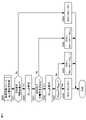
図1は、本発明の第1実施形態による車両制御システム100の概略構成図である。(First embodiment)
FIG. 1 is a schematic configuration diagram of a
図1に示すように、本実施形態による車両制御システム100は、サーバ1と、車両2と、を備える。 As shown in FIG. 1 , a
サーバ1は、サーバ通信部11と、サーバ記憶部12と、サーバ処理部13と、を備える。 The
サーバ通信部11は、サーバ1を例えばゲートウェイ等を介してネットワーク3と接続するための通信インターフェース回路を有し、車両2との間で相互に通信することができるように構成される。 The
サーバ記憶部12は、HDD(Hard Disk Drive)や光記録媒体、半導体メモリ等の記憶媒体を有し、サーバ処理部13での処理に用いられる各種のコンピュータプログラムやデータ等を記憶する。 The
本実施形態ではサーバ記憶部12は、全国の各所に設けられた制限区域に関する情報(後述する境界GFや制限期間に関する情報など)を少なくとも記憶している。制限区域とは、大気汚染防止の観点から、或いは、騒音防止の観点から、或いは、その他の観点から、内燃機関の駆動が制限される区域のことである。図2を参照して制限区域について簡単に説明すると、図2には、制限区域の内側と外側との境界GFと、境界GF上に位置する各道路位置Kd,Ke,Kf,Kgと、が示されている。 In this embodiment, the
図2において、境界GFの内側が制限区域であり、この制限区域が、例えば予め定められた制限期間の間だけ設けられる時間変動制の制限区域である場合には、制限期間の間だけ制限区域内での内燃機関の駆動が制限され、非制限期間においては内燃機関の駆動が許可される。制限期間は、例えば、時間や日、週、月、年、曜日などの単位で設定される。一方で、図2に示す制限区域が、制限期間が特に設けられていない固定制の制限区域である場合には、制限区域内では常に内燃機関の駆動が制限される。 In FIG. 2, the inside of the boundary GF is a restricted area, and if this restricted area is, for example, a time-varying restricted area established only during a predetermined restricted period, the restricted area During the non-restricted period, the internal combustion engine is permitted to be driven. The restricted period is set in units such as hours, days, weeks, months, years, and days of the week. On the other hand, if the restricted area shown in FIG. 2 is a fixed restricted area with no particular restriction period, the driving of the internal combustion engine is always restricted within the restricted area.
境界GF上に位置する各道路位置Kd,Ke,Kf,Kgには、例えばゲートが設けられており、本実施形態では、車両2がゲートを通過して制限区域内に進入すると、ゲートから車両2に対して制限区域に進入したことを知らせる信号が送信される。そして車両2は、この信号を受信して自車両が制限区域内に進入したことを認識すると、自車両に搭載された内燃機関の駆動を自動的に制限する(例えば車両2がハイブリッド車両であれば、走行モードが自動的にEVモードとされる)。 For example, a gate is provided at each road position Kd, Ke, Kf, Kg located on the boundary GF. In this embodiment, when the
図1に戻り、サーバ処理部13は、一又は複数個のプロセッサ及びその周辺回路を有する。サーバ処理部13は、サーバ記憶部12に格納された各種のコンピュータプログラムを実行し、サーバ1の全体的な動作を統括的に制御するものであり、例えばCPU(Central Processing Unit)である。 Returning to FIG. 1, the
図3は、車両2の概略構成図である。 FIG. 3 is a schematic configuration diagram of the
本実施形態による車両2はハイブリッド車両であって、図3に示すように、電子制御ユニット20と、ハイブリッドシステム21と、GPS受信装置22と、地図情報記憶装置23と、通信装置24と、HMI(Human Machine Interface)装置25と、ナビゲーション装置26と、外部情報受信装置27と、SOCセンサ28aや負荷センサ28b、車速センサ28cなどの各種のセンサ類28と、を備える。ハイブリッドシステム21、GPS受信装置22、地図情報記憶装置23、通信装置24、HMI装置25、ナビゲーション装置26、外部情報受信装置27、及び各種のセンサ類28は、CAN(Controller Area Network)等の規格に準拠した車内ネットワーク29を介して電子制御ユニット20と接続されている。 The
ハイブリッドシステム21は、車両2を走行させるために必要な動力を発生させ、その動力を駆動輪に伝達することができるように構成される。ハイブリッドシステム21の詳細については、図4を参照して説明する。 The
図4は、本実施形態によるハイブリッドシステム21の概略構成図である。本実施形態によるハイブリッドシステム21は、いわゆるシリーズ・パラレル式のハイブリッドシステムであるが、シリーズ式やパラレル式などのその他の形式のハイブリッドシステムであってもよい。 FIG. 4 is a schematic configuration diagram of the
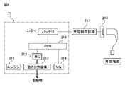
図4に示すように、本実施形態によるハイブリッドシステム21は、内燃機関211と、動力分割機構212と、主に発電機として使用される第1回転電機213と、主に電動機として使用される第2回転電機214と、バッテリ215と、パワーコントロールユニット(以下「PCU」という。)216と、を備える。 As shown in FIG. 4, the
内燃機関211は、その内部に形成された気筒内で燃料を燃焼させて、動力分割機構212に連結された機関出力軸を回転させるための動力を発生させる。なお、本実施形態による内燃機関211は、ガソリン燃料を燃焼させて動力を発生させるガソリンエンジンである。
動力分割機構212は、内燃機関211の動力を、駆動輪を回転させるための動力と、第1回転電機213を回生駆動させるための動力と、の2系統に分割するための公知の遊星歯車機構である。 The
第1回転電機213は、例えば三相の交流同期型のモータジェネレータであり、バッテリ215からの電力供給を受けて力行駆動する電動機としての機能と、内燃機関211の動力を受けて回生駆動する発電機としての機能と、を有する。本実施形態では第1回転電機213は、主に発電機として使用され、バッテリ215を充電するために必要な電力や第2回転電機214を力行駆動するために必要な電力を発電する。そして、内燃機関211の始動時に機関出力軸を回転させてクランキングを行うときに電動機として使用され、スタータとしての役割を果たす。 The first rotating
第2回転電機214は、例えば三相の交流同期型のモータジェネレータであり、バッテリ215からの電力供給を受けて力行駆動する電動機としての機能と、車両2の減速時に駆動輪からの動力を受けて回生駆動する発電機としての機能と、を有する。本実施形態では第2回転電機214は、主に電動機として使用され、駆動輪を回転させるための動力を発生させる。 The second rotating
バッテリ215は、例えばニッケル・カドミウム蓄電池やニッケル・水素蓄電池、リチウムイオン電池などの充放電可能な二次電池である。バッテリ215は、バッテリ215の充電電力を第1回転電機213及び第2回転電機214に供給してそれらを力行駆動することができるように、また、第1回転電機213及び第2回転電機214の発電電力をバッテリ215に充電できるように、PCU216を介して第1回転電機213及び第2回転電機214に電気的に接続される。 The
また本実施形態によるバッテリ215は、自宅や充電スタンドなどで外部電源からの充電が可能なように、充電制御回路217及び充電リッド218を介して外部電源と電気的に接続可能に構成される。充電制御回路217は、電子制御ユニット20からの制御信号に基づいて、外部電源から供給される交流電流を直流電流に変換し、入力電圧をバッテリ電圧まで昇圧して外部電源の電力をバッテリ215に充電することが可能な電気回路である。 Also, the
PCU216は、インバータと昇圧コンバータとを備え、電子制御ユニット20によってその動作が制御される。具体的には、各回転電機213,214を電動機として使用するときは、各回転電機213,214を駆動するために必要な電力がバッテリ215から各回転電機213,214に供給されるように、PCU216の動作が電子制御ユニット20によって制御される。また各回転電機213,214を発電機として使用するときは、各回転電機213,214で発電された電力がバッテリ215に供給されるように、PCU216の動作が電子制御ユニット20によって制御される。
図3に戻り、GPS受信装置22は、人工衛星からの電波を受信してハイブリッド車両2の緯度及び経度を特定し、車両2の現在位置を検出する。 Returning to FIG. 3 , the
地図情報記憶装置23は、道路の位置情報や道路形状の情報(例えば道路勾配や、カーブと直線部の種別、カーブの曲率など)、交差点及び分岐点の位置情報、道路種別、制限車速などの地図情報を記憶する。 The map
通信装置24は、無線通信機能を有する車載の端末である。通信装置24は、ネットワーク3(図1参照)と不図示のゲートウェイ等を介して接続される無線基地局4(図1参照)にアクセスすることで、無線基地局4を介してネットワーク3と接続される。これにより、サーバ1との間で相互に通信が行われる。 The
HMI装置25は、車両乗員との間で情報のやり取りを行うためのインターフェースである。本実施形態によるHMI装置25は、車両乗員に各種の情報を提供するためのディスプレイ及びスピーカと、車両乗員が情報の入力操作を行うためのタッチパネルと、を備える。HMI装置25は、車両乗員によって入力された入力情報(例えば目的地や経由地などの情報)を電子制御ユニット20やナビゲーション装置26に送信する。またHMI装置25は、電子制御ユニット20やナビゲーション装置26、外部情報受信装置27などから各種の情報を受信すると、受信した情報をディスプレイに表示するなどして、車両乗員に提供する。 The
ナビゲーション装置26は、HMI装置25を介して車両乗員によって設定された目的地まで車両2を案内する装置である。ナビゲーション装置26は、車両2の現在位置情報と地図情報とに基づいて、現在位置から目的地までの走行予定ルートを設定し、設定した走行予定ルートに関する情報をナビゲーション情報として電子制御ユニット20やHMI装置25に送信する。 The
外部情報受信装置27は、例えば道路交通情報通信システムセンタなどの外部の通信センタから送信されてくる外部情報を受信する。外部情報は、例えば渋滞情報や事故情報などの道路交通情報や、気象情報(雨や雪、霧、風速、温度、湿度等の情報)などである。外部情報受信装置27は、受信した外部情報を電子制御ユニット20に送信する。 The external
SOCセンサ28aは、バッテリ215に充電されている現在の電力量(以下「バッテリ電力量」という。)Wn[kWh]を検出する。負荷センサ28bは、走行負荷に相当するパラメータとして、アクセルペダルの踏み込み量に比例した出力電圧を検出する。車速センサ28cは、車両2の速度を検出する。 The
電子制御ユニット20は、車内通信インターフェース201、車両記憶部202及び車両処理部203、を備える。車内通信インターフェース201、車両記憶部202及び車両処理部203、信号線を介して互いに接続されている。 The
車内通信インターフェース201は、CAN(Controller Area Network)等の規格に準拠した車内ネットワーク29に電子制御ユニット20を接続するための通信インターフェース回路である。 The in-
車両記憶部202は、HDD(Hard Disk Drive)や光記録媒体、半導体メモリ等の記憶媒体を有し、車両処理部203での処理に用いられる各種のコンピュータプログラムやデータ等を記憶する。 The
車両処理部203は、一又は複数個のプロセッサ及びその周辺回路を有する。車両処理部203は、車両記憶部202に格納された各種のコンピュータプログラムを実行して車両2を統括的に制御するものであり、例えばCPUである。以下、車両処理部203、ひいては電子制御ユニット20によって実施される車両2の各種制御のうち、主に走行計画の作成に関する制御の内容について説明する。 The
電子制御ユニット20は、走行モードをEV(Electric Vehicle)モード又はHV(Hybrid Vehicle)モードのいずれか一方に切り替えて車両2を走行させる。 The
EVモードは、バッテリ215の電力を消費するべく、バッテリ215の電力を優先的に利用して第2回転電機214を力行駆動させ、第2回転電機214の動力を駆動輪に伝達して車両2を走行させるモードである。したがってEVモードは、CD(Charge Depleting;充電消耗)モードと称される場合もある。 In the EV mode, in order to consume the power of the
電子制御ユニット20は、走行モードがEVモードのときは、基本的に内燃機関211を停止させた状態でバッテリ215の電力を使用して第2回転電機214を力行駆動させ、第2回転電機214の動力のみにより駆動輪を回転させて車両2を走行させる。 When the running mode is the EV mode, the
一方でHVモードは、バッテリ電力量が、HVモードに切り替えられたときの電力量(以下「維持電力量」という。)に維持されるように、内燃機関211及び第2回転電機214の出力を制御して車両2を走行させるモードである。したがってHVモードは、CS(Charge Sustaining;充電維持)モードと称される場合もある。 On the other hand, in the HV mode, the outputs of the
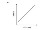
電子制御ユニット20は、走行モードがHVモードのときは、走行負荷が、図5に示す、バッテリ電力量に応じて変化する所定の切替負荷未満であれば、前述したEVモードと同様に、内燃機関211を停止させた状態でバッテリ215の電力を使用して第2回転電機214を力行駆動させ、第2回転電機214の動力のみにより駆動輪を回転させて、車両2を走行させる。なお電子制御ユニット20は、図5に示すように、バッテリ電力量が少ないときほど切替負荷が小さくなるように、バッテリ電力量に応じて切替負荷を変化させる。 When the running mode is the HV mode, the
そして電子制御ユニット20は、走行負荷が切替負荷以上になると、内燃機関211の動力を動力分割機構212によって2系統に分割し、分割した内燃機関211の一方の動力を駆動輪に伝達すると共に、他方の動力によって第1回転電機213を回生駆動させる。そして、第1回転電機213の発電電力によって第2回転電機214を力行駆動しつつ、必要に応じてその発電電力の一部をバッテリ215に供給してバッテリ215を充電し、内燃機関211の一方の動力に加えて第2回転電機214の動力を駆動輪に伝達して車両2を走行させる。 When the traveling load becomes equal to or greater than the switching load, the
内燃機関211は、機関負荷が低いときほど熱効率が悪くなる傾向にある。そのため、燃料消費量を抑えるためには、例えば信号機が多い走行区間や交通量が多く渋滞等が発生しやすい走行区間など、発進及び停止が頻繁に繰り返されたり低速走行が続いたりする走行区間のときに、走行モードをEVモードに設定して車両2を走行させることが望ましい。そして、或る一定以上の車速を維持したままの定常走行を継続して行うことができる走行区間など、熱効率の良い機関負荷領域での走行が可能な走行区間のときに、走行モードをHVモードに設定して車両2を走行させることが望ましい。 The
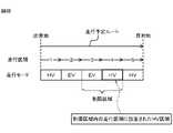
したがって、走行モードをEVモードとHVモードとに切り替えることが可能な車両2の場合、例えば図6Aに示すように、出発地(現在位置)から目的地までの走行予定ルートを複数の走行区間に分割すると共に、各走行区間の地図情報(例えば走行負荷等の道路情報など)に基づいて、どの走行区間をEVモードで走行し、どの走行区間をHVモードで走行するかの走行計画を作成し、当該走行計画に従って走行モードを切り替えながら車両2を走行させることが、燃料消費量を抑制するための有効な方法であるといえる。 Therefore, in the case of the
しかしながら、近年においては、図2を参照して前述した制限区域が各所に設けられている場合があり、このような制限区域の存在を考慮せずに走行計画を作成すると、例えば図6Bに示すように、制限区域内に存在する走行区間をHVモードで走行するHV区間に設定した走行計画を作成してしまうおそれがある。 However, in recent years, there are cases where the restricted areas described above with reference to FIG. 2 are provided in various places. Thus, there is a risk of creating a travel plan in which a travel section that exists within a restricted area is set as an HV section for traveling in the HV mode.
制限区域内を制限期間中に走行することになった場合、制限区域内では内燃機関211の駆動が制限されることになるため、制限区域内に存在する走行区間をHV区間に設定していたとしても、当該走行区間についてはEVモードで走行しなければならなくなる。そのため、走行計画通りに走行モードを切り替えて車両2を走行させることができなくなる。その結果、走行計画通りに走行できた場合と比較して燃料消費量が増大したり、HV区間として設定されていた制限区域内の走行区間においてバッテリ電力量が不足し、最悪の場合、電欠によって走行不能になったりするおそれがある。 If the vehicle were to travel within the restricted area during the restricted period, the driving of the
そこで本実施形態では、制限区域の存在を考慮した走行計画を作成することができるようにした。以下、図7を参照して制限区域情報の取得制御について説明した後、図8A~図8Cを参照して本実施形態による走行計画作成制御について説明する。 Therefore, in the present embodiment, it is possible to create a travel plan that considers the existence of restricted areas. Hereinafter, after the restricted area information acquisition control will be described with reference to FIG. 7, the travel plan creation control according to the present embodiment will be described with reference to FIGS. 8A to 8C.
図7は、本実施形態による制限区域情報の取得制御について説明するフローチャートである。電子制御ユニット20は、本ルーチンを所定の演算周期で繰り返し実行する。 FIG. 7 is a flowchart for explaining restricted area information acquisition control according to the present embodiment. The
ステップS101において、車両2の電子制御ユニット20は、制限区域情報を取得するべく、制限区域情報要求信号をサーバ1に送信する。本実施形態では、制限区域情報要求信号には、車両記憶部202に予め記憶された自車両の識別番号(例えば車両ナンバー)と、自車両の走行予定ルートと、が少なくとも含まれる。なお制限区域情報は、走行予定ルート上に制限区域が存在しているか否かに関する情報や、走行予定ルート上に制限区域が存在している場合にはその制限区域の境界GFや制限期間に関する情報などを含む情報である。 In step S101, the
ステップS102において、サーバ1は、制限区域情報要求信号を受信したか否かを判断する。サーバ1は、制限区域情報要求信号を受信していれば、ステップS3の処理に進む。一方でサーバ1は、制限区域情報要求信号を受信していなければ、今回の処理を終了する。 At step S102, the
ステップS103において、サーバ1は、制限区域情報を生成し、制限区域情報要求信号の送信元となる車両2(以下、必要に応じて「送信元車両2」ともいう。)に送信する。 In step S103, the
具体的にはサーバ1は、まずサーバ記憶部12に記憶された制限区域に関する情報と、送信元車両2の走行予定ルートと、に基づいて、送信元車両2の走行予定ルート上に制限区域が存在しているか否かを判定する。そしてサーバ1は、送信元車両2の走行予定ルート上に制限区域が存在していなければ、その旨の情報を含む制限区域情報を生成し、送信元車両2に送信する。一方でサーバ1は、送信元車両2の走行予定ルート上に制限区域が存在していれば、その制限区域の境界GF及び制限期間に関する情報を含む制限区域情報を生成し、送信元車両2に送信する。 Specifically, the
ステップS104において、車両2の電子制御ユニット20は、制限区域情報を受信したか否かを判定する。電子制御ユニット20は、制限区域情報を受信していれば、ステップS5の処理に進む。一方で電子制御ユニット20は、制限区域情報を受信していなければ、一定の時間を空けた後、制限区域情報を受信したか否かを再度判定する。 In step S104, the
ステップS105において、車両2の電子制御ユニット20は、受信した制限区域情報の内容を車両記憶部202に記憶させ、制限区域情報の内容を更新する。 In step S105, the
なお本実施形態では、このようにサーバ1と通信を行って制限区域情報を取得するようにしているが、これに限らず、例えば外部の通信センタが制限区域に関する情報を外部情報として定期的に送信している場合には、外部情報受信装置27によって制限区域に関する情報を取得し、その情報に基づいて自車両の走行予定ルート上に制限区域が存在するか否か等を電子制御ユニット20によって判断するようにしてもよい。 In this embodiment, the restricted area information is acquired by communicating with the
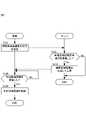
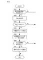
図8Aは、本実施形態による走行計画作成制御について説明するフローチャートである。電子制御ユニット20は、本ルーチンを所定の演算周期で繰り返し実行する。 FIG. 8A is a flowchart for explaining travel plan creation control according to this embodiment. The
ステップS111において、車両2の電子制御ユニット20は、目的地が判明しているか否かを判定する。目的地は、HMI装置25を介して車両乗員によって入力された目的地であってもよいし、例えば過去の車両2の走行履歴等に基づいて推定された目的地であってもよい。電子制御ユニット20は、目的地が判明していれば、ステップS112の処理に進む。一方で電子制御ユニット20は、目的地が判明していなければ、走行計画を作成することなく今回の処理を終了する。 In step S111, the
ステップS112において、車両2の電子制御ユニット20は、地図情報に基づいて、走行予定ルートを複数の走行区間に分割すると共に各走行区間の走行負荷を算出する。 In step S112, the
ステップS113において、車両2の電子制御ユニット20は、車両記憶部202に記憶された制限区域情報を参照し、自車両の走行予定ルート上に制限区域が存在しているか否かを判定する。電子制御ユニット20は、自車両の走行予定ルート上に制限区域が存在していれば、ステップS114の処理に進む。一方で電子制御ユニット20は、自車両の走行予定ルート上に制限区域が存在していなければ、ステップS116の処理に進む。 In step S113, the
ステップS114において、車両2の電子制御ユニット20は、現在時刻、地図情報、及び外部情報(道路交通情報)に基づいて、走行予定ルート上の各走行区間の予想走行時間帯を算出する。そして電子制御ユニット20は、制限区域内に存在する走行区間のうち、予想走行時間帯が当該制限区域の制限期間と被っている走行区間(以下「制限走行区間」という。)があるか否かを判定する。電子制御ユニット20は、制限走行区間がある場合は、制限区域内を制限期間中に走行する可能性があると判定し、ステップS115の処理に進む。一方で電子制御ユニット20は、制限走行区間がない場合は、制限区域内を制限期間中に走行する可能性はないと判定し、ステップS116の処理に進む。 In step S114, the
ステップS115において、車両2の電子制御ユニット20は、制限区域を考慮した走行計画(以下「第1走行計画」という。)を作成するための第1走行計画作成処理を実施する。第1走行計画作成処理の詳細については、図8Bを参照して後述する。 In step S115, the
ステップS116において、車両2の電子制御ユニット20は、制限区域を考慮しない通常の走行計画(以下「第2走行計画」という。)を作成するための第2走行計画作成処理を実施する。第2走行計画作成処理の詳細については、図8Cを参照して後述する。 In step S116, the
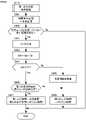
図8Bは、第1走行計画作成処理の詳細について説明するフローチャートである。 FIG. 8B is a flowchart illustrating details of the first travel plan creation process.
ステップS121において、車両2の電子制御ユニット20は、各制限走行区間をEVモードで走行するEV区間に設定する。 In step S121, the
ステップS122において、車両2の電子制御ユニット20は、走行モードの設定を実施していない走行区間があるか否かを判定する。電子制御ユニット20は、走行モードの設定を実施していない走行区間があれば、ステップS123の処理に進む。一方で電子制御ユニット20は、走行モードの設定を実施していない走行区間がなければ、第1走行計画の作成を終了する。 In step S122, the
ステップ123において、車両2の電子制御ユニット20は、各制限走行区間の走行負荷に基づいて、各制限走行区間の全てをEVモードで走破した場合に消費される電力量(第2回転電機214を駆動するために消費される電力量及び第2回転電機214以外の車載機器等により消費される電力量)の推定値(以下「第1推定電力量」という。)W1[kWh]を算出する。 In step 123, the
ステップS124において、車両2の電子制御ユニット20は、SOCセンサ28aによって検出された現在のバッテリ電力量Wnのうち、制限走行区間以外の残りの走行区間で使用可能なバッテリ電力量(以下「使用可能バッテリ電力量」という。)WA[kWh]を算出する。本実施形態では電子制御ユニット20は、現在のバッテリ電力量Wnから第1推定電力量W1を差し引いた残りの電力量を、使用可能バッテリ電力量WAとして算出する。 In step S124, the
ステップS125において、車両2の電子制御ユニット20は、使用可能バッテリ電力量WAが、ゼロよりも大きいか否かを判定する。電子制御ユニット20は、使用可能バッテリ電力量WAがゼロよりも大きければ、ステップS126の処理に進む。一方で電子制御ユニット20は、使用可能バッテリ電力量WAがゼロ以下であれば、ステップS132の処理に進む。 In step S125, the
ステップS126において、車両2の電子制御ユニット20は、走行予定ルート上の制限走行区間以外の残りの各走行区間の走行負荷に基づいて、残りの各走行区間のEV適正度を算出する。EV適正度は、各走行区間がどの程度EV走行に適した区間であるかを表す指標であり、本実施形態では走行区間の走行負荷が低いときほど高い値(すなわちEV走行に適している)にされる。 In step S126, the
ステップS127において、車両2の電子制御ユニット20は、走行モードの設定を実施していない走行区間のうち、EV適正度の最も高い走行区間を走行モード設定区間として設定する。 In step S<b>127 , the
ステップS128において、車両2の電子制御ユニット20は、走行モード設定区間をEV区間に設定することができるか否かを判定する。 In step S128, the
具体的には電子制御ユニット20は、まず、走行モード設定区間の走行負荷に基づいて、走行モード設定区間をEVモードで走破した場合に消費される電力量の推定値(以下「第2推定電力量」という。)W2[kWh]を算出する。 Specifically, the
次に、電子制御ユニット20は、走行モード設定区間と、既にEV区間として設定されている全ての走行区間とを、EVモードで走破した場合に消費される電力量の推定値(以下「第3推定電力量」という。)W3[kWh]を算出する。 Next, the
なお、ステップS126からステップS127を経由して初めて本ステップの処理に進んだ場合には、第3推定電力量W3は、第1推定電力量W1に、本ステップで算出された第2推定電力量W2を加算した値となる。一方でステップS131から本ステップの処理に戻ってきた場合には、第3推定電力量W3は、第3推定電力量W3の前回値に、本ステップの処理に戻ってきて新たに算出された第2推定電力量W2を加算した値となる。 Note that when the process of this step is performed for the first time from step S126 via step S127, the third estimated power amount W3 is added to the first estimated power amount W1, and the second estimated power amount calculated in this step is It becomes the value which added W2. On the other hand, when returning to the process of this step from step S131, the third estimated power amount W3 is the previous value of the third estimated power amount W3, and the newly calculated third power amount after returning to the process of this step. 2 estimated electric energy W2 is added.
そして最後に、電子制御ユニット20は、使用可能バッテリ電力量WAが第3推定電力量W3以上であるか否かを判定する。すなわち電子制御ユニット20は、使用可能バッテリ電力量WAが、既にEV区間として設定されている走行区間に加えて、走行モード設定区間を新たにEV区間に設定することができるだけの電力量以上であるか否かを判定する。電子制御ユニット20は、使用可能バッテリ電力量WAが第3推定電力量W3以上であれば、走行モード設定区間を新たにEV区間に設定することができると判定してステップS129の処理に進む。一方で電子制御ユニット20は、使用可能バッテリ電力量WAが第3推定電力量W3未満であれば、走行モード設定区間をEV区間に設定することができないと判定してステップS130の処理に進む。 Finally, the
ステップS129において、車両2の電子制御ユニット20は、走行モード設定区間をEV区間に設定する。 In step S129, the
ステップS130において、車両2の電子制御ユニット20は、走行モード設定区間をHV区間に設定する。 In step S130, the
ステップS131において、車両2の電子制御ユニット20は、走行モードの設定を実施していない走行区間があるか否かを判定する。電子制御ユニット20は、走行モードの設定を実施していない走行区間があれば、再びステップS127に戻り、走行モードの設定をまだ実施していない走行区間に対して走行モードの設定を行う。一方で電子制御ユニット20は、走行モードの設定を実施していない走行区間がなければ、第1走行計画の作成を終了する。 In step S131, the
ステップS132において、車両2の電子制御ユニット20は、走行モード設定区間を含む、走行モードの設定をまだ実施していない残りの全ての走行区間の走行モードをHV区間に設定する。 In step S132, the
なお、各走行区間の走行モードを決定した後、その中のどのHV区間で、内燃機関211の動力を用いて第1回転電機213で発電した発電電力の一部をバッテリ215に供給してバッテリ215の充電を行うかを決定するようにしてもよい。内燃機関211の動力を用いてバッテリ215の充電を行う場合、バッテリ215に充電するための電力を発電する分だけ内燃機関211の負荷が増大する。そのため、低負荷側の機関運転領域でバッテリ215の充電を行うと、内燃機関211の負荷増大に伴って内燃機関211の騒音も増大するおそれがある。したがって本実施形態では、HV区間の中でも、例えば走行負荷が所定負荷以上となっている走行区間など、内燃機関211を相対的に高負荷側の機関運転領域で運転させることが多くなると予想される走行区間を、バッテリ215の充電を行う充電区間として設定している。 After the travel mode of each travel section is determined, in which HV section, part of the power generated by the first rotary
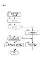
図8Cは、第2走行計画作成処理の詳細について説明するフローチャートである。 FIG. 8C is a flowchart illustrating details of the second travel plan creation process.
ステップS141において、車両2の電子制御ユニット20は、現在のバッテリ電力量Wnを使用可能バッテリ電力量WAに設定する。 In step S141, the
ステップS142において、車両2の電子制御ユニット20は、各走行区間の走行負荷に基づいて、各走行区間のEV適正度を算出する。 In step S142, the
ステップS143において、車両2の電子制御ユニット20は、走行モードの設定を実施していない走行区間のうち、EV適正度の最も高い走行区間を走行モード設定区間として設定する。 In step S143, the
ステップS144において、車両2の電子制御ユニット20は、走行モード設定区間をEV区間に設定することができるか否かを判定する。 In step S144, the
具体的には電子制御ユニット20は、まず、走行モード設定区間の走行負荷に基づいて、走行モード設定区間をEVモードで走破した場合に消費される電力量の推定値である第2推定電力量W2[kWh]を算出する。 Specifically, the
次に、電子制御ユニット20は、走行モード設定区間と、既にEV区間として設定されている走行区間があればその全ての走行区間とを、EVモードで走破した場合に消費される電力量の推定値(以下「第4推定電力量」という。)W4[kWh]を算出する。 Next, the
なお、ステップS142からステップS143を経由して初めて本ステップの処理に進んだ場合には、EV区間として設定された走行区間がまだ無いため、第4推定電力量W4は、本ステップで算出された第2推定電力量W2となる。一方で、ステップS147から本ステップの処理に戻ってきた場合には、第4推定電力量W4は、第4推定電力量W4の前回値に、本ステップの処理に戻ってきて新たに算出された第2推定電力量W2を加算した値となる。 It should be noted that when the processing of this step is performed for the first time from step S142 through step S143, there is no travel section set as an EV section yet, so the fourth estimated electric energy W4 is calculated in this step. It becomes the second estimated power amount W2. On the other hand, when returning to the process of this step from step S147, the fourth estimated power amount W4 is the previous value of the fourth estimated power amount W4, which was newly calculated after returning to the process of this step. It becomes a value obtained by adding the second estimated power amount W2.
最後に、電子制御ユニット20は、使用可能バッテリ電力量WAが第4推定電力量W4以上であるか否かを判定する。すなわち電子制御ユニット20は、使用可能バッテリ電力量WAが、走行モード設定区間と、既にEV区間として設定されている走行区間があればその全ての走行区間とを、EVモードで走破することが可能な電力量以上であるか否かを判定する。そして電子制御ユニット20は、使用可能バッテリ電力量WAが第4推定電力量W4以上であれば、走行モード設定区間をEV区間に設定することができると判定してステップS145の処理に進む。一方で電子制御ユニット20は、使用可能バッテリ電力量WAが第4推定電力量W4未満であれば、走行モード設定区間をEV区間に設定することができないと判定してステップS146の処理に進む。 Finally, the
ステップS145において、車両2の電子制御ユニット20は、走行モード設定区間をEV区間に設定する。 In step S145, the
ステップS146において、車両2の電子制御ユニット20は、走行モード設定区間をHV区間に設定する。 In step S146, the
ステップS147において、車両2の電子制御ユニット20は、走行モードの設定を実施していない走行区間があるか否かを判定する。電子制御ユニット20は、走行モードの設定を実施していない走行区間があれば、再びステップS143に戻り、走行モードの設定をまだ実施していない走行区間に対して走行モードの設定を行う。一方で電子制御ユニット20は、走行モードの設定を実施していない走行区間がなければ、第2走行計画の作成を終了する。 In step S147, the
以上説明した本実施形態によれば、内燃機関211と、第2回転電機214(回転電機)と、バッテリ215と、を備える車両2を制御するための電子制御ユニット20(車両制御装置)が、車両2の目的地までの走行予定ルートを複数の走行区間に分割し、各走行区間を、内燃機関211の駆動を停止して第2回転電機214の動力で走行するEVモード、又は内燃機関211の動力と第2回転電機214の動力とで走行するHVモードのいずれの走行モードで走行するかを設定した走行計画を作成する走行計画作成部と、走行計画に基づいて内燃機関211及び第2回転電機214を制御する動力制御部と、を備える。 According to the present embodiment described above, the electronic control unit 20 (vehicle control device) for controlling the
そして走行計画作成部は、走行区間が予め設定された制限区域内に存在するときは、制限区域内に存在する走行区間のうち、内燃機関211の駆動が制限される制限期間中に走行することになると予想される走行区間を制限走行区間として抽出し、制限走行区間をEVモードで走行することができる走行計画を作成するように構成される。 Then, when the travel section is in a preset restricted area, the travel plan creation unit determines that the travel section within the restricted area travels during the restricted period in which the driving of the
これにより、制限走行区間をEVモードで走行することができる走行計画、すなわち制限区域を考慮した適切な走行計画を作成することができる。 As a result, it is possible to create a travel plan that allows the vehicle to travel in the restricted travel section in the EV mode, that is, an appropriate travel plan that takes into account the restricted area.
なお本実施形態による走行計画作成部は、より詳細には、制限走行区間の走行モードをEVモードに設定し、バッテリ215の電力量のうち、制限走行区間以外の残りの走行区間で使用可能な電力量を使用可能バッテリ電力量WAとして算出し、使用可能バッテリ電力量WAに基づいて制限走行区間以外の残りの走行区間の走行モードを決定するように構成される。そして使用可能バッテリ電力量WAは、現在のバッテリ電力量Wnから、制限走行区間をEVモードで走破した場合に消費される電力量の推定値である第1推定電力量W1を差し引いた残りの電力量とされる。 More specifically, the travel plan creation unit according to the present embodiment sets the travel mode of the restricted travel section to the EV mode, and the electric energy of the
これにより、制限走行区間をEVモードで走行しつつ、その他の走行区間を可能な限りEVモードで走行することが可能な走行計画を作成することができる。そのため、燃料消費量を可能な限り抑制することができる。 As a result, it is possible to create a travel plan that allows the vehicle to travel in the restricted travel section in the EV mode while traveling in the other travel sections in the EV mode as much as possible. Therefore, fuel consumption can be suppressed as much as possible.
また本実施形態による走行計画作成部は、走行モードがHVモードに設定された走行区間のうち、走行負荷が所定負荷以上となる走行区間を、内燃機関211の動力を利用してバッテリ215の充電を行う充電区間に設定するように構成される。 In addition, the travel plan creation unit according to the present embodiment uses the power of the
内燃機関211の動力を利用してバッテリ215の充電を行う際には、バッテリ215に充電するための電力を発電する分だけ内燃機関211の負荷が増大し、その結果として内燃機関211の騒音が増大する。したがって、例えば内燃機関211が相対的に低負荷側の機関運転領域で運転させられている場合など、暗騒音が小さいと考えられるときにバッテリ215の充電を行ってしまうと、内燃機関211の騒音が目立ってしまい、車両乗員が内燃機関211の騒音を不快に感じるおそれがある。 When the power of the
したがって本実施形態のように、走行負荷が所定負荷以上となる走行区間でバッテリ215の充電を行うようにすることで、内燃機関211を相対的に高負荷側の機関運転領域で運転させることが多くなると予想される走行区間、すなわち暗騒音が大きいと考えられる走行区間でバッテリ215の充電を行うことができる。そのため、バッテリ215の充電時に内燃機関211の騒音が目立ってしまうのを抑制し、車両乗員が内燃機関211の騒音を不快に感じるのを抑制することができる。 Therefore, as in the present embodiment, by charging the
(第2実施形態)
次に、本発明の第2実施形態について説明する。本実施形態は、現在のトリップの目的地が制限区域内に存在する場合には、当該目的地から新たな次の目的地へと出発することになる次トリップを考慮して、現在のトリップの走行計画を作成する点で第1実施形態と相違する。以下、その相違点を中心に説明する。(Second embodiment)
Next, a second embodiment of the invention will be described. When the destination of the current trip is within the restricted area, the present embodiment considers the next trip that departs from the destination to a new next destination, This differs from the first embodiment in that a travel plan is created. The difference will be mainly described below.
車両2の現在のトリップの目的地が制限区域内に存在する場合、次トリップでは、制限区域内に存在するその現在のトリップの目的地から、次の目的地へと出発することになる。したがって、制限期間中に次の目的地に向けて次トリップが開始された場合、制限区域内から制限区域外に抜け出すまでの間はEVモードで走行せざるを得なくなる。そのため、次トリップ開始時点のバッテリ電力量が少ないと、制限区域内から抜け出すことができなくなるおそれがある。 If the current trip destination of the
そこで本実施形態では、車両2の現在のトリップの目的地が制限区域内に存在する場合は、次トリップにおいて制限区域内から制限区域外に抜け出すために必要なバッテリ電力量を残すことができるように、現在のトリップの走行計画を作成することとした。 Therefore, in the present embodiment, if the destination of the current trip of the
図9Aは、本実施形態による第1走行計画作成処理の詳細について説明するフローチャートである。図9Aにおいて、ステップS121~S123,S125~S132の処理の内容は、第1実施形態と同様なので、ここでは説明を省略する。 FIG. 9A is a flowchart illustrating details of the first travel plan creation process according to the present embodiment. In FIG. 9A, the contents of the processing of steps S121 to S123 and S125 to S132 are the same as those of the first embodiment, so description thereof is omitted here.
ステップS200において、車両2の電子制御ユニット20は、使用可能バッテリ電力量WAの設定処理を実施する。本実施形態による使用可能バッテリ電力量WAの設定処理は、制限走行区間以外の残りの走行区間で使用可能なバッテリ電力量である使用可能バッテリ電力量WAを、次トリップを考慮して設定するための処理である。この第1走行計画処理の中で実施される本実施形態による使用可能バッテリ電力量WAの設定処理の詳細については、図9Bを参照して説明する。 In step S200, the
図9Bは、第1走行計画処理の中で実施される本実施形態による使用可能バッテリ電力量WAの設定処理の詳細について説明するフローチャートである。 FIG. 9B is a flowchart for explaining the details of the processing for setting the usable battery power amount WA according to the present embodiment, which is performed in the first travel plan processing.
ステップS201において、車両2の電子制御ユニット20は、目的地が制限区域内に存在するか否かを判定する。電子制御ユニット20は、目的地が制限区域内に存在していれば、ステップS202の処理に進む。一方で電子制御ユニット20は、目的地が制限区域内に存在していなければ、ステップS204の処理に進む。 In step S201, the
ステップS202において、車両2の電子制御ユニット20は、目的地から制限区域の境界GF状に位置する各道路位置(図2に示した例ではKd,Ke,Kf,Kg)までの距離を算出し、その中で最も短い距離に基づいて、制限区域内から抜け出すために最低限必要な電力量の推定値(以下「推定脱出電力量」という。)WESC[kWh]を算出する。In step S202, the
ステップS203において、車両2の電子制御ユニット20は、現在のバッテリ電力量Wnから、第1推定電力量W1と推定脱出電力量WESCとを差し引いた電力量を、使用可能バッテリ電力量WAに設定する。これにより、現在のトリップの終了時に、推定脱出電力量WESCの分だけバッテリ電力量が残るような走行計画を作成することができる。In step S203, the
ステップS204において、車両2の電子制御ユニット20は、現在のバッテリ電力量Wnから第1推定電力量W1を差し引いた電力量を、使用可能バッテリ電力量WAに設定する。これにより、目的地が制限区域内に存在していないときは、走行計画通りに走行することによって、バッテリ電力量を無駄なく使い切ることができるので、燃料消費量を抑制することができる。 In step S204, the
図10Aは、本実施形態による第2走行計画作成処理の詳細について説明するフローチャートである。図10Aにおいて、ステップS142~S147の処理の内容は第1実施形態と同様なので、ここでは説明を省略する。 FIG. 10A is a flowchart illustrating details of the second travel plan creation process according to this embodiment. In FIG. 10A, the contents of the processing in steps S142 to S147 are the same as those in the first embodiment, so the description is omitted here.
ステップS210において、車両2の電子制御ユニット20は、使用可能バッテリ電力量WAの設定処理を実施する。この第2走行計画処理の中で実施される本実施形態による使用可能バッテリ電力量WAの設定処理の詳細については、図10Bを参照して説明する。 In step S210, the
図10Bは、第2走行計画処理の中で実施される本実施形態による使用可能バッテリ電力量WAの設定処理の詳細について説明するフローチャートである。図10Bにおいて、ステップS201、S202の処理の内容は、図9Bを参照して説明した処理の内容と同様なので、ここでは説明を省略する。 FIG. 10B is a flowchart for explaining the details of the processing for setting the usable battery power amount WA according to the present embodiment, which is performed during the second travel plan processing. In FIG. 10B, the details of the processing in steps S201 and S202 are the same as the details of the processing described with reference to FIG. 9B, so description thereof will be omitted here.
ステップS211において、車両2の電子制御ユニット20は、現在のバッテリ電力量Wnから推定脱出電力量WESCを差し引いた電力量を、使用可能バッテリ電力量WAに設定する。In step S211, the
ステップS212において、車両2の電子制御ユニット20は、現在のバッテリ電力量Wnを、使用可能バッテリ電力量WAに設定する。 In step S212, the
以上説明した本実施形態による電子制御ユニット20は、第1実施形態と同様に、車両2の目的地までの走行予定ルートを複数の走行区間に分割し、各走行区間を、内燃機関211の駆動を停止して第2回転電機214の動力で走行するEVモード、又は内燃機関211の動力と第2回転電機214の動力とで走行するHVモードのいずれの走行モードで走行するかを設定した走行計画を作成する走行計画作成部を備える。 As in the first embodiment, the
そして本実施形態による走行計画作成部は、目的地が制限区域内に存在する場合は、目的地に到着したときのバッテリ215の電力量が、目的地から制限区域外に抜け出すために必要な電力量を下回らないような走行計画を作成するように構成される。 Then, if the destination is within the restricted area, the travel plan creation unit according to the present embodiment determines that the amount of power in the
具体的には本実施形態による走行計画作成部は、現在のバッテリ電力量Wnのうち、制限走行区間以外の残りの走行区間で使用可能な電力量を使用可能バッテリ電力量WAとして算出するにあたって、制限走行区間をEVモードで走破した場合に消費される電力量の推定値である第1推定電力量W1と、目的地から制限区域外に抜け出すために必要な電力量の推定値である推定脱出電力量WESCと、を算出するように構成される。Specifically, the travel plan creation unit according to the present embodiment calculates, as the usable battery power amount WA, the power amount that can be used in the remaining travel sections other than the restricted travel section from the current battery power amount Wn. A first estimated power consumption W1, which is an estimated value of the power consumption when the restricted driving section is traveled in EV mode, and an estimated escape, which is an estimated value of the power required to escape from the destination to the restricted area. and WESC .
そして本実施形態による走行計画作成部は、現在のバッテリ電力量Wnから、第1推定電力量W1と推定脱出電力量WESCとを差し引いた残りの電力量を使用可能バッテリ電力量WAとし、使用可能バッテリ電力量WAに基づいて制限走行区間以外の残りの走行区間の走行モードを決定するように構成される。Then, the travel plan creation unit according to the present embodiment determines the remaining power amount obtained by subtracting the first estimated power amount W1 and the estimated escape power amount WESC from the current battery power amount Wn as the usable battery power amount WA. It is configured to determine the driving mode for the remaining driving sections other than the restricted driving section based on the available battery power amount WA.
これにより、現在のトリップの目的地が制限区域内に存在しているときは、現在のトリップの終了時に、推定脱出電力量WESCの分だけバッテリ電力量が残るような走行計画を作成することができる。そのため、次トリップにおいて、制限区域内から抜け出すことができなくなるのを抑制することができる。As a result, when the destination of the current trip is within the restricted area, a travel plan is created in which the estimated escape powerWESC remains at the end of the current trip. can be done. Therefore, it is possible to prevent the vehicle from being unable to escape from the restricted area on the next trip.
(第3実施形態)
次に本発明の第3実施形態について説明する。本実施形態は、使用可能バッテリ電力量WAの設定処理の内容が第2実施形態と相違する。以下、その相違点を中心に説明する。(Third Embodiment)
Next, a third embodiment of the invention will be described. This embodiment differs from the second embodiment in the content of the processing for setting the usable battery power amount WA. The difference will be mainly described below.
前述した第2実施形態では、車両2の現在のトリップの目的地が制限区域内に存在する場合には、次トリップにおいて制限区域内から制限区域外に抜け出すために必要なバッテリ電力量の推定値である推定脱出電力量WESCを残すことができるように、現在のトリップの走行計画を作成していた。In the second embodiment described above, when the current trip destination of the
しかしながら、現在のトリップの目的地に到着した後、例えば当該目的地においてバッテリ215を外部電源と接続して満充電する予定がある場合には、次トリップのために推定脱出電力量WESCを残しておく必要性はなく、現在のトリップでバッテリ電力量を使い切ってしまっても問題ない。However, after arriving at the destination of the current trip, for example, if there is a plan to fully charge the
そこで本実施形態では、現在のトリップの目的地が制限区域内に存在する場合には、現在のトリップの目的地に到着した後、当該目的地でバッテリ215が充電されることも考慮して、現在のトリップの走行計画を作成できるようにした。 Therefore, in this embodiment, if the current trip destination is within the restricted area, the
図11は、第1走行計画処理の中で実施される本実施形態による使用可能バッテリ電力量WAの設定処理の詳細について説明するフローチャートである。図11において、ステップS201~S204の処理の内容は、第2実施形態と同様なので、ここでは説明を省略する。 FIG. 11 is a flowchart for explaining the details of the processing for setting the available battery power amount WA according to the present embodiment, which is performed in the first travel plan processing. In FIG. 11, the contents of the processing in steps S201 to S204 are the same as those in the second embodiment, and thus description thereof is omitted here.
ステップS301において、車両2の電子制御ユニット20は、現在のトリップの目的地でバッテリ215の充電を行う予定があるか否かを判定する。電子制御ユニット20は、現在のトリップの目的地でバッテリ215の充電を行う予定があれば、ステップS302の処理に進む。一方で電子制御ユニット20は、現在のトリップの目的地でバッテリ215の充電を行う予定がなければ、ステップS203の処理に進む。 In step S301, the
なお本実施形態では、現在のトリップの目的地でバッテリ215の充電を行う予定があるか否かを判定するために、HMI装置25を介して車両乗員によって目的地が入力されたときに、目的地で充電する予定があるか否かを確認して入力してもらうようにしている。そして目的地で充電する予定がある場合には、現在のトリップの目的地でバッテリ215をどの程度充電することができるかを把握するために、目的地での予定充電時間をさらに入力してもらうようにしている。しかしながら、現在のトリップの目的地でバッテリ215の充電を行う予定があるか否かを判定する方法は、このような方法に限られるものではなく、例えば、HMI装置25を介して入力された目的地の種別(例えば自宅や充電スタンド設置場所など)や、目的地での過去の充電実績などに応じて判定するようにしてもよい。 Note that in the present embodiment, when the destination is input by the vehicle occupant via the
ステップS302において、車両2の電子制御ユニット20は、予定充電時間に基づいて、現在のトリップの目的地に到着した後に当該目的地でバッテリ215に充電される電力量の推定値(以下「推定充電電力量」という。)WCHG[kWh]を算出する。推定充電電力量WCHGは、予定充電時間が長くなるほど大きい値となる。In step S302, the
ステップS303において、車両2の電子制御ユニット20は、推定充電電力量WCHGが、推定脱出電力量WESC以上であるか否かを判定する。In step S303, the
電子制御ユニット20は、推定充電電力量WCHGが推定脱出電力量WESC以上であれば、次トリップのために推定脱出電力量WESCを残しておく必要性はなく、現在のトリップでバッテリ電力量を使い切ってしまっても問題ないため、ステップS304の処理に進み、現在のバッテリ電力量Wnから第1推定電力量W1を差し引いた残りの電力量を、使用可能バッテリ電力量WAに設定する。If the estimated charge energy WCHG is greater than or equal to the estimated escape energy WESC , the
一方で電子制御ユニット20は、推定充電電力量WCHGが推定脱出電力量WESC未満であれば、現在のトリップでバッテリ電力量を使い切ってしまうと、現在のトリップの目的地で予定通り充電が行われたとしても、推定脱出電力量WESCに対して不足している電力量(以下「不足電力量」という。)WSHTG(=WESC-WCHG)[kWh]の分だけ、次トリップにおいて制限区域内から制限区域外に抜け出すために必要な電力が不足する可能性があるため、ステップS305の処理に進む。On the other hand, if the estimated charge power amount WCHG is less than the estimated escape power amount WESC , the
ステップS305において、車両2の電子制御ユニット20は、現在のバッテリ電力量Wnから第1推定電力量W1と不足電力量WSHTGとを差し引いた残りの電力量を、使用可能バッテリ電力量WAに設定する。In step S305, the
図12は、第2走行計画処理の中で実施される本実施形態による使用可能バッテリ電力量WAの設定処理の詳細について説明するフローチャートである。図12において、ステップS201及びS202の処理の内容、S211及びS212の処理の内容、及びS301~S303の処理の内容とは、それぞれ図9B、図10B、及び図11を参照して前述した通りなので、ここでは説明を省略する。 FIG. 12 is a flowchart for explaining the details of the processing for setting the available battery power amount WA according to the present embodiment, which is performed in the second travel plan processing. In FIG. 12, the contents of the processes of steps S201 and S202, the contents of the processes of S211 and S212, and the contents of the processes of S301 to S303 are as described above with reference to FIGS. 9B, 10B, and 11, respectively. , the description is omitted here.
ステップS311において、車両2の電子制御ユニット20は、推定充電電力量WCHGが推定脱出電力量WESC以上であり、次トリップのために推定脱出電力量WESCを残しておく必要性はなく、現在のトリップでバッテリ電力量を使い切ってしまっても問題ないため、現在のバッテリ電力量Wnを、使用可能バッテリ電力量WAに設定する。In step S311, the
ステップS312において、車両2の電子制御ユニット20は、推定充電電力量WCHGが推定脱出電力量WESC未満であり、現在のトリップでバッテリ電力量を使い切ってしまうと、現在のトリップの目的地で予定通り充電が行われたとしても、不足電力量WSHTG(=WESC-WCHG)の分だけ、次トリップにおいて制限区域内から制限区域外に抜け出すために必要な電力が不足する可能性があるため、現在のバッテリ電力量Wnから不足電力量WSHTGを差し引いた残りの電力量を、使用可能バッテリ電力量WAに設定する。In step S312, the
以上説明した本実施形態による電子制御ユニット20も、第1実施形態と同様に、車両2の目的地までの走行予定ルートを複数の走行区間に分割し、各走行区間を、内燃機関211の駆動を停止して第2回転電機214の動力で走行するEVモード、又は内燃機関211の動力と第2回転電機214の動力とで走行するHVモードのいずれの走行モードで走行するかを設定した走行計画を作成する走行計画作成部を備える。 As in the first embodiment, the
そして本実施形態による走行計画作成部は、目的地が制限区域内に存在する場合において、目的地でバッテリ215の充電を行う予定があるときは、目的地から出発する次トリップ開始時のバッテリ215の電力量が、目的地から制限区域外に抜け出すために必要な電力量を下回らないような走行計画を作成するように構成される。 When the destination is within the restricted area, the travel plan creation unit according to the present embodiment, when there is a plan to charge the
具体的には本実施形態による走行計画作成部は、現在のバッテリ電力量Wnのうち、制限走行区間以外の残りの走行区間で使用可能な電力量を使用可能バッテリ電力量WAとして算出するにあたって、制限走行区間をEVモードで走破した場合に消費される電力量の推定値である第1推定電力量W1と、目的地から制限区域外に抜け出すために必要な電力量の推定値である推定脱出電力量WESCと、目的地で充電される電力量の推定値である推定充電電力量WCHGと、を算出するように構成される。Specifically, the travel plan creation unit according to the present embodiment calculates, as the usable battery power amount WA, the power amount that can be used in the remaining travel sections other than the restricted travel section from the current battery power amount Wn. A first estimated power consumption W1, which is an estimated value of the power consumption when the restricted driving section is traveled in EV mode, and an estimated escape, which is an estimated value of the power required to escape from the destination to the restricted area. It is configured to calculate an amount of power WESC and an estimated charge amount of power WCHG , which is an estimate of the amount of power charged at the destination.
そして本実施形態による走行計画作成部は、推定充電電力量WCHGが推定脱出電力量WESC以上であれば、現在のバッテリ電力量Wnから第1推定電力量W1を差し引いた残りの電力量を使用可能バッテリ電力量WAとし、推定充電電力量WCHGが推定脱出電力量WESC未満であれば、現在のバッテリ電力量Wnから、第1推定電力量W1、及び推定脱出電力量WESCと推定充電電力量WCHGとの差分値(=不足電力量WSHTG)を差し引いた残りの電力量を使用可能バッテリ電力量WAとし、使用可能バッテリ電力量WAに基づいて制限走行区間以外の残りの走行区間の走行モードを決定するように構成される。Then, if the estimated charge power amount WCHG is equal to or greater than the estimated escape power amount WESC , the travel plan creation unit according to the present embodiment calculates the remaining power amount obtained by subtracting the first estimated power amount W1 from the current battery power amount Wn. If the available battery power is WA and the estimated charging power WCHG is less than the estimated escape power WESC , the first estimated power W1 and the estimated escape power WESC are estimated from the current battery power Wn. The remaining power amount obtained by subtracting the difference value (=shortage power amount WSHTG ) from the charged power amount WCHG is set as the usable battery power amount WA, and the remaining driving other than the restricted driving section is determined based on the usable battery power amount WA. It is configured to determine the driving mode of the section.
これにより、現在のトリップの目的地でバッテリ215の充電予定がある場合には、その充電予定を考慮した走行計画を作成することができる。すなわち、予定される充電電力量の分だけ、現在のトリップの使用可能バッテリ電力量WAを増大させることができる。そのため、充電予定を考慮せずに走行計画を作成した場合と比較して、EVモードで走行できる走行期間や距離を増やすことができるので、燃費の向上や排気エミッションの向上を図ることができる。 As a result, when there is a plan to charge the
(第4実施形態)
次に本発明の第4実施形態について説明する。本実施形態は、走行計画に従って走行モードを切り替えながら走行すると、バッテリ電力量が所定値よりも少ない状態で制限期間中の制限区域に進入しなければならなくなるおそれがあるときは、走行予定ルートを変更できるようした点で、上記の各実施形態と相違する。以下、その相違点を中心に説明する。(Fourth embodiment)
Next, a fourth embodiment of the invention will be described. In the present embodiment, if there is a risk that the vehicle will have to enter a restricted area during the restricted period with the battery electric energy being less than a predetermined value when driving while switching the driving mode according to the driving plan, the planned driving route will be changed. It is different from each of the above-described embodiments in that it can be changed. The difference will be mainly described below.
制限期間中の制限区域内では、内燃機関211の駆動が制限されるため、バッテリ電力量が十分に確保されていない状態であってもEVモードで走行しなければならず、内燃機関211を駆動してバッテリ215の充電を行うこともできない。そのため、バッテリ電力量が十分に確保されていない状態で制限期間中の制限区域に進入すると、最悪の場合、電欠により走行不能になるおそれがある。 Since the driving of the
そこで本実施形態では、車両走行中に定期的に走行計画を作成して更新することを前提として、走行計画を更新する度に、更新した走行計画に従って走行した場合に予想される、制限区域進入時のバッテリ電力量の推定値(以下「進入時推定バッテリ電力量」という。)WBAT[kWh]を算出することとした。そして、進入時推定バッテリ電力量WBATが所定の第1閾値Wth1未満であるときは、バッテリ電力量が十分に確保されていない状態で制限期間中の制限区域に進入することになると判断し、走行予定ルートに替わる代替走行ルートを検索することとした。以下、この本実施形態による代替走行ルート検索制御について説明する。Therefore, in the present embodiment, on the premise that a travel plan is periodically created and updated while the vehicle is traveling, each time the travel plan is updated, it is expected that the vehicle will enter a restricted area when traveling according to the updated travel plan. An estimated value of the battery electric energy at the time of the approach (hereinafter referred to as “estimated battery electric energy at the time of approach”) WBAT [kWh] is calculated. Then, when the estimated battery power amount WBAT at the time of entry is less than the predetermined first threshold value Wth1, it is determined that the vehicle will enter the restricted area during the restricted period in a state in which the battery power amount is not sufficiently secured, We decided to search for an alternative travel route to replace the planned travel route. The alternative travel route search control according to this embodiment will be described below.
図13は、本実施形態による代替走行ルート検索制御について説明するフローチャートである。 FIG. 13 is a flow chart illustrating alternative travel route search control according to the present embodiment.
ステップS401において、車両2の電子制御ユニット20は、走行計画が新しく作成されたか否かを判定する。電子制御ユニット20は、走行計画が新しく作成されていれば、ステップS402の処理に進む。一方で電子制御ユニット20は、走行計画が新しく作成されていなければ、今回の処理を終了する。 In step S401, the
ステップS402において、車両2の電子制御ユニット20は、新しく作成された走行計画に従って走行モードを切り替えながら走行した場合に予想される進入時推定バッテリ電力量WBATを算出する。進入時推定バッテリ電力量WBATの算出方法は特に限られるものではないが、例えば、現在のバッテリ電力量Wnから、制限区域よりも手前に存在する全てのEV区間をEVモードで走破した場合に消費される電力量の推定値を減算することで算出することができる。In step S402, the
ステップS403において、車両2の電子制御ユニット20は、進入時推定バッテリ電力量WBATが、第1閾値Wth1未満であるか否かを判定する。電子制御ユニット20は、進入時推定バッテリ電力量WBATが第1閾値Wth1未満であれば、ステップS404の処理に進む。一方で電子制御ユニット20は、進入時推定バッテリ電力量WBATが第1閾値Wth1以上であれば、走行予定ルートの変更を行う必要がないと判断して今回の処理を終了する。In step S403, the
なお本実施形態では電子制御ユニット20は、制限区域を通過できる程度の電力量(例えば、制限区域の境界GF状に位置する一の道路位置から他の道路位置まで走行できる程度の電力量)を第1閾値Wth1として設定している。 In the present embodiment, the
しかしながら、例えば、一又は複数の他の車両が制限区域に進入したときのバッテリ電力量に関する情報が、ビッグデータとしてサーバ1に集約されている場合であれば、サーバ1に集約された制限区域進入時のバッテリ電力量のデータの分布に基づいて、第1閾値Wth1を設定することもできる。具体的には、サーバ1に集約された制限区域進入時のバッテリ電力量のデータの分布の中央値や平均値、最頻値などを、第1閾値Wth1として設定することができる。 However, for example, if the information on the battery power amount when one or more other vehicles enter the restricted area is aggregated in the
また、車両2にソーラパネルが取り付けられていて、ソーラパネルの発電電力をバッテリ215に充電することができるようになっている場合、すなわちバッテリ215が、太陽光を利用して発電した電力を蓄電することができるように構成されている場合であれば、制限区域周辺の天気に基づいて、第1閾値Wth1を設定してもよい。具体的には、制限区域周辺の天気が曇り又は雨であった場合には、晴れであった場合よりも第1閾値Wth1を高くするようにしてもよい。 In addition, when a solar panel is attached to the
また、ソーラパネルの取付有無にかかわらず、例えば制限区域周辺の天気が雨である場合など、制限区域周辺の湿度が高い場合には、エアコン負荷が除湿のために増大することを想定して、制限区域周辺の湿度が低い場合よりも第1閾値Wth1を高くするようにしてもよい。 Also, regardless of whether the solar panel is installed or not, if the humidity around the restricted area is high, such as when the weather around the restricted area is rainy, we assume that the air conditioner load will increase due to dehumidification. The first threshold Wth1 may be set higher than when the humidity around the restricted area is low.
ステップS404において、車両2の電子制御ユニット20は、現在位置情報と、地図情報と、に基づいて、現在の走行予定ルートと比較して、進入時推定バッテリ電力量WBATの増大が見込める代替走行ルートを検索する。電子制御ユニット20は、例えば、現在位置から制限区域に進入するまでの複数の走行ルートの中で、HVモードに適した走行区間が多く、現在の走行予定ルートよりもEVモードで走行する距離が短くなると考えられる走行ルートを代替走行ルートとして検索する。また、例えば、現在位置から制限区域に進入するまでの複数の走行ルートの中で、下り坂の多い走行ルートや、相対的に走行負荷の高い走行区間が多く、内燃機関211の動力を用いてバッテリ215を充電しながら走行するのに適した走行ルートなど、現在の走行ルートよりも回生電力量が大きくなると考えられる走行ルートを代替走行ルートとして検索する。In step S404, the
ステップS405において、車両2の電子制御ユニット20は、代替走行ルートへのルート変更を、HMI装置25を介して車両乗員に提案する。 In step S<b>405 , the
ステップS406において、車両2の電子制御ユニット20は、代替走行ルートへのルート変更を車両乗員が承認したか否かを判定する。本実施形態では電子制御ユニット20は、代替走行ルートへのルート変更を提案してから所定時間が経過するまでの間に、車両乗員がHMI装置25を介して承認の意思を示したときに、提案した代替走行ルートへのルート変更を車両乗員が承認したと判定する。電子制御ユニット20は、代替走行ルートへのルート変更を車両乗員が承認したと判定したときは、ステップS407の処理に進む。一方で電子制御ユニット20は、代替走行ルートへのルート変更を車両乗員が承認しなかったと判定したときは、今回の処理を終了する。 In step S406, the
ステップS407において、車両2の電子制御ユニット20は、走行予定ルートを代替走行ルートに変更する。 In step S407, the
なお本実施形態では、このように、代替走行ルートを検索して代替走行ルートへのルート変更を車両乗員に提案するようにしていたが、例えば車両2が自律走行可能な自動運転車両であった場合には、自動的に走行予定ルートを代替走行ルートに切り替えて代替走行ルートを走行するようにしてもよい。 In this embodiment, an alternative travel route is searched and a route change to the alternative travel route is proposed to the vehicle occupant. In this case, the scheduled travel route may be automatically switched to the alternative travel route to travel on the alternative travel route.
以上説明した本実施形態による電子制御ユニット20は、走行予定ルートを走行計画に従って走行した場合に予想される、制限区域に進入するときのバッテリ215の電力量の推定値である進入時推定バッテリ電力量WBATを算出し、進入時推定バッテリ電力量WBATが、所定の第1閾値Wth1未満であれば、走行予定ルートに替わる代替走行ルートを検索するように構成される。The
これにより、進入時推定バッテリ電力量WBATが第1閾値Wth1未満であるときには、車両乗員に代替走行ルートを提案したり、車両2が自律走行可能な自動運転車両であれば走行予定ルートを自動的に代替走行ルートに変更したりすることができる。そのため、例えばバッテリ215の電力量が十分に確保されていない状態で制限期間中の制限区域に進入してしまうよう事態に陥るのを抑制することができる。As a result, when the estimated battery electric power amount WBAT at the time of approach is less than the first threshold value Wth1, an alternative travel route is proposed to the vehicle occupant, or if the
(第5実施形態)
次に、本発明の第5実施形態について説明する。本実施形態は、トリップ開始時に作成された走行計画に基づいて算出された進入時推定バッテリ電力量WBATを、第1閾値Wth1に設定する点で、第4実施形態と相違する。以下、その相違点を中心に説明する。(Fifth embodiment)
Next, a fifth embodiment of the present invention will be described. The present embodiment differs from the fourth embodiment in that the estimated battery power amount WBAT at entry calculated based on the travel plan created at the start of the trip is set to the first threshold value Wth1. The difference will be mainly described below.
図14は、本実施形態による代替走行ルート検索制御について説明するフローチャートである。図14において、ステップS401~S407の処理の内容は、第4実施形態と同様なので、ここでは説明を省略する。 FIG. 14 is a flow chart illustrating alternative travel route search control according to the present embodiment. In FIG. 14, the contents of the processing of steps S401 to S407 are the same as those of the fourth embodiment, so the description is omitted here.
ステップS501において、車両2の電子制御ユニット20は、新しく作成された走行計画が、現在のトリップで最初に作成された走行計画であるか否かを判定する。 In step S501, the
電子制御ユニット20は、新しく作成された走行計画が、現在のトリップで最初に作成された走行計画であれば、ステップS502の処理に進み、現在のトリップで最初に作成された走行計画に基づいて算出された進入時推定バッテリ電力量WBATを、第1閾値Wth1に設定する。If the newly created travel plan is the travel plan first created on the current trip, the
一方で電子制御ユニット20は、新しく作成された走行計画が、現在のトリップで最初に作成された走行計画でなければ、ステップS403以降の処理に進み、新しく作成された走行計画に基づいて算出された進入時推定バッテリ電力量WBATが、ステップS502で設定された第1閾値Wth1未満であるか否かを判定する。そして進入時推定バッテリ電力量WBATが第1閾値Wth1未満であれば、代替走行ルートへのルート変更を、HMI装置25を介して車両乗員に提案する。On the other hand, if the newly created travel plan is not the travel plan first created in the current trip, the
以上説明した本実施形態による電子制御ユニット20は、第4実施形態と同様に、進入時推定バッテリ電力量WBATが所定の第1閾値Wth1未満であれば、走行予定ルートに替わる代替走行ルートを検索すると共に、現在のトリップで最初に走行計画を作成したときに算出された進入時推定バッテリ電力量WBATを第1閾値Wth1として設定するように構成される。電子制御ユニット20をこのように構成しても、第4実施形態と相当の作用効果をえることができる。As in the fourth embodiment, the
(第6実施形態)
次に、本発明の第6実施形態について説明する。本実施形態は、制限期間中の制限区域に実際に進入したときのバッテリ電力量に応じて、車両乗員に対して充電スタンドの位置情報を提供する点で、上記の各実施形態と相違する。以下、その相違点を中心に説明する。(Sixth embodiment)
Next, a sixth embodiment of the present invention will be described. This embodiment differs from the above-described embodiments in that charging station location information is provided to vehicle occupants according to the amount of battery power when the vehicle actually enters the restricted area during the restricted period. The difference will be mainly described below.
前述したように、バッテリ電力量が十分に確保されていない状態で制限期間中の制限区域に進入すると、最悪の場合、電欠により走行不能になるおそれがある。そこで本実施形態では、バッテリ電力量が十分に確保されていない状態で制限期間中の制限区域に進入した場合には、車両乗員に対して充電スタンドの位置情報を提供することとした。以下、この本実施形態による情報提供制御について説明する。 As described above, if the vehicle enters a restricted area during the restricted period with insufficient battery power, in the worst case, the vehicle may run out of power and become unable to travel. Therefore, in the present embodiment, when the vehicle enters a restricted area during the restricted period with insufficient battery power, the vehicle occupant is provided with the location information of the charging station. Information provision control according to this embodiment will be described below.
図15は、本実施形態による情報提供制御について説明するフローチャートである。車両2の電子制御ユニット20は、本ルーチンを所定の演算周期で繰り返し実行する。 FIG. 15 is a flowchart for explaining information provision control according to this embodiment. The
ステップS601において、車両2の電子制御ユニット20は、自車両が制限期間中の制限区域に進入したか否かを判定する。自車両が制限期間中の制限区域に進入したか否かの判定方法は特に限られるものではなく、例えば、現在位置情報、地図情報、及び制限区域情報に基づいて判定することができる。電子制御ユニット20は、自車両が制限期間中の制限区域に進入していれば、ステップS602の処理に進む。一方で電子制御ユニット20は、自車両が制限期間中の制限区域に進入していなければ、今回の処理を終了する。 In step S601, the
ステップS602において、車両2の電子制御ユニット20は、現在のバッテリ電力量Wnが、第1閾値Wth1未満であるか否かを判定する。電子制御ユニット20は、バッテリ電力量Wnが第1閾値Wth1未満であれば、ステップS603の処理に進む。一方で電子制御ユニット20は、バッテリ電力量Wnが第1閾値Wth1以上であれば、制限期間中の制限区域に進入するのに必要最低限のバッテリ電力量が確保されていると判断して今回の処理を終了する。 In step S602, the
ステップS603において、車両2の電子制御ユニット20は、自車両の目的地が判明しているか否かを判定する。電子制御ユニット20は、自車両の目的地が判明していれば、ステップS604の処理に進む。一方で電子制御ユニット20は、自車両の目的地が判明していなければ、ステップS607の処理に進む。 In step S603, the
ステップS604において、車両2の電子制御ユニット20は、目的地が制限区域内に存在するか否かを判定する。電子制御ユニット20は、目的地が制限区域内に存在していれば、ステップS605の処理に進む。一方で電子制御ユニット20は、目的地が制限区域内に存在していなければ、ステップS606の処理に進む。 In step S604, the
ステップS605において、車両2の電子制御ユニット20は、走行予定ルート上に存在する近隣の充電スタンドの位置情報、及び目的地近隣に存在する充電器付きの駐車場の位置情報を、HMI装置25を介して車両乗員に提供する。 In step S605, the
ステップS606において、車両2の電子制御ユニット20は、走行予定ルート上に存在する近隣の充電スタンドの位置情報を、HMI装置25を介して車両乗員に提供する。 In step S<b>606 , the
ステップS607において、車両2の電子制御ユニット20は、近隣の充電スタンドの位置情報を、HMI装置25を介して車両乗員に提供する。 In step S<b>607 , the
なお本実施形態では、このように充電スタンドの位置情報や充電器付きの駐車場の位置情報を車両乗員に提供していたが、例えば車両2が自律走行可能な自動運転車両であった場合には、目的地を最寄りの充電スタンドや充電器付きの駐車場に自動的に切り替えて、車両2を切り替えた目的地に向かわせてもよい。 In the present embodiment, the location information of the charging station and the location information of the parking lot with the charger are provided to the vehicle occupants. may automatically switch the destination to the nearest charging station or a parking lot with a charger, and direct the
以上説明した本実施形態による電子制御ユニット20は、制限期間中の制限区域に進入したときのバッテリ電力量Wnが所定の第1閾値Wth1未満であれば、バッテリ215の充電が可能な充電可能場所を検索し、目的地が制限区域内にあるときは、少なくとも、目的地近隣の充電可能場所の位置情報を車両2の乗員に提供するか、又は目的地を目的地近隣の充電可能場所に変更するように構成される。 The
これにより、バッテリ電力量が十分に確保されていない状態で制限期間中の制限区域に進入した場合であっても、電欠によって走行不能になるような事態に陥るのを抑制することができる。 As a result, even when the vehicle enters a restricted area during the restricted period in a state in which the battery power is not sufficiently secured, it is possible to prevent the vehicle from becoming unable to travel due to lack of electricity.
(第7実施形態)
次に本発明の第7実施形態について説明する。(Seventh embodiment)
Next, a seventh embodiment of the invention will be described.
内燃機関の駆動が制限されることのない区域で例えばイベントが開催される場合や事故が発生した場合などに、その区域が、限られた時間帯だけ臨時的又は突発的に制限区域として設定されることも想定される。このような臨時制限区域が設定されると、臨時制限区域内を走行していた車両2の内燃機関211の駆動が予期せず制限されてしまうことになる。また、臨時制限区域内では交通制限が行われたり、車両が集中したりして渋滞が発生する可能性も高い。そのため、臨時制限区域内を通過して目的地に向かうと、渋滞に巻き込まれ、最悪の場合には電欠により走行不能になるおそれがある。 When an event is held or an accident occurs in an area where the driving of the internal combustion engine is not restricted, the area is temporarily or suddenly set as a restricted area for a limited period of time. It is also assumed that When such a temporary restricted area is set, the driving of the
そこで本実施形態では、臨時制限区域を走行することになった場合には、一旦、臨時走行区域外への脱出を促して、臨時制限区域外に脱出した後に改めて目的地までの走行計画を作成することができるようにした。 Therefore, in this embodiment, when it is decided to travel in the temporary restricted area, once the vehicle is urged to escape from the temporary restricted area, and after escaping from the temporary restricted area, a travel plan to the destination is created again. made it possible.
図16は、本実施形態による臨時制限区域脱出制御について説明するフローチャートである。 FIG. 16 is a flow chart explaining the temporary restricted area escape control according to the present embodiment.
ステップS701において、車両2の電子制御ユニット20は、例えばサーバ1と通信を行って制限区域情報を取得し、現在位置情報に基づいて自車両が臨時制限区域内を走行しているか否かを判定する。電子制御ユニット20は、自車両が臨時制限区域内を走行していれば、ステップS702の処理に進む。一方で電子制御ユニット20は、自車両が臨時制限区域内を走行していなければ、今回の処理を終了する。 In step S701, the
ステップS702において、車両2の電子制御ユニット20は、現在位置情報と、地図情報と、に基づいて、現在位置から臨時制限区域外に脱出することができる脱出最短ルートを検索する。 In step S702, the
ステップS703において、車両2の電子制御ユニット20は、臨時制限区域からの脱出を、HMI装置25を介して車両乗員に提案する。 In step S703, the
ステップS704において、車両2の電子制御ユニット20は、臨時制限区域からの脱出を車両乗員が承認したか否かを判定する。本実施形態では電子制御ユニット20は、臨時制限区域からの脱出を提案してから所定時間が経過するまでの間に、車両乗員がHMI装置25を介して承認の意思を示したときに、臨時制限区域からの脱出を車両乗員が承認したと判定する。電子制御ユニット20は、臨時制限区域からの脱出を車両乗員が承認したと判定したときは、ステップS705の処理に進む。一方で電子制御ユニット20は、臨時制限区域からの脱出を車両乗員が承認しなかったと判定したときは、ステップS706の処理に進み、臨時制限区域を考慮した上で現在位置から目的地までの走行ルートを最適化した走行計画を作成する。 In step S704, the
ステップS705において、車両2の電子制御ユニット20は、現在位置情報に基づいて、自車両が臨時制限区域から脱出したか否かを判定する。電子制御ユニット20は、自車両が臨時制限区域から脱出していれば、ステップS706の処理に進む。一方で電子制御ユニット20は、自車両が臨時制限区域から脱出していなければ、所定の間隔を空けて再度、ステップS705の処理を実施する。 At step S705, the
ステップS706において、車両2の電子制御ユニット20は、臨時制限区域を考慮した上で現在位置(脱出地点)から目的地までの走行ルートを最適化した走行計画を作成する。 In step S706, the
なお本実施形態では、このように、最短脱出ルートを検索して臨時制限区域からの脱出を車両乗員に提案するようにしていたが、例えば車両2が自律走行可能な自動運転車両であった場合には、自動的に最短脱出ルートを走行させて臨時制限区域からの脱出させるようにしてもよい。 In this embodiment, the shortest escape route is searched for and the vehicle occupant is proposed to escape from the temporary restricted area. , the shortest escape route may be automatically run to escape from the temporary restricted area.
以上説明した本実施形態による電子制御ユニット20は、内燃機関211の駆動が制限されることのない地点を走行中に、その地点が、臨時的又は突発的に内燃機関211の駆動が制限される臨時制限区域内の地点となったときは、臨時制限区域から抜け出すことが可能な最短脱出ルートを検索するように構成される。 The
これにより、臨時制限区域が設定された場合には、車両乗員に対して最短脱出ルートを提示して臨時制限区域からの早期の脱出を促したり、また車両2が自律走行可能な自動運転車両であれば、自動的に最短脱出ルートを走行して臨時制限区域から早期に脱出したりすることができる。そして、臨時制限区域から脱出した後に、脱出地点から目的地までの走行ルートを最適化した走行計画を作成することができる。 As a result, when a temporary restricted area is set, the shortest escape route is presented to the vehicle occupants to encourage an early escape from the temporary restricted area. If so, it is possible to automatically run the shortest escape route and escape from the temporary restricted area early. Then, after escaping from the temporary restricted area, it is possible to create a travel plan that optimizes the travel route from the escape point to the destination.
(第8実施形態)
次に本発明の第8実施形態について説明する。本実施形態は、内燃機関211の構成が上記の各実施形態と相違する。以下、その相違点を中心に説明する。(Eighth embodiment)
Next, an eighth embodiment of the present invention will be described. This embodiment differs from the above embodiments in the configuration of an
本実施形態による内燃機関211は、一部の気筒で水素燃料を燃焼させ、残りの気筒でガソリン燃料(化石燃料)を燃焼させることができるように構成されている。これにより、水素燃料のみを燃焼させて内燃機関211を駆動しているときには、内燃機関211からの二酸化炭素の排出量はゼロとなる。したがって、制限地域が地球温暖化防止を目的として設定されている場合であれば、制限期間中の制限区域内でも、水素燃料のみを燃焼させて内燃機関211を駆動することについては許可される。 The
ここで、仮に走行計画通りに走行できていたとしても、必ずしもバッテリ電力量の管理が予定通りにいくとは限らず、制限期間中の制限区域内をEVモードで走行しているときに、バッテリ電力量が予想に反して大きく低下することもあり得る。その結果、制限区域内でバッテリ電力量が不足し、電欠により走行不能になることもあり得る。 Here, even if it is possible to drive according to the driving plan, the management of the battery power amount does not necessarily go as planned. It is also possible that the amount of electric power will drop greatly contrary to expectations. As a result, the battery may run out of power in the restricted area, making it impossible to drive.
そこで本実施形態では、制限地域が地球温暖化防止を目的として設定されていることを前提として、走行計画に従って制限期間中の制限区域内をEVモードで走行している場合に、バッテリ電力量Wnが所定の第2閾値Wth2未満になったときは、水素燃料のみを燃焼させて内燃機関211を駆動することとした。これにより、内燃機関211の動力によって車両2を走行させることもできるし、また、第1回転電機213を回生駆動して発電を行うこともできる。そのため、走行計画に従って制限期間中の制限区域内をEVモードで走行しているときに、バッテリ電力量が予想に反して大きく低下したとしても、走行不能になるような事態に陥るのを抑制することができる。第2閾値Wth2は、例えば、制限区域の中心部から境界まで走行できる程度の電力量とされる。 Therefore, in the present embodiment, on the premise that the restricted area is set for the purpose of preventing global warming, when traveling in the EV mode in the restricted area during the restricted period according to the travel plan, the battery power amount Wn becomes less than the predetermined second threshold value Wth2, the
図17は、この本実施形態による内燃機関211の運転制御について説明するフローチャートである。 FIG. 17 is a flow chart explaining the operation control of the
ステップS801において、車両2の電子制御ユニット20は、自車両が制限区域内を制限期間中に走行しているか否かを判定する。電子制御ユニット20は、自車両が制限区域内を制限期間中に走行していれば、ステップS802の処理に進む。一方で電子制御ユニット20は、自車両が制限区域内を制限期間中に走行していなければ、今回の処理を終了する。 In step S801, the
ステップS802において、車両2の電子制御ユニット20は、現在のバッテリ電力量Wnが、第2閾値Wth2未満であるか否かを判定する。電子制御ユニット20は、バッテリ電力量Wnが第2閾値Wth2未満であれば、ステップS803の処理に進む。一方で電子制御ユニット20は、バッテリ電力量Wnが第2閾値Wth2以上であれば、今回の処理を終了する。 In step S802, the
ステップS803において、車両2の電子制御ユニット20は、水素燃料のみを燃焼させて内燃機関211を駆動する。 In step S803, the
以上説明した本実施形態によれば、内燃機関211は、一部の気筒で水素燃料を燃焼させ、残りの気筒でガソリン燃料(化石燃料)を燃焼させることができるように構成されている。そして本実施形態による電子制御ユニット20は、制限期間中の制限区域内をEVモードで走行している場合にバッテリ電力量Wnが第2閾値Wth2未満になったときは、水素燃料のみを燃焼させて内燃機関211を駆動して、内燃機関211の動力で車両2を走行させるか、又は内燃機関211の動力を利用して発電された電力をバッテリ215に充電するように構成される。 According to the present embodiment described above, the
これにより、走行計画に従って制限期間中の制限区域内をEVモードで走行しているときに、バッテリ電力量が予想に反して大きく低下したとしても、走行不能になるような事態に陥るのを抑制することができる。 This prevents the vehicle from becoming unable to drive even if the battery power drops significantly unexpectedly while driving in EV mode within the restricted area during the restricted period according to the driving plan. can do.
(第9実施形態)
次に本発明の第9実施形態について説明する。本実施形態は、車両2が内燃機関及び電動機を動力源として備えたハイブリッド車両ではなく、内燃機関のみを動力源として備えた通常車両である点で、上記の各実施形態と相違する。以下、その相違点を中心に説明する。(Ninth embodiment)
Next, a ninth embodiment of the present invention will be described. The present embodiment differs from the above-described embodiments in that the
図18は、本実施形態による車両2の概略構成図である。 FIG. 18 is a schematic configuration diagram of the
図18に示すように、本実施形態による車両2は、内燃機関211のみを動力源として備える通常車両であって、内燃機関211の動力を駆動輪に伝達することができるように構成される。内燃機関211は、一部の気筒で水素燃料を燃焼させ、残りの気筒でガソリン燃料(化石燃料)を燃焼させることができるように構成されており、車両2は各燃料の残量を検出する燃料残量センサ28dを備える。 As shown in FIG. 18, the
本実施形態による電子制御ユニット20は、車両2の走行モードを、水素モード又はガソリンモードのいずれか一方に切り替えることができるように構成される。水素モードは、水素燃料のみを燃焼させて内燃機関211を駆動するモードである。ガソリンモードは、少なくともガソリン燃料を燃焼させて内燃機関211を駆動するモードである。 The
そして電子制御ユニット20は、走行予定ルート上のどの走行区間を水素モードで走行し、どの走行区間をガソリンモードで走行するかの走行計画を、制限区域を考慮して作成し、当該走行計画に従って走行モードを切り替えながら車両2を走行させる。 Then, the
図19Aは、本実施形態による第1走行計画作成処理の詳細について説明するフローチャートである。 FIG. 19A is a flowchart illustrating details of the first travel plan creation process according to this embodiment.
ステップS901において、車両2の電子制御ユニット20は、各制限走行区間を水素モードで走行する水素区間に設定する。 In step S901, the
ステップS902において、車両2の電子制御ユニット20は、走行モードの設定を実施していない走行区間があるか否かを判定する。電子制御ユニット20は、走行モードの設定を実施していない走行区間があれば、ステップS903の処理に進む。一方で電子制御ユニット20は、走行モードの設定を実施していない走行区間がなければ、第1走行計画の作成を終了する。 In step S902, the
ステップS903において、車両2の電子制御ユニット20は、各制限走行区間の走行負荷に基づいて、各制限走行区間の全てを水素モードで走破した場合に消費される水素燃料の推定値(以下「推定燃料消費量」という。)Q1[L]を算出する。 In step S903, the
ステップS904において、車両2の電子制御ユニット20は、燃料残量センサ28dで検出された現在の水素燃料量Qnのうち、制限走行区間以外の残りの走行区間で使用可能な水素燃料量(以下「使用可能水素燃料量」という。)QA[L]を算出する。本実施形態では電子制御ユニット20は、現在の水素燃料量Qnから推定燃料消費量Q1を差し引いた残りの水素燃料量を、使用可能水素燃料量QAとして算出する。 In step S904, the
ステップS905において、車両2の電子制御ユニット20は、使用可能水素燃料量QAが、ゼロよりも大きいか否かを判定する。電子制御ユニット20は、使用可能水素燃料量QAがゼロよりも大きければ、ステップS906の処理に進む。一方で電子制御ユニット20は、使用可能水素燃料量QAがゼロ以下であれば、ステップS908の処理に進む。 In step S905, the
ステップS906において、車両2の電子制御ユニット20は、走行予定ルート上で1番最初に走行する第1の走行区間(すなわち出発地を含む走行区間)の走行モードが未設定であるか否かを判定する。電子制御ユニット20は、第1の走行区間の走行モードが未設定であれば、ステップS907の処理に進む。一方で電子制御ユニット20は、第1の走行区間の走行モードが既に設定済みであれば、ステップS909の処理に進む。 In step S906, the
ステップS907において、車両2の電子制御ユニット20は、第1の走行区間を水素区間に設定し、残りの走行区間を全てガソリン区間に設定する。 In step S907, the
このように、第1の走行区間を水素区間に設定するのは以下の理由による。すなわち、内燃機関211の暖機が完了する前の冷間時に液体燃料であるガソリン燃料を燃焼させて内燃機関211を駆動すると、シリンダ壁面に付着するガソリン燃料の影響を受けて、排気エミッションが悪化する傾向がある。したがって、第1の走行区間を水素区間に設定することで、内燃機関211の冷間時には、ガス燃料である水素燃料を燃焼させて内燃機関211を駆動することができ、その結果、排気エミッションの悪化を抑制することができるためである。 The reason for setting the first travel section to the hydrogen section is as follows. That is, when the
ステップS908において、車両2の電子制御ユニット20は、制限走行区間を水素モードで走破するだけの水素燃料が不足しているため、HMI装置25を介して車両乗員に水素燃料の補給を提案する。 In step S<b>908 , the
ステップS909において、車両2の電子制御ユニット20は、残りの走行区間を全てガソリン区間に設定する。 In step S909, the
図19Bは、本実施形態による第2走行計画作成処理の詳細について説明するフローチャートである。なお図19Bにおいて、ステップS905~S909の処理の内容は、図19Aを参照して前述した処理の内容と同様なので、ここでは処理を省略する。 FIG. 19B is a flowchart illustrating details of the second travel plan creation process according to the present embodiment. Note that in FIG. 19B, the details of the processing in steps S905 to S909 are the same as the details of the processing described above with reference to FIG. 19A, so the processing is omitted here.
ステップS911において、車両2の電子制御ユニット20は、燃料残量センサ28dで検出された現在の水素燃料量Qnを、使用可能水素燃料量QAとして算出する。 In step S911, the
なお本実施形態では、制限走行区間と、第1の走行区間と、を水素モードで走行できる走行計画を作成していたが、水素残量に応じて、これの走行区間に加えて他の走行区間を水素モードに設定した走行計画を作成してもよい。 In the present embodiment, a travel plan was created in which the restricted travel section and the first travel section can be traveled in the hydrogen mode. A travel plan may be created in which the section is set to the hydrogen mode.
以上説明した本実施形態によれば、一部の気筒で水素燃料を燃焼させ、残りの気筒で化石燃料を燃焼させることができるように構成された内燃機関211を備える車両2を制御するための電子制御ユニット20(車両制御装置)が、車両2の目的地までの走行予定ルートを複数の走行区間に分割し、各走行区間を水素燃料のみを燃焼させて走行する水素モード(第1モード)又は少なくとも化石燃料を燃焼させて走行するガソリンモード(第2モード)のいずれの走行モードで走行するかを設定した走行計画を作成する走行計画作成部と、走行計画に基づいて内燃機関211を制御する動力制御部と、を備える。 According to the present embodiment described above, the
そして走行計画作成部は、走行区間が予め設定された制限区域内に存在するときは、制限区域内に存在する走行区間のうち、ガソリン燃料(化石燃料)を燃焼させて内燃機関211を駆動することが制限される制限期間中に走行することになると予想される走行区間を制限走行区間として抽出し、制限走行区間を水素モードで走行することができる走行計画を作成するように構成される。 Then, when the travel section exists within a preset restricted area, the travel plan creation unit burns gasoline fuel (fossil fuel) in the travel section existing within the restricted area to drive the
これにより、水素燃料のみを燃焼させて走行する第1モードと、少なくとも化石燃料を燃焼させて走行する第2モードとに走行モードに切り替えることが可能な車両2の走行計画を作成する際に、制限区域を考慮した適切な走行計画を作成することができる。 As a result, when creating a travel plan for the
また本実施形態による電子制御ユニット20は、水素燃料の残量が、制限走行区間を水素モード(第1モード)で走破した場合に消費される水素燃料量の推定値よりも少ないときは、水素燃料の補充が可能な場所の位置情報を車両2の乗員に提供するように構成されているので、制限走行区間の走行中に水素残量が不足するような事態に陥るのを抑制することができる。 Further, the
以上、本発明の実施形態について説明したが、上記実施形態は本発明の適用例の一部を示したに過ぎず、本発明の技術的範囲を上記実施形態の具体的構成に限定する趣旨ではない。 Although the embodiments of the present invention have been described above, the above embodiments merely show a part of the application examples of the present invention, and the technical scope of the present invention is not limited to the specific configurations of the above embodiments. do not have.
例えば上記の各実施形態では、出発地から目的地までの1トリップ(車両2のスタートスイッチがONされてからOFFされるまでの間)の走行を最適化した走行計画を作成していたが、これに限らず、自宅と通勤先とを往復する場合や、複数の目的地(経由地)を巡回して自宅等の当初の出発地に戻ってくる場合など、複数回のトリップ(前者の場合は往路と復路の2回のトリップ。後者の場合は例えば目的地が2か所であれば3回のトリップ。)から構成される走行ルート全体の走行を最適化した走行計画を作成するようにしてもよい。 For example, in each of the above-described embodiments, a travel plan is created that optimizes travel for one trip from the departure point to the destination (the time from when the start switch of the
また上記の各実施形態では、制限区域情報をサーバ1から取得していたが、これに限らず、電子制御ユニット20の車両記憶部202やその他の車載の記憶装置に制限区域情報を予め記憶させるようにしてもよいし、道路交通情報通信システムセンタなどの外部の通信センタが制限区域情報を定期的に送信している場合には、外部の通信センタから送信されてくる制限区域情報を受信することによって取得するようにしてもよい。 Further, in each of the above embodiments, the restricted area information is obtained from the
2 車両
20 電子制御ユニット(車両制御装置)
211 内燃機関
214 第2回転電機(回転電機)
215 バッテリ2
211
215 battery
Claims (23)
Translated fromJapanese前記車両の目的地までの走行予定ルートを複数の走行区間に分割し、各走行区間を、前記内燃機関の駆動を停止して前記回転電機の動力で走行するEVモード、又は前記内燃機関の動力と前記回転電機の動力とで走行するHVモードのいずれの走行モードで走行するかを設定した走行計画を作成する走行計画作成部と、
前記走行計画に基づいて、前記内燃機関及び前記回転電機を制御する動力制御部と、
を備え、
前記走行計画作成部は、
前記走行区間が予め設定された制限区域内に存在するときは、前記制限区域内に存在する前記走行区間のうち、前記内燃機関の駆動が制限される制限期間中に走行することになると予想される前記走行区間を、制限走行区間として抽出し、
前記制限走行区間を前記EVモードで走行することができる前記走行計画を作成する、
車両制御装置。A vehicle control device for controlling a vehicle including an internal combustion engine, a rotating electrical machine, and a battery,
An EV mode in which the planned travel route to the destination of the vehicle is divided into a plurality of travel segments, and each travel segment is driven by the power of the rotating electric machine with the drive of the internal combustion engine stopped, or the power of the internal combustion engine. a travel plan creation unit that creates a travel plan that sets which one of the HV modes for traveling with the power of the rotary electric machine is set;
a power control unit that controls the internal combustion engine and the rotating electrical machine based on the travel plan;
with
The travel plan creation unit
When the travel section exists within a preset restricted area, it is expected that the travel section within the restricted area will be traveled during a restricted period in which the driving of the internal combustion engine is restricted. Extract the running section as a restricted running section,
creating the travel plan that allows the restricted travel section to be traveled in the EV mode;
Vehicle controller.
前記制限走行区間の走行モードを、前記EVモードに設定した前記走行計画を作成する、
請求項1に記載の車両制御装置。The travel plan creation unit
creating the travel plan in which the travel mode of the restricted travel section is set to the EV mode;
The vehicle control device according to claim 1.
前記バッテリの電力量のうち、前記制限走行区間以外の残りの前記走行区間で使用可能な電力量を使用可能バッテリ電力量として算出し、
前記使用可能バッテリ電力量に基づいて、前記制限走行区間以外の残りの前記走行区間の走行モードを決定する、
請求項1又は請求項2に記載の車両制御装置。The travel plan creation unit
calculating, from the electric energy of the battery, the electric energy that can be used in the remaining driving sections other than the restricted driving section as the usable battery electric energy;
determining a driving mode for the remaining driving sections other than the restricted driving section based on the usable battery power amount;
The vehicle control device according to claim 1 or 2.
前記制限走行区間を前記EVモードで走破した場合に消費される電力量の推定値である第1推定電力量を算出し、
前記バッテリの電力量から前記第1推定電力量を差し引いた残りの電力量を、前記使用可能バッテリ電力量とする、
請求項3に記載の車両制御装置。The travel plan creation unit
calculating a first estimated amount of power that is an estimated value of the amount of power consumed when the restricted travel section is traveled in the EV mode;
The remaining power amount obtained by subtracting the first estimated power amount from the power amount of the battery is set as the usable battery power amount.
The vehicle control device according to claim 3.
前記目的地が前記制限区域内に存在する場合は、前記目的地に到着したときの前記バッテリの電力量が、前記目的地から前記制限区域外に抜け出すために必要な電力量を下回らないように、前記走行計画を作成する、
請求項1又は請求項2に記載の車両制御装置。The travel plan creation unit
When the destination is within the restricted area, the amount of power in the battery when the destination is reached should not fall below the amount of power required to get out of the restricted area from the destination. , creating said trip plan;
The vehicle control device according to claim 1 or 2.
前記バッテリの電力量のうち、前記制限走行区間以外の残りの前記走行区間で使用可能な電力量を使用可能バッテリ電力量として算出するにあたって、前記制限走行区間を前記EVモードで走破した場合に消費される電力量の推定値である第1推定電力量と、前記目的地から前記制限区域外に抜け出すために必要な電力量の推定値である推定脱出電力量と、を算出し、
前記バッテリの電力量から、前記第1推定電力量と前記推定脱出電力量とを差し引いた残りの電力量を、前記使用可能バッテリ電力量とし、
前記使用可能バッテリ電力量に基づいて、前記制限走行区間以外の残りの前記走行区間の走行モードを決定する、
請求項5に記載の車両制御装置。The travel plan creation unit
In calculating the amount of electric power that can be used in the remaining travel sections other than the restricted travel section among the electric power of the battery as the usable battery electric power, it is consumed when the restricted travel section is traveled in the EV mode. calculating a first estimated power amount that is an estimated value of the power amount to be used and an estimated escape power amount that is an estimated value of the power amount required to escape from the destination to the outside of the restricted area;
The remaining power amount obtained by subtracting the first estimated power amount and the estimated escape power amount from the power amount of the battery is defined as the usable battery power amount,
determining a driving mode for the remaining driving sections other than the restricted driving section based on the usable battery power amount;
The vehicle control device according to claim 5.
前記目的地が前記制限区域内に存在する場合において、前記目的地で前記バッテリの充電を行う予定があるときは、前記目的地から出発する次トリップ開始時の前記バッテリの電力量が、前記目的地から前記制限区域外に抜け出すために必要な電力量を下回らないように、前記走行計画を作成する、
請求項1又は請求項2に記載の車両制御装置。The travel plan creation unit
When the destination is within the restricted area and there is a plan to charge the battery at the destination, the electric energy of the battery at the start of the next trip departing from the destination create the travel plan so that the amount of power required to get out of the restricted area from the ground is not less than
The vehicle control device according to claim 1 or 2.
前記バッテリの電力量のうち、前記制限走行区間以外の残りの前記走行区間で使用可能な電力量を使用可能バッテリ電力量として算出するにあたって、前記制限走行区間を前記EVモードで走破した場合に消費される電力量の推定値である第1推定電力量と、前記目的地から前記制限区域外に抜け出すために必要な電力量の推定値である推定脱出電力量と、前記目的地で充電される電力量の推定値である推定充電電力量と、を算出し、
前記推定充電電力量が前記推定脱出電力量以上であれば、前記バッテリの電力量から前記第1推定電力量を差し引いた残りの電力量を、前記使用可能バッテリ電力量とし、
前記推定充電電力量が前記推定脱出電力量未満であれば、前記バッテリの電力量から、前記第1推定電力量、及び前記推定脱出電力量と前記推定充電電力量との差分値を差し引いた残りの電力量を、前記使用可能バッテリ電力量とし、
前記使用可能バッテリ電力量に基づいて、前記制限走行区間以外の残りの前記走行区間の走行モードを決定する、
請求項7に記載の車両制御装置。The travel plan creation unit
In calculating the amount of electric power that can be used in the remaining travel sections other than the restricted travel section among the electric power of the battery as the usable battery electric power, it is consumed when the restricted travel section is traveled in the EV mode. a first estimated power amount that is an estimated value of the power amount charged at the destination; an estimated escape power amount that is an estimated value of the power amount required to escape from the destination to the outside of the restricted area; Calculate the estimated charging power amount, which is an estimated value of the power amount,
if the estimated charge power amount is equal to or greater than the estimated escape power amount, the remaining power amount obtained by subtracting the first estimated power amount from the battery power amount is set as the usable battery power amount;
If the estimated charge power amount is less than the estimated escape power amount, the remainder obtained by subtracting the first estimated power amount and the difference value between the estimated escape power amount and the estimated charge power amount from the power amount of the battery. is the usable battery power amount,
determining a driving mode for the remaining driving sections other than the restricted driving section based on the usable battery power amount;
The vehicle control device according to claim 7.
走行モードが前記HVモードに設定された前記走行区間のうち、走行負荷が所定負荷以上となる前記走行区間を、前記内燃機関の動力を利用して前記バッテリの充電を行う充電区間に設定する、
請求項1から請求項8までのいずれか1項に記載の車両制御装置。The travel plan creation unit
Among the travel sections in which the travel mode is set to the HV mode, the travel section in which the travel load is equal to or greater than a predetermined load is set as a charging section in which the battery is charged using the power of the internal combustion engine.
The vehicle control device according to any one of claims 1 to 8.
前記進入時推定バッテリ電力量が、所定の閾値未満であれば、前記走行予定ルートを自動的に変更するため、又は前記走行予定ルートの変更を車両乗員に提案するために、前記走行予定ルートに替わる代替走行ルートを検索する、
請求項1から請求項9までのいずれか1項に記載の車両制御装置。calculating an estimated battery power amount at the time of entry, which is an estimated value of the power amount of the battery when entering the restricted area, which is expected when the scheduled travel route is traveled according to the travel plan;
If the estimated battery electric energy at the time of approach is less than a predetermined threshold value, the planned travel route is automatically changed or a change of the planned travel route is suggested to the vehicle occupant. search for alternative driving routes,
The vehicle control device according to any one of claims 1 to 9.
請求項10に記載の車両制御装置。The alternative travel route is a travel route that is expected to increase the estimated battery power amount at the time of entry compared to the planned travel route.
The vehicle control device according to claim 10.
請求項10に記載の車両制御装置。The alternative travel route is, among a plurality of travel routes from the current position to entering the restricted area, a travel route that is expected to travel in the EV mode in a shorter distance than the planned travel route.
The vehicle control device according to claim 10.
請求項10に記載の車両制御装置。The alternative travel route is, among a plurality of travel routes from the current position to entering the restricted area, a travel route that is expected to increase the amount of regenerative electric power more than the planned travel route.
The vehicle control device according to claim 10.
請求項10から請求項13までのいずれか1項に記載の車両制御装置。setting the estimated battery power amount at the time of approach calculated when the travel plan was created for the first time in the current trip as the threshold;
The vehicle control device according to any one of claims 10 to 13.
請求項10から請求項13までのいずれか1項に記載の車両制御装置。The threshold is set based on a distribution of power amount data of the battery when entering the restricted area, collected and accumulated from one or more other vehicles.
The vehicle control device according to any one of claims 10 to 13.
前記制限区域の周辺の天気が曇り又は雨であった場合には、晴れであった場合よりも前記閾値を高い値に設定する、
請求項10から請求項13までのいずれか1項に記載の車両制御装置。The battery is configured to store electric power generated using sunlight,
When the weather around the restricted area is cloudy or rainy, setting the threshold to a higher value than when it is sunny.
The vehicle control device according to any one of claims 10 to 13.
請求項10から請求項13までのいずれか1項に記載の車両制御装置。setting the threshold to a higher value when the humidity around the restricted area is high compared to when it is low;
The vehicle control device according to any one of claims 10 to 13.
前記目的地が前記制限区域内にあるときは、少なくとも、前記目的地近隣の前記充電可能場所の位置情報を前記車両の乗員に提供するか、又は前記目的地を前記目的地近隣の前記充電可能場所に変更する、
請求項1から請求項9までのいずれか1項に記載の車両制御装置。If the amount of electric power of the battery when entering the restricted area during the restricted period is less than a predetermined threshold, searching for a chargeable place where the battery can be charged;
When the destination is within the restricted area, at least location information of the chargeable locations near the destination is provided to an occupant of the vehicle; change to location,
The vehicle control device according to any one of claims 1 to 9.
請求項1から請求項9までのいずれか1項に記載の車両制御装置。While driving through a point where the internal combustion engine is not restricted, if that point temporarily or unexpectedly falls within a temporary restricted area where the internal combustion engine is restricted, the above-mentioned Search for the shortest escape route that can get out of the temporary restricted area,
The vehicle control device according to any one of claims 1 to 9.
制限期間中の前記制限区域内を前記EVモードで走行している場合に前記バッテリの電力量が所定の閾値未満になったときは、前記水素燃料のみを燃焼させて前記内燃機関を駆動して、前記内燃機関の動力で前記車両を走行させるか、又は前記内燃機関の動力を利用して発電された電力を前記バッテリに充電する、
請求項1から請求項9までのいずれか1項に記載の車両制御装置。The internal combustion engine is configured to be able to burn hydrogen fuel in some cylinders and burn fossil fuel in the remaining cylinders,
When the electric energy of the battery becomes less than a predetermined threshold while the vehicle is traveling in the restricted area in the EV mode during the restricted period, the internal combustion engine is driven by burning only the hydrogen fuel. , running the vehicle with the power of the internal combustion engine, or charging the battery with electric power generated using the power of the internal combustion engine;
The vehicle control device according to any one of claims 1 to 9.
前記車両の目的地までの走行予定ルートを複数の走行区間に分割し、各走行区間を水素燃料のみを燃焼させて走行する第1モード又は少なくとも化石燃料を燃焼させて走行する第2モードのいずれの走行モードで走行するかを設定した走行計画を作成する走行計画作成部と、
前記走行計画に基づいて、前記内燃機関を制御する動力制御部と、
を備え、
前記走行計画作成部は、
前記走行区間が予め設定された制限区域内に存在するときは、前記制限区域内に存在する前記走行区間のうち、化石燃料を燃焼させて前記内燃機関を駆動することが制限される制限期間中に走行することになると予想される前記走行区間を、制限走行区間として抽出し、
前記制限走行区間を前記第1モードで走行することができる前記走行計画を作成する、
車両制御装置。A vehicle control device for controlling a vehicle having an internal combustion engine configured to burn hydrogen fuel in some cylinders and to burn fossil fuel in the remaining cylinders,
Either a first mode in which the planned travel route to the destination of the vehicle is divided into a plurality of travel sections, and each travel section is traveled by burning only hydrogen fuel or a second mode in which at least fossil fuel is burned. A travel plan creation unit that creates a travel plan that sets whether to travel in the travel mode of
a power control unit that controls the internal combustion engine based on the travel plan;
with
The travel plan creation unit
When the traveling section exists within a preset restricted area, during the restricted period during which the driving of the internal combustion engine by burning fossil fuel is restricted in the traveling section existing within the restricted area. Extract the travel section that is expected to travel to as a restricted travel section,
creating the travel plan that allows the restricted travel section to be traveled in the first mode;
Vehicle controller.
請求項21に記載の車両制御装置。When the remaining amount of hydrogen fuel is less than the estimated value of the amount of hydrogen fuel that will be consumed when the restricted driving section is traveled in the first mode, position information of a place where hydrogen fuel can be replenished is sent to the vehicle. to the crew of
The vehicle control device according to claim 21.
前記車両の目的地までの走行予定ルートを複数の走行区間に分割し、各走行区間を、前記内燃機関の駆動を停止して前記回転電機の動力で走行するEVモード、又は前記内燃機関の動力と前記回転電機の動力とで走行するHVモードのいずれの走行モードで走行するかを設定した走行計画を作成する工程を含み、
前記工程は、
前記走行区間が予め設定された制限区域内に存在するか否かを判定する工程と、
前記走行区間が前記制限区域内に存在するときは、前記制限区域内に存在する前記走行区間のうち、前記内燃機関の駆動が制限される制限期間中に走行することになると予想される前記走行区間を、制限走行区間として抽出する工程と、
前記制限走行区間の走行モードを前記EVモードに設定する工程と、
を含む車両制御方法。A vehicle control method for controlling a vehicle including an internal combustion engine, a rotating electric machine, and a battery,
An EV mode in which the planned travel route to the destination of the vehicle is divided into a plurality of travel segments, and each travel segment is driven by the power of the rotating electric machine with the drive of the internal combustion engine stopped, or the power of the internal combustion engine. creating a travel plan that sets which one of the HV modes in which the vehicle travels with the power of the rotating electric machine and the power of the rotating electric machine is to be used;
Said step is
a step of determining whether the travel section exists within a preset restricted area;
When the travel section exists in the restricted area, the travel expected to be traveled during the restricted period in which the driving of the internal combustion engine is restricted in the travel section existing in the restricted area. a step of extracting the section as a restricted driving section;
setting the driving mode of the restricted driving section to the EV mode;
vehicle control methods including;
Priority Applications (4)
| Application Number | Priority Date | Filing Date | Title |
|---|---|---|---|
| JP2021008943AJP7363826B2 (en) | 2021-01-22 | 2021-01-22 | Vehicle control device and vehicle control method |
| US17/457,759US11834032B2 (en) | 2021-01-22 | 2021-12-06 | Vehicle control device and vehicle control method |
| CN202210065586.4ACN114802196A (en) | 2021-01-22 | 2022-01-20 | Vehicle control device and vehicle control method |
| EP22152721.1AEP4043257A3 (en) | 2021-01-22 | 2022-01-21 | Vehicle control device and vehicle control method |
Applications Claiming Priority (1)
| Application Number | Priority Date | Filing Date | Title |
|---|---|---|---|
| JP2021008943AJP7363826B2 (en) | 2021-01-22 | 2021-01-22 | Vehicle control device and vehicle control method |
Publications (2)
| Publication Number | Publication Date |
|---|---|
| JP2022112913Atrue JP2022112913A (en) | 2022-08-03 |
| JP7363826B2 JP7363826B2 (en) | 2023-10-18 |
Family
ID=80218701
Family Applications (1)
| Application Number | Title | Priority Date | Filing Date |
|---|---|---|---|
| JP2021008943AActiveJP7363826B2 (en) | 2021-01-22 | 2021-01-22 | Vehicle control device and vehicle control method |
Country Status (4)
| Country | Link |
|---|---|
| US (1) | US11834032B2 (en) |
| EP (1) | EP4043257A3 (en) |
| JP (1) | JP7363826B2 (en) |
| CN (1) | CN114802196A (en) |
Cited By (2)
| Publication number | Priority date | Publication date | Assignee | Title |
|---|---|---|---|---|
| JP2024065571A (en)* | 2022-10-31 | 2024-05-15 | トヨタ自動車株式会社 | Hybrid Electric Vehicle |
| JP2024072483A (en)* | 2022-11-16 | 2024-05-28 | トヨタ自動車株式会社 | Hybrid Electric Vehicle |
Families Citing this family (2)
| Publication number | Priority date | Publication date | Assignee | Title |
|---|---|---|---|---|
| JP2025070470A (en)* | 2023-10-20 | 2025-05-02 | トヨタ自動車株式会社 | Hybrid vehicles |
| CN118701023A (en)* | 2024-08-27 | 2024-09-27 | 张家港长城汽车研发有限公司 | Vehicle control method, vehicle and storage medium |
Citations (13)
| Publication number | Priority date | Publication date | Assignee | Title |
|---|---|---|---|---|
| JP2003032803A (en)* | 2001-07-18 | 2003-01-31 | Nissan Motor Co Ltd | Hybrid vehicle control device |
| JP2003111208A (en)* | 2001-09-28 | 2003-04-11 | Pioneer Electronic Corp | Hybrid car |
| JP2004156622A (en)* | 2003-12-05 | 2004-06-03 | Denso Corp | Backup unit for regulation of engine drive |
| JP2006311769A (en)* | 2005-05-02 | 2006-11-09 | Denso Corp | Controller of hybrid car |
| JP2008101506A (en)* | 2006-10-18 | 2008-05-01 | Mazda Motor Corp | Control device of dual-fuel engine |
| JP2009207327A (en)* | 2008-02-29 | 2009-09-10 | Aisin Aw Co Ltd | Device, method, and program for supporting driving |
| JP2009244142A (en)* | 2008-03-31 | 2009-10-22 | Toyota Motor Corp | Navigation system and hybrid vehicle with the same |
| EP2689982A1 (en)* | 2012-07-26 | 2014-01-29 | Fujitsu Limited | Method of operating hybrid vehicles |
| JP2014213638A (en)* | 2013-04-23 | 2014-11-17 | トヨタ自動車株式会社 | Control unit of hybrid vehicle |
| JP2015214262A (en)* | 2014-05-12 | 2015-12-03 | トヨタ自動車株式会社 | vehicle |
| JP2019151316A (en)* | 2018-03-02 | 2019-09-12 | トヨタ自動車株式会社 | Control device for hybrid vehicle |
| US20200180599A1 (en)* | 2018-12-07 | 2020-06-11 | Hyundai Motor Company | Hybrid vehicle and driving control method therefor |
| JP2020171077A (en)* | 2019-04-01 | 2020-10-15 | 株式会社東芝 | Energy supply system, information processing device, and energy supply device |
Family Cites Families (39)
| Publication number | Priority date | Publication date | Assignee | Title |
|---|---|---|---|---|
| JP3264123B2 (en)* | 1995-03-06 | 2002-03-11 | 三菱自動車工業株式会社 | Navigation system for hybrid electric vehicles |
| JP3211699B2 (en)* | 1996-09-17 | 2001-09-25 | トヨタ自動車株式会社 | Power output device |
| US6439192B1 (en)* | 2000-10-24 | 2002-08-27 | Westport Research Inc. | Gaseous and liquid fuel injection valve with concentric needles |
| US9193268B2 (en)* | 2001-03-27 | 2015-11-24 | General Electric Company | Hybrid energy power management system and method |
| US6814170B2 (en)* | 2001-07-18 | 2004-11-09 | Nissan Motor Co., Ltd. | Hybrid vehicle |
| JP4831925B2 (en)* | 2002-09-26 | 2011-12-07 | トヨタ自動車株式会社 | Warning about fuel level in fuel cell system |
| WO2005097573A2 (en)* | 2004-03-30 | 2005-10-20 | Railpower Technologies Corp. | Emission management for a hybrid locomotive |
| JP4506613B2 (en)* | 2004-11-12 | 2010-07-21 | マツダ株式会社 | Powertrain control device |
| US7222004B2 (en)* | 2005-02-02 | 2007-05-22 | Deere & Company | Vehicular navigation with location-based noise reduction |
| US7665559B2 (en)* | 2005-06-10 | 2010-02-23 | De La Torre-Bueno Jose | Inputs for optimizing performance in hybrid vehicles |
| DE102005037553A1 (en)* | 2005-08-09 | 2007-02-15 | Robert Bosch Gmbh | Method for controlling a hybrid vehicle and hybrid vehicle |
| JP4281725B2 (en)* | 2005-09-01 | 2009-06-17 | トヨタ自動車株式会社 | Hybrid car |
| WO2008038466A1 (en)* | 2006-09-28 | 2008-04-03 | Toyota Jidosha Kabushiki Kaisha | Vehicle control device, vehicle control method, program for causing computer to execute vehicle control method, and recording medium having program recorded thereon |
| KR100867822B1 (en)* | 2006-12-11 | 2008-11-10 | 현대자동차주식회사 | Battery temperature and humidity control unit for hybrid electric vehicles |
| DE102007026320B4 (en)* | 2007-06-06 | 2009-07-09 | Siemens Enterprise Communications Gmbh & Co. Kg | Method for operating a navigation system and navigation system for a motor vehicle |
| JP4450087B2 (en)* | 2008-03-31 | 2010-04-14 | トヨタ自動車株式会社 | Hybrid vehicle and control method thereof |
| US8180509B2 (en)* | 2009-03-12 | 2012-05-15 | Ford Global Technologies, Llc | Tail pipe emissions mode control for hybrid electric vehicles |
| DE102010039653A1 (en) | 2010-08-23 | 2012-02-23 | Bayerische Motoren Werke Aktiengesellschaft | Method for operating range extender in electric vehicle e.g. electric car, involves activating range extender of vehicle in respective route section based on power requirement of electric vehicle with respect to travel route |
| US20120290149A1 (en)* | 2011-05-09 | 2012-11-15 | Ford Global Technologies, Llc | Methods and Apparatus for Selective Power Enablement with Predictive Capability |
| EP2578997B1 (en)* | 2011-10-07 | 2020-01-08 | Hitachi, Ltd. | System for supporting a user of an electrically driven vehicle |
| US10344687B2 (en)* | 2011-12-16 | 2019-07-09 | Ge Global Sourcing Llc | Fuel selection method and related system for a mobile asset |
| US8676400B2 (en)* | 2012-02-03 | 2014-03-18 | Volkswagen Ag | Navigation system and method for an electric vehicle travelling from a starting point to a destination |
| US8972090B2 (en)* | 2012-04-04 | 2015-03-03 | Chrysler Group Llc | Predictive powertrain control using powertrain history and GPS data |
| CA2780864C (en)* | 2012-06-21 | 2013-09-24 | Westport Power Inc. | Fuel injection valve and method of actuating |
| JP5716779B2 (en)* | 2013-03-22 | 2015-05-13 | トヨタ自動車株式会社 | Hybrid car |
| JP5929866B2 (en)* | 2013-10-03 | 2016-06-08 | トヨタ自動車株式会社 | Movement support device, movement support method, and driving support system |
| DE102013016569A1 (en)* | 2013-10-04 | 2015-04-09 | Man Truck & Bus Ag | Operating method for a hybrid drive, in particular for selecting optimal operating modes of the hybrid drive along a route |
| JP6136965B2 (en)* | 2014-02-06 | 2017-05-31 | 株式会社デンソー | Hybrid vehicle control device |
| US9469289B2 (en)* | 2014-04-14 | 2016-10-18 | Ford Global Technologies, Llc | Energy reservation coordination for hybrid vehicle |
| DE102014014851B4 (en)* | 2014-10-07 | 2018-11-15 | Audi Ag | Method for operating a navigation system of a hybrid motor vehicle and hybrid motor vehicle |
| US9821790B2 (en) | 2015-12-17 | 2017-11-21 | Jaguar Land Rover Limited | System and method to facilitate satisfying low emission zone requirements |
| KR102444661B1 (en)* | 2017-11-01 | 2022-09-19 | 현대자동차주식회사 | Hybrid vehicle and method of changing operation mode for the same |
| US10744892B2 (en)* | 2017-11-15 | 2020-08-18 | Ford Global Technologies, Llc | System and method for battery charging |
| US10401182B2 (en)* | 2017-12-13 | 2019-09-03 | Google Llc | Systems and methods for avoiding location-dependent driving restrictions |
| US11560136B2 (en)* | 2018-03-02 | 2023-01-24 | Toyota Jidosha Kabushiki Kaisha | Control device |
| JP6927133B2 (en)* | 2018-04-19 | 2021-08-25 | トヨタ自動車株式会社 | Hybrid vehicle control device |
| JP7000999B2 (en)* | 2018-06-08 | 2022-01-19 | トヨタ自動車株式会社 | Vehicle management device |
| DE102018209453A1 (en) | 2018-06-13 | 2019-12-19 | Volkswagen Aktiengesellschaft | Method for operating a vehicle |
| KR102569895B1 (en)* | 2018-06-25 | 2023-08-23 | 현대자동차주식회사 | Hybrid vehicle and method of driving control for the same |
- 2021
- 2021-01-22JPJP2021008943Apatent/JP7363826B2/enactiveActive
- 2021-12-06USUS17/457,759patent/US11834032B2/enactiveActive
- 2022
- 2022-01-20CNCN202210065586.4Apatent/CN114802196A/enactivePending
- 2022-01-21EPEP22152721.1Apatent/EP4043257A3/enactivePending
Patent Citations (13)
| Publication number | Priority date | Publication date | Assignee | Title |
|---|---|---|---|---|
| JP2003032803A (en)* | 2001-07-18 | 2003-01-31 | Nissan Motor Co Ltd | Hybrid vehicle control device |
| JP2003111208A (en)* | 2001-09-28 | 2003-04-11 | Pioneer Electronic Corp | Hybrid car |
| JP2004156622A (en)* | 2003-12-05 | 2004-06-03 | Denso Corp | Backup unit for regulation of engine drive |
| JP2006311769A (en)* | 2005-05-02 | 2006-11-09 | Denso Corp | Controller of hybrid car |
| JP2008101506A (en)* | 2006-10-18 | 2008-05-01 | Mazda Motor Corp | Control device of dual-fuel engine |
| JP2009207327A (en)* | 2008-02-29 | 2009-09-10 | Aisin Aw Co Ltd | Device, method, and program for supporting driving |
| JP2009244142A (en)* | 2008-03-31 | 2009-10-22 | Toyota Motor Corp | Navigation system and hybrid vehicle with the same |
| EP2689982A1 (en)* | 2012-07-26 | 2014-01-29 | Fujitsu Limited | Method of operating hybrid vehicles |
| JP2014213638A (en)* | 2013-04-23 | 2014-11-17 | トヨタ自動車株式会社 | Control unit of hybrid vehicle |
| JP2015214262A (en)* | 2014-05-12 | 2015-12-03 | トヨタ自動車株式会社 | vehicle |
| JP2019151316A (en)* | 2018-03-02 | 2019-09-12 | トヨタ自動車株式会社 | Control device for hybrid vehicle |
| US20200180599A1 (en)* | 2018-12-07 | 2020-06-11 | Hyundai Motor Company | Hybrid vehicle and driving control method therefor |
| JP2020171077A (en)* | 2019-04-01 | 2020-10-15 | 株式会社東芝 | Energy supply system, information processing device, and energy supply device |
Cited By (3)
| Publication number | Priority date | Publication date | Assignee | Title |
|---|---|---|---|---|
| JP2024065571A (en)* | 2022-10-31 | 2024-05-15 | トヨタ自動車株式会社 | Hybrid Electric Vehicle |
| JP2024072483A (en)* | 2022-11-16 | 2024-05-28 | トヨタ自動車株式会社 | Hybrid Electric Vehicle |
| JP7715135B2 (en) | 2022-11-16 | 2025-07-30 | トヨタ自動車株式会社 | Hybrid Electric Vehicle |
Also Published As
| Publication number | Publication date |
|---|---|
| US11834032B2 (en) | 2023-12-05 |
| CN114802196A (en) | 2022-07-29 |
| US20220234567A1 (en) | 2022-07-28 |
| EP4043257A2 (en) | 2022-08-17 |
| EP4043257A3 (en) | 2022-10-12 |
| JP7363826B2 (en) | 2023-10-18 |
Similar Documents
| Publication | Publication Date | Title |
|---|---|---|
| JP7363826B2 (en) | Vehicle control device and vehicle control method | |
| CN101778732B (en) | Temperature control method of vehicle and power storage device equipped with power storage device | |
| JP4927016B2 (en) | Navigation system and hybrid vehicle equipped with the same | |
| JP7111469B2 (en) | Vehicle control system, vehicle control method, and program | |
| JP5131516B2 (en) | Hybrid vehicle | |
| JPH08237810A (en) | Hybrid vehicle | |
| JP2009241804A (en) | Hybrid vehicle and control method therefor | |
| JP2009137340A (en) | Power management system and power management method | |
| JP5885170B1 (en) | Vehicle energy management system | |
| CN113841189B (en) | Path planning device, path planning method and path planning system | |
| CN114834429A (en) | Hybrid vehicle | |
| US20200130669A1 (en) | Communication control device, communication system, method of controlling communication | |
| KR20210079569A (en) | Apparatus and method for predicting driving distance according to driving mode of electric vehicle | |
| CN113858968A (en) | Energy distribution control method and system for extended range electric vehicle | |
| JP7327350B2 (en) | HYBRID VEHICLE CONTROL DEVICE AND HYBRID VEHICLE CONTROL METHOD | |
| JP2009196449A (en) | Travel controller and travel control method for hybrid vehicle, and program | |
| CN115660128A (en) | Information processing apparatus and information processing method | |
| EP4008594B1 (en) | Control device for hybrid vehicle and control method for hybrid vehicle | |
| JP7593259B2 (en) | Information processing device and information processing method | |
| JP2023072925A (en) | vehicle | |
| JP2023073679A (en) | vehicle | |
| JP2021123290A (en) | Hybrid vehicle | |
| JP2022006595A (en) | Hybrid vehicle |
Legal Events
| Date | Code | Title | Description |
|---|---|---|---|
| A621 | Written request for application examination | Free format text:JAPANESE INTERMEDIATE CODE: A621 Effective date:20220617 | |
| A977 | Report on retrieval | Free format text:JAPANESE INTERMEDIATE CODE: A971007 Effective date:20230410 | |
| A131 | Notification of reasons for refusal | Free format text:JAPANESE INTERMEDIATE CODE: A131 Effective date:20230418 | |
| A521 | Request for written amendment filed | Free format text:JAPANESE INTERMEDIATE CODE: A523 Effective date:20230510 | |
| TRDD | Decision of grant or rejection written | ||
| A01 | Written decision to grant a patent or to grant a registration (utility model) | Free format text:JAPANESE INTERMEDIATE CODE: A01 Effective date:20230905 | |
| A61 | First payment of annual fees (during grant procedure) | Free format text:JAPANESE INTERMEDIATE CODE: A61 Effective date:20230918 | |
| R151 | Written notification of patent or utility model registration | Ref document number:7363826 Country of ref document:JP Free format text:JAPANESE INTERMEDIATE CODE: R151 |