Movatterモバイル変換


[0]ホーム

URL:


JP2022112777A - Measuring device, measuring system, measuring method and program - Google Patents

Measuring device, measuring system, measuring method and program
Download PDF

Info

Publication number
JP2022112777A
JP2022112777AJP2021008718AJP2021008718AJP2022112777AJP 2022112777 AJP2022112777 AJP 2022112777AJP 2021008718 AJP2021008718 AJP 2021008718AJP 2021008718 AJP2021008718 AJP 2021008718AJP 2022112777 AJP2022112777 AJP 2022112777A
Authority
JP
Japan
Prior art keywords
spacecraft
ground station
change rate
measuring
distance change
Prior art date
Legal status (The legal status is an assumption and is not a legal conclusion. Google has not performed a legal analysis and makes no representation as to the accuracy of the status listed.)
Pending
Application number
JP2021008718A
Other languages
Japanese (ja)
Inventor
貴司 岩本
Takashi Iwamoto
憲司 北村
Kenji Kitamura
Current Assignee (The listed assignees may be inaccurate. Google has not performed a legal analysis and makes no representation or warranty as to the accuracy of the list.)
Mitsubishi Electric Corp
Original Assignee
Mitsubishi Electric Corp
Priority date (The priority date is an assumption and is not a legal conclusion. Google has not performed a legal analysis and makes no representation as to the accuracy of the date listed.)
Filing date
Publication date
Application filed by Mitsubishi Electric CorpfiledCriticalMitsubishi Electric Corp
Priority to JP2021008718ApriorityCriticalpatent/JP2022112777A/en
Publication of JP2022112777ApublicationCriticalpatent/JP2022112777A/en
Pendinglegal-statusCriticalCurrent

Links

Images

Landscapes

Abstract

To shorten time required for measuring a position and speed of a spacecraft.SOLUTION: In a measurement device, a first measurement part 320 measures a distance and a distance change rate between a spacecraft and a ground station on the basis of a communication signal transmitted between the spacecraft and the ground station. A second measurement part 330 measures a distance change rate between the spacecraft and a navigation satellite on the basis of a navigation signal received by the spacecraft from the navigation satellite. A position speed calculation part 340 calculates a position and speed of the spacecraft on the basis of the distance and the distance change rate measured by the first measurement part 320 and the distance change rate measured by the second measurement part 330.SELECTED DRAWING: Figure 2

Description

Translated fromJapanese

本開示は、計測装置、計測システム、計測方法及びプログラムに関する。 The present disclosure relates to a measuring device, a measuring system, a measuring method and a program.

宇宙空間を移動する宇宙機の位置及び速度を計測する技術が知られている。例えば、非特許文献1は、宇宙機と地上局との間を飛行する電波を用いて、宇宙機と地上局との距離及び距離変化率を計測し、計測結果に基づいて宇宙機を制御する方法を開示している。また、特許文献1は、人工衛星に搭載された航法センサにより航法衛星から送信される信号を受信し、受信した信号に基づいて航法衛星に対する人工衛星の相対位置及び相対速度を推定する方法を開示している。 A technique for measuring the position and speed of a spacecraft moving in outer space is known. For example, in Non-Patent Document 1, radio waves flying between a spacecraft and a ground station are used to measure the distance and distance change rate between the spacecraft and the ground station, and the spacecraft is controlled based on the measurement results. discloses a method. Further, Patent Document 1 discloses a method of receiving a signal transmitted from a navigation satellite by a navigation sensor mounted on the satellite, and estimating the relative position and relative velocity of the satellite with respect to the navigation satellite based on the received signal. is doing.

木田隆、小松敬治、川口淳一郎:「人工衛星と宇宙探査機」、株式会社コロナ社、2001年9月28日、141頁9-20行Takashi Kida, Keiji Komatsu, Junichiro Kawaguchi: "Artificial Satellites and Space Probes", Corona Publishing Co., Ltd., September 28, 2001, page 141, lines 9-20

特開平9-301299号公報JP-A-9-301299

宇宙空間を移動している宇宙機の位置及び速度の計測には、計測時間と計測機会の制約が存在する。例えば、宇宙機と地上局との間を飛行する電波を用いる方法では、一時刻に計測される自由度が宇宙機の運動の自由度よりも小さい。そのため、不足する情報を補うために、宇宙機と地上局との相対位置が変化した後に改めて計測を実施する必要がある。一方で、航法センサを搭載して宇宙機の軌道を制御する方法では、計測に必要な4機以上の航法衛星からの電波が常に受信可能とは限らない。特に、宇宙機の高度が航法衛星の軌道よりも高い場合に、計測が不能になりやすい。このような事情に鑑み、宇宙機の位置及び速度の計測を短時間で実現することが求められている。 Measurement of the position and velocity of a spacecraft moving in outer space is limited by measurement time and measurement opportunities. For example, in a method that uses radio waves that fly between a spacecraft and a ground station, the degree of freedom measured at one time is smaller than the degree of freedom of movement of the spacecraft. Therefore, in order to make up for the lack of information, it is necessary to re-measure after the relative position between the spacecraft and the ground station changes. On the other hand, in the method of controlling the orbit of a spacecraft by mounting a navigation sensor, it is not always possible to receive radio waves from four or more navigation satellites necessary for measurement. In particular, when the altitude of the spacecraft is higher than the orbit of the navigation satellite, measurement tends to become impossible. In view of such circumstances, it is desired to realize the measurement of the position and velocity of the spacecraft in a short period of time.

本開示は、上記のような問題点を解決するためになされたものであり、宇宙機の位置及び速度の計測に要する時間を短縮することが可能な計測装置等を提供することを目的とする。 The present disclosure has been made to solve the above-described problems, and aims to provide a measuring device or the like capable of shortening the time required to measure the position and velocity of a spacecraft. .

上記目的を達成するために、本開示に係る計測装置は、宇宙機と地上局との間で送信された通信信号に基づいて、宇宙機と地上局との間の距離及び距離変化率を計測する第1の計測手段と、宇宙機が航法衛星から受信した航法信号に基づいて、宇宙機と航法衛星との間の距離変化率を計測する第2の計測手段と、第1の計測手段により計測された距離及び距離変化率と、第2の計測手段により計測された距離変化率と、に基づいて、宇宙機の位置及び速度を計算する位置速度計算手段と、を備える。 In order to achieve the above object, a measurement device according to the present disclosure measures the distance and distance change rate between a spacecraft and a ground station based on communication signals transmitted between the spacecraft and the ground station. a second measuring means for measuring the rate of change in distance between the spacecraft and the navigation satellite based on the navigation signal received by the spacecraft from the navigation satellite; and the first measuring means position and velocity calculation means for calculating the position and velocity of the spacecraft based on the measured distance and distance change rate and the distance change rate measured by the second measurement means.

本開示に係る計測装置は、宇宙機と地上局との間で送信された通信信号に基づいて宇宙機と地上局との間の距離及び距離変化率を計測し、宇宙機が航法衛星から受信した航法信号に基づいて宇宙機と航法衛星との間の距離変化率を計測し、計測結果に基づいて宇宙機の位置及び速度を計算する。従って、本開示によれば、宇宙機の位置及び速度の計測に要する時間を短縮することができる。 A measuring device according to the present disclosure measures the distance and distance change rate between the spacecraft and the ground station based on communication signals transmitted between the spacecraft and the ground station, and the spacecraft receives signals from navigation satellites. The rate of change in distance between the spacecraft and the navigation satellite is measured based on the obtained navigation signal, and the position and velocity of the spacecraft are calculated based on the measurement results. Therefore, according to the present disclosure, it is possible to shorten the time required to measure the position and velocity of the spacecraft.

実施の形態1に係る計測システムの全体構成を示す図1 is a diagram showing the overall configuration of a measurement system according to Embodiment 1; FIG.実施の形態1に係る宇宙機制御装置の構成を示すブロック図1 is a block diagram showing the configuration of a spacecraft control device according to Embodiment 1; FIG.実施の形態1に係る地上局装置の構成を示すブロック図FIG. 1 is a block diagram showing the configuration of a ground station apparatus according to Embodiment 1;実施の形態1に係る計測システムにより実行される計測処理の流れを示すシーケンス図4 is a sequence diagram showing the flow of measurement processing executed by the measurement system according to the first embodiment; FIG.実施の形態2に係る計測システムにより実行される計測処理の流れを示すシーケンス図FIG. 9 is a sequence diagram showing the flow of measurement processing executed by the measurement system according to the second embodiment;実施の形態4に係る計測システムにより実行される計測処理の流れを示すシーケンス図FIG. 11 is a sequence diagram showing the flow of measurement processing executed by the measurement system according to the fourth embodiment;実施の形態5に係る宇宙機制御装置の構成を示すブロック図Block diagram showing the configuration of a spacecraft control device according toEmbodiment 5実施の形態5に係る地上局装置の構成を示すブロック図Block diagram showing the configuration of the ground station apparatus according toEmbodiment 5実施の形態5に係る計測システムにより実行される計測処理の流れを示すシーケンス図FIG. 12 is a sequence diagram showing the flow of measurement processing executed by the measurement system according to the fifth embodiment;

以下、実施の形態について、図面を参照しながら詳細に説明する。なお、図中同一又は相当部分には同一符号を付す。 Hereinafter, embodiments will be described in detail with reference to the drawings. The same reference numerals are given to the same or corresponding parts in the drawings.

(実施の形態1)
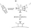
図1に、実施の形態1に係る計測システム1の全体構成を示す。計測システム1は、宇宙空間を移動する宇宙機3の位置及び速度を計測するシステムである。計測システム1は、宇宙機3に搭載される宇宙機制御装置30と、地上局4に設置される地上局装置40と、を備える。
(Embodiment 1)
FIG. 1 shows the overall configuration of a measurement system 1 according to Embodiment 1. As shown in FIG. The measurement system 1 is a system that measures the position and speed of aspacecraft 3 moving in outer space. The measurement system 1 includes aspacecraft control device 30 mounted on thespacecraft 3 and aground station device 40 installed on theground station 4 .

宇宙機3は、宇宙空間を移動する宇宙飛翔体であって、打ち上げロケットを用いて大気圏外で使用される人工物である。宇宙機3として、例えば、人工衛星、人工惑星、宇宙探査機、宇宙船等が挙げられる。宇宙機3は、ミリ波、マイクロ波、光波等の電磁波を用いて無線通信を行う無線通信装置を備えており、宇宙空間を移動しながら、地上局4及び航法衛星5と無線通信を行う。 Thespacecraft 3 is a spacecraft that moves in outer space, and is an artificial object that is used outside the atmosphere using a launch vehicle. Examples of thespacecraft 3 include artificial satellites, artificial planets, space probes, and spaceships. Thespacecraft 3 includes a wireless communication device that performs wireless communication using electromagnetic waves such as millimeter waves, microwaves, and light waves, and performs wireless communication with theground station 4 and thenavigation satellite 5 while moving in outer space.

宇宙機3は、宇宙機制御装置30と、推力印加部38と、を備える。また、宇宙機3は、いずれも図示しないが、電源系、姿勢制御系、熱制御系等のような、大気圏外での使用を目的とした構成を備えている。 Thespacecraft 3 includes aspacecraft controller 30 and athrust applying section 38 . In addition, thespacecraft 3 has a configuration intended for use outside the atmosphere, such as a power supply system, an attitude control system, a thermal control system, etc., although none of them are shown.

宇宙機制御装置30は、宇宙機3の内部に搭載される装置であって、宇宙機3の位置及び速度を計測する計測装置として機能する。図2に示すように、宇宙機制御装置30は、制御部31と、記憶部32と、インタフェース部33と、宇宙側通信部35と、航法信号受信部36と、を備える。 Thespacecraft controller 30 is a device mounted inside thespacecraft 3 and functions as a measuring device that measures the position and speed of thespacecraft 3 . As shown in FIG. 2, thespacecraft control device 30 includes acontrol section 31, astorage section 32, aninterface section 33, a spaceside communication section 35, and a navigation signal reception section .

制御部31は、CPU(Central Processing Unit)、ROM(Read Only Memory)及びRAM(Random Access Memory)を備える。CPUは、マイクロプロセッサ等を備えており、様々な処理及び演算を実行する中央演算処理部である。制御部31において、CPUが、ROMに記憶されている制御プログラムを読み出して、RAMをワークメモリとして用いながら、宇宙機制御装置30全体の動作を制御する。 Thecontrol unit 31 includes a CPU (Central Processing Unit), a ROM (Read Only Memory), and a RAM (Random Access Memory). The CPU includes a microprocessor or the like, and is a central processing unit that performs various processes and calculations. In thecontrol unit 31, the CPU reads out the control program stored in the ROM and controls the overall operation of thespacecraft control device 30 while using the RAM as a work memory.

記憶部32は、フラッシュメモリ、ハードディスク等の不揮発性メモリを備えており、いわゆる二次記憶装置又は補助記憶装置としての役割を担う。記憶部32は、制御部31が各種処理を行うために使用するプログラム及びデータを記憶する。また、記憶部32は、制御部31が各種処理を行うことにより生成又は取得するデータを記憶する。 Thestorage unit 32 includes a nonvolatile memory such as a flash memory and a hard disk, and serves as a so-called secondary storage device or auxiliary storage device. Thestorage unit 32 stores programs and data used by thecontrol unit 31 to perform various processes. Thestorage unit 32 also stores data generated or acquired by thecontrol unit 31 performing various processes.

インタフェース部33は、宇宙機制御装置30の外部との間で送受信される信号を入出力するユニットである。例えば、インタフェース部33は、制御部31から送信された信号を推力印加部38に供給し、推力印加部38から送信された信号を制御部31に供給する。 Theinterface unit 33 is a unit that inputs and outputs signals that are transmitted to and received from the outside of thespacecraft controller 30 . For example, theinterface section 33 supplies a signal transmitted from thecontrol section 31 to thethrust applying section 38 and supplies a signal transmitted from thethrust applying section 38 to thecontrol section 31 .

宇宙側通信部35は、地上局4との間で通信信号Rs,Rbを送受信する。通信信号Rs,Rbは、電波法により定められた周波数帯の電波信号である。宇宙側通信部35は、制御部31の制御のもとで、宇宙機3に搭載されている地上通信用のアンテナを介して、地上局4に向けて通信信号Rsを送信し、地上局4から送信された通信信号Rbを受信する。 Space-side communication unit 35 transmits and receives communication signals Rs and Rb to and fromground station 4 . The communication signals Rs and Rb are radio signals in the frequency band specified by the Radio Law. Under the control of thecontrol unit 31, the space-side communication unit 35 transmits a communication signal Rs to theground station 4 via the ground communication antenna mounted on thespacecraft 3. receives a communication signal Rb transmitted from

より詳細には、宇宙側通信部35は、地上局4に送信する情報を符号化、変調及び増幅することにより通信信号Rsを生成し、生成した通信信号Rsを地上通信用のアンテナから送信する。また、宇宙側通信部35は、通信信号Rbを地上通信用のアンテナを介して受信すると、受信した通信信号Rbを増幅、復調及び復号することにより、通信信号Rbに含まれる情報を取得する。宇宙側通信部35は、宇宙側通信手段の一例である。 More specifically, the space-side communication unit 35 encodes, modulates, and amplifies information to be transmitted to theground station 4 to generate a communication signal Rs, and transmits the generated communication signal Rs from an antenna for ground communication. . Further, when receiving the communication signal Rb via the antenna for ground communication, the space-side communication unit 35 amplifies, demodulates, and decodes the received communication signal Rb to acquire information contained in the communication signal Rb. Space-side communication unit 35 is an example of space-side communication means.

航法信号受信部36は、航法衛星5から送信された航法信号Rgを受信する。航法信号受信部36は、制御部31の制御のもとで、宇宙機3に搭載されている航法信号受信用のアンテナを介して、航法衛星5から送信された航法信号Rgを受信する。Navigation signal receiver 36 receives navigation signal Rg transmitted fromnavigation satellite 5 . Under the control of thecontroller 31 , thenavigation signal receiver 36 receives the navigation signal Rg transmitted from thenavigation satellite 5 via the navigation signal reception antenna mounted on thespacecraft 3 .

より詳細には、航法信号受信部36は、航法信号Rgを航法信号受信用のアンテナを介して受信すると、受信した航法信号Rgを増幅、復調及び復号することにより、航法信号Rgに含まれる情報を復元する。航法信号受信部36は、航法信号受信手段の一例である。 More specifically, when thenavigation signal receiver 36 receives the navigation signal Rg via the navigation signal reception antenna, it amplifies, demodulates, and decodes the received navigation signal Rg to obtain information contained in the navigation signal Rg. to restore. Thenavigation signal receiver 36 is an example of a navigation signal receiver.

図1に戻って、推力印加部38は宇宙機3に推力を印加して、宇宙機3を推進させる。推力印加部38は、宇宙機3の全体を推進させる主推進系と、宇宙機3の姿勢制御、軌道の微修正を行うスラスタと、を含む。推力印加部38は、制御部31による制御のもとで主推進系及びスラスタの出力を調整することにより、宇宙機3に決められた姿勢で決められた軌道上を移動させる。 Returning to FIG. 1, thethrust applying section 38 applies thrust to thespacecraft 3 to propel thespacecraft 3 . Thethrust applying unit 38 includes a main propulsion system that propels theentire spacecraft 3 and thrusters that perform attitude control of thespacecraft 3 and fine correction of the trajectory. Thethrust applying unit 38 adjusts the outputs of the main propulsion system and thrusters under the control of thecontrol unit 31 to move thespacecraft 3 in a predetermined attitude and on a predetermined orbit.

地上局4は、地上に設置されている設備であって、宇宙機3を管理及び運用するための基地局である。地上局4は、宇宙通信用のアンテナを備えており、大気圏外を移動する宇宙機3の方向にアンテナを向けて電波信号である通信信号Rs,Rbを送受信する。これにより、地上局4は、宇宙機3との間で無線通信を行う。 Theground station 4 is a facility installed on the ground and is a base station for managing and operating thespacecraft 3 . Theground station 4 is equipped with an antenna for space communication, and directs the antenna toward thespacecraft 3 moving outside the atmosphere to transmit and receive communication signals Rs and Rb, which are radio signals. Thereby, theground station 4 performs radio communication with thespacecraft 3 .

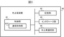
地上局4には、地上局装置40が設置されている。図3に示すように、地上局装置40は、制御部41と、記憶部42と、インタフェース部43と、地上側通信部45と、を備える。 Aground station device 40 is installed in theground station 4 . As shown in FIG. 3 , theground station device 40 includes acontrol section 41 , astorage section 42 , aninterface section 43 and a groundside communication section 45 .

制御部41は、CPU、ROM及びRAMを備える。CPUは、マイクロプロセッサ等を備えており、様々な処理及び演算を実行する中央演算処理部である。制御部41において、CPUが、ROMに記憶されている制御プログラムを読み出して、RAMをワークメモリとして用いながら、地上局装置40全体の動作を制御する。 Thecontrol unit 41 includes a CPU, ROM and RAM. The CPU includes a microprocessor or the like, and is a central processing unit that performs various processes and calculations. In thecontrol unit 41, the CPU reads the control program stored in the ROM and controls the operation of theground station device 40 as a whole while using the RAM as a work memory.

記憶部42は、フラッシュメモリ、ハードディスク等の不揮発性メモリを備えており、いわゆる二次記憶装置又は補助記憶装置としての役割を担う。記憶部42は、制御部41が各種処理を行うために使用するプログラム及びデータを記憶する。また、記憶部42は、制御部41が各種処理を行うことにより生成又は取得するデータを記憶する。 Thestorage unit 42 includes a non-volatile memory such as flash memory and hard disk, and serves as a so-called secondary storage device or auxiliary storage device. Thestorage unit 42 stores programs and data used by thecontrol unit 41 to perform various processes. Thestorage unit 42 also stores data generated or acquired by thecontrol unit 41 performing various processes.

インタフェース部43は、地上局装置40の外部との間で送受信される信号を入出力するユニットである。また、インタフェース部43は、地上局4のオペレータからの操作を受け付ける操作部と、画像を表示する表示部と、を含んでいる。 Theinterface unit 43 is a unit that inputs and outputs signals that are transmitted to and received from the outside of theground station device 40 . Theinterface unit 43 also includes an operation unit that receives operations from the operator of theground station 4, and a display unit that displays images.

地上側通信部45は、宇宙機3との間で通信信号Rs,Rbを送受信する。地上側通信部45は、制御部41の制御のもとで、宇宙通信用のアンテナを介して、宇宙機3から送信された通信信号Rsを受信し、宇宙機3に向けて通信信号Rbを送信する。 The groundside communication unit 45 transmits/receives communication signals Rs and Rb to/from thespacecraft 3 . Under the control of thecontrol unit 41, the groundside communication unit 45 receives the communication signal Rs transmitted from thespacecraft 3 via the antenna for space communication, and transmits the communication signal Rb to thespacecraft 3. Send.

より詳細には、地上側通信部45は、通信信号Rsを宇宙通信用のアンテナを介して受信すると、受信した通信信号Rsを増幅、復調及び復号することにより、通信信号Rsに含まれる情報を復元する。また、地上側通信部45は、宇宙機3に送信する情報を符号化、変調及び増幅することにより通信信号Rbを生成し、生成した通信信号Rbを宇宙通信用のアンテナから送信する。地上側通信部45は、地上側通信手段の一例である。 More specifically, when the ground-side communication unit 45 receives the communication signal Rs via the antenna for space communication, it amplifies, demodulates, and decodes the received communication signal Rs to obtain the information contained in the communication signal Rs. Restore. The ground-side communication unit 45 also encodes, modulates, and amplifies information to be transmitted to thespacecraft 3 to generate a communication signal Rb, and transmits the generated communication signal Rb from an antenna for space communication. The groundside communication unit 45 is an example of ground side communication means.

図1に戻って、航法衛星5は、例えばGPS(Global Positioning System)衛星であって、衛星測位システムにおいて用いられる人工衛星である。航法衛星5は、大気圏外の軌道を周回しながら、受信機が位置情報を取得するための電波信号である航法信号Rgを送信する。 Returning to FIG. 1, thenavigation satellite 5 is, for example, a GPS (Global Positioning System) satellite, which is an artificial satellite used in a satellite positioning system. Thenavigation satellite 5 transmits a navigation signal Rg, which is a radio signal for a receiver to acquire position information, while orbiting in the outer space.

なお、図1では1つの航法衛星5のみしか示していないが、地球の周りには複数の航法衛星5が周回している。そのため、宇宙機3の航法信号受信部36は、複数の航法衛星5のうちの、宇宙機3が航法信号Rgを受信可能な位置にある少なくとも1つの航法衛星5から送信される航法信号Rgを受信する。 Although only onenavigation satellite 5 is shown in FIG. 1, a plurality ofnavigation satellites 5 orbit around the earth. Therefore, thenavigation signal receiver 36 of thespacecraft 3 receives the navigation signal Rg transmitted from at least onenavigation satellite 5 among the plurality ofnavigation satellites 5 at a position where thespacecraft 3 can receive the navigation signal Rg. receive.

次に、計測システム1の機能的な構成を説明する。宇宙機制御装置30は、図2に示すように、機能的に、通信制御部310と、第1の計測部320は、第2の計測部330と、位置速度計算部340と、推力印加指令部350と、を備える。地上局装置40の制御部41は、図3に示すように、機能的に、通信制御部410を備える。 Next, a functional configuration of the measurement system 1 will be described. As shown in FIG. 2, thespacecraft controller 30 functionally includes acommunication control unit 310, afirst measurement unit 320, asecond measurement unit 330, a position/velocity calculation unit 340, and a thrust application command. aportion 350; Thecontrol unit 41 of theground station device 40 functionally includes acommunication control unit 410 as shown in FIG.

これらの各機能は、ソフトウェア、ファームウェア、又は、ソフトウェアとファームウェアとの組み合わせによって実現される。ソフトウェア及びファームウェアは、プログラムとして記述され、ROM又は記憶部32,42に格納される。そして、CPUが、ROM又は記憶部32,42に記憶されたプログラムを実行することによって、これらの各機能を実現する。 Each of these functions is implemented by software, firmware, or a combination of software and firmware. Software and firmware are written as programs and stored in the ROM or thestorage units 32 and 42 . These functions are realized by the CPU executing programs stored in the ROM or thestorage units 32 and 42 .

図2に示す宇宙機制御装置30において、通信制御部310は、宇宙側通信部35及び航法信号受信部36による通信を制御する。通信制御部310は、制御部31が宇宙側通信部35及び航法信号受信部36と協働することにより実現される。通信制御部310は、通信制御手段の一例である。 In thespacecraft control device 30 shown in FIG. 2, thecommunication control section 310 controls communication by the spaceside communication section 35 and the navigationsignal reception section 36 . Thecommunication control unit 310 is implemented by thecontrol unit 31 cooperating with the spaceside communication unit 35 and the navigationsignal reception unit 36 . Thecommunication control unit 310 is an example of communication control means.

宇宙側通信部35は、通信制御部310の制御のもとで、予め定められた送信タイミングで、宇宙側通信部35により地上局4に通信信号Rsを送信する。ここで、送信タイミングは、地上局4との間で通信するための予め設定されたタイミングである。例えば、宇宙側通信部35は、予め定められた時刻が到来すると、又は、予め定められた時間間隔で周期的に、予め定められた周波数帯の電波信号である通信信号Rsを生成し、地上局4に向けて送信する。宇宙側通信部35は、地上局4に通信信号Rsを送信すると、通信信号Rsの送信時刻T1を記憶部32に記録する。 Under the control of thecommunication control unit 310, thespace communication unit 35 transmits the communication signal Rs to theground station 4 at a predetermined transmission timing. Here, the transmission timing is preset timing for communicating with theground station 4 . For example, when a predetermined time arrives or periodically at predetermined time intervals, the space-side communication unit 35 generates a communication signal Rs, which is a radio signal in a predetermined frequency band. Send tostation 4. After transmitting the communication signal Rs to theground station 4 , the space-side communication unit 35 records the transmission time T1 of the communication signal Rs in thestorage unit 32 .

図3に示す地上局装置40において、通信制御部410は、地上側通信部45による通信を制御する。通信制御部410は、制御部41が地上側通信部45と協働することにより実現される。通信制御部410は、通信制御手段の一例である。 In theground station device 40 shown in FIG. 3 , thecommunication control section 410 controls communication by the groundside communication section 45 .Communication control unit 410 is realized by cooperation ofcontrol unit 41 and groundside communication unit 45 . Thecommunication control unit 410 is an example of communication control means.

地上側通信部45は、通信制御部410の制御のもとで、宇宙側通信部35から送信された通信信号Rsを受信する。通信信号Rsを受信すると、地上側通信部45は、通信信号Rsを受信してから既知の応答時間ΔTが経過したタイミングで、通信信号Rsに対する応答として、通信信号Rbを宇宙機3に送信する。 The groundside communication section 45 receives the communication signal Rs transmitted from the spaceside communication section 35 under the control of thecommunication control section 410 . When the communication signal Rs is received, the groundside communication unit 45 transmits the communication signal Rb to thespacecraft 3 as a response to the communication signal Rs at the timing when a known response time ΔT has passed since the communication signal Rs was received. .

図2に示す宇宙機制御装置30において、宇宙側通信部35は、地上側通信部45から送信された通信信号Rbを受信する。通信信号Rbを受信すると、宇宙側通信部35は、通信信号Rbの受信時刻T2と、通信信号Rbの受信時の周波数である受信周波数Fsとを記憶部32記録する。 In thespacecraft controller 30 shown in FIG. 2 , the spaceside communication section 35 receives the communication signal Rb transmitted from the groundside communication section 45 . Upon receiving the communication signal Rb, the space-side communication unit 35 records the reception time T2 of the communication signal Rb and the reception frequency Fs, which is the frequency at which the communication signal Rb was received, in thestorage unit 32 .

航法信号受信部36は、通信制御部310の制御のもとで、地球の周りを回っている複数の航法衛星5のうちのいずれかから航法信号Rgが送信された場合、送信された航法信号Rgを航法信号受信部36により受信する。航法信号Rgを受信すると、航法信号受信部36は、その受信時刻Tgと、航法信号Rgの受信時の周波数である受信周波数Fgとを記憶部32に記録する。 Under the control of thecommunication control unit 310, the navigationsignal receiving unit 36, when a navigation signal Rg is transmitted from one of the plurality ofnavigation satellites 5 orbiting the earth, receives the transmitted navigation signal Rg. Rg is received by thenavigation signal receiver 36 . Upon receiving the navigation signal Rg, thenavigation signal receiver 36 records the reception time Tg and the reception frequency Fg, which is the frequency at which the navigation signal Rg was received, in thestorage 32 .

また、航法衛星5から送信される航法信号Rgには、その航法信号Rgの送信時刻と、その航法信号Rgの送信時における航法衛星5の位置及び速度に関する拘束条件を導出可能にする軌道情報と、が含まれる。航法信号受信部36は、受信した航法信号Rgを復号することにより、その航法信号Rgの送信時刻と送信時における航法衛星5の位置及び速度とを計算する。 In addition, the navigation signal Rg transmitted from thenavigation satellite 5 includes the transmission time of the navigation signal Rg and orbital information that enables derivation of constraint conditions regarding the position and speed of thenavigation satellite 5 at the time of transmission of the navigation signal Rg. , is included. Thenavigation signal receiver 36 decodes the received navigation signal Rg to calculate the transmission time of the navigation signal Rg and the position and velocity of thenavigation satellite 5 at the time of transmission.

第1の計測部320は、宇宙機3と地上局4との間で送信された通信信号Rs,Rbに基づいて、宇宙機3と地上局4との間の距離D及び距離変化率ρを計測する。第1に、第1の計測部320は、宇宙機3と地上局4との間における通信信号Rs,Rbの伝搬時間から、宇宙機3と地上局4との間の距離Dを計測する。 Thefirst measurement unit 320 calculates the distance D and the distance change rate ρ between thespacecraft 3 and theground station 4 based on the communication signals Rs and Rb transmitted between thespacecraft 3 and theground station 4. measure. First, thefirst measuring section 320 measures the distance D between thespacecraft 3 and theground station 4 from the propagation times of the communication signals Rs and Rb between thespacecraft 3 and theground station 4 .

ここで、通信信号Rs,Rbの伝搬時間は、通信信号Rsの送信時刻T1と、通信信号Rbの受信時刻T2と、の時間差から、地上局装置40における応答時間ΔTを減じた時間(T2-T1-ΔT)に相当する。そのため、第1の計測部320は、“D=(T2-T1-ΔT)・c”の関係式に従って、送信時刻T1、受信時刻T2、応答時間ΔT及び光速度cから距離Dを計算する。 Here, the propagation time of the communication signals Rs and Rb is the time (T2- T1-ΔT). Therefore, thefirst measurement unit 320 calculates the distance D from the transmission time T1, the reception time T2, the response time ΔT, and the speed of light c according to the relational expression “D=(T2−T1−ΔT)·c”.

なお、応答時間ΔTは、地上局4と宇宙機3との間で予め知られており、宇宙機制御装置30の記憶部32に予め記憶されている。 The response time ΔT is known between theground station 4 and thespacecraft 3 in advance, and is stored in thestorage unit 32 of thespacecraft controller 30 in advance.

第2に、第1の計測部320は、宇宙機3が地上局4から受信した通信信号Rbに基づいて、宇宙機3と地上局4との間の距離変化率ρを計測する。ここで、距離変化率ρは、単位時間当たりの距離Dの変化量であって、宇宙機3と地上局4とを通る直線方向の宇宙機3の速度成分に相当する。 Second, thefirst measurement unit 320 measures the distance change rate ρ between thespacecraft 3 and theground station 4 based on the communication signal Rb received by thespacecraft 3 from theground station 4 . Here, the distance change rate ρ is the amount of change in the distance D per unit time, and corresponds to the velocity component of thespacecraft 3 in a straight line passing through thespacecraft 3 and theground station 4 .

第1の計測部320は、ドップラー周波数偏移の原理を適用して、宇宙側通信部35により受信された通信信号Rbから距離変化率ρを計測する。具体的に説明すると、宇宙空間を移動している宇宙機3により受信される電波の受信周波数Fsは、ドップラー周波数偏移により、地上局4における電波の送信周波数である基準周波数F0からずれる。 Thefirst measuring unit 320 measures the distance change rate ρ from the communication signal Rb received by the space-side communication unit 35 by applying the principle of Doppler frequency shift. Specifically, the reception frequency Fs of radio waves received by thespacecraft 3 moving in outer space deviates from the reference frequency F0, which is the transmission frequency of radio waves at theground station 4, due to Doppler frequency shift.

このときの受信周波数Fsと基準周波数F0との関係は、宇宙機3の距離変化率ρと光速度cとの比率ρ/cを用いて、“Fs=F0・(1-ρ/c)”と表される。なお、数式中の光速度cは、真空中における光の伝搬速度である。また、数式中の“・”は乗算を表し、“/”は除算を表す。以下、同様である。 The relationship between the reception frequency Fs and the reference frequency F0 at this time is expressed as "Fs=F0·(1−ρ/c)" using the ratio ρ/c between the distance change rate ρ of thespacecraft 3 and the speed of light c. is represented. Note that the speed of light c in the formula is the propagation speed of light in a vacuum. Also, "·" in the formula represents multiplication, and "/" represents division. The same applies hereinafter.

第1の計測部320は、このようなドップラー周波数偏移の関係式に従って、通信信号Rbの受信周波数Fsから距離変化率ρを計算する。なお、基準周波数F0の値は、地上局4と宇宙機3との間で予め取り決められており、宇宙機制御装置30の記憶部32に予め記憶されている。第1の計測部320は、制御部31が記憶部32等と協働することにより実現される。第1の計測部320は、第1の計測手段の一例である。 Thefirst measurement unit 320 calculates the distance change rate ρ from the reception frequency Fs of the communication signal Rb according to the Doppler frequency shift relational expression. Note that the value of the reference frequency F0 is determined in advance between theground station 4 and thespacecraft 3, and is stored in thestorage unit 32 of thespacecraft controller 30 in advance. Thefirst measurement unit 320 is implemented by thecontrol unit 31 cooperating with thestorage unit 32 and the like. Thefirst measuring unit 320 is an example of first measuring means.

第2の計測部330は、宇宙機3が航法衛星5から受信した航法信号Rgに基づいて、宇宙機3と航法衛星5との間の距離変化率ρgを計測する。ここで、距離変化率ρgは、宇宙機3と航法衛星5との間の距離Dgの単位時間当たりの変化量である。宇宙機3と航法衛星5とはどちらも宇宙空間を移動しているため、距離変化率ρgは、宇宙機3と航法衛星5とを通る直線方向の、宇宙機3と航法衛星5との間の相対的な速度成分に相当する。 Thesecond measurement unit 330 measures the distance change rate ρg between thespacecraft 3 and thenavigation satellite 5 based on the navigation signal Rg received by thespacecraft 3 from thenavigation satellite 5 . Here, the distance change rate ρg is the amount of change in the distance Dg between thespacecraft 3 and thenavigation satellite 5 per unit time. Since both thespacecraft 3 and thenavigation satellite 5 are moving in outer space, the distance change rate ρg corresponds to the relative velocity component of

第2の計測部330は、ドップラー周波数偏移の原理を適用して、航法信号受信部36により受信された航法信号Rgから距離変化率ρgを計測する。具体的に説明すると、共に宇宙空間を移動している宇宙機3と航法衛星5との間で送受信される電波の受信周波数は、ドップラー周波数偏移により、宇宙機3と航法衛星5との間の相対的な速度に応じて送信周波数からずれる。 Thesecond measuring unit 330 measures the distance change rate ρg from the navigation signal Rg received by the navigationsignal receiving unit 36 by applying the principle of Doppler frequency shift. More specifically, the reception frequency of radio waves transmitted and received between thespacecraft 3 and thenavigation satellite 5 moving in outer space varies due to Doppler frequency shift. deviates from the transmission frequency according to the relative speed of

そのため、第2の計測部330は、移動する2体間におけるドップラー周波数偏移の関係式に従って、受信した航法信号Rgの受信周波数Fgから距離変化率ρgを計算する。なお、航法信号Rgの送信周波数の値は、予め定められた値であって、宇宙機制御装置30の記憶部32に予め記憶されている。 Therefore, thesecond measurement unit 330 calculates the distance change rate ρg from the reception frequency Fg of the received navigation signal Rg according to the Doppler frequency shift relational expression between the two moving objects. The value of the transmission frequency of the navigation signal Rg is a predetermined value, which is stored in advance in thestorage unit 32 of thespacecraft controller 30. FIG.

第2の計測部330は、航法信号受信部36により地球の周りを回っている複数の航法衛星5のいずれかから航法信号Rgが受信される毎に、航法信号Rgの送信元の航法衛星5と宇宙機3との間の距離変化率ρgを計測する。これにより、第2の計測部330は、宇宙機3に対して様々な方向に位置する航法衛星5との間の距離変化率ρgを時々刻々と計測する。第2の計測部330は、制御部31が記憶部32等と協働することにより実現される。第2の計測部330は、第2の計測手段の一例である。 Each time thenavigation signal receiver 36 receives the navigation signal Rg from one of the plurality ofnavigation satellites 5 orbiting the earth, thesecond measurement unit 330 detects thenavigation satellite 5 from which the navigation signal Rg is transmitted. and thespacecraft 3, the distance change rate ρg is measured. Thereby, thesecond measurement unit 330 measures the distance change rate ρg between thespacecraft 3 and thenavigation satellites 5 located in various directions from time to time. Thesecond measurement unit 330 is implemented by thecontrol unit 31 cooperating with thestorage unit 32 and the like. Thesecond measuring unit 330 is an example of second measuring means.

位置速度計算部340は、第1の計測部320により計測された距離D及び距離変化率ρと、第2の計測部330により計測された距離変化率ρgと、に基づいて、宇宙機3の位置及び速度を計算する。位置速度計算部340は、制御部31が記憶部32等と協働することにより実現される。位置速度計算部340は、位置速度計算手段の一例である。 The position/velocity calculation unit 340 calculates the position of thespacecraft 3 based on the distance D and the distance change rate ρ measured by thefirst measurement unit 320 and the distance change rate ρg measured by thesecond measurement unit 330. Calculate position and velocity. The position/velocity calculation unit 340 is implemented by thecontrol unit 31 cooperating with thestorage unit 32 and the like. The position/velocity calculator 340 is an example of a position/velocity calculator.

第1に、位置速度計算部340は、第1の計測部320により計測された距離Dから、宇宙機3の位置情報を取得する。具体的に説明すると、位置速度計算部340は、宇宙機3の位置が地上局4の位置から距離Dの位置であるという位置の制約条件を取得する。 First, the position/velocity calculation unit 340 acquires position information of thespacecraft 3 from the distance D measured by thefirst measurement unit 320 . More specifically, the position/velocity calculator 340 acquires a position constraint condition that thespacecraft 3 is positioned at a distance D from the position of theground station 4 .

第2に、位置速度計算部340は、第1の計測部320により計測された距離変化率ρから、宇宙機3の速度情報を取得する。距離変化率ρは、宇宙機3と地上局4とを通る直線方向の宇宙機3の速度成分に相当する。そのため、位置速度計算部340は、距離変化率ρにより、宇宙機3と地上局4とを通る直線方向の宇宙機3の速度の制約条件を取得する。 Second, the position/velocity calculator 340 acquires the velocity information of thespacecraft 3 from the distance change rate ρ measured by thefirst measurement unit 320 . The distance change rate ρ corresponds to the velocity component of thespacecraft 3 in a straight line passing through thespacecraft 3 and theground station 4 . Therefore, the position/velocity calculator 340 obtains the speed constraint of thespacecraft 3 in the straight line passing through thespacecraft 3 and theground station 4 from the distance change rate ρ.

このような地上局4との通信による1時刻における計測では、宇宙機3の運動における6個の自由度のうちの、宇宙機3と地上局4とを通る直線方向の位置及び速度という2個の自由度に対する制約しか得られない。6個の自由度に対する制約を得るためには、宇宙機3と地上局4との相対位置が有意に変化した後で改めて計測を実施する必要がある。そのため、計測時間が長時間におよび、その間に地上局4を占有するためのコストが生じる。 In such a one-time measurement by communication with theground station 4, two of the six degrees of freedom in the motion of thespacecraft 3, namely position and velocity in the linear direction passing through thespacecraft 3 and theground station 4, are measured. We can only obtain constraints on the degrees of freedom of In order to obtain the constraints on the six degrees of freedom, it is necessary to perform the measurement again after the relative position between thespacecraft 3 and theground station 4 has significantly changed. Therefore, the measurement takes a long time, and the cost of occupying theground station 4 is incurred during that time.

このような問題を回避するために、位置速度計算部340は、宇宙機3と航法衛星5との間の距離変化率ρgから得られる制約条件を追加する。具体的に説明すると、位置速度計算部340は、第2の計測部330により計測された距離変化率ρgから、距離変化率ρから得られる速度成分とは線形独立な速度成分を計算する。 In order to avoid such a problem, the position/velocity calculator 340 adds a constraint obtained from the distance change rate ρg between thespacecraft 3 and thenavigation satellite 5 . Specifically, from the distance change rate ρg measured by thesecond measurement unit 330, the position/speed calculator 340 calculates a speed component that is linearly independent of the speed component obtained from the distance change rate ρ.

より詳細には、位置速度計算部340は、航法衛星5から受信した航法信号Rgに含まれる航法衛星5の位置情報から、距離変化率ρgにより、航法信号Rgの到来方向、すなわち宇宙機3と航法衛星5とを通る直線方向の宇宙機3の速度の制約条件を取得する。 More specifically, the position/velocity calculator 340 calculates the arrival direction of the navigation signal Rg, that is, thespacecraft 3 and A speed constraint condition of thespacecraft 3 in a straight line passing through thenavigation satellite 5 is obtained.

ここで、距離変化率ρgは、宇宙機3と航法衛星5とを通る直線方向の、共に移動している宇宙機3と航法衛星5との間の相対的な速度成分に相当する。そのため、位置速度計算部340は、航法信号Rgから復号された航法衛星5の速度を用いて、距離変化率ρgから航法衛星5の速度を減じる。これにより、位置速度計算部340は、宇宙機3と航法衛星5とを通る直線方向の宇宙機3単独の速度成分を計算する。 Here, the distance change rate ρg corresponds to the relative velocity component between thespacecraft 3 and thenavigation satellite 5 moving together in a straight line passing through thespacecraft 3 and thenavigation satellite 5 . Therefore, the position/velocity calculator 340 uses the velocity of thenavigation satellite 5 decoded from the navigation signal Rg to subtract the velocity of thenavigation satellite 5 from the distance change rate ρg. Thereby, the position/velocity calculator 340 calculates the velocity component of thespacecraft 3 alone in the straight line passing through thespacecraft 3 and thenavigation satellites 5 .

位置速度計算部340は、複数の航法衛星5から航法信号Rgが受信された場合、各航法衛星5に対する距離変化率ρgから、複数の方向における速度の制約条件を取得する。より多くの航法衛星5から受信された航法信号Rgを用いるほどより多くの制約条件が得られるため、宇宙機3の位置及び速度の計測に要する時間をより短縮することができる。 When the navigation signal Rg is received from a plurality ofnavigation satellites 5 , the position/speed calculator 340 acquires speed constraint conditions in a plurality of directions from the distance change rate ρg for eachnavigation satellite 5 . As more navigation signals Rg received frommore navigation satellites 5 are used, more constraints can be obtained, so the time required to measure the position and velocity of thespacecraft 3 can be further shortened.

宇宙機3の位置と速度との6自由度に対する制約条件が得られると、宇宙機3の位置及び速度を決定することができる。そのため、位置速度計算部340は、距離D及び距離変化率ρ,ρgから6個以上の自由度に対する制約条件が得られると、宇宙機3の位置及び速度の推定値を計算する。 Once the constraints for the six degrees of freedom ofspacecraft 3 position and velocity are obtained, the position and velocity ofspacecraft 3 can be determined. Therefore, the position/velocity calculator 340 calculates estimated values of the position and velocity of thespacecraft 3 when constraint conditions for six or more degrees of freedom are obtained from the distance D and the distance change rates ρ and ρg.

このように、航法信号Rgから計測される距離変化率ρgを用いることで、地上局4との通信から計測される距離D及び距離変化率ρのみを用いる場合に比べて、制約条件を短時間に得ることができる。そのため、宇宙機3の位置及び速度をより短時間に計測することができる。 In this way, by using the distance change rate ρg measured from the navigation signal Rg, the constraint condition can be shortened in a shorter time than when only the distance D and the distance change rate ρ measured from communication with theground station 4 are used. can get to Therefore, the position and velocity of thespacecraft 3 can be measured in a shorter time.

推力印加指令部350は、位置速度計算部340により計算された宇宙機3の位置及び速度に基づく推力を宇宙機3に印加させる。具体的に説明すると、推力印加指令部350は、位置速度計算部340により計算された宇宙機3の位置及び速度の推定値に基づいて、宇宙機3に適正な姿勢で目標軌道上を運動させるのに必要な推力を計算する。 The thrustapplication command unit 350 applies thrust to thespacecraft 3 based on the position and speed of thespacecraft 3 calculated by the position/speed calculation unit 340 . Specifically, the thrustapplication command unit 350 causes thespacecraft 3 to move on the target orbit in an appropriate attitude based on the estimated values of the position and speed of thespacecraft 3 calculated by the position/velocity calculation unit 340. Calculate the thrust required for

推力を計算すると、推力印加指令部350は、推力印加部38に指令を送信し、計算した推力を推力印加部38に印加させる。これにより、推力印加指令部350は、宇宙空間における宇宙機3の運動を制御する。推力印加指令部350は、制御部31がインタフェース部33等と協働することにより実現される。推力印加指令部350は、推力印加指令手段の一例である。 After calculating the thrust force, the thrust forceapplication command unit 350 transmits a command to the thrustforce application unit 38 to cause the thrustforce application unit 38 to apply the calculated thrust force. Thereby, the thrustapplication command section 350 controls the motion of thespacecraft 3 in outer space. The thrustapplication command unit 350 is implemented by thecontrol unit 31 cooperating with theinterface unit 33 and the like. The thrustapplication command section 350 is an example of a thrust application command means.

以上のように構成される計測システム1において実行される計測処理の流れについて、図4を参照して説明する。図4に示す計測処理は、宇宙機3が宇宙空間を正常に移動している状態において、宇宙機制御装置30と地上局装置40との間で繰り返し実行される。 A flow of measurement processing executed in the measurement system 1 configured as described above will be described with reference to FIG. The measurement process shown in FIG. 4 is repeatedly executed between thespacecraft control device 30 and theground station device 40 while thespacecraft 3 is moving normally in outer space.

宇宙機制御装置30において、宇宙側通信部35は、予め定められた送信タイミングが到来すると、地上局4に向けて通信信号Rsを送信する(ステップS101)。通信信号Rsを送信すると、宇宙側通信部35は、その送信時刻T1を記録する。地上局装置40において、地上側通信部45は、宇宙機制御装置30から送信された通信信号Rsを受信する。 In thespacecraft controller 30, the space-side communication unit 35 transmits a communication signal Rs to theground station 4 when a predetermined transmission timing arrives (step S101). When the communication signal Rs is transmitted, the spaceside communication section 35 records the transmission time T1. In theground station device 40 , the groundside communication section 45 receives the communication signal Rs transmitted from thespacecraft controller 30 .

通信信号Rsを受信すると、地上側通信部45は、通信信号Rsを受信してから応答時間ΔTが経過したタイミングで、宇宙機3に向けて通信信号Rbを送信する(ステップS102)。宇宙側通信部35は、地上局装置40から送信された通信信号Rbを受信し、その受信時刻T2と受信周波数Fsとを記録する。 Upon receiving the communication signal Rs, the ground-side communication unit 45 transmits the communication signal Rb to thespacecraft 3 at the timing when the response time ΔT has passed after receiving the communication signal Rs (step S102). The space-side communication unit 35 receives the communication signal Rb transmitted from theground station device 40, and records the reception time T2 and the reception frequency Fs.

通信信号Rbが受信されると、第1の計測部320は、宇宙機3と地上局4との間の距離D及び距離変化率ρを計測する(ステップS103)。具体的に説明すると、第1の計測部320は、通信信号Rs,Rbの伝搬時間(T2-T1-ΔT)に光速度cを乗じることにより、距離Dを計算する。更に、第1の計測部320は、ドップラー周波数偏移の原理を用いて、通信信号Rbの受信周波数Fsから距離変化率ρを計算する。 When the communication signal Rb is received, thefirst measurement unit 320 measures the distance D and the distance change rate ρ between thespacecraft 3 and the ground station 4 (step S103). Specifically, thefirst measurement unit 320 calculates the distance D by multiplying the propagation time (T2-T1-ΔT) of the communication signals Rs and Rb by the speed of light c. Furthermore, thefirst measurement unit 320 calculates the distance change rate ρ from the reception frequency Fs of the communication signal Rb using the principle of Doppler frequency shift.

このような通信信号Rs,Rbを送受信する処理と並行して、航法信号受信部36は、地球の周りを回っている複数の航法衛星5のうちのいずれかから航法信号Rgが送信された場合、送信された航法信号Rgを受信する(ステップS104)。航法信号受信部36は、航法信号Rgを受信すると、その受信時刻Tgと受信周波数Fgとを記録する。また、航法信号受信部36は、受信した航法信号Rgの送信時刻と、航法信号Rgの送信時における航法衛星5の位置及び速度とを、受信した航法信号Rgから復号する。 In parallel with the process of transmitting and receiving the communication signals Rs and Rb, the navigationsignal receiving unit 36 receives the navigation signal Rg from one of the plurality ofnavigation satellites 5 orbiting the earth. , receives the transmitted navigation signal Rg (step S104). Upon receiving the navigation signal Rg, thenavigation signal receiver 36 records the reception time Tg and the reception frequency Fg. Also, thenavigation signal receiver 36 decodes the transmission time of the received navigation signal Rg and the position and velocity of thenavigation satellite 5 at the time of transmission of the navigation signal Rg from the received navigation signal Rg.

航法信号Rgが受信されると、第2の計測部330は、受信された航法信号Rgに基づいて、宇宙機3と航法衛星5との間の距離変化率ρgを計測する(ステップS105)。具体的に説明すると、第2の計測部330は、ドップラー周波数偏移の原理を用いて、航法衛星5の速度情報と航法信号Rgの受信周波数Fgとから距離変化率ρgを計算する。 When the navigation signal Rg is received, thesecond measurement unit 330 measures the distance change rate ρg between thespacecraft 3 and thenavigation satellite 5 based on the received navigation signal Rg (step S105). Specifically, thesecond measurement unit 330 calculates the distance change rate ρg from the speed information of thenavigation satellite 5 and the received frequency Fg of the navigation signal Rg using the principle of Doppler frequency shift.

距離D及び距離変化率ρ,ρgが計測されると、位置速度計算部340は、計測された距離D及び距離変化率ρ,ρgに基づいて、宇宙機3の位置及び速度を計算する(ステップS106)。具体的に説明すると、位置速度計算部340は、距離D及び距離変化率ρから、地上局4の方向における宇宙機3の位置及び速度の制約条件を取得する。また、位置速度計算部340は、距離変化率ρgから、航法衛星5の方向における宇宙機3の速度の制約条件を取得する。そして、位置速度計算部340は、取得された制約条件により定められる宇宙機3の位置及び速度の推定値を計算する。 After the distance D and the distance change rates ρ and ρg are measured, the position/speed calculator 340 calculates the position and speed of thespacecraft 3 based on the measured distance D and the distance change rates ρ and ρg (step S106). More specifically, the position/velocity calculator 340 acquires constraints on the position and velocity of thespacecraft 3 in the direction of theground station 4 from the distance D and the distance change rate ρ. Also, the position/velocity calculator 340 acquires a constraint on the velocity of thespacecraft 3 in the direction of thenavigation satellite 5 from the distance change rate ρg. Then, the position/velocity calculator 340 calculates estimated values of the position and velocity of thespacecraft 3 determined by the obtained constraint conditions.

宇宙機3の位置及び速度が計算されると、推力印加指令部350は、計算された宇宙機3の位置及び速度に基づく推力を宇宙機3に印加させる(ステップS107)。具体的に説明すると、推力印加指令部350は、宇宙機3に印加させる推力を計算し、計算した推力を推力印加部38に印加させる。これにより、推力印加指令部350は、宇宙機3に目標となる運動を実行させる。 After the position and speed of thespacecraft 3 are calculated, the thrustapplication command unit 350 applies thrust to thespacecraft 3 based on the calculated position and speed of the spacecraft 3 (step S107). Specifically, the thrustapplication command unit 350 calculates the thrust to be applied to thespacecraft 3 and causes thethrust application unit 38 to apply the calculated thrust. As a result, the thrustapplication command section 350 causes thespacecraft 3 to execute the target motion.

以上により、図4に示した計測処理は終了する。宇宙機制御装置30及び地上局装置40は、図4に示した計測処理を繰り返し実行することにより、宇宙機3の位置及び速度を継続的に計測し、宇宙空間における宇宙機3の運動を制御する。 With the above, the measurement process shown in FIG. 4 ends. Thespacecraft control device 30 and theground station device 40 continuously measure the position and speed of thespacecraft 3 by repeatedly executing the measurement processing shown in FIG. 4, and control the motion of thespacecraft 3 in outer space. do.

以上説明したように、実施の形態1に係る宇宙機制御装置30は、宇宙機3と地上局4との間で送信される通信信号Rs,Rbに基づいて宇宙機3と地上局4との間の距離D及び距離変化率ρを計測し、宇宙機3が航法衛星5から受信した航法信号Rgに基づいて宇宙機3と航法衛星5との間の距離変化率ρgを計測する。そして、実施の形態1に係る宇宙機制御装置30は、計測された距離D及び距離変化率ρ,ρgに基づいて、宇宙機3の位置及び速度を計算する。このように、航法衛星5に対する距離変化率ρgを計測することにより、地上局4との通信のみに基づく場合に比べて、宇宙機3の位置及び速度に対する制約条件が追加される。そのため、宇宙機3の位置及び速度の計測に要する時間を、地上局4との通信のみに基づいて計測する場合よりも短縮することが可能になる。その結果、より短時間で宇宙機3の運動を制御することができる。 As described above, thespacecraft controller 30 according to the first embodiment communicates between thespacecraft 3 and theground station 4 based on the communication signals Rs and Rb transmitted between thespacecraft 3 and theground station 4. A distance D and a distance change rate ρ between thespacecraft 3 and thenavigation satellite 5 are measured. Then, thespacecraft controller 30 according to Embodiment 1 calculates the position and velocity of thespacecraft 3 based on the measured distance D and the distance change rates ρ and ρg. By measuring the distance change rate ρg with respect to thenavigation satellite 5 in this way, constraints on the position and speed of thespacecraft 3 are added compared to the case based only on communication with theground station 4 . Therefore, the time required to measure the position and velocity of thespacecraft 3 can be shortened compared to the case of measuring based only on communication with theground station 4 . As a result, the motion of thespacecraft 3 can be controlled in a shorter time.

(実施の形態2)
次に、実施の形態2について説明する。実施の形態1と同じ構成及び機能については、適宜説明を省略する。
(Embodiment 2)
Next, Embodiment 2 will be described. Descriptions of the same configurations and functions as in the first embodiment will be omitted as appropriate.

実施の形態2では、地上局や航法衛星と比べて基準周波数の校正が一般的に困難な宇宙機3において宇宙側通信部35により送受信される通信信号Rs,Rbの周波数値に誤差ΔFsが含まれている場合について説明する。即ち、宇宙側通信部35により周波数Fsと観測された受信信号Rbの周波数は、実際にはFs+ΔFsであり、周波数F0のつもりで送信した送信信号Rsの周波数は、実際にはF0+ΔFsである場合について説明する。 In the second embodiment, the error ΔFs is included in the frequency values of the communication signals Rs and Rb transmitted and received by the space-side communication unit 35 in thespacecraft 3 whose reference frequency is generally difficult to calibrate compared to ground stations and navigation satellites. I will explain the case where That is, the frequency of the received signal Rb observed by the space-side communication unit 35 as the frequency Fs is actually Fs+ΔFs, and the frequency of the transmitted signal Rs, which was supposed to be frequency F0, is actually F0+ΔFs. explain.

以下、図5を参照して、実施の形態2に係る計測システム1において実行される計測処理について説明する。 Measurement processing executed in the measurement system 1 according to the second embodiment will be described below with reference to FIG. 5 .

宇宙機制御装置30において、宇宙側通信部35は、送信時刻T1に、基準周波数F0から誤差ΔFsだけずれた中心周波数F0+ΔFsの規定された電波信号である通信信号Rsを地上局4に向けて送信する(ステップS201)。地上局装置40において、地上側通信部45は、宇宙側通信部35から送信された通信信号Rsを受信して、その受信周波数Fbを記憶部42に記録する。 In thespacecraft controller 30, the space-side communication unit 35 transmits a communication signal Rs, which is a radio signal having a center frequency F0+ΔFs shifted from the reference frequency F0 by an error ΔFs, toward theground station 4 at transmission time T1. (step S201). In theground station device 40 , the groundside communication section 45 receives the communication signal Rs transmitted from the spaceside communication section 35 and records the received frequency Fb in thestorage section 42 .

地上側通信部45は、受信周波数Fbの値を符号化し、規定の応答信号である通信信号Rbに連結する。そして、地上側通信部45は、受信周波数Fbの値が連結された通信信号Rbを、通信信号Rsを受信してから既知の応答時間ΔTが経過したタイミングで、宇宙機3に向けて送信する(ステップS202)。 The groundside communication unit 45 encodes the value of the reception frequency Fb and connects it to the communication signal Rb, which is a prescribed response signal. Then, the groundside communication unit 45 transmits the communication signal Rb to which the value of the reception frequency Fb is concatenated, toward thespacecraft 3 at the timing when a known response time ΔT has passed after receiving the communication signal Rs. (Step S202).

宇宙側通信部35は、地上側通信部45から送信された通信信号Rbを受信して、その受信時刻T2と受信周波数Fsとを記憶部32に記録する。宇宙側通信部35における通信信号Rbの受信周波数Fsには、誤差ΔFsが含まれている。宇宙側通信部35は、受信した通信信号Rbから、地上局装置40における受信周波数Fbの値を復号する。 The space-side communication unit 35 receives the communication signal Rb transmitted from the ground-side communication unit 45 and records the reception time T2 and the reception frequency Fs in thestorage unit 32 . The reception frequency Fs of the communication signal Rb in the space-side communication unit 35 contains an error ΔFs. The space-side communication unit 35 decodes the value of the reception frequency Fb in theground station device 40 from the received communication signal Rb.

このように、宇宙機3において送受信される通信信号Rs,Rbの周波数に誤差ΔFsが含まれている場合であって、且つ、距離変化率ρが送信時刻T1から受信時刻T2までの間で一定とみなされ得る場合、宇宙機3及び地上局4における受信周波数Fs,Fbは、下記の(1)式及び(2)式を満たす。 In this way, when the frequencies of the communication signals Rs and Rb transmitted and received by thespacecraft 3 contain an error ΔFs, and the distance change rate ρ is constant from the transmission time T1 to the reception time T2. , the reception frequencies Fs and Fb at thespacecraft 3 and theground station 4 satisfy the following equations (1) and (2).

Fs+ΔFs = F0・(1-ρ/c) …(1)
Fb = (F0+ΔFs)・(1-ρ/c) …(2)
Fs+ΔFs=F0・(1−ρ/c) (1)
Fb = (F0 + ΔFs) (1-ρ/c) (2)

(1)式及び(2)式から“ρ/c”を消去すると、誤差ΔFsが満足する2次方程式が下記(3)式のように導出される。ここで、任意の複素数zに対してその2乗を“z^2”と表す。 If "ρ/c" is eliminated from the equations (1) and (2), a quadratic equation satisfying the error ΔFs is derived as shown in the following equation (3). Here, the square of any complex number z is expressed as "z^2".

ΔFs^2+(F0+Fs)・ΔFs+(Fs-Fb)・F0 = 0 …(3) ΔFs^2+(F0+Fs)・ΔFs+(Fs−Fb)・F0=0 (3)

この2次方程式の解のうち、ρに関する物理的条件を満足しない解を除くと、下記(4)式が得られる。ここで、任意の非負数wに対してその非負の平方根を記号“sqrt(w)”で表す。 The following equation (4) is obtained by excluding solutions that do not satisfy the physical condition regarding ρ among the solutions of this quadratic equation. Here, for any non-negative number w, its non-negative square root is represented by the symbol "sqrt(w)".

ΔFs = [-(F0+Fs)+sqrt{(F0-Fs)^2+4・Fb・F0}]/2 …(4) ΔFs = [−(F0+Fs)+sqrt{(F0−Fs)^2+4·Fb·F0}]/2 (4)

(4)式により得られる誤差ΔFsを(1)式に代入すると、下記(5)式が得られる。 By substituting the error ΔFs obtained from the equation (4) into the equation (1), the following equation (5) is obtained.

ρ = c・{1-(Fs+ΔFs)/F0}
= c・[3・F0-Fs-sqrt{(F0-Fs)^2+4・Fb・F0}]/(2・F0) …(5)
ρ = c・{1−(Fs+ΔFs)/F0}
= c・[3・F0−Fs−sqrt{(F0−Fs)^2+4・Fb・F0}]/(2・F0) (5)

第1の計測部320は、宇宙機3における通信信号Rbの受信周波数Fsと、地上局4における通信信号Rsの受信周波数Fbと、に基づいて、宇宙機3において送受信される通信信号Rs,Rbの周波数の誤差ΔFsを計算する(ステップS203)。具体的に説明すると、第1の計測部320は、記憶部32に記録された受信周波数Fsと、地上局装置40から送信された通信信号Rbを復号することにより得られた受信周波数Fbと、予め定められた基準周波数F0と、を上記(4)式に代入する。これにより、第1の計測部320は、宇宙機3において計測される周波数の誤差ΔFsを計算する。 Thefirst measuring unit 320 measures the communication signals Rs and Rb transmitted and received by thespacecraft 3 based on the reception frequency Fs of the communication signal Rb in thespacecraft 3 and the reception frequency Fb of the communication signal Rs in theground station 4 . is calculated (step S203). Specifically, thefirst measurement unit 320 includes the reception frequency Fs recorded in thestorage unit 32, the reception frequency Fb obtained by decoding the communication signal Rb transmitted from theground station device 40, Substitute the predetermined reference frequency F0 into the above equation (4). Thereby, thefirst measurement unit 320 calculates the error ΔFs of the frequency measured by thespacecraft 3 .

誤差ΔFsを計算すると、第1の計測部320は、宇宙機3と地上局4との間の距離D及び距離変化率ρを計測する(ステップS204)。ここで、距離Dを計測する方法は、実施の形態1と同じである。一方で、第1の計測部320は、距離変化率ρの計測において、計算された誤差ΔFsに基づいて距離変化率ρを補正する。具体的に説明すると、第1の計測部320は、計算された誤差ΔFsを上記(5)式に代入することにより、周波数の誤差ΔFsに起因する誤差が補正された距離変化率ρの値を計算する。 After calculating the error ΔFs, thefirst measurement unit 320 measures the distance D and the distance change rate ρ between thespacecraft 3 and the ground station 4 (step S204). Here, the method for measuring the distance D is the same as in the first embodiment. On the other hand, in measuring the distance change rate ρ, thefirst measurement unit 320 corrects the distance change rate ρ based on the calculated error ΔFs. Specifically, by substituting the calculated error ΔFs into the above equation (5), thefirst measurement unit 320 obtains the value of the distance change rate ρ corrected for the error caused by the frequency error ΔFs. calculate.

このような通信信号Rs,Rbを送受信する処理と並行して、航法信号受信部36は、地球の周りを回っている複数の航法衛星5のうちのいずれかから航法信号Rgが送信された場合、送信された航法信号Rgを受信する(ステップS205)。ステップS205の処理は、実施の形態1におけるステップS104と同じである。 In parallel with the process of transmitting and receiving the communication signals Rs and Rb, the navigationsignal receiving unit 36 receives the navigation signal Rg from one of the plurality ofnavigation satellites 5 orbiting the earth. , receives the transmitted navigation signal Rg (step S205). The processing of step S205 is the same as that of step S104 in the first embodiment.

航法信号Rgが受信されると、第2の計測部330は、受信された航法信号Rgに基づいて、宇宙機3と航法衛星5との間の距離変化率ρgを計測する(ステップS206)。このとき、第2の計測部330は、第1の計測部320により計算された誤差ΔFsに基づいて、宇宙機3と航法衛星5との間の距離変化率ρgを補正する。 When the navigation signal Rg is received, thesecond measurement unit 330 measures the distance change rate ρg between thespacecraft 3 and thenavigation satellite 5 based on the received navigation signal Rg (step S206). At this time, thesecond measuring section 330 corrects the distance change rate ρg between thespacecraft 3 and thenavigation satellite 5 based on the error ΔFs calculated by thefirst measuring section 320 .

具体的に説明すると、第2の計測部330は、上記(5)式においてρ,Fsをρg,Fgに置き換えた式に対して、航法信号受信部36により受信された航法信号Rgの受信周波数Fgと第1の計測部320により計算された誤差ΔFsとを代入する。これにより、第2の計測部330は、周波数の誤差ΔFsに起因する誤差が補正された距離変化率ρgの値を計算する。このように、第2の計測部330は、第1の計測部320により計算された、宇宙側通信部35における周波数の誤差ΔFsを、航法信号受信部36により受信された航法信号Rgの受信周波数Fgの誤差に適用する。 Specifically, thesecond measurement unit 330 calculates the reception frequency Substitute Fg and the error ΔFs calculated by thefirst measurement unit 320 . Thereby, thesecond measurement unit 330 calculates the value of the distance change rate ρg in which the error caused by the frequency error ΔFs is corrected. In this way, thesecond measurement unit 330 calculates the frequency error ΔFs in the spaceside communication unit 35 calculated by thefirst measurement unit 320 as the reception frequency of the navigation signal Rg received by the navigationsignal reception unit 36. Applies to the error of Fg.

距離D及び距離変化率ρ,ρgが計測されると、位置速度計算部340は、計測された距離D及び距離変化率ρ,ρgに基づいて、宇宙機3の位置及び速度を計算する(ステップS207)。このとき、位置速度計算部340は、距離変化率ρ,ρgとして、上述のように周波数の誤差ΔFに基づいて補正された値を用いる。そして、推力印加指令部350は、計算された宇宙機3の位置及び速度に基づく推力を宇宙機3に印加させる(ステップS208)。 After the distance D and the distance change rates ρ and ρg are measured, the position/speed calculator 340 calculates the position and speed of thespacecraft 3 based on the measured distance D and the distance change rates ρ and ρg (step S207). At this time, the position/velocity calculator 340 uses values corrected based on the frequency error ΔF as described above as the distance change rates ρ and ρg. Then, the thrustapplication command unit 350 applies thrust to thespacecraft 3 based on the calculated position and speed of the spacecraft 3 (step S208).

以上説明したように、実施の形態2に係る宇宙機制御装置30は、宇宙機3及び地上局4における受信周波数Fs,Fbに基づいて、宇宙機3において送受信される通信信号Rs,Rbの周波数の誤差ΔFsを計算する。そして、実施の形態2に係る宇宙機制御装置30は、計算された周波数の誤差ΔFsに基づいて、宇宙機3と地上局4との間の距離変化率ρ、及び、宇宙機3と航法衛星5との間の距離変化率ρgを補正する。これにより、宇宙機3で送受信する周波数に誤差ΔFsが含まれている場合であっても、誤差ΔFsに起因する距離変化率ρ,ρgの計測誤差を抑圧することができる。その結果、宇宙機3の運動を高精度に制御することができる。特に、宇宙機3の制御誤差を計測する以前に距離変化率ρ,ρgの計測誤差を抑制することができるため、より短時間で宇宙機3の運動を制御することができる。 As described above, thespacecraft control apparatus 30 according to the second embodiment determines the frequencies of the communication signals Rs and Rb transmitted and received by thespacecraft 3 based on the reception frequencies Fs and Fb of thespacecraft 3 and theground station 4. Calculate the error ΔFs of Based on the calculated frequency error ΔFs, thespacecraft controller 30 according to the second embodiment calculates the distance change rate ρ between thespacecraft 3 and theground station 4 and thespacecraft 3 and thenavigation satellite 5 to correct the distance change rate ρg. As a result, even if the frequency transmitted and received by thespacecraft 3 contains an error ΔFs, it is possible to suppress measurement errors in the distance change rates ρ and ρg caused by the error ΔFs. As a result, the motion of thespacecraft 3 can be controlled with high precision. In particular, since the measurement errors of the distance change rates ρ and ρg can be suppressed before the control errors of thespacecraft 3 are measured, the motion of thespacecraft 3 can be controlled in a shorter time.

なお、第1の計測部320は、周波数の誤差ΔFsを計算するために、(4)式をそのまま用いることに限らず、(4)式を変形した式、又は(4)式を近似した近似式を用いても良い。同様に、第1の計測部320は、距離変化率ρを計算するために、(5)式をそのまま用いることに限らず、(5)式を変形した式、又は(5)式を近似した近似式を用いても良い。以降の実施の形態でも同様である。 In order to calculate the frequency error ΔFs, thefirst measurement unit 320 is not limited to using the equation (4) as it is, but may be a modified equation of the equation (4) or an approximation that approximates the equation (4). A formula may be used. Similarly, in order to calculate the distance change rate ρ, thefirst measurement unit 320 is not limited to using the equation (5) as it is, or a modified equation of the equation (5), or an approximation of the equation (5). An approximation formula may be used. The same applies to subsequent embodiments.

(実施の形態3)
次に、実施の形態3について説明する。実施の形態1,2と同じ構成及び機能については、適宜説明を省略する。
(Embodiment 3)
Next,Embodiment 3 will be described. Descriptions of the same configurations and functions as those of the first and second embodiments will be omitted as appropriate.

実施の形態1,2では、宇宙機3から地上局4に送信される通信信号Rsと地上局4から宇宙機3に送信される通信信号Rbとは、どちらも同じ基準周波数F0の電波信号であった。これに対して、実施の形態3では、宇宙機3から地上局4に送信される通信信号Rsの送信周波数と、地上局4から宇宙機3に送信される通信信号Rbの送信周波数とは、異なる。 In the first and second embodiments, the communication signal Rs transmitted from thespacecraft 3 to theground station 4 and the communication signal Rb transmitted from theground station 4 to thespacecraft 3 are both radio signals having the same reference frequency F0. there were. On the other hand, inEmbodiment 3, the transmission frequency of the communication signal Rs transmitted from thespacecraft 3 to theground station 4 and the transmission frequency of the communication signal Rb transmitted from theground station 4 to thespacecraft 3 are: different.

実施の形態3に係る計測システム1において実行される計測処理は、実施の形態2と同様であるため、図5を参照して説明する。 Since the measurement process executed in the measurement system 1 according to the third embodiment is the same as that of the second embodiment, it will be described with reference to FIG.

宇宙機制御装置30において、宇宙側通信部35は、送信時刻T1に通信信号Rsを、地上局4に向けて送信する(ステップS201)。ここで、通信信号Rsの送信周波数は、第1の倍率msで基準周波数F0を有理数倍し、且つ、誤差ΔFsを含む周波数ms・F0+ΔFsである。地上局装置40において、地上側通信部45は、宇宙側通信部35から送信された通信信号Rsを受信して、その受信周波数Fbを記憶部42に記録する。 In thespacecraft controller 30, the space-side communication unit 35 transmits the communication signal Rs to theground station 4 at transmission time T1 (step S201). Here, the transmission frequency of the communication signal Rs is the frequency ms·F0+ΔFs, which is obtained by multiplying the reference frequency F0 by a rational number by the first magnification ms and including an error ΔFs. In theground station device 40 , the groundside communication section 45 receives the communication signal Rs transmitted from the spaceside communication section 35 and records the received frequency Fb in thestorage section 42 .

地上側通信部45は、受信周波数Fbの値を符号化し、応答信号である通信信号Rbに連結する。ここで、通信信号Rbの送信周波数は、第1の倍率msとは異なる第2の倍率mbで基準周波数F0を有理数倍した周波数mb・F0である。そして、地上側通信部45は、受信周波数Fbの値が連結された通信信号Rbを、通信信号Rsを受信してから既知の応答時間ΔTが経過したタイミングで、宇宙機3に向けて送信する(ステップS202)。 The ground-side communication unit 45 encodes the value of the reception frequency Fb and concatenates it with the communication signal Rb, which is the response signal. Here, the transmission frequency of the communication signal Rb is a frequency mb·F0 obtained by multiplying the reference frequency F0 by a rational number by a second magnification mb different from the first magnification ms. Then, the groundside communication unit 45 transmits the communication signal Rb to which the value of the reception frequency Fb is concatenated, toward thespacecraft 3 at the timing when a known response time ΔT has passed after receiving the communication signal Rs. (Step S202).

宇宙側通信部35は、地上側通信部45から送信された通信信号Rbを受信して、その受信時刻T2と受信周波数Fsとを記憶部32に記録する。ここで、宇宙側通信部35における通信信号Rbの受信周波数Fsには、誤差ΔFsが含まれている。宇宙側通信部35は、受信した通信信号Rbから、地上局装置40における受信周波数Fbの値を復号する。 The space-side communication unit 35 receives the communication signal Rb transmitted from the ground-side communication unit 45 and records the reception time T2 and the reception frequency Fs in thestorage unit 32 . Here, the reception frequency Fs of the communication signal Rb in the space-side communication unit 35 contains an error ΔFs. The space-side communication unit 35 decodes the value of the reception frequency Fb in theground station device 40 from the received communication signal Rb.

ここで、基準周波数F0を第1の倍率ms又は第2の倍率mbで有理数倍することは、逓倍と分周とを組み合わせることで行われる。第1の倍率msと第2の倍率mbとは、互いに異なる有理数であれば、1より大きい値であっても良いし、1より小さい値であっても良い。周波数の逓倍と分周とを組み合わせることで、基準周波数F0の信号を、任意の有理数倍の周波数の信号に変換することができる。第1の倍率ms及び第2の倍率mbの値は、宇宙機3と地上局4との間で予め取り決められており、記憶部32,42に記憶されている。 Here, multiplying the reference frequency F0 by a rational number by the first scaling factor ms or the second scaling factor mb is performed by combining multiplication and frequency division. The first magnification ms and the second magnification mb may be values greater than 1 or values less than 1 as long as they are rational numbers different from each other. By combining frequency multiplication and frequency division, the signal of the reference frequency F0 can be converted into a signal of an arbitrary rational multiple. The values of the first magnification ms and the second magnification mb are determined in advance between thespacecraft 3 and theground station 4 and stored in thestorage units 32 and 42 .

このように通信信号Rs,Rbの送信周波数が基準周波数F0から有理数倍される場合、宇宙機3において送受信される通信信号Rs,Rbの周波数の誤差ΔFsは、上記(4)式を第1の倍率msと第2の倍率mbとを用いて変形した下記(6)式により定められる。 When the transmission frequencies of the communication signals Rs and Rb are multiplied by a rational number from the reference frequency F0 in this way, the frequency error ΔFs of the communication signals Rs and Rb transmitted and received by thespacecraft 3 is given by the first equation (4). It is determined by the following equation (6) modified using the magnification ms and the second magnification mb.

ΔFs = [-(ms・F0+Fs)+sqrt{(ms・F0-Fs)^2+4・mb・Fb・F0}]/2 …(6) ΔFs = [−(ms·F0+Fs)+sqrt{(ms·F0−Fs)^2+4·mb·Fb·F0}]/2 (6)

また、宇宙機3と地上局4との間の距離変化率ρは、上記(5)式を第1の倍率msと第2の倍率mbとを用いて変形した下記(7)式により定められる。 Further, the distance change rate ρ between thespacecraft 3 and theground station 4 is determined by the following equation (7) obtained by modifying the above equation (5) using the first magnification ms and the second magnification mb. .

ρ = c・{1-(Fs+ΔFs)/(mb・F0)}
= c・[(2・mb+ms)・F0-Fs-sqrt{(ms・F0-Fs)^2+4・mb・Fb・F0}]/(2・mb・F0) …(7)
ρ = c・{1−(Fs+ΔFs)/(mb・F0)}
= c・[(2・mb+ms)・F0−Fs−sqrt{(ms・F0−Fs)^2+4・mb・Fb・F0}]/(2・mb・F0) (7)

第1の計測部320は、上記(6)式に従って、宇宙機3において送受信される通信信号Rs,Rbの周波数の誤差ΔFsを計算する(ステップS203)。具体的に説明すると、第1の計測部320は、宇宙機3における通信信号Rbの受信周波数Fsと、地上局4における通信信号Rsの受信周波数Fbと、基準周波数F0と、第1の倍率ms及び第2の倍率mbと、を(6)式に代入することにより、誤差ΔFsを計算する。 Thefirst measurement unit 320 calculates the frequency error ΔFs of the communication signals Rs and Rb transmitted and received by thespacecraft 3 according to the above equation (6) (step S203). Specifically, thefirst measurement unit 320 measures the reception frequency Fs of the communication signal Rb at thespacecraft 3, the reception frequency Fb of the communication signal Rs at theground station 4, the reference frequency F0, and the first magnification ms and the second magnification mb into the equation (6) to calculate the error ΔFs.

誤差ΔFsを計算すると、第1の計測部320は、宇宙機3と地上局4との間の距離D及び距離変化率ρを計測する(ステップS204)。ここで、距離Dを計測する方法は、実施の形態1と同じである。一方で、第1の計測部320は、距離変化率ρの計測において、計算された誤差ΔFsに基づいて距離変化率ρを補正する。具体的に説明すると、第1の計測部320は、計算された誤差ΔFsを上記(7)式に代入することにより、周波数の誤差ΔFsに起因する誤差が補正された距離変化率ρの値を計算する。 After calculating the error ΔFs, thefirst measurement unit 320 measures the distance D and the distance change rate ρ between thespacecraft 3 and the ground station 4 (step S204). Here, the method for measuring the distance D is the same as in the first embodiment. On the other hand, in measuring the distance change rate ρ, thefirst measurement unit 320 corrects the distance change rate ρ based on the calculated error ΔFs. Specifically, by substituting the calculated error ΔFs into the above equation (7), thefirst measurement unit 320 obtains the value of the distance change rate ρ corrected for the error caused by the frequency error ΔFs. calculate.

以下、実施の形態3におけるステップS205~S208の処理は、実施の形態2において(5)式を用いる処理を(7)式を用いる処理に置き換えることで同様に説明することができる。そのため、説明を省略する。 Hereinafter, the processes of steps S205 to S208 in the third embodiment can be similarly explained by replacing the process using the formula (5) in the second embodiment with the process using the formula (7). Therefore, the description is omitted.

以上説明したように、実施の形態3に係る計測システム1では、宇宙機制御装置30と地上局装置40とは、通信信号Rs,Rbとして、互いに異なる周波数の信号を送信する。これにより、宇宙機3から送信される通信信号Rsと地上局4から送信される通信信号Rbとの干渉が抑圧される。その結果、干渉を防止するために通信間隔を空けることが不要になるため、宇宙機3の位置及び速度の計測に要する時間を短縮することができる。また、宇宙機3で送受信する周波数に誤差ΔFsが含まれている場合であっても、誤差ΔFsに起因する距離変化率ρ,ρgの計測誤差の補正に要する時間を短縮することができる。 As described above, in the measurement system 1 according to the third embodiment, thespacecraft control device 30 and theground station device 40 transmit signals of different frequencies as the communication signals Rs and Rb. Thereby, interference between the communication signal Rs transmitted from thespacecraft 3 and the communication signal Rb transmitted from theground station 4 is suppressed. As a result, it is not necessary to leave a communication interval to prevent interference, so the time required to measure the position and velocity of thespacecraft 3 can be shortened. Moreover, even if the frequency transmitted and received by thespacecraft 3 contains an error ΔFs, it is possible to shorten the time required to correct the measurement errors of the distance change rates ρ and ρg caused by the error ΔFs.

(実施の形態4)
次に、実施の形態4について説明する。実施の形態1~3と同じ構成及び機能については、適宜説明を省略する。
(Embodiment 4)
Next,Embodiment 4 will be described. Descriptions of the same configurations and functions as those of the first to third embodiments will be omitted as appropriate.

実施の形態2では、第1の計測部320は、通信信号Rsの送信時刻T1から通信信号Rbの受信時刻T2までの間で距離変化率ρが一定とみなされると仮定して、宇宙機3において送受信される通信信号Rs,Rbの周波数の誤差ΔFsを計算した。これに対して、実施の形態4では、第1の計測部320は、距離変化率ρの時間変化を考慮して、誤差ΔFsを計算する。 In the second embodiment, thefirst measurement unit 320 assumes that the distance change rate ρ is constant from the transmission time T1 of the communication signal Rs to the reception time T2 of the communication signal Rb. The frequency error ΔFs of the communication signals Rs and Rb transmitted and received in . In contrast, inEmbodiment 4, thefirst measurement unit 320 calculates the error ΔFs in consideration of the time change of the distance change rate ρ.

以下、図6を参照して、実施の形態4に係る計測システム1において実行される計測処理について説明する。 The measurement process executed in the measurement system 1 according to the fourth embodiment will be described below with reference to FIG.

地上局装置40において、地上側通信部45は、時刻T1に、中心周波数F0の規定された電波信号である通信信号Rbを、宇宙機3に向けて送信する(ステップS401)。宇宙機制御装置30において、宇宙側通信部35は、地上側通信部45から送信された通信信号Rbを受信して、その受信周波数Fsを記憶部32に記録する。宇宙側通信部35における通信信号Rbの受信周波数Fsには、誤差ΔFsが含まれている。In theground station device 40, the groundside communication unit 45 transmits a communication signal Rb+ , which is a radio signal having a center frequency F0, toward thespacecraft 3 at time T1 (step S401). In thespacecraft controller 30 , the spaceside communication section 35 receives the communication signal Rb+ transmitted from the groundside communication section 45 and records the reception frequency Fs in thestorage section 32 . The reception frequency Fs of the communication signal Rb+ in the space-side communication unit 35 contains an error ΔFs.

宇宙側通信部35は、受信周波数Fsの値を符号化し、規定の応答信号である通信信号Rsに連結する。そして、宇宙側通信部35は、受信周波数Fsの値が連結された通信信号Rsを、通信信号Rbを受信してから既知の応答時間ΔTが経過した時刻T2に、地上局4に向けて送信する(ステップS402)。ここで、通信信号Rsは、誤差ΔFsを含んでおり、基準周波数F0から誤差ΔFsだけずれた中心周波数F0+ΔFsの信号である。The space-side communication unit 35 encodes the value of the reception frequency Fs-and concatenates it with the communication signal Rs, which is a prescribed response signal. Space-side communication unit 35 sends communication signal Rs, to which the value of reception frequencyFs- is concatenated, toground station 4 at time T2 when a known response time ΔT has passed after receiving communication signal Rb+ . and transmit (step S402). Here, the communication signal Rs contains an error ΔFs and is a signal with a center frequency F0+ΔFs shifted from the reference frequency F0 by the error ΔFs.

地上側通信部45は、宇宙側通信部35から送信された通信信号Rsを受信して、その受信周波数Fbを記憶部42に記録する。地上側通信部45は、受信周波数Fbの値を符号化し、中心周波数F0の規定信号に連結する。そして、地上側通信部45は、受信周波数Fbの値が連結された通信信号Rbを、送信時刻T3に、宇宙機3に向けて送信する(ステップS403)。ここで、時刻T3は、時刻T1,T2により“T3=(2・T2-T1)”の関係を満たす時刻である。The groundside communication section 45 receives the communication signal Rs transmitted from the spaceside communication section 35 and records the received frequency Fb in thestorage section 42 . The ground-side communication unit 45 encodes the value of the reception frequency Fb and connects it to the prescribed signal of the center frequency F0. Then, the ground-side communication unit 45 transmits the communication signal Rb-to which the value of the reception frequency Fb is concatenated, toward thespacecraft 3 at transmission time T3 (step S403). Here, the time T3 is a time that satisfies the relationship of "T3=(2·T2−T1)" with the times T1 and T2.

宇宙側通信部35は、地上側通信部45から送信された通信信号Rbを受信して、その受信周波数Fsを記憶部32に記録する。宇宙側通信部35における通信信号Rbの受信周波数Fsには、誤差ΔFsが含まれている。宇宙側通信部35は、受信した通信信号Rbから、地上局装置40における受信周波数Fbの値を復号する。The space-side communication unit 35 receives the communication signal Rb transmitted from the ground-side communication unit 45 and records the received frequency Fs in thestorage unit 32 . The reception frequency Fs of the communication signal Rb in the space-side communication unit 35 contains an error ΔFs. The space-side communication unit 35 decodes the value of the reception frequency Fb in theground station device 40 from the received communication signalRb- .

ここで、宇宙側通信部35により受信された通信信号Rb,Rbの受信周波数Fs,Fsは、距離変化率ρ,ρを用いて、下記(8)式と(9)式とを満たす。ここで、距離変化率ρ,ρは、それぞれ送信時刻T1,T3における宇宙機3と地上局4との間の距離変化率である。Here, the reception frequencies Fs+ , Fs of the communication signals Rb+ , Rb received by the space-side communication unit 35 are calculated using the distance change rates ρ , ρ+ using the following equations (8) and (9) satisfies the expression Here, the distance change rates ρ and ρ+ are distance change rates between thespacecraft 3 and theground station 4 at transmission times T1 and T3, respectively.

Fs+ΔFs = F0・(1-ρ/c) …(8)
Fs+ΔFs = F0・(1-ρ/c) …(9)
Fs +ΔFs = F0·(1 ρ−/c) (8)
Fs+ +ΔFs = F0·(1−ρ+ /c) (9)

受信周波数Fs,Fsの平均値Fs ̄を、下記(10)式のように定義する。また、距離変化率ρ,ρの平均値ρ ̄を、下記(11)式のように定義する。上記(8)式と(9)式とから、Fs ̄とρ ̄とは、下記(12)式の関係を満たす。An average value Fs of the reception frequencies Fs+ and Fs is defined as in the following equation (10). Also, the average value ρ of the distance change rates ρ and ρ+ is defined as in the following equation (11). From the above formulas (8) and (9), Fs and ρ satisfy the following formula (12).

Fs ̄ = (Fs+Fs)/2 …(10)
ρ ̄ = (ρ+ρ)/2 …(11)
Fs ̄+ΔFs = F0・(1-ρ ̄/2) …(12)
Fs = (Fs- + Fs+ )/2 (10)
ρ = (ρ- + ρ+ )/2 …(11)
Fs + ΔFs = F0・(1-ρ/2) …(12)

距離変化率ρの時間変化率、即ち加速度が一定とみなされる場合、ρ ̄はρの良い近似を与える。そのとき、実施の形態2における(4)式及び(5)式におけるFsをFs ̄に置き換えることで、下記(13)式及び(14)式が導出される。 ρ gives a good approximation of ρ if the time rate of change of the rate of change of distance ρ, ie the acceleration, is assumed to be constant. At that time, the following equations (13) and (14) are derived by replacing Fs in equations (4) and (5) in the second embodiment with Fs.

ΔFs = [-(F0+Fs ̄)+sqrt{(F0-Fs ̄)^2+4・Fb・F0}]/2 …(13)
ρ = c・{1-(Fs ̄+ΔFs)/F0}
= c・[3-Fs ̄/F0-sqrt{(1-Fs ̄/F0)^2+4・Fb/F0}]/2 …(14)
ΔFs = [-(F0+Fs~)+sqrt{(F0-Fs~)^2+4・Fb・F0}]/2 (13)
ρ = c・{1-(Fs + ΔFs)/F0}
= c・[3-Fs/F0-sqrt{(1-Fs/F0)^2+4・Fb/F0}]/2 (14)

第1の計測部320は、異なる2つのタイミングである時刻T1,T3に送信された通信信号Rb,Rbの受信周波数Fs,Fsの平均値Fs ̄と、その2つのタイミングの間の時刻T2に送信された通信信号Rsの受信周波数Fbと、に基づいて、誤差ΔFsを計算する(ステップS404)。具体的に説明すると、第1の計測部320は、宇宙機3における通信信号Rb,Rbの受信周波数Fs,Fsから平均値Fs ̄を計算する。そして、第1の計測部320は、平均値Fs ̄と、地上局4における通信信号Rsの受信周波数Fbと、予め定められた基準周波数F0と、を上記(13)式に代入する。これにより、第1の計測部320は、宇宙機3において計測される周波数の誤差ΔFsを計算する。Thefirst measurement unit 320 measures the average value Fs of the reception frequencies Fs+ and Fs of the communication signals Rb+ and Rb transmitted at two different timings, T1 and T3, and the average value Fs between the two timings. The error ΔFs is calculated based on the reception frequency Fb of the communication signal Rs transmitted at time T2 (step S404). Specifically, thefirst measurement unit 320 calculates the average value Fs from the reception frequencies Fs+ , Fs − of the communication signals Rb+ , Rb in thespacecraft 3 . Then, thefirst measurement unit 320 substitutes the average value Fs, the reception frequency Fb of the communication signal Rs at theground station 4, and the predetermined reference frequency F0 into the above equation (13). Thereby, thefirst measurement unit 320 calculates the error ΔFs of the frequency measured by thespacecraft 3 .

誤差ΔFsを計算すると、第1の計測部320は、宇宙機3と地上局4との間の距離D及び距離変化率ρを計測する(ステップS405)。ここで、距離Dを計測する方法は、実施の形態1と同じである。一方で、第1の計測部320は、距離変化率ρの計測において、計算された誤差ΔFsに基づいて距離変化率ρを補正する。具体的に説明すると、第1の計測部320は、計算された誤差ΔFsを上記(14)式に代入することにより、周波数の誤差ΔFsに起因する誤差が補正された距離変化率ρの値を計算する。 After calculating the error ΔFs, thefirst measuring unit 320 measures the distance D and the distance change rate ρ between thespacecraft 3 and the ground station 4 (step S405). Here, the method for measuring the distance D is the same as in the first embodiment. On the other hand, in measuring the distance change rate ρ, thefirst measurement unit 320 corrects the distance change rate ρ based on the calculated error ΔFs. Specifically, by substituting the calculated error ΔFs into the above equation (14), thefirst measurement unit 320 obtains the value of the distance change rate ρ corrected for the error caused by the frequency error ΔFs. calculate.

以下、実施の形態4におけるステップS406~S409の処理は、実施の形態2におけるステップS205~S208で(5)式を用いる処理を(14)式を用いる処理に置き換えることで同様に説明することができる。そのため、説明を省略する。 Hereinafter, the processing of steps S406 to S409 in the fourth embodiment can be similarly explained by replacing the processing using formula (5) in steps S205 to S208 in the second embodiment with processing using formula (14). can. Therefore, the description is omitted.

以上説明したように、実施の形態4に係る宇宙機制御装置30は、異なる2つのタイミングでの宇宙機3における通信信号Rb,Rbの受信周波数Fs,Fsの平均値Fs ̄と、その2つのタイミングの間での地上局4における通信信号の受信周波数Fbと、に基づいて、宇宙機3における周波数の誤差ΔFsを計算する、これにより、宇宙機3と地上局4との間を通信信号Rb,Rs,Rbが伝搬する間における距離変化率ρの変化が無視できない場合であっても、距離変化率ρ,ρgの計測誤差をより正確に抑圧することができる。As described above, thespacecraft controller 30 accordingto the fourth embodiment provides the averagevaluesFsand , and the reception frequency Fb of the communication signal at theground station 4 between the two timings, the frequency error ΔFs at thespacecraft 3 is calculated. Even if the change in the distance change rate ρ during the propagation of the communication signals Rb+ , Rs, Rb cannot be ignored, the measurement error of the distance change rates ρ and ρg can be suppressed more accurately.

(実施の形態5)
次に、実施の形態5について説明する。実施の形態1~4と同じ構成及び機能については、適宜説明を省略する。
(Embodiment 5)
Next,Embodiment 5 will be described. Descriptions of the same configurations and functions as those of the first to fourth embodiments will be omitted as appropriate.

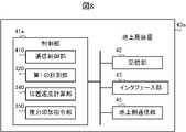
上述した実施の形態1~4では、宇宙機3の位置及び速度を計測する機能は、宇宙機3に搭載された宇宙機制御装置30に備えられていた。これに対して、実施の形態5では、宇宙機3の位置及び速度を計測する機能の主な部分は、地上局4に設置された地上局装置40aに備えられる。以下、説明する。 In the first to fourth embodiments described above, thespacecraft controller 30 mounted on thespacecraft 3 has the function of measuring the position and speed of thespacecraft 3 . In contrast, inEmbodiment 5, the main part of the function of measuring the position and velocity of thespacecraft 3 is provided in theground station device 40a installed in theground station 4. FIG. This will be explained below.

図7及び図8に、それぞれ実施の形態5に係る計測システム1に備えられる宇宙機制御装置30a及び地上局装置40aの構成を示す。図7に示すように、実施の形態5に係る宇宙機制御装置30aにおいて、制御部31aは、機能的に、通信制御部310と第2の計測部330とを備える。図8に示すように、実施の形態5に係る地上局装置40aにおいて、制御部41aは、機能的に、通信制御部410と第1の計測部320と位置速度計算部340と推力印加指令部350とを備える。即ち、第1の計測部320と位置速度計算部340と推力印加指令部350とは、実施の形態1~4では宇宙機制御装置30に備えられていたが、実施の形態5では地上局装置40aに備えられる。 7 and 8 show configurations of aspacecraft control device 30a and aground station device 40a provided in the measurement system 1 according toEmbodiment 5, respectively. As shown in FIG. 7, in thespacecraft control device 30a according to the fifth embodiment, thecontrol section 31a functionally includes acommunication control section 310 and asecond measurement section 330. As shown in FIG. As shown in FIG. 8, in theground station device 40a according toEmbodiment 5, thecontrol unit 41a functionally includes acommunication control unit 410, afirst measurement unit 320, a position/velocity calculation unit 340, and a thrust application command unit. 350. That is, thefirst measurement unit 320, the position/velocity calculation unit 340, and the thrustapplication command unit 350 are provided in thespacecraft controller 30 in the first to fourth embodiments, but in the fifth embodiment, they are provided in the ground station apparatus. 40a.

以下、図9を参照して、実施の形態5に係る計測システム1において実行される計測処理について説明する。 Measurement processing executed in the measurement system 1 according to the fifth embodiment will be described below with reference to FIG. 9 .

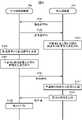
地上局装置40aにおいて、地上側通信部45は、予め定められた送信タイミングが到来すると、宇宙機3に向けて通信信号Rbを送信する(ステップS501)。通信信号Rbを送信すると、地上側通信部45は、その送信時刻T1を記録する。宇宙機制御装置30aにおいて、宇宙側通信部35は、地上局装置40aから送信された通信信号Rbを受信する。 In theground station device 40a, the groundside communication section 45 transmits a communication signal Rb to thespacecraft 3 when a predetermined transmission timing arrives (step S501). When the communication signal Rb is transmitted, the groundside communication section 45 records the transmission time T1. In thespacecraft controller 30a, the spaceside communication unit 35 receives the communication signal Rb transmitted from theground station device 40a.

通信信号Rbを受信すると、宇宙側通信部35は、通信信号Rbを受信してから応答時間ΔTが経過したタイミングで、地上局4に向けて通信信号Rsを送信する(ステップS502)。地上側通信部45は、宇宙機制御装置30aから送信された通信信号Rsを受信し、その受信時刻T2と受信周波数Fbとを記録する。 Upon receiving the communication signal Rb, the space-side communication unit 35 transmits the communication signal Rs to theground station 4 at the timing when the response time ΔT has elapsed after receiving the communication signal Rb (step S502). The groundside communication unit 45 receives the communication signal Rs transmitted from thespacecraft controller 30a and records the reception time T2 and the reception frequency Fb.

通信信号Rsが受信されると、地上局装置40aにおいて、第1の計測部320は、宇宙機3と地上局4との間の距離D及び距離変化率ρを計測する(ステップS503)。具体的に説明すると、第1の計測部320は、通信信号Rs,Rbの伝搬時間(T2-T1-ΔT)に光速度cを乗じることにより、距離Dを計算する。更に、第1の計測部320は、ドップラー周波数偏移の原理を用いて、通信信号Rsの受信周波数Fbから距離変化率ρを計算する。 When the communication signal Rs is received, thefirst measurement unit 320 in theground station device 40a measures the distance D and the distance change rate ρ between thespacecraft 3 and the ground station 4 (step S503). Specifically, thefirst measurement unit 320 calculates the distance D by multiplying the propagation time (T2-T1-ΔT) of the communication signals Rs and Rb by the speed of light c. Furthermore, thefirst measuring unit 320 calculates the distance change rate ρ from the received frequency Fb of the communication signal Rs using the principle of Doppler frequency shift.

ここで、実施の形態1では、第1の計測部320は、地上局4から宇宙機3に送信された通信信号Rbの受信周波数Fsから距離変化率ρを計測した。これに対して、実施の形態5では、第1の計測部320は、宇宙機3から地上局4に送信された通信信号Rsの受信周波数Fbから距離変化率ρを計測する。どちらの場合でも同様に、基準周波数F0からの受信周波数Fs,Fbのずれに基づいて距離変化率ρを計測することができる。 Here, in Embodiment 1, thefirst measurement unit 320 measures the distance change rate ρ from the received frequency Fs of the communication signal Rb transmitted from theground station 4 to thespacecraft 3 . In contrast, inEmbodiment 5, thefirst measurement unit 320 measures the distance change rate ρ from the reception frequency Fb of the communication signal Rs transmitted from thespacecraft 3 to theground station 4 . In either case, similarly, the distance change rate ρ can be measured based on the deviation of the reception frequencies Fs and Fb from the reference frequency F0.

このような通信信号Rs,Rbを送受信する処理と並行して、宇宙機制御装置30aでは、航法信号受信部36は、地球の周りを回っている複数の航法衛星5のうちのいずれかから航法信号Rgが送信された場合、送信された航法信号Rgを受信する(ステップS504)。航法信号受信部36は、航法信号Rgを受信すると、その受信時刻Tgと受信周波数Fgとを記録する。また、航法信号受信部36は、受信した航法信号Rgの送信時刻と、航法信号Rgの送信時における航法衛星5の位置及び速度とを、受信した航法信号Rgから復号する。 In parallel with the process of transmitting and receiving the communication signals Rs and Rb, in thespacecraft controller 30a, thenavigation signal receiver 36 receives a signal from one of the plurality ofnavigation satellites 5 orbiting the earth. When the signal Rg is transmitted, the transmitted navigation signal Rg is received (step S504). Upon receiving the navigation signal Rg, thenavigation signal receiver 36 records the reception time Tg and the reception frequency Fg. Also, thenavigation signal receiver 36 decodes the transmission time of the received navigation signal Rg and the position and velocity of thenavigation satellite 5 at the time of transmission of the navigation signal Rg from the received navigation signal Rg.

航法信号Rgが受信されると、第2の計測部330は、受信された航法信号Rgに基づいて、宇宙機3と航法衛星5との間の距離変化率ρgを計測する(ステップS505)。具体的に説明すると、第2の計測部330は、ドップラー周波数偏移の原理を用いて、航法衛星5の速度情報と航法信号Rgの受信周波数Fgとから距離変化率ρgを計算する。 When the navigation signal Rg is received, thesecond measurement unit 330 measures the distance change rate ρg between thespacecraft 3 and thenavigation satellite 5 based on the received navigation signal Rg (step S505). Specifically, thesecond measurement unit 330 calculates the distance change rate ρg from the speed information of thenavigation satellite 5 and the received frequency Fg of the navigation signal Rg using the principle of Doppler frequency shift.

距離変化率ρgが計測されると、宇宙側通信部35は、距離変化率ρgから得られる宇宙機3の制約情報を、地上局4に向けて送信する(ステップS506)。具体的に説明すると、第2の計測部330は、計測された距離変化率ρgに基づいて、航法信号Rgの到来方向における宇宙機3の速度の制約条件を取得する。そして、宇宙側通信部35は、取得された制約情報を示す制約情報を地上局4に送信する。地上側通信部45は、宇宙側通信部35により送信された制約情報を受信し、受信した制約情報により示される制約条件を記憶部42に記録する。 When the distance change rate ρg is measured, the spaceside communication unit 35 transmits the constraint information of thespacecraft 3 obtained from the distance change rate ρg to the ground station 4 (step S506). Specifically, thesecond measurement unit 330 acquires the speed constraint condition of thespacecraft 3 in the arrival direction of the navigation signal Rg based on the measured distance change rate ρg. Space-side communication unit 35 then transmits restriction information indicating the acquired restriction information toground station 4 . The groundside communication section 45 receives the constraint information transmitted by the spaceside communication section 35 and records the constraint condition indicated by the received constraint information in thestorage section 42 .

制約情報が受信されると、地上局装置40aにおいて、位置速度計算部340は、第1の計測部320により計測された距離D及び距離変化率ρと、宇宙機3から受信した制約情報と、に基づいて、宇宙機3の位置及び速度を計算する(ステップS507)。具体的に説明すると、位置速度計算部340は、距離D及び距離変化率ρから、地上局4の方向における宇宙機3の位置及び速度の制約条件を取得する。そして、位置速度計算部340は、取得された制約条件と、宇宙機3から受信した制約情報により示される制約条件と、により定められる宇宙機3の位置及び速度の推定値を計算する。 When the constraint information is received, in theground station device 40a, the position/velocity calculator 340 calculates the distance D and the distance change rate ρ measured by thefirst measurement unit 320, the constraint information received from thespacecraft 3, , the position and velocity of thespacecraft 3 are calculated (step S507). More specifically, the position/velocity calculator 340 acquires constraints on the position and velocity of thespacecraft 3 in the direction of theground station 4 from the distance D and the distance change rate ρ. Then, the position/velocity calculator 340 calculates estimated values of the position and velocity of thespacecraft 3 defined by the acquired constraint and the constraint indicated by the constraint information received from thespacecraft 3 .

宇宙機3の位置及び速度が計算されると、推力印加指令部350は、計算された宇宙機3の位置及び速度に基づく推力の印加を宇宙機3に指令する(ステップS508)。具体的に説明すると、推力印加指令部350は、宇宙機3に印加させる推力の指令値を計算する。そして、推力印加指令部350は、地上側通信部45を介して、計算した指令値を宇宙機3に送信する。 When the position and speed of thespacecraft 3 are calculated, the thrustapplication command unit 350 commands thespacecraft 3 to apply thrust based on the calculated position and speed of the spacecraft 3 (step S508). Specifically, the thrustapplication command unit 350 calculates a command value for the thrust to be applied to thespacecraft 3 . Then, the thrustapplication command section 350 transmits the calculated command value to thespacecraft 3 via the groundside communication section 45 .

宇宙機制御装置30aにおいて、宇宙側通信部35は、地上局装置40aから送信された指令値を受信する。そして、推力印加部38は、受信した指令値に対応する推力を印加させる(ステップS509)。これにより、推力印加部38は、宇宙機3に目標となる運動を実行させる。 In thespacecraft control device 30a, the space-side communication unit 35 receives the command value transmitted from theground station device 40a. Then, thethrust applying unit 38 applies a thrust corresponding to the received command value (step S509). As a result, thethrust applying section 38 causes thespacecraft 3 to perform the target motion.

以上説明したように、実施の形態5に係る計測システム1では、実施の形態1~4では宇宙機制御装置30aに備えられていた第1の計測部320、位置速度計算部340及び推力印加指令部350の機能を、地上局装置40aが備える。これにより、宇宙機3の位置及び速度を計測するために必要となる演算の主要な部分が地上局装置40aで実行される。そのため、宇宙機3の演算負荷を低減しつつ、宇宙機3の位置及び速度の計測に要する時間を短縮することができる。 As described above, in the measurement system 1 according to the fifth embodiment, thefirst measurement unit 320, the position/velocity calculation unit 340, and the thrust application command, which are provided in thespacecraft controller 30a in the first to fourth embodiments, The function of thesection 350 is provided in theground station device 40a. As a result, theground station apparatus 40a executes the main part of the calculations required to measure the position and velocity of thespacecraft 3. FIG. Therefore, it is possible to shorten the time required to measure the position and velocity of thespacecraft 3 while reducing the calculation load of thespacecraft 3 .

(変形例)
以上、実施の形態を説明したが、各実施の形態を組み合わせたり、各実施の形態を適宜、変形、省略したりすることが可能である。
(Modification)
Although the embodiments have been described above, it is possible to combine each embodiment, and to modify or omit each embodiment as appropriate.

例えば、実施の形態5で説明した地上局装置40aが宇宙機3の位置及び速度を計測する構成と、実施の形態2~4で説明した宇宙機3における周波数の誤差ΔFsを補正する構成とを、組み合わせても良い。これにより、周波数の誤差ΔFsに起因する計測誤差及び宇宙機3の制御誤差を抑圧しつつ、且つ、宇宙機3の演算負荷を低減する、という効果が得られる。 For example, the configuration for measuring the position and velocity of thespacecraft 3 by theground station device 40a described in the fifth embodiment and the configuration for correcting the frequency error ΔFs in thespacecraft 3 described in the second to fourth embodiments are combined. , may be combined. As a result, it is possible to suppress the measurement error and control error of thespacecraft 3 caused by the frequency error ΔFs, and reduce the calculation load of thespacecraft 3 .

実施の形態5と実施の形態2~4のいずれかを組み合わせる場合、地上局装置40aにおいて誤差ΔFsを計算するためには、宇宙機3において受信された通信信号Rb,Rb,Rbの受信周波数Fs,Fs,Fsの値が必要になる。そのため、地上側通信部45は、受信周波数Fs,Fs,Fsの値を、何らかの方法で宇宙機制御装置30aから取得する。例えば、宇宙側通信部35は、ステップS502において、受信周波数Fs,Fs,Fsの値を符号化し、地上側通信部45から受信した通信信号Rbに対する応答信号である通信信号Rsに連結して地上局4に送信しても良い。或いは、宇宙側通信部35は、ステップS506において、航法信号Rgから得られた制約情報を送信する際に、制約情報と共に、受信周波数Fs,Fs,Fsの値を符号化して地上局4に送信しても良い。地上側通信部45は、このようにして宇宙側通信部35から送信された受信周波数Fs,Fs,Fsの値を復号することにより、受信周波数Fs,Fs,Fsの値を取得する。WhenEmbodiment 5 is combined with any of Embodiments 2 to 4, in order to calculate error ΔFs inground station device 40a, reception of communication signals Rb, Rb+ , Rb received byspacecraft 3 Values of frequencies Fs, Fs+ and Fs are required. Therefore, the groundside communication unit 45 acquires the values of the reception frequencies Fs, Fs+ , Fs from thespacecraft controller 30a by some method. For example, in step S502, the space-side communication unit 35 encodes the values of the reception frequencies Fs, Fs+ , and Fs-, and concatenates them with the communication signal Rs, which is a response signal to the communication signal Rb received from the ground-side communication unit 45. may be transmitted to theground station 4. Alternatively, in step S506, when transmitting the constraint information obtained from the navigation signal Rg, the space-side communication unit 35 encodes the values of the reception frequencies Fs, Fs+ , and Fs together with the constraint information, and transmits them to theground station 4. can be sent to The groundside communication unit 45 obtains the values of the reception frequencies Fs, Fs+ , Fs by decoding the values of the reception frequencies Fs, Fs+ , Fs transmitted from the spaceside communication unit 35 in this way. do.

実施の形態5では、宇宙機制御装置30aが第2の計測部330を備えており、地上局装置40aが第1の計測部320と位置速度計算部340と推力印加指令部350とを備えていた。しかしながら、各部の機能は、宇宙機制御装置30aと地上局装置40aとのどちらに備えられていても良い。例えば、宇宙機制御装置30aが第1の計測部320と第2の計測部330とを備えており、地上局装置40aが位置速度計算部340と推力印加指令部350とを備えていても良い。或いは、地上局装置40aがこれらの機能を全て備えていても良い。 InEmbodiment 5, thespacecraft control device 30a includes asecond measurement unit 330, and theground station device 40a includes afirst measurement unit 320, a position/velocity calculation unit 340, and a thrustapplication command unit 350. rice field. However, the function of each unit may be provided in either thespacecraft control device 30a or theground station device 40a. For example, thespacecraft control device 30a may include thefirst measurement unit 320 and thesecond measurement unit 330, and theground station device 40a may include the position/velocity calculation unit 340 and the thrustapplication command unit 350. . Alternatively, theground station device 40a may have all of these functions.

実施の形態1~4では、宇宙機3に搭載されている宇宙機制御装置30が、宇宙機3の位置及び速度を計測する計測装置として機能した。しかしながら、計測装置は、宇宙機3に搭載されていることに限らない。例えば、地上局装置40が上述した第1の計測部320、第2の計測部330及び位置速度計算部340の機能を備えており、計測装置として機能しても良い。或いは、宇宙機3との間で必要な情報を送受信する機能を備えていれば、その他の装置が上述した第1の計測部320、第2の計測部330及び位置速度計算部340の機能を備えており、計測装置として機能しても良い。 In Embodiments 1 to 4, thespacecraft controller 30 mounted on thespacecraft 3 functions as a measuring device that measures the position and speed of thespacecraft 3 . However, the measuring device is not limited to being mounted on thespacecraft 3 . For example, theground station device 40 may have the functions of thefirst measurement unit 320, thesecond measurement unit 330, and the position/velocity calculation unit 340 and function as a measurement device. Alternatively, if the other device has a function of transmitting and receiving necessary information to and from thespacecraft 3, the functions of thefirst measurement unit 320, thesecond measurement unit 330, and the position/velocity calculation unit 340 described above can be performed by another device. and may function as a measuring device.

上記実施の形態では、宇宙機制御装置30,30aの制御部31,31aにおいて、CPUがROM又は記憶部32に記憶されたプログラムを実行することによって、通信制御部310等の各部として機能した。また、地上局装置40,40aの制御部41,41aにおいて、CPUがROM又は記憶部42に記憶されたプログラムを実行することによって、通信制御部410等の各部として機能した。しかしながら、制御部31,31a,41,41aは、専用のハードウェアであってもよい。専用のハードウェアとは、例えば単一回路、複合回路、プログラム化されたプロセッサ、ASIC(Application Specific Integrated Circuit)、FPGA(Field-Programmable Gate Array)、又は、これらの組み合わせ等である。制御部31,31a,41,41aが専用のハードウェアである場合、各部の機能それぞれを個別のハードウェアで実現してもよいし、各部の機能をまとめて単一のハードウェアで実現してもよい。 In the above embodiment, the CPU of thecontrollers 31 and 31a of thespacecraft controllers 30 and 30a functions as thecommunication controller 310 and the like by executing the program stored in the ROM or thememory 32 . Further, in thecontrol units 41 and 41a of theground station devices 40 and 40a, the CPU functions as each unit such as thecommunication control unit 410 by executing programs stored in the ROM or thestorage unit 42. FIG. However, thecontrol units 31, 31a, 41, 41a may be dedicated hardware. Dedicated hardware is, for example, a single circuit, a composite circuit, a programmed processor, an ASIC (Application Specific Integrated Circuit), an FPGA (Field-Programmable Gate Array), or a combination thereof. When thecontrol units 31, 31a, 41, 41a are dedicated hardware, the functions of each unit may be realized by separate hardware, or the functions of each unit may be collectively realized by single hardware. good too.

また、各部の機能のうち、一部を専用のハードウェアによって実現し、他の一部をソフトウェア又はファームウェアによって実現してもよい。このように、制御部31,41は、ハードウェア、ソフトウェア、ファームウェア、又は、これらの組み合わせによって、上述の各機能を実現することができる。 Moreover, among the functions of each unit, a part may be realized by dedicated hardware, and another part may be realized by software or firmware. In this way, thecontrol units 31 and 41 can implement the functions described above by hardware, software, firmware, or a combination thereof.

宇宙機制御装置30,30a及び地上局装置40,40aのそれぞれの動作を規定するプログラムを、パーソナルコンピュータ、情報端末装置等の既存のコンピュータに適用することで、当該コンピュータを、宇宙機制御装置30,30a及び地上局装置40,40aのそれぞれとして機能させることも可能である。 By applying a program that defines the operations of thespacecraft controllers 30 and 30a and theground station devices 40 and 40a to an existing computer such as a personal computer or an information terminal device, the computer can be used as thespacecraft controller 30. , 30a andground station devices 40 and 40a.

また、このようなプログラムの配布方法は任意であり、例えば、CD-ROM(Compact Disk ROM)、DVD(Digital Versatile Disk)、MO(Magneto Optical Disk)、メモリカード等のコンピュータ読み取り可能な記録媒体に格納して配布してもよいし、インターネット等の通信ネットワークを介して配布してもよい。 Any method of distributing such programs may be used. For example, computer-readable recording media such as CD-ROMs (Compact Disk ROMs), DVDs (Digital Versatile Disks), MOs (Magneto Optical Disks), and memory cards may be used. It may be stored and distributed, or may be distributed via a communication network such as the Internet.

本開示は、本開示の広義の精神と範囲を逸脱することなく、様々な実施の形態及び変形が可能とされるものである。また、上述した実施の形態は、この開示を説明するためのものであり、本開示の範囲を限定するものではない。すなわち、本開示の範囲は、実施の形態ではなく、特許請求の範囲によって示される。そして特許請求の範囲内及びそれと同等の開示の意義の範囲内で施される様々な変形が、この開示の範囲内とみなされる。 This disclosure is capable of various embodiments and modifications without departing from the broader spirit and scope of this disclosure. In addition, the embodiments described above are for explaining this disclosure, and do not limit the scope of this disclosure. That is, the scope of the present disclosure is indicated by the claims rather than the embodiments. Various modifications made within the scope of the claims and within the scope of equivalent disclosure are considered to be within the scope of this disclosure.

1 計測システム、3 宇宙機、4 地上局、5 航法衛星、30,30a 宇宙機制御装置、31,31a,41,41a 制御部、32,42 記憶部、33,43 インタフェース部、35 宇宙側通信部、36 航法信号受信部、38 推力印加部、40,40a 地上局装置、45 地上側通信部、310 通信制御部、320 第1の計測部、330 第2の計測部、340 位置速度計算部、350 推力印加指令部、410 通信制御部、Rs,Rb,Rb,Rb 通信信号、Rg 航法信号。1measurement system 3spacecraft 4ground station 5navigation satellite 30,30a spacecraft controller 31, 31a, 41,41a control section 32, 42storage section 33, 43interface section 35 spaceside communication Section 36 NavigationSignal Receiving Section 38Thrust Applying Section 40, 40aGround Station Device 45 GroundSide Communication Section 310Communication Control Section 320 First MeasuringSection 330Second Measuring Section 340 Position/Velocity Calculating Section , 350 thrust application command unit, 410 communication control unit, Rs, Rb, Rb+ , Rb communication signal, Rg navigation signal.

Claims (11)

Translated fromJapanese
宇宙機と地上局との間で送信された通信信号に基づいて、前記宇宙機と前記地上局との間の距離及び距離変化率を計測する第1の計測手段と、
前記宇宙機が航法衛星から受信した航法信号に基づいて、前記宇宙機と前記航法衛星との間の距離変化率を計測する第2の計測手段と、
前記第1の計測手段により計測された前記距離及び前記距離変化率と、前記第2の計測手段により計測された前記距離変化率と、に基づいて、前記宇宙機の位置及び速度を計算する位置速度計算手段と、を備える、
計測装置。
a first measuring means for measuring a distance and a distance change rate between the spacecraft and the ground station based on communication signals transmitted between the spacecraft and the ground station;
second measuring means for measuring a distance change rate between the spacecraft and the navigation satellite based on the navigation signal received by the spacecraft from the navigation satellite;
position for calculating the position and velocity of the spacecraft based on the distance and the distance change rate measured by the first measurement means and the distance change rate measured by the second measurement means; a velocity calculation means;
measuring device.
前記第1の計測手段は、前記宇宙機において受信された前記通信信号の受信周波数と、前記地上局において受信された前記通信信号の受信周波数と、に基づいて、前記宇宙機において送受信される前記通信信号の周波数の誤差を計算し、計算された前記誤差に基づいて、前記宇宙機と前記地上局との間の前記距離変化率を補正する、
請求項1に記載の計測装置。
The first measurement means measures the frequency of the communication signal received by the spacecraft and the reception frequency of the communication signal received by the ground station, and measures the calculating an error in the frequency of the communication signal, and correcting the rate of change in distance between the spacecraft and the ground station based on the calculated error;
The measuring device according to claim 1.
前記第2の計測手段は、前記第1の計測手段により計算された前記誤差に基づいて、前記宇宙機と前記航法衛星との間の前記距離変化率を補正する、
請求項2に記載の計測装置。
the second measuring means corrects the distance change rate between the spacecraft and the navigation satellite based on the error calculated by the first measuring means;
The measuring device according to claim 2.
前記第1の計測手段は、異なる2つのタイミングでの前記宇宙機における前記通信信号の受信周波数の平均値と、前記2つのタイミングの間での前記地上局における前記通信信号の受信周波数と、に基づいて、前記誤差を計算する、
請求項2又は3に記載の計測装置。
The first measuring means measures the average value of the reception frequencies of the communication signal at the spacecraft at two different timings and the reception frequency of the communication signals at the ground station between the two timings. calculating the error based on
The measuring device according to claim 2 or 3.
前記宇宙機から前記地上局に送信される前記通信信号の送信周波数と、前記地上局から前記宇宙機に送信される前記通信信号の送信周波数とは、異なる、
請求項1から4のいずれか1項に記載の計測装置。
a transmission frequency of the communication signal transmitted from the spacecraft to the ground station and a transmission frequency of the communication signal transmitted from the ground station to the spacecraft,
The measuring device according to any one of claims 1 to 4.
前記宇宙機から前記地上局に送信される前記通信信号の前記送信周波数は、第1の倍率で基準周波数を有理数倍した周波数であり、
前記地上局から前記宇宙機に送信される前記通信信号の前記送信周波数は、前記第1の倍率とは異なる第2の倍率で前記基準周波数を有理数倍した周波数である、
請求項5に記載の計測装置。
the transmission frequency of the communication signal transmitted from the spacecraft to the ground station is a frequency obtained by multiplying a reference frequency by a rational number by a first magnification;
The transmission frequency of the communication signal transmitted from the ground station to the spacecraft is a frequency obtained by multiplying the reference frequency by a rational number by a second magnification different from the first magnification.
The measuring device according to claim 5.
前記位置速度計算手段により計算された前記宇宙機の位置及び速度に基づく推力を前記宇宙機に印加させる推力印加指令手段、を更に備える、
請求項1から6のいずれか1項に記載の計測装置。
further comprising thrust application command means for applying a thrust to the spacecraft based on the position and speed of the spacecraft calculated by the position/speed calculation means;
The measuring device according to any one of claims 1 to 6.
宇宙機に搭載される宇宙機制御装置と、地上局に設置される地上局装置と、を備える計測システムであって、
前記宇宙機制御装置は、
前記地上局装置との間で通信信号を送受信する宇宙側通信手段と、
航法衛星から航法信号を受信する航法信号受信手段と、を備え、
前記地上局装置は、
前記宇宙機制御装置との間で前記通信信号を送受信する地上側通信手段、を備え、
前記計測システムは、
前記宇宙機制御装置と前記地上局装置との間で送信された前記通信信号に基づいて、前記宇宙機と前記地上局との間の距離及び距離変化率を計測する第1の計測手段と、
前記航法信号受信手段により受信した前記航法信号に基づいて、前記宇宙機と前記航法衛星との間の距離変化率を計測する第2の計測手段と、
前記第1の計測手段により計測された前記距離及び前記距離変化率と、前記第2の計測手段により計測された前記距離変化率と、に基づいて、前記宇宙機の位置及び速度を計算する位置速度計算手段と、を備える、
計測システム。
A measurement system comprising a spacecraft control device mounted on a spacecraft and a ground station device installed at a ground station,
The spacecraft control device includes:
Space-side communication means for transmitting and receiving communication signals to and from the ground station device;
a navigation signal receiving means for receiving a navigation signal from a navigation satellite;
The ground station device
ground-side communication means for transmitting and receiving the communication signal to and from the spacecraft controller;
The measurement system is
a first measuring means for measuring a distance and a distance change rate between the spacecraft and the ground station based on the communication signal transmitted between the spacecraft controller and the ground station;
second measuring means for measuring a distance change rate between the spacecraft and the navigation satellite based on the navigation signal received by the navigation signal receiving means;
position for calculating the position and velocity of the spacecraft based on the distance and the distance change rate measured by the first measurement means and the distance change rate measured by the second measurement means; a velocity calculation means;
measurement system.
前記宇宙機制御装置は、前記第2の計測手段を備え、
前記地上局装置は、前記第1の計測手段と前記位置速度計算手段とを備え、
前記地上局装置において、
前記地上側通信手段は、前記第2の計測手段により計測された前記距離変化率から得られる前記宇宙機の制約情報を、前記宇宙機制御装置から受信し、
前記位置速度計算手段は、前記第1の計測手段により計測された前記距離及び前記距離変化率と、前記地上側通信手段により受信された前記制約情報と、に基づいて、前記宇宙機の位置及び速度を計算する、
請求項8に記載の計測システム。
The spacecraft control device comprises the second measurement means,
The ground station device comprises the first measuring means and the position/velocity calculating means,
In the ground station device,
the ground-side communication means receives, from the spacecraft control device, constraint information of the spacecraft obtained from the distance change rate measured by the second measurement means;
The position/velocity calculation means calculates the position and speed of the spacecraft based on the distance and the distance change rate measured by the first measurement means and the constraint information received by the ground side communication means. calculate speed,
The measurement system according to claim 8.
宇宙機と地上局との間で送信された通信信号に基づいて、前記宇宙機と前記地上局との間の距離及び距離変化率を計測し、
前記宇宙機が航法衛星から受信した航法信号に基づいて、前記宇宙機と前記航法衛星との間の距離変化率を計測し、
前記宇宙機と前記地上局との間の前記距離及び前記距離変化率と、前記宇宙機と前記航法衛星との間の前記距離変化率と、に基づいて、前記宇宙機の位置及び速度を計算する、
計測方法。
measuring a distance and a distance change rate between the spacecraft and the ground station based on communication signals transmitted between the spacecraft and the ground station;
measuring a distance change rate between the spacecraft and the navigation satellite based on the navigation signal received by the spacecraft from the navigation satellite;
Calculate the position and velocity of the spacecraft based on the distance and the distance change rate between the spacecraft and the ground station and the distance change rate between the spacecraft and the navigation satellite. do,
measurement method.
コンピュータを、
宇宙機と地上局との間で送信された通信信号に基づいて、前記宇宙機と前記地上局との間の距離及び距離変化率を計測する第1の計測手段、
前記宇宙機が航法衛星から受信した航法信号に基づいて、前記宇宙機と前記航法衛星との間の距離変化率を計測する第2の計測手段、
前記第1の計測手段により計測された前記距離及び前記距離変化率と、前記第2の計測手段により計測された前記距離変化率と、に基づいて、前記宇宙機の位置及び速度を計算する位置速度計算手段、として機能させる、
プログラム。
the computer,
a first measuring means for measuring the distance and distance change rate between the spacecraft and the ground station based on communication signals transmitted between the spacecraft and the ground station;
second measuring means for measuring a distance change rate between the spacecraft and the navigation satellite based on the navigation signal received by the spacecraft from the navigation satellite;
position for calculating the position and velocity of the spacecraft based on the distance and the distance change rate measured by the first measurement means and the distance change rate measured by the second measurement means; act as a velocity calculation means,
program.
JP2021008718A2021-01-222021-01-22 Measuring device, measuring system, measuring method and programPendingJP2022112777A (en)

Priority Applications (1)

Application NumberPriority DateFiling DateTitle
JP2021008718AJP2022112777A (en)2021-01-222021-01-22 Measuring device, measuring system, measuring method and program

Applications Claiming Priority (1)

Application NumberPriority DateFiling DateTitle
JP2021008718AJP2022112777A (en)2021-01-222021-01-22 Measuring device, measuring system, measuring method and program

Publications (1)

Publication NumberPublication Date
JP2022112777Atrue JP2022112777A (en)2022-08-03

Family

ID=82656938

Family Applications (1)

Application NumberTitlePriority DateFiling Date
JP2021008718APendingJP2022112777A (en)2021-01-222021-01-22 Measuring device, measuring system, measuring method and program

Country Status (1)

CountryLink
JP (1)JP2022112777A (en)

Cited By (1)

* Cited by examiner, † Cited by third party
Publication numberPriority datePublication dateAssigneeTitle
RU2822690C1 (en)*2023-10-302024-07-11Федеральное государственное казенное военное образовательное учреждение высшего образований "Военная орденов Жукова и Ленина Краснознаменная академия связи имени Маршала Советского Собза С.М. Буденного" Министерства обороны Российской ФедерацииMethod of determining orthogonal components of velocity vectors of two spacecraft using earth stations and emitting supporting reference station

Citations (6)

* Cited by examiner, † Cited by third party
Publication numberPriority datePublication dateAssigneeTitle
JPH042913A (en)*1990-04-201992-01-07Mitsubishi Electric CorpNavigator for spacecraft
JPH06201813A (en)*1992-12-281994-07-22Hitachi Ltd Positioning method and device for moving body
JP2007206065A (en)*2000-10-272007-08-16Qualcomm IncMethod and device for estimating velocity of terminal in wireless communication system
JP2007256004A (en)*2006-03-222007-10-04Kagoshima Univ Orbit determination device, orbit determination method, and computer program
JP2011005985A (en)*2009-06-262011-01-13Mitsubishi Electric CorpOrbit determination device and method for determining orbit
US20130293413A1 (en)*2012-05-032013-11-07Raytheon CompanyPosition and Elevation Acquisition for Orbit Determination

Patent Citations (6)

* Cited by examiner, † Cited by third party
Publication numberPriority datePublication dateAssigneeTitle
JPH042913A (en)*1990-04-201992-01-07Mitsubishi Electric CorpNavigator for spacecraft
JPH06201813A (en)*1992-12-281994-07-22Hitachi Ltd Positioning method and device for moving body
JP2007206065A (en)*2000-10-272007-08-16Qualcomm IncMethod and device for estimating velocity of terminal in wireless communication system
JP2007256004A (en)*2006-03-222007-10-04Kagoshima Univ Orbit determination device, orbit determination method, and computer program
JP2011005985A (en)*2009-06-262011-01-13Mitsubishi Electric CorpOrbit determination device and method for determining orbit
US20130293413A1 (en)*2012-05-032013-11-07Raytheon CompanyPosition and Elevation Acquisition for Orbit Determination

Cited By (1)

* Cited by examiner, † Cited by third party
Publication numberPriority datePublication dateAssigneeTitle
RU2822690C1 (en)*2023-10-302024-07-11Федеральное государственное казенное военное образовательное учреждение высшего образований "Военная орденов Жукова и Ленина Краснознаменная академия связи имени Маршала Советского Собза С.М. Буденного" Министерства обороны Российской ФедерацииMethod of determining orthogonal components of velocity vectors of two spacecraft using earth stations and emitting supporting reference station

Similar Documents

PublicationPublication DateTitle
US11737039B2 (en)Managing doppler and framing impacts in networks
US11867803B2 (en)Global positioning system for compensating for error of relative position between vehicles
CN103299205B (en) Systems and methods for mobile base station RTK surveys
US8963772B2 (en)Method and system for acquiring ephemeris information
JP2020021132A (en)Sensor module, electronic device, and moving object
US10215850B2 (en)Orbital determination (OD) of geosynchronous satellites
US6917330B2 (en)Positioning system
CN113532428B (en)Data processing method, device, communication-in-motion terminal and computer readable storage medium
CN113359165B (en)Method and device for jointly positioning radiation sources by multiple satellites and electronic equipment
JP5605539B2 (en) MOBILE POSITION ESTIMATION TRACKING DEVICE, MOBILE POSITION ESTIMATION TRACKING METHOD, AND MOBILE POSITION ESTIMATION TRACKING PROGRAM
CN115825998A (en)Satellite navigation signal and inertial navigation information synchronous simulation generation method and device
US11079496B2 (en)Precise point positioning method and positioning apparatus and recording medium thereof
US9797987B2 (en)Correcting frequency errors in frequency difference of arrival geolocation systems
JP2022112777A (en) Measuring device, measuring system, measuring method and program
US6563461B1 (en)System, method, and software for non-iterative position estimation using range measurements
CN106404002B (en)A kind of in-orbit bearing calibration of high-precision imaging moment
US11977170B2 (en)Antenna steering-induced phase center error limiter
US20200363536A1 (en)Methods for enhancing non-global navigation satellite system location and timing pseudorange positioning calculations and systems thereof
JP7235357B2 (en) POSITIONING ASSISTANCE DEVICE, POSITIONING ASSISTANCE METHOD, AND PROGRAM
Kulakova et al.Micronavigation system to support a radar with synthetic aperture aboard a small UAV
CN110865402B (en) Precise single point positioning method, positioning device and recording medium
CN107272036B (en)Navigation device and method for determining navigation information
CN113433573A (en)Method and device for multi-satellite combined positioning of radiation source and electronic equipment
JP5203829B2 (en) Synthetic aperture sonar
US12379452B2 (en)Method for locating a vehicle

Legal Events

DateCodeTitleDescription
A621Written request for application examination

Free format text:JAPANESE INTERMEDIATE CODE: A621

Effective date:20221026

A977Report on retrieval

Free format text:JAPANESE INTERMEDIATE CODE: A971007

Effective date:20230726

A131Notification of reasons for refusal

Free format text:JAPANESE INTERMEDIATE CODE: A131

Effective date:20230808

A521Request for written amendment filed

Free format text:JAPANESE INTERMEDIATE CODE: A523

Effective date:20230919

A02Decision of refusal

Free format text:JAPANESE INTERMEDIATE CODE: A02

Effective date:20231212


[8]ページ先頭

©2009-2025 Movatter.jp