JP2022102245A - Vehicle sensor mounting structure - Google Patents
Vehicle sensor mounting structureDownload PDFInfo
- Publication number
- JP2022102245A JP2022102245AJP2020216868AJP2020216868AJP2022102245AJP 2022102245 AJP2022102245 AJP 2022102245AJP 2020216868 AJP2020216868 AJP 2020216868AJP 2020216868 AJP2020216868 AJP 2020216868AJP 2022102245 AJP2022102245 AJP 2022102245A
- Authority
- JP
- Japan
- Prior art keywords
- vehicle
- sensor unit
- option
- frame body
- common
- Prior art date
- Legal status (The legal status is an assumption and is not a legal conclusion. Google has not performed a legal analysis and makes no representation as to the accuracy of the status listed.)
- Granted
Links
Images


Classifications
- B—PERFORMING OPERATIONS; TRANSPORTING
- B60—VEHICLES IN GENERAL
- B60R—VEHICLES, VEHICLE FITTINGS, OR VEHICLE PARTS, NOT OTHERWISE PROVIDED FOR
- B60R11/00—Arrangements for holding or mounting articles, not otherwise provided for
- B—PERFORMING OPERATIONS; TRANSPORTING
- B60—VEHICLES IN GENERAL
- B60R—VEHICLES, VEHICLE FITTINGS, OR VEHICLE PARTS, NOT OTHERWISE PROVIDED FOR
- B60R11/00—Arrangements for holding or mounting articles, not otherwise provided for
- B60R11/02—Arrangements for holding or mounting articles, not otherwise provided for for radio sets, television sets, telephones, or the like; Arrangement of controls thereof
- B—PERFORMING OPERATIONS; TRANSPORTING
- B60—VEHICLES IN GENERAL
- B60R—VEHICLES, VEHICLE FITTINGS, OR VEHICLE PARTS, NOT OTHERWISE PROVIDED FOR
- B60R11/00—Arrangements for holding or mounting articles, not otherwise provided for
- B60R11/04—Mounting of cameras operative during drive; Arrangement of controls thereof relative to the vehicle
- B—PERFORMING OPERATIONS; TRANSPORTING
- B60—VEHICLES IN GENERAL
- B60R—VEHICLES, VEHICLE FITTINGS, OR VEHICLE PARTS, NOT OTHERWISE PROVIDED FOR
- B60R11/00—Arrangements for holding or mounting articles, not otherwise provided for
- B60R2011/0001—Arrangements for holding or mounting articles, not otherwise provided for characterised by position
- B60R2011/004—Arrangements for holding or mounting articles, not otherwise provided for characterised by position outside the vehicle
Landscapes
- Engineering & Computer Science (AREA)
- Mechanical Engineering (AREA)
- Optical Radar Systems And Details Thereof (AREA)
- Fittings On The Vehicle Exterior For Carrying Loads, And Devices For Holding Or Mounting Articles (AREA)
Abstract
Translated fromJapaneseDescription
Translated fromJapanese本発明は、車両用センサ取り付け構造に関する。 The present invention relates to a vehicle sensor mounting structure.
従来、車両用センサ取り付け構造に関する技術文献として、米国特許出願公報第2016/0334790号明細書が知られている。この文献には、車両の外部状況を検出する各種のセンサがルーフ中央に一体のユニットとして取り付けられた車両が示されている。 Conventionally, US Patent Application Publication No. 2016/0334790 is known as a technical document relating to a vehicle sensor mounting structure. This document shows a vehicle in which various sensors for detecting the external condition of the vehicle are mounted as an integrated unit in the center of the roof.
しかしながら、ルーフ上の全てのセンサを取り外し不能の一体的なユニットとすると、センサ故障時などにメンテナンスが困難となると言う問題がある。 However, if all the sensors on the roof are made into a non-removable integrated unit, there is a problem that maintenance becomes difficult in the event of a sensor failure or the like.
本発明の一態様は、車両のルーフ上に車両の外部状況を検出するための複数種類の外部センサを取り付ける車両用センサ取り付け構造であって、車両のルーフに対して固定され、少なくとも一種類の外部センサが取り付けられた共通センサユニットと、共通センサユニットに対して車両左側、車両右側、車両上側、車両前側、車両後側のうち少なくとも二方向で取り付け可能であり、共通センサユニットに対して取り外し可能に取り付けられると共に少なくとも一種類の外部センサが取り付けられたオプションセンサユニットと、を備える。 One aspect of the present invention is a vehicle sensor mounting structure in which a plurality of types of external sensors for detecting an external condition of a vehicle are mounted on the roof of the vehicle, which is fixed to the roof of the vehicle and has at least one type. It can be attached to the common sensor unit to which an external sensor is attached and to the common sensor unit in at least two directions: the left side of the vehicle, the right side of the vehicle, the upper side of the vehicle, the front side of the vehicle, and the rear side of the vehicle. It is equipped with an optional sensor unit that can be mounted and is fitted with at least one type of external sensor.
本発明の一態様に係る車両用センサ取り付け構造によれば、共通センサユニットに対して取り外し可能にオプションセンサユニットを取り付ける構造とすることで、オプションセンサユニットの外部センサの交換が必要となったときにはオプションセンサユニットごと交換することで、全てのセンサを取り外し不能の一体的なユニットとなっている場合と比べてメンテナンスを容易にすることができる。 According to the vehicle sensor mounting structure according to one aspect of the present invention, the optional sensor unit is detachably mounted on the common sensor unit, so that the external sensor of the optional sensor unit needs to be replaced. By replacing the entire optional sensor unit, maintenance can be facilitated compared to the case where all the sensors are a non-removable integrated unit.
上述した車両用センサ取り付け構造において、オプションセンサユニットには、共通センサユニットの車両左側に取り付けられた第一オプションセンサユニットと、共通センサユニットの車両右側に取り付けられた第二オプションセンサユニットとが含まれていてもよい。
この車両用センサ取り付け構造によれば、共通センサユニットの左右それぞれに第一オプションセンサユニット及び第二オプションセンサユニットを取り付ける構造とすることで、第一オプションセンサユニット及び第二オプションセンサユニットのいずれの外部センサの交換が必要になってもユニットごと交換することで、メンテナンスを容易にすることができる。In the vehicle sensor mounting structure described above, the option sensor unit includes a first option sensor unit mounted on the vehicle left side of the common sensor unit and a second option sensor unit mounted on the vehicle right side of the common sensor unit. It may be.
According to this vehicle sensor mounting structure, either the first option sensor unit or the second option sensor unit can be mounted by mounting the first option sensor unit and the second option sensor unit on the left and right sides of the common sensor unit, respectively. Even if the external sensor needs to be replaced, maintenance can be facilitated by replacing the entire unit.
上述した車両用センサ取り付け構造において、共通センサユニットは共通フレーム体を有し、オプションセンサユニットは、共通フレーム体と連結するオプションフレーム体を有していてもよい。
この車両用センサ取り付け構造によれば、共通フレーム体及びオプションフレーム体を採用することで、比較的軽量でありながら十分な剛性を確保することができる。In the vehicle sensor mounting structure described above, the common sensor unit may have a common frame body, and the option sensor unit may have an option frame body connected to the common frame body.
According to this vehicle sensor mounting structure, by adopting a common frame body and an optional frame body, it is possible to secure sufficient rigidity while being relatively lightweight.
上述した車両用センサ取り付け構造において、オプションセンサユニットには、共通センサユニットの車両上側に対して取り付けられ、共通センサユニットの左右いずれかに突出するようにオフセット配置された第三オプションセンサユニットが含まれていてもよい。
この車両用センサ取り付け構造によれば、車両の幅などが足りずに共通センサユニットの左右にオプションセンサユニットを追加できない場合であっても、共通センサユニットの車両上側から左右に突出するようにオプションセンサユニットをオフセット配置することで、車両の左右に対するセンサ追加を容易に実現することができる。In the vehicle sensor mounting structure described above, the option sensor unit includes a third option sensor unit mounted on the upper side of the vehicle of the common sensor unit and offset so as to project to either the left or right side of the common sensor unit. It may be.
According to this vehicle sensor mounting structure, even if the optional sensor units cannot be added to the left and right of the common sensor unit due to insufficient width of the vehicle, the option is to project from the upper side of the vehicle to the left and right of the common sensor unit. By arranging the sensor units at an offset, it is possible to easily add sensors to the left and right sides of the vehicle.
本発明の一態様によれば、車両のルーフ上に取り付ける外部センサのメンテナンスを容易にすることができる。 According to one aspect of the present invention, maintenance of an external sensor mounted on the roof of a vehicle can be facilitated.
以下、本発明の実施形態について図面を参照して説明する。各図において車両前後方向をX軸、車幅方向をY軸、車両の高さ方向をZ軸とするXYZ直交座標系を示す。 Hereinafter, embodiments of the present invention will be described with reference to the drawings. In each figure, an XYZ Cartesian coordinate system with the vehicle front-rear direction as the X-axis, the vehicle width direction as the Y-axis, and the vehicle height direction as the Z-axis is shown.
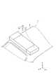
図1は、一実施形態に係る車両用センサ取り付け構造を有する車両を示す図である。図2は、車両用センサ取り付け構造の一例を示す斜視図である。図1及び図2に示す車両1は、一例として小型バス形状の車両である。車両1の車種や形状は、本実施形態の車両用センサ取り付け構造を採用できれば特に限定されない。 FIG. 1 is a diagram showing a vehicle having a vehicle sensor mounting structure according to an embodiment. FIG. 2 is a perspective view showing an example of a vehicle sensor mounting structure. The
車両1のルーフ2の前側には、ルーフ前方センサ群10が搭載されている。車両1の車種や形状は、ルーフ前方センサ群10が搭載可能であれば特に限定されない。なお、車両1のルーフ2の後方には、ルーフ前方センサ群10と同じ構成のルーフ後方センサユニットが設けられていてもよい。 A roof
ルーフ前方センサ群10には、車両1の外部状況(他車両などの物体の状況など)を検出するための外部センサが複数搭載されている。外部センサとは、車両の外部状況を検出するための検出機器である。外部センサは、少なくとも二種類のセンサであるカメラ及びLiDARが含まれる。カメラは、車両の外部状況を撮像する撮像機器である。カメラは、単眼カメラであってもよく、ステレオカメラであってもよい。LiDARは、光を利用して車両の周囲の物体を検出する検出機器である。LiDARは、光を車両の周囲に送信し、物体で反射された光を受信することで物体を検出する。外部センサには、ミリ波レーダが含まれてもよい。外部センサの具体例については後述する。 The roof
図1及び図2に示すように、ルーフ前方センサ群10には、一例として、共通センサユニット11、第一オプションセンサユニット12、及び第二オプションセンサユニット13が含まれている。 As shown in FIGS. 1 and 2, the roof
共通センサユニット11は、車両1のルーフ2に対して固定され、少なくとも一種類の外部センサが取り付けられたユニットである。共通センサユニット11のルーフ2に対する固定方法は特に限定されない。共通センサユニット11は、ボルト止めにより固定されていてもよく、接着により固定されていてもよく、ルーフ2側に形成された嵌合部に嵌合することで機械的に固定されていてもよい。第一オプションセンサユニット12は共通センサユニット11に対して車両右側に設けられ、第二オプションセンサユニット13は共通センサユニット11に対して車両左側に設けられている。 The
図3は、共通センサユニット11に対する第一オプションセンサユニット12の取り付けの一例を示す図である。図3に示すように、共通センサユニット11は、共通フレーム体110を有している。共通フレーム体110とは、共通センサユニット11のベースとなる枠体である。なお、共通センサユニット11は共通フレーム体110の少なくとも一部を覆うカバー部材(図示せず)を有している。カバー部材は必須ではない。 FIG. 3 is a diagram showing an example of mounting the first
共通フレーム体110は、一例として、アングル部材から構成された直方体のフレーム構造とすることができる。アングル部材とは、断面L字形状の長尺部材である。共通フレーム体110の材質は適切な硬度を有していれば特に限定されない。共通フレーム体110は、例えばアルミ材、鋳造部材、樹脂(繊維強化樹脂など)を用いることができる。共通フレーム体110の形状も直方体に限定されず、曲線部分を有していてもよく、一部のアングル部材の延在方向の端部が突出していてもよい。 As an example, the
共通フレーム体110には、外部センサであるカメラ20とLiDAR21が取り付けられている。カメラ20とLiDAR21は車両前側を向くように取り付けられ、車両1の前方の外部状況を検出する。共通フレーム体110には、更に多くの外部センサが取り付けられていてもよい。共通フレーム体110のLiDAR21は、比較的大きい大型LiDARとすることができる。 A
共通フレーム体110におけるカメラ20とLiDAR21の前面(車両前側の面)は、ガラス窓となっていてもよく、カメラ20がLiDAR21露出していてもよい。この点は、第一オプションセンサユニット12及び第二オプションセンサユニット13などにおいても同様である。 The front surface (the surface on the front side of the vehicle) of the
共通フレーム体110には、第一オプションセンサユニット12及び第二オプションセンサユニット13などが取り付けられるためのボルト孔が形成されている。図3では、共通フレーム体110の車両左側に設けられた左側面ボルト孔111a~111dを用いて第一オプションセンサユニット12が取り付けられる。共通フレーム体110には、前面ボルト孔112a~112d、上面ボルト孔113a~113dなどが形成されている。共通フレーム体110には、上下左右の全ての面にボルト孔が形成されていてもよく、二つの面のみにボルト孔が形成されていてもよい。 The
第一オプションセンサユニット12は、第一オプションフレーム体120を有している。第一オプションフレーム体120は、一例として、共通フレーム体110と同様のアングル部材から構成された直方体のフレーム構造とすることができる。第一オプションフレーム体120は、例えば車幅方向で共通フレーム体110より短い幅を有し、車両前後方向(X軸方向)で共通フレーム体110と同じ奥行を有している。 The first
第一オプションフレーム体120の右側面には、共通フレーム体110の左側面ボルト孔111a~111dと対向する右側面ボルト孔121a~121dが形成されている。第一オプションフレーム体120は、その右側面ボルト孔121a~121dと共通フレーム体110の左側面ボルト孔111a~111dとを貫通するように四本のボルトで連結されることで、共通フレーム体110に対して連結されている。 On the right side surface of the first
また、第一オプションフレーム体120には、別な方向から共通フレーム体110に取り付けられるための前面ボルト孔122a~122d、上面ボルト孔123a~123d、及び右側面ボルト孔124a~124dが形成されている。なお、第一オプションフレーム体120には少なくとも一つの面にボルト孔が形成されていればよい。 Further, the first
なお、共通フレーム体110に対する第一オプションフレーム体120の取り付け方法(連結方法)は、ボルト固定に限られない。取り付け方法は取り外し可能な方法であればよい。共通フレーム体110及び第一オプションフレーム体120は、アングル部材同士をステンレスバンドなどの締結金具により締結してもよく、ブラケットを介して取り付けられてもよい。この点は、共通フレーム体110と他のオプションフレーム体との取り付け方法においても同様である。第一オプションセンサユニット12は、例えば共通センサユニット11に対して車両左側、車両右側、車両上側、車両前側、車両後側のうち少なくとも二方向で取り付け可能に構成されていてもよい。 The method of attaching (connecting) the first
第一オプションフレーム体120には、車両左側を向くように設けられた外部センサである左側LiDAR30が取り付けられている。第一オプションフレーム体120に取り付けられる左側LiDAR30は、比較的小さい小型LiDARとしてもよい。第一オプションフレーム体120には、左側LiDAR30の他に複数の外部センサが設けられていてもよい。 The
図4は、第一オプションフレーム体120のセンサ取り付けの一例を示す図である。図4に示すように、第一オプションフレーム体120には、フレーム内側から車両左側を向くように左側LiDAR30が取り付けられている。左側LiDAR30には、下側取付け部31、第一上側取付け部32、及び第二上側取付け部33が設けられている。 FIG. 4 is a diagram showing an example of mounting the sensor of the first
下側取付け部31、第一上側取付け部32、及び第二上側取付け部33は、それぞれ第一オプションフレーム体120の内側(アングル部材の内側)に接合する部位である。下側取付け部31は、左側LiDAR30の下方に突出しており、クッション材31aを介して第一オプションフレーム体120の内側に接合している。 The lower mounting
クッション材31aは、弾性を有する接合材であれば特に限定されない。クッション材31aは、例えばゴム製とすることができ、エチレンプロピレンジエンゴム発泡体に粘着性を持たせたものあってもよい。 The
第一上側取付け部32及び第二上側取付け部33は、左側LiDAR30の上方に突出しており、それぞれクッション材32a、33aを介して第一オプションフレーム体120の内側に接合している。クッション材32a、33aの材質はクッション材31aと同じとすることができる。 The first
なお、下側取付け部31、第一上側取付け部32、及び第二上側取付け部33は、クッション材を介さずに第一オプションフレーム体120に対して直接接合されていてもよい。左側LiDAR30の取付け部は上下二つでもよく、四つ以上であってもよい。共通フレーム体110におけるカメラ20及びLiDAR21も同様の方法で取り付けられていてもよい。 The lower mounting
図5は、第一オプションフレーム体120に対するカバー部材の取り付けの一例を示す端面図である。図5では、第一オプションフレーム体120に対するカバー部材の取り付けを説明するため奥に位置するボルト200及びナット201も図示している。 FIG. 5 is an end view showing an example of mounting the cover member on the first
図5に示すように、第一オプションフレーム体120には、カバー部材130が取り付けられている。カバー部材130は、第一オプションフレーム体120を上から覆うように設けられた部材である。カバー部材130の材質は特に限定されないが、例えば樹脂から形成することができる。 As shown in FIG. 5, a
カバー部材130は、第一オプションフレーム体120の車両左側のアングル側面部120aを覆う側面部130aと、第一オプションフレーム体120のアングル上面部120bに対してボルト止めされた上面固定部130bと、を有している。 The
カバー部材130の側面部130aは、カバー用クッション材131を介してアングル側面部120aに接合されている。カバー用クッション材131の材質は、例えばクッション材31aと同じとすることができる。 The
カバー部材130の上面固定部130bは、ボルト200及びナット201によって第一オプションフレーム体120のアングル上面部120bに固定されている。金属カラーなどを追加で用いてもよい。 The upper
なお、カバー部材130の形状は特に限定されない。カバー部材130は、第一オプションフレーム体120の全体を上から覆う形状であってもよく、第一オプションフレーム体120及び共通フレーム体110の両方を覆う形状であってもよい。カバー部材130は、第一オプションフレーム体120及び共通フレーム体110に加えて、第二オプションセンサユニット13の第二オプションフレーム体(図示せず)を覆う形状であってもよい。或いは、カバー部材130は、少なくとも第一オプションフレーム体120に取り付けられた左側LiDAR30などの外部センサの上方を覆うことができる形状であってもよい。第二オプションセンサユニット13については第一オプションセンサユニット12と同様の構成とすることができる。 The shape of the
以上説明した本実施形態に係る車両用センサ取り付け構造によれば、共通センサユニット11に対して取り外し可能にオプションセンサユニット12、13を取り付ける構造とすることで、オプションセンサユニット12、13の外部センサの交換が必要となったときにはオプションセンサユニット12、13ごと交換することで、全てのセンサが取り外し不能の一体的なユニットとなっている場合と比べてメンテナンスを容易にすることができる。 According to the vehicle sensor mounting structure according to the present embodiment described above, the
また、この車両用センサ取り付け構造によれば、共通センサユニット11の左右それぞれに第一オプションセンサユニット12及び第二オプションセンサユニット13を取り付ける構造とすることで、第一オプションセンサユニット12及び第二オプションセンサユニット13のいずれの外部センサの交換が必要になってもユニットごと交換することで、メンテナンスを容易にすることができる。 Further, according to this vehicle sensor mounting structure, the first
更に、この車両用センサ取り付け構造によれば、共通フレーム体110及び第一オプションフレーム体120を採用することで、比較的軽量でありながら十分な剛性を確保することができる。 Further, according to this vehicle sensor mounting structure, by adopting the
この車両用センサ取り付け構造では、様々な種類の自動運転キットを搭載するにあたり、共通センサユニット11とオプションセンサユニット12,13を選択的に採用可能な構成とすることで、様々な型式の車両に対して設計自由度を高めてセンサ搭載の汎用性を持たせることができる。 In this vehicle sensor mounting structure, the
以上、本発明の実施形態について説明したが、本発明は上述した実施形態に限定されるものではない。本発明は、上述した実施形態を始めとして、当業者の知識に基づいて種々の変更、改良を施した様々な形態で実施することができる。 Although the embodiments of the present invention have been described above, the present invention is not limited to the above-described embodiments. The present invention can be carried out in various forms having various changes and improvements based on the knowledge of those skilled in the art, including the above-mentioned embodiment.
ここで、図6は、共通フレーム体110に対する他のオプションフレーム体の取り付けの例を示す図である。図6では、共通センサユニット11に対して第三オプションセンサユニット14及び第四オプションセンサユニット15が取り付けられている。 Here, FIG. 6 is a diagram showing an example of attaching another option frame body to the
第三オプションセンサユニット14の第三オプションフレーム体140は、共通フレーム体110の車両前側に取り付けられている。第三オプションフレーム体140も、アングル部材からなる直方体の形状を成している。第三オプションフレーム体140は、一例として、車両前方から見て共通フレーム体110からはみ出さない幅となるように形成されている。 The third
第三オプションフレーム体140の後面には、共通フレーム体110の前面ボルト孔112a~112dと対向する後面ボルト孔141a~141dが形成されている。第三オプションフレーム体140は、その後面ボルト孔141a~141dと共通フレーム体110の前面ボルト孔112a~112dとを貫通するように四本のボルトで連結されることで、共通フレーム体110に対して連結されている。第三オプションフレーム体140には、他の面にもボルト孔が形成されていてもよい。 On the rear surface of the third
第三オプションセンサユニット14には、一例として、車両前方を向くように左前側LiDAR40が取り付けられている。LiDARに代えてカメラその他の外部センサを採用してもよく、他の面に外部センサが取り付けられていてもよい。 As an example, the
第四オプションセンサユニット15の第四オプションフレーム体150は、共通フレーム体110の車両上側に取り付けられている。第四オプションフレーム体150もアングル部材からなる直方体の形状を成している。 The fourth
第四オプションフレーム体150は、車両左側(車幅方向)に共通フレーム体110から突出するようにオフセット配置されている。オフセット配置とは、共通センサユニット11の左右何れかに突出するようにオプションセンサユニットが配置されることである。これにより、車両1のルーフ2の幅などが足りない場合であっても外部センサを車両1の外側に突出して設けることができる。 The fourth
第四オプションフレーム体150の下面には、共通フレーム体110の上面ボルト孔113a~113dと対向する後面ボルト孔151a~151dが形成されている。第四オプションフレーム体150も四本のボルトにより共通フレーム体110に対して固定されている。 On the lower surface of the fourth
第四オプションフレーム体150には、一例として、車両前方を向くように左側LiDAR50が取り付けられている。LiDARに代えてカメラその他の外部センサを採用してもよい。LiDARに代えてカメラその他の外部センサを採用してもよく、他の面に外部センサが取り付けられていてもよい。 As an example, the
その他、共通センサユニット11には、車両左側や車両後側にオプションセンサユニットが取り付けられていてもよい。車両後側のオプションセンサユニットは、共通センサユニット11の左右にオフセット配置されてもよい。第三オプションセンサユニット14及び第四オプションセンサユニット15もカバー部材に覆われていてもよい。 In addition, the
以上説明した他の例の車両用センサ取り付け構造によれば、車両の幅などが足りずに共通センサユニット11の左右にオプションセンサユニット12,13を追加できない場合であっても、共通センサユニット11の車両上側から左右に突出するようにオプションセンサユニットをオフセット配置することで、車両の左右に対するセンサ追加を容易に実現することができる。 According to the vehicle sensor mounting structure of the other example described above, even if the
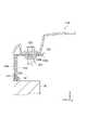
図7は、オプションセンサユニットの車両取り付けの他の例を示す図である。図7に示すように、車両1のルーフ2上においてルーフ前方センサ群10の他に、オプションセンサユニット60を追加で独立して設けてもよい。 FIG. 7 is a diagram showing another example of vehicle mounting of the optional sensor unit. As shown in FIG. 7, an
オプションセンサユニット60は、例えば左側オプションセンサユニット61及び右側オプションセンサユニット62を含んで構成されている。左側オプションセンサユニット61及び右側オプションセンサユニット62は、共通センサユニットではなく車両1のルーフ2に対して直接取り付けられている。これにより、車両1のルーフ2に対する外部センサの追加を汎用的に行うことができる。 The
図8は、共通センサユニット11を有する車両の参考例を示す図である。図8に示す乗用車5のルーフ2では、共通センサユニット11のみを採用している。すなわち、車種によってはオプションセンサユニットを採用しない選択肢も提供でき、設計自由度を高めることができる。 FIG. 8 is a diagram showing a reference example of a vehicle having the
共通フレーム体110及び各種のオプションフレーム体は必ずしもアングル部材を用いた構造である必要はない。板状部材や棒状部材を用いた構造であってもよい。なお、第一オプションセンサユニット12及び第二オプションセンサユニット13は、共通センサユニット11の他に、車両1のルーフ2に対して固定されてもよい。第四オプションフレーム体150は、車両前方に向かって突出するようにオフセット配置されてもよい。 The
1…車両、2…ルーフ、10…ルーフ前方センサ群、11…共通センサユニット、12…第一オプションセンサユニット、13…第二オプションセンサユニット、14…第三オプションセンサユニット、15…第四オプションセンサユニット、20…カメラ、21…LiDAR、110…共通フレーム体、120…第一オプションフレーム体、130…カバー部材、140…第三オプションフレーム体、150…第四オプションフレーム体。 1 ... Vehicle, 2 ... Roof, 10 ... Roof front sensor group, 11 ... Common sensor unit, 12 ... First option sensor unit, 13 ... Second option sensor unit, 14 ... Third option sensor unit, 15 ... Fourth option Sensor unit, 20 ... camera, 21 ... LiDAR, 110 ... common frame body, 120 ... first option frame body, 130 ... cover member, 140 ... third option frame body, 150 ... fourth option frame body.
Claims (4)
Translated fromJapanese前記車両のルーフに対して固定され、少なくとも一種類の前記外部センサが取り付けられた共通センサユニットと、
前記共通センサユニットに対して車両左側、車両右側、車両上側、車両前側、車両後側のうち少なくとも二方向で取り付け可能であり、前記共通センサユニットに対して取り外し可能に取り付けられると共に少なくとも一種類の前記外部センサが取り付けられたオプションセンサユニットと、
を備える、車両用センサ取り付け構造。A vehicle sensor mounting structure in which a plurality of types of external sensors for detecting the external condition of the vehicle are mounted on the roof of the vehicle.
A common sensor unit fixed to the roof of the vehicle and to which at least one type of external sensor is attached.
It can be attached to the common sensor unit in at least two directions of the left side of the vehicle, the right side of the vehicle, the upper side of the vehicle, the front side of the vehicle, and the rear side of the vehicle. The optional sensor unit to which the external sensor is attached and
With a vehicle sensor mounting structure.
Priority Applications (3)
| Application Number | Priority Date | Filing Date | Title |
|---|---|---|---|
| JP2020216868AJP7355003B2 (en) | 2020-12-25 | 2020-12-25 | Vehicle sensor mounting structure |
| US17/510,890US11858425B2 (en) | 2020-12-25 | 2021-10-26 | Vehicle sensor attaching structure |
| CN202111570916.7ACN114684028B (en) | 2020-12-25 | 2021-12-21 | Sensor mounting structure for vehicle |
Applications Claiming Priority (1)
| Application Number | Priority Date | Filing Date | Title |
|---|---|---|---|
| JP2020216868AJP7355003B2 (en) | 2020-12-25 | 2020-12-25 | Vehicle sensor mounting structure |
Publications (2)
| Publication Number | Publication Date |
|---|---|
| JP2022102245Atrue JP2022102245A (en) | 2022-07-07 |
| JP7355003B2 JP7355003B2 (en) | 2023-10-03 |
Family
ID=82118465
Family Applications (1)
| Application Number | Title | Priority Date | Filing Date |
|---|---|---|---|
| JP2020216868AActiveJP7355003B2 (en) | 2020-12-25 | 2020-12-25 | Vehicle sensor mounting structure |
Country Status (3)
| Country | Link |
|---|---|
| US (1) | US11858425B2 (en) |
| JP (1) | JP7355003B2 (en) |
| CN (1) | CN114684028B (en) |
Families Citing this family (5)
| Publication number | Priority date | Publication date | Assignee | Title |
|---|---|---|---|---|
| DE102022106885B4 (en)* | 2022-03-23 | 2025-04-30 | Webasto SE | Vehicle roof with environment sensor and cooling system |
| DE102022114950B3 (en)* | 2022-06-14 | 2023-12-07 | Webasto SE | Motor vehicle with a roof module and at least two environment sensors |
| US12208745B2 (en)* | 2022-10-27 | 2025-01-28 | Honda Motor Co., Ltd. | Water intrusion prevention system for roof top module |
| US20240326714A1 (en)* | 2023-03-31 | 2024-10-03 | Kodiak Robotics, Inc. | Roof mounted sensor pod assembly |
| US20240326712A1 (en)* | 2023-03-31 | 2024-10-03 | Kodiak Robotics, Inc. | Roof mounted sensor pod assembly |
Citations (3)
| Publication number | Priority date | Publication date | Assignee | Title |
|---|---|---|---|---|
| US20180257582A1 (en)* | 2017-03-08 | 2018-09-13 | Baidu Online Network Technology (Beijing) Co., Ltd. | Combinatory sensor apparatus |
| JP2019060680A (en)* | 2017-09-26 | 2019-04-18 | 三菱電機株式会社 | Sensor unit and measurement vehicle |
| JP2021154765A (en)* | 2020-03-25 | 2021-10-07 | 株式会社デンソー | Support mechanism used in measurement device unit |
Family Cites Families (12)
| Publication number | Priority date | Publication date | Assignee | Title |
|---|---|---|---|---|
| US10167015B2 (en) | 2015-05-11 | 2019-01-01 | GM Global Technology Operations LLC | System for retrofitting vehicle automation |
| JP6311685B2 (en)* | 2015-09-29 | 2018-04-18 | トヨタ自動車株式会社 | Vehicle sensor mounting structure |
| US10272850B2 (en) | 2016-07-15 | 2019-04-30 | Ford Global Technologies, Llc | Roof mounting for autonomous vehicle sensor assembly |
| US10099630B1 (en)* | 2017-06-29 | 2018-10-16 | Ford Global Technologies, Llc | Vehicle sensor mount |
| US10514303B2 (en)* | 2017-06-29 | 2019-12-24 | Ford Global Technologies, Llc | Sensor pod with breathable cabin interface |
| US10435077B2 (en) | 2017-11-29 | 2019-10-08 | Ford Global Technologies, Llc | Vehicle sensor cleaning |
| US10302744B1 (en)* | 2018-02-23 | 2019-05-28 | Ford Global Technologies, Llc | Sensor assembly |
| JP6816071B2 (en)* | 2018-08-24 | 2021-01-20 | ファナック株式会社 | Laser processing system, jet observation device, laser processing method, and jet observation method |
| US11240941B2 (en)* | 2018-09-12 | 2022-02-01 | Toyota Motor Engineering & Manufacturing North America, Inc. | Autonomous vehicle lidar cooling system |
| CN110040074A (en)* | 2019-04-04 | 2019-07-23 | 广州小马智行科技有限公司 | Automatic driving vehicle navigation equipment |
| DE102019122197B4 (en)* | 2019-08-19 | 2021-03-11 | Webasto SE | Roof module to form a vehicle roof with a carrier module |
| US20220075030A1 (en)* | 2020-09-09 | 2022-03-10 | Motional Ad Llc | Vehicle Sensor Mounting System |
- 2020
- 2020-12-25JPJP2020216868Apatent/JP7355003B2/enactiveActive
- 2021
- 2021-10-26USUS17/510,890patent/US11858425B2/enactiveActive
- 2021-12-21CNCN202111570916.7Apatent/CN114684028B/enactiveActive
Patent Citations (3)
| Publication number | Priority date | Publication date | Assignee | Title |
|---|---|---|---|---|
| US20180257582A1 (en)* | 2017-03-08 | 2018-09-13 | Baidu Online Network Technology (Beijing) Co., Ltd. | Combinatory sensor apparatus |
| JP2019060680A (en)* | 2017-09-26 | 2019-04-18 | 三菱電機株式会社 | Sensor unit and measurement vehicle |
| JP2021154765A (en)* | 2020-03-25 | 2021-10-07 | 株式会社デンソー | Support mechanism used in measurement device unit |
Also Published As
| Publication number | Publication date |
|---|---|
| CN114684028B (en) | 2023-12-05 |
| US20220203904A1 (en) | 2022-06-30 |
| CN114684028A (en) | 2022-07-01 |
| JP7355003B2 (en) | 2023-10-03 |
| US11858425B2 (en) | 2024-01-02 |
Similar Documents
| Publication | Publication Date | Title |
|---|---|---|
| JP2022102245A (en) | Vehicle sensor mounting structure | |
| US11815595B2 (en) | Vehicle sensor mounting structure and vehicle sensor bracket set | |
| EP4223584A3 (en) | Vehicle seat | |
| CN110294022A (en) | Car body fore part arrangement | |
| JP2008222185A (en) | Front body structure of vehicle | |
| CN104619924B (en) | Cab and work machinery | |
| US20200171998A1 (en) | Integrated lamp-and-camera module | |
| US11458917B2 (en) | Sensor attachment structure | |
| US8033595B2 (en) | Vehicle reinforcing structure | |
| CN106356483A (en) | Battery unit for a vehicle | |
| JP2021024319A (en) | Sensor attachment structure at side part of vehicle body | |
| CN102239306B (en) | Bonnet hinge for an automobile, and automobile including such a bonnet hinge | |
| JP2019162900A (en) | Vehicle body rear structure | |
| CN107042805A (en) | Battery fixing structure | |
| JP5433270B2 (en) | Vehicle traction device | |
| CN113573947B (en) | Near infrared sensor and structure for attaching sensor cover to vehicle | |
| US20220111799A1 (en) | Vehicle sensor attachment structure | |
| JP5785104B2 (en) | Tractor | |
| JP6551435B2 (en) | Arrangement structure of vehicle accessories | |
| CN113039093B (en) | Support for mounting an audible warning device on a body of a motor vehicle | |
| CN212373261U (en) | Integrated warning device and exterior rearview mirror assembly | |
| JP7119850B2 (en) | vehicle body structure | |
| US10173726B2 (en) | Vehicle body structure of automobile | |
| JP2005178441A (en) | Vehicle camera mounting structure | |
| CN116331119B (en) | Vehicle body structure |
Legal Events
| Date | Code | Title | Description |
|---|---|---|---|
| A621 | Written request for application examination | Free format text:JAPANESE INTERMEDIATE CODE: A621 Effective date:20220617 | |
| A977 | Report on retrieval | Free format text:JAPANESE INTERMEDIATE CODE: A971007 Effective date:20230323 | |
| A131 | Notification of reasons for refusal | Free format text:JAPANESE INTERMEDIATE CODE: A131 Effective date:20230404 | |
| A521 | Request for written amendment filed | Free format text:JAPANESE INTERMEDIATE CODE: A523 Effective date:20230522 | |
| TRDD | Decision of grant or rejection written | ||
| A01 | Written decision to grant a patent or to grant a registration (utility model) | Free format text:JAPANESE INTERMEDIATE CODE: A01 Effective date:20230822 | |
| A61 | First payment of annual fees (during grant procedure) | Free format text:JAPANESE INTERMEDIATE CODE: A61 Effective date:20230904 | |
| R151 | Written notification of patent or utility model registration | Ref document number:7355003 Country of ref document:JP Free format text:JAPANESE INTERMEDIATE CODE: R151 |