JP2022096094A - Developer replenishment device and image forming device - Google Patents
Developer replenishment device and image forming deviceDownload PDFInfo
- Publication number
- JP2022096094A JP2022096094AJP2020209007AJP2020209007AJP2022096094AJP 2022096094 AJP2022096094 AJP 2022096094AJP 2020209007 AJP2020209007 AJP 2020209007AJP 2020209007 AJP2020209007 AJP 2020209007AJP 2022096094 AJP2022096094 AJP 2022096094A
- Authority
- JP
- Japan
- Prior art keywords
- toner
- developer
- holding portion
- holding
- pump
- Prior art date
- Legal status (The legal status is an assumption and is not a legal conclusion. Google has not performed a legal analysis and makes no representation as to the accuracy of the status listed.)
- Pending
Links
Images


Classifications
- G—PHYSICS
- G03—PHOTOGRAPHY; CINEMATOGRAPHY; ANALOGOUS TECHNIQUES USING WAVES OTHER THAN OPTICAL WAVES; ELECTROGRAPHY; HOLOGRAPHY
- G03G—ELECTROGRAPHY; ELECTROPHOTOGRAPHY; MAGNETOGRAPHY
- G03G15/00—Apparatus for electrographic processes using a charge pattern
- G03G15/06—Apparatus for electrographic processes using a charge pattern for developing
- G03G15/08—Apparatus for electrographic processes using a charge pattern for developing using a solid developer, e.g. powder developer
- G03G15/0822—Arrangements for preparing, mixing, supplying or dispensing developer
- G03G15/0877—Arrangements for metering and dispensing developer from a developer cartridge into the development unit
- G03G15/0879—Arrangements for metering and dispensing developer from a developer cartridge into the development unit for dispensing developer from a developer cartridge not directly attached to the development unit
- G—PHYSICS
- G03—PHOTOGRAPHY; CINEMATOGRAPHY; ANALOGOUS TECHNIQUES USING WAVES OTHER THAN OPTICAL WAVES; ELECTROGRAPHY; HOLOGRAPHY
- G03G—ELECTROGRAPHY; ELECTROPHOTOGRAPHY; MAGNETOGRAPHY
- G03G15/00—Apparatus for electrographic processes using a charge pattern
- G03G15/06—Apparatus for electrographic processes using a charge pattern for developing
- G03G15/08—Apparatus for electrographic processes using a charge pattern for developing using a solid developer, e.g. powder developer
- G03G15/0822—Arrangements for preparing, mixing, supplying or dispensing developer
- G03G15/0865—Arrangements for supplying new developer
- G—PHYSICS
- G03—PHOTOGRAPHY; CINEMATOGRAPHY; ANALOGOUS TECHNIQUES USING WAVES OTHER THAN OPTICAL WAVES; ELECTROGRAPHY; HOLOGRAPHY
- G03G—ELECTROGRAPHY; ELECTROPHOTOGRAPHY; MAGNETOGRAPHY
- G03G15/00—Apparatus for electrographic processes using a charge pattern
- G03G15/06—Apparatus for electrographic processes using a charge pattern for developing
- G03G15/08—Apparatus for electrographic processes using a charge pattern for developing using a solid developer, e.g. powder developer
- G03G15/0894—Reconditioning of the developer unit, i.e. reusing or recycling parts of the unit, e.g. resealing of the unit before refilling with toner
- G—PHYSICS
- G03—PHOTOGRAPHY; CINEMATOGRAPHY; ANALOGOUS TECHNIQUES USING WAVES OTHER THAN OPTICAL WAVES; ELECTROGRAPHY; HOLOGRAPHY
- G03G—ELECTROGRAPHY; ELECTROPHOTOGRAPHY; MAGNETOGRAPHY
- G03G2215/00—Apparatus for electrophotographic processes
- G03G2215/06—Developing structures, details
- G03G2215/066—Toner cartridge or other attachable and detachable container for supplying developer material to replace the used material
- G03G2215/0685—Toner cartridge or other attachable and detachable container for supplying developer material to replace the used material fulfilling a continuous function within the electrographic apparatus during the use of the supplied developer material, e.g. toner discharge on demand, storing residual toner, not acting as a passive closure for the developer replenishing opening
Landscapes
- Physics & Mathematics (AREA)
- General Physics & Mathematics (AREA)
- Dry Development In Electrophotography (AREA)
- Life Sciences & Earth Sciences (AREA)
- Sustainable Development (AREA)
Abstract
Description
Translated fromJapanese本発明は、電子写真形成プロセスを用いた画像形成装置および画像形成装置に使用される現像剤補給装置に関する。 The present invention relates to an image forming apparatus using an electrophotographic forming process and a developer replenishing apparatus used in the image forming apparatus.
従来の電子写真画像形成装置には、トナーを収容した収容容器と、収容されたトナーを収容容器から排出する排出手段と、が一体的に構成された「トナーカートリッジ」が採用されている。 A conventional electrophotographic image forming apparatus employs a "toner cartridge" in which a storage container containing toner and a discharging means for discharging the stored toner from the storage container are integrally configured.
例えば、特許文献1のトナーカートリッジB100では、図13に示すように、トナーを収納する現像剤収納117と、トナーを排出する排出手段を有する構成が示されている。また、排出手段として、ジャバラポンプ121を用いて排出部123より下方にトナーを排出する構成が提案されていた。 For example, in the toner cartridge B100 of Patent Document 1, as shown in FIG. 13, a configuration having a
本発明は、上述の従来技術を発展させたものであり、所定量のトナーを安定的に搬送することができる構成を提供するものである。 The present invention is an extension of the above-mentioned conventional technique, and provides a configuration capable of stably transporting a predetermined amount of toner.
本発明の現像剤補給装置は、
画像形成装置に使用される現像剤補給装置であって、
現像剤を収容する収容容器と、
容積可変なポンプと、
一端には前記ポンプが連通され、他端には外部に開口する開口部が設けられ、前記ポンプと前記開口部の間で現像剤を搬送する経路を形成する搬送経路部材と、
前記収容容器と前記搬送経路部材を連通すると共に、前記収容容器から前記搬送経路部材へ現像剤を移送する移送部材と、
を有し、
前記移送部材は、
所定容積の現像剤を保持する保持部と、
前記収容容器と前記保持部が連通され前記収容容器から前記保持部に現像剤を充填可能な第1の位置と、前記保持部と前記搬送経路部材が連通される第2の位置との間で、前記保持部を移動する移動機構と、を備える、ことを特徴とする。The developer replenishing device of the present invention is
A developer replenishment device used in an image forming device.
A container for accommodating the developer and
With a variable volume pump,
A transport path member through which the pump is communicated at one end and an opening is provided at the other end to open to the outside to form a path for transporting the developer between the pump and the opening.
A transfer member that communicates the storage container with the transport path member and transfers the developer from the storage container to the transport path member.
Have,
The transfer member is
A holding part that holds a predetermined volume of developer,
Between the first position where the storage container and the holding portion are communicated and the developing agent can be filled from the storage container to the holding portion, and the second position where the holding portion and the transport path member are communicated with each other. , A moving mechanism for moving the holding portion, and the like.
本発明によれば、所定量のトナーを安定的に搬送することができる。 According to the present invention, a predetermined amount of toner can be stably conveyed.
以下、本発明の各実施例について説明する。 Hereinafter, each embodiment of the present invention will be described.
なお、以下の各実施例において、画像形成装置とは、電子写真画像形成プロセスを用いて記録媒体に画像を形成するもので、例えば電子写真複写機、電子写真プリンター(LEDプリンター、レーザービームプリンタ等)、電子写真ファクシミリ装置等が含まれる。 In each of the following embodiments, the image forming apparatus forms an image on a recording medium by using an electrophotographic image forming process, for example, an electrophotographic copying machine, an electrophotographic printer (LED printer, laser beam printer, etc.). ), Electrophotographic facsimile equipment, etc. are included.
また、現像剤補給装置とは、少なくとも現像剤を収容する収容容器と、収容容器から現像剤を排出する排出手段と、を備えるものである。例えば、以下の実施例において、トナーカートリッジの形態として現像剤補給装置について説明する。なお、現像剤補給装置は、画像形成装置本体に対して着脱可能なように構成されてもよい。 Further, the developer replenishing device includes at least a container for accommodating the developer and a discharging means for discharging the developer from the container. For example, in the following embodiment, the developer replenishing device will be described as a form of the toner cartridge. The developer replenishing device may be configured to be detachable from the image forming apparatus main body.
(画像形成装置C)
まず、図1を用いて画像形成装置の全体構成について説明する。(Image forming apparatus C)
First, the overall configuration of the image forming apparatus will be described with reference to FIG.
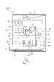
図1は、本発明の実施例1における画像形成装置の断面概念図である。 FIG. 1 is a conceptual cross-sectional view of the image forming apparatus according to the first embodiment of the present invention.
なお、以下の説明において、図1に示す上下方向(鉛直方向)を「Y方向」、水平方向を「X方向」、奥行き方向を「Z方向」とした座標系とする。 In the following description, the coordinate system is defined in which the vertical direction (vertical direction) shown in FIG. 1 is the "Y direction", the horizontal direction is the "X direction", and the depth direction is the "Z direction".
画像形成装置Cの装置本体C1には、プロセスカートリッジAと、トナーカートリッジB(現像剤補給装置)が装着されて画像形成に用いられる。 A process cartridge A and a toner cartridge B (developerable agent replenishing device) are mounted on the apparatus main body C1 of the image forming apparatus C and used for image forming.
画像形成動作は、装置本体の下部に装着されたシートカセット6からシートS(記録紙)を搬送し、このシート搬送と同期して、感光体ドラム11(像担持体)に露光装置8から選択的な露光をして潜像を形成する。 In the image forming operation, the sheet S (recording paper) is conveyed from the sheet cassette 6 mounted on the lower part of the main body of the apparatus, and in synchronization with the sheet transfer, the photoconductor drum 11 (image carrier) is selected from the
トナーは、トナー収容部17より現像ローラ13(現像剤担持体)に供給され、現像ブレード15により現像ローラ13表面に薄層担持される。現像ローラ13に現像バイアスを印加することによって、潜像に応じてトナーを供給しトナー像に現像する。この像を転写ローラ9への転写バイアス印加によって搬送されるシートSに転写する。 The toner is supplied to the developing roller 13 (developer carrier) from the
シートSは、定着装置10へ搬送され画像定着し、装置上部の排紙部4に排出される。ここで、トナーカートリッジBの内部に収容されたトナーは、排出部23(開口部)から装置本体C1の本体経路部1を通り、受け入れ部18を通じてプロセスカートリッジAへ供給される。本体経路部1は、中空の管状(チューブ状)である。 The sheet S is conveyed to the
(プロセスカートリッジA)
図1を用いてプロセスカートリッジAの構成について説明する。(Process cartridge A)
The configuration of the process cartridge A will be described with reference to FIG.
プロセスカートリッジとは、像担持体と、像担持体に作用するプロセス手段を備えたものである。ここで、プロセス手段としては、例えば像担持体の表面を帯電させる帯電手段、像担持体に像を形成する現像装置、像担持体表面に残留したトナーを除去するためのクリーニング手段がある。 The process cartridge includes an image carrier and a process means that acts on the image carrier. Here, as the process means, for example, there are a charging means for charging the surface of the image carrier, a developing device for forming an image on the image carrier, and a cleaning means for removing the toner remaining on the surface of the image carrier.
本実施形態のプロセスカートリッジAは、装置本体C1に対して、着脱自在に構成されている。そして、プロセスカートリッジAは、像担持体である感光体ドラム11の周囲に帯電手段である帯電ローラ12、クリーニング手段として弾性を有するクリーニングブレード14を備えている。 The process cartridge A of the present embodiment is configured to be detachably attached to the apparatus main body C1. The process cartridge A is provided with a
また、プロセスカートリッジAは、現像手段である現像ローラ13と現像ブレード15、トナーを収納するトナー収容部17を備える。また、トナー収容部17には後述するトナーカートリッジBより供給されるトナーを受け入れる受け入れ部18を有している。 Further, the process cartridge A includes a developing
ここで、画像形成装置C内部のトナーの移動について先に説明しておく。即ち、トナーカートリッジBからプロセスカートリッジAへのトナーの流れについて説明する。 Here, the movement of the toner inside the image forming apparatus C will be described first. That is, the flow of toner from the toner cartridge B to the process cartridge A will be described.
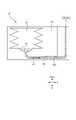
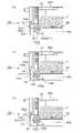
図2は、本発明の実施例1におけるトナーカートリッジの断面概念図である。 FIG. 2 is a conceptual cross-sectional view of the toner cartridge according to the first embodiment of the present invention.
図3は、本発明の実施例1におけるトナーカートリッジの上面概念図である。即ち、図3は、図2に示す方向Y1に沿ってトナーカートリッジをみたときの状態を概念的に示めしている。また、図2は、図3の一点鎖線L2の断面を、図3における右方向に沿って見た状態を概念的に示めしている。 FIG. 3 is a top conceptual view of the toner cartridge according to the first embodiment of the present invention. That is, FIG. 3 conceptually shows the state when the toner cartridge is viewed along the direction Y1 shown in FIG. Further, FIG. 2 conceptually shows a state in which the cross section of the alternate long and short dash line L2 in FIG. 3 is viewed along the right direction in FIG.
トナーカートリッジBのトナー収容部22内部には、後述する搬送手段31が設けられている。トナーカートリッジBの長手一端側のJ1方向にトナーを搬送する。 A transport means 31, which will be described later, is provided inside the
搬送手段31(搬送部材)は、板状の(搬送)部材42(以下、「搬送部材42」とも称する場合がある)を含む。搬送部材42の上面421は、トナーを担持可能な担持面である。なお、搬送部材42を長手一端側のJ1方向と他端側のJ2方向に往復し、J1方向に移動する加速度よりも、J2方向に移動する時の加速度を大きくすることでトナーを搬送する。 The transporting means 31 (conveying member) includes a plate-shaped (conveying) member 42 (hereinafter, may also be referred to as a “conveying
即ち、搬送手段31は、トナー収容部22から後述するトナー保持部102(保持部)へトナーを搬送することができる。 That is, the transport means 31 can transport toner from the
そして、搬送手段31を、担持面(上面421)を備える板状の部材から構成してもよい。また、トナー保持部102(保持部)に近づく第1方向(J1)における最大加速度が、トナー保持部102(保持部)から離れて第1方向とは逆方向である第2方向J2における最大加速度よりも小さくなるように、搬送手段31を往復移動することができる。 Then, the transport means 31 may be composed of a plate-shaped member having a supporting surface (upper surface 421). Further, the maximum acceleration in the first direction (J1) approaching the toner holding portion 102 (holding portion) is the maximum acceleration in the second direction J2 away from the toner holding portion 102 (holding portion) and in the direction opposite to the first direction. The transport means 31 can be reciprocated so as to be smaller than the above.
そして、図3に示すように、搬送手段31によって第1方向J1側に送られたトナーは、後述するトナー移送部材101(保持体)に集められる。 Then, as shown in FIG. 3, the toner sent to the J1 side in the first direction by the transport means 31 is collected by the toner transfer member 101 (holding body) described later.
トナー移送部材101に供給されたトナーは、トナー移送部材101が移動することにより、図2に示すように、流路24(経路)に運ばれる。なお、トナー移送部材101から流路24(経路)へのトナーの流れは、後述する。 The toner supplied to the
流路24(経路)に運ばれたトナーは、ポンプ部21が圧縮する時に発生する空気の流れる方向D1に沿って移動し排出部23側へ送られる。 The toner carried in the flow path 24 (path) moves along the flow direction D1 of the air generated when the
そして、図1で示すように、トナーカートリッジBの排出部23から送り出されたトナーは、画像形成装置Cの本体経路部1を通り、プロセスカートリッジAの受け入れ部18を通じてプロセスカートリッジAのトナー収容部17へ搬送される。 Then, as shown in FIG. 1, the toner sent out from the
(トナーカートリッジB)
次に、図2~図5を用いて、トナーカートリッジBの構成について説明する。(Toner cartridge B)
Next, the configuration of the toner cartridge B will be described with reference to FIGS. 2 to 5.
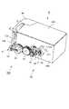
図4は、本発明の実施例1におけるトナーカートリッジの斜視概念図である。 FIG. 4 is a perspective conceptual diagram of the toner cartridge according to the first embodiment of the present invention.
図5は、本発明の実施例1におけるトナーカートリッジの分解(組立前の)概念図である。 FIG. 5 is a conceptual diagram of the toner cartridge disassembled (before assembly) according to the first embodiment of the present invention.
図2は、本発明の実施例1におけるトナーカートリッジの断面概念図である。 FIG. 2 is a conceptual cross-sectional view of the toner cartridge according to the first embodiment of the present invention.
本実施例では、トナーカートリッジBは、装置本体C1に対して、着脱自在に構成されている。 In this embodiment, the toner cartridge B is detachably configured with respect to the apparatus main body C1.
トナーカートリッジB(現像剤補給装置)は、画像形成装置Cに使用されるものである。トナーカートリッジBは、トナー(現像剤)を収容するトナー収容部22(収容容器)と、容積可変なポンプ部21(ポンプ)と、搬送経路部材103と、後述するトナー移送手段100(移送部材)と、を備えている。 The toner cartridge B (developer replenishing device) is used for the image forming device C. The toner cartridge B includes a toner accommodating portion 22 (accommodating container) for accommodating toner (developer), a pump unit 21 (pump) having a variable volume, a
搬送経路部材103は、内部に、トナーを搬送する流路24(経路)が形成されている。流路24の一端24aには、ポンプ部21が連通され、他端24bには、外部に開口する排出部23(開口部)が設けられている。即ち、流路24は、ポンプ部と開口部の間でトナーを搬送可能なように構成されている。 A flow path 24 (path) for transporting toner is formed inside the
ポンプ部21(ポンプ)は、容積変化により空気の流れをつくることができる。流路24内のトナーは、ポンプ部21によって作られた空気の流れによって移動(搬送)される。そして、排出部23を介して、トナー収容部22内のトナーをトナーカートリッジBの外部(即ち、後述するプロセスカートリッジA側)へ排出(補給)することができる。 The pump unit 21 (pump) can create an air flow by changing the volume. The toner in the
後述するトナー移送手段100(移送部材)は、トナー収容部22と搬送経路部材103(流路24)を連通し、トナー収容部22から搬送経路部材103(の流路24)へトナーを移送することができる。即ち、流路24の途中には、トナー収容部22から所定量のトナーを流路24に安定的に供給するトナー移送手段100が配置される。 The toner transfer means 100 (transfer member), which will be described later, communicates the
また、後述するトナー移送手段100は、所定容積のトナーを保持するトナー保持部102(保持部)が備えられたトナー移送部材101(保持体)と、移動機構Mと、を備えている。移動機構Mは、トナー移送部材101を移動するものである。 Further, the toner transfer means 100, which will be described later, includes a toner transfer member 101 (holding body) provided with a toner holding portion 102 (holding portion) for holding a predetermined volume of toner, and a moving mechanism M. The moving mechanism M moves the
具体的には、移動構成Mによって、トナー移送部材101が、第1の位置P1(状態)と、第2の位置P2(状態)の間で、移動(切換)可能である。 Specifically, the movement configuration M allows the
第1の位置(状態)P1では、トナー収容部22とトナー保持部102が連通され、トナー収容部22からトナー保持部102にトナーを充填することができる。第2の位置(状態)P2では、トナー保持部102と搬送経路部材103(流路24)が連通されるようになる。 At the first position (state) P1, the
図4に示すようにトナーカートリッジBは枠体40aと蓋部40dおよびポンプカバー48により外郭を形成される。 As shown in FIG. 4, the toner cartridge B has an outer shell formed by a
図5に示すように、トナーカートリッジBは枠体40a、蓋部40d、搬送手段31、トナー移送手段100(移動部材)、チューブ104、ポンプ部21、ポンプカバー48で構成している。 As shown in FIG. 5, the toner cartridge B includes a
搬送手段31は、搬送部材42、搬送軸43、揺動回転部材41、付勢部材46、回転部材45、アイドラギヤ47、および、入力ギヤ60を含む。 The transport means 31 includes a
トナー移送手段100(移動部材)は、駆動機構M、および、トナー移送部材101(保持体)を含む。なお、駆動機構Mは、入力ギヤ60、回転部材61、ゼネバホイール62、軸部材63などを含む。 The toner transfer means 100 (moving member) includes a drive mechanism M and a toner transfer member 101 (holding body). The drive mechanism M includes an
ポンプ部21は、ジャバラ部材26、ポンプ駆動ギヤ27、および、ポンプ駆動往復部材28を含む。 The
(ポンプ部21)
ここで、図6から図8を用いて、ポンプ部21およびポンプ部21周辺の構成について説明する。(Pump unit 21)
Here, the configuration of the
図6は、本発明の実施例1におけるポンプ部の分解概念図である。 FIG. 6 is an exploded conceptual diagram of the pump unit according to the first embodiment of the present invention.
図7(a、b)は、本発明の実施例1におけるポンプ部の組立時の断面概念図である。 7 (a, b) is a cross-sectional conceptual diagram at the time of assembling the pump part in Example 1 of this invention.
図8(a、b)は、本発明の実施例1におけるポンプ部の動作時の各状態を示す概念図である。 8 (a, b) are conceptual diagrams showing each state at the time of operation of the pump part in Example 1 of this invention.
より具体的には、図6、図8には、本発明のポンプ部21の駆動構成が示されている。特に、図8(a)には、拡張時の状態が示めされ、図8(b)には、圧縮時の状態が示めされている。また、図7(a)には、組立前の状態が示され、図7(b)には組立後の状態が示されている。 More specifically, FIGS. 6 and 8 show a drive configuration of the
図6で示すように、ポンプ部21は断面が丸く、下方が開放したジャバラ部材26の一部で構成される。ジャバラ部材26は、ジャバラ部分26a、一端にポンプ駆動往復部材28と係合する係合部26b、他端が開放した形状であり固定する固定部26cから構成される。 As shown in FIG. 6, the
そして、図7(a)に示すように固定部26cはネジ状の形状を有しており、搬送経路部材103に対してD3方向に回転して固定される。搬送経路部材103は、内部に流路24が設けられている。今後の説明において、ポンプ部21は容積変化をするジャバラ部分26aの部分を指す。一方、容積変化をしない固定部26cはポンプ部21ではなく流路24に含まれる。よってポンプ部21と流路24との境界となるところは、図7(b)に示すように、ジャバラ部材26のジャバラ部と固定部26cの境界G1である。 Then, as shown in FIG. 7A, the fixing
図8で示すように、ポンプ部21はポンプ駆動ギヤ27、ポンプ駆動往復部材28を介して下方向に圧縮、上方向に拡張する。ポンプ駆動ギヤ27はギヤ部27aとカム部27bを有し、画像形成装置Cより入力された駆動力をギヤ部27aで受けてD2方向に回転する。そしてその回転によりカム部27bに係合したポンプ駆動往復部材28を上下方向に動かす。 As shown in FIG. 8, the
(搬送手段31)
次に、図4、図5を用いて、搬送手段31の駆動構成について説明する。(Transporting means 31)
Next, the drive configuration of the transport means 31 will be described with reference to FIGS. 4 and 5.
図5に示すように、枠体40aに、回転部材45と揺動回転部材41をそれぞれ回転可能に支持する支持部と、揺動回転部材41と搬送軸43が係合するための穴である連通口を設けている。そして、揺動回転部材41は連通口を通じて、トナー収容部22内に設けた搬送軸43に揺動回転部材41の一部が係合するよう構成している。 As shown in FIG. 5, the
また、図4に示すように、アイドラギヤ47と回転部材45のギヤ部が噛み合い、入力ギヤ60が回転することで、アイドラギヤ47を介して回転部材45が回転するよう構成している。また、揺動回転部材41には、回転部材45のカム部に当接する腕部を設けている。また、付勢部材46はねじりコイルばねで構成し、付勢部材46の付勢力を発生する方向がCCW方向に設定される。 Further, as shown in FIG. 4, the gear portion of the
次に、図3、図4を用いて、搬送部材42のトナー搬送作用について説明する。 Next, the toner transporting action of the transporting
図4に示すように、装置本体Cに設けた駆動力(不図示)により、入力ギヤ60が回転することで、アイドラギヤ47、回転部材45を介して揺動回転部材41がCW方向に回転と、付勢部材46の付勢力によりCCW方向の回転を繰り返す。 As shown in FIG. 4, a driving force (not shown) provided in the apparatus main body C causes the
この際、図3に示すように、揺動回転部材41の動きに連動し搬送軸43を介して搬送部材42が搬送方向J1と、搬送方向J1の反対方向J2の往復運動を繰り返すことで、搬送部材42上のトナーは搬送方向J1に搬送される。 At this time, as shown in FIG. 3, the
(トナー移送手段100)
次に、図5、図9、図10を用いて、トナー移送手段100の駆動構成について説明する。(Toner transfer means 100)
Next, the drive configuration of the toner transfer means 100 will be described with reference to FIGS. 5, 9, and 10.
図9(a~c)は、本発明の実施例1におけるトナー移送部材の動作時の各状態の断面概念図である。即ち、図9には、トナー移送手段100の主断面が概念的に示されている。 9 (a to 9) are cross-sectional conceptual views of each state at the time of operation of the toner transfer member in Example 1 of this invention. That is, FIG. 9 conceptually shows the main cross section of the toner transfer means 100.
図10(a~c)は、本発明の実施例1におけるトナー移送手段の動作時の駆動伝達の概念図である。 10 (a to c) are conceptual diagrams of drive transmission during operation of the toner transfer means according to the first embodiment of the present invention.
図9(a)に示すように、トナー収容部22の枠体40a内に、軸部材63が連結されたトナー移送部材101を配置している。 As shown in FIG. 9A, the
図5に示すように、枠体40aに、軸部材63と回転部材61をそれぞれ回転可能に支持する支持穴401と支持部402を設けている。そして、軸部材63は搬送経路部材103の支持穴103aを通して、搬送経路部材103の内部に内包されるトナー移送部材101の係合穴101aに連結される。搬送経路部材103はトナー移送部材101を内包した状態で枠体40aに取り付けられる。 As shown in FIG. 5, the
また、軸部材63の一端にはゼネバホイール62を取り付け、回転部材61が一回転するとゼネバホイール62が90度回転するように構成している。 Further, a
次に、図9を用いてトナー移送部材101の構成について説明する。 Next, the configuration of the
図9に示すように、トナー移送部材101は、トナー収容部22内のトナーを流路24に移送するための円筒状の部材である。トナー移送部材101の外周面には内部にトナーを保持するためのトナー保持部102(保持部)を90度おきに4箇所(102a~102d)複数に同形状で設けている。即ち、複数のトナー保持部(102a~102d)が互いに均等の距離を持ってトナー移送部材101に配置される。 As shown in FIG. 9, the
トナー保持部102が円形となる軌跡に沿って移動するように、トナー移送部材101は、移動機構Mによって回転される。 The
搬送経路部材103に内包されるトナー移送部材101は、軸部材63が回転しない間、トナー保持部102のひとつが搬送経路部材103の流路24の一部となるような位置に設けている。同時に、トナー移送部材101のトナー保持部102のひとつがトナー収容部22内のトナーが搬送部材42により供給可能な位置になるよう配置している。 The
次に、図9、図10を用いて、トナー移送手段100の作用について説明する。 Next, the operation of the toner transfer means 100 will be described with reference to FIGS. 9 and 10.
装置本体Cに設けた駆動力(不図示)により、図10(a)に示すように、入力ギヤ60をCW方向に回転させると、入力ギヤ60と噛み合う回転部材61がCCW方向に回転する。そして、図10(a)、図10(b)に経て図10(c)に至るように、回転部材61が1回転する毎にゼネバホイール62がCW方向に90度回転するよう構成している。ゼネバホイール62の動きは軸部材63を介してトナー移送部材101に伝達する。そのため、図9(a)、図9(b)に経て図9(c)に至るように、トナー移送部材101はゼネバホイール62のCW方向の回転に連動してCW方向に90度回転する。 As shown in FIG. 10A, when the
この際、図9(a)に示すように、トナー移送部材101のトナー保持部102には、トナー収容部22内の搬送部材42の搬送方向J1に搬送されたトナーTが供給される。そして、トナー移送部材101の回転に伴い、図9(a)、図9(b)を経て図9(c)に示す状態へと変化し、搬送経路部材103の円周面に沿ってトナー保持部102のトナーを擦切りって所定量のトナーを保持した状態となる。 At this time, as shown in FIG. 9A, the toner T transported in the transport direction J1 of the
さらに、トナー移送部材101のトナー保持部102が所定量のトナーを内包した状態で回転し、図9(c)に示すように、搬送経路部材103の流路24の一部となる。 Further, the
トナー保持部102が流路24の一部となった状態で、ポンプ部21の圧縮により発生したエアーは流路24を通り、流路24の一部であるトナー保持部102が内包したトナーと共に流路24を通過して排出部23に向けてトナーを噴出する。そして、トナーカートリッジBの排出部23から送り出されたトナーは、画像形成装置Cの本体経路部1を通り、プロセスカートリッジAの受け入れ部18を通じてプロセスカートリッジAのトナー収容部17へ搬送される。 In a state where the
このような一連の動作を繰り返すことにより、トナーカートリッジBのトナー収容部22からプロセスカートリッジAのトナー収容部17へ供給するトナー量をコントロールする。 By repeating such a series of operations, the amount of toner supplied from the
上述したトナー移送手段の作用により、トナー移送部材101から(トナー)流路24に所定量のトナーが安定して供給され、トナーカートリッジBからプロセスカートリッジAのトナー収容部17へ供給するトナー量をコントロールすることが可能となる。 By the action of the toner transfer means described above, a predetermined amount of toner is stably supplied from the
なお本実施例ではポンプ部21の容積を約10cc、流路24の容積と本体経路部1の合わせた容積を約3ccとして、ポンプ部21の容積を流路24の容積の2倍以上としている。また、トナー移送部材のトナー保持部の容積を0.4cc程度とした。 In this embodiment, the volume of the
上述した諸条件はこれに限定されるものではなく、トナーの種類や特性、各部材の形状や材質、配置等により適宜選択することができる。 The above-mentioned conditions are not limited to this, and can be appropriately selected depending on the type and characteristics of the toner, the shape and material of each member, the arrangement, and the like.
また、トナー搬送手段は上述した往復運動する搬送部材に限定されるものではなく、回転する撹拌シートやスクリューを利用したもの、または、搬送部材を設けずトナーの自重を利用したトナー搬送手段であっても適宜構成可能である。 Further, the toner transporting means is not limited to the above-mentioned reciprocating transporting member, but is a toner transporting means using a rotating stirring sheet or screw, or a toner transporting means using the own weight of the toner without providing the transporting member. However, it can be configured as appropriate.
実施例1ではトナー移送部材101が回転することにより流路24に所定量のトナーを安定して供給する構成について説明したが、本実施例では、トナー移送部材201が平行移動することにより流路24に所定量のトナーを安定して供給する構成について説明する。 In the first embodiment, a configuration in which a predetermined amount of toner is stably supplied to the
画像形成プロセスや、プロセスカートリッジAの構成は実施例1と同様であり、トナーカートリッジBの構成はトナー移送手段の構成を除き実施例1と同様である。 The image forming process and the configuration of the process cartridge A are the same as those of the first embodiment, and the configuration of the toner cartridge B is the same as that of the first embodiment except for the configuration of the toner transfer means.
(トナー移送手段の構成)
図11、図12を用いて、本実施例の特徴的な構成であるトナー移送手段200の構成について説明する。(Structure of toner transfer means)
The configuration of the toner transfer means 200, which is a characteristic configuration of this embodiment, will be described with reference to FIGS. 11 and 12.
図11(a、b)は、本発明の実施例2におけるトナー移送部材の動作時の駆動伝達の概念図である。 11 (a and b) are conceptual diagrams of drive transmission during operation of the toner transfer member according to the second embodiment of the present invention.
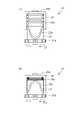
図12(a、b)は、本発明の実施例2におけるトナー移送部材の動作時の断面概念図である。 12A and 12B are conceptual cross-sectional views of the toner transfer member according to the second embodiment of the present invention during operation.
図11に示すように、トナー移送手段200はカム部材210、トナー移送部材201、搬送経路部材103、また図12に示すように付勢部材203で構成している。 As shown in FIG. 11, the toner transfer means 200 is composed of a
図11(a)、図11(b)に示すように、トナー移送部材201はカム部材210がCCW方向に回転することによりJ1方向に平行に移動可能に構成している。さらに、図12(a)、図12(b)に示すように、トナー移送部材201には付勢部材203の一端が連結され、付勢部材203の他端を枠体40aに固定することでトナー移送部材201にJ2方向に付勢力が働くよう構成している。 As shown in FIGS. 11A and 11B, the
次に、図12を用いてトナー移送部材201の構成について説明する。 Next, the configuration of the
図12(a)に示すように、トナー移送部材201は、トナー収容部22内のトナーを流路24に移送するための四角柱型の部材である。トナー移送部材201の一部には内部にトナーを保持するためのトナー保持部202を設けている。 As shown in FIG. 12A, the
次に、図11、図12を用いて、トナー移送部材201の作用について説明する。 Next, the operation of the
図11(a)、図11(b)に示すように、カム部材210がCCW方向に1回転する毎に、トナー移送部材201がJ1方向とJ2方向に往復運動する。 As shown in FIGS. 11 (a) and 11 (b), each time the
この際、トナー移送部材201のトナー保持部202には、トナー収容部22内の搬送部材42の搬送方向J1に搬送されたトナーが供給されている。トナー移送部材201の平行移動に伴い、トナー保持部202のトナーを枠体40aで擦切りって所定量のトナーを安定して保持した状態となる。 At this time, the toner conveyed in the conveying direction J1 of the conveying
さらに、トナー移送部材201のトナー保持部202が所定量のトナーを内包した状態で平行移動し、移動が完了した図12(b)に示す状態で、トナー保持部202が搬送経路部材103の流路24の一部となるよう構成している。 Further, the
図12(b)に示すように、トナー保持部202が流路24の一部となった状態で、ポンプ部21の圧縮により発生したエアーは流路24を通る。そして、流路24の一部であるトナー保持部202が内包したトナーと共に流路24を通過して排出部23に向けてトナーを噴出する。また、トナーカートリッジBの排出部23から送り出されたトナーは、画像形成装置Cの本体経路部1を通り、プロセスカートリッジAの受け入れ部18を通じてプロセスカートリッジAのトナー収容部17へ搬送される。 As shown in FIG. 12B, the air generated by the compression of the
このような一連の動作を繰り返すことにより、トナーカートリッジBのトナー収容部22からプロセスカートリッジAのトナー収容部17へ供給するトナー量をコントロールする。 By repeating such a series of operations, the amount of toner supplied from the
上述したトナー移送手段の作用により、トナー移送部材201から流路24に所定量のトナーが安定して供給され、トナーカートリッジBからトナーカートリッジAのトナー収容部17へ供給するトナー量をコントロールすることが可能となる。 By the action of the toner transfer means described above, a predetermined amount of toner is stably supplied from the
このように、本実施例の構成では、所定量のトナーを安定的に搬送することができる。特に、ポンプで発生させた空気の流れを利用して上方や離れた場所に現像剤収容部から所定量のトナーを安定的に搬送することができる。 As described above, in the configuration of this embodiment, a predetermined amount of toner can be stably conveyed. In particular, it is possible to stably convey a predetermined amount of toner from the developer accommodating portion to an upper position or a distant place by utilizing the air flow generated by the pump.
本発明を以下のように纏めることができる。 The present invention can be summarized as follows.
(1)本発明の現像剤補給装置(B)は、画像形成装置(C)に使用されるものであって、現像剤を収容する収容容器(22)と、容積可変なポンプ(21)と、搬送経路部材(103)と、移送部材(100)と、を有する。 (1) The developer replenishing device (B) of the present invention is used for the image forming apparatus (C), and includes a storage container (22) for accommodating the developer and a pump (21) having a variable volume. , A transport path member (103) and a transport member (100).
搬送経路部材は、一端(24a)にはポンプが連通され、他端(24b)には外部に開口する開口部(23)が設けられ、ポンプと開口部の間で現像剤を搬送する経路(24)を形成するように構成されている。 In the transport path member, a pump is communicated with one end (24a), and an opening (23) is provided at the other end (24b) to open to the outside, and a path (pass) for transporting the developer between the pump and the opening. 24) is configured to form.
移送部材は、収容容器と搬送経路部材を連通すると共に、収容容器から搬送経路部材へ現像剤を移送するように構成され、所定容積の現像剤を保持する保持部(102)を備える保持体(101)と、移動機構(M)と、を備えている。 The transfer member is configured to communicate the accommodating container and the transport path member and transfer the developer from the accommodating container to the transport path member, and is provided with a holding unit (102) for holding a predetermined volume of the developer (102). It includes a 101) and a moving mechanism (M).
なお、移動機構は、収容容器と保持部が連通され収容容器から保持部に現像剤を充填可能な第1の位置(P1)と、保持部と搬送経路部材が連通される第2の位置(P2)との間で保持体(101)を移動するように構成される。 The moving mechanism has a first position (P1) in which the storage container and the holding portion are communicated and the developing agent can be filled from the storage container to the holding portion, and a second position (P1) in which the holding portion and the transport path member are communicated with each other. It is configured to move the retainer (101) to and from P2).
(2)本発明の現像剤補給装置では、保持体(101)に保持部(102a~d)を複数に設けることができる。 (2) In the developer replenishing device of the present invention, a plurality of holding portions (102a to d) can be provided on the holding body (101).
(3)本発明の現像剤補給装置では、複数の保持部(102)を、互いに均等の距離を持って保持体(101)に配置してもよい。 (3) In the developer replenishing device of the present invention, a plurality of holding portions (102) may be arranged on the holding body (101) at equal distances from each other.
(4)本発明の現像剤補給装置では、保持部(102)が円形となる軌跡に沿って移動するように、保持体(101)を移動機構(M)によって回転するようにしてもよい。 (4) In the developer replenishing device of the present invention, the holding body (101) may be rotated by the moving mechanism (M) so that the holding portion (102) moves along a circular locus.
(5)本発明の現像剤補給装置では、収容容器(22)から保持部(102)へ現像剤を搬送する搬送部材(31)を備えることができる。 (5) The developer replenishing device of the present invention may include a transport member (31) for transporting the developer from the storage container (22) to the holding portion (102).
(6)本発明の現像剤補給装置では、搬送部材(31)を、使用時の姿勢において現像剤を担持可能な担持面(421)を備える板状の部材(42)から構成してもよい。この場合、保持部(102)に近づく第1方向(J1)における最大加速度が、保持部(102)から離れて第1方向とは逆方向である第2方向(J2)における最大加速度よりも小さくなるように、搬送部材(31)を往復移動するようにしてもよい。 (6) In the developer replenishing device of the present invention, the transport member (31) may be composed of a plate-shaped member (42) provided with a supporting surface (421) capable of supporting the developer in the posture during use. .. In this case, the maximum acceleration in the first direction (J1) approaching the holding portion (102) is smaller than the maximum acceleration in the second direction (J2) away from the holding portion (102) and in the direction opposite to the first direction. The transport member (31) may be reciprocated so as to be.
(7)本発明の現像剤補給装置では、搬送部材(31)の駆動動作と、移動機構(M)の動作を、同期して行うことができる。 (7) In the developer replenishing device of the present invention, the driving operation of the transport member (31) and the operation of the moving mechanism (M) can be performed in synchronization.
具体的には、保持体(101)の保持部(102)が収容容器と連通する位置へ移動機構(M)を駆動させる際、搬送部材(31)が保持部(102)に近づく第1方向(J1)に移動させるように搬送部材(31)の駆動動作を同期させてもよい。 Specifically, when the moving mechanism (M) is driven to a position where the holding portion (102) of the holding body (101) communicates with the storage container, the transport member (31) approaches the holding portion (102) in the first direction. The drive operation of the transport member (31) may be synchronized so as to move to (J1).
(8)本発明の現像剤補給装置では、移動機構(M)の駆動動作と、ポンプ(21)の駆動動作を、同期して行うことができる。 (8) In the developer replenishing device of the present invention, the driving operation of the moving mechanism (M) and the driving operation of the pump (21) can be performed in synchronization.
具体的には、保持体(101)の保持部(102)が搬送経路部材の経路(24)と連通する位置へ移動機構(M)を駆動させる際、ポンプ(21)が圧縮動作を行うよう駆動動作を同期させてもよい。 Specifically, when the holding portion (102) of the holding body (101) drives the moving mechanism (M) to a position where it communicates with the path (24) of the transport path member, the pump (21) performs a compression operation. The drive operation may be synchronized.
(9)本発明の現像剤補給装置では、収容容器(22)を、現像剤補給装置(B)に対して着脱可能なように構成してもよい。 (9) In the developer replenishing device of the present invention, the storage container (22) may be configured to be detachable from the developer replenishing device (B).
(10)本発明の画像形成装置は、前述の現像剤補給装置(B)と、現像剤補給装置から供給される現像剤を担持する現像剤担持体(13)と、現像剤からなる現像剤像を担持する像担持体(11)と、を備える。 (10) The image forming apparatus of the present invention comprises the above-mentioned developer replenishing device (B), a developer carrier (13) carrying a developer supplied from the developer replenishing device, and a developer. An image carrier (11) that carries an image is provided.
21 ポンプ部(ポンプ)
22 トナー収容部(収容容器)
23 排出部(開口部)
24 流路(経路)
24a 一端(経路の一端)
24b 他端(経路の他端)
100 トナー移送手段(移送部材)
101 トナー移送部材(保持体)
102 トナー保持部(保持部)
103 搬送経路部材
B トナーカートリッジ(現像剤補給装置)
C 画像形成装置
M 移動機構
P1 第1の位置
P2 第2の位置21 Pump section (pump)
22 Toner container (container)
23 Discharge (opening)
24 Flow path (path)
24a One end (one end of the route)
24b The other end (the other end of the path)
100 Toner transfer means (transfer member)
101 Toner transfer member (holding body)
102 Toner holding part (holding part)
103 Transport path member B Toner cartridge (developer replenisher)
C Image forming device M Moving mechanism P1 First position P2 Second position
Claims (10)
Translated fromJapanese現像剤を収容する収容容器と、
容積可変なポンプと、
一端には前記ポンプが連通され、他端には外部に開口する開口部が設けられ、前記ポンプと前記開口部の間で現像剤を搬送する経路を形成する搬送経路部材と、
前記収容容器と前記搬送経路部材を連通すると共に、前記収容容器から前記搬送経路部材へ現像剤を移送する移送部材と、
を有し、
前記移送部材は、
所定容積の現像剤を保持する保持部を備える保持体と、
前記収容容器と前記保持部が連通され前記収容容器から前記保持部に現像剤を充填可能な第1の位置と、前記保持部と前記搬送経路部材が連通される第2の位置との間で、前記保持体を移動する移動機構と、を備える、ことを特徴とする現像剤補給装置。A developer replenishment device used in an image forming device.
A container for accommodating the developer and
With a variable volume pump,
A transport path member through which the pump is communicated at one end and an opening is provided at the other end to open to the outside to form a path for transporting the developer between the pump and the opening.
A transfer member that communicates the storage container with the transport path member and transfers the developer from the storage container to the transport path member.
Have,
The transfer member is
A holding body provided with a holding portion for holding a predetermined volume of the developer, and
Between the first position where the storage container and the holding portion are communicated and the developing agent can be filled from the storage container to the holding portion, and the second position where the holding portion and the transport path member are communicated with each other. , A developer replenishing device comprising a moving mechanism for moving the holding body.
使用時の姿勢において現像剤を担持可能な担持面を備える板状の部材から構成されており、前記保持部に近づく第1方向における最大加速度が、前記保持部から離れて前記第1方向とは逆方向である第2方向における最大加速度よりも小さくなるように、前記搬送部材が往復移動される、ことを特徴とする請求項5に記載の現像剤補給装置。The transport member is
It is composed of a plate-shaped member having a carrying surface capable of carrying the developer in the posture during use, and the maximum acceleration in the first direction approaching the holding portion is different from the first direction away from the holding portion. The developer replenishing device according to claim 5, wherein the transport member is reciprocated so as to be smaller than the maximum acceleration in the second direction, which is the reverse direction.
前記現像剤補給装置から供給される現像剤を担持する現像剤担持体と、
現像剤からなる現像剤像を担持する像担持体と、を備える、ことを特徴とする画像形成装置。The developer replenishing device according to any one of claims 1 to 9.
A developer carrier that supports the developer supplied from the developer replenishment device, and a developer carrier.
An image forming apparatus comprising: an image carrier for supporting a developer image made of a developer.
Priority Applications (5)
| Application Number | Priority Date | Filing Date | Title |
|---|---|---|---|
| JP2020209007AJP2022096094A (en) | 2020-12-17 | 2020-12-17 | Developer replenishment device and image forming device |
| EP21906675.0AEP4266125A4 (en) | 2020-12-17 | 2021-12-09 | DEVELOPER REPLACEMENT DEVICE AND IMAGE FORMING DEVICE |
| CN202180083739.1ACN117178234A (en) | 2020-12-17 | 2021-12-09 | Developer replenishing device and image forming device |
| PCT/JP2021/046398WO2022131314A1 (en) | 2020-12-17 | 2021-12-09 | Developing agent resupply device and image formation device |
| US18/206,144US12174558B2 (en) | 2020-12-17 | 2023-06-06 | Developer replenishment device and image forming apparatus |
Applications Claiming Priority (1)
| Application Number | Priority Date | Filing Date | Title |
|---|---|---|---|
| JP2020209007AJP2022096094A (en) | 2020-12-17 | 2020-12-17 | Developer replenishment device and image forming device |
Publications (1)
| Publication Number | Publication Date |
|---|---|
| JP2022096094Atrue JP2022096094A (en) | 2022-06-29 |
Family
ID=82059530
Family Applications (1)
| Application Number | Title | Priority Date | Filing Date |
|---|---|---|---|
| JP2020209007APendingJP2022096094A (en) | 2020-12-17 | 2020-12-17 | Developer replenishment device and image forming device |
Country Status (5)
| Country | Link |
|---|---|
| US (1) | US12174558B2 (en) |
| EP (1) | EP4266125A4 (en) |
| JP (1) | JP2022096094A (en) |
| CN (1) | CN117178234A (en) |
| WO (1) | WO2022131314A1 (en) |
Citations (5)
| Publication number | Priority date | Publication date | Assignee | Title |
|---|---|---|---|---|
| JP2005195659A (en)* | 2003-12-26 | 2005-07-21 | Ricoh Co Ltd | Developer supply device and image forming apparatus |
| JP5623109B2 (en)* | 2009-03-30 | 2014-11-12 | キヤノン株式会社 | Developer supply container and developer supply system |
| JP2017102344A (en)* | 2015-12-03 | 2017-06-08 | キヤノン株式会社 | Image forming apparatus |
| JP2020166182A (en)* | 2019-03-29 | 2020-10-08 | キヤノン株式会社 | Cartridge and image forming device |
| JP2020169062A (en)* | 2019-04-01 | 2020-10-15 | 富士ゼロックス株式会社 | Powder supply device and image forming apparatus |
Family Cites Families (35)
| Publication number | Priority date | Publication date | Assignee | Title |
|---|---|---|---|---|
| JP2003098813A (en) | 2001-09-21 | 2003-04-04 | Ricoh Co Ltd | Image forming device |
| JP2004177835A (en) | 2002-11-29 | 2004-06-24 | Canon Inc | Parts and how to supply parts |
| JP2005077743A (en) | 2003-08-29 | 2005-03-24 | Canon Inc | Developing frame, process cartridge, and electrophotographic image forming apparatus |
| JP2005148445A (en) | 2003-11-17 | 2005-06-09 | Canon Inc | Developing device, process cartridge, electrophotographic image forming apparatus, and end regulating member |
| JP4617122B2 (en) | 2004-09-08 | 2011-01-19 | キヤノン株式会社 | Developer transport member, developing device, and process cartridge |
| JP4335216B2 (en)* | 2005-01-17 | 2009-09-30 | 株式会社リコー | Electrophotographic powder toner transfer method, transfer device, filling method, and filling device |
| JP4737541B2 (en)* | 2005-09-05 | 2011-08-03 | 株式会社リコー | Developer transport device and image forming apparatus |
| JP4954821B2 (en)* | 2007-07-27 | 2012-06-20 | 株式会社リコー | Development device and image forming device |
| JP5140871B2 (en) | 2007-11-08 | 2013-02-13 | 株式会社リコー | Image forming apparatus |
| CN103869666B (en)* | 2009-03-30 | 2017-10-03 | 佳能株式会社 | Developer replenishing container and developer supplying system |
| PH12014500118A1 (en) | 2011-07-14 | 2014-02-17 | Canon Kk | Developer accommodating unit, process cartridge, electrophotographic image forming apparatus |
| JP5420025B2 (en) | 2011-07-14 | 2014-02-19 | キヤノン株式会社 | Developer storage unit, process cartridge, electrophotographic image forming apparatus |
| JP5420026B2 (en) | 2011-07-14 | 2014-02-19 | キヤノン株式会社 | Developer storage container, developer storage unit, process cartridge, electrophotographic image forming apparatus |
| EP2733543B1 (en) | 2011-07-14 | 2020-04-15 | Canon Kabushiki Kaisha | Developer storage container, process cartridge, and electrophotographic image forming device |
| JP2013024919A (en)* | 2011-07-15 | 2013-02-04 | Ricoh Co Ltd | Image forming method and image forming apparatus |
| JP5911275B2 (en) | 2011-11-29 | 2016-04-27 | キヤノン株式会社 | Developer storage unit, developing device, process cartridge, electrophotographic image forming apparatus |
| JP6157078B2 (en) | 2012-09-04 | 2017-07-05 | キヤノン株式会社 | Developing unit, process cartridge, and image forming apparatus |
| JP6116162B2 (en) | 2012-09-10 | 2017-04-19 | キヤノン株式会社 | Developer storage unit, developing device, process cartridge, and image forming apparatus |
| JP6066841B2 (en) | 2012-09-10 | 2017-01-25 | キヤノン株式会社 | Developing cartridge, process cartridge, and image forming apparatus |
| JP5980061B2 (en) | 2012-09-11 | 2016-08-31 | キヤノン株式会社 | Developer container, process cartridge, and image forming apparatus |
| JP6245932B2 (en) | 2012-11-06 | 2017-12-13 | キヤノン株式会社 | Cartridge, developing cartridge, process cartridge, and image forming apparatus |
| JP6116254B2 (en) | 2013-01-11 | 2017-04-19 | キヤノン株式会社 | Developer storage unit, developing device, process cartridge, image forming apparatus |
| JP6282149B2 (en) | 2013-06-05 | 2018-02-21 | キヤノン株式会社 | Developer storage unit, developing device, process cartridge, and image forming apparatus |
| JP2015092226A (en) | 2013-10-01 | 2015-05-14 | キヤノン株式会社 | Powder conveyance mechanism, powder conveying method, developer storage container, cartridge, and image forming apparatus |
| JP6525556B2 (en)* | 2014-01-29 | 2019-06-05 | キヤノン株式会社 | Developing device, process cartridge and electrophotographic image forming apparatus |
| JP6429597B2 (en)* | 2014-11-10 | 2018-11-28 | キヤノン株式会社 | Developer supply container |
| JP2016090932A (en)* | 2014-11-10 | 2016-05-23 | キヤノン株式会社 | Developer supply container, developer supply device, and image forming apparatus |
| JP6671997B2 (en) | 2015-02-05 | 2020-03-25 | キヤノン株式会社 | Cartridge, photoreceptor unit, electrophotographic image forming apparatus |
| JP7013113B2 (en) | 2015-06-30 | 2022-01-31 | キヤノン株式会社 | Sealing members, units and image forming devices |
| JP2017083559A (en)* | 2015-10-26 | 2017-05-18 | キヤノンファインテック株式会社 | Developing device, process cartridge, and image forming apparatus |
| WO2017142099A1 (en) | 2016-02-18 | 2017-08-24 | Canon Kabushiki Kaisha | Cartridge and image forming apparatus |
| KR102128342B1 (en) | 2016-07-04 | 2020-07-08 | 캐논 가부시끼가이샤 | Reproduction method for developing device |
| US10739702B2 (en) | 2018-07-06 | 2020-08-11 | Canon Kabushiki Kaisha | Developer accommodating unit, cartridge and image forming apparatus |
| WO2021054482A1 (en) | 2019-09-17 | 2021-03-25 | キヤノン株式会社 | Developer supply device and image forming apparatus |
| JP7494013B2 (en)* | 2020-05-28 | 2024-06-03 | キヤノン株式会社 | Toner cartridge and image forming apparatus |
- 2020
- 2020-12-17JPJP2020209007Apatent/JP2022096094A/enactivePending
- 2021
- 2021-12-09EPEP21906675.0Apatent/EP4266125A4/enactivePending
- 2021-12-09WOPCT/JP2021/046398patent/WO2022131314A1/ennot_activeCeased
- 2021-12-09CNCN202180083739.1Apatent/CN117178234A/enactivePending
- 2023
- 2023-06-06USUS18/206,144patent/US12174558B2/enactiveActive
Patent Citations (5)
| Publication number | Priority date | Publication date | Assignee | Title |
|---|---|---|---|---|
| JP2005195659A (en)* | 2003-12-26 | 2005-07-21 | Ricoh Co Ltd | Developer supply device and image forming apparatus |
| JP5623109B2 (en)* | 2009-03-30 | 2014-11-12 | キヤノン株式会社 | Developer supply container and developer supply system |
| JP2017102344A (en)* | 2015-12-03 | 2017-06-08 | キヤノン株式会社 | Image forming apparatus |
| JP2020166182A (en)* | 2019-03-29 | 2020-10-08 | キヤノン株式会社 | Cartridge and image forming device |
| JP2020169062A (en)* | 2019-04-01 | 2020-10-15 | 富士ゼロックス株式会社 | Powder supply device and image forming apparatus |
Also Published As
| Publication number | Publication date |
|---|---|
| US20230324831A1 (en) | 2023-10-12 |
| CN117178234A (en) | 2023-12-05 |
| EP4266125A4 (en) | 2024-11-20 |
| EP4266125A1 (en) | 2023-10-25 |
| US12174558B2 (en) | 2024-12-24 |
| WO2022131314A1 (en) | 2022-06-23 |
Similar Documents
| Publication | Publication Date | Title |
|---|---|---|
| CN104516246A (en) | Powder feeding mechanism, powder feeding method, developer accommodating container, cartridge and image forming apparatus | |
| JP7494013B2 (en) | Toner cartridge and image forming apparatus | |
| JP2025075095A (en) | Developer replenishing device and image forming apparatus | |
| JP2022096094A (en) | Developer replenishment device and image forming device | |
| KR100757819B1 (en) | Process cartridge and image forming apparatus using the same | |
| JP6494293B2 (en) | Cleaning device, process cartridge, image forming apparatus | |
| JP2016184138A (en) | Developer container, developing device, process cartridge, and image forming apparatus | |
| JP7427396B2 (en) | Developing device, process cartridge and image forming device | |
| JPS5868768A (en) | Image former | |
| US20200174401A1 (en) | Developer supplying apparatus, developing apparatus, cartridge, and image forming apparatus | |
| JP6501582B2 (en) | Developer container, developing device, process cartridge and image forming apparatus | |
| JP7375400B2 (en) | Holding member, developer supply device, and image forming device | |
| JP2017076014A (en) | Container, cleaning device, developing device, process cartridge, and image forming apparatus | |
| JP6186942B2 (en) | Powder supply device and image forming apparatus | |
| JP2005338397A (en) | Developer storage device, development device, and image forming apparatus | |
| JP7129023B2 (en) | POWDER CONTAINER, POWDER SUPPLY DEVICE AND IMAGE FORMING APPARATUS | |
| JP2021047224A (en) | Developer replenishment device and image forming device | |
| JP2002099136A (en) | Image forming device | |
| CN118092101A (en) | Developer replenishing device and imaging device | |
| JP4580993B2 (en) | Fluid container and image forming apparatus | |
| JP2019164262A (en) | Developer storage body, developer image forming unit, and image forming apparatus | |
| JP2021152603A (en) | Developer supply container | |
| JP2024002826A (en) | Toner cartridge and image forming apparatus | |
| JP2020166094A (en) | Develop equipment, process cartridge and image forming equipment | |
| JP2020166185A (en) | Cleaning unit, cartridge and image forming device |
Legal Events
| Date | Code | Title | Description |
|---|---|---|---|
| RD01 | Notification of change of attorney | Free format text:JAPANESE INTERMEDIATE CODE: A7421 Effective date:20231213 | |
| A621 | Written request for application examination | Free format text:JAPANESE INTERMEDIATE CODE: A621 Effective date:20231214 | |
| A131 | Notification of reasons for refusal | Free format text:JAPANESE INTERMEDIATE CODE: A131 Effective date:20250212 | |
| A521 | Request for written amendment filed | Free format text:JAPANESE INTERMEDIATE CODE: A523 Effective date:20250409 | |
| A131 | Notification of reasons for refusal | Free format text:JAPANESE INTERMEDIATE CODE: A131 Effective date:20250624 | |
| A521 | Request for written amendment filed | Free format text:JAPANESE INTERMEDIATE CODE: A523 Effective date:20250808 | |
| A01 | Written decision to grant a patent or to grant a registration (utility model) | Free format text:JAPANESE INTERMEDIATE CODE: A01 Effective date:20250909 |