JP2022094921A - Containment vessel and image formation system - Google Patents
Containment vessel and image formation systemDownload PDFInfo
- Publication number
- JP2022094921A JP2022094921AJP2021172315AJP2021172315AJP2022094921AJP 2022094921 AJP2022094921 AJP 2022094921AJP 2021172315 AJP2021172315 AJP 2021172315AJP 2021172315 AJP2021172315 AJP 2021172315AJP 2022094921 AJP2022094921 AJP 2022094921A
- Authority
- JP
- Japan
- Prior art keywords
- fold
- storage container
- pouch
- toner
- image forming
- Prior art date
- Legal status (The legal status is an assumption and is not a legal conclusion. Google has not performed a legal analysis and makes no representation as to the accuracy of the status listed.)
- Pending
Links
Images


Landscapes
- Dry Development In Electrophotography (AREA)
- Electrophotography Configuration And Component (AREA)
Abstract
Translated fromJapaneseDescription
Translated fromJapanese本発明は、粉体を収容する収容容器、及び収容容器を用いて記録材に画像を形成する画像形成システムに関する。 The present invention relates to a container for storing powder and an image forming system for forming an image on a recording material using the container.
一般に、電子写真方式の画像形成装置は、感光ドラムの表面に形成したトナー像を、転写媒体としての転写材に転写することで、画像を形成する。そして、現像剤の補給方式は、例えばプロセスカートリッジ方式やトナー補給方式が知られている。プロセスカートリッジ方式は、感光ドラムと現像容器をプロセスカートリッジとして一体化し、現像剤が切れるとプロセスカートリッジを新品に交換する方式である。 Generally, an electrophotographic image forming apparatus forms an image by transferring a toner image formed on the surface of a photosensitive drum to a transfer material as a transfer medium. As a developer replenishment method, for example, a process cartridge method or a toner replenishment method is known. The process cartridge method is a method in which a photosensitive drum and a developing container are integrated as a process cartridge, and when the developer runs out, the process cartridge is replaced with a new one.
一方、トナー補給方式は、トナーが切れると、新たにトナーを現像容器に補給する方式である。従来、トナーが搬送されるトナー搬送路に、トナーを補給可能なトナー供給箱が接続されるトナー補給方式の一成分現像装置が提案されている(特許文献1参照)。トナー供給箱に貯留されたトナーは、搬送スクリューによってトナー搬送路に搬送される。 On the other hand, the toner replenishment method is a method of replenishing the developing container with new toner when the toner runs out. Conventionally, a toner replenishment type one-component developing device has been proposed in which a toner supply box capable of replenishing toner is connected to a toner transfer path through which toner is conveyed (see Patent Document 1). The toner stored in the toner supply box is conveyed to the toner transfer path by the transfer screw.
近年、画像形成装置に対するトナーの補給容器について、様々な使われ方や形態がユーザから求められている。例えば、パウチを用いた可撓性のトナー収容容器が提案されている(特許文献2参照)。 In recent years, users have requested various ways and forms of toner supply containers for image forming devices. For example, a flexible toner container using a pouch has been proposed (see Patent Document 2).
そこで、本発明は、操作性が更に向上した、粉体を収容可能な収容容器及び画像形成システムの一形態を提供することを目的とする。 Therefore, an object of the present invention is to provide a form of a storage container and an image forming system capable of containing powder, which has further improved operability.
本発明の収容容器は、
粉体を収容する収容容器であって、
底部と、開口を形成するように前記底部から延びる側部とを備え、可撓性を有するパウチと、
前記側部の、前記開口側の内側に設けられ、前記パウチの内外を連通する連通部を備える連通部材と、を備え、
前記連通部材は、前記底部に対向する対向面を備え、
前記側部は、前記連通部材の前記対向面の縁部に沿って折り形状を形成する折り形成部を有する、ことを特徴とする。The storage container of the present invention is
A container for storing powder
A flexible pouch with a bottom and sides extending from the bottom to form an opening.
A communication member provided inside the opening side of the side portion and having a communication portion that communicates inside and outside the pouch.
The communication member comprises a facing surface facing the bottom.
The side portion is characterized by having a fold-forming portion that forms a fold shape along the edge of the facing surface of the communicating member.
また、本発明の画像形成システムは、
現像剤が収容される、上記の収容容器と、
前記収容容器が装着される装着部を備える画像形成装置と、を有し、
前記収容容器より補給される現像剤を用いて画像形成動作を行う、ことを特徴とする。Further, the image forming system of the present invention is
The above-mentioned container in which the developer is stored, and
It has an image forming apparatus including a mounting portion on which the storage container is mounted, and has.
It is characterized in that an image forming operation is performed using a developer supplied from the container.
本発明によれば、操作性が更に向上した、粉体を収容可能な収容容器及び画像形成システムの一形態を提供することができる。 INDUSTRIAL APPLICABILITY According to the present invention, it is possible to provide a form of a storage container and an image forming system capable of containing powder, which has further improved operability.
以下、本発明を実施するための例示的な形態について、図面を参照しながら説明する。 Hereinafter, exemplary embodiments for carrying out the present invention will be described with reference to the drawings.
<第1の実施形態>
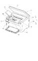
図1(a)は、第1の実施形態に係る画像形成装置1を示す断面概念図である。図1(b)は、画像形成装置1の斜視概念図である。<First Embodiment>
FIG. 1A is a cross-sectional conceptual diagram showing an
本実施形態では、画像形成装置1は、外部機器から入力される画像情報に基づいて記録材Pに画像を形成するモノクロプリンターである。記録材Pには、普通紙及び厚紙等の紙、オーバーヘッドプロジェクタ用シート等のプラスチックフィルム、封筒やインデックス紙等の特殊形状のシート、並びに布等の、材質の異なる様々なシート材が含まれる。 In the present embodiment, the
(画像形成装置の全体構成)
図1(a)、(b)に示すように、本実施形態では、画像形成装置1は、記録材Pにトナー像を形成する画像形成部10と、画像形成部10に記録材Pを給送するピックアップローラ65と、定着部70と、排出ローラ対80と、を有している。なお、定着部70は、画像形成部10によって形成されたトナー像を記録材Pに定着させるものである。(Overall configuration of image forming device)
As shown in FIGS. 1A and 1B, in the present embodiment, the
また、画像形成部10は、スキャナユニット11と、電子写真方式のプロセスカートリッジ20と、プロセスカートリッジ20の感光ドラム21に形成された現像剤像としてのトナー像を記録材Pに転写する転写ローラ12と、を有している。プロセスカートリッジ20は、感光ドラム21と、感光ドラム21の周囲に配置された帯電ローラ22、前露光装置23及び現像ローラ31を含む現像装置30を有している。 Further, the
本実施形態では、感光ドラム21は、円筒型に成形された感光体である。なお、感光ドラム21は、アルミニウムで成形されたドラム状の基体上に、負帯電性の有機感光体で形成された感光層を有している。また、像担持体としての感光ドラム21は、モータによって所定の方向(図中時計周り方向)に所定のプロセススピードで回転駆動される。 In the present embodiment, the
帯電ローラ22は、感光ドラム21に所定の圧接力で接触し、帯電部を形成する。また、帯電高圧電源によって所望の帯電電圧を印加されることで、感光ドラム21の表面を所定の電位に均一に帯電させる。 The
本実施形態では、感光ドラム21は帯電ローラ22により負極性に帯電する。前露光装置23は、帯電部で安定した放電を生じさせるために、帯電部に侵入する前の感光ドラム21の表面電位を除電する。 In the present embodiment, the
露光手段としてのスキャナユニット11は、外部機器から入力された画像情報に対応したレーザ光を、ポリゴンミラーを用いて感光ドラム21に照射することで、感光ドラム21の表面を走査露光する。これにより、感光ドラム21の表面に画像情報に応じた静電潜像が形成される。なお、スキャナユニット11は、レーザスキャナ装置に限定されることはなく、例えば、感光ドラム21の長手方向に沿って複数のLEDが配列されたLEDアレイを有するLED露光装置を採用してもよい。 The
現像装置30は、現像剤を担持する現像剤担持体としての現像ローラ31と、現像装置30の枠体となる現像容器32と、現像ローラ31に現像剤を供給可能な供給ローラ33と、を備えている。現像ローラ31及び供給ローラ33は、現像容器32によって回転可能に支持されている。また、現像ローラ31は、感光ドラム21に対向するように、現像容器32の開口部に配置されている。 The developing
供給ローラ33は、現像ローラ31に回転可能に当接しており、現像容器32に収容されている現像剤としてのトナーは供給ローラ33によって現像ローラ31の表面に塗布される。なお、現像ローラ31に十分にトナーを供給できる構成であれば、必ずしも供給ローラ33は必要としない。 The
本実施形態では、現像装置30は、現像方式として接触現像方式を用いている。即ち、現像ローラ31に担持されたトナー層が、感光ドラム21と現像ローラ31とが対向する現像部(現像領域)において感光ドラム21と接触する。現像ローラ31には現像高圧電源によって現像電圧が印加される。 In this embodiment, the developing
現像電圧の下で、現像ローラ31に担持されたトナーが感光ドラム21の表面の電位分布に従って現像ローラ31からドラム表面に転移することで、静電潜像がトナー像に現像される。なお、本実施形態では、反転現像方式を採用している。即ち、帯電工程において帯電させられた後、露光工程において露光されることで電荷量が減衰した感光ドラム21の表面領域にトナーが付着することでトナー像が形成される。 Under the developing voltage, the toner carried on the developing
また、本実施形態では、粒径が6μmで、正規の帯電極性が負極性のトナーを用いている。本実施形態のトナーは一例として重合法により生成された重合トナーを採用している。 Further, in the present embodiment, a toner having a particle size of 6 μm and a normal charge polarity of negative electrode is used. As an example, the toner of the present embodiment uses a polymerized toner produced by a polymerization method.
また、本実施形態のトナーは磁性成分を含有せず、主に分子間力や静電気力(鏡像力)によってトナーが現像ローラ31に担持される、所謂非磁性の一成分現像剤である。ただし、磁性成分を含有する一成分現像剤を用いてもよい。 Further, the toner of the present embodiment does not contain a magnetic component, and is a so-called non-magnetic one-component developer in which the toner is supported on the developing
また、一成分現像剤には、トナー粒子以外にもトナーの流動性や帯電性能を調整するための添加物(例えば、ワックスやシリカ微粒子)が含まれている場合がある。また、現像剤として非磁性のトナーと磁性を有するキャリアとによって構成された二成分現像剤を用いてもよい。磁性を有する現像剤を用いる場合、現像剤担持体としては、例えば内側にマグネットが配置された円筒状の現像スリーブが用いられる。 In addition to the toner particles, the one-component developer may contain additives (for example, wax or silica fine particles) for adjusting the fluidity and charging performance of the toner. Further, as the developer, a two-component developer composed of a non-magnetic toner and a carrier having magnetism may be used. When a magnetic developer is used, for example, a cylindrical developing sleeve in which a magnet is arranged inside is used as the developer carrier.
現像容器32には、トナーを収容するトナー収容室36と、トナー収容室36の内部に配置される撹拌手段としての撹拌部材34と、が設けられている。撹拌部材34は、不図示のモータに駆動されて回動することで、現像容器32内のトナーを撹拌すると共に、現像ローラ31及び供給ローラ33に向け、トナーを送り込む。また、撹拌部材34は、現像に使用されず現像ローラ31から剥ぎ取られたトナーを現像容器内で循環させ、現像容器内のトナーを均一化する役割を有する。 The developing
なお、撹拌部材34は、回動する形態に限定されない。例えば、揺動する形態の撹拌部材を採用してもよい。 The stirring
また、現像ローラ31が配置される現像容器32の開口部には、現像ローラ31に担持されるトナーの量を規制する現像ブレード35が配置されている。現像ローラ31の表面に供給されたトナーは、現像ローラ31の回転に伴って現像ブレード35との対向部を通過することで、均一に薄層化され、また摩擦帯電により負極性に帯電させられる。 Further, a developing
次に、画像形成装置1の画像形成動作について説明する。 Next, the image forming operation of the
画像形成装置1に画像形成の指令が入力されると、画像形成装置1に接続された外部のコンピュータから入力された画像情報に基づいて、画像形成部10による画像形成プロセスが開始される。スキャナユニット11は、入力された画像情報に基づいて、感光ドラム21に向けてレーザ光を照射する。 When a command for image formation is input to the
このとき感光ドラム21は、帯電ローラ22により予め帯電されており、レーザ光が照射されることで感光ドラム21上に静電潜像が形成される。その後、現像ローラ31によりこの静電潜像が現像され、感光ドラム21上にトナー像が形成される。 At this time, the
上述の画像形成プロセスに並行して、記録材Pはピックアップローラ65によって送り出され、転写ローラ12及び感光ドラム21によって形成される転写ニップに向けて搬送される。 In parallel with the image forming process described above, the recording material P is sent out by the
転写ローラ12には、転写高圧電源から転写電圧が印加され、記録材Pに感光ドラム21に担持されているトナー像が転写される。 A transfer voltage is applied to the
トナー像を転写された記録材Pは、定着部70を通過する際にトナー像が加熱及び加圧される。これによりトナー粒子が溶融し、その後固着することで、トナー像が記録材Pに定着する。 When the recording material P to which the toner image is transferred passes through the fixing
定着部70を通過した記録材Pは、排出手段としての排出ローラ対80によって画像形成装置1の外部(機外)に排出され、プリンタ本体2の上部に形成された積載部としての排出トレイ81に積載される。プリンタ本体2の上部には、積載トレイとしてのトップカバー82が設けられており、トップカバー82の上面には、積載面としての排出トレイ81が形成されている。 The recording material P that has passed through the fixing
トップカバー82には、図1(b)及び図2に示すように、開閉部材83が前後方向に延びる回動軸83aを中心に開閉可能に支持されている。なお、図2は、第1の実施形態に係る読取装置が開かれた状態の画像形成装置を示す斜視概念図である。トップカバー82の排出トレイ81には、上方に開口した開口部82aが形成されている。 As shown in FIGS. 1B and 2, the
開閉部材83は、トナーパック100(収容容器)が現像容器32に装着できないように後述する補給口32aを覆う閉位置と、トナーパック100が現像容器32に装着できるように補給口32aを露出させる開位置と、の間を移動可能に構成される。開閉部材83は、閉位置において、排出トレイ81の一部として機能する。 The opening / closing
本実施形態では、開閉部材83及び開口部82aは、排出トレイ81の左側に形成されている。また、開閉部材83は、トップカバー82に設けられた溝部82bから指を掛けることで左方向に開かれる。開閉部材83は、トップカバー82の形状に沿って、略L字状に形成されている。 In the present embodiment, the opening / closing
排出トレイ81の開口部82aは、現像容器32の上部(画像形成装置の上側)に形成されたトナー補給用の補給口32aが露出するように開口しており、開閉部材83が開かれることで、ユーザは補給口32aにアクセスすることができる。 The
なお、本実施形態では、現像装置30が画像形成装置1に装着されている状態のまま、ユーザが補給用のトナーが充填されているトナーパック100(図1(a)(b)参照)から現像装置30へとトナーを補給する方式(直接補給方式)を採用している。トナーパック100は、画像形成装置1に装着された状態で、少なくとも一部が外部に露出している。 In this embodiment, from the toner pack 100 (see FIGS. 1A and 1B) filled with toner for replenishment by the user while the developing
このため、プロセスカートリッジ20のトナー残量が少なくなった場合に、プロセスカートリッジ20をプリンタ本体2から取り出して新品のプロセスカートリッジに交換する作業が不要になるので、ユーザビリティを向上することができる。 Therefore, when the remaining amount of toner in the process cartridge 20 becomes low, it is not necessary to take out the process cartridge 20 from the printer
また、プロセスカートリッジ20全体を交換するよりも安価に現像容器32にトナーを補給することができる。なお、直接補給方式は、プロセスカートリッジ20の現像装置30のみを交換する場合に比しても、各種のローラやギヤ等を交換する必要が無いので、コストダウンできる。なお、画像形成装置1及びトナーパック100は、画像形成システム1000を構成している。 Further, the toner can be replenished to the developing
(トナーパックの構成)
次に、図3、図4および図9を用いて、本実施形態の、トナー(粉体)を収容するトナーパック100(収容容器)の構成について説明する。特に、本発明の特徴である、トナーパックのパウチの側部に設けられた「折り形状」および「折り形成部」について詳細に説明する。(Toner pack configuration)
Next, the configuration of the toner pack 100 (container container) for accommodating the toner (powder) of the present embodiment will be described with reference to FIGS. 3, 4, and 9. In particular, the "folded shape" and the "folded portion" provided on the side portion of the pouch of the toner pack, which are the features of the present invention, will be described in detail.
図3(a)、(b)は、第1の実施形態に係るトナーパックを異なる視点で見た分解斜視概念図である。 3A and 3B are conceptual perspective views of the toner pack according to the first embodiment as viewed from different viewpoints.
図4(a)は、第1の実施形態に係るトナーパックの排出口が遮蔽された状態を示す斜視概念図である。図4(b)は、トナーパックの排出口が開放された状態を示す斜視概念図である。 FIG. 4A is a perspective conceptual diagram showing a state in which the discharge port of the toner pack according to the first embodiment is shielded. FIG. 4B is a perspective conceptual diagram showing a state in which the toner pack discharge port is open.
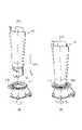
図9(a)は、第1の実施形態に係るトナーパックのパウチの側部(変形前)に設けられた折り形成部の位置を示す側面概念図である。図9(b)は、パウチを不可視した状態を示す側面概念図である。図9(c)は、トナーパックのパウチを不可視した状態を示す斜視概念図である。 FIG. 9A is a side conceptual diagram showing the position of the fold-forming portion provided on the side portion (before deformation) of the pouch of the toner pack according to the first embodiment. FIG. 9B is a side conceptual diagram showing a state in which the pouch is invisible. FIG. 9C is a perspective conceptual diagram showing a state in which the pouch of the toner pack is invisible.
前述した通り、トナーパック100(収容容器)は、画像形成装置1に着脱可能であり、トナーのような粉体を収容可能な可撓性を有する収容容器である。 As described above, the toner pack 100 (container) is a flexible container that can be attached to and detached from the
図3または図4に示すように、本実施形態では、トナーパック100は主に、結合部材102(連通部材)と、パウチ103を備えている。 As shown in FIG. 3 or 4, in the present embodiment, the
そして、トナーパック100には、更に、シャッタ部材110、シール部材104、または、ベース部材101などの構成も備えられている。なお、図3に示すように、シャッタ部材110は、軸線方向Zを回転中心として回転可能である。 The
(パウチ)
図3または図9に示すように、パウチ103は、トナー(粉体)を収容可能な可撓性の容器状のものであり、底部103sと、側部SBと、を備えている。(Pouch)
As shown in FIG. 3 or 9, the
パウチ103の側部SBは、底部103sとは反対側に位置する開口103kが形成されるように、底部103s側から開口103k側へ延びるように構成されている。また、開口103k側に位置する側部SBの内側(103a)には、後述する「開口内面103a」が設けられている。 The side portion SB of the
本実施形態では、パウチ103の側部SBには、(第1の)折り形状75を形成する(第1の)折り形成部75bが設けられている。なお、折り形成部75bは、後述する結合部材102の天面102tの縁部102fに沿って形成される。 In the present embodiment, the side portion SB of the
また、図9に示すように、本実施形態では、パウチ103の側部SBは、第1部分K101と、第1部分に接続され第1部分よりも強度が小さい第2部分K102と、を有し、折り形成部75bは、第1部分と第2部分の境界部K1に設けられている。 Further, as shown in FIG. 9, in the present embodiment, the side portion SB of the
具体的には、本実施形態では、側部SBの第1部分K101は、結合部材102の外周面102bに溶着されるため、側部SBの第2部分K102より強度が高くなる。側部SBが押圧されたとき、境界部K1に沿って、側部SBが変形する傾向がある。本実施形態では、折り形成部75bを第1部分K101と第2部分K102の境界部K1に設けることにより、側部SBが押圧されたとき、境界部K1の位置で側部SBがさらに変形しやすくなり、折り目(折り形状)が形成されやすくなる。 Specifically, in the present embodiment, the first portion K101 of the side portion SB is welded to the outer
そして、折り形成部75bの少なくとも一部75b0は、結合部材102の天面102tよりも、底部103sに近い位置に形成される。例えば、図9に示すように、折り形成部75b(の一部75b0)は、開口103k側と底部103s側を結ぶ高さ方向Z0において、天面102tの位置付近に形成され、天面102tよりやや上方(図9に示す上方)へ延びた位置まで形成されている。 Then, at least a part 75b0 of the
具体的には、折り形成部75bを境界部K1に配置するとき、天面102t位置よりも、天面からやや底部103s側に移動した位置に配置することで、折り形成部75bの幅(変形幅)が若干広がり、ユーザが側部SBを押圧する際に、押しやすくなる。結果的に、トナーパックからトナーが排出されやすくなる。 Specifically, when the
例えば、折り形成部75bの一部75b0を、結合部材102の天面102tの位置から、底部103s側に向かって天面102tから30mm離れた位置までの範囲内で、側部SBに設けることができる。この範囲内に折り形成部75bを設定することにより、ユーザが側部SBを押しやすくなり、より効率よくトナーを排出することができる。なお、より好ましくは、天面102tの位置から、底部103s側に向かって天面から15mm離れた位置までの範囲内で折り形成部75bを設ける。 For example, a part 75b0 of the
図9に示すように、本実施形態では、側部SBは、折り形成部75bから底部103s側に向けて所定の間隔(距離L8)を隔てて、第2の折り形状76を形成する第2の折り形成部76bを備えている。 As shown in FIG. 9, in the present embodiment, the side portion SB forms the
第2の折り形成部を設けることで、よりトナーパックからトナーを効率よく排出することができる。 By providing the second fold forming portion, the toner can be more efficiently discharged from the toner pack.
例えば、側部SBには、高さ方向Z0(軸線方向Z)において、開口側から、第3部分K103、第4部分K104、第5部分K105を順に備えることができる。第4部分K104は、第3部分K103と第5部分K105を接続すると共に、第3および第4部分よりも強度が小さく構成されている。第2の折り形成部76bを、第4部分K104に形成することができる。 For example, the side portion SB may be provided with a third portion K103, a fourth portion K104, and a fifth portion K105 in this order from the opening side in the height direction Z0 (axis direction Z). The fourth portion K104 connects the third portion K103 and the fifth portion K105, and is configured to have a lower strength than the third and fourth portions. The second
第3、第5部分に比べ、第4部分の強度を低くすることにより、押圧により折り形状75付近に変形が発生したとき、第4部分K104に最初に変形する(変形しやすい)。従って、第2の折り形成部を第4部分に設けることにより、折り形成部75bによって折り形状75が形成されたとき、第2の折り形成部76bに沿って折り形状76が形成されやすくなる。この結果、トナーパック内のトナーがより排出しやすくなる。 By lowering the strength of the fourth portion as compared with the third and fifth portions, when deformation occurs in the vicinity of the folded
つまり、折り形成部75b、第2の折り形成部76bを設けることにより、側部SBが押圧されたとき、側部SBの第3部分K103が天面102tに近づくようになり、第5部分K105は、対向する側の側部SBに近づくようになりやすくなる。よって、トナーパック内のトナーがより排出しやすくなる。 That is, by providing the
なお、本実施形態では、折り形成部75bと第2の折り形成部76bは、ほぼ平行となるように側部SBに配置されているが、平行でなくてもよい。 In the present embodiment, the fold-forming
図9に示すように、本実施形態では、パウチ103の側部SBは、折り形成部75bと交差するように配置され、第3の折り形状77、78を形成する第3の折り形成部77b、78bを備えている。 As shown in FIG. 9, in the present embodiment, the side portion SB of the
第3の折り形成部を設けることで、折り形状75、第2の折り形状76付近に変形が起きたとき、側部SBがより円滑に(追従して)変形することができる。これにより、よりトナーパックからトナーを効率よく排出することができる。 By providing the third fold forming portion, the side portion SB can be deformed more smoothly (following) when the
なお、図9に示すように、本実施形態では、第3の折り形成部77b、78bは、第2の折り形成部76bとも交差しており、軸線方向Zの「軸線」を挟んで、両側にそれぞれ配置されている。また、第3の折り形成部77b、78bは、天面102t側から底部103s側に向けて、間の距離が広がるように軸線方向Zに対して傾斜している。 As shown in FIG. 9, in the present embodiment, the third
折り形成部(75b~78b)の加工方法として、パウチ103の側部SBにプレス加工を実施する方法を採用することができる。プレス加工以外にも、パウチ(103)に対して曲げ加工、熱加工、または、ハーフカット加工などの加工方法、もしくはこれらの加工方法の任意の組み合せを採用してもよい。 As a method for processing the fold-forming portion (75b to 78b), a method of performing press processing on the side portion SB of the
(折り形成部)
次に、本実施形態の「折り形成部75b」および「第2の折り形成部76b」の構成、その加工方法(加工条件)、並びに、加工後の断面形状について、図10を用いて説明する。(Folded part)
Next, the configurations of the "
図10(a)は、第1の実施形態に係るトナーパックにおけるパウチの側部の折り形成部(75b)の断面概念図であり、図10(b)は、パウチの側部の第2の折り形成部(76b)の断面概念図である。なお、図10には、折り形成部75bまたは第2の折り形成部76bの、それぞれが延びる方向(図9(a)を参照する)と直交する断面の様子を示している。 10 (a) is a cross-sectional conceptual diagram of a fold-forming portion (75b) of a side portion of the pouch in the toner pack according to the first embodiment, and FIG. 10 (b) is a second cross-sectional view of the side portion of the pouch. It is sectional drawing conceptual figure of the fold forming part (76b). Note that FIG. 10 shows a cross section of the
本実施形態の折り形成部75bは、前述の通り「プレス加工」によって形成される。 The fold-forming
具体的には、図10(a)に示すように、折り形成部75b(山折り)は、パウチ103の側部SBに対して、外側103bとなる表面(平坦部SBP1)から、外側へ突出するように、内側103aからプレス加工により形成される。 Specifically, as shown in FIG. 10A, the
即ち、パウチ103の内側103aとなる面(側)からプレス加工することによって形成された「折り形成部75b」は、側部SBの外側103bの平坦な部分(表面)である平坦部SBP1よりパウチの「外側103b」へ突出する突出部SBP2を備える。 That is, the "folded forming
また、突出部SPB2の突出方向が、内側、外側で逆向きでも良い。さらに、突出部SPB4にも同様のことが言える。 Further, the protruding direction of the protruding portion SPB2 may be opposite on the inner side and the outer side. Further, the same can be said for the protrusion SPB4.
また、図10(a)に示すように、本実施形態では、折り形成部75bを構成する突出部SBP2は、パウチの外側から見ると「凸状」を呈し、内側から見ると「凹状」を呈している。 Further, as shown in FIG. 10A, in the present embodiment, the protruding portion SBP2 constituting the
また、本実施形態では、突出部SBP2の厚み(T2)は、平坦部SBP1の厚み(T1)とほぼ同じである。なお、より折り形状を形成しやすくするために、突出部SBP2の厚み(T2)を、平坦部SBP1の厚み(T1)より小さく構成してもよい。 Further, in the present embodiment, the thickness (T2) of the protruding portion SBP2 is substantially the same as the thickness (T1) of the flat portion SBP1. In addition, in order to make it easier to form the folded shape, the thickness (T2) of the protruding portion SBP2 may be smaller than the thickness (T1) of the flat portion SBP1.
また、本実施形態では、突出部SBP2の高さH1は、平坦部SBP1の厚みT1よりも小さく設定することができる。これにより、パウチに折り形成部をより容易に形成できると共に、トナー収容時のパウチの形状を安定化することができる。 Further, in the present embodiment, the height H1 of the protruding portion SBP2 can be set smaller than the thickness T1 of the flat portion SBP1. As a result, the fold-forming portion can be more easily formed on the pouch, and the shape of the pouch when the toner is stored can be stabilized.
また、本実施形態では、突出部SPB2の幅(W1)は、突出部SBP2の高さH1よりも大きい。これにより、トナー収容時のパウチの形状を安定化することができる。 Further, in the present embodiment, the width (W1) of the protruding portion SPB2 is larger than the height H1 of the protruding portion SBP2. This makes it possible to stabilize the shape of the pouch when the toner is stored.
また、突出部SPB2は滑らかな円弧形状の断面形状である.これにより、折り形成部の強度を高く保つことができる。 The protruding portion SPB2 has a smooth arcuate cross-sectional shape. As a result, the strength of the folded portion can be kept high.
一方、図10(b)に示すように、第2の折り形成部76b(谷折り)は、折り形成部75bとは逆方向(逆側)へ突出するように外側103bからプレス加工することによって形成される。なお、第2の折り形成部76bは、折り形成部75bとは、突出する向きが異なる以外では基本的に同じ構成である。 On the other hand, as shown in FIG. 10B, the second
具体的に、第2の折り形成部76bは、パウチ103の側部SBに対して、内側103aとなる表面(平坦部SBP3)から、内側へ突出するように、外側103bからプレス加工により形成される。 Specifically, the second fold-forming
即ち、パウチ103の外側103bとなる面(側)からプレス加工することによって形成された「第2の折り形成部76b」は、側部SBの内側103aの平坦な部分(表面)である平坦部SBP3よりパウチの「内側103a」へ突出する突出部SBP4を備える。 That is, the "second fold-forming
また、第2の折り形成部76bの突出部SBP4の厚みT2や高さH1に関しては、折り形成部75bと同様に構成することができる。 Further, the thickness T2 and the height H1 of the protrusion SBP4 of the second
なお、他の折り形成部(例えば、第3の折り形成部77b、78b)については、折り形成部75b(山折り)または第2折り形成部76b(谷折り)のように、「山折り」か「谷折り」かによって、プレス加工の条件(例えば、プレス方向)を変更することができる。 The other fold forming portions (for example, the third
また、折り形成部75b(もしくは、第2の折り形成部76b)は、図10に示す断面形状以外に、例えば、図11(a)、(b)に示すような断面形状(変形例)とすることもできる。 Further, the fold-forming
図11(a)は、第1の実施形態の「変形例1」に係るトナーパックにおけるパウチの側部の折り形成部の断面概念図であり、図11(b)は、第1の実施形態の「変形例2」に係るトナーパックにおけるパウチの側部の折り形成部の断面概念図である。なお、図11には、変形例1、2それぞれにおける折り形成部75bの、折り形成部75bが延びる方向(図9(a)を参照する)と直交する断面の様子を示している。 FIG. 11 (a) is a cross-sectional conceptual diagram of a fold-forming portion of a side portion of the pouch in the toner pack according to “
具体的に、図11(a)に示す折り形成部75bの断面形状は、プレス加工や、削り加工の方法により形成することができる。具体的に、側部SBの内側103aの表面に、金型を厚み方向にプレスすることで、所定の溝形状が形成される。また、その金型を加熱した状態でプレスする方法をとっても良い。さらに、内側103aの表面を、刃物で削る加工でも図11(a)のような断面形状を形成することが可能である。これにより、折り形成部75bが「山折り」形状になりやすくなる。なお、第2の折り形成部76b(谷折り)については、第1実施形態と同様に、折り形成部75bと逆方向(側)に所定の溝形状を形成してもよい。 Specifically, the cross-sectional shape of the fold-forming
また、図11(b)に示す折り形成部75bの断面形状は、切削加工方法により形成することができる。具体的に、側部SBの内側103aの表面を、刃物で削る加工でも図11(b)のような断面形状を形成することが可能である。ことで、所定の溝形状が形成される。これにより、折り形成部75bが「山折り」形状になりやすくなる。なお、第2の折り形成部76b(谷折り)については、第1実施形態と同様に、折り形成部75bと逆方向(側)に所定の溝形状を形成してもよい。 Further, the cross-sectional shape of the
また、他の折り形成部(例えば、第2、第3の折り形成部)についても同様である。 The same applies to other fold-forming portions (for example, second and third fold-forming portions).
(結合部材)
図3または図9に示すように、結合部材102(連通部材)は、略筒状であり、外周面102a、内周面102b(穴部)、および、パウチの底部103sに対向する天面102t(対向面)を備えている。結合部材102は、パウチ103の開口側の内側(開口内面103a)に取り付けられる。(Coupling member)
As shown in FIG. 3 or 9, the connecting member 102 (communication member) has a substantially cylindrical shape, and has an outer
結合部材102の外周面102aは、パウチ103の側部SBの、開口内面103aと結合するために溶着される面である。一方、内周面102bは、後述するベース部材101が挿入される「穴部」を構成するものである。 The outer
なお、ベース部材101には、パウチ103の内部と外部を連通する、後述する「排出経路101h(連通部)」が形成されている。ベース部材101と結合部材102は、本発明の「連通部材」を構成するものである。 The
結合部材102には、後述する「凹部102c」も形成されている。 The connecting
本実施形態では、結合部材102とパウチ103は、共に同じ材質の樹脂で構成され、結合部材102は、溶着によりパウチ103の開口側の内側(開口内面103a)に取り付けられる。なお、結合部材102をパウチ103に取り付けた後に、パウチ103にトナーが充填される。その後、結合部材102には、さらに後述するベース部材101が取り付けられる。 In the present embodiment, the
また、本実施形態では、結合部材102の外周面102aには、溶着部1021が備えられており、溶着部1021が側部SBの内側(開口内面103a)に溶着されることにより結合部材がパウチの開口側の内側に取り付けられる。 Further, in the present embodiment, the outer
本実施形態では、溶着部1021は、折り形状75の折り目(線)751(図7を参照する)が延びる第1方向L5に沿う方向L50に、第1の溶着部102g(溶着リブ)と第2の溶着部102h(溶着リブ)を備えている。即ち、高さ方向Z0および第1方向L5に直交する方向に沿ってみたとき、第1の溶着部102gと第2の溶着部102hは、外周面102aから第1方向L5(方向L50)に沿って外側へ突出するように設けられている。 In the present embodiment, the welded
なお、本実施形態では、方向L50を、方向L5と「同一」方向に延びるものとして例示したが、方向L5が延びる方向に沿うものであればよく、必ずしも方向L5と「同一」方向である必要はない。また、本実施形態では、方向L5は、高さ方向Z0と「直交」する方向として例示したが、必ずしも「直交」である必要がなく、方向L5を高さ方向Z0と交差するように構成してもよい。 In the present embodiment, the direction L50 is exemplified as extending in the "identical" direction with the direction L5, but it does not have to be along the extending direction of the direction L5 and must be in the "identical" direction with the direction L5. There is no. Further, in the present embodiment, the direction L5 is exemplified as a direction "orthogonal" with the height direction Z0, but it does not necessarily have to be "orthogonal", and the direction L5 is configured to intersect the height direction Z0. You may.
第1の溶着部102gと第2の溶着部102hは、共に縁部102fの位置からさらに外側へ延出しており、第1方向L5(方向L50)において結合部材102の異なる側に配置されている。第1、2の溶着部102g、102hを設けることにより、結合部材をパウチ100に溶着する際に、より容易かつ確実に結合部材をパウチに取り付けることができる。 Both the first welded
また、天面102tの縁部102fには、第1方向L5に沿う方向L51に延びる直線形状の直線部SLが設けられている。なお、本実施形態では、方向L51を、方向L5と「同一」方向に延びるものとして例示したが、方向L5が延びる方向に沿うものであればよく、必ずしも方向L5と「同一」方向である必要はない。 Further, the
直線部SLは、高さ方向Z0および第1方向L5に交差する方向に沿ってみたとき、第1方向L5(方向L51)において、第1の溶着部102gと第2の溶着部102hの間に位置するように配置される。なお、図9(d)に示すように、直線部SLは、平行する第1直線部SL1と、第2直線部SL2を含む。 The straight line portion SL is located between the first welded
方向L51に延びる第1、2直線部SL1、SL2を、第1、2の溶着部102g、102hの間に配置することにより、結合部材をパウチに容易に溶着できると共に、パウチの側部SBに折り形状(折り形成部)を容易に形成することができる。 By arranging the first and second straight portions SL1 and SL2 extending in the direction L51 between the first and second welded
結合部材102を、開口103k側と底部103s側を結ぶ高さ方向Z0(軸線方向Z)に沿ってみたとき、結合部材の天面102tは、略六角形を呈している。第1の溶着部102gと第2の溶着部102hは、六角形のうち、対向する一対の角部AN1、AN2に設けられている。 When the connecting
パウチ103の開口内面103aと結合部材102の外周面102aを結合する際、開口103kの第1隅部103xと第2隅部103yの隙間を、第1溶着部102gと第2溶着部102hによって埋められる。これにより、溶着時に結合しにくい箇所がより容易に溶着できるようになる。 When the
なお、結合方法は、周知のものでもよく、例えば、ホットメルトなどの各種接着剤を用いた方法や、結合部材102の外周に対してパウチ103を熱溶着して結合する方法などが挙げられる。 The bonding method may be a well-known method, and examples thereof include a method using various adhesives such as hot melt, a method of heat-welding the
しかし、パウチ103と結合部材102を同材質の樹脂で構成して、熱溶着で結合すると、結合された一体物に異なる材質の部分を含まないため、リサイクル等がしやすく、環境負荷の低減に寄与することができる。 However, when the
(ベース部材)
次に、図3および図8を用いて、ベース部材101について説明する。ベース部材01と結合部材102は共に、本発明の「連通部材」を構成するものであり、パウチ103の内外を連通するものである。(Base member)
Next, the
図8は、第1の実施形態に係るトナーパックの補給完了状態を示す断面概念図である。 FIG. 8 is a cross-sectional conceptual diagram showing a state in which the toner pack has been replenished according to the first embodiment.
図3または図8に示すように、本実施形態では、略筒状の「結合部材102」の内周面102b(穴部)には、ベース部材101の一部(軸部101a)が挿入され、係合により一体化される。即ち、「連通部材」は、二つ(複数)の部品(部材)を一体化することにより構成してもよく、一つの部品(部材)で構成してよい。 As shown in FIG. 3 or FIG. 8, in the present embodiment, a part (
具体的には、図3または図8に示すように、ベース部材101は、天面101s(対向面)と、外周面101bと、トナー排出口101rと、軸部101aと、を備えている。 Specifically, as shown in FIG. 3 or FIG. 8, the
なお、天面101s(対向面)は、パウチ103の底部103sに対向している。トナー排出口101rは、外周面101bに形成されている。軸部101aは、結合部材102の内周面102b(穴部)と係合するものである。 The
ベース部材101には、トナーパック100内部のトナーを排出するための排出孔として、「排出経路101h」が設けられている。排出経路101hは、天面102t(対向面)および天面101s(対向面)側から排出口101r側を連通しており、トナーパック100の内外を連通している。 The
これにより、パウチ103に収容されたトナーは、排出口101rを通じてトナーパック100の外部に排出することができる。 As a result, the toner contained in the
また、図8から理解できるように、天面101s(対向面)は、すり鉢状に形成されており、排出経路101h(中心)に近づくほど降下するよう傾斜面として形成される。これにより、ユーザは、折り形状75に沿って側部SBを変形させやすくなる。特に、トナー排出動作の後半では、トナーパック100のパウチ103の内面103p1(第3部分K103)と内面103p2(第3部分K103)をさらに天面101s(傾斜面)側に向かって押し込むことができるようになる。 Further, as can be understood from FIG. 8, the
これにより、より効率よくトナーの排出を実現できるようになる。すなわち、排出経路101hに繋ぐ天面101s(傾斜面)に沿って、より排出経路101h側へパウチ103を変形させられるようになる。その結果、パウチ103内の容積がより確実に小さくなりやすく、トナーの補給操作が一層しやすくなりユーザビリティ性も向上する。 This makes it possible to discharge toner more efficiently. That is, the
図3に示すように、ベース部材101には、結合部材102の凹部102cと係合する凸部101x、凸部101yを備えている。 As shown in FIG. 3, the
内周面102b(穴部)と軸部101aとが係合することで回転方向以外の両部品の相対移動を規制することができる。また、凹部102cと凸部101x、101yとが係合することでさらに回転方向の両部品の相対移動を規制することもできる。これによってベース部材101は結合部材102に相対移動せずに保持されるようになる。 By engaging the inner
シール部材104は、弾性変形可能な発泡ウレタンや不織布等の材質で構成されている。両面テープ等でシャッタ部材110の面110fと固定されている。これにより、シール部材104とシャッタ部材110の界面でのトナー漏れを抑制できる。 The sealing
また、図4に示すように、トナーパック100は、ベース部材101に対してシャッタ部材110が相対的に回転可能な構成になっている。また、軸線方向Zを回転中心とし、Z1方向、及び、Z1方向とは反対のZ2方向に回転可能に設けられている。 Further, as shown in FIG. 4, the
例えば、図4(a)に示す「遮蔽状態」から、シャッタ部材110をZ1方向に回すことで、図4(b)に示す「開放状態」になる。逆に、「開放状態」からシャッタ部材110をZ2方向に回すことで「遮蔽状態」に切り替わることもできる。 For example, by turning the
図4(b)に示す「開放状態」において、パウチ103に収容されているトナーは、トナーパック100の外部(画像形成装置1)に排出(供給)可能になる。 In the "open state" shown in FIG. 4B, the toner contained in the
(トナーパックと補給口の結合)
次に、図5を用いて、トナーパック100と画像形成装置1の補給口32aを連結させ、ユーザがトナーパック100内のトナーを画像形成装置1の現像容器32に補給するための準備動作について説明する。(Combining the toner pack and the supply port)
Next, with reference to FIG. 5, the
図5(a)は、第1の実施形態に係るトナーパックを補給口に装着される直前の状態を示す斜視概念図である。図5(b)は、トナーパックを補給口に装着された状態を示す斜視概念図である。 FIG. 5A is a perspective conceptual diagram showing a state immediately before the toner pack according to the first embodiment is attached to the supply port. FIG. 5B is a perspective conceptual diagram showing a state in which the toner pack is attached to the supply port.
本実施形態では、画像形成装置1は、トナーパック100が装着される補給口32a(装着部)を備え、トナーパック100を補給口にセットすることにより、補給動作を行うことができる。 In the present embodiment, the
なお、前述したように、使用時の姿勢において、補給口32aは、画像形成装置1の上側(図2を参照)に設けされている。 As described above, the
図5に示すように、トナーパック100は、底部103sが重力方向Gの上方G1に位置し、開口103kが重力方向の下方G2に位置する姿勢で、補給口32aに装着される。 As shown in FIG. 5, the
なお、本実施形態では、トナーパック100は、重力方向Gに沿った方向G0に沿って補給口32aに対して着脱される。 In the present embodiment, the
より具体的には、ユーザは、トナーパックの高さ方向Z0(軸線方向Z)を方向G0に合わせ、方向G0に沿ってトナーパック100を補給口32aに装着する。 More specifically, the user aligns the height direction Z0 (axis direction Z) of the toner pack with the direction G0, and attaches the
装着した後、操作レバー310の把持部310aを把持し、操作レバー310を軸線方向Zを回転中心として、Z1方向に回動させる。すると、トナーパック100のシャッタ部材110が回転して「開放状態」(図4(b)を参照)になる。 After mounting, the
逆に、ユーザがトナーパック100を「開放状態」から「遮蔽状態」(図4(a)を参照)へ移行する際には、操作レバー310を軸線方向Zを回転中心としてZ2方向に回動させればよい。 On the contrary, when the user shifts the
なお、本実施形態では、トナーパック100は、画像形成動作を行わない非画像形成時に補給口32aに装着されて画像形成装置1に対して現像剤の補給を行うが、画像形成動作を開始する前には、補給口32aから取り外されるように構成されている。 In the present embodiment, the
(トナーパックによるトナー補給動作)
次に、図6~8を用いて、画像形成装置1(補給口32a)に装着されたトナーパック100からトナーを補給する補給動作、並びに「折り形状」との関係について説明する。(Toner replenishment operation by toner pack)
Next, with reference to FIGS. 6 to 8, the replenishment operation of replenishing the toner from the
図6は、第1の実施形態に係るトナーパックからトナーを排出する方法を示す斜視概念図である。 FIG. 6 is a perspective conceptual diagram showing a method of discharging toner from the toner pack according to the first embodiment.
図7(a)~(c)は、第1の実施形態に係るトナーパックの補給完了状態を異なる視点で見た斜視概念図である。(d)は、トナーパックのパウチを不可視した状態を示す斜視概念図である。なお、図7(a)には、トナーが排出完了されたトナーパックの、一方側の側部SB1をみた斜視概念図を示す。図7(c)には、トナーが排出完了されたトナーパックの、他方側の側部SB2をみた斜視概念図を示す。 7 (a) to 7 (c) are perspective conceptual views of the toner pack replenishment completion state according to the first embodiment as viewed from different viewpoints. (D) is a perspective conceptual diagram showing a state in which the pouch of the toner pack is invisible. Note that FIG. 7A shows a conceptual perspective view of the toner pack on which the toner has been discharged, looking at the side portion SB1 on one side. FIG. 7C shows a conceptual perspective view of the toner pack on which the toner has been discharged, looking at the side portion SB2 on the other side.
前述したように、トナーを画像形成装置1に補給する場合、トナーパック100を画像形成装置1の補給口32aに装着する。装着された状態で、トナーパック100に収容したトナーをトナーパック100から排出させ、補給口32aを介して現像容器32に補給する。 As described above, when the toner is replenished to the
まず、トナーパック100に収容されたトナーを排出する方法について説明する。 First, a method of discharging the toner contained in the
図6に示すように、ユーザはパウチ103を変形させることで、パウチ103のトナーを現像容器32に供給する構成となっている。その為に、パウチ103は変形しやすい構成である必要がある。ユーザがパウチ103を変形させ、パウチ103内の容積を減少させることによって、トナーパック100に収容されたトナーが排出される。 As shown in FIG. 6, the user deforms the
パウチ103は、ユーザが変形させられる可撓性を有したものであって、その材質及び形状は周知するものでもよい。加えて、パウチ103からトナーを吐出させる方法は、可撓性のあるパウチ103であればユーザが指で絞るようにするのが好適である。 The
前述したように、パウチ103の側部には、天面102tの縁部102fに沿って折り形成部75bが設けられている。これにより、ユーザが指でパウチの側部SBを押してトナーを排出させるとき、側部SBが折り形成部75bに沿って変形しやすくなっている。 As described above, the side portion of the
即ち、図7に示すように、本実施形態のトナーパック100は、内部のトナーが排出された状態では、パウチ103の開口103k側が、結合部材102の天面102tの縁部102fに沿って第1の折り形状75が形成されて折り畳まれている。 That is, as shown in FIG. 7, in the
具体的には、本実施形態では、天面102tの縁部102fは、六角形の6つの辺SL1~SL6を備えている。第1方向L5において、第1溶着部102gと第2溶着部102hの間に、中辺SL1、SL2が配置されており、中辺Sl1,SL2は共に第1方向L5と略平行に配置されている。 Specifically, in the present embodiment, the
一方の中辺SL1の両側には、下辺SL3と上辺Sl4が隣り合うように配置され、他方の中辺SL2の両側にも、下辺SL5と上辺SL6が隣り合うように配置される。結合部材102の縁部102fの外形は、第1溶着部102gと第2溶着部102hを通る直線(第1方向L5)に対して「線対称」である。即ち、軸線方向Zから見た場合に、結合部材102の天面102tは「略六角形」となる。 The lower side SL3 and the upper side Sl4 are arranged adjacent to each other on both sides of one middle side SL1, and the lower side SL5 and the upper side SL6 are arranged adjacent to each other on both sides of the other middle side SL2. The outer shape of the
縁部102fの一方の中辺SL1に沿って山折りに折り形状75aが形成され、下辺SL3と上辺SL4に沿って谷折りに折り形状75a1、75a2が形成される。 A
同様に、他方の中辺SL2に沿って山折りに折り形状75aが形成され、下辺SL5と上辺SL6に沿って谷折りに折り形状(図示なし)が形成される。 Similarly, a
本実施形態では、(第1の)折り形状75には、少なくとも折り形状75aを含むようにすれば良く、折り形状75a、75a1、75a2の全てを含むことがより好ましい。即ち、折り形状75aに対応する折り形成部75bを設ければ良く、折り形状75a、75a1、75a2の全てに対応する折り形成部75bを設けることがより好ましい。 In the present embodiment, the (first) folded
ここで、本実施形態においては、中辺SL1(SL2)は「ストレート(直線)形状」である。これにより、(山)折り形状75aが形成されやすくなっている。 Here, in the present embodiment, the middle side SL1 (SL2) has a “straight line” shape. This facilitates the formation of the (mountain) fold
このように、折り形状75を形成する折り形成部75bを、結合部材102(連通部材)の縁部102f近傍に設けることにより、可撓性の側部SBが変形する位置を積極的にガイドすることができる。これにより、トナーパック内のトナーをより効率よく排出させることができる。 In this way, by providing the
前述したように、パウチ103の側部には、折り形成部75bから底部103側に向けて所定の間隔(距離L8)を隔てて、第2の折り形成部76bが設けられている。これにより、折り形成部75bによって折り形状75が形成されるに伴って、第2の折り形状76が形成されやすくなる。したがって、側部SBの変形がより円滑になり、トナーがより効率よく排出できる。 As described above, the side portion of the
即ち、図7に示すように、本実施形態のトナーパック100は、内部のトナーが排出された状態では、第2の(谷)折り形状76が形成されて折り畳まれている。 That is, as shown in FIG. 7, the
前述したように、パウチ103の側部SBは、折り形成部75bと交差するように配置され、第3の折り形成部77b、78bが設けられている。これにより、折り形状75、第2の折り形状75に伴って、第3の折り形状77、78が形成されやすくなり、側部SBの変形がより円滑になり、トナーがより効率よく排出できる。 As described above, the side portion SB of the
具体的に、第1の折り形状75と第2の折り形状76に交差し、底部103sに向かって広がる方向に「山折り」となる第3の折り形状77、78が形成される。 Specifically, the third fold shapes 77 and 78 that intersect the
即ち、中辺SL1の両端SL1a、SL1bから、第2の折り形状76の両端76a、76bに向かって第3の折り形状77、78が形成される。 That is, the third folded
折り形成部を設けることにより、パウチ103の一方側の側部SB1、及び他方側の側部SB2の内面が結合部材の天面102tと接触するように変形しやすくなる。そして、パウチ103の側部SB1と側部SB2の内面同士が互いに接触し合い、パウチ103内の容積が小さくなりやすくなる。 By providing the fold-forming portion, the inner surface of the side portion SB1 on one side of the
このように、第1~3の折り形成部を設けて、「折り形状」が形成されることによって、より円滑にパウチの側部SBを変形させることができ、トナーパック100内のトナーをより効率よく排出することができる。 In this way, by providing the first to third fold forming portions and forming the "folded shape", the side portion SB of the pouch can be deformed more smoothly, and the toner in the
即ち、トナーパック100のパウチ103の容積を限りなく最小に近くなるように変形させて折り畳みやすくすることができる。言い換えると、ユーザがトナーパック100を用いて画像形成装置1にトナーを補給する際に、よりパウチ103を変形させやすく、トナーを補給しやすくなり、ユーザビリティ性が向上する。 That is, the volume of the
なお、本実施形態では、第1~第3の折り形成部を備える構成について説明しが、少なくても第1の折り形成部を備えればよい。 In this embodiment, the configuration including the first to third fold-forming portions will be described, but at least the first fold-forming portion may be provided.
また、図9に示すように、縁部102fから第2の折り形成部76bまでの距離を距離L8、結合部材の天面102tの第1中辺SL1から第2中辺SL2の距離を距離L9とすると、距離L8と距離L9の関係は以下であることが望ましい。
L8≧L9/2
即ち、高さ方向Z0における「第1折り形成部75b」と「第2の折り形成部76b」の間隔を「距離L8」とすることができる。一方、接合部材102の天面102tの縁部102fのうち、第1折り形成部75bが形成される位置(第1中辺SL1もしくは第2中辺SL2)から、天面102tの中心位置S01までの最短距離(L9/2)よりも、「距離L8」を大きく設定することができる。Further, as shown in FIG. 9, the distance from the
L8 ≧ L9 / 2
That is, the distance between the "first
これにより、側部SB1と側部SB2の内面が、隙間や弛みが少なく結合部材の天面102tと接触するように変形可能になる。そして、パウチ103の側部SB1、SB2の内面同士が互いに接触し合い、パウチ103内の容積がより一層小さくなりやすくなる。 As a result, the inner surfaces of the side portions SB1 and the side portions SB2 can be deformed so as to come into contact with the
なお、本実施形態では、接合部材102の天面102tの中心位置S01付近には、排出経路101hの開口が形成されている。また、天面102tの中心と排出経路101hの開口の中心は重なるように配置されている。 In this embodiment, an opening of the
前述したように、結合部材102の外周面102aとパウチ103の開口内面103aは、「熱溶着」等の手段で結合される。即ち、軸線方向Zにおいて、領域Wの範囲が(溶着)結合された結合部は、第1部分K101を構成するものになる。 As described above, the outer
ここで、第1部分(結合部)は、樹脂もしくは金属材質の結合部材102と、パウチ103(側部SB)の一体構成であり、曲げ方向の剛性としての強度が、第2部分K102に比べて高い。前述したように、第1部分K101と第2部分の境界部K1に(第1の)折り形成部75bを設けることで、(第1の)折り形状75が形成されやすくなる。 Here, the first portion (bonding portion) is an integral configuration of the
よって、パウチ103を変形させやすく、トナーの補給がしやすくなり、ユーザビリティ性が向上する。なお、側部SBの強度に差をつける手段として、前述した構成に限らない。例えば、パウチ103の側部SB自体の厚みを一部変化させても良く、サポート(補強)部材をパウチの一部に貼りつけてもよい。 Therefore, the
なお、前述した第1の実施形態では、トナー補給時にユーザが容易に「折り形状」を形成するための「折り形成部」について説明したが、予めパウチの側部にある程度の「折り形状」が形成されるようにすることもできる。また、このような構成でも、前述した同様な効果を奏することもできる。 In addition, in the above-mentioned first embodiment, the "fold formation portion" for easily forming a "fold shape" by the user at the time of toner replenishment has been described, but a certain amount of "fold shape" is provided on the side portion of the pouch in advance. It can also be formed. Further, even with such a configuration, the same effect as described above can be obtained.
例えば、トナーパック100は、可撓性を有するパウチ103と、結合部材102と、を備え、側部SBには、結合部材102の天面102tの縁部102fに沿って折り形状75が形成されるようにしてもよい。 For example, the
また、同様に、側部SBには、折り形状75の位置から、底部103s側に向けて所定の距離L8を離れた位置に、第2の折り形状76が形成されるようにしてもよい。そして、側部SBには、折り形状75と第2の折り形状76を繋ぐ第3の折り形状77、78が形成されるようにしてもよい。 Similarly, a second folded
このように、パウチの側部に「折り形状」または「折り形成部」を設けることにより、パウチ103は変形しやすくなり、より効率よくかつ円滑なトナー補給ができ、ユーザビリティ性が向上する。 By providing the "folded shape" or "folded forming portion" on the side portion of the pouch in this way, the
なお、「折り形状」もしくは、「折り形成部」は、側部SBの両側(第1側部SB1、第2側部SB2)に設けてもよく、片方のみ設けることも可能である。なお、片方のみ設ける場合よりも、両方に設けた場合にトナー(粉体)の排出しやすさが向上するので、望ましい。 The "folded shape" or "folded forming portion" may be provided on both sides of the side portion SB (first side portion SB1 and second side portion SB2), or only one of them may be provided. It should be noted that it is desirable because the ease of discharging the toner (powder) is improved when both are provided as compared with the case where only one is provided.
<第2の実施形態>
以下、図12を用いて第2の実施形態について説明する。<Second embodiment>
Hereinafter, the second embodiment will be described with reference to FIG.
なお、第2の実施形態は、基本的に第1の実施形態に係るトナーパック100の構成と同じであり、以下、異なる部分について説明する。 The second embodiment is basically the same as the configuration of the
図12は、第2の実施形態に係るトナーパックのパウチを不可視した状態を示す斜視概念図である。 FIG. 12 is a perspective conceptual diagram showing a state in which the pouch of the toner pack according to the second embodiment is invisible.
図12に示すように、本実施形態のトナーパック100では、結合部材102を開口103k側と底部103s側を結ぶ高さ方向Z0に沿ってみたとき、天面102t(対向面)は、「異形形状」である。即ち、図9(c)に示す第1の実施形態の「六角形」の形状に対して、六角形の二つの中辺(SL1、SL2)を構成する「直線部」が、「曲線部」に変更されている。 As shown in FIG. 12, in the
具体的には、第2の実施形態の天面102t(異形形状)は、第1の曲線部CL1と、第2の曲線部CL2と、第1の直線部SL3と、第2の直線部SL5と、第3の直線部SL4と、第4の直線部SL6とで構成される。 Specifically, the
第2の直線部SL5の一端と第1の直線部SL3の一端が接続され、第1の内角A1が形成されている。 One end of the second straight line portion SL5 and one end of the first straight line portion SL3 are connected to form a first internal angle A1.
また、第4の直線部SL6の一端と、第3の直線部SL4の一端が接続され、第2の内角A2が形成されている。 Further, one end of the fourth straight line portion SL6 and one end of the third straight line portion SL4 are connected to form a second internal angle A2.
一方、第1の曲線部CL1は、第1の直線部SL3の他端と第3の直線部SL4の他端を繋ぎ、第2の曲線部CL2は、第2の直線部SL5の他端と第4の直線部SL6の他端を繋ぐようになっている。 On the other hand, the first curved portion CL1 connects the other end of the first straight portion SL3 and the other end of the third straight portion SL4, and the second curved portion CL2 connects with the other end of the second straight portion SL5. The other end of the fourth straight line portion SL6 is connected.
言い換えれば、本実施形態では、結合部材102の縁部602fの曲線部CL1は、第1の実施形態の中辺SL1(架空線)、下辺SL3(架空線)、上辺SL4(架空線)に接する円弧形状として形成されている。即ち、架空線であるSL1、SL3,SL4は、曲線部CL1の「円弧」の切線となっている。したがって、第2の実施形態の縁部602fには、第1の実施形態のような変曲点P1、P2が無くなる。 In other words, in the present embodiment, the curved portion CL1 of the
言い換えれば、第1の曲線部CL1は、第1の円弧部CL1sで構成され、第2の曲線部CL2は、第2の円弧部CL2sで構成されている。第1の円弧部と第2の円弧部は、同じ曲率半径を有する。 In other words, the first curved portion CL1 is composed of the first arc portion CL1s, and the second curved portion CL2 is composed of the second arc portion CL2s. The first arc portion and the second arc portion have the same radius of curvature.
また、第1の内角A1と第2の内角A2は同じく鈍角であり、同じ角度に設定されている。 Further, the first internal angle A1 and the second internal angle A2 are also obtuse angles and are set to the same angle.
そして、本実施形態では、第1の実施形態と同様に、溶着部1021には、第1の溶着部102gと、第2の溶着部102hと、を備えている。第1の溶着部102gは、第1の内角A1の頂点TP1に対応する位置から外側へ延出している。第2の溶着部102hは、第2の内角A2の頂点TP2に対応する位置から外側へ延出している。 In the present embodiment, as in the first embodiment, the welded
また、第1の実施形態と同様に、第2の実施形態でも、距離L8(図9(a)を参照する)と距離L9(図9(c)を参照する)の関係は以下であることが望ましい。
L8≧L9/2
即ち、高さ方向Z0における「第1折り形成部75b」と「第2の折り形成部76b」の間隔を「距離L8」とすることができる。一方、接合部材102の天面102tの縁部102fのうち、第1折り形成部75bが形成される位置(架空線で示す中辺SL1)から、天面102tの中心位置S01までの最短距離(L9/2)よりも、「距離L8」を大きく設定することができる。Further, as in the first embodiment, in the second embodiment, the relationship between the distance L8 (see FIG. 9A) and the distance L9 (see FIG. 9C) is as follows. Is desirable.
L8 ≧ L9 / 2
That is, the distance between the "first
第2の実施形態では、第1の実施形態と同様な効果を有する。即ち、トナーパック100のパウチ103を変形させやすく、トナーの補給がしやすくなり、ユーザビリティ性が向上する。さらに、第2の実施形態では、変曲点P1、P2が無くなることにより、補給動作時にパウチ103を変形させたとき、パウチ103に作用する応力の局部的集中を抑制でき、パウチの破損等を抑制することもできる。 The second embodiment has the same effect as the first embodiment. That is, the
本発明の構成を以下のように纏めることができる。 The configuration of the present invention can be summarized as follows.
(1)本発明の収容容器(100)は、
粉体を収容する収容容器であって、
底部(103s)と、開口(103k)を形成するように底部から延びる側部(SB)とを備え、可撓性を有するパウチ(103)と、
側部の、開口側の内側(103a)に設けられ、パウチの内外を連通する連通部(101h)を備える連通部材(101、102)と、を備え、
連通部材(102)は、底部に対向する対向面(102t)を備え、
側部(SB)は、連通部材の対向面の縁部(102f、602f)に沿って折り形状(75)を形成する折り形成部(75b)を有する。(1) The storage container (100) of the present invention is
A container for storing powder
A flexible pouch (103) comprising a bottom portion (103s) and a side portion (SB) extending from the bottom portion to form an opening (103k).
A communication member (101, 102) provided on the inside (103a) of the side portion and having a communication portion (101h) that communicates inside and outside the pouch.
The communication member (102) includes a facing surface (102t) facing the bottom portion.
The side portion (SB) has a fold-forming portion (75b) that forms a fold shape (75) along the edges (102f, 602f) of the facing surfaces of the communicating member.
(2)本発明の収容容器では、側部(SB)は、第1部分(K101)と、第1部分に接続され第1部分よりも強度が小さい第2部分(K102)と、を有することができる。折り形成部(75)を、第1部分と第2部分の境界部(K1)に設けてもよい。 (2) In the storage container of the present invention, the side portion (SB) has a first portion (K101) and a second portion (K102) connected to the first portion and having a strength lower than that of the first portion. Can be done. The fold forming portion (75) may be provided at the boundary portion (K1) between the first portion and the second portion.
(3)本発明の収容容器では、折り形成部(75)の少なくとも一部(75b0)を、対向面(102t)よりも、底部(103s)に近い位置に形成してもよい。 (3) In the storage container of the present invention, at least a part (75b0) of the folding forming portion (75) may be formed at a position closer to the bottom portion (103s) than the facing surface (102t).
(4)本発明の収容容器では、折り形成部(75)を、対向面(102t)の位置から、底部(103s)側に向かって対向面から30mm離れた位置までの範囲内で、側部(SB)に設けてもよい。 (4) In the storage container of the present invention, the folding forming portion (75) is provided on the side portion within a range from the position of the facing surface (102t) to the
(5)本発明の収容容器では、側部(SB)は、折り形成部(75)から底部(103s)側に向けて所定の間隔(L8)を隔てて、第2の折り形状(76)を形成する第2の折り形成部(76b)を有することができる。 (5) In the storage container of the present invention, the side portion (SB) has a second fold shape (76) with a predetermined interval (L8) from the fold forming portion (75) toward the bottom (103s) side. Can have a second fold-forming portion (76b) to form.
(6)本発明の収容容器では、側部(SB)には、開口(103k)側と底部(103s)側を結ぶ高さ方向(Z0)において、開口側から、第3部分(K103)、第4部分(K104)、第5部分(K105)を順に備えることができる。 (6) In the storage container of the present invention, the side portion (SB) has a third portion (K103) from the opening side in the height direction (Z0) connecting the opening (103k) side and the bottom portion (103s) side. A fourth portion (K104) and a fifth portion (K105) can be provided in order.
第4部分(K104)は、第3部分(K103)と第5部分(K105)を接続すると共に、第3部分および第4部分よりも強度が小さくなるように構成されてもよい。 The fourth portion (K104) may be configured to connect the third portion (K103) and the fifth portion (K105) and to have a lower strength than the third portion and the fourth portion.
第2の折り形成部(76b)を、第4部分(K104)に形成してもよい。 The second fold forming portion (76b) may be formed in the fourth portion (K104).
(7)本発明の収容容器では、折り形成部(75)と第2の折り形成部(76)を、ほぼ平行となるように側部(SB)に配置してもよい。 (7) In the storage container of the present invention, the fold-forming portion (75) and the second fold-forming portion (76) may be arranged on the side portion (SB) so as to be substantially parallel to each other.
(8)本発明の収容容器では、側部(SB)は、折り形成部(75b)と交差するように配置され、第3の折り形状(77、78)を形成する第3の折り形成部(77b、78b)を有することができる。 (8) In the storage container of the present invention, the side portion (SB) is arranged so as to intersect the fold forming portion (75b), and the third fold forming portion (77, 78) is formed. Can have (77b, 78b).
(9)本発明の収容容器では、連通部材(101)の、底部(103s)に対向する対向面(101s)は、すり鉢形状を有するように構成されてもよい。 (9) In the storage container of the present invention, the facing surface (101s) of the communication member (101) facing the bottom (103s) may be configured to have a mortar shape.
(10)本発明の収容容器では、パウチ(103)および連通部材(102)は、共に同材の樹脂で構成してもよい。 (10) In the container of the present invention, the pouch (103) and the communication member (102) may both be made of the same resin.
(11)本発明の収容容器では、折り形成部(75)は、パウチ(103)に対して曲げ加工、プレス加工、熱加工、および、ハーフカット加工のうちの、いずれか1つまたは複数の加工方法の組み合わせにより形成してもよい。 (11) In the container of the present invention, the folding forming portion (75) is one or more of bending processing, pressing processing, heat processing, and half-cut processing with respect to the pouch (103). It may be formed by a combination of processing methods.
(12)本発明の収容容器では、連通部材(102)は、側部(SB)の内側(103a)に溶着される溶着部(1021)を備えてもよい。 (12) In the container of the present invention, the communication member (102) may include a welded portion (1021) to be welded to the inside (103a) of the side portion (SB).
(13)本発明の収容容器では、溶着部(1021)は、
折り形状(75)の折り目(751)が延びる第1方向(L5)に沿う方向(L50)に縁部(102f)の位置から外側へ延出する第1の溶着部(102g)と、
第1方向に沿う方向(L50)に縁部の位置から外側へ延出する第2の溶着部(102h)と、を備えることができる。(13) In the container of the present invention, the welded portion (1021) is
A first welded portion (102 g) extending outward from the position of the edge portion (102f) in the direction (L50) along the first direction (L5) where the crease (751) of the folded shape (75) extends.
A second welded portion (102h) extending outward from the position of the edge portion in the direction along the first direction (L50) can be provided.
第1の溶着部と第2の溶着部を、第1方向(L5)において連通部材(102)の異なる側に配置してもよい。 The first welded portion and the second welded portion may be arranged on different sides of the communicating member (102) in the first direction (L5).
(14)本発明の収容容器では、対向面(102t)の縁部(102f)に、第1方向に沿う方向(L51)に延びる直線形状の直線部(SL)を設けてもよい。直線部(SL)を、第1方向(L5)において、第1の溶着部(102g)と第2の溶着部(102h)の間に位置することができる。 (14) In the storage container of the present invention, a linear portion (SL) having a linear shape extending in the direction (L51) along the first direction may be provided on the edge portion (102f) of the facing surface (102t). The straight line portion (SL) can be located between the first welded portion (102 g) and the second welded portion (102h) in the first direction (L5).
(15)本発明の収容容器では、直線部(SL)は、平行する第1直線部(SL1)と、第2直線部(SL2)を含むことができる。 (15) In the storage container of the present invention, the straight line portion (SL) can include a parallel first straight line portion (SL1) and a second straight line portion (SL2).
(16)本発明の収容容器では、連通部材(102)を開口(103k)側と底部(103s)側を結ぶ高さ方向Z0に沿ってみたとき、対向面(102t)は、六角形であってもよい。第1の溶着部(102g)と第2の溶着部(102h)を、六角形の対向する一対の角部(AN1、AN2)に設けてもよい。 (16) In the storage container of the present invention, when the communication member (102) is viewed along the height direction Z0 connecting the opening (103k) side and the bottom (103s) side, the facing surface (102t) is hexagonal. You may. The first welded portion (102 g) and the second welded portion (102h) may be provided on a pair of hexagonal facing corner portions (AN1, AN2).
(17)本発明の収容容器では、連通部材(102)を開口(103k)側と底部(103s)側を結ぶ高さ方向Z0に沿ってみたとき、
対向面(102t)は、
第1の直線部(SL3)と、
第1の直線部との間で第1の内角(A1)を形成するように、一端が第1の直線部(SL)の一端に接続される第2の直線部(SL5)と、
第3の直線部(SL4)と、
第3の直線部との間で第2の内角(A2)を形成するように、一端が第3の直線部の一端に接続される第4の直線部(SL6)と、
第1の直線部の他端と第3の直線部の他端を繋ぐ第1の曲線部(CL1)と、
第2の直線部の他端と第4の直線部の他端を繋ぐ第2の曲線部(CL2)と、
を備える異形形状であってもよい。(17) In the storage container of the present invention, when the communication member (102) is viewed along the height direction Z0 connecting the opening (103k) side and the bottom (103s) side,
The facing surface (102t) is
The first straight line part (SL3) and
A second straight line portion (SL5) having one end connected to one end of the first straight line portion (SL) so as to form a first internal angle (A1) with the first straight line portion.
With the third straight line part (SL4),
A fourth straight line portion (SL6) having one end connected to one end of the third straight line portion so as to form a second internal angle (A2) with the third straight line portion.
A first curved portion (CL1) connecting the other end of the first straight portion and the other end of the third straight portion,
A second curved portion (CL2) connecting the other end of the second straight portion and the other end of the fourth straight portion,
It may have a deformed shape.
(18)本発明の収容容器では、第1の曲線部(CL1)を第1の円弧部(CL1s)で構成し、第2の曲線部(CL2)を、第2の円弧部(CL2s)で構成してもよい。 (18) In the storage container of the present invention, the first curved portion (CL1) is composed of the first arc portion (CL1s), and the second curved portion (CL2) is formed by the second arc portion (CL2s). It may be configured.
(19)本発明の収容容器では、第1の円弧部と第2の円弧部は、同じ曲率半径を有することができる。 (19) In the storage container of the present invention, the first arc portion and the second arc portion can have the same radius of curvature.
(20)本発明の収容容器では、第1の内角(A1)と第2の内角(A2)は、同じく鈍角であってもよい。 (20) In the container of the present invention, the first internal angle (A1) and the second internal angle (A2) may be obtuse as well.
(21)本発明の収容容器では、溶着部(1021)は、
第1の内角(A1)の頂点(TP1)に対応する位置から外側へ延出する第1の溶着部(102g)と、
第2の内角(A2)の頂点(TP2)に対応する位置から外側へ延出する第2の溶着部(102h)と、
を備えてもよい。(21) In the container of the present invention, the welded portion (1021) is
A first welded portion (102 g) extending outward from a position corresponding to the apex (TP1) of the first internal angle (A1), and
A second welded portion (102h) extending outward from a position corresponding to the apex (TP2) of the second internal angle (A2), and
May be provided.
(22)本発明の収容容器では、パウチ(103)に、画像形成動作に用いられる現像剤を収容するようにしてもよい。 (22) In the container of the present invention, the pouch (103) may contain the developer used for the image forming operation.
(23)本発明の収容容器(100)は、
粉体(T)を収容する収容容器であって、
底部(103s)と、開口(103k)を形成するように底部から延びる側部(SB)とを備え、可撓性を有するパウチ(103)と、
側部の、開口側の内側(103a)に設けられ、パウチの内外を連通する連通部(102b)を備える連通部材(102)と、を備え、
連通部材(102)は、底部に対向する対向面(102t)を備え、
側部(SB)には、連通部材の対向面の縁部(102f)に沿って折り形状(75)が形成されている。(23) The storage container (100) of the present invention is
A storage container for storing powder (T).
A flexible pouch (103) comprising a bottom portion (103s) and a side portion (SB) extending from the bottom portion to form an opening (103k).
A communication member (102) provided on the inside (103a) of the side portion and having a communication portion (102b) that communicates inside and outside the pouch.
The communication member (102) includes a facing surface (102t) facing the bottom portion.
A folded shape (75) is formed on the side portion (SB) along the edge portion (102f) of the facing surface of the communicating member.
(24)本発明の収容容器では、側部(SB)には、折り形状(75)の位置から、底部(103s)側に向けて所定の距離(L8)を離れた位置に、第2の折り形状(76)が形成されるようにしてもよい。 (24) In the storage container of the present invention, the side portion (SB) is located at a position separated from the position of the folded shape (75) by a predetermined distance (L8) toward the bottom portion (103s) side. The folded shape (76) may be formed.
(25)本発明の収容容器では、側部(SB)には、折り形状(75)と第2の折り形状(76)を繋ぐ第3の折り形状(77、78)が形成されるようにしてもよい。 (25) In the storage container of the present invention, a third folded shape (77, 78) connecting the folded shape (75) and the second folded shape (76) is formed on the side portion (SB). You may.
(26)本発明の画像形成システム(1000)は、
現像剤が収容される、前述した収容容器(100)と、
収容容器が装着される装着部(32a)を備える画像形成装置(1)と、を有し、
収容容器より補給される現像剤を用いて画像形成動作を行うことができる。(26) The image forming system (1000) of the present invention is
The above-mentioned storage container (100) in which the developing agent is stored, and
It has an image forming apparatus (1) provided with a mounting portion (32a) on which a storage container is mounted, and has.
The image forming operation can be performed by using the developer replenished from the container.
(27)本発明の画像形成システムでは、
使用時の姿勢において、装着部(32a)を画像形成装置(1)の上側(S3)に設けてもよく、
収容容器(100)を、底部(103s)が重力方向(G)の上方(G1)に位置し開口(103k)が重力方向の下方(G2)に位置する姿勢で、装着部(32a)に装着することができ、画像形成装置に対して現像剤の補給を行うことができる。(27) In the image forming system of the present invention,
In the posture at the time of use, the mounting portion (32a) may be provided on the upper side (S3) of the image forming apparatus (1).
The storage container (100) is mounted on the mounting portion (32a) in a posture in which the bottom portion (103s) is located above (G1) in the gravity direction (G) and the opening (103k) is located below (G2) in the gravity direction. And the developer can be replenished to the image forming apparatus.
(28)本発明の画像形成システムでは、収容容器(100)を、重力方向(G)に沿った方向(G0)に沿って装着部(32a)に対して着脱する構成としてもよい。 (28) In the image forming system of the present invention, the storage container (100) may be attached to and detached from the mounting portion (32a) along the direction (G0) along the gravity direction (G).
(29)本発明の画像形成システムでは、収容容器(100)を、
画像形成動作を行わない非画像形成時に、装着部(32a)に装着されて画像形成装置(1)に対して現像剤の補給を行い、画像形成動作を開始する前には、装着部(32a)から取り外されるようにしてもよい。(29) In the image forming system of the present invention, the storage container (100) is used.
At the time of non-image formation in which the image forming operation is not performed, the developer is supplied to the image forming apparatus (1) by being mounted on the mounting portion (32a), and before the image forming operation is started, the mounting portion (32a) is used. ) May be removed.
(30)本発明の画像形成システムでは、収容容器(100)に収容される現像剤は、非磁性一成分現像剤であってもよい。 (30) In the image forming system of the present invention, the developer contained in the container (100) may be a non-magnetic one-component developer.
(31)本発明の収容容器では、開口側(103k)と底部側(103s)を結ぶ高さ方向(Z0)における折り形成部(75b)と第2の折り形成部(76b)の間の距離(L8)を、対向面(102t)の縁部(102f)のうち折り形成部(75b)が形成される位置(SL1)から、対向面の中心位置(S01)までの最短距離(L9/2)より大きく構成してもよい。 (31) In the storage container of the present invention, the distance between the fold-forming portion (75b) and the second fold-forming portion (76b) in the height direction (Z0) connecting the opening side (103k) and the bottom side (103s). (L8) is the shortest distance (L9 / 2) from the position (SL1) where the folding forming portion (75b) is formed in the edge portion (102f) of the facing surface (102t) to the center position (S01) of the facing surface. ) May be larger.
(32)本発明の収容容器では、パウチ(103)を、塑性変形可能な材料から構成してもよい。 (32) In the container of the present invention, the pouch (103) may be made of a plastically deformable material.
75 折り形状
75b 折り形成部
100 トナーパック(収容容器)
103 パウチ
103a (パウチの開口側の)内側
103k (パウチの)開口
103s (パウチの)底部
101 ベース部材(連通部材)
101h 排出経路(連通部)
101s (ベース部材の)天面(対向面)
102 結合部材(連通部材)
102f、602f (結合部材の天面の)縁部
102t (結合部材の)天面(対向面)
SB、SB1、SB2 (パウチの)側部75 Folded
103
101h discharge route (communication part)
101s (opposite surface) of the top surface (of the base member)
102 Coupling member (communication member)
102f, 602f Edge (of the top surface of the coupling member) 102t (top surface (opposite surface) of the coupling member)
SB, SB1, SB2 (of the pouch) side
Claims (30)
Translated fromJapanese底部と、開口を形成するように前記底部から延びる側部とを備え、可撓性を有するパウチと、
前記側部の、前記開口側の内側に設けられ、前記パウチの内外を連通する連通部を備える連通部材と、を備え、
前記連通部材は、前記底部に対向する対向面を備え、
前記側部は、前記連通部材の前記対向面の縁部に沿って折り形状を形成する折り形成部を有する、ことを特徴とする収容容器。A container for storing powder
A flexible pouch with a bottom and sides extending from the bottom to form an opening.
A communication member provided inside the opening side of the side portion and having a communication portion that communicates inside and outside the pouch.
The communication member comprises a facing surface facing the bottom.
The storage container is characterized in that the side portion has a folding forming portion that forms a folding shape along the edge portion of the facing surface of the communicating member.
前記折り形成部は、前記第1部分と前記第2部分の境界部に設けられている、ことを特徴とする請求項1に記載の収容容器。The side portion has a first portion and a second portion connected to the first portion and having a lower strength than the first portion.
The storage container according to claim 1, wherein the fold-forming portion is provided at a boundary portion between the first portion and the second portion.
前記折り形状の折り目が延びる第1方向に沿う方向に前記縁部の位置から外側へ延出する第1の溶着部と、
前記第1方向に沿う方向に前記縁部の位置から外側へ延出する第2の溶着部と、
を備え、
前記第1の溶着部と前記第2の溶着部は、前記第1方向において前記連通部材の異なる側に配置されている、ことを特徴とする請求項12に記載の収容容器。The welded part is
A first welded portion extending outward from the position of the edge portion in a direction along the first direction in which the crease of the folded shape extends.
A second welded portion extending outward from the position of the edge portion in a direction along the first direction, and a second welded portion.
Equipped with
The storage container according to claim 12, wherein the first welding portion and the second welding portion are arranged on different sides of the communicating member in the first direction.
前記直線部は、前記第1方向において、前記第1の溶着部と前記第2の溶着部の間に位置する、ことを特徴とする請求項13に記載の収容容器。A linear portion having a linear shape extending in a direction along the first direction is provided on the edge portion of the facing surface.
The storage container according to claim 13, wherein the straight portion is located between the first welded portion and the second welded portion in the first direction.
前記第1の溶着部と前記第2の溶着部は、前記六角形の対向する一対の角部に設けられている、ことを特徴とする請求項13~15のいずれか1項に記載の収容容器。When the communicating member is viewed along the height direction connecting the opening side and the bottom side, the outer shape of the facing surface is hexagonal.
The accommodation according to any one of claims 13 to 15, wherein the first welding portion and the second welding portion are provided on the pair of opposite corner portions of the hexagon. container.
前記対向面は、
第1の直線部と、
前記第1の直線部との間で第1の内角を形成するように、一端が前記第1の直線部の一端に接続される第2の直線部と、
第3の直線部と、
前記第3の直線部との間で第2の内角を形成するように、一端が前記第3の直線部の一端に接続される第4の直線部と、
前記第1の直線部の他端と前記第3の直線部の他端を繋ぐ第1の曲線部と、
前記第2の直線部の他端と前記第4の直線部の他端を繋ぐ第2の曲線部と、
を備える異形形状を有する、ことを特徴とする請求項12に記載の収容容器。When the communication member is viewed along the height direction connecting the opening side and the bottom side,
The facing surface is
The first straight part and
A second straight line portion whose one end is connected to one end of the first straight line portion so as to form a first internal angle with the first straight line portion.
The third straight part and
A fourth straight line portion whose one end is connected to one end of the third straight line portion so as to form a second internal angle with the third straight line portion.
A first curved portion connecting the other end of the first straight line portion and the other end of the third straight line portion,
A second curved portion connecting the other end of the second straight portion and the other end of the fourth straight portion,
The storage container according to claim 12, wherein the container has a deformed shape.
前記第2の曲線部は、第2の円弧部で構成されている、ことを特徴とする請求項17に記載の収容容器。The first curved portion is composed of a first arc portion.
The storage container according to claim 17, wherein the second curved portion is composed of a second arc portion.
前記第1の内角の頂点に対応する位置から外側へ延出する第1の溶着部と、
前記第2の内角の頂点に対応する位置から外側へ延出する第2の溶着部と、
を備えている、ことを特徴とする請求項17~20のいずれか1項に記載の収容容器。The welded part is
A first welded portion extending outward from a position corresponding to the apex of the first internal angle,
A second welded portion extending outward from a position corresponding to the apex of the second internal angle, and a second welded portion.
The storage container according to any one of claims 17 to 20, wherein the container is provided with.
底部と、開口を形成するように前記底部から延びる側部とを備え、可撓性を有するパウチと、
前記側部の、前記開口側の内側に設けられ、前記パウチの内外を連通する連通部を備える連通部材と、を備え、
前記連通部材は、前記底部に対向する対向面を備え、
前記側部には、前記連通部材の前記対向面の縁部に沿って折り形状が形成されている、ことを特徴とする収容容器。A container for storing powder
A flexible pouch with a bottom and sides extending from the bottom to form an opening.
A communication member provided inside the opening side of the side portion and having a communication portion that communicates inside and outside the pouch.
The communication member comprises a facing surface facing the bottom.
A storage container characterized in that a folded shape is formed on the side portion along the edge portion of the facing surface of the communicating member.
前記収容容器が装着される装着部を備える画像形成装置と、を有し、
前記収容容器より補給される現像剤を用いて画像形成動作を行う、ことを特徴とする画像形成システム。The container according to any one of claims 1 to 24, which contains the developer, and the container.
It has an image forming apparatus including a mounting portion on which the storage container is mounted, and has.
An image forming system characterized in that an image forming operation is performed using a developer replenished from the container.
前記収容容器は、
前記底部が重力方向の上方に位置し前記開口が重力方向の下方に位置する姿勢で前記装着部に装着され、前記画像形成装置に対して現像剤の補給を行う、ことを特徴とする請求項26に記載の画像形成システム。In the posture during use, the mounting portion is provided on the upper side of the image forming apparatus.
The storage container is
The claim is characterized in that the bottom portion is mounted on the mounting portion in a posture in which the bottom portion is located above the gravity direction and the opening is located below the gravity direction, and the developer is supplied to the image forming apparatus. 26. The image forming system.
前記画像形成動作を行わない非画像形成時に、前記装着部に装着されて前記画像形成装置に対して現像剤の補給を行い、
前記画像形成動作を開始する前には、前記装着部から取り外される、ことを特徴とする請求項26~28のいずれか1項に記載の画像形成システム。The storage container is
At the time of non-image formation in which the image forming operation is not performed, the developer is replenished to the image forming apparatus attached to the mounting portion.
The image forming system according to any one of claims 26 to 28, wherein the image forming operation is removed from the mounting portion before starting the image forming operation.
Priority Applications (3)
| Application Number | Priority Date | Filing Date | Title |
|---|---|---|---|
| PCT/JP2021/046399WO2022131315A1 (en) | 2020-12-15 | 2021-12-09 | Storage container, and image forming system |
| US18/142,175US12169374B2 (en) | 2020-12-15 | 2023-05-02 | Accommodating container and image forming system |
| US18/938,540US20250060690A1 (en) | 2020-12-15 | 2024-11-06 | Accommodating container and image forming system |
Applications Claiming Priority (2)
| Application Number | Priority Date | Filing Date | Title |
|---|---|---|---|
| JP2020207264 | 2020-12-15 | ||
| JP2020207264 | 2020-12-15 |
Publications (1)
| Publication Number | Publication Date |
|---|---|
| JP2022094921Atrue JP2022094921A (en) | 2022-06-27 |
Family
ID=82162594
Family Applications (1)
| Application Number | Title | Priority Date | Filing Date |
|---|---|---|---|
| JP2021172315APendingJP2022094921A (en) | 2020-12-15 | 2021-10-21 | Containment vessel and image formation system |
Country Status (1)
| Country | Link |
|---|---|
| JP (1) | JP2022094921A (en) |
Citations (6)
| Publication number | Priority date | Publication date | Assignee | Title |
|---|---|---|---|---|
| JPS55143166A (en)* | 1979-04-09 | 1980-11-08 | Baxter Travenol Lab | Solution vessel which has rectangular shoulder and can be crushed |
| JP2005070449A (en)* | 2003-08-25 | 2005-03-17 | Ricoh Co Ltd | Conveying apparatus and image forming apparatus |
| JP2006184918A (en)* | 2006-01-23 | 2006-07-13 | Ricoh Co Ltd | Developing device and image forming apparatus |
| JP2012053423A (en)* | 2009-09-15 | 2012-03-15 | Ricoh Co Ltd | Image formation apparatus and medium storage case |
| JP2012163808A (en)* | 2011-02-08 | 2012-08-30 | Ricoh Co Ltd | Powder container, toner cartridge, powder conveying device, and image forming apparatus |
| JP2014174443A (en)* | 2013-03-12 | 2014-09-22 | Ricoh Co Ltd | Toner storage container, toner supply system, and process cartridge for use in toner supply system |
- 2021
- 2021-10-21JPJP2021172315Apatent/JP2022094921A/enactivePending
Patent Citations (6)
| Publication number | Priority date | Publication date | Assignee | Title |
|---|---|---|---|---|
| JPS55143166A (en)* | 1979-04-09 | 1980-11-08 | Baxter Travenol Lab | Solution vessel which has rectangular shoulder and can be crushed |
| JP2005070449A (en)* | 2003-08-25 | 2005-03-17 | Ricoh Co Ltd | Conveying apparatus and image forming apparatus |
| JP2006184918A (en)* | 2006-01-23 | 2006-07-13 | Ricoh Co Ltd | Developing device and image forming apparatus |
| JP2012053423A (en)* | 2009-09-15 | 2012-03-15 | Ricoh Co Ltd | Image formation apparatus and medium storage case |
| JP2012163808A (en)* | 2011-02-08 | 2012-08-30 | Ricoh Co Ltd | Powder container, toner cartridge, powder conveying device, and image forming apparatus |
| JP2014174443A (en)* | 2013-03-12 | 2014-09-22 | Ricoh Co Ltd | Toner storage container, toner supply system, and process cartridge for use in toner supply system |
Similar Documents
| Publication | Publication Date | Title |
|---|---|---|
| WO2022131315A1 (en) | Storage container, and image forming system | |
| US12124190B2 (en) | Toner container including guiding portion with a guiding surface | |
| CN113253584B (en) | Image forming apparatus | |
| JP7039226B2 (en) | Developer replenishment container and developer replenishment system | |
| JP2023073116A (en) | Container and image forming system | |
| US20230324829A1 (en) | Toner container and image forming system | |
| JP7005249B2 (en) | Developer replenishment container and developer replenishment system | |
| CN115248545B (en) | Developing device and image forming apparatus including the same | |
| JP2021124694A (en) | Toner container and image formation system | |
| JP4343074B2 (en) | Container storage device, conveyance device provided with the container storage device, and image forming apparatus | |
| JP2022094921A (en) | Containment vessel and image formation system | |
| US12298682B2 (en) | Image forming apparatus having developing apparatus with filter covering vent opening and shutter to shield opening | |
| JP5142894B2 (en) | Developing device and process cartridge | |
| US20240142893A1 (en) | Toner container and image forming system | |
| EP4191342B1 (en) | Image forming apparatus and process unit | |
| JP7247393B2 (en) | Developer supply container and developer supply system | |
| JP7658154B2 (en) | Developing device and image forming apparatus equipped with same | |
| JP5595642B2 (en) | Toner conveying device and image forming apparatus | |
| US20250298342A1 (en) | Developer container | |
| JP7504648B2 (en) | Image forming device | |
| WO2023106053A1 (en) | Developer container and method for producing developer container | |
| JP2023083678A (en) | Toner container and image forming system | |
| JP2020060714A (en) | Developer storing unit, process cartridge, method for manufacturing developer storing unit, and method for manufacturing process cartridge | |
| JP2000075651A (en) | Developing unit and image forming apparatus |
Legal Events
| Date | Code | Title | Description |
|---|---|---|---|
| RD01 | Notification of change of attorney | Free format text:JAPANESE INTERMEDIATE CODE: A7421 Effective date:20231213 | |
| A621 | Written request for application examination | Free format text:JAPANESE INTERMEDIATE CODE: A621 Effective date:20241003 | |
| A131 | Notification of reasons for refusal | Free format text:JAPANESE INTERMEDIATE CODE: A131 Effective date:20250715 | |
| A521 | Request for written amendment filed | Free format text:JAPANESE INTERMEDIATE CODE: A523 Effective date:20250901 |