JP2022094495A - Urine receiving device - Google Patents
Urine receiving deviceDownload PDFInfo
- Publication number
- JP2022094495A JP2022094495AJP2020207412AJP2020207412AJP2022094495AJP 2022094495 AJP2022094495 AJP 2022094495AJP 2020207412 AJP2020207412 AJP 2020207412AJP 2020207412 AJP2020207412 AJP 2020207412AJP 2022094495 AJP2022094495 AJP 2022094495A
- Authority
- JP
- Japan
- Prior art keywords
- cup portion
- urine
- receiving device
- cap
- inner cup
- Prior art date
- Legal status (The legal status is an assumption and is not a legal conclusion. Google has not performed a legal analysis and makes no representation as to the accuracy of the status listed.)
- Granted
Links
- 210000002700urineAnatomy0.000titleclaimsabstractdescription117
- 230000002485urinary effectEffects0.000claimsabstractdescription20
- 230000000740bleeding effectEffects0.000claimsabstractdescription18
- 229920003002synthetic resinPolymers0.000claimsdescription31
- 239000000057synthetic resinSubstances0.000claimsdescription31
- 230000002093peripheral effectEffects0.000claimsdescription21
- 210000000056organAnatomy0.000abstractdescription8
- 238000009792diffusion processMethods0.000abstractdescription2
- 240000001549Ipomoea eriocarpaSpecies0.000description2
- 235000005146Ipomoea eriocarpaNutrition0.000description2
- 206010044565TremorDiseases0.000description2
- 239000000853adhesiveSubstances0.000description2
- 230000001070adhesive effectEffects0.000description2
- 239000000463materialSubstances0.000description2
- 229910052751metalInorganic materials0.000description2
- 239000002184metalSubstances0.000description2
- 229920005989resinPolymers0.000description2
- 239000011347resinSubstances0.000description2
- 229910052782aluminiumInorganic materials0.000description1
- XAGFODPZIPBFFR-UHFFFAOYSA-NaluminiumChemical compound[Al]XAGFODPZIPBFFR-UHFFFAOYSA-N0.000description1
- 235000013361beverageNutrition0.000description1
- 210000003141lower extremityAnatomy0.000description1
- 238000000034methodMethods0.000description1
- 230000004048modificationEffects0.000description1
- 238000012986modificationMethods0.000description1
- 239000004033plasticSubstances0.000description1
Images


Landscapes
- Non-Flushing Toilets (AREA)
- Orthopedics, Nursing, And Contraception (AREA)
Abstract
Description
Translated fromJapanese本発明は、尿受け装置に関する。 The present invention relates to a urine receiving device.
従来、ペットボトル利用の尿瓶として、ペットボトルを逆さ、又は横向きで、上面に開口部を設けて尿受けとして用いたものが知られている(特許文献1参照)。 Conventionally, as a urinal bottle using a PET bottle, a PET bottle is known to be used as a urine receiver by turning it upside down or sideways and providing an opening on the upper surface (see Patent Document 1).
しかし、特許文献1記載の尿瓶は、尿受け部が開いており、周囲に尿臭が拡散して使用者の周囲に不快感を与える欠点があった。特に、渋滞時等に乗用車内で尿瓶を使用する場合、車内空間の狭さから、同乗者に不快感を与えるという問題があった。 However, the urinal described in
そこで、本発明は、尿臭の拡散を防止し、周囲に不快感を与えず(渋滞時等の)車内及び室内で使用できる尿受け装置を提供することを目的とする。さらに、高齢者等の女性の身体弱者も、ベッドの傍等で使用できる尿受け装置を提供することを目的とする。 Therefore, an object of the present invention is to provide a urine receiving device that can be used in a vehicle or indoors (during traffic jams, etc.) without causing discomfort to the surroundings by preventing the diffusion of urine odor. Furthermore, it is an object of the present invention to provide a urine receiving device that can be used by a physically weak woman such as an elderly person by the side of a bed or the like.
本発明に係る尿受け装置は、女性の泌尿器に押圧される尿受け具と、使い捨て自在なペットボトルと、上記ペットボトルの雄ねじに着脱自在に螺着可能な雌ねじを有し、かつ、エア抜き小孔及びチューブ連結孔を有するキャップと、上記尿受け具に先端が取付けられると共に、上記キャップの上記チューブ連結孔に基端が嵌着された可撓性チューブと、を備え、上記尿受け具は、ゴム又は軟質合成樹脂製の内カップ部と、該内カップ部の周囲壁を包囲する合成樹脂製外カップ部と、から成り、内カップ部よりも外カップ部の剛性を高くして、外カップ部を使用者の手で保持するように構成し、上記内カップ部の周囲壁が、肉厚の大きな上方の厚肉部と、肉厚の小さな下方の薄肉部と、を有し、上記内カップ部の下端の第1貫孔の近傍に、複数の孔部と複数の切欠きを形成したものである。 The urine receiving device according to the present invention has a urine receiving device pressed against a female urinary organ, a disposable PET bottle, and a female screw that can be detachably screwed to the male screw of the PET bottle, and bleeds air. The urine receiving device comprises a cap having a small hole and a tube connecting hole, and a flexible tube having a tip attached to the urine receiving device and a base end fitted to the tube connecting hole of the cap. Consists of an inner cup portion made of rubber or soft synthetic resin and an outer cup portion made of synthetic resin that surrounds the peripheral wall of the inner cup portion, and the rigidity of the outer cup portion is made higher than that of the inner cup portion. The outer cup portion is configured to be held by the user's hand, and the peripheral wall of the inner cup portion has a thick upper thick portion having a large wall thickness and a thin lower wall portion having a small wall thickness. A plurality of holes and a plurality of notches are formed in the vicinity of the first through hole at the lower end of the inner cup portion.
また、女性の泌尿器に押圧される尿受け具と、使い捨て自在なペットボトルと、上記ペットボトルの雄ねじに着脱自在に螺着可能な雌ねじを有し、かつ、エア抜き小孔及びチューブ連結孔を有するキャップと、上記尿受け具に先端が取付けられると共に、上記キャップの上記チューブ連結孔に基端が嵌着された可撓性チューブと、を備え、上記尿受け具は、ゴム又は軟質合成樹脂製の内カップ部と、該内カップ部の周囲壁を包囲する合成樹脂製外カップ部と、から成り、内カップ部よりも外カップ部の剛性を高くして、外カップ部を使用者の手で保持するように構成し、上記内カップ部を、上記外カップ部に抜き差し自在に嵌着したものである。 In addition, it has a urine receiver that is pressed against a woman's urine, a disposable PET bottle, and a female screw that can be detachably screwed to the male screw of the PET bottle, and has a small air bleeding hole and a tube connecting hole. The urine receiving device is provided with a cap having a cap, a flexible tube having a tip attached to the urine receiving device and a base end fitted to the tube connecting hole of the cap, and the urine receiving device is made of rubber or a soft synthetic resin. The inner cup part is made of synthetic resin and the outer cup part is made of synthetic resin and surrounds the peripheral wall of the inner cup part. It is configured to be held by hand, and the inner cup portion is freely inserted and removed from the outer cup portion.
また、女性の泌尿器に押圧される尿受け具と、使い捨て自在なペットボトルと、上記ペ
ットボトルの雄ねじに着脱自在に螺着可能な雌ねじを有し、かつ、エア抜き小孔及びチュ
ーブ連結孔を有するキャップと、上記尿受け具に先端が取付けられると共に、上記キャッ
プの上記チューブ連結孔に基端が嵌着された可撓性チューブと、を備え、上記尿受け具は
、ゴム又は軟質合成樹脂製の内カップ部と、該内カップ部の周囲壁を包囲する合成樹脂製
外カップ部と、から成り、内カップ部よりも外カップ部の剛性を高くして、外カップ部を
使用者の手で保持するように構成し、上記外カップ部の底部の第2貫孔の内周面に、外カ
ップ部の内面に沿って落下する洩れた尿を、該第2貫孔から下方へ延伸した短管部に導く
排出溝を形成したものである。In addition, it has a urine receiver that is pressed against a woman's urine, a disposable PET bottle, and a female screw that can be detachably screwed to the male screw of the PET bottle, and has a small air bleeding hole and a tube connecting hole. The urine receiving device is provided with a cap having a cap, a flexible tube having a tip attached to the urine receiving device and a base end fitted to the tube connecting hole of the cap, and the urine receiving device is made of rubber or a soft synthetic resin. The inner cup part is made of synthetic resin and the outer cup part is made of synthetic resin and surrounds the peripheral wall of the inner cup part. It is configured to be held by hand, and leaked urine that falls along the inner surface of the outer cup portion is extended downward from the second through hole on the inner peripheral surface of the second through hole at the bottom of the outer cup portion. A discharge groove is formed to lead to the short pipe portion.
また、女性の泌尿器に押圧される尿受け具と、使い捨て自在なペットボトルと、上記ペ
ットボトルの雄ねじに着脱自在に螺着可能な雌ねじを有し、かつ、エア抜き小孔及びチュ
ーブ連結孔を有するキャップと、上記尿受け具に先端が取付けられると共に、上記キャッ
プの上記チューブ連結孔に基端が嵌着された可撓性チューブと、を備え、上記尿受け具は
、ゴム又は軟質合成樹脂製の内カップ部と、該内カップ部の周囲壁を包囲する合成樹脂製
外カップ部と、から成り、内カップ部よりも外カップ部の剛性を高くして、外カップ部を
使用者の手で保持するように構成し、上記内カップ部は、弾性的に伸び縮みするじゃばら部を有するものである。In addition, it has a urine receiver that is pressed against a woman's urine, a disposable PET bottle, and a female screw that can be detachably screwed to the male screw of the PET bottle, and has a small air bleeding hole and a tube connecting hole. The urine receiving device is provided with a cap having a cap, a flexible tube having a tip attached to the urine receiving device and a base end fitted to the tube connecting hole of the cap, and the urine receiving device is made of rubber or a soft synthetic resin. The inner cup part is made of synthetic resin and the outer cup part is made of synthetic resin and surrounds the peripheral wall of the inner cup part. The inner cup portion is configured to be held by hand and has a jersey portion that elastically expands and contracts.
また、上記キャップの上記チューブ連結孔に係止して、尿受け具がキャップから外れないようにするとともに、上記可撓性チューブのキャップから尿受け具までの長さを調節可能とするリングを、可撓性チューブにスライド可能に密嵌したものである。 In addition, a ring that is locked to the tube connecting hole of the cap to prevent the urine receiving device from coming off the cap and to adjust the length from the cap of the flexible tube to the urine receiving device is provided. , Sliding tightly fitted into a flexible tube.
本発明の尿受け装置によれば、女性の高齢者や体の弱った人(身体弱者ということもある)が、ベッドの傍や椅子上で使用でき、安眠可能となる。また、尿臭の拡散を防止し、周囲に不快感を与えずに室内、又は渋滞時等の車内で使用できる。ペットボトルは使い捨て自在であるので、数回で捨てて、新しいものに容易に交換して、尿臭の発生を低減できる。さらに、女性が使用し易く、尿が尿受け具から外部へ洩れず、スムーズにペットボトルへ導かれる。 According to the urine receiving device of the present invention, an elderly female or a weak person (sometimes referred to as a weak person) can use it near a bed or on a chair, and can sleep well. In addition, it can be used indoors or in a vehicle such as when there is a traffic jam by preventing the spread of urine odor and not causing discomfort to the surroundings. Since PET bottles are disposable, they can be thrown away in a few times and easily replaced with new ones to reduce the generation of urine odor. Furthermore, it is easy for women to use, urine does not leak from the urine receiver to the outside, and it is smoothly guided to the PET bottle.
以下、図示の実施の形態に基づき本発明を詳説する。
図1、図2に示した実施の形態に於て、1は、全体を支えるための底板であり、2は、ペットボトル3を受けて保持するためのボトル受け部であり、ボトル受け部2は平面視正方形として底板1の上面に接着剤(又は、釘、ネジ)等で固着される。なお、ボトル受け部2は、接着剤等による固着前は底壁のない前後左右の側壁のみとして、底板1に接着することで枡形とするか、あるいは、予め底壁部を有する枡形としておいて、これを底板1に接着しても良い。
いずれにせよ、ボトル受け部2は、市販の使い捨て自在なペットボトル3の下部が、上方から挿入され、鉛直に保持する上方開口状であり、しかも、このボトル受け部2の内寸法は、ペットボトル3の下部が密嵌状に挿入されて、ペットボトル3が、がたつかずに鉛直姿勢を保つ。Hereinafter, the present invention will be described in detail based on the illustrated embodiment.
In the embodiments shown in FIGS. 1 and 2, 1 is a bottom plate for supporting the whole, 2 is a bottle receiving portion for receiving and holding a
In any case, the
5は可撓性チューブであり、透明な軟質プラスチック(樹脂)とする。4は、(市販の)ペットボトル3の雄ねじに着脱自在に螺着可能な雌ねじを有するキャップである。このキャップ4は、エア抜き小孔8及びチューブ連結孔11を有する。
可撓性チューブ5の先端には、女性の泌尿器に押圧される尿受け具6が取着される。また、尿受け具6は、具体的には、女性の泌尿器に適用される弾性サック状の内カップ部6aと、内カップ部6aを包囲する外カップ部6bとから成る。
A
そして、キャップ4のチューブ連結孔11に可撓性チューブ5の基端が挿通される。また、底板1から上方へ支柱体7が立設されている。この支柱体7によって、可撓性チューブ5を適切な形状となるように、引掛け状に保持することができる。 Then, the base end of the
図1に示すように、底板1に立設された(金属線材製等の)支柱体7は、その上端(さらには所望により中間高さ)に、可撓性チューブ5を引掛けることができる螺旋状受け部10を設けている。なお、螺旋状受け部10に対して、可撓性チューブ5を引掛ける場合としては、可撓性チューブ5の未使用時、あるいは、使用状態下で長さが余って垂みがでる時、又は尿がスムーズにペットボトル3に流れ易いように(できるだけ)垂みを生じないで上方から下方へ傾斜をつけたい時である。
この支柱体7は、アルミニウム等の柔軟な金属の線材から作成することが好ましい。即ち、身体弱者(女性)が、この支柱体7の上に、万一倒れ込んでも怪我をしないという利点がある。As shown in FIG. 1, the strut body 7 (made of a metal wire or the like) erected on the
The
図2は、キャップ4の周辺部分を示す拡大図であり、繰り返しての説明となるが、キャ
ップ4は、尿が流入し易くするためにエア抜き小孔8を有する。また、可撓性チューブ5にはキャップ4のチューブ連結孔11に係止して、尿受け具6がキャップ4から外れないようにするとともに、可撓性チューブ5のキャップ4から尿受け具6までの長さを調節可能とするリング33を、スライド可能に密嵌している。この構造により、可撓性チューブ5の長さを自在に調節して、様々な使用条件に対応できる。リング33は、チューブ連結孔11に係止するためには十分な強度で密嵌されているが、強い力を加えて可撓性チューブ5に沿って移動させることができる。
使用時には、可撓性チューブ5の先端乃至は中間部位を支柱体7から外して尿受け具6で尿を受け、可撓性チューブ5を通してペットボトル3に流し込む。この際、キャップ4に形成された小孔8によりエアが抜けて、尿が速やかにペットボトル3に流れ込み、一時貯蔵される。FIG. 2 is an enlarged view showing a peripheral portion of the
At the time of use, the tip or intermediate portion of the
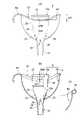
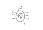
図3~図6に、尿受け具6の詳細を示す。尿受け具6は、女性の泌尿器に適用される内カップ部6aと、内カップ部6aを包囲する外カップ部(朝顔パッド)6bとから成り、外カップ部6bには、使用時に手で保持するための取手6dが一体状に突設されている。 3 to 6 show the details of the
このように、内カップ部6aと外カップ部6bによって、内外二重構造であり、図5に示す平面図のように、中心の円形の内カップ部6aの上端縁を、楕円状の外カップ部6bの上端縁が包囲状となるように、配設される。 As described above, the
内カップ部6aは、ゴム又は軟質合成樹脂製である。外カップ部6bは、この内カップ部6aよりも剛性も硬度も高い(大きい)合成樹脂製とする。従って、使用者が手で保持してもほとんど外カップ部6bは変形せず使い易い。特に、取手6dが前方突出状として、外カップ部6bの上端縁20から一体に形成されている場合にも、剛性があるので、使用し易い。 The
また、図3(A)(B)からも明らかなように、側方側に於て、外カップ部6bの上端縁20の中央底部20Mよりも、内カップ部6aの(側面視水平状の)上端縁部22が、2mm~10mm、好ましくは、5mm~7mmだけ上方突出状とする。即ち、図3に示すように、2mm≦ΔH≦10mmとする。さらに好ましくは、5mm≦ΔH≦7mmとする。 Further, as is clear from FIGS. 3 (A) and 3 (B), on the lateral side, the
ΔHを、このように設定したことにより、使用状態で、内カップ部6aが泌尿器周辺に当接して、弾性的に下方へ変形しつつ、密に圧接状として、尿がラジアル外方向へ(つまり、外カップ部6b側へ)洩れることを防止できる。 By setting ΔH in this way, the
ところで、図3(B)に示す如く、外カップ部6bの上端縁20には、軟質合成樹脂等の断面倒立U字状の縁材(被覆材)13を固着して、使用時の感触を改善している。あるいは、図3(C)に示す如く、小さな半径のアール状に弯曲したカール部14を形成するも、望ましい。 By the way, as shown in FIG. 3B, an inverted U-shaped cross-section (covering material) 13 such as a soft synthetic resin is fixed to the
図4に示すように、尿受け具6の内カップ部6aは、サック状乃至(背の高い)植木鉢状であり、しかも、底部23に第1貫孔24を有し、いわば、底抜けである。 As shown in FIG. 4, the
さらに、内カップ部6aは、第1貫孔24の近傍に、図4(A)(B)に示すように複数個の孔部25を形成している。具体的には、この孔部25は、図4(B)に示すように涙滴型とする。また、内カップ部6aの下端縁には、三角状切欠き26を複数個形成する。図4では、孔部25と切欠き26を、それぞれ2個ずつ形成した場合を例示している。なお、図4(A)と(B)は、略90°異なる角度から見た状態である。 Further, the
他方、外カップ部6bは、底部に、第2貫孔30を有し、この第2貫孔30を下方へ延伸させる短管部(接続用細管部)31が連設されている。
この短管部31に、可撓性チューブ5の先端が、(図1に示す如く)外嵌状として接続される。On the other hand, the
The tip of the
そして、内カップ部6aの下端の上記第1貫孔24の近傍壁部外面を、図3に示す如く、外カップ部6bの第2貫孔30の上方開口端内面30Aに、抜き差し自在に嵌着している。すなわち、内カップ部6aは、外カップ部6bに抜き差し自在である。内カップ部6aを、外カップ部6bに挿入して使用し、使用後は、内カップ部6aを抜き取って、内カップ部6aと外カップ部6bを夫々洗浄できるため、常に衛生的に使用できる。 Then, as shown in FIG. 3, the outer surface of the wall portion near the first through
女性使用者が、内カップ部6aの上縁を泌尿器に当接して使用中、内カップ部6aの上端縁部22から(ラジアル外方向へ)洩れて外カップ部6bの内面に沿って流下する洩れた尿Nを、図9に示す如く、複数の上記孔部25を介して、矢印Fのように、一旦、内カップ部6aの下方内部に流入させた後、直ちに第1貫孔24から短管部31───第2貫孔30───に導いて、可撓性チューブ5へ排出できる。 While the female user is using the upper edge of the
さらに、(前述の如く)切欠き26が内カップ部6aに形成されているので、この切欠き26を介しても、前記尿Nは直ちに矢印Gのように、短管部31へ流下する。すなわち、孔部25と切欠き26の共働により、尿戻り路を形成し、確実に尿Nを排出できる。 Further, since the
また、図4(C)に示すように、ゴム又は軟質合成樹脂製の内カップ部6a自体を、局部的に肉厚部を一体形成して、適度の弾発付勢力をもって泌尿器に当接するように構成している。すなわち、内カップ部6aの周囲壁が、肉厚の大きな上方の厚肉部28と、肉厚の小さな下方の薄肉部29と、を有するように内カップ部6a全体が、上端縁部22まで含めて金型を使用して一体成型されている。厚肉部28の高さは、内カップ部6a全体の高さの30~40%程度が望ましい。 Further, as shown in FIG. 4C, the
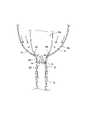
図7に於て、本発明の尿受け装置の使用状態を示す。本図においては、ベッド上に起き上がった状態の使用者(自力で離れた場所にある便所へ行くことが困難である)が取手6dを手で保持して尿受け具6を泌尿器に装着し、夜間の小用に対応している状態を示している。ペットボトル3は、ボトル受け部2に嵌着され、ボトル受け部2は、底板1に支えられて、夜間にペットボトル3が倒れる心配がない。また、ペットボトル3は、取り替え自在(使い捨て自在)であり、常に衛生的な状態で使用できる。 FIG. 7 shows the usage state of the urine receiving device of the present invention. In this figure, the user who is standing up on the bed (it is difficult to go to the toilet at a remote place by himself) holds the
可撓性チューブ5につながる内カップ部6a内に尿を流し込むことが必要であるが、使用中に、手の震え等により、内カップ部6aから尿が外れてしまう場合がある。その場合には、内カップ部6aから外れた尿を外カップ部(朝顔パッド)6bの内壁で受け、内カップ部6aの孔部25と切欠き26とを通して尿を可撓性チューブ5へと導く。 It is necessary to pour urine into the
図8に、馬蹄形(C形)の椅子15を使用した場合の使用状態を示す。
この椅子15は、座部16が馬蹄形(C形)であり、図8(B)に示すようにほぼ等しい間隔で配設された4本の脚を有し、中央のくぼみ部分17に尿受け具6を入れて使用することにより、ベッドの縁に腰掛けて使用する場合に比べて、より快適に尿受け具を使用できる。ところで、図2、及び、図7,図8あるいは(後述の)図10に於て、キャップ4から上方へ突出状の可撓性チューブ5の長さ寸法は、調整自在とするのが望ましい。即ち、キャップ4のチューブ連結孔11の内径寸法を、可撓性チューブ5の外径と同一乃至極微小寸法だけ小さく設定することによって、キャップ4の連結孔11から可撓性チューブ5を、引出し方向に、あるいは、ペットボトル3内方へ、スライド自在として、可撓性チューブ5の突出長さを調整して、身体弱者の体格(下肢の長さ)に合わせることが可能であり、使用し易くなる。
前述のように、リング33を、スライド可能に密嵌しているため、可撓性チューブ5の突出長さを調整しやすくなっている。FIG. 8 shows a usage state when a horseshoe-shaped (C-shaped)
The
As described above, since the
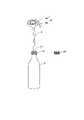
図10は、本発明の別の実施形態を示す。本実施形態では、図1で示したボトル受け部2及び底板1(及び支柱体7)が省略されている。本実施形態は、車両等の内部で、渋滞時等に使用するために携帯するも好適である。使用者は尿受け具6を泌尿器に装着し、尿を速やかにペットボトル3に流し込み、次に、図10に示す孔11の無い(新たな)キャップ4Yをペットボトル3に施蓋して、一時貯蔵する。図10に示す如く、孔11の有るキャップ4と、新品の(孔の無い)キャップ4Yとを、携帯用としては、セットとするのが望ましい。
その後、尿を廃棄できる場所(サービスエリアのトイレや自宅トイレ)に到着したときにペットボトル3内の尿を廃棄する。
あるいは、図10に図示のものを、(図示省略の)吊り下げ具等で携帯して、屋内で移動する際や、テレビ等を鑑賞する際に使用するにも好適である。FIG. 10 shows another embodiment of the present invention. In the present embodiment, the
After that, when arriving at a place where urine can be discarded (toilet in the service area or home toilet), the urine in the
Alternatively, it is also suitable to carry the one shown in FIG. 10 with a hanging tool (not shown) and use it when moving indoors or when watching TV or the like.
図11は、外カップ部6bの他の実施形態を示す。本実施形態では、外カップ部6bの第2貫孔30の内周面に、排出溝35が形成されている。排出溝35は、使用中に、手の震え等により、内カップ部6aから尿が外れてしまう場合に、外カップ部6bから可撓性チューブ5へと尿を導くものである。排出溝35の数は、3~9本とする。特に、5~8本が望ましい。排出溝35を形成した場合には、図3,図4,図5に示した内カップ部6aの孔部25及び切欠き26は省略できる。 FIG. 11 shows another embodiment of the
図12は、内カップ部6aの他の実施形態を示す。本実施形態では、内カップ部6aは、弾性的に伸び縮みするじゃばら部36を有し、未使用時には、図12(A)に示すように伸びた状態であるが、使用状態では、内カップ部6aが泌尿器周辺に当接して、じゃばら部36が図12(B)に矢印で示すように弾性的に縮んで安定するため、密に圧接状として、尿が洩れることを防止できる。 FIG. 12 shows another embodiment of the
本発明は、上述の実施形態に限定されず、例えば、ボトル受け部2の形状は、枡形に限らず、ペットボトル3が安定して嵌着される平面視円形や六角形等の形状であっても自由である。なお、底板1は樹脂などの材質で一体成形しても良い。また、ペットボトル3も、飲料を消費した後の市販のペットボトルを使用でき、その形状も特に制限されない。 The present invention is not limited to the above-described embodiment, and for example, the shape of the
本発明は、以上詳述したように、女性の泌尿器に押圧される尿受け具6と、使い捨て自在なペットボトル3と、上記ペットボトル3の雄ねじに着脱自在に螺着可能な雌ねじを有し、かつ、エア抜き小孔8及びチューブ連結孔11を有するキャップ4と、上記尿受け具6に先端が取付けられると共に、上記キャップ4の上記チューブ連結孔11に基端が嵌着された可撓性チューブ5と、を備え、上記尿受け具6は、ゴム又は軟質合成樹脂製の内カップ部6aと、該内カップ部6aの周囲壁を包囲する合成樹脂製外カップ部6bと、から成り、内カップ部6aよりも外カップ部6bの剛性を高くして、外カップ部6bを使用者の手で保持するように構成し、上記内カップ部6aの周囲壁が、肉厚の大きな上方の厚肉部28と、肉厚の小さな下方の薄肉部29と、を有し、上記内カップ部6aの下端の第1貫孔24の近傍に、複数の孔部25と複数の切欠き26を形成したので、内カップ部6aが、偏平状態となって上端部が垂れ下がることを防止でき、使用が容易である。また、室内にて使い易く、しかも、車両等の内部で、渋滞時等に使用できる。尿Nが貯まることなく、快適かつスムーズな使用を実現する。ペットボトル3が取り替え自在(使い捨て自在)であるため、常に衛生的な状態で使用できる。 As described in detail above, the present invention has a
また、女性の泌尿器に押圧される尿受け具6と、使い捨て自在なペットボトル3と、上記ペットボトル3の雄ねじに着脱自在に螺着可能な雌ねじを有し、かつ、エア抜き小孔8及びチューブ連結孔11を有するキャップ4と、上記尿受け具6に先端が取付けられると共に、上記キャップ4の上記チューブ連結孔11に基端が嵌着された可撓性チューブ5と、を備え、上記尿受け具6は、ゴム又は軟質合成樹脂製の内カップ部6aと、該内カップ部6aの周囲壁を包囲する合成樹脂製外カップ部6bと、から成り、内カップ部6aよりも外カップ部6bの剛性を高くして、外カップ部6bを使用者の手で保持するように構成し、上記内カップ部6aを、上記外カップ部6bに抜き差し自在に嵌着したので、内カップ部6aを抜き取って洗浄でき、常に衛生的に使用できる。 Further, it has a
また、女性の泌尿器に押圧される尿受け具6と、使い捨て自在なペットボトル3と、上記ペットボトル3の雄ねじに着脱自在に螺着可能な雌ねじを有し、かつ、エア抜き小孔8及びチューブ連結孔11を有するキャップ4と、上記尿受け具6に先端が取付けられると共に、上記キャップ4の上記チューブ連結孔11に基端が嵌着された可撓性チューブ5と、を備え、上記尿受け具6は、ゴム又は軟質合成樹脂製の内カップ部6aと、該内カップ部6aの周囲壁を包囲する合成樹脂製外カップ部6bと、から成り、内カップ部6aよりも外カップ部6bの剛性を高くして、外カップ部6bを使用者の手で保持するように構成し、上記外カップ部6bの底部の第2貫孔30の内周面に、外カップ部6bの内面に沿って落下する洩れた尿Nを、該第2貫孔30から下方へ延伸した短管部31に導く排出溝35を形成したので、尿Nが貯まることなく、快適かつスムーズな使用を実現できる。 Further, it has a
また、女性の泌尿器に押圧される尿受け具6と、使い捨て自在なペットボトル3と、上記ペットボトル3の雄ねじに着脱自在に螺着可能な雌ねじを有し、かつ、エア抜き小孔8及びチューブ連結孔11を有するキャップ4と、上記尿受け具6に先端が取付けられると共に、上記キャップ4の上記チューブ連結孔11に基端が嵌着された可撓性チューブ5と、を備え、上記尿受け具6は、ゴム又は軟質合成樹脂製の内カップ部6aと、該内カップ部6aの周囲壁を包囲する合成樹脂製外カップ部6bと、から成り、内カップ部6aよりも外カップ部6bの剛性を高くして、外カップ部6bを使用者の手で保持するように構成し、上記内カップ部6aは、弾性的に伸び縮みするじゃばら部36を有するので、内カップ部6aが、偏平状態となって上端部が垂れ下がることを防止でき、使用が容易である。また、泌尿器に内カップ部6aを押し当てる際に、じゃばら部36の弾性により安定するため、密に圧接状として、尿が洩れることを防止できる。 Further, it has a
また、上記キャップ4の上記チューブ連結孔11に係止して、尿受け具6がキャップ4から外れないようにするとともに、上記可撓性チューブ5のキャップ4から尿受け具6までの長さを調節可能とするリング33を、可撓性チューブ5にスライド可能に密嵌したので、使用条件に対応して可撓性チューブ5の長さを調節でき、また、尿受け具6がキャップ4から外れる事故を防止できる。 Further, the
3 ペットボトル
4 キャップ
5 可撓性チューブ
6 尿受け具
6a 内カップ部
6b 外カップ部
8 エア抜き小孔
11 チューブ連結孔
24 第1貫孔
25 孔部
26 切欠き
28 厚肉部
29 薄肉部
30 第2貫孔
31 短管部
33 リング
35 排出溝
36 じゃばら部3
Claims (5)
Translated fromJapanese使い捨て自在なペットボトル(3)と、
上記ペットボトル(3)の雄ねじに着脱自在に螺着可能な雌ねじを有し、かつ、エア抜き小孔(8)及びチューブ連結孔(11)を有するキャップ(4)と、
上記尿受け具(6)に先端が取付けられると共に、上記キャップ(4)の上記チューブ連結孔(11)に基端が嵌着された可撓性チューブ(5)と、
を備え、
上記尿受け具(6)は、ゴム又は軟質合成樹脂製の内カップ部(6a)と、該内カップ部(6a)の周囲壁を包囲する合成樹脂製外カップ部(6b)と、から成り、内カップ部(6a)よりも外カップ部(6b)の剛性を高くして、外カップ部(6b)を使用者の手で保持するように構成し、
上記内カップ部(6a)の周囲壁が、肉厚の大きな上方の厚肉部(28)と、肉厚の小さな下方の薄肉部(29)と、を有し、
上記内カップ部(6a)の下端の第1貫孔(24)の近傍に、複数の孔部(25)と複数の切欠き(26)を形成したことを特徴とする尿受け装置。A urine receiver (6) pressed against a woman's urinary system,
Disposable PET bottles (3) and
A cap (4) having a female screw that can be detachably screwed to the male screw of the PET bottle (3), and having a small air bleeding hole (8) and a tube connecting hole (11).
A flexible tube (5) having a tip attached to the urine receiving device (6) and a base end fitted to the tube connecting hole (11) of the cap (4).
Equipped with
The urine receiving device (6) is composed of an inner cup portion (6a) made of rubber or a soft synthetic resin and an outer cup portion (6b) made of a synthetic resin surrounding the peripheral wall of the inner cup portion (6a). The outer cup portion (6b) is made more rigid than the inner cup portion (6a) so that the outer cup portion (6b) can be held by the user's hand.
The peripheral wall of the inner cup portion (6a) has an upper thick portion (28) having a large wall thickness and a lower thin wall portion (29) having a small wall thickness.
A urine receiving device characterized in that a plurality of holes (25) and a plurality of notches (26) are formed in the vicinity of the first through hole (24) at the lower end of the inner cup portion (6a).
使い捨て自在なペットボトル(3)と、
上記ペットボトル(3)の雄ねじに着脱自在に螺着可能な雌ねじを有し、かつ、エア抜き小孔(8)及びチューブ連結孔(11)を有するキャップ(4)と、
上記尿受け具(6)に先端が取付けられると共に、上記キャップ(4)の上記チューブ連結孔(11)に基端が嵌着された可撓性チューブ(5)と、
を備え、
上記尿受け具(6)は、ゴム又は軟質合成樹脂製の内カップ部(6a)と、該内カップ部(6a)の周囲壁を包囲する合成樹脂製外カップ部(6b)と、から成り、内カップ部(6a)よりも外カップ部(6b)の剛性を高くして、外カップ部(6b)を使用者の手で保持するように構成し、
上記内カップ部(6a)を、上記外カップ部(6b)に抜き差し自在に嵌着したことを特徴とする尿受け装置。A urine receiver (6) pressed against a woman's urinary system,
Disposable PET bottles (3) and
A cap (4) having a female screw that can be detachably screwed to the male screw of the PET bottle (3), and having a small air bleeding hole (8) and a tube connecting hole (11).
A flexible tube (5) having a tip attached to the urine receiving device (6) and a base end fitted to the tube connecting hole (11) of the cap (4).
Equipped with
The urine receiving device (6) is composed of an inner cup portion (6a) made of rubber or a soft synthetic resin and an outer cup portion (6b) made of a synthetic resin surrounding the peripheral wall of the inner cup portion (6a). The outer cup portion (6b) is made more rigid than the inner cup portion (6a) so that the outer cup portion (6b) can be held by the user's hand.
A urine receiving device characterized in that the inner cup portion (6a) is freely inserted and removed from the outer cup portion (6b).
使い捨て自在なペットボトル(3)と、
上記ペットボトル(3)の雄ねじに着脱自在に螺着可能な雌ねじを有し、かつ、エア抜き小孔(8)及びチューブ連結孔(11)を有するキャップ(4)と、
上記尿受け具(6)に先端が取付けられると共に、上記キャップ(4)の上記チューブ連結孔(11)に基端が嵌着された可撓性チューブ(5)と、
を備え、
上記尿受け具(6)は、ゴム又は軟質合成樹脂製の内カップ部(6a)と、該内カップ部(6a)の周囲壁を包囲する合成樹脂製外カップ部(6b)と、から成り、内カップ部(6a)よりも外カップ部(6b)の剛性を高くして、外カップ部(6b)を使用者の手で保持するように構成し、
上記外カップ部(6b)の底部の第2貫孔(30)の内周面に、外カップ部(6b)の内面に沿って落下する洩れた尿(N)を、該第2貫孔(30)から下方へ延伸した短管部(31)に導く排出溝(35)を形成したことを特徴とする尿受け装置。A urine receiver (6) pressed against a woman's urinary system,
Disposable PET bottles (3) and
A cap (4) having a female screw that can be detachably screwed to the male screw of the PET bottle (3), and having a small air bleeding hole (8) and a tube connecting hole (11).
A flexible tube (5) having a tip attached to the urine receiving device (6) and a base end fitted to the tube connecting hole (11) of the cap (4).
Equipped with
The urine receiving device (6) is composed of an inner cup portion (6a) made of rubber or a soft synthetic resin and an outer cup portion (6b) made of a synthetic resin surrounding the peripheral wall of the inner cup portion (6a). The outer cup portion (6b) is made more rigid than the inner cup portion (6a) so that the outer cup portion (6b) can be held by the user's hand.
The leaked urine (N) that falls along the inner surface of the outer cup portion (6b) is formed in the inner peripheral surface of the second through hole (30) at the bottom of the outer cup portion (6b). A urine receiving device characterized by forming a drain groove (35) leading to a short tube portion (31) extending downward from 30).
使い捨て自在なペットボトル(3)と、
上記ペットボトル(3)の雄ねじに着脱自在に螺着可能な雌ねじを有し、かつ、エア抜き小孔(8)及びチューブ連結孔(11)を有するキャップ(4)と、
上記尿受け具(6)に先端が取付けられると共に、上記キャップ(4)の上記チューブ連結孔(11)に基端が嵌着された可撓性チューブ(5)と、
を備え、
上記尿受け具(6)は、ゴム又は軟質合成樹脂製の内カップ部(6a)と、該内カップ部(6a)の周囲壁を包囲する合成樹脂製外カップ部(6b)と、から成り、内カップ部(6a)よりも外カップ部(6b)の剛性を高くして、外カップ部(6b)を使用者の手で保持するように構成し、
上記内カップ部(6a)は、弾性的に伸び縮みするじゃばら部(36)を有することを特徴とする尿受け装置。A urine receiver (6) pressed against a woman's urinary system,
Disposable PET bottles (3) and
A cap (4) having a female screw that can be detachably screwed to the male screw of the PET bottle (3), and having a small air bleeding hole (8) and a tube connecting hole (11).
A flexible tube (5) having a tip attached to the urine receiving device (6) and a base end fitted to the tube connecting hole (11) of the cap (4).
Equipped with
The urine receiving device (6) is composed of an inner cup portion (6a) made of rubber or a soft synthetic resin and an outer cup portion (6b) made of a synthetic resin surrounding the peripheral wall of the inner cup portion (6a). The outer cup portion (6b) is made more rigid than the inner cup portion (6a) so that the outer cup portion (6b) can be held by the user's hand.
The inner cup portion (6a) is a urine receiving device characterized by having a bellows portion (36) that elastically expands and contracts.
Priority Applications (1)
| Application Number | Priority Date | Filing Date | Title |
|---|---|---|---|
| JP2020207412AJP7050357B1 (en) | 2020-12-15 | 2020-12-15 | Urine receiving device |
Applications Claiming Priority (1)
| Application Number | Priority Date | Filing Date | Title |
|---|---|---|---|
| JP2020207412AJP7050357B1 (en) | 2020-12-15 | 2020-12-15 | Urine receiving device |
Publications (2)
| Publication Number | Publication Date |
|---|---|
| JP7050357B1 JP7050357B1 (en) | 2022-04-08 |
| JP2022094495Atrue JP2022094495A (en) | 2022-06-27 |
Family
ID=81259462
Family Applications (1)
| Application Number | Title | Priority Date | Filing Date |
|---|---|---|---|
| JP2020207412AActiveJP7050357B1 (en) | 2020-12-15 | 2020-12-15 | Urine receiving device |
Country Status (1)
| Country | Link |
|---|---|
| JP (1) | JP7050357B1 (en) |
Citations (6)
| Publication number | Priority date | Publication date | Assignee | Title |
|---|---|---|---|---|
| JPS6010620U (en)* | 1983-06-30 | 1985-01-24 | 深沢 清作 | Urine collector aid |
| JPH0295364A (en)* | 1988-10-02 | 1990-04-06 | Yuichiro Takayama | Urine taking device |
| JP2006141584A (en)* | 2004-11-18 | 2006-06-08 | Kenko Kankyo Toshi Seisaku Center | Simple portable toilet |
| JP2007282665A (en)* | 2006-04-12 | 2007-11-01 | Seiko Go | Disposable urine receptacle |
| JP2011200638A (en)* | 2010-03-03 | 2011-10-13 | Haruyo Kawahara | Simple small urinal carrying support and storage box-cum-toilet seat with the support |
| JP2018130359A (en)* | 2017-02-16 | 2018-08-23 | 悦映 西村 | Portable urinal |
- 2020
- 2020-12-15JPJP2020207412Apatent/JP7050357B1/enactiveActive
Patent Citations (6)
| Publication number | Priority date | Publication date | Assignee | Title |
|---|---|---|---|---|
| JPS6010620U (en)* | 1983-06-30 | 1985-01-24 | 深沢 清作 | Urine collector aid |
| JPH0295364A (en)* | 1988-10-02 | 1990-04-06 | Yuichiro Takayama | Urine taking device |
| JP2006141584A (en)* | 2004-11-18 | 2006-06-08 | Kenko Kankyo Toshi Seisaku Center | Simple portable toilet |
| JP2007282665A (en)* | 2006-04-12 | 2007-11-01 | Seiko Go | Disposable urine receptacle |
| JP2011200638A (en)* | 2010-03-03 | 2011-10-13 | Haruyo Kawahara | Simple small urinal carrying support and storage box-cum-toilet seat with the support |
| JP2018130359A (en)* | 2017-02-16 | 2018-08-23 | 悦映 西村 | Portable urinal |
Also Published As
| Publication number | Publication date |
|---|---|
| JP7050357B1 (en) | 2022-04-08 |
Similar Documents
| Publication | Publication Date | Title |
|---|---|---|
| EP4076301B1 (en) | Apparatus and methods for receiving discharged urine | |
| US20070006368A1 (en) | Disposable funnel for urine samples | |
| US4421511A (en) | Female incontinence device | |
| US6679867B2 (en) | Male incontinence device | |
| US20090056003A1 (en) | Personal urinary director for women | |
| US20070214553A1 (en) | Female urinal with discharge conduit | |
| US20090048569A1 (en) | Disposable female urinary aid | |
| US20170239075A1 (en) | Female Urinal Apparatus | |
| JP2001276108A (en) | Urination for receiver for female | |
| US20080208148A1 (en) | Ophthalmic Device | |
| US20140033414A1 (en) | Portable urinal | |
| US11089909B2 (en) | Bidet for use in tub or shower | |
| US20120238976A1 (en) | Male urine collection and storage device | |
| JP7050357B1 (en) | Urine receiving device | |
| US11795676B2 (en) | Bidet and dispenser for use in tub or shower | |
| CN103251488A (en) | Urine collection device | |
| KR102224322B1 (en) | Free body urinal for male | |
| US5592699A (en) | Device for a urinal used by bedridden patients | |
| GB2070936A (en) | Female incontinence device | |
| JP2021094364A (en) | Urine receiving device | |
| JPH11514890A (en) | Urinary incontinence device for women | |
| US20150065972A1 (en) | Male Urine Collection Device | |
| JP6803096B2 (en) | Urine receiving device | |
| KR100680648B1 (en) | Portable urinal | |
| US20170215661A1 (en) | Portable Urinal |
Legal Events
| Date | Code | Title | Description |
|---|---|---|---|
| A621 | Written request for application examination | Free format text:JAPANESE INTERMEDIATE CODE: A621 Effective date:20211124 | |
| A871 | Explanation of circumstances concerning accelerated examination | Free format text:JAPANESE INTERMEDIATE CODE: A871 Effective date:20211223 | |
| RD02 | Notification of acceptance of power of attorney | Free format text:JAPANESE INTERMEDIATE CODE: A7422 Effective date:20211227 | |
| A521 | Request for written amendment filed | Free format text:JAPANESE INTERMEDIATE CODE: A523 Effective date:20220303 | |
| TRDD | Decision of grant or rejection written | ||
| A01 | Written decision to grant a patent or to grant a registration (utility model) | Free format text:JAPANESE INTERMEDIATE CODE: A01 Effective date:20220315 | |
| A61 | First payment of annual fees (during grant procedure) | Free format text:JAPANESE INTERMEDIATE CODE: A61 Effective date:20220322 | |
| R150 | Certificate of patent or registration of utility model | Ref document number:7050357 Country of ref document:JP Free format text:JAPANESE INTERMEDIATE CODE: R150 |