JP2022092996A - Inspection equipment, exposure equipment and article manufacturing method - Google Patents
Inspection equipment, exposure equipment and article manufacturing methodDownload PDFInfo
- Publication number
- JP2022092996A JP2022092996AJP2020206040AJP2020206040AJP2022092996AJP 2022092996 AJP2022092996 AJP 2022092996AJP 2020206040 AJP2020206040 AJP 2020206040AJP 2020206040 AJP2020206040 AJP 2020206040AJP 2022092996 AJP2022092996 AJP 2022092996A
- Authority
- JP
- Japan
- Prior art keywords
- light receiving
- light
- receiving unit
- inspection
- unit
- Prior art date
- Legal status (The legal status is an assumption and is not a legal conclusion. Google has not performed a legal analysis and makes no representation as to the accuracy of the status listed.)
- Pending
Links
Images


Landscapes
- Preparing Plates And Mask In Photomechanical Process (AREA)
- Exposure And Positioning Against Photoresist Photosensitive Materials (AREA)
Abstract
Description
Translated fromJapanese本発明は、検査装置、露光装置および物品製造方法に関する。 The present invention relates to an inspection device, an exposure device, and a method for manufacturing an article.
特許文献1には、異物からの散乱光を検出する第1の光検出手段と、コンタミネーションからの正反射光を検出する第2の光検出手段を設けて、異物およびコンタミネーションの両方を検出するペリクル検査装置が開示されている。
検査装置によって検査される被検物は、被検面を有する板状部材と、該被検面とは異なる高さを有し該板状部材を保持する保持部とを有する場合がある。このような被検物の被検面を検査する場合、照射部によって被検物に光が照射された状態において、被検面上の異物等の異常個所からの散乱光と、保持部からの正反射光とが受光部に入射しうる。この場合、異常個所からの散乱光と保持部からの正反射光とを区別することができず、異常個所が存在しないにも拘わらず、被検物に異常が存在するとの誤判定がなされうる。 The test object to be inspected by the inspection device may have a plate-shaped member having a surface to be inspected and a holding portion having a height different from the surface to be inspected and holding the plate-shaped member. When inspecting the test surface of such a test object, when the test object is irradiated with light by the irradiation unit, scattered light from an abnormal part such as a foreign substance on the test surface and light from the holding portion are used. Specularly reflected light can be incident on the light receiving portion. In this case, it is not possible to distinguish between the scattered light from the abnormal part and the specularly reflected light from the holding portion, and it may be erroneously determined that the object has an abnormality even though the abnormal part does not exist. ..
本発明は、誤判定の防止あるいは低減に有利な技術を提供することを目的とする。 An object of the present invention is to provide a technique advantageous for preventing or reducing erroneous determination.
本発明の1つの側面は、被検面を有する板状部材、および、前記被検面とは異なる高さを有し前記板状部材を保持する保持部を含む被検物、を検査する検査装置に係り、前記検査装置は、前記被検物に光を照射する照射部と、前記照射部によって光が照射された前記被検面からの散乱光を受光するように配置された第1受光部と、前記照射部によって光が照射された前記保持部からの正反射光を受光するように配置された第2受光部と、前記第1受光部の出力および前記第2受光部の出力に基づいて前記被検面における異常を検出するプロセッサと、を備える。 One aspect of the present invention is an inspection for inspecting a plate-shaped member having an inspected surface and an inspected object including a holding portion having a height different from the inspected surface and holding the plate-shaped member. In relation to the apparatus, the inspection apparatus is a first light receiving unit arranged so as to receive light from an irradiation unit that irradiates the test object with light and a scattered light from the test surface irradiated with light by the irradiation unit. The unit, the second light receiving unit arranged so as to receive the specularly reflected light from the holding unit irradiated with light by the irradiation unit, the output of the first light receiving unit, and the output of the second light receiving unit. A processor for detecting an abnormality on the surface to be inspected based on the above is provided.
本発明によれば、誤判定の防止あるいは低減に有利な技術が提供される。 INDUSTRIAL APPLICABILITY According to the present invention, a technique advantageous for preventing or reducing erroneous determination is provided.
以下、添付図面を参照して実施形態を詳しく説明する。なお、以下の実施形態は特許請求の範囲に係る発明を限定するものではない。実施形態には複数の特徴が記載されているが、これらの複数の特徴の全てが発明に必須のものとは限らず、また、複数の特徴は任意に組み合わせられてもよい。さらに、添付図面においては、同一若しくは同様の構成に同一の参照番号を付し、重複した説明は省略する。 Hereinafter, embodiments will be described in detail with reference to the accompanying drawings. The following embodiments do not limit the invention according to the claims. Although a plurality of features are described in the embodiment, not all of the plurality of features are essential for the invention, and the plurality of features may be arbitrarily combined. Further, in the attached drawings, the same or similar configurations are given the same reference numbers, and duplicate explanations are omitted.
以下の説明および図面では、方向がXYZ座標系において説明される。X方向はX軸に平行な方向、Y方向はY軸に平行な方向。Z方向はZ軸に平行な方向を意味する。 In the following description and drawings, the directions are described in the XYZ coordinate system. The X direction is the direction parallel to the X axis, and the Y direction is the direction parallel to the Y axis. The Z direction means a direction parallel to the Z axis.
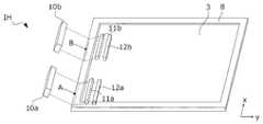
図1、図2には、一実施形態の検査装置100の構成が模式的に示されている。検査装置100は、被検物50を検査するように構成されている。被検物50は、被検面31を有する板状部材3、および、被検面31とは異なる高さを有し板状部材3を保持する保持部8を含みうる。被検物50は、例えば、露光装置において使用される原版(マスク)Mの自重撓みを補正するために原版Mの上に配置されるベンド板アセンブリでありうる。原版Mは、パターンを保護するペリクル膜Pを有しうる。ベンド板アセンブリとして構成される被検物50において、板状部材3は、露光光を透過する透明部材であるベンド板であり、保持部8は、板状部材3を保持するフレーム部材でありうる。ベンド板あるいは板状部材3は、原版Mに対向する内側面(下面)と、該内側面の反対側の外側面(上面)とを有し、被検面31は、ベンド板の該外側面である。保持部8は、例えば、板状部材3の4側面を取り囲む形状を有しうる。以下では特に言及しない限り、被検物50はベンド板アセンブリとして構成されているものとして説明するが、被検物50は、板状部材3および保持部8を有するあらゆる部材でありうる。 1 and 2 schematically show the configuration of the
被検物50は、例えば、原版Mの上に被検物50が配置された状態で検査装置100の検査ステージ6に搬送されうる。あるいは、被検物50は、原版Mが検査装置100の検査ステージ6に搬送された後に、原版Mの上に搬送されうる。検査装置100は、被検物50(ベンド板アセンブル)を検査する第1モードと、原版Mを検査する第2モードとを有してもよい。第2モードでは、原版Mは、原版Mの上に被検物50(ベンド板アセンブリ)が配置されない状態で検査されてもよいし、原版Mの上に被検物50(ベンド板アセンブリ)が配置された状態で検査されてもよい。第2モードでは、プロセッサ13は、第1受光部11の出力に基づいて原版Mにおける異常を検出しうる。 The
検査装置100は、照射部10、第1受光部11、第2受光部12およびプロセッサ13を備えうる。照射部10は、被検物50に光を照射するように構成される。第1受光部11は、照射部10によって光が照射された被検面31からの散乱光を受光するように配置される。ただし、第1受光部11は、照射部10によって光が照射された保持部8からの光も受光しうる。第2受光部12は、照射部10によって光が照射された保持部8からの正反射光を受光するように配置されうる。照射部10は、複数の照射器10a、10bを有してもよい。第1受光部11は、複数の受光器11a、11b、11c、11dを有してもよい。第2受光部12は、複数の受光器12a、12bを有してもよい。複数の照射器10a、10bは、例えば、x方向(第1方向)に互いに離隔して配置されうる。複数の受光器11a、11a、11b、11c、11dは、例えば、x方向に互いに離隔して配置されうる。一例において、受光器11a、11bは、互いにx方向に離隔しつつ、y方向(第1方向に直交する第2方向)については同一位置に配置されうる。また、受光器11c、11dは、互いにx方向に離隔しつつ、y方向については同一位置に配置されうる。また、受光器11a、11bからなる組と受光器11c、11dからなる組とは、y方向については互いに異なる位置に配置されうる。 The
照射部10は、光源1と、光源1からの光を被検物50に照射する光学系2とを含みうる。光源1は、単体の発光素子、または、1次元または二次元に配列された発光素子を含みうる。該発光素子は、例えば、LED(Light Emitting Diode)またはLD(Laser Diode)でありうる。第1受光部11は、ディテクタ5aと、被検面31からの散乱光をディテクタ5aの受光面に結像させる光学系4aとを含みうる。第2受光部12は、ディテクタ5bと、保持部8からの正反射光をディテクタ5bの受光面に結像させる光学系4bとを含みうる。ディテクタ5a、5bは、例えば、ラインセンサまたはイメージセンサを含みうる。 The
プロセッサ13は、第1受光部11の出力および第2受光部12の出力に基づいて被検物50の被検面31における異常(例えば、被検面31上の異物、被検面31の傷等の欠陥)を検出するように構成されうる。異常の検出は、例えば、異常個所が存在することの検出である。プロセッサ13は、例えば、第1受光部11の出力および第2受光部12の出力をAD変換するAD変換器と、該AD変換器によってAD変換された信号を処理するデジタルシグナルプロセッサとを含みうる。あるいは、プロセッサ13は、第1受光部11の出力および第2受光部12の出力をAD変換するAD変換器を搭載したMPU等のプロセッサであってもよい。プロセッサ13は、例えば、FPGA(Field Programmable Gate Arrayの略。)などのPLD(Programmable Logic Deviceの略。)、又は、ASIC(Application Specific Integrated Circuitの略。)、又は、プログラムが組み込まれた汎用又は専用のコンピュータ、又は、これらの全部または一部の組み合わせを含んでもよい。プロセッサ13は、第1受光部11の出力に基づいて被検物50の状態を示す二次元マップを生成しうる。 Based on the output of the first
検査装置100は、照射部10、第1受光部11および第2受光部12を含む検査ヘッドIHを被検物50に対して相対的に移動させる駆動機構20を備えうる。駆動機構20は、検査ヘッドIHをy方向に走査駆動する機構、および、検査ヘッドIHをx方向に駆動する機構を含みうる。また、駆動機構20は、第1受光部11および第2受光部12を含む受光部アセンブリに対して投光部10を相対的に移動させる機構を含みうる。 The
プロセッサ13は、検査ヘッドIHを被検物50に対して相対的に移動させるように駆動機構20を制御しながら、第1受光部11および第2受光部12の出力を処理(例えば、AD変換)して得られる信号を記録する。 The
図2に模式的に示されているように、第1受光部11は、照射部10によって光が照射された被検面31からの散乱光を受光するが、被検面31からの正反射光を受光しないように配置される。第2受光部12は、照射部10によって光が照射された保持部8からの正反射光を受光するように配置されうる。ここで、被検面31と保持部8の上面とは、高低差Δdを有するので、被検面31からの正反射光は、第2受光部12に入射しない。 As schematically shown in FIG. 2, the first
検査装置100は、照射部10の光軸の角度を調整する角度調整機構を有してもよい。また、検査装置100は、第1受光部11の光軸の角度を調整する角度調整機構を有してもよい。また、検査装置100は、第2受光部12の光軸の角度を調整する角度調整機構を有してもよい。 The
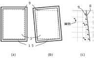
図3(a)に模式的に示されるように、検査装置100では、検査領域9が定義されている。検査領域9は、駆動機構20が照射部10、第1受光部11および第2受光部12を含む検査ヘッドIHを被検物50に対して相対的に移動させることによって検査を実施する領域である。プロセッサ13は、第1受光部11の出力に基づいて被検物50のうち検査領域9に収まっている部分の状態を示す二次元マップを生成しうる。二次元マップは、プロセッサ13が第1受光部11の出力を処理して得られる信号値を二次元空間(座標)上にマッピングして得られるデータであり、プロセッサ13は、該信号値が所定値を超える位置に異常(異常個所)があると判断することができる。被検物50の検査においては、被検物50のうち検査すべき領域が検査領域9に収まるように被検物50が検査ステージ6に配置されることが望まれる。 As schematically shown in FIG. 3A, the
しかし、例えば、図3(b)、図3(c)に模式的に示されるように、検査領域9に対して被検物50の被検面31がX軸、Y軸、θ軸(Z軸周りの回転)に関して、ずれて配置されうる。なお、図3(c)は、図3(b)の一部を拡大した模式図である。屈曲した矢印は、光を模式的に示している。このような状態では、検査領域9と保持部8との距離が近くなり、被検面31における異常個所からの光と保持部8からの光とが第1受光部11によって検出されうる。この場合、プロセッサ13は、第1受光部11の出力に基づいて生成された二次元マップにおいて異常を示している部分が被検面31における異常個所を示しているのか、保持部8の存在を示しているのかを二次元マップのみに基づいて判別することはできない。そこで、プロセッサ13は、第1受光部11の出力および第2受光部12の出力に基づいて被検面31における異常を検出する。具体的には、プロセッサ13は、第1受光部11の出力に基づいて被検物50の状態を示す二次元マップを生成し、第2受光部12の出力に基づいて保持部8が存在する保持部領域を特定しうる。そして、プロセッサ13は、二次元マップのうち保持部領域に対応する領域以外の領域の情報に基づいて被検面31における異常を検出しうる。 However, for example, as schematically shown in FIGS. 3 (b) and 3 (c), the
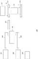
図4において、被検物50の検査において検査ヘッドIHを被検物50に対して相対的に移動させる経路の一例が矢印によって模式的に示されている。図5には、被検物50の検査において検査ヘッドIHを被検物50に対して相対的に移動させる手順の一例が模式的に示されている。図5(a)には、検査の開始時における検査ヘッドIHと被検物50との相対位置が示されている。図5(a)に示す状態では、照射部10の照射器10aからの光が被検物50を介して第1受光部11の受光器11aに入射し、照射部10の照射器10bからの光が被検物50を介して第1受光部11の受光器11bに入射する。駆動機構20は、図5(a)に示す状態から図5(b)に示す状態まで検査ヘッドIHを+y方向に駆動する。次いで、駆動機構20は、図5(c)に示されるように、照射部10を+x方向に移動させる。この移動は、照射部10の照射器10aからの光が被検物50を介して第1受光部11の受光器11cに入射し、照射部10の照射器10bからの光が被検物50を介して第1受光部11の受光器11dに入射するようになされる。次いで、駆動機構20は、図5(c)に示す状態から図5(d)に示す状態まで検査ヘッドIHを-y方向に駆動する。次いで、駆動機構20は、図5(a)に示される状態になるように、照射部10を-x方向に移動させる。この移動は、照射部10の照射器10aからの光が被検物50を介して第1受光部11の受光器11aに入射し、照射部10の照射器10bからの光が被検物50を介して第1受光部11の受光器11bに入射する状態となるようになされる。あるいは、次回の検査は、図5(d)、図5(c)、図5(b)、図5(a)に示すように、即ち、上記の説明とは反対方向に検査ヘッドIHを駆動しながらなされてもよい。 In FIG. 4, an example of a route for moving the inspection head IH relative to the subject 50 in the inspection of the subject 50 is schematically shown by an arrow. FIG. 5 schematically shows an example of a procedure for moving the inspection head IH relative to the subject 50 in the inspection of the subject 50. FIG. 5A shows the relative position of the inspection head IH and the subject 50 at the start of the inspection. In the state shown in FIG. 5A, the light from the
図5に示された構成例では、フレーム形状を有する保持部8の4辺のうち2辺が第2受光部12の受光器12a、12bを使って検出される。プロセッサ13は、該2辺の位置および姿勢に基づいてフレーム形状を有する保持部8の全体の位置および姿勢を検出あるいは特定することができる。 In the configuration example shown in FIG. 5, two of the four sides of the holding
以上の説明では、検査ヘッドIHが駆動機構20によって駆動されているが、これに代えて被検物50(検査ステージ6)が駆動機構20によって駆動されることによって被検物50と検査ヘッドIHとの相対位置が変更されてもよい。 In the above description, the inspection head IH is driven by the
図6には、検査ヘッドIHの他の構成例が示されている。図6に示された例では、照射部10は、照射器10a、10bを含み、第1受光部11は、照射器10a、10bの個数と同数の受光器11a、11bを含み、第2受光部11も、照射器10a、10bの個数と同数の受光器12a、12bを含む。照射部10の照射器10a、10b、第1受光部11の受光器11a、11b、第2受光部12の受光器12a、12bは、それらの間の相対位置を維持しながら駆動機構20(図6において不図示)によって駆動されうる。あるいは、照射部10の照射器10a、10b、第1受光部11の受光器11a、11b、第2受光部12の受光器12a、12bの間の相対位置を維持しながら被検物50(検査ステージ6)が駆動機構20によって駆動されてよい。図6に示された構成例は、図5に示された構成例よりも検査ヘッドIHを小型化するために有利である。 FIG. 6 shows another configuration example of the inspection head IH. In the example shown in FIG. 6, the
以下、図7を参照しながら検査装置100による被検物50の検査処理(検査方法)を例示的に説明する。この検査処理は、プロセッサ13によって制御されうる。工程S800では、プロセッサ13は、検査ヘッドIHによって検査領域9の全域が走査されるように駆動機構20を制御しながら第1受光部11および第2受光部12のそれぞれの出力を処理して得られる信号(信号値)を記録する。この走査は、例えば、図5に例示されるようになされうる。 Hereinafter, the inspection process (inspection method) of the
工程S801では、プロセッサ13は、工程S800で記録された、第1受光部11の出力を処理して得られる信号(信号値)を二次元空間にマッピングして被検物50の状態を示す二次元マップを生成する。工程S801において生成される二次元マップは、図8(a)に例示されている。工程S801は、第1受光部11の出力に基づいて被検物50の状態を示す二次元マップを生成する処理に相当する。 In step S801, the
工程S802では、プロセッサ13は、工程S800で記録された、第2受光部12の出力を処理して得られる信号(信号値)を二次元空間にマッピングして被検物50の状態を示す二次元マップを生成する。工程S802において生成される二次元マップは、図8(b)に例示されている。工程S803では、プロセッサ13は、工程S802で生成された二次元マップから被検物50の保持部8が存在する領域である保持部領域を特定する。この保持部領域は、図8(c)に例示されている。工程S802およびS803は、第2受光部12の出力に基づいて保持部8が存在する保持部領域を特定する処理に相当する。 In step S802, the
工程S804では、プロセッサ13は、工程S801で得られた二次元マップにおいて工程S803で特定された保持部領域を特定する。図8(d)には、工程S801で得られた二次元マップにおける保持部領域が示されている。工程S805では、プロセッサ13は、工程S801で得られた二次元マップのうち工程S804において特定された保持部領域の内側の領域の信号値に基づいて、被検面31における異常を検出する。図8(e)には、工程S805において検出された異常(異常個所)が示されている。なお、図8(a)~図8(e)において、階調値が大きい信号は、信号値が大きい信号値を模式的に示している。工程S804および工程S805は、工程S801で得られた二次元マップのうち保持部領域に対応する領域以外の領域の情報に基づいて被検面31における異常を検出する処理に相当する。 In the step S804, the
他の側面において、検査装置100は、被検物に光を照射する照射部10と、照射部10によって光が照射された被検物からの散乱光を受光する受光部11と、受光部11の出力に基づいて被検物の異常を検出するプロセッサ13と、を備えうる。ここで、照射部10および受光部11は、第1モードでは、原版を被検物として、該原版からの散乱光を受光部11が受光するように配置されうる。一方、第2モードでは、原版の上に配置されたベンド板を被検物として、該ベンド板からの散乱光を受光部11が受光するように配置されうる。 On another aspect, the
図9には、検査装置100が組み込まれた露光装置EXPの構成が例示されている。露光装置EXPは、原版Mを保持する原版チャックを有する原版駆動機構912と、原版Mを照明する照明光学系911と、原版Mのパターンを基板Sに投影する投影光学系913と、基板Sを保持する基板チャックを有する基板駆動機構914とを備えうる。原版Mの上には、不図示のベンド板アセンブリ(前述の被検物50に相当)が配置される。 FIG. 9 illustrates the configuration of the exposure apparatus EXP in which the
露光装置EXPは、ベンド板アセンブリを格納するストッカ901と、原版Mを格納するストッカ902と、ストッカ901内のベンド板アセンブリを搬送する搬送機構903と、ストッカ902内の原版Mを搬送する搬送機構904とを備えうる。ベンド板アセンブリは、検査装置100の検査ステージ6の上で原版Mの上に配置されうる。あるいは、ベンド板アセンブリは、不図示のバッファにおいて原版Mの上に配置され、原版Mとともに検査装置100の検査ステージ6に搬送されうる。検査装置100は、ベンド板アセンブリおよび原版Mを検査する。 The exposure apparatus EXP includes a
露光装置EXPは、制御部920を備えうる。制御部920は、検査装置100による検査結果に異常がない場合に、検査装置100によって検査されたベンド板アセンブリおよび原版Mを使って基板を露光する露光処理を実行する。露光処理は、照明光学系911によって原版Mを照明し、原版Mのパターンを投影光学系913によって基板Sに投影することによって基板Sを露光する処理を含む。制御部920は、検査装置100による検査結果に異常がある場合には、それを示すエラー処理(例えば、報知)を実行しうる。 The exposure apparatus EXP may include a
以下、上記の露光装置EXPを用いて物品を製造する物品製造方法を説明する。該物品製造方法は、該露光装置を用いて基板を露光する露光工程と、前記露光工程を経た前記基板を現像する現像工程と、前記現像工程を経た前記基板を処理して物品を得る処理工程と、を含みうる。露光装置に提供される基板には、感光材(フォトレジスト)が塗布されている。露光工程によって、原版のパターンが潜像パターンとして感光材に転写される。現像工程において、この潜像パターンが物理的なデバイスパターンに変換される。処理工程は、例えば、デバイスパターンを使ってその下地の層をパターニングする工程を含みうる。処理工程はまた、基板をダイシングする工程を含んでもよい。 Hereinafter, an article manufacturing method for manufacturing an article using the above-mentioned exposure apparatus EXP will be described. The article manufacturing method includes an exposure step of exposing a substrate using the exposure apparatus, a developing step of developing the substrate through the exposure step, and a processing step of processing the substrate through the developing step to obtain an article. And can be included. A photosensitive material (photoresist) is applied to the substrate provided for the exposure apparatus. By the exposure process, the pattern of the original plate is transferred to the photosensitive material as a latent image pattern. In the developing process, this latent image pattern is converted into a physical device pattern. The processing step may include, for example, the step of patterning the underlying layer using a device pattern. The processing step may also include a step of dicing the substrate.
発明は上記実施形態に制限されるものではなく、発明の精神及び範囲から離脱することなく、様々な変更及び変形が可能である。従って、発明の範囲を公にするために請求項を添付する。 The invention is not limited to the above embodiment, and various modifications and modifications can be made without departing from the spirit and scope of the invention. Therefore, a claim is attached to publicize the scope of the invention.
3:板状部材、31:被検面、8:保持部、50:被検物、10:照射部:11:第1受光部、12:第2受光部、13:プロセッサ、100:検査装置、M:原版、3: Plate-shaped member, 31: Test surface, 8: Holding part, 50: Subject, 10: Irradiation part: 1: 1st light receiving part, 12: Second light receiving part, 13: Processor, 100: Inspection device , M: Original version,
Claims (9)
Translated fromJapanese前記被検物に光を照射する照射部と、
前記照射部によって光が照射された前記被検面からの散乱光を受光するように配置された第1受光部と、
前記照射部によって光が照射された前記保持部からの正反射光を受光するように配置された第2受光部と、
前記第1受光部の出力および前記第2受光部の出力に基づいて前記被検面における異常を検出するプロセッサと、
を備えることを特徴とする検査装置。An inspection device for inspecting a plate-shaped member having a surface to be inspected and an inspected object having a height different from that of the surface to be inspected and including a holding portion for holding the plate-shaped member.
An irradiation unit that irradiates the subject with light,
A first light receiving unit arranged so as to receive scattered light from the surface to be inspected, which is irradiated with light by the irradiation unit, and a first light receiving unit.
A second light receiving unit arranged so as to receive specularly reflected light from the holding unit irradiated with light by the irradiation unit, and a second light receiving unit.
A processor that detects an abnormality on the surface to be inspected based on the output of the first light receiving unit and the output of the second light receiving unit.
An inspection device characterized by being provided with.
前記第1受光部の出力に基づいて前記被検物の状態を示す二次元マップを生成する処理と、
前記第2受光部の出力に基づいて前記保持部が存在する保持部領域を特定する処理と、
前記二次元マップのうち前記保持部領域に対応する領域以外の領域の情報に基づいて前記被検面における異常を検出する処理と、を実行する、
ことを特徴とする請求項1に記載の検査装置。The processor
A process of generating a two-dimensional map showing the state of the subject based on the output of the first light receiving unit, and
A process of specifying a holding portion region in which the holding portion exists based on the output of the second light receiving portion, and a process of specifying the holding portion region.
A process of detecting an abnormality on the surface to be inspected based on information in a region other than the region corresponding to the holding portion region in the two-dimensional map is executed.
The inspection device according to claim 1.
ことを特徴とする請求項1又は2に記載の検査装置。Further, a driving mechanism for moving the irradiation unit, the first light receiving unit and the second light receiving unit relative to the subject is further provided.
The inspection apparatus according to claim 1 or 2.
前記保持部は、前記ベンド板を保持する、
ことを特徴とする請求項1乃至3のいずれか1項に記載の検査装置。The test object includes a bend plate disposed on the original plate at a distance from the original plate, and the bend plate has an inner surface facing the original plate and an outer surface opposite to the inner side surface. However, the surface to be inspected is the outer surface of the bend plate.
The holding portion holds the bend plate.
The inspection device according to any one of claims 1 to 3.
第1モードでは、前記照射部によって光が照射された前記被検面からの散乱光を前記第1受光部が受光するように配置され、
第2モードでは、前記照射部によって光が照射された前記原版からの散乱光を前記第1受光部が受光するように配置される、
ことを特徴とする請求項4に記載の検査装置。The irradiation unit and the first light receiving unit are
In the first mode, the first light receiving unit is arranged so that the scattered light from the test surface irradiated with the light by the irradiation unit is received by the first light receiving unit.
In the second mode, the first light receiving unit is arranged so that the scattered light from the original plate irradiated with the light by the irradiation unit is received by the first light receiving unit.
The inspection apparatus according to claim 4.
ことを特徴とする請求項5に記載の検査装置。In the second mode, the processor detects an abnormality in the original plate based on the output of the first light receiving unit.
The inspection apparatus according to claim 5.
前記被検物に光を照射する照射部と、
前記照射部によって光が照射された前記被検物からの散乱光を受光する受光部と、
前記受光部の出力に基づいて前記被検物の異常を検出するプロセッサと、を備え、
前記照射部および前記受光部は、
第1モードでは、原版を前記被検物として、前記原版からの散乱光を前記受光部が受光するように配置され、
第2モードでは、前記原版の上に配置されたベンド板を前記被検物として、前記ベンド板からの散乱光を前記受光部が受光するように配置される、
ことを特徴とする検査装置。An inspection device that inspects an object to be inspected.
An irradiation unit that irradiates the subject with light,
A light receiving unit that receives scattered light from the subject irradiated with light by the irradiation unit, and a light receiving unit.
A processor that detects an abnormality in the subject based on the output of the light receiving unit is provided.
The irradiation unit and the light receiving unit are
In the first mode, the original plate is used as the subject, and the light receiving portion is arranged so that the light receiving unit receives the scattered light from the original plate.
In the second mode, the bend plate arranged on the original plate is used as the subject, and the light receiving portion is arranged so as to receive the scattered light from the bend plate.
An inspection device characterized by that.
請求項4乃至7のいずれか1項に記載の検査装置と、
前記検査装置による検査結果に異常がない場合に前記基板を露光する処理を実行する制御部と、
を備えることを特徴とする露光装置。An exposure apparatus that exposes the substrate by projecting the pattern of the original plate onto the substrate by a projection optical system.
The inspection device according to any one of claims 4 to 7.
A control unit that executes a process of exposing the substrate when there is no abnormality in the inspection result by the inspection device, and a control unit.
An exposure apparatus characterized by comprising.
前記露光工程を経た前記基板を現像する現像工程と、
前記現像工程を経た前記基板を処理して物品を得る処理工程と、
を含むことを特徴とする物品製造方法。An exposure step of exposing a substrate using the exposure apparatus according to claim 8.
A developing process for developing the substrate that has undergone the exposure process, and a development process for developing the substrate.
A processing step of processing the substrate that has undergone the development step to obtain an article, and a processing step of obtaining an article.
A method for manufacturing an article, which comprises.
Priority Applications (1)
| Application Number | Priority Date | Filing Date | Title |
|---|---|---|---|
| JP2020206040AJP2022092996A (en) | 2020-12-11 | 2020-12-11 | Inspection equipment, exposure equipment and article manufacturing method |
Applications Claiming Priority (1)
| Application Number | Priority Date | Filing Date | Title |
|---|---|---|---|
| JP2020206040AJP2022092996A (en) | 2020-12-11 | 2020-12-11 | Inspection equipment, exposure equipment and article manufacturing method |
Publications (1)
| Publication Number | Publication Date |
|---|---|
| JP2022092996Atrue JP2022092996A (en) | 2022-06-23 |
Family
ID=82068969
Family Applications (1)
| Application Number | Title | Priority Date | Filing Date |
|---|---|---|---|
| JP2020206040APendingJP2022092996A (en) | 2020-12-11 | 2020-12-11 | Inspection equipment, exposure equipment and article manufacturing method |
Country Status (1)
| Country | Link |
|---|---|
| JP (1) | JP2022092996A (en) |
- 2020
- 2020-12-11JPJP2020206040Apatent/JP2022092996A/enactivePending
Similar Documents
| Publication | Publication Date | Title |
|---|---|---|
| JP3101290B2 (en) | Surface condition inspection device, exposure apparatus, and surface condition inspection method | |
| KR100788055B1 (en) | Substrate Defect Detection Apparatus and Method and Substrate Identification Number Detection Method | |
| JPH075115A (en) | Surface condition inspection device | |
| KR102011553B1 (en) | Foreign matter checking apparatus, exposure apparatus and device manufacturing method | |
| JP2003282675A (en) | Wafer mapping device | |
| US7986403B2 (en) | Foreign substance inspection apparatus | |
| JP2014062940A (en) | Checking device | |
| JP7324116B2 (en) | Foreign matter inspection device and foreign matter inspection method | |
| JP2022092996A (en) | Inspection equipment, exposure equipment and article manufacturing method | |
| JP2008164399A (en) | Device for inspecting abnormality | |
| JP4961615B2 (en) | Photomask inspection method and apparatus | |
| US10386308B2 (en) | Pattern inspection apparatus for detecting a pattern defect | |
| JP2015230273A (en) | Mask inspection device and mask inspection method | |
| JP2006098104A (en) | Printing inspection system and laser marking device | |
| JP4654408B2 (en) | Inspection apparatus, inspection method, and pattern substrate manufacturing method | |
| JP4594833B2 (en) | Defect inspection equipment | |
| JP2001201461A (en) | Foreign-body inspection apparatus | |
| KR101087628B1 (en) | Foreign material inspection device, exposure device and device manufacturing method | |
| JP2006010544A (en) | Apparatus and method for inspecting foreign matter | |
| JPH06273344A (en) | Defect inspection device and defect inspection method | |
| KR101594224B1 (en) | Surface condition insepecting method of planar substrate and surface condition inspecting device of planar substrate using the same | |
| JP2021113795A (en) | Foreign matter inspection device | |
| JP2024076154A (en) | MASK STORAGE, LITHOGRAPHY APPARATUS, INSPECTION METHOD, AND PRODUCTION METHOD OF ARTICLE | |
| JPS6067845A (en) | Foreign object inspection device | |
| JP2022175005A (en) | Inspection device |
Legal Events
| Date | Code | Title | Description |
|---|---|---|---|
| RD02 | Notification of acceptance of power of attorney | Free format text:JAPANESE INTERMEDIATE CODE: A7422 Effective date:20210103 | |
| A521 | Request for written amendment filed | Free format text:JAPANESE INTERMEDIATE CODE: A523 Effective date:20210113 | |
| RD04 | Notification of resignation of power of attorney | Free format text:JAPANESE INTERMEDIATE CODE: A7424 Effective date:20210316 |