JP2022089864A - Rotor for fluid pump and its manufacturing method - Google Patents
Rotor for fluid pump and its manufacturing methodDownload PDFInfo
- Publication number
- JP2022089864A JP2022089864AJP2022056240AJP2022056240AJP2022089864AJP 2022089864 AJP2022089864 AJP 2022089864AJP 2022056240 AJP2022056240 AJP 2022056240AJP 2022056240 AJP2022056240 AJP 2022056240AJP 2022089864 AJP2022089864 AJP 2022089864A
- Authority
- JP
- Japan
- Prior art keywords
- rotor
- state
- reinforcing
- impeller
- elements
- Prior art date
- Legal status (The legal status is an assumption and is not a legal conclusion. Google has not performed a legal analysis and makes no representation as to the accuracy of the status listed.)
- Granted
Links
Images


Classifications
- F—MECHANICAL ENGINEERING; LIGHTING; HEATING; WEAPONS; BLASTING
- F04—POSITIVE - DISPLACEMENT MACHINES FOR LIQUIDS; PUMPS FOR LIQUIDS OR ELASTIC FLUIDS
- F04D—NON-POSITIVE-DISPLACEMENT PUMPS
- F04D29/00—Details, component parts, or accessories
- F04D29/02—Selection of particular materials
- F04D29/026—Selection of particular materials especially adapted for liquid pumps
- A—HUMAN NECESSITIES
- A61—MEDICAL OR VETERINARY SCIENCE; HYGIENE
- A61M—DEVICES FOR INTRODUCING MEDIA INTO, OR ONTO, THE BODY; DEVICES FOR TRANSDUCING BODY MEDIA OR FOR TAKING MEDIA FROM THE BODY; DEVICES FOR PRODUCING OR ENDING SLEEP OR STUPOR
- A61M60/00—Blood pumps; Devices for mechanical circulatory actuation; Balloon pumps for circulatory assistance
- A61M60/10—Location thereof with respect to the patient's body
- A61M60/122—Implantable pumps or pumping devices, i.e. the blood being pumped inside the patient's body
- A61M60/126—Implantable pumps or pumping devices, i.e. the blood being pumped inside the patient's body implantable via, into, inside, in line, branching on, or around a blood vessel
- A—HUMAN NECESSITIES
- A61—MEDICAL OR VETERINARY SCIENCE; HYGIENE
- A61M—DEVICES FOR INTRODUCING MEDIA INTO, OR ONTO, THE BODY; DEVICES FOR TRANSDUCING BODY MEDIA OR FOR TAKING MEDIA FROM THE BODY; DEVICES FOR PRODUCING OR ENDING SLEEP OR STUPOR
- A61M60/00—Blood pumps; Devices for mechanical circulatory actuation; Balloon pumps for circulatory assistance
- A61M60/20—Type thereof
- A61M60/205—Non-positive displacement blood pumps
- A61M60/216—Non-positive displacement blood pumps including a rotating member acting on the blood, e.g. impeller
- A61M60/226—Non-positive displacement blood pumps including a rotating member acting on the blood, e.g. impeller the blood flow through the rotating member having mainly radial components
- A—HUMAN NECESSITIES
- A61—MEDICAL OR VETERINARY SCIENCE; HYGIENE
- A61M—DEVICES FOR INTRODUCING MEDIA INTO, OR ONTO, THE BODY; DEVICES FOR TRANSDUCING BODY MEDIA OR FOR TAKING MEDIA FROM THE BODY; DEVICES FOR PRODUCING OR ENDING SLEEP OR STUPOR
- A61M60/00—Blood pumps; Devices for mechanical circulatory actuation; Balloon pumps for circulatory assistance
- A61M60/10—Location thereof with respect to the patient's body
- A61M60/122—Implantable pumps or pumping devices, i.e. the blood being pumped inside the patient's body
- A61M60/126—Implantable pumps or pumping devices, i.e. the blood being pumped inside the patient's body implantable via, into, inside, in line, branching on, or around a blood vessel
- A61M60/13—Implantable pumps or pumping devices, i.e. the blood being pumped inside the patient's body implantable via, into, inside, in line, branching on, or around a blood vessel by means of a catheter allowing explantation, e.g. catheter pumps temporarily introduced via the vascular system
- A—HUMAN NECESSITIES
- A61—MEDICAL OR VETERINARY SCIENCE; HYGIENE
- A61M—DEVICES FOR INTRODUCING MEDIA INTO, OR ONTO, THE BODY; DEVICES FOR TRANSDUCING BODY MEDIA OR FOR TAKING MEDIA FROM THE BODY; DEVICES FOR PRODUCING OR ENDING SLEEP OR STUPOR
- A61M60/00—Blood pumps; Devices for mechanical circulatory actuation; Balloon pumps for circulatory assistance
- A61M60/20—Type thereof
- A61M60/205—Non-positive displacement blood pumps
- A61M60/216—Non-positive displacement blood pumps including a rotating member acting on the blood, e.g. impeller
- A61M60/237—Non-positive displacement blood pumps including a rotating member acting on the blood, e.g. impeller the blood flow through the rotating member having mainly axial components, e.g. axial flow pumps
- A—HUMAN NECESSITIES
- A61—MEDICAL OR VETERINARY SCIENCE; HYGIENE
- A61M—DEVICES FOR INTRODUCING MEDIA INTO, OR ONTO, THE BODY; DEVICES FOR TRANSDUCING BODY MEDIA OR FOR TAKING MEDIA FROM THE BODY; DEVICES FOR PRODUCING OR ENDING SLEEP OR STUPOR
- A61M60/00—Blood pumps; Devices for mechanical circulatory actuation; Balloon pumps for circulatory assistance
- A61M60/40—Details relating to driving
- A61M60/403—Details relating to driving for non-positive displacement blood pumps
- A61M60/408—Details relating to driving for non-positive displacement blood pumps the force acting on the blood contacting member being mechanical, e.g. transmitted by a shaft or cable
- A61M60/411—Details relating to driving for non-positive displacement blood pumps the force acting on the blood contacting member being mechanical, e.g. transmitted by a shaft or cable generated by an electromotor
- A61M60/414—Details relating to driving for non-positive displacement blood pumps the force acting on the blood contacting member being mechanical, e.g. transmitted by a shaft or cable generated by an electromotor transmitted by a rotating cable, e.g. for blood pumps mounted on a catheter
- A—HUMAN NECESSITIES
- A61—MEDICAL OR VETERINARY SCIENCE; HYGIENE
- A61M—DEVICES FOR INTRODUCING MEDIA INTO, OR ONTO, THE BODY; DEVICES FOR TRANSDUCING BODY MEDIA OR FOR TAKING MEDIA FROM THE BODY; DEVICES FOR PRODUCING OR ENDING SLEEP OR STUPOR
- A61M60/00—Blood pumps; Devices for mechanical circulatory actuation; Balloon pumps for circulatory assistance
- A61M60/80—Constructional details other than related to driving
- A61M60/802—Constructional details other than related to driving of non-positive displacement blood pumps
- A61M60/804—Impellers
- A61M60/806—Vanes or blades
- A61M60/808—Vanes or blades specially adapted for deformable impellers, e.g. expandable impellers
- B—PERFORMING OPERATIONS; TRANSPORTING
- B29—WORKING OF PLASTICS; WORKING OF SUBSTANCES IN A PLASTIC STATE IN GENERAL
- B29C—SHAPING OR JOINING OF PLASTICS; SHAPING OF MATERIAL IN A PLASTIC STATE, NOT OTHERWISE PROVIDED FOR; AFTER-TREATMENT OF THE SHAPED PRODUCTS, e.g. REPAIRING
- B29C45/00—Injection moulding, i.e. forcing the required volume of moulding material through a nozzle into a closed mould; Apparatus therefor
- B29C45/0005—Injection moulding, i.e. forcing the required volume of moulding material through a nozzle into a closed mould; Apparatus therefor using fibre reinforcements
- B—PERFORMING OPERATIONS; TRANSPORTING
- B29—WORKING OF PLASTICS; WORKING OF SUBSTANCES IN A PLASTIC STATE IN GENERAL
- B29C—SHAPING OR JOINING OF PLASTICS; SHAPING OF MATERIAL IN A PLASTIC STATE, NOT OTHERWISE PROVIDED FOR; AFTER-TREATMENT OF THE SHAPED PRODUCTS, e.g. REPAIRING
- B29C45/00—Injection moulding, i.e. forcing the required volume of moulding material through a nozzle into a closed mould; Apparatus therefor
- B29C45/16—Making multilayered or multicoloured articles
- B—PERFORMING OPERATIONS; TRANSPORTING
- B29—WORKING OF PLASTICS; WORKING OF SUBSTANCES IN A PLASTIC STATE IN GENERAL
- B29C—SHAPING OR JOINING OF PLASTICS; SHAPING OF MATERIAL IN A PLASTIC STATE, NOT OTHERWISE PROVIDED FOR; AFTER-TREATMENT OF THE SHAPED PRODUCTS, e.g. REPAIRING
- B29C45/00—Injection moulding, i.e. forcing the required volume of moulding material through a nozzle into a closed mould; Apparatus therefor
- B29C45/17—Component parts, details or accessories; Auxiliary operations
- B29C45/26—Moulds
- B29C45/27—Sprue channels ; Runner channels or runner nozzles
- B29C45/2701—Details not specific to hot or cold runner channels
- B29C45/2708—Gates
- B—PERFORMING OPERATIONS; TRANSPORTING
- B29—WORKING OF PLASTICS; WORKING OF SUBSTANCES IN A PLASTIC STATE IN GENERAL
- B29C—SHAPING OR JOINING OF PLASTICS; SHAPING OF MATERIAL IN A PLASTIC STATE, NOT OTHERWISE PROVIDED FOR; AFTER-TREATMENT OF THE SHAPED PRODUCTS, e.g. REPAIRING
- B29C45/00—Injection moulding, i.e. forcing the required volume of moulding material through a nozzle into a closed mould; Apparatus therefor
- B29C45/17—Component parts, details or accessories; Auxiliary operations
- B29C45/72—Heating or cooling
- B29C45/7207—Heating or cooling of the moulded articles
- F—MECHANICAL ENGINEERING; LIGHTING; HEATING; WEAPONS; BLASTING
- F04—POSITIVE - DISPLACEMENT MACHINES FOR LIQUIDS; PUMPS FOR LIQUIDS OR ELASTIC FLUIDS
- F04D—NON-POSITIVE-DISPLACEMENT PUMPS
- F04D29/00—Details, component parts, or accessories
- F04D29/18—Rotors
- F04D29/181—Axial flow rotors
- A—HUMAN NECESSITIES
- A61—MEDICAL OR VETERINARY SCIENCE; HYGIENE
- A61M—DEVICES FOR INTRODUCING MEDIA INTO, OR ONTO, THE BODY; DEVICES FOR TRANSDUCING BODY MEDIA OR FOR TAKING MEDIA FROM THE BODY; DEVICES FOR PRODUCING OR ENDING SLEEP OR STUPOR
- A61M2207/00—Methods of manufacture, assembly or production
- A61M2207/10—Device therefor
- A—HUMAN NECESSITIES
- A61—MEDICAL OR VETERINARY SCIENCE; HYGIENE
- A61M—DEVICES FOR INTRODUCING MEDIA INTO, OR ONTO, THE BODY; DEVICES FOR TRANSDUCING BODY MEDIA OR FOR TAKING MEDIA FROM THE BODY; DEVICES FOR PRODUCING OR ENDING SLEEP OR STUPOR
- A61M60/00—Blood pumps; Devices for mechanical circulatory actuation; Balloon pumps for circulatory assistance
- A61M60/10—Location thereof with respect to the patient's body
- A61M60/122—Implantable pumps or pumping devices, i.e. the blood being pumped inside the patient's body
- A61M60/126—Implantable pumps or pumping devices, i.e. the blood being pumped inside the patient's body implantable via, into, inside, in line, branching on, or around a blood vessel
- A61M60/148—Implantable pumps or pumping devices, i.e. the blood being pumped inside the patient's body implantable via, into, inside, in line, branching on, or around a blood vessel in line with a blood vessel using resection or like techniques, e.g. permanent endovascular heart assist devices
- B—PERFORMING OPERATIONS; TRANSPORTING
- B29—WORKING OF PLASTICS; WORKING OF SUBSTANCES IN A PLASTIC STATE IN GENERAL
- B29C—SHAPING OR JOINING OF PLASTICS; SHAPING OF MATERIAL IN A PLASTIC STATE, NOT OTHERWISE PROVIDED FOR; AFTER-TREATMENT OF THE SHAPED PRODUCTS, e.g. REPAIRING
- B29C45/00—Injection moulding, i.e. forcing the required volume of moulding material through a nozzle into a closed mould; Apparatus therefor
- B29C45/17—Component parts, details or accessories; Auxiliary operations
- B29C45/26—Moulds
- B29C45/27—Sprue channels ; Runner channels or runner nozzles
- B29C2045/2779—Nozzles with a plurality of outlets
- B—PERFORMING OPERATIONS; TRANSPORTING
- B29—WORKING OF PLASTICS; WORKING OF SUBSTANCES IN A PLASTIC STATE IN GENERAL
- B29L—INDEXING SCHEME ASSOCIATED WITH SUBCLASS B29C, RELATING TO PARTICULAR ARTICLES
- B29L2031/00—Other particular articles
- B29L2031/748—Machines or parts thereof not otherwise provided for
- B29L2031/7498—Rotors
- F—MECHANICAL ENGINEERING; LIGHTING; HEATING; WEAPONS; BLASTING
- F04—POSITIVE - DISPLACEMENT MACHINES FOR LIQUIDS; PUMPS FOR LIQUIDS OR ELASTIC FLUIDS
- F04D—NON-POSITIVE-DISPLACEMENT PUMPS
- F04D29/00—Details, component parts, or accessories
- F04D29/06—Lubrication
- F—MECHANICAL ENGINEERING; LIGHTING; HEATING; WEAPONS; BLASTING
- F04—POSITIVE - DISPLACEMENT MACHINES FOR LIQUIDS; PUMPS FOR LIQUIDS OR ELASTIC FLUIDS
- F04D—NON-POSITIVE-DISPLACEMENT PUMPS
- F04D3/00—Axial-flow pumps
- F04D3/02—Axial-flow pumps of screw type
Landscapes
- Health & Medical Sciences (AREA)
- Engineering & Computer Science (AREA)
- Heart & Thoracic Surgery (AREA)
- Mechanical Engineering (AREA)
- Cardiology (AREA)
- Animal Behavior & Ethology (AREA)
- Anesthesiology (AREA)
- Biomedical Technology (AREA)
- Hematology (AREA)
- Life Sciences & Earth Sciences (AREA)
- General Health & Medical Sciences (AREA)
- Public Health (AREA)
- Veterinary Medicine (AREA)
- Manufacturing & Machinery (AREA)
- Vascular Medicine (AREA)
- General Engineering & Computer Science (AREA)
- Structures Of Non-Positive Displacement Pumps (AREA)
- External Artificial Organs (AREA)
- Injection Moulding Of Plastics Or The Like (AREA)
- Transplantation (AREA)
- Details And Applications Of Rotary Liquid Pumps (AREA)
- Reinforced Plastic Materials (AREA)
Abstract
Description
Translated fromJapanese本特許出願は、機械学の分野にあり、具体的には、流体ポンプ用ロータに関する。特に、カテーテルポンプに関する医用工学の分野において有利に使用可能である。 This patent application is in the field of mechanics and specifically relates to rotors for fluid pumps. In particular, it can be advantageously used in the field of medical engineering related to catheter pumps.
流体ポンプの分野においては、アキシャルポンプまたはラジアルポンプの形態の種々実施形態において、ロータポンプがすでに知られている。いずれの場合も、ロータおよび前記ロータに固定されたインペラ要素の回転によって、搬送対象の流体が軸線方向または半径方向に加速される。 In the field of fluid pumps, rotor pumps are already known in various embodiments in the form of axial pumps or radial pumps. In either case, the rotation of the rotor and the impeller element fixed to the rotor accelerates the fluid to be transported in the axial or radial direction.
また、この種のポンプは、先行技術に従って圧縮することにより、省スペースに配置または移送可能である。このことは、特に医療用のカテーテルポンプに当てはまるが、これは、半径方向に圧縮、展開可能であり、手術での設定に先立って、カテーテルまたは患者の身体の空洞を通じて適用部位に移送した後、適用部位で展開可能であることが多い。このようなポンプは、たとえば血液の循環に際して患者の心臓の補助に用いられるが、この目的のため、血管を通じて心室またはその内部まで送られる。 Also, this type of pump can be placed or transferred in a small space by compressing according to the prior art. This is especially true for medical catheter pumps, which are radial compressible and deployable, and after transfer to the application site through the catheter or the patient's body cavity prior to surgical setting. It is often deployable at the site of application. Such pumps are used, for example, to assist the patient's heart during blood circulation, but for this purpose they are pumped through blood vessels to the ventricles or their interior.
この場合は、ロータの小型化に加えて、その圧縮性が特に課題となる。展開状態において、ロータは、その圧縮性にも関わらず、最大回転搬送速度で動作する場合であっても、可能な限り変化しない動作形態を再現性よく想定することによって、効率の低下のほか、搬送対象の血液成分の損傷を防止する必要がある。 In this case, in addition to the miniaturization of the rotor, its compressibility becomes a particular problem. In the unfolded state, in spite of its compressibility, the rotor can be operated at the maximum rotational transfer speed, but by assuming the operation mode that does not change as much as possible with good reproducibility, the efficiency is reduced and the rotor is operated. It is necessary to prevent damage to the blood components to be transported.
このような理由から、上記目的のため、広範な材料および材料組み合わせの利用がすでに検討され、調査されている。一例として、国際公開第2010/063494号により、繊維強化材と併せた広範なエラストマの利用がすでに知られている。 For this reason, the use of a wide range of materials and material combinations has already been considered and investigated for the above purposes. As an example, according to International Publication No. 2010/063494, the widespread use of elastomers in combination with fiber reinforced plastics is already known.
国際公開第2012/007141号は、たとえば半径方向に配向した形態でロータ中に配置可能な繊維によるポンプロータの強化材を開示している。 WO 2012/007141 discloses, for example, a reinforcement of a pump rotor with fibers that can be placed in the rotor in a radially oriented form.
最後に、国際公開第2012/007140号は、実質的にインペラ要素の外側(たとえば、表面)に設け得る強化要素を備えたポンプロータを開示している。 Finally, WO 2012/007140 discloses a pump rotor with a reinforcing element that may be placed substantially outside (eg, the surface) of the impeller element.
そこで、先行技術の背景に対して、本発明の目的は、圧縮状態と展開状態との変形後の緩みが最小であるとともに、少なくとも展開状態において、その形状の再現性が最も正確と考えられる上記種類のプラスチックロータを創出することにある。 Therefore, in contrast to the background of the prior art, the object of the present invention is that the looseness after deformation between the compressed state and the expanded state is the minimum, and the reproducibility of the shape is considered to be the most accurate at least in the expanded state. It is to create a kind of plastic rotor.
上記目的は、ロータ、ロータの作製方法、および対応するロータの金型によって達成される。 The above objectives are achieved by the rotor, the method of making the rotor, and the corresponding mold of the rotor.
上記は、とりわけ、圧縮性の流体ポンプ、特に、血管を通じて患者の身体に導入可能な血液ポンプ用のロータであって、1つ以上のインペラ要素を有するとともに圧縮状態と展開状態との間で半径方向に圧縮および展開可能であり、少なくとも一部が撚り糸状の強化要素、特に、繊維により強化されたプラスチックから成り、回転軸線周りに回転するように意図され、プラスチックのショア硬度が100D未満であることを特徴とする、ロータをもたらす。 The above is a rotor for a compressible fluid pump, in particular a blood pump that can be introduced into the patient's body through a blood vessel, with one or more impeller elements and a radius between the compressed and unfolded states. It is directionally compressible and expandable, and consists of at least partly twisted reinforcing elements, in particular fiber-reinforced plastic, intended to rotate about the axis of rotation, and the shore hardness of the plastic is less than 100D. It brings the rotor, which is characterized by that.
たとえば80D未満にも選択可能な低いショア硬度のため、材料の大きな湾曲または屈曲によって、埋め込まれた撚り糸状の強化要素、特に、繊維を弾性基材に押し込んで曲率半径を下方に制限することができる。この結果、強化要素/繊維の破壊のリスクが低くなる。 Due to the low shore hardness that can be selected, for example less than 80D, large curvatures or bends in the material can push embedded twisted thread-like reinforcing elements, especially fibers into elastic substrates, to limit the radius of curvature downward. can. As a result, the risk of breaking the reinforcing element / fiber is reduced.
また、この種のロータの場合は、当該ロータの展開状態における強化要素/繊維の第1の群が、回転軸線に最も近く配設された第1の端部から回転軸線の遠くに配設された第2の端部へと実質的に伸長して延びるように構成することも可能である。この強化要素/繊維の位置決め、配向、および形成の結果として、展開状態を超えるロータの伸び過ぎが効果的に回避される。ここで、用語「実質的に伸長して」は、たとえば強化要素の両端が、長手方向の延長なく可能な少なくとも95%、特に、少なくとも99%の両者間距離を有する状態を意味するものと了解され得る。また、伸長状態は、強化要素の一部の長さ(たとえば、長さの90%を超えるまたは50%を超える)にわたってのみ存在し得る。ただし、用語「実質的に伸長して」は、交差織りした織物の繊維によって最大限に想定され得る最大伸長の状態も特徴付ける。 Also, in the case of this type of rotor, the first group of reinforcing elements / fibers in the deployed state of the rotor is disposed far from the first end located closest to the axis of rotation. It can also be configured to substantially extend and extend to the second end. As a result of this reinforcing element / fiber positioning, orientation, and formation, overstretching of the rotor beyond the unfolded state is effectively avoided. Here, the term "substantially elongated" is understood to mean, for example, a condition in which both ends of the reinforcing element have at least 95%, in particular at least 99%, a distance between them that is possible without longitudinal extension. Can be done. Also, the stretched state can only be present over some length of the reinforcing element (eg, greater than 90% or greater than 50% of the length). However, the term "substantially stretched" also characterizes the state of maximum stretch that can be maximally assumed by the fibers of a cross-woven fabric.
また、圧縮性の流体ポンプ、特に、血管を通じて患者の身体に導入可能な血液ポンプ用のロータであって、1つ以上のインペラ要素を有するとともに圧縮状態と展開状態との間で半径方向に圧縮および展開可能であり、少なくとも一部が強化要素、特に、繊維により強化されたプラスチックから成り、回転軸線周りに回転するように意図され、当該ロータの展開状態における強化要素/繊維の30%超、特に、50%超の第1の群が、回転軸線に最も近く配設された第1の端部から回転軸線の遠くに配設された第2の端部へと実質的に伸長して延びることを特徴とするロータが提供される。 Also, a compressible fluid pump, particularly a rotor for a blood pump that can be introduced into the patient's body through a blood vessel, has one or more impeller elements and is radially compressed between compressed and unfolded states. And deployable, at least in part consisting of reinforcing elements, in particular fiber-reinforced plastic, intended to rotate about the axis of rotation, more than 30% of the reinforcing elements / fibers in the unfolded state of the rotor. In particular, the first group of more than 50% extends substantially from the first end located closest to the axis of rotation to the second end located farther from the axis of rotation. A rotor characterized by that is provided.
上記のようなロータ、特に、ロータのインペラ要素における強化要素/繊維の十分な量の配置および配向によって、展開状態におけるロータの安定性が最適化される。強化要素によって、これ以上の変形が事実上防止される。または、少なくとも伸び過ぎた後に、以前のロータ形状に確実に復帰する。このため、ロータ構成プラスチックの材料クリープ等の特定の変化によっても、展開状態におけるロータの形状の永久的な変化は生じない。これは、一例として、熱可塑性物質または熱可塑性もしくは化学的に弱く架橋したエラストマ製のポリマーロータを用いたロータの作製によって実現され得る。 A sufficient amount of reinforcement / fiber placement and orientation in the rotor as described above, in particular in the impeller element of the rotor, optimizes the stability of the rotor in the unfolded state. The reinforcement element effectively prevents further deformation. Or, at least after overstretching, it surely returns to the previous rotor shape. Therefore, even a specific change in the material creep of the rotor constituent plastic does not cause a permanent change in the shape of the rotor in the deployed state. This can be achieved, for example, by making a rotor using a thermoplastic material or a thermoplastic or chemically weakly crosslinked elastomer rotor made of an elastomer.
この場合、特に繊維に関して、ストリップ状の強化要素に適した材料は、特にガラスであるが、カーボンまたはポリカーボネートも適している。この目的のため、強化要素/繊維は、作製プロセスにおいて、たとえば射出成形法または真空鋳造法によりポリマーに導入される。個々の強化要素/繊維は通例、高い弾性率を有しており、伸長した非湾曲状態のマトリクスに組み込まれているのが好都合である。ロータを安定させるため、たとえば繊維の質量、繊維の体積、または強化要素の質量/体積に基づく測定として、ロータ材料中に配設された強化要素/繊維全体の30%超等、強化要素/繊維の十分な構成比が本発明に係る条件を満たす必要がある。 In this case, especially with respect to fibers, a suitable material for the strip-like reinforcing element is glass, but carbon or polycarbonate is also suitable. For this purpose, reinforcing elements / fibers are introduced into the polymer in the fabrication process, for example by injection molding or vacuum casting. The individual reinforcing elements / fibers typically have a high modulus of elasticity and are conveniently incorporated into an elongated, non-curved matrix. Reinforcing element / fiber, such as more than 30% of the reinforcing element / fiber disposed in the rotor material, for example as a measurement based on the mass of the fiber, the volume of the fiber, or the mass / volume of the reinforcing element to stabilize the rotor. It is necessary that a sufficient composition ratio of the above satisfies the condition according to the present invention.
したがって、本発明によれば、与えられた繊維の少なくとも50%を導入、位置決め、および配向できるのが好都合である。また、強化要素/繊維の50%超(たとえば、60%もしくは70%または80%もしくは90%)がこれに応じて位置決めおよび配向されるように構成することも可能である。ここで、強化要素/繊維の考え得る最大構成比は、圧縮または展開時に強化要素/繊維の長手方向の圧縮または延長を生じないように、ロータのインペラ要素のボリューム内の湾曲中立面に配置され得るのが好都合である。ただし、湾曲中立面からある距離での平行な位置決めについても、インペラ要素の外方湾曲時の強化要素/繊維の伸長によって、ある方向の特定の安定性を実現する目的に対して望ましいと考えられる。いずれの場合も、強化要素/繊維は、インペラ要素の全体または大部分にわたって延びるのが好都合であり、特に、インペラ要素の外部境界面から特定の最小距離を維持するものとする。 Therefore, according to the present invention, it is convenient to be able to introduce, position and orient at least 50% of a given fiber. It can also be configured such that more than 50% (eg, 60% or 70% or 80% or 90%) of the reinforcing element / fiber is positioned and oriented accordingly. Here, the maximum possible composition of the reinforcing element / fiber is placed on the curved neutral plane in the volume of the impeller element of the rotor so that there is no longitudinal compression or extension of the reinforcing element / fiber during compression or expansion. It is convenient to be able to. However, parallel positioning at a distance from the curved neutral plane is also desirable for the purpose of achieving specific stability in a certain direction by stretching the reinforcing element / fiber when the impeller element is outwardly curved. Be done. In either case, the reinforcing element / fiber shall conveniently extend over the entire or most of the impeller element, in particular to maintain a certain minimum distance from the outer interface of the impeller element.
ロータには、長さが異なる複数の強化要素/繊維群も設けることができ、少なくとも1つの群が特定の最小長さを有する一方、1つ以上の群の強化要素/繊維は、これより短いか、または、強化要素/繊維の第1の群の通常長さを下回る長さを超える強化要素/繊維の数が無視できるほどの長さ分布を有する。短い方の強化要素/繊維の平均長さは通常、強化要素/繊維の第1の群の長さの3分の1未満である。 The rotor may also be provided with multiple reinforcement elements / fibers of different lengths, with at least one group having a particular minimum length, while one or more groups of reinforcement elements / fibers are shorter. Alternatively, the number of reinforcing elements / fibers exceeding the normal length of the first group of reinforcing elements / fibers has a negligible length distribution. The average length of the shorter reinforcing element / fiber is usually less than one-third of the length of the first group of reinforcing element / fiber.
ロータは、強化要素/繊維の第1の群の各強化要素/各繊維が、ロータ軸線(14)に関して、半径方向に一致した位置から軸線方向および/または方位角方向に最大45°まで延伸方向が外れるように設計できるのが好都合である。そして、強化要素/繊維は、たとえば回転軸線から半径方向外方へと垂直に直接延び得るように、ロータの回転軸線全体が延びた平面において延びる。ただし、回転軸線に対して45°~90°の角度での半径方向における回転軸線からの強化要素/繊維の配向も可能である。一実施形態において、強化要素/繊維の範囲にはいずれにしろ、(円周方向に延びる)方位角方向の配向がないか、または、この種の配向がわずかである。 The rotor is in the direction in which each of the reinforcing elements / fibers of the first group of reinforcing elements / fibers stretches up to 45 ° in the axial direction and / or the azimuth direction from the position corresponding to the radial direction with respect to the rotor axis (14). It is convenient to be able to design it so that it comes off. The reinforcing element / fiber then extends in a plane in which the entire rotation axis of the rotor extends so that it can extend directly, for example, vertically outward from the rotation axis. However, it is also possible to orient the reinforcing element / fiber from the axis of rotation in the radial direction at an angle of 45 ° to 90 ° with respect to the axis of rotation. In one embodiment, the reinforcement element / fiber range has no or no azimuth orientation (extending circumferentially), or this type of orientation, in any case.
別の実施形態では、強化要素/繊維の第1の群の各強化要素/各繊維が、回転軸線に対し実質的に垂直に延びるように構成する。これにより、インペラ要素がロータ軸線に関して円周方向に湾曲するとともに、たとえばロータハブに接触配置されて圧縮される場合は、特に効率的な安定が得られる。 In another embodiment, each reinforcing element / fiber in the first group of reinforcing elements / fibers is configured to extend substantially perpendicular to the axis of rotation. This provides particularly efficient stability when the impeller element curves circumferentially with respect to the rotor axis and is compressed, for example, in contact with the rotor hub.
回転軸線に関する強化要素/繊維の半径方向の延伸方向についても、簡単に与えられる。 The radial stretching direction of the reinforcing element / fiber with respect to the axis of rotation is also briefly given.
別の実施形態では、強化要素/繊維の第1の群の各繊維が、インペラ要素の長手軸線に沿って延びるように構成する。強化要素/繊維のこの種の配置により、個々のインペラ要素は、展開形態において特に効率的に安定化される。ここで、強化要素/繊維は、ロータの圧縮および展開中に最大の変形が生じる領域で半径方向に延びるのが好都合となり得る。ただし、ロータの圧縮および展開中に最大の変形が生じる領域に強化要素が存在しないか、または、少なくされた強化要素のみが設けられるように、強化要素/繊維を配置する構成も可能である。 In another embodiment, each fiber in the first group of reinforcing elements / fibers is configured to extend along the longitudinal axis of the impeller element. This type of arrangement of reinforcing elements / fibers stabilizes the individual impeller elements particularly efficiently in the unfolded form. Here, the reinforcing element / fiber may conveniently extend radially in the region where maximum deformation occurs during compression and unfolding of the rotor. However, it is also possible to arrange the reinforcing elements / fibers so that the reinforcing elements are not present in the region where the maximum deformation occurs during the compression and expansion of the rotor, or only the reduced reinforcing elements are provided.
インペラ要素の長手軸線は本質的に、ロータのロータ軸線に関して、インペラ要素の半径方向の延伸方向を意味するものと了解される。このことは、ロータの軸線方向における当該インペラ要素の高さがその半径方向の範囲よりも大きな場合にも当てはまる。 It is understood that the longitudinal axis of the impeller element essentially means the radial extension direction of the impeller element with respect to the rotor axis of the rotor. This is also true when the height of the impeller element in the axial direction of the rotor is greater than its radial range.
展開状態におけるロータまたはインペラ要素の十分な安定を実現するため、強化要素/繊維の第1の群の強化要素/繊維の長さが、当該ロータの半径の少なくとも10%、特に、少なくとも30%となるように構成できるのが好都合であり、少なくとも50%となるように構成できるのがさらに好都合である。ここで、強化要素/繊維の数または強化要素/繊維の質量に基づく測定として、このような長さの強化要素/繊維の第1の群が、与えられた強化要素/繊維全体の少なくとも70%であれば特に都合が良い。 In order to achieve sufficient stability of the rotor or impeller element in the unfolded state, the length of the reinforcing element / fiber of the first group of reinforcing elements / fibers shall be at least 10% of the radius of the rotor, in particular at least 30%. It is convenient to be able to configure it to be at least 50%, and it is even more convenient to be able to configure it to be at least 50%. Here, as a measurement based on the number of reinforcing elements / fibers or the mass of the reinforcing elements / fibers, the first group of reinforcing elements / fibers of such length is at least 70% of the total of the given reinforcing elements / fibers. If so, it is especially convenient.
ロータの最大圧縮で強化要素/繊維が破壊されることのないように、特にガラスで作製されている場合は、個々の強化要素/繊維が特定の最大直径または最大厚さを超えないものとする。したがって、本発明の一実施形態においては、強化要素/繊維の第1の群の強化要素/繊維の直径または厚さが40μm未満となるように構成できるのが好都合である。この直径条件は、可能であれば強化要素/繊維の第1の群のすべての強化要素/繊維について満たされるものとするが、作製時の直径値の特定の散乱が回避不可能であることを前提として、強化要素/繊維の第1の群の少なくとも90%または80%について満たされるものとする。 To prevent the reinforcement elements / fibers from being destroyed by the maximum compression of the rotor, the individual reinforcement elements / fibers shall not exceed a certain maximum diameter or thickness, especially if made of glass. .. Therefore, in one embodiment of the present invention, it is convenient that the diameter or thickness of the reinforcing element / fiber of the first group of the reinforcing element / fiber can be configured to be less than 40 μm. This diametrical requirement shall be met for all reinforcing elements / fibers in the first group of reinforcing elements / fibers if possible, but that certain scattering of diameter values during fabrication is unavoidable. As a premise, it shall be satisfied for at least 90% or 80% of the first group of reinforcing elements / fibers.
ロータの最大変形(たとえば、インペラ要素の特定点の屈曲)で強化要素/繊維が破壊されることのないように、別の有利な実施形態においては一例として、強化要素/繊維が埋め込まれたプラスチックが100D未満、特に、80D未満のショア硬度を有するように構成可能である。このような材料のショア硬度または弾性により、マトリクスの材料中の強化要素/繊維は、強力な変形の場合でも、特定の湾曲半径を下回ることのないように十分撓み得る。このように、強化要素/繊維の第1の群の強化要素/繊維は、破壊に対して保護されている。 In another advantageous embodiment, the reinforcing element / fiber-embedded plastic is an example so that the reinforcing element / fiber is not destroyed by the maximum deformation of the rotor (for example, bending at a specific point of the impeller element). Can be configured to have a shore hardness of less than 100D, in particular less than 80D. The shore hardness or elasticity of such materials allows the reinforcing elements / fibers in the material of the matrix to flex sufficiently so that they do not fall below a particular radius of curvature, even in the case of strong deformation. Thus, the reinforcing elements / fibers in the first group of reinforcing elements / fibers are protected against destruction.
ロータは、インペラ要素が発泡材料から成るように設計することも可能である。ここでは、閉孔発泡材料が特に考えられるが、これは、強化要素によって効果的に安定化可能であるとともに、依然として十分な程度まで容易に圧縮可能である。特に、発泡材料の場合は、圧縮移動中に、臨界湾曲半径の下回りを回避するための強化要素/繊維の撓みが特に容易に可能である。この種の発泡材料は通例、インペラ要素のボリューム内に対応する細孔を有するが、実際には、外部境界表面にて完全に閉鎖されている。 The rotor can also be designed so that the impeller element is made of foam material. Here, obturator foam materials are particularly conceivable, which can be effectively stabilized by the reinforcing elements and are still easily compressible to a sufficient degree. In particular, in the case of foamed materials, it is particularly easy to bend the reinforcing elements / fibers to avoid falling below the critical radius of curvature during compressive movement. This type of foam material usually has corresponding pores within the volume of the impeller element, but is in fact completely closed at the outer boundary surface.
本発明は、上記種類のロータのほか、成形法、特に、射出成形法により、ロータを作製する方法であって、インペラ要素の材料が、射出成形材料が半径方向にインペラ要素のボリュームに流れ込むように、ロータ軸線に関して半径方向に、インペラ要素のボリュームに導入されることを特徴とする、方法にも関する。 The present invention is a method of manufacturing a rotor by a molding method, particularly an injection molding method, in addition to the above-mentioned type of rotor, so that the material of the impeller element flows into the volume of the impeller element in the radial direction. It also relates to a method characterized by being introduced into the volume of the impeller element in a radial direction with respect to the rotor axis.
また、金型またはインペラ要素のボリューム内への射出成形材料の支配的な半径方向の流れにより、強化要素は、流入方向すなわち半径方向に取り込まれて埋め込まれる。このように、特許請求の範囲に係るロータの材料中の強化要素/繊維の位置決めおよび配向は、特に簡単かつ効果的に確保され得る。 Also, the dominant radial flow of injection molded material into the volume of the mold or impeller element allows the reinforcing element to be incorporated and embedded in the inflow direction, i.e., in the radial direction. Thus, the positioning and orientation of the reinforcing elements / fibers in the rotor material according to the claims can be ensured particularly easily and effectively.
また、射出成形材料が、ロータ軸線に最も近い領域またはロータ軸線から最も遠い領域から、半径方向にインペラ要素それぞれのボリュームに射出されるように構成することも可能である。 It is also possible to configure the injection molding material to be ejected radially into the volume of each impeller element from the region closest to the rotor axis or the region farthest from the rotor axis.
また、本技術革新は、上記種類のロータ用の金型にも関し、成形材料が半径方向に妨げられずに流れ得るように、インペラ要素のボリュームの半径方向縁部に溢流(いつりゅう:オーバーフロー)チャネルが設けられるように構成するのが好都合である。インペラ要素の縁部に溢流チャネルを設けることにより、強化要素/繊維は、この領域で流入する射出成形材料の旋回によって金型の壁に取り込まれることがなく、旋回に追従するように変形されて、伸長した半径方向配向のロータ中に存在しなくなる。また、ポリマーは部分的に排出できるが、強化要素/繊維は排出できないように構成されている(結果的に、溢流チャネルの高さは、少なくとも1つの空間方向において、繊維直径または強化要素の厚さより小さいのが好都合である)。これにより、インペラ要素において、強化要素/繊維の所望の集中が得られる。また、目標とする溢流の結果として、強化要素/繊維の半径方向配向が改善される。これにより溢流した射出成形材料は、後で固化したら、インペラ要素から除去可能である。インペラ要素の長手方向縁部は、インペラ要素と搬送対象の流体との間の相互作用に関する限り、実質的に展開形態の半径方向に延び、実質的にインペラ要素(たとえば、インペラブレード)の前後縁を構成するインペラ要素の縁部を意味するものと了解される。 The innovation also applies to molds for rotors of the above type and overflows to the radial edge of the volume of the impeller element so that the molding material can flow unimpeded in the radial direction. It is convenient to configure it so that an overflow) channel is provided. By providing an overflow channel at the edge of the impeller element, the reinforcing element / fiber is deformed to follow the swirl without being incorporated into the mold wall by the swirl of the injection molding material flowing in this region. It no longer exists in the elongated radial orientation rotor. Also, the polymer is configured to be partially ejected but not the reinforcing element / fiber (resulting in the height of the overflow channel being the fiber diameter or the reinforcing element in at least one spatial direction). It is convenient to be smaller than the thickness). This provides the desired concentration of reinforcing element / fiber in the impeller element. Also, as a result of the targeted overflow, the radial orientation of the reinforcing element / fiber is improved. The injection molding material that has overflowed due to this can be removed from the impeller element when it is solidified later. The longitudinal edge of the impeller element extends substantially in the radial direction of the deployed form as far as the interaction between the impeller element and the fluid to be transported is concerned, and is substantially the anterior-posterior edge of the impeller element (eg, impeller blade). It is understood that it means the edge of the impeller element that constitutes.
また、ロータは、当該ロータの展開状態における強化要素/繊維のある群が、第1の群の強化要素/繊維に対して横方向に延び、特に、平均で少なくとも30°の角度を含むように形成することも可能である。このように、特定の繊維群は、繊維の長手方向のロータまたはロータのインペラ要素の湾曲をほぼ完全に防止可能であるが、これは、引張応力が繊維に印加される方向に湾曲が生じることを前提としている。2つの繊維群の異なる配置によって、2つの方向が上記のように識別される場合は、ロータまたはロータの一部の3次元形態が非常に効率良く安定化されるとともに、さまざまな方向の湾曲に対して強化され得る。 Also, the rotor is such that the group of reinforcing elements / fibers in the deployed state of the rotor extends laterally with respect to the reinforcing elements / fibers of the first group, particularly including an angle of at least 30 ° on average. It is also possible to form. Thus, a particular fiber group can almost completely prevent bending of the rotor or impeller element of the rotor in the longitudinal direction of the fiber, which results in bending in the direction in which tensile stress is applied to the fiber. Is assumed. If the two directions are identified as described above by the different arrangement of the two fiber groups, the three-dimensional morphology of the rotor or part of the rotor is very efficiently stabilized and curved in different directions. On the other hand, it can be strengthened.
また、強化要素/繊維の少なくとも一部が、繊維が長手方向および横方向に延びた織物部の形態で存在するように構成することも可能である。一例として、織物部は、いずれの場合にも細長ストリップを構成するように、長手方向において、それに垂直な横方向の少なくとも2倍、3倍、5倍、または10倍だけ延伸可能である。そして、この織物内で第1の繊維が長手方向に容易に設けられた後、その横方向に延びる第2の繊維が垂直または鈍角で容易に設けられる。 It is also possible that at least a portion of the reinforcing element / fiber is configured to be present in the form of a woven fabric portion in which the fiber extends longitudinally and laterally. As an example, the woven portion can be stretched at least 2, 3, 5, or 10 times in the longitudinal direction and laterally perpendicular to it so as to constitute an elongated strip in any case. Then, after the first fiber is easily provided in the longitudinal direction in the woven fabric, the second fiber extending in the lateral direction is easily provided vertically or at an obtuse angle.
また、一例として、強化要素が、長さが幅の少なくとも3倍、特に、少なくとも5倍、より詳細には少なくとも10倍の膜ストリップの形態で存在するように構成することも可能である。これらの膜ストリップは、たとえば横方向よりも長手方向の引張強度がはるかに大きい異方性ポリマーから成り得る。ただし、これらの膜ストリップは、たとえば高張力プラスチック材料またはアルミニウム、銀、ニチノール、チタン、もしくは金等の金属性の等方性膜からも成り得る。 Also, as an example, the reinforcing element can be configured to be present in the form of a membrane strip that is at least 3 times the width, in particular at least 5 times, and more particularly at least 10 times the width. These membrane strips can consist of, for example, anisotropic polymers with much higher longitudinal tensile strength than lateral. However, these membrane strips can also consist of, for example, high tension plastic materials or metallic isotropic membranes such as aluminum, silver, nitinol, titanium, or gold.
また、強化要素が、少なくともその表面の90%、特に、99%の部分、より詳細には全体が、ロータの大部分を構成するプラスチックにより囲まれるように構成できるのが好都合である。個々の場合、射出成形金型中の強化要素は、最終製品においてロータの外側表面に現れるように、金型の壁に接触し得る。ただし、通常の場合は、強化要素の端部のみがロータの外側に露出して配置されるが、これでさえも、射出成形プロセス中の強化要素の導入および射出成形材料の適当な流れ誘導のため、比較的可能性が低い。 It is also convenient that the reinforcing element can be configured so that at least 90% of its surface, in particular 99%, and more particularly the whole, is surrounded by the plastics that make up most of the rotor. In individual cases, the reinforcing elements in the injection mold may contact the wall of the mold as they appear on the outer surface of the rotor in the final product. However, normally only the ends of the reinforcing elements are exposed and placed on the outside of the rotor, but even this is the introduction of the reinforcing elements during the injection molding process and the proper flow guidance of the injection molding material. Therefore, it is relatively unlikely.
また、ロータの場合、強化要素が埋め込まれたプラスチック材料が、少なくともインペラ要素の流体抵抗圧作用側と比較して、動作中のインペラ要素の流体抵抗圧非作用側の領域において異なる特性を有し、特に、流体抵抗圧非作用側でより多く架橋もしくは収縮しているか、または、インペラ要素上で収縮した支持部であって、1つ以上の膜、被膜、もしくは繊維の形態で設けられた、支持部を表面上に有するように構成することも可能である。これに関して、インペラ要素の2つの側は、特定のインペラ要素のボリュームにおいて、曲げ荷重下の湾曲中立面または表面を構成する面または表面の表裏のボリューム領域を意味することが意図される。 Also, in the case of the rotor, the plastic material in which the reinforcing element is embedded has different properties in the region of the working impeller element on the fluid resistance non-acting side, at least as compared to the fluid resistance acting side of the impeller element. In particular, a support that is more crosslinked or shrunk on the fluid resistance non-acting side or shrunk on the impeller element, provided in the form of one or more films, coatings, or fibers. It can also be configured to have a support on the surface. In this regard, the two sides of the impeller element are intended to mean, in the volume of a particular impeller element, a curved neutral surface or a surface or surface that constitutes a curved neutral surface or surface under bending load, a volume area on the front and back of the surface.
本発明の達成される目的の1つとして、外力のない状態のロータにより想定されるロータの第2の状態は、流体抵抗圧の作用下でロータが流体中で回転することから、動作中のロータにより想定される第3の状態との違いが最小限である。したがって、すでにロータの第2の状態にある強化繊維は、可能な限り最大限に伸長して、少なくともロータの湾曲を区切る方向に延びるのが望ましい。 As one of the objects to be achieved of the present invention, the second state of the rotor assumed by the rotor in the state without external force is that the rotor rotates in the fluid under the action of the fluid resistance pressure, so that the rotor is in operation. The difference from the third state assumed by the rotor is minimal. Therefore, it is desirable that the reinforcing fibers already in the second state of the rotor extend as much as possible, at least in the direction demarcating the curvature of the rotor.
これは、力が加わっていない第2の状態のロータの形態が射出成形金型のロータにより想定される形態と異なる点で補助可能である。射出成形材料により形成されたプラスチックマトリクスの適切な設計によって、すでに外力のない状態では、射出成形材料の弾性力によって、繊維に前もって負荷を加える変形が第3の状態の方向に生じ得る。この効果は、一例として、強化要素と異なる材料がロータ中またはロータ上に提供され、強化要素に前もって負荷が加えられる形態へとロータ、特に、インペラ要素を至らせる点において実現可能である。マトリクス中の強化要素の実際の成形においては、事実上、これらの要素に力が印加されないため、全体として、射出成形プロセスの完了後、プラスチックマトリクスまたはロータ本体の改良によってこれが実現される。一例として、プラスチックマトリクスは、動作中に流体抵抗圧が印加される側でインペラ要素の材料が延長されるか、または、反対側で収縮または異方的に短縮されるように、射出成形金型から取り外した後、特定の処理が可能である。これは、一例として、インペラ要素の中立繊維の2つの側で異なるプラスチックマトリクスの不規則な架橋によって実現される。ただし、動作中のインペラ要素の流体抵抗圧曝露側の反対側において、たとえば電子ビーム架橋もしくはUV架橋または熱処理によって被覆後に収縮する膜または収縮可能な膜でインペラ要素を被覆することによっても実現可能である。 This can be assisted in that the form of the rotor in the second state where no force is applied is different from the form assumed by the rotor of the injection molding die. Due to the proper design of the plastic matrix formed by the injection molding material, in the absence of external force already, the elastic force of the injection molding material can cause deformations that preload the fibers in the direction of the third state. This effect is achievable, for example, in that a material different from the reinforcing element is provided in or on the rotor to bring the rotor, especially the impeller element, into a form in which the reinforcing element is preloaded. In the actual molding of the reinforcing elements in the matrix, virtually no force is applied to these elements, which is achieved by improving the plastic matrix or rotor body as a whole after the injection molding process is complete. As an example, the plastic matrix is an injection molded mold such that the material of the impeller element is extended on the side where the fluid resistance pressure is applied during operation, or contracted or anisotropically shortened on the opposite side. After removal from, certain treatments are possible. This is achieved, for example, by the irregular cross-linking of different plastic matrices on the two sides of the neutral fibers of the impeller element. However, this can also be achieved by coating the impeller element with a film that shrinks or shrinks after coating, for example by electron beam cross-linking or UV cross-linking or heat treatment, on the opposite side of the working impeller element to the fluid resistance pressure exposure side. be.
また、第1の状態である圧縮状態と第2の状態である展開状態との間で半径方向に展開および圧縮可能な圧縮性の流体ポンプ用のロータを提供可能であり、当該ロータの1つ以上のインペラ要素が、展開状態において補強を行う強化要素の同時追加を伴う射出成形によって作製され、強化要素が、射出成形材料によって全面が囲まれ、展開状態において少なくとも部分的に伸長しており、特に、少なくとも90%、より詳細には95%、さらに詳細には99%の程度まで伸長しているか、または、織物の使用により、可能な限り最大限に伸長するように構成することも可能である。 Further, it is possible to provide a rotor for a compressible fluid pump that can be expanded and compressed in a radial direction between a compressed state, which is a first state, and an expanded state, which is a second state, and one of the rotors. The above impeller elements are manufactured by injection molding with the simultaneous addition of reinforcing elements that reinforce in the unfolded state, and the reinforced elements are fully enclosed by the injection molding material and at least partially elongated in the unfolded state. In particular, it may be stretched to at least 90%, more specifically 95%, and even more specifically 99%, or it may be configured to stretch as much as possible by the use of textiles. be.
また、一例として、ロータは、流体抵抗圧のない当該ロータの第2の状態、すなわち展開状態における強化要素が、流体抵抗圧のある動作状態を構成する第3の状態への遷移に際して、5%未満、特に、1%未満だけ長くなる程度まで伸長し、上記延長が、引張荷重前および引張荷重時に、特に強化要素の両端間の距離に基づいて測定されるように設計可能である。 Further, as an example, the rotor has a second state of the rotor having no fluid resistance pressure, that is, the reinforcing element in the deployed state is 5% at the transition to the third state constituting the operating state with the fluid resistance pressure. It can be designed to extend to less than, in particular, less than 1% longer, and the extension to be measured before and under tensile load, especially based on the distance between both ends of the reinforcing element.
また、一例として、ロータの場合は、当該ロータの第2の状態である展開状態および/または流体抵抗圧のある第3の状態である動作状態において、強化要素の少なくともある群、特に、少なくとも10%、より詳細には少なくとも30%が、インペラ要素の少なくとも1つの湾曲領域で伸長して真っ直ぐに延びるように構成することも可能である。 Also, as an example, in the case of a rotor, in the second state of the rotor, the unfolded state and / or the operating state, which is the third state with fluid resistance, at least a group of reinforcing elements, particularly at least 10. %, More specifically at least 30%, can be configured to extend and straighten at at least one curved region of the impeller element.
また、インペラ要素の湾曲領域において、強化要素の少なくとも2つの群が、真っ直ぐに伸長して延びており、強化要素が延びる方向が、同じ群内では平行であるものの、上記2つの異なる群間では異なるように構成することも可能である。さまざまな群内の繊維は、織物の形態で互いに接続された状態または互いに分離した状態、特に、連続した状態で射出成形金型に導入され得る。 Also, in the curved region of the impeller element, at least two groups of reinforcing elements extend straight and extend, and the directions in which the reinforcing elements extend are parallel within the same group, but between the above two different groups. It can also be configured differently. The fibers in the various groups can be introduced into the injection mold in the form of a woven fabric connected to each other or separated from each other, in particular in a continuous state.
ロータの別の実施形態では、少なくとも30%、特に、少なくとも50%の強化要素の長さが、インペラ要素の平均厚さより大きく、特に、少なくとも2倍の長さ、より詳細には少なくとも5倍または10倍の長さであるように構成することも可能である。このような長さの強化要素は、成形材料の充填に際して、他の充填要素(たとえば、非常に短い繊維および/または粒子)による補完が可能であり、この短い繊維は、伸長形態でも存在し得る。ただし、これらの繊維が通例は非常に短いことから、ロータの曲率の限界に関してはほとんど効果がない。これに関して、インペラ要素の任意の点におけるインペラ要素の厚さは、インペラ要素の寸法が最小となる方向の寸法を意味する。 In another embodiment of the rotor, the length of the reinforcing element is at least 30%, in particular at least 50%, greater than the average thickness of the impeller element, in particular at least twice as long, more specifically at least five times or more. It can also be configured to be 10 times longer. Reinforcing elements of such length can be complemented by other filling elements (eg, very short fibers and / or particles) when filling the molding material, which short fibers can also be present in elongated form. .. However, these fibers are usually very short and have little effect on the limits of the curvature of the rotor. In this regard, the thickness of the impeller element at any point of the impeller element means the dimension in the direction in which the dimension of the impeller element is minimized.
ロータの別の実施形態では、強化要素、特に、繊維が、埋め込まれるプラスチックに射出成形時に導入され、当該ロータが射出成形金型に配設されるときに、プラスチックの射出成形金型への流れに沿って部分的に湾曲した延伸方向を有するように構成することも可能である。 In another embodiment of the rotor, a reinforcing element, in particular a fiber, is introduced into the embedded plastic during injection molding and flows into the plastic injection mold when the rotor is placed in the injection mold. It can also be configured to have a partially curved stretching direction along.
また、本発明は、上記種類のロータ用の射出成形金型にも関し、成形材料が半径方向に妨げられずに流れ得るように、インペラ要素のボリュームの半径方向延伸縁部に溢流チャネルが設けられている。 The present invention also relates to an injection molding die for the above type of rotor, where an overflow channel is provided at the radial extension edge of the volume of the impeller element so that the molding material can flow unimpeded in the radial direction. It is provided.
上記ロータを作製する方法では、インペラ要素の材料が、成形材料が半径方向に個々のインペラ要素のボリュームに流れ込むように、ロータ軸線に関して半径方向に、インペラ要素のボリュームに導入されるように構成することも可能である。 In the method of making the rotor, the material of the impeller element is configured to be introduced radially into the volume of the impeller element with respect to the rotor axis so that the molding material flows radially into the volume of the individual impeller element. It is also possible.
鋳型の溢流チャネルの配置およびサイズにより、流入する成形材料の流れ方向ひいては流れに沿った繊維の配向についても制御可能である。 The arrangement and size of the overflow channel of the mold can also control the flow direction of the inflowing molding material and thus the orientation of the fibers along the flow.
ロータを作製する別の方法では、ロータが、成形、特に、射出成形によって作製され、この射出成形プロセスが、異なる射出方向および/または2つの異なる射出点からの2つの連続する段階で実行されるように構成することも可能である。このため、群を成して異なる方向に延びる強化要素/繊維は、目標とする様態で射出成形材料に導入可能である。 In another method of making a rotor, the rotor is made by molding, especially injection molding, and this injection molding process is performed in two consecutive steps from different injection directions and / or two different injection points. It is also possible to configure it as such. For this reason, reinforcing elements / fibers that form a group and extend in different directions can be introduced into the injection molding material in a targeted manner.
また、ロータを作製する方法においては、射出成形の後、ロータが、動作中のインペラ要素の流体抵抗圧作用側の成形材料が反対側と異なる収縮および/または架橋となる処理を受けるように構成することも可能である。このため、ロータには、流体抵抗圧に曝露された場合に、外力の影響なく安定な第3の状態すなわち動作状態が想定済みとなるように、内部応力の生成により前もって負荷を加えることができる。これは、ロータの動作中に強化繊維が曝露される力の順で存在する引張力が結果として強化要素に印加済みとなるように、内部応力が指向および形成される点において実現される。 Further, in the method of manufacturing the rotor, after injection molding, the rotor is configured to undergo a treatment in which the molding material on the fluid resistance pressure acting side of the operating impeller element undergoes a different shrinkage and / or cross-linking treatment from the opposite side. It is also possible to do. Therefore, when the rotor is exposed to the fluid resistance pressure, a load can be applied in advance by generating an internal stress so that a stable third state, that is, an operating state, is assumed without being affected by an external force. .. This is achieved in that internal stresses are directed and formed such that the tensile forces present in the order of the forces exposed to the reinforcing fibers during the operation of the rotor have been applied to the reinforcing elements as a result.
また、一例として、動作中のインペラ要素の流体抵抗圧曝露側と反対側のインペラ要素のうちの少なくとも1つに収縮可能層または収縮層が適用されるように構成することも可能である。 Further, as an example, it is also possible to configure the contractable layer or the contractile layer to be applied to at least one of the impeller elements on the side opposite to the fluid resistance pressure exposed side of the impeller element in operation.
上記の代替または追加により、一例として、射出成形材料の射出成形金型に少なくとも2つの異なる射出開口が設けられるように構成することも可能である。このため、金型中の射出成形材料の流れは、さまざまな段階での強化要素の追加により、いずれの場合にも、射出成形プロセスのさまざまな段階に従って、強化要素が射出成形材料の主流方向ひいては異なる方向に配置可能となるように、成形プロセス中に目標とする様態で変更可能である。 By the above alternatives or additions, as an example, it is possible to configure the injection mold of the injection molding material to have at least two different injection openings. For this reason, the flow of injection molding material in the mold is due to the addition of reinforcing elements at various stages, in each case according to the various stages of the injection molding process, the reinforcing elements are in the mainstream direction of the injection molding material. It can be modified in a targeted manner during the molding process so that it can be placed in different directions.
この目的のため、一例として、第1および第2の射出開口を通して第1および第2の量の射出成形材料をそれぞれ、連続的もしくは同時的または互いに可変割合で射出可能である。 For this purpose, as an example, first and second amounts of injection molded material can be injected continuously or simultaneously or at variable rates with each other through the first and second injection openings, respectively.
以下、図面中の例示的な実施形態に基づいて、本技術革新を提示および説明する。 Hereinafter, the present innovation will be presented and described based on exemplary embodiments in the drawings.
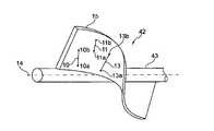
図1は、複数の心室を有する患者の心臓1の断面図であって、心室2は大動脈12と接続している。大動脈12を通じてカテーテル4が心室2まで進められており、回転ポンプを備えたポンプヘッド3がカテーテル4の端部に配置されている。回転ポンプは、カテーテル4を通って延びる回転可能なシャフト6により駆動可能であり、このシャフトは、ポンプヘッド3内でポンプロータ42に接続されている。ポンプロータは、ポンプヘッド3のハウジング(詳しくは図示せず)において回転する。 FIG. 1 is a cross-sectional view of the heart 1 of a patient having a plurality of ventricles, wherein the
可撓性のシャフト6は、たとえば患者の身体の外側に配置されたモータ7に接続されている。トルクは、たとえば磁気結合によって、モータ7から両回転方向8、9でシャフト6に伝達可能である。 The
カテーテル4は通例、身体の外側からポートを介して、皮膚および組織のほか、血管壁を通して大動脈12およびその内部へと進められる。 The catheter 4 is typically advanced from the outside of the body through the port through the skin and tissues, as well as through the walls of blood vessels into the
ポンプは、心室2の血液を吸引して、大動脈12に搬送する。このように、心臓ポンプは、心臓1の機能の補助または少なくとも一時的な置換が可能である。 The pump sucks the blood in the
図示した機械的駆動のカテーテルポンプのほか、たとえば人体内で駆動されるポンプを含む液圧または電気駆動のポンプ等、特に体内使用の他のポンプもまた、本特許の課題を構成する。 In addition to the mechanically driven catheter pumps illustrated, other pumps specifically for internal use, such as hydraulically or electrically driven pumps, including pumps driven within the human body, also constitute the subject of this patent.
上記ポンプは、ポンプヘッド、ポンプハウジング、およびロータと併せて、動脈中を変位するために半径方向に圧縮され、たとえばカテーテル4内で変位する。その後、ポンプは、カテーテル4から軸線方向に滑り出て、半径方向に展延すなわち展開可能である。このプロセスにおいては、ポンプハウジング、特に、ポンプロータの材料に高い要求が課される。ポンプロータのインペラ要素は、壁厚が非常に薄いものの、寸法が安定して、高回転速度であっても、血液を再現性よく搬送する必要がある。 The pump, together with the pump head, pump housing, and rotor, is radially compressed to displace in the artery, eg, displace within the catheter 4. The pump then slides axially out of the catheter 4 and is radially extensible or deployable. This process imposes high demands on the material of the pump housing, especially the pump rotor. Although the impeller element of the pump rotor has a very thin wall thickness, it is necessary to carry blood with good reproducibility even at a stable size and a high rotation speed.
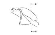
この目的のため、ロータが構成されるプラスチックのマトリクスに強化繊維(繊維)が埋め込まれ、たとえば、ガラス繊維またはポリカーボネート繊維として設けられ得る。このような強化要素/繊維は、3つの個別例にて図2aに図示している。3つの強化要素/繊維10、11、13を示しており、それぞれ、当該強化要素/繊維10、11、13の第2の端部/第2の部分10b、11b、13bよりも回転軸線14に近い第1の端部または第1の部分10a、11a、13aを有する。 For this purpose, reinforcing fibers (fibers) are embedded in a matrix of plastics constituting the rotor and may be provided, for example, as glass fibers or polycarbonate fibers. Such reinforcing elements / fibers are illustrated in FIG. 2a with three individual examples. Three reinforcing elements /
強化要素/繊維10、11、13は実質的に、ロータの回転軸線14または回転軸線近傍の点から半径方向外方に延びている。ここで、ロータ42は、図示の例のようにハブ43を有する必要がない。また、螺旋状のインペラ要素15は、ロータハブが不要となるように、固有の安定性を有し得る。 Reinforcing elements /
原理上、1つ以上のインペラ要素15のプラスチックマトリクスは、長さ、および/または厚さ、および/または配向に関して不規則に分布および配置された強化要素/繊維によって強化可能である。一態様では、図2に示すロータの展開状態における強化要素/繊維の特定の最小群が回転軸線から遠ざかるように実質的に伸長して延びている。ロータのプラスチックに埋め込まれた強化要素/繊維全体のうち、上記条件を満たす強化要素/繊維の群は、強化要素/繊維の体積もしくは質量による割合測定または強化要素/繊維の数に基づいて、少なくとも30%とするが、50%が好都合であり、たとえば70%がさらに好都合である。ここでは、たとえばロータの半径の少なくとも約20%、少なくとも40%、または50%等、強化要素/繊維の特定の最小長さが与えられるのが好都合である。強化要素/繊維は、金型の充填時に、ハブ43に対応する軸線方向配向から、湾曲なくインペラ要素15の半径方向位置へと容易に変化し得る。これは、インペラ要素15とハブ43との間の角度が30°未満、好ましくは20°未満で、比較的平坦に伸びているためである。このように、強化要素/繊維は、インペラ要素15の半径方向充填時に、周囲のマトリクスによって容易に取り込まれるとともに、図2に係るインペラ要素中の材料流れによって、半径方向に配向する。 In principle, the plastic matrix of one or
強化要素/繊維の別の有利な特性は、固有の最大厚さであり、前記強化要素/繊維の強い湾曲の場合でも強化要素/繊維が破壊されないように、最大40μmの直径が好都合となり得る。これに対して、約40μmの寸法においては、強化要素/繊維は、変形後に周囲のマトリクスを最初の状態に戻すとともに、永久的な曲げ荷重下でのマトリクスの長期クリープを防止するのに十分な曲げ剛性である。また、直径40μmの強化要素/繊維は、圧縮応力および引張応力に対する耐性を示して、湾曲中立領域外での配置により、復元モーメントを生じるとともに別の変形に抗する。 Another advantageous property of the reinforcing element / fiber is the inherent maximum thickness, and a diameter of up to 40 μm may be advantageous so that the reinforcing element / fiber is not destroyed even in the case of strong curvature of the reinforcing element / fiber. In contrast, at dimensions of about 40 μm, the reinforcing element / fiber is sufficient to restore the surrounding matrix to its original state after deformation and prevent long-term creep of the matrix under permanent bending loads. Flexural rigidity. Reinforcing elements / fibers with a diameter of 40 μm also exhibit resistance to compressive and tensile stresses, and placement outside the curved neutral region creates a restoring moment and resists other deformations.
強化要素/繊維は、接着促進剤で被覆して、マトリクスへの接続を改善可能である。 Reinforcing elements / fibers can be coated with an adhesion promoter to improve the connection to the matrix.
図2bは、展伸、展開状態のインペラ要素15’、15’’を備えたロータ42’の断面を示している。この状態の強化要素/繊維55、56は、最大限に伸長した形態であるため、その長手方向の剛性により、ロータのさらなる変形に抗する。 FIG. 2b shows a cross section of a rotor 42'with impeller elements 15'and 15' in a stretched and unfolded state. Since the reinforcing elements /
図3に基づいて、強化要素/繊維の考え得る配向を詳細に説明する。図3においては、ロータハブを16で示すとともに、回転軸線を14で示している。切断矩形に基づく平面17を示しているが、この平面17は、回転軸線14を含む。すなわち、回転軸線14は、完全に平面17内を延びている。 The possible orientations of the reinforcing elements / fibers will be described in detail with reference to FIG. In FIG. 3, the rotor hub is indicated by 16 and the rotation axis is indicated by 14. A
一例として、2つの強化要素/繊維18、19を示しているが、両者とも、回転軸線14に関して、平面17中で実質的に半径方向に延びている。繊維18は、回転軸線14に対して角度αで延びており、軸線方向成分を有するが、この角度αは、45°~90°が好都合である。繊維19は、回転軸線14に対して直角に配置されるように配向している。実際のブレードは、3次元の螺旋状に湾曲しているため、多くの場合、方位角方向の強化要素/繊維の範囲が制限される。 As an example, two reinforcing elements /
個々の強化要素/繊維は、最初の開始点/終了点が回転軸線14またはロータハブ16の領域内となるように位置決めする必要がない。また、個々の強化要素/繊維は、ロータ軸線14および/またはロータハブ16から半径方向に離れた2つの端点間で延びるように配置可能である。ただし、軸線を越える如何なる場合も、個々の強化要素/繊維は、第1の半径方向外側ブレード縁部から第2の半径方向反対側ブレード縁部へと延伸可能である。 The individual reinforcing elements / fibers do not need to be positioned so that the initial start / end points are within the region of the
インペラ要素の細部20を図4に模式的に示しているが、この細部20は、立方体状である。部分20には繊維19を示している。 The
図5aは、繊維19の中央配向の実現方法を明示している。境界壁53および54間の金型を充填する際の好ましくは層状の流れプロファイルは、中央で最高流速、壁近傍で最低流速となる。最初に傾斜している繊維19は、左側から右側へと連続して達する3つの角度位置に示しており、矢印50、51で示す材料流れによって、金型中の速度分布の結果として流れプロファイルの中央に引き寄せられる。流れの速度分布は、軸x(速度)およびy(金型中の位置座標)によって図中のグラフ52に示している。 FIG. 5a clearly shows how to realize the central orientation of the
図5bは、インペラ要素の境界面間の略中央の繊維19の延伸方向が見えるように部分20の材料を透視して示した側面図である。 FIG. 5b is a side view showing the material of the
以下、図6に基づいて、インペラ要素の大きな湾曲または屈曲下での繊維の挙動を説明する。 Hereinafter, the behavior of the fiber under a large bending or bending of the impeller element will be described with reference to FIG.
図6は、屈曲後のインペラ要素の部分20を示している。繊維19も変形している。ただし、繊維の特定の固有剛性のため、屈曲の場合には、インペラ要素の材料の弾性によって矢印21の方向へ外方に突出し得るため、繊維の考え得る最大限の曲率半径が実現され、繊維の破壊が防止される。したがって、屈曲点の領域では、屈曲の間、インペラ要素の境界壁間の中央から繊維19が逸れる。図6においては、明瞭化のため、インペラ要素の中心面の少なくとも一部を点線22で示している。この効果を実現するには、ロータのプラスチックマトリクスの柔軟性が好都合であり、100D未満のショア硬度に相当する。 FIG. 6 shows a
以下、図7に基づいて、本発明に係るロータ用の成形具/金型の本発明に係る設計を論じる。 Hereinafter, the design of the molding tool / mold for the rotor according to the present invention will be discussed based on FIG. 7.
図7は、射出成形金型の長手方向断面図であって、ロータハブのボリュームを含む領域を23で示すとともに、個々のインペラ要素のボリュームを24、25、26、および27で示している。また、図7においては、射出方向を矢印28で示している。その他の矢印29、30、31、32、33は、射出成形材料が最終的なロータの回転軸線14に沿って軸線方向に流入し、そこから半径方向外方に、インペラ要素のボリュームに流れ込むことを示している。一例として、インペラ要素のうちの1つの長手軸線を一点鎖線44で示している。十分な数の適当な長さの強化要素/繊維が射出成形材料に導入された場合、これらの強化要素/繊維は、材料の主流方向に従って配向するとともに、材料の固化に際してそれを維持する。 FIG. 7 is a longitudinal cross-sectional view of an injection mold, showing the region containing the volume of the rotor hub at 23 and the volumes of the individual impeller elements at 24, 25, 26, and 27. Further, in FIG. 7, the injection direction is indicated by an
追いやられた空気および過剰な成形材料は、インペラ要素の半径方向外側端において、開口45から流出可能である。 The displaced air and excess molding material can flow out of the opening 45 at the radial outer edge of the impeller element.
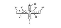
図8には、反対の射出方向を示しており、インペラ要素の半径方向外側端34、35からロータ23のボリュームへと射出成形材料が半径方向内方に射出される。この場合も、長い強化要素/繊維を導入可能であり、本発明に従って意図されるように配向および配置される。 FIG. 8 shows opposite injection directions, in which the injection molding material is ejected inward in the radial direction from the radial outer ends 34, 35 of the impeller element to the volume of the
図9に基づいて、狭隘(きょうあい)なインペラ要素36、37の場合には、内側から半径方向に流出する成形材料が特定のインペラ要素のボリュームの縁部38、39で摩擦により旋回するため、成形材料が流入時に層流とならないことを示す。 Based on FIG. 9, in the case of the
図9の左側には、縁部40、41の領域に溢流開口または溢流スロットを有する金型の変形例を示しており、これらを通って射出成形材料の一部がロータの軸線方向に流出可能であることから、図9の右側に示した旋回が除去される。インペラ要素37の中央領域には、このように疑似層流が形成されるため、射出成形材料の流れの影響による変形なく、導入された強化要素/繊維自体が伸長形態となり得る。射出成形材料が固化すると、たとえば切除によって、射出成形金型中のインペラ要素のボリュームの縁部40、41の開口から退出可能な一部が除去される。この状況は、図7のように、インペラ要素の外側縁部においても同じとなり得る。ここには、強化要素/繊維のないプラスチックが漏出可能な溢流チャネル45が設けられている。 On the left side of FIG. 9, a modified example of a mold having an overflow opening or an overflow slot in the region of the
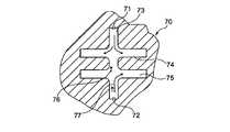
図10は、第1の射出開口71および第2の射出開口72を備えた射出成形金型70を模式的に示しており、これら2つの射出開口71、72は、ロータのハブが成形プロセスで形成される中心空洞73の互いに反対側の端に配置されている。インペラ要素が形成される空洞は、かなり模式的に図示しており、74および75で示している。矢印76、77は、金型に流入するプラスチックの流れ方向を示している。プラスチックが第1の射出開口71および第2の射出開口72から金型へと連続的または交互の割合で射出されている場合は、液体成形材料の異なる流れ方向が形成される。これに強化要素が追加されると、作製されたロータにおいても、強化要素が異なる配向となる。このように、成形法において、射出開口を通る射出速度を制御するとともに、さまざまな射出開口を通る射出速度または射出速度の比を変化させることにより、異なる配向パターンを与えることができる。 FIG. 10 schematically shows an injection molding die 70 having a first injection opening 71 and a second injection opening 72, in which the two
金属箔またはプラスチック膜78の形態の強化要素の斜視図を図11に示すが、この箔/膜は一例として、厚さがわずか数マイクロメートル、幅が10分の数ミリメートル、長さが数ミリメートルであってもよい。 A perspective view of the reinforcing element in the form of a metal foil or
図12は、強化要素としての細長織物ストリップを示しており、長手方向に延びた2つだけの繊維79、80と、横方向に延びた複数の短繊維81とを模式的に有する。この種の織物は、存在する繊維の長手両方向で、引張力を十分に吸収可能である。 FIG. 12 shows an elongated woven strip as a reinforcing element, schematically comprising only two longitudinally extending
図13は、インペラ要素82の領域を示した模式断面図である。ここで、83は、動作中に圧迫側に存在して、矢印84で示す流体抵抗圧に曝露されるカバー面を示している。 FIG. 13 is a schematic cross-sectional view showing a region of the
これと反対側またはカバー面83の反対のカバー面は、85で示している。図示の例においては、インペラ要素82のこちら側に被膜86が設けられているが、これは、接着膜または液体被膜(たとえば、ニス塗装)によって設けることができる。 The cover surface on the opposite side or the opposite side of the
また、ポンプ動作時のインペラ要素82の湾曲に際して機械学の意味で中立「繊維」または平面として知られているものを点線87で示している。 Also, what is known as a neutral "fiber" or a flat surface in the mechanical sense when the
図13に示すインペラ要素が力の加わっていない状態すなわちインペラ要素に外力が作用していない状態と考えられる場合は、この状態において、一例として88で示す強化要素が伸長形態で力が加わらずに存在するように構成することも可能である。 When it is considered that the impeller element shown in FIG. 13 is in a state where no force is applied, that is, a state in which no external force is applied to the impeller element, in this state, as an example, the reinforcing element shown in 88 is in an extended form without applying a force. It can also be configured to exist.
流体中のロータの回転に際して、流体抵抗圧84の作用により、矢印84の方向の湾曲力がインペラ要素に作用すると、インペラ要素の屈曲の結果として図の左側に配置された中立繊維87側が長くなるため、強化要素88は引張荷重を受ける。強化要素88が実際には伸長に抗するため、これらによって湾曲が制限される。 When the bending force in the direction of the
力が加わらない第2の状態と第3の状態すなわち荷重印加状態との間のロータの形態の差異をさらに抑えるため、力が加わらない状態すなわちロータに外力が作用しない状態において、強化要素88に内部材料応力を前もって加えるように構成することも可能である。これは、ロータの作製後、より具体的には、射出成形プロセスの完了後、インペラ要素がカバー面83側で伸長されるか、または、カバー面85側で収縮される点において実現される。 In order to further suppress the difference in the form of the rotor between the second state in which no force is applied and the third state, that is, the load application state, the reinforcing
これは一例として、たとえば射出成形金型の含浸により、射出成形プロセス後または射出成形プロセス中に被膜86がカバー面85に適用される点において実現されるが、この被膜は、乾燥もしくは架橋中またはその後の処理、特に、電子線架橋、UV架橋、もしくは熱処理によって収縮され得る。また、電子線架橋は一例として、1本以上のレーザビームにより導入可能であるため、ごく集中的な様態で局所的に適用可能である。 This is achieved, for example, by impregnation of an injection mold, where the
ただし、カバー層86の追加または代替として、カバー層85に対向する繊維87の中立平面側のインペラ要素82の材料が、たとえばインペラ要素の他方側では一切またはわずかにしか生じない熱処理または架橋/重合によって収縮されることも考えられる。 However, as an addition or alternative to the
図14aおよび図14bは、一例として、繊維で構成された織物を示している。ここで、繊維90は、繊維束の一部として、他の繊維束91に対するある角度で延びているが、繊維束91は、図の平面に垂直に配置されており、繊維90は、左右交互に繊維束91を通過している。ロータの展伸状態を表す図14aにおいて、繊維束91は、互いに距離aで配置されており、繊維90は、前後に湾曲した延伸方向を有する。動作中のロータの状態を表す図14bにおいて、繊維束91は、より大きな相互距離a’で配置されており、繊維90は、より小さく湾曲した延伸方向を有する。図14aおよび図14bから、この種のシステムは、繊維90が完全に伸長する前に、実質的な安定状態となっていることが明らかである。図14bの状態を過ぎると、基材中の繊維90に対して直角に繊維束91が移動する必要があるものの、基本的には、繊維束91および繊維90によってこれが阻止されるためである。 14a and 14b show, as an example, a woven fabric composed of fibers. Here, the
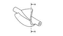
図15aは、力が加わらない展開状態のロータの斜視図であって、断面A-Aも示している。図15bは、前記断面に沿った同じロータの断面図である。点線101および102は、各ブレードの中立繊維または表面を表している。繊維103および104は、一例として、図示の平断面における2つの繊維の延伸方向を示している。繊維は、この状態で湾曲している。荷重下の動作状態では、流体によって、図示の矢印の方向の圧力がブレードに作用するため、前記ブレードがさらに展開される。完全な動作荷重下では、少なくとも105および106で示す領域において、繊維103および104がそれぞれ伸長するため、ブレードのさらなる展開は阻止される。これは、大変高い張力が掛かっている繊維が、軸線方向に更に伸長されなければならないためである。このような設計の利点として、最小回転速度を上回る場合は、ブレードの形態が事実上一定である。 FIG. 15a is a perspective view of the rotor in a deployed state in which no force is applied, and also shows cross sections AA. FIG. 15b is a cross-sectional view of the same rotor along the cross section.
図16aは、力が加わらない展開状態のロータの斜視図であって、断面B-Bも示している。図16bは、前記断面に沿った同じロータの断面図である。点線111および112は、各ブレードの中立繊維または表面を表している。繊維113および114は、一例として、図示の断面における2つの繊維の延伸方向を示している。図示の通り、この例の繊維は、すでに最大限に伸長している。繊維には、大変高い張力が掛かっていることから、これ以上長くなる可能性はほとんどない。動作状態で発生し、流れの圧力によってブレードに作用する図16bの矢印で示す力が加わっても、このようなブレードは、それ以上あまり変形しないため、事実上、回転速度の全範囲でブレードの形態が不変となる利点がある。 FIG. 16a is a perspective view of the rotor in a deployed state in which no force is applied, and also shows a cross section BB. FIG. 16b is a cross-sectional view of the same rotor along the cross section.
図17aは、力が加わらない展開状態のロータの側面図であって、断面C-Cも示している。図17bは、前記平断面に沿った同じロータの断面図である。点線121および122は、各ブレードの中立繊維または表面を表している。繊維123および124は、一例として、図示の平断面における2つの繊維の延伸方向を示している。図示の通り、この例の繊維は、すでに広い領域で伸長している。繊維には、大変高い張力が掛かっていることから、これ以上繊維が長くなる可能性はほとんどない。動作状態で発生し、流れの圧力によってブレードに作用する図17bの矢印で示す力が加わっても、このようなブレードは、それ以上あまり変形しない。 FIG. 17a is a side view of the rotor in a deployed state in which no force is applied, and also shows a cross section CC. FIG. 17b is a cross-sectional view of the same rotor along the plan cross section.
上述の特徴の結果、特に、ロータの設計および適当な強化要素/繊維の導入の結果として、一部が伸び過ぎたり、または荷重が頻繁に切り替わったり、または曲げ荷重が一定に印加されたりした後でも、形態が十分に正確なロータの安定な設計が実現される。本発明に係る作製方法および提示の射出成形金型の結果として、本発明に係るロータを作製するための好都合かつ有利な可能性が立証された。 After the above characteristics, especially as a result of the rotor design and the introduction of suitable reinforcing elements / fibers, some are overstretched, or the load is frequently switched, or a constant bending load is applied. However, a stable design of the rotor with sufficiently accurate morphology is realized. As a result of the fabrication method according to the present invention and the injection molding die presented, the convenient and advantageous possibility for producing the rotor according to the present invention has been proved.
本発明は、以下の態様も包含するが、これらについても個々に、個別かつ独立して保護され得る。 The present invention also includes the following aspects, which can also be individually and independently protected.
第1の態様:圧縮性の流体ポンプ、特に、血管を通じて患者の身体に導入可能な血液ポンプ用のロータであって、1つ以上のインペラ要素(15)を有するとともに第1の状態である圧縮状態と第2の状態である半径方向展開状態との間で半径方向に圧縮および展開可能であり、少なくとも一部が撚り糸状の強化要素、特に、繊維により強化されたプラスチックから成り、回転軸線周りに回転するように意図され、第1の状態、すなわち圧縮状態では引っ張られ、第2の状態、すなわち展開状態では外部応力が加わらず、当該ロータ(42)が荷重下の動作状態で想定する第3の状態が存在しており、当該ロータの第2の状態において、強化要素の引張および/または伸長を引き起こす材料応力が選択的に生成されるように、当該ロータのさまざまな材料およびその分布が相互に適応されたことを特徴とするロータ。 First aspect: a compressible fluid pump, particularly a rotor for a blood pump that can be introduced into the patient's body through a blood vessel, with one or more impeller elements (15) and a first state of compression. It is radially compressible and expandable between the state and the second state, the radial unfolded state, and consists of at least part of a twisted thread-like reinforcing element, in particular a fiber-reinforced plastic, around the axis of rotation. The rotor (42) is assumed to be operating under load without applying external stress in the first state, that is, in the compressed state, and in the second state, that is, in the expanded state. The various materials of the rotor and their distribution are such that in the second state of the rotor, the material stresses that cause the tension and / or elongation of the reinforcing element are selectively generated in the presence of three states. Rotors characterized by being adapted to each other.
第2の態様:第1の態様に記載のロータであって、強化要素が、当該ロータの大部分、少なくとも表面の90%、特に、99%の部分、より詳細には全体が構成されるプラスチックにより囲まれるようにさらに構成されたことを特徴とするロータ。 Second aspect: A plastic according to the first aspect, wherein the reinforcing element constitutes a majority of the rotor, at least 90% of the surface, particularly 99%, more specifically the whole. A rotor characterized by being further configured to be surrounded by.
第3の態様:第1または第2の態様に記載のロータであって、強化要素が埋め込まれたプラスチック材料が、少なくともインペラ要素の流体抵抗圧作用側と比較して、動作中のインペラ要素の流体抵抗圧非作用側、特に、曲げ荷重下のポンプ動作中に湾曲中立繊維または平面を構成する繊維または表面に関するインペラ要素の対応側の領域において異なる特性を有し、特に、流体抵抗圧非作用側でより多く架橋もしくは収縮しているか、または、インペラ要素上で収縮した支持部であって、1つ以上の膜、被膜、もしくは繊維の形態で設けられた、支持部を表面上に有するようにさらに構成されたことを特徴とするロータ。 Third aspect: The rotor according to the first or second aspect, wherein the plastic material in which the reinforcing element is embedded is the impeller element in operation as compared with at least the fluid resistance pressure acting side of the impeller element. It has different properties on the non-fluid side, especially on the corresponding side of the impeller element with respect to the curved neutral fibers or the fibers or surfaces that make up the plane during pump operation under bending load, especially the fluid resistance non-acting side. Supports that are more crosslinked or shrunk on the side or shrunk on the impeller element to have a support on the surface provided in the form of one or more membranes, coatings, or fibers. A rotor characterized by being further configured in.
第4の態様:第1、第2、または第3の態様に記載のロータであって、当該ロータの1つ以上のインペラ要素が、展開状態における強化要素の同時追加を伴う射出成形によって作製され、強化要素が、射出成形材料によって全面が囲まれ、展開状態において少なくとも部分的に伸長した形態で存在しており、特に、少なくとも90%、より詳細には95%、さらに詳細には99%の程度まで伸長した形態で存在するようにさらに構成されたことを特徴とするロータ。 Fourth aspect: The rotor according to the first, second, or third aspect, wherein one or more impeller elements of the rotor are manufactured by injection molding with the simultaneous addition of reinforcing elements in the deployed state. Reinforcement elements are present in a fully elongated form, at least partially elongated in the unfolded state, with the entire surface surrounded by the injection molding material, in particular at least 90%, more specifically 95% and even more specifically 99%. A rotor characterized by being further configured to exist in a to some extent extended form.
第5の態様:第1、第2、第3、または第4の態様に記載のロータであって、流体抵抗圧のない当該ロータの第2の状態である展開状態における強化要素が、流体抵抗圧のある動作状態を構成する第3の状態への遷移に際して、5%未満、特に、1%未満だけ長くなる程度まで伸長した形態で存在しており、上記延長が、特に強化要素の両端間の距離に基づいて測定されるようにさらに構成されたことを特徴とするロータ。 Fifth aspect: The rotor according to the first, second, third, or fourth aspect, wherein the reinforcing element in the deployed state, which is the second state of the rotor without fluid resistance pressure, is fluid resistance. At the time of transition to the third state constituting the operating state with pressure, it exists in a form extended to the extent that it is extended by less than 5%, particularly less than 1%, and the above extension is particularly between both ends of the reinforcing element. A rotor characterized by being further configured to be measured based on the distance of.
第6の態様:第1、第2、第3、第4、または第5の態様に記載のロータであって、当該ロータの第2の状態である展開状態および/または流体抵抗圧のある第3の状態である動作状態において、強化要素の少なくともある群、特に、少なくとも10%、より詳細には少なくとも30%が、インペラ要素の少なくとも1つの湾曲領域で伸長して真っ直ぐに延びるようにさらに構成されたことを特徴とするロータ。 Sixth aspect: The rotor according to the first, second, third, fourth, or fifth aspect, which is the second state of the rotor, that is, the expanded state and / or the fluid resistance pressure. In the operational state of 3, at least some group of reinforcing elements, in particular at least 10%, more particularly at least 30%, is further configured to extend and straighten at at least one curved region of the impeller element. A rotor characterized by being done.
第7の態様:特に第1の態様に記載の流体ポンプ用のロータを作製する方法であって、射出成形の後、ロータが、動作中のインペラ要素の流体抵抗圧作用側の成形材料が反対側と異なる収縮および/または架橋となる処理を受けるように構成されたことを特徴とする方法。 Seventh aspect: A method for producing a rotor for a fluid pump according to the first aspect, wherein after injection molding, the rotor is opposed to the molding material on the fluid resistance pressure acting side of the operating impeller element. A method characterized in that it is configured to undergo a process that results in contraction and / or cross-linking different from that of the side.
第8の態様:射出成形によって、特に第1の態様に記載の流体ポンプ用のロータを作製する方法であって、動作中のインペラ要素の流体抵抗圧曝露側と反対側のインペラ要素のうちの少なくとも1つに収縮可能層が適用されるように構成されたことを特徴とする方法。 Eighth aspect: A method of making a rotor for a fluid pump according to the first aspect by injection molding, among the impeller elements on the side opposite to the fluid resistance pressure exposed side of the operating impeller element. A method characterized in that at least one is configured to have a shrinkable layer applied.
第9の態様:第1の態様に記載のインペラ要素を備えた流体ポンプ用のロータ用の金型であって、少なくとも2つの異なる射出開口が設けられたことを特徴とする金型。 Ninth Embodiment: A mold for a rotor for a fluid pump provided with the impeller element according to the first aspect, wherein the mold is provided with at least two different injection openings.
第10の態様:上記態様のいずれか1項に記載のロータであって、強化要素が、2次元範囲を有し、たとえば、繊維群が互いに交差した膜片または織物として具現化されるように構成されたことを特徴とするロータ(図14aおよび図14b参照)。 A tenth aspect: The rotor according to any one of the above embodiments, such that the reinforcing element has a two-dimensional range and is embodied as, for example, a film piece or a woven fabric in which the fiber groups intersect with each other. A rotor characterized by being configured (see FIGS. 14a and 14b).
<付記>
[1]
圧縮性の流体ポンプ用のロータであって、1つ以上のインペラ要素(15)を有するとともに圧縮状態と展開状態との間で半径方向に圧縮および展開可能であり、少なくとも一部が撚り糸状の強化要素(10、11、13、18、19)により強化されたプラスチックから成り、回転軸線(14)周りに回転するように意図されたロータにおいて、
前記プラスチックのショア硬度が80D未満であって、前記ロータが前記圧縮状態とされて前記インペラ要素(15)が屈曲すると、前記インペラ要素(15)の中央面に位置する前記強化要素が湾曲して屈曲部分の前記中央面より外側に張り出すことができて、当該強化要素の最大限の曲率半径が実現され、当該強化要素の破壊が防止されることを特徴とするロータ。
[2]
上記[1]に記載のロータであって、当該ロータ(42)の前記展開状態における前記強化要素(10、11、13、18、19)の30%超の第1の群が、前記回転軸線に最も近く配設された部分(10a、11a、13a)から前記回転軸線の遠くに配設された第2の部分(10b、11b、13b)へと実質的に伸長して延びることを特徴とするロータ。
[3]
上記[2]に記載のロータであって、前記展開状態において、前記第1の群の各前記強化要素(10、11、13、18、19)が、ロータ軸線に関して、半径方向に一致した位置から軸線方向および/または方位角方向に最大45°まで延伸方向が外れていることを特徴とするロータ。
[4]
上記[2]または[3]に記載のロータであって、前記展開状態において、前記第1の群の各前記強化要素(10、11、13、18、19)が、前記回転軸線に対して、実質的に垂直に延びることを特徴とするロータ。
[5]
上記[2]~[4]のいずれか1項に記載のロータであって、前記展開状態において、前記第1の群の各前記強化要素が、前記回転軸線(14)に関して半径方向に延びることを特徴とするロータ。
[6]
上記[2]~[5]のいずれか1項に記載のロータであって、前記第1の群の各前記強化要素(10、11、13、18、19)が、インペラ要素の長手軸線(44)に沿って延びることを特徴とするロータ。
[7]
上記[2]~[6]のいずれか1項に記載のロータであって、前記第1の群の前記強化要素(10、11、13、18、19)の長さが、当該ロータの半径の少なくとも10%、であることを特徴とするロータ。
[8]
上記[2]~[7]のいずれか1項に記載のロータであって、前記第1の群の前記強化要素(10、11、13、18、19)の直径が、40μm未満であることを特徴とするロータ。
[9]
上記[1]~[8]のいずれか1項に記載のロータであって、前記インペラ要素(15)が、発泡材料で構成されたことを特徴とするロータ。
[10]
上記[2]~[8]のいずれか1項に記載のロータであって、当該ロータの前記展開状態における前記強化要素のある群が、前記第1の群の前記強化要素に対して横方向に延びることを特徴とするロータ。
[11]
上記[1]~[10]のいずれか1項に記載のロータであって、前記強化要素の少なくとも一部が、前記強化要素が長手方向および横方向に延びた織物部の形態で存在することを特徴とするロータ。
[12]
上記[1]~[10]のいずれか1項に記載のロータであって、前記強化要素が、長さが幅の少なくとも3倍の膜ストリップの形態で存在することを特徴とするロータ。
[13]
上記[1]または[2]に記載のロータであって、前記強化要素が、少なくとも表面の90%が、当該ロータの大部分を構成するプラスチックにより囲まれたことを特徴とするロータ。
[14]
上記[1]~[13]のいずれか1項に記載のロータであって、前記強化要素が埋め込まれたプラスチック材料が、少なくとも前記インペラ要素の流体抵抗圧作用側と比較して、動作中の前記インペラ要素の流体抵抗圧非作用側の領域において異なる特性を有し、流体抵抗圧非作用側でより多く架橋もしくは収縮しているか、または、前記インペラ要素(82)上で収縮した支持部(86)であって、1つ以上の膜、被膜、もしくは繊維の形態で設けられた、支持部(86)を表面上に有していることを特徴とするロータ。
[15]
第1の状態である圧縮状態と第2の状態である展開状態との間で半径方向に展開および圧縮可能な圧縮性の流体ポンプ用のロータであって、当該ロータの1つ以上のインペラ要素が、前記展開状態において補強する強化要素の同時追加を伴う射出成形によって作製され、前記強化要素が、射出成形材料によって全面が囲まれ、前記展開状態において少なくとも部分的に伸長形態で存在しており、前記強化要素が埋め込まれるプラスチックに射出成形によって導入され、当該ロータが射出成形金型に配設されるときに、前記プラスチックの射出成形金型への流れに沿って部分的に湾曲した延伸方向を有する、ことを特徴とするロータ。
[16]
上記[1]~[15]のいずれか1項に記載のロータであって、流体抵抗圧のない当該ロータの第2の状態である前記展開状態における前記強化要素が、流体抵抗圧のある動作状態を構成する第3の状態への遷移に際して、5%未満だけ長くなる程度まで伸長する形態で存在していることを特徴とするロータ。
[17]
上記[1]~[16]のいずれか1項に記載のロータであって、当該ロータの第2の状態である展開状態および/または流体抵抗圧のある第3の状態である動作状態において、前記強化要素の少なくともある群が、前記インペラ要素の少なくとも1つの湾曲領域で伸長して真っ直ぐに延びることを特徴とするロータ。
[18]
上記[17]に記載のロータであって、インペラ要素の湾曲領域において、前記強化要素の少なくとも2つの群が、伸長して真っ直ぐに延びており、前記群の前記強化要素が延びる方向が、同じ群内では平行であるものの、前記2つの異なる群間では異なることを特徴とするロータ。
[19]
上記[1]~[18]のいずれか1項に記載のロータであって、少なくとも30%の場合の前記強化要素の長さが、前記インペラ要素の平均厚さより大きい長さであることを特徴とするロータ。
[20]
上記[1]~[14]のいずれか1項に記載のロータであって、前記強化要素が、埋め込まれるプラスチックに射出成形によって導入され、当該ロータが射出成形金型に配設されるときに、前記プラスチックの前記射出成形金型への流れに沿って部分的に湾曲した延伸方向を有することを特徴とするロータ。
[21]
射出成形法により、上記[1]~[20]のいずれか1項に記載のロータ(42)を作製する方法であって、前記インペラ要素(15)の射出成形材料は、前記射出成形材料が半径方向(30、31、32、33)に前記インペラ要素のボリュームに流れ込むように、ロータ軸線(14)に関して半径方向に、前記インペラ要素のボリュームに導入されることを特徴とする方法。
[22]
上記[21]に記載の方法であって、前記射出成形材料が、ロータ軸線に最も近く配設された領域またはロータ軸線から最も遠くに配設された領域から、半径方向(30、31、32、33)に前記インペラ要素(15)のボリュームに射出されることを特徴とする方法。
[23]
上記[1]~[20]のいずれか1項に記載のロータを作製する方法であって、前記ロータが、射出成形法によって作製され、前記射出成形法が、異なる射出方向および/または2つの異なる射出点からの2つの連続する段階で実行されることを特徴とする方法。
[24]
上記[21]~[23]のいずれか1項に記載の方法であって、前記射出成形の後、前記ロータが、動作中の前記インペラ要素の流体抵抗圧作用側の前記成形材料が反対側と異なる収縮および/または架橋となる処理を受けることを特徴とする方法。
[25]
上記[21]~[24]のいずれか1項に記載の方法であって、動作中の前記インペラ要素の流体抵抗圧曝露側と反対側の前記インペラ要素のうちの少なくとも1つに収縮可能層が適用されることを特徴とする方法。
[26]
上記[1]~[20]のいずれか1項に記載のロータ(42)用の射出成形金型であって、射出成形材料が半径方向に妨げられずに流れ得るように、前記インペラ要素(15)のボリュームの半径方向縁部(40、41)に溢流チャネルが設けられたことを特徴とする金型。
[27]
上記[1]~[20]のいずれか1項に記載のロータ用の金型であって、少なくとも2つの異なる射出開口を特徴とする金型。
[28]
圧縮性の流体ポンプ、特に、血管を通じて患者の身体に導入可能な血液ポンプ用のロータであって、1つ以上のインペラ要素(15)を有するとともに圧縮状態と展開状態との間で半径方向に圧縮および展開可能であり、少なくとも一部が撚り糸状の強化要素(10、11、13、18、19)により強化されたプラスチックから成り、回転軸線(14)周りに回転するように意図され、当該ロータ(42)の前記展開状態における前記強化要素(10、11、13、18、19)の30%超、特に、50%超の第1の群が、前記回転軸線に最も近く配設された部分(10a、11a、13a)から前記回転軸線の遠くに配設された第2の部分(10b、11b、13b)へと実質的に伸長して延び、前記強化要素の前記第1の群が、前記展開状態の当該ロータの半径方向に測定して、前記インペラ要素の最大高さの少なくとも30%、特に、少なくとも50%に対応する高さを有する。 さらに、前記ロータは、前記強化要素が、少なくとも表面の90%、特に99%の部分、より詳細には全体が、当該ロータ(42)の大部分を構成するプラスチックマトリクスにより囲まれていてよい。
<Additional notes>
[1]
A rotor for a compressible fluid pump that has one or more impeller elements (15) and can be compressed and unfolded radially between the compressed and unfolded states, at least in part in a twisted thread. In a rotor made of plastic reinforced by reinforcing elements (10, 11, 13, 18, 19) and intended to rotate around the axis of rotation (14).
When the shore hardness of the plastic is less than 80D and the rotor is in the compressed state and the impeller element (15) is bent, the reinforcing element located on the central surface of the impeller element (15) is curved. A rotor characterized in that it can project outward from the central surface of the bent portion, the maximum radius of curvature of the reinforcing element is realized, and the destruction of the reinforcing element is prevented.
[2]
In the rotor according to the above [1], the first group of more than 30% of the reinforcing elements (10, 11, 13, 18, 19) in the deployed state of the rotor (42) is the rotation axis. It is characterized in that it substantially extends and extends from the portion (10a, 11a, 13a) closest to the second portion (10b, 11b, 13b) disposed far from the rotation axis. Rotor to do.
[3]
In the rotor according to the above [2], in the deployed state, each of the reinforcing elements (10, 11, 13, 18, 19) of the first group coincides in the radial direction with respect to the rotor axis. A rotor characterized in that the extension direction deviates from to in the axial direction and / or the azimuth direction up to a maximum of 45 °.
[4]
In the rotor according to the above [2] or [3], in the deployed state, each of the reinforcing elements (10, 11, 13, 18, 19) of the first group is with respect to the rotation axis. A rotor characterized by extending substantially vertically.
[5]
The rotor according to any one of the above [2] to [4], in which the reinforcing element of the first group extends in the radial direction with respect to the rotation axis (14) in the deployed state. A rotor featuring.
[6]
In the rotor according to any one of the above [2] to [5], each of the reinforcing elements (10, 11, 13, 18, 19) in the first group is the longitudinal axis of the impeller element (10, 11, 13, 18, 19). A rotor characterized by extending along 44).
[7]
The rotor according to any one of [2] to [6], wherein the length of the reinforcing element (10, 11, 13, 18, 19) in the first group is the radius of the rotor. A rotor characterized by being at least 10% of.
[8]
The rotor according to any one of the above [2] to [7], wherein the reinforcing element (10, 11, 13, 18, 19) in the first group has a diameter of less than 40 μm. A rotor featuring.
[9]
The rotor according to any one of the above [1] to [8], wherein the impeller element (15) is made of a foam material.
[10]
The rotor according to any one of the above [2] to [8], wherein the group having the reinforcing element in the deployed state of the rotor is laterally oriented with respect to the reinforcing element of the first group. A rotor characterized by extending to.
[11]
The rotor according to any one of [1] to [10] above, wherein at least a part of the reinforcing element exists in the form of a woven fabric portion in which the reinforcing element extends in the longitudinal direction and the lateral direction. A rotor featuring.
[12]
The rotor according to any one of the above [1] to [10], wherein the reinforcing element exists in the form of a membrane strip having a length at least three times the width.
[13]
The rotor according to the above [1] or [2], wherein at least 90% of the surface of the reinforcing element is surrounded by the plastic constituting the majority of the rotor.
[14]
The rotor according to any one of [1] to [13] above, wherein the plastic material in which the reinforcing element is embedded is in operation as compared with at least the fluid resistance pressure acting side of the impeller element. Supports that have different properties in the fluid resistance non-acting side region of the impeller element and are more crosslinked or contracted on the fluid resistance non-acting side, or contracted on the impeller element (82). 86), wherein the rotor has a support portion (86) provided on the surface in the form of one or more films, coatings, or fibers.
[15]
A rotor for a compressible fluid pump that can be expanded and compressed radially between the compressed state, which is the first state, and the expanded state, which is the second state, and one or more impeller elements of the rotor. Is produced by injection molding with the simultaneous addition of reinforcing elements to reinforce in the unfolded state, the reinforcing element being entirely surrounded by the injection molding material and present at least partially in an elongated form in the unfolded state. , A partially curved stretching direction along the flow of the plastic into the injection mold when introduced by injection molding into the plastic into which the reinforcing element is embedded and the rotor is placed in the injection mold. A rotor characterized by having.
[16]
The reinforcing element in the expanded state, which is the second state of the rotor according to any one of the above [1] to [15] and has no fluid resistance pressure, operates with fluid resistance pressure. A rotor characterized in that it exists in a form that extends to a extent that it becomes longer by less than 5% at the time of transition to the third state constituting the state.
[17]
In the rotor according to any one of the above [1] to [16], in the expanded state which is the second state of the rotor and / or the operating state which is the third state with fluid resistance pressure. A rotor characterized in that at least a group of the reinforcing elements extends straight in at least one curved region of the impeller element.
[18]
In the rotor according to the above [17], at least two groups of the reinforcing elements extend straight in the curved region of the impeller element, and the reinforcing elements of the group extend in the same direction. A rotor that is parallel within a group but different between the two different groups.
[19]
The rotor according to any one of the above [1] to [18], characterized in that the length of the reinforcing element in the case of at least 30% is larger than the average thickness of the impeller element. And the rotor.
[20]
The rotor according to any one of the above [1] to [14], when the reinforcing element is introduced into the embedded plastic by injection molding and the rotor is arranged in an injection molding die. , A rotor characterized by having a partially curved stretching direction along the flow of the plastic into the injection mold.
[21]
The method for producing the rotor (42) according to any one of the above items [1] to [20] by an injection molding method, wherein the injection molding material of the impeller element (15) is the injection molding material. A method characterized by being introduced into the volume of the impeller element in a radial direction with respect to the rotor axis (14) so as to flow into the volume of the impeller element in the radial direction (30, 31, 32, 33).
[22]
In the method according to the above [21], the injection molding material is arranged in the radial direction (30, 31, 32) from the region closest to the rotor axis or the region farthest from the rotor axis. 33), the method characterized by being injected into the volume of the impeller element (15).
[23]
The method for manufacturing a rotor according to any one of the above [1] to [20], wherein the rotor is manufactured by an injection molding method, and the injection molding method has different injection directions and / or two. A method characterized by being performed in two consecutive stages from different injection points.
[24]
The method according to any one of [21] to [23] above, wherein after the injection molding, the rotor is on the opposite side of the molding material on the fluid resistance pressure acting side of the impeller element in operation. A method characterized by undergoing a treatment that results in different shrinkage and / or cross-linking.
[25]
The method according to any one of [21] to [24] above, wherein a contractile layer is formed on at least one of the impeller elements on the side opposite to the fluid resistance pressure exposed side of the operating impeller element. A method characterized by the application of.
[26]
The injection molding die for the rotor (42) according to any one of the above [1] to [20], wherein the impeller element (the impeller element () so that the injection molding material can flow without being hindered in the radial direction. A mold characterized in that an overflow channel is provided at the radial edge portion (40, 41) of the volume of 15).
[27]
The mold for a rotor according to any one of the above [1] to [20], which comprises at least two different injection openings.
[28]
Compressible fluid pumps, especially rotors for blood pumps that can be introduced into the patient's body through blood vessels, have one or more impeller elements (15) and are radially between compressed and unfolded states. It is compressible and expandable, and is made of plastic, at least in part, reinforced by twisted thread-like reinforcing elements (10, 11, 13, 18, 19) and is intended to rotate around the axis of rotation (14). A first group of more than 30%, in particular more than 50%, of the reinforcement elements (10, 11, 13, 18, 19) in the unfolded state of the rotor (42) was disposed closest to the axis of rotation. Substantially extending from the portions (10a, 11a, 13a) to a second portion (10b, 11b, 13b) disposed far from the axis of rotation, said first group of the reinforcing elements. The rotor has a height corresponding to at least 30%, in particular at least 50%, of the maximum height of the impeller element as measured in the radial direction of the rotor in the deployed state. Further, the rotor may be surrounded by a plastic matrix in which the reinforcing element constitutes at least 90%, particularly 99% of the surface, and more particularly the entire rotor (42).
Claims (17)
Translated fromJapaneseFabrication of a rotor made of plastic reinforced with reinforcing elements for a compressible fluid pump that can be expanded and compressed radially between the compressed state, which is the first state, and the expanded state, which is the second state. The method is characterized in that one or more impeller elements of the rotor are manufactured by injection molding with the simultaneous addition of the reinforcing elements.
Priority Applications (1)
| Application Number | Priority Date | Filing Date | Title |
|---|---|---|---|
| JP2025021689AJP2025065514A (en) | 2015-04-30 | 2025-02-13 | Method for manufacturing rotor for fluid pump |
Applications Claiming Priority (4)
| Application Number | Priority Date | Filing Date | Title |
|---|---|---|---|
| EP15166045.3 | 2015-04-30 | ||
| EP15166045.3AEP3088018A1 (en) | 2015-04-30 | 2015-04-30 | Rotor for a fluid pump and method and mould for its preparation |
| PCT/EP2016/059703WO2016174252A1 (en) | 2015-04-30 | 2016-04-29 | Rotor for a fluid pump, and method and mold for manufacturing same |
| JP2017556979AJP7051437B2 (en) | 2015-04-30 | 2016-04-29 | Rotor for fluid pump and its manufacturing method and mold |
Related Parent Applications (1)
| Application Number | Title | Priority Date | Filing Date |
|---|---|---|---|
| JP2017556979ADivisionJP7051437B2 (en) | 2015-04-30 | 2016-04-29 | Rotor for fluid pump and its manufacturing method and mold |
Related Child Applications (1)
| Application Number | Title | Priority Date | Filing Date |
|---|---|---|---|
| JP2025021689ADivisionJP2025065514A (en) | 2015-04-30 | 2025-02-13 | Method for manufacturing rotor for fluid pump |
Publications (2)
| Publication Number | Publication Date |
|---|---|
| JP2022089864Atrue JP2022089864A (en) | 2022-06-16 |
| JP7636366B2 JP7636366B2 (en) | 2025-02-26 |
Family
ID=53015719
Family Applications (3)
| Application Number | Title | Priority Date | Filing Date |
|---|---|---|---|
| JP2017556979AActiveJP7051437B2 (en) | 2015-04-30 | 2016-04-29 | Rotor for fluid pump and its manufacturing method and mold |
| JP2022056240AActiveJP7636366B2 (en) | 2015-04-30 | 2022-03-30 | Fluid pump rotor and method for manufacturing same |
| JP2025021689APendingJP2025065514A (en) | 2015-04-30 | 2025-02-13 | Method for manufacturing rotor for fluid pump |
Family Applications Before (1)
| Application Number | Title | Priority Date | Filing Date |
|---|---|---|---|
| JP2017556979AActiveJP7051437B2 (en) | 2015-04-30 | 2016-04-29 | Rotor for fluid pump and its manufacturing method and mold |
Family Applications After (1)
| Application Number | Title | Priority Date | Filing Date |
|---|---|---|---|
| JP2025021689APendingJP2025065514A (en) | 2015-04-30 | 2025-02-13 | Method for manufacturing rotor for fluid pump |
Country Status (9)
| Country | Link |
|---|---|
| US (3) | US10935038B2 (en) |
| EP (3) | EP3088018A1 (en) |
| JP (3) | JP7051437B2 (en) |
| KR (2) | KR20240096789A (en) |
| CN (2) | CN107530480B (en) |
| CA (1) | CA2980518A1 (en) |
| DK (1) | DK3288608T3 (en) |
| ES (1) | ES2988427T3 (en) |
| WO (1) | WO2016174252A1 (en) |
Families Citing this family (28)
| Publication number | Priority date | Publication date | Assignee | Title |
|---|---|---|---|---|
| CN108742951B (en) | 2012-06-06 | 2021-05-25 | 洋红医疗有限公司 | Artificial kidney valve |
| EP4233702A3 (en) | 2013-03-13 | 2023-12-20 | Magenta Medical Ltd. | Manufacture of an impeller |
| US10583231B2 (en) | 2013-03-13 | 2020-03-10 | Magenta Medical Ltd. | Blood pump |
| DK3288609T3 (en)* | 2015-04-30 | 2023-05-01 | Ecp Entw Mbh | ROTOR FOR A FLUID PUMP |
| WO2016185473A1 (en) | 2015-05-18 | 2016-11-24 | Magenta Medical Ltd. | Blood pump |
| CA3039285A1 (en) | 2016-10-25 | 2018-05-03 | Magenta Medical Ltd. | Ventricular assist device |
| JP7094279B2 (en) | 2016-11-23 | 2022-07-01 | マジェンタ・メディカル・リミテッド | Blood pump |
| US11057643B2 (en)* | 2017-03-13 | 2021-07-06 | Mediatek Inc. | Method and apparatus for generating and encoding projection-based frame that includes at least one padding region and at least one projection face packed in 360-degree virtual reality projection layout |
| IL309561B2 (en)* | 2017-04-07 | 2025-06-01 | Ecp Entw Mbh | External drive unit for implantable heart assist pump |
| CA3066361A1 (en) | 2017-06-07 | 2018-12-13 | Shifamed Holdings, Llc | Intravascular fluid movement devices, systems, and methods of use |
| WO2019094963A1 (en) | 2017-11-13 | 2019-05-16 | Shifamed Holdings, Llc | Intravascular fluid movement devices, systems, and methods of use |
| US10905808B2 (en) | 2018-01-10 | 2021-02-02 | Magenta Medical Ltd. | Drive cable for use with a blood pump |
| EP3638336B1 (en) | 2018-01-10 | 2022-04-06 | Magenta Medical Ltd. | Ventricular assist device |
| CN112004563B (en) | 2018-02-01 | 2024-08-06 | 施菲姆德控股有限责任公司 | Intravascular blood pump and methods of use and manufacture |
| US12161857B2 (en) | 2018-07-31 | 2024-12-10 | Shifamed Holdings, Llc | Intravascular blood pumps and methods of use |
| WO2020073047A1 (en) | 2018-10-05 | 2020-04-09 | Shifamed Holdings, Llc | Intravascular blood pumps and methods of use |
| AU2020211431B2 (en) | 2019-01-24 | 2024-10-24 | Magenta Medical Ltd | Ventricular assist device |
| EP3972661B1 (en) | 2019-05-23 | 2024-09-11 | Magenta Medical Ltd. | Blood pumps |
| WO2021011473A1 (en) | 2019-07-12 | 2021-01-21 | Shifamed Holdings, Llc | Intravascular blood pumps and methods of manufacture and use |
| US11654275B2 (en) | 2019-07-22 | 2023-05-23 | Shifamed Holdings, Llc | Intravascular blood pumps with struts and methods of use and manufacture |
| WO2021062265A1 (en) | 2019-09-25 | 2021-04-01 | Shifamed Holdings, Llc | Intravascular blood pump systems and methods of use and control thereof |
| EP4501393A3 (en) | 2019-09-25 | 2025-04-09 | Shifamed Holdings, LLC | Catheter blood pumps and collapsible pump housings |
| US12121713B2 (en) | 2019-09-25 | 2024-10-22 | Shifamed Holdings, Llc | Catheter blood pumps and collapsible blood conduits |
| EP4072650A4 (en) | 2019-12-11 | 2024-01-10 | Shifamed Holdings, LLC | Descending aorta and vena cava blood pumps |
| EP3984589B1 (en) | 2020-04-07 | 2023-08-23 | Magenta Medical Ltd. | Magnetic phase sensing |
| CN116350933B (en)* | 2022-01-26 | 2024-08-02 | 心擎医疗(苏州)股份有限公司 | Device for assisting heart in the event of failure |
| US12257426B2 (en)* | 2022-12-02 | 2025-03-25 | Abiomed Europe Gmbh | Compressible rotor |
| CN118105618B (en)* | 2024-04-29 | 2024-07-02 | 生命盾医疗技术(苏州)有限公司 | Impeller for catheter pump, manufacturing method and inspection method of impeller, and catheter pump |
Citations (4)
| Publication number | Priority date | Publication date | Assignee | Title |
|---|---|---|---|---|
| JP2012505038A (en)* | 2008-10-06 | 2012-03-01 | インディアナ・ユニバーシティ・リサーチ・アンド・テクノロジー・コーポレーション | Method and apparatus for active or passive assistance |
| US20130177409A1 (en)* | 2010-07-15 | 2013-07-11 | Ecp Entwicklungsgesellschaft Mbh | Rotor for a pump, produced with a first elastic material |
| US20130204362A1 (en)* | 2010-07-15 | 2013-08-08 | Ecp Entwicklungsgesellschaft Mbh | Blood pump for the invasive application within a body of a patient |
| WO2014019646A1 (en)* | 2012-07-31 | 2014-02-06 | Rheinisch-Westfälische Technische Hochschule Aachen | Axial flow blood pump device |
Family Cites Families (20)
| Publication number | Priority date | Publication date | Assignee | Title |
|---|---|---|---|---|
| US3676258A (en)* | 1967-07-25 | 1972-07-11 | True Temper Corp | Apparatus for producing fiber glass articles |
| US4093693A (en)* | 1969-08-11 | 1978-06-06 | Lemelson Jerome H | Method for making composite articles |
| US5314309A (en)* | 1990-05-25 | 1994-05-24 | Anthony Blakeley | Turbine blade with metallic attachment and method of making the same |
| US5393215A (en)* | 1992-12-30 | 1995-02-28 | United Technologies Corporation | Centrifugal resin transfer molding |
| US6343773B1 (en)* | 1999-01-21 | 2002-02-05 | Shop Vac Corporation | Support structure |
| US6843954B2 (en)* | 2000-02-24 | 2005-01-18 | Conix Corporation | Injection molding techniques utilizing fluid channels |
| EP1764124B1 (en)* | 2000-12-12 | 2011-01-19 | Datascope Investment Corp. | Intra-aortic balloon catheter having a fiberoptic sensor |
| JP2005153332A (en) | 2003-11-26 | 2005-06-16 | Mitsubishi Materials Corp | Mold for molding rotary body having tooth part |
| CN1930394A (en)* | 2004-03-18 | 2007-03-14 | 弗兰克·丹尼尔·洛特里翁特 | Turbine and rotor therefor |
| EP1877666A1 (en)* | 2005-05-06 | 2008-01-16 | Inter-Ice Pump APS | A rotor, a method for producing such rotor and a pump comprising such rotor |
| NZ584657A (en)* | 2007-10-30 | 2013-02-22 | Smidth As F L | Fiber reinforced plastic composites with longitudinal and transverse reinforcing fibres where at least some of the transverse fibres are curved at their ends along the ends of the product |
| EP2194278A1 (en)* | 2008-12-05 | 2010-06-09 | ECP Entwicklungsgesellschaft mbH | Fluid pump with a rotor |
| EP2229965A1 (en)* | 2009-03-18 | 2010-09-22 | ECP Entwicklungsgesellschaft mbH | Fluid pump with particular form of a rotor blade |
| KR101105405B1 (en)* | 2009-10-30 | 2012-01-17 | 박성형 | Die casting mold for impeller blade and method for manufacturing impeller blade using same |
| EP2363157A1 (en)* | 2010-03-05 | 2011-09-07 | ECP Entwicklungsgesellschaft mbH | Device for exerting mechanical force on a medium, in particular fluid pump |
| EP2407185A1 (en)* | 2010-07-15 | 2012-01-18 | ECP Entwicklungsgesellschaft mbH | Radial compressible and expandable rotor for a pump with a turbine blade |
| CN102284091A (en)* | 2011-06-16 | 2011-12-21 | 北京航空航天大学 | Left ventricle assist device |
| EP2607712B1 (en)* | 2011-12-22 | 2016-07-13 | ECP Entwicklungsgesellschaft mbH | Pump housing with an interior for holding a pump rotor |
| WO2013191879A2 (en)* | 2012-06-19 | 2013-12-27 | Waters Technologies Corporation | Injection-compression molded rotors |
| CN104421198B (en)* | 2013-09-04 | 2018-10-16 | 台达电子工业股份有限公司 | Fan rotor structure and manufacturing method thereof |
- 2015
- 2015-04-30EPEP15166045.3Apatent/EP3088018A1/ennot_activeWithdrawn
- 2016
- 2016-04-29CACA2980518Apatent/CA2980518A1/enactivePending
- 2016-04-29CNCN201680025932.9Apatent/CN107530480B/enactiveActive
- 2016-04-29KRKR1020247018992Apatent/KR20240096789A/enactivePending
- 2016-04-29ESES16719425Tpatent/ES2988427T3/enactiveActive
- 2016-04-29EPEP24183379.7Apatent/EP4410357A3/enactivePending
- 2016-04-29JPJP2017556979Apatent/JP7051437B2/enactiveActive
- 2016-04-29WOPCT/EP2016/059703patent/WO2016174252A1/ennot_activeCeased
- 2016-04-29DKDK16719425.7Tpatent/DK3288608T3/enactive
- 2016-04-29USUS15/570,125patent/US10935038B2/enactiveActive
- 2016-04-29KRKR1020177030846Apatent/KR102674415B1/enactiveActive
- 2016-04-29EPEP16719425.7Apatent/EP3288608B1/enactiveActive
- 2016-04-29CNCN202210139289.XApatent/CN114470511A/enactivePending
- 2021
- 2021-01-20USUS17/153,043patent/US11946481B2/enactiveActive
- 2022
- 2022-03-30JPJP2022056240Apatent/JP7636366B2/enactiveActive
- 2024
- 2024-02-22USUS18/584,217patent/US20240301888A1/enactivePending
- 2025
- 2025-02-13JPJP2025021689Apatent/JP2025065514A/enactivePending
Patent Citations (4)
| Publication number | Priority date | Publication date | Assignee | Title |
|---|---|---|---|---|
| JP2012505038A (en)* | 2008-10-06 | 2012-03-01 | インディアナ・ユニバーシティ・リサーチ・アンド・テクノロジー・コーポレーション | Method and apparatus for active or passive assistance |
| US20130177409A1 (en)* | 2010-07-15 | 2013-07-11 | Ecp Entwicklungsgesellschaft Mbh | Rotor for a pump, produced with a first elastic material |
| US20130204362A1 (en)* | 2010-07-15 | 2013-08-08 | Ecp Entwicklungsgesellschaft Mbh | Blood pump for the invasive application within a body of a patient |
| WO2014019646A1 (en)* | 2012-07-31 | 2014-02-06 | Rheinisch-Westfälische Technische Hochschule Aachen | Axial flow blood pump device |
Also Published As
| Publication number | Publication date |
|---|---|
| US20210222700A1 (en) | 2021-07-22 |
| JP2018517459A (en) | 2018-07-05 |
| CA2980518A1 (en) | 2016-11-03 |
| JP2025065514A (en) | 2025-04-17 |
| JP7051437B2 (en) | 2022-04-11 |
| JP7636366B2 (en) | 2025-02-26 |
| US11946481B2 (en) | 2024-04-02 |
| KR20240096789A (en) | 2024-06-26 |
| CN107530480A (en) | 2018-01-02 |
| EP4410357A2 (en) | 2024-08-07 |
| KR20180002628A (en) | 2018-01-08 |
| CN114470511A (en) | 2022-05-13 |
| US10935038B2 (en) | 2021-03-02 |
| KR102674415B1 (en) | 2024-06-11 |
| EP3288608A1 (en) | 2018-03-07 |
| EP3088018A1 (en) | 2016-11-02 |
| CN107530480B (en) | 2022-03-08 |
| DK3288608T3 (en) | 2024-09-30 |
| EP4410357A3 (en) | 2025-01-01 |
| WO2016174252A1 (en) | 2016-11-03 |
| EP3288608B1 (en) | 2024-07-31 |
| ES2988427T3 (en) | 2024-11-20 |
| US20180149164A1 (en) | 2018-05-31 |
| HK1245165A1 (en) | 2018-08-24 |
| US20240301888A1 (en) | 2024-09-12 |
Similar Documents
| Publication | Publication Date | Title |
|---|---|---|
| JP2022089864A (en) | Rotor for fluid pump and its manufacturing method | |
| JP7725626B2 (en) | Fluid pump rotor, method for producing same, and mold | |
| CN103002930B (en) | Radially compressible and expandable rotors with impeller blades for pumps | |
| EP2408489B1 (en) | Fluid pump | |
| HK1245165B (en) | Rotor for a fluid pump, and method and mold for manufacturing same |
Legal Events
| Date | Code | Title | Description |
|---|---|---|---|
| A621 | Written request for application examination | Free format text:JAPANESE INTERMEDIATE CODE: A621 Effective date:20220330 | |
| A131 | Notification of reasons for refusal | Free format text:JAPANESE INTERMEDIATE CODE: A131 Effective date:20230228 | |
| A601 | Written request for extension of time | Free format text:JAPANESE INTERMEDIATE CODE: A601 Effective date:20230529 | |
| A521 | Request for written amendment filed | Free format text:JAPANESE INTERMEDIATE CODE: A523 Effective date:20230705 | |
| A131 | Notification of reasons for refusal | Free format text:JAPANESE INTERMEDIATE CODE: A131 Effective date:20231024 | |
| A601 | Written request for extension of time | Free format text:JAPANESE INTERMEDIATE CODE: A601 Effective date:20240119 | |
| A601 | Written request for extension of time | Free format text:JAPANESE INTERMEDIATE CODE: A601 Effective date:20240321 | |
| A521 | Request for written amendment filed | Free format text:JAPANESE INTERMEDIATE CODE: A523 Effective date:20240419 | |
| A131 | Notification of reasons for refusal | Free format text:JAPANESE INTERMEDIATE CODE: A131 Effective date:20240618 | |
| A601 | Written request for extension of time | Free format text:JAPANESE INTERMEDIATE CODE: A601 Effective date:20240913 | |
| A521 | Request for written amendment filed | Free format text:JAPANESE INTERMEDIATE CODE: A523 Effective date:20241112 | |
| TRDD | Decision of grant or rejection written | ||
| A01 | Written decision to grant a patent or to grant a registration (utility model) | Free format text:JAPANESE INTERMEDIATE CODE: A01 Effective date:20241217 | |
| A601 | Written request for extension of time | Free format text:JAPANESE INTERMEDIATE CODE: A601 Effective date:20250110 | |
| A61 | First payment of annual fees (during grant procedure) | Free format text:JAPANESE INTERMEDIATE CODE: A61 Effective date:20250213 | |
| R150 | Certificate of patent or registration of utility model | Ref document number:7636366 Country of ref document:JP Free format text:JAPANESE INTERMEDIATE CODE: R150 |