JP2022086237A - Virtual image display device - Google Patents
Virtual image display deviceDownload PDFInfo
- Publication number
- JP2022086237A JP2022086237AJP2020198142AJP2020198142AJP2022086237AJP 2022086237 AJP2022086237 AJP 2022086237AJP 2020198142 AJP2020198142 AJP 2020198142AJP 2020198142 AJP2020198142 AJP 2020198142AJP 2022086237 AJP2022086237 AJP 2022086237A
- Authority
- JP
- Japan
- Prior art keywords
- display device
- image
- display
- virtual image
- region
- Prior art date
- Legal status (The legal status is an assumption and is not a legal conclusion. Google has not performed a legal analysis and makes no representation as to the accuracy of the status listed.)
- Pending
Links
- 230000003287optical effectEffects0.000claimsdescription56
- 230000036544postureEffects0.000claimsdescription24
- 238000012545processingMethods0.000claimsdescription22
- 210000001747pupilAnatomy0.000claimsdescription15
- 230000002093peripheral effectEffects0.000claimsdescription11
- 230000004438eyesightEffects0.000abstractdescription11
- 238000013461designMethods0.000abstractdescription7
- 238000010586diagramMethods0.000description29
- 230000000007visual effectEffects0.000description18
- 101100433523Schizosaccharomyces pombe (strain 972 / ATCC 24843) pab1 geneProteins0.000description4
- 101100406776Xenopus laevis pabpc1-a geneProteins0.000description4
- 230000015572biosynthetic processEffects0.000description4
- 230000004304visual acuityEffects0.000description4
- 210000003128headAnatomy0.000description3
- 230000033001locomotionEffects0.000description3
- 210000004556brainAnatomy0.000description2
- 230000004424eye movementEffects0.000description2
- 239000004973liquid crystal related substanceSubstances0.000description2
- 238000012986modificationMethods0.000description2
- 230000004048modificationEffects0.000description2
- 238000002834transmittanceMethods0.000description2
- 230000004382visual functionEffects0.000description2
- PEDCQBHIVMGVHV-UHFFFAOYSA-NGlycerineChemical compoundOCC(O)COPEDCQBHIVMGVHV-UHFFFAOYSA-N0.000description1
- 206010034719Personality changeDiseases0.000description1
- 238000005452bendingMethods0.000description1
- 230000005540biological transmissionEffects0.000description1
- 238000012937correctionMethods0.000description1
- 238000005401electroluminescenceMethods0.000description1
- 210000000873fovea centralisAnatomy0.000description1
- 239000011521glassSubstances0.000description1
- 230000004886head movementEffects0.000description1
- 238000002347injectionMethods0.000description1
- 239000007924injectionSubstances0.000description1
- 238000004519manufacturing processMethods0.000description1
- 239000000463materialSubstances0.000description1
- 239000011159matrix materialSubstances0.000description1
- 238000000034methodMethods0.000description1
- 230000001681protective effectEffects0.000description1
- 239000002096quantum dotSubstances0.000description1
- 230000004256retinal imageEffects0.000description1
- 229910052710siliconInorganic materials0.000description1
- 239000010703siliconSubstances0.000description1
Images


Classifications
- G—PHYSICS
- G09—EDUCATION; CRYPTOGRAPHY; DISPLAY; ADVERTISING; SEALS
- G09G—ARRANGEMENTS OR CIRCUITS FOR CONTROL OF INDICATING DEVICES USING STATIC MEANS TO PRESENT VARIABLE INFORMATION
- G09G3/00—Control arrangements or circuits, of interest only in connection with visual indicators other than cathode-ray tubes
- G09G3/001—Control arrangements or circuits, of interest only in connection with visual indicators other than cathode-ray tubes using specific devices not provided for in groups G09G3/02 - G09G3/36, e.g. using an intermediate record carrier such as a film slide; Projection systems; Display of non-alphanumerical information, solely or in combination with alphanumerical information, e.g. digital display on projected diapositive as background
- G09G3/002—Control arrangements or circuits, of interest only in connection with visual indicators other than cathode-ray tubes using specific devices not provided for in groups G09G3/02 - G09G3/36, e.g. using an intermediate record carrier such as a film slide; Projection systems; Display of non-alphanumerical information, solely or in combination with alphanumerical information, e.g. digital display on projected diapositive as background to project the image of a two-dimensional display, such as an array of light emitting or modulating elements or a CRT
- G—PHYSICS
- G02—OPTICS
- G02B—OPTICAL ELEMENTS, SYSTEMS OR APPARATUS
- G02B27/00—Optical systems or apparatus not provided for by any of the groups G02B1/00 - G02B26/00, G02B30/00
- G02B27/01—Head-up displays
- G02B27/017—Head mounted
- G—PHYSICS
- G02—OPTICS
- G02B—OPTICAL ELEMENTS, SYSTEMS OR APPARATUS
- G02B27/00—Optical systems or apparatus not provided for by any of the groups G02B1/00 - G02B26/00, G02B30/00
- G02B27/01—Head-up displays
- G02B27/017—Head mounted
- G02B27/0172—Head mounted characterised by optical features
- G—PHYSICS
- G02—OPTICS
- G02B—OPTICAL ELEMENTS, SYSTEMS OR APPARATUS
- G02B27/00—Optical systems or apparatus not provided for by any of the groups G02B1/00 - G02B26/00, G02B30/00
- G02B27/01—Head-up displays
- G02B27/0179—Display position adjusting means not related to the information to be displayed
- G—PHYSICS
- G02—OPTICS
- G02B—OPTICAL ELEMENTS, SYSTEMS OR APPARATUS
- G02B27/00—Optical systems or apparatus not provided for by any of the groups G02B1/00 - G02B26/00, G02B30/00
- G02B27/01—Head-up displays
- G02B27/0101—Head-up displays characterised by optical features
- G02B2027/0132—Head-up displays characterised by optical features comprising binocular systems
- G—PHYSICS
- G02—OPTICS
- G02B—OPTICAL ELEMENTS, SYSTEMS OR APPARATUS
- G02B27/00—Optical systems or apparatus not provided for by any of the groups G02B1/00 - G02B26/00, G02B30/00
- G02B27/01—Head-up displays
- G02B27/0101—Head-up displays characterised by optical features
- G02B2027/014—Head-up displays characterised by optical features comprising information/image processing systems
- G—PHYSICS
- G02—OPTICS
- G02B—OPTICAL ELEMENTS, SYSTEMS OR APPARATUS
- G02B27/00—Optical systems or apparatus not provided for by any of the groups G02B1/00 - G02B26/00, G02B30/00
- G02B27/01—Head-up displays
- G02B27/017—Head mounted
- G02B2027/0178—Eyeglass type
- G—PHYSICS
- G02—OPTICS
- G02B—OPTICAL ELEMENTS, SYSTEMS OR APPARATUS
- G02B27/00—Optical systems or apparatus not provided for by any of the groups G02B1/00 - G02B26/00, G02B30/00
- G02B27/01—Head-up displays
- G02B27/0179—Display position adjusting means not related to the information to be displayed
- G02B2027/0181—Adaptation to the pilot/driver
- G—PHYSICS
- G09—EDUCATION; CRYPTOGRAPHY; DISPLAY; ADVERTISING; SEALS
- G09G—ARRANGEMENTS OR CIRCUITS FOR CONTROL OF INDICATING DEVICES USING STATIC MEANS TO PRESENT VARIABLE INFORMATION
- G09G2340/00—Aspects of display data processing
- G09G2340/04—Changes in size, position or resolution of an image
- G09G2340/0464—Positioning
- G—PHYSICS
- G09—EDUCATION; CRYPTOGRAPHY; DISPLAY; ADVERTISING; SEALS
- G09G—ARRANGEMENTS OR CIRCUITS FOR CONTROL OF INDICATING DEVICES USING STATIC MEANS TO PRESENT VARIABLE INFORMATION
- G09G2340/00—Aspects of display data processing
- G09G2340/12—Overlay of images, i.e. displayed pixel being the result of switching between the corresponding input pixels
Landscapes
- Physics & Mathematics (AREA)
- General Physics & Mathematics (AREA)
- Engineering & Computer Science (AREA)
- Optics & Photonics (AREA)
- Computer Hardware Design (AREA)
- Theoretical Computer Science (AREA)
- Mounting And Adjusting Of Optical Elements (AREA)
- Lenses (AREA)
Abstract
Description
Translated fromJapanese本発明は、虚像の形成及び観察を可能にするヘッドマウントディスプレイ等である虚像表示装置に関する。 The present invention relates to a virtual image display device such as a head-mounted display that enables formation and observation of a virtual image.
ヘッドマウントディスプレイのように虚像の形成及び観察を可能にする両眼視の虚像表示装置(虚像表示装置)として、観察者の耳側から鼻側に向かって画像光(映像光)を導光するものであって、左右の眼において視認される第1映像及び第2映像の表示位置を変更可能として、かつ、互いに異なる表示内容とするものが知られている(特許文献1参照)。 As a binocular virtual image display device (virtual image display device) that enables the formation and observation of virtual images like a head-mounted display, it guides image light (image light) from the observer's ear side to the nose side. It is known that the display positions of the first image and the second image visually recognized by the left and right eyes can be changed, and the display contents are different from each other (see Patent Document 1).
しかしながら、特許文献1に例示するような観察者(装着者)の耳側から鼻側に向かって画像光(映像光)を導光する虚像表示装置の場合、画像光を導光するための導光装置が耳から鼻への左右方向に沿って延びたものとなる。このため、第1映像及び第2映像の表示位置を変更するために、例えば導光装置を左右に動かすとなると、装置全体が大型化したり、頭部搭載型とするに際してのデザイン性に問題が生じたりする可能性がある。 However, in the case of a virtual image display device that guides image light (image light) from the ear side to the nose side of the observer (wearer) as exemplified in
本発明の一態様の虚像表示装置は、右眼用の第1映像を表示する第1表示装置と、左眼用の第2映像を表示する第2表示装置と、第1映像の表示位置と第2映像の表示位置とを調整する調整装置とを備え、第1表示装置及び第2表示装置は、第1表示装置と第2表示装置とが並ぶ第1方向に交差する第2方向について画像光を導光して、第1映像と第2映像とを表示し、調整装置は、第1映像と第2映像とにおいて、重畳して視認される重畳領域と、独立して視認される独立領域とを設けるように調整する。 The imaginary image display device of one aspect of the present invention includes a first display device that displays a first image for the right eye, a second display device that displays a second image for the left eye, and a display position of the first image. The first display device and the second display device include an adjustment device for adjusting the display position of the second image, and the first display device and the second display device are images of a second direction in which the first display device and the second display device intersect in the first direction. The light is guided to display the first image and the second image, and the adjusting device is independent of the superimposed area visually recognized by being superimposed on the first image and the second image. Adjust to provide an area.
〔第1実施形態〕
以下、図1等を参照しつつ、本発明の第1実施形態に係る虚像表示装置について、詳細に説明する。[First Embodiment]
Hereinafter, the virtual image display device according to the first embodiment of the present invention will be described in detail with reference to FIG. 1 and the like.
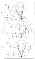
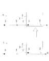
例えば図1、図2等に示すように、本実施形態の虚像表示装置100は、眼鏡のような外観を有するヘッドマウントディスプレイ(HMD)すなわち頭部搭載型表示装置であり、この虚像表示装置100を装着した観察者又は使用者に対して虚像による画像光(映像光)を視認させることができるとともに、観察者に外界像をシースルーで視認又は観察させることができる。虚像表示装置100は、第1表示装置100Aと、第2表示装置100Bと、これらを中央で繋ぎつつ支持する支持部材(ブリッジ部を含む)としてのフレームFRとを備える。すなわち、フレームFRは、第1表示装置100Aを構成する光学系と第2表示装置100Bを構成する光学系とを取り付ける取付部材として機能する。さらに、ここでの一例では、当該取付部材が、第1表示装置100A及び第2表示装置100Bの取付けを行う位置を変更可能となっていることで、第1表示装置100A及び第2表示装置100Bにおける表示位置を調整する調整装置として機能する。なお、取付部材や調整装置についての詳しい一例は、図5や図6等を参照して後述する。 For example, as shown in FIGS. 1, 2, and the like, the virtual
なお、図1等において、X、Y、及びZは、直交座標系であり、+X方向は、虚像表示装置100を装着した観察者又は装着者USの両眼EYの並ぶ横方向に対応し、+Y方向は、装着者USにとっての両眼EYの並ぶ横方向に直交する上方向に相当し、+Z方向は、装着者USにとっての前方向又は正面方向に相当する。±Y方向は、鉛直軸又は鉛直方向に平行になっている。上記各方向について、例えば、±X方向は、例えば右眼用の第1表示装置100Aから左眼用の第2表示装置100Bに向かう方向と平行な方向である、と捉えることもできる。以上のように、±X方向は、第1表示装置100Aと第2表示装置100Bとが並ぶ方向(左右方向)であり、以下、この方向を第1方向D1とする。また、第1方向D1に交差する方向を第2方向D2とし、ここでは、±X方向に垂直な±Y方向(上下方向)を、第2方向D2とする。なお、図示では、-Y方向が、第2方向D2の代表的一例となっている。 In FIG. 1 and the like, X, Y, and Z are orthogonal coordinate systems, and the + X direction corresponds to the lateral direction in which the binocular EYs of the observer or the wearer US wearing the imaginary
図1及び図2に示すように、また、既述のように、第1表示装置100A及び第2表示装置100Bは、右眼用の虚像と左眼用の虚像とをそれぞれ形成する部分である。なお、第1表示装置100Aと第2表示装置100Bとは、光学的に同等の構造を有するため、図2では、第1表示装置100Aについてのみ示し、第2表示装置100Bについては図示や説明を省略する。 As shown in FIGS. 1 and 2, and as described above, the
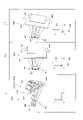
図2に示すように、本実施形態の虚像表示装置100において、右眼用の第1表示装置100Aは、光学的な要素として、表示素子80と導光系90とを備える。導光系90は、表示素子80からの画像光MLを射出瞳EPの形成位置に導く。すなわち、第1表示装置100Aは、第1方向D1に交差する第2方向D2について画像光MLを導光する。なお、図示のように、第1表示装置100Aは、反射面を有して画像光MLの光路を折り曲げて種々の方向に導いているが、表示素子80から射出瞳EPにかけての全体として、第2方向D2について、つまり縦方向について画像光MLを導光していると言える。ここでは、以上のように、個々の箇所では種々の方向に導きつつも全体としては、第1方向D1に交差する第2方向D2に導光していれば、第1表示装置100Aは、画像光MLを第2方向D2について導光しているものとする。 As shown in FIG. 2, in the virtual
表示素子80は、パネル型の映像素子(画像光生成装置)である。表示素子80は、例えば有機EL(有機エレクトロルミネッセンス、Organic Electro-Luminescence)等の自発光型の表示デバイスであり、2次元の表示面SSaにカラーの静止画又は動画を形成する。また、表示素子80は、図示を省略する表示制御回路に駆動されて表示動作を行う。さらに、表示素子80は、有機ELに限らず、無機EL、LEDアレイ、有機LED、レーザーアレイ、量子ドット発光型素子等に置き換えることができる。表示素子80は、自発光型の画像光生成装置に限らず、LCDその他の光変調素子で構成され、当該光変調素子をバックライトのような光源によって照明することによって画像を形成するものであってもよい。表示素子80として、LCDに代えて、LCOS(Liquid crystal on silicon, LCoSは登録商標)や、デジタル・マイクロミラー・デバイス等を用いることもできる。 The
導光系90は、投射光学系21と、プリズム22と、シースルーミラー23とを備える。投射光学系21は、表示素子80から射出された画像光MLを平行光束に近い状態に集光する。投射光学系21は、図示の例では単レンズであり、入射面と、射出面とを有する。プリズム22は、入射面と、内反射面と、射出面とを有し、投射光学系21から射出された画像光MLを入射面に屈折させつつ入射させ、内反射面で全反射させ、射出面から屈折させつつ射出させる。シースルーミラー23は、プリズム22から射出された画像光MLを射出瞳EPに向けて反射する。射出瞳EPは、表示面SSa上の各点からの画像光が所定の発散状態又は平行状態で表示面SSa上の各点の位置に対応する角度方向から重畳するように入射する位置となっている。 The
投射光学系21とプリズム22とは、表示素子80とともにケース51に収納されている。ケース51は、遮光性の材料で形成され、表示素子80を動作させる不図示の駆動回路を内蔵している。ケース51の開口は、プリズム22からシースルーミラー23に向かう画像光MLを妨げないサイズを有する。ケース51の開口については、単なる開口としないで光透過性を有する保護カバーで覆うことができる。ケース51に対しては、支持板54を介してシースルーミラー23が支持されている。ケース51又は支持板54は、フレームFR(図1参照)に支持されていて、例えば支持板54とシースルーミラー23とによって外観部材103が構成される。 The projection
導光系90は、軸外し光学系である。つまり、導光系90を構成する投射光学系21、プリズム22、及びシースルーミラー23は、軸外し光学系を形成するように配置されている。なお、導光系90が軸外し光学系であるとは、導光系90を構成する光学素子21,22,23において、少なくとも1つの反射面又は屈折面への光線の入射の前後で光路が全体として折れ曲がることを意味する。また、上記のような軸外し光学系である導光系90の光軸AXは、横断面で見た場合、Z字状の配置となっている。つまり、図示において、投射光学系21から内反射面までの光路と、内反射面からシースルーミラー23までの光路と、シースルーミラー23から射出瞳EPまでの光路とが、Z字状に2段階で折り返される配置となっている。 The
なお、図示において、中間像MMは、プリズム22とシースルーミラー23との間に形成されている。 In the illustration, the intermediate image MM is formed between the
射出瞳EPには、シースルーミラー23を通過した外界光HLも入射する。つまり、虚像表示装置300を装着した装着者USは、外界像に重ねて、画像光MLによる虚像を観察することができる。 External light HL that has passed through the see-through
ここで、図3において、状態α1及び状態α2として比較して示すように、上記のような構成を有する第1表示装置100Aは、垂直軸方向すなわち第2方向D2である±Y方向について、軸回転可能となっている。特に、本実施形態では、射出瞳EPの中心位置EOを通る軸を回転の中心として、第1表示装置100Aの全体が軸回転している。これにより、虚像表示装置100は、第1表示装置100Aによって表示される画像(虚像)の位置(角度)変更を可能にしている。なお、状態α3として示すように、第2表示装置100Bについても、同様に、全体が軸回転することで、表示される画像の位置(角度)変更がなされる。 Here, as shown in comparison with the state α1 and the state α2 in FIG. 3, the
上記状態α1~α3についてより具体的に説明すると、まず、図示のうち、状態α1は、第1表示装置100Aの回転前の様子を示しており、画像光MLのうち、中心位置EOに入射する成分についての光路が併せて示されている。状態α1の場合、第1表示装置100Aから射出される画像光MLとしての光線のうち、基準成分MLaは、装着者USの眼EYの前方方向であるZ方向を画像の中心とするように設計されている。 More specifically, the states α1 to α3 will be described. First, in the illustration, the state α1 shows the state before the rotation of the
上記に対して、図示のうち、状態α2では、状態α1から中心位置EOを回転中心として、第1表示装置100Aを構成する光学系全体が方向Xから方向Zに向かって10°Y軸回転している。この場合、状態α1では、正面(画角0°の方向)に見えた画像(虚像)すなわち基準成分MLaによる画像が、状態α2では、中心から外れた位置(画角10°の方向)に移動したものとして視認されることになる。なお、虚像の見え方についてより詳しくは、図8等を参照して後述する。 In contrast to the above, in the state α2, the entire optical system constituting the
また、上述した第1表示装置100Aの場合と同様の軸回転が、図示のうち、状態α3に示すように、第2表示装置100Bにおいてもなされる。ただし、第2表示装置100Bでは、回転方向が、第1表示装置100Aとは逆で、中心位置EOを回転中心として、第2表示装置100Bを構成する光学系全体が方向Zから方向Xに向かって10°Y軸回転している。この場合、画像光MLのうち、基準成分MLbによる画像が、中心から外れた位置(画角10°の方向)に移動したものとして視認されることになる。 Further, the same shaft rotation as in the case of the
以上のようにすることで、第1表示装置100A及び第2表示装置100Bを軸回転させることにより、虚像表示装置100は、左右画像の重なり度合を制御することで、FOVを調整できる、特に、拡大できるものとなっている。 By doing so, the virtual
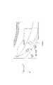
なお、虚像表示装置100は、図4及び図5に例示するように、調光部材としてのシェードSHにより眼前側の全体を覆うことも可能である。この場合、第1表示装置100A及び第2表示装置100Bについての上記のような姿勢調整があっても、すなわち図5において矢印AA,ABに示すような方向に第1表示装置100Aや第2表示装置100Bが移動しても、このような光学系の変動が、シェードSHによって、装着者US以外の他者からは見えにくいようにできる。見方を変えると、シェードSHは、位置変更可能な第1表示装置100A及び第2表示装置100Bを覆う部材となっている。なお、虚像表示装置100には、装着者USの鼻NSに当接するノーズパッドNDが設けられている。ノーズパッドNDやテンプルTMにより、フレームFRやシェードSHが装着者USに対して支持固定される。 As illustrated in FIGS. 4 and 5, the virtual
以下、図6等を参照して、第1表示装置100A及び第2表示装置100Bの姿勢調整(軸回転)を可能とするための一構造例について説明する。なお、図6等では、第1表示装置100Aを代表して説明し、第2表示装置100Bについては、同様であるので、図示や説明を省略する。 Hereinafter, an example of a structure for enabling posture adjustment (axis rotation) of the
図6は、第1表示装置100Aにおける姿勢調整のための取付部材MPの構造について一例を説明するための概念図であり、図7は、姿勢調整における動作方向について説明するための概念図である。なお、図示では、簡略化のため、第1表示装置100Aを構成する光学系を含む外観部材103の位置変更によって姿勢調整を示しているが、実際には、シースルーミラー23等を含む第1表示装置100Aを構成する光学系全体の位置変更がなされる。 FIG. 6 is a conceptual diagram for explaining an example of the structure of the mounting member MP for posture adjustment in the
図6のうち、上欄β1に示すように、フレームFRには、複数個所(図示の例では2か所)に穴部(開口部、開口)HL1,HL2が設けられている。一方、上欄β1及び下欄β2に示すように、外観部材103には、穴部HL1,HL2に嵌合せ可能な突起部PRが設けられている。すなわち、図示の例では、突起部PRは、穴部HL1に嵌め込まれているが、穴部HL2にも嵌め込み可能となっており、穴部HL1,HL2は、図3を参照して説明したように、射出瞳EPの中心位置EOを中心とする回転移動に沿った姿勢変更を可能とするように、配列されている。すなわち、突起部PRの嵌合せ位置を変更することで、所望の姿勢変更を可能としている。言い換えると、穴部HL1,HL2と突起部PRとは、支持部材としてのフレームFRにおける第1表示装置100Aの支持位置を変更する取付部材MPとして機能し、フレームFRの複数個所に設けられた嵌合せ可能な嵌合部材FFとなっている。また、取付部材MPは、第1表示装置100Aによる第1映像の表示位置を調整する調整装置AEを構成するものともなっている。 In FIG. 6, as shown in the upper column β1, the frame FR is provided with holes (openings, openings) HL1 and HL2 at a plurality of locations (two locations in the illustrated example). On the other hand, as shown in the upper column β1 and the lower column β2, the
より具体的に説明すると、図7に示すように、穴部HL1,HL2は、フレームFRにほぼ沿って並んでおり、第1表示装置100Aは、例えば図3に例示したような、Y方向を軸方向として中心位置EOを回転中心とする光学系の姿勢変更が可能である。すなわち、穴部HL1に突起部PRを嵌め合せた第1の状態(図3の状態α1)と穴部HL2に突起部PRを嵌め合せた第2の状態(図3の状態α2)とに切り替えることで、第1表示装置100Aによる第1映像の表示位置を、中心寄り(鼻側)とするか外寄り(耳側)とするかの選択が可能となる。 More specifically, as shown in FIG. 7, the hole portions HL1 and HL2 are arranged substantially along the frame FR, and the
さらに、図7において矢印Da,Dbに示すように、穴部HL1,HL2には、上述した姿勢変更に対応する回転方向に応じた方向に沿って、移動可能とする調整しろ(隙間)DTが設けられている。これにより、第1表示装置100Aの姿勢についての微調整が可能となっている。なお、嵌合部材FFを構成する穴部HL1,HL2や突起部PRの形状については、種々の態様が考えられる。図示の一例では、回転方向に応じた方向以外の方向については、隙間が生じないようにして移動を抑制する形状となっている。 Further, as shown by arrows Da and Db in FIG. 7, the hole portions HL1 and HL2 have an adjustment margin (gap) DT that allows them to move along the direction corresponding to the rotation direction corresponding to the above-mentioned attitude change. It is provided. This makes it possible to make fine adjustments to the posture of the
なお、図示等を省略するが、第2表示装置100Bについても同様に、取付部材として機能する突起部が設けられており、これに応じた複数の穴部がフレームFRに設けられている。すなわち、上記取付部材は、第2表示装置100Bによる第2映像の表示位置を調整する調整装置を構成する。まとめると、第1表示装置100Aと第2表示装置100Bとに設けた取付部材が、調整装置として機能する。 Although not shown, the
以下、図8等を参照して、上記構成の虚像表示装置100における虚像の見え方について、より詳しく説明する。図8は装着者USの両眼視により認識される映像領域の全体について説明するための概念図である。また、図9は、人間の視覚特性について説明するための図であり、図10は、装着者USの視野について説明するための概念的な図である。 Hereinafter, the appearance of the virtual image in the virtual
まず、図8のうち上欄γ1に例示するように、装着者USの右眼EYaにより視認される虚像についての仮想的な領域、すなわち画像光MLを導光して右眼用の第1映像IMaを表示する第1表示装置100Aからの画像光MLに由来して視認される映像領域を第1映像領域PAaとする。同様に、左眼EYbにより視認される虚像についての仮想的な領域、すなわち画像光MLを導光して左眼用の第2映像IMbを表示する第2表示装置100Bからの画像光MLに由来して視認される映像領域を第2映像領域PAbとする。さらに、両眼EYa,EYbで第1映像IMa及び第2映像IMbを視認した結果、装着者USの脳内において一の画像として認識される仮想上の全体映像領域を映像領域PAとする。 First, as illustrated in the upper column γ1 in FIG. 8, a virtual region about a virtual image visually recognized by the right eye EYa of the wearer US, that is, a first image for the right eye by guiding the image light ML. The image region visually recognized from the image light ML from the
本実施形態では、既述のように、第1表示装置100Aと第2表示装置100Bとにおいて、姿勢調整が可能となっている。すなわち、眼EYa,EYbにおける表示位置に相当する画像光MLの射出角度を調整することが可能になっている。この場合、第1表示装置100Aと第2表示装置100Bとからの画像光MLのうち、双方で重畳する角度範囲(画角)で射出される成分については、両眼EYa,EYbにおいて共通する1つの画像として認識される。一方、画像光MLのうち、上記以外の成分については、第1表示装置100Aのみからあるいは第2表示装置100Bのみから射出されるものとして、眼EYa,EYbのうち対応する側においてのみ視認されるものとなる。 In the present embodiment, as described above, the posture of the
ここでは、図示のように、右眼側については、第1映像領域PAaのうち、左右の眼EYa,EYbで共通するものと視認される範囲すなわち画像光MLが射出される角度範囲が重畳する領域を重畳領域Pa1とし、独立している視認される範囲すなわち角度範囲が重畳しない領域を、独立領域Pa2とする。 Here, as shown in the figure, on the right eye side, the range visually recognized as common to the left and right eyes EYa and EYb in the first video region PAa, that is, the angle range from which the image light ML is emitted is superimposed. The region is referred to as a superposed region Pa1, and the independent visible range, that is, the region where the angular range is not superposed is referred to as an independent region Pa2.
同様に、左眼側については、第2映像領域PAbのうち、左右の眼EYa,EYbで共通するものと視認される範囲すなわち画像光MLが射出される角度範囲が重畳する領域を重畳領域Pb1とし、独立している視認される範囲すなわち角度範囲が重畳しない領域を、独立領域Pb2とする。 Similarly, on the left eye side, of the second video region PAb, the region that is visually recognized as common to the left and right eyes EYa and EYb, that is, the region where the angle range in which the image light ML is emitted is superimposed is the superimposed region Pb1. The independent visible range, that is, the region where the angle range does not overlap is referred to as the independent region Pb2.
この場合、例えば右眼用の重畳領域Pa1と左眼用の重畳領域Pb1とにおいて、同じ画像を表示させることで、装着者USは、1つの画像として認識する。一方、重畳領域Pa1とこれに続く独立領域Pa2とは、1つの繋がった画像として認識する。同様に、重畳領域Pb1とこれに続く独立領域Pb2とについても、1つの繋がった画像として認識する。すなわち、以上の場合、仮想上の全体映像領域である映像領域PAは、重畳領域Pa1,Pb1に相当し、中央部の一の画像として脳内で重畳されて認識される中央領域PAcと、独立領域Pa2,Pb2に相当する周辺領域PAap,PAbpとが繋がった1つの大きなものとして認識されることになる。この結果として、下欄γ2に例示するように、中央領域PAc(重畳領域Pa1,Pb1)に表示される画像オブジェクトOB1(ロケットの画像オブジェクト)を含む画像と、周辺領域PAap,PAbp(独立領域Pa2,Pb2)に表示される画像オブジェクトOB2,OB3(惑星の画像や月の画像オブジェクト)を含む画像とが全体として1つの大きな画像として視認させることができる。つまり、FOVを拡大する調整ができる。 In this case, for example, by displaying the same image in the superimposed region Pa1 for the right eye and the superimposed region Pb1 for the left eye, the wearer US recognizes it as one image. On the other hand, the superimposed region Pa1 and the independent region Pa2 following it are recognized as one connected image. Similarly, the superimposed region Pb1 and the independent region Pb2 following it are also recognized as one connected image. That is, in the above case, the video region PA, which is a virtual entire video region, corresponds to the superposed regions Pa1 and Pb1 and is independent of the central region PAc, which is superposed and recognized as one image in the central portion in the brain. The peripheral regions PAap and PAbp corresponding to the regions Pa2 and Pb2 are recognized as one large connected region. As a result, as illustrated in the lower column γ2, the image including the image object OB1 (image object of the rocket) displayed in the central region PAc (superimposed region Pa1 and Pb1) and the peripheral regions PAap and PAbp (independent regions Pa2). , Pb2), the image including the image objects OB2 and OB3 (planetary image and moon image object) can be visually recognized as one large image as a whole. That is, the FOV can be adjusted to be enlarged.
また、以上の場合、中央領域PAcの画像、すなわち画像オブジェクトOB1を含む画像については、適宜画像処理を施すことで立体視画像が可能である。一方、画像オブジェクトOB2,OB3を含む画像については、片眼視のため、平面画像のみの表示が可能ということになる。 Further, in the above case, the stereoscopic image can be obtained by appropriately performing image processing on the image of the central region PAc, that is, the image including the image object OB1. On the other hand, for an image including the image objects OB2 and OB3, only a flat image can be displayed because it is viewed with one eye.
さらに、本実施形態では、例えば図6等を参照して説明したように、第1表示装置100Aと第2表示装置100Bとについて、姿勢調整の度合いを調整することで、表示位置の変更あるいは選択が可能である。すなわち、重畳領域Pa1,Pb1や独立領域Pa2,Pb2について、各表示範囲(領域)をどの程度の範囲とするかについての調整が可能となっている。 Further, in the present embodiment, as described with reference to FIG. 6, for example, the display position of the
以下、図9を参照して、表示範囲の調整について一例を説明する。なお、ここでは、前提として、各表示装置100A,100Bにおける光学系で横方向FOV50°(全画角)の画像がそれぞれ形成されるものとし、図6等を参照した一例において、第1の固定穴としての穴部HL1に各表示装置100A,100Bの光学系を固定した場合、画像重ね合わせの範囲が横方向FOV40°(全画角)となるものとする。また、第2の固定穴としての穴部HL2に各表示装置100A,100Bの光学系を固定した場合、画像重ね合わせの範囲が横方向FOV35°(全画角)となるものとする。なお、以上の場合、いずれの態様においても、重畳領域Pa1,Pb1の全画角を±20°以上(すなわち半画角±10°以上)の状態を確保している。この場合、良好な画像形成が必要な範囲について、重畳領域Pa1,Pb1によってカバーした状態が維持される。 Hereinafter, an example of adjusting the display range will be described with reference to FIG. 9. Here, as a premise, it is assumed that an image of lateral FOV 50 ° (total angle of view) is formed by the optical system in each
図9のうち、上欄δ1は、穴部HL1を利用した態様における各表示装置100A,100Bにおける視認状態を、状態Q1として示しており、穴部HL2を利用した態様における視認状態を、状態Q2として示している。また、下欄δ2は、穴部HL1を利用した態様における仮想上の全体映像領域を映像領域PAの状態を状態R1として示しており、穴部HL2を利用した態様における映像領域PAの状態を状態R2として示している。 In FIG. 9, the upper column δ1 shows the visible state in each of the
以上の場合、状態Q1では、重畳領域Pa1,Pb1における横方向の幅Wcが、横方向FOV40°に相当するものとなっており、独立領域Pa2,Pb2における横方向の幅Wa,Wbが、それぞれ50°-40°=10°に相当するものとなっている。したがって、状態R1に示す映像領域PAは、これらを合わせた全体として、合成横方向FOV60°(=40°+10°+10°)の画像が得られることになる。 In the above case, in the state Q1, the lateral width Wc in the superimposed regions Pa1 and Pb1 corresponds to the lateral FOV 40 °, and the lateral widths Wa and Wb in the independent regions Pa2 and Pb2 are respectively. It corresponds to 50 ° −40 ° = 10 °. Therefore, in the image region PA shown in the state R1, an image of the combined lateral FOV 60 ° (= 40 ° + 10 ° + 10 °) can be obtained as a whole.
同様に、状態Q2では、状態Q1と比較して表示範囲が矢印AA1,AA2に示す方向にシフトすることで、重畳領域Pa1,Pb1における横方向の幅WWcが、横方向FOV35°に相当するものとなっており、独立領域Pa2,Pb2における横方向の幅WWa,WWbが、それぞれ50°-35°=15°に相当するものとなっている。したがって、状態R2に示す映像領域PAは、これらを合わせた全体として、合成横方向FOV65°(=35°+15°+15°)の画像が得られることになる。つまり、各幅WWc等について状態R1と比較することで明らかなように、重畳領域Pa1,Pb1が狭くなる半面、全体としての映像領域PAは、広くなっている。つまり、上記態様では、横方向の画角を変更している(広げている)。 Similarly, in the state Q2, the display range is shifted in the direction indicated by the arrows AA1 and AA2 as compared with the state Q1, so that the lateral width WWc in the superimposed regions Pa1 and Pb1 corresponds to the lateral FOV 35 °. The lateral widths WWa and WWb in the independent regions Pa2 and Pb2 correspond to 50 ° −35 ° = 15 °, respectively. Therefore, in the image region PA shown in the state R2, an image of the combined lateral FOV 65 ° (= 35 ° + 15 ° + 15 °) can be obtained as a whole. That is, as is clear from comparison with the state R1 for each width WWc and the like, the superimposed regions Pa1 and Pb1 are narrowed, while the video region PA as a whole is widened. That is, in the above aspect, the angle of view in the horizontal direction is changed (widened).
なお、表示素子80における画像表示の態様については、上記変更に応じて種々変更することが考えられる。 It should be noted that the mode of image display on the
また、以上の場合、映像領域PAについてのアスペクト比(縦横比)についても、上記重畳度合いや表示素子80の縦横比を適宜調整することで、種々の設定に設定可能にできるようにしてもよい。例えば、状態R1では、9:16となるようにする一方、状態R2では、1:2.35のシネスコのサイズになるようにする、といった態様とすることが考えらえる。 Further, in the above case, the aspect ratio (aspect ratio) of the image area PA may be set to various settings by appropriately adjusting the degree of superimposition and the aspect ratio of the
また、以上のような調整に際して、重畳領域Pa1,Pb1と独立領域Pa2,Pb2との境界位置等が合致するように必要に応じて微調整を行うべく、図7に例示した調整しろDTは、重畳領域の範囲を調整する方向に延びている。 Further, in the above adjustment, the adjustment margin DT exemplified in FIG. 7 is used to make fine adjustments as necessary so that the boundary positions between the overlapping regions Pa1 and Pb1 and the independent regions Pa2 and Pb2 match. It extends in the direction of adjusting the range of the superimposed area.
ここで、以上のような構成とする場合、重畳領域Pa1,Pb1すなわち人間の眼の視野のうち中心に近い側と、独立領域Pa2,Pb2すなわち人間の眼の視野のうち周辺側とにおいて、画像の状態が異なることになる。これに対して、図10等を参照して、人間の眼に関する特性について説明する。図10は、人間の視覚特性について説明するための図である。図10に示すように、眼の並ぶ左右方向に関する人間の視野角(半角)のうち、網膜像が中心窩に映じて解像力が優れた中心視を行える範囲RA1は、約1°程度までであり、視力1.0程度の視力があってもある程度以上の解像が維持できるのは2°程度までで、それ以上の視野角では、急に解像性能は落ちる。また、数字や文字の認識ができる範囲RA2は、約5°程度までである。さらに、色や輝度が変化する場合にこれを感知できる色の弁別限界の範囲RA3は、約20°~25°程度までである。すなわち、人間の視力は、視野角が広がるとともに急速に落ちる。これに応じて、本実施形態では、重畳領域Pa1,Pb1と独立領域Pa2,Pb2とを合わせた全体領域の画角を50°以上とし、重畳領域Pa1,Pb1の周辺側における独立領域Pa2,Pb2を20°~25°または-20°~-25°とすることで、広画角な画像を提供しつつ、画質の劣化を感じさせない態様としている。 Here, in the case of the above configuration, the image is in the superimposed region Pa1, Pb1, that is, the side of the human eye field of view that is closer to the center, and the independent regions Pa2, Pb2, that is, the peripheral side of the human eye field of view. The state of will be different. On the other hand, the characteristics related to the human eye will be described with reference to FIG. 10 and the like. FIG. 10 is a diagram for explaining human visual characteristics. As shown in FIG. 10, among the human viewing angles (half-angles) in the left-right direction in which the eyes are lined up, the range RA1 in which the retinal image is reflected in the fovea centralis and the central vision with excellent resolving power can be performed is up to about 1 °. Even if the visual acuity is about 1.0, the resolution can be maintained above a certain level up to about 2 °, and the resolution performance suddenly drops at a viewing angle of more than that. Further, the range RA2 at which numbers and characters can be recognized is up to about 5 °. Further, the range RA3 of the color discrimination limit that can detect a change in color or brightness is about 20 ° to 25 °. That is, human visual acuity drops rapidly as the viewing angle widens. In response to this, in the present embodiment, the angle of view of the entire region including the superimposed regions Pa1 and Pb1 and the independent regions Pa2 and Pb2 is set to 50 ° or more, and the independent regions Pa2 and Pb2 on the peripheral side of the superimposed regions Pa1 and Pb1 are set. Is set to 20 ° to 25 ° or −20 ° to −25 °, so that an image with a wide angle of view is provided and the image quality is not deteriorated.
さらに、図11を参照して、図10を参照して説明した事項について、虚像表示装置100の装着者USの視野範囲の特性として説明する。まず、図11において、第1欄ε1~第3欄ε3は、装着者USの視野について説明するための概念的な図であり、第1欄ε1は、水平視野の様子を示し、第2欄ε2は、鉛直(垂直)視野の様子を示し、第3欄ε3は、面に投影された視野(視線方向についての視野の広がり)の様子を示している。ここで、各図中において、弁別視野V1とは、視力などの視機能が優れている中心領域(画角約5°以内)であり、有効視野V2とは、眼球運動だけで瞬時に情報需要できる領域(水平約30°、垂直20°以内)であり、安定注視野V3とは、眼球・頭部運動で無理なく注視でき、効果的な情報需要ができる領域(水平60~90°、垂直45~70°以内)である。これらのうち、弁別視野V1を念頭において、例えば映像を眺めている装着者USの視線方向は、通常ほぼ正面方向であると考えれば、弁別視野V1に対して画像の中心から十分な範囲に中央領域PAcを設けて立体視画像が形成可能な範囲が視機能が優れた範囲を含むようにすれば、周辺領域PAap,PAbpが平面画像であっても、あたかも表示エリアの画像全体において立体視画像を行っているかのように見せることができる。すなわち、図8等に示した中央領域PAcが、少なくとも弁別視野V1(画角5°程度)の範囲を視認範囲として含む、さらには、文字を識別できる範囲と考えられる画角10°の範囲である視野VX(有効視野V2よりは狭い範囲)を視認範囲として含むようにすることで、立体画像の視認や文字の多い画像の認識等種々の画像の視認を確保した上で画像表示エリアを拡張させることができる。 Further, with reference to FIG. 11, the matters described with reference to FIG. 10 will be described as the characteristics of the visual field range of the wearer US of the virtual
これに対して、本実施形態では、重畳領域Pa1,Pb1の画角を±10°以上とすることで、良好な視認性を要する範囲を、重畳領域Pa1,Pb1とする状態を確保している。 On the other hand, in the present embodiment, the angle of view of the superimposed regions Pa1 and Pb1 is set to ± 10 ° or more, so that the range requiring good visibility is set to the superimposed regions Pa1 and Pb1. ..
以上のように、本実施形態の虚像表示装置100では、右眼用の第1映像IMaを表示する第1表示装置100Aと、左眼用の第2映像IMbを表示する第2表示装置100Bと、第1映像の表示位置と第2映像の表示位置とを調整する調整装置AEとしての取付部材MPとを備え、第1表示装置100A及び第2表示装置100Bは、第1表示装置100Aと第2表示装置100Bとが並ぶ第1方向D1に交差する第2方向D2について画像光MLを導光して、第1映像IMaと第2映像IMbとを表示し、調整装置AEは、第1映像IMaと第2映像IMbとにおいて、重畳して視認される重畳領域Pa1,Pb1と、独立して視認される独立領域Pa2,Pb2とを設けるように調整する。 As described above, in the imaginary
上記虚像表示装置100では、第1映像IMaの表示位置と第2映像IMbの表示位置とを調整する調整装置AEとしての取付部材MPが、第1映像IMaと第2映像IMbとにおいて、重畳して視認される重畳領域Pa1,Pb1と、独立して視認される独立領域Pa2,Pb2とを設けていることで、重畳領域Pa1,Pb1と独立領域Pa2,Pb2とを合わせた1つの大きな画像を両眼視によって視認させることができる。また、このような調整を行うに際して、第1表示装置100Aと第2表示装置100Bとが並ぶ第1方向D1に交差する第2方向D2について画像光MLを導光するものとなっていることで、調整に伴う装置の増大や頭部搭載型とするに際してのデザイン性の問題発生を回避又は抑制できる。 In the virtual
〔第2実施形態〕
以下、図12等を参照して、第2実施形態に係る虚像表示装置について一例を説明する。図12は、本実施形態に係る虚像表示装置について、姿勢調整のための取付部材について、一構造例を説明するための概念図であり、図7に対応する図である。[Second Embodiment]
Hereinafter, an example of the virtual image display device according to the second embodiment will be described with reference to FIG. 12 and the like. FIG. 12 is a conceptual diagram for explaining a structural example of a mounting member for posture adjustment of the virtual image display device according to the present embodiment, and is a diagram corresponding to FIG. 7.
本実施形態に係る虚像表示装置は、第1実施形態で例示した虚像表示装置100の変形例であり、調整装置AEの構造を除いて、第1実施形態の場合と同様であるので、虚像表示装置の全体に関する説明は省略する。 The virtual image display device according to the present embodiment is a modification of the virtual
図12において、調整装置AEとしての取付部材MPは、突起部PRに嵌合せ可能な複数の穴部HL1,HL2が設けられた嵌合部材で構成されている点においては、第1実施形態の場合と同様であるが、ピン等で瞳中心の回転規制と位置固定をガタ無く行い固定をするものであり、微調整のための隙間を有しない点において、異なっている。本実施形態では、左右画素の位置調整を回路で行うことで、微調整が可能な構成となっている。言い換えると、本実施形態では、回路的な左右画素の位置調整と取付部材MPとが協働して調整装置AEとして機能している。 In FIG. 12, the mounting member MP as the adjusting device AE is the first embodiment in that it is composed of a fitting member provided with a plurality of holes HL1 and HL2 that can be fitted to the protrusion PR. It is the same as the case, but it is different in that it does not have a gap for fine adjustment because it fixes the rotation of the center of the pupil and fixes the position without play with a pin or the like. In this embodiment, fine adjustment is possible by adjusting the positions of the left and right pixels with a circuit. In other words, in the present embodiment, the circuit-like position adjustment of the left and right pixels and the mounting member MP cooperate to function as the adjustment device AE.
理想としては、穴部HL1あるいは穴部HL2に突起部PRを嵌め合せることで、理想上の位置に表示がなされることが望ましい。しかしながら、個体ごとの誤差等により、理想の位置から若干の位置ずれが発生する可能性がある。第1実施形態では、図7を参照して例示したように、穴部HL1,HL2に調整しろ(隙間)DTを設けて微調整可能とすることで、対応していた。これに対して、本実施形態では、回路的処理により、当該微調整を可能としている。 Ideally, the protrusion PR is fitted to the hole HL1 or the hole HL2 to display the display at an ideal position. However, there is a possibility that some misalignment may occur from the ideal position due to an error for each individual. In the first embodiment, as illustrated with reference to FIG. 7, adjustment margins (gap) DTs are provided in the holes HL1 and HL2 to enable fine adjustment. On the other hand, in the present embodiment, the fine adjustment is possible by the circuit processing.
以下、図13及び図14を参照して、実施形態に係る虚像表示装置における回路的な左右画素の位置調整について、一例を説明する。 Hereinafter, an example of circuit-like position adjustment of left and right pixels in the virtual image display device according to the embodiment will be described with reference to FIGS. 13 and 14.
図13は、虚像表示装置における画像処理による表示領域の調整について説明するための概念図であり、図14は、虚像表示装置における画像処理による表示領域の調整について説明するために図13の一部について抽出したものを拡大した概念図である。 FIG. 13 is a conceptual diagram for explaining the adjustment of the display area by image processing in the virtual image display device, and FIG. 14 is a part of FIG. 13 for explaining the adjustment of the display area by image processing in the virtual image display device. It is an enlarged conceptual diagram of what was extracted about.
図13に示すように、本実施形態では、左右画素の位置調整を回路で行うべく、虚像表示装置100は、表示対象として入力される画像データMDについて各種画像処理を行う画像処理装置GPを有する。画像処理装置GPは、第1表示装置100A及び第2表示装置100Bを構成する表示素子80に接続されており、画像データMDについての処理結果として、表示素子80における表示動作の内容としての映像データを出力する。 As shown in FIG. 13, in the present embodiment, the virtual
画像処理装置GPは、各種画像処理の1つとして、第1表示装置100A及び第2表示装置100Bにおける表示領域を変更する。すなわち、上述した左右画素の位置調整を行う。また、結果的に、画像処理装置GPは、重畳領域Pa1,Pb1と独立領域Pa2,Pb2との境界位置を調整するものとなっている。 The image processing device GP changes the display area in the
さらに、以上について、見方を変えると、画像処理装置GPは、調整装置AEを構成するものとなっている。 Further, from a different point of view, the image processing device GP constitutes the adjusting device AE.
また、図13に示す例示では、上記のほか、認識させたい全体としての映像領域についての理想の状態を、理想映像領域PAiとして示している。また、この時の中央領域を理想中央領域PAciとし、周辺領域を理想周辺領域PAapi,PAbpiとする。この上で、実際の第1映像IMa,IMbが上記理想映像領域PAiに合致しているか否かを確認するための基準点として、理想中央領域PAci上の四隅に基準点SS1~SS4を設定しておく。具体的には、基準点SS1~SS4は、例えばパネル型の表示素子80においてマトリクス状に設けられた画素に相当する。 Further, in the example shown in FIG. 13, in addition to the above, the ideal state of the entire image area to be recognized is shown as the ideal image area PAi. Further, the central region at this time is referred to as an ideal central region PAci, and the peripheral regions are referred to as ideal peripheral regions PAapi and PAbpi. On this basis, reference points SS1 to SS4 are set at the four corners on the ideal central region PAci as reference points for confirming whether or not the actual first video IMa and IMb match the ideal video region PAi. Keep it. Specifically, the reference points SS1 to SS4 correspond to pixels provided in a matrix in, for example, a panel-
なお、説明を簡略化するため、図示の一例では、第2表示装置100Bにより表示される第2映像IM2の表示位置が理想映像領域PAiに合致しているものとし、第1表示装置100Aにより表示される第1映像IM1の表示位置について、理想の位置からずれている場合(すなわち第2映像IM2に対して第1映像IM1がずれている場合)に、第1映像IM1について、必要な微調整を回路的に行うものとする。具体的には、図13に示す場合の第1映像IMaでは、状態K1に示すように、第1表示装置100Aの表示素子80において、基準点SS1,SS2が少しずれてしまっていたとする。これは、仮に理想的な組付け(ずれの無い組付け)の状態になっていれば、表示素子80を構成する画素列のうち、200列目に基準点SS1,SS2が表示されるべきであるが、実際には理想的な状態(ずれの無い状態)から2画素分ずれていたとする。この場合、状態K2に示すように、2画素分のずれを考慮して202列目に基準点SS1,SS2が表示されるように、調整装置AEとしての画像処理装置GPによって、第1映像IMaの表示領域全体をシフトさせることで、理想映像領域PAiに合致した状態にすることができる。 In order to simplify the explanation, in the illustrated example, it is assumed that the display position of the second image IM2 displayed by the
なお、上記は一例であり、左右のずれを調整できれば、第2映像IM2を基準とする場合に限らず、種々の態様が考えられる。 The above is an example, and if the left-right deviation can be adjusted, various aspects can be considered, not limited to the case where the second video IM2 is used as a reference.
以上のように、本実施形態においても、重畳領域Pa1,Pb1と独立領域Pa2,Pb2とを合わせた1つの大きな画像を両眼視によって視認させることができる。また、このような調整を行うに際して、第1表示装置100Aと第2表示装置100Bとが並ぶ第1方向D1に交差する第2方向D2について画像光MLを導光するものとなっていることで、調整に伴う装置の増大や頭部搭載型とするに際してのデザイン性の問題発生を回避又は抑制できる。特に、本実施形態では、回路的な処理によって表示領域を適切な状態にできる。 As described above, also in this embodiment, one large image in which the superimposed regions Pa1 and Pb1 and the independent regions Pa2 and Pb2 are combined can be visually recognized by binocular vision. Further, when making such an adjustment, the image light ML is guided with respect to the second direction D2 intersecting the first direction D1 in which the
〔第3実施形態〕
以下、図15を参照して、第3実施形態に係る虚像表示装置について一例を説明する。図15は、本実施形態に係る虚像表示装置について一例を示す概念的な図であり、図2や図3に対応する図である。[Third Embodiment]
Hereinafter, an example of the virtual image display device according to the third embodiment will be described with reference to FIG. FIG. 15 is a conceptual diagram showing an example of the virtual image display device according to the present embodiment, and is a diagram corresponding to FIGS. 2 and 3.
本実施形態に係る虚像表示装置は、光学系の構成が異なる一例について示しており、各表示装置についての姿勢調整の方法等については、第1実施形態等の場合と同様であるので、詳細については省略する。 The virtual image display device according to the present embodiment shows an example in which the configuration of the optical system is different, and the posture adjustment method and the like for each display device are the same as those in the first embodiment and the like. Is omitted.
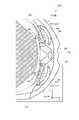
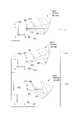
本実施形態に係る虚像表示装置300(第1表示装置300A)は、図示のうち、第1欄ζ1に示すように、表示素子80と、導光系390とを備える。このうち、導光系390は、平板状のシースルーミラー391と、凹面ミラー392とを有し、いわゆるバードバス型の光学系となっている。以下、画像光MLの光路に沿って説明すると、まず、表示素子80から射出された画像光MLは、シースルーミラー391において一部が反射され凹面ミラー392に向かい、凹面ミラー392において反射されて、再度シースルーミラー391に向かう成分のうち、一部がシースルーミラー391を透過することで、射出瞳EPに到達する。なお、凹面ミラー392についてもシースルーミラーとすることで、外界光を重畳して視認可能な構成としてもよい。 The virtual image display device 300 (
本実施形態においても、第2欄ζ2及び第3欄ζ3に示すように、垂直軸方向すなわち第2方向D2である±Y方向について、射出瞳EPの中心位置EOを通る軸を回転の中心として、第1表示装置300A及び第2表示装置300Bの全体が軸回転可能となっている。これにより、本実施形態においても、重畳領域Pa1,Pb1と独立領域Pa2,Pb2とを合わせた1つの大きな画像を両眼視によって視認させることができる。また、このような調整を行うに際して、第1表示装置300Aと第2表示装置300Bとが並ぶ第1方向D1に交差する第2方向D2について画像光MLを導光するものとなっていることで、調整に伴う装置の増大や頭部搭載型とするに際してのデザイン性の問題発生を回避又は抑制できる。 Also in this embodiment, as shown in the
〔第4実施形態〕
以下、図16等を参照して、第4実施形態に係る虚像表示装置について一例を説明する。図16は、本実施形態に係る虚像表示装置400について一例を説明するための光路図であり、図17は、虚像表示装置400の構造について一例を説明するための概念的な図である。また、図18は、両眼視により認識される映像領域PAの全体についての概念図であり、図8に対応する図である。[Fourth Embodiment]
Hereinafter, an example of the virtual image display device according to the fourth embodiment will be described with reference to FIG. 16 and the like. FIG. 16 is an optical path diagram for explaining an example of the virtual
上記各実施形態では、第1及び第2映像IMa,IMbの表示位置を、眼の並ぶ左右方向(水平方向、横方向)について変更していた。つまり、横方向の画角を変更するものとなっていた。これに対して、本実施形態では、眼の並ぶ左右方向(水平方向、横方向)に交差する方向について変更している点において、他の実施形態と異なっている。なお、本実施形態では、一例として、眼の並ぶ左右方向(水平方向、横方向)に垂直な上下方向(垂直方向、縦方向)について表示位置を変更する場合について説明する。つまり、縦方向の画角を変更するものとなっている。 In each of the above embodiments, the display positions of the first and second images IMa and IMb are changed in the left-right direction (horizontal direction and lateral direction) in which the eyes are lined up. That is, the angle of view in the horizontal direction was changed. On the other hand, this embodiment is different from other embodiments in that the direction of intersection in the left-right direction (horizontal direction, lateral direction) in which the eyes are lined up is changed. In this embodiment, as an example, a case where the display position is changed in the vertical direction (vertical direction, vertical direction) perpendicular to the horizontal direction (horizontal direction, horizontal direction) in which the eyes are lined up will be described. That is, the angle of view in the vertical direction is changed.
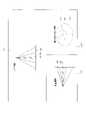
まず、本実施形態の場合、虚像表示装置400は、図16の第1欄η1~第3欄η3に示すように、画像光MLについて、水平軸方向すなわち第1方向D1である±X方向について、射出瞳EPの中心位置EOを通る軸を回転の中心として、第1表示装置400A及び第2表示装置400Bの全体が軸回転可能となっている。なお、第1欄η1は、回転前の状態(傾き0°の状態)を示しており、第2欄η2は、上方向(+Y方向)に傾けた状態を示しており、第3欄η3は、下方向(-Y方向)に傾けた状態(例えば10°傾き有りの状態)を示している。 First, in the case of the present embodiment, as shown in the first column η1 to the third column η3 of FIG. 16, the virtual
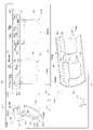
以下、図17を参照して、上記のような姿勢調整を可能とする虚像表示装置400について構造の一例を説明する。図17のうち、第1欄λ1は、虚像表示装置400の概念的な側面図であり、第2欄λ2は、虚像表示装置400の概念的な正面図であり、第3欄λ3は、虚像表示装置400の概念的な斜視図である。 Hereinafter, with reference to FIG. 17, an example of the structure of the virtual
図17に示す一例の虚像表示装置400は、フレームFRにおいて、図16を参照して説明した光路の変更を行うための虚像表示装置400の姿勢変更を可能とするように、穴部HL1,HL2が配列されている。具体的には、図示の一例では、フレームFRが+Y方向について円弧を描くような曲面を有しており、穴部HL1,HL2が、+Y方向について配列されている。なお、各穴部HL1,HL2は、+X方向について並ぶ一対構成として設けられている。また、突起部PRは、各穴部HL1等に対応して嵌合部材FFとして機能すべく、+X方向について並ぶ一対構成となっており、各表示装置400A,400Bの導光系90を収めるケース51の上端において両端に設けられている。以上のような構成とすることで、上下方向(垂直方向、縦方向)について表示位置の変更が可能となる。図示の一例では、右眼用の第1表示装置400Aが、相対的に左眼用の第2表示装置400Bよりも上方側に位置変更されている。したがって、この場合の表示位置については、図18のうち、第1欄ξ1に示すように、第1映像領域PAaは、上下方向について、下方側の重畳領域Pa1と上方側の独立領域Pa2とに区切られる。同様に、第2映像領域PAbは、上下方向について、上方側の重畳領域Pb1と下方側の独立領域Pb2とに区切られる。また、第2欄ξ2に示すように、認識される仮想上の全体映像領域としての映像領域PAとしては、縦方向につながれた1枚の画像となる。 The virtual
なお、上下方向の差異のつけ方については、上記一例に限らず種々の態様が可能であり、例えば左右の一方を、第2欄η2に示すように、画像の中心が水平よりも上方側になるようにし、かつ、他方を、第3欄η3に示すように、画像の中心が水平よりも下方側になるようにしてもよい。あるいは、いずれかを水平方向にし、他方を水平よりも下方側あるいは上方側にしてもよい。 It should be noted that the method of making a difference in the vertical direction is not limited to the above example, and various modes are possible. And the other may be such that the center of the image is below the horizontal, as shown in
本実施形態においても、射出瞳EPの中心位置EOを通る軸を回転の中心として、第1表示装置400A及び第2表示装置400Bの全体が軸回転可能となっている。これにより、本実施形態においても、重畳領域Pa1,Pb1と独立領域Pa2,Pb2とを合わせた1つの大きな画像を両眼視によって視認させることができる。特に、本実施形態では、水平軸方向すなわち第1方向D1である±X方向について、回転可能となっていることで、縦方向(上下方向)について1つになった大きな画像を視認させることができる。また、このような調整を行うに際して、第1表示装置400Aと第2表示装置400Bとが並ぶ第1方向D1に交差する第2方向D2について画像光MLを導光するものとなっていることで、調整に伴う装置の増大や頭部搭載型とするに際してのデザイン性の問題発生を回避又は抑制できる。 Also in this embodiment, the entire
〔変形例及びその他〕
以上実施形態に即して本発明を説明したが、本発明は、上記の実施形態に限られるものではなく、その要旨を逸脱しない範囲において種々の態様において実施することが可能であり、例えば次のような変形も可能である。[Modifications and others]
Although the present invention has been described above in accordance with the embodiments, the present invention is not limited to the above-described embodiments, and can be carried out in various embodiments without departing from the gist thereof. Deformation such as is also possible.
上記各実施形態について、適宜組み合わせた態様とすることも考えられ、例えば左右方向と上下方向との双方について姿勢調整を行う態様としてもよい。 Each of the above embodiments may be combined as appropriate, and for example, the posture may be adjusted in both the left-right direction and the up-down direction.
また、上記各実施形態では、左右の第1及び第2映像IMa,IMbの表示位置について、重畳領域と独立領域との双方がそれぞれに設けられているが、左右のうちいずれか一方のみが両領域を有する構成とすることも考えられる。また、上記実施形態では、双方が重畳領域と独立領域とを有し、これらの領域の割合を姿勢調整によって変更可能としているが、姿勢調整によって重畳領域のみが存在し独立領域がない状態とする態様を含めることも可能である。 Further, in each of the above embodiments, both the superimposed region and the independent region are provided for the display positions of the left and right first and second video IMa and IMb, respectively, but only one of the left and right is both. It is also conceivable to have a configuration having a region. Further, in the above embodiment, both have a superposed region and an independent region, and the ratio of these regions can be changed by posture adjustment, but only the superposed region exists and there is no independent region by posture adjustment. It is also possible to include aspects.
また、シェードSHは、透過光(外界光)を制限することで調光を行う調光デバイスとして、種々のものを採用できるが、例えば電動で透過率を調整するものっであってもよい。また、シェードSHとして、ミラー液晶、電子シェード等を用いることができる。あるいは、シェードSHは、外光照度に応じて透過率を調整するものであってもよい。シェードSHによって外界光を遮断する場合、外界像の作用を受けていない虚像のみを観察することができる。また、本願発明の虚像表示装置は、外光を遮断し画像光のみを視認させるいわゆるクローズ型の頭部搭載型表示装置(HMD)に適用できる。この場合、虚像表示装置と撮像装置とで構成されるいわゆるビデオシースルーの製品に対応させたりするものとしてもよい。 Further, as the shade SH, various dimming devices that perform dimming by limiting the transmitted light (outside light) can be adopted, and for example, a device that electrically adjusts the transmittance may be used. Further, as the shade SH, a mirror liquid crystal display, an electronic shade or the like can be used. Alternatively, the shade SH may adjust the transmittance according to the external light illuminance. When the external light is blocked by the shade SH, only a virtual image that is not affected by the external image can be observed. Further, the virtual image display device of the present invention can be applied to a so-called closed-type head-mounted display device (HMD) that blocks external light and allows only image light to be visually recognized. In this case, it may correspond to a so-called video see-through product composed of a virtual image display device and an image pickup device.
以上では、虚像表示装置100等が頭部に装着されて使用されることを前提としたが、上記虚像表示装置100,300は、頭部に装着せず双眼鏡のようにのぞき込むハンドヘルドディスプレイとしても用いることができる。つまり、本発明において、ヘッドマウントディスプレイには、ハンドヘルドディスプレイも含まれる。 In the above, it is assumed that the virtual
また、以上のうち、例えば、光軸(射出光軸)AXを、前方の+Z方向に対して10°程度下向きに傾いて延びるように構成を基準構成とし、この基準構成に対して、左右方向又は上下方向に表示位置を変更する態様とすることも考えられる。光軸AXを水平軸であるZ軸に対して前方側で10°程度下向きにすることにより、虚像を観察する装着者USの眼EYの疲れを低減することができる。この場合、パネル側で補正に関して、必要に応じて、表示素子80の形状を適宜変更することができる。 Further, among the above, for example, the reference configuration is such that the optical axis (injection optical axis) AX is tilted downward by about 10 ° with respect to the forward + Z direction, and the configuration is set to extend in the left-right direction with respect to this reference configuration. Alternatively, it is conceivable to change the display position in the vertical direction. By setting the optical axis AX downward by about 10 ° on the front side with respect to the Z axis which is the horizontal axis, it is possible to reduce the fatigue of the eye EY of the wearer US who observes the virtual image. In this case, the shape of the
具体的な一態様における虚像表示装置は、右眼用の第1映像を表示する第1表示装置と、左眼用の第2映像を表示する第2表示装置と、第1映像の表示位置と第2映像の表示位置とを調整する調整装置とを備え、第1表示装置及び第2表示装置は、第1表示装置と第2表示装置とが並ぶ第1方向に交差する第2方向について画像光を導光して、第1映像と第2映像とを表示し、調整装置は、第1映像と第2映像とにおいて、重畳して視認される重畳領域と、独立して視認される独立領域とを設けるように調整する。 The imaginary image display device in a specific embodiment includes a first display device that displays a first image for the right eye, a second display device that displays a second image for the left eye, and a display position of the first image. The first display device and the second display device include an adjustment device for adjusting the display position of the second image, and the first display device and the second display device are images of a second direction in which the first display device and the second display device intersect in the first direction. The light is guided to display the first image and the second image, and the adjusting device is independent of the superimposed area visually recognized by being superimposed on the first image and the second image. Adjust to provide an area.
上記虚像表示装置では、第1映像の表示位置と第2映像の表示位置とを調整する調整装置が、第1映像と第2映像とにおいて、重畳して視認される重畳領域と、独立して視認される独立領域とを設けていることで、重畳領域と独立領域とを合わせた1つの大きな画像を両眼視によって視認させることができる。また、このような調整を行うに際して、第1表示装置と第2表示装置とが並ぶ第1方向に交差する第2方向について画像光を導光するものとなっていることで、調整に伴う装置の増大や頭部搭載型とするに際してのデザイン性の問題発生を回避又は抑制できる。 In the above virtual image display device, the adjusting device for adjusting the display position of the first image and the display position of the second image is independent of the superimposed area visually recognized by being superimposed on the first image and the second image. By providing the independent area to be visually recognized, one large image including the superimposed area and the independent area can be visually recognized by binocular vision. Further, when making such an adjustment, the image light is guided in the second direction where the first display device and the second display device intersect in the first direction, so that the device is associated with the adjustment. It is possible to avoid or suppress the increase in the number of lights and the occurrence of design problems when the head-mounted type is used.
本発明の具体的な側面では、調整装置は、第1表示装置及び第2表示装置の姿勢調整を軸回転により行う。この場合、的確な表示位置の調整が可能となる。 In a specific aspect of the present invention, the adjusting device adjusts the postures of the first display device and the second display device by rotating the shaft. In this case, it is possible to accurately adjust the display position.
本発明の別の側面では、第1表示装置及び第2表示装置を支持する支持部材を備え、調整装置は、支持部材における第1表示装置及び第2表示装置の支持位置を変更する取付部材を含む。この場合、取付部材で支持位置を変更することで、表示位置の調整が可能となる。 In another aspect of the present invention, a support member for supporting the first display device and the second display device is provided, and the adjusting device includes a mounting member for changing the support positions of the first display device and the second display device in the support member. include. In this case, the display position can be adjusted by changing the support position with the mounting member.
本発明のさらに別の側面では、取付部材は、支持部材の複数個所に設けられた嵌合せ可能な嵌合部材を含む。この場合、嵌合位置を変更することで、表示位置の調整が可能となる。 In yet another aspect of the invention, the mounting member includes a fitting member provided at a plurality of locations on the support member. In this case, the display position can be adjusted by changing the fitting position.
本発明のさらに別の側面では、嵌合部材は、重畳領域の範囲を調整する方向に延びる調整しろを有する。この場合、調整しろを利用して表示位置の微調整が可能となる。 In yet another aspect of the invention, the fitting member has an adjustment margin that extends in a direction that adjusts the range of the superposed region. In this case, the display position can be finely adjusted by using the adjustment margin.
本発明のさらに別の側面では、調整装置は、第1表示装置及び第2表示装置における表示領域を変更する画像処理装置を含み、画像処理装置は、重畳領域と独立領域との境界位置を調整する。この場合、調整装置を構成する画像処理装置によって、表示位置の調整が可能となる。 In yet another aspect of the present invention, the adjusting device includes an image processing device that changes the display area in the first display device and the second display device, and the image processing device adjusts the boundary position between the superposed area and the independent area. do. In this case, the display position can be adjusted by the image processing device that constitutes the adjustment device.
本発明のさらに別の側面では、調整装置は、重畳領域の画角を±10°以上とする。この場合、高い視認性を要する範囲を重畳領域とすることができる。 In yet another aspect of the present invention, the adjusting device sets the angle of view of the superimposed region to ± 10 ° or more. In this case, a range that requires high visibility can be set as the superimposed region.
本発明のさらに別の側面では、調整装置は、重畳領域と独立領域とを合わせた全体領域の画角を50°以上とし、重畳領域の周辺側における独立領域を20°~25°または-20°~-25°とする。この場合、高い視認性を要する範囲を重畳領域で確保しつつ、全体としては、非常に広画角な画像認識をさせることが可能になる。 In yet another aspect of the present invention, the adjusting device sets the angle of view of the entire region including the superposed region and the independent region to 50 ° or more, and sets the independent region on the peripheral side of the superposed region to 20 ° to 25 ° or −20 °. ° to -25 °. In this case, it is possible to perform image recognition with a very wide angle of view as a whole while securing a range requiring high visibility in the superimposed region.
本発明のさらに別の側面では、調整装置は、第1表示装置及び第2表示装置における表示領域の横方向の画角を変更するように調整する。この場合、横方向に広い画像を形成できる。 In yet another aspect of the invention, the adjusting device adjusts to change the lateral angle of view of the display area in the first display device and the second display device. In this case, a wide image can be formed in the horizontal direction.
本発明のさらに別の側面では、調整装置は、第1表示装置及び第2表示装置における表示領域の縦方向の画角を変更するように調整する。この場合、縦方向に広い画像を形成できる。 In yet another aspect of the present invention, the adjusting device adjusts to change the vertical angle of view of the display area in the first display device and the second display device. In this case, a wide image can be formed in the vertical direction.
本発明のさらに別の側面では、調整装置により位置変更可能な第1表示装置及び第2表示装置を覆う調光部材を備える。この場合、透過する外界光の調光ができる。 Yet another aspect of the present invention includes a dimming member that covers the first display device and the second display device that can be repositioned by the adjusting device. In this case, the transmitted external light can be dimmed.
本発明のさらに別の側面では、第1表示装置及び第2表示装置は、表示素子と、表示素子から射出された画像光を収束させる投射光学系と、投射光学系から射出された画像光を入射面に屈折させつつ入射させ、内反射面で全反射させ、射出面から屈折させつつ射出させるプリズムと、プリズムから射出された画像光を瞳位置に向けて反射するとともに外界光を透過させるシースルーミラーとを有する。この場合、シースルーミラーと投射光学系とプリズムとにより光学性能の向上を図りつつ、装置の小型化ができる。 In yet another aspect of the present invention, the first display device and the second display device have a display element, a projection optical system that converges the image light emitted from the display element, and an image light emitted from the projection optical system. A prism that is refracted while being incident on the incident surface, is totally reflected by the internal reflection surface, and is ejected while being refracted from the emission surface, and a see-through that reflects the image light emitted from the prism toward the pupil position and transmits external light. Has a mirror. In this case, the device can be miniaturized while improving the optical performance by the see-through mirror, the projection optical system, and the prism.
本発明のさらに別の側面では、プリズムの内反射面での折返しとシースルーミラーでの折返しとの2段階での折返しにより、Z字状の光路が形成される。この場合、Z字状に光路を折り曲げることで、装置の小型化を図れる。 In yet another aspect of the present invention, a Z-shaped optical path is formed by folding in two stages of folding at the internal reflection surface of the prism and folding at the see-through mirror. In this case, the device can be downsized by bending the optical path in a Z shape.
本発明のさらに別の側面では、導光系は、軸外し光学系を形成する。この場合、解像度を維持しつつ、光学系の小型化、ひいては装置全体の小型化を達成することができる。 In yet another aspect of the invention, the light guide system forms an off-axis optical system. In this case, it is possible to achieve miniaturization of the optical system and, by extension, miniaturization of the entire device while maintaining the resolution.
21…投射光学系、22…プリズム、23…シースルーミラー、51…ケース、54…支持板、80…表示素子、90…導光系、100…虚像表示装置、100A…第1表示装置、100B…第2表示装置、103…外観部材、300…虚像表示装置、300A…第1表示装置、300B…第2表示装置、390…導光系、391…シースルーミラー、392…凹面ミラー、400…虚像表示装置、400A…第1表示装置、400B…第2表示装置、AA,AB…矢印、AA1,AA2…矢印、AE…調整装置、AX…光軸、DT…調整しろ(隙間)、Da,Db…矢印、EO…中心位置、EP…射出瞳、EY…眼、EYa…右眼、EYb…左眼、FF…嵌合部材、FR…フレーム(支持部材)、GP…画像処理装置、HL…外界光、HL1,HL2…穴部、K1,K2…状態、MD…画像データ、ML…画像光、MLa,MLb…基準成分、MM…中間像、MP…取付部材、ND…ノーズパッド、NS…鼻、OB1,OB2,OB3…画像オブジェクト、PA…映像領域、PAap,PAbp…周辺領域、PAapi,PAbpi…理想周辺領域、PAc…中央領域、PAci…理想中央領域、PAi…理想映像領域、PR…突起部、Pa1,Pb1…重畳領域、Pa2,Pb2…独立領域、Q1,Q2…状態、R1,R2…状態、RA1~RA3…範囲、SH…シェード(調光部材)、SS1~SS4…基準点、SSa…表示面、TM…テンプル、US…装着者、V1…弁別視野、V2…有効視野、V3…安定注視野、VX…視野、Wa,Wb,Wc,WWa,WWb,WWc…幅 21 ... Projection optical system, 22 ... Prism, 23 ... See-through mirror, 51 ... Case, 54 ... Support plate, 80 ... Display element, 90 ... Light guide system, 100 ... Virtual image display device, 100A ... First display device, 100B ... 2nd display device, 103 ... appearance member, 300 ... virtual image display device, 300A ... 1st display device, 300B ... 2nd display device, 390 ... light guide system, 391 ... see-through mirror, 392 ... concave mirror, 400 ... virtual image display Device, 400A ... 1st display device, 400B ... 2nd display device, AA, AB ... arrow, AA1, AA2 ... arrow, AE ... adjustment device, AX ... optical axis, DT ... adjustment margin (gap), Da, Db ... Arrow, EO ... center position, EP ... ejection pupil, EY ... eye, EYa ... right eye, EYb ... left eye, FF ... fitting member, FR ... frame (support member), GP ... image processing device, HL ... external light , HL1, HL2 ... hole, K1, K2 ... state, MD ... image data, ML ... image light, MLa, MLb ... reference component, MM ... intermediate image, MP ... mounting member, ND ... nose pad, NS ... nose, OB1, OB2, OB3 ... Image object, PA ... Video area, PAap, PAbp ... Peripheral area, PAapi, PAbpi ... Ideal peripheral area, PAc ... Central area, PAci ... Ideal central area, PAi ... Ideal video area, PR ... Projection , Pa1, Pb1 ... Superimposed region, Pa2, Pb2 ... Independent region, Q1, Q2 ... State, R1, R2 ... State, RA1 to RA3 ... Range, SH ... Shade (dimming member), SS1 to SS4 ... Reference point, SSa ... Display surface, TM ... Temple, US ... Wearer, V1 ... Discriminatory visual field, V2 ... Effective visual field, V3 ... Stable gaze, VX ... Visual field, Wa, Wb, Wc, WWa, WWb, WWc ... Width
Claims (14)
Translated fromJapanese左眼用の第2映像を表示する第2表示装置と、
前記第1映像の表示位置と前記第2映像の表示位置とを調整する調整装置と
を備え、
前記第1表示装置及び前記第2表示装置は、前記第1表示装置と前記第2表示装置とが並ぶ第1方向に交差する第2方向について画像光を導光して、前記第1映像と前記第2映像とを表示し、
前記調整装置は、前記第1映像と前記第2映像とにおいて、重畳して視認される重畳領域と、独立して視認される独立領域とを設けるように調整する、虚像表示装置。The first display device that displays the first image for the right eye,
A second display device that displays the second image for the left eye,
It is provided with an adjusting device for adjusting the display position of the first image and the display position of the second image.
The first display device and the second display device guide the image light in the second direction where the first display device and the second display device intersect in the first direction, and together with the first image. Display the second image and display
The adjusting device is a virtual image display device that adjusts the first image and the second image so as to provide a superimposed area that is visually recognized by being superimposed and an independent area that is visually recognized independently.
前記調整装置は、前記支持部材における前記第1表示装置及び前記第2表示装置の支持位置を変更する取付部材を含む、請求項1及び2のいずれか一項に記載の虚像表示装置。A support member for supporting the first display device and the second display device is provided.
The virtual image display device according to any one of claims 1 and 2, wherein the adjusting device includes a mounting member for changing the support position of the first display device and the second display device in the support member.
前記画像処理装置は、前記重畳領域と前記独立領域との境界位置を調整する、請求項1~5のいずれか一項に記載の虚像表示装置。The adjusting device includes an image processing device that changes a display area in the first display device and the second display device.
The virtual image display device according to any one of claims 1 to 5, wherein the image processing device adjusts a boundary position between the superposed region and the independent region.
Priority Applications (3)
| Application Number | Priority Date | Filing Date | Title |
|---|---|---|---|
| JP2020198142AJP2022086237A (en) | 2020-11-30 | 2020-11-30 | Virtual image display device |
| CN202111429226.XACN114578557B (en) | 2020-11-30 | 2021-11-29 | virtual image display device |
| US17/536,983US11796816B2 (en) | 2020-11-30 | 2021-11-29 | Virtual image display apparatus |
Applications Claiming Priority (1)
| Application Number | Priority Date | Filing Date | Title |
|---|---|---|---|
| JP2020198142AJP2022086237A (en) | 2020-11-30 | 2020-11-30 | Virtual image display device |
Publications (1)
| Publication Number | Publication Date |
|---|---|
| JP2022086237Atrue JP2022086237A (en) | 2022-06-09 |
Family
ID=81751295
Family Applications (1)
| Application Number | Title | Priority Date | Filing Date |
|---|---|---|---|
| JP2020198142APendingJP2022086237A (en) | 2020-11-30 | 2020-11-30 | Virtual image display device |
Country Status (3)
| Country | Link |
|---|---|
| US (1) | US11796816B2 (en) |
| JP (1) | JP2022086237A (en) |
| CN (1) | CN114578557B (en) |
Cited By (1)
| Publication number | Priority date | Publication date | Assignee | Title |
|---|---|---|---|---|
| WO2023228743A1 (en) | 2022-05-26 | 2023-11-30 | 住友電気工業株式会社 | Optical fiber |
Family Cites Families (22)
| Publication number | Priority date | Publication date | Assignee | Title |
|---|---|---|---|---|
| US20110261174A1 (en)* | 2010-04-27 | 2011-10-27 | Silverstein Barry D | Stereoscopic digital projection apparatus using polarized light |
| US8444275B2 (en)* | 2010-08-12 | 2013-05-21 | Eastman Kodak Company | Light source control for projector with multiple pulse-width modulated light sources |
| JP5929031B2 (en)* | 2011-08-05 | 2016-06-01 | セイコーエプソン株式会社 | Virtual image display device |
| US8873148B1 (en)* | 2011-12-12 | 2014-10-28 | Google Inc. | Eyepiece having total internal reflection based light folding |
| US9158115B1 (en)* | 2013-09-16 | 2015-10-13 | Amazon Technologies, Inc. | Touch control for immersion in a tablet goggles accessory |
| US9626936B2 (en)* | 2014-08-21 | 2017-04-18 | Microsoft Technology Licensing, Llc | Dimming module for augmented and virtual reality |
| NZ773836A (en)* | 2015-03-16 | 2022-07-01 | Magic Leap Inc | Methods and systems for diagnosing and treating health ailments |
| US10645374B2 (en) | 2016-03-04 | 2020-05-05 | Seiko Epson Corporation | Head-mounted display device and display control method for head-mounted display device |
| JP2017158131A (en)* | 2016-03-04 | 2017-09-07 | セイコーエプソン株式会社 | Head mounted display |
| JP2018054976A (en) | 2016-09-30 | 2018-04-05 | セイコーエプソン株式会社 | Head-mounted display device and display control method of head-mounted display device |
| US20180045964A1 (en)* | 2016-08-12 | 2018-02-15 | Esight Corp. | Large exit pupil wearable near-to-eye vision systems exploiting freeform eyepieces |
| WO2018147811A1 (en)* | 2017-02-12 | 2018-08-16 | Lemnis Technologies Pte. Ltd. | Methods, devices and systems for focus adjustment of displays |
| JP2018141874A (en)* | 2017-02-28 | 2018-09-13 | セイコーエプソン株式会社 | Head-mounted display device and image forming optical system |
| US10338400B2 (en)* | 2017-07-03 | 2019-07-02 | Holovisions LLC | Augmented reality eyewear with VAPE or wear technology |
| JP7036572B2 (en)* | 2017-11-02 | 2022-03-15 | マクセル株式会社 | Virtual image display device and head-mounted display using it |
| EP3765943A4 (en)* | 2018-03-16 | 2021-12-22 | Magic Leap, Inc. | DEPTH-BASED FOVEA REPRESENTATION FOR DISPLAY SYSTEMS |
| JP2019179083A (en) | 2018-03-30 | 2019-10-17 | キヤノン株式会社 | Image display device |
| JP2019179084A (en) | 2018-03-30 | 2019-10-17 | キヤノン株式会社 | Image display device |
| US10845600B2 (en)* | 2018-04-24 | 2020-11-24 | Samsung Electronics Co., Ltd. | Controllable modifiable shader layer for head mountable display |
| JP2020079829A (en) | 2018-11-12 | 2020-05-28 | 株式会社Jvcケンウッド | Head-mounted display and display method |
| JP2020106636A (en) | 2018-12-27 | 2020-07-09 | セイコーエプソン株式会社 | Head mounted display |
| JP2020106635A (en) | 2018-12-27 | 2020-07-09 | セイコーエプソン株式会社 | Head-mounted display device and display control method for head-mounted display device |
- 2020
- 2020-11-30JPJP2020198142Apatent/JP2022086237A/enactivePending
- 2021
- 2021-11-29CNCN202111429226.XApatent/CN114578557B/enactiveActive
- 2021-11-29USUS17/536,983patent/US11796816B2/enactiveActive
Cited By (1)
| Publication number | Priority date | Publication date | Assignee | Title |
|---|---|---|---|---|
| WO2023228743A1 (en) | 2022-05-26 | 2023-11-30 | 住友電気工業株式会社 | Optical fiber |
Also Published As
| Publication number | Publication date |
|---|---|
| US20220171195A1 (en) | 2022-06-02 |
| CN114578557A (en) | 2022-06-03 |
| US11796816B2 (en) | 2023-10-24 |
| CN114578557B (en) | 2023-12-01 |
Similar Documents
| Publication | Publication Date | Title |
|---|---|---|
| KR102578929B1 (en) | Steerable foveal display | |
| CN108508600B (en) | Head mounted display device and image forming optical system | |
| KR102139268B1 (en) | Eye projection system | |
| US9519146B2 (en) | Virtual image display apparatus | |
| TWI576610B (en) | Compact architecture for near-to-eye display system | |
| JP6369017B2 (en) | Virtual image display device | |
| CN103620479B (en) | Eyepiece for near-to-eye display with multi-reflectors | |
| WO2012035677A1 (en) | Head-mounted image display device | |
| JP2020106636A (en) | Head mounted display | |
| US11927754B2 (en) | Virtual image display device and optical unit | |
| EP3982189B1 (en) | Image display device and display device | |
| CN113467087A (en) | Virtual image display device | |
| CN114578557B (en) | virtual image display device | |
| JP2020106635A (en) | Head-mounted display device and display control method for head-mounted display device | |
| US12436396B2 (en) | Virtual image display device and optical unit capable of adjusting display position of virtual image | |
| US11940632B2 (en) | Virtual image display device | |
| JP2018113675A (en) | Display device and display method using context display and projector | |
| JP2021152565A (en) | Display unit and optical element | |
| WO2024062812A1 (en) | Image display device and light guide plate | |
| WO2019077975A1 (en) | Video display device and optical see-through display | |
| JP2019159286A (en) | Head-mounted display device and display system | |
| JP2022086236A (en) | Optical module and display device | |
| JP2023022737A (en) | Wearable image display device | |
| JP2022071923A (en) | Virtual image display device and optical unit | |
| JP2011215185A (en) | Direct viewing type image display device |
Legal Events
| Date | Code | Title | Description |
|---|---|---|---|
| RD04 | Notification of resignation of power of attorney | Free format text:JAPANESE INTERMEDIATE CODE: A7424 Effective date:20210915 | |
| RD03 | Notification of appointment of power of attorney | Free format text:JAPANESE INTERMEDIATE CODE: A7423 Effective date:20211102 |