JP2022084742A - Heating system and heating method for inhaler devices - Google Patents
Heating system and heating method for inhaler devicesDownload PDFInfo
- Publication number
- JP2022084742A JP2022084742AJP2022038826AJP2022038826AJP2022084742AJP 2022084742 AJP2022084742 AJP 2022084742AJP 2022038826 AJP2022038826 AJP 2022038826AJP 2022038826 AJP2022038826 AJP 2022038826AJP 2022084742 AJP2022084742 AJP 2022084742A
- Authority
- JP
- Japan
- Prior art keywords
- supply channel
- heating
- heating system
- liquid
- outlet
- Prior art date
- Legal status (The legal status is an assumption and is not a legal conclusion. Google has not performed a legal analysis and makes no representation as to the accuracy of the status listed.)
- Pending
Links
Images


Classifications
- A—HUMAN NECESSITIES
- A24—TOBACCO; CIGARS; CIGARETTES; SIMULATED SMOKING DEVICES; SMOKERS' REQUISITES
- A24F—SMOKERS' REQUISITES; MATCH BOXES; SIMULATED SMOKING DEVICES
- A24F40/00—Electrically operated smoking devices; Component parts thereof; Manufacture thereof; Maintenance or testing thereof; Charging means specially adapted therefor
- A24F40/40—Constructional details, e.g. connection of cartridges and battery parts
- A24F40/46—Shape or structure of electric heating means
- A—HUMAN NECESSITIES
- A24—TOBACCO; CIGARS; CIGARETTES; SIMULATED SMOKING DEVICES; SMOKERS' REQUISITES
- A24F—SMOKERS' REQUISITES; MATCH BOXES; SIMULATED SMOKING DEVICES
- A24F40/00—Electrically operated smoking devices; Component parts thereof; Manufacture thereof; Maintenance or testing thereof; Charging means specially adapted therefor
- A24F40/10—Devices using liquid inhalable precursors
- A—HUMAN NECESSITIES
- A24—TOBACCO; CIGARS; CIGARETTES; SIMULATED SMOKING DEVICES; SMOKERS' REQUISITES
- A24F—SMOKERS' REQUISITES; MATCH BOXES; SIMULATED SMOKING DEVICES
- A24F40/00—Electrically operated smoking devices; Component parts thereof; Manufacture thereof; Maintenance or testing thereof; Charging means specially adapted therefor
- A24F40/40—Constructional details, e.g. connection of cartridges and battery parts
- A24F40/48—Fluid transfer means, e.g. pumps
- A24F40/485—Valves; Apertures
- A—HUMAN NECESSITIES
- A61—MEDICAL OR VETERINARY SCIENCE; HYGIENE
- A61M—DEVICES FOR INTRODUCING MEDIA INTO, OR ONTO, THE BODY; DEVICES FOR TRANSDUCING BODY MEDIA OR FOR TAKING MEDIA FROM THE BODY; DEVICES FOR PRODUCING OR ENDING SLEEP OR STUPOR
- A61M11/00—Sprayers or atomisers specially adapted for therapeutic purposes
- A61M11/04—Sprayers or atomisers specially adapted for therapeutic purposes operated by the vapour pressure of the liquid to be sprayed or atomised
- A61M11/041—Sprayers or atomisers specially adapted for therapeutic purposes operated by the vapour pressure of the liquid to be sprayed or atomised using heaters
- A61M11/042—Sprayers or atomisers specially adapted for therapeutic purposes operated by the vapour pressure of the liquid to be sprayed or atomised using heaters electrical
Abstract
Translated fromJapaneseDescription
Translated fromJapanese本発明は、電子たばこ(eシガレット(e-cigarette))、個人用ヴェポライザ(personal vaporizer)、または電子蒸気送達システムなどの吸入器デバイスに関する。より詳細には、本発明は、このような吸入器デバイス用の加熱システム、およびこのようなデバイス内で加熱される物質からエアロゾルまたは蒸気を生成するために加熱する方法に関する。 The present invention relates to inhaler devices such as e-cigarettes, personal vaporizers, or electronic vapor delivery systems. More specifically, the invention relates to a heating system for such an inhaler device, and a method of heating to produce an aerosol or vapor from a substance heated within such a device.
上記のタイプの吸入器デバイス、すなわちeシガレットおよび個人用ヴェポライザおよび電子蒸気送達システムが、たばこ、シガリロおよび葉巻たばこ等の従来の喫煙具の代替手段として提案されている。通常、これらの吸入器デバイスは、溶液(liquid solution)またはジェルを加熱して、ユーザにより吸入されるエアロゾルおよび/または蒸気を産出または生成するように設計されている。この液体またはジェルは、通常、プロピレン・グリコール(PG:propylene glycol)および/またはベジタブル・グリセリン(VG:vegetable glycerin)の溶液であり、典型的には、香味料または1つもしくは複数の濃縮フレーバを含有する。 The above types of inhaler devices, i.e. e-cigarettes and personal vaporizers and electronic vapor delivery systems, have been proposed as alternatives to traditional smoking devices such as cigarettes, cigarettes and cigarettes. Typically, these inhaler devices are designed to heat a liquid solution or gel to produce or produce aerosols and / or vapors that are inhaled by the user. This liquid or gel is usually a solution of propylene glycol (PG) and / or vegetable glycerin (VG), typically a flavoring or one or more concentrated flavors. contains.
これらの吸入器デバイスの需要の増大および市場の拡大にも関わらず、より効率的な、改善された製品を提供する目的で、これらのデバイスの性能を発展させる努力が依然として必要とされている。例えば、これらの努力は、エアロゾルおよび/または蒸気の生成の改善、エアロゾルおよび/または蒸気の送達の改善、ならびにエネルギー消費を改善させる、例えばデバイスのバッテリ寿命を助長する、エアロゾルおよび/または蒸気の生成におけるより効率的なエネルギー使用に向けられている。 Despite increasing demand and market expansion for these inhaler devices, efforts are still needed to develop the performance of these devices in order to provide more efficient and improved products. For example, these efforts improve aerosol and / or steam production, improve aerosol and / or steam delivery, and improve energy consumption, eg, extend the battery life of the device, aerosol and / or steam production. It is aimed at more efficient energy use in.
上記を考慮して、本発明の目的は、新規の改善された吸入器デバイス、特に電子たばこ、より詳細には、このような吸入器デバイス内で物質からエアロゾルおよび/または蒸気を生成するための、新規の改善された加熱システムおよび加熱方法を提供することである。 In view of the above, an object of the present invention is to produce aerosols and / or vapors from substances in new and improved inhaler devices, especially e-cigarettes, more specifically such inhaler devices. , To provide a new and improved heating system and heating method.
本発明に基づいて、請求項1に記載されている特徴を有する加熱システム、および請求項12に記載されている方法が提供されている。本発明の様々な利点および/または好適な特徴が従属請求項に記載されている。 Based on the present invention, a heating system having the characteristics according to
一態様によれば、本発明は、加熱される物質からエアロゾルおよび/または蒸気を生成するための、eシガレットまたは個人用ヴェポライザなどの吸入器デバイス用の加熱システムを提供する。該システムは:少なくとも1つのチャネルの内部の毛管現象または表面張力下で、供給槽から加熱される物質を運ぶ少なくとも1つの供給チャネルと;該少なくとも1つの供給チャネルの出口に配置または設置されている加熱手段とを含む。 According to one aspect, the invention provides a heating system for an inhaler device, such as an e-cigarette or personal vaporizer, for producing aerosols and / or vapors from heated material. The system is: with at least one supply channel carrying material to be heated from the supply tank under capillarity or surface tension within at least one channel; located or installed at the outlet of the at least one supply channel. Including heating means.
好適な実施形態では、加熱手段は供給チャネルの出口領域に閉じ込められているかまたは限定されている。加熱手段は、通常、少なくとも1つの発熱体と、供給チャネルの幅を横切るように、特に好ましくは、供給チャネルの出口開口部を横切るように延在している少なくとも1つの発熱体を含む。この関連で、加熱手段は、少なくとも部分的に、あるいは全体的に、供給チャネルの外側に配置されている可能性がある。 In a preferred embodiment, the heating means is confined or limited to the outlet region of the supply channel. The heating means typically comprises at least one heating element and at least one heating element extending across the width of the supply channel, particularly preferably across the outlet opening of the supply channel. In this regard, the heating means may be located outside the supply channel, at least partially or wholly.
好適な実施形態では、少なくとも1つの発熱体は、導電性ワイヤ、導電性ストリップ、導電性フォイル、もしくは導電性被覆材の1つまたは複数を含む。フォイルまたは導電性被覆材は、例えば、供給チャネルの出口開口部の周囲に層または被覆として設けられていてもよい。ワイヤ、ストリップ、フォイル、または被覆材の材料は、当業者により、既知の導電性材料から選択される。 In a preferred embodiment, the at least one heating element comprises one or more of a conductive wire, a conductive strip, a conductive foil, or a conductive coating material. The foil or conductive coating may be provided, for example, as a layer or coating around the outlet opening of the supply channel. The material of the wire, strip, foil, or dressing is selected by one of ordinary skill in the art from known conductive materials.
好適な実施形態では、加熱システムは、毛管現象または表面張力下で加熱される物質を運ぶ複数の供給チャネルを含む。加熱手段は、各供給チャネルの出口に配置され、物質が各チャネルの出口から出現した時にこれを加熱するように構成されている。加熱手段は、通常、少なくとも1つの発熱体を含み、該少なくとも1つの発熱体は、各供給チャネルの幅を横切るように、特に各供給チャネルの出口開口部を横切るように延在していることが好ましい。この関連で、加熱手段は、少なくとも部分的に、あるいは全体的に、各供給チャネルの外側に配置されている可能性がある。複数の供給チャネルは、少なくとも一列になど、少なくとも1つの配列に配置されていてもよく、少なくとも1つの発熱体は、該配列内の各供給チャネルの出口開口部を横切るように延在している細長い要素を含んでいてもよい。 In a preferred embodiment, the heating system comprises multiple supply channels carrying substances that are heated under capillarity or surface tension. The heating means is located at the outlet of each supply channel and is configured to heat the material as it emerges from the outlet of each channel. The heating means typically comprises at least one heating element that extends across the width of each supply channel, especially across the outlet opening of each supply channel. Is preferable. In this regard, the heating means may be located outside each supply channel, at least partially or wholly. The plurality of supply channels may be arranged in at least one sequence, such as in at least a row, and the at least one heating element extends across the outlet opening of each supply channel in the sequence. It may contain elongated elements.
好適な実施形態では、少なくとも1つの供給チャネルが本体部材内に形成され、該供給チャネルは、供給槽から吸入器デバイス内のチャンバまで延在するように構成され、この吸入器デバイス内のチャンバからエアロゾルおよび/または蒸気が吸入される。この関連で、本体部材はガラスまたはセラミックで構成されていることが好ましい。本体部材は、少なくとも1つの発熱体を収容するために、各供給チャネルの出口領域に溝部または陥凹部を含むことが好ましい。該溝部または該陥凹部は、供給チャネルの長手方向範囲に対して横方向に延在していることが好ましい。この関連で、少なくとも1つの発熱体は、各供給チャネルの出口領域の所の溝部または陥凹部内にうまく嵌まるかまたは収容されることが好ましい。具体的には、少なくとも1つの発熱体は、少なくとも1つの供給チャネルが中に形成されている本体部材の材料、例えばガラスもしくはセラミック、と融合されるか、または結合されてもよく、少なくとも1つの発熱体は、供給チャネルの長手方向範囲に対して横方向または、これを横切るように延在していることが好ましい。このようにして、各供給チャネルの出口(exitまたはoutlet)で気化が直ちに起こる。 In a preferred embodiment, at least one supply channel is formed within the body member, the supply channel being configured to extend from the supply tank to the chamber within the inhaler device, from the chamber within the inhaler device. Aerosol and / or vapor is inhaled. In this regard, the body member is preferably made of glass or ceramic. The body member preferably includes a groove or recess in the outlet region of each supply channel to accommodate at least one heating element. The groove or recess preferably extends laterally with respect to the longitudinal range of the supply channel. In this regard, it is preferred that the at least one heating element fits well or is accommodated within a groove or recess at the outlet region of each supply channel. Specifically, the at least one heating element may be fused or coupled with, for example, glass or ceramic, the material of the body member in which the at least one supply channel is formed, at least one. The heating element preferably extends laterally or across the longitudinal range of the supply channel. In this way, vaporization occurs immediately at the exit (exit or outlet) of each supply channel.
好適な実施形態では、各供給チャネルは毛細管としてまたは毛細スロットとして形成されている。したがって、毛細管の場合、本体部材はこれを貫通して毛管チャネルを画定している管状部材を含んでいてもよい。毛細スロットの場合、本体部材は少なくとも1つの、好ましくは一対のプレート要素を含んでいてもよく、該プレート要素はスロット様供給チャネルを画定している。この関連で、本体部材は、離間関係で互いに実質的に平行にかつ対向して配置され、間にスロット様供給チャネルを画定している一対のプレート要素を含むことが好ましい。 In a preferred embodiment, each supply channel is formed as a capillary or a capillary slot. Thus, in the case of capillaries, the body member may include a tubular member that penetrates and defines the capillary channel. In the case of a capillary slot, the body member may include at least one, preferably a pair of plate elements, which define the slot-like supply channel. In this regard, it is preferred that the body members include a pair of plate elements that are spaced apart from each other and are located substantially parallel and opposed to each other, with a slot-like supply channel defined between them.
好適な実施形態では、少なくとも1つの供給チャネルは、2mmから20mm、より好ましくは5mmから10mmまでの範囲内の長さを有する。 In a preferred embodiment, the at least one supply channel has a length in the range of 2 mm to 20 mm, more preferably 5 mm to 10 mm.
好適な実施形態では、少なくとも1つの供給チャネルは、0.1mmから3.0mm、より好ましくは0.5mmから1.0mmまでの範囲内の内径を有する。 In a preferred embodiment, the at least one supply channel has an inner diameter in the range of 0.1 mm to 3.0 mm, more preferably 0.5 mm to 1.0 mm.
好適な実施形態では、加熱システムは、吸入器デバイスまたはeシガレット用のカートリッジまたは槽アセンブリと組み合わせられるかまたはこれに組み込まれる。このようにして、槽から加熱される液体を運ぶために、少なくとも1つの供給チャネルが中に形成されている本体部材は、液体を貯蔵または保持する槽を形成するカートリッジまたは槽アセンブリのハウジングに取り付けられてもよいし、またはこれに組み込まれてもよい。 In a preferred embodiment, the heating system is combined with or incorporated into a cartridge or tank assembly for an inhaler device or e-cigarette. In this way, the body member, in which at least one supply channel is formed to carry the liquid to be heated from the tank, is attached to the housing of the cartridge or tank assembly that forms the tank that stores or holds the liquid. Or may be incorporated into it.
好適な実施形態では、少なくとも1つの供給チャネル内に沿って設けられており、加熱システムは、液体の存在を検出または感知する、静電容量センサなどの液体センサを含む。例えば、センサは、供給チャネルの出口またはこのすぐ上流に設けられていてもよい。このようにして、センサが液体を検出または感知した場合、システムは、発熱体を起動するように制御されてもよい。したがって、これはエネルギー消費の最適化を補助し、気化用の出口に液体が存在する場合にのみ発熱体が起動されることを可能にする。また、システムは、センサが所定の時間内に気化用の出口に到達する液体を検出しない場合には、信号を生成するように構成されていてもよい。これにより、槽内の低液体レベルを指示することができる。 In a preferred embodiment, provided along at least one supply channel, the heating system includes a liquid sensor, such as a capacitance sensor, that detects or senses the presence of liquid. For example, the sensor may be located at or just upstream of the outlet of the supply channel. In this way, if the sensor detects or senses a liquid, the system may be controlled to activate the heating element. Therefore, this aids in optimizing energy consumption and allows the heating element to be activated only in the presence of liquid at the vaporization outlet. The system may also be configured to generate a signal if the sensor does not detect the liquid reaching the vaporization outlet within a predetermined time. This makes it possible to indicate the low liquid level in the tank.
別の態様によれば、本発明は、加熱される物質、特に液体またはジェルからエアロゾルおよび/または蒸気を生成するための、電子たばこまたは個人用ヴェポライザなどの吸入器デバイスを提供しており、該吸入器デバイスは、前述されている実施形態のいずれかによる加熱システムを含む。 According to another aspect, the invention provides an inhaler device, such as an electronic cigarette or personal vaporizer, for producing aerosols and / or vapors from heated substances, particularly liquids or gels. The inhaler device comprises a heating system according to any of the embodiments described above.
好適な実施形態では、吸入器デバイスの1つまたは複数の吸気口が、エアロゾルおよび/または蒸気がこれから吸入される吸入器デバイス内のチャンバ(室)内の各々の供給チャネル(例えば、各毛細管または毛細スロット)の出口の近傍に配置されている。このようにして、吸入器デバイスの蒸気室内への空気流が、ユーザによる吸入のために蒸気が生成される加熱システムに近接またはこれに直接隣接している。吸入器デバイスの1つまたは複数の吸気口は、供給チャネルの出口を横切るように、空気流を方向付けるように構成および/または配置されていることが好ましい。 In a preferred embodiment, one or more inlets of the inhaler device are each supply channel (eg, each capillary tube) in a chamber within the inhaler device into which the aerosol and / or vapor is to be inhaled. It is located near the exit of the capillary slot). In this way, the air flow into the vapor chamber of the inhaler device is in close proximity to or directly adjacent to the heating system in which the vapor is generated for inhalation by the user. It is preferred that one or more air intakes of the inhaler device be configured and / or arranged to direct the air flow across the outlet of the supply channel.
さらなる態様によれば、本発明は、eシガレットまたは個人用ヴェポライザなどの吸入器デバイス内で物質、特に液体またはジェルを加熱する方法を提供しており、本方法は、
毛管現象または表面張力により、供給槽から少なくとも1つの供給チャネルを通して、加熱される物質を運ぶステップと、
物質を加熱するステップと、を含む。According to a further aspect, the invention provides a method of heating a substance, in particular a liquid or gel, in an inhaler device such as an e-cigarette or personal vaporizer.
With the step of carrying the material to be heated from the supply tank through at least one supply channel by capillarity or surface tension,
Includes a step of heating the substance.
好適な実施形態では、物質を加熱するステップは、供給チャネルの幅を横切るように、特に供給チャネルの出口開口部を横切るように延在している1つまたは複数の電気発熱体により実施される。この関連で、加熱手段は、少なくとも部分的に、あるいは全体的に、供給チャネルの外側に配置されていてもよい。電気発熱体は、通常、供給チャネルの出口領域に閉じ込められているかもしくは限定され、および/または供給チャネルの外側に設けられている。好適な実施形態では、物質を加熱するステップは、定期的にまたは断続的に、例えば望ましくはパルス状にまたは交互に、実施される。 In a preferred embodiment, the step of heating the material is carried out by one or more electric heating elements extending across the width of the supply channel, particularly across the outlet opening of the supply channel. .. In this regard, the heating means may be located outside the supply channel, at least partially or wholly. The electric heating element is usually confined or limited to the outlet region of the supply channel and / or provided outside the supply channel. In a preferred embodiment, the steps of heating the material are carried out periodically or intermittently, eg, preferably in pulses or alternately.
本発明およびこれの利点のより完全な理解のために、本発明の例示的実施形態が、同様の参照文字が同様の部分を指定する添付図面を参照して、後続の記載においてより詳細に説明される。 For a more complete understanding of the invention and its advantages, exemplary embodiments of the invention will be described in more detail in subsequent description with reference to the accompanying drawings in which similar reference characters specify similar parts. Will be done.
添付図面は本発明のさらなる理解をもたらすために含まれており、本明細書に組み込まれており、本明細書の一部を成している。該図面は本発明の特定の実施形態を例示しており、説明と共に、本発明の原理を説明するのに役立つ。以下の詳細な説明を参照してよりよく理解されるようになるので、本発明の他の実施形態および本発明の付随する利点の多くが容易に理解されるであろう。 The accompanying drawings are included to provide further understanding of the invention and are incorporated herein by them and form part of this specification. The drawings exemplify specific embodiments of the invention and, along with description, serve to illustrate the principles of the invention. Many of the other embodiments of the invention and the accompanying benefits of the invention will be readily understood as they will be better understood with reference to the detailed description below.
当然のことながら、実施形態のより要約された図を促進するために、商業的に実現可能な実施形態において有用であるかまたは必要である可能性がある、一般的なおよび/またはよく理解されている要素が必ずしも示されているとは限らない。図面の要素は、必ずしも互いに縮尺通りに示されているとは限らない。さらに当然のことながら、方法の実施形態におけるある動作および/またはステップが、特定の発生順に記載または示されていてもよく、一方、当業者は順序に関するこのような特異性が実際は必要とされないことを理解するであろう。また、本明細書において用いられている用語および表現は、本明細書において特定の意味が別段に定められている場合を除き、これらの対応する各調査研究の領域に関するこのような用語および表現に与えられる通常の意味を有することが理解されるであろう。 Not surprisingly, the general and / or well-understood that may be useful or necessary in a commercially feasible embodiment to facilitate a more summarized diagram of the embodiment. The elements that are used are not always shown. The elements of the drawing are not always shown to scale with each other. Further, of course, certain actions and / or steps in embodiments of the method may be described or shown in a particular order of occurrence, while one of ordinary skill in the art does not actually require such specificity with respect to the order. Will understand. In addition, the terms and expressions used herein refer to such terms and expressions relating to each of these corresponding areas of research, unless specific meanings are otherwise defined herein. It will be understood that it has the usual meaning given.
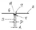
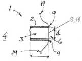
図面の図1および図2を参照すると、吸入器、特にeシガレット(図示せず)内で加熱される液体から蒸気を生成する加熱システム1の一実施形態が概略的に示されている。該液体は、プロピレン・グリコール、ベジタブル・グリセリン、および/または1つまたは複数のフレーバの溶液を含んでいてもよい。加熱システム1は、チャネル3の内部の毛管現象または表面張力下で、本体部材2に隣接した供給槽4から加熱される液体を運ぶために、複数の供給チャネル3が中に設けられているかまたは形成されている、本体部材2を含む。この場合、供給チャネル3の各々は毛細管を含み、複数の供給チャネル3は、直線または列に配置され、本体部材2の入口側または入口領域5から出口側または出口領域6まで、加熱される液体を運ぶ。この関連で、各供給チャネルまたは毛細管3は、約0.5mmから0.8mmまでの内径dを有し、入口側5の所の入口開口部7と出口側6の所の出口開口部8との間に延在している。 With reference to FIGS. 1 and 2 of the drawings, one embodiment of a
本体部材2の出口側6に形成されている、細長い溝部または陥凹部9が、供給チャネル3の各々の出口開口部8を横切るように延在しており、これらと連通、または相互接続している。毛細管3により槽4から運ばれる液体を気化するために、加熱手段10が、溝部9内に配置されるかまたは設置されるワイヤもしくはフィラメントなどの1つまたは複数の細長い発熱体11を含んで設けられている。この関連で、例えば、発熱体11は、0.05mmから0.3mmまで(例えば、約0.1mm)の範囲内の直径および約1アンペアから1.5アンペアまでの範囲内の電流に対して1ohmから5ohmまでの範囲の抵抗を有するワイヤ(例えば、ニクロム線またはカンタル(Kanthal)(商標)ワイヤ)を含んでいてもよい。溝部9は、毛細管3の出口開口部8の直径dより若干大きい幅Dを有する。加熱用ワイヤ11の両端12、13が、電気抵抗加熱のための、eシガレット(図示せず)内の電源に接続するために構成され、配置されている。したがって、加熱手段10は、各供給チャネル3の出口領域6内に配置され、これに閉じ込められ、液体が毛細管3の各々の出口開口部8から出現した時にこれを加熱し、気化するように構成されている。 An elongated groove or
図面の図3から図5までを参照すると、eシガレット(図示せず)内で加熱される液体から蒸気を生成する加熱システム1の別の実施形態が概略的に示されている。この場合、構造の原理は本質的に不変であるが、代替的構造において適用されている。詳細には、本体部材2は、約0.5mmから0.8mmまでの内径dを有する毛細管として形成されている、槽4から複数の供給チャネル3まで、加熱される液体を送達するための断続的送達チャネル14を含む。各供給チャネルまたは毛細管3が、本体部材の送達チャネル14の所の入口開口部7と出口側6の所の出口開口部8との間に延在している。本実施形態では、供給チャネル3は、各毛細管3の出口開口部8が本体部材2の半円形外縁上に存在するように、径方向配列に配置されている。溝部または陥凹部9は本体部材2の出口領域6内に形成され、供給チャネル3の各々の出口開口部8を横切るように延在しており、これと連通または相互接続している。また、加熱手段10が、溝部9内に配置または設置されている、ワイヤまたはフィラメントなどの1つまたは複数の細長い発熱体11を含んで設けられている。このようにして、加熱用ワイヤ11は、液体が各毛細管3の出口開口部8から出現した時にこれを加熱し、気化するように配置され、構成されている。通気キャップまたは通気ストッパ15が、送達チャネル14の端部に設置されるか、または設けられていてもよい。このキャップまたはストッパ15はガス透過性であり、槽4とのガス交換を可能にして、毛細管3を通る液体流を増強しながら、液体の漏出を防止することができる。 Referring to FIGS. 3 to 5 of the drawings, another embodiment of the
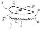
図面の図6および図7を参照すると、eシガレット内で加熱される液体から蒸気を生成する加熱システム1のさらなる実施形態が概略的に示されている。本実施形態では、前の実施形態の複数の毛細管は毛細スロットとして構成されている供給チャネル3に置き換えられている。より詳細には、本体部材2は、離間関係で互いに実質的に平行にかつ対向して配置され、これらの間にスロット様供給チャネル3を画定している一対のプレート要素16を含む。本体部材2のプレート要素16は、入口領域または入口端部5から出口領域または出口端部6まで延在しており、プレート要素16の側部17は閉鎖または封止されている。スロット様供給チャネル3の出口領域または出口端部6の所の各プレート要素16の縁部18は、出口開口部8に向かって面取りまたはテーパが付けられており、出口端部6においてプレート要素16により示される表面積を減少させている。これは、出口領域6においてプレート要素16の端面に対向する傾向を減少させて、加熱される液体の過剰量を収集または溜めるように作用する。 With reference to FIGS. 6 and 7 of the drawings, further embodiments of the
図6および図7の加熱システム1は、液体供給チャネル3の出口領域6に配置されている加熱手段10を含む。この関連で、電気抵抗加熱用ワイヤなどの蛇行発熱体11が、毛細スロット3の横方向に出口開口部8を横切るように延在している。前述の2つの実施形態の場合と同様に、発熱体11の両端12、13が、電気抵抗加熱のための、eシガレット(図示せず)内の電源に接続するために構成され、配置されている。この理由から、電気コネクタ19が発熱体11の両端部12、13の各々に設けられている。したがって、加熱手段10は、液体が供給チャネル3の出口開口部8から出現した時にこれを気化するために、供給チャネル3の出口領域6内に配置され、これに閉じ込められている。 The
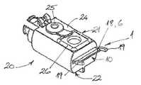
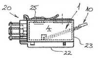
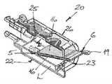
ここで、図面の図8a~図8cおよび図9を参照すると、図6および図7に示されている加熱システム1が電子たばこ30のカートリッジまたは槽アセンブリ20内にどのように含まれるかが例示されている。図9に示されるように、電子たばこ30は、略円筒形のケーシング31と、バッテリ・ユニットの形の電源33を収容または封入している第1の部分32とを有する。ケーシング31の第1の部分32は第2のケーシング部分34に連結され、該第2のケーシング部分34はカートリッジまたは槽アセンブリ20を収容または封入している。図8a~図8cに認められる通り、カートリッジ20は、eシガレット30の使用中に気化され、吸入されるある量の液体Lを保持または貯蔵する樽様の槽またはタンク4を封入しているハウジング21を含む。ハウジング21の基壁22に固定されている入口領域または入口端部5が液体Lの下に沈み、および/またはこれにより覆われると、プレート要素16が槽4内に延在するように、図6および図7の加熱システム1はカートリッジ20内に含まれている。出口領域または出口端部6および加熱手段10が第2のケーシング部分34の蒸気室35の内部に配置されるように、プレート要素16はハウジング21の端壁23から外へ斜角で上方に延在している。カートリッジ・ハウジング21の上面または上壁24が、弾性栓部材25により閉鎖され、封止される詰替え開口部を含む。さらに、ハウジング21の上面または上壁24は、ガス透過性膜を含み、槽4とのガス交換を可能にして、毛細スロット3を通る液体流を増強しながら、ここを通る液体の漏出を防止する通気キャップまたは通気弁26を含む。 Here, with reference to FIGS. 8a-8c and 9 of the drawings, it is exemplified how the
図9に認められる通り、ユーザがeシガレット30を利用するためにかつカートリッジ20内の加熱システム1により生成される蒸気を吸入するために、吸口36がケーシング31の第2の部分34の端部に設けられているかまたは接続されている。この関連で、一列の吸気孔37が、ユーザが吸口36を利用する時に、蒸気室35内へ吸気または空気の流入するために、第2のケーシング部分34に設けられている。液体Lは、蒸気室35内の供給チャネル3の出口6で加熱手段10により気化され、該蒸気は空気流中に引き込まれ、蒸気ガイド38および吸口36を介してユーザへ運ばれる。 As can be seen in FIG. 9, the
ここで図面の図10を参照すると、eシガレットなどの吸入器デバイス内で加熱される液体から蒸気を生成する加熱システム1の簡単な実施形態が概略的に示されている。加熱システム1は、毛管現象により、本体部材2に隣接した供給槽4から加熱される液体を運ぶ毛管チャネル3を画定している管(例えば、ガラス管)の形の本体部材2を含む。この場合、毛管チャネル3は約1.0mmの内径dを有し、供給槽4から出口側6の出口開口部8まで延在している。溝部または陥凹部9が出口開口部8の所の管2の端部に形成され、ワイヤまたはフィラメントなどの細長い発熱体11が配置または設置され、管状本体部材2に関連して溝部9内で融合され、加熱用ワイヤ11は出口開口部8の中央を横切るように横方向に延在している。 Here, with reference to FIG. 10 of the drawing, a simple embodiment of a
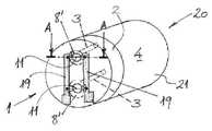
ここで図面の図11を参照すると、カートリッジまたは槽アセンブリ20の別の実施形態が概略的に示されている。本実施形態では、加熱システム1は、毛管現象により、本体部材2に隣接した供給槽4から加熱される液体を運ぶ2つの別個の異なる毛管チャネル3を画定しているディスク形本体部材2を含む。本実施形態では、槽4から液体を運ぶ毛管供給チャネル3の各々は、ワイヤまたはフィラメントなどのこれ自体の発熱体11を有する。矢印Aの方向に取った管3の各々の断面は、本質的に、図10に示されている例に対応する。発熱体11の各々は、一般的な制御および電力供給のための電気コネクタまたは給電リード線19により相互接続されている。発熱体11の各々は、各チャネル3の出口開口部8から出現する液体に対してより大きな表面積を示すために丸い断面またはあるいは平坦な断面を有していてもよい。さらに、各チャネル3の出口開口部8は、液体を溜める小ウェルを形成し、各それぞれの発熱体11に対してより大きな表面積を示す末広円錐表面8’で形成されていてもよい。 Here, with reference to FIG. 11 of the drawing, another embodiment of the cartridge or
最後に、図面の図12を参照すると、図1から図11までに関して前述されている、本発明の実施形態のいずれかによる、eシガレットなどの吸入器デバイス30内で、特に液体Lなどの物質を加熱する方法のステップを概略的に示す流れ図が示されている。この関連で、図12の第1のボックスiは、毛管現象または表面張力により、供給槽4から少なくとも1つの供給チャネル3および、あるいは複数の供給チャネル3を通して加熱される液体を運ぶステップを示す。第2のボックスiiは、次いで、液体が供給チャネル3の出口6から出現した時に各供給チャネル3の出口6で液体Lをもっぱら加熱して液体を気化するステップを示す。第3のボックスiiiは、ユーザによる吸入器デバイス30の使用に依存するように加熱するステップの起動を制御するステップを示す。図面の図12の最後のボックスivは、定期的にまたは断続的に、特にパルス状に、液体の加熱を実施する随意のステップを示す。 Finally, referring to FIG. 12 of the drawing, a substance such as a liquid L in the inhaler device 30 such as an e-cigarette according to any of the embodiments of the present invention described above with respect to FIGS. 1 to 11. A flow chart illustrating the steps of the method of heating is shown. In this regard, the first box i of FIG. 12 shows a step of carrying a liquid heated from a
本発明の特定の実施形態が本明細書において図示され、記載されているが、当業者には当然のことながら、様々な代替的なおよび/または等価の実装形態が存在する。例示的実施形態(単数または複数)が例に過ぎず、範囲、適用性または構造を限定することが全く意図されていないことは言うまでもない。むしろ、上述の要約および詳細な説明は、当業者に、少なくとも1つの例示的実施形態を実施するための重宝な手引きをもたらし、添付の特許請求の範囲およびこれらの法的均等物に記載されている範囲から逸脱することなく、例示的実施形態に記載されている要素の機能および配置に様々な変更が施されてもよいことが分かる。全般的に、本願は、本明細書において検討されている特定の実施形態のいかなる適応形態(adaptation)または変形形態も包含することが意図されている。 Although specific embodiments of the invention are illustrated and described herein, one of ordinary skill in the art will, of course, have various alternative and / or equivalent implementations. It goes without saying that the exemplary embodiments (s) are merely examples and are not intended to limit scope, applicability or structure at all. Rather, the above abstracts and detailed description provide those skilled in the art with useful guidance for implementing at least one exemplary embodiment and are described in the appended claims and their legal equivalents. It can be seen that various changes may be made to the function and arrangement of the elements described in the exemplary embodiments without departing from the scope. In general, the present application is intended to include any adaptation or variant of the particular embodiment considered herein.
また、当然のことながら、本文献において、用語「comprise(含む)」、「comprising(含む)」、「include(含む)」、「including(含む)」、「contain(含有する)」、「containing(含有する)」、「have(有する)」、「having(有する)」およびこれらの任意の変形は、本明細書に記載されている工程、方法、デバイス、装置またはシステムが、記載されている特徴または部分または要素またはステップに限定されず、明示的に列挙されていないかまたはこのような工程、方法、物品または装置に固有の他の要素、特徴、部分またはステップを含むように、包括的な(すなわち非排他的な)意味で理解されることが意図されている。さらに、本明細書において用いられている用語「a」および「an」は、特に明記されていない限り、「1つまたは複数の」の意味で理解されることが意図されている。
さらに、用語「第1の」、「第2の」、「第3の」等は単に標示として用いられているに過ぎず、数的要件を課すことまたはこれらの対象の重要性の一定の序列を確立することは意図されていない。Also, as a matter of course, in this document, the terms "comprise", "comprising", "include", "include", "contain", and "contining" are used. "Contains", "have", "have" and any modifications thereof describe the steps, methods, devices, devices or systems described herein. Comprehensive, not limited to features or parts or elements or steps, but not explicitly listed or to include other elements, features, parts or steps specific to such steps, methods, articles or devices. It is intended to be understood in a non-exclusive sense. Further, the terms "a" and "an" as used herein are intended to be understood in the sense of "one or more" unless otherwise specified.
Moreover, the terms "first", "second", "third", etc. are merely used as markings and impose numerical requirements or a certain order of importance of these objects. Is not intended to be established.
1 加熱システム
2 本体部材
3 供給チャネルまたは毛細管もしくは毛細スロット
4 槽
5 入口側または入口領域
6 出口側または出口領域
7 入口開口部
8 出口開口部
8’ 円錐表面
9 溝部または陥凹部
10 加熱手段
11 発熱体または加熱用ワイヤ
12 発熱体の端部
13 発熱体の端部
14 送達チャネル
15 通気キャップまたは通気ストッパ
16 プレート要素
17 プレート要素の側部
18 プレート要素の面取り縁部またはテーパ縁部
19 電気コネクタ
20 カートリッジまたは槽アセンブリ
21 カートリッジ・ハウジング
22 ハウジングの基壁
23 ハウジングの端壁
24 ハウジングの上面または壁
25 栓部材
26 通気キャップまたは通気弁
30 電子たばこ
31 ケーシング
32 第1のケーシング部分
33 電源またはバッテリ・ユニット
34 第2のケーシング部分
35 蒸気室
36 吸口
37 吸気口
38 クランプ留めリングまたは蒸気ガイド
D 溝部または陥凹部の幅
d 出口開口部の直径
L 加熱される液体1
Claims (18)
Translated fromJapaneseその内部の毛管現象または表面張力下で、供給槽(4)から加熱される液体を運ぶ、少なくとも1つの供給チャネル(3)と、
前記少なくとも1つの供給チャネル(3)の出口(6)に配置または設置されている加熱手段(10)と、を含み、
前記少なくとも1つの供給チャネル(3)は、前記供給槽(4)から前記エアロゾルまたは前記蒸気が吸入される前記吸入器デバイス(30)内の蒸気室(35)まで延在するように構成されている本体部材(2)内に形成され、
前記供給チャネル(3)は、プレート要素(16)により形成された毛細スロットとして構成されている、加熱システム(1)。A heating system (1) for an inhaler device (30), such as an e-cigarette or personal vaporizer, for producing an aerosol or vapor from a heated liquid (L).
With at least one supply channel (3) carrying the liquid heated from the supply tank (4) under capillarity or surface tension within it.
The heating means (10) arranged or installed at the outlet (6) of the at least one supply channel (3) includes.
The at least one supply channel (3) is configured to extend from the supply tank (4) to the steam chamber (35) in the inhaler device (30) into which the aerosol or vapor is sucked. It is formed in the main body member (2) and is
The heating system (1), wherein the supply channel (3) is configured as a capillary slot formed by a plate element (16).
前記少なくとも1つの発熱体(11)は、導電性ワイヤ、導電性ストリップ、導電性フォイル、もしくは導電性被覆材の1つもしくは複数を好ましくは含み、
前記導電性ストリップ、前記導電性フォイル、または前記導電性被覆材は、好ましくは前記供給チャネル(3)の前記出口開口部(8)の周囲に層または被覆として設けられる、請求項4に記載の加熱システム(1)。The heating means (10) is substantially confined to the outlet (6) of the supply channel (3) and / or the at least one heating element (11) is a conductive wire, a conductive strip, and the like. It preferably comprises one or more of the conductive foil, or the conductive coating material.
4. The fourth aspect of the present invention, wherein the conductive strip, the conductive foil, or the conductive coating material is preferably provided as a layer or coating around the outlet opening (8) of the supply channel (3). Heating system (1).
前記加熱手段は、前記各供給チャネル(3)の前記出口(6)に配置され、前記液体が前記各供給チャネル(3)の該出口(6)から出現した時にこれを加熱するように構成されている、請求項3から5のいずれか一項に記載の加熱システム(1)。It comprises a plurality of supply channels (3) carrying the liquid (L) to be heated under capillarity or surface tension.
The heating means is arranged at the outlet (6) of each supply channel (3) and is configured to heat the liquid when it emerges from the outlet (6) of each supply channel (3). The heating system (1) according to any one of claims 3 to 5.
前記溝部または前記陥凹部(9)は、好ましくは前記供給チャネルの長手方向範囲に対して横方向に延在している、請求項1から6のいずれか一項に記載の加熱システム(1)。The main body member (2) includes a groove or a recess (9) at the outlet (6) of each supply channel (3) to accommodate the heating element (11).
The heating system (1) according to any one of claims 1 to 6, wherein the groove or the recess (9) preferably extends laterally with respect to the longitudinal range of the supply channel. ..
前記吸入器デバイスは、請求項1から10のいずれか一項に記載の加熱システム(1)を含む、吸入器デバイス(30)。An inhaler device (30), such as an electronic cigarette or personal vaporizer device, for producing aerosols and / or vapors from a heated liquid or gel.
The inhaler device (30) includes the heating system (1) according to any one of claims 1 to 10.
毛管現象または表面張力により、供給槽(4)から少なくとも1つの供給チャネル(3)を通して、加熱される前記物質を運ぶステップと、
該物質を加熱するステップと、を含み、
前記供給チャネル(3)は、プレート要素(16)により形成された毛細スロットとして構成されている、方法。A method of heating a substance, especially a liquid or gel, in an inhaler device (30) such as an e-cigarette or personal vaporizer.
A step of carrying the substance heated from the supply tank (4) through at least one supply channel (3) by capillarity or surface tension.
Including the step of heating the material,
The method, wherein the supply channel (3) is configured as a capillary slot formed by a plate element (16).
前記加熱システム(1)は、前記ハウジング(21)の基壁(22)に固定されている入口領域または入口端部(5)が液体(L)の下に沈み、および/またはこれにより覆われると、前記プレート要素(16)が前記供給槽(4)内に延在するように、カートリッジ(20)内に含まれている、請求項14に記載のカートリッジ(20)。The cartridge (20) includes a housing 21 that encloses the supply tank (4) that retains or stores a certain amount of liquid (L) that is vaporized and inhaled during use of the inhaler device (30). Including,
In the heating system (1), the inlet region or inlet end (5) fixed to the base wall (22) of the housing (21) sinks under and / or is covered by the liquid (L). The cartridge (20) according to claim 14, wherein the plate element (16) is included in the cartridge (20) so as to extend into the supply tank (4).
Applications Claiming Priority (3)
| Application Number | Priority Date | Filing Date | Title |
|---|---|---|---|
| EP15197837 | 2015-12-03 | ||
| EP15197837.6 | 2015-12-03 | ||
| JP2020127190AJP7059325B2 (en) | 2015-12-03 | 2020-07-28 | Heating system and heating method for inhaler devices |
Related Parent Applications (1)
| Application Number | Title | Priority Date | Filing Date |
|---|---|---|---|
| JP2020127190ADivisionJP7059325B2 (en) | 2015-12-03 | 2020-07-28 | Heating system and heating method for inhaler devices |
Publications (1)
| Publication Number | Publication Date |
|---|---|
| JP2022084742Atrue JP2022084742A (en) | 2022-06-07 |
Family
ID=54780217
Family Applications (3)
| Application Number | Title | Priority Date | Filing Date |
|---|---|---|---|
| JP2018529047AExpired - Fee RelatedJP6742414B2 (en) | 2015-12-03 | 2016-12-02 | Heating system and heating method for an inhaler device |
| JP2020127190AActiveJP7059325B2 (en) | 2015-12-03 | 2020-07-28 | Heating system and heating method for inhaler devices |
| JP2022038826APendingJP2022084742A (en) | 2015-12-03 | 2022-03-14 | Heating system and heating method for inhaler devices |
Family Applications Before (2)
| Application Number | Title | Priority Date | Filing Date |
|---|---|---|---|
| JP2018529047AExpired - Fee RelatedJP6742414B2 (en) | 2015-12-03 | 2016-12-02 | Heating system and heating method for an inhaler device |
| JP2020127190AActiveJP7059325B2 (en) | 2015-12-03 | 2020-07-28 | Heating system and heating method for inhaler devices |
Country Status (8)
| Country | Link |
|---|---|
| US (1) | US12193501B2 (en) |
| EP (2) | EP3574782A3 (en) |
| JP (3) | JP6742414B2 (en) |
| CN (2) | CN108430242B (en) |
| EA (2) | EA039935B1 (en) |
| ES (1) | ES2751382T3 (en) |
| PL (1) | PL3364797T3 (en) |
| WO (1) | WO2017093535A1 (en) |
Families Citing this family (57)
| Publication number | Priority date | Publication date | Assignee | Title |
|---|---|---|---|---|
| US20160345631A1 (en) | 2005-07-19 | 2016-12-01 | James Monsees | Portable devices for generating an inhalable vapor |
| US10279934B2 (en) | 2013-03-15 | 2019-05-07 | Juul Labs, Inc. | Fillable vaporizer cartridge and method of filling |
| USD842536S1 (en) | 2016-07-28 | 2019-03-05 | Juul Labs, Inc. | Vaporizer cartridge |
| US10159282B2 (en) | 2013-12-23 | 2018-12-25 | Juul Labs, Inc. | Cartridge for use with a vaporizer device |
| US20160366947A1 (en) | 2013-12-23 | 2016-12-22 | James Monsees | Vaporizer apparatus |
| USD825102S1 (en) | 2016-07-28 | 2018-08-07 | Juul Labs, Inc. | Vaporizer device with cartridge |
| US10076139B2 (en) | 2013-12-23 | 2018-09-18 | Juul Labs, Inc. | Vaporizer apparatus |
| US10058129B2 (en) | 2013-12-23 | 2018-08-28 | Juul Labs, Inc. | Vaporization device systems and methods |
| DE202014011260U1 (en) | 2013-12-23 | 2018-11-13 | Juul Labs Uk Holdco Limited | Systems for an evaporation device |
| MX394125B (en) | 2014-12-05 | 2025-03-24 | Juul Labs Inc | CALIBRATED DOSE CONTROL |
| US12193501B2 (en)* | 2015-12-03 | 2025-01-14 | Jt International S.A. | Heating system and method for an inhaler device |
| CO2018009342A2 (en) | 2016-02-11 | 2018-09-20 | Juul Labs Inc | Secure fixing cartridges for vaporizing devices |
| EP3413960B1 (en) | 2016-02-11 | 2021-03-31 | Juul Labs, Inc. | Fillable vaporizer cartridge and method of filling |
| US10405582B2 (en) | 2016-03-10 | 2019-09-10 | Pax Labs, Inc. | Vaporization device with lip sensing |
| KR102720307B1 (en) | 2016-03-31 | 2024-10-22 | 필립모리스 프로덕츠 에스.에이. | Atomizing assembly for an aerosol generating system, an aerosol generating system comprising the same, and a method for generating an aerosol |
| US10440996B2 (en)* | 2016-03-31 | 2019-10-15 | Altria Client Services Llc | Atomizing assembly for use in an aerosol-generating system |
| USD849996S1 (en) | 2016-06-16 | 2019-05-28 | Pax Labs, Inc. | Vaporizer cartridge |
| USD836541S1 (en) | 2016-06-23 | 2018-12-25 | Pax Labs, Inc. | Charging device |
| USD851830S1 (en) | 2016-06-23 | 2019-06-18 | Pax Labs, Inc. | Combined vaporizer tamp and pick tool |
| US11660403B2 (en) | 2016-09-22 | 2023-05-30 | Juul Labs, Inc. | Leak-resistant vaporizer device |
| KR102593862B1 (en) | 2016-12-27 | 2023-10-24 | 쥴 랩스, 인크. | Thermal Wick for Electronic Vaporizers |
| GB2561867B (en) | 2017-04-25 | 2021-04-07 | Nerudia Ltd | Aerosol delivery system |
| USD887632S1 (en) | 2017-09-14 | 2020-06-16 | Pax Labs, Inc. | Vaporizer cartridge |
| DE102017123867A1 (en)* | 2017-10-13 | 2019-04-18 | Hauni Maschinenbau Gmbh | Inhaler, in particular electronic cigarette product, and computer program product |
| DE102017123866A1 (en) | 2017-10-13 | 2019-04-18 | Hauni Maschinenbau Gmbh | Inhaler, in particular electronic cigarette product |
| DE102017123869B4 (en) | 2017-10-13 | 2019-05-23 | Hauni Maschinenbau Gmbh | Liquid storage for an inhaler, in particular for an electronic cigarette product |
| CN110313642B (en)* | 2018-03-30 | 2024-07-23 | 上海新型烟草制品研究院有限公司 | Atomizer core structure and electronic cigarette |
| CN209346085U (en)* | 2018-05-04 | 2019-09-06 | 深圳麦克韦尔科技有限公司 | Electronic cigarette and its atomising device |
| KR20250117466A (en) | 2018-05-31 | 2025-08-04 | 필립모리스 프로덕츠 에스.에이. | Heater assembly with pierced transport material |
| EP3813914B1 (en) | 2018-06-26 | 2023-10-25 | Juul Labs, Inc. | Vaporizer wicking elements |
| CN110754696A (en) | 2018-07-23 | 2020-02-07 | 尤尔实验室有限公司 | Airflow management for evaporator units |
| SG11202103757VA (en) | 2018-10-15 | 2021-05-28 | Juul Labs Inc | Heating element |
| US12256784B2 (en) | 2018-10-17 | 2025-03-25 | Juul Labs, Inc. | Cartridge for a vaporizer device |
| IE20190173A1 (en)* | 2018-10-17 | 2021-02-03 | Juul Labs Inc | Cartridge for a vaporizer device |
| GB2613472B (en) | 2018-10-19 | 2023-09-06 | Juul Labs Inc | Vaporizer power system |
| JP7660503B2 (en) | 2018-11-05 | 2025-04-11 | ジュール・ラブズ・インコーポレイテッド | Cartridges for vaporizer devices |
| GB201818270D0 (en)* | 2018-11-09 | 2018-12-26 | Nicoventures Trading Ltd | Component for a vapour provision system |
| CN111358058A (en)* | 2018-12-26 | 2020-07-03 | 常州市派腾电子技术服务有限公司 | Battery case, electronic cigarette and assembling method |
| US11253001B2 (en) | 2019-02-28 | 2022-02-22 | Juul Labs, Inc. | Vaporizer device with vaporizer cartridge |
| EP3930494A2 (en)* | 2019-02-28 | 2022-01-05 | Juul Labs, Inc. | Cartridge for a vaporizer device |
| GB201903538D0 (en) | 2019-03-15 | 2019-05-01 | Nicoventures Trading Ltd | Atomiser enclosure for a vapour provision system |
| GB201903537D0 (en) | 2019-03-15 | 2019-05-01 | Nicoventures Trading Ltd | Flow directing member for a vapour provision system |
| WO2020205561A1 (en) | 2019-03-29 | 2020-10-08 | Juul Labs, Inc. | Cartridges for vaporizer devices |
| CN114390898A (en)* | 2019-08-30 | 2022-04-22 | 日本烟草国际股份有限公司 | Vaporizer for electronic cigarette |
| WO2021037805A1 (en)* | 2019-08-30 | 2021-03-04 | Jt International Sa | Cartridge for an electronic cigarette |
| JP2022546262A (en)* | 2019-08-30 | 2022-11-04 | ジェイティー インターナショナル エス.エイ. | e-cigarette vaporizer |
| WO2021076657A2 (en)* | 2019-10-14 | 2021-04-22 | Juul Labs, Inc. | Vaporizer device microfluidic systems and apparatuses |
| EP4061157B1 (en)* | 2019-11-21 | 2024-01-03 | JT International SA | Electronic cigarette |
| EP4151100A4 (en)* | 2020-05-12 | 2023-10-25 | Shenzhen Smoore Technology Limited | Atomizer, and electronic atomization device thereof |
| US20210401052A1 (en)* | 2020-06-24 | 2021-12-30 | Vuber Technologies, Llc | Vaporization device using frustal porous vaporization media |
| US20210410231A1 (en)* | 2020-06-29 | 2021-12-30 | Shenzhen Eigate Technology Co., Ltd. | Heater |
| US20210410230A1 (en)* | 2020-06-29 | 2021-12-30 | Shenzhen Eigate Technology Co., Ltd. | Heater |
| WO2022023135A1 (en)* | 2020-07-29 | 2022-02-03 | Jt International Sa | Evaporator assembly |
| JP6837594B1 (en)* | 2020-09-30 | 2021-03-03 | 日本たばこ産業株式会社 | Aerosol aspirator power supply unit and aerosol aspirator |
| KR20240126858A (en)* | 2021-12-20 | 2024-08-21 | 필립모리스 프로덕츠 에스.에이. | Replaceable cartridge with capillary tube |
| GB202217022D0 (en)* | 2022-11-15 | 2022-12-28 | Nicoventures Trading Ltd | Heater assembly and method |
| GB202315679D0 (en)* | 2023-10-12 | 2023-11-29 | Nicoventures Trading Ltd | Article for an aerosol provision system |
Citations (9)
| Publication number | Priority date | Publication date | Assignee | Title |
|---|---|---|---|---|
| US6155268A (en)* | 1997-07-23 | 2000-12-05 | Japan Tobacco Inc. | Flavor-generating device |
| JP2005511178A (en)* | 2001-12-06 | 2005-04-28 | クリサリス テクノロジーズ インコーポレイテッド | Aerosol generator having a heater arranged to vaporize fluid in a fluid path between joined layers of a laminate |
| KR200470732Y1 (en)* | 2012-05-14 | 2014-01-08 | 주식회사 손엔 | Vaporizing and inhaling apparatus and vaporizing member applied the vaporizing and inhaling apparatus |
| EP2764783A1 (en)* | 2013-02-11 | 2014-08-13 | Ewwk Ug | Electronic cigarette or pipe |
| CN104287098A (en)* | 2014-10-21 | 2015-01-21 | 朱晓春 | Heating component for electronic cigarette atomizer |
| CN104323432A (en)* | 2014-11-25 | 2015-02-04 | 朱晓春 | Heating device of electronic cigarette atomizer |
| CN104661338A (en)* | 2015-02-12 | 2015-05-27 | 颐中(青岛)实业有限公司 | Heating device of electronic cigarette atomizer |
| CN204483035U (en)* | 2015-04-01 | 2015-07-22 | 湖北中烟工业有限责任公司 | Porous ceramics atomizer and there is the electronic cigarette of this porous ceramics atomizer |
| US20160262454A1 (en)* | 2015-03-10 | 2016-09-15 | R.J. Reynolds Tobacco Company | Aerosol delivery device with microfluidic delivery component |
Family Cites Families (28)
| Publication number | Priority date | Publication date | Assignee | Title |
|---|---|---|---|---|
| US5666977A (en)* | 1993-06-10 | 1997-09-16 | Philip Morris Incorporated | Electrical smoking article using liquid tobacco flavor medium delivery system |
| US7726320B2 (en) | 2006-10-18 | 2010-06-01 | R. J. Reynolds Tobacco Company | Tobacco-containing smoking article |
| MX344758B (en)* | 2009-10-09 | 2017-01-05 | Philip Morris Products Sa | Aerosol generator including multi-component wick. |
| EP2319334A1 (en)* | 2009-10-27 | 2011-05-11 | Philip Morris Products S.A. | A smoking system having a liquid storage portion |
| KR101246816B1 (en)* | 2011-03-09 | 2013-03-26 | 이영인 | Supplying Block for Supplying Nicotine Solution in Electric Cigarette |
| PL2719416T3 (en)* | 2011-08-19 | 2017-11-30 | Japan Tobacco Inc. | Aerosol inhaler |
| AT511344B1 (en)* | 2011-10-21 | 2012-11-15 | Helmut Dr Buchberger | INHALATORKOMPONENTE |
| US9854839B2 (en)* | 2012-01-31 | 2018-01-02 | Altria Client Services Llc | Electronic vaping device and method |
| GB2504077A (en)* | 2012-07-16 | 2014-01-22 | Nicoventures Holdings Ltd | Electronic smoking device |
| US8881737B2 (en)* | 2012-09-04 | 2014-11-11 | R.J. Reynolds Tobacco Company | Electronic smoking article comprising one or more microheaters |
| PT2892370T (en) | 2012-09-10 | 2017-02-10 | Ght Global Heating Tech Ag | Device for vaporizing liquid for inhalation |
| US10154691B2 (en)* | 2012-11-26 | 2018-12-18 | Nu Mark Innovations Ltd. | Bonding for an electronic cigarette cartridge |
| CA2890204C (en)* | 2012-11-28 | 2022-04-05 | E-Nicotine Technology, Inc. | Methods and devices for compound delivery |
| US10031183B2 (en) | 2013-03-07 | 2018-07-24 | Rai Strategic Holdings, Inc. | Spent cartridge detection method and system for an electronic smoking article |
| RU2677617C1 (en)* | 2013-12-11 | 2019-01-17 | Джт Интернэшнл С.А. | Heating system and method of heating for inhaler device |
| US20150216237A1 (en)* | 2014-01-22 | 2015-08-06 | E-Nicotine Technology, Inc. | Methods and devices for smoking urge relief |
| GB201401524D0 (en)* | 2014-01-29 | 2014-03-12 | Batmark Ltd | Aerosol-forming member |
| US20150216234A1 (en)* | 2014-02-06 | 2015-08-06 | Esquire Properties Trading Inc. | Electronic cigarette |
| DE102014106589A1 (en)* | 2014-05-09 | 2015-11-12 | Aie Investments S.A. | Electric cigarette |
| BR112017010106A2 (en) | 2014-11-17 | 2018-01-02 | Mcneil Ab | disposable cartridge for use in an electronic nicotine release system |
| AR103016A1 (en)* | 2014-12-15 | 2017-04-12 | Philip Morris Products Sa | AEROSOL GENERATOR SYSTEMS AND METHODS FOR DIRECTING AN AIR FLOW TOWARDS AN ELECTRIC HEATED AEROSOL GENERATOR SYSTEM |
| US10258085B2 (en)* | 2015-05-14 | 2019-04-16 | Westfield Limited (Ltd.) | System and method for vaporizing fluids by combustion |
| WO2016198417A1 (en)* | 2015-06-12 | 2016-12-15 | Philip Morris Products S.A. | Cartridge for aerosol-generating system |
| PL3127441T3 (en)* | 2015-08-06 | 2019-06-28 | Fontem Holdings 1 B.V. | Electronic smoking device with a glass capillary tube |
| US12193501B2 (en)* | 2015-12-03 | 2025-01-14 | Jt International S.A. | Heating system and method for an inhaler device |
| US10463077B2 (en)* | 2016-06-24 | 2019-11-05 | Altria Client Services Llc | Cartridge for e-vaping device with open-microchannels |
| JP6837594B1 (en)* | 2020-09-30 | 2021-03-03 | 日本たばこ産業株式会社 | Aerosol aspirator power supply unit and aerosol aspirator |
| WO2022189579A1 (en)* | 2021-03-12 | 2022-09-15 | Philip Morris Products S.A. | Aerosol-generating arrangement for generating an inhalable aerosol from an aerosol-forming liquid |
- 2016
- 2016-12-02USUS15/780,933patent/US12193501B2/enactiveActive
- 2016-12-02JPJP2018529047Apatent/JP6742414B2/ennot_activeExpired - Fee Related
- 2016-12-02CNCN201680070744.8Apatent/CN108430242B/enactiveActive
- 2016-12-02EAEA202091892Apatent/EA039935B1/enunknown
- 2016-12-02EPEP19186435.4Apatent/EP3574782A3/ennot_activeWithdrawn
- 2016-12-02WOPCT/EP2016/079670patent/WO2017093535A1/ennot_activeCeased
- 2016-12-02EPEP16806064.8Apatent/EP3364797B1/enactiveActive
- 2016-12-02PLPL16806064Tpatent/PL3364797T3/enunknown
- 2016-12-02ESES16806064Tpatent/ES2751382T3/enactiveActive
- 2016-12-02CNCN202210244898.1Apatent/CN114587024A/enactivePending
- 2016-12-02EAEA201891276Apatent/EA036457B1/ennot_activeIP Right Cessation
- 2020
- 2020-07-28JPJP2020127190Apatent/JP7059325B2/enactiveActive
- 2022
- 2022-03-14JPJP2022038826Apatent/JP2022084742A/enactivePending
Patent Citations (10)
| Publication number | Priority date | Publication date | Assignee | Title |
|---|---|---|---|---|
| US6155268A (en)* | 1997-07-23 | 2000-12-05 | Japan Tobacco Inc. | Flavor-generating device |
| JP2005511178A (en)* | 2001-12-06 | 2005-04-28 | クリサリス テクノロジーズ インコーポレイテッド | Aerosol generator having a heater arranged to vaporize fluid in a fluid path between joined layers of a laminate |
| KR200470732Y1 (en)* | 2012-05-14 | 2014-01-08 | 주식회사 손엔 | Vaporizing and inhaling apparatus and vaporizing member applied the vaporizing and inhaling apparatus |
| EP2764783A1 (en)* | 2013-02-11 | 2014-08-13 | Ewwk Ug | Electronic cigarette or pipe |
| CN104287098A (en)* | 2014-10-21 | 2015-01-21 | 朱晓春 | Heating component for electronic cigarette atomizer |
| CN104323432A (en)* | 2014-11-25 | 2015-02-04 | 朱晓春 | Heating device of electronic cigarette atomizer |
| CN104661338A (en)* | 2015-02-12 | 2015-05-27 | 颐中(青岛)实业有限公司 | Heating device of electronic cigarette atomizer |
| US20160262454A1 (en)* | 2015-03-10 | 2016-09-15 | R.J. Reynolds Tobacco Company | Aerosol delivery device with microfluidic delivery component |
| JP2018509158A (en)* | 2015-03-10 | 2018-04-05 | アール・エイ・アイ・ストラテジック・ホールディングス・インコーポレイテッド | Aerosol delivery device comprising a microfluidic delivery component |
| CN204483035U (en)* | 2015-04-01 | 2015-07-22 | 湖北中烟工业有限责任公司 | Porous ceramics atomizer and there is the electronic cigarette of this porous ceramics atomizer |
Also Published As
| Publication number | Publication date |
|---|---|
| WO2017093535A1 (en) | 2017-06-08 |
| US20180343922A1 (en) | 2018-12-06 |
| EP3574782A2 (en) | 2019-12-04 |
| EP3364797A1 (en) | 2018-08-29 |
| EA036457B1 (en) | 2020-11-12 |
| JP2019503668A (en) | 2019-02-14 |
| EA201891276A1 (en) | 2018-10-31 |
| JP7059325B2 (en) | 2022-04-25 |
| CN108430242B (en) | 2022-03-29 |
| JP2020185006A (en) | 2020-11-19 |
| US12193501B2 (en) | 2025-01-14 |
| EA202091892A2 (en) | 2020-11-30 |
| EP3574782A3 (en) | 2020-01-22 |
| EP3364797B1 (en) | 2019-08-28 |
| PL3364797T3 (en) | 2020-03-31 |
| EA202091892A3 (en) | 2020-12-30 |
| ES2751382T3 (en) | 2020-03-31 |
| JP6742414B2 (en) | 2020-08-19 |
| CN108430242A (en) | 2018-08-21 |
| CN114587024A (en) | 2022-06-07 |
| EA039935B1 (en) | 2022-03-30 |
Similar Documents
| Publication | Publication Date | Title |
|---|---|---|
| JP7059325B2 (en) | Heating system and heating method for inhaler devices | |
| JP7323132B2 (en) | Electronic aerosol delivery system and vaporizer for electronic aerosol delivery system | |
| JP7054676B2 (en) | Aerosol generation system with pump | |
| KR102010104B1 (en) | An aerosol generating device with air flow nozzles | |
| RU2600092C2 (en) | Aerosol generating device with internal heater | |
| JP2021141896A (en) | Cartridge for aerosol generation system | |
| KR102689966B1 (en) | Aerosol provision system | |
| EP3167729B1 (en) | Electronic vapour provision device | |
| US20250311779A1 (en) | Aerosol source for a vapor provision system | |
| CN108135272A (en) | Electrical smoking device with capillary glass tube | |
| CN216147222U (en) | Atomizer and electronic atomization device | |
| JP2022519511A (en) | Steam supply system | |
| JP6928658B2 (en) | Aerosol generation system with fluid sensor | |
| CN113395912A (en) | Consumable unit, inhaler and method of manufacture | |
| RU2846974C2 (en) | Heater assembly for aerosol-generating system | |
| RU2805500C2 (en) | Aerosol generating device, cartridge and aerosol generating system |
Legal Events
| Date | Code | Title | Description |
|---|---|---|---|
| A521 | Request for written amendment filed | Free format text:JAPANESE INTERMEDIATE CODE: A523 Effective date:20220413 | |
| A621 | Written request for application examination | Free format text:JAPANESE INTERMEDIATE CODE: A621 Effective date:20220413 | |
| A131 | Notification of reasons for refusal | Free format text:JAPANESE INTERMEDIATE CODE: A131 Effective date:20230105 | |
| A02 | Decision of refusal | Free format text:JAPANESE INTERMEDIATE CODE: A02 Effective date:20230725 |