JP2022084254A - Vaporizer - Google Patents
VaporizerDownload PDFInfo
- Publication number
- JP2022084254A JP2022084254AJP2020195996AJP2020195996AJP2022084254AJP 2022084254 AJP2022084254 AJP 2022084254AJP 2020195996 AJP2020195996 AJP 2020195996AJP 2020195996 AJP2020195996 AJP 2020195996AJP 2022084254 AJP2022084254 AJP 2022084254A
- Authority
- JP
- Japan
- Prior art keywords
- vaporizer
- raw material
- liquid raw
- vaporization
- heater
- Prior art date
- Legal status (The legal status is an assumption and is not a legal conclusion. Google has not performed a legal analysis and makes no representation as to the accuracy of the status listed.)
- Granted
Links
Images


Landscapes
- Formation Of Insulating Films (AREA)
Abstract
Translated fromJapaneseDescription
Translated fromJapanese本発明は大量の液体原料を効率よく気化することが出来る気化器に関する。 The present invention relates to a vaporizer capable of efficiently vaporizing a large amount of liquid raw materials.
SiやSiCなど半導体材料の熱酸化手法としてウェット酸化とドライ酸化がある。ウェット酸化では水を使う。H2Oをガス(水蒸気)として炉の中に流して水の中の酸素を酸化膜の成長に使う。ウェット酸化の特徴は酸化速度が速いことである。従って厚い膜厚が必要な場合にはこの方法を使う。一方、ドライ酸化は酸化膜成長に酸素ガスを使う。これはウェット酸化の反対で酸化膜の成長速度は遅い。近年、更に酸化膜の成長速度を上げるために、水(H2O)の代わりに過酸化水素(H2O2)が使用されるようになってきた。他方、半導体以外の用途として、光導波路の形成がある。(特許文献1を参照)。この場合、10~25μmの厚さの二酸化ケイ素(SiO2)の堆積には、H2Oによる酸化法では、長時間の堆積時間を必要とする。H2Oの代わりに過酸化水素(H2O2)を利用すれば、大幅な時間短縮が可能となる。There are wet oxidation and dry oxidation as thermal oxidation methods for semiconductor materials such as Si and SiC. Water is used for wet oxidation.H2O is flowed into the furnace as gas (water vapor) and oxygen in water is used for the growth of the oxide film. The characteristic of wet oxidation is that the oxidation rate is high. Therefore, this method is used when a thick film thickness is required. On the other hand, dry oxidation uses oxygen gas for oxide film growth. This is the opposite of wet oxidation, and the growth rate of the oxide film is slow. In recent years, hydrogen peroxide (H2 O2 ) has come to be used instead of water (H2 O) in order to further increase the growth rate of the oxide film. On the other hand, applications other than semiconductors include the formation of optical waveguides. (See Patent Document 1). In this case, the deposition of silicon dioxide (SiO2 ) having a thickness of 10 to 25 μm requires a long deposition time in the oxidation method usingH2O . If hydrogen peroxide (H2 O2 ) is used instead of H2 O, a significant time reduction can be achieved.
そのためには大量の過酸化水素水を気化させて反応炉に送り込む必要がある。このような目的の装置として特許文献1に示すような装置が提案されている。
特許文献1に記載された、過酸化水素水を気化させて酸化性ガスを発生させる気化器は、過酸化水素水の入ったフラスコに似た中空球状容器の気化器の下半分を外からヒーター部で覆うもので、中空球状容器は100~130℃に加熱され、気化した過酸化水素ガスの含有された水蒸気が、ガス供給管を経て反応炉に流れ込むようになっている。この装置は過酸化水素水を単に加熱して気化させているもので、気化器内での過酸化水素水の蒸発と共に、過酸化水素の濃度が変化するだけでなく、気化効率が悪いことが欠点である。For that purpose, it is necessary to vaporize a large amount of hydrogen peroxide solution and send it to the reactor. As an apparatus for such a purpose, an apparatus as shown in
The vaporizer described in
そこで特許文献1に記載した気化器に比べて気化効率が遥かに優れた気化器が提案された(特許文献2)。
特許文献2に記載された気化器は、液体原料を霧化して吹き出すアトマイザと、このアトマイザの噴霧口が開口する中空のアウターチューブと、アウターチューブ内に収納され、前記アトマイザの噴霧口とその先端部分との間に霧化空間が形成されたインナーチューブと、アウターチューブの外側に設けられたアウターヒーター部と、インナーチューブの内側に設けられたインナーヒーター部とで構成されている。そして、アウターチューブの内周面とインナーチューブの外側面との間に前記霧化空間に連通し、この隙間を通過する間に加熱されてガス化された気化ガスを次工程に送出する気化用間隙が設けられている。Therefore, a vaporizer having far superior vaporization efficiency as compared with the vaporizer described in
The vaporizer described in Patent Document 2 is housed in an atomizer that atomizes and blows out a liquid raw material, a hollow outer tube through which the atomizer spray port opens, and the atomizer spray port and its tip. It is composed of an inner tube in which an atomized space is formed between the portions, an outer heater portion provided on the outside of the outer tube, and an inner heater portion provided on the inside of the inner tube. Then, for vaporization, the vaporized gas that communicates with the atomized space between the inner peripheral surface of the outer tube and the outer surface of the inner tube and is heated and gasified while passing through this gap is sent to the next step. There is a gap.
この気化器では、霧化された液体原料が上記気化用間隙を通過する間にインナーチューブとアウターチューブを介してインナーヒーター部とアウターヒーター部からの熱を受けて気化し、次工程に送り出されるようになっている。 In this vaporizer, the atomized liquid raw material is vaporized by receiving heat from the inner heater section and the outer heater section via the inner tube and the outer tube while passing through the vaporization gap, and is sent to the next process. It has become like.
処が最近、気化ガスの使用量の増加から液体原料の流量増加が要求されるようになってきた。そこで、気化用間隙を通過する霧化液体原料に対してより多くの熱量を伝達するようにすればよいのであるが、気化用間隙の幅は、気化効率の面から高い熱伝達率を有する温度境界層が形成される範囲とされている。即ち、気化用間隙を流れる通流気体の温度は、インナーチューブの外周面又はアウターチューブの内周面の壁面から離れるに従って流体温度が次第に下がり、或る温度で一定の温度(一様流温度)になる。壁面から一定の温度になる範囲が温度境界層であり、上記気化用間隙の幅は最大でインナーチューブとアウターチューブの温度境界層の和の範囲に設定されている。 Recently, however, there has been a demand for an increase in the flow rate of liquid raw materials due to an increase in the amount of vaporized gas used. Therefore, it is sufficient to transfer a larger amount of heat to the atomized liquid raw material passing through the vaporization gap, but the width of the vaporization gap is a temperature having a high heat transfer coefficient from the viewpoint of vaporization efficiency. It is the range where the boundary layer is formed. That is, the temperature of the flowing gas flowing through the vaporization gap gradually decreases as the temperature of the flowing gas flows away from the outer peripheral surface of the inner tube or the wall surface of the inner peripheral surface of the outer tube, and is a constant temperature (uniform flow temperature) at a certain temperature. become. The range where the temperature becomes constant from the wall surface is the temperature boundary layer, and the width of the vaporization gap is set to the range of the sum of the temperature boundary layers of the inner tube and the outer tube at the maximum.
処が、この温度境界層は薄いため、気化用間隙の幅も非常に狭いものとなる。とすると、狭い気化用間隙を通流する霧化された液体原料(通流流体)の量は自ずから僅かなものとならざるを得ない。加えて、前記アトマイザの噴霧口から液体原料が噴霧される広い霧化空間から狭い気化用間隙に流れ込む液体原料(通流流体)の速度は、広い霧化空間を流れる時よりも速くなるため、狭い気化用間隙を通過する時間が短くなってしまい、霧化された液体原料(通流流体)がインナーチューブとアウターチューブの壁面から受熱して気化する時間が短くなり、十分な気化が出来ない。そのため狭い気化用間隙に流れ込む液体原料(通流流体)の速度を落とし、十分熱が伝わるように制御しなければならず、その結果、大量の液体原料の気化処理が出来なかった。換言すれば、大量の液体原料の気化処理のためには複数台の気化器を並列にして用いなければならなかった。 However, since this temperature boundary layer is thin, the width of the vaporization gap is also very narrow. Then, the amount of the atomized liquid raw material (flowing fluid) that flows through the narrow vaporization gap must be small. In addition, the speed of the liquid raw material (passing fluid) flowing from the wide atomization space where the liquid raw material is sprayed from the atomizer spray port into the narrow vaporization gap is faster than when flowing through the wide atomization space. The time to pass through the narrow gap for vaporization is shortened, and the time for the atomized liquid raw material (flowing fluid) to receive heat from the wall surfaces of the inner tube and outer tube and vaporize is shortened, so sufficient vaporization cannot be performed. .. Therefore, it is necessary to slow down the speed of the liquid raw material (flowing fluid) flowing into the narrow gap for vaporization and control it so that sufficient heat is transferred, and as a result, it is not possible to vaporize a large amount of the liquid raw material. In other words, multiple vaporizers had to be used in parallel for the vaporization of a large amount of liquid raw material.
霧化された液体原料の大量気化の別の方法としては、ヒーター温度を高くして気化用間隙内の温度を高くし、ここを通る霧化液体原料の受熱量を高くすればよいが、後に詳しく説明するが、インナーチューブやアウターチューブへの熱伝達を高めるために前記両チューブと前記両ヒーター部との間に使用される接着剤となる伝熱ペーストが上記高温のために劣化してしまうという問題もあった。なお、上記従来例では過酸化水素水の気化を例に取ったが、これ以外の液体原料にも同様のことが発生する。 Another method for mass vaporization of the atomized liquid raw material is to raise the heater temperature to raise the temperature in the vaporization gap and increase the amount of heat received by the atomized liquid raw material passing through the gap. As will be described in detail, the heat transfer paste, which is an adhesive used between the two tubes and the heater portions in order to enhance heat transfer to the inner tube and the outer tube, deteriorates due to the high temperature. There was also the problem. In the above-mentioned conventional example, the vaporization of hydrogen peroxide solution is taken as an example, but the same thing occurs in other liquid raw materials.
本発明は、このような問題点の解決のためになされたものであり、その第1の目的は、従来の気化器より大量の液体原料の気化させることができる気化効率に優れた気化器を提供することにあり、第2の目的は、ヒーター部を改良して熱伝達を向上させた気化器を提供することにあり、第3の目的は、熱によって劣化する接着剤となる伝熱ペーストを使用しない気化器を提供することにある。 The present invention has been made to solve such a problem, and the first object thereof is to provide a vaporizer having excellent vaporization efficiency, which can vaporize a large amount of liquid raw materials as compared with a conventional vaporizer. The second purpose is to provide a vaporizer with improved heat transfer by improving the heater part, and the third purpose is to provide a heat transfer paste which is an adhesive which is deteriorated by heat. Is to provide a vaporizer that does not use.
請求項1の発明は、
供給された液体原料Lを気化するための気化用空間3が内部に設けられた気化器本体1と、
前記気化器本体1に設けられ、前記液体原料Lを加熱して気化させるヒーター部Hと、
前記気化器本体1の入口に設けられ、前記液体原料Lを前記気化用空間3に供給する液体原料供給部40と、
前記気化器本体1の出口に設けられ、前記気化用空間3内にて気化された気化ガスG2を排出する気化ガス排出部50とで構成された気化器Aであって、
粒状体5が前記気化用空間3を構成する前記気化器本体1の内壁に接触するようにして前記気化用空間3に充填され、前記液体原料供給部40から気化ガス排出部50に至る、前記液体原料Lを気化させるための連続通流路Cが形成されていることを特徴とする気化器Aである。The invention of
A vaporizer
A heater unit H provided in the vaporizer
A liquid raw
The vaporizer A is provided at the outlet of the vaporizer
The
請求項2の発明は、請求項1に記載の気化器(第1形態A1)において、
前記気化器本体1の内部に形成された前記気化用空間3は平板状に構成され、前記気化用空間3に正対する前記気化器本体1の外面に前記ヒーター部Hが設置されていることを特徴とする。The invention of claim 2 is the vaporizer according to claim 1 (first form A1).
The
請求項3の発明は、請求項1に記載の気化器(第2形態A2とその変形例A3、A4)において、
前記気化器本体1は、中空のアウターチューブ30と、前記アウターチューブ30内に収納されている中空のインナーチューブ20とで構成され、
前記アウターチューブ30と前記インナーチューブ20との間に円筒状の前記気化用空間3が形成され、
前記ヒーター部Hはアウターヒーター部Hoとインナーヒーター部Hiとで構成され、
前記アウターヒーター部Hoはアウターチューブ30の外周面に設置され、
前記インナーヒーター部Hiはインナーチューブ20の内周面に設置されていることを特徴とする。The invention of
The vaporizer
A
The heater unit H is composed of an outer heater unit Ho and an inner heater unit Hi.
The outer heater portion Ho is installed on the outer peripheral surface of the
The inner heater portion Hi is characterized in that it is installed on the inner peripheral surface of the
請求項4の発明は、請求項1~3のいずれかに記載の気化器Aにおいて、
ヒーター部Hの発熱体7が、インジュウム‐錫合金の酸化物(ITO)又は錫の酸化物の蒸着又はスパッタリングの薄膜体で構成されていることを特徴とする。The invention of
The
請求項5の発明は、請求項1~3のいずれかに記載の気化器Aにおいて、
ヒーター部Hが、ヒーターブロックBと、前記ヒーターブロックBに収納された発熱体7と、前記気化器本体1とヒーターブロックBとの間に設けられた隙間に設けられ、ヒーターブロックBの熱による体積変化を吸収するグラファイト粒状体が充填された熱変化吸収層Dとで構成されていることを特徴とする。The invention of
The heater unit H is provided in a gap provided between the heater block B, the
請求項6の発明は、請求項1~5に記載の気化器Aにおいて、
気化器本体1、液体原料供給部40及び気化ガス排出部50が、石英ガラス又は耐熱性ガラスで形成されていることを特徴とする。The invention of claim 6 is in the vaporizer A according to
The vaporizer
請求項7の発明は、請求項1~6に記載の気化器Aにおいて、
前記粒状体5が、石英ガラス、ジルコニア、アルミナ、シリコン、窒化シリコンの内の少なくとも1つで形成されていることを特徴とする。The invention of
The
請求項8の発明は、請求項1~7のいずれかに記載の気化器Aにおいて、
前記気化用空間3の前記液体原料供給部40側において、前記粒状体5を上からカバーする多孔質フィルタFjが設置されていることを特徴とする。The invention of
A porous filter Fj that covers the
請求項9の発明は、請求項1~8のいずれかに記載の気化器Aにおいて(図4(a))、
液体原料供給部40は、供給された液体原料Lを下方に設けられた前記粒状体5に向けて滴下するノズル体41にて形成されていることを特徴とする。The invention of claim 9 is the vaporizer A according to any one of
The liquid raw
請求項10の発明は、請求項1~8のいずれかに記載の気化器Aにおいて(図4(b))、
液体原料供給部40は、キャリアガスG1が供給されるノズル体41と、前記ノズル体41の側面に前記液体原料Lの流出口43が開口するように設置され、前記ノズル体41に前記液体原料Lを供給する枝管42とで形成され、前記ノズル体41の下端には下方に設けられた前記粒状体5に向けて液体原料Lを霧状にして落下(滴下又は流下)させる下端開口44が設けられていることを特徴とする。The invention of claim 10 is the vaporizer A according to any one of
The liquid raw
請求項11の発明は、請求項1~8のいずれかに記載の気化器Aにおいて(図4(c))、
液体原料供給部40は、供給された液体原料Lを下方に設けられた、その下端に開口した下端開口44から前記粒状体5に向けて霧化させて落下させるノズル体41と、前記ノズル体41内に挿入され、且つその下端に開口した噴気口48から前記霧化のために前記ノズル体41内にキャリアガスG1を噴出させる噴気ノズル47とで形成されていることを特徴とする。The invention of
The liquid raw
本発明にかかる気化器本体1の気化用空間3には、気化用空間3を構成する気化器本体1の内壁に接触するようにして粒状体5が充填されているので、ヒーター部Hからの熱は気化器本体1の壁を通って粒状体5に伝わる。その結果、伝熱面積が気化器本体1の内壁に加えて粒状体5の表面積分だけ増加し、気化用空間3を通流する液体原料Lや霧状流体K(通流流体)を従来より効率よく気化させることになる。 Since the
また、気化用空間3に通流する上記通流流体は、この間、粒状体5に接触して蛇行することになるので、層流状態で気化用空間3を流れる従来の場合に比べて内部で乱流が発生し、気化がより促進される、 Further, since the flowing fluid flowing through the
気化器本体1、液体原料供給部40、気化ガス排出部50が石英ガラス又は耐熱性ガラスで形成され、粒状体5が液体原料Lに対して耐食性を有する素材で形成されておれば、例えば、酸化性や浸食性の高い過酸化水素水その他の腐食性や浸食性の高い液体原料Lに冒されることがない。 If the
以下、本発明を図面に従って説明する。本発明の気化器Aは、大略、気化器本体1、ヒーター部H、液体原料供給部40、気化ガス排出部50及び粒状体5並びに必要に応じて設けられる多孔質フィルタFとで構成されている。本明細書ではこの気化器Aとして、第1、第2実施形態及び第2実施形態の変形例1,2が例示されている。これらの説明についてはその構成毎に説明し、次に実施形態毎に順次説明する。説明の簡略化のために同じ又は同様の作用効果を示す構成については同じ符号を付す。また、実施形態及びその変形例毎に説明する場合、符号Aに1~4の番号を添えることとする。ヒーター部Hに付いても、インナーとアウターがあるが、区別する必要のある場合には、インナーには小文字のiを、アウターには小文字のoを添えることとする。
実施形態については、本発明の気化器Aを第1実施形態から順に説明するが、煩雑さを避けるため、第2実施形態以降は第1実施形態と異なる部分を中心に説明し、同じ部分は他の実施形態の説明を援用する。なお、本発明は第1、第2実施形態に限定されるものではない。Hereinafter, the present invention will be described with reference to the drawings. The vaporizer A of the present invention is roughly composed of a vaporizer
As for the embodiment, the vaporizer A of the present invention will be described in order from the first embodiment, but in order to avoid complication, the second and subsequent embodiments will be described mainly on the parts different from the first embodiment, and the same parts will be described. The description of other embodiments is incorporated. The present invention is not limited to the first and second embodiments.
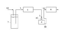
まず、本発明の気化器Aが適用される液体原料気化供給システムに付いて説明する。図12はその第1実施形態であり、図13はその第2実施形態である。液体原料気化供給システムの第1実施形態は、気化器Aに液体原料Lを供給する液体原料供給部40が液体原料Lを液滴又は細い糸状に流下させて供給するスポイト状のものである場合、第2実施形態は、液体原料供給部40が液体原料Lを霧化して供給するアトマイザ(霧吹き)形式である場合である。以下、詳述する。 First, the liquid raw material vaporization supply system to which the vaporizer A of the present invention is applied will be described. FIG. 12 is the first embodiment thereof, and FIG. 13 is the second embodiment thereof. The first embodiment of the liquid raw material vaporization supply system is a case where the liquid raw
<液体原料気化供給システムの第1実施形態:図12>
本発明の気化器Aが適用される液体原料気化供給システムの第1実施形態は、液体原料貯蔵タンクT、液体質量流量制御器(液体マスフローメータE、気化器A及び反応炉Rで構成されている。
上記液体原料貯蔵タンクTには、液体原料L(本実施例では過酸化水素水)が貯蔵され、加圧ガスG0により液体原料Lが必要量だけ送り出される。
液体質量流量制御器(液体マスフローメータ)Eは、前記液体原料貯蔵タンクTに接続され、ここから押し出された液体原料Lの質量流量を次の気化器Aに送り出す。
送り出された液体原料Lは、気化器Aの入口に設けられた液体原料供給部40から内部に供給される。
気化器Aは、供給された液体原料Lを気化し、気化された気化ガスG2の質量流量を反応炉Rに送り出す。
反応炉Rは半導体製造装置で、ここでは例えばシリコン基板酸化用の装置である。<First Embodiment of Liquid Raw Material Vaporization Supply System: FIG. 12>
The first embodiment of the liquid raw material vaporization supply system to which the vaporizer A of the present invention is applied includes a liquid raw material storage tank T, a liquid mass flow controller (liquid mass flow meter E, a vaporizer A, and a reactor R). There is.
The liquid raw material L (hydrogenated water in this embodiment) is stored in the liquid raw material storage tank T, and a required amount of the liquid raw material L is sent out by the pressurized gas G0.
The liquid mass flow controller (liquid mass flow meter) E is connected to the liquid raw material storage tank T, and the mass flow rate of the liquid raw material L extruded from the liquid raw material storage tank T is sent to the next vaporizer A.
The sent out liquid raw material L is supplied to the inside from the liquid raw
The vaporizer A vaporizes the supplied liquid raw material L and sends the mass flow rate of the vaporized gas G2 to the reactor R.
The reactor R is a semiconductor manufacturing apparatus, and here, for example, an apparatus for oxidizing a silicon substrate.
<液体原料気化供給システムの第2実施形態:図13>
第2実施形態では、第1実施形態に加えて窒素ガスや酸素ガスなどの霧化ガス供給源(図示せず)に接続され、キャリアとして働くこれら霧化ガスG1を質量流量だけ送り出す質量流量計Sが更に設けられ、気化器Aの入口には前記液体流量制御器Eから送り出された液体原料Lを前記質量流量計Sから供給された霧化ガスG1によって霧化し、霧化した液体原料Lを供給する液体原料供給部40が設けられている。<Second Embodiment of Liquid Raw Material Vaporization Supply System: FIG. 13>
In the second embodiment, in addition to the first embodiment, a mass flow meter that is connected to an atomized gas supply source (not shown) such as nitrogen gas or oxygen gas and sends out these atomized gas G1 acting as a carrier by the mass flow rate. S is further provided, and the liquid raw material L sent out from the liquid flow rate controller E is atomized by the atomizing gas G1 supplied from the mass flow meter S at the inlet of the vaporizer A, and the atomized liquid raw material L is provided. The liquid raw
気化器Aに適用される液体原料Lは気化して使用されるもの(半導体製造に供される例えば各種の液体原料)であればどのようなものでもよいが、ここではその代表例として過酸化水素水とする。過酸化水素水も符号Lで表す。
気化器Aが、例えば過酸化水素水の気化用で、且つ、半導体製造装置のように極めて高純度な過酸化水素含有水蒸気G2が必要な場合、高温環境において、過酸化水素水Lや気化ガス(過酸化水素含有水蒸気)G2に接する部位(気化器本体1、液体原料供給部40及び気化ガス排出部50)は、これらに侵されないような石英ガラス或いは条件が合えば耐熱性ガラスで作られる。The liquid raw material L applied to the vaporizer A may be any liquid raw material L as long as it is vaporized and used (for example, various liquid raw materials used for semiconductor manufacturing), but here, peroxidation is a typical example thereof. Use hydrogen water. Hydrogen peroxide solution is also represented by the reference numeral L.
When the vaporizer A is for vaporizing a hydrogen peroxide solution and requires extremely high-purity hydrogen peroxide-containing steam G2 as in a semiconductor manufacturing apparatus, the hydrogen peroxide solution L or the vaporizing gas is used in a high temperature environment. (Hydrogen-containing water vapor) The parts in contact with G2 (
勿論、本システムにおいて、液体原料貯蔵タンクTから反応炉Rに至る経路で液体原料Lやその気化ガスG2が接触する部分は、全てこれらに冒されない素材(前記石英ガラス或いは耐熱性ガラス、4フッ化エチレン樹脂、ステンレス鋼)で形成される。そして、気化器Aから反応炉Rに至る経路は結露せず、気化ガスG2をそのままの状態で送れるように更に保温がなされている。 Of course, in this system, all the parts that come into contact with the liquid raw material L and its vaporized gas G2 in the path from the liquid raw material storage tank T to the reaction furnace R are made of materials that are not affected by these (the quartz glass or heat resistant glass, 4 feet). Made of ethylene resin, stainless steel). The path from the vaporizer A to the reactor R does not condense, and the vaporized gas G2 is further kept warm so that it can be sent as it is.
次に、本発明の気化器Aをその構成毎に説明する。上記の通り、本発明の気化器Aはいずれの実施形態においても、大略、気化器本体1、ヒーター部H、液体原料供給部40、気化ガス排出部50及び粒状体5及び必要に応じて設けられる多孔質フィルタFとで構成されている。 Next, the vaporizer A of the present invention will be described for each configuration. As described above, in any of the embodiments, the vaporizer A of the present invention is generally provided with the vaporizer
気化器本体1、液体原料供給部40及び気化ガス排出部50の構成素材は、液体原料Lに冒されない素材(例えば、ステンレス鋼)であれば限定されないが、ここでは上記のように石英ガラスで形成されるものとする。液体原料Lに対する条件が合えば、上記構成素材はパイレックス(登録商標)ガラスのような耐熱性ガラスの使用も可能である。液体原料供給部40で複雑な形状のものは例えば四フッ化エチレン樹脂で形成される。 The constituent materials of the vaporizer
気化器本体1には後述するように様々なものがあり、また、気化器本体1に接続される液体原料供給部40にも後述するように様々なものがある。これらは液体原料Lや気化ガスG2に対する顧客の要求により適切なものが採用される。また、ヒーター部Hにも後述するように様々なものがある。
以下、気化器本体1を実施形態毎に順次説明し、続いて液体原料供給部40、ヒーター部H、多孔質フィルタFを実施形態毎に説明する。There are various types of the vaporizer
Hereinafter, the vaporizer
気化器本体1には、図1~図3に示すような中空立方体或いは直方体の外形を呈するものと、図5~図11に示すような二重チューブ状のものがある。
まず、図1~図3に示すような板状の中空立方体或いは直方体の外形を呈するものについて説明する。The vaporizer
First, a plate-shaped hollow cube or a rectangular parallelepiped having an outer shape as shown in FIGS. 1 to 3 will be described.
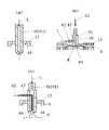
図の中空直方体状の気化器本体1は、一定の幅W(この部分が気化用空間3となる。)を以って平行に設置された、前後一対の矩形板状の本体プレート11、該矩形板状の本体プレート11の両サイド全体に溶接され、該両サイドを閉塞する側面部材12、本体プレート11の上端全体に溶接され、該上端を閉塞する上面部材13、本体プレート11の下端全体に溶接され、該下端を閉塞する底面部材14とで構成されている。
そして必要に応じて、上面部材13側から底面部材14側に至る本体プレート11の中心線に沿って丸孔が一定間隔で複数個(ここでは3個)穿設され、この丸孔に挿通された支柱15が溶接され、上記気化用空間3の幅Wを保っている。本体プレート11の強度が十分に大きければ支柱15を用いず側面部材12だけでもよい。
上面部材13と底面部材14には液体原料供給部40、気化ガス排出部50がそれぞれ取り付けられ、その接合部の全周にわたって溶接されている。なお、上面部材13と液体原料供給部40、底面部材14と気化ガス排出部50とは形状が簡単であれば一体で形成することも可能である。The hollow rectangular parallelepiped vaporizer
Then, if necessary, a plurality of round holes (here, three) are drilled at regular intervals along the center line of the
A liquid raw
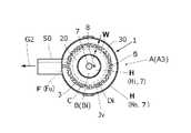
図の二重チューブ状の気化器本体1はインナーチューブ20とアウターチューブ30とで構成されている。アウターチューブ30は石英ガラス(又は上記のように条件が合えば、耐熱性ガラス)製の円筒状の中空管で、一端が上面部材13に溶接或いは当接し、気密的に閉塞されている。そしてこの上面部材13には上記のように液体原料供給部40が取り付けられている。Xの楕円で示す部分には図4(a)~(c)の液体原料供給部40が適宜選択されて装着される。図5では図4(b)の液体原料供給部40が装着されている。上面部材13と一体になった液体原料供給部40の下端中心には液体原料供給部40の噴霧口となる下端開口44が開口している。 The double tube-shaped
インナーチューブ20はアウターチューブ30より細い石英ガラス(又は上記のように条件が合えば、耐熱性ガラス)製の有底円筒状の中空管である。そして、アウターチューブ30と同心でその内部に挿入配置されている。インナーチューブ20の挿入端側である先端頭部21は閉塞されて半球状に形成されている。なお、図の実施例では先端頭部21の形状は半球状であるが、勿論、これに限られず、回転楕円体面、回転放物面或いは円錐状であってもよい。 The
図の場合は、アウターチューブ30とインナーチューブ20とは両者の下端27でその全周が一体的に溶接により接続され、アウターチューブ30の内周面とインナーチューブ20の外周面との間に気化用空間3が形成される。そして、アウターチューブ30内において、インナーチューブ20の先端頭部21より上の部分は気化用空間3に繋がる霧化空間4となっている。そしてこの両者の溶接端である下端27側において、アウターチューブ30の外周面に気化用空間3に連通する後述の気化ガス排出部50が溶接されて側方に突設されている。 In the case of the figure, the
アウターチューブ30とインナーチューブ20との位置関係においては、図5、図11に示すように、インナーチューブ20の外周面には同一円周上で少なくとも3点の微小な突起22が等間隔で且つ上下2段に亘って設けられており、インナーチューブ20をアウターチューブ30に挿入した時にこの微小な突起22がアウターチューブ30の内周面に接触してインナーチューブ20とアウターチューブ30との間に全周に亘って均一な気化用空間3を形成する。この気化用空間3は前述のように、霧化空間4及び気化ガス排出部50に繋がっている。この気化ガス排出部50は例えばシリコン基板酸化用の反応炉Rに接続されている。なお、気化ガス排出部50もアウターチューブ30に溶接されるのであるから石英ガラス(又は条件が合えば耐熱性ガラス)で形成されることになる。 Regarding the positional relationship between the
気化用空間3の幅Wは、特段限定されるものではないが、この気化用空間3に後述する粒状体5が充填されることになるので、粒状体5の直径より大に形成される。従来のような「温度境界層」に制約されることなく、これより大きく形成される。 The width W of the
図では、インナーチューブ20とアウターチューブ30の下端27が上記のように全周に亘って融着されている。アウターチューブ30に収納されたインナーチューブ20の先端頭部21は噴霧口である下端開口44方向に向いており、噴霧口である下端開口44が開口する上面部材13と先端頭部21との間が上記霧化空間4となる。そしてこの霧化空間4に気化用空間3が上記のように全周に亘って連通している。 In the figure, the
ヒーター部Hは、気化器本体1の表面にインジューム-錫合金の酸化物(ITO)や錫酸化物の蒸着或いはスパッタリングして形成した薄膜を発熱体7とするものと、従来のシーズヒーターのような棒状ヒーターを発熱体7とするものがある。ヒーター部Hとしては、薄膜の発熱体7だけのもの、棒状ヒーターの発熱体7だけのもの、或いは薄膜と棒状ヒーターを発熱体7としたハイブリッド型のものがある。
ヒーター部Hは、図1のように気化器本体1の前後両表面に設けられる場合と、図5、図7、図10のようにインナーチューブ20の内側とアウターチューブ30の外側に設けられる場合とがある。図5、図7、図10の場合は、外側のものには小文字のoを、内側のものには小文字のiを添え字する。
図5の内外のヒーター部Hi、Hoは薄膜を発熱体7とするものであり、図7の内外のヒーター部Hi、Hoはハイブリッド型で、アウターチューブ30の外周面に薄膜の発熱体7が設置され、インナーチューブ20の内側にインナーヒーター部Hiが設置される。図10の内外のヒーター部Hは棒状ヒーターだけを発熱体7としたもので、アウターヒーター部Hoはアウターチューブ30の外側に設置され、インナーヒーター部Hiはインナーチューブ20の内側に設置される。The heater unit H uses a thin film formed by vapor deposition or sputtering of an indium-tin alloy oxide (ITO) or tin oxide on the surface of the
The heater portion H is provided on both the front and rear surfaces of the
The inner and outer heater portions Hi and Ho in FIG. 5 have a thin film as a
ヒーター部Hを構成する発熱体7を蒸着やスパッタリングによる薄膜で構成すれば、気化器本体1との密着性が完全であり、後述するようにヒーターブロックBを必要とする発熱体7(棒状ヒーター)に比べて気化器本体1に対する熱伝導性が高くなる。
これに加えて、薄膜は透明性を有するため、気化器本体1を通して気化用空間3の内部を観察することが出来るし、更にヒーター部Hを薄く出来、装置形状を小さく出来る。If the
In addition to this, since the thin film has transparency, the inside of the
上記薄膜を発熱体7とする具体例では、図1に示すように気化器本体1の平坦外面や、図5、図7に示すように円筒状のアウターチューブ30の外周面や、図5に示すようにインナーチューブ20の内周面にインジューム-錫合金の酸化物(ITO)や錫酸化物を蒸着或いはスパッタリングにより薄膜を形成する。(インナーチューブ20の内周面への薄膜形成が困難である場合は、次に述べる、ヒーターブロックBに棒状ヒーターの発熱体7を収納したインナーヒーター部Hiを使用することになる。) In a specific example in which the thin film is a
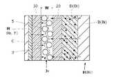
棒状ヒーターを発熱体7とするヒーター部Hの構造は、ヒーターブロックBと、ヒーターブロックBに挿入された発熱体7となる棒状ヒーター及び必要に応じて設けられる温度センサ(熱電対)8とで構成され、ヒーターブロックBとインナーチューブ20又はアウターチューブ30との間に熱変化吸収層Dが設けられる。内外の熱変化吸収層Dを区別する場合、それぞれに上記のように小文字i、oを添える。 The structure of the heater unit H having the rod-shaped heater as the
熱変化吸収層Dは、ヒーターブロックBとインナーチューブ20、又はヒーターブロックBとアウターチューブ30との間に設けられた隙間に充填されたグラファイト粒状体の充填層で構成される。ヒーターブロックBの熱膨張・収縮(体積変化)はこの熱変化吸収層Dのグラファイト粒状体が隙間の中で流動することでこれを吸収し、ガラス製のインナーチューブ20又はアウターチューブ30の破損を回避させることが出来る。これと同時に、このグラファイト粒状体がヒーターブロックBとインナーチューブ20、又はアウターチューブ30と密に接触しているので、ヒーターブロックBからの熱が伝達されやすい。その結果、従来用いられていたヒーターブロックBとインナーチューブ20、又はアウターチューブ30との伝熱ペーストが不要となる。
なお、ヒーターブロックBには、インナー用とアウター用があり、区別する必要がある場合は、インナー用には小文字のi、アウター用には小文字のoをそれぞれに添え字する。The heat change absorbing layer D is composed of a packed layer of graphite granules filled in a gap provided between the heater block B and the
The heater block B has an inner type and an outer type, and when it is necessary to distinguish between them, a lowercase i is added to the inner part and a lowercase letter o is added to the outer part.
上記ヒーターブロックBはアルミニウム又は固形のグラファイト(黒鉛)製である。インナーヒーターブロックBiの外面形状はインナーチューブ20の内面形状より一回り小さい相似形である。従って、このインナーヒーターブロックBiの外面とインナーチューブ20の内面の間に極く僅かな隙間が発生し、この隙間に上記グラファイト粉末が充填されてここにインナー熱変化吸収層Diが形成される。なお、インナー熱変化吸収層Di及び後述するアウター熱変化吸収層Doの充填グラファイト粉末は、充填具合や後述するように重力の関係で粗密が生じるので、熱伝導性に優れていることだけでなく潤滑性に優れていることも重要であり、形状的には鱗片状黒鉛、塊状黒鉛、土状黒鉛、人造黒鉛、高純度黒鉛、薄片化黒鉛、球状黒鉛などから選定される。 The heater block B is made of aluminum or solid graphite. The outer surface shape of the inner heater block Bi is a similar figure that is one size smaller than the inner surface shape of the
熱変化吸収層Dを形成するグラファイト(黒鉛)粉末はその粒度範囲が5~500μmの粉状又は粒状或いはこれらの混合物であり、よりこの好ましくは10~100μmである。 The graphite powder forming the heat change absorption layer D is powdery or granular or a mixture thereof having a particle size range of 5 to 500 μm, and more preferably 10 to 100 μm.
ここで上記グラファイト(黒鉛)とアルミニウムの熱膨張係数を比較すると、グラファイト(黒鉛)の熱膨張係数(概略値)は、2.6×10⁻⁶/K、アルミニウムの熱膨張係数(概略値)は、23×10-6/Kでグラファイトの方がアルミニウムより約1/9程度で小さい。
また、アルミニウム、グラファイト(黒鉛)、ステンレス及び従来使用していた伝熱ペーストの熱伝導率を比較すると、アルミニウムは210W/m・K、グラファイトは50W/m・K、ステンレスは20W/m・K、伝熱ペーストは0.96W/m・Kであり、グラファイトはアルミニウムより劣るが従来例の伝熱ペーストよりは遥かに優れている。Comparing the coefficient of thermal expansion of graphite (graphite) and aluminum, the coefficient of thermal expansion of graphite (graphite) is 2.6 ×10⁻⁶ / K, and the coefficient of thermal expansion of aluminum (approximately value). Is 23 × 10-6 / K, and graphite is about 1/9 smaller than aluminum.
Comparing the thermal conductivity of aluminum, graphite (graphite), stainless steel and the heat transfer paste used conventionally, aluminum is 210 W / m · K, graphite is 50 W / m · K, and stainless steel is 20 W / m · K. The heat transfer paste is 0.96 W / m · K, and graphite is inferior to aluminum but far superior to conventional heat transfer pastes.
アウターヒーターブロックBoは円筒状の部材で、アルミニウム又はグラファイトで形成され、内部に同心にてアウターチューブ30が収納されている。アウターヒーターブロックBoの収納孔の内径はアウターチューブ30の外径より一回り大きく、その間に隙間が設けられ、上記のようにグラファイト(黒鉛)粉末が充填されたアウター熱変化吸収層Doが設けられる。そして、上記収納孔の周囲には同心円上にて発熱体7となる複数本の棒状ヒーターが等角度で配置されている(図11)。 The outer heater block Bo is a cylindrical member, which is made of aluminum or graphite, and concentrically houses the
インナーヒーター部Hiには温度センサ8が装備されており、インナーヒーター部Hiの温度を制御している。アウターヒーター部Hoはインナーヒーター部Hiの温度センサ8に連動するように制御してもよいし、図示していないが、アウターヒーター部Hoにも独自に温度センサを用意してもよい。(なお、薄膜状のヒーター部Hにも図示しない温度センサが設置されている。) The inner heater unit Hi is equipped with a
図4(a)~(c)は、液体原料供給部40の第1~3実施形態で、これらは液体原料Lやこれを霧化した霧状流体Kなど、気化器Aに対して要求される性能に合わせて適宜選択され、図のXで示された楕円形で示した部分にこれらが嵌め込まれる。これらは気化器本体1と同じ材料(石英ガラス、又は条件が合えば耐熱性ガラス)で構成され、上記のように複雑な形状のものは4フッ化エチレンで形成されている。4フッ化エチレンの場合、気化器本体1と異なる材料であるから、図示されていない締結部材(ボルト・ナット)にて気化器本体1に固定される。図の実施例では液体原料供給部40の全体が石英ガラスで形成される場合を代表例として説明する。 4 (a) to 4 (c) are the first to third embodiments of the liquid raw
図4(a)は、液体原料供給部40の(第1実施形態)で、液体原料供給部40がパイプ状の部材で形成され、その下端開口44がスポイト状に細く絞られており、供給された液体原料Lが下端開口44から糸状となって流下、又は滴となって滴下する。 FIG. 4A shows the liquid raw material supply unit 40 (first embodiment), in which the liquid raw
図4(b)は、液体原料供給部40の(第2実施形態)である。この場合、液体原料供給部40に上面部材13が一体化されている。図示していないが、上面部材13の入口孔に液体原料供給部40を溶接してもよい。ここでは一体化した場合で説明する。
この場合、上面部材13に液体原料供給部40の段付き筒状のノズル体41が溶接されている。そしてノズル体41の側面に枝管42が接続されている。ノズル体41の下端開口44は細く絞られている。枝管42の内径はノズル体41の内径より細い。
この液体原料供給部40では、ノズル体41にキャリアガスG1を供給され、枝管42に液体原料Lを供給されるようになっている。枝管42内に流れた液体原料Lはベンチュリ効果によって、ノズル体41内に引き込まれ、絞られた下端開口44から高速で噴出するキャリアガスG1によって霧化され、霧状流体Kとなって下方に散布される。FIG. 4B is a (second embodiment) of the liquid raw
In this case, the stepped
In the liquid raw
図4(c)は、液体原料供給部40の(第3実施形態)である。この場合も上面部材13と液体原料供給部40の段付き筒状のノズル体41とが全周にわたって溶接により一体化されている。ノズル体41の下端は細く絞られている。この部分を下端開口44とする。
そしてノズル体41の側面から内側にL形の噴気ノズル47が挿入され、その挿入部分が下端開口44に向かって垂下するように屈曲されている。このL形の噴気ノズル47の先端部分は細く絞られ、この部分を噴気口48とする。
ノズル体41には液体原料Lが供給され、L形の噴気ノズル47にキャリアガスG1が供給される。ノズル体41内を流下してきた液体原料Lは、L形の枝管42に噴気口48から噴出された高速高圧のキャリアガスG1により霧化され、ノズル体41の下端開口44から霧状流体Kとなって下方に散布される。FIG. 4C is a (third embodiment) of the liquid raw
An L-shaped
The liquid raw material L is supplied to the
粒状体5は、液体原料Lやその高温気化ガスG2に浸食されない素材、例えば、石英ガラス、ジルコニア、アルミナ、シリコン或いは窒化シリコンなどで形成されている。形状は特段限定されるものではないが、通常、球状のものが使用される。その直径は上記のように気化用空間3の幅Wより小さい。なお、粒状体5の表面は、鏡面状態であることが好ましい。 The
その他の構成要素として、多孔質フィルタFが気化器本体1内に設置される。多孔質フィルタFとしては液体原料Lや気化ガスG2に冒されず、液体原料Lや気化ガスG2をスムーズに通過させることが出来るものであればその材質を問わないが、ここでは気化器本体1との溶接固定が可能なように石英ガラス粉粒体(耐熱性ガラス粉体粒)を半溶融状態でその接触部分を溶融接合したポーラスな半溶融石英ガラス多孔質体(或いは、半溶融耐熱性ガラス多孔質体)が使われる。 As another component, the porous filter F is installed in the
<気化器本体1の第1実施形態:平行平板型>
気化器A1の第1実施形態(図1~図3)は、板状の立方体或いは直方体の外形を呈する。構造は上記の通りで、図1、図2のXで示す楕円部分には、既述のように図4(a)~(c)で示す液体原料供給部40が一体的に設置される。ここでは、図4(a)に示すノズル状の液体原料供給部40が設置されているものを代表例とする。そして、気化器A1の底面部材14には円筒状の気化ガス排出部50が一体的に設置されている。
気化器本体1内部の気化用空間3には、液体原料供給部40側に矩形薄板状の上部多孔質フィルタFj、気化ガス排出部50側に矩形薄板状の上部多孔質フィルタFuが設置され、気化器本体1の内壁の溶接されている。<First Embodiment of Vaporizer Main Body 1: Parallel Plate Type>
The first embodiment of the vaporizer A1 (FIGS. 1 to 3) exhibits the outer shape of a plate-shaped cube or a rectangular parallelepiped. The structure is as described above, and the liquid raw
In the
そして、上下の多孔質フィルタFj、Fuの間の空間に上記粒状体5が充填されており、粒状体5同士及び粒状体5と気化器本体1の内壁とが接触している。粒状体5間には上部の多孔質フィルタFj(液体原料供給部40)側から下部の多孔質フィルタFu(気化ガス排出部50)側に至る連続通流露Cが形成されている。 The space between the upper and lower porous filters Fj and Fu is filled with the
気化器本体1の平板状の表裏両外面全面には、図の実施例では、薄膜の発熱体7が蒸着されている。なお、薄膜の発熱体7は透明体なので、気化器本体1を観察することが出来る。
気化用空間3が平板状に構成され、気化用空間3を構成する気化器本体1の板面に薄膜状のヒーター部Hが設置されていると装置の厚みを薄くすることも出来る。In the embodiment shown in the figure, a thin-
If the
<第1実施形態の作用>
図12において、液体原料Lの液体質量流量がノズル状の液体原料供給部40に供給されると、液体原料供給部40の下端開口44から液体原料Lが下方の上部多孔質フィルタFjに向かって滴となって滴下、或いは糸状の流れとなって流下する。
上部多孔質フィルタFjに届いた液体原料Lは直ちに上部多孔質フィルタFj内に厚程度均一に拡散し、上部多孔質フィルタFjの下面からその下の粒状体5が充填された気化用充填層Jvに浸透して行く。<Action of the first embodiment>
In FIG. 12, when the liquid mass flow rate of the liquid raw material L is supplied to the nozzle-shaped liquid raw
The liquid raw material L that has reached the upper porous filter Fj immediately diffuses uniformly into the upper porous filter Fj to a thickness degree, and the vaporization packed bed Jv filled with the
上記薄膜の発熱体7は通電状態にあり、薄膜の発熱体7からの熱は気化器本体1の壁面を通じて内部に伝達される。壁面内面は発熱体7はほぼ同じ温度になる。そして、気化強間隙3内に充填され、前記壁面に接触している粒状体5に熱が更に伝わる。そして、この充填された粒状体5は互いに接触しているので、接触部分と放射熱によって次々と粒状体5が熱せられる。勿論、壁面及び隣接する粒状体5からの放射熱によっても内部の粒状体5は加熱される。その結果、気化用充填層Jvを形成する粒状体5の全てはほぼ壁面に近い同じ温度に保たれる。このことは、気化用空間3の幅Wが従来の温度境界層の幅に制限されず、温度境界層の和を越えて広くすることが出来ることを意味する。 The thin-
上部多孔質フィルタFjから気化用充填層Jvに浸透した液体原料Lは、連続通流路Cを流下する間に加熱された壁面と粒状体5に次々と接触することで徐々に気化し、気化用充填層Jvを通過するいずれかの時点で完全に気化し、下部多孔質フィルタFuを通過する。そして気化ガスG2は気化ガス排出部50を通過し、気化状態を保ったままその質量流量が反応炉Rに供給される。 The liquid raw material L that has permeated into the packed bed Jv for vaporization from the upper porous filter Fj gradually vaporizes and vaporizes by coming into contact with the heated wall surface and the
ここで、第1実施形態の気化器A1の伝熱面積は、従来の気化器に比べて気化用充填層Jvを構成する粒状体5の全表面積の分だけ多く、通過する液体原料Lにより多くの熱をより短時間で与えることが出来る。また、第1実施形態の気化器A1の粒状体5間の通過間隙の全横断面積は、従来の気化器の壁面間に設けられた僅かな幅の気化用間隙の全横断面積より大きく、従来例に比べて大量の液体原料Lを通過させることが出来る。この点は後述する他の実施形態においても同じである。 Here, the heat transfer area of the vaporizer A1 of the first embodiment is larger by the total surface area of the
<気化器本体1の第2実施形態A2:二重チューブ型>
図5、図6は第2実施形態で、気化器本体1のインナーチューブ20の内周面とアウターチューブ30の外周面に薄膜の発熱体7が蒸着されている。そして気化器本体1の霧化空間4において、インナーチューブ20の先端頭部21より上の部分に上部多孔質フィルタFjが全面にわたって配設され、アウターチューブ30の内壁に溶接されている。そして、気化器本体1の気化用空間3の下端出口には下部多孔質フィルタFuがその全面にわたって設置され、下部多孔質フィルタFuの外周が下端出口に溶接されている。
上下多孔質フィルタFj、Fuの間の空間には粒状体5が第1実施形態と同様の状態で充填され、気化用充填層Jvを形成している。
気化器本体1に設置された液体原料供給部40は、第1実施形態と同様、図4(a)~(c)のいずれを選んでもよいが、ここでは図4(b)が設置されるものとする。<Second Embodiment A2 of Vaporizer Main Body 1: Double Tube Type>
5 and 6 show the second embodiment, in which a thin
The space between the upper and lower porous filters Fj and Fu is filled with the
As in the first embodiment, any of FIGS. 4 (a) to 4 (c) may be selected for the liquid raw
<第2実施形態の作用>
図13において、液体原料Lの質量流量が枝管42に供給され、質量流量制御された高圧のキャリアガスG1がノズル体41に供給されると、枝管42に流れ込んだ液体原料Lはノズル体41に供給されたキャリアガスG1によってノズル体41の噴出口である下端開口44から下方に向かって勢いよく噴き出され、霧化されて下方の上部多孔質フィルタFjにほぼ均一に降り注ぐ。
そして、第1実施形態で説明したように気化され、反応炉Rに供給される。<Action of the second embodiment>
In FIG. 13, when the mass flow rate of the liquid raw material L is supplied to the
Then, it is vaporized as described in the first embodiment and supplied to the reactor R.
<気化器本体1の第2実施形態の第1変形例A3:二重チューブ型>
図7、図8は第2実施形態の第1変形例で、気化器本体1のインナーチューブ20の内面に発熱体7である棒状のヒーターと温度センサ8とが挿入されたインナーヒーターブロックBiが挿入され、アウターチューブ30の外周面に薄膜の発熱体7が蒸着されたハイブリッド型の気化器である。インナーヒーターブロックBiとインナーチューブ20の内面との間の隙間にはインナー熱変化吸収層Diが形成されている。
この場合も液体原料供給部40は、図4(a)~(c)のいずれかを選ぶことが出来るが、ここでは第2実施形態と同様、図4(b)が設置されているものとする。その他は第2実施形態と同様である。<First modification A3 of the second embodiment of the vaporizer body 1: double tube type>
7 and 8 are first modifications of the second embodiment, in which an inner heater block Bi in which a rod-shaped heater as a
In this case as well, the liquid raw
<第2実施形態の第1変形例の作用>
図13において、液体原料Lの質量流量が枝管42に供給され、質量流量制御された高圧のキャリアガスG1がノズル体41に供給されると、上記第2実施形態と同様、霧化された液体原料Lが下方の上部多孔質フィルタFjにほぼ均一に降り注ぐ。
上部多孔質フィルタFjに降り注いだ霧状の液体原料Lが気化用空間3内で気化し、気化ガス排出部50から反応炉Rに供給される点は、第2実施形態と同じである。<Action of the first modification of the second embodiment>
In FIG. 13, when the mass flow rate of the liquid raw material L is supplied to the
The point that the mist-like liquid raw material L poured onto the upper porous filter Fj is vaporized in the
この装置において、通電されてインナーヒーター部Hi及びアウターヒーター部Hoが昇温すると、インナーヒーターブロックBiが昇温して膨張を始める。一方、インナーチューブ20は熱膨張率がほぼ零であるため熱膨張しない。 In this device, when the power is applied and the temperature of the inner heater unit Hi and the temperature of the outer heater unit Ho rises, the temperature of the inner heater block Bi rises and begins to expand. On the other hand, the
加熱時にはインナーヒーターブロックBiは熱膨張でその直径が増加し、膨張しないインナーチューブ20の内周面とインナーヒーターブロックBiの外周面との間の隙間がインナーヒーターブロックBiの熱膨張分だけ狭くなる。この隙間にはグラファイト粉末が充填され、この部分がインナー熱変化吸収層Diとなっているので、インナーヒーターブロックBiの熱膨張によって押圧力を受けたグラファイト粉末は、その優れた潤滑性により流動してその充填度合いを最適化し、前記熱膨張分を吸収し、ガラス製のインナーチューブ20に大きな押圧力の印加を防止する。これを図9に示す。その結果、加熱時におけるガラス製のインナーチューブ20の破損を防ぐことが出来る。そしてグラファイト粉末は上記のようにアルミニウムより1/9程度の小さい熱膨張係数であることもインナーチューブ20の破損防止に寄与する。 During heating, the diameter of the inner heater block Bi increases due to thermal expansion, and the gap between the inner peripheral surface of the
<気化器本体1の第2実施形態の第2変形例A4:二重チューブ型>
図10、図11は第2実施形態の第2変形例で、気化器本体1のインナーチューブ20の内面に発熱体7である棒状のヒーターと温度センサ8とが挿入されたインナーヒーターブロックBiが挿入され、アウターチューブ30の外周面に円筒状のアウターヒーターブロックBoが設置された気化器A4である。インナーヒーターブロックBiとインナーチューブ20の内面との間の隙間、アウターヒーターブロックBoとアウターチューブ30の外面との間の隙間にはそれぞれグラファイト粒状体が充填され、インナー又はアウター熱変化吸収層Di、Doがそれぞれ形成されている。
楕円Xで囲んだ液体原料供給部40は上記のように図4(a)~(c)のいずれを選択することが出来るが、ここでは第3実施形態と同様図4(b)が設置されているものとし、これを代表例とする。<Second variant A4 of the second embodiment of the vaporizer body 1: double tube type>
10 and 11 are second modifications of the second embodiment, in which an inner heater block Bi in which a rod-shaped heater as a
The liquid raw
<第2実施形態の第2変形例の作用>
図10において、液体原料Lの気化は第2実施形態の第1変形例と同様に行われる。
この装置において、通電されてインナーヒーター部Hi及びアウターヒーター部Hoが昇温すると、これらを収納するインナーヒーターブロックBi及びアウターヒーターブロックBoが昇温して膨張を始める。一方、アウターチューブ30及びインナーチューブ20は熱膨張率がほぼ零であるため熱膨張しない。<Action of the second modification of the second embodiment>
In FIG. 10, the vaporization of the liquid raw material L is carried out in the same manner as in the first modification of the second embodiment.
In this device, when the inner heater section Hi and the outer heater section Ho are energized and the temperature rises, the inner heater block Bi and the outer heater block Bo that accommodate them rise in temperature and begin to expand. On the other hand, the
加熱時のインナーヒーターブロックBiとインナーチューブ20も関係は上記の通りである。
アウターヒーターブロックBoとアウターチューブ30との関係では、アウターヒーターブロックBoが昇温すると、熱膨張しないアウターチューブ30に対して熱膨張するアウターヒーターブロックBoの収納孔の内径は増加し、収納孔の内周面とアウターチューブ30の外周面との間のインナー熱変化吸収層Doを形成する隙間が増加する。従って、アウターヒーターブロックBo側では加熱時のアウターチューブ30の破損は発生しない。しかしながらこの隙間(アウター熱変化吸収層Do)に充填されているグラファイト粉末は隙間の増加につれて僅かではあるが重力によって下方に移動し、上記隙間に構成されるアウター熱変化吸収層Doに粗密が生じることになる。この粗密はグラファイト粉末が重力により落下することで埋められる。The relationship between the inner heater block Bi and the
Regarding the relationship between the outer heater block Bo and the
気化作業が終了し通電が切られると、アウターヒーターブロックBoとアウターチューブ30との関係では、アウターヒーターブロックBoが冷却して収縮し、収縮しないアウターチューブ30に対してアウターヒーターブロックBoが締め付けるようになる。この時点では上記のように両者の間でアウター熱変化吸収層Doを形成しているグラファイト粉末に重力による落下があるため、アウターヒーターブロックBoの収縮により密に充填されている部分にアウターヒーターブロックBoからの締め付け圧力が加わる。 When the vaporization work is completed and the power is turned off, in the relationship between the outer heater block Bo and the
アウター熱変化吸収層Doを形成しているグラファイト粉末は潤滑性に優れるために、上記締め付け圧力が加わると当該部分のグラファイト粉末はその高潤滑性により流動して押し上げられ、アウターチューブ30への締め付け圧力の上昇を大幅に抑制する。その結果、冷却時におけるアウターチューブ30の破損が防止される。 Since the graphite powder forming the outer heat change absorption layer Do has excellent lubricity, when the tightening pressure is applied, the graphite powder in the portion flows and is pushed up by the high lubricity, and is tightened to the
なお、このグラファイト粉末が充填されたアウター熱変化吸収層Doの熱伝導率も従来の伝熱ペーストより優れている点もインナー熱変化吸収層Diと同じである。 The heat conductivity of the outer heat change absorbing layer Do filled with the graphite powder is also superior to that of the conventional heat transfer paste, which is the same as that of the inner heat change absorbing layer Di.
A(A1~A4):気化器、B(Bi、Bo):(インナー、アウター)ヒーターブロック、C:連続通流路、D(Di、Do):(インナー、アウター)熱変化吸収層、E:液体流量制御器(液体マスフローメータ)、F(Fj、Fu):(上部、下部)多孔質フィルタ、G0:加圧ガス、G1:霧化ガス(キャリアガス)、G2:気化ガス(水蒸気)、H(Hi、Ho):(インナー、アウター)ヒーター部、Jv:気化用充填層、K:霧状流体、L:液体原料、R:反応炉、S:質量流量計、T:液体原料貯蔵タンク、W:気化用空間の幅
1:気化器本体、3:気化用空間、4:霧化空間、5:粒状体、7:発熱体、8:温度センサ、11:本体プレート、12:側面部材、13:上面部材、14:底面部材、、15:支柱、20:インナーチューブ、21:先端頭部、22:突起、27:両チューブの下端(溶接端)、30:アウターチューブ、40:液体原料供給部、41:ノズル体、42:枝管、43:流出口、44:下端開口、47:噴気ノズル、48:噴気口、50:気化ガス排出部A (A1 to A4): vaporizer, B (Bi, Bo): (inner, outer) heater block, C: continuous flow path, D (Di, Do): (inner, outer) heat change absorption layer, E : Liquid flow controller (liquid mass flow meter), F (Fj, Fu): (upper, lower) porous filter, G0: pressurized gas, G1: atomized gas (carrier gas), G2: vaporized gas (steam) , H (Hi, Ho): (inner, outer) heater, Jv: vaporization packing layer, K: atomized fluid, L: liquid raw material, R: reactor, S: mass flow meter, T: liquid raw material storage Tank, W: Width of vaporization space 1: Vaporizer body 3: Vaporization space 4: Atomization space 5: Granules, 7: Heat generator, 8: Temperature sensor, 11: Body plate, 12: Side surface Member, 13: Top member, 14: Bottom member ,, 15: Strut, 20: Inner tube, 21: Tip head, 22: Projection, 27: Lower end (welded end) of both tubes, 30: Outer tube, 40: Liquid raw material supply section, 41: nozzle body, 42: branch pipe, 43: outlet, 44: lower end opening, 47: jet nozzle, 48: jet port, 50: vaporized gas discharge section
Claims (11)
Translated fromJapanese前記気化器本体に設けられ、前記液体原料を加熱して気化させるヒーター部と、
前記気化器本体の入口に設けられ、前記液体原料を前記気化用空間に供給する液体原料供給部と、
前記気化器本体の出口に設けられ、前記気化用空間内にて気化された気化ガスを排出する気化ガス排出部とで構成された気化器であって、
粒状体が前記気化用空間を構成する前記気化器本体の内壁に接触するようにして前記気化用空間に充填され、前記液体原料供給部から気化ガス排出部に至る、前記液体原料を気化させるための連続通流路が形成されていることを特徴とする気化器。The main body of the vaporizer, which has an internal space for vaporization to vaporize the supplied liquid raw material,
A heater unit provided on the vaporizer body to heat and vaporize the liquid raw material,
A liquid raw material supply unit provided at the inlet of the vaporizer main body and supplying the liquid raw material to the vaporization space, and a liquid raw material supply unit.
It is a vaporizer provided at the outlet of the vaporizer main body and composed of a vaporized gas discharging unit that discharges the vaporized gas vaporized in the vaporizing space.
In order to vaporize the liquid raw material from the liquid raw material supply section to the vaporization gas discharge section by filling the vaporization space so that the granules come into contact with the inner wall of the vaporizer main body constituting the vaporization space. A vaporizer characterized in that a continuous flow path is formed.
前記アウターチューブと前記インナーチューブとの間に円筒状の前記気化用空間が形成され、
前記ヒーター部はアウターヒーター部とインナーヒーター部とで構成され、
前記アウターヒーター部はアウターチューブの外周面に設置され、
前記インナーヒーター部はインナーチューブの内周面に設置されていることを特徴とする請求項1に記載の気化器。The vaporizer main body is composed of a hollow outer tube and a hollow inner tube housed in the outer tube.
A cylindrical space for vaporization is formed between the outer tube and the inner tube.
The heater unit is composed of an outer heater unit and an inner heater unit.
The outer heater portion is installed on the outer peripheral surface of the outer tube and is installed.
The vaporizer according to claim 1, wherein the inner heater portion is installed on the inner peripheral surface of the inner tube.
Priority Applications (1)
| Application Number | Priority Date | Filing Date | Title |
|---|---|---|---|
| JP2020195996AJP7495334B2 (en) | 2020-11-26 | 2020-11-26 | Carburetor |
Applications Claiming Priority (1)
| Application Number | Priority Date | Filing Date | Title |
|---|---|---|---|
| JP2020195996AJP7495334B2 (en) | 2020-11-26 | 2020-11-26 | Carburetor |
Publications (2)
| Publication Number | Publication Date |
|---|---|
| JP2022084254Atrue JP2022084254A (en) | 2022-06-07 |
| JP7495334B2 JP7495334B2 (en) | 2024-06-04 |
Family
ID=81868080
Family Applications (1)
| Application Number | Title | Priority Date | Filing Date |
|---|---|---|---|
| JP2020195996AActiveJP7495334B2 (en) | 2020-11-26 | 2020-11-26 | Carburetor |
Country Status (1)
| Country | Link |
|---|---|
| JP (1) | JP7495334B2 (en) |
Cited By (2)
| Publication number | Priority date | Publication date | Assignee | Title |
|---|---|---|---|---|
| JP7569030B1 (en)* | 2024-05-07 | 2024-10-17 | 株式会社リンテック | Carburetor |
| JP7696672B1 (en)* | 2024-10-10 | 2025-06-23 | 株式会社リンテック | Carburetor |
Citations (10)
| Publication number | Priority date | Publication date | Assignee | Title |
|---|---|---|---|---|
| JPH05228361A (en)* | 1991-08-27 | 1993-09-07 | Stec Kk | Device for vaporizing and supplying liquid material |
| JPH05337357A (en)* | 1992-06-10 | 1993-12-21 | Stec Kk | Vaporizer in liquid material supply system |
| JPH0936108A (en)* | 1995-07-21 | 1997-02-07 | Hitachi Ltd | Semiconductor manufacturing method and device, and semiconductor wafer and semiconductor element |
| JPH1187327A (en)* | 1997-06-25 | 1999-03-30 | Ebara Corp | Liquid material gasifying apparatus |
| JP2001295050A (en)* | 2000-04-11 | 2001-10-26 | Sony Corp | Vaporizer, method for using vaporizer, and method for vaporizing raw liquid |
| JP2006013086A (en)* | 2004-06-25 | 2006-01-12 | Japan Pionics Co Ltd | Vaporizer |
| JP2017191940A (en)* | 2012-02-28 | 2017-10-19 | ラム リサーチ コーポレーションLam Research Corporation | Multiplexed heater array using ac drive for semiconductor processing |
| WO2019180906A1 (en)* | 2018-03-23 | 2019-09-26 | 株式会社Kokusai Electric | Vaporizer, substrate treatment device, and method for manufacturing semiconductor device |
| JP2020020036A (en)* | 2018-07-24 | 2020-02-06 | 株式会社リンテック | Vaporizer |
| JP6769645B1 (en)* | 2020-05-28 | 2020-10-14 | 株式会社リンテック | Vaporizer |
- 2020
- 2020-11-26JPJP2020195996Apatent/JP7495334B2/enactiveActive
Patent Citations (10)
| Publication number | Priority date | Publication date | Assignee | Title |
|---|---|---|---|---|
| JPH05228361A (en)* | 1991-08-27 | 1993-09-07 | Stec Kk | Device for vaporizing and supplying liquid material |
| JPH05337357A (en)* | 1992-06-10 | 1993-12-21 | Stec Kk | Vaporizer in liquid material supply system |
| JPH0936108A (en)* | 1995-07-21 | 1997-02-07 | Hitachi Ltd | Semiconductor manufacturing method and device, and semiconductor wafer and semiconductor element |
| JPH1187327A (en)* | 1997-06-25 | 1999-03-30 | Ebara Corp | Liquid material gasifying apparatus |
| JP2001295050A (en)* | 2000-04-11 | 2001-10-26 | Sony Corp | Vaporizer, method for using vaporizer, and method for vaporizing raw liquid |
| JP2006013086A (en)* | 2004-06-25 | 2006-01-12 | Japan Pionics Co Ltd | Vaporizer |
| JP2017191940A (en)* | 2012-02-28 | 2017-10-19 | ラム リサーチ コーポレーションLam Research Corporation | Multiplexed heater array using ac drive for semiconductor processing |
| WO2019180906A1 (en)* | 2018-03-23 | 2019-09-26 | 株式会社Kokusai Electric | Vaporizer, substrate treatment device, and method for manufacturing semiconductor device |
| JP2020020036A (en)* | 2018-07-24 | 2020-02-06 | 株式会社リンテック | Vaporizer |
| JP6769645B1 (en)* | 2020-05-28 | 2020-10-14 | 株式会社リンテック | Vaporizer |
Cited By (2)
| Publication number | Priority date | Publication date | Assignee | Title |
|---|---|---|---|---|
| JP7569030B1 (en)* | 2024-05-07 | 2024-10-17 | 株式会社リンテック | Carburetor |
| JP7696672B1 (en)* | 2024-10-10 | 2025-06-23 | 株式会社リンテック | Carburetor |
Also Published As
| Publication number | Publication date |
|---|---|
| JP7495334B2 (en) | 2024-06-04 |
Similar Documents
| Publication | Publication Date | Title |
|---|---|---|
| CN101285178B (en) | Vaporizer and semiconductor processing system | |
| JP5989107B2 (en) | Organic starting material deposition method, evaporation apparatus and deposition apparatus | |
| JP6138145B2 (en) | Method for producing synthetic quartz glass | |
| JP6085595B2 (en) | OLED deposition method and apparatus | |
| JP2022084254A (en) | Vaporizer | |
| JPH0828332B2 (en) | Liquid evaporation device | |
| US6339678B1 (en) | Method for vaporizing and superheating a sterilizing agent and device therefor | |
| JP2004510058A (en) | In particular, a method and an apparatus for depositing an organic film by an OVPD method | |
| JP6858991B2 (en) | Heat exchangers, separation systems, and aerosol formation systems | |
| JP5361467B2 (en) | Vaporizer | |
| CN114270480B (en) | Gasifier | |
| JP6769645B1 (en) | Vaporizer | |
| KR101772621B1 (en) | Downward Evaporation Apparatus And Downward Evaporation Deposition Apparatus | |
| TWI819519B (en) | vaporizer | |
| JP6203207B2 (en) | Vaporizer | |
| TWI896276B (en) | vaporizer | |
| KR100322411B1 (en) | Apparatus for vaporizing a liquid source | |
| JP7569030B1 (en) | Carburetor | |
| JP4433392B2 (en) | Vaporizer | |
| KR100507961B1 (en) | Liquid raw material gasification system and gas injection device | |
| KR100322410B1 (en) | Apparatus for vaporizing a liquid source | |
| WO2015072509A1 (en) | High-efficiency heat exchanger and high-efficiency heat exchange method | |
| KR100631720B1 (en) | Gas supply structure of plasma polymerization apparatus | |
| JPH0445838A (en) | Vaporizer in liquid material supply system | |
| KR20150055880A (en) | Apparatus for vaporizing liquid and supplying material source |
Legal Events
| Date | Code | Title | Description |
|---|---|---|---|
| A621 | Written request for application examination | Free format text:JAPANESE INTERMEDIATE CODE: A621 Effective date:20230619 | |
| A977 | Report on retrieval | Free format text:JAPANESE INTERMEDIATE CODE: A971007 Effective date:20240131 | |
| A131 | Notification of reasons for refusal | Free format text:JAPANESE INTERMEDIATE CODE: A131 Effective date:20240206 | |
| A521 | Request for written amendment filed | Free format text:JAPANESE INTERMEDIATE CODE: A523 Effective date:20240408 | |
| TRDD | Decision of grant or rejection written | ||
| A01 | Written decision to grant a patent or to grant a registration (utility model) | Free format text:JAPANESE INTERMEDIATE CODE: A01 Effective date:20240424 | |
| A61 | First payment of annual fees (during grant procedure) | Free format text:JAPANESE INTERMEDIATE CODE: A61 Effective date:20240523 | |
| R150 | Certificate of patent or registration of utility model | Ref document number:7495334 Country of ref document:JP Free format text:JAPANESE INTERMEDIATE CODE: R150 |