JP2022080868A - Fabrication line, systems, and methods for fuselage sections - Google Patents
Fabrication line, systems, and methods for fuselage sectionsDownload PDFInfo
- Publication number
- JP2022080868A JP2022080868AJP2021183124AJP2021183124AJP2022080868AJP 2022080868 AJP2022080868 AJP 2022080868AJP 2021183124 AJP2021183124 AJP 2021183124AJP 2021183124 AJP2021183124 AJP 2021183124AJP 2022080868 AJP2022080868 AJP 2022080868A
- Authority
- JP
- Japan
- Prior art keywords
- mandrel
- station
- preform
- zone
- component
- Prior art date
- Legal status (The legal status is an assumption and is not a legal conclusion. Google has not performed a legal analysis and makes no representation as to the accuracy of the status listed.)
- Pending
Links
Images


Classifications
- B—PERFORMING OPERATIONS; TRANSPORTING
- B64—AIRCRAFT; AVIATION; COSMONAUTICS
- B64F—GROUND OR AIRCRAFT-CARRIER-DECK INSTALLATIONS SPECIALLY ADAPTED FOR USE IN CONNECTION WITH AIRCRAFT; DESIGNING, MANUFACTURING, ASSEMBLING, CLEANING, MAINTAINING OR REPAIRING AIRCRAFT, NOT OTHERWISE PROVIDED FOR; HANDLING, TRANSPORTING, TESTING OR INSPECTING AIRCRAFT COMPONENTS, NOT OTHERWISE PROVIDED FOR
- B64F5/00—Designing, manufacturing, assembling, cleaning, maintaining or repairing aircraft, not otherwise provided for; Handling, transporting, testing or inspecting aircraft components, not otherwise provided for
- B64F5/50—Handling or transporting aircraft components
- B—PERFORMING OPERATIONS; TRANSPORTING
- B64—AIRCRAFT; AVIATION; COSMONAUTICS
- B64F—GROUND OR AIRCRAFT-CARRIER-DECK INSTALLATIONS SPECIALLY ADAPTED FOR USE IN CONNECTION WITH AIRCRAFT; DESIGNING, MANUFACTURING, ASSEMBLING, CLEANING, MAINTAINING OR REPAIRING AIRCRAFT, NOT OTHERWISE PROVIDED FOR; HANDLING, TRANSPORTING, TESTING OR INSPECTING AIRCRAFT COMPONENTS, NOT OTHERWISE PROVIDED FOR
- B64F5/00—Designing, manufacturing, assembling, cleaning, maintaining or repairing aircraft, not otherwise provided for; Handling, transporting, testing or inspecting aircraft components, not otherwise provided for
- B64F5/10—Manufacturing or assembling aircraft, e.g. jigs therefor
- B—PERFORMING OPERATIONS; TRANSPORTING
- B29—WORKING OF PLASTICS; WORKING OF SUBSTANCES IN A PLASTIC STATE IN GENERAL
- B29C—SHAPING OR JOINING OF PLASTICS; SHAPING OF MATERIAL IN A PLASTIC STATE, NOT OTHERWISE PROVIDED FOR; AFTER-TREATMENT OF THE SHAPED PRODUCTS, e.g. REPAIRING
- B29C70/00—Shaping composites, i.e. plastics material comprising reinforcements, fillers or preformed parts, e.g. inserts
- B29C70/04—Shaping composites, i.e. plastics material comprising reinforcements, fillers or preformed parts, e.g. inserts comprising reinforcements only, e.g. self-reinforcing plastics
- B29C70/28—Shaping operations therefor
- B29C70/30—Shaping by lay-up, i.e. applying fibres, tape or broadsheet on a mould, former or core; Shaping by spray-up, i.e. spraying of fibres on a mould, former or core
- B29C70/304—In-plane lamination by juxtaposing or interleaving of plies, e.g. scarf joining
- B—PERFORMING OPERATIONS; TRANSPORTING
- B29—WORKING OF PLASTICS; WORKING OF SUBSTANCES IN A PLASTIC STATE IN GENERAL
- B29C—SHAPING OR JOINING OF PLASTICS; SHAPING OF MATERIAL IN A PLASTIC STATE, NOT OTHERWISE PROVIDED FOR; AFTER-TREATMENT OF THE SHAPED PRODUCTS, e.g. REPAIRING
- B29C70/00—Shaping composites, i.e. plastics material comprising reinforcements, fillers or preformed parts, e.g. inserts
- B29C70/04—Shaping composites, i.e. plastics material comprising reinforcements, fillers or preformed parts, e.g. inserts comprising reinforcements only, e.g. self-reinforcing plastics
- B29C70/28—Shaping operations therefor
- B29C70/30—Shaping by lay-up, i.e. applying fibres, tape or broadsheet on a mould, former or core; Shaping by spray-up, i.e. spraying of fibres on a mould, former or core
- B29C70/38—Automated lay-up, e.g. using robots, laying filaments according to predetermined patterns
- B—PERFORMING OPERATIONS; TRANSPORTING
- B29—WORKING OF PLASTICS; WORKING OF SUBSTANCES IN A PLASTIC STATE IN GENERAL
- B29D—PRODUCING PARTICULAR ARTICLES FROM PLASTICS OR FROM SUBSTANCES IN A PLASTIC STATE
- B29D99/00—Subject matter not provided for in other groups of this subclass
- B29D99/001—Producing wall or panel-like structures, e.g. for hulls, fuselages, or buildings
- B29D99/0014—Producing wall or panel-like structures, e.g. for hulls, fuselages, or buildings provided with ridges or ribs, e.g. joined ribs
- B—PERFORMING OPERATIONS; TRANSPORTING
- B29—WORKING OF PLASTICS; WORKING OF SUBSTANCES IN A PLASTIC STATE IN GENERAL
- B29L—INDEXING SCHEME ASSOCIATED WITH SUBCLASS B29C, RELATING TO PARTICULAR ARTICLES
- B29L2031/00—Other particular articles
- B29L2031/30—Vehicles, e.g. ships or aircraft, or body parts thereof
- B29L2031/3076—Aircrafts
- B29L2031/3082—Fuselages
- B—PERFORMING OPERATIONS; TRANSPORTING
- B64—AIRCRAFT; AVIATION; COSMONAUTICS
- B64C—AEROPLANES; HELICOPTERS
- B64C1/00—Fuselages; Constructional features common to fuselages, wings, stabilising surfaces or the like
- B64C1/06—Frames; Stringers; Longerons ; Fuselage sections
- B64C1/12—Construction or attachment of skin panels
- B—PERFORMING OPERATIONS; TRANSPORTING
- B64—AIRCRAFT; AVIATION; COSMONAUTICS
- B64C—AEROPLANES; HELICOPTERS
- B64C1/00—Fuselages; Constructional features common to fuselages, wings, stabilising surfaces or the like
- B64C2001/0054—Fuselage structures substantially made from particular materials
- B64C2001/0072—Fuselage structures substantially made from particular materials from composite materials
- Y—GENERAL TAGGING OF NEW TECHNOLOGICAL DEVELOPMENTS; GENERAL TAGGING OF CROSS-SECTIONAL TECHNOLOGIES SPANNING OVER SEVERAL SECTIONS OF THE IPC; TECHNICAL SUBJECTS COVERED BY FORMER USPC CROSS-REFERENCE ART COLLECTIONS [XRACs] AND DIGESTS
- Y02—TECHNOLOGIES OR APPLICATIONS FOR MITIGATION OR ADAPTATION AGAINST CLIMATE CHANGE
- Y02T—CLIMATE CHANGE MITIGATION TECHNOLOGIES RELATED TO TRANSPORTATION
- Y02T50/00—Aeronautics or air transport
- Y02T50/40—Weight reduction
Landscapes
- Engineering & Computer Science (AREA)
- Manufacturing & Machinery (AREA)
- Transportation (AREA)
- Aviation & Aerospace Engineering (AREA)
- Mechanical Engineering (AREA)
- Chemical & Material Sciences (AREA)
- Composite Materials (AREA)
- Robotics (AREA)
- Architecture (AREA)
- Civil Engineering (AREA)
- Structural Engineering (AREA)
- Moulding By Coating Moulds (AREA)
Abstract
Translated fromJapanese
Description
Translated fromJapanese本開示は、航空機の分野に関し、詳細には、航空機の複合材部品(胴体セクションなど)の製造に関する。 The present disclosure relates to the field of aircraft and, in particular, to the manufacture of aircraft composite parts (such as fuselage sections).
大型の複合材部品(数十フィートにわたるものなど)は、工場のフロアにおいて多大なスペースを占める。このような部品の積層板は、静止型の作業セル内でレイアップマンドレル上にレイアップされる。この作業セルでは、大型ロボットアーム向けの巨大なエンドエフェクタを有する自動繊維配置(AFP)機械が移動して、トウ(tow)単位で繊維強化材料を付加する。単独のAFP機械は、最適化されたレイアップパターンにしたがって、単一の動きで部品の端から端まで動く。 Large composite parts (such as those spanning tens of feet) take up a lot of space on the factory floor. The laminate of such components is laid up on a layup mandrel in a stationary working cell. In this working cell, an automated fiber placement (AFP) machine with huge end effectors for large robot arms moves to add fiber reinforced materials in tow units. A single AFP machine moves from end to end in a single movement according to an optimized layup pattern.
したがって、大型の複合材部品を製造するための従来的な技法では、レイアップマンドレルが位置決めされ、その後積層板がレイアップされるために、相当長い時間が必要とされうる。したがって、上述の問題の少なくとも一部とともに、他の起こりうる問題をも考慮している方法及びシステムを有することができれば、それが望ましい。 Therefore, conventional techniques for manufacturing large composite parts can require a considerable amount of time for the layup mandrel to be positioned and then the laminate to be laid up. Therefore, it would be desirable to have a method and system that considers other possible problems as well as at least some of the above problems.
WO 2006/001860 A2の要約書には、次のように記載されている。「航空機胴体の複合セクション、およびこのようなセクションを製造する方法およびシステムがここに開示される。本発明の一実施形態にしたがって構成された複合セクションは、外板および少なくとも第1および第2のスティフナを含む。外板は、軸周りに360°にわたって延在する連続的な表面を形成する複数の単方向繊維を含むことができる。第1のスティフナは、外板の内部表面に接合される第1のフランジ部分と、外板の内部表面から離れて内側に突出する第1の突起部とを含むことができる。第2のスティフナは、外板の内部表面に接合される第2のフランジ部分と、外板の内部表面から離れて内側に突出する第2の突起部とを含むことができる。本発明の一実施形態にしたがって胴体のセクションを製造する方法は、複数の未硬化のスティフナをマンドレルアセンブリ上に位置づけることを含む。方法は、複数の繊維トウをマンドレルアセンブリ上の複数の未硬化のスティフナの周囲に適用することを更に含むことができる。」 The abstract of WO 2006/001860 A2 states: "Compound sections of an aircraft fuselage, and methods and systems for manufacturing such sections are disclosed herein. The compound sections configured according to one embodiment of the invention are the skin and at least the first and second. Includes stiffeners. The skin can include multiple unidirectional fibers that form a continuous surface extending 360 ° around the axis. The first stiffener is joined to the inner surface of the skin. A first flange portion and a first protrusion that projects inward away from the inner surface of the outer plate can be included. The second stiffener is a second flange joined to the inner surface of the outer plate. A portion and a second protrusion that projects inward away from the inner surface of the outer skin can be included. The method of manufacturing a section of the fuselage according to one embodiment of the invention is a plurality of uncured stiffeners. Includes positioning on the mandrel assembly. The method can further include applying multiple fiber tows around multiple uncured stiffeners on the mandrel assembly. "
US 2006/108058 A1の要約書には、次のように記載されている。「本書では、航空機胴体の複合セクション及びその他の構造物、並びにかかるセクションを製造するための方法及びシステムを開示している。本発明の一実施形態による外殻構造物を製造するための方法は、軸周りに360°にわたって延在する外板を形成するために、ツールの内部成形面に複合材料を付加することを含む。この方法は、外板の内表面に複数のスティフナを位置付けることを更に含みうる。スティフナが位置付けられた後に、スティフナの上に真空バッグが設置されてよく、この真空バッグは、排気されると、スティフナ及び外板を、外向き方向に、ツールの内部成形面に押し付けうる。次に、外板/スティフナの組み合わせが共硬化されて、スティフナと外板とが接合され、外殻構造物が固化されうる。」 The abstract of US 2006/108058 A1 states: "This document discloses compound sections and other structures of an aircraft fuselage, as well as methods and systems for manufacturing such sections. Methods for manufacturing outer shell structures according to one embodiment of the invention. Includes adding a composite material to the inner molding surface of the tool to form a skin that extends 360 ° around the axis. This method involves positioning multiple stiffeners on the inner surface of the skin. Further may include. After the stiffener has been positioned, a vacuum bag may be installed on top of the stiffener, which, when exhausted, will place the stiffener and skin outwards on the tool's internal molded surface. Can be pressed. Next, the skin / stiffener combination can be co-cured to join the stiffener to the skin and solidify the shell structure. "
US 6 613 258 B2の要約書には、次のように記載されている。「熱可塑性マトリックスを有する複合材料から成る航空機胴体部のような外板(10)及び補強板(12、16)から成る大寸法のパーツの製造に対して、方法が提供されている。補強材が積層、硬化、及び成形により個別に作られた後、補強材が治具(23)上に配置され、かつ外板(10)が製造され、同時に拡散溶着により補強材(12、16)と組み立てられる。更に、正確には、外板(10)が積層され、かつ必要なパーツが直接得られるようにレイアップヘッド(36)により連続的に硬化される。」 The abstract of US 6 613 258 B2 states: "A method is provided for the manufacture of large dimensional parts consisting of outer panels (10) and reinforcing plates (12, 16), such as aircraft fuselage parts made of composite materials with a thermoplastic matrix. Is individually made by laminating, curing, and molding, the reinforcing material is placed on the jig (23), and the outer plate (10) is manufactured, and at the same time, the reinforcing material (12, 16) is formed by diffusion welding. Assembled. More precisely, the outer panels (10) are laminated and continuously cured by the lay-up head (36) so that the required parts are directly obtained. "
EP 2 062 814 A1の要約書には、次のように記載されている。「本発明は、円筒形状又は円筒-円錐形状を有する接合部のない外板(1)と、前記外板(1)に長手方向に配置された複数のスティフナ又はストリンガ(2)と、後で組み込まれる他の要素を固定するための複数の固定要素(3)であって、前記スティフナ又はストリンガ(2)の間に横断的に配置された複数の固定要素(3)とを含む複合材料で作製された航空胴体向けの管形状構成要素(19)に関する。本発明は、伸長位置(10)と後退位置(10’)との間で両方向に動きうる支持体(12)及び複数のパネル(9)を含むジグ(18)、並びに、前記構成要素(19)を製造するためのプロセスを含む。このプロセスの最終段階において、管形状構成要素(19)が形成され、硬化されると、管形状構成要素(19)は、ジグ(18)の上記要素の動きにより長手方向の移動が妨げられた後に長手方向の移動を行うことによって、ジグ(18)から分離される。本発明は特に、動かされうるパネル(9)を含む。」 The abstract of EP 2 062 814 A1 states: "The present invention comprises a cylindrical or cylindrical-conical jointless outer plate (1) and a plurality of stiffeners or stringers (2) arranged longitudinally on the outer plate (1), and later. A composite material that includes a plurality of fixing elements (3) for fixing other elements to be incorporated, and a plurality of fixing elements (3) arranged transversely between the stiffener or the stringer (2). Concerning a tube-shaped component (19) made for an aviation fuselage. The present invention relates to a support (12) and a plurality of panels (12) capable of moving in both directions between an extension position (10) and a retracted position (10'). A jig (18) including 9) and a process for manufacturing the component (19) are included. In the final stage of this process, when the tube-shaped component (19) is formed and cured, the tube is formed. The shape component (19) is separated from the jig (18) by performing longitudinal movement after the longitudinal movement of the jig (18) is hindered by the movement of the element. Includes a movable panel (9). "
US 2003/102596 A1の要約書には、次のように記載されている。「ガラス繊維強化パネルを製造するためのプロセス及び装置が提供される。この装置は、ゲルコーティング噴霧セクションを通るように、そしてその後ゲル被覆を硬化させるためにオーブンを通るように、個々の狭長成形型を駆動するための、ガイド機構と駆動機構とを含む。挟長成形型はその後、樹脂とガラス繊維のストランドとの複合物を付加するために、第1及び第2の樹脂/ガラス繊維付加ステーションを通るように駆動される。装置は更に、ステーションであって、それによって、樹脂とガラス繊維のストランドの上に木板が配置されうるステーションと、その後の、真空ステーションであって、それによって、木板の上に真空が印加されることにより、複合物に真空が作用した時に樹脂が木板内に引き込まれて、一体型のデポジットパネルが形成されうる、真空ステーションを含む。」 The abstract of US 2003/102596 A1 states: "Provides a process and equipment for manufacturing fiberglass reinforced panels. This equipment is individually elongated molded to pass through a gel coating spray section and then through an oven to cure the gel coating. Includes a guide mechanism and a drive mechanism for driving the mold. The sandwiched mold then adds a first and second resin / glass fiber to add a composite of the resin and the strands of glass fiber. Driven to pass through the station, the device is further a station, whereby a wooden board can be placed on the strands of resin and fiberglass, followed by a vacuum station, thereby. Includes a vacuum station in which the application of vacuum onto the wood board allows the resin to be drawn into the wood board when the vacuum acts on the composite to form an integrated deposit panel. "
一態様では、本開示は、少なくともコンポーネントステーション、プリフォームステーション、及び外板ステーションを含む複数のステーションを使用して、好ましくは胴体の一セクションである複合材部品を製造するための、方法を含む。この方法は、ステーションにマンドレルを受容することと、コンポーネントステーションにおいて、マンドレル上にコンポーネントを載置することと、プリフォームステーションにマンドレルを動かすことと、プリフォームステーションにおいて、マンドレル上にプリフォームを載置することと、外板ステーションにマンドレルを動かすことと、外板ステーションにおいて、マンドレル上に一又は複数の外板層を載置することによって、一又は複数の外板層が少なくともコンポーネントを覆うことと、を含む。一部の例では、コンポーネントは、分離プライとフレームフィラープリフォームの少なくとも一方を含み、プリフォームは胴体の支持構造物(ストリンガなど)になるよう構成され、かつ/又は、マンドレルは弧状の断面形状を有する。 In one aspect, the disclosure includes a method for manufacturing a composite component, preferably a section of the fuselage, using a plurality of stations, including at least a component station, a preform station, and a skin station. .. This method involves receiving the mandrel at the station, placing the component on the mandrel at the component station, moving the mandrel to the preform station, and placing the preform on the mandrel at the preform station. Placing, moving the mandrel to the skin station, and placing one or more skin layers on the mandrel at the skin station allows one or more skin layers to cover at least the components. And, including. In some examples, the component comprises at least one of a separating ply and a frame filler preform, the preform being configured to be a support structure for the fuselage (such as a stringer) and / or the mandrel having an arcuate cross-sectional shape. Has.
別の態様では、本開示は、複数の物体から胴体の一セクションを製造するためのシステムを含む。システムは、マンドレル上にコンポーネントを載置するコンポーネントステーションと、プロセス方向にコンポーネントステーションから離れている外板ステーションとを含む。外板ステーションは、マンドレル上に一又は複数の外板層を載置する。一部の例では、コンポーネントは、未固化の繊維強化材料で形成されたフレームフィラープリフォームを含む。 In another aspect, the disclosure includes a system for manufacturing a section of a fuselage from multiple objects. The system includes a component station that places the component on the mandrel and a skin station that is away from the component station in the process direction. The skin station places one or more skin layers on the mandrel. In some examples, the component comprises a frame filler preform made of unsolidified fiber reinforced material.
更に別の態様では、本開示は、胴体の一セクションを製造するための方法を含む。この方法は、マンドレルの第1ゾーンに割り当てられた第1サブシステムにマンドレルを動かすことと、第1サブシステムにおいて、マンドレルの第1ゾーン上にコンポーネント、プリフォーム、及び一又は複数の外板層を載置することと、マンドレルの第2ゾーンに割り当てられた第2サブシステムにマンドレルを動かすことと、第2サブシステムにおいて、マンドレルの第2ゾーン上にコンポーネント、プリフォーム、及び一又は複数の外板層を載置することと、を含む。一部の例では、第1ゾーンはマンドレルの頂部を含み、かつ/又は、第2ゾーンはマンドレルの側部を含む。 In yet another aspect, the present disclosure comprises a method for manufacturing a section of the fuselage. This method moves the mandrel to a first subsystem assigned to the first zone of the mandrel, and in the first subsystem, components, preforms, and one or more skin layers on the first zone of the mandrel. And to move the mandrel to a second subsystem assigned to the second zone of the mandrel, and in the second subsystem, components, preforms, and one or more on the second zone of the mandrel. Includes placing a skin layer. In some examples, the first zone contains the top of the mandrel and / or the second zone contains the sides of the mandrel.
更に別の態様では、本開示は、少なくとも第1マンドレル及び第2マンドレルを含むマンドレルの組を使用して、胴体の一セクションを製造するための方法を含む。この方法は、第1マンドレルを、ステーションの群のうちの第1ステーションへと、一又は複数のパルス動作(pulses)によってプロセス方向に動かすことと、第1ステーションに対して第1マンドレルの一部分を位置決めすることと、第1ステーション内で、マンドレル上にコンポーネント、プリフォーム、又は一又は複数の外板層、のうちの少なくとも1つを含む物体を載置することと、第2マンドレルが一又は複数のパルス動作によって第1ステーションへと動かされている間に、第1マンドレルを、ステーションの群のうちの第2ステーションへと、一又は複数のパルス動作によって動かすことと、を含む。 In yet another aspect, the disclosure comprises a method for making a section of the fuselage using a set of mandrel comprising at least a first mandrel and a second mandrel. This method moves the first mandrel to the first station in a group of stations in the process direction by one or more pulses, and a portion of the first mandrel to the first station. Positioning and placing an object containing at least one of a component, preform, or one or more skin layers on the mandrel within the first station, and one or more second mandrel. This includes moving the first mandrel to the second station of the group of stations by one or more pulse movements while being moved to the first station by multiple pulse movements.
本開示の一態様では、フルバレルマンドレルを使用して、胴体の一セクション向けの複合材部品を製造するためのシステムが提供される。このシステムは、スピンドルであって、複数の角度位置を通るように、スピンドルの長手方向軸を中心としてフルバレルマンドレルを回転させる、スピンドルと、複数の角度位置のうちの第1角度位置において、フルバレルマンドレル上にコンポーネントを載置する、コンポーネントステーションと、複数の角度位置のうちの第2角度位置において、フルバレルマンドレル上にコンポーネントを載置する、プリフォームステーションと、複数の角度位置のうちの第3角度位置において、フルバレルマンドレル上に一又は複数の外板層を載置するエンドエフェクタを有する、外板ステーションと、を含む。 In one aspect of the disclosure, a full barrel mandrel is used to provide a system for manufacturing composite parts for a section of the fuselage. This system is a spindle that rotates the full barrel mandrel around the longitudinal axis of the spindle so that it passes through multiple angular positions, at the spindle and at the first angular position of the multiple angular positions. A component station that mounts a component on a barrel mandrel and a preform station that mounts a component on a full barrel mandrel at a second angular position of multiple angular positions. Includes a skin station with an end effector that mounts one or more skin layers on a full barrel mandrel at a third angle position.
別の態様では、本開示は製造ラインを含む。この製造ラインは、レイアップ面を有するフルバレルマンドレルと、フルバレルマンドレルに沿って互いから翼弦方向に分離している複数のトラフ(trough)とを含む。各トラフは、ストリンガプリフォームの寸法に対応する寸法を有する。製造ラインは、複数の角度位置のうちの第1角度位置において、フルバレルマンドレル上にコンポーネントを載置する、コンポーネントステーションと、複数の角度位置のうちの第2角度位置において、フルバレルマンドレル上にプリフォームを載置する、プリフォームステーションと、複数の角度位置のうちの第3角度位置において、フルバレルマンドレル上に一又は複数の外板層を載置するよう構成された、外板ステーションと、を更に含む。 In another aspect, the disclosure comprises a production line. The production line includes a full barrel mandrel with a layup surface and multiple troughs that are separated from each other in the chord direction along the full barrel mandrel. Each trough has dimensions corresponding to the dimensions of the stringer preform. The production line mounts the component on the full barrel mandrel at the first angular position of the multiple angular positions, on the component station and on the full barrel mandrel at the second angular position of the multiple angular positions. A preform station on which the preform is placed and an outer plate station configured to place one or more skin layers on the full barrel mandrel at the third angle position of the plurality of angular positions. , Further including.
更に別の態様では、本開示は、複合材部品を製造するための方法を含む。この方法は、複数の角度位置を通るように、スピンドルの長手方向軸を中心としてフルバレルマンドレルを回転させることであって、複数の角度位置が、少なくとも第1角度位置、第2角度位置、及び第3角度位置を含む、フルバレルマンドレルを回転させることと、スピンドルの第1角度位置において、フルバレルマンドレル上にコンポーネントを載置することと、スピンドルの第2角度位置において、フルバレルマンドレル上にプリフォームを載置することと、スピンドルの第3角度位置において、フルバレルマンドレルに一又は複数の外板層を載置することと、を含む。 In yet another aspect, the present disclosure includes methods for manufacturing composite parts. The method is to rotate the full barrel mandrel around a longitudinal axis of the spindle so that it passes through multiple angular positions, where the multiple angular positions are at least the first angular position, the second angular position, and Rotating the full barrel mandrel, including the third angle position, placing the component on the full barrel mandrel at the first angle position of the spindle, and placing it on the full barrel mandrel at the second angle position of the spindle. It involves placing a preform and placing one or more skin layers on a full barrel mandrel at a third angle position on the spindle.
本開示の一態様は、マンドレル上で部品を製造するための製造システムを含む。この製造システムは、ステーションの少なくとも2つの群に区分されたステーションの組であって、ステーションの各群が、マンドレルの特定のゾーン上で製造工程を実施する、ステーションの組を含む。 One aspect of the present disclosure includes a manufacturing system for manufacturing parts on a mandrel. The manufacturing system comprises a set of stations divided into at least two groups of stations, each group of stations performing a manufacturing process on a particular zone of mandrel.
本開示の別の態様は、マンドレル上で複合材部品を製造するためのシステムを含む。この製造システムは、マンドレルの第1ゾーン上にコンポーネントを載置するよう構成された、一又は複数のゾーン1コンポーネントステーションと、マンドレルの第1ゾーン上にプリフォームを載置するよう構成された、一又は複数のゾーン1プリフォームステーションと、マンドレルの第1ゾーン上に一又は複数の外板層を載置するよう構成された、一又は複数のゾーン1外板ステーションと、マンドレルの第2ゾーン上にコンポーネントを載置するよう構成された、一又は複数のゾーン2コンポーネントステーションと、マンドレルの第2ゾーン上にプリフォームを載置するよう構成された、一又は複数のゾーン2プリフォームステーションと、マンドレルの第2ゾーン上に一又は複数の外板層を載置するよう構成された、一又は複数のゾーン2外板ステーションと、を含む。 Another aspect of the disclosure includes a system for manufacturing composite parts on a mandrel. The manufacturing system was configured to place the component on the first zone of the mandrel, one or
本開示の更に別の態様は、複合材部品を製造するための製造ラインを含む。この製造ラインは、少なくとも第1ゾーン及び第2ゾーンを含むマンドレルと、マンドレルの第1ゾーンで製造工程を実施するよう構成されたステーションの第1の群を備える、第1サブシステムと、マンドレルの第2ゾーンで製造工程を実施するよう構成されたステーションの第2の群を備える、第2サブシステムと、を含む。 Yet another aspect of the present disclosure includes a production line for producing composite parts. This production line comprises a mandrel comprising at
他の例示的な実施形態(例えば、上述した実施形態に関連する方法及びコンピュータ可読媒体)についても、後述されうる。上述した特徴、機能、及び利点は、様々な実施形態において単独で実現可能であるか、又は、更に別の実施形態であって、その更なる詳細が以下の説明及び図面を参照して理解されうる実施形態において、組み合わされることもある。 Other exemplary embodiments (eg, methods and computer-readable media related to the embodiments described above) may also be described below. The features, functions, and advantages described above can be realized independently in various embodiments, or in yet another embodiment, further details thereof are understood with reference to the following description and drawings. In possible embodiments, they may be combined.
これより本開示の実施形態の一部について、例示のみを目的として、添付図面を参照しつつ説明する。全ての図面で、同じ参照番号は同じ要素又は同種の要素を表わしている。 Hereinafter, a part of the embodiments of the present disclosure will be described with reference to the accompanying drawings for the purpose of exemplification only. In all drawings, the same reference number represents the same element or the same type of element.
複合材部品(炭素繊維強化ポリマー(CFRP)部品など)は、最初に、プリフォームと総称される多重層にレイアップされる。プリフォームの各層内の個々の繊維は互いに平行に揃えられるが、別々の層は、結果として得られる複合材部品の種々の次元に沿った強度を向上させるために、別々の繊維配向を示す。プリフォームは、プリフォームを固化して(例えば航空機で使用される)複合材部品にするために、凝固する粘性樹脂を含む。未硬化の熱硬化性樹脂又は熱可塑性樹脂で含浸された炭素繊維は、「プリプレグ(prepreg)」と称される。その他の種類の炭素繊維は、熱硬化性樹脂で含浸されていないが粘性付与剤又は接合剤(binder)を含みうる「乾燥繊維(dry fiber)」を含む。乾燥繊維には、固化前に樹脂が注入される。熱硬化性樹脂では、固化は硬化と称される一方向性プロセスである一方、熱可塑性樹脂では、樹脂は、再加熱されると粘性形態に至り、その後に望ましい形状に固められ、凝固しうる。本書において、プリフォームを最終的な固化済みの形状に変化させる(すなわち、プリフォームを複合材部品に変化させる)プロセスの総称は、「固化(hardening)」であり、この語は、熱硬化性プリフォームを硬化することと、熱可塑性プリフォームを形成し/凝固させて望ましい最終形状にすることの両方を包含する。本書に記載の胴体の様々なセクションは、複合材部品として製造されうる。 Composite components (such as carbon fiber reinforced polymer (CFRP) components) are first laid up in multiple layers, collectively referred to as preforms. The individual fibers within each layer of the preform are aligned parallel to each other, but the separate layers exhibit different fiber orientations to improve the strength of the resulting composite component along the various dimensions. The preform comprises a viscous resin that solidifies to solidify the preform into a composite component (eg, used in aircraft). Carbon fibers impregnated with uncured thermosetting resin or thermoplastic resin are referred to as "prepregs". Other types of carbon fiber include "dry fiber" which is not impregnated with a thermosetting resin but may contain a viscosity-imparting agent or a binder. Resin is injected into the dried fibers before solidification. In thermosetting resins, solidification is a one-way process called curing, whereas in thermoplastics, the resin reaches a viscous form when reheated and can then be solidified into the desired shape and solidify. .. In this book, the generic term for the process of transforming a preform into a final solidified shape (ie, transforming the preform into a composite component) is "hardening", the term thermosetting. It involves both curing the preform and forming / solidifying the thermoplastic preform into the desired final shape. The various sections of the fuselage described in this document can be manufactured as composite parts.
本出願において使用されている「マンドレル(mandrel)」という語は、部品(例えば航空機部品)が位置付けられうるマンドレルを指し示すことが知られている。マンドレルという語は、「レイアップマンドレル(layup mandrel)」という語と交換可能に使用されうる。マンドレルには表面が設けられ、かつ/又はマンドレルは表面として使用され、この表面上に、部品、材料の層、又はこれらの組み合わせが位置付けられうる。これは、例えば、レイアップマンドレル又はマンドレルであってよく、その上に、翼パネル及び/又は翼外板が搬送される。 As used in this application, the term "mandrel" is known to refer to a mandrel in which a part (eg, an aircraft part) can be positioned. The word mandrel may be used interchangeably with the word "layup mandrel". The mandrel is provided with a surface and / or the mandrel is used as a surface on which parts, layers of materials, or combinations thereof may be located. This may be, for example, a layup mandrel or mandrel on which the wing panel and / or wing skin is carried.
本書に記載の実施形態は、マンドレル(その上で複合材部品が製造される)を複数のゾーンに小分けすること(subdividing)、及び各マンドレルゾーンでの作業を製造システム内の異なるステーションに割り当てることによって、複合材部品(例えば、胴体の弧状セクションや胴体のフルバレルセクション)を製造しうる。工程をこのように小分けすることによって、専用機器を必要とすることなく、全体的な製造スピードが急速に向上する。 The embodiments described in this document are subdividing a mandrel (on which composite parts are manufactured) into multiple zones, and assigning work in each mandrel zone to different stations in the manufacturing system. Can be used to manufacture composite parts (eg, arcuate sections of the fuselage or full barrel sections of the fuselage). By subdividing the process in this way, the overall manufacturing speed is rapidly improved without the need for dedicated equipment.
例示的なライン及びシステム
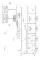
図1は、複合材部品12を製造するための生産ライン10を示している。生産ライン10は製造ライン100を含む。製造ライン100は、未固化の繊維強化材料16のレイアップ14を製造するよう構成される。レイアップ14は、複合材部品12になるので、部品レイアップとも称される。例えば、製造ライン100は、レイアップ14を製造するために、マンドレル102上に物体18を載置するよう構成される。生産ライン10は固化システム20を更に含む。Exemplary Lines and Systems FIG. 1 shows a
固化システム20は、プロセス方向22において、製造ライン100の後ろに位置付けられる。固化システム20は、部品レイアップ14を固化して複合材部品12にするよう構成される。本書で使用される場合、「固化すること(harderning)」は、熱硬化性材料を硬化すること、又は熱可塑性材料を固めることを含む。固化システム20は、未固化の材料(例えば未固化の繊維強化材料16)を固化して、固化された材料にするよう構成される。固化システム20は、熱硬化性材料を硬化すること及び/又は熱可塑性材料を固めることが可能である。例えば、固化システム20はオートクレーブを含む。図2は、図1に示している生産ライン10とともに使用されうる製造ライン100の概略図である。図1及び2を参照するに、製造ライン100は、製造システム200及びマンドレル102を含む。製造ライン100は、単一の線形ライン、間隙を有する(図2参照)線形ラインの対、又は線形ラインと回転式ラインとの組み合わせでありうる(例えば、製造システム200において線形経路が回転構成(図9参照)に、次いで回転経路に至り、その後、線形経路は製造システム200から出るか、又は製造システム200の別のサブシステムに至る)。 The
製造ライン100及び/又は製造システム200は、コントローラ104を含む。コントローラ104は、本書に記載の方法を実施するよう動作可能である。コントローラ104は、製造工程(例えば載置工程)を実施するために、ステーション202(例えば、ステーション202のエンドエフェクタ)と通信する。例えば、コントローラ104は、マンドレル102上に物体18を載置するために、各ステーション202におけるエンドエフェクタ及び/又はセンサに動作可能に連結される。 The
各ステーション202は、製造システム100及び/又はサブシステム106、108における複数のステーション202を制御する、各ステーションのコントローラ104を含みうるか、又は共通のコントローラ104を有しうる。一例では、複数のステーション202は、同一のサブシステム106又は108内にある場合、共通のコントローラ104を有する。しかし、別々のサブシステム106、108内の一又は複数のステーション202が、同一のコントローラ104によって稼働されることもある。各ステーション202が対応するコントローラ104を含む場合、これらのコントローラ104は、互いに通信して複数のステーション202の動作を協調させるよう構成される。 Each
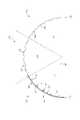
図3は、図1及び図2に示している製造ライン100とともに使用されうるマンドレル102の断面図である。図4は、マンドレル102上のレイアップ14の断面図である。図1から図4を参照するに、製造ライン100は、複合材部品12を製造するために、マンドレル102上に物体18を載置するよう構成される。 FIG. 3 is a cross-sectional view of a
物体18は、コンポーネント24、プリフォーム26、及び一又は複数の外板28を含む。物体18は、表面間異常(ISA)カウル(複数可)30、追加の外板52(図15参照)、電気保護層54(図15参照)、表面外板プライ56(図15参照)、カウル58(図15参照)、及び/又はバッグ60(図15参照)を更に含みうる。本書に記載の「プリフォーム(preform)」はいずれも、未固化の繊維強化材料16の一又は複数のプライから(通常は、未固化の繊維強化材料16の一又は複数のプライから構築される未固化の繊維強化材料16の複数の層から)形成された物体である。一例では、物体18は、分離プライ32、外板パネルプライ34、及びフレームフィラープリフォーム36からなる群から選択される。別の例では、物体18は、分離プライ32、フレームフィラープリフォーム36、及びストリンガプリフォーム38からなる群から選択される。 The
コンポーネント24は、少なくともフレームフィラープリフォーム36(「ポステージスタンプ(postage stamps)」としても既知である)を含む。コンポーネント42は、一又は複数の分離プライ32を更に含みうる。分離プライ32は、プリフォーム36、26及び一又は複数の外板層206が、マンドレル102のレイアップ面110と接触することを防止する。分離プライ32は、未固化の繊維強化材料16や別の繊維強化材料(例えばガラス繊維)から形成されうるか、又は離型膜でありうる。離型膜は、バギング材、剥離プライ、分離膜などを含みうる。 The
プリフォーム26はストリンガプリフォーム38を含む。ストリンガプリフォーム38は、胴体666(図22及び図23参照)の支持構造物となる。ストリンガプリフォーム36は、ショートストリンガプリフォーム40(図12参照)及び/又はロングストリンガプリフォーム42(図1参照)でありうる。この場合、ロングストリンガプリフォームはマンドレル102のレイアップ面110の長さ112にわたって延在し、ショートストリンガプリフォームは、レイアップ面110の長さ112よりも短い距離(例えば、レイアップ面110の長さ112の半分又は1/3)にわたって延在する。レイアップ面110の長さ112は、ISAカウル30及び/又はその他のマンドレル102に取り付けられるツーリングに適応するよう、マンドレル102の長さ114よりも短くなりうる。マンドレル102の長さ114は、胴体セクション670、676(図23参照)と等しいか、又はそれを上回る長さでありうる。更に、レイアップ面110の長さ112は、胴体セクション670、676とおおよそ同じ長さでありうるか、又は、2つ以上の複合材部品12が互いに組み立てられて胴体セクション670、676を形成する場合には、胴体セクション670、676よりも短くなりうる。
一又は複数の外板層28は、未固化の繊維強化材料16の一又は複数のプライ34から形成される。一又は複数の外板層28は、複合材部品12の内側成形ライン(IML)を画定する。 The one or more skin layers 28 are formed from one or
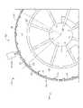
マンドレル102は、レイアップ面110及び複数のトラフ116を含む。トラフ116は、マンドレル102の周縁118に沿って、翼弦方向に互いから分離している。各トラフ116は、1つのプリフォーム26(例えばストリンガプリフォーム38)を内部に受容するよう構成される。一例では、各トラフ116は、ストリンガプリフォーム38の寸法に対応する寸法を有する。例えば、トラフ116の各々は、ハット型ストリンガプリフォームを収容するよう形作られる。 The
マンドレル102は、図6、図10、及び図11に示しているハーフバレルマンドレル120でありうる。ハーフバレルマンドレル120は、胴体666のハーフバレルセクション670(図23参照)の形状を画定する。ハーフバレルマンドレル120の周縁118は、実質的に、レイアップ面110に沿った半円である。あるいは、マンドレル102は、図9に示しているフルバレルマンドレル122であってもよい。フルバレルマンドレル122は、レイアップ面110に沿って全円にわたり延在する周縁118を有する。 The
更に、マンドレル102は、図1及び図6に示している、マンドレルの組(a series of mandrels)124のうちの1つのマンドレルでありうる。マンドレルの組124は、少なくとも第1マンドレル120a及び第2マンドレル102bを含む。一例では、マンドレルの組124は、製造システム200におけるステーション202と同じ数のマンドレル102を有する。あるいは、マンドレルの組124は、製造システム200におけるステーション202よりも少ない数のマンドレル102を有する。 Further, the
図3を参照するに、マンドレル102は、少なくとも第1ゾーン126及び第2ゾーン128を含む。ゾーン126及び128は各々、マンドレル102の部分130、132、及び/又は134に対応しうる。マンドレル102が弧状の断面形状を有する場合、部分130、132、及び/又は134は、マンドレル102の弧のうち少なくとも60°を占めうる。したがって、ハーフバレルマンドレル120には3つの部分があってよく、フルバレルマンドレル122には6つの部分がありうる。あるいは、フルバレルマンドレル122は、3つの部分であって、各々がマンドレル102の弧のうちの120°である、3つの部分を含みうる。 With reference to FIG. 3, the
代替的な一実施形態では、ゾーン126及び128は、マンドレル102の2つ以上の長手方向部分186(図10参照)に対応する。本書のこの例は主に、部分130、132、134に対応するゾーン126及び128に関するものであるが、この説明は、第1ゾーン126が第1長手方向部分186であり、第2ゾーンが第2長手方向部分186に対応している状況にも適用されうる。他の例(例えば図12の例)では、マンドレル102は、ゾーン126、128及び複数の長手方向部分186に区分されうる。 In one alternative embodiment,
ゾーン126及び128の各々は、マンドレル102の一又は複数の部分130、132、及び/又は134に対応しうる。例えば、マンドレル102がハーフバレルマンドレル120である場合、第1ゾーン126は頂部130を含み、第2ゾーン128は第1側部132及び第2側部134を含む。側部132、134は、円周方向で、頂部130の両側に隣接している。マンドレル102がフルバレルマンドレル122である場合、ゾーン126及び128の各々は、マンドレル102の1つの部分に対応しうる。 Each of the
図1を参照するに、製造システム200は、ステーション202の少なくとも1つの群204、206、及び/又は208を含む。例えば、製造システム200は、コンポーネントステーション210、プリフォームステーション212、及び外板ステーション214を有する、ステーション202の群204及び/又は206を含む。したがって、製造ライン100は、コンポーネントステーション210、プリフォームステーション212、及び外板ステーション214を含む。製造システム200が第1の群204及び第2の群206を含む場合、第1の群204は、第1コンポーネントステーション210と、第1プリフォームステーション212と、第1外板ステーション214とを含む。同様に、第2の群206は、第2コンポーネントステーション216と、第2プリフォームステーション218と、第2外板ステーション220とを含む。 Referring to FIG. 1, the
図9に関連付けて詳述するように、マンドレル102がフルバレルマンドレル122である場合、製造ライン100は、第1角度位置A1において、フルバレルマンドレル122上にコンポーネント24を載置するコンポーネントステーション210と、第2角度位置A2において、フルバレルマンドレル122上にプリフォーム26を載置するプリフォームステーション212と、第3角度位置A3において、フルバレルマンドレル122上に一又は複数の外板層28を載置するよう構成された外板ステーション214と、を含む。図9に示しているこれは、回転構成と称される。 As detailed in relation to FIG. 9, when the
マンドレル102が少なくとも第1ゾーン126及び第2ゾーン128を含む場合、製造ライン100は、第1サブシステム106及び第2サブシステム108を含む。第1サブシステム106は、マンドレル102の第1ゾーン126で製造工程を実施するよう構成された、ステーション202の第1の群204を含む。第2サブシステム108は、マンドレル102の第2ゾーン128で製造工程を実施するよう構成された、ステーション202の第2の群206を含む。製造工程は、マンドレル102上に物体18を載置するために、ステーション202によって実施される工程である。 If the
製造ライン100において、マンドレル102は、第1サブシステム106及び第2サブシステム108に対して(第3サブシステム136が存在する場合には、更に第3サブシステム136に対して)動くよう構成される。換言すると、マンドレル102はステーション202に対して動く。マンドレル102がフルバレルマンドレル122である場合、マンドレル122は、回転することによって、ステーション202に対して動く。更に、製造ライン100がマンドレル102の組124を含む場合、マンドレル102は、プロセス方向22に製造システム200に対して動く、マンドレルの組124のうちの1つのマンドレル102a、102b、102nでありうる。 In
マンドレル102を動かすために、製造ライン100は駆動システム138を含む。駆動システム138は、ステーション202に対してマンドレル102を動かすよう構成される。したがって、駆動システム138は、第1サブシステム106及び第2サブシステム108に対してマンドレル102を動かすよう構成される。マンドレル102の動きをステーション202の製造工程と協調させるために、コントローラ104が、駆動システム138に動作可能に連結される。 To operate the
一例では、駆動システム138は、ステーション202に対して、したがって第1サブシステム106及び第2サブシステム108に対して位置付けられた、軌道140を含む。軌道140は、(第3サブシステム136が存在する場合には)第3サブシステム136へと、かつ/又は第3サブシステム136を通って延在しうる。マンドレル102は軌道140に沿って動く。軌道140はチェーン駆動部142を含みうる。チェーン駆動部142は、軌道140に、又は軌道140に沿って動くエンジンに連結される。かかる実施形態では、帯電レール(electrified rail)又は電力供給レールを介して、マンドレル102(又はマンドレル102を駆動するエンジン)に電力が提供されうる。 In one example,
更に、駆動システム138は、追加的又は代替的に、帯電/電力供給レールを含みうる。電力供給レールは、軌道140と一体化されても、軌道140とは別個のものであってもよい。製造ライン100に電力供給レールが含まれる場合、駆動システム138は、マンドレル102をステーション202へと、かつステーション202を通るように搬送するために、電力供給レールに沿ってマンドレル102を動かす。 Further, the
別の例では、駆動システム138は、ステーション202に対して、したがって第1サブシステム106及び第2サブシステム108(更にオプションで第3サブシステム136)に対してマンドレル102を動かすために、マンドレル102に搭載されかつ/又は取り付けられる。特定の例では、駆動システム138は、マンドレル102に取り付けられた、又はマンドレル102及び/若しくはスピンドル252(図9参照)と一体化された、自律搬送ビークル(AGV)144を含む。マンドレル102がAGV144又は駆動システム138として機能するその他の自動駆動部によって搬送される場合、軌道140は駆動システム138から省かれることもある。 In another example, the
製造ライン100は位置決めシステム146を更に含む。位置決めシステム146は、マンドレル102と一又は複数のステーション202との位置を合わせるよう構成される。したがって、位置決めシステム146は、マンドレル102と第1サブシステム106及び第2サブシステム108との(更にオプションで第3サブシステム136との)位置を合わせるようにも構成される。位置決めシステム146は、一又は複数のステーション202におけるシステム位置決め要素148を含む。製造ライン100が第1サブシステム106及び第2サブシステム108を含む場合、位置決めシステム146は、第1サブシステム106における第1システム位置決め要素148aと、第2サブシステム108における第2システム位置決め要素148bとを含む。 The
位置決めシステム146は、マンドレル102におけるマンドレル位置決め要素150を更に含む。マンドレル位置決め要素150は、システム位置決め要素148と相互作用して、マンドレル102と製造システム200との位置を合わせるよう構成される。製造ライン100が第1サブシステム106及び第2サブシステム108を含む場合、マンドレル位置決め要素150は、第1システム位置決め要素148aと相互作用してマンドレル102と第1サブシステム106との位置を合わせるよう、かつ第2システム位置決め要素148bと相互作用してマンドレル102と第2サブシステム108との位置を合わせるよう、構成される。 The
図5は、製造ライン100とともに使用されうる位置決めシステム146の概略図である。図5に示しているように、一例では、位置決めシステム146は、マンドレル位置決め要素150として、マンドレル102に画定された位置決めカップ152を含む。位置決めシステム146は、システム位置決め要素148として、各ステーション202における位置決めピン154も含む。ピンとカップとが一例として提示されているが、ピンとカップの代わりにタブとスロット溝が使用されることもある。 FIG. 5 is a schematic diagram of a
位置決めピン154の各々は、マンドレル102と一又は複数のステーション202との位置を合わせるために、対応する位置決めカップ152と係合するよう構成される。位置決めピン154は、位置決めカップ152と接触して、ステーション(複数可)202に対してマンドレル102をガイドし、マンドレル102とステーション202(より詳細にはステーション202のエンドエフェクタ)との位置を合わせるよう、形作られる。 Each of the positioning pins 154 is configured to engage the
一例では、位置決めピン154の各々は、位置決めカップ152の形状に対応する形状を有する。例えば、カップ152が円錐形状の孔である場合、位置決めピン154の各々は円錐体として構成されうる。したがって、マンドレル102とステーション202との位置が合うと、位置決めピン154の各々は、対応する位置決めカップ152内に受容されうる。位置決めピン154及び位置決めカップ152は、(例えば円錐形状になるように)テーパされている。そのため、初期には、マンドレル102とステーション202との間の位置ずれにおける比較的大きな許容誤差が許容され、位置決めピン154が位置決めカップ152の中心に来る(この時、マンドレル102はステーション202に対して定位置に付く)までマンドレル102とステーション202とが互いに近付くように動くにつれて、位置ずれは低減する。マンドレル102がステーション202から離れるように動く時、位置決めピン154は位置決めカップ152から係合解除される。 In one example, each of the positioning pins 154 has a shape corresponding to the shape of the
製造ライン100が第1サブシステム106及び第2サブシステム108を含む場合、位置決めシステム146は、第1サブシステム106のステーションの第1の群204の各ステーション202における第1位置決めピン154aと、第2サブシステム108のステーションの第2の群206の各ステーション202における第2位置決めピン154bとを含む。一例では、第1位置決めピン154aの各々は、マンドレル102と第1サブシステム106の各ステーション202との位置を合わせるために対応する位置決めカップ152と係合するよう構成され、第2位置決めピン154bの各々は、マンドレル102と第2サブシステム108の各ステーション202との位置を合わせるために対応する位置決めカップ152と係合するよう構成される。 When the
代替的又は追加的には、位置決めシステム146は、マンドレル102上の識別タグ156と、一又は複数のステーション202における識別リーダ158とを含む。識別タグ156は、その内部にマンドレル102及び複合材部品12についての符号化された情報を含む。一部の例では、識別タグ156は無線周波数(RF)識別タグ又はバーコードタグである。識別リーダ158は、識別タグ156から情報を取得して、マンドレル102と各ステーション202との位置合わせを決定し、情報を駆動システム138に伝送するよう構成される。駆動システム138は次いで、各ステーション202に対してマンドレル102を位置決めする。識別タグ156が無線周波数(RF)識別タグ又はバーコードタグである場合、第1識別リーダ158はRFリーダ又はバーコードリーダである。位置決めシステム146が識別リーダ158を含む場合、コントローラ104が識別リーダ158と通信して、駆動システム138及び/又はステーション202を制御する。 Alternatively or additionally, the
製造ライン100が第1サブシステム106及び第2サブシステム108を含む場合、位置決めシステム146は、第1サブシステム106のステーション202のうちの一又は複数に位置付けられた第1識別リーダ158aを含む。第1識別リーダ158aは、第1サブシステム106の各ステーション202に対してマンドレル102を位置決めするために、識別タグ156から情報を取得して、マンドレル102と第1サブシステム106の各ステーション202との位置合わせを決定し、情報を駆動システム138に伝送するよう構成される。位置決めシステム146は、第2サブシステム108のステーション202のうちの一又は複数に位置付けられた第2識別リーダ158bを更に含む。第2識別リーダ158bも、同様に、第2サブシステム108の各ステーション202に対してマンドレル102を位置決めするために、識別タグ156から情報を取得して、マンドレル102と第2サブシステム108の各ステーション202との位置合わせを決定し、情報を駆動システム138に伝送するよう構成される。 If the
追加的又は代替的には、位置決めシステム146はハードストップ160(図6参照)を含む。より具体的には、マンドレル102とステーション(複数可)202との位置を合わせるために、一又は複数のステーション202に(例えば各ステーション202に)ハードストップ106が位置付けられる。 Additional or alternative, the
マンドレル102がフルバレルマンドレル122である場合、位置決めシステム146は位置決めユニット162(図9参照)を含む。位置決めユニット162は、フルバレルマンドレル122を支持しているスピンドル252(図9参照)による各回転の後に、ステーション202に対する所定の角度位置にフルバレルマンドレル122を位置決めするよう構成される。追加的又は代替的には、位置決めユニット162は、スピンドル252の各回転の後に、少なくとも1つのステーション202(例えば、コンポーネントステーション210、プリフォームステーション212、及び外板ステーション214のうちの少なくとも1つ)に対して、フルバレルマンドレル122を位置決めするよう構成される。 If the
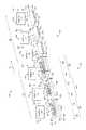
図6は、生産ライン10及び/又は製造ライン100とともに使用されうる製造システム200の概略図である。図1、図2、及び図6を参照するに、製造システム200により、複数の物体18から、複合材部品12(例えば、図23に示している胴体666のセクション670、676)が製造される。製造システム200は、マンドレル102上に物体18を載置するために、複数のステーション200(例えばステーション202の組124)を含む。組124におけるステーション202の数は、各ステーション202の所定のタクトタイム(takt time)222に基づく。以下で詳述するように、タクトタイム222とは、移動パルス226と移動パルス226との間の停止時間224に移動パルス時間228を加えたものである。 FIG. 6 is a schematic diagram of a
一例では、製造システム200は、少なくともコンポーネントステーション210と外板ステーション214とを含む。外板ステーション214は、コンポーネントステーション210からプロセス方向22に離れている。コンポーネントステーション210はマンドレル102上にコンポーネント24(図4参照)を載置し、外板ステーション214はマンドレル102上に一又は複数の外板層28(図4参照)を載置する。例としては、コンポーネント24は、未固化の繊維強化材料16で形成されたフレームフィラープリフォーム36を含む(図4参照)。製造システム200は、コンポーネントステーション210からプロセス方向22に離れた、プリフォームステーション212を更に含みうる。プリフォームステーション212は、マンドレル102上にプリフォーム26(図4参照)を載置する。例えば、プリフォーム26は、未固化の繊維強化材料16で形成されたストリンガプリフォーム38を含む(図4参照)。 In one example, the
コンポーネントステーション210がマンドレル102の第1ゾーン126に割り当てられた第1コンポーネントステーション210であり、外板ステーション214がマンドレル102の第1ゾーン126に割り当てられた第1外板ステーション214である場合、製造システム200は、マンドレル102の第2ゾーン128上にコンポーネント24を載置するよう構成されたコンポーネントエンドエフェクタ236、238を有する第2コンポーネントステーション216(図7、図8、及び図11参照)と、マンドレル102の第2ゾーン128上に一又は複数の外板層28を載置するよう構成された外板エンドエフェクタ244、246を有する第2外板ステーション220(図7、図8、及び図11参照)とを、更に含む。製造システム200は、マンドレル102の第2ゾーン128上にプリフォーム26を載置するよう構成された、第2プリフォームステーション218及びプリフォームエンドエフェクタ240、242(図7、図8、及び図11参照)を更に含む。この例では、第1ゾーン126はマンドレル102の頂部130であり、第2ゾーン128はマンドレル102の一又は複数の側部132、134である。
マンドレル102が少なくとも第1ゾーン126及び第2ゾーン128を含む場合、製造システム200は、ステーションの少なくとも2つの群204、206に区分された、ステーション202の組124を含む。ステーション202の各群204、206は、マンドレル102の特定のゾーン126、128で製造工程を実施する。ステーションの少なくとも2つの群は、ステーション202の第1の群204と、ステーション202の第2の群206とを含む。第1の群204はマンドレル102の第1ゾーン126に割り当てられ、第2の群206はマンドレル102の第2ゾーン128に割り当てられる。 If the
別の例では、製造システム200はステーション202の組124を含み、この場合、組124は、第1ゾーン126上にコンポーネント24を載置するよう構成された一又は複数のゾーン1コンポーネントステーション210と、第1ゾーン126上にプリフォーム26を載置するよう構成された一又は複数のゾーン1プリフォームステーション212と、第1ゾーン126上に一又は複数の外板層28を載置するよう構成された一又は複数のゾーン1外板ステーション214と、マンドレル102の第2ゾーン128上にコンポーネント24を載置するよう構成された一又は複数のゾーン2コンポーネントステーション216と、第2ゾーン128上にプリフォーム26を載置するよう構成された一又は複数のゾーン2プリフォームステーション218と、第2ゾーン128上に一又は複数の外板層28を載置するよう構成された一又は複数のゾーン2外板ステーション220と、を含む。かかる例では、第1の群204は、ゾーン1コンポーネントステーション210と、ゾーン1プリフォームステーション212と、ゾーン1外板ステーション214とを含みうる。同様に、第2の群206は、ゾーン2コンポーネントステーション216と、ゾーン2プリフォームステーション218と、ゾーン2外板ステーション220とを含みうる。 In another example, the
製造システム200は、別様に、マンドレル102の第1ゾーン126において製造工程を実施するよう構成されたステーション202の第1の群204を伴う第1サブシステム106と、マンドレル102の第2ゾーン128において製造工程を実施するよう構成されたステーション202の第2の群206を有する第2サブシステム108とを有する、製造システム200であるとも説明される。第1サブシステム106及び第2サブシステム108の製造工程により、マンドレル102上でレイアップ14が製造される。より具体的には、第1サブシステム106と第2サブシステム108とがともに動作して、少なくともコンポーネント24、プリフォーム26、及び一又は複数の外板プライ28を含むレイアップ14を製造する。 The
群204、206又はサブシステム106、108の各々におけるステーション202の数は、サブシステム106、108のタクトタイム222及び/又は各ステーション202のタクトタイム222に応じて変わる。一例としては、群204、206又はサブシステム106、108の各々は3つ以上のステーション202を含む。群204、206又はサブシステム106、108の各々は、同種又は別種のステーション202を有しうる。例えば、第1サブシステム106及び/又は第2サブシステム108は、マンドレル102上にプリフォーム26を載置するよう構成された、一又は複数のプリフォームステーション212、218を含む。 The number of
一例では、各サブシステム106、108は、マンドレル102上で異なる製造工程を実施するよう構成される。かかる例では、サブシステム106は、第1サブシステム106として、マンドレル102上にコンポーネント24を載置するためのコンポーネントサブシステムを含み、かつ、第2サブシステム108として、マンドレル102上にプリフォーム26を載置するためのプリフォームサブシステムを含む。この例には、マンドレル102上に一又は複数の外板層28を載置するための外板サブシステムも含まれる。マンドレル102が複数のゾーン126、128を含む場合、コンポーネントサブシステム106は、マンドレル102の複数のゾーン126、128上にコンポーネント24を載置するよう構成され、プリフォームサブシステム108は、マンドレル102の複数のゾーン126、128上にプリフォーム26を載置するよう構成され、外板サブシステムは、マンドレル102の複数のゾーン126、128上に一又は複数の外板層28を載置するよう構成される。 In one example, each of the
別の例では、各サブシステム106、108は、マンドレル102上で同様の製造工程を実施するよう構成される。より具体的には、各サブシステム106、108は、マンドレル102上にコンポーネント24を載置し、マンドレル102上にプリフォーム26を載置し、かつマンドレル106上に一又は複数の外板層28を載置するよう、構成される。少なくともコンポーネント24、プリフォーム26、及び外板層(複数可)28により、マンドレル102上にレイアップ14が形成される。したがって、群204、206又はサブシステム106、108の各々は、少なくともコンポーネントステーション210、216と、プリフォームステーション212、218と、外板ステーション214、220とを含む。 In another example, each of the
マンドレル102がハーフバレルマンドレル120である場合、ハーフバレルマンドレル120上で複合材部品12を製造するために、第1サブシステム106及び第2サブシステム108は、プロセス方向22に沿って並ぶように位置付けられる(図6から図8参照)。マンドレル102がフルバレルマンドレル122である場合、第1サブシステム106と第2サブシステム108とは、フルバレルマンドレル122の周縁118を取り囲むよう配列される(図9参照)。あるいは、第1サブシステム106及び第2サブシステム108は、マンドレル102がフルバレルマンドレル122であっても、プロセス方向22に沿って並ぶように位置付けられる。これにより、サブシステム106、108が、同一の又は異なるマンドレル102の別々の長手方向部分で、製造工程を実施することが可能になる。 If the
図7は、製造システム200の第1の例示的な配置構成の概略ブロック図である。図8は、製造システム200の第2の例示的な配置構成の概略ブロック図である。図6から図8を参照するに、ステーション202の組124は別種のステーション(例えばコンポーネントステーション210、214とプリフォームステーション212、218と外板ステーション214、220)を含む。マンドレル102の各ゾーン126、128につき、各種類のステーション202の1つを示しているが、製造システム200は、タクトタイム222に応じて、任意の種類の複数のステーションを含みうる。例えば、プリフォーム26を載置するのに単一のタクトタイム222を超える時間がかかる場合、製造システム200又はサブシステム106、208は、複数のプリフォームステーション212及び/又は218を含む。一例としては、プリフォームを載置するのにタクトタイム222の3倍の時間がかかる場合、製造システム200又はサブシステム106、108は、3つのプリフォームステーション212及び/又は218を含む。分かりやすく言うと、ある種のステーションの1つについて説明しているが、その説明は、システム200又はサブシステム106、108におけるその種のステーションの全てに適用される。 FIG. 7 is a schematic block diagram of a first exemplary layout configuration of the
各ステーション202は、それぞれのステーション202に、製造工程を実施するためのエンドエフェクタ230を含む。エンドエフェクタ230は、ゾーン126又は128によって、図10に関連付けて詳述する第1ゾーン(若しくはゾーン1)エンドエフェクタ232として、又は図11に関連付けて詳述する第2ゾーン(若しくはゾーン2)エンドエフェクタ234として、構成される。 Each
コンポーネントステーション210、216は、マンドレル102上にコンポーネント24を載置するよう構成される。一部の例では、コンポーネントステーション210、216は、マンドレル102上にコンポーネント24(例えばフレームフィラープリフォーム36)を載置するよう構成された、コンポーネントエンドエフェクタ236又は238を含む。コンポーネントステーションがゾーン1コンポーネントステーション210である場合、エンドエフェクタは、第1ゾーン126(例えば頂部130)にコンポーネント24を載置するよう構成されたゾーン1コンポーネントエンドエフェクタ236である。同様に、コンポーネントステーションがゾーン2コンポーネントステーション216である場合、エンドエフェクタは、第2ゾーン128(例えば側部132、134)にコンポーネント24を載置するよう構成されたゾーン2コンポーネントエンドエフェクタ236である。 The
一例では、コンポーネントステーション210、216は、マンドレル102上にコンポーネント24を載置する前に、マンドレル102上に一又は複数の分離プライ32を載置するよう、更に構成される。より具体的には、分離プライ32が使用される場合、コンポーネントエンドエフェクタ236、238は、マンドレル102上に一又は複数の分離プライ32を載置し、次いで、分離プライ32上にフレームフィラープリフォーム36を載置するよう構成される。あるいは、分離プライ32は、タクトタイム222並びに分離プライ32及びフレームフィラープリフォーム36を載置する時間に応じて、コンポーネントステーション210、216の前のステーションにおいて載置される。 In one example, the
プリフォームステーション212、218は、マンドレル102上にプリフォーム26を載置するよう構成される。一部の例では、プリフォームステーション212、208は、プリフォーム26を載置するよう構成されたプリフォームエンドエフェクタ240、242を含む。プリフォームステーションがゾーン1プリフォームステーション212である場合、エンドエフェクタは、第1ゾーン126(例えば頂部130)にプリフォーム26を載置するよう構成されたゾーン1プリフォームエンドエフェクタ240である。同様に、プリフォームステーションがゾーン2プリフォームステーション218である場合、エンドエフェクタは、第2ゾーン128(例えば側部132、134)にプリフォーム26を載置するよう構成されたゾーン2プリフォームエンドエフェクタ242である。 The
プリフォームエンドエフェクタ240、242は、マンドレル102のトラフ116内にプリフォーム26を載置するよう構成される。以下で詳述するように、プリフォームエンドエフェクタ240、242は更に、プリフォーム26同士を長手方向にスプライス留めしうる。 The
外板ステーション214、220は、マンドレル102上に一又は複数の外板層28を載置するよう構成される。一部の例では、外板ステーション214、220は、マンドレル102上に一又は複数の外板層28を載置するよう構成された、外板エンドエフェクタ244、246を含む。外板ステーションがゾーン1プリフォームステーション214である場合、エンドエフェクタは、第1ゾーン126(例えば頂部130)に外板層(複数可)28を載置するよう構成された、ゾーン1外板エンドエフェクタ244である。同様に、外板ステーションがゾーン2外板ステーション220である場合、エンドエフェクタは、第2ゾーン128(例えば側部132、134)に外板層(複数可)28を載置するよう構成された、ゾーン2外板エンドエフェクタ246である。 The
より具体的には、外板エンドエフェクタ244、246は、マンドレル102上に一又は複数の外板層28を積層することによって載置するために、マンドレル102に一又は複数の外板プライ34を付加するよう構成される。少なくとも1つの外板層28は、内側成形ラインプライを含む。外板エンドエフェクタ244、246は、マンドレル102上のコンポーネント24及びプリフォーム26の上に、一又は複数の外板層28を載置するようにも構成される。 More specifically, the outer
外板ステーション210、216は、マンドレル102上に表面間異常(ISA)カウル30を載置するよう、更に構成される。より具体的には、外板ステーション210、216は、プリフォーム26上に、ISAカウル30を載置した後に、一又は複数の外板層28を載置するよう構成される。あるいは、ISAカウル30の載置と一又は複数の外板層28の載置にタクトタイム222よりも長い時間がかかるかどうかに応じて、プリフォームステーション212、218と外板ステーション210、216との間にISAカウルステーションが位置付けられる。 The
エンドエフェクタ230の代替として、任意のステーション202における製造工程(載置など)が手作業で実施されることもある。 As an alternative to the
図1、図2、及び図6から図8を参照するに、製造システム200は一又は複数の供給ライン164を更に含みうる。例えば、各サブシステム106、108は、サブシステム106、108における一又は複数のステーション202に関連付けられた一又は複数の供給ライン164を更に含みうる。したがって、各サブシステム106、108は、ステーション202の群204、206と、一又は複数の供給ライン164とを含む。各供給ライン164は、ステーション202のタクトタイム222に対応するタクトタイムにおいて動作する。製造システム200(又はサブシステム106、108)は、関連供給ライン164から材料を受領するステーション202の種類に応じて、異なる種類の供給ライン164を含む。 With reference to FIGS. 1, 2, and 6-8, the
一又は複数のコンポーネント供給ライン166、168が、少なくとも1つのコンポーネントステーション210、216(例えばゾーン1コンポーネントステーション(複数可)210及び/又はゾーン2コンポーネントステーション(複数可)216)に関連付けられる。ステーション202がゾーン126、128ごとにグループ化されている場合、コンポーネント供給ライン(複数可)166、168は、コンポーネント24をゾーン1コンポーネントステーション(複数可)210に供給するよう構成された、一又は複数のゾーン1コンポーネント供給ライン166と、コンポーネント24をゾーン2コンポーネントステーション(複数可)216に供給するよう構成された、一又は複数のゾーン2コンポーネント供給ライン168と、を含みうる。コンポーネント供給ライン166、168は、分離プライ32及び/又はフレームフィラープリフォーム36を供給しかつ/又は製造するための、システム及び装置を含む。 One or more
一又は複数のプリフォーム供給ライン170、172が、少なくとも1つのプリフォームステーション212、218(例えばゾーン1プリフォームステーション(複数可)212及びゾーン2プリフォームステーション(複数可)218)に関連付けられる。ステーション202がゾーン126、128ごとにグループ化されている場合、プリフォーム供給ライン(複数可)は、プリフォーム26をゾーン1プリフォームステーション(複数可)212に供給するよう構成された一又は複数のゾーン1プリフォーム供給ライン170と、プリフォーム26をゾーン2プリフォームステーション(複数可)218に供給するよう構成された一又は複数のゾーン2プリフォーム供給ライン172と、を含む。供給ライン170、172は、ストリンガプリフォーム38を製造するためのシステム及び装置を含みうる。あるいは、供給ライン170、172は、ストリンガ製造システムからプリフォームステーション(複数可)212、218にストリンガプリフォーム38を搬送する。 One or more
一又は複数の外板供給ライン174、176は、少なくとも1つの外板ステーション214、220(例えばゾーン1外板ステーション(複数可)214及びゾーン2外板ステーション(複数可)220)に関連付けられる。ステーション202がゾーン126、128ごとにグループ化されている場合、外板供給ライン(複数可)は、一又は複数の外板層28をゾーン1外板ステーション(複数可)214に供給するよう構成された一又は複数のゾーン1外板供給ライン174と、一又は複数の外板層28をゾーン2外板ステーション(複数可)220に供給するよう構成された一又は複数のゾーン2外板供給ライン176と、を含む。例えば、外板供給ライン174、176は、外板パネルプライ34を供給し、かつ/又は、外板パネルプライ34から外板ステーション(複数可)214、220によって使用される外板層(複数可)28を製造する。更に、外板供給ライン174、176は、外板ステーション(複数可)214、220にISAカウル30を供給しうる。 One or more
図7を参照するに、ステーション202は、ステーション202がマンドレル102のゾーン126又は128のどちらに割り当てられるかにしたがって配列されうる。この例では、第1サブシステム106のステーション202は、第2サブシステム108のステーション202の前に並べられる。かかる配置構成では、ステーションの組124は、一列に並んだ、第1の群204とそれに続く第2の群206とを含む。より具体的には、ステーションの組124は、順に、ゾーン1コンポーネントステーション(複数可)210、ゾーン1コンポーネントステーション(複数可)210に続くゾーン1プリフォームステーション(複数可)212、ゾーン1プリフォームステーション(複数可)212に続くゾーン1外板ステーション(複数可)214、ゾーン1外板ステーション(複数可)214に続くゾーン2コンポーネントステーション(複数可)216、ゾーン2コンポーネントステーション(複数可)216に続くゾーン2プリフォームステーション(複数可)218、及びゾーン2プリフォームステーション(複数可)218に続くゾーン2外板ステーション(複数可)220を含む。 With reference to FIG. 7, the
図8を参照するに、ステーション202は、どの種類のステーションであるかにしたがって配列されうる。この例では、第1の群204のステーション202と第2の群206のステーション202とが交互配置されている。かかる配置構成では、ステーションの組124は、順に、ゾーン1コンポーネントステーション(複数可)210、ゾーン1コンポーネントステーション(複数可)210に続くゾーン2コンポーネントステーション(複数可)216、ゾーン2コンポーネントテーション(複数可)216に続くゾーン1プリフォームステーション(複数可)212、ゾーン1プリフォームステーション(複数可)212に続くゾーン2プリフォームステーション(複数可)218、ゾーン2プリフォームステーション(複数可)218に続くゾーン1外板ステーション(複数可)214、及びゾーン1外板ステーション(複数可)214に続くゾーン2外板ステーション(複数可)220を含む。 With reference to FIG. 8, the
図9は、製造システム200の回転構成の正面図である。この回転構成では、マンドレル102はフルバレルマンドレル122であり、ステーション202の組124は、フルバレルマンドレル122の周縁118に沿って並んでいる。一例では、複数の外板ステーション214が、フルバレルマンドレル122の周縁118に沿って位置付けられる。システム200が1を上回る数のサブシステムを含む場合、第1サブシステム106と第2サブシステム108とは、フルバレルマンドレル122の周縁118を取り囲むよう配列される。 FIG. 9 is a front view of the rotation configuration of the
図示している例では、プリフォームステーション212は、フルバレルマンドレル122の上方に上昇している。したがって、製造システム200は、プリフォームステーション212を支持するための頭上ガントリ248を含む。より具体的には、ガントリ248は、プリフォームエンドエフェクタ240がフルバレルマンドレル122に対して動きうるように、プリフォームエンドエフェクタ240を支持する。プリフォーム供給ライン170は、プリフォーム26をプリフォームステーション212まで持ち上げるローダ250を含みうる。 In the illustrated example, the
この回転構成では、製造システム200はスピンドル252を更に含む。スピンドル252は、フルバレルマンドレル122の内部からフルバレルマンドレル122を支持するよう構成される。スピンドル252は、複数の角度位置を通るように、スピンドル252の長手方向軸254を中心としてフルバレルマンドレル122を回転させるよう構成される。より具体的には、スピンドル252は、回転することによって、マンドレル122の別々のゾーンを、ステーション202まで、かつステーション202を通るように動かす。スピンドル252は、各角度位置まで回転し、次いで、次の角度位置まで回転する前にその角度位置で動きを停止するよう構成される。回転とそれに次ぐ停止は、スピンドル252の移動パルス226と見なされる。コンポーネントステーション210、プリフォームステーション212、及び外板ステーション214は、スピンドル252の同一停止時間中に動作するよう構成される。 In this rotational configuration, the
スピンドル252は、コンポーネントステーション210、プリフォームステーション212、及び外板ステーション214に対してフルバレルマンドレル122を回転させる。上述したように、コンポーネントステーション210は第1角度位置A1においてコンポーネント24を載置し、プリフォームステーション212は第2角度位置A2においてプリフォーム26を載置し、外板ステーション214は少なくとも第3角度位置A3において外板層(複数可)28を載置する。製造システム200が複数の外板ステーション214を含む場合、外板層28は、複数の角度位置において載置されうる。したがって、外板ステーション(複数可)214は、図14を参照して詳述するように、種々のゾーン126、128及び/又は種々の角度位置A1、A2、A3において、外板層(複数可)28のスプライス278(図14参照)を作り出しうる。 The
スピンドル252は、駆動システム138に含まれる。より具体的には、スピンドル252は、製造ライン100に沿ってフルバレルマンドレル122を動かすために使用される。例えば、スピンドル252は、フルバレルマンドレル122を動かして、ステーション202内に位置付ける。ステーション202が製造工程を実施した後、スピンドル252は、次のシステム又は次のステーション202の群206にフルバレルマンドレル122を動かす。 The
製造システム200が第1の群204と第2の群206、及び/又は第1サブシステム106と第2サブシステム108を含む場合、スピンドル252は、ステーションの第1の群204の各ステーション及びステーションの第2の群206の各ステーションに対して、フルバレルマンドレル122を回転させる。更に、スピンドル252は、駆動システム138の一部として、フルバレルマンドレル122を、第1サブシステム106及び第2サブシステム108へと、かつ第1サブシステム106及び第2サブシステム108を通るように、プロセス方向22に動かすよう構成される。 If the
製造システム200は、オプションで、フルバレルマンドレル122において複合材部品12を切断して、2つのハーフバレルセクション670(図23参照)にするよう構成された、切断機256を含みうる。切断機256は、固化システム20(図1参照)の前又は後ろに位置付けられうる。複合材部品12を切断して2つのハーフバレルセクション670にするために切断機256が使用される場合、ハーフバレルセクション670は、ハーフバレルセクション670にシステム及びハードウェアが設置された後に、フルバレルセクション676に戻るように互いに組み立てられうる。 The
配置構成が線形である場合(図6から図8参照)、ステーション202は、ステーション202がゾーン126又は128のどちらに割り当てられるかに応じて、種々の構成を有する。 When the arrangement configuration is linear (see FIGS. 6-8), the
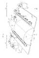
図10は、マンドレル102の第1ゾーン126(例えば頂部130)のためのステーション258の斜視図である。例えば、ステーションの第1の群204中のステーション258は各々、マンドレル102の頂部130で製造工程を実施するよう構成される。したがって、ゾーン1ステーション258(例えばゾーン1コンポーネントステーション(複数可)210、ゾーン1プリフォームステーション(複数可)212、及び/又はゾーン1外板ステーション(複数可)214)は、高所で物体18を載置するよう構成される。少なくともゾーン1コンポーネントステーション210とゾーン1外板ステーション214は各々、マンドレル102の頂部130に物体18を載置するための、高架ガントリ260を含む。ゾーン1コンポーネントステーション210はガントリ260を含むこともある。ガントリ260は、物体18が頂部130に載置されうるように、マンドレル102の上方でエンドエフェクタ232を支持する。エンドエフェクタ232は、ガントリ260のフレーム262に対してX方向、Y方向、及びZ方向に動くことも可能である。ガントリ260は、技術者(複数可)44を支持するためのプラットフォーム264も含みうる。 FIG. 10 is a perspective view of the
ゾーン1ステーション258は一又は複数のトレイ266も含みうる。トレイ266は、マンドレル102上に載置される前のコンポーネント24、プリフォーム26、及び/又は外板層(複数可)28を保持しうる。エンドエフェクタ232は、トレイ(複数可)266とマンドレル102との間でフレーム262に沿って動いて、物体18をトレイ(複数可)266から取り上げ、マンドレル102上に載置しうる。
図11は、マンドレル102の第2ゾーン128(例えば一又は複数の側部132、134)のためのステーション268の斜視図である。例えば、ステーションの第2の群206中のステーション268は各々、マンドレル102の2つの側部132、134で製造工程を実施するよう構成される。したがって、ゾーン2ステーション268(例えばゾーン2コンポーネントステーション(複数可)216、ゾーン2プリフォームステーション(複数可)218、及び/又はゾーン2外板ステーション(複数可)220)は、マンドレル102上に概して水平に物体18を載置するよう構成される。第2ゾーン128は側部(複数可)132、134を含むので、ゾーン2ステーション268は、マンドレル102上に物体18を載置するために水平に動きうるエンドエフェクタ234を含む。 FIG. 11 is a perspective view of the
第2ゾーン128が2つの側部132及び134を含む場合、第2コンポーネントステーション(又はゾーン2コンポーネントステーション)216のコンポーネントエンドエフェクタ238は、コンポーネント24を2つの側部132及び134に並行して(例えば、同一のパルス動作226中に同時に)載置する。同様に、第2外板ステーション(又はゾーン2外板ステーション)220の外板エンドエフェクタ246は、並行して2つの側部12及び134に一又は複数の外板層28を載置する。また、第2プリフォームステーション(又はゾーン2プリフォームステーション)218のプリフォームエンドエフェクタ242は、並行して2つの側部132及び134にプリフォーム26を載置する。 If the
ゾーン2ステーション268は、技術者44が上に立ちうるデッキ270を含みうる。トレイ266は、デッキ270又はフロア上に含まれうる。トレイ266は、マンドレル102上に載置される前のコンポーネント24、プリフォーム26、及び/又は外板層(複数可)28を保持しうる。ロボットアーム272上のエンドエフェクタ234は、トレイ(複数可)266とマンドレル102との間で動いて、物体18をトレイ(複数可)266から取り上げ、マンドレル102上に載置しうる。ロボットアーム272とエンドエフェクタ234との各セットは、ステーション268のサブステーション274とみなされうる。なぜなら、各ロボットアーム272は関連するエンドエフェクタ234を、他のロボットアーム272及びエンドエフェクタ234とは別個に稼働されうるからである。 Zone 2
図12は、プリフォーム26のスプライス276を作り出すために使用されうる複数のプリフォームステーション212の斜視図である。一例ではプリフォーム26が、製造されるストリンガ678(図23参照)の全長よりも短いショートストリンガプリフォーム40である場合、ステーションの群204、206は、マンドレル102上に第1ショートストリンガプリフォーム40を載置するよう構成された一又は複数のプリフォームステーション212、218を含む。例えば、製造システム200は、第1ゾーン1プリフォームステーション212a、第2ゾーン1プリフォームステーション212b、及び第3ゾーン1プリフォームステーション210cを含む。プリフォームステーション212a、212b、及び212cの各々は、マンドレル102のゾーン126、128上にショートストリンガプリフォーム40のセット278を載置する。 FIG. 12 is a perspective view of a plurality of
第1ゾーン1プリフォームステーション212aは、マンドレル102の第1ゾーン126の第1長手方向部分186a上に、ショートストリンガプリフォーム40の第1のセット278aを載置する。第2ゾーン1プリフォームステーション212bは、ショートストリンガプリフォーム40の第2のセット278bがショートストリンガプリフォーム40の第1のセット278aと若干重複するように、ショートストリンガプリフォーム40の第1のセット278aと隣り合った第2長手方向部分186b上に、ショートストリンガプリフォーム40の第2のセット278bを載置する。この重複により、第1のセット278aのショートストリンガプリフォーム40の各々と、第2のセット278bのショートストリンガプリフォーム40のそれぞれとの間のスプライス276として、スカーフスプライス又はラップスプライスが作り出されうる。同様に、第3ゾーン1プリフォームステーション212cは、ショートストリンガプリフォーム40の第3のセット278cがショートストリンガプリフォーム40の第2のセット278bと若干重複するように、ショートストリンガプリフォーム40の第2のセット278bと隣り合った第3長手方向部分186c上に、ショートストリンガプリフォーム40の第3のセット278cを載置して、スプライス276を作り出す。 The
システム200が2つの群204及び206を含む場合、ステーションの第2の群206は一又は複数の第2プリフォームステーション218を含み、一又は複数の第2プリフォームステーション218は、マンドレル102上に、第1ショートストリンガプリプリフォーム40aに対して第2ショートストリンガプリフォーム40bを載置し、第2ショートストリンガプリフォーム40bの各々を第1ショートストリンガプリフォーム40aのそれぞれにスプライス留めするよう構成されている。追加的又は代替的には、第1プリフォームステーション212と第2プリフォームステーション218とがともに作動してスプライス276を作り出す。より具体的には、第2プリフォームステーション(複数可)218は、第2ショートストリンガプリフォーム40bの載置中にスプライス留めを実施するよう構成される。例えば、第2ショートストリンガプリフォーム40bは、載置される際に、第1ショートストリンガプリプリフォーム40aと若干重ねられる。この重複により、第1ショートストリンガプリフォーム40aの各々と、第2ショートストリンガプリフォーム40bのそれぞれとの間に、スカーフスプライス又はラップスプライスが作り出されうる。スプライス276とマンドレル102の周縁118との位置が合っているので、スプライス276は、プリフォーム26の円環方向(hoopwise)スプライスと称されることもある。 If the
図13は外板スプライス278を作り出すために使用されうる外板ステーション220の断面図である。一部の例では、第1外板ステーション214又は第2外板ステーション220は、マンドレル102の第1ゾーン126の外板パネルプライ34と、マンドレル102の第2ゾーン128の外板パネルプライ34とをスプライス留めするよう構成される。より具体的には、外板層(複数可)28を載置するために第1外板ステーション214が外板パネルプライ34を付加した後に、第2外板ステーション220が、第1外板ステーション214により付加された外板パネルプライ34の一部と重複するよう外板パネルプライ34を付加する。あるいは、ステーション202が、物体18を側部132及び143に載置してから頂部に載置する場合は、ゾーン1外板ステーション214がスプライス278を形成する。したがって、第1外板ステーション214及び/又は第2外板ステーション220は、一又は複数の外板層28がマンドレル102上に載置される際に、外板パネルプライ34同士をスプライス留めするよう構成される。スプライス278は、マンドレル102の長手方向軸に沿って位置合わせされるので、長手方向スプライスと称されることもある。 FIG. 13 is a cross-sectional view of a
図14は、外板層スプライス278を作り出すための、回転構成の外板ステーション214の断面図である。フルバレルマンドレル122が2つ以上のゾーン126、128を含む場合、外板ステーション214は、一又は複数の外板層28が載置される際に、第1ゾーン126の外板パネルプライ34と第2ゾーン128の外板パネルプライ34とをスプライス留めするよう構成される。より具体的には、外板層(複数可)28を載置するために外板パネルプライ34が第1ゾーン126に付加された後に、外板ステーション214は、第1ゾーン126に付加された外板パネルプライ34のうちの一又は複数と重複するよう、第2ゾーン128に外板パネルプライ34を付加する。 FIG. 14 is a cross-sectional view of the
フルバレルマンドレル122が頂部130と側部134とを含む場合、外板ステーション214は、一又は複数の外板層28が載置される際に、頂部130の外板パネルプライ34と側部134の外板パネルプライ34とをスプライス留めするよう構成される。より具体的には、外板層(複数可)28を載置するために外板パネルプライ34が頂部130に付加された後に、外板ステーション214は、頂部130に付加された外板パネルプライ34のうちの一又は複数と重複するよう、側部134に外板パネルプライ34を付加する。 If the
図15は、図1から図14に示している製造システム200とともに使用されうる、第3サブシステム136の概略図である。図1、図2、及び図14を参照するに、第3サブシステム136は、プロセス方向22において、第1の群204及び第2の群206、又は第1サブシステム106及び第2サブシステム108の後ろに位置付けられる。したがって、レイアップ14が製造された後に、マンドレル102は第3サブシステム136に動かされる。第3サブシステム136は、複合材部品12となる未固化の部品50を形成するために、マンドレル102上のレイアップ14上で積層工程を実施するよう構成される。上述したように、レイアップ14は、少なくともコンポーネント24、プリフォーム26、及び一又は複数の外板層28を含む。 FIG. 15 is a schematic diagram of a
第3サブシステム136は、マンドレル102の全てのゾーン126、128において製造工程を実施するよう構成された、ステーション202の第3の群208を含む。より具体的には、第3サブシステム136は、レイアップ14上に追加の外板52を製造するために、自動繊維配置(AFP)を実施し、追加の外板52上に電気保護層54を載置し、電気保護層54の上に一又は複数の表面外板プライ56を載置し、マンドレル102上の未固化の部品50の上にカウル58及び/又はバッグ60を載置する、よう構成されたステーション202を含む。 The
一部の例では、電気保護層54は相互編組線ファブリック(IWWF)を含む。例えば、一又は複数の表面外板プライ56は外側成形ライン(OML)プライを含む。未固化の部品50は、レイアップ14、追加の外板52、電気保護層54、及び表面外板プライ56を含む。 In some examples, the
第3サブシステム136は、マンドレル102上のレイアップ14上に追加の外板52を製造するよう構成された、少なくとも1つの高度繊維配置(AFP)ステーション280を含む。AFPステーション(複数可)280は、マンドレル102の第1ゾーン126と第2ゾーン128の少なくとも一方で、追加の外板52を製造するよう構成される。一部の例では、AFPステーション(複数可)280は、各AFPステーション280におけるマンドレル102の全てのゾーンで、追加の外板52を製造するよう構成される。より具体的には、AFPステーション280は、レイアップ14上に追加の外板52を構築するために、AFPヘッドから未固化の繊維強化材料16のプライを付加する、AFP機械281を含む。 The
第3サブシステム136は、電気保護層54を載置するよう構成された一又は複数の電気保護ステーション282を更に含む。一部の例では、電気保護ステーション(複数可)282は、各電気保護ステーション282においてマンドレル102の全てのゾーン上に電気保護層54を載置するよう構成される。別の例では、第3サブシステム136は、複数の電気保護ステーション282を含む。各電気保護ステーション282は、マンドレル102の特定のゾーン126又は128に割り当てられる。かかる例では、電気保護ステーション282は、マンドレル102の第1ゾーン126上に電気保護層54を載置するよう構成された一又は複数のゾーン1電気保護ステーション282と、マンドレル102の第2ゾーン128上に電気保護層54を載置するよう構成された一又は複数のゾーン2電気保護ステーション282とを含む。 The
第3サブシステム136は、一又は複数の表面外板プライ56を載置するよう構成された、一又は複数の表面プライステーション284を含む。表面プライステーション(複数可)284は、複合材部品12のOLMプライ56を載置する。表面プライステーション(複数可)284は、外板ステーション(複数可)214、220と同様に構成されうる。一部の例では、表面プライステーション(複数可)284は、各表面プライステーション284においてマンドレル102の全てのゾーンに一又は複数の表面外板プライ56を載置するよう構成される。 The
別の例では、第3サブシステム136は複数の表面プライステーション284を含み、表面プライステーション284の各々は、マンドレル102の特定のゾーン126又は128に割り当てられる。かかる例では、表面プライステーション284は、マンドレル102の第1ゾーン126上に表面外板プライ(複数可)56を載置するよう構成された一又は複数のゾーン1表面プライステーション284と、マンドレル102の第2ゾーン128上に表面外板プライ(複数可)56を載置するよう構成された一又は複数のゾーン2表面プライステーション284とを含む。 In another example, the
第3サブシステム136は、マンドレル102の上にカウル58及び/又はバッグ60を載置するために、一又は複数のバギング(bagging)ステーション286を更に含む。より具体的には、バギングステーション(複数可)286は、マンドレル102と、レイアップ14及び/又は固化システム20内で固化されるべき未固化の部品50とを準備する。一例では、バギングステーション(複数可)286は、各バギングステーション286においてマンドレル102の全てのゾーン上にカウル58及び/又はバッグ60を載置するよう構成される。 The
第3サブシステム136は、一又は複数の供給ライン164を含みうる。例えば、第3サブシステム136は、一又は複数のAFP供給ライン178、一又は複数の電気保護供給ライン180、一又は複数の表面プライ供給ライン182、及び一又は複数のバギング供給ライン184を含む。各供給ライン178、180、182、及び184は、関連するステーション280、282、284、又は286に適切な材料を供給するよう構成される。例えば、AFP供給ライン(複数可)178は、AFPステーション280にAFPスプール又はその他の材料を供給しうる。電気保護供給ライン(複数可)180は、電気保護層(複数可)54(例えばIWWF)を製造し、かつ/又はそれを電気保護ステーション282に供給しうる。表面プライ供給ライン(複数可)182は、未固化の繊維強化材料16のプライを製造し、かつ/又はそれを表面プライステーション284に供給する。バギング供給ライン(複数可)184は、カウル58(例えば当て板)及び/又はバッグ60を作製するバギング材を、バギングステーション286に供給する。 The
実施例
図7は、例示的な一実施形態における、胴体666の弧状セクション670、676(図23参照)のためのレイアップ14をレイアップするための製造ライン100を示しているこの実施形態では、製造ライン100は、弧状マンドレル102(例えばハーフバレルマンドレル120、フルバレルマンドレル122、又は、図23に示している胴体666のバレルセクション670、676の弧状部分のためのその他のマンドレル)を含む。弧状マンドレル102は軌道140に沿って移動し、軌道140は、弧状マンドレル102を、第1コンポーネントステーション210から第1プリフォームステーション212及び第1外板ステーション214へと、第2プリフォームステーション216から第2プリフォームステーション218及び第2外板ステーション220へと、そして最終的には、固化のために固化システム20(オートクレーブなど)に、移動させるか又は動かす。ステーション202に言及する場合、その説明は、第1コンポーネントステーション210、第1プリフォームステーション212、第1外板ステーション214、第2コンポーネントステーション216、第2プリフォームステーション218、及び第2外板ステーション220に、適用される。更なる実施形態では、ステーション202は、図8に示しているように、第1コンポーネントステーション210から、第2コンポーネントステーション216、第1プリフォームステーション130、第2プリフォームステーション218、第1外板ステーション140、第2外板ステーション220と、並ぶように配置されうる。Example FIG. 7 shows a
製造システム200により、各ステーション202が、マンドレル102(例えば弧状マンドレル)の一セクションを有し、それらに対して同時に作動するとともに、共通タクトタイム222で作業進行することが可能になる。1つのステーション202が、望ましいタクトタイム内で作業を実施することができない場合には、第2のステーション又はより多くのステーション202が並ぶように追加されてよく、作業は、ステーション202ごとに望ましいタクトタイム222を実現するよう分割されうる。つまり、ステーション202は、初日から、望ましいタクトタイム222にしたがった製造が可能になる様態で作業が分割されるように設計され、配置される。ゆえに、製造ライン100では、ステーション202のかかる配置が初日から実装される。 The
また、種々のマンドレル102又はその部分(例えば上部若しくは下部、前方若しくは後方)上で、又は、図6に示している航空機650の第1モデルのハーフバレルセクション670、若しくは航空機650の別のモデルのハーフバレルセクション670の上で作業するために、位置決め(位置決めシステム146など)が各ステーション202によって使用される。この位置決めにより、特定のステーション202の範囲内の三次元(3D)特性が、ステーション202に通知される。一実施形態では、各ステーション202での位置決めは、そのステーション202によってマンドレル102上での作業が開始される前に実施される。更なる実施形態では、各ステーション202での位置決めにより、マンドレル102の一部分がステーション202の範囲内に位置決めされる。 Also on various mandrel 102s or parts thereof (eg, top or bottom, front or rear), or in the half-
また、第1外板ステーション214及び第2外板ステーション220は、複数の外板層206がスプライス留めされうるようにレイダウン外板パネルプライ34を配置するよう構成される。頂部と側部のレイダウンエンドエフェクタ232、234は、側部及び頂部132、134、130へとそれぞれ重複して、スプライス278を作り出しうる。 Further, the first
軌道140は、位置合わせを維持し、マンドレル102の運動を制約する。これにより、ステーション202の各々における弧状マンドレル102に関する設定及び位置決めが容易になる。軌道140は、ステーション202の各々を通って延びているが、分かりやすくするために、図7及び図8では小さな要素として図示している。 The
マンドレル102は、プロセス方向22に移動するにつれて、第1コンポーネントステーション210、第1プリフォームステーション212、及び第1外板ステーション214においてレイアップ14の頂部130をレイアップするための作業を受ける。第1コンポーネントステーション210は、頂部130に分離プライ32及びフレームフィラープリフォーム36を付加する、エンドエフェクタ236を含む。第1プリフォームステーション212は、頂部130のトラフ116内に一又は複数のストリンガプリフォーム38を載置するためのエンドエフェクタ240を含む。第1外板ステーション214は、内側成形ライン(IML)プライ34とともに表面間異常を防止する表面間異常(ISA)カウル30を頂部130に付加する、エンドエフェクタ244を含む。本書に記載のエンドエフェクタ230は、ロボットアーム、ガントリ、レール、軌道などによって動かされうる。 As the
マンドレル102はステーション202を通るように移動するので、一実施形態では、第1コンポーネントステーション210に第1マンドレル102aが配置されると同時に、第1外板ステーション214に第2マンドレル102bが配置され、第1コンポーネントステーション210と第1外板ステーション214とは、同一期間中に、対応するマンドレル102a、102bに作業を実施する。 Since the
供給ライン164は、材料を製造し、ステーション202に適時に提供する。例えば、供給ライン166は、第1コンポーネントステーション210に、フレームフィラープリフォーム36及び一又は複数の分離プライ32を提供する。供給ライン170は、第1プリフォームステーション212にストリンガプリフォーム38を提供する。供給ライン174は、第1外板ステーション214に外板パネルプライ材料を提供する。供給ライン168は、第2コンポーネントステーション216に、フレームフィラープリフォーム36及び分離プライ32を提供する。供給ライン172は、第2プリフォームステーション218にストリンガプリフォーム38を提供する。供給ライン176は、第2外板ステーション220に外板パネルプライ材料を提供する。 The
更なる実施形態では、ステーション202は、第1コンポーネントステーション210から、第2コンポーネントステーション216、第2プリフォームステーション218、第1プリフォームステーション212、第1外板ステーション214、第2外板ステーション220へと、並ぶように配置される。この実施形態を図8に示している。更に別の実施形態では、ISAカウル30は、当て板58及び/又は真空バッグ60を伴う。 In a further embodiment, the
マンドレル102は、第2コンポーネントステーション216、第2プリフォームステーション218、及び第2外板ステーション220において、レイアップ14の側部132及び134(例えば左側部分と右側部分)をレイアップするための作業を更に受ける。第2コンポーネントステーション216は、側部132及び134に分離プライ32及びフレームフィラープリフォーム36を付加する、エンドエフェクタ238を含む。第2プリフォームステーション218は、側部132及び134のトラフ116内にストリンガプリフォーム38を載置する、エンドエフェクタ242を含む。第2外板ステーション220は、外板パネルプライ32とともにISAカウル30を側部132及び134に付加する、エンドエフェクタ246を含む。外板パネルプライ32は、上流のステーション202によって付加された繊維強化型のコンポーネント24及び/又はプリフォーム26を覆う。 The
分離プライ32は、未固化の繊維強化材料16の表面とアルミニウム表面との間に電子ガルバニック分離(electro-galvanic isolation)を提供する。ISAカウル30は、固化中に表面間異常が形成されるのを防止する形状を画定する。フレームフィラープリフォーム36はレイアップ14の湾曲に沿って間隔を提供し、これにより、円環方向に、レイアップ14に沿った円滑表面がもたらされ、ストリンガプリフォーム38は、マンドレル102の長さ114に沿って延在し、かつ固化されてストリンガ678(図23参照)となる、コンポーネントを画定する。 The separation ply 32 provides electronic galvanic isolation between the surface of the unsolidified fiber reinforced
本書に記載のエンドエフェクタ230は、マンドレル102上への物体18(例えばコンポーネント24、プリフォーム26、外板層28など)のレイアップ又は取り上げと載置を容易にするために、使用されうる。各ステーション202は専用のものでありうる。ゆえに、一部が取り上げと載置を実施する一方、他のものはマンドレル102上への直接レイアップを実施し、これらは、互いに対して任意の望ましい順序で配置されうる。 The
本書に記載のステーション202の動作は、コントローラ104によって管理される。この実施形態では、コントローラ104は、メモリ内の一又は複数のプログラム(例えば数値制御(NC)プログラム)に記憶された命令に基づいて、本書に記載の様々なエンドエフェクタ230を動作させる。この様態では、コントローラ104は、望ましい複合材部品12のためのコンポーネント24及びプリフォーム26をレイアップし、準備するよう、エンドエフェクタ230を制御可能に動かし、動作させる。一実施形態では、コントローラ104は、カスタム回路として、メモリ内に記憶されたプログラムされた命令を実行するハードウェアプロセッサとして、又はこれらの何らかの組み合わせとして、実装される。 The operation of the
図7は、ステーション202が作業を完遂した後にマンドレル102に存在する、レイアップ14を更に示している。完遂後、弧状レイアップ14は、マンドレル102の上に置かれており、(例えばオートクレーブを介して)固化されるばかりとなっている。固化後には、離型と組み立てが行われる。レイアッププロセスは塵やデブリの影響を受けやすいことがあるので、製造ライン100は、クリーンルーム環境内に配置されうる。更なる実施形態では、固化システム20により、クリーンルーム環境と組み立て環境との間のポータル又は境界が形成される。 FIG. 7 further shows the
以下の説明は、上述した製造ライン100の一般的な実行形態についての説明を提示することで、製造ライン100の具体的な実行形態を提示している。図6は、例示的な一実施形態における、製造ライン100の複数のステーション202の斜視図である。この実施形態では、6つのステーション202がプロセス方向22に沿って配置されている。コンポーネントステーション210、プリフォームステーション212、及び外板ステーション214は、ハーフバレルマンドレル120の頂部130(図10参照)で作業を実施する。つまり、ハーフバレルマンドレル120は、胴体666のハーフバレルセクション670(図23参照)の形状を画定する、弧状マンドレル102である。 The following description presents a specific embodiment of the
更なる実施形態では、複数のマンドレル102が、並ぶように配置され、ステーション202を通って同期的に移動する。ステーション202は、共通のタクトタイム22にしたがって、マンドレル102の停止時間224中に作業を実施する。ステーション202の各々は、ハーフバレルマンドレル120上に載置される材料を製造する供給ライン164によって材料供給され、これらのステーション202は、ハーフバレルマンドレル120に対して位置決めされた後に、ハーフバレルマンドレル120で同時に作業を実施しうる。作業は、マンドレル102の移動時間228と移動時間228との間の停止時間224中に、コンポーネントステーション210、プリフォームステーション212、及び外板ステーション214によって実施され、かつ、ステーション202によって、共通タクトタイム222にしたがって実施される。マンドレル102は、パルス動作226によって移動するか又は動く。パルス動作226の長さは、同一のもの又は変動するものであるが、最短でもマンドレル102の全長114である。パルス動作226は、ステーション202からステーション202へと、共通タクトタイム222で、マンドレル102を移動させるか又は動かす。タクトタイム222は、パルス動作226とパルス動作226との間の停止時間224に、パルス移動時間228を加えたものである。 In a further embodiment, the plurality of mandrel 102s are arranged side by side and move synchronously through the
更に、本書に記載のステーション202は、頂部レイアップ(例えば、頂部130のプリフォーム26及び/又は外板層28)と、側部レイアップ(例えば、側部132、143のプリフォーム26及び/又は外板層28)とのスプライス留めを実施する。一実施形態では、このことは、頂部130に割り当てられたステーション202と側部132、134に割り当てられたステーション202との間で、エンドエフェクタ232、234を重複させることを含む。これにより、頂部130のレイアップ14と側部132、134のレイアップ14との長手方向のスプライス留めが容易になる。図11に示しているように、長手方向に配置されているレイアップ14の横方向スプライス288、及び/又は、レイアップ14の頂部又は側部にわたって配置されたレイアップ14の円環方向スプライス290を、有することも可能である。 Further, the
横方向スプライス228及び/又は円環方向スプライス290に沿って、プライをより多くの数に分割することで、労働の分割が増大するとともに、必要なスプライス288、290により、図示している6つのステーション202を超える更なる労働の分割が提供され、各パルス停止で共通タクトタイム222が容易になる。ゆえに、更なる実施形態では、図示しているステーション202は、小分けされてより小さなサブステーション(例えば、図11のサブステーション274)となる。このことは、一実施形態では、ステーション202を動作させる方法が、マンドレル102の頂部130の外板パネルプライ34と、マンドレル102の側部(複数可)132、134の外板パネルプライ34とをスプライス留めすることを含むことを意味する。ゆえに、上述したステーション202のいずれもが、かかるスプライス留めのタスクを実施しうる。 By dividing the ply into more numbers along the
この実施形態では、ゾーン1ステーション258の各々には1つの頂部レイアップヘッドだけがある一方、ゾーン2ステーション268の各々には、2つの側部レイアップヘッドがある。これは、側部132及び134には頂部130とよりも多くの材料が付加されるからであり、側部132、134では、より多くのプライ及びより大きなレイアップ複雑性が必要になりうる。つまり、材料載置工程が2つ以上のレイアップサブステーション274の間で分割されて、ステーション内時間が減少し、ひいてはステーション202のタクトタイムが減少するので、より多くの材料が載置されうる。 In this embodiment, each
側部132、134は、ゾーン1ステーション258とゾーン2ステーション268との間で共通タクトタイム22を補償し、許容するよう、頂部130におけるものよりも小さいマイクロパルス動作に分割されうる。本書で使用される場合、「マイクロパルス動作(micro-pulse)」は、マンドレル102の長さ114よりも短い距離の動きを含む。したがって、本書に記載のステーション202は、ゾーン1ステーション258とゾーン2ステーション268とに共通な望ましいタクトタイム222を実現するよう、複数のサブステーション(例えばサブステーション274)に分けられうる。これらのステーションにおける作業負荷は、複数のサブステーション(例えばサブステーション274)の間で分割される。かかる分割されたステーションのレイアップは、並んでいる複数のステーション202のレイアップ同士のある種の円環方向スプライス留め、又は小分けされたステーションの各々における、材料のレイアップの0度、90度、+/-45などの特定の配向、を必要としうる。 The
図6に示している実施形態では、各ステーション202は、マンドレル102上に載置される材料をステーション202に供与する、一又は複数の供給ライン164を伴う。ハーフバレルマンドレル120は、パルス動作226とパルス動作226との間の停止時間224中に、追加の材料を受容する。 In the embodiment shown in FIG. 6, each
ゾーン1ステーション258は、エンドエフェクタ232を介してハーフバレルマンドレル120の頂部130で作業を実施するための、高架ガントリ260(図10参照)を含む。ただし、更なる実施形態では、エンドエフェクタ(例えば、図11のエンドエフェクタ234)は、ロボットアーム(例えば、図11のロボットアーム272)又は類似のデバイスに装着される。ゾーン1コンポーネントステーション212は、ハーフバレルマンドレル120に分離プライ32及びフレームフィラープリフォーム36を付加する、エンドエフェクタ236を含む。ゾーン1プリフォームステーション212は、ゾーン1コンポーネントステーション210から、プロセス方向22に一定距離だけ離れている。第1プリフォームステーション212は、ハーフバレルマンドレル120にプリフォーム26を付加する、エンドエフェクタ240を含む。ゾーン2外板ステーション214は、ゾーン1プリフォームステーション212から、プロセス方向22に一定距離だけ離れている。ゾーン1外板ステーション214は、ハーフバレルマンドレル120にIMLプライ34及び/又はISAカウル(複数可)30を付加する、エンドエフェクタ244を含む。
図11を参照するに、ゾーン2コンポーネントステーション216、ゾーン2プリフォームステーション218、及びゾーン2外板ステーション220を含むゾーン2ステーション268は、ハーフバレルマンドレル120の側部132及び143で作業を実施する。つまり、ゾーン2コンポーネントステーション216、ゾーン2プリフォームステーション218、及びゾーン2外板ステーション220はそれぞれ、ゾーン1コンポーネントステーション210、ゾーン1プリフォームステーション212、及びゾーン1外板ステーション214と同じ役割を(ただし、ハーフバレルマンドレル120上の異なる場所で)果たす。具体的には、第2コンポーネントステーション216は、ハーフバレルマンドレル120に分離プライ32及びフレームフィラープリフォーム36を付加する、エンドエフェクタ238を含む。ゾーン2プリフォームステーション218は、ゾーン2コンポーネントステーション216から、プロセス方向22に一定距離だけ離れている。第2プリフォームステーション218は、ハーフバレルマンドレル120にプリフォーム26を付加する、エンドエフェクタ242を含む。ゾーン2外板ステーション220は、ゾーン2プリフォームステーション218から、プロセス方向22に一定距離だけ離れている。ゾーン2外板ステーション220は、ハーフバレルマンドレル120にIMLプライ32及び/又はISAカウル(複数可)30を付加する、エンドエフェクタ246を含む。ハーフバレルマンドレル120は、ステーション202からステーション202へと、プロセス方向22に動かされ、かつ、マンドレルの全長114ずつ「パルス動作(pulse)」することにより、又は長さ114よりも短い距離ずつ「マイクロパルス動作(micro pulse)」することにより、パルス動作しうる。 With reference to FIG. 11, Zone 2
上述したように、ハーフバレルマンドレル120は頂部130と側部132及び134とに小分けされ(図10参照)、コンポーネントステーション、プリフォームステーション、及び外板ステーションの役割を果たすステーション202は、頂部130と側部132、143とで異なる。更なる実施形態では、ゾーン2ステーション268は、側部132と134の両方において、一度に/同時にレイアップを実施するよう動作する。更なる実施形態では、ハーフバレルマンドレル120は、長さ方向又は長手方向の複数の部分186に小分けされる(例えば、各部分186は、ハーフバレルマンドレル120の全弧を占め、プロセス方向22に連続している)。かかる例では、コンポーネントステーション、プリフォームステーション、及び外板ステーションの役割を果たすステーション202は、長手方向部分186の各々で異なる。これにより、複数のステーション202が、複数のパルス動作226又はマイクロパルス動作の各々につき、マンドレル102に対して同時に作業することが可能になる。 As mentioned above, the half-
図10は、例示的な一実施形態における、胴体666のセクション670、676(図23参照)のためにハーフバレルマンドレル120の頂部130を準備するための、第1ゾーンステーション258の斜視図である。この実施形態では、頂部130と各側部132及び132とは、ハーフバレルマンドレル120の弧のうちの少なくとも60度(60°)に、スプライス278及び/又は横方向スプライス290に適合する重複量を加えたものを占める。特定のプライの各々では、頂部130又は側部132、143は、スプライス留めの要件に適合し、かつ正確な60度の弧からオフセットしたスプライスをずらずという要求に適合するよう、60度を超えた弧にわたって延在する。ゾーン1ステーション258は、エンドエフェクタ232のセットを支持するガントリ260を含む。エンドエフェクタ232は、物体18を、トレイ266から取り上げ、ハーフバレルマンドレル120上に載置する。更なる実施形態では、ゾーン1ステーション258は更に、画定された60度の弧同士の間の境界領域188に、物体18を載置する。 FIG. 10 is a perspective view of the
プラットフォーム264が頂部130に配置されることで、技術者44が、ハーフバレルマンドレル120を人間工学的に検査し、ハーフバレルマンドレル120上に物体18を載置し、かつリワークが所望されればそれを実施することが、可能になる。 With the
更なる実施形態では、1度に1つのプリフォームが載置されるのではなく、複数のプリフォーム26(例えばストリンガプリフォーム38)が複数のトラフ116に、ばらばらに又はいくつかまとめて、載置される。1つのトラフ116は、頂部130と側部134との間の境界領域188にありうる。1つのトラフ116を図示しているが、側部132、134及び頂部130の各々に、長手方向に配置された又は図示しているトラフ116に平行な、多数のトラフ116があることが理解される。 In a further embodiment, instead of mounting one preform at a time, a plurality of preforms 26 (eg, stringer preform 38) are mounted on the
ストリンガプリフォーム38、分離プライ32、フレームフィラープリフォーム36(別名ポステージスタンプ)といった物体18の全てが、ばらばらに又はいくつかまとめて、載置される。一部の実施形態では、物体18の一部又は全部は、予め装備化されて、マンドレル102の望ましい場所に付加されるバッキング(backing)上に、ばらばらに又はいくつかまとめて載置される。更なる実施形態では、繊維配置を除く全ての載置工程が手作業で実施される。また更なる実施形態では、繊維配置を含む全ての工程が、ロボットによって実施される。 All of the
図11は、ハーフバレルマンドレル120の側部132、143を準備するための、ゾーン2ステーション268の斜視図である。ゾーン2ステーション268は、ハーフバレルマンドレル120の横方向部分132及び143の各々にトレイ266を含む。ロボットアーム272に配置されたエンドエフェクタ234は、トレイ266から、側部132及び/又は134に載置される物体18(例えばストリンガプリフォーム38、分離プライ32、フレームフィラープリフォーム36)を取得する。ただし、更なる実施形態では、これらのプロセスは手作業で実施される。 FIG. 11 is a perspective view of Zone 2
一実施形態では、ロボットアーム272に取り付けられたエンドエフェクタ234を動かすことによって、複数のゾーン2ステーション268が、ハーフバレルマンドレル120の側部132、134で作業を実施する。デッキ270が側部132、134に配置されることで、技術者44が、ハーフバレルマンドレル120を人間工学的に検査し、リワークが所望されればそれを実施することが、可能になる。更なる実施形態では、繊維配置を除く全ての載置工程が手作業で実施される。また更なる実施形態では、繊維配置を含む全ての工程が、ロボットによって実施される。また更なる実施形態では、マンドレル102の複数の長手方向部分186(図10参照)では、共通タクトタイム222を実現するために、別々のゾーン2ステーション268によって同時に(例えば、パルス動作226とパルス動作226との間の停止時間224中に)作業が行われる。一実施形態では、ゾーン2ステーション238は、サブステーション274に小分けされる。 In one embodiment, by moving the
図9は、製造システム200の回転構成の正面図である。図9によると、製造システム200はフロア62上にあり、回転スピンドル252は、回転するようにフロア62には装着されている。フルバレルマンドレル122は、スピンドル252に固定されており、レイアップ面110を含む。 FIG. 9 is a front view of the rotation configuration of the
スピンドル252は、スピンドル252の長手方向軸254を中心に、フルバレルマンドレル122を(例えば、トラフ116間の角度差といった小さな増分ごとに周期的に)回転させる。トラフ116の各々は、ハット型ストリンガプリフォームを収容するよう形作られる。つまり、フルバレルマンドレル122は、プリフォーム26を受容するための新たなトラフ116を露出させるよう回転する。これにより、重力によって剥がれ落ちることに関するいかなる懸念も回避するために、及びプリフォーム26を載置するプロセスに含まれる手作業労働量を低減するために、全ての載置が、フルバレルマンドレル122のその時点で上側部分である部分上で行われることが可能になる。システム200は、角度回転に基づいて位置決めされてよく、回転してその時点の位置合わせを示す一又は複数のフィーチャ(特徴部)を含みうる。
更なる実施形態では、レイアップ/載置ゾーンは、横方向スプライス288及び/又は円環方向スプライス290を含む。The
In a further embodiment, the layup / mounting zone comprises a
コンポーネントステーション210は、第1角度位置A1においてフルバレルマンドレル122に分離プライ32及びフレームフィラープリフォーム36を付加する、一又は複数のエンドエフェクタ236を含む。ただし、更なる実施形態では、手作業での装備化及び載置も可能である。また更なる実施形態では、複数のストリンガプリフォーム38が一度に載置され、スピンドル252は、複数のストリンガトラフ116を含む一定の角度ピッチずつ、マンドレル102を回転させる。第1供給ライン166により、分離プライ32及びフレームフィラープリフォーム36が製造され、コンポーネントステーション210に適時(JIT)に供給される。 The
プリフォームステーション212は、ガントリ248に一又は複数のエンドエフェクタ240を含む。ストリンガプリフォーム38は、第2供給ライン170を介して製造され、ローダ250に適時に提供される。エンドエフェクタ240はストリンガプリフォーム38を、ローダ250から受け取って、第2角度位置A2において(例えば、ステーション212内のデッキ配置(decking)の間隙を介して)フルバレルマンドレル122に付加する。ただし、更なる実施形態では、手作業での装備化及び配置も可能である。ゆえに、ストリンガプリフォーム38は、新たに露出したトラフ116内に載置されるのに適時に、かつ適切な順序で到着する。一又は複数のプリフォーム26が、コンポーネントステーション210と同様の様態で、一度に載置されうる。 The
外板ステーション214は、第3角度位置A3においてフルバレルマンドレル122にIMLプライ34を付加する、一又は複数のエンドエフェクタ244を含む。第3供給ライン174により、IMLプライ34が製造され、JITに外板ステーション214に供給される。外板ステーション214は、マンドレル122の上側半分で作業して、既に配置された物体18を定位置に保つのに役立つ外板積層板の何らかの層208で、サブコンポーネント及びサブ構造物を覆うことを可能にする。 The
しかし、マンドレル122の下側にも、テープ状コンポーネントを載置するため、又は新たに載置された物体18に圧縮力を印加するために、後続のレイアップステーションが載置されうる。したがって、いくつかのテープ敷設エンドエフェクタが、マンドレル122の360度のうちの残部の周辺に載置されうる。テープ敷設をこのように分割することは、望ましいタクトタイム222を確立するのに役立つ。 However, a subsequent layup station may also be placed underneath the
コンポーネントステーション210、プリフォームステーション212、及び外板ステーション214は、パルス動作とパルス動作との間の同一停止時間中に、フルバレルマンドレル122上で動作する。図7及び図8に関連して上述したステーション202と同様に、図9に関連付けて本書で説明しているステーション210、212、214のいずれも、フルバレルマンドレルの頂部130の外板パネルプライ34とフルバレルマンドレル122の側部132又は134の外板パネルプライ34とをスプライス留めする、スプライス留めステーションとして動作しうる。 The
製造工程において、マンドレル122の一部分は、ステーション210、212、及び/又は214の範囲内へと回転し、ステーション202に対して位置決めされる。ステーション202は、停止時間中にマンドレル122上に物体(複数可)18を載置する。次いで、マンドレル122のこの部分が次のステーション212、214、及び/又は210へと回転すると同時に、先のステーション210、212、及び/又は214は、マンドレル122の作業が行われる新たな部分を受容する。位置決めにより、各ステーション202が、その時点で作業を受けるために露出されるマンドレル122の部分を決定することが可能になる。頂部、側部、又はキール(keel)部には、異なるサブコンポーネント、サブ構造物、及び外板レイアップが必要になる。これはさらに、バレルセクションごとに、及び航空機モデルごとに変動する。更なる実施形態では、レイアップ14の完成品の製造を容易にするために、ゾーンとゾーンとの間のスプライス留めも実施される。 In the manufacturing process, a portion of the
この実施形態では、製造システム200は、スピンドル252の各回転の後にフルバレルマンドレル122を位置決めする、位置決めユニット162も含む。レイアップ及び固化の後(例えば、固化システム20の下流で)、(例えば、同様に製造システム200の下流に配置された)切断機256が、フルバレルマンドレル122における複合材部品12を切断して、2つのハーフバレルセクション670にする。2つのハーフバレルセクション670は、後にスプライス留めされて、フルバレルセクション676となる(図23参照)。 In this embodiment, the
更なる実施形態では、製造システム200は、複数の回転サブシステム106、108を含む。複数の回転サブシステム106、108の各々は、フルバレルマンドレル122の異なる長手方向部分186で動作するように、ページの手前から向こう側へと、プロセス方向22に配置される。回転サブシステム106、108は、それらのステーション202と同様に、互いと同時に動作しうる。この配置は、フルバレルマンドレル122上で複数の工程を同時に実施することを可能にすることによる技術的利点をもたらし、これによりスループットが向上する。更なる実施形態では、フルバレルマンドレル122上に形成されたフルバレルセクション676は、切断機256によって切断されて、2つの等しいサイズのハーフバレルセクション670になる。これらのハーフバレルセクション670は、それらの長さ118よりも短い距離ずつマイクロパルス動作して、生産ライン10を通る。 In a further embodiment, the
更なる実施形態では、サブシステム106及び/又は108は、フルバレルマンドレル122の外板パネルプライ34を付加する次の第3角度位置A3の外板パネルプライ34と、フルバレルマンドレル122上の先に載置された第3角度位置A3の外板パネルプライ34(先の第3角度位置A3での付加において載置されたもの)とを、スプライス留めする。 In a further embodiment, the
フルバレルマンドレル122は、製造プロセスにおけるパルス動作226によって、図示しているように時計回り方向に回転する。図示していない別の実施形態は、製造プロセスにおいて反時計回り方向に回転するフルバレルマンドレル122を有する。フルバレルマンドレル122は、周縁118全体の一部分のパルス動作226で回転する。図示しているように、フルバレルマンドレル122は、パルス動作226によって回転し、パルス動作226は、第1角度位置A1、第2角度位置A2、第3角度位置A3に適合するよう、約60度である。別の実施形態は、角度回転パルスが変動するパルス動作226、及び/又は約60度未満であるパルス動作226を有する。別の実施形態は、角度回転パルスが変動するパルス動作226、及び/又は約60度を上回るパルス動作226を有する。パルス動作226は各々、第1角度位置A1から第2角度位置A2、第3角度位置Aまで共通のタクトタイム222をもたらす、周縁118の角度数におけるものである。 The
方法
図16から図20に関連して説明する方法は、コントローラ104(図1、図2、及び図7から図9参照)によって実施されうる。例えば、図1及び図2を参照するに、方法のステップは、コントローラ104で具現化されるプログラムに含まれており、方法(複数可)を実施するために、コントローラ104からステーション202への命令において、かつ/又は、マンドレル102及び/若しくは駆動システム138に送信される命令において、送信される。したがって、コントローラ104は、方法300及び400、並びに本書に記載のステップを実施するよう動作可能である。方法ステップが、生産ライン10内の、製造ライン10及び/又は製造システム200とは別のシステムによって実施される時、コントローラ104は、マンドレル102を動かして、この方法ステップ(複数可)の残部を実施するために、かかる別のシステム(例えば固化システム20)内のコントローラ(複数可)と通信する。Methods The methods described in relation to FIGS. 16-20 can be performed by the controller 104 (see FIGS. 1, 2, and 7-9). For example, with reference to FIGS. 1 and 2, the method steps are included in a program embodied in the
方法のステップについて、図1から図15の製造ライン100及び製造システム200を参照して後述するが、当業者には、本書に記載の方法は他のシステムにおいても実施されうることが認識されよう。本書に記載のフロー図のステップは、網羅的なものではなく、その他の図示していないステップを含むことも、一部の例において実施されうるオプションのステップを含むこともある。本書に記載のステップは、代替的な順序で実施されること、及び/又は割愛されることもある。 The steps of the method will be described later with reference to the
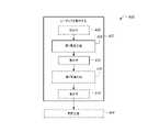
図16は、図1から図15に示しているライン10、100、及びシステム200を使用して、複合材部品12(図1参照)を作製する方法300を示すフロー図である。図1及び16を参照するに、方法300は製造方法400及び生産方法302を含む。製造方法400は、レイアップ14を製造すること402を含む。製造方法400は、レイアップ14から未固化の部品50(図15参照)を作り出す積層方法404を更に含む。積層方法404の後、未固化の部品50は、生産されて302複合材部品12になるために準備される。 FIG. 16 is a flow chart showing a
生産方法302は、レイアップ14及び/又は未固化の部品50を固化して304複合材部品12にすることを含む。例えば、方法300は、コンポーネント24、プリフォーム26、及び一又は複数の外板層28を固化して304、一体型複合材部品12にすることを含む。より具体的には、レイアップ14及び/又は未固化の部品50は、固化システム20(図1、図7、及び図8参照)に動かされる。固化システム20は、レイアップ14及び/又は未固化の部品50を固化して303、複合材部品12にする。 The
フルバレルマンドレル122上でレイアップ14及び/又は未固化の部品50を製造するために製造方法400が使用される場合(図9)、生産方法302は、フルバレル複合材部品12を切断して306、2つのハーフバレル複合材部品12にすることを更に含みうる。より具体的には、切断機256(図1及び図9参照)が、フルバレルセクション676(図23参照)を切断して306、2つのハーフバレルセクション670(図23参照)にする。 When the
図17は、図16に示している方法300とともに使用されうる製造方法400を示すフロー図である。図1及び図17を参照するに、方法400はレイアップ14を製造すること402を含む。方法400は積層方法404を更に含みうる。 FIG. 17 is a flow chart showing a
レイアップ14を製造する402ために、製造工程の少なくとも1つのセットが実施される406。製造工程406は、マンドレル102上に物体18を載置すること416(図18及び図19参照)を含む。例えば、製造工程406は、図18及び図19に関連して詳述するように、マンドレル102上にコンポーネント24、プリフォーム26、及び一又は複数の外板層28を載置すること416を含む。 For 402 to manufacture
製造ライン100が1つのサブシステム106を含む場合、製造工程を実施すること406によりレイアップ14が生産される。更に、製造システム200がステーション202の1つの群204を含む場合でも、製造工程を実施すること406でレイアップ14が作製される。例えば、製造システム200が図9に示している回転構成を有する場合、製造工程を実施すること406によりレイアップ14が作製される。 If the
製造工程が実施される406前に、マンドレル102は、製造システム200の、サブシステム106、群204、及び/又はステーション202(ゾーン1ステーション258など)といった製造システム200に動かされうる408。マンドレル102を製造システム200にかつ/又は製造システム200を通るように動かす408ために、駆動システム138が使用されうる。マンドレル102を動かすこと408については、以下で詳述する。 Prior to 406 when the manufacturing process is carried out, the
レイアップの製造402は、第2製造工程を実施すること410を更に含みうる。第2製造工程は、第1製造工程が実施された406後に実施される410。マンドレル102が、第1ゾーン126及び第2ゾーン128を含むハーフバレルマンドレル120である場合、第1ゾーン126上で第1製造工程が実施され406、第2ゾーン128上で第2製造工程が実施される410。マンドレル102がフルバレルマンドレル122である場合、1つの長手方向部分186上で第1製造工程が実施されてよく406、別の長手方向部分186上で第2製造工程が実施されうる410。 Manufacture 402 of the layup may further include carrying out a
第2製造工程410は第1製造工程406と同じである。より具体的には、第2製造工程410は、マンドレル102上に物体18を載置すること416、440(図18及び図19参照)を含む。例えば、製造工程410は、マンドレル102上にコンポーネント24、プリフォーム26、及び一又は複数の外板層28を載置すること416、440を含む。 The
あるいは、第2製造工程410が第1製造工程406とは異なることもある。例えば、第1製造工程406により1つの種類の物体18が載置され416、第2製造工程410により第2の種類の物体18が載置される416、440。かかる例では、製造すること402は第3製造工程を実施することを含みうる。例えば、第1製造工程406によりコンポーネント24が載置され452(図19参照)、第2製造工程410によりプリフォーム26が載置され454(図19参照)、第3製造工程により一又は複数の外板層28が載置される456(図19参照)。 Alternatively, the
第1製造工程及び第2製造工程が実施された406、410後には、マンドレル102上にレイアップ14が製造されている402。色々な種類の物体18が載置される452、454、456例では、レイアップ14は、第3製造工程も実施された後に製造される402。 After the first manufacturing step and the second manufacturing step were carried out 406 and 410, the
第2製造工程が実施される410前に、マンドレル102は、製造システム200の第2サブシステム108、第2の群20、及び/又はゾーン2ステーション268に動かされうる412。マンドレル102を第2サブシステム108にかつ/又は第2サブシステム108を通るように動かす412ために、駆動システム138が使用されうる。あるいは、マンドレル102が静止しているか又は停止している間に、第1製造工程がマンドレル102の第1長手方向部分186上で実施されてよく406、かつ、第2製造工程がマンドレル102の第2長手方向部分186上で実施されうる410。 Prior to 410 when the second manufacturing process is carried out, the
レイアップ14が製造された402後に、レイアップ14は、積層方法404を実施するために(積層方法404については図20を参照して詳述する)第3サブシステム136に動かされうる414か、又は、製造ライン100若しくは生産ライン10の別の部分に動かされうる414。 After 402 when the
方法400の一例では、方法400、402により、胴体666のセクション670、676(図23参照)が製造される。この例では、方法400、402は、マンドレル102の第1ゾーン126(例えば、マンドレル102の頂部130を含む第1ゾーン126)に割り当てられた第1サブシステム106に、マンドレル102を動かすこと408を含む。方法400、402は、第1サブシステム106において、マンドレル102の第1ゾーン126上にコンポーネント24、プリフォーム26、及び一又は複数の外板層28を載置すること406を含む。マンドレル102は、マンドレル102の第2ゾーン128(例えば、マンドレル102の側部132、134を含む第2ゾーン128)に割り当てられた第2サブシステム108に動かされる412。コンポーネント24、プリフォーム26、及び一又は複数の外板層28は、第2サブシステム108において、マンドレル102の第2ゾーン128上に載置される410。 In one example of
図18は、図17に示している製造方法400とともに使用されうる、レイアップ14を製造する402方法を示すフロー図である。図1及び図18を参照するに、製造すること402は、第1製造工程を実施すること406、及びオプションで、第2製造工程を実施すること410を含む。第1製造工程が実施された406後に、マンドレル102は、第2製造工程が実施される410よう動かされる412か、又は、更なるシステム(例えば第3サブシステム136若しくは固化システム20)に動かされる414。製造すること402に第1製造工程406及び第2製造工程410が含まれる場合、製造工程406、410は、上述したように、同様であっても、別様であってもよい。分かりやすく言うと、以下の説明は、同様である製造工程406、410に基づく。 FIG. 18 is a flow diagram illustrating a 402 method of manufacturing the
第1製造工程を実施すること406は、マンドレル102上に物体18を載置すること416を含む。載置すること416の前に、マンドレル102はまず受容されうる418。より具体的には、マンドレル102はステーション202に受容される418。製造システム200が第1の群204及び第2の群206並びに/又は第1サブシステム106及び第2サブシステム108を含む場合、マンドレル102は、第1の群204及び/又は第1サブシステム106に受容される418。マンドレル102がマンドレル102の組124のうちの1つである場合、マンドレル102は、少なくとも第1マンドレル102a及び第2マンドレル102bを含むマンドレル102の組124から受容される418.例えば、第1マンドレル102aがステーション202に受容されて418から、その後に、第2マンドレル102bがステーション202に受容される418。マンドレル102を動かすこと408により、マンドレル102がステーション202に受容される418ことになりうる。 Carrying out the
製造ライン100においてマンドレル102の組214が使用される例では、受容すること418は、コンポーネントステーション210に第1マンドレル102aを配置することと、コンポーネントステーション210に第1マンドレル102aが配置される時に外板ステーション214に第2マンドレル102bを配置することとを含む。 In the example in which the
マンドレル102を受容すること418によりステーション202内にマンドレル102が位置付けられることも、位置付けられないこともある。あるいは、マンドレル102は、一又は複数のステーション202に、かつ/又は一又は複数のステーション202を通るように動かされうる420。たとえマンドレル102を受容すること418によりステーション202内にマンドレル102が位置付けられても、マンドレル102は、ステーション(複数可)202を通るように動かされうる402。動かすこと420は、マンドレル102を動かす420よう駆動システム138を作動させることによって、実施されうる。 Receiving the
製造システム200が図9の回転構成である場合、動かすこと420は、長手方向軸254を中心にマンドレル102を回転させること422を含む。より具体的には、スピンドル252が、スピンドル252の長手方向軸254を中心に、複数の角度位置(例えば第1角度位置A1、第2角度位置A2、及び第3角度位置A3)を通るようにフルバレルマンドレル122を回転させる422。回転させること422により、ステーション202に対してフルバレルマンドレル122が回転する。一部の例では、フルバレルマンドレル122は、ステーションの第1の群204の各ステーション202、及びステーションの第2の群206の各ステーション202に対して回転する422。 When the
製造ライン100が図6に示しているマンドレル102の組124を含む場合、マンドレル102の組124は、ステーション202の組を通るように動かされる424。組124の各マンドレル102は、プロセス方向22に、製造システム200に対して動く424。例えば、各マンドレル102が、ステーション202の組における第1ステーション202から第2ステーション202に動く424につれて、次のマンドレル102が第1ステーション202内へと動き424、以下同様に続く。第1マンドレル102a及び第2マンドレル102bを有する例では、動かすこと420は、コンポーネントステーション210を通るように第1マンドレル102aを動かすこと424と、外板ステーション214kを通るように第2マンドレル102bを動かすこと424とを同期的に行うことを含む。 If the
動かすこと420は、ステーション(複数可)202への、又はステーション(複数可)202を通る、連続的な動きでありうる。あるいは、動かすこと420は、一又は複数のパルス動作226でマンドレル102をパルス動作させること426でありうる(図6及び図9参照)。動かすこと420がパルス動作426を含む場合、動かすこと420は、各パルス動作226を画定するよう、動き420を停止すること428を含む。あるいは、各パルス動作226は、動き420の部分と停止428の部分とを含む。動き420はタクトタイム222のうちの移動時間228であってよく、停止428は、タクトタイム222のうちの停止時間224でありうる(図6参照)。 The moving 420 can be a continuous movement to or through the station (s) 202. Alternatively, moving 420 can be 426 to pulse the
例えば、マンドレル102は、マンドレル102の長さ114ずつ、プロセス方向22にパルス動作する426。より具体的には、マンドレル102は、マンドレル102の長さ114に対応する距離ずつパルス動作する426(例えば動かされる420)。あるいは、マンドレルは、マンドレル102の長さ114よりも短い距離ずつパルス動作する426(例えば動かされる420)。かかる例は、マンドレル102をマイクロパルス動作で動かすこと420と見なされる。製造ライン100が第1サブシステム106及び第2サブシステム108を含む場合、マンドレル102を動かすこと420は、第1サブシステム106を通るようにマンドレル102をパルス動作させること426と、第2サブシステム108を通るようにマンドレル102をパルス動作させること426とを含む。例えば、第1マンドレル102aは、ステーション202の群204のうちの第1ステーション210へと、一又は複数のパルス動作226によって、プロセス方向22に動かされる424、426。 For example, the
パルス動作426によって動かすこと420は、各パルス動作266を画定するよう、マンドレル102の動き420を停止させること428を含む。より具体的には、パルス動作させること426は、所定の距離ずつマンドレルを動かすこと420と、一又は複数のパルス動作226の各パルス動作226を画定するようマンドレル102の動き420を停止させること428とを含む。一例では、マンドレル102の動き420は、コンポーネントステーション210及び外板ステーション214において停止する428。かかる例では、マンドレル102は、プリフォームステーション212では連続的に動きうる420。別の例では、マンドレル102の動き420は、コンポーネントステーション210、プリフォームステーション212、及び/若しくは外板ステーション214において、又はこれらのステーションを通る時に、停止する428。 The moving 420 by the
製造ライン100がマンドレル102の組124を含む場合、各マンドレル102の動き420は、ステーション202のうちの一又は複数において停止する428。更に、マンドレルの組124の各マンドレル102は、一又は複数のパルス動作226を画定するよう、動き420の段階間で停止する428。 If the
製造システム200が図9の回転構成である場合、フルバレルマンドレル122の回転422は、複数の角度位置の各角度位置において停止する428。回転422と停止428との各段階が、スピンドル252のパルス動作226を画定する。 When the
マンドレル102は、サブシステム106又はステーション202に受容され418かつ/又は動かされた420後に、サブシステム106及び/又はステーション202に対して位置決めされうる430。位置決め430は、動いている420間又は停止している428間に行われうる。各ステーション202での位置決め430は、マンドレル102の各ステーション202内にある部分を位置決めすることを含む。図1、図5、及び図18を参照するに、サブシステム106及び/又はステーション202に対してマンドレル102を位置決めする430ために、位置決めシステム146が使用される。したがって、位置決めすること430は、マンドレル位置決め要素150とシステム位置決め要素148とを係合させることを含む。例えば、位置決めすること430は、位置決めピン154と位置決めカップ152とを、位置決めピン154を対応する位置決めカップ152内に受容することによって、係合させることを含みうる。追加的又は代替的には、位置決めすること430は、識別リーダ158において、識別タグ156からの情報を取得することを含みうる。別の選択肢としては、位置決めすること430は、マンドレル102をハードストップ160に当接係合させることを含みうる。 The
より具体的には、マンドレル102の一部分が、一又は複数のステーション202に対して位置決めされる430。一例では、コンポーネントステーション210、及び外板ステーション214がマンドレル102と位置決めされる430。かかる例では、マンドレル102は、プリフォームステーション212に対して位置決めされる430ことも、されないこともある。マンドレル102がプリフォームステーション212に対して位置決め430されない場合、マンドレル102は別のステーション210及び/又は214に対する位置決め430によりプリフォームステーション212に対して位置決めされるか、又は、マンドレル102はプリフォームステーション212に対して連続的に動いて420位置決め430されない。マンドレル102がコンポーネントステーション210及び外板ステーション214に対して位置決めされる430場合、マンドレル102上へのコンポーネント24の載置452と一又は複数の外板層28の載置456の各々に先だって、各ステーション210、214での位置決め430が実施される。 More specifically, a portion of the
マンドレルが、図9に示しているフルバレルマンドレル122である場合、フルバレルマンドレル122は、複数の角度位置のうちの第1角度位置に位置決めされる430。複数の角度位置は、ステーション202と位置合わせされる。かかる例では、位置決め430は、位置決めユニット162を使用して実施されうる。 When the mandrel is the
マンドレル102が動かされ420かつ/又は位置決めされた430後に、物体18がマンドレル102上に載置される416。載置すること416についての具体的な詳細事項は、図19に関連付けて説明する。物体18を載置すること416は、ステーション(複数可)202内で、マンドレル102にコンポーネント24、プリフォーム26、及び/又は一又は複数の外板層28を載置することを含む。したがって、載置すること416は、コンポーネントステーション210、プリフォームステーション212、及び外板ステーション214を使用して実施される。製造ライン100が2つのサブシステム106、108を含む場合、第1サブシステム106において載置416が実施される。コンポーネント24、プリフォーム26、及び一又は複数の外板層28は、第1サブシステム106において、マンドレル102の第1ゾーン126上に載置される416。 416: The
コンポーネントステーション210、プリフォームステーション212、及び/又は外板ステーション214による載置416は、マンドレル102の停止428時間中432に行われうる。例えば、第1サブシステム106における載置416は、第1サブシステム106を通るマンドレル102のパルス動作426間の停止428時間中432に行われる。一例では、物体18は、第1マンドレル102の各パルス動作226の後の、パルス動作426の停止426時間中432に、ステーション202を使用してマンドレル102の異なる部分上に載置される416。 The mounting 416 by the
マンドレル102の組124が使用される場合、物体18は、一又は複数のパルス動作226の動き420の間の停止428時間中432に、組124の各マンドレル102上に載置される416。マンドレル102の組124がステーション202を通るようにパルス動作する426につれて、物体18は、第1サブシステム106のステーション202内で、第2マンドレル102b上に載置される416。 When the
製造システム200が図9に示している回転構成を有する場合、物体18の載置416は、スピンドル525の各パルス動作226において432行われる。より具体的には、コンポーネント24、プリフォーム26、及び一又は複数の外板層28の載置416は、スピンドル252の回転422間の停止428時間中432に行われる。 When the
更に、コンポーネントステーション210、プリフォームステーション212、及び外板ステーション214による載置416は、ステーション202及び/又はサブシステム106、108に共通なタクトタイム222にしたがって行われうる。 Further, the mounting 416 by the
物体18が載置された416後に、マンドレル102は、更なるプロセスのために動く414か、又は別のサブシステムへと動く412。より具体的には、製造ライン100が2つのサブシステム106、108を含むか、又は製造システム200がステーション202の2つの群204、206を含む場合、マンドレル102は、第2サブシステム106又は第2の群206へと動く412。動き412は、動き420及び/又は408と同様である。したがって、マンドレル102はパルス動作426を介して動いてよく412、かつ/又は、マンドレルの組124のうちの少なくとも1つのマンドレル102が第2サブシステム108及び/又は第2の群206に動きうる424。例えば、マンドレル102は、マンドレル128の第2ゾーン128(例えば、マンドレル102の側部(複数可)132、134)に割り当てられた第2サブシステム108に動かされる412。 After 416 on which the
第2サブシステム108はステーション202の第2の群206を含むので、第2の群206は、分かりやすくするために、以下で第2製造工程410を説明する時に言及される。第2製造工程410は、マンドレル102が動く412につれて、又は動いた412後に、ステーション202の第2の群206にマンドレル102を受容すること434を含む。受容すること434は、第1の群204において受容すること418と同様であり、上記の説明が適用される。 Since the
マンドレル102は、ステーション202の第2の群204に、かつ/又は第2の群204を通るように動かされる436。動き436は、動き420と同様であり、同様の説明が適用される。動かすこと436は、第2サブシステム108を通るようにマンドレル102をパルス動作させること426を含みうる。 The
第2製造工程410は、ステーション202の第2の群206を使用して、マンドレル102上に物体18を載置すること440を更に含む。載置すること440が第2の群206及び/又は第2サブシステム108におけるものであり、載置すること416は第1の群204及び/又は第1サブシステム106におけるものであることを除いて、載置すること440は載置すること416と同様であり、同様の説明が適用される。 The
より具体的には、コンポーネント24、プリフォーム26、及び一又は複数の外板層28は、第2サブシステム108において、マンドレル102の第2ゾーン128上に載置される440。一例では、第2サブシステム108における載置440は、第2サブシステム108を通るマンドレル102のパルス動作426間の停止時間中442に行われる。ステップ442は、ステップ432と同様であり、同様の説明が適用される。 More specifically, the
組124のうちの各マンドレル102が第1ゾーン126及び第2ゾーン128を含む場合、載置することは、第1マンドレル102aの第1ゾーン128及び第2ゾーン128の上に一又は複数の外板層28を載置すること416、440と、第1マンドレル102aの第1ゾーン126及び第2ゾーン128の上にプリフォーム26を載置すること416、440とを含む。かかる例では、より詳細に後述するように、第1ゾーン126での載置416及び第2ゾーン128での載置440は同時に行われうる。 If each
図1、図6、及び図18を参照するに、第1製造工程が実施され406、かつ/又は第2製造工程が実施される410際に、製造すること402は、一又は複数の供給ライン164を使用して、ステーション202に物体18及び/又は材料を供給すること444を含みうる。より具体的には、材料(物体18を含みうる)は、マンドレル102上に載置される416、440ように、一又は複数の供給ライン164によってコンポーネントステーション210、216、プリフォームステーション212、218、及び外板ステーション214、220の各々に供給される444。一例では、材料は、少なくともコンポーネント24、プリフォーム26、及び一又は複数の外板層18を含む。ある種の例では、ステーション202の種類に応じて、材料を供給すること444は、一又は複数の供給ライン164の各々において材料(物体18など)を製造すること446を含む。この種の供給ライン164及び/又は特定の供給ライン166、168、170、172、174、176の具体的な動作について、図6から図8に関連付けて詳述している。 With reference to FIGS. 1, 6, and 18, when the first manufacturing process is performed 406 and / or the second manufacturing process is performed 410, the
第1製造工程の実施406及び/又は第2製造工程の実施410後、マンドレル102上にレイアップ14が製造されている402。レイアップ14を有するマンドレル102は、群(複数可)204、206及び/又はサブシステム(複数可)106、108から出るように動かされる414。より具体的には、レイアップ14を有するマンドレル102は、積層方法404を実施するために積層サブシステム(例えば第3サブシステム136)に動かされる448か、又は生産方法302を実施するために生産ライン10に沿って動かされる450。 After the implementation of the
胴体666のセクション670、676を製造する例示的な方法は、マンドレル102の第1ゾーン126に割り当てられた第1サブシステム108にマンドレル120を動かすこと420を含む。第1ゾーン126は、マンドレル102の頂部130を含みうる。コンポーネント24、プリフォーム26、及び一又は複数の外板層28は、第1サブシステム106において、第1ゾーン126上に載置される416。マンドレル102は次いで、マンドレル102の第2ゾーン128に割り当てられた第2サブシステム108に動かされる412。第2ゾーン128は、マンドレルの側部132、134を含みうる。コンポーネント24、プリフォーム26、及び一又は複数の外板層28は、第2サブシステム108において、第2ゾーン128上に載置される440。 An exemplary method of manufacturing
図19は、図18の方法とともに使用されうる、物体18を載置する416、440ための方法を示すフロー図である。この方法は、単一の群204及び/若しくは単一のサブシステム106又は第1の群204及び/若しくは第1サブシステム106を用いる、載置すること416として使用されうる。方法は、第2の群206及び/又は第2サブシステム108を使用する、載置すること440として使用されることもある。分かりやすく言うと、以下の説明においては、ステーション210、212、及び214を有する群204が使用される。しかし、その説明は、ステーション216、218、及び220を有する群206にも適用されることを理解すべきである。群204の使用と群206の使用との間で相違があれば、それについて言及する。各群204、206において方法(複数可)を使用する例についても後述する。 FIG. 19 is a flow diagram showing a method for placing an
物体18を載置すること416、440は、一又は複数のステーション202において、マンドレル102上にコンポーネント24を載置すること452、プリフォーム26を載置すること454、及び一又は複数の外板層28を載置すること456を含む。一部の例では、載置452、454、及び/又は456を実施するために、ステーション202間でマンドレル102が動かされる。他の例では、ステーション202は、一又は複数のステーション202の間でマンドレル102を動かすことなく、載置452、454、及び456を実施する。更に、載置452、454、及び/又は456は、ステップ432、442に関連して上述したように、各パルス動作226におけるマンドレル102の停止時間中458に行われうる。マンドレル102の停止428及びパルス動作426については、図18に関連付けて説明する。 Placing the
製造ライン100がマンドレル102の組124を含む場合、ステーション202は、共通タクトタイム222にしたがって、マンドレルの組124の各マンドレル102の停止428時間中458に載置452、454、及び/又は456を実施する。追加的又は代替的には、コンポーネント24の載置452と一又は複数の外板層28の載置456とは、一又は複数のマンドレル102の動き420、436の間の停止428時間中に、同時に460行われる。 If the
パルス動作226の停止428時間中に載置すること458により、複数の物体18が同時に載置されうる460。例えば、物体18は、別々のステーション202においてかつ/又は別々のサブシステム106、108において、同時に載置される460。別々のステーション202における同時載置462の例では、プリフォームステーション212においてプリフォーム26が載置され454、かつ/又は外板ステーション214において外板層(複数可)が載置される456際に、コンポーネント24がコンポーネントステーション210において載置される452。 By mounting 458 during the stoppage 428 hours of
マンドレル102の組124とともに使用されうる追加的又は代替的な例では、物体18が、第1サブシステム106において第1マンドレル102a上に、第2サブシステム108において第2マンドレル102b上に、同時に載置される464。更に、別々のステーション202における載置462は、第1ステーション210において第2マンドレル102b上にコンポーネント24を載置する452と同時に行われる460、第2ステーション212又は214における第1マンドレル102a上への、外板層(複数可)28の載置456又はプリフォーム26の載置454を含みうる。 In an additional or alternative example that can be used with the
製造システム200が回転構成である場合、コンポーネント24を載置すること452、プリフォーム26を載置すること454、及び一又は複数の外板層を載置すること456は、図9及び図18に関連付けて説明しているように、スピンドル252の回転422間の停止428時間中458に行われる。より具体的には、コンポーネント24を載置すること452、プリフォーム26を載置すること454、及び一又は複数の外板層26を載置すること456は、スピンドル252の各パルス動作226において458に行われる。例えば、回転422中又は回転422の後に、コンポーネント24がコンポーネントステーション210において載置される452と同時に460、外板層(複数可)28が外板ステーション214において載置される456。換言すると、第1マンドレル102aがコンポーネントステーション210に配置され、かつ第2マンドレル102baが外板ステーション216に配置されている間に、コンポーネント24を載置すること452と外板層(複数可)28を載置すること456とが、同一期間中に行われる460。 When the
マンドレル102が、パルス動作426で動かされるのではなく、連続的に動く420、436場合、マンドレル102が停止している428時ではなく、マンドレル102が動く420、436につれて、物体18の同時載置460が行われる。 If the
コンポーネント24は、コンポーネントステーション212においてマンドレル102上に載置される452。載置すること452は、マンドレル102上に少なくともフレームフィラープリフォーム36を載置すること466を含む。上述したように、コンポーネント24は、分離プライ32及びフレームフィラープリフォーム36を含みうる。したがって、載置すること452は、分離プライ32を載置すること468と、フレームフィラープリフォーム36を載置すること466とを含みうる。かかる例では、分離プライ32がマンドレル102上に載置され468、次いでフレームフィラープリフォーム36が分離プライ32上に載置される466。更に、ステップ432、442、及び/又は458に関連して上述したように、マンドレル102の停止428時間中470にコンポーネント24が載置されうる452。 The
製造システム200が回転構成である場合、載置すること452は、コンポーネントステーション210を使用して、フルバレルマンドレル122上に、分離プライ32及び/又はフレームフィラープリフォーム36を含むコンポーネント24を載置すること452を含む。フルバレルマンドレル122上にコンポーネント24を載置すること472は、スピンドル252の第1角度位置A1において行われうる。 When the
マンドレル102が2つ以上のゾーン126、128を含む場合、第1コンポーネントステーション210において、分離プライ32を載置すること468及びフレームフィラープリフォーム36を載置すること466によって、コンポーネント24が第1ゾーン126上に載置される474。同様に、第2コンポーネントステーション216において、分離プライ32を載置すること468及びフレームフィラープリフォーム36を載置すること466によって、コンポーネント24が第2ゾーン128上に載置される476。かかる例では、コンポーネント24を載置すること452は、コンポーネントステーション210において、ガントリ260のエンドエフェクタ232、236を動かすこと(例えば図10参照)によって、マンドレル102の第1ゾーン126上にコンポーネント24を載置すること474を含みうる。同様に、コンポーネント24を載置すること452は、コンポーネントステーション216において、ロボットアーム(複数可)272に取り付けられたエンドエフェクタ234、238を動かすこと(例えば図11参照)によって、マンドレル102の第2ゾーン128上にコンポーネント24を載置すること476を含みうる。 When the
マンドレル102は、プリフォームステーション212に動かされうる478。動かすこと478は、動かすこと420、436と同様であり、上述の説明が、コンポーネントステーション210とプリフォームステーション212との間で動かすこと478にも適用される。例えば、動かすこと478は、次のステーション202(例えばプリフォームステーション212)へと、マンドレル102をパルス動作426させることを含みうる。マンドレル102の組124が使用される場合、第1マンドレル102aが一又は複数のパルス動作によってステーション202の群204のうちの第2ステーション202に動かされる478と同時に、第2マンドレル102bは、一又は複数のパルス動作によって第1ステーション202に動かされる420、436。例えば、第1マンドレル102aが一又は複数のパルス動作によってプリフォームステーション212又は外板ステーション214に動かされる478と同時に、第2マンドレル102aは、一又は複数のパルス動作によってコンポーネントステーション210に動かされる420、436。
動かすこと478の後、又は動かしている478間、マンドレル102は、オプションで、プリフォームステーション212に対して位置決めされうる480。位置決め480は、図18に関連して説明している位置決め430、438と同様であり、上述の説明が、プリフォームステーション212に対する位置決め480にも適用される。コンポーネントステーション210及び/又はサブシステム106、108に対する位置決め430、438により、それ以外のステーション202に対してマンドレル102が位置決めされる430、438場合には、位置決め480は省かれることもある。 After moving 478, or between moving 478, the
プリフォーム26は、プリフォームステーション212においてマンドレル102上に載置される454。プリフォーム26は、エンドエフェクタ240、242及びプリフォームステーション212を動かすことによって載置される454。上述したように、プリフォーム26は、胴体666の支持構造物(例えばストリンガ678)になるよう構成される。したがって、プリフォーム26を載置すること545は、マンドレル102上にストリンガプリフォーム38を載置すること480を含む。より具体的には、プリフォーム26、38がマンドレル102のトラフ116内に載置される482。一例では、複数のプリフォーム26が、フルバレルマンドレル122の複数のトラフ116内に載置される482。更に、ステップ432、442、及び/又は458に関連して上述したように、マンドレル102の停止428時間中484にプリフォーム26が載置されうる454。あるいは、マンドレル102が次のステーション202(例えば外板ステーション214)へと連続的に動く420につれて、プリフォーム26が載置されうる454。 The
プリフォーム26は、プリフォームステーション212を使用してマンドレル102上に載置される454。マンドレル102が2つ以上のゾーン126、128を含む場合、プリフォーム26は、第1ゾーン126上に載置され486、かつ第2ゾーン128上に載置される488。より具体的には、プリフォーム26は、第1コンポーネントステーション210の後ろに位置付けられた第1プリフォームステーション212においてストリンガプリフォーム38を載置すること454によって、第1ゾーン126上に載置される486。同様に、プリフォーム26は、第2コンポーネントステーション216の後ろに位置付けられた第2プリフォームステーション218においてストリンガプリフォーム38を載置すること454によって、第2ゾーン128上に載置される488。 The
製造システム200が図9の回転構成である場合、プリフォーム26を載置すること454は、スピンドル252の第2角度位置A2において、フルバレルマンドレル122上にプリフォーム26を載置すること490を含む。例えば、ストリンガプリフォーム38は、プリフォームステーション212を使用して、フルバレルマンドレル122上に載置される480、490。 When the
図12に示しているようにショートストリンガプリフォーム40が載置される480場合、プリフォーム26を載置すること454は、プリフォーム26同士を互いにスプライス留めすること492を含みうる。より具体的には、第1ショートプリフォーム40がマンドレル102上に載置される480。例えば、プリフォームステーション212a、212b、及び212cの各々が、マンドレル102のゾーン126、128上にショートストリンガプリフォーム40のセット278を載置する480。特定の例では、プリフォームステーション212a、212b、及び212cの各々は、マンドレル102の特定のゾーン126、128の2つ以上の長手方向部分186a、186b、186c上に、ショートストリンガプリフォーム40のセット278を載置する480。 In the case of 480 on which the
第1プリフォームステーション212aは、マンドレル102の第1長手方向部分186a上に、ショートストリンガプリフォーム40の第1のセット278aを載置する480。第2プリフォームステーション212bは、ショートストリンガプリフォーム40の第2のセット278bを、ショートストリンガプリフォーム40の第2のセット278bがショートストリンガプリフォーム40の第1のセット278aと若干重複するように、ショートストリンガプリフォーム40の第1のセット278aと隣り合わせて載置して480、第2のセット278bの各プリフォーム26と第1のセット278bの対応するプリフォーム26とをスプライス留めする492。より具体的には、この重複により、第1のセット278aの各ショートストリンガプリフォーム40と、第2のセット278bの対応するショートストリンガプリフォーム40とのスプライス留め492として、スカーフスプライス又はラップスプライスが作り出されうる。同様に、第3プリフォームステーション212cは、ショートストリンガプリフォーム40の第3のセット278cを、ショートストリンガプリフォーム40の第3のセット278cがショートストリンガプリフォーム40の第2のセット278bと若干重複するように、ショートストリンガプリフォーム40の第2のセット278bと隣り合わせて載置して480、プリフォーム26同士をスプライス留めする492。 The
したがって、方法402、416、440は、第1ゾーン128及び/又は第1長手方向部分186a上のプリフォーム26を、第2ゾーン128及び/又は第2長手方向部分186b上のプリフォーム26とともにスプライス留めすること492を含む。この例は、第1ゾーン126が第1長手方向部分186aであり、第2ゾーン128が第2長手方向部分186bである場合に、適用されうる。 Thus,
マンドレル102は、外板ステーション214に動かされうる494。動かすこと494は、動かすこと420、436と同様であり、上述の説明が、プリフォームステーション212と外板ステーション214との間で動かすこと494にも適用される。例えば、動かすこと494は、次のステーション202(例えば外板ステーション214)へと、マンドレル102をパルス動作426させることを含みうる。マンドレル102の組124が使用される場合、第1マンドレル102aが一又は複数のパルス動作によってステーション202の群204のうちの第3ステーション202に動かされる494と同時に、第2マンドレル102bは、一又は複数のパルス動作によって第2ステーション202に動かされる420、436。例えば、第1マンドレル102aが一又は複数のパルス動作によって外板ステーション214に動かされる494と同時に、第2マンドレル102aは、一又は複数のパルス動作によってプリフォームステーション212に動かされる478。
動かすこと494の後、又は動かされている494間に、マンドレル102は、オプションで、外板ステーション214に対して位置決めされうる496。位置決め496は、図18に関連して説明している位置決め430、438と同様であり、上述の説明が、外板ステーション214に対する位置決め496にも適用される。コンポーネントステーション210及び/又はサブシステム106、108に対する位置決め430、438により、それ以外のステーション202に対してマンドレル102が位置決めされる430、438場合には、位置決め496は省かれることもある。 The
一又は複数の外板層28は、外板ステーション214においてマンドレル102上に載置される456。外板層(複数可)28は、載置される456と、少なくともコンポーネント24を覆う。外板層(複数可)26は、マンドレル102上にレイアップ14を作り出すよう、コンポーネント24及びプリフォーム26の上に載置されうる465。一部の例では、方法402、416、440は、第2ステーション212、214において、第1マンドレル102上に一又は複数の外板層28又はプリフォーム26を載置すること454、456を含む。 One or more skin layers 28 are placed on the
外板層(複数可)28を載置する454ためには、一又は複数の外板パネルプライ34がマンドレル102上に載置されて498、一又は複数の外板層28が形成される。より具体的には、一又は複数の外板パネル34が、IMLプライとしてマンドレル102上にレイアップされるか又は載置され498、追加の外板パネルプライ34がIMLプライ上にレイアップされて、外板層(複数可)28が形成される。 For 454 on which the skin layer (s) 28 is placed, one or more skin panel plies 34 are placed on the
外板層(複数可)28を載置すること454がISAカウル30を含む場合には、載置すること454は、マンドレル102上にISAカウル30を載置すること、次いで外板パネルプライ(複数可)34を載置することを含む。例えば、ISAカウル30は、プリフォーム26に対して(例えばプリフォーム26の両端に)、マンドレル102上に載置される500。次いで、外板パネルプライ34が、ISAカウル30に対して、プリフォーム26及びコンポーネント24の上にレイアップされるか又は載置される498。更に、ステップ432、442、及び/又は458に関連して上述したように、マンドレル102の停止428時間中502に外板層(複数可)28が載置されうる456。例えば、ISAカウル30及び外板パネルプライ(複数可)は、外板ステーション214において、マンドレル102の停止428時間中502に載置されうる。 When the outer panel layer (s) 28 is mounted, if the mounting 454 includes the
外板層(複数可)28(例えばISAカウル30)及び/又は外板パネルプライ(複数可)34は、外板ステーション214を使用してマンドレル102上に載置される456。マンドレル102が2つ以上のゾーン126、128を含む場合、第1プリフォームステーション212の後ろに位置付けられた第1外板ステーション214において外板パネルプライ34を載置すること504によって、第1ゾーン126上に外板層(複数可)28が載置される456。例えば、外板層(複数可)28は、第1外板ステーション214のガントリ260のエンドエフェクタ232、244(図10参照)を動かすことによって、マンドレル102の第1ゾーン126上に載置される504。同様に、外板層(複数可)28は、第2プリフォームステーション218の後ろに位置付けられた第2外板ステーション220において外板パネルプライ34を載置すること506によって、第2ゾーン128上に載置される456。例えば、外板層(複数可)28は、外板ステーション220のロボットアーム272に取り付けられたエンドエフェクタ234、246を動かすことによって、マンドレル102の第2ゾーン128上に載置される506。 The skin layer (s) 28 (eg, ISA cowl 30) and / or the skin panel ply (s) 34 are mounted on the
製造システム200が図9の回転構成である場合、載置すること456は、スピンドル252の第3角度位置A3において、フルバレルマンドレル122上に一又は複数の外板層28を載置すること508を含む。かかる例では、外板層(複数可)28は、フルバレルマンドレル122の第1ゾーン126及び第2ゾーン128に載置される508、504、506。 When the
外板層(複数可)28を載置すること456は、隣り合ったゾーン126、128及び/又は部分130、132、132、186における外板層(複数可)同士をスプライス留めすること510を含みうる。スプライス留め510は、ステーション202の群204、206のいずれにおいても行われうるが、例で取り上げているのは、第2外板ステーション220で行われるスプライス留め510である。スプライス留め510は、図12に示している複数のプリフォームステーション212、218と同様に、第2ゾーン128に割り当てられた複数の外板ステーション220で実施されることもある。分かりやすくするために、第2外板ステーション220における長手方向スプライス278(図13及び図14参照)について説明する。 Placing the skin layer (s) 28 456 splices the skin layers (s) in
図13、図14、及び図19を参照するに、方法402、416、440は、第1ゾーン126上の一又は複数の外板層28を第2ゾーン128上の一又は複数の外板層28とともにスプライス留めすること510を含む。より具体的には、マンドレル102の第1ゾーン126の外板パネルプライ34が、マンドレル102の第2ゾーン128の外板パネルプライ34にスプライス留めされる510。例えば、マンドレル102の第1ゾーン126(例えば頂部130)の外板パネルプライ34が、マンドレル102の第2ゾーン128(例えば側部132、134)の外板パネルプライ34と重複し、スプライス留めされて510外板層(複数可)28になる。 With reference to FIGS. 13, 14, and 19,
製造システム200が図9の回転構成である場合、フルバレルマンドレル122の第1ゾーン126の外板パネルプライ34は、一又は複数の外板層28の載置456中に、フルバレルマンドレル122の第2ゾーン128の外板パネルプライ34にスプライス留めされる510。例えば、外板ステーション214によってフルバレルマンドレル122上に載置された外板パネルプライ34は、外板ステーション214によって先に載置された外板パネルプライ34にスプライス留めされる510。 When the
方法400は、任意の好適な数の上述したステップ402、416、440、及びこれらの組み合わせを含みうる。方法400の一例では、方法400は、ステーション202にマンドレル102を受容すること418と、コンポーネントステーション210、216においてマンドレル102上にコンポーネン24を載置すること452と、プリフォームステーション212、218にマンドレル102を動かすこと478と、プリフォームステーション212、218においてマンドレル102上にプリフォーム26を載置すること454と、外板ステーション214、220にマンドレル102を動かすこと494と、一又は複数の外板層28が少なくともコンポーネント24を覆うように、外板ステーション214、220においてマンドレル102上に一又は複数の外板層28を載置すること456とを、含む。
少なくとも第1マンドレル102a及び第2マンドレル102bを含むマンドレル102の組124が製造ライン100とともに使用される、別の例示的な組み合わせにおいては、方法400は、第1マンドレル102aを、ステーション202の群204、206のうちの第1ステーション210、202へと、一又は複数のパルス動作226、426によって、プロセス方向22に動かすこと424と、第1ステーション210に対して第1マンドレル102aの一部分を位置決めすること430、438と、第1ステーション210、202内で、マンドレル102上に、コンポーネント24、プリフォーム26、及び/又は一又は複数の外板層28を含む物体18を載置すること416、440と、第2マンドレル102bが一又は複数のパルス動作226、426によって第1ステーション210、202へと動かされている間に、第1マンドレル102aを、ステーション202の群204、206のうちの第2ステーション212、214、202へと、一又は複数のパルス動作226、426によって動かすこと424と、を含む。 In another exemplary combination in which a
製造システム200が図9の回転構成を有する、更に別の例示的なステップの組み合わせにおいては、方法400は、複数の角度位置を通るように、スピンドル252の長手方向軸254を中心としてフルバレルマンドレル122を回転させること422であって、複数の角度位置が、少なくとも第1角度位置A1、第2角度位置A2、及び第3角度位置A3を含む、フルバレルマンドレル122を回転させること422と、スピンドル252の第1角度位置A1において、フルバレルマンドレル122上にコンポーネント24を載置すること472と、スピンドル252の第2角度位置A2において、フルバレルマンドレル122上にプリフォーム26を載置すること490と、スピンドル252の第3角度位置A3において、フルバレルマンドレル122上に一又は複数の外板層28を載置すること508と、を含む。 In yet another exemplary step combination in which the
図20は、図16から図18に示している方法300及び/又は400とともに使用されうる積層方法404を示すフロー図である。積層方法404は、第3サブシステム136を含む製造ライン100及び/又はステーション200の第3の群208を含む製造システム200を用いて実施されうる。 FIG. 20 is a flow chart showing a stacking
図15及び図20を参照するに、積層方法404は、マンドレル102が積層サブシステム(これが第3サブシステム136である)に動かされた414、448後に実施されうる。マンドレル102は、動かされる414、448につれて又は動かされた414、448後に、自動繊維配置(AFP)ステーション280内に位置付けられる。マンドレル102は、ステップ430、438に関連して説明しているように、第3サブシステム136及び/又はAFPステーション280に対して位置決めされうる512。 With reference to FIGS. 15 and 20, the stacking
積層方法404は、マンドレル102上のレイアップ14上に追加の外板52を製造するために、AFPを実施すること514を含む。一例では、AFPは、レイアップ14上に未固化の繊維強化材料16のプライをレイアップして胴体666の外板682(図23参照)となる層を厚化することによって、追加の外板52を製造する516、AFP機械281によって実施される514。AFPは、ステップ432、442、及び/又は458に関連して上述したように、マンドレル102の動き414における停止428時間中518に実施されうる514。
マンドレル102は、AFPステーション280から一又は複数の電気保護ステーション282に動かされうる520。動かすこと520は、図18に関連して説明した動かすこと420、436と同様であり、上述の説明が、AFPステーション280から電気保護ステーション282への動き520にも適用される。 The
動かすこと520の後、又は動かしている520間に、マンドレル102は、オプションで、電気保護ステーション282に対して位置決めされうる522。位置決め522は、図18に関連して説明している位置決め430、438と同様であり、上述の説明が、電気保護ステーション282に対する位置決め522にも適用される。AFPステーション280及び/又はサブシステム130に対する位置決め512によりそれ以外のステーション202に対してマンドレル102が位置決めされる430、438場合には、位置決め522は省かれることもある。 The
積層方法404は、追加の外板52上に電気保護層54を載置すること524を更に含む。電気保護ステーション282が、追加の外板52上に電気保護層54を載置する524。第3サブシステム136が複数の電気保護ステーション282を含む場合、電気保護層54は、ソーンごとに、複数の電気保護ステーション282において載置される526。より具体的には、電気保護ステーション282の各々がマンドレル102の特定のゾーン126、128に割り当てられ、載置526は、図19に関連して説明した外板層(複数可)28の載置456と同様である。ステップ432、442、及び/又は458に関連して上述したように、パルス動作226の一又は複数の停止時間中528に、電気保護層54の載置524が行われうる。 The stacking
マンドレル102は、電気保護ステーション(複数可)282から一又は複数の表面プライステーション284に動かされうる530。動かすこと530は、動かすこと420、436と同様であり、上述の説明が、電気保護ステーション282から表面プライステーション(複数可)284に動かすこと530にも適用される。動かすこと530の後、又は動かしている530間に、マンドレル102は、オプションで、表面プライステーション284に対して位置決めされうる532。位置決め532は位置決め430、438と同様であり、上述の説明が、表面プライステーション284に対する位置決め532にも適用される。 The
表面プライステーション(複数可)284において、電気保護層54の上に一又は複数の表面外板プライ56が載置される534。載置すること534は、胴体666の外板682のOMLプライを載置すること536を含む。第3サブシステム136が複数の表面プライステーション284を含む場合、表面外板プライ56は、ソーンごとに、複数の表面プライステーション284においてレイアップされるか又は載置される538。より具体的には、表面プライステーション284の各々がマンドレル102の特定のゾーン126、128に割り当てられ、載置538は、図19に関連して説明した外板層(複数可)28の載置456と同様である。 In the surface ply station (s) 284, 534 on which one or more surface skin plies 56 are placed on the
したがって、表面外板プライ56を載置すること534は、マンドレル102の別々のゾーン126、128又は部分186における表面外板プライ56同士をスプライス留めすること540を含みうる。表面外板プライ56をスプライス留めすること540は、図19に関連して説明した外板層(複数可)28をスプライス留めすること510と同様であってよく、上記の説明はスプライス留めすること540にも適用される。更に、ステップ432、442、及び/又は458に関連して上述したように、パルス動作226の一又は複数の停止時間中542に、表面外板プライ56の載置534が行われうる。表面外板プライ56を載置した534後、レイアップ14は固化された部品50になっている。 Thus, placing the surface skin ply 56 may include 540 splicing the surface skin plies 56 together in
マンドレル102は、表面プライステーション284からバギングステーション286に動かされうる544。動かすこと544は、動かすこと420、436と同様であり、上述の説明が、表面プライステーション(複数可)284からバギングステーション286に動かすこと544にも適用される。動かすこと544の後、又は動かしている544間に、マンドレル102は、オプションで、バギングステーション286に対して位置決めされうる546。位置決め546は位置決め430、438と同様であり、上述の説明が、表面プライステーション284に対する位置決め546にも適用される。 The
方法404は、未固化の部品50を固化するために準備すること548を含む。より具体的には、未固化の部品50は、マンドレル102の上にカウル58及び/又はバッグ60を載置することによって準備される548。例えば、カウル58は、未固化の部品50上に当て板を位置付けることによって載置される550。次いで、カウル58及び未固化の部品50の上に、バッグ60が載置される552。バギングされた未固化の部品50を生産ライン10に沿って動かす414前に、バッグ60に真空圧力が印加されうる。未固化の部品50が準備された548後、複合材部品12を形成するために、マンドレル102が固化システム20に動かされうる450。
方法の実施例
例1
図1、図18、及び図19に関連付けて、製造ライン100の動作の例示的な詳細について説明する。この実施形態の前提として、複合材部品12を製造するために弧状マンドレル102だけが利用されている。複合材部品12は弧状マンドレル102から既に脱型されており、弧状マンドレル102は洗浄済みである。したがって、弧状マンドレル102は、別の複合材部品12のためのレイアップ14を受容するために製造ライン100に入る準備が整っている。Example 1 of the method
Illustrative details of the operation of the
この例のステップについて、図1、図2、図7、及び図8の製造ライン100を参照しつつ説明するが、当業者には、この方法は他のシステムにおいても実施されうることが認識されよう。 The steps of this example will be described with reference to
418において、マンドレル102が製造ライン100に受容される。マンドレル102は、プリフォーム26(すなわちストリンガプリフォーム38)を受容するためのトラフ116を含む。一実施形態では、ステップ418は、クリーンルーム環境内に又は軌道140上にマンドレル102を載置することを含む。マンドレル102は、コンポーネントステーション210に動かされ420、コンポーネントステーション210に対して位置決めされる430。例えば、マンドレル120はがコンポーネントステーション210に到達するまで動くこと420も、又は、マンドレル102がコンポーネントステーション210におけるシステム位置決め要素148(図5参照)と繋がるまで動くこと420も、可能である。位置決め430は、パルス動作226の終了の一部として、又は停止428の開始時に実施されてよく、これにより、ステーション202に、その特定のステーション202の範囲内の3D特性が通知される。この特性により、同じステーション202によって続けて作業が行われるよう、複数のハーフバレルセクション670が並ぶように配置を変動させることが可能になる。位置決め430により、航空機モデルの上側若しくは下側のセクション、前方若しくは後方のセクションに、又はモデルごとに、作業が実施されることが更に可能になる。 At 418, the
コンポーネントエンドエフェクタ236は、コンポーネントステーション2100において、マンドレル102に(例えば頂部130に)繊維強化コンポーネント24(例えば、ガラス繊維プライなどの分離プライ32やフレームフィラープリフォーム36)を付加する。分離プライ32は、胴体666内に配置されることになるアルミニウムコンポーネントから炭素繊維プライを分離させる役割を果たす。したがって、分離プライ32は、マンドレル102全体を覆う必要はなく、むしろ、炭素ベースの材料とアルミニウム構造物との間に発生する可能性のあるガルバニック問題を防ぐために、アルミニウムコンポーネントが位置付けられるところに載置される。 The
フレームフィラープリフォーム36は、組み立て中にフレーム680を受容するためのパドアップを提供することによって、胴体666のセクション670、676が固化され304、脱型された後のフレーム680の位置合わせ及び設置のための均一面を提供する。フレームフィラープリフォーム36は、フレーム680のセクション同士の接続における幾何形状複雑性の低減を可能にする、定位置に配置される。エンドエフェクタ236は、コントローラ104に記憶されたプログラム(例えばNCプログラム)の方向に稼働され、マンドレル102に沿った所定の場所(例えば、1インチの数分の1単位の望ましい範囲内に)にコンポーネント24を載置する。 The
マンドレル102は、プリフォームステーション212に動かされる478。動かすこと478は、軌道140に沿ってマンドレル102を駆動すること、又は、軌道140がマンドレル102を動かす478よう駆動システム138を動作させることを含みうる。一部の実施形態では、このことは、上述した、ステーション202に対してマンドレル120を位置決めすること430を更に含む。 The
プリフォームステーション212のプリフォームエンドエフェクタ242は、支持構造物のためのプリフォーム26(例えばストリンガプリフォーム38)を、マンドレル102の(例えば頂部130の)トラフ116内に載置する454。一実施形態では、エンドエフェクタ242は、コントローラ104に記憶されたプログラム(例えばNCプログラム)にしたがって、ストリンガプリフォーム38を取り上げ、トラフ116内に載置する。 The
マンドレル102は、外板ステーション214に動かされる494。動かすこと494は、上記のステップ478と同様の様態で実施される。 The
外板ステーション214の外板エンドエフェクタ244は、コンポーネント24を覆う一又は複数の外板層28を載置する456。外板パネルプライ34は、外板供給ライン174を介して、外板ステーション214に適時に供給される。外板パネルプライ34は、AFP技法により、自動テープレイアップ機械(ATLMs)により、又はピックアンドプレース法により、付加されうる。外板パネルプライ34は、ストリンガプリフォーム26を覆い、ストリンガプリフォーム26を構造的に一体化させる。このことは、固化304の後、ストリンガプリフォーム38と外板パネルプライ34とが一体物(an integral whole)を形成することを意味する。エンドエフェクタ244は、外板パネルプライ34をレイアップした後に、マンドレル102上に(例えばその頂部130に)ISAカウル30を載置する500。外板パネルプライ34は、前述した様々なコンポーネント24及び/又はプリフォーム26を一体化し、単一の一体物(例えば、図1、図7、及び図8のレイアップ14)にする。外板パネルプライ34は更に、例えば、マンドレル102によって画定された弧の全体にわたりうる。ISAカウル30は、外板パネルプライ34を覆い、レイアップ14の圧縮及び/又は固化を容易にする。レイアップ14は、バギングされ552、圧縮され、固化システム20内への載置のために準備される548。 The outer
上述のステップは次いで、マンドレル102の側部132、134に物体18を載置する410ために、第2コンポーネントステーション216、第2プリフォームステーション218、及び第2外板ステーション220で反復される。ステップのかかる反復は、頂部130でのステップと同期的実施されることも、非同期的に実施されることもある。 The above steps are then repeated at the
分離プライ32、フレームフィラープリフォーム36、ストリンガプリフォーム38、及び外板パネルプライ34を含むレイアップ14は、固化されて304一体型複合材部品12となる。一実施形態では、固化すること304は、マンドレル102を固化システム20内に挿入すること、熱及び圧力を加えてレイアップ14を固め、固化して望ましい形状にするよう、固化システム20を動作させることによって、実施される。マンドレル102は次いで(例えば、非クリーンルーム環境へと移動することによって)固化システム20を出て、複合材部品12がマンドレル102から脱型される。マンドレル102は次いで、洗浄へと進むが、別のレイアップ14の処理のために戻ることもある。 The
例1の方法は、従来のシステムを凌駕する技術的な利点を提供する。なぜなら、この方法により、多数のマンドレル102が専用の作業ステーション202によって続けて処理されることが可能になるからである。更に、各パルス動作226の後にマンドレル102が各ステーション202に対して位置決めされるので、製造工程においてマンドレル102に対して実施される、時間のかかるスキャンプロセスが必要なくなる。つまり、各パルス動作226(例えば、マンドレル102の長さ114よりも短い距離分のマンドレル102のマイクロパルス動作の各々)の後のスキャンが必要なくなり、ひいては、ステーション(複数可)202(これまで、このステーション202はその範囲内のマンドレル202のセクションをスキャンしていた)に、スキャンデータを提供する必要がなくなる。これにより、スループットの向上が可能になり、ひいては、製造工程の労働量が低減するともに効率が高まる。 The method of Example 1 provides technical advantages over conventional systems. This method allows a large number of mandrel 102s to be continuously processed by a
例2
例1は、例示的な一実施形態における、胴体666の弧状セクション670、676(図23参照)を製造するための方法である。マンドレル102は、少なくとも1つの頂部ステーション(例えばゾーン1ステーション258)に動かされる420。コンポーネント24、支持構造物のためのプリフォーム26、及び外板層(複数可)28が、少なくとも1つの頂部ステーション258において、マンドレル102の頂部130に載置される416。マンドレル102は、少なくとも1つの側部ステーション(例えばゾーン2ステーション268)に動かされる412。繊維強化コンポーネント24、支持構造物のためのプリフォーム26、及び外板層(複数可)28が、少なくとも1つの側部ステーション268において、マンドレル102の側部132、134に載置される440。Example 2
Example 1 is a method for manufacturing
更なる実施形態では、少なくとも1つの頂部ステーション258及び少なくとも1つの側部ステーション268は、マンドレル102の動き420、440における停止時間中に載置416、440を実施する。更なる実施形態では、頂部130に繊維強化コンポーネント24を載置すること416は、コンポーネントステーション210において、分離プライ32を載置すること468と、フレームフィラープリフォーム36を載置すること466とを含み、頂部130に支持構造物のためのプリフォーム26を載置することは、コンポーネントステーション210の下流に配置されたプリフォームステーション212において、ストリンガプリフォーム38を載置すること480を含み、頂部130に外板層28を載置すること546は、プリフォームステーション212の下流に配置された外板ステーション214において、外板パネルプライ34を載置すること498を含む。また更なる実施形態では、側部132、134に繊維強化コンポーネント24を載置すること440は、コンポーネントステーション216において、分離プライ32を載置すること468と、フレームフィラープリフォーム26を載置すること466とを含み、側部132、134にプリフォーム26を載置すること454は、コンポーネントステーション216の下流に配置されたプリフォームステーション218において、ストリンガプリフォーム38を載置すること480を含み、側部132、134に外板層28を載置すること456は、プリフォームステーション218の下流に配置された外板ステーション220において、外板パネルプライ34を載置すること498を含む。 In a further embodiment, at least one
例3
例2は、例示的な一実施形態における、胴体666の弧状セクション670、676(図23参照)を製造するための方法である。マンドレル102は、プロセス方向22にパルス動作する426。マンドレル102の一部分は、第1ステーション202、210に対して、第1ステーション20、210の範囲内に位置決めされる430。第1ステーション202、210内で、繊維強化コンポーネント24、プリフォーム26、又は外板層28のうちの少なくとも1つが、マンドレル102上に載置される416。マンドレル102が第2ステーション202、212、214へとパルス動作する478と同時に、別の弧状マンドレル102が、第1ステーション202、210へとパルス動作する426。Example 3
Example 2 is a method for manufacturing
更なる実施形態では、マンドレル102は、マンドレルの長さ114に対応する距離ずつパルス動作する426、478か、又はマイクロパルス動作で長さ114よりも短い距離ずつパルス動作する426、478。第1ステーション202、210は、各パルス動作の後の停止時間中に、同一のレイアップ14の異なる部分に対して作業を行う。更なる実施形態では、複数のステーション202が、パルス動作とパルス動作との間の停止時間中に、複数のマンドレル202上で同時に作業する。また更なる実施形態では、コンポーネント24を載置すること452は、分離プライ32及びフレームフィラープリフォーム36を載置すること468、466を含み、プリフォーム26を載置すること454は、ストリンガプリフォーム38を載置すること480を含む。 In a further embodiment, the
例4
例4は、例示的な一実施形態における、胴体666のフルバレルセクション676(図9参照)を製造するための方法である。フルバレルマンドレル122は、スピンドル252の長手方向軸254を中心に回転する422。フルバレルマンドレル及びスピンドル252の第1角度位置A1において、コンポーネント24がフルバレルマンドレル122上に載置される472。一実施形態では、コンポーネント24を載置すること472は、分離プライ32及びフレームフィラープリフォーム26を載置すること468、466を含む。Example 4
Example 4 is a method for manufacturing a full barrel section 676 (see FIG. 9) of a fuselage 666 in an exemplary embodiment. The
フルバレルマンドレル122及びスピンドル252の第2角度位置A2において、プリフォーム26がフルバレルマンドレル122上に載置される490。一実施形態では、プリフォーム26を載置すること490は、ストリンガプリフォーム38を載置すること480を含む。更なる実施形態では、ストリンガプリフォーム38を載置すること480は、フルバレルマンドレル122のトラフ116内にストリンガプリフォーム38を載置すること482を含む。フルバレルマンドレル122及びスピンドル252の第3角度位置A3において、外板層(複数可)28がフルバレルマンドレル122上に載置される508。一実施形態では、フルバレルマンドレル122は、一度に全回転を下回る角度ずつ(例えば、位置A1から位置A2まで)パルス動作426し、コンポーネント24を載置すること472は分離プライ32及びフレームフィラープリフォーム36を載置すること468、466を含み、ストリンガプリフォーム38を載置すること480及び外板パネル34を載置すること498は、マンドレル122の回転422におけるパルス動作226とパルス動作226との間の停止428中に行われる。 At the second angle position A2 of the
更なる実施形態では、例4は、外板パネルプライ34をフルバレルマンドレル122上に載置すること508によって、後続の第3角度位置A3の外板層(複数可)28と、フルバレルマンドレル122上の、先に載置された508第3角度位置A3の外板パネルプライ34(先の第3角度位置A3での載置508において載置された508もの)とをスプライス留めすること510も含む。フルバレルマンドレル122は、製造工程406におけるパルス動作226によって、時計回り方向に回転する422(図9参照)。図示していない別の実施形態は、製造工程406において反時計回り方向に回転する422フルバレルマンドレル122を有する。フルバレルマンドレル122は、周縁118全体の一部分のパルス動作226で回転する。図示しているように、フルバレルマンドレル122は、パルス動作226によって回転し422、パルス動作226は、第1角度位置A1、第2角度位置A2、第3角度位置A3に適合するよう、約60度である。第1角度位置A1、第2角度位置A2、第3角度位置A3の各々は、ステーション202に相当する角度である。別の実施形態は、約60度未満のパルス動作226の角度回転パルスが変動する、パルス動作を有する。別の実施形態は、約60度を上回るパルス動作226の角度回転パルスが変動する、パルス動作を有する。 In a further embodiment, in Example 4, the outer panel ply 34 is placed on the
例示的な実行形態
以下の例では、機体コンポーネントの製造のための製造システム(例えば製造システム200)の観点から、追加のプロセス、システム、及び方法について説明する。Exemplary Executions The following examples describe additional processes, systems, and methods in terms of a manufacturing system (eg, manufacturing system 200) for manufacturing airframe components.
図面をより詳細に参照するに、本開示の実施形態は、図21に示している方法600における航空機の製造及び保守の観点から、並びに図22及び図23に示している航空機650の観点から、説明されうる。製造前段階では、方法600は、航空機650の仕様及び設計602と、材料調達604とを含みうる。製造段階では、航空機600のコンポーネント及びサブアセンブリの製造606と、システムインテグレーション608とが行われる。その後、航空機650は、認可及び納品610を経て、運航612に供されうる。顧客により運航612されている期間中、航空機650には、整備及び保守614(改変、再構成、改修なども含みうる)の定期的な作業が予定される。 With reference to the drawings in more detail, embodiments of the present disclosure are from the perspective of aircraft manufacturing and maintenance in
本書で具現化されているライン10、100、システム200、及び方法300、400は、方法600に記載の製造及び保守の、任意の好適な一又は複数の段階(例えば構成要素及びサブアセンブリの製造606、システムインテグレーション608、整備及び保守614)において、及び/又は、航空機650の任意の好適な構成要素(例えば機体652、システム654、内装656、推進システム658、電気システム660、液圧システム662、環境システム664)で、用いられうる。 The
方法600のプロセスの各々は、システムインテグレータ、第三者、及び/又はオペレータ(例えば顧客)によって実施又は実行されうる。この明細書においては、システムインテグレータは任意の数の航空機製造業者及び主要システム下請業者を含みうるがそれらに限定されず、第三者は任意の数のベンダー、下請業者、及び供給業者を含みうるがそれらに限定されず、かつ、オペレータは、航空会社、リース会社、軍事団体、サービス機関などでありうる。 Each of the processes of
図22に示しているように、方法600によって製造される航空機650は、複数のシステム654及び内装656を有する機体652を含みうる。機体652は、内装656の少なくとも一部分を画定する胴体666を含む。システム654の例は、推進システム658、電気システム660、液圧システム662、及び環境システム664のうちの一又は複数を含む。任意の数の他のシステムも含まれうる。航空宇宙産業の例を示しているが、本書に記載のライン、システム、及び方法の原理は、他の産業(自動車産業など)にも適用されうる。 As shown in FIG. 22, the
図23は、図22に示している航空機650の斜視図である。航空機650は胴体666を含む。胴体666は、機体652(図22参照)の一部を構成し、航空機650の内装656を画定しうる。胴体666は更に、システム654の少なくとも一部分を収納する。胴体666は、図1から図20に関連して説明している生産ライン10、製造ライン100、製造システム200、及び方法300、400、を使用して個別に又はサブアセンブリとして製造される、複数の部分668で構成されうる。例えば、胴体666の部分668は、製造ライン100及び/又は製造システム200を使用して製造された構造物12でありうる。 FIG. 23 is a perspective view of the
上述したように、ハーフバレルセクション670は、製造ライン100及び/又は製造システム200、並びに方法300、400を使用して組み立てられた胴体666の部分668の一例である。胴体666は機体652の少なくとも一部を構成するので、部分668及びハーフバレルセクション670は、機体652の部分と見なされうる。図23の例では、上側ハーフバレルセクション672と下側ハーフバレルセクション674とを接合して、対応するフルバレルセクション676を形成することによって、複数のハーフバレルセクション670から胴体666が製造される。フルバレルセクション676-1、676-2、676-3、及び676-4は、一列に接合されて胴体666を形成する。 As mentioned above, the
胴体666の部分668又はセクション670、676の各々は、ストリンガ678、フレーム680、及び外板682を含む。外板682は、ストリンガ678及びフレーム680に取り付けられる。一部の実施形態では、外板682とフレーム680との間にフレームフィラー684が位置付けられうる。固化304(図16参照)の後に、ストリンガプリフォーム38(図3、図4、及び図12参照)はストリンガ678となり、フレームフィラープリフォーム36(図3、図4、及び図12参照)はフレームフィラー684となる。プリフォーム36及び38上の外板層(複数可)28は、固化304後に外板682となる。一実施形態では、部品は、機体652の一部分を含み、コンポーネント及びサブアセンブリの製造606において製造される。この部品は次いで、コンポーネント及びサブアセンブリの製造606及び/又はシステムインテグレーション608において航空機650に組み込まれ、その後摩耗により使用不能となるまで、運航612において利用されうる。その後、整備及び保守614において、この部品は廃棄されてよく、新たに製造された部品と交換されうる。コンポーネント及びサブアセンブリの製造606の全体を通じて、新たな部品を製造するために、新規なコンポーネント及び方法が利用されうる。 Each of the
図に示しているか又は本書に記載している様々な制御要素(例えば電気的コンポーネント又は電子部品)はいずれも、ハードウェア、プロセッサ実装ソフトウェア、プロセッサ実装ファームウェア、又はこれらの何らかの組み合わせとして実装されうる。例えば、ある要素は専用ハードウェアとして実装されうる。専用ハードウェア要素は、「プロセッサ(processors)」、「コントローラ(controllers)」と称されうるか、又は何らかの類似の用語で呼ばれうる。機能は、プロセッサによって提供される場合、単一の専用プロセッサによって、単一の共有プロセッサによって、又は、複数の個別のプロセッサであって、そのうちのいくつかが共有となりうる複数の個別のプロセッサによって、提供されうる。更に、「プロセッサ」又は「コントローラ」という語の明示的な使用は、ソフトウェアを実行可能なハードウェアのみを指していると解釈すべきではなく、デジタル信号プロセッサ(DSP)ハードウェア、ネットワークプロセッサ、特定用途向け集積回路(ASIC)若しくはその他の回路、フィールドプログラマブルゲートアレイ(FPGA)、ソフトウェア記憶用の読取専用メモリ(ROM)、ランダムアクセスメモリ(RAM)、不揮発性記憶装置、ロジック、又は、他の何らかの物理的ハードウェアのコンポーネント若しくはモジュールを黙示的に含みうるが、それらに限定されるわけではない。 Any of the various control elements shown in the figure or described herein (eg, electrical or electronic components) may be implemented as hardware, processor-mounted software, processor-mounted firmware, or any combination thereof. For example, an element may be implemented as dedicated hardware. Dedicated hardware elements may be referred to as "processors", "controllers", or in some similar term. Functions are provided by a processor, by a single dedicated processor, by a single shared processor, or by multiple individual processors, some of which can be shared. Can be provided. Furthermore, the explicit use of the word "processor" or "controller" should not be construed as referring only to hardware capable of running software, but digital signal processor (DSP) hardware, network processors, specific. Integrated circuits (ASICs) or other circuits for applications, field programmable gate arrays (FPGAs), read-only memory (ROMs) for software storage, random access memories (RAMs), non-volatile storage devices, logic, or anything else. It may, but is not limited to, implicitly include, but is not limited to, physical hardware components or modules.
また、制御要素は、その要素の機能を実施するようプロセッサ又はコンピュータによって実行可能な、命令として実装されうる。命令の例の一部は、ソフトウェア、プログラムコード、及びファームウェアである。命令は、プロセッサによって実行されると、要素の機能を実施することをプロセッサに指示するよう、作動可能である。命令は、プロセッサによって可読な記憶デバイスに記憶されうる。記憶デバイスの例の一部は、デジタル若しくはソリッドステートのメモリ、磁気記憶媒体(磁気ディスク及び磁気テープなど)、ハードドライブ、又は光学的に可読なデジタルデータ記憶媒体である。 Also, the control element can be implemented as an instruction that can be executed by a processor or computer to perform the function of that element. Some of the instruction examples are software, program code, and firmware. Instructions, when executed by the processor, can be actuated to instruct the processor to perform the function of the element. Instructions can be stored in a readable storage device by the processor. Some examples of storage devices are digital or solid state memory, magnetic storage media (such as magnetic disks and tapes), hard drives, or optically readable digital data storage media.
図及び上記の説明により、本開示の具体的かつ例示的な実施形態が提供される。ゆえに、当業者は、本開示の原理を具現化し、本開示の範囲に含まれる様々な構成を、(本書で明示的に説明も図示もされていなくとも)考案しうることが、認識されよう。更に、本書に記載のいかなる例も、本開示の原理の理解に役立てるためのものであり、具体的に列挙された例及び条件に限定されるものではないと解釈すべきである。結果として、本開示は、以下の具体的な実施形態又は実施例に限定されず、特許請求項の範囲によって限定される。本書では具体的な実施形態について説明しているが、本開示の範囲は、かかる具体的な実施形態に限定されるものではない。本開示の範囲は、以下の特許請求の範囲によって規定される。 The figures and the above description provide specific and exemplary embodiments of the present disclosure. It will therefore be appreciated that one of ordinary skill in the art may embody the principles of this disclosure and devise various configurations within the scope of this disclosure (even if not explicitly described or illustrated herein). .. In addition, any example described herein is intended to aid in understanding the principles of this disclosure and should be construed as not limited to the examples and conditions specifically listed. As a result, the present disclosure is not limited to the following specific embodiments or examples, but is limited by the scope of the claims. Although specific embodiments have been described in this document, the scope of the present disclosure is not limited to such specific embodiments. The scope of the present disclosure is defined by the following claims.
本開示は以下の条項のグループも含むが、これらの条項は、保護範囲を決定する付随する特許請求の範囲と混同されるべきではない。 This disclosure also includes a group of provisions below, which should not be confused with the accompanying claims that determine the scope of protection.
条項グループ1:
条項1.
少なくともコンポーネントステーション、プリフォームステーション、及び外板ステーションを含む複数のステーションを使用して、好ましくは胴体の一セクションである複合材部品を製造するための方法であって、
ステーションにマンドレルを受容すること、
コンポーネントステーションにおいてマンドレル上にコンポーネントを載置することであって、好ましくは、コンポーネントが分離プライとフレームフィラープリフォームの少なくとも一方を含む、コンポーネントを載置すること、
プリフォームステーションにマンドレルを動かすこと、
プリフォームステーションにおいてマンドレル上にプリフォームを載置することであって、好ましくは、プリフォームが胴体の支持構造物(例えばストリンガ)になるよう構成される、プリフォームを載置すること、
外板ステーションにマンドレルを動かすこと、
外板ステーションにおいてマンドレル上に一又は複数の外板層を載置することとであって、一又は複数の外板層が少なくともコンポーネントを覆う、一又は複数の外板層を載置することと、を含み、
好ましくは、マンドレルが弧状の断面形状を有する、方法。Clause group 1:
A method for manufacturing a composite component, preferably a section of a fuselage, using a plurality of stations, including at least a component station, a preform station, and an outer panel station.
Accepting mandrel at the station,
Placing a component on a mandrel in a component station, preferably a component comprising at least one of a separation ply and a frame filler preform.
Moving the mandrel to the preform station,
Placing the preform on the mandrel at the preform station, preferably the preform configured to be a support structure (eg, stringer) of the fuselage.
Moving the mandrel to the skin station,
Placing one or more skin layers on the mandrel at the skin station, where one or more skin layers cover at least the components, and placing one or more skin layers. , Including
Preferably, the method in which the mandrel has an arcuate cross-sectional shape.
条項2.
一又は複数の供給ラインによって、コンポーネントステーション、プリフォームステーション、及び外板ステーションの各々に、マンドレル上に載置される材料を供給することを更に含み、好ましくは、材料が、少なくともコンポーネント、プリフォーム、及び一又は複数の外板層を含む、条項1に記載の方法。Clause 2.
It further comprises supplying each of the component station, the preform station, and the skin station by one or more supply lines with the material to be placed on the mandrel, preferably the material is at least the component, the preform. , And the method of
条項3.
材料を供給することが、一又は複数の供給ラインの各々において材料を製造することを含む、条項2に記載の方法。Clause 3.
The method of clause 2, wherein supplying the material comprises producing the material in each of one or more supply lines.
条項4.
少なくともコンポーネントステーション及び外板ステーションにおいて、マンドレルの動きを停止させることを更に含み、
コンポーネントの載置と一又は複数の外板層の載置とが、一又は複数のマンドレルの動きと動きとの間の停止時間中に同時に行われる、条項1から3のいずれか一項に記載の方法。Clause 4.
Further including stopping the movement of the mandrel, at least in the component station and the skin station.
Described in any one of
条項5.
マンドレルが少なくとも第1ゾーン及び第2ゾーンを含み、好ましくは、第1ゾーンが頂部を含み、第2ゾーンが2つの側部を含み、好ましくは、頂部と各側部とが、弧状マンドレルの弧の少なくとも60度を占め、
コンポーネントを載置することが、コンポーネントステーションにおいてガントリのエンドエフェクタを動かすことによって、マンドレルの第1ゾーン上にコンポーネントを載置することを含み、
一又は複数の外板層を載置することが、外板ステーションのガントリのエンドエフェクタを動かすことによって、マンドレルの第1ゾーン上に一又は複数の外板層を載置することを含む、条項1から4のいずれか一項に記載の方法。Clause 5.
The mandrel comprises at least a first zone and a second zone, preferably the first zone comprises the apex, the second zone comprises two sides, preferably the apex and each side are arcs of the arced mandrel. Occupies at least 60 degrees of
Placing a component involves placing the component on the first zone of the mandrel by moving the gantry end effector at the component station.
Placing one or more skin layers includes placing one or more skin layers on the first zone of the mandrel by moving the end effector of the gantry of the skin station. The method according to any one of 1 to 4.
条項6.
マンドレルが少なくとも第1ゾーン及び第2ゾーンを含み、好ましくは、第1ゾーンが頂部を含み、第2ゾーンが2つの側部を含み、好ましくは、頂部と各側部とが、弧状マンドレルの弧の少なくとも60度を占め、
コンポーネントを載置することが、コンポーネントステーションにおいてロボットアームに取り付けられたエンドエフェクタを動かすことによって、マンドレルの第2ゾーン上にコンポーネントを載置することを含み、
一又は複数の外板層を載置することが、外板ステーションにおいてロボットアームに取り付けられたエンドエフェクタを動かすことによって、マンドレルの第2ゾーン上に一又は複数の外板層を載置することを含む、条項1から4のいずれか一項に記載の方法。Clause 6.
The mandrel comprises at least a first zone and a second zone, preferably the first zone comprises the apex, the second zone comprises two sides, preferably the apex and each side are arcs of the arced mandrel. Occupies at least 60 degrees of
Placing the component involves placing the component on the second zone of the mandrel by moving an end effector attached to the robot arm at the component station.
Placing one or more skin layers is to place one or more skin layers on the second zone of the mandrel by moving the end effector attached to the robot arm at the skin station. The method according to any one of
条項7.
マンドレルを受容することが、少なくとも第1マンドレル及び第2マンドレルを含むマンドレルの組からマンドレルを受容することを含み、
コンポーネントステーションに動かすこと及び外板ステーションに動かすことが、コンポーネントステーションを通るように第1マンドレルを動かすことと外板ステーションを通るように第2マンドレルを動かすこととを同期的に行うことを含む、条項1から6のいずれか一項に記載の方法。Clause 7.
Accepting a mandrel involves accepting a mandrel from a set of mandrel including at least a first mandrel and a second mandrel.
Moving to the component station and moving to the skin station involves moving the first mandrel through the component station and moving the second mandrel through the skin station synchronously. The method described in any one of
条項8.
ステーションのうちの一又は複数において、各マンドレルの動きを停止させることを更に含み、
ステーションが、共通タクトタイムにしたがって、マンドレルの組の各マンドレルの停止時間中に載置を実施する、条項7に記載の方法。Clause 8.
Further including stopping the movement of each mandrel in one or more of the stations, including
The method of clause 7, wherein the station performs placement during the downtime of each mandrel in a set of mandrel according to a common takt time.
条項9.
マンドレルを受容することが、
コンポーネントステーションに第1マンドレルを配置することと、
コンポーネントステーションに第1マンドレルが配置される時に、外板ステーションに第2マンドレルを配置することと、を含み、
コンポーネントを載置することと、一又は複数の外板層を載置することとが、第1マンドレルがコンポーネントステーションに配置され、かつ第2マンドレルが外板ステーションに配置されている間に、同一期間中に行われる、条項7又は8に記載の方法。Clause 9.
Accepting the mandrel
Placing the first mandrel on the component station and
Including placing the second mandrel in the skin station when the first mandrel is placed in the component station, including
The placement of the component and the placement of one or more skin layers are the same while the first mandrel is placed at the component station and the second mandrel is placed at the skin station. The method according to clause 7 or 8, which is carried out during the period.
条項10.
コンポーネントステーション、プリフォームステーション、及び/若しくは外板ステーションにおいて、又はこれらのステーションを通る際に、マンドレルの動きを停止させることを更に含み、
コンポーネントステーション、プリフォームステーション、及び/又は外板ステーションによる載置は、マンドレルの停止時間中に行われる、条項1から9のいずれか一項に記載の方法。
Further including stopping the movement of the mandrel at or through component stations, preform stations, and / or skin stations.
The method according to any one of
条項11.
コンポーネントステーション、プリフォームステーション、及び外板ステーションによる載置は、ステーションに共通なタクトタイムにしたがって行われる、条項10に記載の方法。
The method according to
条項12.
コンポーネントステーションに動かすこと及び外板ステーションに動かすことは各々、
プロセス方向に、マンドレルの長さずつ、マンドレルをパルス動作させることを含む、条項1から11のいずれか一項に記載の方法。
Moving to the component station and moving to the skin station, respectively
The method of any one of clauses 1-11, comprising pulsing the mandrel in the process direction, one mandrel length by length.
条項13.
コンポーネントステーションに動かすこと及び外板ステーションに動かすことが、
長手方向軸を中心にマンドレルを回転させることを含む、条項1から12のいずれか一項に記載の方法。Clause 13.
Moving to the component station and moving to the skin station
12. The method of any one of clauses 1-12, comprising rotating the mandrel about a longitudinal axis.
条項14.
コンポーネントステーションにおいてコンポーネントを載置することと、外板ステーションにおいて一又は複数の外板層を載置することとが、回転中又は回転の後に同時に行われる、条項13に記載の方法。
13. The method of clause 13, wherein mounting the component at the component station and mounting one or more skin layers at the skin station are performed simultaneously during or after rotation.
条項15.
コンポーネントステーション及び外板ステーションにマンドレルを位置決めすることを更に含む、条項1から14のいずれか一項に記載の方法。Clause 15.
The method of any one of clauses 1-14, further comprising positioning the mandrel on the component station and the skin station.
条項16.
各ステーションでの位置決めが、マンドレル上へのコンポーネントの載置及び一又は複数の外板層の載置の各々に先だって実施される、条項15に記載の方法。
25. The method of clause 15, wherein positioning at each station precedes each of the placement of the component on the mandrel and the placement of one or more skin layers.
条項17.
各ステーションでの位置決めが、マンドレルの各ステーション内にある部分を位置決めすることを含む、条項15又は16に記載の方法。Clause 17.
25. The method of
条項18.
マンドレルがフルバレルマンドレルであり、方法が、
複数の角度位置のうちの第1角度位置にフルバレルマンドレルを位置決めすることを更に含み、好ましくは、複数の角度位置がステーションと位置合わせされる、条項1から17のいずれか一項に記載の方法。
The mandrel is a full barrel mandrel and the method is
17. Method.
条項19.
プリフォームを載置することが、マンドレルのトラフ内にプリフォームを載置することを含む、条項1から18のいずれか一項に記載の方法。Clause 19.
The method of any one of clauses 1-18, wherein placing the preform comprises placing the preform in a mandrel trough.
条項20.
一又は複数の外板層を載置することが、
マンドレルの頂部ゾーンの外板パネルプライとマンドレルの側部ゾーンの外板パネルプライとを重複させることを更に含む、条項1から19のいずれか一項に記載の方法。
Placing one or more skin layers
The method of any one of clauses 1-19, further comprising overlapping the outer panel ply of the top zone of the mandrel with the outer panel ply of the side zone of the mandrel.
条項21.
マンドレルがフルバレルマンドレルであり、外板ステーションが、フルバレルマンドレルに対してある角度位置に位置付けられ、一又は複数の外板層を載置することが、
外板ステーションによってフルバレルマンドレル上に載置された外板パネルプライと、外板ステーションによって先に載置された外板パネルプライとをスプライス留めすることを更に含む、条項1から20のいずれか一項に記載の方法。Clause 21.
The mandrel is a full barrel mandrel, and the skin station is positioned at an angle with respect to the full barrel mandrel, allowing one or more skin layers to be placed.
Any of clauses 1-20, further comprising splicing the skin panel ply mounted on the full barrel mandrel by the skin station and the skin panel ply previously placed by the skin station. The method described in
条項22.
一体型複合材部品を生産するための方法であって、
条項1から21のいずれか一項に記載の方法を使用して、レイアップを製造することと、
コンポーネント、プリフォーム、及び一又は複数の外板層を固化して一体型複合材部品にすることと、を含む、方法。
A method for producing integrated composite parts,
Manufacturing layups using the method described in any one of clauses 1-21
A method comprising solidifying a component, a preform, and one or more skin layers into an integrated composite component.
条項23.
条項1から22のいずれか一項に記載の方法にしたがって組み立てられた、航空機の一部分。Clause 23.
A portion of an aircraft assembled in accordance with the method set forth in any one of clauses 1-22.
条項24.
複数の物体から、好ましくは胴体の一セクションである複合材部品を製造するためのシステムであって、
マンドレル上にコンポーネントを載置するコンポーネントステーションであって、好ましくは、コンポーネントが未固化の繊維強化材料で形成されたフレームフィラープリフォームを含む、コンポーネントステーションと、
コンポーネントステーションからプロセス方向に離れている外板ステーションであって、マンドレル上に一又は複数の外板層を載置する外板ステーションとを備える、システム。
A system for manufacturing composite parts, preferably a section of a fuselage, from multiple objects.
A component station that mounts a component on a mandrel, preferably a component station that includes a frame filler preform in which the component is made of an unsolidified fiber reinforced material.
A system that includes an outer panel station that is separated from the component station in the process direction and has one or more outer panel layers mounted on a mandrel.
条項25.
コンポーネントステーションからプロセス方向に離れているプリフォームステーションであって、マンドレル上にプリフォームを載置するプリフォームステーションを更に備え、好ましくは、プリフォームが未固化の繊維強化材料で形成されたストリンガプリフォームである、条項24に記載のシステム。Clause 25.
A preform station away from the component station in the process direction, further comprising a preform station for placing the preform on a mandrel, preferably a stringap in which the preform is formed of an unsolidified fiber reinforced material. The system described in
条項26.
コンポーネントステーションが、コンポーネントを載置するよう構成されたコンポーネントエンドエフェクタを含み、
プリフォームステーションが、プリフォームを載置するよう構成されたプリフォームエンドエフェクタを含み、
外板ステーションが、一又は複数の外板層を載置するよう構成された外板エンドエフェクタを含む、条項25に記載のシステム。
The component station contains a component end effector that is configured to mount the component.
The preform station contains a preform end effector configured to carry the preform.
25. The system of clause 25, wherein the skin station comprises a skin end effector configured to mount one or more skin layers.
条項27.
プリフォームがストリンガプリフォームを含み、好ましくは、ストリンガプリフォームが胴体の支持構造物を形成する、条項25又は26に記載のシステム。Clause 27.
25 or 26, wherein the preform comprises a stringa preform, preferably the stringa preform forms a support structure for the fuselage.
条項28.
コンポーネントステーション及び外板ステーションが各々、マンドレルの頂部ゾーン上に物体を載置するための高架ガントリを備え、好ましくは、物体が、少なくともコンポーネント及び一又は複数の外板層を含む、条項24から27のいずれか一項に記載のシステム。
Each of the component station and the skin station comprises an elevated gantry for placing the object on the top zone of the mandrel, preferably the object comprises at least the component and one or more skin layers, clauses 24-27. The system described in any one of the above.
条項29.
コンポーネントステーションがマンドレルの第1ゾーンに割り当てられた第1コンポーネントステーションであり、外板ステーションがマンドレルの第1ゾーンに割り当てられた第1外板ステーションであり、好ましくは、第1ゾーンはマンドレルの頂部であり、システムは、
マンドレルの第2ゾーン上にコンポーネントを載置するよう構成されたコンポーネントエンドエフェクタを備える第2コンポーネントステーションであって、好ましくは、第2ゾーンがマンドレルの一又は複数の側部である、第2コンポーネントステーションと、
マンドレルの第2ゾーンに一又は複数の外板層を載置するよう構成された外板エンドエフェクタを備える、第2外板ステーションと、を更に備える、条項24から28のいずれか一項に記載のシステム。Clause 29.
The component station is the first component station assigned to the first zone of the mandrel, the outer panel station is the first outer panel station assigned to the first zone of the mandrel, preferably the first zone is the top of the mandrel. And the system is
A second component station with component end effectors configured to place components on the second zone of the mandrel, preferably a second component in which the second zone is one or more sides of the mandrel. Station and
A second skin station, comprising a skin end effector configured to mount one or more skin layers in the second zone of the mandrel, further comprising any one of clauses 24-28. System.
条項30.
第2ゾーンがマンドレルの2つの側部を含み、
第2コンポーネントステーションのコンポーネントエンドエフェクタが、2つの側部に並行してコンポーネントを載置し、
第2外板ステーションの外板エンドエフェクタが、2つの側部に並行して一又は複数の外板層を載置する、条項29に記載のシステム。
The second zone contains the two sides of the mandrel,
The component end effector of the second component station places the component in parallel on the two sides,
29. The system of clause 29, wherein the skin end effector of the second skin station places one or more skin layers in parallel on two sides.
条項31.
マンドレルの第2ゾーン上にプリフォームを載置するよう構成されたプリフォームエンドエフェクタを備える、第2プリフォームステーションを更に備える、条項24から30のいずれか一項に記載のシステム。Clause 31.
The system according to any one of
条項32.
第2ゾーンがマンドレルの2つの側部を含み、
第2プリフォームステーションのプリフォームエンドエフェクタが、2つの側部に並行してプリフォームを載置する、条項31に記載のシステム。
The second zone contains the two sides of the mandrel,
The system according to clause 31, wherein the preform end effector of the second preform station places the preform in parallel on two sides.
条項33.
物体が、未固化の繊維強化材料から形成され、かつ分離プライ、外板パネルプライ、及びフレームフィラープリフォームからなる群から選択される、条項24から32のいずれか一項に記載のシステム。Clause 33.
The system according to any one of
条項34.
物体が、未固化の繊維強化材料から形成され、かつ分離プライ、フレームフィラープリフォーム、及びストリンガプリフォームからなる群から選択される、条項24から33のいずれか一項に記載のシステム。
The system according to any one of
条項35.
外板ステーション又は第2外板ステーションが、マンドレルの第1ゾーンの外板パネルプライと、マンドレルの第2ゾーンの外板パネルプライとをスプライス留めするよう構成され、好ましくは、外板ステーション又は第2外板ステーションが、一又は複数の外板層がマンドレル上に載置される際に、外板パネルプライ同士をスプライス留めするよう構成される、条項24から34のいずれか一項に記載のシステム。Clause 35.
The outer panel station or the second outer panel station is configured to splice the outer panel ply of the first zone of the mandrel and the outer panel ply of the second zone of the mandrel, preferably the outer panel station or the second outer panel station. 2. The one of
条項36.
複合材部品を製造するための製造ラインであって、
条項27から35のいずれか一項に記載の製造システムと、
マンドレルと、を備える、製造ライン。
A production line for manufacturing composite parts,
The manufacturing system described in any one of paragraphs 27 to 35,
A production line equipped with a mandrel.
条項37.
マンドレルが少なくとも第1ゾーン及び第2ゾーンを含み、好ましくは、第1ゾーンが頂部を含み、第2ゾーンが2つの側部を含み、好ましくは、頂部と各側部とが、弧状マンドレルの弧の少なくとも60度を占める、条項36に記載の製造ライン。Clause 37.
The mandrel comprises at least a first zone and a second zone, preferably the first zone comprises the apex, the second zone comprises two sides, preferably the apex and each side are arcs of the arced mandrel. The production line according to
条項38.
マンドレルが胴体のハーフバレルセクションの形状を画定する、条項36又は37に記載の製造ライン。
The production line according to
条項39.
マンドレルが、製造システムに対してプロセス方向に動くマンドレルの組のうちの1つのマンドレルである、条項36から38のいずれか一項に記載の製造ライン。Clause 39.
The production line according to any one of
条項40.
条項24から35のいずれか一項に記載のシステム、又は条項36から39のいずれか一項に記載の製造ラインを使用する、航空機の一部分の製造。
Manufacture of a portion of an aircraft using the system described in any one of
条項41.
好ましくは条項1から22のいずれか一項に記載の、胴体の一セクションを製造するための方法であって、
マンドレルの第1ゾーンに割り当てられた第1サブシステムにマンドレルを動かすことであって、好ましくは、第1ゾーンがマンドレルの頂部を含む、第1サブシステムにマンドレルを動かすことと、
第1サブシステムにおいて、マンドレルの第1ゾーン上にコンポーネント、プリフォーム、及び一又は複数の外板層を載置することと、
マンドレルの第2ゾーンに割り当てられた第2サブシステムにマンドレルを動かすことであって、好ましくは、第2ゾーンがマンドレルの側部を含む、第2サブシステムにマンドレルを動かすことと、
第2サブシステムにおいて、マンドレルの第2ゾーン上にコンポーネント、プリフォーム、及び一又は複数の外板層を載置することと、を含む、方法。Clause 41.
Preferably, it is a method for manufacturing a section of a fuselage according to any one of
Moving the mandrel to the first subsystem assigned to the first zone of the mandrel, preferably moving the mandrel to the first subsystem, where the first zone contains the top of the mandrel.
In the first subsystem, placing components, preforms, and one or more skin layers on the first zone of the mandrel,
Moving the mandrel to a second subsystem assigned to the second zone of the mandrel, preferably moving the mandrel to a second subsystem where the second zone contains the sides of the mandrel.
A method comprising placing components, preforms, and one or more skin layers on a second zone of a mandrel in a second subsystem.
条項42.
第1サブシステムを通るようにマンドレルをパルス動作させることと、
第2サブシステムを通るようにマンドレルをパルス動作させることとを更に含む、条項41に記載の方法。
Pulsating the mandrel to pass through the first subsystem,
42. The method of clause 41, further comprising pulsing the mandrel to pass through a second subsystem.
条項43.
第1サブシステムを通るマンドレルのパルス動作とパルス動作との間の停止時間中に、第1サブシステムにおける載置が行われ、
第2サブシステムを通るのマンドレルのパルス動作とパルス動作との間の停止時間中に、第2サブシステムにおける載置が行われる、条項42に記載の方法。Clause 43.
Placement in the first subsystem is performed during the downtime between the pulsed and pulsed movements of the mandrel through the first subsystem.
42. The method of
条項44.
第1サブシステムにおける載置が、
第1コンポーネントステーションにおいて分離プライ及びフレームフィラープリフォームを載置することによって、第1ゾーン上にコンポーネントを載置することと、
第1コンポーネントステーションの後ろに位置付けられた第1プリフォームステーションにおいてストリンガプリフォームを載置することによって、第1ゾーン上にプリフォームを載置することと、
第1プリフォームステーションの後ろに位置付けられた第1外板ステーションにおいて外板パネルプライを載置することによって、第1ゾーン上に一又は複数の外板層を載置することと、を含む、条項41から43のいずれか一項に記載の方法。
The placement in the first subsystem is
By placing the separation ply and frame filler preform in the first component station, the component can be placed on the first zone.
By placing the stringer preform in the first preform station located behind the first component station, the preform can be placed on the first zone.
Including placing one or more skin layers on the first zone by placing the skin panel ply at the first skin station located behind the first preform station. The method according to any one of Articles 41 to 43.
条項45
.第2サブシステムにおける載置が、
第2コンポーネントステーションにおいて分離プライ及びフレームフィラープリフォームを載置することによって、第2ゾーン上にコンポーネントを載置することと、
第2コンポーネントステーションの後ろに位置付けられた第2プリフォームステーションにおいてストリンガプリフォームを載置することによって、第2ゾーン上にプリフォームを載置することと、
第2プリフォームステーションの後ろに位置付けられた第2外板ステーションにおいて外板パネルプライを載置することによって、第2ゾーン上に一又は複数の外板層を載置することと、を含む、条項41から44のいずれか一項に記載の方法。Clause 45
.. The placement in the second subsystem is
By placing the separation ply and frame filler preform in the second component station, the component can be placed on the second zone.
By placing the stringer preform in the second preform station located behind the second component station, the preform can be placed on the second zone.
Including placing one or more skin layers on the second zone by placing the skin panel ply at the second skin station located behind the second preform station. The method according to any one of Articles 41 to 44.
条項46.
第2ゾーン上に一又は複数の外板層を載置することが、
マンドレルの第1ゾーンの外板パネルプライと、マンドレルの第2ゾーンの外板パネルプライとをスプライス留めすることを更に含む、条項41から45のいずれか一項に記載の方法。Clause 46.
Placing one or more skin layers on the second zone
The method of any one of clauses 41-45, further comprising splicing the outer panel ply of the first zone of the mandrel and the outer panel ply of the second zone of the mandrel.
条項47.
条項31から46のいずれか一項に記載の方法にしたがって製造された、航空機の一部分。Clause 47.
A portion of an aircraft manufactured in accordance with the method set forth in any one of paragraphs 31-46.
条項48.
好ましくは条項1から22のいずれか一項に記載の方法及び/又は条項41から46のいずれか一項に記載の方法である、少なくとも第1マンドレル及び第2マンドレルを含むマンドレルの組を使用して胴体の一セクションを製造するための方法であって、
第1マンドレルを、ステーションの群のうちの第1ステーションへと、一又は複数のパルス動作によって、プロセス方向に動かすことと、
第1ステーションに対して第1マンドレルの一部分を位置決めすることと;
第1ステーション内で、マンドレル上に、コンポーネント、プリフォーム、又は一又は複数の外板層、のうちの少なくとも1つを含む物体を載置することと、
第2マンドレルが一又は複数のパルス動作によって第1ステーションへと動かされている間に、第1マンドレルを、ステーションの群のうちの第2ステーションへと、一又は複数のパルス動作によって動かすことと、を含む、方法。
Use a set of mandrel comprising at least a first mandrel and a second mandrel, preferably the method according to any one of
Moving the first mandrel to the first station in the group of stations in the process direction by one or more pulse operations.
Positioning a portion of the first mandrel with respect to the first station;
Placing an object containing at least one of a component, a preform, or one or more skin layers on a mandrel within the first station.
Moving the first mandrel to the second station in the group of stations by one or more pulse movements while the second mandrel is being moved to the first station by one or more pulse movements. , Including, how.
条項49.
一又は複数のパルス動作によって動かすことが、
第1マンドレルを所定の距離ずつ動かすことと、
一又は複数のパルス動作の各パルス動作を画定するよう、第1マンドレルの動きを停止させることとを含む、条項48に記載の方法。Clause 49.
To move by one or more pulse movements
Moving the first mandrel by a predetermined distance and
28. The method of
条項50.
第1マンドレルを動かすことが、
第1マンドレルの長さに対応する距離ずつ、第1マンドレルをパルス動作させることを含む、条項48又は49に記載の方法。
Moving the first mandrel
28. The method of
条項51.
第1マンドレルを動かすことが、
マンドレルの長さよりも短い距離ずつ、第1マンドレルをパルス動作させることを含む、条項48又は49に記載の方法。Clause 51.
Moving the first mandrel
28. The method of
条項52.
物体を載置することが、
第1マンドレルの各パルス動作の後に、第1ステーションを使用して第1マンドレルの異なる部分に物体を載置することを含む、条項51に記載の方法。
Placing an object
51. The method of clause 51, comprising placing an object on a different portion of the first mandrel using a first station after each pulse operation of the first mandrel.
条項53.
マンドレルの組の各マンドレルが第1ゾーン及び第2ゾーンを含み、物体を載置することが、
第1マンドレルの第2ゾーン及び第1ゾーンに一又は複数の外板層を載置することと、
第1マンドレルの第1ゾーン及び第2ゾーンにプリフォームを載置することとを含み、
好ましくは、第1ゾーンが第1長手方向部分であり、第2ゾーンが第2長手方向部分である、条項48から52のいずれか一項に記載の方法。Clause 53.
Each mandrel in a set of mandrel contains a first zone and a second zone, and an object can be placed on it.
Placing one or more skin layers in the second and first zones of the first mandrel,
Including placing preforms in the first and second zones of the first mandrel, including
Preferably, the method according to any one of
条項54.
第1ゾーン上の一又は複数の外板層を、第2ゾーン上の一又は複数の外板層とともにスプライス留めすることと、
第1ゾーン上のプリフォームを、第2ゾーン上のプリフォームとともにスプライス留めすることとを更に含む、条項53に記載の方法。
Splice-fastening one or more skin layers on the first zone with one or more skin layers on the second zone.
The method of clause 53, further comprising splicing the preform on the first zone together with the preform on the second zone.
条項55.
第1ステーションにおいて第1マンドレル上に物体を載置することが、第1マンドレル上にコンポーネントを載置することを含み、方法が、
第2ステーションにおいて、第1マンドレル上に一又は複数の外板層又はプリフォームを載置することを更に含む、条項48から54のいずれか一項に記載の方法。Clause 55.
Placing an object on the first mandrel at the first station involves placing a component on the first mandrel, the method of which is:
The method of any one of clauses 48-54, further comprising placing one or more skin layers or preforms on the first mandrel at the second station.
条項56.
第1ステーション内で、第2マンドレル上に物体を載置することを更に含む、条項55に記載の方法。
55. The method of clause 55, further comprising placing an object on the second mandrel within the first station.
条項57.
第2ステーションにおいて第1マンドレル上に一又は複数の外板層又はプリフォームを載置することが、第1ステーションにおいて第2マンドレル上に物体を載置することと同時に行われる、条項56に記載の方法。Clause 57.
条項58.
一又は複数のパルス動作を画定するよう、動きと動きとの間でマンドレルの組の各マンドレルを停止させることを更に含む、条項48から57のいずれか一項に記載の方法。
28. The method of any one of clauses 48-57, further comprising stopping each mandrel in a set of mandrel between movements to define one or more pulse movements.
条項59.
載置することが、
一又は複数のパルス動作の動きと動きとの間の停止時間中に、マンドレルの組の各マンドレル上に物体を載置することを含む、条項58に記載の方法。Clause 59.
To be placed
58. The method of
条項60.
コンポーネントを載置することが、
分離プライ及びフレームフィラープリフォームを載置することを含む、条項48から59のいずれか一項に記載の方法。
Placing the component can
The method of any one of clauses 48-59, comprising placing a separation ply and a frame filler preform.
条項61.
プリフォームを載置することが、
ストリンガプリフォームを載置することを含む、条項48から60のいずれか一項に記載の方法。Clause 61.
Placing the preform can
The method according to any one of paragraphs 48-60, comprising placing a stringer preform.
条項62.
一又は複数の外板層を載置することが、
第1マンドレル上に外板パネルプライをレイアップして一又は複数の外板層を形成することを含む、条項48から61のいずれか一項に記載の方法。
Placing one or more skin layers
The method of any one of clauses 48-61, comprising laying up an outer panel ply on a first mandrel to form one or more outer layers.
条項63.
条項48から62のいずれか一項に記載の方法にしたがって製造された、航空機の一部分。Clause 63.
A portion of an aircraft manufactured in accordance with the method set forth in any one of paragraphs 48-62.
条項グループ2:
条項1.
フルバレルマンドレルを使用して胴体のセクション向けの複合材部品を製造するためのシステムであって、
スピンドルであって、複数の角度位置を通るように、スピンドルの長手方向軸を中心として、フルバレルマンドレルを回転させるスピンドルと、
複数の角度位置のうちの第1角度位置において、フルバレルマンドレル上にコンポーネントを載置する、コンポーネントステーションと、
複数の角度位置のうちの第2角度位置において、フルバレルマンドレル上にプリフォームを載置する、プリフォームステーションと、
複数の角度位置のうちの第3角度位置においてフルバレルマンドレル上に一又は複数の外板層を載置するエンドエフェクタを備える、外板ステーションと、を備える、システム。Clause Group 2:
A system for manufacturing composite parts for fuselage sections using a full barrel mandrel.
A spindle that rotates the full barrel mandrel around the longitudinal axis of the spindle so that it passes through multiple angular positions.
A component station that mounts a component on a full barrel mandrel at the first angular position of multiple angular positions.
A preform station that places the preform on the full barrel mandrel at the second angular position of the multiple angular positions.
A system comprising an outer panel station comprising an end effector that mounts one or more outer panel layers on a full barrel mandrel at a third angular position of a plurality of angular positions.
条項2.
フルバレルマンドレルが、プリフォームを受容するためのトラフを含む、条項1に記載のシステム。Clause 2.
The system according to
条項3.
コンポーネントステーション、プリフォームステーション、及び外板ステーションが、スピンドルの同一停止時間中に動作するよう構成される、条項1又は2に記載のシステム。Clause 3.
The system according to
条項4.
コンポーネントが分離プライ及びフレームフィラープリフォームを含む、条項1から3のいずれか一項に記載のシステム。Clause 4.
The system according to any one of
条項5.
プリフォームがストリンガプリフォームを含む、条項1から4のいずれか一項に記載のシステム。Clause 5.
The system according to any one of
条項6.
フルバレルマンドレルが頂部及び側部を含み、外板ステーションが、一又は複数の外板層が載置される際に、頂部ゾーンの外板パネルプライと側部ゾーンの外板パネルプライとをスプライス留めするよう構成される、条項1から5のいずれか一項に記載のシステム。Clause 6.
The full barrel mandrel includes the top and sides, and the skin station splices the top zone skin panel ply and the side zone skin panel ply when one or more skin layers are mounted. The system according to any one of
条項7.
フルバレルマンドレルの周縁に沿って位置付けられた複数の外板ステーションを更に備える、条項1から6のいずれか一項に記載のシステム。Clause 7.
The system according to any one of
条項8.
スピンドルの各回転の後に、コンポーネントステーション、プリフォームステーション、及び外板ステーションのうちの少なくとも1つに対してフルバレルマンドレルを位置決めするよう構成された、位置決めユニットを更に備える、条項1から7のいずれか一項に記載のシステム。Clause 8.
Any of clauses 1-7, further comprising a positioning unit configured to position the full barrel mandrel with respect to at least one of the component station, preform station, and skin station after each rotation of the spindle. The system described in
条項9.
フルバレルマンドレルにおいて複合材部品を切断して2つのハーフバレルセクションにするよう構成された、切断機を更に備える、条項1から8のいずれか一項に記載のシステム。Clause 9.
The system according to any one of clauses 1-8, further comprising a cutting machine, configured to cut a composite component into two half barrel sections in a full barrel mandrel.
条項10.
条項1から9のいずれか一項に記載のシステムを使用する、航空機の一部分の製造。
Manufacture of a portion of an aircraft using the system described in any one of clauses 1-9.
条項11.
好ましくは条項1から10のいずれか一項に記載のシステムを備える、製造ラインであって、
フルバレルマンドレルを備え、フルバレルマンドレルが、
レイアップ面と、
フルバレルマンドレルに沿って互いから翼弦方向に分離している複数のトラフであって、各トラフがストリンガプリフォームの寸法に対応する寸法を有する、複数のトラフとを備え、製造ラインが更に、
複数の角度位置のうちの第1角度位置において、フルバレルマンドレル上にコンポーネントを載置する、コンポーネントステーションと、
複数の角度位置のうちの第2角度位置において、フルバレルマンドレル上にプリフォームを載置する、プリフォームステーションと、
複数の角度位置のうちの第3角度位置において、フルバレルマンドレル上に一又は複数の外板層を載置するよう構成された、外板ステーションと、を備える、製造ライン。
A production line, preferably comprising the system according to any one of clauses 1-10.
Equipped with a full barrel mandrel, a full barrel mandrel,
Layup side and
The production line further comprises multiple troughs that are separated from each other in the chord direction along the full barrel mandrel, with each trough having dimensions corresponding to the dimensions of the stringer preform.
A component station that mounts a component on a full barrel mandrel at the first angular position of multiple angular positions.
A preform station that places the preform on the full barrel mandrel at the second angular position of the multiple angular positions.
A production line comprising a skin station configured to mount one or more skin layers on a full barrel mandrel at a third angle position among the plurality of angle positions.
条項12.
コンポーネントステーション、プリフォームステーション、及び外板ステーションに対してフルバレルマンドレルを回転させる、スピンドルを更に備える、条項11に記載の製造ライン。
The production line according to
条項13.
各トラフがハット型ストリンガプリフォームを収容するよう形作られる、条項11又は12に記載の製造ライン。Clause 13.
The production line according to
条項14.
条項11から13のいずれか一項に記載の製造ラインを使用する、航空機の一部分の製造。
Manufacture of a portion of an aircraft using the production line described in any one of paragraphs 11-13.
条項15.
複合材部品を製造するための方法であって、
複数の角度位置を通るように、スピンドルの長手方向軸を中心として、フルバレルマンドレルを回転させることであって、複数の角度位置が、少なくとも第1角度位置、第2角度位置、及び第3角度位置を含む、フルバレルマンドレルを回転させることと、
スピンドルの第1角度位置において、フルバレルマンドレル上にコンポーネントを載置することと、
スピンドルの第2角度位置において、フルバレルマンドレル上にプリフォームを載置することと、
スピンドルの第3角度位置において、フルバレルマンドレルに一又は複数の外板層を載置することと、を含む、方法。Clause 15.
A method for manufacturing composite parts,
Rotating the full barrel mandrel around the longitudinal axis of the spindle so that it passes through multiple angular positions, where the multiple angular positions are at least the first angle position, the second angle position, and the third angle. Rotating the full barrel mandrel, including the position,
Placing the component on the full barrel mandrel at the first angle position of the spindle,
Placing the preform on the full barrel mandrel at the second angle position of the spindle,
A method comprising placing one or more skin layers on a full barrel mandrel at a third angle position on a spindle.
条項16.
プリフォームを載置することが、
フルバレルマンドレルのトラフ内にプリフォームを載置することを含む、条項15に記載の方法。
Placing the preform can
The method of clause 15, comprising placing the preform in a trough of a full barrel mandrel.
条項17.
複数の角度位置の各角度位置において、フルバレルマンドレルの回転を停止させることを更に含み、好ましくは、回転と停止との各段階がスピンドルのパルス動作を画定する、条項15又は16に記載の方法。Clause 17.
25. The method of
条項18.
コンポーネントを載置すること、プリフォームを載置すること、及び一又は複数の外板層を載置することが、
スピンドルの回転と回転との間の停止時間中に、コンポーネントを載置すること、プリフォームを載置すること、及び一又は複数の外板層を載置することを含む、条項17に記載の方法。
Placing components, placing preforms, and placing one or more skin layers
17 as described in Clause 17, including mounting components, mounting preforms, and mounting one or more skin layers during the downtime between spindle rotations. Method.
条項19.
コンポーネントを載置すること、プリフォームを載置すること、及び一又は複数の外板層を載置することが、
スピンドルの各パルス動作中に、コンポーネントを載置すること、プリフォームを載置すること、及び一又は複数の外板層を載置することを含む、条項17又は18に記載の方法。Clause 19.
Placing components, placing preforms, and placing one or more skin layers
17. The method of
条項20.
コンポーネントを載置することが、
コンポーネントステーションを使用して、フルバレルマンドレル上に分離プライ及びフレームフィラープリフォームを載置することを含む、条項15から19のいずれか一項に記載の方法。
Placing the component can
The method of any one of clauses 15-19, comprising placing a separation ply and a frame filler preform on a full barrel mandrel using a component station.
条項21.
プリフォームを載置することが、
プリフォームステーションを使用して、フルバレルマンドレル上にストリンガプリフォームを載置することを含む、条項15から20のいずれか一項に記載の方法。Clause 21.
Placing the preform can
The method of any one of clauses 15-20, comprising placing the stringer preform on a full barrel mandrel using a preform station.
条項22.
フルバレルマンドレルが第1ゾーン及び第2ゾーンを含み、一又は複数の外板層を載置することが、
第1マンドレルの第1ゾーン及び第2ゾーンに一又は複数の外板層を載置することを含む、条項15から21のいずれか一項に記載の方法。
A full barrel mandrel may include a first zone and a second zone and may rest on one or more skin layers.
The method of any one of clauses 15-21, comprising placing one or more skin layers in the first and second zones of the first mandrel.
条項23.
一又は複数の外板層の載置中に、フルバレルマンドレルの第1ゾーンの外板パネルプライと、フルバレルマンドレルの第2ゾーンの外板パネルプライとをスプライス留めすることを更に含む、条項22に記載の方法。Clause 23.
A clause further comprising splicing the outer panel ply of the first zone of the full barrel mandrel and the outer panel ply of the second zone of the full barrel mandrel during the placement of one or more skin layers. 22.
条項24.
条項15から23のいずれか一項に記載の方法にしたがって組み立てられた、航空機の一部分。
A portion of an aircraft assembled in accordance with the method set forth in any one of clauses 15-23.
条項グループ3:
条項1.
マンドレル上で部品を製造するための製造システムであって、
ステーションの組を備え、ステーションの組は、ステーションの少なくとも2つの群に区分され、
ステーションの群の各々が、マンドレルの特定のゾーン上で製造工程を実施する、システム。Clause Group 3:
A manufacturing system for manufacturing parts on a mandrel.
It comprises a set of stations, the set of stations is divided into at least two groups of stations,
A system in which each of a group of stations carries out a manufacturing process on a specific zone of mandrel.
条項2.
ステーションの少なくとも2つの群が、
ステーションの第1の群と、
ステーションの第2の群とを含み、
第1の群はマンドレルの第1ゾーンに割り当てられ、第2の群はマンドレルの第2ゾーンに割り当てられ、
好ましくは、第1ゾーンが頂部であり、第2ゾーンが側部である、条項1に記載のシステム。Clause 2.
At least two groups of stations
With the first group of stations,
Including a second group of stations
The first group is assigned to the first zone of the mandrel, the second group is assigned to the second zone of the mandrel,
Preferably, the system according to
条項3.
ステーションの組が、一列に並んだ、第1の群とそれに続く第2の群とを含む、条項2に記載のシステム。Clause 3.
The system according to clause 2, wherein a set of stations comprises a first group followed by a second group in a row.
条項4.
ステーションの組が、交互配置された第1の群のステーションと第2の群のステーションとを含む、条項2に記載のシステム。Clause 4.
The system according to clause 2, wherein the set of stations comprises alternating first group of stations and second group of stations.
条項5.
ステーションの組が、マンドレルの周縁に沿って並んでいる、条項1から4のいずれか一項に記載のシステム。Clause 5.
The system according to any one of
条項6.
各群が3つ以上のステーションを含む、条項2から5のいずれか一項に記載のシステム。Clause 6.
The system according to any one of clauses 2 to 5, wherein each group comprises three or more stations.
条項7.
各群が、少なくとも、
コンポーネントステーションと、
プリフォームステーションと、
外板ステーションとを含む、条項2から6のいずれか一項に記載のシステム。Clause 7.
Each group at least
With the component station
Preform station and
The system according to any one of clauses 2 to 6, including an outer panel station.
条項8.
コンポーネントステーションが、マンドレル上にコンポーネントを載置するよう構成され、好ましくは、コンポーネントがフレームフィラープリフォームを含む、条項7に記載のシステム。Clause 8.
The system according to clause 7, wherein the component station is configured to place the component on a mandrel, preferably the component comprises a frame filler preform.
条項9.
コンポーネントステーションが、マンドレル上にフレームフィラープリフォームを載置する前に、マンドレル上に一又は複数の分離プライを載置するよう更に構成される、条項8に記載のシステム。Clause 9.
The system according to clause 8, wherein the component station is further configured to place one or more separate plies on the mandrel before placing the frame filler preform on the mandrel.
条項10.
プリフォームステーションがマンドレル上にプリフォームを載置するよう構成され、好ましくは、プリフォームがストリンガプリフォームである、条項7から9のいずれか一項に記載のシステム。
The system according to any one of clauses 7-9, wherein the preform station is configured to place the preform on a mandrel, preferably the preform is a stringer preform.
条項11.
外板ステーションが、マンドレル上に一又は複数の外板層を載置するよう構成され、好ましくは、少なくとも1つの外板層が内側成形ラインプライである、条項7から10のいずれか一項に記載のシステム。
In any one of clauses 7-10, the skin station is configured to place one or more skin layers on the mandrel, preferably at least one skin layer is an inner molded line ply. The system described.
条項12.
外板ステーションが、マンドレル上に表面間異常(ISA)カウルを載置するよう更に構成され、好ましくは、外板ステーションが、プリフォーム上にISAカウルを載置した後に、一又は複数の外板層を載置するよう構成される、条項11に記載のシステム。
The skin station is further configured to place an intersurface anomaly (ISA) cowl on the mandrel, preferably one or more skins after the skin station places the ISA cowl on the preform. The system according to
条項13.
組におけるステーションの数は各ステーションの所定のタクトタイムに基づく、条項1から12のいずれか一項に記載のシステム。Clause 13.
The system according to any one of clauses 1-12, wherein the number of stations in a set is based on the predetermined takt time of each station.
条項14.
ステーションの第1の群を含む第1サブシステムと、
ステーションの第2の群を含む第2サブシステムとを更に備える、条項1から13のいずれか一項に記載のシステム。
The first subsystem, including the first group of stations,
The system according to any one of
条項15.
各サブシステムが、マンドレル上で同様の製造工程を実施するよう構成される、条項14に記載のシステム。Clause 15.
The system according to
条項16.
各サブシステムが、
マンドレル上にコンポーネントを載置し、
マンドレル上にプリフォームを載置し、
マンドレル上に一又は複数の外板層を載置する、よう構成され、
少なくともコンポーネント、プリフォーム、及び一又は複数の外板層が、マンドレル上のレイアップを形成する、条項15に記載のシステム。
Each subsystem
Place the component on the mandrel and
Place the preform on the mandrel and
Configured to place one or more skin layers on the mandrel,
25. The system of clause 15, wherein at least the components, preforms, and one or more skin layers form a layup on the mandrel.
条項17.
各サブシステムが、マンドレル上で異なる製造工程を実施するよう構成され、好ましくは、サブシステムが、マンドレル上にコンポーネントを載置するためのコンポーネントサブシステムと、マンドレル上にプリフォームを載置するためのプリフォームサブシステムと、マンドレル上に一又は複数の外板層を載置するための外板サブシステムとを含む、条項14に記載のシステム。Clause 17.
Each subsystem is configured to perform a different manufacturing process on the mandrel, preferably because the subsystem places a component subsystem on the mandrel and a preform on the mandrel. 14. The system according to
条項18.
マンドレルが複数のゾーンを含み、コンポーネントサブシステムがマンドレルの複数のゾーン上にコンポーネントを載置するよう構成され、プリフォームサブシステムがマンドレルの複数のゾーン上にプリフォームを載置するよう構成され、外板サブシステムがマンドレルの複数のゾーン上に一又は複数の外板層を載置するよう構成される、条項17に記載のシステム。
The mandrel contains multiple zones, the component subsystem is configured to place components on multiple zones of the mandrel, and the preform subsystem is configured to place preforms on multiple zones of the mandrel. 17. The system of clause 17, wherein the skin subsystem is configured to place one or more skin layers on multiple zones of the mandrel.
条項19.
第1サブシステム及び第2サブシステムの後ろに位置付けられた第3サブシステムを更に備え、好ましくは、第3サブシステムが、マンドレル上のレイアップ上に積層工程を実施するよう構成される、条項14から18のいずれか一項に記載のシステム。Clause 19.
A clause further comprising a third subsystem located behind the first and second subsystems, preferably the third subsystem being configured to perform a stacking process on a layup on a mandrel. The system according to any one of 14 to 18.
条項20.
第3サブシステムが、マンドレルの全てのゾーンにおいて製造工程を実施するよう構成されたステーションの第3の群を備える、条項19に記載のシステム。
19. The system according to clause 19, wherein the third subsystem comprises a third group of stations configured to carry out the manufacturing process in all zones of the mandrel.
条項21.
第3サブシステムが、
マンドレル上のレイアップ上に追加の外板を製造するために、自動繊維配置(AFP)を実施することであって、好ましくは、レイアップがコンポーネントと、プリフォームと、一又は複数の外板層とを含む、AFPを実施することと、
追加の外板上に電気保護層を載置することであって、好ましくは、電気保護層が相互編組線ファブリック(IWWF)を含む、電気保護層を載置することと、
電気保護層の上に一又は複数の表面外板プライを載置することであって、好ましくは、一又は複数の表面外板プライが外側成形ラインプライを含む、表面外板プライを載置することと、
マンドレルの上にカウル及び/又はバッグを載置することと、を行うよう構成されたステーションを含む、条項19又は20に記載のシステム。Clause 21.
The third subsystem is
An automatic fiber placement (AFP) is to be performed to produce an additional skin on the layup on the mandrel, preferably the layup is a component, a preform, and one or more skins. Performing AFP, including layers,
Placing an electrical protection layer on an additional skin, preferably an electrical protection layer, wherein the electrical protection layer comprises a mutual braided wire fabric (IWWF).
Placing one or more surface skin plies on the electrical protection layer, preferably one or more surface skin plies including outer molded line plies. That and
The system according to
条項22.
第3サブシステムが、マンドレル上のレイアップ上に追加の外板を製造するよう構成された少なくとも1つのAFPステーションを含む、条項19から21のいずれか一項に記載のシステム。
19. The system according to any one of clauses 19-21, wherein the third subsystem comprises at least one AFP station configured to manufacture additional skins on a layup on a mandrel.
条項23.
第3サブシステムが、電気保護層を載置するよう構成された一又は複数の電気保護ステーションを含む、条項19から22のいずれか一項に記載のシステム。Clause 23.
The system according to any one of paragraphs 19 to 22, wherein the third subsystem comprises one or more electrical protection stations configured to mount an electrical protection layer.
条項24.
第3サブシステムが、一又は複数の表面外板プライを載置するよう構成された一又は複数の表面プライステーションを含む、条項19から23のいずれか一項に記載のシステム。
The system according to any one of paragraphs 19 to 23, wherein the third subsystem comprises one or more surface ply stations configured to mount one or more surface skin plies.
条項25.
第3サブシステムが、複数の電気保護ステーション及び複数の表面プライステーションを含み、電気保護ステーションの各々がマンドレルの特定のゾーンに割り当てられ、表面プライステーションの各々がマンドレルの特定のゾーンに割り当てられる、条項23又は24に記載のシステム。Clause 25.
A third subsystem includes multiple electrical protection stations and multiple surface ply stations, each of which is assigned to a specific zone of mandrel and each of the surface ply stations is assigned to a specific zone of mandrel. The system described in
条項26.
第3サブシステムが、マンドレルの上にカウル及び/又はバッグを載置するための一又は複数のバギングステーションを含む、条項19から25のいずれか一項に記載のシステム。
The system according to any one of paragraphs 19 to 25, wherein the third subsystem comprises one or more bagging stations for placing the cowl and / or bag on the mandrel.
条項27.
各サブシステムにおけるステーションの数は、そのサブシステムのタクトタイム及び/又は各ステーションのタクトタイムに基づく、条項14から26のいずれか一項に記載のシステム。Clause 27.
The system according to any one of
条項28.
各サブシステムが、そのサブシステムにおける一又は複数のステーションに関連付けられた一又は複数の供給ラインを更に備える、条項14から27のいずれか一項に記載のシステム。
The system of any one of clauses 14-27, wherein each subsystem further comprises one or more supply lines associated with one or more stations in that subsystem.
条項29.
少なくともコンポーネント、プリフォーム、及び一又は複数の外板プライを含むレイアップを製造するために、第1サブシステム及び第2サブシステムがともに動作する、条項14から28のいずれか一項に記載のシステム。Clause 29.
12. One of paragraphs 14-28, wherein the first and second subsystems operate together to manufacture a layup containing at least components, preforms, and one or more skin plies. system.
条項グループ4:
条項1.
マンドレル上で複合材部品を製造するためのシステムであって、
マンドレルの第1ゾーン上にコンポーネントを載置するよう構成された、一又は複数のゾーン1コンポーネントステーションと、
マンドレルの第1ゾーン上にプリフォームを載置するよう構成された、一又は複数のゾーン1プリフォームステーションと、
マンドレルの第1ゾーン上に一又は複数の外板層を載置するよう構成された、一又は複数のゾーン1外板ステーションと、
マンドレルの第2ゾーン上にコンポーネントを載置するよう構成された、一又は複数のゾーン2コンポーネントステーションと、
マンドレルの第2ゾーン上にプリフォームを載置するよう構成された、一又は複数のゾーン2プリフォームステーションと、
マンドレルの第2ゾーン上に一又は複数の外板層を載置するよう構成された、一又は複数のゾーン2外板ステーションと、を備える、システム。Clause Group 4:
A system for manufacturing composite parts on a mandrel,
One or
One or
A
One or more Zone 2 component stations configured to place components on the second zone of the mandrel.
One or more zone 2 preform stations configured to place the preform on the second zone of the mandrel.
A system comprising one or more zone 2 skin stations configured to place one or more skin layers on a second zone of the mandrel.
条項2.
ステーションの組が、
一又は複数のゾーン1コンポーネントステーションと、
一又は複数のゾーン1コンポーネントステーションに続く、一又は複数のゾーン1プリフォームステーションと、
一又は複数のゾーン1プリフォームステーションに続く、一又は複数のゾーン1外板ステーションと、
一又は複数のゾーン1外板ステーションに続く、一又は複数のゾーン2コンポーネントステーションと、
一又は複数のゾーン2コンポーネントステーションに続く、一又は複数のゾーン2プリフォームステーションと、
一又は複数のゾーン2プリフォームステーションに続く、一又は複数のゾーン2外板ステーションと、を備える、条項1に記載のシステム。Clause 2.
The set of stations
With one or
One or
With one or
One or more Zone 2 component stations following one or
With one or more Zone 2 preform stations following one or more Zone 2 component stations,
The system according to
条項3.
ステーションの組が、
一又は複数のゾーン1コンポーネントステーションと、
一又は複数のゾーン1コンポーネントステーションに続く、一又は複数のゾーン2コンポーネントステーションと、
一又は複数のゾーン2コンポーネントステーションに続く、一又は複数のゾーン1プリフォームステーションと、
一又は複数のゾーン1プリフォームステーションに続く、一又は複数のゾーン2プリフォームステーションと、
一又は複数のゾーン2プリフォームステーションに続く、一又は複数のゾーン1外板ステーションと、
一又は複数のゾーン1外板ステーションに続く、一又は複数のゾーン2外板ステーションと、を備える、条項1に記載のシステム。Clause 3.
The set of stations
With one or
One or more Zone 2 component stations following one or
One or
With one or more Zone 2 preform stations following one or
With one or
The system according to
条項4.
一又は複数のゾーン1コンポーネントステーション、一又は複数のゾーン1プリフォームステーション、及び一又は複数のゾーン1外板ステーションの各々が、第1ゾーンであるマンドレルの頂部で載置工程を実施するよう構成される、条項1から3のいずれか一項に記載のシステム。Clause 4.
Each of one or
条項5.
一又は複数のゾーン2コンポーネントステーション、一又は複数のゾーン2プリフォームステーション、及び一又は複数のゾーン2外板ステーションの各々が、第2ゾーンであるマンドレルの一又は複数の側部で載置工程を実施するよう構成される、条項1から4のいずれか一項に記載のシステム。Clause 5.
Each of one or more Zone 2 component stations, one or more Zone 2 preform stations, and one or more Zone 2 outer panel stations is placed on one or more sides of the second zone mandrel. The system according to any one of
条項6.
マンドレルの第1ゾーンと第2ゾーンの少なくとも一方で追加の外板を製造するよう構成された、一又は複数の高度繊維配置(AFP)ステーションであって、好ましくは、各AFPステーションにおいて、マンドレルの全てのゾーンで追加の外板を製造するよう構成されている、一又は複数のAFPステーションを更に備える、条項1から5のいずれか一項に記載のシステム。Clause 6.
One or more Advanced Fiber Placement (AFP) stations configured to produce additional skins in at least one of the first and second zones of the mandrel, preferably at each AFP station of the mandrel. The system according to any one of clauses 1-5, further comprising one or more AFP stations configured to manufacture additional skins in all zones.
条項7.
マンドレル上に電気保護層を載置するよう構成された、一又は複数の電気保護ステーションを更に備える、条項1から6のいずれか一項に記載のシステム。Clause 7.
The system according to any one of
条項8.
一又は複数の電気保護ステーションが、
マンドレルの第1ゾーン上に電気保護層を載置するよう構成された、一又は複数のゾーン1電気保護ステーションと、
マンドレルの第2ゾーン上に電気保護層を載置するよう構成された、一又は複数のゾーン2電気保護ステーションとを含む、条項7に記載のシステム。Clause 8.
One or more electrical protection stations
One or
The system according to clause 7, comprising one or more zone 2 electrical protection stations configured to place an electrical protection layer on the second zone of the mandrel.
条項9.
一又は複数の電気保護ステーションが、各電気保護ステーションにおいてマンドレルの全てのゾーンに電気保護層を載置するよう構成される、条項7に記載のシステム。Clause 9.
The system according to clause 7, wherein one or more electrical protection stations are configured to place an electrical protection layer in all zones of the mandrel at each electrical protection station.
条項10.
マンドレル上に一又は複数の表面外板プライを載置するよう構成された、一又は複数の表面プライステーションを更に備える、条項1から9のいずれか一項に記載のシステム。
The system according to any one of
条項11.
一又は複数の表面プライステーションが、
マンドレルの第1ゾーン上に一又は複数の表面外板プライを載置するよう構成された、一又は複数のゾーン1表面プライステーションと、
マンドレルの第2ゾーン上に一又は複数の表面外板プライを載置するよう構成された、一又は複数のゾーン2表面プライステーションとを含む、条項10に記載のシステム。
One or more surface ply stations
A
The system according to
条項12.
一又は複数の表面プライステーションが、各表面プライステーションにおいて、マンドレルの全てのゾーンに一又は複数の表面外板プライを載置するよう構成される、条項10に記載のシステム。
The system according to
条項13.
マンドレルの上にカウル及び/又はバッグを載置するための、一又は複数のバギングステーションであって、好ましくは、各バギングステーションにおいて、マンドレルの全てのゾーンにカウル及び/又はバッグを載置するよう構成されている、一又は複数のバギングステーションを更に備える、条項1から12のいずれか一項に記載のシステム。Clause 13.
One or more bagging stations for placing the cowl and / or bag on the mandrel, preferably at each bagging station so that the cowl and / or bag is placed in all zones of the mandrel. The system according to any one of
条項14.
一又は複数のゾーン1コンポーネントステーションと一又は複数のゾーン2コンポーネントステーションの少なくとも一方に関連付けられた、一又は複数のコンポーネント供給ラインを更に備える、条項1から13のいずれか一項に記載のシステム。
The system according to any one of
条項15.
一又は複数のコンポーネント供給ラインが、
コンポーネントを一又は複数のゾーン1コンポーネントステーションに供給するよう構成された、一又は複数のゾーン1コンポーネント供給ラインと、
コンポーネントを一又は複数のゾーン2コンポーネントステーションに供給するよう構成された、一又は複数のゾーン2コンポーネント供給ラインとを含む、条項1から14のいずれか一項に記載のシステム。Clause 15.
One or more component supply lines
One or
The system according to any one of clauses 1-14, comprising one or more Zone 2 component supply lines configured to supply components to one or more Zone 2 component stations.
条項16.
一又は複数のゾーン1プリフォームステーションと一又は複数のゾーン2プリフォームステーションの少なくとも一方に関連付けられた、一又は複数のプリフォーム供給ラインを更に備える、条項1から15のいずれか一項に記載のシステム。
Described in any one of clauses 1-15, further comprising one or more preform supply lines associated with at least one of one or
条項17.
一又は複数のプリフォーム供給ラインが、
プリフォームを一又は複数のゾーン1プリフォームステーションに供給するよう構成された、一又は複数のゾーン1プリフォーム供給ラインと、
プリフォームを一又は複数のゾーン2プリフォームステーションに供給するよう構成された、一又は複数のゾーン2プリフォーム供給ラインとを含む、条項1から16のいずれか一項に記載のシステム。Clause 17.
One or more preform supply lines,
A
The system according to any one of clauses 1-16, comprising one or more Zone 2 preform supply lines configured to supply the preform to one or more Zone 2 preform stations.
条項18.
一又は複数のゾーン1外板ステーションと一又は複数のゾーン2外板ステーションの少なくとも一方に関連付けられた、一又は複数の外板供給ラインを更に備える、条項1から17のいずれか一項に記載のシステム。
Described in any one of clauses 1-17, further comprising one or more skin supply lines associated with at least one of one or
条項19.
一又は複数の外板供給ラインが、
一又は複数の外板層を一又は複数のゾーン1外板ステーションに供給するよう構成された、一又は複数のゾーン1外板供給ラインと、
一又は複数の外板層を一又は複数のゾーン2外板ステーションに供給するよう構成された、一又は複数のゾーン2外板供給ラインとを含む、条項1から18のいずれか一項に記載のシステム。Clause 19.
One or more skin supply lines
A
13. System.
条項20.
各供給ラインは、そのステーションのタクトタイムに対応するタクトタイムで動作する、条項14から19のいずれか一項に記載のシステム。
The system according to any one of
条項21.
好ましくは条項1から20のいずれか一項に記載のシステムを備える、複合材部品を製造するための製造ラインであって、
少なくとも第1ゾーン及び第2ゾーンを含むマンドレルと;
マンドレルの第1ゾーン上で製造工程を実施するよう構成されたステーションの第1の群を備える、第1サブシステムと、
マンドレルの第2ゾーン上で製造工程を実施するよう構成されたステーションの第2の群を備える、第2サブシステムと、を備える、製造ライン。Clause 21.
A production line for manufacturing composite parts, preferably comprising the system according to any one of
With a mandrel containing at
A first subsystem comprising a first group of stations configured to carry out the manufacturing process on the first zone of the mandrel.
A production line comprising a second subsystem, comprising a second group of stations configured to carry out the production process on the second zone of the mandrel.
条項22.
第1ゾーンがマンドレルの頂部を含む、条項21に記載の製造ライン。
The production line according to clause 21, wherein the first zone contains the top of the mandrel.
条項23.
第2ゾーンがマンドレルの一又は複数の側部を含む、条項21又は22に記載の製造ライン。Clause 23.
The production line according to
条項24.
マンドレルが、第1サブシステム及び第2サブシステムに対して動くよう構成される、条項21から23のいずれか一項に記載の製造ライン。
The production line according to any one of clauses 21 to 23, wherein the mandrel is configured to work with respect to a first and second subsystem.
条項25.
第1サブシステム及び第2サブシステムに対してマンドレルを動かすよう構成された駆動システムを更に備える、条項21から24のいずれか一項に記載の製造ライン。Clause 25.
The production line according to any one of paragraphs 21 to 24, further comprising a drive system configured to drive a mandrel with respect to a first and second subsystem.
条項26.
駆動システムが、
第1サブシステム及び第2サブシステムに対して位置付けられた軌道を備え、好ましくは、軌道がチェーン駆動部を含み、マンドレルがこの軌道に沿って動く、条項25に記載の製造ライン。
The drive system
25. The production line according to clause 25, comprising a track positioned relative to a first and second subsystem, preferably the track comprises a chain drive and the mandrel moves along this track.
条項27.
駆動システムが、第1サブシステム及び第2サブシステムに対してマンドレルを動かすよう、マンドレルに搭載されかつ/又は取り付けられ、好ましくは、駆動システムが、マンドレルに取り付けられた、又はマンドレルと一体化された、自律搬送ビークルを含む、条項25に記載の製造ライン。Clause 27.
The drive system is mounted and / or mounted on the mandrel to move the mandrel to the first and second subsystems, preferably the drive system is mounted on the mandrel or integrated with the mandrel. Also, the production line according to clause 25, including autonomous transport vehicles.
条項28.
マンドレルと第1サブシステム及び第2サブシステムとの位置を合わせるよう構成された位置決めシステムを更に備える、条項21から27のいずれか一項に記載の製造ライン。
The production line according to any one of clauses 21 to 27, further comprising a positioning system configured to align the mandrel with the first and second subsystems.
条項29.
位置決めシステムが、
第1サブシステムにおける第1システム位置決め要素と、
第2サブシステムにおける第2システム位置決め要素と、
マンドレルにおけるマンドレル位置決め要素であって、第1システム位置決め要素と相互作用してマンドレルと第1サブシステムとの位置を合わせるよう、かつ第2システム位置決め要素と相互作用してマンドレルと第2サブシステムとの位置を合わせるよう構成される、マンドレル位置決め要素とを備える、条項28に記載の製造ライン。Clause 29.
The positioning system
The first system positioning element in the first subsystem and
The second system positioning element in the second subsystem,
A mandrel positioning element in a mandrel that interacts with the first system positioning element to align the mandrel with the first subsystem and interacts with the second system positioning element to interact with the mandrel and the second subsystem. 28. The production line according to
条項30.
位置決めシステムが、
マンドレルに画定された、マンドレル位置決め要素である位置決めカップと、
第1サブシステムのステーションの第1の群の各ステーションにおける第1位置決めピンであって、各々が、マンドレルと第1サブシステムの各ステーションとの位置を合わせるために、対応する位置決めカップと係合するよう構成された、第1位置決めピンと、
第2サブシステムのステーションの第2の群の各ステーションにおける第2位置決めピンであって、各々が、マンドレルと第2サブシステムの各ステーションとの位置を合わせるために、対応する位置決めカップと係合するよう構成された、第2位置決めピンとを備える、条項28又は29に記載の製造ライン。
The positioning system
A positioning cup, which is a mandrel positioning element defined in the mandrel,
A first positioning pin in each station of the first group of stations in the first subsystem, each engaged with a corresponding positioning cup to align the mandrel with each station in the first subsystem. The first positioning pin, configured to
A second positioning pin in each station of the second group of stations in the second subsystem, each engaged with a corresponding positioning cup to align the mandrel with each station in the second subsystem. 28 or 29 of the production line, comprising a second positioning pin configured to do so.
条項31.
位置決めシステムが、
マンドレル上の識別タグであって、その内部に符号化されたマンドレル及び複合材部品についての情報を含み、好ましくは無線周波数(RF)識別タグ又はバーコードタグである、識別タグと、
第1サブシステムのステーションのうちの少なくとも1つに位置付けられた第1識別リーダであって、識別タグから情報を取得して、マンドレルと第1サブシステムの各ステーションとの位置合わせを決定し、情報を第1サブシステムの各ステーションに対してマンドレルを位置決めする駆動システムに伝送するよう構成されており、好ましくは第1RFリーダ又は第1バーコードリーダである、第1識別リーダと、
第2サブシステムのステーションのうちの少なくとも1つに位置付けられた第2識別リーダであって、識別タグから情報を取得して、マンドレルと第2サブシステムの各ステーションとの位置合わせを決定し、情報を第2サブシステムの各ステーションに対してマンドレルを位置決めする駆動システムに伝送するよう構成されており、好ましくは第2RFリーダ又は第2バーコードリーダである、第2識別リーダとを備える、条項28から30のいずれか一項に記載の製造ライン。Clause 31.
The positioning system
An identification tag that is an identification tag on the mandrel and contains information about the mandrel and the composite component encoded therein, preferably a radio frequency (RF) identification tag or a barcode tag.
A first identification reader located in at least one of the stations of the first subsystem, which obtains information from the identification tag to determine the alignment of the mandrel with each station of the first subsystem. A first identification reader, which is configured to transmit information to a drive system that positions the mandrel for each station of the first subsystem, preferably a first RF reader or a first barcode reader.
A second identification reader located in at least one of the stations of the second subsystem, which obtains information from the identification tag to determine the alignment of the mandrel with each station of the second subsystem. A clause comprising a second identification reader, which is configured to transmit information to a drive system that positions the mandrel for each station of the second subsystem, preferably a second RF reader or a second barcode reader. The production line according to any one of 28 to 30.
条項32.
位置決めシステムが、各ステーションに、マンドレルとそのステーションとの位置を合わせるためのハードストップを備える、条項28から31のいずれか一項に記載の製造ライン。
The production line according to any one of clauses 28-31, wherein the positioning system comprises a hard stop at each station for aligning the mandrel with the station.
条項33.
マンドレルがハーフバレルマンドレルである、条項21から32のいずれか一項に記載の製造ライン。Clause 33.
The production line according to any one of paragraphs 21 to 32, wherein the mandrel is a half barrel mandrel.
条項34.
第1サブシステム及び第2サブシステムが、ハーフバレルマンドレル上で複合材部品を製造するために、プロセス方向に沿って並ぶように位置付けられる、条項33に記載の製造ライン。
The production line according to clause 33, wherein the first and second subsystems are positioned side by side along the process direction to produce composite parts on a half-barrel mandrel.
条項35.
マンドレルが、周縁を有するフルバレルマンドレルである、条項31から34のいずれか一項に記載の製造ライン。Clause 35.
The production line according to any one of clauses 31 to 34, wherein the mandrel is a full barrel mandrel with a perimeter.
条項36.
第1サブシステム及び第2サブシステムが、フルバレルマンドレルの周縁を取り囲むよう位置合わせされる、条項35に記載の製造ライン。
The production line according to clause 35, wherein the first and second subsystems are aligned so as to surround the periphery of the full barrel mandrel.
条項37.
第1サブシステム及び第2サブシステムに対してマンドレルを動かすよう構成された駆動システムであって、
フルバレルマンドレルの内部からフルバレルマンドレルを支持するよう構成されたスピンドルを備える、駆動システムを更に備える、条項35又は36に記載の製造ライン。Clause 37.
A drive system configured to move the mandrel with respect to the first and second subsystems.
The production line according to
条項38.
スピンドルが、
第1サブシステム及び第2システムを通るように、プロセス方向にフルバレルマンドレルを動かすよう構成される、条項37に記載の製造ライン。
The spindle is
The production line according to clause 37, configured to move the full barrel mandrel in the direction of the process so as to pass through the first and second systems.
条項39.
スピンドルが、
ステーションの第1の群の各ステーション及びステーションの第2の群の各ステーションに対してフルバレルマンドレルを回転させるよう構成される、条項37又は38に記載の製造ライン。Clause 39.
The spindle is
The production line according to
条項40.
フルバレルマンドレルを支持しているスピンドルによる各回転の後に、ステーションに対して所定の角度位置にフルバレルマンドレルを位置決めするよう構成された位置決めユニットを備える、位置決めシステムを更に備える、条項36から39のいずれか一項に記載の製造ライン。
Clause 36-39, further comprising a positioning system, comprising a positioning unit configured to position the full barrel mandrel in a predetermined angle position with respect to the station after each rotation by the spindle supporting the full barrel mandrel. The production line described in any one of the items.
条項41.
第1サブシステムと第2サブシステムの少なくとも一方が、好ましくはストリンガプリフォームであるプリフォームをマンドレル上に載置するよう構成された、一又は複数のプリフォームステーションを含む、条項21から40のいずれか一項に記載の製造ライン。Clause 41.
Clauses 21-40, comprising one or more preform stations, wherein at least one of the first and second subsystems is configured to place a preform, preferably a stringer preform, on a mandrel. The production line described in any one of the items.
条項42.
プリフォームが、製造されるべきストリンガの全長よりも短いショートストリンガプリフォームであり、
ステーションの第1の群が、マンドレル上に第1ショートストリンガプリフォームを載置するよう構成された、一又は複数の第1プリフォームステーションを含み、
ステーションの第2の群が、第1ショートストリンガプリプリフォームに対してマンドレル上に第2ショートストリンガプリフォームを載置し、第2ショートストリンガプリフォームの各々と、対応する第1ショートストリンガプリプリフォームとをスプライス留めするよう構成された、一又は複数の第2プリフォームステーションを含む、条項41に記載の製造ライン。
The preform is a short stringer preform that is shorter than the overall length of the stringer to be manufactured.
A first group of stations comprises one or more first preform stations configured to place a first short stringer preform on a mandrel.
A second group of stations placed the second short stringer preform on the mandrel with respect to the first short stringer preform, with each of the second short stringer preforms and the corresponding first short stringer preform. 41. The production line according to clause 41, comprising one or more second preform stations configured to splice.
条項43.
一又は複数の第2プリフォームステーションが、載置中にスプライス留めを実施するよう構成され、好ましくは、一又は複数の第2プリフォームステーションがスカーフスプライス又はラップスプライスを作り出す、条項42に記載の製造ライン。Clause 43.
As described in
条項44.
第1サブシステム及び第2サブシステムの製造工程により、マンドレル上にレイアップが製造される、条項21から43のいずれか一項に記載の製造ライン。
The production line according to any one of Articles 21 to 43, wherein the layup is produced on the mandrel by the manufacturing process of the first and second subsystems.
条項45.
マンドレル上のレイアップ上に積層工程を実施して複合材部品を形成するよう構成された、第3サブシステムを更に備える、条項44に記載の製造ライン。Clause 45.
44. The production line according to
条項46.
複合材部品を生産するための生産ラインであって、
条項21から45のいずれか一項に記載の製造ラインと、
プロセス方向において製造ラインの後ろに位置付けられた固化システムであって、製造ラインによって製造された部品レイアップを固化して複合材部品にするよう構成された、固化システムとを備える、生産ライン。Clause 46.
A production line for producing composite parts,
The production line described in any one of Articles 21 to 45, and
A solidification system positioned behind the production line in the process direction, the production line comprising a solidification system configured to solidify the component layups produced by the production line into composite parts.
Claims (15)
Translated fromJapaneseマンドレル(102)の第1ゾーン(126)に割り当てられた第1サブシステム(106)に、前記マンドレル(102)を動かすこと(408)と、
前記第1サブシステム(106)において、前記マンドレルの前記第1ゾーン(126)上にコンポーネント、プリフォーム、及び一又は複数の外板層を載置すること(406)と、
前記マンドレルの第2ゾーン(128)に割り当てられた第2サブシステム(108)に、前記マンドレルを動かすこと(412)と、
前記第2サブシステム(108)において、前記マンドレル(102)の前記第2ゾーン(128)上に前記コンポーネント、前記プリフォーム、及び前記一又は複数の外板層を載置すること(410)と、を含む、方法。A method (400) for manufacturing a section of the fuselage.
Moving the mandrel (102) to a first subsystem (106) assigned to the first zone (126) of the mandrel (102) (408).
In the first subsystem (106), the component, the preform, and one or more skin layers are placed on the first zone (126) of the mandrel (406).
Moving the mandrel to a second subsystem (108) assigned to the second zone (128) of the mandrel (412),
In the second subsystem (108), the component, the preform, and the one or more skin layers are placed on the second zone (128) of the mandrel (102) (410). , Including, methods.
前記第2サブシステム(108)を通るように前記マンドレル(102)をパルス動作させることとを更に含む、請求項1又は2に記載の方法。Pulse operation of the mandrel (102) so as to pass through the first subsystem (106).
The method of claim 1 or 2, further comprising pulsing the mandrel (102) to pass through the second subsystem (108).
前記第2サブシステム(108)を通る前記マンドレル(102)のパルス動作間の停止時間中に、前記第2サブシステム(108)における前記載置(410)が行われる、請求項3に記載の方法。During the downtime between pulse operations of the mandrel (102) through the first subsystem (106), the preamble (406) in the first subsystem (106) is performed.
23. Method.
第1コンポーネントステーション(210)において分離プライ(32)及びフレームフィラープリフォーム(36)を載置することによって、前記第1ゾーン(126)上に前記コンポーネントを載置することと、
前記第1コンポーネントステーション(210)の後ろに位置付けられた第1プリフォームステーション(212)においてストリンガプリフォーム(38)を載置することによって、前記第1ゾーン(126)上に前記プリフォームを載置することと、
前記第1プリフォームステーション(212)の後ろに位置付けられた第1外板ステーション(214)において外板パネルプライ(34)を載置することによって、前記第1ゾーン(126)上に前記一又は複数の外板層(28)を載置することとを含む、請求項1から4のいずれか一項に記載の方法。The preamble (406) in the first subsystem (106) is
By mounting the separation ply (32) and the frame filler preform (36) in the first component station (210), the component can be mounted on the first zone (126).
By placing the stringer preform (38) in the first preform station (212) located behind the first component station (210), the preform is placed on the first zone (126). To put and
By placing the outer panel ply (34) in the first outer panel station (214) located behind the first preform station (212), the one or the one is placed on the first zone (126). The method according to any one of claims 1 to 4, wherein a plurality of outer panel layers (28) are placed.
第2コンポーネントステーション(216)において分離プライ(32)及びフレームフィラープリフォーム(36)を載置することによって、前記第2ゾーン(128)上に前記コンポーネントを載置することと、
前記第2コンポーネントステーション(216)の後ろに位置付けられた第2プリフォームステーション(218)においてストリンガプリフォーム(38)を載置することによって、前記第2ゾーン(128)上に前記プリフォームを載置することと、
前記第2プリフォームステーション(218)の後ろに位置付けられた第2外板ステーション(220)において外板パネルプライ(34)を載置することによって、前記第2ゾーン上に前記一又は複数の外板層(28)を載置することとを含む、請求項1から5のいずれか一項に記載の方法。The previous description (410) in the second subsystem (108) is
By mounting the separation ply (32) and the frame filler preform (36) in the second component station (216), the component can be mounted on the second zone (128).
By placing the stringer preform (38) in the second preform station (218) located behind the second component station (216), the preform is placed on the second zone (128). To put and
By placing the outer panel ply (34) in the second outer panel station (220) located behind the second preform station (218), the one or more outer panels are placed on the second zone. The method according to any one of claims 1 to 5, comprising placing the plate layer (28).
レイアップマンドレル(102)の前記第1ゾーン(126)の外板パネルプライ(34)と、前記レイアップマンドレル(102)の前記第2ゾーン(128)の外板パネルプライ(34)とをスプライス留めすることを更に含む、請求項6に記載の方法。Placing the one or more outer skin layers on the second zone (128)
The outer panel ply (34) of the first zone (126) of the layup mandrel (102) and the outer panel ply (34) of the second zone (128) of the layup mandrel (102) are spliced. The method of claim 6, further comprising fastening.
前記第1マンドレル(102a)を、前記ステーションの第1の群(204)のうちの第1ステーション(210)へと、一又は複数のパルス動作によって、プロセス方向に動かすこと(420)と、
前記第1ステーション(210)に対して前記第1マンドレル(102a)の一部分を位置決めすること(430)と、
前記第1ステーション(210)内で、コンポーネント、プリフォーム、又は一又は複数の外板層、のうちの少なくとも1つを含む物体を、前記マンドレル(102)上に載置すること(416)と、
前記第2マンドレル(102b)が一又は複数のパルス動作によって前記第1ステーション(210)へと動かされている間に、前記第1マンドレル(102a)を、前記ステーションの第1の群(204)のうちの第2ステーション(212)へと、一又は複数のパルス動作によって動かすこと(412)とを含む、方法。A method for manufacturing a section of a fuselage according to any one of claims 1 to 7, using a set of mandrel comprising at least a first mandrel (102a) and a second mandrel (102b). The first subsystem (106) comprises a first group (204) of stations (202), the second subsystem (108) comprises a second group (206) of stations (202), said method. but,
Moving the first mandrel (102a) to the first station (210) of the first group (204) of the stations in the process direction by one or more pulse operations (420).
Positioning a portion of the first mandrel (102a) with respect to the first station (210) (430).
In the first station (210), an object containing at least one of a component, a preform, or one or more skin layers is placed on the mandrel (102) (416). ,
While the second mandrel (102b) is being moved to the first station (210) by one or more pulse operations, the first mandrel (102a) is moved to the first group (204) of the station. A method comprising moving to a second station (212) of, by one or more pulse operations (412).
前記第1マンドレル(102a)を所定の距離だけ動かすことと、
前記一又は複数のパルス動作の各パルス動作を規定するよう、前記第1マンドレル(102a)の動きを停止させることとを含み、
前記方法が、好ましくは、前記一又は複数のパルス動作を規定するよう、前記動きの間で前記マンドレルの組の各マンドレルを停止させることを含む、請求項8に記載の方法。To move by one or more pulse movements
Moving the first mandrel (102a) by a predetermined distance and
Including stopping the movement of the first mandrel (102a) to specify each pulse movement of the one or more pulse movements.
8. The method of claim 8, wherein the method preferably comprises stopping each mandrel of the set of mandrel during the movement so as to define the one or more pulsed movements.
前記第1マンドレル(102a)の長さに対応する距離ずつ、前記第1マンドレル(102a)をパルス動作させることを含む、請求項8又は9に記載の方法。Moving the first mandrel (102a)
The method according to claim 8 or 9, wherein the first mandrel (102a) is pulsed by a distance corresponding to the length of the first mandrel (102a).
前記マンドレル(102a)の長さよりも短い距離ずつ、前記第1マンドレル(102a)をパルス動作させることを含む、請求項8又は9に記載の方法。Moving the first mandrel (102a)
The method according to claim 8 or 9, wherein the first mandrel (102a) is pulsed at a distance shorter than the length of the mandrel (102a).
前記第1マンドレル(102a)の各パルス動作の後に、前記第1ステーション(210)を使用して前記第1マンドレル(102a)の異なる部分に前記物体を載置することを含む、請求項11に記載の方法。Placing the object
11. A claim comprising mounting the object on a different portion of the first mandrel (102a) using the first station (210) after each pulse operation of the first mandrel (102a). The method described.
マンドレル(102)の第1ゾーン(126)において、前記第1ゾーン上に物体を載置することを含む製造工程を実施するよう構成されたステーション(202)の第1の群(204)を備える、第1サブシステム(106)と、
前記マンドレル(102)の第2ゾーン(128)において、前記第2ゾーン上に物体を載置することを含む製造工程を実施するよう構成されたステーション(202)の第2の群(206)を備える、第2サブシステム(108)と、
前記第1サブシステム(106)及び前記第2サブシステム(108)に対して前記マンドレル(102)を動かすよう構成された、駆動システム(138)と、
前記駆動システム(138)に動作可能に連結されたコントローラ(104)であって、前記マンドレル(102)の動きと、前記第1サブシステム(106)及び前記第2サブシステム(108)の前記ステーション(202)の製造工程とを協調させるよう構成された、コントローラ(104)とを備える、システム。A system for manufacturing composite parts, preferably a section of a fuselage, from multiple objects.
In the first zone (126) of the mandrel (102), there is a first group (204) of stations (202) configured to carry out a manufacturing process comprising placing an object on the first zone. , First subsystem (106),
In the second zone (128) of the mandrel (102), a second group (206) of stations (202) configured to perform a manufacturing process comprising placing an object on the second zone. The second subsystem (108) and
A drive system (138) configured to move the mandrel (102) relative to the first subsystem (106) and the second subsystem (108).
A controller (104) operably coupled to the drive system (138), the movement of the mandrel (102) and the stations of the first and second subsystems (108). A system comprising a controller (104) configured to coordinate with the manufacturing process of (202).
Applications Claiming Priority (2)
| Application Number | Priority Date | Filing Date | Title |
|---|---|---|---|
| US202063115058P | 2020-11-18 | 2020-11-18 | |
| US63/115,058 | 2020-11-18 |
Publications (1)
| Publication Number | Publication Date |
|---|---|
| JP2022080868Atrue JP2022080868A (en) | 2022-05-30 |
Family
ID=81587446
Family Applications (1)
| Application Number | Title | Priority Date | Filing Date |
|---|---|---|---|
| JP2021183124APendingJP2022080868A (en) | 2020-11-18 | 2021-11-10 | Fabrication line, systems, and methods for fuselage sections |
Country Status (3)
| Country | Link |
|---|---|
| US (1) | US12077319B2 (en) |
| JP (1) | JP2022080868A (en) |
| CN (1) | CN114516413A (en) |
Families Citing this family (2)
| Publication number | Priority date | Publication date | Assignee | Title |
|---|---|---|---|---|
| EP4001549A1 (en)* | 2020-11-19 | 2022-05-25 | The Boeing Company | Continuous-line manufacturing system and method for composite parts |
| US11981460B2 (en)* | 2022-05-13 | 2024-05-14 | Firestorm Labs, Inc. | Mission-adaptable aerial vehicle and methods for in-field assembly and use |
Citations (5)
| Publication number | Priority date | Publication date | Assignee | Title |
|---|---|---|---|---|
| WO2006001860A2 (en)* | 2004-04-06 | 2006-01-05 | The Boeing Company | Composite barrel sections for aircraft fuselages and other structures, and methods and systems for manufacturing such barrel sections |
| US20060108058A1 (en)* | 2004-11-24 | 2006-05-25 | Chapman Michael R | Composite sections for aircraft fuselages and other structures, and methods and systems for manufacturing such sections |
| JP2009137578A (en)* | 2007-12-07 | 2009-06-25 | Boeing Co:The | Modular composite manufacturing method |
| US9999950B1 (en)* | 2013-07-08 | 2018-06-19 | The Boeing Company | Fuselage stuffing building and feeder lines |
| US20200346785A1 (en)* | 2019-05-01 | 2020-11-05 | The Boeing Company | Stiffener composite charge application system |
Family Cites Families (17)
| Publication number | Priority date | Publication date | Assignee | Title |
|---|---|---|---|---|
| FR2766407B1 (en) | 1997-07-22 | 1999-10-15 | Aerospatiale | PROCESS FOR MANUFACTURING LARGE-DIMENSIONAL PARTS IN COMPOSITE MATERIAL WITH A THERMOPLASTIC MATRIX, SUCH AS FUSELAGE TRUNKS OF AIRCRAFT |
| AU2002216657A1 (en) | 2000-11-15 | 2002-05-27 | Toyota Motor Sales, U.S.A., Inc. | One-piece closed-shape structure and method of forming same |
| US6755633B2 (en) | 2001-11-30 | 2004-06-29 | Owens Corning Fiberglas Technology, Inc. | Process for manufacturing resin-based composite material |
| US7459048B2 (en) | 2006-01-31 | 2008-12-02 | The Boeing Company | One-piece inner shell for full barrel composite fuselage |
| ES2430554T3 (en) | 2006-08-31 | 2013-11-21 | Airbus Operations S.L. | Procedure and useful for the manufacture of tubular components for aeronautical fuselages |
| US9038265B2 (en)* | 2009-08-25 | 2015-05-26 | Triumph Aerostructures, Llc | Manufacturing system |
| US8826509B2 (en)* | 2011-10-21 | 2014-09-09 | Spirit Aerosystems, Inc. | Automated multi-stage machine for forming composite details |
| US8714226B2 (en)* | 2012-02-27 | 2014-05-06 | The Boeing Company | Automated fiber placement including layup mandrel tool |
| ITTO20120317A1 (en) | 2012-04-12 | 2013-10-13 | Alenia Aermacchi Spa | PROCEDURE FOR THE MANUFACTURE OF FULL-FULL-TYPE COMPOSITE FUSER-BEARING BARRELS |
| US9221235B1 (en)* | 2013-01-02 | 2015-12-29 | The Boeing Company | Systems and methods for assembling stiffened composite structures |
| US10201847B2 (en)* | 2014-07-09 | 2019-02-12 | The Boeing Company | Clamping feet for an end effector |
| US9873500B2 (en) | 2014-09-16 | 2018-01-23 | The Boeing Company | Process and apparatus for handling, installing, compacting, splicing, and/or assembling composite stringers |
| US10800111B2 (en)* | 2015-06-16 | 2020-10-13 | The Boeing Company | Composite structure fabrication systems and methods |
| US9944062B2 (en)* | 2015-12-14 | 2018-04-17 | Gulfstream Aerospace Corporation | Composite aircraft manufacturing tooling and methods using articulating mandrels |
| EP3501971B1 (en)* | 2017-12-19 | 2021-08-18 | Airbus Operations, S.L.U. | Aircraft rear fuselage section and manufacturing method thereof |
| US11220353B2 (en)* | 2019-04-18 | 2022-01-11 | The Boeing Company | Method of fabricating a composite structure |
| US11351658B2 (en)* | 2019-06-05 | 2022-06-07 | The Boeing Company | Ergonomic frame-filler placement tool for manual installation |
- 2021
- 2021-11-10JPJP2021183124Apatent/JP2022080868A/enactivePending
- 2021-11-10USUS17/454,293patent/US12077319B2/enactiveActive
- 2021-11-16CNCN202111351914.9Apatent/CN114516413A/enactivePending
Patent Citations (6)
| Publication number | Priority date | Publication date | Assignee | Title |
|---|---|---|---|---|
| WO2006001860A2 (en)* | 2004-04-06 | 2006-01-05 | The Boeing Company | Composite barrel sections for aircraft fuselages and other structures, and methods and systems for manufacturing such barrel sections |
| JP2007532384A (en)* | 2004-04-06 | 2007-11-15 | ザ・ボーイング・カンパニー | Composite barrel section of aircraft fuselage and other structures, and method and system for manufacturing such barrel section |
| US20060108058A1 (en)* | 2004-11-24 | 2006-05-25 | Chapman Michael R | Composite sections for aircraft fuselages and other structures, and methods and systems for manufacturing such sections |
| JP2009137578A (en)* | 2007-12-07 | 2009-06-25 | Boeing Co:The | Modular composite manufacturing method |
| US9999950B1 (en)* | 2013-07-08 | 2018-06-19 | The Boeing Company | Fuselage stuffing building and feeder lines |
| US20200346785A1 (en)* | 2019-05-01 | 2020-11-05 | The Boeing Company | Stiffener composite charge application system |
Also Published As
| Publication number | Publication date |
|---|---|
| CN114516413A (en) | 2022-05-20 |
| US12077319B2 (en) | 2024-09-03 |
| US20220153452A1 (en) | 2022-05-19 |
Similar Documents
| Publication | Publication Date | Title |
|---|---|---|
| CN101492098B (en) | The manufacture method of modular composite | |
| EP2731784B1 (en) | Cell including clean and dirty sections for fabricating composite parts | |
| JP2022080868A (en) | Fabrication line, systems, and methods for fuselage sections | |
| US12097973B2 (en) | Composite wing panels and fabrication method | |
| EP4008533B1 (en) | System and method for fabricating a composite structure | |
| JP2022080864A (en) | Composite assembly for unhardened fuselage components | |
| EP4000841B1 (en) | Composite assembly for unhardened fuselage components | |
| EP4000845B1 (en) | Fabrication systems and methods for fuselage sections | |
| EP4000844B1 (en) | Composite wing panels and fabrication method | |
| EP4011588B1 (en) | Placement of stringer sections preforms on a wing panel preform | |
| EP4000846B1 (en) | Fabrication line and systems for fuselage sections | |
| NL2027420B1 (en) | Fabrication line, systems, and methods for fuselage sections | |
| EP4000847B1 (en) | Fabrication system for fuselage sections | |
| JP2022081429A (en) | Zone lamination of composite parts on the flow line | |
| NL2027415B1 (en) | Fabrication line, systems, and methods for fuselage sections | |
| NL2027417B1 (en) | Fabrication line, systems, and methods for fuselage sections | |
| NL2027419B1 (en) | Fabrication line, systems, and methods for fuselage sections | |
| EP4000910B1 (en) | Fabrication line, systems, and methods for fuselage sections | |
| EP4000842B1 (en) | Composite preform assembly method and apparatus | |
| NL2027396B1 (en) | Composite wing panels and fabrication method | |
| EP4000888B1 (en) | Continuously moving line for making composite laminate parts | |
| JP2022095538A (en) | Composite preform assembly method and equipment | |
| NL2027406B1 (en) | Multi-lane tows for use with ply-by-ply forming machines | |
| CN114516183A (en) | Multiple belt plies for use in a layer-by-layer forming machine | |
| CN114536944A (en) | Continuous moving line for manufacturing composite laminate parts |
Legal Events
| Date | Code | Title | Description |
|---|---|---|---|
| A621 | Written request for application examination | Free format text:JAPANESE INTERMEDIATE CODE: A621 Effective date:20241105 | |
| A977 | Report on retrieval | Free format text:JAPANESE INTERMEDIATE CODE: A971007 Effective date:20250625 | |
| A131 | Notification of reasons for refusal | Free format text:JAPANESE INTERMEDIATE CODE: A131 Effective date:20250701 | |
| A521 | Request for written amendment filed | Free format text:JAPANESE INTERMEDIATE CODE: A523 Effective date:20250807 |