JP2022079153A - Vial supply system, and gas chromatography analysis system - Google Patents
Vial supply system, and gas chromatography analysis systemDownload PDFInfo
- Publication number
- JP2022079153A JP2022079153AJP2020190157AJP2020190157AJP2022079153AJP 2022079153 AJP2022079153 AJP 2022079153AJP 2020190157 AJP2020190157 AJP 2020190157AJP 2020190157 AJP2020190157 AJP 2020190157AJP 2022079153 AJP2022079153 AJP 2022079153A
- Authority
- JP
- Japan
- Prior art keywords
- vial
- sampler
- teaching
- management device
- display device
- Prior art date
- Legal status (The legal status is an assumption and is not a legal conclusion. Google has not performed a legal analysis and makes no representation as to the accuracy of the status listed.)
- Granted
Links
Images


Classifications
- G—PHYSICS
- G01—MEASURING; TESTING
- G01N—INVESTIGATING OR ANALYSING MATERIALS BY DETERMINING THEIR CHEMICAL OR PHYSICAL PROPERTIES
- G01N35/00—Automatic analysis not limited to methods or materials provided for in any single one of groups G01N1/00 - G01N33/00; Handling materials therefor
- G01N35/00584—Control arrangements for automatic analysers
- G01N35/00722—Communications; Identification
- G01N35/00871—Communications between instruments or with remote terminals
- B—PERFORMING OPERATIONS; TRANSPORTING
- B25—HAND TOOLS; PORTABLE POWER-DRIVEN TOOLS; MANIPULATORS
- B25J—MANIPULATORS; CHAMBERS PROVIDED WITH MANIPULATION DEVICES
- B25J9/00—Programme-controlled manipulators
- B25J9/16—Programme controls
- B25J9/1602—Programme controls characterised by the control system, structure, architecture
- B25J9/161—Hardware, e.g. neural networks, fuzzy logic, interfaces, processor
- B—PERFORMING OPERATIONS; TRANSPORTING
- B25—HAND TOOLS; PORTABLE POWER-DRIVEN TOOLS; MANIPULATORS
- B25J—MANIPULATORS; CHAMBERS PROVIDED WITH MANIPULATION DEVICES
- B25J13/00—Controls for manipulators
- B—PERFORMING OPERATIONS; TRANSPORTING
- B25—HAND TOOLS; PORTABLE POWER-DRIVEN TOOLS; MANIPULATORS
- B25J—MANIPULATORS; CHAMBERS PROVIDED WITH MANIPULATION DEVICES
- B25J9/00—Programme-controlled manipulators
- B25J9/16—Programme controls
- B25J9/1612—Programme controls characterised by the hand, wrist, grip control
- B—PERFORMING OPERATIONS; TRANSPORTING
- B25—HAND TOOLS; PORTABLE POWER-DRIVEN TOOLS; MANIPULATORS
- B25J—MANIPULATORS; CHAMBERS PROVIDED WITH MANIPULATION DEVICES
- B25J9/00—Programme-controlled manipulators
- B25J9/16—Programme controls
- B25J9/1656—Programme controls characterised by programming, planning systems for manipulators
- B25J9/1664—Programme controls characterised by programming, planning systems for manipulators characterised by motion, path, trajectory planning
- G—PHYSICS
- G01—MEASURING; TESTING
- G01N—INVESTIGATING OR ANALYSING MATERIALS BY DETERMINING THEIR CHEMICAL OR PHYSICAL PROPERTIES
- G01N1/00—Sampling; Preparing specimens for investigation
- G01N1/02—Devices for withdrawing samples
- G01N1/10—Devices for withdrawing samples in the liquid or fluent state
- G01N1/14—Suction devices, e.g. pumps; Ejector devices
- G—PHYSICS
- G01—MEASURING; TESTING
- G01N—INVESTIGATING OR ANALYSING MATERIALS BY DETERMINING THEIR CHEMICAL OR PHYSICAL PROPERTIES
- G01N30/00—Investigating or analysing materials by separation into components using adsorption, absorption or similar phenomena or using ion-exchange, e.g. chromatography or field flow fractionation
- G01N30/02—Column chromatography
- G01N30/04—Preparation or injection of sample to be analysed
- G01N30/16—Injection
- G01N30/18—Injection using a septum or microsyringe
- G—PHYSICS
- G01—MEASURING; TESTING
- G01N—INVESTIGATING OR ANALYSING MATERIALS BY DETERMINING THEIR CHEMICAL OR PHYSICAL PROPERTIES
- G01N30/00—Investigating or analysing materials by separation into components using adsorption, absorption or similar phenomena or using ion-exchange, e.g. chromatography or field flow fractionation
- G01N30/02—Column chromatography
- G01N30/04—Preparation or injection of sample to be analysed
- G01N30/24—Automatic injection systems
- G—PHYSICS
- G01—MEASURING; TESTING
- G01N—INVESTIGATING OR ANALYSING MATERIALS BY DETERMINING THEIR CHEMICAL OR PHYSICAL PROPERTIES
- G01N35/00—Automatic analysis not limited to methods or materials provided for in any single one of groups G01N1/00 - G01N33/00; Handling materials therefor
- G01N35/0099—Automatic analysis not limited to methods or materials provided for in any single one of groups G01N1/00 - G01N33/00; Handling materials therefor comprising robots or similar manipulators
- G—PHYSICS
- G01—MEASURING; TESTING
- G01N—INVESTIGATING OR ANALYSING MATERIALS BY DETERMINING THEIR CHEMICAL OR PHYSICAL PROPERTIES
- G01N35/00—Automatic analysis not limited to methods or materials provided for in any single one of groups G01N1/00 - G01N33/00; Handling materials therefor
- G01N35/02—Automatic analysis not limited to methods or materials provided for in any single one of groups G01N1/00 - G01N33/00; Handling materials therefor using a plurality of sample containers moved by a conveyor system past one or more treatment or analysis stations
- G01N35/04—Details of the conveyor system
- G—PHYSICS
- G01—MEASURING; TESTING
- G01N—INVESTIGATING OR ANALYSING MATERIALS BY DETERMINING THEIR CHEMICAL OR PHYSICAL PROPERTIES
- G01N35/00—Automatic analysis not limited to methods or materials provided for in any single one of groups G01N1/00 - G01N33/00; Handling materials therefor
- G01N35/10—Devices for transferring samples or any liquids to, in, or from, the analysis apparatus, e.g. suction devices, injection devices
- G01N35/1009—Characterised by arrangements for controlling the aspiration or dispense of liquids
- G01N35/1011—Control of the position or alignment of the transfer device
- G—PHYSICS
- G01—MEASURING; TESTING
- G01N—INVESTIGATING OR ANALYSING MATERIALS BY DETERMINING THEIR CHEMICAL OR PHYSICAL PROPERTIES
- G01N35/00—Automatic analysis not limited to methods or materials provided for in any single one of groups G01N1/00 - G01N33/00; Handling materials therefor
- G01N35/10—Devices for transferring samples or any liquids to, in, or from, the analysis apparatus, e.g. suction devices, injection devices
- G01N35/1095—Devices for transferring samples or any liquids to, in, or from, the analysis apparatus, e.g. suction devices, injection devices for supplying the samples to flow-through analysers
- G—PHYSICS
- G06—COMPUTING OR CALCULATING; COUNTING
- G06F—ELECTRIC DIGITAL DATA PROCESSING
- G06F3/00—Input arrangements for transferring data to be processed into a form capable of being handled by the computer; Output arrangements for transferring data from processing unit to output unit, e.g. interface arrangements
- G06F3/01—Input arrangements or combined input and output arrangements for interaction between user and computer
- G06F3/03—Arrangements for converting the position or the displacement of a member into a coded form
- G06F3/041—Digitisers, e.g. for touch screens or touch pads, characterised by the transducing means
- G06F3/0412—Digitisers structurally integrated in a display
- G—PHYSICS
- G09—EDUCATION; CRYPTOGRAPHY; DISPLAY; ADVERTISING; SEALS
- G09B—EDUCATIONAL OR DEMONSTRATION APPLIANCES; APPLIANCES FOR TEACHING, OR COMMUNICATING WITH, THE BLIND, DEAF OR MUTE; MODELS; PLANETARIA; GLOBES; MAPS; DIAGRAMS
- G09B5/00—Electrically-operated educational appliances
- G09B5/02—Electrically-operated educational appliances with visual presentation of the material to be studied, e.g. using film strip
- G—PHYSICS
- G01—MEASURING; TESTING
- G01N—INVESTIGATING OR ANALYSING MATERIALS BY DETERMINING THEIR CHEMICAL OR PHYSICAL PROPERTIES
- G01N30/00—Investigating or analysing materials by separation into components using adsorption, absorption or similar phenomena or using ion-exchange, e.g. chromatography or field flow fractionation
- G01N30/02—Column chromatography
- G01N2030/022—Column chromatography characterised by the kind of separation mechanism
- G01N2030/025—Gas chromatography
- G—PHYSICS
- G01—MEASURING; TESTING
- G01N—INVESTIGATING OR ANALYSING MATERIALS BY DETERMINING THEIR CHEMICAL OR PHYSICAL PROPERTIES
- G01N35/00—Automatic analysis not limited to methods or materials provided for in any single one of groups G01N1/00 - G01N33/00; Handling materials therefor
- G01N35/00584—Control arrangements for automatic analysers
- G01N35/00722—Communications; Identification
- G01N2035/00891—Displaying information to the operator
- G01N2035/0091—GUI [graphical user interfaces]
- G—PHYSICS
- G01—MEASURING; TESTING
- G01N—INVESTIGATING OR ANALYSING MATERIALS BY DETERMINING THEIR CHEMICAL OR PHYSICAL PROPERTIES
- G01N35/00—Automatic analysis not limited to methods or materials provided for in any single one of groups G01N1/00 - G01N33/00; Handling materials therefor
- G01N35/02—Automatic analysis not limited to methods or materials provided for in any single one of groups G01N1/00 - G01N33/00; Handling materials therefor using a plurality of sample containers moved by a conveyor system past one or more treatment or analysis stations
- G01N35/04—Details of the conveyor system
- G01N2035/0439—Rotary sample carriers, i.e. carousels
- G01N2035/0441—Rotary sample carriers, i.e. carousels for samples
Landscapes
- Engineering & Computer Science (AREA)
- Physics & Mathematics (AREA)
- General Physics & Mathematics (AREA)
- Life Sciences & Earth Sciences (AREA)
- General Health & Medical Sciences (AREA)
- Health & Medical Sciences (AREA)
- Immunology (AREA)
- Biochemistry (AREA)
- Analytical Chemistry (AREA)
- Pathology (AREA)
- Chemical & Material Sciences (AREA)
- Robotics (AREA)
- Mechanical Engineering (AREA)
- Theoretical Computer Science (AREA)
- General Engineering & Computer Science (AREA)
- Automation & Control Theory (AREA)
- Hydrology & Water Resources (AREA)
- Human Computer Interaction (AREA)
- Software Systems (AREA)
- Orthopedic Medicine & Surgery (AREA)
- Business, Economics & Management (AREA)
- Educational Administration (AREA)
- Educational Technology (AREA)
- Mathematical Physics (AREA)
- Fuzzy Systems (AREA)
- Evolutionary Computation (AREA)
- Artificial Intelligence (AREA)
- Automatic Analysis And Handling Materials Therefor (AREA)
Abstract
Translated fromJapaneseDescription
Translated fromJapanese本発明は、バイアル供給システム及びガスクロマトグラフィ分析システムに関するものである。 The present invention relates to a vial feeding system and a gas chromatography analysis system.
ガスクロマトグラフィ分析装置(ガスクロマトグラフともいう)に試料を自動注入する自動試料注入装置(以下、インジェクタと称する)が知られている(特許文献1参照)。インジェクタは、試料を収容した複数のバイアルがセットされる移動式のターレットと、ターレットにセットされたバイアルから試料を吸入するためのシリンジと、を備えている。ガスクロマトグラフへ試料を注入する際、ターレットが移動することによって目的の試料を収容したバイアルが所定位置に配置され、所定位置に配置されたバイアルの試料がシリンジによって吸入されて分析装置へ注入される。 An automatic sample injection device (hereinafter referred to as an injector) that automatically injects a sample into a gas chromatography analyzer (also referred to as a gas chromatograph) is known (see Patent Document 1). The injector includes a mobile turret in which a plurality of vials containing a sample are set, and a syringe for inhaling a sample from the vials set in the turret. When injecting a sample into a gas chromatograph, the vial containing the target sample is placed in a predetermined position by moving the turret, and the sample in the vial placed in the predetermined position is sucked by the syringe and injected into the analyzer. ..
また、インジェクタのターレットにセット可能なバイアルの数には限界があり、試料の数が多い場合には、すべての試料をインジェクタにセットすることができない。そのため、試料を収容したバイアルをインジェクタへ供給するサンプラがインジェクタと併用されることがある。サンプラは、バイアルをグリッパで把持して搬送する搬送アームを有する装置である。サンプラを併用する場合には、サンプラの搬送アームがインジェクタのターレットとの間でバイアルの受渡しを行なう際の搬送アームの位置をサンプラ等に記憶させるティーチングを実施する必要がある。 In addition, there is a limit to the number of vials that can be set in the turret of the injector, and if the number of samples is large, not all the samples can be set in the injector. Therefore, a sampler that supplies the vial containing the sample to the injector may be used in combination with the injector. A sampler is a device having a transport arm that grips and transports a vial with a gripper. When the sampler is also used, it is necessary to perform teaching to memorize the position of the transfer arm when the transfer arm of the sampler transfers the vial to and from the turret of the injector in the sampler or the like.
ティーチングでは、手で搬送アームを動かしてグリッパが搬送先であるインジェクタのターレット上の所定の場所にくるように搬送アームの位置を調節したり、インジェクタ等に設けられている操作ボタンを使用しながら搬送アームの高さを調節したりする必要がある。そのような操作方法は説明書に記載されているものの、慣れていない作業者にとって説明書を見ながらそれらの操作を実行することは容易でなく、誤った操作によって装置を破損させたり、ティーチングに失敗して搬送エラーになったりする虞があった。 In teaching, you can manually move the transport arm to adjust the position of the transport arm so that the gripper is in place on the turret of the injector to which it is being transported, or use the operation buttons provided on the injector or the like. It is necessary to adjust the height of the transport arm. Although such operation methods are described in the instruction manual, it is not easy for an unfamiliar operator to perform those operations while looking at the instruction manual, and an erroneous operation may damage the device or cause teaching. There was a risk of failure and a transport error.
本発明は上記問題に鑑みてなされたものであり、サンプラのティーチングを容易に実行できるようにすることを目的とするものである。 The present invention has been made in view of the above problems, and an object of the present invention is to facilitate teaching of a sampler.
本発明に係るバイアル供給システムは、搬送アームにより前記バイアルを所定の供給先へ供給するサンプラと、前記サンプラと通信可能に設けられ、前記サンプラによる前記バイアルの供給動作を管理するように構成された管理装置と、前記管理装置と通信可能に設けられた表示装置と、を備え、前記管理装置は、前記サンプラの前記搬送アームが前記供給先との間で前記バイアルの受渡しを行なう際の前記搬送アームの位置を設定するティーチングを実行するためのティーチングモードが開始されたときに、前記ティーチングにおいてユーザが行なうべき操作を前記表示装置に表示するように構成されている。 The vial supply system according to the present invention is provided so as to be able to communicate with a sampler that supplies the vial to a predetermined supply destination by a transport arm and the sampler, and is configured to manage the supply operation of the vial by the sampler. The management device includes a management device and a display device provided so as to be communicable with the management device, and the management device is used when the transfer arm of the sampler transfers the vial to and from the supply destination. When the teaching mode for executing the teaching for setting the position of the arm is started, the operation to be performed by the user in the teaching is configured to be displayed on the display device.
本発明に係るバイアル供給システムによれば、表示装置を通じてティーチングの開始指示を入力することによってティーチングモードが開始され、ティーチングモードでは、ティーチングにおいてユーザが行なうべき操作が表示装置に表示されるので、説明書を参照しながらティーチング作業を行なう必要がなく、ティーチングを容易に実行することができる。 According to the vial supply system according to the present invention, the teaching mode is started by inputting a teaching start instruction through the display device, and in the teaching mode, the operation to be performed by the user in the teaching is displayed on the display device. It is not necessary to perform the teaching work while referring to the book, and the teaching can be easily performed.
以下、図面を参照しながら、本発明に係るバイアル供給システムの一実施例について説明する。 Hereinafter, an embodiment of the vial supply system according to the present invention will be described with reference to the drawings.
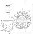
図1に示されているように、バイアル供給システム1は、サンプラ2、管理装置4及び表示装置6を備えている。サンプラ2は、試料などを収容したバイアルVを供給先であるインジェクタ8へ供給するための装置である。管理装置4は、サンプラ2及びインジェクタ8の動作管理を行なうものであり、CPU(中央演算装置)等を備えた電子回路によって実現することができる。表示装置6は、管理装置4と通信可能に設けられ、情報表示機能及び情報入力機能を兼備したタッチパネルである。この実施例では、管理装置4はガスクロマトグラフ100内に搭載された電子回路であり、表示装置6は、ガスクロマトグラフ100に設けられた表示パネルである(図2参照)。なお、本発明はこれに限定されるものではなく、ガスクロマトグラフ100の外部に設けられた電子回路によって管理装置4を実現することができ、ガスクロマトグラフ100の外部の端末に設けられた表示パネルによって表示装置6を実現することもできる。 As shown in FIG. 1, the
サンプラ2は、搬送アーム10及びバイアルホルダ12を備えており、インジェクタ8の側方に配置されている。バイアルホルダ12は、インジェクタ8へ供給すべき複数のバイアルVをセットすることができる円形テーブルである。搬送アーム10はバイアルホルダ12上において水平方向へ伸びるように設けられており、搬送アーム10の先端部に、バイアルVを把持するための複数の爪16を有するグリッパ14が設けられている。搬送アーム10は、バイアルホルダ12の中心を回転中心とした水平面内での回転と軸方向へのスライドにより、バイアルホルダ12にセットされている任意のバイアルVをグリッパ14で把持して搬送し、インジェクタ8のターレット20へ供給することができる。 The
インジェクタ8は、ガスクロマトグラフ100(図2参照)上に配置され、ガスクロマトグラフ100の上面に設けられている注入ポートへ試料を注入する装置である。インジェクタ8は、インジェクタ本体18及びターレット20を備えている。ターレット20は円形の回転テーブルである。ターレット20の上面には、バイアルを保持するための複数のバイアル受け穴24が同一円周上に設けられており、各バイアル受け穴24がターレット20の回転に伴って円軌道を描いて移動する。インジェクタ本体18はシリンジ22を備えている。シリンジ22は、液体の吸入及び吐出を行なう先端が鉛直下方を向いた状態で上下動可能に設けられている。ターレット20は、任意のバイアル受け穴24をシリンジ22の直下に配置することができる。 The
図2に示されているように、サンプラ2及びインジェクタ8は制御部26、28をそれぞれ備えている。サンプラ2の制御部26は、搬送アーム10の動作を制御する。インジェクタ8の制御部28は、インジェクタ本体18及びターレット20の動作を制御する。制御部26及び28は、CPU等を備えた電子回路によって実現されるものであり、管理装置4と通信可能である。管理装置4は、ユーザによって設定された動作条件に基づく制御情報を制御部26及び28へ出力し、制御部26及び28は管理装置6から提供された制御情報に基づく動作制御を行なう。また、管理装置4は、サンプラ2とインジェクタ8のターレット20との間でバイアルの受渡しを行なう際の搬送アーム10の位置を設定するためのユーザによるティーチングを、表示装置6を通じて補助するように構成されている。 As shown in FIG. 2, the
図3に示されているように、サンプラ2の搬送アーム10とインジェクタ8のターレット20との間でバイアルの受渡しを行なう際、サンプラ2が、搬送アーム10のグリッパ14をターレット20上の所定の受渡し位置Pへ正確に配置する必要がある。サンプラ2のティーチングとは、受渡し位置Pに配置されたバイアル受け穴24のバイアルVを把持することができる位置にグリッパ14が配置されるように、ユーザが目視で確認しながら搬送アーム10の位置を調節し、そのときの搬送アーム10の位置をサンプラ2及び/又は管理装置4に記憶させる作業である。管理装置4は、ティーチングにおいてユーザが行なうべき操作を表示装置6に表示することによって、ユーザによるティーチング作業を補助する。 As shown in FIG. 3, when the vial is delivered between the
サンプラ2のティーチングを行なう際の動作について、図1とともに図4のフローチャートを用いて説明する。 The operation when teaching the
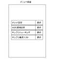
システムを起動すると、管理装置4は、図5に示されているようなメニュー画面を表示装置6に表示する。図5に例示されたメニュー画面には、「メソッド設定」、「AOC(自動試料注入装置)環境設定」、「サンプラティーチング」、「サンプラ搬送テスト」といったメニューが表示され、ユーザは所望のメニューを選択することができる。メニュー画面の「サンプラティーチング」を選択することにより、サンプラ2のティーチングを実行するためのティーチングモードへ移行する。 When the system is started, the
ユーザがメニュー画面の「サンプラティーチング」を選択すると、管理装置4はティーチングモードを開始し(図4:ステップ101)、図6のようなティーチング画面を表示装置6に表示する(図4:ステップ102)。ティーチング画面においてユーザが「ティーチング開始」を選択すると(図4:ステップ103)、管理装置4はインジェクタ8へティーチング開始の信号を送信し、ティーチングに使用する所定のバイアル受け穴24を受渡し位置Pに配置させる(図4:ステップ104)。なお、ティーチング開始の前提として、ティーチングに使用する所定のバイアル受け穴24に、ティーチングに使用するバイアルVがセットされている必要がある。そのため、管理装置4は、ユーザがティーチング開始を選択したときなどに、所定のバイアル受け穴24にバイアルVをセットすることを促す表示を表示装置6にて行なうように構成されていてもよい。 When the user selects "sampler teaching" on the menu screen, the
搬送アーム10は、水平面内方向(搬送アーム10の長手方向と回転方向)と鉛直方向へ移動するように構成されている。ティーチングには、ユーザが手で搬送アーム10を水平面内方向へ移動させる手作業工程と、表示装置6を通じた操作によって搬送アーム10を鉛直方向へ移動させるパネル操作工程と、が含まれる。管理装置4は、図7に示されているように、ティーチングにおいてユーザが行なうべき操作の手順、すなわち、搬送アーム10の操作手順をティーチング画面上にポップアップで表示し(図4:ステップ105)、搬送アーム10を鉛直方向へ移動させるための上下方向指示ボタン(図6において▲ボタンと▼ボタン)をティーチング画面に表示する。ユーザは、ポップアップで表示された操作手順に従い、搬送アーム10を手で動かしてグリッパ14を受渡し位置Pに配置されたバイアルV上の位置に調節し、グリッパ14がバイアルVを把持できる高さとなるように、表示装置6に表示された上下方向指示ボタンによって搬送アーム10を鉛直方向へ移動させる(図4:ステップ106)。 The
管理装置4は、表示装置6に表示したいずれかの上下方向指示ボタンにユーザがタッチすると、タッチされている上下方向指示ボタンを検知し、タッチされている上下方向指示ボタンの方向へ搬送アーム10を移動させる制御信号をサンプラ2へ送信するように構成されている。すなわち、ティーチングモードにおいて、ユーザが表示装置6に表示されたいずれかの上下方向指示ボタンを長押しすると、ユーザがタッチした上下方向指示ボタンの方向へタッチした時間に応じた距離だけ搬送アーム10が移動する。 When the user touches any of the up / down direction instruction buttons displayed on the
上記の手作業工程及びパネル操作工程により、受渡し位置Pに配置されたバイアルVをグリッパ14で把持することができる位置に搬送アーム10の位置が調節された後、ユーザがティーチング画面において「ティーチング確定」を選択すると、ティーチングが完了し(図4:ステップ107)、現在の(調節された)搬送アーム10の位置がサンプラ2及び/又は管理装置4によって「ティーチング位置」として記憶される。 After the position of the
また、図5及び図6に示されているように、メニュー画面及びティーチング画面において、サンプラ2の搬送テストを選択することができるようになっている。ユーザは、メニュー画面又はティーチング画面において「サンプラ搬送テスト」を選択することにより、現時点で記憶されているティーチング位置を使用してバイアルを正確に搬送することが可能か否かを確認するための搬送テストを実行することができる。搬送テストは、ティーチングが完了した後でティーチングが成功したか否かを確認するために実行することができる。また、サンプラ2及びインジェクタ8を互いの位置関係を変更せずに両者を移動させた場合、バイアルの種類を変更した場合などに、新たにティーチングを実行すべきかどうかを判断するために、搬送テストを実行することができる。 Further, as shown in FIGS. 5 and 6, the transport test of the
図8は、「サンプラ搬送テスト」が選択されることによって表示装置6に表示される画面の一例である。この搬送テスト画面では、バイアルの搬送元及び搬送先といった搬送条件を設定することができる。搬送テスト画面には、搬送元と搬送先とを入れ替えるためのボタンも設けられており、バイアルの搬送方向の設定を容易に入れ替えることができる。また、図8のように、搬送テスト画面において、バイアルが搬送元に正しく設置されているかの確認をユーザに促す表示を行なうことができる。 FIG. 8 is an example of a screen displayed on the
ユーザが、搬送元として設定した場所(例えば、インジェクタ8の特定のバイアル受け穴24)にバイアルを設置し、搬送開始ボタンをタッチすると、管理装置6は、サンプラ2のバイアルホルダ12とインジェクタ8のターレット20との間でバイアルの搬送を行なわせる。ユーザは、搬送が正常に実行されたか否かを目視によって確認し、搬送が正常に実行されなかった場合には、ティーチングへ移行することができる。図8の搬送テスト画面では、搬送テストの直後にティーチングを実行することができるように、ティーチングを選択するためのボタンが表示されている。 When the user installs the vial in the place set as the transfer source (for example, the specific
以上において説明したバイアル供給システム1は、ガスクロマトグラフ100及びインジェクタ8とともにガスクロマトグラフィ分析システムを構成する。 The
以上において説明した実施例は、本発明に係るバイアル供給システムの実施形態の一例に過ぎない。本発明に係るバイアル供給システムの実施形態は以下に示すとおりである。 The examples described above are merely examples of embodiments of the vial supply system according to the present invention. An embodiment of the vial supply system according to the present invention is as shown below.
本発明に係るバイアル供給システムの一実施形態では、搬送アームによりバイアルを所定の供給先へ供給するサンプラと、前記サンプラと通信可能に設けられ、前記サンプラによる前記バイアルの供給動作を管理するように構成された管理装置と、前記管理装置と通信可能に設けられた表示装置と、を備え、前記管理装置は、前記サンプラの前記搬送アームが前記供給先との間で前記バイアルの受渡しを行なう際の前記搬送アームの位置を設定するティーチングを実行するためのティーチングモードが開始されたときに、前記ティーチングにおいてユーザが行なうべき操作を前記表示装置に表示するように構成されている。 In one embodiment of the vial supply system according to the present invention, a sampler that supplies a vial to a predetermined supply destination by a transport arm is provided so as to be communicable with the sampler, and the operation of supplying the vial by the sampler is managed. The management device includes a configured management device and a display device provided so as to be able to communicate with the management device, and the management device is used when the transfer arm of the sampler delivers the vial to and from the supply destination. When the teaching mode for executing the teaching for setting the position of the transfer arm is started, the operation to be performed by the user in the teaching is displayed on the display device.
上記一実施形態における第1態様では、前記表示装置はタッチパネルであり、前記ティーチングは、前記タッチパネルを通じたユーザの操作により前記搬送アームを鉛直方向へ移動させるパネル操作工程を含み、前記管理装置は、前記パネル操作工程において、前記搬送アームを移動させる方向を指示するための上下方向指示ボタンを前記タッチパネルに表示するように構成され、かつ、前記ユーザがいずれかの前記上下方向指示ボタンをタッチしたときに、タッチされた前記上下方向指示ボタンの方向へ前記上下方向指示ボタンがタッチされた時間に応じた距離だけ、前記サンプラに前記搬送アームを鉛直方向へ移動させるように構成されている。このような態様により、ユーザは、タッチパネルを通じて搬送アームの高さ調節を容易に実行することができる。 In the first aspect of the above embodiment, the display device is a touch panel, and the teaching includes a panel operation step of moving the transfer arm in the vertical direction by a user operation through the touch panel, and the management device includes a panel operation step. In the panel operation step, when the vertical direction instruction button for instructing the direction in which the transfer arm is moved is displayed on the touch panel and the user touches any of the vertical direction instruction buttons. In addition, the transport arm is configured to be moved vertically to the sampler by a distance corresponding to the time when the vertical direction instruction button is touched in the direction of the touched vertical direction instruction button. According to such an aspect, the user can easily adjust the height of the transfer arm through the touch panel.
上記第1態様において、前記ティーチングは、ユーザに手作業で前記搬送アームを水平面内方向へ移動させる手作業工程を含み、前記管理装置は、前記手作業工程において手作業で前記搬送アームを水平面内方向へ移動させる指示を前記タッチパネルに表示するように構成されている。これにより、ユーザは、搬送アームの平面的な位置調節を手作業で行なうべきことを容易に認識することができる。 In the first aspect, the teaching includes a manual step of manually moving the transport arm inward in the horizontal plane to the user, and the management device manually moves the transport arm in the horizontal plane in the manual step. It is configured to display an instruction to move in the direction on the touch panel. This allows the user to easily recognize that the planar position adjustment of the transfer arm should be manually performed.
また、上記一実施形態における第2態様では、前記管理装置は、前記搬送アームが前記供給先との間で前記バイアルを搬送することができるか否かを確認するための搬送テストを実行すべき指示が前記表示装置を通じて入力されたときに、前記サンプラに前記搬送テストを実行させるように構成されている。このような態様により、ティーチングが成功したか否かの確認を容易に行なうことができる。また、サンプラを移動させた場合、使用するバイアルの種類を変更したなどに、先に搬送テストを実施することによってティーチングが必要か否かを確認することができ、不要なティーチングの実施を回避することができる。 Further, in the second aspect of the above embodiment, the management device should execute a transfer test for confirming whether or not the transfer arm can transfer the vial to and from the supply destination. The sampler is configured to perform the transfer test when instructions are entered through the display device. With such an aspect, it is possible to easily confirm whether or not the teaching is successful. In addition, when the sampler is moved, it is possible to confirm whether teaching is necessary by conducting a transfer test first, such as when the type of vial to be used is changed, and unnecessary teaching can be avoided. be able to.
上記第2態様において、前記管理装置は、前記表示装置を通じてユーザに前記搬送テストの搬送条件を設定させるように構成され、かつ、前記表示装置を通じて設定された前記搬送条件に基づく前記搬送テストを前記サンプラに実行させるように構成されている。 In the second aspect, the management device is configured to allow the user to set the transport conditions of the transport test through the display device, and the transport test based on the transport conditions set through the display device is performed. It is configured to let the sampler do it.
上記一実施形態の第3態様では、前記管理装置はガスクロマトグラフに設けられた電子回路であり、前記表示装置はガスクロマトグラフに設けられた表示パネル又は外部端末に設けられた表示パネルである。 In the third aspect of the above embodiment, the management device is an electronic circuit provided on the gas chromatograph, and the display device is a display panel provided on the gas chromatograph or a display panel provided on an external terminal.
本発明に係るガスクロマトグラフィ分析システムの一実施形態では、ガスクロマトグラフと、前記ガスクロマトグラフへ試料を注入するインジェクタと、試料を収容するバイアルを前記インジェクタへ供給するための、上述のバイアル供給システムと、を備えている。 In one embodiment of the gas chromatography analysis system according to the present invention, there is a gas chromatograph, an injector for injecting a sample into the gas chromatograph, and the above-mentioned vial supply system for supplying a vial containing a sample to the injector. It is equipped with.
1 バイアル供給システム
2 サンプラ
4 管理装置
6 表示装置
8 インジェクタ
10 搬送アーム
12 バイアルホルダ
14 グリッパ
16 爪
18 インジェクタ本体
20 ターレット
22 シリンジ
24 バイアル受け穴
26 サンプラの制御部
28 インジェクタの制御部
100 ガスクロマトグラフ1
Claims (7)
Translated fromJapanese前記サンプラと通信可能に設けられ、前記サンプラによる前記バイアルの供給動作を管理するように構成された管理装置と、
前記管理装置と通信可能に設けられた表示装置と、を備え、
前記管理装置は、前記サンプラの前記搬送アームが前記供給先との間で前記バイアルの受渡しを行なう際の前記搬送アームの位置を設定するティーチングを実行するためのティーチングモードが開始されたときに、前記ティーチングにおいてユーザが行なうべき操作を前記表示装置に表示するように構成されている、バイアル供給システム。A sampler that supplies the vial to the specified supply destination by the transfer arm,
A management device provided so as to be communicable with the sampler and configured to control the supply operation of the vial by the sampler.
A display device provided so as to be able to communicate with the management device is provided.
When the teaching mode for executing the teaching for setting the position of the transfer arm when the transfer arm of the sampler transfers the vial to and from the supply destination is started, the management device is started. A vial feeding system configured to display on the display device an operation to be performed by the user in the teaching.
前記ティーチングは、前記タッチパネルを通じたユーザの操作により前記搬送アームを鉛直方向へ移動させるパネル操作工程を含み、
前記管理装置は、前記パネル操作工程において、前記搬送アームを移動させる方向を指示するための上下方向指示ボタンを前記タッチパネルに表示するように構成され、かつ、前記ユーザがいずれかの前記上下方向指示ボタンをタッチしたときに、タッチされた前記上下方向指示ボタンの方向へ前記上下方向指示ボタンがタッチされた時間に応じた距離だけ、前記サンプラに前記搬送アームを鉛直方向へ移動させるように構成されている、請求項1に記載のバイアル供給システム。The display device is a touch panel.
The teaching includes a panel operation step of moving the transfer arm in the vertical direction by a user operation through the touch panel.
The management device is configured to display a vertical direction instruction button for instructing a direction in which the transfer arm is moved on the touch panel in the panel operation step, and the user gives any of the vertical direction instructions. When the button is touched, the transport arm is configured to move vertically to the sampler by a distance corresponding to the time when the vertical direction instruction button is touched in the direction of the touched vertical direction instruction button. The vial supply system according to claim 1.
前記管理装置は、前記手作業工程において手作業で前記搬送アームを水平面内方向へ移動させる指示を前記タッチパネルに表示するように構成されている、請求項2又は3に記載のバイアル供給システム。The teaching comprises a manual step of manually moving the transport arm inward in a horizontal plane to the user.
The vial supply system according to claim 2 or 3, wherein the management device is configured to display an instruction to manually move the transfer arm inward in a horizontal plane on the touch panel in the manual process.
前記表示装置はガスクロマトグラフに設けられた表示パネル又は外部端末に設けられた表示パネルである、請求項1から5のいずれか一項に記載のバイアル供給システム。The management device is an electronic circuit provided in a gas chromatograph.
The vial supply system according to any one of claims 1 to 5, wherein the display device is a display panel provided on a gas chromatograph or a display panel provided on an external terminal.
前記ガスクロマトグラフへ試料を注入するインジェクタと、
試料を収容するバイアルを前記インジェクタへ供給するための、請求項1から6のいずれか一項に記載のバイアル供給システムと、を備えたガスクロマトグラフィ分析システム。Gas chromatograph and
An injector that injects a sample into the gas chromatograph,
A gas chromatography analysis system comprising the vial supply system according to any one of claims 1 to 6, for supplying a vial containing a sample to the injector.
Priority Applications (3)
| Application Number | Priority Date | Filing Date | Title |
|---|---|---|---|
| JP2020190157AJP7456357B2 (en) | 2020-11-16 | 2020-11-16 | Vial supply system and gas chromatography analysis system |
| US17/510,672US11921092B2 (en) | 2020-11-16 | 2021-10-26 | Vial supply system and gas chromatography analysis system |
| CN202111340224.3ACN114505851A (en) | 2020-11-16 | 2021-11-12 | Bottle supply system and gas chromatography system |
Applications Claiming Priority (1)
| Application Number | Priority Date | Filing Date | Title |
|---|---|---|---|
| JP2020190157AJP7456357B2 (en) | 2020-11-16 | 2020-11-16 | Vial supply system and gas chromatography analysis system |
Publications (2)
| Publication Number | Publication Date |
|---|---|
| JP2022079153Atrue JP2022079153A (en) | 2022-05-26 |
| JP7456357B2 JP7456357B2 (en) | 2024-03-27 |
Family
ID=81547454
Family Applications (1)
| Application Number | Title | Priority Date | Filing Date |
|---|---|---|---|
| JP2020190157AActiveJP7456357B2 (en) | 2020-11-16 | 2020-11-16 | Vial supply system and gas chromatography analysis system |
Country Status (3)
| Country | Link |
|---|---|
| US (1) | US11921092B2 (en) |
| JP (1) | JP7456357B2 (en) |
| CN (1) | CN114505851A (en) |
Citations (5)
| Publication number | Priority date | Publication date | Assignee | Title |
|---|---|---|---|---|
| JPH04164257A (en)* | 1990-10-29 | 1992-06-09 | Ajinomoto Co Inc | Automatic pretreatment device |
| US20080014628A1 (en)* | 2004-10-12 | 2008-01-17 | Chuo Precision Industrial Co., Ltd. | Cell incubator for single cell operation supporting robot |
| JP3188929U (en)* | 2013-12-04 | 2014-02-13 | 株式会社島津製作所 | Autosampler and automatic sample supply apparatus using the same |
| JP2019025562A (en)* | 2017-07-27 | 2019-02-21 | ファナック株式会社 | Robot control device and production system |
| JP2019093492A (en)* | 2017-11-24 | 2019-06-20 | ファナック株式会社 | Teaching device for performing teaching operation to robot |
Family Cites Families (8)
| Publication number | Priority date | Publication date | Assignee | Title |
|---|---|---|---|---|
| JPS61224007A (en)* | 1985-03-29 | 1986-10-04 | Shinko Electric Co Ltd | Displaying method for teach locus of industrial robot |
| JP3682561B2 (en) | 1996-06-05 | 2005-08-10 | 株式会社島津製作所 | Automatic sample injection device |
| SG11201703891RA (en)* | 2014-12-26 | 2017-06-29 | Kawasaki Heavy Ind Ltd | Robot motion program generating method and robot motion program generating apparatus |
| IT201700024734A1 (en) | 2017-03-06 | 2018-09-06 | Dani Instr Spa | PERFORMED SAMPLER DEVICE FOR GAS CHROMATOGRAPHY |
| JP6708581B2 (en)* | 2017-04-07 | 2020-06-10 | ライフロボティクス株式会社 | Teaching device, display device, teaching program and display program |
| JP6469162B2 (en)* | 2017-04-17 | 2019-02-13 | ファナック株式会社 | Offline teaching device for robots |
| JP2019045363A (en)* | 2017-09-05 | 2019-03-22 | 株式会社日立ハイテクノロジーズ | Automatic analyzer |
| KR101957096B1 (en)* | 2018-03-05 | 2019-03-11 | 캐논 톡키 가부시키가이샤 | Robot system, Manufacturing apparatus of device, Manufacturing method of device and Method for adjusting teaching positions |
- 2020
- 2020-11-16JPJP2020190157Apatent/JP7456357B2/enactiveActive
- 2021
- 2021-10-26USUS17/510,672patent/US11921092B2/enactiveActive
- 2021-11-12CNCN202111340224.3Apatent/CN114505851A/enactivePending
Patent Citations (5)
| Publication number | Priority date | Publication date | Assignee | Title |
|---|---|---|---|---|
| JPH04164257A (en)* | 1990-10-29 | 1992-06-09 | Ajinomoto Co Inc | Automatic pretreatment device |
| US20080014628A1 (en)* | 2004-10-12 | 2008-01-17 | Chuo Precision Industrial Co., Ltd. | Cell incubator for single cell operation supporting robot |
| JP3188929U (en)* | 2013-12-04 | 2014-02-13 | 株式会社島津製作所 | Autosampler and automatic sample supply apparatus using the same |
| JP2019025562A (en)* | 2017-07-27 | 2019-02-21 | ファナック株式会社 | Robot control device and production system |
| JP2019093492A (en)* | 2017-11-24 | 2019-06-20 | ファナック株式会社 | Teaching device for performing teaching operation to robot |
Also Published As
| Publication number | Publication date |
|---|---|
| US20220155264A1 (en) | 2022-05-19 |
| CN114505851A (en) | 2022-05-17 |
| US11921092B2 (en) | 2024-03-05 |
| JP7456357B2 (en) | 2024-03-27 |
Similar Documents
| Publication | Publication Date | Title |
|---|---|---|
| CN107290560B (en) | Reagent sucking method and device for multi-bottle reagent and sample analyzer | |
| JP4662987B2 (en) | Robotic handling system and method with independently operable removable tool | |
| JP3581501B2 (en) | Synthetic experiment automation system | |
| US6868308B2 (en) | Operation guidance method of clinical system | |
| JP2022079153A (en) | Vial supply system, and gas chromatography analysis system | |
| CN114544471B (en) | Sample analyzer and sample detection process thereof | |
| US10514376B2 (en) | Position adjustment method for movable unit in sample analyzer, and sample analyzer | |
| CN105682854A (en) | Processing machinery and processing machinery production lines | |
| JP2001074587A (en) | Work-supplying device for supplying work to helium leak tester | |
| JP2001174468A (en) | Automatic testing system | |
| JP7420045B2 (en) | Automatic sample injection system | |
| US12013378B2 (en) | Gas chromatography analysis system | |
| JP2010038762A (en) | Inspection apparatus | |
| JP2018206240A (en) | Processing device | |
| CN105009704B (en) | Electronic circuit component installation method and installation system | |
| CN207817145U (en) | A kind of mobile phone, main board of tablet computer Auto-Test System | |
| JP2000146775A (en) | Automatic sample injection device | |
| EP3576511A1 (en) | Control device, mounting device, and control method | |
| JP3918560B2 (en) | Electronic component mounting equipment | |
| JP2014202721A (en) | Liquid sample introduction device and liquid chromatograph apparatus | |
| WO2021245965A1 (en) | Automatic sample injection device | |
| KR101167455B1 (en) | Transfer Apparatus with intergrated loading and receiving, and Method of Operating the same | |
| JPH0312554A (en) | Automatic sample bottle carrying device | |
| JP2006339537A (en) | Circuit board work system | |
| JP2021033321A (en) | Cutting device |
Legal Events
| Date | Code | Title | Description |
|---|---|---|---|
| A521 | Request for written amendment filed | Free format text:JAPANESE INTERMEDIATE CODE: A523 Effective date:20210624 | |
| A621 | Written request for application examination | Free format text:JAPANESE INTERMEDIATE CODE: A621 Effective date:20230320 | |
| A977 | Report on retrieval | Free format text:JAPANESE INTERMEDIATE CODE: A971007 Effective date:20231011 | |
| A131 | Notification of reasons for refusal | Free format text:JAPANESE INTERMEDIATE CODE: A131 Effective date:20231024 | |
| A521 | Request for written amendment filed | Free format text:JAPANESE INTERMEDIATE CODE: A523 Effective date:20231220 | |
| A521 | Request for written amendment filed | Free format text:JAPANESE INTERMEDIATE CODE: A523 Effective date:20240109 | |
| RD02 | Notification of acceptance of power of attorney | Free format text:JAPANESE INTERMEDIATE CODE: A7422 Effective date:20240116 | |
| TRDD | Decision of grant or rejection written | ||
| A01 | Written decision to grant a patent or to grant a registration (utility model) | Free format text:JAPANESE INTERMEDIATE CODE: A01 Effective date:20240213 | |
| A61 | First payment of annual fees (during grant procedure) | Free format text:JAPANESE INTERMEDIATE CODE: A61 Effective date:20240226 | |
| R151 | Written notification of patent or utility model registration | Ref document number:7456357 Country of ref document:JP Free format text:JAPANESE INTERMEDIATE CODE: R151 |