JP2022076866A - Seat for vehicle - Google Patents
Seat for vehicleDownload PDFInfo
- Publication number
- JP2022076866A JP2022076866AJP2020187496AJP2020187496AJP2022076866AJP 2022076866 AJP2022076866 AJP 2022076866AJP 2020187496 AJP2020187496 AJP 2020187496AJP 2020187496 AJP2020187496 AJP 2020187496AJP 2022076866 AJP2022076866 AJP 2022076866A
- Authority
- JP
- Japan
- Prior art keywords
- support member
- region
- seat back
- width
- right direction
- Prior art date
- Legal status (The legal status is an assumption and is not a legal conclusion. Google has not performed a legal analysis and makes no representation as to the accuracy of the status listed.)
- Granted
Links
Images


Landscapes
- Chair Legs, Seat Parts, And Backrests (AREA)
- Seats For Vehicles (AREA)
Abstract
Translated fromJapanese
Description
Translated fromJapanese本発明は、乗物用シートに関する。 The present invention relates to a vehicle seat.
従来、車両用シートにおいて、シートバックフレームの内側にランバープレートを配置し、シートバックフレームおよびランバープレートによってウレタンフォームを支持する構造が知られている(例えば特許文献1参照)。 Conventionally, in a vehicle seat, a structure in which a lumbar plate is arranged inside a seat back frame and the urethane foam is supported by the seat back frame and the lumbar plate is known (see, for example, Patent Document 1).
上記従来の構造におけるランバープレートは、左右全幅を略一定にしてシートバックの下端部から上方へ延びている。ランバープレートの上端部は、シートバックの上部の手前で終端しているが、この構造では、シートバックにおける乗員の肩部周りのサポートが不足してしまう。このため、長時間の運転等をする際に乗員が疲労を感じやすいといった課題があった。
一方で、単にシートバックのサポート力を高めると、背骨周辺等に局所的な荷重がかかることがあり、乗員の背中に違和感が生じることがある。The lumbar plate in the above-mentioned conventional structure extends upward from the lower end portion of the seat back with the entire width on the left and right substantially constant. The upper end of the lumbar plate terminates short of the top of the seat back, but this structure results in insufficient support around the occupant's shoulders in the seat back. For this reason, there is a problem that the occupant tends to feel tired when driving for a long time.
On the other hand, if the support force of the seat back is simply increased, a local load may be applied to the area around the spine or the like, which may cause discomfort on the back of the occupant.
そこで本発明は、シートバックにおける乗員の身体のサポート力を高めるとともに、乗員の背中の違和感の発生を抑えることができる乗物用シートを提供する。 Therefore, the present invention provides a vehicle seat capable of enhancing the support force of the occupant's body on the seat back and suppressing the occurrence of discomfort on the occupant's back.
上記課題の解決手段として、請求項1に記載した発明は、乗員の背中を支持するシートバック(例えば実施形態のシートバック11)を備えた乗物用シートであって、前記シートバックは、背凭れ面(例えば実施形態の背凭れ面22)を形成するクッション部材(例えば実施形態のクッション部材21)と、前記クッション部材を支持するフレームであり、前記シートバックの左右方向の両側で上下方向に延びる一対の側部フレーム(例えば実施形態の側部フレーム14)を有するシートバックフレーム(例えば実施形態のシートバックフレーム12)と、前記シートバックフレームに保持されて前記クッション部材を支持する部材であり、前記一対の側部フレームに渡るように配置されたサポート部材(例えば肩部サポート部材45)と、を備え、前記サポート部材は、前記左右方向の中央部を含んで予め定めた左右幅に設けられる中央領域(例えば実施形態の中央領域46)と、前記中央領域よりも前記左右方向の外側に設けられる外側領域(例えば実施形態の外側領域47)と、に区画され、前記中央領域は、前記外側領域に対して、前記クッション部材と反対側に凹む凹状領域(例えば実施形態の凹状領域46b)とされ、前記凹状領域は、前記サポート部材の上端(例えば実施形態の上端45b)から下端(例えば実施形態の下端45c)に至るほど左右方向の幅が狭くなるように形成されている。
この構成によれば、シートバックフレームの左右一対の側部フレームに渡るようにサポート部材を設け、このサポート部材の左右中央領域を凹状領域としたので、以下の効果を奏する。すなわち、乗員の背骨がサポート部材からの支持荷重を受け難くなり、局所的な違和感(圧迫感)が抑えられる。これにより、乗員の着座時の姿勢への影響を抑えることができる。凹状領域は、下方ほど左右幅が狭まるので、運転中の乗員の上体に左右方向の振れが生じても、背骨がサポート部材からの支持荷重を受け難くなる。すなわち、乗員の上体が左右方向に振れた際、背骨は上側ほど振れが大きくなるが、凹状領域は上側ほど左右幅が広いので、乗員の上体が左右方向に振れた際にも、背骨周辺の振れを許容して自由度を与え、背骨周辺の違和感を抑えることができる。凹状領域は下側ほど左右幅が狭いので、サポート部材の下側では外側領域(支持領域)を広く確保し、乗員の姿勢を保持しやすくすることができる。As a means for solving the above problems, the invention according to
According to this configuration, the support member is provided so as to extend over the pair of left and right side frames of the seat back frame, and the left and right center region of the support member is a concave region, so that the following effects are obtained. That is, the spine of the occupant is less likely to receive the support load from the support member, and the local discomfort (tightness) is suppressed. As a result, it is possible to suppress the influence on the posture of the occupant when sitting. Since the width of the concave region becomes narrower toward the lower side, the spine is less likely to receive the support load from the support member even if the upper body of the occupant during operation swings in the left-right direction. That is, when the occupant's upper body swings in the left-right direction, the spine swings more toward the upper side, but the concave region has a wider left-right width toward the upper side, so that even when the occupant's upper body swings in the left-right direction, the spine It is possible to allow the fluctuation of the surroundings to give a degree of freedom and suppress the discomfort around the spine. Since the concave region has a narrower left-right width toward the lower side, a wider outer region (support region) can be secured on the lower side of the support member, and it is possible to easily maintain the posture of the occupant.
請求項2に記載した発明は、前記外側領域は、前記クッション部材における前記背凭れ面と反対側の背面(例えば実施形態の背面23)に接近して前記背面を支持し、前記外側領域は、前記サポート部材の上端から下端に至るほど左右方向の幅が広くなるように形成されている。
この構成によれば、サポート部材における凹状領域の左右両側に、クッション部材の背面に接近する外側領域が設けられるので、サポート部材の左右両側で乗員の上体を支持しやすく、乗員の姿勢を良好に保持することができる。乗員の上体に支持荷重を付与しやすい外側領域は、上側ほど左右幅が狭く設けられるので、サポート部材の上側においてクッション部材の柔軟性を確保し、乗員がシートバックに深く凭れたり上体を捻ったりする動作のしやすさを高めることができる。According to the second aspect of the present invention, the outer region is close to the back surface of the cushion member opposite to the backrest surface (for example, the
According to this configuration, since outer regions close to the back surface of the cushion member are provided on the left and right sides of the concave region of the support member, it is easy to support the upper body of the occupant on the left and right sides of the support member, and the posture of the occupant is good. Can be held in. Since the outer region where it is easy to apply a supporting load to the occupant's upper body is provided with a narrower left-right width toward the upper side, the flexibility of the cushion member is ensured on the upper side of the support member, and the occupant can lean deeply on the seat back or hold the upper body. It is possible to increase the ease of twisting motion.
請求項3に記載した発明は、前記シートバックフレームに保持されて前記クッション部材を支持する部材であり、前記一対の側部フレームの下部の間に配置された下部サポート部材(例えば実施形態のランバープレート42)を備え、前記下部サポート部材は、前記一対の側部フレームの間の間隔よりも狭い左右幅を有し、前記サポート部材は、前記下部サポート部材よりも上方に配置され、前記下部サポート部材よりも広い左右幅を有している。
この構成によれば、シートバックフレームの下部に配置された下部サポート部材によって、乗員の腰部を支持するとともに、シートバックフレームの上部に配置されたサポート部材によって、乗員の肩部を支持することができる。サポート部材は、下部サポート部材よりも左右幅が広く、左右側部フレームに渡るように設けられるので、乗員の両肩を良好に支持することができる。The invention according to claim 3 is a member held by the seat back frame to support the cushion member, and is a lower support member (for example, a lumbar of the embodiment) arranged between the lower portions of the pair of side frames. The lower support member comprises a plate 42), the lower support member having a left-right width narrower than the distance between the pair of side frames, the support member being arranged above the lower support member, and the lower support member. It has a wider left-right width than the member.
According to this configuration, the lower support member arranged at the lower part of the seat back frame supports the waist of the occupant, and the support member arranged at the upper part of the seat back frame supports the shoulder portion of the occupant. can. Since the support member has a wider left-right width than the lower support member and is provided so as to extend over the left-right side frames, both shoulders of the occupant can be satisfactorily supported.
請求項4に記載した発明は、前記凹状領域と前記外側領域との間の境界領域(例えば実施形態の境界領域48)は、前記サポート部材を前記シートバックフレームに取り付けるための取り付け領域(例えば実施形態の取り付け領域48a)とされている。
この構成によれば、凹状領域と外側領域との間の境界領域でサポート部材をシートバックフレームに取り付けるので、少ない取り付け構造で凹状領域と外側領域とをシートバックフレームに取り付けることができる。サポート部材の左右両側の境界領域を用いることで、サポート部材をバランスよくシートバックフレームに取り付けることができる。In the invention described in claim 4, the boundary region between the concave region and the outer region (for example, the
According to this configuration, since the support member is attached to the seat back frame at the boundary region between the concave region and the outer region, the concave region and the outer region can be attached to the seat back frame with a small mounting structure. By using the boundary areas on both the left and right sides of the support member, the support member can be attached to the seat back frame in a well-balanced manner.
請求項5に記載した発明は、前記シートバックの上方にヘッドレスト(例えば実施形態のヘッドレスト35)を備え、前記シートバックの正面視において、前記ヘッドレストの左右幅(例えば実施形態の左右幅H1)は、前記サポート部材の上端における前記凹状領域の左右幅(例えば実施形態の左右幅H2)よりも小さく、前記サポート部材の下端における前記凹状領域の左右幅(例えば実施形態の左右幅H3)よりも大きい。
この構成によれば、ヘッドレストの左右幅との関係を加味して、サポート部材の凹状領域の左右幅を設定することで、相対的にサポート部材の接近領域の左右幅を設定し、乗員の肩部の適切なサポートを図ることができる。The invention according to claim 5 is provided with a headrest (for example, the
According to this configuration, by setting the left-right width of the concave region of the support member in consideration of the relationship with the left-right width of the headrest, the left-right width of the relatively approaching region of the support member is set, and the shoulder of the occupant. Appropriate support for the department can be achieved.
請求項6に記載した発明は、前記凹状領域は、前記クッション部材と反対側に凹むように、左右の前記外側領域に渡って連続的に湾曲する湾曲面(例えば実施形態の湾曲面46a)を形成するものであり、前記湾曲面は、前記左右方向で複数の部分領域(例えば実施形態の部分領域51)に区画され、互いに隣接する一対の部分領域の間には、前記湾曲面よりも大きな曲率の形状又は屈曲形状の少なくとも一つを有する区画領域(例えば実施形態の区画領域52a)が形成されている。
この構成によれば、凹状領域が形成する湾曲面が複数の部分領域に区画され、隣り合う部分領域の間の区画領域は、湾曲面に対して形状が変化するものであり、隣り合う部分領域の間(湾曲面の途中)に不連続点(領域)が設けられることとなる。これにより、凹形状部が撓みやすくなってサポート部材に柔軟性を持たせ、シートバックのクッション性を確保することができる。The invention according to claim 6 has a curved surface (for example, a
According to this configuration, the curved surface formed by the concave region is divided into a plurality of partial regions, and the partitioned region between the adjacent partial regions changes in shape with respect to the curved surface, and the adjacent partial regions are formed. A discontinuity point (region) will be provided between the spaces (in the middle of the curved surface). As a result, the concave portion becomes easy to bend, the support member is made flexible, and the cushioning property of the seat back can be ensured.
本発明によれば、シートバックにおける乗員の身体のサポート力を高めるとともに、乗員の背中の違和感の発生を抑えることができる乗物用シートを提供することができる。 According to the present invention, it is possible to provide a vehicle seat capable of enhancing the support force of the occupant's body on the seat back and suppressing the occurrence of discomfort on the occupant's back.
以下、本発明の実施形態について図面を参照して説明する。
<車両用シート>
図1~図3は、実施形態の車両用シート1のシートバック11の構造を示す。車両用シート1は、乗員が着座するシートクッション31と、乗員の背中を支持するシートバック11と、シートバック11の上部に支持されて乗員の頭部を支持するヘッドレスト35(図10参照)と、を備えている。図中矢印Xは車両用シート1を車両に搭載した際の左右方向、矢印Yは同前後方向、矢印Zは同上下方向をそれぞれ示す。
実施形態の車両用シート1は、自動運転車両に好適に採用される。自動運転とは、例えば、車両の加減速または操舵の少なくとも一方を自動に制御して車両を走行させることである。Hereinafter, embodiments of the present invention will be described with reference to the drawings.
<Vehicle seat>
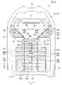
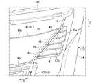
1 to 3 show the structure of the seat back 11 of the
The
シートバック11は、骨格部材である金属製のシートバックフレーム12を備えている。
図6を併せて参照し、シートバック11は、ウレタンフォーム製のクッション部材21を備えている。クッション部材21は、シートバックフレーム12およびクッション支持部材41に後方側から支持されている。クッション部材21の前面は、乗員Jの背中を支持する背凭れ面22を形成している。クッション部材21の背凭れ面22を含む外表面は、表皮材で覆われている。The seat back 11 includes a metal seat back
With reference to FIG. 6, the seat back 11 includes a
例えば、背凭れ面22の左右中央部の上下端を結ぶ直線に沿う方向を、シートバック11の上下方向とする。シートバック11の左右方向は、車両左右方向に相当する。これら上下方向および左右方向と直交する方向を、シートバック11の前後方向とする。この前後方向から見ることを、シートバック11の正面視とする。 For example, the direction along the straight line connecting the upper and lower ends of the left and right center portions of the
図1~図3を参照し、シートバックフレーム12は、シートバック11の正面視でシートバック11の外形状に沿うように形成された枠状部13を備えている。枠状部13は、シートバック11の正面視で概略矩形枠形状をなしている。枠状部13は、シートバック11の上下方向に延在する左右一対の側部フレーム14と、左右の側部フレーム14の上端部間を連結する上部フレーム15と、左右の側部フレーム14の下端部間を連結する下部フレーム16と、を備えている。例えば、側部フレーム14の上部は、左右方向内側に向けて傾斜しており、上部フレーム15は、下部フレーム16よりも左右方向の長さが短くされる。例えば、左右の側部フレーム14の上部間には、左右方向に延びる上部クロスフレーム17が架設されている。 With reference to FIGS. 1 to 3, the seat back
シートバックフレーム12の下端部は、シートクッション31の骨格部材である金属製のシートフレーム(不図示)の後端部に対し、左右方向(シート幅方向)に沿う回転軸C1を介して傾動可能(リクライニング可能)に連結されている。 The lower end of the seat back
シートバックフレーム12は、上下方向に延在する支持ワイヤ18を備えている。支持ワイヤ18は、上部クロスフレーム17および下部フレーム16に上下端部がそれぞれ接続されている。支持ワイヤ18は、左右方向に間隔を空けて左右一対に設けられている。各支持ワイヤ18は、金属製の棒状部材を予め定めた形状に屈曲させて形成されている。各支持ワイヤ18は、クッション支持部材41を支持している。各支持ワイヤ18によって、クッション支持部材41がシートバックフレーム12に取り付けられている。 The seat back
<クッション支持部材>
シートバックフレーム12の枠状部13の内側には、シートバックフレーム12と協働してクッション部材21を支持するクッション支持部材41が設けられている。
クッション支持部材41は、シートバック11の下部に配置されるランバープレート42(下部支持部材)と、シートバック11の上部に配置される肩部サポート部材45(上部支持部材)と、を備えている。ランバープレート42は、左右一対の側部フレーム14の間の間隔よりも狭い左右幅に設けられている。肩部サポート部材45は、ランバープレート42よりも左右幅が広く、左右一対の側部フレーム14に渡るように設けられている。例えば、ランバープレート42および肩部サポート部材45は、左右対称に設けられている。ランバープレート42および肩部サポート部材45は、互いに別体である構成に限らず、互いに一体である構成でもよい。<Cushion support member>
Inside the frame-shaped
The
ランバープレート42は、シートバック11の上下方向に沿うように延びる本体部43と、本体部43の左右方向外側に延出する複数の延出部44と、を備えている。ランバープレート42は、例えば合成樹脂からなる射出成形品である。本体部43および延出部44は、互いに一体形成されている。本体部43は、上下方向で上段部43a、中段部43bおよび下段部43cに区画されている。延出部44は、中段部43bの左右方向外側に延びる複数の中段延出部44bと、下段部43cの左右方向外側に延びる下段延出部44cと、を備えている。 The
中段延出部44bは、上下方向で間隔を空けて複数(実施形態では三つ)設けられている。下段延出部44cは、中段延出部44bよりも上下幅が広く、下段部43cと同等の上下幅で単一に設けられている。各延出部44b,44cの左右方向外側の先端は、例えば同一の左右方向位置にある。この先端部分が、ランバープレート42の左右端部42aとなる。ランバープレート42には、各延出部44b,44cと本体部43とに跨る補強ビード43dが形成されている。本体部43には、適宜開口部43eが形成されており、この開口部43eを避けた残余の部分にも、適宜補強ビード43dが形成されている。 A plurality (three in the embodiment) of the
肩部サポート部材45は、例えば合成樹脂からなる射出成型品である。肩部サポート部材45は、左右一対の側部フレーム14に渡るように設けられている。肩部サポート部材45は、ランバープレート42よりも左右幅が広く、ランバープレート42よりも上下幅が狭い。肩部サポート部材45の左右端部45aは、ランバープレート42の左右端部42aよりも左右側部フレーム14に近接している。肩部サポート部材45の左右端部45aは、それぞれ左右側部フレーム14に対して左右方向の隙間を有している。肩部サポート部材45の左右端部45aは、それぞれ左右側部フレーム14に接触したり連結したりしてもよい。肩部サポート部材45の左右端部45aは、それぞれ左右側部フレーム14との間に隙間を有しながらも、シートバック11の正面視で左右側部フレーム14と重なる構成でもよい。 The
肩部サポート部材45は、乗員の肩甲骨付近に位置するクッション部材21の背面23を支持する。これにより、乗員の肩甲骨付近でウレタンフォーム(クッション部材21)の減衰特性をより効率的に発揮させ、乗員の上体を安定的にサポートする。
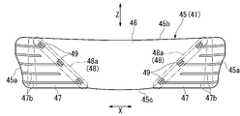
図4~図7を参照し、肩部サポート部材45は、左右方向の中央部を含んで予め定めた左右幅に設けられる中央領域46と、中央領域46よりも左右方向外側に設けられる一対の外側領域47と、に区画されている。The
With reference to FIGS. 4 to 7, the
中央領域46は、各外側領域47に対して、クッション部材21と反対側(後方側)に向けて凹む凹状領域46bとされている。実施形態の凹状領域46bは、湾曲面46aを形成して凹む曲面状に形成されている。湾曲面46aは、クッション部材21と反対側に向けて凹むように、左右外側領域47の左右方向内側端に渡って連続的に湾曲するように設けられている。 The
凹状領域46bは、湾曲面46aを形成する曲面領域である構成に限らず、各外側領域47よりも後方へ凹んだ構成であればよい。例えば、凹状領域46bは、多角状に屈曲した屈曲面を形成して凹んだり、段差状に屈曲して凹んだりする構成でもよい。肩部サポート部材45の左右方向の中央領域46がクッション部材21と反対側に凹むことで、乗員の背骨周辺に対して肩部サポート部材45から受ける支持荷重が抑えられる。 The concave region 46b is not limited to a curved surface region forming the
凹状領域46bは、シートバック11の正面視において、肩部サポート部材45の上端45bから下端45cに至るほど左右方向の幅が狭くなるように形成されている。これにより、乗員の身体(特に上体)に左右方向の振れが生じた際にも、乗員の背骨周辺に対して肩部サポート部材45から受ける支持荷重が抑えられる。 The concave region 46b is formed so that the width in the left-right direction becomes narrower from the
すなわち、自動運転による車両の挙動で乗員の身体(特に上体)に左右方向の振れが生じた場合、乗員の背骨は上側ほど振れが大きくなる。これに対し、凹状領域46bが上側ほど広がるように設けられることで、乗員の身体が左右に振れても、乗員の背骨周辺に対する肩部サポート部材45から受ける支持荷重の増加が抑えられる。
凹部領域は、クッション部材21の背面23に対する支持荷重(面圧)を抑えた退避領域の一例である。That is, when the occupant's body (particularly the upper body) swings in the left-right direction due to the behavior of the vehicle due to automatic driving, the occupant's spine swings more toward the upper side. On the other hand, by providing the concave region 46b so as to expand toward the upper side, even if the occupant's body swings to the left or right, an increase in the supporting load received from the
The recessed region is an example of a retracted region in which the supporting load (surface pressure) on the
左右外側領域47は、中央領域46に対して平坦状に設けられている。例えば、左右外側領域47は、その前方に位置するクッション部材21における背凭れ面22と反対側の背面(後面)23に沿うように平面状に形成されている。実施形態の左右外側領域47は、クッション部材21の背面23に沿う面として、左右方向に沿う平面47aを形成しているが、この構成に限らない。例えば、左右外側領域47は、クッション部材21の背面23に沿う面として、左右方向に対して傾斜する平面を形成してもよい。左右外側領域47は、平面を形成する平面領域である構成に限らず、中央領域46よりも平坦状であればよい。例えば、左右外側領域47は、中央領域46よりも曲率の小さい湾曲を有してもよく、中央領域46よりも細かい凹凸を有してもよい。
左右外側領域47は、中央領域46よりもクッション部材21の背面23に接近し、中央領域46よりも強くクッション部材21の背面23に接してこれを支持する。The left and right
The left and right
左右外側領域47と中央領域46との間に位置する左右一対の境界領域48は、シートバック11の正面視で、上側ほど左右方向外側に位置するように傾斜している。各外側領域47は、肩部サポート部材45の上端45bから下端45cに至るほど左右幅が広くなるように形成されている。すなわち、各外側領域47は、肩部サポート部材45の上側ほど左右幅が狭くなる。このため、肩部サポート部材45の上側において、クッション部材21が各外側領域47から受ける支持荷重が小さくなる。したがって、着座した乗員がシートバック11に深く凭れたり上体を捻ったりする動作がしやすくなる。 The pair of left and
左右境界領域48の裏面(後面)側は、肩部サポート部材45をシートバックフレーム12に取り付けるための取り付け領域48aとされている。
図6、図8を参照し、肩部サポート部材45は、左右支持ワイヤ18に対して係止爪49によって固定される。係止爪49は、例えば円筒形状の周方向の一部を切り欠いた断面C字状の弾性クリップである。係止爪49は、各境界領域48の長さ方向に沿って傾斜して設けられ、支持ワイヤ18の長さ方向中間部を着脱可能に保持する。The back surface (rear surface) side of the left-
With reference to FIGS. 6 and 8, the
各境界領域48よりも左右方向外側の外側領域47において、クッション部材21とは反対側の裏面には、補強構造47bが設けられている。補強構造47bは、例えば左右方向に延びる複数のリブによって構成されている。この補強構造47bによって、外側領域47の剛性が中央領域46よりも高められている。 In the
実施形態において、肩部サポート部材45の取り付け先は支持ワイヤ18であるが、これに限らない。例えば、ワイヤ状の部材ではなく、左右側部フレーム14間を連結するフレーム部材に取り付けたり、シートバックフレーム12の外枠部に適宜架設された筋交い部材に取り付けたり、あるいはシートバックフレーム12に取り付けた樹脂製等の別体部品に取り付けたりしてもよい。 In the embodiment, the attachment destination of the
取り付け領域48aは、各境界領域48に沿うように設けることが好ましいが、これに限らない。例えば、取り付け領域48aは、シートバック11の正面視で各境界領域48と交差するように設けたり、各境界領域48から離れて設けたりしてもよい。取り付け領域48aは、左右一対に設けることが好ましいが、これに限らない。例えば、取り付け領域48aは、連続する一箇所に設けたり、三箇所以上に設けたりしてもよい。 The mounting
図9は、実施形態の変形例としての肩部サポート部材45’の後面図である。
図9の肩部サポート部材45’は、図5等の肩部サポート部材45に対し、中央領域46を含んだ全体の裏面に補強構造47b’が設けられる点で異なり、その他の共通部分には同一符号を付している。このように、車両用シート1の要求性能に応じて、全体的に剛性の高い肩部サポート部材45’とすることも可能である。図9の係止爪49’は、図5の係止爪49に対して大型であり、支持ワイヤ18の保持力を高めている。FIG. 9 is a rear view of the shoulder support member 45'as a modification of the embodiment.
The shoulder support member 45'in FIG. 9 differs from the
図10に示すように、肩部サポート部材45の中央領域46は、ヘッドレスト35の左右全幅H1に対し、上端45b側の左右幅H2が広く、下端45c側の左右幅H3が狭くなるように設けられている。ヘッドレスト35は、シートバック11の正面視で台形状をなし、下端部の左右幅H1が左右全幅(最大幅)となる。
ヘッドレスト35の左右幅との関係を加味して、肩部サポート部材45の凹状領域46bの左右幅を設定することで、乗員の身体のサイズに応じた肩部サポート部材45の設定が可能となり、乗員の肩部の適切なサポートを図ることができる。As shown in FIG. 10, the
By setting the left-right width of the concave region 46b of the
図11は、実施形態の他の変形例としての肩部サポート部材45”の斜視図である。
図11の肩部サポート部材45”は、図7等の肩部サポート部材45に対し、凹状領域46bの湾曲面46aを左右方向で複数の部分領域51に区画した点で異なり、その他の共通部分には同一符号を付している。
図11の例では、湾曲面46aは、左右方向中央において互いに隣接する左右一対の部分領域51に区画されている。これら一対の部分領域51の間には、上下方向に延びる溝部52が形成されている。溝部52は、例えば断面矩形状をなして均等な深さで上下方向に延びている。溝部52は、湾曲面46aを一対の部分領域51に区画する区画領域52aの一例である。区画領域52aは、屈曲形状を組み合わせて形成されているが、湾曲面46aよりも大きな曲率の湾曲形状を組み合わせて形成されてもよい。FIG. 11 is a perspective view of the
The
In the example of FIG. 11, the
このような区画領域52aは、湾曲面46aの湾曲両端に渡る断面において、湾曲面46aに対して断面形状を変化させるものである。すなわち、湾曲面46aは、隣り合う部分領域51の間に不連続点(領域)を有することとなる。このため、区画領域52aにおいて凹状領域46bが撓みやすくなり、肩部サポート部材45の柔軟性を向上させる。その結果、シートバック11のクッション性を確保することができる。なお、湾曲面46aが三つ以上の部分領域に区画され、二つ以上の区画領域を有する構成であってもよい。 Such a
以上説明したように、実施形態における乗物用シートは、乗員の背中を支持するシートバック11を備えた車両用シート1であって、前記シートバック11は、背凭れ面22を形成するクッション部材21と、前記クッション部材21を支持するフレームであり、前記シートバック11の左右方向の両側で上下方向に延びる一対の側部フレーム14を有するシートバックフレーム12と、前記シートバックフレーム12に保持されて前記シートバックフレーム12と協働して前記クッション部材21を支持する部材であり、前記一対の側部フレーム14に渡るように配置された肩部サポート部材45と、を備え、前記肩部サポート部材45は、前記左右方向の中央部を含んで予め定めた左右幅に設けられる中央領域46と、前記中央領域46よりも前記左右方向の外側に設けられる外側領域47と、に区画され、前記中央領域46は、前記外側領域47に対して、前記クッション部材21と反対側に凹む凹状領域46bとされ、前記凹状領域46bは、前記肩部サポート部材45の上端45bから下端45cに至るほど左右方向の幅が狭くなるように形成されている。
この構成によれば、シートバックフレーム12の左右一対の側部フレーム14に渡るように肩部サポート部材45を設け、この肩部サポート部材45の左右方向の中央領域46を凹状領域46bとしたので、以下の効果を奏する。すなわち、乗員の背骨周辺が肩部サポート部材45から支持荷重を受け難くなり、局所的な違和感(圧迫感)が抑えられる。これにより、乗員の着座時の姿勢への影響を抑えることができる。凹状領域46bは、下方ほど左右幅が狭まるので、運転中の乗員の上体に左右方向の振れが生じても、背骨周辺が肩部サポート部材45から支持荷重を受け難くなる。すなわち、乗員の上体が左右方向に振れた際、背骨周辺は上側ほど振れが大きくなるが、凹状領域46bは上側ほど左右幅が広いので、乗員の上体が左右方向に振れた際にも、背骨周辺の振れを許容して自由度を与え、背骨周辺の違和感を抑えることができる。凹状領域46bは下側ほど左右幅が狭いので、肩部サポート部材45の下側では外側領域47(支持領域)を広く確保し、乗員の姿勢を保持しやすくすることができる。As described above, the vehicle seat in the embodiment is a
According to this configuration, the
上記車両用シート1において、前記外側領域47は、前記クッション部材21における前記背凭れ面22と反対側の背面23に接近して前記背面23を支持し前記外側領域47は、前記肩部サポート部材45の上端45bから下端45cに至るほど左右方向の幅が広くなるように形成されている。
この構成によれば、肩部サポート部材45における凹状領域46bの左右両側に、クッション部材21の背面23に接近する外側領域47が設けられるので、肩部サポート部材45の左右両側で乗員の上体を支持しやすく、乗員の姿勢を良好に保持することができる。乗員の上体に支持荷重を付与しやすい外側領域47は、上側ほど左右幅が狭く設けられるので、肩部サポート部材45の上側においてクッション部材21の柔軟性を確保し、乗員がシートバック11に深く凭れたり上体を捻ったりする動作のしやすさを高めることができる。In the
According to this configuration, since the
上記車両用シート1において、前記シートバックフレーム12に保持されて前記シートバックフレーム12と協働して前記クッション部材21を支持する部材であり、前記一対の側部フレーム14の下部の間に配置されたランバープレート42を備え、前記ランバープレート42は、前記一対の側部フレーム14の間の間隔よりも狭い左右幅を有し、前記肩部サポート部材45は、前記ランバープレート42よりも上方に配置され、前記ランバープレート42よりも広い左右幅を有している。
この構成によれば、シートバックフレーム12の下部に配置されたランバープレート42によって、乗員の腰部を支持するとともに、シートバックフレーム12の上部に配置された肩部サポート部材45によって、乗員の肩部を支持することができる。肩部サポート部材45は、ランバープレート42よりも左右幅が広く、左右側部フレーム14に渡るように設けられるので、乗員の両肩を良好に支持することができる。In the
According to this configuration, the
上記車両用シート1において、前記凹状領域46bと前記外側領域47との間の境界領域48は、前記肩部サポート部材45を前記シートバックフレーム12に取り付けるための取り付け領域48aとされている。
この構成によれば、凹状領域46bと外側領域47との間の境界領域48で肩部サポート部材45をシートバックフレーム12に取り付けるので、少ない取り付け構造で凹状領域46bと外側領域47とをシートバックフレーム12に取り付けることができる。肩部サポート部材45の左右両側の境界領域48を用いることで、肩部サポート部材45をバランスよくシートバックフレーム12に取り付けることができる。In the
According to this configuration, since the
上記車両用シート1において、前記シートバック11の上方にヘッドレスト35を備え、前記シートバック11の正面視において、前記ヘッドレスト35の左右幅H1は、前記肩部サポート部材45の上端45bにおける前記凹状領域46bの左右幅H2よりも小さく、前記肩部サポート部材45の下端45cにおける前記凹状領域46bの左右幅H3よりも大きく設定されている。
この構成によれば、ヘッドレスト35の左右幅との関係を加味して、肩部サポート部材45の凹状領域46bの左右幅を設定することで、相対的に肩部サポート部材45の外側領域47の左右幅を設定し、乗員の肩部の適切なサポートを図ることができる。In the
According to this configuration, by setting the left-right width of the concave region 46b of the
上記車両用シート1において、前記凹状領域46bは、前記クッション部材21と反対側に凹むように、左右の前記外側領域47に渡って連続的に湾曲する湾曲面46aを形成するものであり、前記湾曲面46aは、前記左右方向で複数の部分領域51に区画され、互いに隣接する一対の部分領域51の間には、前記湾曲面46aよりも大きな曲率の形状又は屈曲形状の少なくとも一つを有する区画領域52aが形成されている。
この構成によれば、凹状領域46bが形成する湾曲面46aが複数の部分領域51に区画され、隣り合う部分領域51の間の区画領域52aは、湾曲面46aに対して形状が変化するものであり、隣り合う部分領域51の間(湾曲面46aの途中)に不連続点(領域)が設けられることとなる。これにより、凹形状部46が撓みやすくなって肩部サポート部材45に柔軟性を持たせ、シートバック11のクッション性を確保することができる。In the
According to this configuration, the
なお、本発明は上記実施形態に限られるものではなく、例えば、車両用シートへの適用に限らず、航空機や船舶等の種々輸送機器ならびに建設機械等の様々な乗物のシートに適用してもよい。
そして、上記実施形態における構成は本発明の一例であり、実施形態の構成要素を周知の構成要素に置き換える等、本発明の要旨を逸脱しない範囲で種々の変更が可能である。The present invention is not limited to the above embodiment, and may be applied not only to vehicle seats but also to various transportation equipment such as aircraft and ships and various vehicle seats such as construction machinery. good.
The configuration in the above embodiment is an example of the present invention, and various changes can be made without departing from the gist of the present invention, such as replacing the constituent elements of the embodiment with well-known constituent elements.
1 車両用シート(乗物用シート)
11 シートバック
12 シートバックフレーム
14 側部フレーム
21 クッション部材
22 背凭れ面
23 背面
35 ヘッドレスト
42 ランバープレート(下部サポート部材)
45 肩部サポート部材(サポート部材)
45b 上端
45c 下端
46 中央領域
46a 湾曲面
46b 凹状領域
47 外側領域
48 境界領域
48a 取り付け領域
51 部分領域
52a 区画領域
H1,H2,H3 左右幅1 Vehicle seats (vehicle seats)
11 Seat back 12 Seat back
45 Shoulder support member (support member)
Claims (6)
Translated fromJapanese前記シートバックは、背凭れ面を形成するクッション部材と、前記クッション部材を支持するフレームであり、前記シートバックの左右方向の両側で上下方向に延びる一対の側部フレームを有するシートバックフレームと、前記シートバックフレームに保持されて前記クッション部材を支持する部材であり、前記一対の側部フレームに渡るように配置されたサポート部材と、を備え、
前記サポート部材は、前記左右方向の中央部を含んで予め定めた左右幅に設けられる中央領域と、前記中央領域よりも前記左右方向の外側に設けられる外側領域と、に区画され、
前記中央領域は、前記外側領域に対して、前記クッション部材と反対側に凹む凹状領域とされ、
前記凹状領域は、前記サポート部材の上端から下端に至るほど左右方向の幅が狭くなるように形成されている、乗物用シート。A vehicle seat with a seat back that supports the occupant's back.
The seat back includes a cushion member forming a backrest surface, a frame that supports the cushion member, and a seat back frame having a pair of side frames extending in the vertical direction on both left and right sides of the seat back. A member that is held by the seat back frame and supports the cushion member, and includes a support member arranged so as to extend over the pair of side frames.
The support member is divided into a central region provided in a predetermined left-right width including a central portion in the left-right direction, and an outer region provided outside the central region in the left-right direction.
The central region is a concave region recessed on the opposite side of the cushion member with respect to the outer region.
The concave region is a vehicle seat formed so that the width in the left-right direction becomes narrower from the upper end to the lower end of the support member.
前記外側領域は、前記サポート部材の上端から下端に至るほど左右方向の幅が広くなるように形成されている、請求項1に記載の乗物用シート。The outer region approaches and supports the back surface of the cushion member on the side opposite to the backrest surface.
The vehicle seat according to claim 1, wherein the outer region is formed so as to have a wider width in the left-right direction from the upper end to the lower end of the support member.
前記下部サポート部材は、前記一対の側部フレームの間の間隔よりも狭い左右幅を有し、
前記サポート部材は、前記下部サポート部材よりも上方に配置され、前記下部サポート部材よりも広い左右幅を有している、請求項1又は2に記載の乗物用シート。A member that is held by the seat back frame to support the cushion member, and includes a lower support member arranged between the lower portions of the pair of side frames.
The lower support member has a lateral width narrower than the distance between the pair of side frames.
The vehicle seat according to claim 1 or 2, wherein the support member is arranged above the lower support member and has a wider left-right width than the lower support member.
前記シートバックの正面視において、前記ヘッドレストの左右幅は、前記サポート部材の上端における前記凹状領域の左右幅よりも小さく、前記サポート部材の下端における前記凹状領域の左右幅よりも大きい、請求項1から4の何れか一項に記載の乗物用シート。A headrest is provided above the seat back,
The left and right width of the headrest in the front view of the seat back is smaller than the left and right width of the concave region at the upper end of the support member and larger than the left and right width of the concave region at the lower end of the support member. The vehicle seat according to any one of 4 to 4.
前記湾曲面は、前記左右方向で複数の部分領域に区画され、
互いに隣接する一対の部分領域の間には、前記湾曲面よりも大きな曲率の形状又は屈曲形状の少なくとも一つを有する区画領域が形成されている、請求項1から5の何れか一項に記載の乗物用シート。The concave region forms a curved surface that is continuously curved over the left and right outer regions so as to be recessed on the side opposite to the cushion member.
The curved surface is divided into a plurality of partial regions in the left-right direction.
The invention according to any one of claims 1 to 5, wherein a partition region having at least one shape having a curvature larger than the curved surface or a bending shape is formed between the pair of partial regions adjacent to each other. Vehicle seat.
Priority Applications (1)
| Application Number | Priority Date | Filing Date | Title |
|---|---|---|---|
| JP2020187496AJP7203802B2 (en) | 2020-11-10 | 2020-11-10 | vehicle seat |
Applications Claiming Priority (1)
| Application Number | Priority Date | Filing Date | Title |
|---|---|---|---|
| JP2020187496AJP7203802B2 (en) | 2020-11-10 | 2020-11-10 | vehicle seat |
Publications (2)
| Publication Number | Publication Date |
|---|---|
| JP2022076866Atrue JP2022076866A (en) | 2022-05-20 |
| JP7203802B2 JP7203802B2 (en) | 2023-01-13 |
Family
ID=81618260
Family Applications (1)
| Application Number | Title | Priority Date | Filing Date |
|---|---|---|---|
| JP2020187496AActiveJP7203802B2 (en) | 2020-11-10 | 2020-11-10 | vehicle seat |
Country Status (1)
| Country | Link |
|---|---|
| JP (1) | JP7203802B2 (en) |
Citations (6)
| Publication number | Priority date | Publication date | Assignee | Title |
|---|---|---|---|---|
| JPS58105713A (en)* | 1981-12-18 | 1983-06-23 | 池田物産株式会社 | Side support apparatus |
| JP2004290605A (en)* | 2003-03-28 | 2004-10-21 | T S Tec Kk | Backrest seat for vehicle seat |
| JP2011207442A (en)* | 2010-03-30 | 2011-10-20 | Nhk Spring Co Ltd | Seat back for vehicle and seat for vehicle including the same |
| JP2013193568A (en)* | 2012-03-19 | 2013-09-30 | Ts Tech Co Ltd | Vehicle seat |
| JP2018175831A (en)* | 2017-04-03 | 2018-11-15 | テイ・エス テック株式会社 | Arrangement structure of biological sensor |
| JP2019182274A (en)* | 2018-04-12 | 2019-10-24 | テイ・エス テック株式会社 | Vehicle seat |
- 2020
- 2020-11-10JPJP2020187496Apatent/JP7203802B2/enactiveActive
Patent Citations (6)
| Publication number | Priority date | Publication date | Assignee | Title |
|---|---|---|---|---|
| JPS58105713A (en)* | 1981-12-18 | 1983-06-23 | 池田物産株式会社 | Side support apparatus |
| JP2004290605A (en)* | 2003-03-28 | 2004-10-21 | T S Tec Kk | Backrest seat for vehicle seat |
| JP2011207442A (en)* | 2010-03-30 | 2011-10-20 | Nhk Spring Co Ltd | Seat back for vehicle and seat for vehicle including the same |
| JP2013193568A (en)* | 2012-03-19 | 2013-09-30 | Ts Tech Co Ltd | Vehicle seat |
| JP2018175831A (en)* | 2017-04-03 | 2018-11-15 | テイ・エス テック株式会社 | Arrangement structure of biological sensor |
| JP2019182274A (en)* | 2018-04-12 | 2019-10-24 | テイ・エス テック株式会社 | Vehicle seat |
Also Published As
| Publication number | Publication date |
|---|---|
| JP7203802B2 (en) | 2023-01-13 |
Similar Documents
| Publication | Publication Date | Title |
|---|---|---|
| US10144317B2 (en) | Vehicle seat | |
| JP6475278B2 (en) | Vehicle seat | |
| US10093202B2 (en) | Seatback frame | |
| US11046222B2 (en) | Fatigue reducing seat | |
| US20150042134A1 (en) | Vehicle seat | |
| CN110461646A (en) | Vehicle seat | |
| JP2020203588A (en) | Vehicle seat | |
| WO2014033964A1 (en) | Vehicle seat, and seat frame for vehicle seat | |
| JP7053354B2 (en) | Vehicle seat | |
| JP7203803B2 (en) | vehicle seat | |
| JP2022076866A (en) | Seat for vehicle | |
| JP2024019648A (en) | vehicle seat | |
| EP3299215B1 (en) | Vehicle seat | |
| JP5653070B2 (en) | Headrest | |
| JP2019059311A (en) | Vehicle seat | |
| JP7012587B2 (en) | Vehicle seat | |
| JP6639904B2 (en) | Seat frame structure | |
| JP2016175630A (en) | Vehicle seat | |
| JP7101206B2 (en) | Vehicle seat | |
| JP7469618B2 (en) | Vehicle seats | |
| JP7290775B2 (en) | vehicle seat | |
| JP5527519B2 (en) | Vehicle seat | |
| JP2021062825A (en) | Seat for vehicle | |
| JP2019135119A (en) | Vehicular seat back | |
| JP2021046181A (en) | Vehicle seat |
Legal Events
| Date | Code | Title | Description |
|---|---|---|---|
| A621 | Written request for application examination | Free format text:JAPANESE INTERMEDIATE CODE: A621 Effective date:20210727 | |
| A131 | Notification of reasons for refusal | Free format text:JAPANESE INTERMEDIATE CODE: A131 Effective date:20220802 | |
| A521 | Request for written amendment filed | Free format text:JAPANESE INTERMEDIATE CODE: A523 Effective date:20220928 | |
| TRDD | Decision of grant or rejection written | ||
| A01 | Written decision to grant a patent or to grant a registration (utility model) | Free format text:JAPANESE INTERMEDIATE CODE: A01 Effective date:20221220 | |
| A61 | First payment of annual fees (during grant procedure) | Free format text:JAPANESE INTERMEDIATE CODE: A61 Effective date:20221227 | |
| R150 | Certificate of patent or registration of utility model | Ref document number:7203802 Country of ref document:JP Free format text:JAPANESE INTERMEDIATE CODE: R150 |