JP2022075595A - Tip assemblies for real-time sampling system - Google Patents
Tip assemblies for real-time sampling systemDownload PDFInfo
- Publication number
- JP2022075595A JP2022075595AJP2021179422AJP2021179422AJP2022075595AJP 2022075595 AJP2022075595 AJP 2022075595AJP 2021179422 AJP2021179422 AJP 2021179422AJP 2021179422 AJP2021179422 AJP 2021179422AJP 2022075595 AJP2022075595 AJP 2022075595A
- Authority
- JP
- Japan
- Prior art keywords
- end cap
- lumen
- slot
- flexible shaft
- ultrasonic
- Prior art date
- Legal status (The legal status is an assumption and is not a legal conclusion. Google has not performed a legal analysis and makes no representation as to the accuracy of the status listed.)
- Granted
Links
- 238000005070samplingMethods0.000titledescription3
- 230000000712assemblyEffects0.000title1
- 238000000429assemblyMethods0.000title1
- 239000000523sampleSubstances0.000claimsdescription34
- 238000012545processingMethods0.000claimsdescription17
- 238000002604ultrasonographyMethods0.000claimsdescription6
- 238000004891communicationMethods0.000claimsdescription2
- 238000003384imaging methodMethods0.000abstract2
- 238000012800visualizationMethods0.000abstract1
- 208000031481Pathologic ConstrictionDiseases0.000description3
- 239000000463materialSubstances0.000description3
- 238000012986modificationMethods0.000description3
- 230000004048modificationEffects0.000description3
- 208000037804stenosisDiseases0.000description3
- 230000036262stenosisEffects0.000description3
- 239000012530fluidSubstances0.000description2
- 239000002184metalSubstances0.000description2
- 239000004033plasticSubstances0.000description2
- 238000002627tracheal intubationMethods0.000description2
- 239000004593EpoxySubstances0.000description1
- 229910000831SteelInorganic materials0.000description1
- 238000007792additionMethods0.000description1
- 238000013276bronchoscopyMethods0.000description1
- 230000008878couplingEffects0.000description1
- 238000010168coupling processMethods0.000description1
- 238000005859coupling reactionMethods0.000description1
- 239000003814drugSubstances0.000description1
- 229940079593drugDrugs0.000description1
- 239000003822epoxy resinSubstances0.000description1
- 238000003780insertionMethods0.000description1
- 230000037431insertionEffects0.000description1
- 239000007788liquidSubstances0.000description1
- 210000004072lungAnatomy0.000description1
- 238000004021metal weldingMethods0.000description1
- 238000000034methodMethods0.000description1
- 239000003973paintSubstances0.000description1
- 230000000149penetrating effectEffects0.000description1
- 229920000647polyepoxidePolymers0.000description1
- 239000007787solidSubstances0.000description1
- 229910001220stainless steelInorganic materials0.000description1
- 239000010935stainless steelSubstances0.000description1
- 239000010959steelSubstances0.000description1
- 238000003466weldingMethods0.000description1
Images


Classifications
- A—HUMAN NECESSITIES
- A61—MEDICAL OR VETERINARY SCIENCE; HYGIENE
- A61B—DIAGNOSIS; SURGERY; IDENTIFICATION
- A61B8/00—Diagnosis using ultrasonic, sonic or infrasonic waves
- A61B8/44—Constructional features of the ultrasonic, sonic or infrasonic diagnostic device
- A61B8/4444—Constructional features of the ultrasonic, sonic or infrasonic diagnostic device related to the probe
- A—HUMAN NECESSITIES
- A61—MEDICAL OR VETERINARY SCIENCE; HYGIENE
- A61B—DIAGNOSIS; SURGERY; IDENTIFICATION
- A61B1/00—Instruments for performing medical examinations of the interior of cavities or tubes of the body by visual or photographical inspection, e.g. endoscopes; Illuminating arrangements therefor
- A61B1/00064—Constructional details of the endoscope body
- A61B1/00066—Proximal part of endoscope body, e.g. handles
- A—HUMAN NECESSITIES
- A61—MEDICAL OR VETERINARY SCIENCE; HYGIENE
- A61B—DIAGNOSIS; SURGERY; IDENTIFICATION
- A61B1/00—Instruments for performing medical examinations of the interior of cavities or tubes of the body by visual or photographical inspection, e.g. endoscopes; Illuminating arrangements therefor
- A61B1/00131—Accessories for endoscopes
- A61B1/00137—End pieces at either end of the endoscope, e.g. caps, seals or forceps plugs
- A—HUMAN NECESSITIES
- A61—MEDICAL OR VETERINARY SCIENCE; HYGIENE
- A61B—DIAGNOSIS; SURGERY; IDENTIFICATION
- A61B1/00—Instruments for performing medical examinations of the interior of cavities or tubes of the body by visual or photographical inspection, e.g. endoscopes; Illuminating arrangements therefor
- A61B1/012—Instruments for performing medical examinations of the interior of cavities or tubes of the body by visual or photographical inspection, e.g. endoscopes; Illuminating arrangements therefor characterised by internal passages or accessories therefor
- A61B1/018—Instruments for performing medical examinations of the interior of cavities or tubes of the body by visual or photographical inspection, e.g. endoscopes; Illuminating arrangements therefor characterised by internal passages or accessories therefor for receiving instruments
- A—HUMAN NECESSITIES
- A61—MEDICAL OR VETERINARY SCIENCE; HYGIENE
- A61B—DIAGNOSIS; SURGERY; IDENTIFICATION
- A61B1/00—Instruments for performing medical examinations of the interior of cavities or tubes of the body by visual or photographical inspection, e.g. endoscopes; Illuminating arrangements therefor
- A61B1/267—Instruments for performing medical examinations of the interior of cavities or tubes of the body by visual or photographical inspection, e.g. endoscopes; Illuminating arrangements therefor for the respiratory tract, e.g. laryngoscopes, bronchoscopes
- A61B1/2676—Bronchoscopes
- A—HUMAN NECESSITIES
- A61—MEDICAL OR VETERINARY SCIENCE; HYGIENE
- A61B—DIAGNOSIS; SURGERY; IDENTIFICATION
- A61B8/00—Diagnosis using ultrasonic, sonic or infrasonic waves
- A61B8/12—Diagnosis using ultrasonic, sonic or infrasonic waves in body cavities or body tracts, e.g. by using catheters
- A—HUMAN NECESSITIES
- A61—MEDICAL OR VETERINARY SCIENCE; HYGIENE
- A61B—DIAGNOSIS; SURGERY; IDENTIFICATION
- A61B8/00—Diagnosis using ultrasonic, sonic or infrasonic waves
- A61B8/44—Constructional features of the ultrasonic, sonic or infrasonic diagnostic device
- A61B8/4444—Constructional features of the ultrasonic, sonic or infrasonic diagnostic device related to the probe
- A61B8/445—Details of catheter construction
- A—HUMAN NECESSITIES
- A61—MEDICAL OR VETERINARY SCIENCE; HYGIENE
- A61B—DIAGNOSIS; SURGERY; IDENTIFICATION
- A61B8/00—Diagnosis using ultrasonic, sonic or infrasonic waves
- A61B8/46—Ultrasonic, sonic or infrasonic diagnostic devices with special arrangements for interfacing with the operator or the patient
- A61B8/461—Displaying means of special interest
- A61B8/462—Displaying means of special interest characterised by constructional features of the display
- A—HUMAN NECESSITIES
- A61—MEDICAL OR VETERINARY SCIENCE; HYGIENE
- A61B—DIAGNOSIS; SURGERY; IDENTIFICATION
- A61B90/00—Instruments, implements or accessories specially adapted for surgery or diagnosis and not covered by any of the groups A61B1/00 - A61B50/00, e.g. for luxation treatment or for protecting wound edges
- A61B90/39—Markers, e.g. radio-opaque or breast lesions markers
- A—HUMAN NECESSITIES
- A61—MEDICAL OR VETERINARY SCIENCE; HYGIENE
- A61B—DIAGNOSIS; SURGERY; IDENTIFICATION
- A61B17/00—Surgical instruments, devices or methods
- A61B17/34—Trocars; Puncturing needles
- A61B17/3403—Needle locating or guiding means
- A61B2017/3413—Needle locating or guiding means guided by ultrasound
- A—HUMAN NECESSITIES
- A61—MEDICAL OR VETERINARY SCIENCE; HYGIENE
- A61B—DIAGNOSIS; SURGERY; IDENTIFICATION
- A61B90/00—Instruments, implements or accessories specially adapted for surgery or diagnosis and not covered by any of the groups A61B1/00 - A61B50/00, e.g. for luxation treatment or for protecting wound edges
- A61B90/36—Image-producing devices or illumination devices not otherwise provided for
- A61B90/37—Surgical systems with images on a monitor during operation
- A61B2090/378—Surgical systems with images on a monitor during operation using ultrasound
- A61B2090/3782—Surgical systems with images on a monitor during operation using ultrasound transmitter or receiver in catheter or minimal invasive instrument
- A61B2090/3784—Surgical systems with images on a monitor during operation using ultrasound transmitter or receiver in catheter or minimal invasive instrument both receiver and transmitter being in the instrument or receiver being also transmitter
- A—HUMAN NECESSITIES
- A61—MEDICAL OR VETERINARY SCIENCE; HYGIENE
- A61B—DIAGNOSIS; SURGERY; IDENTIFICATION
- A61B90/00—Instruments, implements or accessories specially adapted for surgery or diagnosis and not covered by any of the groups A61B1/00 - A61B50/00, e.g. for luxation treatment or for protecting wound edges
- A61B90/39—Markers, e.g. radio-opaque or breast lesions markers
- A61B2090/3925—Markers, e.g. radio-opaque or breast lesions markers ultrasonic
Landscapes
- Health & Medical Sciences (AREA)
- Life Sciences & Earth Sciences (AREA)
- Surgery (AREA)
- Engineering & Computer Science (AREA)
- Public Health (AREA)
- Pathology (AREA)
- General Health & Medical Sciences (AREA)
- Nuclear Medicine, Radiotherapy & Molecular Imaging (AREA)
- Biomedical Technology (AREA)
- Heart & Thoracic Surgery (AREA)
- Medical Informatics (AREA)
- Molecular Biology (AREA)
- Veterinary Medicine (AREA)
- Animal Behavior & Ethology (AREA)
- Radiology & Medical Imaging (AREA)
- Physics & Mathematics (AREA)
- Biophysics (AREA)
- Optics & Photonics (AREA)
- Pulmonology (AREA)
- Otolaryngology (AREA)
- Physiology (AREA)
- Oral & Maxillofacial Surgery (AREA)
- Ultra Sonic Daignosis Equipment (AREA)
- Endoscopes (AREA)
- Computer Vision & Pattern Recognition (AREA)
Abstract
Description
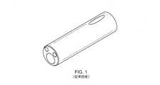
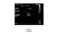
Translated fromJapanese図1は、典型的なリアルタイムサンプリング装置の遠位端を表わす。遠位端は、ラジアル型超音波プローブを受容するためのプローブ管腔と、配向ピンを受容するための2つの小さい管腔とを含んでいる。配向ピンは、図2に表わすように、超音波信号を反射することによって影を落とす。 FIG. 1 represents the distal end of a typical real-time sampling device. The distal end contains a probe lumen for receiving a radial ultrasonic probe and two smaller lumens for receiving an alignment pin. The alignment pin casts a shadow by reflecting the ultrasonic signal, as shown in FIG.
本発明は、医療機器の利用状況を効果的にリアルタイムで視覚化するための例示的なシステムを提供する。当該システムは、ラジアル型超音波プローブを有している画像処理システムと、ラジアル型超音波プローブと信号通信している画像処理プロセッサと、画像処理プロセッサから受信した信号に基づいて超音波画像を表示するように構成されているディスプレイと、を含んでいる。また、当該システムは、医療機器及びラジアル型超音波プローブを受容するように構成されているハンドルと、近位端においてハンドルに取り付けられている可撓性シャフトと、を含んでいる装置を含んでいる。可撓性シャフトは、ハンドルからラジアル型超音波プローブを受容するように構成されている第1の管腔と、ハンドルから医療機器を受容するように構成されている第2の管腔と、を含んでいる。また、当該装置は、可撓性シャフトの遠位端に取り付けられている端部キャップを含んでいる。端部キャップは、第1の管腔と、近位端に配置されている出口ポートと、第1のスロットと、第2のスロットと、を含んでいる。端部キャップの第1の管腔は、端部キャップが可撓性シャフトに取り付けられた場合に、可撓性シャフトの第1の管腔からラジアル型超音波プローブを受容する。出口ポートは、端部キャップが可撓性シャフトに取り付けられた場合に、可撓性シャフトの第2の管腔から医療機器を受容する。スロットは、前記端部キャップの遠位部において、端部キャップの外面に長手方向に配置されている。 The present invention provides an exemplary system for effectively visualizing the usage of medical devices in real time. The system displays an ultrasonic image based on an image processing system having a radial ultrasonic probe, an image processing processor that communicates with the radial ultrasonic probe, and a signal received from the image processing processor. Includes a display that is configured to do so. The system also includes a device that includes a handle that is configured to receive medical devices and radial ultrasound probes, and a flexible shaft that is attached to the handle at the proximal end. There is. The flexible shaft has a first lumen configured to receive a radial ultrasonic probe from the handle and a second lumen configured to receive a medical device from the handle. Includes. The device also includes an end cap attached to the distal end of the flexible shaft. The end cap includes a first lumen, an exit port located at the proximal end, a first slot, and a second slot. The first lumen of the end cap receives the radial ultrasonic probe from the first lumen of the flexible shaft when the end cap is attached to the flexible shaft. The exit port receives the medical device from the second lumen of the flexible shaft when the end cap is attached to the flexible shaft. The slot is located longitudinally on the outer surface of the end cap at the distal portion of the end cap.
一の実施態様では、少なくとも1つの超音波反射材がスロットそれぞれに配置されている。 In one embodiment, at least one ultrasonic reflector is placed in each slot.
他の実施態様では、当該装置は、端部キャップの遠位端に配置されているトラフを含んでいる。トラフは、端部キャップの近位端に配置された端部キャップの第1の管腔からラジアル型超音波プローブを受容する。 In another embodiment, the device comprises a trough located at the distal end of the end cap. The trough receives a radial ultrasonic probe from the first lumen of the end cap located at the proximal end of the end cap.
さらなる他の実施態様では、スロットは、トラフに隣接する端部キャップの少なくとも1つの表面に、又はトラフに近位に位置する端部キャップの他の表面に配置されている。スロットは、端部キャップの一方の長手方向半体に配置されており、端部キャップの一方の長手方向半体は、出口ポートを含む端部キャップの他の長手方向半体に対向している。トラフに隣接している端部キャップの表面は、スロットを含む端部キャップの長手方向半体に配置されている。 In yet another embodiment, the slot is located on at least one surface of the end cap adjacent to the trough, or on the other surface of the end cap located proximal to the trough. The slots are located in one longitudinal half of the end cap, one longitudinal half of the end cap facing the other longitudinal half of the end cap, including the exit port. .. The surface of the end cap adjacent to the trough is located on the longitudinal half of the end cap, including the slot.
さらなる他の実施態様では、端部キャップは、遠位端に配置されている第2のポートを含んでいる。第2のポートは、端部キャップの第1の管腔へのアクセスを提供する。端部キャップの第2のポートは、端部キャップの第1の管腔より小さい断面直径を有している。 In yet another embodiment, the end cap comprises a second port located at the distal end. The second port provides access to the first lumen of the end cap. The second port of the end cap has a smaller cross-sectional diameter than the first lumen of the end cap.
さらなる特徴、利点、及び利用可能性については、本明細書の発明の詳細な説明から明らかとなる。発明の詳細な説明及び特定の実施例は、図解することのみを目的とし、本発明の技術的範囲を限定することを意図する訳ではないことに留意すべきである。 Further features, advantages, and availability will be apparent from the detailed description of the invention herein. It should be noted that the detailed description and specific embodiments of the invention are for illustration purposes only and are not intended to limit the technical scope of the invention.
本願に添付の図面は、図解することのみを目的とし、本発明の技術的範囲を限定することを意図する訳ではない。図面の構成要素は必ずしも縮尺通りではなく、その代わりに本発明の原理を説明することに重点が置かれている。 The drawings attached to this application are for illustration purposes only and are not intended to limit the technical scope of the invention. The components of the drawings are not necessarily on scale and instead the emphasis is on explaining the principles of the invention.
以下の説明自体は、単なる図解のみを目的として、本願の開示内容、適用、又は利用を制限することを意図しない。以下の記述は、限定を目的とせず図解のみを目的として、リアルタイムシステムを提供するための装置及び方法の様々な実施例を説明する。 The following description itself is not intended to limit the disclosure, application, or use of this application for purposes of illustration only. The following description describes various embodiments of devices and methods for providing a real-time system for illustration purposes only, not for limitation purposes.
図3を参照すると、気管支鏡システム10は、挿入管14を具備する気管支鏡12とリアルタイムシステム16とを含んでいる。気管支鏡12の一例としては、診断用気管支鏡(例えば、オリンパス(登録商標)社製のBF-P190)が挙げられる。リアルタイムシステム16は、信号処理装置24と、表示装置18と、ハンドル装置20を介してラジアル型超音波トランスデューサ(図示しない)に接続されているワイヤ22と、を含んでいる。また、リアルタイムシステム16は、ハンドル装置20を介して遠位モータ(図示しない)に接続されているモータ制御装置40を含んでいる。 Referring to FIG. 3, the
リアルタイムシステム16は、医療機器30を含んでおり、医療機器30は、例えば組織サンプリング及び/又は薬液送達のための針であって、カテーテル(図示しない)の管腔の内部に摺動可能に受容される針である。カテーテルは、近位端においてハンドル装置20に取り付けられている。カテーテルは、気管支鏡12のハンドル及び挿入管14を貫通している。リアルタイムシステム16は、気管支鏡システム12から分離しても利用可能される。 The real-
表示装置18は、信号処理装置24と有線又は無線で信号通信している。表示装置18は、ラジアル型超音波プローブのラジアル型超音波トランスデューサ(図示しない)から画像情報を受信する信号処理装置24から受信された画像情報に基づいて、画像を提示する。 The
図4は、可撓性カテーテル33の遠位端32に取り付けられている例示的な端部部品31を表わす。可撓性カテーテル33は、近位端においてハンドル装置20に取り付けられており、ラジアル型超音波装置を受容可能とされる管腔と、ハンドル装置20を貫通している医療装置30を受容するための比較的小さいワーキングチャネルとを含んでいる。一の実施例では、比較的小さいワーキングチャネルは、ラジアル型超音波装置を受容する管腔の内径の半分より小さい内径を有している。端部部品31は、可撓性カテーテル33に取り付けられた場合に可撓性カテーテル33の主管腔と同軸に配置される第1の管腔34を含んでいる。第1の管腔34は、超音波伝導性の流体又はゲルを管腔34の内部に保持するために、遠位端において塞がれている。端部部品31は、可撓性カテーテル33のワーキングチャネルの内部に受容された医療機器30を近位端の近傍の端部部品31の側面から出すための出口傾斜部36を含んでいる。端部部品31は、エポキシ、熱溶着、又は金属同士の溶接によって、可撓性カテーテル33に取り付けられている。出口傾斜部36は鋼から作られている一方、プローブが受容される場所を囲む超音波(US)窓(すなわち、端部部品31の一部分)がプラスチックから作られており、出口傾斜部36は、近位端においてシースの編組材料(図示しない)に溶接されており、遠位端においてUS窓にエポキシ樹脂で接着されている。 FIG. 4 represents an
端部部品31は、遠位端から長手方向において出口傾斜部36の近傍の地点に至るまで延在している2つの長手方向スロット(すなわち、溝)38,39を含んでいる。スロット38,39は、超音波反射材を受容するように構成されている。超音波反射材としては、金属棒、フラットワイヤ、高密度フィルム、金属塗料、又はスロット38,39の内部に配置可能とされる他の材料が挙げられる。超音波反射材は、溶融状態又は液体状態でスロット38,39に挿入された後に、固体状態に冷却される。一の実施例では、図5の超音波画像42に表わすように、出口傾斜部36を標的に向けて配向させるために、ステンレス鋼製のピンがスロット38,39の内部で利用される。出口傾斜部36の中心線は、スロット38,39を二分している。 The
スロット38,39は端部部品31の外側縁部に配置されているので、超音波反射は一層改善される(すなわち、影(shadowing)が最小となる)。医療機器及び標的の向き及び視認性の最良のバランスを提供するために、スロット38,39が成す様々な角度が利用される。一の実施例では、スロット38,39及び/又はスロット38,39の内部の超音波反射材は、0.006インチ以上0.020インチ以下の幅を有している。 Since the
スロット38,39の内部の超音波反射材の形状は、超音波信号を反射させ超音波プローブのトランスデューサに向かって戻すことを条件として、平坦なワイヤ状であっても、丸くなっていても、六角形状であっても、放物線状であっても良い。 The shape of the ultrasonic reflector inside the
図6に表わすように、端部キャップ部品50は、可撓性カテーテル33のワーキングチャネルに対して位置決めされている出口傾斜部56を含んでいる近位セクションを含んでいる。端部キャップ部品50は、近位セクションの管腔54と同軸に配置されているトラフ60を含んでいる遠位セクションを含んでいる。管腔54及びトラフ60のすべてが、超音波プローブを受容する可撓性カテーテル33の管腔と同軸に配置されている。遠位セクションの断面は、略D字状に形成されている。これにより、超音波プローブが周囲組織と直接接触する。図4に表わすスロット38,39のような超音波反射材を受容するように構成されているスロット(すなわち、溝)68,70が、トラフ60に隣接している。 As shown in FIG. 6, the
図7に表わすように、端部キャップ部品80は、可撓性カテーテル33に取り付けられた場合に、取り付けられた可撓性カテーテル33のワーキングチャネルに対して位置決めされる出口傾斜部86を含んでいる近位セクションを含んでいる。端部キャップ部品80は、近位セクションの管腔84と同軸に配置されているトラフ90を含んでいる遠位セクションを含んでいる。管腔84及びトラフ90のすべてが、超音波プローブを受容する可撓性カテーテル33の管腔と同軸に配置されている。トラフ90は、端部キャップ部品50のトラフ60と比較して、端部キャップ部品80の材料によって囲まれている部分が少ない。比較的小さいスロット(すなわち、溝)92,94は、遠位セクションの外側の丸い部分に長手方向に配置されており、図4に表わすスロット38,39のように超音波反射材を受容するように構成されている。 As shown in FIG. 7, the
一の実施例では、図8及び図9に表わすように、端部キャップ部品110は、側部ポート118と、配向ピン管腔120,122と、図1に表わす超音波管腔に類似する超音波管腔116とを含んでいる。配向ピン管腔120,122は、図3に関連して上述した超音波反射材のような超音波反射材で充填されているか、又は単にガス/空気の塊を含んでいる。配向ピン管腔120,122は、周囲環境に対して開口しているので、肺からの空気を取り込むことができる。しかしながら、端部キャップ部品110は、超音波管腔116へのアクセスを提供するために、遠位端に狭窄ポート124を含んでいる。狭窄ポート124を介して、例えば粘性ゲル(例えば、Aquasonic(登録商標) 100)のような超音波結合液を注入することができる。超音波結合液を注入した後に、超音波プローブ126が超音波管腔116に挿入される。超音波プローブ126の直径が狭窄ポート124の直径より大きいので、超音波結合ゲルは、超音波管腔116の内部に保持された状態を維持している。 In one embodiment, as shown in FIGS. 8 and 9, the
図10及び図11に表わすように、前照灯管腔140は、前照灯管腔140に配置された器具(すなわち、前照灯144)がプローブ管腔142に対して露出するように、端部キャップ130のプローブ管腔142に切開されている。これにより、プローブ管腔142に挿入される超音波結合ジェルが、前照灯144と直接接触するので、前照灯144からUSプローブ148に戻るように反射するUS信号のための理想的な結合を形成することができる。 As shown in FIGS. 10 and 11, the
一の実施例では、超音波信号を反射する配向ピン管腔及びスロットは、1つ以上の長手方向の割れ目(すなわち、管腔もスロットも存在しない場所、又は反射材が利用されていない場所)を有している。割れ目の存在により、操作者(one)は、超音波画像を見れば、端部キャップのどこにトランスデューサが位置するのかを視認することができる。このことは、超音波平面が端部キャップのUS窓の長さより小さい厚さを長手方向に有していることに起因して発生する。 In one embodiment, the oriented pin lumens and slots that reflect the ultrasonic signal are one or more longitudinal fissures (ie, where there are no lumens or slots, or where no reflector is used). have. The presence of the crevice allows the operator (one) to see where the transducer is located on the end cap by looking at the ultrasound image. This occurs because the ultrasonic plane has a thickness in the longitudinal direction that is less than the length of the US window of the end cap.
本発明の説明自体は単なる例示であり、本発明の要旨から逸脱しない変形であれば本発明の技術的範囲に属することを意図するものである。このような変形は、本発明の技術的思想及び技術的範囲から逸脱しないものと見なされる。 The description of the present invention itself is merely an example, and is intended to belong to the technical scope of the present invention as long as it is a modification that does not deviate from the gist of the present invention. Such modifications are not considered to deviate from the technical idea and scope of the invention.
[実施例]
A.第1の管腔及び第2の管腔を具備する可撓性シャフトと、前記可撓性シャフトの遠位端に取り付けられている端部キャップとを備えている装置において、前記端部キャップが、第1の管腔と、前記端部キャップの近位端に配置されている出口ポートと、第1のスロットと、第2のスロットとを含んでおり、前記端部キャップの前記第1の管腔が、前記端部キャップが前記可撓性シャフトに取り付けられた場合に前記可撓性シャフトの前記第1の管腔から画像処理ツールを受容するように構成されており、前記出口ポートが、前記端部キャップが前記可撓性シャフトに取り付けられた場合に前記可撓性シャフトの前記第2の管腔から医療機器を受容するように構成されており、前記第1のスロット及び前記第2のスロットが、前記端部キャップの遠位セクションの外面に長手方向に配置されていることを特徴とする装置。[Example]
A. In a device comprising a flexible shaft comprising a first lumen and a second lumen and an end cap attached to the distal end of the flexible shaft, the end cap is , A first lumen, an outlet port located at the proximal end of the end cap, a first slot, and a second slot, the first of the end cap. The lumen is configured to receive the image processing tool from the first lumen of the flexible shaft when the end cap is attached to the flexible shaft and the outlet port is. , The end cap is configured to receive a medical device from the second lumen of the flexible shaft when attached to the flexible shaft, the first slot and the first slot. A device comprising two slots arranged longitudinally on the outer surface of the distal section of the end cap.
B.前記装置が、前記第1のスロット及び前記第2のスロットの内部に配置されている超音波反射材を備えていることを特徴とするAの装置。 B. The device A, characterized in that the device comprises an ultrasonic reflector disposed inside the first slot and the second slot.
C.前記画像処理ツールが、ラジアル型超音波プローブを備えていることを特徴とするA又はBの装置。 C. A device of A or B, wherein the image processing tool comprises a radial ultrasonic probe.
D.前記装置が、前記端部キャップの遠位端に配置されているトラフを備えており、前記トラフが、前記端部キャップの前記第1の管腔から前記画像処理ツールを受容するように構成されており、前記端部キャップの前記第1の管腔が、前記端部キャップの近位端に配置されていることを特徴とするA~Cのいずれかの装置。 D. The device comprises a trough located at the distal end of the end cap, the trough configured to receive the image processing tool from the first lumen of the end cap. A device according to any one of A to C, wherein the first lumen of the end cap is located at the proximal end of the end cap.
E.前記第1のスロット及び前記第2のスロットが、トラフを含んでいる前記端部キャップの一部分の外面に配置されていることを特徴とするDの装置。 E. The apparatus of D, wherein the first slot and the second slot are arranged on the outer surface of a part of the end cap containing a trough.
F.前記第1のスロット及び前記第2のスロットが、出口ポートを含んでいる前記端部キャップの他方の長手方向半体の反対側に位置する前記端部キャップの長手方向半体に配置されていることを特徴とするD又はEの装置。 F. The first slot and the second slot are located in the longitudinal half of the end cap located opposite the other longitudinal half of the end cap containing the exit port. A device of D or E, characterized in that.
G.前記第1のスロット及び前記第2のスロットが、前記トラフに隣接する前記端部キャップの表面に配置されていることを特徴とするD~Fのいずれかの装置。 G. The device according to any one of D to F, wherein the first slot and the second slot are arranged on the surface of the end cap adjacent to the trough.
H.前記トラフに隣接する前記端部キャップの表面が、前記スロットを含んでいる前記端部キャップの長手方向半体に配置されていることを特徴とするGの装置。 H. A device of G, wherein the surface of the end cap adjacent to the trough is arranged in a longitudinal half of the end cap that includes the slot.
I.前記装置が、前記端部キャップの遠位端に配置されている第2のポートを備えており、前記第2のポートが、前記端部キャップの前記第1の管腔へのアクセスを提供することを特徴とするA~Cのいずれかの装置。 I. The device comprises a second port located at the distal end of the end cap, the second port providing access to the first lumen of the end cap. A device according to any one of A to C.
J.前記端部キャップの前記第2のポートが、前記端部キャップの前記第1の管腔より小さい断面直径を有していることを特徴とするIの装置。 J. The device of I, wherein the second port of the end cap has a cross-sectional diameter smaller than that of the first lumen of the end cap.
K.画像処理システムと装置とを具備するシステムであって、
前記画像システムが、
ラジアル型超音波プローブと、
前記ラジアル型超音波プローブと信号通信する画像処理装置と、
前記画像処理プロセッサから受信した信号に基づいて超音波画像を表示するように構成されているディスプレイと、
を備えており、
前記装置が、
医療機器及び前記ラジアル型超音波プローブを受容するように構成されているハンドルと、
近位端において前記ハンドルに取り付けられている可撓性シャフトであって、前記ハンドルから前記ラジアル型超音波プローブを受容するように構成されている第1の管腔と、前記ハンドルから前記医療機器を受容するように構成されている第2の管腔と、を備えている、前記可撓性シャフトと、
前記可撓性シャフトの遠位端に取り付けられている端部キャップであって、第1の管腔と、端部キャップの近位端に配置されている出口ポートと、第1のスロットと、第2のスロットと、を備えている前記端部キャップと、
を備えており、
前記端部キャップの前記第1の管腔が、前記端部キャップが前記可撓性シャフトに取り付けられた場合に、前記可撓性シャフトの前記第1の管腔から前記ラジアル型超音波プローブを受容するように構成されており、
前記出口ポートが、前記端部キャップが前記可撓性シャフトに取り付けられた場合に、前記可撓性シャフトの前記第2の管腔から前記医療機器を受容するように構成されており、
前記第1のスロット及び前記第2のスロットが、前記端部キャップの遠位セクションにおいて端部キャップの外面に長手方向に配置されていることを特徴とするシステム。K. A system equipped with an image processing system and an apparatus,
The image system
Radial type ultrasonic probe and
An image processing device that performs signal communication with the radial ultrasonic probe,
A display configured to display an ultrasonic image based on a signal received from the image processor.
Equipped with
The device
With a handle configured to receive medical devices and said radial ultrasonic probes.
A flexible shaft attached to the handle at the proximal end, the first lumen configured to receive the radial ultrasonic probe from the handle, and the medical device from the handle. The flexible shaft, comprising a second lumen, which is configured to receive.
An end cap attached to the distal end of the flexible shaft, the first lumen, an exit port located at the proximal end of the end cap, and a first slot. With the end cap comprising a second slot,
Equipped with
The first lumen of the end cap allows the radial ultrasonic probe from the first lumen of the flexible shaft when the end cap is attached to the flexible shaft. It is configured to accept and
The outlet port is configured to receive the medical device from the second lumen of the flexible shaft when the end cap is attached to the flexible shaft.
A system characterized in that the first slot and the second slot are arranged longitudinally on the outer surface of the end cap in the distal section of the end cap.
L.前記システムが、前記スロットそれぞれに配置されている少なくとも1つの超音波反射材を備えていることを特徴とするKのシステム。 L. K's system, characterized in that the system comprises at least one ultrasonic reflector disposed in each of the slots.
M.前記装置が、前記端部キャップの遠位端に配置されているトラフを備えており、
前記トラフが、前記端部キャップの前記第1の管腔から前記ラジアル型超音波プローブを受容するように構成されており、
前記端部キャップの前記第1の管腔が、前記端部キャップの近位端に配置されていることを特徴とするK又はLのシステム。M. The device comprises a trough located at the distal end of the end cap.
The trough is configured to receive the radial ultrasonic probe from the first lumen of the end cap.
A system of K or L characterized in that the first lumen of the end cap is located at the proximal end of the end cap.
N.前記第1のスロット及び前記第2のシステムが、前記トラフに隣接する前記端部キャップの表面及び前記トラフを含む前記端部キャップの一部分の外面のうち少なくとも1つに配置されていることを特徴とするMのシステム。 N. The first slot and the second system are located on at least one of the surface of the end cap adjacent to the trough and the outer surface of a portion of the end cap containing the trough. M's system.
O.前記第1のスロット及び前記第2のスロットが、前記出口ポートを含む前記端部キャップの他方の長手方向半体の反対側に位置する前記端部キャップの長手方向半体に配置されていることを特徴とするM又はNのシステム。 O. The first slot and the second slot are located in the longitudinal half of the end cap located opposite the other longitudinal half of the end cap, including the exit port. A system of M or N characterized by.
P.前記トラフに隣接する前記端部キャップの表面が、前記第1のスロット及び前記第2のスロットを含む前記端部キャップの長手方向半体に配置されていることを特徴とするM~Oのいずれか1つに記載のシステム。 P. Any of M to O characterized in that the surface of the end cap adjacent to the trough is arranged in a longitudinal half of the end cap including the first slot and the second slot. The system described in one.
Q.前記装置が、前記端部キャップの遠位端に配置されている第2のポートを備えており、
前記第2のポートが、前記端部キャップの前記第1の管腔へのアクセスを提供することを特徴とするK又はLのシステム。Q. The device comprises a second port located at the distal end of the end cap.
A system of K or L, wherein the second port provides access to the first lumen of the end cap.
R.前記端部キャップの前記第2のポートが、前記端部キャップの前記第1の管腔より小さい断面直径を有していることを特徴とするQのシステム。 R. A system of Q, wherein the second port of the end cap has a cross-sectional diameter smaller than that of the first lumen of the end cap.
以上、本発明の好ましい実施例について説明したが、本発明は当該実施例に限定される訳ではない。本発明の技術的思想又は技術的範囲から逸脱しないことを条件として、追加、省略、置換、及び他の変更を行うことができる。 Although the preferred embodiment of the present invention has been described above, the present invention is not limited to the embodiment. Additions, omissions, replacements, and other modifications may be made provided that they do not deviate from the technical idea or scope of the invention.
10 気管支鏡システム
12 気管支鏡
14 挿入管
16 リアルタイムシステム
18 表示装置
20 ハンドル装置
22 ワイヤ
24 信号処理装置
31 端部部品
32 (可撓性カテーテル33の)遠位端
33 可撓性カテーテル
34 第1の管腔
36 出口傾斜部
38 スロット(溝)
39 スロット(溝)
40 モータ制御装置
42 超音波画像
50 端部キャップ部品10
39 slots (grooves)
40
Claims (14)
Translated fromJapanese前記可撓性シャフトの遠位端に取り付けられている端部キャップであって、
前記画像処理ツールを受容するように構成されている第1の管腔と、
端部キャップの近位端に配置されている出口ポートであって、前記端部キャップが前記可撓性シャフトに取り付けられた場合に前記可撓性シャフトの前記第2の管腔から医療機器を受容するように構成されている前記出口ポートと、
第1のスロットと、
第2のスロットと、
を備えている前記端部キャップと、
前記第1のスロットに配置されている第1の超音波反射材と、
前記第2のスロットに配置されている第2の超音波反射材と、
を備えていることを特徴とする装置。A flexible shaft comprising a first lumen and a second lumen configured to receive an image processing tool.
An end cap attached to the distal end of the flexible shaft.
A first lumen configured to receive the image processing tool, and
An outlet port located at the proximal end of the end cap that allows a medical device to be removed from the second lumen of the flexible shaft when the end cap is attached to the flexible shaft. With the exit port configured to accept,
The first slot and
The second slot and
With the end cap,
The first ultrasonic reflector arranged in the first slot and
With the second ultrasonic reflector arranged in the second slot,
A device characterized by being equipped with.
前記画像処理システムが、
ラジアル型超音波プローブと、
前記ラジアル型超音波プローブと信号通信する画像処理プロセッサと、
前記画像処理プロセッサから受信した信号に基づいて超音波画像を表示するように構成されているディスプレイと、
を備えており、
前記器具が、
医療機器及びラジアル型超音波プローブを受容するように構成されているハンドルと、
近位端において前記ハンドルに取り付けられている可撓性シャフトと、
前記可撓性シャフトの遠位端に取り付けられている端部キャップと、
を備えており、
前記可撓性シャフトが、
前記ハンドルから前記ラジアル型超音波プローブを受容するように構成されている第1の管腔と、
前記ハンドルから前記医療機器を受容するように構成されている第2の管腔と、
を備えており、
前記端部キャップが、
第1の管腔と、
前記端部キャップの近位端に配置されている出口ポートと、
第1のスロットと、
第2のスロットと、
を備えており、
前記端部キャップの第1の管腔が、前記端部キャップが前記可撓性シャフトに取り付けられた場合に、前記可撓性シャフトの前記第1の管腔から前記ラジアル型超音波プローブを受容するように構成されており、
前記出口ポートが、前記端部キャップが前記可撓性シャフトに取り付けられた場合に、可撓性シャフトの前記第2の管腔から前記医療機器を受容するように構成されており、
前記スロットが、前記端部キャップの遠位セクションにおいて前記端部キャップの外面に長手方向に配置されていることを特徴とするシステム。In a system consisting of an image processing system and an instrument
The image processing system
Radial type ultrasonic probe and
An image processor that performs signal communication with the radial ultrasonic probe,
A display configured to display an ultrasonic image based on a signal received from the image processor.
Equipped with
The instrument
With a handle that is configured to receive medical devices and radial ultrasound probes,
A flexible shaft attached to the handle at the proximal end,
An end cap attached to the distal end of the flexible shaft,
Equipped with
The flexible shaft
A first lumen configured to receive the radial ultrasonic probe from the handle, and
A second lumen configured to receive the medical device from the handle,
Equipped with
The end cap
The first lumen and
An exit port located at the proximal end of the end cap,
The first slot and
The second slot and
Equipped with
The first lumen of the end cap receives the radial ultrasonic probe from the first lumen of the flexible shaft when the end cap is attached to the flexible shaft. Is configured to
The outlet port is configured to receive the medical device from the second lumen of the flexible shaft when the end cap is attached to the flexible shaft.
A system characterized in that the slot is longitudinally disposed on the outer surface of the end cap in the distal section of the end cap.
Applications Claiming Priority (2)
| Application Number | Priority Date | Filing Date | Title |
|---|---|---|---|
| US202063109558P | 2020-11-04 | 2020-11-04 | |
| US63/109,558 | 2020-11-04 |
Publications (2)
| Publication Number | Publication Date |
|---|---|
| JP2022075595Atrue JP2022075595A (en) | 2022-05-18 |
| JP7410916B2 JP7410916B2 (en) | 2024-01-10 |
Family
ID=78413792
Family Applications (1)
| Application Number | Title | Priority Date | Filing Date |
|---|---|---|---|
| JP2021179422AActiveJP7410916B2 (en) | 2020-11-04 | 2021-11-02 | Tip assembly for real-time sampling systems |
Country Status (4)
| Country | Link |
|---|---|
| US (1) | US12376734B2 (en) |
| EP (1) | EP3995084B1 (en) |
| JP (1) | JP7410916B2 (en) |
| CN (1) | CN114431894A (en) |
Cited By (1)
| Publication number | Priority date | Publication date | Assignee | Title |
|---|---|---|---|---|
| US12376734B2 (en) | 2020-11-04 | 2025-08-05 | Gyrus Acmi, Inc. | Tip assemblies for real-time sampling system |
Citations (5)
| Publication number | Priority date | Publication date | Assignee | Title |
|---|---|---|---|---|
| JPH0737108U (en)* | 1993-12-22 | 1995-07-11 | アロカ株式会社 | Catheterized ultrasound probe |
| JPH1014858A (en)* | 1996-07-01 | 1998-01-20 | Asahi Optical Co Ltd | Medical probe guidance device |
| JPH10118070A (en)* | 1996-10-16 | 1998-05-12 | Olympus Optical Co Ltd | Ultrasonograph |
| JP2019150567A (en)* | 2018-02-28 | 2019-09-12 | スパイレーション インコーポレイテッド ディー ビー エイ オリンパス レスピラトリー アメリカ | Orientation pins for device using radial ultrasound |
| US20200297311A1 (en)* | 2019-03-21 | 2020-09-24 | Spiration, Inc.D/B/A Olympus Respiratory America | Dual lumen catheter |
Family Cites Families (10)
| Publication number | Priority date | Publication date | Assignee | Title |
|---|---|---|---|---|
| JPH0568517A (en) | 1991-08-02 | 1993-03-23 | Nichimo Co Ltd | Drying of laver sheet and laver screen to be used in laver drying |
| JPH0737108A (en) | 1993-07-20 | 1995-02-07 | Matsushita Electric Ind Co Ltd | Data communication method |
| US6283951B1 (en) | 1996-10-11 | 2001-09-04 | Transvascular, Inc. | Systems and methods for delivering drugs to selected locations within the body |
| JP3525700B2 (en)* | 1997-09-24 | 2004-05-10 | 富士写真光機株式会社 | Ultrasonic probe |
| JP2001224595A (en)* | 1999-12-08 | 2001-08-21 | Olympus Optical Co Ltd | Ultrasonic probe for microscopic operation |
| US6942661B2 (en)* | 2000-08-30 | 2005-09-13 | Boston Scientific Scimed, Inc. | Fluid cooled apparatus for supporting diagnostic and therapeutic elements in contact with tissue |
| US7267650B2 (en)* | 2002-12-16 | 2007-09-11 | Cardiac Pacemakers, Inc. | Ultrasound directed guiding catheter system and method |
| US11883232B2 (en) | 2018-09-11 | 2024-01-30 | Olympus Medical Systems Corporation | Radial ultrasound capsule and system |
| JP7169929B2 (en)* | 2019-04-09 | 2022-11-11 | 富士フイルム株式会社 | ultrasound endoscope |
| US12376734B2 (en) | 2020-11-04 | 2025-08-05 | Gyrus Acmi, Inc. | Tip assemblies for real-time sampling system |
- 2021
- 2021-10-04USUS17/493,320patent/US12376734B2/enactiveActive
- 2021-10-27EPEP21204983.7Apatent/EP3995084B1/enactiveActive
- 2021-11-02JPJP2021179422Apatent/JP7410916B2/enactiveActive
- 2021-11-03CNCN202111294483.7Apatent/CN114431894A/enactivePending
Patent Citations (5)
| Publication number | Priority date | Publication date | Assignee | Title |
|---|---|---|---|---|
| JPH0737108U (en)* | 1993-12-22 | 1995-07-11 | アロカ株式会社 | Catheterized ultrasound probe |
| JPH1014858A (en)* | 1996-07-01 | 1998-01-20 | Asahi Optical Co Ltd | Medical probe guidance device |
| JPH10118070A (en)* | 1996-10-16 | 1998-05-12 | Olympus Optical Co Ltd | Ultrasonograph |
| JP2019150567A (en)* | 2018-02-28 | 2019-09-12 | スパイレーション インコーポレイテッド ディー ビー エイ オリンパス レスピラトリー アメリカ | Orientation pins for device using radial ultrasound |
| US20200297311A1 (en)* | 2019-03-21 | 2020-09-24 | Spiration, Inc.D/B/A Olympus Respiratory America | Dual lumen catheter |
Cited By (1)
| Publication number | Priority date | Publication date | Assignee | Title |
|---|---|---|---|---|
| US12376734B2 (en) | 2020-11-04 | 2025-08-05 | Gyrus Acmi, Inc. | Tip assemblies for real-time sampling system |
Also Published As
| Publication number | Publication date |
|---|---|
| EP3995084B1 (en) | 2024-10-16 |
| EP3995084A1 (en) | 2022-05-11 |
| US12376734B2 (en) | 2025-08-05 |
| US20220133264A1 (en) | 2022-05-05 |
| CN114431894A (en) | 2022-05-06 |
| JP7410916B2 (en) | 2024-01-10 |
Similar Documents
| Publication | Publication Date | Title |
|---|---|---|
| US8657749B2 (en) | Ultrasonic puncture needle | |
| JP4982637B2 (en) | Flexible surgical needle device | |
| US20070191682A1 (en) | Optical probes for imaging narrow vessels or lumens | |
| JP2001104315A (en) | Ultrasonic-guided paracentesis system device | |
| JPH11276422A (en) | Ultrasonic endoscope | |
| JP7551852B2 (en) | Orientation pin for devices using radial ultrasonics | |
| US20250255582A1 (en) | Real-time sampling device | |
| JP6594151B2 (en) | Ultrasound endoscope | |
| JP2022075595A (en) | Tip assemblies for real-time sampling system | |
| JPH1176254A (en) | Puncture needle for ultrasonic | |
| JP4339539B2 (en) | Ultrasound puncture needle | |
| JP7754990B2 (en) | Real-time sampling device | |
| CN223041992U (en) | Interventional catheters and ultrasound imaging equipment | |
| JP2616943B2 (en) | Endoscope | |
| JPH08154940A (en) | Ultrasonic endoscope |
Legal Events
| Date | Code | Title | Description |
|---|---|---|---|
| A621 | Written request for application examination | Free format text:JAPANESE INTERMEDIATE CODE: A621 Effective date:20220420 | |
| A977 | Report on retrieval | Free format text:JAPANESE INTERMEDIATE CODE: A971007 Effective date:20230227 | |
| A131 | Notification of reasons for refusal | Free format text:JAPANESE INTERMEDIATE CODE: A131 Effective date:20230306 | |
| A521 | Request for written amendment filed | Free format text:JAPANESE INTERMEDIATE CODE: A523 Effective date:20230602 | |
| A131 | Notification of reasons for refusal | Free format text:JAPANESE INTERMEDIATE CODE: A131 Effective date:20230626 | |
| A521 | Request for written amendment filed | Free format text:JAPANESE INTERMEDIATE CODE: A523 Effective date:20230920 | |
| TRDD | Decision of grant or rejection written | ||
| A01 | Written decision to grant a patent or to grant a registration (utility model) | Free format text:JAPANESE INTERMEDIATE CODE: A01 Effective date:20231204 | |
| A61 | First payment of annual fees (during grant procedure) | Free format text:JAPANESE INTERMEDIATE CODE: A61 Effective date:20231222 | |
| R150 | Certificate of patent or registration of utility model | Ref document number:7410916 Country of ref document:JP Free format text:JAPANESE INTERMEDIATE CODE: R150 |