JP2022074549A - Vehicle seat - Google Patents
Vehicle seatDownload PDFInfo
- Publication number
- JP2022074549A JP2022074549AJP2020184668AJP2020184668AJP2022074549AJP 2022074549 AJP2022074549 AJP 2022074549AJP 2020184668 AJP2020184668 AJP 2020184668AJP 2020184668 AJP2020184668 AJP 2020184668AJP 2022074549 AJP2022074549 AJP 2022074549A
- Authority
- JP
- Japan
- Prior art keywords
- dimension
- headrest
- stay
- seat
- vehicle seat
- Prior art date
- Legal status (The legal status is an assumption and is not a legal conclusion. Google has not performed a legal analysis and makes no representation as to the accuracy of the status listed.)
- Pending
Links
Images


Landscapes
- Chair Legs, Seat Parts, And Backrests (AREA)
- Seats For Vehicles (AREA)
Abstract
Description
Translated fromJapanese本発明は、車両用シートに適用して有効な技術に関する。 The present invention relates to a technique that is effective when applied to a vehicle seat.
車両用シートでは、JNCAP(Japan New Car Assessment Program)に規定される後面衝突頚部保護性能試験が行われる。後面衝突頚部保護性能試験は、BioRID IIダミー人形を用い、試験装置に車両用シートを固定し、被追突時の衝撃パルスを再現して付与し、頭部がヘッドレストにコンタクトするまでの間(フェーズ1)に発生する「頚部のS字変形」を評価する傷害指標として頚部傷害基準(Neck Injury Criterion(NIC))の値を求める。また、コンタクト後から「最大後屈」まで(フェーズ2)を評価する傷害指標として頚部荷重・モーメントを計測し、欧米等の自動車アセスメントで用いられている点数換算関数を用いて4点満点で点数化し、この点数に事故実態を踏まえた重み係数を掛け合わせた上で点数を加算し、合計点を算出し、その合計点で評価する。このため、JNCAPの車両用シートの開発において、車両用シートの製造メーカ各社は最高評価レベルであるレベル5の車両用シートを開発すべく、後面衝突頚部保護性能試験の合計点が10.5ポイント以上の車両用シートの開発を行っている。 For vehicle seats, a rear collision neck protection performance test specified in JNCAP (Japan New Car Assessment Program) is performed. In the rear-end collision neck protection performance test, a BioRID II dummy doll was used, the vehicle seat was fixed to the test device, the impact pulse at the time of a rear-end collision was reproduced and applied, and until the head contacted the headrest (phase). The value of the neck injury standard (Neck Industry Collision (NIC)) is obtained as an injury index for evaluating the "S-shaped deformation of the neck" that occurs in 1). In addition, the neck load / moment is measured as an injury index to evaluate from the contact to the "maximum backbend" (Phase 2), and the score is scored out of 4 using the score conversion function used in automobile assessment in Europe and the United States. Then, multiply this score by a weighting coefficient based on the actual situation of the accident, add the score, calculate the total score, and evaluate with the total score. Therefore, in the development of JNCAP vehicle seats, the manufacturers of vehicle seats have a total score of 10.5 points in the rear collision neck protection performance test in order to develop a
一方、車両用シートのシートバックフレームは、右サイドフレームと、左サイドフレームと、ロアフレームと、アッパーフレームと、を含む。軽量化、原価低減のため、シートバックフレームのアッパーフレーム(アッパークロスメンバーとも言う)がパイプ構造から板金構造に変更される場合がある。この種の車両用シートの提案として、たとえば、特開2019-209912号公報が有る。 On the other hand, the seat back frame of the vehicle seat includes a right side frame, a left side frame, a lower frame, and an upper frame. In order to reduce weight and cost, the upper frame (also called upper cross member) of the seat back frame may be changed from a pipe structure to a sheet metal structure. As a proposal for this type of vehicle seat, for example, Japanese Patent Application Laid-Open No. 2019-209912 is available.
アッパーフレームが板金構造とされたシートバックフレームを有する車両用シートに対して後面衝突頚部保護性能試験を行った場合、後面衝突頚部保護性能試験の合計点が10.5ポイント以下に低下してしまう場合があった。 When a rear collision neck protection performance test is performed on a vehicle seat having a seat back frame whose upper frame has a sheet metal structure, the total score of the rear collision neck protection performance test drops to 10.5 points or less. There was a case.
本発明の目的は、アッパーフレームが板金構造とされたシートバックフレームを有する車両用シートにおいて、後面衝突頚部保護性能を向上させる技術を提供することにある。 An object of the present invention is to provide a technique for improving the rear collision neck protection performance in a vehicle seat having a seat back frame in which the upper frame has a sheet metal structure.
その他の課題と新規な特徴は、本明細書の記述および添付図面から明らかになるであろう。 Other issues and novel features will become apparent from the description and accompanying drawings herein.
本発明のうち代表的なものの概要を簡単に説明すれば下記の通りである。 The following is a brief description of a typical example of the present invention.
すなわち、車両用シートのトルソー角とB寸法とを変更することなく、リクライニング機構の設計標準角度に応じて、C寸法を調整することでA寸法を変更する。これにより、シートクッションおよびシートバックに取り付けられるクッション材およびシート表皮の材質および形状を変更せずに、C寸法の値の調整により、理想的な位置にシートバックフレームを配置する事ができる。 That is, the A dimension is changed by adjusting the C dimension according to the design standard angle of the reclining mechanism without changing the torso angle and the B dimension of the vehicle seat. As a result, the seat back frame can be arranged at an ideal position by adjusting the value of the C dimension without changing the material and shape of the cushion material and the seat skin attached to the seat cushion and the seat back.
上記車両用シートによれば、後面衝突頚部保護性能を向上させることが可能である。 According to the vehicle seat, it is possible to improve the rear collision neck protection performance.
以下に、本発明の実施の形態について、図面を参照しつつ説明する。 Hereinafter, embodiments of the present invention will be described with reference to the drawings.
なお、開示はあくまで一例にすぎず、図面は説明をより明確にするため、実際の態様に比べ、各部の幅、厚さ、形状等について模式的に表される場合があるが、本発明の解釈を限定するものではない。また、本明細書と各図において、既出の図に関して前述したものと同様の要素には、同一の符号を付して、詳細な説明を適宜省略することがある。また、図面において、矢印前は車両の前方を示し、矢印後は車両の後方を示し、矢印左は車両の左側方を示し、矢印右は車両の右側方を示し、矢印上は車両の上方を示し、矢印下は車両の下方を示している。また、以下の説明においては、特別に断らない限り、前、後や上、下、左、右については、車両に対しての前、後や上、下、左、右を意味するものとする。 It should be noted that the disclosure is merely an example, and the drawings may schematically represent the width, thickness, shape, etc. of each part as compared with the actual embodiment in order to clarify the explanation. It does not limit the interpretation. Further, in the present specification and each figure, the same elements as those described above with respect to the above-mentioned figures may be designated by the same reference numerals, and detailed description thereof may be omitted as appropriate. Further, in the drawing, the front of the arrow indicates the front of the vehicle, the rear of the arrow indicates the rear of the vehicle, the left of the arrow indicates the left side of the vehicle, the right of the arrow indicates the right side of the vehicle, and the upper part of the arrow indicates the upper part of the vehicle. The lower part of the arrow indicates the lower part of the vehicle. In the following explanation, unless otherwise specified, the terms front, rear, top, bottom, left, and right mean front, rear, top, bottom, left, and right with respect to the vehicle. ..
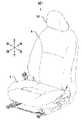
図1は、実施例にかかる車両用シートを示す斜視図である。図2は、図1の車両用シートのシートフレームの構成例を示す前方斜視図である。図3は、図1のシートバックとヘッドレストの断面構造を説明する図である。 FIG. 1 is a perspective view showing a vehicle seat according to an embodiment. FIG. 2 is a front perspective view showing a configuration example of the seat frame of the vehicle seat of FIG. 1. FIG. 3 is a diagram illustrating a cross-sectional structure of the seat back and the headrest of FIG.
図1に示すように、車両用シート1は、シートクッション2と、シートバック3とが組み合わせて構成される。ヘッドレスト20が、シートバック3の上端部に設けられている。シートクッション2は座面を構成し、シートバック3は背もたれを構成する。ヘッドレスト20は、乗員の後頭部を支持する。車両シート1は、シートクッション2とシートバック3との角度調整を可能にするリクライニング機能を有し、リクライニング機能によりシートクッション2とシートバック3とが連結されている。 As shown in FIG. 1, the
図2は、図1の車両用シート1のクッション材およびシート表皮を取り除いた場合のシートフレーム4を示している。シートフレーム4は、シートクッションフレーム(以下、クッションフレームともいう)5と、シートバックフレーム(以下、バックフレームともいう)6と、を有する。バックフレーム6は、バック右サイドフレーム7と、バック左サイドフレーム8と、バックロアフレーム9と、バックアッパーフレーム10とが枠状に組み合わされて構成されている。なお、バックロアフレーム9は、バックロアパネルと言い換えることも可能である。また、バックアッパーフレーム10は、バックアッパークロスメンバー、または、バックアッパーパネルと言い換えることも可能である。 FIG. 2 shows a
バック右サイドフレーム7およびバック左サイドフレーム8のそれぞれは、プレス成形された鉄板(板金構造)から構成されている。バック右サイドフレーム7および左サイドフレーム8のそれぞれの下部には、バックロアフレーム9を取り付けるための下部フランジが設けられる。また、バック右サイドフレーム7およびバック左サイドフレーム8のそれぞれの上部には、バックアッパーフレーム10を取り付けるための上部フランジが設けられる。 Each of the back
バックロアフレーム9は、プレス成形された鉄板(板金構造)により構成される。バックロアフレーム9の左端部および右端部に設けられたフランジが、バック右サイドフレーム7の下部フランジとバック左サイドフレーム8の下部フランジとに、例えば、レーザー溶接またはアーク溶接により、接合されている。なお、バックロアフレーム9の量産性を向上させるためには、レーザー溶接を利用するのが良い。 The back
バックアッパーフレーム10は、プレス成形された鉄板(板金構造)により構成される。バックアッパーフレーム10は、たとえば、下方に開いたU字型の断面形状にプレス成形された鉄板により構成される第1アッパーフレーム(以下、下部アッパーフレームともいう)11と、下方に開いたU字型の断面形状にプレス成形された鉄板により構成される第2アッパーフレーム(以下、上部アッパーフレームともいう)12と、を含む。バックアッパーフレーム10は、第1アッパーフレーム11のU字型の上部が第2アッパーフレーム12の下方に開いたU字型の凹部に重ね合わされるように、組み合わせされている。下方に開いたU字型の断面形状の第1アッパーフレーム11と下方に開いたU字型の断面形状の第2アッパーフレーム12とを重ね合わせることにより、閉断面化されたバックアッパーフレーム10が構成されるので、バックフレーム6のねじれ剛性を向上させることが可能である。なお、第1アッパーフレーム11は、第1アッパーパネル、または、下部アッパーパネルと言い換えることも可能である。また、第2アッパーフレーム12は、第2アッパーパネル、または、上部アッパーパネルと言い換えることも可能である。 The back
また、バック右サイドフレーム7、バック左サイドフレーム8、バックロアフレーム9、第1アッパーフレーム11および第2アッパーフレーム12のそれぞれは、プレス成形された鉄板により構成されるので、レーザー溶接可能な寸法精度を有している。これにより、バックフレーム6は、軽量化および原価低減が図られている。 Further, since each of the back
クッションフレーム5は、クッション右サイドフレーム51、クッション左サイドフレーム52、クッションフロントフレーム53、クッションバックフレーム54を有する。クッションフロントフレーム53は、クッション右サイドフレーム51の前方部とクッション左サイドフレーム52の前方部との間に結合されている。クッションバックフレーム54は、クッション右サイドフレーム51の後方部とクッション左サイドフレーム52の後方部との間に結合されている。 The
リクライニング機構14は、クッション右サイドフレーム51の後方部とバック右サイドフレーム7の下方部との間、および、クッション左サイドフレーム52の後方部とバック左サイドフレーム8の下方部との間に設けられており、シートクッション2とシートバック3との角度調整を可能にする。 The
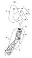
図3には、シートバック3の上部とヘッドレスト20とを左方向から見た場合の概念的な断面構造が示されている。ヘッドレスト20は、クッション材およびヘッドレスト表皮に覆われたヘッドレストステイ21を有する。ヘッドレストステイ21は、車両用シート1を前方側から見た場合、逆U字形状とされており、上下方向(縦方向)に設けられた1対の第1ヘッドレストステイ21aと、左右方向(水平方向)に設けられた第2ヘッドレストステイ21bと、を有する。第2ヘッドレストステイ21bは、1対の第1ヘッドレストステイ21aの上部端の間を連結する様に設けられている。1対の第1ヘッドレストステイ21aのおのおのは、上部ステイ22、中間部ステイ23と、下部ステイ24と、を含む。上部ステイ22は、下部ステイ24より前方側に設けられており、中間部ステイ23は上部ステイ22の下端部と下部ステイ24の上端部との間に設けられている。上部ステイ22の上端部は、第2ヘッドレストステイ21bに接続されている。 FIG. 3 shows a conceptual cross-sectional structure when the upper portion of the seat back 3 and the
バックアッパーフレーム10には、一対のヘッドレストホルダ32が取り付けられている。下部ステイ24の下端部は、ヘッドレストホルダ32に挿入され、ヘッドレスト20の上下方向の高さが調整可能に固定されている。 A pair of
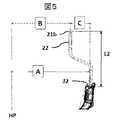
次に、図4および図5を用いて、実施例に係る車両用シート1の構成例を説明する。図4は、実施例に係るシートフレームの構成例を説明する概念図である。図5は、実施例に係る車両用シートのヘッドレストステイの構成例を説明する概念図である。 Next, a configuration example of the
図4には、シートフレーム4を左方向から見た場合のクッション左サイドフレーム52、リクライニング機構14、および、バック左サイドフレーム8が描かれている。図4において、HPはヒップポイントを示しており、シートフレーム4を有する車両用シート1に対する着座者の着座姿勢を示すトルソー角度TAは、この例では、21度にされており、着座者の着座に適した角度になっている。なお、トルソー角度TAは、25度としても良い。ヒップポイントHPとヘッドレストホルダ32のセンタとの間の距離A(A寸法とも言う)は、この例では、366.3mmとされている。リクライニング機構14の新たな設計標準角度RAは、この例では、19.7度とされている。リクライニング機構14の回転中心RCとヘッドレストホルダ32のセンタとの間の距離L1は、この例では、541.0mmとされている。なお、ヘッドレストホルダ32のセンタとは、丸いパイプ構造のヘッドレストホルダ32において、丸いパイプの中心(センタ)を意味している。 FIG. 4 shows a cushion
図5に示す様に、ヒップポイントHPと第2ヘッドレストステイ21bの中心(または、上部ステイ22の中心)との間の距離B(B寸法とも言う)は、この例では、273.9mmとされる。第2ヘッドレストステイ21bの中心とヘッドレストホルダ32のセンタとの間の距離C(C寸法とも言う)は、この例では、92.4mmとされる。第2ヘッドレストステイ21bの中心とヘッドレストホルダ32の上端部との間の距離L2は、この例では、239.0mmとされている。A寸法、B寸法、C寸法の関係は、A寸法=B寸法+C寸法の関係にある。 As shown in FIG. 5, the distance B (also referred to as the B dimension) between the hip point HP and the center of the
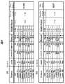
次に、図6および図7を用いて、実施例に係る車両用シート1と比較例に係る車両用シート1rとについて説明する。図6は、実施例に係る車両用シート1と比較例に係る車両用シート1rとを示す図である。図7は、C寸法とポイントとを説明する図である。 Next, the
図6には、実施例に係る車両用シート1と比較例に係る車両用シート1rとについて、リクライニング機構14の設計標準角度(RA)、トルソー角度(TA)、A寸法、B寸法、C寸法等が示されている。車両用シート1の値に関しては、先に説明したので、繰り返しの説明は省略する。車両用シート1rにおいて、リクライニング機構14の設計標準角度(RA)は17.7度、トルソー角度(TA)は21.0度、A寸法は348.4mm、B寸法は273.9mm、C寸法は74.5mmとされている。リクライニング機構14の設計標準角度(RA)において、車両用シート1のリクライニング機構14の新たな設計標準角度(RA)(=19.7度)は、車両用シート1rのリクライニング機構14の設計標準角度(RA)(=17.7度)に対して、+2度分多くされている(+2度後ろ側に傾いている)と見做すことができる。 FIG. 6 shows the design standard angle (RA), torso angle (TA), A dimension, B dimension, and C dimension of the
ここで、トルソー角度(TA)とB寸法とは、車両用シート1と車両用シート1rとで同じである。また、車両用シート1と車両用シート1rとでは、シートフレーム4は同じであり、シートクッション2およびシートバック3に取り付けられるクッション材およびシート表皮の材質および形状も同じである。車両用シート1と車両用シート1rとで異なるのは、リクライニング機構14の設計標準角度(RA)と、ヘッドレスト20のヘッドレストステイ21の構成である。厳密には、着座者の頭の後頭部を支えるヘッドレスト20の前方側の表皮面の位置が、車両用シート1では、車両用シート1rと比較して、約18mm程度(92.4mm-74.5mm=17.9mm)前方側へ移動していることになる。 Here, the torso angle (TA) and the B dimension are the same for the
図6において、ポイントはJNCAPに規定される後面衝突頚部保護性能試験の合計点を示し、コンタクトタイムは衝突瞬間から衝突後のダミーの後頭部がヘッドレストとコンタクトするまでの時間(ms)を示す。車両用シート1のポイントは11.05であり、車両用シート1rのポイントは6.97である。したがって、車両用シート1は、車両用シート1rと比較して、後面衝突頚部保護性能の向上された車両用シートと言うことができる。 In FIG. 6, the points indicate the total points of the rear collision neck protection performance test defined by JNCAP, and the contact time indicates the time (ms) from the moment of collision until the back of the dummy after the collision contacts the headrest. The point of the
図7に示す様に、車両用シート1rでは、A寸法は348.4mm、C寸法は74.5mmであり、ポイントは6.97である。車両用シート1では、A寸法は366.3mm、C寸法は92.4mmであり、ポイントは11.05である。C寸法の値が大きいと、ポイントが向上することが分かる。また、C寸法の値は80mm以上が理想値である。したがって、C寸法の値は、80mm~95mmの範囲とするのが好ましい。 As shown in FIG. 7, in the
つまり、トルソー角度(TA)とB寸法とは変更せずに、リクライニング機構の設計標準角度に応じて、C寸法を調整することでA寸法を変更する。これにより、車両用シート1の後面衝突頚部保護性能を向上させることができる。この例では、車両用シート1のリクライニング機構14の設計標準角度(RA)が、車両用シート1rのリクライニング機構14の設計標準角度(RA)に対して、+2度分多くされていることにしたがって、車両用シート1のヘッドレスト20のC寸法が車両用シート1rのヘッドレスト20のC寸法より、約18mm程度多くされている。この構成により、車両用シート1の後面衝突頚部保護性能を向上させることができる。 That is, the A dimension is changed by adjusting the C dimension according to the design standard angle of the reclining mechanism without changing the torso angle (TA) and the B dimension. This makes it possible to improve the rear collision neck protection performance of the
上記では、トルソー角度(TA)とB寸法とは変更せずに、C寸法を大きくするために、A寸法を大きくする調整を行うようにした構成例を示したが、これに限定されない。C寸法=A寸法-B寸法の関係なので、トルソー角度(TA)とA寸法とは変更せずに、C寸法を大きくするために、B寸法を短くする調整を行うように構成しても良い。この場合、車両用シート1のリクライニング機構14の設計標準角度(RA)は、車両用シート1rのリクライニング機構14の設計標準角度(RA)と同じにされてよい。 In the above, the configuration example in which the adjustment to increase the A dimension is performed in order to increase the C dimension without changing the torso angle (TA) and the B dimension is shown, but the present invention is not limited to this. Since the relationship is C dimension = A dimension-B dimension, the torso angle (TA) and the A dimension may not be changed, and the adjustment may be made to shorten the B dimension in order to increase the C dimension. .. In this case, the design standard angle (RA) of the
次に、JNCAPに規定される後面衝突頚部保護性能試験の試験結果についての説明を行うが、まず、後面衝突頚部保護性能試験で用いられる用語について説明する。なお、各用語については、JNCAPのホームページ(https://www.nasva.go.jp/mamoru/download/car_download.html#h06)の「試験方法のダウンロード」の「後面衝突頚部保護性能試験方法(改定:2020年7月17日)」の記載に基づいている。 Next, the test results of the rear collision neck protection performance test specified in JNCAP will be described. First, the terms used in the rear collision neck protection performance test will be described. For each term, refer to "Download test method" on the JNCAP website (https://www.nasva.go.jp/mamoru/download/car_download.html#h06), "Back collision neck protection performance test method (https://www.nasva.go.jp/mamoru/download/car_download.html#h06)". Revised: July 17, 2020) ”.
NIC:頭部加速度(Head Acceleration:HearGとも言う)と第一胸椎加速度(T1 Acceleration:T1Gとも言う)の組み合わせによって算出される頚部傷害値(Neck Injury Criterion)をいう。 NIC: Neck Injury Criterion calculated by combining head acceleration (also called HearG) and first thoracic spine acceleration (T1 Acceleration: also called T1G).
Upper Neck Fx:頚部の上部に加わる前後方向のせん断荷重(頭後方向)をいう。Upper Fxと略す。 Upper Neck Fx: The anterior-posterior shear load (posterior direction) applied to the upper part of the neck. Abbreviated as Upper Fx.
Upper Neck Fz:頚部の上部に加わる上下方向の引張荷重(上方向)をいう。Upper Fzと略す。 Upper Neck Fz: The vertical tensile load (upward) applied to the upper part of the neck. Abbreviated as Upper Fz.
Upper Neck My:頚部の上部に加わる左右方向軸まわりのモーメントをいう。頭と首の付け根部分の位置の前後方向のモーメントであり、My(+)は前方向のモーメント(屈曲)を示し、My(-)は後ろ方向のモーメント(伸展)を示す。Upper Myと略す。 Upper Neck My: The moment around the left-right axis applied to the upper part of the neck. The anterior-posterior moment of the position of the base of the head and neck, My (+) indicates the anterior moment (flexion), and My (-) indicates the posterior moment (extension). Abbreviated as Upper My.
Lower Neck Fx:頚部の下部に加わる前後方向のせん断荷重(頭後方向)をいう。Lower Fxと略す。 Lower Neck Fx: The anterior-posterior shear load (posterior direction) applied to the lower part of the neck. Abbreviated as Lower Fx.
Lower Neck Fz:頚部の下部に加わる上下方向の引張荷重(上方向)をいう。Lower Fzと略す。 Lower Neck Fz: The vertical tensile load (upward) applied to the lower part of the neck. Abbreviated as Lower Fz.
Lower Neck My:頚部の下部に加わる左右方向軸まわりのモーメントをいう。体と首の付け根部分の位置の前後方向のモーメントであり、My(+)は前方向のモーメント(屈曲)を示し、My(-)は後方向のモーメント(伸展)を示す。Lower Myと略す。 Lower Neck My: The moment around the left-right axis applied to the lower part of the neck. The anterior-posterior moment of the position of the base of the body and neck, My (+) indicates the anterior moment (flexion), and My (-) indicates the posterior moment (extension). Abbreviated as Lower My.
NIC値は、下記の式で得られる。
NIC=0.2×加速度差+速度差2
ここで、加速度差=T1G-HearGであり、速度差=(加速度差の積分値)である。The NIC value is obtained by the following formula.
NIC = 0.2 x acceleration difference + speed difference2
Here, the acceleration difference = T1G-HearG, and the velocity difference = (integral value of the acceleration difference).
後面衝突頚部保護性能試験の合計点(ポイント)は、下記の式で得られる。
ポイント=NIC値+α×2
ここで、αは、「Upper My(+),(-)」、「Lower My(+),(-)」、「Upper Fx」、「Upper Fz」、「Lower Fx」、「Lower Fz」のワースト値である。The total score (points) of the rear collision neck protection performance test is obtained by the following formula.
Point = NIC value + α × 2
Here, α is of "Upper My (+), (-)", "Lower My (+), (-)", "Upper Fx", "Upper Fz", "Lower Fx", "Lower Fz". Worst value.
図8は、試験結果の一例を示す図であり、図8(a)は実施例に係る車両用シート1の試験結果の一例を示す図であり、図8(b)は比較例に係る車両用シート1rの試験結果の一例を示す図である。図8(a)では、NICの点数が3.64、頚部荷重・モーメントの点数は、Upper My(+)の点数が3.71であったほかは全て4.00であった。後面衝突頚部保護性能試験の合計点(ポイント)は、11.05であった。図8(b)では、NICの点数が2.04、頚部荷重・モーメントの点数は、Upper My(+)の点数が3.06、Upper My(-)の点数が2.47であったほかは全て4.00であった。後面衝突頚部保護性能試験の合計点(ポイント)は、6.97であった。 FIG. 8 is a diagram showing an example of a test result, FIG. 8 (a) is a diagram showing an example of a test result of the
実施例に係る車両用シート1では、シートクッション2およびシートバック3に取り付けられるクッション材およびシート表皮の材質および形状を変更せずに、C寸法の値の調整により、理想的な位置にシートバックフレーム6またはシートバックフレーム6のバックアッパーフレーム10を配置する事ができる。これにより、後面衝突頚部保護性能試験の合計点(ポイント)を向上することができ、後面衝突頚部保護性能を向上させることができる。 In the
次に試験結果について、図面を用いて説明する。 Next, the test results will be described with reference to the drawings.
(試験結果1)
ここでは、BioRID IIダミー人形を用い、試験装置に車両用シートを固定し、被追突時の衝撃パルスを再現して付与し、頭部がヘッドレストにコンタクトするまでの間(フェーズ1)に発生する「頚部のS字変形」を評価する傷害指標として頚部傷害基準(Neck Injury Criterion(NIC))の値を求めるための試験について説明する。図9は、フェーズ1の試験を説明する図である。図10は、フェーズ1の試験結果を示すグラフである。図10には、実施例に車両用シート1の試験結果(頭部加速度HearG(1)と第一胸椎加速度T1G(1))と比較例に係る車両用シート1rの試験結果(頭部加速度HearG(1r)と第一胸椎加速度T1G(1r))とが示されている。図10において、縦軸は加速度(m/S2)を示し、横軸は時間(ms)を示している。(Test result 1)
Here, using a BioRID II dummy doll, the vehicle seat is fixed to the test device, the impact pulse at the time of a rear-end collision is reproduced and applied, and it occurs until the head contacts the headrest (Phase 1). A test for obtaining a value of a neck injury standard (Neck Injury Criteria (NIC)) as an injury index for evaluating "S-shaped deformation of the neck" will be described. FIG. 9 is a diagram illustrating the
図9に示す様に、この試験では、頭部加速度HearGと第一胸椎加速度T1Gとを計測する。T1は、第一胸椎の部分を示し、T1SPは第一胸椎T1とヘッドレストホルダ32のセンタとの間の距離を示し、TSはダミー人形の背中とシートバックフレーム6のバックアッパーフレーム10との間の距離を示している。 As shown in FIG. 9, in this test, the head acceleration HearG and the first thoracic spine acceleration T1G are measured. T1 indicates the portion of the first thoracic vertebra, T1SP indicates the distance between the first thoracic vertebra T1 and the center of the
図10に示す様に、車両用シート1の頭部加速度HearG(1)のピークの値は、車両用シート1rの頭部加速度HearG(1r)のピーク値と比較して、17%程度低下している。これにより、車両用シート1のUpper Fx、Upper Fz、Upper My、Lower Fx、Lower FzやLower Myが良化する。また、車両用シート1の第一胸椎加速度T1G(1)の立ち上がりが、車両用シート1rの第一胸椎加速度T1G(1r)の立ち上がりに対して、10ms程度後方へシフトしている。車両用シート1の頭部加速度HearG(1)において、ヘッドレストコンタクトタイム(HRCT)が早期化されていることにより、頭部(Head)先行支持モードへとなる。一方、車両用シート1rの頭部加速度HearG(1r)において、第一胸椎加速度T1G(1r)の先行立ち上がりによりシートバック3が後傾し、ヘッドレスト20が遠ざかるので、ヘッドレストコンタクトタイム(HRCT)の遅れが発生している。 As shown in FIG. 10, the peak value of the head acceleration HearG (1) of the
ヘッドレストコンタクトタイム(HRCT)は、ダミー人形の後頭部がヘッドレスト20にコンタクトするまでの時間であり、後面衝突による第一胸椎T1のシートバック3へ侵入量に依存している。図9に示す様に、比較例に係る車両用シート1rでは、距離TSの不足の為、ダミー人形の上体部がシートバックフレーム6に底づいてシートバックフレーム6が後傾する。これにより、図10に示す様に、ヘッドレストコンタクトタイム(HRCT)の遅れにより、ダミー人形の頭部(Head)の対ヘッドレスト(HR)衝突速度が上昇して、頭部加速度HearG(1r)のピーク値が上昇する。これにより、頭部加速度HearG(1r)の上昇によって、車両用シート1rのUpper Fx、Upper Fz、Upper My、Lower Fx、Lower FzやLower Myの値が上昇し、頚部傷害値(NIC)が悪化したものと考えられる。 The headrest contact time (HRCT) is the time until the occipital region of the dummy doll contacts the
(試験結果2)
次に、車両用シート1および車両用シート1rについて試験を実施し、コンタクト後から「最大後屈」まで(フェーズ2)を評価する傷害指標として頚部荷重・モーメントを計測した。HeadG、NIC、Upper Fx、Upper Fz、Upper My、Lower Fx、Lower FzおよびLower Myの各計測結果を図11~図18を用いて説明する。(Test result 2)
Next, a test was conducted on the
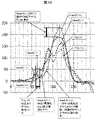
図11は、頭部加速度(HearG)を示すグラフである。縦軸は、加速度(m/S2)を示し、横軸は時間(ms)を示す。図11に示す様に、車両用シート1の頭部加速度HearG(1)のピーク値は、車両用シート1rの頭部加速度HearG(1r)のピーク値より、1.4G低下(約17%低下)している。これは、頚部傷害値(NIC)以外の傷害値の低下に繋がるものである。 FIG. 11 is a graph showing the head acceleration (HearG). The vertical axis shows acceleration (m / S2), and the horizontal axis shows time (ms). As shown in FIG. 11, the peak value of the head acceleration HearG (1) of the
図12は、頚部傷害値(NIC)を示すグラフである。縦軸は、NIC値(m2/S2)を示し、横軸は時間(ms)を示す。車両用シート1の頚部傷害値NIC(1)のピーク値は、車両用シート1rの頚部傷害値NIC(1r)のピーク値より、約49%低下している。 FIG. 12 is a graph showing a cervical injury value (NIC). The vertical axis shows the NIC value (m2 / S2), and the horizontal axis shows the time (ms). The peak value of the neck injury value NIC (1) of the
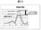
図13は、Upper Myを示すグラフである。縦軸は、モーメント(Nm)を示し、横軸は時間(ms)を示す。車両用シート1のUpper My(1)のピーク値は、車両用シート1rのUpper My(1r)のピーク値より、約33%改善している。 FIG. 13 is a graph showing Upper My. The vertical axis shows the moment (Nm), and the horizontal axis shows the time (ms). The peak value of Upper My (1) of the
図14は、Lower Myを示すグラフである。縦軸は、モーメント(Nm)を示し、横軸は時間(ms)を示す。車両用シート1のlower My(1)のマイナス側My-の値は、車両用シート1rのlower My(1r)のマイナス側My-の値より、改善されており、車両用シート1rのlower My(1r)のマイナス側My-の値は、傾向低下の状態である。170ms以降において、車両用シート1のlower My(1)のプラス側My+の値は、車両用シート1rのlower My(1r)のプラス側My+の値より、低下している。 FIG. 14 is a graph showing Lower My. The vertical axis shows the moment (Nm), and the horizontal axis shows the time (ms). The value of the negative side My- of the lower My (1) of the
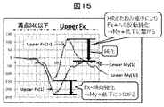
図15は、Upper Fxを示すグラフである。縦軸は、荷重(N)を示し、横軸は時間(ms)を示す。90ms近辺において、車両用シート1のUpper Fx(1)のマイナス側Fx-のピーク値は、車両用シート1rのUpper Fx(1r)のマイナス側Fx-のピーク値と比較して、傾向強化の状態であり、車両用シート1のUpper My+やLower My+の低下につながっている。165ms近辺の車両用シート1のUpper Fx(1)のピーク値は、125ms近辺の車両用シート1rのUpper Fx(1r)のプラス側Fx+のピーク値と比較して、鈍化している。車両用シート1では、ヘッドレスト(HR)20のたわみ減少により、165ms近辺の車両用シート1のUpper Fx(1)は、プラス側Fx+への反転鈍化の状態であり、車両用シート1のUpper My+やLower My+の低下につながっている。 FIG. 15 is a graph showing Upper Fx. The vertical axis shows the load (N), and the horizontal axis shows the time (ms). At around 90 ms, the peak value of the negative side Fx- of Upper Fx (1) of the
図16は、Lower Fxを示すグラフである。縦軸は、荷重(N)を示し、横軸は時間(ms)を示す。車両用シート1のLower Fx(1)のピーク値は、車両用シート1rのLower Fx(1r)のピーク値と比較して、低下しており、約41%改善している。 FIG. 16 is a graph showing Lower Fx. The vertical axis shows the load (N), and the horizontal axis shows the time (ms). The peak value of Lower Fx (1) of the
図17は、Upper Fzを示すグラフである。縦軸は、荷重(N)を示し、横軸は時間(ms)を示す。車両用シート1のUpper Fz (1)のピーク値は、車両用シート1rのUpper Fz (1r)のピーク値と比較して、低下しており、約25%改善している。 FIG. 17 is a graph showing Upper Fz. The vertical axis shows the load (N), and the horizontal axis shows the time (ms). The peak value of Upper Fz (1) of the
図18は、Lower Fzを示すグラフである。縦軸は、荷重(N)を示し、横軸は時間(ms)を示す。車両用シート1のLower Fz (1)のピーク値は、車両用シート1rのLower Fz (1r)のピーク値と比較して、低下しており、約29%改善している。 FIG. 18 is a graph showing Lower Fz. The vertical axis shows the load (N), and the horizontal axis shows the time (ms). The peak value of Lower Fz (1) of the
実施例の車両用シート1によれば、シートクッション2およびシートバック3に取り付けられるクッション材およびシート表皮の材質および形状を変更せずに、C寸法の値の調整により、理想的な位置にシートバックフレーム6のバックアッパーフレーム10を配置する事ができる。これにより、後面衝突頚部保護性能試験の合計点(ポイント)を向上することができ、後面衝突頚部保護性能を向上させることができる。 According to the
以上、本発明者によってなされた発明を実施例に基づき具体的に説明したが、本発明は、上記実施形態および実施例に限定されるものではなく、種々変更可能であることはいうまでもない。 Although the invention made by the present inventor has been specifically described above based on Examples, it is needless to say that the present invention is not limited to the above-described embodiments and examples and can be variously modified. ..
1:車両用シート
2:シートクッション
3:シートバック
4:シートフレーム
5:シートクッションフレーム
6:シートバックフレーム
7:バック右サイドフレーム
8:バック左サイドフレーム
9:バックロアフレーム
10:バックアッパーフレーム
14:リクライニング機構
20:ヘッドレスト
21:ヘッドレストステイ
21a:第1ヘッドレストステイ
21b:第2ヘッドレストステイ
22:上部ステイ
23:中間部ステイ
24:下部ステイ
32:ヘッドレストホルダ1: Vehicle seat 2: Seat cushion 3: Seat back 4: Seat frame 5: Seat cushion frame 6: Seat back frame 7: Back right side frame 8: Back left side frame 9: Back lower frame 10: Back upper frame 14 : Reclining mechanism 20: Headrest 21:
Claims (3)
Translated fromJapaneseシートバックと、
前記シートクッションと前記シートバックとを角度調整可能に連結するリクライニング機構と、
前記シートバックの上端部に設けられたヘッドレストと、含む車両用シートにおいて、
前記シートバックは、バック右サイドフレームと、バック左サイドフレームと、バックロアフレームと、バックアッパーフレームとが枠状に組み合わされて構成され、
前記バックアッパーフレームは、プレス成形された板金構造とされ、
前記バックアッパーフレームには、ヘッドレストホルダが取り付けられ、
前記ヘッドレストは、上下方向に設けられた一対の第1ヘッドレストステイと、前記一対の第1ヘッドレストステイの上部端の間に設けられた第2ヘッドレストステイと、を含み、
前記一対の第1ヘッドレストステイのおのおのは、上部ステイと、中間部ステイと、下部ステイと、を含み、前記上部ステイは、前記下部ステイより前方側に設けられ、前記中間部ステイは前記上部ステイの下端部と前記下部ステイの上端部との間に設けられ、前記上部ステイの上端部は前記第2ヘッドレストステイに接続され、前記下部ステイは前記ヘッドレストホルダに挿入され、
ヒップポイント(HP)と前記ヘッドレストホルダのセンタとの間の距離をA寸法とし、前記HPと前記第2ヘッドレストステイとの間の距離をB寸法とし、前記第2ヘッドレストステイと前記ヘッドレストホルダのセンタとの間の距離をC寸法とし、前記A寸法と前記B寸法と前記C寸法は、A寸法=B寸法+C寸法の関係とされ、
前記車両用シートのトルソー角と前記B寸法とを変更することなく、前記リクライニング機構の設計標準角度に応じて、前記C寸法を調整することで前記A寸法を変更する、車両用シート。With a seat cushion,
Seat back and
A reclining mechanism that connects the seat cushion and the seat back so that the angle can be adjusted,
In the headrest provided at the upper end of the seat back and the vehicle seat including the seat back,
The seat back is configured by combining a back right side frame, a back left side frame, a back lower frame, and a back upper frame in a frame shape.
The back upper frame has a press-molded sheet metal structure.
A headrest holder is attached to the back upper frame.
The headrest includes a pair of first headrest stays provided in the vertical direction and a second headrest stay provided between the upper ends of the pair of first headrest stays.
Each of the pair of first headrest stays includes an upper stay, an intermediate stay, and a lower stay, the upper stay is provided on the front side of the lower stay, and the intermediate stay is the upper stay. The upper end of the upper stay is connected to the second headrest stay, and the lower stay is inserted into the headrest holder.
The distance between the hip point (HP) and the center of the headrest holder is defined as dimension A, the distance between the HP and the second headrest stay is defined as dimension B, and the distance between the second headrest stay and the center of the headrest holder is defined as the center. The distance between the A dimension, the B dimension, and the C dimension is defined as the C dimension, and the relationship between the A dimension, the B dimension, and the C dimension is defined as A dimension = B dimension + C dimension.
A vehicle seat that changes the A dimension by adjusting the C dimension according to the design standard angle of the reclining mechanism without changing the torso angle of the vehicle seat and the B dimension.
前記C寸法は、80mmから95mmの範囲である、車両用シート。In the vehicle seat according to claim 1,
The C dimension is a vehicle seat in the range of 80 mm to 95 mm.
シートバックと、
前記シートクッションと前記シートバックとを角度調整可能に連結するリクライニング機構と、
前記シートバックの上端部に設けられたヘッドレストと、含む車両用シートにおいて、
前記シートバックは、バック右サイドフレームと、バック左サイドフレームと、バックロアフレームと、バックアッパーフレームとが枠状に組み合わされて構成され、
前記バックアッパーフレームは、プレス成形された板金構造とされ、
前記バックアッパーフレームには、ヘッドレストホルダが取り付けられ、
前記ヘッドレストは、上下方向に設けられた一対の第1ヘッドレストステイと、前記一対の第1ヘッドレストステイの上部端の間に設けられた第2ヘッドレストステイと、を含み、
前記一対の第1ヘッドレストステイのおのおのは、上部ステイと、中間部ステイと、下部ステイと、を含み、前記上部ステイは、前記下部ステイより前方側に設けられ、前記中間部ステイは前記上部ステイの下端部と前記下部ステイの上端部との間に設けられ、前記上部ステイの上端部は前記第2ヘッドレストステイに接続され、前記下部ステイは前記ヘッドレストホルダに挿入され、
ヒップポイント(HP)と前記ヘッドレストホルダのセンタとの間の距離をA寸法とし、前記HPと前記第2ヘッドレストステイとの間の距離をB寸法とし、前記第2ヘッドレストステイと前記ヘッドレストホルダのセンタとの間の距離をC寸法とし、前記A寸法と前記B寸法と前記C寸法は、A寸法=B寸法+C寸法の関係とされ、
前記車両用シートのトルソー角と前記A寸法とを変更することなく、前記リクライニング機構の設計標準角度に応じて、前記B寸法を調整することで前記C寸法を変更する、車両用シート。With a seat cushion,
Seat back and
A reclining mechanism that connects the seat cushion and the seat back so that the angle can be adjusted,
In the headrest provided at the upper end of the seat back and the vehicle seat including the seat back,
The seat back is configured by combining a back right side frame, a back left side frame, a back lower frame, and a back upper frame in a frame shape.
The back upper frame has a press-molded sheet metal structure.
A headrest holder is attached to the back upper frame.
The headrest includes a pair of first headrest stays provided in the vertical direction and a second headrest stay provided between the upper ends of the pair of first headrest stays.
Each of the pair of first headrest stays includes an upper stay, an intermediate stay, and a lower stay, the upper stay is provided on the front side of the lower stay, and the intermediate stay is the upper stay. The upper end of the upper stay is connected to the second headrest stay, and the lower stay is inserted into the headrest holder.
The distance between the hip point (HP) and the center of the headrest holder is defined as dimension A, the distance between the HP and the second headrest stay is defined as dimension B, and the distance between the second headrest stay and the center of the headrest holder is defined as the center. The distance between the A dimension, the B dimension, and the C dimension is defined as the C dimension, and the relationship between the A dimension, the B dimension, and the C dimension is defined as A dimension = B dimension + C dimension.
A vehicle seat that changes the C dimension by adjusting the B dimension according to the design standard angle of the reclining mechanism without changing the torso angle of the vehicle seat and the A dimension.
Priority Applications (1)
| Application Number | Priority Date | Filing Date | Title |
|---|---|---|---|
| JP2020184668AJP2022074549A (en) | 2020-11-04 | 2020-11-04 | Vehicle seat |
Applications Claiming Priority (1)
| Application Number | Priority Date | Filing Date | Title |
|---|---|---|---|
| JP2020184668AJP2022074549A (en) | 2020-11-04 | 2020-11-04 | Vehicle seat |
Publications (1)
| Publication Number | Publication Date |
|---|---|
| JP2022074549Atrue JP2022074549A (en) | 2022-05-18 |
Family
ID=81606237
Family Applications (1)
| Application Number | Title | Priority Date | Filing Date |
|---|---|---|---|
| JP2020184668APendingJP2022074549A (en) | 2020-11-04 | 2020-11-04 | Vehicle seat |
Country Status (1)
| Country | Link |
|---|---|
| JP (1) | JP2022074549A (en) |
Cited By (1)
| Publication number | Priority date | Publication date | Assignee | Title |
|---|---|---|---|---|
| WO2025095914A1 (en)* | 2023-11-02 | 2025-05-08 | Hacettepe Universitesi Rektorluk | A seat system |
Citations (8)
| Publication number | Priority date | Publication date | Assignee | Title |
|---|---|---|---|---|
| JP2000270961A (en)* | 1999-03-24 | 2000-10-03 | Nhk Spring Co Ltd | Car seat backrest frame |
| JP2002010865A (en)* | 2000-06-28 | 2002-01-15 | Aisin Seiki Co Ltd | Headrest device |
| JP2006213201A (en)* | 2005-02-04 | 2006-08-17 | T S Tec Kk | Automotive seat with shock absorbing seat back |
| JP2007507389A (en)* | 2003-10-07 | 2007-03-29 | ルノー・エス・アー・エス | Seat back assembly for automobile seat |
| JP2011098588A (en)* | 2009-11-04 | 2011-05-19 | Toyota Boshoku Corp | Seat for vehicle |
| US20110163574A1 (en)* | 2007-05-08 | 2011-07-07 | Tame Omar D | Automatically Adjustable Head Restraint |
| JP2012035707A (en)* | 2010-08-05 | 2012-02-23 | Nhk Spring Co Ltd | Headrest device, method of adjusting headrest position, and vehicle seat |
| JP2019089399A (en)* | 2017-11-13 | 2019-06-13 | 日産自動車株式会社 | Headrest adjustment method and headrest device |
- 2020
- 2020-11-04JPJP2020184668Apatent/JP2022074549A/enactivePending
Patent Citations (8)
| Publication number | Priority date | Publication date | Assignee | Title |
|---|---|---|---|---|
| JP2000270961A (en)* | 1999-03-24 | 2000-10-03 | Nhk Spring Co Ltd | Car seat backrest frame |
| JP2002010865A (en)* | 2000-06-28 | 2002-01-15 | Aisin Seiki Co Ltd | Headrest device |
| JP2007507389A (en)* | 2003-10-07 | 2007-03-29 | ルノー・エス・アー・エス | Seat back assembly for automobile seat |
| JP2006213201A (en)* | 2005-02-04 | 2006-08-17 | T S Tec Kk | Automotive seat with shock absorbing seat back |
| US20110163574A1 (en)* | 2007-05-08 | 2011-07-07 | Tame Omar D | Automatically Adjustable Head Restraint |
| JP2011098588A (en)* | 2009-11-04 | 2011-05-19 | Toyota Boshoku Corp | Seat for vehicle |
| JP2012035707A (en)* | 2010-08-05 | 2012-02-23 | Nhk Spring Co Ltd | Headrest device, method of adjusting headrest position, and vehicle seat |
| JP2019089399A (en)* | 2017-11-13 | 2019-06-13 | 日産自動車株式会社 | Headrest adjustment method and headrest device |
Cited By (1)
| Publication number | Priority date | Publication date | Assignee | Title |
|---|---|---|---|---|
| WO2025095914A1 (en)* | 2023-11-02 | 2025-05-08 | Hacettepe Universitesi Rektorluk | A seat system |
Similar Documents
| Publication | Publication Date | Title |
|---|---|---|
| JP6367406B2 (en) | Vehicle seat | |
| JP5452858B2 (en) | Vehicle seat | |
| US8936317B2 (en) | Seat back for vehicle and seat for vehicle including the same | |
| CN107719196A (en) | Backrest frame | |
| CN102307751A (en) | Vehicle seat | |
| JP2022074549A (en) | Vehicle seat | |
| JP4728670B2 (en) | Automotive seat backrest frame | |
| JP2023161799A (en) | Seat back panel, seat back frame and vehicle seat | |
| JP7271161B2 (en) | Headrests and vehicle seats | |
| JP4037331B2 (en) | Vehicle seat | |
| JP7303463B2 (en) | vehicle seat | |
| JP2011178368A (en) | Frame structure of seat back | |
| JP4147477B2 (en) | Shock absorber and seat structure including the same | |
| JP7718960B2 (en) | Headrest stay structure | |
| US12240362B2 (en) | Seat cushion frame, vehicle seat frame, and vehicle seat | |
| JP7623571B2 (en) | Vehicle seats | |
| US12097788B2 (en) | Vehicle seat and vehicle seat frame | |
| EP2476585B1 (en) | Seat back framework | |
| JP7240230B2 (en) | back frame | |
| JP3114557U (en) | Automotive headrest | |
| JP2023107975A (en) | vehicle seat | |
| JP2023097024A (en) | Seat cushion frame, vehicle seat frame and vehicle seat | |
| JP2023157032A (en) | vehicle seat | |
| JP2022187384A (en) | vehicle seat | |
| JP5424398B2 (en) | Seat structure |
Legal Events
| Date | Code | Title | Description |
|---|---|---|---|
| A621 | Written request for application examination | Free format text:JAPANESE INTERMEDIATE CODE: A621 Effective date:20230718 | |
| A977 | Report on retrieval | Free format text:JAPANESE INTERMEDIATE CODE: A971007 Effective date:20231122 | |
| A131 | Notification of reasons for refusal | Free format text:JAPANESE INTERMEDIATE CODE: A131 Effective date:20231205 | |
| A521 | Request for written amendment filed | Free format text:JAPANESE INTERMEDIATE CODE: A523 Effective date:20240131 | |
| A131 | Notification of reasons for refusal | Free format text:JAPANESE INTERMEDIATE CODE: A131 Effective date:20240423 | |
| A02 | Decision of refusal | Free format text:JAPANESE INTERMEDIATE CODE: A02 Effective date:20240917 |