JP2022072040A - Compounding device - Google Patents
Compounding deviceDownload PDFInfo
- Publication number
- JP2022072040A JP2022072040AJP2020181239AJP2020181239AJP2022072040AJP 2022072040 AJP2022072040 AJP 2022072040AJP 2020181239 AJP2020181239 AJP 2020181239AJP 2020181239 AJP2020181239 AJP 2020181239AJP 2022072040 AJP2022072040 AJP 2022072040A
- Authority
- JP
- Japan
- Prior art keywords
- supply
- powder
- screen
- feeder
- granular material
- Prior art date
- Legal status (The legal status is an assumption and is not a legal conclusion. Google has not performed a legal analysis and makes no representation as to the accuracy of the status listed.)
- Pending
Links
Images


Landscapes
- Weight Measurement For Supplying Or Discharging Of Specified Amounts Of Material (AREA)
- Filling Or Emptying Of Bunkers, Hoppers, And Tanks (AREA)
Abstract
Description
Translated fromJapanese本開示は、配合装置に関する。 The present disclosure relates to a compounding device.
従来、粉粒体や液体等の流動物を供給する供給機が知られている(例えば、特許文献1参照)。 Conventionally, a feeder for supplying a fluid such as a powder or a liquid is known (see, for example, Patent Document 1).
複数種類の流動物を供給して配合する場合に、作業を容易にすることが求められている。 When supplying and blending a plurality of types of fluids, it is required to facilitate the work.
本開示の配合装置は、複数種類の粉粒体又は液体である流動物をそれぞれ供給可能配合装置であって、前記複数種類の流動物が別々に収容されて、排出可能な複数の流動物供給機と、前記複数の流動物供給機が水平面上に並べて固定される可動テーブルと、前記複数の流動物供給機が並べられた方向に前記可動テーブルを動かし、任意の前記流動物供給機を特定位置に配置可能な可動手段と、を備える配合装置である。 The blending device of the present disclosure is a blending device capable of supplying each of a plurality of types of powders and granules or liquids that are liquids, and the plurality of types of fluids are separately contained and can be discharged. The machine, the movable table in which the plurality of fluid feeders are arranged and fixed on a horizontal plane, and the movable table in the direction in which the plurality of fluid feeders are arranged are moved to specify an arbitrary fluid feeder. It is a compounding device including a movable means that can be arranged at a position.
本開示に係る配合装置によれば、複数の流動物供給機が並べられた可動テーブルを動かして、任意の流動物供給機を特定の位置に配置し、供給させることができるので、複数種類の流動物を供給して配合する場合の作業を容易にすることができる。 According to the compounding apparatus according to the present disclosure, since a movable table in which a plurality of fluid feeders are arranged can be moved to arrange and supply an arbitrary fluid feeder at a specific position, a plurality of types can be used. It is possible to facilitate the work when the fluid is supplied and blended.
[第1実施形態]
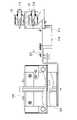
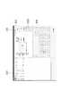
以下、図1から図27を参照して、第1実施形態の配合装置10について説明する。図1に示すように、配合装置10は、ベース11と、ベース上に載置されたスライダー12と、スライダー12に取り付けられた複数の材料供給機構20と、を有する。[First Embodiment]
Hereinafter, the
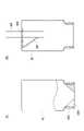
ベース11は、四角形のベース板11Aの一側辺部に、下方開放のコの字状の架台11Bを備えてなる。架台11Bは、ベース板11Aの一側辺部の両端部に配された1対の脚部11Cと、脚部11Cの上端部同士を連絡する天板部11Dと、を有している。以下、天板部11Dの長手方向(ベース板11Aの一側辺部の延在方向)を第1水平方向H1といい、第1水平方向と直交する方向を第2水平方向H2という。 The
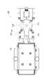
スライダー12は、架台11Bの天板部11D上に配されている。スライダー12は、第1水平方向H1に延びる平面視長方形状の固定ベース12Aと、固定ベース12Aに支持され、図示しないモータにより第1水平方向H1に直動可能なスライダテーブル12Bと、を有している。図2に示すように、固定ベース12Aには、第1水平方向H1に延びるねじ軸12A1が設けられていて、スライダテーブル12Bには、ねじ軸12A1に螺合するナット(図示せず)が設けられている。スライダテーブル12Bは、これらねじ軸12A1及びナットを利用した所謂ボールねじ機構により第1水平方向H1に直動する。 The
[振動式供給機構について]
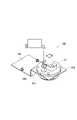
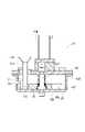
図1に示すように、スライダテーブル12B上には、3つの材料供給機構20が横並びに配されている。図1等では、材料供給機構20として、3つとも振動式供給機構20Aが使用された例が示されている。振動式供給機構20Aは、スライダテーブル12B上に固定された固定部20Xと、固定部20Xから第2水平方向H2へ張り出し、スライダテーブル12B及び架台11Bからずれた(オーバーハングした)張り出し部20Yと、を有している。図3及び図4に示すように、張り出し部20Yは、供給機30(「粉粒体収容器」に相当する)が支持されるブラケット21と、ブラケット21に固定された振動ユニット22と、を有している。図3、図5及び図6に示すように、ブラケット21は、第2水平方向H2に延びた1対の帯板部21Aと、帯板部21Aの中央部に配されて上方へ開放した供給機受容凹部21Bと、を有している。供給機受容凹部21Bのうち1対の帯板部21Aの下方部は切り欠き21Cとなっている。図4に示すように、供給機30は、ブラケット21のうち供給機受容凹部21Bに装着される。[Vibration type supply mechanism]
As shown in FIG. 1, three
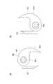
供給機30は、供給機ベース31を備える。図4及び図7に示すように、供給機ベース31は、底壁32Tが厚い円筒状のホルダー32と、シャッター部材33と、通過板34と、押さえ板35と、を有している。シャッター部材33は、ホルダー32より固定部20X側からホルダー32の中央部まで延びた帯板状をなし、先端部が円弧状をなす一方、基端部に2つの貫通孔33Kが形成されている。 The
通過板34は、四角形の主板部34Aと、主板部34Aの一角から延びた帯板部34Bと、を有し、主板部34Aには粉粒体が通過可能な通過孔34K(「粉粒体排出口」に相当する)が貫通形成されている。図8に示すように、通過孔34Kは、帯板部34B側から順に配された、概楕円形状の大孔部34K1と、帯板部34Bから離れるにつれて幅が小さくなった中孔部34K2と、中孔部34K2の先端から直線上に延びた小孔部34K3と、が連なってなる。図7及び図9に示すように、シャッター部材33は、通過板34の下面に重ねられ、第2水平方向H2で直動することにより、通過孔34Kの開放度を変更する。シャッター部材33の先端が通過孔34Kの小孔部34K3の端部に配されたときは、通過孔34Kは完全に閉塞され、シャッター部材33の先端が通過孔34Kの中孔部34K2の中間部に配されたときは、通過孔34Kが30%程開放され、シャッター部材33の先端が通過孔34Kの大孔部34K1と中孔部34K2との境界部に配されたときは、通過孔34Kが60%程開放され、シャッター部材33の先端が通過孔34Kの大孔部34K1より帯板部34B側に配されると、通過孔34Kが100%開放される。つまり、シャッター部材33は、全開状態と全閉状態との間で、通過孔34Kの開放度を段階的に変化させることが可能である。また、通過孔34Kを全開状態から全閉状態にするときは、大孔部34K1側から順に閉塞されていく。これにより、例えば、全開状態からシャッター部材33をスライドさせて通過孔34Kを閉じ始めると、大孔部34K1から閉じていき、全閉に近い状態になると、小孔部34K3のみが開放された状態になるので、粉粒体を微少量ずつ供給することが可能となる。 The
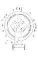
図10に示すように、押さえ板35は、円板部35Aと、円板部35Aの外縁の一部から径方向の外方へ延びた取っ手部35Bと、を有している。円板部35Aには、取っ手部35B側に、比較的大径な大孔35Mが2つ配され、取っ手部35Bと反対側に、比較的小径な小孔35Nが2つ配されている。また、図10及び図11に示すように、押さえ板35には、板厚方向の下部に、各大孔35M及び各小孔35Nを連通するように陥没した下面凹部35Lが形成されている。図10に示すように、2つの大孔35Mを通って延びた円弧部35L1と、円弧部35L1の小孔35N側側辺の中央部へ2つの小孔35Nからそれぞれ伸びた小通路35L2と、を有している。取っ手部35Bは、シャッター部材33の幅の1/3程になっている。 As shown in FIG. 10, the
図12に示すように、2本の小通路35L2が交わる部分は、通過孔34Kの中孔部34K2の中間部の上方に位置し、通過孔34Kのうち中孔部34K2の中間部より小孔部34K3側は、押さえ板35により上方から覆われている。一方、通過孔34Kのうち中孔部34K2の中間部より大孔部34K1側は、全体が押さえ板35の大孔35Mと重なっている。これにより、供給機30に収容された粉粒体は、押さえ板35の大孔35M及び小孔35Nを通過したのち、下面凹部35Lを経由して通過板34の通過孔34Kに到達する。また、図10及び図12に示すように、押さえ板35における円板部35Aには外縁から側方に張り出した係止片35Kが複数形成されている。 As shown in FIG. 12, the portion where the two small passages 35L2 intersect is located above the middle portion of the middle hole portion 34K2 of the
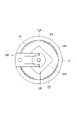
図13に示すように、ホルダー32の底壁32Tには、シャッター部材33の先端部、通過板34の主板部34A及び押さえ板35の円板部35Aを下から順に受容可能な受容凹部32Uが形成されている。ホルダー32の底壁32Tには、中央に、下方へ延びた突出部32Sが形成され、この突出部32Sも貫通する排出孔32Kが形成されている。また、図7に示すように、供給機受容凹部21Bの底壁には、この突出部32Sが挿通する貫通孔21Kが形成されている。 As shown in FIG. 13, the
図7に示すように、ホルダー32の側壁32Aには、上端から中央部まで上下方向に延び、供給機受容凹部21Bの切り欠き21Cと重なる切り欠き32Bが形成されていて、これら切り欠き21C,32Bが、シャッター部材33、通過板34の帯板部34B及び押さえ板35の取っ手部35Bを受容している。切り欠き21C,32Bの幅は、シャッター部材33及び通過板34の帯板部34Bをちょうど受容可能な大きさになっていて、押さえ板35の取っ手部35Bは、その1/3程になっている。これにより、押さえ板35は、ホルダー32内でスライド可能になっている。 As shown in FIG. 7, the
また、図7及び図13に示すように、ホルダー32の側壁32Aの内面には、架空の螺旋に沿って延びた突条32Cが複数形成されていて、これら複数の突条32Cから雌螺子部32Dが構成される。複数の突条32Cは、ホルダー32の側壁32Aの内面を円周方向において4分割した各領域の中央部に上下に並んで配されている。つまり、ホルダー32の側壁32Aの内面には、突条32Cが設けられた領域と突条32Cが設けられていない領域とが円周方向で交互に並んでいる。なお、突条32Cが設けられていない領域の1つが切り欠き32Bとなっている。 Further, as shown in FIGS. 7 and 13, a plurality of
押さえ板35の係止片35Kは、ホルダー32の円周方向における突条32C同士の間隔を通過可能な長さになっている。そして、図12に示すように、取っ手部35Bが切り欠き21C,32B内の一端部に配された状態(図12に実線で示される状態。以降、「取付位置」という)では、押さえ板35の係止片35Kとホルダー32の突条32Cとが上下方向で重なり、取っ手部35Bが切り欠き21C,32B内の他端部に配された状態(図12に二点鎖線で示される状態。以降、「固定位置」という)では、押さえ板35の係止片35Kとホルダー32の突条32Cとが上下方向で重ならない。シャッター部材33と通過板34とを上から受容凹部32Uに受容した状態で、取付位置の押さえ板35を上から受容し、押さえ板35を固定位置にスライドすることで、シャッター部材33、通過板34及び押さえ板35がホルダー32に取り付けられる。 The
そして、ホルダー32の雌螺子部32Dには、粉粒体が収容されたボトル40の雄螺子部40Aが螺合される。ホルダー32は、雌螺子部32Dが下に位置する姿勢で開口を上方にしたボトル40に取り付けられる。そして、通過孔34Kがシャッター部材33により閉塞された状態でボトル40をホルダー32ごとひっくり返し、供給機受容凹部21Bに装着される。なお、供給機30は、供給機受容凹部21Bの底壁を挿通するボルト21Gにより固定可能である。 Then, the
固定部20Xは、シャッター部材33を第2水平方向H2で直動させるためのシャッター駆動部38を備えている。シャッター駆動部38は、シャッター部材33を支持するシャッター支持板38Aと、シャッター支持板38Aを直動させるためのモータ(図示せず)と、を有している。シャッター支持板38Aには、上方へ突出したピン38Bが2つ形成されていて、これらのピン38Bが、シャッター部材33の貫通孔33Kと嵌合し、シャッター部材33がシャッター支持板38Aに固定される。なお、シャッター部材33の裏面には、第2水平方向H2に延びる溝部33Mが形成されていて、ホルダー32の底壁32Tには、この溝部33Mに受容されるプランジャーピン32Pが設けられている。これにより、シャッター部材33が抜け落ちることが防がれる。 The fixed
図4に示すように、振動ユニット22は、供給機30のボトル40の隣に配され、電磁ソレノイドにより駆動されてボトル40の側壁へ衝突する直動子22Aを2つ上下方向に並べて有している。振動式供給機構20Aは、シャッター部材33により通過孔34Kが開放されている状態で直動子22Aがボトル40を振動させることにより、粉粒体が振動により流動化して、押さえ板35の大孔35M及び小孔35Nを通過し、通過板34上に到達した粉粒体が下面凹部35Lを通過したり、シャッター部材33上に配された粉粒体が通過孔34K内を通過して、開放されている部分から流下して、排出孔32Kから排出される。なお、粉粒体の粘性が低い場合は、ボトル40を振動させなくても粉粒体が排出される。 As shown in FIG. 4, the
そして、振動式供給機構20Aでは、シャッター部材33の位置による通過孔34Kの開放度や直動子22Aの強度を変更して、粉粒体の排出量を調整することができる。則ち、シャッター部材33は、全開状態と全閉状態との間で、通過孔34Kの開放度を段階的に変化させることが可能であり、また、通過孔34Kを全開状態から全閉状態にするときは、大孔部34K1側から順に閉塞されていくので、例えば、全開状態からシャッター部材33をスライドさせて通過孔34Kを閉じ始めると、全閉に近い状態になると、小孔部34K3のみが開放された状態になるので、粉粒体を微少量ずつ供給することが可能となる。また、直動子22Aの振動が大きいほど、粉粒体の排出量が多くなり、直動子22Aの振動が小さいほど、粉粒体の排出量が少なくなる。これにより、供給し始め(目標量に遠いとき)には、大量の粉粒体を排出可能である一方、目標量に近づくと、微少量の供給で粉粒体を正確に量り取ることができ、目標量の粉粒体を正確かつ速やかに量り取ることができる。 Then, in the vibration
[配合装置の制御について]
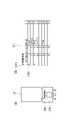
上述したように、本実施形態の配合装置10は、振動式供給機構20Aを複数(例えば、3つ)備えている。そして、配合装置10では、複数の振動式供給機構20Aからの粉粒体の排出を制御して、それら粉粒体を自動配合可能になっている。また、図14に示すように、本実施形態では、それぞれ異なる種類の粉粒体が収容された複数の供給機30がラック45に収納されていて、移載用ロボット53が、ラック45から供給機30を供給機受容凹部21Bに載置可能になっている。移載用ロボット53は、供給機受容凹部21Bから供給機30を取り出したり、ベース11上に配された電子計量器54に粉粒体が供給される容器46を載置することができる。これにより、本実施形態では、粉粒体が供給される容器46や供給機30のセットから、容器46への複数種類の粉粒体の排出までを自動で行うことが可能となる。[Control of compounding equipment]
As described above, the compounding
また、振動式供給機構20A以外の材料(粉粒体又は液体)供給機構20を振動式供給機構20Aと併用し、様々な材料を配合可能な構成としてもよい。この場合、移載用ロボット53が材料供給機構20ごと取り付けを行う構成であってもよい。なお、液体用の材料供給機構20としては、ディスペンサーやギヤポンプ等が挙げられる。 Further, a material (powder or liquid)
以下、自動配合について、マテリアルズインフォマティクスによる新材料の開発を配合装置10を用いて行う場合を例に説明する。マテリアルズインフォマティクスによる新材料の開発は、図15に示されるマテリアルズインフォマティクス用PC50、分子量計算用PC51、機器制御用PC52(又は、PLC)、移載用ロボット53、配合装置10、電子計量器54を用いて、図16に示されるフローにより行われる。なお、機器制御用PC52と移載用ロボット53、配合装置10等から配合システム100が構成されている。 Hereinafter, the automatic blending will be described by taking as an example the case where the development of a new material by materials informatics is performed using the
まず、新材料に求める仕様(機能等)を決定する(S1)。そして、その仕様が入力されたマテリアルズインフォマティクス用PC50により、マテリアルズインフォマティクスによる新材料のターゲットの決定が行われる(S2)。ステップS2では、ターゲットと共に、材料やその配合比等が決定する。なお、マテリアルズインフォマティクスとは、データ科学を用いて、必要な機能、性能から合成すべき材料を決定し、材料開発を行う手法である。 First, the specifications (functions, etc.) required for the new material are determined (S1). Then, the PC50 for materials informatics into which the specifications are input determines the target of the new material by the materials informatics (S2). In step S2, the material, its compounding ratio, and the like are determined together with the target. In addition, materials informatics is a method of determining materials to be synthesized from necessary functions and performances and developing materials using data science.
ステップS2で決定した新材料用のデータ(材料、配合比等)がマテリアルズインフォマティクス用PC50から分子量計算用PC51へ入力され(作業者による手入力であってもよい)、分子量計算用PC51は、各材料の必要量(計量重量)を算出する(S3)。 The data for the new material (material, compounding ratio, etc.) determined in step S2 is input from the materials informatics PC50 to the molecular weight calculation PC51 (may be manually input by the operator), and the molecular weight calculation PC51 is The required amount (measured weight) of each material is calculated (S3).
ステップS3で決定した各材料の必要量(計量重量)が分子量計算用PC51から機器制御用PC52へ入力され(作業者による手入力であってもよい)、機器制御用PC52が配合装置10及び移載用ロボット53を制御して、材料の供給が行われる(S4)。全ての材料が計量されたら、サンプルが作製され(S5)、そのサンプルについて目的の仕様(機能、性能)を満たしているか否か、分析・評価が行われる(S6)。目的の仕様を満たすものであれば(S6でYES)、新材料の開発が完了する。目的の仕様を満たさない場合は(S6でNO)、そのサンプルのデータをマテリアルズインフォマティクス用PC50に入力した上で再度新材料のターゲットの決定が行われる(S2)。 The required amount (weighing weight) of each material determined in step S3 is input from the molecular
さて、材料の供給(S4)について詳細に説明する。材料の供給(S4)では、まず、空の容器46が電子計量器54上に載置されると共に、必要な材料の供給機30が配合装置10の供給機受容凹部21Bにセットされ、排出する供給機30が電子計量器54上(容器46上)に配される。ここで、移載用ロボット53による供給機30の移載プログラムを分子量計算用PC51又は作業者がプログラミングし、機器制御用PC52に入力することで、移載用ロボット53が供給機30を自動で載置する構成であってもよいし、材料を機器制御用PC52へ入力するだけで機器制御用PC52が移載用ロボット53を制御して供給機30を自動で載置する構成であってもよいし、作業者が手作業で供給機30を順番に載置する構成であってもよい。なお、機器制御用PC52に設定されたデータはタッチパネル52A(図15参照)により確認可能である。 Now, the supply of the material (S4) will be described in detail. In the material supply (S4), first, an
次いで、供給機30が供給を開始し、容器46への材料の供給が行われる。供給機30の停止後、電子計量器54の計量重量が目標量の許容範囲内であれば、スライダテーブル12Bが直動して次の材料の供給機30が電子計量器54上(容器46上)に配され、容器46への材料の供給が行われる。なお、一つ目の材料の供給を開始する前に、複数の供給機30を各供給機受容凹部21Bにセットする構成であってもよいし、その都度、供給する材料の供給機30のみを供給機受容凹部21Bにセットする構成であってもよい。また、1つ目の供給機30を供給機受容凹部21Bにセットしてその供給機30から材料を供給したのち、1つ目の供給機30はそのままで、2つ目の供給機30を空いている供給機受容凹部21Bにセットする、という構成であってもよい。 Next, the
材料が4種類以上あるときは、移載用ロボット53は、供給機受容凹部21Bにセットされた供給機30をラック45に戻してから、新たな供給機30を供給機受容凹部21Bにセットする。その後、供給機30が供給を行う。計量個数が複数あるときは、移載用ロボット53は、計量済みの容器46を取り出して計量済み容器ストックエリア(図示しない)に置く。そして、新たな容器46を電子計量器54に載置して、材料の供給を繰り返す。なお、材料が4種類以上あり、計量個数も複数あるときは、1つの容器46に対して全ての材料を供給する作業を計量個数分繰り返し構成であってもよいし、3種類の材料の計量を計量個数分行い、その後、供給機30を取り換えて、さらに計量個数分計量を行う構成であってもよい。 When there are four or more types of materials, the
ここで、本実施形態では、供給機30の停止後、電子計量器54の計量結果(供給量)が必要量の許容範囲外のときに、供給量を調整することが可能になっている。まず、計量重量(供給量)が必要量の許容範囲以下(判定下限以下)である場合、機器制御用PC52は、供給機30を最低速度でスタートさせて供給を行い、必要量の許容範囲の下限(判定下限)を超えたところで供給機30を停止する。これを、計量結果が必要量の許容範囲内になるまで繰り返し行う。なお、計量結果が必要量の許容範囲以下(判定下限以下)になる原因として、例えば、以下のことが挙げられる。即ち、電子計量器54は、材料の落下加速度も含めた重量を重量値として出力するため、供給機30の停止後、電子計量器54の目盛りが安定すると、落下加速度分の重量値がなくなり、計量結果が判定下限以下になる場合などである。他に、設置環境の外乱が大きい場合や、判定上限と判定下限との範囲を厳しく設定した場合なども考えられる。 Here, in the present embodiment, after the
計量重量(供給量)が必要量の許容範囲以上(判定上限以上)である場合、判定上限を超えた分の材料の吸引が行われる。詳細には、図15に示すように、配合システム100は、レーザーセンサー55と吸引ノズル56とを有していて、レーザーセンサー55が容器46内の材料の山頂頭部の高さを計測し、吸引ノズル56を材料の山頂頭部に近づけ、判定上限を超えた分の材料の吸引を行う。なお、吸引ノズル56の吸引はパルスで行われ、吸引された材料はチューブ56Tを通り、チューブ56Tと吸引ポンプ56P(または吸引エジェクタ等の吸引機構でもよい)の間に設けられた、材料捕集機構(図示しない)で捕集される。機器制御用PC52はパルスで1回材料を吸引した後に、電子計量器54からの重量値を入力し、吸引前と吸引後の値を比較してパルス1回の吸引重量を取得する。パルス1回吸引後の判定上限を超えた分の重量値と、パルス1回の吸引重量と、残りの吸引パルス数を演算で求め、判定上限以下になるように吸引を実行する。吸引パルス数が多い場合は、パルス時間を長くし、1回の吸引重量を演算して用いてもよい。計量結果が必要量の許容範囲以上(判定上限以上)になる原因として、例えば、以下のことが挙げられる。即ち、材料の粒度分布が一様でなく、供給機30の停止時に空中に浮遊していた材料の多くが粒径の大きな部分で占められている場合などである。他に、設置環境の外乱が大きい場合や、判定上限と判定下限との範囲を厳しく設定した場合なども考えられる。 When the weighed weight (supply amount) is equal to or more than the required allowable range (more than the judgment upper limit), the material exceeding the judgment upper limit is sucked. Specifically, as shown in FIG. 15, the
このように、本実施形態では、供給機30の停止後、電子計量器54の計量結果(供給量)が必要量の許容範囲外のときに、供給量を調整することが可能になっているので、設置環境の外乱が大きい場合、粒度分布の幅が広い材料やかさ密度が大きい材料を使用した場合、判定上限と判定下限との範囲を厳しく設定した場合等でも、NGを出す事なく自動計量が行える。 As described above, in the present embodiment, it is possible to adjust the supply amount when the measurement result (supply amount) of the
[分子量計算用PC及び機器制御用PCについて]
以下、分子量計算用PC51及び機器制御用PC52の詳細を説明する。[About PC for molecular weight calculation and PC for device control]
Hereinafter, the details of the molecular
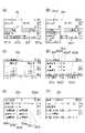
上記ステップにより材料の配合を行うにあたり、準備段階として、分子量計算用PC51に材料のデータを設定する。図17には、分子量計算用PC51に搭載された分子量計算プログラムの材料登録画面51Aが示されている。材料登録画面51Aには、元素周期表画面部51Bと登録画面部51Cと登録済みリスト部51Dとが含まれている。元素周期表画面部51Bには、元素周期表が表示されており、例えば、「C」の部分をクリックすると、原子番号が「6」と、元素記号が「C」と、元素名が「炭素」と、原子量が「12.010712」と、表示される。この元素周期表画面部51Bでは、各元素の既定値に変更があった時に更新を行うことが可能である。 In blending the materials by the above steps, the data of the materials is set in the
登録画面部51Cでは、材料の登録が行われる。以下、「Silica(シリカ)/化学式:SiO2/和名:二酸化ケイ素」を登録する場合を例に材料の登録について説明する。The material is registered on the
(1)分類名を分類欄にキーボード入力して、分類登録ボタンをクリックして登録する。(1) Enter the classification name on the keyboard in the classification field and click the classification registration button to register.
(2)材料の製造元を製造元欄にキーボード入力し、製造元登録ボタンをクリックして登録する。(2) Enter the manufacturer of the material in the manufacturer field using the keyboard, and click the manufacturer registration button to register it.
(3)元素周期表画面部51Bで「Si」を選択し、次に「O」を選択し、次に登録画面部51Cのテンキー51C1中の「2」をクリックする。次に、登録画面部51Cの分子量計算ボタンをクリックすると、化学式欄に「SiO2」が入力され、分子量欄にはプログラムで自動計算された分子量「60」が表示される。(3) Select "Si" on the elemental periodic
(4)化合物名称欄に「Silica(シリカ)」又は「二酸化ケイ素」とキーボード入力する。(4) Enter "Silica" or "silicon dioxide" in the compound name field using the keyboard.
(5)分類欄の下向き矢印をクリックすると、上記(1)で登録された分類名称がポップアップ(図示しない)で表示されるので、クリックで選択する。(5) Click the down arrow in the classification column to display the classification name registered in (1) above in a pop-up (not shown). Click to select it.
(6)係数欄に後述する粉体特性係数PWや液体特性係数LIをテンキー51C1で入力する。なお、この係数は、作業者が計算してもよいし、機器制御用PC52が演算したものを用いてもよい。(6) Enter the powder characteristic coefficient PW and the liquid characteristic coefficient LI, which will be described later, in the coefficient column with the numeric keypad 51C1. It should be noted that this coefficient may be calculated by the operator or may be calculated by the
(7)基準元素欄の下向き矢印をクリックすると、元素周期表に登録された名称がポップアップ(図示しない)で表示されるので、クリックで選択する。(7) Click the down arrow in the reference element column to display the name registered in the Periodic Table of the Elements in a pop-up (not shown). Click to select it.
(8)製造元欄の下向き矢印をクリックすると、上記(2)で登録された製造元名がポップアップ(図示しない)で表示されるので、クリックで選択する。(8) Click the down arrow in the manufacturer column to display the manufacturer name registered in (2) above in a pop-up (not shown). Click to select it.
(9)LotNo.(ロットナンバー)欄に、キーボードとテンキー51C1で入力する。(9) Lot No. Enter in the (lot number) field using the keyboard and the numeric keypad 51C1.
(10)購入日欄の下向き矢印をクリックすると、カレンダーがポップアップ(図示しない)で表示されるので、クリックで選択し購入日を入力する。(10) Click the down arrow in the purchase date column to display the calendar in a pop-up (not shown). Click to select and enter the purchase date.
(11)コメント欄に記載することがあれば、キーボードで入力を行う。(11) If there is something to be described in the comment field, input it with the keyboard.
(12)全てのデータを入力後、登録ボタンをクリックしてデータベースに登録する。登録された材料は、登録済みリスト部51Dにリスト表示される。なお、上記(1)~(10)の操作は順不同であり、材料によっては、行われない操作があてもよい。(12) After entering all the data, click the register button to register it in the database. The registered materials are listed in the registered
材料の配合の準備段階として、供給機30の登録も行う必要がある。図18(A)に示すように、供給機30には、供給機ナンバー30Aとバーコードや二次元コード等の読み取りコード30Bとが割り振られている。そして、図18(B)に示すように、分子量計算用PC51の供給機登録画面51Eで、各供給機30の供給機ナンバー30Aと、ラック45の番号、収容物(材料名)を登録し、供給機30のボトル40に材料を充填する。そして、計量時に使用する供給機30については、符号51E1の使用選択欄に使用選択マーク51E2を入力する(クリックすると表示される構成であってもよい)。なお、読み取りコード30Bを読み取り機で読み取ると自動で供給機ナンバー30Aが入力又は選択される構成であってもよい。移載用ロボット53は、各供給機30をラック45の収納スペースに順次収納し、供給機ナンバー30Aを供給機収納データ(実際に収容されたことを示すデータ)として、機器制御用PC52に保存、又は、機器制御用PC52を介して分子量計算用PC51に保存する。 It is also necessary to register the
次に、材料の配合の各ステップの詳細を説明する。まず、分子量計算用PC51による各材料の必要量(計量重量)の算出について、MgとSiとの化合物(例えば、Mg2Si2X(X=1~5))を作成するための算出を例に説明する。図19には、分子量計算用PC51の重量算出画面51Fが示されている。Next, the details of each step of compounding the material will be described. First, regarding the calculation of the required amount (weighing weight) of each material by the PC51 for molecular weight calculation, an example of calculation for creating a compound of Mg and Si (for example, Mg2 Si2 X (X = 1 to 5)). Explain to. FIG. 19 shows a
(1)元素の入力欄の1つ目をクリックすると、登録されてある元素名の一覧がポップアップ表示される。そして、Mgをクリックすると1つ目の欄にMgが入力される。同様に、2つ目の欄でSiをクリックすると2つ目の欄にSiが入力される。(1) Clicking the first element input field will pop up a list of registered element names. Then, when Mg is clicked, Mg is input in the first column. Similarly, if you click Si in the second column, Si will be entered in the second column.
(2)組成比の欄に、数字か変数を入力すると、組成式欄に組成式が表示される。ここでは、「Mg」の組成比を2、「Si」の組成比を変数Xとすることで、組成比の欄に「Mg2Si」と表示されている。る。なお、変数は、元素の欄の隣のチェックボックスを選択して「*」を表示させることで、使用が可能となる。(2) If you enter a number or variable in the composition ratio column, the composition formula will be displayed in the composition formula column. Here, by setting the composition ratio of "Mg" to 2 and the composition ratio of "Si" to the variable X, "Mg2 Si" is displayed in the column of composition ratio. To. Variables can be used by selecting the check box next to the element column and displaying "*".
(3)変数Xの範囲設定を行う。数字の入力はキーボードで行う。また、数字は任意に設定可能である。ここでは、最小値を1とし、最大値を5とし、間隔値を1とする。(3) Set the range of the variable X. Enter numbers with the keyboard. In addition, the numbers can be set arbitrarily. Here, the minimum value is 1, the maximum value is 5, and the interval value is 1.
(4)各材料の総量を入力する。ここでは、総量を2gとする。この条件で計量値を計算するボタンをクリックすると、組成式の欄に、Mg2Si1からMg2Si5までが自動で表示されるとともに、材料であるSiO2とMgOの組成式が登録済みリスト部51D(図17参照)のリストを引用して自動で表示される。そして、Mg2Si1からMg2Si5までの「Mg」と「Si」との組成比に対応して、MgOの必要量とSiO2の必要量とが自動で計算され、表示される。(4) Enter the total amount of each material. Here, the total amount is 2 g. When you click the button to calculate the measured value under these conditions, Mg2 Si1 to Mg2 Si5 are automatically displayed in the composition formula column, and the composition formulas of the materials SiO2 and MgO are already registered. The list of the
なお、材料の必要量の算出は以下のように行われる。まず、Mgの原子量は24、Siの原子量は28、Oの原子量16である。原子重量=モル数×原子量から、Mg2の原子重量は2×24=48、Si1の原子重量は1×28=28から、合計原子重量=48+28=76となる。The required amount of material is calculated as follows. First, the atomic weight of Mg is 24, the atomic weight of Si is 28, and the atomic weight of O is 16. From atomic weight = number of moles × atomic weight, the atomic weight of Mg2 is 2 × 24 = 48, the atomic weight of Si1 is 1 × 28 = 28, and the total atomic weight = 48 + 28 = 76.
Si1の重量比は28÷76=0.3684210526315789、Mg2の重量比は48÷76=0.631578947368421から、Si1とMg2を重量比37:63で配合すれば、Mg2Si1の組成になる。The weight ratio of Si1 is 28 ÷ 76 = 0.3684210526315789, and the weight ratio of Mg2 is 48 ÷ 76 = 0.631578947368421. If Si1 and Mg2 are mixed at a weight ratio of 37:63, Mg2 Si1 can be obtained. It becomes a composition.
Si1とMg2を重量比37:63で配合するには、Si1が0.37g、Mg2が0.63gになるように材料を計量することが考えられる。Si1の原子重量28は、SiO2の分子量60の47%なので、SiO2を0.79g計量すれば、Si1が0.37gとなる。同様に、Mg2原子重量48は、MgOの分子量40の60%なので、MgOを1.05g計量すれば、Mg2が0.63gとなる。この2種の材料を合計すると、0.79g+1.05g=1.84gとなる。In order to mix Si1 and Mg2 at a weight ratio of 37:63, it is conceivable to weigh the materials so that Si1 is 0.37 g and Mg2 is 0.63 g. Since the atomic weight 28 of Si1 is 47% of the
求める材料の合計を2gにするための、SiO2の重量は、0.79/1.84×2=0.85714gとなる。同様に、MgOの重量は1.05/1.84×2=1.14286gとなる。このように、必要な数値を画面に入力するだけで、所望する材料の必要量(重量)が得られる。The weight of SiO2 for making the total of the required
(5)入力、算出が完了すると、各組成式のための計量を行うか否かを選択する。全てチェックボタンをクリックすると、全ての組成式が選択され、全てチェック解除ボタンをクリックすると、全ての組成式が選択されていない状態になる。また、各組成式を個別に選択することも可能である。 (5) When the input and calculation are completed, it is selected whether or not to perform weighing for each composition formula. If you click the check all button, all composition formulas will be selected, and if you click the uncheck all button, all composition formulas will not be selected. It is also possible to select each composition formula individually.
(6)所望する材料の計量数を、キーボード入力する。例えば、それぞれの組成式の材料を3つずつ得たい場合(計量の組合せ1種類につき配合を3回行いたい場合)は、3と入力する。 (6) Enter the weighing number of the desired material on the keyboard. For example, if you want to obtain 3 materials of each composition formula (when you want to mix 3 times for each combination of weighing),
(6)「この配合を計量する」ボタンをクリックすると、機器制御用PC52、各材料の重量と計量回数がインプットされる。また、「この配合を登録」ボタンをクリックすればデータベースにデータとして保存される。 (6) When the "Weigh this composition" button is clicked, the weight of the
[機器制御用PCについて]
次に、材料の供給(S4)の前に、機器制御用PC52の使用方法について、図20~図27に示される機器制御用PC52のタッチパネル52Aの表示画面を参照しつつ、説明する。[About PC for device control]
Next, before supplying the material (S4), a method of using the
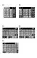
図20(A)には、メニュー画面D1が示されている。メニュー画面D1には、種々の項目の画面への移行ボタンと、各項目の内容の設定を行うためのポップアップ表示ボタンと、が表示されている。 FIG. 20A shows the menu screen D1. On the menu screen D1, a button for shifting to the screen of various items and a pop-up display button for setting the contents of each item are displayed.
符号D1aはタイトルバーであり、ここではメニュー画面D1を表す「メニュ」というタイトルが表示されている。タイトルバーD1aを長押しすると、画面内容設定方法説明と画面ナンバーが表示さる。また、符号D1e”の「▽」ボタンを押すと、符号D1e’の欄に予め設定された選択一覧項目(図示しない)がポップアップ表示され、一覧項目の中から1つの項目を選択をすると、その欄に選択した項目が表示される。符号D1gのM1ボタンが操作されると、各画面D1~D30のタイトル名がポップアップして表示され、その中から1の画面が選択されると、その画面に移動する。符号D1hの「上へ」ボタンが操作されると、現在の画面より階層が1段上の画面が表示される。符号D1iの保存ボタンが操作されると、現在の内容がデータベースに登録される。これらの項目は画面D1~D30に共通している。 Reference numeral D1a is a title bar, and here, a title "menu" representing the menu screen D1 is displayed. Press and hold the title bar D1a to display the screen content setting method explanation and screen number. Further, when the "▽" button of the code D1e "is pressed, a preset selection list item (not shown) is pop-up displayed in the field of the code D1e', and when one item is selected from the list items, the selection list item is displayed. The selected item is displayed in the field. When the M1 button of the symbol D1g is operated, the title names of the screens D1 to D30 pop up and are displayed, and when the
上記共通項目に加え、メニュー画面D1には、自動計量メニュー画面D2、標準設定画面、特殊機能画面、一定速供給メニュー画面D12、ステップ計量設定画面D30、供給画面、付加機器設定画面、メーカ設定画面への移行ボタンが表示されている。なお、メーカ設定画面(図示せず)には、かさ密度、安息角、粒子径、比重、粘度の基準値が登録されている。 In addition to the above common items, the menu screen D1 includes an automatic weighing menu screen D2, a standard setting screen, a special function screen, a constant speed supply menu screen D12, a step weighing setting screen D30, a supply screen, an additional device setting screen, and a manufacturer setting screen. A transition button to is displayed. Reference values for bulk density, angle of repose, particle size, bulk density, and viscosity are registered on the manufacturer setting screen (not shown).
図20(B)には、メニュー画面D1から移行ボタンにより移行される自動計量メニュー画面D2が示されている。自動計量メニュー画面D2には、自動計量画面D7、配合設定画面D5、重量設定画面、計量設定画面、機能メニュ画面D9、供給機設定画面(D3,D3L)、記録メニュ画面への移行ボタンが表示されている。また、供給機設定画面(D3,D3L)への移行ボタンD2dが操作されると、粉粒体材料用の供給機設定画面D3と液体材料用の液体供給機設定画面D3Lとの何れかを選択して移行する構成になっている。 FIG. 20B shows an automatic weighing menu screen D2 that is transferred from the menu screen D1 by the transition button. The automatic weighing menu screen D2 displays an automatic weighing screen D7, a blending setting screen D5, a weight setting screen, a weighing setting screen, a function menu screen D9, a feeder setting screen (D3, D3L), and a transition button to the recording menu screen. Has been done. Further, when the transition button D2d to the feeder setting screen (D3, D3L) is operated, either the feeder setting screen D3 for the powder or granular material or the liquid feeder setting screen D3L for the liquid material is selected. It is configured to migrate.
符号D2fの「次へ」ボタンが操作されると、次の画面に移行する。ここでは、例えば、粉粒体材料用の供給機設定画面(D3)に移行する。 When the "Next" button of the symbol D2f is operated, the screen shifts to the next screen. Here, for example, the screen shifts to the feeder setting screen (D3) for the powder or granular material.
図20(C)には、粉粒体材料用の供給機設定画面の1ページ目(供給機設定1-1画面D3)が示されている。供給機設定画面は、供給機30に関するデータを入力するための画面であり、1ページ目(符号D3)では、供給機ナンバー30A(図18(B)に示されるリストに登録されているナンバー)、供給機種類、保管されているラック45の番号、ラック45内の収納スペースの番号、シャッターナンバー(後に詳説する)を入力、設定する。なお、ここでは、供給機種類として、振動式供給機構20Aに対応する「振動底面型」が選択されている。 FIG. 20C shows the first page (feeder setting 1-1 screen D3) of the feeder setting screen for the powder or granular material. The feeder setting screen is a screen for inputting data related to the
供給機設定画面の1ページ目(符号D3)で「次へ」ボタンD3fが操作されると、図20(D)に示された供給機設定画面の2ページ目(符号D4)へ移行する。2ページ目(符号D4)は、材料データを入力する画面であり、材料名、かさ密度、安息角、粒子径が、入力、設定される。材料名は、分子量計算用PC51の材料登録画面51Aの登録済みリスト部51Dから転送されたデータから選択し、確定する。登録されていない場合は、ここで作成、保存してもよい。かさ密度、安息角、粒子径は予測値がある場合は予測値を、不明の場合は0を入力する。 When the "Next" button D3f is operated on the first page (reference numeral D3) of the feeder setting screen, the process shifts to the second page (reference numeral D4) of the feeder setting screen shown in FIG. 20 (D). The second page (reference numeral D4) is a screen for inputting material data, and the material name, bulk density, angle of repose, and particle size are input and set. The material name is selected from the data transferred from the registered
供給機30には、液体材料を収容するものもある。図21(A),(B)には、液体材料用の液体供給機設定画面D3L,D4Lが示されている。液体供給機設定画面の1ページ目(D3L)では、供給機設定画面の1ページ目(符号D3)と同様に、供給機ナンバー30A、供給機種類、保管されているラック45の番号、ラック45内の収納スペースの番号、を入力、設定する。なお、供給機種類として、チュービングディスペンサ、ローラーチューブポンプ、ピペットディスペンサ、ボトルトップディスペンサ、スクリューポンプ、ピペッター、シリンジポンプ、プランジャポンプ、注射器が予め登録されていて、ここでは、チュービングディスペンサが選択されている。また、液体供給機設定画面の1ページ目(D3L)では、バルブナンバーを登録する。バルブが無い機構、または不使用の場合は、バルブナンバーの欄に0と入力する。 Some
液体供給機設定画面の1ページ目(符号D3L)で「次へ」ボタンD3Lfが操作されると、図21(B)に示された供給機設定画面の2ページ目(符号D4L)へ移行する。2ページ目(符号D4L)は、液体材料データを入力する画面であり、材料名、比重、粘度を入力、設定する。材料名は、分子量計算用PC51の材料登録画面51Aの登録済みリスト部51Dから転送されたデータから選択し、確定する。登録されていない場合は、ここで作成、保存してもよい。比重、粘度は予測値がある場合は予測値を、不明の場合は0を入力する。 When the "Next" button D3Lf is operated on the first page (reference numeral D3L) of the liquid feeder setting screen, the screen shifts to the second page (reference numeral D4L) of the feeder setting screen shown in FIG. 21 (B). .. The second page (reference numeral D4L) is a screen for inputting liquid material data, in which a material name, specific density, and viscosity are input and set. The material name is selected from the data transferred from the registered
図20(E)には、配合設定画面D5が示されている。配合設定画面D5は、M1ボタンを操作したときの選択画面か自動計量メニュー画面D2から移行可能である。配合設定画面D5は、分子量計算用PC51の重量算出画面51F(図19)で決定された各計量パターンで使用する供給機30の設定を行う画面であり、計量パターンナンバー、使用する供給機30の供給機ナンバー30A、計量数、OK品数を入力、設定する。計量パターンナンバーは、分子量計算用PC51の重量算出画面51F(図19)で決定し、転送されたデータから選択可能になっている。ここでは、供給機ナンバー30Aの欄に、1(MgO(図18(B)参照))、3(SiO2(図18(B)参照))、L1と入力されている。なお、L1の「L」は、液体材料であることを示している。また、計量数には3が、OK品数には3が入力されている。計量パターン2~5も同様に設定される。FIG. 20 (E) shows the blending setting screen D5. The blending setting screen D5 can be moved from the selection screen when the M1 button is operated or the automatic weighing menu screen D2. The blending setting screen D5 is a screen for setting the
配合設定画面D5で「次へ」ボタンD5fが操作されると、図20(F)に示された供給機計量設定画面D6へ移行する。供給機計量設定画面D6では、まず、計量パターンの番号(「P」と略されている)、供給機ナンバー30Aを入力し、その計量パターン、供給機30に対して、設定値(計量重量の設定値)、判定上限、判定下限、落差補正の値を設定する。設定値には、供給機設定画面の2ページ目(符号D4)で登録した材料名と配合設定画面D5で登録した計量パターンとに基づいて、分子量計算用PC51から転送された値が自動入力される(上述したMg2Si1用のSiO2の重量の場合、0.857と入力される)。判定上限、判定下限は、許容誤差を定めるものであり、任意に入力可能である。また、計量を行う際、後になるほど材料供給機構20からの距離が近くなり、排出された空中に浮遊していた材料が、容器46の充填された材料上に着底するまでの空中浮遊重量が小さくなるが、落差補正は、その空中浮遊重量の変化に対して補正を行うための数値でさる。ここでは、判定上限、判定下限、落差補正には全て0.005と入力されている。なお、液体材料について設定を行う場合、供給機計量設定画面D6のタイトルバーD6aには「液体供給機計量設定」と表示され、供給機ナンバー30Aには、「L」が先頭に自動で付けられる。When the "Next" button D5f is operated on the blending setting screen D5, the screen shifts to the feeder weighing setting screen D6 shown in FIG. 20 (F). On the feeder weighing setting screen D6, first, the weighing pattern number (abbreviated as “P”) and the
図20(C)の供給機設定画面の1ページ目(符号D3)でシャッターナンバーを入力する、又は、M1ボタンを操作したときの選択画面で選択されると、図22(A)に示されるシャッタメニュー画面DS1に移行する。シャッタメニュー画面DS1は、シャッター部材33の動作の設定を行うものである。符号DS1dの欄には、配合設定画面D5で入力した計量パターンナンバーが自動入力される。ここに他の数字を入力すると、その計量パターンの画面が表示される。符号DS1eの欄には、高精度、標準、速度優先がポップアップ表示され、シャッター部材33の動作をどのように制御するかを選択する。ここでは、高精度が選択されている。符号DS1gの欄には、シャッターナンバーは入力される。また、この欄に他の数字を入力すると、そのシャッターナンバーの画面が表示される。図22(B)には、シャッタメニュー画面DS1で符号DS1bの欄をポップアップ表示した状態が示されていて、シャッタ設定、シャッタNo登録、シャッタ呼び出No、移動速度登録、シャッタ単動、端点登録、供給量シャッタ閉度設定という項目が一覧表示されている。符号DS1fは、シャッタ不使用かシャッタ使用かを選択する欄になっている。 When the shutter number is input on the first page (reference numeral D3) of the feeder setting screen of FIG. 20 (C) or is selected on the selection screen when the M1 button is operated, it is shown in FIG. 22 (A). The screen shifts to the shutter menu screen DS1. The shutter menu screen DS1 sets the operation of the
シャッタメニュー画面DS1で「次へ」ボタンが操作されると、図22(C)に示された移動速度登録画面DS2へ移行する。移動速度登録画面DS2は、シャッター部材33の開閉動作を設定するものであり、閉速度のP1からP4の欄に閉速度値と、開速度のP2からP5の欄に開速度値をそれぞれ入力する。このPはポインントの略であり、P1は、通過孔34Kが100%開放されるときのシャッター部材33の位置(開端位置)、P5は、通過孔34Kが閉塞されるときのシャッター部材33の位置(閉端位置)、P2~P4は両者の間を分割した3位置である。これらP1~P5の位置は後述する供給量シャッタ閉度設定画面DS5で設定される。閉速度値及び開速度値は、数字が大きいほどスライド速度が大きいことを示しており、ここでは、開放時は、スライド速度を徐々に速くするように、閉塞時は、スライド速度を徐々に遅くするように数値を入力している。符号DS2Bの、P1開端、P2、P3、P4、P5閉端のボタンが操作されると、シャッター部材33が設定された速度でそれぞれの位置に移動する。例えば、シャッター部材33がP1に配されているときにP5閉端のボタンが操作されると、シャッター部材33は順次変速を行いながらポイントを通過して、P5に到達する。 When the "Next" button is operated on the shutter menu screen DS1, the screen shifts to the movement speed registration screen DS2 shown in FIG. 22 (C). The moving speed registration screen DS2 sets the opening / closing operation of the
移動速度登録画面DS2で「次へ」ボタンが操作されると、図22(D)に示されたシャッタ単動画面DS3へ移行する。シャッタ単動画面DS3は、シャッター部材33の閉速度と開速度との動作確認を行うための画面である。符号DS3bの、P1開端、P2、P3、P4、P5閉端のボタンが操作されると、シャッター部材33がそれぞれの位置に移動する。符号DS3cの全開動作ボタンが操作されると、シャッター部材33が全開位置(P1)以外のどの位置にあってもシャッター部材33が全開位置に移動する。符号DS3c’の全閉動作ボタンが操作されると、シャッター部材33が全閉位置(P5)以外のどの位置にあってもシャッター部材33が全閉位置に移動する。符号DS3c”の停止ボタンは、動作中のシャッター部材33の移動を停止する。符号DS3dには、シャッター部材33の現在位置(開度)が表示される。符号DS3d’は、次の移動位置(開度)を目標点として読み込み、都度表示している。符号DS3d”の移動速度には、移動速度登録画面DS2で設定された速度値に応じて変化する速度値の現在の速度値を読み込み、都度表示している。 When the "Next" button is operated on the movement speed registration screen DS2, the screen shifts to the shutter single action screen DS3 shown in FIG. 22 (D). The shutter single-acting screen DS3 is a screen for confirming the operation of the closing speed and the opening speed of the
シャッタ単動画面DS3で「次へ」ボタンが操作されると、図22(E)に示された端点登録画面DS4へ移行する。端点登録画面DS4は、端点登録のデータ入力と動作確認を行う画面であり、符号DS4fの欄にインチング速度を入力し、符号DS4Bの全開動作ボタンが操作されると、操作されている間、入力されたインチング速度でシャッター部材33が移動する。所望する位置で全開動作ボタンDS4bの操作を止めると、その位置が全開点となり、符号DS4b’の全開登録ボタンが操作されると、その全開点が登録され、符号DS4b”の開端ランプが点灯する。また、符号DS4c”の全閉動作ボタンが操作されると、操作されている間、入力されたインチング速度でシャッター部材33が移動する。所望する位置で全閉動作ボタンDS4c”の操作を止めると、その位置が全閉点となり、符号DS4c’の全閉登録ボタンが操作されると、その全閉点が登録され、符号DS4c”の閉端ランプが点灯する。上記の登録完了後保存をする。 When the "Next" button is operated on the shutter single action screen DS3, the screen shifts to the end point registration screen DS4 shown in FIG. 22 (E). The end point registration screen DS4 is a screen for inputting data for end point registration and confirming the operation. When the inching speed is input in the field of the code DS4f and the fully open operation button of the code DS4B is operated, the input is performed while the end point is being operated. The
端点登録画面DS4で「次へ」ボタンが操作されると、図22(F)に示された供給量シャッタ閉度設定画面DS5へ移行する。供給量シャッタ閉度設定画面DS5は、供給残量に対するシャッタ開度のデータ入力を行う画面である。供給量シャッタ閉度設定画面DS5では、P1開端、P2、P3、P4、P5閉端位置のそれぞれに対応する供給残量値とシャッタ開度とを%で入力する。ここでは、供給残量値には、P1開端に100が、P2に60が、P3に10が、P4に3が、P5閉端に0.001の数字が入力されていて、シャッタ開度には、P1開端に100が、P2に40が、P3に10が、P4に5が、P5閉端に0の数字が入力されている。これにより、供給残量が100%のときはシャッタ開度が100%(P1開端)となり、供給残量が60%になるとシャッタ開度が40%(P2)となり、供給残量が10%になるとシャッタ開度が10%(P3)となり、供給残量が3%になるとシャッタ開度が5%(P4)となり、供給残量が0.001%になるとシャッタ開度が0%(P5閉端)となるようにシャッター部材33が動作する。なお、供給残量が0.001%でシャッタ開度を0%にする(P5閉端にする)のは、供給残量が0%になったという出力信号からシャッター部材33が動作するまでの機械的動作遅延の防止策と、落差補正(空中浮遊材料)の精度を上げるためである。 When the "Next" button is operated on the end point registration screen DS4, the screen shifts to the supply amount shutter closing degree setting screen DS5 shown in FIG. 22 (F). The supply amount shutter closing degree setting screen DS5 is a screen for inputting data of the shutter opening degree with respect to the remaining supply amount. On the supply amount shutter closing degree setting screen DS5, the remaining supply value and the shutter opening corresponding to each of the P1 open end, P2, P3, P4, and P5 closed end positions are input in%. Here, 100 is input to the open end of P1, 60 is input to P2, 10 is input to P3, 3 is input to P4, and 0.001 is input to the closed end of P5, and the shutter opening is set to the remaining supply value. Is 100 entered at the open end of P1, 40 is entered at P2, 10 is entered at P3, 5 is entered at P4, and 0 is entered at the closed end of P5. As a result, when the remaining supply amount is 100%, the shutter opening becomes 100% (P1 open end), and when the supply remaining amount becomes 60%, the shutter opening becomes 40% (P2) and the supply remaining amount becomes 10%. Then, the shutter opening becomes 10% (P3), the shutter opening becomes 5% (P4) when the supply remaining amount becomes 3%, and the shutter opening becomes 0% (P5 closed) when the supply remaining amount becomes 0.001%. The
図21(A)の液体供給機設定画面の1ページ目(符号D3L)でバルブナンバーを入力すると、シャッタメニュー画面DS1、移動速度登録画面DS2、シャッタ単動画面DS3、端点登録画面DS4、供給量シャッタ閉度設定画面DS5の代わりに、図示しないバルブメニュー画面、移動速度登録画面、バルブ単動画面、端点登録画面、供給量バルブ閉度設定画面が表示され、バルブの動作について、シャッター部材33の動作と同様の設定、動作が行える。 When the valve number is input on the first page (reference numeral D3L) of the liquid feeder setting screen of FIG. 21 (A), the shutter menu screen DS1, the moving speed registration screen DS2, the shutter single action screen DS3, the end point registration screen DS4, and the supply amount Instead of the shutter closing degree setting screen DS5, a valve menu screen (not shown), a moving speed registration screen, a valve single action screen, an end point registration screen, and a supply amount valve closing degree setting screen are displayed. The same settings and operations as the operation can be performed.
図23(A)には、自動計量メニュー画面D2から移行ボタンにより移行される自動計量画面D7が示されている。自動計量画面D7は、計量(供給)を開始するときに表示する画面であり、計量開始から計量完了まで表示される。自動計量画面D7には、計量を開始する(又は計量を行なっている)計量パターンナンバー、供給機30の供給機ナンバー30A、が入力、表示される。液体材料の場合「L」の欄に入力、表示される。供給機30の供給機ナンバー30Aに他の数字を入力すると、その供給機30に移行する。符号D7kの欄は、自動計量プログラムの種類を自動計量、AI自動計量、ステップ計量の3つの中から選択するものである。 FIG. 23A shows an automatic weighing screen D7 that is transferred from the automatic weighing menu screen D2 by the transition button. The automatic weighing screen D7 is a screen displayed when starting weighing (supply), and is displayed from the start of weighing to the completion of weighing. On the automatic weighing screen D7, the weighing pattern number for starting (or performing weighing) the weighing pattern number and the
計量は、符号D7hのスタートボタンを操作すると開始される。図23(A)に示されている状態は、1回目の自動計量が完了した状態の自動計量画面D7であり、設定値(符号D7d)が10.000gに対して、計量値(符号D7f)が9.996g、実測値(符号D7g)が9.997gと表示され、計量時間(D7j)が35secと表示されている。計量値(符号D7f)は、プログラムが計算した制御値を示し、実測値(符号D7g)は、制御値に基づき制御された結果の値(電子計量器54から出力された値)である。ここでは、供給機計量設定画面D6で判定上限及び判定下限を0.005gと設定していたので、計量値(符号D7f)9.996gと実測値(符号D7g)9.997gとが共に許容範囲内であり、OK判定で1回目の自動計量が完了している。このとき、画面が緑色で表示される。なお、ここでの計量値(符号D7f)は、プログラム上で計量が終了したと判定した時点の制御値であり、実測値(符号D7g)は、電子計量器54から出力された値である。判定上限と判定下限の判定は、実測値(符号D7g)に基いて行われる。 Weighing is started by operating the start button of reference numeral D7h. The state shown in FIG. 23A is the automatic weighing screen D7 in the state where the first automatic weighing is completed, and the set value (reference numeral D7d) is 10.000 g, while the weighing value (reference numeral D7f) is shown. Is displayed as 9.996 g, the measured value (reference numeral D7 g) is displayed as 9.997 g, and the weighing time (D7j) is displayed as 35 sec. The measured value (reference numeral D7f) indicates a control value calculated by the program, and the measured value (reference numeral D7g) is a result value (value output from the electronic measuring instrument 54) controlled based on the control value. Here, since the upper limit of judgment and the lower limit of judgment are set to 0.005 g on the feeder weighing setting screen D6, both the measured value (reference numeral D7f) of 9.996 g and the measured value (reference numeral D7 g) of 9.997 g are within the permissible range. The first automatic weighing is completed by the OK judgment. At this time, the screen is displayed in green. The weighing value (reference numeral D7f) here is a control value at the time when it is determined on the program that the weighing is completed, and the measured value (reference numeral D7g) is a value output from the
図23(B)には、2回目の自動計量がNG判定で終了した状態の自動計量画面D7が示されている。図23(B)に示される例では、設定値(符号D7d)が10.000gに対して、計量値(符号D7f)が10.009g、実測値(符号D7g)が10.010gであり、許容範囲外であるので、NG判定で終了している。このとき、画面が赤色で表示される。 FIG. 23B shows an automatic weighing screen D7 in a state where the second automatic weighing is completed by the NG determination. In the example shown in FIG. 23B, the set value (reference numeral D7d) is 10.000 g, the measured value (reference numeral D7f) is 10.09 g, and the measured value (reference numeral D7g) is 10.010 g, which are permissible. Since it is out of the range, it ends with an NG judgment. At this time, the screen is displayed in red.
図23(C)には、自動計量メニュー画面D2から移行ボタンにより移行される機能メニュ画面D9が示されている。機能メニュ画面D9は、I/O確認画面D10、加減速時間設定画面D11への移行ボタンを表示すると共に、時計設定、機能割当等を行うための画面である。また、供給機30やシャッター部材33又はバルブごとに設定を行うものに関しては、符号D9hやD9iの欄に数字を入力することで呼び出しが行える。 FIG. 23C shows a function menu screen D9 that is transferred from the automatic weighing menu screen D2 by the transition button. The function menu screen D9 is a screen for displaying a transition button to the I / O confirmation screen D10 and the acceleration / deceleration time setting screen D11, as well as performing clock setting, function assignment, and the like. Further, for the
図23(D)には、機能メニュ画面D9から移行ボタンにより移行されるI/O確認画面D10が示されている。I/O確認画面D10では、機器制御用PC52に接続されている各機器の接続状態を見ることができる。符号D10B等のXから始まるボタンは、入力信号表示用I/Oボタンであり、符号D10c等のYから始まるボタンは、出力信号表示用I/Oボタンである。これらボタンが操作されると、正常に接続されている場合は「正常に接続されています」というメッセージが表示され、正常に接続されていない場合は「接続が確認できません」というメッセージが表示される。また、供給機30やシャッター部材33又はバルブごとに設定を行うものに関しては、符号D10dやD10eの欄に数字を入力することで呼び出しが行える。これにより、I/O確認画面D10では、機器、センサ等が故障した場合の、信号の入力と、出力が確認できる。 FIG. 23 (D) shows an I / O confirmation screen D10 that is transferred from the function menu screen D9 by the transition button. On the I / O confirmation screen D10, the connection status of each device connected to the
図23(E)には、機能メニュ画面D9から移行ボタンにより移行される加減速時間設定画面D11が示されている。加減速時間設定画面D11は、各機器の加減速時間の設定を行う画面である。符号D11eの欄に数字を入力すると、対応する粉粒体用及び液体用の供給機30の呼び出しが行え、各供給機30の供給の加速減速(供給量の増減)が設定できる。 FIG. 23 (E) shows an acceleration / deceleration time setting screen D11 that is transferred from the function menu screen D9 by the transition button. The acceleration / deceleration time setting screen D11 is a screen for setting the acceleration / deceleration time of each device. By inputting a number in the field of the reference numeral D11e, the corresponding
図23(F)には、メニュー画面D1から移行ボタンにより移行される一定速供給メニュ画面D12が示されている。一定速供給メニュ画面D12には、一定速供給設定画面D13、一定速供給画面D14、測定間グラフ画面D16(直近の供給グラフの確認)、積算グラフ画面D17(直近の供給グラフの確認)、供給記録表画面D15(直近の記録を確認する)、への移行ボタンに加え、記録閲覧(メモリ内の過去の記録を参照)のボタンが配されている。なお、符号D12hの欄に数字を入力すると、対応する粉粒体用及び液体用の供給機30の呼び出しが行える。 FIG. 23F shows a constant-speed supply menu screen D12 that is transferred from the menu screen D1 by the transition button. The constant speed supply menu screen D12 includes a constant speed supply setting screen D13, a constant speed supply screen D14, an inter-measurement graph screen D16 (confirmation of the latest supply graph), an integrated graph screen D17 (confirmation of the latest supply graph), and supply. In addition to the button for shifting to the record table screen D15 (confirm the latest record), the button for viewing the record (see the past record in the memory) is arranged. By inputting a number in the field of the reference numeral D12h, the corresponding
図24(A)には、一定速供給メニュ画面D12から移行ボタンにより移行される一定速供給設定画面D13が示されている。一定速供給設定画面D13には、符号D13Bの運転時間を入力する欄(0sec入力で連続運転となる)と、符号D13dのサンプリング間隔を入力する欄(0sec入力でサンプリング機能を停止)と、符号D13fの回転方向(減速機モーターは回転方向が反対になる場合がある)切り替えボタンと、が設けられている。ここでは、運転時間(符号D13b)に60、サンプリング間隔(符号D13d)に5と入力されている。なお、符号D13gの欄に数字を入力すると、対応する粉粒体用及び液体用の供給機30の呼び出しが行える。 FIG. 24A shows a constant speed supply setting screen D13 that is transferred from the constant speed supply menu screen D12 by the transition button. The constant speed supply setting screen D13 has a field for inputting the operation time of the code D13B (continuous operation is performed by inputting 0 sec), a field for inputting the sampling interval of the code D13d (stopping the sampling function at input of 0 sec), and a code. A rotation direction switching button for D13f (the rotation direction of the speed reducer motor may be opposite) is provided. Here, 60 is input for the operation time (reference numeral D13b) and 5 is input for the sampling interval (reference numeral D13d). By inputting a number in the field of the reference numeral D13g, the corresponding
図24(B)には、一定速供給メニュ画面D12から移行ボタンにより移行される一定速供給画面D14が示されている。一定速供給画面D14では、符号D14bの欄に数字を入力すると、対応する粉粒体用及び液体用の供給機30の呼び出しが行える。符号D14cの時間設定の欄には、一定速供給設定画面D13で設定した運転時間(符号D13b。ここでは、60)が表示される。符号D14hは、供給速度の入力欄であり、ここでは、10と入力されている。符号D14dの天びん値ボタンが操作されると、電子計量器54がゼロリセット(天びんを接続している場合)され、値が0になる。そして、符号D14eのスタートボタンが操作されると、10%の供給速度で60秒間供給が行われる。供給中、符号D14gの欄に供給経過時間が表示されると共に、D14dの欄に、電子計量器54から出力された供給重量がリアルタイムに表示される。 FIG. 24B shows a constant speed supply screen D14 that is transferred from the constant speed supply menu screen D12 by the transition button. On the constant speed supply screen D14, by inputting a number in the field of the reference numeral D14b, the corresponding powder or granular material and
この一定速供給画面D14を利用して、登録されている各供給機30の供給能力を求めることが可能である。詳細には、D14hの供給速度の入力欄に100%と5%の数字を入力し、供給機を稼働させそれぞれの供給重量データを取得する。得られた供給重量データは、データベースに登録保存する。なお、供給速度100%と、5%の供給重量データを取得するのは、粉体の粘性抵抗により、供給速度100%での値から計算で5%の値を求めても等しくならないためである。 Using this constant speed supply screen D14, it is possible to obtain the supply capacity of each registered
一定速供給画面D14において「次へ」ボタンが操作されると、図24(C)に示された供給記録表画面D15へ移行する。供給記録表画面D15では、直近の供給の経過時間と重量とが表示されると共に、秒間重量(1秒毎の供給重量)が表示される。なお、符号D15gの欄に数字を入力すると、対応する粉粒体用及び液体用の供給機30の呼び出しが行える。 When the "Next" button is operated on the constant speed supply screen D14, the screen shifts to the supply record table screen D15 shown in FIG. 24 (C). On the supply record table screen D15, the elapsed time and weight of the latest supply are displayed, and the weight per second (supply weight per second) is displayed. By inputting a number in the field of the reference numeral D15g, the corresponding
供給記録表画面D15において「次へ」ボタンが操作されると、または、供給記録表画面D15において符号D15eの欄にポップアップ表示される一覧(図示せず)から「測定間グラフ」が選択されると、図24(D)に示された測定間グラフ画面D16に移行する。測定間グラフ画面D16では、一定速供給設定画面D13で設定したサンプリング間隔(符号D13d。ここでは、5sec)毎の重量値が都度プロットされる。図24(D)には、60秒後のグラフが示されている。また、符号D16eの欄には日付が表示され、符号D16fの欄には、内部で演算された平均値近辺の重量が自動で表示される。 When the "Next" button is operated on the supply record table screen D15, or "inter-measurement graph" is selected from the list (not shown) pop-up displayed in the column of the reference numeral D15e on the supply record table screen D15. Then, the process shifts to the inter-measurement graph screen D16 shown in FIG. 24 (D). On the inter-measurement graph screen D16, the weight value for each sampling interval (reference numeral D13d, here, 5 sec) set on the constant speed supply setting screen D13 is plotted. FIG. 24D shows a graph after 60 seconds. Further, the date is displayed in the column of reference numeral D16e, and the weight in the vicinity of the average value calculated internally is automatically displayed in the column of reference numeral D16f.
供給記録表画面D15において符号D15eの欄にポップアップ表示される一覧(図示せず)から「積算グラフ」が選択されると、図24(E)に示された積算グラフ画面D17に移行する。積算グラフ画面D17では、一定速供給設定画面D13で設定したサンプリング間隔で(符号D13d。ここでは、5sec毎に)、重量値(累積値)が都度プロットされる。図24(D)には、60秒後のグラフが示されている。また、符号D17eの欄には日付が表示され、符号D17fの欄には、内部で演算された累積値近辺の重量が表示される。また、積算グラフ画面D17には、実測値から導出されたモデルライン(符号D17g)が表示される。 When the "integration graph" is selected from the list (not shown) pop-up displayed in the column of the reference numeral D15e on the supply record table screen D15, the process shifts to the integration graph screen D17 shown in FIG. 24 (E). On the integrated graph screen D17, the weight value (cumulative value) is plotted each time at the sampling interval set on the constant speed supply setting screen D13 (reference numeral D13d. Here, every 5 sec). FIG. 24D shows a graph after 60 seconds. Further, the date is displayed in the column of reference numeral D17e, and the weight in the vicinity of the cumulative value calculated internally is displayed in the column of reference numeral D17f. Further, a model line (reference numeral D17g) derived from the actually measured value is displayed on the integration graph screen D17.
M1ボタンを操作したときの選択画面で選択されると、図24(E)に示された自動計量メニュ2画面D18に移行する。自動計量メニュ2画面D18は、自動計量に必要なデータの入力を行う画面である。符号D18dの自動計量の欄と、符号D18fの供給機ナンバーの欄とには、登録済みの計量パターンと供給機ナンバーとが自動で表示される。また、これらの欄に数字を入力すると、対応する計量パターン、又は、粉粒体用及び液体用の供給機30の呼び出しが行える。符号D18cの欄では、供給の精度を、高精度、標準、速度優先の中から選択可能である。 When selected on the selection screen when the M1 button is operated, the process shifts to the automatic weighing
図25(A)には、自動計量メニュ2画面D18において、符号D18bを操作すると表示される共通設定の一覧と、符号D18eを操作すると表示される個別設定の一覧と、が表示された状態が示されている。 FIG. 25A shows a state in which a list of common settings displayed when the reference numeral D18b is operated and a list of individual settings displayed when the reference numeral D18e is operated are displayed on the automatic weighing
図25(B)には、自動計量メニュ2画面D18で共通設定の中から「重量閾設定」を選択すると移行する重量閾設定画面D20が示されている。重量閾設定画面D20は、計量値の閾値をパーセンテージで入力する画面であり、計量値が入力された閾値の重量のときに、供給された供給重量を電子計量器54から読み込み、確認している。材料供給機構20の供給速度が速いと閾値に対して読み込まれた重量は大きくなり、材料供給機構20の供給速度が遅いと閾値に対して読み込まれた重量は小さくなる。 FIG. 25B shows a weight threshold setting screen D20 that shifts when "weight threshold setting" is selected from the common settings on the automatic weighing
図25(C)には、重量閾設定画面D20で「次へ」ボタンが操作されると、又は、自動計量メニュ2画面D18で共通設定の中から「精度閾設定」を選択すると、移行する精度閾設定画面D21が示されている。精度閾設定画面D21は、計量重量と計量精度から、供給量速度の目安を取得する閾値の入力画面である。供給機計量設定画面D6で設定した判定上限と判定下限とを足して計量精度の係数とし、計量重量の設定値を係数で除算することで、供給量速度の目安が得られる。判定上限と判定下限とが共に0.005で、設定値が0.857の場合、計量精度の係数は、0.005+0.005=0.01となり、供給量速度の目安は、0.857÷0.01=85.7となる。符号D21Bの数値欄に当てはめると6の50倍以上、5の100倍未満となるが、計量精度を保持するために、ここでは、低い方の6の50倍以上を選択する。 FIG. 25C shows the transition when the "Next" button is operated on the weight threshold setting screen D20 or when "precision threshold setting" is selected from the common settings on the automatic weighing
図25(D)には、度閾設定画面D21で「次へ」ボタンが操作されると、又は、自動計量メニュ2画面D18で共通設定の中から「速度設定1-1」を選択すると、移行する速度設定1-1画面D22が示されている。速度設定1-1画面D22は、計量重量が精度に対して何倍かで、初期速度を求める数値を入力する画面であり、精度閾設定画面D21の設定欄が1のときは、初期速度は6の60%を、以下同様に、2のときは5の40%を、3のときは4の20%を、4のときは3の15%を、5のときは3の10%を、6から15のときは5%未満を選択する様に割り振られている。なお、割り振りの変更は、各欄の数値を変更し、符号D22eのボタンを操作し、精度閾設定画面D21に対応した1から15の一覧が表示され選択し変更できる。なお、ここでは、速度と表記しているが、モーターの回転で供給する供給機であればモーターの回転数、振動で供給する供給機であれば振動数になるが、どちらも供給量の増減量を意味するので、速度と表記する。 In FIG. 25 (D), when the "Next" button is operated on the degree threshold setting screen D21, or when "Speed setting 1-1" is selected from the common settings on the automatic weighing
図25(E)には、速度設定1-1画面D22で「次へ」ボタンが操作されると、又は、自動計量メニュ2画面D18で共通設定の中から「速度設定1-2」を選択すると、移行する速度設定1-2画面D23が示されている。速度設定1-2画面D23では、符号D23bの欄に加速時間タイマリセット係数を入力することで、加速時間タイマリセット係数に0.1を乗じた秒数毎(加速時間タイマリセット係数が2の場合、0.2秒毎)に電子計量器54から重量値を読み込み、所望する計量重量値に対して加速を行うかを判定する。例えば、所望する計量重量値が10gで、読み込み時の重量が2gとした場合、0.2秒間の重量増大値から、供給残量重量を0.2秒間の重量増大値を定数とし、演算を行う。所望する計量重量精度を得るための減速重量ポイントまでは、加速を行う。 In FIG. 25 (E), when the "Next" button is operated on the speed setting 1-1 screen D22, or "speed setting 1-2" is selected from the common settings on the automatic weighing
また、符号D23cの欄に初期最低供給量を入力することで、所望する計量重量値に対して、供給機の供給速度の維持を、入力した数値まで行う。例えば、所望する計量重量値が10gで、初期最低供給量が40の場合、40%の4gまでは与えられた初期速度で供給を行い、4gを過ぎたところで符号D23bで定めた加速時間タイマリセット係数に応じた加速を開始する。符号D23dの欄に最低供給重量時の掛率を入力することで、単独での自動計量時は、最低供給重量時の掛率入力値から自動計量を行う。 Further, by inputting the initial minimum supply amount in the field of the reference numeral D23c, the supply speed of the feeder is maintained up to the input value with respect to the desired weighing weight value. For example, when the desired weighing weight value is 10 g and the initial minimum supply amount is 40, up to 4 g of 40% is supplied at a given initial speed, and after 4 g, the acceleration time timer reset specified by the reference numeral D23b is performed. Start accelerating according to the coefficient. By inputting the multiplication rate at the time of the minimum supply weight in the field of the reference numeral D23d, the automatic weighing is performed from the multiplication rate input value at the time of the minimum supply weight at the time of automatic weighing by itself.
図25(F)には、速度設定1-2画面D23で「次へ」ボタンが操作されると、又は、自動計量メニュ2画面D18で共通設定の中から「速度設定1-3」を選択すると、移行する速度設定1-3画面D24が示されている。速度設定1-3画面D24は、初期速度判定時間(符号D24b)を入力することで、入力した値で初期速度供給量の良否判定を行うための画面である。符号D24cの欄に加速時間を入力することで、入力した値で供給機の加速を行い、供給量の増大を行う。符号D24dの欄に最大初期速度を入力することで、入力した値で供給機の加速を停止する。符号D24eの欄に目標供給時間を入力することで、入力した値で目標供給量の計算を行う。なお、目標供給時間とは、初期速度供給量に達するまでの目標時間である。 In FIG. 25 (F), when the "Next" button is operated on the speed setting 1-2 screen D23, or "speed setting 1-3" is selected from the common settings on the automatic weighing
図26(A)には、速度設定1-3画面D24で「次へ」ボタンが操作されると、又は、自動計量メニュ2画面D18で共通設定の中から「速ズレ幅設定」を選択すると、移行するズレ幅設定画面D25が示されている。ズレ幅設定画面D25は、符号D25Bの欄にズレ幅を、符号D25cの欄にズレ時間を、入力し、設定する画面である。符号D25bの欄には、1から6までの各欄にズレ幅重量をパーセンテージで入力し、その数値から、重量閾設定画面D20で設定された閾値の重量時の供給重量の差(閾値の重量と、計測値が閾値になった時点での供給重量(実測値)との差)から、ズレ幅の判定を行う。ここでは、1に2が、2に4が、3に6が、4に8が、4に12、4に16の数値が入力されている。符号D25cの欄にズレ時間を入力設定する事で、入力された数値から重量閾設定画面D20で設定された閾値の重量時の供給時間の差(計測値が閾値の重量になった時と、供給重量(実測値)が閾値の重量になった時との時間の差)から、ズレ時間の判定を行う。ここでは、数値の3が入力されている。 In FIG. 26A, when the "Next" button is operated on the speed setting 1-3 screen D24, or when "speed deviation width setting" is selected from the common settings on the automatic weighing
図26(B)には、ズレ幅設定画面D25で「次へ」ボタンが操作されると、又は、自動計量メニュ2画面D18で共通設定の中から「加減速率設定」を選択すると、移行する加減速率設定画面D26が示されている。加減速率設定画面D26は、加減速率の設定を行う画面である。大加速、加速、維持、減速、大減速の項目のそれぞれに1から6までの欄があり、各欄に数値を入力することで、入力した値で現在の供給量を、今後何%加減速するかの、計算の員数に用いる。また、1から6までの番号は、ズレ幅設定画面D25の1から6までの番号に対応している。計量精度が出ない場合は、これらの数字を小さめに設定し、計量時間が長い場合は、これらの数字を大きめに設定する。 FIG. 26B shows the transition when the "Next" button is operated on the shift width setting screen D25 or when "acceleration / deceleration rate setting" is selected from the common settings on the automatic weighing
図26(C)には、加減速率設定画面D26で「次へ」ボタンが操作されると、又は、自動計量メニュ2画面D18で共通設定の中から「上下限速度設定」を選択すると、移行する上下限速度設定画面D27が示されている。上下限速度設定画面D27は、材料の性状によって、加減速がうまく働かない場合に、供給速度の最高速度と最低速度の設定を行う画面である。材料の性状によって、加速がうまく働かない場合は、符号D27bの最高速度の欄に上限値を、減速がうまく働かない場合は、符号D27cの最低速度の欄に下限値を設定し、設定した値を超えて供給を行わない様にする。 In FIG. 26C, when the "Next" button is operated on the acceleration / deceleration rate setting screen D26, or when "upper / lower limit speed setting" is selected from the common settings on the automatic weighing
図26(D)には、上下限速度設定画面D27で「次へ」ボタンが操作されると、又は、自動計量メニュ2画面D18で共通設定の中から「精度係数設定」を選択すると、移行する精度係数設定画面D28が示されている。精度係数設定画面D28は、精度の幅を入力する画面である。符号D28cの精度係数の欄に入力された数字が、設定した公差に対して供給量を減らすか判定する演算の員数になる。例えば、精度係数を5にすると、公差範囲を5で除した値の供給量(1秒毎の供給量)になるように自動変速を行う。例えば±10mgの場合、10÷5=2となり、最終の供給量は2mgとなる。精度係数を2にすると、公差範囲を2で除した値の供給量になるように自動変速を行う。例えば、±20mgの場合、20÷2=10となり、最終の供給量は10mgとなる。 In FIG. 26 (D), when the "Next" button is operated on the upper / lower limit speed setting screen D27, or when "precision coefficient setting" is selected from the common settings on the automatic weighing
図26(E)には、M1ボタンを操作したときの選択画面で「AI設定」が選択されると移行するAI設定画面D29が示されている。AI設定画面D29では、自動計量(符号D29b)、シャッター(符号D29c)及びバルブ(符号D29d)、AI計量(自動計量メニュ2画面D18での設定内容)(符号D29e)、供給機30、自動交換(符号D29k)等を使用するかどうかの各種設定を行う。符号D29fの欄には、配合設定画面D5で入力した計量パターンナンバーが自動入力されていて、符号D29f’のボタンを操作することで、他の計量パターン一覧を表示させ、変更が行える。符号D29gの欄には、供給機設定1-1画面D3で入力したシャッタナンバーが自動入力されていて、符号D29g’のボタンを操作することで、他のシャッタ一覧を表示させ、変更が行える。 FIG. 26 (E) shows an AI setting screen D29 that shifts when "AI setting" is selected on the selection screen when the M1 button is operated. On the AI setting screen D29, automatic weighing (reference numeral D29b), shutter (reference numeral D29c) and valve (reference numeral D29d), AI weighing (setting contents on the automatic weighing
符号D29hの欄は、初期速度固定を行うか否かを選択する。詳細には、計量に時間がかかる、目標の計量重量が特段に多い等で、自動計量、AI自動計量で計算された初期速度を早くする場合の、初期速度変更割り込みの、使用と不使用の選択になる。使用方法は、符号D29hの欄をONにして、D29h”に表示されている自動計量、AI自動計量で計算された初期速度値を、希望の数値に変更し、その数値を確定させる。すると、入力された数値の初期速度で計量が開始される。計量を行いNGがでなければ、自動計量、AI自動計量のデータに自動で書き込まれ、以降はこの値で自動計量される。 The column of reference numeral D29h selects whether or not to fix the initial speed. In detail, when the initial speed calculated by automatic weighing and AI automatic weighing is increased due to the time required for weighing, the target weighing weight is particularly large, etc., the use and non-use of the initial speed change interrupt It becomes a choice. The usage method is to turn on the column of the code D29h, change the initial speed value calculated by the automatic weighing and AI automatic weighing displayed in "D29h" to a desired numerical value, and confirm the numerical value. Weighing starts at the initial speed of the input numerical value. If weighing is performed and there is no NG, it is automatically written in the data of automatic weighing and AI automatic weighing, and thereafter, automatic weighing is performed at this value.
図26(F)には、メニュー画面D1から移行ボタンにより移行されるステップ計量設定画面D30が示されている。ステップ計量設定画面D30は、ステップ計量を使用する場合の各設定の入力を行う画面である。符合D30cの欄には、自動計量画面D7で入力された設定値(ここでは、10.000)が自動入力されている。符合D30b’の各欄は、1st、2nd、3rd、4thとの表記に合わせて設定重量に対する残量をパーセンテージで入力するものである。ここでは、1stに30が、2ndに15が、3rdに4が、4thに2が、それぞれ入力されている。設定値が10gの場合、1st(30%)での残量は10g×30%=3g、2nd(15%)での残量は10g×15%=1.5g、3rd(4%)での残量は10g×4%=0.4g、4th(2%)での残量は10g×2%=0.2gとなる。符合D30b”の欄には、1st、2nd、3rd、4th、設定値の項目に合わせて、上記計算の残量が、D7自動計量画面D7で自動計量を行ったときの、D30b’横欄の1st、2nd、3rd、4th、設定重量のパーセンテージに対応しての重量値として表示される。 FIG. 26F shows a step weighing setting screen D30 that is transferred from the menu screen D1 by the transition button. The step weighing setting screen D30 is a screen for inputting each setting when using step weighing. In the field of the code D30c, the set value (here, 10.000) input on the automatic weighing screen D7 is automatically input. In each column of the code D30b', the remaining amount with respect to the set weight is input as a percentage according to the notation of 1st, 2nd, 3rd, and 4th. Here, 30 is input to the 1st, 15 is input to the 2nd, 4 is input to the 3rd, and 2 is input to the 4th. When the set value is 10 g, the remaining amount at 1st (30%) is 10g x 30% = 3g, and the remaining amount at 2nd (15%) is 10g x 15% = 1.5g, 3rd (4%). The remaining amount is 10 g × 4% = 0.4 g, and the remaining amount at 4th (2%) is 10 g × 2% = 0.2 g. In the column of "sign D30b", the remaining amount of the above calculation according to the items of 1st, 2nd, 3rd, 4th, and the set value is the column in the horizontal column of D30b'when the automatic weighing is performed on the D7 automatic weighing screen D7. It is displayed as a weight value corresponding to 1st, 2nd, 3rd, 4th, and a percentage of the set weight.
符合D30d”の各欄は、1st、2nd、3rd、4th、5thとの表記に合わせて供給機の供給能力に対する出力がパーセンテージで入力するものである。ここでは、1stに20が、2ndに10が、3rdに5が、4thに1が、5thに0.5が、入力されている。この符合D30d”の数値は、符合D30b’に入力された数値及び設定値に連動していて、符合D30b’の1stの30には符合D30d”の1stの20が、符合D30b’の2ndの15には符合D30d”の2ndの10が、符合D30b’の3rdの4には符合D30d”の3rdの5が、符合D30b’の4thの2には符合D30d”の4thの1が、設定値の10.000には符合D30d”の5thの0.5が、それぞれ対応している。これにより、計量値又は実測値が符合D30b”の欄の残量に到達するたびに、供給量を減らす動作となる。符合D30gの「▽」ボタンを操作すると、符合D30g’セレクタ枠に1.5倍、2.0倍、2.5倍、3.0倍、3.5倍、4.0倍、4.5倍、5.0倍の選択一覧項目(図示しない)がポップアップされる。一覧項目の中から所望する倍数を選択すると、1stの30に対して選択された倍数の、初期供給量を決める事ができる。符合D30e,D30f,D30hの欄には、自動計量画面D7で入力されている、計量パターンナンバー、供給機ナンバー(又は、液体材料用の供給機ナンバー)、シャッタナンバーを入力する(又は、自動入力される)。 In each column of "sign D30d", the output with respect to the supply capacity of the feeder is input as a percentage according to the notation of 1st, 2nd, 3rd, 4th, and 5th. Here, 20 is input to 1st and 10 is input to 2nd. However, 5 is input to the 3rd, 1 is input to the 4th, and 0.5 is input to the 5th. The
なお、重量閾設定画面D20から精度係数設定画面D28までと、ステップ計量設定画面D30と、の入力内容は、粉体材料供給と液体材料供給との両方に使用されるパラメータである。図27には、機器制御用PC52の画面に入力するためにタッチパネル52Aに表示されるキーボード等が示されている。詳細には、図27(A)には数字入力用キーボードが示されており、図27(B)には電卓機能が示されており、図27(C)~(E)には文字入力用キーボードが示されている。文字入力用キーボードは切替可能となっている。 The input contents of the weight threshold setting screen D20 to the accuracy coefficient setting screen D28 and the step measurement setting screen D30 are parameters used for both the powder material supply and the liquid material supply. FIG. 27 shows a keyboard and the like displayed on the
機器制御用PC52では、上述した供給機設定画面(符号D4。図20(D)参照)及び供給機設定画面(符号D4L。図21(B))において、予め、粉粒体材料のかさ密度、安息角、粒子径と、液体材料の比重、粘度と、が入力しておく。機器制御用PC52は、これらの値を基に、供給機の供給速度(供給量を意味する)を自動で変更して、所望する粉粒体材料と液体材料に対し、所望する計量重量と計量精度を得るプログラムを有している。また、機器制御用PC52には、基準値として、かさ密度1、安息角40°、粒子径0.1mm、比重1、粘度1が登録されていて、この基準値と、入力値との比較から供給速度(供給量を意味する)を変更する。なお、基準値は、過去の粉粒体材料と液体材料の取り扱い経験から割り出している。 In the
上述した基準値と入力値とから供給速度を設定するための係数を算出する。まず、粉粒体材料について説明する。使用する材料のかさ密度が0.1の時は、1÷0.1=10が、使用する材料のかさ密度が2の時は、1÷2=0.5が係数として得られる。この係数をかさ密度係数Kとする。同一の供給機を使用した場合、かさ密度が0.1の材料は10倍、かさ密度が2の材料は0.5倍の供給速度にしないと、かさ密度が1の材料に対する体積比で、同等の供給重量が得られない。 A coefficient for setting the supply speed is calculated from the above-mentioned reference value and input value. First, the powder or granular material will be described. When the bulk density of the material to be used is 0.1, 1 ÷ 0.1 = 10 is obtained as a coefficient, and when the bulk density of the material to be used is 2, 1 ÷ 2 = 0.5 is obtained as a coefficient. Let this coefficient be the bulk density coefficient K. When the same feeder is used, a material with a bulk density of 0.1 must be supplied at a supply rate of 10 times, and a material with a bulk density of 2 must be supplied at a supply rate of 0.5 times. Equivalent supply weight cannot be obtained.
同様に、使用する材料の安息角が20°の時は、20÷40=0.5が、使用する材料の安息角が60°の時は、60÷40=1.5が係数として得られる。この係数を安息角度係数Aとする。同一の供給機を使用した場合、安息角が10°の材料は0.5倍、安息角が60°の材料は1.5倍の供給速度にしないと、安息角が40°の材料に対する流動性比で、同等の供給重量が得られない。 Similarly, when the angle of repose of the material used is 20 °, 20 ÷ 40 = 0.5 is obtained as a coefficient, and when the angle of repose of the material used is 60 °, 60 ÷ 40 = 1.5 is obtained as a coefficient. .. Let this coefficient be the rest angle coefficient A. When the same feeder is used, the material with an angle of repose of 10 ° must be supplied at a rate of 0.5 times, and the material with an angle of repose of 60 ° must be supplied at a rate of 1.5 times. In terms of sex ratio, the same supply weight cannot be obtained.
同様に、使用する材料の粒子径が0.04mmの時は、0.1÷0.04=2.5が、使用する材料の粒子径が1mmの時は、0.1÷1=0.1が係数として得られる。この係数を粒子径係数Paとする。同一の供給機を使用した場合、粒子径が0.04mmの材料は2.5倍、粒子径が1mmの材料は0.1倍の供給速度にしないと、粒子径が0.1mmの材料に対する体積比で、同等の供給重量値が得られない。 Similarly, when the particle size of the material used is 0.04 mm, 0.1 ÷ 0.04 = 2.5, and when the particle size of the material used is 1 mm, 0.1 ÷ 1 = 0. 1 is obtained as a coefficient. This coefficient is defined as the particle size coefficient Pa. When the same feeder is used, the material with a particle diameter of 0.04 mm must be supplied at a supply rate of 2.5 times, and the material with a particle size of 1 mm must be supplied at a supply rate of 0.1 times for a material with a particle size of 0.1 mm. Equivalent supply weight values cannot be obtained in terms of volume ratio.
ある粉粒体材料のかさ密度が0.5、安息角が45°、粒子径が0.02mmの場合、かさ密度係数Kが2、安息角度係数Aが1.125、粒子径係数Paが5となる。これら係数を乗算した値(2×1.125×5=11.25)を粉体特性係数PWとする。 When the bulk density of a certain powder or granular material is 0.5, the angle of repose is 45 °, and the particle size is 0.02 mm, the bulk density coefficient K is 2, the rest angle coefficient A is 1.125, and the particle size coefficient Pa is 5. It becomes. The value obtained by multiplying these coefficients (2 × 1.125 × 5 = 11.25) is defined as the powder characteristic coefficient PW.
次に、液体材料について説明する。使用する材料の比重が0.8の場合、1÷0.8=1.25が係数として得られる。この係数を比重係数SGとする。使用する材料の粘度が0.9の場合、1÷0.9=1.11が係数として得られる。この係数を粘度係数VCとする。これらの係数を乗算した値(1.25×1.111×5=1.39)を液体特性係数LIとする。 Next, the liquid material will be described. When the specific gravity of the material used is 0.8, 1 ÷ 0.8 = 1.25 is obtained as a coefficient. This coefficient is referred to as the specific gravity coefficient SG. When the viscosity of the material used is 0.9, 1 ÷ 0.9 = 1.11 is obtained as a coefficient. This coefficient is referred to as the viscosity coefficient VC. The value obtained by multiplying these coefficients (1.25 × 1.111 × 5 = 1.39) is defined as the liquid characteristic coefficient LI.
また、機器制御用PC52では、一定速供給画面D14(図24(B)参照)を利用して、登録されている各供給機30の供給能力を求めておく必要がある。供給速度が100%の場合と5%の場合とで、それぞれ供給機30を稼働させ、それぞれの供給重量データを取得する。得られた供給重量データは、データベースに登録保存する。なお、供給速度100%と、5%の供給重量データを取得するのは、粉体の粘性抵抗により、供給速度100%での値から計算で5%の値を求めても等しくならないためである。 Further, in the
[計量について]
次に、計量(材料の供給)について説明する。材料の供給は、自動計量画面D7(図23(A)参照)で計量パターンを選択し、スタートボタン(符号D7h)を操作すると開始される。[About weighing]
Next, weighing (supply of material) will be described. Material supply is started by selecting a weighing pattern on the automatic weighing screen D7 (see FIG. 23A) and operating the start button (reference numeral D7h).
例えば、1番のラック45の10番の収納スペースに収容された供給機ナンバー12の供給機30の材料を10g量り取る場合を例に説明する。この供給機30(供給機ナンバー12)には、シャッターナンバー(供給機設定1-1画面D3、図20(C)参照)に1が入力され、材料名(供給機設定1-2画面D4、図20(D)参照)にSiO2(シリカ)が入力され、計量パターンナンバー(配合設定画面D5、図20(E)参照)には10が入力され、計量数(配合設定画面D5、図20(E)参照)には5が入力され、OK品数(配合設定画面D5、図20(E)参照)には5が入力されているとする。さらに、供給機計量設定画面D6において、設定値に10.000が、判定上限、判定下限、落差補正に0.005が入力されているとする。For example, a case where 10 g of the material of the
(1)スタートボタン(符号D7h)が操作されると、機器制御用PC52から移載用ロボット53に供給機設定1-1画面D3の設定内容と、運転指令信号と、が出力される。 (1) When the start button (reference numeral D7h) is operated, the
(2)移載用ロボット53は、空容器ストックエリア(図示せず)から空の容器46を取り出し、容器46を計量器の上に載せる。次に、移載用ロボット53は、1番のラック45の10番の収納スペースから、供給機ナンバー12の供給機30を取り出し供給機受容凹部21Bに取り付け、機器制御用PC52に容器46と供給機ナンバー12の供給機30の移載動作完了信号を出力する。 (2) The
(3)移載動作完了信号を受けた機器制御用PC52は、供給機30(供給機ナンバー12)の材料供給の自動計量を選択した計量プログラムにて開始する。この計量プログラムについては、後に詳細を説明する。 (3) Upon receiving the transfer operation completion signal, the
(4)自動計量が終了し、予め設定された計量重量(設定値)に対する計量精度の許容範囲内の場合(OK判定の場合)は、自動計量画面D7(図23(A)参照)が緑色で表示され、1回目の計量が完了する。予め設定された計量重量(設定値)に対する計量精度の許容範囲外の場合(NG判定の場合)は、自動計量画面D7(図23(A)参照)が赤色で表示され、1回目の計量が完了する。そして、機器制御用PC52は、移載用ロボット53にOK又はNGの計量完了信号を出力する。 (4) When the automatic weighing is completed and the weighing accuracy is within the allowable range for the preset weighing weight (set value) (in the case of OK judgment), the automatic weighing screen D7 (see FIG. 23 (A)) is green. Is displayed, and the first weighing is completed. When the weighing accuracy is out of the allowable range for the preset weighing weight (set value) (in the case of NG judgment), the automatic weighing screen D7 (see FIG. 23 (A)) is displayed in red and the first weighing is performed. Complete. Then, the
(5)計量完了信号を入力した移載用ロボット53は、容器46を取り出し、OK品は計量済み容器ストックエリアのOKゾーン(図示しない)に、NG品は計量済み容器ストックエリアのNGゾーン(図示しない)に載置する。 (5) The
その後、(2)~(5)の容器46の移動、自動計量を繰り返し、OK品が5個になった時点でこの供給機30(供給機ナンバー12)の単独計量が終了する。 After that, the movement of the
さて、機器制御用PC52では、自動計量画面D7(図23(A)参照)において、計量プログラムを、自動計量プログラム、AI自動計量プログラム、ステップ計量プログラムの3つの中から選択可能になっている。 By the way, in the
[ステップ計量について]
まず、ステップ計量について説明する。ステップ計量プログラムでは、ステップ計量設定画面D30での設定内容と、供給量シャッタ閉度設定画面DS5での設定内容とが読み込まれ、この設定に沿って自動計量が行われる。則ち、ステップ計量設定画面D30での設定内容に沿って、残量が3g(1stの残量10g×30%=3g)になると材料供給機構20の出力(材料供給機構20の供給能力に対する出力)を20%(1st)とし、残量が1.5g(2ndの残量10g×15%=1.5g)になると材料供給機構20の出力を10%(2nd)とし、残量が0.4g(3rdの残量10g×4%=0.4g)になると材料供給機構20の出力を5%(3rd)とし、残量が0.2g(4thの残量10g×2%=0.2g)になると材料供給機構20の出力を1%(4th)とし、残量が4thの残量の1/2の0.1gになると材料供給機構20の出力を0.5%(5th)とする、というように、供給量(計量重量)が10gに到達するまで材料供給機構20の出力を変更しながら供給が行われる。また、供給開始時の材料供給機構20の出力(初期供給量とする)は、1stの供給量(出力)に、符合D30gの「▽」ボタンの操作に起因して選択された倍数を乗じた数値が適用され、例えば、4倍を選択した場合、80%(20×4=80)となる。なお、初期供給量の決定は、一定速供給画面D14のプログラムを行って得られた供給量データから、妥当と考えられる供給量を鑑みて判断することが好ましい。[About step weighing]
First, step weighing will be described. In the step weighing program, the setting content on the step weighing setting screen D30 and the setting content on the supply amount shutter closing degree setting screen DS5 are read, and automatic weighing is performed according to this setting. That is, when the remaining amount reaches 3 g (1st remaining amount 10 g × 30% = 3 g) according to the setting contents on the step weighing setting screen D30, the output of the material supply mechanism 20 (output with respect to the supply capacity of the
さらに、供給量シャッタ閉度設定画面DS5での設定内容に沿って、シャッター部材33は、供給残量100%(P1開端)でシャッタ開度100%の全開に、供給残量60%(P2)でシャッタ開度を40%に、供給残量10%(P3)でシャッタ開度を10%に、供給残量3%(P4)でシャッタ開度を5%に、供給残量0.001%(P5閉端)でシャッタ開度0%の全閉になるように、順次制御される。 Further, according to the setting contents on the supply amount shutter closing degree setting screen DS5, the
NG判定だった場合の対策について説明する。例えば、設定値10.000gに対して、計量値10.009g、実測値10.010gだった場合、落差補正値の0.005gを0.015gに変更し、設定値10.000gに対して0.015g手前の実測値でプログラムが終了する(供給が終了する)ようにする。これで、0.015g(変更後の落差補正値)-0.005g(変更前の落差補正値)=0.01g少なく供給されやすくなり、10.010g(落差補正値変更前の実測値)-0.01g=10.000g近くになりやすくなる。また、ステップ計量設定画面D30で、4th又は5thの出力(供給量)を減らしてもよい。液体材料の自動計量も同様に動作させることができる。 The measures to be taken when the judgment is NG will be described. For example, if the measured value is 10.09 g and the measured value is 10.010 g with respect to the set value of 10.000 g, the head correction value of 0.005 g is changed to 0.015 g and 0 with respect to the set value of 10.000 g. The program ends (supply ends) at the measured value before .015 g. This makes it easier to supply 0.015 g (head correction value after change) -0.005 g (head correction value before change) = 0.01 g less, 10.010 g (actual measurement value before change of head correction value)- It tends to be close to 0.01 g = 10.000 g. Further, the output (supply amount) of the 4th or 5th may be reduced on the step weighing setting screen D30. Automatic weighing of liquid materials can be operated in the same manner.
このステップ計量プログラムは、いわば、自動車のMT(マニュアル)車の運転に近く、プログラム中の各変速点パラメータ作成は、入力者が行う。 This step weighing program is, so to speak, similar to the driving of an MT (manual) vehicle of an automobile, and each shift point parameter is created by the input person in the program.
[自動計量について]
次に、自動計量について説明する。自動計量プログラムでは、各画面において設定されたパラメータから逐次必要なパラメータを読み込み、このパラメータに沿って自動計量が行われる。[About automatic weighing]
Next, automatic weighing will be described. In the automatic weighing program, necessary parameters are sequentially read from the parameters set on each screen, and automatic weighing is performed according to these parameters.
粉粒体材料の場合、算出された、かさ密度係数K(例えば、0.5)と、安息角度係数A(例えば、0.5)と、粉体特性係数PW(例えば、11.25)と、を基に以下のように処理を行う。 In the case of a powder or granular material, the calculated bulk density coefficient K (for example, 0.5), the rest angle coefficient A (for example, 0.5), and the powder characteristic coefficient PW (for example, 11.25) are used. , Is performed as follows.
(1)まず、この自動計量で所望する誤差範囲を求める。自動計量画面D7(図23(A)参照)の設定より、判定上限値と判定下限値とは0.005gであるから、許容誤差値は0.005g+0.005g=0.01gとなる。設定値10.000gを許容誤差値の0.01gで除すと、10.000g÷0.01g=1,000の係数が得られる。ちなみに、同じ許容誤差値で設定値を50.000gとすると50.000g÷0.01g=5,000の係数が、設定値を0.500gをとすると0.500g÷0.01g=50の係数が得られる。得られた係数は、自動計量における設定値に対する許容誤差値の倍数となる。この許容誤差値倍数を係数Bとする。 (1) First, a desired error range is obtained by this automatic weighing. According to the setting of the automatic weighing screen D7 (see FIG. 23A), the upper limit value of the judgment and the lower limit of the judgment are 0.005 g, so that the permissible error value is 0.005 g + 0.005 g = 0.01 g. Dividing the set value of 10.000 g by the tolerance value of 0.01 g gives a coefficient of 10.000 g ÷ 0.01 g = 1,000. By the way, if the set value is 50.000 g with the same tolerance value, the coefficient is 50.000 g ÷ 0.01 g = 5,000, and if the set value is 0.500 g, the coefficient is 0.500 g ÷ 0.01 g = 50. Is obtained. The obtained coefficient is a multiple of the permissible error value with respect to the set value in automatic weighing. Let the coefficient B be a multiple of this margin of error value.
(2)係数Bから精度閾設定画面D21の精度閾値を読み込む。係数Bの1,000は精度閾設定画面D21中の「1」の1000倍に該当するので、1が読み込まれる。 (2) The accuracy threshold of the accuracy threshold setting screen D21 is read from the coefficient B. Since the coefficient B of 1,000 corresponds to 1000 times "1" in the accuracy threshold setting screen D21, 1 is read.
(3)精度閾設定画面D21の「1」に対応して、重量閾設定画面D20から「1」の100%が読み込まれる。この100%の内容は、供給速度上限の員数となり、100%まで加速を行う。 (3) 100% of "1" is read from the weight threshold setting screen D20 corresponding to "1" of the accuracy threshold setting screen D21. The content of this 100% is the number of members of the upper limit of the supply speed, and accelerates to 100%.
(4)精度閾設定画面D21の「1」に対応して、速度設定1-1画面D22から「6」の60%が読み込まれる。 (4) 60% of "6" is read from the speed setting 1-1 screen D22 corresponding to "1" of the accuracy threshold setting screen D21.
(5)速度設定1-2画面D23の入力から、加速時間タイマリセット係数は2が、初期速度最低供給重量は10が、最低供給重量時の掛率入力値は2が読み込まれる。 (5) Speed setting 1-2 From the input on the screen D23, the acceleration time timer reset coefficient is 2, the initial speed minimum supply weight is 10, and the multiplication rate input value at the minimum supply weight is 2.
(6)D24速度設定1-3画面D24の入力から、初期速度判定時間は50が、加速時間は30が、最大初期速度は100が、目標供給時間は2が読み込まれる。なお、 (6) D24 speed setting 1-3 From the input of the screen D24, the initial speed determination time is 50, the acceleration time is 30, the maximum initial speed is 100, and the target supply time is 2. note that,
(7)自動計量プログラムは、読み込んだ上記(2)から(6)の値に対し、それらに粉体特性係数PWの11.25を乗じて演算を行い、自動計量(供給)が開始される。 (7) The automatic weighing program calculates by multiplying the read values (2) to (6) by 11.25 of the powder characteristic coefficient PW, and automatic weighing (supply) is started. ..
(8)自動計量が開始されると、上記(5)の初期速度最低供給重量10%(10.000g×10%=1g)までは、上記(4)の60%に上記(6)の最大初期速度100%を乗じた供給量(出力)で、供給を行う。それと同時に、上記(5)の加速時間タイマリセット係数2に従い、0.2sec毎に重量値を読み取る。 (8) When the automatic weighing is started, the maximum of the above (6) is 60% of the above (4) up to the initial speed minimum supply weight of 10% (10.000 g × 10% = 1 g) of the above (5). Supply is performed with the supply amount (output) multiplied by the initial speed of 100%. At the same time, the weight value is read every 0.2 sec according to the acceleration time timer reset
(9)上記(5)の初期速度最低供給重量10%(10.000g×10%=1g)に達した時間から、単位時間当たりの供給量(g/sec)を演算する。それと同時に、その時間と上記(6)の目標供給時間2secを比較し、早い場合の時間差と、遅い場合の時間差を演算する。この演算値は、以降の計量時に反映させる。例えば、1gに達した時間が2.5secの場合、供給量(g/sec)は、0.4g/secとなる。また、目標供給時間2secに対して0.5sec遅いので、供給量を0.25(0.5sec÷2sec)倍増量する。 (9) The supply amount (g / sec) per unit time is calculated from the time when the initial speed minimum supply weight of 10% (10.000 g × 10% = 1 g) in the above (5) is reached. At the same time, the time is compared with the target supply time of 2 sec in (6) above, and the time difference in the early case and the time difference in the late case are calculated. This calculated value is reflected in the subsequent weighing. For example, when the time to reach 1 g is 2.5 sec, the supply amount (g / sec) is 0.4 g / sec. Further, since the target supply time is 0.5 sec later than the target supply time of 2 sec, the supply amount is doubled by 0.25 (0.5 sec ÷ 2 sec).
(10)精度閾設定画面D21から、「2」の値を読み込み、精度閾値の800倍から0.01g×800=8gの重量値が得られる。供給量を100%に変更し供給を続行する。 (10) The value of "2" is read from the accuracy threshold setting screen D21, and a weight value of 0.01 g × 800 = 8 g can be obtained from 800 times the accuracy threshold. Change the supply amount to 100% and continue the supply.
(11)60%の供給量(g/sec)から速度100%の供給量(g/sec)を演算し、演算で得られた8g通過時の予測時間と、重量8g時の時間とを比較する。これは、計量時間を短縮するために、計量NGを出さない範囲で供給速度を、限界まで上げるためである。 (11) Calculate the supply amount (g / sec) at a speed of 100% from the supply amount (g / sec) of 60%, and compare the estimated time when passing 8 g obtained by the calculation with the time when the weight is 8 g. do. This is to increase the supply speed to the limit within the range where the weighing NG is not issued in order to shorten the weighing time.
(12)演算で得られた8g通過時の予測時間の実際の重量値と8gとの誤差値を演算する。演算された誤差値%を、ズレ幅設定画面D25の1から6のズレ幅重量%の数値と比較し、ズレ幅設定画面D25の1から6の番号表記を読み込む。2%未満の場合は1を選択する。数値の狭間の場合は低い数値を選択し、8%の場合は2を選択する。 (12) The error value between the actual weight value of the estimated time when passing 8 g and 8 g obtained by the calculation is calculated. The calculated error value% is compared with the numerical value of the deviation width weight% of 1 to 6 on the deviation width setting screen D25, and the number notation of 1 to 6 on the deviation width setting screen D25 is read. If it is less than 2%, select 1. If there is a gap between the numbers, select a low number, and if it is 8%, select 2.
(13)加減速率設定画面D26の設定に基づいて現状の速度に対しての制御を行う。詳細には、加減速率設定画面D26の1から6の番号から、読み込まれたズレ幅設定画面D25の1から6の番号と対応した番号が選択される。また、大加速・加速・維持・減速・大減速の中から、符号D25cのズレ時間が、0~±10msでは維持が、10ms~30msでは減速が、30ms超では大減速が、-10ms~-30msでは加速が、-30ms超では大加速がそれぞれ選択される。そして、選択された番号と、選択された大加速・加速・維持・減速・大減速の項目とが交差する欄の数値が読み込まれ、現状の速度に対して制御を行う。 (13) Control is performed for the current speed based on the setting of the acceleration / deceleration rate setting screen D26. Specifically, from the
このように、自動計量プログラムは、設定された重量値と精度を達成するために、各設定画面で設定された計量に必要な基礎数値を読み込み、重量値と供給速度を判定しつつ、逐次与えられたパラメーターを読み込み、演算を繰り返して自動計量を行うプログラムである。液体自動計量も同様に動作させることができる。 In this way, in order to achieve the set weight value and accuracy, the automatic weighing program reads the basic values required for weighing set on each setting screen, determines the weight value and supply speed, and gives them sequentially. It is a program that reads the parameters and repeats the calculation to perform automatic weighing. The liquid automatic weighing can be operated in the same manner.
この自動計量は、いわば、自動車のAT(オートマチックトランスミッション)車の運転に近く、プログラム中の各変速点の切り替えは、設定されたパラメータを読み込み、行われる。 This automatic weighing is, so to speak, similar to the driving of an AT (automatic transmission) vehicle of an automobile, and switching of each shift point in the program is performed by reading the set parameters.
[AI自動計量について]
次に、AI自動計量について説明する。AI自動計量を行うには、AI設定画面D29の符号D29eのAI計量のボタンをONにし、符号D29bの自動計量のボタンをOFFにする必要がある。[About AI automatic weighing]
Next, AI automatic weighing will be described. In order to perform AI automatic weighing, it is necessary to turn on the AI weighing button of the reference numeral D29e on the AI setting screen D29 and turn off the automatic weighing button of the reference numeral D29b.
AI自動計量プログラムでは、設定値を変数Sとし、許容誤差値を変数kとする。変数Sを変数kで除算し解を得る。得られた解は、設定値に対する許容誤差値の倍数となる。この倍数を倍数係数Baとする。設定値が10.000g、許容誤差値が0.01gで倍数係数Baを求める演算を行うと、変数S÷変数k=倍数係数Baから、10.000g÷0.01g=1,000となる。この倍数係数Baに、供給機ナンバー12の供給機30の設定の粉体特性係数PW11.25を乗じる。その解を百分率表示にするために100で除すと、(演算1)1.000×11.25÷100=112.5となる。得られた値を初期速度係数Tとし、初期速度の係数として読み込む。これにより、設定値と許容誤差値が変更されても、設定値と許容誤差値の比例定数値として読み込み演算が行える。 In the AI automatic weighing program, the set value is the variable S and the tolerance value is the variable k. Divide the variable S by the variable k to obtain a solution. The obtained solution is a multiple of the permissible error value with respect to the set value. This multiple is defined as the multiple coefficient Ba. When the calculation for obtaining the multiple coefficient Ba is performed with the set value being 10.000 g and the margin of error value being 0.01 g, it becomes 10.000 g ÷ 0.01 g = 1,000 from the variable S ÷ variable k = multiple coefficient Ba. This multiple coefficient Ba is multiplied by the powder characteristic coefficient PW11.25 set in the
例として、粉体特性係数PWの11.25は一定で、変数Sと変数kの数字を代えて、初期速度係数Tを求める演算を行うと次の通りになる。
(演算2)Sは10.000のままで、kを0.02に代えると、10.000÷0.02×11.25÷100=56.25となる。
(演算3)Sを5.000に代え、kは0.02のままでは、5.000÷0.02×11.25÷100=28.125となる。
(演算4)Sを1.000に代え、kは0.02のままでは、1.000÷0.02×11.25÷100=5.625となる。
(演算5)Sは1.000のままで、kを0.01に代えると、1.000÷0.01×11.25÷100=11.25となる。
(演算6)Sを0.500に代え、kは0.01のままでは、0.500÷0.01×11.25÷100=5.625となる。
(演算7)Sを0.200に、kを0.004に代えると、0.200÷0.004×11.25÷100=5.625となる。
(演算8)Sを0.100に代え、kは0.004のままでは、0.10÷0.004×11.25÷100=2.813となる。
(演算9)Sを0.050に代え、kは0.004のままでは、0.050÷0.004×11.25÷100=1.403となる。
(演算10)Sを0.020に代え、kは0.004のままでは、0.020÷0.004×11.25÷100=0.563となる。
(演算11)Sを0.010に代え、kは0.004のままでは、0.010÷0.004×11.25÷100=0.281となる。As an example, the powder characteristic coefficient PW of 11.25 is constant, and the calculation for obtaining the initial velocity coefficient T by substituting the numbers of the variable S and the variable k is as follows.
(Operation 2) If S remains 10.000 and k is replaced with 0.02, it becomes 10.000 ÷ 0.02 × 11.25 ÷ 100 = 56.25.
(Operation 3) If S is replaced with 5.000 and k remains 0.02, then 5.000 ÷ 0.02 × 11.25 ÷ 100 = 28.125.
(Operation 4) If S is replaced with 1.000 and k remains 0.02, then 1.000 ÷ 0.02 × 11.25 ÷ 100 = 5.625.
(Operation 5) If S remains 1.000 and k is replaced with 0.01, it becomes 1.000 ÷ 0.01 × 11.25 ÷ 100 = 11.25.
(Operation 6) If S is replaced with 0.500 and k remains 0.01, then 0.500 ÷ 0.01 × 11.25 ÷ 100 = 5.625.
(Operation 7) When S is replaced with 0.200 and k is replaced with 0.004, 0.200 ÷ 0.004 × 11.25 ÷ 100 = 5.625.
(Operation 8) If S is replaced with 0.100 and k remains 0.004, then 0.10 ÷ 0.004 × 11.25 ÷ 100 = 2.813.
(Calculation 9) If S is replaced with 0.050 and k remains 0.004, then 0.050 ÷ 0.004 × 11.25 ÷ 100 = 1.403.
(Calculation 10) If S is replaced with 0.020 and k remains 0.004, then 0.020 ÷ 0.004 × 11.25 ÷ 100 = 0.563.
(Operation 11) If S is replaced with 0.010 and k remains 0.004, then 0.010 ÷ 0.004 × 11.25 ÷ 100 = 0.281.
上記の初期速度係数Tの計算では、変数Sと変数kをかえても、(演算4)と(演算6)と(演算7)は同じ5.625となり、設定値と許容誤差値の相関関係が得られる。初期速度係数Tの読み込みは、初期速度係数Tが10≦Tの場合は、得られた値そのままを、T≧10の場合は、得られた値を平方根で演算し読み込み初期速度とする。100≦Tの場合は100として読み込み、初期速度とする。 In the above calculation of the initial velocity coefficient T, even if the variable S and the variable k are changed, (calculation 4), (calculation 6) and (calculation 7) are the same 5.625, and the correlation between the set value and the margin of error value. Is obtained. When the initial speed coefficient T is 10 ≦ T, the obtained value is used as it is, and when T ≧ 10, the obtained value is calculated by the square root and used as the read initial speed. In the case of 100 ≦ T, it is read as 100 and used as the initial speed.
AI自動計量プログラムは、設定値に対しての重量値チェックの閾値を作成する。閾値ポイントは、設定値10.000gは100%Pとして、9.000gは90%Pとして、10%単位で減少させていき、80%P、70%P、60%P、50%P、40%P、30%Pのポイントを設定する。30%Pからは。5%単位で減少させていき、25%P、20%P、15%P、10%Pのポイントを設定する。10%Pからは1%単位で減少させていき、9%P、8%P、7%P、6%P、5%Pのポイントを設定する。5%Pからは0.2%単位で減少させていき、4.8%P、4.6%P、4.4%Pと連続させ、0%Pまでのポイントを設定する。この各ポイント%Pの数字は重量値チェック係数P%とする。これにより、設定値が変更されても、設定値の比例定数として読み込みを行う。 The AI automatic weighing program creates a threshold for the weight value check for the set value. The threshold points are reduced in increments of 10% with the set value of 10.000 g as 100% P and 9.000 g as 90% P, and are reduced in increments of 10%, 80% P, 70% P, 60% P, 50% P, 40. Set points of% P and 30% P. From 30% P. Decrease in 5% increments and set points of 25% P, 20% P, 15% P, 10% P. Decrease from 10% P in 1% increments, and set points of 9% P, 8% P, 7% P, 6% P, and 5% P. Decrease from 5% P in 0.2% increments, continue with 4.8% P, 4.6% P, 4.4% P, and set points up to 0% P. The number of each point% P is a weight value check coefficient P%. As a result, even if the set value is changed, it is read as a proportional constant of the set value.
(1)自動計量(供給)が開始されると、供給機30の供給速度は、設定値からの初期速度係数Tから開始する。設定値の5%重量で所要時間を計測し、単位時間当たりの重量値(g/sec)を演算し、係数F1として保存する。また、重量値0~5%までの所要時間を係数T1として保存する。 (1) When the automatic weighing (supply) is started, the supply speed of the
(2)供給速度を初期速度係数Tの2倍に上げ、設定値の10%重量で所要時間を計測し、単位時間当たりの重量値g/secを演算で導きだし係数F2として保存する。 (2) The supply speed is increased to twice the initial speed coefficient T, the required time is measured with a weight of 10% of the set value, the weight value g / sec per unit time is derived by calculation and stored as the coefficient F2.
(3)次に、係数F2を用い設定値10.000gに対する重量値チェック係数P30%の、残量3gに達するまで、サンプリング方式PID制御式(PID制御の式は多くの文献と書籍があるのでここでは述べない)のプログラムを基に演算で供給速度を求め供給を行う。サンプリングは0.2sec毎に行い供給速度の調整を行う。重量値チェック係数P%では重量値のチェックを行い、逐次ズレ幅を確認する。ズレが発生した場合は補正を行い、供給速度を修正する。 (3) Next, the sampling method PID control formula (the formula of PID control has many documents and books until the remaining amount of 3 g is reached, which is the weight value check coefficient P30% with respect to the set value 10.000 g using the coefficient F2. The supply speed is calculated based on the program (not described here) and supply is performed. Sampling is performed every 0.2 sec and the supply rate is adjusted. With the weight value check coefficient P%, the weight value is checked and the deviation width is confirmed sequentially. If any deviation occurs, correct it and correct the supply speed.
(4)次に、重量値チェック係数P30%からは、サンプリング方式PID制御で減速供給速度を求め供給を行う。重量値チェック係数P%では重量値のチェックを行い、逐次ズレ幅を確認する。ズレが発生した場合は補正で供給速度を修正して、許容誤差値範囲に収まる様に供給を行う。液体自動計量も同様に動作させることができる。シャッター部材33およびバルブは、重量値チェック係数P%を基に閉度が演算され動作を行う。 (4) Next, from the weight value check coefficient P30%, the deceleration supply speed is obtained by the sampling method PID control and supply is performed. With the weight value check coefficient P%, the weight value is checked and the deviation width is confirmed sequentially. If a deviation occurs, the supply speed is corrected by correction, and supply is performed so that it falls within the permissible error value range. The liquid automatic weighing can be operated in the same manner. The
このAI自動計量プログラムは、粉粒体材料の許容誤差値の倍数係数B、かさ密度係数k、安息角度係数A、粒子径係数Pa、粉体特性係数PW、及び、液体材料の許容誤差値の倍数係数BL、比重係数SG、粘度係数VC、液体特性係数LI、といったこれら係数を用いてプログラムを作成し、データを蓄積する事で、計量重量に関係なく、より高精度な計量精度を得る自動計量が行える。なお、かさ密度、安息角、粒子径、比重、粘度が不明な場合は、基準値を代入して演算を行い、初期速度を2%から開始し、サンプリングを行い結果を比較し自動計量を行っている。 This AI automatic weighing program includes a multiple coefficient B of the tolerance value of the powder and granule material, a bulk density coefficient k, a rest angle coefficient A, a particle size coefficient Pa, a powder characteristic coefficient PW, and a tolerance value of the liquid material. By creating a program using these coefficients such as multiple coefficient BL, specific gravity coefficient SG, viscosity coefficient VC, and liquid characteristic coefficient LI, and accumulating data, automatic measurement to obtain more accurate measurement accuracy regardless of the weight to be measured. Weighing is possible. If the bulk density, angle of repose, particle size, bulk density, and viscosity are unknown, perform the calculation by substituting the reference values, start the initial velocity from 2%, perform sampling, compare the results, and perform automatic weighing. ing.
一般的に用いられるPID制御は、設定値に対して上下の誤差を小さくするように、持続した運転制御に用いられているが、ここでの自動計量運転制御は、設定値の重量が終了点となる。計量結果が判定上限と判定下限の間に入り、NGを出さないアルゴリズムプログラムを求めて、プログラムが作成されている。 Generally used PID control is used for continuous operation control so as to reduce the error between the upper and lower sides with respect to the set value, but in the automatic weighing operation control here, the weight of the set value is the end point. It becomes. A program has been created in search of an algorithm program in which the weighing result falls between the upper limit of judgment and the lower limit of judgment and does not give an NG.
このAI自動計量プログラムは、言わば、自動車のAI(システムが運転を操作する)車の運転に近く、判定と演算を繰り返すことで、パラメータの作成と蓄積を行っている。 This AI automatic weighing program is, so to speak, similar to the driving of an AI (system controls driving) vehicle, and parameters are created and accumulated by repeating determination and calculation.
[マイナスNG再スタートプログラムについて]
機器制御用PC52には、計量結果が判定下限以下でのNGの場合に、NGを回避するために計量を再開するマイナスNG再スタートプログラムが組み込まれている。なお、判定下限以下でのNGの発生理由は、設置環境の外乱もあるが、供給機30の停止後の空中浮遊量の変動が考えられる。詳細には、機器制御用PC52は、電子計量器54から重量値の信号を受け、重量値が、設定値から落差補正値を引いた値又は設定値から判定下限値を引いた値となると、供給機30を停止させる。このとき、電子計量器54は、材料の落下加速度も含めた重量を重量値として出力する。よって、供給機30の停止後、電子計量器54の目盛りが安定すると、落下加速度分の重量値がなくなり、計量結果が判定下限以下になることがある。この現象は、かさ密度が1.5程度以上の材料を使用した場合や、判定上限と判定下限の範囲を設定値に対して1から4%等と厳しくした場合に顕著に現れる。[About the minus NG restart program]
The
マイナスNG再スタートプログラムが起動されると、供給機30を最低速度でスタートさせて供給を行い、判定下限を超えた重量値で供給機30を停止させる。再度停止後の重量値を、判定上限、判定下限、実測値と照合し精度範囲内であれば、OKの判定を行い終了する。判定下限よりもマイナスで終了しNGの判定を行った場合は、再度マイナスNG再スタートプログラムを起動し、OKの判定になるまで供給を行う。液体自動計量も同様に動作させることができる。 When the minus NG restart program is started, the
[プラスNG再スタートプログラムについて]
また、機器制御用PC52には、計量結果が判定上限以上でのNGの場合に、NGを回避するために計量を再開するプラスNG再スタートプログラムが組み込まれている。なお、判定上限以上でのNGの発生理由は、設置環境の外乱の他に、材料の粒子径による場合もある。詳細には、材料の粒度分布が一様でなく、供給機30の停止時に空中に浮遊していた材料の多くが粒径の大きな部分で占められている場合などである。計判定上限と判定下限の範囲を設定値に対して1から4%等と厳しくした事で発生する事もある。[About the Plus NG Restart Program]
Further, the
図15に示すように、プラスNG再スタートプログラムでは、レーザーセンサー55が容器46内の材料の山頂頭部の高さを計測し、吸引ノズル56を材料の山頂頭部に近づけ、判定上限を超えた分の材料の吸引を行う。レーザーセンサー55は固定されていてもよいし、移載用ロボット53を用いてもよい。吸引ノズル56は、ノズル伸長式(ノズル先端が前後に移動する)で固定されていてもよいし、移載用ロボット53を用いて材料山頂頭部にノズル先端を当てる構成でもよい。 As shown in FIG. 15, in the plus NG restart program, the
詳細には、計量結果が判定上限以上でNGが発生した場合は、レーザーセンサー55のレーザー光で山頂頭部の高さを計測し、そのデータを機器制御用PC52に出力する。機器制御用PC52は入力したデータを基に、吸引ノズル56の先端を材料山頂頭部に当てる。吸引ノズル56の吸引はパルスで行われ、吸引された材料はチューブ56Tを通り、チューブ56Tと吸引ポンプ56P(または吸引エジェクタ等の吸引機構でもよい)の間に設けられた、材料捕集機構(図示しない)で捕集される。機器制御用PC52はパルスで1回材料を吸引した後に、電子計量器54からの重量値を入力し、吸引前と吸引後の値を比較してパルス1回の吸引重量を取得する。パルス1回吸引後の判定上限を超えた分の重量値と、パルス1回の吸引重量と、残りの吸引パルス数を演算で求め、判定上限以下になるように吸引を実行する。吸引パルス数が多い場合は、パルス時間を長くし、1回の吸引重量を演算して用いてもよい。 Specifically, when the measurement result is equal to or higher than the determination upper limit and NG occurs, the height of the mountaintop head is measured by the laser light of the
また、液体自動計量の場合は、液体計量が最初に行われる、または容器46内に吸引ノズル(ピペット等でもよい)で吸引できる液体の溜まり部分がある事が前提となるが、液体吸引ノズルの先端を容器46の底部、または液体溜まり部分に当て行えばよい。吸引された材料は、チューブ56Tを通り、チューブ56Tと吸引ポンプ56P(または吸引エジェクタ等の吸引機構でもよい)の間に設けられた材料捕集機構(図示しない)で捕集され、再び材料として用いることも可能である。 Further, in the case of automatic liquid weighing, it is premised that the liquid weighing is performed first, or that there is a liquid pool portion in the
プラスNG再スタートプログラムを実行した事で、判定下限を下回った場合は、再度、マイナスNG再スタートプログラムを起動し、OKの判定になるまで供給を行う。 If the judgment lower limit is exceeded by executing the plus NG restart program, the minus NG restart program is started again and supply is performed until the judgment is OK.
このプラスNG再スタートプログラムとマイナスNG再スタートプログラムとを用いる事で、設置環境の外乱が大きい場合、粒度分布の幅が広い材料やかさ密度が大きい材料を使用した場合、判定上限と判定下限との範囲を厳しく設定した場合等でも、NGを出す事なく自動計量が行える。 By using this plus NG restart program and minus NG restart program, when the disturbance of the installation environment is large, when a material with a wide particle size distribution or a material with a large bulk density is used, the judgment upper limit and the judgment lower limit are set. Even when the range is set strictly, automatic weighing can be performed without issuing NG.
また、機器制御用PC52では、計量をした使用材料の履歴と、変数値、日時、時間、設定重量、実重量データはデータベースに保存される。そして、設定重量に対する実重量誤差の内容をデータベースの履歴から確認をしたのちに、サンプル作製(ステップS5)の工程に進むか決定することができる。 Further, in the
[変形例]
(1)上記実施形態では、振動ユニット22が電磁ソレノイドであったが、粉粒体が振動により流動化できる機構であれば、振動モータ、圧電素子振動方式、超音波振動方式、空気式ボールバイブレータ、空気式タービンバイブレータ、電動バイブレータ、電磁式バイブレータ、エアーピストン式バイブレータ等であってもよい。[Modification example]
(1) In the above embodiment, the
(2)図28(A)に示すように、ボトル40の雄螺子部40Aの内側に、ロート形状のアダプタ40Hを装着し、ボトル40の開口中央から材料を排出可能な構成としてもよい。 (2) As shown in FIG. 28 (A), a funnel-shaped
(3)図28(B)に示すように、ボトル40の底部(図28(B)における上端部)に貫通孔40Kを設け、パイプ40Pにより材料を補充可能な構成としてもよい。貫通孔40Kは、ボトル40内に配され、底部へ向けて付勢された弾性部材40Fにより常には閉塞されていて、反転しても内容物が保持される。そして、外側からパイプ40Pで弾性部材40Fを押し込むと貫通孔40Kが開放される。これにより、ボトル40をホルダー32に取り付けた状態でも、外部から材料の補充が可能となり、連続での使用が行える。 (3) As shown in FIG. 28 (B), a through
(4)図29に示すように、押さえ板35Wを、大孔35M、小孔35N及び下面凹部35Lではなく、中央に形成された中央孔35Hを有する構成とし、押さえ板35Wと通過板34との間にメッシュ部材31Mを挟んだ構成としてもよい。この構成によれば、材料排出量の規制、調整を行いつつ、排出されずにボトル40内に残ってしまう粉粒体を減らすことができる。 (4) As shown in FIG. 29, the holding
(5)上記実施形態では、振動式供給機構20Aを配合装置10に使用した例が示されているが、図30に示すように、電子計量器54の上に振動式供給機構20Aの固定部20Xを固定し、減算式供給機110に利用してもよい。この減算式供給機110では、排出された分(容器46へ供給された分)、電子計量器54の計量値が減少するので、供給量が計測可能となる。振動式供給機構20Aを用いた場合、振動のため、電子計量器54の表示値が安定しない現象が発生するが、入力値(計量値)に上限を設け上限以上の入力はノイズとして無視するプログラムで使用することが好ましい。または、振動を与えたあと静止する時間を取り、表示値(計量値)が安定した際の信号を入力値とし取り込むように制御を行うことが好ましい。 (5) In the above embodiment, an example in which the vibration
[第2実施形態]
材料供給機構20として、上記第1実施形態の振動式供給機構20Aではなく、テーブルフィーダー機構20Bを使用してもよい。以下、図31~図37を参照して、テーブルフィーダー機構20Bについて説明する。テーブルフィーダー機構20Bは、スライダテーブル12Bに固定されたブラケット60と、ブラケット60に装着された供給機61と、を有している。図32に示すように、ブラケット60は、平板をクランク状に屈曲させた形状をなし、スライダテーブル12Bに重なる第1板部60Aと、第1板部60Aの一端から起立した起立部60Bと、起立部60Bの上端から第1板部60Aと反対側へ延びた第2板部60Cと、を有する。第2板部60Cには貫通孔60Dが形成され、この貫通孔60Dに供給機61(図31参照)が装着されている。[Second Embodiment]
As the
図33に示すように、供給機61は、偏平で両端が開放した円筒ケース62を有している。円筒ケース62は、上端から側方へ張り出したフランジ62Fを備え、円筒ケース62の上端開口は、フランジ62Fに重ねられるケース蓋63により閉塞されている。 As shown in FIG. 33, the
図34に示すように、円筒ケース62の下端開口は回転テーブル65により閉塞されている。回転テーブル65は、円板状をなし、ケース蓋63上に配されたモータ65Mにより回転軸65Jを介して回転駆動されている。円筒ケース62内には、回転テーブル65に対して摺接するスクレッパー70が配されている。図35及び図36に示すように、スクレッパー70は、回転テーブル65の中央から渦巻き曲線状に延びた形状をなしている。詳細には、スクレッパー70は、図36において回転軸65Jより少し左方の位置から時計回りに徐々に曲率半径が大きくなりながら2周分程延び、外方を向いた渦巻き外面70Aと、渦巻き外面70Aの中心側端部の少し左方の位置から、時計回りに徐々に曲率半径が大きくなりながら1周分程延び、内側を向いた渦巻き内面70Bと、を有している。 As shown in FIG. 34, the lower end opening of the
図33及び図36に示すように、円筒ケース62における周方向の1/4程の部分には、切欠き63が形成されている。スクレッパー70の外側端部は、切欠き63の内側端面に突き当てられ、渦巻き外面70Aの外側部分は切欠き63から露出している。また、渦巻き外面70Aの外側端部は、円筒ケース62の外面より外方に位置している。なお、このスクレッパー70は、切欠き63の内側端面に突き当てられることで、回転テーブル65が回転しても回らないように位置決めされる。 As shown in FIGS. 33 and 36, a
図35及び図36に示すように、供給機61は、粉粒体の材料を回転テーブル65上に排出する材料投入ロート71を有している。材料投入ロート71は、材料を投入するためのロート部71Aと、ロート部71Aの下端から回転テーブル65まで延びた円筒部71Bと、を有している。円筒部71Bの下端には、周方向の一部に、図36における左方、即ち、渦巻き外面70Aが外方へ延びる向きに貫通したロート排出孔71Cが形成されている。 As shown in FIGS. 35 and 36, the
回転テーブル65が時計回りに回転している状態で、材料投入ロート71に粉粒体が投入されると、ロート排出孔71Cから少しずつ粉粒体が排出される。排出された粉粒体は、回転中心を中心とする架空の円弧65E上を移動する。そして、粉粒体がスクレッパー70の渦巻き外面70Aに接すると、回転テーブル65の回転と渦巻き外面70Aの反力により、粉粒体は、渦巻き外面70Aに沿って外側へ寄りながら移動する。そして、渦巻き外面70Aの外側端部に到達した粉粒体は回転テーブル65の外縁部と渦巻き外面70Aとが交わる落下点65Hから落下する。 When the powder or granular material is charged into the
このとき、渦巻き外面70Aの角度ごとの長さが外方へ向かうにつれて長くなっていくので、渦巻き外面70Aに沿って移動する粉粒体が、外側ほど速く移動する。これにより、外方へ向かうほど粉粒体間の距離が広がりまばらになるので、粉粒体を少量ずつ排出することが可能となる。 At this time, since the length of the spiral
また、本実施形態の供給機61には、図37に示すように、材料投入ロート71に、ロート排出孔71Cの開放度を変更可能なシャッター部材72が備えられている。シャッター部材72は、モータ72Mにより駆動され、上下に直動可能となっている。このシャッター部材72によりロート排出孔71Cから排出される粉粒体の量を抑制することで、落下点65H付近での粉粒体間の距離がよりまばらになり、粉粒体をより少量ずつ排出することが可能となる。 Further, as shown in FIG. 37, the
本実施形態のテーブルフィーダー機構20Bを振動式供給機構20Aの代わりに用いてもよいし、テーブルフィーダー機構20Bと振動式供給機構20Aとを併用して用いてもよい。なお、振動により流動化しにくい材料にはテーブルフィーダー機構20Bを採用することが好ましい。また、テーブルフィーダー機構20Bより振動式供給機構20Aの方がコンパクトなので、振動により流動化する材料の場合は、振動式供給機構20Aを採用した方が、配合装置10全体をコンパクトにできたり、スライダテーブル12Bに材料供給機構20をより多く搭載できる。また、液体材料用の材料供給機構20とも併用して用いてもよい。 The
[変形例]
(1)スクレッパー70の渦巻き外面70Aに接した粉粒体は、回転テーブル65の回転によって外側へ移動するが、粉粒体は点接触(渦巻き外面70Aとの間と、回転テーブル65との間との両方が点接触)になるため、粉粒体の性質によっては粉粒体のスクレッパー70への付着力が勝り、回転テーブル65との間で滑りが発生し、粉粒体が移動しない場合がある。これに対し、図38に示すように、回転テーブル65Wに凹部65Uを設けると、凹部65Uに粉粒体が堆積し、スクレッパー70の渦巻き外面70Aに接した粉粒体と凹部65Uに堆積した粉粒体との間に摩擦が生じるので、スクレッパー70の渦巻き外面70Aに接した粉粒体が回転テーブル65の回転に応じて移動しやすくなる。[Modification example]
(1) The powder or granular material in contact with the spiral
また、凹部65Uを設ける代わりに、回転テーブル65の材料接触面を粗化して凹凸を設けることで、摩擦力を向上させてもよい。回転テーブル65を粗化する方法としては、例えば、ショットブラスト処理、化学エッチングまたは電解エッチング(電解腐食)、ケガキ針で引っ掻く程度の筋を全面に施すこと、等が挙げられる。 Further, instead of providing the
(2)図39に示される変形例では、スクレッパー70の渦巻き状の壁の一部に内外方向に貫通するバイパス流路70Rを設けるとともに、スクレッパー70の渦巻き外面70Aのうちバイパス流路70Rより僅かに中心側に、外面突部70Tを設けた構成となっている。また、バイパス流路70R内には、内外方法で直動する直動部材74が配されている。この構成によれば、スクレッパー70の渦巻き外面70Aに沿って移動する粉粒体が、外面突部70Tに接すると、その後、外面突部70Tを通る架空の円弧65F上を移動し、バイパス流路70Rに取り込まれるものと、バイパス流路70Rより先のスクレッパー70の渦巻き外面70Aへ向かうものとに分離される。バイパス流路70Rに取り込まれた粉粒体は、再び、スクレッパー70の渦巻き外面70Aに沿って移動し、外側へ向かう。 (2) In the modified example shown in FIG. 39, a
ここで、円弧65Fは、スクレッパー70の渦巻き外面70Aのうちバイパス流路70Rより外側部分と交わっているので、直動部材74の先端が円弧65Fより内側に配されている場合は、ほとんどの粉粒体がそのまま落下点65Hへ到達すると考えられる。直動部材74がモータ74Mにより駆動され、直動部材74の先端が円弧65Fより外側へ配されると、粉粒体は、直動部材74に誘導されてバイパス流路70Rを通過するものと、直動部材74を乗り越えて落下点65Hへ向かうものとに分離し、粉粒体が落下点65Hへ到達する量(つまり排出量)を微小量にすることができる。そして、直動部材74の円弧65Fからの突出量が大きければ大きいほど、バイパス流路70Rに取り込まれる粉粒体が多くなり、排出量が小さくなる。 Here, since the arc 65F intersects the portion of the spiral
このように、本変形例によれば、直動部材74の位置(円弧65Fからの飛び出し量)を調整することにより、バイパス流路70Rを通過する粉粒体量及び落下点65Hへ向かう粉粒体量を調整することができる。 As described above, according to this modification, by adjusting the position of the linear motion member 74 (the amount of protrusion from the arc 65F), the amount of powder or granular material passing through the
(3)上記実施形態では、スクレッパー70の形状が渦巻き状であったが、図40~図42に示されるスクレッパー70Wのような形状であってもよい。図40に示すように、スクレッパー70Wは、90°折れ曲がったドロップ状の第1構成部70Xと、直線状の第2構成部70Yと、を有している。第1構成部70Xは、図40(A)において、回転テーブル65の回転中心から右方へ延びたのち手前側へ屈曲していて、その外側の面は、全体的に湾曲した円弧外面70X1となっている。第2構成部70Yは、回転テーブル65の回転中心より左方で奥行き方向に延びていて、図40(B)に示すように、スクレッパー70Wの下部では、第1構成部70Xと第2構成部70Yとの間に隙間が設けられている。この構成であっても、回転テーブル65の回転によって、ロート排出孔71Cから排出された粉粒体が第2構成部70Yの内側の面に沿って移動したのち、第1構成部70Xの円弧外面70X1に沿って外側へ移動し、落下点65Hから排出される。 (3) In the above embodiment, the shape of the
(4)図43に示すように、テーブルフィーダー機構20Bを電子計量器54の上に固定し、減算式供給機110Wに利用してもよい。この減算式供給機110Wでは、排出された分(容器46へ供給された分)、電子計量器54の計量値が減少するので、供給量が計測可能となる。 (4) As shown in FIG. 43, the
[他の実施形態]
(1)移載用ロボット53ではなく作業者が手作業で材料供給機構20又は供給機30,61の装着、付け替えや、容器46の移動を行う構成であってもよい。[Other embodiments]
(1) Instead of the
(2)配合装置10に配される材料供給機構20は、3つに限られるものではなく、2つであってもよいし、4つ以上であってもよい。 (2) The
(3)配合装置は単一の材料供給機構として用いてもよい。 (3) The compounding device may be used as a single material supply mechanism.
(4)容器46をトレー(図示せず)上に載置する構成とし、移載用ロボット53が、トレーラックからトレーを取り出し、計量済みの容器46が載置されたトレーをトレーラックに戻す構成としてもよい。 (4) The
(5)容器46に、計量日時、計量材料ロット、空容器重量、材料品種、計量重量、供給機ナンバー等の情報が付与された、RFIDタグ(電波を用いてRFタグのデータを非接触で読み書きするシステム)、バーコード、二次元コード等を取り付ける構成であってもよい。 (5) RFID tag (RF tag data using radio waves in a non-contact manner) to which information such as weighing date and time, weighing material lot, empty container weight, material type, weighing weight, and feeder number is attached to the
(6)材料供給機構20として、テーブルフィーダー機構20や振動式供給機構20A以外の他の方式のもの、例えば、振動コンベアフィーダー、升式テーブルフィーダ、オーガ式フィーダ、メッシュ押し出し式フィーダ、スパイラルフィーダー等を用いてもよい。 (6) As the
(7)配合装置10全体を気密空間に成るように囲い、内部をクリーンルームとして、または不活性ガスで置換して、空気に触れると反応する活物質材料の使用に用いてもよい。気密空間への供給機、計量済み容器の出し入れを、パスバックスを介して移載用ロボット53が行い、気密空間内は無人とする方式で用いてもよい。 (7) The
(8)自動計量及びAI自動計量においても、シャッタメニュー画面DS1(図22(A)参照)の符号DS1eの欄と同様に、シャッター部材33の動作制御を、高精度、標準、速度優先から選択可能な構成としてもよい。 (8) In automatic weighing and AI automatic weighing, the operation control of the
なお、本明細書及び図面には、特許請求の範囲に含まれる技術の具体例が開示されているが、特許請求の範囲に記載の技術は、これら具体例に限定されるものではなく、具体例を様々に変形、変更したものも含み、また、具体例から一部を単独で取り出したものも含む。 Although specific examples of the techniques included in the claims are disclosed in the present specification and the drawings, the techniques described in the claims are not limited to these specific examples, and are specific. It includes various modifications and changes of the examples, and also includes those obtained by extracting a part of the specific examples independently.
10 配合装置
12 スライダー
12B スライダテーブル
20 材料供給機構
20A 振動式供給機構
20B テーブルフィーダー機構
22 振動ユニット
30 供給機
33 シャッター部材33
34 通過板
34K1 大孔部
34K2 中孔部
34K3 小孔部
40 ボトル
45 ラック
50 マテリアルズインフォマティクス用PC
51 分子量計算用PC
52 機器制御用PC
53 移載用ロボット
54 電子計量器
55 レーザーセンサー
56 吸引ノズル
61 供給機
65,65W 回転テーブル
65H 落下点
70,70W スクレッパー
71 材料投入ロート10
34 Passing plate 34K1 Foramen magnum 34K2 Foramen magnum
51 Molecular weight calculation PC
52 Device control PC
53
Claims (12)
Translated fromJapanese前記複数種類の流動物が別々に収容されて、排出可能な複数の流動物供給機構と、
前記複数の流動物供給機構が水平面上に並べて固定されるスライダテーブルと、
前記複数の流動物供給機構が並べられた方向に前記スライダテーブルを動かし、任意の前記流動物供給機構を特定位置に配置可能な可動手段と、を備える配合装置。A compounding device capable of supplying a plurality of types of powders or liquids, which are liquids, respectively.
A plurality of fluid supply mechanisms capable of separately accommodating and discharging the plurality of types of fluids, and
A slider table in which the plurality of fluid supply mechanisms are fixed side by side on a horizontal plane, and
A compounding device comprising a movable means capable of moving the slider table in a direction in which the plurality of fluid supply mechanisms are arranged and arranging any of the fluid supply mechanisms at a specific position.
前記閉塞板部に重ねられ、前記粉粒体排出口を前記第1水平方向の前記一方から徐々に開放していくように前記第1水平方向に直動可能なシャッター部材を備える請求項2又は3に記載の配合装置。The powder / granular material discharge port is formed through a closing plate portion arranged at the bottom of the powder / granular material container, and the second horizontal direction is orthogonal to the first horizontal direction toward one of the first horizontal directions. Extends to reduce the horizontal width,
2. 3. The compounding apparatus according to 3.
前記迂回板の下面に形成され、少なくとも一部が前記粉粒体排出口と上下方向で重なる凹部と、
前記迂回板に形成され、前記迂回板の上面から下方へ延びて前記凹部と連通し、かつ、上方から見て前記粉粒体通過孔と重ならない又は一部のみが重なる連通孔と、を備え、
前記迂回部は、前記連通孔と、前記凹部と、から構成されている請求項4に記載の配合装置。A plate-shaped detour plate that is stacked from above on the block plate portion,
A recess formed on the lower surface of the detour plate and at least partially overlapping the powder or granular material discharge port in the vertical direction.
It is provided with a communication hole formed in the detour plate, extending downward from the upper surface of the detour plate and communicating with the recess, and having a communication hole that does not overlap with or only partially overlaps with the powder or granular material passing hole when viewed from above. ,
The compounding device according to claim 4, wherein the detour portion includes the communication hole and the recess.
粉粒体を排出する排出部と、
支持ベースと、
前記支持ベースに対して回転する前記回転ステージと、
前記支持ベースに固定され、かつ、前記回転ステージの回転方向の前方へ向かうにつれて前記回転ステージの外縁へ近づくように湾曲して延びた固定面と、を備え、
回転する前記回転ステージ上に排出される粉粒体を前記固定面に沿ってばらけさせながら前記排出部まで移動させる回転式粉粒体供給機である請求項1から6の何れか1の請求項に記載の配合装置。At least one of the plurality of fluid supply mechanisms is a fluid supply mechanism.
The discharge part that discharges the powder and granules, and the discharge part
Support base and
The rotating stage that rotates with respect to the support base, and
It comprises a fixed surface that is fixed to the support base and that is curved and extended toward the outer edge of the rotary stage as it moves forward in the rotational direction of the rotary stage.
3. The compounding device described in the section.
前記戻し通路から外方へ突出し、粉粒体を前記戻し通路へ取り込む突出部材と、
前記突出部材の前記戻し通路からの突出量を調整可能な調整部と、を有する請求項8に記載の配合装置。A return passage that penetrates the fixed wall having the fixed surface and can guide the powder or granular material from the outside to the inside of the rotating stage.
A protruding member that protrudes outward from the return passage and takes in the powder or granular material into the return passage.
The compounding device according to claim 8, further comprising an adjusting portion capable of adjusting the amount of protrusion of the protruding member from the return passage.
計量器と、
前記スライダテーブルに固定される前記流動物供給機構を取り換え可能な供給機取り換え装置と、を備える流動物配合システム。The compounding apparatus according to any one of claims 1 to 9, and the compounding apparatus according to claim 1.
With a measuring instrument
A fluid compounding system comprising a feeder replacement device capable of replaceing the fluid supply mechanism fixed to the slider table.
供給終了後、計量器による実測値が前記目標値以下である場合に、再度供給を行う再供給手段と、
供給終了後、計量器による実測値が前記目標値以上である場合に、供給された流動体を吸い込み、供給総量を減らす吸引手段と、を備える請求項10に記載の流動物配合システム。When the target value of the total supply amount is set, the compounding control means for controlling the compounding device so as to supply the fluid to the target value while gradually reducing the supply amount from the start of supply, and
After the end of supply, if the measured value by the measuring instrument is less than or equal to the target value, the resupply means for resupplying and
The fluid compounding system according to claim 10, further comprising a suction means for sucking the supplied fluid and reducing the total amount of supply when the measured value by the measuring instrument is equal to or higher than the target value after the end of supply.
Priority Applications (2)
| Application Number | Priority Date | Filing Date | Title |
|---|---|---|---|
| JP2020181239AJP2022072040A (en) | 2020-10-29 | 2020-10-29 | Compounding device |
| JP2024103001AJP7685789B2 (en) | 2020-10-29 | 2024-06-26 | Powder feeding machine |
Applications Claiming Priority (1)
| Application Number | Priority Date | Filing Date | Title |
|---|---|---|---|
| JP2020181239AJP2022072040A (en) | 2020-10-29 | 2020-10-29 | Compounding device |
Related Child Applications (1)
| Application Number | Title | Priority Date | Filing Date |
|---|---|---|---|
| JP2024103001ADivisionJP7685789B2 (en) | 2020-10-29 | 2024-06-26 | Powder feeding machine |
Publications (1)
| Publication Number | Publication Date |
|---|---|
| JP2022072040Atrue JP2022072040A (en) | 2022-05-17 |
Family
ID=81605083
Family Applications (2)
| Application Number | Title | Priority Date | Filing Date |
|---|---|---|---|
| JP2020181239APendingJP2022072040A (en) | 2020-10-29 | 2020-10-29 | Compounding device |
| JP2024103001AActiveJP7685789B2 (en) | 2020-10-29 | 2024-06-26 | Powder feeding machine |
Family Applications After (1)
| Application Number | Title | Priority Date | Filing Date |
|---|---|---|---|
| JP2024103001AActiveJP7685789B2 (en) | 2020-10-29 | 2024-06-26 | Powder feeding machine |
Country Status (1)
| Country | Link |
|---|---|
| JP (2) | JP2022072040A (en) |
Citations (4)
| Publication number | Priority date | Publication date | Assignee | Title |
|---|---|---|---|---|
| JPH0672558A (en)* | 1992-08-24 | 1994-03-15 | Sharp Corp | Hopper for powder transfer |
| JPH07241454A (en)* | 1994-03-04 | 1995-09-19 | C C A Kk | Simultaneous granular body feeder, device for feeding, sucking and removing granular body and formation of patterned compact using the feeder and device |
| JP2008502461A (en)* | 2004-05-07 | 2008-01-31 | フルイド マネジメント インコーポレーテッド | Apparatus for dispensing multiple materials and method of mixing substances |
| JP2008532100A (en)* | 2004-11-08 | 2008-08-14 | アール. バーソロミュー ジュリー | Customized cosmetic automatic blending equipment |
Family Cites Families (2)
| Publication number | Priority date | Publication date | Assignee | Title |
|---|---|---|---|---|
| JPS52111752A (en)* | 1976-03-17 | 1977-09-19 | Central Glass Co Ltd | Continuous throw type electronic packing scale |
| JP4576136B2 (en)* | 2004-03-18 | 2010-11-04 | 株式会社松井製作所 | Multistage shutter type weighing damper device and material supply device using the same |
- 2020
- 2020-10-29JPJP2020181239Apatent/JP2022072040A/enactivePending
- 2024
- 2024-06-26JPJP2024103001Apatent/JP7685789B2/enactiveActive
Patent Citations (4)
| Publication number | Priority date | Publication date | Assignee | Title |
|---|---|---|---|---|
| JPH0672558A (en)* | 1992-08-24 | 1994-03-15 | Sharp Corp | Hopper for powder transfer |
| JPH07241454A (en)* | 1994-03-04 | 1995-09-19 | C C A Kk | Simultaneous granular body feeder, device for feeding, sucking and removing granular body and formation of patterned compact using the feeder and device |
| JP2008502461A (en)* | 2004-05-07 | 2008-01-31 | フルイド マネジメント インコーポレーテッド | Apparatus for dispensing multiple materials and method of mixing substances |
| JP2008532100A (en)* | 2004-11-08 | 2008-08-14 | アール. バーソロミュー ジュリー | Customized cosmetic automatic blending equipment |
Also Published As
| Publication number | Publication date |
|---|---|
| JP2024124435A (en) | 2024-09-12 |
| JP7685789B2 (en) | 2025-05-30 |
Similar Documents
| Publication | Publication Date | Title |
|---|---|---|
| KR0143227B1 (en) | Device for quantitative measurement of fluids and its measuring method and its application | |
| CN101275963B (en) | Sample analyzer | |
| JP2024019250A (en) | drug dispensing device | |
| CN118883964A (en) | Automatic analysis device and cleaning method thereof | |
| US20120181093A1 (en) | Multi-flow bulk weighing system | |
| JPS63269020A (en) | Weighing equipment for powder dyestuff | |
| US8105535B2 (en) | Pipette tip supplier, sample analyzer and pipette tip supplying method | |
| US7451665B2 (en) | Autoanalyzer and probe cleaning method | |
| JP2022072040A (en) | Compounding device | |
| EP1406071A2 (en) | Methods of and systems for measurement of fluids | |
| US6981529B2 (en) | Measuring catalyst(s) for filling reactor tubes in reactor vessels | |
| JP2022163884A (en) | Compounding device | |
| JP5978036B2 (en) | Automatic analyzer | |
| JP4576136B2 (en) | Multistage shutter type weighing damper device and material supply device using the same | |
| US6674019B2 (en) | Display and operating element for an electronic scale | |
| CN102207400B (en) | Semi-automatic combined scale | |
| CN115432403B (en) | Sampling method and sample divider | |
| JP4481163B2 (en) | Sorting device | |
| JP7592645B2 (en) | Method for controlling a dispenser of a fluid product - Patent application | |
| US5433103A (en) | Method of calibration for volumetric blending | |
| US20230358520A1 (en) | Powder trickler | |
| JP2011085556A (en) | Weight sorting device | |
| JP6990912B2 (en) | Granule supply device | |
| JPS60135845A (en) | Method and device for automatically supplying sample | |
| JP6924484B2 (en) | Granule supply device |
Legal Events
| Date | Code | Title | Description |
|---|---|---|---|
| A711 | Notification of change in applicant | Free format text:JAPANESE INTERMEDIATE CODE: A711 Effective date:20220323 | |
| A521 | Request for written amendment filed | Free format text:JAPANESE INTERMEDIATE CODE: A821 Effective date:20220323 | |
| A521 | Request for written amendment filed | Free format text:JAPANESE INTERMEDIATE CODE: A821 Effective date:20220506 | |
| A621 | Written request for application examination | Free format text:JAPANESE INTERMEDIATE CODE: A621 Effective date:20231018 | |
| A977 | Report on retrieval | Free format text:JAPANESE INTERMEDIATE CODE: A971007 Effective date:20240423 | |
| A131 | Notification of reasons for refusal | Free format text:JAPANESE INTERMEDIATE CODE: A131 Effective date:20240507 | |
| A02 | Decision of refusal | Free format text:JAPANESE INTERMEDIATE CODE: A02 Effective date:20241105 |