JP2022071806A - Portable RFID reader including cross Yagi antenna - Google Patents
Portable RFID reader including cross Yagi antennaDownload PDFInfo
- Publication number
- JP2022071806A JP2022071806AJP2021059966AJP2021059966AJP2022071806AJP 2022071806 AJP2022071806 AJP 2022071806AJP 2021059966 AJP2021059966 AJP 2021059966AJP 2021059966 AJP2021059966 AJP 2021059966AJP 2022071806 AJP2022071806 AJP 2022071806A
- Authority
- JP
- Japan
- Prior art keywords
- antenna
- yagi
- cross
- yagi antenna
- rfid reader
- Prior art date
- Legal status (The legal status is an assumption and is not a legal conclusion. Google has not performed a legal analysis and makes no representation as to the accuracy of the status listed.)
- Pending
Links
Images


Classifications
- G—PHYSICS
- G06—COMPUTING OR CALCULATING; COUNTING
- G06K—GRAPHICAL DATA READING; PRESENTATION OF DATA; RECORD CARRIERS; HANDLING RECORD CARRIERS
- G06K7/00—Methods or arrangements for sensing record carriers, e.g. for reading patterns
- G06K7/10—Methods or arrangements for sensing record carriers, e.g. for reading patterns by electromagnetic radiation, e.g. optical sensing; by corpuscular radiation
- G06K7/10009—Methods or arrangements for sensing record carriers, e.g. for reading patterns by electromagnetic radiation, e.g. optical sensing; by corpuscular radiation sensing by radiation using wavelengths larger than 0.1 mm, e.g. radio-waves or microwaves
- G06K7/10316—Methods or arrangements for sensing record carriers, e.g. for reading patterns by electromagnetic radiation, e.g. optical sensing; by corpuscular radiation sensing by radiation using wavelengths larger than 0.1 mm, e.g. radio-waves or microwaves using at least one antenna particularly designed for interrogating the wireless record carriers
- G06K7/10356—Methods or arrangements for sensing record carriers, e.g. for reading patterns by electromagnetic radiation, e.g. optical sensing; by corpuscular radiation sensing by radiation using wavelengths larger than 0.1 mm, e.g. radio-waves or microwaves using at least one antenna particularly designed for interrogating the wireless record carriers using a plurality of antennas, e.g. configurations including means to resolve interference between the plurality of antennas
- G—PHYSICS
- G06—COMPUTING OR CALCULATING; COUNTING
- G06K—GRAPHICAL DATA READING; PRESENTATION OF DATA; RECORD CARRIERS; HANDLING RECORD CARRIERS
- G06K7/00—Methods or arrangements for sensing record carriers, e.g. for reading patterns
- G06K7/10—Methods or arrangements for sensing record carriers, e.g. for reading patterns by electromagnetic radiation, e.g. optical sensing; by corpuscular radiation
- G06K7/10009—Methods or arrangements for sensing record carriers, e.g. for reading patterns by electromagnetic radiation, e.g. optical sensing; by corpuscular radiation sensing by radiation using wavelengths larger than 0.1 mm, e.g. radio-waves or microwaves
- G06K7/10297—Methods or arrangements for sensing record carriers, e.g. for reading patterns by electromagnetic radiation, e.g. optical sensing; by corpuscular radiation sensing by radiation using wavelengths larger than 0.1 mm, e.g. radio-waves or microwaves arrangements for handling protocols designed for non-contact record carriers such as RFIDs NFCs, e.g. ISO/IEC 14443 and 18092
- G—PHYSICS
- G06—COMPUTING OR CALCULATING; COUNTING
- G06K—GRAPHICAL DATA READING; PRESENTATION OF DATA; RECORD CARRIERS; HANDLING RECORD CARRIERS
- G06K7/00—Methods or arrangements for sensing record carriers, e.g. for reading patterns
- G06K7/10—Methods or arrangements for sensing record carriers, e.g. for reading patterns by electromagnetic radiation, e.g. optical sensing; by corpuscular radiation
- G06K7/10009—Methods or arrangements for sensing record carriers, e.g. for reading patterns by electromagnetic radiation, e.g. optical sensing; by corpuscular radiation sensing by radiation using wavelengths larger than 0.1 mm, e.g. radio-waves or microwaves
- G06K7/10366—Methods or arrangements for sensing record carriers, e.g. for reading patterns by electromagnetic radiation, e.g. optical sensing; by corpuscular radiation sensing by radiation using wavelengths larger than 0.1 mm, e.g. radio-waves or microwaves the interrogation device being adapted for miscellaneous applications
- G06K7/10376—Methods or arrangements for sensing record carriers, e.g. for reading patterns by electromagnetic radiation, e.g. optical sensing; by corpuscular radiation sensing by radiation using wavelengths larger than 0.1 mm, e.g. radio-waves or microwaves the interrogation device being adapted for miscellaneous applications the interrogation device being adapted for being moveable
- G06K7/10386—Methods or arrangements for sensing record carriers, e.g. for reading patterns by electromagnetic radiation, e.g. optical sensing; by corpuscular radiation sensing by radiation using wavelengths larger than 0.1 mm, e.g. radio-waves or microwaves the interrogation device being adapted for miscellaneous applications the interrogation device being adapted for being moveable the interrogation device being of the portable or hand-handheld type, e.g. incorporated in ubiquitous hand-held devices such as PDA or mobile phone, or in the form of a portable dedicated RFID reader
- H—ELECTRICITY
- H01—ELECTRIC ELEMENTS
- H01Q—ANTENNAS, i.e. RADIO AERIALS
- H01Q19/00—Combinations of primary active antenna elements and units with secondary devices, e.g. with quasi-optical devices, for giving the antenna a desired directional characteristic
- H01Q19/28—Combinations of primary active antenna elements and units with secondary devices, e.g. with quasi-optical devices, for giving the antenna a desired directional characteristic using a secondary device in the form of two or more substantially straight conductive elements
- H01Q19/30—Combinations of primary active antenna elements and units with secondary devices, e.g. with quasi-optical devices, for giving the antenna a desired directional characteristic using a secondary device in the form of two or more substantially straight conductive elements the primary active element being centre-fed and substantially straight, e.g. Yagi antenna
- H—ELECTRICITY
- H01—ELECTRIC ELEMENTS
- H01Q—ANTENNAS, i.e. RADIO AERIALS
- H01Q5/00—Arrangements for simultaneous operation of antennas on two or more different wavebands, e.g. dual-band or multi-band arrangements
- H01Q5/40—Imbricated or interleaved structures; Combined or electromagnetically coupled arrangements, e.g. comprising two or more non-connected fed radiating elements
- H01Q5/48—Combinations of two or more dipole type antennas
- H01Q5/49—Combinations of two or more dipole type antennas with parasitic elements used for purposes other than for dual-band or multi-band, e.g. imbricated Yagi antennas
Landscapes
- Engineering & Computer Science (AREA)
- Physics & Mathematics (AREA)
- Toxicology (AREA)
- Health & Medical Sciences (AREA)
- Electromagnetism (AREA)
- General Health & Medical Sciences (AREA)
- Artificial Intelligence (AREA)
- Computer Vision & Pattern Recognition (AREA)
- General Physics & Mathematics (AREA)
- Theoretical Computer Science (AREA)
- Computer Networks & Wireless Communication (AREA)
- Computer Security & Cryptography (AREA)
- Variable-Direction Aerials And Aerial Arrays (AREA)
- Support Of Aerials (AREA)
Abstract
Description
Translated fromJapanese本発明は、携帯型RFIDリーダーに関し、より詳細には、RFIDタグの位置に関係なく、良好な信号リーディング特性を有するクロス八木アンテナを含む携帯型RFIDリーダーに関する。The present invention relates to a portable RFID reader, and more particularly to a portable RFID reader including a cross Yagi antenna having good signal reading characteristics regardless of the position of the RFID tag.
一般的に、電子タグというのは、自動認識手段であるRFID(radio frequency identification)を含むRFIDタグであり、記録された情報を超短波や長波を利用して無線で伝送することができる。RFIDタグから無線で伝送された情報は、RFIDリーダーのアンテナを介して受信される。RFIDリーダーは、RFIDタグから受信した情報を認識し分析して、RFIDタグが装着された物品等の固有情報を取得することができる。Generally, an electronic tag is an RFID tag including an RFID (radio frequency identification) that is an automatic recognition means, and recorded information can be wirelessly transmitted by using ultra-short waves or long waves. Information transmitted wirelessly from the RFID tag is received via the antenna of the RFID reader. The RFID reader can recognize and analyze the information received from the RFID tag to acquire unique information such as an article to which the RFID tag is attached.
したがって、RFIDリーダーは、RFIDタグにより非接触方式による情報をリーディング(読み出し)するだけでなく、記録することによって、付着した物品ばかりでなく、動物、人等のオブジェクトに対する認識、追跡および管理を行うことができる。Therefore, RFID readers not only read (read) non-contact information by RFID tags, but also recognize, track and manage not only attached articles but also objects such as animals and humans by recording them. be able to.
RFIDリーダーのうちUHF帯域でリーディングを行う携帯型RFIDリーダーに適用されるアンテナとしては、線形偏波(linear polarization)または円形偏波(circular polarization)アンテナが主に使用される。Among the RFID readers, a linear polarization antenna or a circular polarization antenna is mainly used as an antenna applied to a portable RFID reader reading in the UHF band.
線形偏波アンテナが適用されたRFIDリーダーは、垂直偏波と垂直偏波の分離度が0の値を有する。これにより、RFIDタグと互いに水平方向であるとき、最大の信号リーディング特性を示すが、反対に互いに垂直方向であるとき、最低の信号リーディング特性を示す。すなわちRFIDリーダーとRFIDタグとの間の位置によって信号リーディング特性に顕著な差異を発生する。An RFID reader to which a linearly polarized antenna is applied has a value of 0 for the degree of separation between vertically polarized waves and vertically polarized waves. Thereby, when it is horizontal to the RFID tag, it shows the maximum signal reading characteristic, and when it is perpendicular to each other, it shows the lowest signal reading characteristic. That is, the position between the RFID reader and the RFID tag causes a remarkable difference in the signal reading characteristics.
円形偏波アンテナが適用されたRFIDリーダーは、垂直偏波と垂直偏波の分離度が0.5(-3dB)の値を有する。RFIDリーダーとRFIDタグとの間の位置した方向による信号リーディング特性にはほとんど差異がない。しかしながら、RFIDタグアンテナの偏波特性とRFIDリーダーアンテナの偏波特性による3dBの損失が発生するので、同一ゲイン(gain)の線形偏波アンテナと比較して信号リーディング特性が低下する。RFID readers to which a circularly polarized antenna is applied have a value of 0.5 (-3 dB) separation between vertically polarized waves and vertically polarized waves. There is little difference in signal reading characteristics depending on the location between the RFID reader and the RFID tag. However, since a loss of 3 dB occurs due to the polarization characteristics of the RFID tag antenna and the polarization characteristics of the RFID reader antenna, the signal reading characteristic is deteriorated as compared with the linear polarization antenna having the same gain.
したがって、本発明の目的は、従来の線形偏波または円形偏波アンテナの信号リーディング特性に関連した短所を改善できるRFIDタグの位置に関係なく、良好な信号リーディング特性を有するクロス八木アンテナを含む携帯型RFIDリーダーを提供することにある。Therefore, an object of the present invention is to carry a cross-Yagi antenna having good signal reading characteristics regardless of the position of the RFID tag which can improve the disadvantages related to the signal reading characteristics of the conventional linearly polarized or circularly polarized antennas. The purpose is to provide a type RFID reader.
上記目的を達成するために、本発明は、取っ手を含む携帯型タイプであり、非接触式方式でRFIDタグと通信を行うリーダー本体と、前記リーダー本体に連結され、非接触式方式でRFIDタグとの通信に必要なRF信号を送受信するクロス八木アンテナを具備するクロス八木アンテナ組立体と、を含むクロス八木アンテナを含む携帯型RFIDリーダーを提供する。In order to achieve the above object, the present invention is a portable type including a handle, and is connected to a reader body that communicates with the RFID tag by a non-contact method and an RFID tag that is connected to the reader body and is a non-contact method. Provided is a cross Yagi antenna assembly comprising a cross Yagi antenna for transmitting and receiving RF signals necessary for communication with, and a portable RFID reader including the cross Yagi antenna including.
前記クロス八木アンテナは、水平面に対して-45度の角度で配置された板状の第1八木アンテナと、水平面に対して45度の角度で配置され、前記第1八木アンテナに交差するように結合された板状の第2八木アンテナと、を含む。The cross Yagi antenna is arranged so as to intersect the plate-shaped first Yagi antenna arranged at an angle of −45 degrees with respect to the horizontal plane and the first Yagi antenna arranged at an angle of 45 degrees with respect to the horizontal plane. Includes a combined plate-shaped second Yagi antenna.
前記クロス八木アンテナは、前記第1および第2八木アンテナが設置されるベース基板をさらに含むことができる。The cross-Yagi antenna may further include a base substrate on which the first and second Yagi antennas are installed.
前記クロス八木アンテナ組立体は、前記クロス八木アンテナが内蔵されるアンテナケースをさらに含む。The cross-Yagi antenna assembly further includes an antenna case in which the cross-Yagi antenna is incorporated.
前記アンテナケースは、前記ベース基板が挿入される第1アンテナケースと、前記第1アンテナケースに結合され、内部に前記ベース基板に結合された前記第1および第2八木アンテナが位置する第2アンテナケースと、を含むことができる。The antenna case includes a first antenna case into which the base board is inserted, and a second antenna in which the first and second Yagi antennas coupled to the first antenna case and coupled to the base board are located inside. Can include cases and.
前記第1八木アンテナは、第1-1面と前記第1-1面に反対になる第1-2面とを有する第1印刷回路基板と、前記第1-1面に形成された第1-1アンテナパターンと、前記第1-2面に形成された第1-2アンテナパターンと、前記第1印刷回路基板の上部中心から下方に一定の深さで形成された第1スロットと、を含むことができる。The first Yagi antenna has a first printed circuit board having a first surface and a second surface opposite to the 1-1 surface, and a first surface formed on the 1-1 surface. The -1 antenna pattern, the 1-2 antenna pattern formed on the first and second surfaces, and the first slot formed at a certain depth downward from the upper center of the first printed circuit board. Can include.
前記第2八木アンテナは、第2-1面と前記第2-1面に反対になる第2-2面とを有する第2印刷回路基板と、前記第2-1面に形成された第2-1アンテナパターンと、前記第2-2面に形成された第2-2アンテナパターンと、前記第2印刷回路基板の下部中心から上方に一定の深さで形成された第2スロットと、を含むことができる。The second Yagi antenna has a second printed circuit board having a second surface and a second surface opposite to the second surface, and a second surface formed on the second surface. The -1 antenna pattern, the 2-2 antenna pattern formed on the 2nd and 2nd surfaces, and the second slot formed at a certain depth upward from the lower center of the second printed circuit board. Can include.
前記第1スロットに前記第2スロットが結合されて、前記第1八木アンテナと前記第2八木アンテナが重なることができる。The second slot is coupled to the first slot, and the first Yagi antenna and the second Yagi antenna can overlap.
前記ベース基板を介して前記第1および第2八木アンテナにそれぞれ連結される第1および第2ポートを介して前記第1および第2八木アンテナに交互にRF信号を送受信することができる。RF signals can be alternately transmitted to and received from the first and second Yagi antennas via the first and second ports connected to the first and second Yagi antennas via the base substrate, respectively.
前記第1-1アンテナパターンに給電する前記第1ポートの同軸が、前記ベース基板を介して連結され得る。The coaxial of the first port that feeds the 1-1 antenna pattern may be connected via the base substrate.
前記第1-2アンテナパターンは、給電する前記第1ポートの接地面が前記ベース基板を介して連結され得る。In the 1-2 antenna pattern, the ground plane of the first port to be fed may be connected via the base substrate.
前記第1-1および前記第1-2アンテナパターンは、それぞれ、前記第1印刷回路基板の下部中心から垂直方向に形成された第1-1および第1-2垂直ラインと、前記第1-1および第1-2垂直ラインの上部で連結されて、前記第1-1および第1-2垂直ラインから外側に伸びている第1-1および第1-2放射ラインと、を含むことができる。The 1-1 and 1-2 antenna patterns are the 1-1 and 1-2 vertical lines formed in the vertical direction from the lower center of the first printed circuit board, respectively, and the 1-. It may include 1-1 and 1-2 radiation lines that are connected at the top of the 1 and 1-2 vertical lines and extend outward from the 1-1 and 1-2 vertical lines. can.
前記第1-1および第1-2垂直ラインは、前記第1印刷回路基板を挟んで前記第1-1面と前記第1-2面に重なるように形成され得る。The 1-1 and 1-2 vertical lines may be formed so as to overlap the 1-1 surface and the 1-2 surface with the first printed circuit board interposed therebetween.
前記第1-1および第1-2放射ラインは、前記第1-1および第1-2垂直ラインを中心に互いに反対方向に形成され得る。The 1-1 and 1-2 radiation lines may be formed in opposite directions with respect to the 1-1 and 1-2 vertical lines.
前記第1-1垂直ラインは、前記第1ポートの同軸に電気的に連結され得る。The 1-1 vertical line may be electrically connected coaxially with the first port.
前記第1-2垂直ラインは、前記第1ポートの接地面に電気的に連結され得る。The 1-2 vertical line may be electrically connected to the ground plane of the first port.
前記第2-1アンテナパターンに給電する前記第2ポートの同軸が前記ベース基板を介して連結され得る。The coaxial of the second port that feeds the 2-1 antenna pattern may be connected via the base substrate.
前記第2-2アンテナパターンは、給電する前記第2ポートの接地面が前記ベース基板を介して連結され得る。In the 2-2 antenna pattern, the ground plane of the second port to be fed may be connected via the base substrate.
前記第2-1および前記第2-2アンテナパターンは、それぞれ、前記第2印刷回路基板の下部中心から垂直方向に形成された第2-1および第2-2垂直ラインと、前記第2-1および第2-2垂直ラインの上部で連結されて、前記第2-1および第2-2垂直ラインから外側に伸びている第1-1および第1-2放射ラインと、を含むことができる。The 2-1 and 2-2 antenna patterns are the 2-1 and 2-2 vertical lines formed in the vertical direction from the lower center of the second printed circuit board, respectively, and the 2-. It may include 1-1 and 1-2 radiation lines that are connected at the top of the 1 and 2-2 vertical lines and extend outward from the 2-1 and 2-2 vertical lines. can.
前記第2-1および第2-2垂直ラインは、前記第2印刷回路基板を挟んで前記第1-1面と前記第1-2面に重なるように形成され得る。The 2-1 and 2-2 vertical lines may be formed so as to overlap the 1-1 surface and the 1-2 surface with the second printed circuit board interposed therebetween.
前記第2-1および第2-2放射ラインは、前記第2-1および第2-2垂直ラインを中心に互いに反対方向に形成され得る。The 2-1 and 2-2 radiation lines may be formed in opposite directions with respect to the 2-1 and 2-2 vertical lines.
前記第2-1垂直ラインは、前記第2ポートの同軸に電気的に連結され得る。The 2-1 vertical line may be electrically connected coaxially with the second port.
そして、前記第2-2垂直ラインは、前記第2ポートの接地面に電気的に連結され得る。Then, the 2-2 vertical line may be electrically connected to the ground plane of the second port.
本発明によれば、携帯型RFIDリーダーは、水平面に対して-45度および45度で重なったクロス八木アンテナを含むので、携帯型RFIDリーダーとRFIDタグとの間の位置した方向と関係なく、良好な信号リーディング特性を示す。According to the present invention, the portable RFID reader includes a cross-Yagi antenna that overlaps at -45 degrees and 45 degrees with respect to the horizontal plane, regardless of the positional orientation between the portable RFID reader and the RFID tag. Shows good signal reading characteristics.
本発明によるクロス八木アンテナは、同一形態の第1八木アンテナと第2八木アンテナが互いに直交するように結合され、且つ、水平面に対して-45度および45度で重なった構造を有するので、2つのアンテナを使用しても、占める大きさを減らすことができる。The cross-Yagi antenna according to the present invention has a structure in which the first Yagi antenna and the second Yagi antenna of the same form are coupled so as to be orthogonal to each other and overlap at -45 degrees and 45 degrees with respect to the horizontal plane. Even with one antenna, the size it occupies can be reduced.
本発明によるクロス八木アンテナは、第1八木アンテナに連結された第1ポートと、第2八木アンテナに連結された第2ポートを介して数十msの時間差をもってそれぞれリーディングのためのRF信号を供給して出力することによって、携帯型RFIDリーダーとRFIDタグとの間に垂直および水平を含む任意の角度でも良好な信号リーディング特性を示す。The cross Yagi antenna according to the present invention supplies RF signals for reading via a first port connected to the first Yagi antenna and a second port connected to the second Yagi antenna with a time difference of several tens of ms. By outputting the device, good signal reading characteristics are exhibited at any angle including vertical and horizontal between the portable RFID reader and the RFID tag.
下記の説明では、本発明の実施形態を理解するに必要な部分のみが説明され、その他の部分の説明は、本発明の要旨を逸脱しない範囲で省略されることに留意しなければならない。It should be noted that in the following description, only the parts necessary for understanding the embodiment of the present invention will be described, and the description of the other parts will be omitted without departing from the gist of the present invention.
以下で説明される本明細書および請求範囲に使用された用語や単語は、通常的または辞書的な意味に限定して解釈されてならず、発明者は、自分の発明を最善の方法で説明するために用語の概念で適切に定義することができるという原則に基づいて本発明の技術的思想に符合する意味と概念で解釈されなければならない。したがって、本明細書に記載された実施形態と図面に図示された構成は、本発明の好ましい実施形態に過ぎないだけであり、本発明の技術的思想を全部代弁するものではないので、本出願時点においてこれらを代替できる多様な均等物と変形例があり得ることを理解しなければならない。The terms and words used herein and in the scope of the claims described below shall not be construed in a general or lexical sense and the inventor describes his invention in the best possible way. In order to do so, it must be interpreted in a meaning and concept that is consistent with the technical idea of the present invention on the basis of the principle that it can be properly defined in the concept of terms. Therefore, the embodiments described herein and the configurations illustrated in the drawings are merely preferred embodiments of the present invention and do not represent all the technical ideas of the present invention. It must be understood that at some point there can be a variety of equivalents and variants that can replace them.
以下、添付の図面を参照して本発明の実施形態をより詳細に説明する。Hereinafter, embodiments of the present invention will be described in more detail with reference to the accompanying drawings.
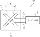
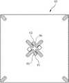
図1は、本実施形態によるクロス八木アンテナを含む携帯型RFIDリーダーを示すブロック図である。FIG. 1 is a block diagram showing a portable RFID reader including a cross Yagi antenna according to the present embodiment.
図1を参照すると、本実施形態による携帯型RFIDリーダー100は、リーダー本体10と、クロス八木アンテナ組立体20とを含む。リーダー本体10は、取っ手を含む携帯型タイプであり、非接触式方式でRFIDタグと通信を行う。そして、クロス八木アンテナ組立体20は、リーダー本体10に連結され、非接触式方式でRFIDタグとの通信に必要なRF信号を送受信する。Referring to FIG. 1, the
リーダー本体10は、クロス八木アンテナ組立体20に内蔵されたクロス八木アンテナ30を介してRFIDタグと通信を行う。このようなリーダー本体10は、RFIDタグをリーディングし、リーディングしたRFIDタグの情報を保存する。リーダー本体10は、リーディングしたRFIDタグの情報をユーザが確認できるように表示することができる。リーダー本体10は、RFIDタグに必要な情報を保存し、リーディングしたRFIDタグの情報を更新することができる。The
このようなリーダー本体10は、ユーザが手で把持した状態で使用できる携帯型タイプで具現される。例えばリーダー本体10は、ガンタイプで具現され得る。Such a
そして、クロス八木アンテナ組立体20は、クロス八木アンテナ30と、クロス八木アンテナ30が内蔵されるアンテナケース70と、を含む。The
クロス八木アンテナ30は、クロスで交差するように結合された板状の第1八木アンテナ40と、板状の第2八木アンテナ50とを含む。第1八木アンテナ40は、水平面に対して-45度の角度で配置される。そして、第2八木アンテナ50は、水平面に対して45度の角度で配置され、第1八木アンテナ40に交差するように結合される。The
第1および第2八木アンテナ40、50は、それぞれ、第1および第2ポート80、90を介してリーダー本体10に電気的に連結され、第1および第2ポート80、90を介してRF信号を送受信する。±45度方向に互いに直交するように配置された第1および第2八木アンテナ40、50は、第1および第2ポート80、90を介して数十msの時間差をもってRF信号を送受信することによって、携帯型RFIDリーダー100とRFIDタグとの間に垂直および水平を含む任意の角度でも良好な信号リーディング特性を示すことができる。The first and
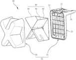
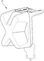
このような本実施形態による携帯型RFIDリーダー100用クロス八木アンテナ組立体20について図1~図3を参照して説明すると、次の通りである。ここで、図2は、本実施形態による携帯型RFIDリーダー用クロス八木アンテナ組立体20を示す分解斜視図である。そして、図3は、図2のクロス八木アンテナ組立体20を示す結合斜視図である。The cross
クロス八木アンテナ組立体20は、前述したように、クロス八木アンテナ30と、クロス八木アンテナ30が内蔵されるアンテナケース70とを含む。As described above, the
クロス八木アンテナ30は、第1および第2八木アンテナ40、50を含み、ベース基板60をさらに含むことができる。第1および第2八木アンテナ40、50は、ベース基板60の上に交差するように結合される。The
ベース基板60は、第1および第2八木アンテナ40、50が交差するように結合される支持板である。第1および第2ポート80、90は、ベース基板60を介して第1および第2八木アンテナ40、50に電気的に連結される。The
アンテナケース70は、第1アンテナケース71と第2アンテナケース79を含む。第1アンテナケース71は、ベース基板60が挿入されて支持される。そして、第2アンテナケース79は、第1アンテナケース71に結合され、内部にベース基板60に結合された第1および第2八木アンテナ40、50が位置する。The
ここで、第1アンテナケース71は、ベース基板60が挿入される基板挿入部73と、基板挿入部73に連結されて、リーダー本体10に結合される結合部75と、を含む。結合部75には、第1および第2八木アンテナ40、50から引き出された第1および第2ポート80、90がリーダー本体10に連結され得る通路77が形成されている。Here, the
第2アンテナケース79は、第1および第2八木アンテナ40、50が挿入される内部空間を有する。例えば、第2アンテナケース79は、挿入される第1および第2八木アンテナ40、50の形状に対応するように、クロス形態の内部空間および外形を有するように具現され得る。The
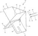
このような本実施形態によるクロス八木アンテナ30について図4~図7を参照して説明すると、次の通りである。図4は、図2のクロス八木アンテナ30を示す斜視図である。図5は、図4のクロス八木アンテナ30のベース基板60を示す平面図である。図6は、図4のクロス八木アンテナ30の第1八木アンテナ40を示す平面図である。そして、図7は、図4のクロス八木アンテナ30の第2八木アンテナ50を示す平面図である。The
図4を参照すると、クロス八木アンテナ30は、前述したように、ベース基板60、第1八木アンテナ40および第2八木アンテナ50を含む。Referring to FIG. 4, the
ベース基板60は、四角板形態であり、上部にクロス形態で交差するように結合された第1および第2八木アンテナ40、50が結合されて固定される。第1および第2八木アンテナ40、50は、物理的な結合方式、接着剤またはハンダ付けを用いた接合方式等を用いてベース基板60の上に固定され得る。The
ベース基板60の中心部分には、第1および第2八木アンテナ40、50にそれぞれ電気的に連結される第1および第2ポート80、90が挿入され得る複数の貫通ホール61、63が形成されている。複数の貫通ホール61、63は、第1ポート80が挿入される第1貫通ホール61と、第2ポート90が挿入される第2貫通ホール63とを含む。A plurality of through
ベース基板60の上に結合される第1および第2八木アンテナ40、50の位置自由度を提供するために、第1および第2貫通ホール61、63に対称する側に第1および第2ダミー貫通ホールが形成されている。すなわち第1および第2八木アンテナ40、50がベース基板60の上にいずれの方向に設置されても、第1および第2貫通ホール61、63と第1および第2ダミー貫通ホールを介して第1および第2ポート80、90を第1および第2八木アンテナ40、50に電気的に連結することができる。First and second dummies symmetrical to the first and second through
なお、本実施形態では、第1および第2八木アンテナ40、50がベース基板60に設置される例を開示したが、これに限定されるものではない。すなわちクロス八木アンテナ30は、ベース基板60を含まなくてもよい。この場合、第1および第2八木アンテナ40、50は、アンテナケース70に結合されて固定される。第1および第2八木アンテナ40、50に直接第1および第2ポート80、90が電気的に連結される。In this embodiment, an example in which the first and
ここで、第1および第2ポート80、90は、中心に同軸81、91が形成され、同軸81、91の周りに接地面83、93が形成された同軸ケーブルでありうる。すなわち第1ポート80は、第1同軸81と第1接地面83を含み、第2ポート90は、第2同軸91と第2接地面93を含む。Here, the first and
クロス形態で交差するように結合された第1および第2八木アンテナ40、50は、第1八木アンテナ40の上部から下方に結合する方式で第2八木アンテナ50が結合され得る。The first and
第1および第2八木アンテナ40、50は、それぞれ、印刷回路基板41、51、アンテナパターン44、45、54、55およびスロット47、57を含む。第1および第2八木アンテナ40、50を区分して説明すると、次の通りである。The first and
第1八木アンテナ40は、図6を参照すると、第1印刷回路基板41、第1アンテナパターン44、45および第1スロット47を含む。第1アンテナパターン44、45は、第1-1アンテナパターン44および第1-2アンテナパターン45を含む。第1印刷回路基板41は、第1-1面42と、第1-1面42に反対になる第1-2面43とを有する。第1-1アンテナパターン44は、第1-1面42に形成される。第1-2アンテナパターン45は、第1-2面43に形成される。第1スロット47は、第1印刷回路基板41の上部中心から下方に一定の深さで形成される。そして、第1八木アンテナ40は、第1接地パッド46をさらに含むことができる。The
ここで、第1印刷回路基板41は、横の長さが相対的に長い矩形の板で具現され得る。第1印刷回路基板41は、絶縁性を有するプラスチック素材の基板でありうる。Here, the first printed
第1-1および前記第1-2アンテナパターン44、45は、それぞれ、第1印刷回路基板41の下部中心から垂直方向に形成された第1-1および第1-2垂直ライン44a、45aと、第1-1および第1-2垂直ライン44a、45aの上部で連結されて、第1-1および第1-2垂直ライン44a、45aから外側に伸びている第1-1および第1-2放射ライン44b、45bとを含む。The 1-1 and the 1-2
第1-1および第1-2垂直ライン44a、45aは、第1印刷回路基板41を挟んで第1-1面42と第1-2面43に重なるように形成され得る。The 1-1 and 1-2
第1-1および第1-2放射ライン44b、45bは、第1-1および第1-2垂直ライン44a、45aを中心に互いに反対方向に形成され得る。The 1-1 and 1-2
第1スロット47を中心に両側に第1-1および第1-2放射ライン44b、45bが形成される。第1-1および第1-2垂直ライン44a、45aは、第1スロット47から離隔するように形成される。The 1-1 and 1-2
第1-1垂直ライン44aは、第1ポート80の第1同軸81に電気的に連結される。第1-2垂直ライン45aは、第1ポート80の第1接地面83に電気的に連結される。この際、第1-2垂直ライン45aは、第1接地パッド46を介して第1ポート80の第1接地面83に電気的に連結される。The 1-1
第1接地パッド46は、第1-1面42に形成され、且つ、第1ポート80の第1同軸81が連結される第1-1垂直ライン44aの下方に形成される。第1接地パッド46が第1-1面42に反対になる第1-2面43には、第1-2垂直ライン45aの下端部が位置する。もちろん第1接地パッド46は、第1-1垂直ライン44aに対して離隔している。第1接地パッド46は、第1-2垂直ライン45aに連結される。例えば、第1接地パッド46は、第1-1面42に反対になる第1-2面43に形成された第1-2垂直ライン45aに第1印刷回路基板41の下端部を介して直接電気的に連結されたり、第1印刷回路基板41を貫通するビアを介して電気的に連結される。The
したがって、第1ポート80を第1八木アンテナ40に電気的に連結するとき、第1ポート80の第1同軸81は、第1-1垂直ライン44aに電気的に接合し、第1ポート80の第2接地面83は、第1接地パッド46に電気的に接合する。そして、第1接地パッド46は、第1-2垂直ライン45aに連結されている。Therefore, when the
第2八木アンテナ50は、図7を参照すると、第2印刷回路基板51、第2アンテナパターン54、55および第2スロット57を含む。第2アンテナパターン54、55は、第2-1アンテナパターン54および第2-2アンテナパターン55を含む。第2印刷回路基板51は、第2-1面52と、第2-1面52に反対になる第2-2面53とを有する。第2-1アンテナパターン54は、第2-1面52に形成される。第2-2アンテナパターン55は、第2-2面53に形成される。第2スロット57は、第2印刷回路基板51の下部中心から上方に一定の深さで形成される。そして、第2八木アンテナ50は、第2接地パッド56をさらに含むことができる。The
したがって、第1八木アンテナ40に第2八木アンテナ50が結合されるとき、第1スロット47に第2スロット57が結合されて、第1八木アンテナ40と第2八木アンテナ50がクロスで重なる。Therefore, when the
ここで、第2印刷回路基板51は、横の長さが相対的に長い矩形の板で具現され得る。第2印刷回路基板51は、絶縁性を有するプラスチック素材の基板でありうる。Here, the second printed
第2-1および前記第2-2アンテナパターン54、55は、それぞれ、第2印刷回路基板51の下部中心から垂直方向に形成された第2-1および第2-2垂直ライン54a、55aと、第2-1および第2-2垂直ライン54a、55aの上部で連結されて、第2-1および第2-2垂直ライン54a、55aから外側に伸びている第2-1および第2-2放射ライン54b、55bを含む。The 2-1 and the 2-2
第2-1および第2-2垂直ライン54a、55aは、第2印刷回路基板51を挟んで第2-1面52と第2-2面53に重なるように形成され得る。The 2-1 and 2-2
第2-1および第2-2放射ライン54b、55bは、第2-1および第2-2垂直ライン54a、55aを中心に互いに反対方向に形成され得る。The 2-1 and 2-2
第2スロット57を中心に両側に第2-1および第2-2放射ライン54b、55bが形成される。第2-1および第2-2垂直ライン54a、55aは、第2スロット57から離隔するように形成される。The 2-1 and 2-2
第2-1垂直ライン54aは、第2ポート90の第2同軸91に電気的に連結される。第2-2垂直ライン55aは、第2ポート90の第2接地面93に電気的に連結される。この際、第2-2垂直ライン55aは、第2接地パッド56を介して第2ポート90の第2接地面93に電気的に連結される。The 2-1
第2接地パッド56は、第2-1面52に形成され、且つ、第2ポート90の第2同軸91が連結される第2-1垂直ライン54aの下方に形成される。第2接地パッド56が第2-1面52に反対になる第2-2面53には、第2-2垂直ライン55aの下端部が位置する。もちろん、第2接地パッド56は、第2-1垂直ライン54aに対して離隔している。第2接地パッド56は、第2-2垂直ライン55aに連結される。例えば、第2接地パッド56は、第2-1面52に反対になる第2-2面53に形成された第2-2垂直ライン55aに第2印刷回路基板51の下端部を介して直接電気的に連結されたり、第2印刷回路基板51を貫通するビアを介して電気的に連結される。The
したがって、第2ポート90を第2八木アンテナ50に電気的に連結するとき、第2ポート90の第2同軸91は、第2-1垂直ライン54aに電気的に接合し、第2ポート90の第2接地面93は、第2接地パッド56に電気的に接合する。そして、第2接地パッド56は、第2-2垂直ライン55aに連結されている。Therefore, when the
このように本実施形態による携帯型RFIDリーダー100は、水平面に対して-45度および45度で重なったクロス八木アンテナ30を含むので、携帯型RFIDリーダー100とRFIDタグ間の位置した方向と関係なく、良好な信号リーディング特性を示す。As described above, since the
本実施形態によるクロス八木アンテナ30は、同一形態の第1八木アンテナ40と第2八木アンテナ50が互いに直交するように結合され、且つ、水平面に対して-45度および45度で重なった構造を有するので、2つのアンテナを使用しても、占める大きさを減らすことができる。The
そして、本実施形態によるクロス八木アンテナ30は、第1八木アンテナ40に連結された第1ポート80と第2八木アンテナ50に連結された第2ポート90を介して数十msの時間差をもってそれぞれリーディングのためのRF信号を供給して出力することによって、携帯型RFIDリーダー100とRFIDタグとの間に垂直および水平を含む任意の角度でも良好な信号リーディング特性を示す。The
なお、本明細書と図面に開示された実施形態は、理解を助けるために特定例を提示したものに過ぎず、本発明の範囲を限定しようとするものではない。ここに開示された実施形態以外にも本発明の技術的思想に基づく他の変形例が実施可能であることは、本発明の属する技術分野における通常の知識を有する者に自明なものである。It should be noted that the embodiments disclosed in the present specification and the drawings merely present specific examples for the sake of understanding, and do not intend to limit the scope of the present invention. It is obvious to those who have ordinary knowledge in the technical field to which the present invention belongs that other modifications based on the technical idea of the present invention can be carried out in addition to the embodiments disclosed herein.
10 リーダー本体
20 クロス八木アンテナ組立体
30 クロス八木アンテナ
40 第1八木アンテナ
41 第1印刷回路基板
42 第1-1面
43 第1-2面
44 第1-1アンテナパターン
44a 第1-1垂直ライン
44b 第1-1放射ライン
45 第1-2アンテナパターン
45a 第1-2垂直ライン
45b 第1-2放射ライン
46 第1接地パッド
47 第1スロット
50 第2八木アンテナ
51 第2印刷回路基板
52 第2-1面
53 第2-2面
54 第2-1アンテナパターン
54a 第2-1垂直ライン
54b 第2-1放射ライン
55 第2-2アンテナパターン
55a 第2-2垂直ライン
55b 第2-2放射ライン
56 第2接地パッド
57 第2スロット
60 ベース基板
61 第1貫通ホール
63 第2貫通ホール
70 アンテナケース
71 第1アンテナケース
73 基板挿入部
75 結合部
77 通路
79 第2アンテナケース
80 第1ポート
81 第1同軸
83 第1接地面
90 第2ポート
91 第2同軸
93 第2接地面
100 携帯型RFIDリーダー10
Claims (11)
Translated fromJapanese前記リーダー本体に連結され、非接触式方式でRFIDタグとの通信に必要なRF信号を送受信するクロス八木アンテナを具備するクロス八木アンテナ組立体と、を含み、
前記クロス八木アンテナは、
水平面に対して-45度の角度で配置された板状の第1八木アンテナと、
水平面に対して45度の角度で配置され、前記第1八木アンテナに交差するように結合された板状の第2八木アンテナと、
を含む、クロス八木アンテナを含む携帯型RFIDリーダー。A portable type that includes a handle, and a reader body that communicates with RFID tags in a non-contact manner.
A cross-Yagi antenna assembly comprising a cross-Yagi antenna that is connected to the reader body and that transmits and receives RF signals necessary for communication with an RFID tag in a non-contact manner.
The cross Yagi antenna is
A plate-shaped first Yagi antenna placed at an angle of -45 degrees with respect to the horizontal plane,
A plate-shaped second Yagi antenna arranged at an angle of 45 degrees with respect to the horizontal plane and coupled so as to intersect the first Yagi antenna.
A portable RFID reader that includes a cross Yagi antenna.
前記第1および第2八木アンテナが設置されるベース基板をさらに含むことを特徴とする請求項1に記載のクロス八木アンテナを含む携帯型RFIDリーダー。The cross Yagi antenna is
The portable RFID reader including the cross Yagi antenna according to claim 1, further comprising a base substrate on which the first and second Yagi antennas are installed.
前記クロス八木アンテナが内蔵されるアンテナケースをさらに含み、
前記アンテナケースは、
前記ベース基板が挿入される第1アンテナケースと、
前記第1アンテナケースに結合され、内部に前記ベース基板に結合された前記第1および第2八木アンテナが位置する第2アンテナケースと、
を含むことを特徴とする請求項2に記載のクロス八木アンテナを含む携帯型RFIDリーダー。The cross Yagi antenna assembly is
Further including an antenna case in which the cross Yagi antenna is built-in,
The antenna case is
The first antenna case into which the base board is inserted and
A second antenna case in which the first and second Yagi antennas coupled to the first antenna case and coupled to the base substrate are located inside.
2. A portable RFID reader comprising the cross-Yagi antenna according to claim 2.
第1-1面と、前記第1-1面に反対になる第1-2面と、を有する第1印刷回路基板と、
前記第1-1面に形成された第1-1アンテナパターンと、
前記第1-2面に形成された第1-2アンテナパターンと、
前記第1印刷回路基板の上部中心から下方に一定の深さで形成された第1スロットと、
を含むことを特徴とする請求項3に記載のクロス八木アンテナを含む携帯型RFIDリーダー。The first Yagi antenna is
A first printed circuit board having a first surface and a first and second surfaces opposite to the 1-1 surface.
The 1-1 antenna pattern formed on the 1-1 surface and the 1-1 antenna pattern
The 1-2 antenna pattern formed on the 1-2 surface and the 1-2 antenna pattern
The first slot formed at a certain depth from the upper center of the first printed circuit board to the lower side,
A portable RFID reader comprising the cross Yagi antenna according to claim 3, wherein the RFID reader comprises.
第2-1面と、前記第2-1面に反対になる第2-2面と、を有する第2印刷回路基板と、
前記第2-1面に形成された第2-1アンテナパターンと、
前記第2-2面に形成された第2-2アンテナパターンと、
前記第2印刷回路基板の下部中心から上方に一定の深さで形成された第2スロットと、
を含むことを特徴とする請求項4に記載のクロス八木アンテナを含む携帯型RFIDリーダー。The second Yagi antenna is
A second printed circuit board having a second surface and a second surface opposite to the 2-1 surface.
The 2-1 antenna pattern formed on the 2-1 surface and the 2-1 antenna pattern
The 2-2 antenna pattern formed on the 2-2 surface and the 2-2 antenna pattern
A second slot formed at a constant depth upward from the lower center of the second printed circuit board,
A portable RFID reader comprising the cross Yagi antenna according to claim 4, wherein the RFID reader comprises.
前記第1-2アンテナパターンは、給電する前記第1ポートの接地面が前記ベース基板を介して連結されることを特徴とする請求項7に記載のクロス八木アンテナを含む携帯型RFIDリーダー。The coaxial of the first port that feeds the 1-1 antenna pattern is connected via the base board, and the coaxial is connected.
The portable RFID reader including the cross Yagi antenna according to claim 7, wherein the 1-2 antenna pattern is connected to the ground plane of the first port to be fed via the base substrate.
前記第1印刷回路基板の下部中心から垂直方向に形成された第1-1および第1-2垂直ラインと、
前記第1-1および第1-2垂直ラインの上部で連結されて、前記第1-1および第1-2垂直ラインから外側に伸びている第1-1および第1-2放射ラインと、を含み、
前記第1-1および第1-2垂直ラインは、前記第1印刷回路基板を挟んで前記第1-1面と前記第1-2面に重なるように形成され、
前記第1-1および第1-2放射ラインは、前記第1-1および第1-2垂直ラインを中心に互いに反対方向に形成され、
前記第1-1垂直ラインは、前記第1ポートの同軸に電気的に連結され、
前記第1-2垂直ラインは、前記第1ポートの接地面に電気的に連結されることを特徴とする請求項8に記載のクロス八木アンテナを含む携帯型RFIDリーダー。The 1-1 and 1-2 antenna patterns are, respectively.
The 1-1 and 1-2 vertical lines formed in the vertical direction from the lower center of the first printed circuit board,
The 1-1 and 1-2 radial lines, which are connected at the top of the 1-1 and 1-2 vertical lines and extend outward from the 1-1 and 1-2 vertical lines, Including
The 1-1 and 1-2 vertical lines are formed so as to overlap the 1-1 surface and the 1-2 surface with the first printed circuit board interposed therebetween.
The 1-1 and 1-2 radiation lines are formed in opposite directions with respect to the 1-1 and 1-2 vertical lines.
The 1-1 vertical line is electrically connected coaxially with the first port.
The portable RFID reader including the cross Yagi antenna according to claim 8, wherein the 1-2 vertical line is electrically connected to the ground plane of the first port.
前記第2-2アンテナパターンは、給電する前記第2ポートの接地面が前記ベース基板を介して連結されることを特徴とする請求項9に記載のクロス八木アンテナを含む携帯型RFIDリーダー。The coaxial of the second port that feeds the 2-1 antenna pattern is connected via the base board.
The second-2 antenna pattern is a portable RFID reader including the cross Yagi antenna according to claim 9, wherein the ground plane of the second port to be fed is connected via the base substrate.
前記第2印刷回路基板の下部中心から垂直方向に形成された第2-1および第2-2垂直ラインと、
前記第2-1および第2-2垂直ラインの上部で連結されて、前記第2-1および第2-2垂直ラインから外側に伸びている第1-1および第1-2放射ラインと、を含み、
前記第2-1および第2-2垂直ラインは、前記第2印刷回路基板を挟んで前記第1-1面と前記第1-2面に重なるように形成され、
前記第2-1および第2-2放射ラインは、前記第2-1および第2-2垂直ラインを中心に互いに反対方向に形成され、
前記第2-1垂直ラインは、前記第2ポートの同軸に電気的に連結され、
前記第2-2垂直ラインは、前記第2ポートの接地面に電気的に連結されることを特徴とする請求項10に記載のクロス八木アンテナを含む携帯型RFIDリーダー。The 2-1 and 2-2 antenna patterns are, respectively.
The 2-1 and 2-2 vertical lines formed in the vertical direction from the lower center of the second printed circuit board,
The 1-1 and 1-2 radial lines, which are connected at the top of the 2-1 and 2-2 vertical lines and extend outward from the 2-1 and 2-2 vertical lines, Including
The 2-1 and 2-2 vertical lines are formed so as to overlap the 1-1 surface and the 1-2 surface with the second printed circuit board interposed therebetween.
The 2-1 and 2-2 radiation lines are formed in opposite directions with respect to the 2-1 and 2-2 vertical lines.
The 2-1 vertical line is electrically connected coaxially with the second port.
The portable RFID reader including the cross-Yagi antenna according to claim 10, wherein the 2-2 vertical line is electrically connected to the ground plane of the second port.
Applications Claiming Priority (2)
| Application Number | Priority Date | Filing Date | Title |
|---|---|---|---|
| KR10-2020-0141588 | 2020-10-28 | ||
| KR1020200141588AKR102561439B1 (en) | 2020-10-28 | 2020-10-28 | Handheld RFID reader comprising cross Yagi antenna |
Publications (1)
| Publication Number | Publication Date |
|---|---|
| JP2022071806Atrue JP2022071806A (en) | 2022-05-16 |
Family
ID=74946963
Family Applications (1)
| Application Number | Title | Priority Date | Filing Date |
|---|---|---|---|
| JP2021059966APendingJP2022071806A (en) | 2020-10-28 | 2021-03-31 | Portable RFID reader including cross Yagi antenna |
Country Status (5)
| Country | Link |
|---|---|
| US (1) | US20220129650A1 (en) |
| EP (1) | EP3992839A1 (en) |
| JP (1) | JP2022071806A (en) |
| KR (1) | KR102561439B1 (en) |
| CN (1) | CN114492483A (en) |
Citations (12)
| Publication number | Priority date | Publication date | Assignee | Title |
|---|---|---|---|---|
| US6483476B2 (en)* | 2000-12-07 | 2002-11-19 | Telex Communications, Inc. | One-piece Yagi-Uda antenna and process for making the same |
| US20030160730A1 (en)* | 2002-02-26 | 2003-08-28 | Alsliety Mazen K. | Microstrip Yagi-Uda antenna |
| JP2006352293A (en)* | 2005-06-14 | 2006-12-28 | Denki Kogyo Co Ltd | Polarization diversity antenna |
| KR100884461B1 (en)* | 2007-02-22 | 2009-02-20 | 권혁숙 | Wireless barcode and RF ID scanner with voice communication |
| JP2009124403A (en)* | 2007-11-14 | 2009-06-04 | Samsung Electronics Co Ltd | Antenna device |
| US20090174557A1 (en)* | 2008-01-03 | 2009-07-09 | Intermec Ip Corp. | Compact flexible high gain antenna for handheld rfid reader |
| US20130300624A1 (en)* | 2012-05-08 | 2013-11-14 | Peraso Technologies Inc. | Broadband end-fire multi-layer antenna |
| CN103579783A (en)* | 2012-07-20 | 2014-02-12 | 航天信息股份有限公司 | Vehicle-mounted reader-writer antenna |
| JP2014039192A (en)* | 2012-08-17 | 2014-02-27 | Denki Kogyo Co Ltd | Dual polarized antenna |
| KR102004294B1 (en)* | 2018-04-13 | 2019-07-26 | 주식회사 에이스테크놀로지 | Base Station Antenna Radiator Having Stable Polarization Characteristic |
| CN212011244U (en)* | 2020-07-01 | 2020-11-24 | 上海贝喆通信技术有限公司 | RFID handset reader-writer antenna structure |
| KR102358984B1 (en)* | 2020-10-28 | 2022-02-07 | 주식회사 에이펄스테크롤리지 | Cross Yagi antenna for handheld RFID reader |
Family Cites Families (11)
| Publication number | Priority date | Publication date | Assignee | Title |
|---|---|---|---|---|
| JP4702336B2 (en)* | 2007-08-10 | 2011-06-15 | 株式会社デンソーウェーブ | Portable RFID tag reader |
| JP2012529143A (en)* | 2009-06-05 | 2012-11-15 | コーニンクレッカ フィリップス エレクトロニクス エヌ ヴィ | Lighting device with built-in RF antenna |
| KR101021934B1 (en)* | 2009-08-20 | 2011-03-16 | (주) 인트정보시스템 | Folded Dipole Antenna for RFID Handheld Reader |
| KR101256931B1 (en)* | 2011-04-07 | 2013-04-19 | (주) 네톰 | Rfid tag and pcb of electronic product provided with the rfid tag and management system for electronic product |
| US9444145B2 (en)* | 2014-03-04 | 2016-09-13 | Symbol Technologies, Llc | Compact, polarization-insensitive antenna for handheld RFID reader and method of making and using same |
| CN104600422B (en)* | 2014-12-19 | 2017-11-10 | 康凯科技(杭州)股份有限公司 | A kind of coaxial yagi aerial system of dual polarization |
| WO2017205619A1 (en)* | 2016-05-27 | 2017-11-30 | Berntsen International, Inc. | Uhf rfid tag for marking underground assets and locations and methods of using same |
| KR102605856B1 (en)* | 2017-01-03 | 2023-11-24 | 주식회사 위츠 | Antenna device and portable terminal including the same |
| KR101955661B1 (en) | 2017-06-07 | 2019-03-07 | 주식회사 에이펄스테크롤리지 | Electronic tag reader |
| JP6658987B2 (en)* | 2017-11-09 | 2020-03-04 | 株式会社村田製作所 | RFID tag reading method, RFID tag reading system, RFID tag reader device, and article |
| KR102107493B1 (en)* | 2018-10-15 | 2020-05-07 | 김창일 | Radio Frequency Identification Reader |
- 2020
- 2020-10-28KRKR1020200141588Apatent/KR102561439B1/enactiveActive
- 2021
- 2021-03-16USUS17/202,699patent/US20220129650A1/ennot_activeAbandoned
- 2021-03-16EPEP21162727.8Apatent/EP3992839A1/ennot_activeWithdrawn
- 2021-03-17CNCN202110286820.1Apatent/CN114492483A/ennot_activeWithdrawn
- 2021-03-31JPJP2021059966Apatent/JP2022071806A/enactivePending
Patent Citations (12)
| Publication number | Priority date | Publication date | Assignee | Title |
|---|---|---|---|---|
| US6483476B2 (en)* | 2000-12-07 | 2002-11-19 | Telex Communications, Inc. | One-piece Yagi-Uda antenna and process for making the same |
| US20030160730A1 (en)* | 2002-02-26 | 2003-08-28 | Alsliety Mazen K. | Microstrip Yagi-Uda antenna |
| JP2006352293A (en)* | 2005-06-14 | 2006-12-28 | Denki Kogyo Co Ltd | Polarization diversity antenna |
| KR100884461B1 (en)* | 2007-02-22 | 2009-02-20 | 권혁숙 | Wireless barcode and RF ID scanner with voice communication |
| JP2009124403A (en)* | 2007-11-14 | 2009-06-04 | Samsung Electronics Co Ltd | Antenna device |
| US20090174557A1 (en)* | 2008-01-03 | 2009-07-09 | Intermec Ip Corp. | Compact flexible high gain antenna for handheld rfid reader |
| US20130300624A1 (en)* | 2012-05-08 | 2013-11-14 | Peraso Technologies Inc. | Broadband end-fire multi-layer antenna |
| CN103579783A (en)* | 2012-07-20 | 2014-02-12 | 航天信息股份有限公司 | Vehicle-mounted reader-writer antenna |
| JP2014039192A (en)* | 2012-08-17 | 2014-02-27 | Denki Kogyo Co Ltd | Dual polarized antenna |
| KR102004294B1 (en)* | 2018-04-13 | 2019-07-26 | 주식회사 에이스테크놀로지 | Base Station Antenna Radiator Having Stable Polarization Characteristic |
| CN212011244U (en)* | 2020-07-01 | 2020-11-24 | 上海贝喆通信技术有限公司 | RFID handset reader-writer antenna structure |
| KR102358984B1 (en)* | 2020-10-28 | 2022-02-07 | 주식회사 에이펄스테크롤리지 | Cross Yagi antenna for handheld RFID reader |
Non-Patent Citations (1)
| Title |
|---|
| 藤本 伸一: "アマチュア無線のアンテナ(2)", 子供の科学 10月号, vol. 第52巻, JPN6022023032, 1 October 1989 (1989-10-01), JP, pages 105 - 107, ISSN: 0004799091* |
Also Published As
| Publication number | Publication date |
|---|---|
| US20220129650A1 (en) | 2022-04-28 |
| KR20220056736A (en) | 2022-05-06 |
| CN114492483A (en) | 2022-05-13 |
| KR102561439B1 (en) | 2023-07-31 |
| EP3992839A1 (en) | 2022-05-04 |
Similar Documents
| Publication | Publication Date | Title |
|---|---|---|
| US7963451B2 (en) | Antenna unit and noncontact IC tag | |
| US9692128B2 (en) | Antenna device and wireless communication device | |
| US8902119B2 (en) | Dual polarized UHF antenna | |
| US6839035B1 (en) | Magnetically coupled antenna range extender | |
| US8723727B2 (en) | Slot antenna and RFID method | |
| CN1577965A (en) | Bifrequency shared antenna apparatus | |
| JP2011010202A (en) | Wireless tag reading apparatus, and method for arrangement of reader antenna thereof | |
| JP2012108843A (en) | RFID tag | |
| US20090128414A1 (en) | High gain omni-directional antenna | |
| KR102358984B1 (en) | Cross Yagi antenna for handheld RFID reader | |
| JP2022071806A (en) | Portable RFID reader including cross Yagi antenna | |
| JP4218044B2 (en) | 3D antenna | |
| US8570230B2 (en) | Antenna | |
| JP4712573B2 (en) | Omnidirectional antenna | |
| JP5489978B2 (en) | RFID reader / writer antenna | |
| JP4862572B2 (en) | Antenna device, antenna assembly device, and reader / writer device | |
| JP6561858B2 (en) | Jacket type device and portable communication terminal with jacket type device | |
| US7375697B2 (en) | Meandered slit antenna | |
| JP2008542937A (en) | Apparatus and method for reading and / or writing data from and / or to multiple RFID chips | |
| JPH0964797A (en) | Card type data carrier of mobile object identifying device | |
| US20160239695A1 (en) | Chip card reading arrangement | |
| US7538733B2 (en) | Information communication device | |
| JP6226313B1 (en) | Antenna device | |
| JP7188102B2 (en) | RFID system and reader/writer device | |
| KR20110092579A (en) | Microstrip antenna |
Legal Events
| Date | Code | Title | Description |
|---|---|---|---|
| A621 | Written request for application examination | Free format text:JAPANESE INTERMEDIATE CODE: A621 Effective date:20210401 | |
| A131 | Notification of reasons for refusal | Free format text:JAPANESE INTERMEDIATE CODE: A131 Effective date:20220614 | |
| A521 | Request for written amendment filed | Free format text:JAPANESE INTERMEDIATE CODE: A523 Effective date:20220913 | |
| A02 | Decision of refusal | Free format text:JAPANESE INTERMEDIATE CODE: A02 Effective date:20230117 |