JP2022069828A - Identification method, image display method, identification system, image display system, and program - Google Patents
Identification method, image display method, identification system, image display system, and programDownload PDFInfo
- Publication number
- JP2022069828A JP2022069828AJP2020178717AJP2020178717AJP2022069828AJP 2022069828 AJP2022069828 AJP 2022069828AJP 2020178717 AJP2020178717 AJP 2020178717AJP 2020178717 AJP2020178717 AJP 2020178717AJP 2022069828 AJP2022069828 AJP 2022069828A
- Authority
- JP
- Japan
- Prior art keywords
- image
- identification
- sub
- pixel
- type
- Prior art date
- Legal status (The legal status is an assumption and is not a legal conclusion. Google has not performed a legal analysis and makes no representation as to the accuracy of the status listed.)
- Granted
Links
Images


Classifications
- G—PHYSICS
- G06—COMPUTING OR CALCULATING; COUNTING
- G06V—IMAGE OR VIDEO RECOGNITION OR UNDERSTANDING
- G06V20/00—Scenes; Scene-specific elements
- G—PHYSICS
- G06—COMPUTING OR CALCULATING; COUNTING
- G06T—IMAGE DATA PROCESSING OR GENERATION, IN GENERAL
- G06T7/00—Image analysis
- G06T7/10—Segmentation; Edge detection
- G—PHYSICS
- G06—COMPUTING OR CALCULATING; COUNTING
- G06V—IMAGE OR VIDEO RECOGNITION OR UNDERSTANDING
- G06V10/00—Arrangements for image or video recognition or understanding
- G06V10/20—Image preprocessing
- G06V10/22—Image preprocessing by selection of a specific region containing or referencing a pattern; Locating or processing of specific regions to guide the detection or recognition
- G—PHYSICS
- G06—COMPUTING OR CALCULATING; COUNTING
- G06V—IMAGE OR VIDEO RECOGNITION OR UNDERSTANDING
- G06V10/00—Arrangements for image or video recognition or understanding
- G06V10/70—Arrangements for image or video recognition or understanding using pattern recognition or machine learning
- G06V10/77—Processing image or video features in feature spaces; using data integration or data reduction, e.g. principal component analysis [PCA] or independent component analysis [ICA] or self-organising maps [SOM]; Blind source separation
- G06V10/80—Fusion, i.e. combining data from various sources at the sensor level, preprocessing level, feature extraction level or classification level
- G—PHYSICS
- G06—COMPUTING OR CALCULATING; COUNTING
- G06V—IMAGE OR VIDEO RECOGNITION OR UNDERSTANDING
- G06V20/00—Scenes; Scene-specific elements
- G06V20/60—Type of objects
- G06V20/64—Three-dimensional objects
Landscapes
- Engineering & Computer Science (AREA)
- Theoretical Computer Science (AREA)
- Physics & Mathematics (AREA)
- General Physics & Mathematics (AREA)
- Multimedia (AREA)
- Computer Vision & Pattern Recognition (AREA)
- Computing Systems (AREA)
- Artificial Intelligence (AREA)
- Health & Medical Sciences (AREA)
- Databases & Information Systems (AREA)
- Evolutionary Computation (AREA)
- General Health & Medical Sciences (AREA)
- Medical Informatics (AREA)
- Software Systems (AREA)
- Image Analysis (AREA)
- Studio Devices (AREA)
Abstract
Translated fromJapanese
Description
Translated fromJapanese本開示は、識別方法、画像表示方法、識別システム、画像表示システム、及びプログラム、に関する。 The present disclosure relates to an identification method, an image display method, an identification system, an image display system, and a program.
カメラにより撮像された撮像画像に写っている物体の種類を識別する識別技術の一例として特許文献1に開示の技術が挙げられる。特許文献1に開示の技術では、撮像画像内に写っている物体と、データベースに保存された物体のテンプレート画像とのテンプレートマッチングにより撮像画像に写っている物体の種類が識別される。 The technique disclosed in Patent Document 1 is mentioned as an example of the identification technique for identifying the type of the object shown in the captured image captured by the camera. In the technique disclosed in Patent Document 1, the type of the object shown in the captured image is identified by template matching between the object shown in the captured image and the template image of the object stored in the database.
特許文献1に開示の技術では、識別対象の物体の一部に他の物体が重なって写っている場合、誤った識別結果が得られる場合がある。 In the technique disclosed in Patent Document 1, when another object overlaps with a part of the object to be identified, an erroneous identification result may be obtained.
上記課題を解決するために、本開示の識別方法は、識別対象物を含む被写体の第1位置からの距離を各画素の画素値が表す第1画像を取得し、前記第1位置又は前記第1位置とは異なる第2位置から撮像された画像であって、各画素の画素値が前記被写体からの反射光の輝度を少なくとも表す第2画像を取得し、前記第2画像に基づいて前記識別対象物の種類を識別する一方、前記第2画像に基づく識別結果の信頼度を示す指標値を前記第1画像に基づいて算出する。 In order to solve the above problems, the identification method of the present disclosure acquires a first image in which the pixel value of each pixel represents the distance from the first position of the subject including the identification object, and the first position or the first position. An image captured from a second position different from the first position, in which a second image in which the pixel value of each pixel represents at least the brightness of the reflected light from the subject is acquired, and the identification is performed based on the second image. While identifying the type of the object, an index value indicating the reliability of the identification result based on the second image is calculated based on the first image.
また、上記課題を解決するために、本開示の画像表示方法は、識別対象物を含む被写体の第1位置からの距離を各画素の画素値が表す第1画像を取得し、前記第1位置又は前記第1位置とは異なる第2位置から撮像された画像であって、各画素の画素値が前記被写体からの反射光の輝度を少なくとも表す第2画像を取得し、前記第2画像に基づいて前記識別対象物の種類を識別する一方、前記第2画像に基づく前記識別対象物の種類の識別結果の信頼度を示す指標値を前記第1画像に基づいて算出し、前記識別対象物の種類の識別結果に応じた第3画像を前記識別対象物に重ねて表示する。 Further, in order to solve the above problems, the image display method of the present disclosure acquires a first image in which the pixel value of each pixel represents the distance from the first position of the subject including the identification target, and the first position. Alternatively, an image captured from a second position different from the first position, in which the pixel value of each pixel represents at least the brightness of the reflected light from the subject, is acquired and based on the second image. While identifying the type of the identification object, an index value indicating the reliability of the identification result of the identification object type based on the second image is calculated based on the first image, and the identification object is identified. The third image corresponding to the identification result of the type is displayed superimposed on the identification object.
また、上記課題を解決するために、本開示の識別システムは、第1位置に設置され、識別対象物を含む被写体の前記第1位置からの距離を各画素の画素値が表す第1画像を撮像する第1撮像装置と、前記第1位置又は前記第1位置とは異なる第2位置に設置され、各画素の画素値が前記被写体からの反射光の輝度を少なくとも表す第2画像を撮像する第2撮像装置と、処理装置と、を備え、前記処理装置は、前記第1撮像位置から前記第1画像を取得すること、前記第2撮像装置から前記第2画像を取得すること、及び、前記第2画像に基づいて前記識別対象物の種類を識別する一方、前記第2画像に基づく前記識別対象物の種類の識別結果の信頼度を示す指標値を前記第1画像に基づいて算出すること、を実行する。 Further, in order to solve the above problems, the identification system of the present disclosure is installed at a first position, and a first image in which the pixel value of each pixel represents the distance of the subject including the identification object from the first position is displayed. A first image pickup device for taking an image and a second image installed at the first position or a second position different from the first position, and the pixel value of each pixel represents at least the brightness of the reflected light from the subject. A second image pickup device and a processing device are provided, and the processing device acquires the first image from the first image pickup position, acquires the second image from the second image pickup device, and While the type of the identification object is identified based on the second image, an index value indicating the reliability of the identification result of the type of the identification object based on the second image is calculated based on the first image. That, to do.
また、上記課題を解決するために、本開示の画像表示システムは、第1位置に設置され、識別対象物を含む被写体の前記第1位置からの距離を各画素の画素値が表す第1画像を撮像する第1撮像装置と、前記第1位置又は前記第1位置とは異なる第2位置に設置され、各画素の画素値が前記被写体からの反射光の輝度を少なくとも表す第2画像を撮像する第2撮像装置と、表示装置と、処理装置と、を備え、前記処理装置は、前記第1撮像装置から前記第1画像を取得すること、前記第2撮像装置から前記第2画像を取得すること、前記第2画像に基づいて前記識別対象物の種類を識別する一方、前記第2画像に基づく前記識別対象物の種類の識別結果の信頼度を示す指標値を前記第1画像に基づいて算出すること、及び、前記識別対象物の種類の識別結果に応じた第3画像を前記識別対象物に重ねて前記表示装置に表示させること、を実行する。 Further, in order to solve the above problems, the image display system of the present disclosure is installed at the first position, and the first image in which the pixel value of each pixel represents the distance of the subject including the identification object from the first position. A first image pickup device for taking an image of an image and a second image installed at the first position or a second position different from the first position, and the pixel value of each pixel at least represents the brightness of the reflected light from the subject. The processing device includes a second image pickup device, a display device, and a processing device, and the processing device acquires the first image from the first image pickup device and acquires the second image from the second image pickup device. The index value indicating the reliability of the identification result of the type of the identification object based on the second image is determined based on the first image while identifying the type of the identification object based on the second image. And to superimpose the third image corresponding to the identification result of the type of the identification object on the identification object and display it on the display device.
また、上記課題を解決するために、本開示のプログラムは、コンピューターに、識別対象物を含む被写体の第1位置からの距離を各画素の画素値が表す第1画像を取得すること、前記第1位置又は前記第1位置とは異なる第2位置から撮像された画像であって、各画素の画素値が前記被写体からの反射光の輝度を少なくとも表す第2画像を取得すること、及び、前記第2画像に基づいて前記識別対象物の種類を識別する一方、前記第2画像に基づく前記識別対象の種類の識別結果の信頼度を示す指標値を前記第1画像に基づいて算出すること、を実行させる。 Further, in order to solve the above-mentioned problems, the program of the present disclosure obtains, on a computer, a first image in which the pixel value of each pixel represents the distance from the first position of the subject including the identification object. Obtaining a second image captured from one position or a second position different from the first position, wherein the pixel value of each pixel at least represents the brightness of the reflected light from the subject, and the above. While identifying the type of the identification target based on the second image, calculating an index value indicating the reliability of the identification result of the identification target type based on the second image is calculated based on the first image. To execute.
また、上記課題を解決するために、本開示のプログラムは、コンピューターに、識別対象物を含む被写体の第1位置からの距離を各画素の画素値が表す第1画像を取得すること、前記第1位置又は前記第1位置とは異なる第2位置から撮像された画像であって、各画素の画素値が前記被写体からの反射光の輝度を少なくとも表す第2画像を取得すること、前記第2画像に基づいて前記識別対象物の種類を識別する一方、前記第2画像に基づく前記識別対象物の種類の識別結果の信頼度を示す指標値を前記第1画像に基づいて算出すること、及び、前記識別対象物の種類の識別結果に応じた第3画像を前記識別対象物に重ねて表示すること、を実行させる。 Further, in order to solve the above-mentioned problems, the program of the present disclosure obtains, on a computer, a first image in which the pixel value of each pixel represents the distance from the first position of the subject including the identification object. Acquiring a second image captured from one position or a second position different from the first position, wherein the pixel value of each pixel at least represents the brightness of the reflected light from the subject. While identifying the type of the identification object based on the image, the index value indicating the reliability of the identification result of the identification object type based on the second image is calculated based on the first image, and , Displaying the third image corresponding to the identification result of the type of the identification object on the identification object is executed.
以下、図面を参照して本開示の実施形態を説明する。以下に述べる実施形態には技術的に好ましい種々の限定が付されている。しかし、本開示の実施形態は、以下に述べる形態に限られるものではない。 Hereinafter, embodiments of the present disclosure will be described with reference to the drawings. The embodiments described below are subject to various technically preferred limitations. However, the embodiments of the present disclosure are not limited to the embodiments described below.
1.第1実施形態
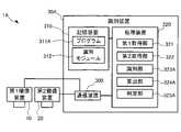
図1は、本開示の第1実施形態に係る識別方法を実行する識別装置30Aを含む識別システム1Aの構成例を示すブロック図である。図1に示すように、識別システム1Aは、識別装置30Aの他に、第1撮像装置10と、第2撮像装置20と、を含む。図1に示すように、第1撮像装置10と、第2撮像装置20とは、識別装置30Aに接続される。1. 1. First Embodiment FIG. 1 is a block diagram showing a configuration example of an
詳細については後述するが、識別装置30Aは、背景となる物体の上に識別対象となる物体が配置された被写体の撮像画像に基づいて、識別対象となる物体の種類を識別する。以下では、背景となる物体のことを背景物と呼ぶ。また、識別対象となる物体のことを識別対象物と呼ぶ。背景物の上に識別対象物が配置された被写体は、本開示における識別対象物を含む被写体の一例である。図2は、本実施形態における被写体の一例を示す図である。本実施形態における被写体では、背景物B1の上に識別対象物A1、A2及びC1が配置される。背景物B1は机である。識別対象物A1及び識別対象物A2はリンゴである。識別対象物C1は円筒状の花瓶である。 Although the details will be described later, the
第1撮像装置10は、ToFカメラ、構造化光カメラ又はステレオカメラ等の距離カメラである。距離カメラとは距離画像を撮像するカメラである。距離画像とは、各画素の画素値が被写体から距離カメラの設置位置までの距離を表す画像である。第1撮像装置10は、被写体を撮像する毎に撮像した距離画像を表す画像データを識別装置30Aへ出力する。以下では、距離画像を表す画像データを距離画像データと呼ぶ。 The first
第1撮像装置10は、図2に示す被写体の斜め上方の位置に固定され、図2において破線で囲った範囲を所定の時間長のフレーム期間毎に撮像する。図3は、図2に示す被写体を第1撮像装置10により撮像して得られる距離画像の一例を示す図である。図3に示すように、本実施形態における距離画像はグレイスケール画像である。本実施形態の距離画像において、第1画素についての被写体からの距離が第2画素についての被写体からの距離よりも長い場合、第1画素の画素値は第2画素の画素値よりも小さくなる。つまり、第1画素は第2画素よりも黒くなる。第1撮像装置10の設置位置は本開示における第1位置の一例ある。図2に示す被写体を第1撮像装置10により撮像される距離画像は本開示における第1画像の一例である。 The first
第2撮像装置20は、RGBカメラである。第2撮像装置20により撮像された画像における各画素の画素値は被写体からの反射光の輝度を表す。以下では、各画素の画素値が被写体からの反射光の輝度を表す画像を輝度画像と呼ぶ。本実施形態における第2撮像装置20はRGBカメラであるが、グレーカメラ又は赤外線カメラであってもよい。第2撮像装置20は、第1撮像装置10の近傍の位置に固定される。第2撮像装置20の設置位置は本開示における第1位置とは異なる第2位置の一例ある。第2撮像装置20により撮像される輝度画像は本開示における第2画像の一例である。 The second
第2撮像装置20は、第1撮像装置10と同様に、図2に示す被写体の斜め上方から、図2において破線で囲った範囲をフレーム期間毎に撮像する。なお、本実施形態では、第2撮像装置20による撮像タイミングと第1撮像装置10による撮像タイミングとは同じである。第2撮像装置20は、被写体を撮像する毎に撮像した輝度画像を表す画像データを識別装置30Aへ出力する。以下では、輝度画像を表す画像データを輝度画像データと呼ぶ。図4は、図2に示す被写体を第2撮像装置20により撮像して得られる輝度画像の一例を示す図である。図4では、背景物B1、識別対象物A1、A2及びC1の各々の違いがハッチングの有無及びハッチングパターンで示されている。本実施形態では、第2撮像装置20におけるズームと第1撮像装置10におけるズームとは同じ値に設定される。このため、第1撮像装置10により撮像された距離画像と第2撮像装置20により撮像された輝度画像は、同じ撮像範囲を略同じ位置から略同じズームで撮像した画像となる。 Similar to the first
識別装置30Aは、第2撮像装置20から出力される輝度画像データに基づいて識別対象物A1、A2及びC1の種類を識別する。また、識別装置30Aは、輝度画像データに基づく識別結果の信頼度を示す指標値を、第1撮像装置10から出力される距離画像データに基づいて算出する。識別装置30Aは,この指標値に基づいて、輝度画像データに基づく識別結果を有効とするのか、無効とするのかを判定する。以下、本実施形態の特徴を顕著に示す識別装置30Aを中心に説明する。 The
識別装置30Aは、例えばパーソナルコンピューターである。図1に示すように、識別装置30Aは、通信装置300と、記憶装置310と、処理装置320と、を含む。通信装置300には、第1撮像装置10及び第2撮像装置20が接続される。通信装置300は、外部の装置とデータ通信を実行する通信インターフェースである。通信装置300は、例えば、送受信する信号を処理するインターフェース回路を備える。通信装置300の具体例としては、無線通信モジュール又は有線通信モジュールが挙げられる。通信装置300が有線通信モジュールである場合、通信装置300には、通信線を介して第1撮像装置10及び第2撮像装置20が接続される。第1撮像装置10及び第2撮像装置20と識別装置30Aとの接続は、無線アクセスポイント装置又はルーター等の中継装置を介さない直接接続であってもよいし、中継装置を介する間接接続であってもよい。通信装置300が無線通信モジュールである場合、直接接続の具体例としてはアドホック接続が挙げられ、間接接続の具体例としては無線アクセスポイント装置を介するアクセスポイント接続が挙げられる。また、通信装置300が有線通信モジュールである場合、直接接続の具体例としてはピアトゥーピア接続が挙げられ、間接接続の具体例としては有線ルーター又は有線ハブを介する接続が挙げられる。通信装置300は、第1撮像装置10から出力される距離画像データを受信する。また、通信装置300は、第2撮像装置20から出力される輝度画像データを受信する。 The
記憶装置310は、処理装置320が読み取り可能な記録媒体である。記憶装置310は、例えば、不揮発性メモリーと揮発性メモリーとを含む。不揮発性メモリーは、例えば、ROM(Read Only Memory)、EPROM(Erasable Programmable Read Only Memory)又はEEPROM(Electrically Erasable Programmable Read Only Memory)である。揮発性メモリーは、例えば、RAM(Radom Access Memory)である。 The
記憶装置310の不揮発性メモリーには、処理装置320によって実行されるプログラム311Aと、識別モジュール312と、が記憶される。記憶装置310の揮発性メモリーはプログラム311Aを実行する際のワークエリアとして処理装置320によって利用される。プログラム311Aは、「アプリケーションプログラム」、「アプリケーションソフトウェア」又は「アプリ」とも称され得る。プログラム311Aは、例えば、通信装置300を介して不図示のサーバー等から取得され、その後、記憶装置310に記憶される。プログラム311Aは、記憶装置310に予め記憶されてもよい。 The non-volatile memory of the
識別モジュール312は、物体の輝度画像と物体の種類を示すラベルとを対応付けた学習データを用いてディープラーニング等の機械学習により生成された畳み込みニューラルネットワークである。識別モジュール312は、リンゴ、花瓶及び机について学習済である。識別モジュール312は、入力された輝度画像に写っている物体の種類を示すラベルを出力する。識別モジュール312は、本開示における識別器の一例である。 The
処理装置320は、例えばCPU(Central Processing Unit)等のプロセッサー、即ちコンピューターを含んで構成される。処理装置320は、単一のコンピューターで構成されてもよいし、複数のコンピューターで構成されてもよい。処理装置320は、プログラム311Aの実行開始を指示する操作が不図示の入力装置に対して為されたことを契機としてプログラム311Aを不揮発性メモリーから揮発性メモリーに読み出し、プログラム311Aの実行を開始する。プログラム311Aに従って作動中の処理装置320は、図1に示す第1取得部321、第2取得部322、識別部323A、算出部324A、及び判定部325Aとして機能する。図1に示す第1取得部321、第2取得部322、識別部323A、算出部324A、及び判定部325Aは、処理装置320をプログラム311Aに従って動作させることで実現されるソフトウェアモジュールである。 The
第1取得部321は、通信装置300により受信した距離画像データを取得する。第2取得部322は、通信装置300により受信した輝度画像データを取得する。 The
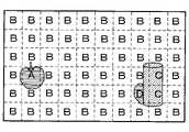
識別部323Aは、第2取得部322により取得した輝度画像データの表す輝度画像と識別モジュール312とを用いて、輝度画像に写っている物体の種類を識別する。なお、識別部323Aは、第2取得部322により取得した輝度画像データの表す輝度画像が所定の大きさの矩形となるように当該輝度画像データに矩形変換を施してもよい。識別部323Aは、輝度画像データの表す輝度画像を、図5に示すように、グリッドを用いてN行M列の合計N×M個のサブ輝度画像に分割する。図5に示す例ではN=6である。Nは2以上の整数であればよい。図5に示す例ではM=10である。Mは2以上の整数であればよい。N×M個のサブ輝度画像のうちの何れか一のサブ輝度画像は本開示における第3サブ画像の一例であり、当該一のサブ輝度画像とは異なるサブ輝度画像は本開示における第4サブ画像の一例である。 The
以下では、サブ輝度画像のN個の行に上から下に向けて第1行、第2行…第N行と番号を付ける。サブ輝度画像のM個の列についても同様に左から右へ向けて第1列、第2列…第M列と番号を付ける。従って、図5に示す6×10個の画素のうち左上隅のサブ輝度画像を1行1列目のサブ輝度画像となり、右下隅のサブ輝度画像を6行10列目のサブ輝度画像となる。 In the following, the N lines of the sub-luminance image are numbered from top to bottom as the first line, the second line, and the Nth line. Similarly, the M columns of the sub-luminance image are numbered from left to right as the first column, the second column, and the M column. Therefore, of the 6 × 10 pixels shown in FIG. 5, the sub-luminance image in the upper left corner is the sub-luminance image in the 1st row and 1st column, and the sub-luminance image in the lower right corner is the sub-luminance image in the 6th row and 10th column. ..
識別部323Aは、N×M個のサブ輝度画像の各々を識別対象画像として当該識別対象画像を表す画像データを識別モジュール312へ入力する。識別部323Aは、識別対象画像に写っている物体の種別を示すラベルを識別モジュール312から取得することで、当該物体の種別を識別する。図5では、N×M個のサブ輝度画像の各々について識別モジュール312から取得されるラベルが一文字のアルファベットで示されている。図5においてAはリンゴを、Bは背景物を、Cは花瓶を夫々表すラベルである。図5におけるDは、リンゴ、背景物及び花瓶の何れでもない物を示すラベルである。5行8列目のサブ輝度画像に対してラベルDが出力されるのは、当該サブ輝度画像には識別対象物A2の一部が写っているものの、識別対象物C1及び背景物B1も写っているため、識別モジュール312を用いた識別に失敗したからである。 The
算出部324Aは、識別部323Aによる識別結果の信頼度を示す指標値を、第1取得部321により取得した距離画像データの表す距離画像に基づいて算出する。より詳細に説明すると、算出部324Aは、距離画像データの表す距離画像を、グリッドを用いてN×M個のサブ距離画像に分割する。前述したように、第1撮像装置10により撮像された距離画像と第2撮像装置により撮像された輝度画像とは同じ撮像範囲を略同じ位置から同じズームで撮像した画像であるから、N×M個のサブ距離画像の各々はN×M個のサブ輝度画像の各々に一対一に対応する。例えば、1行1列目のサブ距離画像と1行1列目のサブ輝度画像とは略同じ撮像範囲を撮像した画像となる。なお、サブ輝度画像とサブ距離画像とをより正確に対応させるため、識別部323Aは、輝度画像の輪郭が所定の大きさの矩形となるように輝度画像に矩形変換を施した後にサブ輝度画像に分割し、算出部324Aは距離画像に当該矩形変換を施した後にサブ距離画像に分割してもよい。距離画像を分割して得られるN×M個のサブ距離画像のうちの何れか一のサブ距離画像は本開示における第1サブ画像の一例であり、当該一のサブ画像とは異なるサブ距離画像は本開示における第2サブ画像の一例である。 The
次いで、算出部324Aは、N×M個のサブ距離画像の各々を算出対象画像とし、算出対象画像を構成する画素の画素値の統計量に基づいて指標値を算出する。本実施形態では、算出部324Aは、算出対象画像を構成する各画素の画素値の統計量として、以下の式(1)に示す分散S2を算出する。なお、式(1)においてLは算出対象画像を構成する画素の総数である。Lは2以上の整数である。xiは、算出対象画像を構成するL個の画素におけるi番目の画素の画素値である。つまり、iは1からLまでの整数の何れかである。xaveは算出対象画像を構成するL個の画素の画素値の加算平均値である。
Next, the
図6はN×M個のサブ距離画像の各々について算出される統計量の一例を示す図である。図6では、N×M個のサブ距離画像の各々について算出された分散S2の値が各サブ距離画像内に示されている。なお、図6では、距離を表す階調の描画は省略されている。4行8列目、4行9列目、5行8列、及び5行9列目の各サブ距離画像についての分散S2が著しく大きくなっているのは、これらのサブ距離画像には複数の物体が写っており、サブ距離画像内での距離のバラつきが大きいためである。FIG. 6 is a diagram showing an example of statistics calculated for each of N × M sub-distance images. In FIG. 6, the value of the variance S2 calculated for each of the N × M sub-distance images is shown in each sub-distance image. In FIG. 6, the drawing of the gradation representing the distance is omitted. The dispersion S2 foreach sub-distance image in the 4th row, 8th column, 4th row, 9th column, 5th row, 8th column, and 5th row, 9th column is remarkably large in these sub-distance images. This is because the object of is shown and the distance variation in the sub-distance image is large.
算出部324Aは、上記統計量が大きいほど小さくなる指標値を算出する。本実施形態では、算出部324Aは、上記統計量の逆数を上記指標値として算出するが、予め定められた値から上記統計量を減算して得られる値であってもよい。この指標値が、識別部323Aによる識別結果の信頼度を示す理由は次の通りである。前述したように、サブ距離画像について算出される統計量が大きいということは、サブ距離画像を構成する各画素の画素値のバラつきが大きいことを意味する。サブ距離画像について算出される上記統計量が大きい場合、当該サブ距離画像には複数の物体が写っている可能性が高く、当該サブ距離画像に対応するサブ輝度画像にも複数の物体が写っている可能性が高い。複数の物体が写っているサブ輝度画像に対して識別部323Aによる物体の識別を行っても、その識別結果は誤っている可能が高い。従って、サブ距離画像を構成する画素の画素値の統計量に基づいて算出される指標値は、当該サブ距離画像に対応するサブ輝度画像に対する識別部323Aによる識別結果の信頼度を示す。 The
判定部325Aは、識別部323Aによる識別結果が無効であるか否かを、算出部324Aにより算出された信頼度に基づいてサブ輝度画像毎に判定する。より詳細に説明すると、判定部325Aは、N×M個のサブ輝度画像の各々を判定対象画像として、判定対象画像に対応するサブ距離画像について算出部324Aにより算出された指標値が閾値未満であるか否かを判定する。そして、判定部325Aは、算出部324Aにより算出された指標値が閾値未満である場合には、判定対象画像に基づく識別部323Aの識別結果を無効にする。上記閾値の値は例えば0.5であるが、他の値であってもよい。上記閾値については適宜実験を行って好適な値を設定すればよい。本実施形態では、サブ距離画像について算出された分散S2の逆数が指標値となるから、分散S2が2.0以上のサブ距離画像については指標値が0.5未満となり、当該サブ距離画像に対応するサブ輝度画像に基づく識別結果は無効とされる。具体的には、図6における4行8列目、4行9列目、5行8列、及び5行9列目の各サブ距離画像に対応するサブ輝度画像に基づく識別結果は無効とされる。その結果、図7に示す識別結果が得られる。図7では識別結果を無効とされたラベルが削除されている点が図5と異なる。The
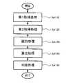
また、プログラム311Aに従って作動している処理装置320は、本開示の第1実施形態の識別方法を実行する。図8は、この識別方法の流れを示すフローチャートである。図8に示すように、この識別方法には、第1取得処理SA110、第2取得処理SA120、識別処理SA130、算出処理SA140、及び判定処理SA150が含まれる。 Further, the
第1取得処理SA110では、処理装置320は第1取得部321として機能する。第1取得処理SA110では、処理装置320は、通信装置300により受信した距離画像データを取得する。第1取得処理SA110に後続する第2取得処理SA120では、処理装置320は、第2取得部322として機能する。第2取得処理SA120では、処理装置320は、通信装置300により受信した輝度画像データを取得する。 In the first acquisition process SA110, the
第2取得処理SA120に後続する識別処理SA130では、処理装置320は、識別部323Aとして機能する。識別処理SA130では、処理装置320は、第2取得部322により取得した輝度画像データの表す輝度画像をN×M個のサブ輝度画像に分割する。次いで、処理装置320は、N×M個のサブ輝度画像の各々を識別対象画像として識別モジュール312へ入力し、識別対象画像に写っている物体の種別を示すラベルを取得する。 In the identification process SA130 following the second acquisition process SA120, the
識別処理SA130に後続する算出処理SA140では、処理装置320は、算出部324Aとして機能する。算出処理SA140では、処理装置320は、第1取得部321により取得した距離画像データの表す距離画像をN×M個のサブ距離画像に分割する。次いで、処理装置320は、N×M個のサブ距離画像の各々算出対象画像とし、算出対象画像における画素値の統計量に応じた指標値を算出する。 In the calculation process SA140 following the identification process SA130, the
算出処理SA140に後続する判定処理SA150では、処理装置320は、判定部325Aとして機能する。判定処理SA150では、処理装置320は、N×M個のサブ輝度画像の各々を判定対象画像として、判定対象画像に対応するサブ距離画像について算出処理SA140にて算出した指標値が閾値未満であるか否かを判定する。そして、処理装置320は、算出処理SA140にて算出した指標値が閾値未満である場合には、判定対象画像に基づく識別部323Aの識別結果を無効にする。 In the determination process SA150 following the calculation process SA140, the
本実施形態によれば、輝度画像に基づく識別対象物の識別結果の信頼度を、輝度画像とは別個の距離画像から把握できる。加えて、本実施形態では、輝度画像に基づく識別結果の信頼度を示す指標値が閾値未満である場合にはその識別結果は無効とされる。本実施形態では、距離画像における画素値の統計量に応じた指標値を用いて輝度画像に基づく識別結果の有効性が判定されるので、複数の物体が写っていることに起因する識別誤りを無効とすることができる。 According to the present embodiment, the reliability of the identification result of the identification object based on the luminance image can be grasped from the distance image separate from the luminance image. In addition, in the present embodiment, when the index value indicating the reliability of the identification result based on the luminance image is less than the threshold value, the identification result is invalid. In the present embodiment, the validity of the identification result based on the luminance image is determined using the index value according to the statistic of the pixel value in the distance image, so that the identification error due to the appearance of a plurality of objects can be detected. It can be invalidated.
2.第2実施形態
図9は、本開示の第2実施形態に係る識別システム1Bの構成例を示すブロック図である。図9では、図1におけるものと同じ構成要素には同じ符号が付されている。図9と図1とを対比すれば明らかなように、識別システム1Bは、識別装置30Aに代えて識別装置30Bを有する点において識別システム1Aと異なる。識別装置30Bは、識別装置30Aと同様に、パーソナルコンピューターである。図9と図1とを対比すれば明らかなように、識別装置30Bのハードウェア構成は識別装置30Aのハードウェア構成と同一である。識別装置30Bは、プログラム311Aに代えてプログラム311Bが記憶装置310に記憶されている点において、識別装置30Aと異なる。2. 2. The second embodiment is a block diagram showing a configuration example of the
識別装置30Bの処理装置320は、プログラム311Bを実行することにより、図9に示す第1取得部321、第2取得部322、識別部323B、算出部324B、及び判定部325Bとして機能する。第1取得部321、第2取得部322、識別部323B、算出部324B、及び判定部325Bは、処理装置320をプログラム311Bに従って動作させることで実現されるソフトウェアモジュールである。以下、第1実施形態との相違点である識別部323B、算出部324B、及び判定部325Bを中心に説明する。 By executing the
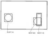
識別部323Bは、識別部323Aと同様に、第2取得部322により取得した輝度画像データの表す輝度画像と識別モジュール312とを用いて輝度画像に写っている物体の種類を識別する。なお、識別部323Bについても、輝度画像データの表す輝度画像に矩形変換を施した後に物体の種類の識別を行ってもよい。識別部323Bは、第2取得部322により取得した輝度画像データを識別モジュール312へ入力し、輝度画像に写っている識別対象物の種別を示すラベルと、注目領域を示すデータとを取得する。注目領域とは、Region Of Interestのことであり、輝度画像において当該識別対象物が占める領域のことをいう。注目領域は本開示における第1領域の一例である。図10は、図4に示す輝度画像を表す輝度画像データを識別モジュール312に入力した場合の識別結果及び注目領域の特定結果の一例を示す図である。図10に示すように、本実施形態では、識別対象物A1について注目領域R1が特定され、ラベルとしてAが取得される。また、識別対象物A2については、注目領域R2が特定され、ラベルとしてDが取得される。そして、識別対象物C1については注目領域R3が特定され、ラベルとしてCが取得される。 Similar to the
算出部324Bは、識別部323Bにより特定された注目領域に対応する距離画像の領域を算出対象画像とし、識別部323Bによる識別結果の信頼度を示す指標値を、算出対象画像における画素値の統計量に基づいて算出する。注目領域に対応する距離画像の領域は本開示における第2領域の一例である。本実施形態における指標値も、第1実施形態と同様に上記統計量の逆数である。本実施形態では、算出対象画像における画素値の統計量として前述の式(1)に示す分散S2が用いられる。本実施形態における第1実施形態と同様に、指標値が大きいほど識別部323Bによる識別結果の信頼度が高いことを意味する。なお、算出部324Bについても、距離画像データの表す距離画像に矩形変換を施した後に指標値の算出を行ってもよい。The
図11は、注目領域R1、R2及びR3の各々について、図3に示す輝度画像に基づく統計量の算出結果を示す図である。図11に示すように、注目領域R1については分散S2として1.5が、注目領域R2については分散S2として6.0が、注目領域R3については分散S2として1.0が夫々算出される。注目領域R2について算出される分散S2が著しく大きいのは、注目領域R2には複数の物体の画像が含まれているからである。前述したように、算出部324Bは、算出対象画像における画素値の統計量の逆数を指標値として算出するため、注目領域R1については指標値として0.67が、注目領域R2については指標値として0.16が、注目領域R3については指標値として1.0が夫々算出される。FIG. 11 is a diagram showing the calculation results of statistics based on the luminance image shown in FIG. 3 for each of the regions of interest R1, R2, and R3. As shown in FIG. 11, 1.5 is calculated as the variance S2 for the region of interest R1, 6.0 is calculated as the variance S2 for the region of interest R2, and 1.0 is calculated as the variance S2 for the region of interest R3. Will be done. The variance S2 calculated for the region of interest R2 is remarkably large because the region of interest R2 contains images of a plurality of objects. As described above, since the
判定部325Bは、識別部323Bによる識別結果が無効であるか否かを、算出部324Bにより算出された信頼度に基づいて注目領域毎に判定する。より詳細に説明すると、判定部325Bは、注目領域毎に、算出部324Bにより算出された指標値が閾値未満であるか否かを判定する。そして、判定部325Bは、算出部324Bにより算出された指標値が閾値未満である注目領域については、識別部323Bの識別結果を無効にする。本実施形態では、上記閾値の値は第1実施形態と同様に0.5である。このため、本実施形態では、注目領域R1、R2及びR3のうち注目領域R2についてのみ、識別結果が無効とされる。 The determination unit 325B determines whether or not the identification result by the
また、識別装置30Bの処理装置320は、プログラム311Bに従って、本開示の第2実施形態の識別方法を実行する。図12は、この識別方法の流れを示すフローチャートである。図12に示すように、この識別方法には、第1取得処理SA110、第2取得処理SA120、識別処理SB130、算出処理SB140、及び判定処理SB150が含まれる。以下、第1実施形態における識別方法との相違点である識別処理SB130、算出処理SB140、及び判定処理SB150を中心に説明する。 Further, the
識別処理SB130では、識別装置30Bの処理装置320は、識別部323Bとして機能する。識別処理SB130では、識別装置30Bの処理装置320は、第2取得部322により取得した輝度画像データを識別モジュール312へ入力し、輝度画像に写っている識別対象物の種別を示すラベルと、注目領域を示すデータとを取得する。 In the identification processing SB 130, the
識別処理SB130に後続する算出処理SB140では、識別装置30Bの処理装置320は、算出部324Bとして機能する。算出処理SB140では、識別装置30Bの処理装置320は、識別処理SB130にて特定した注目領域に対応する距離画像の領域を算出対象画像とし、識別処理SB130における識別結果の信頼度を示す指標値を、算出対象画像における画素値の統計量に基づいて算出する。 In the calculation process SB140 following the identification process SB130, the
算出処理SB140に後続する判定処理SB150では、識別装置30Bの処理装置320は、判定部325Bとして機能する。判定処理SB150では、識別装置30Bの処理装置320は、注目領域毎に、算出処理SB140にて算出した指標値が閾値未満であるか否かを判定し、指標値が閾値未満である注目領域についての識別結果を無効にする。 In the determination process SB150 following the calculation process SB140, the
本実施形態によっても、輝度画像に基づく識別対象物の識別結果の信頼度を、輝度画像とは別個の距離画像から把握できる。本実施形態においても、距離画像における画素値の統計量に応じた指標値を用いて輝度画像に基づく識別結果の有効性が判定されるので、複数の物体が写っていることに起因する識別誤りを無効とすることができる。また、本実施形態によれば、注目領域についてのみ指標値が算出されるので、第1実施形態に比較して指標値の算出に要する処理負荷を低減できる。 Also in this embodiment, the reliability of the identification result of the identification object based on the luminance image can be grasped from the distance image separate from the luminance image. Also in this embodiment, since the validity of the identification result based on the luminance image is determined using the index value according to the statistic of the pixel value in the distance image, the identification error due to the appearance of a plurality of objects is performed. Can be disabled. Further, according to the present embodiment, since the index value is calculated only for the region of interest, the processing load required for calculating the index value can be reduced as compared with the first embodiment.
3.第3実施形態
図13は、本開示の第3実施形態に係る画像表示方法を実行する表示制御装置40を含む画像表示システム2の構成例を示すブロック図である。図13に示すように画像表示システム2は、表示制御装置40の他に、第1撮像装置10と、第2撮像装置20と、表示装置50と、を含む。図13に示すように、第1撮像装置10、第2撮像装置20、及び表示装置50は、表示制御装置40に接続される。以下、第1実施形態との相違点である表示装置50及び表示制御装置40について説明する。3. 3. Third Embodiment FIG. 13 is a block diagram showing a configuration example of an
表示装置50は、表示制御装置40による制御の下、画像を表示する。本実施形態における表示装置50はプロジェクターである。 The
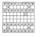
表示制御装置40は、識別装置30A又は識別装置30Bと同様にパーソナルコンピューターである。表示制御装置40は、表示装置50による画像の投写先となる物体の種類を第2撮像装置20により撮像される輝度画像に基づいて識別する。そして、表示制御装置40は、輝度画像に基づく識別結果に応じた画像を投写するように表示装置50を制御する。つまり、本実施形態では、表示装置50からの画像の投写先となる物体が識別対象物となる。図14は、本実施形態における被写体を示す図である。図14に示すように本実施形態の被写体は将棋の各駒が配置された将棋盤である。本実施形態では、将棋の9種類の駒が識別対象物であり、将棋盤が背景物である。なお、図14では、各駒の名称が一文字で略記されている。例えば、図14における「歩」は将棋の駒のうちの「歩兵」を意味し、「玉」は将棋の駒のうちの「玉将」を意味する。本実施形態では、識別モジュール312は、将棋盤、及び将棋の9種類の駒について学習済である。 The
表示制御装置40は、第1撮像装置10により撮像される距離画像に基づいて、被写体における何れかの駒へのユーザーのタッチを検出し、タッチされた駒の種類を識別する。そして、表示制御装置40は、ユーザーのタッチした駒が移動可能なマス目を示す画像を被写体に重ねて表示するように、表示装置50を制御する。なお、第1撮像装置10により撮像される距離画像は、第1及び第2実施形態と同様に、輝度画像に基づく物体の種類の識別結果の有効性の判定にも利用される。 The
図13と図1とを比較すれば明らかなように、表示制御装置40のハードウェア構成は識別装置30Aのハードウェア構成と同一である。即ち、表示制御装置40は、通信装置300と、記憶装置310と、処理装置320と、を含む。通信装置300には、第1撮像装置10、第2撮像装置20、及び表示装置50が接続される。通信装置300は、第1撮像装置10から出力される距離画像データを受信する。また、通信装置300は、第2撮像装置20から出力される輝度画像データを受信する。また、通信装置300は、識別対象物に投写する画像を表す画像データを表示装置50へ出力する。 As is clear from comparing FIGS. 13 and 1, the hardware configuration of the
表示制御装置40の記憶装置310には、プログラム311Cと、識別モジュール312と、テーブル313とが記憶されている。以下、第1実施形態との相違点であるテーブル313及びプログラム311Cについて説明する。 The
テーブル313には、将棋の駒の種類毎に、移動可能なマス目を示すデータが格納されている。例えば、「歩」については図15に示すように前方の1マスを示すデータが、「銀」については右斜め前、前方、左斜め前、右斜め後ろ、及び左斜め後ろの各1マスを示すデータがテーブル313に格納されている。なお、図15では、「歩」及び「銀」の各々の移動可能なマス目がハッチングで示されている。 The table 313 stores data indicating movable squares for each type of shogi piece. For example, for "walk", as shown in FIG. 15, the data showing one square in front, and for "silver", one square each diagonally to the right, front, diagonally to the left, diagonally to the right, and diagonally to the left. The data shown is stored in the table 313. In addition, in FIG. 15, each movable square of "step" and "silver" is shown by hatching.
表示制御装置40の処理装置320は、プログラム311Cに従って作動することにより、第1取得部321、第2取得部322、識別部323A、算出部324C、判定部325A、検出部326、及び表示制御部327として機能する。つまり、第1取得部321、第2取得部322、識別部323A、算出部324C、判定部325A、検出部326及び表示制御部327は、処理装置320をプログラム311Cに従って作動させることにより実現されるソフトウェアモジュールである。以下、第1実施形態との相違点である算出部324C、検出部326及び表示制御部327を中心に説明する。 By operating the
検出部326は、第1取得部321により取得された距離画像データに基づいて、被写体に対するユーザーの指先のタッチを検出する。より詳細に説明すると、検出部326は、距離画像データの表す距離画像を構成する各画素について、事前に保持した基準距離と、現在の画素値が表す距離との差分ΔDを算出する。基準距離とは、被写体を単独で撮像して得られた距離画像における画素値の表す距離である。検出部326は、差分ΔDがより大きく、かつ所定の閾値よりも小さい画素があった場合に、ユーザーのタッチがあったと判定し、当該画素の位置をタッチ位置として検出する。本実施形態では上記閾値は1cmである。 The
算出部324Cは、第1実施形態における算出部324Aと同様に、識別部323Aによる識別結果の信頼度を示す指標値を、第1取得部321により取得した距離画像データの表す距離画像に基づいて算出する。より詳細に説明すると、算出部324Cは、距離画像データの表す距離画像を、背景物である将棋盤のマス目に合わせて9×9個のサブ距離画像に分割する。本実施形態ではN=9且つM=9であり、9×9個のサブ距離画像は将棋盤の9×9個のマス目に一対一に対応する。算出部324Cは、9×9個のサブ距離画像の各々について、以下の式(2)に示す指標値Cを算出する。式(2)においてGtは算出対象画像を構成する画素の総数であり、Geは算出対象画像を構成する画素のうち基準画像からの画素値の変動量が所定の閾値を超える画素の数である。つまり、算出部324Cと算出部324Aとでは、指標値の計算式のみが異なる。
表示制御部327は、検出部326により検出されたタッチ位置に対応するサブ輝度画像についての識別結果が判定部325Aにより有効と判定された場合に、タッチ位置に対応する駒が移動可能なマス目をテーブル313を参照して特定する。そして、表示制御部327は、特定したマス目を示す画像データを表示装置50に与え、当該画像データの示す画像を被写体に重ねて表示させる。 The
また、表示制御装置40の処理装置320は、プログラム311Cに従って、本開示の第3実施形態の画像表示方法を実行する。図16は、この画像表示方法の流れを示すフローチャートである。図16に示すように、この画像表示方法には、第1取得処理SA110、第2取得処理SA120、検出処理SC125、識別処理SA130、算出処理SC140、判定処理SA150、及び表示制御処理SC160が含まれる。 Further, the
第1取得処理SA110では、表示制御装置40の処理装置320は第1取得部321として機能する。第1取得処理SA110では、処理装置320は、通信装置300により受信した距離画像データを取得する。第1取得処理SA110に後続する第2取得処理SA120では、表示制御装置40の処理装置320は、第2取得部322として機能する。第2取得処理SA120では、処理装置320は、通信装置300により受信した輝度画像データを取得する。 In the first acquisition process SA110, the
検出処理SC125では、表示制御装置40の処理装置320は検出部326として機能する。検出処理SC125では、表示制御装置40の処理装置320は、第1取得部321により取得された距離画像データの示す距離画像に基づいて、識別対象物へのユーザーのタッチ位置を検出する。以下では、図14において1行5列目に配置される「王」、即ち「王将」を使う側のユーザーが3行7列目の「歩」を動かすために当該「歩」にタッチした場合を例にとって説明する。 In the detection processing SC125, the
識別処理SA130では、表示制御装置40の処理装置320は、識別部323Aとして機能する。識別処理SA130では、表示制御装置40の処理装置320は、9×9個のサブ輝度画像の各々に基づいて識別対象物の種類を識別する。図17には、将棋盤の1行目に対応する9個のサブ輝度画像の各々に基づく識別結果が示されている。図17に示す例では、1行6列目についての識別結果は「香」、即ち「香車」であるが、図14に示すように実際に配置されている駒は「金」、即ち「金将」である。また、図17に示す例では、1行7列目についての識別結果は「角」、即ち「角行」であるが、図14に示すように実際に配置されている駒は「銀」である。また、図17に示す例では、1行8列目についての識別結果は「飛」、即ち「飛車」であるが、図14に示すように実際に配置されている駒は「桂」、即ち「桂馬」である。つまり、図17に示す例では、1行6列目、1行7列目、及び1行8列目の各サブ輝度画像に基づく識別結果は誤っている。これは、3行7列目の「歩」にタッチする際にユーザーの腕が将棋盤の1行6列目、1行7列目、及び1行8列目の上を横切り、ユーザーの腕が重なった状態で撮像された輝度画像に基づいて識別対象物の識別が行われたことに起因する。 In the identification processing SA130, the
識別処理SA130に後続する算出処理SC140では、表示制御装置40の処理装置320は、算出部324Cとして機能する。算出処理SC140では、表示制御装置40の処理装置320は、9×9個のサブ距離画像の各々に基づいて指標値を算出する。図17には、将棋盤の1行目に対応する9個のサブ距離画像の各々に基づいて算出された指標値が示されている。図17に示す例において、1行6列目、1行7列目、及び1行8列目の指標値が0となっているのは、これらのサブ距離画像においては、ユーザーの腕が重なった状態で撮像された影響で、全ての画素について基準画像からの画素値の変動が大きくなるからである。 In the calculation process SC140 following the identification process SA130, the
算出処理SA140に後続する判定処理SA150では、表示制御装置40の処理装置320は、判定部325Aとして機能する。判定処理SA150では、表示制御装置40の処理装置320は、9×9個のサブ輝度画像の各々について、対応するサブ距離画像に基づいて算出された指標値が閾値未満であるか否かを判定し、指標値が閾値未満である場合には、識別処理SA130の識別結果を無効にする。図17には、将棋盤の1行目に対応する9個のサブ輝度画像の各々についての判定結果が占められている。前述したように上記閾値は0.5であるため、図17に示す例では、1行1列目~1行5列目及び1行9列目についての識別結果は有効と、1行6列目~1行8列目についての識別結果は無効とされる。以下では、9×9個のサブ輝度画像のうち1行6列目~1行8列目の3つのサブ輝度画像については識別結果が無効とされるものの、他の78個のサブ輝度画像の各々に基づく識別結果は有効とされた場合について説明する。なお、タッチ位置に対応するサブ輝度画像に基づく識別結果が無効であった場合には、過去のフレーム期間において有効となった識別結果を利用すればよい。 In the determination process SA150 following the calculation process SA140, the
表示制御処理SC160では、表示制御装置40の処理装置320は、表示制御部327として機能する。表示制御処理SC160では、処理装置320は、判定処理SA150にて有効と判定された識別結果に応じた画像を表示装置50に表示させる。本実施形態では、ユーザーのタッチ位置として3行7列目のマス目が検出処理SC125で検出されている。このマス目に配置されている駒は「歩」であるから、移動可能なマス目として一つ前方のマス目、即ち4行7列目のマス目が特定される。本実施形態では、3行7列目のマス目についての識別結果は有効とされるので、4行7列目のマス目を所定の色で塗りつぶす画像を被写体に重ねて表示装置50に表示させる。その結果、ユーザーの目には図18に示す画像が映る。図18に示す例では、ユーザーのタッチした駒が移動可能なマス目を示す色がハッチングで示されている。 In the display control processing SC160, the
本実施形態によっても、輝度画像に基づく識別対象物の識別結果の信頼度を、輝度画像とは別個の距離画像から把握できる。本実施形態では、輝度画像に基づく識別対象物の識別結果の信頼度を示す指標値が閾値未満である識別結果は無効とされるので、タッチ位置に対応する駒の種別が誤って識別された場合であっても、誤った識別結果に基づいて移動可能なマス目が誤って表示されることを回避できる。 Also in this embodiment, the reliability of the identification result of the identification object based on the luminance image can be grasped from the distance image separate from the luminance image. In the present embodiment, the identification result in which the index value indicating the reliability of the identification result of the identification object based on the luminance image is less than the threshold value is invalid. Therefore, when the type of the piece corresponding to the touch position is erroneously identified. Even so, it is possible to prevent the movable squares from being erroneously displayed based on the erroneous identification result.
4.変形例
各実施形態は、以下のように変更されてもよい。
(1)第1、第2及び第3施形態では、第1取得処理SA110に後続して第2取得処理SA120が実行されたが、第1取得処理SA110と第2取得処理SA120の実行順が入れ替わってもよい。また、第1実施形態における識別処理SA130と算出処理SA140の実行順が入れ替わってもよい。識別処理SA130に先立って算出処理SA140を実行する態様は、算出処理SA140にて算出された指標値が所定の閾値以上であるサブ輝度画像についてのみ識別処理SA130を実行されるように変更されてもよい。第3実施形態の画像表示方法についても同様に識別処理SA130に先立って算出処理SC140が実行されるように変更されてもよい。識別処理SA130に先立って算出処理SC140が実行される場合、算出処理SC140にて算出された指標値が所定の閾値以上であるサブ輝度画像についてのみ識別処理SA130を実行されるように変更されてもよい。4. Modifications Each embodiment may be modified as follows.
(1) In the first, second and third embodiments, the second acquisition process SA120 is executed after the first acquisition process SA110, but the execution order of the first acquisition process SA110 and the second acquisition process SA120 is It may be replaced. Further, the execution order of the identification process SA130 and the calculation process SA140 in the first embodiment may be interchanged. The mode in which the calculation process SA140 is executed prior to the identification process SA130 is changed so that the identification process SA130 is executed only for the sub-luminance image whose index value calculated by the calculation process SA140 is equal to or higher than a predetermined threshold value. good. Similarly, the image display method of the third embodiment may be changed so that the calculation process SC140 is executed prior to the identification process SA130. When the calculation process SC140 is executed prior to the identification process SA130, even if the identification process SA130 is changed so that the identification process SA130 is executed only for the sub-luminance image whose index value calculated by the calculation process SC140 is equal to or higher than a predetermined threshold value. good.
同様に、第2実施形態における識別処理SB130と算出処理SB140の実行順が入れ替わってもよい。識別処理SB130に先立って算出処理SB140を実行する場合には、距離画像に基づいて注目領域を特定すればよい。具体的には、輝度画像にエッジ検出を施し、検出されたエッジを注目領域の輪郭線とすればよい。エッジとは画像の水平走査方向又は垂直走査方向に画素値をサンプリングしたときに画素値が急激に変化する画素のことをいう。被写体の距離画像において識別対象物に対応する画素と背景物に対応する画素とでは画素値が異なることが通常である。つまり、被写体の距離画像において識別対象物の輪郭線はエッジとなっていることが通常である。このため、被写体の距離画像からエッジを検出することで、距離画像に写っている識別対象物の輪郭線を検出することができ、この輪郭線で囲まれた領域が注目領域となる。なお、識別処理SB130に先立って算出処理SB140が実行される態様は、算出処理SB140にて算出された指標値が所定の閾値以上であるサブ輝度画像についてのみ識別処理SB130を実行されるように変更されてもよい。 Similarly, the execution order of the identification process SB130 and the calculation process SB140 in the second embodiment may be interchanged. When the calculation process SB140 is executed prior to the identification process SB130, the region of interest may be specified based on the distance image. Specifically, edge detection may be performed on the luminance image, and the detected edge may be used as the contour line of the region of interest. An edge is a pixel whose pixel value changes abruptly when the pixel value is sampled in the horizontal scanning direction or the vertical scanning direction of an image. In a distance image of a subject, the pixel value is usually different between the pixel corresponding to the identification target and the pixel corresponding to the background object. That is, in the distance image of the subject, the contour line of the identification object is usually an edge. Therefore, by detecting the edge from the distance image of the subject, the contour line of the identification object reflected in the distance image can be detected, and the area surrounded by the contour line becomes the region of interest. The mode in which the calculation process SB140 is executed prior to the identification process SB130 is changed so that the identification process SB130 is executed only for the sub-luminance image whose index value calculated by the calculation process SB140 is equal to or higher than a predetermined threshold value. May be done.
(2)識別装置30A、識別装置30B、及び表示制御装置40は、パーソナルコンピューターであったが、スマートフォン又はタブレット端末であってもよい。また、上記第1及び第3実施形態における統計量は分散であったが、標準偏差であってもよく、平均値、最大値、最小値、中央値、最頻出値又は四分位値であってもよい。また、算出対象画像を構成する各画素の画素値の統計量ではなく、各画素の画素値を畳み込みカーネルを用いて畳み込んだ演算値が、指標値とされてもよい。また、識別モジュール312は、畳み込みニューラルネットワークには限定されず、画像特徴量を用いた機械学習等、大量のデータから識別パラメーターを構成する非ルールベースの手法で構成された識別器であればよい。また、第3実施形態における表示装置50はプロジェクターであったが、被写体に含まれる識別対象物の種類に応じた画像を被写体の画像に重ねて表示する液晶ディスプレイであってもよい。表示装置50が液晶ディスプレイの場合、被写体の輝度画像に対して、輝度画像内に写っている識別対象物の位置及び種類に応じたコンテンツを重畳するARのような使い方が可能になる。(2) The
(3)上記各実施形態では、距離画像と輝度画像とを各々別個のカメラで撮像した。しかし、第1撮像装置10と第2撮像装置20とに代えて、距離画像の撮像機能と輝度画像の撮像機能とを兼ね備えた1台のカメラを用いてもよい。距離画像の撮像機能と輝度画像の撮像機能とを兼ね備えた1台のカメラを用いる場合、第2位置は第1位置と同じ位置になる。(3) In each of the above embodiments, the distance image and the luminance image are captured by separate cameras. However, instead of the first
(4)第1実施形態における第1取得部321、第2取得部322、識別部323A、算出部324A、及び判定部325Aはソフトウェアモジュールであったが、第1取得部321、第2取得部322、識別部323A、算出部324A、及び判定部325Aの一部又は全部がハードウェアであってもよい。このハードウェアの一例としては、DSP(Digital Signal Processor)、ASIC(Application Specific Integrated Circuit)、PLD(Programmable Logic Device)、及びFPGA(Field Programmable Gate Array)が挙げられる。第1取得部321、第2取得部322、識別部323A、算出部324A、及び判定部325Aの一部又は全部がハードウェアであっても、第1実施形態と同一の効果が奏される。第2実施形態における識別部323B、算出部324B、及び判定部325Bについても同様に一部又は全部がハードウェアであってもよい。第3実施形態における算出部324C、検出部326及び表示制御部327についても同様に一部又は全部がハードウェアであってもよい。(4) Although the
(5)第1実施形態及び第3実施形態における判定部325A及び判定処理SA150と、第2実施形態における判定部325B及び判定処理SB150とは必須ではなく、省略可能である。算出部324Aによりサブ輝度画像毎に算出された指標値又は算出部324Bにより注目領域毎に算出された指標値を表示装置に表示させることによっても、識別結果の信頼度をユーザーに把握させることができるからである。同様に第3実施形態における検出部326及び検出処理SC125も省略可能である。移動可能なマス目の表示を所望する駒を表示制御装置40に指示する方法は、当該駒へのタッチには限定されず、当該駒が配置されているマス目の行数及び列数を示す数値を入力装置へ入力する態様であってもよいからである。(5) The
(6)上述した第1実施形態では、プログラム311Aが記憶装置310に記憶済であった。しかし、プログラム311Aを単体で製造又は配布してもよい。プログラム311Aの具体的な配布方法としては、フラッシュROM(Read Only Memory)等のコンピューター読み取り可能な記録媒体に上記プログラム311Aを書き込んで配布する態様、又はインターネット等の電気通信回線経由のダウンロードにより配布する態様が考えられる。第2実施形態におけるプログラム311B、及び第3実施形態におけるプログラム311Cについても同様である。(6) In the first embodiment described above, the program 311A has already been stored in the
5.各実施形態及び各変形例の少なくとも1つから把握される態様
本開示は、上述した各実施形態及び変形例に限られるものではなく、その趣旨を逸脱しない範囲において種々の態様で実現することができる。例えば、本開示は、以下の態様によっても実現可能である。以下に記載した各態様中の技術的特徴に対応する上記実施形態中の技術的特徴は、本開示の課題の一部又は全部を解決するために、或いは本開示の効果の一部又は全部を達成するために、適宜、差し替えや、組み合わせを行うことが可能である。また、その技術的特徴が本明細書中に必須なものとして説明されていなければ、適宜、削除することが可能である。5. Aspects grasped from at least one of each embodiment and each modification The present disclosure is not limited to each of the above-described embodiments and modifications, and may be realized in various embodiments without departing from the spirit thereof. can. For example, the present disclosure can also be realized by the following aspects. The technical features in the above embodiments that correspond to the technical features in each aspect described below are for solving some or all of the problems of the present disclosure, or some or all of the effects of the present disclosure. It is possible to replace or combine as appropriate to achieve this. Further, if the technical feature is not described as essential in the present specification, it can be appropriately deleted.
以上に説明した課題を解決するため、本開示の識別方法の一態様は、第1取得処理SA110、第2取得処理SA120、識別処理SA130、及び算出処理SA140を含む。第1取得処理SA110では、机等の背景物B1の上に識別対象物である識別対象物A1、A2及びC1が配置された被写体、即ち識別対象物A1、A2及びC1を含む被写体を、第1位置に設置される第1撮像装置10により撮像して得られる第1画像が取得される。第1撮像装置10は距離カメラであり、第1画像は距離画像である。第1画像における各画素の画素値は、第1位置から被写体までの距離を表す。第2取得処理SA120では、第1位置又は第1位置とは異なる第2位置に設置される第2撮像装置20により被写体を撮像して得られる第2画像が取得される。第2画像は輝度画像である。第2画像における各画素の画素値は被写体からの反射光の輝度を少なくとも表す。識別処理SA130では、第2画像に基づいて識別対象物の種類が識別される。算出処理SA140では、第2画像に基づく識別結果の信頼度を示す指標値が第1画像に基づいて算出される。本態様によれば、輝度画像に基づく識別対象物の識別結果の信頼度を、輝度画像とは別個の距離画像から把握できる。なお、識別処理SA130に代えて識別処理SB130を設けてもよく、算出処理SA140に代えて算出処理SB140を設けてもよい。本態様によっても、輝度画像に基づく識別対象物の識別結果の信頼度を、輝度画像とは別個の距離画像から把握できる。 In order to solve the above-described problems, one aspect of the identification method of the present disclosure includes a first acquisition process SA110, a second acquisition process SA120, an identification process SA130, and a calculation process SA140. In the first acquisition process SA110, a subject in which the identification objects A1, A2 and C1 which are identification objects are arranged on a background object B1 such as a desk, that is, a subject including the identification objects A1, A2 and C1 is first. The first image obtained by imaging by the first
より好ましい態様の識別方法では、識別処理SA130に後続して算出処理SA140が実行されてもよい。つまり、識対象物の種類が第2画像に基づいて識別され、その後、第1画像に基づいて指標値が算出されてもよい。更に好ましい態様の識別方法は、算出された指標値が閾値未満であるか否かを判定し、閾値未満である場合には、第2画像に基づく識別結果は無効にする判定処理SA150を含んでもよい。 In a more preferred embodiment of the identification method, the calculation process SA140 may be executed after the identification process SA130. That is, the type of the object to be recognized may be identified based on the second image, and then the index value may be calculated based on the first image. A further preferred embodiment of the identification method includes a determination process SA150 that determines whether or not the calculated index value is less than the threshold value, and if it is less than the threshold value, invalidates the identification result based on the second image. good.
更に好ましい態様における識別方法では、第2画像において識別対象物の画像が占める注目領域が第1画像又は第2画像に基づいて識別されてもよい。この態様においては、識別対象物の種類が注目領域の画像に基づいて識別され、第1画像において注目領域に対応する領域の画像に基づいて指標値が算出される。 In the identification method in a further preferred embodiment, the region of interest occupied by the image of the identification target in the second image may be identified based on the first image or the second image. In this embodiment, the type of the identification target is identified based on the image of the region of interest, and the index value is calculated based on the image of the region corresponding to the region of interest in the first image.
別の好ましい態様における識別方法では、第1画像は第1サブ画像と第2サブ画像とに分割される。第2画像も第1サブ画像に対応する第3サブ画像と前記第2サブ画像に対応する第4サブ画像とに分割される。本態様では、第3サブ画像と第4サブ画像の各々について識別対象物の識別が試みられ、第1サブ画像と第2サブ画像の各々に基づいて指標値が算出される。そして、第1サブ画像に基づいて算出された指標値が閾値未満である場合には第3サブ画像に基づく識別結果は無効とされる。同様に、第2サブ画像に基づいて算出された指標値が閾値未満である場合には第4サブ画像に基づく識別結果は無効とされる。 In another preferred embodiment of the identification method, the first image is divided into a first sub-image and a second sub-image. The second image is also divided into a third sub-image corresponding to the first sub-image and a fourth sub-image corresponding to the second sub-image. In this embodiment, identification of the identification target is attempted for each of the third sub-image and the fourth sub-image, and the index value is calculated based on each of the first sub-image and the second sub-image. When the index value calculated based on the first sub-image is less than the threshold value, the identification result based on the third sub-image is invalid. Similarly, if the index value calculated based on the second sub-image is less than the threshold value, the identification result based on the fourth sub-image is invalid.
好ましい態様における識別方法では、第1画像は第1サブ画像と第2サブ画像とに分割され、第2画像も第1サブ画像に対応する第3サブ画像と第2サブ画像に対応する第4サブ画像とに分割される。本態様では、まず、第1サブ画像と第2サブ画像の各々に基づいて指標値が算出される。そして、第1サブ画像に基づいて算出された指標値が閾値以上である場合には第3サブ画像に基づいて識別対象物の種類が識別される。第2サブ画像に基づいて算出された指標値が閾値以上である場合には第4サブ画像に基づいて識別対象物の種類が識別される。 In the identification method in the preferred embodiment, the first image is divided into a first sub-image and a second sub-image, and the second image also corresponds to a third sub-image corresponding to the first sub-image and a fourth sub-image corresponding to the second sub-image. It is divided into sub-images. In this embodiment, first, the index value is calculated based on each of the first sub-image and the second sub-image. Then, when the index value calculated based on the first sub-image is equal to or greater than the threshold value, the type of the identification target is identified based on the third sub-image. When the index value calculated based on the second sub-image is equal to or greater than the threshold value, the type of the identification target is identified based on the fourth sub-image.
更に好ましい態様の識別方法では、第1サブ画像に基づく指標値は、第1サブ画像を構成する各画素の画素値の統計量である。同様に、第2サブ画像に基づく指標値は、第2サブ画像を構成する各画素の画素値の統計量である。 In a more preferred embodiment of the identification method, the index value based on the first sub-image is a statistic of the pixel value of each pixel constituting the first sub-image. Similarly, the index value based on the second sub-image is a statistic of the pixel value of each pixel constituting the second sub-image.
識別処理SA130又は識別処理SB130では、物体の画像と物体の種類を示すラベルとを対応付けた学習データを予め学習済であり、且つ入力された画像に写っている物体の種類を示すラベルを出力する識別器を用いて、識別対象物の種類が識別されてもよい。 In the identification process SA130 or the identification process SB130, learning data in which an image of an object and a label indicating the type of the object are associated with each other has been learned in advance, and a label indicating the type of the object shown in the input image is output. The type of the object to be identified may be identified by using the discriminator.
また、以上に説明した課題を解決するため、本開示の画像表示方法の一態様は、前述の第1取得処理SA110と、第2取得処理SA120と、識別処理SA130と、算出処理SC140と、判定処理SA150と、表示制御処理SC160を含む。表示制御処理SC160では、識別対象物の種類の識別結果に応じた第3画像が被写体に重ねて表示される。 Further, in order to solve the problems described above, one aspect of the image display method of the present disclosure is determined to be the above-mentioned first acquisition process SA110, second acquisition process SA120, identification process SA130, and calculation process SC140. The processing SA150 and the display control processing SC160 are included. In the display control process SC160, a third image corresponding to the identification result of the type of the identification object is displayed superimposed on the subject.
また、以上に説明した課題を解決するため、本開示の識別システムの一態様は、第1位置に設置される第1撮像装置10と、第1位置又は第1位置とは異なる第2位置に設置される第2撮像装置20と、処理装置320と、を備える。処理装置320は、前述の第1取得処理SA110、第2取得処理SA120、識別処理SA130及び算出処理SA140を実行する。本態様によっても、輝度画像に基づく識別対象物の識別結果の信頼度を、輝度画像とは別個の距離画像から把握できる。なお、識別処理SA130を識別処理SB130に置き換え、且つ算出処理SA140を算出処理SB140に置き換えても同じ効果が得られる。 Further, in order to solve the above-described problems, one aspect of the identification system of the present disclosure is a first
また、以上に説明した課題を解決するため、本開示の画像表示システムの一態様は、第1位置に設置される第1撮像装置10と、第1位置又は第1位置とは異なる第2位置に設置される第2撮像装置20と、表示装置の一例である表示装置50と、処理装置320と、を備える。処理装置320は、前述の第1取得処理SA110、第2取得処理SA120、識別処理SA130、算出処理SC140、及び表示制御処理SC160を実行する。本態様によれば、輝度画像に基づく識別対象物の識別結果の信頼度を、輝度画像とは別個の距離画像から把握でき、識別対象物の識別結果に応じた第3画像を被写体に重ねて表示することができる。 Further, in order to solve the above-described problems, one aspect of the image display system of the present disclosure is a first
また、以上に説明した課題を解決するため、本開示のプログラムの一態様は、コンピューターの一例である処理装置320に、前述の第1取得処理SA110、第2取得処理SA120、識別処理SA130及び算出処理SA140を実行させる。本態様によっても、輝度画像に基づく識別対象物の識別結果の信頼度を、輝度画像とは別個の距離画像から把握できる。なお、識別処理SA130を識別処理SB130に置き換え、且つ算出処理SA140を算出処理SB140に置き換えても同じ効果が得られる。また、本開示のプログラムの別の態様は、コンピューターの一例である処理装置320に、前述の第1取得処理SA110、第2取得処理SA120、識別処理SA130、算出処理SC140、及び表示制御処理SC160を実行させる。本態様によれば、輝度画像に基づく識別対象物の識別結果の信頼度を、輝度画像とは別個の距離画像から把握でき、識別対象物の識別結果に応じた第3画像を被写体に重ねて表示することができる。 Further, in order to solve the above-described problems, one aspect of the program of the present disclosure is to use a
1A,1B…識別システム、2…画像表示システム、10…第1撮像装置、20…第2撮像装置、30A、30B…識別装置、40…表示制御装置、50…表示装置、300…通信装置、310…記憶装置、320…処理装置、321…第1取得部、322…第2取得部、323A、323B…識別部、324A、324B、324C…算出部、325A、325B…判定部、326…検出部、327…表示制御部、311A、311B、311C…プログラム、312…識別モジュール、313…テーブル、A1、A2、C1…識別対象物、B1…背景物。1A, 1B ... identification system, 2 ... image display system, 10 ... first image pickup device, 20 ... second image pickup device, 30A, 30B ... identification device, 40 ... display control device, 50 ... display device, 300 ... communication device, 310 ... Storage device, 320 ... Processing device, 321 ... First acquisition unit, 322 ... Second acquisition unit, 323A, 323B ... Identification unit, 324A, 324B, 324C ... Calculation unit, 325A, 325B ... Judgment unit, 326 ... Detection unit Unit, 327 ... Display control unit, 311A, 311B, 311C ... Program, 312 ... Identification module, 313 ... Table, A1, A2, C1 ... Identification target, B1 ... Background object.
Claims (12)
Translated fromJapanese前記第1位置又は前記第1位置とは異なる第2位置から撮像された画像であって、各画素の画素値が前記被写体からの反射光の輝度を少なくとも表す第2画像を取得し、
前記第2画像に基づいて前記識別対象物の種類を識別する一方、前記第2画像に基づく識別結果の信頼度を示す指標値を前記第1画像に基づいて算出する、
識別方法。The first image in which the pixel value of each pixel represents the distance from the first position of the subject including the identification target is acquired.
An image captured from the first position or a second position different from the first position, in which the pixel value of each pixel at least represents the brightness of the reflected light from the subject, is acquired.
While identifying the type of the identification object based on the second image, an index value indicating the reliability of the identification result based on the second image is calculated based on the first image.
Identification method.
前記第3サブ画像と前記第4サブ画像の各々について前記識別対象物の識別を試みる一方、前記第1サブ画像と前記第2サブ画像の各々に基づいて前記指標値を算出し、
前記第1サブ画像に基づいて算出された前記指標値が前記閾値未満である場合には前記第3サブ画像に基づく識別結果を無効とし、前記第2サブ画像に基づいて算出された前記指標値が前記閾値未満である場合には前記第4サブ画像に基づく識別結果を無効とする、請求項2に記載の識別方法。The first image is divided into a first sub-image and a second sub-image, while the second image is divided into a third sub-image corresponding to the first sub-image and a fourth sub-image corresponding to the second sub-image. Divide into and
While trying to discriminate the identification object for each of the third sub-image and the fourth sub-image, the index value is calculated based on each of the first sub-image and the second sub-image.
When the index value calculated based on the first sub-image is less than the threshold value, the identification result based on the third sub-image is invalidated, and the index value calculated based on the second sub-image is invalidated. The identification method according to claim 2, wherein when is less than the threshold value, the identification result based on the fourth sub-image is invalidated.
前記第1サブ画像と前記第2サブ画像の各々に基づいて前記指標値を算出し、
前記第1サブ画像に基づいて算出された前記指標値が閾値以上である場合には前記第3サブ画像に基づいて前記識別対象物の種類を識別し、前記第2サブ画像に基づいて算出された前記指標値が閾値以上である場合には前記第4サブ画像に基づいて前記識別対象物の種類を識別する、請求項1に記載の識別方法。The first image is divided into a first sub-image and a second sub-image, while the second image is divided into a third sub-image corresponding to the first sub-image and a fourth sub-image corresponding to the second sub-image. Divide into and
The index value is calculated based on each of the first sub-image and the second sub-image.
When the index value calculated based on the first sub-image is equal to or higher than the threshold value, the type of the identification target is identified based on the third sub-image, and the calculation is performed based on the second sub-image. The identification method according to claim 1, wherein when the index value is equal to or more than a threshold value, the type of the identification object is identified based on the fourth sub-image.
前記第1位置又は前記第1位置とは異なる第2位置から撮像された画像であって、各画素の画素値が前記被写体からの反射光の輝度を少なくとも表す第2画像を取得し、
前記第2画像に基づいて前記識別対象物の種類を識別する一方、前記第2画像に基づく前記識別対象物の種類の識別結果の信頼度を示す指標値を前記第1画像に基づいて算出し、
前記識別対象物の種類の識別結果に応じた第3画像を前記被写体に重ねて表示する、
画像表示方法。The first image in which the pixel value of each pixel represents the distance from the first position of the subject including the identification target is acquired.
An image captured from the first position or a second position different from the first position, in which the pixel value of each pixel at least represents the brightness of the reflected light from the subject, is acquired.
While the type of the identification object is identified based on the second image, an index value indicating the reliability of the identification result of the type of the identification object based on the second image is calculated based on the first image. ,
A third image corresponding to the identification result of the type of the identification object is superimposed and displayed on the subject.
Image display method.
前記第1位置又は前記第1位置とは異なる第2位置に設置され、各画素の画素値が前記被写体からの反射光の輝度を少なくとも表す第2画像を撮像する第2撮像装置と、
処理装置と、を備え、
前記処理装置は、
前記第1撮像装置から前記第1画像を取得すること、
前記第2撮像装置から前記第2画像を取得すること、及び、
前記第2画像に基づいて前記識別対象物の種類を識別する一方、前記第2画像に基づく前記識別対象物の種類の識別結果の信頼度を示す指標値を前記第1画像に基づいて算出すること、を実行する、
識別システム。A first image pickup device installed at a first position and capturing a first image in which the pixel value of each pixel represents the distance of a subject including an object to be identified from the first position.
A second image pickup device installed at the first position or a second position different from the first position and capturing a second image in which the pixel value of each pixel represents at least the brightness of the reflected light from the subject.
Equipped with a processing device,
The processing device is
Acquiring the first image from the first image pickup device,
Acquiring the second image from the second image pickup device and
While the type of the identification object is identified based on the second image, an index value indicating the reliability of the identification result of the type of the identification object based on the second image is calculated based on the first image. That, to do,
Identification system.
前記第1位置又は前記第1位置とは異なる第2位置に設置され、各画素の画素値が前記被写体からの反射光の輝度を少なくとも表す第2画像を撮像する第2撮像装置と、
表示装置と、
処理装置と、を備え、
前記処理装置は、
前記第1撮像装置から前記第1画像を取得すること、
前記第2撮像装置から前記第2画像を取得すること、
前記第2画像に基づいて前記識別対象物の種類を識別する一方、前記第2画像に基づく前記識別対象物の種類の識別結果の信頼度を示す指標値を前記第1画像に基づいて算出すること、及び、
前記識別対象物の種類の識別結果に応じた第3画像を前記識別対象物に重ねて前記表示装置に表示させること、を実行する
画像表示システム。A first image pickup device installed at a first position and capturing a first image in which the pixel value of each pixel represents the distance of a subject including an object to be identified from the first position.
A second image pickup device installed at the first position or a second position different from the first position and capturing a second image in which the pixel value of each pixel represents at least the brightness of the reflected light from the subject.
Display device and
Equipped with a processing device,
The processing device is
Acquiring the first image from the first image pickup device,
Acquiring the second image from the second image pickup device,
While the type of the identification object is identified based on the second image, an index value indicating the reliability of the identification result of the type of the identification object based on the second image is calculated based on the first image. That and,
An image display system that superimposes a third image according to the identification result of the type of the identification object on the identification object and displays it on the display device.
識別対象物を含む被写体の第1位置からの距離を各画素の画素値が表す第1画像を取得すること、
前記第1位置又は前記第1位置とは異なる第2位置から撮像された画像であって、各画素の画素値が前記被写体からの反射光の輝度を少なくとも表す第2画像を取得すること、及び、
前記第2画像に基づいて前記識別対象物の種類を識別する一方、前記第2画像に基づく前記識別対象の種類の識別結果の信頼度を示す指標値を前記第1画像に基づいて算出すること、
を実行させるプログラム。On the computer
Acquiring the first image in which the pixel value of each pixel represents the distance from the first position of the subject including the identification object.
Obtaining a second image captured from the first position or a second position different from the first position, wherein the pixel value of each pixel at least represents the brightness of the reflected light from the subject. ,
While identifying the type of the identification target based on the second image, an index value indicating the reliability of the identification result of the identification target type based on the second image is calculated based on the first image. ,
A program to execute.
識別対象物を含む被写体の第1位置からの距離を各画素の画素値が表す第1画像を取得すること、
前記第1位置又は前記第1位置とは異なる第2位置から撮像された画像であって、各画素の画素値が前記被写体からの反射光の輝度を少なくとも表す第2画像を取得すること、
前記第2画像に基づいて前記識別対象物の種類を識別する一方、前記第2画像に基づく前記識別対象物の種類の識別結果の信頼度を示す指標値を前記第1画像に基づいて算出すること、及び、
前記識別対象物の種類の識別結果に応じた第3画像を前記識別対象物に重ねて表示すること、
を実行させるプログラム。On the computer
Acquiring the first image in which the pixel value of each pixel represents the distance from the first position of the subject including the identification object.
Acquiring a second image captured from the first position or a second position different from the first position, wherein the pixel value of each pixel at least represents the brightness of the reflected light from the subject.
While the type of the identification object is identified based on the second image, an index value indicating the reliability of the identification result of the type of the identification object based on the second image is calculated based on the first image. That and,
Displaying a third image according to the identification result of the type of the identification object superimposed on the identification object.
A program to execute.
Priority Applications (2)
| Application Number | Priority Date | Filing Date | Title |
|---|---|---|---|
| JP2020178717AJP7571461B2 (en) | 2020-10-26 | 2020-10-26 | Identification method, image display method, identification system, image display system, and program |
| US17/509,883US12020479B2 (en) | 2020-10-26 | 2021-10-25 | Identification method, identification system, and non-transitory computer-readable storage medium storing a program |
Applications Claiming Priority (1)
| Application Number | Priority Date | Filing Date | Title |
|---|---|---|---|
| JP2020178717AJP7571461B2 (en) | 2020-10-26 | 2020-10-26 | Identification method, image display method, identification system, image display system, and program |
Publications (3)
| Publication Number | Publication Date |
|---|---|
| JP2022069828Atrue JP2022069828A (en) | 2022-05-12 |
| JP2022069828A5 JP2022069828A5 (en) | 2023-07-31 |
| JP7571461B2 JP7571461B2 (en) | 2024-10-23 |
Family
ID=81258593
Family Applications (1)
| Application Number | Title | Priority Date | Filing Date |
|---|---|---|---|
| JP2020178717AActiveJP7571461B2 (en) | 2020-10-26 | 2020-10-26 | Identification method, image display method, identification system, image display system, and program |
Country Status (2)
| Country | Link |
|---|---|
| US (1) | US12020479B2 (en) |
| JP (1) | JP7571461B2 (en) |
Families Citing this family (1)
| Publication number | Priority date | Publication date | Assignee | Title |
|---|---|---|---|---|
| CN118692146B (en)* | 2024-06-19 | 2025-01-17 | 广东科技学院 | Intelligent auxiliary training method, system, equipment and medium for badminton |
Citations (6)
| Publication number | Priority date | Publication date | Assignee | Title |
|---|---|---|---|---|
| JPH0927969A (en)* | 1995-05-08 | 1997-01-28 | Matsushita Electric Ind Co Ltd | Multiple image intermediate image generation method and parallax estimation method and apparatus |
| JP2011063131A (en)* | 2009-09-17 | 2011-03-31 | Hitachi Automotive Systems Ltd | Vehicle control apparatus |
| JP2015143966A (en)* | 2013-07-25 | 2015-08-06 | 株式会社リコー | Image processor, solid object detection method, solid object detection program, and moving object control system |
| JP2017037428A (en)* | 2015-08-07 | 2017-02-16 | キヤノン株式会社 | Information processing method, information processing apparatus, and program |
| US10452960B1 (en)* | 2018-10-01 | 2019-10-22 | Texas Instruments Incorporated | Image classification |
| CN110930547A (en)* | 2019-02-28 | 2020-03-27 | 上海商汤临港智能科技有限公司 | Vehicle door unlocking method, vehicle door unlocking device, vehicle door unlocking system, electronic equipment and storage medium |
Family Cites Families (16)
| Publication number | Priority date | Publication date | Assignee | Title |
|---|---|---|---|---|
| US8040328B2 (en)* | 2000-10-11 | 2011-10-18 | Peter Smith | Books, papers, and downloaded information to facilitate human interaction with computers |
| US8083588B2 (en)* | 2003-09-04 | 2011-12-27 | Pryor Timothy R | Reconfigurable surface based video games |
| US7315793B2 (en)* | 2004-09-11 | 2008-01-01 | Philippe Jean | Apparatus, system and methods for collecting position information over a large surface using electrical field sensing devices |
| JP4991154B2 (en) | 2005-06-03 | 2012-08-01 | 株式会社リコー | Image display device, image display method, and command input method |
| JP4525526B2 (en) | 2005-08-26 | 2010-08-18 | パナソニック電工株式会社 | Pattern matching method and apparatus |
| JP2010191745A (en) | 2009-02-19 | 2010-09-02 | Seiko Epson Corp | Device and method for supporting cooking |
| JP2014009975A (en) | 2012-06-28 | 2014-01-20 | Hitachi Automotive Systems Ltd | Stereo camera |
| JP2015132523A (en) | 2014-01-10 | 2015-07-23 | キヤノン株式会社 | Position/attitude measurement apparatus, position/attitude measurement method, and program |
| US20160019429A1 (en) | 2014-07-17 | 2016-01-21 | Tomoko Ishigaki | Image processing apparatus, solid object detection method, solid object detection program, and moving object control system |
| JP5848486B1 (en) | 2015-08-07 | 2016-01-27 | チームラボ株式会社 | Drawing image display system |
| JP6752007B2 (en) | 2015-10-06 | 2020-09-09 | チームラボ株式会社 | Drawing image display system |
| JP2018147286A (en) | 2017-03-07 | 2018-09-20 | オムロン株式会社 | Object analyzing apparatus, object analyzing method, learning apparatus, and learning method |
| JP7054774B2 (en) | 2018-01-10 | 2022-04-15 | パナソニックIpマネジメント株式会社 | Projection control system and projection control method |
| JP6549764B1 (en) | 2018-07-17 | 2019-07-24 | 恵 志水 | IMAGE PROJECTION SYSTEM, IMAGE PROJECTION METHOD, AND PROGRAM |
| JP2020123118A (en) | 2019-01-30 | 2020-08-13 | セイコーエプソン株式会社 | Position detection method, position detection device, and interactive projector |
| JP2020123115A (en) | 2019-01-30 | 2020-08-13 | セイコーエプソン株式会社 | Position detection method, position detection device, and interactive projector |
- 2020
- 2020-10-26JPJP2020178717Apatent/JP7571461B2/enactiveActive
- 2021
- 2021-10-25USUS17/509,883patent/US12020479B2/enactiveActive
Patent Citations (7)
| Publication number | Priority date | Publication date | Assignee | Title |
|---|---|---|---|---|
| JPH0927969A (en)* | 1995-05-08 | 1997-01-28 | Matsushita Electric Ind Co Ltd | Multiple image intermediate image generation method and parallax estimation method and apparatus |
| JP2011063131A (en)* | 2009-09-17 | 2011-03-31 | Hitachi Automotive Systems Ltd | Vehicle control apparatus |
| JP2015143966A (en)* | 2013-07-25 | 2015-08-06 | 株式会社リコー | Image processor, solid object detection method, solid object detection program, and moving object control system |
| JP2017037428A (en)* | 2015-08-07 | 2017-02-16 | キヤノン株式会社 | Information processing method, information processing apparatus, and program |
| US10452960B1 (en)* | 2018-10-01 | 2019-10-22 | Texas Instruments Incorporated | Image classification |
| CN110930547A (en)* | 2019-02-28 | 2020-03-27 | 上海商汤临港智能科技有限公司 | Vehicle door unlocking method, vehicle door unlocking device, vehicle door unlocking system, electronic equipment and storage medium |
| WO2020173155A1 (en)* | 2019-02-28 | 2020-09-03 | 上海商汤临港智能科技有限公司 | Vehicle door unlocking method and apparatus, system, vehicle, electronic device and storage medium |
Non-Patent Citations (2)
| Title |
|---|
| JOHN-ROSS RIZZO ET AL.: ""Sensor fusion for ecologically valid obstacle identification: Building a comprehensive assistive te", 2017 7TH INTERNATIONAL CONFERENCE ON MODELING, SIMULATION, AND APPLIED OPTIMIZATION (ICMSAO), JPN6024013443, 4 April 2017 (2017-04-04), US, pages 1 - 5, XP033100123, ISSN: 0005411872, DOI: 10.1109/ICMSAO.2017.7934891* |
| 城殿 清澄、外2名: ""高解像度レーザレーダと画像の統合による歩行者認識"", SSII2012 第18回画像センシングシンポジウム 講演論文集, JPN6024013442, 6 June 2012 (2012-06-06), JP, pages 1 - 6, ISSN: 0005354399* |
Also Published As
| Publication number | Publication date |
|---|---|
| US12020479B2 (en) | 2024-06-25 |
| JP7571461B2 (en) | 2024-10-23 |
| US20220129672A1 (en) | 2022-04-28 |
Similar Documents
| Publication | Publication Date | Title |
|---|---|---|
| CN104853668B (en) | For eyes and the leading position scan based on tiling image for watching search attentively | |
| EP3608755B1 (en) | Electronic apparatus operated by head movement and operation method thereof | |
| US12141343B2 (en) | Personalized calibration-independent regional fixation prediction for simultaneous users of a digital display | |
| CN110123257A (en) | A kind of vision testing method, device, sight tester and computer storage medium | |
| US10771761B2 (en) | Information processing apparatus, information processing method and storing unit | |
| US12400471B2 (en) | Automatic iris capturing method and apparatus, computer-readable storage medium, and computer device | |
| RU2016107189A (en) | DEVICES, SYSTEMS AND METHODS OF VIRTUALIZATION OF THE MIRROR | |
| CN102508574A (en) | Projection-screen-based multi-touch detection method and multi-touch system | |
| CN104035555A (en) | System, Information Processing Apparatus, And Information Processing Method | |
| US20170024044A1 (en) | Touch apparatus and operating method of touch apparatus | |
| JP6558435B2 (en) | Color measuring device and color measuring method | |
| JP4774390B2 (en) | Character segmentation device, method and program | |
| US20140104161A1 (en) | Gesture control device and method for setting and cancelling gesture operating region in gesture control device | |
| US10013632B2 (en) | Object tracking apparatus, control method therefor and storage medium | |
| JP5278576B2 (en) | Gesture recognition device, gesture recognition method and program thereof | |
| CN108363485B (en) | Control method, device and system of non-touch screen display terminal and computer equipment | |
| JP2022069828A (en) | Identification method, image display method, identification system, image display system, and program | |
| JP2011118466A (en) | Difference noise replacement device, difference noise replacement method, difference noise replacement program, computer readable recording medium, and electronic equipment with difference noise replacement device | |
| WO2019051688A1 (en) | Method and apparatus for detecting optical module, and electronic device | |
| CN105959528A (en) | Working scene switching method and apparatus and test device | |
| JP2013089187A (en) | Display device and display method | |
| WO2024055531A1 (en) | Illuminometer value identification method, electronic device, and storage medium | |
| KR102505705B1 (en) | Image analysis server, object counting method using the same and object counting system | |
| JP7560950B2 (en) | Image processing system and control program | |
| JP6661882B2 (en) | Information processing apparatus, tremor information display method, information processing system, and program |
Legal Events
| Date | Code | Title | Description |
|---|---|---|---|
| RD04 | Notification of resignation of power of attorney | Free format text:JAPANESE INTERMEDIATE CODE: A7424 Effective date:20210922 | |
| RD03 | Notification of appointment of power of attorney | Free format text:JAPANESE INTERMEDIATE CODE: A7423 Effective date:20211104 | |
| A521 | Request for written amendment filed | Free format text:JAPANESE INTERMEDIATE CODE: A523 Effective date:20230721 | |
| A621 | Written request for application examination | Free format text:JAPANESE INTERMEDIATE CODE: A621 Effective date:20230721 | |
| A977 | Report on retrieval | Free format text:JAPANESE INTERMEDIATE CODE: A971007 Effective date:20240405 | |
| A131 | Notification of reasons for refusal | Free format text:JAPANESE INTERMEDIATE CODE: A131 Effective date:20240409 | |
| A521 | Request for written amendment filed | Free format text:JAPANESE INTERMEDIATE CODE: A523 Effective date:20240607 | |
| A131 | Notification of reasons for refusal | Free format text:JAPANESE INTERMEDIATE CODE: A131 Effective date:20240625 | |
| A521 | Request for written amendment filed | Free format text:JAPANESE INTERMEDIATE CODE: A523 Effective date:20240819 | |
| TRDD | Decision of grant or rejection written | ||
| A01 | Written decision to grant a patent or to grant a registration (utility model) | Free format text:JAPANESE INTERMEDIATE CODE: A01 Effective date:20240910 | |
| A61 | First payment of annual fees (during grant procedure) | Free format text:JAPANESE INTERMEDIATE CODE: A61 Effective date:20240923 | |
| R150 | Certificate of patent or registration of utility model | Ref document number:7571461 Country of ref document:JP Free format text:JAPANESE INTERMEDIATE CODE: R150 |