JP2022067748A - Heater for smoking cartridge - Google Patents
Heater for smoking cartridgeDownload PDFInfo
- Publication number
- JP2022067748A JP2022067748AJP2020176516AJP2020176516AJP2022067748AJP 2022067748 AJP2022067748 AJP 2022067748AJP 2020176516 AJP2020176516 AJP 2020176516AJP 2020176516 AJP2020176516 AJP 2020176516AJP 2022067748 AJP2022067748 AJP 2022067748A
- Authority
- JP
- Japan
- Prior art keywords
- smoking
- support
- heater
- smoking cartridge
- heating means
- Prior art date
- Legal status (The legal status is an assumption and is not a legal conclusion. Google has not performed a legal analysis and makes no representation as to the accuracy of the status listed.)
- Pending
Links
Images


Classifications
- A—HUMAN NECESSITIES
- A24—TOBACCO; CIGARS; CIGARETTES; SIMULATED SMOKING DEVICES; SMOKERS' REQUISITES
- A24F—SMOKERS' REQUISITES; MATCH BOXES; SIMULATED SMOKING DEVICES
- A24F40/00—Electrically operated smoking devices; Component parts thereof; Manufacture thereof; Maintenance or testing thereof; Charging means specially adapted therefor
- A24F40/20—Devices using solid inhalable precursors
- A—HUMAN NECESSITIES
- A24—TOBACCO; CIGARS; CIGARETTES; SIMULATED SMOKING DEVICES; SMOKERS' REQUISITES
- A24F—SMOKERS' REQUISITES; MATCH BOXES; SIMULATED SMOKING DEVICES
- A24F40/00—Electrically operated smoking devices; Component parts thereof; Manufacture thereof; Maintenance or testing thereof; Charging means specially adapted therefor
- A24F40/40—Constructional details, e.g. connection of cartridges and battery parts
Abstract
Description
Translated fromJapanese本発明は、喫煙カートリッジを加熱可能な喫煙カートリッジ用加熱器に関する。 The present invention relates to a heater for a smoking cartridge capable of heating a smoking cartridge.
喫煙カートリッジは、例えば、タバコ植物、非タバコ植物などの芳香源材と、加熱されることによってエアロゾルを発生するエアロゾルフォーマ(エアロゾル形成剤)と、を含む芳香発生基材を有する。したがって、喫煙カートリッジは、喫煙カートリッジ用加熱器で加熱されることによって芳香を発生する。 The smoking cartridge has an aerosol-generating substrate comprising, for example, an aromatic source material such as a tobacco plant, a non-tobacco plant, and an aerosol former (aerosol forming agent) that generates an aerosol by heating. Therefore, the smoking cartridge generates an aroma by being heated by the smoking cartridge heater.
喫煙カートリッジは、用いられる喫煙カートリッジ用加熱器によって加熱される態様が異なる。例えば、芳香源材に加熱手段を挿通して喫煙カートリッジを加熱することが行われている。このような、喫煙カートリッジ用加熱器としては、芳香源材に対して挿通可能な加熱ブレードを有するエアロゾル発生装置が特許文献1に開示されている。 The smoking cartridge is heated differently depending on the smoking cartridge heater used. For example, a heating means is inserted through an aromatic source material to heat a smoking cartridge. As such a heater for a smoking cartridge, an aerosol generator having a heating blade that can be inserted through an aromatic source material is disclosed in
また、芳香源材の周囲を加熱手段で加熱することが行われている。このような、喫煙カートリッジ用加熱器としては、例えば、カートリッジの周囲を覆うことが可能に形成されたヒータを有する喫煙装置が特許文献2に開示されている。 Further, the surroundings of the fragrance source material are heated by a heating means. As such a heater for a smoking cartridge, for example, a smoking device having a heater formed so as to cover the periphery of the cartridge is disclosed in Patent Document 2.
しかしながら、喫煙カートリッジは、一般的には円筒状に形成されるが、用いられる喫煙カートリッジ用加熱器によってその長さが異なる。例えば、加熱ブレードを有する喫煙カートリッジ用加熱器に用いられる喫煙カートリッジは、カートリッジの周囲を覆うヒータを有する喫煙カートリッジ用加熱器に用いられる喫煙カートリッジよりも短く形成される傾向がある。 However, although the smoking cartridge is generally formed in a cylindrical shape, its length varies depending on the smoking cartridge heater used. For example, a smoking cartridge used in a smoking cartridge heater having a heating blade tends to be formed shorter than a smoking cartridge used in a smoking cartridge heater having a heater that surrounds the cartridge.
したがって、特許文献2に記載の喫煙カートリッジ用加熱器で、特許文献1に用いられる喫煙カートリッジの使用を試みると、喫煙カートリッジの長さが合わないため使用することができない虞がある。また、喫煙カートリッジの長さが適切でない場合、喫煙カートリッジを差し込む際に折れて喫煙することができなくなる虞がある。 Therefore, if the smoking cartridge heater described in Patent Document 2 is attempted to use the smoking cartridge used in
本発明は、上記問題に鑑みてなされたものであり、様々な長さの喫煙カートリッジを使用することが可能な喫煙カートリッジ用加熱器を提供することを目的とする。 The present invention has been made in view of the above problems, and an object of the present invention is to provide a heater for smoking cartridges capable of using smoking cartridges of various lengths.
本発明の喫煙カートリッジ用加熱器は、筒状のカバーと、前記カバーの一端側に収容された、加熱されることによって芳香成分を含有するエアロゾルを発生させる芳香発生基材と、前記カバーの他端側に収容されたフィルタとを備えた喫煙カートリッジのための加熱器において、前記喫煙カートリッジの前記芳香発生基材が設けられた部分が挿入される収容部を有する本体と、前記収容部に設けられた、前記芳香発生基材を加熱する加熱手段と、前記収容部の入口側で前記喫煙カートリッジを支持する支持部と、前記支持部から前記収容部の底部までの距離を変更可能な可変機構と、を有することを特徴とする。 The heater for a smoking cartridge of the present invention includes a tubular cover, an fragrance generating base material contained in one end side of the cover, which generates an aerosol containing an fragrance component when heated, and the cover. In a heater for a smoking cartridge provided with a filter accommodated on the end side, a main body having an accommodating portion into which a portion of the smoking cartridge provided with the aerosol generating base material is inserted, and a main body provided in the accommodating portion. A variable mechanism capable of changing the distance between the heating means for heating the aromatic base material, the support portion that supports the smoking cartridge on the inlet side of the storage portion, and the bottom portion of the storage portion. And, characterized by having.
喫煙カートリッジの長さに応じて、支持部と前記収容部の底部との距離を変えることにより、喫煙カートリッジを適切に支持することができ、種類の異なる喫煙カートリッジに対応することができる。 By changing the distance between the support portion and the bottom of the accommodating portion according to the length of the smoking cartridge, the smoking cartridge can be appropriately supported, and different types of smoking cartridges can be supported.
本発明の喫煙カートリッジ用加熱器において、前記加熱手段として、前記筒状のカバーの一端側から前記芳香発生基材に挿通可能に前記収容部の底部側から突出可能に設けられている第1の加熱手段と、前記収容部において、前記筒状のカバーの前記芳香発生基材が設けられた部分の外周を加熱可能に設けられている第2の加熱手段と、を有することが好ましい。 In the heating device for smoking cartridges of the present invention, the first heating means is provided so as to be able to be inserted into the aroma generating base material from one end side of the tubular cover and to project from the bottom side of the accommodating portion. It is preferable to have a heating means and a second heating means provided in the accommodating portion so that the outer periphery of the portion of the tubular cover provided with the aroma generating base material can be heated.
筒状のカバーの一端側から芳香発生基材に挿通可能に収容部の底部側から突出可能に設けられている第1の加熱手段と、収容部において、筒状のカバーの芳香発生基材が設けられた部分の外周を加熱可能に設けられている第2の加熱手段とを備えているので、第1の加熱手段に対応した喫煙カートリッジでも、第2の加熱手段に対応した喫煙カートリッジでも使用可能となる。また、支持部と収容部の底部との距離が、喫煙カートリッジの種類に応じて変えられるように構成されているので、上記加熱手段のタイプが異なることによって、喫煙カートリッジの長さが異なる場合でも、適切な位置で喫煙カートリッジを支持することができる。 The first heating means provided so as to be able to be inserted into the aroma generating base material from one end side of the tubular cover and projectable from the bottom side of the accommodating portion, and the aroma generating base material of the tubular cover in the accommodating portion. Since it is provided with a second heating means provided so that the outer periphery of the provided portion can be heated, it can be used with either a smoking cartridge compatible with the first heating means or a smoking cartridge compatible with the second heating means. It will be possible. Further, since the distance between the support portion and the bottom portion of the accommodating portion is configured to be changed according to the type of the smoking cartridge, even if the length of the smoking cartridge is different due to the difference in the type of the heating means. , The smoking cartridge can be supported in the proper position.
本発明の喫煙カートリッジ用加熱器において、前記支持部は、前記本体の側面にスライド可能に取付けられた支持具の一端に設けられていることが好ましい。 In the heating device for smoking cartridges of the present invention, it is preferable that the support portion is provided at one end of a support tool slidably attached to the side surface of the main body.
支持具の本体に対するスライド量を変えることにより、喫煙カートリッジの長さに応じて支持位置を変化させることができる。 By changing the slide amount of the support with respect to the main body, the support position can be changed according to the length of the smoking cartridge.
本発明の喫煙カートリッジ用加熱器において、前記本体の外周にスライド可能に取付けられた枠状カバーを有し、前記枠状カバーの端面に前記支持部が設けられていることが好ましい。 In the heater for smoking cartridge of the present invention, it is preferable that the heater has a frame-shaped cover slidably attached to the outer periphery of the main body, and the support portion is provided on the end face of the frame-shaped cover.
枠状カバーの本体に対するスライド量を変えることにより、喫煙カートリッジの長さに応じて支持位置を変化させることができる。 By changing the slide amount of the frame-shaped cover with respect to the main body, the support position can be changed according to the length of the smoking cartridge.
本発明の喫煙カートリッジ用加熱器において、前記本体に回動可能に取付けられた支持具を有し、この支持具の一端に前記支持部が設けられていることが好ましい。 In the heating device for smoking cartridges of the present invention, it is preferable to have a support rotatably attached to the main body, and the support portion is provided at one end of the support.
喫煙カートリッジが短いときは、収容部の入口で支持し、喫煙カートリッジが長いときは、支持具を回動させて、その一端に設けた支持部で支持させることができる。 When the smoking cartridge is short, it can be supported by the entrance of the accommodating portion, and when the smoking cartridge is long, the support can be rotated and supported by the support portion provided at one end thereof.
本発明の喫煙カートリッジ用加熱器において、前記収容部の底部が、前記支持部に対して可動するように構成されていることが好ましい。 In the heater for smoking cartridges of the present invention, it is preferable that the bottom portion of the accommodating portion is configured to be movable with respect to the support portion.
喫煙カートリッジが短いときは、収容部の底部を、支持部に近づくように移動させ、喫煙カートリッジが長いときは、収容部の底部を、支持部から遠ざかるように移動させることができる。 When the smoking cartridge is short, the bottom of the containment can be moved closer to the support, and when the smoking cartridge is long, the bottom of the containment can be moved away from the support.
本発明の喫煙カートリッジ用加熱器によれば、喫煙カートリッジの長さによらず使用することが可能となる。したがって、ユーザは、様々な種類の喫煙カートリッジを1の喫煙カートリッジ用加熱器で使用することができる。 According to the heater for a smoking cartridge of the present invention, it can be used regardless of the length of the smoking cartridge. Therefore, the user can use various types of smoking cartridges in one smoking cartridge heater.
以下、図面を参照して、本発明に係る喫煙カートリッジ用加熱器の一実施形態について説明する。 Hereinafter, an embodiment of a heater for a smoking cartridge according to the present invention will be described with reference to the drawings.
[喫煙カートリッジの構成]
図1は、本発明に係る喫煙カートリッジ用加熱器に用いることが可能な喫煙カートリッジの一例が示されている。この図1に示すように、喫煙カートリッジ10は、例えば、加熱式喫煙具のカートリッジ等に用いることができる。[Smoking cartridge configuration]
FIG. 1 shows an example of a smoking cartridge that can be used in the smoking cartridge heater according to the present invention. As shown in FIG. 1, the
この喫煙カートリッジ10は、筒状のカバー11と、カバー11の一端側に収容された芳香発生基材12と、カバー11の他端側に収容されたフィルタ13と、カバー11に収容され、かつ芳香発生基材12及びフィルタ13の間に配された支持部材14と、を備える。 The
カバー11は、本実施形態においては円筒状に形成されている。カバー11は、筒状であれば特に形状は限定されない。カバー11は、例えば、多角柱状、直方体状等に形成されていてもよい。 The
本実施例においては、芳香発生基材12、支持部材14及びフィルタ13は、カバー11の一端側から他端側に向かって軸方向に沿って配設されている。 In this embodiment, the aroma generating
芳香発生基材12は、例えば、棒状、短冊状、粉体状、顆粒状、ペレット状、小片状、シート状、繊維状、多孔質状またはブロック状、ペースト状の構成要素の集合体である。本実施形態においては、芳香発生基材12は、短冊状の構成要素によって全体として円筒状に形成されている。 The aroma generating
芳香発生基材12は、加熱式喫煙具の電気的加熱手段によって加熱されることにより、エアロゾルを発生させることが可能である。芳香発生基材12は、加熱されることによって芳香を発生する芳香源材と、加熱されることによってエアロゾルを発生するエアロゾルフォーマとを少なくとも含有する。また、加熱されることによって溶融する熱融解性物質を含有することが更に好ましい。以下、それぞれの原料について更に詳しく説明する。 The aroma
(芳香源材)
加熱されることによって芳香を発生する芳香源材としては、例えば、タバコの葉、茎の他、非タバコ植物、すなわちタバコ以外の植物を含みうる。植物の使用部位としては、例えば、根(鱗根(鱗茎)、塊根(イモ類)、球根等を含む)、茎、皮(茎皮、樹皮等を含む)、葉、花(花弁、雌蕊、雄蕊等を含む)、樹木の幹や枝等、様々な部位を含む。(Aroma source material)
The aroma source material that generates aroma by heating may include, for example, tobacco leaves, stems, and non-tobacco plants, that is, plants other than tobacco. The parts of the plant used include, for example, roots (including bulbs (bulbs), lump roots (potatoes), bulbs, etc.), stems, bark (including stem bark, bark, etc.), leaves, flowers (petals, female buds, etc.). Includes various parts such as bulbs), tree trunks and branches.
使用されうる植物は、例えば、ハーブやスパイスとして使用されている植物としては、くちなしの実、こぶみかんの葉、みょうが、よもぎ、わさび、アジョワンシード、アニス、アルファルファ、エキナセア、エシャロット、エストラゴン、エバーラスティングフラワー、エルダー、オールスパイス、オリスルート、オレガノ、オレンジピール、オレンジフラワー、オレンジリーフ、カイエンチリペッパー(カイエンヌチリペッパー)、カモミールジャーマン、カモミールローマン、カルダモン、カレーリーフ、ガーリック(にんにく)、キャニトップ、キャラウェイ、キャラウェイシード、キンモクセイ、クミン、クミンシード、クローブ、グリーンカルダモン、グリーンペッパー、コーンフラワー、サフラン、シダー、シナモン、ジャスミン、ジュニパーベリー、ジョロキア、ジンジャー(しょうが)、スターアニス、スペアミント、スマック、セイジ、セボリ(セイボリー)、セロリ、セロリシード、ターメリック(ウコン)、タイム、タマリンド、タラゴン、チャービル(セルフィーユ)、チャイブ、ディル、ディルシード、トマト(ドライトマト)、トンカ豆、ドライパクチー、ナツメグ、ハイビスカス、ハバネロ、ハラペーニョ、バーズアイ、バジル、バニラ、パクチー(コリアンダー)、パセリ、パプリカ、ヒソップ、ピメンツデスペレット、ピンクペッパー、フェヌグリークシード、フェンネル、ブラウンマスタード、ブラックカルダモン、ブラッククミン、ブラックペッパー、ベチバー、ペニーロイヤル、ペパーミント(ハッカ)、ホースラディッシュ、ホワイトペッパー、ホワイトマスタード、ポピーシード、ポルチーニ、マジョラム、マスタードシード、マニゲット、マリーゴールド、マルバフラワー、メース、ヤローフラワー、ユーカリ、ラベンダー、リコリス、リンデン、レッドクローバー、レッドペッパー、レモングラス、レモンバーベナ、レモンバーム、レモンピール、ローズ(バラ)、ローズバッズ(パープル)、ローズヒップ、ローズペタル、ローズマリー、ローズレッド、ローレル(ローリエ)、ロングペッパー、胡麻(生胡麻、煎り胡麻)、黄金唐辛子、花椒(ホアジャオ)、三鷹、山椒、唐辛子、柚子等を使用できる。また、ミックススパイス(例えば、五香粉、ガラムマサラ、ラスエルハヌート、バリグール、チキンカレーマサラ、タンドリーマサラ、カトルエピス、エルブ・ド・プロバンス)や、ポプリ等として使用されている様々な植物の混合物が挙げられる。 Plants that can be used include, for example, peppercorns, pepper leaves, peppers, yomogi, wasabi, ajowan seeds, anis, alfalfa, echinacea, eshalot, estragon, everlasting, as plants used as herbs and spices. Flower, Elder, All Spice, Oris Root, Olegano, Orange Peel, Orange Flower, Orange Leaf, Kaien Chili Pepper (Kaienne Chili Pepper), Chamomile German, Chamomile Roman, Cardamon, Curry Leaf, Garlic (Ningu), Cannitop, Chara Way, Chara Way Seed, Kinmokusei, Kumin, Kumin Seed, Clove, Green Cardamon, Green Pepper, Cornflower, Saffron, Cedar, Cinnamon, Jasmine, Juniper Berry, Jorokia, Ginger, Star Anis, Spare Mint, Smack, Sage, Seboli (Savory), celery, celery seed, turmeric (pepper), thyme, tamarind, taragon, charville (selfille), chive, dill, dill seed, tomato (dried tomato), tonka bean, dried pepper, nutmeg, hibiscus, habanero , Jalapeno, Bird's Eye, Basil, Vanilla, Pakuchi (Coriander), Parsley, Paprika, Hisop, Piments Death Pellet, Pink Pepper, Fene Greek Seed, Fennel, Brown Mustard, Black Cardamon, Black Cumin, Black Pepper, Vetiba, Penny Royal, Peppermint (Hacka), Horse Radish, White Pepper, White Mustard, Poppy Seed, Porcini, Majorum, Mustard Seed, Maniget, Marigold, Malva Flower, Mace, Yarrow Flower, Eucalyptus, Lavender, Licoris, Linden, Red Clover, Red Pepper , Lemongrass, Lemon verbena, Lemon balm, Lemon peel, Rose (rose), Rose buds (Purple), Rose hips, Rose petals, Rosemary, Rose red, Laurel (Laurier), Long pepper, Pepper (Raw sesame, Roasted sesame) , Golden pepper, pepper (Hua Jiao), Mitaka, Sansho, pepper, Yuzu, etc. can be used. In addition, mixed spices (for example, five-spice powder, garam masala, Ras el hanout, Baligur, chicken curry masala, tandoori masala, cattle epis, Herbes de Provence), and a mixture of various plants used as popli and the like can be mentioned.
特に、よもぎ、レモン、白檀、ペパーミント、バジル等は、葉を好適に使用できる。桃、ブルーベリー、レモン、オレンジ、リンゴ、バナナ、パイナップル、マンゴー、葡萄、梅、アーモンド、カカオ、コーヒー豆、ピーナッツ、ひまわり、オリーブ、クルミ、その他ナッツ類等は、果実(種子を含む)を好適に使用することができる。 In particular, leaves can be preferably used for wormwood, lemon, sandalwood, peppermint, basil and the like. Fruits (including seeds) are suitable for peaches, blueberries, lemons, oranges, apples, bananas, pineapples, mangoes, grapes, plums, almonds, cacao, coffee beans, peanuts, sunflowers, olives, walnuts, and other nuts. Can be used.
また、キンモクセイ、ジャスミン、ハイビスカス、バラ、ラベンダー、ローズヒップ等は、花を好適に使用することができる。また、白檀、しょうが、ベチバー等は、根を好適に使用することができる。また、さとうきび、松、杉、ヒバ、椿、白檀、檜、シナモン等は、幹又は皮を好適に使用することができる。 In addition, flowers can be preferably used for osmanthus fragrans, jasmine, hibiscus, roses, lavender, rose hips and the like. Further, for sandalwood, ginger, vetiver and the like, roots can be preferably used. Further, for sugar cane, pine, cedar, hiba, camellia, sandalwood, cypress, cinnamon and the like, the trunk or skin can be preferably used.
また、茶類を使用することができる。茶類は茶になる植物が異なるだけでなく、同じ植物であっても加工方法によって異なるお茶になる。茶類としては、紅茶、緑茶の他に、例えば、明日葉茶、甘茶、アマチャヅル茶、アロエ茶、イチョウ葉茶、ウーロン茶、ウコン茶、ウラジロガシ茶、エゾウコギ茶、オオバコ茶、カキオドシ茶、柿の葉茶、カミツレ茶、カモミールティ、河原決明茶、カリン茶、菊花茶、ギムネマ茶、グァバ茶、クコ茶、桑の葉茶、黒豆茶、ゲンノショウコ茶、玄米茶、ゴボウ茶、コンフリー茶、昆布茶、桜茶、サフラン茶、シイタケ茶、シソ茶、ジャスミン茶、しょうが茶、スギナ茶、セキショウ茶、センブリ茶、ソバ茶、タラノキ茶、タンポポ茶、甜茶、ドクダミ茶、杜仲茶、ナタマメ茶、ニワトコ茶、ネズミモチ茶、ハトムギ茶、ハブ茶、ビワの葉茶、プーアル茶、紅花茶、松葉茶、マテ茶、麦茶、メグスリノキ茶、ヨモギ茶、ユーカリ茶、羅漢果茶及びルイボスティ等を含む。これらお茶については、飲用後の茶殻を使用してもよい。茶殻等を使用すれば、高価なお茶等を再利用して有効活用することができる。 In addition, tea can be used. Not only are the plants that make tea different, but even the same plants are different depending on the processing method. In addition to tea and green tea, for example, tomorrow's leaf tea, sweet tea, Amachazuru tea, aloe tea, ginkgo leaf tea, oolong tea, corn tea, urajirogashi tea, eleuthero tea, obaco tea, kakiodoshi tea, and persimmon leaf Tea, chamomile tea, chamomile tea, Kawahara decision tea, karin tea, chrysanthemum tea, gymnema tea, guaba tea, kuco tea, mulberry leaf tea, black soybean tea, gennoshoko tea, brown rice tea, gobo tea, comfrey tea, kelp Tea, cherry blossom tea, saffron tea, shiitake tea, shiso tea, jasmine tea, ginger tea, sugina tea, sekisho tea, senburi tea, buckwheat tea, taranoki tea, dandelion tea, sardine tea, dokudami tea, tochu tea, natamame tea, niwatoko Includes tea, rat mochi tea, honeybee tea, hub tea, biwa leaf tea, puer tea, red flower tea, pine needle tea, mate tea, wheat tea, megusurinoki tea, yomogi tea, eucalyptus tea, Rakan fruit tea, and Louis Bosti. For these teas, tea leaves after drinking may be used. If tea leaves and the like are used, expensive tea and the like can be reused and effectively utilized.
この他にも、例えば日本酒、ワイン等の発酵酒を製造する際の副産物や絞りかす(酒粕、葡萄の絞りかす(葡萄の皮や種子、果軸等からなる))、さとうきびの糖蜜の搾りかす等を使用することができる。さらに、上述した様々な植物を混合して使用してもよい。もちろん、ここに挙げた以外の植物を使用することもできる。 In addition to this, for example, by-products and pomace (consisting of lees, grape pomace (consisting of grape skins, seeds, fruit stems, etc.)) in the production of fermented sake such as sake and wine, and molasses pomace of sugar cane. Etc. can be used. Further, the various plants described above may be mixed and used. Of course, plants other than those listed here can also be used.
(エアロゾルフォーマ)
エアロゾルフォーマとしては、例えば、グリセリン、プロピレングリコール、ソルビトール、トリエチレングリコール、乳酸、ジアセチン(グリセリンジアセタート)、トリアセチン(グリセリントリアセタート)、トリエチレングリコールジアセタート、クエン酸トリエチル、ミリスチン酸イソプロピル、ステアリン酸メチル、ドデカンジオン酸ジメチル、テトラデカンサンジオン酸ジメチルなどが使用できるが、特に、グリセリン、プロピレングリコールが好ましく用いられる。(Aerosol former)
Examples of the aerosolformer include glycerin, propylene glycol, sorbitol, triethylene glycol, lactic acid, diacetin (glycerin diacetate), triacetin (glycerin triacetate), triethylene glycol diacetate, triethyl citrate, and isopropyl myristate. , Methyl stearate, dimethyl dodecandionate, dimethyl tetradecanesandioate and the like can be used, but glycerin and propylene glycol are particularly preferably used.
(熱融解物質)
熱融解物質は、融点が50~100℃の範囲にあり、好ましくは、50~80℃の範囲にあり、より好ましくは60~67℃の範囲にある。熱融性解物質の融点が50℃未満であると、夏場などの気温の高い時期に熱溶融性物質が溶解して、べた付きが生じる恐れがある。また、熱融性解物質の融点が100℃を超えると、被加熱芳香発生基材の昇温過程の初期の段階で熱融性解物質が十分に融解されず、加熱式喫煙具による昇温過程終了直後のエアロゾルの芳香が不足する傾向がある。(Heat melting substance)
The heat-melting material has a melting point in the range of 50 to 100 ° C, preferably in the range of 50 to 80 ° C, and more preferably in the range of 60 to 67 ° C. If the melting point of the heat-meltable substance is less than 50 ° C., the heat-meltable substance may be melted in a high temperature period such as summer, and stickiness may occur. Further, when the melting point of the heat-meltable material exceeds 100 ° C., the heat-meltable material is not sufficiently melted in the initial stage of the temperature raising process of the heat-not-burned aerosol-generating base material, and the temperature is raised by the heating type smoking tool. There is a tendency for the aerosol aroma to be insufficient immediately after the end of the process.
尚、熱融解物質の融点は、例えば、JIS K2235に規定されるパラフィンワックスの融点測定方法に準拠して測定することができる。すなわち、所定の融点試験器を用い、融かした試料を試験官に入れ、15秒ごとに融点測定用温度計の示度を読みとり、温度降下が一定範囲内(0.1℃以内の差が5回続いた時)にあるときの温度を融点として測定することができる。 The melting point of the heat-melting substance can be measured, for example, according to the method for measuring the melting point of paraffin wax specified in JIS K2235. That is, using a predetermined melting point tester, put the melted sample into the examiner, read the reading of the melting point measuring thermometer every 15 seconds, and the temperature drop is within a certain range (difference within 0.1 ° C). The temperature at which it is at 5 times) can be measured as the melting point.
熱融解物質は、粉末状であることが好ましい。熱融解物質の平均粒径は、125~355μmであることが好ましく、150~300μmであることがより好ましく、180~250μmであることがより更に好ましい。尚、平均粒径は、例えば、レーザ回折式粒度分布測定装置などによって測定することができる。本発明における平均粒径とは、メディアン径を意味するものとする。 The heat-melting substance is preferably in the form of powder. The average particle size of the heat-melting substance is preferably 125 to 355 μm, more preferably 150 to 300 μm, and even more preferably 180 to 250 μm. The average particle size can be measured by, for example, a laser diffraction type particle size distribution measuring device or the like. The average particle size in the present invention means the median diameter.
熱融解物質としては、好ましい融点を有する点や、風味付与の点から、植物系天然蝋や動物系天然蝋が好ましく使用される。植物系天然蝋としては、例えば、ハゼ蝋、ウルシ蝋、カルナウバ蝋、サトウキビ蝋、パーム蝋、カンデリラ蝋などを用いることができる。また、動物系天然蝋としては、蜜蝋、鯨蝋、イボタ蝋、羊毛蝋、シェラックなどを用いることができる。これらは、本発明で規定する融点が50~100℃の範囲のものを得やすく、また、それ自体好ましい風味を有しているので、エアロゾルの芳香を高めることができる。これらの天然蝋の中でも、カルナウバ蝋、蜜蝋、ワセリン、パラフィンワックスが特に好ましく、融点が62~65℃で芳香成分を豊富に含有する蜜蝋が最も好ましい。 As the heat-melting substance, plant-based natural wax and animal-based natural wax are preferably used from the viewpoint of having a preferable melting point and imparting flavor. As the plant-based natural wax, for example, goby wax, sumac wax, carnauba wax, sugar cane wax, palm wax, candelilla wax and the like can be used. Further, as the animal-based natural wax, beeswax, spermaceti, Ibota wax, wool wax, shellac and the like can be used. These are easy to obtain those having a melting point in the range of 50 to 100 ° C. specified in the present invention, and have a preferable flavor by themselves, so that the aroma of the aerosol can be enhanced. Among these natural waxes, carnauba wax, beeswax, petrolatum, and paraffin wax are particularly preferable, and beeswax having a melting point of 62 to 65 ° C. and rich in aromatic components is most preferable.
芳香発生基材12は、上記の他に、例えば、メントール、メントール誘導体、メントン、メントン誘導体、メンタンカルボン酸アミド、2,3-ジメチル-2-(2-プロピル)-酪酸誘導体、メンタン、メンタン誘導体、L-カルボン、キシリトール、ユーカリ精油、ハッカ油、スペアミント精油、スピラントール等の芳香剤を含有していてもよい。また、セルロース繊維、微結晶セルロースなどの成形材や、例えば、多糖類系高分子、セルロース系高分子などの結合剤を含有していてもよい。 In addition to the above, the fragrance
芳香発生基材12は、例えば上述の材料を混合し、例えば棒状、シート状などの適宜形状に成形して乾燥させ、必要により切断、粉砕したり、あるいはシート状に成形したものを巻付けたり、折り畳んだりして、製造することができる。或いは、乾燥させずに水分を含むペースト状のものをそのまま所定形状に成形することにより製造することもできる。 For the aroma
フィルタ13は、芳香発生基材12から発生する主流煙又は、エアロゾルに対して一定の通気性を有し、かつ主流煙又はエアロゾルに含まれている固形粒子を捕捉し、有害成分などを吸着する機能を有するものが好ましく用いられる。フィルタ13の形状は、特に限定されず、カバー11で包むことができる形状であればよい。 The
フィルタ13としては、例えば、アセテート繊維を用いたアセテートフィルタ、アセテートフィルタに活性炭を含有するチャコールフィルタ、フィルタ13の外周面からカバー11の軸方向に亘って凹んで形成されている複数の溝を有するAFT(Advanced Filter Technology)などを用いることができる。本実施形態においては、フィルタ13は、カバー11の基材12の内周面に接着、溶着などの固定手段によって固定されている。 The
支持部材14は、芳香発生基材12とフィルタ13との間に位置し、それぞれに隣接して配されている。支持部材14は、カバー11の内周面の形状に応じた外周面を有する形状であり得る。本実施形態においては、支持部材14は、全体として円筒状に形成されている。支持部材14は、カバー11に接着、溶着などの固定手段で固定され、本実施形態においては、基材12の内周面に固定されている。 The
支持部材14は、その一端側から他端側に通気可能な構造を有し、かつ芳香発生基材12の他端側への移動を規制する機能があれば、その形状は限定されない。 The shape of the
支持部材14は、本実施形態においては、その軸方向に貫通する1又は複数の通気路15を有する。通気路15は、本実施形態においては、支持部材14の外周面において、周方向に等間隔、かつ軸方向に沿って形成された4つの凹状の溝及びカバー11の内周面によって画定されている。 In the present embodiment, the
また、通気路15は、例えば、支持部材14の一端面から他端面にかけて、軸方向に貫通するように形成された1又は複数の貫通孔で構成されていてもよい。通気路15は、例えば、支持部材14の軸心に沿って形成された中央の通気路と、この中央の通気路を囲むように、周方向に並んで配置され、同じく軸方向に貫通するように形成された複数の通気路とで構成されていてもよい。 Further, the
また、支持部材14は、隔壁の端面形状が六角形で軸方向に貫通する通気路を複数有するハニカム構造体などで構成されていてもよい。更に、支持部材14は、例えば、連続気泡が形成されている多孔質体で構成されていてもよい。 Further, the
支持部材14は、カバー11の軸方向の一方又は、両方の端面、好ましくは芳香発生基材12側に配される端面において、吸引器具の電気的加熱手段を挿入された際に、芳香発生基材12のカバー11の軸方向への移動を規制可能な形状をなしていることが好ましい。ここで、芳香発生基材12のカバー11の軸方向への移動を規制可能な形状とは、例えば、芳香発生基材12の材料の移動が実用上の支障がない程度に規制できる形状であればよい。 The
支持部材14がこのように形成されていることにより、加熱式喫煙具の芳香発生基材12を加熱する電気的加熱手段が喫煙カートリッジ10の一端側から挿入された際に、支持部材14が芳香発生基材12の他端側への移動を規制する。言い換えれば、支持部材14は、芳香発生基材12を支持することができる。 Since the
また、支持部材14は、芳香発生基材12から発生された芳香成分を含有するエアロゾルが通過する際に、高温のエアロゾルを冷却することができる。このため、支持部材14は、喫煙カートリッジ10の燃焼温度又は、加熱温度に応じた耐熱性を有する部材によって形成されている。例えば、喫煙カートリッジ10が加熱式喫煙具のカートリッジである場合、支持部材14は、200~350℃程度の耐熱性を有する部材で形成されているとよい。 Further, the
喫煙カートリッジ10の芳香発生基材12は、吸引器具(図示せず)の電気的加熱手段によって、室温又は外気温から200℃以上の加熱目標温度に加熱される。したがって、芳香発生基材12は、室温又は外気温から加熱目標温度までの昇温過程を経ることになる。ユーザは、昇温過程の終了直後から喫煙カートリッジ10から発せられたエアロゾルを吸引することが可能となる。 The aroma
[実施形態1]
[喫煙カートリッジ用加熱具の構成]
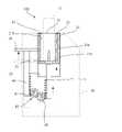
図2は、実施形態1に係る喫煙カートリッジ用加熱具を示している。図3乃至5は、実施形態1に係る喫煙カートリッジ用加熱具の動作態様を示す説明図である。図2乃至5に示すように、喫煙カートリッジ用加熱器100は、喫煙カートリッジ10の芳香発生基材12が設けられた部分が挿入される収容部21を有する本体20と、収容部21に設けられた、芳香発生基材12を加熱する加熱手段22、23と、収容部21の入口側で喫煙カートリッジ10を支持する支持部30と、支持部30と収容部21の底部21aとの距離を喫煙カートリッジ10の長さに応じて変更可能な可変機構40と、を有する。[Embodiment 1]
[Composition of heating tool for smoking cartridge]
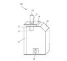
FIG. 2 shows a heating tool for a smoking cartridge according to the first embodiment. 3 to 5 are explanatory views showing an operation mode of the heating tool for smoking cartridge according to the first embodiment. As shown in FIGS. 2 to 5, the
本体20は、その形状は特には限定されないが、例えば、円筒状、角柱状等に形成されている筐体である。本体20は、本実施形態においては、略直方体状に形成されている。本体20の正面には、喫煙カートリッジ用加熱器100の電源のON又はOFFを操作することが可能な電源ボタンPBが設けられている。 The shape of the
本体20の一方の端面には、喫煙カートリッジ10を挿通可能な挿通孔が形成されている。収容部21は、この挿通孔と接続可能な本体20の内部に設けられている。 An insertion hole through which the
収容部21は、底部21a及び底部21aを囲み、かつ底部21aから立設された側壁部21bを有する。収容部21は、本実施形態においては、底部21a及び側壁部21bによって有底の円筒状に形成されている。 The
加熱手段は、収容部21の底部21a側に設けられている第1の加熱手段22及び収容部21の側壁部21bに設けられている第2の加熱手段23を有する。 The heating means includes a first heating means 22 provided on the
第1の加熱手段22は、収容部21の軸方向に沿って延びるピン形又はブレード形とすることができる。本実施形態において、第1の加熱手段22は、板状に形成され、一の面から見た場合に挿入口側の先端が鋭角に形成されたブレード状に形成されている。したがって、第1の加熱手段22は、カバー11の一端側から芳香発生基材12に挿通可能に収容部21の底部21a側から突出可能に設けられている。 The first heating means 22 may be pin-shaped or blade-shaped extending along the axial direction of the
第2の加熱手段23は、収容部21の側壁部21bの内周面に沿って配されている。本実施形態において、第2の加熱手段23は、収容部21の側壁部21bに固定されている。 The second heating means 23 is arranged along the inner peripheral surface of the
第2の加熱手段23は、例えば、ポリイミドなどの誘電体基材上の1つ又はそれ以上の可撓性加熱ホイルの形態とすることができる。可撓性加熱ホイルは、収容部21の内周と一致する形状とすることができる。 The second heating means 23 can be in the form of one or more flexible heating foils on a dielectric substrate such as polyimide. The flexible heating foil can have a shape that coincides with the inner circumference of the
第2の加熱手段24は、喫煙カートリッジ10の周囲を加熱することが可能であれば、このような態様に限られず、例えば、環状に形成した電熱線によって構成してもよい。また、第2の加熱手段24は、周方向に分割された複数の加熱部材(図示せず)によって構成されていてもよい。さらに、第2の加熱手段24は、収容部21の軸方向において、積層された複数の加熱部材(図示せず)によって構成されていてもよい。さらにまた、第2の加熱手段24は、周方向に分割された複数の加熱部材及び収容部21の軸方向において積層された複数の加熱部材を組み合わせて構成されていてもよい。 The second heating means 24 is not limited to such an embodiment as long as it is possible to heat the periphery of the
第2の加熱手段23は、1つ又はそれ以上の金属グリッド、可撓性プリント回路基板、成形回路部品(MID)、セラミック加熱器、可撓性炭素繊維加熱器の形態とすること、又は適切な形状の基材上にプラズマ蒸着などのコーティング技術を用いて形成することができる。したがって、第2の加熱手段23は、喫煙カートリッジ10の芳香発生基材12が設けられている部位を覆うことが可能に形成されている。言い換えれば、第2の加熱手段23は、収容部21において、カバー11の芳香発生基材12が設けられた部分の外周を加熱可能に設けられている The second heating means 23 is in the form of one or more metal grids, flexible printed circuit boards, molded circuit boards (MIDs), ceramic heaters, flexible carbon fiber heaters, or is suitable. It can be formed on a substrate having a different shape by using a coating technique such as plasma vapor deposition. Therefore, the second heating means 23 is formed so as to be able to cover the portion of the
第1の加熱手段22及び第2の加熱手段23は、給電されることによって加熱することが可能である。第1の加熱手段22及び第2の加熱手段23は、例えば、電気抵抗材料を含み、給電されることによって、150~350℃に加熱することが可能である。電気抵抗材料としては、限定されるものではないが、ドープセラミックスのような半導体、「導電性」セラミックス(例えば、二珪化モリブデン)、炭素、グラファイト、金属、金属合金、及びセラミック材料及び金属材料から作られる複合材料を挙げることができる。 The first heating means 22 and the second heating means 23 can be heated by being fed. The first heating means 22 and the second heating means 23 include, for example, an electric resistance material, and can be heated to 150 to 350 ° C. by being fed. Electrical resistance materials include, but are not limited to, semiconductors such as dope ceramics, "conductive" ceramics (eg, molybdenum disilicate), carbon, graphite, metals, metal alloys, and ceramic and metal materials. The composite material to be made can be mentioned.
電気抵抗材料は、複合材料において、絶縁材料に埋め込むこと、封入すること、又はそれでコーティングすること、又はその逆とすることができる。代替的に、電気加熱器は、赤外線加熱要素、光学的ソース、又は誘導加熱要素を含むことができる。 The electrical resistance material can be embedded in an insulating material, encapsulated, coated with it, or vice versa in a composite material. Alternatively, the electric heater can include an infrared heating element, an optical source, or an induction heating element.
第1の加熱手段22及び第2加熱手段23は、例えば、第1の加熱手段22の位置に応じて、回路接続を切り替えることによりいずれか一方を加熱させることができる。本実施形態においては、第1の加熱手段22の位置に応じて加熱させる加熱手段を選択する例を説明する。 One of the first heating means 22 and the second heating means 23 can be heated, for example, by switching the circuit connection according to the position of the first heating means 22. In this embodiment, an example of selecting a heating means to be heated according to the position of the first heating means 22 will be described.
尚、第1の加熱手段22及び第2加熱手段23を加熱させる態様は、手動によって行われてもよい。第1の加熱手段22及び第2加熱手段23は、例えば、喫煙カートリッジ用加熱器100の電源ボタンPBの押下の態様に応じて選択的に加熱させるようにしてもよい。 The mode of heating the first heating means 22 and the second heating means 23 may be performed manually. The first heating means 22 and the second heating means 23 may be selectively heated, for example, according to the mode of pressing the power button PB of the
例えば、電源ボタンPBを1秒以内に2回連続して押下された場合に第1の加熱手段22を加熱させ、電源ボタンPBを2秒以上長押しされた場合に第2の加熱手段23を加熱させるようにしてもよい。 For example, when the power button PB is pressed twice in succession within 1 second, the first heating means 22 is heated, and when the power button PB is pressed and held for 2 seconds or longer, the second heating means 23 is heated. It may be heated.
第1の加熱手段23及び第2の加熱手段24の加熱は、このような態様に限られず、電源ボタンPBとは別のボタンを1又は複数設けて、そのボタンの押下の態様によって行ってもよい。また、ボタンは、第1の加熱手段23及び第2の加熱手段24の加熱を選択可能であればよく、例えば、静電容量式のタッチパネルであってもよい。尚、第1の加熱手段23及び第2の加熱手段24のうち、いずれか一方を加熱する態様を説明したが、これには限られず、第1の加熱手段23及び第2の加熱手段24両方を加熱してもよい。 The heating of the first heating means 23 and the second heating means 24 is not limited to such an embodiment, and may be performed by providing one or a plurality of buttons different from the power button PB and pressing the buttons. good. Further, the button may be a capacitive touch panel, for example, as long as the heating of the first heating means 23 and the second heating means 24 can be selected. Although the embodiment of heating one of the first heating means 23 and the second heating means 24 has been described, the present invention is not limited to this, and both the first heating means 23 and the second heating means 24 are not limited to this. May be heated.
支持部30は、本実施形態においては、板状に形成されている。尚、支持部30の形態は、喫煙カートリッジ10を支持可能な厚さ及び形態を有するものであれば、板状には限られず、例えば、棒状、筒状等であってもよい。支持部30は、一の面が本体20の挿通孔に対向して配されている。支持部30は、喫煙カートリッジ10の形状に応じた支持孔31(図2参照)を有する。支持孔31は、本実施形態においては、上面視が円状又は、U字状に切り欠いて形成されている。支持孔31は、収容部21の中心軸線上に配されている。 In the present embodiment, the
支持部30は、本体20の側面にスライド可能に取付けられた支持具32の一端に設けられている。支持具32は、本実施形態においては、矩形の板状に形成されている。支持具32は、例えば、その側面において、本体20の側面の形状に沿って形成されている凹状に形成されているガイド溝(図示せず)を有する。また、本体20の側面には、このガイド溝(図示せず)に係合可能な係合突起(図示せず)が収容部21の軸方向に沿って形成されている。尚、支持具32が本体20の側面においてスライド可能な構成であればよく、このような構成に限定されない。例えば、ガイド溝が支持具32に形成され、本体20の側面においてガイド溝に係合する係合突起が形成されているようにしてもよい。このように、本体20の側面に支持具32が設けられていることにより、ユーザは容易に支持具32の位置を調整することが可能となる。 The
支持具32は、収容部21の軸方向に沿ってスライド可能であればよく、例えば、本体20に内蔵されるように収容され、かつ本体20の上面からの突出量を調整可能に設けられているようにしてもよい。 The
支持部30は、支持具32の本体20の挿通孔が配されている側の一端に設けられている。本実施形態においては、支持部30は、L字となるように支持具32に設けられている。 The
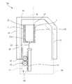
可変機構40は、図3乃至5にも示すように、第1の加熱手段23から収容部21の軸方向に沿って延びる第1のラック41と、第1ラック41と歯合可能な歯車42と、支持具32から収容部21の軸方向に沿って延びる第2のラック43と、歯車42に歯合可能な歯車45を有するアクチュエータ44と、を有する。 As shown in FIGS. 3 to 5, the
尚、歯車45は、第1のラック41及び第2のラック43とはオフセットした位置にあり、歯車42には歯合するが、第1のラック41及び第2のラック43とは歯合しないようになっている。 The
第1のラック41は、歯車42の回転に伴って収容部21の軸方向に沿って移動可能である。本実施形態においては、歯車42が反時計回りに回転すると、第1のラック41は、挿通孔側に移動する。また、歯車42が時計回りに回転すると、第1のラック41は、本体20の底面側に移動する。 The
尚、第1のラック41は、本体20の収容部21の軸方向に沿って設けられているガイド溝(図示せず)に収容されている。したがって、第1のラック41は、ガイド溝に沿って収容部21の軸方向に移動可能である。 The
歯車42は、本体20に固定されている回転軸の軸周りに回転可能に設けられている。歯車42は、第2のラック43の移動に連動して回転することが可能である。 The
第2のラック43は、支持具32の本体20に対向する面に設けられている。第2のラック43は、収容部21の軸方向に沿って設けられ、当該軸方向にスライドして移動可能である。第2のラック43が収容部21の軸方向の上側、すなわち、本体20の挿通孔側に向かって移動すると、歯車42は、時計回りに回転させられる。第2のラック43が収容部21の軸方向の下側、すなわち、本体20の底面側に向かって移動すると、歯車42は、反時計回りに回転させられる。 The
アクチュエータ44は、モータの回転軸に設けられている歯車45を有する。歯車45は、第1のラック41、第2のラック43とはオフセットされていて歯合せず、歯車42に歯合する。 The
アクチュエータ44は、電源(図示せず)に接続されている。したがって、アクチュエータ44は、電源ボタンPBの操作により喫煙カートリッジ用加熱器100の電源がONにされると、図3に示されている第1の態様となる。第1の態様では、第1の加熱手段22に対して加熱し、第2の加熱手段23に対しては加熱されないように回路が接続されている。また、第1の態様においては、第1の加熱手段22に対して喫煙カートリッジ10を挿通することにより、喫煙カートリッジ10の芳香発生基材12に第1の加熱手段22を差し込んで加熱することが可能である。 The
喫煙カートリッジ10が図3に示したものよりも長い場合、支持部30から収容部21の底部21aまでの距離を延ばすようにするとよい。具体的には、喫煙カートリッジ10が収容部21に差し込まれ、所定以上の力が加えられると、アクチュエータ44の歯車45は、時計回りに回転させられる。これにより、アクチュエータのモータが回転し微弱な電流が生じる。 If the
アクチュエータ44は、この電流を検知すると、歯車45を反時計回りに回転させることにより、歯車42を時計回りに回転させて、第1のラック41を本体20の底面側に移動させる。したがって、図4に示す第2の態様となる。第1のラック41が底面側に移動すると、第1の加熱手段22が収容部21から退避する。第1の加熱手段22が収容部21から退避すると、第2の加熱手段23を加熱可能に回路が切り替わる。 When the
尚、手動で支持具32を本体20の上面側にスライドさせた場合も、アクチュエータのモータが回転し微弱な電流が生じる。すなわち、第1のラック41が押下される力及び支持具32を押し上げる力に基づいて、第1のラック41を移動させることが可能である。 Even when the
このように、第1のラック41が本体20の底面側に移動して第1の加熱手段23が収容部21から退避すると、これに伴って第2のラック43が本体20の底面から離れる方向に移動して支持具32が上昇する。したがって、収容部21の底面21aと支持部30との距離を長くすることができる。これにより、長い喫煙カートリッジ10であっても支持部30によって支持すること可能となる。 In this way, when the
喫煙カートリッジ10が図4に示したものよりもさらに長い場合、支持部30から収容部21の底部21aまでの距離をさらに延ばすようにするとよい。具体的には、支持具32は、伸縮自在な構造を有する。したがって、図4に示した状態から、さらに手動によって支持具32を引き上げると、支持具32が所定距離だけ伸ばされ、図5に示す第3の態様となる。すなわち、支持具32の本体に対するスライド量を変えることにより、喫煙カートリッジ10の長さに応じて支持位置を変化させることができる。 If the
上述の第1の態様及び第2の態様は、電源ボタンPBの操作に応じて変更されるようにしてもよい。例えば、電源ボタンPBが1度押下されると第1の態様、電源ボタンPBが2度押下されると第2の態様となるように設定されるとよい。 The first aspect and the second aspect described above may be changed according to the operation of the power button PB. For example, it may be set so that the power button PB is pressed once to be in the first mode, and the power button PB is set to be pressed twice to be in the second mode.
第1の態様及び第2の態様の変更は、このような態様に限られず、例えば、第1の態様を設定する第1の設定ボタン(図示せず)、第2の態様を設定する第2の設定ボタン(図示せず)を本体20に設けることによって行ってもよい。ユーザは、第1の設定ボタン又は第2の設定ボタンを押下することにより、容易に第1の加熱手段22及び支持部30の位置を切り替えることができる。 The modification of the first aspect and the second aspect is not limited to such an aspect, for example, a first setting button (not shown) for setting the first aspect, and a second aspect for setting the second aspect. The setting button (not shown) may be provided on the
尚、第3の態様は、アクチュエータの稼働によって切り替えるように構成してもよい。この場合、上述のように第1の態様乃至第3の態様を、上記の電源ボタンPBの操作に応じて変更してもよいし、各態様に応じた設定ボタンを設けて変更してもよい。 The third aspect may be configured to be switched depending on the operation of the actuator. In this case, as described above, the first to third aspects may be changed according to the operation of the power button PB described above, or may be changed by providing a setting button corresponding to each aspect. ..
以上のように、本実施形態の喫煙カートリッジ用加熱器100によれば、喫煙カートリッジ10の長さに応じて、支持部30と収容部21の底部21aとの距離を変えることにより、喫煙カートリッジ10を適切に支持することができ、種類の異なる喫煙カートリッジ10に対応することができる。 As described above, according to the
また、喫煙カートリッジ用加熱器100は、第1の加熱手段22と、第2の加熱手段23とを有しているので、第1の加熱手段22に対応した喫煙カートリッジ10でも、第2の加熱手段23に対応した喫煙カートリッジ10でも使用可能となる。また、上記加熱手段のタイプに応じて喫煙カートリッジ10の長さが異なる場合でも、適切な位置で喫煙カートリッジ10を支持することができる。 Further, since the
[実施形態2]
実施形態1においては、支持具32に支持部30が設けられている態様を説明した。支持部30は、枠状に形成されている枠状カバーに設けられているようにしてもよい。尚、実施形態1と同一の構成については、同一の符号を付して説明を省略する。[Embodiment 2]
In the first embodiment, an embodiment in which the
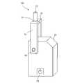
図6及び7は、実施形態2に係る喫煙カートリッジ用加熱具の動作態様を示す説明図である。図6及び7に示すように、枠状カバー33は、本体20の右側面、左側面及び上面を覆うようにU字状に形成されている枠状部材である。尚、枠状カバー33は、本体20の右側面、左側面、正面、背面及び上面を覆い、かつ本体20の底面側の一端が開口して形成されている箱状部材であってもよい。 6 and 7 are explanatory views showing an operation mode of the heating tool for smoking cartridge according to the second embodiment. As shown in FIGS. 6 and 7, the frame-shaped
枠状カバー33は、本体20の外周にスライド可能に取付けられている。本実施形態においては、枠状カバー33は、本体20の右側面及び左側面に取り付けられている。枠状カバー33は、実施形態1で説明した支持具32と同様に、ガイド溝(図示せず)に係合可能な係合突起(図示せず)によって本体20の外周にスライド可能に取付けられている。 The frame-shaped
支持部30は、枠状カバー33の端面、すなわち、本体20の挿通孔に対向する位置に設けられている。 The
可変機構40の構成は、実施形態1と同一である。すなわち、図6は、喫煙カートリッジ用加熱器100の第1の態様を示しており、第1の態様では、第1の加熱手段22に対応した喫煙カートリッジ10を使用することが可能である。 The configuration of the
図7は、喫煙カートリッジ用加熱器100の第2の態様を示している。第2の態様では、第2の加熱手段23に対応した喫煙カートリッジ10を使用することが可能である。すなわち、第2の態様では、第1の態様よりも長い喫煙カートリッジ10を使用することができる。 FIG. 7 shows a second aspect of the
このように喫煙カートリッジ用加熱器100を構成しても、枠状カバー33の本体に対するスライド量を変えることにより、喫煙カートリッジ10の長さに応じて支持位置を変化させることができる。喫煙カートリッジ10の長さに応じて、支持部30と収容部21の底部21aとの距離を変えることにより、喫煙カートリッジ10を適切に支持することができ、種類の異なる喫煙カートリッジ10に対応することができる。 Even if the
[実施形態3]
上述の実施形態1においては、支持具32は、本体20にスライド可能に設けられている例を説明した。支持具32は、本体20に回動可能に取り付けられているようにしてもよい。[Embodiment 3]
In the above-described first embodiment, an example in which the
図8は、実施形態3に係る喫煙カートリッジ用加熱具100の斜視図である。図9及び10は、実施形態3に係る喫煙カートリッジ用加熱具の動作態様を示す説明図である。 FIG. 8 is a perspective view of the
図8乃至10に示すように、支持具34は、本体20の正面、上面及び背面に対向する面を有するU字状に形成されている枠状部材である。支持部30は、本体20の上面に対向する面において、収容部21の軸線上に設けられている。すなわち、支持部30は、支持具34の一端に設けられている。 As shown in FIGS. 8 to 10, the
支持具34は、本体20の正面及び背面に設けられている回動軸AXに取り付けられている。したがって、支持具34は、回動軸AXの軸周りに回動することが可能である。 The
可変機構40は、回動軸AXに取り付けられている歯車46を有する。図9及び10に示すように、支持具34の回動に伴って、歯車46が時計回りに回転すると、第1のラック41が上面側に移動する。すなわち、第1の加熱手段22が押し上げられる。また支持具34の回動に伴って、歯車46が反時計回りに回転すると、第1のラック41が底面側に移動する。すなわち、第1の加熱手段22が押し下げられる。第2の加熱手段23に通電されるように回路が切り替えられる。 The
このように、喫煙カートリッジ10が短いときは、収容部21で支持し、喫煙カートリッジ10が長いときは、支持具34を回動させて、その一端に設けた支持部30で支持させることができる。したがって、喫煙カートリッジ10の長さに応じて、支持部30と収容部21の底部21aとの距離を変えることにより、喫煙カートリッジ10を適切に支持することができ、種類の異なる喫煙カートリッジ10に対応することができる。 As described above, when the
[実施形態4]
上述の実施形態においては、支持部30は、支持具32、34又は、枠状カバー33に設けられている例を説明した。支持部30は、収容部21によって構成されているようにしてもよい。[Embodiment 4]
In the above-described embodiment, the example in which the
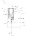
図11及び12は、実施形態4に係る喫煙カートリッジ用加熱具の動作態様を示す説明図である。図11及び12に示すように、本体20は、収容部21を収容するハウジング25を有する。ハウジング25は、収容部21の外形に沿った内部構造を有する。本実施形態において、ハウジング25は、円筒状に形成されている。ハウジング25は、収容部21の軸方向において、その長さが収容部21よりも長く形成されている。したがって、収容部21は、ハウジング25内においてその軸方向にスライド可能に収容されている。 11 and 12 are explanatory views showing an operation mode of the heating tool for a smoking cartridge according to the fourth embodiment. As shown in FIGS. 11 and 12, the
収容部21は、その側面から本体20の側面に向かって突出して形成された突出部26を有する。突出部26には、第2のラック43が設けられている。歯車47は、第2のラック43及び歯車42に歯合されている。 The
したがって、図11に示すように、突出部26が押し下げられた状態から上方に押し上げられると、収容部21がハウジング25の支持部としての挿入口27側に移動して上昇する。 Therefore, as shown in FIG. 11, when the protruding
これに伴って、第2のラック43が歯車47を時計回りに回転させ、歯車42が反時計回りに回転する。その結果、第1のラック41が支持部としての挿入口27側に移動して押し上げられる。 Along with this, the
これに伴って、第1の加熱手段22が、収容部21の底面21aから突出すると、第1の加熱手段22に通電されるように第2の加熱手段23から回路の接続が切り替わる。 Along with this, when the first heating means 22 protrudes from the
また、図12に示すように、突出部26が押し上げられた状態から押し下げられると、収容部21がハウジング25の底部側に移動して下降する。これに伴って、第2のラック43が歯車47を反時計回りに回転し、歯車42が時計回りに回転し、第1のラック41が本体20の底部側に移動して押し下げられる。 Further, as shown in FIG. 12, when the protruding
これに伴って、第1の加熱手段22が収容部21の底面21aから退避されると、第2の加熱手段23に通電がなされるように回路が切り替わる。 Along with this, when the first heating means 22 is retracted from the
このように、喫煙カートリッジ10が短いときは、収容部21の底部を、支持部としての挿入口27に近づくように移動させ、喫煙カートリッジ10が長いときは、収容部21の底部を、支持部としての挿入口27から遠ざかるように移動させることができる。したがって、異なる長さの喫煙カートリッジ10を使用することが可能となる。 As described above, when the
また、例えば、収容部21のハウジング25内の移動量を、芳香カートリッジ100の長さに応じて調整することにより、本体20から突出している芳香カートリッジ100の長さを常に一定にすることができる。これにより、ユーザは、芳香カートリッジ100が本体20から突出している長さの違いにより感じる違和感を、減少させながら使用することができる。 Further, for example, by adjusting the amount of movement of the
100 喫煙カートリッジ用加熱器
10 喫煙カートリッジ
11 カバー
12 芳香発生基材
13 フィルタ
20 本体
21 収容部
21a 底部
22 第1の加熱手段
23 第2の加熱手段
27 挿通口(支持部)
30 支持部
32、34 支持具
33 枠状カバー
40 可変機構100 Heater for smoking
30
Claims (6)
Translated fromJapanese前記喫煙カートリッジの前記芳香発生基材が設けられた部分が挿入される収容部を有する本体と、
前記収容部に設けられた、前記芳香発生基材を加熱する加熱手段と、
前記収容部の入口側で前記喫煙カートリッジを支持する支持部と、
前記支持部から前記収容部の底部までの距離を変更可能な可変機構と、
を有することを特徴とする喫煙カートリッジ用加熱器。For smoking cartridges comprising a tubular cover, an aroma generating substrate contained in the cover that generates an aerosol containing an aromatic component by heating, and a filter contained in the cover. In the heater
A main body having an accommodating portion into which a portion of the smoking cartridge provided with the aroma generating base material is inserted.
A heating means for heating the aroma-generating base material provided in the accommodating portion,
A support portion that supports the smoking cartridge on the entrance side of the storage portion, and a support portion.
A variable mechanism that can change the distance from the support to the bottom of the housing,
A heater for smoking cartridges, characterized by having.
前記収容部において、前記筒状のカバーの前記芳香発生基材が設けられた部分の外周を加熱可能に設けられている第2の加熱手段と、
を有する請求項1記載の喫煙カートリッジ用加熱器。As the heating means, a first heating means provided so as to be able to be inserted into the aroma generating base material from one end side of the tubular cover and projectable from the bottom side of the accommodating portion.
A second heating means provided so as to be able to heat the outer periphery of the portion of the cylindrical cover provided with the aroma generating base material in the accommodating portion.
The heater for a smoking cartridge according to claim 1.
Priority Applications (2)
| Application Number | Priority Date | Filing Date | Title |
|---|---|---|---|
| JP2020176516AJP2022067748A (en) | 2020-10-21 | 2020-10-21 | Heater for smoking cartridge |
| PCT/JP2021/038562WO2022085671A1 (en) | 2020-10-21 | 2021-10-19 | Smoking cartridge heater |
Applications Claiming Priority (1)
| Application Number | Priority Date | Filing Date | Title |
|---|---|---|---|
| JP2020176516AJP2022067748A (en) | 2020-10-21 | 2020-10-21 | Heater for smoking cartridge |
Publications (1)
| Publication Number | Publication Date |
|---|---|
| JP2022067748Atrue JP2022067748A (en) | 2022-05-09 |
Family
ID=81290577
Family Applications (1)
| Application Number | Title | Priority Date | Filing Date |
|---|---|---|---|
| JP2020176516APendingJP2022067748A (en) | 2020-10-21 | 2020-10-21 | Heater for smoking cartridge |
Country Status (2)
| Country | Link |
|---|---|
| JP (1) | JP2022067748A (en) |
| WO (1) | WO2022085671A1 (en) |
Family Cites Families (7)
| Publication number | Priority date | Publication date | Assignee | Title |
|---|---|---|---|---|
| US9913493B2 (en)* | 2014-08-21 | 2018-03-13 | Rai Strategic Holdings, Inc. | Aerosol delivery device including a moveable cartridge and related assembly method |
| CN205597118U (en)* | 2016-03-14 | 2016-09-28 | 深圳市合元科技有限公司 | Cigarette heating device and electron cigarette |
| CN207855049U (en)* | 2018-02-26 | 2018-09-14 | 深圳市铭明电子有限公司 | A kind of electronics tobacco pipe |
| CN208064484U (en)* | 2018-03-09 | 2018-11-09 | 广东中烟工业有限责任公司 | One-step method realizes that cigarette detaches with heater and cleans the cigarette electric heater unit of heater |
| CN108669658B (en)* | 2018-08-16 | 2023-11-07 | 重庆中烟工业有限责任公司 | Low-temperature baking smoke-removing smoking set |
| CN109602092A (en)* | 2019-01-22 | 2019-04-12 | 云南中烟工业有限责任公司 | A heating system that can adapt to cigarettes of different sizes |
| CN111869933A (en)* | 2020-07-31 | 2020-11-03 | 福建中烟工业有限责任公司 | Smoking set for heating non-burning cigarette |
- 2020
- 2020-10-21JPJP2020176516Apatent/JP2022067748A/enactivePending
- 2021
- 2021-10-19WOPCT/JP2021/038562patent/WO2022085671A1/ennot_activeCeased
Also Published As
| Publication number | Publication date |
|---|---|
| WO2022085671A1 (en) | 2022-04-28 |
Similar Documents
| Publication | Publication Date | Title |
|---|---|---|
| JP6931449B1 (en) | How to make an electronic cigarette cartridge | |
| JP3212228U (en) | Electronic cigarette cartridge using tobacco plant or non-tobacco plant and supporting member thereof | |
| JP6280287B1 (en) | Electronic cigarette cartridge using tobacco plant or non-tobacco plant and supporting member thereof | |
| WO2018230002A1 (en) | Method for manufacturing filler for electronic cigarette cartridge in which non-tobacco plant is used, and filler for electronic cigarette cartridge in which non-tobacco plant is used | |
| JP6748124B2 (en) | cartridge | |
| JP7084060B2 (en) | Fragrance cartridge | |
| CN117897063A (en) | Extruded substrate for aerosol delivery device | |
| JP2022067751A (en) | Heater for smoking cartridge | |
| WO2022071267A1 (en) | Smoking cartridge and smoking cartridge system | |
| WO2022085671A1 (en) | Smoking cartridge heater | |
| CN119789793A (en) | Aerosol-generating substrate comprising microcrystalline cellulose | |
| CN114269175A (en) | Heating non-combustion device and flavor carrier | |
| KR20240036585A (en) | Substrates with multiple aerosol-forming materials for aerosol delivery devices | |
| JP6769644B2 (en) | cartridge | |
| JP6867064B2 (en) | cartridge | |
| JP7263599B2 (en) | Cartridge for smoking paraphernalia | |
| JP2022069542A (en) | Smoking equipment cartridge | |
| WO2021117264A1 (en) | Fragrance cartridge | |
| JP2022069541A (en) | Method of manufacturing cartridge for smoking tool | |
| KR20230117742A (en) | Articles for use in aerosol delivery systems | |
| KR20240019155A (en) | Articles for use with non-flammable aerosol delivery devices | |
| JP2022069540A (en) | How to make a cartridge for smoking equipment | |
| WO2025135105A1 (en) | Method for using flavor-generating article and flavor-generating system | |
| HK1261218A1 (en) | Electronic cigarette cartridge using tobacco plant or non-tobacco plant and support member thereof |
Legal Events
| Date | Code | Title | Description |
|---|---|---|---|
| A711 | Notification of change in applicant | Free format text:JAPANESE INTERMEDIATE CODE: A712 Effective date:20210916 |