Movatterモバイル変換


[0]ホーム

URL:


JP2022065652A - Inverting braided aneurysm treatment system and method - Google Patents

Inverting braided aneurysm treatment system and method
Download PDF

Info

Publication number
JP2022065652A
JP2022065652AJP2021168753AJP2021168753AJP2022065652AJP 2022065652 AJP2022065652 AJP 2022065652AJP 2021168753 AJP2021168753 AJP 2021168753AJP 2021168753 AJP2021168753 AJP 2021168753AJP 2022065652 AJP2022065652 AJP 2022065652A
Authority
JP
Japan
Prior art keywords
braid
aneurysm
implant
segment
shape
Prior art date
Legal status (The legal status is an assumption and is not a legal conclusion. Google has not performed a legal analysis and makes no representation as to the accuracy of the status listed.)
Pending
Application number
JP2021168753A
Other languages
Japanese (ja)
Inventor
レイシー・ゴロチョウ
Gorochow Lacey
ルイジャオ・シュー
Ruijiao Xu
ショーン・カリヴァヤリル
Kallivayalil Shawn
Current Assignee (The listed assignees may be inaccurate. Google has not performed a legal analysis and makes no representation or warranty as to the accuracy of the list.)
DePuy Synthes Products Inc
Original Assignee
DePuy Synthes Products Inc
Priority date (The priority date is an assumption and is not a legal conclusion. Google has not performed a legal analysis and makes no representation as to the accuracy of the date listed.)
Filing date
Publication date
Priority claimed from US17/071,565external-prioritypatent/US11278292B2/en
Application filed by DePuy Synthes Products IncfiledCriticalDePuy Synthes Products Inc
Publication of JP2022065652ApublicationCriticalpatent/JP2022065652A/en
Pendinglegal-statusCriticalCurrent

Links

Images

Classifications

Landscapes

Abstract

To improve methods, devices, and systems for implants for aneurysm treatment.SOLUTION: An example system can include a tubular braid, a catheter, and an embolic coil. The tubular braid can have an open end, a pinched end, and a predetermined shape. In the predetermined shape, the tubular braid can have two inversions and a middle segment extending between the two inversions that forms a sack. The tubular braid can be implanted in an implanted shape based on the predetermined shape. A distal end of the catheter can be inserted into the sack when the tubular braid is implanted. The embolic coil can be delivered through the catheter into the sack. An opening to the sack can correspond to a constricted columnar segment of the middle segment when the braid is in the predetermined shape.SELECTED DRAWING: Figure 1A

Description

Translated fromJapanese

(関連出願の相互参照)
本出願は、各々2020年5月1日に出願された米国特許出願第16/865,116号及び米国特許出願第16/865,165号の一部継続出願であり、これらは各々、2020年1月22日に出願された米国特許出願第16/748,877号の一部継続出願及び2020年4月20日に出願された米国特許出願第16/853,135号の一部継続出願である。米国特許出願第16/748,877号及び米国特許出願第16/853,135号は各々、2019年5月21日に出願され2020年5月19日に米国特許第10,653,425号として発行された米国特許出願第16/418,199号の一部継続出願である。
(Mutual reference of related applications)
This application is a partial continuation of U.S. Patent Application Nos. 16 / 856,116 and U.S. Patent Application Nos. 16 / 856,165 filed May 1, 2020, respectively, which are 2020, respectively. A partial continuation of US Patent Application No. 16 / 748,877 filed on January 22, and a partial continuation of US Patent Application No. 16 / 853,135 filed on April 20, 2020. be. U.S. Patent Application Nos. 16 / 748,877 and U.S. Patent Application No. 16 / 853,135 were filed May 21, 2019, respectively, as U.S. Patent No. 10,653,425 on May 19, 2020. This is a partial continuation of the issued US Patent Application No. 16 / 418,199.

本出願はまた、2019年12月5日に出願された米国特許出願第16/703,973号の一部継続出願である。 This application is also a partial continuation of US Patent Application No. 16 / 703,973, filed December 5, 2019.

これらすべての内容は、本明細書に記載されているかのように、その全体が参照により本明細書に組み込まれる。 All of these are incorporated herein by reference in their entirety, as described herein.

(発明の分野)
本発明は、概して、医療器具に関し、より詳細には、動脈瘤治療用塞栓インプラントに関する。
(Field of invention)
The present invention relates generally to medical devices and, more particularly to, embolic implants for the treatment of aneurysms.

頭蓋動脈瘤は複雑であり、重要な脳組織に近接していることに起因して、処置するのが困難であり得る。これまでの解決策としては、動脈の血圧及び血流から動脈瘤嚢の内部容積が除去又は排除される血管内処置が挙げられる。血管内又は他の外科的手法の現行の代替法は、動脈瘤の嚢を塞栓材料で充填する又は動脈瘤の入り口若しくは頸部を塞ぐ、血管内送達処置デバイスを含むことができる。両方の手法のいずれも、動脈瘤への血液の流入を防止しようとするものである。動脈瘤嚢を充填する場合、塞栓材料は、血液を凝固させ、動脈瘤内に血栓塊を作成する。動脈瘤頸部を処置する場合、動脈瘤の入り口への血液の流入が阻止され、動脈瘤内での静脈のうっ血を誘発し、動脈瘤内での血栓塊の自然な形成を促進する。 Cranial aneurysms are complex and can be difficult to treat due to their proximity to important brain tissue. Previous solutions include intravascular procedures in which the internal volume of the aneurysm sac is removed or eliminated from the blood pressure and blood flow of the artery. Current alternatives to intravascular or other surgical procedures can include intravascular delivery treatment devices that fill the aneurysm sac with embolic material or block the entrance or neck of the aneurysm. Both methods seek to prevent the inflow of blood into the aneurysm. When filling the aneurysm sac, the embolic material coagulates blood and creates a thrombus mass within the aneurysm. When treating the aneurysm neck, the inflow of blood into the entrance of the aneurysm is blocked, inducing venous congestion within the aneurysm and promoting the natural formation of a thrombosis within the aneurysm.

現行の血管内送達デバイスは、通常、複数の塞栓用コイルを利用して、動脈瘤の嚢を充填するか、又は動脈瘤の入り口を処置するかのどちらかを行う。塞栓用コイルで入り口を処置することによって形成される自然に形成された血栓塊は、動脈壁から膨張が起こる可能性を低減させ、頸部平面に沿った元の親血管形状への再統合を容易にすることができるので、自然に形成された血栓塊は、塞栓用コイルにより包まれた動脈瘤塊と比べて、治癒の改善がもたらされ得る。しかし、動脈瘤の頸部に送達される塞栓用コイルは、特に、入り口が過剰に包まれた場合、血管に接触する際に、血液の流れを妨害するという有害作用を潜在的に有し得る。反対に、入り口が十分に包まれていない場合、血流は、動脈瘤内に残るおそれがある。ある種の動脈瘤形態(例えば、幅広の頸部、分岐など)の処置は、コイル塊を支持し、所望の充填密度を得るためにステント又はバルーンなどの補助デバイスが必要となり得る。埋め込まれると、コイルは、容易に後退又は再位置決めすることができない。更に、多数のコイルで処置された動脈瘤は、多くの場合、コイリング不良、動脈瘤頸部全体が被覆されないこと、血流又は動脈瘤のサイズが大きいために、再開通又は圧縮を起こすので、塞栓用コイルは、動脈瘤を常に効果的に処置するわけではない。 Current intravascular delivery devices typically utilize multiple embolic coils to either fill the aneurysm sac or treat the aneurysm entrance. The naturally formed thrombus clot formed by treating the entrance with an embolic coil reduces the likelihood of swelling from the arterial wall and reintegrates into the original parent vessel shape along the cervical plane. Since it can be facilitated, a naturally formed thrombus mass can result in improved healing compared to an aneurysm mass wrapped by an embolic coil. However, the embolic coil delivered to the neck of the aneurysm can potentially have the adverse effect of obstructing blood flow when contacting blood vessels, especially if the entrance is over-wrapped. .. Conversely, if the entrance is not well wrapped, blood flow can remain within the aneurysm. Treatment of certain aneurysm forms (eg, wide neck, bifurcation, etc.) may require an auxiliary device such as a stent or balloon to support the coil mass and obtain the desired filling density. Once embedded, the coil cannot be easily retracted or repositioned. In addition, aneurysms treated with multiple coils often cause recanalization or compression due to poor coiling, uncovered entire aneurysm neck, and large blood flow or aneurysm size. Embolic coils do not always effectively treat aneurysms.

塞栓用コイルの代替物が、探索されており、例えば、管状編組インプラントが、参照により本明細書に組み込まれる、米国特許第10,751,066号に開示されている。管状編組インプラントは、親血管と連通する穿通枝血管への流れを妨げることなく、動脈瘤又は親血管内の他の動静脈奇形部を、容易、正確、かつ安全に処置する可能性を有する。しかし、塞栓用コイルと比較して、管状編組インプラントは、より新しい技術であり、したがって、管状編組インプラント用の改善された幾何形状、構成、送達システムなどに改善の余地がある。 Alternatives to embolic coils are being sought, for example, tubular braided implants are disclosed in US Pat. No. 10,751,066, which is incorporated herein by reference. Tubular braided implants have the potential to treat aneurysms or other arteriovenous malformations within the parent vessel easily, accurately and safely without obstructing the flow to the perforator vessels that communicate with the parent vessel. However, compared to embolic coils, tubular braided implants are a newer technique and therefore there is room for improvement in improved geometry, composition, delivery system, etc. for tubular braided implants.

したがって、動脈瘤処置のためのインプラント向けの方法、デバイス及びシステムの改善が必要とされている。 Therefore, there is a need for improvements in methods, devices and systems for implants for the treatment of aneurysms.

例示的なシステムは、管状編組、カテーテル、及び塞栓コイルを含むことができる。管状編組は、開放端部、挟持端部、及び所定の形状を有することができる。所定の形状において、編組が、開放端部から第1の反転部まで延在する第1のセグメント、第1の反転部から第2の反転部まで延在する第2のセグメント、及び第2のセグメントに囲まれ、第2の反転部から挟持端部まで延在する第3のセグメントを有することができる。第2のセグメントは、開口部を有する袋部を第1の反転部の近くに形成することができる。カテーテルは、内部を通る管腔と、遠位端部と、袋部の開口部を通って袋部に挿入されるような大きさの、遠位端部における外径とを有することができる。塞栓コイルは、管状編組から切り離され、管腔内に位置決めされる。塞栓コイルは、カテーテルの遠位端部から出るように構成されている。 Exemplary systems can include tubular braids, catheters, and embolic coils. The tubular braid can have an open end, a pinching end, and a predetermined shape. In a given shape, the braid has a first segment extending from the open end to the first inversion, a second segment extending from the first inversion to the second inversion, and a second. It is possible to have a third segment that is surrounded by segments and extends from the second inversion to the pinching end. The second segment can form a bag with an opening near the first inversion. The catheter can have a lumen through the interior, a distal end, and an outer diameter at the distal end sized to be inserted into the bag through the opening of the bag. The embolic coil is detached from the tubular braid and positioned within the lumen. The embolic coil is configured to exit from the distal end of the catheter.

管状編組は、管状編組が実質的に球状の空洞によって収縮されるときに、所定の形状に基づく埋め込み形状で安定であり得る。埋め込み形状において、第1のセグメントの少なくとも一部が、実質的に球形の空洞の空洞壁に接触するように位置決めされ得、所定の形状の第1の反転部に対応する近位反転部が、実質的に球形の空洞への入口に位置決めされ得、袋部が、実質的に球形の空洞内に位置決めされ得、袋部の開口部が、実質的に球形の空洞への入口でアクセス可能であり得、開口部が、カテーテルの遠位端部を袋部に受容されるように構成され得る。埋め込み形状では、編組は、カテーテルの遠位端部が第1のセグメントと袋部との間に位置決めされるように、カテーテルが細孔のうちの1つを通過することができるような大きさである、近位変換の近くに細孔を有することができる。 The tubular braid can be stable in an embedded shape based on a given shape when the tubular braid is contracted by a substantially spherical cavity. In the embedded shape, at least a portion of the first segment can be positioned to contact the cavity wall of a substantially spherical cavity, with a proximal inversion corresponding to the first inversion of the given shape. The bag can be positioned at the entrance to the substantially spherical cavity, the bag can be positioned within the substantially spherical cavity, and the opening of the bag can be accessed at the entrance to the substantially spherical cavity. Possible, the opening may be configured to receive the distal end of the catheter into the bag. In the implantable shape, the braid is sized so that the catheter can pass through one of the pores so that the distal end of the catheter is positioned between the first segment and the bag. Can have pores near the proximal transformation.

埋め込み形状では、開口部は、カテーテルの遠位端部を受容するように拡張し、カテーテルが開口部から取り外されたときに収縮するように弾性であり得る。 In the implantable form, the opening can be elastic to expand to receive the distal end of the catheter and to contract when the catheter is removed from the opening.

塞栓コイルは、管状編組が埋め込み形状にあるときに袋部内に適合するようにサイズ決めされ得る。 The embolic coil can be sized to fit within the bag when the tubular braid is in the embedded shape.

所定の形状において、管状編組が、中心軸を中心に円筒対称であり、第2のセグメントが、袋部から近位方向に延在し、中心軸の周りで収縮し、袋部の開口部を画定する柱状セクションを含み得る。 In a given shape, the tubular braid is cylindrically symmetric about the central axis, with a second segment extending proximally from the sac and contracting around the central axis to open the opening of the sac. It may include a demarcating columnar section.

所定の形状において、第2のセグメントは、柱状セクションから袋部を分離するおよそ90°の屈曲部を含むことができる。 In a given shape, the second segment can include a bend of approximately 90 ° that separates the bag from the columnar section.

編組が所定の形状にあるときの柱状セクションの直径は、編組が埋め込み形状にあるときに圧潰され得る。 The diameter of the columnar section when the braid is in a given shape can be crushed when the braid is in an embedded shape.

柱状セクションは、管状編組が埋め込み形状にあるとき、柱状の形状であり得る。 The columnar section can be in a columnar shape when the tubular braid is in an embedded shape.

所定の形状の管状編組の外側輪郭は、およそ直円筒であり得る。代替的に、所定の形状の管状編組の外側輪郭は、およそ洋梨形状であり得る。 The outer contour of a tubular braid of a given shape can be approximately a straight cylinder. Alternatively, the outer contour of the tubular braid of a given shape can be approximately pear-shaped.

動脈瘤インプラントの例示的な管状編組は、開放端部及び挟持端部を有することができる。管状編組は、管状編組が実質的に球状の空洞によって収縮されたときに安定である所定の形状及び埋め込み形状を有することができる。 An exemplary tubular braid of an aneurysm implant can have an open end and a pinching end. The tubular braid can have a predetermined shape and an embedded shape that is stable when the tubular braid is contracted by a substantially spherical cavity.

所定の形状において、編組が、開放端部から第1の反転部まで延在する第1のセグメント、第1の反転部から第2の反転部まで延在し、第1の反転部の近くに開口部を含む袋部を形成する第2のセグメント、及び第2のセグメントに囲まれ、第2の反転部から挟持端部まで延在する第3のセグメントを有することができる。埋め込み形状は、所定の形状に基づくことができる。所定の形状において、管状編組が、中心軸を中心に円筒対称であり、第2のセグメントが、袋部から近位方向に延在し、中心軸の周りで収縮し、袋部の開口部を画定する柱状セクションを含み得る。 In a given shape, the braid extends from the open end to the first inversion, the first segment, from the first inversion to the second inversion, near the first inversion. It is possible to have a second segment that forms a bag portion including an opening, and a third segment that is surrounded by the second segment and extends from the second inversion portion to the pinching end portion. The embedded shape can be based on a predetermined shape. In a given shape, the tubular braid is cylindrically symmetric about the central axis, with a second segment extending proximally from the sac and contracting around the central axis to open the opening of the sac. It may include a demarcating columnar section.

埋め込み形状において、第1のセグメントの少なくとも一部が、実質的に球形の空洞の空洞壁に接触するように位置決めされ得る、埋め込み形状であって、所定の形状の第1の反転部に対応する近位反転部が、実質的に球形の空洞への入口に位置決めされ、袋部が、実質的に球形の空洞内に位置決めされ、袋部の開口部が、ねじれており、それによって開口部を介した袋部へのアクセスを阻止することができる。埋め込み形状において、柱状セクションは、中心軸の周りでねじれることができる。 In the embedded shape, at least a portion of the first segment is an embedded shape that can be positioned to contact the cavity wall of a substantially spherical cavity, corresponding to a first inverted portion of a predetermined shape. The proximal inversion is positioned at the entrance to the substantially spherical cavity, the bag is positioned within the substantially spherical cavity, and the opening of the bag is twisted, thereby opening the opening. It is possible to prevent access to the bag portion through the bag. In the embedded shape, the columnar section can be twisted around the central axis.

動脈瘤を治療する例示的な方法は、以下のように提示されるステップの任意の組み合わせを特定のものではなく、本明細書に提示されない追加のステップを含むことができる。編組は、送達構成において、送達システムへの取り付けを介して、カテーテルを通して送達され得る。編組は、送達構成の外側表面を含むことができる。編組された袋部は、編組された袋部が送達構成における編組の外部表面に対応する内部表面を含むように、動脈瘤嚢内に編組された袋部を作成することができる。編組は、送達システムから切り離すことができ、それによって編組を動脈瘤嚢内で埋め込み形状に埋め込むことができる。編組を送達システムから取り外した後、塞栓コイルを編組された袋部に挿入することができる。 An exemplary method of treating an aneurysm is not specific to any combination of steps presented as follows and may include additional steps not presented herein. The braid can be delivered through a catheter in a delivery configuration via attachment to a delivery system. The braid can include the outer surface of the delivery configuration. The braided bag can create a braided bag within the aneurysm sac such that the braided bag contains an inner surface that corresponds to the outer surface of the braid in the delivery configuration. The braid can be detached from the delivery system, thereby implanting the braid in an implantable shape within the aneurysm sac. After the braid is removed from the delivery system, the embolic coil can be inserted into the braided bag.

本方法は、編組の第1の部分を動脈瘤壁に並置することを更に含むことができる。本方法は、動脈瘤頸部の近くで編組を反転させることによって近位反転部を作成することを更に含むことができる。本方法は、編組された袋部が近位反転部と遠位反転部との間に延在するように、動脈瘤嚢内で編組を反転させることによって遠位反転部を作成することを更に含むことができる。 The method can further include juxtaposing the first portion of the braid on the aneurysm wall. The method can further include creating a proximal inversion by inversion of the braid near the aneurysm neck. The method further comprises creating a distal inversion by inverting the braid within the aneurysm sac such that the braided pouch extends between the proximal and distal inversions. be able to.

本方法は、編組が埋め込み形状の動脈瘤嚢内にある間に、編組された袋部を第1の部分の開放端部で取り囲むことを更に含むことができる。 The method can further comprise enclosing the braided pouch with the open end of the first portion while the braid is in the implantable aneurysm sac.

編組は、埋め込み形状が、編組の所定の形状に部分的に基づいて、動脈瘤嚢の形状に部分的に基づくように埋め込まれることができる。 The braid can be implanted so that the implant shape is based in part on the shape of the aneurysm sac, based in part on the predetermined shape of the braid.

編組が所定の形状にあるとき、近位反転部及び遠位反転部が編組のそれぞれの反転部に対応するように、編組を埋め込むことができる。 When the braid is in a predetermined shape, the braid can be embedded so that the proximal inversion and the distal inversion correspond to the respective inversions of the braid.

本方法は、編組を送達システムから取り外した後に、編組を動脈瘤内で自己固定させることを更に含むことができる。 The method can further include self-fixing the braid within the aneurysm after removing the braid from the delivery system.

本方法は、編組された袋部を塞栓コイルと共に拡張することを更に含むことができる。 The method can further include expanding the braided bag with an embolic coil.

編組を送達システムから取り外すことは、挟持された端部が編組された袋部内に懸架されるように、送達システムから編組の挟持端部を解放することを更に含むことができる。代替的に、送達システムから編組を取り外すことは、送達システムから編組の挟持端部を解放することを更に含むことができ、これにより、挟持端部は、動脈瘤頸部によって画定される平面の近くに位置決めされる。 Removing the braid from the delivery system can further include releasing the braided pinch end from the delivery system such that the pinched end is suspended within the braided bag. Alternatively, removing the braid from the delivery system can further include releasing the pinch end of the braid from the delivery system, whereby the pinch end is in the plane defined by the aneurysm neck. Positioned close.

編組は、編組の挟持端部が送達システムと接触し、編組が、編組の挟持端部から遠位の開放端部まで遠位方向に単層管状形状で延在するように、送達構成で送達することができる。 The braid is delivered in a delivery configuration such that the pinching end of the braid contacts the delivery system and the braid extends distally in a single layer tubular shape from the pinching end of the braid to the distal open end. can do.

本発明の上記及び更なる態様は、添付の図面と併せて以下の説明を参照して更に考察され、様々な図面において、同様の数字は、同様の構造要素及び特徴を示す。図面は、必ずしも縮尺どおりではなく、代わりに、本発明の原理を例示することに主眼が置かれている。図は、限定としてではなく単なる例示として、本発明のデバイスの1つ又は2つ以上の実装形態を描写している。
本発明の態様による所定の形状にある管状編組を有する例となるインプラントの例示である。本発明の態様による第1の埋め込み形状にある管状編組を有する例となるインプラントの例示である。本発明の態様による第2の埋め込み形状にある管状編組を有する例となるインプラントの例示である。管状編組が、本発明の態様によるマイクロカテーテルを出るときの、図1Aに例示されているものと同様の所定の形状まで拡張している管状編組を有するインプラントの例示である。管状編組が、本発明の態様によるマイクロカテーテルを出るときの、図1Aに例示されているものと同様の所定の形状まで拡張している管状編組を有するインプラントの例示である。管状編組が、本発明の態様によるマイクロカテーテルを出るときの、図1Aに例示されているものと同様の所定の形状まで拡張している管状編組を有するインプラントの例示である。管状編組が、本発明の態様によるマイクロカテーテルを出るときの、図1Aに例示されているものと同様の所定の形状まで拡張している管状編組を有するインプラントの例示である。管状編組が、本発明の態様によるマイクロカテーテルを出るときの、図1Aに例示されているものと同様の所定の形状まで拡張している管状編組を有するインプラントの例示である。管状編組が、本発明の態様によるマイクロカテーテルを出るときの、図1Aに例示されているものと同様の所定の形状まで拡張している管状編組を有するインプラントの例示である。管状編組が、本発明の態様によるマイクロカテーテルを出るときの、図1Aに例示されているものと同様の所定の形状まで拡張している管状編組を有するインプラントの例示である。管状編組が、本発明の態様によるマイクロカテーテルを出るときの、図1Aに例示されているものと同様の所定の形状まで拡張している管状編組を有するインプラントの例示である。本発明の態様による動脈瘤内の第1の埋め込み形状及び第2の埋め込み形状まで拡張している管状編組を示す、インプラントの例示である。本発明の態様による動脈瘤内の第1の埋め込み形状及び第2の埋め込み形状まで拡張している管状編組を示す、インプラントの例示である。本発明の態様による動脈瘤内の第1の埋め込み形状及び第2の埋め込み形状まで拡張している管状編組を示す、インプラントの例示である。本発明の態様による動脈瘤内の第1の埋め込み形状及び第2の埋め込み形状まで拡張している管状編組を示す、インプラントの例示である。本発明の態様による動脈瘤内の第1の埋め込み形状及び第2の埋め込み形状まで拡張している管状編組を示す、インプラントの例示である。本発明の態様による動脈瘤内の第1の埋め込み形状及び第2の埋め込み形状まで拡張している管状編組を示す、インプラントの例示である。本発明の態様による動脈瘤内の第1の埋め込み形状及び第2の埋め込み形状まで拡張している管状編組を示す、インプラントの例示である。本発明の態様による動脈瘤内の第1の埋め込み形状及び第2の埋め込み形状まで拡張している管状編組を示す、インプラントの例示である。本発明の態様による、5mmの直径を有するチューブにおける、第1の埋め込み形状で拡張された管状編組を示すインプラントの例示である。本発明の態様による、4mmの直径を有するチューブにおける第2の埋め込み形状で拡張された管状編組を示すインプラントの例示である。本発明の態様による、様々なサイズの動脈瘤における第1の埋め込み形状又は第2の埋め込み形状のどちらか一方で埋め込まれた図1A~図1Cに例示されている例となるインプラントの例示である。本発明の態様による、様々なサイズの動脈瘤における第1の埋め込み形状又は第2の埋め込み形状のどちらか一方で埋め込まれた図1A~図1Cに例示されている例となるインプラントの例示である。本発明の態様による、様々なサイズの動脈瘤における第1の埋め込み形状又は第2の埋め込み形状のどちらか一方で埋め込まれた図1A~図1Cに例示されている例となるインプラントの例示である。本発明の態様による、様々なサイズの動脈瘤における第1の埋め込み形状又は第2の埋め込み形状のどちらか一方で埋め込まれた図1A~図1Cに例示されている例となるインプラントの例示である。本発明の態様による、例となるインプラント及び動脈瘤の測定の例示である。本発明の態様による、例となるインプラント及び動脈瘤の測定の例示である。本発明の態様による、代替の所定の形状にある管状編組を有する例となるインプラントの例示である。本発明の態様による、埋め込み形状にある管状編組を有する、図7Aに例示されている例となるインプラントの例示である。本発明の態様による、別の代替的な所定の形状にある管状編組を有する、例となるインプラントの例示である。本発明の態様による、埋め込み形状にある管状編組を有する、図8Aに例示されている例となるインプラントの例示である。本発明の態様による、別の代替的な所定の形状にある管状編組を有する、例となるインプラントの例示である。本発明の態様による、埋め込み形状にある管状編組を有する、図9Aに例示されている例となるインプラントの例示である。本発明の態様による、図9Aに例示されているものと同様の所定の形状にある管状編組を有するインプラントの例示である。本発明の態様による、図9Bに例示されているものと同様の埋め込み形状まで拡張している管状編組を示す、図10に例示されているインプラントの例示である。本発明の態様による、図9Bに例示されているものと同様の埋め込み形状まで拡張している管状編組を示す、図10に例示されているインプラントの例示である。本発明の態様による、図9Bに例示されているものと同様の埋め込み形状まで拡張している管状編組を示す、図10に例示されているインプラントの例示である。本発明の態様による、図9Bに例示されているものと同様の埋め込み形状まで拡張している管状編組を示す、図10に例示されているインプラントの例示である。本発明の態様による、図9Bに例示されているものと同様の埋め込み形状まで拡張している管状編組を示す、図10に例示されているインプラントの例示である。本発明の態様による所定の形状にある管状編組の2つの層を有する例となるインプラントの例示である。本発明の態様による、送達のためのカテーテルの図12Aの例となるインプラントの例示である。本発明の態様による第1の埋め込み形状にある管状編組の2つの層を有する図12A及び12Bの例となるインプラントの例示である。本発明の態様による第2の埋め込み形状にある管状編組の2つの層を有する図12A~12Cの例となるインプラントの例示である。図12Aのものと同様の所定の形状にある管状編組の2つの層を有し、本発明の態様による代替の編組構成を有する、例となるインプラントの例示である。本発明の態様による、代替の所定の形状にある管状編組の2つの層を有する例となるインプラントの例示である。本発明の態様による所定の形状にある1つ又は2つ以上の波形折り重ね部を有する例となるインプラントを例示する。本発明の態様による所定の形状にある1つ又は2つ以上の波形折り重ね部を有する例となるインプラントを例示する。本発明の態様による所定の形状にある1つ又は2つ以上の波形折り重ね部を有する例となるインプラントを例示する。本発明の態様による、埋め込み形状にある1つ又は2つ以上の波形折り重ね部を有する例となるインプラントを例示する。本発明の態様による、埋め込み形状にある1つ又は2つ以上の波形折り重ね部を有する例となるインプラントを例示する。本発明の態様による、圧縮された波形折り重ね部の断面図を例示する。本発明の態様による所定の形状にある管状編組を有する例となるインプラントの例示である。本発明の態様による第1の埋め込み形状にある管状編組を有する例となるインプラントの例示である。本発明の態様による、管状編組体がマイクロカテーテルを出るにつれて、図17Bに例示されているものと同様の埋め込み形状に拡張する管状編組体を有するインプラントの例示である。本発明の態様による、管状編組体がマイクロカテーテルを出るにつれて、図17Bに例示されているものと同様の埋め込み形状に拡張する管状編組体を有するインプラントの例示である。本発明の態様による、管状編組体がマイクロカテーテルを出るにつれて、図17Bに例示されているものと同様の埋め込み形状に拡張する管状編組体を有するインプラントの例示である。本発明の態様による、管状編組体がマイクロカテーテルを出るにつれて、図17Bに例示されているものと同様の埋め込み形状に拡張する管状編組体を有するインプラントの例示である。本発明の態様による、管状編組体がマイクロカテーテルを出るにつれて、図17Bに例示されているものと同様の埋め込み形状に拡張する管状編組体を有するインプラントの例示である。本発明の態様による、管状編組体がマイクロカテーテルを出るにつれて、図17Bに例示されているものと同様の埋め込み形状に拡張する管状編組体を有するインプラントの例示である。本発明の態様による、管状編組体がマイクロカテーテルを出るにつれて、図17Bに例示されているものと同様の埋め込み形状に拡張する管状編組体を有するインプラントの例示である。本発明の態様による、管状編組体がマイクロカテーテルを出るにつれて、図17Bに例示されているものと同様の埋め込み形状に拡張する管状編組体を有するインプラントの例示である。本発明の態様による、管状編組体がマイクロカテーテルを出るにつれて、図17Bに例示されているものと同様の埋め込み形状に拡張する管状編組体を有するインプラントの例示である。動脈瘤を治療するための閉塞デバイスを形成する方法のフロー図である。動脈瘤を治療するための閉塞デバイスを形成する方法のフロー図である。動脈瘤を治療するための方法のフロー図である。動脈瘤を治療するための方法のフロー図である。本発明の態様による、所定の形状に形成された例となるインプラントの例示である。本発明の態様による、所定の形状に形成された例となるインプラントの例示である。本発明の態様による、埋め込み形状にある編組を有するインプラントの例示である。本発明の態様による、埋め込み形状にある編組を有するインプラントの例示である。本発明の態様による、埋め込み形状にある編組を有するインプラントの例示である。動脈瘤を治療する方法のフロー図である。動脈瘤を治療する閉塞デバイスを形成する方法のフロー図である。本発明の態様による、カテーテルを通して送達するために成形された編組を有するインプラントの例示である。本発明の態様による、所定の形状にある編組を有するインプラントの例示である。本発明の態様による、動脈瘤処置プロセスのステップの例示である。本発明の態様による、動脈瘤処置プロセスのステップの例示である。本発明の態様による、動脈瘤処置プロセスのステップの例示である。本発明の態様による、動脈瘤処置プロセスのステップの例示である。本発明の態様による、動脈瘤処置プロセスのステップの例示である。本発明の態様による、動脈瘤処置プロセスのステップの例示である。本発明の態様による、動脈瘤処置プロセスのステップの例示である。本発明の態様による、動脈瘤処置プロセスのステップの例示である。本発明の態様による、動脈瘤処置プロセスのステップの例示である。本発明の態様による、遠位反転部付近でねじられた編組を有するインプラントの例示である。本発明の態様による、動脈瘤処置プロセスのステップの例示である。本発明の態様による、動脈瘤処置プロセスのステップの例示である。本発明の態様による、カテーテルを通して送達するために各々成形された編組及び塞栓用コイルを有するインプラントの例示である。本発明の態様による、編組が所定の形状にある、編組及び塞栓用コイルを有するインプラントの例示である。本発明の態様による、動脈瘤に埋め込まれた編組及び塞栓用コイルを有するインプラントの例示である。本発明の態様による、実行可能な方法ステップを列挙したフロー図である。本発明の態様による、動脈瘤処置プロセスのステップの例示である。本発明の態様による、動脈瘤処置プロセスのステップの例示である。本発明の態様による、動脈瘤処置プロセスのステップの例示である。本発明の態様による、動脈瘤処置プロセスのステップの例示である。本発明の態様による、別の代替的な所定の形状にある管状編組を有する、例となるインプラントの例示である。それぞれ本発明の態様による、2つの可能な埋め込み形状にある管状編組を有する、図35Aに例示されている例となるインプラントの例示である。それぞれ本発明の態様による、2つの可能な埋め込み形状にある管状編組を有する、図35Aに例示されている例となるインプラントの例示である。本発明の態様による、別の代替的な所定の形状にある管状編組を有する、例となるインプラントの例示である。それぞれ本発明の態様による、2つの可能な埋め込み形状にある管状編組を有する、図36Aに例示されている例となるインプラントの例示である。それぞれ本発明の態様による、2つの可能な埋め込み形状にある管状編組を有する、図36Aに例示されている例となるインプラントの例示である。本発明の態様による、別の代替的な所定の形状にある管状編組を有する、例となるインプラントの例示である。それぞれ本発明の態様による、2つの可能な埋め込み形状にある管状編組を有する、図37Aに例示されている例となるインプラントの例示である。それぞれ本発明の態様による、2つの可能な埋め込み形状にある管状編組を有する、図37Aに例示されている例となるインプラントの例示である。
The above and further aspects of the invention are further discussed with reference to the following description in conjunction with the accompanying drawings, where similar numbers indicate similar structural elements and features. The drawings are not necessarily in scale and instead focus on exemplifying the principles of the invention. The figure illustrates one or more implementations of the device of the invention, not as a limitation but merely as an example.
It is an example of an implant as an example having a tubular braid in a predetermined shape according to the aspect of the present invention. It is an example of an implant as an example having a tubular braid in the first implant shape according to the aspect of the present invention. It is an example of an implant as an example having a tubular braid in a second implant shape according to an aspect of the present invention. It is an example of an implant having a tubular braid that extends to a predetermined shape similar to that exemplified in FIG. 1A as the tubular braid exits the microcatheter according to the embodiment of the invention. It is an example of an implant having a tubular braid that extends to a predetermined shape similar to that exemplified in FIG. 1A as the tubular braid exits the microcatheter according to the embodiment of the invention. It is an example of an implant having a tubular braid that extends to a predetermined shape similar to that exemplified in FIG. 1A as the tubular braid exits the microcatheter according to the embodiment of the invention. It is an example of an implant having a tubular braid that extends to a predetermined shape similar to that exemplified in FIG. 1A as the tubular braid exits the microcatheter according to the embodiment of the invention. It is an example of an implant having a tubular braid that extends to a predetermined shape similar to that exemplified in FIG. 1A as the tubular braid exits the microcatheter according to the embodiment of the invention. It is an example of an implant having a tubular braid that extends to a predetermined shape similar to that exemplified in FIG. 1A as the tubular braid exits the microcatheter according to the embodiment of the invention. It is an example of an implant having a tubular braid that extends to a predetermined shape similar to that exemplified in FIG. 1A as the tubular braid exits the microcatheter according to the embodiment of the invention. It is an example of an implant having a tubular braid that extends to a predetermined shape similar to that exemplified in FIG. 1A as the tubular braid exits the microcatheter according to the embodiment of the invention. It is an example of an implant showing a tubular braid extending to a first implant shape and a second implant shape in an aneurysm according to an aspect of the present invention. It is an example of an implant showing a tubular braid extending to a first implant shape and a second implant shape in an aneurysm according to an aspect of the present invention. It is an example of an implant showing a tubular braid extending to a first implant shape and a second implant shape in an aneurysm according to an aspect of the present invention. It is an example of an implant showing a tubular braid extending to a first implant shape and a second implant shape in an aneurysm according to an aspect of the present invention. It is an example of an implant showing a tubular braid extending to a first implant shape and a second implant shape in an aneurysm according to an aspect of the present invention. It is an example of an implant showing a tubular braid extending to a first implant shape and a second implant shape in an aneurysm according to an aspect of the present invention. It is an example of an implant showing a tubular braid extending to a first implant shape and a second implant shape in an aneurysm according to an aspect of the present invention. It is an example of an implant showing a tubular braid extending to a first implant shape and a second implant shape in an aneurysm according to an aspect of the present invention. It is an example of an implant showing a tubular braid expanded in a first implant shape in a tube having a diameter of 5 mm according to an aspect of the present invention. It is an example of an implant showing a tubular braid expanded in a second implant shape in a tube having a diameter of 4 mm according to an aspect of the present invention. It is an example of an example implant exemplified in FIGS. 1A to 1C in which either the first implant shape or the second implant shape is implanted in an aneurysm of various sizes according to the aspect of the present invention. .. It is an example of an example implant exemplified in FIGS. 1A to 1C in which either the first implant shape or the second implant shape is implanted in an aneurysm of various sizes according to the aspect of the present invention. .. It is an example of an example implant exemplified in FIGS. 1A to 1C in which either the first implant shape or the second implant shape is implanted in an aneurysm of various sizes according to the aspect of the present invention. .. It is an example of an example implant exemplified in FIGS. 1A to 1C in which either the first implant shape or the second implant shape is implanted in an aneurysm of various sizes according to the aspect of the present invention. .. It is an example of the measurement of an exemplary implant and aneurysm according to an aspect of the present invention. It is an example of the measurement of an exemplary implant and aneurysm according to an aspect of the present invention. It is an example of an example implant having a tubular braid in an alternative predetermined shape according to an aspect of the present invention. It is an example of an example implant exemplified in FIG. 7A having a tubular braid in an embedded shape according to an aspect of the present invention. It is an example of an exemplary implant having a tubular braid in another alternative predetermined shape according to aspects of the invention. It is an example of an example implant exemplified in FIG. 8A having a tubular braid in an embedded shape according to an aspect of the present invention. It is an example of an exemplary implant having a tubular braid in another alternative predetermined shape according to aspects of the invention. It is an example of an example implant exemplified in FIG. 9A having a tubular braid in an embedded shape according to an aspect of the present invention. It is an example of an implant having a tubular braid in a predetermined shape similar to that exemplified in FIG. 9A, according to an aspect of the present invention. It is an example of an implant exemplified in FIG. 10 showing a tubular braid according to an aspect of the present invention that extends to an implant shape similar to that exemplified in FIG. 9B. It is an example of an implant exemplified in FIG. 10 showing a tubular braid according to an aspect of the present invention that extends to an implant shape similar to that exemplified in FIG. 9B. It is an example of an implant exemplified in FIG. 10 showing a tubular braid according to an aspect of the present invention that extends to an implant shape similar to that exemplified in FIG. 9B. It is an example of an implant exemplified in FIG. 10 showing a tubular braid according to an aspect of the present invention that extends to an implant shape similar to that exemplified in FIG. 9B. It is an example of an implant exemplified in FIG. 10 showing a tubular braid according to an aspect of the present invention that extends to an implant shape similar to that exemplified in FIG. 9B. It is an example of an implant that has two layers of a tubular braid in a predetermined shape according to an aspect of the present invention. It is an example of an implant that is an example of FIG. 12A of a catheter for delivery according to an aspect of the present invention. It is an example of an implant as an example of FIGS. 12A and 12B having two layers of tubular braid in the first implant shape according to the aspect of the present invention. It is an example of an implant as an example of FIGS. 12A-12C having two layers of tubular braid in a second implant shape according to an aspect of the present invention. FIG. 12A is an example of an exemplary implant having two layers of tubular braid in a predetermined shape similar to that of FIG. 12A and having an alternative braid configuration according to aspects of the invention. It is an exemplary implant having two layers of tubular braids in an alternative predetermined shape according to aspects of the invention. An exemplary implant having one or more corrugated folds in a given shape according to aspects of the invention is illustrated. An exemplary implant having one or more corrugated folds in a given shape according to aspects of the invention is illustrated. An exemplary implant having one or more corrugated folds in a given shape according to aspects of the invention is illustrated. An exemplary implant having one or more corrugated folds in an embedded shape according to an aspect of the invention is illustrated. An exemplary implant having one or more corrugated folds in an embedded shape according to an aspect of the invention is illustrated. A cross-sectional view of a compressed corrugated folded portion according to an aspect of the present invention is illustrated. It is an example of an implant as an example having a tubular braid in a predetermined shape according to the aspect of the present invention. It is an example of an implant as an example having a tubular braid in the first implant shape according to the aspect of the present invention. It is an example of an implant having a tubular braid that expands into an implant shape similar to that illustrated in FIG. 17B as the tubular braid exits the microcatheter according to aspects of the invention. It is an example of an implant having a tubular braid that expands into an implant shape similar to that illustrated in FIG. 17B as the tubular braid exits the microcatheter according to aspects of the invention. It is an example of an implant having a tubular braid that expands into an implant shape similar to that illustrated in FIG. 17B as the tubular braid exits the microcatheter according to aspects of the invention. It is an example of an implant having a tubular braid that expands into an implant shape similar to that illustrated in FIG. 17B as the tubular braid exits the microcatheter according to aspects of the invention. It is an example of an implant having a tubular braid that expands into an implant shape similar to that illustrated in FIG. 17B as the tubular braid exits the microcatheter according to aspects of the invention. It is an example of an implant having a tubular braid that expands into an implant shape similar to that illustrated in FIG. 17B as the tubular braid exits the microcatheter according to aspects of the invention. It is an example of an implant having a tubular braid that expands into an implant shape similar to that illustrated in FIG. 17B as the tubular braid exits the microcatheter according to aspects of the invention. It is an example of an implant having a tubular braid that expands into an implant shape similar to that illustrated in FIG. 17B as the tubular braid exits the microcatheter according to aspects of the invention. It is an example of an implant having a tubular braid that expands into an implant shape similar to that illustrated in FIG. 17B as the tubular braid exits the microcatheter according to aspects of the invention. It is a flow chart of the method of forming an occlusion device for treating an aneurysm. It is a flow chart of the method of forming an occlusion device for treating an aneurysm. It is a flow chart of the method for treating an aneurysm. It is a flow chart of the method for treating an aneurysm. It is an example of an example implant formed in a predetermined shape according to the aspect of the present invention. It is an example of an example implant formed in a predetermined shape according to the aspect of the present invention. It is an example of an implant having a braid in an embedded shape according to an aspect of the present invention. It is an example of an implant having a braid in an embedded shape according to an aspect of the present invention. It is an example of an implant having a braid in an embedded shape according to an aspect of the present invention. It is a flow chart of the method of treating an aneurysm. It is a flow chart of the method of forming an occlusion device for treating an aneurysm. It is an example of an implant having a braid shaped for delivery through a catheter according to an aspect of the present invention. It is an example of an implant having a braid in a predetermined shape according to the aspect of the present invention. It is an example of the steps of the aneurysm treatment process according to the aspect of the present invention. It is an example of the steps of the aneurysm treatment process according to the aspect of the present invention. It is an example of the steps of the aneurysm treatment process according to the aspect of the present invention. It is an example of the steps of the aneurysm treatment process according to the aspect of the present invention. It is an example of the steps of the aneurysm treatment process according to the aspect of the present invention. It is an example of the steps of the aneurysm treatment process according to the aspect of the present invention. It is an example of the steps of the aneurysm treatment process according to the aspect of the present invention. It is an example of the steps of the aneurysm treatment process according to the aspect of the present invention. It is an example of the steps of the aneurysm treatment process according to the aspect of the present invention. It is an example of an implant having a twisted braid near the distal inversion according to an aspect of the present invention. It is an example of the steps of the aneurysm treatment process according to the aspect of the present invention. It is an example of the steps of the aneurysm treatment process according to the aspect of the present invention. It is an illustration of an implant having a braid and an embolic coil, respectively, shaped for delivery through a catheter according to aspects of the invention. It is an example of an implant having a braid and an embolic coil with a braid in a predetermined shape according to an aspect of the present invention. It is an example of an implant having a braid and an embolic coil embedded in an aneurysm according to an aspect of the present invention. It is a flow diagram which listed the practicable method step according to the aspect of this invention. It is an example of the steps of the aneurysm treatment process according to the aspect of the present invention. It is an example of the steps of the aneurysm treatment process according to the aspect of the present invention. It is an example of the steps of the aneurysm treatment process according to the aspect of the present invention. It is an example of the steps of the aneurysm treatment process according to the aspect of the present invention. It is an example of an exemplary implant having a tubular braid in another alternative predetermined shape according to aspects of the invention. It is an illustration of an exemplary implant exemplified in FIG. 35A, each having a tubular braid in two possible implantable shapes, according to aspects of the invention. It is an illustration of an exemplary implant exemplified in FIG. 35A, each having a tubular braid in two possible implantable shapes, according to aspects of the invention. It is an example of an exemplary implant having a tubular braid in another alternative predetermined shape according to aspects of the invention. Illustrative is an example implant exemplified in FIG. 36A, each having a tubular braid in two possible implantable shapes, according to aspects of the invention. Illustrative is an example implant exemplified in FIG. 36A, each having a tubular braid in two possible implantable shapes, according to aspects of the invention. It is an example of an exemplary implant having a tubular braid in another alternative predetermined shape according to aspects of the invention. Illustrative is an example implant exemplified in FIG. 37A, each having a tubular braid in two possible implantable shapes, according to aspects of the invention. Illustrative is an example implant exemplified in FIG. 37A, each having a tubular braid in two possible implantable shapes, according to aspects of the invention.

本明細書に提示されている例は、概して、動脈瘤嚢内に固定し、動脈瘤頸部の大部分を閉塞することができる編組インプラントを含む。本インプラントは、所定の形状に硬化されて、マイクロカテーテルを介して送達するよう圧縮され、所定の形状及び編組が埋め込まれる動脈瘤の幾何形状に基づいた少なくとも1つの埋め込み位置に埋め込まれ得る、管状編組を含むことができる。 The examples presented herein generally include braided implants that can be immobilized within the aneurysm sac and occlude most of the aneurysm neck. The implant is tubular, cured to a given shape, compressed for delivery via a microcatheter, and may be placed in at least one implant location based on the geometry of the aneurysm in which the given shape and braid is implanted. Can include braids.

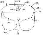
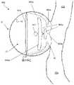
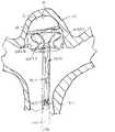
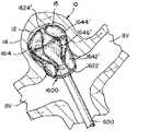
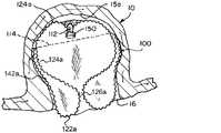
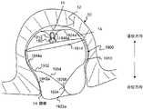
図1A~図1Cは、図1Aに例示されている所定の形状、並びに図1B及び図1Cに例示されている2つの個別の埋め込み形状を有することができる、例となる編組インプラント100の例示である。インプラント100は、図1Bに例示されている大きい方の動脈瘤10a、及び図1Cに例示されている小さい方の動脈瘤10bを含む、ある範囲のサイズの動脈瘤を処置することができる。インプラント100は、大きい方の動脈瘤10aの処置に貢献することができる第1の埋め込み形状(図1B)、及び小さい方の動脈瘤10bの処置に貢献することができる第2の埋め込み形状(図1C)を有することができる。インプラント100は、開放端部114及び挟持端部112を有する管状編組110を含むことができる。インプラント100は、挟持端部112において、編組110に取り付けられた脱着機構部150を含むことができる。管状編組110は、所定の形状に形成され得(図1A)、マイクロカテーテルを介して送達するために圧潰され、脱着機構部150において送達システムに取り付けられ、2つの埋め込み形状の一方又は他方に類似した形状で埋め込まれ得る(図1B又は図1C)。 1A-1C are illustrations of anexemplary braided implant 100 that can have the predetermined shape exemplified in FIG. 1A and the two individual implant shapes exemplified in FIGS. 1B and 1C. be.Implant 100 can treat aneurysms of a range of sizes, including thelarger aneurysm 10a exemplified in FIG. 1B and thesmaller aneurysm 10b exemplified in FIG. 1C. Theimplant 100 has a first implant shape that can contribute to the treatment of thelarger aneurysm 10a (FIG. 1B) and a second implant shape that can contribute to the treatment of thesmaller aneurysm 10b (FIG. 1B). It can have 1C). Theimplant 100 can include atubular braid 110 having anopen end 114 and a pinchingend 112. Theimplant 100 can include adesorption mechanism 150 attached to thebraid 110 at the pinchingend 112. Thetubular braid 110 can be formed into a predetermined shape (FIG. 1A), crushed for delivery via a microcatheter, attached to the delivery system at thedesorption mechanism 150, and resembles one or the other of the two implant shapes. Can be embedded in the shape (FIG. 1B or FIG. 1C).

図1Aを参照すると、管状編組110が所定の形状にあるとき、編組110を3つのセグメント142、144、146に分割する、2つの反転部122、124を含むことができる。所定の形状では、編組110は、編組110の開放端部114から反転部122の一方まで延在している外側セグメント142、編組110の挟持端部112から反転部124の他方まで延在している内側セグメント146、及び2つの反転部122、124の間に延在する中間セグメント144を有することができる。管状編組110は、所定の形状にある場合、中心縦軸yを中心に、実質的に半径方向に対称となり得る(図6Aを参照されたい)。図1Aは、各セグメント142、144、146の輪郭を例示しており、脱着機構部150は、機械式インプラント送達システム(例示せず)と共に使用され得る平坦鍵部として例示されている。 Referring to FIG. 1A, when thetubular braid 110 is in a predetermined shape, it may include two reversingportions 122, 124 that divide thebraid 110 into threesegments 142, 144, 146. In a predetermined shape, thebraid 110 extends from theouter segment 142 extending from theopen end 114 of thebraid 110 to one of the reversingportions 122, and from the pinchingend 112 of thebraid 110 to the other of the reversingportions 124. It can have aninner segment 146 and anintermediate segment 144 extending between the twoinversions 122, 124. When thetubular braid 110 is in a predetermined shape, it can be substantially radial symmetric with respect to the central vertical axis y (see FIG. 6A). FIG. 1A illustrates the contours of eachsegment 142, 144, 146, with thedesorption mechanism 150 being exemplified as a flat key section that can be used with a mechanical implant delivery system (not shown).

管状編組110は、編組を外側方向に最初に反転させて、内側セグメント146と、反転部124を備える中間セグメント144とを分離することにより所定の形状に形成することができ、次に、中間セグメント144は、例示されている実質的に「S」形状の輪郭を生成する形態の上に成形することができ、最後に、編組110を、やはり外側方向に反転させて、中間セグメント144と別の反転部122を備える外側セグメント142とを分離することができる。必要な場合、編組は、開放端部114において整えることができる。開放端部114は、中間セグメント144を囲むよう位置決めされ得る。開放端部114は、例示されているとおり、編組の高さの中間の第3の区域内に位置決めされ得る。 Thetubular braid 110 can be formed into a predetermined shape by first flipping the braid outward to separate theinner segment 146 from theintermediate segment 144 with theflip portion 124, and then the intermediate segment. The 144 can be molded on top of the illustrated substantially "S" contour contouring form, and finally thebraid 110 is also flipped outwards to be separate from theintermediate segment 144. It can be separated from theouter segment 142 having theinversion portion 122. If necessary, the braid can be trimmed at theopen end 114. Theopen end 114 may be positioned to surround theintermediate segment 144. Theopen end 114 may be positioned within a third area in the middle of the braid height, as illustrated.

インプラント100が埋め込まれたとき、動脈瘤頸部の閉塞を最大化するために、中間セグメント144の「S」形状の伸張をより低くすることによって、頸部開口部126を最小化するのが有利となり得る。中間セグメント144は、1つ又は2つ以上の屈曲部132、134を有することができる。この屈曲部132、134は、編組110が図1Cに例示されている第2の埋め込み形状へと移動するのを容易にするよう位置決めされ得、屈曲部132、134は、第1及び/又は第2の埋め込み形状にある編組110を安定化するよう位置決めされ得る。 Whenimplant 100 is implanted, it is advantageous to minimize thecervical opening 126 by lowering the extension of the "S" shape of theintermediate segment 144 in order to maximize the occlusion of the aneurysm neck. Can be. Theintermediate segment 144 can have one ormore bends 132, 134. Thebends 132, 134 may be positioned to facilitate the movement of thebraid 110 to the second embedded shape exemplified in FIG. 1C, with thebends 132, 134 being the first and / or the first. Thebraid 110 in the embedded shape of 2 may be positioned to stabilize it.

管状編組110は、所定の形状に熱硬化して、カテーテルを介して送達するよう変形され得、所定の形状に基づいて埋め込み形状に自己拡張することができる記憶形状材料を含むことができ、埋め込まれた動脈瘤の解剖学的構造によって留め置かれる。 Thetubular braid 110 can include a memory shape material that can be thermoset to a predetermined shape and deformed to be delivered via a catheter and can self-expand to an implant shape based on the predetermined shape. It is retained by the anatomy of the aneurysm.

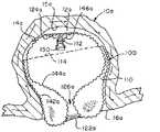
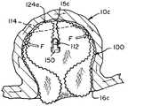
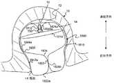
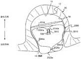
図1Bに例示されているとおり、編組110は、第1の埋め込み形状にあるとき、動脈瘤壁14aに接触する外側層142a、外側層142a内に入れ子にされた袋部144a、動脈瘤頸部16aに位置決めされた近位反転部122a、及び動脈瘤壁14aの遠位部分15aの近傍に位置決めされている遠位反転部124aを有することができる。第1の埋め込み形状において、編組110の脱着機構部150及び挟持端部112は、袋部144a内に吊り下げられ得る。 As illustrated in FIG. 1B, thebraid 110, when in the first implant shape, has anouter layer 142a in contact with theaneurysm wall 14a, asac 144a nested within theouter layer 142a, and an aneurysm neck. It can have aproximal inversion 122a positioned at 16a and adistal inversion 124a positioned in the vicinity of thedistal portion 15a of theaneurysm wall 14a. In the first embedded shape, thedetachable mechanism portion 150 and the holdingend portion 112 of thebraid 110 can be suspended in thebag portion 144a.

図1A及び図1Bに例示されているとおり、第1の埋め込み形状にある管状編組110は、所定の形状に比べて、半径方向に圧縮されて、垂直方向に延在され得る。第1の埋め込み形状にある外側層142aは、所定の形状にある外側層142に相当することができ、第1の埋め込み形状にある近位反転部122aは、所定の形状にある外側層142に隣接する反転部122に相当することができ、第1の埋め込み形状にある袋部144aは、所定の形状にある中間セグメント144に相当することができ、第1の埋め込み形状にある遠位反転部124aは、所定の形状にある内側セグメント146に隣接する反転部124に相当することができ、第1の埋め込み形状にある脱着機構部150を吊り下げている内側編組セグメント146aは、所定の形状にある内側セグメント146に相当することができる。第1の埋め込み形状では、袋部144aは、所定の形状にある、頸部開口部126に相当する頸部開口部126aを有することができる。 As illustrated in FIGS. 1A and 1B, thetubular braid 110 in the first embedded shape can be compressed radially and extended vertically as compared to the predetermined shape. Theouter layer 142a in the first embedded shape can correspond to theouter layer 142 in the predetermined shape, and theproximal inversion portion 122a in the first embedded shape becomes theouter layer 142 in the predetermined shape. Thebag portion 144a in the first embedded shape can correspond to the adjacentinverted portion 122 and can correspond to theintermediate segment 144 in the predetermined shape, and the distal inverted portion in the first embedded shape. The 124a can correspond to aninversion portion 124 adjacent to theinner segment 146 in a predetermined shape, and theinner braided segment 146a suspending thedetachable mechanism portion 150 in the first embedded shape has a predetermined shape. It can correspond to someinner segment 146. In the first embedded shape, thebag portion 144a can have aneck opening 126a corresponding to theneck opening 126 in a predetermined shape.

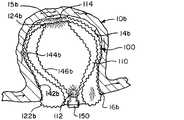
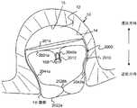
図1Cに例示されているとおり、編組110は、第2の埋め込み形状にあるとき、動脈瘤壁14bに接触する外側層142b、動脈瘤頸部16bに位置決めされている近位反転部122b、外側層142b内に延在し、外側層142bを押し込む中間層144b、編組110の開放端部114の近傍に位置決めされた遠位反転部124b、及び中間層144b内に延在しており中間層144bを押し込む内側層146bを有することができる。第2の埋め込み形状では、編組110の脱着機構部150及び挟持端部112は、近位反転部122bの近傍の動脈瘤頸部16bに位置決めされ得る。 As illustrated in FIG. 1C, thebraid 110, when in the second implant shape, has anouter layer 142b in contact with theaneurysm wall 14b, aproximal inversion 122b positioned on theaneurysm neck 16b, and the outer side. Anintermediate layer 144b extending into thelayer 142b and pushing theouter layer 142b, adistal inversion 124b positioned near theopen end 114 of thebraid 110, and anintermediate layer 144b extending into theintermediate layer 144b. Can have aninner layer 146b to push in. In the second implant shape, thedesorption mechanism portion 150 and the pinchingend portion 112 of thebraid 110 may be positioned at theaneurysm neck 16b in the vicinity of theproximal inversion portion 122b.

図1A及び図1Cに例示されているとおり、第2の埋め込み形状にある管状編組110は、所定の形状に比べて、半径方向に圧縮され得、所定の形状の中間セグメント144は、折り重ねられることができ、その結果、管状編組110の高さは、所定の形状に比べて、第2の埋め込み形状に圧縮される。代替的に、第2の埋め込み形状は、動脈瘤の高さよりも著しく小さい直径を有する動脈瘤に、第2の埋め込み形状で埋め込まれると、所定の形状に比べて、半径方向に圧縮され得、第2の埋め込み形状にある編組の高さは、所定の形状にある編組の高さよりも高くあることができる。 As illustrated in FIGS. 1A and 1C, thetubular braid 110 in the second embedded shape can be compressed in the radial direction as compared to the predetermined shape, and theintermediate segment 144 of the predetermined shape is folded. As a result, the height of thetubular braid 110 is compressed into a second embedded shape compared to a predetermined shape. Alternatively, the second implant can be radially compressed compared to a given shape when implanted in an aneurysm having a diameter significantly smaller than the height of the aneurysm with the second implant. The height of the braid in the second embedded shape can be higher than the height of the braid in the predetermined shape.

第2の埋め込み形状にある外側層142bは、所定の形状にある外側層142に相当することができ、第2の埋め込み形状にある近位反転部122bは、所定の形状にある外側層142に隣接する反転部122に相当することができ、第2の埋め込み形状にある中間層144b及び内側層146bは、所定の形状にある中間セグメント144に相当することができ、第2の埋め込み形状にある遠位反転部124bは、所定の形状にある中間セグメント144における屈曲部134に相当することができ、第2の埋め込み形状にある内側層146bを形成する脱着機構部150の近傍の編組110の一部は、所定の形状にある内側セグメント146に相当することができる。 Theouter layer 142b in the second embedded shape can correspond to theouter layer 142 in the predetermined shape, and theproximal inversion portion 122b in the second embedded shape is in theouter layer 142 in the predetermined shape. Theintermediate layer 144b and theinner layer 146b, which can correspond to theadjacent inversion portion 122 and are in the second embedded shape, can correspond to theintermediate segment 144 in the predetermined shape and are in the second embedded shape. Thedistal reversal portion 124b can correspond to theflexion portion 134 in theintermediate segment 144 in the predetermined shape and is one of thebraids 110 in the vicinity of thedesorption mechanism portion 150 forming theinner layer 146b in the second embedded shape. The portion can correspond to aninner segment 146 in a predetermined shape.

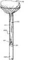
図2A~図2Hは、編組110がマイクロカテーテル600を出ると、所定の形状まで拡張する編組110を有する、例となるインプラント100の例示である。インプラント100は、図1Aに例示されているものに類似した所定の形状を有する。図2Aに例示されているとおり、編組110は、マイクロカテーテル600を介して送達されるサイズの圧縮された円周/直径及び長さLを有する管状編組の単層に拡張される送達形状に成形され得る。例示のインプラント100は、約22mm~約25mmの長さLを有する。当業者によって認識され理解されるように、特定の編組110の長さLは、治療される動脈瘤のサイズ及び形状に基づいて調整することができる。 2A-2H are illustrations of anexemplary implant 100 having abraid 110 that expands to a predetermined shape when thebraid 110 exits themicrocatheter 600.Implant 100 has a predetermined shape similar to that illustrated in FIG. 1A. As illustrated in FIG. 2A, thebraid 110 is molded into a delivery shape that extends into a single layer of tubular braid with a compressed circumference / diameter and length L of size delivered via themicrocatheter 600. Can be done. Theexemplary implant 100 has a length L of about 22 mm to about 25 mm. As recognized and understood by those skilled in the art, the length L of aparticular braid 110 can be adjusted based on the size and shape of the aneurysm being treated.

マイクロカテーテル600を介する送達の間に、脱着機構部150は、インプラント100の近位端部において送達システムに取り付けることができ、挟持端部112は、インプラント100の近位端部の近傍に位置決めされ得、開放端部114は、インプラント100の遠位端部を画定することができる。編組110が単層チューブに圧潰されると、マイクロカテーテルを介して送達されるとき、編組110への摩擦力の作用を緩和するのに十分に小さい直径及び十分に短い長さLを有する編組110をもたすことができ、これにより、編組110は、一部の用途において脱被覆状態で送達されることが可能となり得る。 During delivery via themicrocatheter 600, thedesorption mechanism 150 can be attached to the delivery system at the proximal end of theimplant 100 and the pinchingend 112 is positioned near the proximal end of theimplant 100. Obtained, theopen end 114 can define the distal end of theimplant 100. When thebraid 110 is crushed into a single layer tube, thebraid 110 has a diameter small enough to mitigate the effect of frictional forces on thebraid 110 and a length L short enough when delivered via a microcatheter. This may allow thebraid 110 to be delivered in a stripped state for some applications.

図2Bに例示されているとおり、開放端部114は、編組110の他の任意の部分がマイクロカテーテルを出る前に、マイクロカテーテル600を出るよう位置決めされ得る。開放端部114がマイクロカテーテル600を出ると、開放端部114は拡張することができる。開放端部114が、例示されているとおり、動脈瘤により拘束されていない場合、開放端部は、所定の形状で、その円周にまで拡張することができる。 As illustrated in FIG. 2B, theopen end 114 may be positioned to exit themicrocatheter 600 before any other portion of thebraid 110 exits the microcatheter. When theopen end 114 exits themicrocatheter 600, theopen end 114 can be expanded. If theopen end 114 is not constrained by an aneurysm, as illustrated, the open end can have a predetermined shape and extend to its circumference.

図2Cに例示されているとおり、編組110の遠位部分は、これがマイクロカテーテル600を出ると、半径方向への拡張を継続することができる。 As illustrated in FIG. 2C, the distal portion of thebraid 110 can continue to expand radially as it exits themicrocatheter 600.

図2Dに例示されているとおり、編組110は、編組110が、マイクロカテーテル600から更に押されると、外側セグメント142を画定する反転部122を形成することができる。 As illustrated in FIG. 2D, thebraid 110 can form aninversion portion 122 that defines theouter segment 142 when thebraid 110 is further pushed from themicrocatheter 600.

図2E~図2Gに例示されているとおり、中間セグメント144の「S」形状は、編組110が、マイクロカテーテル600から更に押されると、形成を開始することができる。 As illustrated in FIGS. 2E-2G, the "S" shape of theintermediate segment 144 can begin to form when thebraid 110 is further pushed from themicrocatheter 600.

図2Hに例示されているとおり、編組110のすべて又はほぼすべてが、マイクロカテーテル600を出ると、動脈瘤によって留め置かれていない編組110は、図1Aに例示されている形状に類似した所定の形状に拡張することができる。所定の形状では、例示されたインプラントの編組110は、約6mm~約6.5mmの直径及び約5mm~約5.5mmの高さを有する。 As illustrated in FIG. 2H, when all or almost all of thebraid 110 exits themicrocatheter 600, thebraid 110 not retained by the aneurysm has a predetermined shape similar to the shape illustrated in FIG. 1A. Can be expanded into shapes. In a given shape, the exemplifiedimplant braid 110 has a diameter of about 6 mm to about 6.5 mm and a height of about 5 mm to about 5.5 mm.

図2Hに例示されている所定の形状にある編組110の最外径と、図2Aに例示されている送達形状にある編組110の長さとの比は、約0.3~約0.24である。 The ratio of the outermost diameter of thebraid 110 in the predetermined shape exemplified in FIG. 2H to the length of thebraid 110 in the delivery shape exemplified in FIG. 2A is about 0.3 to about 0.24. be.

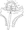
図3A~図3Hは、2つの異なる埋め込み形状にある動脈瘤10内で拡張する、図2A~図2Hに例示されているインプラント100の例示である。動脈瘤10は、高さが約6mm、直径が約6mm、頸部の直径が約4mmである。動脈瘤10の寸法を、図2Hに例示される所定の形状の編組110と比較すると、編組110は、わずかに大きい直径及びわずかに小さい高さを有し、動脈瘤10の内部は、実質的に球形であるが、編組110の外側寸法は、より円筒形である(測定方向については図6A及び図6Bを参照のこと)。したがって、インプラント100の編組110が動脈瘤10によって留め置かれていると、編組110は、半径方向に拘束される。 3A-3H are illustrations of theimplant 100 exemplified in FIGS. 2A-2H, which dilate within ananeurysm 10 in two different implant shapes. Theaneurysm 10 has a height of about 6 mm, a diameter of about 6 mm, and a neck diameter of about 4 mm. Comparing the dimensions of theaneurysm 10 with thebraid 110 of the predetermined shape exemplified in FIG. 2H, thebraid 110 has a slightly larger diameter and a slightly smaller height, and the interior of theaneurysm 10 is substantially. Although spherical, the outer dimensions of thebraid 110 are more cylindrical (see FIGS. 6A and 6B for measurement directions). Therefore, when thebraid 110 of theimplant 100 is anchored by theaneurysm 10, thebraid 110 is radially constrained.

図3Aに例示されているとおり、インプラント100は、図2Aに関連して記載されているとおり、マイクロカテーテル600を介して、動脈瘤10へと送達され得る。管状編組110の開放端部114がマイクロカテーテル600を出ると、これは、動脈瘤10内で拡張することができる。例示されている動脈瘤10は、幹血管20及び2本の分岐血管22a、22bを含む分岐部に位置決めされ、マイクロカテーテル600は、幹血管20を通って送達されているように例示されている。インプラントは、湾曲したマイクロカテーテルを介して血管の側壁上の動脈瘤へと送達され得、このような手技は、本開示の範囲によって包含されることが意図されることが企図されている。 As illustrated in FIG. 3A, theimplant 100 can be delivered to theaneurysm 10 via themicrocatheter 600, as described in connection with FIG. 2A. When theopen end 114 of thetubular braid 110 exits themicrocatheter 600, it can be dilated within theaneurysm 10. The exemplifiedaneurysm 10 is positioned at a bifurcation including thestem blood vessel 20 and the twobifurcated blood vessels 22a, 22b, and themicrocatheter 600 is exemplified as being delivered through thestem blood vessel 20. .. Implants can be delivered to an aneurysm on the side wall of a blood vessel via a curved microcatheter, and such procedures are intended to be incorporated by the scope of the present disclosure.

図3Bに例示されているとおり、編組110が、マイクロカテーテル600から遠位に更に押されると、編組110は、拡張して動脈瘤壁14に並置し、動脈瘤頸部16に形状を合わせることができる。処置される動脈瘤10は、所定の形状にある管状編組110の外径より小さい直径を有することができ、その結果、編組110は、外側方向に拡張する傾向があり、動脈瘤壁14への力、及び動脈瘤頸部16の外周周りの封止をもたらす。編組110によってもたらされる動脈瘤壁14及び頸部16の外周に対する半径方向の力は、幅広い頸部動脈瘤におけるインプラント100の固定と動脈瘤10の頸部16の封止の両方を行うのに十分となり得るので、インプラント100は、分岐部において一般に発生するなどの、幅広い頸部動脈瘤を処置するのに特に好適となり得る。 As illustrated in FIG. 3B, when thebraid 110 is further pushed distally from themicrocatheter 600, thebraid 110 expands and juxtaposes theaneurysm wall 14 to reshape theaneurysm neck 16. Can be done. Theaneurysm 10 to be treated can have a diameter smaller than the outer diameter of thetubular braid 110 in a predetermined shape, so that thebraid 110 tends to expand laterally and into theaneurysm wall 14. It provides force and a seal around the perimeter of theaneurysm neck 16. The radial force on the perimeter of theaneurysm wall 14 and cervical 16 provided by thebraid 110 is sufficient to both immobilize theimplant 100 in a wide cervical aneurysm and seal the cervical 16 of theaneurysm 10.Implant 100 may be particularly suitable for treating a wide range of cervical aneurysms, such as those commonly occurring at bifurcations.

図3Cに例示されているとおり、編組110が、マイクロカテーテル600から遠位に更に押されると、近位反転部122aが形成され得る。 As illustrated in FIG. 3C, when thebraid 110 is further pushed distally from themicrocatheter 600, aproximal inversion portion 122a may be formed.

図3Dに例示されているとおり、マイクロカテーテル600は、動脈瘤頸部16に、近位反転部122aを留置するよう操作され得る。近位反転部122aは、動脈瘤10と分岐血管22a、22bとの間の境界18(図6Bを参照されたい)を画定する平面の近位側面に留置され得る。一部の用途では、平面18から近位方向に十分に離して近位反転部122aを留置し、その結果、編組110の外側層142aが、動脈瘤頸部16の外周の周りを封止するが、インプラント100が血管22a、22b、20への閉塞となるほどかなり近位に留置されない。 As illustrated in FIG. 3D, themicrocatheter 600 can be engineered to place aproximal inversion 122a in theaneurysm neck 16. Theproximal inversion portion 122a may be placed on the proximal side surface of the plane defining the boundary 18 (see FIG. 6B) between theaneurysm 10 and thebifurcated vessels 22a, 22b. In some applications, theproximal inversion portion 122a is placed sufficiently distanced proximally from theplane 18, so that theouter layer 142a of thebraid 110 seals around the perimeter of theaneurysm neck 16. However, theimplant 100 is not placed so proximally that it obstructs theblood vessels 22a, 22b, 20.

図3Eに例示されているとおり、編組110は、動脈瘤嚢12の内部で拡張することができ、かつ延在して、編組110の外側層142aの内側表面に並置することができる。外側層142aへの並置は、外側層142aを動脈瘤壁14に固定する更なる力をもたらすことができる。 As illustrated in FIG. 3E, thebraid 110 can be expanded inside theaneurysm sac 12 and can be extended and juxtaposed on the medial surface of theouter layer 142a of thebraid 110. Placement on theouter layer 142a can provide additional force to secure theouter layer 142a to theaneurysm wall 14.

図3Fに例示されているとおり、動脈瘤10は、図1Bに例示されているものに類似した第1の埋め込み形状にある管状編組110を収容することが可能な高さを有する。編組110は、半径方向に拘束されて、動脈瘤が実質的に球形状をしていることに比べて、一層円筒の形状を有するので、編組110は、所定の形状よりも高い動脈瘤を収容するよう、所定の形状の高さを超えて延在することができる。例示では、所定の形状にあるインプラント100の管状編組110は、動脈瘤の高さよりも約0.5mm~1mm分短い高さを有するか、又は言い換えると、インプラントは、所定の形状に比べて、第1の埋め込み形状において、約10%~約20%の高さの分、延在する。 As illustrated in FIG. 3F, theaneurysm 10 has a height capable of accommodating atubular braid 110 in a first implant shape similar to that illustrated in FIG. 1B. Thebraid 110 accommodates an aneurysm higher than the predetermined shape because thebraid 110 is radially constrained and has a more cylindrical shape as compared to the aneurysm having a substantially spherical shape. As such, it can extend beyond the height of a predetermined shape. By way of example, thetubular braid 110 of theimplant 100 in a given shape has a height about 0.5 mm to 1 mm shorter than the height of the aneurysm, or in other words, the implant has a height that is about 0.5 mm to 1 mm shorter than the height of the aneurysm. In the first embedded shape, it extends by a height of about 10% to about 20%.

編組は、図3Gに例示されているとおり近位に引っ張られて、図1Cに例示されている第2の埋め込み形状に類似した図3Hに例示されている第2の埋め込み形状を形成することができるが、図1Cに例示されている動脈瘤10bは、図3Hに例示されている疑似動脈瘤10よりも小さい(編組110に比べて比例的に)という点で異なる。インプラント100は、送達システムから放出される前に、インプラント100は、マイクロカテーテル600に一部又は完全に後退して、第1の埋め込み形状又は第2の埋め込み形状のどちらか一方で再位置決めされ得る。更に又は代替的に、マイクロカテーテル600は、遠位に移動されて、図3Hに例示されている第2の埋め込み形状から、図3Fに例示されている第1の埋め込み形状まで編組110を移動させることができる。一部の用途では、医師は、インプラント100を位置決めしながら、第1の埋め込み形状又は第2の埋め込み形状が、動脈瘤の解剖学的構造及び処置部位に一層好適となるかどうかを選択することができる。図3A~図3Hに例示されている動脈瘤10及びインプラント100に類似した形状の動脈瘤及びインプラントを含む処置に関し、この例の実装形態における第1の埋め込み形状は、動脈瘤壁14と接触してより大きい表面積の編組110を実現するので、(図3Gに例示されている第2の埋め込み形状よりもむしろ)図3Fに例示されている第1の埋め込み形状にある編組110を成形するのが一層有利となり得る。 The braid can be pulled proximally as illustrated in FIG. 3G to form the second embedding shape exemplified in FIG. 3H, which is similar to the second embedding shape exemplified in FIG. 1C. However, theaneurysm 10b exemplified in FIG. 1C differs in that it is smaller (proportional to braid 110) than the pseudo-aneurysm 10 exemplified in FIG. 3H. Before theimplant 100 is released from the delivery system, theimplant 100 can be partially or completely retracted into themicrocatheter 600 and repositioned in either the first implant or the second implant. .. Further or alternative, themicrocatheter 600 is moved distally to move thebraid 110 from the second implant shape exemplified in FIG. 3H to the first implant shape exemplified in FIG. 3F. be able to. In some applications, the physician may choose whether the first implant or second implant is more suitable for the anatomy and treatment site of the aneurysm while positioning theimplant 100. Can be done. For a procedure comprising an aneurysm and an implant having a shape similar to theaneurysm 10 and theimplant 100 exemplified in FIGS. 3A-3H, the first implant shape in the embodiment of this example is in contact with theaneurysm wall 14. Since thebraid 110 having a larger surface area is realized, it is preferable to form thebraid 110 in the first embedded shape exemplified in FIG. 3F (rather than the second embedded shape illustrated in FIG. 3G). It can be even more advantageous.

図4A及び図4Bは、図2A~図2H及び図3A~図3Hに例示されている例となるインプラントの編組110の例示であり、これらは、管状編組110が、チューブ内で拡張されて、例となるインプラント100のその寸法を有するインプラント100が処置に好適となると思われる、動脈瘤直径及び動脈瘤高さの範囲が決まることを示している。図4Aは、5mmの直径を有するチューブ中の編組110を例示している。編組110は、第1の埋め込まれた形状であり、約8mmの高さを有する。したがって、編組110は、その所定の形状から直径約1mm~1.5mm、又は約17%~23%で半径方向に拘束され、高さが約2.5mm~3mm、又は約45%~60%で垂直方向に拡張される。 4A and 4B are illustrations of theimplant braid 110, which is an example exemplified in FIGS. 2A-2H and 3A-3H, wherein thetubular braid 110 is expanded in a tube. It shows that theimplant 100 with its dimensions of theexample implant 100 determines the range of aneurysm diameter and aneurysm height for which theimplant 100 would be suitable for treatment. FIG. 4A illustrates abraid 110 in a tube having a diameter of 5 mm. Thebraid 110 is the first embedded shape and has a height of about 8 mm. Therefore, thebraid 110 is radially constrained from its predetermined shape with a diameter of about 1 mm to 1.5 mm, or about 17% to 23%, and a height of about 2.5 mm to 3 mm, or about 45% to 60%. Is expanded vertically with.

図4Bは、4mmの直径を有するチューブ中の編組110を例示している。編組110は、第2の埋め込まれた形状であり、約6mmの高さを有する。したがって、編組は、その所定の形状から直径約2mm~2.5mm、又は約33%~38%の間で半径方向に拘束され、約0.5mm~1mm、又は約10%~20%で垂直方向に拡張される。 FIG. 4B illustrates abraid 110 in a tube having a diameter of 4 mm. Thebraid 110 is a second embedded shape and has a height of about 6 mm. Therefore, the braid is radially constrained from its predetermined shape to a diameter of about 2 mm to 2.5 mm, or about 33% to 38%, and is vertical at about 0.5 mm to 1 mm, or about 10% to 20%. Expanded in the direction.

図2Hに関連して例示及び記載されているような所定の形状及び寸法を有するインプラントは、したがって、直径が約4mm~約5mmであり、高さが約6mm~約8mmである動脈瘤を治療するのに好適であり得る。図3Fに例示されているとおり、インプラントはまた、直径6mm及び高さ6mmを有する動脈瘤を治療するのに好適であり得る。当業者によって認識され理解されるように、所定の形状にある管状編組の寸法は、本明細書に記載の原理に従って本明細書に具体的に概説されていないサイズの範囲内の動脈瘤を治療するように調整することができる。そのように成形されたインプラントのコレクションは、医師が入手可能となり得、医師は、動脈瘤の高さ、直径、頸部直径及び/又は他の解剖学的特徴に基づいて、コレクションから好適なインプラントを選択することができる。 Implants having predetermined shapes and dimensions as exemplified and described in connection with FIG. 2H therefore treat aneurysms having a diameter of about 4 mm to about 5 mm and a height of about 6 mm to about 8 mm. May be suitable for As illustrated in FIG. 3F, implants may also be suitable for treating aneurysms having a diameter of 6 mm and a height of 6 mm. As will be recognized and understood by those skilled in the art, the dimensions of the tubular braid in a given shape will treat aneurysms within the size range not specifically outlined herein according to the principles described herein. Can be adjusted to. A collection of such molded implants may be available to the physician, who will be suitable implants from the collection based on the height, diameter, cervical diameter and / or other anatomical features of the aneurysm. Can be selected.

それぞれが特有の形状をしている管状編組を有するインプラントのコレクションが作成されて、直径及び高さが様々な動脈瘤を処置するためのインプラントのカタログを提供することができる。このカタログは、直径が3mm~15mmの範囲、及び高さが3mm~15mmの範囲、又は別の例では、直径が3~11mmの範囲、及び高さが3~7mmの範囲の動脈瘤を処置するのに好適なインプラントを含むことができる。当業者により認識及び理解されているとおり、一部の動脈瘤の寸法は、かなり稀であり、カタログは、大きい高さ:直径の比、又は大きい直径:高さの比を有する動脈瘤を処置するためのインプラントを含むことを必要としない。 A collection of implants, each with a tubular braid having a unique shape, can be created to provide a catalog of implants for treating aneurysms of various diameters and heights. This catalog treats aneurysms in the range of 3 mm to 15 mm in diameter and 3 mm to 15 mm in height, or in another example, in the range of 3 to 11 mm in diameter and 3 to 7 mm in height. Suitable implants can be included. As recognized and understood by those of skill in the art, the dimensions of some aneurysms are fairly rare and the catalog treats aneurysms with large height: diameter ratios or large diameter: height ratios. It is not necessary to include an implant to do so.

コレクション中の各インプラントは、部分範囲の直径及び部分範囲の高さを有する動脈瘤を処置するのに好適となり得る。例となるカタログは、以下に限定されないが、以下のサイズの部分範囲(直径範囲(mm)、高さ範囲(mm)):(3~5、3~5)、(6~8、4~5)及び(9~11、5~7)のうちの1つ又は2つ以上の動脈瘤を処置するためのインプラントのリストを含むことができる。 Each implant in the collection may be suitable for treating an aneurysm with a partial range diameter and partial range height. The example catalog is not limited to the following, but is a partial range of the following sizes (diameter range (mm), height range (mm)): (3 to 5, 3 to 5), (6 to 8, 4 to). 5) and (9-11, 5-7) can include a list of implants for treating one or more aneurysms.

一部の例では、サイズの部分範囲の各々は、その部分範囲内にある動脈瘤を処置するのに好適な特有のサイズ及び形状をしている管状編組を有する単一インプラントによって処置され得る。いくつかの例において、カタログ中の部分範囲は、約10mm、約40mmである(編組が、マイクロカテーテルを介して送達するよう圧潰されたときの長さ)、及び/又はその間の長さを含む送達長さを有する管状編組を有する各インプラントによって表示され得る。 In some examples, each of the subranges of size can be treated with a single implant with a tubular braid having a unique size and shape suitable for treating an aneurysm within that subrange. In some examples, the partial range in the catalog is about 10 mm, about 40 mm (the length when the braid is crushed to deliver via a microcatheter), and / or includes lengths in between. It can be indicated by each implant with a tubular braid having a delivery length.

当業者によって認識及び理解されるとおり、動脈瘤の高さ及び直径は、ある程度の誤差範囲を伴って測定される。そのため、所与のインプラントに関するカタログ中に含まれるサイズの部分範囲は、インプラントにより処置され得る動脈瘤サイズの一部を表示することができ、インプラントは、列挙した部分範囲を外れた動脈瘤を処置することができる。例えば、高さa~高さbの間の高さ、及び直径x~直径yの間の範囲の直径を有する動脈瘤を処置するために列挙されているインプラントは、動脈瘤の直径が、この範囲の下限値(直径は約x)に近い場合、最大値と列挙されている高さbよりもわずかに高い動脈瘤を処置するのに好適となり得、動脈瘤の高さが、高さ範囲の下限値(高さは約a)に近い場合、本インプラントは、直径yよりもわずかに大きい直径を処置するのに好適となり得る。 As recognized and understood by those skilled in the art, the height and diameter of an aneurysm are measured with some margin of error. Therefore, a partial range of sizes contained in the catalog for a given implant can display a portion of the aneurysm size that can be treated by the implant, and the implant treats an aneurysm outside the listed partial range. can do. For example, implants listed for treating an aneurysm having a height between heights a and b, and a diameter in the range x to y in diameter have an aneurysm diameter that is this. If it is close to the lower limit of the range (diameter is about x), it may be suitable for treating an aneurysm slightly higher than the height b listed as the maximum value, and the height of the aneurysm is the height range. When close to the lower limit of (height is about a), the implant may be suitable for treating diameters slightly larger than diameter y.

図5A~図5Dは、様々なサイズの動脈瘤に、第1の埋め込み形状又は第2の埋め込み形状のどちらか一方で、埋め込まれた、図1A~図1Cに例示されている、例となるインプラント100の例示である。図5Aは、大きい動脈瘤10aを例示し、図5B及び図5Cは、中程度の動脈瘤10cを例示し、図5Dは、小さい動脈瘤10bを例示している。インプラント100は、有利には、所定の形状にある編組110の直径にほぼ等しい、又はこれより小さい直径を有する、動脈瘤10a、10b、10cに埋め込まれ、その結果、編組110は、埋め込まれると、動脈瘤壁14に対して外向きの力Fをもたらす。編組110は、1つ又は2つ以上の外側層に対して押し込む内側層を有し、力Fに寄与することができる。 5A-5D are exemplary, exemplified in FIGS. 1A-1C, implanted in aneurysms of various sizes, either in the first implant or the second implant. It is an example of theimplant 100. FIG. 5A illustrates alarge aneurysm 10a, FIGS. 5B and 5C illustrate amedium aneurysm 10c, and FIG. 5D illustrates asmall aneurysm 10b.Implant 100 is advantageously implanted inaneurysms 10a, 10b, 10c having a diameter approximately equal to or smaller than the diameter of thebraid 110 in a predetermined shape, so that thebraid 110 is implanted. , Brings an outward force F to theaneurysm wall 14. Thebraid 110 has an inner layer that pushes against one or more outer layers and can contribute to the force F.

図5Aに例示されているとおり、インプラント100が処置するのに好適となり得る動脈瘤10aの最大サイズは、編組110が第1の埋め込み形状をとり得る寸法によって決まり得る。挟持端部112及び脱着機構部150は、図1Bに同様に例示されているとおり、動脈瘤壁14aの遠位部分15aの近傍に位置決めされ得る。 As illustrated in FIG. 5A, the maximum size of theaneurysm 10a that theimplant 100 may be suitable for treatment can be determined by the dimensions in which thebraid 110 can take the first implant shape. The pinchingend 112 and thedesorption mechanism 150 may be positioned in the vicinity of thedistal portion 15a of theaneurysm wall 14a, as exemplified in FIG. 1B.

図5Bに例示されているとおり、インプラント100はまた、第1の埋め込み形状の、図5Aに例示されている動脈瘤10aよりも小さい、中程度のサイズの動脈瘤10cを処置するのに好適となり得る。第1の埋め込み形状にある中程度の動脈瘤10c内に適合させるため、挟持端部112及び脱着機構部150は、大きい動脈瘤10aにおける挟持端部112及び脱着機構部150の位置に比べて、動脈瘤壁の遠位部分15cから離れて位置決めされ得る。所定の形状(図1Aを参照されたい)では、中間セグメント144は、図5Bに例示されている中程度の動脈瘤10cにおける第1の埋め込み形状にある管状編組110を安定化させるための屈曲部134を含むことができる。 As illustrated in FIG. 5B, theimplant 100 is also suitable for treating a medium-sized aneurysm 10c, which is smaller than theaneurysm 10a exemplified in FIG. 5A, in the first implant shape. obtain. In order to fit into themedium aneurysm 10c in the first implant shape, the pinchingend 112 and thedesorption mechanism 150 are compared to the positions of the pinchingend 112 and thedesorption mechanism 150 in thelarge aneurysm 10a. It can be positioned away from thedistal portion 15c of the aneurysm wall. In a given shape (see FIG. 1A), theintermediate segment 144 is a bend for stabilizing thetubular braid 110 in the first implant shape in themoderate aneurysm 10c exemplified in FIG. 5B. 134 can be included.

図5Cに例示されているとおり、インプラント100はまた、第2の埋め込み形状にある中程度のサイズの動脈瘤10cを処置するのに好適となり得る。所定の形状にある編組の中間セグメント144(図1Aを参照されたい)は、折り重ねられて、図1Cに関連して記載されているものと類似した中間層144b及び内側層146bを形成することができる。一部の用途では、いずれかの埋め込み形状は、動脈瘤10cを処置するのに有効となり得、医師は、処置の間に、好ましい形状を選択することができる。例えば、医師は、インプラントを伸長するため、第1の埋め込み形状(図5B)の使用を決めることができ、その結果、近位折り重ね部122aは、動脈瘤頸部の外側の近位に配置され得るか、又は医師は、頸部開口部16cを塞栓するために動脈瘤頸部にあるより多くの層の編組を設けるよう、第2の埋め込み形状(図5C)の使用を決めることができる。 As illustrated in FIG. 5C, theimplant 100 may also be suitable for treating a mediumsized aneurysm 10c in a second implant shape. Braided intermediate segments 144 (see FIG. 1A) in a predetermined shape are folded to form anintermediate layer 144b and aninner layer 146b similar to those described in connection with FIG. 1C. Can be done. For some applications, either implant shape may be effective in treating theaneurysm 10c, allowing the physician to select the preferred shape during the procedure. For example, the physician can decide to use the first implant shape (FIG. 5B) to extend the implant, so that theproximal fold 122a is located proximal to the outside of the aneurysm neck. Alternatively, the physician may decide to use a second implant shape (FIG. 5C) to provide a braid of more layers in the aneurysm neck to embolize thecervical opening 16c. ..

図5Dに例示されているとおり、インプラント100が処置するのに好適な動脈瘤10bの最小サイズは、編組110が第2の埋め込み形状をとり得る寸法によって決まり得る。開放端部114及び/又は遠位折り重ね部124bは、第2の埋め込み形状にある動脈瘤壁の遠位部分15bの近傍で圧潰され得る。 As illustrated in FIG. 5D, the minimum size of ananeurysm 10b suitable for treatment by theimplant 100 can be determined by the dimensions by which thebraid 110 can take a second implant shape. Theopen end 114 and / or thedistal fold 124b can be crushed in the vicinity of thedistal portion 15b of the aneurysm wall in the second implant shape.

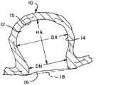
図6Aは、所定の形状にある例となるインプラント100の高さHI、及び直径D1、D2の測定の例示である。所定の形状では、例となるインプラント100の編組110は、垂直軸yを中心に実質的に半径方向に対称となり得、したがって、その直径によってそれぞれが描写可能な実質的に同心円断面を有することができる。図6Aは、反転部122、124の間で測定される、所定の形状にあるインプラント100の高さHI、開放端部114の直径に相当する外側セグメント142の外径D1、及び中間セグメントD2の外径D2を強調している。図6Aは、たった一例の所定の形状を例示しているに過ぎないが、本明細書に記載されている例となるインプラント100、200、300、400及びそれらの部分の高さ及び直径が、図6Aに例示されているものと同様に測定され得ることを理解すべきである。 FIG. 6A is an example of measuring the height HI and the diameters D1 and D2 of anexample implant 100 in a predetermined shape. In a given shape, thebraid 110 of theexemplary implant 100 can be substantially radial symmetric about the vertical axis y and thus each have a substantially concentric cross section depict by its diameter. can. FIG. 6A shows the height HI of theimplant 100 in a predetermined shape, the outer diameter D1 of theouter segment 142 corresponding to the diameter of theopen end 114, and the middle segment D2, measured between thereversals 122, 124. The outer diameter D2 is emphasized. FIG. 6A illustrates only one example of a given shape, but the heights and diameters of theexemplary implants 100, 200, 300, 400 and their portions described herein are. It should be understood that measurements can be made similar to those illustrated in FIG. 6A.

図6Bは、動脈瘤10の高さHA、嚢直径DA及び頸部直径DNの測定の例示である。動脈瘤10及び血管との間の境界を画定する平面18の位置もまた、例示されている。 FIG. 6B is an example of the measurement of height HA, sac diameter DA and cervical diameter DN ofaneurysm 10. The location of theplane 18 that defines the boundary between theaneurysm 10 and the blood vessels is also exemplified.

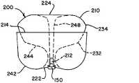
図7Aは、代替の所定の形状にある、管状編組210を有する、例となるインプラント200の例示である。図7Bは、埋め込み形状にある管状編組210を含む動脈瘤10における例となるインプラント200の例示である。管状編組210は、開放端部214及び挟持端部212を有することができる。インプラント200は、挟持端部212において、編組210に取り付けられた脱着機構部150を含むことができる。編組210は、所定の形状で形成されて、マイクロカテーテルを介して送達するために圧潰され、脱着機構部150において送達システムに取り付けられ、埋め込み形状で埋め込まれ得る。 FIG. 7A is an example of anexemplary implant 200 having atubular braid 210 in an alternative predetermined shape. FIG. 7B is an example of animplant 200 as an example in ananeurysm 10 including atubular braid 210 in an implantable shape. Thetubular braid 210 can have anopen end 214 and a pinchingend 212. Theimplant 200 may include adesorption mechanism 150 attached to thebraid 210 at the pinchingend 212. Thebraid 210 may be formed in a predetermined shape, crushed for delivery via a microcatheter, attached to the delivery system at thedetachable mechanism 150, and implanted in an embedded shape.

図7Aに例示されているとおり、管状編組210は、所定の形状にあるとき、編組210を3つのセグメント242、244、248に分割する、2つの反転部222、224を含むことができる。所定の形状では、編組210は、編組210の開放端部214から反転部222の一方まで延在している外側セグメント242、編組210の挟持端部212から反転部224の他方まで延在している内側セグメント248、及び2つの反転部222、224の間に延在する中間セグメント244を有することができる。管状編組210は、所定の形状にある場合、中心縦軸yを中心に、実質的に半径方向に対称となり得る(図6Aを参照されたい)。図7Aは、各セグメント242、244、248の輪郭を例示している。 As illustrated in FIG. 7A, thetubular braid 210 may include two reversingportions 222, 224 that, when in a predetermined shape, divide thebraid 210 into threesegments 242, 244, 248. In a predetermined shape, thebraid 210 extends from theouter segment 242 extending from theopen end 214 of thebraid 210 to one of the reversingportions 222, and from the sandwichingend 212 of thebraid 210 to the other of the reversingportions 224. It can have aninner segment 248 and anintermediate segment 244 extending between the twoinversions 222 and 224. Thetubular braid 210, when in a predetermined shape, can be substantially radial symmetric about the central vertical axis y (see FIG. 6A). FIG. 7A illustrates the contours of eachsegment 242, 244, 248.

図7Aに例示されている編組210の所定の形状と図1Aに例示されている編組110の所定の形状とを比較すると、外側セグメント142、242及び中間セグメント144、244は、それぞれ、互いに類似しており、図7Aに例示されている編組210の内側セグメント248は、図1Aに例示されている編組110の内側セグメント146よりも長い。図7A中の編組210の挟持端部212は、図1Aに例示されている内側セグメント146の近傍の反転部124の近傍よりもむしろ、外側セグメント242に隣接する反転部222の近傍に位置決めされる。図7Aに例示されている細長い内側セグメント248は、図7Bに例示されているとおりに埋め込まれた場合、インプラント200が圧縮に耐性を示す一助となるように位置決めされ得る。 Comparing the predetermined shape of thebraid 210 exemplified in FIG. 7A with the predetermined shape of thebraid 110 exemplified in FIG. 1A, theouter segments 142 and 242 and theintermediate segments 144 and 244 are similar to each other, respectively. Theinner segment 248 of thebraid 210 exemplified in FIG. 7A is longer than theinner segment 146 of thebraid 110 illustrated in FIG. 1A. The sandwichedend 212 of thebraid 210 in FIG. 7A is positioned near the reversingportion 222 adjacent to theouter segment 242 rather than near the reversingportion 124 near theinner segment 146 exemplified in FIG. 1A. .. The elongatedinner segment 248 exemplified in FIG. 7A can be positioned to help implant 200 exhibit compression resistance when implanted as illustrated in FIG. 7B.

図7Aに例示されている管状編組210は、一部差異のある、図1Aに関連して記載されているものに類似した所定の形状に形成され得る。中間セグメント244は、第2の埋め込み形状への編組210の移動を容易にするよう位置決めされた、屈曲部132、134を有する必要はない。図7Aに例示されている内側セグメント248は、図1Aに例示されているものよりも長く作製され得る。内側セグメント248は、埋め込まれると、インプラント200が圧縮された状態になることができる可能性を低減するよう最適化された長さを有するよう成形され得る。 Thetubular braid 210 illustrated in FIG. 7A can be formed into a predetermined shape, with some differences, similar to those described in relation to FIG. 1A. Theintermediate segment 244 does not need to havebends 132, 134 positioned to facilitate the movement of thebraid 210 into the second embedded shape. Theinner segment 248 exemplified in FIG. 7A can be made longer than that exemplified in FIG. 1A. Theinner segment 248, when implanted, may be shaped to have a length optimized to reduce the possibility that theimplant 200 can be in a compressed state.

図7Aに例示されている所定の形状を有する編組210を有するインプラント200は、図2Hに関連して例示及び記載されているものと類似した外径及び高さを含めた、所定の形状の外側寸法を有することができる。図7Aに例示されている編組210の内側セグメント248は、所定の形状にある編組210の高さにほぼ等しい高さを有することができる。 Theimplant 200 with thebraid 210 having the predetermined shape exemplified in FIG. 7A is outside the predetermined shape, including an outer diameter and height similar to those exemplified and described in connection with FIG. 2H. Can have dimensions. Theinner segment 248 of thebraid 210 illustrated in FIG. 7A can have a height approximately equal to the height of thebraid 210 in a predetermined shape.

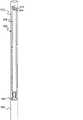
編組210は、マイクロカテーテルを横断するようなサイズにされている、送達形状の単層管状編組に引き延ばされ得る。送達形状にある編組210の長さは、開放端部214から挟持端部212まで測定され得る。図7Aに例示されている所定の形状、並びに図2Hに関連して例示及び記載されている外側寸法を有する編組210は、図2Aに例示されている編組110の長さと比べてより長い、送達形状にある長さを有することができる。図7Aに例示されている編組210の長さは、送達形状にあるとき、図1Aに例示されている所定の形状を有する編組110よりも、所定の形状にある編組110、210のほぼ高さ分だけ長くすることができる。言い換えると、図7Aに例示されている所定の形状を有する編組210を有するインプラント200は、所定の形状にあるとき、約6mm~約6.5mmの外径、及び約5mm~5.5mmの高さを有することができ、圧潰されてマイクロカテーテル内に適合する円周、及び約27mm~30mmとなる長さを有する単層チューブへと引き延ばされ得る。所定の形状の最外径と送達形状の長さの比は、約0.24~約0.2であり得る。 Thebraid 210 can be stretched into a delivery-shaped single-layer tubular braid that is sized to traverse the microcatheter. The length of thebraid 210 in the delivery shape can be measured from theopen end 214 to the pinchingend 212. Thebraid 210 having the predetermined shape exemplified in FIG. 7A, as well as the outer dimensions exemplified and described in connection with FIG. 2H, is longer than the length of thebraid 110 exemplified in FIG. 2A, delivery. Can have a length in shape. The length of thebraid 210 exemplified in FIG. 7A, when in the delivery shape, is approximately the height of thebraids 110, 210 in the predetermined shape than thebraid 110 having the predetermined shape exemplified in FIG. 1A. It can be lengthened by a minute. In other words, theimplant 200 with thebraid 210 having the predetermined shape exemplified in FIG. 7A has an outer diameter of about 6 mm to about 6.5 mm and a height of about 5 mm to 5.5 mm when in the predetermined shape. Can have a crushed circumference that fits within the microcatheter, and can be stretched into a single layer tube with a length of about 27 mm to 30 mm. The ratio of the outermost diameter of a given shape to the length of the delivered shape can be from about 0.24 to about 0.2.

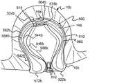
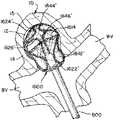
図7Bに例示されているとおり、編組210は、埋め込み形状にあるとき、動脈瘤壁14に接触している外側層242a、外側層242a内に入れ子にされている袋部244a、動脈瘤頸部16に位置決めされている近位反転部222a、及び動脈瘤壁14の遠位部分15の近傍に位置決めされている遠位反転部224aを有することができる。編組210の脱着機構部150及び挟持端部212は、近位反転部222aの近傍の動脈瘤頸部16の近傍に位置決めされ得る。脱着機構部150及び挟持端部212は、インプラント200が衝突を受ける状態になる可能性を低減するよう位置決めされ得る。 As illustrated in FIG. 7B, thebraid 210 has an outer layer 242a in contact with theaneurysm wall 14, asac portion 244a nested within the outer layer 242a, and an aneurysm neck when in the implantable shape. It can have aproximal inversion 22a positioned at 16 and a distal inversion 224a positioned in the vicinity of thedistal portion 15 of theaneurysm wall 14. Thedesorption mechanism portion 150 and the pinchingend portion 212 of thebraid 210 may be positioned in the vicinity of theaneurysm neck 16 in the vicinity of theproximal inversion portion 222a. Thedesorption mechanism portion 150 and the pinchingend portion 212 may be positioned to reduce the likelihood that theimplant 200 will be subject to collision.

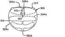
図8Aは、別の代替的な所定の形状にある管状編組310を有する例となるインプラント300の例示である。図8Bは、管状編組310が埋め込み形状にあるときの例となるインプラント300の例示である。管状編組310は、開放端部314及び挟持端部312を有することができ、脱着機構部150は、挟持端部312において編組310に取り付けることができる。編組310は、所定の形状で形成されて、マイクロカテーテルを介して送達するために圧潰され、脱着機構部150において送達システムに取り付けられ、埋め込み形状で埋め込まれ得る。 FIG. 8A is an example of anexemplary implant 300 having atubular braid 310 in another alternative predetermined shape. FIG. 8B is an example of animplant 300 as an example when thetubular braid 310 is in an embedded shape. Thetubular braid 310 can have anopen end 314 and a pinchingend 312, and adetachable mechanism 150 can be attached to thebraid 310 at the pinchingend 312. Thebraid 310 can be formed in a predetermined shape, crushed for delivery via a microcatheter, attached to the delivery system at thedetachable mechanism 150, and implanted in an embedded shape.

図8Aに例示されているとおり、管状編組310は、所定の形状にあるとき、編組310を3つのセグメント342、344、346に分割する、2つの反転部322、324を含むことができる。所定の形状において、編組310は、編組310の開放端部314から反転部322のうちの1つまで延在する外側セグメント342、編組310の挟持端部312から他の反転部324まで延在する内側セグメント346、及び2つの反転部322、324の間に延在する中間セグメント344を有することができる。管状編組310は、所定の形状にある場合、中心縦軸を中心に、実質的に半径方向に対称となり得る。図8Aは、各セグメント342、344、346の輪郭を例示する。 As illustrated in FIG. 8A, thetubular braid 310 may include two reversingportions 322, 324 that, when in a predetermined shape, divide thebraid 310 into threesegments 342, 344, 346. In a predetermined shape, thebraid 310 extends from theouter segment 342 extending from theopen end 314 of thebraid 310 to one of the reversingportions 322, from the sandwichingend portion 312 of thebraid 310 to the other reversingportion 324. It can have aninner segment 346 and anintermediate segment 344 extending between the twoinversions 322 and 324. When thetubular braid 310 is in a predetermined shape, it can be substantially radial symmetric with respect to the central vertical axis. FIG. 8A illustrates the contours of eachsegment 342, 344, 346.

図8Aに例示されている編組310の所定の形状と図1Aに例示されている編組110の所定の形状とを比較すると、外側セグメント142、342及び内側セグメント146、346は、それぞれ、互いに類似しており、図8Aに例示されている編組310の中間セグメント344は、図1Aに例示されている編組110の中間セグメント144の「S」形状よりもむしろ、起伏パターンを有する。起伏パターンにある中間セグメント344は、半径方向に対称となり、ハニカム形状を形成することができる。起伏パターンにある中間セグメント344は、埋め込まれると、図1Aに例示されている「S」形状を有する中間セグメント144によりもたらされ得る力パターンとは異なる、動脈瘤内にインプラント300を固定するよう外側方向に押し込む力パターンをもたらすことができる。図8Aにおける編組310の挟持端部312は、例示されている内側セグメント346に隣接する反転部324の近傍に位置決めされ得る。代替的に、内側セグメント346は、外側セグメント342に隣接する反転部322まで延在して、圧縮抵抗支柱をもたらすよう成形され得る。 Comparing the predetermined shape of thebraid 310 exemplified in FIG. 8A with the predetermined shape of thebraid 110 exemplified in FIG. 1A, theouter segments 142, 342 and theinner segments 146, 346 are similar to each other, respectively. Theintermediate segment 344 of thebraid 310 exemplified in FIG. 8A has an undulating pattern rather than the "S" shape of theintermediate segment 144 of thebraid 110 exemplified in FIG. 1A. Theintermediate segments 344 in the undulating pattern are radially symmetrical and can form a honeycomb shape. Theintermediate segment 344 in the undulation pattern, when implanted, secures theimplant 300 within the aneurysm, which is different from the force pattern that can be provided by theintermediate segment 144 having the "S" shape exemplified in FIG. 1A. It can provide a force pattern that pushes outwards. The sandwichedend portion 312 of thebraid 310 in FIG. 8A may be positioned in the vicinity of theinverted portion 324 adjacent to the exemplifiedinner segment 346. Alternatively, theinner segment 346 can be shaped to extend to theinversion 322 adjacent to theouter segment 342 to provide a compression resistance strut.

図8Aに例示されている管状編組310は、一部差異のある、図1Aに関連して記載されているものに類似した所定の形状に形成され得る。中間セグメント344は、「S」形状パターンよりもむしろ、起伏パターンを有するよう形成され得る。中間セグメント344は、第2の埋め込み形状への編組310の移動を容易にするよう位置決めされた、屈曲部を有する必要はない。 Thetubular braid 310 illustrated in FIG. 8A can be formed into a predetermined shape, with some differences, similar to those described in relation to FIG. 1A. Theintermediate segment 344 may be formed to have an undulating pattern rather than an "S" shape pattern. Theintermediate segment 344 need not have a bend that is positioned to facilitate the movement of thebraid 310 into the second embedded shape.

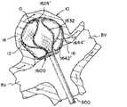
図8Bに例示されているとおり、編組310は、埋め込み形状にあるとき、動脈瘤壁に接触するように成形された外側層342a、外側層342a内に入れ子にされている起伏状の中間層344aの圧縮伸長部、動脈瘤頸部に配置されるよう位置決めされた近位反転部322a、及び動脈瘤壁の遠位部分の近傍に配置されるよう位置決めされた遠位反転部324aを有することができる。編組310の脱着機構部150及び挟持端部312は、近位反転部322aの近傍、例示されている遠位反転部324aの近傍、又はそれらの間の位置のどちらかの、動脈瘤嚢内に位置決めされ得る。脱着機構部150及び挟持端部312は、インプラント300が衝突を受ける状態になる可能性を低減するよう位置決めされ得る。 As illustrated in FIG. 8B, thebraid 310 has an undulating intermediate layer 344a nested within an outer layer 342a and an outer layer 342a molded to contact the aneurysm wall when in an implantable shape. Can have a compression extension, aproximal inversion 322a positioned to be located in the aneurysm neck, and adistal inversion 324a positioned to be located near the distal portion of the aneurysm wall. can. Thedesorption mechanism portion 150 and the pinchingend portion 312 of thebraid 310 are positioned within the aneurysm sac either in the vicinity of theproximal inversion portion 322a, in the vicinity of the exemplifieddistal inversion portion 324a, or in a position between them. Can be done. Thedesorption mechanism portion 150 and the pinchingend portion 312 may be positioned to reduce the likelihood that theimplant 300 will be subject to collision.

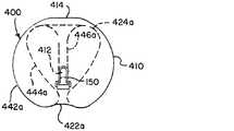
図9Aは、別の代替的な所定の形状にある管状編組410を有する例となるインプラント400の例示である。図9Bは、埋め込み形状にある、管状編組410を例示する例となるインプラント400の例示である。管状編組410は、開放端部414及び挟持端部412を有することができる。脱着機構部150は、挟持端部412において、編組410に取り付けることができる。インプラント400は、所定の形状に形成されて、マイクロカテーテルを介して送達するよう圧潰され、脱着機構部150において送達システムに取り付けられ、埋め込み形状で埋め込まれ得る。 FIG. 9A is an example of anexemplary implant 400 having atubular braid 410 in another alternative predetermined shape. FIG. 9B is an example of animplant 400, which is an example of atubular braid 410 in an embedded shape. Thetubular braid 410 can have anopen end 414 and a pinchingend 412. Thedetachable mechanism portion 150 can be attached to thebraid 410 at the sandwichingend portion 412. Theimplant 400 can be formed into a predetermined shape, crushed for delivery via a microcatheter, attached to the delivery system at thedesorption mechanism 150, and implanted in an implantable shape.

図9Aに例示されているとおり、管状編組410は、所定の形状にあるとき、編組410を3つのセグメント442、444、446に分割する、2つの反転部422、424を含むことができる。所定の形状では、編組410は、編組410の開放端部414から反転部422の一方まで延在している外側セグメント442、編組410の挟持端部412から反転部424の他方まで延在している内側セグメント446、及び2つの反転部422、424の間に延在する中間セグメント444を有することができる。管状編組410は、所定の形状にある場合、中心縦軸yを中心に、実質的に半径方向に対称となり得る(図6Aを参照されたい)。図9Aは、各セグメント442、444、446の輪郭を例示する。 As illustrated in FIG. 9A, thetubular braid 410 may include two reversingportions 422, 424 that, when in predetermined shape, divide thebraid 410 into threesegments 442, 444, 446. In a predetermined shape, thebraid 410 extends from theouter segment 442 extending from theopen end 414 of thebraid 410 to one of the reversingportions 422, and from the pinchingend 412 of thebraid 410 to the other of the reversingportions 424. It can have aninner segment 446 and anintermediate segment 444 extending between the twoinversions 422 and 424. When thetubular braid 410 is in a predetermined shape, it can be substantially radial symmetric with respect to the central vertical axis y (see FIG. 6A). FIG. 9A illustrates the contours of eachsegment 442, 444, 446.

図9Aに例示されている編組410の所定の形状と、図1Aに例示されている編組110の所定の形状を比較すると、外側セグメント142、442は、互いに類似することができ、図9Aに例示されている編組410の中間セグメント444は、図1Aに例示されている「S」字形状の中間セグメント144に比べて、それほど顕著ではない「S」字形状を有することができ、内側セグメント446は、図1Aに例示されている内側層146に隣接する反転部424の近傍よりもむしろ、外側層442に隣接する反転部422の近傍に位置決めされた挟持端部412を有する輪郭の、円錐形又は「V」字形状とすることができる。内側セグメント446は、埋め込まれると、圧縮抵抗支柱を形成するよう再成形され得る。 Comparing the predetermined shape of thebraid 410 exemplified in FIG. 9A with the predetermined shape of thebraid 110 exemplified in FIG. 1A, theouter segments 142 and 442 can be similar to each other and are exemplified in FIG. 9A. Theintermediate segment 444 of the braided 410 can have an "S" shape that is less pronounced than the "S" shapedintermediate segment 144 exemplified in FIG. 1A, and theinner segment 446 , Conical, conical or contoured with a pinchingend 412 positioned near the reversingportion 422 adjacent to theouter layer 442, rather than in the vicinity of the reversingportion 424 adjacent to theinner layer 146 exemplified in FIG. 1A. It can have a "V" shape. Theinner segment 446, when embedded, can be reshaped to form a compression resistance strut.

図9Aに例示されている管状編組410は、一部差異のある、図1Aに関連して記載されているものに類似した所定の形状に形成され得る。図9Aに例示されている中間セグメント444は、図1Aに例示されている「S]形状パターン144に比べて、それほど顕著ではない「S」形状パターンを有するよう形成され得る。中間セグメント444は、第2の埋め込み形状への編組410の移動を容易にするよう位置決めされた、屈曲部を有する必要はない。内側セグメント446は、図1Aに例示されている内側セグメント146と比べて、図9Aに例示されているより長い長さを有することができる。内側セグメント446に隣接する反転部424は、図1Aに例示されている相当する反転部124に比べて、図9Aに例示されているとおり、一層、鋭い湾曲部を有することができる。 Thetubular braid 410 illustrated in FIG. 9A can be formed into a predetermined shape, with some differences, similar to those described in relation to FIG. 1A. Theintermediate segment 444 exemplified in FIG. 9A may be formed to have a less prominent "S" shape pattern as compared to the "S"shape pattern 144 exemplified in FIG. 1A. Theintermediate segment 444 does not need to have a bend that is positioned to facilitate the movement of thebraid 410 to the second embedded shape. Theinner segment 446 can have a longer length than theinner segment 146 exemplified in FIG. 1A. The reversingsection 424 adjacent to theinner segment 446 can have a sharper curved section as illustrated in FIG. 9A as compared to the corresponding reversingsection 124 exemplified in FIG. 1A.

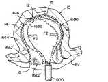
図9Bに例示されているとおり、編組410は、埋め込み形状にあるとき、動脈瘤壁に接触するよう成形された外側層442a、外側層442a内に入れ子にされているチューリップ又は心臓形状の袋部444a、動脈瘤頸部に配置されるよう位置決めされている近位反転部422a、動脈瘤壁の遠位部分の近傍に配置されるよう位置決めされている遠位反転部424a、及び袋部444a内に延在している圧縮抵抗支柱446aを有することができる。編組410の脱着機構部150及び挟持端部412は、近位反転部422aの近傍の袋部444a内に位置決めされ得る。脱着機構部150及び挟持端部412は、インプラント400が衝突を受ける状態になる可能性を低減するよう位置決めされ得る。 As illustrated in FIG. 9B, thebraid 410 is a tulip or heart-shaped sac that is nested within anouter layer 442a,outer layer 442a that is shaped to contact the aneurysm wall when in the implanted shape. Within 444a, aproximal inversion 422a positioned to be located in the neck of the aneurysm, adistal inversion 424a positioned to be located near the distal portion of the aneurysm wall, and a sac 444a. It is possible to have a compression resistance column 446a extending to the. Thedesorption mechanism portion 150 and the pinchingend portion 412 of thebraid 410 may be positioned in the bag portion 444a in the vicinity of theproximal inversion portion 422a. Thedesorption mechanism portion 150 and the pinchingend portion 412 may be positioned to reduce the likelihood that theimplant 400 will be subject to collision.

図10は、図9Aに例示されているものに類似した所定の形状にある、管状編組410を有する例となるインプラント400の例示である。 FIG. 10 is an example of anexemplary implant 400 with atubular braid 410 in a predetermined shape similar to that illustrated in FIG. 9A.

図11A~図11Eは、図10に例示されている例となるインプラント400の例示であり、管状編組410が、図9Bに例示されているものに類似した疑似動脈瘤10内の埋め込み形状まで拡張していることを示している。図11Aに例示されているとおり、開放端部414は、最初にマイクロカテーテルを出て、動脈瘤10内に拡張することができる。図11Bに例示されているとおり、所定の形状にある外側層442に相当する編組410の遠位部分は、拡張して、動脈瘤壁14に並置し、埋め込み形状にある外側層442aを形成することができる。図11Cに例示されているとおり、編組410が、マイクロカテーテル600から遠位に更に押されると、編組410は反転し始めることができる。図11Dに例示されているとおり、近位反転部422aは、チューリップ形状の袋部444aが外側層442a内に拡張すると、動脈瘤頸部16に配置され得る。図11Eに例示されているとおり、編組410は、図9Bに例示されているものに類似した、動脈瘤10内の埋め込み形状に成形され得る。 11A-11E are examples of theimplant 400, which is an example exemplified in FIG. 10, in which thetubular braid 410 extends to an implantable shape within a pseudo-aneurysm 10 similar to that exemplified in FIG. 9B. It shows that it is doing. As illustrated in FIG. 11A, theopen end 414 can first exit the microcatheter and dilate into theaneurysm 10. As illustrated in FIG. 11B, the distal portion of thebraid 410 corresponding to theouter layer 442 in a predetermined shape expands and juxtaposes theaneurysm wall 14 to form theouter layer 442a in an implantable shape. be able to. As illustrated in FIG. 11C, when thebraid 410 is further pushed distally from themicrocatheter 600, thebraid 410 can begin to flip. As illustrated in FIG. 11D, theproximal inversion portion 422a may be placed in theaneurysm neck 16 when the tulip-shaped bag portion 444a extends into theouter layer 442a. As illustrated in FIG. 11E, thebraid 410 can be molded into an implantable shape within theaneurysm 10 similar to that illustrated in FIG. 9B.

本明細書に図示及び記載されているインプラント100、200、300、400のいずれも、管状編組110、210、310、410と実質的に平行に移動する1つ又は2つ以上の追加の編組層を含むことができる。複数の層は、互いに同軸に積層され、単一ユニットとして所定の形状に熱処理され得る。いくつかの用途では、多数の層は、動脈瘤頸部において追加の被覆を提供し、動脈瘤内での更なる支持及び適合性を提供することができる。編組の各1層は、様々なワイヤ数と太さ、編組の角度と直径、及びワイヤの材質を使用して、様々なプロパティで選択して金属被覆率を潜在的に高め、輪郭(マイクロカテーテルサイズ)を縮小し、展開を容易にし、血管造影下での視認性を提供しながら、頸部インレットチャネルのサイズを縮小することができる。 Each of theimplants 100, 200, 300, 400 illustrated and described herein has one or more additional braided layers moving substantially parallel to thetubular braids 110, 210, 310, 410. Can be included. The plurality of layers may be laminated coaxially with each other and heat-treated to a predetermined shape as a single unit. In some applications, multiple layers can provide additional coverage in the aneurysm neck and provide additional support and compatibility within the aneurysm. Each layer of braid uses different wire counts and thicknesses, braid angles and diameters, and wire materials, and can be selected with different properties to potentially increase metal coverage and contour (microcatheter). The size of the cervical inlet channel can be reduced while reducing the size), facilitating deployment and providing visibility under angiography.

図12Aは、図1Aに例示されるものと同様の所定の形状の2つの編組層510、560を含むインプラント500の断面図である。編組層510、560は、脱着機構部550が編組層510、560に固定され得る、挟持端部512で収縮される。例示されているとおり、所定の形状では、編組層510、560の各々は、図1Aに例示されるインプラント100に関して記載されたものと同様の、それぞれの開放端部514、564、第1のセグメント542、582、第1の反転部522、572、第2のセグメント544、584、第1の屈曲部532、592、第2の屈曲部534、594、第2の反転部524、574、及び第3のセグメント546、586を有することができる。2つの編組層510、560の各々について、第3のセグメントは、挟持端部512から第2の反転部524、574まで延在し、第2のセグメント544、584は、第2の反転部524、574から第1の反転部まで延在し、第3のセグメント546、586を少なくとも部分的に取り囲み、第1のセグメントは、第1の反転部522、572から542、582まで延在し、第2のセグメント544、584を少なくとも部分的に取り囲む。図に例示されているとおり、2つの層の各々について、第1のセグメントは、第2のセグメントを部分的にのみ取り囲む。2つの層の各々の第1の反転部の周りで、層B(560)は、層A(510)内に入れ子になっている。2つの層の各々の第2の反転部の周りで、層Aは、層B内に入れ子になっている。 FIG. 12A is a cross-sectional view of theimplant 500 comprising two braidedlayers 510 and 560 of a predetermined shape similar to those exemplified in FIG. 1A. The braided layers 510 and 560 are shrunk at the sandwichingend portion 512 where thedetachable mechanism portion 550 can be fixed to the braided layers 510 and 560. As exemplified, in a given shape, each of the braided layers 510 and 560 has anopen end 514, 564, first segment similar to that described for theimplant 100 exemplified in FIG. 1A. 542, 582, first reversingpart 522, 571,second segment 544, 584, first bendingpart 532, 592,second bending part 534, 594, second reversingpart 524, 574, and first. It can have 3segments 546, 586. For each of the two braidedlayers 510 and 560, the third segment extends from the sandwichingend 512 to thesecond inversion 524, 574, and thesecond segments 544, 584 are thesecond inversion 524. It extends from 574 to the first inversion, at least partially surrounding thethird segment 546, 586, and the first segment extends from thefirst inversions 522, 572 to 542, 582. It surrounds the second segments 544,584 at least partially. As illustrated in the figure, for each of the two layers, the first segment only partially surrounds the second segment. Around the first inversion of each of the two layers, layer B (560) is nested within layer A (510). Around the second inversion of each of the two layers, layer A is nested within layer B.

図12Bは、マイクロカテーテル600内に位置決めされた編組層510、560を例示する。編組層510、560は、例示されているとおり、内側層560(層B)及び外側層510(層A)を有する同軸チューブとして位置決めすることができる。卓上試験は、2つの編組層が、同じ総ワイヤ数を有する単層の編組と比較して、より小さい編組の外側周(C)に至ることができることが実証されている。単層の管状編組110、210、310、410を含むインプラント100、200、300、400は、72本のワイヤ又は96本のワイヤのワイヤ数を有することが好ましい。同じ総ワイヤ数を有すると、2つの層510、560を有するインプラント500は、送達システムへの崩壊時に編組輪郭サイズを低減することができる。それは、トラック力及びまたマイクロカテーテルサイズを低減することができ、これは、より困難かつ遠位脈管構造への操縦能力を促進することができる。同じ送達チューブサイズでは、編組の2つの層510、560は、そのサイズに適合することができる総ワイヤ数を増加させることができる。追加されたワイヤ数は、動脈瘤の頸部における多孔性を減少させて、頸部の流れの迂回及び血栓症を促進して、治癒を促進し、破裂した動脈瘤をより迅速に治療することができる。追加されたワイヤはまた、異なる解剖学的場所におけるより大きい動脈瘤内のインプラントの展開を容易にすることができる。 FIG. 12B illustrates the braided layers 510 and 560 positioned within themicrocatheter 600. As exemplified, the braided layers 510 and 560 can be positioned as a coaxial tube having an inner layer 560 (layer B) and an outer layer 510 (layer A). Desktop tests have demonstrated that two braid layers can reach the outer circumference (C) of a smaller braid compared to a single braid with the same total number of wires.Implants 100, 200, 300, 400 including a single layertubular braid 110, 210, 310, 410 preferably have a wire number of 72 wires or 96 wires. With the same total number of wires, theimplant 500 with twolayers 510, 560 can reduce the braid contour size upon collapse to the delivery system. It can reduce track force and also microcatheter size, which can promote more difficult and maneuverability to distal vascular structures. For the same delivery tube size, the twolayers 510 and 560 of the braid can increase the total number of wires that can fit that size. The added number of wires reduces the porosity of the aneurysm in the neck, promotes cervical flow diversion and thrombosis, promotes healing and treats ruptured aneurysms more quickly. Can be done. The added wire can also facilitate the deployment of the implant within a larger aneurysm at different anatomical locations.

図12Cは、図1Bに例示される埋め込み形状と同様の第1の埋め込み形状の、より大きい動脈瘤10a内に埋め込まれたインプラント500を例示する。より大きい動脈瘤10aは、頸部開口部16aである入口を有する第1の実質的に球状の空洞を画定する。図に例示されているとおり、第1の埋め込み形状では、2つの層の各々は、所定の形状の第1のセグメントに対応する外側層と、所定の形状の第1の反転部に対応する近位反転部とを有する。図に例示されているとおり、層A510の外側層542aは、より大きい動脈瘤10の空洞壁14aに接触するように位置決めされ、層B560の外側層582aは、層A510の外側層542aを並置し、2つの層510、560の各々の近位反転部522a、572aは、より大きい動脈瘤10aへの入口16aの近くに位置決めされている。図に例示されているとおり、管状編組の2つの層510、560の各々は、所定の形状の第2のセグメント544、584に対応する袋部544a、584aを含む。層B560の袋部584aは、より大きい動脈瘤10aの空洞壁の一部分を並置するように位置決めされる。層A510の袋部544aは、層B560の袋部584a内に収容される。 FIG. 12C illustrates animplant 500 implanted in alarger aneurysm 10a with a first implant shape similar to the implant shape exemplified in FIG. 1B. Thelarger aneurysm 10a defines a first substantially spherical cavity with an entrance that is acervical opening 16a. As illustrated in the figure, in the first embedded shape, each of the two layers corresponds to an outer layer corresponding to a first segment of a given shape and a near portion corresponding to a first inverted portion of a given shape. It has a position reversal part. As illustrated in the figure, theouter layer 542a of layer A510 is positioned to contact thecavity wall 14a of thelarger aneurysm 10, and theouter layer 582a of layer B560 juxtaposes theouter layer 542a of layer A510. Theproximal inversions 522a, 572a of the twolayers 510 and 560, respectively, are positioned near theentrance 16a to thelarger aneurysm 10a. As illustrated in the figure, each of the twolayers 510 and 560 of the tubular braid comprises abag portion 544a, 584a corresponding to asecond segment 544, 584 of a predetermined shape. Thebag portion 584a of layer B560 is positioned so as to juxtapose a portion of the cavity wall of thelarger aneurysm 10a. Thebag portion 544a of the layer A510 is housed in thebag portion 584a of the layer B560.

2つの層510、560は、共に押し込んで、より強力な単層編組のように機能する可能性があり、これは、いくつかの用途では、角度のある動脈瘤におけるインプラントの展開を容易にすることができる。動脈瘤内に展開されると、2つの層のそれぞれの外側セグメントは、動脈瘤壁に対して外向きに拡張して、動脈瘤壁に対して編組を安定化させる。単一の編組層を有するインプラントを2つ又は3つ以上の編組層を有するインプラントと比較して、2つのインプラントは、同様のサイズ及び形状の所定の形状を有し、単一の編組層は、動脈瘤の頸部の近くでの反転を容易にするために、カテーテルの遠位端部の再位置決めを必要とし得、一方、2つ又は3つ以上の編組層を有するインプラントは、カテーテルの遠位端部の再位置決めを必要とせずに、挟持端部の遠位移動によって動脈瘤頸部の近くで反転させ得る。追加のワイヤ数はまた、動脈瘤ドームにおける適合性及び支持を増加させることができる。 The twolayers 510 and 560 can be pushed together to act like a stronger single-layer braid, which in some applications facilitates the deployment of implants in angled aneurysms. be able to. When deployed within the aneurysm, the outer segments of each of the two layers extend outward with respect to the aneurysm wall to stabilize the braid against the aneurysm wall. Compared to an implant with a single braided layer, an implant with two or more braided layers, the two implants have a given shape of similar size and shape, and the single braided layer Implants with two or more braided layers may require repositioning of the distal end of the catheter to facilitate reversal of the aneurysm near the neck. Distal movement of the pinching end can invert near the aneurysm neck without the need for distal end repositioning. The additional number of wires can also increase compatibility and support in the aneurysm dome.

2つの層はまた、外側編組に対して内側の編組を支持し、圧縮に抵抗するために、慢性的な外向きの力を潜在的に増加させることができる。図5Aに例示されているとおり、単層の編組110は、動脈瘤壁14aに対して半径方向の力Fを提供することができる。同様に、図12Cに例示されるような編組の2つの層510、560は、すべてが等しくなる単層の編組110よりも大きい動脈瘤壁14aに対して半径方向の力Fを提供することができる。言い換えると、所定の形状に形成され、総ワイヤ数を有し、各ワイヤがワイヤ円周を有し、動脈瘤10aを治療するために使用される単層編組110を有するインプラント100が与えられ、かつ、編組の2つの層510、560を有し、総ワイヤ数が単層編組110のそれに等しく、平均ワイヤ円周が単層編組110のワイヤにほぼ等しく、同じ動脈瘤又は実質的に同じサイズの動脈瘤10aを治療するために使用されるインプラント500が与えられると、2つの層510、560は、単層110と比較して、動脈瘤壁14aに対してより大きい半径方向の力Fを提供することができる。 The two layers can also potentially increase the chronic outward force to support the inner braid against the outer braid and resist compression. As illustrated in FIG. 5A, themonolayer braid 110 can provide a radial force F against theaneurysm wall 14a. Similarly, the twolayers 510 and 560 of the braid as illustrated in FIG. 12C can provide a radial force F to theaneurysm wall 14a, which is larger than themonolayer braid 110, which is all equal. can. In other words, given animplant 100 formed into a predetermined shape, having a total number of wires, each wire having a wire circumference and having asingle layer braid 110 used to treat ananeurysm 10a. And it has twolayers 510 and 560 of the braid, the total number of wires is equal to that of thesingle layer braid 110, the average wire circumference is approximately equal to the wires of thesingle layer braid 110, the same aneurysm or substantially the same size. Given theimplant 500 used to treat theaneurysm 10a, the twolayers 510, 560 exert a greater radial force F with respect to theaneurysm wall 14a compared to themonolayer 110. Can be provided.

図12Dは、図1Cに例示される埋め込み形状と同様の第2の埋め込み形状で、より小さい動脈瘤10b内に埋め込まれたインプラント500を例示する。より小さい動脈瘤10bは、頸部開口部16bである入口を有する第2の実質的に球状の空洞を画定する。例示されているとおり、第2の埋め込み形状では、2つの層510、560の各々は、所定の形状の第1のセグメント542、582に対応する外側層542b、582bと、所定の形状の第1の反転部522、572に対応する近位反転部522b、572bと、を有する。層A510の外側層542bは、より小さい動脈瘤10bの空洞壁14bに接触する。層B560の外側層582bは、層A510の外側層542bと並置する。2つの層の各々の近位反転部522b、572bは、第2の実質的に球状の空洞10bへの入口16bの近くに配置される。管状編組の2つの層の各々は、所定の形状の第2のセグメント544、584に対応する中間層544b、584b及び内側層546b、586b、並びに中間層及び内側層を分離する折り重ね部524b、564bを有する。層B560の内側層586bは、層B560の外側層582bを並置する層B560の中間層584bを並置する層A510の中間層544bを並置する層A510の内側層546bを並置する。 FIG. 12D illustrates animplant 500 implanted in asmaller aneurysm 10b with a second implant shape similar to the implant shape exemplified in FIG. 1C. Thesmaller aneurysm 10b defines a second substantially spherical cavity with an entrance that is thecervical opening 16b. As exemplified, in the second embedded shape, each of the twolayers 510, 560 has anouter layer 542b, 582b corresponding to thefirst segment 542, 582 of the predetermined shape, and a first of the predetermined shape. It hasproximal inversion portions 522b, 572b corresponding to theinversion portions 522, 572 of the above. Theouter layer 542b of layer A510 contacts thecavity wall 14b of thesmaller aneurysm 10b. Theouter layer 582b of the layer B560 is juxtaposed with theouter layer 542b of the layer A510.Proximal inversions 522b, 572b, respectively, of the two layers are located near theentrance 16b to the second substantiallyspherical cavity 10b. Each of the two layers of the tubular braid hasintermediate layers 544b, 584b andinner layers 546b, 586b corresponding to thesecond segments 544, 584 of the predetermined shape, and a foldedportion 524b that separates the intermediate and inner layers. It has 564b. Theinner layer 586b of the layer B560 juxtaposes theinner layer 546b of the layer A510 juxtaposing theintermediate layer 544b of the layer A510 juxtaposing theintermediate layer 584b of the layer B560 juxtaposing theouter layer 582b of the layer B560.

図12Aに例示される所定の形状では、管状編組の2つの層510、560の各々は、それぞれの第2のセグメント544、584内に位置決めされた1つ又は2つ以上の屈曲部532、534、592、594を含む。2つの層510、560の各々について図12Dに例示する第2の埋め込み形状では、中間層544b、584bと内側層546b、586bとを分離する折り重ね部524b、574bは、所定の形状の第2のセグメントの屈曲部のうちの1つに対応する。 In the predetermined shape exemplified in FIG. 12A, each of the twolayers 510, 560 of the tubular braid has one ormore bends 532, 534 positioned within their respectivesecond segments 544, 584. , 592, 594. In the second embedded shape exemplified in FIG. 12D for each of the twolayers 510 and 560, the foldedportions 524b and 574b that separate theintermediate layers 544b and 584b from theinner layers 546b and 586b are second in a predetermined shape. Corresponds to one of the bends in the segment.

図12Cに例示される第1の埋め込み形状において、挟持端部512は、層A510及び層B560の袋部544a、584a内に懸架される。図12Dに例示される第2の埋め込み形状において、挟持端部512は、層A510及び層B560の近位反転部522a、572aによって囲まれている。 In the first embedded shape exemplified in FIG. 12C, the pinchingend portion 512 is suspended in thebag portions 544a and 584a of the layer A510 and the layer B560. In the second embedded shape exemplified in FIG. 12D, thepinched end 512 is surrounded by theproximal inversions 522a, 572a of layer A510 and layer B560.

図12Cに例示される第1の埋め込み形状では、2つの層510、560は、袋部544a、584aを囲む開放端部514、564を形成する。図12Dに例示される第2の埋め込み形状において、開放端部514、564は、2つの層510、560の各々の折り重ね部524b、574bを囲む。 In the first embedded shape exemplified in FIG. 12C, the twolayers 510 and 560 formopen end portions 514 and 564 surrounding thebag portions 544a and 584a. In the second embedded shape exemplified in FIG. 12D, theopen end portions 514 and 564 surround the respective foldedportions 524b and 574b of the twolayers 510 and 560.

インプラント500は、図3A~図3Gに例示されるものと同様のステップに従って送達及び埋め込まれ得る。インプラント500は、カテーテルの挟持端部の操作及びカテーテルの遠位端部の位置決めによってのみ動脈瘤/球状空洞内に位置決めすることができる。カテーテルの遠位端部は、動脈瘤頸部/空洞入口付近に位置決めすることができる。インプラント500の挟持端部512は、遠位方向に押されて、インプラント500をカテーテル600の少なくとも一部分を通して押すことができる。層A510の外側層542a、542bは、動脈瘤壁14に並置され得る。層B560の外側層582a、582bは、層A510の外側層542a、542bに並置され得る。少なくとも第1の埋め込み形状について、袋部584aは、層A及び層Bの外側層542a、582aによって少なくとも部分的に囲まれている層B560から形成することができ、袋部544aは、層A及び層Bの外側層によって少なくとも部分的に囲まれ、層Bの袋部内に収容される層A510から形成することができる。挟持端部は、2つの層510、560が各々、それぞれの袋部544a、584aを保持している間に解放されて、インプラント500を第1の埋め込み形状に埋め込まれたままにすることができる。少なくとも第2の埋め込み形状について、第2の埋め込み形状の2つの層510、560の各々の第2のセグメント544、584は、層B560の内側層586bが、層B560の外側層582bを並置する層B560の中間の584b層を並置する層A510の中間層544bを並置する層A510の内側層546bを並置するように、折り重ね部524b、574bによって分離された内側層546b、586b及び中間層544b、584bを形成するように折り重ねることができる。Implant 500 can be delivered and implanted according to the same steps as those exemplified in FIGS. 3A-3G. Theimplant 500 can be positioned within the aneurysm / spherical cavity only by manipulating the pinching end of the catheter and positioning the distal end of the catheter. The distal end of the catheter can be positioned near the aneurysm neck / cavity entrance. The sandwichingend 512 of theimplant 500 can be pushed distally to push theimplant 500 through at least a portion of thecatheter 600. Theouter layers 542a, 542b of layer A510 may be juxtaposed to theaneurysm wall 14. Theouter layers 582a, 582b of the layer B560 may be juxtaposed with theouter layers 542a, 542b of the layer A510. For at least the first embedded shape, thebag portion 584a can be formed from the layer B560 which is at least partially surrounded by theouter layers 542a, 582a of the layer A and the layer B, and thebag portion 544a is formed of the layer A and the layer B. It can be formed from layer A510, which is at least partially surrounded by the outer layer of layer B and housed within the bag portion of layer B. The pinching ends can be released while the twolayers 510 and 560 hold therespective bag portions 544a, 584a, respectively, to leave theimplant 500 embedded in the first implant shape. .. For at least the second embedding shape, thesecond segments 544 and 584 of the twolayers 510 and 560 of the second embedding shape are layers in which theinner layer 586b of the layer B560 juxtaposes theouter layer 582b of the layer B560. Theinner layers 546b and 586b and theintermediate layer 544b separated by thefolding portions 524b and 574b so as to juxtapose theinner layer 546b of the layer A510 in which theintermediate layer 544b of the layer A510 juxtaposed the intermediate 584b layer of B560. It can be folded to form 584b.

図1A~図1Cに例示されるインプラント100と同様の2つの埋め込み形状を有することにより、図12A~図12Dに例示されるインプラント500は、(医療機器の適切な管轄要件を介して)第1の直径が約4mmであり、第1の高さが約6mmである第1の動脈瘤、第2の直径が約5mmであり、第2の高さが約8mmである第2の動脈瘤、及び第3の直径が約6mmであり、第3の高さが約6mmである第3の動脈瘤を治療するために好適であり得る。また、図1A~図1Cに例示されるインプラント100と同様に、2つの埋め込み形状を有することにより、図12A~図12Dに例示されるインプラント500は、約4mm~約5mmの直径及び約6mm~約8mmの高さによって境界が定められ、それらを含む動脈瘤サイズの連続体内の動脈瘤を治療するために好適であり得る。 By having two implant shapes similar to theimplant 100 exemplified in FIGS. 1A-1C, theimplant 500 exemplified in FIGS. 12A-12D is the first (via the appropriate jurisdiction requirements of the medical device). A first aneurysm having a diameter of about 4 mm and a first height of about 6 mm, a second aneurysm having a second diameter of about 5 mm and a second height of about 8 mm. And may be suitable for treating a third aneurysm having a third diameter of about 6 mm and a third height of about 6 mm. Further, similarly to theimplant 100 exemplified in FIGS. 1A to 1C, theimplant 500 exemplified in FIGS. 12A to 12D has a diameter of about 4 mm to about 5 mm and a diameter of about 6 mm to 6 mm by having two implant shapes. Boundaries are defined by a height of about 8 mm and may be suitable for treating aneurysms in an aneurysm-sized continuous body containing them.

図13は、所定の形状の2つの編組層710、760を有する別のインプラント700の断面を例示する。インプラント700は、図1A及び図12Aに例示されるインプラント100、500と同様の所定の形状に形成される。図13に例示されるインプラント700は、主に、頸部チャネル526、716の領域において図12Aに例示されるインプラント500とは異なる。 FIG. 13 illustrates a cross section of anotherimplant 700 having two braidedlayers 710, 760 of a predetermined shape. Theimplant 700 is formed in a predetermined shape similar to theimplants 100 and 500 exemplified in FIGS. 1A and 12A. Theimplant 700 exemplified in FIG. 13 differs from theimplant 500 exemplified in FIG. 12A primarily in the region of cervical channels 526,716.

2つ又は3つ以上の編組層を含むことにより、ニチノール-白金ワイヤ織編み編組で作製されたデバイスの内側頸部チャネルサイズを潜在的に減少させることができる。換言すれば、所定の形状を達成する実質的に同一のプロセスの場合、2つの層510、710、560、760を有するインプラント500、700の頸部チャネル開口部526、726は、単一の編組層110を有するインプラント100の頸部チャネル開口部126よりも小さくすることができる。同様に、埋め込まれると、図12Cに例示される頸部チャネル開口部526aは、図1Bに例示される頸部チャネル開口部126aよりも小さく、図13の頸部チャネル726に対して更に小さくすることができる。大きい開口部を有する頸部チャネルは、動脈瘤頸部に一定の血流を到達させ、治癒を遅くすることができる。編組に加えられた白金ワイヤは、概して、血管造影下で視認可能なそれぞれのインプラントの編組部分を作製する。しかしながら、白金ワイヤは、熱処理後のニチノールワイヤと同様にその形状を保持しないため、展開すると、ニチノール-白金編組デバイスは、すべてのニチノール編組(ニチノール-白金編組及びすべてのニチノール編組が実質的に同一の所定の形状を有する)と比較して、より大きい頸部チャネル開口部を有することが期待される。 The inclusion of two or more braided layers can potentially reduce the medial neck channel size of devices made from nitinol-platinum wire braided braids. In other words, in the case of substantially the same process to achieve a given shape, thecervical channel openings 526, 726 ofimplants 500, 700 with twolayers 510, 710, 560, 760 are a single braid. It can be smaller than thecervical channel opening 126 of theimplant 100 withlayer 110. Similarly, when implanted, thecervical channel opening 526a exemplified in FIG. 12C is smaller than thecervical channel opening 126a exemplified in FIG. 1B and is even smaller than thecervical channel 726 of FIG. be able to. A cervical channel with a large opening can allow constant blood flow to the aneurysm neck and slow healing. The platinum wire added to the braid generally creates a braided portion of each implant that is visible under angiography. However, since the platinum wire does not retain its shape like the heat treated nitinol wire, when unfolded, the nitinol-platinum braided device is substantially identical to all nitinol braids (nitinol-platinum braid and all nitinol braids). It is expected to have a larger cervical channel opening compared to (having a given shape).

特定のニーズと編組の特性に応じて、2つ又は3つ以上の編組層を含むインプラントでは、ニチノール-白金編組が編組の編組部分の視覚化を容易にし、すべてのニチノール編組が編組層の所定の形状への移動を容易にするように、すべてのニチノール編組は、ニチノール-プラチナ編組と組み合わせて使用することができる。すべてのニチノール編組は、ニチノール-白金編組で製作されたときに内側チャネルサイズを低減するために、内側又は外側の編組として使用することができる。図12Aは、すべてのニチノール編組が送達中に外側に位置決めされたインプラント500、層A510、及び送達中に内側に位置決めされたニチノール-白金編組、層B560を例示する。展開されると、ニチノール編組510は、小さい頸部内側チャネル526aを作成することができ、ニチノール-白金編組560のより大きいチャネルを覆うことができる。図13は、層B760として位置決めされたすべてのニチノール編組と、層A710として位置決めされたニチノール-白金編組とを有するインプラント700を例示する。展開されると、ニチノール編組760は、ニチノール-プラチナ編組710上でシンチダウンすることができ、図1Aに例示されているとおり、ニチノール-白金編組のみ110を有する頸部チャネル126の開口部よりも小さい二重層頸部チャネル726を作成することができる。 For implants containing two or more braid layers, depending on specific needs and braid characteristics, the nitinol-platinum braid facilitates visualization of the braided portion of the braid, and all nitinol braids are defined in the braid layer. All nitinol braids can be used in combination with the nitinol-platinum braid to facilitate transfer to the shape of. All Nitinol braids can be used as the inner or outer braid to reduce the inner channel size when made with the Nitinol-platinum braid. FIG. 12A illustrates animplant 500, layer A510, with all nitinol braids positioned outward during delivery, and a nitinol-platinum braid, layer B560, with all nitinol braids positioned inward during delivery. When unfolded, thenitinol braid 510 can create a smallmedial neck channel 526a and cover the larger channel of the nitinol-platinum braid 560. FIG. 13 illustrates animplant 700 with all nitinol braids positioned as layer B760 and a nitinol-platinum braid positioned as layer A710. When unfolded, thenitinol braid 760 can be scinted down on the nitinol-platinum braid 710 and, as illustrated in FIG. 1A, than the opening of thecervical channel 126 having only the nitinol-platinum braid 110. A small double-layer neck channel 726 can be created.

図13を参照すると、編組層710、760は、脱着機構部750が編組層710、760に固定され得る、挟持端部712で収縮される。図示のように、所定の形状では、編組層710、760の各々は、図1Aに例示されるインプラント100及び図12Aに例示されるインプラント500に関して記載されたものと同様の、それぞれの開放端部714、764、第1のセグメント742、782、第1の反転部722、772、第2のセグメント744、784、第1の屈曲部732、792、第2の屈曲部734、794、第2の反転部724、774、及び第3のセグメント746、786を有することができる。2つの編組層710、760の各々について、第3のセグメント746、786は、挟持端部712から第2の反転部724、774まで延在し、第2のセグメント744、784は、第2の反転部724、774から第1の反転部まで延在し、第3のセグメント746、786を少なくとも部分的に取り囲み、第1のセグメント742、782は、第1の反転部722、772から延在し、第2のセグメント744、784を少なくとも部分的に取り囲む。例示されているとおり、2つの層710、760の各々について、第1のセグメント742、782は、それぞれの第2のセグメント744、784を部分的にのみ取り囲む。2つの層の各々の第1の反転部722、772の周りで、層B760は、層A710内に入れ子にされている。2つの層の各々の第2の反転部724、774の周りで、層A710は、層B760内に入れ子にされている。 Referring to FIG. 13, the braided layers 710, 760 are contracted at the pinchingend 712, where thedesorption mechanism portion 750 can be secured to the braided layers 710, 760. As shown, in a given shape, each of the braided layers 710, 760 has an open end similar to that described for theimplant 100 exemplified in FIG. 1A and theimplant 500 exemplified in FIG. 12A. 714, 764,1st segment 742, 782,1st reversing part 722, 772,2nd segment 744, 784,1st bending part 732, 792, 2nd bendingpart 734, 794, 2nd It can haveinversions 724, 774, andthird segments 746, 786. For each of the two braidedlayers 710, 760, thethird segments 746, 786 extend from the pinchingend 712 to the second reversingportions 724, 774, and thesecond segments 744, 784 are the second. It extends from theinversions 724, 774 to the first inversion, at least partially surrounding thethird segments 746, 786, and thefirst segments 742, 782 extend from thefirst inversions 722, 772. And at least partially surround the second segments 744,784. As illustrated, for each of the twolayers 710, 760, thefirst segments 742, 782 partially surround thesecond segments 744, 784, respectively. Around thefirst inversions 722, 772 of each of the two layers, layer B760 is nested within layer A710. Around thesecond inversions 724, 774 of each of the two layers, layer A710 is nested within layer B760.

インプラント700は、図12Bに例示されるものと同様のカテーテル600を通して送達され得る。インプラントは、図3A~図3Gに例示されるもの、及び図12A~図12Dに関して記載されたものと同様のステップを介して位置決めすることができる。インプラント700は、図12C及び図12Dに例示されるものと同様の2つの別個の埋め込み形状に埋め込むことができる。Implant 700 can be delivered through acatheter 600 similar to that illustrated in FIG. 12B. Implants can be positioned via the same steps as those exemplified for FIGS. 3A-3G and those described for FIGS. 12A-12D.Implant 700 can be implanted in two separate implant shapes similar to those exemplified in FIGS. 12C and 12D.

図14は、所定の形状の2つの編組層810、860を有する別のインプラント800の断面を例示する。インプラント800は、図7Aに例示されるものと同様の所定の形状を有し、違いは、図14に例示されるインプラント800が2つの管状編組層を有するが、図7Aに例示されるインプラントが1つの管状編組を有することである。図14に例示されるインプラント800は、また、図12Aに例示するものと同様の所定の形状を有し、違いは、図14に例示されるインプラント800が、編組810の内側セグメント846、886から形成された二重層の耐圧縮性ポストを含むことである。 FIG. 14 illustrates a cross section of anotherimplant 800 having two braidedlayers 810, 860 of a given shape. Theimplant 800 has a predetermined shape similar to that exemplified in FIG. 7A, the difference being that theimplant 800 exemplified in FIG. 14 has two tubular braid layers, whereas the implant exemplified in FIG. 7A has. To have one tubular braid. Theimplant 800 exemplified in FIG. 14 also has a predetermined shape similar to that exemplified in FIG. 12A, the difference being that theimplant 800 exemplified in FIG. 14 is from theinner segments 846, 886 of thebraid 810. It is to include a compression resistant post of the formed double layer.

編組層810、860は、脱着機構部850が編組層810、860に固定され得る、挟持端部812で収縮される。例示されているとおり、所定の形状において、編組層810、860の各々は、図1Aに例示されるインプラント100に関して及び図12Aに例示されているインプラント500に関して記載したものと同様、それぞれの開放端部814、864、第1のセグメント842、882、第1の反転部822、872、第2のセグメント844、884、第1の屈曲部832、892、第2の屈曲部834、894、第2の反転部824、874、及び第3のセグメント846、886を有することができる。2つの編組層810、860の各々について、第3のセグメント846、886は、挟持端部812から第2の反転部824、874まで延在し、第2のセグメント844、884は、第2の反転部824、874から第1の反転部まで延在し、第3のセグメント846、886を少なくとも部分的に取り囲み、第1のセグメント842、882は、第1の反転部822、872から延在し、第2のセグメント844、884を少なくとも部分的に取り囲む。例示されているとおり、2つの層810、860の各々について、第1のセグメント842、882は、それぞれの第2のセグメント844、884を部分的にのみ取り囲む。2つの層の各々の第1の反転部822、872の周りで、層B860は、層A810内に入れ子にされている。2つの層の各々の第2の反転部824、874の周りで、層A810は、層B860内に入れ子にされている。 The braided layers 810, 860 are shrunk at the pinchingend 812, where thedesorption mechanism portion 850 can be secured to the braided layers 810, 860. As illustrated, in a given shape, each of the braided layers 810, 860 has its own open end, similar to that described for theimplant 100 exemplified in FIG. 1A and for theimplant 500 exemplified in FIG. 12A.Section 814, 864,first segment 842, 882, first reversingsection 822, 872,second segment 844, 884,first bending section 832, 892,second bending section 834, 894, second Can have invertedportions 824, 874, andthird segments 846, 886. For each of the two braidedlayers 810, 860, thethird segments 846, 886 extend from the pinchingend 812 to the secondinverted portions 824, 874, and thesecond segments 844, 884 are the second. It extends from theinversions 824, 874 to the first inversion, at least partially surrounding thethird segments 846, 886, and thefirst segments 842, 882 extend from thefirst inversions 822, 872. And at least partially surround the second segments 844,884. As illustrated, for each of the twolayers 810, 860, thefirst segments 842, 882 partially surround thesecond segments 844, 884, respectively. Around thefirst inversions 822, 872 of each of the two layers, layer B860 is nested within layer A810. Around thesecond inversions 824, 874 of each of the two layers, layer A810 is nested within layer B860.

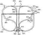
編組層810、860が動脈瘤の内部などの実質的に球状の空洞によって拘束されるとき、管状編組の2つの層810、860は、図14に例示される所定の形状に基づいて、埋め込み形状で安定化することができる。埋め込み形状において、層A810は、実質的に球形の空洞/動脈瘤の空洞壁を並置する第1のセグメント842に対応する外側層を有し、層B760は、層A810の外側層に並置する第1のセグメント882に対応する外側層を有し、層B860は、層B860の外側層に並置する中間セグメント884に対応する内側の袋部を有し、層A810は、層B860の内側袋部内に位置決めされた中間セグメント844に対応する内側袋部を有し、2つの層810、860の各々について、第1の反転部822、872に対応する近位反転部は、実質的に球形の空洞/動脈瘤頸部への入口の近くに位置決めされ、2つの層810、860の各々について、第2の反転部824、874に対応する遠位反転部は、空洞壁の遠位部分の近くに位置決めされ、2つの層810、860の各々は、第3のセグメント846、886に対応する支柱を有し、支柱は、層Bの柱が層Aの柱内に位置決めされるように内側の袋部内の中央に、かつ遠位反転部と近位反転部の間の長さの大部分に沿って延在する。 When the braided layers 810, 860 are constrained by a substantially spherical cavity, such as inside an aneurysm, the twolayers 810, 860 of the tubular braid are embedded shapes based on the predetermined shape exemplified in FIG. Can be stabilized with. In the embedded shape, layer A810 has an outer layer corresponding to afirst segment 842 juxtaposed with a substantially spherical cavity / aneurysm cavity wall, and layer B760 juxtaposed to the outer layer of layer A810. The layer B860 has an inner bag portion corresponding to theintermediate segment 884 juxtaposed to the outer layer of the layer B860, and the layer A810 has an inner bag portion corresponding to the inner bag portion of the layer B860. For each of the twolayers 810, 860, the proximal inversion corresponding to thefirst inversion 822, 872 has an inner bag corresponding to the positionedintermediate segment 844, and the proximal inversion corresponds to a substantially spherical cavity / Positioned near the entrance to the aneurysm neck, for each of the twolayers 810, 860, the distal reversal corresponding to thesecond reversal 824, 874 is positioned near the distal portion of the cavity wall. Each of the twolayers 810, 860 has a strut corresponding to thethird segment 846, 886, which is in the inner bag so that the column of layer B is positioned within the column of layer A. It extends in the center of and along most of the length between the distal and proximal inversions.

インプラント800は、図12A~図12Cに例示されるインプラント500の第1の埋め込み形状に関して記載されたのと同様に送達され、埋め込まれ得、違いは、図15に例示されるインプラント800の挟持端部812が、動脈瘤の頸部の近くに位置決めすることができ、第3のセグメント846に対応する層Aの管状セグメントは、層A810の袋部及び層B860の袋部内で延在して、挟持端部812で終端することができ、第3のセグメント886に対応する層B860の管状セグメントが、層A810の管状セグメント内で延在して、挟持端部812で終端することができることである。 Theimplant 800 can be delivered and implanted in the same manner as described for the first implant shape of theimplant 500 exemplified in FIGS. 12A-12C, the difference being the pinching end of theimplant 800 exemplified in FIG. Theportion 812 can be positioned near the neck of the aneurysm, and the tubular segment of layer A corresponding to the third segment 846 extends within the pouch of layer A810 and the pouch of layer B860. It can be terminated at the pinchingend 812, the tubular segment of layer B860 corresponding to thethird segment 886 can extend within the tubular segment of layer A810 and be terminated at the pinchingend 812. ..

例示されていないが、図8A~図8B、図9A~図9B、図10、及び図11A~図11Eに例示されるインプラント300、400は、代替的に、図12A~図12D、図13、及び図14に関連して例示及び記載された原理に従って、2つ又は3つ以上の編組層を含むことができる。更に、各インプラント100、200、300、400、500、700、800は、合計2つ、3つ、4つ、又は5つの編組層を含むことができる。 Although not exemplified, theimplants 300, 400 exemplified in FIGS. 8A-8B, 9A-9B, 10 and 11A-11E are alternatives to FIGS. 12A-12D, 13. And according to the principles exemplified and described in connection with FIG. 14, two or more braided layers can be included. Further, eachimplant 100, 200, 300, 400, 500, 700, 800 can include a total of 2, 3, 4, or 5 braided layers.

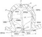
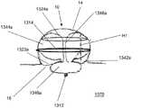
図15A~図15Cは、所定の形状を有することができる例となる管状インプラント900の例示である。インプラント900は、動脈瘤サイズの範囲を治療することができる。インプラント900は、開放端部914及び挟持端部912を有する管状編組910を含むことができる。所定の形状は、編組910が送達カテーテルによって留め置かれていないとき、管状編組910の拡張形状である。埋め込まれたとき、編組910は、埋め込み形状であり、これは、所定の形状及び動脈瘤10の解剖学的構造に少なくとも部分的に基づく。管状編組910は、1本又は2本以上のワイヤから構成することができる。 15A-15C are illustrations of an exemplarytubular implant 900 that can have a given shape.Implant 900 can treat a range of aneurysm sizes. Theimplant 900 can include atubular braid 910 with anopen end 914 and a pinchingend 912. The predetermined shape is an extended shape of thetubular braid 910 when thebraid 910 is not anchored by the delivery catheter. When implanted, thebraid 910 is an implantable shape, which is at least partially based on the predetermined shape and the anatomy of theaneurysm 10. Thetubular braid 910 can be composed of one or more wires.

インプラント900は、挟持端部912において、編組910に取り付けられた接続及び脱着機構部150を含むことができる。挟持端部912は、視認性を有するマーカーバンド及び/又ははんだ付け点を含むことができ、及び/又は接続機構部150は、放射線不透過性材料を含み得る。管状編組910は、所定の形状(図15A~図15C)で形成することができ、マイクロカテーテルを通って送達するために圧潰され、接続機構部150で送達システムに取り付けられ、図16A及び図16Bに例示されるものなどの埋め込み形状で埋め込まれる。 Theimplant 900 can include a connecting anddetaching mechanism 150 attached to thebraid 910 at the pinchingend 912. The pinchingend portion 912 may include a marker band having visibility and / or a soldering point, and / or the connectingmechanism portion 150 may include a radiation opaque material. Thetubular braid 910 can be formed in a predetermined shape (FIGS. 15A-15C), crushed for delivery through a microcatheter, attached to the delivery system at theconnection mechanism 150, and is attached to the delivery system in FIGS. 16A and 16B. It is embedded in an embedded shape such as those exemplified in.

図15A~図15Cを参照すると、所定の形状にあるとき、管状編組910は、反転部922、挟持端部912、及び開放端部914を含むことができる。管状編組は、2つのセグメント942及び944を含むことができる。第1のセグメント942は、管状編組910の開放端部914から近位反転部922まで延在することができる。第2のセグメント944は、開放端部914によって少なくとも部分的に囲まれてもよく、近位反転部922から挟持端部912まで延在することができる。図15A~図15Cに示されるように、第2のセグメントはまた、少なくとも1つの波形折り重ね部950を含むことができる。図15B及び図15Cに示されるように、第1のセグメントはまた、少なくとも1つの波形折り重ね部960を含むことができる。波形折り重ね部950、960は、埋め込み形状(例えば図16A及び図16B)にあるとき、動脈瘤10内にデバイスを固定するのを支援するように構成され得る。波形折り重ね部は、管状編組910がその所定の形状又は埋め込み形状を保持するのを助けるために、ステントストラットと同様の形態で作用することができる。 Referring to FIGS. 15A-15C, thetubular braid 910 can include aninversion portion 922, a pinchingend portion 912, and anopen end portion 914 when in a predetermined shape. The tubular braid can include twosegments 942 and 944. Thefirst segment 942 can extend from theopen end 914 of thetubular braid 910 to theproximal inversion 922. Thesecond segment 944 may be at least partially surrounded by theopen end 914 and can extend from theproximal inversion 922 to thepinch end 912. As shown in FIGS. 15A-15C, the second segment can also include at least onecorrugated fold section 950. As shown in FIGS. 15B and 15C, the first segment can also include at least onecorrugated fold section 960. The corrugated folds 950, 960 may be configured to assist in immobilizing the device within theaneurysm 10 when in implantable shapes (eg, FIGS. 16A and 16B). The corrugated folds can act in a similar fashion to the stent struts to help thetubular braid 910 retain its predetermined or embedded shape.

管状編組910は、所定の形状にあるとき、中心縦軸を中心に、実質的に半径方向に対称となり得る。管状編組は、第2のセグメント944を第1のセグメント942から分離するために、編組を内側に反転させることによって、所定の形状に形成され得る。管状編組910は、所定の形状に熱硬化され得る記憶形状材料を含むことができる。この熱硬化材料を利用して、第1のセグメント942及び/又は第2のセグメント944内に1つ又は2つ以上の波形950、960を形成することができる。 When thetubular braid 910 is in a predetermined shape, it can be substantially radial symmetric with respect to the central vertical axis. The tubular braid can be formed into a predetermined shape by flipping the braid inward to separate thesecond segment 944 from thefirst segment 942. Thetubular braid 910 can include a memory shape material that can be thermoset into a given shape. This thermosetting material can be used to form one ormore waveforms 950, 960 within thefirst segment 942 and / or thesecond segment 944.

図16Cに例示されているとおり、波形折り重ね部950、960を構成する管状編組910の1本又は2本以上のワイヤは、垂直軸に沿って圧縮又は平坦化することができ、その結果、管状編組910の非圧縮部分と比較して、波形折り重ね部950、960の垂直軸に沿ったワイヤ直径が小さくなる。波形折り重ね部950、960を構成するワイヤの圧縮部分はまた、管状編組910内のワイヤの非圧縮部分に対して異なる断面形状を有し得る。例えば、ワイヤの非圧縮部分は、円形であってもよく、圧縮部分は、楕円形であってもよい。波形折り重ね部950、960を構成する1本又は2本以上のワイヤを平坦化することにより、管状編組910のこれらの部分をより剛性にし、それによって管状編組910の形状を維持し、動脈瘤内に固定することを支援することができる。ワイヤを圧縮することにより、ワイヤは、すべての方向に屈曲又は撓むことができなくなる。好ましくは、波形折り重ね部950、960を構成する1本又は2本以上のワイヤを平坦化することにより、ワイヤを2つの反対方向に曲げることができる。したがって、波形折り重ね部950、960などの平坦化されたワイヤで構成された編組910の部分は、編組の残りの部分における非平坦なワイヤに対する曲げに対してより抵抗性であり得る。 As illustrated in FIG. 16C, one or more wires of thetubular braid 910 constituting the corrugated folds 950, 960 can be compressed or flattened along the vertical axis, resulting in. The wire diameter along the vertical axis of the corrugated folds 950, 960 is smaller than that of the uncompressed portion of thetubular braid 910. The compressed portion of the wire constituting the corrugated folds 950, 960 may also have a different cross-sectional shape with respect to the uncompressed portion of the wire in thetubular braid 910. For example, the uncompressed portion of the wire may be circular and the compressed portion may be elliptical. Flattening one or more wires that make up the corrugated folds 950, 960 makes these parts of thetubular braid 910 more rigid, thereby maintaining the shape of thetubular braid 910 and aneurysm. It can help to fix it inside. By compressing the wire, the wire cannot bend or bend in all directions. Preferably, the wires can be bent in two opposite directions by flattening the one or more wires that make up the corrugated folds 950, 960. Therefore, a portion of thebraid 910 composed of flattened wires such ascorrugated folds 950, 960 may be more resistant to bending against non-flat wires in the rest of the braid.

管状編組910は、カテーテルを通って送達するために変形することができ、所定の形状に基づき、かつ埋め込まれる動脈瘤の解剖学的構造によって留め置かれる埋め込み形状(例えば、図16A及び図16B)に自己拡張することができる。管状編組910が所定の形状にあるとき、第2のセグメント944内の少なくとも1つの波形折り重ね部950は、第1のセグメント942内に第1のセグメント942又は波形折り重ね部960を並置することができ、それによって第1のセグメント942に外向きの半径方向の力をかけることができる。 Thetubular braid 910 can be deformed for delivery through a catheter and is an implantable shape (eg, FIGS. 16A and 16B) that is based on a predetermined shape and is retained by the anatomy of the aneurysm to be implanted. Can self-expand to. When thetubular braid 910 is in a predetermined shape, at least onecorrugated folding portion 950 in thesecond segment 944 may juxtapose thefirst segment 942 or thecorrugated folding portion 960 in thefirst segment 942. Thefirst segment 942 can be subjected to an outward radial force.

埋め込み形状の管状編組910は、所定の形状と比較して、半径方向又は垂直方向に圧縮又は延在され得る。管状編組910を圧縮することにより、内側層950aの折り重ね部は、第1のセグメント942a及び/又は第1のセグメント960a内の波形折り重ね部に対して力を提供することができる。この圧縮はまた、第1のセグメント942a内の波形折り重ね部960aに、動脈瘤壁14に対して半径方向の力を加えることができる。 The embeddedtubular braid 910 can be compressed or extended radially or vertically as compared to a given shape. By compressing thetubular braid 910, the folds of theinner layer 950a can provide force to the corrugated folds in thefirst segment 942a and / or thefirst segment 960a. This compression can also apply a radial force to thecorrugated folds 960a in thefirst segment 942a with respect to theaneurysm wall 14.

図16Aは、動脈瘤に埋め込まれた図15Aの所定の形状を例示する。図16Aの埋め込み形状において、編組910は、所定の形状の第1のセグメント942に対応し、動脈瘤10の動脈瘤壁14に接触するように位置決めされた外側層942aを有することができる。近位反転部922aは、所定の形状の近位反転部922に対応することができ、動脈瘤10の頸部16の近くに配置されるように位置決めされ得る。内側層944aは、所定の形状の第2のセグメント944に対応することができる。管状編組910は、所定の形状の第2のセグメント内の少なくとも1つの波形折り重ね部に対応する内側層内に、少なくとも1つの波形折り重ね部950aを有することができる。 FIG. 16A illustrates the predetermined shape of FIG. 15A implanted in an aneurysm. In the embedded shape of FIG. 16A, thebraid 910 can have anouter layer 942a that corresponds to afirst segment 942 of a predetermined shape and is positioned to contact theaneurysm wall 14 of theaneurysm 10. Theproximal inversion 922a can correspond to theproximal inversion 922 of a predetermined shape and can be positioned to be located near theneck 16 of theaneurysm 10. Theinner layer 944a can correspond to asecond segment 944 having a predetermined shape. Thetubular braid 910 can have at least one corrugated fold in the inner layer corresponding to at least one corrugated fold in a second segment of predetermined shape.

管状編組910が動脈瘤10内で埋め込み形状にあるとき、内側層950a内の少なくとも1つの波形折り重ね部は、外側層942aの少なくとも一部分を並置することができ、それによって外側層942aに外向きの半径方向の力を及ぼしてインプラント900を動脈瘤10内に固定することができる。内側層946aに波形折り重ね部950aを含む管状編組910のワイヤは、図15A~図15Cに記載されるように及び図16Cに示されているように平坦化して波形の剛性を高め、動脈瘤10内に管状編組910を固定するのを支援することができる。 When thetubular braid 910 is in an implanted shape within theaneurysm 10, at least one corrugated fold within theinner layer 950a can juxtapose at least a portion of theouter layer 942a, thereby facing outward to theouter layer 942a. Theimplant 900 can be fixed within theaneurysm 10 by exerting a radial force on theaneurysm 10. The wire of thetubular braid 910 containing thecorrugated folds 950a in the inner layer 946a is flattened as shown in FIGS. 15A-15C and as shown in FIG. 16C to increase the stiffness of the corrugation and aneurysm. It is possible to assist in fixing thetubular braid 910 within 10.

図16Bにおいて、図15Bの所定の形状は、埋め込み形状にある。この埋め込み形状では、管状編組910はまた、所定の形状の第1のセグメント内の少なくとも1つの波形折り重ね部に対応する外側層960a内に、少なくとも1つの波形折り重ね部を有することができる。内側層950aの波形折り重ね部は、埋め込み形状のときに、外側層960a内に波形折り重ね部を並置するような位置で形成され得る。外側層960aの波形折り重ね部は、動脈瘤10と血管22a、22bとの間の境界を画定する平面内に外向きに半径方向の力を提供し、この力は、外側層942aを動脈瘤10の壁14に並置し、インプラント900を動脈瘤内に固定するのに十分である。更に、図16Bに例示されているとおり、外側層942aに波形折り重ね部960aを含む管状編組910のワイヤはまた、図16Cに例示されているとおり平坦化され得、波形の剛性を高め、動脈瘤10内に管状編組910を固定するのを支援する。 In FIG. 16B, the predetermined shape of FIG. 15B is an embedded shape. In this embedded shape, thetubular braid 910 can also have at least one corrugated fold within theouter layer 960a corresponding to at least one corrugated fold within the first segment of the predetermined shape. The corrugated folded portion of theinner layer 950a may be formed at a position where the corrugated folded portion is juxtaposed in theouter layer 960a in the embedded shape. The corrugated folds of theouter layer 960a provide an outward radial force in the plane defining the boundary between theaneurysm 10 and thevessels 22a, 22b, which forces the aneurysm in theouter layer 942a. Sufficient to juxtapose on thewall 14 of 10 to secure theimplant 900 within the aneurysm. Further, as illustrated in FIG. 16B, the wires of thetubular braid 910 including thecorrugated folds 960a in theouter layer 942a can also be flattened as illustrated in FIG. 16C to increase the stiffness of the corrugations and the arteries. Helps secure thetubular braid 910 within theknob 10.

動脈瘤を治療するためにインプラント900を形成するための方法は、カテーテルの遠位端部を動脈瘤10の頸部16の近くに位置決めすることと、1本又は2本以上のワイヤ及び開放端部914を有する管状編組910の挟持端部912を、カテーテルの少なくとも一部を通して遠位方向に押すことと、動脈瘤10の嚢12内に開放端部914を位置決めすることと、管状編組910を、所定の形状に基づいて動脈瘤内で埋め込み形状に展開することと、を含むことができる。インプラント900は、開放端部914を編組910の少なくとも一部上で動かすことにより、管状編組910を反転させて近位反転部922aを形成し、開放端部914と近位反転部922aとの間に延在する管状編組910の外側層942aを成形し、近位反転部922aと挟持端部912との間に延在する管状編組944aの内側層を成形することによって、所定の形状に基づいて動脈瘤内で埋め込み形状に展開することができ、少なくとも1つの波形の折り重ね部950aは、内側層944a内に位置している。 The method for forming theimplant 900 to treat an aneurysm is to position the distal end of the catheter near theneck 16 of theaneurysm 10 and one or more wires and an open end. Pushing the sandwichingend 912 of thetubular braid 910 with theportion 914 distally through at least a portion of the catheter, positioning theopen end 914 within thesac 12 of theaneurysm 10, and placing thetubular braid 910. Can include deploying into an implantable shape within an aneurysm based on a predetermined shape. Theimplant 900 flips thetubular braid 910 to form aproximal inversion 922a by moving theopen end 914 over at least a portion of thebraid 910, between theopen end 914 and theproximal inversion 922a. By forming theouter layer 942a of thetubular braid 910 extending in and forming the inner layer of thetubular braid 944a extending between theproximal inversion portion 922a and the pinchingend portion 912, based on a predetermined shape. It can be expanded into an implantable shape within the aneurysm, and the foldedportion 950a of at least one corrugation is located within themedial layer 944a.

本方法は、挟持端部の操作を介して、かつカテーテルの遠位端部の位置決めを介して、動脈瘤嚢内にインプラントを位置決めすることを更に含み得る。外側層はまた、外側層942a内に少なくとも1つの波形折り重ね部960aを含むことができる。埋め込まれると、内側層944a内の少なくとも1つの波形折り重ね部950aは、外側層942aに対して、動脈瘤10と血管22、又はその両方との間の境界を画定する平面内の外側層960aの波形の折り重ね部に対して、外向きに半径方向の力を提供することができる。力は、外側層942aを動脈瘤10の壁14に並置するのに十分であり得る。同様の形態で、外側層942aの波形折り重ね部960aは、動脈瘤10と血管22との間の境界を画定する平面内に外向きに半径方向の力を提供することができ、この力は、外側層942aを動脈瘤10の壁14に並置するのに十分である。 The method may further comprise positioning the implant within the aneurysm sac, via manipulation of the pinch end and via positioning of the distal end of the catheter. The outer layer can also include at least onecorrugated fold portion 960a within theouter layer 942a. When implanted, at least one corrugated fold in theinner layer 944a, theouter layer 960a in a plane defining the boundary between theaneurysm 10 and the vessel 22 or both with respect to theouter layer 942a. It is possible to provide an outward radial force to the folded portion of the waveform of. The force may be sufficient to juxtapose thelateral layer 942a on thewall 14 of theaneurysm 10. In a similar manner, thecorrugated folds 960a of theouter layer 942a can provide an outward radial force in the plane defining the boundary between theaneurysm 10 and the vessel 22. , Sufficient to juxtapose theouter layer 942a on thewall 14 of theaneurysm 10.

少なくとも1つの波形折り重ね部を含む管状編組910のワイヤは、軸線に沿った波形折り重ね部の直径が、管状編組910の非圧縮部分の直径よりも小さいように、垂直軸に沿って圧縮され得る。この圧縮は、編組の残りの部分に対する少なくとも1つの波形折り重ね部の剛性を増大させることができる。 The wire of thetubular braid 910 containing at least one corrugated fold is compressed along the vertical axis so that the diameter of the corrugated fold along the axis is smaller than the diameter of the uncompressed portion of thetubular braid 910. obtain. This compression can increase the stiffness of at least one corrugated fold over the rest of the braid.

本明細書に提示されている例は、概して、動脈瘤嚢内に固定し、動脈瘤頸部の大部分を閉塞することができる編組インプラントを含む。本インプラントは、所定の形状に硬化されて、マイクロカテーテルを介して送達するよう圧縮され、所定の形状及び編組が埋め込まれる動脈瘤の幾何形状に基づいた少なくとも1つの埋め込み位置に埋め込まれ得る、管状編組を含むことができる。インプラントは、管状編組の近位端部に後退可能な二重層を有する複数層に熱処理された単層の編組(例えば、単層チューブを形成するために延在され得る編組)を含むことができる。圧縮されたとき、インプラントは、インプラントがマイクロカテーテルを通して脱被覆状態で送達されたときに発生する摩擦力を軽減するのに十分に短くすることができる。 The examples presented herein generally include braided implants that can be immobilized within the aneurysm sac and occlude most of the aneurysm neck. The implant is tubular, cured to a given shape, compressed for delivery via a microcatheter, and may be placed in at least one implant location based on the geometry of the aneurysm in which the given shape and braid is implanted. Can include braids. The implant can include a single layer braid that has been heat treated into multiple layers with a retractable bilayer at the proximal end of the tubular braid (eg, a braid that can be extended to form a single layer tube). .. When compressed, the implant can be short enough to reduce the frictional forces generated when the implant is delivered uncovered through a microcatheter.

管状編組の第1の部分は、動脈瘤内に位置決めすることができ、その後、後退可能な二重層をマイクロカテーテルから展開し、管状編組の第1の部分上に押し込むことができる。この構成は、動脈瘤の頸部に3層の編組を提供する。二重層は、埋め込まれた管状編組の第1の部分と動脈瘤の頸部との間の任意のギャップを潜在的に覆うことができ、金属被覆率を潜在的に増加させ、インプラントの多孔性を減少させ、動脈瘤の頸部でのうっ滞と血流の迂回を増加させて、二重層を欠く同様の形状の編組インプラントと比較して動脈瘤の封止と治癒を促進することができる。インプラント全体は、所望の位置が達成されるまで後退可能であり得る。 The first portion of the tubular braid can be positioned within the aneurysm, after which a retractable bilayer can be unfolded from the microcatheter and pushed onto the first portion of the tubular braid. This configuration provides a three-layer braid on the neck of the aneurysm. The bilayer can potentially cover any gap between the first part of the implanted tubular braid and the neck of the aneurysm, potentially increasing metal coverage and the porosity of the implant. Can reduce aneurysm cervical stasis and increase blood flow diversion and promote aneurysm encapsulation and healing compared to similarly shaped braided implants lacking a bilayer. .. The entire implant may be retractable until the desired position is achieved.

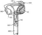
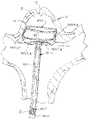
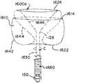
図17A~図17Bは、図17Aに例示されている所定の形状、並びに図17Bに例示されている個別の埋め込み形状を有することができる、例となる編組インプラント100の例示である。インプラント1000は、動脈瘤サイズの範囲を治療することができる。インプラント1000は、開放端部1014及び挟持端部1012を有する管状編組1010を含むことができる。インプラント1000は、挟持端部1012で編組1010に取り付けられた接続及び脱着機構部150(本明細書では「接続機構部」及び「脱着機構部」と同等に称される)を含み得る。挟持端部1012は、視認性を有するマーカーバンド及び/又ははんだ付け点を含むことができ、及び/又は接続機構部150は、放射線不透過性材料を含み得る。管状編組1010は、所定の形状(図17A)に形成され、マイクロカテーテルを介した送達のために圧潰され、接続特徴部150で送達システムに取り付けられ、図17Bに示されるもののような埋め込み形状で埋め込まれ得る。 17A-17B are exemplary braidedimplants 100 that can have the predetermined shapes exemplified in FIG. 17A as well as the individual implant shapes exemplified in FIG. 17B.Implant 1000 can treat a range of aneurysm sizes. Theimplant 1000 can include atubular braid 1010 having anopen end 1014 and a pinchingend 1012. Theimplant 1000 may include a connection and attachment / detachment mechanism 150 (also referred to herein as "connecting mechanism" and "attachment / detachment mechanism") attached to thebraid 1010 at the pinchingend 1012. The pinchingend portion 1012 may include a marker band and / or a soldering point having visibility, and / or the connectingmechanism portion 150 may include a radiation opaque material. Thetubular braid 1010 is formed into a predetermined shape (FIG. 17A), crushed for delivery via a microcatheter, attached to the delivery system at theconnection feature 150, and in an embedded shape as shown in FIG. 17B. Can be embedded.

図17Aを参照すると、所定の形状である場合、管状編組1010は、2つの反転部1022、1024、挟持端部1012、及び開放端部1014を含むことができる。管状編組1010は、4つのセグメント1042、1044、1046及び1052を含むことができる。第1のセグメント1042は、管状編組1010の開放端部1014から近位反転部1022まで延在することができる。第2のセグメント1044は、開放端部1014によって囲まれ、近位反転部1022から遠位反転部1024まで延在することができる。第3のセグメント1046は、第2のセグメント1044によって取り囲まれ、遠位反転部1024から近位反転部1022まで延在することができる。第1のセグメント1042、第2のセグメント1044及び第3のセグメント1046は、管状編組1010の第1の部分を形成することができる。第4のセグメント1052は、第3のセグメント1046から中心軸から半径方向外側に延在して、近位反転部1022を横断し、挟持端部1012で折り重なり、かつ収束することができる。第4のセグメント1052は、近位反転部1022によって部分的に囲まれ得る。 Referring to FIG. 17A, thetubular braid 1010 may include two reversingportions 1022, 1024, a pinchingend portion 1012, and anopen end portion 1014, given the predetermined shape. Thetubular braid 1010 can include foursegments 1042, 1044, 1046 and 1052. Thefirst segment 1042 can extend from theopen end 1014 of thetubular braid 1010 to theproximal inversion 1022. Thesecond segment 1044 is surrounded by theopen end 1014 and can extend from theproximal inversion 1022 to thedistal inversion 1024. Thethird segment 1046 is surrounded by thesecond segment 1044 and can extend from thedistal inversion 1024 to theproximal inversion 1022. Thefirst segment 1042, thesecond segment 1044 and thethird segment 1046 can form the first portion of thetubular braid 1010. Thefourth segment 1052 extends radially outward from the central axis from thethird segment 1046, traverses theproximal inversion 1022, folds and converges at the pinchingend 1012. Thefourth segment 1052 may be partially surrounded by theproximal inversion 1022.

管状編組1010は、所定の形状にある場合、中心縦軸を中心に、実質的に半径方向に対称となり得る。脱着機構部150は、機械式送達インプラントシステム(図示せず)と共に使用することができる平坦な鍵として図17Aに例示されている。管状編組1010は、最初に編組を外側に反転させて、第3のセグメント1046を第2のセグメント1044から遠位反転部1024と分離することによって、所定の形状に形成され得る。次に、第2のセグメント1044は、図17Aに例示される実質的に「S」字形輪郭を生成するような形態で成形することができる。次に、編組1010を再び外側に反転させて、近位の反転部1022を備える第1のセグメント1042から第2のセグメント1044を分離することができる。最後に、第4のセグメント1052は、第4のセグメント1052を径方向に拡張することによって成形することができる。第4のセグメント1052は、管状編組1010の第1の部分内に遠位に押し込まれ得る。インプラント1000が埋め込まれたとき、動脈瘤頸部の閉塞を最大化するために、第2のセグメント1044の「S」形状の伸張をより低くすることによって画定される、頸部開口部1026を最小化するのが有利となり得る。 When thetubular braid 1010 is in a predetermined shape, it can be substantially radial symmetric with respect to the central vertical axis. Thedesorption mechanism 150 is illustrated in FIG. 17A as a flat key that can be used with a mechanical delivery implant system (not shown). Thetubular braid 1010 can be formed into a predetermined shape by first flipping the braid outwards and separating thethird segment 1046 from thesecond segment 1044 with thedistal inversion 1024. Thesecond segment 1044 can then be shaped to produce a substantially "S" -shaped contour exemplified in FIG. 17A. Thebraid 1010 can then be flipped outwards again to separate thesecond segment 1044 from thefirst segment 1042 with theproximal flip portion 1022. Finally, thefourth segment 1052 can be formed by radially expanding thefourth segment 1052. Thefourth segment 1052 can be pushed distally into the first portion of thetubular braid 1010. Minimalcervical opening 1026, defined by lowering the extension of the "S" shape of thesecond segment 1044, to maximize occlusion of the aneurysm neck whenimplant 1000 is implanted It can be advantageous to make it.

管状編組1010は、所定の形状に熱硬化され、カテーテルを介して送達するよう変形され得、所定の形状に基づいて埋め込み形状に自己拡張することができる記憶形状材料を含むことができ、埋め込まれた動脈瘤の解剖学的構造によって留め置かれる。管状編組1010が図17Aに描写されるように所定の形状にあるとき、第4のセグメント1052は、第1のセグメント1042の最大直径D2よりも大きい又はおよそ等しい直径D1を備えることができる。代替的に、管状編組1010が図17Aに描写されるように所定の形状にあるとき、第4のセグメント1052は、第1のセグメント1042の最大直径D2よりも小さい直径D1を備えることができる。管状編組1010が所定の形状にあるとき(図17A)、第2のセグメント1044は、袋部を形成することができ、第3のセグメント1046の少なくとも一部は、袋部内に位置決めすることができ、第4のセグメント1052の少なくとも一部は、袋部の外部に位置決めすることができる。例示されているとおり(図17B)、埋め込まれたとき、第4のセグメント1052は、動脈瘤頸部16を横切って延在する動脈瘤嚢の外部に位置決めされ得る。好ましくは、第4のセグメント1052は、埋め込まれたときに動脈瘤頸部16を取り囲む血管壁を並置することができる。代替的に、成形された第4のセグメント1052はまた、動脈瘤嚢内に配置されてもよい。脱着機構部150は、動脈瘤頸部16の中央に埋め込まれ得る。脱着機構部150は、袋部12の外部に位置決めすることができる。 Thetubular braid 1010 can include a memory shape material that is thermosetting to a predetermined shape, can be deformed to be delivered via a catheter, and can self-expand to an embedded shape based on the predetermined shape, and is embedded. It is retained by the anatomy of the aneurysm. When thetubular braid 1010 is in a predetermined shape as depicted in FIG. 17A, thefourth segment 1052 can comprise a diameter D1 that is greater than or approximately equal to the maximum diameter D2 of thefirst segment 1042. Alternatively, when thetubular braid 1010 is in a predetermined shape as depicted in FIG. 17A, thefourth segment 1052 can comprise a diameter D1 that is smaller than the maximum diameter D2 of thefirst segment 1042. When thetubular braid 1010 is in a predetermined shape (FIG. 17A), thesecond segment 1044 can form a bag and at least a portion of thethird segment 1046 can be positioned within the bag. , At least a portion of thefourth segment 1052 can be positioned outside the bag. As illustrated (FIG. 17B), when implanted, thefourth segment 1052 may be positioned outside the aneurysm sac that extends across theaneurysm neck 16. Preferably, thefourth segment 1052 can juxtapose the vessel wall surrounding theaneurysm neck 16 when implanted. Alternatively, the moldedfourth segment 1052 may also be placed within the aneurysm sac. Thedesorption mechanism 150 can be implanted in the center of theaneurysm neck 16. Thedetachable mechanism portion 150 can be positioned outside thebag portion 12.

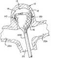
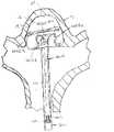
埋め込み形状の管状編組1010(図17B)は、所定の形状と比較して、半径方向又は垂直方向に圧縮又は延在され得る。図17Bに例示されているとおり、埋め込み形状にあるとき、編組1010は、所定の形状の第1のセグメント1042に対応し、動脈瘤10の動脈瘤壁14に接触するように位置決めされた外側層1042aと、所定の形状の近位反転部1022に対応し、動脈瘤10の頸部16の近くに配置されるように位置決めされた近位反転部1022aと、所定の形状の第2のセグメント1044に対応し、動脈瘤10の動脈瘤壁14の一部を並置し、外側層1042aを並置するように位置決めされた袋部1044aを有することができる。遠位反転部1024aは、所定の形状の遠位反転部1024に対応することができ、第3のセグメント1046aは、所定の形状の第3のセグメント1046に対応することができる。編組1010はまた、所定の形状の第4のセグメント1052に対応する第4のセグメント1052aを有することができ、第3のセグメント1046aから中心軸から半径方向外側に延在して近位反転部1022aを横断し、挟持端部1012で収束する。図17Aに記載されるように、第4のセグメント1052aは、管状編組1010の第1の部分内に遠位に押し込まれ得る。 The embedded tubular braid 1010 (FIG. 17B) can be compressed or extended radially or vertically as compared to a given shape. As illustrated in FIG. 17B, when in implantable shape, thebraid 1010 corresponds to afirst segment 1042 of a predetermined shape and is an outer layer positioned to contact theaneurysm wall 14 of theaneurysm 10. Aproximal inversion 1022a corresponding to the 1042a and aproximal inversion 1022 of a predetermined shape and positioned to be located near theneck 16 of theaneurysm 10, and asecond segment 1044 of the predetermined shape. Corresponding to, a portion of theaneurysm wall 14 of theaneurysm 10 can be juxtaposed and have asac 1044a positioned to juxtapose theouter layer 1042a. Thedistal inversion 1024a can correspond to adistal inversion 1024 of a predetermined shape, and thethird segment 1046a can correspond to athird segment 1046 of a predetermined shape. Thebraid 1010 can also have afourth segment 1052a corresponding to afourth segment 1052 of a predetermined shape, extending radially outward from the central axis from thethird segment 1046a to theproximal inversion 1022a. Crosses and converges at the pinchingend 1012. As described in FIG. 17A, thefourth segment 1052a can be pushed distally into the first portion of thetubular braid 1010.

第4のセグメント1052aを管状編組1010の第1の部分内に遠位に押し込むことによって、管状編組1010の第1の部分1042aを動脈瘤壁15の遠位部分に向かって移動させて、動脈瘤10の頸部16の一部分を閉塞することができる。第4のセグメント1052aを編組1010の第1の部分に押し込むことは、インプラント1000を動脈瘤10の形状に適合させる助けとなり、圧縮に抵抗することができる。第4のセグメント1052aは、半径方向に拡張され、編組1010の第1の部分に押し込まれると、動脈瘤10の頸部16に更なる被覆を提供して血栓症を増加させ、動脈瘤10を封止することもできる。第4のセグメント1052aが編組1010の第1の部分に押し込まれると、編組の3つの層が動脈瘤の頸部に存在する。第4のセグメント1052aは、埋め込まれた管状編組1010の第1の部分と動脈瘤頸部16との間の空間的ギャップを覆うことができ、金属被覆率を潜在的に増加させ、インプラント1000の多孔性を減少させ、動脈瘤10の封止及び血栓症を促進するために、動脈瘤10の頸部16でのうっ滞及び血流の迂回を増加させることができる。第4のセグメント1052aは、デバイス1000が埋め込まれたときに動脈瘤頸部16の大部分を閉塞するように成形することができる。第4のセグメント1052aは、デバイス1000が埋め込まれたときに動脈瘤頸部16をすべて閉塞するように成形することができる。 By pushing thefourth segment 1052a distally into the first portion of thetubular braid 1010, thefirst portion 1042a of thetubular braid 1010 is moved towards the distal portion of theaneurysm wall 15 and the aneurysm. A portion of thecervical part 16 of 10 can be occluded. Pushing thefourth segment 1052a into the first portion of thebraid 1010 helps theimplant 1000 adapt to the shape of theaneurysm 10 and can resist compression. Thefourth segment 1052a, when expanded radially and pushed into the first portion of thebraid 1010, provides additional coverage for theneck 16 of theaneurysm 10 to increase thrombosis and cause theaneurysm 10. It can also be sealed. When thefourth segment 1052a is pushed into the first portion of thebraid 1010, three layers of braid are present in the neck of the aneurysm. Thefourth segment 1052a can cover the spatial gap between the first portion of the implantedtubular braid 1010 and theaneurysm neck 16 and potentially increase the metal coverage of theimplant 1000. Stasis and blood flow diversion in the cervical 16 of theaneurysm 10 can be increased in order to reduce porosity and promote sealing of theaneurysm 10 and thrombosis. Thefourth segment 1052a can be shaped to occlude most of theaneurysm neck 16 when thedevice 1000 is implanted. Thefourth segment 1052a can be shaped to occlude theentire aneurysm neck 16 when thedevice 1000 is implanted.

管状編組1010が埋め込み形状にあるとき(図17B)、第4のセグメント1052aは、第1のセグメント1042aの最大直径D2よりも大きい又はおよそ等しい直径D1を備えることができる。代替的に、管状編組1010が埋め込み形状にあるとき(図17B)、第4のセグメント1052aは、第1のセグメント1042aの最大直径D2よりも小さい直径D1を備えることができる。管状編組1010が埋め込まれた形状にあるとき(図17B)、第2のセグメント1044aは袋部を形成することができ、第3のセグメント1046aの少なくとも一部は、袋部内に位置決めすることができ、第4のセグメント1052aの少なくとも一部は、袋部の外部に位置決めすることができる。成形された第4のセグメント1052aはまた、袋部12の外部の分離点150のみを有する動脈瘤嚢12内に配置され得る。 When thetubular braid 1010 is in the embedded shape (FIG. 17B), thefourth segment 1052a can comprise a diameter D1 that is greater than or approximately equal to the maximum diameter D2 of thefirst segment 1042a. Alternatively, when thetubular braid 1010 is in the embedded shape (FIG. 17B), thefourth segment 1052a can comprise a diameter D1 that is smaller than the maximum diameter D2 of thefirst segment 1042a. When thetubular braid 1010 is in an embedded shape (FIG. 17B), thesecond segment 1044a can form a bag and at least a portion of thethird segment 1046a can be positioned within the bag. , At least a portion of thefourth segment 1052a can be positioned outside the bag. The moldedfourth segment 1052a can also be placed within theaneurysm sac 12 having only theouter separation point 150 of thepouch 12.

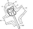
図18A~図18Iは、編組1010がマイクロカテーテル600を出るときに、所定の形状及び動脈瘤の解剖学的構造及び近くの血管の解剖学的形状に基づく埋め込み形状に拡張する編組1010を有する例となるインプラント1000の例示である。インプラント1000は、図17Aに例示されているものに類似した所定の形状を有する。図18Aに例示されているとおり、編組1010は、マイクロカテーテル600を介して送達されるサイズの圧縮された円周/直径及び長さLを有する管状編組の単層に延在する送達形状に成形され得る。当業者によって認識され理解されるように、特定の編組1010の長さLは、治療される動脈瘤のサイズ及び形状に基づいて調整することができる。長さLは、長さおよそ1インチであり得る。 18A-18I are examples ofbraids 1010 havingbraids 1010 that extend into a predetermined shape and implant shape based on the anatomy of the aneurysm and the anatomy of nearby blood vessels as thebraid 1010 exits themicrocatheter 600. This is an example of theimplant 1000.Implant 1000 has a predetermined shape similar to that illustrated in FIG. 17A. As illustrated in FIG. 18A, thebraid 1010 is molded into a delivery shape extending into a single layer of tubular braid having a compressed circumference / diameter and length L of a size delivered via themicrocatheter 600. Can be done. As recognized and understood by those skilled in the art, the length L of aparticular braid 1010 can be adjusted based on the size and shape of the aneurysm being treated. The length L can be approximately 1 inch in length.

マイクロカテーテル600を介する送達の間に、脱着機構部150は、インプラント1000の近位端部において送達システムに取り付けることができ、挟持端部1012は、インプラント1000の近位端部の近傍に位置決めされ得、開放端部1014は、インプラント1000の遠位端部を画定することができる。編組1010を単層管に圧潰すると、マイクロカテーテルを介して送達されるときに編組1010に対する摩擦力の影響を軽減するのに十分に小さい直径及び十分に短い長さLを有する編組1010が得られ得、一部の用途では、編組1010を脱被覆状態で送達することができる。 During delivery via themicrocatheter 600, thedesorption mechanism 150 can be attached to the delivery system at the proximal end of theimplant 1000 and the pinchingend 1012 is positioned near the proximal end of theimplant 1000. Obtained, theopen end 1014 can define the distal end of theimplant 1000. Crushing thebraid 1010 into a single layer tube gives the braid 1010 a diameter small enough to mitigate the effect of frictional forces on thebraid 1010 when delivered via a microcatheter and a length L short enough. Obtained, and in some applications, thebraid 1010 can be delivered in a stripped state.

図18Bに例示されているとおり、インプラント1000は、マイクロカテーテル600を介して、動脈瘤10へと送達され得る。開放端部1014は、編組1010の他の任意の部分がマイクロカテーテルを出る前に、マイクロカテーテル600を出るよう位置決めされ得る。開放端部1014がマイクロカテーテル600を出ると、これは、動脈瘤嚢12内で拡張することができる。例示されている動脈瘤10は、幹血管20及び2本の分岐血管22a、22bを含む分岐部に位置決めされ、マイクロカテーテル600は、幹血管20を通って送達されているように例示されている。インプラントは、湾曲したマイクロカテーテルを介して血管の側壁上の動脈瘤へと送達され得、このような手技は、本開示の範囲によって包含されることが意図されることが企図されている。図18Cに例示されているとおり、編組1010の遠位部分は、これがマイクロカテーテル600を出ると、動脈瘤嚢12内で半径方向への拡張を継続することができる。編組1010が、マイクロカテーテル600から遠位に更に押し込まれると、編組1010は、拡張して動脈瘤壁14に並置し、動脈瘤頸部16近くに適合させることができる。治療される動脈瘤10は、所定の形状の管状編組1010の外径よりも小さい直径を有することができ、その結果、編組1010は、外側に拡張する傾向があり、動脈瘤壁14に対して力を提供し、動脈瘤頸部16の周囲の近くを封止する。 As illustrated in FIG. 18B, theimplant 1000 can be delivered to theaneurysm 10 via themicrocatheter 600. Theopen end 1014 may be positioned to exit themicrocatheter 600 before any other portion of thebraid 1010 exits the microcatheter. When theopen end 1014 exits themicrocatheter 600, it can be dilated within theaneurysm sac 12. The exemplifiedaneurysm 10 is positioned at a bifurcation including thestem blood vessel 20 and the twobifurcated blood vessels 22a, 22b, and themicrocatheter 600 is exemplified as being delivered through thestem blood vessel 20. .. Implants can be delivered to an aneurysm on the side wall of a blood vessel via a curved microcatheter, and such procedures are intended to be incorporated by the scope of the present disclosure. As illustrated in FIG. 18C, the distal portion ofbraid 1010 can continue to expand radially within theaneurysm sac 12 once it exits themicrocatheter 600. When thebraid 1010 is further pushed distally from themicrocatheter 600, thebraid 1010 can be expanded and juxtaposed to theaneurysm wall 14 to fit near theaneurysm neck 16. Theaneurysm 10 to be treated can have a diameter smaller than the outer diameter of thetubular braid 1010 of a predetermined shape, so that thebraid 1010 tends to dilate outward and with respect to theaneurysm wall 14. It provides force and seals near the perimeter of theaneurysm neck 16.

図18Dに例示されているとおり、編組1010は、編組1010が、マイクロカテーテル600から更に押し込まれると、第1のセグメント1042aを画定する反転部1022aを形成することができる。近位反転部1022aは、動脈瘤頸部16の近くに位置決めされ得る。第2のセグメント1044aを画定する遠位反転部1024aはまた、編組1010がマイクロカテーテル600から押し出されるときに形成し始めることができる。図18E~図18Fに例示されているとおり、第2のセグメント1044aの「S」形状は、編組1010が、マイクロカテーテル600から更に押されると、形成を開始することができる。 As illustrated in FIG. 18D, thebraid 1010 can form aninverted portion 1022a defining thefirst segment 1042a when thebraid 1010 is further pushed from themicrocatheter 600.Proximal inversion 1022a may be positioned near theaneurysm neck 16. Thedistal inversion 1024a defining thesecond segment 1044a can also begin to form when thebraid 1010 is extruded from themicrocatheter 600. As illustrated in FIGS. 18E-18F, the "S" shape of thesecond segment 1044a can begin to form when thebraid 1010 is further pushed from themicrocatheter 600.

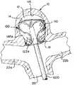
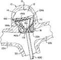
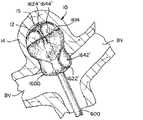
図18Gに例示されているとおり、第1のセグメント1042a、第2のセグメント1044a、及び第3のセグメント1046aを含むことができる編組1010の第1の部分が動脈瘤嚢12内に配置されると、第4のセグメント1052aは、編組1010の遠位部分がマイクロカテーテル600を出続けているときに、動脈瘤10の外側に半径方向に拡張することができる。 As illustrated in FIG. 18G, when the first portion of thebraid 1010 that can include thefirst segment 1042a, thesecond segment 1044a, and thethird segment 1046a is placed within theaneurysm sac 12. ,Fourth segment 1052a can be radially extended to the outside of theaneurysm 10 as the distal portion of thebraid 1010 continues to exit themicrocatheter 600.

図18Hに例示されているとおり、次いで、第4のセグメント1052aは、半径方向に拡張し続けるにつれて遠位に圧縮され、第4のセグメント1052aを編組1010の第1の部分内まで圧縮することができる。 As illustrated in FIG. 18H, thefourth segment 1052a can then be compressed distally as it continues to expand radially, compressing thefourth segment 1052a into the first portion ofbraid 1010. can.

最後に、図18Iに例示されているとおり、第4のセグメント1052aは、動脈瘤10及び頸部開口部1026の頸部16を少なくとも部分的に閉塞する編組1010の第1の部分内へと遠位に圧縮され得る。第4のセグメント1052aが最終的な膨張状態及び圧縮状態に達すると、挟持端部1012及び/又は分離点150は動脈瘤嚢の外部に留まることができる。圧縮されたとき、第4のセグメント1052aは、周囲の血管への閉塞にならないように、最小の厚さに圧縮され得る。 Finally, as illustrated in FIG. 18I, thefourth segment 1052a is far into the first portion of thebraid 1010 that at least partially occludes theaneurysm 10 and theneck 16 of theneck opening 1026. Can be compressed to the order. When thefourth segment 1052a reaches the final inflated and compressed state, the pinchingend 1012 and / or theseparation point 150 can remain outside the aneurysm sac. When compressed, thefourth segment 1052a can be compressed to a minimum thickness so as not to obstruct the surrounding blood vessels.

インプラント1000は、送達システムから放出される前に、インプラント1000は、マイクロカテーテル600に一部又は完全に後退して、再位置決めされ得る。 Before theimplant 1000 is released from the delivery system, theimplant 1000 can be partially or completely retracted into themicrocatheter 600 and repositioned.

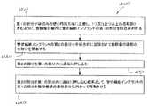
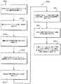
図19Aは、動脈瘤10を治療するための閉塞デバイスを形成するための方法1100のフロー図である。ステップ1110は、管状編組、開放端部、及び挟持端部を含むインプラントを選択することを含む。ステップ1120は、図17Aに例示されるものなどの所定の形状に管状編組を成形することを含む。図19Bに例示されているとおり、ステップ1120は更なるステップを更に含むことができる。ステップ1122は、管状編組を反転させて遠位反転部を形成することを含む。ステップ1124は、編組の少なくとも一部分の上で開放端部を移動させることによって、管状編組を反転させて近位反転部を形成する。ステップ1126は、開放端部と近位反転部との間に延在する管状編組の第1のセグメントを成形することを含む。ステップ1128は、近位反転部と遠位反転部との間に延在する管状編組の第2のセグメントを成形する。ステップ1130は、開放端部を位置決めして第2のセグメントを囲むことを含む。ステップ1132は、遠位反転部から近位反転部まで延在する第3のセグメントを成形する。ステップ1134は、第2のセグメントを位置決めして第3のセグメントを取り囲むことを含む。ステップ1136は、中心軸から半径方向外側に延在して近位反転部を横断し、中心軸に向かって内側に折り重ねられ、挟持端部で収束する、第3のセグメントから延在する管状編組の第4のセグメントを成形する。ステップ1138は、第4のセグメントを動脈瘤の頸部の近くに位置決めさせることを含む。 FIG. 19A is a flow chart ofmethod 1100 for forming an occlusion device for treatinganeurysm 10.Step 1110 comprises selecting an implant that includes a tubular braid, an open end, and a pinching end.Step 1120 comprises forming a tubular braid into a predetermined shape, such as that illustrated in FIG. 17A. As illustrated in FIG. 19B,step 1120 may further include additional steps.Step 1122 involves flipping the tubular braid to form a distal flip.Step 1124 inverts the tubular braid to form a proximal inversion by moving the open end over at least a portion of the braid. Step 1126 involves forming a first segment of tubular braid that extends between the open end and the proximal inversion.Step 1128 forms a second segment of tubular braid extending between the proximal inversion and the distal inversion.Step 1130 includes positioning the open end to enclose the second segment.Step 1132 forms a third segment that extends from the distal inversion to the proximal inversion.Step 1134 includes positioning the second segment and surrounding the third segment.Step 1136 extends radially outward from the central axis, traverses the proximal inversion, folds inward toward the central axis, and converges at the pinching end, a tubular extending from a third segment. Form the fourth segment of the braid.Step 1138 involves positioning the fourth segment near the neck of the aneurysm.

方法1100において、管状編組を所定の形状に成形するステップ1120は、第1のセグメントの最大直径より大きいか又はおよそこれに等しい直径を含むように、第4のセグメントを成形することを更に含み得る。方法1100において、管状編組を所定の形状に成形するステップ1120は、第4のセグメントを第1のセグメントの最大直径より小さい直径に成形することを更に含み得る。方法1100は、マイクロカテーテルの管腔を横断するようなサイズにされた送達形状に管状編組インプラントを成形することを更に含み得る。 Inmethod 1100,step 1120 of forming a tubular braid into a predetermined shape may further comprise forming a fourth segment so as to include a diameter greater than or approximately equal to the maximum diameter of the first segment. .. Inmethod 1100,step 1120 of forming a tubular braid into a predetermined shape may further comprise forming the fourth segment into a diameter smaller than the maximum diameter of the first segment.Method 1100 may further comprise molding a tubular braided implant into a delivery shape sized to traverse the lumen of a microcatheter.

図20Aは、動脈瘤10を治療するための方法のための方法1200のフローチャートである。ステップ1210は、管状編組インプラントの第1の部分を動脈瘤の嚢内に位置決めし、管状編組インプラントは、管状編組、開放端部、及び挟持端部を含み、第1の部分が嚢内の壁を円周方向に並置するようにする。第1の部分は、1つ又は2つ以上の反転部を含んでもよい。ステップ1220は、動脈瘤の頸部の大部分を閉塞するために、管状編組インプラントの第2の部分を径方向に拡張させることを含む。ステップ1230は、第2の部分を第1の部分内に遠位に押し込む。第2の部分を第1の部分内に遠位に押し込むことにより、動脈瘤の頸部に3層の編組を形成することができる。第2の部分は、第1の部分と動脈瘤頸部との間の任意の空間的ギャップを覆うことができ、金属被覆率を潜在的に高め、インプラントの多孔性を減らし、動脈瘤の頸部のうっ滞と血流の迂回を増加させて動脈瘤の封止と治癒を促進する。ステップ1240は、第2の部分を第1の部分内に遠位に押し込む結果として、管状編組インプラントの第1の部分を動脈瘤壁の遠位部分に向かって移動させることを含む。 FIG. 20A is a flow chart of method 1200 for a method for treatinganeurysm 10.Step 1210 positions a first portion of the tubular braided implant within the sac of the aneurysm, the tubular braided implant comprising a tubular braid, an open end, and a pinching end, the first portion circularizing the wall within the sac. Try to juxtapose in the circumferential direction. The first portion may include one or more inversions.Step 1220 involves radially dilating a second portion of the tubular braided implant to occlude most of the neck of the aneurysm.Step 1230 pushes the second portion distally into the first portion. By pushing the second portion distally into the first portion, a three-layer braid can be formed in the neck of the aneurysm. The second part can cover any spatial gap between the first part and the aneurysm neck, potentially increasing the metal coverage, reducing the porosity of the implant, and reducing the aneurysm neck. Increases local stasis and diversion of blood flow to promote aneurysm sealing and healing.Step 1240 involves moving the first portion of the tubular braided implant towards the distal portion of the aneurysm wall as a result of pushing the second portion distally into the first portion.

図20Bに例示されているとおり、ステップ1220は、第2の部分の円周を実質的に画定するように第2のセグメント内に折り重ね部を位置決めすることを含むステップ1222を更に含むことができる。ステップ1220は、加えて、又は代替的に、第2の部分が領域を有する実質的に円形の形状を含み、第2の部分が実質的に円形の領域の大部分にわたって編組の2つの層を含むように、管状編組インプラントの中心軸に沿って第2の部分を圧縮することを含むステップ1224を含むことができる。 As illustrated in FIG. 20B,step 1220 may further includestep 1222 comprising positioning the fold within the second segment so as to substantially demarcate the circumference of the second portion. can.Step 1220 additionally or alternatively comprises a substantially circular shape in which the second portion has a region, the second portion comprising two layers of braid over most of the substantially circular region. To include,step 1224 may include compressing a second portion along the central axis of the tubular braided implant.

ステップ1210は、管状編組インプラントを成形して、管状編組インプラントの中心軸を取り囲む柱状ポストを形成し、第1の部分の高さの大部分を延在させることを更に含み得る。ステップ1210は、管状編組インプラントの第1の部分の近位反転部を動脈瘤の頸部の近くに位置決めすることと、管状編組インプラントの第1の部分の遠位反転部を動脈瘤壁の遠位部分の近くに位置決めすることと、を更に含むことができる。ステップ1210は、動脈瘤壁を円周方向に並置するために管状編組インプラントの開放端部を位置決めすることと、動脈瘤の嚢内の動脈瘤の壁の少なくとも一部を並置するために、開放端部と近位反転部との間に延在する管状編組の第1のセグメントを成形することと、第1のセグメントが、動脈瘤と血管枝との間の境界を画定する平面において外向きに半径方向の力を提供するように、管状編組の第2のセグメントの成形することと、を更に含むことができ、力は、動脈瘤の壁に第1のセグメントを並置するのに十分である。Step 1210 may further comprise forming a tubular braided implant to form a columnar post surrounding the central axis of the tubular braided implant, extending most of the height of the first portion.Step 1210 positions the proximal inversion of the first portion of the tubular braided implant near the neck of the aneurysm and the distal inversion of the first portion of the tubular braided implant far from the aneurysm wall. Positioning near the position portion can be further included.Step 1210 positions the open end of the tubular braided implant to juxtapose the aneurysm wall in the circumferential direction and the open end to juxtapose at least a portion of the aneurysm wall within the aneurysm sac. Forming a first segment of a tubular braid that extends between the aneurysm and the proximal inversion, and the first segment outward in the plane defining the boundary between the aneurysm and the vascular branch. Molding of the second segment of the tubular braid can be further included to provide radial force, and the force is sufficient to juxtapose the first segment on the wall of the aneurysm. ..

ステップ1230は、管状編組インプラントの第2の部分を、管状編組インプラントの第1の部分の近位反転部に押し込むことを更に含み得る。ステップ1240は、管状編組インプラントの第1の部分の遠位反転部を動脈瘤壁の遠位部分に向かって移動させることを更に含み得る。Step 1230 may further include pushing the second portion of the tubular braided implant into the proximal inversion of the first portion of the tubular braided implant.Step 1240 may further include moving the distal inversion of the first portion of the tubular braided implant towards the distal portion of the aneurysm wall.

方法1200は、管状編組インプラントを成形して、管状編組インプラントの中心軸を取り囲む柱状ポストを形成し、第1の部分の高さの大部分を延在させることを更に含み得る。方法1200は、動脈瘤に対して所望の位置が達成されるまで、管状編組を後退させることを更に含み得る。方法1200は、マイクロカテーテルの管腔を横断するようなサイズにされた送達形状に管状編組インプラントを成形することを更に含み得る。 Method 1200 may further comprise forming a tubular braided implant to form a columnar post surrounding the central axis of the tubular braided implant, extending most of the height of the first portion. Method 1200 may further comprise retracting the tubular braid until the desired position with respect to the aneurysm is achieved. Method 1200 may further comprise molding a tubular braided implant into a delivery shape sized to traverse the lumen of a microcatheter.

図21A~図21Bは、所定の形状に形成されるときの例となる編組インプラント1300の例示である(図21B)。インプラント1300は、動脈瘤サイズの範囲を治療することができる。インプラント1300は、図17A及び図17Bと同様に、開放端部1314及び挟持端部1312を有する管状編組1310を含むことができる。管状編組1310は、所定の形状に熱硬化することができる記憶形状材料を含むことができ、カテーテルを介して送達するために変形することができ、所定の形状に基づいており、それが埋め込まれている動脈瘤の解剖学的構造によって留め置かれている、埋め込み形状に自己拡張することができる。 21A-21B are examples of braidedimplants 1300 as an example when formed into a predetermined shape (FIG. 21B).Implant 1300 can treat a range of aneurysm sizes.Implant 1300 can include atubular braid 1310 with anopen end 1314 and a pinchingend 1312, similar to FIGS. 17A and 17B. Thetubular braid 1310 can contain a memory shape material that can be thermoset to a given shape, can be deformed for delivery via a catheter, is based on a given shape, and is implanted. It can self-expand into an implantable shape, which is retained by the anatomy of the aneurysm.

管状編組1310は、所定の形状にあるとき、中心縦軸を中心に、実質的に半径方向に対称となり得る。インプラント1300は、前の図に例示されるような接続及び脱着機構部150を含むことができる。挟持端部1312は、視認性を有するマーカーバンド及び/又ははんだ付け点を含むことができ、及び/又は脱着機構部150は、放射線不透過性材料を含み得る。管状編組1310は、所定の形状(図21B)に形成され、接続機構部150で送達システムに取り付けられた、図18Aと同様のマイクロカテーテルを介して送達するための編組1310の単層を備えた送達形状に圧潰され得、図18A~図18Fに記載された送達と同様の形態で、図22A~図6Cに示されているような埋め込み形状で埋め込まれ得る。 When thetubular braid 1310 is in a predetermined shape, it can be substantially radial symmetric with respect to the central vertical axis.Implant 1300 can include a connection anddetachment mechanism 150 as illustrated in the previous figure. The pinchingend 1312 may include a visible marker band and / or a soldering point, and / or thedesorption mechanism 150 may include a radiation opaque material. Thetubular braid 1310 comprises a single layer ofbraid 1310 formed into a predetermined shape (FIG. 21B) and attached to the delivery system at theconnection mechanism 150 for delivery via a microcatheter similar to FIG. 18A. It can be crushed into a delivery shape and can be embedded in an embedded shape as shown in FIGS. 22A-6C in a manner similar to the delivery described in FIGS. 18A-18F.

図21Aを参照すると、管状編組1310は、2つの反転部、1322、1324、挟持端部1312、及び開放端部1314を含むことができる。図21Aに描写される管状編組1310は、4つのセグメント1342、1344、1346及び1348を含むことができる。第1のセグメント1342は、管状編組1310の開放端部1314から近位反転1322まで延在することができる。第2のセグメント1344は、開放端部1314によって囲まれ、近位反転部1322から遠位反転部1324まで延在することができる。第3のセグメント1346は、第2のセグメント1344によって取り囲まれることができる。 With reference to FIG. 21A, thetubular braid 1310 can include two reversing portions, 1322, 1324, a pinchingend 1312, and anopen end 1314. Thetubular braid 1310 depicted in FIG. 21A can include foursegments 1342, 1344, 1346 and 1348. Thefirst segment 1342 can extend from theopen end 1314 of thetubular braid 1310 to theproximal inversion 1322. Thesecond segment 1344 is surrounded by theopen end 1314 and can extend from theproximal inversion 1322 to thedistal inversion 1324. Thethird segment 1346 can be surrounded by thesecond segment 1344.

管状編組は、最初に編組1310を外側に反転させて、第3のセグメント1346を第2のセグメント1344から遠位反転部1324と分離することによって、所定の形状に形成され得る。次いで、第2のセグメント1344は、型又は成形型にはめて成形することができる。型は、袋部の形状であり得る。次に、編組1310を再び外側に反転させて、第2のセグメント1344を第1のセグメント1342から近位反転部1322と分離することができる。 The tubular braid can be formed into a predetermined shape by first flipping thebraid 1310 outwards and separating thethird segment 1346 from thesecond segment 1344 with thedistal flip portion 1324. Thesecond segment 1344 can then be molded into a mold or mold. The mold can be in the shape of a bag. Thebraid 1310 can then be flipped outwards again to separate thesecond segment 1344 from thefirst segment 1342 from theproximal flip section 1322.

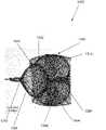
図21Aに更に例示されるように、第3のセグメント1346は、遠位反転部1324からボールセグメント1348まで広がることができる。第1のセグメント1342、第2のセグメント1344及び第3のセグメント1346は、管状編組1310の第1の部分を形成することができる。ボールセグメント1348は、管状編組1310の中心軸から半径方向外側に第3のセグメント1346の近位部分から延在して、実質的に楕円形状を形成し、挟持端部1312で収束することができる。成形型1320を適用することができ、ボールセグメント1348が成形されるこの形は、図21Bに描写するように所定の形状を設定するために、熱で処理することができる。 As further illustrated in FIG. 21A, thethird segment 1346 can extend from thedistal reversal section 1324 to theball segment 1348. Thefirst segment 1342, thesecond segment 1344 and thethird segment 1346 can form the first portion of thetubular braid 1310. Theball segment 1348 extends radially outward from the central axis of thetubular braid 1310 from the proximal portion of thethird segment 1346 to form a substantially elliptical shape and can converge at the pinchingend 1312. ..Mold 1320 can be applied and this shape into which theball segment 1348 is molded can be heat treated to set the predetermined shape as depicted in FIG. 21B.

図21Bに見られるように、ボールセグメント1348は、管状編組1310の第1の部分内に遠位に押し込まれ得る。ボールセグメント1348が管状編組1310の第1の部分内に遠位に押し込まれると、ボールセグメント1348は、近位反転部1322を並置するために半径方向外側の力を提供することができる。更に、ボールセグメント1348が管状編組1310の第1の部分内に遠位に押し込まれると、ボールセグメント1348は、近位反転部1322の遠位の第2のセグメント1344内に少なくとも部分的に包囲され得る。ボールセグメント1348はまた、近位反転部1322の遠位の第2のセグメント1344内に完全に包囲され得る。管状編組1310が所定の形状にあるとき、第2のセグメント1344は、袋部を形成することができ、第3のセグメント1346の少なくとも一部は、袋部内に位置決めすることができ、ボールセグメント1348の少なくとも一部を、袋部の外部に位置決めすることができる。ボールセグメント1348は、近位反転部1322の少なくとも一部分を閉塞して、近位反転部1322によって作成された開口部を封止することができる。 As seen in FIG. 21B, theball segment 1348 may be pushed distally into the first portion of thetubular braid 1310. When theball segment 1348 is pushed distally into the first portion of thetubular braid 1310, theball segment 1348 can provide a radial lateral force to juxtapose theproximal inversion portion 1322. Further, when theball segment 1348 is pushed distally into the first portion of thetubular braid 1310, theball segment 1348 is at least partially enclosed within the distalsecond segment 1344 of theproximal inversion 1322. obtain. Theball segment 1348 may also be completely enclosed within asecond segment 1344 distal to theproximal reversal section 1322. When thetubular braid 1310 is in a predetermined shape, thesecond segment 1344 can form a bag and at least a portion of thethird segment 1346 can be positioned within the bag and theball segment 1348. At least a part of the bag can be positioned outside the bag. Theball segment 1348 can block at least a portion of theproximal inversion portion 1322 to seal the opening created by theproximal inversion portion 1322.

図22A~図22Cは、動脈瘤10内に埋め込まれた例となる編組インプラント1300の例示である。管状編組1310は、様々なサイズ、高さ、及び形状の動脈瘤に適合するように、所定の形状と比較して、半径方向又は垂直方向に圧縮又は拡張され得る。図22Aに例示されているとおり、高さH1を有する動脈瘤10で埋め込み形状にあるとき、編組1310は、所定の形状の第1のセグメント1342に対応し、動脈瘤10の動脈瘤壁14に接触するように位置決めされた外側層1342aと、所定の形状の近位反転部1322に対応し、動脈瘤10の頸部16の近くに配置されるように位置決めされた近位反転部1322aと、所定の形状の第2のセグメント1344に対応し、外側層1342aを並置するように位置決めされた袋部1344aを有することができる。遠位反転部1324aは、所定の形状の遠位反転部1324に対応することができ、第3のセグメント1346aは、所定の形状の第3のセグメント1346に対応することができる。編組1310はまた、所定の形状のボールセグメント1348に対応し、第3のセグメント1346aから中心軸から半径方向外側に延在して、実質的に楕円形状を形成し、挟持端部1312で収束するボールセグメント1348aを有することができる。図21Bに記載されるように、ボールセグメント1348aは、管状編組1310の第1の部分内に遠位に押し込まれ得る。ボールセグメント1348aを管状編組1310の第1の部分内に遠位に押すことにより、動脈瘤10の頸部16に据えられた編組1310の複数の層をもたらすことができる。これらの複数の編組層1310は、近位反転部1322aによって形成されるチャネル又はその両方によって形成されるチャネルをより良好に閉塞することによって、動脈瘤頸部16をより良好に閉塞することによって動脈瘤10への血流を阻止することができる。 22A-22C are illustrations of abraided implant 1300 as an example implanted in ananeurysm 10. Thetubular braid 1310 can be compressed or expanded radially or vertically compared to a given shape to fit aneurysms of various sizes, heights, and shapes. As illustrated in FIG. 22A, when in an implantable shape with ananeurysm 10 having a height H1, thebraid 1310 corresponds to afirst segment 1342 of a predetermined shape and on theaneurysm wall 14 of theaneurysm 10. Anouter layer 1342a positioned to contact and aproximal inversion 1322a corresponding to a predetermined shape of theproximal inversion 1322 and positioned to be located near theneck 16 of theaneurysm 10. It can have abag portion 1344a that corresponds to asecond segment 1344 of a predetermined shape and is positioned so that theouter layer 1342a is juxtaposed. Thedistal reversal portion 1324a can correspond to thedistal reversal portion 1324 of a predetermined shape, and thethird segment 1346a can correspond to thethird segment 1346 of a predetermined shape. Thebraid 1310 also corresponds to aball segment 1348 of a predetermined shape, extending radially outward from the central axis from thethird segment 1346a to form a substantially elliptical shape and converge at the pinchingend 1312. It can have aball segment 1348a. As described in FIG. 21B, theball segment 1348a can be pushed distally into the first portion of thetubular braid 1310. Pushing theball segment 1348a distally into the first portion of thetubular braid 1310 can result in multiple layers ofbraid 1310 placed on theneck 16 of theaneurysm 10. These plurality of braidedlayers 1310 better occlude theaneurysm neck 16 by better occluding the channel formed by theproximal inversion portion 1322a or both. Blood flow to theaneurysm 10 can be blocked.

図22Aに例示されているとおり、埋め込まれたとき、ボールセグメント1348aは、動脈瘤頸部16を横切って延在する動脈瘤10の外部に位置決めされ得る。ボールセグメント1348aは、動脈瘤頸部16の少なくとも一部分を閉塞し得る。ボールセグメント1348aはまた、近位反転部1322aの少なくとも一部分を閉塞して、近位反転部1322aによって作成された開口部を封止することもできる。 As illustrated in FIG. 22A, when implanted, theball segment 1348a may be positioned outside theaneurysm 10 extending across theaneurysm neck 16. Theball segment 1348a may occlude at least a portion of theaneurysm neck 16. Theball segment 1348a can also block at least a portion of theproximal inversion portion 1322a to seal the opening created by theproximal inversion portion 1322a.

図22Bは、高さH2を有する動脈瘤10内のインプラント1300を描写する。図22Bの動脈瘤の高さH2は、図6Aの動脈瘤の高さH1よりも大きくてもよい。高さH2を有する動脈瘤内の管状編組1310の第1の部分にボールセグメント1348aを押し込むことによって、管状編組1310の第1の部分1342aは、動脈瘤10内へ動脈瘤壁15の遠位部分に向かって更に移動させることができる。ボールセグメント1348aは、動脈瘤10の頸部16の少なくとも一部分を閉塞することができる。ボールセグメント1348aはまた、近位反転部1322aの少なくとも一部分を閉塞して、近位反転部1322aによって作成された開口部を封止することもできる。編組1310の第1の部分内にボールセグメント1348aを押すことはまた、管状編組1310が動脈瘤10の壁14を動脈瘤10の頸部16の近くに並置するように、近位反転部1322を並置して、近位反転部1322に対して半径方向外向きの力を提供することができる。 FIG. 22B depictsimplant 1300 in ananeurysm 10 with height H2. The height H2 of the aneurysm of FIG. 22B may be larger than the height H1 of the aneurysm of FIG. 6A. By pushing theball segment 1348a into the first portion of thetubular braid 1310 within the aneurysm having a height H2, thefirst portion 1342a of thetubular braid 1310 is the distal portion of theaneurysm wall 15 into theaneurysm 10. Can be moved further towards. Theball segment 1348a can occlude at least a portion of theneck 16 of theaneurysm 10. Theball segment 1348a can also block at least a portion of theproximal inversion portion 1322a to seal the opening created by theproximal inversion portion 1322a. Pushing theball segment 1348a into the first portion of thebraid 1310 also causes theproximal inversion 1322 so that thetubular braid 1310 juxtaposes thewall 14 of theaneurysm 10 near theneck 16 of theaneurysm 10. They can be juxtaposed to provide a radial outward force to theproximal inversion portion 1322.

代替的に、管状編組1310の第1の部分内へ遠位にボールセグメント1348aを押すことは、外側層1342a及び/又は袋部1344aの遠位方向への移動とは無関係に、第3のセグメント1346aを動脈瘤壁15の遠位部分に向かって遠位に押すことができる。これは、動脈瘤H2の高さに良好に適合するようにインプラント1300の高さを延在させることができる。ボールセグメント1348aの少なくとも一部分は、袋部1344aによって包囲され得る。ボールセグメント1348aの少なくとも一部分は、袋部1344aの外側に位置決めされ得る。 Alternatively, pushing theball segment 1348a distally into the first portion of thetubular braid 1310 is independent of the distal movement of theouter layer 1342a and / or thebag 1344a, the third segment. 1346a can be pushed distally towards the distal portion of theaneurysm wall 15. This can extend the height of theimplant 1300 to better fit the height of the aneurysm H2. At least a portion of theball segment 1348a may be surrounded by thebag portion 1344a. At least a portion of theball segment 1348a may be positioned outside thebag portion 1344a.

図22Cに例示されているとおり、インプラント1300は、図22A及び図22BのそれぞれのH1及びH2より大きい高さH3を有する動脈瘤内に展開され得る。ここで分かるように、ボールセグメント1348aは、袋部1344a内に完全に包囲されるまで、管状編組1310の第1の部分内に更に遠位に押され得る。高さH3を有する動脈瘤内の管状編組1310の第1の部分にボールセグメント1348aを押し込むことによって、管状編組1310の第1の部分1342aを動脈瘤壁15の遠位部分に向かって移動させることができる。代替的に、図22Bに記載されるように、管状編組1310の第1の部分内へ遠位にボールセグメント1348aを押すことは、外側層1342a及び/又は袋部1344aの遠位方向への移動とは無関係に、第3のセグメント1346aを動脈瘤壁15の遠位部分に向かって遠位に押すことができる。これは、動脈瘤H3の高さに良好に適合するようにインプラント1300の高さを延在させることができる。ボールセグメント1348aは、動脈瘤頸部16の少なくとも一部分を閉塞し得る。ボールセグメント1348aはまた、近位反転部1322aの少なくとも一部分を閉塞して、近位反転部1322aによって作成された開口部を封止することもできる。このようにして、インプラント1300を使用して、編組1310の第1の部分に対するボールセグメント1348の位置決めに応じて、様々な高さ及び幅のインプラントを治療することができる。 As illustrated in FIG. 22C, theimplant 1300 can be deployed into an aneurysm having a height H3 greater than H1 and H2, respectively in FIGS. 22A and 22B. As can be seen here, theball segment 1348a can be pushed further distally into the first portion of thetubular braid 1310 until it is completely enclosed within thebag portion 1344a. Moving thefirst portion 1342a of thetubular braid 1310 towards the distal portion of theaneurysm wall 15 by pushing theball segment 1348a into the first portion of thetubular braid 1310 within the aneurysm having a height H3. Can be done. Alternatively, as described in FIG. 22B, pushing theball segment 1348a distally into the first portion of thetubular braid 1310 is a distal movement of theouter layer 1342a and / or thebag 1344a. Regardless, thethird segment 1346a can be pushed distally towards the distal portion of theaneurysm wall 15. This can extend the height of theimplant 1300 to better fit the height of the aneurysm H3. Theball segment 1348a may occlude at least a portion of theaneurysm neck 16. Theball segment 1348a can also block at least a portion of theproximal inversion portion 1322a to seal the opening created by theproximal inversion portion 1322a. In this way, theimplant 1300 can be used to treat implants of various heights and widths, depending on the positioning of theball segment 1348 with respect to the first portion of thebraid 1310.

図23は、動脈瘤10を治療するための方法1400のフロー図である。方法1400を利用して、単一のデバイスを用いて様々な大きさ、高さ、及び形状の動脈瘤を治療することができる。ステップ1410は、管状編組インプラントの第1の部分を位置決めし、管状編組インプラントは、第1の部分が袋部内の壁を円周方向に並置するように、動脈瘤の嚢内に、管状編組、開放端部、及び挟持端部を有する。第1の部分は、動脈瘤壁の遠位部分に近い遠位反転部を含む、1つ又は2つ以上の反転部を含み得る。ステップ1420は、管状編組インプラントの第1の部分に関連させて管状編組インプラントの第2の部分を放射状に拡張して、動脈瘤の頸部の大部分を閉塞することを含む。ステップ1430は、第2の部分を第1の部分に遠位方向に押し込んで、動脈瘤壁に向かって第1の部分に対して半径方向の力を動脈瘤と血管枝との間の境界を画定する平面内の動脈瘤の頸部の近くに提供する。最後に、ステップ1440は、第2の部分を第1の部分の中に遠位に押し込む結果として、動脈瘤壁の遠位部分に向かって遠位反転部を移動させる。 FIG. 23 is a flow chart ofmethod 1400 for treatinganeurysm 10.Method 1400 can be utilized to treat aneurysms of various sizes, heights, and shapes using a single device.Step 1410 positions the first portion of the tubular braided implant and the tubular braided implant is tubular braided and opened in the aneurysm sac such that the first portion juxtaposes the wall within the sac in the circumferential direction. It has an end and a pinching end. The first portion may include one or more inversions, including a distal inversion near the distal portion of the aneurysm wall.Step 1420 comprises radiating a second portion of the tubular braided implant in relation to the first portion of the tubular braided implant to occlude most of the neck of the aneurysm.Step 1430 pushes the second portion distally into the first portion and exerts a radial force against the first portion towards the aneurysm wall at the boundary between the aneurysm and the vascular branch. Provided near the neck of the aneurysm in the demarcating plane. Finally,step 1440 moves the distal inversion towards the distal portion of the aneurysm wall as a result of pushing the second portion distally into the first portion.

管状編組インプラントの第1の部分を位置決めするステップ1410は、管状編組インプラントの開放端部を動脈瘤壁を円周方向に並置するように位置決めすることと、管状編組インプラントの第1の部分に近位反転部を動脈瘤の頸部の近くに位置決めすることと、動脈瘤の嚢内の動脈瘤の壁の少なくとも一部を並置にするために、開放端部と近位反転部との間に延在する管状編組の第1のセグメントを成形することと、を更に含むことができる。Step 1410, which positions the first portion of the tubular braided implant, positions the open end of the tubular braided implant so that the aneurysm wall is juxtaposed in the circumferential direction and is close to the first portion of the tubular braided implant. Extend between the open end and the proximal inversion to position the inversion near the neck of the aneurysm and to juxtapose at least part of the aneurysm wall within the aneurysm sac. It can further include forming a first segment of an existing tubular braid.

管状編組インプラントの第2の部分を拡張するステップ1420は、第2の部分が実質的に楕円形状を形成するように、管状編組インプラントの中心軸に沿って第2の部分を圧縮することを更に含むことができる。Step 1420, which expands the second portion of the tubular braided implant, further compresses the second portion along the central axis of the tubular braided implant so that the second portion forms a substantially elliptical shape. Can include.

第2の部分を第1の部分に遠位方向に押し込むステップ1430は、第1の部分の少なくとも一部を第2の部分と並置して、第2の部分から第1の部分まで管状編組インプラントの中心軸に沿って外向きに半径方向の力を提供することを更に含むことができる。第2の部分を遠位に押し込むステップ1430はまた、管状編組インプラントの第2の部分が少なくとも部分的に近位反転部によって包囲されるまで、管状編組インプラントの第2の部分を管状編組インプラントの第1の部分の近位反転部に対して押し込むことを包含することができる。第2の部分を遠位に押し込むステップ1430はまた、複数の編組層を動脈瘤の頸部の近くに配置することによって、動脈瘤内への血流を妨害することもできる。Step 1430, which pushes the second part distally into the first part, juxtaposes at least part of the first part with the second part and is a tubular braided implant from the second part to the first part. It can further include providing an outward radial force along the central axis of the.Step 1430, which pushes the second portion distally, also applies the second portion of the tubular braided implant to the tubular braided implant until the second portion of the tubular braided implant is at least partially surrounded by the proximal inversion. It can include pushing against the proximal inversion of the first portion.Step 1430, which pushes the second portion distally, can also block blood flow into the aneurysm by placing multiple braided layers near the aneurysm's neck.

方法1400は、マイクロカテーテルの管腔を横断するようなサイズにされた編組の単層を有する送達形状に管状編組インプラントを成形することを更に含み得る。Method 1400 may further comprise molding a tubular braided implant into a delivery shape with a single layer of braid sized to traverse the lumen of a microcatheter.

図24は、動脈瘤を治療する閉塞デバイスを形成する方法のフロー図である。方法は、開放端部及び挟持端部を含む管状編組を反転させて遠位反転部を形成すること(1510)と、編組の少なくとも一部分の上で開放端部を移動させることによって、管状編組を反転させて近位反転部を形成すること(1520)と、開放端部と近位反転部との間に延在する管状編組の第1のセグメントを成形すること(1530)と、近位反転部と遠位反転部との間に延在する管状編組の第2のセグメントを成形すること(1540)と、開放端部を位置決めして第2のセグメントを囲むこと(1550)と、遠位反転部から挟持端部まで延在する第3のセグメントを成形すること(1560)と、第2のセグメントを位置決めして第3のセグメントを取り囲むこと(1570)と、第3のセグメントから中心軸から半径方向外向きに延在する管状編組のボールセグメントを成形して、実質的に楕円形状を形成し、挟持端部に収束すること(1580)と、管状編組のボールセグメントに成形型を適用し、ボールセグメントを熱で処理して、ボールセグメントを形成された形状に適合させることであって、ボールセグメントは、管状編組の中心軸に沿って移動可能である、適合させること(1590)と、を含むことができる。 FIG. 24 is a flow chart of a method of forming an occlusion device for treating an aneurysm. The method is to invert the tubular braid, including the open and pinched ends, to form a distal inversion (1510), and to move the open end over at least a portion of the braid to fold the tubular braid. Inversion to form a proximal inversion (1520), forming a first segment of a tubular braid extending between the open end and the proximal inversion (1530), and proximal inversion. Forming a second segment of a tubular braid extending between the portion and the distal inversion (1540), positioning the open end to enclose the second segment (1550), and distal. Forming a third segment that extends from the inversion to the pinching end (1560), positioning the second segment to surround the third segment (1570), and the central axis from the third segment. Forming a tubular braided ball segment that extends radially outward from the to form a substantially elliptical shape and converge to the pinching end (1580) and apply the molding die to the tubular braided ball segment. And the ball segment is heat treated to fit the ball segment into the formed shape, the ball segment is movable along the central axis of the tubular braid, to fit (1590). , Can be included.

方法1500は、動脈瘤内に第1のセグメント、第2のセグメント、及び第3のセグメントを位置決めすることと、ボールセグメントを近位反転部に遠位に前進させることと、を更に含むことができる。近位反転部へと遠位にボールセグメントを前進させるこのステップは、動脈瘤の壁の遠位部分に向かって遠位反転部を移動させることができ、これは動脈瘤の高さにデバイスを適合させることができる。このようにして、デバイスを使用して、様々な高さ、形状、及び大きさの動脈瘤を治療することができる。Method 1500 may further include positioning the first segment, the second segment, and the third segment within the aneurysm and advancing the ball segment distally to the proximal inversion. can. This step of advancing the ball segment distally to the proximal inversion can move the distal inversion towards the distal portion of the aneurysm wall, which moves the device to the height of the aneurysm. Can be adapted. In this way, the device can be used to treat aneurysms of various heights, shapes, and sizes.

方法1500はまた、近位反転部をボールセグメントの少なくとも一部分と並置することを含むことができる。方法1500は、ボールセグメントを、近位反転部の遠位の第2のセグメントによって少なくとも部分的に包囲された位置に移動させることを更に含むことができる。方法1500はまた、動脈瘤に対して所望の位置が達成されるまで、管状編組を後退させることを包含し得る。Method 1500 can also include juxtaposing the proximal inversion with at least a portion of the ball segment.Method 1500 can further comprise moving the ball segment to a position at least partially enclosed by a second segment distal to the proximal inversion.Method 1500 may also include retracting the tubular braid until the desired position with respect to the aneurysm is achieved.

幅広の頸部の動脈瘤の既知の処置では、動脈瘤は、典型的には、動脈瘤嚢内に塞栓用コイルを配置して、動脈瘤頸部にわたって親血管内にステントを配置することによって処置される。ステントは、多くの場合に、塞栓用コイルが親血管に入るのを阻止するために必要である。塞栓用コイルが親血管に入ると、コイルが血管を閉塞することがあり、及び/又は血塊が血管内のコイル上に形成されて、親血管内に閉塞物を生成することがある。編組動脈瘤嚢内インプラントは、動脈瘤頸部に編組インプラントを固定するためのステントを必要とせずに、幅広の頸部の動脈瘤を処置するために使用され得る。しかしながら、幅広の頸部の分岐部に編組インプラントを固定するのに必要な力を得るために、編組は剛性であり、所定の形状とは著しく異なる埋め込まれた形状に再成形するのを妨げることがある。したがって、場合によっては、動脈瘤嚢内のうっ血を迅速かつ効果的に誘導するのに十分な編組密度で動脈瘤を充填することは困難であり得る。非常に柔軟に作製された編組は、形状が小さくなり、インプラントが動脈瘤の頸部をもはや封止しないため、動脈瘤を再開通させることがある。 In the known treatment of wide cervical aneurysms, the aneurysm is typically treated by placing an embolic coil within the aneurysm sac and placing a stent in the parent vessel over the aneurysm neck. Will be done. Stents are often needed to prevent the embolic coil from entering the parent vessel. When the embolic coil enters the parent vessel, the coil may occlude the vessel and / or blood clots may form on the coil within the vessel, creating an obstruction within the parent vessel. Braided aneurysm intracapsular implants can be used to treat wide cervical aneurysms without the need for a stent to secure the braided implant to the aneurysm neck. However, in order to obtain the force required to secure the braided implant to the wide cervical bifurcation, the braid is rigid and prevents it from being reshaped into an embedded shape that is significantly different from the given shape. There is. Therefore, in some cases, it may be difficult to fill the aneurysm with a braid density sufficient to induce congestion in the aneurysm sac quickly and effectively. Braids made very flexibly may reopen the aneurysm as it becomes smaller in shape and the implant no longer seals the neck of the aneurysm.

本発明の態様は、上記課題に対処することを目的とする。本明細書に提示される例では、管状の編組インプラントは、単層編組として送達されることができ、展開中にそれ自体の中に反転して少なくとも2つの入れ子状の袋部を形成することができ、最も内側の袋部を充填し得る追加の編組材料を含むことができる、編組を含み得る。追加の編組材料は、リボンのようにループ状若しくはコイル状になり、及び/又は反転して更に小さい入れ子状の袋部を形成することができる。本発明の一態様は、効果的な処置のために動脈瘤が迅速に凝固するように、十分な量の追加の編組材料を最も内側の袋部内に配置することができる構造を提供することである。 An aspect of the present invention is to address the above problems. In the examples presented herein, the tubular braided implant can be delivered as a single layer braid and inverts into itself during deployment to form at least two nested pouches. Can include braids, which can include additional braided material that can fill the innermost bag. The additional braided material can be looped or coiled like a ribbon and / or inverted to form smaller nested pouches. One aspect of the invention is to provide a structure in which a sufficient amount of additional braided material can be placed within the innermost pouch so that the aneurysm coagulates rapidly for effective treatment. be.

本明細書で使用されるとき、用語「管状」及び「チューブ」は、広義に解釈されるものとし、直円柱構造や、断面が厳密に円形である構造、全長にわたって均一な断面である構造に制限されるものではない。簡略化のために、管状構造は、一般に、本明細書では実質的に直円筒形の構造を有するように示されている。しかしながら、管状構造は、本発明の範囲から逸脱することなく、テーパ状又は湾曲した外側表面を有することができる。 As used herein, the terms "tubular" and "tube" shall be broadly construed to include right-cylinder structures, structures with a strictly circular cross section, and structures with a uniform cross section over the entire length. It is not limited. For brevity, tubular structures are generally shown herein to have a substantially right-cylindrical structure. However, tubular structures can have a tapered or curved outer surface without departing from the scope of the invention.

動脈瘤内で確実な固定を得るための編組の剛性と、動脈瘤内で編組を高い充填密度に変形させるための編組の柔軟性との、矛盾する必要性を満たすために、編組は、動脈瘤がより高い充填密度を有するときに動脈瘤に押される編組の部分が、動脈瘤内に編組を固定するために拡張する編組のより剛性の部分と比較して弱くなるように作製され得る。編組部分の剛性/柔軟性は、編組角度(例えば、インチ当たりのピック)、ストランドの直径、ストランドの数、ストランドの材料、及び/又はストランドの材料特性を変更するための処理(例えば、熱処理)などによって制御することができる。より剛性の部分は、より高い編組角度、より大きいストランド直径、より多くのストランド、より剛性の材料を含むストランド、及び/又はより弱い部分と比較してより大きい剛性を有するように処理されたストランドを有することができる。 To meet the contradictory needs of the rigidity of the braid to obtain a secure fixation in the aneurysm and the flexibility of the braid to transform the braid into a high filling density in the aneurysm, the braid is an artery. The portion of the braid that is pushed by the aneurysm when the aneurysm has a higher filling density can be made weaker than the more rigid portion of the braid that expands to secure the braid within the aneurysm. Stiffness / flexibility of the braided portion is a process for changing the braided angle (eg, picks per inch), the diameter of the strands, the number of strands, the material of the strands, and / or the material properties of the strands (eg, heat treatment). It can be controlled by such as. The stiffer part is a higher braid angle, a larger strand diameter, more strands, a strand containing a more rigid material, and / or a strand treated to have greater rigidity compared to a weaker part. Can have.

編組のより剛性の部分は、編組がカテーテルを通して送達されるときに編組の遠位端付近に位置付けられ得、それによって編組のより剛性の部分は、動脈瘤が充填される前にカテーテルから出て動脈瘤内で固定するように拡張する。編組のより剛性の部分は、熱硬化又は他の手段によって所定の形状に成形され得、それによって、より剛性の部分の場合に所定の形状に拡張する。所定の形状に拡張する編組のより剛性の部分の傾向は、動脈瘤壁に対する十分な力を生み出し、動脈瘤嚢内に編組を固定することができる。編組のより弱い部分は、編組がカテーテルを通して送達されるときに編組の近位端付近に位置付けられ得る。最大の可撓性を有する編組の部分は、動的に変形されて動脈瘤内でループ状又は入れ子状になり、より剛性の編組の固定部分内で折り重なり得る。 The stiffer portion of the braid may be located near the distal end of the braid when the braid is delivered through the catheter, whereby the stiffer portion of the braid exits the catheter before the aneurysm is filled. Dilate to fix in the aneurysm. The stiffer portion of the braid can be formed into a predetermined shape by thermosetting or other means, thereby expanding to a predetermined shape in the case of the stiffer portion. The tendency of the stiffer portion of the braid to expand into a given shape creates sufficient force against the aneurysm wall and allows the braid to be anchored within the aneurysm sac. The weaker part of the braid may be located near the proximal end of the braid as it is delivered through the catheter. The portion of the braid with maximum flexibility can be dynamically deformed to loop or nest within the aneurysm and fold within the fixed portion of the more rigid braid.

最も内側の袋部を充填する編組材料に加えて、又はその代わりとして、インプラントは、最も内側の袋部内でループ状になり得る塞栓用コイルを含むことができる。 In addition to, or as an alternative to, the braided material that fills the innermost pouch, the implant can include an embolic coil that can be looped within the innermost pouch.

本明細書に提示されている例は、概して、動脈瘤嚢内に固定し、動脈瘤頸部の大部分を閉塞することができる編組インプラントを含む。インプラントは、より剛性の部分とより弱い部分とを有する管状の編組を含むことができ、少なくともより剛性の部分は所定の形状に設定され、編組は、マイクロカテーテルを通して送達するために圧縮可能であり、編組は、編組が埋め込まれる動脈瘤の形状に基づく、かつ少なくとも部分的に所定の形状に基づく、埋め込まれた位置に埋め込み可能である。 The examples presented herein generally include braided implants that can be immobilized within the aneurysm sac and occlude most of the aneurysm neck. The implant can include a tubular braid with a stiffer part and a weaker part, at least the stiffer part is set to a predetermined shape and the braid is compressible for delivery through a microcatheter. The braid can be implanted in place of implantation, based on the shape of the aneurysm into which the braid is implanted, and at least partially based on the predetermined shape.

図25に例示されるような例となるインプラント1600は、各端部1612、1614の間で測定された長さL及び長さLに沿った可変剛性を有する実質的に管状の単層形状に成形され得る編組1610を含むことができる。図示のように、剛性は、編組角度θ1、θ2、θ3、θ4によって少なくとも部分的に決定することができる。説明を容易にするために、編組のより弱い、より可撓性の部分は、編組のより強い、より剛性の部分と比較して、より低い編組角度を有するものとして例示されているが、しかしながら、編組のより弱い部分とより剛性の部分は、ストランドの直径、ストランドの数、ストランドの材料が異なり、異なる剛性/柔軟性を有するように及び/又は当業者によって認識され理解される他の手段によって処理され得る。更に、異なる剛性の編組セグメントを含む例示的なインプラントは、編組を形成するように接合された2つの別個のセクションを含んでいてもよく、編組は、連続する編組管として異なる剛性のセグメントを含む必要はない。 Anexample implant 1600, as illustrated in FIG. 25, has a substantially tubular monolayer shape with length L measured between theends 1612, 1614 and variable stiffness alonglength L. Braids 1610 that can be molded can be included. As shown, the stiffness can be determined at least partially by the braided angles θ1, θ2, θ3, θ4. For ease of explanation, the weaker, more flexible parts of the braid are exemplified as having a lower braid angle compared to the stronger, more rigid parts of the braid, however. The weaker and stiffer parts of the braid are different in strand diameter, number of strands, strand material, and have different stiffness / flexibility and / or other means recognized and understood by those skilled in the art. Can be processed by. Further, an exemplary implant containing braided segments of different stiffness may include two separate sections joined to form a braid, the braid containing different stiffness segments as a continuous braided tube. No need.

図25に例示される単層の管状形状において、編組1610は、長さLに沿って実質的に均一である円周Cを有することができる。管状形状は、編組1610の長さに沿って延在する中心軸Aを有することができる。編組角度θ1、θ2、θ3、θ4は、図示するように編組ストランドの接線軌道を中心軸Aと比較することによって、さもなければ本明細書の教示に従って当業者に理解されるように、測定することができる。 In the single-layer tubular shape exemplified in FIG. 25, thebraid 1610 can have a circumference C that is substantially uniform along length L. The tubular shape can have a central axis A extending along the length of thebraid 1610. Braided angles θ1, θ2, θ3, θ4 are measured by comparing the tangential trajectories of the braided strands with the central axis A as shown, otherwise as understood by those of skill in the art as taught herein. be able to.

編組は、一方の編組端部1612から他方1614まで各々延在する多数のストランド、例えば、約4~約96本のストランドを含むことができる。本明細書で使用するとき、任意の数値又は数値の範囲について「約」又は「およそ」という用語は、構成要素の部分又は構成要素の集合が、本明細書において説明されるその意図された目的に沿って機能することを可能にする、好適な寸法の許容誤差を示すものである。ストランドは、外周Cの周囲に螺旋状に巻き付くことができる。ストランドの数、ストランドの角度、ストランドの直径、ストランドの材料、及びストランドの材料特性はすべて、多孔性及び可撓性を含む編組1610の材料特性を制御する要因となり得る。編組ストランドは、ストランドラップの約半分が時計回りに螺旋状に巻かれ、他の半分が反時計回りに螺旋状に巻かれ、逆方向に巻かれたストランドが交互に相互に上下に交差するように織られることができる。そのような構成にすることによって、より高い編組角度を有する編組の部分は、より低い編組角度を有する編組の部分と比較して、より高いストランド密度を有することができる。より高いストランド密度は、より高密度のより剛性の編組部分をもたらすことができる。 The braid can include a large number of strands, each extending from onebraid end 1612 to the other 1614, eg, about 4 to about 96 strands. As used herein, the term "about" or "approximately" for any number or range of numbers is the intended purpose for which a component or set of components is described herein. It indicates a suitable dimensional tolerance that allows it to function alongside. The strand can be spirally wound around the outer circumference C. The number of strands, the angle of the strands, the diameter of the strands, the material of the strands, and the material properties of the strands can all be factors that control the material properties of thebraid 1610, including porosity and flexibility. The braided strands are such that about half of the strand wraps are spirally wound clockwise, the other half are spirally wound counterclockwise, and the strands wound in the opposite direction alternate up and down. Can be woven into. With such a configuration, the braided portion with the higher braid angle can have a higher strand density than the braided portion with the lower braid angle. Higher strand densities can result in higher density and more rigid braided portions.

ストランドは、ニッケルチタン合金、コバルトクロム合金、白金、ニチノール、ステンレス鋼、タンタル、若しくは他の合金などの複数の合金、又は他の任意の好適な生体適合性材料、又はこれらの材料の組み合わせから作製することができる。更に、これらの材料は、経時的に患者の体内で吸収性であってよく、又は非吸収性であってもよい。いくつかの又はすべての編組1610は、放射線不透過性のために、好ましくは、織り合わされた白金フィラメントを伴うニチノール、又は約10~約40%の白金を伴うDrawn Filled Tube(DFT)ニチノールで製造された、マルチフィラメントの円筒状メッシュであり得る。編組1610のメッシュの開口部はまた、実質的に一体型のフレームワーク又はメッシュを作成することができる。したがって、開口部は、可変のサイズ、形状、又は多孔性を有することができ、また編組1610のメッシュの壁全体にわたって均一間隔又は無作為な間隔であってもよい。開口部は、編組1610に可撓性を提供し、圧潰された状態から拡張した展開状態への編組の変形、又はその逆の変形を支援することもできる。 Strands are made from multiple alloys such as nickel-titanium alloys, cobalt-chromium alloys, platinum, nitinol, stainless steel, tantalum, or other alloys, or any other suitable biocompatible material, or a combination of these materials. can do. Furthermore, these materials may be absorbable or non-absorbent in the patient's body over time. Some or allbraids 1610 are preferably made from nitinol with woven platinum filaments, or Drawn Filled Tube (DFT) nitinol with about 10 to about 40% platinum, due to radiodensity. Can be a multifilament cylindrical mesh. The mesh openings in thebraid 1610 can also create a substantially integrated framework or mesh. Thus, the openings can have variable size, shape, or porosity and may be evenly spaced or randomly spaced across the entire wall of the mesh of thebraid 1610. The openings provide flexibility to thebraid 1610 and can also assist in the deformation of the braid from the crushed state to the expanded unfolded state and vice versa.

図25に描写されるような編組1610は、編組1610の近位端部1612から遠位端部1614まで測定されるように増加する4つの編組角度θ1、θ2、θ3、θ4を示し、編組1610の近位部分1616における編組角度θ4は、最小であり、近位部分1616のすぐ遠位のセクションの編組角度θ3は、近位部分1616の編組角度θ4よりも大きく、次の遠位セクションの編組角度θ2は、そのすぐ近位のセクションの角度θ3よりも大きく、編組1610の最も遠位のセクション1618における編組角度θ1は、最大である。認識され理解されるように、編組1610は、異なる編組角度を有し、それによって異なる剛性/可撓性を有する、2つ又は3つ以上のセクションを含むことができる。編組は加えて、編組角度の連続勾配変化を含み、それによって1つの編組セクションから別の編組セクションへの剛性/可撓性の連続勾配変化を含むことができ、例えば、編組角度は、近位部分1616から遠位部分1618へと連続的に変化することができる。Braids 1610, as depicted in FIG. 25, show four braided angles θ1, θ2, θ3, θ4 that increase as measured from theproximal end 1612 to thedistal end 1614 of thebraid 1610, thebraid 1610. The braid angle θ4 at theproximal portion 1616 is the smallest, the braid angle θ3 of the section immediately distal to theproximal portion 1616 is greater than the braid angle θ4 of theproximal portion 1616, and the braid of the next distal section. The angle θ2 is greater than the angle θ3 of the section immediately proximal to it, and the braid angle θ1 in the mostdistal section 1618 of thebraid 1610 is maximum. As recognized and understood, thebraid 1610 can include two or more sections having different braid angles and thereby different stiffness / flexibility. The braid can also include a continuous gradient change of the braid angle, thereby including a continuous stiffness / flexibility gradient change from one braid section to another, eg, the braid angle is proximal. It can change continuously frompart 1616 todistal part 1618.

インプラント1600は、編組1610がカテーテルを通過するようにサイズ決めされるとき、動脈瘤に送達され得る。例えば、編組1610は、図25に例示されているとおり、編組1614の一方の端部が、編組1610の残りの部分の前にカテーテルを出るように位置決めされた遠位端部であり、もう一方の端部1612が、編組1610の残りの部分の後にカテーテルを出るように位置決めされた近位端部であるように、単層管状形状で送達することができる。あるいは、編組は、折り目、反転部、及び/又は多層を含む他の形状で送達されてもよい。送達形状にかかわらず、編組1610は、編組1610の残りの部分より先にカテーテルから出るように位置決めされた遠位部分1618と、編組1610の残りの部分の後にカテーテルから出るように位置決めされた近位部分1616と、を有することができる。遠位部分1618は、遠位部分1618が編組1610を動脈瘤内に固定するのに十分な剛性を有するように、高い編組角度θ1を有し得る。近位部分1616は、近位部分が編組1610の残りの部分を収容する動脈瘤嚢内に圧潰されるのに十分な可撓性を有するように、低い編組角度θ4を有し得る。インプラント1600は、インプラント送達システムに取り外し可能に取り付けられるように構成された脱着特徴部150を更に含むことができる。脱着特徴部150は、編組1610の近位端部1612で編組1610に固定され得る。Implant 1600 may be delivered to the aneurysm when thebraid 1610 is sized to pass through the catheter. For example, thebraid 1610 is a distal end in which one end of thebraid 1614 is positioned to exit the catheter in front of the rest of thebraid 1610, as illustrated in FIG. 25. Theend 1612 can be delivered in a single layer tubular shape such that it is a proximal end positioned to exit the catheter after the rest of thebraid 1610. Alternatively, the braid may be delivered in other shapes including creases, inversions, and / or multilayers. Regardless of the delivery shape, thebraid 1610 has adistal portion 1618 positioned to exit the catheter prior to the rest of thebraid 1610 and a near portion positioned to exit the catheter after the rest of thebraid 1610. It can have aposition portion 1616 and. Thedistal portion 1618 may have a high braid angle θ1 such that thedistal portion 1618 is rigid enough to secure thebraid 1610 within the aneurysm. Theproximal portion 1616 may have a low braid angle θ4 such that the proximal portion is flexible enough to be crushed into the aneurysm sac accommodating the rest of thebraid 1610. Theimplant 1600 can further include adetachable feature 150 configured to be removablely attached to the implant delivery system. Thedetachable feature 150 may be secured to thebraid 1610 at theproximal end 1612 of thebraid 1610.

図26は、所定の形状に成形された図25に例示する編組1610などの編組1610を例示する。編組1610は、ニチノール、ニチノール合金、ポリマー記憶形状材料、又は本明細書に記載されるような再成形のための特性を有する他の記憶形状材料などの記憶形状材料を含むことができる。編組1610は、熱硬化、又は当業者によって認識され理解されるような他の手段によって、所定の形状に設定することができる。編組セグメント1610は、所定の形状から、動脈瘤までマイクロカテーテルを通過するようにサイズ決めされた変形形状へと圧潰することができる。マイクロカテーテルを出るときに血液と接触すると、編組1610は、変形形状から所定の形状に移行することができる。動脈瘤及び治療部位の解剖学的構造は、編組1610が展開されるとき、それが、所定の形状及び編組が埋め込まれる解剖学的構造の形状に部分的に基づく展開された形状をとることができるように、編組1610が所定の形状に移行するのを阻止することができる。 FIG. 26 illustrates abraid 1610 such as thebraid 1610 exemplified in FIG. 25 molded into a predetermined shape. Thebraid 1610 can include storage shape materials such as nitinol, nitinol alloys, polymer storage shape materials, or other storage shape materials with properties for remolding as described herein. Thebraid 1610 can be set to a predetermined shape by thermosetting or other means as recognized and understood by those skilled in the art. Thebraided segment 1610 can be crushed from a predetermined shape into a deformed shape sized to pass through the microcatheter to the aneurysm. Upon contact with blood as it exits the microcatheter, thebraid 1610 can transition from a deformed shape to a predetermined shape. The anatomy of the aneurysm and treatment site can take an expanded shape that is partially based on the predetermined shape and the shape of the anatomical structure in which the braid is embedded when thebraid 1610 is unfolded. As possible, it is possible to prevent thebraid 1610 from transitioning to a predetermined shape.

所定の形状において、編組1610は、編組1610を4つのセグメント1642、1644、1646、1630に分割する2つの反転部1622、1624と挟持点1626とを含むことができる。所定の形状において、編組1610は、編組1610の開放端部1614から2つの反転部1622、1624の第1の反転部1622まで延在する外側セグメント1642、2つの反転部1622、1624の間に延在する中間セグメント1644、2つの反転部1622、1624の第2の反転部1624から編組1610の挟持点1626まで延在する内側セグメント1646、及び挟持点1626から編組1610の反対側の端部1612まで延在する細長いセクション1630を有することができる。管状編組1610は、所定の形状にある場合、中心縦軸yを中心に、実質的に半径方向に対称となり得る。 In a given shape, thebraid 1610 may include two reversingportions 1622, 1624 and pinchingpoints 1626 that divide thebraid 1610 into foursegments 1642, 1644, 1646, 1630. In a given shape, thebraid 1610 extends between theouter segments 1642 and the tworeversals 1622, 1624 extending from theopen end 1614 of thebraid 1610 to thefirst reversal 1622 of the tworeversals 1622, 1624. The existingintermediate segment 1644, theinner segment 1646 extending from the second reversingpart 1624 of the two reversingparts 1622, 1624 to thepinching point 1626 of thebraid 1610, and thepinching point 1626 to theopposite end 1612 of thebraid 1610. It can have an elongatedelongated section 1630. When thetubular braid 1610 has a predetermined shape, it can be substantially radial symmetric with respect to the central vertical axis y.

図26は、各セグメント1642、1644、1646、1630の輪郭を例示する。脱離特徴部150は、機械式インプラント送達システム(図示せず)と共に使用することができる平坦な鍵として示されている。例示的なインプラント送達システムは、例えば、本明細書にその全体が記載されるように参照により本明細書にそれぞれ組み込まれる米国特許出願公開第2019/0192162号及び同第2019/0328398号に記載されている。インプラントの送達及び/又は位置決めの間、鍵150をX線撮影で可視化することができる。鍵150を送達システムから解放し、それによって、送達システムからインプラント1600を解放することができる。インプラントを解放するときに、鍵をインプラントに取り付けたままにすることができる。 FIG. 26 illustrates the contours of eachsegment 1642, 1644, 1646, 1630. Thedetachment feature 150 is shown as a flat key that can be used with a mechanical implant delivery system (not shown). Exemplary implant delivery systems are described, for example, in US Patent Application Publication Nos. 2019/0192162 and 2019/0328398, respectively, which are incorporated herein by reference in their entirety as described herein. ing. The key 150 can be visualized by radiography during implant delivery and / or positioning. The key 150 can be released from the delivery system, thereby releasing theimplant 1600 from the delivery system. The key can be left attached to the implant when it is released.

管状編組1610は、最初に、挟持点1626で編組1610を挟み、次に、編組を外側に反転させて、内側セグメント1646を中間セグメント1644から反転部1624で分離し、次に、中間セグメント1644を型にはめて成形して、図示の実質的に「S」字型の輪郭を生成し、最後に、編組1610を再び外側に反転させて、中間セグメント1644を外側セグメント1642から別の反転部1622で分離することによって所定の形状に形成することができる。任意選択的に、編組を開放端部1614及び/又は近位端部1612でトリミングすることができる。開放端部1614は、中間セグメント1644を取り囲むよう位置決めされ得る。開放端部1614は、例示されているとおり、編組の高さの中間の第3のセクション内に位置決めされ得る。代替的に、開放端部1614は、遠位反転部1624の近くなど、他の場所に位置決めされてもよい。 Thetubular braid 1610 first sandwiches thebraid 1610 at pinchingpoints 1626, then flips the braid outwards to separate theinner segment 1646 from theintermediate segment 1644 at the reversingsection 1624, and then theintermediate segment 1644. Molded and molded to produce a substantially "S" -shaped contour in the figure, and finally thebraid 1610 is flipped outwards again to flip theintermediate segment 1644 from theouter segment 1642 to anotherflip section 1622. It can be formed into a predetermined shape by separating with. Optionally, the braid can be trimmed at theopen end 1614 and / or theproximal end 1612. Theopen end 1614 may be positioned to surround theintermediate segment 1644. Theopen end 1614 may be positioned within a third section in the middle of the braid height, as illustrated. Alternatively, theopen end 1614 may be positioned elsewhere, such as near thedistal inversion 1624.

外側袋部1642は、図25に例示する編組1610の遠位部分1618に対応し得る。遠位部分1618は、図25に例示する単層管状形状のとき、その長さに沿って実質的に均一な編組角度θ1を有することができる。編組1610は、近位屈曲部1622で急激な編組角度の変化を有することができる。編組1610は、中間セクション1644及び内側セクション1646を通して段階的な編組角度の変化を有することができる。尾部1630は、尾部1630の長さに沿って実質的に一定の編組角度θ4を有することができる。尾部1630は、図25に例示する単層管状形状において編組1610の近位部分1616に対応し得る。 Theouter bag portion 1642 may correspond to thedistal portion 1618 of thebraid 1610 illustrated in FIG. 25. Thedistal portion 1618 can have a substantially uniform braid angle θ1 along its length when in the monolayer tubular shape illustrated in FIG. 25. Thebraid 1610 can have a sharp change in braid angle at theproximal bend 1622. Thebraid 1610 can have a gradual change in braid angle through theintermediate section 1644 and theinner section 1646. Thetail 1630 can have a substantially constant braid angle θ4 along the length of thetail 1630. Thetail 1630 may correspond to theproximal portion 1616 of thebraid 1610 in the single layer tubular shape exemplified in FIG. 25.

代替的に、挟持点1626の遠位のセクション1642、1644、1646は、編組1610が単層管状形状である場合、それらのセクション1642、1644、1646の長さに沿って一貫する高い編組角度θ1を有することができ、尾部セクション1630は、その長さに沿って一定の低い編組角度θ4を有することができ、編組1610は、挟持点1626で編組角度の急激な変化を有することができる。尾部1630は、血管内処置部位で操作されるとき、リボン形状に平坦化してそれ自体の上に折り重ねるように、十分に可撓性であり得る。代替的に、編組1610は、近位屈曲部1622、遠位屈曲部1624、挟持点1626、又はそれらの任意の組み合わせにおいて、急激な編組角度の変化を含むことができる。 Alternatively, thedistal sections 1642, 1644, 1646 of thepinch points 1626 have a consistently high braid angle θ1 along the length of thosesections 1642, 1644, 1646 when thebraid 1610 has a single layer tubular shape. Thetail section 1630 can have a constant low braid angle θ4 along its length, and thebraid 1610 can have a sharp change in braid angle atpinching point 1626. Thetail 1630 can be flexible enough to flatten into a ribbon shape and fold over itself when operated at the intravascular treatment site. Alternatively, thebraid 1610 can include a sharp change in braid angle at theproximal bend 1622, thedistal bend 1624, thepinch point 1626, or any combination thereof.

開放端部1614における編組1610のストランドは、自由な、切断端部であり得、又は、代替的に、開放端部1614におけるストランドは閉じられており、開放端部1614における編組内のストランドが、糊、溶接などによって互いに取り付けられるか、又はストランドが、開放端部1614において折り返されることを意味する。自由切断端部は、閉鎖ストランド端部が、切断端部と比較してより非外傷性であるという利点を有し得る一方で、製造がより容易であるという利点を有することができる。 The strands of thebraid 1610 at theopen end 1614 can be free, cut ends, or alternative, the strands at theopen end 1614 are closed and the strands within the braid at theopen end 1614 It means that they are attached to each other by glue, welding, etc., or that the strands are folded back at theopen end 1614. The free cut end can have the advantage that the closed strand end is more non-traumatic as compared to the cut end, while it can have the advantage of being easier to manufacture.

図27A~図27Iは、カテーテル600を経由した動脈瘤10内のインプラントである、図25及び/又は図26に例示するインプラント1600などのインプラント1600を例示する。カテーテル600のサイズは、治療部位に到達するためにカテーテルが通過しなければならない動脈瘤又は身体の管腔のサイズ、形状、及び方向を考慮して選択されることができる。カテーテル600は、約80センチメートル~約170センチメートルの総使用可能長さを有し得る。カテーテル600は、約0.015~約0.032インチの内径IDを有し得る。外径ODは、また、サイズが変動してもよく、かつ、近位端部又は遠位端部のどちらかにて狭くなってもよい。カテーテル600は、その近位端部26において、最終使用者が手動で操作することができ、その遠位端部において、例示されているとおり、動脈瘤10の頸部16に位置決めされるように動作可能であり得る。カテーテル600の遠位端部は、インプラント1600を収容できるが、遠位端部は形状を変更することができ、また所定の角度で湾曲することができる。 27A-27I illustrateimplants 1600, such as theimplant 1600 illustrated in FIGS. 25 and / or 26, which are implants in theaneurysm 10 via thecatheter 600. The size of thecatheter 600 can be selected taking into account the size, shape, and orientation of the aneurysm or lumen of the body that the catheter must pass through to reach the treatment site. Thecatheter 600 may have a total usable length of about 80 cm to about 170 cm. Thecatheter 600 may have an inner diameter ID of about 0.015 to about 0.032 inches. The outer diameter OD may also vary in size and may be narrowed at either the proximal end or the distal end. At its proximal end 26, thecatheter 600 can be manually operated by the end user and at its distal end, as illustrated, to be positioned at theneck 16 of theaneurysm 10. It can be operational. The distal end of thecatheter 600 can accommodate theimplant 1600, while the distal end can be reshaped and curved at a predetermined angle.

図27Aは、動脈瘤10の嚢12内で拡張して動脈瘤10の壁14に接触する編組1610の開放端部1614を例示する。動脈瘤壁14に接触するセクション1642’は、図26に例示する所定の形状の外側1642セクション、及び/又は図25に例示する編組1610の遠位のより剛性の部分1618に対応し得る。インプラント1600は、選択されたインプラント1600が、動脈瘤嚢12の円周よりも大きい円周を有する所定の形状の外側セグメント1642を有するように治療用に選択することができ、動脈瘤壁に接触する編組1610のセクション1642’は、動脈瘤壁14が所定の形状に拡張する傾向があるので、動脈瘤壁14に対して力を提供することを意味する。それにより、外側セクション1642’の埋め込み形状は、外側セクション1642の所定の形状よりも周囲が小さくなり得る。 FIG. 27A illustrates theopen end 1614 of thebraid 1610 that expands within thesac 12 of theaneurysm 10 and contacts thewall 14 of theaneurysm 10. The section 1642'contacting theaneurysm wall 14 may correspond to the outer 1642 section of the predetermined shape illustrated in FIG. 26 and / or the distal, morerigid portion 1618 of thebraid 1610 exemplified in FIG. 25. Theimplant 1600 can be selected therapeutically such that the selectedimplant 1600 has a predeterminedly shapedouter segment 1642 with a circumference larger than the circumference of theaneurysm sac 12 and contacts the aneurysm wall. Section 1642'of thebraid 1610 is meant to provide force against theaneurysm wall 14 as theaneurysm wall 14 tends to expand into a predetermined shape. Thereby, the embedded shape of the outer section 1642'can be smaller in circumference than the predetermined shape of theouter section 1642.

図27Bは、埋め込み形状で近位反転部1622’を形成するように反転した編組1610を例示する。近位反転部1622’は、所定の形状における近位反転部1622に対応し得る。 FIG. 27B illustrates abraid 1610 inverted to form a proximal inversion portion 1622'in an embedded shape. The proximal inversion portion 1622'can correspond to theproximal inversion portion 1622 in a predetermined shape.

図27Cは、外側セクション1642’内で拡張する編組1610を例示する。 FIG. 27C illustrates abraid 1610 extending within the outer section 1642'.

図27Dは、外側セクション1642’の内部で内側の袋部1644’を形成する編組を例示する。遠位反転部1624’は、動脈瘤壁14の遠位部分15付近に位置決めされて例示されている。遠位反転部1624’は、所定の形状における編組1610の遠位反転部1624に対応し得る。内側の袋部1644’は、図26に例示する所定の形状の中間セグメント1644に対応し得る。内側の袋部1644’は、図25に例示する編組1610の剛性の遠位部分1618、及び/又は遠位部分1618よりも低い剛性を有する編組1610の部分に対応し得る。内側の袋部1644’は、図25に例示する可撓性の近位部分1616よりも高い剛性を有する編組1610の部分に対応し得る。 FIG. 27D illustrates a braid forming the inner bag portion 1644'inside the outer section 1642'. The distal inversion 1624'is positioned and exemplified near thedistal portion 15 of theaneurysm wall 14. The distal inversion 1624'can correspond to thedistal inversion 1624 of thebraid 1610 in a given shape. The inner bag portion 1644'can correspond to anintermediate segment 1644 of the predetermined shape exemplified in FIG. 26. The inner bag portion 1644'can correspond to a portion of thebraid 1610 that has a lower stiffness than thedistal portion 1618 and / or thedistal portion 1618 of thebraid 1610 exemplified in FIG. 25. The inner bag portion 1644'can correspond to a portion of thebraid 1610 that has a higher rigidity than the flexibleproximal portion 1616 exemplified in FIG. 25.

図27Eは、更にカテーテル20を出て内側の袋部1614’内で拡張する編組1610の圧潰可能部分1646’を例示する。圧潰可能部分1646’は、所定の形状における編組1610の内側セグメント1646に対応し得る。圧潰可能部分1646’は、図25に例示する編組1610の剛性の遠位部分1618、及び/又は遠位部分よりも低い剛性を有する編組1610の部分に対応し得る。圧潰可能部分1646’は、図25に例示する可撓性の近位部分1616よりも高い剛性を有する編組1610の部分に対応し得る。 FIG. 27E illustrates a crushableportion 1646'of braid 1610 that further exits thecatheter 20 and extends within the inner bag portion 1614'. The crushable portion 1646'can correspond to theinner segment 1646 of thebraid 1610 in a given shape. The crushable portion 1646'can correspond to adistal portion 1618 of the stiffness of thebraid 1610 exemplified in FIG. 25 and / or a portion of thebraid 1610 having a lower stiffness than the distal portion. The crushable portion 1646'can correspond to a portion of thebraid 1610 that has a higher rigidity than the flexibleproximal portion 1616 exemplified in FIG.

図27Fは、遠位反転部1624’付近にドームを形成する圧潰可能部分1646’を例示する。挟持点1626’は、圧潰可能部分1646’によって形成されたドームの近位側に例示されている。埋め込み形状における挟持点1626’は、所定の形状における挟持点1626に対応し得る。 FIG. 27F illustrates a crushable portion 1646'forming a dome near the distal inversion portion 1624'. The pinch point 1626'is exemplified on the proximal side of the dome formed by the crushable portion 1646'. The pinch point 1626'in the embedded shape may correspond to thepinch point 1626 in the predetermined shape.

図27Gは、リボン形状に平坦化して、内側の袋部1644’及び圧潰可能部分1646’のドームによって画定される空間内で折り重ねる、編組1610の近位尾部1630’を例示する。近位尾部1630’は、図26に例示する所定の形状における編組の近位尾部1630に対応し得る。近位尾部1630’は、図25に例示する可撓性の近位部分1616に対応し得る。 FIG. 27G illustrates the proximaltail 1630'of braid 1610, which is flattened into a ribbon shape and folded in a space defined by a dome of inner bag portion 1644'and crushable portion 1646'. The proximal tail 1630'can correspond to theproximal tail 1630 of the braid in the predetermined shape exemplified in FIG. 26. The proximal tail 1630'can correspond to the flexibleproximal portion 1616 illustrated in FIG. 25.

図27Hは、内側の袋部1644’及び圧潰可能部分1646’のドームによって画定される空間内で折り重ねる近位尾部1630’の更なる長さを例示する。 FIG. 27H illustrates the further length of the proximal tail 1630'folding within the space defined by the dome of the inner bag portion 1644'and the crushable portion 1646'.

図27Iは、最終的に埋め込み形状のインプラント1600を例示する。外側セクション1642’、内側の袋部1644’、及び圧潰可能部分1646’は、近位尾部1630’の折り重なったリボン形状をより良く例示するために断面で例示されている。 FIG. 27I finally illustrates animplant 1600 in an implant shape. The outer section 1642', theinner bag portion 1644', and the crushable portion 1646' are illustrated in cross section to better illustrate the folded ribbon shape of theproximal tail 1630'.

図28は、編組1610の別の埋め込み形状を例示する。図28に例示されているとおり、編組1610は、遠位反転部1624’付近にねじり部1625を含むことができる。図28に例示されているとおりねじれ部1625がある場合でも、又は図27Iに例示されているとおりねじれ部がない場合でも、内側の袋部1644’は、外側セクション1642’の被覆範囲に応じて、動脈瘤壁14及び/又は外側セクション1642’を押し込む力F1を与えることができる。外側セクション1642’はまた、開放端部1614が動脈瘤壁14の遠位部分15の近くに位置決めされるように、代替的な構成で示されている。 FIG. 28 illustrates another embedded shape of thebraid 1610. As illustrated in FIG. 28, thebraid 1610 can include atwisted portion 1625 in the vicinity of the distal inversion portion 1624'. The inner bag portion 1644'depending on the coverage of the outer section 1642', even with the twistedportion 1625 as illustrated in FIG. 28 or without the twisted portion as illustrated in FIG. 27I. , Theaneurysm wall 14 and / or the force F1 pushing the outer section 1642'can be applied. The outer section 1642'is also shown in an alternative configuration such that theopen end 1614 is positioned near thedistal portion 15 of theaneurysm wall 14.

図29A及び図29Bは、図28に例示するインプラント1600の次の埋め込みステップを例示する。図29Aは、上述した第1の袋部1642’内で拡張する第2の内側の袋部1632を例示する。図29Bは、第1の袋部1642’に押し込む第2の力F2を与える第2の内側の袋部1632を例示する。図29Bに、編組1610を断面で例示している。その後の埋め込みステップにおいて、編組1610は、更なる入れ子状の袋部を形成することができる。加えて、又は代替的に、編組は、図27G~図27Iに例示するものと同様に、リボン形状を形成して、1つ又は2つ以上の入れ子状の袋部によって画定される空間に折り重ねられるように、圧潰することができる。 29A and 29B illustrate the next implantation step for theimplant 1600 illustrated in FIG. 28. FIG. 29A illustrates a secondinner bag portion 1632 that extends within the first bag portion 1642'described above. FIG. 29B illustrates a secondinner bag portion 1632 that exerts a second force F2 that pushes into the first bag portion 1642'. FIG. 29B illustrates thebraid 1610 in cross section. In subsequent embedding steps, thebraid 1610 can form additional nested pouches. In addition, or alternative, the braid forms a ribbon shape, similar to that illustrated in FIGS. 27G-27I, and folds into a space defined by one or more nested bags. It can be crushed so that it can be stacked.

図30は、異なる編組角度θ1、θ4の2つのセクション1616、1618を有する編組1610と、塞栓用コイル1660と、脱着鍵150と、を含む、代替的なインプラント1600aを例示する。塞栓用コイル1660は、編組1610の近位端部1612に取り付けられ得る。近位端部1612付近の編組1610の近位部分1616は、小さい編組角度θ4を有することができる。編組の遠位端部1614付近の編組1610の遠位部分1618は、より大きい編組角度θ4を有することができる。編組1610は、図30に例示する単層管状形状に成形することができる。編組は、本明細書の他の箇所に記載されるように送達するために成形することができる。 FIG. 30 illustrates analternative implant 1600a comprising abraid 1610 having twosections 1616, 1618 with different braid angles θ1 and θ4, anembolic coil 1660, and adesorption key 150. Theembolic coil 1660 may be attached to theproximal end 1612 of thebraid 1610. Theproximal portion 1616 of thebraid 1610 near theproximal end 1612 can have a small braid angle θ4. Thedistal portion 1618 of thebraid 1610 near thedistal end 1614 of the braid can have a larger braid angle θ4. Thebraid 1610 can be molded into the single-layer tubular shape illustrated in FIG. Braids can be molded for delivery as described elsewhere herein.

図31は、所定の形状の編組1610を有する、図30に例示するインプラント1600aなどの代替的なインプラント1600aを例示する。所定の形状は、図26に関連して記載したものと同様に、4つのセクション1642、1644、1646、1630と、2つの反転部1622、1624と、挟持点1626とを有することができる。塞栓用コイル1660は、編組1610の尾部セクション1630から延在し得る。埋め込まれたとき、塞栓用コイル1660は、図27Iに例示するインプラント1600の尾部1630’の一部又はすべてに取って代わることができる。 FIG. 31 illustrates analternative implant 1600a, such as theimplant 1600a exemplified in FIG. 30, having a braid of apredetermined shape 1610. The predetermined shape can have foursections 1642, 1644, 1646, 1630, twoinversions 1622, 1624, and apinch point 1626, similar to those described in connection with FIG. Theembolic coil 1660 may extend from thetail section 1630 of thebraid 1610. When implanted, theembolic coil 1660 can replace part or all of the tail 1630'of theimplant 1600 illustrated in FIG. 27I.

図32は、埋め込み形状にある、図30及び/又は図31に例示するインプラント1600aなどのインプラント1600aを例示する。編組1610は、図27I及び/又は図28に関連して開示したものと同様に、埋め込まれたときに外側セクション1642’及び内側の袋部1644’を有することができる。塞栓用コイル1660は、内側の袋部1644’内で巻き付くことができる。 FIG. 32 illustrates animplant 1600a, such as theimplant 1600a exemplified in FIGS. 30 and / or FIG. 31, in an implantable shape. Thebraid 1610 can have an outer section 1642'and aninner bag 1644' when embedded, similar to those disclosed in connection with FIG. 27I and / or FIG. 28. Theembolic coil 1660 can be wound within theinner bag portion 1644'.

図33は、当技術分野の技術者に認識され理解されるように、本明細書に記載の例示的なインプラント1600、1600a及び/又はシステム、それらの変形、又は代替のインプラント/又はシステムなどのインプラント及び/又はシステムで動脈瘤を治療するための例示的な方法ステップを概説するフロー図である。 FIG. 33 illustrates theexemplary implants 1600, 1600a and / or systems described herein, variants thereof, or alternative implants / or systems, etc., as recognized and understood by engineers in the art. It is a flow diagram which outlines an exemplary method step for treating an aneurysm with an implant and / or a system.

図33に概説される方法1700を参照すると、ステップ1702において、より強いセクションとより弱いセクションとを有する管状編組を選択することができる。選択された管状編組は、本明細書に記載されるような例となる管状編組1610、その変形、又は当業者によって認識され理解されるようなその代替物を含むことができる。より強いセクションは、より弱いセクションと比べてより大きい編組角度を有することができ、その結果、編組セクションの強度は、少なくとも部分的にそれぞれの編組角度によってそれぞれ決定される。加えて、又は代替的に、より強いセクション及びより弱いセクションの一方又は両方を処理(例えば、熱処理)して、セクションの一方又は両方の材料特性を変更することができ、その結果、2つのセクション間の強度の差は、少なくとも部分的に処理によって決定される。加えて、又は代替的に、より強いセクションは、より弱いセクションと比較してより多数のストランドを有することができ、その結果、編組セクションの強度は、少なくとも部分的にストランドの数によって決定される。加えて、又は代替的に、より強いセクションにおけるストランドは、より弱いセクションにおけるストランドの直径と比較してより大きい直径を有することができ、その結果、編組セクションの強度は、少なくとも部分的にストランドの直径でそれぞれ決定される。加えて、又は代替的に、より強いセクション及びより弱いセクションにおけるストランドは、異なる材料を含むことができ、その結果、セクションの強度は、少なくとも部分的にストランドの材料特性によってそれぞれ決定される。 With reference tomethod 1700 outlined in FIG. 33, instep 1702 it is possible to select a tubular braid with stronger and weaker sections. The selected tubular braid may include anexemplary tubular braid 1610, a variant thereof, or an alternative thereof as recognized and understood by one of ordinary skill in the art, as described herein. The stronger section can have a larger braid angle than the weaker section, so that the strength of the braided section is at least partially determined by each braid angle. In addition or alternatives, one or both of the stronger and weaker sections can be treated (eg, heat treated) to change the material properties of one or both of the sections, resulting in two sections. The difference in intensity between them is at least partially determined by the treatment. In addition, or alternative, the stronger section can have more strands compared to the weaker section, so that the strength of the braided section is at least partially determined by the number of strands. .. In addition, or alternative, the strands in the stronger section can have a larger diameter compared to the diameter of the strands in the weaker section, so that the strength of the braided section is at least partially of the strands. Each is determined by the diameter. In addition, or alternative, the strands in the stronger and weaker sections can contain different materials, so that the strength of the sections is at least partially determined by the material properties of the strands, respectively.

ステップ1704において、編組をマイクロカテーテルを通して動脈瘤に送達することができる。編組は、細長い送達システムに取り外し可能に取り付けられ得る。インプラント(及びそれによって編組)は、送達システムの遠位端で送達システムに取り付けられ得る。送達システム及びインプラントは、送達システムがマイクロカテーテルの近位端から延在するように、マイクロカテーテル内に配置され得る。使用者(例えば、医師)は、マイクロカテーテルの近位端から延在する送達システムの部分を操作することによって、マイクロカテーテルを通してインプラントを送達することができる。使用者は、図27A~図27I、図28、図29A~図29B、及び/又は図32に例示するものと同様に、さもなければ本明細書に記載されるように、ないしは別の方法で本明細書の教示に従って当業者に理解されるように、マイクロカテーテルの近位端部から延在する送達システムの部分を操作することによって、インプラントを配置することができる。 Atstep 1704, the braid can be delivered to the aneurysm through a microcatheter. The braid can be detachably attached to an elongated delivery system. Implants (and thereby braids) can be attached to the delivery system at the distal end of the delivery system. The delivery system and implant can be placed within the microcatheter such that the delivery system extends from the proximal end of the microcatheter. The user (eg, a physician) can deliver the implant through the microcatheter by manipulating a portion of the delivery system that extends from the proximal end of the microcatheter. The user is as illustrated in FIGS. 27A-27I, 28, 29A-29B, and / or 32, otherwise as described herein or otherwise. Implants can be placed by manipulating parts of the delivery system that extend from the proximal end of the microcatheter, as will be appreciated by those of skill in the art according to the teachings herein.

ステップ1706において、編組の遠位端部を動脈瘤壁14の遠位部分15に位置決めすることができる。編組の遠位端部は、図28、図29A~図29B、及び/又は図32に例示されているとおり位置決めされ得る。代替的に、編組の遠位端部は、他の部分、例えば、動脈瘤壁14の中部3分の1以内で、図27A~図27Iに例示するような壁14の遠位部分15と動脈瘤頸部16との間の約半分の位置に位置決めされ得る。 Instep 1706, the distal end of the braid can be positioned at thedistal portion 15 of theaneurysm wall 14. The distal end of the braid may be positioned as illustrated in FIGS. 28, 29A-29B, and / or 32. Alternatively, the distal end of the braid is within the middle third of theaneurysm wall 14, eg, thedistal portion 15 of thewall 14 and the artery as illustrated in FIGS. 27A-27I. It can be positioned approximately halfway between theaneurysm neck 16 and theaneurysm neck 16.

ステップ1708において、編組のより強いセクションを拡張して、動脈瘤壁14に並置する外側袋部を形成することができる。外側袋部は、図28、図29A~図29B、及び/又は図32に例示する外側袋部1642’と同様に成形することができる。代替的に、編組のより強いセクションを拡張して、図27A~図27Iに例示する外側セクション1642’の形状と同様の碗形状を形成することができる。 Atstep 1708, a stronger section of the braid can be extended to form an outer pouch juxtaposed to theaneurysm wall 14. The outer bag portion can be molded in the same manner as the outer bag portion 1642'exemplified in FIGS. 28, 29A to 29B, and / or 32. Alternatively, the stronger section of the braid can be extended to form a bowl shape similar to the shape of the outer section 1642' exemplified in FIGS. 27A-27I.

ステップ1710において、動脈瘤の頸部で編組に近位反転部を形成することができる。近位反転部は、図27A~図27I、図28、図29A~図29B、及び/又は図32に例示する近位反転部1622’と同様に位置決めされ得る。近位反転部は、図27A~図27I、図28、図29A~図29B、及び/又は図32に例示する近位反転部1622’と同様に成形され得る。近位反転部1622’は、ステップ1708で拡張された外側袋部又は外側セクションと、外側袋部又は外側セクション内に位置決めされる反転部分との境界を画定することができる。 Instep 1710, a proximal inversion can be formed in the braid at the neck of the aneurysm. The proximal inversion section can be positioned similarly to the proximal inversion section 1622' exemplified in FIGS. 27A-27I, 28, 29A-29B, and / or 32. The proximal inversion portion can be molded in the same manner as the proximal inversion portion 1622'illustrated in FIGS. 27A-27I, 28, 29A-29B, and / or 32. Proximal inversion 1622'can demarcate the boundary between the outer bag or section expanded instep 1708 and the inversion located within the outer bag or section.

ステップ1712において、反転部分を拡張して、外側の袋部又は外側セクションの内部に袋部を形成することができる。反転部分は、外側の袋部(又はセクション)を押し込み、それによって外側の袋部(又はセクション)を動脈瘤壁14内に押し込むことができる。反転部分は、図27A~図27I、図28、図29A~図29B、及び/又は図32に例示するような内側の袋部1644’を形成することができる。 Instep 1712, the inverted portion can be expanded to form a bag within the outer bag or section. The inverted portion can push the outer pouch (or section), thereby pushing the outer pouch (or section) into theaneurysm wall 14. The inverted portion can form an inner bag portion 1644'as illustrated in FIGS. 27A-27I, 28, 29A-29B, and / or 32.

ステップ1714において、遠位反転部を編組に形成することができる。遠位反転部は、ステップ1712で拡張された反転した内側の袋部の遠位側を画定することができる。遠位反転部は、内側の袋部と、編組の内側の非反転部分との境界を画定することができる。編組の内側の非反転部分は、編組のより弱いセクションを含むことができる。 Instep 1714, the distal inversion can be formed into a braid. The distal inversion can define the distal side of the inverted inner pouch that was expanded instep 1712. The distal inversion can demarcate the inner bag and the inner non-inversion of the braid. The inner non-inverted portion of the braid can include a weaker section of the braid.

ステップ1716において、編組のより弱いセクションを反転した袋部内に位置決めすることができる。より弱いセクションは、リボン形状に平坦化され、反転した袋部内に折り重ねられ得る。より弱いセクションは、図27G~図27Iに例示されているとおり、さもなければ本明細書に記載されるように、及び/又は本明細書の教示に従って当業者に理解されるように、平坦化されて折り重ねられ得る。より弱いセクションは、編組1610の尾部セクション1630、1630’に対応し得る。 Instep 1716, the weaker section of the braid can be positioned within the inverted bag. The weaker sections can be flattened into a ribbon shape and folded into an inverted bag. The weaker sections are flattened, as exemplified in FIGS. 27G-27I, otherwise as described herein and / or as understood by one of ordinary skill in the art according to the teachings of this specification. Can be folded and folded. The weaker section may correspond to thetail sections 1630, 1630'of thebraid 1610.

図34A~図34Dは、動脈瘤治療プロセスのステップの例示である。図34Aは、動脈瘤10内に埋め込まれたインプラント100を例示する。図34Aに例示される埋め込み形状を達成するために、インプラント100は、図3A~図3Fに例示されるものと同様に、又は本明細書に記載される他の実施例のインプラントと同様の方法を介して、埋め込むことができる。埋め込まれたように、編組110は、袋部144aを含む。編組は、外部表面を有する送達構成で送達され、反転されて袋部144aを形成することができ、その結果、送達構成の編組の外部表面は、袋部144aの内部表面に対応する。送達システム又は他のインプラント操作装置との相互作用がない状態で、脱着機構部150は、動脈瘤10内に位置決めされるように切り離される。編組は、図34B~図34Dに例示されるステップに備えて、動脈瘤10内に自己固定されたままにすることができる場合がある。 34A-34D are illustrations of steps in the aneurysm treatment process. FIG. 34A illustrates animplant 100 implanted in ananeurysm 10. In order to achieve the implant shape exemplified in FIG. 34A, theimplant 100 is the same as that exemplified in FIGS. 3A-3F, or the same method as the implants of the other embodiments described herein. Can be embedded via. As embedded, thebraid 110 includes abag portion 144a. The braid can be delivered in a delivery configuration with an outer surface and inverted to form thebag portion 144a so that the outer surface of the braid in the delivery configuration corresponds to the inner surface of thebag portion 144a. In the absence of interaction with the delivery system or other implant manipulator, thedesorption mechanism 150 is detached to be positioned within theaneurysm 10. The braid may be able to remain self-fixed within theaneurysm 10 in preparation for the steps exemplified in FIGS. 34B-34D.

図34Bは、インプラント100の頸部開口部126aに挿入されているカテーテル600を例示する。カテーテル600は、インプラント100が送達される同じカテーテル、又は異なるカテーテルであってもよい。カテーテル600は、頸部開口部126aを通して編組110の袋部144aの中に挿入されるようなサイズにされた外径(OD)を有することができる。頸部開口部126aは、カテーテル600を受容するために拡張することができ、カテーテル600が取り外されると、より小さい直径に圧潰することができるように弾性であり得る。編組110は、血栓材料が蓄積し得る塞栓材料を含むことができる。カテーテル600は、好ましくは、頸部開口部126aが拡張してカテーテル600を受容するのを阻止するために血栓材料が蓄積する前に、頸部開口部126a内に挿入される。 FIG. 34B illustrates acatheter 600 inserted into thecervical opening 126a of theimplant 100. Thecatheter 600 may be the same catheter to which theimplant 100 is delivered, or a different catheter. Thecatheter 600 can have an outer diameter (OD) sized to be inserted into thebag 144a of thebraid 110 through theneck opening 126a. Thecervical opening 126a can be expanded to receive thecatheter 600 and can be elastic so that when thecatheter 600 is removed, it can be crushed to a smaller diameter. Thebraid 110 can include an embolic material in which the thrombus material can accumulate. Thecatheter 600 is preferably inserted into thecervical opening 126a before the thrombotic material accumulates to prevent thecervical opening 126a from expanding and receiving thecatheter 600.

図34Cは、カテーテル600を介して編組110の袋部144aに挿入されている塞栓コイル602を例示する。塞栓コイル602は、インプラント100の袋部144aを少なくとも部分的に充填することができる。塞栓コイル602は、インプラント100を動脈瘤壁14内に固定するために外向きに押し込むことができる。編組110の袋部144a及び外側層146aは、コイル602が動脈瘤嚢12から出るのを阻止するための容器として機能することができる。コイル602は、動脈瘤内の塞栓材料がより多く存在するため、動脈瘤10を閉塞するのを助けることができる。コイル602はまた、編組110の圧縮を阻止するために使用することができる。この方法はまた、動脈瘤が再確定する場合にも使用することができ、医師が閉塞しなかった領域に塞栓材料を配置することを可能にする。他の塞栓材料は、動脈瘤10の閉塞及び/又は編組110の圧縮に抵抗するために、発泡体、糊剤、又は生分解性材料などの塞栓コイル602の代わりに使用することができる。いくつかの実施例では、近位反転部122aにおける編組110は、動脈瘤頸部16付近の血流を阻止するのに十分に小さい細孔径を有することができ、動脈瘤10はコイル602を欠いている。この場合、処理方法は、図34Dに例示するステップに進むことなく停止することができる。 FIG. 34C illustrates theembolic coil 602 inserted into thebag portion 144a of thebraid 110 via thecatheter 600. Theembolic coil 602 can at least partially fill thebag portion 144a of theimplant 100. Theembolic coil 602 can be pushed outward to secure theimplant 100 within theaneurysm wall 14. Thebag portion 144a and theouter layer 146a of thebraid 110 can function as a container for preventing thecoil 602 from exiting theaneurysm sac 12. Thecoil 602 can help occlude theaneurysm 10 due to the presence of more embolic material within the aneurysm. Thecoil 602 can also be used to prevent compression of thebraid 110. This method can also be used when the aneurysm is reconfirmed, allowing the physician to place the embolic material in the unoccluded area. Other embolic materials can be used in place of theembolic coil 602, such as foam, glue, or biodegradable material, to resist occlusion of theaneurysm 10 and / or compression of thebraid 110. In some embodiments, thebraid 110 at theproximal inversion portion 122a can have a pore diameter small enough to block blood flow near theaneurysm neck 16, and theaneurysm 10 lackscoil 602. ing. In this case, the processing method can be stopped without proceeding to the step illustrated in FIG. 34D.

図34Dは、編組110の近位反転部122aにおいて、編組110のメッシュの開口部を通って延在するように動脈瘤頸部16の近くに再位置決めされたカテーテル600を例示している。塞栓コイル602は、外側層142aと袋部144aとの間に挿入されている。例示されているとおり、近位反転部122aの編組110は、カテーテル600が近位反転部122aでメッシュを通して挿入され得るように、カテーテル600の外径ODにおよそ等しい又はこれより大きい細孔径を有する。一般に、より大きい細孔径は、編組110が送達中により小さい直径を有することを可能にすることができ、かつ/又はより小さい細孔径を有するいくつかの編組と比較してより可撓性であることを可能にすることができる。したがって、より大きい細孔径により、編組110は、より小さい細孔径を有する編組よりも容易に血管構造を横断することができる。例示されているとおり、コイル602が動脈瘤への血流を停止することに依存している場合、編組110は主にコイル602をケージに入れることに依存することができ、編組110自体が血流を停止する能力はそれほど重要ではない。 FIG. 34D illustrates acatheter 600 repositioned near theaneurysm neck 16 so as to extend through the mesh opening of thebraid 110 at theproximal inversion portion 122a of thebraid 110. Theembolic coil 602 is inserted between theouter layer 142a and thebag portion 144a. As exemplified, thebraid 110 of theproximal inversion portion 122a has a pore diameter approximately equal to or greater than the outer diameter OD of thecatheter 600 so that thecatheter 600 can be inserted through the mesh at theproximal inversion portion 122a. .. In general, a larger pore diameter can allow thebraid 110 to have a smaller diameter during delivery and / or is more flexible compared to some braids with a smaller pore diameter. Can be made possible. Therefore, the larger pore size allows thebraid 110 to traverse the vascular structure more easily than a braid with a smaller pore size. As illustrated, if thecoil 602 relies on stopping blood flow to the aneurysm, thebraid 110 can rely primarily on putting thecoil 602 in a cage, and thebraid 110 itself is blood. The ability to stop the flow is less important.

編組110の多孔率は、均一であり得、又はその長さに沿って変化し得る。細孔径の変化は、編組ストランドの編組角度及び/又は変形の変化によって達成することができる。例えば、図34Cに例示されるステップで終了する治療において、編組110は、近位反転部122a及び動脈瘤頸部16を横切る可能性が高い近くの編組を含む部分に小さい細孔を有し得、他の場所に大きい細孔を有し得る。この実施例では、編組110は、近位反転部122aにおけるより小さいサイズの細孔を有する均一な多孔性を有する編組と比較してより容易に送達され得、動脈瘤頸部16の小さい細孔は、動脈瘤10内への血流を停止するのに有効であり得る。別の例では、図34Dに例示されるステップを含む治療において、編組110は、近位反転部122a及び動脈瘤頸部16を横切る可能性が高い近くの編組を含む部分に大きい細孔を有し、遠位反転部124a及び動脈瘤壁14に接触する可能性が高い編組を含む編組の少なくとも一部に小さい細孔を有することができる。この例では、動脈瘤が破裂した場合、遠位反転部124aでより小さい細孔を有する編組部分は、コイル602の送達前に破裂を凝固させ、出血を停止するのに効果的であり得、一方、近位反転部122aでの編組部分は、動脈瘤頸部16におけるコイル602の充填を可能にする。別の例として、図34Cに例示されるステップで終了する治療において、編組は、近位反転部122a及び遠位反転部124aに小さい細孔を有し得、他の場所により大きい細孔を有し得る。 The porosity of thebraid 110 can be uniform or vary along its length. Changes in pore size can be achieved by changing the braiding angle and / or deformation of the braided strands. For example, in the treatment ending at the step exemplified in FIG. 34C, thebraid 110 may have small pores in the portion containing theproximal inversion portion 122a and the nearby braid that is likely to cross theaneurysm neck 16. , May have large pores elsewhere. In this embodiment, thebraid 110 can be delivered more easily compared to a braid with uniform porosity with smaller size pores in theproximal inversion 122a, with smaller pores in theaneurysm neck 16. May be effective in stopping blood flow into theaneurysm 10. In another example, in a treatment comprising the steps exemplified in FIG. 34D, thebraid 110 has large pores in theproximal inversion portion 122a and the portion containing the nearby braid that is likely to cross theaneurysm neck 16. And can have small pores in at least part of the braid, including the braid that is likely to come into contact with thedistal inversion portion 124a and theaneurysm wall 14. In this example, if the aneurysm ruptures, a braided portion with smaller pores at thedistal inversion 124a can be effective in coagulating the rupture and stopping bleeding prior to delivery ofcoil 602. On the other hand, the braided portion at theproximal inversion portion 122a allows filling of thecoil 602 in theaneurysm neck 16. As another example, in the treatment ending at the step exemplified in FIG. 34C, the braid may have small pores in theproximal inversion 122a and thedistal inversion 124a, with larger pores elsewhere. Can be.

インプラント100は図1Bに例示されるものと同様の埋め込み形状を有するが、袋部内に開口部を有する他のインプラントも同様に塞栓コイル602を受容することができる。カテーテル600は、図7B及び図9Bに例示されるインプラント200、400の圧縮抵抗性ポスト248a、446a、846の周囲をナビゲートして塞栓コイル602をそれぞれの袋部244a、444aに配置することができ、図14に例示されるインプラント800についても同様である。塞栓コイル602は、図8B、図16A、及び図16Bに例示されるインプラント300、900の袋部344a、944aのローブに埋め込むことができる。塞栓コイル602は、図12Cに例示されるインプラント500の内側の袋部544aに、及び同様に図13に例示されるインプラント700に埋め込むことができる。カテーテル600は、図22Cに例示するインプラント1300の袋部1344a内に塞栓コイル602を配置するために、ボールセグメント1348aの周囲をナビゲートすることができる。塞栓コイル602は更に、図27I、図29B及び図32に例示されるインプラント1600、1600aの袋部1644’を充填することができる。塞栓コイル602は、図35B、図36B及び図37Bに例示されるインプラント1800、1900、2000の袋部1844a、1944a、2044a内に位置決めすることができる。 Theimplant 100 has an implant shape similar to that illustrated in FIG. 1B, but other implants with an opening in the bag can also receive theembolic coil 602. Thecatheter 600 may navigate around the compression resistant posts 248a, 446a, 846 of theimplants 200, 400 exemplified in FIGS. 7B and 9B to place theembolic coil 602 in therespective bag portions 244a, 444a. The same can be said for theimplant 800 exemplified in FIG. Theembolic coil 602 can be implanted in the lobes of thebag portions 344a, 944a of theimplants 300, 900 exemplified in FIGS. 8B, 16A, and 16B. Theembolic coil 602 can be implanted in theinner bag 544a of theimplant 500 exemplified in FIG. 12C and similarly in theimplant 700 exemplified in FIG. Thecatheter 600 can navigate around theball segment 1348a to place theembolic coil 602 within thebag portion 1344a of theimplant 1300 illustrated in FIG. 22C. Theembolic coil 602 can further fill the bag portion 1644'of theimplants 1600, 1600a exemplified in FIGS. 27I, 29B and 32. Theembolic coil 602 can be positioned within thebag portions 1844a, 1944a, 2044a of theimplants 1800, 1900, 2000 exemplified in FIGS. 35B, 36B and 37B.

図35A、図36A及び図37Aは各々、それぞれ別の代替的な所定の形状を有するそれぞれのインプラント1800、1900、2000の例示である。所定の形状の変形は、それぞれ、図35B、図35C、図36B、図36C、図37B及び図37Cに例示されているとおり、異なる埋め込み形状をもたらす。図35C、図36C、及び図37Cに例示される埋め込み形状は、頸部開口部1826b、1926b、2026bの各々でねじれ部を含むが、一方図35B、36B、及び37Bに例示される埋め込み形状は、それぞれの頸部開口部1826a、1926a、2026aにおいてそのようなねじれを欠いている。ねじれは、所定の形状(例示せず)の形状に組み込むことができ、及び/又は、編組角度又は編組ワイヤ形状などの編組の特徴を頸部開口部1826、1926、2026で操作することによって成し遂げることができる。 35A, 36A and 37A are illustrations ofimplants 1800, 1900 and 2000, respectively, having different alternative predetermined shapes, respectively. Deformations of a given shape result in different embedded shapes, respectively, as illustrated in FIGS. 35B, 35C, 36B, 36C, 37B and 37C. The implants exemplified in FIGS. 35C, 36C, and 37C include twists at theneck openings 1826b, 1926b, 2026b, respectively, while the implants exemplified in FIGS. 35B, 36B, and 37B. , Eachneck opening 1826a, 1926a, 2026a lacks such a twist. Twisting can be incorporated into shapes of predetermined shape (not shown) and / or achieved by manipulating braid features such as braid angles or braided wire shapes atneck openings 1826, 1926, 2026. be able to.

図6Aに例示するインプラント100と同様に、図35A、図35B、図36A、図36B、図37A及び図37Bの例示される各インプラント1800、1900、2000は各々、開放端部1814、1914、2014及び挟持端部1812、1912、2012を有するそれぞれの管状編組1810、1910、2010を含むことができる。各々のインプラント1800、1900、200は、挟持端部1812、1912、2012において、編組1810、1910、2010に取り付けられた脱着機構部150を含むことができる。管状編組1810、1910、2010は、それぞれの所定の形状に形成され、マイクロカテーテルを介して送達するために圧潰され、脱着機構部150で送達システムに取り付けられ、図35B、図35C、図36B、図36C、図37B、及び図37Cにそれぞれ例示されるのと同様の形状で埋め込まれ得る。 Similar to theimplant 100 exemplified in FIG. 6A, the illustratedimplants 1800, 1900, 2000 of FIGS. 35A, 35B, 36A, 36B, 37A and 37B, respectively, haveopen ends 1814, 1914, 2014, respectively. And the respectivetubular braids 1810, 1910, 2010 with pinching ends 1812, 1912, 2012 can be included. Eachimplant 1800, 1900, 200 can include adesorption mechanism 150 attached to thebraid 1810, 1910, 2010 at the pinching ends 1812, 1912, 2012.Tubular braids 1810, 1910, 2010 are formed into their respective predetermined shapes, crushed for delivery via a microcatheter, attached to the delivery system by thedetachable mechanism 150, and are attached to the delivery system in FIGS. 35B, 35C, 36B. It can be embedded in the same shape as exemplified in FIGS. 36C, 37B, and 37C, respectively.

所定の形状にあるとき、それぞれのインプラント1800、1900、2000の管状編組1810、1910、2010は、編組1810、1910、2010を3つのセグメント1842、1844、1846、1942、1944、1946、2042、2044、2046に分割する2つの反転部1822、1824、1922、1924、2022、2024を含むことができる。所定の形状において、各編組1810、1910、2010は、編組1810、1910、2010の開放端部1814、1914、2014から反転部1822、1922、2022の1つまで延在する外側セグメント1842、1942、2042、それぞれの編組1810、1910、2010の挟持端部1812、1912、2012から他の反転部1824、1924、2024まで延在する内側セグメント1846、1946、2046、及び2つの反転部1822、1824、1922、1924、2022、2024の間に延在する中間セグメント1844、1944、2044を有することができる。各管状編組1810、1910、2010は、所定の形状にある場合、中心縦軸yを中心に、実質的に半径方向に対称となり得る。図35A、図36A、及び図37Aは各々、それぞれの編組1800、1900、2000の各セグメント1842、1844、1846、1942、1944、1946、2042、2044、2046の輪郭を例示し、脱着機構部150は、機械的インプラント送達システム(図示せず)と共に使用することができる平坦な鍵として例示されている。 When in a given shape, thetubular braids 1810, 1910, 2010 of theimplants 1800, 1900, 2000 respectively havebraids 1810, 1910, 2010 in threesegments 1842, 1844, 1846, 1942, 1944, 1946, 2042, 2044. , 2046 can include twoinversions 1822, 1824, 1922, 1924, 2022, 2024. In a given shape, eachbraid 1810, 1910, 2010 extends from the open ends 1814, 1914, 2014 of thebraids 1810, 1910, 2010 to one of theinverted portions 1822, 1922, 2022,outer segments 1842, 1942, 2042,inner segments 1846, 1946, 2046, and twoinversions 1822, 1824, extending from the sandwiching ends 1812, 1912, 2012 of eachbraid 1810, 1910, 2010 to theother inversions 1824, 1924, 2024, respectively. It can haveintermediate segments 1844, 1944, 2044 extending between 1922, 1924, 2022, 2024. Eachtubular braid 1810, 1910, 2010 may be substantially radial symmetric about the central vertical axis y when in a predetermined shape. 35A, 36A, and 37A exemplify the contours of therespective segments 1842, 1844, 1846, 1942, 1944, 1946, 2042, 2044, 2046 of therespective braids 1800, 1900, 2000, respectively, and thedetachable mechanism unit 150. Is exemplified as a flat key that can be used with a mechanical implant delivery system (not shown).

管状編組1810、1910、2010は、本明細書の他の箇所に記載される方法と同様の所定の形状に形成することができる。各管状編組1810、1910、2010は、所定の形状に熱硬化することができる記憶形状材料を含むことができ、カテーテルを介して送達するために変形することができ、所定の形状に基づいており、それが埋め込まれている動脈瘤10の解剖学的構造によって留め置かれている、埋め込み形状に自己拡張することができる。Tubular braids 1810, 1910, 2010 can be formed into a predetermined shape similar to the methods described elsewhere herein. Eachtubular braid 1810, 1910, 2010 can contain a memory shape material that can be thermally cured to a given shape, can be deformed for delivery via a catheter, and is based on a given shape. It can self-expand into an implantable shape, which is retained by the anatomy of theaneurysm 10 in which it is implanted.

所定の形状の各インプラント1800、1900、2000の一般的な寸法は、図6Aに例示されているとおり、高さH1、H2、H3及び直径D1、D2に関して記載し得る。図35B、図36B、図37Bに例示される埋め込み形状では、動脈瘤10は、それらのそれぞれの所定の形状の編組1810、1910、2010の外側セグメント1842、1942、2042の直径D1及び中間セグメント1844、1944、2044の直径D2とおよそ等しいか又はそれよりも小さい直径DAを有する。 The general dimensions of eachimplant 1800, 1900, 2000 of a given shape can be described with respect to heights H1, H2, H3 and diameters D1, D2, as illustrated in FIG. 6A. In the implant shapes exemplified in FIGS. 35B, 36B, 37B, theaneurysm 10 has a diameter D1 and anintermediate segment 1844 of theouter segments 1842, 1942, 2042 of thebraids 1810, 1910, 2010 of their respective predetermined shapes. , 1944, 2044 with a diameter DA approximately equal to or less than the diameter D2.

それぞれのインプラント1800、1900、2000が埋め込まれるときの動脈瘤頸部16の閉塞を最大化するために、それぞれの編組1810、1910、2010内の頸部開口部1826、1926、2026を最小化することが有利であり得る。各編組1810、1910、2010は、高さH4及び直径D3を有する所定の形状の管状頸部開口部1826、1926、2026を有するものとして示されている。頸部開口部1826、1926、2026はそれぞれ、それぞれの編組1810、1910、2010が埋め込まれたときに収縮するように構成され得る。図35B、図36B、及び図37Bに例示されているとおり、頸部開口部1826a、1926a、2026aは、それらの所定の形状と比較して収縮しており、図34Cに例示されるのと同様に、塞栓コイル602が各々のそれぞれの編組された袋部1844a、1944a、2044aに埋め込まれることができるように、カテーテル600によって押し開かれることができる。頸部開口部1826a、1926a、2026aは、カテーテル600が取り外されると、弾性的に圧潰することができる。図35C、図36C及び図37Cに例示されているとおり、頸部開口部1826b、1926b、2026bがねじられて、各々それぞれの編組された袋部1844a、1944a、2044aへの入口を更に収縮させる。好ましくは、ねじれた収縮部は、開口部に対して抵抗性である。いくつかの実施例では、ねじられた頸部開口部1826b、1926b、2026bは、カテーテル600がねじられた頸部開口部1826b、1926b、2026bを編組された袋部1844a、1944a、2044a内へと通過できない開口部に対して抵抗性であり得る。編組1810、1910、2010は、塞栓コイル602をケージに入れるように構成されているそのような例では、編組1810、1910、2010は、カテーテル600を挿入して、編組された袋部1844a、1944a、2044a内、及び/又は袋部1844a、1944a、2044aと外側層1842a、1942a、2042aとの間にコイルを埋め込むことができる大きい細孔を含むことができる。 Minimize thecervical openings 1826, 1926, 2026 within eachbraid 1810, 1910, 2010 to maximize the occlusion of theaneurysm neck 16 when therespective implants 1800, 1900, 2000 are implanted. Can be advantageous. Eachbraid 1810, 1910, 2010 is shown to have a predetermined shapedtubular neck opening 1826, 1926, 2026 with a height H4 and a diameter D3. Thecervical openings 1826, 1926, 2026 may be configured to contract when therespective braids 1810, 1910, 2010 are implanted, respectively. As illustrated in FIGS. 35B, 36B, and 37B, thecervical openings 1826a, 1926a, 2026a are contracted relative to their predetermined shape and are similar to those exemplified in FIG. 34C. In addition, theembolic coil 602 can be pushed open by thecatheter 600 so that it can be implanted in each of thebraided bag portions 1844a, 1944a, 2044a. Thecervical openings 1826a, 1926a, 2026a can be elastically crushed when thecatheter 600 is removed. As illustrated in FIGS. 35C, 36C and 37C, theneck openings 1826b, 1926b, 2026b are twisted to further contract the entrances to the respectivebraided bag portions 1844a, 1944a, 2044a, respectively. Preferably, the twisted contraction is resistant to the opening. In some embodiments, the twistedcervical openings 1826b, 1926b, 2026b into thesack 1844a, 1944a, 2044a in which thecatheter 600 twistedcervical openings 1826b, 1926b, 2026b. It can be resistant to openings that cannot be passed through.Braids 1810, 1910, 2010 are configured to house theembolic coil 602 in such an example, braids 1810, 1910, 2010 are braidedbag portions 1844a, 1944a with thecatheter 600 inserted. , 2044a and / or can include large pores in which a coil can be embedded between thebag portions 1844a, 1944a, 2044a and theouter layers 1842a, 1942a, 2042a.

図35Aは、図36A及び図37Aに例示されるインプラント1900、2000の頸部開口部1926、2026と比較して細長い、高さH4を有する頸部開口部1826を有するインプラント1800を例示する。結果として、頸部開口部1826を取り囲む編組セグメント1852は、図35Bに例示されているとおり埋め込まれたときに細長い柱を形成する。編組1810は塞栓であるため、血液が柱状編組セグメント1852の延在長さを通って移動する際、編組セグメントは血栓材料で詰まる場合があり、それによって動脈瘤10内の静脈性の静止を促進する。中間セグメント1844は、およそ90°の屈曲部1832、1834を含むことができ、中間セグメント1844の遠位セクション1856を動脈瘤壁14内に押し込み、頸部開口部1826の直径D3を、埋め込まれたときにより小さい頸部開口部1826aに圧潰するようにすることができる。編組1810は、近位反転部1822a(埋め込まれた場合)の付近の編組1810を頸部平面18(図6B)に実質的に平行にし、また、埋め込まれたときに頸部開口部1826の直径D3をより小さい頸部開口部1826aに圧潰される近位反転部1822(所定の形状の)の近くにおよそ90°の屈曲部を含むことができる。埋め込み形状は、所定の形状の反転部1822、1824及びセグメント1842、1844、1846にそれぞれ対応する反転部1822a、1824a及び層1842a、1844a、1846aを含む。 FIG. 35A exemplifies animplant 1800 having acervical opening 1826 with a height H4 that is elongated compared to thecervical openings 1926, 2026 of theimplants 1900, 2000 exemplified in FIGS. 36A and 37A. As a result, thebraided segment 1852 surrounding theneck opening 1826 forms an elongated column when implanted as illustrated in FIG. 35B. Because thebraid 1810 is an embolus, as blood travels through the extending length of thecolumnar braided segment 1852, the braided segment may become clogged with thrombotic material, thereby promoting venous rest within theaneurysm 10. do. Theintermediate segment 1844 can includeflexions 1832, 1834 of approximately 90 °, thedistal section 1856 of theintermediate segment 1844 is pushed into theaneurysm wall 14, and the diameter D3 of thecervical opening 1826 is implanted. Sometimes it can be crushed into asmaller neck opening 1826a. Thebraid 1810 makes thebraid 1810 in the vicinity of theproximal inversion 1822a (if embedded) substantially parallel to the cervical plane 18 (FIG. 6B) and also the diameter of thecervical opening 1826 when implanted. A bend of approximately 90 ° can be included near the proximal inversion 1822 (of a given shape) where D3 is crushed into asmaller neck opening 1826a. The embedded shape includesinverted portions 1822, 1824 andinverted portions 1822a, 1824a andlayers 1842a, 1844a, 1846a corresponding tosegments 1842, 1844, 1846, respectively, having a predetermined shape.

図36Aは、頸部開口部1926の高さH4が比較的短縮されていることを除いて、図35Aに例示されるものと同様の所定の形状を有するインプラント1900を例示する。頸部開口部1926の短縮された高さH4は、埋め込まれたときの頸部開口部1926aの直径D3を、図35Bに例示されるインプラント1800の頸部開口部1826aの直径よりも小さくすることができ、他のすべての要素は等しいものとする。 FIG. 36A illustrates animplant 1900 having a predetermined shape similar to that exemplified in FIG. 35A, except that the height H4 of theneck opening 1926 is relatively shortened. The shortened height H4 of thecervical opening 1926 makes the diameter D3 of thecervical opening 1926a when implanted smaller than the diameter of thecervical opening 1826a of theimplant 1800 exemplified in FIG. 35B. And all other elements are equal.

中間セグメント1944は、およそ90°の屈曲部1932、1934を含むことができ、中間セグメント1944の遠位セクション1956を動脈瘤壁14内に押し込み、頸部開口部1926の直径D3を、埋め込まれたときにより小さい頸部開口部1926aに圧潰するようにすることができる。編組1910は、近位反転部1922a(埋め込まれた場合)の近くの編組1910を頸部平面18(図6B)に実質的に平行にし、また、埋め込まれたときに頸部開口部1826の直径D3をより小さい頸部開口部1826aに圧潰される近位反転部1922(所定の形状の)に近いおよそ90°の屈曲部を含むことができる。埋め込み形状は、所定の形状の反転部1922、1924及びセグメント1942、1944、1946にそれぞれ対応する反転部1922a、1924a及び層1942a、1944a、1946aを含む。 Theintermediate segment 1944 can includeflexions 1932, 1934 of approximately 90 °, thedistal section 1956 of theintermediate segment 1944 is pushed into theaneurysm wall 14, and the diameter D3 of thecervical opening 1926 is implanted. Sometimes it can be crushed into a smallercervical opening 1926a. Thebraid 1910 makes thebraid 1910 near theproximal inversion 1922a (if embedded) substantially parallel to the cervical plane 18 (FIG. 6B) and also the diameter of thecervical opening 1826 when implanted. D3 can include a bend of approximately 90 ° close to the proximal inversion 1922 (of a given shape) crushed by asmaller neck opening 1826a. The embedded shape includes reversingportions 1922a, 1924a andlayers 1942a, 1944a, 1946a corresponding to reversingportions 1922, 1924 andsegments 1942, 1944, 1946 of the predetermined shape, respectively.

図35A及び図36Aに例示される所定の形状は、直円筒に近い外側輪郭を有する。それぞれの編組1810、1910は、近位反転部1822、1922の近くにおよそ90°の近位屈曲部1836、1936をそれぞれ有することができる。それぞれの編組1810、1910は、それぞれの遠位反転部1824、1924の付近に鋭角を有するものとして例示されている。代替的に、それぞれの編組1810、1910は、それぞれの近位屈曲部1836、1936と同様に成形された遠位反転部1824、1924付近のおよそ90°の遠位屈曲部を含むことができる。 The predetermined shapes exemplified in FIGS. 35A and 36A have an outer contour close to a straight cylinder. Eachbraid 1810, 1910 can haveproximal bends 1836, 1936 at approximately 90 ° near theproximal inversions 1822, 1922, respectively. Thebraids 1810 and 1910, respectively, are exemplified as having an acute angle in the vicinity of thedistal inversions 1824 and 1924, respectively. Alternatively, eachbraid 1810, 1910 can include a distal bend of approximately 90 ° near thedistal inversions 1824, 1924 shaped similarly to theproximal bends 1836, 1936, respectively.

図37Aは、図36Aに例示されるものと同様の頸部開口部2026の短縮された高さH4を有するインプラント2000を例示する。図37Aは、洋梨又は涙滴形状の輪郭を有する編組2010を例示する。代替的に、編組2010は、例示されるような洋梨と球体との間の球体又はなんらかの形状に近い輪郭を有することができる。図35A及び図36Aに例示される形状と比較して、洋梨又は涙滴形状の輪郭は、動脈瘤嚢12の近位部分(すなわち、頸部16の近く)の動脈瘤壁14に対する外向きの力の増加、及び動脈瘤嚢12のドーム(すなわち、遠位壁15の近く)の外向きの力の減少を提供することができる。近位部分における増加した外向きの力は、インプラント2000の嵌入抵抗を増加させることができる。ドームにおける低減された力は、インプラント2000によって脆弱ドームを破裂させるリスクを低減することができる。 FIG. 37A illustrates animplant 2000 having a shortened height H4 of aneck opening 2026 similar to that exemplified in FIG. 36A. FIG. 37A illustrates abraid 2010 with a pear or teardrop shaped contour. Alternatively, thebraid 2010 can have a contour close to a sphere or some shape between the pear and the sphere as exemplified. Compared to the shapes exemplified in FIGS. 35A and 36A, the pear or teardrop shaped contour is outward with respect to theaneurysm wall 14 in the proximal portion of the aneurysm sac 12 (ie, near the neck 16). It can provide an increase in force and a decrease in outward force of the dome of the aneurysm sac 12 (ie, near the distal wall 15). The increased outward force in the proximal portion can increase the inset resistance of theimplant 2000. The reduced force in the dome can reduce the risk of rupturing the fragile dome with theimplant 2000.

中間セグメント2044は、柱状セグメント2052を袋形状セグメント2054から分離する屈曲部2034を含む。そのように構成されると、頸部開口部2026の直径D3は、埋め込まれたときにより小さい頸部開口部2026aに圧潰することができる。埋め込み形状は、所定の形状の反転部2022、2024及びセグメント2042、2044、2046にそれぞれ対応する反転部2022a、2024a及び層2042a、2044a、2046aを含む。中間層2044aは、図1B、図35B、及び図36Bに例示されるインプラント100、1800、1900を含む、本明細書に例示される他の例示的な編組のいくつかと比較して、動脈瘤頸部16により近接して位置決めされ得る。動脈瘤頸部16における編組材料の密度の増加は、動脈瘤嚢12への血流を更に阻止し、それによって静脈の静止を促進することができる。中間層2044aが動脈瘤頸部により近接していることにより、編組2010をそれ自体に反転させるための反転ステップを実行するためにカテーテル600から展開する必要のある材料が少なくなるため、編組2010をより容易に反転させることを更に可能にし得る。 Theintermediate segment 2044 includes abend 2034 that separates thecolumnar segment 2052 from the bag-shapedsegment 2054. With such a configuration, the diameter D3 of thecervical opening 2026 can be crushed into a smallercervical opening 2026a when implanted. The embedded shape includesinverted portions 2022, 2024 andinverted portions 2022a, 2024a andlayers 2042a, 2044a, 2046a corresponding tosegments 2042, 2044, 2046, respectively, having a predetermined shape.Intermediate layer 2044a is compared to some of the other exemplary braids exemplified herein, including theimplants 100, 1800, 1900 exemplified in FIGS. 1B, 35B, and 36B. It can be positioned closer to theunit 16. Increasing the density of the braided material in theaneurysm neck 16 can further block blood flow to theaneurysm sac 12 and thereby promote venous rest. Because theintermediate layer 2044a is closer to the aneurysm neck, less material needs to be deployed from thecatheter 600 to perform the reversal step to invert thebraid 2010 to itself, thus braiding 2010. It may even be possible to invert more easily.

本明細書に例示及び記載される例となるインプラント、システム、及び方法の様々な特徴は、本明細書の教示に従う当業者によって理解されるように組み合わせることができる。すべての組み合わせ可能な特徴は、簡潔にするために明示的に例示又は述べられていない。 Various features of the implants, systems, and methods exemplified and described herein can be combined as understood by those of skill in the art who follow the teachings herein. All combinable features are not explicitly exemplified or stated for brevity.

インプラント100、200、300、400、500、700、800、900、1000、1300、1600、1600a、1800、1900、2000は、図15A~図15C及び図16A~図16Cに関連して例示及び記載された原理に従って、丸みのある及び平坦なワイヤの組み合わせを含むことができる。Implants 100, 200, 300, 400, 500, 700, 800, 900, 1000, 1300, 1600, 1600a, 1800, 1900, 2000 are exemplified and described in relation to FIGS. 15A-15C and 16A-16C. A combination of rounded and flat wires can be included according to the principles set forth.

インプラントの例100、200、300、400、500、700、800、900、1000、1300、1600、1600a、1800、1900、2000の管状編組110、210、310、410、510、560、710、760、810、860、910、1010、1310、1610、1810、1910、2010は、所定の形状に熱硬化することができる記憶形状材料を含むことができ、カテーテルを介して送達するために変形することができ、所定の形状に基づいており、それが埋め込まれている動脈瘤の解剖学的構造によって留め置かれている、埋め込み形状に自己拡張することができる。管状編組は、白金ワイヤストランド、マーカー、又は他の放射線不透過性特徴部を更に含むことができる。 Examples ofimplants 100, 200, 300, 400, 500, 700, 800, 900, 1000, 1300, 1600, 1600a, 1800, 1900, 2000tubular braids 110, 210, 310, 410, 510, 560, 710, 760 , 810, 860, 910, 1010, 1310, 1610, 1810, 1910, 2010 can contain a memory shape material that can be thermally cured to a predetermined shape and are deformed for delivery via a catheter. Can self-expand to an implantable shape, which is based on a given shape and is retained by the anatomy of the aneurysm in which it is implanted. Tubular braids can further include platinum wire strands, markers, or other radiodensity features.

例となるインプラント100、200、300、400、500、700、800、900、1000、1300、1600、1600a、1800、1900、2000は、動脈瘤の嚢内にインプラントを固定するために、半径方向外向きの力に依存し得る。この目的のために、編組110、210、310、410、510、560、710、760、810、860、910、1010、1310、1610、1810、1910、2010は、動脈瘤に埋め込まれたときに編組が放射状に収縮するように、その高さ(複数の編組層を有するインプラントの最遠位層と最近位層の間)よりも大きい直径(複数の編組層を有するインプラントの場合、半径方向の最も外側の編組の直径)を有する所定の形状に成形することができる。個々の所定の形状にある編組(複数可)の直径と高さの比は、多数の既知のサイズ及び形状の動脈瘤を処置するため、2:1~1:3の範囲内とすることができる。 Examples ofimplants 100, 200, 300, 400, 500, 700, 800, 900, 1000, 1300, 1600, 1600a, 1800, 1900, 2000 are out of the radial direction to secure the implant in the aneurysm sac. It can depend on the force of orientation. For this purpose, braids 110, 210, 310, 410, 510, 560, 710, 760, 810, 860, 910, 1010, 1310, 1610, 1810, 1910, 2010 are when implanted in an aneurysm. A diameter larger than its height (between the most distal layer and the most recent layer of an implant with multiple braid layers) so that the braid contracts radially (radially for implants with multiple braid layers). It can be molded into a predetermined shape with the outermost braid diameter). The diameter-to-height ratio of the braids (s) in each given shape may be in the range 2: 1 to 1: 3 to treat a large number of known size and shape aneurysms. can.

本明細書で使用するとき、任意の数値又は数値の範囲について「約」又は「およそ」という用語は、構成要素の部分又は構成要素の集合が、本明細書において説明されるその意図された目的に沿って機能することを可能にする、好適な寸法の許容誤差を示すものである。より具体的には、「約」又は「およそ」は、列挙された値の±20%の値の範囲を指し得、例えば「約90%」は、71%~99%の値の範囲を指し得る。 As used herein, the term "about" or "approximately" for any number or range of numbers is the intended purpose for which a component or set of components is described herein. It indicates a suitable dimensional tolerance that allows it to function alongside. More specifically, "about" or "approximately" can refer to a range of ± 20% of the listed values, for example "about 90%" refers to a range of values from 71% to 99%. obtain.

本明細書に含まれる記述は、本発明の実施形態の例であり、本発明の範囲を何ら制限するものではない。本明細書に記載されているように、本発明は、代替材料、代替形状、代替分離機能、代替送達システム、編組を所定の形状に形成するための代替手段、代替処理方法、代替数の編組層などを含む、インプラントの多くの変形及び修正を企図する。本発明が関連する当業者には明らかなこれらの修正は、以下の特許請求の範囲内であることが意図される。 The description contained herein is an example of an embodiment of the present invention and does not limit the scope of the present invention in any way. As described herein, the present invention provides alternative materials, alternative shapes, alternative separation functions, alternative delivery systems, alternative means for forming braids into predetermined shapes, alternative processing methods, and alternative number braids. Many modifications and modifications of implants are intended, including layers and the like. These modifications, apparent to those skilled in the art to which the invention relates, are intended to be within the scope of the following claims.

〔実施の態様〕
(1) システムであって、
管状編組であって、開放端部と、挟持端部と、前記編組が、前記開放端部から第1の反転部まで延在する第1のセグメント、前記第1の反転部から前記第2の反転部まで延在し、前記第1の反転部の近くに開口部を含む袋部を形成する第2のセグメント、及び前記第2のセグメントに囲まれ、前記第2の反転部から前記挟持端部まで延在する第3のセグメントを含む所定の形状と、を含む管状編組と、
内部を通る管腔と、遠位端部と、前記袋部の前記開口部を通って前記袋部に挿入されるような大きさの、前記遠位端部における外径と、を含むカテーテルと、
前記管状編組から切り離され、前記管腔内に位置決めされ、前記カテーテルの前記遠位端部を出るように構成された塞栓コイルと、を備える、システム。
(2) 前記管状編組が、実質的に球形の空洞によって収縮されたときに、前記所定の形状に基づいて埋め込み形状で安定しており、
前記埋め込み形状において、前記第1のセグメントの少なくとも一部が、前記実質的に球形の空洞の空洞壁に接触するように位置決めされ、前記所定の形状の前記第1の反転部に対応する近位反転部が、前記実質的に球形の空洞への入口に位置決めされ、前記袋部が、前記実質的に球形の空洞内に位置決めされ、前記袋部の前記開口部が、前記実質的に球形の空洞への前記入口でアクセス可能であり、前記開口部が、前記カテーテルの前記遠位端部を前記袋部に受け入れるように構成されている、実施態様1に記載のシステム。
(3) 前記埋め込み形状において、前記開口部が、前記カテーテルの前記遠位端部を受容するように拡張し、前記カテーテルが前記開口部から取り外されると収縮するように弾性である、実施態様2に記載のシステム。
(4) 前記塞栓コイルが、前記管状編組が前記埋め込み形状であるときに前記袋部内に収まるような大きさである、実施態様2に記載のシステム。
(5) 前記埋め込み形状において、前記近位反転部に近い、前記編組が、細孔を備え、前記細孔は、前記カテーテルの前記遠位端部が前記第1のセグメントと前記袋部との間に位置決めされるように、前記カテーテルが前記細孔を通過することを可能にするような大きさである、実施態様2に記載のシステム。
[Implementation mode]
(1) It is a system
A tubular braid, the open end, the pinching end, the first segment in which the braid extends from the open end to the first inversion, the first inversion to the second. A second segment extending to the inversion portion and forming a bag portion including an opening near the first inversion portion, and surrounded by the second segment, from the second inversion portion to the holding end. A tubular braid containing, and a predetermined shape, including a third segment extending to the portion.
A catheter comprising a lumen through the interior, a distal end, and an outer diameter at the distal end sized to be inserted into the bag through the opening of the bag. ,
A system comprising an embolic coil that is detached from the tubular braid, positioned within the lumen, and configured to exit the distal end of the catheter.
(2) When the tubular braid is contracted by a substantially spherical cavity, it is stable in an embedded shape based on the predetermined shape.
In the embedded shape, at least a portion of the first segment is positioned in contact with the cavity wall of the substantially spherical cavity and is proximal to the first reversal portion of the predetermined shape. The inversion is positioned at the entrance to the substantially spherical cavity, the bag is positioned within the substantially spherical cavity, and the opening of the bag is said to be substantially spherical. The system according to embodiment 1, wherein the opening is accessible at the entrance to the cavity and the opening is configured to receive the distal end of the catheter into the bag.
(3) In the embedded shape, embodiment 2 is elastic such that the opening expands to receive the distal end of the catheter and contracts when the catheter is removed from the opening. The system described in.
(4) The system according to the second embodiment, wherein the embolic coil has a size that fits in the bag portion when the tubular braid has the embedded shape.
(5) In the embedded shape, the braid, which is close to the proximal inversion, comprises pores in which the distal end of the catheter is the first segment and the bag. The system according to embodiment 2, wherein the catheter is sized to allow it to pass through the pores so that it is positioned in between.

(6) 前記所定の形状において、前記管状編組が、中心軸の周りで円筒対称であり、前記第2のセグメントが、前記袋部から近位方向に延在し、前記中心軸の周りで収縮し、前記袋部の前記開口部を画定する柱状セクションを備える、実施態様2に記載のシステム。
(7) 前記所定の形状の前記管状編組の外側輪郭が、およそ直円筒である、実施態様2に記載のシステム。
(8) 前記所定の形状の前記管状編組の外側輪郭が、およそ洋梨形状である、実施態様2に記載のシステム。
(9) 動脈瘤インプラントの管状編組であって、前記管状編組が、
開放端部と、
挟持端部と、
前記編組が、前記開放端部から第1の反転部まで延在する第1のセグメント、前記第1の反転部から前記第2の反転部まで延在し、前記第1の反転部の近くに開口部を含む袋部を形成する第2のセグメント、及び前記第2のセグメントに囲まれ、前記第2の反転部から前記挟持端部まで延在する第3のセグメントを含む所定の形状と、
前記所定の形状に基づく埋め込み形状であって、前記管状編組が、実質的に球形の空洞によって収縮されたときに安定しており、前記第1のセグメントの少なくとも一部が、前記実質的に球形の空洞の空洞壁に接触するように位置決めされ、前記所定の形状の前記第1の反転部に対応する近位反転部が、前記実質的に球形の空洞への入口に位置決めされ、前記袋部が、前記実質的に球形の空洞内に位置決めされ、前記袋部の前記開口部が、ねじれており、それによって前記開口部を介した前記袋部へのアクセスが阻止されている、埋め込み形状と、を備える、管状編組。
(10) 前記所定の形状において、前記管状編組が、中心軸の周りで円筒対称であり、前記第2のセグメントが、前記袋部から近位方向に延在し、前記中心軸の周りで収縮し、前記袋部の前記開口部を画定する柱状セクションを備える、実施態様9に記載の管状編組。
(6) In the predetermined shape, the tubular braid is cylindrically symmetric about the central axis, and the second segment extends proximally from the bag and contracts around the central axis. The system according to embodiment 2, wherein the system comprises a columnar section defining the opening of the bag.
(7) The system according to the second embodiment, wherein the outer contour of the tubular braid having the predetermined shape is approximately a straight cylinder.
(8) The system according to the second embodiment, wherein the outer contour of the tubular braid having the predetermined shape is approximately pear-shaped.
(9) A tubular braid of an aneurysm implant, wherein the tubular braid is
With the open end,
With the pinching end,
The braid extends from the open end to the first inversion, a first segment, from the first inversion to the second inversion, and near the first inversion. A predetermined shape including a second segment forming a bag portion including an opening, and a third segment surrounded by the second segment and extending from the second inversion portion to the pinching end portion.
An embedded shape based on the predetermined shape, the tubular braid is stable when contracted by a substantially spherical cavity, and at least a portion of the first segment is said to be substantially spherical. A proximal inversion that corresponds to the first inversion of the predetermined shape, positioned in contact with the cavity wall of the cavity, is positioned at the entrance to the substantially spherical cavity of the bag. With an embedded shape, which is positioned within the substantially spherical cavity and the opening of the bag is twisted, thereby blocking access to the bag through the opening. , With a tubular braid.
(10) In the predetermined shape, the tubular braid is cylindrically symmetric about the central axis, and the second segment extends proximally from the bag and contracts around the central axis. 9. The tubular braid according to embodiment 9, comprising a columnar section defining the opening of the bag.

(11) 前記埋め込み形状において、前記柱状セクションが、前記中心軸の周りにねじれている、実施態様10に記載の管状編組。
(12) 方法であって、
送達構成において、送達システムへの取り付けを介して、カテーテルを介して、編組を送達することであって、前記編組が、前記送達構成における外側表面を含む、送達することと、
動脈瘤嚢内に編組された袋部を作成することであって、前記編組された袋部が、前記送達構成における前記編組の外表面に対応する内表面を備える、作成することと、
前記編組が前記動脈瘤嚢内で埋め込み形状になるように、前記編組を前記送達システムから切り離すことと、
前記編組を前記送達システムから切り離した後、塞栓コイルを前記編組された袋部に挿入することと、を含む、方法。
(13) 前記編組の第1の部分を動脈瘤壁に並置することと、
動脈瘤頸部の近くで前記編組を反転させることによって近位反転部を作成することと、
前記編組された袋部が前記近位反転部と遠位反転部との間に延在するように、前記動脈瘤嚢内の前記編組を反転させることによって前記遠位反転部を作成することと、を更に含む、実施態様12に記載の方法。
(14) 前記編組が前記埋め込み形状で前記動脈瘤嚢内にある間に、前記編組された袋部を前記第1の部分の開放端部で囲むことを更に含む、実施態様13に記載の方法。
(15) 前記埋め込み形状が、部分的に前記編組の所定の形状に基づき、かつ部分的に前記動脈瘤嚢の形状に基づいている、実施態様13に記載の方法。
(11) The tubular braid according toembodiment 10, wherein in the embedded shape, the columnar section is twisted around the central axis.
(12) It is a method
In a delivery configuration, delivering the braid via a catheter, via attachment to a delivery system, wherein the braid comprises the outer surface in the delivery configuration.
Creating a braided bag within an aneurysm sac, wherein the braided bag comprises an inner surface corresponding to the outer surface of the braid in the delivery configuration.
Detachment of the braid from the delivery system so that the braid is implanted within the aneurysm sac.
A method comprising disconnecting the braid from the delivery system and then inserting an embolic coil into the braided bag.
(13) Placing the first part of the braid juxtaposed on the aneurysm wall and
Creating a proximal inversion by inversion of the braid near the aneurysm neck,
Creating the distal inversion by inverting the braid within the aneurysm sac such that the braided pouch extends between the proximal inversion and the distal inversion. The method according toembodiment 12, further comprising.
(14) The method of embodiment 13, further comprising enclosing the braided bag with the open end of the first portion while the braid is in the embedded shape within the aneurysm sac.
(15) The method according to embodiment 13, wherein the implant shape is partially based on a predetermined shape of the braid and partially based on the shape of the aneurysm sac.

(16) 前記編組を前記送達システムから切り離した後、前記編組が、前記動脈瘤内に自己固定できるようにすることを更に含む、実施態様12に記載の方法。
(17) 前記編組された袋部を前記塞栓コイルで拡張することを更に含む、実施態様12に記載の方法。
(18) 前記編組を前記送達システムから切り離すことが、
前記編組の挟持端部を前記送達システムから解放して、前記挟持端部が前記編組された袋部内に懸架されるようにすることを更に含む、実施態様12に記載の方法。
(19) 前記編組を前記送達システムから切り離すことが、
前記編組の挟持端部を前記送達システムから解放して、前記挟持端部が、前記動脈瘤頸部によって画定される平面の近くに位置決めされるようにすることを更に含む、実施態様12に記載の方法。
(20) 前記送達構成において、前記編組の挟持端部が、前記送達システムと接触し、前記編組が、前記挟持端部から前記編組の遠位の開放端部まで遠位方向に単層管状形状で延在する、実施態様12に記載の方法。
(16) The method ofembodiment 12, further comprising disengaging the braid from the delivery system and then allowing the braid to self-fix in the aneurysm.
(17) The method according toembodiment 12, further comprising expanding the braided bag portion with the embolic coil.
(18) Separating the braid from the delivery system
12. The method ofembodiment 12, further comprising releasing the braided pinch end from the delivery system so that the braided end is suspended within the braided bag.
(19) Separating the braid from the delivery system
12. The embodiment further comprises releasing the holding end of the braid from the delivery system so that the holding end is positioned near a plane defined by the aneurysm neck. the method of.
(20) In the delivery configuration, the sandwiched end of the braid is in contact with the delivery system, and the braid has a single-layer tubular shape in the distal direction from the pinched end to the distal open end of the braid. 12. The method ofembodiment 12, which is protracted in.

Claims (11)

Translated fromJapanese
システムであって、
管状編組であって、開放端部と、挟持端部と、前記編組が、前記開放端部から第1の反転部まで延在する第1のセグメント、前記第1の反転部から前記第2の反転部まで延在し、前記第1の反転部の近くに開口部を含む袋部を形成する第2のセグメント、及び前記第2のセグメントに囲まれ、前記第2の反転部から前記挟持端部まで延在する第3のセグメントを含む所定の形状と、を含む管状編組と、
内部を通る管腔と、遠位端部と、前記袋部の前記開口部を通って前記袋部に挿入されるような大きさの、前記遠位端部における外径と、を含むカテーテルと、
前記管状編組から切り離され、前記管腔内に位置決めされ、前記カテーテルの前記遠位端部を出るように構成された塞栓コイルと、を備える、システム。
It ’s a system,
A tubular braid, the open end, the pinching end, the first segment in which the braid extends from the open end to the first inversion, the first inversion to the second. A second segment extending to the inversion portion and forming a bag portion including an opening near the first inversion portion, and surrounded by the second segment, from the second inversion portion to the holding end. A tubular braid containing, and a predetermined shape, including a third segment extending to the portion.
A catheter comprising a lumen through the interior, a distal end, and an outer diameter at the distal end sized to be inserted into the bag through the opening of the bag. ,
A system comprising an embolic coil that is detached from the tubular braid, positioned within the lumen, and configured to exit the distal end of the catheter.
前記管状編組が、実質的に球形の空洞によって収縮されたときに、前記所定の形状に基づいて埋め込み形状で安定しており、
前記埋め込み形状において、前記第1のセグメントの少なくとも一部が、前記実質的に球形の空洞の空洞壁に接触するように位置決めされ、前記所定の形状の前記第1の反転部に対応する近位反転部が、前記実質的に球形の空洞への入口に位置決めされ、前記袋部が、前記実質的に球形の空洞内に位置決めされ、前記袋部の前記開口部が、前記実質的に球形の空洞への前記入口でアクセス可能であり、前記開口部が、前記カテーテルの前記遠位端部を前記袋部に受け入れるように構成されている、請求項1に記載のシステム。
The tubular braid is stable in an embedded shape based on the predetermined shape when contracted by a substantially spherical cavity.
In the embedded shape, at least a portion of the first segment is positioned in contact with the cavity wall of the substantially spherical cavity and is proximal to the first reversal portion of the predetermined shape. The inversion is positioned at the entrance to the substantially spherical cavity, the bag is positioned within the substantially spherical cavity, and the opening of the bag is said to be substantially spherical. The system of claim 1, wherein the opening is accessible at the entrance to the cavity and the opening is configured to receive the distal end of the catheter into the bag.
前記埋め込み形状において、前記開口部が、前記カテーテルの前記遠位端部を受容するように拡張し、前記カテーテルが前記開口部から取り外されると収縮するように弾性である、請求項2に記載のシステム。 2. The implant according to claim 2, wherein the opening is elastic to receive the distal end of the catheter and contract when the catheter is removed from the opening. system. 前記塞栓コイルが、前記管状編組が前記埋め込み形状であるときに前記袋部内に収まるような大きさである、請求項2に記載のシステム。 The system of claim 2, wherein the embolic coil is sized to fit within the bag when the tubular braid has the embedded shape. 前記埋め込み形状において、前記近位反転部に近い、前記編組が、細孔を備え、前記細孔は、前記カテーテルの前記遠位端部が前記第1のセグメントと前記袋部との間に位置決めされるように、前記カテーテルが前記細孔を通過することを可能にするような大きさである、請求項2に記載のシステム。 In the embedded shape, the braid, close to the proximal inversion, comprises pores in which the distal end of the catheter is positioned between the first segment and the bag. 2. The system of claim 2, wherein the catheter is sized to allow it to pass through the pores. 前記所定の形状において、前記管状編組が、中心軸の周りで円筒対称であり、前記第2のセグメントが、前記袋部から近位方向に延在し、前記中心軸の周りで収縮し、前記袋部の前記開口部を画定する柱状セクションを備える、請求項2に記載のシステム。 In the predetermined shape, the tubular braid is cylindrically symmetric about the central axis, and the second segment extends proximally from the bag and contracts around the central axis. The system of claim 2, comprising a columnar section defining the opening of the bag. 前記所定の形状の前記管状編組の外側輪郭が、およそ直円筒である、請求項2に記載のシステム。 The system according to claim 2, wherein the outer contour of the tubular braid having the predetermined shape is approximately a straight cylinder. 前記所定の形状の前記管状編組の外側輪郭が、およそ洋梨形状である、請求項2に記載のシステム。 The system according to claim 2, wherein the outer contour of the tubular braid having the predetermined shape is approximately pear-shaped. 動脈瘤インプラントの管状編組であって、前記管状編組が、
開放端部と、
挟持端部と、
前記編組が、前記開放端部から第1の反転部まで延在する第1のセグメント、前記第1の反転部から前記第2の反転部まで延在し、前記第1の反転部の近くに開口部を含む袋部を形成する第2のセグメント、及び前記第2のセグメントに囲まれ、前記第2の反転部から前記挟持端部まで延在する第3のセグメントを含む所定の形状と、
前記所定の形状に基づく埋め込み形状であって、前記管状編組が、実質的に球形の空洞によって収縮されたときに安定しており、前記第1のセグメントの少なくとも一部が、前記実質的に球形の空洞の空洞壁に接触するように位置決めされ、前記所定の形状の前記第1の反転部に対応する近位反転部が、前記実質的に球形の空洞への入口に位置決めされ、前記袋部が、前記実質的に球形の空洞内に位置決めされ、前記袋部の前記開口部が、ねじれており、それによって前記開口部を介した前記袋部へのアクセスが阻止されている、埋め込み形状と、を備える、管状編組。
A tubular braid of an aneurysm implant, said tubular braid
With the open end,
With the pinching end,
The braid extends from the open end to the first inversion, a first segment, from the first inversion to the second inversion, and near the first inversion. A predetermined shape including a second segment forming a bag portion including an opening, and a third segment surrounded by the second segment and extending from the second inversion portion to the pinching end portion.
An embedded shape based on the predetermined shape, the tubular braid is stable when contracted by a substantially spherical cavity, and at least a portion of the first segment is said to be substantially spherical. A proximal inversion that corresponds to the first inversion of the predetermined shape, positioned in contact with the cavity wall of the cavity, is positioned at the entrance to the substantially spherical cavity of the bag. With an embedded shape, which is positioned within the substantially spherical cavity and the opening of the bag is twisted, thereby blocking access to the bag through the opening. , With a tubular braid.
前記所定の形状において、前記管状編組が、中心軸の周りで円筒対称であり、前記第2のセグメントが、前記袋部から近位方向に延在し、前記中心軸の周りで収縮し、前記袋部の前記開口部を画定する柱状セクションを備える、請求項9に記載の管状編組。 In the predetermined shape, the tubular braid is cylindrically symmetric about the central axis, and the second segment extends proximally from the bag and contracts around the central axis. The tubular braid according to claim 9, comprising a columnar section defining the opening of the bag. 前記埋め込み形状において、前記柱状セクションが、前記中心軸の周りにねじれている、請求項10に記載の管状編組。 10. The tubular braid according to claim 10, wherein in the embedded shape, the columnar section is twisted around the central axis.
JP2021168753A2020-10-152021-10-14Inverting braided aneurysm treatment system and methodPendingJP2022065652A (en)

Applications Claiming Priority (2)

Application NumberPriority DateFiling DateTitle
US17/071,5652020-10-15
US17/071,565US11278292B2 (en)2019-05-212020-10-15Inverting braided aneurysm treatment system and method

Publications (1)

Publication NumberPublication Date
JP2022065652Atrue JP2022065652A (en)2022-04-27

Family

ID=78211990

Family Applications (1)

Application NumberTitlePriority DateFiling Date
JP2021168753APendingJP2022065652A (en)2020-10-152021-10-14Inverting braided aneurysm treatment system and method

Country Status (4)

CountryLink
EP (1)EP3984473A1 (en)
JP (1)JP2022065652A (en)
KR (1)KR20220050060A (en)
CN (1)CN114366206A (en)

Families Citing this family (1)

* Cited by examiner, † Cited by third party
Publication numberPriority datePublication dateAssigneeTitle
CN116211377B (en)*2023-03-162023-10-17上海心玮医疗科技股份有限公司Intratumoral turbulence device

Family Cites Families (9)

* Cited by examiner, † Cited by third party
Publication numberPriority datePublication dateAssigneeTitle
EP1006890B1 (en)*1997-08-042006-09-20Boston Scientific LimitedOcclusion system for aneurysm repair
US6391037B1 (en)*2000-03-022002-05-21Prodesco, Inc.Bag for use in the intravascular treatment of saccular aneurysms
US10342546B2 (en)*2013-01-142019-07-09Microvention, Inc.Occlusive device
CN110545739A (en)2017-02-232019-12-06德普伊新特斯产品公司aneurysm devices and delivery systems
US10806462B2 (en)2017-12-212020-10-20DePuy Synthes Products, Inc.Implantable medical device detachment system with split tube and cylindrical coupling
US10806461B2 (en)2018-04-272020-10-20DePuy Synthes Products, Inc.Implantable medical device detachment system with split tube
US11596412B2 (en)*2018-05-252023-03-07DePuy Synthes Products, Inc.Aneurysm device and delivery system
US11076861B2 (en)*2018-10-122021-08-03DePuy Synthes Products, Inc.Folded aneurysm treatment device and delivery method
US10653425B1 (en)*2019-05-212020-05-19DePuy Synthes Products, Inc.Layered braided aneurysm treatment device

Also Published As

Publication numberPublication date
EP3984473A1 (en)2022-04-20
KR20220050060A (en)2022-04-22
CN114366206A (en)2022-04-19

Similar Documents

PublicationPublication DateTitle
US11278292B2 (en)Inverting braided aneurysm treatment system and method
JP7618425B2 (en) Intracapsular inverted braid with highly flexible filling material
JP7358109B2 (en) Convoluted delivery system for embolic braids
US20220225997A1 (en)Aneurysm treatment device
JP7669433B2 (en) Embolic device with improved necking coverage - Patents.com
JP2022532912A (en) Systems and methods for treating aneurysms
JP2021094382A (en)Implant having intrasaccular section and intravascular section
JP2020157066A (en)Aneurysm treatment device
JP2016209575A (en)Expandable vascular occlusion device with lead framing coil
US20220202425A1 (en)Semispherical braided aneurysm treatment system and method
US12127743B2 (en)Inverting braided aneurysm implant with dome feature
JP2021176512A (en)Double layer braid
JP2020189093A (en) Stratified braided aneurysm treatment device
JP2023539265A (en) Aneurysm occlusion devices, aneurysm occlusion treatment devices, and aneurysm occlusion systems
JP2022065652A (en)Inverting braided aneurysm treatment system and method
WO2023175451A1 (en)Semispherical braided aneurysm treatment system and method
JP2021115460A (en) Stratified braided aneurysm treatment device
CN118175965A (en)Vascular occlusion device and methods of making and using the same

[8]ページ先頭

©2009-2025 Movatter.jp