JP2022059237A - Light source device and projector - Google Patents
Light source device and projectorDownload PDFInfo
- Publication number
- JP2022059237A JP2022059237AJP2020166840AJP2020166840AJP2022059237AJP 2022059237 AJP2022059237 AJP 2022059237AJP 2020166840 AJP2020166840 AJP 2020166840AJP 2020166840 AJP2020166840 AJP 2020166840AJP 2022059237 AJP2022059237 AJP 2022059237A
- Authority
- JP
- Japan
- Prior art keywords
- light
- optical member
- incident
- light source
- source device
- Prior art date
- Legal status (The legal status is an assumption and is not a legal conclusion. Google has not performed a legal analysis and makes no representation as to the accuracy of the status listed.)
- Pending
Links
- 230000003287optical effectEffects0.000claimsabstractdescription230
- 230000010287polarizationEffects0.000claimsabstractdescription165
- 238000006243chemical reactionMethods0.000claimsabstractdescription100
- 238000000926separation methodMethods0.000claimsabstractdescription94
- 239000004973liquid crystal related substanceSubstances0.000claimsdescription21
- 230000004907fluxEffects0.000claimsdescription12
- 239000000463materialSubstances0.000description20
- 238000005286illuminationMethods0.000description8
- 230000000694effectsEffects0.000description7
- 238000010586diagramMethods0.000description6
- 239000011159matrix materialSubstances0.000description5
- 230000005540biological transmissionEffects0.000description3
- 239000000758substrateSubstances0.000description3
- OAICVXFJPJFONN-UHFFFAOYSA-NPhosphorusChemical compound[P]OAICVXFJPJFONN-UHFFFAOYSA-N0.000description2
- JNDMLEXHDPKVFC-UHFFFAOYSA-Naluminum;oxygen(2-);yttrium(3+)Chemical compound[O-2].[O-2].[O-2].[Al+3].[Y+3]JNDMLEXHDPKVFC-UHFFFAOYSA-N0.000description2
- 239000003086colorantSubstances0.000description2
- 238000000265homogenisationMethods0.000description2
- 238000000034methodMethods0.000description2
- 239000005304optical glassSubstances0.000description2
- 230000008569processEffects0.000description2
- 230000004044responseEffects0.000description2
- 239000004065semiconductorSubstances0.000description2
- 239000007787solidSubstances0.000description2
- 239000002699waste materialSubstances0.000description2
- 229910019901yttrium aluminum garnetInorganic materials0.000description2
- 229910052684CeriumInorganic materials0.000description1
- 229910001111Fine metalInorganic materials0.000description1
- 238000010521absorption reactionMethods0.000description1
- 239000012190activatorSubstances0.000description1
- 229910052782aluminiumInorganic materials0.000description1
- XAGFODPZIPBFFR-UHFFFAOYSA-NaluminiumChemical compound[Al]XAGFODPZIPBFFR-UHFFFAOYSA-N0.000description1
- 238000003491arrayMethods0.000description1
- GWXLDORMOJMVQZ-UHFFFAOYSA-NceriumChemical compound[Ce]GWXLDORMOJMVQZ-UHFFFAOYSA-N0.000description1
- 230000008859changeEffects0.000description1
- 238000010276constructionMethods0.000description1
- 229910052736halogenInorganic materials0.000description1
- 150000002367halogensChemical class0.000description1
- 238000004519manufacturing processMethods0.000description1
- 229910052751metalInorganic materials0.000description1
- 239000002184metalSubstances0.000description1
- 238000001579optical reflectometryMethods0.000description1
- 229910052724xenonInorganic materials0.000description1
- FHNFHKCVQCLJFQ-UHFFFAOYSA-Nxenon atomChemical compound[Xe]FHNFHKCVQCLJFQ-UHFFFAOYSA-N0.000description1
Images


Landscapes
- Liquid Crystal (AREA)
- Projection Apparatus (AREA)
- Video Image Reproduction Devices For Color Tv Systems (AREA)
Abstract
Description
Translated fromJapanese本発明は、光源装置およびプロジェクターに関する。 The present invention relates to a light source device and a projector.
光源から射出された光を変調して画像情報に基づく画像光を生成し、生成された画像光を投射するプロジェクターが知られている(例えば、下記特許文献1、2、3参照)。例えば、下記の特許文献1に、光源と、複数のダイクロイックミラーと、マイクロレンズアレイを有する液晶表示素子と、投射レンズと、を備えた投射型カラー画像表示装置が開示されている。投射型カラー画像表示装置は、光源から射出された白色光を互いに異なる色の複数の色光に分離し、分離された複数の色光のそれぞれを1つの液晶表示素子内の異なるサブ画素に入射させることによってカラー表示を行う。 There are known projectors that modulate the light emitted from a light source to generate image light based on image information and project the generated image light (see, for example,
上記の投射型カラー画像表示装置においては、光源から射出される白色光の入射光軸に沿って、赤色反射ダイクロイックミラー、緑色反射ダイクロイックミラー、および青色反射ダイクロイックミラーが互いに非平行な状態で配置されている。光源から射出された白色光は、上記のダイクロイックミラーを通過することにより、進行方向が互いに異なる赤色光、緑色光、および青色光に分離される。赤色光、緑色光、および青色光は、光変調素子の入射側に設けられたマイクロレンズによって空間的に分離された状態で、光変調素子の赤色サブ画素、緑色サブ画素、および青色サブ画素にそれぞれ入射される。 In the above projection type color image display device, the red reflection dichroic mirror, the green reflection dichroic mirror, and the blue reflection dichroic mirror are arranged in a non-parallel state along the incident optical axis of the white light emitted from the light source. ing. The white light emitted from the light source is separated into red light, green light, and blue light having different traveling directions by passing through the above-mentioned dichroic mirror. The red light, green light, and blue light are spatially separated by a microlens provided on the incident side of the light modulation element, and are connected to the red subpixel, green subpixel, and blue subpixel of the light modulation element. Each is incident.
また、下記の特許文献2、3には、光源から射出した赤色光、緑色光、および青色光を重畳レンズの異なる位置に入射させることで光変調素子の入射側に設けられたマイクロレンズに対して各色光を異なる方向から入射させ、光変調素子の赤色サブ画素、緑色サブ画素、および青色サブ画素に対応する色光をそれぞれ入射させる投射型カラー画像表示装置が開示されている。 Further, in
特許文献1の投射型カラー画像表示装置では、白色光源としてハロゲンランプ、キセノンランプ等のランプ光源が採用され、光変調素子として液晶表示素子が採用されている。また、特許文献2、3の投射型カラー画像表示装置では、光源から射出する赤色光、緑色光、および青色光の一部に蛍光を用いている。ランプ光源から射出される光や蛍光は非偏光であるため、光変調素子として液晶表示素子を用いる場合、液晶表示素子に入射される光は特定の偏光方向を有する直線偏光である必要がある。これに対し、液晶表示素子を均一に照明する手段として、光源から液晶表示素子までの間に、入射光を複数の部分光束に分割する一対のマルチレンズアレイと、複数の部分光束の偏光方向を揃える偏光変換素子と、を設けることが考えられる。この場合、光の入射方向に交差する方向に沿って交互に配列される複数の偏光分離層および複数の反射層と、偏光分離層を透過した光の光路、または、反射層で反射された光の光路のいずれかに設けられる位相差層と、を備える偏光変換素子がよく用いられる。 In the projection type color image display device of Patent Document 1, a lamp light source such as a halogen lamp or a xenon lamp is adopted as a white light source, and a liquid crystal display element is adopted as a light modulation element. Further, in the projection type color image display devices of
しかしながら、近年の小型化の要求に応じて、上記の投射型カラー画像表示装置を小型化する場合、偏光分離層と反射層との間のピッチが狭い偏光変換素子を製造することが難しい。このため、この種の偏光変換素子を備える光源装置の小型化、ひいては、光源装置を備えるプロジェクターの小型化が困難である。このような課題から、ピッチが狭い偏光変換素子を用いることなく、偏光方向が揃えられた複数の色光を射出できる光源装置の提供が求められている。 However, when the above-mentioned projection type color image display device is miniaturized in response to the recent demand for miniaturization, it is difficult to manufacture a polarization conversion element having a narrow pitch between the polarization separation layer and the reflection layer. Therefore, it is difficult to miniaturize the light source device provided with this kind of polarization conversion element, and by extension, to miniaturize the projector provided with the light source device. From such a problem, it is required to provide a light source device capable of emitting a plurality of colored lights having the same polarization direction without using a polarization conversion element having a narrow pitch.
上記の課題を解決するために、本発明の1つの態様によれば、第1波長帯を有する第1光を射出する光源部と、第1光が入射され、第1光の一部を波長変換して第1波長帯とは異なる第2波長帯を有する第2光を射出し、第1光の他の一部を波長変換することなく未変換光として射出する波長変換素子と、波長変換素子から第1方向に沿って第1光の未変換光および第2光が入射され、第1偏光方向に偏光する第2光を第1方向に透過し、第1偏光方向とは異なる第2偏光方向に偏光する第2光を第1方向と交差する第2方向に反射し、第1光の未変換光の少なくとも一部を第2方向に反射する第1光学部材と、第1光学部材に対して第2方向に配置され、第1光学部材から第2方向に沿って入射される第1光の未変換光の少なくとも一部を第1方向に反射し、第1光学部材から第2方向に沿って入射される第2偏光方向に偏光する第2光を第1方向に反射する第2光学部材と、第1光学部材に対して第1方向に配置され、第1光学部材から射出された光を、第2波長帯とは異なる第3波長帯を有する第3光と、第2波長帯および第3波長帯とは異なる第4波長帯を有する第4光と、に分離する第1色分離素子と、第2光学部材に対して第1方向に配置され、第2光学部材から射出された光を、第1波長帯を有する第5光と、第2波長帯を有する第6光と、に分離する第2色分離素子と、を備える光源装置が提供される。 In order to solve the above problems, according to one aspect of the present invention, a light source unit that emits first light having a first wavelength band and a first light are incident on the light, and a part of the first light is wavelengthed. A wavelength conversion element that emits second light that has a second wavelength band different from the first wavelength band after conversion, and emits the other part of the first light as unconverted light without wavelength conversion, and wavelength conversion. Unconverted light and second light of the first light are incident from the element along the first direction, and the second light polarized in the first polarization direction is transmitted in the first direction, and the second light is different from the first polarization direction. A first optical member and a first optical member that reflect the second light polarized in the polarization direction in the second direction intersecting the first direction and reflect at least a part of the unconverted light of the first light in the second direction. At least a part of the unconverted light of the first light, which is arranged in the second direction with respect to the light and is incident along the second direction from the first optical member, is reflected in the first direction and is reflected from the first optical member to the second. A second optical member that reflects the second light polarized in the second polarization direction incident along the direction in the first direction, and a second optical member that is arranged in the first direction with respect to the first optical member and emitted from the first optical member. The generated light is separated into a third light having a third wavelength band different from the second wavelength band and a fourth light having a fourth wavelength band different from the second wavelength band and the third wavelength band. The one-color separation element and the light emitted from the second optical member arranged in the first direction with respect to the second optical member are the fifth light having the first wavelength band and the sixth light having the second wavelength band. A light source device comprising a second color separating element for separating light and light is provided.
本発明の1つの態様によれば、本発明の1つの態様の光源装置と、前記光源装置からの光を画像情報に応じて変調する光変調装置と、前記光変調装置により変調された光を投射する投射光学装置と、を備えるプロジェクターが提供される。 According to one aspect of the present invention, the light source device of one aspect of the present invention, the optical modulator that modulates the light from the light source device according to the image information, and the light modulated by the optical modulator. A projector comprising a projection optical device for projecting is provided.
[第1実施形態]
以下、本発明の第1実施形態について、図1~図7を用いて説明する。
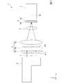
図1は、本実施形態のプロジェクター1の概略構成図である。
なお、以下の各図面においては各構成要素を見やすくするため、構成要素によって寸法の縮尺を異ならせて示すことがある。[First Embodiment]
Hereinafter, the first embodiment of the present invention will be described with reference to FIGS. 1 to 7.
FIG. 1 is a schematic configuration diagram of the projector 1 of the present embodiment.
In each of the following drawings, in order to make each component easy to see, the scale of the dimensions may be different depending on the component.
本実施形態に係るプロジェクター1は、光源装置2から射出された光を変調して画像情報に応じた画像を形成し、形成された画像をスクリーン等の被投射面上に拡大して投射する。換言すると、プロジェクター1は、光源装置2から射出された光を1つの液晶パネル61を含む1つの光変調装置6により変調して画像を形成し、形成された画像を投射する。プロジェクター1は、いわゆる、単板方式のプロジェクターである。 The projector 1 according to the present embodiment modulates the light emitted from the
図1に示すように、プロジェクター1は、光源装置2と、均一化装置4と、フィールドレンズ5と、光変調装置6と、投射光学装置7と、を備える。光源装置2、均一化装置4、フィールドレンズ5、光変調装置6、および投射光学装置7は、照明光軸Axに沿う所定の位置に配置されている。照明光軸Axは、光源装置2から射出される光Lの主光線の進行方向に沿う軸と定義する。 As shown in FIG. 1, the projector 1 includes a
光源装置2および均一化装置4の構成については、後で詳しく説明する。
フィールドレンズ5は、均一化装置4と光変調装置6との間に配置されている。フィールドレンズ5は、均一化装置4から射出される光Lを平行化し、光変調装置6に導く。The configuration of the
The
投射光学装置7は、光変調装置6によって変調された光、すなわち、画像を形成する光をスクリーンなどの被投射面(図示略)上に投射する。投射光学装置7は、単数または複数の投射レンズを有する。 The projection
以下の説明においては、照明光軸Axに沿って光源装置2から射出された光の進行方向に平行な軸をZ軸とし、光の進行方向を+Z方向とする。また、Z軸にそれぞれ直交し、かつ、互いに直交する2つの軸をX軸およびY軸とする。これらの軸に沿う方向のうち、プロジェクター1を設置した空間における鉛直方向上方を+Y方向とする。また、+Y方向が鉛直方向上方を向くように、+Z方向に沿って光が入射される対象物を見た場合の水平方向右方を+X方向とする。図示を省略するが、+X方向の反対方向を-X方向とし、+Y方向の反対方向を-Y方向とし、+Z方向の反対方向を-Z方向とする。
本実施形態の+Z方向は特許請求の範囲の第1方向に対応し、本実施形態の-X方向は特許請求の範囲の第2方向に対応する。また、本実施形態の+X方向は特許請求の範囲の第3方向に対応し、本実施形態の-Z方向は特許請求の範囲の第4方向に対応する。In the following description, the axis parallel to the traveling direction of the light emitted from the
The + Z direction of the present embodiment corresponds to the first direction of the claims, and the −X direction of the present embodiment corresponds to the second direction of the claims. Further, the + X direction of the present embodiment corresponds to the third direction of the claims, and the −Z direction of the present embodiment corresponds to the fourth direction of the claims.
[光源装置の構成]
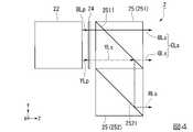
図2は、本実施形態の光源装置2の斜視図である。図3は、+Y方向から見た光源装置2の平面図である。
図2および図3に示すように、光源装置2は、光変調装置6を照明する光Lを、照明光軸Axに平行な方向、すなわち+Z方向に射出する。光源装置2が射出する光Lは、偏光方向が揃った直線偏光であり、空間的に分離された複数の色光を含む。本実施形態では、光源装置2が射出する光Lは、それぞれがY方向に振動する偏光、すなわち後述のS偏光成分からなる4本の光束で構成される。4本の光束は、シアン色光CLs、赤色光RLs、青色光BLsおよび黄色光YLsである。[Structure of light source device]
FIG. 2 is a perspective view of the
As shown in FIGS. 2 and 3, the
光源装置2は、光源部10と、集光素子11と、波長変換素子12と、ピックアップ素子13と、第1光学部材22と、第2光学部材23と、第1位相差素子24と、第1色分離素子25と、第2色分離素子26と、を有する。 The
なお、本実施形態のP偏光成分は特許請求の範囲の第1偏光方向に偏光する光に相当し、S偏光成分は特許請求の範囲の第2偏光方向に偏光する光に相当する。また、後述するように、第1光学部材22および第2光学部材23と、第1色分離素子25および第2色分離素子26とでは、偏光成分または色光を分離する膜の向きが異なっている。したがって、P偏光成分およびS偏光成分という表記は、第1光学部材22および第2光学部材23に対する偏光方向で表しており、第1色分離素子25および第2色分離素子26に対する偏光方向では逆になる。すなわち、第1光学部材22および第2光学部材23に対するP偏光成分は、第1色分離素子25および第2色分離素子26に対するS偏光成分であり、第1光学部材22および第2光学部材23に対するS偏光成分は、第1色分離素子25および第2色分離素子26に対するP偏光成分である。ただし、説明を混乱させないため、以下では、P偏光成分およびS偏光成分を、第1光学部材22および第2光学部材23に対する偏光方向として表記する。 The P-polarized component of the present embodiment corresponds to the light polarized in the first polarization direction in the range of the patent claim, and the S-polarized component corresponds to the light polarized in the second polarization direction in the range of the patent claim. Further, as will be described later, the orientation of the film that separates the polarization component or the color light is different between the first
[光源部の構成]
光源部10は、発光素子10aとコリメーターレンズ10bとを有する。発光素子10aは、青色光を射出する固体光源で構成されている。コリメーターレンズ10bは発光素子10aに対応して設けられている。コリメーターレンズ10bは、発光素子10aから射出された光を平行化する。
具体的には、発光素子10aは、S偏光の青色光Bを射出する半導体レーザーで構成されている。青色光Bは、例えば440~480nmの青色波長帯を有し、例えば450~460nmの範囲内にピーク波長を有するレーザー光である。なお、発光素子10aは、半導体レーザーに代えて、LED(Light Emitting Diode)等の他の固体光源から構成されていてもよい。[Structure of light source unit]
The
Specifically, the
光源部10における発光素子10aの数は限定されず、発光素子10aを複数備えていてもよい。この場合、各発光素子10aに対応するようにコリメーターレンズ10bが設けられる。また、発光素子10aは、S偏光成分の青色光Bを射出するように配置されているが、P偏光成分の青色光を射出するように配置されていてもよい。すなわち、発光素子10aは、射出光軸を中心として90°回転していてもよい。 The number of
このようにして、本実施形態の光源部10は、S偏光成分の青色光Bを射出する。本実施形態において、青色波長帯を有する青色光Bは特許請求の範囲の第1波長帯を有する第1光に対応する。 In this way, the
[集光素子の構成]
集光素子11は、光源部10の+Z方向に配置される。集光素子11は、光源部10から射出された青色光Bを波長変換素子12上に集束させる。なお、図3の例では、集光素子11は、1枚のレンズで構成されているが、集光素子11を構成するレンズの数は限定されない。[Construction of light collecting element]
The
[波長変換素子の構成]
波長変換素子12は、集光素子11に対して+Z方向に配置されている。波長変換素子12は、光が入射されることによって励起され、入射された光の波長とは異なる波長を有する光を、光の入射方向と同じ方向に射出する透過型の波長変換素子である。換言すると、波長変換素子12は、入射された光を波長変換し、波長変換された光を光の入射方向と同じ方向に射出する。[Structure of wavelength conversion element]
The
本実施形態の波長変換素子12は、青色光Bによって励起されて黄色光を射出する黄色蛍光体を含有している。具体的には、波長変換素子12は、例えば賦活剤としてセリウム(Ce)を含有するイットリウム・アルミニウム・ガーネット(YAG)系蛍光体を含んでいる。波長変換素子12は、+Z方向に沿って入射される青色光Bの青色波長帯よりも長い黄色波長帯を有する蛍光、すなわち、非偏光の黄色光YLを+Z方向に射出する。黄色光YLは、例えば500~700nmの波長帯を有する。黄色光YLは、緑色光成分と赤色光成分とを含み、各色光成分においてS偏光成分とP偏光成分とが混在した非偏光である。
本実施形態の黄色波長帯を有する蛍光、すなわち、非偏光の黄色光YLは、特許請求の範囲の第2波長帯を有する第2光に対応する。The
The fluorescence having the yellow wavelength band of the present embodiment, that is, the unpolarized yellow light YL corresponds to the second light having the second wavelength band in the claims.
本実施形態の波長変換素子12は、青色光Bの一部を黄色光YLに波長変換し、青色光Bの他の一部を波長変換しない。波長変換されなかった青色光Bの他の一部は、未変換青色光BLとして波長変換素子12から射出される。すなわち、本実施形態の波長変換素子12は、青色光Bが入射される入射面12aと、黄色光YLおよび未変換青色光BLが射出される射出面12bと、を有している。このように本実施形態の波長変換素子12は、射出面12bから黄色光YLと未変換青色光BLとを含む白色光を射出することが可能である。 The
波長変換素子12から射出された光はピックアップ素子13に入射する。未変換青色光BLは波長変換素子12を透過する過程で偏光状態が乱れることでS偏光成分およびP偏光成分が混在した状態となっている。
本実施形態の未変換青色光BLは、特許請求の範囲の未変換光に対応する。The light emitted from the
The unconverted blue light BL of the present embodiment corresponds to the unconverted light in the claims.
なお、本実施形態の波長変換素子12は固定型の波長変換素子であるが、この構成に代えて、Z軸に平行な回転軸を中心として波長変換素子12を回転させる回転装置を備える回転型の波長変換素子が用いられてもよい。この場合、波長変換素子12の温度上昇が抑えられ、波長変換効率を高めることができる。 The
[ピックアップ素子の構成]
ピックアップ素子13は、波長変換素子12から射出された黄色光YLおよび未変換青色光BLを平行化し、第1光学部材22に向けて射出する。なお、図3の例では、ピックアップ素子13は、第1レンズ13aと第2レンズ13bとから構成されているが、ピックアップ素子13を構成するレンズの数は限定されない。[Pickup element configuration]
The
[第1光学部材の構成]
第1光学部材22には、黄色光YLおよび未変換青色光BLが、+Z方向に沿って入射される。第1光学部材22は、プリズム型の偏光分離素子で構成されている。第1光学部材22は、偏光分離層221と、偏光分離層221を挟んで設けられる2つの第1基材222と、を有する。具体的には、2つの第1基材222の各々は、略直角二等辺三角柱状の形状を有する。2つの第1基材222は、傾斜面同士が対向するように組み合わされ、全体として略直方体状に形成されている。偏光分離層221は、2つの第1基材222の傾斜面の間に設けられている。したがって、偏光分離層221は、X軸およびZ軸に対して45°傾斜している。言い換えると、偏光分離層221は、XY平面およびYZ平面に対して45°傾斜している。[Structure of the first optical member]
Yellow light YL and unconverted blue light BL are incident on the first
偏光分離層221は、波長帯によらず入射される光のうち、P偏光成分を透過し、S偏光成分を反射する偏光分離特性を有する。未変換青色光BLは上述のようにS偏光成分およびP偏光成分が混在した偏光状態であるため、第1光学部材22は、+Z方向に沿って入射される未変換青色光BLのうち、P偏光成分の青色光BLpを+Z方向に沿って透過させ、S偏光成分の青色光BLsを-X方向に反射する。また、偏光分離層221は、+Z方向に沿って入射される黄色光YLのうち、P偏光成分の黄色光YLpを+Z方向に沿って透過させ、S偏光成分の黄色光YLsを-X方向に反射する。
なお、偏光分離層221は、例えば誘電体多層膜から構成されている。第1基材222は、一般的な光学ガラスから構成されている。The
The
上記構成の第1光学部材22によれば、波長変換素子12から射出された黄色光YLおよび未変換青色光BLを偏光分離し、P偏光成分の黄色光YLpおよび青色光BLpを+Z方向に透過させて第1位相差素子24に入射させるとともに、S偏光成分の黄色光YLsおよび青色光BLsを-X方向に反射して第2光学部材23に入射させることが可能である。
本実施形態において、P偏光成分の青色光BLpは、特許請求の範囲の第1偏光方向に偏光する未変換光に対応し、S偏光成分の青色光BLsは、特許請求の範囲の第2偏光方向に偏光する未変換光に対応し、P偏光成分の黄色光YLpは、特許請求の範囲の第1偏光方向に偏光する第2光に対応し、S偏光成分の黄色光YLsは、特許請求の範囲の第2偏光方向に偏光する第2光に対応する。According to the first
In the present embodiment, the blue light BLp of the P polarization component corresponds to the unconverted light polarized in the first polarization direction in the range of the patent claim, and the blue light BLs of the S polarization component is the second polarization in the range of the patent claim. Corresponding to unconverted light polarized in the direction, the yellow light YLp of the P polarization component corresponds to the second light polarized in the first polarization direction within the scope of the patent claim, and the yellow light YLs of the S polarization component corresponds to the patent claim. Corresponds to the second light polarized in the second polarization direction in the range of.
[第1位相差素子の構成]
図4は、+X方向から見た光源装置2の側面図である。換言すると、図4は、+X方向から見た第1位相差素子24および第1色分離素子25を示している。[Structure of first phase difference element]
FIG. 4 is a side view of the
図3および図4に示すように、第1位相差素子24は、第1光学部材22に対して+Z方向に配置されている。第1位相差素子24には、第1光学部材22から+Z方向に射出された黄色光YLpおよび青色光BLpが入射する。第1位相差素子24は、黄色光YLpの黄色波長帯および青色光BLpの青色波長帯に対する1/2波長板で構成されている。第1位相差素子24は、P偏光成分の黄色光YLpおよび青色光BLpをS偏光成分の黄色光YLsおよび青色光BLsにそれぞれ変換する。S偏光成分に変換された黄色光YLsおよび青色光BLsは、第1色分離素子25に入射する。 As shown in FIGS. 3 and 4, the
[第1色分離素子の構成]
図4に示すように、第1色分離素子25は、第1光学部材22に対して+Z方向に配置されている。第1色分離素子25は、ダイクロイックプリズム251と、反射プリズム252と、を有する。ダイクロイックプリズム251と反射プリズム252とは、Y軸に沿って並んで配置されている。第1色分離素子25は、第1光学部材22から+Z方向に射出され、第1位相差素子24によってS偏光成分に変換された光を、シアン色光CLsと赤色光RLsとに分離して射出させる。[Structure of first color separation element]
As shown in FIG. 4, the first
具体的にダイクロイックプリズム251には、第1光学部材22から射出されて第1位相差素子24によってS偏光成分に変換された黄色光YLsおよび青色光BLsが入射される。ダイクロイックプリズム251は、略直角二等辺三角柱状の2つの基材を組み合わせて略直方体形状に形成されたプリズム型の色分離素子から構成されている。2つの基材の界面には、色分離層2511が設けられている。色分離層2511は、Y軸およびZ軸に対して45°傾斜している。換言すると、色分離層2511は、XY平面およびYZ平面に対して45°傾斜している。 Specifically, yellow light YLs and blue light BLs emitted from the first
色分離層2511は、入射される光のうち、赤色光成分を反射させ、青色光成分および緑色光成分を透過させるダイクロイックミラーとして機能する。このため、第1光学部材22からダイクロイックプリズム251に入射した光のうち、青色光BLsは、色分離層2511を+Z方向に透過して、ダイクロイックプリズム251の外部に射出される。 The
また、第1光学部材22からダイクロイックプリズム251に入射した黄色光YLsのうち、S偏光の緑色光GLsは色分離層2511を+Z方向に透過して、青色光BLsとともにダイクロイックプリズム251の外部に射出される。これにより、S偏光の緑色光GLsおよび青色光BLsは、シアン色を有するシアン色光CLsとして光源装置2から+Z方向に射出され、均一化装置4に入射される。 Of the yellow light YLs incident on the
一方、第1光学部材22からダイクロイックプリズム251に入射した黄色光YLsのうち、S偏光の赤色光RLsは、色分離層2511で-Y方向に反射される。なお、ダイクロイックプリズム251に代えて、色分離層2511を有するダイクロイックミラーが用いられてもよい。また、第1色分離素子25は、偏光分離層を有する偏光分離素子と、反射プリズム252とを有する構成であってもよい。 On the other hand, of the yellow light YLs incident on the
反射プリズム252は、ダイクロイックプリズム251に対して-Y方向に配置されている。反射プリズム252には、色分離層2511で反射された赤色光RLsが入射される。反射プリズム252は、略直角二等辺三角柱状の2つの基材を組み合わせて略直方体形状に形成されたプリズム型の反射素子である。2つの基材の界面には、反射層2521が設けられている。反射層2521は、+Y方向および+Z方向に対して45°傾斜している。換言すると、反射層2521は、XY平面およびYZ平面に対して45°傾斜している。すなわち、反射層2521と色分離層2511とは、平行に配置されている。 The
反射層2521は、ダイクロイックプリズム251から-Y方向に入射される赤色光RLsを+Z方向に反射する。反射層2521によって反射された赤色光RLsは、反射プリズム252から+Z方向に射出される。なお、反射プリズム252に代えて、反射層2521を有する反射ミラーを採用してもよい。 The
これにより、赤色光RLsは、シアン色光CLsとは空間的に分離され、シアン色光CLsとは異なる位置から射出され、均一化装置4に入射される。換言すると、赤色光RLsは、光源装置2におけるシアン色光CLsの射出位置から-Y方向に離れた射出位置から射出され、均一化装置4に入射される。 As a result, the red light RLs are spatially separated from the cyan light CLs, emitted from a position different from the cyan light CLs, and incident on the
[第2光学部材の構成]
図3に示すように、第2光学部材23は、第1光学部材22に対して-X方向に配置されている。
第2光学部材23には、第1光学部材22から-X方向に射出された青色光BLsおよび黄色光YLsが入射される。第2光学部材23は、プリズム型の反射素子で構成されている。第2光学部材23は、反射ミラー層231と、反射ミラー層231を挟んで設けられる2つの第2基材232と、を有する。[Structure of the second optical member]
As shown in FIG. 3, the second
Blue light BLs and yellow light YLs emitted from the first
具体的には、2つの第2基材232の各々は、略直角二等辺三角柱状の形状を有する。2つの第2基材232は、傾斜面同士が対向するように組み合わされ、全体として略直方体状に形成されている。反射ミラー層231は、2つの第2基材232の傾斜面の間に設けられている。反射ミラー層231は、X軸およびZ軸に対して45°傾斜している。言い換えると、反射ミラー層231は、XY平面およびYZ平面に対して45°傾斜している。また、反射ミラー層231と偏光分離層221とは、平行に配置されている。 Specifically, each of the two
反射ミラー層231は、第1光学部材22から入射されるS偏光成分の青色光BLsおよび黄色光YLsを+Z方向に反射する。反射ミラー層231は、例えば光反射性を有する金属膜から構成されている。第2基材232は、一般的な光学ガラスから構成されている。 The
本実施形態の場合、第1光学部材22と第2光学部材23とは、別個の部材として構成されている。そのため、図示を省略するが、第1光学部材22と第2光学部材23とは、互いに対向する面の間に設けられた接合材を介して接合されている。なお、第1光学部材22と第2光学部材23とは、一体化されていてもよい。すなわち、第2光学部材23に隣り合う第1基材222と第1光学部材22に隣り合う第2基材232とは、同一の材料からなる共通の部材であってもよい。 In the case of the present embodiment, the first
上記構成の第2光学部材23によれば、第1光学部材22から-X方向に射出されたS偏光成分の青色光BLsおよび黄色光YLsを+Z方向に反射して第2色分離素子26に入射させることが可能である。 According to the second
[第2色分離素子の構成]
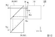
図5は、-X方向から見た光源装置2の側面図である。換言すると、図5は、-X方向から見た第2色分離素子26を示している。
図5に示すように、第2色分離素子26は、第2光学部材23に対して+Z方向に配置されている。第2色分離素子26は、ダイクロイックプリズム261と、反射プリズム262と、を有する。ダイクロイックプリズム261と反射プリズム262とは、Y軸に沿って並んで配置されている。第2色分離素子26は、第2光学部材23から+Z方向に射出された光を青色光BLsと黄色光YLsとに分離する。[Structure of second color separation element]
FIG. 5 is a side view of the
As shown in FIG. 5, the second
ダイクロイックプリズム261は、ダイクロイックプリズム251と同様、プリズム型の色分離素子で構成されている。2つの基材の界面には、色分離層2611が設けられている。色分離層2611は、+Y方向および+Z方向に対して45°傾斜している。換言すると、色分離層2611は、XY平面およびYZ平面に対して45°傾斜している。色分離層2611と反射層2621とは、平行に配置されている。 Like the
色分離層2611は、入射される光のうち、黄色光成分を反射させ、青色光成分を透過させるダイクロイックミラーとして機能する。このため、ダイクロイックプリズム261に入射した青色光BLsは、色分離層2611を+Z方向に透過して、ダイクロイックプリズム261の外部に射出される。 The
一方、黄色光YLsは、色分離層2611で-Y方向に反射される。なお、ダイクロイックプリズム261に代えて、色分離層2611を有するダイクロイックミラーが用いられてもよい。 On the other hand, the yellow light YLs is reflected by the
反射プリズム262は、反射プリズム252と同様の構成を有する。すなわち、反射プリズム262は、色分離層2511、色分離層2611、および反射層2521と平行な反射層2621を有する。 The
反射層2621は、色分離層2611で反射されて入射する黄色光YLsを+Z方向に反射する。反射層2621で反射された黄色光YLsは、反射プリズム262の外部に射出される。黄色光YLsは、光源装置2から+Z方向に射出され、均一化装置4に入射される。すなわち、黄色光YLsは、シアン色光CLs、赤色光RLsおよび青色光BLsとは空間的に分離され、シアン色光CLs、赤色光RLsおよび青色光BLsとは異なる位置から射出され、均一化装置4に入射される。換言すると、黄色光YLsは、光源装置2における青色光BLsの射出位置から-Y方向に離れ、赤色光RLsの射出位置から-X方向に離れた射出位置から射出され、均一化装置4に入射される。 The
[均一化装置の構成]
図1に示すように、均一化装置4は、光源装置2から射出された光が照射される光変調装置6の画像形成領域における照度を均一化する。均一化装置4は、第1マルチレンズ41と、第2マルチレンズ42と、重畳レンズ43と、を有する。[Structure of homogenizer]
As shown in FIG. 1, the homogenizing
第1マルチレンズ41は、光源装置2から入射される光Lの中心軸、すなわち、照明光軸Axに直交する面内にマトリクス状に配列された複数のレンズ411を有する。第1マルチレンズ41は、複数のレンズ411によって光源装置2から入射される光を複数の部分光束に分割する。 The
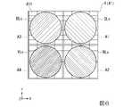
図6は、-Z方向から見た第1マルチレンズ41における各色光の入射位置を示す模式図である。
図6に示すように、光源装置2から射出されたシアン色光CLs、赤色光RLs、青色光BLsおよび黄色光YLsは、第1マルチレンズ41に入射される。光源装置2における+X方向で+Y方向の位置から射出されたシアン色光CLsは、第1マルチレンズ41における+X方向で+Y方向の領域A1に含まれる複数のレンズ411に入射される。また、光源装置2における+X方向で-Y方向の位置から射出された赤色光RLsは、第1マルチレンズ41における+X方向で-Y方向の領域A2に含まれる複数のレンズ411に入射される。FIG. 6 is a schematic diagram showing the incident positions of the light of each color in the first multi-lens 41 viewed from the −Z direction.
As shown in FIG. 6, the cyan light CLs, the red light RLs, the blue light BLs, and the yellow light YLs emitted from the
光源装置2における-X方向で+Y方向の位置から射出された青色光BLsは、第1マルチレンズ41における-X方向で+Y方向の領域A3に含まれる複数のレンズ411に入射される。光源装置2における-X方向で-Y方向の位置から射出された黄色光YLsは、第1マルチレンズ41における-X方向で-Y方向の領域A4に含まれる複数のレンズ411に入射される。各レンズ411に入射された各色光は、複数の部分光束となって、第2マルチレンズ42においてレンズ411に対応するレンズ421に入射する。
本実施形態の光源装置2から射出された光Lのうち、シアン色光CLsは特許請求の範囲の第3波長帯を有する第3光に対応し、赤色光RLsは特許請求の範囲の第4波長帯を有する第4光に対応し、青色光BLsは特許請求の範囲の第1波長帯を有する第5光に対応し、黄色光YLsは特許請求の範囲の第2波長帯を有する第6光に対応する。The blue light BLs emitted from the position in the + Y direction in the −X direction in the
Of the light L emitted from the
図1に示すように、第2マルチレンズ42は、照明光軸Axに直交する面内にマトリクス状に配列されるとともに、第1マルチレンズ41の複数のレンズ411に対応した複数のレンズ421を有する。各レンズ421には、当該レンズ421に対応するレンズ411から射出された複数の部分光束が入射される。各レンズ421は、入射された部分光束を重畳レンズ43に入射させる。 As shown in FIG. 1, the
重畳レンズ43は、第2マルチレンズ42から入射される複数の部分光束を光変調装置6の画像形成領域において重畳する。詳述すると、それぞれが複数の部分光束に分割されたシアン色光CLs、赤色光RLs、青色光BLsおよび黄色光YLsは、第2マルチレンズ42と重畳レンズ43とによって、フィールドレンズ5を介して、光変調装置6の後述するマイクロレンズアレイ62を構成する複数のマイクロレンズ621のそれぞれに異なる角度で入射する。 The superimposing
[光変調装置の構成]
図1に示すように、光変調装置6は、光源装置2から射出された光を変調する。詳述すると、光変調装置6は、光源装置2から射出されて均一化装置4およびフィールドレンズ5を介して入射される各色光を画像情報に応じてそれぞれ変調し、画像情報に応じた画像光を形成する。光変調装置6は、1つの液晶パネル61と、1つのマイクロレンズアレイ62と、を備える。[Configuration of optical modulator]
As shown in FIG. 1, the
[液晶パネルの構成]
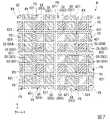
図7は、-Z方向から見た光変調装置6の一部を拡大視した模式図である。換言すると、図7は、液晶パネル61が有する画素PXと、マイクロレンズアレイ62が有するマイクロレンズ621と、の対応関係を示している。
図7に示すように、液晶パネル61は、照明光軸Axに直交する面内にマトリクス状に配列された複数の画素PXを有する。[LCD panel configuration]
FIG. 7 is a schematic view of a part of the
As shown in FIG. 7, the
各画素PXは、互いに異なる色の色光を変調する複数のサブ画素SXを有する。本実施形態では、各画素PXは、4つのサブ画素SX(SX1~SX4)を有する。具体的に、1つの画素PX内において、+X方向で+Y方向の位置に、第1サブ画素SX1が配置されている。+X方向で-Y方向の位置に、第2サブ画素SX2が配置されている。-X方向で+Y方向の位置に、第3サブ画素SX3が配置されている。-X方向で-Y方向の位置に、第4サブ画素SX4が配置されている。 Each pixel PX has a plurality of sub-pixel SXs that modulate colored light of different colors from each other. In this embodiment, each pixel PX has four sub-pixels SX (SX1 to SX4). Specifically, the first sub-pixel SX1 is arranged at a position in the + X direction and the + Y direction in one pixel PX. The second sub-pixel SX2 is arranged at a position in the + X direction and the −Y direction. The third sub-pixel SX3 is arranged at a position in the + Y direction in the −X direction. The fourth sub-pixel SX4 is arranged at a position in the −X direction and the −Y direction.
[マイクロレンズアレイの構成]
図1に示すように、マイクロレンズアレイ62は、液晶パネル61に対して光入射側である-Z方向に設けられている。マイクロレンズアレイ62は、マイクロレンズアレイ62に入射される色光を個々の画素PXに導く。マイクロレンズアレイ62は、複数の画素PXに対応する複数のマイクロレンズ621を有する。[Microlens array configuration]
As shown in FIG. 1, the
図7に示すように、複数のマイクロレンズ621は、照明光軸Axに直交する面内にマトリクス状に配列されている。換言すると、複数のマイクロレンズ621は、フィールドレンズ5から入射される光の中心軸に対する直交面内にマトリクス状に配列されている。本実施形態では、1つのマイクロレンズ621は、+X方向に配列された2つのサブ画素と、+Y方向に配列された2つのサブ画素と、に対応して設けられている。すなわち、1つのマイクロレンズ621は、XY平面内に2行2列に配列された4つのサブ画素SX1~SX4に対応して設けられている。 As shown in FIG. 7, the plurality of
マイクロレンズ621には、均一化装置4によって重畳されたシアン色光CLs、赤色光RLs、青色光BLsおよび黄色光YLsがそれぞれ異なる角度で入射される。マイクロレンズ621は、マイクロレンズ621に入射される色光を、当該色光に対応するサブ画素SXに入射させる。具体的には、マイクロレンズ621は、対応する画素PXのサブ画素SXのうち、第1サブ画素SX1にシアン色光CLsを入射させ、第2サブ画素SX2に赤色光RLsを入射させ、第3サブ画素SX3に青色光BLsを入射させ、第4サブ画素SX4に黄色光YLsを入射させる。これにより、各サブ画素SX1~SX4に、当該サブ画素SX1~SX4に対応する色光が入射され、各サブ画素SX1~SX4によって対応する色光がそれぞれ変調される。このように、液晶パネル61によって変調された画像光は、投射光学装置7によって図示しない被投射面上に投射される。 Cyan light CLs, red light RLs, blue light BLs, and yellow light YLs superimposed by the homogenizing
[第1実施形態の効果]
特許文献1に記載された従来のプロジェクターにおいては、光源としてランプが用いられている。ランプから射出される光は偏光方向が揃っていないため、光変調装置として液晶パネルを用いるためには、偏光方向を揃えるための偏光変換手段が必要となる。プロジェクターには、マルチレンズアレイと偏光分離素子(PBS)アレイとを備える偏光変換手段が一般的に用いられている。ところが、プロジェクターを小型化するために、ピッチが狭いマルチレンズアレイとPBSアレイとが必要となるが、ピッチが狭いPBSアレイの作成は非常に困難である。[Effect of the first embodiment]
In the conventional projector described in Patent Document 1, a lamp is used as a light source. Since the light emitted from the lamp does not have the same polarization direction, in order to use the liquid crystal panel as the optical modulation device, a polarization conversion means for aligning the polarization directions is required. A polarization conversion means including a multi-lens array and a polarization separating element (PBS) array is generally used in a projector. However, in order to reduce the size of the projector, a multi-lens array with a narrow pitch and a PBS array are required, but it is very difficult to create a PBS array with a narrow pitch.
この問題に対して、本実施形態においては、偏光方向が揃った複数の色光、すなわち、S偏光成分のシアン色光CLs、S偏光成分の赤色光RLs、S偏光成分の青色光BLsおよびS偏光成分の黄色光YLsが光源装置2から射出される。この構成によれば、上記のようなピッチが狭い偏光変換素子を用いることなく、空間的に分離され、偏光方向が揃えられた複数の色光を射出可能な光源装置2を実現することができる。これにより、光源装置2の小型化が可能となり、ひいては、プロジェクター1の小型化を図ることができる。 In response to this problem, in the present embodiment, a plurality of colored lights having the same polarization direction, that is, cyan light CLs of the S polarization component, red light RLs of the S polarization component, blue light BLs of the S polarization component, and S polarization component. Yellow light YLs is emitted from the
また、本実施形態の光源装置2は、青色光Bを射出する光源部10と、青色光Bが入射され、青色光Bの一部を波長変換して黄色光YLを射出し、青色光Bの他の一部を波長変換することなく未変換青色光BLとして射出する波長変換素子12と、波長変換素子12から+Z方向に沿って未変換青色光BLおよび黄色光YLが入射され、黄色光YLpを+Z方向に透過し、黄色光YLsを-X方向に反射し、青色光BLsを-X方向に反射する第1光学部材22と、第1光学部材22に対して-X方向に配置され、第1光学部材22から-X方向に沿って入射される青色光BLsを+Z方向に反射し、第1光学部材22から-X方向に沿って入射される黄色光YLsを+Z方向に反射する第2光学部材23と、第1光学部材22に対して+Z方向に配置され、第1光学部材22から射出された光をシアン色光CLsと赤色光RLsとに分離する第1色分離素子25と、第2光学部材23に対して+Z方向に配置され、第2光学部材23から射出された光を青色光BLsと黄色光YLsとに分離する第2色分離素子26と、を備えている。 Further, in the
本実施形態の光源装置2によれば、未変換青色光BLと黄色光YLとを含む白色光を波長変換素子12から射出することができる。本実施形態の場合、波長変換素子12から射出された白色光をピックアップ素子13で平行化して第1色分離素子25に入射させることで4つの色光をできるので、個別に生成した黄色光および青色光を第1色分離素子25および第2光学部材23にそれぞれ入射させる構成に比べて、光源装置を構成する部品点数を減らすことができる。
したがって、本実施形態の光源装置2によれば、装置構成のさらなる小型化が可能となり、ひいては、プロジェクター1のさらなる小型化を実現できる。According to the
Therefore, according to the
本実施形態の光源装置2において、波長変換素子12は、青色光Bが入射される入射面12aと、黄色光YLおよび未変換青色光BLが射出される射出面12bと、を有している。
この構成によれば、光源装置2において、透過型の波長変換素子12を用いた構成を採用することができる。In the
According to this configuration, in the
本実施形態の光源装置2において、第1光学部材22は、波長変換素子12から+Z方向に沿って未変換青色光BLが入射され、青色光BLpを+Z方向に透過し、青色光BLsを-X方向に反射してもよい。
この構成によれば、未変換青色光BLから分離した青色光BLsを第2色分離素子26によって外部に取り出すことができる。In the
According to this configuration, the blue light BLs separated from the unconverted blue light BL can be taken out to the outside by the second
また、本実施形態の場合、第1光学部材22と第1色分離素子25との間に設けられ、少なくとも黄色光YLpに対して黄色波長帯の1/2の位相差を付与する第1位相差素子24をさらに備えている。
この構成によれば、第1光学部材22から射出された黄色光YLpおよび青色光BLpをS偏光成分の黄色光YLsおよび青色光BLsに変換することができる。よって、光源装置2から射出される青色光BLsおよび黄色光YLsの偏光方向をシアン色光CLs、赤色光RLsに合わせることができる。Further, in the case of the present embodiment, the first position provided between the first
According to this configuration, the yellow light YLp and the blue light BLp emitted from the first
また、本実施形態の場合、プロジェクター1が光源装置2と光変調装置6との間に位置する均一化装置4を備えているため、光源装置2から射出されるシアン色光CLs、赤色光RLs、青色光BLsおよび黄色光YLsによって光変調装置6を略均一に照明することができる。これにより、投射画像の色むらおよび輝度むらを抑制することができる。 Further, in the case of the present embodiment, since the projector 1 includes the
また、本実施形態の場合、光変調装置6が複数の画素PXに対応する複数のマイクロレンズ621を有するマイクロレンズアレイ62を備えているため、光変調装置6に入射される4つの色光を、マイクロレンズ621によって液晶パネル61の対応する4つのサブ画素SXに入射させることができる。これにより、光源装置2から射出された各色光を各サブ画素SXに効率良く入射させることができ、各色光の利用効率を高めることができる。 Further, in the case of the present embodiment, since the
[第2実施形態]
以下、本発明の第2実施形態について、図8~図10を用いて説明する。
第2実施形態の光源装置の基本構成は第1実施形態と同様であり、反射型の波長変換素子を用いる点で第1実施形態と異なる。そのため、以下では第1実施形態と共通の構成については同じ符号を付し、その詳細については説明を省略する。[Second Embodiment]
Hereinafter, the second embodiment of the present invention will be described with reference to FIGS. 8 to 10.
The basic configuration of the light source device of the second embodiment is the same as that of the first embodiment, and is different from the first embodiment in that a reflection type wavelength conversion element is used. Therefore, in the following, the same reference numerals will be given to the configurations common to those of the first embodiment, and the details thereof will be omitted.
図8は+Y方向から見た光源装置20の平面図である。
図8に示すように、本実施形態の光源装置20は、光源部10と、波長変換素子112と、ピックアップ素子13と、第1光学部材122と、第2光学部材123と、第1位相差素子24と、第2位相差素子27と、第1色分離素子25と、第2色分離素子26と、を有する。FIG. 8 is a plan view of the
As shown in FIG. 8, the
本実施形態の光源部10は、第2光学部材123の-X方向に配置されている。本実施形態の光源部10において、発光素子10aはP偏光成分の青色光B1を射出するように配置されている。 The
第1光学部材122において、-Z方向に反射された青色光Bは、波長変換素子112の第1面112aに入射する。 In the first
本実施形態の第2光学部材123は、偏光分離層1231と、偏光分離層1231を挟んで設けられる2つの第2基材232と、を有する。偏光分離層1231は、波長帯によらず入射される光のうち、P偏光成分を透過し、S偏光成分を反射する偏光分離特性を有する。そのため、偏光分離層1231は、光源部10から+X方向に沿って入射されるP偏光成分の青色光B1を+X方向に透過させ、第1光学部材122に入射させる。 The second
本実施形態の第1光学部材122は、偏光分離層1221と、偏光分離層1221を挟んで設けられる2つの第1基材222と、を有する。偏光分離層1221は、黄色波長帯の光について、P偏光成分を透過し、S偏光成分を反射する偏光分離特性を有し、青色波長帯の光を偏光状態によらず反射する特性を有する。 The first
そのため、第1光学部材122は、+X方向に沿って入射される青色光B1を-Z方向に反射する。第1光学部材122により反射された青色光B1は第2位相差素子27に入射する。 Therefore, the first
[第2位相差素子の構成]
第2位相差素子27は、第1光学部材122に対して-Z方向に配置されている。すなわち、第2位相差素子27は、Z軸上において第1光学部材122と波長変換素子112との間に配置されている。第2位相差素子27は、入射される青色光B1の青色波長帯に対して1/4の位相差を付与する1/4波長板で構成されている。第1光学部材122で反射されたS偏光成分の青色光B1は、第2位相差素子27によって例えば右回りの円偏光の青色光BLc1に変換された後、ピックアップ素子13に向けて射出される。[Structure of second phase difference element]
The second
本実施形態の波長変換素子112は、光源部10からの青色光Bが入射される第1面112aと、第1面112aと反対方向を向く第2面112bと、を有している。波長変換素子112の第2面112bには、反射層113が設けられている。本実施形態の波長変換素子12は、青色光Bの一部を黄色光YLに波長変換し、青色光Bの他の一部を波長変換することなく表面反射する。波長変換されなかった青色光Bの他の一部は、未変換青色光として波長変換素子112の第1面112aから射出される。 The
反射層113は、波長変換素子112内で生成された黄色光YLを+Z方向に反射する。なお、反射層113は、波長変換素子112内において波長変換されていない青色光Bを+Z方向に反射してもよい。反射層113に反射された青色光Bは黄色光YLの励起に利用される。 The
すなわち、本実施形態の波長変換素子112は、第1面112aから入射された青色光Bの一部を波長変換して黄色光YLを生成し、第1面112aから黄色光YLおよび未変換青色光を射出する反射型の波長変換素子である。 That is, the
ここで、未変換青色光は、波長変換素子112の第1面112aに入射した右回りの円偏光の青色光BLc1を反射した光である。そのため、本実施形態の未変換青色光BLc2は左回りの円偏光として第1面112aから射出される。波長変換素子12の第1面112aから射出された黄色光YLおよび未変換青色光BLc2はピックアップ素子13で平行化されて第2位相差素子27に入射する。 Here, the unconverted blue light is light that reflects the clockwise circularly polarized blue light BLc1 incident on the
このとき、ピックアップ素子13から第2位相差素子27に入射される未変換青色光BLc2は、第2位相差素子27によって、S偏光成分の青色光BLsに変換される。変換された青色光BLsは、第1光学部材122に入射し、-X方向に反射されことで第2光学部材23に入射する。上述のように第2光学部材123の偏光分離層1231は、波長帯によらず入射される光のうちS偏光成分を反射するため、青色光BLsは+Z方向に反射される。 At this time, the unconverted blue light BLc2 incident on the second
また、ピックアップ素子13から第2位相差素子27に入射される黄色光YLは非偏光であるため、第2位相差素子27の透過前後で偏光状態は変化し難い。第1光学部材122の偏光分離層1221は、+Z方向に沿って入射される黄色光YLのうち、P偏光成分の黄色光YLpを+Z方向に沿って透過させ、S偏光成分の黄色光YLsを-X方向に反射する。 Further, since the yellow light YL incident on the second
上記構成の第1光学部材122によれば、波長変換素子12から射出された黄色光YLを偏光分離し、P偏光成分の黄色光YLpを+Z方向に透過させて第1位相差素子24に入射させるとともに、S偏光成分の青色光BLsおよび黄色光YLsを-X方向に反射して第2光学部材123に入射させることが可能である。 According to the first
一方、第1光学部材122から-X方向に射出されたS偏光成分の黄色光YLsおよび青色光BLsは、第2光学部材123の偏光分離層1231で+Z方向に反射される。
上記構成の第2光学部材123によれば、第1光学部材122から-X方向に射出されたS偏光成分の青色光BLsおよび黄色光YLsを+Z方向に反射して第2色分離素子26に入射させることが可能である。On the other hand, the yellow light YLs and the blue light BLs of the S polarization component emitted from the first
According to the second
図9は、+X方向から見た光源装置20の側面図である。換言すると、図9は、+X方向から見た第1色分離素子25を示している。
図9に示すように、本実施形態の第1色分離素子25は、第1光学部材122から+Z方向に射出され、第1位相差素子24によってS偏光成分に変換された光を、緑色光GLsと赤色光RLsとに分離して射出させる。FIG. 9 is a side view of the
As shown in FIG. 9, the first
本実施形態のダイクロイックプリズム251には、第1光学部材122から射出されて第1位相差素子24によってS偏光成分に変換された黄色光YLsが入射される。そのため、第1光学部材122からダイクロイックプリズム251に入射した黄色光YLsは、色分離層2511においてS偏光の緑色光GLsおよび赤色光RLsに分離され、緑色光GLsおよび赤色光RLsが光源装置2から+Z方向に射出され、均一化装置4に入射される。
なお、第2色分離素子26による色分離については第1実施形態と共通であるため、説明を省略する。The
Since the color separation by the second
すなわち、本実施形態の光源装置20では、第1実施形態の光源装置2におけるシアン色光CLsが射出された位置から、シアン色光CLsに代えて緑色光GLsを射出することができる。
したがって、本実施形態では、シアン色光CLsが射出された位置から射出される緑色光GLsが、特許請求の範囲の第3光に対応する。That is, in the
Therefore, in the present embodiment, the green light GLs emitted from the position where the cyan light CLs are emitted correspond to the third light in the claims.
図10は本実施形態の光源装置20においてマルチレンズ上の各色光の入射位置を示す模式図である。
図10に示すように、本実施形態の光源装置20は、緑色光GLs、赤色光RLs、青色光BLsおよび黄色光YLsを射出する。緑色光GLsは、光源装置20における+X方向で+Y方向の位置から射出され、第1マルチレンズ41における+X方向で+Y方向の領域A1に配置された複数のレンズ411に入射する。図示を省略するが、緑色光GLsは、第1実施形態のシアン色光CLsと同様、第1マルチレンズ41、第2マルチレンズ42、重畳レンズ43、およびフィールドレンズ5を介して各マイクロレンズ621に入射する。各マイクロレンズ621に入射された緑色光GLsは、当該マイクロレンズ621に対応する画素PXの第1サブ画素SX1に入射する。FIG. 10 is a schematic diagram showing the incident positions of each color light on the multi-lens in the
As shown in FIG. 10, the
[第2実施形態の効果]
本実施形態の光源装置20によれば、第1実施形態の光源装置2におけるシアン色光CLsに代えて緑色光GLsを射出することで、投射画像における緑色波長帯の色域を拡げることができる。
また、本実施形態においても、ピッチが狭い偏光変換素子を用いることなく、偏光方向が揃えられた複数の色光を射出可能な光源装置を実現できる、光源装置およびプロジェクターの小型化が図れる、といった第1実施形態と同様の効果が得られる。[Effect of the second embodiment]
According to the
Further, also in the present embodiment, it is possible to realize a light source device capable of emitting a plurality of colored lights having the same polarization direction without using a polarization conversion element having a narrow pitch, and to reduce the size of the light source device and the projector. The same effect as that of 1 embodiment can be obtained.
[第3実施形態]
以下、本発明の第3実施形態について、図11および図12を用いて説明する。
第3実施形態の光源装置の基本構成は第1実施形態と同様であり、反射型偏光素子を備える点で第1実施形態と異なる。そのため、以下では第1実施形態と共通の構成については同じ符号を付し、その詳細については説明を省略する。[Third Embodiment]
Hereinafter, the third embodiment of the present invention will be described with reference to FIGS. 11 and 12.
The basic configuration of the light source device of the third embodiment is the same as that of the first embodiment, and is different from the first embodiment in that it includes a reflective polarizing element. Therefore, in the following, the same reference numerals will be given to the configurations common to those of the first embodiment, and the details thereof will be omitted.
図11は+Y方向から見た光源装置120の平面図である。図12は-X方向から見た光源装置120の側面図である。
図11に示すように、本実施形態の光源装置120は、光源部10と、波長変換素子12と、ピックアップ素子13と、第1光学部材122と、第2光学部材23と、第1位相差素子24と、第1色分離素子25と、第2色分離素子26と、反射型偏光素子28と、を有する。FIG. 11 is a plan view of the
As shown in FIG. 11, the
本実施形態の光源装置120において、波長変換素子12から射出された黄色光YLは第1光学部材122においてP偏光成分の黄色光YLpとS偏光成分の黄色光YLsとに分離され、黄色光YLpは+Z方向に射出され、黄色光YLsは-X方向に射出されて第2光学部材23に入射する。 In the
本実施形態の第1光学部材122における偏光分離層1221は、青色波長帯の光を偏光状態によらず反射する。そのため、波長変換素子12から射出された未変換青色光BLは第1光学部材122の偏光分離層1221により-X方向に反射されて第2光学部材23に入射する。 The
第2光学部材23に入射した未変換青色光BLは、第2光学部材23の反射ミラー層231で反射されて+Z方向に射出され、反射型偏光素子28に入射する。反射型偏光素子28は、第2光学部材23と第2色分離素子26との間に設けられている。 The unconverted blue light BL incident on the second
図11および図12に示すように、反射型偏光素子28は、S偏光成分の光を透過させ、P偏光成分の光を反射させる特性を有する。具体的に反射型偏光素子28は、例えばアルミニウム等からなる複数の金属細線が微細なピッチで基材の一面に設けられたワイヤーグリッド型偏光素子で構成されている。本実施形態において、反射型偏光素子28は、第2光学部材23からS偏光成分として射出された光を透過させる方向にグリッドの向きを設定している。 As shown in FIGS. 11 and 12, the reflective
波長変換素子12から射出された未変換青色光BLは、波長変換素子12を透過する過程で偏光状態が乱れることでS偏光成分およびP偏光成分が混在した状態となっている。そのため、未変換青色光BLのうち、S偏光成分の青色光BLsは反射型偏光素子28を透過して+Z方向に射出される。一方、未変換青色光BLのうち、P偏光成分の青色光BLpは反射型偏光素子28で反射されて第2光学部材23、第1光学部材22およびピックアップ素子13を経由して波長変換素子12に戻される。波長変換素子12に戻された青色光BLpの少なくとも一部は黄色光YLの励起に使用される。 The unconverted blue light BL emitted from the
[第3実施形態の効果]
本実施形態の光源装置120によれば、偏光状態が乱れた状態で第2光学部材23から射出される未変換青色光BLを反射型偏光素子28によってS偏光成分の青色光BLsに変換することができる。この場合、光変調装置6の液晶パネル61の入射側偏光板(不図示)による青色光BLsの吸収が抑制されるため、入射側偏光板の発熱量を低減することができる。また、反射型偏光素子28により反射した青色光BLpを波長変換素子12に戻して黄色光YLの励起に使用することができる。よって、光源装置120は、青色光BLpを無駄なく利用し、波長変換素子12の波長変換効率を向上させることができる。
また、本実施形態の光源装置120は、第1実施形態の光源装置2におけるシアン色光CLsに代えて緑色光GLsを射出することで、投射画像における緑色波長帯の色域を拡げることができる。
また、本実施形態においても、ピッチが狭い偏光変換素子を用いることなく、偏光方向が揃えられた複数の色光を射出可能な光源装置を実現できる、光源装置およびプロジェクターの小型化が図れる、といった第1実施形態と同様の効果が得られる。[Effect of the third embodiment]
According to the
Further, the
Further, also in the present embodiment, it is possible to realize a light source device capable of emitting a plurality of colored lights having the same polarization direction without using a polarization conversion element having a narrow pitch, and to reduce the size of the light source device and the projector. 1 The same effect as that of the embodiment can be obtained.
[第4実施形態]
以下、本発明の第4実施形態について、図13を用いて説明する。
第4実施形態の光源装置の基本構成は第1実施形態と同様であり、反射型偏光素子を備える点で第1実施形態と異なる。そのため、以下では第1実施形態と共通の構成については同じ符号を付し、その詳細については説明を省略する。[Fourth Embodiment]
Hereinafter, the fourth embodiment of the present invention will be described with reference to FIG.
The basic configuration of the light source device of the fourth embodiment is the same as that of the first embodiment, and is different from the first embodiment in that it includes a reflective polarizing element. Therefore, in the following, the same reference numerals will be given to the configurations common to those of the first embodiment, and the details thereof will be omitted.
図13は+Y方向から見た光源装置220の平面図である。
図13に示すように、本実施形態の光源装置220は、光源部10と、波長変換素子12と、ピックアップ素子13と、第1光学部材22と、第2光学部材23と、第1位相差素子24と、光学層30と、第1色分離素子25と、第2色分離素子26と、を有する。FIG. 13 is a plan view of the
As shown in FIG. 13, the
本実施形態において、光学層30は第1位相差素子24の-Z方向に配置されている。具体的に光学層30は、第1位相差素子24における第1光学部材22と対向する面に設けられている。光学層30は、青色波長帯の反射し、それ以外の波長帯である黄色波長帯の光を透過させる光学特性を有したダイクロイックミラーで構成される。 In the present embodiment, the
本実施形態の光源装置220において、波長変換素子12から射出された黄色光YLは第1光学部材22においてP偏光成分の黄色光YLpとS偏光成分の黄色光YLsとに分離され、黄色光YLpは+Z方向に射出され、黄色光YLsは-X方向に射出されて第2光学部材23に入射する。 In the
黄色光YLsは第2光学部材23の反射ミラー層231で+Z方向に反射されて第2色分離素子26に入射する。黄色光YLpは光学層30を透過して第1位相差素子24に入射し、黄色光YLsに変換されて第1色分離素子25に入射する。 The yellow light YLs is reflected in the + Z direction by the
また、第1光学部材22に入射した未変換青色光BLのうち、P偏光成分の青色光BLpは+Z方向に射出され、S偏光成分の青色光BLsは-X方向に射出されて第2光学部材23に入射する。青色光BLsは第2光学部材23の反射ミラー層231で+Z方向に反射されて第2色分離素子26に入射する。 Further, of the unconverted blue light BL incident on the first
一方、青色光BLpは光学層30によって-Z方向に反射され、第1光学部材22およびピックアップ素子13を経由して波長変換素子12に戻される。波長変換素子12に戻された青色光BLpの少なくとも一部は黄色光YLの励起に使用される。本実施形態の青色光BLpは特許請求の範囲の未変換光の他の一部に対応する。 On the other hand, the blue light BLp is reflected by the
[第4実施形態の効果]
本実施形態の光源装置220によれば、第1光学部材22において未変換青色光BLから偏光分離したP偏光成分の青色光BLpを光学層30によって波長変換素子12に戻すことができる。よって、光源装置220は、未変換青色光BLから分離した青色光BLpを無駄なく利用し、波長変換素子12の波長変換効率を向上させることができる。
また、本実施形態の光源装置220は、第1実施形態の光源装置2におけるシアン色光CLsに代えて緑色光GLsを射出することで、投射画像における緑色波長帯の色域を拡げることができる。
また、本実施形態においても、ピッチが狭い偏光変換素子を用いることなく、偏光方向が揃えられた複数の色光を射出可能な光源装置を実現できる、光源装置およびプロジェクターの小型化が図れる、といった第1実施形態と同様の効果が得られる。[Effect of Fourth Embodiment]
According to the
Further, the
Further, also in the present embodiment, it is possible to realize a light source device capable of emitting a plurality of colored lights having the same polarization direction without using a polarization conversion element having a narrow pitch, and to reduce the size of the light source device and the projector. 1 The same effect as that of the embodiment can be obtained.
なお、本発明の技術範囲は上記実施形態に限定されるものではなく、本発明の趣旨を逸脱しない範囲において種々の変更を加えることが可能である。
例えば、上記実施形態においては、第1光学部材22および第2光学部材23をいずれもプリズム型の光学素子で構成する場合を例に挙げたが、第1光学部材22および第2光学部材23をそれぞれプレート型の光学素子で構成してもよい。The technical scope of the present invention is not limited to the above embodiment, and various changes can be made without departing from the spirit of the present invention.
For example, in the above embodiment, the case where the first
上記第1~第3実施形態の光源装置2、20、120において、第1位相差素子24は第1色分離素子25の光射出側に配置されてもよい。すなわち、第1第1位相差素子24は、第1光学部材22の後段側であって均一化装置4(第1マルチレンズ41)の前段側に配置されていればよい。 In the
上記各実施形態のプロジェクター1は、第1マルチレンズ41、第2マルチレンズ42、および重畳レンズ43を有する均一化装置4を備えている。この構成に代えて、他の構成を有する均一化装置が設けられてもよいし、均一化装置4は設けられていなくてもよい。 The projector 1 of each of the above embodiments includes a
上記実施形態の光源装置2は、それぞれがS偏光であり、空間的に分離された4つの色光を射出する。これらの構成に代えて、光源装置が射出する各色光の偏光状態は、他の偏光状態であってもよい。例えば、光源装置は、それぞれがP偏光であり、空間的に分離された複数の色光を射出する構成であってもよい。 The
その他、光源装置、およびプロジェクターの各構成要素の形状、数、配置、材料等の具体的な記載については、上記実施形態に限らず、適宜変更が可能である。また、上記実施形態では、本発明による光源装置をプロジェクターに搭載した例を示したが、これに限られない。本発明の一つの形態の光源装置は、照明器具や自動車のヘッドライト等にも適用することができる。 In addition, the specific description of the shape, number, arrangement, material, etc. of the light source device and each component of the projector is not limited to the above embodiment, and can be appropriately changed. Further, in the above embodiment, an example in which the light source device according to the present invention is mounted on the projector is shown, but the present invention is not limited to this. The light source device of one embodiment of the present invention can also be applied to lighting equipment, headlights of automobiles, and the like.
本発明の一つの態様の光源装置は、以下の構成を有していてもよい。
本発明の一つの態様の光源装置は、第1波長帯を有する第1光を射出する光源部と、第1光が入射され、第1光の一部を波長変換して第1波長帯とは異なる第2波長帯を有する第2光を射出し、第1光の他の一部を波長変換することなく未変換光として射出する波長変換素子と、波長変換素子から第1方向に沿って第1光の未変換光および第2光が入射され、第1偏光方向に偏光する第2光を第1方向に透過し、第1偏光方向とは異なる第2偏光方向に偏光する第2光を第1方向と交差する第2方向に反射し、第1光の未変換光の少なくとも一部を第2方向に反射する第1光学部材と、第1光学部材に対して第2方向に配置され、第1光学部材から第2方向に沿って入射される第1光の未変換光の少なくとも一部を第1方向に反射し、第1光学部材から第2方向に沿って入射される第2偏光方向に偏光する第2光を第1方向に反射する第2光学部材と、第1光学部材に対して第1方向に配置され、第1光学部材から射出された光を、第2波長帯とは異なる第3波長帯を有する第3光と、第2波長帯および第3波長帯とは異なる第4波長帯を有する第4光と、に分離する第1色分離素子と、第2光学部材に対して第1方向に配置され、第2光学部材から射出された光を、第1波長帯を有する第5光と、第2波長帯を有する第6光と、に分離する第2色分離素子と、を備える。The light source device of one aspect of the present invention may have the following configuration.
The light source device according to one aspect of the present invention includes a light source unit that emits first light having a first wavelength band, a light source unit that emits the first light, and a part of the first light that is incidentally converted into the first wavelength band. A wavelength conversion element that emits second light having a different second wavelength band and emits the other part of the first light as unconverted light without wavelength conversion, and a wavelength conversion element along the first direction. The unconverted light and the second light of the first light are incident, and the second light polarized in the first polarization direction is transmitted in the first direction and polarized in the second polarization direction different from the first polarization direction. A first optical member that reflects in the second direction intersecting the first direction and reflects at least a part of the unconverted light of the first light in the second direction, and an arrangement in the second direction with respect to the first optical member. Then, at least a part of the unconverted light of the first light incident from the first optical member along the second direction is reflected in the first direction, and the light is incident from the first optical member along the second direction. The second optical member that reflects the second light polarized in the two polarization directions in the first direction, and the light that is arranged in the first direction with respect to the first optical member and emitted from the first optical member have a second wavelength. A first color separating element that separates a third light having a third wavelength band different from the band and a fourth light having a fourth wavelength band different from the second wavelength band and the third wavelength band, and a second light. A second light, which is arranged in the first direction with respect to the optical member and emits light from the second optical member, is separated into a fifth light having a first wavelength band and a sixth light having a second wavelength band. A color separating element is provided.
本発明の一つの態様の光源装置において、波長変換素子は、第1光が入射される入射面と、第2光および第1光の未変換光が射出される射出面と、を有する構成としてもよい。 In the light source device of one aspect of the present invention, the wavelength conversion element has an incident surface on which the first light is incident and an emission surface on which the second light and the unconverted light of the first light are emitted. May be good.
本発明の一つの態様の光源装置において、第1光学部材は、波長変換素子から第1方向に沿って第1光の未変換光が入射され、第1偏光方向に偏光する未変換光を第1方向に透過し、第2偏光方向に偏光する未変換光を第2方向に反射する構成としてもよい。 In the light source device according to one aspect of the present invention, in the first optical member, the unconverted light of the first light is incident from the wavelength conversion element along the first direction, and the unconverted light polarized in the first polarization direction is the first. The unconverted light that is transmitted in one direction and polarized in the second polarization direction may be reflected in the second direction.
本発明の一つの態様の光源装置において、第1光学部材と第1色分離素子との間に設けられ、少なくとも第1偏光方向に偏光する第2光に対して第2波長帯の1/2の位相差を付与する第1位相差素子をさらに備える構成としてもよい。 In the light source device of one aspect of the present invention, it is provided between the first optical member and the first color separation element, and is at least 1/2 of the second wavelength band with respect to the second light polarized in the first polarization direction. The configuration may be further provided with a first phase difference element that imparts the phase difference of.
本発明の一つの態様の光源装置において、第2光学部材と第2色分離素子との間に設けられ、第2光学部材から射出された第1光の未変換光のうち、第2偏光方向に偏光する未変換光を第1方向に透過させ、第1偏光方向に偏光する未変換光を1方向とは反対方向である第4方向に反射する反射型偏光素子をさらに備える構成としてもよい。 In the light source device of one aspect of the present invention, the second polarization direction of the unconverted light of the first light emitted from the second optical member provided between the second optical member and the second color separation element. The configuration may further include a reflective polarizing element that transmits the unconverted light polarized in the first direction in the first direction and reflects the unconverted light polarized in the first polarization direction in the fourth direction opposite to the one direction. ..
本発明の一つの態様の光源装置において、第1光学部材と第1色分離素子との間に設けられ、第1光学部材から第1方向に射出される未変換光の他の一部を1方向とは反対方向である第4方向に反射する光学層をさらに備える構成としてもよい。 In the light source device of one aspect of the present invention, the other part of the unconverted light provided between the first optical member and the first color separating element and emitted from the first optical member in the first direction is 1 The configuration may further include an optical layer that reflects in a fourth direction opposite to the direction.
本発明の一つの態様の光源装置において、波長変換素子は、第1光が入射される第1面と、第1面と異なる第2面とを有し、波長変換素子の第2面には、少なくとも第2光を第1方向に反射する反射層が設けられており、第1面は、第2光および第1光の未変換光を射出する構成としてもよい。 In the light source device of one aspect of the present invention, the wavelength conversion element has a first surface on which the first light is incident and a second surface different from the first surface, and the second surface of the wavelength conversion element has a surface. A reflective layer that reflects at least the second light in the first direction is provided, and the first surface may be configured to emit unconverted light of the second light and the first light.
本発明の一つの態様の光源装置において、第2光学部材は、光源部から第2方向とは反対方向である第3方向に沿って入射される第1光を、第3方向に透過させ、第1光学部材は、第3方向に沿って入射される第1光を、1方向とは反対方向である第4方向に反射し、第1光学部材において、第4方向に反射された1光は、波長変換素子の第1面に入射する構成としてもよい。 In the light source device of one aspect of the present invention, the second optical member transmits the first light incident from the light source unit along the third direction opposite to the second direction in the third direction. The first optical member reflects the first light incident along the third direction in the fourth direction opposite to the one direction, and the first optical member reflects the first light reflected in the fourth direction. May be configured to be incident on the first surface of the wavelength conversion element.
本発明の一つの態様の光源装置において、第1光学部材と波長変換素子との間に設けられ、第1光に対して第1波長帯の1/4の位相差を付与する第2位相差素子をさらに備える構成としてもよい。 In the light source device of one aspect of the present invention, a second phase difference provided between the first optical member and the wavelength conversion element and imparting a phase difference of 1/4 of the first wavelength band to the first light. It may be configured to further include an element.
本発明の一つの態様のプロジェクターは、以下の構成を有していてもよい。
本発明の一つの態様のプロジェクターは、本発明の一つの態様の光源装置と、光源装置からの光を画像情報に応じて変調する光変調装置と、光変調装置により変調された光を投射する投射光学装置と、を備える。The projector of one aspect of the present invention may have the following configurations.
The projector according to one aspect of the present invention projects the light source device according to one aspect of the present invention, the optical modulator that modulates the light from the light source apparatus according to the image information, and the light modulated by the optical modulator. It is equipped with a projection optical device.
本発明の一つの態様のプロジェクターにおいて、光源装置と光変調装置との間に設けられる均一化装置をさらに備え、均一化装置は、光源装置から入射される光を複数の部分光束に分割する2つのマルチレンズと、2つのマルチレンズから入射される複数の部分光束を光変調装置に重畳させる重畳レンズと、を有する構成としてもよい。 In the projector of one aspect of the present invention, a homogenizing device provided between the light source device and the light modulation device is further provided, and the homogenizing device divides the light incident from the light source device into a plurality of partial luminous flux2. The configuration may include one multi-lens and a superposed lens in which a plurality of partial light sources incident from the two multi-lenses are superimposed on the light modulator.
本発明の一つの態様のプロジェクターにおいて、光変調装置は、複数の画素を有する液晶パネルと、液晶パネルに対して光入射側に設けられ、複数の画素に対応する複数のマイクロレンズを有するマイクロレンズアレイと、を有し、複数の画素のそれぞれは、第1サブ画素、第2サブ画素、第3サブ画素、および第4サブ画素を有し、マイクロレンズは、第3光を第1サブ画素に入射させ、第4光を第2サブ画素に入射させ、第5光を第3サブ画素に入射させ、第6光を第4サブ画素に入射させる構成としてもよい。 In the projector according to one aspect of the present invention, the optical modulation device is a microlens having a liquid crystal panel having a plurality of pixels and a plurality of microlenses provided on the light incident side with respect to the liquid crystal panel and having a plurality of microlenses corresponding to the plurality of pixels. With an array, each of the plurality of pixels has a first sub-pixel, a second sub-pixel, a third sub-pixel, and a fourth sub-pixel, and the microlens has a third light as the first sub-pixel. The fourth light may be incident on the second sub-pixel, the fifth light may be incident on the third sub-pixel, and the sixth light may be incident on the fourth sub-pixel.
1…プロジェクター、2,20,120,220…光源装置、4…均一化装置、6…光変調装置、7…投射光学装置、10…光源部、12,112…波長変換素子、12a…入射面、12b…射出面、22,122…第1光学部材、23,123…第2光学部材、24…第1位相差素子、25…第1色分離素子、26…第2色分離素子、27…第2位相差素子、28…反射型偏光素子、30…光学層、43…重畳レンズ、61…液晶パネル、62…マイクロレンズアレイ、112a…第1面、112b…第2面、113…反射層、621…マイクロレンズ、B,B1…青色光(第1光)、BLp…青色光(第1偏光方向に偏光する未変換光)、BLs…青色光(第5光、第2偏光方向に偏光する未変換光)、CLs…シアン色光(第3光)、RLs…赤色光(第4光)、YLs…黄色光(第6光)、PX…画素、SX…サブ画素、SX1…第1サブ画素、SX2…第2サブ画素、SX3…第3サブ画素、SX4…第4サブ画素。 1 ... Projector, 2, 20, 120, 220 ... Light source device, 4 ... Uniformization device, 6 ... Light modulation device, 7 ... Projection optical device, 10 ... Light source unit, 12, 112 ... Wavelength conversion element, 12a ... Incident surface , 12b ... Ejection surface, 22,122 ... 1st optical member, 23,123 ... 2nd optical member, 24 ... 1st retardation element, 25 ... 1st color separation element, 26 ... 2nd color separation element, 27 ... 2nd phase difference element, 28 ... reflective polarizing element, 30 ... optical layer, 43 ... superimposed lens, 61 ... liquid crystal panel, 62 ... microlens array, 112a ... first surface, 112b ... second surface, 113 ... reflective layer , 621 ... Microlens, B, B1 ... Blue light (first light), BLp ... Blue light (unconverted light polarized in the first polarization direction), BLs ... Blue light (fifth light, polarized in the second polarization direction) Unconverted light), CLs ... Cyan color light (3rd light), RLs ... Red light (4th light), YLs ... Yellow light (6th light), PX ... Pixel, SX ... Sub pixel, SX1 ... 1st sub Pixel, SX2 ... 2nd sub-pixel, SX3 ... 3rd sub-pixel, SX4 ... 4th sub-pixel.
Claims (12)
Translated fromJapanese前記第1光が入射され、前記第1光の一部を波長変換して前記第1波長帯とは異なる第2波長帯を有する第2光を射出し、前記第1光の他の一部を波長変換することなく未変換光として射出する波長変換素子と、
前記波長変換素子から第1方向に沿って前記第1光の未変換光および前記第2光が入射され、第1偏光方向に偏光する前記第2光を前記第1方向に透過し、前記第1偏光方向とは異なる第2偏光方向に偏光する前記第2光を前記第1方向と交差する第2方向に反射し、前記第1光の前記未変換光の少なくとも一部を前記第2方向に反射する第1光学部材と、
前記第1光学部材に対して前記第2方向に配置され、前記第1光学部材から前記第2方向に沿って入射される前記第1光の前記未変換光の少なくとも一部を前記第1方向に反射し、前記第1光学部材から前記第2方向に沿って入射される前記第2偏光方向に偏光する前記第2光を前記第1方向に反射する第2光学部材と、
前記第1光学部材に対して前記第1方向に配置され、前記第1光学部材から射出された光を、前記第2波長帯とは異なる第3波長帯を有する第3光と、前記第2波長帯および前記第3波長帯とは異なる第4波長帯を有する第4光と、に分離する第1色分離素子と、
前記第2光学部材に対して前記第1方向に配置され、前記第2光学部材から射出された光を、前記第1波長帯を有する第5光と、前記第2波長帯を有する第6光と、に分離する第2色分離素子と、を備える
光源装置。A light source unit that emits first light having a first wavelength band,
The first light is incident, and a part of the first light is wavelength-converted to emit a second light having a second wavelength band different from the first wavelength band, and the other part of the first light is emitted. A wavelength conversion element that emits unconverted light without converting the wavelength of
The unconverted light of the first light and the second light are incident from the wavelength conversion element along the first direction, and the second light polarized in the first polarization direction is transmitted in the first direction, and the second light is transmitted. The second light polarized in a second polarization direction different from the first polarization direction is reflected in the second direction intersecting the first direction, and at least a part of the unconverted light of the first light is in the second direction. The first optical member that reflects on the
At least a part of the unconverted light of the first light arranged in the second direction with respect to the first optical member and incident along the second direction from the first optical member is in the first direction. A second optical member that reflects the second light, which is reflected from the first optical member and is incident along the second direction and is polarized in the second polarization direction, in the first direction.
The light emitted from the first optical member, which is arranged in the first direction with respect to the first optical member, is the third light having a third wavelength band different from the second wavelength band, and the second light. A first color separating element that separates into a wavelength band and a fourth light having a fourth wavelength band different from the third wavelength band.
The light emitted from the second optical member, which is arranged in the first direction with respect to the second optical member, is the fifth light having the first wavelength band and the sixth light having the second wavelength band. A light source device including a second color separating element for separating into and.
請求項1に記載の光源装置。The light source device according to claim 1, wherein the wavelength conversion element has an incident surface on which the first light is incident and an emission surface on which the second light and the unconverted light of the first light are emitted. ..
請求項1または請求項2に記載の光源装置。In the first optical member, the unconverted light of the first light is incident from the wavelength conversion element along the first direction, and the unconverted light polarized in the first polarization direction is directed to the first direction. The light source device according to claim 1 or 2, wherein the unconverted light that is transmitted and polarized in the second polarization direction is reflected in the second direction.
請求項1から請求項3のうちのいずれか一項に記載の光源装置。It is provided between the first optical member and the first color separation element, and imparts a phase difference of at least 1/2 of the second wavelength band to the second light polarized in the first polarization direction. The light source device according to any one of claims 1 to 3, further comprising a first retardation element.
請求項1から請求項4のうちのいずれか一項に記載の光源装置。Of the unconverted light of the first light emitted from the second optical member, which is provided between the second optical member and the second color separation element, the unconverted light is polarized in the second polarization direction. From claim 1, further comprising a reflective polarizing element that transmits the converted light in the first direction and reflects the unconverted light polarized in the first polarization direction in the fourth direction opposite to the one direction. The light source device according to any one of claims 4.
請求項1から請求項4のうちのいずれか一項に記載の光源装置。The other part of the unconverted light provided between the first optical member and the first color separating element and emitted from the first optical member in the first direction is in a direction opposite to the one direction. The light source device according to any one of claims 1 to 4, further comprising an optical layer that reflects in the fourth direction.
前記波長変換素子の前記第2面には、少なくとも前記第2光を前記第1方向に反射する反射層が設けられており、
前記第1面は、前記第2光および前記第1光の前記未変換光を射出する
請求項1に記載の光源装置。The wavelength conversion element has a first surface on which the first light is incident and a second surface different from the first surface.
A reflection layer that reflects at least the second light in the first direction is provided on the second surface of the wavelength conversion element.
The light source device according to claim 1, wherein the first surface emits the second light and the unconverted light of the first light.
前記第1光学部材は、前記第3方向に沿って入射される前記第1光を、前記1方向とは反対方向である第4方向に反射し、
前記第1光学部材において、前記第4方向に反射された前記1光は、前記波長変換素子の前記第1面に入射する
請求項7に記載の光源装置。The second optical member transmits the first light incident from the light source unit along a third direction opposite to the second direction in the third direction.
The first optical member reflects the first light incident along the third direction in the fourth direction opposite to the first direction.
The light source device according to claim 7, wherein in the first optical member, the one light reflected in the fourth direction is incident on the first surface of the wavelength conversion element.
請求項7または請求項8に記載の光源装置。7. Claim 7 further comprising a second phase difference element provided between the first optical member and the wavelength conversion element and imparting a phase difference of 1/4 of the first wavelength band to the first light. Alternatively, the light source device according to claim 8.
前記光源装置からの光を画像情報に応じて変調する光変調装置と、
前記光変調装置により変調された光を投射する投射光学装置と、を備える
プロジェクター。The light source device according to any one of claims 1 to 9.
An optical modulation device that modulates the light from the light source device according to the image information, and
A projector including a projection optical device for projecting light modulated by the light modulation device.
前記均一化装置は、
前記光源装置から入射される光を複数の部分光束に分割する2つのマルチレンズと、
前記2つのマルチレンズから入射される前記複数の部分光束を前記光変調装置に重畳させる重畳レンズと、を有する
請求項10に記載のプロジェクター。Further, a homogenizing device provided between the light source device and the light modulation device is provided.
The homogenizing device is
Two multi-lenses that divide the light incident from the light source device into a plurality of partial luminous fluxes, and
The projector according to claim 10, further comprising a superimposed lens that superimposes the plurality of partial luminous fluxes incident from the two multi-lenses on the optical modulation device.
前記複数の画素のそれぞれは、第1サブ画素、第2サブ画素、第3サブ画素、および第4サブ画素を有し、
前記マイクロレンズは、前記第3光を前記第1サブ画素に入射させ、前記第4光を前記第2サブ画素に入射させ、前記第5光を前記第3サブ画素に入射させ、前記第6光を前記第4サブ画素に入射させる
請求項11に記載のプロジェクター。The optical modulator has a liquid crystal panel having a plurality of pixels and a microlens array provided on the light incident side with respect to the liquid crystal panel and having a plurality of microlenses corresponding to the plurality of pixels.
Each of the plurality of pixels has a first sub-pixel, a second sub-pixel, a third sub-pixel, and a fourth sub-pixel.
The microlens has the third light incident on the first sub-pixel, the fourth light incident on the second sub-pixel, the fifth light incident on the third sub-pixel, and the sixth. The projector according to claim 11, wherein light is incident on the fourth sub-pixel.
Priority Applications (1)
| Application Number | Priority Date | Filing Date | Title |
|---|---|---|---|
| JP2020166840AJP2022059237A (en) | 2020-10-01 | 2020-10-01 | Light source device and projector |
Applications Claiming Priority (1)
| Application Number | Priority Date | Filing Date | Title |
|---|---|---|---|
| JP2020166840AJP2022059237A (en) | 2020-10-01 | 2020-10-01 | Light source device and projector |
Publications (1)
| Publication Number | Publication Date |
|---|---|
| JP2022059237Atrue JP2022059237A (en) | 2022-04-13 |
Family
ID=81124237
Family Applications (1)
| Application Number | Title | Priority Date | Filing Date |
|---|---|---|---|
| JP2020166840APendingJP2022059237A (en) | 2020-10-01 | 2020-10-01 | Light source device and projector |
Country Status (1)
| Country | Link |
|---|---|
| JP (1) | JP2022059237A (en) |
- 2020
- 2020-10-01JPJP2020166840Apatent/JP2022059237A/enactivePending
Similar Documents
| Publication | Publication Date | Title |
|---|---|---|
| JP6939834B2 (en) | Light source device, projector and light source module | |
| JP7014210B2 (en) | Illumination optics and projectors | |
| JP6866682B2 (en) | Lighting equipment and projector | |
| US11523093B2 (en) | Light source apparatus and projector | |
| CN112987470B (en) | Light source device and projector | |
| JP2022138861A (en) | Light source device and projector | |
| JP2021110883A (en) | Light source device and projector | |
| CN108388021A (en) | Polarization conversion device and projecting apparatus | |
| CN114384747B (en) | Light source device, projector and display device | |
| JP4382503B2 (en) | Light source device for projection display device and projection display device | |
| JP7468267B2 (en) | Light source device and projector | |
| JP7463925B2 (en) | Light source device and projector | |
| JP2019138940A (en) | Light source device, illumination device and projector | |
| JP2022059237A (en) | Light source device and projector | |
| JP7543801B2 (en) | Light source device and projector | |
| JP7484605B2 (en) | Light source device and projector | |
| JP7508964B2 (en) | Light source device and projector | |
| JP2021103201A (en) | Light source device and projector | |
| JP7543806B2 (en) | Light source device and projector | |
| CN114200757B (en) | Light source device and projector | |
| JP2021096321A (en) | Light source device and projector | |
| JP2022049266A (en) | Light source device and projector | |
| JP2009098569A (en) | projector |
Legal Events
| Date | Code | Title | Description |
|---|---|---|---|
| RD04 | Notification of resignation of power of attorney | Free format text:JAPANESE INTERMEDIATE CODE: A7424 Effective date:20210913 | |
| RD03 | Notification of appointment of power of attorney | Free format text:JAPANESE INTERMEDIATE CODE: A7423 Effective date:20211104 |