JP2022059154A - Analytical equipment and analytical method - Google Patents
Analytical equipment and analytical methodDownload PDFInfo
- Publication number
- JP2022059154A JP2022059154AJP2020166708AJP2020166708AJP2022059154AJP 2022059154 AJP2022059154 AJP 2022059154AJP 2020166708 AJP2020166708 AJP 2020166708AJP 2020166708 AJP2020166708 AJP 2020166708AJP 2022059154 AJP2022059154 AJP 2022059154A
- Authority
- JP
- Japan
- Prior art keywords
- pores
- reactive particles
- substance
- sample
- measured
- Prior art date
- Legal status (The legal status is an assumption and is not a legal conclusion. Google has not performed a legal analysis and makes no representation as to the accuracy of the status listed.)
- Pending
Links
Images


Landscapes
- Investigating Or Analyzing Materials By The Use Of Electric Means (AREA)
Abstract
Description
Translated fromJapanese本開示は、分析装置及び分析方法に関する。 The present disclosure relates to an analyzer and an analysis method.
免疫分析装置は、抗原抗体反応を利用してサンプル溶液中に占める計測対象物質(抗原や抗体等)の濃度を計測する装置であり、生化学分析装置及び遺伝子検査装置と並ぶ重要な臨床検査装置である。免疫分析装置において、主に化学発光や電気化学発光といった微弱な光を定量的に検出する方式が広く用いられてきた。上記方式の免疫分析装置には、高感度な光検出器である光電子増倍管を搭載する必要がある。しかしながら、光電子増倍管は一般に高額であり、かつ光量過多により壊れやすいという特徴があるため、小型で持ち運び可能な免疫分析装置への適用は困難である。また、これらの免疫分析装置の計測可能な濃度レンジは10-15mol/L以上であり、より低濃度の計測対象物質を計測するためには、更に高感度な検出方式が必要である。The immunoassay device is a device that measures the concentration of the substance to be measured (antigen, antibody, etc.) in the sample solution by using the antigen-antibody reaction, and is an important clinical test device along with the biochemical analyzer and the genetic test device. Is. In immunoassays, a method of quantitatively detecting faint light such as chemiluminescence or electrochemical luminescence has been widely used. The immunoassay device of the above method needs to be equipped with a photomultiplier tube, which is a highly sensitive photodetector. However, photomultiplier tubes are generally expensive and fragile due to excessive light intensity, which makes them difficult to apply to small and portable immunoassays. In addition, the measurable concentration range of these immunoassays is10-15 mol / L or more, and a more sensitive detection method is required to measure a substance to be measured at a lower concentration.
高感度な免疫分析装置として、計測対象物質を1つ1つカウントするデジタルカウント方式が注目を集めている。中でも、抵抗パルス法(非特許文献1)を原理とする計測方式は、計測対象物質と試薬中の抗体修飾粒子との反応生成物が、検出部であるポアを通過するときのイオン電流変化を計測する方式であり、光検出ではなく電流計測を原理とするため、小型化だけでなく低コスト化も期待できる方式として注目されている。 As a highly sensitive immunoassay device, a digital counting method that counts substances to be measured one by one is attracting attention. Among them, the measurement method based on the resistance pulse method (Non-Patent Document 1) changes the ion current when the reaction product between the substance to be measured and the antibody-modified particles in the reagent passes through the pore, which is the detection unit. Since it is a measurement method and is based on current measurement rather than light detection, it is attracting attention as a method that can be expected not only to reduce size but also to reduce costs.
非特許文献1には、計測対象物質と抗体修飾粒子との反応生成物がポアを通過したときのパルス信号の大きさが、抗体修飾粒子の単量体(非凝集体)と2量体(凝集体)とで異なることを利用して、凝集体比率を算出する方式が開示されている。非特許文献1に記載の方式では、パルス信号の最大変動幅(=封鎖電流量)のみで判定するため、簡便なアルゴリズムで非凝集体と凝集体の比率を算出できる。本文献では、サンプルの抗原濃度によって凝集体比率が変わることを示し、十分な時間の反応後(エンドポイント)における凝集体比率から抗原濃度が算出される。 In
図1は、反応性粒子103及び計測対象物質101の凝集反応を示す模式図である。図1に示すように、反応性粒子103の表面には複数の反応サイト104があるため、反応性粒子103の単量体102と計測対象物質101との凝集反応が進むと、2量体105だけなく、3量体106などの多量体も生成される。非特許文献1では、サンプルに計測対象物質として抗原が極微量含まれる場合のデータが示されているが、抗原濃度が高い条件になると、短時間でこのような多量体(凝集体)が生成される。なお、単量体102には、1つの反応性粒子103と1つの計測対象物質101とが結合したものも含まれる。 FIG. 1 is a schematic diagram showing the agglutination reaction of the
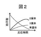
図2は、反応性粒子及び計測対象物質の反応時間の経過に伴う単量体~3量体の数の変化を示す模式図である。図2に示すように、凝集反応が進むことで、2量体数はある時間までは徐々に増加するが、3量体以上の凝集体が生成されることでやがて2量体数は低減する。したがって、非特許文献1に記載の方式のように封鎖電流量に基づき単量体と2量体の数を計数するだけでは、計測精度が低減しやすい。 FIG. 2 is a schematic diagram showing changes in the number of monomers to trimers with the passage of reaction time of the reactive particles and the substance to be measured. As shown in FIG. 2, as the agglutination reaction progresses, the number of dimers gradually increases until a certain time, but the number of dimers decreases due to the formation of aggregates of trimeric or more. .. Therefore, the measurement accuracy can be easily reduced only by counting the number of the monomer and the dimer based on the amount of the blocking current as in the method described in
そこで、本開示は、検体中の計測対象物質の濃度を正確に算出する技術を提供する。 Therefore, the present disclosure provides a technique for accurately calculating the concentration of the substance to be measured in the sample.
上記課題を解決するために、本開示の分析装置は、検体と、前記検体に含まれ得る計測対象物質に対して特異的に結合する物質が修飾された反応性粒子とを含む第1の溶液が導入される第1の区画と、第2の溶液が導入される第2の区画と、前記第1の区画と前記第2の区画を接続する細孔を備えた薄膜と、を有する計測容器と、前記第1の区画の内部に設けられた第1の電極と、前記第2の区画の内部に設けられた第2の電極と、前記第1の電極と前記第2の電極との間に電圧を印加する電圧源と、前記第1の電極と前記第2の電極との間に流れる電流を計測する電流計と、前記電流計により得られた電流データを処理するプロセッサと、を備え、前記プロセッサは、前記電流データから、前記反応性粒子が前記細孔を通過する際に生じる封鎖電流波形を抽出する処理と、前記封鎖電流波形に基づき、3つ以上の前記反応性粒子が凝集したときの凝集数を識別する処理と、単位時間中に前記細孔を通過した単量体、2量体及び3量体以上の凝集体の通過数に基づいて、前記検体中の前記計測対象物質の濃度を算出する処理と、を実行することを特徴とする。 In order to solve the above problems, the analyzer of the present disclosure includes a sample and a first solution containing reactive particles modified with a substance that specifically binds to a measurement target substance that can be contained in the sample. A measuring container having a first compartment into which a second compartment is introduced, a second compartment into which a second solution is introduced, and a thin film having pores connecting the first compartment and the second compartment. Between the first electrode provided inside the first compartment, the second electrode provided inside the second compartment, and the first electrode and the second electrode. A voltage source for applying a voltage to the current, a current meter for measuring the current flowing between the first electrode and the second electrode, and a processor for processing the current data obtained by the current meter are provided. The processor extracts the blockage current waveform generated when the reactive particles pass through the pores from the current data, and three or more of the reactive particles aggregate based on the blockage current waveform. The measurement target in the sample is based on the process of identifying the number of aggregates when the current is formed and the number of aggregates of the monomer, dimer, and trimer or more that have passed through the pores during a unit time. It is characterized by performing a process of calculating the concentration of a substance and performing.
本開示に関連する更なる特徴は、本明細書の記述、添付図面から明らかになるものである。また、本開示の態様は、要素及び多様な要素の組み合わせ及び以降の詳細な記述と添付される特許請求の範囲の様態により達成され実現される。
本明細書の記述は典型的な例示に過ぎず、本開示の特許請求の範囲又は適用例を如何なる意味に於いても限定するものではない。Further features relating to this disclosure will be apparent from the description herein and the accompanying drawings. In addition, the aspects of the present disclosure are achieved and realized by the combination of elements and various elements, the detailed description below, and the aspects of the appended claims.
The description of the present specification is merely a typical example, and does not limit the scope of claims or application examples of the present disclosure in any sense.
本開示の技術によれば、検体中の計測対象物質の濃度を正確に算出することができる。上記した以外の課題、構成及び効果は、以下の実施形態の説明により明らかにされる。 According to the technique of the present disclosure, the concentration of the substance to be measured in the sample can be accurately calculated. Issues, configurations and effects other than those described above will be clarified by the following description of the embodiments.
本開示の実施の形態を説明するための全図において、同一機能を有するものには同一の符号を付すようにし、その繰り返しの説明は可能な限り省略するようにしている。また、本開示は以下に示す実施の形態の記載内容に限定して解釈されるものではない。本開示の思想ないし趣旨から逸脱しない範囲で、その具体的構成を変更し得ることは当業者であれば容易に理解される。 In all the drawings for explaining the embodiments of the present disclosure, those having the same function are designated by the same reference numerals, and the repeated description thereof is omitted as much as possible. In addition, the present disclosure is not construed as being limited to the description of the embodiments shown below. It is easily understood by those skilled in the art that the specific composition can be changed without departing from the idea or purpose of the present disclosure.
図面等において示す各構成の位置、大きさ、形状、範囲などは、発明の理解を容易にするため、実際の位置、大きさ、形状、範囲などを表していない場合がある。このため、本開示は、必ずしも、図面等に開示された位置、大きさ、形状、範囲などに限定されない。本明細書で引用した刊行物、特許公報は、そのまま本明細書の説明の一部を構成する。本明細書において単数形で表される構成要素は、特段文脈で明らかに示されない限り、複数形を含むものとする。 The position, size, shape, range, etc. of each configuration shown in the drawings and the like may not represent the actual position, size, shape, range, etc. in order to facilitate understanding of the invention. Therefore, the present disclosure is not necessarily limited to the position, size, shape, range, etc. disclosed in the drawings and the like. The publications and patent gazettes cited herein constitute a part of the description of the present specification as they are. The components represented in the singular form herein are intended to include the plural, unless explicitly stated in the context.
以下の実施形態において、分析装置の一例として免疫分析装置について説明するが、本開示の技術は免疫分析装置以外の分析装置にも適用可能である。本開示の分析装置における計測に用いられる反応性粒子は、計測対象物質と特異的に結合する。このような結合には、例えば抗原抗体反応による結合、アビジン-ビオチン結合、磁気による結合など、任意の化学的結合及び物理的結合が含まれる。また、反応性粒子の表面には、計測対象物質と特異的に結合する物質が修飾されていてもよい。 In the following embodiment, the immunoassay device will be described as an example of the analyzer, but the technique of the present disclosure can be applied to an analyzer other than the immunoassay device. The reactive particles used for measurement in the analyzer of the present disclosure specifically bind to the substance to be measured. Such binding includes any chemical and physical binding, such as, for example, antigen-antibody reaction binding, avidin-biotin binding, magnetic binding, and the like. Further, the surface of the reactive particles may be modified with a substance that specifically binds to the substance to be measured.
[第1の実施形態]
<免疫分析装置の構成例>
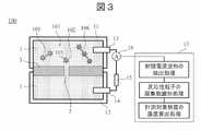
図3は、第1の実施形態に係る免疫分析装置100の構成例を示す模式図である。図3に示すように、免疫分析装置100は、薄膜3、第1の槽11(第1の区画)、第2の槽12(第2の区画)、第1の電極13、第2の電極14、電源装置15(電圧源)、電流計16及び演算処理部17(プロセッサ)を備える。[First Embodiment]
<Configuration example of immunoassay device>
FIG. 3 is a schematic diagram showing a configuration example of the
薄膜3には細孔2が設けられている。薄膜3は、片面が第1の槽11に配置され、もう一方の面が第2の槽12に配置されている。第1の槽11及び第2の槽12は、薄膜3によって分離され、細孔2を通じて連通している。これにより、薄膜3、第1の槽11及び第2の槽12により計測容器が構成される。第1の槽11及び第2の槽12には電解質を含む溶液1が充填されている。第1の槽11中の溶液1と第2の槽12中の溶液1とは、組成が異なっていてもよい。第1の電極13は第1の槽11の内部に設けられ、第1の槽11内の溶液1に接している。第2の電極14は第2の槽12の内部に設けられ、第2の槽12内の溶液1に接している。第1の電極13及び第2の電極14は配線と接合されており、電流計16へと電気信号が送られる。電流計16は、細孔2を通過する電流を計測する。電源装置15は、第1の電極13と第2の電極14との間に電圧を印加する。 The
第1の電極13及び第2の電極14は、溶液1中の電解質と電子授受反応(ファラデー反応)を行うことが可能な材質で作製することができ、典型的にはハロゲン化銀又はハロゲン化アルカリ銀で作製することができる。電位安定性及び信頼性の観点からは、第1の電極13及び第2の電極14として銀/銀塩化銀電極を使用することができる。第1の電極13及び第2の電極14は、分極電極となる材質で作製されてもよく、例えば金や白金などで作製されてもよい。その場合は、安定的なイオン電流を確保するために、溶液1に電子授受反応を補助することができる物質、例えばフェリシアン化カリウム又はフェロシアン化カリウムなどを添加することができる。あるいは、電子授受反応を行うことが可能な物質、例えばフェロセン類をその分極電極の表面に固定化することができる。第1の電極13及び第2の電極14の構造は、その全てが前記材質で構成されていてもよく、あるいは前記材質が銅、アルミニウムなどの下地材の表面に被覆されていてもよい。第1の電極13及び第2の電極14の形状は特に限定されるものではないが、溶液1と接液する表面積が大きくなる形状を採用することができる。 The
薄膜3の材質は、例えば半導体微細加工技術で細孔2を形成可能な無機材料とすることができる。このような無機材料として、典型的には窒化ケイ素、酸化ケイ素、酸化ハフニウム、二硫化モリブデン及びグラフェンなどが挙げられる。中でも、窒化ケイ素及び酸化ケイ素は、半導体プロセスで量産可能なSi化合物である。薄膜3に設けられる細孔2は、大量生産ができるよう半導体プロセスによって形成することができる。あるいは、ガラス管をピペット状に加工することで、微小体積を有する細孔を作製してもよい。あるいは、細孔2が設けられていない状態の薄膜3の両側に対し、電源装置15により電位差を印加することによって、絶縁破壊現象を利用して細孔2を形成することもできる。 The material of the
薄膜3は、支持基板により支持されていてもよい。例えば、725μmの厚さのシリコンの支持基板により、厚さ10μm以下、面積10mm2以下のSiNの薄膜3を支持したデバイスを使用することができる。The
少なくとも第1の槽11中の溶液1には、検体(検体中の計測対象物質101)と反応性粒子103とを反応させた物質が含まれる。また、溶液1は、イオン電流を計測できるように1mM以上の塩を含む溶液とすることができる。電流計測時におけるシグナルを向上させるためには、電気伝導度が上がるように塩濃度を高くすればよく、例えば10mM以上又は50mM以上とすることができる。溶液1に含まれるカチオンとしては、電離するカチオン類を用いることができ、典型的にはLi、Na、K、Rb、Cs、Mg、Ca、Sr及びBaなどの一族元素又は二族元素を用いることができる。溶液1に含まれるアニオンとしては、電離するアニオン類を用いることができ、電極の材質との相性によって選定することができる。例えば電極の材質としてハロゲン化銀を用いた場合、I、Br、Clなどのハロゲン化物のイオンをアニオンとして用いることができる。また、アニオンは、グルタミン酸イオン等に代表される有機アニオン類であってもよい。溶液1に含まれる検体と反応性粒子103は、第1の槽11及び第2の槽12の双方に含まれていても良いが、検体量の削減や試薬コストを考慮すると、片方のみに導入することもできる。 At least the
反応性粒子103の大きさは、反応確率を高めるために、例えば粒径10~100nm程度であってもよく、封鎖信号量を高めるためには粒径500~1000nmであってもよいが、典型的な免疫凝集法では、粒径100~500nm程度の粒子が用いられる。一般によく販売される粒径300nm程度の粒子を用いてもよい。反応性粒子103の材質には、典型的には比較的安価で使用例も多いラテックス粒子が用いられる。ただし、免疫検査装置等で広く用いられるB/F(Bound/Free)分離を実施できるように、超常磁性等の磁気特性を有する磁性粒子を用いてもよい。 The size of the
反応性粒子103は、計測対象物質101と抗原抗体反応により結合する。例えば抗原を計測対象物質101とする場合は、表面に抗体が修飾された反応性粒子103を用いることができる。このような抗体は抗原抗体反応によって凝集反応が生じるものであればよく、モノクローナル抗体であってもよいしポリクローナル抗体であってもよい。また、反応性粒子103には、異なる抗体が修飾された粒子が混在していてもよい。一方、抗体を計測対象物質101とする場合には、表面に抗原が修飾された反応性粒子103を用いることができる。また、反応性粒子103は表面電荷を帯びていてもよい。さらに、粒径や表面電荷が異なる複数種類の反応性粒子103の凝集反応を活用することで、複数種類の抗原又は抗体を異なる種類の反応性粒子103に反応させる方式を採用することもできる。異なる粒径を用いると細孔2の封鎖量の大きさが異なり、また表面電荷の大きさが異なることで細孔2の通過時間が異なるため、これを利用することで多項目の抗原又は抗体の濃度を同時に計測することが可能である。多項目同時検出により、1つの検体から複数項目を同時に計測できることから、試薬代の低コスト化、計測時間の短時間化、検体量の低減等の多方面における効果をもたらす。 The
免疫分析装置100に導入される検体と反応性粒子103の、第1の槽11又は第2の槽12への導入方法は、一態様としては、予め混合及び撹拌した後に第1の槽11又は第2の槽12に導入するものである。ただし、免疫分析装置100内に混合及び撹拌機構を一体化させて、第1の槽11又は第2の槽12内で、混合及び撹拌を実施してもよい。また、検体と反応性粒子103を反応させる前に、検体中に含まれる比較的大きな計測対象外の物質を除去する処理を施してもよい。一般に検体サンプル中には、血小板やタンパク質の凝集体等が多数含まれているため、これらを遠心分離処理等によって除去するとよい。また遠心分離以外にも、例えば400nm以下の物質や200nm以下の物質のみを通すようなフィルタ処理を施すことで、夾雑物由来の信号発生を抑制できる。このような遠心分離やフィルタ処理等を施した後に、検体を反応性粒子103と反応させることができる。 The method for introducing the sample and the
電流計16は、電圧の印加によって第1の電極13及び第2の電極14間に流れる電流を増幅するアンプと、増幅された電流信号(アナログ)をデジタル信号に変換するADコンバータ(Analog to Digital Converter)と、を有していてもよい。電流計16は、取得した電流データを演算処理部17に出力する。 The
演算処理部17は、電流計16からの電流データの入力を受け付け、電流データを処理する。演算処理部17は、電流データから反応性粒子103が細孔2を通過する時の電流波形(封鎖電流波形)を抽出する処理と、封鎖電流波形に基づいて反応性粒子103の凝集数を識別する処理と、計測対象物質101の濃度を算出する処理と、を実行する。これらの処理の詳細は後述する。演算処理部17は、単一の装置(プロセッサ)で構成されていてもよいが、例えば、一部の演算処理までは電気回路やFPGAで実装されており、残りの後段処理はPCで実装するといったように、複数の装置で実装する形態であってもよい。 The
電流計測の一態様としては、例えば、第1の電極13及び第2の電極14の端子に1~1000mV程度の電位差を与えることができる。第1の電極13及び第2の電極14の端子はアンプに接続して、利得106~1012倍程度、カットオフ周波数1kHz~10MHz程度で電圧信号に変換する。電圧信号は、ADコンバータによりサンプリング周波数10kHz~100MHz程度でデジタル信号に変換して、演算処理部17(PC等)に保存する。カットオフ周波数が大きくなると、高周波ノイズが増幅しやすいというトレードオフがあることから、カットオフ周波数は、特に10kHz~1MHzとすることができる。これに合わせて、サンプリング周波数は100kHz~10MHzとするとよい。細孔2を通過する電流の主成分は高周波ノイズであり、高周波ノイズは主にデバイス(薄膜3)の静電容量の大きさに依存することから、静電容量は可能な限り小さくするとよい。典型的には、デバイスの静電容量は1nF以下であるが、場合に応じて100pF以下、又は10pF以下とすることができる。静電容量の低減方法としては、一態様として、デバイスと溶液1との接液面積を狭める方法か、又はデバイス表面に絶縁膜を塗布する方法を用いることができる。As one aspect of current measurement, for example, a potential difference of about 1 to 1000 mV can be applied to the terminals of the
<電流データの処理方法>
(i)封鎖電流波形の抽出
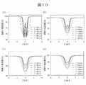
図4Aは、反応性粒子103の単量体、2量体及び3量体、並びに異常サイズの反応性粒子103が細孔2を通過する様子と、そのときに得られる電流データを示す模式図である。図4Aにおいては、一例として、単量体(a)、2量体(b)、3量体(c)及び異常サイズ(d)の順に細孔2を通過した場合の電流データが示されている。図4Aの電流データに示すように、反応性粒子103が細孔2を通過すると、細孔2が封鎖されることにより電流が低下し、このときの電流波形(封鎖電流波形)は反応性粒子103の凝集数や大きさに応じて異なっている。<Current data processing method>
(I) Extraction of blocking current waveform FIG. 4A shows a state in which the monomer of the
演算処理部17は、得られた電流データから封鎖電流波形を抽出することによって、より効率的に後段処理を進めることができる。封鎖電流波形の抽出方法としては、例えば、細孔2を通過する電流量(=ベース電流量)からある閾値以上の変動が生じたときに細孔2中を物体が通過したと判断し、このときの波形を封鎖電流波形として抽出することができる。 The
(ii)反応性粒子の凝集数識別
図4Bは、抽出された封鎖電流波形の代表的な例を示す模式図である。演算処理部17は、抽出された封鎖電流波形に基づいて、細孔2を通過した反応性粒子103の凝集数を識別する。(Ii) Identification of Aggregation Number of Reactive Particles FIG. 4B is a schematic diagram showing a typical example of the extracted blockage current waveform. The
なお、反応性粒子103の凝集数を識別する処理の前又は同時に、細孔2を通過した物体が評価対象の反応性粒子103であるか、その他の物質であるかの判定を行うことができる。溶液1中には異常サイズの粒子や検体由来のタンパク質等が含まれており、これらの夾雑物由来の封鎖信号が発生する。こうした夾雑物由来の封鎖信号を評価対象から除外する信号処理を行うことにより、凝集数の識別処理の精度を向上させることができる。 Before or at the same time as the process of identifying the number of aggregates of the
演算処理部17は、少なくとも3つ以上の反応性粒子103の凝集数を識別する。演算処理部17は、封鎖電流波形から得られる複数の特徴量を用いて凝集数を識別することができる。図4Bに示すように、封鎖電流波形の特徴量の一例としては、封鎖電流波形の極大値における時間及び電流値、封鎖電流波形の極小値における時間及び電流値、封鎖電流波形の最大変動幅(=封鎖電流量)などが挙げられる。非特許文献1に記載の方法のように、封鎖電流量のみを特徴量に用いると、各凝集体と同程度の体積を持つ物質(コンタミネーション)が細孔2を通過した際に、凝集体とコンタミネーションとの区別が困難になる。比較的サイズが揃っているサイズ標準粒子を用いても、図4Aの(d)に示すような体積3~4倍程度の異常サイズの反応性粒子103が僅かに含まれるため、封鎖電流量のみによる凝集数の識別では、細孔2を通過した物体が異常サイズの反応性粒子103であるか、通常サイズの反応性粒子103の凝集体であるかを正確に識別することは困難である。そのため、演算処理部17は、封鎖電流量だけではなく、時間変化する波形の形状に基づいて、反応性粒子103の凝集数を識別することができる。例えば、細孔2の封鎖の開始から例えば0.01秒後の電流値、0.1秒後の電流値といった、封鎖電流波形全体のうち特定の時刻の電流値を複数点取得して、得られる特徴量を用いることができる。本実施形態では、一例として、反応性粒子103の凝集数の数だけピーク値(極大値)が出現するような波形を取得し、封鎖電流波形中に占める極大値の数によって凝集数を識別する手法を説明する。 The
後述するように、細孔2の寸法を適切にコントロールすることによって、複数の反応性粒子103が一本の鎖状に繋がった凝集体が細孔2を通過する時、1つの封鎖電流波形中に凝集数の数だけ下に凸のピークが生じる。反応性粒子103の中心部が細孔2を通過する時、すなわち細孔2の内部に占める反応性粒子103の体積比率が大きい時に、最も電流値が減少する(極小値が得られる)。これに対し、反応性粒子103同士の接合部にあたる箇所が細孔2を通過する時に電流値が一時的に増加する(極大値が得られる)。図4B(a)に示すように、単一の反応性粒子103が細孔2を通過した場合は単一ピークが生じ、図4B(b)に示すように、2つの反応性粒子103の凝集体が細孔2を通過した場合は2ピークが生じ、図4B(c)に示すように、3つの反応性粒子103の凝集体が細孔2を通過した場合は3ピークが生じており、以下同様に凝集数の数だけピーク数が増加する。図4B(d)に示すように、異常サイズの反応性粒子103が細孔2を通過した場合には、ピークの封鎖電流量は増加するものの、ピーク数は1つであるため、2粒子や3粒子の凝集体による封鎖電流波形と区別できる。このように、演算処理部17は、ピーク数(極大値の数)と封鎖電流量とに基づいて、細孔2を通過した反応性粒子103の凝集数を識別することができる。演算処理部17には、ソフトウェアによる自動識別アルゴリズムを構築してもよく、この場合は、前処理として移動平均フィルタ等で封鎖電流波形を平滑化した後、閾値等を設定して極大値と極小値を識別することができる。 As will be described later, by appropriately controlling the dimensions of the
なお、極大値の数によって凝集数を識別する手法を説明したが、当然のことながら、複数の極小値及び極大値を検出して、それらの電流値又は時間に基づいて凝集数を識別するようにしてもよい。また、実際の計測で得られる電流データから、極小値及び極大値が誤って検出される場合もあり、このような誤った情報も用いて機械学習等により凝集数を識別するようにしてもよい。 Although the method of identifying the number of aggregates by the number of maximum values has been described, it is natural that a plurality of minimum and maximum values should be detected and the number of aggregates should be identified based on their current values or time. You may do it. In addition, the minimum value and the maximum value may be erroneously detected from the current data obtained by actual measurement, and the number of aggregates may be identified by machine learning or the like using such erroneous information. ..
上記した以外の封鎖電流波形の特徴量として、封鎖電流波形全体の時間(細孔2の封鎖による電流値の立ち下りの開始時から立ち上がりの終了までの時間)、封鎖電流波形の中間時刻での封鎖電流値、ピークの半値幅、異なる点間の電流値の差分又は積分値等の特徴量を用いてもよく、複数の特徴量の組み合わせにより凝集数を識別してもよい。さらに、その他の手法として、封鎖電流波形のデータ全体を入力として、凝集数を識別するような機械学習を用いたアプローチであってもよく、データベース中に保存されている封鎖電流波形との相関性から凝集数を識別するアルゴリズムであってもよい。 The characteristic quantities of the blockage current waveform other than the above are the time of the entire blockage current waveform (the time from the start of the fall of the current value due to the blockage of the
(iii)計測対象物質の濃度の算出
演算処理部17は、単位時間中に細孔2を通過した各凝集体の通過数に基づいて、検体中の計測対象物質の濃度を算出する。より具体的には、単位時間中に細孔2を通過した全反応性粒子103中に占める各凝集体の通過数の比率に基づいて、検体中の計測対象物質の濃度を算出することができる。この場合、演算処理部17は、細孔2を通過した各反応性粒子103の凝集数を識別した後、例えば次式(1)によって凝集体比率nを算出する。(Iii) Calculation of Concentration of Substance to be Measured The

ただし、Nkは単位時間中に細孔2を通過したk量体の数であり、mは評価対象とする最大凝集数であり、3以上の整数とする。式(1)の分母は封鎖イベントの総数を示しており、分子は反応性粒子103間の結合部の総数(=計測対象物質の数)を示している。凝集体比率nを精度よく算出するためには、式(1)のようにk量体に(k-1)個の結合部があることを考慮する必要があるため、各k量体の数Nkを正確に計数する必要がある。このように各封鎖イベント中に占める結合部数を考慮した算出方法により、正確な凝集体比率nを算出できる。However, Nk is the number of k-dimers that have passed through the
図4Cは、検体中の計測対象物質の濃度を算出する方法を説明するためのグラフである。図4Cは、反応時間毎に得られた反応性粒子103の凝集数のデータから凝集体比率nを算出し、グラフ中にプロットしたものである。図4C中の点線は、それぞれ計測対象物質の濃度1、10、100及び1000pmol/Lでのキャリブレーションデータを示している。演算処理部17は、予め取得した反応曲線や、反応曲線式より予測される理論曲線に対し、計測データ(算出した凝集体比率n)をフィッティングさせることで、計測対象物質の濃度を推定できる。図4Cに示す例では、未知濃度の計測対象物質を含む検体のデータ(#1~4)をプロットしており、プロット点が濃度10pmol/Lの反応曲線に従ったことから、計測対象物質の濃度が10pmol/Lであると推定できる。 FIG. 4C is a graph for explaining a method of calculating the concentration of the substance to be measured in the sample. FIG. 4C shows an aggregate ratio n calculated from the data of the number of aggregates of the
ある一点のデータのみで計測対象物質の濃度を推定しても良く、例えば、反応が収束したエンドポイントにあたる#4のデータのみを用いて、濃度を推定してもよい。ただし、反応時間が異なる2点以上のデータに基づいて濃度を推定することで、精度を向上することができる。なお、凝集体比率nの反応曲線理論式は、反応時間や溶液状態によって異なるが、時間(t)に対して線形に変化する式(n(t)=αt、αは比例定数)、及び、指数関数に従う式(n(t)=nend(1-exp(-kt)、nendは終状態での凝集体比率、kは反応速度定数)等が考えられる。The concentration of the substance to be measured may be estimated using only the data at a certain point, and for example, the concentration may be estimated using only the data of # 4, which is the endpoint where the reaction has converged. However, the accuracy can be improved by estimating the concentration based on the data of two or more points having different reaction times. The reaction curve theoretical formula of the aggregate ratio n varies depending on the reaction time and the solution state, but it changes linearly with respect to time (t) (n (t) = αt, α is a proportional constant), and An equation according to an exponential function (n (t) =nend (1-exp (-kt),nend is the aggregate ratio in the final state, k is the reaction rate constant) and the like can be considered.
なお、計測対象物質の濃度を簡易に推定するため、各凝集体の数から凝集体比率nを算出する方法を説明したが、計測対象物質の濃度を推定する際に凝集体比率nの算出は必須ではない。例えば、様々な濃度の計測対象物質を含むサンプルを用いて、各サンプルにて所定の反応時間毎に得られる単量体、2量体、3量体及び4量体等の比率をデータセットとして予め取得しておくといった手法も採用することができる。この手法の場合には、演算処理部17は、未知濃度のサンプルを計測した際に、所定の反応時間毎に得られる単量体、2量体、3量体及び4量体等の比率に基づく多次元パラメータを入力値として、例えば機械学習等を用いて計測対象物質の濃度を推定することができる。本手法は、予め多数のデータセットを用意しておく必要があるものの、凝集体比率nを算出する手法と比較して、より高精度な濃度計測が可能となる。 In order to easily estimate the concentration of the substance to be measured, the method of calculating the agglomerate ratio n from the number of each agglomerate has been described. However, when estimating the concentration of the substance to be measured, the agglomerate ratio n is calculated. Not required. For example, using samples containing substances to be measured at various concentrations, the ratio of the monomer, dimer, trimer, tetramer, etc. obtained in each sample for each predetermined reaction time is used as a data set. It is also possible to adopt a method such as acquiring in advance. In the case of this method, the
<反応性粒子の凝集体の構造>
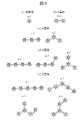
図5は、複数の反応性粒子103が凝集した状態を説明するための模式図である。立体的な回転を考慮すると、図5(a)及び(b)に示すように、単量体と2量体は単一構造のみを取りうるのに対して、図5(c)~(e)に示すように、3量体以上では、反応性粒子103同士の結合方向によって、複数種類の構造を取りうる。図5(c)に示す3量体を例にとると、一直線に繋がった3量体c-1だけでなく、3量体c-2のように折れ曲がった構造も取りうる。ただし、3量体c-2のような構造も一本の鎖状構造であるため、立体的な回転をしながら細孔2中を通過し、図4B(c)に示したような、3つのピークを有する封鎖電流波形が得られる。これらに対して、図5(d)に示すように、4粒子になると、4量体d-3のように1粒子の周囲(3方向)に粒子が結合した状態が発生する。細孔2の直径が粒径と同程度(2倍以下)である場合には、4量体d-3の構造の凝集体は細孔2を通過できずに、細孔2を閉塞させる。5粒子以上の状態においても同様であり、5量体e-3及びe-4のような構造は、細孔2を通過せずに閉塞させる。このように、多数の粒子が凝集すると、一本の鎖状構造を形成する確率は低下するため、極端に大きな凝集塊においては、その凝集数を識別することは困難である。本発明者らの実験によると、式(1)における最大凝集数mを4~6程度に設定することにより、凝集数の識別が容易となる。また、式(1)は、3量体以上の凝集体数を計測できた場合における凝集体比率計算の一例であり、計算式は必ずしもこの方法に限定されない。例えば、式(1)の分母及び分子の各パラメータに、ある定数等を加算、減算、乗算又は除算等を施した場合にも、同様の効果が得られる。<Structure of agglomerates of reactive particles>
FIG. 5 is a schematic diagram for explaining a state in which a plurality of
<細孔の寸法>
細孔2の直径(薄膜3の表面に沿った方向の寸法)は、典型的には50~5000nm程度とすることができ、細孔2の厚さは例えば1~10μm程度とすることができるが、封鎖電流波形中の極小値及び極大値を高精度に検出するためには、細孔2の寸法を適切に設定する必要がある。後述の実験例に示すとおり、極小値と極大値との電流値差分が、細孔2を通過する電流量(ベース電流量)の少なくとも1%以上となるためには、細孔2の直径は粒径の1.7倍以下、厚さは粒径の0.7倍以下とすることができる。また、極小値と極大値との電流値差分をベース電流量の5%以上とするためには、細孔2の直径は粒径の1.4倍以下、厚さは粒径の0.35倍以下とすることができる。細孔2の直径を粒径の2倍以上に設計すると、2つ以上の粒子が細孔2を水平方向に並んだ状態で通過するため、例えば図5(d)に示す4量体d-3、図5(e)に示す5量体e-3及びe-4のような鎖状構造でない凝集体も通過するため、封鎖信号の種類が多岐に渡り、通過物体の推定が極めて困難になる。そのため、このように細孔2の直径を小さく設定することは非常に重要である。また、細孔2の直径を小さくするほど、反応性粒子の通過位置の水平方向のばらつきを低減できるという利点も有する。一方で、細孔2の直径が小さいほど不純物、粒子凝集体、複数粒子の同時通過現象等によって細孔2が閉塞しやすいため、典型的には細孔2の直径は粒径の1.05倍以上とすることができる。細孔2の厚さについても、薄くなるほど通過物体の形状をより高分解能に計測できる利点があるが、薄くなるほど細孔2の製造時に壊れやすいといったトレードオフがあるため、典型的には厚さ1nm以上とすることができる。<Dimensions of pores>
The diameter of the pores 2 (dimensions along the surface of the thin film 3) can typically be about 50 to 5000 nm, and the thickness of the
<免疫分析装置の他の構成例>
図6は、他の免疫分析装置200の構成例を示す模式図である。免疫分析装置200は、第1の槽11に圧力制御機構21が設けられ、第2の槽12が大気圧開放されている点で、図3に示した免疫分析装置100と異なっている。その他の構成については免疫分析装置100と同様である。<Other configuration examples of immunoassay device>
FIG. 6 is a schematic diagram showing a configuration example of another
図6に示すように、圧力制御機構21は、例えば加圧ポンプとすることができる。反応性粒子103を細孔2に通す際に、圧力制御機構21を用いて圧力勾配を与えて反応性粒子103を搬送させることができる。反応性粒子103(ラテックス粒子)は一般に負電荷を帯びていることから、電圧勾配を与えることで電気泳動によっても搬送できるが、例えば粒径50nm以上では、圧力勾配を与えることで、より効率よく反応性粒子103を搬送できる。圧力勾配の与え方としては、例えば反応性粒子103を細孔2中に導入する方向に圧力を与えることができる(図6では第1の槽11から第2の槽12に反応性粒子103が流れるように、圧力勾配を設定する)。圧力制御機構21の動作は、演算処理部17により制御することができるが、ユーザがマニュアルで制御してもよい。 As shown in FIG. 6, the
圧力を与える機構は、ポンプによる圧力制御を用いてもよいが、細孔2の上下に満たした水溶液量(液面高さ)に差を生じさせることで、圧力流を与えてもよい。図6では、第2の槽12を大気圧に開放し、第1の槽11を加圧することで圧力流を与えているが、圧力の与え方はこの限りではない。例えば、第1の槽11を大気圧開放して、第2の槽12に陰圧を与えるといった方法でも良い。圧力勾配の大きさは、0.1~1000hPa程度とすることができる。電気泳動や圧力勾配以外の反応性粒子103の搬送方法として、反応性粒子103の自重を活用する方法や、細孔2の上下に満たした溶液1に濃度勾配を与えるといった手法等であってもよい。圧力勾配を高めすぎると、反応性粒子103の通過速度が速くなり、前述したような複数ピークの波形を捉えることが困難になる。本発明者らの実験の結果、反応性粒子103の通過時間を0.01~1ms程度に調整することにより、通過速度、頻度ともに効率よく計測できることが分かった。 As the mechanism for applying pressure, pressure control by a pump may be used, but a pressure flow may be applied by causing a difference in the amount of aqueous solution (liquid level height) filled above and below the
図7は、他の免疫分析装置300の構成例を示す模式図である。免疫分析装置300は、第1の槽11に温調機構22が設けられている点で、図6に示した免疫分析装置200と異なっている。図7に示すように、温調機構22を用いて溶液1の温度を調整することにより、第1の槽11内の検体と反応性粒子103とを効率よく反応させることができる。温調機構22としては、例えば簡便な機構であるペルチェ等を用いることができる。あるいは、ヒーターを用いて、計測容器(薄膜3、第1の槽11及び第2の槽12)全体の雰囲気温度を調整してもよい。温調機構22の出力は、演算処理部17により制御することができる。目標温度は、抗原抗体反応を促進可能な温度であり、一般には37℃(±2℃)程度に設定する。計測方法の一例としては、この37℃の温度条件下にて抗原抗体反応を進めながら、同時並行で圧力制御機構21によって反応性粒子103を細孔2中に導入し、封鎖電流波形を電流計16によって計測する方法である。電流計測、反応及び圧力勾配印加を同時に実行することで、より短時間で計測結果を出力することができるが、例えばシーケンシャルに動作するようにしてもよい。具体的には、温調機構22により一度37℃に保って検体と反応性粒子103とを一定時間反応させた後に、温度を下げて反応を止め、圧力制御機構21により圧力勾配印加をさせながら電流計測を行う方法が挙げられる。この場合、一度反応を止めているため、所定時間反応させたときの凝集体比率をより高精度に計測できる利点がある。 FIG. 7 is a schematic diagram showing a configuration example of another
以上説明した免疫分析装置100~300では、いずれも単一の細孔2を用いた計測方法を採用していたが、2個以上の複数の細孔2を用いて計測するようにしてもよい。本実施形態の手法では、単位時間あたりに得られた封鎖イベント中に占める、凝集体の通過イベントの比率を算出する。水溶液中に占める計測対象物質の濃度が薄い場合や、反応初期段階では、凝集体比率は0.1%程度以下と非常に低濃度になりうることから、凝集体比率を正しく算出するためには、十分な数の封鎖イベントを得る必要がある。封鎖イベント数を増やす方法としては、圧力勾配を高めて細孔2への導入効率を高める方法も有効であるが、同時に粒子通過速度も速くなるため、封鎖信号の判定が困難になりやすい。これに対し、細孔2の数を増やす手法は、圧力勾配を与える手法と比較して、簡易に通過イベント数を増加できる。細孔2の数は、例えば4以上、場合に応じて10以上とすることができる。低濃度サンプルでも計測できることは、免疫計測において重要度が高く、また、反応初期段階でも凝集体比率を算出できることは、計測時間を短縮させる利点もある。 In the
図8は、他の免疫分析装置400の構成例を示す模式図である。免疫分析装置400においては、薄膜3に複数(図8では3つ)の細孔2が設けられている。また、第2の槽12に複数の隔壁41と複数の第2の電極14が設けられ、各細孔2に対して個別チャンバが形成されている。第1の槽11は全ての細孔2に対して共通チャンバとし、第1の槽11側に検体(計測対象物質)が導入される。計測時には、圧力制御機構21により共通チャンバ全体を加圧することで、全ての細孔2に同時に反応性粒子103を導入できる。第1の槽11にも個別チャンバを設ける構造としてもよいが、その場合、個別チャンバへの検体サンプル導入や圧力制御機構が困難になる。図8に示すように、共通チャンバと個別チャンバを用いた構成とすることで、複数の細孔2を用いた計測を簡便に実現できる。 FIG. 8 is a schematic diagram showing a configuration example of another
<第1の実施形態のまとめ>
以上のように、第1の実施形態の免疫分析装置は、検体と、検体に含まれ得る計測対象物質101に対して特異的に結合する物質が修飾された反応性粒子103とを含む溶液1(第1の溶液)が導入される第1の槽11(第1の区画)と、溶液1(第2の溶液)が導入される第2の槽12(第2の区画)と、第1の槽11及び第2の槽12を接続する細孔2を有する薄膜3と、第1の槽11の内部に設けられた第1の電極13と、第2の槽12の内部に設けられた第2の電極14と、第1の電極13と第2の電極14との間に電圧を印加する電源装置15(電圧源)と、第1の電極13と第2の電極14との間に流れる電流を計測する電流計16と、電流計16により得られる電流データを処理する演算処理部17(プロセッサ)と、を備える。演算処理部17は、電流データから、反応性粒子103が細孔2を通過する際に生じる封鎖電流波形を抽出する処理と、封鎖電流波形に基づき、3つ以上の反応性粒子が凝集したときの凝集数を識別する処理と、単位時間中に細孔2を通過した単量体、2量体及び3量体以上の凝集体の通過数に基づいて、検体中の計測対象物質101の濃度を算出する処理と、を実行する。<Summary of the first embodiment>
As described above, the immunoanalyzer of the first embodiment is a
このように、単量体及び2量体だけでなく、3量体以上の凝集体(多量体)を個々にカウントし、計測対象物質101の濃度の算出に用いることにより、単量体及び2量体の数のみを用いる場合と比較して、計測対象物質の濃度をより正確に計測することができる。 In this way, not only the monomers and dimers but also aggregates (multimers) of trimers or more are individually counted and used to calculate the concentration of the
また、反応性粒子103の各凝集体の数から、式(1)により凝集体比率n(単位時間中に細孔2を通過した全反応性粒子中に占める単量体、2量体及び3量体以上の凝集体の通過数の比率)を算出することにより、凝集体比率nという1つの情報を用いて計測対象物質の濃度を推定することができるので、処理が簡単である。したがって、演算処理部17の製造コストも抑制できる。 Further, from the number of each aggregate of the
[実験例]
以下、第1の実施形態の効果を検証した実験例(計算例)を示す。以下で述べる検討では、薄膜3として、細孔を有するSiN膜を用い、反応性粒子103として粒径290nmのラテックス粒子を用いた場合について説明するが、その他の細孔や粒子を用いた場合においても同様の結果を期待できる。[Experimental example]
Hereinafter, an experimental example (calculation example) for verifying the effect of the first embodiment is shown. In the study described below, a case where a SiN film having pores is used as the
<実験例1:細孔の寸法の検証>
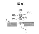
図9は、反応性粒子103の2量体105が細孔2の中心を通過するときの断面模式図である。図9において、鉛直上向き方向をZ軸と定義し、原点を細孔2の中心とした。計測対象物質の大きさは、反応性粒子に対して十分に小さいため、図9では計測対象物質の図示を省略した。2量体105の重心位置(結合部)の座標z(μm)をZ軸方向に掃引して、細孔2を通過する電流量を、マクスウェル方程式を用いて計算した。<Experimental example 1: Verification of pore dimensions>
FIG. 9 is a schematic cross-sectional view when the
図10は、実験例1における細孔2を通過する電流量のシミュレーション結果を示すグラフである。図10(a)~(d)は、それぞれ細孔2の直径D[nm]が300nm(a)、400nm(b)、500nm(c)及び600nm(d)の4つの条件のシミュレーション結果を示している。細孔2の直径の各条件について、細孔2の厚さT[nm]を25nm、50nm、100nm、200nm、400nm及び800nmに設定して、各設定で得られる電流量を計算した。図10の横軸は2量体105の重心位置の座標zを示し、縦軸はベース電流量を基準(=100%)としたときの規格化電流値を示している。本シミュレーション結果から、直径D及び厚さTが小さい値のときに、極小値と極大値との差分は大きくなることが分かった。極大値と極小値の差分を1%以上とするためには、直径Dは500nm以下(粒径の1.7倍以下)、厚さTは200nm以下(粒径の0.7倍以下)である必要があることがわかる。また極大値と極小値の差分を5%以上とするためには、直径Dは400nm以下(粒径の1.4倍以下)、厚さTは100nm以下(粒径の0.35倍以下)である必要があることがわかる。本結果から、免疫分析装置に用いる最適な細孔2の寸法を確認できた。 FIG. 10 is a graph showing a simulation result of the amount of current passing through the
<実験例2:封鎖電流波形の抽出及び凝集体比率nの算出>
図10のシミュレーション結果を踏まえて、細孔2の寸法を厚さ35nm、直径400nmに設計して、計測対象物質の濃度を変えたときに得られる封鎖電流波形を計測した。本実験例2では、計測対象物質(AFP抗原)濃度が2.25pmol/L、22.5pmol/L及び225pmol/Lになるようトリス緩衝生理食塩水(TBS)中で調整した。本実験例2においては、シリンジポンプ(圧力制御機構)を用いて、第1の槽11及び第2の槽12間に1~20hPa程度の圧力勾配を与え、反応性粒子の通過時間が0.01~1msになるように調整した。温調機構により計測容器全体を37℃の恒温槽内に配置し、恒温槽内で反応性粒子と計測対象物質とを免疫凝集させながら、同時にシリンジポンプで圧力勾配を印加して反応生成物を細孔内に搬送した。電流計測時のカットオフ周波数は34kHzに設定し、サンプリング周波数は500kHzに設定した。<Experimental example 2: Extraction of blockage current waveform and calculation of aggregate ratio n>
Based on the simulation results of FIG. 10, the dimensions of the
図11は、実験例2において得られた封鎖電流波形の一例を示すグラフである。電流データから封鎖電流波形を抽出する際には、一定の閾値(本実験例2では5nA程度)以上の封鎖電流量を有する封鎖イベントを抽出した。また、得られた封鎖電流波形に移動平均フィルタによる波形平滑化処理を施し、極小値及び極大値をソフトウェアのプログラムで自動抽出した。図11(a)~(d)の各封鎖電流波形に含まれる極小値及び極大値の数は、順に1つずつ大きくなり、それぞれ(a)単量体、(b)2量体、(c)3量体、(d)4量体を反映したものと考えられる。本結果から封鎖電流波形を自動抽出でき、また凝集状態を反映した複数ピークを有する封鎖電流波形が得られることを確認できた。 FIG. 11 is a graph showing an example of the blockage current waveform obtained in Experimental Example 2. When extracting the blocking current waveform from the current data, a blocking event having a blocking current amount equal to or higher than a certain threshold value (about 5 nA in this experimental example 2) was extracted. Further, the obtained blockage current waveform was subjected to waveform smoothing processing by a moving average filter, and the minimum value and the maximum value were automatically extracted by a software program. The number of minimum values and maximum values included in each of the blockage current waveforms of FIGS. 11 (a) to 11 (d) increases by one in order, and the (a) monomer, (b) dimer, and (c) are respectively. ) It is considered to reflect the trimer and (d) tetramer. From this result, it was confirmed that the blockage current waveform could be automatically extracted and that the blockage current waveform having multiple peaks reflecting the aggregated state could be obtained.
次に、計測対象物質の濃度2.25pmol/L、22.5pmol/L及び225pmol/Lの各条件で、それぞれ単位時間中に得られた全封鎖電流波形を、ソフトウェア処理により単量体~4量体又は粒子以外信号と判定した。さらに、反応時間毎に、式(1)より凝集体比率nを算出し、パーセントに換算した。 Next, the total blockage current waveforms obtained during the unit time under the conditions of the concentration of the substance to be measured of 2.25 pmol / L, 22.5 pmol / L and 225 pmol / L were subjected to software processing to obtain a monomer to 4 of the total block current waveform. It was determined to be a signal other than a substance or a particle. Further, for each reaction time, the aggregate ratio n was calculated from the formula (1) and converted into a percentage.
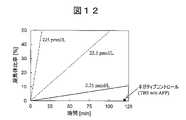
図12は、実験例2において計測対象物質濃度ごとに得られた凝集体比率n(%)の近似直線を示すグラフである。図中のネガティブコントロールのプロットは、計測対象物質を含まないサンプル(トリス緩衝生理食塩水)の結果を示したものである。本結果から明らかなとおり、計測対象物質濃度の増加に伴って、凝集体比率nの増加速度(傾き)は単調に増加した。図12に示す各近似直線をキャリブレーションデータとして用いて、計測対象物質が未知濃度含まれる検体の計測時に算出される凝集体比率nのデータをフィッティングすることで、濃度を推定することが可能である。本結果から、抗原抗体反応を起こしながら、リアルタイムで凝集体比率nを計測して、計測対象物質の濃度を算出できることを確認できた。 FIG. 12 is a graph showing an approximate straight line of the aggregate ratio n (%) obtained for each concentration of the substance to be measured in Experimental Example 2. The plot of the negative control in the figure shows the result of the sample (Tris buffered saline) containing no substance to be measured. As is clear from this result, the rate of increase (slope) of the aggregate ratio n increased monotonically as the concentration of the substance to be measured increased. Using each approximate straight line shown in FIG. 12 as calibration data, it is possible to estimate the concentration by fitting the data of the aggregate ratio n calculated at the time of measurement of the sample containing the unknown concentration of the substance to be measured. be. From this result, it was confirmed that the concentration of the substance to be measured can be calculated by measuring the aggregate ratio n in real time while causing the antigen-antibody reaction.
<実験例3:模擬検体を用いた凝集体比率の算出>
模擬検体(血漿サンプル溶液)中に計測対象物質(AFP抗原)を22.5pmol/L溶かし、細孔2の寸法及び計測条件を実験例2と同様にして、反応時間毎の凝集体比率nを式(1)により算出した。なお、模擬検体には予め孔径100nmのシリンジフィルタを適用して、検体中に含まれるタンパク質や血小板等の異物は除去した後、反応性粒子と混和した。また、比較例として、従来法と同様に単量体の数(N1)と2量体の数(N2)のみを用いて凝集体比率(n=N2/(N1+N2))を算出した。<Experimental example 3: Calculation of aggregate ratio using simulated sample>
The substance to be measured (AFP antigen) was dissolved in a simulated sample (plasma sample solution) at 22.5 pmol / L, the dimensions of the
図13は、実験例3及び比較例に係る凝集体比率の算出結果を示すグラフである。図13から明らかなとおり、比較例のように単量体と2量体の数のみで凝集体比率を計算した際には、時間経過に伴って途中で凝集体比率が減衰したのに対して、式(1)を用いて算出すると、単調に増加する様子が得られた。本実験に用いた模擬検体は、トリス緩衝生理食塩水と比較して塩濃度が高いために短時間で反応が進み、2量体だけでなく3量体以上の凝集体が速やかに生成された。図13において、20分を超えた時点では、2量体数は減少傾向に転じており、したがって比較例における凝集体比率の値が減少した。このように、2量体数から凝集体比率を算出すると、時間経過に伴って減少する場合があることから、濃度計測の精度が低減しやすい。特に、計測対象物質の濃度が高い検体になるほど(例えば1nmol/L程度)、2量体比率は減少傾向に転じやすく、1分未満の反応時間で2量体比率がピーク値に到達して減衰することも想定できる。一般に凝集体比率nを算出するためには、1000個以上の封鎖イベントを取得する必要があり、これには数秒~数十秒以上の計測時間を要する。そのため、短時間で減少傾向に転じやすい2量体比率のみでは、高濃度サンプルの凝集体比率及び計測対象物質濃度を精度よく算出することは困難である。一般に免疫分析装置ではダイナミックレンジは2~3桁以上、検査項目によっては4桁以上必要な場合もあり、高濃度帯域のサンプルも精度よく計測できることは非常に重要である。本結果から、2量体だけでなく3量体以上の凝集体も計数し、また3量体以上の凝集体数を用いて濃度判定するという、本開示の手法の有効性が示された。 FIG. 13 is a graph showing the calculation results of the aggregate ratio according to Experimental Example 3 and Comparative Example. As is clear from FIG. 13, when the aggregate ratio was calculated only by the number of monomers and dimers as in the comparative example, the aggregate ratio decreased in the middle with the passage of time. , When calculated using the equation (1), it was obtained that the increase was monotonous. Since the simulated sample used in this experiment had a higher salt concentration than Tris-buffered saline, the reaction proceeded in a short time, and not only dimers but also aggregates of trimers or more were rapidly produced. .. In FIG. 13, after 20 minutes, the number of dimers turned to a decreasing tendency, and therefore the value of the aggregate ratio in the comparative example decreased. As described above, when the aggregate ratio is calculated from the number of dimers, it may decrease with the passage of time, so that the accuracy of concentration measurement is likely to be reduced. In particular, the higher the concentration of the substance to be measured (for example, about 1 nmol / L), the more easily the dimer ratio tends to decrease, and the dimer ratio reaches the peak value and attenuates in a reaction time of less than 1 minute. It can be assumed that it will be done. Generally, in order to calculate the aggregate ratio n, it is necessary to acquire 1000 or more blockade events, which requires a measurement time of several seconds to several tens of seconds or more. Therefore, it is difficult to accurately calculate the aggregate ratio of the high-concentration sample and the concentration of the substance to be measured only by the dimer ratio that tends to decrease in a short time. In general, an immunoassay device requires a dynamic range of 2 to 3 digits or more, and depending on the test item, 4 digits or more may be required, and it is very important to be able to accurately measure a sample in a high concentration band. From this result, the effectiveness of the method of the present disclosure, in which not only the dimer but also the aggregates of the trimer or more are counted and the concentration is determined by using the number of aggregates of the trimer or more, is shown.
以上の実験例では、特定の寸法及び材質の細孔、粒子、並びに検体を用いた場合の実験結果を例示したが、当然のことながら、本開示の技術は上述の実験例に限定されるものではない。例えば、細孔と粒子の寸法比率が同様であれば、各実験例とはサイズの異なる細孔及び粒子を用いても、同様の結果が得られる。 In the above experimental examples, the experimental results when pores, particles, and specimens of specific dimensions and materials are used are exemplified, but as a matter of course, the technique of the present disclosure is limited to the above-mentioned experimental examples. is not. For example, if the dimensional ratios of the pores and the particles are the same, the same results can be obtained even if the pores and particles having different sizes from those of the experimental examples are used.
[変形例]
本開示は、上述した実施形態に限定されるものでなく、様々な変形例を含んでいる。例えば、上述した実施形態は、本開示を分かりやすく説明するために詳細に説明したものであり、必ずしも説明した全ての構成を備える必要はない。また、ある実施形態の一部を他の実施形態の構成に置き換えることができる。また、ある実施形態の構成に他の実施形態の構成を加えることもできる。また、各実施形態の構成の一部について、他の実施形態の構成の一部を追加、削除又は置換することもできる。[Modification example]
The present disclosure is not limited to the embodiments described above, but includes various modifications. For example, the embodiments described above have been described in detail in order to explain the present disclosure in an easy-to-understand manner, and do not necessarily have all the configurations described. In addition, a part of one embodiment can be replaced with the configuration of another embodiment. It is also possible to add the configuration of another embodiment to the configuration of one embodiment. Further, it is possible to add, delete, or replace a part of the configuration of another embodiment with respect to a part of the configuration of each embodiment.
1 溶液
2 細孔
3 薄膜
11 第1の槽
12 第2の槽
13 第1の電極
14 第2の電極
15 電源装置
16 電流計
17 演算処理部
21 圧力制御機構
22 温調機構
41 隔壁
101 計測対象物質
102 単量体
103 反応性粒子
104 反応サイト
105 2量体
106 3量体1
Claims (15)
Translated fromJapanese前記第1の区画の内部に設けられた第1の電極と、
前記第2の区画の内部に設けられた第2の電極と、
前記第1の電極と前記第2の電極との間に電圧を印加する電圧源と、
前記第1の電極と前記第2の電極との間に流れる電流を計測する電流計と、
前記電流計により得られた電流データを処理するプロセッサと、を備え、
前記プロセッサは、
前記電流データから、前記反応性粒子が前記細孔を通過する際に生じる封鎖電流波形を抽出する処理と、
前記封鎖電流波形に基づき、3つ以上の前記反応性粒子が凝集したときの凝集数を識別する処理と、
単位時間中に前記細孔を通過した単量体、2量体及び3量体以上の凝集体の通過数に基づいて、前記検体中の前記計測対象物質の濃度を算出する処理と、を実行することを特徴とする分析装置。The first section into which the first solution containing the sample and the reactive particles modified with the substance specifically bound to the substance to be measured that can be contained in the sample is introduced, and the second solution A measuring container having a second compartment to be introduced and a thin film having pores connecting the first compartment and the second compartment.
With the first electrode provided inside the first compartment,
A second electrode provided inside the second compartment, and
A voltage source that applies a voltage between the first electrode and the second electrode,
An ammeter that measures the current flowing between the first electrode and the second electrode,
A processor that processes the current data obtained by the ammeter is provided.
The processor
A process of extracting the blockage current waveform generated when the reactive particles pass through the pores from the current data, and
A process of identifying the number of aggregates when three or more of the reactive particles aggregate based on the blockage current waveform.
A process of calculating the concentration of the substance to be measured in the sample based on the number of passages of the monomer, the dimer, and the aggregate of the trimer or more that passed through the pores in a unit time is executed. An analyzer characterized by
前記単位時間中に前記細孔を通過した全ての前記反応性粒子中に占める前記単量体、前記2量体及び前記3量体以上の凝集体の通過数の比率に基づいて、前記検体中の前記計測対象物質の濃度を算出することを特徴とする請求項1に記載の分析装置。The processor
In the sample, based on the ratio of the number of passages of the monomer, the dimer and the aggregates of the trimer or more to all the reactive particles that have passed through the pores during the unit time. The analyzer according to claim 1, wherein the concentration of the substance to be measured is calculated.
前記封鎖電流波形に基づき、前記細孔を通過した物質が、計測対象である前記単量体、前記2量体及び前記3量体以上の凝集体であるか、前記第1の溶液中に含まれる前記計測対象以外の物質であるかを識別する処理をさらに実行することを特徴とする請求項1に記載の分析装置。The processor
Based on the blockage current waveform, the substance that has passed through the pores is the monomer to be measured, the dimer, and the aggregate of the trimer or more, or is contained in the first solution. The analyzer according to claim 1, further performing a process of identifying whether the substance is a substance other than the measurement target.
前記反応性粒子と前記検体との反応時間が異なる、少なくとも2点以上の反応時間において前記比率を取得し、前記計測対象物質の濃度を算出することを特徴とする請求項2に記載の分析装置。The processor
The analyzer according to claim 2, wherein the ratio is acquired at at least two or more reaction times in which the reaction times of the reactive particles and the sample are different, and the concentration of the substance to be measured is calculated. ..
前記封鎖電流波形に含まれる極大値及び極小値の数に基づいて前記反応性粒子の凝集数を識別することを特徴とする請求項1に記載の分析装置。The processor
The analyzer according to claim 1, wherein the number of aggregates of the reactive particles is identified based on the number of maximum values and minimum values included in the blockage current waveform.
下記式(1)に基づいて凝集体比率nを算出し、所定の反応時間tだけ前記反応性粒子と前記検体中の前記計測対象物質を反応させ、前記反応時間tと前記凝集体比率nの値に基づいて、前記検体中の前記計測対象物質の濃度を算出することを特徴とする請求項1に記載の分析装置。

The aggregate ratio n is calculated based on the following formula (1), the reactive particles are reacted with the substance to be measured in the sample for a predetermined reaction time t, and the reaction time t and the aggregate ratio n are set. The analyzer according to claim 1, wherein the concentration of the substance to be measured in the sample is calculated based on the value.
前記プロセッサは、前記圧力制御機構による前記反応性粒子の前記細孔への搬送と、前記温度調整機構による前記第1の溶液の温度の調整を同時に実行することを特徴とする請求項11に記載の分析装置。Further provided is a pressure control mechanism that applies a pressure gradient between the first compartment and the second compartment to adjust the passage time of the reactive particles passing through the pores to 0.01 ms to 1 ms. ,
11. The processor according to claim 11, wherein the processor simultaneously carries out the transfer of the reactive particles to the pores by the pressure control mechanism and the temperature adjustment of the first solution by the temperature adjustment mechanism. Analyzer.
前記プロセッサは、
複数の前記細孔を通過した全ての前記反応性粒子中に占める前記単量体、前記2量体及び前記3量体以上の凝集体の通過数の比率に基づいて、前記検体中の前記計測対象物質の濃度を算出することを特徴とする請求項1に記載の分析装置。The number of the pores is 2 or more,
The processor
The measurement in the sample based on the ratio of the number of passages of the monomer, the dimer and the aggregates of the trimer or more to all the reactive particles that have passed through the plurality of pores. The analyzer according to claim 1, wherein the concentration of the target substance is calculated.
前記分析装置は、
検体と、前記検体に含まれ得る計測対象物質に対して特異的に結合する物質が修飾された反応性粒子とを含む第1の溶液が導入される第1の区画と、第2の溶液が導入される第2の区画と、前記第1の区画と前記第2の区画を接続する細孔を備えた薄膜と、を有する計測容器と、
前記第1の区画の内部に設けられた第1の電極と、
前記第2の区画の内部に設けられた第2の電極と、
前記第1の電極と前記第2の電極との間に電圧を印加する電圧源と、
前記第1の電極と前記第2の電極との間に流れる電流を計測する電流計と、を備え、
前記分析方法は、
前記プロセッサにより、前記電流計により得られる電流データから、前記反応性粒子が前記細孔を通過する際に生じる封鎖電流波形を抽出することと、
前記プロセッサにより、前記封鎖電流波形に基づき、3つ以上の前記反応性粒子が凝集したときの凝集数を識別することと、
前記プロセッサにより、単位時間中に前記細孔を通過した単量体、2量体及び3量体以上の凝集体の通過数に基づいて、前記検体中の前記計測対象物質の濃度を算出することと、を含む、分析方法。An analytical method performed by the processor of an analyzer,
The analyzer is
The first section into which the first solution containing the sample and the reactive particles modified with the substance specifically bound to the substance to be measured that can be contained in the sample is introduced, and the second solution A measuring container having a second compartment to be introduced and a thin film having pores connecting the first compartment and the second compartment.
With the first electrode provided inside the first compartment,
A second electrode provided inside the second compartment, and
A voltage source that applies a voltage between the first electrode and the second electrode,
An ammeter for measuring the current flowing between the first electrode and the second electrode is provided.
The analysis method is
Extracting the blockage current waveform generated when the reactive particles pass through the pores from the current data obtained by the ammeter by the processor, and
The processor identifies the number of aggregates when three or more of the reactive particles aggregate based on the blockage current waveform.
Using the processor, the concentration of the substance to be measured in the sample is calculated based on the number of passages of the monomer, the dimer, and the aggregate of the trimer or more that have passed through the pores in a unit time. And, including, analysis methods.
Priority Applications (1)
| Application Number | Priority Date | Filing Date | Title |
|---|---|---|---|
| JP2020166708AJP2022059154A (en) | 2020-10-01 | 2020-10-01 | Analytical equipment and analytical method |
Applications Claiming Priority (1)
| Application Number | Priority Date | Filing Date | Title |
|---|---|---|---|
| JP2020166708AJP2022059154A (en) | 2020-10-01 | 2020-10-01 | Analytical equipment and analytical method |
Publications (1)
| Publication Number | Publication Date |
|---|---|
| JP2022059154Atrue JP2022059154A (en) | 2022-04-13 |
Family
ID=81124020
Family Applications (1)
| Application Number | Title | Priority Date | Filing Date |
|---|---|---|---|
| JP2020166708APendingJP2022059154A (en) | 2020-10-01 | 2020-10-01 | Analytical equipment and analytical method |
Country Status (1)
| Country | Link |
|---|---|
| JP (1) | JP2022059154A (en) |
Cited By (3)
| Publication number | Priority date | Publication date | Assignee | Title |
|---|---|---|---|---|
| WO2023248624A1 (en)* | 2022-06-24 | 2023-12-28 | アイポア株式会社 | Method, device, and program for detecting and quantifying protein |
| WO2023248623A1 (en)* | 2022-06-24 | 2023-12-28 | アイポア株式会社 | Method and program for detecting and quantifying protein |
| EP4545956A4 (en)* | 2022-06-24 | 2025-10-01 | Aipore Inc | Methods for measuring and analyzing the presence and quantification of pathogens, microorganisms, or proteins, and computer programs for implementing these methods |
- 2020
- 2020-10-01JPJP2020166708Apatent/JP2022059154A/enactivePending
Cited By (4)
| Publication number | Priority date | Publication date | Assignee | Title |
|---|---|---|---|---|
| WO2023248624A1 (en)* | 2022-06-24 | 2023-12-28 | アイポア株式会社 | Method, device, and program for detecting and quantifying protein |
| WO2023248623A1 (en)* | 2022-06-24 | 2023-12-28 | アイポア株式会社 | Method and program for detecting and quantifying protein |
| EP4545958A4 (en)* | 2022-06-24 | 2025-10-01 | Aipore Inc | METHOD, DEVICE AND PROGRAM FOR DETECTING AND QUANTIFYING PROTEIN |
| EP4545956A4 (en)* | 2022-06-24 | 2025-10-01 | Aipore Inc | Methods for measuring and analyzing the presence and quantification of pathogens, microorganisms, or proteins, and computer programs for implementing these methods |
Similar Documents
| Publication | Publication Date | Title |
|---|---|---|
| JP2022059154A (en) | Analytical equipment and analytical method | |
| US9316576B2 (en) | Sample detection apparatus and detection method | |
| JP4796265B2 (en) | Immunoassay method and immunoassay device | |
| AU2016200628B2 (en) | Lipoprotein analysis by differential charged-particle mobility | |
| JP2021039114A (en) | Debye length modulation | |
| JPH11148901A (en) | Improved apparatus for inspecting luminescence | |
| JP2010504515A (en) | Sensor device and method for detecting particles | |
| EP2503335A2 (en) | Method and device for detecting analytes | |
| US10451556B2 (en) | Metal-antibody tagging and plasma-based detection | |
| JP2002502035A (en) | Sample analysis using electrochemiluminescence binding reaction test | |
| JP5977654B2 (en) | Luminescence method and analysis system for detecting an analyte in a liquid sample | |
| CN102713636B (en) | Human sCD14-ST assay method | |
| Li et al. | Monitoring of dynamic processes during detection of cardiac biomarkers using silicon nanowire field‐effect transistors | |
| US20210247409A1 (en) | Graphene-based sensor for detecting hemoglobin in a biological sample | |
| RU2564516C2 (en) | Capacitance measurement method and its application | |
| CN105102982A (en) | A New Method for Flow Cytometry Analysis of Targets | |
| Huang et al. | Concurrent detection of cellular and molecular cancer markers using an immunomagnetic flow system | |
| Jin et al. | Real-time determination of carcinoembryonic antigen by using a contactless electrochemical immunosensor | |
| CN101639444B (en) | Method for nano particle reinforced fluorescence polarization analysis | |
| US20140235480A1 (en) | Ultra-sensitive Detection of Analytes | |
| JP2018036154A (en) | Method for electrically detecting target material, method for determining amount of the material, detection system, amount determination system, and reagent | |
| WO2017033296A1 (en) | Immunological measurement device and immunological measurement method | |
| CN112415079B (en) | A dual-parameter self-validating homogeneous immunoassay method for single particle inductively coupled plasma mass spectrometry | |
| KR102543112B1 (en) | Method for detecting particles of a target substance contained in a small amount in a fluid sample | |
| US20230296555A1 (en) | Method for preparing biochip and biochip prepared therefrom |