JP2022058549A - Endotracheal tube insertion device - Google Patents
Endotracheal tube insertion deviceDownload PDFInfo
- Publication number
- JP2022058549A JP2022058549AJP2022002169AJP2022002169AJP2022058549AJP 2022058549 AJP2022058549 AJP 2022058549AJP 2022002169 AJP2022002169 AJP 2022002169AJP 2022002169 AJP2022002169 AJP 2022002169AJP 2022058549 AJP2022058549 AJP 2022058549A
- Authority
- JP
- Japan
- Prior art keywords
- endotracheal tube
- distal end
- rod
- path
- flexible
- Prior art date
- Legal status (The legal status is an assumption and is not a legal conclusion. Google has not performed a legal analysis and makes no representation as to the accuracy of the status listed.)
- Granted
Links
Images


Classifications
- A—HUMAN NECESSITIES
- A61—MEDICAL OR VETERINARY SCIENCE; HYGIENE
- A61B—DIAGNOSIS; SURGERY; IDENTIFICATION
- A61B1/00—Instruments for performing medical examinations of the interior of cavities or tubes of the body by visual or photographical inspection, e.g. endoscopes; Illuminating arrangements therefor
- A61B1/267—Instruments for performing medical examinations of the interior of cavities or tubes of the body by visual or photographical inspection, e.g. endoscopes; Illuminating arrangements therefor for the respiratory tract, e.g. laryngoscopes, bronchoscopes
- A—HUMAN NECESSITIES
- A61—MEDICAL OR VETERINARY SCIENCE; HYGIENE
- A61B—DIAGNOSIS; SURGERY; IDENTIFICATION
- A61B1/00—Instruments for performing medical examinations of the interior of cavities or tubes of the body by visual or photographical inspection, e.g. endoscopes; Illuminating arrangements therefor
- A61B1/00002—Operational features of endoscopes
- A61B1/00004—Operational features of endoscopes characterised by electronic signal processing
- A61B1/00009—Operational features of endoscopes characterised by electronic signal processing of image signals during a use of endoscope
- A—HUMAN NECESSITIES
- A61—MEDICAL OR VETERINARY SCIENCE; HYGIENE
- A61B—DIAGNOSIS; SURGERY; IDENTIFICATION
- A61B1/00—Instruments for performing medical examinations of the interior of cavities or tubes of the body by visual or photographical inspection, e.g. endoscopes; Illuminating arrangements therefor
- A61B1/00002—Operational features of endoscopes
- A61B1/00011—Operational features of endoscopes characterised by signal transmission
- A61B1/00016—Operational features of endoscopes characterised by signal transmission using wireless means
- A—HUMAN NECESSITIES
- A61—MEDICAL OR VETERINARY SCIENCE; HYGIENE
- A61B—DIAGNOSIS; SURGERY; IDENTIFICATION
- A61B1/00—Instruments for performing medical examinations of the interior of cavities or tubes of the body by visual or photographical inspection, e.g. endoscopes; Illuminating arrangements therefor
- A61B1/00064—Constructional details of the endoscope body
- A61B1/00071—Insertion part of the endoscope body
- A61B1/00078—Insertion part of the endoscope body with stiffening means
- A—HUMAN NECESSITIES
- A61—MEDICAL OR VETERINARY SCIENCE; HYGIENE
- A61B—DIAGNOSIS; SURGERY; IDENTIFICATION
- A61B1/00—Instruments for performing medical examinations of the interior of cavities or tubes of the body by visual or photographical inspection, e.g. endoscopes; Illuminating arrangements therefor
- A61B1/00112—Connection or coupling means
- A61B1/00121—Connectors, fasteners and adapters, e.g. on the endoscope handle
- A61B1/00124—Connectors, fasteners and adapters, e.g. on the endoscope handle electrical, e.g. electrical plug-and-socket connection
- A—HUMAN NECESSITIES
- A61—MEDICAL OR VETERINARY SCIENCE; HYGIENE
- A61B—DIAGNOSIS; SURGERY; IDENTIFICATION
- A61B1/00—Instruments for performing medical examinations of the interior of cavities or tubes of the body by visual or photographical inspection, e.g. endoscopes; Illuminating arrangements therefor
- A61B1/00112—Connection or coupling means
- A61B1/00121—Connectors, fasteners and adapters, e.g. on the endoscope handle
- A61B1/00126—Connectors, fasteners and adapters, e.g. on the endoscope handle optical, e.g. for light supply cables
- A—HUMAN NECESSITIES
- A61—MEDICAL OR VETERINARY SCIENCE; HYGIENE
- A61B—DIAGNOSIS; SURGERY; IDENTIFICATION
- A61B1/00—Instruments for performing medical examinations of the interior of cavities or tubes of the body by visual or photographical inspection, e.g. endoscopes; Illuminating arrangements therefor
- A61B1/00147—Holding or positioning arrangements
- A61B1/00154—Holding or positioning arrangements using guiding arrangements for insertion
- A—HUMAN NECESSITIES
- A61—MEDICAL OR VETERINARY SCIENCE; HYGIENE
- A61B—DIAGNOSIS; SURGERY; IDENTIFICATION
- A61B1/00—Instruments for performing medical examinations of the interior of cavities or tubes of the body by visual or photographical inspection, e.g. endoscopes; Illuminating arrangements therefor
- A61B1/005—Flexible endoscopes
- A61B1/0051—Flexible endoscopes with controlled bending of insertion part
- A61B1/0052—Constructional details of control elements, e.g. handles
- A—HUMAN NECESSITIES
- A61—MEDICAL OR VETERINARY SCIENCE; HYGIENE
- A61B—DIAGNOSIS; SURGERY; IDENTIFICATION
- A61B1/00—Instruments for performing medical examinations of the interior of cavities or tubes of the body by visual or photographical inspection, e.g. endoscopes; Illuminating arrangements therefor
- A61B1/005—Flexible endoscopes
- A61B1/0051—Flexible endoscopes with controlled bending of insertion part
- A61B1/0055—Constructional details of insertion parts, e.g. vertebral elements
- A—HUMAN NECESSITIES
- A61—MEDICAL OR VETERINARY SCIENCE; HYGIENE
- A61B—DIAGNOSIS; SURGERY; IDENTIFICATION
- A61B1/00—Instruments for performing medical examinations of the interior of cavities or tubes of the body by visual or photographical inspection, e.g. endoscopes; Illuminating arrangements therefor
- A61B1/005—Flexible endoscopes
- A61B1/01—Guiding arrangements therefore
- A—HUMAN NECESSITIES
- A61—MEDICAL OR VETERINARY SCIENCE; HYGIENE
- A61B—DIAGNOSIS; SURGERY; IDENTIFICATION
- A61B1/00—Instruments for performing medical examinations of the interior of cavities or tubes of the body by visual or photographical inspection, e.g. endoscopes; Illuminating arrangements therefor
- A61B1/04—Instruments for performing medical examinations of the interior of cavities or tubes of the body by visual or photographical inspection, e.g. endoscopes; Illuminating arrangements therefor combined with photographic or television appliances
- A61B1/05—Instruments for performing medical examinations of the interior of cavities or tubes of the body by visual or photographical inspection, e.g. endoscopes; Illuminating arrangements therefor combined with photographic or television appliances characterised by the image sensor, e.g. camera, being in the distal end portion
- A61B1/051—Details of CCD assembly
- A—HUMAN NECESSITIES
- A61—MEDICAL OR VETERINARY SCIENCE; HYGIENE
- A61B—DIAGNOSIS; SURGERY; IDENTIFICATION
- A61B1/00—Instruments for performing medical examinations of the interior of cavities or tubes of the body by visual or photographical inspection, e.g. endoscopes; Illuminating arrangements therefor
- A61B1/06—Instruments for performing medical examinations of the interior of cavities or tubes of the body by visual or photographical inspection, e.g. endoscopes; Illuminating arrangements therefor with illuminating arrangements
- A61B1/0661—Endoscope light sources
- A61B1/0684—Endoscope light sources using light emitting diodes [LED]
- A—HUMAN NECESSITIES
- A61—MEDICAL OR VETERINARY SCIENCE; HYGIENE
- A61M—DEVICES FOR INTRODUCING MEDIA INTO, OR ONTO, THE BODY; DEVICES FOR TRANSDUCING BODY MEDIA OR FOR TAKING MEDIA FROM THE BODY; DEVICES FOR PRODUCING OR ENDING SLEEP OR STUPOR
- A61M16/00—Devices for influencing the respiratory system of patients by gas treatment, e.g. ventilators; Tracheal tubes
- A61M16/04—Tracheal tubes
- A61M16/0402—Special features for tracheal tubes not otherwise provided for
- A61M16/0418—Special features for tracheal tubes not otherwise provided for with integrated means for changing the degree of curvature, e.g. for easy intubation
- A—HUMAN NECESSITIES
- A61—MEDICAL OR VETERINARY SCIENCE; HYGIENE
- A61M—DEVICES FOR INTRODUCING MEDIA INTO, OR ONTO, THE BODY; DEVICES FOR TRANSDUCING BODY MEDIA OR FOR TAKING MEDIA FROM THE BODY; DEVICES FOR PRODUCING OR ENDING SLEEP OR STUPOR
- A61M16/00—Devices for influencing the respiratory system of patients by gas treatment, e.g. ventilators; Tracheal tubes
- A61M16/04—Tracheal tubes
- A61M16/0434—Cuffs
- A61M16/0445—Special cuff forms, e.g. undulated
- A—HUMAN NECESSITIES
- A61—MEDICAL OR VETERINARY SCIENCE; HYGIENE
- A61M—DEVICES FOR INTRODUCING MEDIA INTO, OR ONTO, THE BODY; DEVICES FOR TRANSDUCING BODY MEDIA OR FOR TAKING MEDIA FROM THE BODY; DEVICES FOR PRODUCING OR ENDING SLEEP OR STUPOR
- A61M16/00—Devices for influencing the respiratory system of patients by gas treatment, e.g. ventilators; Tracheal tubes
- A61M16/04—Tracheal tubes
- A61M16/0463—Tracheal tubes combined with suction tubes, catheters or the like; Outside connections
- A—HUMAN NECESSITIES
- A61—MEDICAL OR VETERINARY SCIENCE; HYGIENE
- A61M—DEVICES FOR INTRODUCING MEDIA INTO, OR ONTO, THE BODY; DEVICES FOR TRANSDUCING BODY MEDIA OR FOR TAKING MEDIA FROM THE BODY; DEVICES FOR PRODUCING OR ENDING SLEEP OR STUPOR
- A61M16/00—Devices for influencing the respiratory system of patients by gas treatment, e.g. ventilators; Tracheal tubes
- A61M16/04—Tracheal tubes
- A61M16/0486—Multi-lumen tracheal tubes
- A—HUMAN NECESSITIES
- A61—MEDICAL OR VETERINARY SCIENCE; HYGIENE
- A61M—DEVICES FOR INTRODUCING MEDIA INTO, OR ONTO, THE BODY; DEVICES FOR TRANSDUCING BODY MEDIA OR FOR TAKING MEDIA FROM THE BODY; DEVICES FOR PRODUCING OR ENDING SLEEP OR STUPOR
- A61M16/00—Devices for influencing the respiratory system of patients by gas treatment, e.g. ventilators; Tracheal tubes
- A61M16/04—Tracheal tubes
- A61M16/0488—Mouthpieces; Means for guiding, securing or introducing the tubes
- A61M16/049—Mouthpieces
- A61M16/0495—Mouthpieces with tongue depressors
Landscapes
- Health & Medical Sciences (AREA)
- Life Sciences & Earth Sciences (AREA)
- Surgery (AREA)
- Engineering & Computer Science (AREA)
- Public Health (AREA)
- Animal Behavior & Ethology (AREA)
- Veterinary Medicine (AREA)
- Biomedical Technology (AREA)
- Heart & Thoracic Surgery (AREA)
- General Health & Medical Sciences (AREA)
- Pulmonology (AREA)
- Optics & Photonics (AREA)
- Physics & Mathematics (AREA)
- Radiology & Medical Imaging (AREA)
- Molecular Biology (AREA)
- Medical Informatics (AREA)
- Pathology (AREA)
- Nuclear Medicine, Radiotherapy & Molecular Imaging (AREA)
- Biophysics (AREA)
- Emergency Medicine (AREA)
- Anesthesiology (AREA)
- Hematology (AREA)
- Otolaryngology (AREA)
- Physiology (AREA)
- Microelectronics & Electronic Packaging (AREA)
- Computer Networks & Wireless Communication (AREA)
- Signal Processing (AREA)
- Endoscopes (AREA)
- Optical Couplings Of Light Guides (AREA)
- Instruments For Viewing The Inside Of Hollow Bodies (AREA)
Abstract
Translated fromJapanese
Description
Translated fromJapanese [001]本発明は、概して、患者内に気管内チューブなどの挿管装置を導入するための装
置に関する。特に、本発明は、気道を確保することと、患者の気道を見ることと、気道内に挿管装置を正確に配置することと、患者から離れて位置する操作者および/または医療専門家に患者の気道のビデオ画像を送信することとを使用者が同時に行うことを可能にする、改善された気管内チューブ挿入装置に関する。[001] The present invention generally relates to a device for introducing an intubation device such as an endotracheal tube into a patient. In particular, the present invention provides the patient to secure the airway, to see the patient's airway, to place the intubation device accurately in the airway, and to the operator and / or medical professional located away from the patient. With respect to an improved endotracheal tube insertion device that allows the user to simultaneously transmit a video image of the airway.
[002]気管挿管は、典型的には、気道確保を維持するための、または、特定の薬剤を投
与する際に通る管路として機能するための、気管(trachea)または気管(windpipe)内に可撓性プラスチックチューブを配置することを含む。気管挿管は、重度に負傷した、病気の、または麻酔にかかった患者に対して、機械的換気といった肺の換気をしやすくするために、および、窒息または気道閉塞のおそれを防ぐために、頻繁に実行される。最も広く使用される方法は、経口気管挿管であり、この方法では、気管内チューブが口および声帯を通って気管内に向かう。[002] Tracheal intubation is typically in the trachea or windpipe to maintain airway management or to serve as a conduit through which certain agents are administered. Includes placing flexible plastic tubes. Tracheal intubation is often done to facilitate lung ventilation, such as mechanical ventilation, and to prevent the risk of choking or airway obstruction for severely injured, sick, or anesthetized patients. Will be executed. The most widely used method is oral tracheal intubation, in which the endotracheal tube is directed into the trachea through the mouth and vocal cords.
[003]通常、従来の喉頭鏡、ビデオ喉頭鏡、可撓性光ファイバー気管支鏡、または可撓
性ビデオ内視鏡を使用して、声門を識別し、患者の気管に挿管することにより、挿管をしやすくされるが、他の装置および技術が使用され得る。気管に挿管された後、定位置に気管内チューブを固定することを補助するために、呼吸ガスの漏れを防止するために、および、胃酸などの望ましくない物質がかからないように気管気管支樹を保護するために、バルーンカフが、典型的には、チューブの遠端の真上で膨らまされる。次に、気管内チューブが患者の顔または首に固定され、機械的人工呼吸装置などの呼吸装置に接続される。換気補助および/または気道の保護がもはや必要ではなくなった場合、気管内チューブが除去される。[003] Intubation is typically performed by identifying the glottis and intubating the patient's trachea using a conventional laryngoscope, video laryngoscope, flexible optical fiber bronchi, or flexible video endoscope. Although facilitated, other devices and techniques may be used. After being intubated into the trachea, to help secure the endotracheal tube in place, to prevent respiratory gas leaks, and to protect the tracheobronchial tree from unwanted substances such as gastric acid. To do so, the balloon cuff is typically inflated just above the far end of the tube. The endotracheal tube is then secured to the patient's face or neck and connected to a respiratory device such as a mechanical mechanical ventilator. When ventilation assistance and / or airway protection is no longer needed, the endotracheal tube is removed.
[004]従来の気管挿管の多くは、視認器具の使用を伴う。例えば、従来の喉頭鏡は、照
明に給電する電池を搭載したハンドルと、直線的な、または湾曲した1セットの交換可能な硬質板状部材とから構成され得る。この装置は、喉頭鏡検査者が喉頭を直接見ることを可能にするように設計される。[004] Many conventional tracheal intubations involve the use of visual instruments. For example, a conventional laryngoscope may consist of a handle with a battery that powers the light and a set of straight or curved interchangeable rigid plate members. This device is designed to allow a laryngoscopist to see the larynx directly.
[005]ビデオ喉頭鏡、可撓性光ファイバー気管支鏡、および可撓性ビデオ内視鏡も、益
々利用されるようになっている。ビデオ喉頭鏡は、デジタルビデオカメラ検出器を使用して、ビデオ表示器において声門および喉頭を操作者が見ることを可能にする特殊な硬質板状部材喉頭鏡である。従来の喉頭鏡とは対照的に、ビデオ喉頭鏡は、喉頭を喉頭鏡検査者が間接的に見ることを可能にする。これは、操作者が声門を見るために鋭い屈曲部の周囲を見る必要があるが、他の手法では困難な挿管処置を伴う状況において、優れた利点を提供する。可撓性ビデオ内視鏡および光ファイバー気管支鏡は、硬質の器具ではなく、カメラ検出器および光学装置の角度および位置を十分に操作する能力により、声帯を可視化するための非常に大きな機会を提供する。[005] Video laryngoscopes, flexible fiber optic bronchoscopes, and flexible video endoscopes are also becoming increasingly popular. A video laryngoscope is a special rigid plate-like member laryngoscope that allows an operator to see the glottis and larynx on a video display using a digital video camera detector. In contrast to traditional laryngoscopes, video laryngoscopes allow the larynx to indirectly see the larynx. This provides an excellent advantage in situations where the operator needs to look around the sharp bend to see the glottis, but involves intubation procedures that are difficult with other techniques. Flexible video endoscopes and fiber optic bronchoscopes are not rigid instruments, but offer a tremendous opportunity to visualize the vocal cords with the ability to fully manipulate the angles and positions of camera detectors and optics. ..
[006]適切な気管内挿管は、適切で非侵襲的な喉頭の退避、声帯の可視化、気管内チュ
ーブの配置、および気管内への気管内チューブの滑らかな移送を必要とする。数分以内に気管内チューブを適切に配置することに失敗すると、永久的な患者の身体障害をもたらし、さらには死につながることが多い。現在利用可能な挿管器具は、これらの要求のうちの1つまたは複数を満たす能力に欠けることが多い。[006] Proper endotracheal intubation requires proper, non-invasive laryngeal evacuation, vocal cord visualization, endotracheal tube placement, and smooth transfer of the endotracheal tube into the trachea. Failure to properly position the endotracheal tube within minutes can lead to permanent disability and even death in the patient. Currently available intubation devices often lack the ability to meet one or more of these requirements.
[007]声帯の可視化は、舌および、喉頭蓋などの喉頭の構造物の退避を必要とする。大
きな舌、過剰な口咽頭軟組織、硬直した動かない首、および、患者固有の解剖学的構造は、声帯の可視化を困難にし得る。硬質板状部材を使用した直接的な、またはカメラに補助された視認のために、口咽頭および喉頭の構造物を退避させて、適切に物理的に位置合わせするための機能は、困難または不可能であり得る。可撓性ビデオ内視鏡および光ファイバー気管支鏡は、舌および喉頭の構造物を退避させることができない。Visualization of the vocal cords requires the evacuation of the tongue and laryngeal structures such as the epiglottis. Large tongue, excess oropharyngeal soft tissue, stiff, immobile neck, and patient-specific anatomy can make vocal cord visualization difficult. The ability to retract and properly physically align the pharyngeal and laryngeal structures for direct or camera-assisted visual inspection using rigid plate members is difficult or impaired. It can be possible. Flexible video endoscopes and fiber optic bronchoscopes are unable to retract tongue and laryngeal structures.
[008]直接硬質板状部材喉頭鏡検査は、喉頭の構造物の適切な退避を可能にするが、特
定の患者集団(例えば、厚い、硬直した、および/または動かない首)における声帯の可視化を提供することにおいて制限されることが多く、歯の間で硬質板状部材を操作すること、および、喉頭組織を伸ばすことにより視認性を改善することを試みるとき、外傷を与え得る。[008] Direct rigid plate laryngoscopy allows for proper retraction of laryngeal structures, but visualization of the vocal cords in a particular patient population (eg, thick, stiff, and / or immobile neck). Often limited in providing, can be traumatic when manipulating rigid plate-like members between teeth and attempting to improve visibility by stretching laryngeal tissue.
[009]間接硬質板状部材ビデオ内視鏡は、直接硬質板状部材をまたいだ視野を改善する
が、カメラの先端が硬質板状部材の一か所に永久的に取り付けられるので、医師は、声帯の可視化をさらに改善または達成するために、依然、硬質板状部材の操作を実行しなければならず、その結果、直接経口喉頭鏡検査により発生するような外傷を与えることが多い。硬質板状部材ビデオ内視鏡とその固定カメラとを操作するにもかかわらず、角度、湾曲、および深さが制限されることが多く、声帯の可視化が達成されない場合があり得る。[009] Indirect rigid plate-like member video endoscopes improve the field of view directly across the rigid plate-like member, but because the tip of the camera is permanently attached to one place of the rigid plate-like member, doctors In order to further improve or achieve vocal cord visualization, manipulation of rigid plate members must still be performed, which often results in trauma as caused by direct oral laryngoscopy. Despite operating the rigid plate-like member video endoscope and its fixed camera, the angle, curvature, and depth are often limited and vocal cord visualization may not be achieved.
[010]可撓性ビデオ内視鏡および光ファイバー気管支鏡は、複数の見る角度と深さとを
提供する。残念ながら、それらは、声帯の可視化を可能にする、舌および喉頭組織を退避させる手段を提供しない。その代わり、別の気道を使用して舌を退避させること、および/または、別の医師が舌または下顎を手動で退避させるか、または動かすことが必要とされる。患者が全身麻酔状態にあるとき、挿管中に可撓性光ファイバー気管支鏡または可撓性ビデオ内視鏡を使用することが知られているが、このような装置の使用は、典型的には、患者に挿管するために2人の熟練者を必要とするという欠点を有する。可撓性光ファイバー気管支鏡および可撓性ビデオ内視鏡を使用して喉頭における軟組織を操作することは難しく、可視化のためのこれらの操縦にもかかわらず、気管内への気管内チューブの移送および送達は、喉頭の構造物により抑制されることが多い。[010] Flexible video endoscopes and fiber optic bronchoscopes provide multiple viewing angles and depths. Unfortunately, they do not provide a means of retracting the tongue and laryngeal tissue that allows visualization of the vocal cords. Instead, another airway is required to retract the tongue and / or another physician manually retracts or moves the tongue or mandible. It is known to use a flexible fiber optic bronchoscope or flexible video endoscope during intubation when the patient is under general anesthesia, but the use of such a device is typically It has the disadvantage of requiring two experts to intubate the patient. Manipulating soft tissues in the larynx using flexible fiber optic bronchoscopes and flexible video endoscopes is difficult, and despite these maneuvers for visualization, the transfer of endotracheal tubes into the trachea and Delivery is often suppressed by laryngeal structures.
[011]直接喉頭鏡、間接ビデオ喉頭鏡、または可撓性ビデオ内視鏡などの現在利用可能
な器具を使用した適切な組織の退避および声帯の可視化にもかかわらず、気管内チューブの送達、配置、および移送は困難なことが多い。可撓性が低く硬質で外傷のおそれのあるスタイレットは、気管内チューブ内で頻繁に変形および配置されて、可視化される声帯の方向に気管内チューブの先端に対して、より高い制御性と案内とをもたらす。しかし、硬質のスタイレットが手作業で変形されると、使用者は、その特定の湾曲および形状を使用して作業しなければならない。湾曲および形状が満足のいくものでない場合、使用者は、喉頭鏡検査を中断し、すべての機器を除去し、スタイレットを手作業で変形させ、最初から処置をやり直さなければならない。[011] Delivery of endotracheal tubes, despite proper tissue retraction and vocal cord visualization using currently available instruments such as direct laryngoscopes, indirect video laryngoscopes, or flexible video endoscopes. Deployment and transfer are often difficult. The less flexible, rigid and potentially traumatic stylet is frequently deformed and placed within the endotracheal tube for greater control over the tip of the endotracheal tube in the direction of the vocal cords that are visible. Bring guidance and. However, if the rigid stylet is manually deformed, the user must work with that particular curvature and shape. If the curvature and shape are unsatisfactory, the user must interrupt the laryngoscopy, remove all equipment, manually deform the stylet and start over.
[012]これは、声帯の可視化が達成され得る可撓性ビデオ内視鏡、可撓性光ファイバー
気管支鏡、および硬質直接または間接喉頭鏡の場合によく当てはまり、気管内チューブの先端の位置が声帯であるか、または、可撓内視鏡が気管内であるが、声帯の間の喉頭を通した、および気管内への気管内チューブの先端の移送は妨害される。気管内チューブの先端の前縁部は、破裂軟骨または気管の前壁などの喉頭の構造物に衝突して、気管内への気管内チューブの滑らかな移送を妨げることが多い。[012] This is often the case for flexible video endoscopes, flexible optical fiber bronchoscopes, and rigid direct or indirect laryngoscopes where vocal cord visualization can be achieved, where the tip of the endotracheal tube is located in the vocal cords. Or, the flexible endoscope is in the trachea, but the transfer of the tip of the endotracheal tube through the larynx between the vocal cords and into the trachea is impeded. The leading edge of the tip of the endotracheal tube often collides with ruptured cartilage or laryngeal structures such as the anterior wall of the trachea, preventing the smooth transfer of the endotracheal tube into the trachea.
[013]救急および緊急の状況、特に、病院から遠い場所において、可撓性ビデオ喉頭鏡
検査または光ファイバー気管支鏡検査の使用は制限され得、緊急の気管挿管を必要とする
状況において、直接または間接喉頭鏡検査を実行することについて経験のある人が、すぐに対応可能であるとは限らない。[013] In emergency and emergency situations, especially in situations far from the hospital, the use of flexible video laryngoscopy or optical fiber bronchoscopy may be restricted and direct or indirect in situations requiring emergency tracheal intubation. Someone who has experience in performing a laryngoscopy may not be immediately available.
[014]したがって、患者内に気管内チューブを導入するための装置のための改善された
構造物を提供することが望ましく、このような改善された装置は、気道を確保することと、患者の気道を見ることと、気道内に気管内チューブまたは他の挿管装置を正確に配置することと、所望される場合、患者から離れて位置する操作者および/または医療専門家に患者の気道のビデオ画像を送信することとを使用者が同時に行うことを可能にする。[014] Therefore, it is desirable to provide an improved structure for the device for introducing the endotracheal tube into the patient, such an improved device for ensuring the airway and for the patient. A video of the patient's airway to see the airway and to accurately place the endotracheal tube or other intubation device within the airway and, if desired, to an operator and / or medical professional located away from the patient. Allows the user to send the image at the same time.
[015]本発明は、患者内に気管内チューブを導入するための装置のための改善された構
造物に関する。改善された装置は、気道を確保することと、患者の気道を見ることと、気道内に気管内チューブまたは他の挿管装置を正確に配置することと、患者から離れて位置する操作者および/または医療専門家に患者の気道のビデオ画像を送信することとを使用者が同時に行うことを可能にするように構成される。[015] The present invention relates to an improved structure for a device for introducing an endotracheal tube into a patient. Improved devices include securing the airway, looking at the patient's airway, accurately placing an endotracheal tube or other intubation device within the airway, and an operator and / / located away from the patient. Or it is configured to allow the user to simultaneously send a video image of the patient's airway to a medical professional.
[016]第1の実施形態において、気管内チューブ挿入装置は、挿入部材と、挿入部材に
可動に取り付けられた可撓性光学組立体部材と、気管内チューブと、挿入部材に装着され気管内チューブを受容および保持するように構成された気管内チューブ装着部材とを含む。[016] In the first embodiment, the endotracheal tube insertion device is attached to the insertion member, the flexible optical assembly member movably attached to the insertion member, the endotracheal tube, and the insertion member, and is intratracheal. Includes an endotracheal tube mounting member configured to receive and hold the tube.
[017]第2の実施形態において、気管内チューブ挿入装置とともに使用するために構成
された光学組立体は、長尺本体を含む可撓性部材を含む。長尺本体は、実質的に円柱形であり、遠位端と近位端とを有する。気管内チューブは、可撓性部材により搬送され、気管内チューブ保持タブは、可撓性部材から外向きに延び、気管内チューブが可撓性部材の中に配置および保持されることを可能にするように構成される。気管内チューブ保持タブは、実質的に円形の断面形状を有し、長手方向に延びる経路部を規定し、気管内チューブ保持タブに形成された長尺間隙を含む。長尺間隙は、経路部へのアクセスを提供するように、および気管内チューブを除去しやすくするように構成される。[017] In a second embodiment, the optical assembly configured for use with an endotracheal tube insertion device comprises a flexible member including a long body. The elongated body is substantially cylindrical and has a distal end and a proximal end. The endotracheal tube is conveyed by the flexible member, and the endotracheal tube holding tab extends outward from the flexible member, allowing the endotracheal tube to be placed and held within the flexible member. It is configured to do. The endotracheal tube holding tab has a substantially circular cross-sectional shape, defines a longitudinally extending path, and includes a long gap formed in the endotracheal tube holding tab. The long gap is configured to provide access to the pathway and to facilitate removal of the endotracheal tube.
[018]第3の実施形態において、気管内チューブ挿入装置とともに使用するために構成
された光学組立体は、長尺光学筐体を含む。可撓性部材は、光学筐体内において滑動可能に取り付けられ、可撓性部材は、長尺本体を含み、長尺本体は、実質的に円柱形であり、遠位端と、近位端と、長尺本体の中に形成された複数の長手方向に延びる管路とを含む。管路は、管路の中に位置する第1のビデオ画像形成装置および第1の光源のうちの1つまたは複数を有するように構成される。長尺経路部は、光学筐体の外面に沿って形成され、長尺経路部は、長尺経路部の中に第2のビデオ画像形成装置および第2の光源のうちの少なくとも1つを受容するように構成される。[018] In a third embodiment, the optical assembly configured for use with an endotracheal tube inserter comprises an elongated optical enclosure. The flexible member is slidably mounted within the optical housing, the flexible member comprising a long body, which is substantially cylindrical and has a distal end and a proximal end. Includes a plurality of longitudinally extending conduits formed within the elongated body. The conduit is configured to have one or more of a first video image forming apparatus and a first light source located in the conduit. The long path section is formed along the outer surface of the optical housing, and the long path section receives at least one of a second video image forming apparatus and a second light source in the long path section. It is configured to do.
[019]第4の実施形態において、気管内チューブ挿入装置とともに使用するために構成
された光学組立体は、長尺本体を含む可撓性部材を含む。長尺本体は実質的に円柱形であり、遠位端と近位端とを有し、複数の長手方向に延びる管路が長尺本体の中に形成される。管路は、管路の中に位置する第1のビデオ画像形成装置および第1の光源のうちの1つまたは複数を有するように構成される。挿管組立体ロッド受容部は、可撓性部材本体の遠位端に形成され、挿管組立体ロッド受容部は、挿管組立体ロッドに装着されるように構成される。[019] In a fourth embodiment, the optical assembly configured for use with an endotracheal tube insertion device comprises a flexible member including a long body. The elongated body is substantially cylindrical, has a distal end and a proximal end, and a plurality of longitudinally extending conduits are formed within the elongated body. The conduit is configured to have one or more of a first video image forming apparatus and a first light source located in the conduit. The intubation assembly rod receiving portion is formed at the distal end of the flexible member body, and the intubation assembly rod receiving portion is configured to be mounted on the intubation assembly rod.
[020]添付図面を考慮に入れて読んだとき、好ましい実施形態の以下の詳細な説明から
、本発明の様々な態様が当業者に明らかとなると考えられる。[020] Various aspects of the invention will be apparent to those skilled in the art from the following detailed description of preferred embodiments when read in view of the accompanying drawings.
[076]本発明の特定の実施形態を適宜参照しながら、本発明が以下で説明される。しか
し、本発明は様々な形態で具現化され得、本明細書に記載される実施形態に限定されると解釈されてはならない。むしろ、これらの実施形態は、本開示が十分かつ完全であるよう
に、および、当業者に本発明の範囲を十分に理解させるように提供される。[076] The invention will be described below with reference to specific embodiments of the invention as appropriate. However, the invention may be embodied in various forms and should not be construed as limited to the embodiments described herein. Rather, these embodiments are provided so that the present disclosure is sufficient and complete, and one of ordinary skill in the art is fully aware of the scope of the invention.
[077]図面を参照すると、図1において、知られた喉頭鏡の一実施形態が全体として1
0と示される。示される喉頭鏡10は、Gardnerの米国特許第7,563,227号において詳細に説明され、この開示の全体が本明細書に組み込まれる。[077] Referring to the drawings, in FIG. 1, one known embodiment of a laryngoscope is 1 as a whole.
Shown as 0. The
[078]図1に示されるように、喉頭鏡10は、ハンドル12と視認部材14とを含む。
視認部材14は、第1の伸張位置と第2の収縮位置との間で入れ子状に伸縮し得るように作られる。入れ子状伸縮部14aは、板状部材18を含む板状部材部17にヒンジ16において装着される。視認部材14は、図1の想像線により示されるように、ハンドル12と平行な第1の屈曲位置に移動され得るように構成される。[078] As shown in FIG. 1, the
The
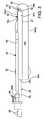
[079]喉頭鏡10は、板状部材18に隣接した可撓性チューブ状部材20をさらに含む
。接眼部材22とラチェット部材24とは、可撓性チューブ状部材20に操作可能に装着される。全体的にC字形の硬質経路部17cは、板状部材18の下側に提供され、可撓性チューブ状部材20を保持し、可撓性チューブ状部材20が進むときに、可撓性チューブ状部材20のための案内体として機能するように構成される。可撓性チューブ部材20の先端20tが板状部材18の端部の遠位にあるように、可撓性チューブ部材20が経路部17cを通して(図1を見たときの右に)前進し得るように構成され、患者の解剖学的構造のより良好な視認性を提供する。[079] The
[080]可撓性チューブ部材20は、複数の長手方向に延びた経路部(図1に示されない
)を含む。経路部は、吸引チューブとしてなど、様々な使用のために構成され得るか、または、その器具内に、光ファイバー内視鏡、照明手段、または案内ワイヤ26などが取り付けられ得る。案内ワイヤ26は、図1に示されない従来の気管内チューブを通して挿入されるように構成される。吸引チューブは、真空ポート28に装着され得、真空ポート28は、喉頭鏡10の外部の吸引源(図示せず)にさらに接続され得る。[080] The
[081]図2から図15は、全体として30として示される改善された気管内チューブ挿
入装置の部分を示す。改善された気管内チューブ挿入装置30は、患者内に、図9に示される従来の気管内チューブ92などの挿管装置を導入するための改善された装置である。改善された気管内チューブ挿入装置30は、気道を確保することと、患者の気道を見ることと、気道内に気管内チューブ92を正確に配置することと、患者の気道のビデオ画像を送信することとを使用者が同時に行うことを可能にするように構成される。[081] FIGS. 2 to 15 show a portion of the improved endotracheal tube insertion device, shown as 30 as a whole. The improved endotracheal
[082]改善された気管内チューブ挿入装置30は、板状部材組立体34に装着されたハ
ンドル32と、光学組立体36と、案内される導入体挿管組立体38とを含む。図2と図3とに示される実施形態において、ハンドル32は、気管内チューブ挿入装置30の使用者の手により把持されるように構成される。[082] The improved endotracheal
[083]ビデオ表示器40は、光学組立体36の近位端に装着され、光学組立体36内で
、図7に示されて後述されるビデオ画像形成装置60に操作可能に接続される。示される実施形態において、ビデオ表示器40は、後で詳細に説明される可撓性部材52に取り付けられるので、視認しやすいように所望のあらゆる角度に可動または調節可能である。ビデオ表示器40は、さらに、患者から離れて遠隔で見るために、光学組立体36に解放可能に装着され得る。さらに、1つまたは複数の別のビデオ表示器40(図示せず)が、気管内チューブ挿入装置30から遠隔に配置されて、気管内チューブ挿入装置30に有線接続または無線接続により接続され得る。代替的に、ビデオ表示器40は、さらに、ハンドル32に解放可能に装着されるなど、ハンドル32に装着され得る。示される実施形態において、ビデオ表示器は、実質的に長方形の形状を有する。代替的に、ビデオ表示器40
は、所望のあらゆる形状と寸法とを有し得る。[083] The
Can have any desired shape and dimensions.
[084]ハンドル32は、気管内チューブ挿入装置30がコンピュータネットワーク構築
に関与することを可能にする、Wi-Fiまたはローカルエリア無線技術を搭載したプロセッサまたは制御装置33をさらに含み得る。プロセッサまたは制御装置33は、光学組立体36により捕捉されたあらゆるビデオ画像を、インターネットを介して医療専門家が見ることを可能にするBluetooth(登録商標)機能をさらに含み得る。所望される場合、制御装置33は、ビデオ表示器40の一部として、または、改善された気管内チューブ挿入装置30内の他の所望のあらゆる位置において提供され得る。代替的に、ハンドル32の代わりに、米国特許第7,563,227号において説明されるハンドルおよび視認部材が提供され得る。[084] The
[085]図3と図4とに最もよく示されるように、板状部材組立体34は、経路部部材3
7に装着された長尺板状部材本体35として構成された挿入部材を含む。長尺板状部材本体35は、第1の端部すなわち遠位端35aとハンドル32に装着された第2の端部すなわち近位端35bとを有する。図3と図4とに示されるように、板状部材本体35は、長手方向に実質的に直線状であり、弓形の断面形状を含む。[085] As best shown in FIGS. 3 and 4, the plate-
The insertion member configured as the long plate-shaped member
[086]経路部部材37は、第1の端部すなわち遠位端37aと第2の端部すなわち近位
端37bとを含み、長手方向に延びた経路部37cを規定し、板状部材本体35の第1の側部35c(図2と図4とを見たときの下側)に装着される。図4にさらに示されるように、経路部部材37は、断面を見たとき、実質的にC字形であり、経路部37cへのアクセスを提供する長尺間隙37bを規定する。代替的に、経路部部材37は、実質的に長円形および実質的に長方形などの所望のあらゆる断面形状を有し得る。[086] The
[087]図3に示されるように、板状部材本体35の下から見たとき、経路部部材37の
経路部37cは、板状部材本体35の第1の縁部35e1(図3を見たときの上縁部)に向けて開放される。代替的に、経路部部材37の経路部37cは、板状部材本体35の第2の縁部35e2(図3を見たときの下縁部)などに向けて、所望のあらゆる方向に開放され得る。図3にさらに示されるように、経路部部材37は、板状部材本体35の第1の縁部35e1(図3を見たときの上縁部)付近に位置する。代替的に、経路部部材37は、板状部材本体35の第2の縁部35e2(図3を見たときの下縁部)付近、または、第1の縁部35e1と第2の縁部35e2との間のいずれかの位置に配置され得る。As shown in FIG. 3, when viewed from below the plate-shaped member
[088]板状部材本体35は、約8cmから約20cmの範囲内の長さなどの、所望のあ
らゆる長さであり得る。代替的に、板状部材本体35は、約8cmより短い、または約20cmより長いものであり得る。板状部材本体35と経路部部材37とは、ステンレス鋼およびポリ塩化ビニル(PVC)などの所望のあらゆる硬質材料または半硬質材料により形成され得る。示される実施形態において、経路部部材37の遠位端37aは、板状部材本体35の遠位端35aから短い距離ぶん離れており、経路部部材37の近位端37bは、板状部材本体の近位端35bにおいて終端する。経路部部材37の遠位端37aは、板状部材本体35の遠位端35aから所望のあらゆる距離に配置され得る。所望される場合、経路部部材37の近位端37bは、板状部材本体の近位端35bの前に(図3を見たとき、板状部材本体の近位端35bの右で)終端し得るか、または、板状部材本体の近位端35bを越えて(図3を見たとき、板状部材本体の近位端35bの左に)延び得る。示される板状部材組立体34は、実質的に直線状の板状部材本体35を含む。代替的に、板状部材組立体34は、後で詳細に説明される湾曲した板状部材本体44により形成され得る。[088] The plate-
[089]所望される場合、気管内チューブ挿入装置30の板状部材組立体34上に、気管
内チューブ保持タブが提供され得る。例えば、図2に示されるように、2つの気管内チューブ保持タブ39aが、(図2を見たとき)経路部部材37から外向きおよび上向きに延び、1つの気管内チューブ保持タブ39bが、(図2を見たとき)ハンドル32から外向きおよび下向きに延びる。気管内チューブ保持タブ39aおよび39bは、全体的に弓形であり、気管内チューブ保持タブ39aと気管内チューブ保持タブ39bとの間に気管内チューブ92が一時的に配置されて保持されることとを可能にするように構成される。代替的に、気管チューブ保持タブ39aおよび39bは、気管内チューブ92を保持することに適した他の所望のあらゆる形状であり得る。板状部材本体35および経路部部材37と同様に、気管内チューブ保持タブ39aおよび39bは、ステンレス鋼およびポリ塩化ビニル(PVC)などの所望のあらゆる硬質材料または半硬質材料により形成され得る。所望のあらゆる数の気管内チューブ保持タブ39aおよび39bが提供され得ることが理解されると考えられる。さらに、気管内チューブ保持タブ39aおよび39bは、板状部材組立体34および/またはハンドル32上の所望のあらゆる位置に提供され得る。[089] If desired, an endotracheal tube holding tab may be provided on the plate-
[090]図11を参照すると、ハンドル32に装着された第2の実施形態の板状部材組立
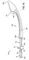
体が42として示される。板状部材組立体42は、経路部部材46に装着された、長尺の上向きに湾曲した板状部材本体44を含む。板状部材本体44は、第1の端部すなわち遠位端44aとハンドル32に装着された第2の端部すなわち近位端44bとを含む。板状部材本体35と同様に、板状部材本体44は弓形の断面形状を有する。[090] With reference to FIG. 11, the plate-like member assembly of the second embodiment mounted on the
[091]経路部部材46は、板状部材本体44の第1の側部44c(図11を見たとき下
側)に装着され、第1の部分46aと第2の部分46bとを含み、長手方向に延びた経路部46cを規定する。経路部部材46は、断面を見たとき実質的にC字形であり、経路部46cへのアクセスを提供する長尺間隙46dを規定する。代替的に、経路部部材46は、実質的に長円形および実質的に長方形などの、所望のあらゆる断面形状を有し得る。経路部部材46の第2の部分46bは、所望のあらゆる距離ぶん板状部材本体44の近位端44bを越えて延び、長尺間隙46dの少なくとも1つの側部内に形成された複数の切り込み48を含む。経路部部材46の第1の部分46aの遠位端は、板状部材本体44の遠位端44aから所望のあらゆる距離に配置され得る。経路部部材37の経路部37cと同様に、経路部部材46の経路部46cは、板状部材本体44に対する所望のあらゆる方向に開放され得、板状部材本体44の長手縁部のいずれかの、または、その中間のいずれかの位置付近で横方向に位置し得る。示される板状部材組立体42は、湾曲した板状部材本体44を含む。代替的に、板状部材組立体42は、ここまでに詳細に説明される実質的に直線状の板状部材本体35を使用して形成され得る。[091] The
[092]所望される場合、気管内チューブ保持タブは、板状部材組立体42上にも提供さ
れ得る。例えば、図11に示されるように、2つの気管内チューブ保持タブ49aが、(図11を見たとき)経路部部材46から外向きおよび上向きに延び、1つの気管内チューブ保持タブ49bは、(図11を見たとき)ハンドル32から外向きおよび下向きに延びる。気管内チューブ保持タブ49aおよび49bは全体的に弓形であり、気管内チューブ保持タブ49aと気管内チューブ保持タブ49bとの間に気管内チューブ92が一時的に配置されて保持されることを可能にするように構成される。代替的に、気管内チューブ保持タブ49aおよび49bは、気管内チューブ92を保持することに適した他の所望のあらゆる形状であり得る。気管内チューブ保持タブ39aおよび39bと同様に、気管内チューブ保持タブ49aおよび49bは、ステンレス鋼およびポリ塩化ビニル(PVC)などの、所望のあらゆる硬質材料または半硬質材料により形成され得る。所望のあらゆる数の気管内チューブ保持タブ49aおよび49bが提供され得ることが理解されると考えられる。さらに、気管内チューブ保持タブ49aおよび49bは、板状部材組立体42および/またはハンドル32上における所望のあらゆる位置に提供され得る。[092] If desired, the endotracheal tube holding tab may also be provided on the
[093]図2に示されるように、光学組立体36は、経路部部材37の経路部37c内に
配置される。図5から図7に最もよく示されるように、光学組立体36は、光学筐体50と可撓性部材52とを含む。示される光学筐体50は、第1の部分50aと第2の部分50bとを含み、長手方向に延びた経路部50cを規定する。光学筐体50は、断面を見たとき実質的に円形であり、経路部50cへのアクセスを提供する長尺間隙50dを規定する。代替的に、光学筐体50は、実質的に長円形などの、所望のあらゆる断面形状を有し得る。光学筐体50の示される実施形態において、光学筐体50の第2の部分50bの内径は、第1の部分50aの内径より大きい。代替的に、第2の部分50bの内径は、第1の部分50aの内径以下であり得る。第2の部分は、長尺間隙50dの少なくとも1つの側部内に形成された複数の切り込み48をさらに含む。光学筐体50は、PVC、ワイヤ強化シリコン、およびステンレス鋼などの、所望のあらゆる硬質材料または半硬質材料により形成され得る。さらに、光学筐体50は、第1の部分50aと第2の部分50bとの間の光学筐体50の一部分において比較的可撓性が高いように構成され得、これにより、図2に示されるように経路部部材37とビデオ表示器40との間に延びる光学筐体50の一部分を使用者が屈曲させることを可能にする。[093] As shown in FIG. 2, the
[094]示される改善された気管内チューブ挿入装置30の板状部材組立体34は、板状
部材組立体34に対して装着された経路部部材37を含むように示されるが、経路部部材37が必要というわけではない。例えば、図5に示される光学筐体50の第1の部分50aは、経路部部材37が装着されるのと同じ手法で、板状部材本体35の第1の側部35c(図2と図4とを見たとき下側)に装着され得る。このような一実施形態において、長手方向に延びた経路部50cは、長手方向延びた経路部部材37の経路部37cと同じ手法で機能する。[094] The plate-
[095]図6と図7とに最もよく示されるように、可撓性部材52は、軸A1を有する実
質的に円柱形の長尺部材であり、第1の端部すなわち遠位端52aと第2の端部すなわち近位端52bとを有する。代替的に、可撓性部材52は、実質的に長円形、実質的に六角形、および実質的に長方形など、他の所望のあらゆる断面形状を有し得る。複数の長手方向に延びた管路が、可撓性部材52内に形成される。図7に示されるように、可撓性部材52は、第1の長手方向に延びた管路54と第2の長手方向に延びた管路56と第3の長手方向に延びた管路58とを含む。ビデオ画像形成装置60は、第1の長手方向に延びた管路54内に配置される。示される実施形態において、ビデオ画像形成装置60は、相補型金属酸化物シリコン(CMOS:Complementary Metal Oxide Silicon)カメラである。代替的に、ビデオ画像形成装置60は、電荷結合素子(CCD:Charge-Coupled Device)、光ファイバーカメラ、および他のあらゆる直接的または間接的な像形成装置などの、所望のあらゆるビデオ画像形成装置であり得る。[095] As best shown in FIGS. 6 and 7, the
[096]光源62は、第2の長手方向に延びた管路56内に配置される。示される実施形
態において、光源62は、可撓性部材52の遠位端52aに取り付けられたLEDランプまたは白熱電球である。代替的に、光源62は、他のあらゆる光源であり得る。さらに、光源62は、LEDランプ、白熱電球、または他の所望のあらゆる光源などの、その近位端において照明の光源(図示せず)に接続された光ファイバーケーブルであり得る。ビデオ画像形成装置60と光源62とは、図6において66として示される1つまたは複数の可撓性の電気的および/または光学的な接続体によりビデオ表示器40および/または制御装置33に操作可能に接続される。[096] The
[097]図5に示されるように、第3の長手方向に延びた管路58は吸引チューブとして
構成され、ノブ68aから外向きに延びた真空ポート59などの真空ポートに接続される。吸引チューブとして説明されるが、管路58は、患者に酸素を提供するためにも使用さ
れ得る。管路58は、患者内に医療器具(図示せず)などの器具を導入するためにさらに使用され得る。示される実施形態において、可撓性部材52は、約4mmの外径を有する。代替的に、可撓性部材52は、他のあらゆる外径を有し得る。[097] As shown in FIG. 5, the third longitudinally extending
[098]可撓性部材52の遠位端52aは、挿管組立体案内経路部64をさらに含み、そ
の目的が以下で説明される。図7Aに示されるように、示される挿管組立体案内経路部64は、第1の部分64aと、第1の部分64aの近位にある第2の部分64bと、第2の部分64bに隣接し、第2の部分64bより半径方向内側にある第3の部分64cを含む。示される実施形態において、第3の部分64cは、以下で説明される理由により、第2の部分64bより幅が広い。特に、第3の部分64cは実質的に円筒形であり、後述のように、案内レール75の長尺案内部材部78の外径と略同じ寸法の内径を有する。代替的に、第3の部分64cは、実質的に長円形、実質的に六角形、および実質的に長方形などの他の所望のあらゆる断面形状を有し得る。所望される場合、第3の部分64cは、案内レール75の案内部材部78の外径より大きな内径などの、所望のあらゆる内径を有し得る。さらに、第1の部分64aは、比較的幅の広い長手開口を有し、第2の部分64bは、第1の部分64aの長手開口より小さな長手開口を有する。[098] The
[099]示される実施形態において、挿管組立体案内経路部64は、約3cmから約7c
mの範囲内の長さを有し、第1の部分64aは、約0.5cmから約2cmの範囲内の長さを有し、第2の部分64bと第3の部分64cとは、約2cmから約5cmの範囲内の長さを有する。代替的に、挿管組立体案内経路部64、および第1の部分64aと第2の部分64bと第3の部分64cとの各々は、所望のあらゆる長さと幅とを有し得る。[099] In the embodiments shown, the intubation assembly
Having a length in the range of m, the
[0100]さらに、例えば、図7Aに示されるように、可撓性部材52は、比較的幅の広い第1の経路部部64aなしで、第2の部分64bと第3の部分64cとのみを含むように形成され得ることが理解されると考えられる。挿管組立体案内経路部64の第2の部分64bと第3の部分64cとのみを有する可撓性部材52の一実施形態において、第2の部分64bと第3の部分64cとの各々は、約2cmから約7cmの範囲内の長さなどの、所望のあらゆる長さを有し得る。 [0100] Further, for example, as shown in FIG. 7A, the
[0101]示される実施形態において、第1の長手方向に延びた管路54と第2の長手方向に延びた管路56とは、円形の断面形状を有し、第3の長手方向に延びた管路58は、長円形の断面形状を有する。代替的に、第1の長手方向に延びた管路54と第2の長手方向に延びた管路56と第3の長手方向に延びた管路58とは、所望のあらゆる断面形状を有し得る。可撓性部材52は、シリコン、ゴム、ワイヤ強化シリコン、ワイヤ強化ゴム、およびポリマーなどの、所望のあらゆる可撓性材料または半可撓性材料により形成され得る。さらに、可撓性部材52は、可撓性部材52の遠位端52aにおいて比較的可撓性が高いように、および、可撓性部材52の近位端52bにおいて比較的可撓性が低いように構成され得、これにより、患者の気道内において、より高い可撓性を提供するとともに、近位端52bを取り扱うときに使用者に対してより低い可撓性を提供することにより、より高い制御性を提供する。 [0101] In the embodiments shown, the first longitudinally extending
[0102]可撓性部材52の遠位端52aは、患者の気道の所望の部位を見るために、遠位端52aの一部分を動かす機構(図示せず)をさらに含む。本機構(図示せず)は、継手Jを規定し、機械的または電気的に操作され得、角度B1にわたって遠位端52aを動かすように構成される。示される実施形態において、角度B1は、可撓性部材52の軸A1から約+/-90度である。さらに、可撓性部材52の遠位端52aは、いずれの半径方向にも動くように構成されるために関節接続し得、したがって、継手Jは、関節接続継手として構成され得る。 [0102] The
[0103]遠位端52aの一部分を動かす機構は、可撓性部材52の近位端52bにおいて制御装置68により制御され得る。示される制御装置68は、回転可能ノブ68aと取り付け支柱68bとを含む。代替的に、制御装置68は、可撓性部材52上の他の所望のあらゆる位置、または、改善された気管内チューブ挿入装置30上の他の所望のあらゆる位置に配置され得る。遠位端52aの一部分を動かす機構と、結果的な可撓性部材52の遠位端52aの動きは、制御装置68により制御され得、したがって、使用者が可撓性部材52の遠位端52aを所望の位置に動かして、使用者により選択された位置に遠位端52aを固定または保持することを可能にする。図5から図7に示されるように、装着部材70は、制御装置68の取り付け支柱68bに装着される。装着部材70は、改善された気管内チューブ挿入装置30に対して、および、より具体的には可撓性部材52に対して、案内される導入体挿管組立体38と、後述の、その装着された気管内チューブ92とを保持するように構成されたあらゆる装置であり得る。代替的に、装着部材70は、ハンドル32とビデオ表示器40とを含む、改善された気管内チューブ挿入装置30の所望のあらゆる部分に取り付けられ得る。 [0103] The mechanism for moving a portion of the
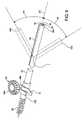
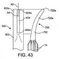
[0104]案内される導入体挿管組立体38は、導入体またはブジーを規定する、図8と図8Aとに最もよく示されるロッド72として構成された挿管組立体本体を含む。ロッド72は、実質的に円柱状であり、第1の端部すなわち遠位端72aと第2の端部すなわち近位端72bとを有する長尺本体を有する。代替的に、ロッド72は、実質的に長円形、実質的に六角形、および実質的に長方形などの、他の所望のあらゆる断面形状を有し得る。ロッド72の遠位端72aは、テーパ付であるか、または、実質的に錐形であり、ロッド72の前端部を規定する。ロッド72は、複数の長手方向および半径方向外向きに延びたリブ74を含む。示される実施形態において、図9に示される気管内チューブ92などの気管内チューブ92内に挿入される前のロッド72が示される。示されるように、リブ74は、弓形の断面形状を有する。リブ74は、ロッド72の所望のあらゆる長さにわたって広がり得、遠位端72aに向けてテーパを有する。 [0104] The guided
[0105]示されるロッド72は、気管内へ気管内チューブ92を案内するように構成された、および、光学組立体36の可撓性部材52に解放可能に装着されるように構成された案内装置を含む。示される実施形態において、案内装置は、案内レール75である。示される案内レール75は、案内部材部78の遠位端に実質的に球形の先端76を含む。案内部材部78は、ロッド72と案内部材部78との間に延びる実質的に平らなブリッジ部80によりロッド72に装着され得る。代替的に、案内部材部78は、ブリッジ部80なしでロッド72に直接装着され得る。球形として示されるが、先端76は、実質的に卵形などの他の形状を有し得るか、または、四角柱または三角柱の形状を有し得る。先端76が必要とされないことと、案内部材部78の遠位端が丸みを帯びた、またはテーパ付の表面を有し得ることとが理解されると考えられる。さらに、先端76は、あらゆる寸法であり得、第1の部分64a内に適合するあらゆる形状を有し得る。さらに、案内部材部78は、第3の部分64c内に適合するように構成され、案内部材部78が横方向に保持されるように、すなわち、案内部材部78が脱落せず、さらに、案内経路部64の第2の部分64bを通して横方向に外れ得ないように、十分大きな直径を有する。示される実施形態において、案内される導入体挿管組立体38は、約40cmから約50cmの範囲内の全長を有する。代替的に、案内される導入体挿管組立体38は、他の所望のあらゆる長さを有し得る。 [0105] The
[0106]図8に最もよく示されるように、案内部材部78は、実質的に円柱形であり、球形の先端76から測定して約5cmの長さL1である。代替的に、案内部材部78は、実質的に長円形、実質的に六角形、および実質的に長方形などの他の所望のあらゆる断面形状を有し得る。さらに、案内部材部78は、約4cmから約6cmの長さなどの、所望のあらゆる長さL1を有し得る。示されるブリッジ部80は、球形の先端76付近の点から
、案内部材部78の近位端付近の点まで延びる。ブリッジ部80は、あらゆる幅と長さとを有し得、球形の先端76付近、または、案内部材部78が先端76なしで形成される場合は案内部材部78の遠位端付近のあらゆる点において案内部材部78に装着され得る。代替的に、ブリッジ部80は、ロッド72の所望のあらゆる部分に位置し得る。したがって、ロッド72の実質的に円柱形の部分は、球形の先端76から約7cmの点から始まる。代替的に、ロッド72の実質的に円柱形の部分は、約6cmから約8cmの距離など、球形の先端76から所望のあらゆる距離から始まり得る。後で詳細に説明されるように、ブリッジ部80が案内経路部64の第2の部分64bを通って広がり得るように、ブリッジ部80は所望のあらゆる厚さを有し得る。[0106] As best shown in FIG. 8, the
[0107]ロッド72、ロッド72の上に形成されたリブ74、案内レール75、および、案内レール75の構成部材、すなわち、案内部材部78と実質的に球形の先端76とブリッジ部80とは、シリコン、ゴム、ワイヤ強化シリコン、ワイヤ強化ゴム、およびポリマーなどの、あらゆる可撓性材料または半可撓性材料により形成され得る。さらに、ロッド72は、ロッド72の遠位端72aにおいて比較的可撓性が高いように、および、ロッド72の近位端72bにおいて比較的可撓性が低いように構成され得、したがって、患者の気道内において、より高い可撓性を提供するとともに、近位端72bを取り扱うときに使用者に対してより低い可撓性を提供することにより、より高い制御性を提供する。 [0107] The
[0108]所望される場合、リブ74の代わりに、ロッド72のリブ付部分は、中実の、伸張可能な、または中空で膨張可能な部分を含むように構成され得、その部分の前縁部は、テーパ付の、または実質的に錐台形の移行セグメントを含んで形成され得、移行セグメントはリブ74がある場合にリブ74が始まる場所である。ロッド72のこの中実の、伸張可能な、または膨張可能な部分は、気管内チューブ92の内径に対応した所望の外径を有し得るか、または、気管内チューブ92の内径に対応した所望の外径を有するように膨らまされ得る。 [0108] If desired, instead of the
[0109]代替的に、改善された気管内チューブ挿入装置30に、複数のロッド72が提供され得、複数のロッド72の各々が、異なる内径を有する複数の気管内チューブ92の1つの内径に対応する異なる外径を有するリブ74を含む。さらに、改善された気管内チューブ挿入装置30に、リブなしで形成された複数のロッド72が提供され得、複数のロッドの各々が、異なる内径を有する複数の気管内チューブ92の1つの内径に対応する異なる外径を有する。上述の中空の膨張可能部材を含むロッドの実施形態を含む、本明細書において説明されるロッドの各実施形態は、上述の、例えば、図8において72aとして示される、テーパ付または実質的に錐形の前端部を含んで形成され得ることが理解されると考えられる。 [0109] Alternatively, an improved endotracheal
[0110]リブの外径が変化し得るように、および、ロッド72が、約3.0mm、すなわち、従来の小児気管内チューブ92の寸法から、約9.0mm、すなわち、従来の成人気管内チューブ92の寸法までの内径などの様々な内径を有する気管内チューブ92内で使用され得るように、リブが全体的に可撓性であり、すなわち、半径方向に圧縮可能であることを、リブ74の可撓性材料または半可撓性材料と弓形の断面形状とが可能にする。代替的に、気管内チューブ92は、約3.0mm未満または約9.0mmを上回る内径を有し得る。好ましくは、内面が、約3.0mmなどの小さな内径を有するか、約9.0mmなどのより大きな内径を有するかによらず、内部にロッド72が挿入された気管内チューブ92の内面に、リブ74が係合する。 [0110] So that the outer diameter of the ribs can be varied, and the
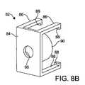
[0111]ロッド72の近位端72bは、図8と図8Bとに示される第1の接続部材82にロッド72を接続するために構成されたねじ山73を含む。第1の接続部材82は、そこから外向きに延びた複数の腕86を含む基体84を含む。腕86は、内向きに延びたフラ
ンジまたは止め部材88を含む。さらに、実質的に円筒形の本体90は、腕86の間において基体84から外向きに延びる。長手方向に延びたねじ山付経路部95は、少なくとも基体84を通して形成される。第1の接続部材82は、ロッド72のねじ山73に装着されるように構成される。このねじ山付接続体は、装着式の第1の接続部材82を時計回りまたは反時計回りに回転させることにより、ロッド72に対して、すなわち、図8に示す矢印93の方向に、第1の接続部材82の長手方向位置を使用者が調節することを可能にする。このねじ山付接続体は、さらに、ロッド72に取り付けられる気管内チューブ92のチューブ本体94の長さに対してロッド72を使用者が短くすることまたは長くすることを可能にする。所望される場合、ロッド72の近位端72bのうち、第1の接続部材82から外向きに延びた部分は、切断などにより、使用者により除去され得る。ロッド72は、他のあらゆる手段によりチューブ本体94の長さに対して短くされるか、または長くされ得ることが理解されると考えられる。[0111] The
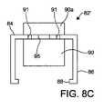
[0112]図8Cを参照すると、82’により、第1の代替的な実施形態に係る第1の接続部材が示される。第1の接続部材82’は、第1の接続部材82と同様であるが、第1の接続部材82’の円筒形の本体90は、例えば、酸素源への接続のための、基体84から外向きに延びた部分90aを含む。部分90aは、所望のあらゆる内径と外径とを有し得、円筒形の本体90の長さに等しい長さを含み得る所望のあらゆる長さを有し得る。代替的に、部分90aは、円筒形の本体90の長さより短いまたはより長い長さを有し得る。図9に示される従来の接続体98の円筒形の本体98bが、酸素源または空気源に装着されるように構成されるのと同じ手法で、部分90aが、酸素源または空気源に装着されるように構成され得る。 [0112] With reference to FIG. 8C, 82'indicates a first connecting member according to a first alternative embodiment. The first connecting member 82'is similar to the first connecting
[0113]所望される場合、図8Cに示されるように、空気流路91は、部分90a内において基体84を通るように形成され得る。空気流路91は、酸素源または空気源から気管内チューブ92への酸素または空気のための流路を規定する。 [0113] If desired, the
[0114]図8Dを参照すると、第2の代替的な実施形態に係る第1の接続部材が182として示される。第1の接続部材182は、第1の接続部材82と同様であり、そこから外向きに延びた複数の腕186を含む基体184を含む。第1の接続部材182の示される実施形態は、第1の腕ペア186aと第2の腕ペア186bとを含み、第2の腕ペア186bの一方のみが、第1の腕ペア186aの反対側において図8Dに示される。腕186aと腕186bとの各々が、内向きに延びた止め部材188を含む。さらに、実質的に円筒形の本体190が、腕186aと腕186bとの間において基体184から外向きに延びる。長手方向に延びたねじ山付経路部195は、基体184内に形成される。側壁192は、基体184の側縁部において腕186aと腕186bとから離れる方向に、基体184から外向きに延びる。側壁192は、腕186aと腕186bとの延長部であり、使用者などにより互いに向けて圧縮または押圧されたとき、第1の腕ペア186aと第2の腕ペア186bとが互いから離れるように動かされることにより、第1の接続部材182に対して接続体98のフランジ98aを使用者がより簡単に装着および分離することを可能にする開口タブを規定する。所望される場合、側壁192は、第1の接続部材82および82’など、第1の接続部材のあらゆる実施形態上に形成され得る。 [0114] With reference to FIG. 8D, the first connecting member according to the second alternative embodiment is shown as 182. The first connecting
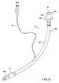
[0115]案内される導入体挿管組立体38は、図9において92として示されるものなど、従来の気管内チューブをさらに含む。気管内チューブ92は、図2に最もよく示されるように、ロッド72に装着されるように構成される。気管内チューブ92は、第1の端部すなわち遠位端92aと第2の端部すなわち近位端92bとを有する。気管内チューブ92は、遠位端92aにおけるバルーンカフ96と、気管内チューブ92の近位端92bにおける従来の接続体98とを含むチューブ本体94をさらに含む。ここまでに詳細に説明されるように、気管内チューブ92のチューブ本体94は、約3.0mmから約9.0m
mの内径を有し得る。[0115] The guided
It may have an inner diameter of m.
[0116]接続体98は、フランジ98aから外向きに延びる実質的に円筒形の本体98bを含むフランジ98aを含む。本体98bは、本体98bを通して形成された、長手方向に延びた経路部99を含む。空気膨張チューブ100は、バルーンカフ96に装着され、シリンジなどの空気源に装着されるように構成される。 [0116] The
[0117]接続体98は、第1の接続部材82に装着されるように構成される。装着されたとき、本体98bが第1の接続部材82の本体90内に挿入され、フランジ98aが腕86の間にスナップ留めされ、止め部材88により腕86の間で保持される。接続体98の本体98bは、約15mmの外径を有する。代替的に、本体98bは、他のあらゆる外径を有し得る。所望される場合、第1の接続部材82の本体90が接続体98の本体98bより小さく、接続体98の本体98b内に挿入され得るように、従来の接続体98と第1の接続部材82とが構成され得る。 [0117] The connecting
[0118]案内される導入体挿管組立体38が組み立てられたとき、ロッド72は、接続体98の経路部99を通して、案内部材部78が気管内チューブ92の遠位端92aから外向きに延びるまで、従来の気管内チューブ92のチューブ本体94内に挿入される。ロッド72が気管内チューブ92のチューブ本体94内に取り付けられたとき、挿管中、および案内される導入体挿管組立体38が除去される前に、リブ74の間において長手方向に延びた空間が、酸素源(図示せず)から患者への酸素のための流路を規定する。 [0118] When the guided
[0119]示されないが、ロッド72は、中空部材として形成され得、ロッド72の長さに沿った1つまたは複数の半径方向に延びた孔または穿孔をさらに含んで、ロッド72の近位端72bからの酸素の送達および流れを促進し得る。 [0119] Although not shown, the
[0120]有益には、改善された気管内チューブ挿入装置30、特に、リブ74の形状およびテーパ付の前縁部(または、中空の膨張可能部材として構成されたロッド72の代替的なリブ付部分)、ロッド72の滑らかなテーパ付または錐形の前端部72a、球形の先端76、および、改善された案内される導入体挿管組立体38の案内部材部78は、案内される導入体挿管組立体38と気管内チューブ92の前縁部または遠位端92aとが患者の気道内に進むときに、喉頭の構造物上に引っ掛かることを防ぐように構成され、その結果、声帯の間における気管内チューブ92の送達をしやすくし、声帯および気道の他の部分への外傷またはけがを防ぐ。 [0120] Beneficially, the improved endotracheal
[0121]図10において、第2の実施形態の挿管組立体ロッドが102として示される。ロッド102は、ロッド72と同様であり、複数の長手方向および半径方向外向きに延びたリブ104を含む。さらに、ロッド102の近位端102bは、上述の第1の接続部材82にロッド102を接続するために構成されたねじ山105を含む。 [0121] In FIG. 10, the intubation assembly rod of the second embodiment is shown as 102. The
[0122]ロッド102の遠位端102aは、テーパ付であるか、または実質的に錐形であり、ロッド102の前端部を規定し、案内レール75の案内部材部78と球形の先端76との代わりに、案内スリーブ106として構成された案内装置を含む。案内スリーブ106は、第1の端部すなわち遠位端106aと第2の端部すなわち近位端106bとを含み、案内スリーブ106を通して形成された長手方向に延びた実質的に円筒形の経路部106cを含む。示される案内スリーブ106はロッド102に直接取り付けられ、ブリッジ部80および112などのブリッジ部が必要とされないが、所望される場合には提供され得る。 [0122] The
[0123]示される実施形態において、遠位端106aと近位端106bとはテーパ付であ
る。図12に最もよく示されるように、光学筐体50または可撓性部材52が経路部106cを通して挿入され得るように、および、案内スリーブ106が経路部部材37内に滑動可能に取り付けられ得るように、案内スリーブ106が構成される。有益には、案内スリーブ106のテーパ付の前端部または遠位端106aは、さらに、患者の気道内に簡単で非侵襲的に進行するように構成されるのであり、すなわち、案内される導入体挿管組立体38と気管内チューブ92の前縁部または遠位端92aとが患者の気道内に進むときに、喉頭の構造物上に引っ掛かることを防ぐように構成され、その結果、声帯の間における気管内チューブ92の送達をしやすくし、声帯および気道の他の部分に対する外傷またはけがを防ぐ。[0123] In the embodiments shown, the
[0124]図12において、第3の実施形態の挿管組立体ロッドが108として示される。ロッド108の遠位端108aは、テーパ付であるか、または実質的に錐形であり、ロッド108の前端部を規定する。ロッド108は、案内スリーブ110を含む。案内スリーブ110は、第1の端部すなわち遠位端110aと第2の端部すなわち近位端110bとを含み、案内スリーブ110を通して形成された長手方向に延びた実質的に円筒形の経路部110cを含む。案内スリーブ110は、ロッド108と案内スリーブ110との間に延びる実質的に平らなブリッジ部112によりロッド108に装着される。ロッド108は、その他の点では、ロッド102と実質的に同じである。ブリッジ部80と同様に、ブリッジ部112は、ロッド108の所望のあらゆる部分に位置し得る。ブリッジ部112は、あらゆる幅と長さとを有し得、案内スリーブ110の遠位端110a付近のあらゆる点において案内スリーブ110に装着され得る。さらに、案内スリーブ110は、他のあらゆる長手方向位置において、または、ロッド108の遠位端108aからの他の所望のあらゆる距離においてロッド108に装着され得る。図12に示されるように、可撓性部材52の遠位端52aが経路部110cを通して挿入され得るように、案内スリーブ110が構成される。さらに、案内スリーブ110は、光学筐体50の経路部50c、経路部部材37の経路部37c、および経路部部材46に経路部46cを通して挿入するように構成される。ブリッジ部80と同様に、ブリッジ部112が経路部50cの間隙50d、経路部37cの間隙37b、および経路部46cの間隙46dを通って広がり得るように、ブリッジ部112は、所望のあらゆる厚さを有し得る。 [0124] In FIG. 12, the intubation assembly rod of the third embodiment is shown as 108. The
[0125]図12Aは、ロッド108の端面図であり、案内スリーブ110の遠位端110aに形成された、半径方向内向きに延びた停止部材114を示す。停止部材114は、患者の気道内への気管内チューブ挿入装置30の挿入中、案内スリーブ110内に可撓性部材52を保持することを補助するために提供され得る。代替的に、案内スリーブ110の遠位端110aは、2つ以上の停止部材114を含み得る。案内スリーブ110の遠位端110aに形成されるように示されるが、停止部材114は、案内スリーブ110の近位端110bに、または、遠位端110aと近位端110bとの間のあらゆる位置に形成され得る。さらに、停止部材114は、所望のあらゆる形状と寸法とを有し得る。 [0125] FIG. 12A is an end view of the
[0126]案内レール75および案内レール75の構成部材と同様に、案内スリーブ110とブリッジ部112とは、シリコン、ゴム、ワイヤ強化シリコン、ワイヤ強化ゴム、およびポリマーなどの、あらゆる可撓性材料または半可撓性材料により形成され得る。 [0126] Similar to the
[0127]図13において、第4の実施形態の挿管組立体ロッドが116として示される。ロッド116の遠位端116aは、テーパ付であるか、または実質的に錐形であり、ロッド116の前端部を規定する。ロッド116は、案内スリーブ118を含む。案内スリーブ118は、第1の端部すなわち遠位端118aと第2の端部すなわち近位端118bとを含み、案内スリーブ118を通して形成された、長手方向に延びた実質的に円筒形の経路部118cを含む。案内スリーブ118は、ロッド116と案内スリーブ118との間に延びる実質的に平らなブリッジ部112によりロッド116に装着される。示される案
内スリーブ118は、案内スリーブ118を通して形成された、長手方向に延びた間隙120をさらに含む。ロッド116は、その他の点では、ロッド102と実質的に同じである。[0127] In FIG. 13, the intubation assembly rod of the fourth embodiment is shown as 116. The
[0128]図14において、第5の実施形態の挿管組立体ロッドが122として示される。ロッド122の遠位端122aは、テーパ付であるか、または実質的に錐形であり、ロッド122の前端部を規定する。ロッド122は、案内スリーブ124を含む。案内スリーブ124は、案内スリーブ118と同様であり、第1の端部すなわち遠位端124aと第2の端部すなわち近位端124bとを含み、案内スリーブ124を通して形成された長手方向に延びた実質的に円筒形の経路部124cを含む。案内スリーブ124は、ロッド122と案内スリーブ124との間に延びる実質的に平らなブリッジ部112によりロッド122に装着される。案内スリーブ118とは異なり、案内スリーブ124の遠位端124aは、テーパ付ではない。むしろ、遠位端124aの端面は、案内スリーブ124の軸A2に実質的に直交する。ロッド122は、その他の点では、ロッド102と実質的に同じである。 [0128] In FIG. 14, the intubation assembly rod of the fifth embodiment is shown as 122. The
[0129]図14Aは、ロッド122の端面図であり、案内スリーブ124の遠位端124aに形成された、第1の実施形態の停止部材126を示す。示される停止部材126は、3つの半径方向内向きに延びた脚部128を含む。停止部材126は、患者の気道内への気管内チューブ挿入装置30の挿入中、案内スリーブ124内に可撓性部材52を保持することを補助するために提供され得る。代替的に、案内スリーブ124の遠位端124aは、1つ、2つ、または、3つを上回る脚部128など、所望のあらゆる数の脚部128を含み得る。案内スリーブ124の遠位端124aに形成されるように示されるが、停止部材126は、案内スリーブ124の近位端124bに、または遠位端124aと近位端124bとの間におけるあらゆる位置に形成され得る。さらに、脚部128は、所望のあらゆる形状と寸法とを有し得る。 [0129] FIG. 14A is an end view of the
[0130]図14Bは、ロッド122の端面図であり、第2の実施形態の案内スリーブ124’を示し、その遠位端124’aは、半径方向内向きに延びた3つの停止部材114を含む。上述のように、停止部材114は、患者の気道内への気管内チューブ挿入装置30の挿入中、案内スリーブ124内に可撓性部材52を保持することを補助するために提供され得る。代替的に、案内スリーブ124’の遠位端124’aは、2つの停止部材114、または、3つを上回る停止部材114を含み得る。案内スリーブ124’の遠位端124’aに形成されるように示されるが、停止部材114は、案内スリーブ124’の近位端124’bに、または、遠位端124’aと近位端124’bとの間におけるあらゆる位置に形成され得る。さらに、停止部材114は、所望のあらゆる形状と寸法とを有し得る。所望される場合、可撓性部材52の遠位端52aの外面は、停止部材114に対応する案内溝(図示せず)を含んで形成され得る。したがって、可撓性部材52は、案内スリーブ124’内で滑動可能に可動であり、停止部材114は、溝内において可撓性部材52を滑動可能に係合する。 [0130] FIG. 14B is an end view of the
[0131]図15において、第6の実施形態の挿管組立体ロッドが130として示される。ロッド130の遠位端130aは、テーパ付であるか、または実質的に錐形であり、ロッド130の前端部を規定する。ロッド130は、第1の端部すなわち遠位端132aと第2の端部すなわち近位端132bとを含む案内スリーブ132を含み、案内スリーブ132を通して形成された長手方向に延びた実質的に円筒形の経路部132cを含む。案内スリーブ132は、ロッド130と案内スリーブ132との間に延びる実質的に平らなブリッジ部112によりロッド130に装着される。案内スリーブ132の遠位端132aは、錐台形である。案内スリーブ132は、134として一部分が示される第2の実施形態の可撓性部材を保持するように構成される。さらに、可撓性部材134の遠位端134a
が錐台形であるので、可撓性部材134の遠位端134aが案内スリーブ132の遠位端132a内に保持される。ロッド130は、その他の点では、ロッド102と実質的に同じである。[0131] In FIG. 15, the intubation assembly rod of the sixth embodiment is shown as 130. The
Is trapezoidal, so that the
[0132]ロッド108および案内スリーブ110、ロッド116および案内スリーブ118、ロッド122および案内スリーブ124、ならびに、ロッド130および案内スリーブ132を含む、本明細書において説明されるロッドおよび案内スリーブの各実施形態は、実質的に平らなブリッジ部112なしで形成され得ることが理解されると考えられる。このような実施形態において、スリーブ、110、118、124、および132は、それぞれ、ロッド108、116、122、および130に直接取り付けられる。ブリッジ部112は、あらゆる幅と長さとを有し得、案内スリーブ110、118、124、および132の遠位端付近のあらゆる点において、それぞれ、案内スリーブ110、118、124、および132に装着され得る。 [0132] Each embodiment of the rod and guide sleeve described herein, including
[0133]使用前、図2と図19とに示されるように、案内部材部78が挿管組立体案内経路部64の第2の部分64c内に載置されるまで、先端76が挿管組立体案内経路部64の第1の部分64a内に載置されるまで、および、ブリッジ部80が挿管組立体案内経路部64の第2の部分64bを通って延びるまで、第1の部分64aを介して挿管組立体案内経路部64内に案内レール75の案内部材部78を挿入することにより、案内される導入体挿管組立体38が光学組立体36に固定される。制御装置68の取り付け支柱68bを手動で動かすことにより、切り込み48の1つ内において光学組立体36の可撓性部材52が光学筐体50に対して固定され得るか、または固定して配置され得る。 [0133] Prior to use, as shown in FIGS. 2 and 19, the
[0134]代替的に、機械的または電気機械的な動作装置(図示せず)は、可撓性部材52と光学筐体50との間において、または、可撓性部材52と気管内チューブ挿入装置30の所望のあらゆる部分との間において可撓性部材52に装着され得、光学筐体50内で長手方向に可撓性部材52を選択的に動かすように構成される。 [0134] Alternatively, a mechanical or electromechanical operating device (not shown) is between the
[0135]図2に最もよく示されるように、患者の気道内に挿入される前、案内される導入体挿管組立体38と装着された気管内チューブ92とは、装着部材70内において気管内チューブ挿入装置30に解放可能に装着され得る。 [0135] As best shown in FIG. 2, prior to insertion into the patient's airway, the guided
[0136]使用時、操作者または使用者が、患者の気道内に、装着された光学組立体36と案内される導入体挿管組立体38とを使用して、板状部材組立体34を板状部材本体35の遠位端35aが喉頭蓋に達するまで挿入し得る。可撓性部材52の遠位端52aは、次に、経路部部材37の遠位端から外向きに動かされ、声帯の視認性を確保し得る。制御装置68の取り付け支柱68bは、内部に取り付け支柱68bが配置されている切り込み48から外に動かされ、可撓性部材52の遠位端52aが、最大約7cmの距離まで、約0.5cm単位の増分などの増分により、外向きに移動され得る。上述のように、可撓性部材52の遠位端52aは、その軸A1に対して動かされて、声帯のより良好な視認性を確保し得、使用者により選択された位置に固定または保持され得る。 [0136] During use, the operator or user can plate the plate-
[0137]次に、使用者は、装着部材70内から気管内チューブ92を取り外し得る。続いて、使用者は、先端76が声帯の約12cm下方に位置するか、または声帯を約12cm越えるまで、および、バルーンカフ96が声帯の下方に位置するまで、案内される導入体挿管組立体38を前方に気管内へ、および、案内経路部64から外向きに滑動させ得る。次に、バルーンカフ96が、従来の手法で膨らませられ得る。板状部材組立体34と光学組立体36とが患者から除去され得る。次に、案内される導入体挿管組立体38が気管内チューブ92から切り離されて、さらに患者から除去され得る。 [0137] The user may then remove the
[0138]有益には、改善された気管内チューブ挿入装置30は、相互接続された、気管内チューブ92の配置中に単一ユニットとして機能する、案内される導入体挿管組立体38と光学組立体36と板状部材組立体34とを含む。 [0138] Beneficially, the improved endotracheal
[0139]別の利点を挙げると、改善された気管内チューブ挿入装置30は、何百または何千もの気管内挿管処置を行った人の経験がなくても、患者または事故の犠牲者の気道の完全な制御を使用者が獲得および維持することを可能にする比較的単純なツールである。第1応答者などの使用者は、このような多くの経験がなくても、処置のビデオを遠くからであるがリアルタイムで見得る医師である気道の専門家の補助とともに、または補助なしで、改善された気管内チューブ挿入装置30を使用して、患者の気道に挿管し得る。 [0139] To give another advantage, the improved endotracheal
[0140]有益には、気道のビデオは、世界のどこにいる専門家にもリアルタイムでインターネットを介して送信され得る。これは、使用者および患者が病院内にいるか、遠くの事故現場にいるかによらず、専門家が、経験の少ない、または、知識の少ない使用者に助言および指導を提供することを可能にする。 [0140] Beneficially, airway videos can be transmitted over the Internet in real time to professionals anywhere in the world. This allows professionals to provide advice and guidance to inexperienced or inexperienced users, regardless of whether the user and patient are in the hospital or at a distant accident site. ..
[0141]示されないが、光学組立体36は、案内部材部78と同様の長手方向に延びたレールを含んで形成され得、案内される導入体挿管組立体38は対応する長手方向に延びた間隙または溝を含んで形成され得、間隙または溝内に、レールが滑動可能に取り付けられ得る。球形の先端76と同様のものなどの、限定はされないが保持球を含む停止部材が、レールまたは溝の遠位端または近位端上に提供されて、レールに沿った、案内される導入体挿管組立体38の近位方向または後方への動きを防ぎ得る。 [0141] Although not shown, the
[0142]図16から図18において、第2の実施形態の気管内チューブ挿入装置が230として示される。図16において、明確にするために、案内される導入体挿管組立体38とビデオ表示器40とが除去された状態で、気管内チューブ挿入装置230が示される。気管内チューブ挿入装置230は、上述の光学組立体36をさらに含む。 [0142] In FIGS. 16-18, the endotracheal tube insertion device of the second embodiment is shown as 230. In FIG. 16, for clarity, the endotracheal
[0143]改善された気管内チューブ挿入装置30とは異なり、改善された気管内チューブ挿入装置230は、板状部材組立体34を含まない。所望される場合、気管内チューブ挿入装置230は、ハンドル32を含み得る。図16に示されるように、改善された気管内チューブ挿入装置230は、板状部材35の代わりに声門上部材232として構成された挿入部材を含む。声門上部材232は、第1の端部すなわち遠位端232aと第2の端部すなわち近位端232bとを含み、声門上部材232を通して形成された長手方向に延びた通路234と、声門上部材232の壁を通して形成された長手方向に延びた間隙236とを含む。間隙236は、所望のあらゆる長さと幅とを有し得る。示される全体的に直線形の間隙236に加えて、間隙236は、通路234内に案内される導入体挿管組立体38を保持することを支援するために、全体的に蛇行したまたは波状のパターン(図示せず)などの、他の所望のあらゆる形状であり得る。 [0143] Unlike the improved endotracheal
[0144]間隙236は、後述のように、案内される導入体挿管組立体38を除去しやすくする。示される実施形態において、図18に最もよく示されるように、通路234は、実質的に長円形の断面形状を有し、図16から図18に示されない、示される光学組立体36と案内される導入体挿管組立体38とのための空間を提供する。示される実施形態において、光学組立体36の光学筐体50は、通路234内に装着されまたは取り付けられる。光学筐体50は、声門上部材232と一体的に形成され得るか、または、接着剤を使用すること、溶接によること、またはスナップ留め構成によることといった所望のあらゆる手段により装着されて、使用中に声門上部材232に対して光学筐体50が動かないことを確実にし得ることが理解されると考えられる。 [0144] The
[0145]図17と図18とに最もよく示されるように、案内される導入体挿管組立体38は、通路234内に広がるように、および、通路234を通るように説明される。しかし、代替的に、通路234は、光学組立体36のみがその中に適合することを可能にするように十分に大きく構成され得る。このような一実施形態において、案内される導入体挿管組立体38は、可撓性部材52に装着され得るが、声門上部材232の外部を通る。 [0145] As best shown in FIGS. 17 and 18, the guided
[0146]示される実施形態において、図18に最もよく示されるように、長手方向に延びた間隙236は、(図18に示す声門上部材232の断面図を見たとき)声門上部材232を長手方向に2分割する平面P1から角度B2で形成される。示される実施形態において、角度B2は平面P1から、約30度から約60度の範囲内である。代替的に、角度B2は平面P1から、0度から360度のあらゆる角度であり得る。 [0146] In the embodiments shown, as best shown in FIG. 18, the
[0147]声門上部材232は、声門上部材232の遠位端232aに形成された全体的にお椀形(換言すれば、ボウル形)の声門上カフ237を含む。声門上カフ237は、本分野の従来技術であり得、カフ壁238とカフ開口240とを含み、カフ開口240内に、光学組立体36と案内される導入体挿管組立体38(図16から図18に示されない)とが延びる。示される通路234は、実質的に長円形の断面形状を有するが、通路234は、実質的に円形および実質的に長方形などの所望のあらゆる断面形状を有し得る。さらに、通路234は、他の所望のあらゆる直径または断面寸法を有し得る。 [0147] The
[0148]声門上カフ237は、Intersurgical Ltd製のi-gel(登録商標)声門上気道などの膨張不能カフであり得る。膨張不能声門上カフ237は、喉頭口上への解剖学的な圧入嵌合を提供するように設計された、あらゆるゲル様の、または他の実質的に柔らかい材料により形成され得る。好ましくは、声門上カフ237の形状、柔らかさ、および外形は、喉頭周囲の解剖学的構造を正確に模倣する。代替的に、声門上カフ237、または、そのあらゆる1つまたは複数の部分は、膨張可能であり得、したがって、例えば、図18に示されるような従来の空気膨張チューブ242を含む。空気膨張チューブ242は、声門上カフ237に装着され得、シリンジなどの空気源に装着されるように構成され得る。空気膨張チューブ242は1つの位置に示されるが、所望のあらゆる位置において声門上カフ237に装着され得る。声門上カフ237は、喉頭蓋と喉頭の構造物とを動かして使用者による声帯の視認性を最適化するように構成された形状を含む、所望のあらゆる形状を有し得ることが理解されると考えられる。有益には、膨張可能声門上カフ237は、喉頭蓋などの喉頭の構造物を使用者がより簡単に動かすことを可能にする。 [0148] The
[0149]使用時、改善された気管内チューブ挿入装置230は、動作のための喉頭内におけるその位置に関して、改善された気管内チューブ挿入装置30とは異なる。例えば、改善された気管内チューブ挿入装置230は、患者の口内に見ずに挿入されるように、およびカフ開口240が声門上構造物を向いた状態で、声門上カフ237の遠位先端部カフ237tが下咽頭内に載置されるまで、硬いおよび柔らかい口蓋に沿って進められるように設計および構成される。次に、可撓性部材52は、硬質板状部材本体35を有する改善された気管内チューブ挿入装置30の使用のための前述の方法と同様の手法で、案内される導入体挿管組立体38を可撓性部材52とともに搬送しながら、光学筐体50内を進められ得る。光学組立体36が声帯を向いて最適に配置および固定されたとき、上述のように、案内される導入体挿管組立体38が前に進められて光学組立体36から外れ、その結果、案内される導入体挿管組立体38が声帯の間および気管内に配置される。 [0149] When in use, the improved endotracheal
[0150]気管内チューブ92は、声帯の下方に配置されて気管内に残る。可撓性部材52と光学筐体50と声門上部材232とは、次に、一緒に除去され得る。有益には、声門上部材232内の間隙236は、声門上部材232と可撓性部材52と光学筐体50とが気
管内チューブ92の周囲から除去されることを可能にすることにより、気管内チューブ92が声帯の下方において所望の位置に残ることを可能にする。最後に、案内される導入体挿管組立体38が、気管内チューブ内92から除去され得る。[0150] The
[0151]図20と図21とにおいて、第3の実施形態の気管内チューブ挿入装置が330として示される。気管内チューブ挿入装置330は、ビデオ表示器40を含む気管内チューブ挿入装置230と同様であり、気管内チューブ92および可撓性部材52とともに使用されるように構成される。 [0151] In FIGS. 20 and 21, the endotracheal tube insertion device of the third embodiment is shown as 330. The endotracheal
[0152]図20に示されるように、改善された気管内チューブ挿入装置330は、声門上部分332を含む。声門上部分332は、第1の端部すなわち遠位端332aと第2の端部すなわち近位端332bとを含み、声門上部分332を通して形成された長手方向に延びた通路334と、声門上部分332の壁を通して形成された長手方向に延びた間隙336とを含む。上述の間隙236と同様に、間隙336は、通路334内に気管内チューブ92を保持することを補助するために、所望のあらゆる長さと幅とを有し得、全体的に蛇行したまたは波状のパターン(図示せず)などの他の所望のあらゆる形状であり得る。通路334は、実質的に長円形の断面形状または実質的に円柱形などの、所望のあらゆる形状を有し得る。通路334は、その中に気管内チューブ92が挿入されることを可能にするのに十分な大きさでなければならないことが理解されると考えられる。 [0152] As shown in FIG. 20, the improved endotracheal
[0153]声門上部分332は、声門上部分332の遠位端332aに形成された全体的にお椀形の声門上カフ337を含む。声門上カフ337は、本分野の従来技術であり得、カフ壁338とカフ開口340とを含み、カフ開口340内に、同心に配置された可撓性部材52と気管内チューブ92(図21に最もよく示される)とが延びる。声門上カフ237と同様に、声門上部分332は、上述のように膨張不能声門上カフ337を含み得る。声門上カフ337、または声門上カフ337のあらゆる1つまたは複数の部分が、上述のように膨張可能であり得、したがって、図18に示されるように従来の空気膨張チューブ242を含み得る。声門上カフ337は、喉頭蓋と喉頭の構造物とを動かして使用者による声帯の視認性を最適化するように構成された形状を含む所望のあらゆる形状を有し得る。有益には、膨張可能声門上カフ337は、喉頭蓋などの喉頭の構造物を使用者がより簡単に動かすことを可能にする。 [0153] The
[0154]光学筐体部350は、声門上部分332の近位端332bから外向きに延びる。大きな開口または滑り領域341が、声門上部分332の近位端332bに隣接して光学筐体部350内に規定される。滑り領域341は、同心に配置された可撓性部材52と気管内チューブ92とが滑り領域341の中に挿入されることを可能にするために十分な、所望のあらゆる寸法であり得る。光学筐体部350は、接着剤を使用すること、ねじ山付接続体によること、または溶接によることなどの、所望のあらゆる手段により声門上部分332に装着され得る。代替的に、光学筐体部350は、図20に示されるように、声門上部分332と一体的に形成され得る。 [0154] The
[0155]図20に示される実施形態において、可撓性部材52が気管内チューブ92内に挿入される。気管内チューブ92の中に取り付けられた可撓性部材52を含む気管内チューブ92は、次に、滑り領域341を通して通路334内に挿入される。可撓性部材52の近位端は、可撓性部材52が上述の光学筐体50の第2の部分50b内に固定されるのと同じ手法で、光学筐体部350内に固定され得る。気管内チューブ92の近位端92bと装着された接続体98とは、滑り領域341内に残り、光学筐体部350または可撓性部材52に解放可能に装着され得る。 [0155] In the embodiment shown in FIG. 20, the
[0156]上述のように、可撓性部材52と同心に取り付けられた気管内チューブ92とが
、声門上部分332の通路334を通して長手方向に延びる。使用時、気管内チューブ挿入装置330は、気道内に挿入され得、次に、可撓性部材52と同心に取り付けられた気管内チューブ92とが声帯の下方に進められ得る。気管内チューブ92が声帯の下方に配置されたとき、可撓性部材52と声門上部分332とが除去される。可撓性部材52は、気管内チューブ92の近位端92bから除去され得る。声門上部分332内の間隙336は、気管内チューブ92の周囲から声門上部分332が取り外されることを可能にすることにより、気管内チューブ92が声帯の下方における所望の位置に残ることを可能にする。[0156] As described above, the
[0157]図21を参照すると、可撓性部材52と気管内チューブ92とが声門上部分332の一部分内に示される。示されるように、上述のように、可撓性部材52と気管内チューブ92とが同心に配置され、可撓性部材52が気管内チューブ92内に挿入され、気管内チューブ92が通路334内に挿入される。 [0157] With reference to FIG. 21, the
[0158]所望される場合、可撓性部材52の遠位端52aは、ロッド72上のリブ74と同様のテーパ付の前縁部を有するリブ432などの保持機構を有し、気道内への挿入中、可撓性部材52の遠位端52aの周りに気管内チューブ92の遠位端92aを保持し得る。代替的に、図15に示されるように、可撓性部材52の遠位端52aが錐台形であり得ることにより、さらに、気道内への挿入中、可撓性部材52の遠位端52aの周りに気管内チューブ92の遠位端92aを保持する。さらに、可撓性部材52の遠位端52aは、図21に示されるリブ432のテーパ付の前縁部が形成されるエリアと概して同じエリアに、中実の、伸張可能な、または中空で膨張可能な部分を含むように構成され得、その部分の前縁部は、テーパ付の、または実質的に錐台形の移行セグメントを含んで形成され得、移行セグメントは、リブ432がある場合にリブ432が始まる場所である。重要なことに、リブ432、特にリブ432の形状およびテーパ付の前縁部、または改善された気管内チューブ挿入装置330の可撓性部材52の、中実の、伸張可能な、または膨張可能な部分を含む代替的な遠位端52aおよび対応するテーパ付の、または実質的に錐台形の移行セグメントは、可撓性部材52および周辺の気管内チューブ92が患者の気道内に進行するときに、可撓性部材52の前縁部または遠位端52aが喉頭の構造物に引っ掛かることを防ぐように構成され、したがって、声帯の間における気管内チューブ92の送達をしやすくし、声帯および気道の他の部分に対する外傷またはけがを防ぐ。 [0158] If desired, the
[0159]本明細書において提示および説明される、改善された気管内チューブ挿入装置30、230、および330の各々が所望のあらゆる寸法で製造され得ることが理解されると考えられる。例えば、改善された気管内チューブ挿入装置30、230、および330は、小児患者に使用するために構成されるように比較的小さなものであり得、成人患者に使用するために構成されるように比較的大きなものであり得る。 [0159] It will be appreciated that each of the improved endotracheal
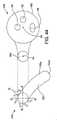
[0160]図22は、第2の実施形態の可撓性部材500である。可撓性部材500は、可撓性部材52と同様であり、軸A3を有する長尺部材として構成される。可撓性部材500は、実質的に円柱形の本体502と、第1の端部すなわち遠位端502aと、第2の端部すなわち近位端(図示されないが、可撓性部材52の近位端52bと実質的に同じである)とを含む。可撓性部材52と同様に、可撓性部材本体502は、実質的に長円形、実質的に六角形、および実質的に長方形などの、任意の他の所望の断面形状を代替的に有し得る。可撓性部材本体502は、上述の第1および第2の長手方向に延びる管路内に位置するビデオ画像形成装置60および光源62、ならびに、吸引チューブとして構成された第3の長手方向に延びる管路58を含む。 [0160] FIG. 22 is the
[0161]可撓性部材500は、挿管組立体ロッド受容部504をさらに含む。挿管組立体ロッド受容部504は、軸A4を有する長尺部材として構成され、実質的に円柱形であり
、第1の端部すなわち遠位端504aを含む。挿管組立体ロッド受容部504の近位端504bは、軸A4が可撓性部材本体502の軸A3と平行であるように、可撓性部材500の本体502から半径方向外向きに長手方向に延びる。挿管組立体ロッド受容部504の遠位端504aが可撓性部材本体502の遠位端502aと実質的に同一平面上にあるように、挿管組立体ロッド受容部504は、約1cmから約5cmの範囲内の長さL2を有する。[0161] The
[0162]代替的に、挿管組立体ロッド受容部504は、実質的に長円形、実質的に六角形、および実質的に長方形などの、任意の他の所望の断面形状を有し得る。さらに、挿管組立体ロッド受容部504は、約0.5cmから約10cmの長さなどの任意の所望の長さL2を有し得る。 [0162] Alternatively, the intubation
[0163]図23は、第3の実施形態の可撓性部材510である。可撓性部材510は、実質的に円柱形の本体512と、第1の端部すなわち遠位端512aと、第2の端部すなわち近位端(図示されないが、可撓性部材52の近位端52bと実質的に同じである)と、軸A3とを含む。可撓性部材本体502と同様に、可撓性部材本体512は、実質的に長円形、実質的に六角形、および実質的に長方形などの、任意の他の所望の断面形状を代替的に有し得る。可撓性部材本体512は、上述の、第1および第2の長手方向に延びる管路内に位置するビデオ画像形成装置60および光源62、ならびに、吸引チューブとして構成された第3の長手方向に延びる管路58を含む。 [0163] FIG. 23 is the
[0164]可撓性部材510は、挿管組立体ロッド受容部514をさらに含む。挿管組立体ロッド受容部514は、軸A4を有する長尺部材として構成され、実質的に円柱形であり、および、第1の端部すなわち遠位端514aを含む。挿管組立体ロッド受容部514の近位端514bは、任意の所望の長さを有し、軸A4が可撓性部材本体512の軸A3と平行であるように可撓性部材510の本体512から半径方向外向きに長手方向に延びる。挿管組立体ロッド受容部514の遠位端514aは、約0.5cmから約2.5cmの範囲内の距離L3ぶん、本体512の遠位端512aを越えて延びる。代替的に、挿管組立体ロッド受容部514の遠位端514aは、約0.1cmから約5cmの距離などの任意の所望の距離L3ぶん、本体512の遠位端512aを越えて延び得る。 [0164] The
[0165]図24は、第4の実施形態の可撓性部材520である。可撓性部材520は、実質的に円柱形の本体522と、第1の端部すなわち遠位端522aと、第2の端部すなわち近位端(図示されないが、可撓性部材52の近位端52bと実質的に同じである)と、軸A3とを含む。可撓性部材本体502と同様に、可撓性部材本体522は、実質的に長円形、実質的に六角形、および実質的に長方形などの、他の所望の任意の断面形状を代替的に有し得る。可撓性部材本体522は、上述の、第1および第2の長手方向に延びる管路内に位置するビデオ画像形成装置60および光源62、ならびに吸引チューブとして構成された第3の長手方向に延びる管路58を含む。 [0165] FIG. 24 is a
[0166]可撓性部材520は、挿管組立体ロッド受容部524をさらに含む。挿管組立体ロッド受容部524は、軸A4を有する長尺部材として構成され、実質的に円柱形であり、任意の所望の長さを有し、および第1の端部すなわち遠位端524aを含む。挿管組立体ロッド受容部524の近位端524bは、可撓性部材本体522の軸A3と平行に、可撓性部材520の本体522から半径方向外向きに長手方向に延びる。挿管組立体ロッド受容部524の遠位端524aは、本体522の遠位端522aまで延びていないが、約0.5cmから約2.5cmの範囲内の距離L4ぶん、本体522の遠位端522aから離間している。代替的に、挿管組立体ロッド受容部524の遠位端524aは、約0.1cmから約7cmの距離などの任意の所望の距離L4ぶん、本体522の遠位端522aから離間され得る。 [0166] The
[0167]図25は、第5の実施形態の可撓性部材530である。可撓性部材530は、可撓性部材52と同様であり、軸A3を有する長尺部材として構成される。可撓性部材530は、実質的に長円形の断面形状を有する本体532と、第1の端部すなわち遠位端532aと、第2の端部すなわち近位端(図示されないが、可撓性部材52の近位端52bと実質的に同じである)とを含む。可撓性部材52と同様に、可撓性部材本体532は、実質的に六角形、実質的に長方形、および実質的に円形などの、他の所望の任意の断面形状を代替的に有し得る。可撓性部材本体532は、上述の、第1および第2の長手方向に延びる管路内に位置するビデオ画像形成装置60および光源62、ならびに、吸引チューブとして構成された第3の長手方向に延びる管路58を含む。 [0167] FIG. 25 is a
[0168]可撓性部材530は、挿管組立体ロッド受容部534をさらに含む。挿管組立体ロッド受容部534は、軸A4を有する長尺部材として構成され、実質的に長円形の断面形状を有し、および第1の端部すなわち遠位端534aを含む。挿管組立体ロッド受容部534は、可撓性部材本体532の軸A3と平行に、可撓性部材500の本体532から半径方向外向きに長手方向に延びる。挿管組立体ロッド受容部534は、弓形間隙または溝536により、本体532から離間している。挿管組立体ロッド受容部534は、長さL2(図22参照)などの任意の所望の長さを有し得、挿管組立体ロッド受容部534の遠位端534aが可撓性部材本体532の遠位端532aと実質的に同一平面上にあるように構成され得る。代替的に、遠位端534aは、長さL3(図23参照)ぶんなど、本体532の遠位端532aを越えて延び得、または、受容部534の遠位端534aが本体532の遠位端532aまで延びないように、距離L4(図24参照)ぶんなど、遠位端532aから離間され得る。さらに、挿管組立体ロッド受容部534は、実質的に六角形および実質的に長方形などの任意の他の所望の断面形状を有し得、および、実質的に円柱形でもあり得る。 [0168] The
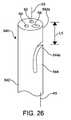
[0169]図26は第6の実施形態の可撓性部材540である。可撓性部材540は、可撓性部材52と同様であり、軸A3を有する長尺部材として構成される。可撓性部材540は、実質的に円柱形の本体542と、第1の端部すなわち遠位端542aと、第2の端部すなわち近位端(図示されないが、可撓性部材52の近位端52bと実質的に同じである)とを含む。可撓性部材本体532と同様に、可撓性部材本体542は、実質的に長円形、実質的に六角形、および実質的に長方形などの、他の所望の任意の断面形状を代替的に有し得る。可撓性部材本体542は、上述の、第1および第2の長手方向に延びる管路内に位置するビデオ画像形成装置60および光源62、ならびに、吸引チューブとして構成された第3の長手方向に延びる管路58を含む。 [0169] FIG. 26 is the
[0170]可撓性部材540は、挿管組立体ロッド受容部544をさらに含む。挿管組立体ロッド受容部544は、軸A5を有する長尺部材として構成され、第1の端部すなわち遠位端544aを含む。挿管組立体ロッド受容部544は、本体542から形成され、弓形間隙または溝546によりそこから分離される。挿管組立体ロッド受容部544の遠位端544aは、本体542の遠位端542aまで延びていないが、約1cmから約2.5cmの範囲内の距離L5ぶん、本体542の遠位端542aから離間している。代替的に、挿管組立体ロッド受容部544の遠位端544aは、約0.5cmから約5cmの距離などの任意の所望の距離L5ぶん、本体542の遠位端542aから離間され得る。 [0170] The
[0171]受容部504、514、524、534、および544などの示される挿管組立体ロッド受容部は、可撓性部材500、510、520、530、および540の遠位端における任意の所望の位置に形成され得、図中に示される位置に限定されないことが理解される。 [0171] The intubation assembly rod receptors shown, such as the
[0172]受容部504、514、524、534、および544の遠位端504a、514a、524a、534a、および544aが、それぞれ、使用中に改善された硬さを提供するために、硬質または半硬質のポリマー、金属、複合材料、または類似材料などの実質的に硬質の材料により形成または補強され得ることがさらに理解される。 [0172] The distal ends 504a, 514a, 524a, 534a, and 544a of the
[0173]図27は、案内される導入体挿管組立体38の第7の実施形態の挿管組立体ロッド550である。挿管組立体ロッド550は、図10に示される挿管組立体ロッド102と同様であり、複数の長手方向および半径方向外向きに延びるリブ104を含み得る。図27に示されないが、挿管組立体ロッド550の近位端は、上述の第1の接続部材82に挿管組立体ロッド550を接続するために構成されたねじ山105をさらに含み得る。 [0173] FIG. 27 is the
[0174]本明細書において説明される挿管組立体ロッドの各実施形態が、リブ74および104以外の特徴を有し得ることが理解される。例えば、リブ74および104の代わりに、挿管組立体ロッド550および本明細書において説明される挿管組立体ロッドの各実施形態を含む挿管組立体ロッドのリブ付部分は、中実の、伸張可能な、または中空で膨張可能な部分を含むように構成され得、その部分の前縁部は、テーパ付の、または実質的に錐台形の移行セグメントを含んで形成され得、移行セグメントはリブ74または104がある場合にはリブ74または104が始まる場所である。挿管組立体ロッド550のこの中実の、伸張可能な、または膨張可能な部分は、気管内チューブ92の内径に対応した所望の外径を有し得るか、または、気管内チューブ92の内径に対応した所望の外径を有するように膨らまされ得る。案内される導入体挿管組立体38および気管内チューブ92の前縁部または遠位端92aが患者の気道内に進行するとき、リブ74および104、ならびに、リブ74および104の代替例を提供する構造物、すなわち、中実の、伸張可能な、または膨張可能な部分、および対応するテーパ付の、または実質的に錐台形の移行セグメントは、喉頭の構造物上に捕捉されることを防ぐように構成され、したがって、声帯の間における気管内チューブ92の送達をしやすくし、声帯および気道の他の部分に対する外傷またはけがを防ぐ。 [0174] It is understood that each embodiment of the intubation assembly rod described herein may have features other than
[0175]ロッド550の遠位端550aは、図示されるように丸みを帯びたもの、またはテーパ付であり得、ロッド550の前端部を規定する。ロッド550の遠位端550aは、案内スリーブ552として構成された案内装置をさらに含み得る。案内スリーブ552は、開放された第1の端部すなわち遠位端552aと、開放された第2の端部すなわち近位端552bとを含み、案内スリーブ552を通って形成された、軸A6を規定する長手方向に延びる実質的に円筒形の経路部552cを含む。示される案内スリーブ552は、受容部504、514、524、534、および544が経路部552c内に挿入され得るように構成される。 [0175] The
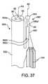
[0176]図28は、案内される導入体挿管組立体38の第8の実施形態の挿管組立体ロッド560である。挿管組立体ロッド560は、挿管組立体ロッド550と同様であり、上述の、長手方向および半径方向外向きに延びるリブ104を含み得る。図28に示されないが、挿管組立体ロッド560は、上述の第1の接続部材82にロッド560を接続するために構成されたねじ山105をさらに含み得る。 [0176] FIG. 28 is the
[0177]ロッド560の遠位端560aは、案内スリーブ562として構成された案内装置をさらに含み得る。案内スリーブ562は、閉じた第1の端部すなわち遠位端562aと、開放された第2の端部すなわち近位端562bとを含む。長手方向に延びる実質的に円筒形の経路部562cは、閉じた遠位端562aから開放された近位端562bまで案内スリーブ562を通って、軸A6を規定するように形成される。示される案内スリーブ562は、受容部504、514、524、534、および54が経路部562c内に挿入され得るように構成される。案内スリーブ562の遠位端562aは、図示されるよう
に丸みを帯びたもの、またはテーパ付であり得、ロッド560の前端部を規定する。[0177] The
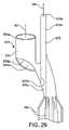
[0178]図29は、案内される導入体挿管組立体38の第9の実施形態の挿管組立体ロッド570である。挿管組立体ロッド570は、挿管組立体ロッド560と同様であり、上述の長手方向および半径方向外向きに延びるリブ104を含み得る。図28に示されないが、挿管組立体ロッド570は、上述の第1の接続部材82に挿管組立体ロッド570を接続するために構成されたねじ山105をさらに含み得る。 [0178] FIG. 29 is the
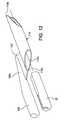
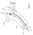
[0179]ロッド570の遠位端570aは、第1の案内スリーブ572と第2の案内スリーブ574とを備える案内装置をさらに含み得る。第1の案内スリーブ572は、閉じた第1の端部すなわち遠位端572aと、ロッド570内に形成された開放された第2の端部すなわち近位端572bとを含む。長手方向に延びる実質的に円筒形の経路部572cは、閉じた遠位端572aから開放された近位端572bまで第1の案内スリーブ572を通って形成され、軸A6を規定する。 [0179] The
[0180]第2の案内スリーブ574は、開放された第1の端部すなわち遠位端574aと、開放された第2の端部すなわち近位端574bとを含む。長手方向に延びる実質的に円筒形の経路部574cは、開放された遠位端574aから開放された近位端574bまで第2の案内スリーブ574を通って形成され、軸A7を規定する。 [0180] The
[0181]示される第1の案内スリーブ572は、受容部504、514、524、534、および544が経路部572c内に挿入され得るように構成される。第1の案内スリーブ572の遠位端572aは、図示されるように丸みを帯びたもの、またはテーパ付であり得、ロッド570の前端部を規定する。同様に、第2の案内スリーブ574は、可撓性部材本体502、512、522、532、および542の遠位端502a、512a、522a、532a、および542aが、それぞれ、経路部574c内に挿入され得るように構成される。所望される場合、第1の案内スリーブ572の遠位端572aが開放され得る。 [0181] The
[0182]図30Aは、案内される導入体挿管組立体38の第10の実施形態の挿管組立体ロッド580である。挿管組立体ロッド580は、上述の挿管組立体ロッド550と同様であり、遠位端580aを含み、軸A8を規定する。挿管組立体ロッド580は、上述の長手方向および半径方向外向きに延びるリブ104を含み得、第1の接続部材82にロッド580を接続するために構成されたねじ山105をさらに含み得る。挿管組立体ロッド580の遠位端580aは、図示されるように丸みを帯びたもの、またはテーパ付であり得、挿管組立体ロッド580の前端部を規定する。 [0182] FIG. 30A is an
[0183]挿管組立体ロッド580は、案内スリーブまたは案内リング582を備える案内装置をさらに含み得る。案内リング582は、開放された第1の端部すなわち遠位端582aと、開放された第2の端部すなわち近位端582bとを含む。長手方向に延びる実質的に円筒形の経路部582cは、案内リング582の遠位端582aから近位端582bまで案内リング582を通って形成され、軸A6を規定する。所望される場合、1つまたは複数の案内リング582が、挿管組立体ロッド580に形成され得る。 [0183] The
[0184]示される案内リング582は、受容部504、514、524、534、および544が経路部582c内に挿入され得るように構成される。代替的に、案内リング582は、可撓性部材本体502、512、522、532、および542の遠位端502a、512a、522a、532a、および542aが、それぞれ、経路部582c内に、および経路部582cを通って挿入され得るように構成され得る。 [0184] The indicated
[0185]図30Bは、案内される導入体挿管組立体38の第11の実施形態の挿管組立体ロッド580’である。挿管組立体ロッド580’は、上述の挿管組立体ロッド580と同様であり、遠位端580a’を含み、軸A8を規定する。挿管組立体ロッド580と同様に、挿管組立体ロッド580’は、上述の長手方向および半径方向外向きに延びるリブ104を含み得、上述の第1の接続部材82にロッド580’を接続するために構成されたねじ山105をさらに含み得る。挿管組立体ロッド580’の遠位端580a’は、図示されるように丸みを帯びたもの、またはテーパ付であり得、挿管組立体ロッド580’の前端部を規定する。 [0185] FIG. 30B is the intubation assembly rod 580'of the eleventh embodiment of the guided
[0186]挿管組立体ロッド580’は、案内スリーブまたは案内リング582’を備える案内装置をさらに含み得る。案内リング582’は、開放された第1の端部すなわち遠位端582a’と、開放された第2の端部すなわち近位端582b’とを含む。長手方向に延びる実質的に円筒形の経路部582c’は、案内リング582’の遠位端582a’から近位端582b’まで案内リング582’を通って形成され、軸A6を規定。所望される場合、1つまたは複数の案内リング582’が、挿管組立体ロッド580’に形成され得る。 [0186] The intubation assembly rod 580'may further include a guide device with a guide sleeve or
[0187]挿管組立体ロッド580’の挿入中に前縁部を規定する案内リング582’の遠位端582a’は軸A6に対して角度584で形成され得るという点で、案内リング582’は案内リング582とは異なる。示される実施形態において、角度584は約45度である。代替的に、案内リング582’の遠位端582a’は、約35度から約65度の間の角度など、軸A6に対して所望の任意の角度584で形成され得る。さらに、案内リング582’の近位端582b’は、遠位端582a’に実質的に平行なある角度で形成され得る。代替的に、近位端は、想像線582b”により示されるように、また、軸A8に対して角度586で形成され得る。例えば、角度586は、約35度から約65度の間の角度など、軸A8に対して所望の任意の角度584であり得る。挿管組立体ロッド580’の除去中に、近位端582b’および582b”が前縁部を規定することが理解される。 [0187] The guide ring 582'is such that during insertion of the
[0188]案内リング582’は、受容部504、514、524、534、および544が経路部582c’内に挿入され得るように構成される。代替的に、案内リング582’は、可撓性部材本体502、512、522、532、および542の遠位端502a、512a、522a、532a、および542aがそれぞれ、経路部582c’内に、および経路部582c’を通って挿入され得るように構成され得る。 [0188] The guide ring 582'is configured such that the
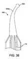
[0189]代替的に、ロッド550、560、570、580、および580’の遠位端550a、560a、570a、580a、および580a’は、図36および図37に564として示されるような球またはボールとして形成され得る。図36および図37に示されるように、挿管組立体ロッド560’は、実質的に挿管組立体ロッド560と同様であり、案内スリーブ562’を含み、長手方向に延びる実質的に円筒形の経路部562c’が、閉じた遠位端562a’から開放された近位端562b’まで案内スリーブ562’を通って形成される。挿管組立体ロッド560’の遠位端は、ボール564として構成される。 [0189] Alternatively, the distal ends of
[0190]代替的に、本明細書において提示および説明される挿管組立体ロッドの実施形態の遠位端は、湾曲したものであり得る。例えば、図38は、湾曲した遠位端630aを含む第12の実施形態の挿管組立体ロッド630を示す。ロッド630は、他の面では上述の挿管組立体ロッド72と同様であり、複数の長手方向および半径方向外向きに延びるリブ74を含み得る。挿管組立体ロッド630の近位端(図示されない)は、上述の第1の接続部材82に挿管組立体ロッド630を接続するために構成されたねじ山73をさらに
含み得る。[0190] Alternatively, the distal end of the embodiment of the intubation assembly rod presented and described herein can be curved. For example, FIG. 38 shows a twelfth embodiment of an
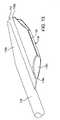
[0191]図38に示されるように、挿管組立体ロッド630の遠位端630aは、球形の先端634で終端し、挿管組立体ロッド630の前端部を規定する。代替的に、挿管組立体ロッド630の遠位端630aは、丸みを帯びたもの、またはテーパ付であり得る。 [0191] As shown in FIG. 38, the
[0192]同様に、図39は、湾曲した遠位端640aを含む第13の実施形態の挿管組立体ロッド640を示す。挿管組立体ロッド640は、上述のロッド560と同様であり、複数の長手方向および半径方向外向きに延びるリブ74を含み得る。挿管組立体ロッド630の近位端(図示されない)は、上述の第1の接続部材82に挿管組立体ロッド630を接続するために構成されたねじ山73をさらに含み得る。 [0192] Similarly, FIG. 39 shows the
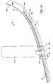
[0193]挿管組立体ロッド640の遠位端640aは、案内スリーブ642として構成された案内装置をさらに含み得る。案内スリーブ642は、開放された第1の端部すなわち遠位端642aと、開放された第2の端部すなわち近位端642bとを含み、案内スリーブ642を通して形成された長尺経路部642cを含む。示される案内スリーブ642は、受容部504、514、524、534、および544が経路部642c内に挿入され得るように構成される。 [0193] The
[0194]図40は、湾曲した遠位端部を含む第14の実施形態の挿管組立体ロッド650をさらに示す。挿管組立体ロッド650は上述の挿管組立体ロッド640と同様であるが、閉じた遠位端652aを含む案内スリーブ652を含む。挿管組立体ロッド650は、複数の長手方向および半径方向外向きに延びるリブ74を含み得る。挿管組立体ロッド630の近位端(図示されない)は、上述の第1の接続部材82に挿管組立体ロッド630を接続するために構成されたねじ山73をさらに含み得る。 [0194] FIG. 40 further shows the
[0195]図40に示されるように、挿管組立体ロッド650の遠位端650aは、案内スリーブ652として構成された案内装置を含む。案内スリーブ652は、閉じた第1の端部すなわち遠位端652aと、開放された第2の端部すなわち近位端652bとを含み、案内スリーブ652を通して形成された長尺経路部652cを含む。示される案内スリーブ652は、受容部504、514、524、534、および544が経路部652c内に挿入され得るように構成される。 [0195] As shown in FIG. 40, the distal end 650a of the
[0196]本明細書において提示および説明される挿管組立体ロッドの実施形態のうちの任意のもの全長は、湾曲したものであり得ることが理解される。代替的に、本明細書において提示および説明される挿管組立体ロッドの実施形態の任意の所望の部分、例えば挿管組立体ロッドの遠位端は、図38から図40に示されるように湾曲したものであり得る。有益には、湾曲した遠位端を含む挿管組立体ロッドは、気管内に、案内される導入体挿管組立体38などの挿管組立体を進めるときに、挿管組立体ロッド遠位端が気管の前壁に、または破裂軟骨などの他の喉頭の構造物に捕捉されるか、または捉えられる可能性を最小化する。 It is understood that the overall length of any of the embodiments of the intubation assembly rod presented and described herein can be curved. Alternatively, any desired portion of the embodiment of the intubation assembly rod presented and described herein, eg, the distal end of the intubation assembly rod, is curved as shown in FIGS. 38-40. It can be a thing. Beneficially, the intubation assembly rod, including the curved distal end, has the distal end of the intubation assembly rod in the trachea as it advances the intubation assembly, such as the introduced
[0197]上述のように、挿管組立体ロッドおよび挿管組立体ロッドのコンポーネントパーツ、すなわち、挿管組立体ロッドに形成された案内装置は、シリコン、ゴム、ワイヤ強化シリコン、ワイヤ強化ゴム、およびポリマーなどの任意の可撓性材料または半可撓性材料により形成され得る。したがって、自由な状態において、すなわち、気管内チューブ92内への挿入前、挿管組立体ロッドは湾曲形状を有し得る。患者の気道内に挿入されたときにロッドに有益な柔軟性を提供することに加えて、挿管組立体ロッドの柔軟性は、気管内チューブ92内にロッドを挿入するとき、ユーザーにより高い制御性をさらに提供する。 [0197] As described above, the intubation assembly rods and the component parts of the intubation assembly rods, i.e., the guides formed on the intubation assembly rods, include silicon, rubber, wire reinforced silicon, wire reinforced rubber, and polymers. Can be formed of any flexible or semi-flexible material. Therefore, in the free state, i.e. before insertion into the
[0198]図31および図32は、図2から図4に示されるように板状部材本体35に装着されるように構成された、および、光学組立体36の可撓性部材52を受容および保持するようにさらに構成された、第2の実施形態の経路部部材600を示す。 [0198] FIGS. 31 and 32 are configured to be mounted on the plate-
[0199]上述のように、および図3および図4にさらに示されるように、板状部材本体35は、長手方向に実質的に直線状であり、弓形の断面形状を有する。代替的に、板状部材本体35、および本明細書において説明される各実施形態の板状部材本体は、ここまでに詳細に説明される、および図11に示される湾曲した板状部材本体44を含んで形成され得る。 [0199] As described above, and as further shown in FIGS. 3 and 4, the plate-
[0200]経路部部材600は、第1の端部すなわち遠位端600aと、第2の端部すなわち近位端(図示されない)とを含み、長手方向に延びる経路部601を規定し、および、板状部材本体35の第1の側35c(図31を見たとき下側)に装着される。示される経路部部材600は、実質的に円形の断面形状を含む。代替的に、経路部部材600は、実質的に長円形、実質的に長方形、または他の幾何学的形状などの、所望の任意の断面形状を有し得る。 [0200]
[0201]図31および図32に示されるように、経路部部材600は、板状部材本体35の第2の縁部35e2(図31を見たとき右端)付近に位置する。代替的に、経路部部材600は、板状部材本体35の第1の縁部35e1の付近(図31を見たとき左縁部)に、または第1の縁部35e1と第2の縁部35e2との間のいずれかの位置に配置され得る。 [0201] As shown in FIGS. 31 and 32, the
[0202]経路部部材600は、経路部部材600から外向きに延びる1つまたは複数の気管内チューブ保持タブ602を含み得る。気管内チューブ保持タブ602は、気管内チューブ92などの気管内チューブが、気管内チューブ保持タブ602にまたは気管内チューブ保持タブ602の中に一時的に配置および保持されることを可能にするように構成される。 [0202] The
[0203]保持タブ602は、長手方向に延びる経路部606を規定し、板状部材本体35の第2の縁部35e2(図31を見たとき右端)から延びる。図31にさらに示されるように、保持タブ602は、実質的に円形の断面形状を有し、経路部606へのアクセスを提供する長尺間隙608を規定する。断面を見たとき、間隙608は、保持タブ602の円周の約120度などの任意の所望の寸法を有し得る。代替的に、間隙608は、保持タブ602の円周の約90度から約180度内であり得る。保持タブ602は、さらに、実質的に長円形、実質的に長方形、または他の幾何学的形状などの任意の所望の断面形状を有し得る。 [0203] The
[0204]保持タブ602は、気管内への気管内チューブ92の配置および送達中に、気管内チューブ92を保持、案内、および制御することに役立つ任意の所望の長さを有し得る。さらに、2つ以上の保持タブ602が提供される場合、各保持タブ602は、経路部部材600における保持タブ602の相対位置により決定された、異なる長さを有し得る。 [0204] The
[0205]任意の所望の数の気管内チューブ保持タブ602が提供され得ることが理解される。さらに、気管内チューブ保持タブ602は、近位端または近位端付近(図31および図32に示されない)、および、例えば図32に示されるような板状部材本体35の遠位端35a、または板状部材本体35の遠位端35a付近を含む、経路部部材600における任意の所望の位置に提供され得る。 [0205] It is understood that any desired number of endotracheal
[0206]保持タブ602は、PVC、ワイヤ強化シリコン、およびステンレス鋼などの任
意の所望の実質的に硬質の材料または半硬質材料により形成され得る。代替的に、保持タブ602は、シリコン、ゴム、ワイヤ強化シリコン、ワイヤ強化ゴム、およびポリマーなどの、任意の可撓性材料または半可撓性材料により形成され得る。可撓性材料または半可撓性材料が、患者の気道内に挿入されたときに保持タブ602に有益な柔軟性を提供することに加えて、この柔軟性はさらに、保持タブ602と保持タブ602に形成された間隙608とに気管内チューブ92の挿入および保持タブ602からの除去をしやすくする十分な柔軟性を提供する。[0206] The
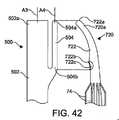
[0207]所望される場合、板状部材本体35は、板状部材本体35の第1の縁部35e1(図31を見たとき左縁部)に沿って形成されたカメラ経路部610を含み得る。カメラ経路部610は、第2のビデオ画像形成装置60’、すなわち、可撓性部材52、500、510、520、530、および540を含む本明細書において説明される可撓性部材のうちの任意のもの内のビデオ画像形成装置60に加えてビデオ画像形成装置を受容するように構成される。カメラ経路部610は、第2の光源62’、すなわち、可撓性部材52、500、510、520、530、および540のうちの任意の1つ内における光源62に加えて光源を受容するようにさらに構成される。 [0207] If desired, the plate-shaped
[0208]第2のビデオ画像形成装置60’は、上述のビデオ画像形成装置60と同じであり得、したがって、CMOSカメラ、CCD、光ファイバーカメラ、および任意の他の直接的または間接的な像形成装置であり得る。したがって、CCDなどの像形成装置のための電気配線は、カメラ経路部610内に延び得る。 [0208] The second video image forming apparatus 60'can be the same as the video
[0209]第2の光源62’は、上述の光源62と同じであり得、したがって、可撓性部材52の遠位端52aなどの可撓性部材の遠位端に取り付けられたLEDランプまたは白熱電球であり得る。代替的に、第2の光源62’は、任意の他の光源であり得る。さらに、第2の光源62’は、光ファイバーケーブルの近位端においてLEDランプ、白熱電球、または任意の他の所望の光源などの照明の光源(図示されない)に接続された、その光ファイバーケーブルであり得る。ビデオ画像形成装置60および60’、ならびに光源62および62’は、図6において66として示される1つまたは複数の可撓性の電気的および/または光学的なコネクタにより、ビデオ表示器40および/または制御装置33に操作可能に接続される。ビデオ表示器40は、2つ以上のビデオ画像形成装置60および/または60’からの像が、分割スクリーン構成などで同じスクリーン上で視認されることを可能にするように構成され得る。代替的に、2つ以上のビデオ画像形成装置60および/または60’からの像が同時に視認されることを可能にするために、2つ以上のビデオ表示器40が提供され得る。 [0209] The second light source 62'can be the same as the
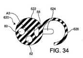
[0210]図33から図35は、第7の実施形態の可撓性部材620を示す。可撓性部材620は、図24に示される可撓性部材520と同様である。可撓性部材620は、実質的に円柱形の本体622と、第1の端部すなわち遠位端622aと、第2の端部すなわち近位端(図示されないが、可撓性部材52の近位端52bと実質的に同じである)と、軸A3とを含む。可撓性部材本体522と同様に、可撓性部材本体622は、実質的に長円形、実質的に六角形、および実質的に長方形などの、他の所望の任意の断面形状を代替的に有し得る。可撓性部材本体622は、上述の、第1および第2の長手方向に延びる管路内に位置するビデオ画像形成装置60および光源62、ならびに吸引チューブとして構成された第3の長手方向に延びる管路58を含む。 [0210] FIGS. 33 to 35 show the
[0211]可撓性部材620は、挿管組立体ロッド受容部624をさらに含む。挿管組立体ロッド受容部624は、軸A4を有する長尺部材として構成され、実質的に円柱形であり、任意の所望の長さを有し、第1の端部すなわち遠位端624aを含む。挿管組立体ロッド受容部624の近位端624bは、可撓性部材本体622の軸A3と平行に、可撓性部
材620の本体622から半径方向外向きに長手方向に延びる。挿管組立体ロッド受容部624の遠位端624aは、本体622の遠位端622aまで延びていないが、約0.5cmから約2.5cmの範囲内の距離L4ぶん、本体622の遠位端622aから離間している。代替的に、挿管組立体ロッド受容部624の遠位端624aは、約0.1cmから約7cmの距離などの任意の所望の距離L4ぶん、本体622の遠位端622aから離間され得る。[0211] The
[0212]可撓性部材本体622は、可撓性部材620から外向きに延びる1つまたは複数の気管内チューブ保持タブ626を含み得る。気管内チューブ保持タブ626は、気管内チューブ92などの気管内チューブが、気管内チューブ保持タブ626にまたは気管内チューブ保持タブ626の中に一時的に配置および保持されることを可能にするように構成される。気管内チューブ保持タブ626は、気管内チューブ保持タブ602と実質的に同じであり、さらに詳細には説明されない。保持タブ626は、気管内への気管内チューブ92の配置および送達中に気管内チューブ92を保持、案内、および制御することに役立つ任意の所望の長さを有し得る。さらに、2つ以上の保持タブ626が提供される場合、各保持タブ626は、可撓性部材本体622における保持タブ626の相対位置により決定された、異なる長さを有し得る。 [0212] The
[0213]本体622の遠位端622aは、上述の、および図6にも示される関節接続継手Jを含み得る。図33に示される可撓性部材620の実施形態では、関節接続継手Jは、好ましくは保持タブ626に隣接して位置し、したがって、ユーザーが気管内チューブ保持タブ626にまたは気管内チューブ保持タブ626内に保持される気管内チューブ92をより正確に制御することを可能にする。 [0213] The
[0214]任意の所望の数の気管内チューブ保持タブ626が提供され得ることが理解される。さらに、気管内チューブ保持タブ626は、可撓性部材620における任意の所望の位置に提供され得る。 [0214] It is understood that any desired number of endotracheal
[0215]図33において、気管内チューブ保持タブ626は、可撓性部材520と実質的に同じである可撓性部材620に形成されて示される。1つまたは複数の気管内チューブ保持タブ626が、可撓性部材52、500、510、520、530、および540を含む、本明細書において説明される可撓性部材のうちの任意のものに形成され得ることが理解される。可撓性部材620は、1つまたは複数の気管内チューブ保持タブ626を含むが、挿管組立体ロッド受容部624を含まないで形成され得ることがさらに理解される。 [0215] In FIG. 33, the endotracheal
[0216]第4の実施形態の気管内チューブ挿入装置の一部分が、図41において700として示される。図41において、気管内チューブ挿入装置700は、図2から図4に示される板状部材本体35と、図16から図18に示される気管内チューブ挿入装置230とのハイブリッドである。 [0216] A portion of the endotracheal tube insertion device of the fourth embodiment is shown as 700 in FIG. In FIG. 41, the endotracheal
[0217]気管内チューブ挿入装置700は、板状部材本体704を含む本体702と、その遠位端702aに形成された全体的にお椀形の声門上カフ706とを含む。所望される場合、気管内チューブ挿入装置700は、上述のハンドル32を含み得る。 [0217] The endotracheal
[0218]板状部材本体704は、板状部材本体35と同様であり、第1の端部すなわち遠位端704aと、第2の端部すなわち近位端(図示されない)とを含むが、これは、図2に示されるハンドル32に装着され得る。板状部材本体35と同様に、板状部材本体704は、長手方向に実質的に直線状であり、弓形の断面形状を有する。図41に示されるように、板状部材本体704は、板状部材本体704に装着されるように構成された、およ
び、経路部部材720の中に可撓性部材52と気管内チューブ92とを受容および保持するようにさらに構成された第3の実施形態の経路部部材720を含み得る。[0218] The plate-
[0219]経路部部材720は、第1の端部すなわち遠位端720aと、第2の端部すなわち近位端(図示されない)とを含み、長手方向に延びる経路部722を規定し、板状部材本体704の下側(図41を見たとき下側)に装着される。示される経路部部材720は、実質的に円形の断面形状を有し、経路部722へのアクセスを提供し、気管内チューブ92を除去しやすくする長尺間隙724を含み得る。代替的に、経路部部材722は、実質的に長円形、実質的に長方形、または他の幾何学的形状などの、所望の任意の断面形状を有し得る。示されるように、可撓性部材52と気管内チューブ92とは、同心に配置され、可撓性部材52が気管内チューブ92内に挿入され、気管内チューブ92が通路経路部722内に挿入される。 [0219]
[0220]経路部部材720は、PVC、ワイヤ強化シリコン、およびステンレス鋼などの、任意の所望の実質的に硬質の材料または半硬質材料により形成され得る。代替的に、経路部部材720は、シリコン、ゴム、ワイヤ強化シリコン、ワイヤ強化ゴム、およびポリマーなどの、任意の可撓性材料または半可撓性材料により形成され得る。患者の気道内に挿入されたときに可撓性材料または半可撓性材料が経路部部材720に有益な柔軟性を提供することに加えて、この柔軟性はさらに、経路部部材720と経路部部材720に形成された間隙724とに、気管内チューブ92の挿入および経路部部材720からの気管内チューブ92の除去をしやすくする十分な柔軟性を提供する。 [0220] The
[0221]所望される場合、可撓性部材52の遠位端52aは、気道内への挿入中に可撓性部材52の遠位端52aの周りで気管内チューブ92の遠位端92aを保持する、ロッド72上のリブ74と同様の、テーパ付の前縁部を含むリブ432(図21にも示される)などの保持および移行特徴を含み得る。代替的に、可撓性部材52の遠位端52aは、例えば図15に示されるような錐台形であり得、したがって、気道内への可撓性部材52の挿入をしやすくする。さらに、可撓性部材52の遠位端52aは、図41に示されるリブ432のテーパ付の前縁部が形成されるエリアと概して同じエリアに、テーパ付または錐台形の前縁部を含む中実の、または膨張可能な部分を含み得る。 [0221] If desired, the
[0222]重要なことに、リブ432、特にリブ432の形状およびテーパ付の前縁部、または改善された気管内チューブ挿入装置700の可撓性部材52の、中実の、または膨張可能な錐台形部を含む代替的な遠位端52aは、可撓性部材52および周辺の気管内チューブ92が患者の気道内に進行するときに可撓性部材52の前縁部または遠位端52aが喉頭の構造物に引っ掛かることを防ぐように構成され、したがって、声帯の間における気管内チューブ92の送達をしやすくし、声帯および気道の他の部分に対する外傷またはけがを防ぐ。 [0222] Importantly, the shape and tapered anterior edge of the
[0223]所望される場合、板状部材本体704は、板状部材本体704の縁部(図41を見たとき左縁部)に沿って形成されたカメラ経路部705を含み得る。カメラ経路部705は、第2のビデオ画像形成装置60’、すなわち、可撓性部材52、500、510、520、530、および540を含む本明細書において説明される可撓性部材のうちの任意のもの内におけるビデオ画像形成装置60に加えて、ビデオ画像形成装置を受容するように構成される。カメラ経路部705は、第2の光源62’、すなわち、可撓性部材52、500、510、520、530、および540のうちの任意の1つ内における光源62に加えて、光源を受容するようにさらに構成される。 [0223] If desired, the plate-shaped
[0224]声門上カフ706は、上述の声門上部材232の声門上カフ237と同様である。声門上カフ706は、第1の端部すなわち遠位端706aと第2の端部すなわち近位端
706bとを含み、声門上カフ706を通して形成された長手方向に延びる通路708と、声門上カフ706の壁を通して形成された長手方向に延びる間隙710とを含む。通路708は、通路708内に位置する板状部材本体704と経路部部材720とカメラ経路部705との合計の寸法よりはるかに大きいとして示される。しかし、声門上カフ706は、通路708の中に板状部材本体704と経路部部材720とカメラ経路部70とを配置するのに十分であるにすぎない大きさの通路708を含んで形成され得ることが理解される。間隙710は、任意の所望の長さと幅とを有し得る。示される全体的に直線形の間隙710に加えて、間隙710は、通路708内において案内される導入体挿管組立体38などの案内される導入体挿管組立体を保持することを補助する、全体的に蛇行したまたは波状のパターン(図示せず)などの、任意の他の所望の形状であり得る。[0224] The
[0225]間隙710は、上述のような案内される導入体挿管組立体38を除去しやすくする。示される実施形態において、通路708は、実質的に長円形の断面形状を有し、したがって、図41に示されない光学組立体36および案内される導入体挿管組立体38などのために空間を提供する。 [0225] The
[0226]声門上カフ706は、当技術分野における従来技術であり得、全体的にお椀形であり、カフ壁712とカフ開口714とを含み、カフ開口714内に光学組立体36と案内される導入体挿管組立体38(図41に示されない)とが延びる。示される通路708は、実質的に長円形の断面形状を有するが、通路708は、実質的に円形および実質的に長方形などの、所望の任意の断面形状を有し得る。さらに、通路708は、任意の他の所望の直径または断面寸法を有し得る。 [0226] The
[0227]声門上カフ706は、上述のゲル様または他の実質的に柔らかい材料のうちの任意のものにより形成され得、喉頭口上への解剖学的な圧入嵌合を提供するように設計され得る。さらに、間隙710が形成される声門上カフ706の一部分は、PVC、シリコン、ゴム、ワイヤ強化シリコン、ワイヤ強化ゴム、およびポリマーなどの、任意の所望の実質的に硬質の材料または半硬質材料により形成され得る。声門上カフ706の間隙710に追加的な剛性を提供することは、間隙710の形状を維持するための、および声門上カフ706の中に気管内チューブ92を保持するための十分な剛性を間隙710に提供するとともに、さらに気管内チューブ92の挿入および声門上カフ706からの除去をしやすくするのに十分な柔軟性を提供する。 [0227] The
[0228]声門上カフ706は、Intersurgical Ltd製のi-gel(登録商標)声門上気道などの膨張不能カフであり得る。膨張不能声門上カフ706は、喉頭口上への解剖学的な圧入嵌合を提供するように設計された、任意のゲル様の、または他の実質的に柔らかい材料により形成され得る。好ましくは、声門上カフ706の形状、柔らかさ、および外形は、喉頭周囲の解剖学的構造を正確に模倣している。代替的に、声門上カフ706、または声門上カフ706のいずれか1つまたは複数の部分は、膨張可能であり得、したがって、図18に示される空気膨張チューブ242などの従来の空気膨張チューブを含む。空気膨張チューブ242は、声門上カフ706に装着され得、シリンジなどの空気源に装着されるように構成される。声門上カフ706は、喉頭蓋と喉頭の構造物とを動かしてユーザーによる声帯の視認性を最適化するように構成された形状を含む任意の所望の形状を有し得ることが理解される。有益には、膨張可能声門上カフ706は、喉頭蓋などの喉頭の構造物をユーザーがより簡単に動かすことを可能にする。声門上カフ706は、接着剤を使用することなどの任意の所望の方法により、板状部材本体704に装着され得る。代替的に、声門上カフ706は、スナップ留め構成を使用すること、または機械的な留め具を使用することなどにより、機械的に板状部材本体704に装着され得る。 [0228] The
[0229]図42から図44は、湾曲した遠位端720aを含む第15の実施形態の挿管組
立体ロッド720を示す。挿管組立体ロッド720は、挿管組立体ロッド720が装着され得る可撓性部材500を含んで示される。可撓性部材500は、本体502と挿管組立体ロッド受容部504とを含む。[0229] FIGS. 42-44 show the
[0230]挿管組立体ロッド720は、上述の挿管組立体ロッド650と同様である。挿管組立体ロッド720は、複数の長手方向および半径方向外向きに延びるリブ74を含み得る。挿管組立体ロッド720の近位端(図示されない)は、上述の第1の接続部材82に挿管組立体ロッド720を接続するために構成されたねじ山73をさらに含み得る。 [0230] The
[0231]図42から図44に示されるように、挿管組立体ロッド720の遠位端720aは、案内スリーブ722として構成された案内装置を含む。案内スリーブ722は、閉じた第1の端部すなわち遠位端722aと、開放された第2の端部すなわち近位端722bとを含み、案内スリーブ722を通して形成された長尺経路部722cを含む。示される案内スリーブ722は、受容部504、514、524、534、および544が経路部722c内に挿入され得るように構成される。 [0231] As shown in FIGS. 42-44, the
[0232]図42から図44に示されるように、挿管組立体ロッド720の遠位端720aは、2方向に屈曲または湾曲している。遠位端720aは、可撓性部材500の本体502に向けて(図42参照)、正のx方向に湾曲している(図44参照)。遠位端720aは、さらに可撓性部材500の本体502から離れるように、負のy方向(図43を見たとき右に)に湾曲している(図44参照)。 [0232] As shown in FIGS. 42-44, the
[0233]ここで図45を参照すると、代替的な実施形態の光学組立体が36’に示される。光学組立体36’は、図16から図18にも示される気管内チューブ挿入装置230内に示される。示される実施形態において、光学組立体36’の光学筐体50’は、光学筐体50’の外面に沿って長手方向に形成されたカメラ経路部51を含む。カメラ経路部51は、第2のビデオ画像形成装置60’、すなわち、可撓性部材52内のビデオ画像形成装置60に加えて、ビデオ画像形成装置を受容するように構成される。カメラ経路部51は、第2の光源62’、すなわち、可撓性部材52内の光源62に加えて、光源を受容するようにさらに構成される。 [0233] With reference to FIG. 45 here, an alternative embodiment of the optical assembly is shown in 36'. The optical assembly 36'is shown in the endotracheal
[0234]カメラ経路部51は、また、説明され、および示される光学組立体の実施形態のうちの任意のものに提供され得ることが理解される。
[0235]第2のビデオ画像形成装置60’は、上述のビデオ画像形成装置60と同じであり得、したがって、CMOSカメラ、CCD、光ファイバーカメラ、および任意の他の直接的または間接的な像形成装置であり得る。したがって、CCDなどの像形成装置のための電気配線は、カメラ経路部51内に延び得る。[0234] It is understood that the
[0235] The second video image forming apparatus 60'can be the same as the video
[0236]第2の光源62’は、上述の光源62と同じであり得、したがって、可撓性部材52の遠位端52aなどの可撓性部材の遠位端に取り付けられたLEDランプまたは白熱電球であり得る。代替的に、第2の光源62’は、任意の他の光源であり得る。さらに、第2の光源62’は、光ファイバーケーブルの近位端においてLEDランプ、白熱電球、または任意の他の所望の光源などの照明の光源(図示されない)に接続された、その光ファイバーケーブルであり得る。ビデオ画像形成装置60および60’および光源62および62’は、図6において66として示される1つまたは複数の可撓性の電気的および/または光学的なコネクタによりビデオ表示器40および/または制御装置33に操作可能に接続される。ビデオ表示器40は、2つ以上のビデオ画像形成装置60および/または60’からの像が分割スクリーン構成などにより同じスクリーン上で視認されることを可能にするように構成され得る。代替的に、2つ以上のビデオ画像形成装置60および/または60’からの像が同時に視認されることを可能にするために、2つ以上のビデオ表示
器40が提供され得る。[0236] The second light source 62'can be the same as the
[0237]ここで図46を参照すると、第3の実施形態の板状部材組立体の端面図が800に示される。板状部材組立体800は、板状部材35と、光学組立体36の可撓性部材52と気管内チューブ92とを受容および保持するように構成された経路部部材801とを含む。示されるように、可撓性部材52と気管内チューブ92とが同心に配置され、可撓性部材52が気管内チューブ92内に挿入され、気管内チューブ92が経路部部材801の経路部802内に挿入される。 [0237] With reference to FIG. 46, an end view of the plate-like member assembly of the third embodiment is shown in 800. The plate-shaped
[0238]上述のように、および図3および図4にさらに示されるように、板状部材本体35は、長手方向に実質的に直線状であり、弓形の断面形状を有する。代替的に、板状部材本体35、および本明細書において説明される各実施形態の板状部材本体は、ここまでに詳細に説明される、および図11に示される湾曲した板状部材本体44を含んで形成され得る。 [0238] As described above, and as further shown in FIGS. 3 and 4, the plate-
[0239]経路部部材801は、板状部材本体35の第1の側35c(図46を見たとき下側)に装着される。示される経路部部材801は、実質的に円形の断面形状を有する。代替的に、経路部部材801は、実質的に長円形、実質的に長方形、または他の幾何学的形状などの、所望の任意の断面形状を有し得る。 [0239] The
[0240]図46に示されるように、経路部部材801は、板状部材本体35の第2の縁部35e2(図46を見たとき右端)付近に位置する。代替的に、経路部部材801は、板状部材本体35の第1の縁部35e1(図46を見たとき左縁部)付近、または第1の縁部35e1と第2の縁部35e2との間のいずれかの位置に配置され得る。 As shown in FIG. 46, the
[0241]経路部部材801は、経路部802へのアクセスを提供する、経路部部材801に形成された長尺の長手方向に延びる間隙804を含む。
[0242]図46に示されるように、経路部部材801の間隙804は、板状部材本体35の第2の縁部35e2(図46を見たとき右端)に向けて開放される。代替的に、経路部部材801の間隙804は、板状部材本体35の第1の縁部35e1(図31を見たとき左縁部)に向けてなど、任意の所望の方向に開放され得る。図46にさらに示されるように、経路部部材801は、板状部材本体35の第2の縁部35e2(図46を見たとき右端)付近に位置する。代替的に、経路部部材801は、板状部材本体35の第1の縁部35e1(図46を見たとき左縁部)付近、または第1の縁部35e1と第2の縁部35e2との間のいずれかの位置に配置され得る。[0241] The
[0242] As shown in FIG. 46, the
[0243]図46に示されないが、可撓性部材52の遠位端52aは、気道内への挿入中に気管内チューブ92の遠位端(図46に示されない)を可撓性部材52の遠位端(図46に示されない)の周りに保持するために、ロッド72上のリブ74と同様のテーパ付の前縁部を含む(図21および図41にも示される)リブ432などの保持機構を有し得る。代替的に、可撓性部材52の遠位端(図46に示されない)は、例えば図15に示されるような錐台形であり得、したがって、気道内への可撓性部材52の挿入をしやすくする。さらに、可撓性部材52の遠位端(図46に示されない)は、例えば図41に示されるようなリブ432のテーパ付の前縁部が形成されるエリアと概して同じエリアに、テーパ付または錐台形の前縁部を含む中実の、または膨張可能な部分を含み得る。 [0243] Although not shown in FIG. 46, the
[0244]重要なことに、リブ432、特にリブ432の形状およびテーパ付の前縁部、または改善された板状部材組立体800の可撓性部材52の中実の、または膨張可能な錐台形部を含む代替的な遠位端(図46に示されない)は、可撓性部材52および周辺の気管内チューブ92が患者の気道内に進行するときに、可撓性部材52の前縁部または遠位端
(図46に示されない)が喉頭の構造物に引っ掛かることを防ぐように構成され、したがって、声帯の間における気管内チューブ92の送達をしやすくし、声帯および気道の他の部分に対する外傷またはけがを防ぐ。[0244] Importantly, the shape and tapered front edges of the
[0245]本発明の原理と動作形態とが、その好ましい実施形態において説明および例示される。しかし、本発明は、その趣旨または範囲から逸脱することなく、特に説明および例示されるものとは異なる手法で実施され得ることが理解されなければならない。
本発明は、以下の態様を含む。
1. 挿入部材と、
前記挿入部材に可動に取り付けられた可撓性光学組立体部材と、
気管内チューブと、
前記挿入部材に装着され前記気管内チューブを受容および保持するように構成された気管内チューブ装着部材と、
を備える、気管内チューブ挿入装置。
2. 前記気管内チューブが、前記可撓性光学組立体部材の周りで同心に取り付けられ、前記気管内チューブ装着部材が長尺経路部部材であり、前記長尺経路部部材が、前記挿入部材の近位端から遠位端へ延び前記可撓性光学組立体部材と同心に取り付けられた前記気管内チューブとを受容および保持するように構成され、前記長尺経路部部材が、前記長尺経路部部材に形成された長尺間隙を含み、前記長尺間隙が、前記経路部へのアクセスを提供するように、および前記気管内チューブを除去しやすくするように構成された、
上記1.に記載の気管内チューブ挿入装置。
3. 長尺の閉じた経路部部材をさらに含み、前記長尺の閉じた経路部部材が、前記挿入部材に装着され前記長尺の閉じた経路部部材の中に前記可撓性光学組立体部材を受容および保持するように構成され、前記気管内チューブ装着部材が気管内チューブ保持タブであり、前記気管内チューブ保持タブが、前記経路部部材から外向きに延び前記気管内チューブ保持タブの中に前記気管内チューブが配置および保持されることを可能にするように構成された、
上記1.に記載の気管内チューブ挿入装置。
4. 前記気管内チューブ保持タブが、実質的に円形の断面形状を有し、長手方向に延びる経路部を規定し、および、前記気管内チューブ保持タブの中に形成された長尺間隙を含み、前記長尺間隙が、前記経路部へのアクセスを提供するように、および前記気管内チューブを除去しやすくするように構成された、
上記3.に記載の気管内チューブ挿入装置。
5. 前記挿入部材が、長尺板状部材である、
上記4.に記載の気管内チューブ挿入装置。
6. 前記可撓性光学組立体部材が、長尺本体を含み、前記長尺本体が、実質的に円柱形であり、複数の長手方向に延びる管路が、前記長尺本体の中に形成され、前記管路が、前記管路の中に位置する第1のビデオ画像形成装置および第1の光源のうちの1つまたは複数を有するように構成された、
上記5.に記載の気管内チューブ挿入装置。
7. 前記板状部材の縁部に沿って形成された長尺経路部をさらに含み、前記長尺経路部が、前記長尺経路部の中に第2のビデオ画像形成装置および第2の光源のうちの少なくとも1つを受容するように構成された、
上記6.に記載の気管内チューブ挿入装置。
8. 前記挿入部材が、第1の部分と第2の部分とを含み、前記第1の部分が、第1の端部と、第2の端部と、前記第1の部分を通して形成された長手方向に延びる通路と、前記第1の部分の壁を通して形成された長手方向に延びる間隙とを含む声門上部材を規定し、前記声門上部材が、前記声門上部材の前記第1の端部に形成された全体的にボウル形の声門上カフをさらに含み、前記声門上カフが、カフ壁とカフ開口とを含み、前記カフ開口内に前記可撓性光学組立体部材と前記気管内チューブとが延び、前記声門上カフが、膨張可能カフおよび部分的膨張可能カフおよび膨張不能カフのうちの1つとしてさらに構成され、
前記挿入部材の前記第2の部分が、前記声門上部材の前記長手方向に延びる通路に装着され、前記長手方向に延びる通路から外向きに延びる、
上記1.に記載の気管内チューブ挿入装置。
9. 前記挿入部材が、板状部材である、
上記8.に記載の気管内チューブ挿入装置。
10. 長尺本体を含む可撓性光学組立体部材であって、前記長尺本体が、実質的に円柱形であり、複数の長手方向に延びる管路が、前記長尺本体の中に形成され、前記管路が、前記管路の中に位置する第1のビデオ画像形成装置および第1の光源のうちの1つまたは複数を有するように構成された、可撓性光学組立体部材と、
前記板状部材に装着され前記可撓性光学組立体部材を受容および保持するように構成された長尺経路部部材と、
をさらに含み、
前記気管内チューブが、前記長尺経路部部材の長手方向に延びる経路部内において前記可撓性光学組立体部材の周りで同心に取り付けられ、
前記長尺経路部部材が、実質的に円形の断面形状を有し、および、前記長尺経路部部材に形成された長尺間隙を含み、前記長尺間隙が、前記経路部へのアクセスを提供するように、および前記気管内チューブを除去しやすくするように構成された、
上記9.に記載の気管内チューブ挿入装置。
11. 前記板状部材の表面に沿って形成された長尺経路部をさらに含み、前記長尺経路部が、前記長尺経路部の中に第2のビデオ画像形成装置および第2の光源のうちの少なくとも1つを受容するように構成された、
上記10.に記載の気管内チューブ挿入装置。
12. 気管内チューブ挿入装置とともに使用するために構成された光学組立体であって、前記光学組立体が、
実質的に円柱形である長尺本体と遠位端と近位端とを有する可撓性部材と、
前記可撓性部材により搬送される気管内チューブと、
前記可撓性部材から外向きに延び前記気管内チューブが気管内チューブ保持タブの中に配置および保持されることを可能にするように構成された前記気管内チューブ保持タブと、
を備え、
前記気管内チューブ保持タブが、実質的に円形の断面形状を有し、長手方向に延びる経路部を規定し、および、前記気管内チューブ保持タブの中に形成された長尺間隙を含み、前記長尺間隙が、前記経路部へのアクセスを提供するように、および前記気管内チューブを除去しやすくするように構成された、
光学組立体。
13. 前記可撓性部材の前記遠位端が、関節接続継手を含み、前記関節接続継手が、前記気管内チューブ保持タブ内に保持される前記気管内チューブの動きが正確に制御され得るように、前記気管内チューブ保持タブに隣接した、および、前記可撓性部材の前記遠位端の関節接続の動きのために構成された、
上記12.に記載の光学組立体。
14. 前記可撓性部材が、前記可撓性部材本体の前記遠位端と前記気管内チューブ保持タブとの間において、前記可撓性部材に形成された挿管組立体ロッド受容部をさらに含む、
上記12.に記載の光学組立体。
15. 前記可撓性部材が、前記可撓性部材本体の前記遠位端と前記気管内チューブ保持タブとの間において、前記可撓性部材に形成された挿管組立体ロッド受容部をさらに含む、
上記13.に記載の光学組立体。
16. 前記挿管組立体ロッド受容部が、前記可撓性部材本体の軸に対して実質的に平行な軸を含む長尺部材として構成され、実質的に円柱形であり、および、遠位端と近位端とを含み、前記挿管組立体ロッド受容部の前記近位端が、前記可撓性部材本体から半径方向外向きに長手方向に延びる、
上記14.に記載の光学組立体。
17. 前記可撓性部材本体が、前記可撓性部材本体の中に形成された複数の長手方向に延びる管路を含み、前記管路が、前記管路の中に位置するビデオ画像形成装置および光源のうちの1つまたは複数を有するように構成された、
上記12.に記載の光学組立体。
18. 気管内チューブ挿入装置とともに使用するために構成された光学組立体であって、前記光学組立体が、
長尺光学筐体と、
前記光学筐体内において滑動可能に取り付けられた可撓性部材であって、前記可撓性部材が、実質的に円柱形である長尺本体と、遠位端と、近位端と、前記長尺本体の中に形成された複数の長手方向に延びる管路とを含み、前記管路が、前記管路の中に位置する第1のビデオ画像形成装置および第1の光源のうちの1つまたは複数を有するように構成された、可撓性部材と、
前記光学筐体の外面に沿って形成された長尺経路部であって、前記長尺経路部が、前記長尺経路部の中に第2のビデオ画像形成装置および第2の光源のうちの少なくとも1つを受容するように構成された、長尺経路部と、
を備える、光学組立体。
19. 気管内チューブ挿入装置とともに使用するために構成された光学組立体であって、前記光学組立体が、
実質的に円柱形である長尺本体と遠位端と近位端とを含む可撓性部材であって、複数の長手方向に延びる管路が、前記長尺本体の中に形成され、前記管路が、前記管路の中に位置する第1のビデオ画像形成装置および第1の光源のうちの1つまたは複数を有するように構成された、可撓性部材と、
前記可撓性部材本体の前記遠位端に形成された挿管組立体ロッド受容部であって、前記挿管組立体ロッド受容部が、挿管組立体ロッドに装着されるように構成された、挿管組立体ロッド受容部と、
を備える、光学組立体。
20. 前記挿管組立体ロッド受容部が、前記可撓性部材本体の軸に対して実質的に平行な軸を含む長尺部材として構成され、実質的に円柱形であり、および、遠位端と近位端とを含み、前記挿管組立体ロッド受容部の前記近位端が、前記可撓性部材本体から半径方向外向きに長手方向に延びる、
上記19.に記載の光学組立体。
21. 前記挿管組立体ロッド受容部が、前記可撓性部材本体の前記遠位端の端面に形成された弓形間隙として構成された、
上記19.に記載の光学組立体。
22. 前記挿管組立体ロッド受容部が、前記可撓性部材本体に形成された弓形間隙として構成され、前記弓形間隙が、半径方向内向きに前記可撓性部材本体の前記遠位端から離れるように前記可撓性部材本体の外面から延びる、
上記19.に記載の光学組立体。
23. 挿管組立体ロッドをさらに含み、前記挿管組立体ロッドが、挿管組立体ロッドにより搬送される気管内チューブを含むように構成され、かつ前記光学組立体の前記可撓性部材本体に装着されるようにさらに構成され、前記挿管組立体ロッドが、遠位端と近位端とを含む実質的に円筒形であり、前記挿管組立体ロッドの前記遠位端が、テーパ付である、丸みを帯びている、および球形のうちの1つであり、前記挿管組立体ロッドの前端部を規定し、前記挿管組立体ロッドが、前記挿管組立体ロッドの前記遠位端において前記挿管組立体ロッドを通して形成された長手方向に延びる実質的に円筒形の経路部を含み、前記経路部が、前記組立体ロッド受容部が前記経路部内に挿入され得るように構成された、
上記19.に記載の光学組立体。
24. 前記挿管組立体ロッドに装着され前記可撓性部材本体の前記遠位端が案内スリーブ内に挿入され得るように構成された前記案内スリーブをさらに含む、
上記23.に記載の光学組立体。
25. 前記挿管組立体ロッドの前記遠位端が、湾曲した、
上記23.に記載の光学組立体。
26.
挿管組立体ロッドをさらに含み、前記挿管組立体ロッドが、挿管組立体ロッドにより搬送される気管内チューブを含むように構成され、かつ前記光学組立体の前記可撓性部材本体に装着されるようにさらに構成され、前記挿管組立体ロッドが、実質的に円筒形であり、遠位端と近位端とを含み、前記挿管組立体ロッドの前記遠位端が、テーパ付である、丸みを帯びている、および球形のうちの1つであり、前記挿管組立体ロッドの前端部を規定し、前記挿管組立体ロッドが、前記挿管組立体ロッドから半径方向外向きに延び案内スリーブを通して形成された長手方向に延びる経路部を有する前記案内スリーブを含み、前記経路部が、前記組立体ロッド受容部が前記経路部内に挿入され得るように構成された、
上記19.に記載の光学組立体。
27. 前記案内スリーブの遠位端面が、前記挿管組立体ロッドの軸に対して角度をなして位置する、
上記26.に記載の光学組立体。
28. 前記案内スリーブの近位端面が、前記挿管組立体ロッドの軸に対して角度をなして位置する、
上記26.に記載の光学組立体。
29. 挿管組立体ロッドをさらに含み、前記挿管組立体ロッドが、挿管組立体ロッドにより搬送される気管内チューブを含むように構成され、かつ前記光学組立体の前記可撓性部材本体に装着されるようにさらに構成され、前記挿管組立体ロッドが、実質的に円筒形であり、遠位端と近位端とを含み、前記挿管組立体ロッドの前記遠位端が、テーパ付である、丸みを帯びている、および球形のうちの1つであり、前記挿管組立体ロッドの前端部を規定し、前記挿管組立体ロッドの前記遠位端が、湾曲した、
上記19.に記載の光学組立体。
30. 挿管組立体ロッドをさらに含み、前記挿管組立体ロッドが、挿管組立体ロッドにより搬送される気管内チューブを含むように構成され、かつ前記光学組立体の前記可撓性部材本体に装着されるようにさらに構成され、前記挿管組立体ロッドが、実質的に円筒形であり、遠位端と近位端とを含み、前記挿管組立体ロッドの前記遠位端が、テーパ付である、丸みを帯びている、および球形のうちの1つであり、前記挿管組立体ロッドの前端部を規定し、前記挿管組立体ロッドが、前記挿管組立体ロッドの前記遠位端において前記挿管組立体ロッドを通して形成された長手方向に延びる実質的に円筒形の経路部を含み、前記経路部が、前記組立体ロッド受容部が前記経路部内に挿入され得るように構成され、前記挿管組立体ロッドの前記遠位端が、2方向に湾曲した、
上記19.に記載の光学組立体。
31. 長尺挿入部材と、
前記長尺挿入部材に可動に取り付けられた可撓性光学組立体部材であって、前記可撓性光学組立体部材の遠位端が、長手方向及び半径方向外向きに延びて前記遠位端に向けてテーパを有する複数のリブを含むか、または、錐台形状を含む可撓性光学組立体部材と、
気管内チューブと、
前記長尺挿入部材に装着され前記気管内チューブを受容および保持するように構成された気管内チューブ装着部材と、
を備え、
前記気管内チューブが、前記可撓性光学組立体部材の周りで同心に取り付けられ、前記気管内チューブ装着部材が長尺経路部部材であり、前記長尺経路部部材が、前記長尺挿入部材の近位端から遠位端へ延び、前記可撓性光学組立体部材と、同心に取り付けられた前記気管内チューブとを受容および保持するように構成され、前記長尺経路部部材が、前記長尺経路部部材に形成された長尺間隙を含み、前記長尺間隙が、前記長尺経路部部材の経路部へのアクセスを提供するように、および前記気管内チューブを除去しやすくするように構成され、
前記長尺挿入部材が、第1の部分と第2の部分とを含み、前記第1の部分が、第1の端部と、第2の端部と、前記第1の部分を通して形成された長手方向に延びる通路と、前記第1の部分の壁を通して形成された長手方向に延びる間隙とを含む声門上部材を規定し、前記声門上部材が、前記声門上部材の前記第1の端部に形成された全体的にボウル形の声門上カフをさらに含み、前記声門上カフが、カフ壁とカフ開口とを含み、前記カフ開口内に前記可撓性光学組立体部材と前記気管内チューブとが延び、前記声門上カフが、膨張可能カフおよび部分的膨張可能カフおよび膨張不能カフのうちの1つとしてさらに構成され、
前記長尺挿入部材の前記第2の部分が、前記声門上部材の前記長手方向に延びる通路に装着され、前記長手方向に延びる通路から外向きに延びる、
気管内チューブ挿入装置。
32. 長尺板状部材と、
前記長尺板状部材に可動に取り付けられた可撓性光学組立体部材であって、前記可撓性光学組立体部材の遠位端が、長手方向及び半径方向外向きに延びて前記遠位端に向けてテーパを有する複数のリブを含むか、または、錐台形状を含む可撓性光学組立体部材と、
気管内チューブと、
長尺の閉じた経路部部材であって、前記長尺板状部材に装着され円形の断面形状を有する長手方向に延びる経路部を規定し、前記長尺の閉じた経路部部材の中に前記可撓性光学組立体部材を受容および保持するように構成される、長尺の閉じた経路部部材と、
気管内チューブ保持タブであって、前記長尺の閉じた経路部部材から半径方向外向きに延び、円形の断面形状を有し、長手方向に延びる経路部を規定し、前記気管内チューブ保持タブに形成された長尺空隙を有し、前記気管内チューブ保持タブの中に前記気管内チューブが配置および保持されることを可能にするように構成された気管内チューブ保持タブと、
を備える、気管内チューブ挿入装置。
33. 前記気管内チューブ保持タブが、実質的に円形の断面形状を有し、長手方向に延びる経路部を規定し、および、前記気管内チューブ保持タブの中に形成された長尺間隙を含み、前記気管内チューブ保持タブの前記長尺間隙が、前記気管内チューブ保持タブの前記長手方向に延びる経路部へのアクセスを提供するように、および前記気管内チューブを除去しやすくするように構成された、
上記32.に記載の気管内チューブ挿入装置。
34. 前記可撓性光学組立体部材が、長尺本体を含み、前記長尺本体が、実質的に円柱形であり、複数の長手方向に延びる管路が、前記長尺本体の中に形成され、前記複数の長手方向に延びる管路が、前記管路の中に位置する第1のビデオ画像形成装置および第1の光源のうちの1つまたは複数を有するように構成された、
上記33.に記載の気管内チューブ挿入装置。
35. 前記長尺板状部材の縁部に沿って形成された長尺経路部をさらに含み、前記長尺経路部が、前記長尺経路部の中に第2のビデオ画像形成装置および第2の光源のうちの少なくとも1つを受容するように構成された、
上記34.に記載の気管内チューブ挿入装置。
36. さらに、前記長尺挿入部材の前記第2の部分の表面に沿って形成される長尺カメラ経路部部材を含み、前記長尺挿入部材の前記第2の部分の前記長尺カメラ経路部部材は、ビデオ画像形成装置及び光源のうちの少なくとも一方を有する、上記31.に記載の気管内チューブ挿入装置。
37. さらに、前記声門上部材の前記長手方向に延びる通路の内面に装着される長尺カメラ経路部部材を含み、前記長手方向に延びる通路の前記内面の前記長尺カメラ経路部部材は、ビデオ画像形成装置及び光源のうちの少なくとも一方を受容するように構成された、上記31.に記載の気管内チューブ挿入装置。
38. 前記長尺挿入部材の前記第2の部分は、板状部材である、上記31.に記載の気管内チューブ挿入装置。[0245] Principles and modes of operation of the invention are described and exemplified in preferred embodiments thereof. However, it must be understood that the invention can be practiced in a manner different from that specifically described and exemplified, without departing from its spirit or scope.
The present invention includes the following aspects.
1. 1. Insertion member and
A flexible optical assembly member movably attached to the insertion member,
Endotracheal tube and
An endotracheal tube mounting member mounted on the insertion member and configured to receive and hold the endotracheal tube.
An endotracheal tube insertion device.
2. 2. The endotracheal tube is concentrically attached around the flexible optical assembly member, the endotracheal tube mounting member is a long path member, and the long path member is close to the insertion member. It is configured to receive and hold the endotracheal tube extending concentrically from the flexible optical assembly member extending from the position end to the distal end, and the long path portion member is the long path portion. A long gap formed in the member is included, the long gap being configured to provide access to the pathway and to facilitate removal of the endotracheal tube.
Above 1. The endotracheal tube insertion device described in.
3. 3. Further including a long closed path member, the long closed path member is mounted on the insertion member and the flexible optical assembly member is placed in the long closed path member. Configured to receive and hold, the endotracheal tube mounting member is an endotracheal tube holding tab, and the endotracheal tube holding tab extends outward from the pathway member into the endotracheal tube holding tab. The endotracheal tube was configured to allow placement and retention.
Above 1. The endotracheal tube insertion device described in.
4. The endotracheal tube holding tab has a substantially circular cross-sectional shape, defines a longitudinally extending path, and comprises an elongated gap formed within the endotracheal tube holding tab. The long gap was configured to provide access to the pathway and to facilitate removal of the endotracheal tube.
Above 3. The endotracheal tube insertion device described in.
5. The insertion member is a long plate-shaped member.
Above 4. The endotracheal tube insertion device described in.
6. The flexible optical assembly member includes a long body, the long body is substantially cylindrical, and a plurality of longitudinally extending conduits are formed in the long body. The conduit is configured to have one or more of a first video image forming apparatus and a first light source located in the conduit.
Above 5. The endotracheal tube insertion device described in.
7. Further including a long path portion formed along the edge portion of the plate-shaped member, the long path portion is included in the long path portion among the second video image forming apparatus and the second light source. Configured to accept at least one of,
6. Above. The endotracheal tube insertion device described in.
8. The insertion member includes a first portion and a second portion, and the first portion is formed through a first end portion, a second end portion, and the first portion in the longitudinal direction. Defines an supraglottic member comprising a passage extending to the glottis and a longitudinally extending gap formed through the wall of the first portion, the supraglottic member being formed at the first end of the supraglottic member. It further comprises an overall bowl-shaped supraglottic cuff, wherein the supraglottic cuff comprises a cuff wall and a cuff opening, and within the cuff opening the flexible optical assembly member and the endotracheal tube. Extending, the supraglottic cuff is further configured as one of an inflatable cuff and a partially inflatable cuff and an inflatable cuff.
The second portion of the insertion member is attached to the longitudinally extending passage of the supraglottic member and extends outward from the longitudinally extending passage.
Above 1. The endotracheal tube insertion device described in.
9. The insertion member is a plate-shaped member.
8. above. The endotracheal tube insertion device described in.
10. A flexible optical assembly member including a long body, wherein the long body is substantially cylindrical, and a plurality of longitudinally extending conduits are formed in the long body. A flexible optical assembly member configured such that the conduit has one or more of a first video image forming apparatus and a first light source located in the conduit.
A long path member mounted on the plate-shaped member and configured to receive and hold the flexible optical assembly member.
Including
The endotracheal tube is concentrically attached around the flexible optical assembly member within the longitudinally extending path portion of the long path section member.
The long path section member has a substantially circular cross-sectional shape and includes a long gap formed in the long path section member, and the long path section provides access to the path section. Configured to provide and facilitate removal of the endotracheal tube.
9. above. The endotracheal tube insertion device described in.
11. Further including a long path portion formed along the surface of the plate-shaped member, the long path portion is included in the long path portion among a second video image forming apparatus and a second light source. Configured to accept at least one,
10. The endotracheal tube insertion device described in.
12. An optical assembly configured for use with an endotracheal tube insertion device, said optical assembly.
A flexible member having a substantially cylindrical long body and a distal end and a proximal end,
The endotracheal tube conveyed by the flexible member and
The endotracheal tube holding tab, which extends outward from the flexible member and is configured to allow the endotracheal tube to be placed and held within the endotracheal tube holding tab.
Equipped with
The endotracheal tube holding tab has a substantially circular cross-sectional shape, defines a longitudinally extending path, and comprises an elongated gap formed within the endotracheal tube holding tab. The long gap was configured to provide access to the pathway and to facilitate removal of the endotracheal tube.
Optical assembly.
13. The distal end of the flexible member comprises a joint connection joint so that the movement of the endotracheal tube in which the joint connection joint is held within the endotracheal tube holding tab can be precisely controlled. Adjacent to the endotracheal tube holding tab and configured for the movement of the distal end joint connection of the flexible member.
12. above. The optical assembly described in.
14. The flexible member further comprises an intubation assembly rod receiving portion formed in the flexible member between the distal end of the flexible member body and the endotracheal tube holding tab.
12. above. The optical assembly described in.
15. The flexible member further comprises an intubation assembly rod receiving portion formed in the flexible member between the distal end of the flexible member body and the endotracheal tube holding tab.
13. The optical assembly described in.
16. The intubation assembly rod receiver is configured as a long member comprising an axis substantially parallel to the axis of the flexible member body, is substantially cylindrical, and is close to the distal end. The proximal end of the intubation assembly rod receiving portion, including the position end, extends radially outwardly and longitudinally from the flexible member body.
14. The optical assembly described in.
17. The flexible member body includes a plurality of longitudinally extending conduits formed in the flexible member body, wherein the conduit is a video image forming apparatus and a light source located in the conduit. Configured to have one or more of,
12. above. The optical assembly described in.
18. An optical assembly configured for use with an endotracheal tube insertion device, said optical assembly.
With a long optical housing,
A flexible member slidably mounted within the optical housing, wherein the flexible member has a substantially cylindrical long body, a distal end, a proximal end, and the length. The conduit is one of a first video image forming apparatus and a first light source located in the conduit, including a plurality of longitudinally extending conduits formed in the shaku body. Or with a flexible member configured to have more than one,
A long path portion formed along the outer surface of the optical housing, wherein the long path portion is one of a second video image forming apparatus and a second light source in the long path portion. A long pathway section configured to receive at least one, and
An optical assembly.
19. An optical assembly configured for use with an endotracheal tube insertion device, said optical assembly.
A flexible member including a substantially cylindrical long body and a distal end and a proximal end, wherein a plurality of longitudinally extending conduits are formed in the long body. A flexible member configured such that the conduit has one or more of a first video image forming apparatus and a first light source located in the conduit.
An intubation assembly rod receiving portion formed at the distal end of the flexible member body, wherein the intubation assembly rod receiving portion is mounted on the intubation assembly rod. Three-dimensional rod receiver and
An optical assembly.
20. The intubation assembly rod receiver is configured as a long member comprising an axis substantially parallel to the axis of the flexible member body, is substantially cylindrical, and is close to the distal end. The proximal end of the intubation assembly rod receiving portion, including the position end, extends radially outwardly and longitudinally from the flexible member body.
19. The optical assembly described in.
21. The intubation assembly rod receiving portion is configured as an arcuate gap formed on the distal end face of the flexible member body.
19. The optical assembly described in.
22. The intubation assembly rod receiving portion is configured as an arched gap formed in the flexible member body so that the arched gap is radially inwardly separated from the distal end of the flexible member body. Extending from the outer surface of the flexible member body,
19. The optical assembly described in.
23. Further including an intubation assembly rod, such that the intubation assembly rod is configured to include an intratracheal tube carried by the intubation assembly rod and is mounted to the flexible member body of the optical assembly. Further configured, the intubation assembly rod is substantially cylindrical, including a distal end and a proximal end, and the distal end of the intubation assembly rod is tapered, rounded. And one of the spheres that define the front end of the intubation assembly rod, the intubation assembly rod being formed through the intubation assembly rod at the distal end of the intubation assembly rod. It comprises a substantially cylindrical path section extending in the longitudinal direction, wherein the path section is configured such that the assembly rod receiving portion can be inserted into the path section.
19. The optical assembly described in.
24. Further comprising the guide sleeve mounted on the intubation assembly rod and configured such that the distal end of the flexible member body can be inserted into the guide sleeve.
23. above. The optical assembly described in.
25. The distal end of the intubation assembly rod is curved,
23. above. The optical assembly described in.
26.
Further including an intubation assembly rod, such that the intubation assembly rod is configured to include an intratracheal tube carried by the intubation assembly rod and is mounted to the flexible member body of the optical assembly. Further configured, the intubation assembly rod is substantially cylindrical and includes a distal end and a proximal end, the distal end of the intubation assembly rod being tapered, rounded. One of the tinged and spherical, defining the front end of the intubation assembly rod, the intubation assembly rod extending radially outward from the intubation assembly rod and formed through a guide sleeve. A guide sleeve having a longitudinally extending pathway is included, the pathway being configured such that the assembly rod receiving portion can be inserted into the pathway.
19. The optical assembly described in.
27. The distal end face of the guide sleeve is located at an angle to the axis of the intubation assembly rod.
26. The optical assembly described in.
28. The proximal end face of the guide sleeve is located at an angle to the axis of the intubation assembly rod.
26. The optical assembly described in.
29. Further including an intubation assembly rod, such that the intubation assembly rod is configured to include an intratracheal tube carried by the intubation assembly rod and is mounted to the flexible member body of the optical assembly. Further configured, the intubation assembly rod is substantially cylindrical and includes a distal end and a proximal end, the distal end of the intubation assembly rod being tapered, rounded. One of the tinged and spherical, defining the anterior end of the intubation assembly rod, the distal end of the intubation assembly rod being curved.
19. The optical assembly described in.
30. Further including an intubation assembly rod, such that the intubation assembly rod is configured to include an intratracheal tube carried by the intubation assembly rod and is mounted to the flexible member body of the optical assembly. Further configured, the intubation assembly rod is substantially cylindrical and includes a distal end and a proximal end, and the distal end of the intubation assembly rod is tapered, rounded. One of the tinged and spherical, defining the anterior end of the intubation assembly rod, the intubation assembly rod passing through the intubation assembly rod at the distal end of the intubation assembly rod. A substantially cylindrical path portion extending in the formed longitudinal direction is included, the path portion is configured such that the assembly rod receiving portion can be inserted into the path portion, and the distance of the intubation assembly rod. The end is curved in two directions,
19. The optical assembly described in.
31. With a long insertion member,
A flexible optical assembly member movably attached to the long insertion member, wherein the distal end of the flexible optical assembly member extends longitudinally and radially outwards to the distal end. Flexible optical assembly members that include multiple ribs that taper towards or include a frustum shape.
Endotracheal tube and
An endotracheal tube mounting member mounted on the long insertion member and configured to receive and hold the endotracheal tube.
Equipped with
The endotracheal tube is concentrically attached around the flexible optical assembly member, the endotracheal tube mounting member is a long path member, and the long path member is the long insertion member. Extending from the proximal end to the distal end of the Including the long gap formed in the long path member so that the long gap provides access to the path of the long path member and facilitates removal of the endotracheal tube. Consists of
The elongated insertion member includes a first portion and a second portion, and the first portion is formed through a first end portion, a second end portion, and the first portion. A supraglottic member comprising a longitudinally extending passage and a longitudinally extending gap formed through the wall of the first portion, wherein the supraglottic member is the first end of the supraglottic member. Further comprising an overall bowl-shaped supraglottic cuff formed in, said supraglottic cuff comprising a cuff wall and a cuff opening, the flexible optical assembly member and the endotracheal tube within the cuff opening. And the supraglottic cuff is further configured as one of an inflatable cuff and a partially inflatable cuff and an inflatable cuff.
The second portion of the elongated insertion member is attached to the longitudinally extending passage of the supraglottic member and extends outward from the longitudinally extending passage.
Endotracheal tube insertion device.
32. With a long plate-shaped member,
A flexible optical assembly member movably attached to the elongated plate-like member, wherein the distal end of the flexible optical assembly member extends longitudinally and radially outwards to the distal end. Flexible optical assembly members that include multiple ribs that taper towards the edges or that include a frustum shape.
Endotracheal tube and
A long closed path member, which is attached to the long plate-shaped member and has a circular cross-sectional shape and extends in the longitudinal direction, is defined in the long closed path member. With long closed path members configured to receive and hold flexible optical assembly members,
An endotracheal tube holding tab that defines a longitudinally extending path that extends radially outward from the long closed path member and has a circular cross-sectional shape. An endotracheal tube holding tab, which has a long void formed in the endotracheal tube holding tab and is configured to allow the endotracheal tube to be placed and held within the endotracheal tube holding tab.
An endotracheal tube insertion device.
33. The endotracheal tube holding tab has a substantially circular cross-sectional shape, defines a longitudinally extending path, and comprises an elongated gap formed within the endotracheal tube holding tab. The long gap in the endotracheal tube holding tab is configured to provide access to the longitudinally extending path of the endotracheal tube holding tab and to facilitate removal of the endotracheal tube. ,
32. Above. The endotracheal tube insertion device described in.
34. The flexible optical assembly member includes a long body, the long body is substantially cylindrical, and a plurality of longitudinally extending conduits are formed in the long body. The plurality of longitudinally extending conduits are configured to have one or more of a first video image forming apparatus and a first light source located in the conduit.
33. Above. The endotracheal tube insertion device described in.
35. Further including a long path portion formed along the edge portion of the long plate-shaped member, the long path portion includes a second video image forming apparatus and a second light source in the long path portion. Configured to accept at least one of,
34. The endotracheal tube insertion device described in.
36. Further, the long camera path member including the long camera path member formed along the surface of the second portion of the long insertion member, and the long camera path member of the second portion of the long insertion member includes the long camera path member. 31. The above, which has at least one of a video image forming apparatus and a light source. The endotracheal tube insertion device described in.
37. Further, the long camera path member on the inner surface of the longitudinal passage including the long camera path member mounted on the inner surface of the longitudinal passage of the glandular member is video image forming. 31. The above, configured to receive at least one of the device and the light source. The endotracheal tube insertion device described in.
38. The second portion of the long insertion member is a plate-shaped member, 31. The endotracheal tube insertion device described in.
Claims (4)
Translated fromJapanese前記長尺板状部材に可動に取り付けられた可撓性光学組立体部材であって、前記可撓性光学組立体部材の遠位端が、長手方向及び半径方向外向きに延びて前記遠位端に向けてテーパを有する複数のリブを含むか、または、錐台形状を含む可撓性光学組立体部材と、
気管内チューブと、
長尺の閉じた経路部部材であって、前記長尺板状部材に装着され円形の断面形状を有する長手方向に延びる経路部を規定し、前記長尺の閉じた経路部部材の中に前記可撓性光学組立体部材を受容および保持するように構成される、長尺の閉じた経路部部材と、
気管内チューブ保持タブであって、前記長尺の閉じた経路部部材から半径方向外向きに延び、円形の断面形状を有し、長手方向に延びる経路部を規定し、前記気管内チューブ保持タブに形成された長尺空隙を有し、前記気管内チューブ保持タブの中に前記気管内チューブが配置および保持されることを可能にするように構成された気管内チューブ保持タブと、
を備える、気管内チューブ挿入装置。With a long plate-shaped member,
A flexible optical assembly member movably attached to the elongated plate-like member, wherein the distal end of the flexible optical assembly member extends longitudinally and radially outwards to the distal end. Flexible optical assembly members that include multiple ribs that taper towards the edges or that include a frustum shape.
Endotracheal tube and
A long closed path member, which is attached to the long plate-shaped member and has a circular cross-sectional shape and extends in the longitudinal direction, is defined in the long closed path member. With long closed path members configured to receive and hold flexible optical assembly members,
An endotracheal tube holding tab that defines a longitudinally extending path that extends radially outward from the long closed path member and has a circular cross-sectional shape. An endotracheal tube holding tab, which has a long void formed in the endotracheal tube holding tab and is configured to allow the endotracheal tube to be placed and held within the endotracheal tube holding tab.
An endotracheal tube insertion device.
請求項1に記載の気管内チューブ挿入装置。The endotracheal tube holding tab has a substantially circular cross-sectional shape, defines a longitudinally extending path, and comprises an elongated gap formed within the endotracheal tube holding tab. The long gap in the endotracheal tube holding tab is configured to provide access to the longitudinally extending path of the endotracheal tube holding tab and to facilitate removal of the endotracheal tube. ,
The endotracheal tube insertion device according to claim 1.
請求項2に記載の気管内チューブ挿入装置。The flexible optical assembly member includes a long body, the long body is substantially cylindrical, and a plurality of longitudinally extending conduits are formed in the long body. The plurality of longitudinally extending conduits are configured to have one or more of a first video image forming apparatus and a first light source located in the conduit.
The endotracheal tube insertion device according to claim 2.
請求項3に記載の気管内チューブ挿入装置。Further including a long path portion formed along the edge portion of the long plate-shaped member, the long path portion includes a second video image forming apparatus and a second light source in the long path portion. Configured to accept at least one of,
The endotracheal tube insertion device according to claim 3.
Applications Claiming Priority (4)
| Application Number | Priority Date | Filing Date | Title |
|---|---|---|---|
| US201662276035P | 2016-01-07 | 2016-01-07 | |
| US62/276,035 | 2016-01-07 | ||
| PCT/US2017/012440WO2017120408A1 (en) | 2016-01-07 | 2017-01-06 | Endotracheal tube insertion device |
| JP2018535297AJP7008628B2 (en) | 2016-01-07 | 2017-01-06 | Endotracheal tube insertion device |
Related Parent Applications (1)
| Application Number | Title | Priority Date | Filing Date |
|---|---|---|---|
| JP2018535297ADivisionJP7008628B2 (en) | 2016-01-07 | 2017-01-06 | Endotracheal tube insertion device |
Publications (2)
| Publication Number | Publication Date |
|---|---|
| JP2022058549Atrue JP2022058549A (en) | 2022-04-12 |
| JP7133111B2 JP7133111B2 (en) | 2022-09-07 |
Family
ID=59273981
Family Applications (3)
| Application Number | Title | Priority Date | Filing Date |
|---|---|---|---|
| JP2018535297AExpired - Fee RelatedJP7008628B2 (en) | 2016-01-07 | 2017-01-06 | Endotracheal tube insertion device |
| JP2020550831ACeasedJP2021518225A (en) | 2016-01-07 | 2019-03-15 | Endotracheal tube insertion device |
| JP2022002169AActiveJP7133111B2 (en) | 2016-01-07 | 2022-01-11 | Endotracheal tube insertion device |
Family Applications Before (2)
| Application Number | Title | Priority Date | Filing Date |
|---|---|---|---|
| JP2018535297AExpired - Fee RelatedJP7008628B2 (en) | 2016-01-07 | 2017-01-06 | Endotracheal tube insertion device |
| JP2020550831ACeasedJP2021518225A (en) | 2016-01-07 | 2019-03-15 | Endotracheal tube insertion device |
Country Status (8)
| Country | Link |
|---|---|
| US (2) | US9949629B2 (en) |
| EP (2) | EP3399903A4 (en) |
| JP (3) | JP7008628B2 (en) |
| CN (2) | CN108697317B (en) |
| AU (4) | AU2017205628B2 (en) |
| CA (2) | CA3008028A1 (en) |
| MX (3) | MX2018008354A (en) |
| WO (2) | WO2017120408A1 (en) |
Families Citing this family (24)
| Publication number | Priority date | Publication date | Assignee | Title |
|---|---|---|---|---|
| US9357905B2 (en) | 2012-06-01 | 2016-06-07 | Robert Molnar | Airway device, airway assist device and the method of using same |
| US10722110B2 (en) | 2014-08-08 | 2020-07-28 | Wm & Dg, Inc. | Medical devices and methods of placement |
| US11633093B2 (en) | 2014-08-08 | 2023-04-25 | Wm & Dg, Inc. | Medical devices and methods of placement |
| US11147442B2 (en)* | 2014-08-08 | 2021-10-19 | Wm & Dg, Inc. | Medical devices and methods of placement |
| CA3008028A1 (en)* | 2016-01-07 | 2017-07-13 | Glenn P. Gardner | Endotracheal tube insertion device |
| DE102016001309B4 (en)* | 2016-02-05 | 2020-06-18 | Karl Storz Se & Co. Kg | Laryngoscope |
| TW201818868A (en)* | 2016-11-16 | 2018-06-01 | 陳天生 | Laryngoscope |
| JP6854469B2 (en)* | 2017-02-24 | 2021-04-07 | パナソニックIpマネジメント株式会社 | Visible light communication device and visible light communication system |
| GB2563567B (en) | 2017-05-05 | 2022-01-05 | Flexicare Group Ltd | Intubation devices |
| US11051682B2 (en)* | 2017-08-31 | 2021-07-06 | Wm & Dg, Inc. | Medical devices with camera and methods of placement |
| CN112367900A (en)* | 2018-03-20 | 2021-02-12 | 格伦·P·加德纳 | Endotracheal tube insertion device |
| US12257387B2 (en)* | 2018-10-10 | 2025-03-25 | Wm & Dg, Inc. | Medical devices for airway management and methods of placement |
| US10653307B2 (en) | 2018-10-10 | 2020-05-19 | Wm & Dg, Inc. | Medical devices for airway management and methods of placement |
| WO2020096878A2 (en)* | 2018-11-06 | 2020-05-14 | Gardner Glenn P | Introducing stylet |
| CA3112459A1 (en)* | 2018-11-20 | 2020-05-28 | Glenn P. Gardner | Bi-functional intubating and ventilating supraglottic airway |
| WO2020105158A1 (en)* | 2018-11-22 | 2020-05-28 | オリンパス株式会社 | Guide tube, treatment system, and guide tube attachment method |
| JP7369792B2 (en) | 2019-05-15 | 2023-10-26 | テレフレックス、ライフ、サイエンシーズ、アンリミテッド、カンパニー | tracheostomy dilator |
| US11744970B2 (en) | 2019-08-27 | 2023-09-05 | Kb Pro, Llc | Airway device |
| US20210386271A1 (en)* | 2020-06-11 | 2021-12-16 | Gabriel Peterman | Introducer Clip for an Intubation Tube |
| US12083273B1 (en)* | 2020-09-09 | 2024-09-10 | SafER Medical Products, LLC | Vacuum shield assembly for attachment to medical masks |
| US11206973B1 (en) | 2020-09-14 | 2021-12-28 | Kenneth Hiller | Laryngoscope |
| US11497394B2 (en) | 2020-10-12 | 2022-11-15 | Wm & Dg, Inc. | Laryngoscope and intubation methods |
| CN117651581A (en)* | 2021-05-27 | 2024-03-05 | 声带通有限责任公司 | Systems, devices, and techniques for locating a tube |
| US20240195447A1 (en)* | 2022-12-08 | 2024-06-13 | Gilbert Baca | Personal electronic device support stand assembly |
Citations (9)
| Publication number | Priority date | Publication date | Assignee | Title |
|---|---|---|---|---|
| US5551946A (en)* | 1994-05-17 | 1996-09-03 | Bullard; James R. | Multifunctional intubating guide stylet and laryngoscope |
| US5733242A (en)* | 1996-02-07 | 1998-03-31 | Rayburn; Robert L. | Intubation system having an axially moveable memory cylinder |
| US5800342A (en)* | 1994-03-18 | 1998-09-01 | Lee; Jai S. | Method of endotracheal intubation |
| US20020108610A1 (en)* | 1996-02-26 | 2002-08-15 | Christopher Kent L. | Method and apparatus for endotracheal intubation using a light wand and curved guide |
| JP2002537011A (en)* | 1999-02-15 | 2002-11-05 | エフ ヘルマン,インゴ | Deformable fiberscope with movable aid |
| US20060247497A1 (en)* | 2005-04-29 | 2006-11-02 | Gardner Glenn P | Instrument for direct laryngoscopy with a rigid blade and flexible fiberoptics |
| JP2008528131A (en)* | 2005-01-26 | 2008-07-31 | イーゼットシー ホールディング, エルエルシー | Video-assisted laryngeal mask airway device |
| US20090125002A1 (en)* | 2005-07-25 | 2009-05-14 | Km Technologies | Device and method for placing within a patient an enteral tube after endotracheal intubation |
| US20130014750A1 (en)* | 2011-07-14 | 2013-01-17 | Soheil Etesham | Intubation Apparatus |
Family Cites Families (77)
| Publication number | Priority date | Publication date | Assignee | Title |
|---|---|---|---|---|
| US2923299A (en)* | 1957-10-17 | 1960-02-02 | Robert C Blackwood | Tracheostomy tube device |
| US3606669A (en)* | 1969-05-26 | 1971-09-21 | Philip Morris Inc | Method of making tracheal tube device |
| US4067331A (en)* | 1976-07-23 | 1978-01-10 | Berman Robert A | Intubating pharyngeal airway |
| US4185639A (en)* | 1978-03-27 | 1980-01-29 | Linder Gerald S | Adjustable stop for endotracheal tube guide |
| US4211234A (en)* | 1978-08-24 | 1980-07-08 | Joseph Fisher | Endotracheal tube introducer |
| US4246897A (en)* | 1979-02-15 | 1981-01-27 | Rudolph Muto | Tracheotomy obturator and tube flange |
| US4527553A (en)* | 1980-04-28 | 1985-07-09 | Upsher Michael S | Laryngoscope with improved light source |
| US4672960A (en)* | 1984-08-15 | 1987-06-16 | Renbec International Corporation | Automatic intubation device for guiding endotracheal tube into trachea |
| US4798193A (en)* | 1987-05-18 | 1989-01-17 | Thomas J. Fogarty | Protective sheath instrument carrier |
| US4913139A (en)* | 1989-02-09 | 1990-04-03 | Ballew Donald H | Method of translaryngeal retrograde tracheal intubation |
| US5443058A (en) | 1989-05-26 | 1995-08-22 | Ough; Yon D. | Blade for telescopic laryngoscope |
| US5184603A (en) | 1991-02-15 | 1993-02-09 | Stone J Gilbert | Automatic intubating laryngoscope |
| US5163941A (en)* | 1991-05-07 | 1992-11-17 | California Medical Products | Intubation device |
| CA2064396C (en)* | 1992-03-30 | 1996-04-23 | Joseph Arnold Fisher | Endotracheal tube introducer |
| US5269769A (en)* | 1992-06-04 | 1993-12-14 | Biosensors International Pte Ltd. | Catheter guide system for management of difficult upper airway maneuvers |
| JP3421038B2 (en) | 1992-09-01 | 2003-06-30 | エドウィン エル アデアー, | Sterilizable endoscope having a detachable disposable tube assembly |
| US5607386A (en) | 1993-09-21 | 1997-03-04 | Flam; Gary H. | Malleable fiberoptic intubating stylet and method |
| JP3455289B2 (en)* | 1994-06-23 | 2003-10-14 | ペンタックス株式会社 | Endoscope device for fluorescence diagnosis |
| US5749357A (en)* | 1995-05-19 | 1998-05-12 | Linder; Gerald S. | Malleable introducer |
| US5682880A (en)* | 1996-07-26 | 1997-11-04 | Brain; Archibald Ian Jeremy | Laryngeal-mask airway with guide element, stiffener, and fiberoptic access |
| US6606515B1 (en) | 1996-09-13 | 2003-08-12 | Scimed Life Systems, Inc. | Guide wire insertion and re-insertion tools and methods of use |
| US6146402A (en) | 1997-06-09 | 2000-11-14 | Munoz; Cayetano S. | Endotracheal tube guide introducer and method of intubation |
| US5850832A (en)* | 1997-06-23 | 1998-12-22 | Chu; Kyo Y. | Laryngeal mask airway insertion guide |
| US6471643B1 (en)* | 1997-10-11 | 2002-10-29 | Karl Storz Gmbh & Co. Kg | Laryngoscope |
| US6340344B1 (en) | 2000-07-18 | 2002-01-22 | Evergreen Medical Incorporated | Endoscope with a removable suction tube |
| US6443156B1 (en)* | 2000-08-02 | 2002-09-03 | Laura E. Niklason | Separable double lumen endotracheal tube |
| US7552729B2 (en)* | 2001-03-05 | 2009-06-30 | The United States Of America As Represented By The Secretary Of The Army | Intubation device and method |
| US6929600B2 (en) | 2001-07-24 | 2005-08-16 | Stephen D. Hill | Apparatus for intubation |
| US6923176B2 (en)* | 2002-03-26 | 2005-08-02 | Willy Rusch Gmbh | Resuscitation tube |
| US7182728B2 (en)* | 2002-07-24 | 2007-02-27 | Intubation Plus, Inc. | Laryngoscope with multi-directional eyepiece |
| GB0218868D0 (en)* | 2002-08-14 | 2002-09-25 | Nasir Muhammed A | Improved airway management device |
| US6792948B2 (en)* | 2003-01-22 | 2004-09-21 | Archibald I. J. Brain | Laryngeal mask airway device with airway tube having flattened outer circumference and elliptical inner airway passage |
| US7052456B2 (en) | 2003-04-16 | 2006-05-30 | Simon James S | Airway products having LEDs |
| US7815565B2 (en) | 2003-05-16 | 2010-10-19 | Ethicon Endo-Surgery, Inc. | Endcap for use with an endoscope |
| US20050090712A1 (en)* | 2003-10-23 | 2005-04-28 | Anthony Cubb | Res-Q-Scope |
| US6978784B2 (en)* | 2003-12-11 | 2005-12-27 | The Research Foundation State University Of New York | Atraumatic endotracheal tube introducer and atraumatic intubation methods |
| GB0408548D0 (en)* | 2004-04-16 | 2004-05-19 | Brain Archibald Ian Jeremy | Laryngeal mask airway device |
| US7322357B2 (en)* | 2004-06-05 | 2008-01-29 | Radlyn Llc | Intubation device |
| WO2006055934A2 (en)* | 2004-11-19 | 2006-05-26 | The Regents Of The University Of California | Intubating bronchoscope |
| US7857750B2 (en)* | 2005-01-18 | 2010-12-28 | The Regents Of The University Of California | Endoscopic tube delivery system |
| US7510524B2 (en)* | 2005-04-04 | 2009-03-31 | Invuity, Inc. | Optical waveguide sheath |
| US20060258904A1 (en) | 2005-05-13 | 2006-11-16 | David Stefanchik | Feeding tube and track |
| US20060258903A1 (en) | 2005-05-13 | 2006-11-16 | David Stefanchik | Method of inserting a feeding tube |
| US7658708B2 (en) | 2005-09-20 | 2010-02-09 | Ai Medical Devices, Inc. | Endotracheal intubation device |
| US7458375B2 (en)* | 2006-09-01 | 2008-12-02 | Ai Medical Devices, Inc. | Endotracheal intubation device |
| US20070066869A1 (en) | 2005-09-21 | 2007-03-22 | David Hoffman | Endoscopic assembly including cap and sheath |
| JP4928860B2 (en)* | 2005-10-24 | 2012-05-09 | Hoya株式会社 | Intubation support device |
| US7543586B2 (en) | 2005-12-16 | 2009-06-09 | University Of Medicine & Denistry Of New Jersey | System and method for transcutaneous monitoring of endotracheal tube placement |
| US7735489B2 (en)* | 2006-01-13 | 2010-06-15 | Olympus Medical Systems Corp. | Endotracheal tube, device for use in medical procedure through natural opening and medical procedure through natural opening |
| US7918783B2 (en) | 2006-03-22 | 2011-04-05 | Boston Scientific Scimed, Inc. | Endoscope working channel with multiple functionality |
| US7771396B2 (en) | 2006-03-22 | 2010-08-10 | Ethicon Endo-Surgery, Inc. | Intubation device for enteral feeding |
| WO2008019367A2 (en)* | 2006-08-07 | 2008-02-14 | Innovative Medical Devices, Inc. | System to aid in the positioning, confirmation and documentation of an endotracheal tube |
| US8042545B2 (en)* | 2006-09-01 | 2011-10-25 | Al Medical Devices, Inc. | Endotracheal intubation and fluid delivery device |
| US20140275772A1 (en) | 2007-03-29 | 2014-09-18 | Robert Michael Chuda | Intubation device with video and anatomic stylet steering |
| WO2009004483A2 (en)* | 2007-07-02 | 2009-01-08 | Supiez Frederic | Endotracheal intubation system and intubation procedure |
| EP3199094B1 (en)* | 2007-08-28 | 2020-10-21 | Aircraft Medical Limited | Laryngoscope insertion section |
| CN201175511Y (en)* | 2007-10-12 | 2009-01-07 | 王国胜 | Non-aerated boot shaped laryngeal mask |
| WO2009051698A2 (en)* | 2007-10-12 | 2009-04-23 | Beth Israel Deaconess Medical Center | Catheter guided endotracheal intubation |
| US8888683B2 (en)* | 2008-01-28 | 2014-11-18 | Mauricio Mejia | Modifications in endoscope apparatus, using fluid and gas dynamics, and methods for improving visibility during endoscopy |
| GB0810446D0 (en)* | 2008-06-06 | 2008-07-09 | Laryngeal Mask Company The Ltd | Laryngosocpe |
| USD603958S1 (en) | 2008-10-14 | 2009-11-10 | Ai Medical Devices, Inc. | Endoscope intubation device with a control grip and a pivotable display |
| GB0821291D0 (en)* | 2008-11-21 | 2008-12-31 | Nasir Muhammed A | Improved airway device |
| US8479625B2 (en)* | 2009-01-21 | 2013-07-09 | Mark S. Klepper | Method to manufacture a tube sump with integral clips |
| WO2010091309A1 (en)* | 2009-02-06 | 2010-08-12 | Endoclear, Llc | Methods for cleaning endotracheal tubes |
| US8468637B2 (en) | 2009-02-06 | 2013-06-25 | Endoclear Llc | Mechanically-actuated endotracheal tube cleaning device |
| GB0903611D0 (en) | 2009-03-03 | 2009-04-08 | Aircraft Medical Ltd | Laryngoscope insertion section with tube guide for guiding endotracheal tubes having a range of external diameters |
| CN201578717U (en)* | 2009-10-29 | 2010-09-15 | 肖金仿 | Glottis-tracheal catheter combined ventilation apparatus used for general anesthesia |
| US9795753B2 (en)* | 2012-03-07 | 2017-10-24 | Chunyuan Qiu | Intubation delivery systems and methods |
| US8667966B2 (en) | 2010-08-03 | 2014-03-11 | Hideo Koike | Intubating attachment and method |
| US9888832B2 (en) | 2010-09-24 | 2018-02-13 | Blink Device LLC | Endotracheal intubation device |
| DK201001052A (en)* | 2010-11-19 | 2011-11-10 | Ambu As | A tracheal intubation guide |
| US20130096379A1 (en) | 2011-10-14 | 2013-04-18 | Gary Stuart Goldberg | Double-lumen endotracheal tube devices, systems and methods |
| US10004863B2 (en)* | 2012-12-04 | 2018-06-26 | Endoclear Llc | Closed suction cleaning devices, systems and methods |
| CN105407786B (en) | 2013-07-22 | 2018-11-23 | 伍恩迪吉股份有限公司 | Medical apparatus and the method for using the medical apparatus |
| US9283342B1 (en)* | 2015-03-04 | 2016-03-15 | Glenn P. Gardner | Endotracheal tube insertion device |
| CN204815254U (en)* | 2015-07-13 | 2015-12-02 | 南昌贝欧特医疗科技股份有限公司 | Novel binary channels exempts from to aerify laryngeal mask |
| CA3008028A1 (en)* | 2016-01-07 | 2017-07-13 | Glenn P. Gardner | Endotracheal tube insertion device |
- 2017
- 2017-01-06CACA3008028Apatent/CA3008028A1/enactivePending
- 2017-01-06CNCN201780005903.0Apatent/CN108697317B/ennot_activeExpired - Fee Related
- 2017-01-06AUAU2017205628Apatent/AU2017205628B2/ennot_activeCeased
- 2017-01-06EPEP17736386.8Apatent/EP3399903A4/ennot_activeWithdrawn
- 2017-01-06MXMX2018008354Apatent/MX2018008354A/enunknown
- 2017-01-06WOPCT/US2017/012440patent/WO2017120408A1/ennot_activeCeased
- 2017-01-06USUS15/399,816patent/US9949629B2/enactiveActive
- 2017-01-06JPJP2018535297Apatent/JP7008628B2/ennot_activeExpired - Fee Related
- 2018
- 2018-03-20USUS15/926,197patent/US10335023B2/enactiveActive
- 2018-07-05MXMX2022010806Apatent/MX2022010806A/enunknown
- 2019
- 2019-03-15CNCN201980020211.2Apatent/CN112351726A/enactivePending
- 2019-03-15WOPCT/US2019/022494patent/WO2019182898A1/ennot_activeCeased
- 2019-03-15CACA3093090Apatent/CA3093090A1/enactivePending
- 2019-03-15MXMX2020009735Apatent/MX2020009735A/enunknown
- 2019-03-15AUAU2019239630Apatent/AU2019239630A1/ennot_activeAbandoned
- 2019-03-15JPJP2020550831Apatent/JP2021518225A/ennot_activeCeased
- 2019-03-15EPEP19772402.4Apatent/EP3768146A4/ennot_activeWithdrawn
- 2021
- 2021-03-08AUAU2021201466Apatent/AU2021201466B2/ennot_activeCeased
- 2022
- 2022-01-11JPJP2022002169Apatent/JP7133111B2/enactiveActive
- 2022-04-21AUAU2022202643Apatent/AU2022202643A1/ennot_activeAbandoned
Patent Citations (9)
| Publication number | Priority date | Publication date | Assignee | Title |
|---|---|---|---|---|
| US5800342A (en)* | 1994-03-18 | 1998-09-01 | Lee; Jai S. | Method of endotracheal intubation |
| US5551946A (en)* | 1994-05-17 | 1996-09-03 | Bullard; James R. | Multifunctional intubating guide stylet and laryngoscope |
| US5733242A (en)* | 1996-02-07 | 1998-03-31 | Rayburn; Robert L. | Intubation system having an axially moveable memory cylinder |
| US20020108610A1 (en)* | 1996-02-26 | 2002-08-15 | Christopher Kent L. | Method and apparatus for endotracheal intubation using a light wand and curved guide |
| JP2002537011A (en)* | 1999-02-15 | 2002-11-05 | エフ ヘルマン,インゴ | Deformable fiberscope with movable aid |
| JP2008528131A (en)* | 2005-01-26 | 2008-07-31 | イーゼットシー ホールディング, エルエルシー | Video-assisted laryngeal mask airway device |
| US20060247497A1 (en)* | 2005-04-29 | 2006-11-02 | Gardner Glenn P | Instrument for direct laryngoscopy with a rigid blade and flexible fiberoptics |
| US20090125002A1 (en)* | 2005-07-25 | 2009-05-14 | Km Technologies | Device and method for placing within a patient an enteral tube after endotracheal intubation |
| US20130014750A1 (en)* | 2011-07-14 | 2013-01-17 | Soheil Etesham | Intubation Apparatus |
Also Published As
| Publication number | Publication date |
|---|---|
| JP2019502478A (en) | 2019-01-31 |
| EP3399903A4 (en) | 2019-08-21 |
| CN108697317B (en) | 2021-10-08 |
| AU2019239630A1 (en) | 2020-09-24 |
| AU2022202643A1 (en) | 2022-05-12 |
| WO2017120408A1 (en) | 2017-07-13 |
| US20180242833A1 (en) | 2018-08-30 |
| WO2019182898A1 (en) | 2019-09-26 |
| AU2021201466B2 (en) | 2022-04-07 |
| MX2022010806A (en) | 2022-09-27 |
| CA3093090A1 (en) | 2019-09-26 |
| JP2021518225A (en) | 2021-08-02 |
| AU2017205628B2 (en) | 2021-02-25 |
| US9949629B2 (en) | 2018-04-24 |
| MX2020009735A (en) | 2021-01-20 |
| MX2018008354A (en) | 2019-05-30 |
| JP7133111B2 (en) | 2022-09-07 |
| AU2017205628A1 (en) | 2018-06-21 |
| US10335023B2 (en) | 2019-07-02 |
| CN112351726A (en) | 2021-02-09 |
| US20170196445A1 (en) | 2017-07-13 |
| CA3008028A1 (en) | 2017-07-13 |
| AU2021201466A1 (en) | 2021-03-25 |
| JP7008628B2 (en) | 2022-01-25 |
| EP3768146A1 (en) | 2021-01-27 |
| CN108697317A (en) | 2018-10-23 |
| EP3399903A1 (en) | 2018-11-14 |
| EP3768146A4 (en) | 2022-03-09 |
Similar Documents
| Publication | Publication Date | Title |
|---|---|---|
| JP7008628B2 (en) | Endotracheal tube insertion device | |
| JP7008735B2 (en) | Endotracheal tube insertion device | |
| EP3768145B1 (en) | Endotracheal tube insertion device |
Legal Events
| Date | Code | Title | Description |
|---|---|---|---|
| A621 | Written request for application examination | Free format text:JAPANESE INTERMEDIATE CODE: A621 Effective date:20220111 | |
| TRDD | Decision of grant or rejection written | ||
| A01 | Written decision to grant a patent or to grant a registration (utility model) | Free format text:JAPANESE INTERMEDIATE CODE: A01 Effective date:20220729 | |
| A61 | First payment of annual fees (during grant procedure) | Free format text:JAPANESE INTERMEDIATE CODE: A61 Effective date:20220826 | |
| R150 | Certificate of patent or registration of utility model | Ref document number:7133111 Country of ref document:JP Free format text:JAPANESE INTERMEDIATE CODE: R150 | |
| R250 | Receipt of annual fees | Free format text:JAPANESE INTERMEDIATE CODE: R250 |