JP2022056578A - Optical systems, optical instruments, and methods for manufacturing optical systems - Google Patents
Optical systems, optical instruments, and methods for manufacturing optical systemsDownload PDFInfo
- Publication number
- JP2022056578A JP2022056578AJP2020164402AJP2020164402AJP2022056578AJP 2022056578 AJP2022056578 AJP 2022056578AJP 2020164402 AJP2020164402 AJP 2020164402AJP 2020164402 AJP2020164402 AJP 2020164402AJP 2022056578 AJP2022056578 AJP 2022056578A
- Authority
- JP
- Japan
- Prior art keywords
- lens group
- lens
- optical system
- focusing
- conditional expression
- Prior art date
- Legal status (The legal status is an assumption and is not a legal conclusion. Google has not performed a legal analysis and makes no representation as to the accuracy of the status listed.)
- Granted
Links
Images


Classifications
- G—PHYSICS
- G02—OPTICS
- G02B—OPTICAL ELEMENTS, SYSTEMS OR APPARATUS
- G02B13/00—Optical objectives specially designed for the purposes specified below
- G02B13/001—Miniaturised objectives for electronic devices, e.g. portable telephones, webcams, PDAs, small digital cameras
- G02B13/009—Miniaturised objectives for electronic devices, e.g. portable telephones, webcams, PDAs, small digital cameras having zoom function
- G—PHYSICS
- G02—OPTICS
- G02B—OPTICAL ELEMENTS, SYSTEMS OR APPARATUS
- G02B13/00—Optical objectives specially designed for the purposes specified below
- G—PHYSICS
- G02—OPTICS
- G02B—OPTICAL ELEMENTS, SYSTEMS OR APPARATUS
- G02B13/00—Optical objectives specially designed for the purposes specified below
- G02B13/001—Miniaturised objectives for electronic devices, e.g. portable telephones, webcams, PDAs, small digital cameras
- G02B13/0015—Miniaturised objectives for electronic devices, e.g. portable telephones, webcams, PDAs, small digital cameras characterised by the lens design
- G02B13/002—Miniaturised objectives for electronic devices, e.g. portable telephones, webcams, PDAs, small digital cameras characterised by the lens design having at least one aspherical surface
- G02B13/0045—Miniaturised objectives for electronic devices, e.g. portable telephones, webcams, PDAs, small digital cameras characterised by the lens design having at least one aspherical surface having five or more lenses
- G—PHYSICS
- G02—OPTICS
- G02B—OPTICAL ELEMENTS, SYSTEMS OR APPARATUS
- G02B13/00—Optical objectives specially designed for the purposes specified below
- G02B13/02—Telephoto objectives, i.e. systems of the type + - in which the distance from the front vertex to the image plane is less than the equivalent focal length
- G—PHYSICS
- G02—OPTICS
- G02B—OPTICAL ELEMENTS, SYSTEMS OR APPARATUS
- G02B13/00—Optical objectives specially designed for the purposes specified below
- G02B13/18—Optical objectives specially designed for the purposes specified below with lenses having one or more non-spherical faces, e.g. for reducing geometrical aberration
- G—PHYSICS
- G02—OPTICS
- G02B—OPTICAL ELEMENTS, SYSTEMS OR APPARATUS
- G02B15/00—Optical objectives with means for varying the magnification
- G02B15/14—Optical objectives with means for varying the magnification by axial movement of one or more lenses or groups of lenses relative to the image plane for continuously varying the equivalent focal length of the objective
- G02B15/144—Optical objectives with means for varying the magnification by axial movement of one or more lenses or groups of lenses relative to the image plane for continuously varying the equivalent focal length of the objective having four groups only
- G02B15/1441—Optical objectives with means for varying the magnification by axial movement of one or more lenses or groups of lenses relative to the image plane for continuously varying the equivalent focal length of the objective having four groups only the first group being positive
- G02B15/144107—Optical objectives with means for varying the magnification by axial movement of one or more lenses or groups of lenses relative to the image plane for continuously varying the equivalent focal length of the objective having four groups only the first group being positive arranged +++-
Landscapes
- Physics & Mathematics (AREA)
- General Physics & Mathematics (AREA)
- Optics & Photonics (AREA)
- Lenses (AREA)
Abstract
Translated fromJapaneseDescription
Translated fromJapanese本発明は、光学系、光学機器、および光学系の製造方法に関する。 The present invention relates to an optical system, an optical instrument, and a method for manufacturing the optical system.
従来から、小型で広い画角を有する単焦点の光学系が提案されている(例えば、特許文献1を参照)。このような光学系では、光学系の焦点距離に対して全長が長くなっていた。 Conventionally, a single-focus optical system having a small size and a wide angle of view has been proposed (see, for example, Patent Document 1). In such an optical system, the total length is longer than the focal length of the optical system.
第1の本発明に係る光学系は、光軸に沿って物体側から順に並んだ、正の屈折力を有する第1レンズ群と、開口絞りと、後続群とを有し、前記後続群は、合焦の際に光軸に沿って移動する第1合焦レンズ群と、前記第1合焦レンズ群より像側に配置されて合焦の際に光軸に沿って移動する第2合焦レンズ群とを有し、以下の条件式を満足する。
0.03<D1/TL<0.25
但し、D1:前記第1レンズ群における最も物体側のレンズ面から最も像側のレンズ面までの光軸上の距離
TL:前記光学系の全長The first optical system according to the present invention has a first lens group having a positive refractive force, an aperture aperture, and a succeeding group, which are arranged in order from the object side along the optical axis, and the succeeding group is The first focusing lens group that moves along the optical axis during focusing and the second focusing lens group that is arranged on the image side of the first focusing lens group and moves along the optical axis during focusing. It has an optical lens group and satisfies the following conditional expression.
0.03 <D1 / TL <0.25
However, D1: the distance on the optical axis from the lens surface on the most object side to the lens surface on the image side in the first lens group TL: Overall length of the optical system.
第2の本発明に係る光学系は、光軸に沿って物体側から順に並んだ、正の屈折力を有する第1レンズ群と、正の屈折力を有する第2レンズ群と、正の屈折力を有する第3レンズ群と、負の屈折力を有する第4レンズ群とを有し、合焦の際、隣り合う各レンズ群の間隔が変化する。 The second optical system according to the present invention includes a first lens group having a positive refractive power, a second lens group having a positive refractive power, and a positive refraction, which are arranged in order from the object side along the optical axis. It has a third lens group having a force and a fourth lens group having a negative refractive power, and the distance between adjacent lens groups changes at the time of focusing.
第3の本発明に係る光学系は、光軸に沿って物体側から順に並んだ、正の屈折力を有する第1レンズ群と、正の屈折力を有する第2レンズ群と、正の屈折力を有する第3レンズ群と、負の屈折力を有する第4レンズ群とを有し、合焦の際、前記第2レンズ群と前記第3レンズ群とが光軸に沿って移動し、以下の条件式を満足する。
0.03<D1/TL<0.25
但し、D1:前記第1レンズ群における最も物体側のレンズ面から最も像側のレンズ面までの光軸上の距離
TL:前記光学系の全長The third optical system according to the present invention includes a first lens group having a positive refractive power, a second lens group having a positive refractive power, and a positive refraction, which are arranged in order from the object side along the optical axis. It has a third lens group having a force and a fourth lens group having a negative refractive power, and at the time of focusing, the second lens group and the third lens group move along the optical axis. The following conditional expression is satisfied.
0.03 <D1 / TL <0.25
However, D1: the distance on the optical axis from the lens surface on the most object side to the lens surface on the image side in the first lens group TL: Overall length of the optical system.
本発明に係る光学機器は、上記光学系を備えて構成される。 The optical device according to the present invention is configured to include the above optical system.
第1の本発明に係る光学系の製造方法は、光軸に沿って物体側から順に並んだ、正の屈折力を有する第1レンズ群と、開口絞りと、後続群とを有する光学系の製造方法であって、前記後続群は、合焦の際に光軸に沿って移動する第1合焦レンズ群と、前記第1合焦レンズ群より像側に配置されて合焦の際に光軸に沿って移動する第2合焦レンズ群とを有し、以下の条件式を満足するように、レンズ鏡筒内に各レンズを配置する。
0.03<D1/TL<0.25
但し、D1:前記第1レンズ群における最も物体側のレンズ面から最も像側のレンズ面までの光軸上の距離
TL:前記光学系の全長The first method for manufacturing an optical system according to the present invention is an optical system having a first lens group having a positive refractive force, an aperture aperture, and a subsequent group arranged in order from the object side along the optical axis. In the manufacturing method, the succeeding group is arranged on the image side of the first focusing lens group that moves along the optical axis at the time of focusing and the first focusing lens group at the time of focusing. It has a second focusing lens group that moves along the optical axis, and each lens is arranged in a lens barrel so as to satisfy the following conditional expression.
0.03 <D1 / TL <0.25
However, D1: the distance on the optical axis from the lens surface on the most object side to the lens surface on the image side in the first lens group TL: Overall length of the optical system.
第2の本発明に係る光学系の製造方法は、光軸に沿って物体側から順に並んだ、正の屈折力を有する第1レンズ群と、正の屈折力を有する第2レンズ群と、正の屈折力を有する第3レンズ群と、負の屈折力を有する第4レンズ群とを有する光学系の製造方法であって、合焦の際、隣り合う各レンズ群の間隔が変化するように、レンズ鏡筒内に各レンズを配置する。 The second method for manufacturing an optical system according to the present invention includes a first lens group having a positive refractive power and a second lens group having a positive refractive power arranged in order from the object side along the optical axis. It is a method of manufacturing an optical system having a third lens group having a positive refractive power and a fourth lens group having a negative refractive power so that the distance between adjacent lens groups changes during focusing. Each lens is placed in the lens barrel.
第3の本発明に係る光学系の製造方法は、光軸に沿って物体側から順に並んだ、正の屈折力を有する第1レンズ群と、正の屈折力を有する第2レンズ群と、正の屈折力を有する第3レンズ群と、負の屈折力を有する第4レンズ群とを有する光学系の製造方法であって、合焦の際、前記第2レンズ群と前記第3レンズ群とが光軸に沿って移動し、以下の条件式を満足するように、レンズ鏡筒内に各レンズを配置する。
0.03<D1/TL<0.25
但し、D1:前記第1レンズ群における最も物体側のレンズ面から最も像側のレンズ面までの光軸上の距離
TL:前記光学系の全長The third method for manufacturing an optical system according to the present invention includes a first lens group having a positive refractive force and a second lens group having a positive refractive force arranged in order from the object side along the optical axis. It is a method of manufacturing an optical system having a third lens group having a positive refractive force and a fourth lens group having a negative refractive force, and is a method for manufacturing the second lens group and the third lens group at the time of focusing. Each lens is placed in the lens barrel so that the and the lens move along the optical axis and satisfy the following conditional expression.
0.03 <D1 / TL <0.25
However, D1: the distance on the optical axis from the lens surface on the most object side to the lens surface on the image side in the first lens group TL: Overall length of the optical system.
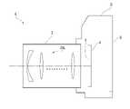
以下、本発明に係る好ましい実施形態について説明する。まず、各実施形態に係る光学系を備えたカメラ(光学機器)を図9に基づいて説明する。このカメラ1は、図9に示すように、本体2と、本体2に装着される撮影レンズ3により構成される。本体2は、撮像素子4と、デジタルカメラの動作を制御する本体制御部(不図示)と、液晶画面5とを備える。撮影レンズ3は、複数のレンズ群からなる光学系OLと、各レンズ群の位置を制御するレンズ位置制御機構(不図示)とを備える。レンズ位置制御機構は、レンズ群の位置を検出するセンサと、レンズ群を光軸に沿って前後に移動させるモータと、モータを駆動する制御回路などにより構成される。 Hereinafter, preferred embodiments according to the present invention will be described. First, a camera (optical device) provided with an optical system according to each embodiment will be described with reference to FIG. As shown in FIG. 9, the
被写体からの光は、撮影レンズ3の光学系OLにより集光されて、撮像素子4の像面I上に到達する。像面Iに到達した被写体からの光は、撮像素子4により光電変換され、デジタル画像データとして不図示のメモリに記録される。メモリに記録されたデジタル画像データは、ユーザの操作に応じて液晶画面5に表示することが可能である。なお、このカメラは、ミラーレスカメラでも、クイックリターンミラーを有した一眼レフタイプのカメ
ラであっても良い。また、図9に示す光学系OLは、光学系を模式的に示したものであり、光学系OLのレンズ構成はこの構成に限定されるものではない。The light from the subject is collected by the optical system OL of the photographing
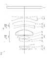
次に、第1実施形態に係る光学系について説明する。第1実施形態に係る光学系OLの一例としての光学系OL(1)は、図1に示すように、光軸に沿って物体側から順に並んだ、正の屈折力を有する第1レンズ群G1と、開口絞りSと、後続群GRとを有して構成される。後続群GRは、合焦の際に光軸に沿って移動する第1合焦レンズ群GF1と、第1合焦レンズ群GF1より像側に配置されて合焦の際に光軸に沿って移動する第2合焦レンズ群GF2とを有して構成される。なお、合焦の際、第1合焦レンズ群GF1と第2合焦レンズ群GF2とが光軸に沿って異なる移動量で移動することが望ましい。 Next, the optical system according to the first embodiment will be described. As shown in FIG. 1, the optical system OL (1) as an example of the optical system OL according to the first embodiment is a first lens group having a positive refractive power arranged in order from the object side along the optical axis. It is composed of G1, an aperture stop S, and a subsequent group GR. The subsequent group GR is arranged on the image side of the first focusing lens group GF1 that moves along the optical axis during focusing and the first focusing lens group GF1 and is arranged along the optical axis during focusing. It is configured to have a moving second focusing lens group GF2. At the time of focusing, it is desirable that the first focusing lens group GF1 and the second focusing lens group GF2 move along the optical axis by different amounts of movement.
上記構成の下、第1実施形態に係る光学系OLは、以下の条件式(1)を満足する。
0.03<D1/TL<0.25 ・・・(1)
但し、D1:第1レンズ群G1における最も物体側のレンズ面から最も像側のレンズ面までの光軸上の距離
TL:光学系OLの全長Under the above configuration, the optical system OL according to the first embodiment satisfies the following conditional expression (1).
0.03 <D1 / TL <0.25 ... (1)
However, D1: the distance on the optical axis from the lens surface on the most object side to the lens surface on the image side in the first lens group G1 TL: the total length of the optical system OL.
第1実施形態によれば、光学系の焦点距離に対して全長が短くなり、小型でありながら良好な光学性能を有した光学系、およびこの光学系を備えた光学機器を得ることが可能になる。第1実施形態に係る光学系OLは、図3に示す光学系OL(2)でもよく、図5に示す光学系OL(3)でもよく、図7に示す光学系OL(4)でもよい。 According to the first embodiment, the total length is shortened with respect to the focal length of the optical system, and it is possible to obtain an optical system having good optical performance while being compact, and an optical device provided with this optical system. Become. The optical system OL according to the first embodiment may be the optical system OL (2) shown in FIG. 3, the optical system OL (3) shown in FIG. 5, or the optical system OL (4) shown in FIG. 7.
条件式(1)は、第1レンズ群G1における最も物体側のレンズ面から最も像側のレンズ面までの光軸上の距離と、光学系OLの全長との適切な関係を規定するものである。条件式(1)を満足することで、光学系を小型化しつつ、像面(撮像素子)に対する射出瞳位置を最適化することができる。 The conditional expression (1) defines an appropriate relationship between the distance on the optical axis from the lens surface on the most object side to the lens surface on the image side in the first lens group G1 and the total length of the optical system OL. be. By satisfying the conditional expression (1), it is possible to optimize the exit pupil position with respect to the image plane (image sensor) while reducing the size of the optical system.
条件式(1)の対応値が下限値を下回ると、第1レンズ群G1が薄くなりすぎるため、色収差や非点隔差を補正することが困難になる。また、第1レンズ群G1を構成するレンズの縁厚および中心厚が薄くなりすぎるため、レンズの製造が困難になる。条件式(1)の下限値を0.05、さらに0.07に設定することで、本実施形態の効果をより確実なものとすることができる。 When the corresponding value of the conditional expression (1) is less than the lower limit value, the first lens group G1 becomes too thin, and it becomes difficult to correct chromatic aberration and astigmatism. Further, since the edge thickness and the center thickness of the lenses constituting the first lens group G1 are too thin, it becomes difficult to manufacture the lens. By setting the lower limit of the conditional expression (1) to 0.05 and further to 0.07, the effect of the present embodiment can be further ensured.
条件式(1)の対応値が上限値を上回ると、射出瞳位置を像面(撮像素子)から遠くすることが困難になる。射出瞳位置を像面(撮像素子)から遠くしようとすると、像面湾曲を補正することが困難になる。条件式(1)の上限値を0.22、さらに0.20に設定することで、本実施形態の効果をより確実なものとすることができる。 When the corresponding value of the conditional expression (1) exceeds the upper limit value, it becomes difficult to move the exit pupil position far from the image plane (image sensor). If the exit pupil position is moved away from the image plane (image sensor), it becomes difficult to correct the curvature of field. By setting the upper limit value of the conditional expression (1) to 0.22 and further to 0.20, the effect of the present embodiment can be further ensured.
第1実施形態に係る光学系OLにおいて、後続群GRは、光軸に沿って物体側から順に並んだ、正の屈折力を有する第2レンズ群G2と、正の屈折力を有する第3レンズ群G3とを有し、第2レンズ群G2が第1合焦レンズ群GF1であり、第3レンズ群G3が第2合焦レンズ群GF2であることが望ましい。さらに、後続群GRは、第3レンズ群G3の像側に並んで配置された負の屈折力を有する第4レンズ群G4を有することが望ましい。これにより、光学系の焦点距離に対して全長が短くなり、小型でありながら良好な光学性能を有した光学系を得ることができる。 In the optical system OL according to the first embodiment, the succeeding group GR includes a second lens group G2 having a positive refractive power and a third lens having a positive refractive power arranged in order from the object side along the optical axis. It is desirable to have a group G3, the second lens group G2 is the first focusing lens group GF1, and the third lens group G3 is the second focusing lens group GF2. Further, it is desirable that the succeeding group GR has a fourth lens group G4 having a negative refractive power arranged side by side on the image side of the third lens group G3. As a result, the total length is shortened with respect to the focal length of the optical system, and it is possible to obtain an optical system having good optical performance while being compact.
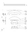
次に、第2実施形態に係る光学系について説明する。第2実施形態に係る光学系OLの一例としての光学系OL(1)は、図1に示すように、光軸に沿って物体側から順に並んだ、正の屈折力を有する第1レンズ群G1と、正の屈折力を有する第2レンズ群G2と、正の屈折力を有する第3レンズ群G3と、負の屈折力を有する第4レンズ群G4とを有し
て構成される。合焦の際、隣り合う各レンズ群の間隔が変化する。Next, the optical system according to the second embodiment will be described. As shown in FIG. 1, the optical system OL (1) as an example of the optical system OL according to the second embodiment is a first lens group having a positive refractive power arranged in order from the object side along the optical axis. It is composed of G1, a second lens group G2 having a positive refractive power, a third lens group G3 having a positive refractive power, and a fourth lens group G4 having a negative refractive power. When focusing, the distance between adjacent lens groups changes.
第2実施形態によれば、光学系の焦点距離に対して全長が短くなり、小型でありながら良好な光学性能を有した光学系、およびこの光学系を備えた光学機器を得ることが可能になる。第2実施形態に係る光学系OLは、図3に示す光学系OL(2)でもよく、図5に示す光学系OL(3)でもよく、図7に示す光学系OL(4)でもよい。第2実施形態に係る光学系OLは、第1レンズ群G1と第2レンズ群G2との間に配置された開口絞りSを有することが望ましい。 According to the second embodiment, the total length is shortened with respect to the focal length of the optical system, and it is possible to obtain an optical system having good optical performance while being compact, and an optical device provided with this optical system. Become. The optical system OL according to the second embodiment may be the optical system OL (2) shown in FIG. 3, the optical system OL (3) shown in FIG. 5, or the optical system OL (4) shown in FIG. 7. It is desirable that the optical system OL according to the second embodiment has an aperture stop S arranged between the first lens group G1 and the second lens group G2.
第2実施形態に係る光学系OLは、前述の条件式(1)を満足することが望ましい。条件式(1)を満足することで、第1実施形態の場合と同様に、光学系を小型化しつつ、像面(撮像素子)に対する射出瞳位置を最適化することができる。また、条件式(1)の下限値を0.05、さらに0.07に設定することで、本実施形態の効果をより確実なものとすることができる。条件式(1)の上限値を0.22、さらに0.20に設定することで、本実施形態の効果をより確実なものとすることができる。 It is desirable that the optical system OL according to the second embodiment satisfies the above-mentioned conditional expression (1). By satisfying the conditional expression (1), it is possible to optimize the exit pupil position with respect to the image plane (image sensor) while reducing the size of the optical system as in the case of the first embodiment. Further, by setting the lower limit value of the conditional expression (1) to 0.05 and further to 0.07, the effect of the present embodiment can be further ensured. By setting the upper limit value of the conditional expression (1) to 0.22 and further to 0.20, the effect of the present embodiment can be further ensured.
次に、第3実施形態に係る光学系について説明する。第3実施形態に係る光学系OLの一例としての光学系OL(1)は、図1に示すように、光軸に沿って物体側から順に並んだ、正の屈折力を有する第1レンズ群G1と、正の屈折力を有する第2レンズ群G2と、正の屈折力を有する第3レンズ群G3と、負の屈折力を有する第4レンズ群G4とを有して構成される。合焦の際、第2レンズ群G2と第3レンズ群G3とが光軸に沿って移動する。なお、合焦の際、隣り合う各レンズ群の間隔が変化することが望ましい。 Next, the optical system according to the third embodiment will be described. As shown in FIG. 1, the optical system OL (1) as an example of the optical system OL according to the third embodiment is a first lens group having a positive refractive power arranged in order from the object side along the optical axis. It is composed of G1, a second lens group G2 having a positive refractive power, a third lens group G3 having a positive refractive power, and a fourth lens group G4 having a negative refractive power. At the time of focusing, the second lens group G2 and the third lens group G3 move along the optical axis. It is desirable that the distance between adjacent lens groups changes during focusing.
上記構成の下、第3実施形態に係る光学系OLは、前述の条件式(1)を満足する。第3実施形態によれば、光学系の焦点距離に対して全長が短くなり、小型でありながら良好な光学性能を有した光学系、およびこの光学系を備えた光学機器を得ることが可能になる。第3実施形態に係る光学系OLは、図3に示す光学系OL(2)でもよく、図5に示す光学系OL(3)でもよく、図7に示す光学系OL(4)でもよい。第3実施形態に係る光学系OLは、第1レンズ群G1と第2レンズ群G2との間に配置された開口絞りSを有することが望ましい。 Under the above configuration, the optical system OL according to the third embodiment satisfies the above-mentioned conditional expression (1). According to the third embodiment, the total length is shortened with respect to the focal length of the optical system, and it is possible to obtain an optical system having good optical performance while being compact, and an optical device provided with this optical system. Become. The optical system OL according to the third embodiment may be the optical system OL (2) shown in FIG. 3, the optical system OL (3) shown in FIG. 5, or the optical system OL (4) shown in FIG. 7. It is desirable that the optical system OL according to the third embodiment has an aperture stop S arranged between the first lens group G1 and the second lens group G2.
また、条件式(1)を満足することで、第1実施形態の場合と同様に、光学系を小型化しつつ、像面(撮像素子)に対する射出瞳位置を最適化することができる。また、条件式(1)の下限値を0.05、さらに0.07に設定することで、本実施形態の効果をより確実なものとすることができる。条件式(1)の上限値を0.22、さらに0.20に設定することで、本実施形態の効果をより確実なものとすることができる。 Further, by satisfying the conditional expression (1), it is possible to optimize the exit pupil position with respect to the image plane (image sensor) while reducing the size of the optical system as in the case of the first embodiment. Further, by setting the lower limit value of the conditional expression (1) to 0.05 and further to 0.07, the effect of the present embodiment can be further ensured. By setting the upper limit value of the conditional expression (1) to 0.22 and further to 0.20, the effect of the present embodiment can be further ensured.
第1~第3実施形態に係る光学系OLは、以下の条件式(2)を満足することが望ましい。
1.20<(-f4)/f<2.00 ・・・(2)
但し、f4:第4レンズ群G4の焦点距離
f:光学系OLの焦点距離It is desirable that the optical system OL according to the first to third embodiments satisfies the following conditional expression (2).
1.20 <(-f4) /f<2.00 ... (2)
However, f4: focal length of the fourth lens group G4 f: focal length of the optical system OL
条件式(2)は、第4レンズ群G4の屈折力について適切な範囲を規定するものである。条件式(2)を満足することで、倍率色収差や歪曲収差、像面湾曲を良好に補正することができる。 The conditional expression (2) defines an appropriate range for the refractive power of the fourth lens group G4. By satisfying the conditional expression (2), chromatic aberration of magnification, distortion, and curvature of field can be satisfactorily corrected.
条件式(2)の対応値が下限値を下回ると、第4レンズ群G4の屈折力が強くなりすぎるため、倍率色収差や歪曲収差を補正することが困難になる。また、射出瞳位置を像面(撮像素子)から遠くすることが困難になる。条件式(2)の下限値を1.40、さらに1
.50に設定することで、各実施形態の効果をより確実なものとすることができる。When the corresponding value of the conditional expression (2) is less than the lower limit value, the refractive power of the fourth lens group G4 becomes too strong, and it becomes difficult to correct the chromatic aberration of magnification and the distortion. In addition, it becomes difficult to move the exit pupil position far from the image plane (image sensor). The lower limit of conditional expression (2) is 1.40, and 1
.. By setting it to 50, the effect of each embodiment can be made more reliable.
条件式(2)の対応値が上限値を上回ると、第4レンズ群G4の屈折力が弱くなりすぎるため、像面湾曲を補正することが困難になる。条件式(2)の上限値を1.85、さらに1.80に設定することで、各実施形態の効果をより確実なものとすることができる。 If the corresponding value of the conditional expression (2) exceeds the upper limit value, the refractive power of the fourth lens group G4 becomes too weak, and it becomes difficult to correct the curvature of field. By setting the upper limit value of the conditional expression (2) to 1.85 and further to 1.80, the effect of each embodiment can be further ensured.
第1~第3実施形態に係る光学系OLは、以下の条件式(3)を満足することが望ましい。
1.10<β4<1.40 ・・・(3)
但し、β4:無限遠合焦時の第4レンズ群G4の横倍率It is desirable that the optical system OL according to the first to third embodiments satisfies the following conditional expression (3).
1.10 <β4 <1.40 ... (3)
However, β4: lateral magnification of the 4th lens group G4 at infinity focusing
条件式(3)は、第4レンズ群G4の横倍率について適切な範囲を規定するものである。条件式(3)を満足することで、光学系を小型化しつつ、良好な光学性能を得ることができる。 The conditional expression (3) defines an appropriate range for the lateral magnification of the fourth lens group G4. By satisfying the conditional expression (3), good optical performance can be obtained while downsizing the optical system.
条件式(3)の対応値が下限値を下回ると、光学系が大型化すると同時に、像面湾曲を補正することが困難になる。条件式(3)の下限値を1.17に設定することで、各実施形態の効果をより確実なものとすることができる。 When the corresponding value of the conditional expression (3) is less than the lower limit value, the optical system becomes large and at the same time, it becomes difficult to correct the curvature of field. By setting the lower limit of the conditional expression (3) to 1.17, the effect of each embodiment can be made more reliable.
条件式(3)の対応値が上限値を上回ると、像面湾曲や歪曲収差の補正が困難になる。条件式(3)の上限値を1.35に設定することで、各実施形態の効果をより確実なものとすることができる。 If the corresponding value of the conditional expression (3) exceeds the upper limit value, it becomes difficult to correct curvature of field and distortion. By setting the upper limit value of the conditional expression (3) to 1.35, the effect of each embodiment can be made more reliable.
第1~第3実施形態に係る光学系OLにおいて、第4レンズ群G4は、1枚の負レンズからなり、以下の条件式(4)を満足することが望ましい。
28.0<νd41<45.0 ・・・(4)
但し、νd41:第4レンズ群G4の負レンズのd線を基準とするアッベ数In the optical system OL according to the first to third embodiments, the fourth lens group G4 is composed of one negative lens, and it is desirable that the following conditional expression (4) is satisfied.
28.0 <νd41 <45.0 ... (4)
However, νd41: Abbe number based on the d line of the negative lens of the 4th lens group G4.
条件式(4)は、第4レンズ群G4を構成する負レンズのアッベ数について適切な範囲を規定するものである。条件式(4)を満足することで、倍率色収差を良好に補正することができる。 The conditional expression (4) defines an appropriate range for the Abbe number of the negative lenses constituting the fourth lens group G4. By satisfying the conditional expression (4), the chromatic aberration of magnification can be satisfactorily corrected.
条件式(4)の対応値が下限値を下回ると、倍率色収差の補正が過剰となる。条件式(4)の下限値を30.0、さらに32.0に設定することで、各実施形態の効果をより確実なものとすることができる。 When the corresponding value of the conditional expression (4) is less than the lower limit value, the correction of the chromatic aberration of magnification becomes excessive. By setting the lower limit of the conditional expression (4) to 30.0 and further to 32.0, the effect of each embodiment can be further ensured.
条件式(4)の対応値が上限値を上回ると、倍率色収差の補正が不足となる。条件式(4)の上限値を43.0、さらに41.0に設定することで、各実施形態の効果をより確実なものとすることができる。 If the corresponding value of the conditional expression (4) exceeds the upper limit value, the correction of the chromatic aberration of magnification becomes insufficient. By setting the upper limit value of the conditional expression (4) to 43.0 and further to 41.0, the effect of each embodiment can be further ensured.
第1~第3実施形態に係る光学系OLは、以下の条件式(5)を満足することが望ましい。
0.50<f2/f3<2.00 ・・・(5)
但し、f2:第2レンズ群G2の焦点距離
f3:第3レンズ群G3の焦点距離It is desirable that the optical system OL according to the first to third embodiments satisfies the following conditional expression (5).
0.50 <f2 / f3 <2.00 ... (5)
However, f2: focal length of the second lens group G2 f3: focal length of the third lens group G3
条件式(5)は、第2レンズ群G2の焦点距離と、第3レンズ群G3の焦点距離との適切な関係を規定するものである。条件式(5)を満足することで、非点隔差や像面湾曲を良好に補正することができる。 The conditional expression (5) defines an appropriate relationship between the focal length of the second lens group G2 and the focal length of the third lens group G3. By satisfying the conditional expression (5), the astigmatism difference and the curvature of field can be satisfactorily corrected.
条件式(5)の対応値が下限値を下回ると、第3レンズ群G3の屈折力が弱くなりすぎるため、非点隔差を補正することが困難になる。条件式(5)の下限値を0.60、さらに0.70に設定することで、各実施形態の効果をより確実なものとすることができる。 When the corresponding value of the conditional expression (5) is less than the lower limit value, the refractive power of the third lens group G3 becomes too weak, and it becomes difficult to correct the astigmatism difference. By setting the lower limit of the conditional expression (5) to 0.60 and further to 0.70, the effect of each embodiment can be further ensured.
条件式(5)の対応値が上限値を上回ると、第3レンズ群G3の屈折力が強くなりすぎるため、像面湾曲を補正することが困難になる。条件式(5)の上限値を1.90、さらに1.80に設定することで、各実施形態の効果をより確実なものとすることができる。 If the corresponding value of the conditional expression (5) exceeds the upper limit value, the refractive power of the third lens group G3 becomes too strong, and it becomes difficult to correct the curvature of field. By setting the upper limit value of the conditional expression (5) to 1.90 and further to 1.80, the effect of each embodiment can be further ensured.
第1~第3実施形態に係る光学系OLは、以下の条件式(6)を満足することが望ましい。
0.04<d23/TL<0.11 ・・・(6)
但し、d23:無限遠合焦時の第2レンズ群G2と第3レンズ群G3との光軸上の間隔
TL:光学系OLの全長It is desirable that the optical system OL according to the first to third embodiments satisfies the following conditional expression (6).
0.04 <d23 / TL <0.11 ... (6)
However, d23: the distance between the second lens group G2 and the third lens group G3 at the time of infinity focusing TL: the total length of the optical system OL.
条件式(6)は、第2レンズ群G2と第3レンズ群G3との光軸上の間隔と、光学系OLの全長との適切な関係を規定するものである。条件式(6)を満足することで、合焦に必要な各レンズ群の移動スペースを確保するとともに、至近距離合焦時においても良好な光学性能を得ることができる。 The conditional expression (6) defines an appropriate relationship between the distance between the second lens group G2 and the third lens group G3 on the optical axis and the total length of the optical system OL. By satisfying the conditional expression (6), it is possible to secure a moving space for each lens group required for focusing, and to obtain good optical performance even at close range focusing.
条件式(6)の対応値が下限値を下回ると、合焦に必要な各レンズ群の移動スペースが不足する上、至近距離合焦時の非点収差の補正が困難になる。条件式(6)の下限値を0.05に設定することで、各実施形態の効果をより確実なものとすることができる。 When the corresponding value of the conditional expression (6) is less than the lower limit value, the moving space of each lens group required for focusing is insufficient, and it becomes difficult to correct astigmatism at the time of close-range focusing. By setting the lower limit of the conditional expression (6) to 0.05, the effect of each embodiment can be further ensured.
条件式(6)の対応値が上限値を上回ると、至近距離合焦時のコマ収差の補正が困難になる。条件式(6)の上限値を0.10に設定することで、各実施形態の効果をより確実なものとすることができる。 If the corresponding value of the conditional expression (6) exceeds the upper limit value, it becomes difficult to correct the coma aberration at the time of close-range focusing. By setting the upper limit value of the conditional expression (6) to 0.10, the effect of each embodiment can be made more reliable.
第1~第3実施形態に係る光学系OLは、以下の条件式(7)を満足することが望ましい。
0.60<d23/d12<1.00 ・・・(7)
但し、d23:無限遠合焦時の第2レンズ群G2と第3レンズ群G3との光軸上の間隔
d12:無限遠合焦時の第1レンズ群G1と第2レンズ群G2との光軸上の間隔It is desirable that the optical system OL according to the first to third embodiments satisfies the following conditional expression (7).
0.60 <d23 / d12 <1.00 ... (7)
However, d23: the distance on the optical axis between the second lens group G2 and the third lens group G3 at the time of infinity focusing d12: the light between the first lens group G1 and the second lens group G2 at the time of infinity focusing. Axis spacing
条件式(7)は、第2レンズ群G2と第3レンズ群G3との光軸上の間隔と、第1レンズ群G1と第2レンズ群G2との光軸上の間隔との適切な関係を規定するものである。条件式(7)を満足することで、合焦に必要な各レンズ群の移動スペースを確保するとともに、至近距離合焦時においても良好な光学性能を得ることができる。 In the conditional expression (7), an appropriate relationship between the distance between the second lens group G2 and the third lens group G3 on the optical axis and the distance between the first lens group G1 and the second lens group G2 on the optical axis. It regulates. By satisfying the conditional expression (7), it is possible to secure a moving space for each lens group required for focusing, and to obtain good optical performance even at close range focusing.
条件式(7)の対応値が下限値を下回ると、至近距離合焦時の非点収差の補正が困難になる。条件式(7)の下限値を0.67に設定することで、各実施形態の効果をより確実なものとすることができる。 When the corresponding value of the conditional expression (7) is less than the lower limit value, it becomes difficult to correct the astigmatism at the time of close-range focusing. By setting the lower limit of the conditional expression (7) to 0.67, the effect of each embodiment can be made more reliable.
条件式(7)の対応値が上限値を上回ると、至近距離合焦時のコマ収差の補正が困難になる。条件式(7)の上限値を0.92に設定することで、各実施形態の効果をより確実なものとすることができる。 If the corresponding value of the conditional expression (7) exceeds the upper limit value, it becomes difficult to correct the coma aberration at the time of close-range focusing. By setting the upper limit value of the conditional expression (7) to 0.92, the effect of each embodiment can be made more reliable.
第1~第3実施形態に係る光学系OLは、以下の条件式(8)を満足することが望ましい。
0.10<β2/β3<0.90 ・・・(8)
但し、β2:無限遠合焦時の第2レンズ群G2の横倍率
β3:無限遠合焦時の第3レンズ群G3の横倍率It is desirable that the optical system OL according to the first to third embodiments satisfies the following conditional expression (8).
0.10 <β2 / β3 <0.90 ... (8)
However, β2: lateral magnification of the second lens group G2 at the time of infinity focusing β3: lateral magnification of the third lens group G3 at the time of infinity focusing
条件式(8)は、第2レンズ群G2の横倍率と、第3レンズ群G3の横倍率との適切な関係を規定するものである。条件式(8)を満足することで、至近距離合焦時においても良好な光学性能を得ることができる。 The conditional expression (8) defines an appropriate relationship between the lateral magnification of the second lens group G2 and the lateral magnification of the third lens group G3. By satisfying the conditional expression (8), good optical performance can be obtained even at the time of close-range focusing.
条件式(8)の対応値が下限値を下回ると、至近距離合焦時の非点収差の補正が困難になる。条件式(8)の下限値を0.18に設定することで、各実施形態の効果をより確実なものとすることができる。 When the corresponding value of the conditional expression (8) is less than the lower limit value, it becomes difficult to correct the astigmatism at the time of close-range focusing. By setting the lower limit of the conditional expression (8) to 0.18, the effect of each embodiment can be made more reliable.
条件式(8)の対応値が上限値を上回ると、至近距離合焦時のコマ収差の補正が困難になる。条件式(8)の上限値を0.80に設定することで、各実施形態の効果をより確実なものとすることができる。 If the corresponding value of the conditional expression (8) exceeds the upper limit value, it becomes difficult to correct the coma aberration at the time of close-range focusing. By setting the upper limit value of the conditional expression (8) to 0.80, the effect of each embodiment can be made more reliable.
第1~第3実施形態に係る光学系OLは、以下の条件式(9)を満足することが望ましい。
0.015<{β2+(1/β2)}-2<0.170 ・・・(9)
但し、β2:無限遠合焦時の第2レンズ群G2の横倍率It is desirable that the optical system OL according to the first to third embodiments satisfies the following conditional expression (9).
0.015 <{β2 + (1 / β2)}-2 <0.170 ... (9)
However, β2: lateral magnification of the second lens group G2 when focusing at infinity.
条件式(9)は、第2レンズ群G2の横倍率について適切な範囲を規定するものである。条件式(9)を満足することで、無限遠合焦状態から至近距離合焦状態に至るまでの第2レンズ群の移動量を少なくすることができ、レンズの小型化が可能になるとともに、良好な光学性能を得ることができる。 The conditional expression (9) defines an appropriate range for the lateral magnification of the second lens group G2. By satisfying the conditional expression (9), the amount of movement of the second lens group from the infinity focusing state to the close range focusing state can be reduced, the lens can be miniaturized, and the lens can be miniaturized. Good optical performance can be obtained.
条件式(9)の対応値が下限値を下回ると、球面収差および軸上色収差の補正が困難になる。条件式(9)の下限値を0.020に設定することで、各実施形態の効果をより確実なものとすることができる。 When the corresponding value of the conditional expression (9) is less than the lower limit value, it becomes difficult to correct the spherical aberration and the axial chromatic aberration. By setting the lower limit of the conditional expression (9) to 0.020, the effect of each embodiment can be made more reliable.
条件式(9)の対応値が上限値を上回ると、無限遠合焦状態から至近距離合焦状態に至るまでの第2レンズ群の移動量が大きくなり、レンズが大型化するとともに、非点収差の補正が困難になる。条件式(9)の上限値を0.150に設定することで、各実施形態の効果をより確実なものとすることができる。 When the corresponding value of the conditional expression (9) exceeds the upper limit value, the amount of movement of the second lens group from the infinity focusing state to the close range focusing state becomes large, the lens becomes large, and astigmatism occurs. It becomes difficult to correct the aberration. By setting the upper limit value of the conditional expression (9) to 0.150, the effect of each embodiment can be made more reliable.
第1~第3実施形態に係る光学系OLは、以下の条件式(10)を満足することが望ましい。
0.100<{β3+(1/β3)}-2<0.250 ・・・(10)
但し、β3:無限遠合焦時の第3レンズ群G3の横倍率It is desirable that the optical system OL according to the first to third embodiments satisfies the following conditional expression (10).
0.100 <{β3 + (1 / β3)}-2 <0.250 ... (10)
However, β3: lateral magnification of the third lens group G3 when focusing at infinity
条件式(10)は、第3レンズ群G3の横倍率について適切な範囲を規定するものである。条件式(10)を満足することで、無限遠合焦状態から至近距離合焦状態に至るまでの第3レンズ群の移動量を少なくすることができ、レンズの小型化が可能になるとともに、良好な光学性能を得ることができる。 The conditional expression (10) defines an appropriate range for the lateral magnification of the third lens group G3. By satisfying the conditional expression (10), the amount of movement of the third lens group from the infinity focusing state to the close range focusing state can be reduced, the lens can be miniaturized, and the lens can be miniaturized. Good optical performance can be obtained.
条件式(10)の対応値が下限値を下回ると、像面湾曲や非点収差の補正が困難になる。条件式(10)の下限値を0.160に設定することで、各実施形態の効果をより確実なものとすることができる。 If the corresponding value of the conditional expression (10) is less than the lower limit, it becomes difficult to correct curvature of field and astigmatism. By setting the lower limit of the conditional expression (10) to 0.160, the effect of each embodiment can be made more reliable.
条件式(10)の対応値が上限値を上回ると、無限遠合焦状態から至近距離合焦状態に至るまでの第3レンズ群の移動量が大きくなり、レンズが大型化するとともに、非点収差の補正が困難になる。条件式(10)の上限値を0.230に設定することで、各実施形
態の効果をより確実なものとすることができる。When the corresponding value of the conditional expression (10) exceeds the upper limit value, the amount of movement of the third lens group from the infinity focusing state to the close range focusing state becomes large, the lens becomes large, and astigmatism occurs. It becomes difficult to correct the aberration. By setting the upper limit value of the conditional expression (10) to 0.230, the effect of each embodiment can be made more reliable.
第1~第3実施形態に係る光学系OLにおいて、第2レンズ群G2は、光軸に沿って物体側から順に並んだ、第1正レンズと、第1負レンズと、第2負レンズと、第2正レンズとからなることが望ましい。また、第2レンズ群G2は、光軸に沿って物体側から順に並んだ、第1正レンズおよび第1負レンズからなる正レンズ成分と、第2負レンズと、第2正レンズとからなることが望ましい。これにより、軸上色収差、球面収差、コマ収差、非点隔差等を良好に補正しつつ、ペッツバール和を適切に低減させ像面湾曲を良好に補正することができる。 In the optical system OL according to the first to third embodiments, the second lens group G2 includes a first positive lens, a first negative lens, and a second negative lens arranged in order from the object side along the optical axis. , It is desirable to consist of a second positive lens. Further, the second lens group G2 includes a positive lens component composed of a first positive lens and a first negative lens, a second negative lens, and a second positive lens arranged in order from the object side along the optical axis. Is desirable. As a result, while satisfactorily correcting axial chromatic aberration, spherical aberration, coma, astigmatism, etc., the Petzval sum can be appropriately reduced and curvature of field can be satisfactorily corrected.
第1~第3実施形態に係る光学系OLは、以下の条件式(11)を満足することが望ましい。
0.00<N21-N22<0.40 ・・・(11)
但し、N21:第2レンズ群G2の第1正レンズのd線に対する屈折率
N22:第2レンズ群G2の第1負レンズのd線に対する屈折率It is desirable that the optical system OL according to the first to third embodiments satisfies the following conditional expression (11).
0.00 <N21-N22 <0.40 ... (11)
However, N21: the refractive index of the first positive lens of the second lens group G2 with respect to the d-line N22: the refractive index of the first negative lens of the second lens group G2 with respect to the d-line.
条件式(11)は、第2レンズ群G2における第1正レンズの屈折率と第1負レンズの屈折率との差について適切な範囲を規定するものである。条件式(11)を満足することで、像面湾曲や球面収差を良好に補正することができる。 The conditional expression (11) defines an appropriate range for the difference between the refractive index of the first positive lens and the refractive index of the first negative lens in the second lens group G2. By satisfying the conditional expression (11), curvature of field and spherical aberration can be satisfactorily corrected.
条件式(11)の対応値が下限値を下回ると、像面湾曲を補正することが困難になる。条件式(11)の下限値を0.10、さらに0.15に設定することで、各実施形態の効果をより確実なものとすることができる。 When the corresponding value of the conditional expression (11) is less than the lower limit value, it becomes difficult to correct the curvature of field. By setting the lower limit of the conditional expression (11) to 0.10 and further to 0.15, the effect of each embodiment can be further ensured.
条件式(11)の対応値が上限値を上回ると、球面収差を補正することが困難になる。条件式(11)の上限値を0.35、さらに0.30に設定することで、各実施形態の効果をより確実なものとすることができる。 If the corresponding value of the conditional expression (11) exceeds the upper limit value, it becomes difficult to correct the spherical aberration. By setting the upper limit value of the conditional expression (11) to 0.35 and further to 0.30, the effect of each embodiment can be further ensured.
第1~第3実施形態に係る光学系OLは、以下の条件式(12)を満足することが望ましい。
N21>1.90 ・・・(12)
但し、N21:第2レンズ群G2の第1正レンズのd線に対する屈折率It is desirable that the optical system OL according to the first to third embodiments satisfies the following conditional expression (12).
N21> 1.90 ... (12)
However, N21: the refractive index of the first positive lens of the second lens group G2 with respect to the d line.
条件式(12)は、第2レンズ群G2における第1正レンズの屈折率について適切な範囲を規定するものである。条件式(12)を満足することで、球面収差やコマ収差を悪化させることなくペッツバール和を低減し、像面湾曲を良好に補正することができる。 The conditional expression (12) defines an appropriate range for the refractive index of the first positive lens in the second lens group G2. By satisfying the conditional equation (12), the Petzval sum can be reduced and the curvature of field can be satisfactorily corrected without aggravating spherical aberration and coma.
条件式(12)の対応値が下限値を下回ると、ペッツバール和が増大し、像面湾曲の補正が困難になる。条件式(12)の下限値を1.95に設定することで、各実施形態の効果をより確実なものとすることができる。 When the corresponding value of the conditional expression (12) is less than the lower limit value, the Petzval sum increases and it becomes difficult to correct the curvature of field. By setting the lower limit of the conditional expression (12) to 1.95, the effect of each embodiment can be made more reliable.
第1~第3実施形態に係る光学系OLは、以下の条件式(13)を満足することが望ましい。
25.0<νd21<35.0 ・・・(13)
但し、νd21:第2レンズ群G2の第1正レンズのd線を基準とするアッベ数It is desirable that the optical system OL according to the first to third embodiments satisfies the following conditional expression (13).
25.0 <νd21 <35.0 ... (13)
However, νd21: Abbe number based on the d line of the first positive lens of the second lens group G2.
条件式(13)は、第2レンズ群G2における第1正レンズのアッベ数について適切な範囲を規定するものである。条件式(13)を満足することで、軸上色収差を良好に補正することができる。 The conditional expression (13) defines an appropriate range for the Abbe number of the first positive lens in the second lens group G2. By satisfying the conditional expression (13), the axial chromatic aberration can be satisfactorily corrected.
条件式(13)の対応値が下限値を下回ると、軸上色収差が補正不足となり、良好な補正が困難になる。条件式(13)の下限値を28.0に設定することで、各実施形態の効果をより確実なものとすることができる。 When the corresponding value of the conditional expression (13) is less than the lower limit value, the axial chromatic aberration is insufficiently corrected, and good correction becomes difficult. By setting the lower limit value of the conditional expression (13) to 28.0, the effect of each embodiment can be made more reliable.
条件式(13)の対応値が上限値を上回ると、軸上色収差が補正過剰となり、良好な補正が困難になる。条件式(13)の上限値を31.0に設定することで、各実施形態の効果をより確実なものとすることができる。 If the corresponding value of the conditional expression (13) exceeds the upper limit value, the axial chromatic aberration will be overcorrected, and good correction will be difficult. By setting the upper limit value of the conditional expression (13) to 31.0, the effect of each embodiment can be made more reliable.
第1~第3実施形態に係る光学系OLにおいて、第3レンズ群G3は、1枚の正レンズを有することが望ましい。これにより、光学系を小型化しつつ、像面湾曲を良好に補正することができる。 In the optical system OL according to the first to third embodiments, it is desirable that the third lens group G3 has one positive lens. This makes it possible to satisfactorily correct curvature of field while reducing the size of the optical system.
第1~第3実施形態に係る光学系OLは、以下の条件式(14)を満足することが望ましい。
-1.20<(R31+R32)/(R32-R31)<0.00 ・・・(14)
但し、R31:第3レンズ群G3の正レンズにおける物体側のレンズ面の近軸曲率半径
R32:第3レンズ群G3の正レンズにおける像側のレンズ面の近軸曲率半径It is desirable that the optical system OL according to the first to third embodiments satisfies the following conditional expression (14).
-1.20 <(R31 + R32) / (R32-R31) <0.00 ... (14)
However, R31: the paraxial radius of curvature of the lens surface on the object side in the positive lens of the third lens group G3 R32: the paraxial radius of curvature of the lens surface on the image side in the positive lens of the third lens group G3.
条件式(14)は、第3レンズ群G3を構成する正レンズのシェイプファクターについて適切な範囲を規定するものである。条件式(14)を満足することで、球面収差と非点収差を良好に補正することができる。 The conditional expression (14) defines an appropriate range for the shape factor of the positive lens constituting the third lens group G3. By satisfying the conditional expression (14), spherical aberration and astigmatism can be satisfactorily corrected.
条件式(14)の対応値が下限値を下回ると、球面収差の補正が困難になる。条件式(14)の下限値を-1.05に設定することで、各実施形態の効果をより確実なものとすることができる。 When the corresponding value of the conditional expression (14) is less than the lower limit value, it becomes difficult to correct the spherical aberration. By setting the lower limit of the conditional expression (14) to −1.05, the effect of each embodiment can be further ensured.
条件式(14)の対応値が上限値を上回ると、非点収差の補正が困難になる。条件式(14)の上限値を-0.10に設定することで、各実施形態の効果をより確実なものとすることができる。 If the corresponding value of the conditional expression (14) exceeds the upper limit value, it becomes difficult to correct the astigmatism. By setting the upper limit value of the conditional expression (14) to −0.10, the effect of each embodiment can be further ensured.
第1~第3実施形態に係る光学系OLは、以下の条件式(15)を満足することが望ましい。
0.00<f/f1<0.70 ・・・(15)
但し、f:光学系OLの焦点距離
f1:第1レンズ群G1の焦点距離It is desirable that the optical system OL according to the first to third embodiments satisfies the following conditional expression (15).
0.00 <f / f1 <0.70 ... (15)
However, f: focal length of the optical system OL f1: focal length of the first lens group G1
条件式(15)は、第1レンズ群G1の屈折力について適切な範囲を規定するものである。条件式(15)を満足することで、球面収差や、像面湾曲および非点隔差を良好に補正することができる。 The conditional expression (15) defines an appropriate range for the refractive power of the first lens group G1. By satisfying the conditional expression (15), spherical aberration, curvature of field, and astigmatism can be satisfactorily corrected.
条件式(15)の対応値が下限値を下回ると、球面収差を補正することが困難になる。条件式(15)の下限値を0.10、さらに0.13に設定することで、各実施形態の効果をより確実なものとすることができる。 When the corresponding value of the conditional expression (15) is less than the lower limit value, it becomes difficult to correct the spherical aberration. By setting the lower limit of the conditional expression (15) to 0.10 and further to 0.13, the effect of each embodiment can be further ensured.
条件式(15)の対応値が上限値を上回ると、像面湾曲および非点隔差を補正することが困難になる。条件式(15)の上限値を0.50、さらに0.35に設定することで、各実施形態の効果をより確実なものとすることができる。 When the corresponding value of the conditional expression (15) exceeds the upper limit value, it becomes difficult to correct the curvature of field and the astigmatism difference. By setting the upper limit of the conditional expression (15) to 0.50 and further to 0.35, the effect of each embodiment can be further ensured.
第1~第3実施形態に係る光学系OLにおいて、第1レンズ群G1は、少なくとも2つのレンズからなることが望ましい。これにより、軸上色収差、球面収差、コマ収差を良好
に補正することができる。In the optical system OL according to the first to third embodiments, it is desirable that the first lens group G1 is composed of at least two lenses. As a result, axial chromatic aberration, spherical aberration, and coma can be satisfactorily corrected.
第1~第3実施形態に係る光学系OLにおいて、第1レンズ群G1は、最も物体側に配置された負レンズを有することが望ましい。これにより、非点収差を良好に補正することができる。 In the optical system OL according to the first to third embodiments, it is desirable that the first lens group G1 has a negative lens arranged on the object side most. As a result, astigmatism can be satisfactorily corrected.
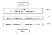
続いて、図10を参照しながら、第1実施形態に係る光学系OLの製造方法について概説する。まず、光軸に沿って物体側から順に、正の屈折力を有する第1レンズ群G1と、開口絞りSと、後続群GRとを配置する(ステップST1)。次に、後続群GRに、合焦の際に光軸に沿って移動する第1合焦レンズ群GF1と、第1合焦レンズ群GF1より像側で合焦の際に光軸に沿って移動する第2合焦レンズ群とを配置する(ステップST2)。そして、少なくとも上記条件式(1)を満足するように、レンズ鏡筒内に各レンズを配置する(ステップST3)。このような製造方法によれば、光学系の焦点距離に対して全長が短くなり、小型でありながら良好な光学性能を有した光学系を製造することが可能になる。 Subsequently, with reference to FIG. 10, the manufacturing method of the optical system OL according to the first embodiment will be outlined. First, the first lens group G1 having a positive refractive power, the aperture stop S, and the subsequent group GR are arranged in order from the object side along the optical axis (step ST1). Next, in the subsequent group GR, the first focusing lens group GF1 that moves along the optical axis during focusing and the first focusing lens group GF1 along the optical axis on the image side during focusing. A moving second focusing lens group is arranged (step ST2). Then, each lens is arranged in the lens barrel so as to satisfy at least the above conditional expression (1) (step ST3). According to such a manufacturing method, the total length is shortened with respect to the focal length of the optical system, and it becomes possible to manufacture an optical system having good optical performance while being compact.
続いて、図11を参照しながら、第2実施形態に係る光学系OLの製造方法について概説する。まず、光軸に沿って物体側から順に、正の屈折力を有する第1レンズ群G1と、正の屈折力を有する第2レンズ群G2と、正の屈折力を有する第3レンズ群G3と、負の屈折力を有する第4レンズ群G4とを配置する(ステップST11)。そして、合焦の際、隣り合う各レンズ群の間隔が変化するように、レンズ鏡筒内に各レンズを配置する(ステップST12)。このような製造方法によれば、光学系の焦点距離に対して全長が短くなり、小型でありながら良好な光学性能を有した光学系を製造することが可能になる。 Subsequently, with reference to FIG. 11, the manufacturing method of the optical system OL according to the second embodiment will be outlined. First, the first lens group G1 having a positive refractive power, the second lens group G2 having a positive refractive power, and the third lens group G3 having a positive refractive power in order from the object side along the optical axis. , A fourth lens group G4 having a negative refractive power is arranged (step ST11). Then, each lens is arranged in the lens barrel so that the distance between the adjacent lens groups changes at the time of focusing (step ST12). According to such a manufacturing method, the total length is shortened with respect to the focal length of the optical system, and it becomes possible to manufacture an optical system having good optical performance while being compact.
続いて、図12を参照しながら、第3実施形態に係る光学系OLの製造方法について概説する。まず、光軸に沿って物体側から順に、正の屈折力を有する第1レンズ群G1と、正の屈折力を有する第2レンズ群G2と、正の屈折力を有する第3レンズ群G3と、負の屈折力を有する第4レンズ群G4とを配置する(ステップST21)。次に、合焦の際、第2レンズ群G2と第3レンズ群G3とが光軸に沿って移動するように構成する(ステップST22)。そして、少なくとも上記条件式(1)を満足するように、レンズ鏡筒内に各レンズを配置する(ステップST23)。このような製造方法によれば、光学系の焦点距離に対して全長が短くなり、小型でありながら良好な光学性能を有した光学系を製造することが可能になる。 Subsequently, with reference to FIG. 12, the manufacturing method of the optical system OL according to the third embodiment will be outlined. First, the first lens group G1 having a positive refractive power, the second lens group G2 having a positive refractive power, and the third lens group G3 having a positive refractive power in order from the object side along the optical axis. , A fourth lens group G4 having a negative refractive power is arranged (step ST21). Next, at the time of focusing, the second lens group G2 and the third lens group G3 are configured to move along the optical axis (step ST22). Then, each lens is arranged in the lens barrel so as to satisfy at least the above conditional expression (1) (step ST23). According to such a manufacturing method, the total length is shortened with respect to the focal length of the optical system, and it becomes possible to manufacture an optical system having good optical performance while being compact.
以下、各実施形態の実施例に係る光学系OLを図面に基づいて説明する。図1、図3、図5、図7は、第1~第4実施例に係る光学系OL{OL(1)~OL(4)}の構成及び屈折力配分を示す断面図である。第1~第4実施例に係る光学系OL(1)~OL(4)の断面図では、無限遠から近距離物体へ合焦する際の各レンズ群の光軸に沿った移動方向を矢印で示している。 Hereinafter, the optical system OL according to the embodiment of each embodiment will be described with reference to the drawings. 1, FIG. 3, FIG. 5, and FIG. 7 are cross-sectional views showing the configuration and refractive power distribution of the optical system OL {OL (1) to OL (4)} according to the first to fourth embodiments. In the cross-sectional views of the optical systems OL (1) to OL (4) according to the first to fourth embodiments, the moving direction along the optical axis of each lens group when focusing on a short-range object from infinity is indicated by an arrow. Shows.
これら図1、図3、図5、図7において、各レンズ群を符号Gと数字の組み合わせにより、各レンズを符号Lと数字の組み合わせにより、それぞれ表している。この場合において、符号、数字の種類および数が大きくなって煩雑化するのを防止するため、実施例毎にそれぞれ独立して符号と数字の組み合わせを用いてレンズ群等を表している。このため、実施例間で同一の符号と数字の組み合わせが用いられていても、同一の構成であることを意味するものでは無い。 In FIGS. 1, 3, 5, and 7, each lens group is represented by a combination of reference numerals G and numbers, and each lens is represented by a combination of reference numerals L and numbers. In this case, in order to prevent the types and numbers of the reference numerals and numbers from becoming large and complicated, the lens group and the like are represented by independently using combinations of the reference numerals and numbers for each embodiment. Therefore, even if the same combination of reference numerals and numbers is used between the examples, it does not mean that they have the same configuration.
以下に表1~表4を示すが、この内、表1は第1実施例、表2は第2実施例、表3は第3実施例、表4は第4実施例における各諸元データを示す表である。各実施例では収差特
性の算出対象として、d線(波長λ=587.6nm)、g線(波長λ=435.8nm)を選んでいる。Tables 1 to 4 are shown below, of which Table 1 is the first embodiment, Table 2 is the second embodiment, Table 3 is the third embodiment, and Table 4 is the specification data in the fourth embodiment. It is a table showing. In each embodiment, the d-line (wavelength λ = 587.6 nm) and the g-line (wavelength λ = 435.8 nm) are selected as the calculation targets of the aberration characteristics.
[全体諸元]の表において、fはレンズ全系の焦点距離、FNОはFナンバー、ωは半画角(最大入射角、単位は「°」)、Yは像高を示す。TLは光軸上でのレンズ最前面からレンズ最終面までの距離にBFを加えた距離を示し、BFは光軸上でのレンズ最終面から像面Iまでの距離(バックフォーカス)を示す。また、BFaはバックフォーカスの空気換算長を示す。また、[全体諸元]の表において、β2は、無限遠合焦時の第2レンズ群の横倍率を示す。β3は、無限遠合焦時の第3レンズ群の横倍率を示す。β4は、無限遠合焦時の第4レンズ群の横倍率を示す。 In the [Overall Specifications] table, f is the focal length of the entire lens system, FNO is the F number, ω is the half angle of view (maximum angle of view, unit is “°”), and Y is the image height. TL indicates the distance from the frontmost surface of the lens to the final surface of the lens on the optical axis plus BF, and BF indicates the distance (back focus) from the final surface of the lens to the image plane I on the optical axis. Further, BFa indicates the air conversion length of the back focus. Further, in the table of [Overall specifications], β2 indicates the lateral magnification of the second lens group at the time of infinity focusing. β3 indicates the lateral magnification of the third lens group at the time of focusing at infinity. β4 indicates the lateral magnification of the fourth lens group at the time of focusing at infinity.
[レンズ諸元]の表において、面番号は光線の進行する方向に沿った物体側からの光学面の順序を示し、Rは各光学面の曲率半径(曲率中心が像側に位置する面を正の値としている)、Dは各光学面から次の光学面(又は像面)までの光軸上の距離である面間隔、ndは光学部材の材料のd線に対する屈折率、νdは光学部材の材料のd線を基準とするアッベ数をそれぞれ示す。曲率半径の「∞」は平面又は開口を、(絞りS)は開口絞りSをそれぞれ示す。空気の屈折率nd=1.00000の記載は省略している。光学面が非球面であ
る場合には面番号に*印を付して、曲率半径Rの欄には近軸曲率半径を示している。In the [Lens Specifications] table, the plane numbers indicate the order of the optical planes from the object side along the traveling direction of the light beam, and R is the radius of curvature of each optical plane (the plane whose center of curvature is located on the image side). (Positive value), D is the distance on the optical axis from each optical surface to the next optical surface (or image surface), nd is the refractive index of the material of the optical member with respect to the d line, and νd is optical. The Abbe numbers based on the d-line of the material of the member are shown. “∞” of the radius of curvature indicates a plane or an opening, and (aperture S) indicates an opening aperture S. The description of the refractive index nd of air = 1.00000 is omitted. When the optical surface is an aspherical surface, the surface number is marked with *, and the radius of curvature R indicates the near-axis radius of curvature.
[非球面データ]の表には、[レンズ諸元]に示した非球面について、その形状を次式(A)で示す。ここで、yは光軸と垂直な方向の高さを、X(y)は高さyにおける非球面の頂点の接平面から当該非球面までの光軸方向に沿った距離(サグ量)を、Rは基準球面の曲率半径(近軸曲率半径)を、κは円錐定数を、Aiは第i次の非球面係数を示す。「E-n」は、「×10-n」を示す。例えば、1.234E-05=1.234×10⁻⁵である。なお、2次の非球面係数A2は0であり、その記載を省略している。In the table of [Aspherical surface data], the shape of the aspherical surface shown in [Lens specifications] is shown by the following equation (A). Here, y is the height in the direction perpendicular to the optical axis, and X (y) is the distance (sag amount) along the optical axis direction from the tangent plane of the apex of the aspherical surface at the height y to the aspherical surface. , R is the radius of curvature of the reference sphere (near-axis radius of curvature), κ is the conical constant, and Ai is the i-th order aspherical coefficient. "E-n" indicates "x10 -n ". For example, 1.234E-05 = 1.234 × 10⁻⁵ . The second-order aspherical coefficient A2 is 0, and the description thereof is omitted.
X(y)=(y2/R)/{1+(1-κ×y2/R2)1/2}+A4×y4+A6×y6+A8×y8+A10×y10+A12×y12+A14×y14 ・・・(A)X (y) = (y2 / R) / {1 + (1-κ × y2 / R2 )1/2 } + A4 × y4 + A6 × y6 + A8 × y8 + A10 × y10 + A12 × y12 + A14 × y14・ ・ ・ (A)
[可変間隔データ]の表には、[レンズ諸元]の表において面間隔が(Di)となっている面番号iでの面間隔を示す。[可変間隔データ]の表において、fはレンズ全系の焦点距離を、βは撮影倍率をそれぞれ示す。D0は物体から光学系の最も物体側のレンズ面までの距離を示す。なお、無限遠は無限遠物体への合焦時を、近距離は近距離物体(最短撮影距離物体)への合焦時をそれぞれ示す。 The table of [variable spacing data] shows the surface spacing at the surface number i in which the surface spacing is (Di) in the table of [lens specifications]. In the [Variable Interval Data] table, f indicates the focal length of the entire lens system, and β indicates the photographing magnification. D0 indicates the distance from the object to the lens surface on the most object side of the optical system. Note that infinity indicates the time of focusing on an infinity object, and short distance indicates the time of focusing on a short-distance object (the shortest shooting distance object).
[レンズ群データ]の表には、各レンズ群のそれぞれの始面(最も物体側の面)と焦点距離を示す。 The table of [lens group data] shows the start surface (the surface closest to the object) and the focal length of each lens group.
以下、全ての諸元値において、掲載されている焦点距離f、曲率半径R、面間隔D、その他の長さ等は、特記のない場合一般に「mm」が使われるが、光学系は比例拡大又は比例縮小しても同等の光学性能が得られるので、これに限られるものではない。 Hereinafter, in all the specification values, "mm" is generally used for the focal length f, the radius of curvature R, the plane spacing D, other lengths, etc., unless otherwise specified, but the optical system is expanded proportionally. Alternatively, it is not limited to this because the same optical performance can be obtained even if the proportional reduction is performed.
ここまでの表の説明は全ての実施例において共通であり、以下での重複する説明は省略する。 The description of the table so far is common to all the examples, and the duplicate description below is omitted.
(第1実施例)
第1実施例について、図1~図2および表1を用いて説明する。図1は、第1実施例に係る光学系の無限遠合焦状態におけるレンズ構成を示す図である。第1実施例に係る光学系OL(1)は、光軸に沿って物体側から順に並んだ、正の屈折力を有する第1レンズ群G1と、開口絞りSと、正の屈折力を有する第2レンズ群G2と、正の屈折力を有する第
3レンズ群G3と、負の屈折力を有する第4レンズ群G4とから構成される。無限遠物体から近距離物体(最短撮影距離物体)への合焦の際、第2レンズ群G2と第3レンズ群G3とが光軸に沿って異なる移動量で物体側へ移動し、隣り合う各レンズ群の間隔が変化する。なお、合焦の際、第1レンズ群G1、開口絞りS、および第4レンズ群G4は、像面Iに対して位置が固定される。各レンズ群記号に付けている符号(+)もしくは(-)は各レンズ群の屈折力を示し、このことは以下の全ての実施例でも同様である。(First Example)
The first embodiment will be described with reference to FIGS. 1 to 2 and Table 1. FIG. 1 is a diagram showing a lens configuration in an infinity-focused state of the optical system according to the first embodiment. The optical system OL (1) according to the first embodiment has a first lens group G1 having a positive refractive power, an aperture aperture S, and a positive refractive power arranged in order from the object side along the optical axis. It is composed of a second lens group G2, a third lens group G3 having a positive refractive power, and a fourth lens group G4 having a negative refractive power. When focusing from an infinite object to a short-range object (shortest shooting distance object), the second lens group G2 and the third lens group G3 move toward the object side by different amounts of movement along the optical axis and are adjacent to each other. The distance between each lens group changes. At the time of focusing, the positions of the first lens group G1, the aperture stop S, and the fourth lens group G4 are fixed with respect to the image plane I. The symbol (+) or (−) attached to each lens group symbol indicates the refractive power of each lens group, and this also applies to all the following examples.
本実施例では、第2レンズ群G2と、第3レンズ群G3と、第4レンズ群G4とが、全体として正の屈折力を有する後続群GRを構成する。また、第2レンズ群G2が後続群GRにおける第1合焦レンズ群GF1に該当する。第3レンズ群G3が後続群GRにおける第2合焦レンズ群GF2に該当する。 In this embodiment, the second lens group G2, the third lens group G3, and the fourth lens group G4 constitute a subsequent group GR having a positive refractive power as a whole. Further, the second lens group G2 corresponds to the first focusing lens group GF1 in the subsequent group GR. The third lens group G3 corresponds to the second focusing lens group GF2 in the subsequent group GR.
第1レンズ群G1は、物体側から順に、負レンズL11と正レンズL12とが接合された正の屈折力を有する接合レンズから構成される。すなわち、第1レンズ群G1は、1つのレンズ成分から構成される。正レンズL12は、像側のレンズ面が非球面である。 The first lens group G1 is composed of a bonded lens having a positive refractive power in which a negative lens L11 and a positive lens L12 are bonded in order from the object side. That is, the first lens group G1 is composed of one lens component. The positive lens L12 has an aspherical lens surface on the image side.
第2レンズ群G2は、光軸に沿って物体側から順に並んだ、第1正レンズL21と第1負レンズL22とが接合された正の屈折力を有する接合レンズと、第2負レンズL23と、第2正レンズL24とから構成される。第2正レンズL24は、ガラス製レンズ本体の像側の面に樹脂層が設けられて構成されるハイブリッド型のレンズである。樹脂層の像側の面が非球面であり、第2正レンズL24は複合型の非球面レンズである。後述の[レンズ諸元]において、面番号10がレンズ本体の物体側の面、面番号11がレンズ本体の像側の面および樹脂層の物体側の面(両者が接合する面)、面番号12が樹脂層の像側の面を示す。 The second lens group G2 includes a bonded lens having a positive refractive power in which the first positive lens L21 and the first negative lens L22 are joined in order from the object side along the optical axis, and a second negative lens L23. And the second positive lens L24. The second positive lens L24 is a hybrid type lens configured by providing a resin layer on the image side surface of the glass lens body. The surface of the resin layer on the image side is an aspherical surface, and the second positive lens L24 is a composite aspherical surface lens. In the [lens specifications] described later, the
第3レンズ群G3は、1枚の正レンズ31から構成される。正レンズ31は、像側のレンズ面が非球面である。 The third lens group G3 is composed of one positive lens 31. The positive lens 31 has an aspherical lens surface on the image side.
第4レンズ群G4は、1枚の負レンズ41から構成される。第4レンズ群G4の像側に、像面Iが配置される。第4レンズ群G4と像面Iとの間には、抜き差し交換可能な光学フィルターFLが配設されている。光学フィルターFLとして、例えば、NCフィルター(ニュートラルカラーフィルター)や、カラーフィルター、偏光フィルター、NDフィルター(減光フィルター)、IRカットフィルター(赤外線カットフィルター)、UVカットフィルター(紫外線カットフィルター)等が用いられる。なお、後述する第2~第4実施例に記載の光学フィルターFLについても同様である。また、像面Iには、CCDやCMOS等から構成された撮像素子(図示せず)が配置される。 The fourth lens group G4 is composed of one negative lens 41. The image plane I is arranged on the image side of the fourth lens group G4. An optical filter FL that can be inserted and removed is arranged between the fourth lens group G4 and the image plane I. As the optical filter FL, for example, an NC filter (neutral color filter), a color filter, a polarizing filter, an ND filter (dimming filter), an IR cut filter (infrared cut filter), a UV cut filter (ultraviolet cut filter), etc. are used. Be done. The same applies to the optical filter FL described in the second to fourth embodiments described later. Further, an image pickup device (not shown) composed of a CCD, CMOS, or the like is arranged on the image plane I.
以下の表1に、第1実施例に係る光学系の諸元の値を掲げる。 Table 1 below lists the values of the specifications of the optical system according to the first embodiment.
(表1)
[全体諸元]
f=28.819
FNO=2.867
ω=37.317
Y=21.700
TL=50.000
Bf=0.860
Bfa=11.955
β2=0.441
β3=0.571
β4=1.266
[レンズ諸元]
面番号 R D nd νd
物体面 ∞
1 -60.48802 0.700 1.59270 35.27
2 11.61464 3.100 1.85135 40.13
3* 561.56916 1.000
4 ∞ (D4) (絞りS)
5 35.50000 2.500 2.00100 29.12
6 -14.64116 0.700 1.72825 28.38
7 30.24772 3.950
8 -9.76003 0.900 1.84666 23.80
9 -30.93498 0.200
10 ∞ 6.300 1.77250 49.62
11 -17.91507 0.100 1.56093 36.64
12* -17.00000 (D12)
13 414.76419 5.100 1.80139 45.46
14* -27.47335 (D14)
15 -34.00000 1.100 1.67270 32.19
16 500.00000 10.040
17 ∞ 1.600 1.51680 63.88
18 ∞ BF
像面 ∞
[非球面データ]
第3面
κ=1.00000E+00,A4=1.25556E-05,A6=1.12657E-07,A8=0.00000E+00
A10=-5.00000E-12,A12=0.00000E+00,A14=0.00000E+00
第12面
κ=1.00000E+00,A4=2.16700E-05,A6=-5.98193E-08,A8=8.79250E-10
A10=-1.62238E-12,A12=4.08020E-15,A14=0.00000E+00
第14面
κ=1.00000E+00,A4=1.90302E-05,A6=5.11786E-08,A8=-1.22839E-10
A10=1.54556E-13,A12=-5.38110E-17,A14=0.00000E+00
[可変間隔データ]
無限遠 近距離
f=28.819 β=-0.196
D0 ∞ 140.000
D4 3.850 2.550
D12 4.300 1.296
D14 3.700 8.004
[レンズ群データ]
群 始面 焦点距離
G1 1 90.286
G2 5 57.993
G3 13 32.318
G4 15 -47.285(Table 1)
[Overall specifications]
f = 28.819
FNO = 2.867
ω = 37.317
Y = 21.700
TL = 50.000
Bf = 0.860
Bfa = 11.955
β2 = 0.441
β3 = 0.571
β4 = 1.266
[Lens specifications]
Surface number R D nd νd
Object surface ∞
1 -60.48802 0.700 1.59270 35.27
2 11.61464 3.100 1.85135 40.13
3 * 561.56916 1.000
4 ∞ (D4) (Aperture S)
5 35.50000 2.500 2.00100 29.12
6 -14.64116 0.700 1.72825 28.38
7 30.24772 3.950
8-9.76003 0.900 1.84666 23.80
9-30.93498 0.200
10 ∞ 6.300 1.77250 49.62
11 -17.91507 0.100 1.56093 36.64
12 * -17.00000 (D12)
13 414.76419 5.100 1.80139 45.46
14 * -27.47335 (D14)
15 -34.00000 1.100 1.67270 32.19
16 500.00000 10.040
17 ∞ 1.600 1.51680 63.88
18 ∞ BF
Image plane ∞
[Aspherical data]
A10 = -5.0000E-12, A12 = 0.00000E + 00, A14 = 0.00000E + 00
Side 12 κ = 1.00000E + 00, A4 = 2.16700E-05, A6 = -5.98193E-08, A8 = 8.79250E-10
A10 = -1.62238E-12, A12 = 4.08020E-15, A14 = 0.00000E + 00
Surface 14 κ = 1.00000E + 00, A4 = 1.90302E-05, A6 = 5.11786E-08, A8 = -1.22839E-10
A10 = 1.54556E-13, A12 = -5.38110E-17, A14 = 0.00000E + 00
[Variable interval data]
Infinity short distance
f = 28.819 β = -0.196
D0 ∞ 140.000
D4 3.850 2.550
D12 4.300 1.296
D14 3.700 8.004
[Lens group data]
Focal length of group origin
G3 13 32.318
G4 15 -47.285
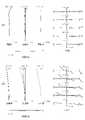
図2(A)は、第1実施例に係る光学系の無限遠合焦時の諸収差図である。図2(B)は、第1実施例に係る光学系の最短撮影距離合焦時の諸収差図である。無限遠合焦時の各収差図において、FNOはFナンバー、Yは像高をそれぞれ示す。最短撮影距離合焦時の
各収差図において、NAは開口数、Yは像高をそれぞれ示す。なお、球面収差図では最大口径に対応するFナンバーまたは開口数の値を示し、非点収差図および歪曲収差図では像高の最大値をそれぞれ示し、コマ収差図では各像高の値を示す。dはd線(波長λ=587.6nm)、gはg線(波長λ=435.8nm)をそれぞれ示す。非点収差図において、実線はサジタル像面、破線はメリディオナル像面をそれぞれ示す。なお、以下に示す各実施例の収差図においても、本実施例と同様の符号を用い、重複する説明は省略する。FIG. 2A is a diagram of various aberrations of the optical system according to the first embodiment at the time of infinity focusing. FIG. 2B is a diagram of various aberrations of the optical system according to the first embodiment when the shortest shooting distance is in focus. In each aberration diagram at infinity focus, FNO indicates F number and Y indicates image height. In each aberration diagram at the time of focusing at the shortest shooting distance, NA indicates the numerical aperture and Y indicates the image height. The spherical aberration diagram shows the value of the F number or numerical aperture corresponding to the maximum aperture, the astigmatism diagram and the distortion diagram show the maximum image height, and the coma aberration diagram shows the value of each image height. .. d indicates the d line (wavelength λ = 587.6 nm), and g indicates the g line (wavelength λ = 435.8 nm). In the astigmatism diagram, the solid line shows the sagittal image plane and the broken line shows the meridional image plane. In the aberration diagrams of each embodiment shown below, the same reference numerals as those of the present embodiment are used, and duplicate description is omitted.
各諸収差図より、第1実施例に係る光学系は、無限遠合焦時から最短撮影距離合焦時までの全域において、諸収差が良好に補正され、優れた結像性能を有していることがわかる。 From each aberration diagram, the optical system according to the first embodiment has excellent imaging performance in which various aberrations are satisfactorily corrected in the entire range from infinity focusing to the shortest shooting distance focusing. You can see that there is.
(第2実施例)
第2実施例について、図3~図4および表2を用いて説明する。図3は、第2実施例に係る光学系の無限遠合焦状態におけるレンズ構成を示す図である。第2実施例に係る光学系OL(2)は、光軸に沿って物体側から順に並んだ、正の屈折力を有する第1レンズ群G1と、開口絞りSと、正の屈折力を有する第2レンズ群G2と、正の屈折力を有する第3レンズ群G3と、負の屈折力を有する第4レンズ群G4とから構成される。無限遠物体から近距離物体(最短撮影距離物体)への合焦の際、第2レンズ群G2と第3レンズ群G3とが光軸に沿って異なる移動量で物体側へ移動し、隣り合う各レンズ群の間隔が変化する。なお、合焦の際、第1レンズ群G1、開口絞りS、および第4レンズ群G4は、像面Iに対して位置が固定される。(Second Example)
The second embodiment will be described with reference to FIGS. 3 to 4 and Table 2. FIG. 3 is a diagram showing a lens configuration in an infinity-focused state of the optical system according to the second embodiment. The optical system OL (2) according to the second embodiment has a first lens group G1 having a positive refractive power, an aperture aperture S, and a positive refractive power arranged in order from the object side along the optical axis. It is composed of a second lens group G2, a third lens group G3 having a positive refractive power, and a fourth lens group G4 having a negative refractive power. When focusing from an infinite object to a short-range object (shortest shooting distance object), the second lens group G2 and the third lens group G3 move toward the object side by different amounts of movement along the optical axis and are adjacent to each other. The distance between each lens group changes. At the time of focusing, the positions of the first lens group G1, the aperture stop S, and the fourth lens group G4 are fixed with respect to the image plane I.
本実施例では、第2レンズ群G2と、第3レンズ群G3と、第4レンズ群G4とが、全体として正の屈折力を有する後続群GRを構成する。また、第2レンズ群G2が後続群GRにおける第1合焦レンズ群GF1に該当する。第3レンズ群G3が後続群GRにおける第2合焦レンズ群GF2に該当する。 In this embodiment, the second lens group G2, the third lens group G3, and the fourth lens group G4 constitute a subsequent group GR having a positive refractive power as a whole. Further, the second lens group G2 corresponds to the first focusing lens group GF1 in the subsequent group GR. The third lens group G3 corresponds to the second focusing lens group GF2 in the subsequent group GR.
第1レンズ群G1は、光軸に沿って物体側から順に並んだ、負レンズL11と、正レンズL12とから構成される。 The first lens group G1 is composed of a negative lens L11 and a positive lens L12 arranged in order from the object side along the optical axis.
第2レンズ群G2は、光軸に沿って物体側から順に並んだ、第1正レンズL21と第1負レンズL22とが接合された正の屈折力を有する接合レンズと、第2負レンズL23と、第2正レンズL24とから構成される。第2正レンズL24は、ガラス製レンズ本体の像側の面に樹脂層が設けられて構成されるハイブリッド型のレンズである。樹脂層の像側の面が非球面であり、第2正レンズL24は複合型の非球面レンズである。後述の[レンズ諸元]において、面番号11がレンズ本体の物体側の面、面番号12がレンズ本体の像側の面および樹脂層の物体側の面(両者が接合する面)、面番号13が樹脂層の像側の面を示す。 The second lens group G2 includes a bonded lens having a positive refractive power in which the first positive lens L21 and the first negative lens L22 are joined in order from the object side along the optical axis, and a second negative lens L23. And the second positive lens L24. The second positive lens L24 is a hybrid type lens configured by providing a resin layer on the image side surface of the glass lens body. The surface of the resin layer on the image side is an aspherical surface, and the second positive lens L24 is a composite aspherical surface lens. In the [lens specifications] described later, the surface number 11 is the surface on the object side of the lens body, the surface number 12 is the surface on the image side of the lens body, the surface on the object side of the resin layer (the surface where both are joined), and the surface number. Reference numeral 13 indicates a surface of the resin layer on the image side.
第3レンズ群G3は、光軸に沿って物体側から順に並んだ、負レンズ31と、正レンズ32とから構成される。負レンズ31は、両側のレンズ面が非球面である。 The third lens group G3 is composed of a negative lens 31 and a positive lens 32 arranged in order from the object side along the optical axis. The negative lens 31 has aspherical lens surfaces on both sides.
第4レンズ群G4は、1枚の負レンズ41から構成される。第4レンズ群G4の像側に、像面Iが配置される。第4レンズ群G4と像面Iとの間には、抜き差し交換可能な光学フィルターFLが配設されている。また、像面Iには、CCDやCMOS等から構成された撮像素子(図示せず)が配置される。 The fourth lens group G4 is composed of one negative lens 41. The image plane I is arranged on the image side of the fourth lens group G4. An optical filter FL that can be inserted and removed is arranged between the fourth lens group G4 and the image plane I. Further, an image pickup device (not shown) composed of a CCD, CMOS, or the like is arranged on the image plane I.
以下の表2に、第2実施例に係る光学系の諸元の値を掲げる。 Table 2 below lists the values of the specifications of the optical system according to the second embodiment.
(表2)
[全体諸元]
f=28.824
FNO=2.909
ω=38.029
Y=21.700
TL=54.610
Bf=0.860
Bfa=13.138
β2=0.163
β3=0.721
β4=1.310
[レンズ諸元]
面番号 R D nd νd
物体面 ∞
1 -67.65263 0.800 1.53172 48.78
2 18.07229 1.030
3 19.61204 2.300 1.80400 46.60
4 ∞ 1.000
5 ∞ (D5) (絞りS)
6 39.03942 3.000 2.00100 29.12
7 -14.01800 0.700 1.80518 25.45
8 44.52125 3.457
9 -11.08066 0.900 1.80809 22.74
10 -29.93301 0.150
11 ∞ 6.550 1.80400 46.60
12 -17.50329 0.140 1.56093 36.64
13* -16.27553 (D13)
14* -26.85154 2.000 1.53113 55.73
15* -28.96313 0.200
16 ∞ 4.500 1.80400 46.60
17 -36.85132 (D17)
18 -34.46648 1.200 1.64769 33.73
19 173.14403 11.223
20 ∞ 1.600 1.51680 63.88
21 ∞ BF
像面 ∞
[非球面データ]
第13面
κ=1.00000E+00,A4=2.85655E-05,A6=-1.38279E-08,A8=5.79289E-10
A10=9.06875E-13,A12=-2.25760E-15,A14=1.33070E-17
第14面
κ=1.00000E+00,A4=2.41081E-05,A6=9.24872E-08,A8=-6.64821E-10
A10=1.30136E-12,A12=8.89760E-16,A14=0.00000E+00
第15面
κ=1.00000E+00,A4=3.97489E-05,A6=2.41498E-07,A8=-1.14609E-09
A10=2.49848E-12,A12=-2.3864E-15,A14=0.00000E+00
[可変間隔データ]
無限遠 近距離
f=28.824 β=-0.203
D0 ∞ 135.390
D5 4.850 3.169
D13 4.450 1.339
D17 3.700 8.492
[レンズ群データ]
群 始面 焦点距離
G1 1 187.243
G2 6 34.689
G3 14 46.577
G4 18 -44.279(Table 2)
[Overall specifications]
f = 28.824
FNO = 2.909
ω = 38.029
Y = 21.700
TL = 54.610
Bf = 0.860
Bfa = 13.138
β2 = 0.163
β3 = 0.721
β4 = 1.310
[Lens specifications]
Surface number R D nd νd
Object surface ∞
1 -67.65263 0.800 1.53172 48.78
2 18.07229 1.030
3 19.61204 2.300 1.80400 46.60
4 ∞ 1.000
5 ∞ (D5) (Aperture S)
6 39.03942 3.000 2.00100 29.12
7 -14.01800 0.700 1.80518 25.45
8 44.52125 3.457
9 -11.08066 0.900 1.80809 22.74
10 -29.93301 0.150
11 ∞ 6.550 1.80400 46.60
12 -17.50329 0.140 1.56093 36.64
13 * -16.27553 (D13)
14 * -26.85154 2.000 1.53113 55.73
15 * -28.96313 0.200
16 ∞ 4.500 1.80400 46.60
17 -36.85132 (D17)
18 -34.46648 1.200 1.64769 33.73
19 173.14403 11.223
20 ∞ 1.600 1.51680 63.88
21 ∞ BF
Image plane ∞
[Aspherical data]
Surface 13 κ = 1.00000E + 00, A4 = 2.85655E-05, A6 = -1.38279E-08, A8 = 5.79289E-10
A10 = 9.06875E-13, A12 = -2.25760E-15, A14 = 1.33070E-17
Surface 14 κ = 1.00000E + 00, A4 = 2.41081E-05, A6 = 9.24872E-08, A8 = -6.68421E-10
A10 = 1.30136E-12, A12 = 8.89760E-16, A14 = 0.00000E + 00
A10 = 2.49848E-12, A12 = -2.3864E-15, A14 = 0.00000E + 00
[Variable interval data]
Infinity short distance
f = 28.824 β = -0.203
D0 ∞ 135.390
D5 4.850 3.169
D13 4.450 1.339
D17 3.700 8.492
[Lens group data]
Focal length of group origin
G2 6 34.689
G3 14 46.577
G4 18 -44.279
図4(A)は、第2実施例に係る光学系の無限遠合焦時の諸収差図である。図4(B)は、第2実施例に係る光学系の最短撮影距離合焦時の諸収差図である。各諸収差図より、第2実施例に係る光学系は、無限遠合焦時から最短撮影距離合焦時までの全域において、諸収差が良好に補正され、優れた結像性能を有していることがわかる。 FIG. 4A is a diagram of various aberrations of the optical system according to the second embodiment at the time of infinity focusing. FIG. 4B is an aberration diagram at the time of focusing the shortest shooting distance of the optical system according to the second embodiment. From each aberration diagram, the optical system according to the second embodiment has excellent imaging performance in which various aberrations are satisfactorily corrected in the entire range from infinity focusing to the shortest shooting distance focusing. You can see that there is.
(第3実施例)
第3実施例について、図5~図6および表3を用いて説明する。図5は、第3実施例に係る光学系の無限遠合焦状態におけるレンズ構成を示す図である。第3実施例に係る光学系OL(3)は、光軸に沿って物体側から順に並んだ、正の屈折力を有する第1レンズ群G1と、開口絞りSと、正の屈折力を有する第2レンズ群G2と、正の屈折力を有する第3レンズ群G3と、負の屈折力を有する第4レンズ群G4とから構成される。無限遠物体から近距離物体(最短撮影距離物体)への合焦の際、第2レンズ群G2と第3レンズ群G3とが光軸に沿って異なる移動量で物体側へ移動し、隣り合う各レンズ群の間隔が変化する。なお、合焦の際、第1レンズ群G1、開口絞りS、および第4レンズ群G4は、像面Iに対して位置が固定される。(Third Example)
The third embodiment will be described with reference to FIGS. 5 to 6 and Table 3. FIG. 5 is a diagram showing a lens configuration in an infinity-focused state of the optical system according to the third embodiment. The optical system OL (3) according to the third embodiment has a first lens group G1 having a positive refractive power, an aperture aperture S, and a positive refractive power arranged in order from the object side along the optical axis. It is composed of a second lens group G2, a third lens group G3 having a positive refractive power, and a fourth lens group G4 having a negative refractive power. When focusing from an infinite object to a short-range object (shortest shooting distance object), the second lens group G2 and the third lens group G3 move toward the object side by different amounts of movement along the optical axis and are adjacent to each other. The distance between each lens group changes. At the time of focusing, the positions of the first lens group G1, the aperture stop S, and the fourth lens group G4 are fixed with respect to the image plane I.
本実施例では、第2レンズ群G2と、第3レンズ群G3と、第4レンズ群G4とが、全体として正の屈折力を有する後続群GRを構成する。また、第2レンズ群G2が後続群GRにおける第1合焦レンズ群GF1に該当する。第3レンズ群G3が後続群GRにおける第2合焦レンズ群GF2に該当する。 In this embodiment, the second lens group G2, the third lens group G3, and the fourth lens group G4 constitute a subsequent group GR having a positive refractive power as a whole. Further, the second lens group G2 corresponds to the first focusing lens group GF1 in the subsequent group GR. The third lens group G3 corresponds to the second focusing lens group GF2 in the subsequent group GR.
第1レンズ群G1は、光軸に沿って物体側から順に並んだ、第1負レンズL11と、第2負レンズL12と、正レンズL13と第3負レンズL14とが接合された正の屈折力を有する接合レンズとから構成される。第2負レンズL12は、両側のレンズ面が非球面である。 The first lens group G1 is a positive refraction in which the first negative lens L11, the second negative lens L12, the positive lens L13, and the third negative lens L14, which are arranged in order from the object side along the optical axis, are joined. It consists of a bonded lens with power. The second negative lens L12 has aspherical lens surfaces on both sides.
第2レンズ群G2は、光軸に沿って物体側から順に並んだ、第1正レンズL21と第1負レンズL22とが接合された正の屈折力を有する接合レンズと、第2負レンズL23と、第2正レンズL24とから構成される。第2正レンズL24は、像側のレンズ面が非球面である。 The second lens group G2 includes a bonded lens having a positive refractive power in which the first positive lens L21 and the first negative lens L22 are joined in order from the object side along the optical axis, and a second negative lens L23. And the second positive lens L24. The second positive lens L24 has an aspherical lens surface on the image side.
第3レンズ群G3は、1枚の正レンズ31から構成される。正レンズ31は、像側のレンズ面が非球面である。 The third lens group G3 is composed of one positive lens 31. The positive lens 31 has an aspherical lens surface on the image side.
第4レンズ群G4は、1枚の負レンズ41から構成される。第4レンズ群G4の像側に、像面Iが配置される。第4レンズ群G4と像面Iとの間には、抜き差し交換可能な光学フィルターFLが配設されている。また、像面Iには、CCDやCMOS等から構成された撮像素子(図示せず)が配置される。 The fourth lens group G4 is composed of one negative lens 41. The image plane I is arranged on the image side of the fourth lens group G4. An optical filter FL that can be inserted and removed is arranged between the fourth lens group G4 and the image plane I. Further, an image pickup device (not shown) composed of a CCD, CMOS, or the like is arranged on the image plane I.
以下の表3に、第3実施例に係る光学系の諸元の値を掲げる。 Table 3 below lists the values of the specifications of the optical system according to the third embodiment.
(表3)
[全体諸元]
f=28.805
FNO=2.067
ω=37.270
Y=21.700
TL=59.500
Bf=0.800
Bfa=11.855
β2=0.427
β3=0.565
β4=1.245
[レンズ諸元]
面番号 R D nd νd
物体面 ∞
1 40.41078 1.000 1.48749 70.31
2 16.22403 3.600
3* -70.24185 1.300 1.82115 24.06
4* 148.16663 0.200
5 20.51937 4.000 1.88300 40.66
6 -32.92528 1.100 1.59270 35.27
7 65.09547 2.000
8 ∞ (D8) (絞りS)
9 44.75110 3.300 2.00100 29.12
10 -20.22294 0.800 1.75520 27.57
11 61.74745 4.400
12 -12.31509 0.900 1.84666 23.80
13 -49.27479 0.200
14 -1190.54970 6.300 1.76802 49.23
15* -19.49783 (D15)
16 76.50071 4.700 1.77377 47.18
17* -42.68869 (D17)
18 -34.74758 1.200 1.64769 33.73
19 714.84773 10.000
20 ∞ 1.600 1.51680 63.88
21 ∞ BF
像面 ∞
[非球面データ]
第3面
κ=1.00000E+00,A4=-3.81302E-05,A6=1.79518E-07,A8=0.00000E+00
A10=0.00000E+00,A12=0.00000E+00,A14=0.00000E+00
第4面
κ=1.00000E+00,A4=-2.32360E-05,A6=2.17814E-07,A8=2.83578E-10
A10=0.00000E+00,A12=0.00000E+00,A14=0.00000E+00
第15面
κ=1.00000E+00,A4=-3.48371E-06,A6=1.39242E-08,A8=1.83753E-10
A10=2.97697E-13,A12=0.00000E+00,A14=0.00000E+00
第17面
κ=1.00000E+00,A4=2.81807E-05,A6=-1.57952E-08,A8=4.54301E-11
A10=-1.20045E-13,A12=0.00000E+00,A14=0.00000E+00
[可変間隔データ]
無限遠 近距離
f=28.805 β=-0.124
D0 ∞ 220.500
D8 4.000 3.015
D15 3.500 1.629
D17 4.600 7.456
[レンズ群データ]
群 始面 焦点距離
G1 1 95.848
G2 9 63.426
G3 16 36.030
G4 18 -51.129(Table 3)
[Overall specifications]
f = 28.805
FNO = 2.067
ω = 37.270
Y = 21.700
TL = 59.500
Bf = 0.800
Bfa = 11.855
β2 = 0.427
β3 = 0.565
β4 = 1.245
[Lens specifications]
Surface number R D nd νd
Object surface ∞
1 40.41078 1.000 1.48749 70.31
2 16.22403 3.600
3 * -70.24185 1.300 1.82115 24.06
4 * 148.16663 0.200
5 20.51937 4.000 1.88300 40.66
6 -32.92528 1.100 1.59270 35.27
7 65.09547 2.000
8 ∞ (D8) (Aperture S)
9 44.75110 3.300 2.00100 29.12
10 -20.22294 0.800 1.75520 27.57
11 61.74745 4.400
12 -12.31509 0.900 1.84666 23.80
13 -49.27479 0.200
14 -1190.54970 6.300 1.76802 49.23
15 * -19.49783 (D15)
16 76.50071 4.700 1.77377 47.18
17 * -42.68869 (D17)
18 -34.74758 1.200 1.64769 33.73
19 714.84773 10.000
20 ∞ 1.600 1.51680 63.88
21 ∞ BF
Image plane ∞
[Aspherical data]
Third surface κ = 1.00000E + 00, A4 = -3.81302E-05, A6 = 1.79518E-07, A8 = 0.00000E + 00
A10 = 0.00000E + 00, A12 = 0.00000E + 00, A14 = 0.00000E + 00
4th surface κ = 1.00000E + 00, A4 = -2.32360E-05, A6 = 2.17814E-07, A8 = 2.83578E-10
A10 = 0.00000E + 00, A12 = 0.00000E + 00, A14 = 0.00000E + 00
A10 = 2.97697E-13, A12 = 0.00000E + 00, A14 = 0.00000E + 00
Surface 17 κ = 1.00000E + 00, A4 = 2.81807E-05, A6 = -1.57952E-08, A8 = 4.54301E-11
A10 = -1.20045E-13, A12 = 0.00000E + 00, A14 = 0.00000E + 00
[Variable interval data]
Infinity short distance
f = 28.805 β = -0.124
D0 ∞ 220.500
D8 4.000 3.015
D15 3.500 1.629
D17 4.600 7.456
[Lens group data]
Focal length of group origin
G2 9 63.426
G3 16 36.030
G4 18 -51.129
図6(A)は、第3実施例に係る光学系の無限遠合焦時の諸収差図である。図6(B)は、第3実施例に係る光学系の最短撮影距離合焦時の諸収差図である。各諸収差図より、第3実施例に係る光学系は、無限遠合焦時から最短撮影距離合焦時までの全域において、諸収差が良好に補正され、優れた結像性能を有していることがわかる。 FIG. 6A is a diagram of various aberrations of the optical system according to the third embodiment at the time of infinity focusing. FIG. 6B is a diagram of various aberrations of the optical system according to the third embodiment when the shortest shooting distance is in focus. From each aberration diagram, the optical system according to the third embodiment has excellent imaging performance in which various aberrations are satisfactorily corrected in the entire range from infinity focusing to the shortest shooting distance focusing. You can see that there is.
(第4実施例)
第4実施例について、図7~図8および表4を用いて説明する。図7は、第4実施例に係る光学系の無限遠合焦状態におけるレンズ構成を示す図である。第4実施例に係る光学系OL(4)は、光軸に沿って物体側から順に並んだ、正の屈折力を有する第1レンズ群G1と、開口絞りSと、正の屈折力を有する第2レンズ群G2と、正の屈折力を有する第3レンズ群G3と、負の屈折力を有する第4レンズ群G4とから構成される。無限遠物体から近距離物体(最短撮影距離物体)への合焦の際、第2レンズ群G2と第3レンズ群G3とが光軸に沿って異なる移動量で物体側へ移動し、隣り合う各レンズ群の間隔が変化する。なお、合焦の際、第1レンズ群G1、開口絞りS、および第4レンズ群G4は、像面Iに対して位置が固定される。(Fourth Example)
The fourth embodiment will be described with reference to FIGS. 7 to 8 and Table 4. FIG. 7 is a diagram showing a lens configuration in an infinity-focused state of the optical system according to the fourth embodiment. The optical system OL (4) according to the fourth embodiment has a first lens group G1 having a positive refractive power, an aperture aperture S, and a positive refractive power arranged in order from the object side along the optical axis. It is composed of a second lens group G2, a third lens group G3 having a positive refractive power, and a fourth lens group G4 having a negative refractive power. When focusing from an infinite object to a short-range object (shortest shooting distance object), the second lens group G2 and the third lens group G3 move toward the object side by different amounts of movement along the optical axis and are adjacent to each other. The distance between each lens group changes. At the time of focusing, the positions of the first lens group G1, the aperture stop S, and the fourth lens group G4 are fixed with respect to the image plane I.
本実施例では、第2レンズ群G2と、第3レンズ群G3と、第4レンズ群G4とが、全体として正の屈折力を有する後続群GRを構成する。また、第2レンズ群G2が後続群GRにおける第1合焦レンズ群GF1に該当する。第3レンズ群G3が後続群GRにおける第2合焦レンズ群GF2に該当する。 In this embodiment, the second lens group G2, the third lens group G3, and the fourth lens group G4 constitute a subsequent group GR having a positive refractive power as a whole. Further, the second lens group G2 corresponds to the first focusing lens group GF1 in the subsequent group GR. The third lens group G3 corresponds to the second focusing lens group GF2 in the subsequent group GR.
第1レンズ群G1は、光軸に沿って物体側から順に並んだ、負レンズL11と、正レンズL12とから構成される。正レンズL12は、ガラス製レンズ本体の像側の面に樹脂層が設けられて構成されるハイブリッド型のレンズである。樹脂層の像側の面が非球面であり、正レンズL12は複合型の非球面レンズである。後述の[レンズ諸元]において、面番号3がレンズ本体の物体側の面、面番号4がレンズ本体の像側の面および樹脂層の物体側の面(両者が接合する面)、面番号5が樹脂層の像側の面を示す。 The first lens group G1 is composed of a negative lens L11 and a positive lens L12 arranged in order from the object side along the optical axis. The positive lens L12 is a hybrid type lens configured by providing a resin layer on the image side surface of the glass lens body. The surface of the resin layer on the image side is an aspherical surface, and the positive lens L12 is a composite aspherical surface lens. In the [lens specifications] described later, the
第2レンズ群G2は、光軸に沿って物体側から順に並んだ、第1正レンズL21と第1負レンズL22とが接合された正の屈折力を有する接合レンズと、第2負レンズL23と、第2正レンズL24とから構成される。第2正レンズL24は、像側のレンズ面が非球面である。 The second lens group G2 includes a bonded lens having a positive refractive power in which the first positive lens L21 and the first negative lens L22 are joined in order from the object side along the optical axis, and a second negative lens L23. And the second positive lens L24. The second positive lens L24 has an aspherical lens surface on the image side.
第3レンズ群G3は、1枚の正レンズ31から構成される。正レンズ31は、像側のレンズ面が非球面である。 The third lens group G3 is composed of one positive lens 31. The positive lens 31 has an aspherical lens surface on the image side.
第4レンズ群G4は、1枚の負レンズ41から構成される。第4レンズ群G4の像側に、像面Iが配置される。第4レンズ群G4と像面Iとの間には、抜き差し交換可能な光学フィルターFLが配設されている。また、像面Iには、CCDやCMOS等から構成された撮像素子(図示せず)が配置される。 The fourth lens group G4 is composed of one negative lens 41. The image plane I is arranged on the image side of the fourth lens group G4. An optical filter FL that can be inserted and removed is arranged between the fourth lens group G4 and the image plane I. Further, an image pickup device (not shown) composed of a CCD, CMOS, or the like is arranged on the image plane I.
以下の表4に、第4実施例に係る光学系の諸元の値を掲げる。 Table 4 below lists the values of the specifications of the optical system according to the fourth embodiment.
(表4)
[全体諸元]
f=28.802
FNO=2.861
ω=37.036
Y=21.700
TL=50.042
Bf=0.860
Bfa=11.697
β2=0.406
β3=0.679
β4=1.248
[レンズ諸元]
面番号 R D nd νd
物体面 ∞
1 -33.60557 0.900 1.59270 35.27
2 24.37821 0.300
3 21.36640 2.400 1.84850 43.79
4 -64.21743 0.100 1.56093 36.64
5* -64.21743 1.000
6 ∞ (D6) (絞りS)
7 48.57194 2.700 2.00100 29.12
8 -16.54854 0.700 1.71736 29.57
9 50.38696 3.800
10 -11.12244 1.000 1.80809 22.74
11 -43.70934 0.200
12 -628.97652 7.000 1.75501 51.15
13* -16.56020 (D13)
14 326.40430 3.900 1.76802 49.23
15* -38.59856 (D15)
16 -23.79495 1.000 1.58144 40.98
17 -129.23419 9.782
18 ∞ 1.600 1.51680 63.88
19 ∞ BF
像面 ∞
[非球面データ]
第5面
κ=5.65120E+00,A4=1.32957E-05,A6=3.71890E-08,A8=0.00000E+00
A10=0.00000E+00,A12=0.00000E+00,A14=0.00000E+00
第13面
κ=-5.67700E-01,A4=-1.05001E-05,A6=-8.81582E-08,A8=4.96402E-10
A10=-7.84585E-13,A12=0.00000E+00,A14=0.00000E+00
第15面
κ=1.00000E+00,A4=1.63200E-05,A6=5.26856E-08,A8=-1.38087E-10
A10=2.83555E-13,A12=0.00000E+00,A14=0.00000E+00
[可変間隔データ]
無限遠 近距離
f=28.802 β=-0.199
D0 ∞ 139.958
D6 4.100 2.428
D13 4.300 0.956
D15 4.400 9.416
[レンズ群データ]
群 始面 焦点距離
G1 1 83.642
G2 7 47.380
G3 14 45.152
G4 16 -50.335(Table 4)
[Overall specifications]
f = 28.802
FNO = 2.861
ω = 37.036
Y = 21.700
TL = 50.042
Bf = 0.860
Bfa = 11.697
β2 = 0.406
β3 = 0.679
β4 = 1.248
[Lens specifications]
Surface number R D nd νd
Object surface ∞
1 -33.60557 0.900 1.59270 35.27
2 24.37821 0.300
3 21.36640 2.400 1.84850 43.79
4 -64.21743 0.100 1.56093 36.64
5 * -64.21743 1.000
6 ∞ (D6) (Aperture S)
7 48.57194 2.700 2.00100 29.12
8 -16.54854 0.700 1.71736 29.57
9 50.38696 3.800
10 -11.12244 1.000 1.80809 22.74
11 -43.70934 0.200
12 -628.97652 7.000 1.75501 51.15
13 * -16.56020 (D13)
14 326.40430 3.900 1.76802 49.23
15 * -38.59856 (D15)
16 -23.79495 1.000 1.58144 40.98
17 -129.23419 9.782
18 ∞ 1.600 1.51680 63.88
19 ∞ BF
Image plane ∞
[Aspherical data]
Fifth surface κ = 5.65120E + 00, A4 = 1.32957E-05, A6 = 3.71890E-08, A8 = 0.00000E + 00
A10 = 0.00000E + 00, A12 = 0.00000E + 00, A14 = 0.00000E + 00
Surface 13 κ = -5.67700E-01, A4 = -1.05001E-05, A6 = -8.81582E-08, A8 = 4.96402E-10
A10 = -7.84585E-13, A12 = 0.00000E + 00, A14 = 0.00000E + 00
A10 = 2.83555E-13, A12 = 0.00000E + 00, A14 = 0.00000E + 00
[Variable interval data]
Infinity short distance
f = 28.802 β = -0.199
D0 ∞ 139.958
D6 4.100 2.428
D13 4.300 0.956
D15 4.400 9.416
[Lens group data]
Focal length of group origin
G2 7 47.380
G3 14 45.152
G4 16 -50.335
図8(A)は、第4実施例に係る光学系の無限遠合焦時の諸収差図である。図8(B)は、第4実施例に係る光学系の最短撮影距離合焦時の諸収差図である。各諸収差図より、第4実施例に係る光学系は、無限遠合焦時から最短撮影距離合焦時までの全域において、諸収差が良好に補正され、優れた結像性能を有していることがわかる。 FIG. 8A is a diagram of various aberrations of the optical system according to the fourth embodiment at the time of infinity focusing. FIG. 8B is an aberration diagram at the time of focusing the shortest shooting distance of the optical system according to the fourth embodiment. From each aberration diagram, the optical system according to the fourth embodiment has excellent imaging performance in which various aberrations are satisfactorily corrected in the entire range from infinity focusing to the shortest shooting distance focusing. You can see that there is.
次に、[条件式対応値]の表を下記に示す。この表には、各条件式(1)~(15)に対応する値を、全実施例(第1~第4実施例)について纏めて示す。
条件式(1) 0.03<D1/TL<0.25
条件式(2) 1.20<(-f4)/f<2.00
条件式(3) 1.10<β4<1.40
条件式(4) 28.0<νd41<45.0
条件式(5) 0.50<f2/f3<2.00
条件式(6) 0.04<d23/TL<0.11
条件式(7) 0.60<d23/d12<1.00
条件式(8) 0.10<β2/β3<0.90
条件式(9) 0.015<{β2+(1/β2)}-2<0.170
条件式(10) 0.100<{β3+(1/β3)}-2<0.250
条件式(11) 0.00<N21-N22<0.40
条件式(12) N21>1.90
条件式(13) 25.0<νd21<35.0
条件式(14) -1.20<(R31+R32)/(R32-R31)<0.00
条件式(15) 0.00<f/f1<0.70Next, the table of [Conditional expression correspondence value] is shown below. In this table, the values corresponding to each conditional expression (1) to (15) are collectively shown for all the examples (first to fourth examples).
Conditional expression (1) 0.03 <D1 / TL <0.25
Conditional expression (2) 1.20 <(-f4) /f<2.000
Conditional expression (3) 1.10 <β4 <1.40
Conditional expression (4) 28.0 <νd41 <45.0
Conditional expression (5) 0.50 <f2 / f3 <2.000
Conditional expression (6) 0.04 <d23 / TL <0.11
Conditional expression (7) 0.60 <d23 / d12 <1.000
Conditional expression (8) 0.10 <β2 / β3 <0.90
Conditional expression (9) 0.015 <{β2 + (1 / β2)}-2 <0.170
Conditional expression (10) 0.100 <{β3 + (1 / β3)}-2 <0.250
Conditional expression (11) 0.00 <N21-N22 <0.40
Conditional expression (12) N21> 1.90
Conditional expression (13) 25.0 <νd21 <35.0
Conditional expression (14) -1.20 <(R31 + R32) / (R32-R31) <0.00
Conditional expression (15) 0.00 <f / f1 <0.70
[条件式対応値]
条件式 第1実施例 第2実施例 第3実施例 第4実施例
(1) 0.076 0.076 0.188 0.074
(2) 1.641 1.536 1.775 1.748
(3) 1.266 1.310 1.245 1.248
(4) 32.190 33.730 33.730 40.980
(5) 1.794 0.745 1.760 1.049
(6) 0.086 0.081 0.059 0.086
(7) 0.887 0.761 0.700 0.843
(8) 0.772 0.226 0.756 0.598
(9) 0.136 0.025 0.130 0.122
(10) 0.186 0.225 0.183 0.216
(11) 0.273 0.196 0.246 0.284
(12) 2.001 2.001 2.001 2.001
(13) 29.120 29.120 29.120 29.120
(14) -0.876 -1.000 -0.284 -0.789
(15) 0.319 0.154 0.301 0.344[Conditional expression correspondence value]
Conditional expression 1st Example 2nd Example 3rd Example 4th Example (1) 0.076 0.076 0.188 0.074
(2) 1.641 1.536 1.775 1.748
(3) 1.266 1.310 1.245 1.248
(4) 32.190 33.730 33.730 40.980
(5) 1.794 0.745 1.760 1.049
(6) 0.086 0.081 0.059 0.086
(7) 0.887 0.761 0.700 0.843
(8) 0.772 0.226 0.756 0.598
(9) 0.136 0.025 0.130 0.122
(10) 0.186 0.225 0.183 0.216
(11) 0.273 0.196 0.246 0.284
(12) 2.001 2.001 2.001 2.001
(13) 29.120 29.120 29.120 29.120
(14) -0.876 -1.000 -0.284 -0.789
(15) 0.319 0.154 0.301 0.344
上記各実施例によれば、光学系の焦点距離に対して全長が短くなり、小型でありながら良好な光学性能を有した光学系を実現することができる。 According to each of the above embodiments, the total length is shortened with respect to the focal length of the optical system, and it is possible to realize an optical system having good optical performance while being compact.
上記各実施例は本願発明の一具体例を示しているものであり、本願発明はこれらに限定されるものではない。 Each of the above examples shows a specific example of the present invention, and the present invention is not limited thereto.
以下の内容は、本実施形態の光学系の光学性能を損なわない範囲で適宜採用することが可能である。 The following contents can be appropriately adopted as long as the optical performance of the optical system of the present embodiment is not impaired.
本実施形態の光学系の実施例として4群構成のものを示したが、本願はこれに限られず、その他の群構成(例えば、5群等)の変倍光学系を構成することもできる。具体的には、本実施形態の光学系の最も物体側や最も像面側にレンズ又はレンズ群を追加した構成でも構わない。なお、レンズ群とは、合焦時に変化する空気間隔で分離された、少なくとも1枚のレンズを有する部分を示す。 As an example of the optical system of the present embodiment, a four-group configuration is shown, but the present application is not limited to this, and a variable magnification optical system having another group configuration (for example, five groups or the like) can also be configured. Specifically, a lens or a lens group may be added to the most object side or the most image plane side of the optical system of the present embodiment. The lens group refers to a portion having at least one lens separated by an air interval that changes at the time of focusing.
レンズ群または部分レンズ群を光軸に垂直な方向の成分を持つように移動させ、または、光軸を含む面内方向に回転移動(揺動)させて、手ブレによって生じる像ブレを補正する防振レンズ群としても良い。 The lens group or partial lens group is moved so as to have a component in the direction perpendicular to the optical axis, or is rotationally moved (swinged) in the in-plane direction including the optical axis to correct image blur caused by camera shake. It may be used as an anti-vibration lens group.
レンズ面は、球面または平面で形成されても、非球面で形成されても構わない。レンズ面が球面または平面の場合、レンズ加工および組立調整が容易になり、加工および組立調整の誤差による光学性能の劣化を防げるので好ましい。また、像面がずれた場合でも描写性能の劣化が少ないので好ましい。 The lens surface may be formed on a spherical surface or a flat surface, or may be formed on an aspherical surface. When the lens surface is spherical or flat, lens processing and assembly adjustment are facilitated, and deterioration of optical performance due to processing and assembly adjustment errors can be prevented, which is preferable. Further, even if the image plane is displaced, the deterioration of the depiction performance is small, which is preferable.
レンズ面が非球面の場合、非球面は、研削加工による非球面、ガラスを型で非球面形状に形成したガラスモールド非球面、ガラスの表面に樹脂を非球面形状に形成した複合型非球面のいずれでも構わない。また、レンズ面は回折面としても良く、レンズを屈折率分布型レンズ(GRINレンズ)あるいはプラスチックレンズとしても良い。 When the lens surface is an aspherical surface, the aspherical surface is an aspherical surface formed by grinding, a glass mold aspherical surface formed by forming glass into an aspherical surface shape, or a composite aspherical surface formed by forming resin on the glass surface into an aspherical surface shape. It doesn't matter which one. Further, the lens surface may be a diffraction surface, and the lens may be a refractive index distribution type lens (GRIN lens) or a plastic lens.
開口絞りは第1レンズ群と第2レンズ群との間に配置されるのが好ましいが、開口絞りとしての部材を設けずに、レンズの枠でその役割を代用しても良い。 The aperture diaphragm is preferably arranged between the first lens group and the second lens group, but the role may be substituted by the frame of the lens without providing the member as the aperture diaphragm.
各レンズ面には、フレアやゴーストを軽減し、コントラストの高い光学性能を達成するために、広い波長域で高い透過率を有する反射防止膜を施しても良い。 An antireflection film having a high transmittance in a wide wavelength range may be provided on each lens surface in order to reduce flare and ghosting and achieve high-contrast optical performance.
G1 第1レンズ群 G2 第2レンズ群
G3 第3レンズ群 G4 第4レンズ群
I 像面 S 開口絞りG1 1st lens group G2 2nd lens group G3 3rd lens group G4 4th lens group I image plane S aperture stop
Claims (31)
Translated fromJapanese前記後続群は、合焦の際に光軸に沿って移動する第1合焦レンズ群と、前記第1合焦レンズ群より像側に配置されて合焦の際に光軸に沿って移動する第2合焦レンズ群とを有し、
以下の条件式を満足する光学系。
0.03<D1/TL<0.25
但し、D1:前記第1レンズ群における最も物体側のレンズ面から最も像側のレンズ面までの光軸上の距離
TL:前記光学系の全長It has a first lens group having a positive refractive power, an aperture diaphragm, and a subsequent group, which are arranged in order from the object side along the optical axis.
The subsequent group includes a first focusing lens group that moves along the optical axis during focusing, and a first focusing lens group that is arranged on the image side of the first focusing lens group and moves along the optical axis during focusing. It has a second focusing lens group and
An optical system that satisfies the following conditional expression.
0.03 <D1 / TL <0.25
However, D1: the distance on the optical axis from the lens surface on the most object side to the lens surface on the image side in the first lens group TL: Overall length of the optical system.
前記第2レンズ群が前記第1合焦レンズ群であり、
前記第3レンズ群が前記第2合焦レンズ群である請求項1または2に記載の光学系。The subsequent group has a second lens group having a positive refractive power and a third lens group having a positive refractive power arranged in order from the object side along the optical axis.
The second lens group is the first focusing lens group.
The optical system according to claim 1 or 2, wherein the third lens group is the second focusing lens group.
合焦の際、隣り合う各レンズ群の間隔が変化する光学系。The first lens group having a positive refractive power, the second lens group having a positive refractive power, and the third lens group having a positive refractive power arranged in order from the object side along the optical axis are negative. It has a fourth lens group with refractive power,
An optical system in which the distance between adjacent lens groups changes when focusing.
0.03<D1/TL<0.25
但し、D1:前記第1レンズ群における最も物体側のレンズ面から最も像側のレンズ面までの光軸上の距離
TL:前記光学系の全長The optical system according to claim 5, which satisfies the following conditional expression.
0.03 <D1 / TL <0.25
However, D1: the distance on the optical axis from the lens surface on the most object side to the lens surface on the image side in the first lens group TL: Overall length of the optical system.
合焦の際、前記第2レンズ群と前記第3レンズ群とが光軸に沿って移動し、
以下の条件式を満足する光学系。
0.03<D1/TL<0.25
但し、D1:前記第1レンズ群における最も物体側のレンズ面から最も像側のレンズ面までの光軸上の距離
TL:前記光学系の全長The first lens group having a positive refractive power, the second lens group having a positive refractive power, and the third lens group having a positive refractive power arranged in order from the object side along the optical axis are negative. It has a fourth lens group with refractive power,
At the time of focusing, the second lens group and the third lens group move along the optical axis, and the second lens group and the third lens group move along the optical axis.
An optical system that satisfies the following conditional expression.
0.03 <D1 / TL <0.25
However, D1: the distance on the optical axis from the lens surface on the most object side to the lens surface on the image side in the first lens group TL: Overall length of the optical system.
1.20<(-f4)/f<2.00
但し、f4:前記第4レンズ群の焦点距離
f:前記光学系の焦点距離The optical system according to any one of claims 4 to 9, which satisfies the following conditional expression.
1.20 <(-f4) /f<2.000
However, f4: the focal length of the fourth lens group f: the focal length of the optical system.
1.10<β4<1.40
但し、β4:無限遠合焦時の前記第4レンズ群の横倍率The optical system according to any one of claims 4 to 10, which satisfies the following conditional expression.
1.10 <β4 <1.40
However, β4: lateral magnification of the fourth lens group at the time of focusing at infinity.
以下の条件式を満足する請求項4~11のいずれか一項に記載の光学系。
28.0<νd41<45.0
但し、νd41:前記第4レンズ群の前記負レンズのd線を基準とするアッベ数The fourth lens group consists of one negative lens.
The optical system according to any one of claims 4 to 11, which satisfies the following conditional expression.
28.0 <νd41 <45.0
However, νd41: Abbe number based on the d-line of the negative lens of the fourth lens group.
0.50<f2/f3<2.00
但し、f2:前記第2レンズ群の焦点距離
f3:前記第3レンズ群の焦点距離The optical system according to any one of claims 3 to 12, which satisfies the following conditional expression.
0.50 <f2 / f3 <2.000
However, f2: focal length of the second lens group f3: focal length of the third lens group
0.04<d23/TL<0.11
但し、d23:無限遠合焦時の前記第2レンズ群と前記第3レンズ群との光軸上の間隔
TL:前記光学系の全長The optical system according to any one of claims 3 to 13, which satisfies the following conditional expression.
0.04 <d23 / TL <0.11
However, d23: the distance between the second lens group and the third lens group on the optical axis at the time of infinity focusing TL: the total length of the optical system.
0.60<d23/d12<1.00
但し、d23:無限遠合焦時の前記第2レンズ群と前記第3レンズ群との光軸上の間隔
d12:無限遠合焦時の前記第1レンズ群と前記第2レンズ群との光軸上の間隔The optical system according to any one of claims 3 to 14, which satisfies the following conditional expression.
0.60 <d23 / d12 <1.00
However, d23: the distance on the optical axis between the second lens group and the third lens group at the time of infinity focusing d12: the light between the first lens group and the second lens group at the time of infinity focusing. Axis spacing
0.10<β2/β3<0.90
但し、β2:無限遠合焦時の前記第2レンズ群の横倍率
β3:無限遠合焦時の前記第3レンズ群の横倍率The optical system according to any one of claims 3 to 15, which satisfies the following conditional expression.
0.10 <β2 / β3 <0.90
However, β2: lateral magnification of the second lens group at the time of infinity focusing β3: lateral magnification of the third lens group at the time of infinity focusing
0.015<{β2+(1/β2)}-2<0.170
但し、β2:無限遠合焦時の前記第2レンズ群の横倍率The optical system according to any one of claims 3 to 16, which satisfies the following conditional expression.
0.015 <{β2 + (1 / β2)}-2 <0.170
However, β2: lateral magnification of the second lens group at the time of focusing at infinity.
0.100<{β3+(1/β3)}-2<0.250
但し、β3:無限遠合焦時の前記第3レンズ群の横倍率The optical system according to any one of claims 3 to 17, which satisfies the following conditional expression.
0.100 <{β3 + (1 / β3)}-2 <0.250
However, β3: lateral magnification of the third lens group at the time of focusing at infinity.
0.00<N21-N22<0.40
但し、N21:前記第2レンズ群の前記第1正レンズのd線に対する屈折率
N22:前記第2レンズ群の前記第1負レンズのd線に対する屈折率The optical system according to claim 19, which satisfies the following conditional expression.
0.00 <N21-N22 <0.40
However, N21: the refractive index of the first positive lens of the second lens group with respect to the d-line N22: the refractive index of the first negative lens of the second lens group with respect to the d-line.
N21>1.90
但し、N21:前記第2レンズ群の前記第1正レンズのd線に対する屈折率The optical system according to claim 19 or 20, which satisfies the following conditional expression.
N21> 1.90
However, N21: the refractive index of the first positive lens of the second lens group with respect to the d line.
25.0<νd21<35.0
但し、νd21:前記第2レンズ群の前記第1正レンズのd線を基準とするアッベ数The optical system according to any one of claims 19 to 21, which satisfies the following conditional expression.
25.0 <νd21 <35.0
However, νd21: Abbe number based on the d-line of the first positive lens of the second lens group.
-1.20<(R31+R32)/(R32-R31)<0.00
但し、R31:前記第3レンズ群の前記正レンズにおける物体側のレンズ面の近軸曲率半径
R32:前記第3レンズ群の前記正レンズにおける像側のレンズ面の近軸曲率半径The optical system according to claim 23, which satisfies the following conditional expression.
-1.20 <(R31 + R32) / (R32-R31) <0.00
However, R31: the paraxial radius of curvature of the lens surface on the object side of the positive lens of the third lens group R32: the paraxial radius of curvature of the lens surface on the image side of the positive lens of the third lens group.
0.00<f/f1<0.70
但し、f:前記光学系の焦点距離
f1:前記第1レンズ群の焦点距離The optical system according to any one of claims 1 to 24, which satisfies the following conditional expression.
0.00 <f / f1 <0.70
However, f: the focal length of the optical system f1: the focal length of the first lens group.
前記後続群は、合焦の際に光軸に沿って移動する第1合焦レンズ群と、前記第1合焦レンズ群より像側に配置されて合焦の際に光軸に沿って移動する第2合焦レンズ群とを有し、
以下の条件式を満足するように、
レンズ鏡筒内に各レンズを配置する光学系の製造方法。
0.03<D1/TL<0.25
但し、D1:前記第1レンズ群における最も物体側のレンズ面から最も像側のレンズ面までの光軸上の距離
TL:前記光学系の全長A method for manufacturing an optical system having a first lens group having a positive refractive power, an aperture diaphragm, and a subsequent group arranged in order from the object side along the optical axis.
The subsequent group includes a first focusing lens group that moves along the optical axis during focusing, and a first focusing lens group that is arranged on the image side of the first focusing lens group and moves along the optical axis during focusing. It has a second focusing lens group and
To satisfy the following conditional expression
A method of manufacturing an optical system in which each lens is placed inside a lens barrel.
0.03 <D1 / TL <0.25
However, D1: the distance on the optical axis from the lens surface on the most object side to the lens surface on the image side in the first lens group TL: Overall length of the optical system.
合焦の際、隣り合う各レンズ群の間隔が変化するように、
レンズ鏡筒内に各レンズを配置する光学系の製造方法。The first lens group having a positive refractive power, the second lens group having a positive refractive power, and the third lens group having a positive refractive power arranged in order from the object side along the optical axis are negative. A method for manufacturing an optical system having a fourth lens group having an optical power.
When focusing, the distance between adjacent lens groups changes so that
A method of manufacturing an optical system in which each lens is placed inside a lens barrel.
合焦の際、前記第2レンズ群と前記第3レンズ群とが光軸に沿って移動し、
以下の条件式を満足するように、
レンズ鏡筒内に各レンズを配置する光学系の製造方法。
0.03<D1/TL<0.25
但し、D1:前記第1レンズ群における最も物体側のレンズ面から最も像側のレンズ面までの光軸上の距離
TL:前記光学系の全長The first lens group having a positive refractive power, the second lens group having a positive refractive power, and the third lens group having a positive refractive power arranged in order from the object side along the optical axis are negative. A method for manufacturing an optical system having a fourth lens group having an optical power.
At the time of focusing, the second lens group and the third lens group move along the optical axis, and the second lens group and the third lens group move along the optical axis.
To satisfy the following conditional expression
A method of manufacturing an optical system in which each lens is placed inside a lens barrel.
0.03 <D1 / TL <0.25
However, D1: the distance on the optical axis from the lens surface on the most object side to the lens surface on the image side in the first lens group TL: Overall length of the optical system.
Priority Applications (4)
| Application Number | Priority Date | Filing Date | Title |
|---|---|---|---|
| JP2020164402AJP7749916B2 (en) | 2020-09-30 | 2020-09-30 | Optical Systems and Optical Instruments |
| CN202180063836.4ACN116209937A (en) | 2020-09-30 | 2021-09-27 | Optical system, optical device and method for manufacturing optical system |
| PCT/JP2021/035454WO2022071249A1 (en) | 2020-09-30 | 2021-09-27 | Optical system, optical apparatus, and method for manufacturing optical system |
| US18/024,030US20230266571A1 (en) | 2020-09-30 | 2021-09-27 | Optical system, optical apparatus and method for manufacturing the optical system |
Applications Claiming Priority (1)
| Application Number | Priority Date | Filing Date | Title |
|---|---|---|---|
| JP2020164402AJP7749916B2 (en) | 2020-09-30 | 2020-09-30 | Optical Systems and Optical Instruments |
Publications (2)
| Publication Number | Publication Date |
|---|---|
| JP2022056578Atrue JP2022056578A (en) | 2022-04-11 |
| JP7749916B2 JP7749916B2 (en) | 2025-10-07 |
Family
ID=80951673
Family Applications (1)
| Application Number | Title | Priority Date | Filing Date |
|---|---|---|---|
| JP2020164402AActiveJP7749916B2 (en) | 2020-09-30 | 2020-09-30 | Optical Systems and Optical Instruments |
Country Status (4)
| Country | Link |
|---|---|
| US (1) | US20230266571A1 (en) |
| JP (1) | JP7749916B2 (en) |
| CN (1) | CN116209937A (en) |
| WO (1) | WO2022071249A1 (en) |
Cited By (2)
| Publication number | Priority date | Publication date | Assignee | Title |
|---|---|---|---|---|
| CN116009217A (en)* | 2023-03-07 | 2023-04-25 | 东莞市宇瞳玖洲光学有限公司 | Vehicle-mounted infrared large aperture lens |
| CN118244463A (en)* | 2024-05-28 | 2024-06-25 | 深圳市东正光学技术股份有限公司 | Optical lens and camera module |
Citations (4)
| Publication number | Priority date | Publication date | Assignee | Title |
|---|---|---|---|---|
| JPS58186714A (en)* | 1982-04-26 | 1983-10-31 | Nippon Kogaku Kk <Nikon> | Large aperture ratio photographic lens corrected to short distance |
| JPH0961708A (en)* | 1995-08-29 | 1997-03-07 | Olympus Optical Co Ltd | Standard lens system |
| JP2004334185A (en)* | 2003-04-18 | 2004-11-25 | Canon Inc | Zoom lens |
| WO2014118865A1 (en)* | 2013-01-30 | 2014-08-07 | パナソニック株式会社 | Internal-focus lens system, interchangeable lens device, and camera system |
Family Cites Families (9)
| Publication number | Priority date | Publication date | Assignee | Title |
|---|---|---|---|---|
| US5066113A (en)* | 1989-08-18 | 1991-11-19 | Nikon Corporation | Projecting lens |
| JP3136151B2 (en)* | 1990-02-28 | 2001-02-19 | オリンパス光学工業株式会社 | Zoom lens |
| JPH06308383A (en)* | 1993-04-23 | 1994-11-04 | Nikon Corp | Intermediate telephoto lens for underwater camera |
| US6014265A (en)* | 1997-01-28 | 2000-01-11 | Olympus Optical Co., Ltd. | Zoom optical system |
| JP3713370B2 (en)* | 1997-10-14 | 2005-11-09 | オリンパス株式会社 | Zoom optical system |
| JP3400799B2 (en)* | 2002-05-14 | 2003-04-28 | オリンパス光学工業株式会社 | Zoom lens with extended wide angle range |
| JP4563061B2 (en)* | 2004-03-29 | 2010-10-13 | オリンパス株式会社 | Telephoto lens and telephoto lens device |
| JP2011118159A (en)* | 2009-12-03 | 2011-06-16 | Olympus Corp | Zoom lens for microscope |
| JP7074985B2 (en)* | 2018-05-09 | 2022-05-25 | 株式会社シグマ | Imaging optical system |
- 2020
- 2020-09-30JPJP2020164402Apatent/JP7749916B2/enactiveActive
- 2021
- 2021-09-27CNCN202180063836.4Apatent/CN116209937A/enactivePending
- 2021-09-27USUS18/024,030patent/US20230266571A1/enactivePending
- 2021-09-27WOPCT/JP2021/035454patent/WO2022071249A1/ennot_activeCeased
Patent Citations (4)
| Publication number | Priority date | Publication date | Assignee | Title |
|---|---|---|---|---|
| JPS58186714A (en)* | 1982-04-26 | 1983-10-31 | Nippon Kogaku Kk <Nikon> | Large aperture ratio photographic lens corrected to short distance |
| JPH0961708A (en)* | 1995-08-29 | 1997-03-07 | Olympus Optical Co Ltd | Standard lens system |
| JP2004334185A (en)* | 2003-04-18 | 2004-11-25 | Canon Inc | Zoom lens |
| WO2014118865A1 (en)* | 2013-01-30 | 2014-08-07 | パナソニック株式会社 | Internal-focus lens system, interchangeable lens device, and camera system |
Cited By (2)
| Publication number | Priority date | Publication date | Assignee | Title |
|---|---|---|---|---|
| CN116009217A (en)* | 2023-03-07 | 2023-04-25 | 东莞市宇瞳玖洲光学有限公司 | Vehicle-mounted infrared large aperture lens |
| CN118244463A (en)* | 2024-05-28 | 2024-06-25 | 深圳市东正光学技术股份有限公司 | Optical lens and camera module |
Also Published As
| Publication number | Publication date |
|---|---|
| WO2022071249A1 (en) | 2022-04-07 |
| JP7749916B2 (en) | 2025-10-07 |
| CN116209937A (en) | 2023-06-02 |
| US20230266571A1 (en) | 2023-08-24 |
Similar Documents
| Publication | Publication Date | Title |
|---|---|---|
| JP5396888B2 (en) | Wide angle lens, imaging device, and manufacturing method of wide angle lens | |
| JP7574897B2 (en) | Optical Systems and Instruments | |
| JPWO2017099244A1 (en) | Zoom lens, optical device, and method of manufacturing zoom lens | |
| JP7218813B2 (en) | Variable magnification optical system and optical equipment | |
| WO2022071249A1 (en) | Optical system, optical apparatus, and method for manufacturing optical system | |
| JP2017161847A (en) | OPTICAL SYSTEM, OPTICAL DEVICE, AND OPTICAL SYSTEM MANUFACTURING METHOD | |
| JP2017107067A (en) | Zoom lens, optical apparatus and method for manufacturing zoom lens | |
| JP2024045767A (en) | Optical system and optical device | |
| JP7420200B2 (en) | Variable magnification optics and optical equipment | |
| JP2017161846A (en) | OPTICAL SYSTEM, OPTICAL DEVICE, AND OPTICAL SYSTEM MANUFACTURING METHOD | |
| JP2017161844A (en) | OPTICAL SYSTEM, OPTICAL DEVICE, AND OPTICAL SYSTEM MANUFACTURING METHOD | |
| JP2017107065A (en) | Zoom lens, optical device, and method of manufacturing zoom lens | |
| JP7603981B2 (en) | Inner focus optical system | |
| JP6701831B2 (en) | Optical system and optical equipment | |
| JP2023052982A (en) | Optical system, optical instrument, and method of manufacturing optical system | |
| JP2017161848A (en) | Optical system, optical instrument and method for manufacturing optical system | |
| JP2017161849A (en) | OPTICAL SYSTEM, OPTICAL DEVICE, AND OPTICAL SYSTEM MANUFACTURING METHOD | |
| JP5338345B2 (en) | Wide angle lens, imaging device, and manufacturing method of wide angle lens | |
| JP2021189351A (en) | Optical systems, optical instruments, and methods for manufacturing optical systems | |
| JP2021162822A (en) | Zoom lens and imaging device | |
| JP7722493B2 (en) | Optical Systems and Optical Instruments | |
| JP7726314B2 (en) | Optical Systems and Optical Instruments | |
| JP7544209B2 (en) | Variable magnification optical system and optical equipment | |
| JP7654253B2 (en) | Inner focus optical system | |
| JP7646195B2 (en) | Inner focus optical system |
Legal Events
| Date | Code | Title | Description |
|---|---|---|---|
| A621 | Written request for application examination | Free format text:JAPANESE INTERMEDIATE CODE: A621 Effective date:20230803 | |
| A131 | Notification of reasons for refusal | Free format text:JAPANESE INTERMEDIATE CODE: A131 Effective date:20240507 | |
| RD03 | Notification of appointment of power of attorney | Free format text:JAPANESE INTERMEDIATE CODE: A7423 Effective date:20240611 | |
| A601 | Written request for extension of time | Free format text:JAPANESE INTERMEDIATE CODE: A601 Effective date:20240619 | |
| A521 | Request for written amendment filed | Free format text:JAPANESE INTERMEDIATE CODE: A523 Effective date:20240826 | |
| A131 | Notification of reasons for refusal | Free format text:JAPANESE INTERMEDIATE CODE: A131 Effective date:20241203 | |
| A521 | Request for written amendment filed | Free format text:JAPANESE INTERMEDIATE CODE: A523 Effective date:20250129 | |
| A131 | Notification of reasons for refusal | Free format text:JAPANESE INTERMEDIATE CODE: A131 Effective date:20250422 | |
| A521 | Request for written amendment filed | Free format text:JAPANESE INTERMEDIATE CODE: A523 Effective date:20250611 | |
| TRDD | Decision of grant or rejection written | ||
| A01 | Written decision to grant a patent or to grant a registration (utility model) | Free format text:JAPANESE INTERMEDIATE CODE: A01 Effective date:20250826 | |
| A61 | First payment of annual fees (during grant procedure) | Free format text:JAPANESE INTERMEDIATE CODE: A61 Effective date:20250908 |