JP2022041061A - Multicopter - Google Patents
MulticopterDownload PDFInfo
- Publication number
- JP2022041061A JP2022041061AJP2020146071AJP2020146071AJP2022041061AJP 2022041061 AJP2022041061 AJP 2022041061AJP 2020146071 AJP2020146071 AJP 2020146071AJP 2020146071 AJP2020146071 AJP 2020146071AJP 2022041061 AJP2022041061 AJP 2022041061A
- Authority
- JP
- Japan
- Prior art keywords
- engine
- multicopter
- support frame
- generator
- annular
- Prior art date
- Legal status (The legal status is an assumption and is not a legal conclusion. Google has not performed a legal analysis and makes no representation as to the accuracy of the status listed.)
- Pending
Links
Images


Landscapes
- Connection Of Motors, Electrical Generators, Mechanical Devices, And The Like (AREA)
Abstract
Description
Translated fromJapanese本発明は、一般に「ドローン」と称されるマルチコプターに関するものである。 The present invention relates to a multicopter commonly referred to as a "drone".
複数の回転翼(プロペラ)を有し、垂直離着陸するマルチコプターが知られている。マルチコプターは、当初、玩具として販売されたが、次第に高機能化し、航空写真の撮影や、物資の運搬等の業務用にも使用されつつある。また有人飛行が可能なマルチコプターも開発されている。 Multicopters that have multiple rotors (propellers) and take off and land vertically are known. Initially, multicopters were sold as toys, but they have gradually become more sophisticated and are being used for commercial purposes such as taking aerial photographs and transporting goods. A multicopter capable of manned flight has also been developed.
マルチコプターの回転翼は、モータで駆動される。そのためマルチコプターには、モータを駆動するための蓄電池が搭載されている。従来技術のマルチコプターは、蓄電池にためられた電気によってモータが回転され、飛行する。従って、従来技術のマルチコプターの航続距離は、蓄電池の容量に依存する。
本発明者らは、マルチコプターの航続距離を延ばす方策として、マルチコプターに発電機と当該発電機を駆動するエンジンを搭載し、飛行中に発電を行って、その電力で回転翼(プロペラ)を駆動する方式を発明した。The rotor blades of the multicopter are driven by a motor. Therefore, the multicopter is equipped with a storage battery for driving the motor. In the conventional multicopter, the motor is rotated by the electricity stored in the storage battery and flies. Therefore, the cruising range of the prior art multicopter depends on the capacity of the storage battery.
As a measure to extend the cruising range of the multicopter, the present inventors mount a generator and an engine for driving the generator on the multicopter, generate electricity during flight, and use the power to generate a rotary wing (propeller). Invented the driving method.
この方式のマルチコプターでは、飛行開始時にエンジンを始動する必要がある。
そのため、セルモーターが取り付けられたエンジンや、リコイルスターターが取り付けられたエンジンが知られている。
しかしながらセルモーターは、相当に重量がある。リコイルスターターは、セルモーターに比べると重量は軽いが、セルモーターやリコイルスターターは、始動時だけに使用するものであり。飛行中に使用することはない。
マルチコプターは、原則的に回転翼が発生させる送風のみによって浮力を発生させるものであるから、機体の軽量化が求められる。
本発明はこの問題に注目し、エンジンによって駆動する発電機と、モータによって回転し揚力を発生させる回転翼するマルチコプターであって、エンジンの始動が容易なマルチコプターを開発することを課題とするものである。With this type of multicopter, it is necessary to start the engine at the start of flight.
Therefore, an engine equipped with a starter motor and an engine equipped with a recoil starter are known.
However, starter motors are quite heavy. The recoil starter is lighter in weight than the starter motor, but the starter motor and recoil starter are used only at the start. Never used during flight.
In principle, the multicopter generates buoyancy only by the air blown by the rotor blades, so it is required to reduce the weight of the airframe.
Focusing on this problem, it is an object of the present invention to develop a multicopter having a generator driven by an engine and a rotary wing multicopter which is rotated by a motor to generate lift, and the engine can be easily started. It is a thing.
上記した課題を解決するための態様は、エンジンによって駆動する発電機と、モータによって回転し揚力を発生させる回転翼を有するマルチコプターであって、前記エンジンの回転軸が概ね上下方向に向けて配置されていることを特徴とするマルチコプターである。 An embodiment for solving the above-mentioned problems is a multicopter having a generator driven by an engine and a rotary wing that is rotated by a motor to generate lift, and the rotation axis of the engine is arranged substantially in the vertical direction. It is a multicopter characterized by being.
「概ね上下方向に向けて」とは、鉛直方向に限定されず、マルチコプターを水平姿勢に置いたとき、回転軸の延長線が、概ね上下に向けば足りる趣旨である。例えば回転軸と鉛直線とのなす角度が45度以下の範囲である。
エンジンの形式は限定されるものではなく、例えばレシプロエンジンやロータリーエンジン、タービンエンジン、ジェットエンジン等の公知のエンジンが採用可能である。またエンジンは水冷式であっても空冷式であってよい。
本態様のマルチコプターは、発電機を有しており、発電機によって発生させた電気をモータに供給することができる。そのため本態様のマルチコプターは、航続距離が長い。
本態様のマルチコプターでは、エンジンの回転軸が天地方向に向けて配置されているので、外部の機器を利用してエンジンを始動させる際に、上から器具を押し当てることができ、マルチコプターが外力によって移動しにくく、始動しやすい。"Approximately in the vertical direction" is not limited to the vertical direction, and means that when the multicopter is placed in a horizontal position, the extension line of the rotation axis is generally oriented in the vertical direction. For example, the angle between the axis of rotation and the vertical line is in the range of 45 degrees or less.
The type of engine is not limited, and known engines such as a reciprocating engine, a rotary engine, a turbine engine, and a jet engine can be adopted. The engine may be water-cooled or air-cooled.
The multicopter of this embodiment has a generator, and the electricity generated by the generator can be supplied to the motor. Therefore, the multicopter of this embodiment has a long cruising range.
In the multicopter of this embodiment, the rotation axis of the engine is arranged toward the top and bottom, so that when starting the engine using an external device, the equipment can be pressed from above, and the multicopter can be used. It is difficult to move due to external force and easy to start.
上記した態様において、前記回転軸の端部又は回転軸と一体的に回転する部材を露出可能であることが望ましい。 In the above aspect, it is desirable that the end of the rotating shaft or a member that rotates integrally with the rotating shaft can be exposed.
露出可能であるとは、外部から器具等を接続可能となる状態をいい、回転軸の端部又は回転軸と一体的に回転する部材が奥まった位置に設けられていてもよい。
本態様によると、回転軸の端部又は回転軸と一体的に回転する部材を露出可能であるから、器具を接続しやすい。Exposed means a state in which an instrument or the like can be connected from the outside, and the end of the rotating shaft or a member that rotates integrally with the rotating shaft may be provided at a recessed position.
According to this aspect, since it is possible to expose the end of the rotating shaft or a member that rotates integrally with the rotating shaft, it is easy to connect an instrument.
上記した態様において、本体部を有し、当該本体部に前記回転翼が複数取り付けられており、前記本体部には環状であって、上下方向に通気性を有する支持フレーム部があり、当該支持フレーム部に前記エンジンと前記発電機が搭載されており、前記エンジンの下部側に前記発電機があることが望ましい。 In the above-described embodiment, the main body portion is provided, and a plurality of the rotary blades are attached to the main body portion, and the main body portion has a support frame portion which is annular and has air permeability in the vertical direction, and the support thereof is provided. It is desirable that the engine and the generator are mounted on the frame portion, and the generator is on the lower side of the engine.
本態様のマルチコプターは、環状であって、上下方向に通気性を有する支持フレーム部を有しており、当該支持フレーム部にエンジンと発電機がある。そのため、エンジンと発電機は、風通しの良い部位に配置され、冷却効率が高い。 The multicopter of this embodiment has a support frame portion that is annular and has air permeability in the vertical direction, and the support frame portion includes an engine and a generator. Therefore, the engine and the generator are arranged in a well-ventilated part, and the cooling efficiency is high.
上記した各態様において、本体部を有し、当該本体部に前記回転翼が複数取り付けられており、前記支持フレーム部自体の内部に中空部があり、当該中空部に燃料を貯留可能であることが望ましい。 In each of the above-described embodiments, the main body portion is provided, a plurality of the rotary blades are attached to the main body portion, a hollow portion is provided inside the support frame portion itself, and fuel can be stored in the hollow portion. Is desirable.
本態様のマルチコプターは、別途の燃料タンクが不要であり、空間を有効活用することができる。そのため機器や物品を搭載する領域を増大することができる。また燃料タンクに要する重量を低減することができる。
本態様のマルチコプターは、空間を有効活用することができ、全体を小型化することができる。The multicopter of this embodiment does not require a separate fuel tank and can effectively utilize the space. Therefore, it is possible to increase the area for mounting equipment and articles. In addition, the weight required for the fuel tank can be reduced.
The multicopter of this embodiment can effectively utilize the space and can reduce the size of the whole.
本発明のマルチコプターは、エンジンの始動が容易である。 The multicopter of the present invention makes it easy to start the engine.
以下、本発明の実施形態について説明する。
本実施形態のマルチコプター100は、公知のそれと同様に、回転翼2を有し、当該回転翼2は、モータ20によって回転する。
本実施形態のマルチコプター100には、発電機11と、エンジン135が搭載されている。発電機11は、エンジン135と一体化されており、エンジン135を駆動することによって電気を発生させることができる。エンジン135は、燃料タンクから燃料が供給されて回転する。
発電機11は、蓄電池(図示せず)に接続されており、飛行中に発電機11で発電し、直接、または蓄電池を介してモータ20に給電される。
そのため、本実施形態のマルチコプター100は、航続距離が長い。Hereinafter, embodiments of the present invention will be described.
The
A
The
Therefore, the
本実施形態のマルチコプター100は、本体部103に環状の支持フレーム部105がある。そして当該支持フレーム部105によって囲まれた空間に、発電機11と、エンジン135が配されている。 The
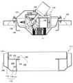
マルチコプター100は、図3に示すように、支持フレーム部105自身の一部に燃料タンクとなる中空部200が設けられたものである。即ち、支持フレーム部105の外壁を構成する部分の下部側であって、壁の内部に中空部200があり、当該中空部200が燃料タンクとなっている。
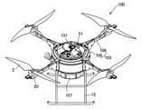
本実施形態のマルチコプター100は、本体部103と、4個の回転翼2を有している。回転翼2は、モータ20によって回転する。
本体部103は、図1の様に、支持フレーム部105と、リブ部106と、制御機器載置部107と、脚部12を有している。As shown in FIG. 3, the
The
As shown in FIG. 1, the
リブ部106は、支持フレーム部105とは別に成形され、後で支持フレーム部105に取り付けられる。リブ部106は、図7の様に、支持フレーム部105に取り付けられる固定部160と、アーム部161と、座部162が一体的に成型されたものである。座部162は、回転翼2を駆動するモータ20を固定する部位である。座部162は、アーム部161に比べて大きく作らており、上面が平滑な取り付け面となっている。そして当該取り付け面の表面にねじを挿通するための孔165が設けられている。 The
制御機器載置部107は、図3の様に、ピアノ線の様な硬質の吊り下げ部材166によって、支持フレーム部105の下部に距離をあけて取り付けられている。支持フレーム部105と制御機器載置部107の間には隙間がある。制御機器載置部107には、通信機器や、姿勢制御装置等が搭載されている。 As shown in FIG. 3, the control
支持フレーム部105は、環状構造部111と、支持構造部102を有している。環状構造部111は外観形状が環状であって、中心部には図3の様に、上下に連通する空洞部108がある。そして当該空洞部108を含む領域に、発電ユニット110が内蔵されている。
また本実施形態では、支持フレーム部105自身の一部に中空部200があり、当該中空部200が燃料タンクとして機能する。中空部200の内面は、軟質の樹脂でコーティングするか、軟質の樹脂で内張りをおこなうことが推奨される。
軟質の樹脂で内張りすることにより、衝撃を受けて支持フレーム部105に亀裂が生じた際に、燃料の漏出を防ぐことができる。
また中空部200内に耐油性軟質樹脂(ゴムなど)で製作された燃料バッグ(ブラダー)を内蔵させ、支持フレーム部105に直接燃料が触れない構造とすることも、燃料の漏洩を防ぐ目的として有効である。The
Further, in the present embodiment, there is a
By lining with a soft resin, it is possible to prevent fuel from leaking when the
In addition, a fuel bag (bladder) made of oil-resistant soft resin (rubber, etc.) is built in the
支持フレーム部105の環状構造部111は、無端環状に成形された部分である。本実施形態では、環状構造部111の平面形状は、図1の様に円形である。環状構造部111は、炭素繊維等の軽く、且つ剛性が高い素材で作られている。 The
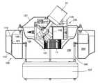
環状構造部111は、図2に示すように、外郭部材112と中蓋部材(蓋部材)113とによって構成されている。
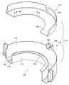
外郭部材112は、外筒状の外側周壁部115と、内筒状の内側周壁部117と、両者の下端部を繋ぐ底壁部118を有している。外郭部材112には、図4乃至図6の様に、外側周壁部115の内周を取り巻く環状の溝部120がある。溝部120は、上面が解放されている。外郭部材112の中央には、大きな開口121がある。
外側周壁部115を単体でみると、平面断面が円形であり、筒状を呈している。
内側周壁部117も平面断面が円形であり、筒状である。内側周壁部117は、外側周壁部115と同心であり、外側周壁部115によって囲まれた領域に立設されている。内側周壁部117は、外側周壁部115よりも高さが低く、上端に内フランジ122が形成されている。As shown in FIG. 2, the
The
Looking at the outer
The inner
外側周壁部115の側面には、リブ取り付け部140が4か所に設けられている。リブ取り付け部140は、リブ部106の端部が固定されるものであり、嵌合部158を有している。嵌合部158は、縦溝状であり、当該縦溝の開口部は、幅が狭められていてスリット状となっている。
中蓋部材113は、一端側に内フランジ125が設けられて半ば閉塞された短い筒状の部材である。
中蓋部材113は、前記した外側周壁部115の内壁にぴったりと挿入される筒状の内筒部123を有し、当該内筒部123の一端に内フランジ125が設けられたものである。中蓋部材113の内フランジ125の内径は、外郭部材112の内側周壁部117の内フランジ122の内径と略等しい。The
The
環状構造部111は、外郭部材112の凹状部内に、中蓋部材113がはめ込まれたものである。
即ち、外郭部材112に中蓋部材113が挿入され、外郭部材112の内フランジ122と、中蓋部材113の内フランジ125の中心側の面が合わされ、両者の間がねじ145等の締結要素で結合されている。
そして中蓋部材113の内フランジ125によって、外郭部材112の溝部120の上面の開口が封鎖されている。
その結果、外郭部材112の溝部120と、内筒部123の一端に内フランジ125に囲まれた、環状の中空部200が形成されている。そして、当該環状の中空部200が燃料タンクとして機能する。
本実施形態では、中空部200につながる燃料供給口86があり、当該燃料供給口86には、栓87が装着されている。燃料供給口86は、支持フレーム部105の外側面に設けられている。The
That is, the
The opening on the upper surface of the
As a result, an annular
In the present embodiment, there is a
環状構造部111は、支持フレーム部105の一部であって、その外壁を構成する部材である。本実施形態では、支持フレーム部105の下部側が内側に向かって膨らみ、当該膨らみ部の中が前記した中空部200となり、燃料が貯留される。 The
環状構造部111内における上部側の領域は、円筒形の大空洞部137となっている。また環状構造部111内には、内側周壁部117によって、小空洞部138が形成されている。大空洞部137の上部側は解放されている。大空洞部137の下部側は、内側周壁部117によって構成される小空洞部138を介して下部側に連通している。この様に、支持フレーム部105の環状構造部111内には、大空洞部137と小空洞部138によって構成される空洞部108がある。 The upper region in the
支持構造部102は、中間蓋部材146と、支持部材126及び外蓋部材127を有している。
中間蓋部材146は、円環状の支持枠部155と、当該支持枠部155の内縁側から垂下された垂下部156を有し、当該垂下部156の下端に内フランジ157が形成された部材である。中間蓋部材146は、上下方向に貫通している。
支持枠部155には、小蓋部147が4個設けられている。The
The
The
支持部材126は、上側環状部材130と、下側環状部材131を有し、両者の間が接続部材132で接続されたものである。接続部材132は、複数の板状部133によって構成されており、板状部133同士の間には大きな隙間141がある。 The
外蓋部材127は、複数の開口を有するドーム状の蓋である。即ち外蓋部材127は、中央部に開口142がある。また側方にも開口143がある。 The
支持構造部102は、前記した中間蓋部材146と、支持部材126及び外蓋部材127がネジ等によって結合されたものである。
本実施形態では。図5の様に、中間蓋部材146の支持枠部155に、支持部材126の上側環状部材130が、ネジ167等の締結要素によって結合されており、支持部材126の接続部材132及び下側環状部材131が、中間蓋部材146の開口内に入り込んでいる。
また支持部材126の上に外蓋部材127が取り付けられている。The
In this embodiment. As shown in FIG. 5, the upper
Further, the
本実施形態では、支持構造部102の中間蓋部材146が、環状構造部111の外側周壁部115に取り付けられており、支持部材126の接続部材132及び下側環状部材131は、支持フレーム部105の外郭部材112で囲まれた空間内に配されている。
また下側環状部材131及びその近傍の接続部材132は、内側周壁部117によって構成される小空洞部138の中に入り込んでいる。In the present embodiment, the
Further, the lower
発電ユニット110は、エンジン135及びその付属品と、発電機11が一体化されたものである。エンジン135には、インジェクター(図示せず)と、吸気フィルター51と、マフラー(図示せず)が取り付けられている。
エンジン135は、単気筒、空冷の2ストロークエンジンである。エンジン135のクランク軸(回転軸)150の一端側には、発電機11が直接的に接続されている。また図8、図9の様に、クランク軸(回転軸)150の一端側には、模型飛行機のスピナーコーン151が取り付けられている。スピナーコーン151は、エンジン135のクランク軸(回転軸)150と一体的に回転する。The
The
本実施形態では、発電ユニット110は、図3、図4、図9の様に、クランク軸(回転軸)150を上下方向に向け、且つ発電機11を下部側にした姿勢で、支持部材126と、外蓋部材127の間で形成される領域に配されている。
本実施形態では、図3、図4の様に、発電機11が、支持部材126の下側環状部材131に接続されている。また図1の様に、クランク軸(回転軸150)の他端側に取り付けられたスピナーコーン151が、外蓋部材127の中央部の開口142から外部に突出している。また吸気フィルター51についても開口143から外部に突出している。In the present embodiment, as shown in FIGS. 3, 4, and 9, the
In this embodiment, as shown in FIGS. 3 and 4, the
発電ユニット110は、発電機11の全部と、エンジン135の一部が、環状構造部111の環状部分で囲まれた領域にあり、エンジン135の他の一部は、環状構造部111の環状部分で囲まれた領域の上の領域にある。 In the
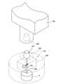
発電ユニット110を起動する際には、図9の様に、外部に突出したスピナーコーン151に、エンジン起動用のモータ153を接続する。そしてモータ153を回転することによって、発電ユニットのエンジン135を起動する。
本実施形態によると、エンジン135を起動する際に係合させる部材が、外部に露出しているので、エンジン起動用のモータ153を接続しやすい。
またエンジン135のクランク軸(回転軸)150が、天地方向に配置されているので、エンジン起動用のモータ153を接続しやすい。
即ち、エンジン起動する際には、エンジン起動用のモータ153のコネクター148を、スピナーコーン151に押し付ける必要があるが、本実施形態では、コネクター148を上から下に向かって押圧することになるので、スピナーコーン151が逃げない。When starting the
According to the present embodiment, since the member to be engaged when starting the
Further, since the crank shaft (rotating shaft) 150 of the
That is, when starting the engine, it is necessary to press the
クランク軸(回転軸)150の姿勢は、マルチコプター100を水平姿勢に置いたとき、垂直方向に延びていることが推奨されるが、概ね上下方向に向いていれば、始動の際にマルチコプター100が動きにくい。
クランク軸(回転軸)150の向きは、鉛直方向に対して45度以下であることが推奨され、望ましくは、30度以下である。より望ましい角度は、鉛直方向に対して5度以下である。It is recommended that the posture of the crank shaft (rotating shaft) 150 extends in the vertical direction when the
The orientation of the crank shaft (rotating shaft) 150 is recommended to be 45 degrees or less with respect to the vertical direction, and preferably 30 degrees or less. A more desirable angle is 5 degrees or less with respect to the vertical direction.
本実施形態のマルチコプター100は、外蓋部材127に開口142、143があり、当該開口142、143によって、支持フレーム部105の内外が連通している。また支持フレーム部105の下部は、小空洞部138を介して外部に開放されている。
そのため、本実施形態のマルチコプター100では、空洞部108の上下が連通しており、当該、連通する部分に発電ユニット110が配置されている。
即ち本実施形態では、大空洞部137と小空洞部138によって構成される空洞部108が上下方向の通気流路として機能する。
そして発電ユニット110は、その通気流路で囲まれた位置に配置されている。従って、発電ユニット110は、上下方向が貫通していて上下方向に通気性を有する領域に配置されている。
本実施形態のマルチコプター100では、飛行中、支持フレーム部105の空洞部108に風が呼び込まれ、発電ユニット110が通風環境下にさらされる。
即ちマルチコプター100を前進させる際は、やや前傾姿勢となる。そのため、図6に示すように、空洞部108に風が呼び込まれ、発電ユニット110が通風環境下にさらされる。
そのため、発電ユニット110が冷却される。The
Therefore, in the
That is, in the present embodiment, the
The
In the
That is, when the
Therefore, the
本実施形態のマルチコプター100は、飛行中にエンジン135によって発電機11が駆動され、発電機11の電気でモータ20が駆動される。また余剰の電力は、蓄電池(図示せず)に蓄電される。本実施形態では、発電機11が蓄電池に接続されており、発電機11の発電量が不足する場合には、蓄電池から不足分が補われる。そのため、モータ20の駆動や、制御装置(図示せず)の動作が安定する。
また発電量が過大である場合には、蓄電池に蓄電される。そのため、本実施形態のマルチコプター100は、航続距離が長い。In the
If the amount of power generation is excessive, it is stored in the storage battery. Therefore, the
以上説明した実施形態では、発電機11の全部と、エンジン135の一部が、環状構造部111の環状部分で囲まれた領域にあり、エンジン135の他の一部は、環状構造部111の環状部分で囲まれた領域の上の領域にあるが、環状構造部111の環状部分で囲まれた領域にエンジン135の全部が収容されていてもよい。
またエンジン135や発電機11の一部または全部が、環状構造部111の環状部分で囲まれた領域の上の領域又は下の領域にあってもよい。In the embodiment described above, the
Further, a part or all of the
以上説明した実施形態では、エンジン135の端部にスピナーコーン151を設けた。当該スピナーコーン151は、模型飛行機の部材であり、本実施形態では、本来の用途を離れて、エンジン起動用のモータ153を係合させるための係合片として活用している。エンジン起動用のモータ153を係合させるための部材は、スピナーコーン151に限定されるものではなく、他の係合片であってもよい。また係合片は無くてもよい。
本実施形態では、係合片となるスピナーコーン151が常時外部に露出しているが、蓋を外す等の行為によって、露出させてもよい。
なお露出するとは、外部から部材を接続可能となる状態をいい、係合片が奥まった位置に設けられていてもよい。In the embodiment described above, the
In the present embodiment, the
The term “exposed” refers to a state in which members can be connected from the outside, and the engaging piece may be provided at a recessed position.
以上説明したマルチコプターは、いずれも燃料タンクまたは燃料タンクに相当する部材を有している。
そのため、燃料の残量が少なくなった場合、燃料タンクや、燃料を貯留する支持フレーム部に空気層ができ、全体の比重が低下する。
仮に上記したマルチコプターが、池や海に墜落し、その際に燃料が少ない状態であるならば、マルチコプターは水面に浮く。そのため、墜落したマルチコプターを回収することができる。Each of the multicopters described above has a fuel tank or a member corresponding to the fuel tank.
Therefore, when the remaining amount of fuel is low, an air layer is formed in the fuel tank and the support frame portion for storing the fuel, and the overall specific gravity is lowered.
If the above-mentioned multicopter crashes into a pond or the sea and the fuel is low at that time, the multicopter floats on the surface of the water. Therefore, the crashed multicopter can be recovered.
以上説明したマルチコプターは、蓄電池を備えているが、蓄電池を省略し、発電機から直接モータ20や制御装置に給電してもよい。
以上説明した実施形態では、支持フレーム部105の平面形状が円形であるが、楕円形であってもよく多角形であってもよい。Although the multicopter described above includes a storage battery, the storage battery may be omitted and power may be supplied directly from the generator to the
In the embodiment described above, the planar shape of the
以上説明したマルチコプターは、いずれも環状の支持フレーム部を有しているが、フレームの形状自体は任意であり、枝分かれ状や放射型であってもよい。
以上説明したマルチコプターは、いずれも上下方向に通気性を有するものであるが、通気性を有することは必須ではない。All of the multicopters described above have an annular support frame portion, but the shape of the frame itself is arbitrary, and may be branched or radial.
All of the multicopters described above have vertical air permeability, but it is not essential to have air permeability.
以上説明した実施形態では、支持フレーム部105内の中空部200に燃料を貯留したが、別途の燃料タンクを有していてもよい。 In the embodiment described above, the fuel is stored in the
2 回転翼
11 発電機
20 モータ
100 マルチコプター
103 本体部
105 支持フレーム部
110 発電ユニット
111 環状構造部
135 エンジン
137 大空洞部
138 小空洞部
150 回転軸
151 スピナーコーン
153 モータ
200 中空部2
Claims (4)
Translated fromJapanesePriority Applications (1)
| Application Number | Priority Date | Filing Date | Title |
|---|---|---|---|
| JP2020146071AJP2022041061A (en) | 2020-08-31 | 2020-08-31 | Multicopter |
Applications Claiming Priority (1)
| Application Number | Priority Date | Filing Date | Title |
|---|---|---|---|
| JP2020146071AJP2022041061A (en) | 2020-08-31 | 2020-08-31 | Multicopter |
Publications (1)
| Publication Number | Publication Date |
|---|---|
| JP2022041061Atrue JP2022041061A (en) | 2022-03-11 |
Family
ID=80499646
Family Applications (1)
| Application Number | Title | Priority Date | Filing Date |
|---|---|---|---|
| JP2020146071APendingJP2022041061A (en) | 2020-08-31 | 2020-08-31 | Multicopter |
Country Status (1)
| Country | Link |
|---|---|
| JP (1) | JP2022041061A (en) |
Citations (9)
| Publication number | Priority date | Publication date | Assignee | Title |
|---|---|---|---|---|
| JP2007510591A (en)* | 2003-11-03 | 2007-04-26 | ジ インサイチュー グループ インコーポレイテッド | Method and system for starting a propeller driven device |
| JP2010137844A (en)* | 2008-12-12 | 2010-06-24 | Honeywell Internatl Inc | Hybrid power for ducted-fan unmanned aviation system |
| JP2010234960A (en)* | 2009-03-31 | 2010-10-21 | Honda Motor Co Ltd | Liquid storage structure of saddle-ride type vehicle |
| CN206900666U (en)* | 2017-06-19 | 2018-01-19 | 张万民 | A kind of oil electric mixed dynamic multiaxis rotary wind type unmanned plane |
| CN109592052A (en)* | 2018-12-26 | 2019-04-09 | 航天神舟飞行器有限公司 | A kind of combined type starter of unmanned vehicle engine |
| WO2019204932A1 (en)* | 2018-04-25 | 2019-10-31 | Flir Unmanned Aerial Systems Ulc | Unmanned vehicle |
| JP2020511350A (en)* | 2017-03-10 | 2020-04-16 | トップ フライト テクノロジーズ, インコーポレイテッド | Power system cooling for unmanned aerial vehicles |
| JP2020073379A (en)* | 2020-01-17 | 2020-05-14 | 株式会社石川エナジーリサーチ | Engine-mounted autonomous flight device |
| JP2020118115A (en)* | 2019-01-25 | 2020-08-06 | 本田技研工業株式会社 | engine |
- 2020
- 2020-08-31JPJP2020146071Apatent/JP2022041061A/enactivePending
Patent Citations (9)
| Publication number | Priority date | Publication date | Assignee | Title |
|---|---|---|---|---|
| JP2007510591A (en)* | 2003-11-03 | 2007-04-26 | ジ インサイチュー グループ インコーポレイテッド | Method and system for starting a propeller driven device |
| JP2010137844A (en)* | 2008-12-12 | 2010-06-24 | Honeywell Internatl Inc | Hybrid power for ducted-fan unmanned aviation system |
| JP2010234960A (en)* | 2009-03-31 | 2010-10-21 | Honda Motor Co Ltd | Liquid storage structure of saddle-ride type vehicle |
| JP2020511350A (en)* | 2017-03-10 | 2020-04-16 | トップ フライト テクノロジーズ, インコーポレイテッド | Power system cooling for unmanned aerial vehicles |
| CN206900666U (en)* | 2017-06-19 | 2018-01-19 | 张万民 | A kind of oil electric mixed dynamic multiaxis rotary wind type unmanned plane |
| WO2019204932A1 (en)* | 2018-04-25 | 2019-10-31 | Flir Unmanned Aerial Systems Ulc | Unmanned vehicle |
| CN109592052A (en)* | 2018-12-26 | 2019-04-09 | 航天神舟飞行器有限公司 | A kind of combined type starter of unmanned vehicle engine |
| JP2020118115A (en)* | 2019-01-25 | 2020-08-06 | 本田技研工業株式会社 | engine |
| JP2020073379A (en)* | 2020-01-17 | 2020-05-14 | 株式会社石川エナジーリサーチ | Engine-mounted autonomous flight device |
Similar Documents
| Publication | Publication Date | Title |
|---|---|---|
| CN207000807U (en) | Aircraft | |
| KR101806261B1 (en) | Multi-Copter Having Fuel Tank Installation Part | |
| KR20210055263A (en) | Frame for drone | |
| JP6856910B1 (en) | Multicopter | |
| CN109606605A (en) | An airship multi-rotor composite aircraft | |
| EP3050598A1 (en) | Electrical forward-moving assistant apparatus | |
| JP2022041061A (en) | Multicopter | |
| JP6856911B1 (en) | Multicopter | |
| CN108454606B (en) | Side wall type hovercraft | |
| WO2022034681A1 (en) | Unmanned aircraft capable of takeoff/landing on water | |
| KR102029318B1 (en) | A multi copter comprising hybrid propulsion system | |
| JP6811506B1 (en) | Multicopter | |
| JP4241537B2 (en) | Electric outboard motor | |
| CN115123511A (en) | A small hybrid automatic control conversion device for unmanned ship | |
| JP7033052B2 (en) | Power supply and flying object | |
| CN108454868A (en) | A kind of rotor wing unmanned aerial vehicle protective cover | |
| JP2021142953A (en) | Air vehicle | |
| US1832808A (en) | Electric motor boat | |
| JP2023083859A (en) | multicopter | |
| JP4265710B2 (en) | Underwater propulsion machine | |
| JP2020183211A (en) | Multicopter | |
| JP2021024512A (en) | Flight vehicle | |
| US20220194539A1 (en) | Outboard motor | |
| US9616999B1 (en) | Rotating wing | |
| CN101304917A (en) | Power generation device of marine vessel |
Legal Events
| Date | Code | Title | Description |
|---|---|---|---|
| A711 | Notification of change in applicant | Free format text:JAPANESE INTERMEDIATE CODE: A711 Effective date:20210728 | |
| A621 | Written request for application examination | Free format text:JAPANESE INTERMEDIATE CODE: A621 Effective date:20230814 | |
| A977 | Report on retrieval | Free format text:JAPANESE INTERMEDIATE CODE: A971007 Effective date:20240213 | |
| A131 | Notification of reasons for refusal | Free format text:JAPANESE INTERMEDIATE CODE: A131 Effective date:20240222 | |
| A601 | Written request for extension of time | Free format text:JAPANESE INTERMEDIATE CODE: A601 Effective date:20240419 | |
| A521 | Request for written amendment filed | Free format text:JAPANESE INTERMEDIATE CODE: A523 Effective date:20240617 | |
| A131 | Notification of reasons for refusal | Free format text:JAPANESE INTERMEDIATE CODE: A131 Effective date:20240926 | |
| A601 | Written request for extension of time | Free format text:JAPANESE INTERMEDIATE CODE: A601 Effective date:20241122 | |
| A521 | Request for written amendment filed | Free format text:JAPANESE INTERMEDIATE CODE: A523 Effective date:20250121 | |
| A131 | Notification of reasons for refusal | Free format text:JAPANESE INTERMEDIATE CODE: A131 Effective date:20250424 | |
| A521 | Request for written amendment filed | Free format text:JAPANESE INTERMEDIATE CODE: A523 Effective date:20250623 | |
| A01 | Written decision to grant a patent or to grant a registration (utility model) | Free format text:JAPANESE INTERMEDIATE CODE: A01 Effective date:20250918 |