JP2022033538A - How to position a vehicle in a forest area - Google Patents
How to position a vehicle in a forest areaDownload PDFInfo
- Publication number
- JP2022033538A JP2022033538AJP2020137493AJP2020137493AJP2022033538AJP 2022033538 AJP2022033538 AJP 2022033538AJP 2020137493 AJP2020137493 AJP 2020137493AJP 2020137493 AJP2020137493 AJP 2020137493AJP 2022033538 AJP2022033538 AJP 2022033538A
- Authority
- JP
- Japan
- Prior art keywords
- representative
- tree
- distance
- vehicle
- position information
- Prior art date
- Legal status (The legal status is an assumption and is not a legal conclusion. Google has not performed a legal analysis and makes no representation as to the accuracy of the status listed.)
- Pending
Links
Images


Landscapes
- Operation Control Of Excavators (AREA)
- Length Measuring Devices By Optical Means (AREA)
Abstract
Description
Translated fromJapanese本発明は、森林地域での車両位置決定方法に関する。 The present invention relates to a vehicle positioning method in a forest area.
現在では、衛星測位システム(GNSS/GPS)は測位精度が向上し、一般車両だけではなく、建築機械や圃場作業機の位置検出にも用いられている(特許文献1、特許文献2)。 At present, the satellite positioning system (GNSS / GPS) has improved positioning accuracy and is used not only for general vehicles but also for position detection of construction machines and field work machines (Patent Documents 1 and 2).
しかし、森林地域のように、視界が狭く平坦でない地形では、衛星測位システムによる位置検出だけでは必ずしも正確な車両位置を検出していない。
特に、建設機械では、正確な作業が求められるとともに、安全性のためにも、より正確な車両位置の特定が必要となる。However, in terrain where the field of view is narrow and not flat, such as in a forest area, the position detection by the satellite positioning system alone does not always detect the accurate vehicle position.
In particular, in construction machinery, accurate work is required, and more accurate vehicle position identification is required for safety.
本発明は、衛星測位システムでは十分な精度が出ない森林地域において、高い精度で車両位置を決定できる森林地域での車両位置決定方法を提供することを目的とする。 An object of the present invention is to provide a method for determining a vehicle position in a forest area where the vehicle position can be determined with high accuracy in a forest area where sufficient accuracy cannot be obtained by a satellite positioning system.
請求項1記載の本発明の森林地域での車両位置決定方法は、森林地域に存在する立木の中から代表立木10を抽出し、抽出した前記代表立木10の位置情報20を取得し、前記代表立木10の前記位置情報20を用いて前記森林地域での車両30が存在する車両位置30Xを決定する森林地域での車両位置決定方法であって、前記代表立木10として、第1代表立木11、第2代表立木12、及び第3代表立木13を用い、前記位置情報20として、前記第1代表立木11の第1位置情報21、前記第2代表立木12の第2位置情報22、及び前記第3代表立木13の第3位置情報23を用い、前記車両30から前記第1代表立木11までの第1距離L1を検出する第1距離検出ステップと、前記車両30から前記第2代表立木12までの第2距離L2を検出する第2距離検出ステップと、前記車両30から前記第3代表立木13までの第3距離L3を検出する第3距離検出ステップと、前記第1位置情報21、前記第2位置情報22、前記第3位置情報23、前記第1距離L1、前記第2距離L2、及び前記第3距離L3から前記車両位置30Xを決定する車両位置決定ステップとを有することを特徴とする。
請求項2記載の本発明は、請求項1に記載の森林地域での車両位置決定方法において、前記代表立木10に反射材40を設け、前記車両30から照射され、前記反射材40で反射される光によって前記第1距離L1、前記第2距離L2、及び前記第3距離L3を検出することを特徴とする。
請求項3記載の本発明は、請求項1に記載の森林地域での車両位置決定方法において、前記代表立木10に反射材40を設け、前記車両30から照射され、前記反射材40で反射される光によって前記第1距離L1、前記第2距離L2、及び前記第3距離L3を検出することを特徴とする。
請求項4記載の本発明の森林地域での車両位置決定方法は、森林地域に存在する立木の中から代表立木10を抽出し、抽出した前記代表立木10の位置情報20を取得し、前記代表立木10の前記位置情報20を用いて前記森林地域での車両30が存在する車両位置30Xを決定する森林地域での車両位置決定方法であって、前記代表立木10として、第1代表立木11及び第2代表立木12を用い、前記位置情報20として、前記第1代表立木11の第1位置情報21及び前記第2代表立木12の第2位置情報22を用い、前記車両30から前記第1代表立木11までの第1距離L1を検出する第1距離検出ステップと、前記車両30から前記第2代表立木12までの第2距離L2を検出する第2距離検出ステップと、前記車両30を中心として前記第1代表立木11から前記第2代表立木12までの第1角度θ1を検出する第1角度θ1検出ステップと、前記第1位置情報21、前記第2位置情報22、前記第1距離L1、前記第2距離L2、及び前記第1角度θ1から前記車両位置30Xを決定する車両位置決定ステップとを有することを特徴とする。
請求項5記載の本発明は、請求項4に記載の森林地域での車両位置決定方法において、前記車両30が、走行部2、旋回部3、及び作業部4からなるショベルカー31であり、前記走行部2を停止した状態で、前記旋回部3及び前記作業部4を動作させ、前記作業部4を前記第1代表立木11及び前記第2代表立木12に接触させることで、前記第1距離L1、前記第2距離L2、及び前記第1角度θ1を検出することを特徴とする。
請求項6記載の本発明は、請求項4に記載の森林地域での車両位置決定方法において、前記代表立木10に反射材40を設け、前記車両30から照射され、前記反射材40で反射される光によって前記第1距離L1及び前記第2距離L2を検出することを特徴とする。
請求項7記載の本発明の森林地域での車両位置決定方法は、森林地域に存在する立木の中から代表立木10を抽出し、抽出した前記代表立木10の位置情報20を取得し、前記代表立木10の前記位置情報20を用いて前記森林地域での車両30が存在する車両位置30Xを決定する森林地域での車両位置決定方法であって、前記代表立木10として、第1代表立木11、第2代表立木12、及び第3代表立木13を用い、前記車両30から前記第1代表立木11までの第1距離L1を検出する第1距離検出ステップと、前記車両30から前記第2代表立木12までの第2距離L2を検出する第2距離検出ステップと、前記車両30から前記第3代表立木13までの第3距離L3を検出する第3距離検出ステップと、前記車両30を中心として、前記第1代表立木11から前記第2代表立木12までの第1角度θ1を検出する第1角度θ1検出ステップと、前記車両30を中心として、前記第2代表立木12から前記第3代表立木13までの第2角度θ2を検出する第2角度θ2検出ステップと、前記第1距離L1、前記第2距離L2、前記第3距離L3、前記第1角度θ1、及び前記第2角度θ2から、前記第1代表立木11と前記第2代表立木12と前記第3代表立木13との間の立木間情報を算出する立木間情報算出ステップと、前記立木間情報算出ステップで算出される前記立木間情報から、前記第1代表立木11の第1位置情報21、前記第2代表立木12の第2位置情報22、及び前記第3代表立木13の第3位置情報23を特定する立木位置情報20特定ステップと、前記第1位置情報21、前記第2位置情報22、及び前記第3位置情報23と、前記第1距離L1、前記第2距離L2、前記第3距離L3、前記第1角度θ1、及び前記第2角度θ2の内の少なくとも3つとから前記車両位置30Xを決定する車両位置決定ステップとを有することを特徴とする。
請求項8記載の本発明は、請求項7に記載の森林地域での車両位置決定方法において、前記代表立木10として、第N(ただしNは4以上の整数)代表立木10を用い、前記車両30から前記第N代表立木までの第N距離を検出する第N距離検出ステップと、前記車両30を中心として、前記第(N-1)代表立木10から前記第N代表立木までの第(N-1)角度を検出する第(N-1)角度検出ステップとを有し、前記立木位置情報20特定ステップで、前記第1位置情報21、前記第2位置情報22、及び前記第3位置情報23が特定できない場合には、前記立木間情報算出ステップでは、前記第1距離L1から前記第3距離L3に前記第N距離を加え、前記第1角度θ1及び前記第2角度θ2に前記第(N-1)角度を加えて前記立木間情報を算出することを特徴とする。
請求項9記載の本発明は、請求項7又は請求項8に記載の森林地域での車両位置決定方法において、前記代表立木10に反射材40を設け、前記車両30にトータルステーション90を載置することを特徴とする。The vehicle position determination method in the forest area of the present invention according to claim 1 extracts a
According to the second aspect of the present invention, in the vehicle position determination method in the forest area according to the first aspect, a
According to the third aspect of the present invention, in the vehicle position determination method in the forest area according to the first aspect, a
The vehicle position determination method in the forest area of the present invention according to
According to the fifth aspect of the present invention, in the vehicle position determination method in the forest area according to the fourth aspect, the
The present invention according to claim 6 is the method for determining a vehicle position in a forest area according to
The vehicle position determination method in the forest area of the present invention according to claim 7 extracts a
The present invention according to claim 8 uses the Nth (where N is an integer of 4 or more)
According to the ninth aspect of the present invention, in the vehicle position determination method in the forest area according to the seventh or eighth aspect, the
本発明の森林地域での車両位置決定方法によれば、衛星測位システムでは十分な精度が出ない森林地域において、高い精度で車両位置を決定できる。 According to the vehicle position determination method in the forest area of the present invention, the vehicle position can be determined with high accuracy in the forest area where the satellite positioning system does not provide sufficient accuracy.
本発明の第1の実施の形態による森林地域での車両位置決定方法は、代表立木として、第1代表立木、第2代表立木、及び第3代表立木を用い、位置情報として、第1代表立木の第1位置情報、第2代表立木の第2位置情報、及び第3代表立木の第3位置情報を用い、車両から第1代表立木までの第1距離を検出する第1距離検出ステップと、車両から第2代表立木までの第2距離を検出する第2距離検出ステップと、車両から第3代表立木までの第3距離を検出する第3距離検出ステップと、第1位置情報、第2位置情報、第3位置情報、第1距離、第2距離、及び第3距離から車両位置を決定する車両位置決定ステップとを有するものである。本実施の形態によれば、第1代表立木の第1位置情報、第2代表立木の第2位置情報、第3代表立木の第3位置情報、車両から第1代表立木までの第1距離、車両から第2代表立木までの第2距離、及び車両から第3代表立木までの第3距離を用いることで、衛星測位システムでは十分な精度が出ない森林地域において、高い精度で車両位置を決定できる。 In the method for determining the vehicle position in the forest area according to the first embodiment of the present invention, the first representative tree, the second representative tree, and the third representative tree are used as the representative tree, and the first representative tree is used as the position information. The first distance detection step for detecting the first distance from the vehicle to the first representative tree using the first position information, the second position information of the second representative tree, and the third position information of the third representative tree. A second distance detection step that detects the second distance from the vehicle to the second representative tree, a third distance detection step that detects the third distance from the vehicle to the third representative tree, first position information, and a second position. It has information, a third position information, a first distance, a second distance, and a vehicle position determination step for determining a vehicle position from a third distance. According to the present embodiment, the first position information of the first representative standing tree, the second position information of the second representative standing tree, the third position information of the third representative standing tree, the first distance from the vehicle to the first representative standing tree, By using the second distance from the vehicle to the second representative tree and the third distance from the vehicle to the third representative tree, the vehicle position is determined with high accuracy in forest areas where the satellite positioning system does not provide sufficient accuracy. can.
本発明の第2の実施の形態は、第1の実施の形態による森林地域での車両位置決定方法において、車両が、走行部、旋回部、及び作業部からなるショベルカーであり、走行部を停止した状態で、旋回部及び作業部を動作させ、作業部を第1代表立木、第2代表立木、及び第3代表立木に接触させることで、第1距離、第2距離、及び第3距離を検出するものである。本実施の形態によれば、ショベルカーが基本機能として備えている旋回部及び作業部を利用することで、第1距離、第2距離、及び第3距離を検出することができる。 In the second embodiment of the present invention, in the vehicle position determination method in the forest area according to the first embodiment, the vehicle is a shovel car including a traveling portion, a turning portion, and a working portion, and the traveling portion is used. By operating the swivel part and the working part in the stopped state and bringing the working part into contact with the first representative standing tree, the second representative standing tree, and the third representative standing tree, the first distance, the second distance, and the third distance are reached. Is to detect. According to the present embodiment, the first distance, the second distance, and the third distance can be detected by using the turning portion and the working portion provided as the basic functions of the excavator car.
本発明の第3の実施の形態は、第1の実施の形態による森林地域での車両位置決定方法において、代表立木に反射材を設け、車両から照射され、反射材で反射される光によって第1距離、第2距離、及び第3距離を検出するものである。本実施の形態によれば、反射材に光を照射することで、第1距離、第2距離、及び第3距離を検出することができる。 A third embodiment of the present invention is the method for determining a vehicle position in a forest area according to the first embodiment, wherein a reflective material is provided on a representative standing tree, and the light emitted from the vehicle and reflected by the reflective material is used. It detects the first distance, the second distance, and the third distance. According to the present embodiment, the first distance, the second distance, and the third distance can be detected by irradiating the reflective material with light.
本発明の第4の実施の形態による森林地域での車両位置決定方法は、代表立木として、第1代表立木及び第2代表立木を用い、位置情報として、第1代表立木の第1位置情報及び第2代表立木の第2位置情報を用い、車両から第1代表立木までの第1距離を検出する第1距離検出ステップと、車両から第2代表立木までの第2距離を検出する第2距離検出ステップと、車両を中心として第1代表立木から第2代表立木までの第1角度を検出する第1角度検出ステップと、第1位置情報、第2位置情報、第1距離、第2距離、及び第1角度から車両位置を決定する車両位置決定ステップとを有するものである。本実施の形態によれば、第1代表立木の第1位置情報、第2代表立木の第2位置情報、車両から第1代表立木までの第1距離、車両から第2代表立木までの第2距離、及び車両を中心として第1代表立木から第2代表立木までの第1角度を用いることで、衛星測位システムでは十分な精度が出ない森林地域において、高い精度で車両位置を決定できる。 In the vehicle position determination method in the forest area according to the fourth embodiment of the present invention, the first representative standing tree and the second representative standing tree are used as the representative standing trees, and the first position information of the first representative standing tree and the first representative standing tree are used as the position information. The first distance detection step for detecting the first distance from the vehicle to the first representative tree and the second distance for detecting the second distance from the vehicle to the second representative tree using the second position information of the second representative tree. The detection step, the first angle detection step for detecting the first angle from the first representative tree to the second representative tree centered on the vehicle, the first position information, the second position information, the first distance, the second distance, It also has a vehicle position determining step that determines the vehicle position from the first angle. According to the present embodiment, the first position information of the first representative standing tree, the second position information of the second representative standing tree, the first distance from the vehicle to the first representative standing tree, and the second from the vehicle to the second representative standing tree. By using the distance and the first angle from the first representative tree to the second representative tree centered on the vehicle, the vehicle position can be determined with high accuracy in the forest area where the satellite positioning system does not provide sufficient accuracy.
本発明の第5の実施の形態は、第4の実施の形態による森林地域での車両位置決定方法において、車両が、走行部、旋回部、及び作業部からなるショベルカーであり、走行部を停止した状態で、旋回部及び作業部を動作させ、作業部を第1代表立木及び第2代表立木に接触させることで、第1距離、第2距離、及び第1角度を検出するものである。本実施の形態によれば、ショベルカーが基本機能として備えている旋回部及び作業部を利用することで、第1距離、第2距離、及び第1角度を検出することができる。 A fifth embodiment of the present invention is the method for determining a vehicle position in a forest area according to the fourth embodiment, wherein the vehicle is a shovel car including a traveling portion, a turning portion, and a working portion, and the traveling portion is used. The first distance, the second distance, and the first angle are detected by operating the swivel part and the working part in the stopped state and bringing the working part into contact with the first representative standing tree and the second representative standing tree. .. According to the present embodiment, the first distance, the second distance, and the first angle can be detected by using the swivel portion and the working portion provided as the basic functions of the excavator car.
本発明の第6の実施の形態は、第4の実施の形態による森林地域での車両位置決定方法において、代表立木に反射材を設け、車両から照射され、反射材で反射される光によって第1距離及び第2距離を検出するものである。本実施の形態によれば、反射材に光を照射することで、第1距離及び第2距離を検出することができる。 A sixth embodiment of the present invention is the method for determining a vehicle position in a forest area according to the fourth embodiment, wherein a reflective material is provided on a representative standing tree, and the light emitted from the vehicle and reflected by the reflective material is used. It detects the first distance and the second distance. According to this embodiment, the first distance and the second distance can be detected by irradiating the reflective material with light.
本発明の第7の実施の形態による森林地域での車両位置決定方法は、代表立木として、第1代表立木、第2代表立木、及び第3代表立木を用い、車両から第1代表立木までの第1距離を検出する第1距離検出ステップと、車両から第2代表立木までの第2距離を検出する第2距離検出ステップと、車両から第3代表立木までの第3距離を検出する第3距離検出ステップと、車両を中心として、第1代表立木から第2代表立木までの第1角度を検出する第1角度検出ステップと、車両を中心として、第2代表立木から第3代表立木までの第2角度を検出する第2角度検出ステップと、第1距離、第2距離、第3距離、第1角度、及び第2角度から、第1代表立木と第2代表立木と第3代表立木との間の立木間情報を算出する立木間情報算出ステップと、立木間情報算出ステップで算出される立木間情報から、第1代表立木の第1位置情報、第2代表立木の第2位置情報、及び第3代表立木の第3位置情報を特定する立木位置情報特定ステップと、第1位置情報、第2位置情報、及び第3位置情報と、第1距離、第2距離、第3距離、第1角度、及び第2角度の内の少なくとも3つとから車両位置を決定する車両位置決定ステップとを有するものである。本実施の形態によれば、第1距離、第2距離、第3距離、第1角度、及び第2角度から、第1代表立木と第2代表立木と第3代表立木との間の立木間情報を算出し、算出される立木間情報から、第1代表立木の第1位置情報、第2代表立木の第2位置情報、及び第3代表立木の第3位置情報を特定できるため、衛星測位システムでは十分な精度が出ない森林地域において、高い精度で車両位置を決定できる。 In the method for determining the vehicle position in the forest area according to the seventh embodiment of the present invention, the first representative tree, the second representative tree, and the third representative tree are used as the representative tree, and the vehicle to the first representative tree are used. A first distance detection step for detecting the first distance, a second distance detection step for detecting the second distance from the vehicle to the second representative tree, and a third for detecting the third distance from the vehicle to the third representative tree. A distance detection step, a first angle detection step that detects the first angle from the first representative tree to the second representative tree centered on the vehicle, and a vehicle as the center from the second representative tree to the third representative tree. From the second angle detection step that detects the second angle, and from the first distance, the second distance, the third distance, the first angle, and the second angle, the first representative standing tree, the second representative standing tree, and the third representative standing tree. From the standing tree spacing information calculation step for calculating the standing tree spacing information and the standing tree spacing information calculated in the standing tree spacing information calculation step, the first position information of the first representative standing tree, the second position information of the second representative standing tree, And the standing tree position information specifying step for specifying the third position information of the third representative tree, the first position information, the second position information, and the third position information, and the first distance, the second distance, the third distance, and the third. It has a vehicle position determination step for determining a vehicle position from at least three of one angle and a second angle. According to the present embodiment, from the first distance, the second distance, the third distance, the first angle, and the second angle, between the first representative tree, the second representative tree, and the third representative tree. Since the information can be calculated and the first position information of the first representative tree, the second position information of the second representative tree, and the third position information of the third representative tree can be specified from the calculated inter-tree information, satellite positioning can be performed. Vehicle position can be determined with high accuracy in forest areas where the system does not provide sufficient accuracy.
本発明の第8の実施の形態は、第7の実施の形態による森林地域での車両位置決定方法において、代表立木として、第N(ただしNは4以上の整数)代表立木を用い、車両から第N代表立木までの第N距離を検出する第N距離検出ステップと、車両を中心として、第(N-1)代表立木から第N代表立木までの第(N-1)角度を検出する第(N-1)角度検出ステップとを有し、立木位置情報特定ステップで、第1位置情報、第2位置情報、及び第3位置情報が特定できない場合には、立木間情報算出ステップでは、第1距離から第3距離に第N距離を加え、第1角度及び第2角度に第(N-1)角度を加えて立木間情報を算出するものである。本実施の形態によれば、更に車両から第N代表立木までの第N距離、及び第(N-1)代表立木から第N代表立木までの第(N-1)角度を用いることで、立木位置情報特定ステップで、第1位置情報、第2位置情報、及び第3位置情報を特定でき、衛星測位システムでは十分な精度が出ない森林地域において、高い精度で車両位置を決定できる。 In the eighth embodiment of the present invention, in the vehicle position determination method in the forest area according to the seventh embodiment, the Nth (where N is an integer of 4 or more) representative tree is used as the representative tree from the vehicle. The Nth distance detection step for detecting the Nth distance to the Nth representative tree, and the (N-1) angle for detecting the (N-1) angle from the (N-1) representative tree to the Nth representative tree centering on the vehicle. (N-1) If the angle detection step is provided and the first position information, the second position information, and the third position information cannot be specified in the standing tree position information specifying step, the standing tree distance information calculation step is the first. The Nth distance is added to the third distance from the first distance, and the (N-1) angle is added to the first angle and the second angle to calculate the standing tree spacing information. According to the present embodiment, by further using the Nth distance from the vehicle to the Nth representative standing tree and the (N-1) angle from the (N-1) representative standing tree to the Nth representative standing tree, the standing tree In the position information specifying step, the first position information, the second position information, and the third position information can be specified, and the vehicle position can be determined with high accuracy in a forest area where sufficient accuracy cannot be obtained by the satellite positioning system.
本発明の第9の実施の形態は、第7又は第8の実施の形態による森林地域での車両位置決定方法において、代表立木に反射材を設け、車両にトータルステーションを載置するものである。本実施の形態によれば、測量の現場で用いられるトータルステーションを利用して車両位置を決定できる。 A ninth embodiment of the present invention is the method for determining a vehicle position in a forest area according to the seventh or eighth embodiment, in which a reflective material is provided on a representative standing tree and a total station is mounted on the vehicle. According to this embodiment, the vehicle position can be determined by using a total station used in the field of surveying.
以下本発明の実施例について図面とともに説明する。
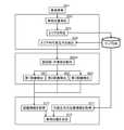
図1は本実施例による森林地域での車両位置決定方法を示す概念図であり、図1(a)は検出方法を示す概念図、図1(b)は検出結果を示す概念図である。
本実施例による森林地域での車両位置決定方法では、森林地域に存在する立木の中から代表立木10を抽出し、抽出した代表立木10の位置情報20をマップデータベースから取得している。マップデータベースには、森林地域に存在する立木の少なくとも一部の立木については位置情報(X、Yの二次元位置情報(緯度経度)でもよいが、更に高さ情報Zを加えた三次元位置情報であることが好ましい。)を記憶している。以下の説明では、二次元位置情報を用いる場合を説明する。
図1では、代表立木10として、第1代表立木11、第2代表立木12、及び第3代表立木13を用いている。
位置情報20として、第1代表立木11の第1位置情報21が(X1、Y1)、第2代表立木12の第2位置情報22が(X2、Y2)、及び第3代表立木13の第3位置情報23が(X3、Y3)である。Hereinafter, examples of the present invention will be described with reference to the drawings.
1A and 1B are conceptual diagrams showing a vehicle position determination method in a forest area according to the present embodiment, FIG. 1A is a conceptual diagram showing a detection method, and FIG. 1B is a conceptual diagram showing a detection result.
In the vehicle position determination method in the forest area according to the present embodiment, the
In FIG. 1, as the
As the
本実施例では、車両30としてショベルカー31を用いる。
ショベルカー31は、位置検出部1、走行部2、旋回部3、作業部4、及び制御部5を備えている。
位置検出部1は、衛星が発信する信号を受信して現在位置を検出するもので、GPS受信部やGNSS受信部である。走行部2は車両30を移動させるクローラやタイヤであり、エンジンや駆動伝達機構を含む。旋回部3は作業部4の方向を変更するターンテーブルであり、駆動源や駆動伝達機構を含む。作業部4はブーム、アーム、及びバケットであり、動力源を含む。制御部5は、少なくとも車両30に対する作業部4の位置、特にバスケットの位置を算出する演算部を有する。In this embodiment, the
The
The position detection unit 1 receives a signal transmitted by a satellite and detects the current position, and is a GPS receiving unit or a GNSS receiving unit. The traveling unit 2 is a crawler or a tire for moving the
図1(a)において、作業部4aは、旋回部3及び作業部4を動作させ、作業部4を第1代表立木11に接触させた状態を示し、作業部4bは、旋回部3及び作業部4を動作させ、作業部4を第2代表立木12に接触させた状態を示し、作業部4cは、旋回部3及び作業部4を動作させ、作業部4を第3代表立木13に接触させた状態を示している。
このように、車両30の走行部2を停止した状態で、旋回部3及び作業部4を動作させ、作業部4を第1代表立木11、第2代表立木12、及び第3代表立木13に接触させることで、図1(b)に示すように、第1距離L1、第2距離L2、及び第3距離L3を検出することができる。なお、第1距離L1、第2距離L2、及び第3距離L3は、制御部5によって算出される。In FIG. 1A, the working
In this way, with the traveling unit 2 of the
このように、ショベルカー31が基本機能として備えている旋回部3及び作業部4を利用することで、第1距離L1、第2距離L2、及び第3距離L3を検出することができる。
そして、第1位置情報21が(X1、Y1)、第2位置情報22が(X2、Y2)、第3位置情報23が(X3、Y3)であり、車両30から第1代表立木11までの第1距離L1、車両30から第2代表立木12までの第2距離L2、及び車両30から第3代表立木13までの第3距離L3を用いることで、車両30が存在する車両位置30Xを決定することができる。In this way, by using the swivel portion 3 and the working
The
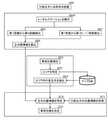
図2は本実施例による森林地域での車両位置決定方法を示すフローチャートである。
車両30を停車し(S51)、位置検出部1によって車両位置30Xを測位する(S52)。
S52で測位された地点を含んで所定範囲のエリアを特定し(S53)、マップデータベースから、特定したエリア内にある代表立木10を抽出する(S54)。
本実施例では、抽出された代表立木10の中で、第1代表立木11、第2代表立木12、及び第3代表立木13を用いる。
旋回部3及び作業部4を動作させ(S60A)、作業部4を、第1代表立木11、第2代表立木12、及び第3代表立木13に順に接触させる。
作業部4を第1代表立木11に接触させることで第1距離L1を検出し(S61)、作業部4を第2代表立木12に接触させることで第2距離L2を検出し(S62)、作業部4を第3代表立木13に接触させることで第3距離L3を検出する(S63)。
S61が第1距離検出ステップ、S62が第2距離検出ステップ、S63が第3距離検出ステップである。FIG. 2 is a flowchart showing a vehicle position determination method in a forest area according to the present embodiment.
The
An area in a predetermined range including the point positioned in S52 is specified (S53), and the
In this embodiment, among the extracted
The swivel part 3 and the working
The first distance L1 is detected by contacting the working
S61 is the first distance detection step, S62 is the second distance detection step, and S63 is the third distance detection step.
そして、マップデータベースから第1代表立木11の第1位置情報21、第2代表立木12の第2位置情報22、及び第3代表立木13の第3位置情報23を取得し(S71)、制御部5から第1距離L1、第2距離L2、及び第3距離L3を取得し(S72)、取得した第1位置情報21、第2位置情報22、第3位置情報23、第1距離L1、第2距離L2、及び第3距離L3を用いて車両位置30Xを決定する(S70)。
S70が車両位置決定ステップである。Then, the
S70 is the vehicle position determination step.
このように、本実施例によれば、第1代表立木11の第1位置情報21、第2代表立木12の第2位置情報22、第3代表立木13の第3位置情報23、車両30から第1代表立木11までの第1距離L1、車両30から第2代表立木12までの第2距離L2、及び車両30から第3代表立木13までの第3距離L3を用いることで、衛星測位システムでは十分な精度が出ない森林地域において、高い精度で車両位置30Xを決定できる。 As described above, according to the present embodiment, from the
図3は本発明の他の実施例による森林地域での車両位置決定方法を示す概念図であり、図3(a)は検出方法を示す概念図、図3(b)は検出結果を示す概念図である。なお、図1と同一機能、同一動作については説明を省略し、相違点について以下に説明する。
図1に示す実施例では、車両30としてショベルカー31を用い、旋回部3及び作業部4を動作させ、作業部4を第1代表立木11、第2代表立木12、及び第3代表立木13に接触させることで第1距離L1、第2距離L2、及び第3距離L3を検出する場合を説明したが、本実施例では、代表立木10に反射材40を設け、車両30から照射され、反射材40で反射される光によって第1距離L1、第2距離L2、及び第3距離L3を検出する。
図3(a)では、第1代表立木11には反射材41を、第2代表立木12には反射材42を、第3代表立木13には反射材43を設けている。
このような距離測定には光波距離計91が適しており、車両30に光波距離計91を設ける。3A and 3B are conceptual diagrams showing a vehicle position determination method in a forest area according to another embodiment of the present invention, FIG. 3A is a conceptual diagram showing a detection method, and FIG. 3B is a conceptual diagram showing a detection result. It is a figure. The same functions and operations as those in FIG. 1 will be omitted, and the differences will be described below.
In the embodiment shown in FIG. 1, a
In FIG. 3A, the first
A light
図4は本実施例による森林地域での車両位置決定方法を示すフローチャートである。
図2に示すフローチャートと同一処理については同一符号を付して説明を省略する。
本実施例では、あらかじめ代表立木10反射材40を設置する(S50)。
また、第1距離検出ステップ(S61)、第2距離検出ステップ(S62)、及び第3距離検出ステップ(S63)は、光波距離計91を動作させることで行う(S60B)。
S60Bでは、光波距離計91を、第1代表立木11の反射材41、第2代表立木12の反射材42、及び第3代表立木13の反射材43に順に向けて光を照射し、反射される光によって距離を検出する。FIG. 4 is a flowchart showing a vehicle position determination method in a forest area according to this embodiment.
The same processing as that shown in FIG. 2 is designated by the same reference numerals and description thereof will be omitted.
In this embodiment, the
Further, the first distance detection step (S61), the second distance detection step (S62), and the third distance detection step (S63) are performed by operating the light wave distance meter 91 (S60B).
In S60B, the light
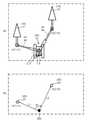
図5は本発明の更に他の実施例による森林地域での車両位置決定方法を示す概念図であり、図5(a)は検出方法を示す概念図、図5(b)は検出結果を示す概念図である。なお、図1と同一機能、同一動作については一部説明を省略する。
本実施例による森林地域での車両位置決定方法では、森林地域に存在する立木の中から代表立木10を抽出し、抽出した代表立木10の位置情報20をマップデータベースから取得している。
図5では、代表立木10として、第1代表立木11、及び第2代表立木12を用いた場合を示している。
位置情報20として、第1代表立木11の第1位置情報21が(X1、Y1)、及び第2代表立木12の第2位置情報22が(X2、Y2)であることを示している。5A and 5B are conceptual diagrams showing a vehicle position determination method in a forest area according to still another embodiment of the present invention, FIG. 5A shows a conceptual diagram showing a detection method, and FIG. 5B shows a detection result. It is a conceptual diagram. A part of the same functions and operations as those in FIG. 1 will be omitted.
In the vehicle position determination method in the forest area according to the present embodiment, the
FIG. 5 shows a case where the first
As the
本実施例においても図1と同様に、車両30としてショベルカー31を用いる。
このように、車両30の走行部2を停止した状態で、旋回部3及び作業部4を動作させ、作業部4を第1代表立木11、及び第2代表立木12に接触させることで、図5(b)に示すように、第1距離L1、第2距離L2、及び第1角度θ1を検出することができる。ここで、第1角度θ1は、車両30を中心として第1代表立木11から第2代表立木12までの角度である。なお、第1距離L1、第2距離L2、及び第1角度θ1は、制御部5によって算出される。In this embodiment as well, the
In this way, with the traveling portion 2 of the
このように、ショベルカー31が基本機能として備えている旋回部3及び作業部4を利用することで、第1距離L1、第2距離L2、及び第1角度θ1を検出することができる。
そして、第1位置情報21が(X1、Y1)、第2位置情報22が(X2、Y2)であり、車両30から第1代表立木11までの第1距離L1、車両30から第2代表立木12までの第2距離L2、及び車両30を中心として第1代表立木11から第2代表立木12までの第1角度θ1を用いることで、車両30が存在する車両位置30Xを決定することができる。In this way, by using the swivel portion 3 and the working
The
図6は本実施例による森林地域での車両位置決定方法を示すフローチャートである。
図2に示すフローチャートと同一処理については同一符号を付して説明を省略する。
旋回部3及び作業部4を動作させ(S60C)、作業部4を、第1代表立木11及び第2代表立木12に順に接触させる。
作業部4を第1代表立木11に接触させることで第1距離L1を検出し(S61)、作業部4を第2代表立木12に接触させることで第2距離L2を検出し(S62)、旋回部3を第1代表立木11から第2代表立木12まで旋回させることで第1角度θ1を検出する(S64)。
S61が第1距離検出ステップ、S62が第2距離検出ステップ、S64が第1角度検出ステップである。FIG. 6 is a flowchart showing a vehicle position determination method in a forest area according to the present embodiment.
The same processing as that shown in FIG. 2 is designated by the same reference numerals and description thereof will be omitted.
The swivel part 3 and the working
The first distance L1 is detected by contacting the working
S61 is the first distance detection step, S62 is the second distance detection step, and S64 is the first angle detection step.
そして、マップデータベースから第1代表立木11の第1位置情報21、及び第2代表立木12の第2位置情報22を取得し(S71)、制御部5から第1距離L1、第2距離L2、及び第1角度θ1を取得し(S73)、取得した第1位置情報21、第2位置情報22、第1距離L1、第2距離L2、及び第1角度θ1を用いて車両位置30Xを決定する(S70)。
S70が車両位置決定ステップである。Then, the
S70 is the vehicle position determination step.
このように、本実施例によれば、第1代表立木11の第1位置情報21、第2代表立木12の第2位置情報22、車両30から第1代表立木11までの第1距離L1、車両30から第2代表立木12までの第2距離L2、及び車両30を中心として第1代表立木11から第2代表立木12までの第1角度θ1を用いることで、衛星測位システムでは十分な精度が出ない森林地域において、高い精度で車両位置30Xを決定できる。 As described above, according to the present embodiment, the
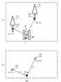
図7は本発明の他の実施例による森林地域での車両位置決定方法を示す概念図であり、図7(a)は検出方法を示す概念図、図7(b)は検出結果を示す概念図である。なお、図1又は図5と同一機能、同一動作については説明を省略し、相違点について以下に説明する。 7A and 7B are conceptual diagrams showing a vehicle position determination method in a forest area according to another embodiment of the present invention, FIG. 7A is a conceptual diagram showing a detection method, and FIG. 7B is a conceptual diagram showing a detection result. It is a figure. The same functions and operations as those in FIGS. 1 or 5 will be omitted, and the differences will be described below.
なお、図5に示す実施例では、車両30としてショベルカー31を用い、旋回部3及び作業部4を動作させ、作業部4を第1代表立木11及び第2代表立木12に接触させることで第1距離L1、第2距離L2、及び第1角度θ1を検出する場合を説明したが、本実施例では、代表立木10に反射材40を設け、車両30から照射され、反射材40で反射される光によって第1距離L1及び第2距離L2を検出するとともに、車両30を中心として第1代表立木11から第2代表立木12までの第1角度θ1を検出する。 In the embodiment shown in FIG. 5, a
図7(a)では、第1代表立木11には反射材41を、第2代表立木12には反射材42を設けている。
距離測定には光波距離計91を用いることができ、角度の検出にはセオドライトを用いることができるが、光波距離計91とセオドライトとの機能を備えたトータルステーション90を用いることが適している。トータルステーション90を車両30に設けることで、第1距離L1、第2距離L2、及び第1角度θ1を検出することができる。In FIG. 7A, the first
A
図8は本実施例による森林地域での車両位置決定方法を示すフローチャートである。
図2及び図4に示すフローチャートと同一処理については同一符号を付して説明を省略する。
本実施例では、第1距離検出ステップ(S61)、第2距離検出ステップ(S62)、及び第1角度検出ステップ(S64)は、トータルステーション90を動作させることで行う(S60D)。
S60Dでは、トータルステーション90を、第1代表立木11の反射材41、第2代表立木12の反射材42に順に向けて光を照射し、反射される光によって距離を検出するとともに、第1代表立木11から第2代表立木12までの角度を検出する。
S61が第1距離検出ステップ、S62が第2距離検出ステップ、S64が第1角度検出ステップである。FIG. 8 is a flowchart showing a vehicle position determination method in a forest area according to the present embodiment.
The same processing as in the flowcharts shown in FIGS. 2 and 4 is designated by the same reference numerals and description thereof will be omitted.
In this embodiment, the first distance detection step (S61), the second distance detection step (S62), and the first angle detection step (S64) are performed by operating the total station 90 (S60D).
In S60D, the
S61 is the first distance detection step, S62 is the second distance detection step, and S64 is the first angle detection step.
そして、マップデータベースから第1代表立木11の第1位置情報21、及び第2代表立木12の第2位置情報22を取得し(S71)、トータルステーション90から第1距離L1、第2距離L2、及び第1角度θ1を取得し(S73)、取得した第1位置情報21、第2位置情報22、第1距離L1、第2距離L2、及び第1角度θ1を用いて車両位置30Xを決定する(S70)。
S70が車両位置決定ステップである。Then, the
S70 is the vehicle position determination step.
このように、本実施例によれば、第1代表立木11の第1位置情報21、第2代表立木12の第2位置情報22、車両30から第1代表立木11までの第1距離L1、車両30から第2代表立木12までの第2距離L2、及び車両30を中心として第1代表立木11から第2代表立木12までの第1角度θ1を用いることで、衛星測位システムでは十分な精度が出ない森林地域において、高い精度で車両位置30Xを決定できる。 As described above, according to the present embodiment, the
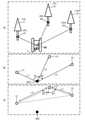
図9は本発明の更に他の実施例による森林地域での車両位置決定方法を示す概念図であり、図9(a)は検出方法を示す概念図、図9(b)は検出結果を示す概念図、図9(c)は検出結果によって得られる情報を示す概念図である。
本実施例による森林地域での車両位置決定方法では、反射材40を設けている代表立木10に、車両30に設けたトータルステーション90から光を照射し、反射材40で反射される光によって、車両30から第1代表立木11までの第1距離L1、車両30から第2代表立木12までの第2距離L2、車両30から第3代表立木13までの第3距離L3、車両30を中心とした、第1代表立木11から第2代表立木12までの第1角度θ1、及び車両30を中心とした、第2代表立木12から第3代表立木13までの第2角度θ2を検出する。
なお、本実施例では、図1から図8で説明した実施例と異なり、第1代表立木11、第2代表立木12、及び第3代表立木13は特定されておらず、第1代表立木11の第1位置情報21、第2代表立木12の第2位置情報22、及び第3代表立木13の第3位置情報23は不明な状態である。9A and 9B are conceptual diagrams showing a vehicle position determination method in a forest area according to still another embodiment of the present invention, FIG. 9A shows a conceptual diagram showing a detection method, and FIG. 9B shows a detection result. The conceptual diagram and FIG. 9 (c) are conceptual diagrams showing the information obtained by the detection result.
In the vehicle position determination method in the forest area according to the present embodiment, the
In this embodiment, unlike the embodiments described with reference to FIGS. 1 to 8, the first
検出される情報は、図9(b)に示す通りである。
図9(b)に示す、第1距離L1、第2距離L2、及び第1角度θ1によって、図9(c)に示すように、第1代表立木11から第2代表立木12までの距離LX、及び第2代表立木12を中心とした、第1代表立木11から車両位置30Xまでの角度θXが算出される。
また、図9(b)に示す、第2距離L2、第3距離L3、及び第2角度θ2によって、図9(c)に示すように、第2代表立木12から第3代表立木13までの距離LY、及び第2代表立木12を中心とした、第3代表立木13から車両位置30Xまでの角度θYが算出される。
従って、図9(c)に示すように、第1代表立木11、第2代表立木12、及び第3代表立木13によって立木間情報を算出することができる。立木間情報は、例えば、形成される三角形状であってもよく、立木間距離や立木間角度であってもよい。The detected information is as shown in FIG. 9B.
The distance LX from the first
Further, according to the second distance L2, the third distance L3, and the second angle θ2 shown in FIG. 9B, the second
Therefore, as shown in FIG. 9C, the information between the standing trees can be calculated by the first
一方、車両30には、位置検出部1を備えている。
そして、位置検出部1で測位された地点を含む所定範囲のエリア内にある代表立木10を抽出し、これらの代表立木10の位置情報20を元に、第1代表立木11、第2代表立木12、及び第3代表立木13によって算出された立木間情報に一致する代表立木10を特定する。
代表立木10が特定されることで、第1代表立木11の第1位置情報21、第2代表立木12の第2位置情報22、及び第3代表立木13の第3位置情報23が特定される。
従って、第1位置情報21、第2位置情報22、及び第3位置情報23を用い、例えば、第1距離L1、第2距離L2、及び第3距離L3を用いることで車両位置30Xを特定することができる。
なお、第1距離L1、第2距離L2、及び第3距離L3に代えて、第1距離L1、第2距離L2、及び第1角度θ1を用いても車両位置30Xを特定することができる。このように、第1位置情報21、第2位置情報22、及び第3位置情報23と、第1距離L1、第2距離L2、第3距離L3、第1角度θ1、及び第2角度θ2の内の少なくとも3つとから車両位置30Xを決定することができる。On the other hand, the
Then, the
By specifying the
Therefore, the
The
図10は本実施例による森林地域での車両位置決定方法を示すフローチャートである。
本実施例では、あらかじめ代表立木10に反射材40を設置する(S50)。
本実施例では、第1距離検出ステップ(S61)、第2距離検出ステップ(S62)、第3距離検出ステップ(S63)、第1角度検出ステップ(S64)、及び第2角度検出ステップ(S65)は、トータルステーション90を動作させることで行う(S60E)。
S60Eでは、トータルステーション90を、第1代表立木11の反射材41、第2代表立木12の反射材42、及び第3代表立木13の反射材43に順に向けて光を照射し、反射される光によって距離を検出するとともに、第1代表立木11から第2代表立木12までの角度、及び第2代表立木12から第3代表立木13までの角度を検出する。FIG. 10 is a flowchart showing a vehicle position determination method in a forest area according to the present embodiment.
In this embodiment, the
In this embodiment, the first distance detection step (S61), the second distance detection step (S62), the third distance detection step (S63), the first angle detection step (S64), and the second angle detection step (S65). Is performed by operating the total station 90 (S60E).
In S60E, the
第1距離検出ステップ(S61)では、車両30から第1代表立木11までの第1距離L1を検出し、第2距離検出ステップ(S62)では、車両30から第2代表立木12までの第2距離L2を検出し、第3距離検出ステップ(S63)では、車両30から第3代表立木13までの第3距離L3を検出し、第1角度検出ステップ(S64)では、車両30を中心として、第1代表立木11から第2代表立木12までの第1角度θ1を検出し、及び第2角度検出ステップ(S65)では、車両30を中心として、第2代表立木12から第3代表立木13までの第2角度θ2を検出する。 In the first distance detection step (S61), the first distance L1 from the
そして、検出された、第1距離L1、第2距離L2、第3距離L3、第1角度θ1、及び第2角度θ2から、第1代表立木11と第2代表立木12と第3代表立木13との間の立木間情報を算出する(S69)。
S69が立木間情報算出ステップである。Then, from the detected first distance L1, second distance L2, third distance L3, first angle θ1, and second angle θ2, the first
S69 is the step for calculating the information between standing trees.
一方、位置検出部1によって車両位置30Xを測位する(S52)。
S52で測位された地点を含んで所定範囲のエリアを特定し(S53)、マップデータベースから、特定したエリア内にある、全ての代表立木10を抽出する(S54)。
また、S54で抽出される代表立木10については、全ての代表立木10についての位置情報20をマップデータベースから取得する。On the other hand, the position detection unit 1 positions the
An area within a predetermined range including the point positioned in S52 is specified (S53), and all representative standing
Further, for the representative standing
立木間情報算出ステップ(S69)で算出される立木間情報を、抽出された全ての代表立木10、及びこれらの代表立木10について取得した位置情報20に照合することで、第1代表立木11、第2代表立木12、及び第3代表立木13を特定でき、代表立木10が特定できることで、第1位置情報21、第2位置情報22、及び第3位置情報23を特定できる(S74)。
S74が立木位置情報特定ステップである。
立木位置情報特定ステップ(S74)で特定された第1位置情報21、第2位置情報22、及び第3位置情報23と、第1距離L1、第2距離L2、第3距離L3、第1角度θ1、及び第2角度θ2の内の少なくとも3つの情報とから車両位置30Xを決定する(S70)。
S70が車両位置決定ステップである。By collating the standing tree spacing information calculated in the standing tree spacing information calculation step (S69) with all the extracted
S74 is the standing tree position information specifying step.
The
S70 is the vehicle position determination step.
このように、本実施例によれば、第1距離L1、第2距離L2、第3距離L3、第1角度θ1、及び第2角度θ2から、第1代表立木11と第2代表立木12と第3代表立木13との間の立木間情報を算出し、算出される立木間情報から、第1代表立木11の第1位置情報21、第2代表立木12の第2位置情報22、及び第3代表立木13の第3位置情報23を特定できるため、衛星測位システムでは十分な精度が出ない森林地域において、高い精度で車両位置30Xを決定できる。 As described above, according to the present embodiment, from the first distance L1, the second distance L2, the third distance L3, the first angle θ1, and the second angle θ2, the first
図11は本発明の更に他の実施例による森林地域での車両位置決定方法を示すフローチャートである。
図8及び図9に示す実施例では、3つの代表立木10を用いたが、本実施例ではN本の代表立木10を用いるものである。なお、Nは整数であり、N=3であれば、図8及び図9に示す実施例と同じであるため、本実施例ではNは4以上である。
すなわち、本実施例では、車両30から第N代表立木までの第N距離を検出する第N距離検出ステップ(S66)と、車両30を中心として、第(N-1)代表立木から第N代表立木までの第(N-1)角度を検出する第(N-1)角度検出ステップ(S67)とを有している。
なお、第N距離検出ステップ(S66)では、第N代表立木までの第N距離だけではなく、第1代表立木11の第1距離L1から第N代表立木の第N距離までの距離を検出し、第(N-1)角度検出ステップ(S67)では、同様に、第(N-1)角度だけではなく、第1角度θ1から第(N-1)角度までの角度を検出する。
本実施例では、第N距離検出ステップ(S66)、及び第(N-1)角度検出ステップ(S67)は、トータルステーション90を動作させることで行う(S60F)。FIG. 11 is a flowchart showing a vehicle position determination method in a forest area according to still another embodiment of the present invention.
In the examples shown in FIGS. 8 and 9, three representative standing
That is, in this embodiment, the Nth distance detection step (S66) for detecting the Nth distance from the
In the Nth distance detection step (S66), not only the Nth distance to the Nth representative standing tree but also the distance from the first distance L1 of the first
In this embodiment, the Nth distance detection step (S66) and the (N-1) angle detection step (S67) are performed by operating the total station 90 (S60F).
本実施例は、図8及び図9に示す実施例では、立木位置情報が一つに特定できない場合に有効であり、図8及び図9に示す立木位置情報特定ステップ(S74)で、第1位置情報21、第2位置情報22、及び第3位置情報23が特定できない場合に、立木間情報算出ステップ(S69)で、第1距離L1から第3距離L3に第N距離までを加え、第1角度θ1及び第2角度θ2に第(N-1)角度までを加えて立木間情報を算出することもできる。
本実施例は、例えばエリア特定範囲が広い場合で、代表立木10が多数存在する場合に特に有効である。
本発明は、森林地域に存在する立木を代表立木として利用するものであるが、衛星測位システムによる位置検出だけでは必ずしも正確な車両位置を検出できないような、視界が狭く平坦でない地形、例えば狭い崖下や谷間の河川敷も森林地域であり、代表立木とともに、又は代表立木に代えて岩石のような自然物を利用することもでき、代表立木の一部又は全部を柱材や杭材のような人工材や構造物としてもよい。特に、反射材40を用いる場合には、岩石、崖面、又はトンネル内であって、位置情報が特定できる場所に反射材40を設けることで、本発明による車両位置決定方法を利用することができる。This embodiment is effective when the standing tree position information cannot be specified as one in the examples shown in FIGS. 8 and 9, and is the first in the standing tree position information specifying step (S74) shown in FIGS. 8 and 9. When the
This embodiment is particularly effective when, for example, the area specific range is wide and there are a large number of representative standing
The present invention uses a standing tree existing in a forest area as a representative standing tree, but the terrain where the visibility is narrow and not flat, for example, a narrow cliff, where the accurate vehicle position cannot always be detected only by the position detection by the satellite positioning system. The riverbed below and in the valley is also a forest area, and natural objects such as rocks can be used together with or in place of the representative tree, and part or all of the representative tree is artificial such as pillars and piles. It may be a material or a structure. In particular, when the
本発明は、傾斜や起伏が大きく、樹木などの障害物の多い、森林地域での車両位置決定方法に適している。 The present invention is suitable for a vehicle positioning method in a forest area where the slope and undulations are large and there are many obstacles such as trees.
1 位置検出部
2 走行部
3 旋回部
4、4a、4b、4c 作業部
5 制御部
10 代表立木
11 第1代表立木
12 第2代表立木
13 第3代表立木
20 位置情報
21 第1位置情報
22 第2位置情報
23 第3位置情報
30 車両
30X 車両位置
31 ショベルカー
40、41、42、43 反射材
90 トータルステーション
91 光波距離計
L1 第1距離
L2 第2距離
L3 第3距離
LX、LY 距離
θ1 第1角度
θ2 第2角度
θX 角度1 Position detection unit 2 Running unit 3
Claims (9)
Translated fromJapanese前記代表立木として、第1代表立木、第2代表立木、及び第3代表立木を用い、
前記位置情報として、前記第1代表立木の第1位置情報、前記第2代表立木の第2位置情報、及び前記第3代表立木の第3位置情報を用い、
前記車両から前記第1代表立木までの第1距離を検出する第1距離検出ステップと、
前記車両から前記第2代表立木までの第2距離を検出する第2距離検出ステップと、
前記車両から前記第3代表立木までの第3距離を検出する第3距離検出ステップと、
前記第1位置情報、前記第2位置情報、前記第3位置情報、前記第1距離、前記第2距離、及び前記第3距離から前記車両位置を決定する車両位置決定ステップと
を有する
ことを特徴とする森林地域での車両位置決定方法。A representative tree is extracted from the standing trees existing in the forest area, the position information of the extracted representative tree is acquired, and the position information of the representative tree is used to determine the vehicle position where the vehicle exists in the forest area. It is a method of determining the vehicle position in the forest area.
As the representative standing tree, the first representative standing tree, the second representative standing tree, and the third representative standing tree are used.
As the position information, the first position information of the first representative tree, the second position information of the second representative tree, and the third position information of the third representative tree are used.
A first distance detection step for detecting a first distance from the vehicle to the first representative tree,
A second distance detection step for detecting a second distance from the vehicle to the second representative tree, and
A third distance detection step for detecting a third distance from the vehicle to the third representative tree, and
It is characterized by having the first position information, the second position information, the third position information, the first distance, the second distance, and the vehicle position determination step for determining the vehicle position from the third distance. How to determine the vehicle position in the forest area.
前記走行部を停止した状態で、前記旋回部及び前記作業部を動作させ、前記作業部を前記第1代表立木、前記第2代表立木、及び前記第3代表立木に接触させることで、前記第1距離、前記第2距離、及び前記第3距離を検出する
ことを特徴とする請求項1に記載の森林地域での車両位置決定方法。The vehicle is a shovel car including a traveling portion, a turning portion, and a working portion.
With the traveling portion stopped, the swivel portion and the working portion are operated, and the working portion is brought into contact with the first representative standing tree, the second representative standing tree, and the third representative standing tree. The method for determining a vehicle position in a forest area according to claim 1, wherein one distance, the second distance, and the third distance are detected.
前記車両から照射され、前記反射材で反射される光によって前記第1距離、前記第2距離、及び前記第3距離を検出する
ことを特徴とする請求項1に記載の森林地域での車両位置決定方法。A reflective material is provided on the representative standing tree, and
The vehicle position in a forest area according to claim 1, wherein the first distance, the second distance, and the third distance are detected by the light emitted from the vehicle and reflected by the reflective material. How to decide.
前記代表立木として、第1代表立木及び第2代表立木を用い、
前記位置情報として、前記第1代表立木の第1位置情報及び前記第2代表立木の第2位置情報を用い、
前記車両から前記第1代表立木までの第1距離を検出する第1距離検出ステップと、
前記車両から前記第2代表立木までの第2距離を検出する第2距離検出ステップと、
前記車両を中心として前記第1代表立木から前記第2代表立木までの第1角度を検出する第1角度検出ステップと、
前記第1位置情報、前記第2位置情報、前記第1距離、前記第2距離、及び前記第1角度から前記車両位置を決定する車両位置決定ステップと
を有する
ことを特徴とする森林地域での車両位置決定方法。A representative tree is extracted from the standing trees existing in the forest area, the position information of the extracted representative tree is acquired, and the position information of the representative tree is used to determine the vehicle position where the vehicle exists in the forest area. It is a method of determining the vehicle position in the forest area.
As the representative standing tree, the first representative standing tree and the second representative standing tree are used.
As the position information, the first position information of the first representative tree and the second position information of the second representative tree are used.
A first distance detection step for detecting a first distance from the vehicle to the first representative tree,
A second distance detection step for detecting a second distance from the vehicle to the second representative tree, and
A first angle detection step for detecting a first angle from the first representative tree to the second representative tree centered on the vehicle, and
In a forest area characterized by having the first position information, the second position information, the first distance, the second distance, and a vehicle position determining step for determining the vehicle position from the first angle. Vehicle position determination method.
前記走行部を停止した状態で、前記旋回部及び前記作業部を動作させ、前記作業部を前記第1代表立木及び前記第2代表立木に接触させることで、前記第1距離、前記第2距離、及び前記第1角度を検出する
ことを特徴とする請求項4に記載の森林地域での車両位置決定方法。The vehicle is a shovel car including a traveling portion, a turning portion, and a working portion.
The first distance and the second distance are obtained by operating the turning part and the working part in a state where the traveling part is stopped and bringing the working part into contact with the first representative standing tree and the second representative standing tree. The method for determining a vehicle position in a forest area according to claim 4, wherein the first angle is detected.
前記車両から照射され、前記反射材で反射される光によって前記第1距離及び前記第2距離を検出する
ことを特徴とする請求項4に記載の森林地域での車両位置決定方法。A reflective material is provided on the representative standing tree, and
The method for determining a vehicle position in a forest area according to claim 4, wherein the first distance and the second distance are detected by the light emitted from the vehicle and reflected by the reflective material.
前記代表立木として、第1代表立木、第2代表立木、及び第3代表立木を用い、
前記車両から前記第1代表立木までの第1距離を検出する第1距離検出ステップと、
前記車両から前記第2代表立木までの第2距離を検出する第2距離検出ステップと、
前記車両から前記第3代表立木までの第3距離を検出する第3距離検出ステップと、
前記車両を中心として、前記第1代表立木から前記第2代表立木までの第1角度を検出する第1角度検出ステップと、
前記車両を中心として、前記第2代表立木から前記第3代表立木までの第2角度を検出する第2角度検出ステップと、
前記第1距離、前記第2距離、前記第3距離、前記第1角度、及び前記第2角度から、前記第1代表立木と前記第2代表立木と前記第3代表立木との間の立木間情報を算出する立木間情報算出ステップと、
前記立木間情報算出ステップで算出される前記立木間情報から、前記第1代表立木の第1位置情報、前記第2代表立木の第2位置情報、及び前記第3代表立木の第3位置情報を特定する立木位置情報特定ステップと、
前記第1位置情報、前記第2位置情報、及び前記第3位置情報と、前記第1距離、前記第2距離、前記第3距離、前記第1角度、及び前記第2角度の内の少なくとも3つとから前記車両位置を決定する車両位置決定ステップと
を有する
ことを特徴とする森林地域での車両位置決定方法。A representative tree is extracted from the standing trees existing in the forest area, the position information of the extracted representative tree is acquired, and the position information of the representative tree is used to determine the vehicle position where the vehicle exists in the forest area. It is a method of determining the vehicle position in the forest area.
As the representative standing tree, the first representative standing tree, the second representative standing tree, and the third representative standing tree are used.
A first distance detection step for detecting a first distance from the vehicle to the first representative tree,
A second distance detection step for detecting a second distance from the vehicle to the second representative tree, and
A third distance detection step for detecting a third distance from the vehicle to the third representative tree, and
A first angle detection step for detecting a first angle from the first representative tree to the second representative tree centered on the vehicle, and
A second angle detection step for detecting a second angle from the second representative tree to the third representative tree centered on the vehicle, and
From the first distance, the second distance, the third distance, the first angle, and the second angle, between the first representative tree, the second representative tree, and the third representative tree. The step for calculating the information between standing trees to calculate the information, and
From the standing tree information calculated in the standing tree information calculation step, the first position information of the first representative standing tree, the second position information of the second representative standing tree, and the third position information of the third representative standing tree are obtained. Standing tree position information identification step to specify and
The first position information, the second position information, and the third position information, and at least three of the first distance, the second distance, the third distance, the first angle, and the second angle. A method for determining a vehicle position in a forest area, which comprises a vehicle position determining step for determining the vehicle position.
前記車両から前記第N代表立木までの第N距離を検出する第N距離検出ステップと、
前記車両を中心として、前記第(N-1)代表立木から前記第N代表立木までの第(N-1)角度を検出する第(N-1)角度検出ステップと
を有し、
前記立木位置情報特定ステップで、前記第1位置情報、前記第2位置情報、及び前記第3位置情報が特定できない場合には、前記立木間情報算出ステップでは、前記第1距離から前記第3距離に前記第N距離を加え、前記第1角度及び前記第2角度に前記第(N-1)角度を加えて前記立木間情報を算出する
ことを特徴とする請求項7に記載の森林地域での車両位置決定方法。As the representative standing tree, the Nth (where N is an integer of 4 or more) representative standing tree is used.
The Nth distance detection step for detecting the Nth distance from the vehicle to the Nth representative standing tree, and
It has a (N-1) angle detection step for detecting a first (N-1) angle from the first (N-1) representative tree to the Nth representative tree around the vehicle.
When the first position information, the second position information, and the third position information cannot be specified in the standing tree position information specifying step, in the standing tree information calculation step, the first distance to the third distance The forest area according to claim 7, wherein the N-th distance is added to, and the (N-1) angle is added to the first angle and the second angle to calculate the information between standing trees. Vehicle position determination method.
前記車両にトータルステーションを載置する
ことを特徴とする請求項7又は請求項8に記載の森林地域での車両位置決定方法。A reflective material is provided on the representative standing tree, and
The vehicle position determination method in a forest area according to claim 7 or 8, wherein a total station is mounted on the vehicle.
Priority Applications (1)
| Application Number | Priority Date | Filing Date | Title |
|---|---|---|---|
| JP2020137493AJP2022033538A (en) | 2020-08-17 | 2020-08-17 | How to position a vehicle in a forest area |
Applications Claiming Priority (1)
| Application Number | Priority Date | Filing Date | Title |
|---|---|---|---|
| JP2020137493AJP2022033538A (en) | 2020-08-17 | 2020-08-17 | How to position a vehicle in a forest area |
Publications (1)
| Publication Number | Publication Date |
|---|---|
| JP2022033538Atrue JP2022033538A (en) | 2022-03-02 |
Family
ID=80375273
Family Applications (1)
| Application Number | Title | Priority Date | Filing Date |
|---|---|---|---|
| JP2020137493APendingJP2022033538A (en) | 2020-08-17 | 2020-08-17 | How to position a vehicle in a forest area |
Country Status (1)
| Country | Link |
|---|---|
| JP (1) | JP2022033538A (en) |
Citations (5)
| Publication number | Priority date | Publication date | Assignee | Title |
|---|---|---|---|---|
| JPH05118851A (en)* | 1991-10-23 | 1993-05-14 | Kajima Corp | Measuring method of inclination fluctuation |
| JPH05282042A (en)* | 1992-03-31 | 1993-10-29 | Suzuki Motor Corp | Position measuring instrument |
| JP2004233058A (en)* | 2003-01-28 | 2004-08-19 | Hitachi Ltd | Mobile phone and positioning system |
| JP2015195457A (en)* | 2014-03-31 | 2015-11-05 | 株式会社Jvcケンウッド | object display device |
| JP2019152924A (en)* | 2018-02-28 | 2019-09-12 | 学校法人立命館 | Self-position identification system, vehicle, and processing device |
- 2020
- 2020-08-17JPJP2020137493Apatent/JP2022033538A/enactivePending
Patent Citations (5)
| Publication number | Priority date | Publication date | Assignee | Title |
|---|---|---|---|---|
| JPH05118851A (en)* | 1991-10-23 | 1993-05-14 | Kajima Corp | Measuring method of inclination fluctuation |
| JPH05282042A (en)* | 1992-03-31 | 1993-10-29 | Suzuki Motor Corp | Position measuring instrument |
| JP2004233058A (en)* | 2003-01-28 | 2004-08-19 | Hitachi Ltd | Mobile phone and positioning system |
| JP2015195457A (en)* | 2014-03-31 | 2015-11-05 | 株式会社Jvcケンウッド | object display device |
| JP2019152924A (en)* | 2018-02-28 | 2019-09-12 | 学校法人立命館 | Self-position identification system, vehicle, and processing device |
Similar Documents
| Publication | Publication Date | Title |
|---|---|---|
| KR102286005B1 (en) | Cruise control system and cruise control method thereof | |
| US11231279B2 (en) | Work machine management system and work machine | |
| US8306705B2 (en) | Earthmoving machine sensor | |
| US9422692B2 (en) | Systems for performing non-contact based determination of the position of an implement | |
| US9142063B2 (en) | Positioning system utilizing enhanced perception-based localization | |
| US10019007B2 (en) | Work machine control system, work machine, and work machine management system | |
| US10203412B2 (en) | Positioning system | |
| JP2011514455A (en) | Terrain map update system | |
| JP6499909B2 (en) | Obstacle detection device and method | |
| Bobkowska et al. | Implementation of spatial information for monitoring and analysis of the area around the port using laser scanning techniques | |
| AU2016390303B2 (en) | Work machine management system, work machine, and work machine management method | |
| CN104641254A (en) | Positioning system using radio frequency signals | |
| EP4187346A1 (en) | Traveling body, method for controlling traveling body, and carrier medium | |
| JP2020056169A (en) | A construction machine that has an on-ground and underground alerting function and can acquire construction data for new buried objects. | |
| CA3001963A1 (en) | Work machine management system and work machine | |
| US12006661B2 (en) | Environment cognition system for construction machinery | |
| WO2024062781A1 (en) | Computing device, computing method, and program | |
| US10329740B2 (en) | Earth moving machine, range finder arrangement and method for 3D scanning | |
| US11520009B2 (en) | Method and system for detecting an obstacle | |
| JP2022033538A (en) | How to position a vehicle in a forest area | |
| JP2000352297A (en) | Tunnel excavator position detection system and tunnel excavator position detection method | |
| JPH0628031A (en) | Position detecting group control device for mobile body | |
| CN113638463B (en) | Excavator work guiding method, device and system | |
| Seward | Automating the construction workplace: Positioning and navigational factors |
Legal Events
| Date | Code | Title | Description |
|---|---|---|---|
| A621 | Written request for application examination | Free format text:JAPANESE INTERMEDIATE CODE: A621 Effective date:20230714 | |
| A977 | Report on retrieval | Free format text:JAPANESE INTERMEDIATE CODE: A971007 Effective date:20240117 | |
| A131 | Notification of reasons for refusal | Free format text:JAPANESE INTERMEDIATE CODE: A131 Effective date:20240206 | |
| A02 | Decision of refusal | Free format text:JAPANESE INTERMEDIATE CODE: A02 Effective date:20240730 |