JP2022028529A - Chair type massage machine - Google Patents
Chair type massage machineDownload PDFInfo
- Publication number
- JP2022028529A JP2022028529AJP2020131997AJP2020131997AJP2022028529AJP 2022028529 AJP2022028529 AJP 2022028529AJP 2020131997 AJP2020131997 AJP 2020131997AJP 2020131997 AJP2020131997 AJP 2020131997AJP 2022028529 AJP2022028529 AJP 2022028529A
- Authority
- JP
- Japan
- Prior art keywords
- armrest
- backrest
- massage machine
- chair
- type massage
- Prior art date
- Legal status (The legal status is an assumption and is not a legal conclusion. Google has not performed a legal analysis and makes no representation as to the accuracy of the status listed.)
- Granted
Links
Images


Classifications
- A—HUMAN NECESSITIES
- A61—MEDICAL OR VETERINARY SCIENCE; HYGIENE
- A61H—PHYSICAL THERAPY APPARATUS, e.g. DEVICES FOR LOCATING OR STIMULATING REFLEX POINTS IN THE BODY; ARTIFICIAL RESPIRATION; MASSAGE; BATHING DEVICES FOR SPECIAL THERAPEUTIC OR HYGIENIC PURPOSES OR SPECIFIC PARTS OF THE BODY
- A61H9/00—Pneumatic or hydraulic massage
- A61H9/005—Pneumatic massage
- A—HUMAN NECESSITIES
- A61—MEDICAL OR VETERINARY SCIENCE; HYGIENE
- A61H—PHYSICAL THERAPY APPARATUS, e.g. DEVICES FOR LOCATING OR STIMULATING REFLEX POINTS IN THE BODY; ARTIFICIAL RESPIRATION; MASSAGE; BATHING DEVICES FOR SPECIAL THERAPEUTIC OR HYGIENIC PURPOSES OR SPECIFIC PARTS OF THE BODY
- A61H1/00—Apparatus for passive exercising; Vibrating apparatus; Chiropractic devices, e.g. body impacting devices, external devices for briefly extending or aligning unbroken bones
- A—HUMAN NECESSITIES
- A61—MEDICAL OR VETERINARY SCIENCE; HYGIENE
- A61H—PHYSICAL THERAPY APPARATUS, e.g. DEVICES FOR LOCATING OR STIMULATING REFLEX POINTS IN THE BODY; ARTIFICIAL RESPIRATION; MASSAGE; BATHING DEVICES FOR SPECIAL THERAPEUTIC OR HYGIENIC PURPOSES OR SPECIFIC PARTS OF THE BODY
- A61H23/00—Percussion or vibration massage, e.g. using supersonic vibration; Suction-vibration massage; Massage with moving diaphragms
- A—HUMAN NECESSITIES
- A61—MEDICAL OR VETERINARY SCIENCE; HYGIENE
- A61H—PHYSICAL THERAPY APPARATUS, e.g. DEVICES FOR LOCATING OR STIMULATING REFLEX POINTS IN THE BODY; ARTIFICIAL RESPIRATION; MASSAGE; BATHING DEVICES FOR SPECIAL THERAPEUTIC OR HYGIENIC PURPOSES OR SPECIFIC PARTS OF THE BODY
- A61H39/00—Devices for locating or stimulating specific reflex points of the body for physical therapy, e.g. acupuncture
- A61H39/002—Using electric currents
- A—HUMAN NECESSITIES
- A61—MEDICAL OR VETERINARY SCIENCE; HYGIENE
- A61H—PHYSICAL THERAPY APPARATUS, e.g. DEVICES FOR LOCATING OR STIMULATING REFLEX POINTS IN THE BODY; ARTIFICIAL RESPIRATION; MASSAGE; BATHING DEVICES FOR SPECIAL THERAPEUTIC OR HYGIENIC PURPOSES OR SPECIFIC PARTS OF THE BODY
- A61H39/00—Devices for locating or stimulating specific reflex points of the body for physical therapy, e.g. acupuncture
- A61H39/06—Devices for heating or cooling such points within cell-life limits
Landscapes
- Health & Medical Sciences (AREA)
- Rehabilitation Therapy (AREA)
- Epidemiology (AREA)
- Pain & Pain Management (AREA)
- Physical Education & Sports Medicine (AREA)
- Life Sciences & Earth Sciences (AREA)
- Animal Behavior & Ethology (AREA)
- General Health & Medical Sciences (AREA)
- Public Health (AREA)
- Veterinary Medicine (AREA)
- Massaging Devices (AREA)
Abstract
Description
Translated fromJapanese本発明は、椅子式マッサージ機に関する。 The present invention relates to a chair-type massage machine.
特許文献1で開示されている椅子式マッサージ機は、ひじ掛け部(被施療者の腕部を保持する保持部)の後端が背凭れ部に取り付けられている。このような構成により、背凭れ部のリクライニング動作に連動して、ひじ掛け部が前後に移動する。すなわち、背凭れ部が座部に対して傾倒すると、ひじ掛け部が後方に移動し、背凭れ部が座部に対して起立すると、ひじ掛け部が前方に移動する。 In the chair-type massage machine disclosed in
しかしながら、被施療者の体格、被施療者の好み等によっては、背凭れ部のリクライニング動作に応じたひじ掛け部の位置が適切でない場合がある。 However, depending on the physique of the treated person, the preference of the treated person, and the like, the position of the armrest portion according to the reclining motion of the backrest portion may not be appropriate.
本発明は、上記の状況に鑑み、背凭れ部のリクライニング動作に連動してひじ掛け部が前後に移動可能であり、尚且つ、背凭れ部の位置に関わらないひじ掛け部の位置調整も可能である椅子式マッサージ機を提供することを目的とする。 In view of the above situation, in the present invention, the armrest portion can be moved back and forth in conjunction with the reclining operation of the backrest portion, and the position of the armrest portion can be adjusted regardless of the position of the backrest portion. The purpose is to provide a chair-type massage machine.
本明細書中に開示されている椅子式マッサージ機は、被施療者の肩、腰、及び背中を支持するリクライニング可能な背凭れ部と、前記被施療者の腕を支持するひじ掛け部と、を備え、前記ひじ掛け部の後部が前記背凭れ部に対して接触及び分離の両方が可能であり、前記ひじ掛け部と前記背凭れ部とを分離させる外力が前記ひじ掛け部に加わらない場合、前記ひじ掛け部の後部が前記背凭れ部に対して接触して、前記背凭れ部のリクライニング動作に連動して前記ひじ掛け部が前後に移動する構成(第1の構成)である。 The chair-type massage machine disclosed in the present specification includes a reclining backrest portion that supports the shoulders, hips, and back of the treated person, and an armrest portion that supports the arm of the treated person. When the rear portion of the armrest portion is capable of both contacting and separating from the backrest portion and no external force for separating the armrest portion and the backrest portion is applied to the armrest portion, the armrest portion is provided. The rear portion comes into contact with the backrest portion, and the armrest portion moves back and forth in conjunction with the reclining operation of the backrest portion (first configuration).
上記第1の構成の椅子式マッサージ機において、前記ひじ掛け部に前記外力を加えて前記ひじ掛け部と前記背凭れ部とを分離させた状態から前記ひじ掛け部への前記外力の付加を止めると、前記ひじ掛け部は前記ひじ掛け部の自重により後方に移動する構成(第2の構成)にしてもよい。 In the chair-type massage machine having the first configuration, when the external force is applied to the armrest to stop the application of the external force to the armrest from the state where the armrest and the backrest are separated from each other, the external force is stopped. The armrest portion may be configured to move backward due to the weight of the armrest portion (second configuration).
上記第1又は第2の構成の椅子式マッサージ機において、前記ひじ掛け部が後方に移動するほど、側方視における前記ひじ掛け部の長手方向と前記椅子式マッサージ機の底面とのなす鋭角が大きくなる構成(第3の構成)にしてもよい。 In the chair-type massage machine having the first or second configuration, as the armrest portion moves backward, the acute angle between the longitudinal direction of the armrest portion and the bottom surface of the chair-type massage machine in lateral view becomes larger. It may be configured (third configuration).
上記第1~第3いずれかの構成の椅子式マッサージ機において、前記ひじ掛け部の前方への移動を規制する規制部をさらに備える構成(第4の構成)にしてもよい。 The chair-type massage machine having any of the first to third configurations may be configured to further include a restricting portion for restricting the forward movement of the armrest portion (fourth configuration).
上記第4の構成の椅子式マッサージ機において、前記背凭れ部が最も起立した状態で、前記ひじ掛け部の後部が前記背凭れ部に対して接触しているときよりも前記ひじ掛け部が前方に移動できるように、前記規制部が前記ひじ掛け部の前方への移動を規制する構成(第5の構成)にしてもよい。 In the chair-type massage machine having the fourth configuration, the armrest moves forward more than when the rear part of the armrest is in contact with the backrest in the most upright state. As possible, the restricting portion may be configured to restrict the forward movement of the armrest portion (fifth configuration).
本明細書中に開示されている椅子式マッサージ機によれば、背凭れ部のリクライニング動作に連動してひじ掛け部が前後に移動可能であり、尚且つ、背凭れ部の位置に関わらないひじ掛け部の位置調整も可能である。 According to the chair-type massage machine disclosed in the present specification, the armrest can be moved back and forth in conjunction with the reclining operation of the backrest, and the armrest can be moved regardless of the position of the backrest. It is also possible to adjust the position of.
以下、本発明の例示的な実施形態について、図面を参照しながら詳細に説明する。 Hereinafter, exemplary embodiments of the present invention will be described in detail with reference to the drawings.
図1は一実施例に係る椅子式マッサージ機1(以下、「マッサージ機1」と称す)の前方斜視図である。以下の説明において、背凭れ部3を倒していない状態のマッサージ機1に着座した被施療者から見て前側(正面側)を「前側」又は「前方」といい、背凭れ部3を倒していない状態のマッサージ機1に着座した被施療者から見て後側(背面側)を「後側」又は「後方」という。また、背凭れ部3を倒していない状態のマッサージ機1に着座した被施療者から見て上側(頭側)を「上側」又は「上方」といい、背凭れ部3を倒していない状態のマッサージ機1に着座した被施療者から見て下側(脚側)を「下側」又は「下方」という。また、マッサージ機1に着座した被施療者から見て右側を「右側」又は「右方」といい、マッサージ機1に着座した被施療者から見て左側を「左方」という。 FIG. 1 is a front perspective view of a chair-type massage machine 1 (hereinafter referred to as “
マッサージ機1は、座部2、背凭れ部3、側壁部4、ひじ掛け部5、操作部6、コード線7、スタンド8、及びオットマン9を備える。 The
座部2は、被施療者の臀部及び大腿部を支持する。 The
背凭れ部3は、被施療者の肩、腰、及び背中を支持する。背凭れ部3は、リクライニング可能である。つまり、背凭れ部3は、左右方向に沿って延びるリクライニング回転軸AX1(後述する図5参照)回りに回動可能である。 The
背凭れ部3は、マッサージユニット(不図示)と、被施療者の肩及び腰に接する面3Aに沿って延びるガイドレール3B及び3Cと、を内蔵している。当該マッサージユニットは、ガイドレール3B及び3Cによって案内されて背凭れ部3内で昇降する。 The
側壁部4は、座部2の左右両側に立設して設けられる。 The
ひじ掛け部5は、座部2の左右両側に設けられ、側壁部4によって支持される。ひじ掛け部5は、被施療者の腕を支持する。より詳細には、ひじ掛け部5は、被施療者の前腕を支持する。 The armrests 5 are provided on both the left and right sides of the
また、本実施形態では、ひじ掛け部5は、膨縮可能なエアバッグを内蔵しており、当該エアバッグによって被施療者の前腕及び手を施療する。つまり、ひじ掛け部5は、被施療者の前腕及び手を施療する施療部を備える。なお、被施療者の前腕及び手に対する施療は、当該エアバッグによる施療に限定されず、物理的手段を用いて行われる施療であればよい。すなわち、ひじ掛け部5に設けられる施療部が被施療者の前腕及び手に対して行う施療は、前腕及び手に対するマッサージに限定されず、例えば、前腕及び手に熱を与える施療、前腕及び手に電気刺激を与える施療等であってもよい。したがって、ひじ掛け部5は、例えば、施療子、エアバッグ、振動子、ヒーター、電極パッド等を単独又は複数の組み合わせで含む施療部を備える構成であってもよい。 Further, in the present embodiment, the armrest portion 5 has a built-in inflatable airbag, and the forearm and the hand of the person to be treated are treated by the airbag. That is, the armrest portion 5 includes a treatment portion for treating the forearm and the hand of the person to be treated. The treatment for the forearm and hand of the person to be treated is not limited to the treatment by the airbag, and may be the treatment performed by physical means. That is, the treatment performed by the treatment unit provided on the armrest portion 5 on the forearm and hand of the treated person is not limited to the massage on the forearm and hand, and for example, the treatment that gives heat to the forearm and hand, the forearm and the hand. It may be a treatment that gives an electrical stimulus. Therefore, the armrest portion 5 may be configured to include, for example, a treatment unit including a treatment element, an airbag, a vibrator, a heater, an electrode pad, or the like alone or in a combination of a plurality of treatment units.
また、本実施形態とは異なり、ひじ掛け部5は、被施療者の前腕及び手を施療する施療部を備えない構成であってもよい。 Further, unlike the present embodiment, the armrest portion 5 may be configured not to include a treatment portion for treating the forearm and the hand of the person to be treated.
操作部6は、被施療者が施療パターンの選択や施療の強弱調節などを行うための入力装置である。操作部6はコード線7を介して座部2の下方に設けられる制御部(図1において不図示)に接続される。当該制御部は、操作部6から出力される信号に基づいてマッサージ機1の各部を制御する。 The
スタンド8は、座部2の左側に設けられるひじ掛け部5に固定されている。操作部6はスタンド8に対して装脱着可能である。 The
オットマン9は、被施療者の下腿を収容する。 The
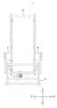
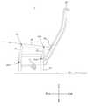
図2及び図4は、マッサージ機1のフレーム等を模式的に示す正面図である。図3及び図5は、マッサージ機1のフレーム等を模式的に示す側面図である。 2 and 4 are front views schematically showing a frame and the like of the
図2及び図3はマッサージ機1の背凭れ部3が最も起立した状態を示している。図4及び図5は、マッサージ機1の背凭れ部3が最も後方に倒れた状態(フルリクライニング状態)を示している。 2 and 3 show a state in which the
マッサージ機1は、基台フレーム10を備える。基台フレーム10は、座部2(図2~図5において不図示)の下方に位置し、座部2を支持する。 The
ひじ掛け部5は、上部フレーム5Aと、前方アーム5Bと、後方アーム5Cと、を備える。 The armrest portion 5 includes an
上部フレーム5Aは、前後方向に沿って尚且つ後方ほど下方に下がって延びる。上部フレーム5Aの長手方向は、ひじ掛け部5の長手方向である。ひじ掛け部5の長手方向は、被施療者が前腕をひじ掛け部5に置いたときの被施療者の肘と手首とを通る直線の方向と言い換えることができる。 The
前方アーム5Bは、側面視において長方形状の部材であり、マッサージ機1の背凭れ部3が最も起立した状態において、上下方向に沿って尚且つ上方ほど後方に向かって延びる。 The
前方アーム5Bの下端は、左右方向に沿って延びる回転軸AX2回りに回動可能に、基台フレーム10に取り付けられている。前方アーム5Bの上端は、左右方向に沿って延びる回転軸AX3回りに回動可能に、上部フレーム5Aに取り付けられている。 The lower end of the
後方アーム5Cは、側面視において長方形状の部材であり、マッサージ機1の背凭れ部3が最も起立した状態において、上下方向に沿って尚且つ上方ほど後方に向かうように延びる。 The
後方アーム5Cの下端は、左右方向に沿って延びる回転軸AX4回りに回動可能に、基台フレーム10に取り付けられている。後方アーム5Cの上端は、左右方向に沿って延びる回転軸AX5回りに回動可能に、上部フレーム5Aに取り付けられている。 The lower end of the
基台フレーム10における後方アーム5Cの取り付け位置は、基台フレーム10における前方アーム5Bの取り付け位置よりも後方である。同様に、上部フレーム5Aにおける後方アーム5Cの取り付け位置は、上部フレーム5Aにおける前方アーム5Bの取り付け位置よりも後方である。 The mounting position of the
前方アーム5Bのアーム長、すなわち前方アーム5Bの側面視における長方形状の長辺長さは、後方アーム5Cのアーム長、すなわち後方アーム5Cの側面視における長方形状の長辺長さより長い。このような構成により、前方アーム5B及び後方アーム5Cは、上部フレーム5Aが前後方向に沿って尚且つ後方ほど下方に下がって延びるように、上部フレーム5Aを支持することができる。 The arm length of the
背凭れ部3は、フレーム3Dと、当て板3Eと、当て板3Fと、を備える。当て板3Eは、フレーム3Dの左端から左側に向かって突出している。当て板3Fは、フレーム3Dの右端から右側に向かって突出している。 The
ひじ掛け部5は背凭れ部3に取り付けられていない。そして、ひじ掛け部5の後部は、背凭れ部3に対して接触及び分離の両方が可能である。本実施形態では、ひじ掛け部5の後端が背凭れ部3に対して接触及び分離の両方が可能である。なお、本実施形態とは異なり、ひじ掛け部5の後端以外のひじ掛け部5の後部が背凭れ部3に対して接触及び分離の両方が可能であってもよい。 The armrest portion 5 is not attached to the
図3及び図5から分かるように、ひじ掛け部5の後端にローラが設けられている。左側に配置されるひじ掛け部5の後端ローラは、背凭れ部3の当て板3Eに対して接触及び分離の両方が可能である。同様に、右側に配置されるひじ掛け部5の後端ローラは、背凭れ部3の当て板3Fに対して接触及び分離の両方が可能である。 As can be seen from FIGS. 3 and 5, a roller is provided at the rear end of the armrest portion 5. The rear end roller of the armrest portion 5 arranged on the left side can be both in contact with and separated from the
ひじ掛け部5に、ひじ掛け部5と背凭れ部3とを分離させる外力を加えてひじ掛け部5と背凭れ部3とを分離させた状態からひじ掛け部5への当該外力の付加を止めると、ひじ掛け部5はひじ掛け部5の自重により後方に移動する。このような自重による移動が起こるように、ひじ掛け部5の重心位置が設計される。 When an external force for separating the armrest 5 and the
したがって、ひじ掛け部5と背凭れ部3とを分離させる外力がひじ掛け部5に加わらない場合、図2及び図3に示す背凭れ部3が最も起立した状態から、背凭れ部用アクチュエータ11の駆動によって背凭れ部3が傾倒していき、図4及び図5に示す背凭れ部3が最も後方に倒れた状態に至るまでの間、ひじ掛け部5の後部の背凭れ部3に対する接触が維持される。さらに、ひじ掛け部5と背凭れ部3とを分離させる外力がひじ掛け部5に加わらない場合、図4及び図5に示す背凭れ部3が最も後方に倒れた状態から、背凭れ部用アクチュエータ11の駆動によって背凭れ部3が起立していき、図2及び図3に示す背凭れ部3が最も起立した状態に至るまでの間も同様に、ひじ掛け部5の後部の背凭れ部3に対する接触が維持される。 Therefore, when an external force that separates the armrest portion 5 and the
つまり、ひじ掛け部5と背凭れ部3とを分離させる外力がひじ掛け部5に加わらない場合、ひじ掛け部5の後部が背凭れ部3に対して接触して、背凭れ部3のリクライニング動作に連動してひじ掛け部5が前後に移動する。これにより、背凭れ部3が傾倒した場合でも被施療者は肘を伸ばしきることなく、ひじ掛け部5を利用することができる。言い換えると、背凭れ部3が傾倒した場合に被施療者の腕をリラックス状態にすることができる。 That is, when an external force that separates the armrest portion 5 and the
また、上部フレーム5Aが前方アーム5B及び後方アーム5Cによって支持されているため、前方アーム5B及び後方アーム5Cの基台フレーム10に対する回転に伴い、上部フレーム5Aは円弧状に近い軌跡を描きながら移動する。したがって、ひじ掛け部5が後方に移動するほど、側方視におけるひじ掛け部5の長手方向と基台フレーム10の底面すなわちマッサージ機1の底面とのなす鋭角θが大きくなる。これにより、背凭れ部3が傾倒した場合でも背凭れ部3が起立している場合と比較して被施療者は肘の角度を大きく変化させることなく、ひじ掛け部5を利用することができる。言い換えると、背凭れ部3が傾倒した場合に被施療者の腕をより一層リラックス状態にすることができる。 Further, since the
一方、ひじ掛け部5と背凭れ部3とを分離させる外力を加えてひじ掛け部5と背凭れ部3とを分離させた状態にすると、ひじ掛け部5の後部を背凭れ部3から離すことができる。つまり、被施療者が腕をひじ掛け部5に載せたまま腕を前方に押し出すと、ひじ掛け部5を前方に移動させることができる。つまり、マッサージ機1は、背凭れ部3の位置に関わらないひじ掛け部5の位置調整も可能である。これにより、被施療者の体格、被施療者の好み等によって背凭れ部3のリクライニング動作に応じたひじ掛け部5の位置が適切でない場合に、ひじ掛け部5に外力を加えることによってひじ掛け部5を適切な位置に調整することができる。 On the other hand, when an external force for separating the armrest portion 5 and the
上記実施形態は、全ての点で例示であって、制限的なものではないと考えられるべきであり、本発明の技術的範囲は、上記実施形態の説明ではなく、特許請求の範囲によって示されるものであり、特許請求の範囲と均等の意味及び範囲内に属する全ての変更が含まれると理解されるべきである。 It should be considered that the embodiments are exemplary in all respects and are not restrictive, and the technical scope of the invention is indicated by the claims rather than the description of the embodiments. It should be understood that it includes all modifications that fall within the meaning and scope of the claims.
また、ひじ掛け部5の前方への移動を規制する規制部12を、上述したマッサージ機1に追加してもよい。つまり、変形例に係る椅子式マッサージ機1’(以下、「マッサージ機1’」と称す)は、ひじ掛け部5の前方への移動を規制する規制部12をさらに備える。マッサージ機1’は、規制部12を備える点でマッサージ機1と相違し、それ以外の点でマッサージ機1と同一である。 Further, the restricting
規制部12を設けることで、ひじ掛け部5が前方へ移動し過ぎることを防止することができる。 By providing the restricting
図6は、マッサージ機1’のフレーム等の一例を模式的に示す側面図である。図7は、マッサージ機1’のフレーム等の他の例を模式的に示す側面図である。 FIG. 6 is a side view schematically showing an example of the frame and the like of the massage machine 1'. FIG. 7 is a side view schematically showing another example such as the frame of the massage machine 1'.
図6に示す例では、規制部12は、背凭れ部3が最も起立した状態で、ひじ掛け部5の後部が背凭れ部3に対して接触しているときよりもひじ掛け部5が前方に移動できないように、ひじ掛け部5の前方への移動を規制する。 In the example shown in FIG. 6, in the regulating
図7に示す例では、規制部12は、背凭れ部3が最も起立した状態で、ひじ掛け部5の後部が背凭れ部3に対して接触しているときよりもひじ掛け部5が前方に移動できるように、ひじ掛け部5の前方への移動を規制する。図7に示す例では、背凭れ部3が最も起立した状態で、ひじ掛け部5の後部と背凭れ部3との間に異物(例えば人の手など)が挟まっていても、ひじ掛け部5の後部と背凭れ部3との間に隙間を確保することができるので、当該異物に加わる力を低減することができる。 In the example shown in FIG. 7, in the regulating
上述したマッサージ機1及び上述したマッサージ機1’では、ひじ掛け部5の後部が、フレーム3Dから突出している当て板3E及び3Fに接触可能な構成であったが、例えば、ひじ掛け部5の後部が、背凭れ部3の内部に設けられフレーム3Dに取り付けられる樹脂成型部材に接触可能な構成であってもよい。 In the above-mentioned
また、上述したマッサージ機1が備えるひじ掛け部5を、例えば図8に示すような形態に変更してもよい。図8は、ひじ掛け部5のフレーム等の変形例を模式的に示す側面図である。 Further, the armrest portion 5 provided in the above-mentioned
図8に示す変形例では、ひじ掛け部5は、上部フレーム5Aを備える。上部フレーム5Aは、支持フレーム13によって支持される。上部フレーム5Aの下面は、支持フレーム13の上面に対してひじ掛け部5の長手方向にスライド可能に、支持フレーム13の上面に取り付けられている。支持フレーム13は基台フレーム10に固定されている。なお、この変形例では、上述した実施形態とは異なり、側方視におけるひじ掛け部5の長手方向と基台フレーム10の底面すなわちマッサージ機1の底面とのなす鋭角は、ひじ掛け部5の位置にかかわらず一定である。 In the modified example shown in FIG. 8, the armrest portion 5 includes an
図8に示す変形例において、ひじ掛け部5の前方への移動を規制する規制部12を設ける場合は、図9に示すように支持フレーム13の前部に規制部12を設置すればよい。 In the modified example shown in FIG. 8, when the restricting
また、上述した実施形態及び変形例では、ひじ掛け部5に、ひじ掛け部5と背凭れ部3とを分離させる外力を加えてひじ掛け部5と背凭れ部3とを分離させた状態からひじ掛け部5への当該外力の付加を止めると、ひじ掛け部5はひじ掛け部5の自重により後方に移動するようにしたが、本発明は、このような構成に限定されない。例えば、ひじ掛け部5を移動させるひじ掛け部用アクチュエータを設け、ひじ掛け部5と背凭れ部3とを分離させる外力がひじ掛け部5に加わらない場合、ひじ掛け部5の後部が背凭れ部3に対して接触して、背凭れ部3のリクライニング動作に連動してひじ掛け部5が前後に移動するように、制御部が背凭れ部用アクチュエータ及びひじ掛け部用アクチュエータを制御すればよい。そして、ひじ掛け部5と背凭れ部3とを分離させる外力がひじ掛け部5に加わった場合、当該外力によってひじ掛け部5が移動できるように、ひじ掛け部用アクチュエータがひじ掛け部5の位置を拘束しないようにすればよい。 Further, in the above-described embodiments and modifications, the armrest portion 5 is separated from the armrest portion 5 by applying an external force to separate the armrest portion 5 and the
1 一実施例に係る椅子式マッサージ機
3 背凭れ部
5 ひじ掛け部
12 規制部1 Chair-type massage machine according to one example 3 Backrest part 5
Claims (5)
Translated fromJapanese前記被施療者の腕を支持するひじ掛け部と、
を備え、
前記ひじ掛け部の後部が前記背凭れ部に対して接触及び分離の両方が可能であり、
前記ひじ掛け部と前記背凭れ部とを分離させる外力が前記ひじ掛け部に加わらない場合、前記ひじ掛け部の後部が前記背凭れ部に対して接触して、前記背凭れ部のリクライニング動作に連動して前記ひじ掛け部が前後に移動する、椅子式マッサージ機。A reclining backrest that supports the shoulders, hips, and back of the patient,
The armrest that supports the arm of the patient and the armrest
Equipped with
The rear part of the armrest can be both contacted and separated from the backrest.
When an external force that separates the armrest portion and the backrest portion is not applied to the armrest portion, the rear portion of the armrest portion comes into contact with the backrest portion and is linked to the reclining operation of the backrest portion. A chair-type massage machine in which the armrest moves back and forth.
Priority Applications (3)
| Application Number | Priority Date | Filing Date | Title |
|---|---|---|---|
| JP2020131997AJP7457598B2 (en) | 2020-08-03 | 2020-08-03 | chair massage machine |
| CN202110816403.3ACN114053118A (en) | 2020-08-03 | 2021-07-19 | massage chair |
| JP2024041418AJP7547669B2 (en) | 2020-08-03 | 2024-03-15 | Chair massage machine |
Applications Claiming Priority (1)
| Application Number | Priority Date | Filing Date | Title |
|---|---|---|---|
| JP2020131997AJP7457598B2 (en) | 2020-08-03 | 2020-08-03 | chair massage machine |
Related Child Applications (1)
| Application Number | Title | Priority Date | Filing Date |
|---|---|---|---|
| JP2024041418ADivisionJP7547669B2 (en) | 2020-08-03 | 2024-03-15 | Chair massage machine |
Publications (2)
| Publication Number | Publication Date |
|---|---|
| JP2022028529Atrue JP2022028529A (en) | 2022-02-16 |
| JP7457598B2 JP7457598B2 (en) | 2024-03-28 |
Family
ID=80233327
Family Applications (2)
| Application Number | Title | Priority Date | Filing Date |
|---|---|---|---|
| JP2020131997AActiveJP7457598B2 (en) | 2020-08-03 | 2020-08-03 | chair massage machine |
| JP2024041418AActiveJP7547669B2 (en) | 2020-08-03 | 2024-03-15 | Chair massage machine |
Family Applications After (1)
| Application Number | Title | Priority Date | Filing Date |
|---|---|---|---|
| JP2024041418AActiveJP7547669B2 (en) | 2020-08-03 | 2024-03-15 | Chair massage machine |
Country Status (2)
| Country | Link |
|---|---|
| JP (2) | JP7457598B2 (en) |
| CN (1) | CN114053118A (en) |
Citations (3)
| Publication number | Priority date | Publication date | Assignee | Title |
|---|---|---|---|---|
| JPS5938129U (en)* | 1982-09-04 | 1984-03-10 | 池田物産株式会社 | Armrest for vehicle seat |
| JP2008188055A (en)* | 2007-01-31 | 2008-08-21 | Fuji Iryoki:Kk | Massage chair |
| JP2009028463A (en)* | 2007-07-31 | 2009-02-12 | Sanyo Electric Co Ltd | Chair type massage machine |
Family Cites Families (5)
| Publication number | Priority date | Publication date | Assignee | Title |
|---|---|---|---|---|
| CH208327A (en)* | 1938-04-09 | 1940-01-31 | Luckhardt Hans | Adjustable seat and deck chair with a handlebar guide. |
| FR2567733B1 (en)* | 1984-07-18 | 1987-01-02 | Allibert Sa | REST SEAT |
| CN208972999U (en)* | 2018-09-12 | 2019-06-14 | 佛山市南海区世纪隆马五金制品有限公司 | A kind of adjustable massaging, working chair of work backrest |
| CN209862927U (en)* | 2019-04-10 | 2019-12-31 | 北京源树景观规划设计事务所 | Comfortable park bench with adjustable backrest |
| CN210383339U (en)* | 2019-08-26 | 2020-04-24 | 杭州佳名佳纺织品有限公司 | Mechanism for replacing sofa backrest |
- 2020
- 2020-08-03JPJP2020131997Apatent/JP7457598B2/enactiveActive
- 2021
- 2021-07-19CNCN202110816403.3Apatent/CN114053118A/enactivePending
- 2024
- 2024-03-15JPJP2024041418Apatent/JP7547669B2/enactiveActive
Patent Citations (3)
| Publication number | Priority date | Publication date | Assignee | Title |
|---|---|---|---|---|
| JPS5938129U (en)* | 1982-09-04 | 1984-03-10 | 池田物産株式会社 | Armrest for vehicle seat |
| JP2008188055A (en)* | 2007-01-31 | 2008-08-21 | Fuji Iryoki:Kk | Massage chair |
| JP2009028463A (en)* | 2007-07-31 | 2009-02-12 | Sanyo Electric Co Ltd | Chair type massage machine |
Also Published As
| Publication number | Publication date |
|---|---|
| JP7547669B2 (en) | 2024-09-09 |
| CN114053118A (en) | 2022-02-18 |
| JP7457598B2 (en) | 2024-03-28 |
| JP2024060081A (en) | 2024-05-01 |
Similar Documents
| Publication | Publication Date | Title |
|---|---|---|
| JP7001283B2 (en) | Chair type massage machine and massage mechanism | |
| US20090021063A1 (en) | Chair-type massage machine | |
| JP6455889B2 (en) | Lumbar traction device | |
| JP2012091009A (en) | Massage machine | |
| JP4684151B2 (en) | Massage machine | |
| JP2012235879A (en) | Chair type massage machine | |
| JP2003289975A (en) | Chair | |
| JP2007209404A (en) | Massage machine | |
| US11690778B2 (en) | Chair-type massage machine and massage machine | |
| WO2019159811A1 (en) | Chair-type massaging machine | |
| JP4719055B2 (en) | Massage machine | |
| JP7457598B2 (en) | chair massage machine | |
| JP2009000157A (en) | Massage machine | |
| JP2005218511A (en) | Chair | |
| JP2021006187A (en) | Chair type massage machine | |
| JP2002336311A (en) | Chair for treatment | |
| JP4843809B2 (en) | IV chair | |
| JP2020202914A (en) | Massage machine | |
| JP2011250934A (en) | Chair type massage machine | |
| JP2021177831A (en) | Chair type massage machine | |
| CN221950171U (en) | Massaging machine | |
| JP6927712B2 (en) | Reclining chair and chair type massage machine | |
| JP2007209405A (en) | Massage machine | |
| JP7583673B2 (en) | Massage machine | |
| JP2020195713A (en) | Massage machine |
Legal Events
| Date | Code | Title | Description |
|---|---|---|---|
| A621 | Written request for application examination | Free format text:JAPANESE INTERMEDIATE CODE: A621 Effective date:20230614 | |
| A977 | Report on retrieval | Free format text:JAPANESE INTERMEDIATE CODE: A971007 Effective date:20231201 | |
| A131 | Notification of reasons for refusal | Free format text:JAPANESE INTERMEDIATE CODE: A131 Effective date:20231212 | |
| A521 | Request for written amendment filed | Free format text:JAPANESE INTERMEDIATE CODE: A523 Effective date:20240201 | |
| TRDD | Decision of grant or rejection written | ||
| A01 | Written decision to grant a patent or to grant a registration (utility model) | Free format text:JAPANESE INTERMEDIATE CODE: A01 Effective date:20240220 | |
| A61 | First payment of annual fees (during grant procedure) | Free format text:JAPANESE INTERMEDIATE CODE: A61 Effective date:20240315 | |
| R150 | Certificate of patent or registration of utility model | Ref document number:7457598 Country of ref document:JP Free format text:JAPANESE INTERMEDIATE CODE: R150 |