JP2022023820A - Systems and methods for controlling surgical staple fasteners - Google Patents
Systems and methods for controlling surgical staple fastenersDownload PDFInfo
- Publication number
- JP2022023820A JP2022023820AJP2021121225AJP2021121225AJP2022023820AJP 2022023820 AJP2022023820 AJP 2022023820AJP 2021121225 AJP2021121225 AJP 2021121225AJP 2021121225 AJP2021121225 AJP 2021121225AJP 2022023820 AJP2022023820 AJP 2022023820A
- Authority
- JP
- Japan
- Prior art keywords
- staple
- surgical
- pusher
- compressive force
- anvil assembly
- Prior art date
- Legal status (The legal status is an assumption and is not a legal conclusion. Google has not performed a legal analysis and makes no representation as to the accuracy of the status listed.)
- Granted
Links
Images


Classifications
- A—HUMAN NECESSITIES
- A61—MEDICAL OR VETERINARY SCIENCE; HYGIENE
- A61B—DIAGNOSIS; SURGERY; IDENTIFICATION
- A61B17/00—Surgical instruments, devices or methods
- A61B17/11—Surgical instruments, devices or methods for performing anastomosis; Buttons for anastomosis
- A61B17/115—Staplers for performing anastomosis, e.g. in a single operation
- A61B17/1155—Circular staplers comprising a plurality of staples
- A—HUMAN NECESSITIES
- A61—MEDICAL OR VETERINARY SCIENCE; HYGIENE
- A61B—DIAGNOSIS; SURGERY; IDENTIFICATION
- A61B17/00—Surgical instruments, devices or methods
- A61B17/068—Surgical staplers, e.g. containing multiple staples or clamps
- A61B17/072—Surgical staplers, e.g. containing multiple staples or clamps for applying a row of staples in a single action, e.g. the staples being applied simultaneously
- A—HUMAN NECESSITIES
- A61—MEDICAL OR VETERINARY SCIENCE; HYGIENE
- A61B—DIAGNOSIS; SURGERY; IDENTIFICATION
- A61B90/00—Instruments, implements or accessories specially adapted for surgery or diagnosis and not covered by any of the groups A61B1/00 - A61B50/00, e.g. for luxation treatment or for protecting wound edges
- A61B90/06—Measuring instruments not otherwise provided for
- A—HUMAN NECESSITIES
- A61—MEDICAL OR VETERINARY SCIENCE; HYGIENE
- A61B—DIAGNOSIS; SURGERY; IDENTIFICATION
- A61B90/00—Instruments, implements or accessories specially adapted for surgery or diagnosis and not covered by any of the groups A61B1/00 - A61B50/00, e.g. for luxation treatment or for protecting wound edges
- A61B90/08—Accessories or related features not otherwise provided for
- A—HUMAN NECESSITIES
- A61—MEDICAL OR VETERINARY SCIENCE; HYGIENE
- A61B—DIAGNOSIS; SURGERY; IDENTIFICATION
- A61B17/00—Surgical instruments, devices or methods
- A61B2017/00017—Electrical control of surgical instruments
- A—HUMAN NECESSITIES
- A61—MEDICAL OR VETERINARY SCIENCE; HYGIENE
- A61B—DIAGNOSIS; SURGERY; IDENTIFICATION
- A61B17/00—Surgical instruments, devices or methods
- A61B2017/00017—Electrical control of surgical instruments
- A61B2017/00115—Electrical control of surgical instruments with audible or visual output
- A61B2017/00119—Electrical control of surgical instruments with audible or visual output alarm; indicating an abnormal situation
- A—HUMAN NECESSITIES
- A61—MEDICAL OR VETERINARY SCIENCE; HYGIENE
- A61B—DIAGNOSIS; SURGERY; IDENTIFICATION
- A61B17/00—Surgical instruments, devices or methods
- A61B2017/00017—Electrical control of surgical instruments
- A61B2017/00199—Electrical control of surgical instruments with a console, e.g. a control panel with a display
- A—HUMAN NECESSITIES
- A61—MEDICAL OR VETERINARY SCIENCE; HYGIENE
- A61B—DIAGNOSIS; SURGERY; IDENTIFICATION
- A61B17/00—Surgical instruments, devices or methods
- A61B2017/00367—Details of actuation of instruments, e.g. relations between pushing buttons, or the like, and activation of the tool, working tip, or the like
- A61B2017/00398—Details of actuation of instruments, e.g. relations between pushing buttons, or the like, and activation of the tool, working tip, or the like using powered actuators, e.g. stepper motors, solenoids
- A—HUMAN NECESSITIES
- A61—MEDICAL OR VETERINARY SCIENCE; HYGIENE
- A61B—DIAGNOSIS; SURGERY; IDENTIFICATION
- A61B17/00—Surgical instruments, devices or methods
- A61B2017/0046—Surgical instruments, devices or methods with a releasable handle; with handle and operating part separable
- A—HUMAN NECESSITIES
- A61—MEDICAL OR VETERINARY SCIENCE; HYGIENE
- A61B—DIAGNOSIS; SURGERY; IDENTIFICATION
- A61B17/00—Surgical instruments, devices or methods
- A61B17/068—Surgical staplers, e.g. containing multiple staples or clamps
- A61B17/072—Surgical staplers, e.g. containing multiple staples or clamps for applying a row of staples in a single action, e.g. the staples being applied simultaneously
- A61B2017/07214—Stapler heads
- A61B2017/07257—Stapler heads characterised by its anvil
- A—HUMAN NECESSITIES
- A61—MEDICAL OR VETERINARY SCIENCE; HYGIENE
- A61B—DIAGNOSIS; SURGERY; IDENTIFICATION
- A61B17/00—Surgical instruments, devices or methods
- A61B17/068—Surgical staplers, e.g. containing multiple staples or clamps
- A61B17/072—Surgical staplers, e.g. containing multiple staples or clamps for applying a row of staples in a single action, e.g. the staples being applied simultaneously
- A61B2017/07214—Stapler heads
- A61B2017/07271—Stapler heads characterised by its cartridge
- A—HUMAN NECESSITIES
- A61—MEDICAL OR VETERINARY SCIENCE; HYGIENE
- A61B—DIAGNOSIS; SURGERY; IDENTIFICATION
- A61B17/00—Surgical instruments, devices or methods
- A61B17/068—Surgical staplers, e.g. containing multiple staples or clamps
- A61B17/072—Surgical staplers, e.g. containing multiple staples or clamps for applying a row of staples in a single action, e.g. the staples being applied simultaneously
- A61B2017/07214—Stapler heads
- A61B2017/07278—Stapler heads characterised by its sled or its staple holder
- A—HUMAN NECESSITIES
- A61—MEDICAL OR VETERINARY SCIENCE; HYGIENE
- A61B—DIAGNOSIS; SURGERY; IDENTIFICATION
- A61B90/00—Instruments, implements or accessories specially adapted for surgery or diagnosis and not covered by any of the groups A61B1/00 - A61B50/00, e.g. for luxation treatment or for protecting wound edges
- A61B90/06—Measuring instruments not otherwise provided for
- A61B2090/064—Measuring instruments not otherwise provided for for measuring force, pressure or mechanical tension
- A61B2090/065—Measuring instruments not otherwise provided for for measuring force, pressure or mechanical tension for measuring contact or contact pressure
- A—HUMAN NECESSITIES
- A61—MEDICAL OR VETERINARY SCIENCE; HYGIENE
- A61B—DIAGNOSIS; SURGERY; IDENTIFICATION
- A61B90/00—Instruments, implements or accessories specially adapted for surgery or diagnosis and not covered by any of the groups A61B1/00 - A61B50/00, e.g. for luxation treatment or for protecting wound edges
- A61B90/08—Accessories or related features not otherwise provided for
- A61B2090/0807—Indication means
- A61B2090/0811—Indication means for the position of a particular part of an instrument with respect to the rest of the instrument, e.g. position of the anvil of a stapling instrument
- A61B2090/0812—Indication means for the position of a particular part of an instrument with respect to the rest of the instrument, e.g. position of the anvil of a stapling instrument indicating loosening or shifting of parts of an instrument, signaling maladjustment of parts
- A—HUMAN NECESSITIES
- A61—MEDICAL OR VETERINARY SCIENCE; HYGIENE
- A61B—DIAGNOSIS; SURGERY; IDENTIFICATION
- A61B2560/00—Constructional details of operational features of apparatus; Accessories for medical measuring apparatus
- A61B2560/04—Constructional details of apparatus
- A61B2560/0475—Special features of memory means, e.g. removable memory cards
- A—HUMAN NECESSITIES
- A61—MEDICAL OR VETERINARY SCIENCE; HYGIENE
- A61B—DIAGNOSIS; SURGERY; IDENTIFICATION
- A61B2562/00—Details of sensors; Constructional details of sensor housings or probes; Accessories for sensors
- A61B2562/02—Details of sensors specially adapted for in-vivo measurements
- A61B2562/0261—Strain gauges
Landscapes
- Health & Medical Sciences (AREA)
- Surgery (AREA)
- Life Sciences & Earth Sciences (AREA)
- Heart & Thoracic Surgery (AREA)
- Engineering & Computer Science (AREA)
- Biomedical Technology (AREA)
- Nuclear Medicine, Radiotherapy & Molecular Imaging (AREA)
- Medical Informatics (AREA)
- Molecular Biology (AREA)
- Animal Behavior & Ethology (AREA)
- General Health & Medical Sciences (AREA)
- Public Health (AREA)
- Veterinary Medicine (AREA)
- Pathology (AREA)
- Oral & Maxillofacial Surgery (AREA)
- Surgical Instruments (AREA)
Abstract
Description
Translated fromJapanese (関連出願の相互参照)
本出願は、2020年7月27日に出願された米国仮特許出願第63/056,746号の利益および優先権を主張するものであり、その内容全体が、参照により、本明細書によって組み込まれる。(Mutual reference of related applications)
This application claims the interests and priorities of US Provisional Patent Application No. 63 / 056,746 filed July 27, 2020, the entire contents of which are incorporated herein by reference in their entirety. Is done.
(分野)
本開示は、一般に、電動外科用ステープル留め器具に関し、より詳細には、ステープル形成範囲に基づいて外科用ステープル留め器具を制御するための方法、および本方法を実施するための外科用ステープル留め器具に関する。(Field)
The present disclosure generally relates to electrosurgical staple fasteners, more particularly methods for controlling surgical staple fasteners based on the extent of staple formation, and surgical staple fasteners for carrying out the method. Regarding.
吻合は、別々の中空臓器部分を外科的に接合することである。通常、吻合処置は、臓器の罹患または欠陥のある部分が除去され、臓器の残りの端部部分が外科用ステープル留め器具を介して接合される手術に続く。所望の吻合処置に応じて、残りの端部部分は、例えば、円形または側部から側部への臓器再建法によって接合されてもよい。 Anastomosis is the surgical joining of separate hollow organ parts. Anastomotic procedures usually follow surgery in which the affected or defective part of the organ is removed and the remaining ends of the organ are joined via surgical staples. Depending on the desired anastomotic procedure, the remaining end portions may be joined, for example, by circular or side-to-side organ reconstruction methods.
円形吻合処置では、臓器の残りの端部部分が、残りの端部部分を介してステープルの円形アレイを駆動し、同時に臓器内の管状通路を解放するように駆動されたステープルの円形アレイの任意の組織内部をくり抜く外科用ステープル留め器具によって接合される。円形吻合処置中に送達されるステープルは、消化管の内容物が腹腔または胸腔に漏れないように形成されるべきである。 In a circular anastomosis procedure, the remaining end of the organ drives a circular array of staples through the remaining ends, while at the same time any of the circular arrays of staples driven to open the tubular passages within the organ. It is joined by a surgical staple fastener that hollows out the inside of the tissue. Staples delivered during the circular anastomosis procedure should be formed so that the contents of the gastrointestinal tract do not leak into the abdominal cavity or thoracic cavity.
漏れを防止することができるステープル形成と、十分に閉じられていないステープル形成とを区別することができるステープル留め器具が引き続き必要とされている。 There is still a need for staple fasteners that can distinguish between staple formation that can prevent leaks and staple formation that is not fully closed.
本開示によれば、組織をステープル留めするための外科用ステープル留め器具を制御するためのコンピュータによる実施方法は、プッシャを外科用ステープル留め器具のアンビルアセンブリに向かって第1の位置から第2の位置まで進めることであって、プッシャが、外科用ステープル留め器具のステープルカートリッジからステープルを排出するように構成されている、進めることと、プッシャが、第2の位置に先立ってアンビルアセンブリに向かって進むのを停止したかどうかを判定することと、プッシャによってステープルカートリッジから排出されたステープルのステープル圧縮力を測定することと、ステープル圧縮力が所定の範囲外であるかどうかを判定することと、を含む。 According to the present disclosure, a computerized method for controlling a surgical stapler for stapling tissue is a second position to a second position of the pusher towards the anvil assembly of the surgical stapler. To advance to position, the pusher is configured to eject the staples from the staple cartridge of the surgical staple fastener, advance and the pusher towards the anvil assembly prior to the second position. Determining if the staple has stopped advancing, measuring the staple compressive force of the staples ejected from the staple cartridge by the pusher, and determining if the staple compressive force is out of the specified range. including.
一態様では、本方法は、所定の許容可能なステープル圧縮範囲に基づくステープル圧縮力に応答して、外科用ステープル留め器具の組織切断モードに入れることをさらに含む。 In one aspect, the method further comprises entering a tissue cutting mode of a surgical stapler in response to a staple compressive force based on a predetermined acceptable staple compression range.
別の態様では、ステープル圧縮力は、ひずみゲージによって測定されてもよい。 In another aspect, the staple compressive force may be measured by a strain gauge.
さらに別の態様では、ステープル圧縮力は、プッシャを進めるように構成されたモータの電流に基づいて測定されてもよい。 In yet another aspect, the staple compressive force may be measured based on the current of the motor configured to advance the pusher.
一態様では、本方法は、ステープル圧縮力が所定の範囲よりも大きいことに応答して、ステープルの発射を防止することをさらに含み得る。 In one aspect, the method may further comprise preventing the staple from firing in response to the staple compressive force being greater than a predetermined range.
別の態様では、本方法は、ステープル圧縮力が所定の範囲よりも大きいことに応答して、警告を表示することをさらに含み得る。 In another aspect, the method may further comprise displaying a warning in response to the staple compressive force being greater than a predetermined range.
さらに別の態様では、表示される警告は、手術部位を検査するための、および/または組織をクランプ解除するための警告を含み得る。 In yet another aspect, the warnings displayed may include warnings for examining the surgical site and / or for unclamping the tissue.
またさらに別の態様では、本方法は、プッシャを引っ込めることをさらに含み得る。 In yet another aspect, the method may further comprise retracting the pusher.
またさらに別の態様では、本方法は、ステープル圧縮力が所定の範囲よりも大きいことに応答して、音声警告を生成することをさらに含み得る。 In yet another aspect, the method may further comprise generating a voice alert in response to a staple compressive force greater than a predetermined range.
またさらに別の態様では、本方法は、機能的に閉じたステープル形成が達成されたかどうかを判定することをさらに含み得る。 In yet another aspect, the method may further comprise determining whether functionally closed staple formation has been achieved.
本開示の態様によれば、外科用ステープル留め器具は、アンビルヘッド、およびアンビルヘッドから近位に延在するアンビルセンタロッドを含むアンビルアセンブリと、プッシャを含むリロードアセンブリと、複数のステープルを含む環状ステープルカートリッジと、を含む。プッシャは、環状ステープルカートリッジからステープルを排出するように構成されている。外科用ステープル留め器具は、プロセッサおよびメモリをさらに含む。メモリは、実行されたとき、外科用ステープル留め器具に、プッシャをアンビルアセンブリに向かって第1の位置から第2の位置まで進めることと、プッシャが、第2の位置に先立ってアンビルアセンブリに向かって進めるのを停止したかどうかを判定することと、プッシャがアンビルアセンブリに向かって進むのを停止したことに応答して、プッシャによって環状ステープルカートリッジから排出されるステープルのステープル圧縮力を測定することと、ステープル圧縮力が、所定の範囲外であるかどうかを判定することと、を行わせる、その上に記憶された命令を含む。 According to aspects of the present disclosure, the surgical staple fastener is an anvil assembly comprising an anvil head and an anvil center rod extending proximally from the anvil head, a reload assembly including a pusher, and an annular including multiple staples. Includes staple cartridges and. The pusher is configured to eject staples from the annular staple cartridge. Surgical staple fasteners further include a processor and memory. When the memory is executed, the surgical staple fastener advances the pusher from the first position to the second position toward the anvil assembly, and the pusher heads toward the anvil assembly prior to the second position. Measuring the staple compressive force of the staple ejected by the pusher from the annular staple cartridge in response to determining whether it has stopped advancing and stopping the pusher from advancing towards the anvil assembly. And to determine if the staple compressive force is out of the predetermined range, and includes instructions stored on it.
一態様では、命令は、プロセッサによって実行されたときに、所定の許容可能なステープル圧縮範囲に基づくステープル圧縮力に応答して、外科用ステープル留め器具を外科用ステープル留め器具の組織切断モードにさらに入れてもよい。 In one aspect, the instruction further puts the surgical stapler into the tissue cutting mode of the surgical stapler in response to a stapler compressive force based on a predetermined acceptable stapler compression range when executed by the processor. You may put it in.
別の態様では、ステープル圧縮力は、ひずみゲージによって測定される。 In another aspect, the staple compressive force is measured by a strain gauge.
さらに別の態様では、ステープル圧縮力は、プッシャを進めるように構成されたモータの電流に基づいて測定される。 In yet another aspect, the staple compressive force is measured based on the current of the motor configured to advance the pusher.
またさらに別の態様では、命令は、プロセッサによって実行されたとき、外科用ステープル留め器具に、ステープル圧縮力が所定の範囲よりも大きいことに応答してステープルの発射をさらに防止させてもよい。 In yet another aspect, the instruction may further prevent the staple firing device from firing the staple in response to the staple compressive force being greater than a predetermined range when executed by the processor.
またさらに別の態様では、命令は、プロセッサによって実行されたとき、外科用ステープル留め器具に、ステープル圧縮力が所定の範囲よりも大きい場合、警告をディスプレイ上にさらに表示させてもよい。 In yet another aspect, when the instruction is executed by the processor, the surgical staple fastener may further display a warning on the display if the staple compressive force is greater than a predetermined range.
またさらに別の態様では、表示された警告は、手術部位を検査するための、および/または組織をクランプ解除するための警告を含み得る。 In yet another aspect, the displayed warning may include a warning for examining the surgical site and / or for unclamping the tissue.
またさらに別の態様では、命令は、プロセッサによって実行されたとき、外科用ステープル留め器具に、プッシャをさらに引っ込めさせてもよい。 In yet another aspect, the instruction may be further retracted into a surgical stapler when executed by the processor.
またさらに別の態様では、命令は、プロセッサによって実行されたとき、外科用ステープル留め器具に、ステープル圧縮力が所定の範囲よりも大きいことに応答して音声警告をさらに生成させてもよい。 In yet another aspect, the instruction may cause the surgical staple fastener to further generate a voice alert in response to the staple compressive force being greater than a predetermined range when executed by the processor.
本開示の他の態様によれば、非一時的なコンピュータ可読媒体は、プロセッサによって実行されたときに、プロセッサに、プッシャを外科用ステープル留め器具のアンビルアセンブリに向かって第1の位置から第2の位置まで進めることであって、プッシャが、外科用ステープル留め器具のステープルカートリッジからステープルを排出するように構成されている、進めることと、プッシャが、第2の位置に先立ってアンビルアセンブリに向かって進むのを停止したかどうかを判定することと、プッシャによってステープルカートリッジから排出されたステープルのステープル圧縮力を測定することと、ステープル圧縮力が、所定の範囲外であるかどうかを判定することと、を含む、外科用ステープル留め器具を制御するための方法を実行させる命令を記憶する。 According to another aspect of the present disclosure, the non-temporary computer-readable medium, when run by the processor, causes the pusher to a second position from a first position towards the anvil assembly of the surgical staple fastener. The pusher is configured to eject the staples from the staple cartridge of the surgical staple fastener, which is to advance to the position of, and the pusher is directed to the anvil assembly prior to the second position. To determine whether the staple has stopped moving, to measure the staple compressive force of the staples ejected from the staple cartridge by the pusher, and to determine whether the staple compressive force is out of the predetermined range. Memorize instructions to perform methods for controlling surgical staple fasteners, including.
本発明は、例えば以下を提供する。
(項目1)
外科用ステープル留め器具を制御するためのコンピュータによる実施方法であって、
プッシャを前記外科用ステープル留め器具のアンビルアセンブリに向かって第1の位置から第2の位置まで進めることであって、前記プッシャが、前記外科用ステープル留め器具のステープルカートリッジからステープルを排出するように構成されている、進めることと、
前記プッシャが、前記第2の位置に先立って前記アンビルアセンブリに向かって進めるのを停止したかどうかを判定することと、
前記プッシャによって前記ステープルカートリッジから排出されたステープルのステープル圧縮力を測定することと、
前記ステープル圧縮力が、所定の範囲外であるかどうかを判定することと、を含む、方法。
(項目2)
所定の許容可能なステープル圧縮範囲に基づく前記ステープル圧縮力に応答して、前記外科用ステープル留め器具の組織切断モードに入れることをさらに含む、上記項目に記載のコンピュータによる実施方法。
(項目3)
前記ステープル圧縮力が、ひずみゲージによって測定される、上記項目のいずれかに記載のコンピュータによる実施方法。
(項目4)
前記ステープル圧縮力が、前記プッシャを進めるように構成されたモータの電流に基づいて測定される、上記項目のいずれかに記載のコンピュータによる実施方法。
(項目5)
前記ステープル圧縮力が、前記所定の範囲よりも大きいことに応答して、ステープルが発射するのを防止することをさらに含む、上記項目のいずれかに記載のコンピュータによる実施方法。
(項目6)
前記ステープル圧縮力が、前記所定の範囲よりも大きいことに応答して、警告を表示することをさらに含む、上記項目のいずれかに記載のコンピュータによる実施方法。
(項目7)
前記表示された警告が、手術部位を検査するため、または組織をクランプ解除するための警告のうちの少なくとも1つを含む、上記項目のいずれかに記載のコンピュータによる実施方法。
(項目8)
前記プッシャを引っ込めることをさらに含む、上記項目のいずれかに記載のコンピュータによる実施方法。
(項目9)
前記ステープル圧縮力が、前記所定の範囲よりも大きいことに応答して、音声警告を生成することをさらに含む、上記項目のいずれかに記載のコンピュータによる実施方法。
(項目10)
機能的に閉じたステープル形成が、達成されたかどうかを判定することをさらに含む、上記項目のいずれかに記載のコンピュータによる実施方法。
(項目11)
外科用ステープル留め器具であって、
アンビルヘッド、および前記アンビルヘッドから近位に延在するアンビルセンタロッドを含むアンビルアセンブリと、
プッシャ、および複数のステープルを含む環状ステープルカートリッジを含むリロードアセンブリであって、前記プッシャが、前記環状ステープルカートリッジからステープルを排出するように構成されている、リロードアセンブリと、
プロセッサと、
記憶された命令を含むメモリであって、前記命令は、実行されたときに、前記外科用ステープル留め器具に、
前記プッシャを前記アンビルアセンブリに向かって第1の位置から第2の位置まで進めることと、
前記プッシャが、前記第2の位置に先立って前記アンビルアセンブリに向かって進むのを停止したかどうかを判定することと、
前記プッシャが前記アンビルアセンブリに向かって進むのを停止したことに応答して、前記プッシャによって前記環状ステープルカートリッジから排出されたステープルのステープル圧縮力を測定することと、
前記ステープル圧縮力が、所定の範囲外であるかどうかを判定することと、を行わせる、メモリと、を備える、外科用ステープル留め器具。
(項目12)
前記命令が、前記プロセッサによって実行されたときに、所定の許容可能なステープル圧縮範囲に基づく前記ステープル圧縮力に応答して、前記外科用ステープル留め器具を前記外科用ステープル留め器具の組織切断モードにさらに入れる、上記項目のいずれかに記載の外科用ステープル留め器具。
(項目13)
前記ステープル圧縮力が、ひずみゲージによって測定される、上記項目のいずれかに記載の外科用ステープル留め器具。
(項目14)
前記ステープル圧縮力が、前記プッシャを進めるように構成されたモータの電流に基づいて測定される、上記項目のいずれかに記載の外科用ステープル留め器具。
(項目15)
前記命令が、前記プロセッサによって実行されたとき、前記外科用ステープル留め器具に、前記ステープル圧縮力が前記所定の範囲よりも大きいことに応答してステープルの発射をさらに防止させる、上記項目のいずれかに記載の外科用ステープル留め器具。
(項目16)
前記命令が、前記プロセッサによって実行されたとき、前記外科用ステープル留め器具に、前記ステープル圧縮力が前記所定の範囲よりも大きい場合、警告をディスプレイ上にさらに表示させる、上記項目のいずれかに記載の外科用ステープル留め器具。
(項目17)
前記表示された警告が、手術部位を検査するため、または組織をクランプ解除するための警告のうちの少なくとも1つを含む、上記項目のいずれかに記載の外科用ステープル留め器具。
(項目18)
前記命令が、前記プロセッサによって実行されたとき、前記外科用ステープル留め器具に、前記プッシャをさらに引っ込めさせる、上記項目のいずれかに記載の外科用ステープル留め器具。
(項目19)
前記命令が、前記プロセッサによって実行されたとき、前記外科用ステープル留め器具に、前記ステープル圧縮力が前記所定の範囲よりも大きいことに応答して音声警告をさらに生成させる、上記項目のいずれかに記載の外科用ステープル留め器具。
(項目20)
プロセッサによって実行されたとき、前記プロセッサに、外科用ステープル留め器具を制御するための方法を実施させる命令を記憶する非一時的なコンピュータ可読媒体であって、前記命令は、
プッシャを前記外科用ステープル留め器具のアンビルアセンブリに向かって第1の位置から第2の位置まで進めることであって、前記プッシャが、前記外科用ステープル留め器具のステープルカートリッジからステープルを排出するように構成されている、進めることと、
前記プッシャが、前記第2の位置に先立って前記アンビルアセンブリに向かって進むのを停止したかどうかを判定することと、
前記プッシャが前記アンビルアセンブリに向かって進むのを停止したことに応答して、前記プッシャによって前記ステープルカートリッジから排出されたステープルのステープル圧縮力を測定することと、
前記ステープル圧縮力が、所定の範囲外であるかどうかを判定することと、を含む、非一時的なコンピュータ可読媒体。
(摘要)
外科用ステープル留め器具は、アンビルアセンブリと、リロードアセンブリと、アダプタアセンブリと、プロセッサと、メモリと、を含む。目標の力にクランプするときに、命令は、外科用ステープル留め器具に、プッシャをアンビルアセンブリに向かって第1の位置から第2の位置まで進めることと、プッシャが、第2の位置に先立ってアンビルアセンブリに向かって進むのを停止したかどうかを判定することと、プッシャがアンビルアセンブリに向かって進むのを停止したことに応答して、プッシャによって環状ステープルカートリッジから排出されるステープルのステープル圧縮力を測定することと、ステープル圧縮力が、所定の範囲外であるかどうかを判定することと、を行わせる。The present invention provides, for example,:
(Item 1)
A computerized method for controlling surgical staple fasteners,
The pusher is advanced from a first position to a second position towards the anvil assembly of the surgical staple fastener so that the pusher ejects the staple from the staple cartridge of the surgical staple fastener. It is composed, to proceed, and
Determining whether the pusher has stopped advancing towards the anvil assembly prior to the second position.
Measuring the staple compressive force of the staple discharged from the staple cartridge by the pusher, and
A method comprising determining whether the staple compressive force is outside a predetermined range.
(Item 2)
The computerized method according to the above item, further comprising entering a tissue cutting mode of the surgical staple fastener in response to the staple compressive force based on a predetermined acceptable staple compression range.
(Item 3)
The computerized method according to any of the above items, wherein the staple compressive force is measured by a strain gauge.
(Item 4)
The computerized method of any of the above items, wherein the staple compressive force is measured based on the current of a motor configured to advance the pusher.
(Item 5)
The computerized method according to any of the above items, further comprising preventing the staples from firing in response to the staple compressive force being greater than the predetermined range.
(Item 6)
The computerized method according to any of the above items, further comprising displaying a warning in response to the staple compressive force being greater than the predetermined range.
(Item 7)
The computerized method according to any of the above items, wherein the displayed warning comprises at least one of warnings for inspecting a surgical site or for unclamping tissue.
(Item 8)
The computerized method according to any of the above items, further comprising retracting the pusher.
(Item 9)
The computerized method according to any of the above items, further comprising generating an audible alert in response to the staple compressive force being greater than the predetermined range.
(Item 10)
The computerized method according to any of the above items, further comprising determining if functionally closed staple formation has been achieved.
(Item 11)
Surgical staple fasteners
An anvil assembly including an anvil head and an anvil center rod extending proximally from the anvil head.
A reload assembly comprising a pusher and an annular staple cartridge comprising a plurality of staples, wherein the pusher is configured to eject staples from the annular staple cartridge.
With the processor
A memory containing stored instructions that, when executed, are attached to the surgical stapler.
To advance the pusher from the first position to the second position toward the anvil assembly,
Determining whether the pusher has stopped advancing towards the anvil assembly prior to the second position.
Measuring the staple compressive force of the staples ejected from the annular staple cartridge by the pushers in response to the pushers stopping advancing towards the anvil assembly.
A surgical staple fastening device comprising a memory for determining whether or not the staple compressive force is out of a predetermined range.
(Item 12)
When the instruction is executed by the processor, the surgical staple fastener is put into the tissue cutting mode of the surgical staple fastener in response to the staple compressive force based on a predetermined acceptable staple compression range. Further insert, the surgical staple fastening device described in any of the above items.
(Item 13)
The surgical staple fastening device according to any one of the above items, wherein the staple compressive force is measured by a strain gauge.
(Item 14)
The surgical staple fastener according to any one of the above items, wherein the staple compressive force is measured based on the current of a motor configured to advance the pusher.
(Item 15)
Any of the above items, when the instruction is executed by the processor, causes the surgical staple fastener to further prevent the staple from firing in response to the staple compressive force being greater than the predetermined range. Surgical staple fasteners described in.
(Item 16)
Described in any of the above items, when the instruction is executed by the processor, the surgical staple fastener will further display a warning on the display if the staple compressive force is greater than the predetermined range. Surgical staple fasteners.
(Item 17)
The surgical staple fastener according to any of the above items, wherein the displayed warning comprises at least one of the warnings for inspecting the surgical site or for unclamping the tissue.
(Item 18)
The surgical stapler according to any of the above items, wherein when the instruction is executed by the processor, the surgical stapler further retracts the pusher.
(Item 19)
When the instruction is executed by the processor, any of the above items causes the surgical staple fastener to further generate a voice warning in response to the staple compressive force being greater than the predetermined range. Described surgical staple fastening device.
(Item 20)
A non-temporary computer-readable medium that stores instructions that, when executed by a processor, causes the processor to perform a method for controlling a surgical stapler.
The pusher is advanced from a first position to a second position towards the anvil assembly of the surgical staple fastener so that the pusher ejects the staple from the staple cartridge of the surgical staple fastener. It is composed, to proceed, and
Determining whether the pusher has stopped advancing towards the anvil assembly prior to the second position.
Measuring the staple compressive force of the staples ejected from the staple cartridge by the pushers in response to the pushers stopping advancing towards the anvil assembly.
A non-temporary computer-readable medium, including determining if the staple compressive force is outside a predetermined range.
(Summary)
Surgical staple fasteners include anvil assembly, reload assembly, adapter assembly, processor and memory. When clamping to the target force, the command is to advance the pusher from the first position to the second position towards the anvil assembly on the surgical staple fastener, and the pusher precedes the second position. Staple compressive force of the staples ejected from the annular staple cartridge by the pusher in response to determining whether it has stopped moving towards the anvil assembly and in response to the pusher stopping moving towards the anvil assembly. And to determine whether the staple compressive force is out of the predetermined range.
クランプおよびステープル留めするための外科用ステープル留め器具を制御するためのシステムおよび方法が、図面を参照して本明細書に開示される。
ここで、開示された外科用デバイスについて、図面を参照して詳細に説明し、図面では、同様の参照番号は、いくつかの図の各々において同一または対応する要素を示す。しかしながら、本開示の態様は、本開示の単なる例示に過ぎず、様々な形態で具現化され得ることを理解されたい。既知の機能または構成は、不必要な詳細で本開示を曖昧にすることを避けるために、詳細には記載されない。ゆえに、本明細書で開示される特定の構造的および機能的な詳細は、限定として解釈されるべきではなく、単に特許請求の範囲の基礎として、かつ本開示を実質的に任意の適切な詳細構造に様々に用いることを当業者に教示するための代表的な基礎として解釈されるべきである。加えて、前方、後方、上方、下方、上部、底部、遠位、近位、および同様の用語などの方向を示す用語は、説明の理解を助けるために使用され、本開示を限定することを意図しない。 Here, the disclosed surgical device is described in detail with reference to the drawings, in which similar reference numbers indicate the same or corresponding elements in each of several figures. However, it should be understood that aspects of the present disclosure are merely exemplary of the present disclosure and can be embodied in various forms. Known features or configurations are not described in detail to avoid obscuring this disclosure with unnecessary details. Therefore, the particular structural and functional details disclosed herein should not be construed as limiting, but merely as the basis of the claims and substantially any suitable detail of the present disclosure. It should be interpreted as a representative basis for teaching those skilled in the art to use it in various ways in the structure. In addition, directional terms such as anterior, posterior, superior, inferior, upper, bottom, distal, proximal, and similar terms are used to aid understanding of the description and limit the present disclosure. Not intended.
本開示は、ステープルの閉じ状態の決定に部分的に基づいて組織のステープル留めを制御する、具体的には、十分なステープル形成を区別し、漏れおよび不十分なステープル形成を防止する外科用ステープル留め器具を対象とする。 The present disclosure controls tissue staple retention based in part on determining the staple closure, specifically surgical staples that distinguish between sufficient staple formation and prevent leakage and inadequate staple formation. Target staples.
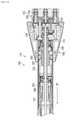
図1は、一般にステープル留め器具10として示される外科用ステープル留め器具を示す。ステープル留め器具10は、円形ステープル留め器具であり、ハンドルアセンブリ20と、ハンドルアセンブリ20から遠位に延在するアダプタアセンブリ100と、アダプタアセンブリ100の遠位部分上で支持されているリロードアセンブリ16と、アダプタアセンブリ100に動作可能に結合されているアンビルアセンブリ50と、ハンドルアセンブリ20内に支持されたコントローラ300(図3A)と、を含む。リロードアセンブリ16は、複数のステープル(図示せず)を含む環状ステープルカートリッジ48を支持する。アンビルアセンブリ50は、ステープル形成ポケット48a(図2B)を画定し、ステープルカートリッジ48に対して開位置とクランプ位置との間で移動可能であるステープル形成面29(図2B)を含むアンビルヘッド28を含む。 FIG. 1 shows a surgical stapler, commonly referred to as a
ハンドルアセンブリ20は、電動アセンブリとして示されており、グリップ22と、リロードアセンブリ16の環状ステープルカートリッジ48からのステープル(図示せず)の発射を制御するための作動ボタン24と、開位置とクランプ位置との間でリロードアセンブリ16に向かう、かつ、そこから離れるアンビルアセンブリ50の軸方向変位を制御するための接近ボタン26a、26bと、を含む。例示的な電動ハンドルアセンブリの構造および機能の詳細な説明については、米国特許出願公開第2020/0015820号および同第2019/0343517号を参照することができる。本開示は、動力アセンブリを示しているが、以下で詳細に説明するように、本開示の利点は、ロボットで作動する手術器具にも適用可能であることが想定されている。 The
ハンドルアセンブリ20は、主ねじ125に加えられたひずみを測定するように構成されたひずみゲージ51(図2B)を含む電気アセンブリを含み得、これはまた、ステープル「S」がアンビルアセンブリ50に対してリロードアセンブリ16のステープルカートリッジ48から発射されるときのステープル形成に起因する、ステープル留め器具10のモータ(例えば、図2Cのモータ152、154、156)の機械的負荷も示す。 The
図2Aは、アダプタアセンブリ100が、ステープル留め器具10の様々な機能(例えば、クランプ、ステープル留め、および/または組織の切断)を制御するためにハンドルアセンブリ20に結合されたときに、ハンドルアセンブリ20(図1)内で支持されるモータ152、154、156(図2C)の駆動シャフト152a、154a、156aに結合された第1の駆動シャフト106、第2の駆動シャフト108、および第3の駆動シャフト110を含むアダプタアセンブリ100を示す。アダプタアセンブリ100内の駆動シャフト106は、ギアによって駆動アセンブリ114に結合されて、ステープルカートリッジ48に対して開位置とクランプ位置との間のアンビルアセンブリ50の移動を制御する。アダプタアセンブリ100の駆動シャフト108は、ギアによって駆動アセンブリ119に結合されて、リロードアセンブリ16(図1)内のプッシャアセンブリ61(図2B)の移動を制御して、ステープルカートリッジ48(図1)からのステープルの発射を制御する。アダプタアセンブリ100の駆動シャフト110は、組織の切断を制御するためにギアによって駆動アセンブリ116に結合されている。駆動アセンブリ114、116、119(図2A)の各々は、本明細書では詳細に説明されていないねじおよびナットを含み、ナットは、ねじに対して駆動されて、ねじの長手方向の移動をもたらす。 FIG. 2A shows the
図1は、アダプタアセンブリ100の外管122の遠位部分上で支持され、ステープルカートリッジ48を支持するシェルハウジング46を含むリロードアセンブリ16を示す。本開示の態様では、ステープルカートリッジ48は、ステープルSを受容するステープル受容ポケット48aの環状列を画定する。本開示のいくつかの態様では、リロードアセンブリ16は、管状シャフト(図示せず)の遠位部分に解放可能に結合されており、各使用後に環状ステープルカートリッジ48の交換を容易にして、外科用器具10の再使用を促進する。電動ハンドルアセンブリおよび解放可能なアダプタアセンブリの例示的な態様の詳細な説明については、米国特許第10,085,744号を参照することができる。 FIG. 1 shows a reload
ステープルカートリッジ48のステープル受容ポケット48a(図2B)の各々は、ハンドルアセンブリ20の作動ボタン24の作動を介してステープルカートリッジ48から発射することができるステープル(図示せず)を支持する。リロードアセンブリ16のシェルハウジング46は、環状空洞60を画定する。環状空洞60は、駆動アセンブリ119(図2A)および駆動アセンブリ116(図2A)のナイフドライバナット264にそれぞれ結合されたステープルプッシャ61(図2B)および環状ナイフ62を支持しており、その結果、ステープルプッシャ61および環状ナイフ62は、ステープルカートリッジ48からステープル「S」を排出し、ステープルカートリッジ48によって画定された環内に位置付けられた組織を切裂または切断するようにステープルカートリッジ48に対して移動可能である。ステープル「S」がステープルカートリッジ48から発射されたときに、ステープル「S」は、アンビルアセンブリ50のアンビルヘッド28のステープル形成面29のステープル形成ポケット29a(図2B)内に駆動され、その中に形成される。 Each of the
上記のように、第1、第2、および第3のシャフトは、ギアアセンブリ(図示せず)によってハンドルアセンブリ20内のモータ152、154、156(図2C)に結合されたモータシャフト152a、154a、156aによって動力ハンドルアセンブリ20に結合されているアダプタアセンブリ100の106、108、および110である。モータ152、154、156によるモータシャフト152a、154a、156aの回転は、コントローラ300によって制御されており、その結果、モータ152、154、156は、シャフト106、108、および110を駆動移動して、駆動アセンブリ114、駆動アセンブリ119、および駆動アセンブリ116を所定のストロークで移動させ、ステープルカートリッジ48に対してアンビルアセンブリ50を開位置からクランプ位置に移動させて、アンビルアセンブリ50とステープルカートリッジ48との間に所定の組織ギャップを画定し、シェルハウジング46内のプッシャ61を進めて、ステープルカートリッジ48からステープル「S」を排出し、シェルハウジング46内のナイフ搬送体(図示せず)を進めて組織を切断する。所定のストロークは、ハンドルアセンブリ20内のモータ駆動シャフト152a、154a、156aの回転位置に基づいて基準位置から計算される。 As described above, the first, second, and third shafts are
駆動アセンブリ119(図2A)は、ステープル主ねじ253およびステープルドライバナット254を含み、ステープルドライバナット254は、ステープル主ねじ253に対して駆動されて、ステープル主ねじ253の長手方向の移動をもたらす。駆動アセンブリ116(図2A)は、ナイフ主ねじ263およびナイフドライバナット264を含み、ナイフドライバナット264は、ナイフ主ねじ263に対して駆動されて、ナイフ主ねじ263の長手方向の移動をもたらす。 The drive assembly 119 (FIG. 2A) includes a staple
外科用ステープル留め器具10が発射されたときに、ステープル脚部504(図5Aおよび図5B)は、アンビルアセンブリ50のそれぞれのステープル形成ポケット48a(図2B)に画定された凹部(図示せず)内に受容される。ステープル脚部504が凹部内に移動したときに、脚部504は、ステープル形成ポケット48a(図2B)のステープル形成面(図示せず)と係合し、形成される。 When the
ハンドルアセンブリ20は、コントローラ300(図3A)と通信し、かつ、アンビルアセンブリ50とステープルカートリッジ48との間に組織がクランプされたことに起因する外科用ステープル留め器具10のモータへの負荷を決定するように構成されているひずみゲージ51(図2B)などのセンサを含み得る。この決定は、アンビルアセンブリ50とステープルカートリッジ48との間にクランプされている組織への圧縮力を決定するために使用される。 The
図3Aは、本開示による、コンピュータ可読記憶媒体またはメモリ330に接続されているプロセッサ320を含むコントローラ300を示す。コンピュータ可読ストレージ媒体またはメモリ330は、揮発性タイプのメモリ、例えば、RAM、または不揮発性タイプのメモリ、例えば、フラッシュ媒体、ディスク媒体などであってもよい。本開示の様々な態様において、プロセッサ320は、限定しないが、デジタル信号プロセッサ、マイクロプロセッサ、ASIC、グラフィックス処理ユニット(GPU)、フィールドプログラマブルゲートアレイ(FPGA)、または中央処理ユニット(CPU)などの別のタイプのプロセッサであってもよい。本開示の特定の態様では、ネットワーク推論もまた、プロセッサとは対照的に、メモリスタとして、化学的に、または他の推論計算として実装される重みを有するシステム内で達成されてもよい。 FIG. 3A shows a
本開示の態様では、メモリ330は、ランダムアクセスメモリ、読み取り専用メモリ、磁気ディスクメモリ、固体メモリ、光学的ディスクメモリ、および/または別のタイプのメモリであり得る。本開示のいくつかの態様では、メモリ330は、コントローラ300とは別個とすることができ、回路基板の通信バスを通して、かつ/またはシリアルATAケーブルもしくは他のタイプのケーブルなどの通信ケーブルを通して、プロセッサ320と通信することができる。メモリ330は、コントローラ300を動作させるためにプロセッサ320によって実行可能である、コンピュータ可読命令を含む。メモリ330は、ハンドルアセンブリ20を動作させるためのソフトウェア命令を含む、データを記憶するように構成された揮発性(例えば、RAM)および不揮発性記憶装置を含み得る。本開示の他の態様では、コントローラ300は、他のコンピュータまたはサーバと通信するためのネットワークインターフェース340を含んでもよい。データを記憶するために、記憶装置310が使用されてもよい。 In aspects of the present disclosure, the
本開示の態様では、ひずみゲージ51(図2B)は、プロセッサに結合されており、開示された方法では、コントローラ300上で、または、例えば、モバイル装置、IoT装置、もしくはサーバシステム上を含め、ユーザ装置上で実行される。 In aspects of the present disclosure, the strain gauge 51 (FIG. 2B) is coupled to a processor and, in the disclosed method, includes on the
図3Bを参照すると、ハンドルアセンブリ20、アダプタアセンブリ200、およびリロードアセンブリ16の概略図が示されている。簡潔にするために、モータ152、154、156のうちの1つ、すなわちモータ152のみが示される。モータ152は、バッテリ144に結合される。実施形態では、モータ152は、AC/DC変圧器などの、モータ152に電気エネルギーを提供するように構成された任意の好適な電源に結合され得る。 Referring to FIG. 3B, schematic views of the
バッテリ144およびモータ152は、バッテリ144からモータ152への電気エネルギーの流れを含むモータ152の動作を制御するモータコントローラ143を有するモータコントローラ回路基板142aに結合される。メインコントローラ300(図3A)は、ハンドルアセンブリ20を制御する。モータコントローラ143は、モータ152およびバッテリ144の動作状態を測定するように構成された複数のセンサ408a、408b、…408nを含む。センサ408a~nは、電圧センサ、電流センサ、温度センサ、遠隔測定センサ、光学センサ、およびそれらの組み合わせを含み得る。センサ408a~408nは、バッテリ144によって供給される電気エネルギーの電圧、電流、および他の電気的特性を測定することができる。センサ408a~408nはまた、モータ152の角速度(例えば、回転速度)を、毎分回転数(RPM)、トルク、温度、電流引き込み、および他の動作特性として測定することができる。角速度は、モータ152、またはそれに結合され、かつ、モータ152によって回転可能な駆動シャフト106、108、110(図2A)の回転を測定することによって決定することができる。また、様々な軸方向に移動可能な駆動シャフトの位置は、シャフト内またはシャフトの近傍に配設された様々な線形センサを使用して決定してもよいし、またはRPM測定から推定してもよい。態様では、トルクは、一定のRPMにおいてモータ152の安定化電流引き込みに基づいて計算することができる。さらなる態様では、モータコントローラ143および/またはメインコントローラ300は、時間を測定し、積分および/または微分を含む時間の関数として上記の値を処理して、例えば、測定値の変化率を決定してもよい。メインコントローラ300はまた、モータ152、154、および156の回転をカウントすることによって、円形アダプタアセンブリ200および/またはリロードアセンブリ16の様々な構成要素の移動距離を決定するように構成されている。 The
モータコントローラ143は、モータコントローラ143とインターフェースで接続するための複数の入力および出力を含むメインコントローラ300に結合されている。具体的には、メインコントローラ300は、モータコントローラ143から、モータ152およびバッテリ144の動作状態に関する測定されたセンサ信号を受信し、次いで、モータコントローラ143に制御信号を出力して、以下で詳細に説明するセンサ測定値および特定のアルゴリズム命令に基づいて、モータ152の動作を制御する。メインコントローラ300はまた、ユーザインターフェース(例えば、メインコントローラ300に結合されたスイッチ、ボタン、タッチスクリーンなど)からの複数のユーザ入力を受信するように構成されている。 The
メインコントローラ300はまた、有線または無線接続を使用して円形アダプタアセンブリ200のひずみゲージ51に結合され、かつ、ハンドルアセンブリ20の動作中に使用されるひずみゲージ51からひずみ測定値を受信するように構成されている。 The
リロードアセンブリ16は、記憶装置405(例えば、チップ464c)を含む。アダプタアセンブリ200はまた、記憶装置407を含む。記憶装置405および407は、リロードアセンブリ16および円形アダプタアセンブリ200に関する任意のデータを記憶するように構成された不揮発性記憶媒体(例えば、EEPROM)を含み、任意のデータには、使用回数、識別情報、モデル番号、シリアル番号、ステープルサイズ、ストローク長、最大作動力、最小作動力、工場較正データなどを含むが、これらに限定されない。態様では、データは、暗号化されてもよく、適切なキーを有する装置(例えば、メインコントローラ300)によってのみ復号可能である。データはまた、円形アダプタアセンブリ200および/またはリロードアセンブリ16を認証するためにメインコントローラ300によって使用され得る。記憶装置405および407は、読み取り専用モードまたは読み取り/書き込みモードで構成されてもよく、これにより、メインコントローラ300が、記憶装置405および407にデータを読み書きすることが可能になる。 The reload
図4は、電流または力の限界が測定されたときに機能的に閉じたステープル形成が達成されたかどうかを判定するための外科用ステープル留め器具10を制御するためのコンピュータによる実施方法400の流れ図を示す。開示された外科用ステープル留め器具10を使用して端から端までの吻合を形成する方法は、組織のクランプおよび外科用ステープル留め器具10による組織へのステープル「S」の発射を含む。ステープル発射段階中、モータ154は、シャフト108を駆動して、駆動アセンブリ119を所定のストロークで(例えば、第1の位置から第2の位置まで)移動して、シェルハウジング46内のプッシャ61を進めて、ステープルカートリッジ48からステープル「S」を排出する(ステップ402)。 FIG. 4 is a flow chart of a
プッシャ61がアンビルアセンブリ50に対して移動すると、コントローラ300は、プッシャ61が所定の第2の位置に到達する前にアンビルアセンブリ50に向かって進むのを停止したと判断した場合(ステップ404)、ステープルカートリッジ48とアンビルアセンブリ50との間にクランプされたステープル「S」上のステープル圧縮力が測定される(ステップ406)。上述のように、アンビルアセンブリ50と、リロードアセンブリ16(図1)内のプッシャ61との間にクランプされたステープル「S」のステープル力は、コントローラ300と通信するひずみゲージ51を使用して測定することができる。あるいは、他の力測定装置またはひずみ測定装置を使用して、アンビルアセンブリ50とプッシャ61との間にクランプされたステープルのクランプ圧力を測定してもよい。様々な態様では、モータ154の電流引き込みは、ステープル圧縮力を示すためにコントローラ300によって使用され得る。 If the
コントローラ300は、ステープル圧縮力が所定の許容範囲外にあるかどうかを判定する(ステップ408)。例えば、ステープル圧縮力は、ステープル形成中に測定された力の範囲を超えて急上昇する場合がある。 The
ステープルにかかる圧縮力が所定の許容可能な圧縮範囲内にある場合、外科用ステープル留め器具10は、組織切断モードに入り、外科医が組織を切断して処置を完了することを可能にする(ステップ410)。態様では、所定の許容可能なステープル圧縮範囲は、治療されている組織のタイプに応じて変化し得、器具10またはユーザによって自動的に設定され得る。様々な態様では、所定の許容可能なステープル圧縮範囲は、異なるリロード、異なるステープル高さ、および/または異なるタイプの外科用ステープラの使用に基づいてもよい。 If the compressive force applied to the staples is within a predetermined acceptable compression range, the
圧縮力が所定の許容可能な圧縮範囲よりも大きい場合、プッシャ61は引っ込められ、外科用ステープル留め器具10は発射モードを終了する(ステップ412)。本開示のいくつかの態様では、コントローラは、外科医に、組織に対する圧縮力が所定の圧縮範囲内にないという警報を出すために、例えば、外科用ステープル留め器具のハンドルアセンブリに配設されたディスプレイ146(図1)上に警告を提供してもよく、その結果、外科医が外科用ステープル留め器具10を組織上に再位置決めすることができる。いくつかの態様では、警告は、音声警報、例えば、手術部位を検査するためのビープ音または言語による警告であってもよい。 If the compressive force is greater than a predetermined acceptable compression range, the
本開示は、電動外科用ステープル留め器具を対象とするが、本開示の原理は、手動によるステープル留め器具に適用可能であると想定される。例えば、ステープル留め器具が所定の許容可能な組織ギャップ範囲を通って移動すると、ステープル留め器具のアンビルアセンブリとステープルカートリッジとの間にクランプされた組織に対するクランプ圧力を測定することができる。このようなデバイスでは、ライトなどのインジケータを器具に提供することができる。組織のクランプ圧力が、所定の許容可能なギャップ範囲内で器具を用いて所定の許容可能な圧縮範囲に入るときに、インジケータを作動させて、器具は発射する準備ができていることを外科医に通知することができる。 Although the present disclosure is intended for electrosurgical staple fasteners, it is assumed that the principles of the present disclosure are applicable to manual staple fasteners. For example, as the staple fastener moves through a predetermined acceptable tissue gap range, the clamping pressure on the tissue clamped between the anvil assembly of the staple fastener and the staple cartridge can be measured. In such devices, indicators such as lights can be provided to the appliance. When the tissue clamping pressure falls within a given acceptable gap range with the instrument and within a given acceptable compression range, activate the indicator to inform the surgeon that the instrument is ready to fire. You can be notified.
本開示の態様は、円形ステープル留め器具に関連付けられて図示されているが、線形ステープル留めデバイス、血管シーリングデバイス、および組織部分を一緒に接合するための他のデバイスを含む他のタイプのステープル留め器具に等しく適用可能であることが想定される。 Aspects of the present disclosure are illustrated in association with a circular staple fastening device, but other types of staple fastening including linear staple fastening devices, vascular sealing devices, and other devices for joining tissue portions together. It is assumed that it is equally applicable to appliances.
当業者は、方法500の1つ以上の動作が、本開示の範囲から逸脱することなく、異なる順序で実施され、繰り返され、かつ/または省略されてもよいことを認識するであろう。様々な態様では、図示される方法400は、コントローラ300(図3A)において、リモート装置において、または別のサーバもしくはシステムにおいて動作させることができる。他の変形例も、本開示の範囲内にあると想到される。方法400の動作は、コントローラ、例えば、外科用ステープル留め器具10(図3A)のコントローラ300(図3A)に関して記載されるが、図示される動作も同様に、他のシステムおよびその構成要素に適用可能であることが理解されるであろう。 One of ordinary skill in the art will recognize that one or more operations of Method 500 may be performed, repeated, and / or omitted in different order without departing from the scope of the present disclosure. In various embodiments, the illustrated
当業者であれば、本明細書において具体的に説明され、添付の図面に図示される器具および方法が非限定的であることを理解するであろう。本開示の範囲を逸脱することなく、本要素および特徴を、別の要素および特徴と組み合わせ得ることが想定される。同様に、当業者であれば、本開示のさらなる特徴および利点を理解するであろう。 Those skilled in the art will appreciate that the instruments and methods specifically described herein and illustrated in the accompanying drawings are non-limiting. It is envisioned that this element and feature may be combined with another element and feature without departing from the scope of the present disclosure. Similarly, one of ordinary skill in the art will understand the additional features and advantages of the present disclosure.
Claims (20)
Translated fromJapaneseプッシャを前記外科用ステープル留め器具のアンビルアセンブリに向かって第1の位置から第2の位置まで進めることであって、前記プッシャが、前記外科用ステープル留め器具のステープルカートリッジからステープルを排出するように構成されている、進めることと、
前記プッシャが、前記第2の位置に先立って前記アンビルアセンブリに向かって進めるのを停止したかどうかを判定することと、
前記プッシャによって前記ステープルカートリッジから排出されたステープルのステープル圧縮力を測定することと、
前記ステープル圧縮力が、所定の範囲外であるかどうかを判定することと、を含む、方法。A computerized method for controlling surgical staples.
The pusher is advanced from a first position to a second position towards the anvil assembly of the surgical staple fastener so that the pusher ejects the staple from the staple cartridge of the surgical staple fastener. It is composed, to proceed, and
Determining whether the pusher has stopped advancing towards the anvil assembly prior to the second position.
Measuring the staple compressive force of the staple discharged from the staple cartridge by the pusher, and
A method comprising determining whether the staple compressive force is outside a predetermined range.
アンビルヘッド、および前記アンビルヘッドから近位に延在するアンビルセンタロッドを含むアンビルアセンブリと、
プッシャ、および複数のステープルを含む環状ステープルカートリッジを含むリロードアセンブリであって、前記プッシャが、前記環状ステープルカートリッジからステープルを排出するように構成されている、リロードアセンブリと、
プロセッサと、
記憶された命令を含むメモリであって、前記命令は、実行されたときに、前記外科用ステープル留め器具に、
前記プッシャを前記アンビルアセンブリに向かって第1の位置から第2の位置まで進めることと、
前記プッシャが、前記第2の位置に先立って前記アンビルアセンブリに向かって進むのを停止したかどうかを判定することと、
前記プッシャが前記アンビルアセンブリに向かって進むのを停止したことに応答して、前記プッシャによって前記環状ステープルカートリッジから排出されたステープルのステープル圧縮力を測定することと、
前記ステープル圧縮力が、所定の範囲外であるかどうかを判定することと、を行わせる、メモリと、を備える、外科用ステープル留め器具。Surgical staple fasteners
An anvil assembly including an anvil head and an anvil center rod extending proximally from the anvil head.
A reload assembly comprising a pusher and an annular staple cartridge comprising a plurality of staples, wherein the pusher is configured to eject staples from the annular staple cartridge.
With the processor
A memory containing stored instructions that, when executed, are attached to the surgical stapler.
To advance the pusher from the first position to the second position toward the anvil assembly,
Determining whether the pusher has stopped advancing towards the anvil assembly prior to the second position.
Measuring the staple compressive force of the staples ejected from the annular staple cartridge by the pushers in response to the pushers stopping advancing towards the anvil assembly.
A surgical staple fastening device comprising a memory for determining whether or not the staple compressive force is out of a predetermined range.
プッシャを前記外科用ステープル留め器具のアンビルアセンブリに向かって第1の位置から第2の位置まで進めることであって、前記プッシャが、前記外科用ステープル留め器具のステープルカートリッジからステープルを排出するように構成されている、進めることと、
前記プッシャが、前記第2の位置に先立って前記アンビルアセンブリに向かって進むのを停止したかどうかを判定することと、
前記プッシャが前記アンビルアセンブリに向かって進むのを停止したことに応答して、前記プッシャによって前記ステープルカートリッジから排出されたステープルのステープル圧縮力を測定することと、
前記ステープル圧縮力が、所定の範囲外であるかどうかを判定することと、を含む、非一時的なコンピュータ可読媒体。A non-temporary computer-readable medium that stores instructions that, when executed by a processor, causes the processor to perform a method for controlling a surgical stapler.
The pusher is advanced from a first position to a second position towards the anvil assembly of the surgical staple fastener so that the pusher ejects the staple from the staple cartridge of the surgical staple fastener. It is composed, to proceed, and
Determining whether the pusher has stopped advancing towards the anvil assembly prior to the second position.
Measuring the staple compressive force of the staples ejected from the staple cartridge by the pushers in response to the pushers stopping advancing towards the anvil assembly.
A non-temporary computer-readable medium, including determining if the staple compressive force is outside a predetermined range.
Applications Claiming Priority (4)
| Application Number | Priority Date | Filing Date | Title |
|---|---|---|---|
| US202063056746P | 2020-07-27 | 2020-07-27 | |
| US63/056,746 | 2020-07-27 | ||
| US17/366,122 | 2021-07-02 | ||
| US17/366,122US20220022878A1 (en) | 2020-07-27 | 2021-07-02 | Systems and methods for controlling a surgical stapling instrument |
Publications (2)
| Publication Number | Publication Date |
|---|---|
| JP2022023820Atrue JP2022023820A (en) | 2022-02-08 |
| JP7737255B2 JP7737255B2 (en) | 2025-09-10 |
Family
ID=77042788
Family Applications (1)
| Application Number | Title | Priority Date | Filing Date |
|---|---|---|---|
| JP2021121225AActiveJP7737255B2 (en) | 2020-07-27 | 2021-07-26 | Systems and methods for controlling a surgical stapling instrument |
Country Status (4)
| Country | Link |
|---|---|
| US (1) | US20220022878A1 (en) |
| EP (1) | EP3944824A1 (en) |
| JP (1) | JP7737255B2 (en) |
| CN (1) | CN113974734A (en) |
Families Citing this family (1)
| Publication number | Priority date | Publication date | Assignee | Title |
|---|---|---|---|---|
| US20220104820A1 (en)* | 2020-10-02 | 2022-04-07 | Ethicon Llc | Surgical instrument with adaptive motor control |
Citations (5)
| Publication number | Priority date | Publication date | Assignee | Title |
|---|---|---|---|---|
| JP2007203073A (en)* | 2006-02-02 | 2007-08-16 | Tyco Healthcare Group Lp | Method and system for determining optimal tissue compression time to implant surgical element |
| JP2011049170A (en)* | 2006-05-19 | 2011-03-10 | Ethicon Endo-Surgery Inc | Pressure switch |
| JP2016514025A (en)* | 2013-03-14 | 2016-05-19 | エシコン・エンド−サージェリィ・インコーポレイテッドEthicon Endo−Surgery,Inc. | Surgical instrument control system |
| JP2018069017A (en)* | 2016-10-31 | 2018-05-10 | ビーエヌアール カンパニー リミテッドBnr Co.,Ltd. | Circular stapler |
| WO2019133140A1 (en)* | 2017-12-28 | 2019-07-04 | Ethicon Llc | Powered stapling device configured to adjust force, advancement speed, and overall stroke of cutting member based on sensed parameter of firing or clamping |
Family Cites Families (35)
| Publication number | Priority date | Publication date | Assignee | Title |
|---|---|---|---|---|
| USH1821H (en)* | 1997-07-02 | 1999-12-07 | Caterpillar, Incorporated | Method and apparatus for operating a driver and an associated number of work tools |
| US8573462B2 (en)* | 2006-05-19 | 2013-11-05 | Ethicon Endo-Surgery, Inc. | Electrical surgical instrument with optimized power supply and drive |
| EP3181063B1 (en)* | 2006-05-19 | 2019-09-11 | Ethicon Endo-Surgery, Inc. | Surgical device |
| US20080255413A1 (en) | 2007-04-13 | 2008-10-16 | Michael Zemlok | Powered surgical instrument |
| US8955732B2 (en)* | 2009-08-11 | 2015-02-17 | Covidien Lp | Surgical stapling apparatus |
| KR102359695B1 (en)* | 2011-02-15 | 2022-02-09 | 인튜어티브 서지컬 오퍼레이션즈 인코포레이티드 | Systems for detecting clamping or firing failure |
| US9649113B2 (en)* | 2011-04-27 | 2017-05-16 | Covidien Lp | Device for monitoring physiological parameters in vivo |
| US8490850B2 (en)* | 2011-04-29 | 2013-07-23 | Covidien Lp | Circular stapler with controlled tissue compression |
| US9220502B2 (en)* | 2011-12-28 | 2015-12-29 | Covidien Lp | Staple formation recognition for a surgical device |
| US9463556B2 (en)* | 2012-03-13 | 2016-10-11 | Hubbell Incorporated | Crimp tool force monitoring device |
| US9468438B2 (en)* | 2013-03-01 | 2016-10-18 | Eticon Endo-Surgery, LLC | Sensor straightened end effector during removal through trocar |
| US10175127B2 (en)* | 2014-05-05 | 2019-01-08 | Covidien Lp | End-effector force measurement drive circuit |
| US9788835B2 (en)* | 2014-09-02 | 2017-10-17 | Ethicon Llc | Devices and methods for facilitating ejection of surgical fasteners from cartridges |
| US10085744B2 (en) | 2014-12-08 | 2018-10-02 | Covidien Lp | Loading unit attachment band for surgical stapling instrument |
| EP3741309A1 (en) | 2015-04-22 | 2020-11-25 | Covidien LP | Handheld electromechanical surgical system |
| US10456137B2 (en)* | 2016-04-15 | 2019-10-29 | Ethicon Llc | Staple formation detection mechanisms |
| US10357247B2 (en)* | 2016-04-15 | 2019-07-23 | Ethicon Llc | Surgical instrument with multiple program responses during a firing motion |
| US20170323578A1 (en)* | 2016-05-04 | 2017-11-09 | Covidien Lp | Systems and methods for simulating prior use of a surgical instrument based on obtained surgical instrument data |
| KR102456430B1 (en)* | 2016-09-09 | 2022-10-19 | 인튜어티브 서지컬 오퍼레이션즈 인코포레이티드 | Stapler reload detection and identification |
| US10945727B2 (en)* | 2016-12-21 | 2021-03-16 | Ethicon Llc | Staple cartridge with deformable driver retention features |
| AU2018202629A1 (en)* | 2017-05-15 | 2018-11-29 | Covidien Lp | Powered surgical stapling device |
| US10932784B2 (en)* | 2017-06-09 | 2021-03-02 | Covidien Lp | Handheld electromechanical surgical system |
| US11045199B2 (en)* | 2017-06-09 | 2021-06-29 | Covidien Lp | Handheld electromechanical surgical system |
| WO2019043507A1 (en)* | 2017-08-29 | 2019-03-07 | Ethicon Llc | Circular stapler |
| US20190059986A1 (en)* | 2017-08-29 | 2019-02-28 | Ethicon Llc | Methods, systems, and devices for controlling electrosurgical tools |
| US10905421B2 (en)* | 2017-08-29 | 2021-02-02 | Ethicon Llc | Electrically-powered surgical box staplers |
| US10905417B2 (en)* | 2017-08-29 | 2021-02-02 | Ethicon Llc | Circular stapler |
| US10912567B2 (en)* | 2017-08-29 | 2021-02-09 | Ethicon Llc | Circular stapler |
| US11109866B2 (en)* | 2017-12-28 | 2021-09-07 | Cilag Gmbh International | Method for circular stapler control algorithm adjustment based on situational awareness |
| US20190200997A1 (en)* | 2017-12-28 | 2019-07-04 | Ethicon Llc | Stapling device with both compulsory and discretionary lockouts based on sensed parameters |
| US11090047B2 (en)* | 2018-03-28 | 2021-08-17 | Cilag Gmbh International | Surgical instrument comprising an adaptive control system |
| JP7539364B2 (en)* | 2018-07-09 | 2024-08-23 | コヴィディエン リミテッド パートナーシップ | Handheld electromechanical surgical system |
| US11185331B2 (en)* | 2019-09-18 | 2021-11-30 | Cilag Gmbh International | Method for controlling end effector closure for powered surgical stapler |
| US11123074B2 (en)* | 2019-09-18 | 2021-09-21 | Cilag Gmbh International | Method for controlling cutting member actuation for powered surgical stapler |
| US11806011B2 (en)* | 2021-03-22 | 2023-11-07 | Cilag Gmbh International | Stapling instrument comprising tissue compression systems |
- 2021
- 2021-07-02USUS17/366,122patent/US20220022878A1/enactivePending
- 2021-07-22CNCN202110830758.8Apatent/CN113974734A/enactivePending
- 2021-07-23EPEP21187342.7Apatent/EP3944824A1/enactivePending
- 2021-07-26JPJP2021121225Apatent/JP7737255B2/enactiveActive
Patent Citations (5)
| Publication number | Priority date | Publication date | Assignee | Title |
|---|---|---|---|---|
| JP2007203073A (en)* | 2006-02-02 | 2007-08-16 | Tyco Healthcare Group Lp | Method and system for determining optimal tissue compression time to implant surgical element |
| JP2011049170A (en)* | 2006-05-19 | 2011-03-10 | Ethicon Endo-Surgery Inc | Pressure switch |
| JP2016514025A (en)* | 2013-03-14 | 2016-05-19 | エシコン・エンド−サージェリィ・インコーポレイテッドEthicon Endo−Surgery,Inc. | Surgical instrument control system |
| JP2018069017A (en)* | 2016-10-31 | 2018-05-10 | ビーエヌアール カンパニー リミテッドBnr Co.,Ltd. | Circular stapler |
| WO2019133140A1 (en)* | 2017-12-28 | 2019-07-04 | Ethicon Llc | Powered stapling device configured to adjust force, advancement speed, and overall stroke of cutting member based on sensed parameter of firing or clamping |
Also Published As
| Publication number | Publication date |
|---|---|
| JP7737255B2 (en) | 2025-09-10 |
| CN113974734A (en) | 2022-01-28 |
| US20220022878A1 (en) | 2022-01-27 |
| EP3944824A1 (en) | 2022-02-02 |
Similar Documents
| Publication | Publication Date | Title |
|---|---|---|
| EP2777518A1 (en) | Powered stapling apparatus | |
| US12161341B2 (en) | Slow speed staple and staple relaxation for stapling optimization | |
| US20250221712A1 (en) | Handheld electromechanical surgical system | |
| US12048434B2 (en) | Systems and methods for suture failure detection during surgical stapling | |
| JP2022023820A (en) | Systems and methods for controlling surgical staple fasteners | |
| JP2024528888A (en) | HANDHELD ELECTROMECHANICAL STAPLER WITH TISSUE THICKNESS DETECTION - Patent application | |
| JP2022019591A (en) | Systems and methods for clamping and stapling to pressure by surgical stapling instrument | |
| JP2024528889A (en) | Handheld electromechanical surgical device with strain gauge drift detection | |
| EP3939521A1 (en) | Handheld electromechanical surgical system | |
| EP4223234A1 (en) | Determination of anvil release during anastomosis | |
| US12213674B2 (en) | Determination of premature staple ejection | |
| EP4561462A1 (en) | Handheld electromechanical surgical system with low tissue compression indication | |
| AU2023313503A1 (en) | Graphic display for powered surgical staplers |
Legal Events
| Date | Code | Title | Description |
|---|---|---|---|
| A621 | Written request for application examination | Free format text:JAPANESE INTERMEDIATE CODE: A621 Effective date:20240626 | |
| A131 | Notification of reasons for refusal | Free format text:JAPANESE INTERMEDIATE CODE: A131 Effective date:20250115 | |
| A977 | Report on retrieval | Free format text:JAPANESE INTERMEDIATE CODE: A971007 Effective date:20250115 | |
| A521 | Request for written amendment filed | Free format text:JAPANESE INTERMEDIATE CODE: A523 Effective date:20250414 | |
| A131 | Notification of reasons for refusal | Free format text:JAPANESE INTERMEDIATE CODE: A131 Effective date:20250507 | |
| A521 | Request for written amendment filed | Free format text:JAPANESE INTERMEDIATE CODE: A523 Effective date:20250730 | |
| TRDD | Decision of grant or rejection written | ||
| A01 | Written decision to grant a patent or to grant a registration (utility model) | Free format text:JAPANESE INTERMEDIATE CODE: A01 Effective date:20250801 | |
| A61 | First payment of annual fees (during grant procedure) | Free format text:JAPANESE INTERMEDIATE CODE: A61 Effective date:20250829 | |
| R150 | Certificate of patent or registration of utility model | Ref document number:7737255 Country of ref document:JP Free format text:JAPANESE INTERMEDIATE CODE: R150 |