JP2022023812A - Systems and methods for suture failure detection during surgical stapling - Google Patents
Systems and methods for suture failure detection during surgical staplingDownload PDFInfo
- Publication number
- JP2022023812A JP2022023812AJP2021119357AJP2021119357AJP2022023812AJP 2022023812 AJP2022023812 AJP 2022023812AJP 2021119357 AJP2021119357 AJP 2021119357AJP 2021119357 AJP2021119357 AJP 2021119357AJP 2022023812 AJP2022023812 AJP 2022023812A
- Authority
- JP
- Japan
- Prior art keywords
- tissue
- compressive force
- force
- anvil assembly
- measured
- Prior art date
- Legal status (The legal status is an assumption and is not a legal conclusion. Google has not performed a legal analysis and makes no representation as to the accuracy of the status listed.)
- Pending
Links
Images


Classifications
- A—HUMAN NECESSITIES
- A61—MEDICAL OR VETERINARY SCIENCE; HYGIENE
- A61B—DIAGNOSIS; SURGERY; IDENTIFICATION
- A61B17/00—Surgical instruments, devices or methods
- A61B17/04—Surgical instruments, devices or methods for suturing wounds; Holders or packages for needles or suture materials
- A61B17/0401—Suture anchors, buttons or pledgets, i.e. means for attaching sutures to bone, cartilage or soft tissue; Instruments for applying or removing suture anchors
- A—HUMAN NECESSITIES
- A61—MEDICAL OR VETERINARY SCIENCE; HYGIENE
- A61B—DIAGNOSIS; SURGERY; IDENTIFICATION
- A61B17/00—Surgical instruments, devices or methods
- A61B17/11—Surgical instruments, devices or methods for performing anastomosis; Buttons for anastomosis
- A61B17/115—Staplers for performing anastomosis, e.g. in a single operation
- A61B17/1155—Circular staplers comprising a plurality of staples
- A—HUMAN NECESSITIES
- A61—MEDICAL OR VETERINARY SCIENCE; HYGIENE
- A61B—DIAGNOSIS; SURGERY; IDENTIFICATION
- A61B17/00—Surgical instruments, devices or methods
- A61B17/04—Surgical instruments, devices or methods for suturing wounds; Holders or packages for needles or suture materials
- A61B17/0482—Needle or suture guides
- A—HUMAN NECESSITIES
- A61—MEDICAL OR VETERINARY SCIENCE; HYGIENE
- A61B—DIAGNOSIS; SURGERY; IDENTIFICATION
- A61B17/00—Surgical instruments, devices or methods
- A61B17/04—Surgical instruments, devices or methods for suturing wounds; Holders or packages for needles or suture materials
- A61B17/0491—Sewing machines for surgery
- A—HUMAN NECESSITIES
- A61—MEDICAL OR VETERINARY SCIENCE; HYGIENE
- A61B—DIAGNOSIS; SURGERY; IDENTIFICATION
- A61B17/00—Surgical instruments, devices or methods
- A61B17/068—Surgical staplers, e.g. containing multiple staples or clamps
- A61B17/072—Surgical staplers, e.g. containing multiple staples or clamps for applying a row of staples in a single action, e.g. the staples being applied simultaneously
- A—HUMAN NECESSITIES
- A61—MEDICAL OR VETERINARY SCIENCE; HYGIENE
- A61B—DIAGNOSIS; SURGERY; IDENTIFICATION
- A61B90/00—Instruments, implements or accessories specially adapted for surgery or diagnosis and not covered by any of the groups A61B1/00 - A61B50/00, e.g. for luxation treatment or for protecting wound edges
- A61B90/06—Measuring instruments not otherwise provided for
- A—HUMAN NECESSITIES
- A61—MEDICAL OR VETERINARY SCIENCE; HYGIENE
- A61B—DIAGNOSIS; SURGERY; IDENTIFICATION
- A61B90/00—Instruments, implements or accessories specially adapted for surgery or diagnosis and not covered by any of the groups A61B1/00 - A61B50/00, e.g. for luxation treatment or for protecting wound edges
- A61B90/08—Accessories or related features not otherwise provided for
- A—HUMAN NECESSITIES
- A61—MEDICAL OR VETERINARY SCIENCE; HYGIENE
- A61B—DIAGNOSIS; SURGERY; IDENTIFICATION
- A61B17/00—Surgical instruments, devices or methods
- A61B2017/00017—Electrical control of surgical instruments
- A—HUMAN NECESSITIES
- A61—MEDICAL OR VETERINARY SCIENCE; HYGIENE
- A61B—DIAGNOSIS; SURGERY; IDENTIFICATION
- A61B17/00—Surgical instruments, devices or methods
- A61B2017/00017—Electrical control of surgical instruments
- A61B2017/00115—Electrical control of surgical instruments with audible or visual output
- A61B2017/00119—Electrical control of surgical instruments with audible or visual output alarm; indicating an abnormal situation
- A—HUMAN NECESSITIES
- A61—MEDICAL OR VETERINARY SCIENCE; HYGIENE
- A61B—DIAGNOSIS; SURGERY; IDENTIFICATION
- A61B17/00—Surgical instruments, devices or methods
- A61B2017/00367—Details of actuation of instruments, e.g. relations between pushing buttons, or the like, and activation of the tool, working tip, or the like
- A61B2017/00398—Details of actuation of instruments, e.g. relations between pushing buttons, or the like, and activation of the tool, working tip, or the like using powered actuators, e.g. stepper motors, solenoids
- A—HUMAN NECESSITIES
- A61—MEDICAL OR VETERINARY SCIENCE; HYGIENE
- A61B—DIAGNOSIS; SURGERY; IDENTIFICATION
- A61B17/00—Surgical instruments, devices or methods
- A61B2017/00681—Aspects not otherwise provided for
- A61B2017/00734—Aspects not otherwise provided for battery operated
- A—HUMAN NECESSITIES
- A61—MEDICAL OR VETERINARY SCIENCE; HYGIENE
- A61B—DIAGNOSIS; SURGERY; IDENTIFICATION
- A61B17/00—Surgical instruments, devices or methods
- A61B17/04—Surgical instruments, devices or methods for suturing wounds; Holders or packages for needles or suture materials
- A61B17/0401—Suture anchors, buttons or pledgets, i.e. means for attaching sutures to bone, cartilage or soft tissue; Instruments for applying or removing suture anchors
- A61B2017/0409—Instruments for applying suture anchors
- A—HUMAN NECESSITIES
- A61—MEDICAL OR VETERINARY SCIENCE; HYGIENE
- A61B—DIAGNOSIS; SURGERY; IDENTIFICATION
- A61B17/00—Surgical instruments, devices or methods
- A61B17/068—Surgical staplers, e.g. containing multiple staples or clamps
- A61B17/072—Surgical staplers, e.g. containing multiple staples or clamps for applying a row of staples in a single action, e.g. the staples being applied simultaneously
- A61B2017/07214—Stapler heads
- A61B2017/07257—Stapler heads characterised by its anvil
- A—HUMAN NECESSITIES
- A61—MEDICAL OR VETERINARY SCIENCE; HYGIENE
- A61B—DIAGNOSIS; SURGERY; IDENTIFICATION
- A61B17/00—Surgical instruments, devices or methods
- A61B17/068—Surgical staplers, e.g. containing multiple staples or clamps
- A61B17/072—Surgical staplers, e.g. containing multiple staples or clamps for applying a row of staples in a single action, e.g. the staples being applied simultaneously
- A61B2017/07214—Stapler heads
- A61B2017/07271—Stapler heads characterised by its cartridge
- A—HUMAN NECESSITIES
- A61—MEDICAL OR VETERINARY SCIENCE; HYGIENE
- A61B—DIAGNOSIS; SURGERY; IDENTIFICATION
- A61B17/00—Surgical instruments, devices or methods
- A61B17/068—Surgical staplers, e.g. containing multiple staples or clamps
- A61B17/072—Surgical staplers, e.g. containing multiple staples or clamps for applying a row of staples in a single action, e.g. the staples being applied simultaneously
- A61B2017/07214—Stapler heads
- A61B2017/07278—Stapler heads characterised by its sled or its staple holder
- A—HUMAN NECESSITIES
- A61—MEDICAL OR VETERINARY SCIENCE; HYGIENE
- A61B—DIAGNOSIS; SURGERY; IDENTIFICATION
- A61B17/00—Surgical instruments, devices or methods
- A61B17/068—Surgical staplers, e.g. containing multiple staples or clamps
- A61B17/072—Surgical staplers, e.g. containing multiple staples or clamps for applying a row of staples in a single action, e.g. the staples being applied simultaneously
- A61B2017/07214—Stapler heads
- A61B2017/07285—Stapler heads characterised by its cutter
- A—HUMAN NECESSITIES
- A61—MEDICAL OR VETERINARY SCIENCE; HYGIENE
- A61B—DIAGNOSIS; SURGERY; IDENTIFICATION
- A61B17/00—Surgical instruments, devices or methods
- A61B17/11—Surgical instruments, devices or methods for performing anastomosis; Buttons for anastomosis
- A61B2017/1142—Purse-string sutures
- A—HUMAN NECESSITIES
- A61—MEDICAL OR VETERINARY SCIENCE; HYGIENE
- A61B—DIAGNOSIS; SURGERY; IDENTIFICATION
- A61B90/00—Instruments, implements or accessories specially adapted for surgery or diagnosis and not covered by any of the groups A61B1/00 - A61B50/00, e.g. for luxation treatment or for protecting wound edges
- A61B90/06—Measuring instruments not otherwise provided for
- A61B2090/064—Measuring instruments not otherwise provided for for measuring force, pressure or mechanical tension
- A61B2090/065—Measuring instruments not otherwise provided for for measuring force, pressure or mechanical tension for measuring contact or contact pressure
- A—HUMAN NECESSITIES
- A61—MEDICAL OR VETERINARY SCIENCE; HYGIENE
- A61B—DIAGNOSIS; SURGERY; IDENTIFICATION
- A61B90/00—Instruments, implements or accessories specially adapted for surgery or diagnosis and not covered by any of the groups A61B1/00 - A61B50/00, e.g. for luxation treatment or for protecting wound edges
- A61B90/08—Accessories or related features not otherwise provided for
- A61B2090/0807—Indication means
- A61B2090/0809—Indication of cracks or breakages
- A—HUMAN NECESSITIES
- A61—MEDICAL OR VETERINARY SCIENCE; HYGIENE
- A61B—DIAGNOSIS; SURGERY; IDENTIFICATION
- A61B2562/00—Details of sensors; Constructional details of sensor housings or probes; Accessories for sensors
- A61B2562/02—Details of sensors specially adapted for in-vivo measurements
- A61B2562/0261—Strain gauges
Landscapes
- Health & Medical Sciences (AREA)
- Surgery (AREA)
- Life Sciences & Earth Sciences (AREA)
- Heart & Thoracic Surgery (AREA)
- Molecular Biology (AREA)
- Veterinary Medicine (AREA)
- Engineering & Computer Science (AREA)
- Biomedical Technology (AREA)
- Nuclear Medicine, Radiotherapy & Molecular Imaging (AREA)
- Medical Informatics (AREA)
- Public Health (AREA)
- Animal Behavior & Ethology (AREA)
- General Health & Medical Sciences (AREA)
- Pathology (AREA)
- Oral & Maxillofacial Surgery (AREA)
- Rheumatology (AREA)
- Surgical Instruments (AREA)
Abstract
Description
Translated fromJapanese関連出願の相互参照
本出願は、2020年7月27日に出願された米国仮特許出願第63/056,765号の利益および優先権を主張し、その内容全体が、参照により、本明細書によって組み込まれる。Cross-reference to related applications This application claims the interests and priorities of US Provisional Patent Application No. 63 / 056,765 filed July 27, 2020, the entire contents of which are hereby referred to herein. Incorporated by.
本開示は、概して、電動外科用ステープル留め器具、より具体的には、縫合不全を検出することに基づいて外科用ステープル留め器具を制御するための方法に関し、かつ方法を実施するための外科用ステープル留め器具に関する。 The present disclosure relates, and more specifically, to methods for controlling surgical staples based on the detection of suture insufficiency, and more specifically, surgically to implement the method. Regarding staple fasteners.
吻合は、別々の中空臓器部分を外科的に接合することである。典型的に、吻合処置は、臓器の罹患または欠陥のある部分が除去され、臓器の残りの端部部分が外科用ステープル留め器具を介して接合される手術に続く。所望の吻合処置に応じて、残りの端部部分は、例えば、円形または側部から側部への臓器再建法によって接合され得る。 Anastomosis is the surgical joining of separate hollow organ parts. Anastomotic procedures typically follow surgery in which the affected or defective part of the organ is removed and the remaining ends of the organ are joined via surgical staples. Depending on the desired anastomotic procedure, the remaining end portions may be joined, for example, by circular or side-to-side organ reconstruction methods.
円形吻合処置では、臓器の残りの端部部分が、残りの端部部分を介してステープルの円形アレイを駆動し、同時に臓器内の管状通路を解放するように駆動されたステープルの円形アレイの任意の組織内部をくり抜く外科用ステープル留め器具によって接合される。処置中、吻合の完全性を高め、漏出を防止するのを助けるために、巾着縫合糸を外科用ステープル留め器具の片側または両側の周りに結ぶことができる。場合によっては、外科医の技術または組織の特性のいずれかにより、外科用ステープル留め器具による組織のクランプ中に巾着縫合糸が不全である可能性がある。巾着縫合が不全であると、組織ドーナツ全体がデバイスに捕捉されずに漏出し得るか、または不完全なドーナツが形成され得る。 In a circular anastomosis procedure, the remaining end of the organ drives a circular array of staples through the remaining ends, while at the same time any of the circular arrays of staples driven to open the tubular passages within the organ. It is joined by a surgical staple fastener that hollows out the inside of the tissue. During the procedure, drawstring sutures can be tied around one or both sides of the surgical staple fastener to enhance the integrity of the anastomosis and help prevent leakage. In some cases, either the surgeon's technique or the characteristics of the tissue, the drawstring suture may be incomplete during clamping of the tissue with a surgical staple fastener. If the drawstring suture is inadequate, the entire tissue donut can leak out without being captured by the device, or an incomplete donut can be formed.
組織のクランプ中に巾着縫合がいつ不全であるかを判定することができるステープル留め器具に対する継続的な必要性が存在する。 There is a continuing need for staple fasteners that can determine when a drawstring suture is incomplete during tissue clamping.
本開示によれば、組織をステープル留めするための外科的ステープル留め器具を制御するためのコンピュータ実装方法は、ステープルカートリッジとアンビルアセンブリとの間の組織ギャップを画定し、それらの間に組織をクランプする、第1の位置まで、ステープルカートリッジに対して、アンビルアセンブリを前進させることであって、クランプされた組織は、内部を通る縫合を含む、前進させることと、第1の時点で、アンビルアセンブリを用いて、組織ギャップ内にクランプされた組織の第1の組織圧縮力を測定することと、測定された第1の力が所定の閾値より大きいかどうかを判定することと、第1の力が閾値よりも大きいという判定に応答して、第2の時点で組織ギャップ内にクランプされた組織の第2の組織圧縮力を測定することと、測定された第2の組織圧縮力が測定された第1の組織圧縮力よりも小さい所定量であることに基づいて、縫合が不全となったかどうかを判定することと、判定された縫合不全に基づいて、アンビルアセンブリの前進を停止することと、を含む。 According to the present disclosure, a computer mounting method for controlling a surgical stapling device for stapling tissue defines a tissue gap between the stapling cartridge and the anvil assembly and clamps the tissue between them. To advance the anvil assembly to the staple cartridge to the first position, the clamped tissue, including the suture through the interior, to advance and, at the first point, the anvil assembly. To measure the first tissue compressive force of the tissue clamped in the tissue gap, to determine if the measured first force is greater than a predetermined threshold, and to use the first force. In response to the determination that is greater than the threshold, the second tissue compressive force of the tissue clamped in the tissue gap at the second time point is measured and the measured second tissue compressive force is measured. Determining if the suture has failed based on a predetermined amount less than the first tissue compressive force, and stopping the advance of the anvil assembly based on the determined suture failure. ,including.
一態様では、第1の組織圧縮力および第2の組織圧縮力は、ひずみゲージによって測定され得る。 In one aspect, the first tissue compressive force and the second tissue compressive force can be measured by strain gauges.
別の態様では、縫合が不全となったかどうかを判定することは、クランプされた組織に経時的に加えられた力の曲線の形状にさらに基づき得る。 In another aspect, determining whether a suture has failed can be further based on the shape of the curve of force applied over time to the clamped tissue.
さらに別の態様では、方法は、第2の組織圧縮力が第1の組織圧縮力よりも小さいときにステープルの発射を防止することをさらに含み得る。 In yet another aspect, the method may further comprise preventing the staples from firing when the second tissue compressive force is less than the first tissue compressive force.
一態様では、方法は、判定されている縫合不全に応答して警告を表示することをさらに含み得る。 In one aspect, the method may further comprise displaying a warning in response to the determined anastomotic insufficiency.
別の態様では、表示された警告は、手術部位を検査するため、または組織のクランプを解除するための警告のうちの少なくとも1つを含み得る。 In another aspect, the displayed warning may include at least one of the warnings for inspecting the surgical site or for unclamping the tissue.
さらに別の態様では、方法は、縫合不全が判定されたときに音声警告を生成することをさらに含み得る。 In yet another aspect, the method may further comprise generating a voice alert when suture failure is determined.
なおさらに別の態様では、所定の閾値は、所定の組織圧縮許容範囲よりも大きくてもよい。 In yet another embodiment, the predetermined threshold value may be larger than the predetermined tissue compression tolerance.
なおさらに別の態様では、方法は、第1の組織圧縮力と第2の組織圧縮力との間の組織クランプ力の減少を判定することをさらに含み得る。 In yet another aspect, the method may further comprise determining a decrease in the tissue clamping force between the first tissue compressive force and the second tissue compressive force.
なおさらに別の態様では、第1の時点でアンビルアセンブリを用いて組織ギャップ内にクランプされた組織の第1の組織圧縮力を測定することは、アンビルアセンブリがステープルカートリッジの所定の距離範囲内にないときに、第1の組織圧縮力を測定することを含み得る。 In yet another embodiment, measuring the first tissue compressive force of the tissue clamped in the tissue gap using the anvil assembly at the first time means that the anvil assembly is within a predetermined distance range of the staple cartridge. In the absence, it may include measuring the first tissue compressive force.
本開示によれば、外科用ステープル留め器具は、アンビルヘッドおよびアンビルヘッドから近位に延在するアンビルセンターロッドを含むアンビルアセンブリと、複数のステープルを含む環状ステープルカートリッジを含むリロードアセンブリと、プロセッサと、メモリと、を含む。メモリは、その上に記憶された命令であって、プロセッサによって実行されると、外科用ステープル留め器具に、ステープルカートリッジとアンビルアセンブリとの間の組織ギャップを画定し、それらの間に組織をクランプする、第1の位置まで、ステープルカートリッジに対して、アンビルアセンブリを前進させることであって、クランプされた組織は、内部を通る縫合を含む、前進させることと、第1の時点で、アンビルアセンブリを用いて、組織ギャップ内にクランプされた組織の第1の組織圧縮力を測定することと、測定された第1の力が所定の閾値より大きいかどうかを判定することと、第1の力が閾値よりも大きいという判定に応答して、第2の時点で、組織ギャップ内にクランプされた組織の第2の組織圧縮力を測定することと、測定された第2の組織圧縮力が測定された第1の組織圧縮力よりも小さい所定量であることに基づいて、縫合が不全となったかどうかを判定することと、判定された縫合不全に基づいて、アンビルアセンブリの前進を停止することと、を行わせる、命令を含む。 According to the present disclosure, surgical staple fasteners include anvil assemblies that include anvil heads and anvil center rods that extend proximally from the anvil head, reload assemblies that include annular staple cartridges that include multiple staples, and processors. , Memory, and so on. Memory is an instruction stored on it that, when executed by the processor, defines a tissue gap between the suture cartridge and the anvil assembly on the surgical suture fastener and clamps the tissue between them. To advance the anvil assembly to the staple cartridge to a first position, the clamped tissue, including suturing through the interior, to advance and, at the first point, the anvil assembly. To measure the first tissue compressive force of the tissue clamped in the tissue gap, determine if the measured first force is greater than a predetermined threshold, and use the first force. In response to the determination that is greater than the threshold, at a second time point, the second tissue compressive force of the tissue clamped within the tissue gap is measured and the measured second tissue compressive force is measured. Determining if a suture has failed based on a predetermined amount less than the first tissue compressive force applied, and stopping the advance of the anvil assembly based on the determined suture failure. And, including instructions to do.
一態様では、第1の組織圧縮力および第2の組織圧縮力は、ひずみゲージによって測定され得る。 In one aspect, the first tissue compressive force and the second tissue compressive force can be measured by strain gauges.
別の態様では、縫合が不全となったかどうかを判定することは、クランプされた組織に経時的に加えられた力の曲線の形状にさらに基づき得る。 In another aspect, determining whether a suture has failed can be further based on the shape of the curve of force applied over time to the clamped tissue.
さらに別の態様では、命令は、プロセッサによって実行されると、測定された第2の組織圧縮力が第1の組織圧縮力よりも小さいときに、外科用ステープル留め器具にステープルの発射をさらに防止させ得る。 In yet another aspect, when the instruction is executed by the processor, it further prevents the staple from firing on the surgical staple fastener when the measured second tissue compressive force is less than the first tissue compressive force. I can let you.
なおさらに別の態様では、命令は、プロセッサによって実行されると、判定されている縫合不全に応答して、外科用ステープル留め器具に警告をさらに引き起こし得る。 In yet yet another aspect, the instruction, when executed by the processor, may further trigger a warning to the surgical stapler in response to the determined suture failure.
なおさらに別の態様では、表示された警告は、手術部位を検査するため、または組織のクランプを解除するための警告の少なくとも1つを含み得る。 In yet another aspect, the displayed warning may include at least one of the warnings for inspecting the surgical site or for unclamping the tissue.
なおさらに別の態様では、命令は、プロセッサによって実行されると、縫合不全が判定されたときに、外科用ステープル留め器具に音声警告を生成させ得る。 In yet another aspect, the instruction, when executed by the processor, may cause the surgical stapler to generate a voice alert when a suture failure is determined.
なおさらに別の態様では、所定の閾値は、所定の組織圧縮許容範囲よりも大きくてもよい。 In yet another embodiment, the predetermined threshold value may be larger than the predetermined tissue compression tolerance.
別の態様では、命令は、プロセッサによって実行されると、外科用ステープル留め器具に、第1の組織圧縮力と第2の組織圧縮力との間の組織クランプ力の減少をさらに判定させ得る。 In another aspect, the instruction, when executed by the processor, may cause the surgical stapler to further determine a decrease in tissue clamping force between the first tissue compressive force and the second tissue compressive force.
本開示によれば、プロセッサによって実行されると、プロセッサに、外科用ステープル留め器具を制御するための方法であって、ステープルカートリッジとアンビルアセンブリとの間の組織ギャップを画定し、それらの間に組織をクランプする、第1の位置まで、ステープルカートリッジに対して、アンビルアセンブリを前進させることであって、クランプされた組織は、内部を通る縫合糸を含む、前進させることと、第1の時点で、アンビルアセンブリを用いて、組織ギャップ内にクランプされた組織の第1の組織圧縮力を測定することと、測定された第1の力が所定の閾値より大きいかどうかを判定することと、第1の力が所定の閾値よりも大きいという判定に応答して、第2の時点で、組織ギャップ内にクランプされた組織の第2の組織圧縮力を測定することと、測定された第2の組織圧縮力が測定された第1の組織圧縮力よりも小さい所定量であることに基づいて、縫合が不全となったかどうかを判定することと、判定された縫合不全に基づいて、アンビルアセンブリの前進を停止することと、を含む、方法を実施させる命令を記憶する、非一時的コンピュータ可読媒体。
例えば、本願は以下の項目を提供する。
(項目1)
外科用ステープル留め器具を制御するためのコンピュータ実装方法であって、
アンビルアセンブリをステープルカートリッジに対して、上記ステープルカートリッジと上記アンビルアセンブリとの間の組織ギャップを画定し、それらの間に組織をクランプする、第1の位置まで、前進させることであって、上記クランプされた組織は、内部を通る縫合を含む、前進させることと、
第1の時点で、上記アンビルアセンブリを用いて、上記組織ギャップ内にクランプされた上記組織の第1の組織圧縮力を測定することと、
上記測定された第1の力が所定の閾値より大きいかどうかを判定することと、
上記第1の力が上記所定の閾値よりも大きいという上記判定に応答して、第2の時点で、上記組織ギャップ内にクランプされた上記組織の第2の組織圧縮力を測定することと、
上記測定された第2の組織圧縮力が上記測定された第1の組織圧縮力よりも小さい所定量であることに基づいて、上記縫合が不全となったかどうかを判定することと、
上記判定された縫合不全に基づいて、上記アンビルアセンブリの上記前進を停止することと、を含む、コンピュータ実装方法。
(項目2)
上記第1の組織圧縮力および上記第2の組織圧縮力は、ひずみゲージによって測定される、上記項目に記載のコンピュータ実装方法。
(項目3)
上記縫合が不全となったかどうかを判定することは、上記クランプされた組織に経時的に加えられた力の曲線の形状にさらに基づく、上記項目のいずれか一項に記載のコンピュータ実装方法。
(項目4)
上記第2の組織圧縮力が上記第1の組織圧縮力よりも小さいときに、ステープルの発射を防止することをさらに含む、上記項目のいずれか一項に記載のコンピュータ実装方法。
(項目5)
上記判定されている縫合不全に応答して警告を表示することをさらに含む、上記項目のいずれか一項に記載のコンピュータ実装方法。
(項目6)
上記表示された警告は、手術部位を検査するため、または上記組織のクランプを解除するための警告のうちの少なくとも1つを含む、上記項目のいずれか一項に記載のコンピュータ実装方法。
(項目7)
縫合不全が判定されたときに、音声警告を生成することをさらに含む、上記項目のいずれか一項に記載のコンピュータ実装方法。
(項目8)
上記所定の閾値は、所定の組織圧縮許容範囲よりも大きい、上記項目のいずれか一項に記載のコンピュータ実装方法。
(項目9)
上記第1の組織圧縮力と上記第2の組織圧縮力との間の組織クランプ力の減少を判定することをさらに含む、上記項目のいずれか一項に記載のコンピュータ実装方法。
(項目10)
第1の時点で、上記アンビルアセンブリを用いて、上記組織ギャップ内にクランプされた上記組織の上記第1の組織圧縮力を測定することは、上記アンビルアセンブリが上記ステープルカートリッジの所定の距離範囲内にないときに、上記第1の組織圧縮力を測定することを含む、上記項目のいずれか一項に記載のコンピュータ実装方法。
(項目11)
外科用ステープル留め器具であって、
アンビルヘッドおよび上記アンビルヘッドから近位に延在するアンビルセンターロッドを含むアンビルアセンブリと、
複数のステープルを含む環状ステープルカートリッジを含むリロードアセンブリと、
プロセッサと、
メモリであって、その上に記憶された命令であって、上記プロセッサによって実行されると、上記外科用ステープル留め器具に、
上記アンビルアセンブリを上記ステープルカートリッジに対して、上記ステープルカートリッジと上記アンビルアセンブリとの間の組織ギャップを画定し、それらの間に組織をクランプする、第1の位置まで前進させることであって、上記クランプされた組織は、内部を通る縫合を含む、前進させること、
第1の時点で、上記アンビルアセンブリを用いて、上記組織ギャップ内にクランプされた上記組織の第1の組織圧縮力を測定すること、
上記測定された第1の力が所定の閾値より大きいかどうかを判定すること、
上記第1の力が上記所定の閾値よりも大きいという上記判定に応答して、第2の時点で、上記組織ギャップ内にクランプされた上記組織の第2の組織圧縮力を測定すること、
上記測定された第2の組織圧縮力が上記測定された第1の組織圧縮力よりも小さい所定量であることに基づいて、上記縫合が不全となったかどうかを判定すること、および
上記判定された縫合不全に基づいて、上記アンビルアセンブリを上記前進させることを停止すること、を行わせる、命令を含む、メモリと、を備える、外科用ステープル留め器具。
(項目12)
上記第1の組織圧縮力および上記第2の組織圧縮力は、ひずみゲージによって測定される、上記項目のいずれか一項に記載の外科用ステープル留め器具。
(項目13)
上記縫合が不全となったかどうかを判定することは、上記クランプされた組織に経時的に加えられた力の曲線の形状にさらに基づく、上記項目のいずれか一項に記載の外科用ステープル留め器具。
(項目14)
上記命令は、上記プロセッサによって実行されると、上記測定された第2の組織圧縮力が上記第1の組織圧縮力よりも小さいときに、上記外科用ステープル留め器具にステープルの発射をさらに防止させる、上記項目のいずれか一項に記載の外科用ステープル留め器具。
(項目15)
上記命令は、上記プロセッサによって実行されると、上記縫合不全が判定されることに応答して、上記外科用ステープル留め器具に警告をさらに引き起こす、上記項目のいずれか一項に記載の外科用ステープル留め器具。
(項目16)
上記表示された警告は、手術部位を検査するため、または上記組織のクランプを解除するための警告のうちの少なくとも1つを含む、上記項目のいずれか一項に記載の外科用ステープル留め器具。
(項目17)
上記命令は、上記プロセッサによって実行されると、縫合不全が判定されたときに、上記外科用ステープル留め器具に音声警告をさらに生成させる、上記項目のいずれか一項に記載の外科用ステープル留め器具。
(項目18)
上記所定の閾値は、所定の組織圧縮許容範囲よりも大きい、上記項目のいずれか一項に記載の外科用ステープル留め器具。
(項目19)
上記命令は、上記プロセッサによって実行されると、上記外科用ステープル留め器具に、上記第1の組織圧縮力と上記第2の組織圧縮力との間の組織クランプ力の減少をさらに判定させる、上記項目のいずれか一項に記載の外科用ステープル留め器具。
(項目20)
命令を記憶する、非一時的コンピュータ可読媒体であって、上記命令は、プロセッサによって実行されると、上記プロセッサに、外科用ステープル留め器具を制御するための方法を実施させ、上記方法は、
上記ステープルカートリッジと上記アンビルアセンブリとの間の組織ギャップを画定し、それらの間に組織をクランプする、第1の位置まで、ステープルカートリッジに対して、アンビルアセンブリを前進させることであって、し、上記クランプされた組織は、内部を通る縫合を含む、前進させることと、
第1の時点で、上記アンビルアセンブリを用いて、上記組織ギャップ内にクランプされた上記組織の第1の組織圧縮力を測定することと、
上記測定された第1の力が所定の閾値より大きいかどうかを判定することと、
上記第1の力が上記所定の閾値よりも大きいという上記判定に応答して、第2の時点で、上記組織ギャップ内にクランプされた上記組織の第2の組織圧縮力を測定することと、
上記測定された第2の組織圧縮力が上記測定された第1の組織圧縮力よりも小さい所定量であることに基づいて、上記縫合が不全となったかどうかを判定することと、
上記判定された縫合不全に基づいて、上記アンビルアセンブリの上記前進を停止することと、を含む、非一時的コンピュータ可読媒体。
(摘要)
組織をステープル留めするための外科的ステープル留め器具を制御するためのコンピュータ実装方法は、アンビルアセンブリをステープルカートリッジに対して、ステープルカートリッジとアンビルアセンブリとの間の組織ギャップを画定し、組織をクランプする、第1の位置まで、前進させることであって、クランプされた組織は、縫合を含む、前進させることと、第1の時点で、アンビルアセンブリを用いて、組織ギャップ内にクランプされた組織の第1の組織圧縮力を測定することと、測定された第1の力が閾値より大きいかどうかを判定することと、第1の力が閾値よりも大きいという判定に応答して、第2の時点で、組織ギャップ内にクランプされた組織の第2の組織圧縮力を測定することと、測定された第2の力が測定された第1の力よりも小さい量であることに基づいて、縫合が不全であるかどうかを判定することと、判定された縫合不全に基づいて、アンビルアセンブリの前進を停止することと、を含む。According to the present disclosure, when performed by a processor, it is a method for controlling a surgical suture fastener to the processor, defining a tissue gap between the suture cartridge and the anvil assembly and between them. To advance the anvil assembly relative to the staple cartridge to a first position that clamps the tissue, the clamped tissue containing sutures passing through the interior, and the first time point. So, using anvil assembly to measure the first tissue compressive force of the tissue clamped in the tissue gap and to determine if the measured first force is greater than a predetermined threshold. In response to the determination that the first force is greater than a predetermined threshold, at a second time point, measuring the second tissue compressive force of the tissue clamped within the tissue gap and the measured second. Determining if a suture has failed based on a predetermined amount of tissue compressive force less than the measured first tissue compressive force, and anvil assembly based on the determined suture failure. A non-temporary computer-readable medium that stores instructions to implement the method, including stopping the advancement of.
For example, the present application provides the following items.
(Item 1)
A computer mounting method for controlling surgical staple fasteners,
The clamp is to advance the anvil assembly to a first position with respect to the staple cartridge, defining a tissue gap between the staple cartridge and the anvil assembly and clamping the tissue between them. The tissue is advanced, including sutures that pass through the interior.
At the first time point, the anvil assembly is used to measure the first tissue compressive force of the tissue clamped in the tissue gap.
Determining whether the measured first force is greater than a predetermined threshold
In response to the determination that the first force is greater than the predetermined threshold, measuring the second tissue compressive force of the tissue clamped within the tissue gap at a second time point.
Determining whether or not the suture has failed based on a predetermined amount of the measured second tissue compressive force smaller than the measured first tissue compressive force.
A computer mounting method comprising stopping the advance of the anvil assembly based on the determined anastomotic insufficiency.
(Item 2)
The computer mounting method according to the above item, wherein the first tissue compressive force and the second tissue compressive force are measured by a strain gauge.
(Item 3)
The computer mounting method according to any one of the above items, wherein determining whether or not the suture has failed is further based on the shape of the curve of the force applied to the clamped tissue over time.
(Item 4)
The computer mounting method according to any one of the above items, further comprising preventing the firing of staples when the second tissue compressive force is smaller than the first tissue compressive force.
(Item 5)
The computer implementation method according to any one of the above items, further comprising displaying a warning in response to the determined suture failure.
(Item 6)
The computer mounting method according to any one of the above items, wherein the displayed warning comprises at least one of the warnings for inspecting the surgical site or for unclamping the tissue.
(Item 7)
The computer implementation method according to any one of the above items, further comprising generating a voice alert when a suture failure is determined.
(Item 8)
The computer mounting method according to any one of the above items, wherein the predetermined threshold value is larger than a predetermined tissue compression allowable range.
(Item 9)
The computer mounting method according to any one of the above items, further comprising determining a decrease in the tissue clamping force between the first tissue compressive force and the second tissue compressive force.
(Item 10)
At the first time point, using the anvil assembly to measure the first tissue compressive force of the tissue clamped in the tissue gap is such that the anvil assembly is within a predetermined distance range of the staple cartridge. The computer mounting method according to any one of the above items, which comprises measuring the first tissue compressive force when the above item is not present.
(Item 11)
Surgical staple fasteners
An anvil assembly including an anvil head and an anvil center rod extending proximally from the anvil head,
A reload assembly containing an annular staple cartridge containing multiple staples,
With the processor
A memory, an instruction stored on it, and when executed by the processor, to the surgical stapler.
The anvil assembly is advanced relative to the staple cartridge to a first position that defines a tissue gap between the staple cartridge and the anvil assembly and clamps the tissue between them. Clamped tissue, including sutures through the interior, advancing,
At the first time point, using the anvil assembly, measuring the first tissue compressive force of the tissue clamped in the tissue gap,
Determining if the measured first force is greater than a predetermined threshold,
Measuring the second tissue compressive force of the tissue clamped within the tissue gap at a second time point in response to the determination that the first force is greater than the predetermined threshold.
It is determined whether or not the suture is incomplete, and the determination is made, based on the predetermined amount of the measured second tissue compressive force being smaller than the measured first tissue compressive force. A surgical staple fastening device, comprising a memory, including instructions, to stop advancing the anvil assembly based on suture failure.
(Item 12)
The surgical staple fastening device according to any one of the above items, wherein the first tissue compressive force and the second tissue compressive force are measured by a strain gauge.
(Item 13)
The surgical staple fastening device according to any one of the above items, further based on the shape of the curve of the force applied over time to the clamped tissue, to determine if the suture has failed. ..
(Item 14)
When executed by the processor, the instruction causes the surgical staple fastener to further prevent the staple from firing when the measured second tissue compressive force is less than the first tissue compressive force. , The surgical staple fastening device according to any one of the above items.
(Item 15)
The surgical staple according to any one of the above items, wherein the instruction, when executed by the processor, further alerts the surgical staple fastener in response to the determination of the suture failure. Fastener.
(Item 16)
The surgical staple fastening device according to any one of the above items, wherein the displayed warning comprises at least one of the warnings for inspecting the surgical site or for unclamping the tissue.
(Item 17)
The surgical stapler according to any one of the above items, wherein the instruction, when executed by the processor, causes the surgical stapler to further generate a voice alert when a suture failure is determined. ..
(Item 18)
The surgical staple fastening device according to any one of the above items, wherein the predetermined threshold value is larger than the predetermined tissue compression tolerance.
(Item 19)
When executed by the processor, the instruction causes the surgical stapler to further determine a decrease in tissue clamping force between the first tissue compressive force and the second tissue compressive force. Surgical staple fastening device according to any one of the items.
(Item 20)
A non-temporary computer-readable medium that stores instructions that, when executed by a processor, causes the processor to perform a method for controlling a surgical stapler.
By advancing the anvil assembly relative to the staple cartridge to a first position that defines the tissue gap between the staple cartridge and the anvil assembly and clamps the tissue between them. The clamped tissue is advancing and advancing, including suturing through the interior.
At the first time point, the anvil assembly is used to measure the first tissue compressive force of the tissue clamped in the tissue gap.
Determining whether the measured first force is greater than a predetermined threshold
In response to the determination that the first force is greater than the predetermined threshold, measuring the second tissue compressive force of the tissue clamped within the tissue gap at a second time point.
Determining whether or not the suture has failed based on a predetermined amount of the measured second tissue compressive force smaller than the measured first tissue compressive force.
A non-temporary computer-readable medium, including stopping the advance of the anvil assembly based on the determined anastomotic insufficiency.
(Summary)
A computer-mounted method for controlling a surgical stapler to staple tissue is to apply the anvil assembly to the staple cartridge, defining the tissue gap between the staple cartridge and the anvil assembly and clamping the tissue. The clamped tissue is to advance to a first position, including sutures, and at the first point, using an anvil assembly, the clamped tissue in the tissue gap. In response to measuring the first tissue compressive force, determining if the measured first force is greater than the threshold, and determining that the first force is greater than the threshold, the second At this point, based on measuring the second tissue compressive force of the tissue clamped in the tissue gap and the measured second force being less than the measured first force. Includes determining if the suture is defective and stopping the advance of the anvil assembly based on the determined suture failure.
ある力までクランプし、かつステープル留めするための外科用ステープル留め器具を制御するためのシステムおよび方法が、図面を参照して本明細書に開示される。 Systems and methods for controlling surgical stapling instruments for clamping to a certain force and stapled are disclosed herein with reference to the drawings.
ここで、開示された外科用デバイスについて、図面を参照して詳細に説明し、図面では、同様の参照番号は、いくつかの図の各々において同一または対応する要素を示す。しかしながら、本開示の態様は、本開示の単なる例示に過ぎず、様々な形態で具現化され得ることを理解されたい。周知の機能または構成は、不必要な詳細で本開示を曖昧にすることを避けるために、詳細には記載されない。ゆえに、本明細書で開示される特定の構造的および機能的な詳細は、限定として解釈されるべきではなく、単に特許請求の範囲の基礎として、かつ本開示を実質的に任意の適切な詳細構造に様々に用いることを当業者に教示するための代表的な基礎として解釈されるべきである。加えて、前方、後方、上方、下方、上部、底部、遠位、近位、および同様の用語などの方向を示す用語は、説明の理解を助けるために使用され、本開示を限定することを意図しない。 Here, the disclosed surgical device is described in detail with reference to the drawings, in which similar reference numbers indicate the same or corresponding elements in each of several figures. However, it should be understood that aspects of the present disclosure are merely exemplary of the present disclosure and can be embodied in various forms. Well-known features or configurations are not described in detail to avoid obscuring this disclosure with unnecessary details. Therefore, the particular structural and functional details disclosed herein should not be construed as limiting, but merely as the basis of the claims and substantially any suitable detail of the present disclosure. It should be interpreted as a representative basis for teaching those skilled in the art to use it in various ways in the structure. In addition, directional terms such as anterior, posterior, superior, inferior, upper, bottom, distal, proximal, and similar terms are used to aid understanding of the description and limit the present disclosure. Not intended.
本開示は、漏出を防止し得るステープル形成と十分に閉じられていないステープル形成とを区別することに部分的に基づいて組織のステープル留めを制御する外科用ステープル留め器具を対象とする。 The present disclosure is directed to surgical stapling instruments that control tissue stapling based in part on the distinction between stapling that can prevent leakage and stapling that is not sufficiently closed.
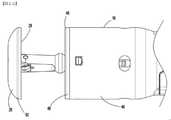
図1は、概して外科用ステープル留め器具10として示される外科用ステープル留め器具を示す。外科用ステープル留め器具10は、円形ステープル留め器具であり、ハンドルアセンブリ20、ハンドルアセンブリ20から遠位に延在するアダプタアセンブリ100、アダプタアセンブリ100の遠位部分上で支持されているリロードアセンブリ16、アダプタアセンブリ100に動作可能に結合されているアンビルアセンブリ50、およびハンドルアセンブリ20内に支持されたコントローラ300(図3A)を含む。リロードアセンブリ16は、複数のステープル(図示せず)を含む環状ステープルカートリッジ48を支持する。アンビルアセンブリ50は、ステープル形成面29を含むアンビルヘッド28を含む(図2A)。 FIG. 1 shows a surgical stapler, generally referred to as a
ハンドルアセンブリ20は、電動アセンブリとして示され、固定グリップ22と、リロードアセンブリ16のステープルカートリッジ48からのステープル(図示せず)の発射を制御するための作動ボタン24と、開位置とクランプ位置との間のリロードアセンブリ16のステープルカートリッジ48に向かう、およびステープルカートリッジ48から離れるアンビルアセンブリ50の軸方向変位を制御するための接近ボタン26a、26bと、を含む。例示的な電動ハンドルアセンブリの構造および機能の詳細な説明については、米国特許出願公開第2020/0015820号および同第2019/0343517号を参照することができる。本開示は電動アセンブリを示しているが、本開示の利点は、以下で詳細に説明するように、ロボット的に作動する外科用器具および/または手動で動作するステープラ(例えば、手動での接近が実施されているときに、許容可能なクランプ力に到達したことの表示を提供する力センサを含む)に適用可能であると想定されている。 The
図2Aおよび図2Bは、開位置およびクランプ位置にある外科用ステープル留め器具10を示している。開位置(図2A)では、アンビルアセンブリ50は、アンビルアセンブリ50のアンビルヘッド28のステープル形成面29とリロードアセンブリ16のステープルカートリッジ48との間の組織の配置を容易にするために、リロードアセンブリ16のステープルカートリッジ48から離間されている。クランプ位置では、アンビルアセンブリ50は、ステープルカートリッジ48と並置された整列に移動し、アンビルアセンブリ50のアンビルヘッド28のステープル形成面29とリロードアセンブリ16のステープルカートリッジ48との間の組織ギャップ「G」を画定する。手動および電動の両方の現在のステープル留め器具では、ステープル留め器具は、組織ギャップ「G」が所定の範囲内にない限り、ステープル留め器具の発射を防止するためのロックアウトを含む。この所定の範囲は、形成されるステープルのサイズに部分的に基づいて判定され、アンビルアセンブリ50のアンビルヘッド28が、ステープルを適切に形成するためにステープルカートリッジ48に十分に近接していることを保証する。所定の組織ギャップ範囲は、ギャップG最大に許容可能な最大値および許容可能な最小組織ギャップG最小によって画定される。2A and 2B show the
ハンドルアセンブリ20は、コントローラ300(図3A)と通信し、かつアンビルアセンブリ50とステープルカートリッジ48との間に組織がクランプされたことに起因する外科用ステープル留め器具10のモータ(図示せず)への負荷を判定するように構成されているひずみゲージ360(図3A)などの電気アセンブリを含み得る。この判定は、アンビルアセンブリ50とステープルカートリッジ48との間にクランプされている組織への圧縮力を判定するために使用することができる。 The
図1を引き続き参照すると、アダプタアセンブリ100は、ハンドルアセンブリ20に取り外し可能に結合されているインターフェース部分232と、インターフェース部分232から遠位に延在する管状シャフト234と、アダプタアセンブリ100内で移動可能に支持されているドライブカップリングアセンブリ(図示せず)と、アンビルアセンブリ50のアンビルシャフト52に結合されている駆動シャフト(図示せず)と、を含む。ドライブカップリングアセンブリ(図示せず)は、ハンドルアセンブリ20と係合して、それによって駆動され、ドライブシャフトの軸方向変位を制御して、アンビルアセンブリ50をステープルカートリッジ48に対して開位置とクランプ位置との間で移動させる。 With reference to FIG. 1, the adapter assembly 100 is movable within the adapter assembly 100 with an
リロードアセンブリ16は、アダプタアセンブリ100の遠位部分上で支持され、ステープルカートリッジ48を支持するシェルハウジング46を含む。本開示の態様では、ステープルカートリッジ48は、ステープル受容ポケット48aの環状列を画定する(図1)。本開示のいくつかの態様では、リロードアセンブリ16は、アダプタアセンブリ100の遠位部分に解放可能に結合されて、各使用後の環状ステープルカートリッジ48の交換を容易にする。 The reload
ステープルカートリッジ48のステープル受容ポケット48aの各々は、ハンドルアセンブリ20の作動ボタン24の作動を介してステープルカートリッジ48から発射することができるステープル(図示せず)を支持する。リロードアセンブリ16のシェルハウジング46は、環状空洞60を画定する。環状空洞60は、ステープルカートリッジ48に対して移動可能であるステープルプッシャー(図示せず)および環状ナイフ(図示せず)を支持して、ステープルカートリッジ48からステープルを排出し、ステープルカートリッジ48によって画定された環内に位置決めされた組織を切り裂くか、または切断する。ステープル(図示せず)がステープルカートリッジ48から発射されると、ステープルは、アンビルアセンブリ50のアンビルヘッド28のステープル形成面29のステープル形成ポケット内に駆動され、その中で形成される。 Each of the staple receiving pockets 48a of the
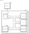
図3Aは、本開示による、コンピュータ可読ストレージ媒体またはメモリ330に接続されているプロセッサ320を含むコントローラ300を示している。コンピュータ可読ストレージ媒体またはメモリ330は、揮発性タイプのメモリ、例えば、RAM、または不揮発性タイプのメモリ、例えば、フラッシュ媒体、ディスク媒体などであってもよい。本開示の様々な態様において、プロセッサ320は、限定しないが、デジタル信号プロセッサ、マイクロプロセッサ、ASIC、グラフィックス処理ユニット(GPU)、フィールドプログラマブルゲートアレイ(FPGA)、または中央処理ユニット(CPU)などの別のタイプのプロセッサであってもよい。本開示の特定の態様では、プロセッサとは対照的に、メミスターとして、化学的に、または他の推論計算として実装される重みを有する、ネットワーク推論もまたシステム内で達成され得る。 FIG. 3A shows a
本開示の態様では、メモリ330は、ランダムアクセスメモリ、読み取り専用メモリ、磁気ディスクメモリ、固体メモリ、光学的ディスクメモリ、および/または別のタイプのメモリであり得る。本開示のいくつかの態様では、メモリ330は、コントローラ300とは別個とすることができ、回路基板の通信バスを通して、かつ/またはシリアルATAケーブルもしくは他のタイプのケーブルのなどの通信ケーブルを通して、プロセッサ320と通信することができる。メモリ330は、コントローラ300を動作させるためにプロセッサ320によって実行可能である、コンピュータ可読命令を含む。本開示の他の態様では、コントローラ300は、他のコンピュータまたはサーバと通信するためのネットワークインターフェース340を含み得る。データを記憶するために、ストレージデバイス310が使用され得る。 In aspects of the present disclosure, the
本開示の態様では、ひずみゲージ360はプロセッサに結合され、開示された方法は、コントローラ300上で、または例えば、モバイルデバイス、IoTデバイス、もしくはサーバシステム上を含む、ユーザデバイス上で実行される。 In aspects of the present disclosure, the
図3Bを参照して、ハンドルアセンブリ20、アダプタアセンブリ200、およびリロードアセンブリ16の概略図が示されている。簡潔にするために、モータ152、154、156のうちの1つのみ、すなわちモータ152が示される。モータ152は、バッテリ144に結合される。いくつかの態様では、モータ152は、AC/DC変圧器などの、電気エネルギーをモータ152に提供するように構成された任意の好適な電源に結合され得る。 A schematic diagram of the
バッテリ144およびモータ152は、バッテリ144からモータ152への電気エネルギーの流れを含むモータ152の動作を制御するモータコントローラ143を有するモータコントローラ回路基板142aに結合される。メインコントローラ回路基板142b(図1)は、ハンドルアセンブリ20を制御するメインコントローラ300を含む。モータコントローラ143は、モータ152およびバッテリ144の動作状態を測定するように構成された複数のセンサ408a、408b、…408nを含む。センサ408a~408nは、電圧センサ、電流センサ、温度センサ、遠隔測定センサ、光学センサ、およびそれらの組み合わせを含み得る。センサ408a~408nは、バッテリ144によって供給される電気エネルギーの電圧、電流、および他の電気的特性を測定し得る。センサ408a~408nはまた、モータ152の角速度(例えば、回転速度)を、毎分回転数(RPM)、トルク、温度、電流引き込み、および他の動作特性として測定し得る。角速度は、モータ152、またはそれに結合され、かつモータ152によって回転可能な駆動シャフト106、108、110(図2A)の回転を測定することによって判定され得る。様々な軸方向に移動可能な駆動シャフトの位置は、シャフト内またはシャフトの近傍に配設された様々な線形センサを使用することによって判定され得る、またはRPM測定から推定され得る。いくつかの態様では、トルクは、一定のRPMにおいてモータ152の安定化電流引き込みに基づいて計算され得る。さらなる態様では、モータコントローラ143および/またはメインコントローラ300は、時間を測定し、積分および/または微分を含む時間の関数として上記の値を処理して、例えば、測定値の変化率を判定することができる。メインコントローラ300はまた、モータ152、154、および156の回転をカウントすることによって、円形アダプタアセンブリ200および/またはリロードアセンブリ16の様々な構成要素の移動距離を判定するように構成される。 The
モータコントローラ143は、モータコントローラ143とインターフェースするための複数の入力および出力を含むメインコントローラ300に結合される。特に、メインコントローラ300は、モータ152およびバッテリ144の動作状態に関してモータコントローラ143から測定されたセンサ信号を受信し、次いで、制御信号をモータコントローラ143に出力して、以下でより詳細に論じられるセンサの読み取り値および特定のアルゴリズム命令に基づいて、モータ152の動作を制御する。メインコントローラ300はまた、ユーザインターフェース(例えば、メインコントローラ300に結合されたスイッチ、ボタン、タッチスクリーンなど)からの複数のユーザ入力を受け入れるように構成される。 The
メインコントローラ300はまた、有線または無線接続を使用して円形アダプタアセンブリ200のひずみゲージ360に結合され、かつハンドルアセンブリ20の動作中に使用されるひずみゲージ360からひずみ測定値を受信するように構成される。 The
リロードアセンブリ16は、ストレージデバイス405(例えば、チップ464c)を含む。アダプタアセンブリ200はまた、ストレージデバイス407を含む。ストレージデバイス405および407は、それぞれリロードアセンブリ16および円形アダプタアセンブリ200に関係する任意のデータを記憶するように構成される不揮発性記憶媒体(例えば、EEPROM)を含み、関係する任意のデータは、使用カウント、識別情報、モデル番号、シリアル番号、ステープルサイズ、ストローク長、最大作動力、最小作動力、工場較正データなどを含むが、これらに限定されない。態様において、データは、暗号化され得、適切なキーを有するデバイス(例えば、メインコントローラ300)によってのみ解読可能である。データはまた、円形アダプタアセンブリ200および/またはリロードアセンブリ16を認証するためにメインコントローラ300によって使用され得る。ストレージデバイス405および407は、読み取り専用モードまたは読み取り/書き込みモードで構成することができ、これにより、メインコントローラ300が、ストレージデバイス405および407にデータを読み取りならびに書き込みすることが可能になる。 The reload
外科用ステープル留め器具10が外科的処置を実施するために使用されるときに、外科用ステープル留め器具10は、ステープルカートリッジ48とアンビルアセンブリ50との間に組織を位置決めするように操作される。外科用器具が組織を治療するために組織に対して適切に位置決めされると、ハンドルアセンブリ20が作動して、アンビルアセンブリ50をクランプ位置に向かってG最小位置に移動させる。When the
図4は、外科用ステープル留め器具を制御し、組織のクランプ中に縫合不全を検出するためのフローコンピュータ実装方法400の流れ図を示している。処置中、巾着縫合糸600(図6)は、吻合の完全性を高め、漏出を防止するのを助けるために、外科用ステープル留め器具を覆う組織の片側または両側の周りに結ばれ得る。第1のクランプ段階の間、アンビルアセンブリ50(図1)は、ステープルカートリッジ48に対して、開位置から、アンビルアセンブリ50とステープルカートリッジ48との間に画定された組織ギャップが適切なステープル形成を容易にするための所定の許容可能なギャップ範囲内にあるクランプ位置に移動する。より具体的には、第1のクランプ段階において、アンビルアセンブリ50は、G最大の組織ギャップを画定するために、リロードアセンブリ16のステープルカートリッジ48に対して接近する(ステップ402)。本開示の態様では、G最大は、約0.037インチ~約0.024インチであってもよい。しかしながら、G最大の値は、ステープルカートリッジ48内のステープルのサイズに応じて変化し得る。クランプされた組織は、縫合を含む。FIG. 4 shows a flow chart of a flow
アンビルアセンブリ50が、G最大の組織ギャップに到達するまで、ステープルカートリッジ48に対して移動すると、ステープルカートリッジ48とアンビルアセンブリ50との間にクランプされた組織に対する組織圧縮力が第1の時点で測定される(ステップ404)。上記のように、アンビルアセンブリ50とシェルアセンブリのステープルカートリッジ48との間にクランプされた組織のクランプ力は、コントローラ300と通信するひずみゲージ360を使用して測定することができる。代替的に、任意の他の力またはひずみ測定デバイスを使用して、アンビルアセンブリ50とステープルカートリッジ48との間にクランプされた組織のクランプ力を測定し得る。例えば、駆動シャフト106(図2A)を駆動するハンドルアセンブリ20内のモータ154の電流引き込みは、クランプ力の測定に使用することができる。組織に対する圧縮力が所定の閾値よりも大きい場合(ステップ406)、外科用ステープル留め器具10は、ステープルカートリッジ48に対してアンビルアセンブリ50を前進させ続ける。所定の閾値は、圧縮されている組織のタイプおよび厚さに基づいて変化し得、器具10またはユーザによって自動的に設定され得る。As the
ステープルカートリッジ48とアンビルアセンブリ50との間にクランプされた組織に対する組織圧縮の力が、第2の時点で測定される(ステップ408)。第2の時点での圧縮力が第1の時点での圧縮力よりも小さい場合、コントローラは、巾着縫合が不全であると判断する(ステップ410)。巾着縫合不全は、例えば、縫合の破裂、縫合材料の不全、および/または組織から剥離した縫合の非限定的なリストを含み得る。第2の時点での圧縮力は、第1の時点での圧縮力から急激に減少する可能性があり(例えば、図5の曲線502を参照)、これは巾着縫合不全を示している。 The force of tissue compression against the tissue clamped between the
図5は、組織のクランプ中のひずみゲージプロファイルを示すグラフである。例えば、これらの力は、アンビルアセンブリ50がステープルカートリッジ48から約1.500インチ~約0.460インチであるときに見られ得る。曲線502は、クランプ中に巾着縫合が不全であることによって見られる力のために閉塞力制限エラーを引き起こしたクランプされた組織を表す。他のすべての曲線504は、問題なく、正常なクランプされた組織を示している。これらの曲線は、結腸直腸空間における5つの異なる処置タイプを表す。 FIG. 5 is a graph showing strain gauge profiles during tissue clamping. For example, these forces can be seen when the
様々な態様において、圧縮力は、例えば曲線として、経時的に監視することができる。様々な態様において、コントローラ300は、変化率、形状などを含む曲線の形状を分析し、曲線を記憶された曲線のデータベースと比較し、測定された曲線と記憶された曲線の特性間の差に基づいて縫合不全を判定することができる。様々な態様において、コントローラは、アンビルアセンブリ50がステープルカートリッジ48の第1の所定の範囲内にあり、ステープルカートリッジ48に対して第2の所定の範囲所定の範囲内にないときに測定される測定された圧縮力値を使用することができる。例えば、第1の所定の範囲は、アンビルアセンブリ50がステープルカートリッジ48から約1.500インチ~約0.9インチであるときに、例えば、組織圧縮力が通常、組織が圧縮されていないことを示す閾値を下回る距離の範囲であり得、第2の所定の範囲は、アンビルアセンブリ50がステープルカートリッジ48から約0.7インチ~約0.45インチであるときに、例えば、組織圧縮力が通常、組織が圧縮されていることを示す閾値を超える距離の範囲であり得る。 In various embodiments, the compressive force can be monitored over time, eg as a curve. In various embodiments, the
縫合が不全であるとコントローラが判定した場合、外科用ステープル留め器具10は、発射モードに入らない。そのため、外科用ステープル留め器具10は、発射モードに入るのを防止され、コントローラ#は、外科医が外科用ステープル留め器具10を組織上に再位置決めし、縫合を交換することができるように、圧縮力が高すぎることを外科医に警告し、組織のクランプを停止するために、例えば、外科用ステープル留め器具のハンドルアセンブリ上のディスプレイ146(図1)に警告を提供し得る。いくつかの態様において、警告は、外科医に手術部位を検査するように警告し得る。様々な態様において、外科用ステープル留め器具10は、ビープ音、トーン、または発話フレーズなどの可聴警告を生成し得る。例えば、発話フレーズは、不全である縫合のために手術部位を検査するように外科医に警告し得る。 If the controller determines that the suture is incomplete, the
本開示は、電動外科用ステープル留め器具を対象とするが、本開示の原理は、手動によるステープル留め器具に適用可能であると想定される。例えば、ステープル留め器具が所定の許容可能な組織ギャップ範囲を通って移動すると、ステープル留め器具のアンビルアセンブリとステープルカートリッジとの間にクランプされた組織に対するクランプ力を測定することができる。このようなデバイスでは、ライトなどのインジケータを器具に提供することができる。組織のクランプ力が、所定の許容可能なギャップ範囲内で器具を用いて所定の許容可能な圧縮範囲に入るときに、インジケータを作動させて、器具は発射する準備ができていることを外科医に通知することができる。 Although the present disclosure is intended for electrosurgical staple fasteners, it is assumed that the principles of the present disclosure are applicable to manual staple fasteners. For example, as the staple fastener moves through a predetermined acceptable tissue gap range, the clamping force on the tissue clamped between the anvil assembly of the staple fastener and the staple cartridge can be measured. In such devices, indicators such as lights can be provided to the appliance. When the tissue clamping force falls within a given acceptable compression range with the instrument within a given acceptable gap range, activate the indicator to inform the surgeon that the instrument is ready to fire. You can be notified.
本開示の態様は、円形ステープル留め器具に関連付けられて図示されているが、線形ステープル留めデバイス、血管シーリングデバイス、および組織部分を一緒に接合するための他のデバイスを含む他のタイプのステープル留め器具に等しく適用可能であることが想定される。 Aspects of the present disclosure are illustrated in association with a circular staple fastening device, but other types of staple fastening including linear staple fastening devices, vascular sealing devices, and other devices for joining tissue portions together. It is assumed that it is equally applicable to appliances.
当業者は、方法500の1つ以上の動作が、本開示の範囲から逸脱することなく、異なる順序で実施され、繰り返され、かつ/または省略され得ることを認識するであろう。様々な態様において、図示される方法500は、コントローラ300(図3A)において、リモートデバイスにおいて、または別のサーバもしくはシステムにおいて動作させることができる。他の変形例も、本開示の範囲内にあると想到される。方法500の動作は、コントローラ、例えば、外科用ステープル留め器具10(図3A)のコントローラ300(図3A)に関して記載されるが、図示される動作も同様に、他のシステムおよびその構成要素に適用可能であることが理解されるであろう。 One of ordinary skill in the art will recognize that one or more operations of Method 500 may be performed, repeated, and / or omitted in different order without departing from the scope of the present disclosure. In various embodiments, the illustrated method 500 can be operated in controller 300 (FIG. 3A) at a remote device or at another server or system. Other variations are also conceivable to be within the scope of the present disclosure. The operation of method 500 is described for a controller, eg, controller 300 (FIG. 3A) of surgical stapler 10 (FIG. 3A), but the illustrated operation is also applicable to other systems and their components. It will be understood that it is possible.
当業者であれば、本明細書において具体的に説明され、添付の図面に図示される器具および方法が非限定的であることを理解するであろう。本開示の範囲を逸脱することなく、本要素および特徴を、別の要素および特徴と組み合わせ得ることが想定される。同様に、当業者であれば、本開示のさらなる特徴および利点を理解するであろう。 Those skilled in the art will appreciate that the instruments and methods specifically described herein and illustrated in the accompanying drawings are non-limiting. It is envisioned that this element and feature may be combined with another element and feature without departing from the scope of the present disclosure. Similarly, one of ordinary skill in the art will understand the additional features and advantages of the present disclosure.
Claims (20)
Translated fromJapaneseアンビルアセンブリをステープルカートリッジに対して、前記ステープルカートリッジと前記アンビルアセンブリとの間の組織ギャップを画定し、それらの間に組織をクランプする、第1の位置まで、前進させることであって、前記クランプされた組織は、内部を通る縫合を含む、前進させることと、
第1の時点で、前記アンビルアセンブリを用いて、前記組織ギャップ内にクランプされた前記組織の第1の組織圧縮力を測定することと、
前記測定された第1の力が所定の閾値より大きいかどうかを判定することと、
前記第1の力が前記所定の閾値よりも大きいという前記判定に応答して、第2の時点で、前記組織ギャップ内にクランプされた前記組織の第2の組織圧縮力を測定することと、
前記測定された第2の組織圧縮力が前記測定された第1の組織圧縮力よりも小さい所定量であることに基づいて、前記縫合が不全となったかどうかを判定することと、
前記判定された縫合不全に基づいて、前記アンビルアセンブリの前記前進を停止することと、を含む、コンピュータ実装方法。A computer mounting method for controlling surgical staple fasteners,
The clamp is to advance the anvil assembly to a first position with respect to the staple cartridge, defining a tissue gap between the staple cartridge and the anvil assembly and clamping the tissue between them. The tissue is advanced, including sutures that pass through the interior.
At the first time point, the anvil assembly is used to measure the first tissue compressive force of the tissue clamped in the tissue gap.
Determining whether the measured first force is greater than a predetermined threshold
In response to the determination that the first force is greater than the predetermined threshold, measuring the second tissue compressive force of the tissue clamped within the tissue gap at a second time point.
Determining whether or not the suture has failed based on a predetermined amount of the measured second tissue compressive force smaller than the measured first tissue compressive force.
A computer mounting method comprising stopping the advance of the anvil assembly based on the determined anastomotic insufficiency.
アンビルヘッドおよび前記アンビルヘッドから近位に延在するアンビルセンターロッドを含むアンビルアセンブリと、
複数のステープルを含む環状ステープルカートリッジを含むリロードアセンブリと、
プロセッサと、
メモリであって、その上に記憶された命令であって、前記プロセッサによって実行されると、前記外科用ステープル留め器具に、
前記アンビルアセンブリを前記ステープルカートリッジに対して、前記ステープルカートリッジと前記アンビルアセンブリとの間の組織ギャップを画定し、それらの間に組織をクランプする、第1の位置まで前進させることであって、前記クランプされた組織は、内部を通る縫合を含む、前進させること、
第1の時点で、前記アンビルアセンブリを用いて、前記組織ギャップ内にクランプされた前記組織の第1の組織圧縮力を測定すること、
前記測定された第1の力が所定の閾値より大きいかどうかを判定すること、
前記第1の力が前記所定の閾値よりも大きいという前記判定に応答して、第2の時点で、前記組織ギャップ内にクランプされた前記組織の第2の組織圧縮力を測定すること、
前記測定された第2の組織圧縮力が前記測定された第1の組織圧縮力よりも小さい所定量であることに基づいて、前記縫合が不全となったかどうかを判定すること、および
前記判定された縫合不全に基づいて、前記アンビルアセンブリを前記前進させることを停止すること、を行わせる、命令を含む、メモリと、を備える、外科用ステープル留め器具。Surgical staple fasteners
An anvil assembly including an anvil head and an anvil center rod extending proximally from the anvil head,
A reload assembly containing an annular staple cartridge containing multiple staples,
With the processor
A memory, an instruction stored on it, and when executed by the processor, to the surgical stapler.
The anvil assembly is advanced relative to the staple cartridge to a first position that defines a tissue gap between the staple cartridge and the anvil assembly and clamps the tissue between them. Clamped tissue, including sutures through the interior, advancing,
At a first time point, the anvil assembly is used to measure the first tissue compressive force of the tissue clamped within the tissue gap.
Determining if the measured first force is greater than a predetermined threshold,
Measuring the second tissue compressive force of the tissue clamped within the tissue gap at a second time point in response to the determination that the first force is greater than the predetermined threshold.
Determining whether or not the suture has failed, and the determination, based on a predetermined amount of the measured second tissue compressive force smaller than the measured first tissue compressive force. A surgical staple fastening device comprising a memory, including instructions, to stop the anvil assembly from advancing, based on suture failure.
前記ステープルカートリッジと前記アンビルアセンブリとの間の組織ギャップを画定し、それらの間に組織をクランプする、第1の位置まで、ステープルカートリッジに対して、アンビルアセンブリを前進させることであって、し、前記クランプされた組織は、内部を通る縫合を含む、前進させることと、
第1の時点で、前記アンビルアセンブリを用いて、前記組織ギャップ内にクランプされた前記組織の第1の組織圧縮力を測定することと、
前記測定された第1の力が所定の閾値より大きいかどうかを判定することと、
前記第1の力が前記所定の閾値よりも大きいという前記判定に応答して、第2の時点で、前記組織ギャップ内にクランプされた前記組織の第2の組織圧縮力を測定することと、
前記測定された第2の組織圧縮力が前記測定された第1の組織圧縮力よりも小さい所定量であることに基づいて、前記縫合が不全となったかどうかを判定することと、
前記判定された縫合不全に基づいて、前記アンビルアセンブリの前記前進を停止することと、を含む、非一時的コンピュータ可読媒体。A non-temporary computer-readable medium that stores instructions that, when executed by the processor, causes the processor to implement a method for controlling a surgical stapler.
By advancing the anvil assembly relative to the staple cartridge to a first position that defines the tissue gap between the staple cartridge and the anvil assembly and clamps the tissue between them. The clamped tissue is advancing, including suturing through the interior.
At the first time point, the anvil assembly is used to measure the first tissue compressive force of the tissue clamped in the tissue gap.
Determining whether the measured first force is greater than a predetermined threshold
In response to the determination that the first force is greater than the predetermined threshold, measuring the second tissue compressive force of the tissue clamped within the tissue gap at a second time point.
Determining whether or not the suture has failed based on a predetermined amount of the measured second tissue compressive force smaller than the measured first tissue compressive force.
A non-temporary computer-readable medium comprising stopping the advance of the anvil assembly based on the determined anastomotic insufficiency.
Applications Claiming Priority (4)
| Application Number | Priority Date | Filing Date | Title |
|---|---|---|---|
| US202063056765P | 2020-07-27 | 2020-07-27 | |
| US63/056,765 | 2020-07-27 | ||
| US17/355,250 | 2021-06-23 | ||
| US17/355,250US11622769B2 (en) | 2020-07-27 | 2021-06-23 | Systems and methods for suture failure detection during surgical stapling |
Publications (1)
| Publication Number | Publication Date |
|---|---|
| JP2022023812Atrue JP2022023812A (en) | 2022-02-08 |
Family
ID=77042735
Family Applications (1)
| Application Number | Title | Priority Date | Filing Date |
|---|---|---|---|
| JP2021119357APendingJP2022023812A (en) | 2020-07-27 | 2021-07-20 | Systems and methods for suture failure detection during surgical stapling |
Country Status (4)
| Country | Link |
|---|---|
| US (2) | US11622769B2 (en) |
| EP (1) | EP3944825A1 (en) |
| JP (1) | JP2022023812A (en) |
| CN (1) | CN113974729A (en) |
Families Citing this family (2)
| Publication number | Priority date | Publication date | Assignee | Title |
|---|---|---|---|---|
| US11622769B2 (en)* | 2020-07-27 | 2023-04-11 | Covidien Lp | Systems and methods for suture failure detection during surgical stapling |
| US12213674B2 (en)* | 2021-12-08 | 2025-02-04 | Covidien Lp | Determination of premature staple ejection |
Family Cites Families (16)
| Publication number | Priority date | Publication date | Assignee | Title |
|---|---|---|---|---|
| WO2003090630A2 (en)* | 2002-04-25 | 2003-11-06 | Tyco Healthcare Group, Lp | Surgical instruments including micro-electromechanical systems (mems) |
| US7669746B2 (en)* | 2005-08-31 | 2010-03-02 | Ethicon Endo-Surgery, Inc. | Staple cartridges for forming staples having differing formed staple heights |
| US7467740B2 (en)* | 2005-09-21 | 2008-12-23 | Ethicon Endo-Surgery, Inc. | Surgical stapling instruments having flexible channel and anvil features for adjustable staple heights |
| EP2486862B1 (en)* | 2006-05-19 | 2019-03-27 | Ethicon Endo-Surgery, Inc. | Electrical surgical instrument |
| US20080255413A1 (en) | 2007-04-13 | 2008-10-16 | Michael Zemlok | Powered surgical instrument |
| KR102359695B1 (en) | 2011-02-15 | 2022-02-09 | 인튜어티브 서지컬 오퍼레이션즈 인코포레이티드 | Systems for detecting clamping or firing failure |
| US20140131418A1 (en)* | 2012-11-09 | 2014-05-15 | Covidien Lp | Surgical Stapling Apparatus Including Buttress Attachment |
| BR112016023849B1 (en)* | 2014-04-16 | 2022-09-27 | Ethicon Endo-Surgery, Llc | END ACTUATOR |
| EP3741309A1 (en) | 2015-04-22 | 2020-11-25 | Covidien LP | Handheld electromechanical surgical system |
| US11045199B2 (en) | 2017-06-09 | 2021-06-29 | Covidien Lp | Handheld electromechanical surgical system |
| US10905417B2 (en) | 2017-08-29 | 2021-02-02 | Ethicon Llc | Circular stapler |
| US20190200997A1 (en) | 2017-12-28 | 2019-07-04 | Ethicon Llc | Stapling device with both compulsory and discretionary lockouts based on sensed parameters |
| US11311306B2 (en)* | 2017-12-28 | 2022-04-26 | Cilag Gmbh International | Surgical systems for detecting end effector tissue distribution irregularities |
| CN109984797B (en)* | 2017-12-29 | 2024-04-12 | 天臣国际医疗科技股份有限公司 | Firing equipment |
| CN110811766A (en)* | 2019-10-25 | 2020-02-21 | 河南名门整形医院有限公司 | Beauty treatment technology for improving nasal tip and columella nasi |
| US11622769B2 (en)* | 2020-07-27 | 2023-04-11 | Covidien Lp | Systems and methods for suture failure detection during surgical stapling |
- 2021
- 2021-06-23USUS17/355,250patent/US11622769B2/enactiveActive
- 2021-07-20JPJP2021119357Apatent/JP2022023812A/enactivePending
- 2021-07-22EPEP21187262.7Apatent/EP3944825A1/enactivePending
- 2021-07-23CNCN202110835888.0Apatent/CN113974729A/enactivePending
- 2023
- 2023-04-11USUS18/133,082patent/US12048434B2/enactiveActive
Also Published As
| Publication number | Publication date |
|---|---|
| US20220022877A1 (en) | 2022-01-27 |
| US20230240684A1 (en) | 2023-08-03 |
| US11622769B2 (en) | 2023-04-11 |
| US12048434B2 (en) | 2024-07-30 |
| CN113974729A (en) | 2022-01-28 |
| EP3944825A1 (en) | 2022-02-02 |
Similar Documents
| Publication | Publication Date | Title |
|---|---|---|
| US11051805B2 (en) | System and method of using simulation reload to optimize staple formation | |
| US12048434B2 (en) | Systems and methods for suture failure detection during surgical stapling | |
| JP2012170820A (en) | System and method for controlled tissue compression | |
| US20250221712A1 (en) | Handheld electromechanical surgical system | |
| CN117915844A (en) | Slow staple speed and staple relaxation for suture optimization | |
| JP2024528888A (en) | HANDHELD ELECTROMECHANICAL STAPLER WITH TISSUE THICKNESS DETECTION - Patent application | |
| JP7737255B2 (en) | Systems and methods for controlling a surgical stapling instrument | |
| JP2022019591A (en) | Systems and methods for clamping and stapling to pressure by surgical stapling instrument | |
| JP2024528889A (en) | Handheld electromechanical surgical device with strain gauge drift detection | |
| US12245767B2 (en) | Handheld electromechanical surgical system | |
| US11832823B2 (en) | Determination of anvil release during anastomosis | |
| JP2025525051A (en) | Handheld electromechanical surgical system with low tissue compression indication - Patents.com | |
| CN118354727A (en) | Determination of nail pre-discharge | |
| CN116546930A (en) | Handheld Electromechanical Surgical System |
Legal Events
| Date | Code | Title | Description |
|---|---|---|---|
| A621 | Written request for application examination | Free format text:JAPANESE INTERMEDIATE CODE: A621 Effective date:20240620 | |
| A977 | Report on retrieval | Free format text:JAPANESE INTERMEDIATE CODE: A971007 Effective date:20250121 | |
| A131 | Notification of reasons for refusal | Free format text:JAPANESE INTERMEDIATE CODE: A131 Effective date:20250207 | |
| A02 | Decision of refusal | Free format text:JAPANESE INTERMEDIATE CODE: A02 Effective date:20250729 |