JP2022023762A - Image capturing optical lens - Google Patents
Image capturing optical lensDownload PDFInfo
- Publication number
- JP2022023762A JP2022023762AJP2020216586AJP2020216586AJP2022023762AJP 2022023762 AJP2022023762 AJP 2022023762AJP 2020216586 AJP2020216586 AJP 2020216586AJP 2020216586 AJP2020216586 AJP 2020216586AJP 2022023762 AJP2022023762 AJP 2022023762A
- Authority
- JP
- Japan
- Prior art keywords
- lens
- curvature
- radius
- optical
- ttl
- Prior art date
- Legal status (The legal status is an assumption and is not a legal conclusion. Google has not performed a legal analysis and makes no representation as to the accuracy of the status listed.)
- Granted
Links
Images


Classifications
- G—PHYSICS
- G02—OPTICS
- G02B—OPTICAL ELEMENTS, SYSTEMS OR APPARATUS
- G02B9/00—Optical objectives characterised both by the number of the components and their arrangements according to their sign, i.e. + or -
- G02B9/64—Optical objectives characterised both by the number of the components and their arrangements according to their sign, i.e. + or - having more than six components
- G—PHYSICS
- G02—OPTICS
- G02B—OPTICAL ELEMENTS, SYSTEMS OR APPARATUS
- G02B13/00—Optical objectives specially designed for the purposes specified below
- G02B13/001—Miniaturised objectives for electronic devices, e.g. portable telephones, webcams, PDAs, small digital cameras
- G02B13/0015—Miniaturised objectives for electronic devices, e.g. portable telephones, webcams, PDAs, small digital cameras characterised by the lens design
- G02B13/002—Miniaturised objectives for electronic devices, e.g. portable telephones, webcams, PDAs, small digital cameras characterised by the lens design having at least one aspherical surface
- G02B13/0045—Miniaturised objectives for electronic devices, e.g. portable telephones, webcams, PDAs, small digital cameras characterised by the lens design having at least one aspherical surface having five or more lenses
- G—PHYSICS
- G02—OPTICS
- G02B—OPTICAL ELEMENTS, SYSTEMS OR APPARATUS
- G02B13/00—Optical objectives specially designed for the purposes specified below
- G02B13/06—Panoramic objectives; So-called "sky lenses" including panoramic objectives having reflecting surfaces
- G—PHYSICS
- G02—OPTICS
- G02B—OPTICAL ELEMENTS, SYSTEMS OR APPARATUS
- G02B13/00—Optical objectives specially designed for the purposes specified below
- G02B13/18—Optical objectives specially designed for the purposes specified below with lenses having one or more non-spherical faces, e.g. for reducing geometrical aberration
Landscapes
- Physics & Mathematics (AREA)
- General Physics & Mathematics (AREA)
- Optics & Photonics (AREA)
- Lenses (AREA)
Abstract
Translated fromJapanese
Description
Translated fromJapanese本発明は、光学レンズ分野に関し、特にスマートフォン、デジタルカメラなどの携帯端末装置と、モニタ、PCレンズなどの撮像装置とに適用される撮像光学レンズに関する。 The present invention relates to the field of optical lenses, and more particularly to an image pickup optical lens applied to a portable terminal device such as a smartphone or a digital camera and an image pickup device such as a monitor or a PC lens.
結像レンズの発展に伴い、レンズの結像に対する人々の要求が高まってきており、レンズの「夜景撮影」や「背景ぼかし」もレンズの結像規格を測る重要な指標となっている。従来の構成の撮像光学レンズでは、パワー配分、レンズ間隔およびレンズ形状の設定が不十分であり、レンズの極薄化および広角化が不十分である。また、現在、回転対称の非球面が多く採用され、このような非球面は、タンジェンシャル平面内のみで十分な自由度を有するため、収差を良好に補正することができなかった。自由曲面は、非回転対称の表面タイプであり、収差をより良くバランスさせ、結像品質を向上させることができ、しかも自由曲面の加工も徐々に成熟している。レンズの結像要求の向上に伴い、レンズを設計する際に自由曲面を入れることが重要であり、特に広角と超広角レンズの設計において効果が一層顕著である。 With the development of imaging lenses, people's demands for image formation of lenses are increasing, and "night view photography" and "background blur" of lenses are also important indicators for measuring the imaging standard of lenses. In the imaging optical lens having the conventional configuration, the power distribution, the lens spacing, and the lens shape are insufficiently set, and the ultrathinning and widening of the lens are insufficient. Further, at present, many rotationally symmetric aspherical surfaces are adopted, and such aspherical surfaces have a sufficient degree of freedom only in the tangential plane, so that aberrations cannot be corrected satisfactorily. The free-form surface is a non-rotational symmetric surface type, which can better balance aberrations and improve image quality, and the processing of the free-form surface is gradually maturing. With the increasing demand for imaging of lenses, it is important to include a free-form surface when designing a lens, and the effect is even more remarkable especially in the design of wide-angle and ultra-wide-angle lenses.
上記問題に鑑みて、本発明は、良好な光学性能を図るとともに、大口径、広角化及び極薄化の特性を有する撮像光学レンズを提供することを目的とする。 In view of the above problems, it is an object of the present invention to provide an image pickup optical lens having good optical performance and characteristics of large aperture, wide angle and ultra-thinning.
上記技術的課題を解決するために、本発明の実施形態は、撮像光学レンズを提供する。前記撮像光学レンズは、合計で8枚のレンズを備え、前記8枚のレンズは、物体側から像側へ順に、第1レンズ、第2レンズ、第3レンズ、第4レンズ、第5レンズ、第6レンズ、第7レンズ及び第8レンズであり、
前記第1レンズから前記第8レンズのうちの少なくとも1つは、自由曲面を含み、
前記第2レンズの焦点距離をf2、前記第6レンズの焦点距離をf6、前記第1レンズの物体側面の曲率半径をR1、前記第1レンズの像側面の曲率半径をR2としたときに、以下の条件式(1)~(2)を満たす。
-7.50≦f2/f6≦-1.50 (1)
-6.00≦R1/R2≦-0.18 (2)In order to solve the above technical problems, an embodiment of the present invention provides an image pickup optical lens. The imaging optical lens includes a total of eight lenses, and the eight lenses are the first lens, the second lens, the third lens, the fourth lens, and the fifth lens in this order from the object side to the image side. The sixth lens, the seventh lens, and the eighth lens.
At least one of the first lens to the eighth lens includes a free-form surface.
When the focal length of the second lens is f2, the focal length of the sixth lens is f6, the radius of curvature of the object side surface of the first lens is R1, and the radius of curvature of the image side surface of the first lens is R2. The following conditional expressions (1) and (2) are satisfied.
-7.50 ≤ f2 / f6 ≤ -1.50 (1)
-6.00≤R1 / R2≤-0.18 (2)
改良態様の1つとして、前記第3レンズの軸上厚みをd5、前記第3レンズの像側面から前記第4レンズの物体側面までの軸上距離をd6としたときに、以下の条件式(3)を満たす。
4.00≦d5/d6≦9.00 (3)As one of the improved embodiments, when the axial thickness of the third lens is d5 and the axial distance from the image side surface of the third lens to the object side surface of the fourth lens is d6, the following conditional expression ( 3) is satisfied.
4.00 ≤ d5 / d6 ≤ 9.00 (3)
改良態様の1つとして、前記撮像光学レンズの焦点距離をf、前記第1レンズの焦点距離をf1、前記第1レンズの軸上厚みをd1、前記撮像光学レンズの光学長をTTLとしたときに、以下の条件式(4)~(6)を満たす。
-4.14≦f1/f≦-1.07 (4)
-1.36≦(R1+R2)/(R1-R2)≦1.07 (5)
0.03≦d1/TTL≦0.14 (6)As one of the improved embodiments, when the focal length of the imaging optical lens is f, the focal length of the first lens is f1, the axial thickness of the first lens is d1, and the optical length of the imaging optical lens is TTL. In addition, the following conditional expressions (4) to (6) are satisfied.
-4.14 ≦ f1 / f ≦ -1.07 (4)
-1.36 ≤ (R1 + R2) / (R1-R2) ≤ 1.07 (5)
0.03 ≤ d1 / TTL ≤ 0.14 (6)
改良態様の1つとして、前記撮像光学レンズの焦点距離をf、前記第2レンズの物体側面の曲率半径をR3、前記第2レンズの像側面の曲率半径をR4、前記第2レンズの軸上厚みをd3、前記撮像光学レンズの光学長をTTLとしたときに、以下の条件式(7)~(9)を満たす。
-28.38≦f2/f≦8.13 (7)
-12.87≦(R3+R4)/(R3-R4)≦18.86 (8)
0.02≦d3/TTL≦0.07 (9)As one of the improved embodiments, the focal length of the imaging optical lens is f, the radius of curvature of the object side surface of the second lens is R3, the radius of curvature of the image side surface of the second lens is R4, and the axis of the second lens is on the axis. When the thickness is d3 and the optical length of the image pickup optical lens is TTL, the following conditional equations (7) to (9) are satisfied.
-28.38 ≤ f2 / f ≤ 8.13 (7)
-12.87 ≤ (R3 + R4) / (R3-R4) ≤ 18.86 (8)
0.02 ≤ d3 / TTL ≤ 0.07 (9)
改良態様の1つとして、前記撮像光学レンズの焦点距離をf、前記第3レンズの焦点距離をf3、前記第3レンズの物体側面の曲率半径をR5、前記第3レンズの像側面の曲率半径をR6、前記第3レンズの軸上厚みをd5、前記撮像光学レンズの光学長をTTLとしたときに、以下の条件式(10)~(12)を満たす。
0.53≦f3/f≦10.57 (10)
-6.72≦(R5+R6)/(R5-R6)≦-0.10 (11)
0.02≦d5/TTL≦0.12 (12)As one of the improved embodiments, the focal length of the imaging optical lens is f, the focal length of the third lens is f3, the radius of curvature of the object side surface of the third lens is R5, and the radius of curvature of the image side surface of the third lens. The following conditional equations (10) to (12) are satisfied, where R6, the axial thickness of the third lens is d5, and the optical length of the image pickup optical lens is TTL.
0.53 ≦ f3 / f ≦ 10.57 (10)
-6.72 ≤ (R5 + R6) / (R5-R6) ≤ -0.10 (11)
0.02 ≤ d5 / TTL ≤ 0.12 (12)
改良態様の1つとして、前記撮像光学レンズの焦点距離をf、前記第4レンズの焦点距離をf4、前記第4レンズの物体側面の曲率半径をR7、前記第4レンズの像側面の曲率半径をR8、前記第4レンズの軸上厚みをd7、前記撮像光学レンズの光学長をTTLとしたときに、以下の条件式(13)~(15)を満たす。
0.65≦f4/f≦7.26 (13)
0.14≦(R7+R8)/(R7-R8)≦6.79 (14)
0.03≦d7/TTL≦0.15 (15)As one of the improved embodiments, the focal length of the imaging optical lens is f, the focal length of the fourth lens is f4, the radius of curvature of the object side surface of the fourth lens is R7, and the radius of curvature of the image side surface of the fourth lens. The following conditional equations (13) to (15) are satisfied, where R8, the axial thickness of the fourth lens is d7, and the optical length of the imaging optical lens is TTL.
0.65 ≤ f4 / f ≤ 7.26 (13)
0.14 ≤ (R7 + R8) / (R7-R8) ≤ 6.79 (14)
0.03 ≤ d7 / TTL ≤ 0.15 (15)
改良態様の1つとして、前記撮像光学レンズの焦点距離をf、前記第5レンズの焦点距離をf5、前記第5レンズの物体側面の曲率半径をR9、前記第5レンズの像側面の曲率半径をR10、前記第5レンズの軸上厚みをd9、前記撮像光学レンズの光学長をTTLとしたときに、以下の条件式(16)~(18)を満たす。
-8.07≦f5/f≦-1.92 (16)
0.02≦(R9+R10)/(R9-R10)≦6.14 (17)
0.02≦d9/TTL≦0.06 (18)As one of the improved embodiments, the focal length of the imaging optical lens is f, the focal length of the fifth lens is f5, the radius of curvature of the object side surface of the fifth lens is R9, and the radius of curvature of the image side surface of the fifth lens. When R10, the axial thickness of the fifth lens is d9, and the optical length of the image pickup optical lens is TTL, the following conditional equations (16) to (18) are satisfied.
−8.07 ≦ f5 / f ≦ -1.92 (16)
0.02 ≤ (R9 + R10) / (R9-R10) ≤ 6.14 (17)
0.02 ≤ d9 / TTL ≤ 0.06 (18)
改良態様の1つとして、前記撮像光学レンズの焦点距離をf、前記第6レンズの物体側面の曲率半径をR11、前記第6レンズの像側面の曲率半径をR12、前記第6レンズの軸上厚みをd11、前記撮像光学レンズの光学長をTTLとしたときに、以下の条件式(19)~(21)を満たす。
-6.00≦f6/f≦2.97 (19)
-1.17≦(R11+R12)/(R11-R12)≦0.60 (20)
0.05≦d11/TTL≦0.16 (21)As one of the improved embodiments, the focal length of the imaging optical lens is f, the radius of curvature of the object side surface of the sixth lens is R11, the radius of curvature of the image side surface of the sixth lens is R12, and the axis of the sixth lens is on the axis. When the thickness is d11 and the optical length of the image pickup optical lens is TTL, the following conditional equations (19) to (21) are satisfied.
-6.00≤f6 / f≤2.97 (19)
-1.17 ≤ (R11 + R12) / (R11-R12) ≤ 0.60 (20)
0.05 ≤ d11 / TTL ≤ 0.16 (21)
改良態様の1つとして、前記撮像光学レンズの焦点距離をf、前記第7レンズの焦点距離をf7、前記第7レンズの物体側面の曲率半径をR13、前記第7レンズの像側面の曲率半径をR14、前記第7レンズの軸上厚みをd13、前記撮像光学レンズの光学長をTTLとしたときに、以下の条件式(22)~(24)を満たす。
0.41≦f7/f≦1.99 (22)
0.26≦(R13+R14)/(R13-R14)≦5.59 (23)
0.04≦d13/TTL≦0.20 (24)As one of the improved embodiments, the focal length of the imaging optical lens is f, the focal length of the seventh lens is f7, the radius of curvature of the object side surface of the seventh lens is R13, and the radius of curvature of the image side surface of the seventh lens. The following conditional equations (22) to (24) are satisfied, where R14, the axial thickness of the seventh lens is d13, and the optical length of the imaging optical lens is TTL.
0.41 ≦ f7 / f ≦ 1.99 (22)
0.26 ≤ (R13 + R14) / (R13-R14) ≤ 5.59 (23)
0.04 ≤ d13 / TTL ≤ 0.20 (24)
改良態様の1つとして、前記撮像光学レンズの焦点距離をf、前記第8レンズの焦点距離をf8、前記第8レンズの物体側面の曲率半径をR15、前記第8レンズの像側面の曲率半径をR16、前記第8レンズの軸上厚みをd15、前記撮像光学レンズの光学長をTTLとしたときに、以下の条件式(25)~(27)を満たす。
-2.74≦f8/f≦-0.82 (25)
1.15≦(R15+R16)/(R15-R16)≦4.00 (26)
0.03≦d15/TTL≦0.16 (27)As one of the improved embodiments, the focal length of the imaging optical lens is f, the focal length of the eighth lens is f8, the radius of curvature of the object side surface of the eighth lens is R15, and the radius of curvature of the image side surface of the eighth lens. The following conditional equations (25) to (27) are satisfied, where R16, the axial thickness of the eighth lens is d15, and the optical length of the imaging optical lens is TTL.
-2.74 ≤ f8 / f ≤ -0.82 (25)
1.15 ≤ (R15 + R16) / (R15-R16) ≤ 4.00 (26)
0.03 ≤ d15 / TTL ≤ 0.16 (27)
本発明は、下記の有利な効果を奏することができる。本発明に係る撮像光学レンズによれば、良好な光学性能を有するとともに、大口径、広角化及び極薄化の光学撮像レンズの特性を有し、特に高画素用のCCD、CMOSなどの撮像素子により構成された携帯電話の撮像レンズユニットとWEB撮像レンズに適用することができる。 The present invention can exert the following advantageous effects. According to the image pickup optical lens according to the present invention, the image pickup lens has good optical performance and has the characteristics of a large-diameter, wide-angle and ultra-thin optical image pickup lens, and particularly, an image pickup device such as a CCD or CMOS for high pixels. It can be applied to the image pickup lens unit and the WEB image pickup lens of the mobile phone configured by the above.
本発明の実施形態における技術案をより明瞭に説明するために、以下では、実施形態の記述に使用必要な図面を簡単に紹介する。明らかに、以下に記載される図面は、本発明の一部の実施形態に過ぎず、当業者にとって、創造的労力をかけない前提で、これらの図面から他の図面を得ることができる。 In order to more clearly explain the technical proposal in the embodiment of the present invention, the drawings necessary for describing the embodiment will be briefly introduced below. Obviously, the drawings described below are only partial embodiments of the present invention, and other drawings can be obtained from these drawings without any creative effort for those skilled in the art.
本発明の目的、解決手段及びメリットがより明瞭になるように、本発明の各実施形態を図面を参照しながら詳細に説明する。しかし、本発明の各実施形態において、本発明が良く理解されるように多くの技術的詳細が与えられているが、それらの技術的詳細および以下の各実施形態に基づく各種の変化及び修正が存在しなくとも、本発明の保護しようとするものを実現可能であることは、当業者に理解されるべきである。 Each embodiment of the present invention will be described in detail with reference to the drawings so that the object, the means and the merits of the present invention become clearer. However, in each embodiment of the invention, many technical details have been given so that the present invention may be well understood, but the technical details and various changes and modifications based on the following embodiments may be made. It should be understood by those skilled in the art that what is to be protected by the present invention is feasible even if it does not exist.
(第1実施形態)
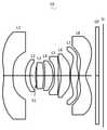
図面を参照すると、本発明は、撮像光学レンズ10を提供する。図1には、本発明に係る第1実施形態の撮像光学レンズ10が示され、当該撮像光学レンズ10は、合計で8枚のレンズを備える。具体的に、前記撮像光学レンズ10は、物体側から像側へ順に、第1レンズL1、第2レンズL2、絞りS1、第3レンズL3、第4レンズL4、第5レンズL5、第6レンズL6、第7レンズL7及び第8レンズL8から構成される。第8レンズL8と像面Siとの間に光学フィルタ(filter)GFなどの光学素子が設けられてもよい。(First Embodiment)
Referring to the drawings, the present invention provides an imaging
本実施形態では、第1レンズL1がプラスチック材質であり、第2レンズL2がプラスチック材質であり、第3レンズL3がプラスチック材質であり、第4レンズL4がプラスチック材質であり、第5レンズL5がプラスチック材質であり、第6レンズL6がプラスチック材質であり、第7レンズL7がプラスチック材質であり、第8レンズL8がプラスチック材質である。他の実施例では、各レンズが他の材質であってもよい。 In the present embodiment, the first lens L1 is made of a plastic material, the second lens L2 is made of a plastic material, the third lens L3 is made of a plastic material, the fourth lens L4 is made of a plastic material, and the fifth lens L5 is made of a plastic material. The sixth lens L6 is a plastic material, the seventh lens L7 is a plastic material, and the eighth lens L8 is a plastic material. In other embodiments, each lens may be of another material.
本実施形態では、前記第1レンズL1から第8レンズL8のうちの少なくとも1つが自由曲面を含むこととし、自由曲面は、広角光学系における非点収差、像面湾曲、歪曲収差等の収差の補正に有利であり、更に結像品質を向上させる。 In the present embodiment, at least one of the first lens L1 to the eighth lens L8 includes a free curved surface, and the free curved surface is used for aberrations such as astigmatism, curvature of field, and distortion in a wide-angle optical system. It is advantageous for correction and further improves the image quality.
第2レンズL2の焦点距離をf2、第6レンズL6の焦点距離をf6として定義すると、条件式-7.50≦f2/f6≦-1.50を満たす。この条件式は、第2レンズL2の焦点距離と第6レンズL6の焦点距離との比を規定するものである。条件式の範囲内では、結像品質の向上に有利である。 If the focal length of the second lens L2 is defined as f2 and the focal length of the sixth lens L6 is defined as f6, the conditional expression −7.50 ≦ f2 / f6 ≦ -1.50 is satisfied. This conditional expression defines the ratio between the focal length of the second lens L2 and the focal length of the sixth lens L6. Within the range of the conditional expression, it is advantageous for improving the image quality.
第1レンズL1の物体側面の曲率半径をR1、第1レンズL1の像側面の曲率半径をR2として定義すると、条件式-6.00≦R1/R2≦-0.18を満たす。この条件式は、第1レンズL1の形状を規定するものである。条件式の範囲内では、光線の偏向度合いの低減に有利であり、結像品質を向上させる。 If the radius of curvature of the object side surface of the first lens L1 is defined as R1 and the radius of curvature of the image side surface of the first lens L1 is defined as R2, the conditional expression −6.00 ≦ R1 / R2 ≦ −0.18 is satisfied. This conditional expression defines the shape of the first lens L1. Within the range of the conditional expression, it is advantageous to reduce the degree of deflection of the light beam and improve the image quality.
第3レンズL3の軸上厚みをd5、第3レンズL3の像側面から第4レンズL4の物体側面までの軸上距離をd6として定義すると、条件式4.00≦d5/d6≦9.00を満たす。d5/d6が条件式を満たすときに、システムの像面湾曲をバランスさせ、結像品質を向上させる。 If the axial thickness of the third lens L3 is defined as d5 and the axial distance from the image side surface of the third lens L3 to the object side surface of the fourth lens L4 is defined as d6, the conditional expression 4.00 ≦ d5 / d6 ≦ 9.00. Meet. When d5 / d6 satisfy the conditional expression, it balances the curvature of field of the system and improves the image quality.
本実施形態では、第1レンズL1は、負の屈折力を有し、第1レンズL1は、物体側面が近軸において凹面であり、像側面が近軸において凹面である。 In the present embodiment, the first lens L1 has a negative refractive power, and the first lens L1 has a concave surface on the paraxial side surface of the object and a concave surface on the paraxial axis.
第1レンズL1の焦点距離をf1、撮像光学レンズ10の焦点距離をfとして定義すると、条件式-4.14≦f1/f≦-1.07を満たす。この条件式は、第1レンズL1の焦点距離と全体焦点距離との比を規定するものである。規定された範囲内では、第1レンズL1は、適切な負の屈折力を有し、システム収差の低減に有利であるとともに、レンズの極薄化、広角化にも有利である。好ましくは、条件式-2.59≦f1/f≦-1.34を満たす。 If the focal length of the first lens L1 is defined as f1 and the focal length of the imaging
第1レンズL1の物体側面の曲率半径をR1、第1レンズL1の像側面の曲率半径をR2として定義すると、条件式-1.36≦(R1+R2)/(R1-R2)≦1.07を満たす。第1レンズL1の形状を合理的に規定することにより、第1レンズL1によってシステムの球面収差を効果的に補正することができる。好ましくは、条件式-0.85≦(R1+R2)/(R1-R2)≦0.85を満たす。 If the radius of curvature of the object side surface of the first lens L1 is defined as R1 and the radius of curvature of the image side surface of the first lens L1 is defined as R2, the conditional equation −1.36 ≦ (R1 + R2) / (R1-R2) ≦ 1.07. Fulfill. By rationally defining the shape of the first lens L1, the spherical aberration of the system can be effectively corrected by the first lens L1. Preferably, the conditional expression −0.85 ≦ (R1 + R2) / (R1-R2) ≦ 0.85 is satisfied.
第1レンズL1の軸上厚みをd1、撮像光学レンズ10の光学長をTTLとして定義すると、条件式0.03≦d1/TTL≦0.14を満たす。これにより、極薄化を図ることに有利である。好ましくは、条件式0.05≦d1/TTL≦0.11を満たす。 If the axial thickness of the first lens L1 is defined as d1 and the optical length of the imaging
本実施形態では、第2レンズL2は、正の屈折力を有し、第2レンズL2は、物体側面が近軸において凸面であり、像側面が近軸において凹面である。 In the present embodiment, the second lens L2 has a positive refractive power, and the second lens L2 has an object side surface that is convex in the paraxial axis and an image side surface that is concave in the paraxial axis.
第2レンズL2の焦点距離をf2、撮像光学レンズ10の焦点距離をfとして定義すると、条件式-28.38≦f2/f≦8.13を満たす。第2レンズL2の屈折力を合理的な範囲で規定することにより、光学システムの収差の補正に有利である。好ましくは、条件式-17.74≦f2/f≦6.50を満たす。 If the focal length of the second lens L2 is defined as f2 and the focal length of the imaging
第2レンズL2の物体側面の曲率半径をR3、第2レンズL2の像側面の曲率半径をR4として定義すると、条件式-12.87≦(R3+R4)/(R3-R4)≦18.86を満たす。この条件式は、第2レンズL2の形状を規定するものである。範囲内では、レンズの極薄広角化が進行するにつれて、軸上色収差の補正に有利になる。好ましくは、条件式-8.04≦(R3+R4)/(R3-R4)≦15.09を満たす。 If the radius of curvature of the object side surface of the second lens L2 is defined as R3 and the radius of curvature of the image side surface of the second lens L2 is defined as R4, the conditional equation −12.87 ≦ (R3 + R4) / (R3-R4) ≦ 18.86 is obtained. Fulfill. This conditional expression defines the shape of the second lens L2. Within the range, as the ultra-thin and wide-angle lens progresses, it becomes advantageous for correcting axial chromatic aberration. Preferably, the conditional expression −8.04 ≦ (R3 + R4) / (R3-R4) ≦ 15.09 is satisfied.
第2レンズL2の軸上厚みをd3、撮像光学レンズ10の光学長をTTLとして定義すると、条件式0.02≦d3/TTL≦0.07を満たす。これにより、極薄化を図ることに有利である。好ましくは、条件式0.03≦d3/TTL≦0.06を満たす。 If the axial thickness of the second lens L2 is defined as d3 and the optical length of the imaging
本実施形態では、第3レンズL3は、正の屈折力を有し、第3レンズL3は、物体側面が近軸において凸面であり、像側面が近軸において凸面である。 In the present embodiment, the third lens L3 has a positive refractive power, and the third lens L3 has an object side surface that is convex in the paraxial axis and an image side surface that is convex in the paraxial axis.
第3レンズL3の焦点距離をf3、撮像光学レンズ10の焦点距離をfとして定義すると、条件式0.53≦f3/f≦10.57を満たす。屈折力の合理的な配分により、システムが優れた結像品質及び低い感度を有する。好ましくは、条件式0.84≦f3/f≦8.46を満たす。 If the focal length of the third lens L3 is defined as f3 and the focal length of the imaging
第3レンズL3の物体側面の曲率半径をR5、第3レンズL3の像側面の曲率半径をR6として定義すると、条件式-6.72≦(R5+R6)/(R5-R6)≦-0.10を満たす。この条件式は、第3レンズL3の形状を規定するものである。条件式で規定された範囲内では、光線がレンズを通る偏向度合いを緩和可能であり、収差を効果的に低減することができる。好ましくは、条件式-4.20≦(R5+R6)/(R5-R6)≦-0.12を満たす。 If the radius of curvature of the object side surface of the third lens L3 is defined as R5 and the radius of curvature of the image side surface of the third lens L3 is defined as R6, the conditional equation −6.72 ≦ (R5 + R6) / (R5-R6) ≦ −0.10. Meet. This conditional expression defines the shape of the third lens L3. Within the range defined by the conditional expression, the degree of deflection of the light ray passing through the lens can be relaxed, and the aberration can be effectively reduced. Preferably, the conditional expression -4.20 ≦ (R5 + R6) / (R5-R6) ≦ −0.12 is satisfied.
第3レンズL3の軸上厚みをd5、撮像光学レンズ10の光学長をTTLとして定義すると、条件式0.02≦d5/TTL≦0.12を満たす。これにより、極薄化を図ることに有利である。好ましくは、条件式0.04≦d5/TTL≦0.10を満たす。 If the axial thickness of the third lens L3 is defined as d5 and the optical length of the imaging
本実施形態では、第4レンズL4は、正の屈折力を有し、第4レンズL4は、物体側面が近軸において凹面であり、像側面が近軸において凸面である。 In the present embodiment, the fourth lens L4 has a positive refractive power, and the fourth lens L4 has an object side surface that is concave in the paraxial axis and an image side surface that is convex in the paraxial axis.
第4レンズL4の焦点距離をf4、撮像光学レンズ10の焦点距離をfとして定義すると、条件式0.65≦f4/f≦7.26を満たす。この条件式は、第4レンズL4の焦点距離とシステムの焦点距離との比を規定するものである。条件式の範囲内では、光学システム性能の向上に有利になる。好ましくは、条件式1.04≦f4/f≦5.80を満たす。 If the focal length of the fourth lens L4 is defined as f4 and the focal length of the imaging
第4レンズL4の物体側面の曲率半径をR7、第4レンズL4の像側面の曲率半径をR8として定義すると、条件式0.14≦(R7+R8)/(R7-R8)≦6.79を満たす。この条件式は、第4レンズL4の形状を規定するものである。範囲内では、レンズの極薄広角化が進行するにつれて、軸外画角の収差などの補正に有利である。好ましくは、条件式0.23≦(R7+R8)/(R7-R8)≦5.43を満たす。 If the radius of curvature of the object side surface of the fourth lens L4 is defined as R7 and the radius of curvature of the image side surface of the fourth lens L4 is defined as R8, the conditional expression 0.14 ≦ (R7 + R8) / (R7-R8) ≦ 6.79 is satisfied. .. This conditional expression defines the shape of the fourth lens L4. Within the range, as the ultra-thin and wide-angle lens progresses, it is advantageous for correcting aberrations of the off-axis angle of view and the like. Preferably, the conditional expression 0.23 ≦ (R7 + R8) / (R7-R8) ≦ 5.43 is satisfied.
第4レンズL4の軸上厚みをd7、撮像光学レンズ10の光学長をTTLとして定義すると、条件式0.03≦d7/TTL≦0.15を満たす。これにより、極薄化を図ることに有利である。好ましくは、条件式0.05≦d7/TTL≦0.12を満たす。 If the axial thickness of the fourth lens L4 is defined as d7 and the optical length of the imaging
本実施形態では、第5レンズL5は、負の屈折力を有し、第5レンズL5は、物体側面が近軸において凹面であり、像側面が近軸において凹面である。 In the present embodiment, the fifth lens L5 has a negative refractive power, and the fifth lens L5 has a concave surface on the paraxial side surface of the object and a concave surface on the paraxial axis.
第5レンズの焦点距離をf5、撮像光学レンズ10の焦点距離をfとして定義すると、条件式-8.07≦f5/f≦-1.92を満たす。第5レンズL5に対する限定により、効果的に撮像レンズの光線角度を緩やかにさせ、公差感度の低減に有利である。好ましくは、条件式-5.05≦f5/f≦-2.40を満たす。 If the focal length of the fifth lens is defined as f5 and the focal length of the imaging
第5レンズL5の物体側面の曲率半径をR9、第5レンズL5の像側面の曲率半径をR10として定義すると、条件式0.02≦(R9+R10)/(R9-R10)≦6.14を満たす。この条件式は、第5レンズL5の形状を規定するものである。条件式の範囲内では、極薄広角化が進行するにつれて、軸外画角の収差等の補正に有利になる。好ましくは、条件式0.03≦(R9+R10)/(R9-R10)≦4.92を満たす。 If the radius of curvature of the object side surface of the fifth lens L5 is defined as R9 and the radius of curvature of the image side surface of the fifth lens L5 is defined as R10, the conditional expression 0.02 ≦ (R9 + R10) / (R9-R10) ≦ 6.14 is satisfied. .. This conditional expression defines the shape of the fifth lens L5. Within the range of the conditional expression, as the ultra-thin wide-angle lens progresses, it becomes advantageous for correcting aberrations of the off-axis angle of view and the like. Preferably, the conditional expression 0.03 ≦ (R9 + R10) / (R9-R10) ≦ 4.92 is satisfied.
第5レンズL5の軸上厚みをd9、撮像光学レンズ10の光学長をTTLとして定義すると、0.02≦d9/TTL≦0.06を満たす。これにより、極薄化を図ることに有利である。好ましくは、条件式0.03≦d9/TTL≦0.05を満たす。 If the axial thickness of the fifth lens L5 is defined as d9 and the optical length of the imaging
本実施形態では、第6レンズL6は、負の屈折力を有し、第6レンズL6は、物体側面が近軸において凹面であり、像側面が近軸において凹面である。 In the present embodiment, the sixth lens L6 has a negative refractive power, and the sixth lens L6 has a concave surface on the paraxial side surface of the object and a concave surface on the paraxial axis.
第6レンズL6の焦点距離をf6、撮像光学レンズ10の焦点距離をfとして定義すると、条件式-6.00≦f6/f≦2.97を満たす。屈折力の合理的な配分により、システムが優れた結像品質及び低い感度を有する。好ましくは、条件式-3.75≦f6/f≦2.37を満たす。 If the focal length of the sixth lens L6 is defined as f6 and the focal length of the imaging
第6レンズL6の物体側面の曲率半径をR11、前記第6レンズL6の像側面の曲率半径をR12として定義すると、条件式-1.17≦(R11+R12)/(R11-R12)≦0.60を満たす。この条件式は、第6レンズL6の形状を規定するものである。条件式の範囲内では、極薄広角化が進行するにつれて、軸外画角の収差などの補正に有利になる。好ましくは、条件式-0.73≦(R11+R12)/(R11-R12)≦0.48を満たす。 If the radius of curvature of the object side surface of the sixth lens L6 is defined as R11 and the radius of curvature of the image side surface of the sixth lens L6 is defined as R12, the conditional equation-1.17 ≦ (R11 + R12) / (R11-R12) ≦ 0.60 Meet. This conditional expression defines the shape of the sixth lens L6. Within the range of the conditional expression, as the ultra-thin wide-angle lens progresses, it becomes advantageous for correction of aberrations of the off-axis angle of view and the like. Preferably, the conditional expression −0.73 ≦ (R11 + R12) / (R11-R12) ≦ 0.48 is satisfied.
第6レンズL6の軸上厚みをd11、撮像光学レンズ10の光学長をTTLとして定義すると、条件式0.05≦d11/TTL≦0.16を満たす。これにより、極薄化を図ることに有利である。好ましくは、条件式0.07≦d11/TTL≦0.13を満たす。 If the axial thickness of the sixth lens L6 is defined as d11 and the optical length of the imaging
本実施形態では、第7レンズL7は、正の屈折力を有し、第7レンズL7は、物体側面が近軸において凸面であり、像側面が近軸において凸面である。 In the present embodiment, the seventh lens L7 has a positive refractive power, and the seventh lens L7 has an object side surface that is convex in the paraxial axis and an image side surface that is convex in the paraxial axis.
第7レンズL7の焦点距離をf7、撮像光学レンズ10の焦点距離をfとして定義すると、条件式0.41≦f7/f≦1.99を満たす。屈折力の合理的な配分により、システムが優れた結像品質及び低い感度を有する。好ましくは、条件式0.66≦f7/f≦1.59を満たす。 If the focal length of the seventh lens L7 is defined as f7 and the focal length of the imaging
第7レンズL7の物体側面の曲率半径をR13、第7レンズL7の像側面の曲率半径をR14として定義すると、条件式0.26≦(R13+R14)/(R13-R14)≦5.59を満たす。この条件式は、第7レンズL7の形状を規定するものである。条件式の範囲内では、極薄広角化が進行するにつれて、軸外画角の収差などの補正に有利になる。好ましくは、条件式0.41≦(R13+R14)/(R13-R14)≦4.47を満たす。 If the radius of curvature of the object side surface of the 7th lens L7 is defined as R13 and the radius of curvature of the image side surface of the 7th lens L7 is defined as R14, the conditional expression 0.26 ≦ (R13 + R14) / (R13-R14) ≦ 5.59 is satisfied. .. This conditional expression defines the shape of the seventh lens L7. Within the range of the conditional expression, as the ultra-thin wide-angle lens progresses, it becomes advantageous for correction of aberrations of the off-axis angle of view and the like. Preferably, the conditional expression 0.41 ≦ (R13 + R14) / (R13-R14) ≦ 4.47 is satisfied.
第7レンズL7の軸上厚みをd13、撮像光学レンズ10の光学長をTTLとして定義すると、条件式0.04≦d13/TTL≦0.20を満たす。これにより、極薄化を図ることに有利である。好ましくは、条件式0.06≦d13/TTL≦0.16を満たす。 If the axial thickness of the seventh lens L7 is defined as d13 and the optical length of the imaging
本実施形態では、第8レンズL8は、負の屈折力を有し、第8レンズL8は、物体側面が近軸において凸面であり、像側面が近軸において凹面である。 In the present embodiment, the eighth lens L8 has a negative refractive power, and the eighth lens L8 has an object side surface that is convex in the paraxial axis and an image side surface that is concave in the paraxial axis.
第8レンズL8の焦点距離をf8、撮像光学レンズ10の焦点距離をfとして定義すると、条件式-2.74≦f8/f≦-0.82を満たす。屈折力の合理的な配分により、システムが優れた結像品質及び低い感度を有する。好ましくは、条件式-1.71≦f8/f≦-1.02を満たす。 If the focal length of the eighth lens L8 is defined as f8 and the focal length of the imaging
第8レンズL8の物体側面の曲率半径をR15、第8レンズL8の像側面の曲率半径をR16として定義すると、条件式1.15≦(R15+R16)/(R15-R16)≦4.00を満たす。この条件式は、第8レンズL8の形状を規定するものである。条件式の範囲内では、極薄広角化が進行するにつれて、軸外画角の収差などの補正に有利である。好ましくは、条件式1.84≦(R15+R16)/(R15-R16)≦3.20を満たす。 If the radius of curvature of the object side surface of the eighth lens L8 is defined as R15 and the radius of curvature of the image side surface of the eighth lens L8 is defined as R16, the conditional expression 1.15 ≦ (R15 + R16) / (R15-R16) ≦ 4.00 is satisfied. .. This conditional expression defines the shape of the eighth lens L8. Within the range of the conditional expression, it is advantageous to correct the aberration of the off-axis angle of view as the ultra-thin wide-angle lens progresses. Preferably, the conditional expression 1.84 ≦ (R15 + R16) / (R15-R16) ≦ 3.20 is satisfied.
第8レンズL8の軸上厚みをd15、撮像光学レンズ10の光学長をTTLとして定義すると、条件式0.03≦d15/TTL≦0.16を満たす。これにより、極薄化を図ることに有利である。好ましくは、条件式0.05≦d15/TTL≦0.13を満たす。 If the axial thickness of the eighth lens L8 is defined as d15 and the optical length of the imaging
本実施形態では、撮像光学レンズ10の絞り値FNOは、2.06以下である。これにより、大口径を図り、結像性能は良好になる。好ましくは、FNOは、2.02以下である。 In the present embodiment, the aperture value FNO of the image pickup
本実施形態では、撮像光学レンズの光学長TTLと全視野像高(対角線方向)IHとの比は、条件式TTL/IH≦2.07を満たし、これによって極薄化を図ることに有利である。対角線方向の画角FOVは、119°以上であり、広角化を図ることに有利である。 In the present embodiment, the ratio of the optical length TTL of the imaging optical lens to the total field image height (diagonal direction) IH satisfies the conditional expression TTL / IH ≦ 2.07, which is advantageous for ultrathinning. be. The angle of view FOV in the diagonal direction is 119 ° or more, which is advantageous for widening the angle.
本実施形態において、撮像光学レンズ10の光学長TTLは、6.82mm以下であり、極薄化を図ることに有利である。好ましくは、光学長TTLは、6.51mm以下である。 In the present embodiment, the optical length TTL of the image pickup
上記関係を満たす場合、撮像光学レンズ10は、良好な光学性能を有するとともに、自由曲面が用いられることで、設計像面領域と実使用領域とのマッチングが可能となり、有効領域の像質を最大限に向上させることができる。当該撮像光学レンズ10の特性から、当該光学レンズ10の特性によれば、当該光学レンズ10は、特に高画素用のCCD、CMOSなどの撮像素子により構成された携帯電話の撮像レンズユニットとWEB撮像レンズに適用することができる。 When the above relationship is satisfied, the image pickup
以下では、実施例を用いて、本発明に係る撮像光学レンズ10について説明する。各実施例に記載の符号は、以下の通りである。
焦点距離、軸上距離、曲率半径、軸上厚みの単位は、mmである。Hereinafter, the image pickup
The unit of focal length, on-axis distance, radius of curvature, and on-axis thickness is mm.
TTLは、光学長(第1レンズL1の物体側面から結像面までの軸上距離)であり、単位はmmである。
絞り値FNOとは、撮像光学レンズの有効焦点距離と入射瞳径との比を指すものである。TTL is the optical length (the axial distance from the side surface of the object of the first lens L1 to the image plane), and the unit is mm.
The aperture value FNO refers to the ratio between the effective focal length of the imaging optical lens and the entrance pupil diameter.
表1及び表2は、本発明に係る第1実施形態の撮像光学レンズ10の設計データを示す。ここで、第8レンズL8の物体側面及び像側面は、自由曲面である。 Tables 1 and 2 show the design data of the image pickup

ここで、各符号の意味は、以下の通りである。
S1:絞り
R:光学面中心における曲率半径
R1:第1レンズL1の物体側面の曲率半径
R2:第1レンズL1の像側面の曲率半径
R3:第2レンズL2の物体側面の曲率半径
R4:第2レンズL2の像側面の曲率半径
R5:第3レンズL3の物体側面の曲率半径
R6:第3レンズL3の像側面の曲率半径
R7:第4レンズL4の物体側面の曲率半径
R8:第4レンズL4の像側面の曲率半径
R9:第5レンズL5の物体側面の曲率半径
R10:第5レンズL5の像側面の曲率半径
R11:第6レンズL6の物体側面の曲率半径
R12:第6レンズL6の像側面の曲率半径
R13:第7レンズL7の物体側面の曲率半径
R14:第7レンズL7の像側面の曲率半径
R15:第8レンズL8の物体側面の曲率半径
R16:第8レンズL8の像側面の曲率半径
R17:光学フィルタGFの物体側面の曲率半径
R18:光学フィルタGFの像側面の曲率半径
d:レンズの軸上厚み、レンズ間の軸上距離
d0:絞りS1から第1レンズL1の物体側面の軸上距離
d1:第1レンズL1の軸上厚み
d2:第1レンズL1の像側面から第2レンズL2の物体側面までの軸上距離
d3:第2レンズL2の軸上厚み
d4:第2レンズL2の像側面から第3レンズL3の物体側面までの軸上距離
d5:第3レンズL3の軸上厚み
d6:第3レンズL3の像側面から第4レンズL4の物体側面までの軸上距離
d7:第4レンズL4の軸上厚み
d8:第4レンズL4の像側面から第5レンズL5の物体側面までの軸上距離
d9:第5レンズL5の軸上厚み
d10:第5レンズL5の像側面から第6レンズL6の物体側面までの軸上距離
d11:第6レンズL6の軸上厚み
d12:第6レンズL6の像側面から第7レンズL7の物体側面までの軸上距離
d13:第7レンズL7の軸上厚み
d14:第7レンズL7の像側面から第8レンズL8の物体側面までの軸上距離
d15:第8レンズL8の軸上厚み
d16:第8レンズL8の像側面から光学フィルタGFの物体側面までの軸上距離
d17:光学フィルタGFの軸上厚み
d18:光学フィルタGFの像側面から像面までの軸上距離
nd:d線の屈折率
nd1:第1レンズL1のd線の屈折率
nd2:第2レンズL2のd線の屈折率
nd3:第3レンズL3のd線の屈折率
nd4:第4レンズL4のd線の屈折率
nd5:第5レンズL5のd線の屈折率
nd6:第6レンズL6のd線の屈折率
nd7:第7レンズL7のd線の屈折率
nd8:第8レンズL8のd線の屈折率
ndg:光学フィルタGFのd線の屈折率
vd:アッベ数
v1:第1レンズL1のアッベ数
v2:第2レンズL2のアッベ数
v3:第3レンズL3のアッベ数
v4:第4レンズL4のアッベ数
v5:第5レンズL5のアッベ数
v6:第6レンズL6のアッベ数
v7:第7レンズL7のアッベ数
v8:第8レンズL8のアッベ数
vg:光学フィルタGFのアッベ数Here, the meaning of each code is as follows.
S1: Aperture R: Radius of curvature at the center of the optical surface R1: Radius of curvature on the side of the object of the first lens L1 R2: Radius of curvature on the side of the image of the first lens L1 R3: Radius of curvature on the side of the object of the second lens L2 R4: First 2 Radius of curvature on the image side of lens L2 R5: Radius of curvature on the side of the object of the third lens L3 R6: Radius of curvature on the side of the image of the third lens L3 R7: Radius of curvature on the side of the object of the fourth lens L4 R8: Fourth lens Radius of curvature on the image side of L4 R9: Radius of curvature on the side of the object of the fifth lens L5 R10: Radius of curvature on the side of the image of the fifth lens L5 R11: Radius of curvature on the side of the object of the sixth lens L6 R12: Radius of curvature on the side of the object of the sixth lens L6 Radius of curvature on the side of the image R13: Radius of curvature on the side of the object of the 7th lens L7 R14: Radius of curvature on the side of the image of the 7th lens L7 R15: Radius of curvature on the side of the object of the 8th lens L8 R16: Radius of curvature on the side of the object of the 8th lens L8 Radical radius of curvature R17: Radius of curvature on the side surface of the object of the optical filter GF R18: Radius of curvature on the side surface of the image of the optical filter GF d: Axial thickness of the lens, on-axis distance between lenses d0: Object from the aperture S1 to the first lens L1 Axial distance of the side surface d1: Axial thickness of the first lens L1 d2: Axial distance from the image side surface of the first lens L1 to the object side surface of the second lens L2 d3: Axial thickness of the second lens L2 d4: No. 2 Axial distance from the image side of the lens L2 to the object side of the third lens L3 d5: Axial thickness of the third lens L3 d6: On the axis from the image side of the third lens L3 to the object side of the fourth lens L4 Distance d7: Axial thickness of the 4th lens L4 d8: Axial distance from the image side surface of the 4th lens L4 to the object side surface of the 5th lens L5 d9: Axial thickness of the 5th lens L5 d10: Of the 5th lens L5 Axial distance from the image side surface to the object side surface of the sixth lens L6 d11: Axial thickness of the sixth lens L6 d12: Axial distance from the image side surface of the sixth lens L6 to the object side surface of the seventh lens L7 d13: No. 7 Axial thickness of lens L7 d14: Axial distance from the image side surface of the 7th lens L7 to the object side surface of the 8th lens L8 d15: Axial thickness of the 8th lens L8 d16: Optical from the image side surface of the 8th lens L8 Axial distance to the object side surface of the filter GF d17: Axial thickness of the optical filter GF d18: Axial distance from the image side surface to the image plane of the optical filter GF nd: Refractive coefficient of d line nd1: d of the first lens L1 Line refractive index nd2: d-line refractive index of the second lens L2 nd3: d-line refractive index of the third lens L3 nd4: d of the fourth lens L4 Line refractive index nd5: d-line refractive index of the fifth lens L5 nd6: d-line refractive index of the sixth lens L6 nd7: d-line refractive index of the seventh lens L7 nd8: d-line refractive index of the eighth lens L8 Refractive index ndg: Refractive coefficient of d-line of optical filter GF vd: Abbe number v1: Abbe number of first lens L1 v2: Abbe number of second lens L2 v3: Abbe number of third lens L3 v4: Fourth lens L4 Number of Abbe v5: Number of Abbe of the 5th lens L5 v6: Number of Abbe of the 6th lens L6 v7: Number of Abbe of the 7th lens L7 v8: Number of Abbe of the 8th lens L8 vg: Number of Abbe of the optical filter GF
表2は、本発明に係る第1実施形態の撮像光学レンズ10における各レンズの非球面データを示す。 Table 2 shows the aspherical data of each lens in the image pickup

z=(cr2)/{1+[1-(k+1)(c2r2)]1/2}
+A4r4+A6r6+A8r8+A10r10+A12r12+A14r14+A16r16+A18r18+A20r20 (28)
但し、kは円錐係数であり、A4、A6、A8、A10、A12、A14、A16、A18、A20は非球面係数であり、cは、光学面中心における曲率であり、rは、非球面曲線上の点と光軸との垂直距離であり、zは、非球面深さ(非球面において光軸からr離れた点と、非球面の光軸上の頂点に接する接平面の両者間の垂直距離)である。z = (cr2 ) / {1 + [1- (k + 1) (c2 r2 )]1/2 }
+ A4r4 + A6r6 + A8r8 + A10r10 + A12r12 + A14r14 + A16r16 + A18r18 + A20r20 (28)
However, k is a conical coefficient, A4, A6, A8, A10, A12, A14, A16, A18, and A20 are aspherical coefficients, c is a curvature at the center of the optical plane, and r is an aspherical curve. The vertical distance between the upper point and the optical axis, where z is the aspherical depth (vertical between the point r away from the optical axis in the aspherical surface and the tangent plane tangent to the apex on the optical axis of the aspherical surface). Distance).
各レンズ面の非球面は、便宜上、上記式(28)で表される非球面を使用している。しかしながら、本発明は、特にこの式(28)の非球面多項式に限定されるものではない。 As the aspherical surface of each lens surface, the aspherical surface represented by the above equation (28) is used for convenience. However, the present invention is not particularly limited to the aspherical polynomial of the equation (28).
表3は、本発明に係る第1実施形態の撮像光学レンズ10における自由曲面データを示す。 Table 3 shows the free curved surface data in the image pickup


ただし、kは円錐係数であり、Biは自由曲面係数であり、cは光学面中心における曲率であり、rは自由曲面上の点と光軸との垂直距離であり、xはrのx方向成分であり、yはrのy方向成分であり、zは、非球面深さ(非球面において光軸からr離れた点と、非球面の光軸上の頂点に接する接平面の両者間の垂直距離)である。 Where k is the conical coefficient, Bi is the free curved surface coefficient, c is the curvature at the center of the optical plane, r is the vertical distance between the point on the free curved surface and the optical axis, and x is the x direction of r. It is a component, y is a y-direction component of r, and z is an aspherical depth (between a point r away from the optical axis in the aspherical surface and a tangent plane tangent to the apex on the optical axis of the aspherical surface). Vertical distance).
個々の自由曲面は、便宜上、上記式(29)に示すような拡張多項式面型(Extended Polynomial)を用いる。ただし、本発明は、この式(29)で表される自由曲面多項式形式に限定されるものではない。 For convenience, each free-form surface uses an extended polynomial as shown in the above equation (29). However, the present invention is not limited to the free-form surface polynomial form represented by this equation (29).
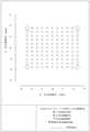
図2は、第1実施形態の撮像光学レンズ10のRMS光スポットの直径が第1象限内にある場合を示し、図2からわかるように、第1実施形態の撮像光学レンズ10は、良好な結像品質を実現することができる。 FIG. 2 shows a case where the diameter of the RMS optical spot of the image pickup
後の表13は、各実施形態1、2、3、4における諸値及び条件式で規定されたパラメータに対応する値を示す。 The latter Table 13 shows the values in the first, second, third, and fourth embodiments and the values corresponding to the parameters defined by the conditional expressions.
表13に示すように、第1実施形態は、各条件式を満たす。 As shown in Table 13, the first embodiment satisfies each conditional expression.
本実施形態では、撮像光学レンズ10の入射瞳径ENPDは、1.000mmであり、全視野像高(対角線方向)IHは、6.000mmであり、x方向像高は、4.800mmであり、y方向像高は、3.600mmであり、この矩形範囲内で結像効果は最も優れ、対角線方向の画角FOVは、119.99°であり、x方向の画角は、107.00°であり、y方向の画角は、89.94°である。撮像光学レンズ10は、広角化及び極薄化を満たし、その軸上、軸外色収差が十分に補正され、優れた光学特性を有する。 In the present embodiment, the entrance pupil diameter ENPD of the imaging
(第2実施形態)
第2実施形態は、第1実施形態と基本的に同じであり、符号の意味も第1実施形態と同様であるため、相違点のみを以下に示す。
本実施形態において、第3レンズL3の像側面は、近軸において凹面である。第4レンズL4の物体側面は、近軸において凸面である。(Second Embodiment)
Since the second embodiment is basically the same as the first embodiment and the meaning of the reference numerals is the same as that of the first embodiment, only the differences are shown below.
In the present embodiment, the image side surface of the third lens L3 is a concave surface in the paraxial axis. The object side surface of the fourth lens L4 is a convex surface in the paraxial axis.
表4及び表5は、本発明に係る第2実施形態の撮像光学レンズ20の設計データを示す。ここで、第7レンズL7の物体側面及び像側面は、自由曲面である。 Tables 4 and 5 show the design data of the image pickup

表5は、本発明に係る第2実施形態の撮像光学レンズ20における各レンズの非球面データを示す。 Table 5 shows the aspherical data of each lens in the image pickup

表6は、本発明に係る第2実施形態の撮像光学レンズ20における自由曲面データを示す。 Table 6 shows the free curved surface data in the image pickup

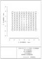
図4は、第2実施形態に係る撮像光学レンズ20のRMS光スポットの直径が第1象限内にある場合を示し、図4からわかるように、第2実施形態の撮像光学レンズ20は、良好な結像品質を実現することができる。 FIG. 4 shows a case where the diameter of the RMS optical spot of the image pickup
表13に示すように、第2実施形態は、各条件式を満たす。 As shown in Table 13, the second embodiment satisfies each conditional expression.
本実施形態では、前記撮像光学レンズ20の入射瞳径ENPDは、1.000mmであり、全視野像高(対角線方向)IHは、6.000mmであり、x方向像高は、4.800mmであり、y方向像高は、3.600mmであり、この矩形範囲内で結像効果は最も優れ、対角線方向の画角FOVは、119.99°であり、x方向の画角は、106.86°であり、y方向の画角は、90.50°である。撮像光学レンズ20は、広角化及び極薄化を満たし、その軸上、軸外色収差が十分に補正され、優れた光学特性を有する。 In the present embodiment, the entrance pupil diameter ENPD of the image pickup
(第3実施形態)
第3実施形態は、第1実施形態と基本的に同じであり、符号の意味も第1実施形態と同様であるため、相違点のみを以下に示す。(Third Embodiment)
Since the third embodiment is basically the same as the first embodiment and the meaning of the reference numerals is the same as that of the first embodiment, only the differences are shown below.
第2レンズL2は、負の屈折力を有し、第5レンズL5は、物体側面が近軸において凸面であり、第6レンズL6は、正の屈折力を有し、第6レンズL6は、物体側面が近軸において凸面であり、像側面が近軸において凸面であり、第7レンズL7は、物体側面が近軸において凹面である。絞りS1は、第1レンズL1と第2レンズL2の間に設けられている。 The second lens L2 has a negative refractive power, the fifth lens L5 has a convex surface on the paraxial side surface of the object, the sixth lens L6 has a positive refractive power, and the sixth lens L6 has a positive refractive power. The side surface of the object is convex in the paraxial axis, the side surface of the image is convex in the paraxial axis, and the side surface of the object is concave in the near axis of the seventh lens L7. The diaphragm S1 is provided between the first lens L1 and the second lens L2.
表7及び表8は、本発明に係る第3実施形態の撮像光学レンズ30の設計データを示す。ここで、第1レンズL1の物体側面及び像側面は、自由曲面である。 Tables 7 and 8 show the design data of the image pickup

表8は、本発明に係る第3実施形態の撮像光学レンズ30における各レンズの非球面データを示す。 Table 8 shows the aspherical data of each lens in the image pickup

表9は、本発明に係る第3実施形態の撮像光学レンズ30における自由曲面データを示す。 Table 9 shows the free curved surface data in the image pickup

図6は、第3実施形態の撮像光学レンズ30のRMS光スポットの直径が第1象限内にある場合を示し、図6からわかるように、第3実施形態の撮像光学レンズ30は、良好な結像品質を実現することができる。 FIG. 6 shows a case where the diameter of the RMS optical spot of the image pickup
以下では、表13は、上記条件式に従って本実施形態において各条件式に対応する値を示す。明らかに、本実施形態に係る撮像光学システムは、上記条件式を満たす。 In the following, Table 13 shows the values corresponding to each conditional expression in the present embodiment according to the above conditional expression. Obviously, the imaging optical system according to the present embodiment satisfies the above conditional expression.
本実施形態では、前記撮像光学レンズ30の入射瞳径ENPDは、1.042mmであり、全視野像高(対角線方向)IHは、6.000mmであり、x方向像高は、4.800mmであり、y方向像高は、3.600mmであり、この矩形範囲内で結像効果は最も優れ、対角線方向の画角FOVは、121.90°であり、x方向の画角は、98.29°であり、y方向の画角は、78.47°であり、撮像光学レンズ30は、広角化及び極薄化を満たし、その軸上、軸外色収差が十分に補正され、優れた光学特性を有する。 In the present embodiment, the entrance pupil diameter ENPD of the imaging
(第4実施形態)
第4実施形態は、第1実施形態と基本的に同じであり、符号の意味も第1実施形態と同様であるため、相違点のみを以下に示す。(Fourth Embodiment)
Since the fourth embodiment is basically the same as the first embodiment and the meaning of the reference numerals is the same as that of the first embodiment, only the differences are shown below.
第2レンズL2は、負の屈折力を有し、第5レンズL5は、物体側面が近軸において凸面であり、第6レンズL6は、正の屈折力を有し、第6レンズL6は、物体側面が近軸において凸面であり、像側面が近軸において凸面であり、第7レンズL7は、物体側面が近軸において凹面である。絞りS1は、第1レンズL1と第2レンズL2の間に設けられている。 The second lens L2 has a negative refractive power, the fifth lens L5 has a convex surface on the paraxial side surface of the object, the sixth lens L6 has a positive refractive power, and the sixth lens L6 has a positive refractive power. The side surface of the object is convex in the paraxial axis, the side surface of the image is convex in the paraxial axis, and the side surface of the object is concave in the near axis of the seventh lens L7. The diaphragm S1 is provided between the first lens L1 and the second lens L2.
表10、表11は、本発明に係る第4実施形態の撮像光学レンズ40の設計データを示す。ここで、第2レンズL2の物体側面及び像側面は、自由曲面である。 Tables 10 and 11 show the design data of the image pickup

表11は、本発明に係る第4実施形態の撮像光学レンズ40における各レンズの非球面データを示す。 Table 11 shows the aspherical data of each lens in the image pickup

表12は、本発明に係る第4実施形態の撮像光学レンズ40における自由曲面データを示す。 Table 12 shows the free curved surface data in the image pickup

図8は、第4実施形態の撮像光学レンズ40のRMS光スポットの直径が第1象限内にある場合を示し、図8からわかるように、第4実施形態の撮像光学レンズ40は、良好な結像品質を実現することができる。 FIG. 8 shows a case where the diameter of the RMS optical spot of the image pickup
以下では、表13は、上記条件式に従って本実施形態において各条件式に対応する値を示す。明らかに、本実施形態に係る撮像光学システムは、上記条件式を満たす。 In the following, Table 13 shows the values corresponding to each conditional expression in the present embodiment according to the above conditional expression. Obviously, the imaging optical system according to the present embodiment satisfies the above conditional expression.
本実施形態では、前記撮像光学レンズ40の入射瞳径ENPDは、1.054mmであり、全視野像高(対角線方向)IHは、6.000mmであり、x方向像高は、4.800mmであり、y方向像高は、3.600mmであり、この矩形範囲内で結像効果は最も優れ、対角線方向の画角FOVは、122.35°であり、x方向の画角は、98.71°であり、y方向の画角は、78.16°であり、撮像光学レンズ40は、広角化及び極薄化を満たし、その軸上、軸外色収差が十分に補正され、優れた光学特性を有する。 In the present embodiment, the incident pupil diameter ENPD of the imaging

当業者であれば分かるように、上記各実施形態が本発明を実現するための具体的な実施形態であり、実際の応用において、本発明の要旨と範囲から逸脱しない限り、形式及び詳細に対する各種の変更は可能である。 As will be appreciated by those skilled in the art, each of the above embodiments is a specific embodiment for realizing the present invention, and various forms and details are provided in actual applications as long as they do not deviate from the gist and scope of the present invention. Can be changed.
Claims (10)
Translated fromJapanese前記撮像光学レンズは、合計で8枚のレンズを備え、前記8枚のレンズは、物体側から像側へ順に、第1レンズ、第2レンズ、第3レンズ、第4レンズ、第5レンズ、第6レンズ、第7レンズ及び第8レンズであり、
前記第1レンズから前記第8レンズのうちの少なくとも1つは、自由曲面を含み、
前記第2レンズの焦点距離をf2、前記第6レンズの焦点距離をf6、前記第1レンズの物体側面の曲率半径をR1、前記第1レンズの像側面の曲率半径をR2としたときに、以下の条件式(1)~(2)を満たすことを特徴とする撮像光学レンズ。
-7.50≦f2/f6≦-1.50 (1)
-6.00≦R1/R2≦-0.18 (2)It is an image pickup optical lens
The imaging optical lens includes a total of eight lenses, and the eight lenses are the first lens, the second lens, the third lens, the fourth lens, and the fifth lens in this order from the object side to the image side. The sixth lens, the seventh lens, and the eighth lens.
At least one of the first lens to the eighth lens includes a free-form surface.
When the focal length of the second lens is f2, the focal length of the sixth lens is f6, the radius of curvature of the object side surface of the first lens is R1, and the radius of curvature of the image side surface of the first lens is R2. An image pickup optical lens characterized by satisfying the following conditional equations (1) and (2).
-7.50 ≤ f2 / f6 ≤ -1.50 (1)
-6.00≤R1 / R2≤-0.18 (2)
4.00≦d5/d6≦9.00 (3)When the axial thickness of the third lens is d5 and the axial distance from the image side surface of the third lens to the object side surface of the fourth lens is d6, the following conditional expression (3) is satisfied. The imaging optical lens according to claim 1.
4.00 ≤ d5 / d6 ≤ 9.00 (3)
-4.14≦f1/f≦-1.07 (4)
-1.36≦(R1+R2)/(R1-R2)≦1.07 (5)
0.03≦d1/TTL≦0.14 (6)When the focal length of the imaging optical lens is f, the focal length of the first lens is f1, the axial thickness of the first lens is d1, and the optical length of the imaging optical lens is TTL, the following conditional equations ( 4) The image pickup optical lens according to claim 1, wherein the image pickup optical lens satisfies (6) to (6).
-4.14 ≦ f1 / f ≦ -1.07 (4)
-1.36 ≤ (R1 + R2) / (R1-R2) ≤ 1.07 (5)
0.03 ≤ d1 / TTL ≤ 0.14 (6)
-28.38≦f2/f≦8.13 (7)
-12.87≦(R3+R4)/(R3-R4)≦18.86 (8)
0.02≦d3/TTL≦0.07 (9)The focal distance of the imaging optical lens is f, the radius of curvature of the object side surface of the second lens is R3, the radius of curvature of the image side surface of the second lens is R4, the axial thickness of the second lens is d3, and the imaging optics. The imaging optical lens according to claim 1, wherein the following conditional equations (7) to (9) are satisfied when the optical length of the lens is TTL.
-28.38 ≤ f2 / f ≤ 8.13 (7)
-12.87 ≤ (R3 + R4) / (R3-R4) ≤ 18.86 (8)
0.02 ≤ d3 / TTL ≤ 0.07 (9)
0.53≦f3/f≦10.57 (10)
-6.72≦(R5+R6)/(R5-R6)≦-0.10 (11)
0.02≦d5/TTL≦0.12 (12)The focal distance of the imaging optical lens is f, the focal distance of the third lens is f3, the radius of curvature of the object side surface of the third lens is R5, the radius of curvature of the image side surface of the third lens is R6, and the third lens. The image pickup optical lens according to claim 1, wherein when the axial thickness of the lens is d5 and the optical length of the image pickup optical lens is TTL, the following conditional expressions (10) to (12) are satisfied.
0.53 ≦ f3 / f ≦ 10.57 (10)
-6.72 ≤ (R5 + R6) / (R5-R6) ≤ -0.10 (11)
0.02 ≤ d5 / TTL ≤ 0.12 (12)
0.65≦f4/f≦7.26 (13)
0.14≦(R7+R8)/(R7-R8)≦6.79 (14)
0.03≦d7/TTL≦0.15 (15)The focal distance of the imaging optical lens is f, the focal distance of the fourth lens is f4, the radius of curvature of the object side surface of the fourth lens is R7, the radius of curvature of the image side surface of the fourth lens is R8, and the fourth lens. The image pickup optical lens according to claim 1, wherein when the axial thickness of the lens is d7 and the optical length of the image pickup optical lens is TTL, the following conditional expressions (13) to (15) are satisfied.
0.65 ≤ f4 / f ≤ 7.26 (13)
0.14 ≤ (R7 + R8) / (R7-R8) ≤ 6.79 (14)
0.03 ≤ d7 / TTL ≤ 0.15 (15)
-8.07≦f5/f≦-1.92 (16)
0.02≦(R9+R10)/(R9-R10)≦6.14 (17)
0.02≦d9/TTL≦0.06 (18)The focal distance of the imaging optical lens is f, the focal distance of the fifth lens is f5, the radius of curvature of the object side surface of the fifth lens is R9, the radius of curvature of the image side surface of the fifth lens is R10, and the fifth lens. The image pickup optical lens according to claim 1, wherein when the axial thickness of the lens is d9 and the optical length of the image pickup optical lens is TTL, the following conditional expressions (16) to (18) are satisfied.
−8.07 ≦ f5 / f ≦ -1.92 (16)
0.02 ≤ (R9 + R10) / (R9-R10) ≤ 6.14 (17)
0.02 ≤ d9 / TTL ≤ 0.06 (18)
-6.00≦f6/f≦2.97 (19)
-1.17≦(R11+R12)/(R11-R12)≦0.60 (20)
0.05≦d11/TTL≦0.16 (21)The focal distance of the imaging optical lens is f, the radius of curvature of the object side surface of the sixth lens is R11, the radius of curvature of the image side surface of the sixth lens is R12, the axial thickness of the sixth lens is d11, and the imaging optics. The imaging optical lens according to claim 1, wherein the following conditional equations (19) to (21) are satisfied when the optical length of the lens is TTL.
-6.00≤f6 / f≤2.97 (19)
-1.17 ≤ (R11 + R12) / (R11-R12) ≤ 0.60 (20)
0.05 ≤ d11 / TTL ≤ 0.16 (21)
0.41≦f7/f≦1.99 (22)
0.26≦(R13+R14)/(R13-R14)≦5.59 (23)
0.04≦d13/TTL≦0.20 (24)The focal distance of the imaging optical lens is f, the focal distance of the 7th lens is f7, the radius of curvature of the object side surface of the 7th lens is R13, the radius of curvature of the image side surface of the 7th lens is R14, and the 7th lens. The image pickup optical lens according to claim 1, wherein when the axial thickness of the lens is d13 and the optical length of the image pickup optical lens is TTL, the following conditional expressions (22) to (24) are satisfied.
0.41 ≦ f7 / f ≦ 1.99 (22)
0.26 ≤ (R13 + R14) / (R13-R14) ≤ 5.59 (23)
0.04 ≤ d13 / TTL ≤ 0.20 (24)
-2.74≦f8/f≦-0.82 (25)
1.15≦(R15+R16)/(R15-R16)≦4.00 (26)
0.03≦d15/TTL≦0.16 (27)The focal distance of the imaging optical lens is f, the focal distance of the eighth lens is f8, the radius of curvature of the object side surface of the eighth lens is R15, the radius of curvature of the image side surface of the eighth lens is R16, and the eighth lens. The image pickup optical lens according to claim 1, wherein when the axial thickness of the lens is d15 and the optical length of the image pickup optical lens is TTL, the following conditional expressions (25) to (27) are satisfied.
-2.74 ≤ f8 / f ≤ -0.82 (25)
1.15 ≤ (R15 + R16) / (R15-R16) ≤ 4.00 (26)
0.03 ≤ d15 / TTL ≤ 0.16 (27)
Applications Claiming Priority (2)
| Application Number | Priority Date | Filing Date | Title |
|---|---|---|---|
| CN202010727540.5 | 2020-07-27 | ||
| CN202010727540.5ACN111736308B (en) | 2020-07-27 | 2020-07-27 | Camera optics |
Publications (2)
| Publication Number | Publication Date |
|---|---|
| JP2022023762Atrue JP2022023762A (en) | 2022-02-08 |
| JP7082181B2 JP7082181B2 (en) | 2022-06-07 |
Family
ID=72657784
Family Applications (1)
| Application Number | Title | Priority Date | Filing Date |
|---|---|---|---|
| JP2020216586AActiveJP7082181B2 (en) | 2020-07-27 | 2020-12-25 | Imaging optical lens |
Country Status (4)
| Country | Link |
|---|---|
| US (1) | US12055790B2 (en) |
| JP (1) | JP7082181B2 (en) |
| CN (1) | CN111736308B (en) |
| WO (1) | WO2022021457A1 (en) |
Families Citing this family (9)
| Publication number | Priority date | Publication date | Assignee | Title |
|---|---|---|---|---|
| CN111736309B (en)* | 2020-07-27 | 2020-11-10 | 常州市瑞泰光电有限公司 | Image pickup optical lens |
| CN111929853B (en)* | 2020-10-12 | 2020-12-18 | 瑞泰光学(常州)有限公司 | Image pickup optical lens |
| CN112698492A (en)* | 2020-12-30 | 2021-04-23 | 诚瑞光学(苏州)有限公司 | Image pickup optical lens |
| CN112965223B (en)* | 2021-02-22 | 2022-06-24 | 江西晶超光学有限公司 | Optical systems, camera modules and electronic equipment |
| TWI781573B (en)* | 2021-04-07 | 2022-10-21 | 大立光電股份有限公司 | Optical imaging lens assembly, image capturing unit and electronic device |
| TWI792526B (en)* | 2021-08-30 | 2023-02-11 | 大陸商信泰光學(深圳)有限公司 | Wide-angle lens assembly |
| TWI840823B (en)* | 2022-06-01 | 2024-05-01 | 大立光電股份有限公司 | Imaging optical lens system, image capturing unit and electronic device |
| CN117192736A (en)* | 2023-09-15 | 2023-12-08 | 浙江舜宇光学有限公司 | optical lens |
| CN118151334A (en)* | 2024-03-05 | 2024-06-07 | 辰瑞光学(常州)股份有限公司 | Image pickup optical lens |
Citations (10)
| Publication number | Priority date | Publication date | Assignee | Title |
|---|---|---|---|---|
| JPH02158706A (en)* | 1988-12-13 | 1990-06-19 | Dainippon Screen Mfg Co Ltd | Lens constituted of 4 groups |
| JP2007279184A (en)* | 2006-04-04 | 2007-10-25 | Olympus Imaging Corp | Zoom lens |
| JP2011107450A (en)* | 2009-11-18 | 2011-06-02 | Sony Corp | Imaging lens and imaging apparatus |
| JP2014052511A (en)* | 2012-09-07 | 2014-03-20 | Sony Corp | Imaging lens and image capturing device |
| WO2018230033A1 (en)* | 2017-06-13 | 2018-12-20 | パナソニックIpマネジメント株式会社 | Lens system, camera system, and imaging system |
| CN110007444A (en)* | 2019-05-21 | 2019-07-12 | 浙江舜宇光学有限公司 | Optical imaging lens |
| US20190361203A1 (en)* | 2017-12-29 | 2019-11-28 | Genius Electronic Optical (Xiamen) Co., Ltd. | Optical imaging lens |
| US20200012078A1 (en)* | 2018-07-04 | 2020-01-09 | Largan Precision Co., Ltd. | Photographing optical lens assembly, imaging apparatus and electronic device |
| CN110824664A (en)* | 2018-08-10 | 2020-02-21 | 佳能企业股份有限公司 | Optical lens |
| US20200073092A1 (en)* | 2018-08-31 | 2020-03-05 | Ability Enterprise Co., Ltd. | Optical lens |
Family Cites Families (26)
| Publication number | Priority date | Publication date | Assignee | Title |
|---|---|---|---|---|
| JP4744711B2 (en)* | 2001-04-02 | 2011-08-10 | 富士フイルム株式会社 | Image capture lens |
| JP4685907B2 (en)* | 2008-07-29 | 2011-05-18 | オリンパス株式会社 | Imaging device |
| JP2013235239A (en)* | 2012-04-12 | 2013-11-21 | Konica Minolta Inc | Macro lens and image capturing device |
| TWI662291B (en)* | 2015-04-14 | 2019-06-11 | 佳能企業股份有限公司 | Optical lens |
| JP6478903B2 (en)* | 2015-12-21 | 2019-03-06 | カンタツ株式会社 | Imaging lens |
| TWI724190B (en)* | 2017-06-23 | 2021-04-11 | 佳能企業股份有限公司 | Optical lens and electronic device using the same |
| CN109143534B (en)* | 2017-06-28 | 2022-02-08 | 佳能企业股份有限公司 | Optical lens and electronic device using same |
| TWI636279B (en)* | 2017-08-18 | 2018-09-21 | 大立光電股份有限公司 | Image capturing optical system group, image capturing device and electronic device |
| JP7086709B2 (en)* | 2018-05-14 | 2022-06-20 | キヤノン株式会社 | Optical system and an image pickup device having it |
| CN112166363B (en)* | 2018-07-18 | 2023-01-06 | 松下知识产权经营株式会社 | Imaging optical system, imaging device, and imaging system |
| TWI769289B (en)* | 2018-08-08 | 2022-07-01 | 佳能企業股份有限公司 | Optical lens |
| CN110873944B (en)* | 2018-09-04 | 2022-06-17 | 佳能企业股份有限公司 | Optical lens |
| TWI699574B (en)* | 2018-10-24 | 2020-07-21 | 大立光電股份有限公司 | Imaging lens system, image capturing unit and electronic device |
| CN110609376B (en)* | 2019-09-27 | 2024-04-19 | 浙江舜宇光学有限公司 | Optical imaging lens |
| CN110632742B (en)* | 2019-11-06 | 2024-09-27 | 浙江舜宇光学有限公司 | Optical imaging lens |
| CN110967812B (en)* | 2019-12-13 | 2021-07-30 | 诚瑞光学(常州)股份有限公司 | Camera optics |
| CN111025589B (en)* | 2019-12-28 | 2021-09-24 | 诚瑞光学(常州)股份有限公司 | Camera optics |
| TWI725714B (en)* | 2020-01-20 | 2021-04-21 | 大立光電股份有限公司 | Photographing optical lens assembly, imaging apparatus and electronic device |
| CN111239970A (en)* | 2020-02-21 | 2020-06-05 | 天津欧菲光电有限公司 | Optical system, camera module, electronic device and automobile |
| CN111308651B (en)* | 2020-02-24 | 2022-03-01 | 诚瑞光学(常州)股份有限公司 | Image pickup optical lens |
| CN111736311B (en)* | 2020-07-27 | 2020-11-13 | 常州市瑞泰光电有限公司 | Camera optics |
| CN111736309B (en)* | 2020-07-27 | 2020-11-10 | 常州市瑞泰光电有限公司 | Image pickup optical lens |
| CN111596446B (en)* | 2020-07-27 | 2020-10-27 | 常州市瑞泰光电有限公司 | Image pickup optical lens |
| CN111736312B (en)* | 2020-07-27 | 2020-11-27 | 诚瑞光学(常州)股份有限公司 | Camera optics |
| CN111736310B (en)* | 2020-07-27 | 2020-11-27 | 诚瑞光学(常州)股份有限公司 | Camera optics |
| CN113960769A (en)* | 2021-09-23 | 2022-01-21 | 诚瑞光学(苏州)有限公司 | Image pickup optical lens |
- 2020
- 2020-07-27CNCN202010727540.5Apatent/CN111736308B/enactiveActive
- 2020-08-03WOPCT/CN2020/106613patent/WO2022021457A1/ennot_activeCeased
- 2020-12-24USUS17/133,680patent/US12055790B2/enactiveActive
- 2020-12-25JPJP2020216586Apatent/JP7082181B2/enactiveActive
Patent Citations (10)
| Publication number | Priority date | Publication date | Assignee | Title |
|---|---|---|---|---|
| JPH02158706A (en)* | 1988-12-13 | 1990-06-19 | Dainippon Screen Mfg Co Ltd | Lens constituted of 4 groups |
| JP2007279184A (en)* | 2006-04-04 | 2007-10-25 | Olympus Imaging Corp | Zoom lens |
| JP2011107450A (en)* | 2009-11-18 | 2011-06-02 | Sony Corp | Imaging lens and imaging apparatus |
| JP2014052511A (en)* | 2012-09-07 | 2014-03-20 | Sony Corp | Imaging lens and image capturing device |
| WO2018230033A1 (en)* | 2017-06-13 | 2018-12-20 | パナソニックIpマネジメント株式会社 | Lens system, camera system, and imaging system |
| US20190361203A1 (en)* | 2017-12-29 | 2019-11-28 | Genius Electronic Optical (Xiamen) Co., Ltd. | Optical imaging lens |
| US20200012078A1 (en)* | 2018-07-04 | 2020-01-09 | Largan Precision Co., Ltd. | Photographing optical lens assembly, imaging apparatus and electronic device |
| CN110824664A (en)* | 2018-08-10 | 2020-02-21 | 佳能企业股份有限公司 | Optical lens |
| US20200073092A1 (en)* | 2018-08-31 | 2020-03-05 | Ability Enterprise Co., Ltd. | Optical lens |
| CN110007444A (en)* | 2019-05-21 | 2019-07-12 | 浙江舜宇光学有限公司 | Optical imaging lens |
Also Published As
| Publication number | Publication date |
|---|---|
| JP7082181B2 (en) | 2022-06-07 |
| US12055790B2 (en) | 2024-08-06 |
| WO2022021457A1 (en) | 2022-02-03 |
| US20220026672A1 (en) | 2022-01-27 |
| CN111736308A (en) | 2020-10-02 |
| CN111736308B (en) | 2020-12-22 |
Similar Documents
| Publication | Publication Date | Title |
|---|---|---|
| JP7029516B2 (en) | Imaging optical lens | |
| JP7082181B2 (en) | Imaging optical lens | |
| JP7075474B2 (en) | Imaging optical lens | |
| JP7011691B1 (en) | Imaging optical lens | |
| JP7007435B1 (en) | Imaging optical lens | |
| JP7093399B2 (en) | Imaging optical lens | |
| JP7079296B2 (en) | Imaging optical lens | |
| JP7072630B2 (en) | Imaging optical lens | |
| JP2021189427A (en) | Imaging optical lens | |
| JP7082176B2 (en) | Imaging optical lens | |
| JP7064817B2 (en) | Imaging optical lens | |
| JP7093398B2 (en) | Imaging optical lens | |
| JP7098707B2 (en) | Imaging optical lens | |
| JP7083387B2 (en) | Imaging optical lens | |
| JP7105858B2 (en) | imaging optical lens | |
| JP7026199B2 (en) | Imaging optical lens | |
| JP6501373B1 (en) | Imaging optical lens | |
| JP7061661B2 (en) | Imaging optical lens | |
| JP2021135491A (en) | Imaging optical lens | |
| JP2022039896A (en) | Image capturing optical lens | |
| JP2022017155A (en) | Image capturing optical lens | |
| JP6961318B1 (en) | Imaging optical lens | |
| JP7091432B2 (en) | Imaging optical lens | |
| JP6917120B1 (en) | Imaging optical lens | |
| JP2022037853A (en) | Image capturing optical lens |
Legal Events
| Date | Code | Title | Description |
|---|---|---|---|
| A621 | Written request for application examination | Free format text:JAPANESE INTERMEDIATE CODE: A621 Effective date:20210114 | |
| A977 | Report on retrieval | Free format text:JAPANESE INTERMEDIATE CODE: A971007 Effective date:20220127 | |
| A131 | Notification of reasons for refusal | Free format text:JAPANESE INTERMEDIATE CODE: A131 Effective date:20220208 | |
| A521 | Request for written amendment filed | Free format text:JAPANESE INTERMEDIATE CODE: A523 Effective date:20220506 | |
| TRDD | Decision of grant or rejection written | ||
| A01 | Written decision to grant a patent or to grant a registration (utility model) | Free format text:JAPANESE INTERMEDIATE CODE: A01 Effective date:20220525 | |
| A61 | First payment of annual fees (during grant procedure) | Free format text:JAPANESE INTERMEDIATE CODE: A61 Effective date:20220526 | |
| R150 | Certificate of patent or registration of utility model | Ref document number:7082181 Country of ref document:JP Free format text:JAPANESE INTERMEDIATE CODE: R150 | |
| R250 | Receipt of annual fees | Free format text:JAPANESE INTERMEDIATE CODE: R250 |