JP2022022949A - Monitoring equipment, monitoring methods and monitoring programs - Google Patents
Monitoring equipment, monitoring methods and monitoring programsDownload PDFInfo
- Publication number
- JP2022022949A JP2022022949AJP2020203552AJP2020203552AJP2022022949AJP 2022022949 AJP2022022949 AJP 2022022949AJP 2020203552 AJP2020203552 AJP 2020203552AJP 2020203552 AJP2020203552 AJP 2020203552AJP 2022022949 AJP2022022949 AJP 2022022949A
- Authority
- JP
- Japan
- Prior art keywords
- individual
- monitoring
- monitoring device
- identification unit
- millimeter wave
- Prior art date
- Legal status (The legal status is an assumption and is not a legal conclusion. Google has not performed a legal analysis and makes no representation as to the accuracy of the status listed.)
- Pending
Links
Images


Landscapes
- Measurement Of The Respiration, Hearing Ability, Form, And Blood Characteristics Of Living Organisms (AREA)
- Emergency Alarm Devices (AREA)
- Alarm Systems (AREA)
- Radar Systems Or Details Thereof (AREA)
Abstract
Translated fromJapaneseDescription
Translated fromJapanese本発明は、ミリ波センサを用いた監視装置に関する。 The present invention relates to a monitoring device using a millimeter wave sensor.
周波数30GHz~300GHz、波長1mm~1cmのミリ波は電波の中でも光に近い周波数帯であり、直進性が非常に強い、耐環境性(雨、霧、雪、汚れ)に優れている、アンテナの小型化が可能、情報伝送容量が大きいといった特徴を有する。ミリ波センサは、物体の位置と速度を瞬時に検知することができるため、例えば、自動車の衝突防止システムに用いられている。 Millimeter waves with a frequency of 30 GHz to 300 GHz and a wavelength of 1 mm to 1 cm are in the frequency band close to light in radio waves, have very strong straightness, and have excellent environmental resistance (rain, fog, snow, dirt). It has the features of being able to be miniaturized and having a large information transmission capacity. Millimeter-wave sensors are used, for example, in automobile collision prevention systems because they can instantly detect the position and speed of an object.
特に、FMCW(周波数変調連続波)方式のミリ波センサは、最小で0.1mm単位の動きを検出することが可能である(例えば、非特許文献1)。 In particular, the FMCW (continuous wave) type millimeter wave sensor can detect motion in units of 0.1 mm at the minimum (for example, Non-Patent Document 1).
例えば、介護施設において、ミリ波センサを用いて複数の高齢者の行動を監視する場合、ミリ波センサは、監視領域内に人が存在するか否か、人がどのような行動を取っているかは検知できる。しかし、誰が存在するか、誰がどのような行動を取っているかは、従来のミリ波センサを用いた装置では検知できない。 For example, in a long-term care facility, when monitoring the behavior of a plurality of elderly people using a millimeter-wave sensor, the millimeter-wave sensor determines whether or not a person exists in the monitoring area and what kind of behavior the person is taking. Can be detected. However, who exists and who is taking what kind of action cannot be detected by a device using a conventional millimeter-wave sensor.
本発明は、上記問題を鑑みてなされたものであって、簡易な構成で個体を識別可能な監視装置を提供することを課題とする。 The present invention has been made in view of the above problems, and an object of the present invention is to provide a monitoring device capable of identifying an individual with a simple configuration.
上記課題を解決するために、本発明は以下の態様を含む。
項1.
複数の個体を監視するための監視装置であって、
前記個体にミリ波を照射するミリ波センサと、
前記ミリ波センサの測定結果に基づいて、前記個体を識別する識別部と、
を備え、
前記識別部は、前記個体の規則的に振動する部位の振幅に基づいて、前記個体を識別することを特徴とする監視装置。
項2.
前記部位は動脈であることを特徴とする項1に記載の監視装置。
項3.
前記部位は頚動脈であることを特徴とする項2に記載の監視装置。
項4.
前記部位は胸膜または腹膜であることを特徴とする項1~3のいずれかに記載の監視装置。
項5.
前記識別部は、さらに前記個体の身長に基づいて、前記個体を識別することを特徴とする項1~4のいずれかに記載の監視装置。
項6.
前記ミリ波の周波数帯域は、60GHz~64GHzであることを特徴とする項1~5のいずれかに記載の監視装置。
項7.
前記個体の位置を追跡する追跡部をさらに備えることを特徴とする項1~6に記載の監視装置。
項8.
特定の領域内の個体を項1~7のいずれかに記載の監視装置によって監視することを特徴とする監視方法。
項9.
前記領域は、介護施設または病院であることを特徴とする項8に記載の監視方法。
項10.
項1~6のいずれかに記載の監視装置の前記識別部としてコンピュータを動作させる監視プログラム。In order to solve the above problems, the present invention includes the following aspects.
It is a monitoring device for monitoring multiple individuals.
A millimeter wave sensor that irradiates the individual with millimeter waves,
An identification unit that identifies the individual based on the measurement result of the millimeter wave sensor,
Equipped with
The identification unit is a monitoring device characterized by identifying the individual based on the amplitude of a regularly vibrating portion of the individual.
Item 4.
Item 6. The monitoring device according to any one of
Item 5.
Item 6.
Item 6. The monitoring device according to any one of
Item 7.
Item 6. The monitoring device according to
Item 8.
A monitoring method comprising monitoring an individual in a specific area by the monitoring device according to any one of
Item 9.
Item 8. The monitoring method according to Item 8, wherein the area is a long-term care facility or a hospital.
A monitoring program that operates a computer as the identification unit of the monitoring device according to any one of
本発明によれば、簡易な構成で個体を識別可能な監視装置を提供することができる。 According to the present invention, it is possible to provide a monitoring device capable of identifying an individual with a simple configuration.
[第1の実施形態]
以下、本発明の第1の実施形態について添付図面を参照して説明する。なお、本発明は、下記の実施形態に限定されるものではない。[First Embodiment]
Hereinafter, the first embodiment of the present invention will be described with reference to the accompanying drawings. The present invention is not limited to the following embodiments.
(全体構成)
本実施形態では、本発明に係る監視装置を、介護施設における入居者の監視(見守り)に利用する形態について説明する。図1は、本実施形態に係る監視システム100の概略図である。監視システム100は、複数の監視装置1と、サーバ10とを備えている。監視装置1は、介護施設の各部屋、廊下、休憩所、玄関等に設置されている。サーバ10は、介護施設の管理者が駐在する部屋に設けられており、LAN等のネットワークNを介して監視装置1と通信可能である。サーバ10は、各監視装置1の制御を行うとともに、監視装置1からの情報に基づいて、介護施設の入居者の行動を検知する。これにより、介護施設内の入居者を監視装置1によって監視する監視方法を実施することができる。(overall structure)
In the present embodiment, a mode in which the monitoring device according to the present invention is used for monitoring (watching) a resident in a nursing care facility will be described. FIG. 1 is a schematic diagram of a
(監視装置の構成)
図2は、本実施形態に係る監視装置1のブロック図である。監視装置1は、FMCW(周波数連続変調)方式のミリ波レーダシステムを構成する装置であり、ミリ波センサ2と、マイコン3とを主に備えている。(Configuration of monitoring device)
FIG. 2 is a block diagram of the
ミリ波センサ2は、n個の送信アンテナTX1~TXnと、n個の受信アンテナRX1~RXnと、シンセサイザ21と、ミキサ22と、ADC23とを主に備えている。送信アンテナおよび受信アンテナの個数(n)は特に限定されないが、個数が多いほど、より多くの個体(入居者)を同時に測定できる。本実施形態では、n=5である。 The
シンセサイザ21は、時間経過に応じて周波数が直線的に変化する変調波(チャープ信号)を生成する。本実施形態では、チャープ信号の周波数帯域は60GHz~64GHzである。 The
チャープ信号は、時分割多重(TDM)方式で送信アンテナTX1~TXnを介して送信され、受信アンテナRX1~RXnは、個体からの反射波を受信する。ミキサ22は、送信波と受信波を混合し、IF(中間周波数)信号を生成する。IF信号は、ADC23においてデジタル信号に変換され、マイコン3に入力される。 The chirp signal is transmitted via the transmitting antennas TX1 to TXn in a time division multiplexing (TDM) method, and the receiving antennas RX1 to RXn receive the reflected wave from the individual. The
マイコン3は、補助記憶装置31と、CPU32と、図示しない主記憶装置とを主に備えている。本実施形態では、ミリ波センサ2およびマイコン3は一体化されているが、マイコン3の機能の少なくとも一部を図1に示すサーバ10に持たせてもよい。 The
補助記憶装置31は、EEPROMやフラッシュメモリなどの不揮発性メモリで構成される。補助記憶装置31には、監視プログラム311およびパターン情報312が記憶されている。監視プログラム311は、通信ネットワークを介して供給してもよく、あるいは、コンピュータで読み取り可能に記録した記録媒体を介して供給してもよい。パターン情報312については、後述する。 The
CPU32は、監視プログラム311を主記憶装置に読み出して実行することにより、波形発生部321、DSP322、識別部323およびジェスチャー判別部324として動作する。また、321~324の各機能ブロックの少なくとも一部を、集積回路(ICチップ)上に形成された論理回路によってハードウェア的に実現してもよい。 The
波形発生部321は、シンセサイザ21が生成するチャープ信号の波形を設定する機能を有している。具体的には、波形発生部321は、チャープ信号の開始周波数、帯域幅、持続時間などを設定する。 The
DSP322は、AD変換されたIF信号に各種信号処理(フーリエ変換等)を実施して、個体の距離・速度・角度を検出することにより、個体の位置および速度を取得する機能を有している。個体の距離・速度・角度の検出方法は、従来公知であり、例えば、非特許文献1に記載の方法を採用することができる。本実施形態では、個体の特に頚動脈および胸膜を含む複数の部位の位置および速度を検出する。 The DSP322 has a function of acquiring the position and speed of an individual by performing various signal processing (Fourier transform, etc.) on the AD-converted IF signal and detecting the distance, speed, and angle of the individual. .. Methods for detecting the distance, speed, and angle of an individual are conventionally known, and for example, the method described in
さらに、本実施形態では、送信アンテナおよび受信アンテナを公知のMIMO(マルチインプット、マルチアウトプット)構成としている。これにより、複数の個体の位置および速度を同時に取得することができる。 Further, in the present embodiment, the transmitting antenna and the receiving antenna have a known MIMO (multi-input, multi-output) configuration. This makes it possible to simultaneously acquire the positions and velocities of a plurality of individuals.
識別部323は、ミリ波センサ2の測定結果、すなわち、個体の位置および速度の情報に基づいて、個体を識別する(すなわち、個体が誰であるかを特定する)機能を有している。特に、識別部323は、個体の位置および速度の情報の中で、個体の規則的に振動する部位の振幅に基づいて、個体を識別することを特徴としている。本実施形態では、規則的に振動する部位は、頚動脈および胸膜である。 The
頚動脈および胸膜はそれぞれ、心拍および呼吸によって規則的に振動する。人の心拍数および呼吸数は変動するが、頚動脈および胸膜の振幅は、心拍数および呼吸数の変化に関わらず一定である。すなわち、頚動脈および胸膜の振幅は、各個体に固有のものである。また、頚動脈および胸膜は、他の組織とのインピーダンスの差が大きいため、ミリ波を反射しやすい。本願の発明者は、これらに着目し、頚動脈および胸膜の振幅を、個体を識別する指標とすることで、ミリ波センサを用いて個体を識別できることを見出した。 The carotid artery and pleura vibrate regularly with heartbeat and respiration, respectively. A person's heart rate and respiratory rate fluctuate, but the carotid and pleural amplitudes are constant regardless of changes in heart rate and respiratory rate. That is, the carotid and pleural amplitudes are unique to each individual. In addition, the carotid artery and pleura have a large impedance difference from other tissues, so that they tend to reflect millimeter waves. Focusing on these, the inventor of the present application has found that an individual can be identified by using a millimeter-wave sensor by using the amplitudes of the carotid artery and the pleura as an index for identifying the individual.
さらに、識別部323は、頚動脈および胸膜に加え、個体の身長に基づいて個体を識別している。個体を識別する指標に身長を加えることにより、頚動脈および胸膜の振幅がいずれも共通する個体が複数検知された場合であっても、身長が異なれば個体を識別することができるため、識別精度を向上させることができる。 Further, the
本実施形態では、介護施設の全入居者、或いは、少なくとも監視装置1が設置されている部屋の全入居者に対し、あらかじめミリ波センサを用いて頚動脈および胸膜の振幅を測定しておく。これに、各入居者の番号、氏名、身長の情報を対応付けてパターン情報312を作成し、監視装置1の補助記憶装置31にパターン情報312を記憶させておく。 In the present embodiment, the amplitudes of the carotid artery and the pleura are measured in advance using a millimeter-wave sensor for all the residents of the long-term care facility, or at least all the residents of the room in which the
パターン情報312の一例を図3に示す。頚動脈の振幅は概ね0.1mm~0.5mmの範囲であり、胸膜の振幅は概ね0.5mm~5.0mmの範囲になる。 An example of the
ミリ波センサ2は、個体の各部位の位置を0.1mm単位で測定することが可能である。本実施形態では、DSP322は、個体の頚動脈および胸膜の位置および速度、並びに、個体の高さ方向12箇所および水平方向12箇所の位置および速度を測定する。識別部323は、この測定結果の中で、頚動脈および胸膜の位置および速度に基づき、頚動脈および胸膜の振幅を算出するとともに、個体の高さ方向の両端2箇所の位置に基づき、個体の身長を算出する。さらに、識別部323は、算出された頚動脈および胸膜の振幅並びに身長を、パターン情報312に照会し、それらの数値に合致する(または、所定以上に類似する)入居者を特定する。これにより、識別部323は、測定された個体がどの入居者であるかを識別することができる。 The
ジェスチャー判別部324は、識別部323によって識別された個体の動作を判別する機能を有している。動作の判別方法は、従来公知のものを採用することができ、本実施形態では、個体の高さ方向12箇所および水平方向12箇所の位置および速度から、個体の動作(起きる、寝る、座る、歩く、走る等)を判別することができる。 The
以上のように、本実施形態に係る監視装置1によって、介護施設の特定の領域に、誰が存在しているか、さらに、誰がどのような行動を取っているかを把握することができる。また、ミリ波センサは、一般的な監視カメラに比べ簡易かつ安価であるので、簡易な構成で個体を識別することができる。また、図1に示す監視システム100は、監視カメラを利用した監視システムに比べ、安価に構築することができる。 As described above, the
(付記事項)
以上、本発明の第1の実施形態について説明したが、本発明は上記実施形態に限定されるものではなく、その趣旨を逸脱しない限りにおいて、種々の変更が可能である。(Additional notes)
Although the first embodiment of the present invention has been described above, the present invention is not limited to the above embodiment, and various modifications can be made without departing from the spirit of the present invention.
上記実施形態では、識別部323は、個体の頚動脈および胸膜の振幅に基づいて個体を識別していたが、個体を識別する指標となる部位は、個体に固有の振幅で規則的に振動する部位であれば特に限定されない。例えば、橈骨動脈、尺骨動脈、上腕動脈、浅側頭動脈、膝窩動脈、足背動脈などの比較的皮膚に近い動脈は、ミリ波が入射しやすいので、個体を識別する指標として好ましい。また、呼吸に応じて規則的に振動する部位として、胸膜の他に腹膜が挙げられる。 In the above embodiment, the
上記実施形態では、ミリ波センサ2から照射されるミリ波の周波数帯域は、60GHz~64GHzであったが、本発明はこれに限定されず、例えば、77GHz~81GHzであってもよい。ただし、この周波数帯域は、自動車の衝突防止システム等に用いられることが多いため、干渉を防止する観点では、60GHz~64GHzが好ましい。 In the above embodiment, the frequency band of the millimeter wave emitted from the
[第2の実施形態]
以下、本発明の第2の実施形態について添付図面を参照して説明する。なお、上記の第1の実施形態におけるものと同様の機能を有する部材については、同じ符号を付し、その詳細な説明を省略する。[Second Embodiment]
Hereinafter, the second embodiment of the present invention will be described with reference to the accompanying drawings. The members having the same functions as those in the first embodiment are designated by the same reference numerals, and detailed description thereof will be omitted.
図4は、本実施形態に係る監視装置1’のブロック図である。監視装置1’は、ミリ波センサ2と、マイコン3’とを主に備えている。 FIG. 4 is a block diagram of the monitoring device 1'according to the present embodiment. The monitoring device 1'mainly includes a
ミリ波センサ2は、図2に示すものと同一であってもよいが、本実施形態では、例えば、116度角、到達距離6mの扇形の範囲にミリ波を照射することができる。 The
マイコン3’は、図2に示すマイコン3において、CPU32をCPU32’に置き換えたものであり、CPU32’は、CPU32において、ジェスチャー判別部324を追跡部325に置き換えたものである。なお、CPU32’は、ジェスチャー判別部324をさらに備えていてもよい。 The microcomputer 3'is the one in which the
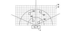
追跡部325は、個体の位置を追跡(トラッキング)する機能を有している。図5に示すように、センサ2の検知領域は、多数(例えば256個)の格子状のマスMに細分化されている。追跡部325は、DSP322によって検出された個体が、細分化されたマスのどのマスに位置するのかを特定する。 The
図5において、実線枠で示されているマスM1~M4は、個体が位置するマスを示している。さらに追跡部325は、センサ2に近い順に、マスM1~M4の各々を識別部323による識別結果と対応付けることにより、どのマスに誰がいるかを特定する。識別部323による個体の識別方法は、第1の実施形態におけるものと同様であり、頚動脈および胸膜の2つの特徴点における振幅に基づいて個体を識別する。 In FIG. 5, the squares M1 to M4 shown by the solid line frame indicate the squares in which the individual is located. Further, the
このように、追跡部325は、個体が存在するマスの特定、および、マスと個体の識別結果との対応付けの処理を、周期的(例えば0.5秒毎)に行うことで、リアルタイムで個体の位置を追跡することができる。追跡部325によって特定された個体の位置および識別情報は、リアルタイムでマイコン3のメモリに記憶されるとともに、サーバ10に送信されてもよい。これにより、サーバ10では、施設のセンサ2が設けられている全領域の個体の位置および識別情報を管理することができる。なお、施設における個体の位置および識別情報を、複数の施設を管理するクラウドサーバにさらに送信してもよい。 In this way, the
いったん個体が識別された後は、原則として、識別部323による個体の識別は行われず、追跡部325は、個体が存在するマスM1~M4の時間的な変化に基づき、各個体を追跡する。例えば、図5において実線枠で示されるマスが隣接するマスに移動した場合は、追跡部325は、同じ個体が移動したものと推定する。一方、複数の個体が同じマスに移動し、その後、各個体が異なるマスに移動した場合は、どの個体がどのマスに移動したかが推定できなくなるため、再度、識別部323による個体の識別が行われ、追跡部325は、マスと個体の識別結果とを対応付ける。これにより、追跡部325は、個体の追跡を継続することができる。 Once an individual is identified, in principle, the
個体がセンサ2の検知領域の外に移動した場合、追跡部325は当該個体を追跡できなくなる。その場合、サーバ10は、当該個体がセンサ2の設置されている部屋から出たものと推定する。その後、当該個体が他の部屋に入った場合、当該他の部屋に設置されているセンサ2において、上記と同様に、個体の識別および位置の特定が行われ、追跡が再開される。なお、別の部屋に設置されているセンサ2に、当該個体を識別するためのパターン情報が記憶されていない場合は、センサ2がサーバ10に記憶されている全個体のパターン情報にアクセスすることにより、当該個体を識別することができる。これにより、サーバ10は、施設内における個体の移動状況を把握できる。 When an individual moves out of the detection area of the
なお、センサ2を各部屋だけでなく、廊下や休憩室などにも設置することにより、サーバ10では、ほぼ常時、施設内における各個体の追跡が可能となる。 By installing the
(付記事項)
以上、本発明の第2の実施形態について説明したが、本発明は上記実施形態に限定されるものではなく、その趣旨を逸脱しない限りにおいて、種々の変更が可能である。(Additional notes)
Although the second embodiment of the present invention has been described above, the present invention is not limited to the above embodiment, and various modifications can be made without departing from the spirit of the present invention.
本発明は、特に介護施設や病院における人間の行動の監視に好適であるが、監視領域は特に限定されない。また、本発明は、ペット等の動物の監視にも適用することができる。すなわち、本発明の監視対象となる「個体」は、人間以外の動物も含んでもよい。 The present invention is particularly suitable for monitoring human behavior in nursing care facilities and hospitals, but the monitoring area is not particularly limited. The present invention can also be applied to monitoring animals such as pets. That is, the "individual" to be monitored by the present invention may include animals other than humans.
1 監視装置
1’ 監視装置
2 ミリ波センサ
21 シンセサイザ
22 ミキサ
23 ADC
3 マイコン
3’ マイコン
31 補助記憶装置
32 CPU
32’ CPU
311 監視プログラム
312 パターン情報
321 波形発生部
322 DSP
323 識別部
324 ジェスチャー判別部
325 追跡部
10 サーバ
100 監視システム
M マス
M1~M4 マス
RX1~RXn 受信アンテナ
TX1~TXn 送信アンテナ1 Monitoring
3
32'CPU
311
323
Claims (10)
Translated fromJapanese前記個体にミリ波を照射するミリ波センサと、
前記ミリ波センサの測定結果に基づいて、前記個体を識別する識別部と、
を備え、
前記識別部は、前記個体の規則的に振動する部位の振幅に基づいて、前記個体を識別することを特徴とする監視装置。It is a monitoring device for monitoring multiple individuals.
A millimeter wave sensor that irradiates the individual with millimeter waves,
An identification unit that identifies the individual based on the measurement result of the millimeter wave sensor,
Equipped with
The identification unit is a monitoring device characterized by identifying the individual based on the amplitude of a regularly vibrating portion of the individual.
Applications Claiming Priority (2)
| Application Number | Priority Date | Filing Date | Title |
|---|---|---|---|
| JP2020117335 | 2020-07-07 | ||
| JP2020117335 | 2020-07-07 |
Publications (1)
| Publication Number | Publication Date |
|---|---|
| JP2022022949Atrue JP2022022949A (en) | 2022-02-07 |
Family
ID=80225250
Family Applications (1)
| Application Number | Title | Priority Date | Filing Date |
|---|---|---|---|
| JP2020203552APendingJP2022022949A (en) | 2020-07-07 | 2020-12-08 | Monitoring equipment, monitoring methods and monitoring programs |
Country Status (1)
| Country | Link |
|---|---|
| JP (1) | JP2022022949A (en) |
Cited By (3)
| Publication number | Priority date | Publication date | Assignee | Title |
|---|---|---|---|---|
| JP7327868B1 (en)* | 2022-08-17 | 2023-08-16 | フィンガルリンク株式会社 | Biological condition measuring device, biological condition measuring method, program and biological condition measuring system |
| WO2024038629A1 (en)* | 2022-08-17 | 2024-02-22 | フィンガルリンク株式会社 | Biological state measurement device, biological state measurement method, program, and biological state measurement system |
| WO2025197292A1 (en)* | 2024-03-19 | 2025-09-25 | 株式会社村田製作所 | Fall detecting device and fall detecting method |
Citations (17)
| Publication number | Priority date | Publication date | Assignee | Title |
|---|---|---|---|---|
| KR20080028595A (en)* | 2006-09-27 | 2008-04-01 | 김현호 | Fuzzy based door lock device and control method |
| WO2010024417A1 (en)* | 2008-09-01 | 2010-03-04 | 学校法人同志社 | Arteriosclerosis evaluating apparatus |
| JP2011519288A (en)* | 2008-04-03 | 2011-07-07 | カイ メディカル、 インコーポレイテッド | Non-contact physiological motion sensor and method of use thereof |
| US20120068819A1 (en)* | 2006-04-05 | 2012-03-22 | Mcgrath William R | Systems and methods for remote long standoff biometric identification using microwave cardiac signals |
| WO2016057781A1 (en)* | 2014-10-08 | 2016-04-14 | The University Of Florida Research Foundation, Inc. | Method and apparatus for non-contact fast vital sign acquisition based on radar signal |
| JP2017164405A (en)* | 2016-03-18 | 2017-09-21 | 医療法人社団皓有会 | Blood pressure information estimation device |
| JP2017530762A (en)* | 2014-09-10 | 2017-10-19 | エーアイティー オーストリアン インスティテュート オブ テクノロジー ゲゼルシャフト ミット ベシュレンクテル ハフツングAIT Austrian Institute of Technology GmbH | Method and apparatus for determining time curves of respiratory depth |
| US20180000355A1 (en)* | 2015-04-08 | 2018-01-04 | Google Inc. | Assessing Cardiovascular Function Using an Optical Sensor |
| JP2018517448A (en)* | 2015-04-20 | 2018-07-05 | レスメッド センサー テクノロジーズ リミテッド | Human detection and identification from characteristic signals |
| US20180279884A1 (en)* | 2017-03-29 | 2018-10-04 | Texas Instruments Incorporated | Multi-person vital signs monitoring using millimeter wave (mm-wave) signals |
| US20180289305A1 (en)* | 2017-04-05 | 2018-10-11 | Nokia Technologies Oy | Determining breathing attributes by a detection device |
| WO2018211948A1 (en)* | 2017-05-17 | 2018-11-22 | 日本電気株式会社 | Object detection device, in-vehicle radar system, monitoring radar system, object detection method of object detection device, and program |
| US20190298208A1 (en)* | 2018-03-30 | 2019-10-03 | Zoll Medical Israel Ltd. | Systems, devices and methods for radio frequency-based physiological monitoring of patients |
| JP2019211467A (en)* | 2018-05-30 | 2019-12-12 | パナソニックIpマネジメント株式会社 | Monitoring support apparatus and monitoring support method |
| JP2020081312A (en)* | 2018-11-22 | 2020-06-04 | 公立大学法人北九州市立大学 | Living body detection device, living body detection system, living body detection method, and living body data acquisition device |
| US20200184055A1 (en)* | 2018-12-11 | 2020-06-11 | Alibaba Group Holding Limited | Authentication based on correlation of multiple pulse signals |
| CN111358464A (en)* | 2018-12-26 | 2020-07-03 | 北京信息科技大学 | A non-contact vital sign monitoring method for bedridden patients |
- 2020
- 2020-12-08JPJP2020203552Apatent/JP2022022949A/enactivePending
Patent Citations (17)
| Publication number | Priority date | Publication date | Assignee | Title |
|---|---|---|---|---|
| US20120068819A1 (en)* | 2006-04-05 | 2012-03-22 | Mcgrath William R | Systems and methods for remote long standoff biometric identification using microwave cardiac signals |
| KR20080028595A (en)* | 2006-09-27 | 2008-04-01 | 김현호 | Fuzzy based door lock device and control method |
| JP2011519288A (en)* | 2008-04-03 | 2011-07-07 | カイ メディカル、 インコーポレイテッド | Non-contact physiological motion sensor and method of use thereof |
| WO2010024417A1 (en)* | 2008-09-01 | 2010-03-04 | 学校法人同志社 | Arteriosclerosis evaluating apparatus |
| JP2017530762A (en)* | 2014-09-10 | 2017-10-19 | エーアイティー オーストリアン インスティテュート オブ テクノロジー ゲゼルシャフト ミット ベシュレンクテル ハフツングAIT Austrian Institute of Technology GmbH | Method and apparatus for determining time curves of respiratory depth |
| WO2016057781A1 (en)* | 2014-10-08 | 2016-04-14 | The University Of Florida Research Foundation, Inc. | Method and apparatus for non-contact fast vital sign acquisition based on radar signal |
| US20180000355A1 (en)* | 2015-04-08 | 2018-01-04 | Google Inc. | Assessing Cardiovascular Function Using an Optical Sensor |
| JP2018517448A (en)* | 2015-04-20 | 2018-07-05 | レスメッド センサー テクノロジーズ リミテッド | Human detection and identification from characteristic signals |
| JP2017164405A (en)* | 2016-03-18 | 2017-09-21 | 医療法人社団皓有会 | Blood pressure information estimation device |
| US20180279884A1 (en)* | 2017-03-29 | 2018-10-04 | Texas Instruments Incorporated | Multi-person vital signs monitoring using millimeter wave (mm-wave) signals |
| US20180289305A1 (en)* | 2017-04-05 | 2018-10-11 | Nokia Technologies Oy | Determining breathing attributes by a detection device |
| WO2018211948A1 (en)* | 2017-05-17 | 2018-11-22 | 日本電気株式会社 | Object detection device, in-vehicle radar system, monitoring radar system, object detection method of object detection device, and program |
| US20190298208A1 (en)* | 2018-03-30 | 2019-10-03 | Zoll Medical Israel Ltd. | Systems, devices and methods for radio frequency-based physiological monitoring of patients |
| JP2019211467A (en)* | 2018-05-30 | 2019-12-12 | パナソニックIpマネジメント株式会社 | Monitoring support apparatus and monitoring support method |
| JP2020081312A (en)* | 2018-11-22 | 2020-06-04 | 公立大学法人北九州市立大学 | Living body detection device, living body detection system, living body detection method, and living body data acquisition device |
| US20200184055A1 (en)* | 2018-12-11 | 2020-06-11 | Alibaba Group Holding Limited | Authentication based on correlation of multiple pulse signals |
| CN111358464A (en)* | 2018-12-26 | 2020-07-03 | 北京信息科技大学 | A non-contact vital sign monitoring method for bedridden patients |
Non-Patent Citations (1)
| Title |
|---|
| RAHMAN, A. ET AL.: "Doppler Radar Techniques for Accurate Respiration Characterization and Subject Identification", IEEE JOURNAL ON EMERGING AND SELECTED TOPICS IN CIRCUITS AND SYSTEMS, vol. 8, no. 2, JPN6024049216, 22 March 2018 (2018-03-22), US, pages 350 - 359, XP093051577, ISSN: 0005576540, DOI: 10.1109/JETCAS.2018.2818181* |
Cited By (3)
| Publication number | Priority date | Publication date | Assignee | Title |
|---|---|---|---|---|
| JP7327868B1 (en)* | 2022-08-17 | 2023-08-16 | フィンガルリンク株式会社 | Biological condition measuring device, biological condition measuring method, program and biological condition measuring system |
| WO2024038629A1 (en)* | 2022-08-17 | 2024-02-22 | フィンガルリンク株式会社 | Biological state measurement device, biological state measurement method, program, and biological state measurement system |
| WO2025197292A1 (en)* | 2024-03-19 | 2025-09-25 | 株式会社村田製作所 | Fall detecting device and fall detecting method |
Similar Documents
| Publication | Publication Date | Title |
|---|---|---|
| US11402484B2 (en) | Object detection device, in-vehicle radar system, monitoring radar system, object detection method of object detection device, and program | |
| JP2022022949A (en) | Monitoring equipment, monitoring methods and monitoring programs | |
| JP6965879B2 (en) | Object detection device, in-vehicle radar system, surveillance radar system, object detection method and program | |
| US7894305B2 (en) | Methods for detecting humans | |
| US20170123058A1 (en) | Systems and methods for detection of occupancy using radio waves | |
| Zhang et al. | Lt-fall: The design and implementation of a life-threatening fall detection and alarming system | |
| CN113260872A (en) | Providing an image unit for vital sign monitoring | |
| JP2022001864A (en) | Methods, devices and devices for detecting moving objects | |
| Lee et al. | Object motion detection based on passive UHF RFID tags using a hidden Markov model-based classifier | |
| CN117315888A (en) | Bed falling early warning method based on millimeter wave radar | |
| Li et al. | Gait Recognition Using Spatio‐Temporal Information of 3D Point Cloud via Millimeter Wave Radar | |
| JP2020056629A (en) | Biological information detector | |
| RU2384860C2 (en) | Method of detecting people and moving objects behind barrier and device for realising said method | |
| WO2022249881A1 (en) | Electronic device, method for controlling electronic device, and program | |
| KR102476688B1 (en) | System and method for management of hospital room | |
| CN114509749A (en) | Indoor positioning detection system and method | |
| KR100857248B1 (en) | Apparatus and method for generating mobile position information and Apparatus and method for recognizing mobile position | |
| Diraco et al. | A fall detector based on ultra-wideband radar sensing | |
| JP7308470B2 (en) | Signal processing system, sensor system, signal processing method, and program | |
| CN115166708A (en) | Judgment method, device and equipment for target identification in sensor blind area | |
| Fet et al. | Enhancements to the LOCOSmotion person tracking system | |
| CN113075631A (en) | Method for sensing posture of living body | |
| JP7474997B2 (en) | Sensor, estimation method, and sensor system | |
| Abedi et al. | Unsupervised Learning for Hallway Gait Analysis using FMCW Radar | |
| Hammoud et al. | Enhanced still presence sensing with supervised learning over segmented ultrasonic reflections |
Legal Events
| Date | Code | Title | Description |
|---|---|---|---|
| AA64 | Notification of invalidation of claim of internal priority (with term) | Free format text:JAPANESE INTERMEDIATE CODE: A241764 Effective date:20210112 | |
| A521 | Request for written amendment filed | Free format text:JAPANESE INTERMEDIATE CODE: A523 Effective date:20210113 | |
| A521 | Request for written amendment filed | Free format text:JAPANESE INTERMEDIATE CODE: A523 Effective date:20210113 | |
| A621 | Written request for application examination | Free format text:JAPANESE INTERMEDIATE CODE: A621 Effective date:20230925 | |
| A977 | Report on retrieval | Free format text:JAPANESE INTERMEDIATE CODE: A971007 Effective date:20240522 | |
| A131 | Notification of reasons for refusal | Free format text:JAPANESE INTERMEDIATE CODE: A131 Effective date:20240618 | |
| A521 | Request for written amendment filed | Free format text:JAPANESE INTERMEDIATE CODE: A523 Effective date:20240805 | |
| A131 | Notification of reasons for refusal | Free format text:JAPANESE INTERMEDIATE CODE: A131 Effective date:20241203 | |
| A521 | Request for written amendment filed | Free format text:JAPANESE INTERMEDIATE CODE: A523 Effective date:20250130 | |
| A02 | Decision of refusal | Free format text:JAPANESE INTERMEDIATE CODE: A02 Effective date:20250422 | |
| A521 | Request for written amendment filed | Free format text:JAPANESE INTERMEDIATE CODE: A523 Effective date:20250703 |