JP2022001104A - Seats, chairs and load supports - Google Patents
Seats, chairs and load supportsDownload PDFInfo
- Publication number
- JP2022001104A JP2022001104AJP2020106454AJP2020106454AJP2022001104AJP 2022001104 AJP2022001104 AJP 2022001104AJP 2020106454 AJP2020106454 AJP 2020106454AJP 2020106454 AJP2020106454 AJP 2020106454AJP 2022001104 AJP2022001104 AJP 2022001104A
- Authority
- JP
- Japan
- Prior art keywords
- base portion
- support layer
- elastic support
- load
- upper base
- Prior art date
- Legal status (The legal status is an assumption and is not a legal conclusion. Google has not performed a legal analysis and makes no representation as to the accuracy of the status listed.)
- Granted
Links
Images


Classifications
- A—HUMAN NECESSITIES
- A47—FURNITURE; DOMESTIC ARTICLES OR APPLIANCES; COFFEE MILLS; SPICE MILLS; SUCTION CLEANERS IN GENERAL
- A47C—CHAIRS; SOFAS; BEDS
- A47C9/00—Stools for specified purposes
- A47C9/002—Stools for specified purposes with exercising means or having special therapeutic or ergonomic effects
- A—HUMAN NECESSITIES
- A47—FURNITURE; DOMESTIC ARTICLES OR APPLIANCES; COFFEE MILLS; SPICE MILLS; SUCTION CLEANERS IN GENERAL
- A47C—CHAIRS; SOFAS; BEDS
- A47C7/00—Parts, details, or accessories of chairs or stools
- A47C7/002—Chair or stool bases
- A47C7/006—Chair or stool bases with castors
- A—HUMAN NECESSITIES
- A47—FURNITURE; DOMESTIC ARTICLES OR APPLIANCES; COFFEE MILLS; SPICE MILLS; SUCTION CLEANERS IN GENERAL
- A47C—CHAIRS; SOFAS; BEDS
- A47C3/00—Chairs characterised by structural features; Chairs or stools with rotatable or vertically-adjustable seats
- A47C3/02—Rocking chairs
- A47C3/025—Rocking chairs with seat, or seat and back-rest unit elastically or pivotally mounted in a rigid base frame
- A47C3/027—Rocking chairs with seat, or seat and back-rest unit elastically or pivotally mounted in a rigid base frame with curved rocking members between seat and base frame
- A—HUMAN NECESSITIES
- A47—FURNITURE; DOMESTIC ARTICLES OR APPLIANCES; COFFEE MILLS; SPICE MILLS; SUCTION CLEANERS IN GENERAL
- A47C—CHAIRS; SOFAS; BEDS
- A47C3/00—Chairs characterised by structural features; Chairs or stools with rotatable or vertically-adjustable seats
- A47C3/18—Chairs or stools with rotatable seat
- A—HUMAN NECESSITIES
- A47—FURNITURE; DOMESTIC ARTICLES OR APPLIANCES; COFFEE MILLS; SPICE MILLS; SUCTION CLEANERS IN GENERAL
- A47C—CHAIRS; SOFAS; BEDS
- A47C3/00—Chairs characterised by structural features; Chairs or stools with rotatable or vertically-adjustable seats
- A47C3/20—Chairs or stools with vertically-adjustable seats
- A47C3/22—Chairs or stools with vertically-adjustable seats with balancing device, e.g. by spring, by weight
- A—HUMAN NECESSITIES
- A47—FURNITURE; DOMESTIC ARTICLES OR APPLIANCES; COFFEE MILLS; SPICE MILLS; SUCTION CLEANERS IN GENERAL
- A47C—CHAIRS; SOFAS; BEDS
- A47C7/00—Parts, details, or accessories of chairs or stools
- A47C7/002—Chair or stool bases
- A47C7/004—Chair or stool bases for chairs or stools with central column, e.g. office chairs
- A—HUMAN NECESSITIES
- A47—FURNITURE; DOMESTIC ARTICLES OR APPLIANCES; COFFEE MILLS; SPICE MILLS; SUCTION CLEANERS IN GENERAL
- A47C—CHAIRS; SOFAS; BEDS
- A47C7/00—Parts, details, or accessories of chairs or stools
- A47C7/02—Seat parts
- A47C7/025—Springs not otherwise provided for in A47C7/22 - A47C7/35
- A—HUMAN NECESSITIES
- A47—FURNITURE; DOMESTIC ARTICLES OR APPLIANCES; COFFEE MILLS; SPICE MILLS; SUCTION CLEANERS IN GENERAL
- A47C—CHAIRS; SOFAS; BEDS
- A47C7/00—Parts, details, or accessories of chairs or stools
- A47C7/02—Seat parts
- A47C7/14—Seat parts of adjustable shape; elastically mounted ; adaptable to a user contour or ergonomic seating positions
- A47C7/142—Seat parts of adjustable shape; elastically mounted ; adaptable to a user contour or ergonomic seating positions by fluid means
- A—HUMAN NECESSITIES
- A47—FURNITURE; DOMESTIC ARTICLES OR APPLIANCES; COFFEE MILLS; SPICE MILLS; SUCTION CLEANERS IN GENERAL
- A47C—CHAIRS; SOFAS; BEDS
- A47C7/00—Parts, details, or accessories of chairs or stools
- A47C7/02—Seat parts
- A47C7/14—Seat parts of adjustable shape; elastically mounted ; adaptable to a user contour or ergonomic seating positions
- A47C7/144—Seat parts of adjustable shape; elastically mounted ; adaptable to a user contour or ergonomic seating positions with array of movable supports
- A—HUMAN NECESSITIES
- A47—FURNITURE; DOMESTIC ARTICLES OR APPLIANCES; COFFEE MILLS; SPICE MILLS; SUCTION CLEANERS IN GENERAL
- A47C—CHAIRS; SOFAS; BEDS
- A47C7/00—Parts, details, or accessories of chairs or stools
- A47C7/02—Seat parts
- A47C7/18—Seat parts having foamed material included in cushioning part
- A—HUMAN NECESSITIES
- A47—FURNITURE; DOMESTIC ARTICLES OR APPLIANCES; COFFEE MILLS; SPICE MILLS; SUCTION CLEANERS IN GENERAL
- A47C—CHAIRS; SOFAS; BEDS
- A47C7/00—Parts, details, or accessories of chairs or stools
- A47C7/36—Supports for the head or the back
- A47C7/40—Supports for the head or the back for the back
- A47C7/44—Supports for the head or the back for the back with elastically-mounted back-rest or backrest-seat unit in the base frame
- A47C7/446—Supports for the head or the back for the back with elastically-mounted back-rest or backrest-seat unit in the base frame with fluid springs
- A—HUMAN NECESSITIES
- A47—FURNITURE; DOMESTIC ARTICLES OR APPLIANCES; COFFEE MILLS; SPICE MILLS; SUCTION CLEANERS IN GENERAL
- A47C—CHAIRS; SOFAS; BEDS
- A47C7/00—Parts, details, or accessories of chairs or stools
- A47C7/36—Supports for the head or the back
- A47C7/40—Supports for the head or the back for the back
- A47C7/44—Supports for the head or the back for the back with elastically-mounted back-rest or backrest-seat unit in the base frame
- A47C7/448—Supports for the head or the back for the back with elastically-mounted back-rest or backrest-seat unit in the base frame with resilient blocks
Landscapes
- Chairs Characterized By Structure (AREA)
- Chair Legs, Seat Parts, And Backrests (AREA)
- Seats For Vehicles (AREA)
Abstract
Translated fromJapaneseDescription
Translated fromJapanese本発明は、オフィス等で好適に利用されて前後左右方向へ傾動可能な座、椅子および荷重支持体に関するものである。 The present invention relates to a seat, a chair, and a load support that can be suitably used in an office or the like and can be tilted in the front-back, left-right directions.
座が前後左右方向へ傾動可能な椅子であって、クッション効果を利用したものとして、例えば特許文献1、2に示すものが知られている。 A chair whose seat can be tilted in the front-back and left-right directions and which utilizes a cushioning effect is known, for example, those shown in
特許文献1には、複数の流体袋を流路で接続し、空気の移動で座を傾動させる構成が記載されている。
特許文献2には、座の凹みに、複数の独立したエアクッションを被覆部材で被包してはめ込み、着座時のクッション性を得られるようにした構成が記載されている。
しかしながら、特許文献1や特許文献2の構成では、座はクッション効果の下に自由に動くことができるが、逆に座の変形自由度が高すぎて、いわゆる踏ん張りが効かないため、座が着座者の動きに追従するというよりも、着座者が座の動きに追従する状態になり、着座者が荷重バランスをとりながら連続的に姿勢変更する動きを支持するには不向きである。 However, in the configurations of
本発明は、このような課題に着目してなされたものであって、着座者の前後左右への自然な動きに追従でき、構造も簡素で、着座者が荷重バランスをとりながら連続的に姿勢変更する動きを適切に支持できるようにした、従来にはない座、椅子および荷重支持体を実現することを目的としている。 The present invention has been made by paying attention to such a problem, and can follow the natural movement of the seated person back and forth and left and right, has a simple structure, and the seated person continuously takes a posture while balancing the load. The aim is to provide a non-traditional seat, chair and load bearing that can adequately support changing movements.
本発明は、かかる目的を達成するために、次のような手段を講じたものである。 The present invention has taken the following measures in order to achieve such an object.
すなわち、本発明の座は、弾性支持層と、この弾性支持層を挟むように配置される上側ベース部および下側ベース部とを備え、前記上側ベース部及び下側ベース部の少なくとも一方は、他方に向かって膨出する転動面を前記弾性支持層を介して前記他方のベース部上に配置したものであって、前記上側ベース部は、着座荷重を受けて傾動基準位置から360°方向に転動可能で、傾動基準位置から離れるにつれて移動先端側を下向きに傾斜させつつ、前記転動面で前記弾性支持層を圧縮しながら移動する、ことを特徴とする。
That is, the seat of the present invention includes an elastic support layer and an upper base portion and a lower base portion arranged so as to sandwich the elastic support layer, and at least one of the upper base portion and the lower base portion is. A rolling surface that bulges toward the other is arranged on the other base portion via the elastic support layer, and the upper base portion receives a seating load and is 360 ° from the tilt reference position. It is characterized in that it can be rolled and moves while compressing the elastic support layer on the rolling surface while tilting the moving tip side downward as it moves away from the tilting reference position.
このように構成すると、上側ベース部は転動面において下側ベース部上を転動するので、着座者の動きに合わせて上側ベース部が前後左右に連続的かつ滑らかに転動しながら比較的大きく動くことができる。そして着座者は、転動面において着座荷重でバランスをとりながら安定して傾動動作を行うことができ、安全性を担保することができる。しかも、上側ベース部は移動先端側が下向きに傾斜するので、着座者の自然な姿勢変化に追従することができる。 With this configuration, the upper base portion rolls on the lower base portion on the rolling surface, so that the upper base portion rolls continuously and smoothly back and forth and left and right according to the movement of the seated person, and is relatively relatively. You can move a lot. Then, the seated person can perform a stable tilting operation while balancing with the seating load on the rolling surface, and can ensure safety. Moreover, since the upper base portion is inclined downward on the moving tip side, it is possible to follow the natural posture change of the seated person.
また、本発明の座は上側ベース部と下側ベース部の間に弾性支持層を挟み込むだけであるので、構造的も簡単であり、弾性支持層を挟み込んでいるので上側ベース部は弾性支持層の上を転動することとなり、下側ベース部上を直接転動する場合に比べて座り心地が柔らかくなり、異音の発生も抑えられる。さらに移動先端側が下向きに傾斜するに伴い弾性支持層を圧縮するので、転動面を通じて転がり易い構造にしても、弾性支持層によるクッション効果が安全性の担保に役立つとともに、転動先から戻らなくなる事態を防止することができ、傾動基準位置への復帰も弾性支持層の弾性復元動作を利用して適切に行うことができる。 Further, since the seat of the present invention only sandwiches the elastic support layer between the upper base portion and the lower base portion, the structure is simple, and since the elastic support layer is sandwiched, the upper base portion is the elastic support layer. It rolls on the top, which makes it more comfortable to sit on and suppresses the generation of abnormal noise compared to when it rolls directly on the lower base. Furthermore, since the elastic support layer is compressed as the moving tip side tilts downward, the cushioning effect of the elastic support layer helps to ensure safety and does not return from the rolling destination even if the structure is easy to roll through the rolling surface. The situation can be prevented, and the return to the tilt reference position can be appropriately performed by utilizing the elastic restoration operation of the elastic support layer.
傾動基準位置に重力により自動復帰させるためには、傾動基準位置から離れるに従い、重心が上昇することが好ましい。 In order to automatically return to the tilt reference position by gravity, it is preferable that the center of gravity rises as the distance from the tilt reference position increases.
何れの方向にも弾性支持層に対する圧縮が行われ、傾くにつれて弾性支持層の圧縮速度を速めることでクッション効果を高めるためには、前記転動面の略全面が前記弾性支持層に接していることが好ましい。 Compression is performed on the elastic support layer in either direction, and in order to enhance the cushioning effect by increasing the compression speed of the elastic support layer as it tilts, substantially the entire surface of the rolling surface is in contact with the elastic support layer. Is preferable.
前後左右で着座者の動きに合わせた上側ベース部の適切な揺れを実現するためには、前記転動面は、前後方向と左右方とで曲率を異ならせていることが好ましい。 In order to realize appropriate shaking of the upper base portion according to the movement of the seated person in the front-back and left-right directions, it is preferable that the rolling surface has different curvatures in the front-back direction and the left-right direction.
同様の趣旨で、前記転動面は、前方と後方とで曲率を異ならせていることが好ましい。 For the same purpose, it is preferable that the rolling surface has different curvatures in the front and the rear.
狭いスペースでより上側ベース部の傾動角度を大きくした場合は、前記上側ベース部及び下側ベース部は、互いに相手方に向かって膨出する転動面を有しており、前記上側ベース部は、転動面間で前記弾性支持層を圧縮しながら移動する。
さらに安全性を担保するためには、弾性支持層がダンパー効果を有するものであることが好ましい。When the tilt angle of the upper base portion is increased in a narrow space, the upper base portion and the lower base portion have rolling surfaces that bulge toward each other, and the upper base portion has a rolling surface. The elastic support layer moves between the rolling surfaces while compressing.
Further, in order to ensure safety, it is preferable that the elastic support layer has a damper effect.
弾性支持層については、樹脂発泡弾性体を通気性を有する表皮材で包んだ荷重支持体によって構成されていることが好ましい。 The elastic support layer is preferably composed of a load support in which a resin foam elastic body is wrapped with a breathable skin material.
弾性支持層は空気の流出入を利用するので、空気を閉じ込める場合に比べて必要な圧縮変形量や上側ベース部の適切な傾動範囲も確保することができる。 Since the elastic support layer utilizes the inflow and outflow of air, it is possible to secure a required amount of compression deformation and an appropriate tilt range of the upper base portion as compared with the case of confining air.
そして、弾性支持層を構成する樹脂弾性発泡体の弾性特性や表皮材の空気透過度を適宜に設定すれば、低反発マットのような温度依存性や湿度依存性の素材を用いずとも、弾性支持層を、軟らかすぎず硬すぎない適度のクッション性やダンパー作用を伴うように調整することができ、これにより、着座時のクッション性に富み、着座者の動きに緩やかに追従して緩衝性や安定性、安全性にも優れた座を実現することが可能となる。 Then, if the elastic properties of the resin elastic foam constituting the elastic support layer and the air permeability of the skin material are appropriately set, the elasticity can be obtained without using a temperature-dependent or humidity-dependent material such as a low-resilience mat. The support layer can be adjusted to have moderate cushioning and damper action that is neither too soft nor too hard, which provides excellent cushioning when seated and gently follows the movement of the seated person for cushioning. It is possible to realize a seat with excellent stability and safety.
弾性支持層の支持領域ごとに適切な支持を実現するためには、前記弾性支持層は、前記荷重支持体を複数配置することによって構成されていることが好ましい。 In order to realize appropriate support for each support region of the elastic support layer, it is preferable that the elastic support layer is configured by arranging a plurality of the load supports.
構成が簡単でダンパー作用の適正化にも資するためには、前記荷重支持体の各々は平面視扇形をなし、傾動基準位置の周囲に放射状に配置することによって前記弾性支持層を構成していることが好ましい。 In order to have a simple structure and contribute to the optimization of the damper action, each of the load supports has a fan shape in a plan view, and the elastic support layer is formed by arranging them radially around the tilting reference position. Is preferable.
荷重支持体の型崩れを防ぎつつ、動作中のガタつきを抑えてダンパー機能を高めるためには、前記弾性支持層は上下に複数層からなり、各層を構成する荷重支持体は傾動基準位置の周りに円周方向にピッチをずらして配置されていることが好ましい。 In order to prevent the load support from losing its shape, suppress rattling during operation, and enhance the damper function, the elastic support layer is composed of a plurality of upper and lower layers, and the load support constituting each layer is at the tilt reference position. It is preferable that the pitches are staggered in the circumferential direction.
前後左右への傾動特性を自由に設定可能とするためには、前後方向に配置される荷重支持体と左右方向に配置される荷重支持体とで、樹脂発泡弾性体の大きさ、材質、形状、表皮材の空気透過度等の荷重支持体構成パラメータを異ならせていることが好ましい。 In order to be able to freely set the tilt characteristics in the front-back and left-right directions, the size, material, and shape of the resin foam elastic body should be set between the load support arranged in the front-rear direction and the load support arranged in the left-right direction. , It is preferable that the load support constituent parameters such as the air permeability of the skin material are different.
回転方向の力によって荷重支持体が偏ったり剥がれたりするのを防ぐためには、前記荷重支持体は、上面において上側ベース部に固定され、下面において下側ベース部に固定されていることが好ましい。 In order to prevent the load support from being biased or peeled off due to the force in the rotational direction, it is preferable that the load support is fixed to the upper base portion on the upper surface and fixed to the lower base portion on the lower surface.
着座時のショックを緩和するためには、前記上側ベース部は、着座荷重を受けた際に前記弾性支持層を圧縮しながら沈み込むことが好ましい。 In order to alleviate the shock at the time of seating, it is preferable that the upper base portion sinks while compressing the elastic support layer when receiving a seating load.
通常は上側ベース部の自由な傾動を許容しながら、必要以上の傾動動作を適切に規制するためには、上側ベース部又は下側ベース部の何れか一方の中心部に開口を設け何れか他方にストッパ軸を設けて、前記ストッパ軸を前記開口内に挿入し、ストッパ軸は前記開口内で相対的に遊動可能であり、上側ベース部が所定の傾動範囲を越えて傾動した際に前記ストッパ軸が前記開口の周縁部に当接するように構成していることが好ましい。 Normally, in order to allow free tilting of the upper base portion and appropriately regulate the tilting motion more than necessary, an opening is provided in the center of either the upper base portion or the lower base portion, and either one is provided. The stopper shaft is inserted into the opening, the stopper shaft is relatively idle in the opening, and the stopper is tilted when the upper base portion tilts beyond a predetermined tilt range. It is preferable that the shaft is configured to abut on the peripheral edge of the opening.
着座時に上側ベース部が下側ベース部に向かって沈み込む動作を実現しつつ、離席した際の上側ベース部の上昇動作を適切に規制するためには、上側ベース部又は下側ベース部の何れか一方の中心部に開口を設け何れか他方にストッパ軸を設けて、前記ストッパ軸を前記開口内に挿入し、弾性支持層の弾性復元時に上側ベース部が下側ベース部から離れた際に前記ストッパ軸に設けた抜止め部材が前記開口の周縁部に係合してストッパとして機能することが好ましい。 In order to properly regulate the ascending motion of the upper base portion when the seat is left while realizing the motion of the upper base portion sinking toward the lower base portion when seated, the upper base portion or the lower base portion may be used. When an opening is provided in the center of either one and a stopper shaft is provided in the other, the stopper shaft is inserted into the opening, and the upper base portion separates from the lower base portion during elastic restoration of the elastic support layer. It is preferable that the retaining member provided on the stopper shaft engages with the peripheral edge of the opening and functions as a stopper.
離席時の座の基準位置復帰機能を簡単に付与するためには、前記開口の周縁部と前記ストッパ軸の抜止め部材がテーパ係合することによって、前記上側ベース部を所定姿勢で位置決めすることが好ましい。 In order to easily provide the function of returning to the reference position of the seat when leaving the seat, the upper base portion is positioned in a predetermined posture by tapering engagement between the peripheral edge portion of the opening and the retaining member of the stopper shaft. Is preferable.
以上の座を用いて椅子を構成すれば、着座時のクッション性に富み、着座者の動きに緩やかに追従して緩衝性や安定性にも優れた椅子を実現することが可能となる。 If the chair is configured using the above seats, it is possible to realize a chair that is rich in cushioning when seated, gently follows the movement of the seated person, and has excellent cushioning and stability.
以上の座を利用すれば、座がキャスタを有する脚によって支持されている椅子においても、同様の機能を実現することができる。 By utilizing the above seats, the same function can be realized even in a chair in which the seats are supported by legs having casters.
以上の座を利用すれば、座が脚によって支持され、前記下側ベース部が前記脚の上端側に配されている椅子においても、同様の機能を実現することができる。 By utilizing the above seat, the same function can be realized even in a chair in which the seat is supported by the legs and the lower base portion is arranged on the upper end side of the legs.
また、以上のように非低反発の樹脂発泡弾性体を通気性を有する表皮材で包んでなる荷重支持体を座の荷重を支持する位置に複数個配置して分散して荷重を支持するようにすれば、ダンパー効果を生じる領域を独立に区画して、弾性支持層の内部だけで空気が移動する状況を避け、前後左右への荷重移動を各荷重支持体が協働して適切に支持することができる。 Further, as described above, a plurality of load supports formed by wrapping a non-low-resilience resin foam elastic body with a breathable skin material are arranged at positions that support the load of the seat and dispersed to support the load. If set, the area where the damper effect is generated is divided independently, avoiding the situation where the air moves only inside the elastic support layer, and the load transfer to the front, back, left and right is supported appropriately by the cooperation of each load support. can do.
その場合、表皮材の具体的な実施の態様としては、その空気透過度が200〜500sであるものが好ましい。 In that case, as a specific embodiment of the skin material, it is preferable that the air permeability is 200 to 500 s.
本発明は、以上説明した構成であるから、着座者の前後左右への自然な動きに追従でき、構造も簡素で、着座者が荷重バランスをとりながら連続的に姿勢変更する動きを適切に支持できるようにした、新規有用な座、椅子および荷重支持体を提供することが可能となる。 Since the present invention has the configuration described above, it can follow the natural movement of the seated person from front to back and left and right, has a simple structure, and appropriately supports the movement of the seated person to continuously change the posture while balancing the load. It will be possible to provide new and useful seats, chairs and load bearings that have been made possible.
以下、本発明の第1実施形態を、図面を参照して説明する。 Hereinafter, the first embodiment of the present invention will be described with reference to the drawings.
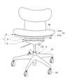
この実施形態に係る椅子は、図1〜図3に示すように、前後左右に傾動可能に構成された座1を、キャスタ2aを有する脚2に回転可能に支持させている。 In the chair according to this embodiment, as shown in FIGS. 1 to 3, the
座1は、弾性支持層3と、この弾性支持層3を挟むように配置される上部ユニットである上側ベース部4および下部ユニットである下側ベース部5とを備え、座1が前後又は左右に傾動可能とされたものである。 The
脚2は、脚羽根21の下端にキャスタ2aを有し、脚羽根21の中心部から脚支柱22を立設したもので、脚支柱22はガススプリング23によって昇降可能とされている。 The
上側ベース部4は、座本体41と、この座本体41の下面に取り付けられて弾性支持層3の上面に接する上板42とを含む。座本体41はこの実施形態の場合、座板41aの上にクッション41bを配することによって構成されるもので、座板41aは背板51aとともに一体的に設けられ、背板51aにもクッション51bが配されて背部5を構成している。上側ベース部4の上面が荷重の掛かる着座面4aとして設定される。 The
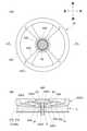
上板42は、平面視円盤状のもので、板状部42aと、この板状部42aの中心部に位置するボス部42bと、板状部42aの外周に位置する円環部42cと、ボス部42bから放射方向に延びて円環部42cに接続されるリブ42dと、を樹脂等により一体成形されている。板状部42aは、図4(b)等に示すように下方に向かって緩やかに膨出する略部分球面状もしくは断面略円弧状、換言すればお椀状、凸形状のR状をなしている。板状部42aの下面42eも、これに応じて下方に向かって緩やかに膨出する略部分球面状もしくは断面略円弧状、換言すればお椀状、凸形状のR状をなし、この下面42eは後述する下板51上を弾性支持層3を介して上板42が転動する際の転動面となっている。円環部42cの適宜箇所にはねじ挿通孔42c1が設けてあり、このねじ挿通孔42c1を利用して、上板42とその上面に載置される座本体41とがねじにより連結される。 The
ボス部42bは、図4(b)等に示すように内側に底壁42b1を有している。底壁42b1は中心部に開口42b2を有し、開口42b2の一部は上方に向かって開くテーパ面42b3をなし、更にその上は拡径した筒状部42b4をなしている。この開口42b2には後述するストッパ軸6の抜止め部材62が遊動可能に収容される。 The
下側ベース部5は、上側ベース部4の下方に配置される円盤状のもので、この実施形態では剛性を有し弾性支持層3の下面に接する下板51と、この下板51の下方に取り付けられる座受52とを備える。座受52はすり鉢状のもので、内部の中心部にガススプリング23の上端部を挿入する孔52aおよび中空部52bを有している。そして、ガススプリング23の上端部と下板51の間に隙間を確保しつつ、リブ52c上に下板51を当接させ、リブ52cに設けたねじ挿通孔52c1と下板51に設けたねじ孔51aとを利用して、座受52と下板51とがねじにより連結される。 The
座受52の外周の一部に設けた孔52dからは操作レバー24が挿入されて当該操作レバー24の支点24aが座受52の軸受52eに支持され、操作レバー24の基端24bがガススプリング23の入力端23aに係合される。そして、操作レバー24の操作端24cに加える上下方向の操作によって、ガススプリング23のロック/ロック解除が行われる。 An
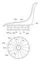
弾性支持層3は、図1〜図4に示すように、上側ベース部4を構成する上板42と下側ベース部5を構成する下板51の間に挟まれた状態で所定の傾動基準位置IRPの周囲に荷重支持体31を複数個配置することによって構成された円盤状のものである。この実施形態の荷重支持体31には、個々に独立に構成されたエアバッグABが用いられている。傾動基準位置IRPは、上述した上側ベース部4を構成する円盤状の上板42の中心位置であり、また下側ベース部5を構成する円盤状の下板51の中心位置である。 As shown in FIGS. 1 to 4, the
個々の荷重支持体31を構成するエアバッグABは、樹脂発泡弾性体31aの周囲を表皮材32bで包んだものである。樹脂発泡弾性体31aには、低反発ウレタンよりも弾性率が高い素材、例えば高反発ウレタン等が用いられている。表皮材31bには、多孔性シート部材を平織り布で目止め加工して用いられている。勿論、身近な素材であれば、例えば雨カッパや傘の素材のように、空気は通し難いが完全に遮断するのではなく多少の通気性を有するものを利用することができる。また表皮材31bには、密閉タイプのフィルムに適度に空気が出入りできるように小さい穴を複数ないし多数開けることで空気透過度を調整したものを用いてもよい。何れにしても、好ましい空気透過度は300〜400s程度とされるが、200〜500s程度のものを用いることも有効である。この空気透過度は、JIS L 1096:2010「織物及び織物の生地試験方法」8.26.2 B法(ガーレー形法)試験を通じて300mLの空気が排出される時間を計測した。 The airbag AB constituting each
このように、本実施形態のエアバッグABは、表皮材31bによって樹脂発泡弾性体31aの周囲を覆い、表皮材31b以外の箇所から空気の流出入がないように、所要箇所が封止されている。勿論、ダンパー効果は、樹脂発泡弾性体31aの圧縮復元特性と、表皮材31bの空気流出入抵抗との兼ね合いによって定まるものであり、樹脂発泡弾性体31aの弾性特性と表皮材31bの空気透過度の2つの荷重支持体構成パラメータによって設定される。 As described above, in the airbag AB of the present embodiment, the periphery of the resin foam
この実施形態のエアバッグABは、平面視扇形で所定の厚みをなすもので、偶数個(この実施形態では8個)の頂点部を集合させるように傾動基準位置IRPの周囲に放射状に配置されている。エアバッグABの上面31aと上側ベース部4を構成する上板42の下面42eとの間、及び、エアバッグABの下面31bと下側ベース部5を構成する下板51の上面51bとの間は、図示しない両面テープまたは接着剤によって固定される。勿論、固定は他の手段によってもよい。 The airbag AB of this embodiment is fan-shaped in a plan view and has a predetermined thickness, and is arranged radially around the tilting reference position IRP so as to gather an even number of vertices (8 in this embodiment). ing. Between the
そして、上板42と下板51の間に弾性支持層3を構成するエアバッグABを挟んだ状態で、下方からワッシャ6aを介してストッパ軸6を下板51の中央の孔51cより挿入して弾性支持層3を構成する各エアバッグABの頂点部が集合する部分の内側を通過させ、その通過部分に位置するようにストッパ軸6にカラー61を被せている。ストッパ軸6は基端が太く構成されたもので、先端部には前記テーパ面42b3とテーパ係合するテーパ面62aを有した抜止め部材62が装着される。そして、ストッパ軸6の端部に形成したねじ6bにナット63を螺合させて締結することによって、抜止め部材62はカラー61を介してストッパ軸6に締結される。カラー61は下板51と抜止め部材62の距離を一定に保つ役割を担う。 Then, with the airbag AB constituting the
このようにして、上側ベース部4、下側ベース部5及び、弾性支持層3を構成するエアバッグABを不離一体に連結している。この状態で、転動面42eの略全面が弾性支持層3に接している。転動面42eは、上側ベース部のほぼ全域に設定されているが、前後左右への傾動範囲において転動面42eと下側ベース部との間に弾性支持層3を介した接点が得られれば、全域でなくてもよい。 In this way, the
この際、上板42の下面42eは図4(b)等に示したように下方に膨出しており、弾性支持層3を構成するエアバッグABは傾動基準位置IRPに近い位置ほど圧縮された状態で締め付けられる。そして、上載荷重がないときの上板42は、弾性支持層3を構成するエアバッグABの弾性反発力によって上方に付勢され、ストッパ軸6の抜止め部材62のテーパ面62aと上板42のテーパ面42b3がテーパ係合することによって、上板42を含む上側ベース部4をストッパ軸6に沿って最も高い位置に水平もしくは水平に近い所定姿勢(基準姿勢)で保持する。 At this time, the
図4(a)は着座荷重が掛かっていない状態にある上板42を示す平面図であり、図4(b)は図4(a)における前後方向のH−H線に沿った断面図である。図5(a)は傾動基準位置IRPに着座荷重が掛かったときの上板42を示す平面図であり、図5(b)は図5(a)における前後方向のH−H線に沿った断面図である。図6(a)は傾動基準位置IRPよりも前方に着座荷重が掛かったときの上板42の平面図であり、図6(b)は図6(a)における前後方向のH−H線に沿った断面図である。図6(c)は傾動基準位置IRPよりも後方に着座荷重が掛かったときの図6(b)に対応した断面図である。 4 (a) is a plan view showing the
図4(b)の状態から傾動基準位置IRPに着座荷重が掛かると、上板42を含む上側ベース部4が図5(b)に示すように真っすぐに降下し、抜止め部材62のテーパ面62aから上板42のテーパ面42b3が離れる。このとき、傾動基準位置IRPに対して前方のエアバッグABと後方のエアバッグABは均等に圧縮される。着座荷重がなくなれば、エアバッグABの復元力で上板42上を含む上側ベース部4が真っすぐに上昇し、上板42のテーパ面42b3が抜止め部材62のテーパ面62aに再びテーパ係合したところで上板42を含む上側ベース部4は水平もしくは水平に近い所定姿勢で停止して保持される。 When a seating load is applied to the tilting reference position IRP from the state of FIG. 4 (b), the
図5の状態で、ストッパ軸6の抜止め部材62は上板42の開口42b2(テーパ面42b3の内周縁やその上の筒状部42b4の内周縁を含む)内で相対的に遊動可能であり、上板42を含む上側ベース部4は前後方向に自由に着座荷重とのバランスをとりながら傾動動作(グライディング動作)を行うことができる。このため、例えば前方に荷重を移せば、上板42を含む上側ベース部4は前方のエアバッグABを圧縮しながらエアバッグABを介して下板51上を転動し、その結果、上板42を含む上側ベース部4は図6(a)、(b)に示すように前端が下向きに傾斜し後端が上向きに傾斜した状態になる。 In the state of FIG. 5, the retaining
逆に、後方に荷重を移せば、上板42を含む上側ベース部4は後方のエアバッグABを圧縮しながらエアバッグABを介して下板51上を転動し、その結果、上板42を含む上側ベース部4は図6(c)に示すように後端が下向きに傾斜し前端が上向きに傾斜した状態になる。 On the contrary, when the load is transferred to the rear, the
何れの方向へ傾動するときも、上板42を含む上側ベース部4が所定範囲を越えて傾動しようとすると、上板42の開口42b2の内周縁(テーパ面42b3の内周縁やその上の筒状部42c4の内周縁を含む)がストッパ軸6の上部に取り付けた抜止め部材62に係合することで、それ以上の傾動が規制される。 When the
ストッパ軸6の抜止め部材62と上板42の開口42b2の周縁部は傾動規制機構を構成している。 The peripheral portion of the retaining
傾動中に着座者が離席すると、エアバッグABは復元することによって上板42を上方に付勢し、上板42を含む座4が上昇するので、上板42のテーパ面42b3がストッパ軸6の抜止め部材62のテーパ面62aに係合することによって、上板42を含む上側ベース部4は図4に示す非着座時の所定姿勢に戻ることができる。座本体41に背5が一体に設けられることによって、座本体41の重心位置が傾動基準位置IRPからずれている場合にも、上記テーパ係合によって上板42を含む上側ベース部4の所定姿勢が保持される。 When the seated person leaves the seat during tilting, the airbag AB is restored to urge the
このような係合の下では、着座しない限りテーパ係合が外れないため、背部5に手をかけて椅子を移動させる場合などにも背部5や上側ベース部4はぐらつかずに一定姿勢に保持される。 Under such engagement, the tapered engagement does not come off unless the chair is seated, so the
図7(a)は着座荷重が掛かっていない状態にある上板42を示す平面図であり、図7(b)は図7(a)における左右方向のG−G線に沿った断面図である。図8(a)は傾動基準位置IRPに着座荷重が掛かったときの上板42を示す平面図であり、図8(b)は図8(a)における左右方向のG−G線に沿った断面図である。図9(a)は傾動基準位置IRPよりも左方に着座荷重が掛かったときの上板42の平面図であり、図9(b)は図9(a)における左右方向のG−G線に沿った断面図である。図9(c)は傾動基準位置IRPよりも右方に着座荷重が掛かったときの図9(b)に対応した断面図である。 FIG. 7A is a plan view showing the
図4、図5、図6についての上述した説明において、「前」を「左」に、「後」を「右」に読み替えれば、図7、図8、図9についての説明になる。 In the above description of FIGS. 4, 5, and 6, if "front" is read as "left" and "rear" is read as "right", the description of FIGS. 7, 8 and 9 is obtained.
このような前後左右の動作が複合的に起これば、上板42を含む上側ベース部4が傾動基準位置IRPのまわりをローリングするような動作も可能になる。 If such front-back and left-right movements occur in a complex manner, it becomes possible for the
上板42は転動面42eが下向きに膨出しているため、転動しながら移動する際に移動方向の先端側が下向きに傾斜し、移動方向の後端側が上向きに傾斜する。転動面42eの曲率は各部位において常に一律とは限らないが、その転動中心は常に上側ベース部4を含めた可動部の重心よりも高い位置に設定されている。このため、可動部が傾動基準位置IRPから移動するにつれて重心は上昇し、転動先から重力で傾動基準位置IRPに復帰する復帰力を蓄積する。 Since the rolling
着座面4aが上載荷重を受けると、上側ベース部4が弾性支持層3を圧縮して沈み込み、その際に上側ベース部4のクッション41bも圧縮される。上側ベース部4を含む座1の可動部の重心と人間の体の重心とを加重平均した全体の可動部の重心位置を図5(b)、図8(b)においてSで表す。この状態においても、転動面42eの転動中心は重心Sよりも高くなるように設定されている。この位置から座面4aとともに上側ベース部4が着座者とともに前後左右に傾動すると、転動面42eの接地点(詳細には弾性支持層3を介した下側ベース部5の下板51への接地点)が移動するに伴い、重心Sは前後左右に移動しながら図5(b)の位置から図6(b)または図6(c)の位置まで、あるいは図8(b)の位置から図9(b)または図9(c)の位置まで移動し、このとき重心Sが高さ方向に持ち上がる。そして、重心Sが持ち上がることで、上側ベース部4及び着座者を含む可動部には位置エネルギーとして傾動基準位置IRPに向かう重力復帰力が蓄えられるものとなっている。 When the
このような重力復帰機構が備わるため、基本的に座1は弾性支持層3がなくても着座者は前後左右の揺動動作を重力とのバランスをとりながら安全に行い、所定の傾動位置に安定して着座することができる。弾性支持層3は、着座者が急激に動いたときにダンパー効果を働かせるのが主な役割であり、復元することによって上側ベース部4をゆっくり傾動基準位置IRPに戻す機能も備えるが、弾性支持層3のみによって着座荷重とバランスするほどの弾性力は備えていない。 Since such a gravity return mechanism is provided, basically, even if the
エアバッグABが収縮するときは、表皮材31bを通じて内部の空気が内部から外部に流出し、エアバッグABが膨張するときは、表皮材31bを通じて外部の空気が内部に流入する。このときの流出入抵抗により、例えば樹脂発泡弾性体31aのみを用いた場合に比べて、上側ベース部4の動きはゆるやかになる。この作用はダンパー作用、ディレイ作用とも言われる。 When the airbag AB contracts, the internal air flows out from the inside through the
例えば、利用者が傾動基準位置IRPに重心が位置するように着座すると、各エアバッグABには均等に圧縮力が掛かり、図4(b)の状態から図5(b)の状態に向かって座板42が真っすぐ下がる。これに伴って、エアバッグAB内の樹脂発泡弾性体31aが圧縮されて収縮し、このとき表皮材31bを通じて内部の空気が内部から外部に均等に流出する(図5(b)矢印参照)。これに伴い、上板42そして上板62を一体に含む上側ベース部4はゆっくり下がる。 For example, when the user sits so that the center of gravity is located at the tilt reference position IRP, the compressive force is evenly applied to each airbag AB, and the compression force is applied evenly from the state of FIG. 4 (b) to the state of FIG. 5 (b). The
着座荷重がなくなると、エアバッグABを構成する樹脂発弾性体31aが復元動作によって膨張し、これに伴って表示材31bを通じて外部の空気が内部に流入する。ここでは、図5(b)における矢印と反対向きのエアの流れが生じ、上板42は図4(b)の状態に戻る。 When the seating load is removed, the resin
一方、利用者が傾動基準位置IRPから図6(b)又は図6(c)のように前後に偏った位置に重心が位置するように着座すると、重心が位置する側のエアバッグABは圧縮されて収縮し、逆に反対側のエアバッグABは引っ張られて膨張する。このため、圧縮された側のエアバッグABは圧縮前の状態に比べて内部から外部に空気を流出させ(傾動基準位置IRPから離れる方向の矢印参照)、膨張する側のエアバッグABは外部から内部に空気を流入させる(傾動基準位置IRPに向かう方向の矢印参照)。このエアの流出入は、エアバッグABの上面31a及び下面31bが上板42及び下板51で塞がれている関係上、主にエアバッグABの側面において生じる。 On the other hand, when the user sits so that the center of gravity is located at a position biased back and forth from the tilt reference position IRP as shown in FIG. 6 (b) or FIG. 6 (c), the airbag AB on the side where the center of gravity is located is compressed. And contracts, and conversely, the airbag AB on the opposite side is pulled and expands. Therefore, the airbag AB on the compressed side causes air to flow out from the inside to the outside compared to the state before compression (see the arrow in the direction away from the tilt reference position IRP), and the airbag AB on the expanding side is from the outside. Inflow air into the interior (see arrow in the direction towards the tilt reference position IRP). This inflow and outflow of air occurs mainly on the side surface of the airbag AB because the
このように、着座者が下側ベース部5に対して前後左右に体を動かすことで、それに応じて上側ベース部4が傾動基準位置IRPを中心に前後左右に傾動する際に、各エアバッグABごとに樹脂発泡弾性体31aの収縮、膨張、復元動作が、表皮材31bを通じた空気の流出入により一定のディレイ効果が起こり、着座者の姿勢を安全に支持することになる。本明細書にいう「ディレイ効果」とは、空気の流体抵抗等によって前後左右への傾動動作を遅らせる効果を言う。 In this way, when the seated person moves his / her body back and forth and left and right with respect to the
このようなディレイ効果は、着座者がゆっくり動いたときよりも速く動いたときの方が強く出るため、上側ベース部4が前後左右にふいに動くことを抑制する効果につながり、弾性支持層3は前後左右に傾動可能な上側ベース部4の安全装置としても働く。 Since such a delay effect is stronger when the seated person moves faster than when the seated person moves slowly, it leads to an effect of suppressing the
この実施形態は、図1に示すように椅子本体3が丸椅子ではなく座本体31が背凭れ31aを備えたもので、着座方向が決まっている。このため、転動面42eは、前後方向と左右方向とで曲率を異ならせて、前後方向の揺れが左右方向の揺れよりも大きくなるように設定することもできる。 In this embodiment, as shown in FIG. 1, the
より具体的には、前後方向と左右方向とで曲率を異ならせるとは、転動面42eの前後及び左右各々の方向に沿った断面の形状を異ならせることによって実現している。 More specifically, different curvatures in the front-rear direction and the left-right direction are realized by making the shape of the cross section of the rolling
例えば、図6(b)における上板42の傾きθ1と、図9(b)における上板42の傾きθ2を変えることによって、前後左右で非対称な傾動状態を実現することもできる。例えば、θ1>θ2とした場合には、左右方向に比較的限られた範囲で緩やかに傾動するのに対して、前後方向には比較的広範囲に大きく傾動する。このため、前後方向には広範囲に傾動させることで自由な揺れを許容し、左右方向には限られた範囲で傾動させることでサポート感を高めるような設定も可能になる。この場合には、エアバッグABを構成する樹脂発泡弾性31aの大きさ、材質、形状や、表皮材31bの空気透過度を、前後方向と左右方向で異ならせても構わない。 For example, by changing the inclination θ1 of the
さらに、転動面42eは、前方と後方とで曲率を異ならせて、後方への揺れが前方への揺れよりも大きくなるように設定することもできる。例えば、図6(b)におけるθ1と、図6(c)におけるθ1´との関係を、θ1<θ1´とした場合には、前方に比べて後方がより大きく傾動することでリラックスした後傾姿勢をとれるようになる。この場合も、エアバッグABを構成する樹脂発泡弾性31aの大きさ、材質、形状や、表皮材31bの空気透過度を、前方と後方で異ならせても構わない。 Further, the rolling
以上のように、本実施形態の座1は、弾性支持層3と、この弾性支持層3を挟むように配置される上側ベース部4および下側ベース部5とを備え、上側ベース部4は、下側ベース部5に向かって膨出する転動面42eを弾性支持層3を介して下側ベース部5上に配置したものであって、上側ベース部4は、着座荷重を受けて傾動基準位置IRPから360°方向に転動可能で、傾動基準位置IRPから離れるにつれて移動先端側を下向きに傾斜させつつ、転動面で弾性支持層3を圧縮しながら移動する、ことを特徴とする。 As described above, the
このように構成すると、上側ベース部4は下方に膨出する転動面42eにおいて下側ベース部5上を転動するので、着座者の動きに合わせて上側ベース部4が前後左右に連続的かつ滑らかに転動しながら比較的大きく動くことができる。そして着座者は、転動面42eにおいて着座荷重でバランスをとりながら安定して傾動動作を行うことができ、安全性を担保することができる。しかも、上側ベース部4は移動先端側が下向きに傾斜するので、着座者の自然な姿勢変化に追従することができる。 With this configuration, the
また、本発明の座1は上側ベース部4と下側ベース部5の間に弾性支持層3を挟み込むだけであるので、構造的も簡単であり、弾性支持層3を挟み込んでいるので上側ベース部4が弾性支持層3の上を転動することとなり、下側ベース部5上を直接転動する場合に比べて座り心地が柔らかくなり、異音の発生も抑えられる。さらに移動先端側が下向きに傾斜するに伴い弾性支持層3を圧縮するので、転動面42eを通じて転がり易い構造にしても、弾性支持層3によるダンパー効果が安全性の担保に役立つとともに、転動先から戻らなくなる事態を防止することができ、傾動基準位置IRPへの復帰も弾性支持層3の弾性復元動作を利用して適切に行うことができる。 Further, since the
また、上側ベース部4は、傾動基準位置IRPから離れるに従い、重心Sが上昇するので、傾動基準位置IRPに重力により自動復帰させることができる。 Further, since the center of gravity S of the
また、転動面42eの略全面が弾性支持層3に接しているので、何れの方向にも弾性支持層3に対する圧縮が行われ、傾くにつれて弾性支持層3の圧縮速度を速めることでダンパー効果を高めることができる。 Further, since substantially the entire surface of the rolling
また、転動面42eは、前後方向と左右方向とで曲率を異ならせることもできる。前後と左右では着座者の体の揺れ方が違うため、このような曲率の違いを通じて着座者の動きに合わせた上側ベース部4の適切な揺れを実現することができる。 Further, the rolling
また、転動面42eは、前方と後方とで曲率を異ならせることもできる。前方と後方でも着座者の体の揺れ方が違うため、このような曲率の違いを通じて着座者の動きに合わせた上側ベース部4の適切な揺れを実現することができる。 Further, the rolling
また、弾性支持層3を、ダンパー効果を有するものにしているので、衝撃を吸収するとともに着座者の動きに対して上側ベース部4を含む可動部の動きを遅らせて、安全性を向上させることができる。
また、弾性支持層3については、樹脂発泡弾性体31aを通気性を有する表皮材31bで包んだ荷重支持体31(エアバッグAB)によって構成することで、空気の流出入を利用することができ、空気を閉じ込める場合に比べて必要な圧縮変形量や上側ベース部4の適切な傾動範囲も確保することができる。Further, since the
Further, the
そして、弾性支持層3を構成する樹脂弾性発泡体31aの弾性特性や表皮材31bの空気透過度を適宜に設定すれば、低反発マットのような温度依存性や湿度依存性の素材を用いずとも、弾性支持層3を、軟らかすぎず硬すぎない適度のクッション性やダンパー作用(シフト作用)を伴うように調整することができ、これにより、着座時のクッション性に富み、着座者の動きに緩やかに追従して緩衝性や安定性に優れた座1を実現することが可能となる。 If the elastic properties of the resin
また、弾性支持層3は、荷重支持体31を複数配置することによって構成されているので、ダンパー効果を生じる領域を独立に区画して、弾性支持層3の内部だけで空気が移動する状況を避け、荷重支持体31ごとに適切な支持状態を実現して、各荷重支持体31が協働して前後左右の荷重移動を適切に支持することができる。 Further, since the
また、荷重支持体31の各々は平面視扇形をなし、傾動基準位置IRPの周囲に放射状に配置することによって弾性支持層3を構成しているので、隙間なく荷重支持体を敷き詰められて、いずれの揺れ方向にも適切にダンパー作用を発揮させることができる。 Further, each of the load supports 31 has a fan shape in a plan view, and the
また、弾性支持層3は上下に複数層からなり、各層を構成する荷重支持体31は傾動基準位置IRPの周りに円周方向にピッチをずらして配置されているので、荷重支持体31の型崩れを防ぎつつ、厚みをもたせかつ動作中のガタつきを抑えてダンパー機能を高めることができる。 Further, the
また、前後方向に配置される荷重支持体31と左右方向に配置される荷重支持体31とで、樹脂発泡弾性体31aの大きさ、材質、形状、表皮材31bの空気透過度等の荷重支持体構成パラメータを異ならせることができるため、前後左右への傾動特性を自由に設定することができる。 Further, the
また、荷重支持体31は、上面31aにおいて上側ベース部4に固定され、下面31bにおいて下側ベース部5に固定される。着座者の体の動きや回転椅子等の椅子の構造に起因して上側ベース部4と下側ベース部5の間に回転方向の力が働く場合には、上記の構成によって荷重支持体31が偏ったり剥がれたりするのを防ぐことができる。 Further, the
また、上側ベース部4は、着座荷重を受けた際に弾性支持層3を圧縮しながら沈み込むように構成されているので、着座時のショックを緩和することができる。 Further, since the
また、上側ベース部4の中心部に開口42b2を設け、下側ベース部5にストッパ軸6を設けて、ストッパ軸6を開口42b2内に挿入し、ストッパ軸6は開口42b2内で相対的に遊動可能であり、上側ベース部4が所定の傾動範囲を越えて傾動した際にストッパ軸6が開口42b2の周縁部に当接するように構成される。このため、通常は上側ベース部4の自由な傾動を許容しながら、必要以上の傾動動作を適切に規制することができる。 Further, an opening 42b2 is provided in the center of the
また、上側ベース部4の中心部に開口42b2を設け、下側ベース部5にストッパ軸6を設けて、ストッパ軸6を開口内に挿入し、弾性支持層3の弾性復元時に上側ベース部4が下側ベース部5から離れた際にストッパ軸6に設けた抜止め部材62が開口42b2の周縁部に係合してストッパとして機能するようにしている。このため、上側ベース部4が下側ベース部5に向かって沈み込む動作を実現しつつ、離席した際の上側ベース部4の上昇動作を適切に規制することができる。 Further, an opening 42b2 is provided in the center of the
また、開口42b2の周縁部とストッパ軸6の抜止め部材62がテーパ係合することによって、上側ベース部4を所定姿勢で位置決めするので、離席時の姿勢保持機能を簡単に付与することができる。 Further, since the
そして、以上の座1を備えて椅子を構成すれば、簡易な構造で着座者の前後左右への傾動動作を適切に支持することができ、これにより、着座時のクッション性に富み、着座者の動きに緩やかに追従して緩衝性や安定性にも優れた椅子を実現することが可能となる。 Then, if the chair is configured with the
以上の座1を利用すれば、座1がキャスタ2aを有する脚2によって支持されている椅子においても、同様の機能を実現することができる。 If the
また、以上の座1を利用すれば、座1が脚2によって支持され、下側ベース部5が脚2の上端側に配されている椅子においても、同様の機能を実現することができる。 Further, if the
また、非低反発の樹脂発泡弾性体31aを通気性を有する表皮材31bで包んで荷重支持体31を構成し、この荷重支持体31を複数個配置して荷重を分散して支持するようにすれば、ダンパー効果を生じる領域を独立に区画して、弾性支持層3の内部だけで空気が移動する状況を避け、前後左右への荷重移動を各荷重支持体31が協働して適切に支持することができる。 Further, the non-low-resilience resin foam
特に、表皮材31bの空気透過度が200〜500sの範囲であれば、適切なディレイ効果を奏することができる。 In particular, if the air permeability of the
以上、本発明の一実施形態について説明したが、各部の具体的な構成は、上述した実施形態のみに限定されるものではない。 Although one embodiment of the present invention has been described above, the specific configuration of each part is not limited to the above-described embodiment.
例えば、上記実施形態では弾性支持層3を構成する弾性支持体31を、高反発の樹脂発泡弾性体31aを通気性を有する表皮材31bで包んだエアバッグABで構成して所要のダンパー効果やディレイ効果が得られるようにしたが、低反発の樹脂発泡弾性体を用いてもよい。 For example, in the above embodiment, the
また、上記実施形態ではダンパー効果やディレイ効果を奏する構成としたが、そのような効果を特に必要としない場合は、通常の高反発弾性体を単体ですなわち表皮材で包まずに用いてもよい。 Further, in the above embodiment, the damper effect and the delay effect are exhibited, but if such an effect is not particularly required, a normal high-resilience elastic body may be used alone, that is, without being wrapped with a skin material. ..
また、上記実施形態では弾性支持層3を樹脂発泡弾性体31aを主体として構成したが、弾性支持層3の全部または一部をバネによって構成してもよい。 Further, in the above embodiment, the
また、上記実施形態では上側ベース部4に開口42b2を設け、下側ベース部5にストッパ軸6を設けたが、下側ベース部5に開口を設け、上側ベース部4にストッパ軸を設けても構わない。 Further, in the above embodiment, the
また、上記実施形態では上板42を座本体41の真下に配置したが、上板42は、座本体41から下方に離間する位置に設けられていてもよい。 Further, in the above embodiment, the
また、上記実施形態では上側ベース部4は座本体41と上板42から構成され、座本体41の上面を着座面としたが、上側ベース部4を上板42のみによって構成し、その上板42の上面を着座面としてもよい。 Further, in the above embodiment, the
また、上記実施形態では上側ベース部4に転動面を設けたが、下側ベース部5に転動面を設けてもよい。 Further, in the above embodiment, the rolling surface is provided on the
また、上記実施形態では上側ベース部4のみに転動面を設けたが、図10に示すように、上側ベース部4及び下側ベース部5は、互いに相手方に向かって膨出する転動面42e、52eを有しており、上側ベース部4は、転動面42e、52e間で弾性支持層3を圧縮しながら移動するように構成してもよい。 Further, in the above embodiment, the rolling surface is provided only on the
このようにすれば、狭いスペースでより上側ベース部4の傾動角度を大きくとることができる。 By doing so, the tilt angle of the
また、上記実施形態では上側ベース部を構成する座本体が背凭れと一体をなす構成であったが、丸椅子であって着座方向が全方位型である椅子にも適用することができる。 Further, in the above embodiment, the seat body constituting the upper base portion is integrated with the backrest, but it can also be applied to a round chair having an omnidirectional seating direction.
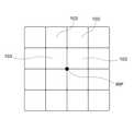
また、図4に対応する図11に示すように、弾性支持層103は、前記傾動基準位置IRPの周囲を埋めるようにマトリックス状に配置されたものであってもよい。このような構成は、上側ベース部4を構成する図3の上板42や下板51の形状が円盤状ではなく四角形状である場合等に有効となる。 Further, as shown in FIG. 11 corresponding to FIG. 4, the
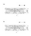
さらにまた、図12に示すように、弾性支持層を第1段の弾性支持層203a、第2段の弾性支持層203bという具合に積み上げて上下に複数段をなす構造にし、弾性支持層203a、203a同士の継目Paと、弾性支持層203b、203b同士の継目Pbとを、上段側と下段側とで円周方向にずらして配置することも有効である。 Furthermore, as shown in FIG. 12, the elastic support layers are stacked in the order of the
このように上下複数段にすることで、上側ベース部204の変形量を大きくしてクッション性を高めることができる。その際、上下の弾性支持層203a、203bの位相を円周方向にずらすことで、弾性支持層203aの面に弾性支持層203b、203b同士の継目Pbが位置し、弾性支持層203bの面に弾性支持層203a、203a同士の継目Paが位置することになり、継目部分Pa、Pbで型崩れを防ぎつつ、動作中のガタつきを抑えて着座時の違和感を解消することができる。 By having a plurality of upper and lower stages in this way, the amount of deformation of the
その他の構成も、本発明の趣旨を逸脱しない範囲で種々変形が可能である。 Other configurations can be variously modified without departing from the spirit of the present invention.
例えば、上記実施形態では弾性支持層を構成する弾性体が複数に分かれていたが、全体を一体物として構成することもできる。 For example, in the above embodiment, the elastic body constituting the elastic support layer is divided into a plurality of pieces, but the whole may be configured as an integral body.
また、上記実施形態では座を適用した椅子として説明したが、本発明は座を単体で用いる場合を含む。この場合も、人が着座していないときの上側ベース部を含む可動部の重心が転動面の転動中心よりも低くなるように、また、人が着座したときの上側ベース部を含む可動部の重心と着座者の重心とを加重平均した全体の重心が転動面の転動中心より低くなるように設定しておけば、重力復帰機能を担保することができる。 Further, in the above embodiment, the chair to which the seat is applied has been described, but the present invention includes the case where the seat is used alone. Also in this case, the center of gravity of the movable part including the upper base part when the person is not seated is lower than the rolling center of the rolling surface, and the movable part including the upper base part when the person is seated is movable. If the total center of gravity, which is the weighted average of the center of gravity of the portion and the center of gravity of the seated person, is set to be lower than the rolling center of the rolling surface, the gravity return function can be ensured.
1…座
3…弾性支持層
4…上側ベース部
4e…下面
5…下側ベース部
6…ストッパ軸
31…荷重支持体
31a…樹脂発泡弾性体
31b…表皮材
42b2…開口
62…抜止め部材
IRP…傾動基準位置
S…重心1 ...
Claims (22)
Translated fromJapanese前記上側ベース部及び下側ベース部の少なくとも一方は、他方に向かって膨出する転動面を前記弾性支持層を介して前記他方のベース部上に配置したものであって、
前記上側ベース部は、着座荷重を受けて傾動基準位置から360°方向に転動可能で、
傾動基準位置から離れるにつれて移動先端側を下向きに傾斜させつつ、前記転動面で前記弾性支持層を圧縮しながら移動する、ことを特徴とする座。An elastic support layer and an upper base portion and a lower base portion arranged so as to sandwich the elastic support layer are provided.
At least one of the upper base portion and the lower base portion has a rolling surface that bulges toward the other and is arranged on the other base portion via the elastic support layer.
The upper base portion can roll in the direction of 360 ° from the tilting reference position by receiving a seating load.
A seat characterized in that it moves while compressing the elastic support layer on the rolling surface while tilting the moving tip side downward as the distance from the tilting reference position increases.
Priority Applications (4)
| Application Number | Priority Date | Filing Date | Title |
|---|---|---|---|
| JP2020106454AJP7527857B2 (en) | 2020-06-19 | 2020-06-19 | Seats, Chairs and Load Supports |
| US17/331,933US11540637B2 (en) | 2020-06-19 | 2021-05-27 | Seat, chair, and load support body |
| CN202110590256.2ACN113812789A (en) | 2020-06-19 | 2021-05-28 | Seats, Chairs and Load Supports |
| EP21177367.6AEP3925491B1 (en) | 2020-06-19 | 2021-06-02 | Seat and chair |
Applications Claiming Priority (1)
| Application Number | Priority Date | Filing Date | Title |
|---|---|---|---|
| JP2020106454AJP7527857B2 (en) | 2020-06-19 | 2020-06-19 | Seats, Chairs and Load Supports |
Publications (2)
| Publication Number | Publication Date |
|---|---|
| JP2022001104Atrue JP2022001104A (en) | 2022-01-06 |
| JP7527857B2 JP7527857B2 (en) | 2024-08-05 |
Family
ID=76250189
Family Applications (1)
| Application Number | Title | Priority Date | Filing Date |
|---|---|---|---|
| JP2020106454AActiveJP7527857B2 (en) | 2020-06-19 | 2020-06-19 | Seats, Chairs and Load Supports |
Country Status (4)
| Country | Link |
|---|---|
| US (1) | US11540637B2 (en) |
| EP (1) | EP3925491B1 (en) |
| JP (1) | JP7527857B2 (en) |
| CN (1) | CN113812789A (en) |
Cited By (1)
| Publication number | Priority date | Publication date | Assignee | Title |
|---|---|---|---|---|
| KR102586292B1 (en)* | 2022-12-27 | 2023-10-10 | 홍상희 | A chair equipped with a tilting module unit having a multi-directional bending and restoration structure |
Families Citing this family (5)
| Publication number | Priority date | Publication date | Assignee | Title |
|---|---|---|---|---|
| CN111251958A (en)* | 2020-03-19 | 2020-06-09 | 徐庆 | A seat cushion structure that can adjust soft and hard sitting feeling |
| USD1049670S1 (en)* | 2021-07-14 | 2024-11-05 | Anthro Form, Llc | Chair |
| JP7735142B2 (en)* | 2021-10-01 | 2025-09-08 | コクヨ株式会社 | chair |
| JP7735143B2 (en)* | 2021-10-01 | 2025-09-08 | コクヨ株式会社 | chair |
| JP7750705B2 (en)* | 2021-10-01 | 2025-10-07 | コクヨ株式会社 | chair |
Citations (3)
| Publication number | Priority date | Publication date | Assignee | Title |
|---|---|---|---|---|
| US4673605A (en)* | 1985-05-23 | 1987-06-16 | Baxter Travenol Laboratories, Inc. | Body support pad |
| US20080079301A1 (en)* | 2006-09-29 | 2008-04-03 | Horst Schaaf | Method and apparatus to enhance proprioception and core health of the human body |
| US20150223607A1 (en)* | 2014-02-11 | 2015-08-13 | Ju-Yi Ma | Seat pad |
Family Cites Families (33)
| Publication number | Priority date | Publication date | Assignee | Title |
|---|---|---|---|---|
| US3309137A (en)* | 1966-05-13 | 1967-03-14 | Aaron A Wiebe | Seating arrangement |
| US4826247A (en)* | 1986-09-26 | 1989-05-02 | The Boeing Company | System for assisting a fighter pilot in checking the six-o'clock position |
| FR2697419B1 (en)* | 1992-11-04 | 1994-12-09 | Tritube | Reclining seat. |
| US5649740A (en)* | 1995-11-27 | 1997-07-22 | Hodgdon; Dewey | Chair tilt control mechanism |
| DE29520565U1 (en) | 1995-12-27 | 1996-02-29 | Buchwald, Gerlinde, 79104 Freiburg | Seating device for seating |
| US5857749A (en)* | 1996-05-28 | 1999-01-12 | Jay Medical Ltd. | Wheelchair seat assembly with contoured seat pan and cushion and method |
| US5769492A (en)* | 1996-12-10 | 1998-06-23 | Jensen; Robert J. | Back saver sport seat |
| DE19654500C1 (en)* | 1996-12-18 | 1998-03-12 | Ulrich Dipl Ing Huber | Adjustable furniture frame with triple axis movement for lying and sitting |
| DE19726409A1 (en)* | 1997-06-21 | 1998-12-24 | Bayerische Motoren Werke Ag | Seat with cushion and tilting mechanism adjustment |
| US6209958B1 (en)* | 1998-10-23 | 2001-04-03 | Haworth, Inc. | Universal tilt mechanism for a chair |
| US6176548B1 (en)* | 1998-10-23 | 2001-01-23 | Haworth, Inc. | Tilt mechanism for chair having adjustable spring characteristics |
| US6688689B1 (en)* | 1999-06-24 | 2004-02-10 | Lord Corporation | Multiple degree of freedom seat suspension system |
| US6413194B1 (en)* | 1999-10-25 | 2002-07-02 | Richard A. Gant | Lumbar flexing seating pad |
| DE20019569U1 (en)* | 2000-11-17 | 2001-01-11 | Meyer, Stephan, 79100 Freiburg | Seating device for seating |
| US7100983B1 (en)* | 2004-12-09 | 2006-09-05 | Gant Richard A | Lumbar flexing seating apparatus |
| US7374517B2 (en)* | 2005-11-16 | 2008-05-20 | Ricky Poole Lockett | Portable therapeutic seat exercise apparatus and method |
| JP2009540871A (en)* | 2006-03-16 | 2009-11-26 | ギル ガン,スン | Chair used to strengthen the waist |
| US8439442B2 (en)* | 2006-09-29 | 2013-05-14 | Corewerks, Inc. | Method and apparatus to enhance proprioception and core health of the human body |
| US7806479B2 (en)* | 2007-02-14 | 2010-10-05 | Wisys Technology Foundation | Seat with adjustable dynamic joint |
| JP5124797B2 (en) | 2007-10-01 | 2013-01-23 | コクヨ株式会社 | Chair seat |
| US7922247B2 (en)* | 2008-04-18 | 2011-04-12 | Spark Innovations, Inc. | Hydraulic adjustable seat |
| JP5390127B2 (en) | 2008-06-16 | 2014-01-15 | 株式会社岡村製作所 | Chair |
| DE202009017844U1 (en)* | 2009-12-23 | 2010-07-22 | Topstar Gmbh | Tilting device for a chair |
| DE202010006149U1 (en) | 2010-04-28 | 2010-07-29 | Frese, Walter | Seat hinge for a swiveling seat |
| DE102011101388B3 (en)* | 2011-05-12 | 2012-11-15 | Stephan Meyer | Seating furniture e.g. office chair, has tilting portion that is formed as separate structure on seat plate to perform tilting movement around pivot point in seat portion |
| CN203577251U (en)* | 2012-12-07 | 2014-05-07 | 杏柏健康有限公司 | Resistance adjusting type balance plate |
| US9084494B2 (en)* | 2013-06-28 | 2015-07-21 | Oakworks, Inc. | Body support |
| DE102014109438A1 (en)* | 2013-07-07 | 2015-01-08 | Bock 1 Gmbh & Co. Kg | Mechanics for an office chair |
| EP3212039B1 (en)* | 2014-10-28 | 2018-12-05 | iii-solutions GmbH | Office, work and leisure chair and retrofit kit for a chair or a seat surface for causing subliminal movements of the person sitting thereon |
| US10610021B2 (en)* | 2017-03-27 | 2020-04-07 | Virco Mfg. Corporation | Chair supported by bellows with motion control |
| WO2019073419A1 (en)* | 2017-10-11 | 2019-04-18 | Fleetwood Group, Inc. | Stool with wobble seat |
| US10588415B2 (en)* | 2017-10-11 | 2020-03-17 | Reactive Training, LLC | Seating device and method of use |
| CA3092069C (en)* | 2018-02-27 | 2022-08-30 | Mascull, Roger Thomas | A seating support |
- 2020
- 2020-06-19JPJP2020106454Apatent/JP7527857B2/enactiveActive
- 2021
- 2021-05-27USUS17/331,933patent/US11540637B2/enactiveActive
- 2021-05-28CNCN202110590256.2Apatent/CN113812789A/enactivePending
- 2021-06-02EPEP21177367.6Apatent/EP3925491B1/enactiveActive
Patent Citations (3)
| Publication number | Priority date | Publication date | Assignee | Title |
|---|---|---|---|---|
| US4673605A (en)* | 1985-05-23 | 1987-06-16 | Baxter Travenol Laboratories, Inc. | Body support pad |
| US20080079301A1 (en)* | 2006-09-29 | 2008-04-03 | Horst Schaaf | Method and apparatus to enhance proprioception and core health of the human body |
| US20150223607A1 (en)* | 2014-02-11 | 2015-08-13 | Ju-Yi Ma | Seat pad |
Cited By (1)
| Publication number | Priority date | Publication date | Assignee | Title |
|---|---|---|---|---|
| KR102586292B1 (en)* | 2022-12-27 | 2023-10-10 | 홍상희 | A chair equipped with a tilting module unit having a multi-directional bending and restoration structure |
Also Published As
| Publication number | Publication date |
|---|---|
| JP7527857B2 (en) | 2024-08-05 |
| US11540637B2 (en) | 2023-01-03 |
| EP3925491B1 (en) | 2025-08-06 |
| CN113812789A (en) | 2021-12-21 |
| US20210393036A1 (en) | 2021-12-23 |
| EP3925491A2 (en) | 2021-12-22 |
| EP3925491A3 (en) | 2022-03-23 |
Similar Documents
| Publication | Publication Date | Title |
|---|---|---|
| JP2022001104A (en) | Seats, chairs and load supports | |
| WO2017145271A1 (en) | Chair and seat support mechanism | |
| US20110031794A1 (en) | Link mechanism for a chair and a chair | |
| WO2017221312A1 (en) | Chair and seat support mechanism | |
| JP6918639B2 (en) | Chair | |
| JP7735142B2 (en) | chair | |
| JPWO2017221310A1 (en) | Chair and seat support mechanism | |
| US12245702B2 (en) | Chair having a movable seat | |
| JP2007181617A (en) | Seat structure | |
| JPWO2018235174A1 (en) | Chair | |
| CN102573572A (en) | upright seat | |
| JP3210109U (en) | Folding chair | |
| JP2013066656A (en) | Chair | |
| JP2022026201A (en) | Seat/backrest-integrated reclinable sofa | |
| KR102032781B1 (en) | Reclining chair | |
| JP2008173332A (en) | Seat structure | |
| JP7556811B2 (en) | Vehicle chairs and vehicles | |
| JP7210523B2 (en) | Chair | |
| KR20250149011A (en) | Chair with supporting structure | |
| NL2034876B1 (en) | Movable device for a seat, such as the seat of a piece of seating furniture | |
| KR102583528B1 (en) | A functional sofa | |
| JP7489124B2 (en) | Chairs and movable tiered seating | |
| KR102273459B1 (en) | tilting chair | |
| JPH0524586Y2 (en) | ||
| JP5512953B2 (en) | Chair |
Legal Events
| Date | Code | Title | Description |
|---|---|---|---|
| A621 | Written request for application examination | Free format text:JAPANESE INTERMEDIATE CODE: A621 Effective date:20230517 | |
| A977 | Report on retrieval | Free format text:JAPANESE INTERMEDIATE CODE: A971007 Effective date:20240215 | |
| A131 | Notification of reasons for refusal | Free format text:JAPANESE INTERMEDIATE CODE: A131 Effective date:20240319 | |
| A521 | Request for written amendment filed | Free format text:JAPANESE INTERMEDIATE CODE: A523 Effective date:20240517 | |
| TRDD | Decision of grant or rejection written | ||
| A01 | Written decision to grant a patent or to grant a registration (utility model) | Free format text:JAPANESE INTERMEDIATE CODE: A01 Effective date:20240702 | |
| A61 | First payment of annual fees (during grant procedure) | Free format text:JAPANESE INTERMEDIATE CODE: A61 Effective date:20240724 | |
| R150 | Certificate of patent or registration of utility model | Ref document number:7527857 Country of ref document:JP Free format text:JAPANESE INTERMEDIATE CODE: R150 |