JP2021536370A - Machining equipment for laser machining the workpiece and method for laser machining the workpiece - Google Patents
Machining equipment for laser machining the workpiece and method for laser machining the workpieceDownload PDFInfo
- Publication number
- JP2021536370A JP2021536370AJP2021522939AJP2021522939AJP2021536370AJP 2021536370 AJP2021536370 AJP 2021536370AJP 2021522939 AJP2021522939 AJP 2021522939AJP 2021522939 AJP2021522939 AJP 2021522939AJP 2021536370 AJP2021536370 AJP 2021536370A
- Authority
- JP
- Japan
- Prior art keywords
- laser beam
- illuminated
- laser
- illumination
- processed
- Prior art date
- Legal status (The legal status is an assumption and is not a legal conclusion. Google has not performed a legal analysis and makes no representation as to the accuracy of the status listed.)
- Granted
Links
- 238000003754machiningMethods0.000titleclaimsabstractdescription116
- 238000000034methodMethods0.000titleclaimsabstractdescription69
- 238000012545processingMethods0.000claimsabstractdescription123
- 238000005286illuminationMethods0.000claimsabstractdescription118
- 230000003595spectral effectEffects0.000claimsabstractdescription99
- 238000003698laser cuttingMethods0.000claimsabstractdescription14
- 239000000835fiberSubstances0.000claimsdescription148
- 230000005540biological transmissionEffects0.000claimsdescription53
- 230000003287optical effectEffects0.000claimsdescription34
- 238000000576coating methodMethods0.000claimsdescription18
- 239000011248coating agentSubstances0.000claimsdescription17
- 239000000463materialSubstances0.000claimsdescription12
- 230000015572biosynthetic processEffects0.000claimsdescription10
- 238000001228spectrumMethods0.000claimsdescription10
- 230000001678irradiating effectEffects0.000claimsdescription3
- 230000008569processEffects0.000description22
- 238000005520cutting processMethods0.000description9
- 210000003128headAnatomy0.000description8
- 229910001220stainless steelInorganic materials0.000description8
- 239000010935stainless steelSubstances0.000description8
- 230000004048modificationEffects0.000description7
- 238000012986modificationMethods0.000description7
- 230000008901benefitEffects0.000description6
- 239000002184metalSubstances0.000description5
- 229910052751metalInorganic materials0.000description5
- 238000012544monitoring processMethods0.000description5
- 238000001514detection methodMethods0.000description4
- 230000005855radiationEffects0.000description4
- 238000000354decomposition reactionMethods0.000description3
- 238000013461designMethods0.000description3
- 238000003384imaging methodMethods0.000description3
- 150000002739metalsChemical class0.000description3
- 244000309466calfSpecies0.000description2
- 238000004587chromatography analysisMethods0.000description2
- 238000011109contaminationMethods0.000description2
- 230000001419dependent effectEffects0.000description2
- 238000002844meltingMethods0.000description2
- 230000008018meltingEffects0.000description2
- 230000009467reductionEffects0.000description2
- 230000001629suppressionEffects0.000description2
- 238000013459approachMethods0.000description1
- 230000007423decreaseEffects0.000description1
- 230000000694effectsEffects0.000description1
- 238000000295emission spectrumMethods0.000description1
- 230000006872improvementEffects0.000description1
- 230000006698inductionEffects0.000description1
- 230000003993interactionEffects0.000description1
- 238000012423maintenanceMethods0.000description1
- 239000013307optical fiberSubstances0.000description1
- 238000002360preparation methodMethods0.000description1
- 239000005336safety glassSubstances0.000description1
- 238000007493shaping processMethods0.000description1
- 230000004936stimulating effectEffects0.000description1
- 230000005469synchrotron radiationEffects0.000description1
- 230000000007visual effectEffects0.000description1
- 238000003466weldingMethods0.000description1
Images


Classifications
- B—PERFORMING OPERATIONS; TRANSPORTING
- B23—MACHINE TOOLS; METAL-WORKING NOT OTHERWISE PROVIDED FOR
- B23K—SOLDERING OR UNSOLDERING; WELDING; CLADDING OR PLATING BY SOLDERING OR WELDING; CUTTING BY APPLYING HEAT LOCALLY, e.g. FLAME CUTTING; WORKING BY LASER BEAM
- B23K26/00—Working by laser beam, e.g. welding, cutting or boring
- B23K26/02—Positioning or observing the workpiece, e.g. with respect to the point of impact; Aligning, aiming or focusing the laser beam
- B23K26/03—Observing, e.g. monitoring, the workpiece
- B23K26/032—Observing, e.g. monitoring, the workpiece using optical means
- B—PERFORMING OPERATIONS; TRANSPORTING
- B23—MACHINE TOOLS; METAL-WORKING NOT OTHERWISE PROVIDED FOR
- B23K—SOLDERING OR UNSOLDERING; WELDING; CLADDING OR PLATING BY SOLDERING OR WELDING; CUTTING BY APPLYING HEAT LOCALLY, e.g. FLAME CUTTING; WORKING BY LASER BEAM
- B23K26/00—Working by laser beam, e.g. welding, cutting or boring
- B23K26/02—Positioning or observing the workpiece, e.g. with respect to the point of impact; Aligning, aiming or focusing the laser beam
- B23K26/06—Shaping the laser beam, e.g. by masks or multi-focusing
- B23K26/064—Shaping the laser beam, e.g. by masks or multi-focusing by means of optical elements, e.g. lenses, mirrors or prisms
- B23K26/0643—Shaping the laser beam, e.g. by masks or multi-focusing by means of optical elements, e.g. lenses, mirrors or prisms comprising mirrors
- B—PERFORMING OPERATIONS; TRANSPORTING
- B23—MACHINE TOOLS; METAL-WORKING NOT OTHERWISE PROVIDED FOR
- B23K—SOLDERING OR UNSOLDERING; WELDING; CLADDING OR PLATING BY SOLDERING OR WELDING; CUTTING BY APPLYING HEAT LOCALLY, e.g. FLAME CUTTING; WORKING BY LASER BEAM
- B23K26/00—Working by laser beam, e.g. welding, cutting or boring
- B23K26/36—Removing material
- B23K26/38—Removing material by boring or cutting
- G—PHYSICS
- G02—OPTICS
- G02B—OPTICAL ELEMENTS, SYSTEMS OR APPARATUS
- G02B6/00—Light guides; Structural details of arrangements comprising light guides and other optical elements, e.g. couplings
- G02B6/02—Optical fibres with cladding with or without a coating
- G—PHYSICS
- G02—OPTICS
- G02B—OPTICAL ELEMENTS, SYSTEMS OR APPARATUS
- G02B6/00—Light guides; Structural details of arrangements comprising light guides and other optical elements, e.g. couplings
- G02B6/24—Coupling light guides
- G02B6/26—Optical coupling means
- G02B6/262—Optical details of coupling light into, or out of, or between fibre ends, e.g. special fibre end shapes or associated optical elements
Landscapes
- Physics & Mathematics (AREA)
- Optics & Photonics (AREA)
- Engineering & Computer Science (AREA)
- Plasma & Fusion (AREA)
- Mechanical Engineering (AREA)
- General Physics & Mathematics (AREA)
- Laser Beam Processing (AREA)
- Investigating Or Analysing Materials By Optical Means (AREA)
Abstract
Translated fromJapaneseDescription
Translated fromJapanese本発明は、被加工物をレーザ加工するための加工装置、被加工物をレーザ加工するための加工装置の使用、および被加工物をレーザ加工するための方法に関する。 The present invention relates to a processing apparatus for laser processing an workpiece, the use of a processing apparatus for laser machining an workpiece, and a method for laser machining an workpiece.
平台型切断システムは、典型的には、加工レーザとして1kWを上回る出力を有するファイバレーザで動作される。平板切断設備などのレーザ加工システムは、多くの場合、例えば、US2018104769AまたはUS2018104838Aに説明されるような、例えば、加工レーザの位置またはビーム軸を設備のオペレータに示す、補助レーザを含む。補助レーザは、例えば、JP11344417AおよびJP2000135583Aから知られているように、加工レーザと同軸で誘導され得る。これらの補助レーザは、典型的には、5mW未満の低い出力を有する。 The flatbed cutting system is typically operated with a fiber laser with an output of more than 1 kW as a machining laser. Laser machining systems such as plate cutting equipment often include auxiliary lasers, such as those described in US2018104769A or US2018104838A, which indicate, for example, the position or beam axis of the machining laser to the equipment operator. The auxiliary laser can be guided coaxially with the processing laser, for example, as is known from JP11344417A and JP2000135583A. These auxiliary lasers typically have a low power output of less than 5 mW.
平台型切断システムは、通常、プロセス監視を有さないか、または非常に単純なプロセス監視を有する。後者の場合、通常、フォトダイオードが使用され、これにより、被加工物の熱加工中に生じる、プロセス光とも称されるプロセス発光を検出する。場合によっては、複数のダイオードが使用される。しかしながら、フォトダイオードでは、プロセス光の局所分解は表示されない。 Flatbed disconnection systems usually do not have process monitoring or have very simple process monitoring. In the latter case, photodiodes are typically used to detect process emission, also known as process light, that occurs during thermal processing of the workpiece. In some cases, multiple diodes are used. However, with photodiodes, the local decomposition of process light is not visible.
レーザ溶接においては、しばらくの間カメラベースのプロセス監視が定着している。加えて、カメラによる能動的なプロセス監視は、ここで自らの能力も示す。プロセス発光が受動的に観察されるだけでなく、プロセスゾーンが人工照明で照明され、(典型的には同軸の)カメラは、主に、被加工物に反射されるこの照明の光を見ることを目的とする。 In laser welding, camera-based process monitoring has been established for some time. In addition, active process monitoring with cameras also shows their capabilities here. Not only is the process emission passively observed, but the process zone is illuminated with artificial illumination, and the (typically coaxial) camera primarily sees the light of this illumination reflected by the workpiece. With the goal.
照明を用いたカメラ観察の利益は(照明なしに対して)主に、プロセスゾーン(カーフ幾何形状など)がより良好に観察され得るように、プロセス自体の熱照明が抑制され得ることである。 The benefit of camera observation with illumination is primarily that the thermal illumination of the process itself can be suppressed so that the process zone (such as calf geometry) can be better observed (as opposed to no illumination).
ここでは自己放射または熱自己放射と称される、熱プロセス発光が抑制され得るように、加工レーザのスペクトルの外側にある狭帯域照明および対応する狭帯域検出が必要とされる。市販されている費用対効果の高いカメラは、可視から近赤外の電磁スペクトル領域内にあり、これは、照明もこの領域内で選択される必要があることを意味する。しかしながら、熱自己放射、特にレーザ加工される金属の熱自己放射は、典型的には、可視から近赤外のスペクトル領域内にある。言い換えると、特に金属のレーザ加工において、照明、検出、および熱自己放射は、実質的に同じスペクトル範囲で発生するため、プロセス観察の目的のための熱自己照明の抑制は困難である。 Narrowband illumination and corresponding narrowband detection outside the spectrum of the processed laser are required so that thermal process emission, referred to here as self-radiation or thermal self-radiation, can be suppressed. Cost-effective cameras on the market are in the visible to near-infrared electromagnetic spectrum region, which means that lighting also needs to be selected within this region. However, thermal self-emissions, especially those of laser-machined metals, are typically in the visible to near-infrared spectral region. In other words, it is difficult to suppress thermal self-illumination for process observation purposes because illumination, detection, and thermal self-emission occur in substantially the same spectral range, especially in metal laser machining.
狭帯域照明に利用可能な照明源には、例えば、LEDまたはダイオードレーザがある。既知の利用可能な照明源をレーザ加工システムの加工ヘッドに装着することができるようにするため、例えば、照明源は、通常、この目的のために特別に設計される。ここでの欠点は、通常、加工ヘッド上の利用可能な空間が限られており、加工ヘッドができる限り小さい重量を有さなければならないということである。加えて、プロセスゾーンが十分に照明され得るような照明源のための照明特有の理想の配置は、多くの場合、加工ヘッド上で見つけるのが困難である。 Illumination sources available for narrowband illumination include, for example, LEDs or diode lasers. For example, lighting sources are usually specially designed for this purpose so that known available lighting sources can be attached to the machining heads of laser machining systems. The drawback here is that the available space on the machining head is usually limited and the machining head must have as little weight as possible. In addition, the lighting-specific ideal placement for a lighting source such that the process zone can be fully illuminated is often difficult to find on the machining head.
本発明の目的は、照明により被加工物をレーザ加工するための加工装置、および照明により被加工物をレーザ加工するための方法を提供することである。 It is an object of the present invention to provide a processing apparatus for laser processing an workpiece by illumination and a method for laser machining the workpiece by illumination.
本目的は、請求項1に記載の被加工物をレーザ加工するための加工装置、請求項13に記載の加工装置の使用、および請求項14に記載の被加工物をレーザ加工するための方法によって達成される。 An object of the present invention is a processing apparatus for laser machining the workpiece according to claim 1, the use of the processing apparatus according to
本発明の1つの実施形態において、被加工物をレーザ加工するための、特にレーザ切断のための、加工装置であって、加工レーザビームを生成するための加工レーザ源と、あるスペクトル範囲を有する照明レーザビームを生成するための出力を有する照明レーザ源と、加工レーザビームおよび照明レーザビームのための出口開口部と、加工レーザビームおよび照明レーザビームが出口開口部を通って同軸で出現するように設計されているレーザビーム誘導デバイスとを有し、照明レーザ源の出力と照明レーザビームのスペクトル範囲との各要素から選択される少なくとも1つの要素が、照明レーザビームによる照明が、レーザ加工中、加工領域内の被加工物の自己放射よりも明るくなるように選択される、加工装置が提供される。 In one embodiment of the present invention, it is a processing apparatus for laser processing a workpiece, particularly for laser cutting, and has a processing laser source for generating a processing laser beam and a certain spectral range. Illuminated laser sources with outputs to generate illuminated laser beams, outlet openings for processed laser beams and illuminated laser beams, and processed laser beams and illuminated laser beams appear coaxially through the exit openings. With a laser beam guidance device designed for, at least one element selected from each element of the output of the illuminated laser source and the spectral range of the illuminated laser beam is illuminated by the illuminated laser beam during laser processing. , A machining apparatus is provided that is selected to be brighter than the self-radiation of the workpiece in the machining area.
本実施形態の利点は、同軸の加工レーザおよび照明レーザビームのおかげで、照明部位が、理想的には加工部位と合致することである。加えて、照明レーザビームによる照明が被加工物の自己放射よりも明るいため、加工領域は、レーザ加工中に生成される被加工物の自己放射が抑制または低減されるように、加工レーザビームと同軸に照明される。言い換えると、照明は、照明レーザ源の選択された出力および/または照明レーザビームの選択されたスペクトル範囲において、自己放射よりも強力である。このやり方では、プロセスゾーンとも称される加工領域は、十分に観察され得る。特に、被加工物によって反射される照明レーザビームのスペクトル放射照度は、レーザ加工の際、加工領域内の被加工物の自己放射のスペクトル放射照度よりも大きい。 The advantage of this embodiment is that the illuminated area ideally matches the processed area, thanks to the coaxial processed laser and the illuminated laser beam. In addition, because the illumination by the illuminated laser beam is brighter than the self-radiation of the workpiece, the machining area is with the machining laser beam so that the self-radiation of the workpiece generated during laser machining is suppressed or reduced. Illuminated coaxially. In other words, illumination is more powerful than self-radiation in the selected output of the illuminating laser source and / or in the selected spectral range of the illuminating laser beam. In this way, the machining area, also referred to as the process zone, can be fully observed. In particular, the spectral irradiance of the illuminated laser beam reflected by the workpiece is greater than the spectral irradiance of the self-radiation of the workpiece in the workpiece during laser processing.
加えて、照明の出力および/またはスペクトル範囲は、異なる有利な要件が、個々に、または組み合わせて、満たされるように、調節または選択され得る。上に記されるように、被加工物の照明、検出、および熱自己放射は、実質的に、可視から近赤外の電磁スペクトル領域内で発生し得る。例えば、レーザ加工される金属の最大自己放射は、典型的には、近赤外領域(約760〜2500nm)内にあり、波長が更に短くなるにつれて可視領域(約300〜780nm)内で減少する。照明レーザビームのスペクトル範囲が、選択または調節される自己放射のスペクトル範囲と比較して、より短い波長、例えば、青色スペクトル範囲内にある場合、照明は、照明レーザビームのより長い波長スペクトル範囲よりも低い照明強度で発生し得る。照明出力はまた、要件またはタスクに従って、例えば、被加工物の表面構造、材料、および/もしくは形状に従って、ならびに/または照明の目的に従って調節され得る。さらには、照明レーザ源の出力は、例えば、加工ヘッドの任意選択的に照射されたノズルから、加工装置の出口開口部に従って調節され得る。さらには、照明レーザの出力を調節することは、加工装置のオペレータの安全性を促進し得る。 In addition, the output and / or spectral range of the illumination may be adjusted or selected so that different advantageous requirements are met individually or in combination. As noted above, illumination, detection, and thermal self-radiation of the workpiece can substantially occur within the visible to near infrared electromagnetic spectrum region. For example, the maximum self-emission of laser-machined metal is typically in the near-infrared region (about 760-2,500 nm) and decreases in the visible region (about 300-780 nm) as wavelengths get shorter. .. If the spectral range of the illuminated laser beam is within a shorter wavelength, eg, the blue spectral range, compared to the selected or adjusted spectral range of self-radiation, then the illumination is greater than the longer wavelength spectral range of the illuminated laser beam. Can also occur at low illumination intensity. The illumination output can also be adjusted according to requirements or tasks, eg, according to the surface structure, material, and / or shape of the workpiece, and / or according to the purpose of the illumination. Further, the output of the illumination laser source can be adjusted according to the outlet opening of the machining apparatus, for example, from an optionally illuminated nozzle of the machining head. Furthermore, adjusting the output of the illumination laser can promote the safety of the operator of the processing equipment.
特定の実施形態において、照明レーザ源の出力は、少なくとも50mW、好ましくは100mW〜3000mW、より好ましくは130mW〜1000mW、さらに好ましくは150mW〜300mWであるように、選択され得るか、または調節され得る。照明レーザ源のそのような出力は、加工プロセスの自己放射の抑制または低減を可能にする。さらには、照明レーザビームのスペクトル範囲は、その中心波長が、300〜1000nm、好ましくは300〜820nm、より好ましくは300〜550nm、さらに好ましくは300〜490nmの範囲内にあるように選択または調節され得る。照明レーザビームのそのようなスペクトル範囲は、典型的な加工レーザを使用するとき、より高い波長と比較して、明るさの小さい、またはあまり強くない照明が必要とされることを意味し得る。照明レーザビームのスペクトル範囲は、20nm未満、好ましくは10nm未満、より好ましくは5nm未満の幅を有する波長帯としてさらに選択され得る。照明レーザビームの、この狭帯域、すなわち、スペクトル波長帯のこの狭い幅は、加工プロセス中、被加工物の自己放射を抑制または低減することを助ける。 In certain embodiments, the output of the illuminated laser source can be selected or adjusted to be at least 50 mW, preferably 100 mW to 3000 mW, more preferably 130 mW to 1000 mW, even more preferably 150 mW to 300 mW. Such an output of an illuminated laser source allows for suppression or reduction of self-radiation in the machining process. Furthermore, the spectral range of the illuminated laser beam is selected or adjusted so that its central wavelength is in the range of 300-1000 nm, preferably 300-820 nm, more preferably 300-550 nm, even more preferably 300-490 nm. obtain. Such a spectral range of an illumination laser beam can mean that less bright or less intense illumination is required when using a typical processed laser, compared to higher wavelengths. The spectral range of the illuminated laser beam may be further selected as a wavelength band having a width of less than 20 nm, preferably less than 10 nm, more preferably less than 5 nm. This narrow band of the illuminated laser beam, i.e., this narrow width of the spectral wavelength band, helps suppress or reduce self-radiation of the workpiece during the machining process.
さらには、レーザビーム誘導デバイス、加工レーザ源、および照明レーザ源から選択される少なくとも1つの要素は、被加工物の照明領域が、被加工物の加工領域よりも大きくなる、特に少なくとも1.5倍の大きさ、好ましくは加工領域の2倍の大きさであるように、設計され得るか、または調節され得る。これが、加工領域の広範な照明を可能にする。 Furthermore, at least one element selected from the laser beam guidance device, the processed laser source, and the illuminated laser source makes the illuminated area of the workpiece larger than the processed area of the workpiece, in particular at least 1.5. It can be designed or adjusted to be twice as large, preferably twice as large as the machined area. This allows for a wide range of illumination in the machining area.
加工装置のさらなる実施形態において、レーザビーム誘導デバイスは、加工レーザビームおよび照明レーザビームが同軸で誘導されるように設計される少なくとも1つの伝送ファイバと、加工レーザビームおよび/または照明レーザビームの焦点を合わせるための少なくとも1つの光学ユニットと、照明レーザビームおよび/または加工レーザビームを少なくとも部分的に偏向するための少なくとも1つのユニット、特に、ダイクロイックミラーの各要素からなる群から選択される少なくとも1つの要素を備え得る。加工レーザビームおよび照明レーザビームが、伝送ファイバによって同軸で誘導される場合、加工装置、特に加工装置の加工ヘッドに取り付けるには不便な、コストをかけて設計された照明レーザ源は必要とされない。加えて、加工装置または加工ヘッドは、そこに追加的に取り付けられる照明レーザ源が理由でより複雑になること、またはより重くなることがない。 In a further embodiment of the processing apparatus, the laser beam guiding device is the focal point of the processed laser beam and / or the illuminated laser beam with at least one transmission fiber designed to guide the processed laser beam and the illuminated laser beam coaxially. At least one selected from the group consisting of at least one optical unit for matching and at least one unit for at least partially deflecting the illuminated laser beam and / or the processed laser beam, in particular the elements of the dichroic mirror. It can have two elements. When the processed laser beam and the illuminated laser beam are coaxially guided by the transmission fiber, no costly designed illuminated laser source is required, which is inconvenient to attach to the processing equipment, especially the processing head of the processing equipment. In addition, the machining equipment or machining head does not become more complex or heavier due to the illumination laser source additionally attached to it.
さらには、レーザビーム誘導デバイス、光学ユニット、加工レーザ源、および照明レーザ源の各要素から選択される少なくとも1つの要素は、照明レーザビームの焦点と加工レーザビームの焦点が軸方向において互いに離れるように設計されるか、または調節され得る。この方策は、十分に大きい面積が加工領域の周りで照明されることを促進し、特に、照明領域は、加工領域よりも大きくなり得る。加えて、加工レーザ源および照明レーザ源は、加工レーザ源および照明レーザ源によってそれぞれ生成されるレーザビームのスペクトル範囲が異なるように設計され得るか、または調節され得、光学ユニットは、分散型であり得る。特に、加工レーザビームのスペクトル範囲は、第1の波長を含み得、照明レーザビームのスペクトル範囲は、第1の波長よりも短い第2の波長を含み得る。この場合、第1の波長は、加工レーザビームのスペクトル範囲の中心波長であり得、第2の波長は、照明レーザビームのスペクトル範囲の中心波長であり得る。これらの方策を、個々に、または組み合わせて、用いることにより、照明レーザの焦点が加工レーザの焦点と合致しないということが達成され得る。したがって、特に、加工レーザの焦点が加工部位のところで静止する場合、照明領域が加工領域よりも大きくなることが可能である。 Furthermore, at least one element selected from each element of the laser beam guiding device, the optical unit, the processed laser source, and the illuminated laser source is such that the focal point of the illuminated laser beam and the focal point of the processed laser beam are axially separated from each other. Can be designed or adjusted to. This measure facilitates that a sufficiently large area is illuminated around the machined area, in particular the illuminated area can be larger than the machined area. In addition, the processed and illuminated laser sources can be designed or adjusted so that the spectral range of the laser beam produced by the processed and illuminated laser sources is different, respectively, and the optical unit is distributed. possible. In particular, the spectral range of the processed laser beam may include a first wavelength and the spectral range of the illuminated laser beam may include a second wavelength shorter than the first wavelength. In this case, the first wavelength may be the central wavelength of the spectral range of the processed laser beam and the second wavelength may be the central wavelength of the spectral range of the illuminated laser beam. By using these measures individually or in combination, it can be achieved that the focal point of the illuminated laser does not match the focal point of the processed laser. Therefore, the illuminated area can be larger than the machined area, especially when the focal point of the machined laser is stationary at the machined area.
加工装置のさらなる実施形態によると、伝送ファイバは、内側ファイバコアを備え得る。この場合、加工レーザ源および照明レーザ源は、加工レーザビームが内側ファイバコアを通じて誘導されるように、伝送ファイバに結合され得る。これは、特に、加工レーザビームおよび照明レーザビームが伝送ファイバにより同軸で誘導される実施形態に当てはまる。伝送ファイバは、内側ファイバコアを取り囲む外側ファイバコア、および/または内側もしくは外側ファイバコアを取り囲むファイバ被覆材を備え得る。この場合、加工レーザ源および照明レーザ源は、照明レーザビームが、少なくとも部分的に外側ファイバコアを通じておよび/またはファイバ被覆材を通じて誘導されるように、伝送ファイバに結合され得る。これらの方策を単独で、または組み合わせて用いることにより、照明領域はまた、加工領域よりも大きくされ得る。加えて、この実施形態における照明領域の達成サイズは、有利には、加工および照明レーザ源の焦点の相対位置から独立している。さらには、照明レーザビームが伝送ファイバを介して誘導されるすべての実施形態において、照明レーザ源は、加工レーザにおける汚染から十分に保護される。 According to a further embodiment of the processing equipment, the transmission fiber may include an inner fiber core. In this case, the processed laser source and the illuminated laser source can be coupled to the transmission fiber such that the processed laser beam is guided through the inner fiber core. This is particularly true for embodiments in which the processed laser beam and the illuminated laser beam are coaxially guided by the transmission fiber. The transmission fiber may comprise an outer fiber core that surrounds the inner fiber core and / or a fiber coating that surrounds the inner or outer fiber core. In this case, the processed and illuminated laser sources may be coupled to the transmission fiber such that the illuminated laser beam is at least partially guided through the outer fiber core and / or through the fiber dressing. By using these measures alone or in combination, the illuminated area can also be made larger than the machined area. In addition, the achieved size of the illuminated area in this embodiment is advantageously independent of the relative position of the focal point of the processing and illuminated laser source. Furthermore, in all embodiments where the illuminated laser beam is guided through the transmission fiber, the illuminated laser source is adequately protected from contamination in the processed laser.
上の実施形態の変形において、被加工物の照明領域が、被加工物の加工領域よりも大きくなる、特に少なくとも1.5倍の大きさ、好ましくは加工領域の2倍の大きさであるように、外側ファイバコアは、第1の直径を有し得、および/またはファイバ被覆材は、第2の直径を有し得る。 In the modification of the above embodiment, the illuminated area of the work piece is larger than the work area of the work piece, particularly at least 1.5 times as large, preferably twice as large as the work area. In addition, the outer fiber core may have a first diameter and / or the fiber dressing may have a second diameter.
本加工装置のさらなる実施形態によると、レーザビーム誘導デバイスは、被加工物の照明領域が、被加工物の加工領域よりも大きくなる、特に少なくとも1.5倍の大きさ、好ましくは加工領域の2倍の大きさであるように設計される、照明レーザビームの選択的ビーム形成のためのユニット、特に、選択的ビーム形成のための少なくとも1つの回折光学素子を有し得る。「選択的ビーム形成のためのユニット」という用語は、特に、加工レーザ波長に対してのみ、または照明レーザ波長に対してのみ作用する1つ以上の回折光学素子を指す。 According to a further embodiment of the processing apparatus, the laser beam guidance device has an illuminated area of the workpiece larger than the machining area of the workpiece, particularly at least 1.5 times larger, preferably in the machining area. It may have a unit for selective beam formation of an illuminated laser beam, in particular at least one diffractive optical element for selective beam formation, which is designed to be twice as large. The term "unit for selective beam formation" specifically refers to one or more diffractive optics that act only on the processed laser wavelength or only on the illumination laser wavelength.
本実施形態の加工装置は、被加工物から反射される照明レーザビームを検出するための検出器デバイスをさらに備え得、検出器デバイスのスペクトル範囲は、それが、照明レーザビーム、特に、反射された照明レーザビームのスペクトル範囲と少なくとも部分的に合致するように選択されるか、または調節され得る。 The processing apparatus of the present embodiment may further include a detector device for detecting an illuminated laser beam reflected from the workpiece, and the spectral range of the detector device is such that the illuminated laser beam is reflected, in particular. It can be selected or adjusted to at least partially match the spectral range of the illuminated laser beam.
本発明のさらなる実施形態は、被加工物をレーザ加工するための、特にレーザ切断のための、先行する実施形態のいずれか1つに従う加工装置の使用に関する。したがって、本加工装置について記載される利点および機能は、レーザ加工中、特に被加工物のレーザ切断中に実現される。 A further embodiment of the invention relates to the use of a machining apparatus according to any one of the preceding embodiments for laser machining a workpiece, especially for laser cutting. Therefore, the advantages and functions described for this machining apparatus are realized during laser machining, especially during laser cutting of the workpiece.
本発明の1つの実施形態は、特に、先行する実施形態のいずれか1つに従う加工装置を使用した、被加工物をレーザ加工するための、特にレーザ切断のための方法を開示する。本方法は、被加工物を加工レーザ源からの加工レーザビームおよび照明レーザ源からの照明レーザビームで同軸に照射するステップを含み、照明レーザ源の出力と照明レーザビームのスペクトル範囲との各要素から選択される少なくとも1つの要素は、照明レーザビームによる照明が、レーザ加工中、加工領域内の被加工物の自己放射よりも明るくなるように選択される。 One embodiment of the present invention discloses, in particular, a method for laser machining a workpiece, especially for laser cutting, using a machining apparatus according to any one of the preceding embodiments. The method comprises irradiating the workpiece coaxially with a processed laser beam from the processed laser source and an illuminated laser beam from the illuminated laser source, each element of the output of the illuminated laser source and the spectral range of the illuminated laser beam. At least one element selected from is selected such that the illumination by the illuminating laser beam is brighter than the self-radiation of the workpiece in the machining area during laser machining.
本方法において、照明レーザ源の出力は、少なくとも50mW、好ましくは100mW〜3000mW、より好ましくは130mW〜1000mW、さらに好ましくは150mW〜300mWであるように、選択または調節され得る。さらには、照明レーザビームのスペクトル範囲は、その中心波長が、300〜1000nmの範囲内、好ましくは300〜820nm、より好ましくは300〜550nm、さらに好ましくは300〜490nmの範囲内にあるように選択または調節され得る。照明レーザビームのスペクトル範囲は、20nm未満、好ましくは10nm未満、より好ましくは5nm未満の幅を有する波長帯としてさらに選択され得る。 In this method, the output of the illuminated laser source can be selected or adjusted to be at least 50 mW, preferably 100 mW to 3000 mW, more preferably 130 mW to 1000 mW, even more preferably 150 mW to 300 mW. Furthermore, the spectral range of the illuminated laser beam is selected such that its central wavelength is in the range of 300-1000 nm, preferably in the range of 300-820 nm, more preferably in the range of 300-550 nm, even more preferably in the range of 300-490 nm. Or it can be adjusted. The spectral range of the illuminated laser beam may be further selected as a wavelength band having a width of less than 20 nm, preferably less than 10 nm, more preferably less than 5 nm.
本実施形態の方法において、被加工物の照明領域が、被加工物の加工領域よりも大きくなる、特に少なくとも1.5倍の大きさ、好ましくは加工領域の2倍の大きさであるように、加工レーザビームおよび照明レーザビームが誘導され得、ならびに/または、加工レーザ源および照明レーザ源から選択される少なくとも1つの要素が選択または調節される。 In the method of the present embodiment, the illuminated area of the work piece is larger than the work area of the work piece, particularly at least 1.5 times as large, preferably twice as large as the work area. , The processed laser beam and the illuminated laser beam can be guided, and / or at least one element selected from the processed laser source and the illuminated laser source is selected or adjusted.
本方法は、加工レーザビームおよび照明レーザビームを少なくとも1つの伝送ファイバを通じて同軸で誘導するステップと、加工レーザビームおよび照明レーザビームから選択される少なくとも1つの要素の焦点を合わせるステップと、特にダイクロイックミラーを用いて、照明レーザビームおよび/または加工レーザビームを少なくとも部分的に偏向するステップと、のうちの少なくとも1つを含み得る。 The method comprises a step of coaxially guiding the processed laser beam and the illuminated laser beam through at least one transmission fiber and a step of focusing at least one element selected from the processed laser beam and the illuminated laser beam, especially a dichroic mirror. Can include at least one of a step of deflecting an illuminated laser beam and / or a processed laser beam at least partially.
本実施形態の方法において、加工レーザビームおよび/または照明レーザビームは、照明レーザビームの焦点と加工レーザビームの焦点が軸方向において互いに離れるように、焦点を合わせられ得る。 In the method of the present embodiment, the processed laser beam and / or the illuminated laser beam can be focused such that the focal point of the illuminated laser beam and the focused laser beam are axially separated from each other.
さらには、本方法において、加工レーザ源および照明レーザ源は、これらにそれぞれよって生成されるレーザビームのスペクトル範囲が異なるように選択または調節され得、加工レーザビームおよび照明レーザビームは、分散型光学ユニットを通じて誘導される。特に、加工レーザビームのスペクトル範囲は、第1の波長を含み得、照明レーザビームのスペクトル範囲は、第1の波長よりも小さい第2の波長を含み得る。この場合、第1の波長は、加工レーザビームのスペクトル範囲の中心波長であり得、第2の波長は、照明レーザビームのスペクトル範囲の中心波長であり得る。 Furthermore, in the present method, the processed laser source and the illuminated laser source may be selected or adjusted so that the spectral range of the laser beam generated by them is different, and the processed laser beam and the illuminated laser beam are distributed optics. Guided through the unit. In particular, the spectral range of the processed laser beam may include a first wavelength and the spectral range of the illuminated laser beam may include a second wavelength smaller than the first wavelength. In this case, the first wavelength may be the central wavelength of the spectral range of the processed laser beam and the second wavelength may be the central wavelength of the spectral range of the illuminated laser beam.
1つの実施形態の方法において、伝送ファイバは、内側ファイバコアを含み得る。この場合、加工レーザビームは、内側ファイバコアを通じて誘導され得る。伝送ファイバは、内側ファイバコアを取り囲む外側ファイバコア、および/または内側もしくは外側ファイバコアを取り囲むファイバ被覆材を備え得る。この場合、照明レーザビームは、少なくとも部分的に外側ファイバコアを通じておよび/またはファイバ被覆材を通じて誘導され得る。 In one embodiment, the transmission fiber may include an inner fiber core. In this case, the processed laser beam can be guided through the inner fiber core. The transmission fiber may comprise an outer fiber core that surrounds the inner fiber core and / or a fiber coating that surrounds the inner or outer fiber core. In this case, the illuminated laser beam can be guided, at least partially, through the outer fiber core and / or through the fiber dressing.
したがって、被加工物の照明領域が、被加工物の加工領域よりも大きくなる、特に少なくとも1.5倍の大きさ、好ましくは加工領域の2倍の大きさであるように、外側ファイバコアについては第1の直径、および/またはファイバ被覆材については第2の直径が選択され得る。 Therefore, for the outer fiber core, the illuminated area of the work piece is larger than the work area of the work piece, particularly at least 1.5 times larger, preferably twice the work area. A first diameter and / or a second diameter may be selected for the fiber dressing.
本実施形態の方法において、照明レーザビームはさらに、被加工物の照明領域が、被加工物の加工領域よりも大きくなる、特に少なくとも1.5倍の大きさ、好ましくは加工領域の2倍の大きさであるように、選択的に形成され得る、特に、少なくとも1つの回折光学素子によって誘導され得る。 In the method of the present embodiment, the illuminated laser beam further has an illuminated area of the work piece larger than the work area of the work piece, particularly at least 1.5 times larger, preferably twice the work area. It can be selectively formed to be sized, in particular guided by at least one diffractive optical element.
本実施形態の方法は、照明レーザビーム、特に、反射された照明レーザビームのスペクトル範囲と少なくとも部分的に合致するスペクトル範囲が検出されるように、被加工物から反射される照明レーザビームを検出するステップをさらに含み得る。 The method of the present embodiment detects the illuminated laser beam reflected from the workpiece so that the illuminated laser beam, in particular the spectral range that at least partially matches the spectral range of the reflected illuminated laser beam, is detected. May include more steps to do.
上の実施形態の被加工物をレーザ加工するための方法を用いて、同じ利点および機能が、特に、同一および/または類似の特徴を有する、被加工物をレーザ加工するための加工装置の実施形態のように実現され得る。 Implementation of a machining apparatus for laser machining a workpiece having the same advantages and functions, in particular having the same and / or similar characteristics, using the method for laser machining the workpiece of the above embodiment. It can be realized like a form.
さらなる特徴および利点は、以下の実施形態の説明、図、および従属請求項から明らかになる。 Further features and advantages will be apparent from the following embodiments, illustrations, and dependent claims.
本明細書に説明される実施形態のすべての非相互排他的な特徴は、互いに組み合わされ得る。実施形態の同じ要素は、以下の説明において同じ参照符号が付与される。1つの実施形態の個々または複数の要素は、さらなる記載なしに他の実施形態において使用され得る。本発明の実施形態は、これより、図を参照して、以下の例を使用してより詳細に説明されるが、これによるいかなる限定も意図しない。 All non-mutually exclusive features of the embodiments described herein can be combined with each other. The same elements of the embodiment are given the same reference numerals in the following description. Individual or multiple elements of one embodiment may be used in other embodiments without further description. The embodiments of the present invention are now described in more detail with reference to the figures and with reference to the following examples, but are not intended to be any limitation thereof.
本発明の実施形態に従う加工装置は、とりわけ加工ヘッドを伴う例により、以下に説明されるが、本発明をそれに限定するものではない。本発明の実施形態に従う加工装置および方法はまた、加工ヘッドなしで実現され得る。 The processing apparatus according to the embodiment of the present invention will be described below, particularly by example with a processing head, but the present invention is not limited thereto. Machining devices and methods according to embodiments of the present invention can also be realized without a machining head.
実施形態内の「軸方向において互いに離れた照明レーザビームの焦点と加工レーザビームの焦点」という用語は、2つの焦点が、被加工物へ向かう照射の方向において互いに軸方向に離れていること、すなわち、加工レーザおよび照明レーザビームが同軸に伸長する光軸に沿って互いに軸方向に離れていることを意味する。 The term "focus of illuminated laser beam and focal of processed laser beam separated from each other in the axial direction" in the embodiment means that the two focal points are axially separated from each other in the direction of irradiation toward the workpiece. That is, it means that the processed laser and the illumination laser beam are axially separated from each other along the optical axis extending coaxially.
さらには、値範囲がここで説明される場合、より狭い代案を伴う広い範囲または好ましい範囲の指定もまた、指定の下方範囲限界および指定の上方範囲限界の任意の組み合わせによって形成され得る範囲を開示すると考えられる。 Furthermore, if the value range is described herein, a wide range or preferred range specification with a narrower alternative also discloses a range that can be formed by any combination of the specified lower range limit and the specified upper range limit. It is thought that.
図1は、本発明の実施形態に従う、被加工物をレーザ加工するための加工装置10の第1の例を概略的に表す。 FIG. 1 schematically shows a first example of a
加工装置10は、加工レーザビーム14を生成するための加工レーザ源10aを有する。さらには、照明レーザビーム16を生成するための照明レーザ源10bが提供される。加えて、加工装置10内には、加工レーザビーム14および照明レーザビーム16のための出口開口部10cが存在する。さらには、レーザビーム誘導デバイスが提供される。レーザビーム誘導デバイスは、加工レーザビーム14および照明レーザビーム16が、出口開口部10cを通じて同軸で伝導されるようなやり方で設計される。本例では、レーザビーム誘導デバイスは、加工レーザ源10aおよび照明レーザ源10bが結合される伝送ファイバ17を含む。加工レーザ源10aは、約6kWの出力を有し、1070nmの波長を含むスペクトル範囲内の加工レーザビームを生成する。照明レーザ源10bは、約300mWの出力を有し、6nmの波長帯であり、973〜979nmのスペクトル範囲内に中心波長を有する照明レーザビーム16を生成する。 The
ステンレス鋼製の被加工物11を加工するため、加工レーザ源10aおよび照明レーザ源10bは、上に説明される出力およびスペクトル範囲で動作される。それによりもたらされる加工レーザ14および照明レーザビーム16は、レーザビーム誘導デバイス17を通過し、および最終的に同軸で出口開口部10cを通過して、被加工物11の方へ同軸で向けられる。このやり方では、被加工物は、加工レーザビーム14によって加工領域11a内で加工され、その結果として、被加工物の自己放射が発生する。加えて、加工領域11aは、被加工物11のレーザ加工が観察され得るように、照明レーザビーム16によって照明される。 To machine the
レーザ加工における自己放射は、熱であり、すなわち、被加工物の自己放射は、図2に示されるプランクの放射スペクトルに比例する。ステンレス鋼のレーザ加工のプロセス温度は、その融解温度の範囲内にある。ステンレス鋼、加えて、例えば、平台型切断システムにおいてレーザを使用して処理される他の金属は、典型的には、3000Kより低い融解温度を有する。これは、近赤外領域内のこれらの金属の最大熱放射が、ステンレス鋼を含め、760〜2500nmであることを意味する。 The self-radiation in laser machining is heat, that is, the self-radiation of the workpiece is proportional to the Planck's emission spectrum shown in FIG. The process temperature of laser machining of stainless steel is within its melting temperature. Stainless steel, in addition, for example, other metals processed using a laser in a flatbed cutting system, typically have a melting temperature below 3000 K. This means that the maximum thermal radiation of these metals in the near infrared region, including stainless steel, is 760-2500 nm.
照明レーザ源10bの出力および照明レーザビーム16のスペクトル範囲は、照明レーザビーム16による照明が、レーザ加工中、加工領域11a内の被加工物の自己放射よりも明るくなるように、上に説明した範囲で選択される。 The output of the
近赤外領域内のステンレス鋼の最大自己放射の波長、すなわち、1000nm波長より長い波長と比較して、それは、より短い波長で照明および観察され得る。したがって、照明レーザビーム16の選択されたスペクトル範囲については、ステンレス鋼最大自己放射の波長範囲内の照明よりも低い照明強度が必要とされる。このやり方では、被加工物11の自己放射は、観察されたスペクトル範囲内の照明と比較して明るさが小さいため、加工領域11aは、被加工物のより低い自己放射を伴って観察され得る。 It can be illuminated and observed at shorter wavelengths compared to the wavelength of the maximum self-radiation of stainless steel in the near infrared region, i.e., wavelengths longer than 1000 nm wavelength. Therefore, for the selected spectral range of the
照明レーザビーム16のスペクトル範囲に代替的に、または追加的に、照明出力が、要件もしくはタスクに従って、例えば、被加工物の表面構造、材料、および/もしくは形状、例えば、厚さに従って、ならびに/または要求される照明に従って調節される。さらには、照明レーザ源の出力は、加工装置の出口開口部、例えば、加工ヘッドの任意選択的に照射されたノズル、に従って調節され得る。さらには、照明レーザ源の出力を調節することは、加工装置のオペレータの安全性、特に眼の安全を促進することができる。これは、開いた加工装置または開いた加工ヘッドを保守点検するときに特に有利であり得る。例えば、そのような状況または同様の状況において、照明レーザ源は、例えば、照明レーザ源が眼に実質的に安全であるように、少なくとも50mWの出力では1mW未満の出力に低減され得る。 Alternatively or additionally to the spectral range of the
少なくとも50mWの出力を有する照明レーザ源が使用される場合、出力の調節に加えて、同様の安全予防策が、加工レーザと同様にオペレータの眼を守るために取られ得る。1つの可能性は、加工レーザの安全回路に照明レーザを統合することである。安全回路は、レーザ放出が認識される、および/または機械格納装置が閉じられているときにのみ照明レーザ源がオンにされることを可能にする。代替的に、特に(開いた)レーザヘッド/機械内部の保守点検中、安全眼鏡などの眼の安全予防策なしに、照明レーザがオンに切り替えられることがないように注意が払われ得る。 If an illuminated laser source with an output of at least 50 mW is used, in addition to adjusting the output, similar safety precautions may be taken to protect the operator's eyes as well as the processed laser. One possibility is to integrate the illumination laser into the safety circuit of the processed laser. The safety circuit allows the illuminated laser source to be turned on only when the laser emission is recognized and / or the mechanical enclosure is closed. Alternatively, care may be taken to prevent the illuminated laser from being turned on without eye safety precautions such as safety glasses, especially during maintenance of the (open) laser head / machine interior.
第1の例の変形において、照明レーザ源10bの出力は、約50mWであり、生成された照明レーザビーム16は、約486〜490nmの範囲に中心波長を有する。照明レーザ源のこのような出力および/または照明レーザビームのこのようなスペクトル範囲であっても、前記スペクトル範囲内のステンレス鋼被加工物の自己放射は、照明と比較して明るさが小さいため、加工領域11aは、低減または抑制された自己放射を伴って観察され得る。照明レーザビームのスペクトル範囲は、4nmの波長帯として選択される。この狭帯域が、加工プロセス中、被加工物の自己放射を抑制または低減することを助ける。さらには、照明の第1の例と比較してより短い波長が選択されることが理由で、必要とされる出力がより小さい。 In the variant of the first example, the output of the illuminated
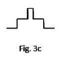
第1の例の別の変形は、伝送ファイバ17に関する。ここでは、伝送ファイバ17は、内側ファイバコア17a、内側ファイバコア17aを取り囲む外側ファイバコア17b、および外側ファイバコア17bを取り囲むファイバ被覆材17cを有するように設計される。伝送ファイバ17は、図3aでは伝送ファイバ17に沿った断面図で、また図3bでは伝送ファイバ17に対して横の断面図で示される。図3cは、図3bの断面に対応する伝送ファイバの屈折率プロファイルを示す。加工レーザ源10aおよび照明レーザ源10bは、加工レーザビーム14が内側ファイバコア17aによって誘導され、照明レーザビーム16もまた、外側ファイバコア17bによって部分的に誘導されるように、伝送ファイバ17に結合される。この構成は、被加工物の照明領域が被加工物の加工領域11aよりも実質的に少なくとも1.5倍大きくなることを引き起こす。さらには、照明レーザビーム16は、追加的に、ファイバ被覆材17cを通じて誘導され得、同様に、被加工物の照明領域は、加工領域よりも大きい。これらの場合すべてにおいて、加工レーザビーム14および照明レーザビーム16は、伝送ファイバ17によって同軸で誘導される。 Another variant of the first example relates to the
一部のファイバは、外側コアなしで構成され、(内側)コアが被覆材によって直接囲まれるということに留意されたい。この場合にも、照明レーザビームは、ファイバ被覆材を通じて誘導され得る。そのような例において、ファイバコアは、100μmの直径を有し得、コアを囲むファイバ被覆材は、150または360μmの直径を有し得る。 Note that some fibers are configured without an outer core and the (inner) core is directly surrounded by a dressing. Again, the illuminated laser beam can be guided through the fiber dressing. In such an example, the fiber core may have a diameter of 100 μm and the fiber dressing surrounding the core may have a diameter of 150 or 360 μm.
図3a〜図3cの例にあるように、照明レーザビーム16が、外側ファイバコア17bを介して、または追加的に伝送ファイバ17のファイバ被覆材17cを介して伝導される場合、照明レーザビーム16は、加工レーザビーム14よりも幅広い。加工レーザビーム14は、内側の明らかにより小さいファイバコア17aによってのみ誘導され、図3aおよび図3bを参照されたい。被加工物11の加工領域11aが加工レーザビーム14の伸長の領域内にあるため、加工領域11aは、したがって、照明領域よりも小さい。外側コア17bの直径またはファイバ被覆材17cの直径は、原則として、ファイバ設計中に選択され得る。照明領域の所望の伸長に応じて、それに対応して大きいファイバ被覆材または外側コア直径が選択され得る。加工領域11aの周りの照明領域が十分に大きいことを確実にするこの方策は、加工および照明レーザビーム14および16の焦点位置から独立している。加工領域11aおよび照明領域のサイズ比は、特に、外側コア17bの直径に依存する。ファイバの設計は、ファイバ17の製造業者に応じて異なり、またそれに応じて選択され得、例えば、内側ファイバコアの直径は、100μmであり得、外側ファイバコアは、150または360μmであり得る(ファイバの中心から)。 As in the example of FIGS. 3a-3c, when the illuminated
第1の例のさらなる変形において、レーザビーム誘導デバイスは、伝送ファイバ17を含むか、または伝送ファイバ17を含まず、以下の群(図1には図示せず):加工レーザビームおよび/または照明レーザビームの焦点を合わせるための少なくとも1つの光学ユニット、例えば、集束レンズ、ならびに照明レーザビームおよび/または加工レーザビームを少なくとも部分的に偏向するための少なくとも1つのユニット、特に、ダイクロイックミラー、から選択される少なくとも1つの要素を含む。それぞれの場合において、レーザビーム誘導デバイスは、加工レーザビームおよび照明レーザビームが同軸で誘導されることを引き起こす。 In a further variant of the first example, the laser beam guiding device includes or does not include the
本例およびその変形において、加工レーザビームおよび照明レーザビームが、伝送ファイバ17によって同軸で誘導される場合、加工装置、特に加工装置の加工ヘッドに取り付けるには不便な、コストをかけて設計された照明レーザ源は必要とされない。加えて、加工装置または加工ヘッドは、そこに追加的に取り付けられる照明レーザ源が理由でより複雑になること、またはより重くなることがない。 In this example and its variants, if the processed laser beam and the illuminated laser beam are coaxially guided by the
第1の例の別の変形は、被加工物から反射される照明レーザビームを検出するために、検出器デバイス(図1には図示せず)としてビデオカメラを備え、検出器デバイスのスペクトル範囲は、それが、照明レーザビーム、特に、反射された照明レーザビームのスペクトル範囲と少なくとも部分的に合致するように選択されるか、または調節可能である。この場合、照明レーザ源の出力および照明レーザビームのスペクトル範囲から選択される要素は、検出された自己放射が、被加工物によって反射され検出される照明レーザビームの出力よりも、検出されたスペクトル範囲が小さくなるように選択され得る。検出器デバイスの検出されたスペクトル範囲は、20nm未満、好ましくは10nm未満、より好ましくは5nm未満の幅を有する波長帯として選択され得る。さらには、検出されたスペクトル範囲は、照明レーザビームのスペクトル範囲内にあり得るか、または実質的にそれを検出し得るか、または実質的にそれと合致し得る。例えば、ビデオカメラは、観察領域を同軸に記録する検出器デバイスとして使用され得る。このやり方では、加工領域は、ビデオカメラによって監視される。カメラなどの、二次元の空間分解検出ユニットの代わりに、一次元検出器アレイも使用され得、その配向は、切断方向に対して横に提供される。切断方向を使用すると、空間分解は、アレイに対して垂直の方向で見ることができる。 Another variant of the first example comprises a video camera as a detector device (not shown in FIG. 1) to detect the illuminated laser beam reflected from the workpiece, and the spectral range of the detector device. It is selected or adjustable to at least partially match the spectral range of the illuminated laser beam, in particular the reflected illuminated laser beam. In this case, the element selected from the output of the illuminated laser source and the spectral range of the illuminated laser beam is the detected spectrum rather than the output of the illuminated laser beam where the detected self-radiation is reflected and detected by the workpiece. The range can be selected to be smaller. The detected spectral range of the detector device can be selected as a wavelength band having a width of less than 20 nm, preferably less than 10 nm, more preferably less than 5 nm. Furthermore, the detected spectral range may be within, substantially detect, or substantially match the spectral range of the illuminated laser beam. For example, a video camera can be used as a detector device that records the observation area coaxially. In this way, the machining area is monitored by a video camera. Instead of a two-dimensional spatial decomposition detection unit, such as a camera, a one-dimensional detector array can also be used, the orientation of which is provided laterally to the cutting direction. Using the cutting direction, the spatial decomposition can be seen in the direction perpendicular to the array.
図5および図6は、第1の例の上の変形に従う加工装置を用いた、ステンレス鋼被加工物のレーザ切断プロセスにおける、同軸ビデオカメラからの記録を示す。加工される被加工物は、レーザ切断プロセス中、熱放射され、すなわち、広いスペクトル範囲にわたる広帯域である。狭いスペクトル帯でのみ検出される場合、被加工物の自己放射の検出される出力は、それに応じてはるかに低い。レーザは、本質的に狭帯域である。レーザのすべての出力は、狭いスペクトル帯のみに存在することになる。狭帯域が、好ましくはもっぱらレーザが放射するスペクトル範囲内で、検出される場合、著しく小さい照明出力が、自己放射の明るさと比較してより明るい照明を提供するために必要とされる。この場合、視覚印象が特に重要である。 5 and 6 show recordings from a coaxial video camera in a laser cutting process of a stainless steel workpiece using a processing device that follows the deformation above in the first example. The workpiece to be machined is thermally radiated during the laser cutting process, i.e., wide band over a wide spectral range. When detected only in the narrow spectral band, the detected output of self-radiation of the workpiece is correspondingly much lower. Lasers are inherently narrow band. All outputs of the laser will be present only in the narrow spectral band. If a narrow band is detected, preferably within the spectral range emitted exclusively by the laser, a significantly smaller illumination output is needed to provide brighter illumination compared to the brightness of the self-emission. In this case, the visual impression is especially important.
図5は、照明なしのレーザ切断プロセスのカメラ記録を示す。本質的に、プロセスの自己放射を見ることができる。図6では、照明レーザが、追加的に、切断プロセスにおいてオンにされる。図6の記録の場合、照明なしよりも著しく短いカメラ露出時間が必要とされる。自己放射は強力に抑制される(カーフ裂け目の真ん中でそれを依然として弱く見ることができる)が、切断裂け目の環境は明白に目に見える。 FIG. 5 shows a camera recording of a laser cutting process without illumination. In essence, you can see the self-radiation of the process. In FIG. 6, the illumination laser is additionally turned on in the cutting process. The recording of FIG. 6 requires a significantly shorter camera exposure time than without illumination. Self-radiation is strongly suppressed (it can still be seen weakly in the middle of the calf rift), but the environment of the cut rift is clearly visible.
さらなる変形において、レーザビーム誘導デバイス、またはその単一もしくは複数の要素は、少なくとも部分的に、照明レーザビームの反射を低減するための外側コーティングを有する。コーティングは、選択された照明および観察スペクトルに適合している。これにより、反射された照明レーザビーム16のできる限り大きい部分が観察されるようにし、光学ユニットの刺激性の反射が発生するのをできる限り少なくする。特に、このやり方では、平面光学ユニットからの反射を回避することが有利である。この変形では、照明レーザビーム16の波長において、ダイクロイックミラーは、例えば、約50%の反射対透過比を有する。すべての他の光学素子は、照明波長において実質的に100%透過性である。 In a further variant, the laser beam guiding device, or a single or multiple element thereof, has, at least in part, an outer coating to reduce the reflection of the illuminated laser beam. The coating is compatible with the selected illumination and observation spectrum. This allows the observation of as large a portion of the reflected
図4は、本発明の実施形態に従う、被加工物をレーザ加工するための加工装置100の第2の例を概略的に示す。 FIG. 4 schematically shows a second example of a
図4の例では、伝送ファイバ17は、加工装置100の加工ヘッド12に横方向に結合される。さらには、加工レーザビーム14および照明レーザビーム16を反射し、照明の波長範囲内で被加工物11によって反射される放射に対して少なくとも部分的に透過的であるダイクロイックミラー13が提供される。ダイクロイックミラー13は、加工レーザビーム14および照明レーザビーム16が出口開口部10cの方へ偏向されるように、加工ヘッド12内で配向される。加えて、ダイクロイックミラー13と出口開口部10cとの間には光学ユニットがあり、これは、本例においては、集束レンズ18として設計される。さらには、ビデオカメラ15の形態にある検出器デバイスが提供される。ダイクロイックミラー13は、集束レンズ18とビデオカメラ15との間に設置される。これにより、被加工物によって反射される照明ビーム14が、集束レンズ18およびダイクロイックミラー13を通じて、少なくとも部分的にビデオカメラ15に当たることを可能にする。 In the example of FIG. 4, the
動作中、加工レーザビーム14および照明レーザビーム16は、伝送ファイバ17を介して加工ヘッド12内へ横方向に向けられ、ダイクロイックミラー13において被加工物11の方へ偏向され、集束レンズ18によって被加工物11の上に集束される。照明レーザビーム16は、出口開口部10cを通じて加工ヘッド12内へ少なくとも部分的に反射され、集束レンズ18およびダイクロイックミラー13を通じて伝送され、ビデオカメラ15に当たる。このやり方では、加工レーザ14によって加工される被加工物11の加工領域11aは、照明レーザビーム16によって照明され、ビデオカメラ15上に少なくとも部分的に反射される照明レーザビームによって観察される。 During operation, the
第2の例の変形において、集束レンズ18と、加工レーザ源10aと、照明レーザ源10bの各要素から選択される少なくとも1つの要素は、照明レーザビーム16の焦点と加工レーザビーム14の焦点が、特に光学軸上で、軸方向において互いに離れるように設計されるか、または調節され得る。この設計は、加工領域11aの周りの十分に大きい面積の照明を促進する。特に、照明領域は、プロセス相互作用ゾーンとも称される加工領域11aより大きく、例えば、少なくとも1.5の大きさ、好ましくは2倍の大きさであり得る。 In the modification of the second example, at least one element selected from the focused
特定の変形によると、加工レーザ源10aおよび照明レーザ源10bは、それらによって生成されるレーザビームのスペクトル範囲が異なるように設計されるか、または調節され得、集束レンズ18は、分散型であるように設計される。 According to certain modifications, the processed
第2の例の上の変形において、照明レーザビーム16の焦点と加工レーザビーム14の焦点は、合致せず、光軸上で軸方向に互いから離れる。これは、加工レーザビーム14および照明レーザビーム16の波長が不一致であること、ならびに光学ユニット、本変形では集束レンズ18が、分散型であるように設計されること、すなわち、波長依存の屈折率を有することによって達成される。後者は、実質的にすべての既知の光学材料で同じである。 In the above variant of the second example, the focal point of the illuminated
既知のレンズ焦点距離定式を用いると、加工レーザビーム14および照明レーザビーム16の2つの波長の焦点距離には差Δf=f2−f1が存在する。
第2の例の別の変形によると、照明のさらなる改善は、ビーム形成によって達成される。この場合、レーザビーム誘導デバイスは、被加工物11の照明領域が被加工物11の加工領域よりも大きくなる、特に少なくとも1.5倍の大きさ、好ましくは加工領域11aの2倍の大きさであるように設計される、照明レーザビームの選択的ビーム形成のためのユニット、例えば、修正された集束レンズ18を備える。このビーム形成は、照明レーザビーム16に対してのみ作用し、加工レーザビーム14に対しては作用しない。 According to another variant of the second example, further improvement in lighting is achieved by beam formation. In this case, in the laser beam guidance device, the illumination region of the
前記選択的ビーム形成の例は、照明レーザ波長の範囲内の波長を有する放射にのみ影響を及ぼし、加工レーザビーム14を未変更のままにする回折光学素子であり得る。回折光学素子として、回折光学格子もまた、(既に存在している)光学素子上で使用され得る。 The example of selective beam formation may be a diffractive optical element that affects only radiation having a wavelength within the wavelength of the illuminated laser and leaves the processed
別の例は、伝送ファイバ17の外側コアを介して誘導される照明レーザビーム16のみが影響され、加工レーザビーム14が未変更のままであるように実装および/または設計される、最適照明のためのビーム形成素子であり得る。 Another example is of optimal illumination, where only the illuminated
最後に、本発明および例示的な実施形態の説明は、本発明の特定の物理的実現に関して限定すると理解されるべきではないということに留意されたい。本発明の個々の実施形態と関連して説明され、また示される特徴のすべては、それらの有利な効果を同時に実現するために、本発明に従う主題において異なる組み合わせで提供され得る。 Finally, it should be noted that the description of the invention and exemplary embodiments should not be understood as limiting with respect to the particular physical realization of the invention. All of the features described and shown in connection with the individual embodiments of the invention may be provided in different combinations in the subject matter according to the invention in order to simultaneously realize their advantageous effects.
本発明の保護の範囲は、特許請求の範囲によって付与され、説明に例証される、または図に示される特徴によって限定されない。 The scope of protection of the present invention is conferred by the claims and is not limited by the features exemplified by or illustrated in the description.
本発明がレーザ加工システムだけでなく、レーザを備える他のデバイスにも使用され得ることは、当業者には特に明白である。さらには、被加工物をレーザ加工するための加工装置の構成要素は、いくつかの物理的製品にわたって分散されるように生産されてもよい。 It is particularly apparent to those skilled in the art that the present invention can be used not only for laser processing systems but also for other devices equipped with lasers. Furthermore, the components of the machining equipment for laser machining the workpiece may be produced to be dispersed across several physical products.
10 加工装置、 10a 加工レーザ源、 10b 照明レーザ源、 10c 出口開口部、 11 被加工物、 11a 加工領域、 12 加工ヘッド、 13 ダイクロイックミラー、 14 加工レーザビーム、 15 検出器デバイス、例えば、ビデオカメラ、 16 照明レーザビーム、 17 レーザビーム誘導デバイス、例えば、伝送ファイバ、 17a 内側ファイバコア、 17b 外側ファイバコア、 17c ファイバ被覆材、 18 光学ユニット、例えば、集束レンズ、 100 加工装置。 10 Machining equipment, 10a Machining laser source, 10b Illuminated laser source, 10c Outlet opening, 11 Work piece, 11a Machining area, 12 Machining head, 13 Dichromic mirror, 14 Machining laser beam, 15 Detector device, for example, video camera , 16 Illuminated Laser Beams, 17 Laser Beam Induction Devices, For example, Transmission Fibers, 17a Inner Fiber Cores, 17b Outer Fiber Cores, 17c Fiber Coatings, 18 Optical Units, For example, Focusing Lenses, 100 Processing Equipment.
狭帯域照明に利用可能な照明源には、例えば、LEDまたはダイオードレーザがある。既知の利用可能な照明源をレーザ加工システムの加工ヘッドに装着することができるようにするため、例えば、照明源は、通常、この目的のために特別に設計される。ここでの欠点は、通常、加工ヘッド上の利用可能な空間が限られており、加工ヘッドができる限り小さい重量を有さなければならないということである。加えて、プロセスゾーンが十分に照明され得るような照明源のための照明特有の理想の配置は、多くの場合、加工ヘッド上で見つけるのが困難である。
US2017/0043431A1は、照明用の光源を含むカメラモニタを有するレーザ処理ヘッド装置を開示する。光学フィルタは、処理点放射光および処理点反射レーザビームの透過を阻止し、撮像用の照明光を透過する。DE10 2012 001 609 B3は、光ファイバのファイバ端から出現する作業レーザビームをコリメートするためのビーム整形光学系、作業レーザビームを被加工物上に集束させるための集束光学系、および調節可能な撮像光学系を伴うカメラを有する、作業レーザビームによって被加工物を処理するためのレーザ処理ヘッドに関する。US2016/0193692A1は、被加工物における切断プロセスを監視するためのデバイスおよび方法に関する。集束素子は、高エネルギービームを被加工物上に集束させる。画像捕捉装置は、監視されるべき被加工物における領域を捕捉する。評価装置は、切断プロセスの少なくとも1つの特性変数を決定する。Illumination sources available for narrowband illumination include, for example, LEDs or diode lasers. For example, lighting sources are usually specially designed for this purpose so that known available lighting sources can be attached to the machining heads of laser machining systems. The drawback here is that the available space on the machining head is usually limited and the machining head must have as little weight as possible. In addition, the lighting-specific ideal placement for a lighting source such that the process zone can be fully illuminated is often difficult to find on the machining head.
US2017 / 0043431A1 discloses a laser processing head apparatus having a camera monitor including a light source for illumination. The optical filter blocks the transmission of the processing point synchrotron radiation and the processing point reflected laser beam, and transmits the illumination light for imaging. The DE10 2012 001 609 B3 is a beam shaping optical system for collimating a working laser beam emerging from the fiber end of an optical fiber, a focusing optical system for focusing the working laser beam on a workpiece, and adjustable imaging. It relates to a laser processing head for processing an workpiece by a working laser beam having a camera with an optical system. US2016 / 0193692A1 relates to devices and methods for monitoring cutting processes in workpieces. The focusing element focuses a high energy beam on the workpiece. The image capture device captures the area in the workpiece to be monitored. The evaluator determines at least one characteristic variable for the cutting process.
本目的は、請求項1に記載の被加工物をレーザ加工するための加工装置、請求項8に記載の加工装置の使用、および請求項9に記載の被加工物をレーザ加工するための方法によって達成される。An object of the present invention is a processing apparatus for laser machining the workpiece according to claim 1, the use of the processing apparatus according to claim8 , and a method for laser machining the workpiece according toclaim 9. Achieved by.
本発明の1つの実施形態において、被加工物をレーザ加工するための、特にレーザ切断のための、加工装置であって、加工レーザビームを生成するように構成された加工レーザ源と、あるスペクトル範囲を有する照明レーザビームを生成するように構成された出力を有する照明レーザ源と、加工レーザビームおよび照明レーザビームのための出口開口部と、加工レーザビームおよび照明レーザビームを出口開口部を通じて同軸で誘導するように構成されたレーザビーム誘導デバイスとを備え、照明レーザ源の出力と照明レーザビームのスペクトル範囲が、レーザ加工中、加工領域内の被加工物の自己放射よりも明るい照明レーザビームによる照明を生成するように選択され、照明レーザ源の出力が、少なくとも50mWであり、照明レーザビームのスペクトル範囲の中心波長が、300〜1000nmの範囲内であり、照明レーザビームのスペクトル範囲が、20nm未満の幅を有する波長帯であり、レーザビーム誘導デバイスと、光学ユニットと、加工レーザ源と、照明レーザ源とのうち少なくとも1つの要素が、軸方向において互いに離れている照明レーザビームの焦点と加工レーザビームの焦点を生成するように構成され、加工レーザ源および照明レーザ源が、これらによりそれぞれ生成されるレーザビームの異なるスペクトル範囲を生成するように構成され、光学ユニットが分散型であり、加工レーザビームのスペクトル範囲が、第1の波長を含み、照明レーザビームのスペクトル範囲が、第1の波長よりも短い第2の波長を含み、レーザビーム誘導デバイスが、加工レーザビームおよび照明レーザビームを同軸で誘導するように構成される少なくとも1つの伝送ファイバを備え、伝送ファイバが、内側ファイバコアを有し、加工レーザ源および照明レーザ源が、内側ファイバコアを通じて加工レーザビームを誘導するために伝送ファイバに結合され、伝送ファイバが、内側ファイバコアを取り囲む外側ファイバコア、および/または内側もしくは外側ファイバコアを取り囲むファイバ被覆材を有し、加工レーザ源および照明レーザ源が、照明レーザビームを少なくとも部分的に、外側ファイバコアを通じておよび/またはファイバ被覆材を通じて誘導するために伝送ファイバに結合される、加工装置が提供される。In one embodiment of the invention, a processing apparatus for laser processing an workpiece, especially for laser cutting,with a processing laser source configured to generate a processing laser beam, and a spectrum.Illuminated laser sources with outputs configured to produce illuminated laser beams with range, outlet openings for processed laser beams and illuminated laser beams,and processed laser beams and illuminated laser beams through outlet openings.With a laser beam guiding deviceconfigured to guide coaxially,the output of the illuminated laser source and the spectral range of the illuminated laser beamare brighter than the self-radiation of the workpiece in the machining area during laser machining. Selected to generate illumination with a laser beam, the output of the illuminated laser source is at least 50 mW, the center wavelength of the spectral range of the illuminated laser beam is in the range of 300-1000 nm, and the spectral range of the illuminated laser beam. Is an illuminated laser beam having a width of less than 20 nm, wherein at least one element of the laser beam guiding device, the optical unit, the processed laser source, and the illuminated laser source is axially separated from each other. The focal point of the laser beam and the focal point of the processed laser beam are configured to generate, the processed laser source and the illuminated laser source are configured to generate different spectral ranges of the laser beam produced by them, and the optical unit is distributed. The spectral range of the processed laser beam includes the first wavelength, the spectral range of the illuminated laser beam includes the second wavelength shorter than the first wavelength, and the laser beam guidance device is the processed laser beam and. It comprises at least one transmission fiber configured to guide the illumination laser beam coaxially, the transmission fiber has an inner fiber core, and the processing laser source and the illumination laser source guide the processing laser beam through the inner fiber core. The transmission fiber has an outer fiber core that surrounds the inner fiber core and / or a fiber coating material that surrounds the inner or outer fiber core, and the processed and illuminated laser sources are illuminated lasers. Processing equipment is provided that iscoupled to the transmission fiber to guide the beam, at least in part, through the outer fiber core and / or through the fiber coating.
特定の実施形態において、照明レーザ源の出力は、100mW〜3000mW、好ましくは130mW〜1000mW、さらに好ましくは150mW〜300mWであり得る。照明レーザ源のそのような出力は、加工プロセスの自己放射の抑制または低減を可能にする。さらには、照明レーザビームのスペクトル範囲の中心波長は、300〜820nm、好ましくは300〜550nm、さらに好ましくは300〜490nmの範囲内にあり得る。照明レーザビームのそのようなスペクトル範囲は、典型的な加工レーザを使用するとき、より高い波長と比較して、明るさの小さい、またはあまり強くない照明が必要とされることを意味し得る。照明レーザビームのスペクトル範囲は、10nm未満、より好ましくは5nm未満の幅を有する波長帯としてさらに選択され得る。照明レーザビームの、この狭帯域、すなわち、スペクトル波長帯のこの狭い幅は、加工プロセス中、被加工物の自己放射を抑制または低減することを助ける。In certain embodiments, the output of the illumination lasersource, 100MW~3000mW, good Mashiku is 130MW~1000mW, more preferablybe a 150MW~300mW. Such an output of an illuminated laser source allows for suppression or reduction of self-radiation in the machining process. Further, the center wavelengthof the spectrumrange of the illumination laserbeam, 300~820Nm, good Mashiku is 300~550Nm, more preferablybe in the range of 300~490Nm. Such a spectral range of an illumination laser beam can mean that less bright or less intense illumination is required when using a typical processed laser, compared to higher wavelengths. The spectral range of the illuminated laser beam may be further selected as a wavelength band having a width of less than10 nm, more preferably less than 5 nm. This narrow band of the illuminated laser beam, i.e., this narrow width of the spectral wavelength band, helps suppress or reduce self-radiation of the workpiece during the machining process.
さらには、レーザビーム誘導デバイス、加工レーザ源、および照明レーザ源から選択される少なくとも1つの要素は、被加工物の加工領域よりも大きい、特に少なくとも1.5倍の大きさ、好ましくは加工領域の2倍の大きさである被加工物の照明領域を生成するように、構成され得る。これが、加工領域の広範な照明を可能にする。Further, the laser beam guiding device, processing laser source, and at least one element selected from the illumination laser source isgreater than themachining areaof the workpiece, in particular at least 1.5 times as large, preferably machining so asto produce an illumination area of the workpiece which is twice as large as the region,that could beconfigured. This allows for a wide range of illumination in the machining area.
加工装置のさらなる実施形態において、レーザビーム誘導デバイスは、加工レーザビームおよび/または照明レーザビームの焦点を合わせるための少なくとも1つの光学ユニットと、照明レーザビームおよび/または加工レーザビームを少なくとも部分的に偏向するための少なくとも1つのユニット、特に、ダイクロイックミラーの各要素からなる群から選択される少なくとも1つの要素を備え得る。加工レーザビームおよび照明レーザビームが、伝送ファイバによって同軸で誘導される場合、加工装置、特に加工装置の加工ヘッドに取り付けるには不便な、コストをかけて設計された照明レーザ源は必要とされない。加えて、加工装置または加工ヘッドは、そこに追加的に取り付けられる照明レーザ源が理由でより複雑になること、またはより重くなることがない。In a further embodiment of the machining apparatus, a laser beam guidingdevice, machining laser beam and / or at least one optical unit for focusing the illumination laser beam, at least partially illuminating laser beam and / or the working laser beam It may comprise at least one unit for deflecting to, in particular at least one element selected from the group consisting of each element of the dichroic mirror. When the processed laser beam and the illuminated laser beam are coaxially guided by the transmission fiber, no costly designed illuminated laser source is required, which is inconvenient to attach to the processing equipment, especially the processing head of the processing equipment. In addition, the machining equipment or machining head does not become more complex or heavier due to the illumination laser source additionally attached to it.
上で述べたように、レーザビーム誘導デバイス、光学ユニット、加工レーザ源、および照明レーザ源の各要素から選択される少なくとも1つの要素は、軸方向において互いに離れた照明レーザビームの焦点と加工レーザビームの焦点を生成するように構成される。この方策は、十分に大きい面積が加工領域の周りで照明されることを促進し、特に、照明領域は、加工領域よりも大きくなり得る。加えて、加工レーザ源および照明レーザ源は、加工レーザ源および照明レーザ源によってそれぞれ生成されるレーザビームの異なるスペクトル範囲を生成するように構成され、光学ユニットは、分散型である。上で述べたように、加工レーザビームのスペクトル範囲は、第1の波長を含み、照明レーザビームのスペクトル範囲は、第1の波長よりも短い第2の波長を含む。この場合、第1の波長は、加工レーザビームのスペクトル範囲の中心波長であり得、第2の波長は、照明レーザビームのスペクトル範囲の中心波長であり得る。これらの方策を、個々に、または組み合わせて、用いることにより、照明レーザの焦点が加工レーザの焦点と合致しないということが達成され得る。したがって、特に、加工レーザの焦点が加工部位のところで静止する場合、照明領域が加工領域よりも大きくなることが可能である。As mentioned above, at least one element selected from the elements of the laser beam guidance device, the optical unit, the processed laser source, and the illuminated laser source is the focal point of the illuminated laser beam and the processed laserthat are axially separated from each other.Ru isconfiguredto generate a focus of thebeam. This measure facilitates that a sufficiently large area is illuminated around the machined area, in particular the illuminated area can be larger than the machined area. In addition, processing laser source and an illumination laser sourceis configuredto generate adifferent spectral range of the laser beam generated respectively by the processing laser source and an illumination laser source, optical unitis distributed.As noted above, the spectral range of the machining laser beam,viewed contains a firstwavelength, the spectral range of the illuminating laser beam,including a second wavelength shorter than the first wavelength. In this case, the first wavelength may be the central wavelength of the spectral range of the processed laser beam and the second wavelength may be the central wavelength of the spectral range of the illuminated laser beam. By using these measures individually or in combination, it can be achieved that the focal point of the illuminated laser does not match the focal point of the processed laser. Therefore, the illuminated area can be larger than the machined area, especially when the focal point of the machined laser is stationary at the machined area.
上で述べたように、伝送ファイバは、内側ファイバコアを備える。加工レーザ源および照明レーザ源は、加工レーザビームを内側ファイバコアを通じて誘導するために、伝送ファイバに結合される。これは、特に、加工レーザビームおよび照明レーザビームが伝送ファイバにより同軸で誘導される実施形態に当てはまる。伝送ファイバは、内側ファイバコアを取り囲む外側ファイバコア、および/または内側もしくは外側ファイバコアを取り囲むファイバ被覆材を備える。加工レーザ源および照明レーザ源は、照明レーザビームを少なくとも部分的に外側ファイバコアを通じておよび/またはファイバ被覆材を通じて誘導するために伝送ファイバに結合される。これらの方策を単独で、または組み合わせて用いることにより、照明領域はまた、加工領域よりも大きくされ得る。加えて、この実施形態における照明領域の達成サイズは、有利には、加工および照明レーザ源の焦点の相対位置から独立している。さらには、照明レーザビームが伝送ファイバを介して誘導されるすべての実施形態において、照明レーザ源は、加工レーザにおける汚染から十分に保護される。As noted above, the transmission fiber,obtain Preparations inner fibercore. Machining laser source and illumination laser source,in order to inducethe working laser beam through inner fiber core,it is coupled to the transmission fiber. This is particularly true for embodiments in which the processed laser beam and the illuminated laser beam are coaxially guided by the transmission fiber. Transmission fiber,obtain Bei the fiber coating material which surrounds the outer fiber core surrounds the inner fiber core and / or the inner or outer fibercore. Machining laser source and illumination laser sourceis coupled to the transmission fiberto induce through through and / or fiber coating material at least partially outside the fiber corean illumination laser beam. By using these measures alone or in combination, the illuminated area can also be made larger than the machined area. In addition, the achieved size of the illuminated area in this embodiment is advantageously independent of the relative position of the focal point of the processing and illuminated laser source. Furthermore, in all embodiments where the illuminated laser beam is guided through the transmission fiber, the illuminated laser source is adequately protected from contamination in the processed laser.
上の実施形態の変形において、被加工物の加工領域よりも大きい、特に少なくとも1.5倍の大きさ、好ましくは加工領域の2倍の大きさである被加工物の照明領域を生成するために、外側ファイバコアは、第1の直径を有し得、および/またはファイバ被覆材は、第2の直径を有し得る。In a variation of the above embodiments,greater thanmachining regionof the workpiece, in particular at least 1.5 times as large, preferablygenerates an illumination region of the workpiece which is twice as large as the working areafor, the outer fiber core can have a first diameter, and / or fiber coating material may have a second diameter.
本加工装置のさらなる実施形態によると、レーザビーム誘導デバイスは、被加工物の加工領域よりも大きい、特に少なくとも1.5倍の大きさ、好ましくは加工領域の2倍の大きさである被加工物の照明領域を生成するように構成される、照明レーザビームの選択的ビーム形成のためのユニット、特に、選択的ビーム形成のための少なくとも1つの回折光学素子を有し得る。「選択的ビーム形成のためのユニット」という用語は、特に、加工レーザ波長に対してのみ、または照明レーザ波長に対してのみ作用する1つ以上の回折光学素子を指す。According to a further embodiment of the machining apparatus, a laser beam guiding device isgreater than themachining areaof the workpiece, in particular at least 1.5 times the size is twice the size of preferably processed areato be workpiece isconfiguredto produce an illumination area, the unit for selective beamforming illumination laser beam, in particular, can have at least one diffractive optical element for selective beamforming. The term "unit for selective beam formation" specifically refers to one or more diffractive optics that act only on the processed laser wavelength or only on the illumination laser wavelength.
本発明のさらなる実施形態は、被加工物をレーザ加工するための、特にレーザ切断のための、先行する実施形態のいずれか1つに従う加工装置の使用に関する。したがって、レーザ加工中、特にレーザ切断中の、本加工装置について記載される利点および機能が、被加工物により実現される。A further embodiment of the invention relates to the use of a machining apparatus according to any one of the preceding embodiments for laser machining a workpiece, especially for laser cutting.Therefore, inLe chromatography The processing,inJP-Les chromatography Thecutting, advantages and features are described the processing apparatus is realizedby the workpiece.
本発明の1つの実施形態は、特に、先行する実施形態のいずれか1つに従う加工装置を使用した、被加工物をレーザ加工するための、特にレーザ切断のための方法を開示する。本方法は、被加工物を加工レーザ源からの加工レーザビームおよび照明レーザ源からの照明レーザビームで同軸に照射するステップを含み、照明レーザ源の出力と照明レーザビームのスペクトル範囲は、照明レーザビームによる照明が、レーザ加工中、加工領域内の被加工物の自己放射よりも明るくなるように選択され、照明レーザ源の出力が、少なくとも50mWであるように選択または調節され、照明レーザビームのスペクトル範囲が、その中心波長が300〜1000nmの範囲内にあるように選択または調節され、照明レーザビームのスペクトル範囲が、20nm未満の幅を有する波長帯として選択され、加工レーザビームおよび/または照明レーザビームが、照明レーザビームの焦点と加工レーザビームの焦点が軸方向において互いに離れるように焦点を合わせられ、加工レーザ源および照明レーザ源が、それらにより生成されるレーザビームのスペクトル範囲が異なるように選択または調節され、加工レーザビームおよび照明レーザビームが、分散型光学ユニットを通じて誘導され、加工レーザビームのスペクトル範囲が、第1の波長を含み、照明レーザビームのスペクトル範囲が、第1の波長より短い第2の波長を含み、加工レーザビームおよび照明レーザビームが、少なくとも1つの伝送ファイバを通じて同軸で誘導され、伝送ファイバが内側ファイバコアを有し、加工レーザビームが内側ファイバコアを通じて誘導され、伝送ファイバが、内側ファイバコアを取り囲む外側ファイバコア、および/または内側もしくは外側ファイバコアを取り囲むファイバ被覆材を有し、照明レーザビームが少なくとも部分的に外側ファイバコアを通じておよび/またはファイバ被覆材を通じて誘導される。One embodiment of the present invention discloses, in particular, a method for laser machining a workpiece, especially for laser cutting, using a machining apparatus according to any one of the preceding embodiments. The method comprises irradiating the workpiece coaxially with a processed laser beam from the processed laser source and an illuminated laser beam from the illuminated laser source, the output of the illuminated laser source and the spectral rangeof the illuminated laser beam being the illuminated laser. Illumination by the beam is selected to be brighter than the self-emission of the workpiece in the machining area during laser machining, and the output of the illuminating laser source is selected or adjusted to be at least 50 mW of the illuminating laser beam. The spectral range is selected or adjusted so that its center wavelength is in the range of 300-1000 nm, and the spectral range of the illuminated laser beam is selected as a wavelength band with a width of less than 20 nm, the processed laser beam and / or illumination. The laser beam is focused so that the focal point of the illuminated laser beam and the focal point of the processed laser beam are axially separated from each other so that the processed laser source and the illuminated laser source have different spectral ranges of the laser beam produced by them. The processed laser beam and the illuminated laser beam are guided through the distributed optical unit, the spectral range of the processed laser beam includes the first wavelength, and the spectral range of the illuminated laser beam is the first wavelength. Containing a shorter second wavelength, the processed and illuminated laser beams are coaxially guided through at least one transmission fiber, the transmission fiber has an inner fiber core, and the processed laser beam is guided through the inner fiber core. The transmission fiber has an outer fiber core that surrounds the inner fiber core and / or a fiber coating that surrounds the inner or outer fiber core, and the illuminated laser beam is at least partially guided through the outer fiber core and / or through the fiber coating. Will be done.
本方法において、照明レーザ源の出力は、100mW〜3000mW、好ましくは130mW〜1000mW、さらに好ましくは150mW〜300mWであるように、選択または調節され得る。さらには、照明レーザビームのスペクトル範囲は、その中心波長が、300〜820nm、好ましくは300〜550nm、さらに好ましくは300〜490nmの範囲内にあるように選択または調節され得る。照明レーザビームのスペクトル範囲は、10nm未満、好ましくは5nm未満の幅を有する波長帯としてさらに選択され得る。In this method, the output of the illumination lasersource, 100MW~3000mW, thegood Mashiku 130MW~1000mW, more preferably such that 150MW~300mW, may be selected or adjusted. Furthermore, the spectral range of the illuminating laser beam, the centerwavelength, 300~820Nm, the
本方法は、加工レーザビームおよび照明レーザビームから選択される少なくとも1つの要素の焦点を合わせるステップと、特にダイクロイックミラーを用いて、照明レーザビームおよび/または加工レーザビームを少なくとも部分的に偏向するステップと、のうちの少なくとも1つを含み得る。The methodincludes focusing the at least one element selected from themachining laser beam and the illumination laser beam, in particular by using a dichroic mirror, at least partially deflects the illumination laser beam and / or the working laser beam It may include at least one of the steps.
上で述べたように、加工レーザビームのスペクトル範囲は、第1の波長を含み、照明レーザビームのスペクトル範囲は、第1の波長よりも小さい第2の波長を含む。この場合、第1の波長は、加工レーザビームのスペクトル範囲の中心波長であり得、第2の波長は、照明レーザビームのスペクトル範囲の中心波長であり得る。As noted above, the spectral range of the machining laser beam,viewed contains a firstwavelength, the spectral range of the illuminating laser beam,including a second wavelength less than the firstwavelength. In this case, the first wavelength may be the central wavelength of the spectral range of the processed laser beam and the second wavelength may be the central wavelength of the spectral range of the illuminated laser beam.
被加工物の照明領域が、被加工物の加工領域よりも大きくなる、特に少なくとも1.5倍の大きさ、好ましくは加工領域の2倍の大きさであるように、外側ファイバコアについては第1の直径、および/またはファイバ被覆材については第2の直径が選択され得る。Illumination region of theworkpiece is greater than the machining area of the workpiece, in particular at least 1.5 times as large, preferably such that 2 times the size of the processing area, the about outer fiber core A diameter of 1 and / or a second diameter may be selected for the fiber dressing.
Claims (25)
Translated fromJapanese加工レーザビーム(14)を生成するための加工レーザ源(10a)と、
あるスペクトル範囲を有する照明レーザビーム(16)を生成するための出力を有する照明レーザ源(10b)と、
前記加工レーザビームおよび前記照明レーザビームのための出口開口部(10c)と、
前記加工レーザビームおよび前記照明レーザビームが前記出口開口部(10c)を通って同軸で出現するように設計されるレーザビーム誘導デバイス(17)と、
を有し、
前記照明レーザ源の出力と前記照明レーザビームのスペクトル範囲とのうち少なくとも1つの要素が、前記照明レーザビームによる照明が、レーザ加工中、加工領域(11a)内の前記被加工物の自己放射よりも明るくなるように選択されていることを特徴とする加工装置。A processing device for laser processing a workpiece, especially for laser cutting.
A processed laser source (10a) for generating a processed laser beam (14), and
An illuminated laser source (10b) having an output for generating an illuminated laser beam (16) having a spectral range, and an illuminated laser source (10b).
With the outlet opening (10c) for the processed laser beam and the illumination laser beam,
A laser beam guiding device (17) designed so that the processed laser beam and the illumination laser beam appear coaxially through the outlet opening (10c).
Have,
At least one element of the output of the illuminating laser source and the spectral range of the illuminating laser beam is that the illumination by the illuminating laser beam is from the self-radiation of the workpiece in the machining region (11a) during laser machining. A processing device characterized by being selected to be bright.
前記照明レーザ源の出力が、少なくとも50mW、好ましくは100mW〜3000mW、より好ましくは130mW〜1000mW、さらに好ましくは150mW〜300mWであるように選択されているか、もしくは調節され得、および/または
前記照明レーザビームのスペクトル範囲が、その中心波長が、300〜1000nm、好ましくは300〜820nm、より好ましくは300〜550nm、さらに好ましくは300〜490nmの範囲内であるように選択されているか、もしくは調節され得、および/または
前記照明レーザビームのスペクトル範囲が、20nm未満、好ましくは10nm未満、より好ましくは5nm未満の幅を有する波長帯として選択されている、
ことを特徴とする加工装置。The processing apparatus according to claim 1.
The output of the illumination laser source may be selected or adjusted to be at least 50 mW, preferably 100 mW to 3000 mW, more preferably 130 mW to 1000 mW, even more preferably 150 mW to 300 mW, and / or the illumination laser. The spectral range of the beam may be selected or adjusted so that its central wavelength is in the range of 300-1000 nm, preferably 300-820 nm, more preferably 300-550 nm, even more preferably 300-490 nm. And / or the spectral range of the illuminated laser beam is selected as a wavelength band having a width of less than 20 nm, preferably less than 10 nm, more preferably less than 5 nm.
A processing device characterized by that.
前記レーザビーム誘導デバイス(17)と、前記加工レーザ源(10a)と、前記照明レーザ源(10b)とのうち少なくとも1つの要素が、前記被加工物(11)の照明領域が、前記被加工物の前記加工領域よりも大きくなる、特に少なくとも1.5倍の大きさ、好ましくは前記加工領域の2倍の大きさであるように、設計されているか、または調節され得ることを特徴とする加工装置。The processing apparatus according to claim 1 or 2.
The laser beam guiding device (17), the processed laser source (10a), and the illuminated laser source (10b) have at least one element, and the illuminated area of the workpiece (11) is the workpiece. It is characterized by being designed or adjustable to be larger than the machined area of the object, particularly at least 1.5 times larger, preferably twice the size of the machined area. Processing equipment.
前記レーザビーム誘導デバイスが、
前記加工レーザビームおよび前記照明レーザビームが同軸で誘導されるように設計される少なくとも1つの伝送ファイバ(17)と、
前記加工レーザビームおよび/または前記照明レーザビームの焦点を合わせるための少なくとも1つの光学ユニット(18)と、、
前記照明レーザビームおよび/または前記加工レーザビームを少なくとも部分的に偏向するための少なくとも1つのユニット(13)、特に、ダイクロイックミラーと、
からなる群のうち少なくとも1つの要素を備えることを特徴とする加工装置。The processing apparatus according to any one of claims 1 to 3.
The laser beam guidance device
With at least one transmission fiber (17) designed so that the processed laser beam and the illumination laser beam are coaxially guided.
With at least one optical unit (18) for focusing the processed laser beam and / or the illumination laser beam, ...
With at least one unit (13) for at least partially deflecting the illuminated laser beam and / or the processed laser beam, in particular a dichroic mirror.
A processing apparatus comprising at least one element in the group consisting of.
前記伝送ファイバ(17)が、内側ファイバコア(17a)を有し、
前記加工レーザ源および前記照明レーザ源が、前記加工レーザビームが前記内側ファイバコアを通じて誘導されるように、前記伝送ファイバに結合されていることを特徴とする加工装置。The processing apparatus according to any one of claims 4 to 7.
The transmission fiber (17) has an inner fiber core (17a).
A processing apparatus characterized in that the processing laser source and the illumination laser source are coupled to the transmission fiber so that the processing laser beam is guided through the inner fiber core.
前記伝送ファイバ(17)が、前記内側ファイバコアを取り囲む外側ファイバコア(17b)、および/または前記内側もしくは外側ファイバコアを取り囲むファイバ被覆材(17c)を有し、
前記加工レーザ源および前記照明レーザ源が、前記照明レーザビームが少なくとも部分的に、前記外側ファイバコアを通じておよび/または前記ファイバ被覆材を通じて誘導されるように、前記伝送ファイバに結合されていることを特徴とする加工装置。The processing apparatus according to claim 8.
The transmission fiber (17) has an outer fiber core (17b) surrounding the inner fiber core and / or a fiber coating material (17c) surrounding the inner or outer fiber core.
The processed laser source and the illuminated laser source are coupled to the transmission fiber such that the illuminated laser beam is at least partially guided through the outer fiber core and / or through the fiber dressing. Characterized processing equipment.
被加工物に加工レーザ源からの加工レーザビームおよび照明レーザ源からの照明レーザビームを同軸に照射するステップを含み、
前記照明レーザ源の出力と前記照明レーザビームのスペクトル範囲とのうち少なくとも1つの要素は、前記照明レーザビームによる照明が、レーザ加工中、加工領域内の前記被加工物の自己放射よりも明るくなるように選択されることを特徴とする方法。In particular, it is a method for laser processing of a workpiece, particularly for laser cutting, using the processing apparatus according to any one of claims 1 to 10.
Including the step of coaxially irradiating the workpiece with the processed laser beam from the processed laser source and the illuminated laser beam from the illuminated laser source.
At least one element of the output of the illuminated laser source and the spectral range of the illuminated laser beam is that the illumination by the illuminated laser beam is brighter than the self-radiation of the workpiece in the machining area during laser machining. A method characterized by being selected as.
前記照明レーザ源の出力が、少なくとも50mW、好ましくは100mW〜3000mW、より好ましくは130mW〜1000mW、さらに好ましくは150mW〜300mWであるように選択もしくは調節され、および/または
前記照明レーザビームのスペクトル範囲が、その中心波長が、300〜1000nm、好ましくは300〜820nm、より好ましくは300〜550nm、さらに好ましくは300〜490nmの範囲内であるように選択もしくは調節され、および/または
前記照明レーザビームのスペクトル範囲が、20nm未満、好ましくは10nm未満、より好ましくは5nm未満の幅を有する波長帯として選択される、
ことを特徴とする方法。The method according to claim 14.
The output of the illuminated laser source is selected or adjusted to be at least 50 mW, preferably 100 mW to 3000 mW, more preferably 130 mW to 1000 mW, even more preferably 150 mW to 300 mW, and / or the spectral range of the illuminated laser beam. The central wavelength is selected or adjusted to be in the range of 300-1000 nm, preferably 300-820 nm, more preferably 300-550 nm, even more preferably 300-490 nm, and / or the spectrum of the illuminated laser beam. The range is selected as a wavelength band having a width of less than 20 nm, preferably less than 10 nm, more preferably less than 5 nm.
A method characterized by that.
前記被加工物の照明領域が、前記被加工物の前記加工領域よりも大きくなる、特に少なくとも1.5倍の大きさ、好ましくは前記加工領域の2倍の大きさであるように、前記加工レーザビームおよび前記照明レーザビームが誘導され、および/または、
前記加工レーザ源と前記照明レーザ源とのうち少なくとも1つの要素が、選択もしくは調節される、
ことを特徴とする方法。The method according to claim 14 or 15.
The processing so that the illuminated area of the work piece is larger than the processing area of the work piece, particularly at least 1.5 times larger, preferably twice the size of the processing area. The laser beam and the illuminated laser beam are guided and / or
At least one element of the processed laser source and the illuminated laser source is selected or adjusted.
A method characterized by that.
前記加工レーザビームおよび前記照明レーザビームを少なくとも1つの伝送ファイバを通じて同軸で誘導するステップと、
前記加工レーザビームおよび前記照明レーザビームから選択される少なくとも1つの要素の焦点を合わせるステップと、
特にダイクロイックミラーを用いて、前記照明レーザビームおよび/または前記加工レーザビームを、少なくとも部分的に偏向するステップと、
のうちの少なくとも1つを含むことを特徴とする方法。The method according to any one of claims 14 to 16.
A step of coaxially guiding the processed laser beam and the illumination laser beam through at least one transmission fiber.
A step of focusing at least one element selected from the processed laser beam and the illumination laser beam.
A step of at least partially deflecting the illuminated laser beam and / or the processed laser beam, particularly using a dichroic mirror.
A method comprising at least one of.
前記加工レーザ源および前記照明レーザ源が、これらによりそれぞれ生成される前記レーザビームのスペクトル範囲が異なるように選択または調節され、
前記加工レーザビームおよび前記照明レーザビームが、分散型光学ユニットを通じて誘導されることを特徴とする方法。The method according to claim 18.
The processed laser source and the illuminated laser source are selected or adjusted so that the spectral range of the laser beam generated by them is different.
A method characterized in that the processed laser beam and the illumination laser beam are guided through a distributed optical unit.
前記伝送ファイバが、内側ファイバコア(17a)を備え、
前記加工レーザビームが、前記内側ファイバコアを通じて誘導されることを特徴とする方法。The method according to any one of claims 17 to 20.
The transmission fiber comprises an inner fiber core (17a).
A method characterized in that the processed laser beam is guided through the inner fiber core.
前記伝送ファイバ(17)が、前記内側ファイバコアを取り囲む外側ファイバコア(17b)、および/または前記内側もしくは外側ファイバコアを取り囲むファイバ被覆材(17c)を有し、
前記照明レーザビームが少なくとも部分的に、前記外側ファイバコアを通じておよび/または前記ファイバ被覆材を通じて誘導されることを特徴とする方法。The method according to claim 21.
The transmission fiber (17) has an outer fiber core (17b) surrounding the inner fiber core and / or a fiber coating material (17c) surrounding the inner or outer fiber core.
A method characterized in that the illuminated laser beam is at least partially guided through the outer fiber core and / or through the fiber dressing.
The method according to any one of claims 14 to 24 so that a spectral range that at least partially matches the spectral range of the illuminated laser beam, particularly the reflected illuminated laser beam, is detected. , A method further comprising the step of detecting the illumination laser beam reflected from the workpiece.
Applications Claiming Priority (3)
| Application Number | Priority Date | Filing Date | Title |
|---|---|---|---|
| DE102018126846.7 | 2018-10-26 | ||
| DE102018126846.7ADE102018126846A1 (en) | 2018-10-26 | 2018-10-26 | Machining device for laser machining a workpiece and method for laser machining a workpiece |
| PCT/EP2019/079185WO2020084114A1 (en) | 2018-10-26 | 2019-10-25 | Machining apparatus for laser machining a workpiece and method for laser machining a workpiece |
Publications (2)
| Publication Number | Publication Date |
|---|---|
| JP2021536370Atrue JP2021536370A (en) | 2021-12-27 |
| JP6992214B2 JP6992214B2 (en) | 2022-01-13 |
Family
ID=68392984
Family Applications (1)
| Application Number | Title | Priority Date | Filing Date |
|---|---|---|---|
| JP2021522939AActiveJP6992214B2 (en) | 2018-10-26 | 2019-10-25 | Machining equipment for laser machining the workpiece and method for laser machining the workpiece |
Country Status (6)
| Country | Link |
|---|---|
| US (1) | US12194563B2 (en) |
| EP (1) | EP3870385B1 (en) |
| JP (1) | JP6992214B2 (en) |
| CN (1) | CN113015594B (en) |
| DE (1) | DE102018126846A1 (en) |
| WO (1) | WO2020084114A1 (en) |
Families Citing this family (3)
| Publication number | Priority date | Publication date | Assignee | Title |
|---|---|---|---|---|
| EP4292753A1 (en)* | 2022-06-16 | 2023-12-20 | Bystronic Laser AG | Determining the degree of fouling of a transmissive element |
| DE102022128180A1 (en)* | 2022-10-25 | 2024-04-25 | TRUMPF Werkzeugmaschinen SE + Co. KG | Media supply during laser welding |
| EP4628243A1 (en) | 2024-04-04 | 2025-10-08 | Bystronic Laser AG | Flatbed laser cutting machine, system and method |
Citations (5)
| Publication number | Priority date | Publication date | Assignee | Title |
|---|---|---|---|---|
| JP2003001465A (en)* | 2001-06-21 | 2003-01-08 | Japan Atom Energy Res Inst | Laser processing system using composite optical fiber |
| WO2013110467A1 (en)* | 2012-01-26 | 2013-08-01 | Precitec Gmbh & Co. Kg | Laser machining head with focus control |
| US20160193692A1 (en)* | 2013-09-13 | 2016-07-07 | Trumpf Werkzeugmaschinen Gmbh + Co. Kg | Devices and Methods for Monitoring, in Particular for Regulating, a Cutting Process |
| JP6180620B2 (en)* | 2014-03-12 | 2017-08-16 | 三菱電機株式会社 | Laser processing head device with camera monitor |
| JP2018047475A (en)* | 2016-09-20 | 2018-03-29 | 株式会社Okファイバーテクノロジー | Laser irradiation device |
Family Cites Families (11)
| Publication number | Priority date | Publication date | Assignee | Title |
|---|---|---|---|---|
| JPH11344417A (en) | 1998-06-03 | 1999-12-14 | Amada Eng Center Co Ltd | Detecting method for fracture and incidence deviation of optical fiber and laser machining apparatus |
| JP3038196B1 (en) | 1998-10-30 | 2000-05-08 | ファナック株式会社 | Laser light concentrator |
| JP2008170366A (en)* | 2007-01-15 | 2008-07-24 | Disco Abrasive Syst Ltd | Measuring device for workpiece held on chuck table and laser processing machine |
| DE102010020183B4 (en)* | 2010-05-11 | 2013-07-11 | Precitec Kg | Laser cutting head and method for cutting a workpiece by means of a laser cutting head |
| CN102059451A (en)* | 2010-11-08 | 2011-05-18 | 北京理工大学 | Nano-femtosecond dual-laser composite machining system |
| DE102011075213B4 (en)* | 2011-05-04 | 2013-02-21 | Trumpf Laser Gmbh + Co. Kg | Laser processing system with an adjustable laser beam in its brilliance |
| CN103212842B (en)* | 2012-01-19 | 2016-07-06 | 昆山思拓机器有限公司 | A kind of support laser cutting device |
| US8983259B2 (en)* | 2012-05-04 | 2015-03-17 | Raytheon Company | Multi-function beam delivery fibers and related system and method |
| DE102014214427B4 (en)* | 2014-07-23 | 2021-11-18 | Technische Universität Dresden | Method and device for removing a coating from a surface of a base material |
| JP6367886B2 (en) | 2016-10-14 | 2018-08-01 | ファナック株式会社 | Laser processing equipment |
| JP6306659B1 (en) | 2016-10-19 | 2018-04-04 | ファナック株式会社 | Beam distributor |
- 2018
- 2018-10-26DEDE102018126846.7Apatent/DE102018126846A1/ennot_activeWithdrawn
- 2019
- 2019-10-25USUS17/288,553patent/US12194563B2/enactiveActive
- 2019-10-25CNCN201980070632.6Apatent/CN113015594B/enactiveActive
- 2019-10-25EPEP19795526.3Apatent/EP3870385B1/enactiveActive
- 2019-10-25JPJP2021522939Apatent/JP6992214B2/enactiveActive
- 2019-10-25WOPCT/EP2019/079185patent/WO2020084114A1/ennot_activeCeased
Patent Citations (5)
| Publication number | Priority date | Publication date | Assignee | Title |
|---|---|---|---|---|
| JP2003001465A (en)* | 2001-06-21 | 2003-01-08 | Japan Atom Energy Res Inst | Laser processing system using composite optical fiber |
| WO2013110467A1 (en)* | 2012-01-26 | 2013-08-01 | Precitec Gmbh & Co. Kg | Laser machining head with focus control |
| US20160193692A1 (en)* | 2013-09-13 | 2016-07-07 | Trumpf Werkzeugmaschinen Gmbh + Co. Kg | Devices and Methods for Monitoring, in Particular for Regulating, a Cutting Process |
| JP6180620B2 (en)* | 2014-03-12 | 2017-08-16 | 三菱電機株式会社 | Laser processing head device with camera monitor |
| JP2018047475A (en)* | 2016-09-20 | 2018-03-29 | 株式会社Okファイバーテクノロジー | Laser irradiation device |
Also Published As
| Publication number | Publication date |
|---|---|
| US12194563B2 (en) | 2025-01-14 |
| US20210354235A1 (en) | 2021-11-18 |
| WO2020084114A1 (en) | 2020-04-30 |
| CN113015594B (en) | 2022-09-23 |
| CN113015594A (en) | 2021-06-22 |
| EP3870385B1 (en) | 2022-04-13 |
| EP3870385A1 (en) | 2021-09-01 |
| DE102018126846A1 (en) | 2020-04-30 |
| JP6992214B2 (en) | 2022-01-13 |
Similar Documents
| Publication | Publication Date | Title |
|---|---|---|
| JP6992214B2 (en) | Machining equipment for laser machining the workpiece and method for laser machining the workpiece | |
| RU2711996C2 (en) | Laser welding head with two movable mirrors guiding laser beam, and laser welding system and methods, in which it is used | |
| CN105246636B (en) | Apparatus and method for determining the focal position of a high-energy beam | |
| US11491583B2 (en) | Methods and apparatuses for controlling cutting processes | |
| DE102012001609B3 (en) | Laser processing head | |
| CN102905841B (en) | Laser cutting head and for the method by means of laser cutting head cut workpiece | |
| DE19949198B4 (en) | Device having at least one light source comprising a plurality of individual light sources | |
| WO2009003449A1 (en) | Monitoring the temperature of an optical element | |
| US20130342678A1 (en) | Visual monitoring, or imaging, system and method for using same | |
| JP6873062B2 (en) | Laser processing head and laser processing equipment equipped with a laser processing head | |
| US10471537B2 (en) | Direct diode laser processing apparatus and sheet metal processing method using the same | |
| CN111479648B (en) | Apparatus, method and use for monitoring beam processing of workpieces | |
| US12076811B2 (en) | Device for laser machining workpieces that are difficult to access | |
| WO2021182122A1 (en) | Laser welding monitoring device and laser welding monitoring method | |
| US5938953A (en) | Laser beam apparatus for machining a workpiece | |
| US5562842A (en) | Material treatment apparatus combining a laser diode and an illumination light with a video imaging system | |
| JP6788123B2 (en) | Laser system with protective device | |
| US20220241894A1 (en) | Laser processing machine and laser processing method | |
| US20240091883A1 (en) | Process Monitor for Laser Processing Head | |
| EP4316725B1 (en) | Laser machining head, and laser machining system comprising same | |
| JPS5945964B2 (en) | arc | |
| JP2017189801A (en) | Laser processing machine, and laser processing method | |
| JP3592821B2 (en) | Hand-held laser processing head | |
| JP7157450B2 (en) | Laser processing equipment | |
| Dyer | Optical Considerations for Viewing Laser Operations |
Legal Events
| Date | Code | Title | Description |
|---|---|---|---|
| A521 | Request for written amendment filed | Free format text:JAPANESE INTERMEDIATE CODE: A523 Effective date:20210730 | |
| A529 | Written submission of copy of amendment under article 34 pct | Free format text:JAPANESE INTERMEDIATE CODE: A529 Effective date:20210628 | |
| A621 | Written request for application examination | Free format text:JAPANESE INTERMEDIATE CODE: A621 Effective date:20210730 | |
| A871 | Explanation of circumstances concerning accelerated examination | Free format text:JAPANESE INTERMEDIATE CODE: A871 Effective date:20210730 | |
| TRDD | Decision of grant or rejection written | ||
| A01 | Written decision to grant a patent or to grant a registration (utility model) | Free format text:JAPANESE INTERMEDIATE CODE: A01 Effective date:20211130 | |
| A61 | First payment of annual fees (during grant procedure) | Free format text:JAPANESE INTERMEDIATE CODE: A61 Effective date:20211208 | |
| R150 | Certificate of patent or registration of utility model | Ref document number:6992214 Country of ref document:JP Free format text:JAPANESE INTERMEDIATE CODE: R150 | |
| R250 | Receipt of annual fees | Free format text:JAPANESE INTERMEDIATE CODE: R250 |