JP2021535466A - Methods and systems for reconstructing scene color and depth information - Google Patents
Methods and systems for reconstructing scene color and depth informationDownload PDFInfo
- Publication number
- JP2021535466A JP2021535466AJP2021507020AJP2021507020AJP2021535466AJP 2021535466 AJP2021535466 AJP 2021535466AJP 2021507020 AJP2021507020 AJP 2021507020AJP 2021507020 AJP2021507020 AJP 2021507020AJP 2021535466 AJP2021535466 AJP 2021535466A
- Authority
- JP
- Japan
- Prior art keywords
- color
- depth
- image
- scene
- color image
- Prior art date
- Legal status (The legal status is an assumption and is not a legal conclusion. Google has not performed a legal analysis and makes no representation as to the accuracy of the status listed.)
- Granted
Links
Images


Classifications
- G—PHYSICS
- G06—COMPUTING OR CALCULATING; COUNTING
- G06T—IMAGE DATA PROCESSING OR GENERATION, IN GENERAL
- G06T5/00—Image enhancement or restoration
- G—PHYSICS
- G06—COMPUTING OR CALCULATING; COUNTING
- G06T—IMAGE DATA PROCESSING OR GENERATION, IN GENERAL
- G06T5/00—Image enhancement or restoration
- G06T5/77—Retouching; Inpainting; Scratch removal
- G—PHYSICS
- G06—COMPUTING OR CALCULATING; COUNTING
- G06T—IMAGE DATA PROCESSING OR GENERATION, IN GENERAL
- G06T7/00—Image analysis
- G06T7/90—Determination of colour characteristics
- G—PHYSICS
- G06—COMPUTING OR CALCULATING; COUNTING
- G06T—IMAGE DATA PROCESSING OR GENERATION, IN GENERAL
- G06T15/00—3D [Three Dimensional] image rendering
- G06T15/10—Geometric effects
- G06T15/20—Perspective computation
- G06T15/205—Image-based rendering
- G—PHYSICS
- G06—COMPUTING OR CALCULATING; COUNTING
- G06T—IMAGE DATA PROCESSING OR GENERATION, IN GENERAL
- G06T2207/00—Indexing scheme for image analysis or image enhancement
- G06T2207/10—Image acquisition modality
- G06T2207/10024—Color image
- G—PHYSICS
- G06—COMPUTING OR CALCULATING; COUNTING
- G06T—IMAGE DATA PROCESSING OR GENERATION, IN GENERAL
- G06T2207/00—Indexing scheme for image analysis or image enhancement
- G06T2207/10—Image acquisition modality
- G06T2207/10028—Range image; Depth image; 3D point clouds
- G—PHYSICS
- G06—COMPUTING OR CALCULATING; COUNTING
- G06T—IMAGE DATA PROCESSING OR GENERATION, IN GENERAL
- G06T2207/00—Indexing scheme for image analysis or image enhancement
- G06T2207/20—Special algorithmic details
- G06T2207/20081—Training; Learning
- G—PHYSICS
- G06—COMPUTING OR CALCULATING; COUNTING
- G06T—IMAGE DATA PROCESSING OR GENERATION, IN GENERAL
- G06T2207/00—Indexing scheme for image analysis or image enhancement
- G06T2207/20—Special algorithmic details
- G06T2207/20084—Artificial neural networks [ANN]
- G—PHYSICS
- G06—COMPUTING OR CALCULATING; COUNTING
- G06T—IMAGE DATA PROCESSING OR GENERATION, IN GENERAL
- G06T2207/00—Indexing scheme for image analysis or image enhancement
- G06T2207/30—Subject of image; Context of image processing
- G06T2207/30168—Image quality inspection
- G—PHYSICS
- G06—COMPUTING OR CALCULATING; COUNTING
- G06T—IMAGE DATA PROCESSING OR GENERATION, IN GENERAL
- G06T7/00—Image analysis
- G06T7/50—Depth or shape recovery
Landscapes
- Engineering & Computer Science (AREA)
- Theoretical Computer Science (AREA)
- Physics & Mathematics (AREA)
- General Physics & Mathematics (AREA)
- Computer Vision & Pattern Recognition (AREA)
- Computing Systems (AREA)
- Geometry (AREA)
- Computer Graphics (AREA)
- Image Analysis (AREA)
- Image Processing (AREA)
- Processing Or Creating Images (AREA)
Abstract
Translated fromJapaneseDescription
Translated fromJapanese本開示は、シーンの色及び深度の情報を再構成するための方法及びシステムに関する。 The present disclosure relates to methods and systems for reconstructing scene color and depth information.
シーンを三次元(3D)でグラフィカルに再構成することができる多くの方法が存在する。これらの方法の1つは、表面再構成を行うために、シーンの点群を取り込むことと、点群を多角形又は三角形メッシュに変換することとを伴う。同じシーンの対応する色画像が取り込まれる場合、再構成表面の色は、色画像中の対応する表面に合わせることができる。このようにして、シーンの3Dグラフィカル表現を再構成することができる。 There are many ways in which a scene can be graphically reconstructed in three dimensions (3D). One of these methods involves capturing the point cloud of the scene and converting the point cloud into a polygonal or triangular mesh for surface reconstruction. If the corresponding color image of the same scene is captured, the color of the reconstructed surface can be matched to the corresponding surface in the color image. In this way, the 3D graphical representation of the scene can be reconstructed.
しかしながら、このようにしてシーンを再構成することは、問題を含むことがある。場合によっては、シーン中のオブジェクトが他のオブジェクトによって遮蔽される場合があり、したがって、それらのオブジェクトについて色及び深度の情報を取得できない場合がある。したがって、視聴者が異なる視点からシーンのグラフィカル表現を視聴したい場合、深度及び色のデータが欠落しているシーンの部分があり得る。したがって、これらの遮蔽されたオブジェクトは、仮に可視であっても、3D再構成で不完全に見える場合がある。 However, reconstructing the scene in this way can be problematic. In some cases, objects in the scene may be occluded by other objects, and therefore color and depth information may not be available for those objects. Therefore, if the viewer wants to view the graphical representation of the scene from different perspectives, there may be parts of the scene where depth and color data are missing. Therefore, these occluded objects may appear incomplete in 3D reconstruction, even if they are visible.
一般に、この問題は、それぞれ異なる視点から、シーンの複数の色及び深度の画像を取り込み、それらを結合することによって克服することができる。理解されるように、これは、労働集約的とは言わないまでも、やや時間のかかるプロセスになることがある。 In general, this problem can be overcome by capturing images of multiple colors and depths of the scene from different perspectives and combining them. As you can see, this can be a rather time-consuming process, if not labor-intensive.
いくつかの既知の方法で、既存の色及び深度の画像対から色及び深度の情報を回復するために機械学習又は解析的方法が使用される。しかしながら、これらの方法でさえ、再構成された色及び深度の情報は、シーン中の遮蔽されたオブジェクトに対して多くの場合不正確である。 In some known methods, machine learning or analytical methods are used to recover color and depth information from existing color and depth image pairs. However, even with these methods, the reconstructed color and depth information is often inaccurate for occluded objects in the scene.
本発明は、これらの問題を軽減するよう努める。 The present invention strives to alleviate these problems.
本明細書に開示される第1の実施態様によれば、請求項1による、シーンの色及び深度の情報を再構成する方法が提供される。 According to a first embodiment disclosed herein, there is provided a method of reconstructing scene color and depth information according to
本明細書に開示される第2の実施態様によれば、請求項11による、シーンの色及び深度の情報を再構成するためのシステムが提供される。 According to a second embodiment disclosed herein, there is provided a system for reconstructing scene color and depth information according to claim 11.
添付図面に関連して考慮されるとき、以下の詳細な説明を参照することによって本開示がよりよく理解されるようになるにつれて、本開示及びこれに付帯する利点の多くのより完全な評価が容易に得られることになる。 As the present disclosure becomes better understood by reference to the detailed description below, when considered in the context of the accompanying drawings, a more complete evaluation of the present disclosure and its ancillary benefits. It will be easily obtained.
ここで図面を参照すると、図1は、ユーザ102が位置している、本発明が使用され得るシーン100の一実施例を概略的に示している。図面の中で同様な参照符号は、いくつかの図全体を通して同一の要素又は対応する要素を指定する。 With reference to the drawings here, FIG. 1 schematically illustrates an embodiment of a
図1で、カメラ104がユーザに対する第1の位置及び向きを有するものとして示される。カメラは、シーンの色画像及びシーンの深度画像を取り込むように動作可能とすることができる。いくつかの実施例で、色カメラ及び深度カメラは、スマートフォンなどの単一デバイスに組み込まれていてもよい。他の実施例で、それらは互いに物理的に分かれていてもよい。 In FIG. 1, the
色カメラは、外部環境から、センサに衝突する可視光の周波数を検出するための色センサを含み得る。当技術分野で知られているように、色センサは、特定の周波数で可視光を受け取り、受け取った光の強度を検出するための複数の画素を備える。異なる周波数で検出された光の強度は、それから、シーンの色画像を生成するために結合することができる。 The color camera may include a color sensor for detecting the frequency of visible light colliding with the sensor from the external environment. As is known in the art, a color sensor comprises a plurality of pixels for receiving visible light at a specific frequency and detecting the intensity of the received light. The light intensities detected at different frequencies can then be combined to produce a color image of the scene.
深度カメラは、深度センサによって画成される平面に対する、シーン内の複数の点の距離を検出するための深度センサを含み得る。深度カメラは、信号を発してその信号の反射を受信するように動作可能とし、配置することができ、それによって信号の飛行時間から深度を推測することが可能になる。あるいは、深度カメラは、例えば赤外光の一様格子などのパターン信号を発してその信号の反射を受信するように構成され得る。それから、深度センサで受信した反射信号中の任意の歪みに基づいて深度情報が決定され得る。深度カメラは、例えばKinect商標デバイスとすることができる。深度カメラの他の実施例が除外されるものではない。 The depth camera may include a depth sensor for detecting the distance of a plurality of points in the scene with respect to the plane defined by the depth sensor. The depth camera can be operated and arranged to emit a signal and receive the reflection of that signal, which allows the depth to be inferred from the flight time of the signal. Alternatively, the depth camera may be configured to emit a pattern signal, such as a uniform grid of infrared light, and receive the reflection of that signal. The depth information can then be determined based on any distortion in the reflected signal received by the depth sensor. The depth camera can be, for example, a Kinect trademark device. Other embodiments of depth cameras are not excluded.
いくつかの実施例で深度カメラがない場合があり、色カメラは、シーンの立体画像を生成するように構成され得る。例えば、色カメラは、各レンズ用の別個の画像センサ又はフィルムフレームを持つ2つ以上のレンズを備え得る。あるいは、2つの別個の色カメラを使用してもよく、各色カメラによって取り込まれた画像は、立体画像を形成するように結合され得る。それから、例えば既知のコンピュータ立体視覚技法を使用して、立体画像からシーンの深度情報を取得することができる。 In some embodiments, there may be no depth camera, and the color camera may be configured to produce a stereoscopic image of the scene. For example, a color camera may include two or more lenses with separate image sensors or film frames for each lens. Alternatively, two separate color cameras may be used and the images captured by each color camera may be combined to form a stereoscopic image. Then, for example, using known computer stereoscopic visual techniques, depth information of the scene can be obtained from the stereoscopic image.
別個の色カメラ及び深度カメラが使用される実施形態で、カメラによって取り込まれたそれぞれの画像が正確に対応しない場合があることは、理解されたい。例えば、深度カメラは、(取り込まれたデータ点に関して)色カメラよりも解像度が低い場合がある。加えて、カメラの一方が、他方と焦点距離が異なる場合があり、空間位置及び/又は向きが異なる場合がある。いずれにしても、本明細書に説明された実施形態では、色カメラ及び深度カメラは、所与の視点について、各それぞれのカメラによって取り込まれるシーンの部分間に、実質的とは言わないまでも少なくともいくらかの重複があるように配置される。いくつかの実施形態で、各取込み画像中の対応する場所を決定するために、色及び深度の画像の処理が必要な場合がある。これは、例えば、色及び深度の画像中の共通のオブジェクトを識別し、例えば各カメラの焦点距離及び姿勢に基づいて、各画像中の対応する点を決定することによって達成され得る。 It should be understood that in embodiments where separate color and depth cameras are used, the images captured by the cameras may not correspond exactly. For example, a depth camera may have a lower resolution than a color camera (in terms of captured data points). In addition, one of the cameras may have a different focal length from the other and may have a different spatial position and / or orientation. In any case, in the embodiments described herein, the color camera and the depth camera are, if not substantial, between the parts of the scene captured by each camera for a given viewpoint. Arranged so that there is at least some overlap. In some embodiments, color and depth image processing may be required to determine the corresponding location in each captured image. This can be achieved, for example, by identifying common objects in the image of color and depth and determining the corresponding points in each image, for example based on the focal length and orientation of each camera.
なおさらなる実施形態又は代替の実施形態で、色カメラ及び/又は深度カメラがない場合がある。例えば、色画像は、仮想環境のものであって、現実の物理的環境のものでない場合がある。色画像は、ゲームコンソールなどの、計算機器デバイスのゲームエンジンによって生成され得る。1つの実施例で、ゲームエンジンは、「Epic Games」商標によって開発された「Unreal Engine」商標であってもよい。色画像が「取り込まれる」視点は、色画像が生成された、仮想環境における、仮想カメラの位置及び向きに対応し得る。深度画像は、色画像中の各画素の深度バッファを使用して生成され得る。これらの実施形態に関して、本発明の目的は、代替の仮想カメラアングルからの仮想シーンの一部を再構成することとし得る。 Further embodiments or alternative embodiments may not have a color camera and / or a depth camera. For example, the color image may be from a virtual environment, not a real physical environment. Color images can be generated by the game engine of a computing device, such as a game console. In one embodiment, the game engine may be the "Unreal Engine" trademark developed by the "Epic Games" trademark. The viewpoint from which the color image is "captured" may correspond to the position and orientation of the virtual camera in the virtual environment in which the color image was generated. The depth image can be generated using the depth buffer of each pixel in the color image. With respect to these embodiments, an object of the present invention may be to reconstruct a portion of a virtual scene from an alternative virtual camera angle.
図1は、第1の位置及び向きでカメラ104によって取り込まれたシーンの色画像及び深度画像の一実施例を概略的に示す。図1では、簡潔にするために単一カメラが示されている。しかしながら、上記の通り、2つのカメラ(それぞれ色及び深度)又は単一色カメラが実際にあり得る。図1で、色及び深度の画像は、第1の視点から取り込まれているものとされる。この視点から、画像はユーザの正面像に対応する。 FIG. 1 schematically illustrates an embodiment of a color image and a depth image of a scene captured by a
図1で、カメラ104は、シーンの第2の視点に対応する第2の位置及び向きで同様に示されている。第2の視点は、この視点のために取り込まれた色及び深度の画像106Bに見られるように、ユーザの背面像に対応する。 In FIG. 1, the
図1は、カメラ104を、シーンの第3の視点に対応する、ユーザに対する第3の位置及び向きを有するものとして同様に示している。この第3の視点は、この視点のためにカメラによって取り込まれた色及び深度の画像106Cで表されるように、ユーザの側面像に対応する。 FIG. 1 also shows the
図1で、カメラは、それがシーンの再構成を所望される視点であることを表すために破線で示される。すなわち、色及び深度の画像がこの位置から取り込まれていない。図1で、第1及び第2の色−深度画像対のうちの1つ又は複数を使用して、この視点からのシーンの色及び深度の画像を再構成することができる。そうするための方法について、図2と関連させてここで説明する。 In FIG. 1, the camera is indicated by a dashed line to indicate that it is the desired viewpoint for reconstructing the scene. That is, the color and depth images are not captured from this position. In FIG. 1, one or more of the first and second color-depth image pairs can be used to reconstruct the image of the color and depth of the scene from this point of view. A method for doing so will be described here in connection with FIG.
図1におけるカメラ104の位置がただ例示的なものであり、実際には、位置の相違がそれほど大きくなくてもよいことを理解されたい。1つの実施例で、ユーザが(ユーザ102などの)オブジェクトの周りで彼らのカメラ104を動かして、ユーザがオブジェクトのより多くの色及び深度の画像を取得するにつれて再構成が行われてもよい。 It should be understood that the position of the
別の実施例で、(例えば、カメラの前でオブジェクトを回転させることによって)ユーザがカメラに対してオブジェクトを動かすにつれて色及び深度の画像が取り込まれてもよい。この場合、オブジェクトの異なるそれぞれの視点ごとに色及び深度の画像を取り込むことができ、各それぞれの視点は、カメラに対するオブジェクトの異なる向きに対応する。さらなる実施例で、複数の異なる色カメラ及び深度カメラを使用してもよく、各カメラは、それぞれの見地からオブジェクトの色及び深度の画像を取り込むように配置される。オブジェクトの色及び深度の画像を取得するために、これらの実施例の任意の組合せが使用され得る。 In another embodiment, images of color and depth may be captured as the user moves the object with respect to the camera (eg, by rotating the object in front of the camera). In this case, images of color and depth can be captured for each different viewpoint of the object, and each viewpoint corresponds to a different orientation of the object with respect to the camera. In a further embodiment, a plurality of different color and depth cameras may be used, each camera being arranged to capture an image of the color and depth of the object from its respective point of view. Any combination of these examples can be used to obtain an image of the color and depth of the object.
ほとんどの場合、カメラを位置決めし、又は動かす方式は、取り込むシーン及び1つ又は複数のオブジェクトの性質に依存することになる。一般に、非対称オブジェクトと比較して、対称オブジェクトのために取り込む必要のある色及び深度の画像がより少なくなると予想される。これは、対称オブジェクトについてはオブジェクトの全体的な幾何学的形状から欠落部分を推測できるはずだからである。非対称オブジェクトについては、非対称を生じさせる部分の色及び深度の情報を少なくともいくつか取り込むことが必要な場合がある。 In most cases, the method of positioning or moving the camera will depend on the scene being captured and the nature of one or more objects. In general, less color and depth images are expected to be captured for symmetric objects compared to asymmetric objects. This is because for symmetric objects, the missing part should be inferred from the overall geometry of the object. For asymmetric objects, it may be necessary to capture at least some color and depth information for the part that causes the asymmetry.
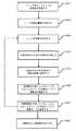
図2は、本発明による再構成を行うための方法の一実施例を例示する。 FIG. 2 illustrates an embodiment of a method for performing reconstruction according to the present invention.
第1のステップS201で、シーンの少なくとも1つの色画像が受信される。少なくとも1つの色画像は、それぞれの視点から色カメラによって取り込まれる。視点は、図1に示される第1の視点に対応し得る(色−深度画像対106Aに対応する)。色画像は、色カメラを含む計算機器のプロセッサ、又は色カメラと通信状態にある別個の計算機器のプロセッサで受信することができる。色画像は、色カメラの視野内のシーン中の複数の点の色情報を(すなわち色画素の形で)定める。色画像は、例えば、RGB画像又はYUV画像とし得る。 In the first step S201, at least one color image of the scene is received. At least one color image is captured by the color camera from each viewpoint. The viewpoint may correspond to the first viewpoint shown in FIG. 1 (corresponds to color-depth image vs. 106A). The color image can be received by the processor of the computing device including the color camera, or by the processor of a separate computing device that is in communication with the color camera. A color image defines color information (ie, in the form of color pixels) of a plurality of points in a scene in the field of view of a color camera. The color image may be, for example, an RGB image or a YUV image.
第2のステップS201で、色画像が取り込まれた部分と一致するシーンの部分について、シーンの深度情報が取得される。上記のように、深度画像は、色カメラと同じ視野をカバーしない場合があるが、深度カメラの視野内にある環境の範囲では、少なくとも実質的に重なり合うことになる。いくつかの実施例で、色画像は、深度画像の範囲と合致するように切り取られてもよい(又はその逆も同様である)。例えば、深度画像が色画像との5%の境界を残すか、又は色画像の左端の85%だけカバーする場合、色画像をそれに応じて切り取ることができる。環境の同じ範囲をカバーするように切り取られた色及び深度の画像は、それから、後に処理されるべき色−画像深度対を形成することができる(ステップS202と関連させて後述する通り)。 In the second step S201, the depth information of the scene is acquired for the portion of the scene that matches the portion where the color image is captured. As mentioned above, depth images may not cover the same field of view as a color camera, but will at least substantially overlap within the range of the environment within the field of view of the depth camera. In some embodiments, the color image may be cropped to match the range of the depth image (or vice versa). For example, if the depth image leaves a 5% boundary with the color image or covers only 85% of the left edge of the color image, the color image can be cropped accordingly. Images of color and depth clipped to cover the same range of environment can then form a color-image depth pair to be processed later (as described below in connection with step S202).
深度画像は、深度カメラを用いて取り込んでもよく、又は、前述のように、シーンの立体画像を解析することによって取得してもよい。深度画像は、シーン中の複数の点(すなわち深度画素)の相対深度を定める深度情報を備える。いくつかの実施例で、色画像及び深度画像は、RGB−D画像を形成してもよい。 The depth image may be captured using a depth camera, or may be acquired by analyzing a stereoscopic image of the scene as described above. The depth image comprises depth information that determines the relative depth of a plurality of points (ie, depth pixels) in the scene. In some embodiments, the color and depth images may form RGB-D images.
第3のステップS203で、少なくとも1つの色画像及び深度画像に基づいてシーンの点群が生成される。これは、色及び深度の画像に逆射影を適用することを伴い得る。ここで「逆」という用語は、(従来の方式で、カメラマトリックスを使用して3D実世界の点を2D画像平面に変えるのに対して)2Dの色及び深度の画像の点(すなわち画素)を3D座標システムの点にマッピングすることを言う。点群は、点群中の点の数が、取り込まれた色及び深度の画像の数、並びにそれらの色及び深度の画像が取り込まれている視点によって限定されることになるという点で、部分点群とみなすことができる。例えば、図1に示される実施例で、色−深度画像対106A及び106Bから生成された点群は、側面像からユーザ102を表現する限定された数の点を有することになる。 In the third step S203, a point cloud of the scene is generated based on at least one color image and a depth image. This can involve applying back projection to images of color and depth. The term "reverse" here refers to points (ie, pixels) in a 2D color and depth image (as opposed to using a camera matrix to transform 3D real-world points into a 2D image plane in the traditional fashion). Is to map to a point in the 3D coordinate system. The point cloud is partial in that the number of points in the point cloud will be limited by the number of captured color and depth images and the viewpoint from which those color and depth images are captured. It can be regarded as a point cloud. For example, in the embodiment shown in FIG. 1, the point cloud generated from the color-depth image pairs 106A and 106B will have a limited number of points representing the
逆射影は、色及び深度の画像中の画素の座標と色カメラの焦点距離とを使用して、任意選択的にそのカメラ又は各カメラの位置及び向きについての情報と併用して、決定することができる。これは、例えば、深度画素が色画像中の色画素の少なくともいくつかについてz値を定めるように、少なくとも1つの色画像中の画素と、対応する深度画像中の画素との間の対応を決定することを伴い得る。それから、色カメラの焦点距離と、色画素の少なくともいくつかについて知られている深度情報とに基づいて、色画像平面中の色画素を3D空間の座標にマッピングすることができる。このようにして、シーンのそれぞれの色及び深度の画像から、3Dシーン中の複数の点のx、y及びz座標を表現する点群を生成することができる。図1に示される実施例で、これは、第1及び第2の色−深度画像対106A、106Bのうちの1つ又は複数からユーザの点群を生成することに対応し得る。 Back projection shall be determined using the coordinates of the pixels in the image of color and depth and the focal length of the color camera, optionally in combination with information about the position and orientation of that camera or each camera. Can be done. This determines the correspondence between a pixel in at least one color image and a pixel in the corresponding depth image so that, for example, the depth pixel determines a z-value for at least some of the color pixels in the color image. Can be accompanied by doing. Then, based on the focal length of the color camera and the depth information known about at least some of the color pixels, the color pixels in the color image plane can be mapped to the coordinates in 3D space. In this way, it is possible to generate a point cloud representing the x, y, and z coordinates of a plurality of points in the 3D scene from the images of the respective colors and depths of the scene. In the embodiment shown in FIG. 1, this may correspond to generating a user's point cloud from one or more of the first and second color-depth image pairs 106A, 106B.
1つの実施例で、逆射影を決定するためにピンホール・カメラ・モデルが使用され得る。例えば、画像平面における色画素のx座標がBxと定義され、対応する深度画素がAzと定義され、色カメラの焦点距離がFと定義される場合、3D空間における色画素の座標、Axは、式:
Ax=BxAz/F
によって(システムの幾何学を使用して)近似することができる。In one embodiment, a pinhole camera model can be used to determine the back projection. For example, if the x-coordinate of a color pixel in the image planeis defined as B x , the corresponding depth pixel isdefined as Az, and the focal length of the color camera is defined as F, the coordinate of the color pixel in 3D space, A.x is the formula:
Ax = Bx Az / F
Can be approximated by (using the geometry of the system).
同じ公式は、(システムの対称性によって)3D空間中の色画素のy座標を決定するために使用され得る。もちろん、ピンホールモデルは、色カメラ及び/又は深度カメラ内の任意の光学要素、並びにそれぞれのカメラの異なる姿勢及び焦点距離(別個のカメラが使用される場合)を考慮に入れるように適切に適合され得る。 The same formula can be used to determine the y-coordinate of a color pixel in 3D space (due to system symmetry). Of course, the pinhole model fits well to take into account any optical elements within the color and / or depth cameras, as well as the different orientations and focal lengths of each camera (if separate cameras are used). Can be done.
いくつかの実施形態で、ステップS201及びS202は、複数の色及び深度の画像を取り込むことを伴い得る。ここで各色及び深度の画像対は、異なるそれぞれの視点から取り込まれる。ステップ203は、それから、複数の色−深度画像対から点群を生成することを伴い得る。これらの実施形態で、逆射影は、色及び深度の画像の各色及び対応する深度の画素を共通の3D座標システムの点にマッピングする。このようにして点群を生成することは、再構成を必要とするシーンがそれほどないことを意味するので、望ましい場合がある。同じく、それは、シーンの再構成の基とすることができる、利用可能な色及び深度の情報がより多くあることを同様に意味する。もちろん、本明細書でさらに説明する実施形態から明らかになるように、取り込むべき色及び深度の画像の数は、通常必要とされることになる数よりも少ないはずである。 In some embodiments, steps S201 and S202 may involve capturing images of multiple colors and depths. Here, the image pairs of each color and depth are captured from different viewpoints. Step 203 may then involve generating a point cloud from multiple color-depth image pairs. In these embodiments, the back projection maps each color and corresponding depth pixel of the color and depth image to a point in a common 3D coordinate system. Generating a point cloud in this way may be desirable as it means that there are not many scenes that need to be reconstructed. Similarly, it also means that there is more color and depth information available that can be the basis for the reconstruction of the scene. Of course, as will be apparent from the embodiments further described herein, the number of color and depth images to be captured should be less than would normally be required.
第4のステップS204で、代替の視点から点群の射影が生成される。この視点は、少なくとも1つの色画像及び深度画像が取り込まれた視点と異なる。図1に示される実施例で、これは、色及び深度の画像が取り込まれていない第3の視点に対応する点群の射影を生成することを伴い得る。一般に、代替の視点は、色及び深度の情報がないシーンの部分を含むことになる。シーンのそれらの部分は、前に取り込まれた色画像及び深度画像では遮蔽されていたからである。 In the fourth step S204, a projection of the point cloud is generated from an alternative viewpoint. This viewpoint is different from the viewpoint in which at least one color image and depth image are captured. In the embodiment shown in FIG. 1, this may involve producing a point cloud projection corresponding to a third viewpoint where the color and depth images are not captured. In general, alternative viewpoints will include parts of the scene where there is no color and depth information. This is because those parts of the scene were obscured by the previously captured color and depth images.
第5のステップS205で、代替の視点からの点群の射影は、それぞれの二次元の色及び深度の画像に変換される。これらの色及び深度の画像は、本明細書で「疎な」色及び深度の画像と呼ばれる。これらの画像内に、前に取り込まれた色及び深度の画像ではシーンのそれらの部分が遮蔽されているため、色/深度画素密度の低い領域があると予想されるからである。 In the fifth step S205, the projection of the point cloud from the alternative viewpoint is converted into an image of each two-dimensional color and depth. These color and depth images are referred to herein as "sparse" color and depth images. This is because it is expected that there will be areas of low color / depth pixel density within these images because those parts of the scene are obscured by the previously captured color and depth images.
色及び深度の画像の疎性は、一般に視点の変化の範囲に依存することになる。単一の色及び深度の画像対のみが取り込まれている場合、理想的には、視点の変化は初期の視点に対して90度(すなわち側面視)未満であるべきである。これは、視点が90度に近づくにつれて、色及び深度の画像に含まれている画素がますます少なくなるからである(そこでは例えば2D表面が線に見えることになる)。色及び深度の画像中の画素が少なければ少ないほど、再構成の精度が低くなる可能性が高い。複数の色−深度画像対が取り込まれている実施例で、代替の視点は、各色−深度画像対が取り込まれた視点とは異なる、それらの視点の間にある視点に対応するべきである。 The sparseness of the image in color and depth will generally depend on the extent of the change in perspective. Ideally, if only a single color and depth image pair is captured, the viewpoint change should be less than 90 degrees (ie, side view) with respect to the initial viewpoint. This is because as the viewpoint approaches 90 degrees, fewer and fewer pixels are included in the color and depth image (where, for example, the 2D surface looks like a line). The fewer pixels in an image of color and depth, the less likely it is that the reconstruction will be accurate. In an embodiment in which multiple color-depth image pairs are captured, the alternative viewpoint should correspond to a viewpoint between those viewpoints that is different from the viewpoint in which each color-depth image pair is captured.
疎な色及び深度の画像は、点群の射影を2D画像平面に射影することによって生成される。疎な色画像は、2D画像平面における各点の色値(例えばR、G、B又はY、U、V)を定め、深度画像は、2D画像平面における各点の深度値を定める。 Images of sparse colors and depths are generated by projecting a point cloud onto a 2D image plane. The sparse color image determines the color value of each point in the 2D image plane (eg R, G, B or Y, U, V), and the depth image determines the depth value of each point in the 2D image plane.
第6のステップS206で、色情報がない疎な色画像中のシーンの少なくともいくつかについて色情報(すなわち色画素値)が推定される。すなわち、色情報が欠落しているシーンの部分に対してインペインティング動作が行われる。これにより、代替の視点のために、シーンのより完全な色画像が再構成される。インペインティング動作はただシーンのいくつかの部分(すなわちインペインティング動作が正確である可能性が高い部分)に対して行われ得るにすぎないことに留意するべきである。 In the sixth step S206, the color information (that is, the color pixel value) is estimated for at least some of the scenes in the sparse color image without the color information. That is, the inpainting operation is performed on the part of the scene where the color information is missing. This reconstructs a more complete color image of the scene for an alternative perspective. It should be noted that the inpainting action can only be performed on some part of the scene (ie, the part where the inpainting action is likely to be accurate).
いくつかの実施例で、インペインティング動作は、疎な色画像を訓練された機械学習モデルに入力することを伴い得る。ここで機械学習モデルは画像の不完全な部分(いわゆる「穴」)について色画素値を推定するように訓練されている。機械学習モデルは、例えば、完全畳込みネットワークモデルを使用して、完全な色画像及び不完全な色画像の対で訓練され得る。そのような使用され得る技法の一実施例が、「Globally and Locally Consistent Image Completion」、飯塚里志他、早稲田大学、107:1〜107:14ページに説明されており、この文献は参照により本明細書に援用される。 In some embodiments, the inpainting motion may involve inputting a sparse color image into a trained machine learning model. Here the machine learning model is trained to estimate color pixel values for imperfections (so-called "holes") in the image. Machine learning models can be trained with pairs of full color images and incomplete color images, for example using a fully convoluted network model. An example of such a technique that can be used is described in "Globally and Consistent Image Collection", Satoshi Iizuka et al., Waseda University, pp. 107: 1-107: 14, which is referenced in this article. Incorporated in the statement.
追加の実施例又は代替の実施例で、インペインティング動作を行うために異なる技法が使用され得る。これは、例えば、疎な色画像に対して形態学的膨張を行うことを含み得る。当技術分野で知られているように、形態学的膨張を使用して画像内のオブジェクトの境界に画素を加えることができる。 In additional or alternative embodiments, different techniques may be used to perform the inpainting operation. This may include, for example, performing morphological expansion on a sparse color image. As is known in the art, morphological expansion can be used to add pixels to the boundaries of objects in an image.
なおさらなる実施例又は代替の実施例で、単純な補間を使用して、例えば最近傍画素の平均色に基づいて、色画素が欠落している画像の部分を塗りつぶすことができる。場合によっては、この補間は、疎な色画像の画素密度が閾値密度よりも高い場合にのみ使用することができる。これは、色情報が、既存の色情報が妥当である可能性が高い画像の部分についてのみ推定されることを保証する。 Further in a further embodiment or an alternative embodiment, simple interpolation can be used to fill a portion of the image in which the color pixels are missing, for example based on the average color of the nearest neighbor pixels. In some cases, this interpolation can only be used if the pixel density of the sparsely colored image is higher than the threshold density. This ensures that the color information is estimated only for the parts of the image where the existing color information is likely to be valid.
第7のステップS207で、深度情報が欠落しているシーンの少なくともいくつかの部分について深度情報が推定される。換言すれば、疎な深度画像に対して深度インペインティング動作が行われる。これにより、代替の視点からの、シーンのより完全な深度画像が再構成される。 In step S207, depth information is estimated for at least some parts of the scene where depth information is missing. In other words, the depth inpainting operation is performed on the sparse depth image. This reconstructs a more complete depth image of the scene from an alternative perspective.
いくつかの実施形態で、深度インペインティング動作は、再構成された色画像と、シーンの既存の深度情報(すなわちステップS202で取得した深度画像)とに基づいて行われる。 In some embodiments, the depth inpainting operation is based on the reconstructed color image and the existing depth information of the scene (ie, the depth image acquired in step S202).
これは、例えば、色画像中の面法線及びオクルージョン境界を検出するために、ニューラルネットワークなどのディープネットワークを訓練することを伴い得る。ディープネットワークは、ネットワークが面法線及び/又はオクルージョン境界と一致する画像特徴を学習することができるように、面法線及びオクルージョン境界がラベル付けされた多数の色画像で訓練され得る。一度訓練されると、再構成された画像中の任意の面法線及びオクルージョン境界を検出するために、再構成された色画像をディープネットワークに入力することができる。 This may involve training a deep network, such as a neural network, for example to detect surface normals and occlusion boundaries in a color image. Deep networks can be trained with a large number of color images labeled with surface normals and occlusion boundaries so that the network can learn image features that match surface normals and / or occlusion boundaries. Once trained, the reconstructed color image can be input to the deep network to detect any surface normals and occlusion boundaries in the reconstructed image.
ディープネットワークによって検出された面法線及びオクルージョン境界を既存の深度情報とともに使用して、大域的最適化プロセスを導くことができる。大域的最適化プロセスは、推定された深度情報が、(i)検出された面法線を尊重すること、(ii)オクルージョン境界に属さない点のすべてにおいて滑らかであること、及び(iii)シーンの既存の深度値に近い値を保つことを保証する。そのようなディープネットワーク及び大域的最適化プロセスの一実施例が、「Deep Depth Completion of a Single RGB−D Image」、Y.Zhang、T.Funkhouser、石川博、プリンストン大学、1〜11ページに概説されている。 The surface normals and occlusion boundaries detected by the deep network can be used with existing depth information to guide the global optimization process. The global optimization process is that the estimated depth information is (i) respecting the detected surface normals, (ii) smooth at all points that do not belong to the occlusion boundary, and (iii) the scene. Guarantee to keep close to the existing depth value of. An embodiment of such a deep network and global optimization process is described in "Deep Depth Completion of a Single RGB-D Image", Y. et al. Zhang, T.I. It is outlined in Funkhauser, Hiroshi Ishikawa, Princeton University, pp. 1-11.
他の実施例で、深度情報は、例えばマルコフ過程による画像合成を使用して推定することができ、又は、当技術分野で知られているように、境界面を外挿法によって推定し、それらの間を補間することによって推定することができる(例えば、「Depth image enhancement using local tangent plane approximations」、K.Matsuo及びY.B Yang、慶応義塾大学総合デザイン工学科を参照のこと)。 In other embodiments, depth information can be estimated, for example, using image composition by Markov process, or, as is known in the art, the interface is estimated by extrapolation and they. It can be estimated by interpolating between (see, for example, "Deptic image enhancement using global tangent plan approximations", K. Matsuo and Y. B Yang, Department of Comprehensive Design Engineering, Keio University).
当技術分野で知られているように、面法線は、表面上の点に垂直なベクトルを定める。表面が平らである(例えばx−y平面にある)場合、表面ベクトルは同じ方向(z方向)を指し示すことになる。これは、例えば、表面が深度センサに平行であると検出される場合、その表面上の点が深度センサから同じ相対距離を有するはずであるということを意味する。より一般には、面法線は、深度カメラに対するシーン中の表面の向きと、この表面上の少なくともいくつかの点の距離の指標を提供する。このことから、補間を使用して、深度データが欠落しているシーンの部分について深度データを推定することができる(すなわち穴を埋める)。 As is known in the art, surface normals define a vector perpendicular to a point on the surface. If the surface is flat (eg in the xy plane), the surface vector will point in the same direction (z direction). This means that, for example, if a surface is detected parallel to the depth sensor, the points on that surface should have the same relative distance from the depth sensor. More generally, surface normals provide an indicator of the orientation of a surface in the scene with respect to a depth camera and the distance of at least some points on this surface. From this, interpolation can be used to estimate depth data (ie, fill holes) for parts of the scene where depth data is missing.
オクルージョン境界は、検出されたオブジェクトの縁を画定し、検出されたオブジェクトの後ろに他のオブジェクトが遮蔽されていることになる。オクルージョン境界は、シーン内で深度の変化が起こる場所の指標を提供する。したがって、オクルージョン境界を面法線とともに使用して、シーンの異なる部分について深度情報を推定することができる。 The occlusion boundary demarcates the edges of the detected object, and other objects are occluded behind the detected object. Occlusion boundaries provide an indicator of where depth changes occur in the scene. Therefore, occlusion boundaries can be used with surface normals to estimate depth information for different parts of the scene.
ディープネットワークの使用が上記の実施例で提供されるが、画像中の面法線及びオクルージョン境界を検出するための他の方法が本発明によって使われてもよいことを理解されたい。 Although the use of deep networks is provided in the above embodiment, it should be understood that other methods for detecting surface normals and occlusion boundaries in images may be used by the present invention.
ステップS208で、再構成された色画像が表示のために出力される。いくつかの実施例で、再構成された色画像は、後で表示するためにメモリに記憶されてもよい。色画像の出力は、表示装置で表示するために再構成された色画像を出力することを伴い得る。 In step S208, the reconstructed color image is output for display. In some embodiments, the reconstructed color image may be stored in memory for later display. The output of the color image may involve outputting the color image reconstructed for display on the display device.
ステップS208は、例えば、グレースケール画像として、表示するために深度画像を出力することを同様に伴い得る。グレースケール画像では、画素の暗さは、点(取り込まれた点とシミュレートされた点の両方)がカメラから、深度センサからどれほど近いか又は遠いかを表す。これは情報目的のために有用であり得る。より一般には、再構成された深度画像を使用して、再構成された色画像中のオブジェクトが正しいオクルージョンで表示されることを保証することができる。例えば、再構成された色画像の上に仮想オブジェクトが重畳される場合、深度画像を使用して、仮想オブジェクトがシーン中の任意の表面/オブジェクト及びそれらの対応する深度を尊重することを保証することができる。 Step S208 may also involve outputting a depth image for display, for example as a grayscale image. In a grayscale image, the darkness of a pixel represents how close or far the point (both the captured point and the simulated point) is from the camera and from the depth sensor. This can be useful for informational purposes. More generally, the reconstructed depth image can be used to ensure that the objects in the reconstructed color image are displayed with the correct occlusion. For example, if a virtual object is superimposed on a reconstructed color image, the depth image is used to ensure that the virtual object respects any surface / object in the scene and their corresponding depth. be able to.
場合によっては、取り込まれた色及び深度の情報と推定された色及び深度の情報の組合せは、代替の視点からシーンの色画像(及び深度画像)を正確に再構成するために不十分な場合があることを理解されたい。すなわち、再構成された色及び深度の画像には、比較的大きい穴が依然としてあり得る。これらの場合、再構成を生成することができるより完全な点群を取得するために、(異なる視点から)シーンの別の色及び深度の画像を取り込むことが必要な場合がある。 In some cases, the combination of captured color and depth information and estimated color and depth information is insufficient to accurately reconstruct the scene's color image (and depth image) from an alternative perspective. Please understand that there is. That is, there may still be relatively large holes in the reconstructed color and depth image. In these cases, it may be necessary to capture images of different colors and depths of the scene (from different perspectives) in order to obtain a more complete point cloud from which the reconstruction can be generated.
いくつかの実施形態で、再構成された色及び深度の画像を使用して、シーンのさらなる再構成を行うことができる。すなわち、本方法を反復的に行い、連続的に再構成された各色及び深度の画像を使用して、より完全な点群を生成することができる。反復ごとに、ステップS204は、さらなる代替の視点から、より完全な点群の射影を生成することを伴い得る。換言すれば、色及び深度の画像が取り込まれている視点並びに色及び深度の画像が再構成されている視点とは、異なる視点からである。このようにして、点群における点の密度は、所望の視点からシーンの完全な色及び深度の画像をレンダリングするために十分な数の点が取得されるまで、増大させることができる。 In some embodiments, the reconstructed color and depth images can be used to further reconstruct the scene. That is, the method can be iteratively performed and a continuously reconstructed image of each color and depth can be used to generate a more complete point cloud. With each iteration, step S204 may involve producing a more complete point cloud projection from a further alternative point of view. In other words, the viewpoint in which the color and depth image is captured and the viewpoint in which the color and depth image is reconstructed are different viewpoints. In this way, the density of points in the point cloud can be increased until sufficient points have been obtained to render an image of the full color and depth of the scene from the desired viewpoint.
いくつかの実施例で、反復的方法は、再構成された色及び深度の画像の画素密度が閾値画素密度を超えるまで続いてもよい。 In some embodiments, the iterative method may continue until the pixel density of the reconstructed color and depth image exceeds the threshold pixel density.
より精巧な実施例で、本方法は、追加のステップ、例えば、再構成された色及び深度の画像と関連付けられた誤差を決定することを伴うステップS208B(図示されない)を伴い得る。再構成された色及び深度の画像対と関連付けられた誤差を使用して、本方法の次の反復を行うべきかどうかを決定することができる。例えば、再構成された色及び深度の画像対と関連付けられた誤差が(例えば、色画像が実際は再構成であると視聴者が気づく可能性が低いことを表す)閾値未満であるとき、さらなる反復を行うことはできない。いくつかの実施例で、閾値数の反復がすでに起こっており、かつ現在の再構成された色及び深度の画像と関連付けられた誤差が閾値を超える場合、さらなる反復を行うことはできない。これは、誤差に限りがなくなる場合に対応し得る。 In a more elaborate embodiment, the method may involve additional steps, eg, step S208B (not shown), which involves determining the error associated with the reconstructed color and depth image. The error associated with the reconstructed color and depth image pair can be used to determine whether the next iteration of the method should be performed. For example, further iterations when the error associated with the reconstructed color and depth image pair is less than a threshold (eg, indicating that the viewer is unlikely to notice that the color image is actually reconstructed). Cannot be done. In some embodiments, if a threshold number of iterations has already occurred and the error associated with the current reconstructed color and depth image exceeds the threshold, no further iterations can be performed. This can be done when the error is endless.
いくつかの実施例で、本方法は、特定の種類のオブジェクト又はシーンを再構成するために特化され得る。例えば、本方法は、人間の顔の色及び深度の画像を再構成するために設計されてもよい。本方法を開始して、グラウンドトゥルースを定めるために使用する前に、(色及び深度の画像を含む)人間の顔の走査を取り込むことができる。それから、各再構成された色及び深度の画像を人間の顔の走査と比較することができ、この比較に基づいて誤差を決定することができる。この誤差を決定するにあたり、カメラの姿勢を使用して、色及び深度の画像を取り込んだカメラの同じ位置及び向きから走査の遠近図を生成することができる。誤差が決定されると、再構成された色及び深度の画像がグラウンドトゥルースから極端に逸脱しているかどうかを決定するために、誤差を閾値と比較することができる。一般に、閾値は、異なる人間の顔に固有の相違を許すのに十分大きくするべきであるが、人間の顔以外のオブジェクトが許容可能な関連誤差を持つとみなされることを許すようにそれほど大きくするべきではない。 In some embodiments, the method may be specialized for reconstructing a particular type of object or scene. For example, the method may be designed to reconstruct an image of human face color and depth. Scans of the human face (including images of color and depth) can be captured before starting this method and using it to determine ground truth. Images of each reconstructed color and depth can then be compared with a scan of the human face and the error can be determined based on this comparison. In determining this error, the camera orientation can be used to generate a scan perspective from the same position and orientation of the camera that captured the color and depth images. Once the error is determined, the error can be compared to the threshold to determine if the reconstructed color and depth image deviates significantly from the ground truth. In general, the threshold should be large enough to allow differences inherent in different human faces, but so large to allow objects other than human faces to be considered to have acceptable related errors. Should not be.
他の実施例で、誤差は、(再構成から生じた点を含む)点群と、一般的な人間の顔を表現する基準点群との比較に基づいて決定することができる。 In another embodiment, the error can be determined based on a comparison of the point cloud (including the points resulting from the reconstruction) with the reference point cloud representing a typical human face.
一般的に言って、誤差は、取り込まれるオブジェクトについてなされた仮定に基づいて決定することができる。この仮定は、例えば、取り込まれるオブジェクトの形状又は平滑度を含み得る。それゆえ、再構成された色及び深度の画像と関連付けられた誤差は、仮定されたオブジェクトの特徴と、再構成された色及び深度の画像から推測できるオブジェクトの特徴との偏差に基づいて決定することができる。 Generally speaking, the error can be determined based on the assumptions made about the objects to be captured. This assumption may include, for example, the shape or smoothness of the captured object. Therefore, the error associated with the reconstructed color and depth image is determined based on the deviation between the assumed object characteristics and the object characteristics that can be inferred from the reconstructed color and depth image. be able to.
図2と関連させて説明した本方法は、ユーザが異なる視点からシーンの色及び深度の画像を過剰に取り込むことを必要とせず、シーンの部分を再構成することを可能にするという点で、非常に柔軟性がある。 The method described in connection with FIG. 2 allows the user to reconstruct parts of the scene without requiring the user to overcapture images of the color and depth of the scene from different perspectives. Very flexible.
いくつかの実施例で、本明細書に説明した方法は、意味情報などの追加情報を考慮に入れるために拡張することができる。例えば、人物の画像を完成させるにあたり、人物がどのように見えるかについての情報を先験的に追加し、所望の視点からの人物の画像を再構成するとき、この情報を考慮に入れることができる。 In some embodiments, the methods described herein can be extended to take into account additional information such as semantic information. For example, in completing an image of a person, you can a priori add information about what the person will look like, and take this information into account when reconstructing the image of the person from the desired perspective. can.
さらなる実施例で、再構成は、必要とされる限り行われてもよい。例えば、ユーザがオブジェクトの周りで彼らのカメラを動かす場合、新しいデータをリアルタイムで生成して、ユーザの視野内のすべてのギャップを埋めることができる。 In a further embodiment, the reconstruction may be performed as long as required. For example, if a user moves their camera around an object, new data can be generated in real time to fill all gaps in the user's field of view.
図3は、本発明による、色及び深度の画像を再構成するためのシステム300を例示する。 FIG. 3 illustrates a
システム300は、シーンの少なくとも1つの色画像を受信するための受信ユニット301を備える。図3で、少なくとも1つの色画像は入力「RGB」と表される。前述のように、少なくとも1つの色画像は、色カメラによってそれぞれの視点から取り込まれる(視点は色カメラの視野に対応する)。 The
受信ユニット301は、色カメラと通信状態にあるか、又は色カメラを含む計算機器に位置していてもよい。計算機器は、例えばパーソナルコンピュータ(PC)、ラップトップ、タブレット、スマートフォンなどとし得る。いくつかの実施例で、計算機器は、例えばゲームコンソールとし得る。 The receiving
システム300は、色画像で取り込まれた部分に対応するシーンの部分について深度画像を取得するように動作可能な深度ユニット302をさらに備える。深度ユニット302は、図3に入力「D」で表されるように、深度カメラから深度画像を受信するように構成され得る。あるいは、深度ユニット302は、受信ユニット301を深度ユニット302にリンクする破線矢印で表される、立体画像から深度画像を生成するように構成され得る。深度カメラは、前述の深度カメラのいずれかに対応し得る。再び、色カメラ及び深度カメラは、分かれていても、単一デバイスに組み込まれていてもよい。 The
システム300は、色−深度画像対を受信し、受信した色−深度画像対から点群を生成するように構成された、点群生成器303を同様に備える。点群生成器303は、受信した色及び深度の画像中の色及び深度の画素に逆射影を適用するように構成される。前述のように、逆射影は、色画素及び対応する深度画素を共通の3D座標システム300にマッピングする。このマッピングにより、受信した色及び深度の画像からシーンの点群を生成することが可能になる。 The
いくつかの実施例で、点群生成器303は、色(及び任意選択的に、深度)カメラの姿勢及び焦点距離を表す情報を受信するように構成される。この情報は、色(及び深度)画像におけるメタデータとして色(及び深度)カメラによって提供され得る。点群生成器303は、それから、受信したメタデータに基づいて逆射影を決定することができる。これは、逆射影を決定するとき、色カメラ及び深度カメラの位置及び焦点距離の変化を考慮に入れることを可能にするので望ましい。 In some embodiments, the
図3で、点群ユニットは、射影ユニット304への入力を提供するものとして示される。射影ユニット304は、色及び深度の画像が取り込まれている視点とは異なる視点から点群の射影を生成するように構成される。いくつかの実施例で、この代替の視点は、視点を任意に変更することに対応し得る。例えば、点群の+1度の回転である。 In FIG. 3, the point cloud unit is shown as providing an input to the
いくつかの実施形態で、射影ユニット304は、点群生成器303で受信した各色及び深度の画像が取り込まれた視点の指標を受信するように構成され得る。これに基づいて、射影ユニット304は、それから、これらの既知の視点と異なる視点を決定することができる。例えば、2つの色−深度画像対が点群生成器303で受信されている場合、射影ユニット304は、各画像対と関連付けられた視点間にある視点を選択することができる。 In some embodiments, the
図3で、射影ユニット304は、変換ユニット305への入力を提供するものとして示される。変換ユニット305は、生成された射影をそれぞれの2Dの疎な色及び深度の画像に変換するように構成される。前述のように、これらの画像は、色及び深度の情報が欠落している部分があることになるので、疎と称される。先述のように、それぞれの視点から取り込まれた色及び深度の画像ではシーンの対応する部分が遮蔽されていることになるので、この情報は欠落していることになる。 In FIG. 3, the
変換ユニット305は、疎な色及び深度の画像をインペインティングプロセッサ306に出力する。インペインティングプロセッサ306は、色情報が欠落している、シーンの少なくともいくつかの部分について色画素値を生成するように構成される。そうするにあたり、インペインティングプロセッサ306は、代替の視点から、シーンの再構成された色画像を生成する。図3で、再構成された色画像は、インペインティングプロセッサ306の出力の1つとして示されており、RGB'と表される。この再構成された色画像は、例えば、(図示されない)表示装置で表示するために出力され得る。 The
いくつかの実施形態で、モノラルの(すなわち再構成された)色画像から立体画像対を生成することができる。立体画像は、頭部装着可能なディスプレイ(HMD)での視聴用とすることができ、各画像は、HMD内の異なるそれぞれの表示要素に表示される。第1の表示要素をユーザの左目の前に、第2の表示要素をユーザの右目の前に配置することができる。深度を伝達するために、立体対の各画像は、互いに対して横方向の変位を呈するように生成され得る。横方向の変位は、例えば、個々の画像を取り込むために使用された可能性がある2つのカメラのシミュレートされた横方向の分離に依存し得る。 In some embodiments, stereoscopic image pairs can be generated from monaural (ie, reconstructed) color images. The stereoscopic image can be viewed on a head-mounted display (HMD), and each image is displayed on different display elements within the HMD. The first display element can be placed in front of the user's left eye and the second display element can be placed in front of the user's right eye. To convey the depth, each image of the stereoscopic pair can be generated to exhibit lateral displacement with respect to each other. The lateral displacement may depend, for example, on the simulated lateral separation of the two cameras that may have been used to capture the individual images.
追加の実施形態又は代替の実施形態で、立体画像対は、それぞれシーンの異なる視点に対応する、2つの色画像から生成することができる。上述のように、これらの画像の一方又は両方が、再構成された色画像を含み得る。2つの色画像は、一般に、同じような視点から取り込まれるが、(すなわち、両方の色画像が実質的に同じ視野をカバーするように)間に比較的小さい変位を有する、2つの色画像に対応することになる。 In additional or alternative embodiments, stereoscopic image pairs can be generated from two color images, each corresponding to a different viewpoint in the scene. As mentioned above, one or both of these images may include a reconstructed color image. The two color images are generally captured from similar perspectives, but with a relatively small displacement between them (ie, so that both color images cover substantially the same field of view) into the two color images. It will correspond.
インペインティングプロセッサ306は、ステップS206と関連させて前述したインペインティング動作のいずれかを行うように構成され得る。インペインティングの範囲は、疎な色画像の色画素密度に依存し得る。例えば、場合によっては、色情報が、既存の色情報に近接している画像の部分についてのみ推定される可能性がある。疎な色画像の残りの部分については、インペインティングを行うことはできない。画像のこれらの部分は、さらに取り込まれた色及び深度の画像を使用して、又は前述の方法をさらに反復して、インペインティングすることができる。 The
インペインティングプロセッサ306は、再構成された色画像を深度データ生成器307に提供するように構成される。深度データ生成器307は、再構成された色画像に基づいて、深度画像が欠落している疎な深度画像の少なくともいくつかの部分について深度データを生成するように構成される。そうするにあたり、深度データは、代替の視点からのシーンのより完全な深度画像を生成する。 The
深度データ生成器307は、ステップS207と関連させて前述した方法のいずれかを使用して深度データを生成するように構成され得る。例えば、深度データは、再構成された色画像中の1つ又は複数の表面の面法線を推定するように動作可能な面法線推定器を備え得る。深度データ生成器307は、再構成された色画像中の1つ又は複数のオクルージョン境界を検出するためのオクルージョン境界検出器を同様に備え得る。面法線推定器及びオクルージョン境界検出器は、前述のように、ニューラルネットワークの形とし得る。面法線及び検出されたオクルージョン境界を既存の深度データとともに使用して、深度情報が欠落しているシーンの部分について深度データを生成することができる。前述のように、これは、検出された面法線、オクルージョン境界及び既存の深度データを使用して、大域的最適化プロセスを導くことを伴い得る。 The
再構成された深度画像は、それから、深度データ生成器307によって、例えば表示のために、出力され得る。図3で、これは出力D’と表される。しかしながら、いくつかの実施形態で、再構成された深度画像は、表示のために出力される必要がない。一般に、色画像が、ユーザに視聴される可能性がより高い画像になるからである。図3に破線矢印で表されるように、表示のための深度画像の出力は、任意選択的なものである。 The reconstructed depth image can then be output by the
図3で、点群生成器303は、再構成された色及び深度の画像を受信するように構成され得る。これは、インペインティングプロセッサ306及び深度データ生成器307の出力を点群生成器303とリンクして、図3に表される。 In FIG. 3, the
したがって、インペインティング及び深度データ生成の一部として推定された色及び深度の画素を使用して、より多くの点を点群に加えることができる。前述のように、これを使用して、本方法のさらなる反復を行うことができ、射影ユニット304は、さらなる異なる視点から、より完全な点群の射影を生成する。それから、射影は、変換ユニット305によって疎な(しかし前の反復で生成された色及び深度の画像よりも疎でない)色及び深度の画像に変換され得る。 Therefore, more points can be added to the point cloud using pixels of color and depth estimated as part of inpainting and depth data generation. As mentioned above, this can be used to make further iterations of the method, where the
それから、現在の反復で生成された疎な色及び深度の画像を使用して、インペインティング及び深度データ生成動作を再び行うことができる。インペインティングプロセッサ306と深度データ生成器307との間のこのフィードバックループは、シーンを表現する十分に高密度の(かつ正確な)点群が取得されるまで繰り返すことができる。十分に高密度の点群が取得された時点で、任意の所望の視点から、シーンの色及び深度の画像を生成することができるはずである。これは、色及び深度の画像が取り込まれていない視点を含む。 The sparse color and depth images generated in the current iteration can then be used again for inpainting and depth data generation operations. This feedback loop between the
S207と関連させて前述したように、行われる反復の数は、再構成された色及び深度の画像と関連付けられた誤差に依存し得る。例えば、各再構成された色及び深度の画像は、誤差値と比較することができ、誤差値は、再構成された画像中の知覚的誤差又はアーチファクトの尺度を提供する。連続的な反復ごとに、再構成された色及び深度の画像と関連付けられた誤差が許容可能な値(又は範囲)に収束する場合、これは、シーンの色及び深度の画像を再構成するために十分な量の色及び深度のデータがあることを表し得る。したがって、現在の再構成された色及び深度の画像と関連付けられた誤差が誤差値の許容可能な範囲未満、又はこの範囲内になるまで、反復を続けることができる。逆に、連続的な反復で誤差が許容可能な値(又は範囲)から発散する場合、これは、再構成が機能しておらず、方法を終了するべきであることを表し得る。そのような場合、誤差に限りがないと言える。 As mentioned above in relation to S207, the number of iterations performed may depend on the error associated with the reconstructed color and depth image. For example, each reconstructed color and depth image can be compared to an error value, which provides a measure of perceptual error or artifacts in the reconstructed image. For each successive iteration, if the error associated with the reconstructed color and depth image converges to an acceptable value (or range), this is to reconstruct the scene color and depth image. Can represent that there is a sufficient amount of color and depth data. Therefore, the iterations can be continued until the error associated with the current reconstructed color and depth image is less than or within the acceptable range of error values. Conversely, if the error diverges from an acceptable value (or range) in continuous iterations, this may indicate that the reconstruction is not working and the method should be terminated. In such a case, it can be said that the error is unlimited.
受信ユニット301、深度ユニット302、点群生成器303、射影ユニット304、変換ユニット305、インペインティングプロセッサ306及び深度データ生成器307は、単一デバイスに実装しても別個のデバイスに実装してもよいことを理解されたい。いくつかの実施例で、図3に示される構成要素は、色画像(及び任意選択的に、深度画像)を受信し、色(及び任意選択的に、深度)画像を表示装置に出力するように構成された計算機器に含まれていてもよい。計算機器は、例えば、パーソナルコンピュータ(PC)、ラップトップ、ゲームコンソール、サーバなどとし得る。 The receiving
インペインティング及び/又は深度データ生成のために機械学習が使用される実施例で、機械学習モデル(例えば、ニューラルネットワーク)を例えばサーバにおいて訓練し、訓練したモデルをインペインティングプロセッサ及び/又は深度データ生成器にエクスポートしてもよい。インペインティング及び深度データ生成は、必要とされる処理に関して最も集中的になる可能性が高い。そのため、いくつかの実施例で、インペインティングプロセッサ306及び深度データ生成器307は、システム300の他の構成要素が位置している計算機器よりも高い計算能力を持つ計算機器に位置していてもよい。そのような場合、2つの計算機器は、(すなわち有線又は無線の接続を介して)互いに通信状態にあることになる。 In an embodiment where machine learning is used for inpainting and / or depth data generation, a machine learning model (eg, a neural network) is trained, eg, in a server, and the trained model is an inpainting processor and / or depth. It may be exported to a data generator. Inpainting and depth data generation are likely to be most focused on the processing required. Therefore, in some embodiments, the
上述の技法は、ハードウェア、ソフトウェア又は両者の組合せで実装することができる。実施形態の1つ又は複数の特徴を実装するためにソフトウェア制御されたデータ処理装置が使われる場合、そのようなソフトウェア、及びそのようなソフトウェアを提供する非一時的機械可読記憶媒体などの記憶又は伝送媒体は、同様に本発明の実施形態とみなされることを理解されたい。 The techniques described above can be implemented in hardware, software or a combination of both. If software-controlled data processing equipment is used to implement one or more features of the embodiment, storage or storage of such software, and a non-temporary machine-readable storage medium that provides such software. It should be understood that the transmission medium is also regarded as an embodiment of the present invention.
上記の考察は、単に本発明の代表的な実施形態を開示し説明するにすぎない。当業者には当然のことながら、本発明は、その趣旨又は本質的特質から逸脱することなく他の特定の形で実施することができる。したがって、本発明の本開示は、例示的であるように意図されるが、本発明の範囲及び他の請求項を限定するものではない。本明細書の教示の容易に認識可能な任意の変形形態を含む、本開示は、発明の主題が公に捧げられないように、上記の請求項の用語の範囲を部分的に定義する。 The above considerations merely disclose and explain typical embodiments of the present invention. As a matter of course to those skilled in the art, the invention can be practiced in other particular forms without departing from its spirit or essential nature. Accordingly, the present disclosure of the present invention is intended to be exemplary but does not limit the scope of the invention and other claims. The present disclosure, including any easily recognizable variant of the teachings herein, defines the scope of the terms in the above claims in part so that the subject matter of the invention is not publicly devoted.
Claims (16)
Translated fromJapaneseシーンの少なくとも1つの色画像を受信することであって、前記少なくとも1つの色画像はそれぞれの視点から取り込まれることと、
前記それぞれの視点について前記シーンの深度情報を取得することと、
前記少なくとも1つの色画像及び前記取得された深度情報に基づいて前記シーンの点群を生成することと、
代替の視点からの前記点群の射影を生成することであって、前記代替の視点は、前記それぞれの視点と異なり、色及び深度の情報が欠落している前記シーンの遮蔽された部分を含むことと、
前記点群の前記射影をそれぞれの疎な色及び深度の画像に変換することと、
色情報がない前記疎な色画像中の前記シーンの少なくともいくつかについて色情報を推定し、それによって前記代替の視点からの前記シーンのより完全な色画像を再構成することと、
前記再構成された色画像及び前記取得された深度情報に基づいて、深度情報がない前記シーンの少なくともいくつかについて深度情報を推定し、それによって前記代替の視点からの前記シーンのより完全な深度画像を再構成することと、
を含む、方法。A method of reconstructing scene color and depth information, wherein the method is:
Receiving at least one color image of the scene, the at least one color image being captured from their respective viewpoints.
Acquiring the depth information of the scene for each of the viewpoints,
Generating a point cloud of the scene based on the at least one color image and the acquired depth information.
It is to generate a projection of the point cloud from an alternative viewpoint, wherein the alternative viewpoint includes a shielded portion of the scene where color and depth information is missing, unlike the respective viewpoints. That and
Converting the projection of the point cloud into an image of each sparse color and depth,
Estimating color information for at least some of the scenes in the sparse color image without color information, thereby reconstructing a more complete color image of the scene from the alternative perspective.
Based on the reconstructed color image and the acquired depth information, depth information is estimated for at least some of the scenes without depth information, thereby making the scene more complete depth from the alternative viewpoint. Reconstructing the image and
Including, how.
前記再構成された色画像中の1つ又は複数の表面の面法線を推定することと、
前記再構成された色画像中の1つ又は複数のオクルージョン境界を検出することと、
前記推定された面法線、前記検出されたオクルージョン境界及び前記取得された深度情報に基づいて前記深度情報を推定することと、
を含む、請求項1から3のいずれか一項に記載の方法。Estimating the depth information is
Estimating the surface normals of one or more surfaces in the reconstructed color image,
Detecting one or more occlusion boundaries in the reconstructed color image and
Estimating the depth information based on the estimated surface normal, the detected occlusion boundary, and the acquired depth information.
The method according to any one of claims 1 to 3, comprising.
前記深度情報を推定することは、前記推定された面法線、検出されたオクルージョン境界及び前記取得された深度情報を使用して、大域的最適化プロセスを導くことを含む、
請求項4に記載の方法。Including inputting the reconstructed color image into a neural network model, the neural network model is trained to estimate surface normals and occlusion boundaries in the color image.
Estimating the depth information includes guiding the global optimization process using the estimated surface normals, the detected occlusion boundaries, and the acquired depth information.
The method according to claim 4.
前記それぞれの視点の各視点について深度情報を取得することと、
前記複数の取り込まれた色画像及び前記取得された深度情報に基づいて前記点群を生成することと、
代替の視点からの前記点群の射影を生成することであって、前記代替の視点は、前記それぞれの視点の各視点と異なり、色及び深度の情報が欠落している前記シーンの遮蔽された部分を含むことと、
前記点群の前記射影をそれぞれの疎な色及び深度の画像に変換することと、
色情報がない前記疎な色画像中の前記シーンの少なくともいくつかについて色情報を推定し、それによって前記代替の視点からの前記シーンのより完全な色画像を再構成することと、
前記再構成された色画像及び前記取得された深度情報に基づいて、深度情報がない前記シーンの少なくともいくつかについて深度情報を推定し、それによって前記代替の視点からの前記シーンのより完全な深度画像を再構成することと、
を含む、請求項1から7のいずれか一項に記載の方法。By receiving multiple color images, each color image is captured from different viewpoints.
Acquiring depth information for each viewpoint of each of the above viewpoints,
To generate the point cloud based on the plurality of captured color images and the acquired depth information.
To generate a projection of the point cloud from an alternative viewpoint, the alternative viewpoint is different from each viewpoint of the respective viewpoints, and the scene is shielded from which color and depth information is missing. Including the part and
Converting the projection of the point cloud into an image of each sparse color and depth,
Estimating color information for at least some of the scenes in the sparse color image without color information, thereby reconstructing a more complete color image of the scene from the alternative perspective.
Based on the reconstructed color image and the acquired depth information, depth information is estimated for at least some of the scenes without depth information, thereby making the scene more complete depth from the alternative viewpoint. Reconstructing the image and
The method according to any one of claims 1 to 7, comprising the method according to claim 1.
シーンの少なくとも1つの色画像を受信するステップは、前に再構成された色画像を受信することを含み、シーンの深度情報を取得するステップは、前に再構成された深度画像を受信することを含む、
請求項1から8のいずれか一項に記載の方法。Includes continuous reconstruction of color and depth images
The step of receiving at least one color image of the scene involves receiving the previously reconstructed color image, and the step of acquiring the depth information of the scene is to receive the previously reconstructed depth image. including,
The method according to any one of claims 1 to 8.
を含み、
色及び深度の画像の連続的な再構成は、(i)現在の再構成された色画像及び深度画像と関連付けられた前記誤差が閾値未満であるとき、又は(ii)閾値数の連続的な再構成が起こっており、かつ前記現在の再構成された色画像及び深度画像と関連付けられた前記誤差が前記閾値を超えるときに終了する、
請求項9に記載の方法。Including determining the error associated with the reconstructed color and depth image
Continuous reconstruction of color and depth images is (i) when the error associated with the current reconstructed color and depth images is less than the threshold, or (ii) continuous of the number of thresholds. It ends when the reconstruction is occurring and the error associated with the current reconstructed color image and depth image exceeds the threshold.
The method according to claim 9.
シーンの少なくとも1つの色画像を受信するように構成された受信ユニットであって、前記色画像はそれぞれの視点から取り込まれる、受信ユニットと、
前記シーンの対応する部分について深度画像を取得するように動作可能な深度ユニットと、
前記色画像及び取得された深度画像から点群を生成するように動作可能な点群生成器と、
前記それぞれの視点とは異なる視点から前記点群の射影を生成するように構成された射影ユニットと、
前記生成された射影をそれぞれの疎な色及び深度の画像に変換するように動作可能な変換ユニットであって、前記疎な色及び深度の画像は、色及び深度の情報が欠落している前記シーンの遮蔽された部分を含む、変換ユニットと、
色情報が欠落している前記シーンの少なくともいくつかの部分について画素値を生成するように構成され、それによって再構成された色画像を生成する、インペインティングプロセッサと、
深度データが欠落している前記シーンの少なくともいくつかの部分について深度データを生成するように構成された深度データ生成器であって、前記深度データは、前記再構成された色画像に基づいて生成され、それによって再構成された深度画像を生成する、深度データ生成器と、
を備える、システム。A system for reconstructing scene color and depth information.
A receiving unit configured to receive at least one color image of a scene, wherein the color image is captured from each viewpoint.
A depth unit that can operate to acquire a depth image for the corresponding part of the scene,
A point cloud generator that can operate to generate a point cloud from the color image and the acquired depth image,
A projection unit configured to generate a projection of the point cloud from a viewpoint different from each of the viewpoints.
A conversion unit capable of converting the generated projection into an image of each sparse color and depth, wherein the sparse color and depth image lacks color and depth information. With a conversion unit, including the shielded part of the scene,
With an inpainting processor, which is configured to generate pixel values for at least some part of the scene that lacks color information, thereby producing a reconstructed color image.
A depth data generator configured to generate depth data for at least some portion of the scene where depth data is missing, the depth data being generated based on the reconstructed color image. With a depth data generator, which is and thereby produces a reconstructed depth image,
The system.
前記射影ユニットは、前記受信された色及び深度の画像、並びに前記再構成された色及び深度の画像に基づいて、さらなる異なる視点から前記点群の射影を生成するように構成される、
請求項12に記載のシステム。The point cloud generator is configured to receive the reconstructed color image and the reconstructed depth image.
The projection unit is configured to generate a projection of the point cloud from a further different perspective based on the received color and depth image and the reconstructed color and depth image.
The system according to claim 12.
前記機械学習モデルは、前記疎な色画像を受信し、前記受信することに応答して、色情報が欠落している前記シーンの少なくともいくつかの部分について画素値を生成するように構成される、
請求項12又は13に記載のシステム。The inpainting processor comprises a machine learning model, which is trained to generate pixel values for incomplete images.
The machine learning model is configured to receive the sparse color image and generate pixel values for at least some portion of the scene lacking color information in response to the reception. ,
The system according to claim 12 or 13.
前記再構成された色画像中の少なくとも1つの表面の面法線を推定するように動作可能な面法線推定器と、
前記再構成された色画像中のオクルージョン境界を検出するように構成されたオクルージョン境界検出器と、
を備え、
前記深度データ生成器は、前記少なくとも1つの推定された面法線、検出されたオクルージョン境界、及び前記シーンの既存の深度情報に基づいて、深度データを生成するように構成される、
請求項12から14のいずれか一項に記載のシステム。The depth data generator is
A surface normal estimator that can operate to estimate the surface normal of at least one surface in the reconstructed color image.
An occlusion boundary detector configured to detect the occlusion boundary in the reconstructed color image,
Equipped with
The depth data generator is configured to generate depth data based on the at least one estimated surface normal, detected occlusion boundaries, and existing depth information for the scene.
The system according to any one of claims 12 to 14.
Applications Claiming Priority (3)
| Application Number | Priority Date | Filing Date | Title |
|---|---|---|---|
| GB1813752.1AGB2576548B (en) | 2018-08-23 | 2018-08-23 | Method and system for reconstructing colour and depth information of a scene |
| GB1813752.1 | 2018-08-23 | ||
| PCT/GB2019/052199WO2020039166A1 (en) | 2018-08-23 | 2019-08-06 | Method and system for reconstructing colour and depth information of a scene |
Publications (2)
| Publication Number | Publication Date |
|---|---|
| JP2021535466Atrue JP2021535466A (en) | 2021-12-16 |
| JP7403528B2 JP7403528B2 (en) | 2023-12-22 |
Family
ID=63715307
Family Applications (1)
| Application Number | Title | Priority Date | Filing Date |
|---|---|---|---|
| JP2021507020AActiveJP7403528B2 (en) | 2018-08-23 | 2019-08-06 | Method and system for reconstructing color and depth information of a scene |
Country Status (5)
| Country | Link |
|---|---|
| US (1) | US20210241495A1 (en) |
| EP (1) | EP3841554B1 (en) |
| JP (1) | JP7403528B2 (en) |
| GB (1) | GB2576548B (en) |
| WO (1) | WO2020039166A1 (en) |
Cited By (2)
| Publication number | Priority date | Publication date | Assignee | Title |
|---|---|---|---|---|
| JPWO2024028988A1 (en)* | 2022-08-02 | 2024-02-08 | ||
| WO2024232204A1 (en)* | 2023-05-10 | 2024-11-14 | 株式会社Jvcケンウッド | Three-dimensional information processing device and three-dimensional information processing method |
Families Citing this family (23)
| Publication number | Priority date | Publication date | Assignee | Title |
|---|---|---|---|---|
| KR20250137725A (en) | 2018-03-20 | 2025-09-18 | 피씨엠에스 홀딩스, 인크. | System and method for optimizing dynamic point clouds based on prioritized transformations |
| US11276244B2 (en)* | 2018-09-18 | 2022-03-15 | AB Strategies SEZC Ltd. | Fixing holes in a computer generated model of a real-world environment |
| CN118781209A (en) | 2018-12-14 | 2024-10-15 | 交互数字Vc控股公司 | Method and apparatus for programmatically coloring spatial data |
| US11250580B2 (en)* | 2019-09-24 | 2022-02-15 | Dentsply Sirona Inc. | Method, system and computer readable storage media for registering intraoral measurements |
| CN110866969B (en)* | 2019-10-18 | 2022-06-14 | 西北工业大学 | Reconstruction method of engine blade based on neural network and point cloud registration |
| US11107228B1 (en)* | 2020-04-02 | 2021-08-31 | Ford Global Technologies, Llc | Realistic image perspective transformation using neural networks |
| US12254244B1 (en)* | 2020-04-24 | 2025-03-18 | Apple Inc. | 2D floorplan pipeline and refinement |
| US11508077B2 (en)* | 2020-05-18 | 2022-11-22 | Samsung Electronics Co., Ltd. | Method and apparatus with moving object detection |
| US20220122311A1 (en)* | 2020-10-21 | 2022-04-21 | Samsung Electronics Co., Ltd. | 3d texturing via a rendering loss |
| US12100104B2 (en)* | 2020-11-17 | 2024-09-24 | International Institute Of Information Technology, Hyderabad | System and method for automatically reconstructing 3D model of an object using machine learning model |
| US11475631B2 (en) | 2020-11-23 | 2022-10-18 | Sony Corporation | Training dataset generation for depth measurement |
| CN114723873A (en)* | 2021-01-06 | 2022-07-08 | 微软技术许可有限责任公司 | End-to-end 3D scene reconstruction and image projection |
| CN113052890B (en)* | 2021-03-31 | 2024-12-13 | 奥比中光科技集团股份有限公司 | A method, device, system and depth camera for obtaining true depth value |
| US11651506B2 (en)* | 2021-04-20 | 2023-05-16 | Microsoft Technology Licensing, Llc | Systems and methods for low compute high-resolution depth map generation using low-resolution cameras |
| CN113436318A (en)* | 2021-06-30 | 2021-09-24 | 北京市商汤科技开发有限公司 | Scene reconstruction method and device, electronic equipment and computer storage medium |
| CN114004754B (en)* | 2021-09-13 | 2022-07-26 | 北京航空航天大学 | A system and method for scene depth completion based on deep learning |
| CN115908520A (en)* | 2021-09-29 | 2023-04-04 | 华为技术有限公司 | Depth estimation method, training method of depth estimation model, device and system thereof |
| CN114332351B (en)* | 2021-11-29 | 2024-07-05 | 清华大学 | Mouse motion reconstruction method and device based on multi-view camera |
| GB2628153B (en)* | 2023-03-16 | 2025-03-12 | Pommelhorse Ltd | Identification of inaccuracies in a depth frame/image |
| CN116704114A (en)* | 2023-03-20 | 2023-09-05 | 东南大学 | Depth map synthesis method for realizing high-resolution wide-angle virtual viewpoint generation |
| US20240331280A1 (en)* | 2023-03-27 | 2024-10-03 | Nvidia Corporation | Generation of 3d objects using point clouds and text |
| US20250054168A1 (en)* | 2023-08-11 | 2025-02-13 | Qualcomm Incorporated | Attention-based refinement for depth completion |
| CN117934692B (en)* | 2023-12-29 | 2024-07-19 | 山东舜网传媒股份有限公司 | SC-FEGAN depth model-based 3D scene self-adaptive mapping method |
Citations (5)
| Publication number | Priority date | Publication date | Assignee | Title |
|---|---|---|---|---|
| US20110254841A1 (en)* | 2010-04-20 | 2011-10-20 | Samsung Electronics Co., Ltd. | Mesh generating apparatus, method and computer-readable medium, and image processing apparatus, method and computer-readable medium |
| CN104504671A (en)* | 2014-12-12 | 2015-04-08 | 浙江大学 | Method for generating virtual-real fusion image for stereo display |
| CN106341676A (en)* | 2016-09-29 | 2017-01-18 | 济南大学 | Super-pixel-based depth image preprocessing and depth hole filling method |
| WO2017082079A1 (en)* | 2015-11-11 | 2017-05-18 | ソニー株式会社 | Image processing device and image processing method |
| WO2018123801A1 (en)* | 2016-12-28 | 2018-07-05 | パナソニック インテレクチュアル プロパティ コーポレーション オブ アメリカ | Three-dimensional model distribution method, three-dimensional model receiving method, three-dimensional model distribution device, and three-dimensional model receiving device |
Family Cites Families (5)
| Publication number | Priority date | Publication date | Assignee | Title |
|---|---|---|---|---|
| KR101669820B1 (en)* | 2010-07-02 | 2016-10-27 | 삼성전자주식회사 | Apparatus and method for bidirectional inpainting in occlusion based on volume prediction |
| EP2933778A1 (en)* | 2014-04-15 | 2015-10-21 | Alcatel Lucent | Capturing an environment with objects |
| KR102380862B1 (en)* | 2015-09-01 | 2022-03-31 | 삼성전자주식회사 | Method and apparatus for image processing |
| EP3351899B1 (en)* | 2017-01-24 | 2020-06-17 | Leica Geosystems AG | Method and device for inpainting of colourised three-dimensional point clouds |
| CN108053367B (en)* | 2017-12-08 | 2021-04-20 | 北京信息科技大学 | A 3D point cloud stitching and fusion method based on RGB-D feature matching |
- 2018
- 2018-08-23GBGB1813752.1Apatent/GB2576548B/enactiveActive
- 2019
- 2019-08-06WOPCT/GB2019/052199patent/WO2020039166A1/ennot_activeCeased
- 2019-08-06JPJP2021507020Apatent/JP7403528B2/enactiveActive
- 2019-08-06EPEP19753429.0Apatent/EP3841554B1/enactiveActive
- 2019-08-06USUS17/268,856patent/US20210241495A1/ennot_activeAbandoned
Patent Citations (5)
| Publication number | Priority date | Publication date | Assignee | Title |
|---|---|---|---|---|
| US20110254841A1 (en)* | 2010-04-20 | 2011-10-20 | Samsung Electronics Co., Ltd. | Mesh generating apparatus, method and computer-readable medium, and image processing apparatus, method and computer-readable medium |
| CN104504671A (en)* | 2014-12-12 | 2015-04-08 | 浙江大学 | Method for generating virtual-real fusion image for stereo display |
| WO2017082079A1 (en)* | 2015-11-11 | 2017-05-18 | ソニー株式会社 | Image processing device and image processing method |
| CN106341676A (en)* | 2016-09-29 | 2017-01-18 | 济南大学 | Super-pixel-based depth image preprocessing and depth hole filling method |
| WO2018123801A1 (en)* | 2016-12-28 | 2018-07-05 | パナソニック インテレクチュアル プロパティ コーポレーション オブ アメリカ | Three-dimensional model distribution method, three-dimensional model receiving method, three-dimensional model distribution device, and three-dimensional model receiving device |
Non-Patent Citations (1)
| Title |
|---|
| ZHANG YINDA ET AL.: "Deep Depth Completion of a Single RGB-D Image", オンライン, JPN7023002520, 25 May 2018 (2018-05-25), ISSN: 0005099148* |
Cited By (3)
| Publication number | Priority date | Publication date | Assignee | Title |
|---|---|---|---|---|
| JPWO2024028988A1 (en)* | 2022-08-02 | 2024-02-08 | ||
| WO2024028988A1 (en)* | 2022-08-02 | 2024-02-08 | 日本電信電話株式会社 | Image processing device, method, and program |
| WO2024232204A1 (en)* | 2023-05-10 | 2024-11-14 | 株式会社Jvcケンウッド | Three-dimensional information processing device and three-dimensional information processing method |
Also Published As
| Publication number | Publication date |
|---|---|
| GB2576548B (en) | 2021-11-03 |
| EP3841554B1 (en) | 2024-12-18 |
| GB2576548A (en) | 2020-02-26 |
| GB201813752D0 (en) | 2018-10-10 |
| US20210241495A1 (en) | 2021-08-05 |
| WO2020039166A1 (en) | 2020-02-27 |
| EP3841554A1 (en) | 2021-06-30 |
| JP7403528B2 (en) | 2023-12-22 |
Similar Documents
| Publication | Publication Date | Title |
|---|---|---|
| JP7403528B2 (en) | Method and system for reconstructing color and depth information of a scene | |
| CN109003325B (en) | Three-dimensional reconstruction method, medium, device and computing equipment | |
| CN106993112B (en) | Background blurring method and device based on depth of field and electronic device | |
| CN108734776B (en) | Speckle-based three-dimensional face reconstruction method and equipment | |
| US9082224B2 (en) | Systems and methods 2-D to 3-D conversion using depth access segiments to define an object | |
| EP3326156B1 (en) | Consistent tessellation via topology-aware surface tracking | |
| CN118212141A (en) | Systems and methods for hybrid deep regularization | |
| CN110799991A (en) | Method and system for performing simultaneous localization and mapping using a convolutional image transform | |
| US20130095920A1 (en) | Generating free viewpoint video using stereo imaging | |
| US20130127988A1 (en) | Modifying the viewpoint of a digital image | |
| US20080228449A1 (en) | Systems and methods for 2-d to 3-d conversion using depth access segments to define an object | |
| US20120176478A1 (en) | Forming range maps using periodic illumination patterns | |
| US20140300941A1 (en) | Method and apparatus for generating hologram based on multi-view image | |
| US20160005221A1 (en) | Photometric optimization with t-splines | |
| US9147279B1 (en) | Systems and methods for merging textures | |
| EP3756164B1 (en) | Methods of modeling a 3d object, and related devices and computer program products | |
| JP5909176B2 (en) | Shadow information deriving device, shadow information deriving method and program | |
| CN115409949A (en) | Model training method, perspective image generation method, device, equipment and medium | |
| KR102648882B1 (en) | Method for lighting 3D map medeling data | |
| KR20220071935A (en) | Method and Apparatus for Deriving High-Resolution Depth Video Using Optical Flow | |
| US12340466B2 (en) | Multiresolution neural networks for 3D reconstruction | |
| Nadar et al. | Sensor simulation for monocular depth estimation using deep neural networks | |
| Fan et al. | Photo Hull regularized stereo | |
| Chia et al. | Novel view image synthesis based on photo-consistent 3D model deformation | |
| Zhang | Multi-image 3-D Scene Reconstruction |
Legal Events
| Date | Code | Title | Description |
|---|---|---|---|
| A621 | Written request for application examination | Free format text:JAPANESE INTERMEDIATE CODE: A621 Effective date:20220608 | |
| A977 | Report on retrieval | Free format text:JAPANESE INTERMEDIATE CODE: A971007 Effective date:20230626 | |
| A131 | Notification of reasons for refusal | Free format text:JAPANESE INTERMEDIATE CODE: A131 Effective date:20230704 | |
| A521 | Request for written amendment filed | Free format text:JAPANESE INTERMEDIATE CODE: A523 Effective date:20230817 | |
| TRDD | Decision of grant or rejection written | ||
| A01 | Written decision to grant a patent or to grant a registration (utility model) | Free format text:JAPANESE INTERMEDIATE CODE: A01 Effective date:20231114 | |
| A61 | First payment of annual fees (during grant procedure) | Free format text:JAPANESE INTERMEDIATE CODE: A61 Effective date:20231212 | |
| R150 | Certificate of patent or registration of utility model | Ref document number:7403528 Country of ref document:JP Free format text:JAPANESE INTERMEDIATE CODE: R150 |