JP2021533919A - Patient visibility system - Google Patents
Patient visibility systemDownload PDFInfo
- Publication number
- JP2021533919A JP2021533919AJP2021509779AJP2021509779AJP2021533919AJP 2021533919 AJP2021533919 AJP 2021533919AJP 2021509779 AJP2021509779 AJP 2021509779AJP 2021509779 AJP2021509779 AJP 2021509779AJP 2021533919 AJP2021533919 AJP 2021533919A
- Authority
- JP
- Japan
- Prior art keywords
- tip
- patient
- catheter
- movement
- head
- Prior art date
- Legal status (The legal status is an assumption and is not a legal conclusion. Google has not performed a legal analysis and makes no representation as to the accuracy of the status listed.)
- Granted
Links
Images


Classifications
- H—ELECTRICITY
- H04—ELECTRIC COMMUNICATION TECHNIQUE
- H04N—PICTORIAL COMMUNICATION, e.g. TELEVISION
- H04N13/00—Stereoscopic video systems; Multi-view video systems; Details thereof
- H04N13/30—Image reproducers
- H04N13/332—Displays for viewing with the aid of special glasses or head-mounted displays [HMD]
- H04N13/344—Displays for viewing with the aid of special glasses or head-mounted displays [HMD] with head-mounted left-right displays
- A—HUMAN NECESSITIES
- A61—MEDICAL OR VETERINARY SCIENCE; HYGIENE
- A61B—DIAGNOSIS; SURGERY; IDENTIFICATION
- A61B6/00—Apparatus or devices for radiation diagnosis; Apparatus or devices for radiation diagnosis combined with radiation therapy equipment
- A61B6/54—Control of apparatus or devices for radiation diagnosis
- A61B6/547—Control of apparatus or devices for radiation diagnosis involving tracking of position of the device or parts of the device
- A—HUMAN NECESSITIES
- A61—MEDICAL OR VETERINARY SCIENCE; HYGIENE
- A61B—DIAGNOSIS; SURGERY; IDENTIFICATION
- A61B5/00—Measuring for diagnostic purposes; Identification of persons
- A61B5/0033—Features or image-related aspects of imaging apparatus, e.g. for MRI, optical tomography or impedance tomography apparatus; Arrangements of imaging apparatus in a room
- A61B5/0037—Performing a preliminary scan, e.g. a prescan for identifying a region of interest
- A—HUMAN NECESSITIES
- A61—MEDICAL OR VETERINARY SCIENCE; HYGIENE
- A61B—DIAGNOSIS; SURGERY; IDENTIFICATION
- A61B5/00—Measuring for diagnostic purposes; Identification of persons
- A61B5/06—Devices, other than using radiation, for detecting or locating foreign bodies ; Determining position of diagnostic devices within or on the body of the patient
- A61B5/061—Determining position of a probe within the body employing means separate from the probe, e.g. sensing internal probe position employing impedance electrodes on the surface of the body
- A—HUMAN NECESSITIES
- A61—MEDICAL OR VETERINARY SCIENCE; HYGIENE
- A61B—DIAGNOSIS; SURGERY; IDENTIFICATION
- A61B5/00—Measuring for diagnostic purposes; Identification of persons
- A61B5/06—Devices, other than using radiation, for detecting or locating foreign bodies ; Determining position of diagnostic devices within or on the body of the patient
- A61B5/065—Determining position of the probe employing exclusively positioning means located on or in the probe, e.g. using position sensors arranged on the probe
- A61B5/066—Superposing sensor position on an image of the patient, e.g. obtained by ultrasound or x-ray imaging
- A—HUMAN NECESSITIES
- A61—MEDICAL OR VETERINARY SCIENCE; HYGIENE
- A61B—DIAGNOSIS; SURGERY; IDENTIFICATION
- A61B5/00—Measuring for diagnostic purposes; Identification of persons
- A61B5/68—Arrangements of detecting, measuring or recording means, e.g. sensors, in relation to patient
- A61B5/6846—Arrangements of detecting, measuring or recording means, e.g. sensors, in relation to patient specially adapted to be brought in contact with an internal body part, i.e. invasive
- A61B5/6847—Arrangements of detecting, measuring or recording means, e.g. sensors, in relation to patient specially adapted to be brought in contact with an internal body part, i.e. invasive mounted on an invasive device
- A61B5/6852—Catheters
- A—HUMAN NECESSITIES
- A61—MEDICAL OR VETERINARY SCIENCE; HYGIENE
- A61B—DIAGNOSIS; SURGERY; IDENTIFICATION
- A61B5/00—Measuring for diagnostic purposes; Identification of persons
- A61B5/74—Details of notification to user or communication with user or patient; User input means
- A61B5/742—Details of notification to user or communication with user or patient; User input means using visual displays
- A61B5/743—Displaying an image simultaneously with additional graphical information, e.g. symbols, charts, function plots
- A—HUMAN NECESSITIES
- A61—MEDICAL OR VETERINARY SCIENCE; HYGIENE
- A61B—DIAGNOSIS; SURGERY; IDENTIFICATION
- A61B6/00—Apparatus or devices for radiation diagnosis; Apparatus or devices for radiation diagnosis combined with radiation therapy equipment
- A61B6/02—Arrangements for diagnosis sequentially in different planes; Stereoscopic radiation diagnosis
- A61B6/022—Stereoscopic imaging
- A—HUMAN NECESSITIES
- A61—MEDICAL OR VETERINARY SCIENCE; HYGIENE
- A61B—DIAGNOSIS; SURGERY; IDENTIFICATION
- A61B6/00—Apparatus or devices for radiation diagnosis; Apparatus or devices for radiation diagnosis combined with radiation therapy equipment
- A61B6/02—Arrangements for diagnosis sequentially in different planes; Stereoscopic radiation diagnosis
- A61B6/03—Computed tomography [CT]
- A61B6/032—Transmission computed tomography [CT]
- A—HUMAN NECESSITIES
- A61—MEDICAL OR VETERINARY SCIENCE; HYGIENE
- A61B—DIAGNOSIS; SURGERY; IDENTIFICATION
- A61B6/00—Apparatus or devices for radiation diagnosis; Apparatus or devices for radiation diagnosis combined with radiation therapy equipment
- A61B6/46—Arrangements for interfacing with the operator or the patient
- A61B6/461—Displaying means of special interest
- A61B6/464—Displaying means of special interest involving a plurality of displays
- A—HUMAN NECESSITIES
- A61—MEDICAL OR VETERINARY SCIENCE; HYGIENE
- A61B—DIAGNOSIS; SURGERY; IDENTIFICATION
- A61B6/00—Apparatus or devices for radiation diagnosis; Apparatus or devices for radiation diagnosis combined with radiation therapy equipment
- A61B6/46—Arrangements for interfacing with the operator or the patient
- A61B6/461—Displaying means of special interest
- A61B6/466—Displaying means of special interest adapted to display 3D data
- A—HUMAN NECESSITIES
- A61—MEDICAL OR VETERINARY SCIENCE; HYGIENE
- A61B—DIAGNOSIS; SURGERY; IDENTIFICATION
- A61B6/00—Apparatus or devices for radiation diagnosis; Apparatus or devices for radiation diagnosis combined with radiation therapy equipment
- A61B6/52—Devices using data or image processing specially adapted for radiation diagnosis
- A61B6/5205—Devices using data or image processing specially adapted for radiation diagnosis involving processing of raw data to produce diagnostic data
- G—PHYSICS
- G06—COMPUTING OR CALCULATING; COUNTING
- G06T—IMAGE DATA PROCESSING OR GENERATION, IN GENERAL
- G06T15/00—3D [Three Dimensional] image rendering
- G—PHYSICS
- G06—COMPUTING OR CALCULATING; COUNTING
- G06T—IMAGE DATA PROCESSING OR GENERATION, IN GENERAL
- G06T7/00—Image analysis
- G06T7/0002—Inspection of images, e.g. flaw detection
- G06T7/0012—Biomedical image inspection
- H—ELECTRICITY
- H04—ELECTRIC COMMUNICATION TECHNIQUE
- H04N—PICTORIAL COMMUNICATION, e.g. TELEVISION
- H04N13/00—Stereoscopic video systems; Multi-view video systems; Details thereof
- H04N13/20—Image signal generators
- H04N13/275—Image signal generators from 3D object models, e.g. computer-generated stereoscopic image signals
- A—HUMAN NECESSITIES
- A61—MEDICAL OR VETERINARY SCIENCE; HYGIENE
- A61B—DIAGNOSIS; SURGERY; IDENTIFICATION
- A61B2560/00—Constructional details of operational features of apparatus; Accessories for medical measuring apparatus
- A61B2560/06—Accessories for medical measuring apparatus
- A61B2560/063—Devices specially adapted for delivering implantable medical measuring apparatus
- A61B2560/066—Devices specially adapted for delivering implantable medical measuring apparatus catheters therefor
- A—HUMAN NECESSITIES
- A61—MEDICAL OR VETERINARY SCIENCE; HYGIENE
- A61B—DIAGNOSIS; SURGERY; IDENTIFICATION
- A61B2562/00—Details of sensors; Constructional details of sensor housings or probes; Accessories for sensors
- A61B2562/02—Details of sensors specially adapted for in-vivo measurements
- A61B2562/0219—Inertial sensors, e.g. accelerometers, gyroscopes, tilt switches
- G—PHYSICS
- G02—OPTICS
- G02B—OPTICAL ELEMENTS, SYSTEMS OR APPARATUS
- G02B6/00—Light guides; Structural details of arrangements comprising light guides and other optical elements, e.g. couplings
- G02B6/0001—Light guides; Structural details of arrangements comprising light guides and other optical elements, e.g. couplings specially adapted for lighting devices or systems
- G02B6/0011—Light guides; Structural details of arrangements comprising light guides and other optical elements, e.g. couplings specially adapted for lighting devices or systems the light guides being planar or of plate-like form
Landscapes
- Health & Medical Sciences (AREA)
- Life Sciences & Earth Sciences (AREA)
- Engineering & Computer Science (AREA)
- Medical Informatics (AREA)
- Physics & Mathematics (AREA)
- General Health & Medical Sciences (AREA)
- Public Health (AREA)
- Animal Behavior & Ethology (AREA)
- Biophysics (AREA)
- Surgery (AREA)
- Molecular Biology (AREA)
- Heart & Thoracic Surgery (AREA)
- Biomedical Technology (AREA)
- Pathology (AREA)
- Veterinary Medicine (AREA)
- Nuclear Medicine, Radiotherapy & Molecular Imaging (AREA)
- Radiology & Medical Imaging (AREA)
- Human Computer Interaction (AREA)
- High Energy & Nuclear Physics (AREA)
- Optics & Photonics (AREA)
- Theoretical Computer Science (AREA)
- Computer Vision & Pattern Recognition (AREA)
- General Physics & Mathematics (AREA)
- Multimedia (AREA)
- Signal Processing (AREA)
- Pulmonology (AREA)
- Computer Graphics (AREA)
- Gynecology & Obstetrics (AREA)
- Quality & Reliability (AREA)
- Apparatus For Radiation Diagnosis (AREA)
- Endoscopes (AREA)
- Closed-Circuit Television Systems (AREA)
- Processing Or Creating Images (AREA)
Abstract
Translated fromJapaneseDescription
Translated fromJapanese(関連出願の相互参照)
本願は、それぞれが参照することによってそれらの全体として本明細書に組み込まれる、2018年8月22日に出願された米国仮特許出願第62/721,516号、および2018年11月26日に出願された米国仮特許出願第62/771,534号からの優先権を主張する。(Mutual reference of related applications)
The present application is incorporated herein by reference in their entirety, US Provisional Patent Application No. 62 / 721,516, filed August 22, 2018, and November 26, 2018. Claim priority from the filed US Provisional Patent Application No. 62 / 771,534.
本発明は、患者視認システムに関する。 The present invention relates to a patient visual recognition system.
内視鏡カテーテルが、患者内の身体部分の画像を捕捉するために、外科医、医師、および他の視認者によって使用される。気管支鏡は、例えば、区気管支を検査するために使用される内視鏡カテーテルである。カテーテルはまた、他の内視鏡視認機能等の他の機能を果たし、疾患を治療する、または外科的手技を実施する。 Endoscopic catheters are used by surgeons, doctors, and other viewers to capture images of body parts within a patient. A bronchoscope is, for example, an endoscopic catheter used to inspect a bronchus. The catheter also performs other functions, such as other endoscopic visual features, to treat the disease or to perform a surgical procedure.
カテーテルの先端が、低侵襲性または非侵襲性外科手術を用いて患者の身体の中に挿入されるため、視認者には、裸眼ではカテーテルの先端の場所が見えない。視認者を支援するために、画面が、画像の組み合わせとともに提供される。これらの画像は、一般的に、カテーテルの先端内のカテーテルカメラからのライブビデオデータとともに、術前および術中に発生されるコンピュータ断層撮影(CT)画像を含む。これらの画像は、通常、表示の異なる象限内で提供される。 The tip of the catheter is inserted into the patient's body using minimally invasive or non-invasive surgery, so that the naked eye cannot see the location of the tip of the catheter. To assist the viewer, a screen is provided with a combination of images. These images generally include computed tomography (CT) images generated preoperatively and intraoperatively, along with live video data from the catheter camera within the tip of the catheter. These images are usually provided within different quadrants of display.
気管支の場合、全ての気管支トンネルは、同一に見える。結果として、視認者は、気管支が現在ナビゲートしているものである場所を頻繁に推測している。そのような視認者は、肺内にある場所を決定するために、気管支を通して気管支鏡を押動するにつれて、複数のCTスキャンを頻繁に撮影するであろう。 In the case of bronchi, all bronchial tunnels look the same. As a result, viewers frequently infer where the bronchi are currently navigating. Such a viewer will frequently take multiple CT scans as he pushes the bronchoscope through the bronchus to determine where it is in the lungs.
本発明は、管腔と、先端とを有する、カテーテルと、先端の移動を検出する、先端追跡デバイスと、左および右プロジェクタと、左および右プロジェクタに接続される、左および右光導波管と、プロセッサと、プロセッサに接続される、コンピュータ可読媒体と、コンピュータ可読媒体上のデータ記憶部と、コンピュータ可読媒体上に記憶され、プロセッサによって実行可能である、命令のセットを含む、患者視認システムを提供する。命令のセットは、1)先端追跡デバイスに接続され、先端追跡デバイスによって検出される移動に基づいて、測定値を受信し、測定値に基づいて、先端の位置を決定し、データ記憶部内に先端の位置を記憶する、カテーテル追跡システムと、2)画像データを受信するようにデータ記憶部に接続される、立体分析器であって、立体分析器は、左および右画像データセットを決定し、左および右プロジェクタは、それぞれ、左および右画像データセットを投影し、左および右画像データセットは、3次元レンダリングの知覚を視認者に与えるように相互と異なる、立体分析器とを含んでもよい。 The present invention comprises a catheter having a lumen and a tip, a tip tracking device for detecting tip movement, left and right processors, and left and right optical waveguides connected to left and right processors. A patient visibility system, including a processor, a computer-readable medium connected to the processor, a data storage on the computer-readable medium, and a set of instructions stored on the computer-readable medium and executable by the processor. offer. The set of instructions is: 1) Connected to a tip tracking device, receive measurements based on the movement detected by the tip tracking device, position the tip based on the measurements, and tip into the data storage. A 3D analyzer that stores the position of a catheter tracking system and 2) is connected to a data storage unit to receive image data, the 3D analyzer determines the left and right image data sets. Left and right projectors project left and right image datasets, respectively, and left and right image datasets may include stereoanalysts that are different from each other to give the viewer the perception of 3D rendering. ..
本発明はさらに、カテーテルの先端を患者の身体の中に挿入することと、先端追跡デバイスを用いて、先端の移動を検出することと、先端追跡デバイスによって検出される移動に基づいて、測定値を受信することと、測定値に基づいて、先端の位置を決定することと、先端の位置を記憶することと、先端の位置に基づいて、左および右画像データセットを決定することと、それぞれ、左および右画像データセットを光として投影する、左および右プロジェクタを使用して、先端の位置を表すパターンで光を発生させることと、視認者に先端の位置が見えるように、光を視認者の左および右眼の網膜に誘導することであって、左および右画像データセットは、3次元レンダリングの知覚を視認者に与えるように相互と異なる、こととを含む、患者を視認する方法を提供する。 The invention is further based on inserting the tip of the catheter into the patient's body, using a tip tracking device to detect tip movement, and the movement detected by the tip tracking device. To receive, to determine the position of the tip based on the measured values, to memorize the position of the tip, and to determine the left and right image data sets based on the position of the tip, respectively. Use the left and right projectors to project the left and right image datasets as light, to generate light in a pattern that represents the position of the tip, and to visually recognize the light so that the viewer can see the position of the tip. A method of visualizing a patient, including directing to the retinas of a person's left and right eyes, the left and right image datasets being different from each other to give the viewer the perception of three-dimensional rendering. I will provide a.
本発明はまた、管腔と、先端とを有する、カテーテルと、先端の移動を検出する、先端追跡デバイスと、プロジェクタと、プロジェクタに接続される、光導波管と、プロセッサと、プロセッサに接続される、コンピュータ可読媒体と、コンピュータ可読媒体上のデータ記憶部と、コンピュータ可読媒体上に記憶され、プロセッサによって実行可能である、命令のセットとを含む、患者視認システムも提供する。命令のセットは、1)先端追跡デバイスに接続され、先端追跡デバイスによって検出される移動に基づいて、測定値を受信し、測定値に基づいて、先端の位置を決定し、データ記憶部内に先端の位置を記憶する、カテーテル追跡システムと、2)データ記憶部内に先端の過去経路を記憶する、過去経路計算機と、3)カテーテル表示インテグレータであって、先端の位置とともに先端の過去経路を表示する、カテーテル表示インテグレータとを含んでもよい。 The invention also has a lumen, a tip, a catheter, a tip tracking device to detect movement of the tip, a projector, connected to a projector, an optical waveguide, a processor, and a processor. Also provided is a patient visibility system that includes a computer-readable medium, a data storage unit on the computer-readable medium, and a set of instructions that are stored on the computer-readable medium and can be executed by a processor. The set of instructions is 1) connected to a tip tracking device, receives measurements based on the movement detected by the tip tracking device, determines the position of the tip based on the measurements, and tip into the data storage. A catheter tracking system that memorizes the position of the tip, 2) a past path calculator that memorizes the past path of the tip in the data storage unit, and 3) a catheter display integrator that displays the past path of the tip along with the position of the tip. , A catheter display integrator and may be included.
本発明はさらに、カテーテルの先端を患者の身体の中に挿入することと、先端追跡デバイスを用いて、先端の移動を検出することと、先端追跡デバイスによって検出される移動に基づいて、測定値を受信することと、測定値に基づいて、先端の位置を決定することと、先端の位置を記憶することと、先端の位置に基づいて、左および右画像データセットを決定することと、それぞれ、左および右画像データセットを光として投影する、左および右プロジェクタを使用して、先端の位置を表すパターンで光を発生させることと、視認者に先端の位置が見えるように、光を視認者の左および右眼の網膜に誘導することであって、左および右画像データセットは、3次元レンダリングの知覚を視認者に与えるように相互と異なる、ことと、データ記憶部内に先端の過去経路を記憶することと、先端の位置とともに先端の過去経路を表示することとを含む、患者を視認する方法を提供する。 The invention is further based on inserting the tip of the catheter into the patient's body, using a tip tracking device to detect tip movement, and the movement detected by the tip tracking device. To receive, to determine the position of the tip based on the measured values, to memorize the position of the tip, and to determine the left and right image data sets based on the position of the tip, respectively. Use the left and right projectors to project the left and right image datasets as light, to generate light in a pattern that represents the position of the tip, and to visually recognize the light so that the viewer can see the position of the tip. By directing to the retinas of one's left and right eyes, the left and right image datasets are different from each other to give the viewer the perception of three-dimensional rendering, and the tip of the past in the data storage. Provided is a method of visually recognizing a patient, including memorizing the route and displaying the past route of the tip together with the position of the tip.
本発明はまた、管腔と、先端とを有する、カテーテルと、先端の移動を検出する、先端追跡デバイスと、プロジェクタと、プロジェクタに接続される、光導波管と、プロセッサと、プロセッサに接続される、コンピュータ可読媒体と、コンピュータ可読媒体上のデータ記憶部と、コンピュータ可読媒体上に記憶され、プロセッサによって実行可能である、命令のセットとを含む、患者視認システムも提供する。命令のセットは、1)先端追跡デバイスに接続され、先端追跡デバイスによって検出される移動に基づいて、測定値を受信し、測定値に基づいて、先端の位置を決定し、データ記憶部内に先端の位置を記憶する、カテーテル追跡システムと、2)先端の位置に基づいて、先端の将来の経路を計算する、予想経路計算機であって、カテーテル表示インテグレータは、将来の経路を表示する、予想経路計算機と、3)カテーテル表示インテグレータであって、先端の位置とともに先端の将来の経路を表示する、カテーテル表示インテグレータとを含んでもよい。 The invention also has a lumen, a tip, a catheter, a tip tracking device to detect movement of the tip, a projector, connected to a projector, an optical waveguide, a processor, and a processor. Also provided is a patient visibility system that includes a computer-readable medium, a data storage unit on the computer-readable medium, and a set of instructions that are stored on the computer-readable medium and can be executed by a processor. The set of instructions is 1) connected to the tip tracking device, receives measurements based on the movement detected by the tip tracking device, determines the position of the tip based on the measurements, and points into the data storage. A catheter tracking system that memorizes the position of the tip and 2) a predictive path calculator that calculates the future path of the tip based on the position of the tip, and the catheter display integrator displays the future path, the predicted path. It may include a computer and 3) a catheter display integrator that displays the position of the tip as well as the future path of the tip.
本発明はさらに、カテーテルの先端を患者の身体の中に挿入することと、先端追跡デバイスを用いて、先端の移動を検出することと、先端追跡デバイスによって検出される移動に基づいて、測定値を受信することと、測定値に基づいて、先端の位置を決定することと、先端の位置を記憶することと、先端の位置に基づいて、左および右画像データセットを決定することと、それぞれ、左および右画像データセットを光として投影する、左および右プロジェクタを使用して、先端の位置を表すパターンで光を発生させることと、視認者に先端の位置が見えるように、光を視認者の左および右眼の網膜に誘導することであって、左および右画像データセットは、3次元レンダリングの知覚を視認者に与えるように相互と異なる、ことと、先端の位置に基づいて、先端の将来の経路を計算することと、先端の位置とともに先端の将来の経路を表示することとを含む、患者を視認する方法を提供する。 The invention is further based on inserting the tip of the catheter into the patient's body, using a tip tracking device to detect tip movement, and the movement detected by the tip tracking device. To receive, to determine the position of the tip based on the measured values, to memorize the position of the tip, and to determine the left and right image data sets based on the position of the tip, respectively. Use the left and right projectors to project the left and right image datasets as light, to generate light in a pattern that represents the position of the tip, and to visually recognize the light so that the viewer can see the position of the tip. Directing to the retinas of one's left and right eyes, the left and right image datasets are different from each other to give the viewer the perception of three-dimensional rendering, and based on the position of the tip. It provides a method of visualizing a patient, including calculating the future path of the tip and displaying the future path of the tip along with the position of the tip.
本発明はまた、伝送機と、伝送機をアクティブ化するように伝送機に接続される、エネルギー源であって、患者の身体は、伝送機が身体内の身体部分において前進波を発生させるために、伝送機に対して位置付け可能である、エネルギー源と、身体部分からの帰還波を検出するように身体に対して位置付け可能である、受信機であって、身体部分からの帰還波は、伝送機によって生成される前進波に応答する、受信機と、プロセッサと、プロセッサに接続される、コンピュータ可読媒体と、コンピュータ可読媒体上のデータ記憶部と、コンピュータ可読媒体上に記憶され、プロセッサによって実行可能である、命令のセットとを含む、患者視認システムも提供する。命令のセットは、1)受信機によって検出される帰還波の未加工データを受信し、データ記憶部内に未加工データを記憶する、未加工データ受信ユニットと、2)帰還波の未加工データを処理して、画像を表す画像データを生成し、データ記憶部内に画像データを記憶するようにデータ記憶部に接続される、画像発生ユニットと、3)データ記憶部から画像データを受信する、画像データ受信ユニットと、4)画像データを受信するように画像データ受信ユニットに接続される、プロジェクタであって、画像データを表すパターンで光を発生させる、プロジェクタと、5)視認者に身体部分のレンダリングを用いて拡張された身体の外面が見えるように、身体の外面からの光が眼の網膜に透過している間に、光を視認者の眼の網膜に誘導するようにプロジェクタに接続される、光導波管とを含んでもよい。 The invention is also a transmitter and an energy source connected to the transmitter to activate the transmitter, because the patient's body causes the transmitter to generate forward waves in body parts within the body. In addition, the energy source, which can be positioned with respect to the transmitter, and the receiver, which can be positioned with respect to the body so as to detect the feedback wave from the body part, are the feedback waves from the body part. A receiver, a processor, a computer-readable medium connected to the processor, a data storage on the computer-readable medium, and a data storage on the computer-readable medium, which are stored on the computer-readable medium and are stored by the processor in response to the forward wave generated by the transmitter. It also provides a patient visibility system, including a set of instructions that is feasible. The set of instructions is 1) a raw data receiving unit that receives the raw data of the feedback wave detected by the receiver and stores the raw data in the data storage unit, and 2) the raw data of the feedback wave. An image generation unit that is processed to generate image data representing an image and is connected to the data storage unit so as to store the image data in the data storage unit, and 3) receive image data from the data storage unit, an image. A data receiving unit and 4) a projector connected to an image data receiving unit to receive image data, which emits light in a pattern representing the image data, and 5) a body part to the viewer. Connected to a projector to direct light to the viewer's eye retina while light from the body's exterior is transmitted through the eye's retina so that the exterior of the body can be seen expanded using rendering. It may also include an optical waveguide.
本発明はさらに、伝送機をアクティブ化し、身体内の身体部分において前進波を発生させることと、受信機を用いて、身体部分からの帰還波を検出することであって、身体部分からの帰還波は、伝送機によって生成される前進波に応答する、ことと、受信機によって検出される帰還波の未加工データを受信することと、データ記憶部内に未加工データを記憶することと、帰還波の未加工データを処理し、画像を表す画像データを生成することと、データ記憶部内に画像データを記憶することと、データ記憶部から画像データを受信することと、画像データを表すパターンで光を発生させることと、視認者に身体部分のレンダリングを用いて拡張された身体の外面が見えるように、身体の外面からの光が眼の網膜に透過している間に、光を視認者の眼の網膜に誘導することとを含む、患者を視認する方法を提供する。 The present invention further comprises activating a transmitter to generate a forward wave in a body part within the body and detecting a feedback wave from the body part using a receiver, that is, feedback from the body part. The wave responds to the forward wave generated by the transmitter, receives the raw data of the feedback wave detected by the receiver, stores the raw data in the data storage, and feeds back. Processing the raw data of the wave to generate the image data representing the image, storing the image data in the data storage unit, receiving the image data from the data storage unit, and the pattern representing the image data. The viewer sees the light while the light from the outside of the body is transmitted through the retina of the eye so that the light is generated and the viewer can see the outer surface of the body expanded using the rendering of the body part. Provides a method of visualizing a patient, including guiding to the retina of the eye.
本発明は、付随する図面を参照して、一例としてさらに説明される。 The present invention will be further described as an example with reference to the accompanying drawings.
付随する図面のうちの図1は、CTスキャナ22と、データ記憶部24と、カテーテル26と、表示システム28とを含む、本発明のある実施形態による、患者視認システム20を図示する。 FIG. 1 of the accompanying drawings illustrates a patient viewing system 20 according to an embodiment of the invention, including a
データ記憶部24は、CTスキャナ22に接続される。CTスキャナ22からの未加工データが、データ記憶部24内に記憶されてもよい。データ記憶部24はまた、未加工データに基づく画像データも記憶する。 The
表示システム28は、データ記憶部24から画像データを読み出すことが可能であるようにデータ記憶部24に接続される。カテーテル26は、表示システム28が、さらなる処理のために、または視認者への表示のために、カテーテル26から測定値およびビデオデータを読み出し得るように、表示システム28に接続される。 The
使用時、患者が、CTスキャナ22におけるステーション32に位置する。患者の身体30が、CTスキャナ22がデータ記憶部24内に記憶する未加工データを取得するように、CTスキャナ22を用いてスキャンされる。未加工データは、次いで、3D画像データを取得するように処理される。 At the time of use, the patient is located at
患者は、CTスキャナ22におけるステーション32から表示システム28におけるステーション34に移送される。視認者が、表示システム28を使用し、患者の身体30を視認する。表示システム28はまた、データ記憶部24から画像データを読み出す。視認者は、表示システム28を使用し、患者の身体30の3Dレンダリングの形態の画像を視認する。視認者は、カテーテル26を身体30の中に挿入する。表示システム28は、さらなる処理のために、または視認者への表示のために、カテーテル26の先端からデータを読み出す。 The patient is transferred from the
図2は、いくつかの実施形態による、CTスキャナ22と、データ記憶部24と、エネルギー源36と、データ受信ユニット38と、画像発生ユニット40とを含む、患者視認システム20のコンポーネントを図示する。 FIG. 2 illustrates the components of a patient visibility system 20 including a
CTスキャナ22は、基部42と、プラットフォーム44と、回転子46と、X線伝送機48と、複数のX線検出器50とを含む。 The
プラットフォーム44は、基部42に対してプラットフォーム44の平行移動を許容する機構(図示せず)を通して、基部42に固着される。ステッピングモータ(図示せず)等のアクチュエータが、基部42に対してプラットフォーム44の平行移動を引き起こすように動作可能である。 The
回転子46は、開口部52を有する。X線伝送機48は、開口部52の片側で回転子46に固着され、X線検出器50は、開口部52の反対側で回転子46に固着される。回転子46は、プラットフォーム44の周囲で基部42に搭載される。プラットフォーム44は、その平行移動の間に開口部52に対して移動する。モータ(図示せず)が、基部42と回転子46との間に接続され、プラットフォーム44の周囲で回転子46を回転させるように動作可能である。 The rotor 46 has an
エネルギー源36は、スイッチ54を通してX線伝送機48に接続されてもよい。X線検出器50は、データ受信ユニット38に接続される。データ受信ユニット38は、コンピュータのコンピュータ可読媒体上に常駐するソフトウェアユニットであってもよい。データ記憶部24は、コンピュータ可読媒体上に常駐する。コンピュータ可読媒体は、単一のコンピュータ可読媒体であってもよい、または1つのパーソナルコンピュータ、またはネットワーク上で相互に接続されるいくつかのパーソナルコンピュータ内で分離されてもよい。データ受信ユニット38は、直接またはネットワークを経由してのいずれかにおいて、データ記憶部24に接続される。 The energy source 36 may be connected to the X-ray transmitter 48 through the
画像発生ユニット40は、コンピュータ可読媒体上に常駐するコンピュータプログラムであってもよい。画像発生ユニット40は、直接またはネットワークを経由してのいずれかにおいて、データ記憶部24に接続される。 The
使用時、CTスキャナ22のオペレータが、プラットフォーム44上にその身体30を横たえて患者を設置する。基部42と回転子46との間に接続されるモータは、次いで、回転子46が、プラットフォーム44および患者の身体30を中心とした方向58に回転するように、スイッチを入れられる。オペレータはまた、プラットフォーム44が、回転子46に対して方向60に移動するように、基部42に対して平行移動方向にプラットフォーム44を移動させるモータのスイッチを入れる。オペレータは、次いで、エネルギー源36とX線伝送機48との間にスイッチ54を接続し、X線伝送機48をアクティブ化する。X線伝送機は、次いで、前進X線波62を発生させる。 In use, the operator of the
患者の身体30は、前進X線波62が、身体30内の身体部分(図示せず)まで身体30に透過するように、X線伝送機48に対して位置付けられる。本実施例の目的のために、スキャンされる身体部分は、患者の肺である。肺は、それを通してカテーテルが進行し得る、多くの気管支を有する。また、カテーテルが、血液循環系等の心臓、動脈、および静脈内の中空通路を通して進行することも可能性として考えられ得る。本明細書に説明されるシステムはまた、視覚、外科手術、または介入のためにカテーテルを使用することなく内部身体部分を視認するため、例えば、腹部内の成長を視認するため、膝の内部機能を分析するため等の用途を見出し得る。身体部分は、前進X線波62のエネルギーを低減させる。身体部分内の異なる物質が、異なる量だけエネルギーを低減させる。X線検出器50のうちの1つが、身体部分からの帰還X線波64を検出するように身体30に対して位置付けられる。身体部分からの帰還X線波64は、前進X線波62に応答して検出されており、本質的に、身体部分による出力の低減により、低減された出力を有する前進X線波62である。さらなる前進X線波66もまた、図示される。さらなるX線波は、前進X線波62と66との間に発生され、X線検出器50のうちの個別のものによって検出される。このように、帰還X線波が、身体部分の異なる部分から受信される。 The patient's
X線伝送機48およびX線検出器50は、患者の身体30内の身体部分の周囲で回転子46とともに回転する。このように、身体部分は、生体構造の2次元「スライス」を生成するように、異なる角度からスキャンされ得る。CTスキャンは、骨、器官、軟組織を示すことが可能である。後続のスライスが、方向60にプラットフォーム44を移動させることによって撮影される。各スライスは、したがって、2次元データを表し、スライスはともに、身体部分のデータを3次元で表す。 The X-ray transmitter 48 and the
データ受信ユニット38は、X線検出器50から帰還X線波64の未加工データを受信する。未加工データは、患者の身体30内の身体部分に対するX線伝送機48の角度、X線検出器50のそれぞれによって検出されるエネルギー、X線検出器50のそれぞれの場所、およびプラットフォーム44の位置の間の時系列相関を含む。データ受信ユニット38は、X線検出器50によって検出される帰還X線波の未加工データ68として未加工データを記憶する。 The
身体部分の十分な未加工データ68が収集されるとき、オペレータは、スイッチ54を接続解除し、プラットフォーム44を停止させる。オペレータは、次いで、回転子46を停止させ、プラットフォーム44から患者を除去する。 When sufficient
画像発生ユニット40は、データ記憶部24から未加工データ68を読み出す。画像発生ユニット40は、未加工データ68に基づいて、画像データを発生させる。画像データは、身体部分の3次元レンダリングを含む。画像発生ユニット40は、次いで、データ記憶部24内に画像データ70として画像データを記憶する。データ記憶部24は、単一のデータ記憶部であってもよく、またはプラットフォームの間に分散されてもよく、したがって、未加工データ68および画像データ70は、パーソナルコンピュータ内の単一のデータ記憶部内に、またはいくつかのパーソナルコンピュータ内のいくつかのデータ記憶部内に位置することができる。 The
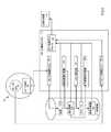
図3は、より詳細に患者視認システム20のコンポーネントを図示し、いくつかの実施形態による、データ記憶部24(画像データ70を保持する)、カテーテル26、および表示システム28を示す。 FIG. 3 illustrates the components of the patient visibility system 20 in more detail and shows a data storage unit 24 (holding image data 70), a
カテーテル26は、管腔76と、管腔76の端部に取り付けられた先端78とを含む。管腔は、カテーテル26の長さの大部分を形成する伸長部材(例えば、管状部品の空洞)である。管腔76は、少なくとも4つの直交方向および直交方向の間の全ての方向に先端78を移動させるように動作可能である、機構(図示せず)を含む。先端78は、したがって、管腔76内の機構を用いて操向可能である。管腔は、管腔76を通して先端から表示システム28に信号を中継するために要求され得る、任意の電気ケーブルおよび/または光ファイバとともに、先端を操向するために使用される機構を保持するために十分に大型である、中空ボアを有する。 The
カテーテル26はさらに、カテーテル慣性運動ユニット(IMU)80と、先端78に固着されるカテーテルカメラ82とを含む。カテーテルIMU80は、例えば、その中に形成されたいくつかの測定デバイスを有する、半導体チップであってもよい。測定デバイスは、1つ以上のジャイロスコープと、1つ以上の加速度計とを含む。ジャイロスコープおよび加速度計からの測定は、個別に、または組み合わせて、先端78の移動を示すデータを提供する。そのような移動は、6自由度、例えば、x、y、およびz方向への平行移動、およびx、y、およびz軸を中心とした回転において、追跡されることができる。 The
カテーテルカメラ82は、管腔76に対向する先端78の側にレンズ(図示せず)を有する。カテーテルカメラ82は、先端78の前の面積内に、すなわち、管腔76に対向する側に、ライブビデオデータの形態の画像を捕捉するように位置付けられる。カメラの先端の異なる側に複数の光源および複数のカメラが存在し得るが、議論を容易にするために、単一のカメラのみ、例えば、カテーテルの遠位端上の内蔵カメラおよび光源が存在すると仮定されるであろう。 The
表示システム28は、頭部搭載可能フレーム86と、左および右プロジェクタ88Aおよび88Bと、左および右導波管90Aおよび90Bと、検出デバイス92と、視覚アルゴリズム94とを含む。左および右プロジェクタ88Aおよび88B、左および右導波管90Aおよび90B、および検出デバイス92は、頭部搭載可能フレーム86に固着される。頭部搭載可能フレーム86は、視認者の頭部に搭載されるように成形される。頭部搭載可能フレーム86のコンポーネントは、例えば、視認者の頭部の後部に巻着するストラップ(図示せず)を含んでもよい。 The
左および右プロジェクタ88Aおよび88Bは、電力供給部に接続される。各プロジェクタ88Aまたは88Bは、画像データが個別のプロジェクタ88Aまたは88Bに提供されるための個別の入力を有する。個別のプロジェクタ88Aまたは88Bは、給電されると、2次元パターンで光を発生させ、そこから光を発する。左および右導波管90Aおよび90Bは、それぞれ、左および右プロジェクタ88Aおよび88Bから光を受光するように位置付けられる。左および右導波管90Aおよび90Bは、透明導波管である。 The left and
検出デバイス92は、頭部ユニットIMU100と、1つ以上の頭部ユニットカメラ102とを含む。頭部ユニットIMU100は、1つ以上のジャイロスコープと、1つ以上の加速度計とを含む。ジャイロスコープおよび加速度計は、典型的には、半導体チップ内に形成され、3つの直交軸に沿った移動および3つの直交軸を中心とした回転を含む、頭部ユニットIMU100および頭部搭載可能フレーム86の移動を検出することが可能である。 The detection device 92 includes a head unit IMU 100 and one or more head unit cameras 102. The head unit IMU100 includes one or more gyroscopes and one or more accelerometers. Gyroscopes and accelerometers are typically formed within a semiconductor chip and include head unit IMU100 and head mountable frame that include movement along three orthogonal axes and rotation around the three orthogonal axes. It is possible to detect the movement of 86.
頭部ユニットカメラ102は、頭部搭載可能フレーム86の周囲の環境から画像を継続的に捕捉する。画像は、頭部搭載可能フレーム86および視認者の頭部の移動を検出するように、相互と比較されることができる。 The head unit camera 102 continuously captures images from the environment around the head mountable frame 86. The images can be compared to each other to detect head mountable frame 86 and movement of the viewer's head.
視覚アルゴリズム94は、画像データ受信ユニット106と、表示位置付けアルゴリズム108と、カテーテル統合システム110と、表示調節アルゴリズム112と、画像処理システム114と、立体分析器116とを含む。画像データ受信ユニット106は、直接接続を通して、またはネットワークを経由して、データ記憶部24に接続される。視覚アルゴリズム94のコンポーネントは、サブルーチンまたはコールを通して相互にリンクされる。そのようなサブルーチンまたはコールを通して、画像データ受信ユニット106は、表示位置付けアルゴリズム108を介して立体分析器116にリンクされる。 The
カテーテル統合システム110は、管腔76内の導体を通してカテーテルIMU80およびカテーテルカメラ82に接続されてもよい。当業者は、視覚アルゴリズム94がコンピューティングシステム上に常駐し、カテーテル統合システム110がカテーテルカメラ82およびカテーテルIMU80から信号を受信し、そのような信号がアナログまたはデジタルデータからコンピュータソフトウェアデータに変換され得ることを理解するであろう。カテーテル統合システム110は、サブルーチンまたはコールを通して立体分析器116に接続されてもよい。 The
表示調節アルゴリズム112および画像処理システム114は、それぞれ、頭部ユニットIMU100および頭部ユニットカメラ102に接続される。そのような接続は、導体を通し、適用可能である場合、アナログまたはデジタルデータをコンピュータソフトウェアデータに変換するインバータを通す。表示調節アルゴリズム112は、サブルーチンおよびコールを通して表示位置付けアルゴリズム108に接続されてもよい。画像処理システム114は、コールおよびサブルーチンを通して表示調節アルゴリズム112に接続されてもよい。 The
使用時、視認者が、頭部搭載可能フレーム86をその頭部に搭載する。左および右導波管90Aおよび90Bは、次いで、視認者の左および右眼120Aおよび120Bの前に位置する。 At the time of use, the viewer mounts the head mountable frame 86 on the head. The left and
画像データ受信ユニット106は、データ記憶部24から画像データ70を読み出し、画像データ70を表示位置付けアルゴリズム108に提供する。表示位置付けアルゴリズム108は、画像データ70を立体分析器116の中に入力する。画像データ70は、上記に説明されるような身体部分の3次元画像データである。立体分析器116は、画像データ70を分析し、画像データ70に基づいて、左および右画像データセットを決定する。左および右画像データセットは、3次元レンダリングの知覚を視認者に与える目的のために相互とわずかに異なる、2次元画像を表すデータセットである。画像データ70は、経時的に変化しない静的データセットである。 The image
立体分析器116は、左および右画像データセットを左および右プロジェクタ88Aおよび88Bの中に入力する。左および右プロジェクタ88Aおよび88Bは、次いで、左および右光パターン122Aおよび122Bを生成する。表示システム28のコンポーネントは、平面図で示され、左および右光パターン122Aおよび122Bは、正面立面図で示される。各光パターン122Aおよび122Bは、複数のピクセルを含む。例証の目的のために、ピクセルのうちの2つからの光線124Aおよび126Aが、左プロジェクタ88Aから退出し、左導波管90Aに入射して示される。光線124Aおよび126Aは、左導波管90Aの側面から反射する。光線124Aおよび126Aは、内部反射を通して左導波管90A内で左から右に伝搬することが示されるが、光線124Aおよび126Aはまた、耐熱および反射システムを使用する紙の中への方向にも伝搬することを理解されたい。光線124Aおよび126Aは、瞳孔128Aを通して左光導波管90Aから出射し、左眼の瞳孔130Aを通して左眼120Aに入射する。光線124Aおよび126Aは、次いで、左眼120Aの網膜132A上に当射する。このように、左光パターン122Aは、左眼120Aの網膜132A上に当射する。視認者は、網膜132A上に形成されるピクセルが、視認者が左眼120Aに対向する左導波管90Aの側面上である距離を置いていると知覚する、ピクセル134Aおよび136Aであるという知覚を与えられる。 The
類似様式で、立体分析器116は、右画像データセットを右プロジェクタ88Bの中に入力する。右プロジェクタ88Bは、光線124Bおよび126Bの形態でピクセルによって表される、右光パターン122Bを伝送する。光線124Bおよび126Bは、右導波管90B内で反射し、瞳孔128Bを通して出射する。光線124Bおよび126Bは、次いで、右眼120Bの瞳孔130Bを通して入射し、右眼120Bの網膜132B上に当射する。光線124Bおよび126Bのピクセルは、右光導波管90Bの背後のピクセル134Bおよび136Bとして知覚される。 In a similar fashion, the
網膜132Aおよび132B上に生成されるパターンは、正面立面図に示される左および右画像140Aおよび140Bとして個別に知覚される。左および右画像140Aおよび140Bは、立体分析器116の機能に起因して、相互とわずかに異なる。左および右画像140Aおよび140Bは、視認者の脳では3次元レンダリングとして知覚される。 The patterns generated on the
述べられたように、左および右導波管90Aおよび90Bは、透明である。眼120Aおよび120Bに対向する左および右導波管90Aおよび90Bの側面上の実際の物体からの光は、左および右導波管90Aおよび90Bを通して投影し、網膜132Aおよび132B上に当射することができる。特に、患者の身体30の表面からの光は、視認者に患者の身体30の表面が見え得るように、網膜132Aおよび132B上に当射する。視認者に見える患者の身体30の表面が、組み合わせて視認者によって知覚される左および右画像140Aおよび140Bに起因して、視認者によって知覚される3次元レンダリングを用いて拡張される、拡張現実が、生成される。 As mentioned, the left and
頭部ユニットIMU100は、視認者の頭部の全移動を検出する。視認者が、例えば、患者の身体30の周囲で反時計回りに移動し、同時に、その頭部を反時計回りに回転させ、患者の身体30を見続けた場合、そのような移動は、頭部ユニットIMU100内のジャイロスコープおよび加速度計によって検出されるであろう。頭部ユニットIMU100は、ジャイロスコープおよび加速度計からの測定値を表示調節アルゴリズム112に提供する。表示調節アルゴリズム112は、設置値を計算し、設置値を表示位置付けアルゴリズム108に提供する。表示位置付けアルゴリズム108は、画像データ70を修正し、視認者の頭部の移動を補償する。表示位置付けアルゴリズム108は、視認者への表示のために、修正された画像データ70を立体分析器116に提供する。 The head unit IMU100 detects the entire movement of the viewer's head. If, for example, the viewer moves counterclockwise around the patient's
頭部ユニットカメラ102は、視認者がその頭部を移動させるにつれて、画像を継続的に捕捉する。画像処理システム114は、画像内の物体の画像を識別することによって、画像を分析する。画像処理システム114は、物体の移動を分析し、頭部搭載可能フレーム86の姿勢位置を決定する。画像処理システム114は、姿勢位置を表示調節アルゴリズム112に提供する。表示調節アルゴリズム112は、姿勢位置を使用し、表示調節アルゴリズム112が表示位置付けアルゴリズム108に提供する設置値をさらに精緻化する。表示位置付けアルゴリズム108は、したがって、頭部ユニットIMU100内の運動センサおよび頭部ユニットカメラ102によって撮影される画像の組み合わせに基づいて、画像データ70を修正する。 The head unit camera 102 continuously captures images as the viewer moves his head. The
カテーテル統合システム110は、視認者が先端78を患者の身体30の中に挿入する前に、カテーテル26の先端78の場所を検出してもよい。視認者は、続いて、先端78を患者の身体30の中に挿入する。先端78は、次いで、視認者に可視ではなくなる。カテーテルIMU80は、先端78の全移動を示す信号をカテーテル統合システム110に提供する。カテーテル統合システム110は、したがって、カテーテルIMU80内の運動センサを使用して、先端78の位置を追跡することができる。静的である画像データ70と異なり、先端78の位置は、経時的に変化する。カテーテル統合システム110は、先端78の位置を立体分析器116に提供する。先端78の位置は、それが経時的に変化し、3次元で移動するという点で、動的であり得る。立体分析器116は、左および右プロジェクタ88Aおよび88Bの中に挿入される左および右画像データセット内で先端78を位置付ける。視認者は、したがって、左および右画像140Aおよび140B内の先端78の場所を見ることができる。先端78の場所は、視認者が3次元で先端78の場所を知覚するように、左および右画像140Aおよび140B内でわずかに変動する。左および右画像140Aおよび140Bによって提供されるような先端78の場所のレンダリングは、先端78が患者の身体30を通り抜けるにつれて経時的に変化する。レンダリングとしての先端78の場所のそのような移動は、3次元で、すなわち、左、右、上、下、前方、後方等に移動するにつれて、視認者が先端78のレンダリングを知覚するように、3次元で変化する。 The
カテーテルカメラ82は、ビデオデータを捕捉し続け、ビデオデータをカテーテル統合システム110に提供する。カテーテル統合システム110は、ビデオデータを立体分析器116に提供する。立体分析器116は、場所が変化するべきであることを示すユーザ相互作用イベントが検出されない限り、または検出されるまで、視認者のビュー内の固定された場所にビデオデータを設置する。ビデオデータは、異なる画像がカテーテルカメラ82によって捕捉されるにつれて経時的に変化する。 The
視覚アルゴリズム94は、コンピュータ可読媒体上にデータ記憶部24とともに記憶される命令のセットである。命令のセットは、上記に説明される方法を実行するようにプロセッサによって実行可能である。視覚アルゴリズム94を記憶するコンピュータ可読媒体は、視認者によって装着されるベルトパック上に位置してもよい。 The
図4は、患者視認システム20のコンポーネント、特に、カテーテル統合システム110のコンポーネントと、先端78内のカテーテルIMU80およびカテーテルカメラ82および立体分析器116とのそれらの関係とをより詳細に図示する。 FIG. 4 illustrates in more detail the components of the patient visibility system 20, in particular the components of the
カテーテル統合システム110は、カテーテル追跡システム150と、過去経路計算機152と、メッシュ発生器154と、予想経路計算機156と、ビデオデータ受信ユニット158と、カテーテル表示インテグレータ160とを含む。カテーテル追跡システム150は、カテーテルIMU80に接続される。カテーテル追跡システム150は、カテーテルIMU80によって検出される移動に基づいて、先端78の位置を計算する。カテーテルIMU80は、6自由度でその移動を追跡するためのいくつかのジャイロスコープおよび加速度計を含む、いくつかの先端追跡デバイスを含む。カテーテル追跡システム150は、データ記憶部24内に位置162として先端78の現在の位置を記憶する。カテーテル追跡システム150は、カテーテルIMU80を監視し続け、先端78の現在の位置を計算し続け、データ記憶部24内に現在の位置162として先端78の現在の位置を記憶し続ける。 The
カテーテル表示インテグレータ160は、データ記憶部24から現在の位置162を受信し、現在の位置162を立体分析器116に提供する。立体分析器116は、視認者に3次元でのレンダリングとして先端78の位置が見え得るように、レンダリングとして先端78の現在の位置162を視認者に表示する。 The catheter display integrator 160 receives the current position 162 from the
過去経路計算機152は、データ記憶部24から全瞬間における全位置162を読み出す。過去経路計算機152は、3次元で先端78の過去経路を計算し、データ記憶部24内に過去経路164として過去経路を記憶する。カテーテル表示インテグレータ160は、データ記憶部24から過去経路164を受信し、過去経路164を立体分析器116に提供する。立体分析器116は、3次元レンダリングとして過去経路164を視認者に表示する。 The past route computer 152 reads out all positions 162 at all moments from the
メッシュ発生器154は、データ記憶部から過去経路164を読み出し、過去経路164の周囲に3次元メッシュを発生させる。メッシュ発生器154は、次いで、データ記憶部24内にメッシュ166としてメッシュを記憶する。カテーテル表示インテグレータ160は、データ記憶部24からメッシュ166を読み出し、メッシュ166を立体分析器116に提供する。立体分析器116は、メッシュ166を視認者に表示する。立体分析器116は、いくつかの実施形態では、過去経路164にオーバーレイする、メッシュ166の3次元レンダリングを生成する。 The mesh generator 154 reads the
予想経路計算機156は、データ記憶部24から先端78の全位置162を読み出し、データ記憶部24から読み出される位置162および過去の位置に基づいて、先端78の将来の経路を計算する。予想経路計算機156は、次いで、データ記憶部24内に将来の経路168として将来の経路を記憶する。カテーテル表示インテグレータ160は、データ記憶部24から将来の経路168を読み出し、将来の経路168を立体分析器116に提供する。立体分析器116は、3次元レンダリングとして将来の経路168を視認者に表示する。 The
ビデオデータ受信ユニット158は、カテーテルカメラ82からライブビデオを受信する。ビデオデータ受信ユニット158は、ライブビデオデータをカテーテル表示インテグレータ160に提供する。カテーテル表示インテグレータ160は、ライブビデオデータを立体分析器116に提供する。立体分析器116は、ライブビデオデータを視認者に表示する。ライブビデオデータは、3次元空間内である所定の距離において視認者に表示される、2次元表示である。カテーテル表示インテグレータはまた、メッシュ166がビデオデータ上に表示されるように、メッシュ166をビデオデータ受信ユニット158からのビデオデータと統合する。ビデオデータが、患者の身体30内のカテーテル26の変化する位置とともに変化するにつれて、メッシュ166もまた、それに応じて変化する。 The video data receiving unit 158 receives live video from the
図5は、いくつかの実施形態による、患者の肺内の区気管支を含む身体部分174を検査する目的のために、気管支鏡としてカテーテル26を使用する外科医の形態の視認者172による、前述で説明されたような患者視認システム20の使用を図示する。 FIG. 5 is described above by a
視認者172は、左および右導波管90Aおよび90Bを通して患者の身体30を見ることができる。身体部分174は、患者の身体30の内側にあり、したがって、視認者は、実際の(すなわち、物理的な)身体部分174を見ることができない。 The
視認者172にはまた、前述で説明されたような画像データ70に基づく3次元レンダリング176も見える。特定の実施形態では、レンダリング176は、患者の身体30の隣に位置する。レンダリング176は、視認者172が患者の身体30に対してレンダリング176を知覚する場所を示すように図に含まれるが、本書の読者の視点から、レンダリング176は実世界に存在しないことを理解されたい。差込図180は、視認者172にはレンダリング176の一部として身体部分174の3次元レンダリング182が見え得ることを示す。 The
視認者172は、カテーテル26の先端78を患者の口の中に挿入する。視認者172は、次いで、先端78を身体部分174の中に前進させる。先端78の場所は、前述で説明されたように時間が密接に離間される事例において監視され、その過去経路が、3次元で記憶される。サンプリング時間は、ユースケースに応じて変動し得、内視鏡が患者の身体の内側にある間に、またはユーザが「記録/サンプリングを開始する」特徴をアクティブ化した後のみに、データを捕捉すること等の最適化が、可能性として考えられる。差込図184は、レンダリング176が3次元における先端78の場所のレンダリング186と、3次元における先端78の過去経路のレンダリング188とを含むことを示す。レンダリング182、186、および188は、視認者にレンダリング182内のレンダリング186および188が見えるように、同時に視認者172に表示されてもよい。 The
図6は、いくつかの実施形態による、患者の身体30に対して視認者172の場所を示す、上平面図であり、視認者172のビュー内のレンダリング176の場所をさらに図示する。レンダリング176は、ユーザ選好、事前プログラムされたデフォルト設定、または任意の他の好適な手段に基づいて、患者の身体30に対して任意の位置に設置されてもよい。図6のレンダリング176に対する患者の身体30の特定の相対場所は、例証目的のためにすぎず、いかようにも限定的と見なされるべきではない。 FIG. 6 is an upper plan view showing the location of the
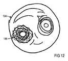
図7は、いくつかの実施形態による、図6の視認者172によって見られるようなビュー192を図示する。視認者172は、患者の実際の身体30およびレンダリング176を見ることができる。ビュー192はさらに、図4のカテーテルカメラ82によって捕捉されるビデオデータに基づくライブビデオを含む。ビュー192はさらに、ビデオ194にオーバーレイするメッシュ196を示す。メッシュ196は、図4のメッシュ166の表示である。 FIG. 7 illustrates
図8では、視認者172は、いくつかの実施形態によると、患者の身体30の周囲で反時計回りに移動し、また、患者の身体30を見続けるようにその頭部を反時計回りに回転させた。表示調節アルゴリズム112は、視認者172の頭部の移動を検出し、レンダリング176が、視認者172のビュー内の患者の身体30に対して静止したままに見えるように、それに応じて、レンダリング176の位置を調節する。 In FIG. 8, the
図9では、患者の身体30は、いくつかの実施形態によると、図7に対して時計回りに回転した。レンダリング176もまた、患者の身体30に対して静止したままであるように、時計回りに回転した。しかしながら、ライブビデオ194の場所は、図7のビュー192から図9のビュー192まで変化していない。視認者172には、したがって、同一の場所でライブビデオ194およびメッシュ196が見え、これらのコンポーネントは、視認者172の頭部の移動に応じて移動しない。視認者172は、したがって、ライブビデオ194およびメッシュ196のビューを失うことなく、異なる側面および角度から患者の身体30およびレンダリング176を視認することができる。メッシュ196の目的は、メッシュが生成された後に、またはカテーテルが反対方向に同一の経路を通して移動するにつれてカテーテルの除去の間に、視認者172が2回目に先端78を身体部分174a内の通路の中に挿入するときに、視認者がカテーテル26の先端78を誘導することを支援することであり得る。いくつかの実施形態は、仮想コンテンツの一部または全てが、実世界座標に対して固定される、または視認者に対して固定される、仮想コンテンツに関する異なる視認構成(例えば、メッシュ196、ライブビデオ194、レンダリング176)を有してもよい。 In FIG. 9, the patient's
図10は、いくつかの実施形態による、図7および9の図では小さすぎて見えない、視認者に表示されるレンダリング176のコンポーネントを示す。視認者172には、身体部分174のレンダリング182、186、および188、先端78、および先端の過去経路が見える。視認者にはまた、メッシュ196の3次元レンダリングも見える。メッシュ196は、例証の目的のためにレンダリング182、186、および188から分離されて示されるが、メッシュ196は、身体部分174のレンダリング182にオーバーレイし得ることを理解されたい。 FIG. 10 shows a component of rendering 176 that is visible to the viewer, according to some embodiments, which is too small to be seen in the figures of FIGS. 7 and 9. The
図11および12に示されるように、いくつかの実施形態では、視認者172には、2つの場所で、すなわち、レンダリング176の一部として(図11)、およびライブビデオ194にオーバーレイして(図12)、メッシュ196が見える。 As shown in FIGS. 11 and 12, in some embodiments, the
図13は、いくつかの実施形態による、図4の予想経路計算機156の機能を図示する。グラフは、経時的にx、y、およびz軸を中心としたカテーテル26の先端78の回転を図示する。各軸を中心とした回転は、第1の位置202から第2の位置204までの移動の第1の量200を決定するように、短い時間量にわたって分析されてもよい。移動の第1の量200は、先端78の将来移動の予測を計算するために使用されてもよい。 FIG. 13 illustrates the functionality of the
図14は、いくつかの実施形態による、第1の位置202における先端78を図示する。図15では、先端78は、いくつかの実施形態によると、第1の量200だけ第1の位置202から第2の位置204まで移動した。図15に示される第1の量200は、全ての軸を中心とした、および全ての平行移動方向への全ての移動の全てのベクトルの合計である。 FIG. 14 illustrates the
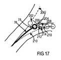
図14では、先端78が身体部分174の中にさらに挿入される場合、先端78が辿るであろう方向が、管腔76の延在206に沿っているという仮定が立てられ得る。図16は、いくつかの実施形態による、管腔76が第1の量200だけ移動した後の管腔76の延在208を示す。視認者は、先端78が身体部分174と接触して傷害を引き起こすであろうため、典型的には、延在208の経路に沿って先端78を前進させないであろう。代わりに、視認者172は、傷害を回避するために、経路210を辿ることを好むであろう。経路210は、第2の位置204から第3の位置214まで第2の量212だけ変位される。第1の量200および第2の量212は、参照を容易にするために同一の方向に測定される。 In FIG. 14, if the
図17は、いくつかの実施形態による、先端78がおそらく辿るであろう実際の経路218を図示する。経路218は、経路208から出て、視認者が先端78を身体部分174の中にさらに挿入するにつれて、経路214に接近する。立体分析器116は、3次元で経路218を視認者172に表示する。 FIG. 17 illustrates the
図18は、いくつかの実施形態による、その内側で、コンピュータシステム900の例示的形態の機械に、本明細書に議論される方法論のうちのいずれか1つ以上のものを実施させるための命令のセットが、実行され得る、機械の図形表現を示す。代替実施形態では、機械は、独立型デバイスとして動作する、または他の機械に接続(例えば、ネットワーク化)されてもよい。さらに、単一の機械のみが図示されるが、用語「機械」はまた、本明細書に議論される方法論のうちのいずれか1つ以上のものを実施する命令のセット(または複数のセット)を個別に、または合同で実行する、機械の任意の集合を含むように解釈されるものとする。 FIG. 18 is an instruction, according to some embodiments, for causing a machine of an exemplary embodiment of a
例示的コンピュータシステム900は、バス908を介して相互と通信する、プロセッサ902(例えば、中央処理ユニット(CPU)、グラフィック処理ユニット(GPU)、または両方)と、メインメモリ904(例えば、読取専用メモリ(ROM)、フラッシュメモリ、同期DRAM(SDRAM)またはRambus DRAM(RDRAM)等のダイナミックランダムアクセスメモリ(DRAM)等)と、静的メモリ906(例えば、フラッシュメモリ、スタティックランダムアクセスメモリ(SRAM)等)とを含む。 An
コンピュータシステム900はさらに、ディスクドライブユニット916と、ネットワークインターフェースデバイス920とを含んでもよい。 The
ディスクドライブユニット916は、本明細書に説明される方法論または機能のいずれかうちの1つ以上のものを具現化する、命令924(例えば、ソフトウェア)の1つ以上のセットが記憶される、機械可読媒体922を含む。ソフトウェアはまた、同様に機械可読媒体を構成する、コンピュータシステム900、メインメモリ904、およびプロセッサ902による、その実行の間に、完全に、または少なくとも部分的にメインメモリ904内に、および/またはプロセッサ902内に常駐してもよい。 The
ソフトウェアはさらに、ネットワークインターフェースデバイス920を介して、ネットワーク928を経由して伝送または受信されてもよい。 The software may also be transmitted or received via
コンピュータシステム900は、プロジェクタを駆動してレーザ光を発生させるために使用される、レーザドライバチップ950を含む。レーザドライバチップ950は、その独自のデータ記憶部と、その独自のプロセッサ962とを含む。 The
機械可読媒体922は、例示的実施形態では、単一の媒体であるように示されるが、用語「機械可読媒体」は、命令の1つ以上のセットを記憶する、単一の媒体または複数の媒体(例えば、集中または分散データベース、および/または関連付けられるキャッシュおよびサーバ)を含むように解釈されるべきである。用語「機械可読媒体」はまた、機械による実行のための命令のセットを記憶、エンコード、または搬送することが可能であり、機械に本発明の方法論のうちのいずれか1つ以上のものを実施させる、任意の媒体を含むように解釈されるものとする。用語「機械可読媒体」は、故に、限定ではないが、ソリッドステートメモリ、光学および磁気媒体、および搬送波信号を含むように解釈されるものとする。 The machine-
上記に説明される実装は、CTスキャナ22を使用し、身体部分174をスキャンする。CTスキャナは、X線伝送機の形態の伝送機と、X線検出器の形態の受信機とを有し、X線波の形態の波を伝送および受信する。他の伝送機および受信機を使用し、異なる波を伝送および検出する、他のスキャンデバイスを使用することが、可能性として考えられ得る。例えば、ソーナシステムが、音波を伝送するための音声伝送機および音波を受信するための音声受信機を使用する。視覚システムは、光波を伝送する、身体部分の中に挿入される光源を含み、身体部分から反射される光波を捕捉する、身体部分内に位置するカメラを有してもよい。 The implementation described above uses a
しかしながら、CTスキャナが、3次元で身体部分の極めて高度に詳細な未加工データを提供し、そのようなデータが、3次元画像データを生成するように画像発生ユニットを用いて容易に変換され得るため、CTスキャナは、他のスキャンデバイスよりも好ましい。CTデータはまた、特定の物質、材料、および材料の密度に関するデータを含み得るという利点も有する。説明される実装は、視認者172のビュー192内で患者の身体30の隣に設置されたレンダリング176を示す。また、身体部分のレンダリングが、実際の身体部分がある場所であり、カテーテルの先端のレンダリングが、カテーテルの先端の実際の位置がある場所であるように、レンダリングを患者の身体30と合致させることも、可能性として考えられ得る。 However, the CT scanner provides 3D, highly detailed raw data of the body part, which can be easily converted using the image generation unit to generate 3D image data. Therefore, CT scanners are preferred over other scanning devices. CT data also has the advantage that it may contain data on specific substances, materials, and densities of materials. The implementation described shows a
本発明の側面はまた、カテーテルを伴わずに実装されることもできる。例えば、患者の身体をスキャンし、成長を決定することと、視認者が、表示システムを使用し、患者の実際の身体上に3次元における成長のレンダリングをオーバーレイすることとが、可能性として考えられ得る。このように、視認者は、患者の実際の身体「内の」成長を「見る」ことができる。 Aspects of the invention can also be implemented without a catheter. For example, it is possible to scan the patient's body and determine growth, and to have the viewer use a display system to overlay the rendering of growth in three dimensions on the patient's actual body. Can be. In this way, the viewer can "see" the actual "inside" growth of the patient's body.
ある側面および実施形態では、侵襲性外科手術道具全般が、説明されるカテーテルの代わりに、またはそれに加えて、利用される。例えば、図14−17を参照すると、先端78は、それが通して通過している解剖学的チャネルを通して温度データを収集するようにカテーテルに結合される、熱画像カメラの先頭点を示し得る。熱データが、次いで、白黒の熱画像から変換され、画像受信ユニット106を通して可変色オーバーレイとしてオペレータに表示されてもよい。全ての表示が全てのユーザに共通画像を必要とするわけではないことを理解されたい。第1のオペレータまたは観察者(ローカルまたは遠隔)が、動脈血対静脈血または凍傷組織を示す温度データ等のある情報表示を所望し得る一方で、第2のオペレータまたは観察者が、外科手術道具の位置を示すもの等のある情報を所望し得る。換言すると、情報の表示は、患者内の道具の位置の画像に限定される必要はなく、道具から収集される画像でもあり得る。ある熱画像実施形態では、温度勾配が、ユーザあたりで選択されることができ、第1のオペレータが、有機組織と無機材料を見分け、基礎温度を華氏98.6度に設定することを所望し得る一方で、第2のオペレータが、具体的に外科手術道具を追跡し、撮像のための基礎温度を絶対ではなく事前設定された温度に設定することを意図し得る。 In certain aspects and embodiments, invasive surgical tools in general are utilized in place of or in addition to the catheters described. For example, referring to FIG. 14-17, the
いくつかの実施形態では、動作エンベロープが、実装される。図14−17に戻ると、解剖学的チャネルをナビゲートしながら、患者の特定の配置が、器具の動作負荷を改変し得る。例えば、患者画像が、器具に近接する敏感な組織を示す場合、負荷は、比例して調節されてもよい。さらに例証すると、心房細動がある患者の画像が、薄い左心房壁を示す場合、0.1Nの標準軸方向負荷を伴うアブレーションカテーテルが、左心房壁に近接して動作しながら、0.01または0.05Nの範囲までテント状に張られてもよい。いくつかの実施形態では、敏感な組織等の解剖学的マーカに対して絶対および相対の両方である、位置の関数としての負荷パラダイムが、位置または収集された画像等の器具画像と併せてオペレータに表示されてもよい。オペレータにその瞬間におけるデバイス能力および限界を知らせるように、位置の関数として、器具上の負荷に定められる上限を示す、視覚フィードバックが、したがって、提供され得る。代替として、付加的オペレータまたは観察者が、器具が正しい位置にない、または所与の手技に関する患者パラメータを超えているときを即時に識別することができる。そのようなフィードバックは、視覚として説明されたが、フィードバックは、オーディオまたは触覚(器具制御における増加した抵抗または摩擦)等の他の形態をとってもよい。 In some embodiments, a motion envelope is implemented. Returning to FIG. 14-17, the particular placement of the patient may alter the operational load of the instrument while navigating the anatomical channel. For example, if the patient image shows sensitive tissue in close proximity to the device, the load may be adjusted proportionally. Further exemplifying, if the image of a patient with atrial fibrillation shows a thin left atrial wall, 0.01 while an ablation catheter with a standard axial load of 0.1 N moves in close proximity to the left atrial wall. Alternatively, it may be stretched in a tent shape up to a range of 0.05 N. In some embodiments, the load paradigm as a function of position, both absolute and relative to anatomical markers such as sensitive tissues, is an operator along with instrument images such as positions or collected images. It may be displayed in. As a function of position, visual feedback may be provided, indicating an upper limit set on the load on the instrument, to inform the operator of the device capabilities and limits at that moment. Alternatively, the additional operator or observer can immediately identify when the instrument is not in the correct position or exceeds patient parameters for a given procedure. Such feedback has been described as visual, but feedback may take other forms such as audio or tactile sensation (increased resistance or friction in instrument control).
いくつかの実施形態では、観察可能な運動アーチファクトが、位置調節を器具に提供する。頭部ユニットカメラ102は、患者位置データを撮像し、リアルタイム位置調節を器具に提供してもよい。いくつかの実施形態では、患者の呼吸リズムが、観察され、器具制御が、呼吸状態に適応するように修正される。頭部ユニットカメラ102は、動作環境または既知の寸法の固定された機械内の基準マーカ等によって、位置データを位置合わせし、呼気および吸気の間の胸部位置を比較し、寸法の変化を関連付けてもよい。いくつかの実施形態では、肺が吸気の間に拡張し、周辺生体構造が反応して圧縮するにつれて、器具運動が、対応して減速し、次いで、肺が呼気の間に収縮するにつれて正常な動作パラメータを回復し得る、または器具が解剖学的チャネル内で絶対的に移動するが、その解剖学的参照に対して安定しているように、x−y−z調節が、胸腔の上下に合致するように行われ得る。他の観察される誘因が、動作調節も提供し得、心拍数および血管の予期される収縮/拡張が、位置の更新を器具に提供し得る。 In some embodiments, observable motor artifacts provide position adjustment to the instrument. The head unit camera 102 may capture patient position data and provide real-time position adjustment to the instrument. In some embodiments, the patient's respiratory rhythm is observed and instrument control is modified to adapt to respiratory conditions. The head unit camera 102 aligns position data, compares chest positions between exhalation and inspiration, and correlates dimensional changes, such as by operating environment or a fixed machine reference marker of known dimensions. May be good. In some embodiments, as the lungs expand during inspiration and the surrounding anatomy reacts and compresses, instrumental movements are correspondingly slowed down and then normal as the lungs contract during exhalation. X-yz regulation is up and down the thoracic cavity so that motion parameters can be restored, or the instrument moves absolutely within the anatomical channel, but is stable for its anatomical reference. Can be done to match. Other observed triggers may also provide motion regulation, and expected contraction / expansion of heart rate and blood vessels may provide repositioning to the device.
いくつかの実施形態では、患者活動(例えば、呼吸リズム、心拍)のフィードバック制御が、時間T1〜T2〜T3において頭部ユニットカメラ102によって3つの別個の時間に収集され、画像は、(患者の移動、その呼吸リズム、心拍等に起因する)患者位置の変化を決定するように、時間T4において分析される。頭部ユニットカメラ102に動作可能に結合される器具が、時間T0において(すなわち、T1の前に、またはそれと同時に)制御入力を与えられ、時間T1〜T3にわたって経時的に観察される患者位置の変化に基づく制御入力の調節が、時間T5において行われる。いくつかの実施形態では、制御入力の変化は、患者位置の測定された変化の割合である。In some embodiments, patient activity (e.g., breathing rhythm, heart) feedback control, are collected in time T1 through T2 through T 3 distinct time by the head unit camera 102 at3, image, (movement of the patient, the breathing rhythm, due to heart beat, etc.) to determine the changes in the patient position are analyzed at time T4. Instrument is operatively coupled to the head unit camera 102, at time T0 (i.e., before the T1, or at the same time) is given a control input, it is observed over time for a time T1 through T3 adjustment of the control input based on the changes in the patient position that is carried out at time T5. In some embodiments, the change in control input is the percentage of measured change in patient position.
図19は、測定された患者位置データと制御フィードバック調節との間の例示的関係を図示する。描写されるように、呼吸から起こる胸部拡張による患者位置の理論的y方向変化が、曲線1901によって表される。観察された患者位置データが、それぞれ、胸部位置y1、y2、およびy3に対応する、時間T1、T2、およびT3において収集される。好ましくは、3つの収集時間が、標的測定のための傾向分析を提供するように作成される。例えば、平均ヒト呼吸数は、1分あたり15回の呼吸であり、任意の所与の吸気または呼気に約2秒を配分する。測定された吸気に基づくが、呼気の間に適用される、器具位置の補正を回避するために、少なくとも3回の測定が、傾向分析を提供するように行われる。平均ヒト呼吸数を考慮すると、少なくとも0.667秒または1.5Hzの測定の合間の時間間隔が、好ましい。そのような周波数は、T0およびT5のそれぞれの合間の時間である必要はなく、T4およびT5における関連付けられるアクションを可能な限り迅速に適用させることが好ましい。FIG. 19 illustrates an exemplary relationship between measured patient position data and control feedback regulation. As depicted, the theoretical y-direction change in patient position due to chest dilation resulting from breathing is represented by the
図19に戻ると、位置y1−y2−y3の変化は、T4における分析の間に、吸気がT3に近接して完結していることをシステムに示す。したがって、T5におけるフィードバック制御は、呼気の間に「吸気補正」を適用することを回避するように、調節を提供しなくてもよい、またはT3に対するT5の時間関係および推定y位置変化に基づいて、負のy位置調節を提供してもよい。例えば、T3とT5との間の時間が、T2とT3との間の時間に類似し、システムが、y2およびy3と比較して、y1とy2との間にあるような変化から、患者がy方向への変化を受けていることを認識する場合、調節は、T2からT3まで測定されるような変化未満またはそれと等しくあり得る。これは、下記の論理的関係として描写され得る。
(T5−T3=T3−T2)∩(y3−y2)<(y2−y1)である場合、T5における補正<(y3−y2)Returning to FIG. 19, the change in position y1-y2-y3 indicates to the system thatthe inspiration is complete in close proximity to T 3 during the analysis atT 4. Therefore,the feedback control at T 5 may not provide adjustment to avoid applying "inspiratory correction" during exhalation, orthe time relationship of T 5 with respect to T3 and the estimated y position change. May provide a negative y position adjustment based on. For example, the time betweenT 3 and T5 is similar to the time betweenT 2 and T3, and the system is betweeny 1 and y2 compared toy 2 and y3. If the patient recognizes that the patient is undergoing a change in the y direction from such a change, the adjustment can be less than or equal to the change as measured from T2to T 3. This can be described as the following logical relationship.
If (T5 −T3 = T3 −T2 ) ∩ (y3 − y2 ) <(y2 − y1 ), thecorrection in T 5 <(y3 − y2 )
ある例示的実施形態が、説明され、付随する図面に示されたが、そのような実施形態は、例証的にすぎず、現在の発明の制限ではなく、修正が当業者に想起され得るため、本発明は、示されて説明される具体的構造および配列に制限されないことを理解されたい。 Certain exemplary embodiments have been described and shown in the accompanying drawings, as such embodiments are merely exemplary and not a limitation of the present invention, as modifications may be recalled to those of skill in the art. It should be understood that the invention is not limited to the specific structures and sequences shown and described.
Claims (183)
Translated fromJapanese管腔と、先端とを有するカテーテルと、
前記先端の移動を検出する先端追跡デバイスと、
左および右プロジェクタと、
前記左および右プロジェクタに接続される左および右光導波管と、
プロセッサと、
前記プロセッサに接続されるコンピュータ可読媒体と、
前記コンピュータ可読媒体上のデータ記憶部と、
前記データ記憶部上に記憶される画像データと、
前記コンピュータ可読媒体上に記憶され、前記プロセッサによって実行可能である命令のセットであって、
前記先端追跡デバイスに接続されるカテーテル追跡システムであって、前記カテーテル追跡システムは、前記先端追跡デバイスによって検出される移動に基づいて、測定値を受信し、前記測定値に基づいて、前記先端の位置を決定し、前記データ記憶部内に前記先端の位置を記憶する、カテーテル追跡システムと、
前記画像データを受信するように前記データ記憶部に接続される立体分析器であって、前記立体分析器は、左および右画像データセットを決定し、前記左および右プロジェクタは、それぞれ、前記左および右画像データセットを投影し、前記左および右画像データセットは、3次元レンダリングの知覚を視認者に与えるように相互と異なる、立体分析器と
を含む、命令のセットと
を備える、患者視認システム。It ’s a patient visibility system.
A catheter with a lumen and a tip,
A tip tracking device that detects the movement of the tip,
With left and right projectors,
The left and right optical waveguides connected to the left and right projectors,
With the processor
A computer-readable medium connected to the processor and
The data storage unit on the computer-readable medium and
Image data stored on the data storage unit and
A set of instructions stored on the computer-readable medium and capable of being executed by the processor.
A catheter tracking system connected to the tip tracking device, wherein the catheter tracking system receives measurements based on the movement detected by the tip tracking device and is based on the measurements of the tip. A catheter tracking system that determines the position and stores the position of the tip in the data storage unit.
A three-dimensional analyzer connected to the data storage unit to receive the image data, wherein the three-dimensional analyzer determines a left and right image data set, and the left and right projectors determine the left and right image data sets, respectively. And projecting the right image data set, the left and right image data sets are different from each other to give the viewer the perception of 3D rendering, with a set of instructions, including a stereoanalyst, patient visibility. system.
をさらに備える、請求項1に記載の患者視認システム。The patient viewing system according to claim 1, wherein the optical waveguide is a head-mountable frame, further comprising a head-mountable frame that is fixed to the head-mountable frame.
前記命令のセットは、
前記頭部ユニット検出デバイスに接続され、前記頭部ユニット検出デバイスによって検出される移動に基づいて測定値を受信し、設置値を計算する表示調節アルゴリズムと、
前記設置値に基づいて、前記眼のビュー内の前記身体部分の位置を修正する表示位置付けアルゴリズムと
を含む、請求項2に記載の患者視認システム。Further equipped with a head unit detection device for detecting the movement of the head mountable frame,
The set of instructions is
A display adjustment algorithm that is connected to the head unit detection device, receives measurements based on movements detected by the head unit detection device, and calculates installation values.
The patient viewing system of claim 2, comprising a display positioning algorithm that corrects the position of the body portion in the view of the eye based on the placement value.
前記頭部搭載可能フレームに搭載される頭部ユニット慣性測定ユニット(IMU)であって、前記頭部ユニットIMUは、前記頭部搭載可能フレームの移動を検出する運動センサを含む、頭部ユニットIMU
を含む、請求項4に記載の患者視認システム。The head unit detection device is
A head unit inertial measurement unit (IMU) mounted on the head mountable frame, wherein the head unit IMU includes a motion sensor that detects movement of the head mountable frame.
4. The patient visual recognition system according to claim 4.
前記頭部搭載可能フレームに搭載される頭部ユニットカメラであって、前記頭部ユニットカメラは、前記頭部ユニットカメラのビュー内の物体の画像を撮影することによって前記頭部搭載可能フレームの移動を検出する、頭部ユニットカメラ
を含む、請求項4に記載の患者視認システム。The head unit detection device is
A head unit camera mounted on the head mountable frame, wherein the head unit camera moves the head mountable frame by capturing an image of an object in the view of the head unit camera. 4. The patient viewing system according to claim 4, comprising a head unit camera to detect.
前記伝送機をアクティブ化するように前記伝送機に接続されるエネルギー源であって、患者の身体は、前記伝送機が前記身体内の身体部分において前進波を発生させるために、前記伝送機に対して位置付け可能である、エネルギー源と、
前記身体部分からの帰還波を検出するように前記身体に対して位置付け可能である受信機であって、前記身体部分からの前記帰還波は、前記伝送機によって生成される前記前進波に応答する、受信機と
をさらに備え、
前記命令のセットは、
前記受信機によって検出される前記帰還波の未加工データを受信し、前記データ記憶部内に前記未加工データを記憶する未加工データ受信ユニットと、
前記帰還波の未加工データを処理して、画像を表す画像データを生成し、前記データ記憶部内に前記画像データを記憶するように前記データ記憶部に接続される画像発生ユニットと、
前記データ記憶部から前記画像データを受信する画像データ受信ユニットと、
前記先端の位置を前記画像データと組み合わせるカテーテル表示インテグレータであって、前記プロジェクタによって生成される前記光のパターンは、前記画像データおよび前記先端の位置を表すパターンを含む、カテーテル表示インテグレータと
を含む、請求項1に記載の患者視認システム。With a transmitter,
An energy source connected to the transmitter to activate the transmitter, the patient's body is exposed to the transmitter in order for the transmitter to generate forward waves in a body portion within the body. An energy source that can be positioned with respect to
A receiver that can be positioned relative to the body to detect the feedback wave from the body portion, the feedback wave from the body portion responding to the forward wave generated by the transmitter. , Further equipped with a receiver,
The set of instructions is
A raw data receiving unit that receives raw data of the feedback wave detected by the receiver and stores the raw data in the data storage unit.
An image generation unit connected to the data storage unit so as to process the raw data of the feedback wave to generate image data representing an image and store the image data in the data storage unit.
An image data receiving unit that receives the image data from the data storage unit, and
A catheter display integrator that combines the position of the tip with the image data, wherein the pattern of light produced by the projector includes a catheter display integrator that includes the image data and a pattern representing the position of the tip. The patient visual recognition system according to claim 1.
基部と、
前記患者のためのプラットフォームと、
前記患者を中心とした回転のために前記基部に搭載される回転子であって、前記伝送機は、前記回転子に固着され、X線波を伝送する、X線伝送機であり、前記受信機は、前記X線波を検出するように前記回転子に固着されるX線検出器であり、前記基部に対する前記プラットフォームの移動は、前記X線伝送機から前記X線検出器まで延在する平面に対して前記患者の移動を可能にする、回転子と
を含む、コンピュータ断層撮影(CT)スキャナ
を備える、請求項8に記載の患者視認システム。Computed tomography (CT) scanner
At the base,
The platform for the patient and
A rotor mounted on the base for rotation centered on the patient, wherein the transmitter is an X-ray transmitter that is fixed to the rotor and transmits an X-ray wave, and is a receiver. The machine is an X-ray detector fixed to the rotor so as to detect the X-ray wave, and the movement of the platform with respect to the base extends from the X-ray transmitter to the X-ray detector. The patient visibility system of claim 8, comprising a computed tomography (CT) scanner comprising a rotor that allows the patient to move relative to a plane.
前記データ記憶部内に前記先端の過去経路を記憶する過去経路計算機であって、前記カテーテル表示インテグレータは、前記先端の位置とともに前記先端の過去経路を表示する、過去経路計算機
を含む、請求項1に記載の患者視認システム。The set of instructions is
The first aspect of the present invention includes a past route calculator that stores the past route of the tip in the data storage unit, wherein the catheter display integrator displays the past route of the tip together with the position of the tip. Described patient visibility system.
前記先端の過去経路を記憶する過去経路計算機と、
前記先端の過去経路の周囲に3次元メッシュを発生させ、前記データ記憶部内に前記メッシュを記憶するメッシュ発生器であって、前記カテーテル表示インテグレータは、前記先端の位置とともに前記メッシュを表示する、メッシュ発生器と
を含む、請求項1に記載の患者視認システム。The set of instructions is
A past route computer that stores the past route at the tip,
A mesh generator that generates a three-dimensional mesh around the past path of the tip and stores the mesh in the data storage unit, wherein the catheter display integrator displays the mesh together with the position of the tip. The patient visibility system of claim 1, comprising a generator.
をさらに備え、
前記命令のセットは、
前記ビデオデータを受信するように前記先端内の前記カテーテルカメラに接続されるビデオデータ受信ユニットであって、前記カテーテル表示インテグレータは、前記ビデオデータに基づいて、ライブビデオを表示する、ビデオデータ受信ユニット
を含む、請求項11に記載の患者視認システム。A catheter camera within the tip, said catheter camera further comprising a catheter camera for capturing video data.
The set of instructions is
A video data receiving unit connected to the catheter camera in the tip so as to receive the video data, wherein the catheter display integrator displays a live video based on the video data. 11. The patient visual recognition system according to claim 11.
前記先端の位置に基づいて、前記先端の将来の経路を計算する予想経路計算機であって、前記カテーテル表示インテグレータは、前記将来の経路を表示する、予想経路計算機
を含む、請求項1に記載の患者視認システム。The set of instructions is
The one according to claim 1, wherein the catheter display integrator includes a predictive route calculator that displays the future route, which is a predictive route calculator that calculates the future route of the tip based on the position of the tip. Patient visibility system.
前記カメラによって捕捉される画像をオペレータに表示するための少なくとも1つのディスプレイと
をさらに備える、請求項1に記載の患者視認システム。With the camera on the tip,
The patient viewing system of claim 1, further comprising at least one display for displaying the image captured by the camera to the operator.
前記カメラによって捕捉される前記画像を第2のオペレータに表示する第2のディスプレイ
をさらに備える、請求項17に記載の患者視認システム。The first display displays the three-dimensional rendering to the first operator.
The patient viewing system according to claim 17, further comprising a second display for displaying the image captured by the camera to a second operator.
前記カテーテルを用いることなくデータを収集するデータ収集システムと、
前記データ収集システムを用いて収集される前記データを第2のオペレータに表示するための第2のディスプレイと
をさらに備える、請求項1に記載の患者視認システム。A first display for displaying the 3D rendering to the first operator,
A data collection system that collects data without using the catheter,
The patient viewing system according to claim 1, further comprising a second display for displaying the data collected using the data collection system to a second operator.
前記先端上の負荷が所定の限界を超える場合、オペレータに警告するように前記負荷検出システムに接続される、警告システムと
をさらに備える、請求項1に記載の患者視認システム。A load detection system connected to the tip to determine the operating load on the tip,
The patient visibility system according to claim 1, further comprising a warning system, which is connected to the load detection system to warn the operator when the load on the tip exceeds a predetermined limit.
前記運動アーチファクトに基づいて、前記先端に位置調節を行うように前記運動検出システムに接続される位置調節システムと
をさらに備える、請求項1に記載の患者視認システム。A motion detection system for observing motion artifacts,
The patient visual recognition system according to claim 1, further comprising a position adjustment system connected to the movement detection system so as to perform position adjustment at the tip based on the movement artifact.
カテーテルの先端を患者の身体の中に挿入することと、
先端追跡デバイスを用いて、前記先端の移動を検出することと、
前記先端追跡デバイスによって検出される移動に基づいて、測定値を受信することと、
前記測定値に基づいて、前記先端の位置を決定することと、
前記先端の位置を記憶することと、
前記先端の位置に基づいて、左および右画像データセットを決定することと、
それぞれ、前記左および右画像データセットを光として投影する左および右プロジェクタを使用して、前記先端の位置を表すパターンで光を発生させることと、
視認者に前記先端の位置が見えるように、前記光を前記視認者の左および右眼の網膜に誘導することであって、前記左および右画像データセットは、3次元レンダリングの知覚を前記視認者に与えるように相互と異なる、ことと
を含む、方法。It ’s a way to see the patient.
Inserting the tip of the catheter into the patient's body,
Using a tip tracking device to detect the movement of the tip,
Receiving measurements based on the movement detected by the advanced tracking device,
Determining the position of the tip based on the measured value,
To memorize the position of the tip and
Determining the left and right image data sets based on the position of the tip,
Using left and right projectors that project the left and right image datasets as light, respectively, to generate light in a pattern that represents the position of the tip.
Directing the light to the retinas of the left and right eyes of the viewer so that the viewer can see the position of the tip, the left and right image datasets perceive the perception of 3D rendering. Methods, including things that are different from each other as given to a person.
をさらに含む、請求項26に記載の方法。26. The method of claim 26, further comprising mounting the head mountable frame on the head of a viewer, wherein the optical waveguide is fixed to the head mountable frame.
検出される前記移動に基づいて、設置値を計算することと、
前記設置値に基づいて、前記眼のビュー内の前記身体部分の位置を修正することと
をさらに含む、請求項27に記載の方法。Detecting the movement of the frame that can be mounted on the head and
To calculate the installation value based on the detected movement,
27. The method of claim 27, further comprising modifying the position of the body part within the view of the eye based on the placement value.
受信機を用いて、前記身体部分からの帰還波を検出することであって、前記身体部分からの前記帰還波は、前記伝送機によって生成される前記前進波に応答する、ことと、
前記受信機によって検出される前記帰還波の未加工データを受信することと、
データ記憶部内に前記未加工データを記憶することと、
前記帰還波の未加工データを処理し、画像を表す画像データを生成することと、
前記データ記憶部内に前記画像データを記憶することと、
前記データ記憶部から前記画像データを受信することと、
前記先端の位置を前記画像データと組み合わせることであって、生成される前記光のパターンは、前記画像データおよび前記先端の位置を表すパターンを含む、ことと
をさらに含む、請求項26に記載の方法。Activating the transmitter to generate a forward wave in the body part of the body,
The receiver is used to detect the feedback wave from the body part, and the feedback wave from the body part responds to the forward wave generated by the transmitter.
Receiving the raw data of the feedback wave detected by the receiver,
To store the raw data in the data storage unit,
Processing the raw data of the feedback wave to generate image data representing an image,
To store the image data in the data storage unit,
Receiving the image data from the data storage unit and
26. Method.
前記先端の位置とともに前記先端の過去経路を表示することと
をさらに含む、請求項26に記載の方法。To store the past route of the tip in the data storage unit,
26. The method of claim 26, further comprising displaying the past path of the tip as well as the position of the tip.
前記データ記憶部、前記カテーテル表示インテグレータ内に前記メッシュを記憶することと、
前記先端の位置とともに前記メッシュを表示することと
をさらに含む、請求項26に記載の方法。To generate a three-dimensional mesh around the past path at the tip,
To store the mesh in the data storage unit and the catheter display integrator,
26. The method of claim 26, further comprising displaying the mesh along with the position of the tip.
前記ビデオデータを受信することであって、前記カテーテル表示インテグレータは、前記ビデオデータに基づいて、ライブビデオを表示する、ことと、
前記ビデオデータに基づいて、ライブビデオを表示することと
をさらに含む、請求項36に記載の方法。Using the catheter camera in the tip to capture video data,
Receiving the video data, the catheter display integrator displays a live video based on the video data.
36. The method of claim 36, further comprising displaying a live video based on the video data.
前記先端の位置に基づいて、前記先端の将来の経路を計算することと、
前記将来の経路を表示することと
を含む、請求項26に記載の方法。The set of instructions is
To calculate the future path of the tip based on the position of the tip,
26. The method of claim 26, comprising displaying the future route.
前記カメラによって捕捉される画像をオペレータに表示することと
をさらに含む、請求項26に記載の方法。Using the camera on the tip to capture the image,
26. The method of claim 26, further comprising displaying to the operator an image captured by the camera.
前記カメラによって捕捉される前記画像を第2のオペレータに表示することと
をさらに含む、請求項42に記載の方法。Displaying the 3D rendering to the first operator and
42. The method of claim 42, further comprising displaying the image captured by the camera to a second operator.
前記カテーテルを用いることなくデータを収集することと、
前記カテーテルを用いることなく収集される前記データを第2のオペレータに表示することと
をさらに含む、請求項26に記載の方法。Displaying the 3D rendering to the first operator and
Collecting data without using the catheter and
26. The method of claim 26, further comprising displaying the data collected without the use of the catheter to a second operator.
前記先端上の負荷が所定の限界を超える場合、オペレータに警告することと
をさらに含む、請求項26に記載の方法。Determining the operating load on the tip and
26. The method of claim 26, further comprising alerting the operator if the load on the tip exceeds a predetermined limit.
前記運動アーチファクトに基づいて、前記先端に位置調節を行うことと
をさらに含む、請求項26に記載の方法。Observing motor artifacts and
26. The method of claim 26, further comprising adjusting the position of the tip based on the motion artifact.
管腔と、先端とを有するカテーテルと、
前記先端の移動を検出する先端追跡デバイスと、
プロジェクタと、
前記プロジェクタに接続される光導波管と、
プロセッサと、
前記プロセッサに接続されるコンピュータ可読媒体と、
前記コンピュータ可読媒体上のデータ記憶部と、
前記コンピュータ可読媒体上に記憶され、前記プロセッサによって実行可能である命令のセットであって、
カテーテル追跡システムであって、前記カテーテル追跡システムは、前記先端追跡デバイスに接続され、前記先端追跡デバイスによって検出される移動に基づいて、測定値を受信し、前記測定値に基づいて、前記先端の位置を決定し、前記データ記憶部内に前記先端の位置を記憶する、カテーテル追跡システムと、
前記データ記憶部内に前記先端の過去経路を記憶する過去経路計算機と、
カテーテル表示インテグレータであって、前記カテーテル表示インテグレータは、前記先端の位置とともに前記先端の過去経路を表示する、カテーテル表示インテグレータと
を含む、命令のセットと
を備える、患者視認システム。It ’s a patient visibility system.
A catheter with a lumen and a tip,
A tip tracking device that detects the movement of the tip,
With a projector
An optical waveguide connected to the projector,
With the processor
A computer-readable medium connected to the processor and
The data storage unit on the computer-readable medium and
A set of instructions stored on the computer-readable medium and capable of being executed by the processor.
A catheter tracking system, the catheter tracking system connected to the tip tracking device, receiving measurements based on the movement detected by the tip tracking device, and based on the measurements, the tip of the tip. A catheter tracking system that determines the position and stores the position of the tip in the data storage unit.
A past route computer that stores the past route of the tip in the data storage unit,
A catheter display integrator, the catheter display integrator, comprising a set of instructions, including a catheter display integrator, that displays the location of the tip as well as the past path of the tip.
前記先端の過去経路の周囲に3次元メッシュを発生させ、前記データ記憶部内に前記メッシュを記憶するメッシュ発生器であって、前記カテーテル表示インテグレータは、前記先端の位置とともに前記メッシュを表示する、メッシュ発生器
を含む、請求項51に記載の患者視認システム。The set of instructions is
A mesh generator that generates a three-dimensional mesh around the past path of the tip and stores the mesh in the data storage unit, wherein the catheter display integrator displays the mesh together with the position of the tip. 51. The patient visibility system of claim 51, comprising a generator.
をさらに備え、
前記命令のセットは、
前記ビデオデータを受信するように前記先端内の前記カテーテルカメラに接続されるビデオデータ受信ユニットであって、前記カテーテル表示インテグレータは、前記ビデオデータに基づいて、ライブビデオを表示する、ビデオデータ受信ユニット
を含む、請求項51に記載の患者視認システム。A catheter camera within the tip, said catheter camera further comprising a catheter camera for capturing video data.
The set of instructions is
A video data receiving unit connected to the catheter camera in the tip so as to receive the video data, wherein the catheter display integrator displays a live video based on the video data. 51. The patient visual recognition system according to claim 51.
前記先端の位置に基づいて、前記先端の将来の経路を計算する予想経路計算機であって、前記カテーテル表示インテグレータは、前記将来の経路を表示する、予想経路計算機
を含む、請求項51に記載の患者視認システム。The set of instructions is
51. Patient visibility system.
をさらに備える、請求項51に記載の患者視認システム。The patient viewing system according to claim 51, wherein the optical waveguide is a head-mountable frame, further comprising a head-mountable frame that is fixed to the head-mountable frame.
前記画像データを受信するように前記画像データ受信ユニットに接続される右プロジェクタであって、前記右プロジェクタは、前記画像データを表すパターンで光を発生させる、右プロジェクタと、
右光導波管であって、前記右光導波管は、前記視認者に右眼を伴う身体部分のレンダリングを用いて拡張された前記身体の外面が見えるように、前記身体の外面からの光が前記右眼の網膜に透過している間に、前記右プロジェクタからの光を前記視認者の右眼の網膜に誘導するように前記右プロジェクタに接続される、右光導波管と
をさらに備える、請求項57に記載の患者視認システム。The projector is a left projector, the optical waveguide is a left optical waveguide, and the eye is the left eye of the viewer.
A right projector connected to the image data receiving unit so as to receive the image data, the right projector includes a right projector and a right projector that generates light in a pattern representing the image data.
A right light waveguide that allows light from the outer surface of the body to be visible to the viewer so that the viewer can see the outer surface of the body expanded using rendering of the body portion with the right eye. Further comprising a right light waveguide connected to the right projector so as to direct light from the right projector to the retina of the right eye of the viewer while being transmitted through the retina of the right eye. The patient visual recognition system according to claim 57.
前記画像データを受信するように前記データ受信ユニットに接続される立体分析器であって、前記立体分析器は、左および右画像データセットを決定し、前記左および右プロジェクタは、それぞれ、前記左および右画像データセットを投影し、前記左および右画像データセットは、3次元レンダリングの知覚を前記視認者に与えるように相互と異なる、立体分析器
を含む、請求項59に記載の患者視認システム。The set of instructions is
A 3D analyzer connected to the data receiving unit to receive the image data, the 3D analyzer determining the left and right image data sets, and the left and right projectors being the left, respectively. And the right image data set, the left and right image data sets are different from each other so as to give the viewer the perception of three-dimensional rendering, comprising a three-dimensional analyzer, according to claim 59. ..
前記命令のセットは、
表示調節アルゴリズムであって、前記表示調節アルゴリズムは、前記頭部ユニット検出デバイスに接続され、前記頭部ユニット検出デバイスによって検出される移動に基づいて測定値を受信し、設置値を計算する、表示調節アルゴリズムと、
前記設置値に基づいて、前記眼のビュー内の前記身体部分の位置を修正する表示位置付けアルゴリズムと
を含む、請求項57に記載の患者視認システム。Further equipped with a head unit detection device for detecting the movement of the head mountable frame,
The set of instructions is
A display adjustment algorithm that is connected to the head unit detection device, receives measurements based on movements detected by the head unit detection device, and calculates installation values. Adjustment algorithm and
58. The patient visibility system of claim 57, comprising a display positioning algorithm that corrects the position of the body portion within the view of the eye based on the placement value.
前記頭部搭載可能フレームに搭載される頭部ユニット慣性測定ユニット(IMU)であって、前記頭部ユニットIMUは、前記頭部搭載可能フレームの移動を検出する運動センサを含む、頭部ユニットIMU
を含む、請求項61に記載の患者視認システム。The head unit detection device is
A head unit inertial measurement unit (IMU) mounted on the head mountable frame, wherein the head unit IMU includes a motion sensor that detects movement of the head mountable frame.
61. The patient visual recognition system according to claim 61.
前記頭部搭載可能フレームに搭載される頭部ユニットカメラであって、前記頭部ユニットカメラは、前記頭部ユニットカメラのビュー内の物体の画像を撮影することによって、前記頭部搭載可能フレームの移動を検出する、頭部ユニットカメラ
を含み、
前記命令のセットは、
前記画像を分析し、前記頭部搭載可能フレームの姿勢位置を検出する画像処理システムを含む、請求項61に記載の患者視認システム。The head unit detection device is
A head unit camera mounted on the head mountable frame, wherein the head unit camera captures an image of an object in the view of the head unit camera to mount the head mountable frame. Includes head unit camera to detect movement,
The set of instructions is
The patient visual recognition system according to claim 61, comprising an image processing system that analyzes the image and detects the posture position of the head mountable frame.
前記伝送機をアクティブ化するように前記伝送機に接続されるエネルギー源であって、患者の身体は、前記伝送機が前記身体内の身体部分において前進波を発生させるために、前記伝送機に対して位置付け可能である、エネルギー源と、
前記身体部分からの帰還波を検出するように前記身体に対して位置付け可能である受信機であって、前記身体部分からの前記帰還波は、前記伝送機によって生成される前記前進波に応答する、受信機と
をさらに備え、
前記命令のセットは、
前記受信機によって検出される前記帰還波の未加工データを受信し、前記データ記憶部内に前記未加工データを記憶する未加工データ受信ユニットと、
前記帰還波の未加工データを処理して、画像を表す画像データを生成し、前記データ記憶部内に前記画像データを記憶するように前記データ記憶部に接続される画像発生ユニットと、
前記データ記憶部から前記画像データを受信する画像データ受信ユニットと、
前記先端の位置を前記画像データと組み合わせるカテーテル表示インテグレータであって、前記プロジェクタによって生成される前記光のパターンは、前記画像データおよび前記先端の位置を表すパターンを含む、カテーテル表示インテグレータと
を含む、請求項31に記載の患者視認システム。With a transmitter,
An energy source connected to the transmitter to activate the transmitter, the patient's body is exposed to the transmitter in order for the transmitter to generate forward waves in a body portion within the body. An energy source that can be positioned with respect to
A receiver that can be positioned relative to the body to detect the feedback wave from the body portion, the feedback wave from the body portion responding to the forward wave generated by the transmitter. , Further equipped with a receiver,
The set of instructions is
A raw data receiving unit that receives raw data of the feedback wave detected by the receiver and stores the raw data in the data storage unit.
An image generation unit connected to the data storage unit so as to process the raw data of the feedback wave to generate image data representing an image and store the image data in the data storage unit.
An image data receiving unit that receives the image data from the data storage unit, and
A catheter display integrator that combines the position of the tip with the image data, wherein the pattern of light produced by the projector includes a catheter display integrator that includes the image data and a pattern representing the position of the tip. The patient visual recognition system according to claim 31.
基部と、
前記患者のためのプラットフォームと、
前記患者を中心とした回転のために前記基部に搭載される回転子であって、前記伝送機は、前記回転子に固着され、X線波を伝送する、X線伝送機であり、前記受信機は、前記X線波を検出するように前記回転子に固着されるX線検出器であり、前記基部に対する前記プラットフォームの移動は、前記X線伝送機から前記X線検出器まで延在する平面に対して前記患者の移動を可能にする、回転子と
を含む、コンピュータ断層撮影(CT)スキャナ
を備える、請求項64に記載の患者視認システム。Computed tomography (CT) scanner
At the base,
The platform for the patient and
A rotor mounted on the base for rotation centered on the patient, wherein the transmitter is an X-ray transmitter that is fixed to the rotor and transmits an X-ray wave, and is a receiver. The machine is an X-ray detector fixed to the rotor so as to detect the X-ray wave, and the movement of the platform with respect to the base extends from the X-ray transmitter to the X-ray detector. 64. The patient visibility system according to claim 64, comprising a computed tomography (CT) scanner that includes a rotor that allows the patient to move relative to a plane.
前記カメラによって捕捉される画像をオペレータに表示するための少なくとも1つのディスプレイと
をさらに備える、請求項51に記載の患者視認システム。With the camera on the tip,
51. The patient viewing system of claim 51, further comprising at least one display for displaying the image captured by the camera to the operator.
前記カメラによって捕捉される前記画像を第2のオペレータに表示する第2のディスプレイ
をさらに備える、請求項67に記載の患者視認システム。The first display displays the three-dimensional rendering to the first operator.
22. The patient viewing system of claim 67, further comprising a second display that displays the image captured by the camera to a second operator.
前記カテーテルを用いることなくデータを収集するデータ収集システムと、
前記データ収集システムを用いて収集される前記データを第2のオペレータに表示するための第2のディスプレイと
をさらに備える、請求項51に記載の患者視認システム。A first display for displaying the 3D rendering to the first operator,
A data collection system that collects data without using the catheter,
The patient viewing system according to claim 51, further comprising a second display for displaying the data collected using the data collection system to a second operator.
前記先端上の負荷が所定の限界を超える場合、オペレータに警告するように前記負荷検出システムに接続される警告システムと
をさらに備える、請求項51に記載の患者視認システム。A load detection system connected to the tip to determine the operating load on the tip,
51. The patient visibility system of claim 51, further comprising a warning system connected to the load detection system to warn the operator when the load on the tip exceeds a predetermined limit.
前記運動アーチファクトに基づいて、前記先端に位置調節を行うように前記運動検出システムに接続される位置調節システムと
をさらに備える、請求項51に記載の患者視認システム。A motion detection system for observing motion artifacts,
51. The patient visibility system of claim 51, further comprising a position adjustment system connected to the motion detection system to adjust the position of the tip based on the motion artifact.
カテーテルの先端を患者の身体の中に挿入することと、
先端追跡デバイスを用いて、前記先端の移動を検出することと、
前記先端追跡デバイスによって検出される移動に基づいて、測定値を受信することと、
前記測定値に基づいて、前記先端の位置を決定することと、
前記先端の位置を記憶することと、
前記先端の位置に基づいて、左および右画像データセットを決定することと、
それぞれ、前記左および右画像データセットを光として投影する左および右プロジェクタを使用して、前記先端の位置を表すパターンで光を発生させることと、
視認者に前記先端の位置が見えるように、前記光を前記視認者の左および右眼の網膜に誘導することであって、前記左および右画像データセットは、3次元レンダリングの知覚を前記視認者に与えるように相互と異なる、ことと、
前記データ記憶部内に前記先端の過去経路を記憶することと、
前記先端の位置とともに前記先端の過去経路を表示することと
を含む、方法。It ’s a way to see the patient.
Inserting the tip of the catheter into the patient's body,
Using a tip tracking device to detect the movement of the tip,
Receiving measurements based on the movement detected by the advanced tracking device,
Determining the position of the tip based on the measured value,
To memorize the position of the tip and
Determining the left and right image data sets based on the position of the tip,
Using left and right projectors that project the left and right image datasets as light, respectively, to generate light in a pattern that represents the position of the tip.
Directing the light to the retinas of the left and right eyes of the viewer so that the viewer can see the position of the tip, the left and right image datasets perceive the perception of 3D rendering. And that they are different from each other as they give to
To store the past route of the tip in the data storage unit,
A method comprising displaying the past path of the tip along with the position of the tip.
前記データ記憶部、前記カテーテル表示インテグレータ内に前記メッシュを記憶することと、
前記先端の位置とともに前記メッシュを表示することと
をさらに含む、請求項76に記載の方法。To generate a three-dimensional mesh around the past path at the tip,
To store the mesh in the data storage unit and the catheter display integrator,
76. The method of claim 76, further comprising displaying the mesh along with the position of the tip.
前記ビデオデータを受信することであって、前記カテーテル表示インテグレータは、前記ビデオデータに基づいて、ライブビデオを表示する、ことと、
前記ビデオデータに基づいて、ライブビデオを表示することと
をさらに含む、請求項76に記載の方法。Using the catheter camera in the tip to capture video data,
Receiving the video data, the catheter display integrator displays a live video based on the video data.
76. The method of claim 76, further comprising displaying a live video based on the video data.
前記先端の位置に基づいて、前記先端の将来の経路を計算することと、
前記将来の経路を表示することと
を含む、請求項76に記載の方法。The set of instructions is
To calculate the future path of the tip based on the position of the tip,
76. The method of claim 76, comprising displaying the future route.
をさらに含む、請求項76に記載の方法。The method of claim 76, further comprising mounting the head mountable frame on the head of a viewer, wherein the optical waveguide is fixed to the head mountable frame.
前記視認者に右眼を伴う身体部分のレンダリングを用いて拡張された前記身体の外面が見えるように、前記身体の外面からの光が前記右眼の網膜に透過している間に、前記光を前記視認者の右眼の網膜に誘導すること
をさらに含む、請求項82に記載の方法。The eye is the left eye of the viewer,
The light is transmitted while the light from the outer surface of the body is transmitted through the retina of the right eye so that the viewer can see the outer surface of the body expanded by using the rendering of the body portion with the right eye. 82. The method of claim 82, further comprising directing the light to the retina of the right eye of the viewer.
をさらに含む、請求項84に記載の方法。84. the method of.
検出される前記移動に基づいて、設置値を計算することと、
前記設置値に基づいて、前記眼のビュー内の前記身体部分の位置を修正することと
をさらに含む、請求項82に記載の方法。Detecting the movement of the frame that can be mounted on the head and
To calculate the installation value based on the detected movement,
82. The method of claim 82, further comprising modifying the position of the body part within the view of the eye based on the placement value.
前記画像を分析し、前記頭部搭載可能フレームの姿勢位置を検出すること
をさらに含む、請求項86に記載の方法。The movement is detected using a head unit camera mounted on the head mountable frame, and the head unit camera captures an image of an object in the view of the head unit camera. Detects the movement of the frame that can be mounted on the head,
86. The method of claim 86, further comprising analyzing the image and detecting the posture position of the head mountable frame.
受信機を用いて、前記身体部分からの帰還波を検出することであって、前記身体部分からの前記帰還波は、前記伝送機によって生成される前記前進波に応答する、ことと、
前記受信機によって検出される前記帰還波の未加工データを受信することと、
データ記憶部内に前記未加工データを記憶することと、
前記帰還波の未加工データを処理し、画像を表す画像データを生成することと、
前記データ記憶部内に前記画像データを記憶することと、
前記データ記憶部から前記画像データを受信することと、
前記先端の位置を前記画像データと組み合わせることであって、生成される前記光のパターンは、前記画像データおよび前記先端の位置を表すパターンを含む、ことと
をさらに含む、請求項76に記載の方法。Activating the transmitter to generate a forward wave in the body part of the body,
The receiver is used to detect the feedback wave from the body part, and the feedback wave from the body part responds to the forward wave generated by the transmitter.
Receiving the raw data of the feedback wave detected by the receiver,
To store the raw data in the data storage unit,
Processing the raw data of the feedback wave to generate image data representing an image,
To store the image data in the data storage unit,
Receiving the image data from the data storage unit and
76. Method.
前記カメラによって捕捉される画像をオペレータに表示することと
をさらに含む、請求項76に記載の方法。Using the camera on the tip to capture the image,
76. The method of claim 76, further comprising displaying to the operator an image captured by the camera.
前記カメラによって捕捉される前記画像を第2のオペレータに表示することと
をさらに含む、請求項92に記載の方法。Displaying the 3D rendering to the first operator and
92. The method of claim 92, further comprising displaying the image captured by the camera to a second operator.
前記カテーテルを用いることなくデータを収集することと、
前記カテーテルを用いることなく収集される前記データを第2のオペレータに表示することと
をさらに含む、請求項76に記載の方法。Displaying the 3D rendering to the first operator and
Collecting data without using the catheter and
76. The method of claim 76, further comprising displaying the data collected without the use of the catheter to a second operator.
前記先端上の負荷が所定の限界を超える場合、オペレータに警告することと
をさらに含む、請求項76に記載の方法。Determining the operating load on the tip and
76. The method of claim 76, further comprising alerting the operator if the load on the tip exceeds a predetermined limit.
前記運動アーチファクトに基づいて、前記先端に位置調節を行うことと
をさらに含む、請求項76に記載の方法。Observing motor artifacts and
76. The method of claim 76, further comprising adjusting the position of the tip based on the motion artifact.
管腔と、先端とを有するカテーテルと、
前記先端の移動を検出する先端追跡デバイスと、
プロジェクタと、
前記プロジェクタに接続される光導波管と、
プロセッサと、
前記プロセッサに接続されるコンピュータ可読媒体と、
前記コンピュータ可読媒体上のデータ記憶部と、
前記コンピュータ可読媒体上に記憶され、前記プロセッサによって実行可能である命令のセットであって、
カテーテル追跡システムであって、前記カテーテル追跡システムは、前記先端追跡デバイスに接続され、前記先端追跡デバイスによって検出される移動に基づいて、測定値を受信し、前記測定値に基づいて、前記先端の位置を決定し、前記データ記憶部内に前記先端の位置を記憶する、カテーテル追跡システムと、
前記先端の位置に基づいて、前記先端の将来の経路を計算する予想経路計算機であって、カテーテル表示インテグレータは、前記将来の経路を表示する、予想経路計算機と、
カテーテル表示インテグレータであって、前記カテーテル表示インテグレータは、前記先端の位置とともに前記先端の将来の経路を表示する、カテーテル表示インテグレータと
を含む、命令のセットと
を備える、患者視認システム。It ’s a patient visibility system.
A catheter with a lumen and a tip,
A tip tracking device that detects the movement of the tip,
With a projector
An optical waveguide connected to the projector,
With the processor
A computer-readable medium connected to the processor and
The data storage unit on the computer-readable medium and
A set of instructions stored on the computer-readable medium and capable of being executed by the processor.
A catheter tracking system, the catheter tracking system connected to the tip tracking device, receiving measurements based on the movement detected by the tip tracking device, and based on the measurements, the tip of the tip. A catheter tracking system that determines the position and stores the position of the tip in the data storage unit.
The catheter display integrator is a predictive route calculator that calculates the future route of the tip based on the position of the tip, and the catheter display integrator is a predictive route calculator that displays the future route.
A catheter display integrator, the catheter display integrator, comprising a set of instructions, including a catheter display integrator, that displays the position of the tip as well as the future path of the tip.
をさらに備え、
前記命令のセットは、
前記ビデオデータを受信するように前記先端内の前記カテーテルカメラに接続されるビデオデータ受信ユニットであって、前記カテーテル表示インテグレータは、前記ビデオデータに基づいて、ライブビデオを表示する、ビデオデータ受信ユニット
を含む、請求項101に記載の患者視認システム。A catheter camera within the tip, said catheter camera further comprising a catheter camera for capturing video data.
The set of instructions is
A video data receiving unit connected to the catheter camera in the tip so as to receive the video data, wherein the catheter display integrator displays a live video based on the video data. The patient visual recognition system according to claim 101.
前記先端の位置に基づいて、前記先端の過去経路を計算する過去経路計算機であって、前記カテーテル表示インテグレータは、前記将来の経路を表示する、過去経路計算機
を含む、請求項101に記載の患者視認システム。The set of instructions is
10. The patient of claim 101, wherein the catheter display integrator is a past route calculator that calculates a past route of the tip based on the position of the tip, including a past route calculator that displays the future route. Visualization system.
前記先端の過去経路の周囲に3次元メッシュを発生させ、前記データ記憶部内に前記メッシュを記憶するメッシュ発生器であって、前記カテーテル表示インテグレータは、前記先端の位置とともに前記メッシュを表示する、メッシュ発生器
を含む、請求項105に記載の患者視認システム。The set of instructions is
A mesh generator that generates a three-dimensional mesh around the past path of the tip and stores the mesh in the data storage unit, wherein the catheter display integrator displays the mesh together with the position of the tip. The patient visibility system of claim 105, comprising a generator.
をさらに備える、請求項101に記載の患者視認システム。The patient viewing system according to claim 101, wherein the optical waveguide is a head-mountable frame, further comprising a head-mountable frame that is fixed to the head-mountable frame.
前記画像データを受信するように前記画像データ受信ユニットに接続される右プロジェクタであって、前記右プロジェクタは、前記画像データを表すパターンで光を発生させる、右プロジェクタと、
右光導波管であって、前記右光導波管は、前記視認者に右眼を伴う身体部分のレンダリングを用いて拡張された前記身体の外面が見えるように、前記身体の外面からの光が前記右眼の網膜に透過している間に、前記右プロジェクタからの光を前記視認者の右眼の網膜に誘導するように前記右プロジェクタに接続される、右光導波管と
をさらに備える、請求項108に記載の患者視認システム。The projector is a left projector, the optical waveguide is a left optical waveguide, and the eye is the left eye of the viewer.
A right projector connected to the image data receiving unit so as to receive the image data, the right projector includes a right projector and a right projector that generates light in a pattern representing the image data.
A right light waveguide that allows light from the outer surface of the body to be visible to the viewer so that the viewer can see the outer surface of the body expanded using rendering of the body portion with the right eye. Further comprising a right light waveguide connected to the right projector so as to direct light from the right projector to the retina of the right eye of the viewer while being transmitted through the retina of the right eye. The patient visual recognition system according to claim 108.
前記画像データを受信するように前記データ受信ユニットに接続される立体分析器であって、前記立体分析器は、左および右画像データセットを決定し、前記左および右プロジェクタは、それぞれ、前記左および右画像データセットを投影し、前記左および右画像データセットは、3次元レンダリングの知覚を前記視認者に与えるように相互と異なる、立体分析器
を含む、請求項110に記載の患者視認システム。The set of instructions is
A 3D analyzer connected to the data receiving unit to receive the image data, the 3D analyzer determining the left and right image data sets, and the left and right projectors being the left, respectively. And the right image data set, the left and right image data sets are different from each other so as to give the viewer the perception of three-dimensional rendering, comprising a three-dimensional analyzer, according to claim 110. ..
前記命令のセットは、
表示調節アルゴリズムであって、前記表示調節アルゴリズムは、前記頭部ユニット検出デバイスに接続され、前記頭部ユニット検出デバイスによって検出される移動に基づいて測定値を受信し、設置値を計算する、表示調節アルゴリズムと、
前記設置値に基づいて、前記眼のビュー内の前記身体部分の位置を修正する表示位置付けアルゴリズムと
を含む、請求項108に記載の患者視認システム。Further equipped with a head unit detection device for detecting the movement of the head mountable frame,
The set of instructions is
A display adjustment algorithm that is connected to the head unit detection device, receives measurements based on movements detected by the head unit detection device, and calculates installation values. Adjustment algorithm and
The patient viewing system of claim 108, comprising a display positioning algorithm that corrects the position of the body portion within the view of the eye based on the placement value.
前記頭部搭載可能フレームに搭載される頭部ユニット慣性測定ユニット(IMU)であって、前記頭部ユニットIMUは、前記頭部搭載可能フレームの移動を検出する運動センサを含む、頭部ユニットIMU
を含む、請求項112に記載の患者視認システム。The head unit detection device is
A head unit inertial measurement unit (IMU) mounted on the head mountable frame, wherein the head unit IMU includes a motion sensor that detects movement of the head mountable frame.
The patient visual recognition system according to claim 112.
前記頭部搭載可能フレームに搭載される頭部ユニットカメラであって、前記頭部ユニットカメラは、前記頭部ユニットカメラのビュー内の物体の画像を撮影することによって、前記頭部搭載可能フレームの移動を検出する、頭部ユニットカメラ
を含み、
前記命令のセットは、
前記画像を分析し、前記頭部搭載可能フレームの姿勢位置を検出する画像処理システムを含む、請求項112に記載の患者視認システム。The head unit detection device is
A head unit camera mounted on the head mountable frame, wherein the head unit camera captures an image of an object in the view of the head unit camera to mount the head mountable frame. Includes head unit camera to detect movement,
The set of instructions is
The patient visual recognition system according to claim 112, comprising an image processing system that analyzes the image and detects the posture position of the head mountable frame.
前記伝送機をアクティブ化するように前記伝送機に接続されるエネルギー源であって、患者の身体は、前記伝送機が前記身体内の身体部分において前進波を発生させるために、前記伝送機に対して位置付け可能である、エネルギー源と、
前記身体部分からの帰還波を検出するように前記身体に対して位置付け可能である受信機であって、前記身体部分からの前記帰還波は、前記伝送機によって生成される前記前進波に応答する、受信機と
をさらに備え、
前記命令のセットは、
前記受信機によって検出される前記帰還波の未加工データを受信し、前記データ記憶部内に前記未加工データを記憶する未加工データ受信ユニットと、
画像発生ユニットであって、前記画像発生ユニットは、前記帰還波の未加工データを処理して、画像を表す画像データを生成し、前記データ記憶部内に前記画像データを記憶するように前記データ記憶部に接続される、画像発生ユニットと、
前記データ記憶部から前記画像データを受信する画像データ受信ユニットと、
前記先端の位置を前記画像データと組み合わせるカテーテル表示インテグレータであって、前記プロジェクタによって生成される前記光のパターンは、前記画像データおよび前記先端の位置を表すパターンを含む、カテーテル表示インテグレータと
を含む、請求項1011に記載の患者視認システム。With a transmitter,
An energy source connected to the transmitter to activate the transmitter, the patient's body is exposed to the transmitter in order for the transmitter to generate forward waves in a body portion within the body. An energy source that can be positioned with respect to
A receiver that can be positioned relative to the body to detect the feedback wave from the body portion, the feedback wave from the body portion responding to the forward wave generated by the transmitter. , Further equipped with a receiver,
The set of instructions is
A raw data receiving unit that receives raw data of the feedback wave detected by the receiver and stores the raw data in the data storage unit.
An image generation unit, the image generation unit processes the raw data of the feedback wave to generate image data representing an image, and stores the data so as to store the image data in the data storage unit. The image generation unit connected to the unit and
An image data receiving unit that receives the image data from the data storage unit, and
A catheter display integrator that combines the position of the tip with the image data, wherein the pattern of light produced by the projector includes a catheter display integrator that includes the image data and a pattern representing the position of the tip. The patient visual recognition system according to claim 1011.
基部と、
前記患者のためのプラットフォームと、
前記患者を中心とした回転のために前記基部に搭載される回転子であって、前記伝送機は、前記回転子に固着され、X線波を伝送するX線伝送機であり、前記受信機は、前記X線波を検出するように前記回転子に固着されるX線検出器であり、前記基部に対する前記プラットフォームの移動は、前記X線伝送機から前記X線検出器まで延在する平面に対して前記患者の移動を可能にする、回転子と
を含む、コンピュータ断層撮影(CT)スキャナ
を備える、請求項115に記載の患者視認システム。Computed tomography (CT) scanner
At the base,
The platform for the patient and
A rotor mounted on the base for rotation around the patient, the transmitter is an X-ray transmitter fixed to the rotor and transmitting an X-ray wave, and the receiver. Is an X-ray detector fixed to the rotor so as to detect the X-ray wave, and the movement of the platform with respect to the base extends from the X-ray transmitter to the X-ray detector. The patient visibility system according to claim 115, comprising a computed tomography (CT) scanner, comprising a rotor, which allows the patient to move with respect to.
前記カメラによって捕捉される画像をオペレータに表示するための少なくとも1つのディスプレイと
をさらに備える、請求項101に記載の患者視認システム。With the camera on the tip,
The patient viewing system of claim 101, further comprising at least one display for displaying the image captured by the camera to the operator.
前記カメラによって捕捉される前記画像を第2のオペレータに表示する第2のディスプレイ
をさらに備える、請求項118に記載の患者視認システム。The first display displays the three-dimensional rendering to the first operator.
The patient viewing system of claim 118, further comprising a second display that displays the image captured by the camera to a second operator.
前記カテーテルを用いることなくデータを収集するデータ収集システムと、
前記データ収集システムを用いて収集される前記データを第2のオペレータに表示するための第2のディスプレイと
をさらに備える、請求項101に記載の患者視認システム。A first display for displaying the 3D rendering to the first operator,
A data collection system that collects data without using the catheter,
The patient viewing system according to claim 101, further comprising a second display for displaying the data collected using the data collection system to a second operator.
前記先端上の負荷が所定の限界を超える場合、オペレータに警告するように前記負荷検出システムに接続される警告システムと
をさらに備える、請求項101に記載の患者視認システム。A load detection system connected to the tip to determine the operating load on the tip,
10. The patient visibility system of claim 101, further comprising a warning system connected to the load detection system to warn the operator if the load on the tip exceeds a predetermined limit.
前記運動アーチファクトに基づいて、前記先端に位置調節を行うように前記運動検出システムに接続される位置調節システムと
をさらに備える、請求項101に記載の患者視認システム。A motion detection system for observing motion artifacts,
10. The patient visibility system of claim 101, further comprising a position adjustment system connected to the motion detection system to adjust the position of the tip based on the motion artifact.
カテーテルの先端を患者の身体の中に挿入することと、
先端追跡デバイスを用いて、前記先端の移動を検出することと、
前記先端追跡デバイスによって検出される移動に基づいて、測定値を受信することと、
前記測定値に基づいて、前記先端の位置を決定することと、
前記先端の位置を記憶することと、
前記先端の位置に基づいて、左および右画像データセットを決定することと、
それぞれ、前記左および右画像データセットを光として投影する左および右プロジェクタを使用して、前記先端の位置を表すパターンで光を発生させることと、
視認者に前記先端の位置が見えるように、前記光を前記視認者の左および右眼の網膜に誘導することであって、前記左および右画像データセットは、3次元レンダリングの知覚を前記視認者に与えるように相互と異なる、ことと、
前記先端の位置に基づいて、前記先端の将来の経路を計算することと、
前記先端の位置とともに前記先端の将来の経路を表示することと
を含む、方法。It ’s a way to see the patient.
Inserting the tip of the catheter into the patient's body,
Using a tip tracking device to detect the movement of the tip,
Receiving measurements based on the movement detected by the advanced tracking device,
Determining the position of the tip based on the measured value,
To memorize the position of the tip and
Determining the left and right image data sets based on the position of the tip,
Using left and right projectors that project the left and right image datasets as light, respectively, to generate light in a pattern that represents the position of the tip.
Directing the light to the retinas of the left and right eyes of the viewer so that the viewer can see the position of the tip, the left and right image datasets perceive the perception of 3D rendering. And that they are different from each other as they give to
To calculate the future path of the tip based on the position of the tip,
A method comprising displaying the future path of the tip along with the position of the tip.
前記ビデオデータを受信することであって、前記カテーテル表示インテグレータは、前記ビデオデータに基づいて、ライブビデオを表示する、ことと、
前記ビデオデータに基づいて、ライブビデオを表示することと
をさらに含む、請求項127に記載の方法。Using the catheter camera in the tip to capture video data,
Receiving the video data, the catheter display integrator displays a live video based on the video data.
The method of claim 127, further comprising displaying a live video based on the video data.
前記データ記憶部内に前記先端の過去経路を記憶することと、
前記先端の位置とともに前記先端の過去経路を表示することと
を含む、請求項127に記載の方法。The set of instructions is
To store the past route of the tip in the data storage unit,
The method of claim 127, comprising displaying the past path of the tip as well as the position of the tip.
前記データ記憶部、前記カテーテル表示インテグレータ内に前記メッシュを記憶することと、
前記先端の位置とともに前記メッシュを表示することと
をさらに含む、請求項131に記載の方法。To generate a three-dimensional mesh around the past path at the tip,
To store the mesh in the data storage unit and the catheter display integrator,
13. The method of claim 131, further comprising displaying the mesh along with the position of the tip.
をさらに含む、請求項127に記載の方法。The method of claim 127, further comprising mounting the head mountable frame on the head of a viewer, wherein the optical waveguide is fixed to the head mountable frame.
前記視認者に右眼を伴う身体部分のレンダリングを用いて拡張された前記身体の外面が見えるように、前記身体の外面からの光が前記右眼の網膜に透過している間に、前記光を前記視認者の右眼の網膜に誘導すること
をさらに含む、請求項134に記載の方法。The eye is the left eye of the viewer,
The light is transmitted while the light from the outer surface of the body is transmitted through the retina of the right eye so that the viewer can see the outer surface of the body expanded by using the rendering of the body portion with the right eye. 134. The method of claim 134, further comprising directing the light to the retina of the right eye of the viewer.
をさらに含む、請求項136に記載の方法。The 136. the method of.
検出される前記移動に基づいて、設置値を計算することと、
前記設置値に基づいて、前記眼のビュー内の前記身体部分の位置を修正することと
をさらに含む、請求項134に記載の方法。Detecting the movement of the frame that can be mounted on the head and
To calculate the installation value based on the detected movement,
The method of claim 134, further comprising modifying the position of the body part within the view of the eye based on the placement value.
前記画像を分析し、前記頭部搭載可能フレームの姿勢位置を検出すること
をさらに含む、請求項138に記載の方法。The movement is detected using a head unit camera mounted on the head mountable frame, and the head unit camera captures an image of an object in the view of the head unit camera. Detects the movement of the frame that can be mounted on the head,
138. The method of claim 138, further comprising analyzing the image and detecting the posture position of the head mountable frame.
受信機を用いて、前記身体部分からの帰還波を検出することであって、前記身体部分からの前記帰還波は、前記伝送機によって生成される前記前進波に応答する、ことと、
前記受信機によって検出される前記帰還波の未加工データを受信することと、
データ記憶部内に前記未加工データを記憶することと、
前記帰還波の未加工データを処理し、画像を表す画像データを生成することと、
前記データ記憶部内に前記画像データを記憶することと、
前記データ記憶部から前記画像データを受信することと、
前記先端の位置を前記画像データと組み合わせることであって、生成される前記光のパターンは、前記画像データおよび前記先端の位置を表すパターンを含む、ことと
をさらに含む、請求項127に記載の方法。Activating the transmitter to generate a forward wave in the body part of the body,
The receiver is used to detect the feedback wave from the body part, and the feedback wave from the body part responds to the forward wave generated by the transmitter.
Receiving the raw data of the feedback wave detected by the receiver,
To store the raw data in the data storage unit,
By processing the raw data of the feedback wave to generate image data representing an image,
To store the image data in the data storage unit,
Receiving the image data from the data storage unit and
27. Method.
前記カメラによって捕捉される画像をオペレータに表示することと
をさらに含む、請求項127に記載の方法。Using the camera on the tip to capture the image,
The method of claim 127, further comprising displaying to the operator an image captured by the camera.
をさらに含む、請求項144に記載の方法。The method of claim 144, further comprising displaying the three-dimensional rendering and the image captured by the camera to a first operator.
前記カメラによって捕捉される前記画像を第2のオペレータに表示することと
をさらに含む、請求項144に記載の方法。Displaying the 3D rendering to the first operator and
14. The method of claim 144, further comprising displaying the image captured by the camera to a second operator.
前記カテーテルを用いることなくデータを収集することと、
前記カテーテルを用いることなく収集される前記データを第2のオペレータに表示することと
をさらに含む、請求項127に記載の方法。Displaying the 3D rendering to the first operator and
Collecting data without using the catheter and
The method of claim 127, further comprising displaying the data collected without the use of the catheter to a second operator.
前記先端上の負荷が所定の限界を超える場合、オペレータに警告することと
をさらに含む、請求項127に記載の方法。Determining the operating load on the tip and
The method of claim 127, further comprising alerting the operator if the load on the tip exceeds a predetermined limit.
前記運動アーチファクトに基づいて、前記先端に位置調節を行うことと
をさらに含む、請求項127に記載の方法。Observing motor artifacts and
The method of claim 127, further comprising adjusting the position of the tip based on the motion artifact.
前記伝送機をアクティブ化するように前記伝送機に接続されるエネルギー源であって、患者の身体は、前記伝送機が前記身体内の身体部分において前進波を発生させるために、前記伝送機に対して位置付け可能である、エネルギー源と、
前記身体部分からの帰還波を検出するように前記身体に対して位置付け可能である受信機であって、前記身体部分からの前記帰還波は、前記伝送機によって生成される前記前進波に応答する、受信機と、
プロセッサと、
前記プロセッサに接続されるコンピュータ可読媒体と、
前記コンピュータ可読媒体上のデータ記憶部と、
前記コンピュータ可読媒体上に記憶され、前記プロセッサによって実行可能である命令のセットであって、
前記受信機によって検出される前記帰還波の未加工データを受信し、前記データ記憶部内に前記未加工データを記憶する未加工データ受信ユニットと、
画像発生ユニットであって、前記画像発生ユニットは、前記帰還波の未加工データを処理して、画像を表す画像データを生成し、前記データ記憶部内に前記画像データを記憶するように前記データ記憶部に接続される、画像発生ユニットと、
前記データ記憶部から前記画像データを受信する画像データ受信ユニットと、
前記画像データを受信するように前記画像データ受信ユニットに接続されるプロジェクタであって、前記プロジェクタは、前記画像データを表すパターンで光を発生させる、プロジェクタと、
光導波管であって、前記光導波管は、前記視認者に身体部分のレンダリングを用いて拡張された身体の外面が見えるように、前記身体の外面からの光が眼の網膜に透過している間に、前記光を前記視認者の眼の網膜に誘導するように前記プロジェクタに接続される、光導波管と
を含む、命令のセットと
を備える、患者視認システム。With a transmitter,
An energy source connected to the transmitter to activate the transmitter, the patient's body is exposed to the transmitter in order for the transmitter to generate forward waves in a body portion within the body. An energy source that can be positioned with respect to
A receiver that can be positioned relative to the body to detect the feedback wave from the body portion, the feedback wave from the body portion responding to the forward wave generated by the transmitter. , Receiver and,
With the processor
A computer-readable medium connected to the processor and
The data storage unit on the computer-readable medium and
A set of instructions stored on the computer-readable medium and capable of being executed by the processor.
A raw data receiving unit that receives raw data of the feedback wave detected by the receiver and stores the raw data in the data storage unit.
An image generation unit, the image generation unit processes the raw data of the feedback wave to generate image data representing an image, and stores the data so as to store the image data in the data storage unit. The image generation unit connected to the unit and
An image data receiving unit that receives the image data from the data storage unit, and
A projector connected to the image data receiving unit so as to receive the image data, wherein the projector generates light in a pattern representing the image data.
An optical waveguide, in which light from the outer surface of the body is transmitted through the retina of the eye so that the viewer can see the outer surface of the body expanded by using the rendering of the body part. A patient visibility system comprising a set of instructions, including an optical waveguide, which is connected to the projector to direct the light to the retina of the eye of the viewer while the light is present.
をさらに備える、請求項153に記載の患者視認システム。The patient viewing system according to claim 153, which is a head mountable frame, wherein the optical waveguide further comprises a head mountable frame that is fastened to the head mountable frame.
前記画像データを受信するように前記画像データ受信ユニットに接続される右プロジェクタであって、前記右プロジェクタは、前記画像データを表すパターンで光を発生させる、右プロジェクタと、
右光導波管であって、前記右光導波管は、前記視認者に右眼を伴う身体部分のレンダリングを用いて拡張された前記身体の外面が見えるように、前記身体の外面からの光が前記右眼の網膜に透過している間に、前記右プロジェクタからの光を前記視認者の右眼の網膜に誘導するように前記右プロジェクタに接続される、右光導波管と
をさらに備える、請求項154に記載の患者視認システム。The projector is a left projector, the optical waveguide is a left optical waveguide, and the eye is the left eye of the viewer.
A right projector connected to the image data receiving unit so as to receive the image data, the right projector includes a right projector and a right projector that generates light in a pattern representing the image data.
A right light waveguide that allows light from the outer surface of the body to be visible to the viewer so that the viewer can see the outer surface of the body expanded using rendering of the body portion with the right eye. Further comprising a right light waveguide connected to the right projector so as to direct light from the right projector to the retina of the right eye of the viewer while being transmitted through the retina of the right eye. The patient visual recognition system according to claim 154.
前記画像データを受信するように前記データ受信ユニットに接続される立体分析器であって、前記立体分析器は、左および右画像データセットを決定し、前記左および右プロジェクタは、それぞれ、前記左および右画像データセットを投影し、前記左および右画像データセットは、3次元レンダリングの知覚を前記視認者に与えるように相互と異なる、立体分析器
を含む、請求項156に記載の患者視認システム。The set of instructions is
A 3D analyzer connected to the data receiving unit to receive the image data, the 3D analyzer determining the left and right image data sets, and the left and right projectors being the left, respectively. 156. The patient visibility system according to claim 156, comprising a three-dimensional analyzer that projects the right image data set and the left and right image data sets are different from each other so as to give the viewer the perception of three-dimensional rendering. ..
前記命令のセットは、
表示調節アルゴリズムであって、前記表示調節アルゴリズムは、前記頭部ユニット検出デバイスに接続され、前記頭部ユニット検出デバイスによって検出される移動に基づいて測定値を受信し、設置値を計算する、表示調節アルゴリズムと、
前記設置値に基づいて、前記眼のビュー内の前記身体部分の位置を修正する表示位置付けアルゴリズムと
を含む、請求項154に記載の患者視認システム。Further equipped with a head unit detection device for detecting the movement of the head mountable frame,
The set of instructions is
A display adjustment algorithm that is connected to the head unit detection device, receives measurements based on movements detected by the head unit detection device, and calculates installation values. Adjustment algorithm and
154. The patient visibility system of claim 154, comprising a display positioning algorithm that corrects the position of the body portion within the view of the eye based on the placement value.
前記頭部搭載可能フレームに搭載される頭部ユニット慣性測定ユニット(IMU)であって、前記頭部ユニットIMUは、前記頭部搭載可能フレームの移動を検出する運動センサを含む、頭部ユニットIMU
を含む、請求項158に記載の患者視認システム。The head unit detection device is
A head unit inertial measurement unit (IMU) mounted on the head mountable frame, wherein the head unit IMU includes a motion sensor that detects movement of the head mountable frame.
158. The patient visual recognition system according to claim 158.
前記頭部搭載可能フレームに搭載される頭部ユニットカメラであって、前記頭部ユニットカメラは、前記頭部ユニットカメラのビュー内の物体の画像を撮影することによって、前記頭部搭載可能フレームの移動を検出する、頭部ユニットカメラ
を含み、
前記命令のセットは、
前記画像を分析し、前記頭部搭載可能フレームの姿勢位置を検出する、画像処理システム
を含む、請求項158に記載の患者視認システム。The head unit detection device is
A head unit camera mounted on the head mountable frame, wherein the head unit camera captures an image of an object in the view of the head unit camera to mount the head mountable frame. Includes head unit camera to detect movement,
The set of instructions is
158. The patient viewing system of claim 158, comprising an image processing system that analyzes the image and detects the posture position of the head mountable frame.
基部と、
前記患者のためのプラットフォームと、
前記患者を中心とした回転のために前記基部に搭載される回転子であって、前記伝送機は、前記回転子に固着され、X線波を伝送する、X線伝送機であり、前記受信機は、前記X線波を検出するように前記回転子に固着されるX線検出器であり、前記基部に対する前記プラットフォームの移動は、前記X線伝送機から前記X線検出器まで延在する平面に対して前記患者の移動を可能にする、回転子と
を含む、コンピュータ断層撮影(CT)スキャナ
を備える、請求項158に記載の患者視認システム。Computed tomography (CT) scanner
At the base,
The platform for the patient and
A rotor mounted on the base for rotation centered on the patient, wherein the transmitter is an X-ray transmitter that is fixed to the rotor and transmits an X-ray wave, and is a receiver. The machine is an X-ray detector fixed to the rotor so as to detect the X-ray wave, and the movement of the platform with respect to the base extends from the X-ray transmitter to the X-ray detector. 158. The patient visibility system of claim 158, comprising a computed tomography (CT) scanner that includes a rotor that allows the patient to move relative to a plane.
前記先端の移動を検出する先端追跡デバイスと
をさらに備え、
前記命令のセットは、
カテーテル追跡システムであって、前記カテーテル追跡システムは、前記先端追跡デバイスに接続され、前記先端追跡デバイスによって検出される移動に基づいて、測定値を受信し、前記測定値に基づいて、前記先端の位置を決定する、カテーテル追跡システムと、
前記先端の位置を前記画像データと組み合わせるカテーテル表示インテグレータであって、前記プロジェクタによって生成される前記光のパターンは、前記画像データおよび前記先端の位置を表すパターンを含む、カテーテル表示インテグレータと
を含む、請求項153に記載の患者視認システム。A catheter with a lumen and a tip,
Further equipped with a tip tracking device for detecting the movement of the tip,
The set of instructions is
A catheter tracking system, the catheter tracking system connected to the tip tracking device, receiving measurements based on the movement detected by the tip tracking device, and based on the measurements, the tip of the tip. Catheter tracking system and positioning system
A catheter display integrator that combines the position of the tip with the image data, wherein the pattern of light produced by the projector includes a catheter display integrator that includes the image data and a pattern representing the position of the tip. The patient visual recognition system according to claim 153.
前記データ記憶部内に前記先端の過去経路を記憶する過去経路計算機であって、前記カテーテル表示インテグレータは、前記先端の位置とともに前記先端の過去経路を表示する、過去経路計算機
を含む、請求項162に記載の患者視認システム。The set of instructions is
16. 2. Described patient visibility system.
前記先端の過去経路を記憶する過去経路計算機と、
前記先端の過去経路の周囲に3次元メッシュを発生させ、前記データ記憶部内に前記メッシュを記憶するメッシュ発生器であって、前記カテーテル表示インテグレータは、前記先端の位置とともに前記メッシュを表示する、メッシュ発生器と
を含む、請求項162に記載の患者視認システム。The set of instructions is
A past route computer that stores the past route at the tip,
A mesh generator that generates a three-dimensional mesh around the past path of the tip and stores the mesh in the data storage unit, wherein the catheter display integrator displays the mesh together with the position of the tip. The patient visibility system of claim 162, comprising a generator.
をさらに備え、
前記命令のセットは、
前記ビデオデータを受信するように前記先端内の前記カテーテルカメラに接続されるビデオデータ受信ユニットであって、前記カテーテル表示インテグレータは、前記ビデオデータに基づいて、ライブビデオを表示する、ビデオデータ受信ユニット
を含む、請求項164に記載の患者視認システム。A catheter camera within the tip, said catheter camera further comprising a catheter camera for capturing video data.
The set of instructions is
A video data receiving unit connected to the catheter camera in the tip so as to receive the video data, wherein the catheter display integrator displays a live video based on the video data. The patient visual recognition system according to claim 164.
前記先端の位置に基づいて、前記先端の将来の経路を計算する予想経路計算機であって、前記カテーテル表示インテグレータは、前記将来の経路を表示する、予想経路計算機
を含む、請求項162に記載の患者視認システム。The set of instructions is
162. Patient visibility system.
伝送機をアクティブ化し、身体内の身体部分において前進波を発生させることと、
受信機を用いて、前記身体部分からの帰還波を検出することであって、前記身体部分からの前記帰還波は、前記伝送機によって生成される前記前進波に応答する、ことと、
前記受信機によって検出される前記帰還波の未加工データを受信することと、
データ記憶部内に前記未加工データを記憶することと、
前記帰還波の未加工データを処理し、画像を表す画像データを生成することと、
前記データ記憶部内に前記画像データを記憶することと、
前記データ記憶部から前記画像データを受信することと、
前記画像データを表すパターンで光を発生させることと、
視認者に前記身体部分のレンダリングを用いて拡張された前記身体の外面が見えるように、前記身体の外面からの光が眼の網膜に透過している間に、前記光を前記視認者の眼の網膜に誘導することと
を含む、方法。It ’s a way to see the patient.
Activating the transmitter to generate forward waves in parts of the body,
The receiver is used to detect the feedback wave from the body part, and the feedback wave from the body part responds to the forward wave generated by the transmitter.
Receiving the raw data of the feedback wave detected by the receiver,
To store the raw data in the data storage unit,
Processing the raw data of the feedback wave to generate image data representing an image,
To store the image data in the data storage unit,
Receiving the image data from the data storage unit and
To generate light with a pattern representing the image data,
While the light from the outer surface of the body is transmitted through the retina of the eye so that the viewer can see the outer surface of the body expanded using the rendering of the body part, the light is transmitted to the eye of the viewer. Methods, including guiding to the retina of the body.
をさらに含む、請求項169に記載の方法。169. The method of claim 169, further comprising mounting a head mountable frame on the head of a viewer, wherein the optical waveguide is fixed to the head mountable frame.
前記視認者に右眼を伴う身体部分のレンダリングを用いて拡張された前記身体の外面が見えるように、前記身体の外面からの光が前記右眼の網膜に透過している間に、前記光を前記視認者の右眼の網膜に誘導すること
をさらに含む、請求項170に記載の方法。The eye is the left eye of the viewer,
The light is transmitted while the light from the outer surface of the body is transmitted through the retina of the right eye so that the viewer can see the outer surface of the body expanded by using the rendering of the body portion with the right eye. 170. The method of claim 170, further comprising directing the light to the retina of the right eye of the viewer.
をさらに含む、請求項172に記載の方法。172. The invention further comprises determining the left and right image datasets, wherein the left and right image datasets are different from each other to give the viewer the perception of 3D rendering. the method of.
検出される前記移動に基づいて、設置値を計算することと、
前記設置値に基づいて、前記眼のビュー内の前記身体部分の位置を修正することと
をさらに含む、請求項170に記載の方法。Detecting the movement of the frame that can be mounted on the head and
To calculate the installation value based on the detected movement,
The method of claim 170, further comprising modifying the position of the body part within the view of the eye based on the placement value.
前記画像を分析し、前記頭部搭載可能フレームの姿勢位置を検出すること
をさらに含む、請求項174に記載の方法。The movement is detected using a head unit camera mounted on the head mountable frame, and the head unit camera captures an image of an object in the view of the head unit camera. Detects the movement of the frame that can be mounted on the head,
174. The method of claim 174, further comprising analyzing the image and detecting the posture position of the head mountable frame.
先端追跡デバイスを用いて、前記先端の移動を検出することと、
前記先端追跡デバイスによって検出される移動に基づいて、測定値を受信することと、
前記測定値に基づいて、前記先端の位置を決定することと、
前記先端の位置を前記画像データと組み合わせることであって、生成される前記光のパターンは、前記画像データおよび前記先端の位置を表すパターンを含む、ことと
をさらに含む、請求項179に記載の方法。Inserting the tip of the catheter into the patient's body,
Using a tip tracking device to detect the movement of the tip,
Receiving measurements based on the movement detected by the advanced tracking device,
Determining the position of the tip based on the measured value,
179. Method.
前記先端の位置とともに前記先端の過去経路を表示することと
をさらに含む、請求項178に記載の方法。To store the past route of the tip in the data storage unit,
178. The method of claim 178, further comprising displaying the past path of the tip as well as the position of the tip.
前記データ記憶部、前記カテーテル表示インテグレータ内に前記メッシュを記憶することと、
前記先端の位置とともに前記メッシュを表示することと
をさらに含む、請求項178に記載の方法。To generate a three-dimensional mesh around the past path at the tip,
To store the mesh in the data storage unit and the catheter display integrator,
178. The method of claim 178, further comprising displaying the mesh along with the position of the tip.
前記ビデオデータを受信することであって、前記カテーテル表示インテグレータは、前記ビデオデータに基づいて、ライブビデオを表示する、ことと、
前記ビデオデータに基づいて、ライブビデオを表示することと
をさらに含む、請求項180に記載の方法。Using the catheter camera in the tip to capture video data,
Receiving the video data, the catheter display integrator displays a live video based on the video data.
180. The method of claim 180, further comprising displaying a live video based on the video data.
前記先端の位置に基づいて、前記先端の将来の経路を計算することと、
前記将来の経路を表示することと
を含む、請求項178に記載の方法。The set of instructions is
To calculate the future path of the tip based on the position of the tip,
178. The method of claim 178, comprising displaying the future route.
Priority Applications (1)
| Application Number | Priority Date | Filing Date | Title |
|---|---|---|---|
| JP2023118968AJP7705431B2 (en) | 2018-08-22 | 2023-07-21 | Patient Visibility System |
Applications Claiming Priority (5)
| Application Number | Priority Date | Filing Date | Title |
|---|---|---|---|
| US201862721516P | 2018-08-22 | 2018-08-22 | |
| US62/721,516 | 2018-08-22 | ||
| US201862771534P | 2018-11-26 | 2018-11-26 | |
| US62/771,534 | 2018-11-26 | ||
| PCT/US2019/047746WO2020041615A1 (en) | 2018-08-22 | 2019-08-22 | Patient viewing system |
Related Child Applications (1)
| Application Number | Title | Priority Date | Filing Date |
|---|---|---|---|
| JP2023118968ADivisionJP7705431B2 (en) | 2018-08-22 | 2023-07-21 | Patient Visibility System |
Publications (3)
| Publication Number | Publication Date |
|---|---|
| JP2021533919Atrue JP2021533919A (en) | 2021-12-09 |
| JPWO2020041615A5 JPWO2020041615A5 (en) | 2022-07-21 |
| JP7487176B2 JP7487176B2 (en) | 2024-05-20 |
Family
ID=69591341
Family Applications (2)
| Application Number | Title | Priority Date | Filing Date |
|---|---|---|---|
| JP2021509779AActiveJP7487176B2 (en) | 2018-08-22 | 2019-08-22 | Patient Visibility System |
| JP2023118968AActiveJP7705431B2 (en) | 2018-08-22 | 2023-07-21 | Patient Visibility System |
Family Applications After (1)
| Application Number | Title | Priority Date | Filing Date |
|---|---|---|---|
| JP2023118968AActiveJP7705431B2 (en) | 2018-08-22 | 2023-07-21 | Patient Visibility System |
Country Status (5)
| Country | Link |
|---|---|
| US (2) | US12016719B2 (en) |
| EP (1) | EP3840645A4 (en) |
| JP (2) | JP7487176B2 (en) |
| CN (1) | CN112955073B (en) |
| WO (1) | WO2020041615A1 (en) |
Families Citing this family (3)
| Publication number | Priority date | Publication date | Assignee | Title |
|---|---|---|---|---|
| US11648081B2 (en) | 2019-04-02 | 2023-05-16 | Intuitive Surgical Operations, Inc. | System and method for image detection during instrument grasping and stapling |
| US11510750B2 (en)* | 2020-05-08 | 2022-11-29 | Globus Medical, Inc. | Leveraging two-dimensional digital imaging and communication in medicine imagery in three-dimensional extended reality applications |
| US12064191B2 (en)* | 2020-06-03 | 2024-08-20 | Covidien Lp | Surgical tool navigation using sensor fusion |
Citations (11)
| Publication number | Priority date | Publication date | Assignee | Title |
|---|---|---|---|---|
| JP2001327514A (en)* | 2000-05-23 | 2001-11-27 | Toshiba Corp | Radiation treatment planning device and radiation treatment planning method |
| JP2010516406A (en)* | 2007-01-25 | 2010-05-20 | ウォーソー・オーソペディック・インコーポレーテッド | Integrated surgical navigational nerve monitoring system with automatic surgical support and control |
| JP2010220885A (en)* | 2009-03-24 | 2010-10-07 | Terumo Corp | Medical device |
| JP2015019678A (en)* | 2013-07-16 | 2015-02-02 | セイコーエプソン株式会社 | Information processing apparatus, information processing method, and information processing system |
| JP2015504690A (en)* | 2011-12-03 | 2015-02-16 | コーニンクレッカ フィリップス エヌ ヴェ | Automatic depth scrolling and orientation adjustment for semi-automatic route planning |
| US20160015470A1 (en)* | 2014-07-15 | 2016-01-21 | Osterhout Group, Inc. | Content presentation in head worn computing |
| WO2017049163A1 (en)* | 2015-09-18 | 2017-03-23 | Auris Surgical Robotics, Inc. | Navigation of tubular networks |
| JP2017153498A (en)* | 2014-06-17 | 2017-09-07 | 日本電産コパル電子株式会社 | Pressure-sensitive sensor and pressure-sensitive catheter |
| WO2018057564A1 (en)* | 2016-09-22 | 2018-03-29 | Medtronic Navigation, Inc. | System for guided procedures |
| WO2018085287A1 (en)* | 2016-11-02 | 2018-05-11 | Intuitive Surgical Operations, Inc. | Systems and methods of continuous registration for image-guided surgery |
| JP2018126251A (en)* | 2017-02-07 | 2018-08-16 | キヤノンメディカルシステムズ株式会社 | Medical image diagnostic system and mixed reality image generation device |
Family Cites Families (566)
| Publication number | Priority date | Publication date | Assignee | Title |
|---|---|---|---|---|
| US6541736B1 (en) | 2001-12-10 | 2003-04-01 | Usun Technology Co., Ltd. | Circuit board/printed circuit board having pre-reserved conductive heating circuits |
| US4344092A (en) | 1980-10-21 | 1982-08-10 | Circon Corporation | Miniature video camera means for video system |
| US4652930A (en) | 1984-11-19 | 1987-03-24 | Rca Corporation | Television camera structure |
| US4810080A (en) | 1987-09-03 | 1989-03-07 | American Optical Corporation | Protective eyewear with removable nosepiece and corrective spectacle |
| US5142684A (en) | 1989-06-23 | 1992-08-25 | Hand Held Products, Inc. | Power conservation in microprocessor controlled devices |
| US4997268A (en) | 1989-07-24 | 1991-03-05 | Dauvergne Hector A | Corrective lens configuration |
| US5074295A (en) | 1989-08-03 | 1991-12-24 | Jamie, Inc. | Mouth-held holder |
| JPH0712944Y2 (en) | 1989-08-24 | 1995-03-29 | 株式会社アドバンテスト | Electronic component mounting board temperature protection structure |
| US5007727A (en) | 1990-02-26 | 1991-04-16 | Alan Kahaney | Combination prescription lens and sunglasses assembly |
| US5396635A (en) | 1990-06-01 | 1995-03-07 | Vadem Corporation | Power conservation apparatus having multiple power reduction levels dependent upon the activity of the computer system |
| US5240220A (en) | 1990-09-12 | 1993-08-31 | Elbex Video Ltd. | TV camera supporting device |
| DE69225826T2 (en) | 1991-03-22 | 1998-10-15 | Nippon Kogaku Kk | Optical apparatus for correcting the image shift |
| WO1993001743A1 (en) | 1991-07-22 | 1993-02-04 | Adair Edwin Lloyd | Sterile video microscope holder for operating room |
| US5251635A (en) | 1991-09-03 | 1993-10-12 | General Electric Company | Stereoscopic X-ray fluoroscopy system using radiofrequency fields |
| US5224198A (en) | 1991-09-30 | 1993-06-29 | Motorola, Inc. | Waveguide virtual image display |
| CA2061117C (en) | 1991-12-02 | 1998-09-29 | Neta J. Amit | Apparatus and method for distributed program stack |
| US5497463A (en) | 1992-09-25 | 1996-03-05 | Bull Hn Information Systems Inc. | Ally mechanism for interconnecting non-distributed computing environment (DCE) and DCE systems to operate in a network system |
| US5937202A (en) | 1993-02-11 | 1999-08-10 | 3-D Computing, Inc. | High-speed, parallel, processor architecture for front-end electronics, based on a single type of ASIC, and method use thereof |
| US5410763A (en) | 1993-02-11 | 1995-05-02 | Etablissments Bolle | Eyeshield with detachable components |
| US5682255A (en) | 1993-02-26 | 1997-10-28 | Yeda Research & Development Co. Ltd. | Holographic optical devices for the transmission of optical signals of a plurality of channels |
| US6023288A (en) | 1993-03-31 | 2000-02-08 | Cairns & Brother Inc. | Combination head-protective helmet and thermal imaging apparatus |
| EP0632360A1 (en) | 1993-06-29 | 1995-01-04 | Xerox Corporation | Reducing computer power consumption by dynamic voltage and frequency variation |
| US5455625A (en) | 1993-09-23 | 1995-10-03 | Rosco Inc. | Video camera unit, protective enclosure and power circuit for same, particularly for use in vehicles |
| US5689669A (en) | 1994-04-29 | 1997-11-18 | General Magic | Graphical user interface for navigating between levels displaying hallway and room metaphors |
| US6016147A (en) | 1995-05-08 | 2000-01-18 | Autodesk, Inc. | Method and system for interactively determining and displaying geometric relationships between three dimensional objects based on predetermined geometric constraints and position of an input device |
| US5835061A (en) | 1995-06-06 | 1998-11-10 | Wayport, Inc. | Method and apparatus for geographic-based communications service |
| CA2180899A1 (en) | 1995-07-12 | 1997-01-13 | Yasuaki Honda | Synchronous updating of sub objects in a three dimensional virtual reality space sharing system and method therefore |
| US5826092A (en) | 1995-09-15 | 1998-10-20 | Gateway 2000, Inc. | Method and apparatus for performance optimization in power-managed computer systems |
| US5737533A (en) | 1995-10-26 | 1998-04-07 | Wegener Internet Projects Bv | System for generating a virtual reality scene in response to a database search |
| US6219045B1 (en) | 1995-11-13 | 2001-04-17 | Worlds, Inc. | Scalable virtual world chat client-server system |
| US5864365A (en) | 1996-01-26 | 1999-01-26 | Kaman Sciences Corporation | Environmentally controlled camera housing assembly |
| US6064749A (en) | 1996-08-02 | 2000-05-16 | Hirota; Gentaro | Hybrid tracking for augmented reality using both camera motion detection and landmark tracking |
| US5854872A (en) | 1996-10-08 | 1998-12-29 | Clio Technologies, Inc. | Divergent angle rotator system and method for collimating light beams |
| US8005254B2 (en) | 1996-11-12 | 2011-08-23 | Digimarc Corporation | Background watermark processing |
| US6012811A (en) | 1996-12-13 | 2000-01-11 | Contour Optik, Inc. | Eyeglass frames with magnets at bridges for attachment |
| JP3651204B2 (en) | 1996-12-18 | 2005-05-25 | トヨタ自動車株式会社 | Stereoscopic image display device, stereoscopic image display method, and recording medium |
| JP3465528B2 (en) | 1997-04-22 | 2003-11-10 | 三菱瓦斯化学株式会社 | New resin for optical materials |
| JPH10309381A (en) | 1997-05-13 | 1998-11-24 | Yoshimasa Tanaka | Amusement system for mobile object |
| US6271843B1 (en) | 1997-05-30 | 2001-08-07 | International Business Machines Corporation | Methods systems and computer program products for transporting users in three dimensional virtual reality worlds using transportation vehicles |
| ES2280096T3 (en) | 1997-08-29 | 2007-09-01 | Kabushiki Kaisha Sega Doing Business As Sega Corporation | IMAGE PROCESSING SYSTEM AND IMAGE PROCESSING METHOD. |
| JPH11142783A (en) | 1997-11-12 | 1999-05-28 | Olympus Optical Co Ltd | Image display device |
| US6243091B1 (en) | 1997-11-21 | 2001-06-05 | International Business Machines Corporation | Global history view |
| US6385735B1 (en) | 1997-12-15 | 2002-05-07 | Intel Corporation | Method and apparatus for limiting processor clock frequency |
| US6079982A (en) | 1997-12-31 | 2000-06-27 | Meader; Gregory M | Interactive simulator ride |
| US6191809B1 (en) | 1998-01-15 | 2001-02-20 | Vista Medical Technologies, Inc. | Method and apparatus for aligning stereo images |
| US6362817B1 (en) | 1998-05-18 | 2002-03-26 | In3D Corporation | System for creating and viewing 3D environments using symbolic descriptors |
| US6076927A (en) | 1998-07-10 | 2000-06-20 | Owens; Raymond L. | Adjustable focal length eye glasses |
| US6119147A (en) | 1998-07-28 | 2000-09-12 | Fuji Xerox Co., Ltd. | Method and system for computer-mediated, multi-modal, asynchronous meetings in a virtual space |
| JP2000099332A (en) | 1998-09-25 | 2000-04-07 | Hitachi Ltd | Remote procedure call optimization method and program execution method using the same |
| US6414679B1 (en) | 1998-10-08 | 2002-07-02 | Cyberworld International Corporation | Architecture and methods for generating and displaying three dimensional representations |
| US6415388B1 (en) | 1998-10-30 | 2002-07-02 | Intel Corporation | Method and apparatus for power throttling in a microprocessor using a closed loop feedback system |
| US6918667B1 (en) | 1998-11-02 | 2005-07-19 | Gary Martin Zelman | Auxiliary eyewear attachment apparatus |
| US6487319B1 (en) | 1998-11-18 | 2002-11-26 | Sarnoff Corporation | Apparatus and method for identifying the location of a coding unit |
| US7111290B1 (en) | 1999-01-28 | 2006-09-19 | Ati International Srl | Profiling program execution to identify frequently-executed portions and to assist binary translation |
| US6396522B1 (en) | 1999-03-08 | 2002-05-28 | Dassault Systemes | Selection navigator |
| US6556245B1 (en) | 1999-03-08 | 2003-04-29 | Larry Allan Holmberg | Game hunting video camera |
| US7119819B1 (en) | 1999-04-06 | 2006-10-10 | Microsoft Corporation | Method and apparatus for supporting two-dimensional windows in a three-dimensional environment |
| WO2000060443A1 (en) | 1999-04-06 | 2000-10-12 | Microsoft Corporation | Method and apparatus for handling dismissed dialogue boxes |
| US6375369B1 (en) | 1999-04-22 | 2002-04-23 | Videolarm, Inc. | Housing for a surveillance camera |
| GB9930850D0 (en) | 1999-12-24 | 2000-02-16 | Koninkl Philips Electronics Nv | 3D environment labelling |
| US6621508B1 (en) | 2000-01-18 | 2003-09-16 | Seiko Epson Corporation | Information processing system |
| AU2001233019A1 (en) | 2000-01-28 | 2001-08-07 | Intersense, Inc. | Self-referenced tracking |
| JP4921634B2 (en) | 2000-01-31 | 2012-04-25 | グーグル インコーポレイテッド | Display device |
| US9129034B2 (en) | 2000-02-04 | 2015-09-08 | Browse3D Corporation | System and method for web browsing |
| KR20000030430A (en) | 2000-02-29 | 2000-06-05 | 김양신 | Internet advertisement system using virtual space based on 3 dimension graphic |
| JP4479051B2 (en) | 2000-04-28 | 2010-06-09 | ソニー株式会社 | Information processing apparatus and method, and recording medium |
| US6784901B1 (en) | 2000-05-09 | 2004-08-31 | There | Method, system and computer program product for the delivery of a chat message in a 3D multi-user environment |
| KR100487543B1 (en) | 2000-09-01 | 2005-05-03 | 엘지전자 주식회사 | Cpu scheduling method |
| US7788323B2 (en) | 2000-09-21 | 2010-08-31 | International Business Machines Corporation | Method and apparatus for sharing information in a virtual environment |
| JP4646374B2 (en) | 2000-09-29 | 2011-03-09 | オリンパス株式会社 | Image observation optical system |
| US20020082498A1 (en)* | 2000-10-05 | 2002-06-27 | Siemens Corporate Research, Inc. | Intra-operative image-guided neurosurgery with augmented reality visualization |
| US7168051B2 (en) | 2000-10-10 | 2007-01-23 | Addnclick, Inc. | System and method to configure and provide a network-enabled three-dimensional computing environment |
| TW522256B (en) | 2000-12-15 | 2003-03-01 | Samsung Electronics Co Ltd | Wearable display system |
| US6715089B2 (en) | 2001-01-22 | 2004-03-30 | Ati International Srl | Reducing power consumption by estimating engine load and reducing engine clock speed |
| US20020108064A1 (en) | 2001-02-07 | 2002-08-08 | Patrick Nunally | System and method for optimizing power/performance in network-centric microprocessor-controlled devices |
| US6807352B2 (en) | 2001-02-11 | 2004-10-19 | Georgia Tech Research Corporation | Optical waveguides with embedded air-gap cladding layer and methods of fabrication thereof |
| US6931596B2 (en) | 2001-03-05 | 2005-08-16 | Koninklijke Philips Electronics N.V. | Automatic positioning of display depending upon the viewer's location |
| US7176942B2 (en) | 2001-03-23 | 2007-02-13 | Dassault Systemes | Collaborative design |
| US20020140848A1 (en) | 2001-03-30 | 2002-10-03 | Pelco | Controllable sealed chamber for surveillance camera |
| EP1249717A3 (en) | 2001-04-10 | 2005-05-11 | Matsushita Electric Industrial Co., Ltd. | Antireflection coating and optical element using the same |
| JPWO2002088913A1 (en) | 2001-04-27 | 2004-08-19 | インターナショナル・ビジネス・マシーンズ・コーポレーションInternational Business Maschines Corporation | Method and apparatus for controlling the operating speed of a processor |
| US6961055B2 (en) | 2001-05-09 | 2005-11-01 | Free Radical Design Limited | Methods and apparatus for constructing virtual environments |
| JP4682470B2 (en) | 2001-07-16 | 2011-05-11 | 株式会社デンソー | Scan type display device |
| US6622253B2 (en) | 2001-08-02 | 2003-09-16 | Scientific-Atlanta, Inc. | Controlling processor clock rate based on thread priority |
| US6762845B2 (en) | 2001-08-23 | 2004-07-13 | Zygo Corporation | Multiple-pass interferometry |
| US7101048B2 (en) | 2001-09-25 | 2006-09-05 | Cambridge Flat Protection Displays Limited | Flat-panel projection display |
| US6833955B2 (en) | 2001-10-09 | 2004-12-21 | Planop Planar Optics Ltd. | Compact two-plane optical device |
| AU2002361572A1 (en)* | 2001-10-19 | 2003-04-28 | University Of North Carolina At Chape Hill | Methods and systems for dynamic virtual convergence and head mountable display |
| JP3805231B2 (en) | 2001-10-26 | 2006-08-02 | キヤノン株式会社 | Image display apparatus and method, and storage medium |
| JP3834615B2 (en) | 2001-11-02 | 2006-10-18 | 独立行政法人産業技術総合研究所 | Image display method and system |
| US7076674B2 (en) | 2001-12-19 | 2006-07-11 | Hewlett-Packard Development Company L.P. | Portable computer having dual clock mode |
| JP2003329873A (en) | 2001-12-27 | 2003-11-19 | Fujikura Ltd | Optical fiber gripper with positioning mechanism, optical fiber adapter, and optical fiber processing device |
| US6592220B1 (en) | 2002-01-30 | 2003-07-15 | Lak Cheong | Eyeglass frame with removably mounted lenses |
| US7305020B2 (en) | 2002-02-04 | 2007-12-04 | Vizionware, Inc. | Method and system of reducing electromagnetic interference emissions |
| US7038694B1 (en) | 2002-03-11 | 2006-05-02 | Microsoft Corporation | Automatic scenery object generation |
| US6999087B2 (en) | 2002-03-12 | 2006-02-14 | Sun Microsystems, Inc. | Dynamically adjusting sample density in a graphics system |
| EP1351117A1 (en) | 2002-04-03 | 2003-10-08 | Hewlett-Packard Company | Data processing system and method |
| AU2003223746A1 (en) | 2002-04-25 | 2003-11-10 | Arc International | Apparatus and method for managing integrated circuit designs |
| US6849558B2 (en) | 2002-05-22 | 2005-02-01 | The Board Of Trustees Of The Leland Stanford Junior University | Replication and transfer of microstructures and nanostructures |
| KR100382232B1 (en) | 2002-05-31 | 2003-05-09 | Palm Palm Tech | Mobile terminal having enhanced power managing function and power managing method thereof |
| US7046515B1 (en) | 2002-06-06 | 2006-05-16 | Raytheon Company | Method and apparatus for cooling a circuit component |
| US7155617B2 (en) | 2002-08-01 | 2006-12-26 | Texas Instruments Incorporated | Methods and systems for performing dynamic power management via frequency and voltage scaling |
| US6714157B2 (en) | 2002-08-02 | 2004-03-30 | The Boeing Company | Multiple time-interleaved radar operation using a single radar at different angles |
| US20040113887A1 (en) | 2002-08-27 | 2004-06-17 | University Of Southern California | partially real and partially simulated modular interactive environment |
| KR100480786B1 (en) | 2002-09-02 | 2005-04-07 | 삼성전자주식회사 | Integrated type optical head with coupler |
| US20040111248A1 (en) | 2002-09-04 | 2004-06-10 | Granny Nicola V. | Polymorphic computational system and method |
| US8458028B2 (en) | 2002-10-16 | 2013-06-04 | Barbaro Technologies | System and method for integrating business-related content into an electronic game |
| US7500126B2 (en) | 2002-12-04 | 2009-03-03 | Nxp B.V. | Arrangement and method for controlling power modes of hardware resources |
| US20050128212A1 (en) | 2003-03-06 | 2005-06-16 | Edecker Ada M. | System and method for minimizing the amount of data necessary to create a virtual three-dimensional environment |
| US7306337B2 (en) | 2003-03-06 | 2007-12-11 | Rensselaer Polytechnic Institute | Calibration-free gaze tracking under natural head movement |
| DE10311972A1 (en) | 2003-03-18 | 2004-09-30 | Carl Zeiss | Head-mounted display (HMD) apparatus for use with eyeglasses, has optical projector that is fastened to rack, and under which eyeglasses are positioned when rack and eyeglasses are attached together |
| AU2003901272A0 (en) | 2003-03-19 | 2003-04-03 | Martin Hogan Pty Ltd | Improvements in or relating to eyewear attachments |
| US7294360B2 (en) | 2003-03-31 | 2007-11-13 | Planar Systems, Inc. | Conformal coatings for micro-optical elements, and method for making the same |
| US20040205757A1 (en) | 2003-04-09 | 2004-10-14 | Pering Trevor A. | Performance scheduling using multiple constraints |
| CN100416340C (en)* | 2003-04-25 | 2008-09-03 | 微型光学公司 | binocular viewing system |
| US20060132914A1 (en) | 2003-06-10 | 2006-06-22 | Victor Weiss | Method and system for displaying an informative image against a background image |
| US20040268159A1 (en) | 2003-06-30 | 2004-12-30 | Microsoft Corporation | Power profiling |
| US7467356B2 (en) | 2003-07-25 | 2008-12-16 | Three-B International Limited | Graphical user interface for 3d virtual display browser using virtual display windows |
| US7134031B2 (en) | 2003-08-04 | 2006-11-07 | Arm Limited | Performance control within a multi-processor system |
| JP3931336B2 (en) | 2003-09-26 | 2007-06-13 | マツダ株式会社 | Vehicle information providing device |
| US7434083B1 (en) | 2004-01-06 | 2008-10-07 | Apple Inc. | Method and apparatus for the generation and control of clock signals |
| JP4699699B2 (en) | 2004-01-15 | 2011-06-15 | 株式会社東芝 | Beam light scanning apparatus and image forming apparatus |
| US7269590B2 (en) | 2004-01-29 | 2007-09-11 | Yahoo! Inc. | Method and system for customizing views of information associated with a social network user |
| US7418170B2 (en) | 2004-03-29 | 2008-08-26 | Sony Corporation | Optical device and virtual image display device |
| CN100350792C (en) | 2004-04-14 | 2007-11-21 | 奥林巴斯株式会社 | Image capturing apparatus |
| JP4364047B2 (en) | 2004-04-14 | 2009-11-11 | オリンパス株式会社 | Display device, imaging device |
| US7219245B1 (en) | 2004-06-03 | 2007-05-15 | Advanced Micro Devices, Inc. | Adaptive CPU clock management |
| US20060019723A1 (en) | 2004-06-29 | 2006-01-26 | Pieter Vorenkamp | Automatic control of power save operation in a portable communication device utilizing historical usage information |
| US7382288B1 (en) | 2004-06-30 | 2008-06-03 | Rockwell Collins, Inc. | Display of airport signs on head-up display |
| GB0416038D0 (en) | 2004-07-16 | 2004-08-18 | Portland Press Ltd | Document display system |
| WO2006007868A1 (en) | 2004-07-22 | 2006-01-26 | Pirelli & C. S.P.A. | Integrated wavelength selective grating-based filter |
| WO2006020846A2 (en) | 2004-08-11 | 2006-02-23 | THE GOVERNMENT OF THE UNITED STATES OF AMERICA as represented by THE SECRETARY OF THE NAVY Naval Research Laboratory | Simulated locomotion method and apparatus |
| US8109635B2 (en) | 2004-08-12 | 2012-02-07 | Ophthalmic Imaging Systems | Integrated retinal imager and method |
| US9030532B2 (en) | 2004-08-19 | 2015-05-12 | Microsoft Technology Licensing, Llc | Stereoscopic image display |
| US7029114B2 (en) | 2004-09-03 | 2006-04-18 | E'lite Optik U.S. L.P. | Eyewear assembly with auxiliary frame and lens assembly |
| KR101294551B1 (en) | 2004-09-16 | 2013-08-07 | 가부시키가이샤 니콘 | MgF2 OPTICAL THIN FILM CONTAINING AMORPHOUS SILICON OXIDE BINDER, OPTICAL DEVICE HAVING SAME, AND METHOD FOR PRODUCING SUCH MgF2 OPTICAL THIN FILM |
| US20060090092A1 (en) | 2004-10-25 | 2006-04-27 | Verhulst Anton H | Clock timing adjustment |
| US7536567B2 (en) | 2004-12-10 | 2009-05-19 | Hewlett-Packard Development Company, L.P. | BIOS-based systems and methods of processor power management |
| US20060126181A1 (en) | 2004-12-13 | 2006-06-15 | Nokia Corporation | Method and system for beam expansion in a display device |
| US8619365B2 (en) | 2004-12-29 | 2013-12-31 | Corning Incorporated | Anti-reflective coating for optical windows and elements |
| GB0502453D0 (en) | 2005-02-05 | 2005-03-16 | Cambridge Flat Projection | Flat panel lens |
| US7573640B2 (en) | 2005-04-04 | 2009-08-11 | Mirage Innovations Ltd. | Multi-plane optical apparatus |
| US20060250322A1 (en) | 2005-05-09 | 2006-11-09 | Optics 1, Inc. | Dynamic vergence and focus control for head-mounted displays |
| US7948683B2 (en) | 2006-05-14 | 2011-05-24 | Holochip Corporation | Fluidic lens with manually-adjustable focus |
| US7644148B2 (en) | 2005-05-16 | 2010-01-05 | Hewlett-Packard Development Company, L.P. | Historical data based workload allocation |
| US20090303599A1 (en) | 2005-06-03 | 2009-12-10 | Nokia Corporation | General diffractive optics method for expanding an exit pupil |
| US7364306B2 (en) | 2005-06-20 | 2008-04-29 | Digital Display Innovations, Llc | Field sequential light source modulation for a digital display system |
| US10198521B2 (en) | 2005-06-27 | 2019-02-05 | Google Llc | Processing ambiguous search requests in a geographic information system |
| JP4776285B2 (en) | 2005-07-01 | 2011-09-21 | ソニー株式会社 | Illumination optical device and virtual image display device using the same |
| JP4660787B2 (en) | 2005-08-25 | 2011-03-30 | 隆広 西岡 | glasses |
| US7739524B2 (en) | 2005-08-29 | 2010-06-15 | The Invention Science Fund I, Inc | Power consumption management |
| US20080043334A1 (en) | 2006-08-18 | 2008-02-21 | Mirage Innovations Ltd. | Diffractive optical relay and method for manufacturing the same |
| US20070058248A1 (en) | 2005-09-14 | 2007-03-15 | Nguyen Minh T | Sport view binocular-zoom lens focus system |
| US7869128B2 (en) | 2005-09-27 | 2011-01-11 | Konica Minolta Holdings, Inc. | Head mounted display |
| US20100232016A1 (en) | 2005-09-28 | 2010-09-16 | Mirage Innovations Ltd. | Stereoscopic Binocular System, Device and Method |
| US7817150B2 (en) | 2005-09-30 | 2010-10-19 | Rockwell Automation Technologies, Inc. | Three-dimensional immersive system for representing an automation control environment |
| US7835785B2 (en)* | 2005-10-04 | 2010-11-16 | Ascension Technology Corporation | DC magnetic-based position and orientation monitoring system for tracking medical instruments |
| US20070081123A1 (en) | 2005-10-07 | 2007-04-12 | Lewis Scott W | Digital eyewear |
| US8696113B2 (en) | 2005-10-07 | 2014-04-15 | Percept Technologies Inc. | Enhanced optical and perceptual digital eyewear |
| US9658473B2 (en) | 2005-10-07 | 2017-05-23 | Percept Technologies Inc | Enhanced optical and perceptual digital eyewear |
| US11428937B2 (en) | 2005-10-07 | 2022-08-30 | Percept Technologies | Enhanced optical and perceptual digital eyewear |
| KR101193331B1 (en) | 2005-10-14 | 2012-10-19 | 엘지전자 주식회사 | Power Consumption Management System and Method in the Graphic Apparatus |
| EP1943556B1 (en) | 2005-11-03 | 2009-02-11 | Mirage Innovations Ltd. | Binocular optical relay device |
| EP1949147B1 (en) | 2005-11-18 | 2012-03-21 | Nanocomp Oy Ltd. | Method of producing a diffraction grating element |
| EP1952189B1 (en) | 2005-11-21 | 2016-06-01 | Microvision, Inc. | Display with image-guiding substrate |
| US7917573B2 (en) | 2005-11-30 | 2011-03-29 | International Business Machines Corporation | Measuring and reporting processor capacity and processor usage in a computer system with processors of different speed and/or architecture |
| JP2007199841A (en) | 2006-01-24 | 2007-08-09 | Seiko Epson Corp | Electronic device controller, bus control device |
| WO2007085682A1 (en) | 2006-01-26 | 2007-08-02 | Nokia Corporation | Eye tracker device |
| KR20060059992A (en) | 2006-01-31 | 2006-06-02 | 닛토덴코 가부시키가이샤 | Interference optical filter |
| JP2007219106A (en) | 2006-02-16 | 2007-08-30 | Konica Minolta Holdings Inc | Optical device for expanding diameter of luminous flux, video display device and head mount display |
| US7461535B2 (en) | 2006-03-01 | 2008-12-09 | Memsic, Inc. | Multi-temperature programming for accelerometer |
| IL174170A (en) | 2006-03-08 | 2015-02-26 | Abraham Aharoni | Device and method for binocular alignment |
| US7353134B2 (en) | 2006-03-09 | 2008-04-01 | Dean A. Cirielli | Three-dimensional position and motion telemetry input |
| JP5129229B2 (en) | 2006-03-15 | 2013-01-30 | グーグル・インコーポレーテッド | Automatic display of resized images |
| JP2007273733A (en) | 2006-03-31 | 2007-10-18 | Tdk Corp | Manufacturing method of solid state electrolytic capacitor |
| CN101460882B (en) | 2006-06-02 | 2010-10-27 | 诺基亚公司 | Apparatus and method for providing color separation in exit pupil expander and electronic device |
| EP1868149B1 (en) | 2006-06-14 | 2019-08-07 | Dassault Systèmes | Improved computerized collaborative work |
| US7692855B2 (en) | 2006-06-28 | 2010-04-06 | Essilor International Compagnie Generale D'optique | Optical article having a temperature-resistant anti-reflection coating with optimized thickness ratio of low index and high index layers |
| US9015501B2 (en) | 2006-07-13 | 2015-04-21 | International Business Machines Corporation | Structure for asymmetrical performance multi-processors |
| US7724980B1 (en) | 2006-07-24 | 2010-05-25 | Adobe Systems Incorporated | System and method for selective sharpening of images |
| US8214660B2 (en) | 2006-07-26 | 2012-07-03 | International Business Machines Corporation | Structure for an apparatus for monitoring and controlling heat generation in a multi-core processor |
| KR100809479B1 (en) | 2006-07-27 | 2008-03-03 | 한국전자통신연구원 | Face Wearable Display Devices for Mixed Reality Environments |
| US20080030429A1 (en) | 2006-08-07 | 2008-02-07 | International Business Machines Corporation | System and method of enhanced virtual reality |
| US7640449B2 (en) | 2006-08-17 | 2009-12-29 | Via Technologies, Inc. | Systems and methods for dynamic clock frequencies for low power design |
| US9582060B2 (en) | 2006-08-31 | 2017-02-28 | Advanced Silicon Technologies Llc | Battery-powered device with reduced power consumption based on an application profile data |
| JP4861105B2 (en) | 2006-09-15 | 2012-01-25 | 株式会社エヌ・ティ・ティ・ドコモ | Spatial bulletin board system |
| US20080068557A1 (en) | 2006-09-20 | 2008-03-20 | Gilbert Menduni | Lens holding frame |
| US20080125218A1 (en) | 2006-09-20 | 2008-05-29 | Kelly James Collins | Method of use for a commercially available portable virtual reality system |
| WO2008038058A1 (en) | 2006-09-28 | 2008-04-03 | Nokia Corporation | Beam expansion with three-dimensional diffractive elements |
| US20090300528A1 (en) | 2006-09-29 | 2009-12-03 | Stambaugh Thomas M | Browser event tracking for distributed web-based processing, spatial organization and display of information |
| RU2009119058A (en) | 2006-10-31 | 2010-12-10 | Ой Модинес Лтд. (Fi) | OUTPUT LIGHT STRUCTURE FOR LIGHT DEVICE |
| US20080146942A1 (en)* | 2006-12-13 | 2008-06-19 | Ep Medsystems, Inc. | Catheter Position Tracking Methods Using Fluoroscopy and Rotational Sensors |
| WO2008071830A1 (en) | 2006-12-14 | 2008-06-19 | Nokia Corporation | Display device having two operating modes |
| JP4847351B2 (en) | 2007-01-11 | 2011-12-28 | キヤノン株式会社 | Diffractive optical element and diffraction grating using the same |
| US7418368B2 (en) | 2007-01-18 | 2008-08-26 | International Business Machines Corporation | Method and system for testing processor cores |
| JP4348441B2 (en) | 2007-01-22 | 2009-10-21 | 国立大学法人 大阪教育大学 | Position detection apparatus, position detection method, data determination apparatus, data determination method, computer program, and storage medium |
| US8726681B2 (en) | 2007-01-23 | 2014-05-20 | Hewlett-Packard Development Company, L.P. | Method and system of cooling components of a computer system |
| US20090017910A1 (en) | 2007-06-22 | 2009-01-15 | Broadcom Corporation | Position and motion tracking of an object |
| JP5194530B2 (en) | 2007-04-09 | 2013-05-08 | 凸版印刷株式会社 | Image display device and image display method |
| US7733439B2 (en) | 2007-04-30 | 2010-06-08 | Qualcomm Mems Technologies, Inc. | Dual film light guide for illuminating displays |
| EP3667399A1 (en) | 2007-06-04 | 2020-06-17 | Magic Leap, Inc. | A diffractive beam expander |
| US8060759B1 (en) | 2007-06-29 | 2011-11-15 | Emc Corporation | System and method of managing and optimizing power consumption in a storage system |
| US9387402B2 (en) | 2007-09-18 | 2016-07-12 | Disney Enterprises, Inc. | Method and system for converting a computer virtual environment into a real-life simulation environment |
| JP2009090689A (en) | 2007-10-03 | 2009-04-30 | Calsonic Kansei Corp | Head-up display |
| US8368721B2 (en) | 2007-10-06 | 2013-02-05 | Mccoy Anthony | Apparatus and method for on-field virtual reality simulation of US football and other sports |
| US7844724B2 (en) | 2007-10-24 | 2010-11-30 | Social Communications Company | Automated real-time data stream switching in a shared virtual area communication environment |
| US20110041083A1 (en) | 2007-12-12 | 2011-02-17 | Oz Gabai | System and methodology for providing shared internet experience |
| WO2009077802A1 (en) | 2007-12-18 | 2009-06-25 | Nokia Corporation | Exit pupil expanders with wide field-of-view |
| DE102008005817A1 (en) | 2008-01-24 | 2009-07-30 | Carl Zeiss Ag | Optical display device |
| US8494229B2 (en) | 2008-02-14 | 2013-07-23 | Nokia Corporation | Device and method for determining gaze direction |
| US8926511B2 (en)* | 2008-02-29 | 2015-01-06 | Biosense Webster, Inc. | Location system with virtual touch screen |
| JP2009244869A (en) | 2008-03-11 | 2009-10-22 | Panasonic Corp | Display apparatus, display method, goggle-type head-mounted display, and vehicle |
| US8296196B2 (en) | 2008-05-15 | 2012-10-23 | International Business Machines Corporation | Tag along shopping |
| US8197088B2 (en) | 2008-06-13 | 2012-06-12 | Barco, Inc. | Vertical handling apparatus for a display |
| JP5181860B2 (en) | 2008-06-17 | 2013-04-10 | セイコーエプソン株式会社 | Pulse width modulation signal generation apparatus, image display apparatus including the same, and pulse width modulation signal generation method |
| JP5027746B2 (en) | 2008-07-01 | 2012-09-19 | 株式会社トプコン | POSITION MEASUREMENT METHOD, POSITION MEASUREMENT DEVICE, AND PROGRAM |
| US8250389B2 (en) | 2008-07-03 | 2012-08-21 | International Business Machines Corporation | Profiling an application for power consumption during execution on a plurality of compute nodes |
| US10885471B2 (en) | 2008-07-18 | 2021-01-05 | Disney Enterprises, Inc. | System and method for providing location-based data on a wireless portable device |
| GB2462589B (en) | 2008-08-04 | 2013-02-20 | Sony Comp Entertainment Europe | Apparatus and method of viewing electronic documents |
| US7850306B2 (en) | 2008-08-28 | 2010-12-14 | Nokia Corporation | Visual cognition aware display and visual data transmission architecture |
| US8229800B2 (en) | 2008-09-13 | 2012-07-24 | At&T Intellectual Property I, L.P. | System and method for an enhanced shopping experience |
| US7885506B2 (en) | 2008-09-26 | 2011-02-08 | Nokia Corporation | Device and a method for polarized illumination of a micro-display |
| JP5805537B2 (en) | 2008-10-14 | 2015-11-04 | オブロング・インダストリーズ・インコーポレーテッド | Multi-process interactive system and method |
| WO2010065786A1 (en) | 2008-12-03 | 2010-06-10 | St. Jude Medical, Atrial Fibrillation Division, Inc. | System and method for determining the positioin of the tip of a medical catheter within the body of a patient |
| JP2010139575A (en) | 2008-12-09 | 2010-06-24 | Brother Ind Ltd | See-through type head-mounted display device |
| US20100153934A1 (en) | 2008-12-12 | 2010-06-17 | Peter Lachner | Prefetch for systems with heterogeneous architectures |
| US8325088B2 (en) | 2009-02-04 | 2012-12-04 | Google Inc. | Mobile device battery management |
| US8539359B2 (en) | 2009-02-11 | 2013-09-17 | Jeffrey A. Rapaport | Social network driven indexing system for instantly clustering people with concurrent focus on same topic into on-topic chat rooms and/or for generating on-topic search results tailored to user preferences regarding topic |
| US8411086B2 (en) | 2009-02-24 | 2013-04-02 | Fuji Xerox Co., Ltd. | Model creation using visual markup languages |
| US8699141B2 (en) | 2009-03-13 | 2014-04-15 | Knowles Electronics, Llc | Lens assembly apparatus and method |
| JP5121764B2 (en) | 2009-03-24 | 2013-01-16 | 株式会社東芝 | Solid-state imaging device |
| US9095436B2 (en) | 2009-04-14 | 2015-08-04 | The Invention Science Fund I, Llc | Adjustable orthopedic implant and method for treating an orthopedic condition in a subject |
| US20100274627A1 (en) | 2009-04-22 | 2010-10-28 | Mark Carlson | Receiving an announcement triggered by location data |
| US20100274567A1 (en) | 2009-04-22 | 2010-10-28 | Mark Carlson | Announcing information about payment transactions of any member of a consumer group |
| US8839121B2 (en) | 2009-05-06 | 2014-09-16 | Joseph Bertolami | Systems and methods for unifying coordinate systems in augmented reality applications |
| US9383823B2 (en) | 2009-05-29 | 2016-07-05 | Microsoft Technology Licensing, Llc | Combining gestures beyond skeletal |
| US20110010636A1 (en) | 2009-07-13 | 2011-01-13 | International Business Machines Corporation | Specification of a characteristic of a virtual universe establishment |
| KR20110006408A (en) | 2009-07-14 | 2011-01-20 | 권소망 | Joining method of eyeglasses and clips, and the joining structure |
| US20110022870A1 (en) | 2009-07-21 | 2011-01-27 | Microsoft Corporation | Component power monitoring and workload optimization |
| US8758125B2 (en) | 2009-07-24 | 2014-06-24 | Wms Gaming, Inc. | Controlling event-driven behavior of wagering game objects |
| JP2011033993A (en) | 2009-08-05 | 2011-02-17 | Sharp Corp | Information presenting apparatus and method for presenting information |
| US8738949B2 (en) | 2009-08-31 | 2014-05-27 | Empire Technology Development Llc | Power management for processor |
| JP5316391B2 (en) | 2009-08-31 | 2013-10-16 | ソニー株式会社 | Image display device and head-mounted display |
| US20110050640A1 (en) | 2009-09-03 | 2011-03-03 | Niklas Lundback | Calibration for a Large Scale Multi-User, Multi-Touch System |
| US8170283B2 (en) | 2009-09-17 | 2012-05-01 | Behavioral Recognition Systems Inc. | Video surveillance system configured to analyze complex behaviors using alternating layers of clustering and sequencing |
| US11320571B2 (en) | 2012-11-16 | 2022-05-03 | Rockwell Collins, Inc. | Transparent waveguide display providing upper and lower fields of view with uniform light extraction |
| EP2494454A4 (en) | 2009-10-30 | 2013-05-15 | Intel Corp | Two way communication support for heterogeneous processors of a computer platform |
| US8305502B2 (en) | 2009-11-11 | 2012-11-06 | Eastman Kodak Company | Phase-compensated thin-film beam combiner |
| US8605209B2 (en) | 2009-11-24 | 2013-12-10 | Gregory Towle Becker | Hurricane damage recording camera system |
| US8909962B2 (en) | 2009-12-16 | 2014-12-09 | Qualcomm Incorporated | System and method for controlling central processing unit power with guaranteed transient deadlines |
| US9244533B2 (en) | 2009-12-17 | 2016-01-26 | Microsoft Technology Licensing, Llc | Camera navigation for presentations |
| US8751854B2 (en) | 2009-12-21 | 2014-06-10 | Empire Technology Development Llc | Processor core clock rate selection |
| US8565554B2 (en) | 2010-01-09 | 2013-10-22 | Microsoft Corporation | Resizing of digital images |
| KR101099137B1 (en) | 2010-01-29 | 2011-12-27 | 주식회사 팬택 | Method and Apparatus for Providing Augmented Reality Information in Mobile Communication System |
| US8549339B2 (en) | 2010-02-26 | 2013-10-01 | Empire Technology Development Llc | Processor core communication in multi-core processor |
| US8467133B2 (en) | 2010-02-28 | 2013-06-18 | Osterhout Group, Inc. | See-through display with an optical assembly including a wedge-shaped illumination system |
| US11275482B2 (en) | 2010-02-28 | 2022-03-15 | Microsoft Technology Licensing, Llc | Ar glasses with predictive control of external device based on event input |
| US9547910B2 (en) | 2010-03-04 | 2017-01-17 | Honeywell International Inc. | Method and apparatus for vision aided navigation using image registration |
| WO2011107831A1 (en) | 2010-03-04 | 2011-09-09 | Nokia Corporation | Optical apparatus and method for expanding an exit pupil |
| JP5499854B2 (en) | 2010-04-08 | 2014-05-21 | ソニー株式会社 | Optical position adjustment method for head mounted display |
| US8118499B2 (en) | 2010-05-19 | 2012-02-21 | LIR Systems, Inc. | Infrared camera assembly systems and methods |
| US20110291964A1 (en) | 2010-06-01 | 2011-12-01 | Kno, Inc. | Apparatus and Method for Gesture Control of a Dual Panel Electronic Device |
| JP5923696B2 (en) | 2010-06-08 | 2016-05-25 | アキム株式会社 | Table device for angular velocity sensor inspection |
| JP2012015774A (en) | 2010-06-30 | 2012-01-19 | Toshiba Corp | Stereoscopic image processing device and stereoscopic image imaging method |
| US8560876B2 (en) | 2010-07-06 | 2013-10-15 | Sap Ag | Clock acceleration of CPU core based on scanned result of task for parallel execution controlling key word |
| US8854594B2 (en) | 2010-08-31 | 2014-10-07 | Cast Group Of Companies Inc. | System and method for tracking |
| US8601288B2 (en) | 2010-08-31 | 2013-12-03 | Sonics, Inc. | Intelligent power controller |
| KR101479262B1 (en) | 2010-09-02 | 2015-01-12 | 주식회사 팬택 | Method and apparatus for authorizing use of augmented reality information |
| JP5632693B2 (en) | 2010-09-28 | 2014-11-26 | 任天堂株式会社 | Information processing program, information processing apparatus, information processing method, and information processing system |
| US20120081392A1 (en) | 2010-09-30 | 2012-04-05 | Apple Inc. | Electronic device operation adjustment based on face detection |
| US8688926B2 (en) | 2010-10-10 | 2014-04-01 | Liqid Inc. | Systems and methods for optimizing data storage among a plurality of solid state memory subsystems |
| KR101260576B1 (en) | 2010-10-13 | 2013-05-06 | 주식회사 팬택 | User Equipment and Method for providing AR service |
| WO2012055049A1 (en) | 2010-10-26 | 2012-05-03 | Optotune Ag | Variable focus lens having two liquid chambers |
| WO2012062681A1 (en) | 2010-11-08 | 2012-05-18 | Seereal Technologies S.A. | Display device, in particular a head-mounted display, based on temporal and spatial multiplexing of hologram tiles |
| US20120113235A1 (en) | 2010-11-08 | 2012-05-10 | Sony Corporation | 3d glasses, systems, and methods for optimized viewing of 3d video content |
| JP5854593B2 (en) | 2010-11-17 | 2016-02-09 | キヤノン株式会社 | Multilayer diffractive optical element |
| US9304319B2 (en) | 2010-11-18 | 2016-04-05 | Microsoft Technology Licensing, Llc | Automatic focus improvement for augmented reality displays |
| US9213405B2 (en) | 2010-12-16 | 2015-12-15 | Microsoft Technology Licensing, Llc | Comprehension and intent-based content for augmented reality displays |
| US10391277B2 (en)* | 2011-02-18 | 2019-08-27 | Voxel Rad, Ltd. | Systems and methods for 3D stereoscopic angiovision, angionavigation and angiotherapeutics |
| US20160187654A1 (en) | 2011-02-28 | 2016-06-30 | Microsoft Technology Licensing, Llc | See-through near-eye display glasses with a light transmissive wedge shaped illumination system |
| US8949637B2 (en) | 2011-03-24 | 2015-02-03 | Intel Corporation | Obtaining power profile information with low overhead |
| KR20160084502A (en) | 2011-03-29 | 2016-07-13 | 퀄컴 인코포레이티드 | Modular mobile connected pico projectors for a local multi-user collaboration |
| KR101210163B1 (en) | 2011-04-05 | 2012-12-07 | 엘지이노텍 주식회사 | Optical sheet and method of fabricating the same |
| US8856571B2 (en) | 2011-04-05 | 2014-10-07 | Apple Inc. | Adjusting device performance over multiple time domains |
| US8856355B2 (en) | 2011-05-09 | 2014-10-07 | Samsung Electronics Co., Ltd. | Systems and methods for facilitating communication between mobile devices and display devices |
| JP2012235036A (en) | 2011-05-09 | 2012-11-29 | Shimadzu Corp | Thick copper foil printed wiring board for mounting heating component and manufacturing method of the same |
| US20150077312A1 (en) | 2011-05-13 | 2015-03-19 | Google Inc. | Near-to-eye display having adaptive optics |
| KR101547740B1 (en) | 2011-06-01 | 2015-08-26 | 엠파이어 테크놀로지 디벨롭먼트 엘엘씨 | Structured light projection for motion detection in augmented reality |
| US10606066B2 (en) | 2011-06-21 | 2020-03-31 | Gholam A. Peyman | Fluidic light field camera |
| US20120326948A1 (en) | 2011-06-22 | 2012-12-27 | Microsoft Corporation | Environmental-light filter for see-through head-mounted display device |
| US9675304B2 (en)* | 2011-06-27 | 2017-06-13 | Koninklijke Philips N.V. | Live 3D angiogram using registration of a surgical tool curve to an X-ray image |
| US9100587B2 (en) | 2011-07-22 | 2015-08-04 | Naturalpoint, Inc. | Hosted camera remote control |
| US8548290B2 (en) | 2011-08-23 | 2013-10-01 | Vuzix Corporation | Dynamic apertured waveguide for near-eye display |
| US10670876B2 (en) | 2011-08-24 | 2020-06-02 | Digilens Inc. | Waveguide laser illuminator incorporating a despeckler |
| EP3309602A1 (en) | 2011-08-29 | 2018-04-18 | Vuzix Corporation | Controllable waveguide for near-eye display applications |
| US9025252B2 (en) | 2011-08-30 | 2015-05-05 | Microsoft Technology Licensing, Llc | Adjustment of a mixed reality display for inter-pupillary distance alignment |
| US9213163B2 (en) | 2011-08-30 | 2015-12-15 | Microsoft Technology Licensing, Llc | Aligning inter-pupillary distance in a near-eye display system |
| KR101407670B1 (en) | 2011-09-15 | 2014-06-16 | 주식회사 팬택 | Mobile terminal, server and method for forming communication channel using augmented reality |
| US8998414B2 (en) | 2011-09-26 | 2015-04-07 | Microsoft Technology Licensing, Llc | Integrated eye tracking and display system |
| US9835765B2 (en) | 2011-09-27 | 2017-12-05 | Canon Kabushiki Kaisha | Optical element and method for manufacturing the same |
| US8847988B2 (en) | 2011-09-30 | 2014-09-30 | Microsoft Corporation | Exercising applications for personal audio/visual system |
| US9125301B2 (en) | 2011-10-18 | 2015-09-01 | Integrated Microwave Corporation | Integral heater assembly and method for carrier or host board of electronic package assembly |
| US8782454B2 (en) | 2011-10-28 | 2014-07-15 | Apple Inc. | System and method for managing clock speed based on task urgency |
| US9678102B2 (en) | 2011-11-04 | 2017-06-13 | Google Inc. | Calibrating intertial sensors using an image sensor |
| US8891918B2 (en) | 2011-11-17 | 2014-11-18 | At&T Intellectual Property I, L.P. | Methods, systems, and products for image displays |
| US20130162940A1 (en) | 2011-12-27 | 2013-06-27 | Zoom Focus Eyeware, LLC | Spectacles With Removable Optics |
| EP2797657B1 (en)* | 2011-12-30 | 2019-03-13 | St. Jude Medical, Atrial Fibrillation Division, Inc. | System and method for detection and avoidance of collisions of robotically-controlled medical devices |
| US8608309B2 (en) | 2011-12-30 | 2013-12-17 | A New Vision Llc | Eyeglass system |
| KR101655137B1 (en) | 2012-02-04 | 2016-09-07 | 엠파이어 테크놀로지 디벨롭먼트 엘엘씨 | Core-level dynamic voltage and frequency scaling in a chip multiporcessor |
| JP5942456B2 (en) | 2012-02-10 | 2016-06-29 | ソニー株式会社 | Image processing apparatus, image processing method, and program |
| GB2499635B (en) | 2012-02-23 | 2014-05-14 | Canon Kk | Image processing for projection on a projection screen |
| US9704220B1 (en) | 2012-02-29 | 2017-07-11 | Google Inc. | Systems, methods, and media for adjusting one or more images displayed to a viewer |
| EP2688060A4 (en) | 2012-03-22 | 2015-08-05 | Sony Corp | Display device, image processing device, and image processing method, as well as computer program |
| JP5966510B2 (en) | 2012-03-29 | 2016-08-10 | ソニー株式会社 | Information processing system |
| US10013511B2 (en) | 2012-04-09 | 2018-07-03 | Purdue Research Foundation | System and method for energy usage accounting in software applications |
| US20130278633A1 (en) | 2012-04-20 | 2013-10-24 | Samsung Electronics Co., Ltd. | Method and system for generating augmented reality scene |
| CN104471463B (en) | 2012-05-03 | 2018-02-13 | 诺基亚技术有限公司 | Image providing device, method and computer program |
| US20130318084A1 (en) | 2012-05-22 | 2013-11-28 | Xockets IP, LLC | Processing structured and unstructured data using offload processors |
| US8989535B2 (en) | 2012-06-04 | 2015-03-24 | Microsoft Technology Licensing, Llc | Multiple waveguide imaging structure |
| US9671566B2 (en) | 2012-06-11 | 2017-06-06 | Magic Leap, Inc. | Planar waveguide apparatus with diffraction element(s) and system employing same |
| US9113291B2 (en) | 2012-06-18 | 2015-08-18 | Qualcomm Incorporated | Location detection within identifiable pre-defined geographic areas |
| US8848741B2 (en) | 2012-06-21 | 2014-09-30 | Breakingpoint Systems, Inc. | High-speed CLD-based TCP segmentation offload |
| US9696547B2 (en) | 2012-06-25 | 2017-07-04 | Microsoft Technology Licensing, Llc | Mixed reality system learned input and functions |
| US9645394B2 (en) | 2012-06-25 | 2017-05-09 | Microsoft Technology Licensing, Llc | Configured virtual environments |
| US9767720B2 (en) | 2012-06-25 | 2017-09-19 | Microsoft Technology Licensing, Llc | Object-centric mixed reality space |
| JP5538483B2 (en) | 2012-06-29 | 2014-07-02 | 株式会社ソニー・コンピュータエンタテインメント | Video processing apparatus, video processing method, and video processing system |
| TW201403299A (en) | 2012-07-04 | 2014-01-16 | Acer Inc | Central processor control method |
| US8605764B1 (en) | 2012-07-09 | 2013-12-10 | Microvision, Inc. | Laser diode junction temperature compensation |
| US9031283B2 (en) | 2012-07-12 | 2015-05-12 | Qualcomm Incorporated | Sensor-aided wide-area localization on mobile devices |
| US9860522B2 (en) | 2012-08-04 | 2018-01-02 | Paul Lapstun | Head-mounted light field display |
| US9841563B2 (en) | 2012-08-04 | 2017-12-12 | Paul Lapstun | Shuttered waveguide light field display |
| US9923840B2 (en) | 2012-08-20 | 2018-03-20 | Donald Kevin Cameron | Improving performance and security of multi-processor systems by moving thread execution between processors based on data location |
| CN102829880B (en) | 2012-08-23 | 2014-04-16 | 江苏物联网研究发展中心 | High-performance MEMS (Micro Electro Mechanical System) thermopile infrared detector based on black silicon and preparation method thereof |
| EP2893388B1 (en) | 2012-09-03 | 2016-08-03 | SensoMotoric Instruments Gesellschaft für innovative Sensorik mbH | Head mounted system and method to compute and render a stream of digital images using a head mounted system |
| KR102044054B1 (en) | 2012-09-12 | 2019-11-12 | 소니 주식회사 | Image control device and image control method |
| KR101923723B1 (en) | 2012-09-17 | 2018-11-29 | 한국전자통신연구원 | Metaverse client terminal and method for providing metaverse space for user interaction |
| US9177404B2 (en) | 2012-10-31 | 2015-11-03 | Qualcomm Incorporated | Systems and methods of merging multiple maps for computer vision based tracking |
| US9576183B2 (en) | 2012-11-02 | 2017-02-21 | Qualcomm Incorporated | Fast initialization for monocular visual SLAM |
| US9584382B2 (en) | 2012-11-28 | 2017-02-28 | At&T Intellectual Property I, L.P. | Collecting and using quality of experience information |
| US20140168260A1 (en) | 2012-12-13 | 2014-06-19 | Paul M. O'Brien | Waveguide spacers within an ned device |
| US8988574B2 (en) | 2012-12-27 | 2015-03-24 | Panasonic Intellectual Property Corporation Of America | Information communication method for obtaining information using bright line image |
| US20150355481A1 (en) | 2012-12-31 | 2015-12-10 | Esight Corp. | Apparatus and method for fitting head mounted vision augmentation systems |
| US10716469B2 (en) | 2013-01-25 | 2020-07-21 | Wesley W. O. Krueger | Ocular-performance-based head impact measurement applied to rotationally-centered impact mitigation systems and methods |
| US9336629B2 (en) | 2013-01-30 | 2016-05-10 | F3 & Associates, Inc. | Coordinate geometry augmented reality process |
| GB201301764D0 (en) | 2013-01-31 | 2013-03-20 | Adlens Ltd | Actuation of fluid-filled lenses |
| WO2014124706A1 (en) | 2013-02-15 | 2014-08-21 | Adlens Limited | Adjustable lens and article of eyewear |
| US8884663B2 (en) | 2013-02-25 | 2014-11-11 | Advanced Micro Devices, Inc. | State machine for low-noise clocking of high frequency clock |
| US10437591B2 (en) | 2013-02-26 | 2019-10-08 | Qualcomm Incorporated | Executing an operating system on processors having different instruction set architectures |
| US9600068B2 (en) | 2013-03-13 | 2017-03-21 | Sony Interactive Entertainment Inc. | Digital inter-pupillary distance adjustment |
| US9854014B2 (en) | 2013-03-14 | 2017-12-26 | Google Inc. | Motion data sharing |
| US9779517B2 (en) | 2013-03-15 | 2017-10-03 | Upskill, Inc. | Method and system for representing and interacting with augmented reality content |
| EP2972547B1 (en) | 2013-03-15 | 2024-10-23 | Immy Inc. | Head mounted display with non-pupil forming optical path |
| JP6337418B2 (en) | 2013-03-26 | 2018-06-06 | セイコーエプソン株式会社 | Head-mounted display device and method for controlling head-mounted display device |
| EP2979446A1 (en) | 2013-03-26 | 2016-02-03 | Seiko Epson Corporation | Head-mounted display device, control method of head-mounted display device, and display system |
| JP2014191718A (en) | 2013-03-28 | 2014-10-06 | Sony Corp | Display control device, display control method, and recording medium |
| US9079399B2 (en) | 2013-05-16 | 2015-07-14 | Océ-Technologies B.V. | Method for operating a printing system |
| US9235395B2 (en) | 2013-05-30 | 2016-01-12 | National Instruments Corporation | Graphical development and deployment of parallel floating-point math functionality on a system with heterogeneous hardware components |
| JP6232763B2 (en)* | 2013-06-12 | 2017-11-22 | セイコーエプソン株式会社 | Head-mounted display device and method for controlling head-mounted display device |
| JP5967597B2 (en) | 2013-06-19 | 2016-08-10 | パナソニックIpマネジメント株式会社 | Image display device and image display method |
| US9256987B2 (en) | 2013-06-24 | 2016-02-09 | Microsoft Technology Licensing, Llc | Tracking head movement when wearing mobile device |
| US9998863B2 (en) | 2013-08-19 | 2018-06-12 | Estimote Polska Sp. Z O. O. | System and method for providing content using beacon systems |
| CN105593746A (en) | 2013-08-27 | 2016-05-18 | 弗拉梅里公司 | Removable eyeglass lens and frame platform |
| WO2015047312A1 (en) | 2013-09-27 | 2015-04-02 | Intel Corporation | Techniques for tracing wakelock usage |
| US9256072B2 (en) | 2013-10-02 | 2016-02-09 | Philip Scott Lyren | Wearable electronic glasses that detect movement of a real object copies movement of a virtual object |
| US20150097719A1 (en) | 2013-10-03 | 2015-04-09 | Sulon Technologies Inc. | System and method for active reference positioning in an augmented reality environment |
| US20150123966A1 (en) | 2013-10-03 | 2015-05-07 | Compedia - Software And Hardware Development Limited | Interactive augmented virtual reality and perceptual computing platform |
| US9996797B1 (en) | 2013-10-31 | 2018-06-12 | Leap Motion, Inc. | Interactions with virtual objects for machine control |
| KR102189115B1 (en) | 2013-11-11 | 2020-12-09 | 삼성전자주식회사 | System on-chip having a symmetric multi-processor, and method of determining a maximum operating clock frequency for the same |
| US9286725B2 (en) | 2013-11-14 | 2016-03-15 | Nintendo Co., Ltd. | Visually convincing depiction of object interactions in augmented reality images |
| CN105706028B (en) | 2013-11-19 | 2018-05-29 | 麦克赛尔株式会社 | Projection type image display device |
| US10234699B2 (en) | 2013-11-26 | 2019-03-19 | Sony Corporation | Head-mounted display |
| IL313875A (en) | 2013-11-27 | 2024-08-01 | Magic Leap Inc | Virtual and augmented reality systems and methods |
| US20160327798A1 (en) | 2014-01-02 | 2016-11-10 | Empire Technology Development Llc | Augmented reality (ar) system |
| US9524580B2 (en) | 2014-01-06 | 2016-12-20 | Oculus Vr, Llc | Calibration of virtual reality systems |
| US10228562B2 (en) | 2014-02-21 | 2019-03-12 | Sony Interactive Entertainment Inc. | Realtime lens aberration correction from eye tracking |
| US9383630B2 (en) | 2014-03-05 | 2016-07-05 | Mygo, Llc | Camera mouth mount |
| US9871741B2 (en) | 2014-03-10 | 2018-01-16 | Microsoft Technology Licensing, Llc | Resource management based on device-specific or user-specific resource usage profiles |
| US9251598B2 (en) | 2014-04-10 | 2016-02-02 | GM Global Technology Operations LLC | Vision-based multi-camera factory monitoring with dynamic integrity scoring |
| US11137601B2 (en) | 2014-03-26 | 2021-10-05 | Mark D. Wieczorek | System and method for distanced interactive experiences |
| US20170123775A1 (en) | 2014-03-26 | 2017-05-04 | Empire Technology Development Llc | Compilation of application into multiple instruction sets for a heterogeneous processor |
| JP6442149B2 (en) | 2014-03-27 | 2018-12-19 | オリンパス株式会社 | Image display device |
| US20150301955A1 (en) | 2014-04-21 | 2015-10-22 | Qualcomm Incorporated | Extending protection domains to co-processors |
| US20150312558A1 (en)* | 2014-04-29 | 2015-10-29 | Quentin Simon Charles Miller | Stereoscopic rendering to eye positions |
| US10424103B2 (en) | 2014-04-29 | 2019-09-24 | Microsoft Technology Licensing, Llc | Display device viewer gaze attraction |
| US9626802B2 (en) | 2014-05-01 | 2017-04-18 | Microsoft Technology Licensing, Llc | Determining coordinate frames in a dynamic environment |
| WO2016018487A2 (en) | 2014-05-09 | 2016-02-04 | Eyefluene, Inc. | Systems and methods for biomechanically-based eye signals for interacting with real and virtual objects |
| CA2950432C (en) | 2014-05-30 | 2022-01-04 | Magic Leap, Inc. | Methods and systems for generating virtual content display with a virtual or augmented reality apparatus |
| EP2952850A1 (en) | 2014-06-03 | 2015-12-09 | Optotune AG | Optical device, particularly for tuning the focal length of a lens of the device by means of optical feedback |
| JP6917710B2 (en) | 2014-07-01 | 2021-08-11 | ソニーグループ株式会社 | Information processing equipment and methods |
| RU2603238C2 (en) | 2014-07-15 | 2016-11-27 | Самсунг Электроникс Ко., Лтд. | Light-guide structure, holographic optical device and imaging system |
| US9865089B2 (en) | 2014-07-25 | 2018-01-09 | Microsoft Technology Licensing, Llc | Virtual reality environment with real world objects |
| WO2016017254A1 (en) | 2014-08-01 | 2016-02-04 | ソニー株式会社 | Information processing device, information processing method, and program |
| US9615806B2 (en)* | 2014-08-20 | 2017-04-11 | David Byron Douglas | Method and apparatus for creation and display of artifact-corrected three dimentional (3D) volumetric data from biplane fluoroscopic image acquisition |
| JP6690538B2 (en) | 2014-08-28 | 2020-04-28 | ソニー株式会社 | Image processing apparatus and image processing system |
| US20160077338A1 (en) | 2014-09-16 | 2016-03-17 | Steven John Robbins | Compact Projection Light Engine For A Diffractive Waveguide Display |
| US9494799B2 (en) | 2014-09-24 | 2016-11-15 | Microsoft Technology Licensing, Llc | Waveguide eye tracking employing switchable diffraction gratings |
| US10176625B2 (en) | 2014-09-25 | 2019-01-08 | Faro Technologies, Inc. | Augmented reality camera for use with 3D metrology equipment in forming 3D images from 2D camera images |
| US20160093269A1 (en) | 2014-09-26 | 2016-03-31 | Pixtronix, Inc. | Laser-Pumped Phosphor Backlight and Methods |
| CN112925100B (en) | 2014-09-29 | 2023-10-31 | 奇跃公司 | Optical system |
| US9612722B2 (en) | 2014-10-31 | 2017-04-04 | Microsoft Technology Licensing, Llc | Facilitating interaction between users and their environments using sounds |
| US10371936B2 (en) | 2014-11-10 | 2019-08-06 | Leo D. Didomenico | Wide angle, broad-band, polarization independent beam steering and concentration of wave energy utilizing electronically controlled soft matter |
| US20170243403A1 (en) | 2014-11-11 | 2017-08-24 | Bent Image Lab, Llc | Real-time shared augmented reality experience |
| IL235642B (en) | 2014-11-11 | 2021-08-31 | Lumus Ltd | Compact head-mounted display system protected by a hyperfine structure |
| KR20160059406A (en) | 2014-11-18 | 2016-05-26 | 삼성전자주식회사 | Wearable device and method for outputting virtual image |
| US10794728B2 (en) | 2014-12-19 | 2020-10-06 | Invensense, Inc. | Device and method for sensor calibration |
| WO2016106220A1 (en) | 2014-12-22 | 2016-06-30 | Dimensions And Shapes, Llc | Headset vision system for portable devices |
| JP2016126134A (en) | 2014-12-26 | 2016-07-11 | シャープ株式会社 | Display device and wearable device |
| US10154239B2 (en)* | 2014-12-30 | 2018-12-11 | Onpoint Medical, Inc. | Image-guided surgery with surface reconstruction and augmented reality visualization |
| US10018844B2 (en) | 2015-02-09 | 2018-07-10 | Microsoft Technology Licensing, Llc | Wearable image display system |
| US9696795B2 (en) | 2015-02-13 | 2017-07-04 | Leap Motion, Inc. | Systems and methods of creating a realistic grab experience in virtual reality/augmented reality environments |
| KR102358110B1 (en) | 2015-03-05 | 2022-02-07 | 삼성디스플레이 주식회사 | Display apparatus |
| US10180734B2 (en) | 2015-03-05 | 2019-01-15 | Magic Leap, Inc. | Systems and methods for augmented reality |
| WO2016146963A1 (en) | 2015-03-16 | 2016-09-22 | Popovich, Milan, Momcilo | Waveguide device incorporating a light pipe |
| WO2016149536A1 (en) | 2015-03-17 | 2016-09-22 | Ocutrx Vision Technologies, Llc. | Correction of vision defects using a visual display |
| US20160287337A1 (en) | 2015-03-31 | 2016-10-06 | Luke J. Aram | Orthopaedic surgical system and method for patient-specific surgical procedure |
| EP3745167A1 (en) | 2015-04-07 | 2020-12-02 | Magic Leap, Inc. | Diffraction grating and method of manufacture |
| US9779554B2 (en) | 2015-04-10 | 2017-10-03 | Sony Interactive Entertainment Inc. | Filtering and parental control methods for restricting visual activity on a head mounted display |
| EP3164776B1 (en) | 2015-04-20 | 2019-07-31 | SZ DJI Technology Co., Ltd. | Systems and methods for thermally regulating sensor operation |
| WO2016171705A1 (en) | 2015-04-23 | 2016-10-27 | Leia Inc. | Dual light guide grating-based backlight and electronic display using same |
| WO2016174659A1 (en) | 2015-04-27 | 2016-11-03 | Snapaid Ltd. | Estimating and using relative head pose and camera field-of-view |
| US10909464B2 (en) | 2015-04-29 | 2021-02-02 | Microsoft Technology Licensing, Llc | Semantic locations prediction |
| US9664569B2 (en) | 2015-05-15 | 2017-05-30 | Google Inc. | Circuit board configurations facilitating operation of heat sensitive sensor components |
| KR20160139727A (en) | 2015-05-28 | 2016-12-07 | 엘지전자 주식회사 | Glass type terminal and method of controlling the same |
| GB2539009A (en) | 2015-06-03 | 2016-12-07 | Tobii Ab | Gaze detection method and apparatus |
| CN107683497B (en) | 2015-06-15 | 2022-04-08 | 索尼公司 | Information processing apparatus, information processing method, and program |
| KR20190087292A (en) | 2015-06-15 | 2019-07-24 | 시리트 엘엘씨 | Method and system for communication using beam forming antenna |
| FR3037672B1 (en) | 2015-06-16 | 2017-06-16 | Parrot | DRONE COMPRISING IMPROVED COMPENSATION MEANS THROUGH THE INERTIAL CENTER BASED ON TEMPERATURE |
| US9519084B1 (en) | 2015-06-18 | 2016-12-13 | Oculus Vr, Llc | Securing a fresnel lens to a refractive optical element |
| WO2017004695A1 (en) | 2015-07-06 | 2017-01-12 | Frank Jones | Methods and devices for demountable head mounted displays |
| US11190681B1 (en) | 2015-07-10 | 2021-11-30 | Snap Inc. | Systems and methods for DSP fast boot |
| US20170100664A1 (en) | 2015-10-12 | 2017-04-13 | Osterhout Group, Inc. | External user interface for head worn computing |
| US20170038607A1 (en) | 2015-08-04 | 2017-02-09 | Rafael Camara | Enhanced-reality electronic device for low-vision pathologies, and implant procedure |
| KR20170017243A (en) | 2015-08-06 | 2017-02-15 | 강경득 | Detachable sub-glasses frame |
| US9781246B2 (en) | 2015-08-28 | 2017-10-03 | Qualcomm Incorporated | Augmenting reality using a small cell |
| US9880611B2 (en) | 2015-08-31 | 2018-01-30 | Google Llc | Energy saving mode for electronic devices |
| US20170061696A1 (en) | 2015-08-31 | 2017-03-02 | Samsung Electronics Co., Ltd. | Virtual reality display apparatus and display method thereof |
| US9489027B1 (en) | 2015-08-31 | 2016-11-08 | Wave Resource Strategies, Inc. | System and method for the accurate recordation of power consumption in a computing device utilizing power profiles |
| JP6615541B2 (en) | 2015-09-02 | 2019-12-04 | 株式会社バンダイナムコアミューズメント | Projection system |
| US20150378407A1 (en) | 2015-09-04 | 2015-12-31 | Mediatek Inc. | Loading-Based Dynamic Voltage And Frequency Scaling |
| CN112839111B (en) | 2015-09-11 | 2024-02-02 | 亚马逊科技公司 | System, method, and medium for customizable event-triggered computation at edge locations |
| WO2017051595A1 (en) | 2015-09-25 | 2017-03-30 | ソニー株式会社 | Information processing device, information processing method and program |
| US10082865B1 (en) | 2015-09-29 | 2018-09-25 | Rockwell Collins, Inc. | Dynamic distortion mapping in a worn display |
| GB2542853B (en) | 2015-10-02 | 2021-12-15 | Cambridge Consultants | Processing apparatus and methods |
| US10241332B2 (en) | 2015-10-08 | 2019-03-26 | Microsoft Technology Licensing, Llc | Reducing stray light transmission in near eye display using resonant grating filter |
| US10067346B2 (en) | 2015-10-23 | 2018-09-04 | Microsoft Technology Licensing, Llc | Holographic display |
| US9983709B2 (en) | 2015-11-02 | 2018-05-29 | Oculus Vr, Llc | Eye tracking using structured light |
| NZ742518A (en) | 2015-11-04 | 2019-08-30 | Magic Leap Inc | Dynamic display calibration based on eye-tracking |
| US9671615B1 (en) | 2015-12-01 | 2017-06-06 | Microsoft Technology Licensing, Llc | Extended field of view in near-eye display using wide-spectrum imager |
| US10445860B2 (en) | 2015-12-08 | 2019-10-15 | Facebook Technologies, Llc | Autofocus virtual reality headset |
| US10025060B2 (en) | 2015-12-08 | 2018-07-17 | Oculus Vr, Llc | Focus adjusting virtual reality headset |
| DE102015122055B4 (en) | 2015-12-17 | 2018-08-30 | Carl Zeiss Ag | Optical system and method for transmitting a source image |
| US20170185261A1 (en) | 2015-12-28 | 2017-06-29 | Htc Corporation | Virtual reality device, method for virtual reality |
| US10838116B2 (en) | 2016-01-06 | 2020-11-17 | University Of Utah Research Foundation | Low-power large aperture adaptive lenses for smart eyeglasses |
| EP3190447B1 (en) | 2016-01-06 | 2020-02-05 | Ricoh Company, Ltd. | Light guide and virtual image display device |
| US9978180B2 (en) | 2016-01-25 | 2018-05-22 | Microsoft Technology Licensing, Llc | Frame projection for augmented reality environments |
| WO2017127897A1 (en) | 2016-01-27 | 2017-08-03 | Paul Lapstun | Shuttered waveguide light field display |
| US10429639B2 (en) | 2016-01-31 | 2019-10-01 | Paul Lapstun | Head-mounted light field display |
| US9891436B2 (en) | 2016-02-11 | 2018-02-13 | Microsoft Technology Licensing, Llc | Waveguide-based displays with anti-reflective and highly-reflective coating |
| JP6686504B2 (en) | 2016-02-15 | 2020-04-22 | セイコーエプソン株式会社 | Head-mounted image display device |
| JP6686505B2 (en) | 2016-02-15 | 2020-04-22 | セイコーエプソン株式会社 | Head-mounted image display device |
| JP6544447B2 (en) | 2016-02-18 | 2019-07-17 | 富士電機株式会社 | Signal transmission device |
| US10667981B2 (en) | 2016-02-29 | 2020-06-02 | Mentor Acquisition One, Llc | Reading assistance system for visually impaired |
| US9880441B1 (en) | 2016-09-08 | 2018-01-30 | Osterhout Group, Inc. | Electrochromic systems for head-worn computer systems |
| US20170256096A1 (en) | 2016-03-07 | 2017-09-07 | Google Inc. | Intelligent object sizing and placement in a augmented / virtual reality environment |
| CN111329553B (en) | 2016-03-12 | 2021-05-04 | P·K·朗 | Devices and methods for surgery |
| US10223605B2 (en) | 2016-03-18 | 2019-03-05 | Colorvision International, Inc. | Interactive virtual aquarium simulation system and associated methods |
| US12303253B2 (en) | 2016-03-31 | 2025-05-20 | Zoll Medical Corporation | Systems and methods of tracking patient movement |
| US11067797B2 (en) | 2016-04-07 | 2021-07-20 | Magic Leap, Inc. | Systems and methods for augmented reality |
| EP3236211A1 (en) | 2016-04-21 | 2017-10-25 | Thomson Licensing | Method and apparatus for estimating a pose of a rendering device |
| US10197804B2 (en) | 2016-04-25 | 2019-02-05 | Microsoft Technology Licensing, Llc | Refractive coating for diffractive optical elements |
| KR102522502B1 (en) | 2016-04-26 | 2023-04-17 | 매직 립, 인코포레이티드 | Electromagnetic tracking with augmented reality systems |
| US20170312032A1 (en) | 2016-04-27 | 2017-11-02 | Arthrology Consulting, Llc | Method for augmenting a surgical field with virtual guidance content |
| WO2017193012A1 (en) | 2016-05-06 | 2017-11-09 | Magic Leap, Inc. | Metasurfaces with asymetric gratings for redirecting light and methods for fabricating |
| US10241346B2 (en) | 2016-05-07 | 2019-03-26 | Microsoft Technology Licensing, Llc | Degrees of freedom for diffraction elements in wave expander |
| US11228770B2 (en) | 2016-05-16 | 2022-01-18 | Qualcomm Incorporated | Loop sample processing for high dynamic range and wide color gamut video coding |
| US10215986B2 (en) | 2016-05-16 | 2019-02-26 | Microsoft Technology Licensing, Llc | Wedges for light transformation |
| GB201609027D0 (en) | 2016-05-23 | 2016-07-06 | Bae Systems Plc | Waveguide manufacturing method |
| US10078377B2 (en) | 2016-06-09 | 2018-09-18 | Microsoft Technology Licensing, Llc | Six DOF mixed reality input by fusing inertial handheld controller with hand tracking |
| US9939647B2 (en) | 2016-06-20 | 2018-04-10 | Microsoft Technology Licensing, Llc | Extended field of view in near-eye display using optically stitched imaging |
| US10114440B2 (en) | 2016-06-22 | 2018-10-30 | Razer (Asia-Pacific) Pte. Ltd. | Applying power management based on a target time |
| US10372184B2 (en) | 2016-06-28 | 2019-08-06 | Renesas Electronics America Inc. | Method and apparatus for implementing power modes in microcontrollers using power profiles |
| WO2018008232A1 (en) | 2016-07-04 | 2018-01-11 | ソニー株式会社 | Information processing device, information processing method, and program |
| CN109417608B (en) | 2016-07-07 | 2021-02-02 | 日立乐金光科技株式会社 | video display device |
| TW201803289A (en) | 2016-07-11 | 2018-01-16 | 原相科技股份有限公司 | Wireless transceiver apparatus and method capable of controlling gain(s) of amplifier(s) by detecting power of interference signal in the air with considerations of power saving and smaller circuit area |
| US10838210B2 (en) | 2016-07-25 | 2020-11-17 | Magic Leap, Inc. | Imaging modification, display and visualization using augmented and virtual reality eyewear |
| PL3494695T3 (en) | 2016-08-04 | 2024-02-19 | Dolby Laboratories Licensing Corporation | Single depth tracked accommodation-vergence solutions |
| EP3494447B1 (en) | 2016-08-04 | 2021-05-19 | Reification Inc. | Methods for simultaneous localization and mapping (slam) and related apparatus and systems |
| US10278167B2 (en) | 2016-08-12 | 2019-04-30 | Qualcomm Incorporated | Downlink control channel structure for low latency applications |
| US10676345B2 (en) | 2016-08-15 | 2020-06-09 | Y-Sensors Ltd. | Temperature stabilized MEMS device |
| US10481317B2 (en) | 2016-08-22 | 2019-11-19 | Magic Leap, Inc. | Nanograting method and apparatus |
| US10690936B2 (en) | 2016-08-29 | 2020-06-23 | Mentor Acquisition One, Llc | Adjustable nose bridge assembly for headworn computer |
| US20180067779A1 (en) | 2016-09-06 | 2018-03-08 | Smartiply, Inc. | AP-Based Intelligent Fog Agent |
| KR102626257B1 (en) | 2016-09-26 | 2024-01-16 | 매직 립, 인코포레이티드 | Calibration of magnetic and optical sensors in a virtual reality or augmented reality display system |
| US10134192B2 (en) | 2016-10-17 | 2018-11-20 | Microsoft Technology Licensing, Llc | Generating and displaying a computer generated image on a future pose of a real world object |
| US10373297B2 (en) | 2016-10-26 | 2019-08-06 | Valve Corporation | Using pupil location to correct optical lens distortion |
| US10735691B2 (en) | 2016-11-08 | 2020-08-04 | Rockwell Automation Technologies, Inc. | Virtual reality and augmented reality for industrial automation |
| EP3320829A1 (en) | 2016-11-10 | 2018-05-16 | E-Health Technical Solutions, S.L. | System for integrally measuring clinical parameters of visual function |
| KR102573744B1 (en) | 2016-11-23 | 2023-09-01 | 삼성디스플레이 주식회사 | Display device and method of driving the same |
| WO2018097831A1 (en)* | 2016-11-24 | 2018-05-31 | Smith Joshua R | Light field capture and rendering for head-mounted displays |
| JP6917701B2 (en) | 2016-11-30 | 2021-08-11 | キヤノン株式会社 | Information processing device, control method and program of information processing device |
| JPWO2018101394A1 (en) | 2016-12-01 | 2019-10-24 | ソニー株式会社 | Information processing apparatus, information processing method, and program |
| US10185151B2 (en) | 2016-12-20 | 2019-01-22 | Facebook Technologies, Llc | Waveguide display with a small form factor, a large field of view, and a large eyebox |
| CN108885533B (en) | 2016-12-21 | 2021-05-07 | 杰创科科技有限公司 | Combining virtual reality and augmented reality |
| EP3563215A4 (en) | 2016-12-29 | 2020-08-05 | Magic Leap, Inc. | Automatic control of wearable display device based on external conditions |
| US10203252B2 (en) | 2016-12-29 | 2019-02-12 | Industrial Technology Research Institute | Microelectromechanical apparatus having a measuring range selector |
| WO2018125812A1 (en) | 2017-01-02 | 2018-07-05 | Gauss Surgical, Inc. | Tracking surgical items with prediction of duplicate imaging of items |
| US10489975B2 (en) | 2017-01-04 | 2019-11-26 | Daqri, Llc | Environmental mapping system |
| US10436594B2 (en) | 2017-01-17 | 2019-10-08 | Blind InSites, LLC | Devices, systems, and methods for navigation and usage guidance in a navigable space using wireless communication |
| US9978118B1 (en) | 2017-01-25 | 2018-05-22 | Microsoft Technology Licensing, Llc | No miss cache structure for real-time image transformations with data compression |
| CN110476090B (en) | 2017-01-27 | 2023-04-25 | 奇跃公司 | Antireflective coating for supersurfaces |
| US20180218545A1 (en) | 2017-01-31 | 2018-08-02 | Daqri, Llc | Virtual content scaling with a hardware controller |
| US12153723B2 (en) | 2017-03-06 | 2024-11-26 | Universal City Studios Llc | Systems and methods for layered virtual features in an amusement park environment |
| US20180260218A1 (en) | 2017-03-07 | 2018-09-13 | Vinodh Gopal | Instruction set architectures for fine-grained heterogeneous processing |
| EP3376279B1 (en)* | 2017-03-13 | 2022-08-31 | Essilor International | Optical device for a head-mounted display, and head-mounted device incorporating it for augmented reality |
| US10452123B2 (en) | 2017-03-30 | 2019-10-22 | Google Llc | Predictive power saving and screen dimming for computing devices |
| US10642045B2 (en) | 2017-04-07 | 2020-05-05 | Microsoft Technology Licensing, Llc | Scanner-illuminated LCOS projector for head mounted display |
| US10241545B1 (en) | 2017-06-01 | 2019-03-26 | Facebook Technologies, Llc | Dynamic distortion correction for optical compensation |
| US11132533B2 (en) | 2017-06-07 | 2021-09-28 | David Scott Dreessen | Systems and methods for creating target motion, capturing motion, analyzing motion, and improving motion |
| US11236993B1 (en) | 2017-06-08 | 2022-02-01 | Facebook Technologies, Llc | Depth sensing using a time of flight system including a scanning beam in combination with a single photon avalanche diode array |
| GB201709199D0 (en) | 2017-06-09 | 2017-07-26 | Delamont Dean Lindsay | IR mixed reality and augmented reality gaming system |
| US10623896B1 (en) | 2017-06-18 | 2020-04-14 | Moovit App Global Ltd. | System and method for determining transit stop location |
| US20190196690A1 (en) | 2017-06-23 | 2019-06-27 | Zyetric Virtual Reality Limited | First-person role playing interactive augmented reality |
| US10022192B1 (en)* | 2017-06-23 | 2018-07-17 | Auris Health, Inc. | Automatically-initialized robotic systems for navigation of luminal networks |
| US10578870B2 (en) | 2017-07-26 | 2020-03-03 | Magic Leap, Inc. | Exit pupil expander |
| US20190056591A1 (en) | 2017-08-18 | 2019-02-21 | Microsoft Technology Licensing, Llc | Optical waveguide with multiple antireflective coatings |
| WO2019040493A1 (en)* | 2017-08-21 | 2019-02-28 | The Trustees Of Columbia University In The City Of New York | Systems and methods for augmented reality guidance |
| US9948612B1 (en) | 2017-09-27 | 2018-04-17 | Citrix Systems, Inc. | Secure single sign on and conditional access for client applications |
| US10437065B2 (en) | 2017-10-03 | 2019-10-08 | Microsoft Technology Licensing, Llc | IPD correction and reprojection for accurate mixed reality object placement |
| US20190137788A1 (en) | 2017-11-08 | 2019-05-09 | Interstol Trading Co. Inc. | Lens assembly including magnet assembly components for mounting onto an eye glass frame |
| US10317680B1 (en) | 2017-11-09 | 2019-06-11 | Facebook Technologies, Llc | Optical aberration correction based on user eye position in head mounted displays |
| DK3482802T3 (en) | 2017-11-13 | 2021-03-01 | Vr Coaster Gmbh & Co Kg | DEVICE FOR EXPERIENCE A VIRTUAL REALITY SIMULATION IN AN UNDERWATER WORLD |
| US10599259B2 (en) | 2017-11-20 | 2020-03-24 | Google Llc | Virtual reality / augmented reality handheld controller sensing |
| KR102411287B1 (en) | 2017-11-22 | 2022-06-22 | 삼성전자 주식회사 | Apparatus and method for controlling media output level |
| AU2018375665A1 (en) | 2017-12-01 | 2020-05-14 | Rhodan Marine Systems Of Florida, Llc | Dynamic augmented reality headset system |
| US10916059B2 (en) | 2017-12-06 | 2021-02-09 | Universal City Studios Llc | Interactive video game system having an augmented virtual representation |
| US10636198B2 (en) | 2017-12-28 | 2020-04-28 | Beijing Jingdong Shangke Information Technology Co., Ltd. | System and method for monocular simultaneous localization and mapping |
| US10620430B2 (en) | 2018-01-12 | 2020-04-14 | Microsoft Technology Licensing, Llc | Geometrically multiplexed RGB lasers in a scanning MEMS display system for HMDS |
| US10773169B2 (en) | 2018-01-22 | 2020-09-15 | Google Llc | Providing multiplayer augmented reality experiences |
| US11348257B2 (en) | 2018-01-29 | 2022-05-31 | Philipp K. Lang | Augmented reality guidance for orthopedic and other surgical procedures |
| US11386572B2 (en) | 2018-02-03 | 2022-07-12 | The Johns Hopkins University | Calibration system and method to align a 3D virtual scene and a 3D real world for a stereoscopic head-mounted display |
| US10422989B2 (en) | 2018-02-06 | 2019-09-24 | Microsoft Technology Licensing, Llc | Optical systems including a single actuator and multiple fluid-filled optical lenses for near-eye-display devices |
| GB201805301D0 (en) | 2018-03-29 | 2018-05-16 | Adlens Ltd | Improvements In Or Relating To Variable Focusing Power Optical Devices |
| US10997746B2 (en) | 2018-04-12 | 2021-05-04 | Honda Motor Co., Ltd. | Feature descriptor matching |
| US10504288B2 (en) | 2018-04-17 | 2019-12-10 | Patrick Piemonte & Ryan Staake | Systems and methods for shared creation of augmented reality |
| JP6779939B2 (en) | 2018-04-19 | 2020-11-04 | グリー株式会社 | Game device, control method and control program |
| US10969486B2 (en) | 2018-04-26 | 2021-04-06 | SCRRD, Inc. | Augmented reality platform and method for use of same |
| US12062249B2 (en) | 2018-05-04 | 2024-08-13 | Northeastern University | System and method for generating image landmarks |
| US10740966B2 (en) | 2018-05-14 | 2020-08-11 | Microsoft Technology Licensing, Llc | Fake thickness on a two-dimensional object |
| US10825424B2 (en) | 2018-06-05 | 2020-11-03 | Magic Leap, Inc. | Homography transformation matrices based temperature calibration of a viewing system |
| WO2019245865A1 (en) | 2018-06-19 | 2019-12-26 | Tornier, Inc. | Mixed reality indication of points at which 3d bone and implant models collide |
| WO2020010226A1 (en) | 2018-07-03 | 2020-01-09 | Magic Leap, Inc. | Systems and methods for virtual and augmented reality |
| CN109223121A (en)* | 2018-07-31 | 2019-01-18 | 广州狄卡视觉科技有限公司 | Based on medical image Model Reconstruction, the cerebral hemorrhage puncturing operation navigation system of positioning |
| US10854004B2 (en) | 2018-08-24 | 2020-12-01 | Facebook, Inc. | Multi-device mapping and collaboration in augmented-reality environments |
| US10902678B2 (en) | 2018-09-06 | 2021-01-26 | Curious Company, LLC | Display of hidden information |
| CN110942518B (en) | 2018-09-24 | 2024-03-29 | 苹果公司 | Contextual Computer Generated Reality (CGR) digital assistant |
| US11017217B2 (en) | 2018-10-09 | 2021-05-25 | Midea Group Co., Ltd. | System and method for controlling appliances using motion gestures |
| US10838488B2 (en) | 2018-10-10 | 2020-11-17 | Plutovr | Evaluating alignment of inputs and outputs for virtual environments |
| US10678323B2 (en) | 2018-10-10 | 2020-06-09 | Plutovr | Reference frames for virtual environments |
| US10516853B1 (en) | 2018-10-10 | 2019-12-24 | Plutovr | Aligning virtual representations to inputs and outputs |
| US10776933B2 (en) | 2018-12-06 | 2020-09-15 | Microsoft Technology Licensing, Llc | Enhanced techniques for tracking the movement of real-world objects for improved positioning of virtual objects |
| US10970547B2 (en) | 2018-12-07 | 2021-04-06 | Microsoft Technology Licensing, Llc | Intelligent agents for managing data associated with three-dimensional objects |
| US11216150B2 (en) | 2019-06-28 | 2022-01-04 | Wen-Chieh Geoffrey Lee | Pervasive 3D graphical user interface with vector field functionality |
| CA3146658A1 (en) | 2019-07-11 | 2021-01-14 | Elo Labs, Inc. | Interactive personal training system |
| US11174153B2 (en) | 2019-08-21 | 2021-11-16 | Invensense, Inc. | Package level thermal gradient sensing |
| US11182612B2 (en) | 2019-10-28 | 2021-11-23 | The Chinese University Of Hong Kong | Systems and methods for place recognition based on 3D point cloud |
| US11209656B1 (en) | 2020-10-05 | 2021-12-28 | Facebook Technologies, Llc | Methods of driving light sources in a near-eye display |
- 2019
- 2019-08-22WOPCT/US2019/047746patent/WO2020041615A1/ennot_activeCeased
- 2019-08-22JPJP2021509779Apatent/JP7487176B2/enactiveActive
- 2019-08-22EPEP19851373.1Apatent/EP3840645A4/enactivePending
- 2019-08-22USUS17/268,376patent/US12016719B2/enactiveActive
- 2019-08-22CNCN201980069194.1Apatent/CN112955073B/enactiveActive
- 2023
- 2023-07-21JPJP2023118968Apatent/JP7705431B2/enactiveActive
- 2024
- 2024-05-14USUS18/663,682patent/US20240293096A1/enactivePending
Patent Citations (11)
| Publication number | Priority date | Publication date | Assignee | Title |
|---|---|---|---|---|
| JP2001327514A (en)* | 2000-05-23 | 2001-11-27 | Toshiba Corp | Radiation treatment planning device and radiation treatment planning method |
| JP2010516406A (en)* | 2007-01-25 | 2010-05-20 | ウォーソー・オーソペディック・インコーポレーテッド | Integrated surgical navigational nerve monitoring system with automatic surgical support and control |
| JP2010220885A (en)* | 2009-03-24 | 2010-10-07 | Terumo Corp | Medical device |
| JP2015504690A (en)* | 2011-12-03 | 2015-02-16 | コーニンクレッカ フィリップス エヌ ヴェ | Automatic depth scrolling and orientation adjustment for semi-automatic route planning |
| JP2015019678A (en)* | 2013-07-16 | 2015-02-02 | セイコーエプソン株式会社 | Information processing apparatus, information processing method, and information processing system |
| JP2017153498A (en)* | 2014-06-17 | 2017-09-07 | 日本電産コパル電子株式会社 | Pressure-sensitive sensor and pressure-sensitive catheter |
| US20160015470A1 (en)* | 2014-07-15 | 2016-01-21 | Osterhout Group, Inc. | Content presentation in head worn computing |
| WO2017049163A1 (en)* | 2015-09-18 | 2017-03-23 | Auris Surgical Robotics, Inc. | Navigation of tubular networks |
| WO2018057564A1 (en)* | 2016-09-22 | 2018-03-29 | Medtronic Navigation, Inc. | System for guided procedures |
| WO2018085287A1 (en)* | 2016-11-02 | 2018-05-11 | Intuitive Surgical Operations, Inc. | Systems and methods of continuous registration for image-guided surgery |
| JP2018126251A (en)* | 2017-02-07 | 2018-08-16 | キヤノンメディカルシステムズ株式会社 | Medical image diagnostic system and mixed reality image generation device |
Also Published As
| Publication number | Publication date |
|---|---|
| CN112955073B (en) | 2025-01-28 |
| US12016719B2 (en) | 2024-06-25 |
| US20240293096A1 (en) | 2024-09-05 |
| US20210177370A1 (en) | 2021-06-17 |
| EP3840645A4 (en) | 2021-10-20 |
| JP2023133406A (en) | 2023-09-22 |
| JP7705431B2 (en) | 2025-07-09 |
| JP7487176B2 (en) | 2024-05-20 |
| CN112955073A (en) | 2021-06-11 |
| WO2020041615A1 (en) | 2020-02-27 |
| EP3840645A1 (en) | 2021-06-30 |
Similar Documents
| Publication | Publication Date | Title |
|---|---|---|
| JP7705431B2 (en) | Patient Visibility System | |
| KR102558061B1 (en) | A robotic system for navigating the intraluminal tissue network that compensates for physiological noise | |
| Bichlmeier et al. | The virtual mirror: a new interaction paradigm for augmented reality environments | |
| US9232982B2 (en) | System for orientation assistance and display of an instrument in an object under examination particularly for use in human body | |
| US6768496B2 (en) | System and method for generating an image from an image dataset and a video image | |
| US8350902B2 (en) | System and method of providing real-time dynamic imagery of a medical procedure site using multiple modalities | |
| JP7276150B2 (en) | Medical imaging system, method and computer program product | |
| US20020188172A1 (en) | Endoscopic system | |
| US20110105895A1 (en) | Guided surgery | |
| JP6116754B2 (en) | Device for stereoscopic display of image data in minimally invasive surgery and method of operating the device | |
| US20130250081A1 (en) | System and method for determining camera angles by using virtual planes derived from actual images | |
| JP2023502927A (en) | Visualization system for use in a surgical environment | |
| WO2008004222A2 (en) | Computer image-aided method and system for guiding instruments through hollow cavities | |
| KR20220019353A (en) | User terminal for providing augmented reality medical image and method for providing augmented reality medical image | |
| WO2015091226A1 (en) | Laparoscopic view extended with x-ray vision | |
| JP3499946B2 (en) | Diagnostic imaging device | |
| US20240057847A1 (en) | Endoscope system, lumen structure calculation system, and method for creating lumen structure information | |
| KR20210042784A (en) | Smart glasses display device based on eye tracking | |
| US20250318877A1 (en) | Navigation in hollow anatomical structures | |
| EP4485043A1 (en) | Display system, medical system with a display system and method of displaying | |
| JPWO2020041615A5 (en) | ||
| KR101529659B1 (en) | Method of comparing preoperative respiratory level with intraoperative respiratory level | |
| CN120569170A (en) | Systems and methods for visual image guidance during medical procedures | |
| KR20200132189A (en) | System and method for tracking motion of medical device using augmented reality | |
| WO2014175608A1 (en) | Method for comparing preoperative respiratory level with intraoperative respiratory level |
Legal Events
| Date | Code | Title | Description |
|---|---|---|---|
| A521 | Request for written amendment filed | Free format text:JAPANESE INTERMEDIATE CODE: A523 Effective date:20220712 | |
| A621 | Written request for application examination | Free format text:JAPANESE INTERMEDIATE CODE: A621 Effective date:20220712 | |
| A977 | Report on retrieval | Free format text:JAPANESE INTERMEDIATE CODE: A971007 Effective date:20230414 | |
| A131 | Notification of reasons for refusal | Free format text:JAPANESE INTERMEDIATE CODE: A131 Effective date:20230421 | |
| A521 | Request for written amendment filed | Free format text:JAPANESE INTERMEDIATE CODE: A523 Effective date:20230721 | |
| A131 | Notification of reasons for refusal | Free format text:JAPANESE INTERMEDIATE CODE: A131 Effective date:20231019 | |
| A521 | Request for written amendment filed | Free format text:JAPANESE INTERMEDIATE CODE: A523 Effective date:20240117 | |
| TRDD | Decision of grant or rejection written | ||
| A01 | Written decision to grant a patent or to grant a registration (utility model) | Free format text:JAPANESE INTERMEDIATE CODE: A01 Effective date:20240419 | |
| A61 | First payment of annual fees (during grant procedure) | Free format text:JAPANESE INTERMEDIATE CODE: A61 Effective date:20240508 | |
| R150 | Certificate of patent or registration of utility model | Ref document number:7487176 Country of ref document:JP Free format text:JAPANESE INTERMEDIATE CODE: R150 |